Embed Size (px)
Citation preview
•
Project Report No.7 5
Report on
PERCOLATION STUDIES FOR THE
ST. LOUI~ RIVER STORAGE DAM
by
Alvin G. Anderson
Prepared for
Oglebay Norton Company
Cleveland, Ohio
October 1964
•
CONTENTS
Introduction. • • • • • • • • • • • • • Foundation Borings. • • • • • • • • • • Permeability of Foundation Mate~ia1s ••
• • • · " • • • • • • • • • • • • • • • • • • •
Flow Nets ••• • • • • • • • • • • • • • • • • • • · .. Exit Gradients. • • • • • • • • • • • • • • · • • • • • The Weighted.Creep Method for Stability • • • • • • • • Uplift Forces • • • • • • • • • • • • • • • • • • • • • Conclusions and Recommendations • • • • • • • • • • • •
List of Charts and 11 accompanying Charts
• • • • · . . ,. • • • • • , • Cf
• • · • • • • • • • • • • • • •
Page
'1
1
3 5 8
:1.0 11
13

•
Introduction
Report on the
PERCOLATION STUDIES FOR THE
ST. LOUIS RIVER STORAGE DAM
This report on the peroolaMon oharacteristics of the foundations for
a proposed dam on the St. Louis River is the consequence of discussions con
cerning the relative merits of several proposed foundation designs. The
study was undertaken at the request of Mr. H. K. Martin of the Oglebay
Norton Company to evaluate several proposed foundation designs from the
point of view of safety from deleterious seepage or piping. Estimates of
the uplift' pressures and exit gradients based upon flow net analysis were
made to establish the hydraulic stability of the structure.
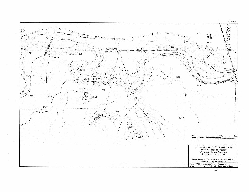
The proposed dam is to provide a reservoir of approximately 1200 acre
ft with a maximum reservoir water surface elevation of 1320 ft to supply
water used in the taconite beneficiation process. It is located on the St.
Louis River near EvlUet'H.,~ Minnesota. and is shown in Chart 1. This chart
also shows the shape and extent of the reservoir that would be created by
the installation of the proposed dam. The dam itself consists of a ooncrete
sill or slab supported on reotangular cells of sheet piling driven to such
a depth as to inhibit seepage in the under strata. On the concrete sill a
"Fabridam," a composition dam in the form of a flexible tubep is mounted.
The crest of the "Fabridamll may be adjusted in elevation by varying the
degree of inflation and thus can maintain the headwater elevation at 1320
ft for all discharges within the range of the dam design. For high discharges,
the tube is completely deflated~ leaving the two bays open through which the
flood water can pass with a minimum of backwater·effect. Chart 2 shows the
longitudinal and transverse sections through the dam.
Foundation Borings
In order to study the percolation through tJ:>.e foundation, it is neces ...
sary to know the relative permeabilities and the geomat.ry of the various
layers that may exist under the dam. An earlier report [1] on the sub
surface structure at the damsite provided information on the location of
(1) Armstrong, L. C. I'Report to the Eveleth Taconite Company on Sub-Surface
at Damsite on the St. Louis River neal" Forbes, Ninnesota.1V E. J.
Longyear Company, Minneapolis, Minnesota. December 17. 196;.

I·
... 2-
various layersp the grain size distribution of a number of sediment samples
taken from the drill holesp and some bailing tests made for some holes into
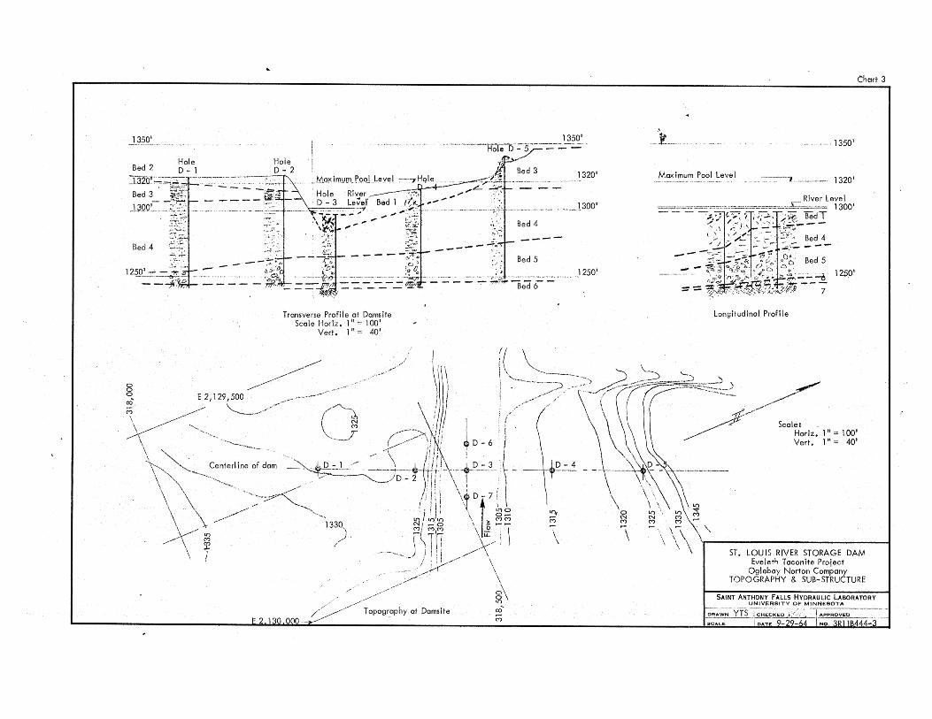
which water seeped in measurable quantities. Chart 3, from Reference (1~~
shows the topography at the damsite and the location of the bore holes as
well as the sub .. surfMe profile as determined by these bore holes. The
beds or soil profiles, as shown in Chart :3, have been characterized as
follows in Table I.
Bed 1:
Bed 2:
Bed 3:
Bed 4:
Bed 5: Bed 6: Bed ?:
TABLE I
FOUNDATION PROFILES AT DJU1SITE
Alluvium
Glaoial deposit
Glacial deposit
Glacial deposit
Glacial deposit
Ledge rock
Ledge rock
Sand? gravel, silt. Loose. Logs and other vegetational trash.
Sand~ brown, medium-fine .. coarse. Hodium dense.
Clay, gr~~brown .. red, some silt laminae. Stiff to very stiff.
Silt, some clay, min6r fine sand. Medium dense. Denser in the lower half.
Gravel, sand, cobbles, boulders.
Infirm slate, broken. Locally clayey.
Firm slate, gray, some fraotures and joints.
Beds 2 and :3 were restricted to the left side of the ohannel and are
not involved in the flow peroolation under the structure itself. In the
river channel and on the right bank, bed 1 is in contact with bed 4, so
that the beds involved are limited to beds 1, 4, and ,. It is assumed that
beds 6 and,? are impermeable. The longitudinal profiles through which the
flow takes place are those determined by the three borings, D-6, D-:3, and
D .. 7, on the centerline of the river and perpendioular to the centerline of
the dam. The longitudinal soil profile as shown in Chart 3 was used for
the determination of the percolation oharacteristics under the dam.
In the course of drilling the exploration holes, samples of the soil
material through which the drill passed were col1eoted at various depths.
These were anlayzed in regard to size distribution.
In addition to these measurements? the report (Reference t~n) also
inoluded data regarding the percolation of water into oertain of the drill
,'. ...
.. "
..
•
-3 ..
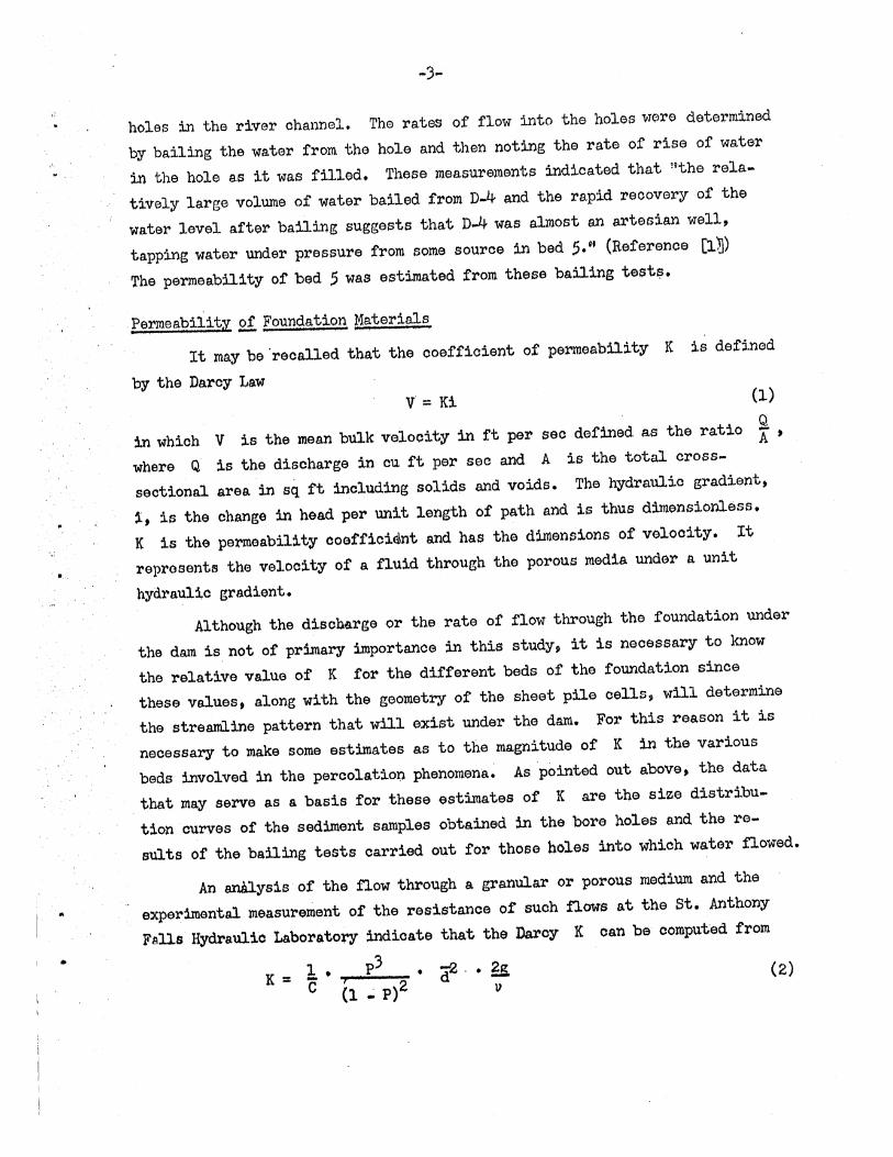
holes in the river ohannel. The rates of flow into the holes were determined
by bailing the water from the hole and then noting the rate of rise of water
in the hole as it was filled. These measurements indicated that "the rela
tively large volume of water bailed from D~ and the rapid reoovery of the
water level after bailing suggests that D-4 was almost an artesian well,
tapping water under pressure from some sOUl'oe in bed 5." (Reference [l~)
The permeability of bed 5 was estimated fl'om these bailing test~.
Permeabilit~ 2! Foundation Matel'ials
It may be'reoalled that the ooefficient of pe~eability K is defined
by the Daroy Law v = Ki (1)
in whioh V is the mean bulk velocity in ft per seo defined as the ratio ~.
where Q is the discharge in au ft per sec and A is the total cross ..
seotional area in sq ft including solid~ and voids. The hydraulio gradient,
~, is the ohange in head per unit length of path and is thus dimensionless.
K is the permeability coeffioi$nt and has the dimensions of velocity. It
reprosents the velooity of a fluid through the porous media under a unit
hydraulio gradient.
Although the discnal'ge or the rate of flow through the foundation under
the dam is, not or primary importanoe in this study, it is necessary to know
the relative value of K for the different beds of the foundation sinoe
these values, along with the geometry of the sheet pile cells, will determine
the st~eamline pattern that will exist under the d~. For this reason it is
necessar,y to make some estimates as to the magnitude ot K in the various
beds involved in the peroolatio~ phenomena~ As pointed out above, the data
that m~ serve as a basis for these estimates of K are the size distribu.
tion curves of the sediment s~ples obtained in the bo~e holes and the re
sults of the bailing tests carried out for those boles into which water flowed.
An analysis' of the flow through a granular O~ porous medium and the
experimental measu~ement of the resistance of such flows at the St. Anthony
Falls Hydraulic Laboratory indicate that the Darcy K can be computed from
1 P3 K = -' • <r'. ~ (2)
c h..; p)2 v
c-0,
t'
I ~
-4-
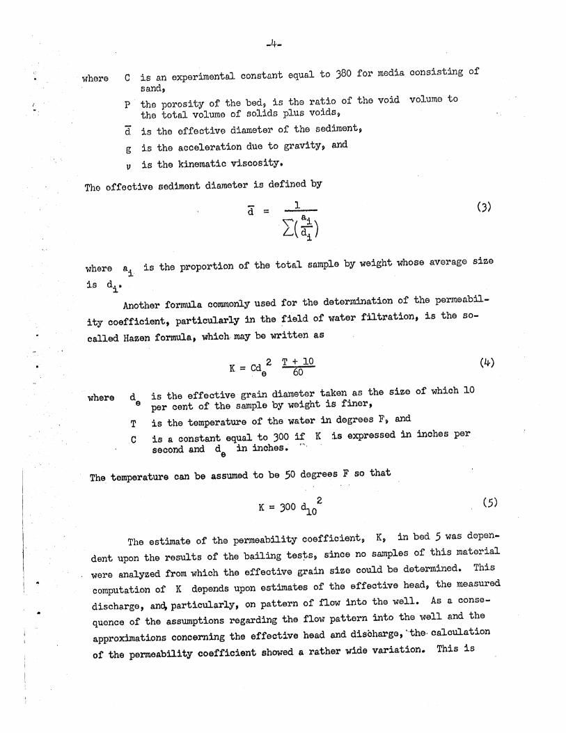
where C is an experimental constant equal to 380 for media oonsisting of
sand,
P the porosity of the bed, is the ratio of the void volume to
the total volume of solids plus voids?
d is the effective diameter of the sediment,
g is the acceleration due to gravity, and
v is the kinematic visoosity.
Tho offeotive sediment diameter is defined by
1
where ai is the proportion of the total sample by weight whose average size
is di -
Another formula oommonly used for the determination of the permeabil
ity ooeffioient, particularly in the field of water filtration, is the so
called Hazen formula, which· may be written as
K - Cd 2 T + 10 - e 60
where de is the effeotive grain diameter taken as the size of whioh 10 per oent of the sample by weight is finer, ,
T is the temperature of the water in degrees F, and
C is a oonstant equal to 300 it K is expressed in inohes per second and de in inobes. n"
The, temperature oan be assU1l1ed to be 50 degrees F so that
(4)
2 K = 300 ~o (5)
The estimate of the permeability coefficient, K, in bed 5 was depen
dent upon the results of the bailing tes~s, since no samples of this material
were analyzed from which the effeotive grain size could be determined. This
computation of K depends upon estimates of the effective head, the measured
discharge, an~particularly, on pattern of flow into the well. As a conse
quence of the assumptions regarding the flow pattern into the well and the
approximations concerning the effective head and disoharge, ··the· caloulation
of the permeability coefficient showed a rather wide variation. This is
/'
•
-5 ..
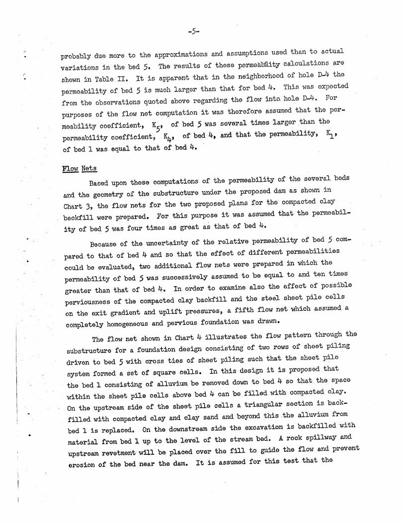
probably due more to the approximations and assumptions used than to actual
variations in the bed 5. The results of these permeability calculations are
shown in Table II. It is apparent that in the neighborhood of hole D~4 the
permeability of bed 5 is much larger than that for bed 4. This was expected
from the observations quoted above regarding the flow into. hole D~4·. For
purposes of the flow net oomputation it was therefore assumed that the per~
meability coefficient, KS' of bed 5 Was several times larger .than the
permeability coefficient p K4, of bed 4, and that the permeabi1ity~ Ki' of bed 1 was equal to that of bed 4.
Flow Nets --Based upon these computations of the permeability of the several beds
and the geometry of the substructure under the proposed dam as shown in
Chart )7 the flow nets for the two proposed plans for the compacted clay
be,ckfill were prepared. For this purpose it was assumed that the permeabil ..
ity of bed 5 waS four times as great as that of bed 4.
Because of the uncertainty of the relative permeability of bed 5 com
pared to that of bed 4 and so that the effect of different permeabilities
could be evaluatedp two additional flow nets were prepared in which the
permeability of bed 5 was successively assumed to be equal to and ten times
greater than that of bed 4. In order to examine also the effect of possible
perviousness of the compacted clay backfill and the steel sheet pile cells
on the exit gradient and uplift pressures, a fifth flow net which assmued a
completely homogeneous and pervious foundation was drawn.
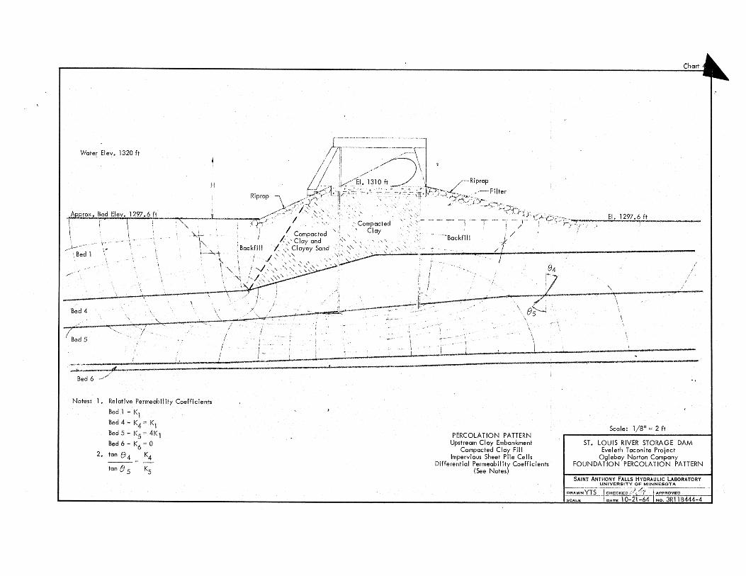
The flow net shown in Chart 4 illustrates the flow pattern through the
substructure for a foundation design oonsisting of two rows of sheet piling
driven to bed 5 with cross ties of sheet piling such that the sheet pile
system formed a set of square cells. In this design it is proposed that
the bed 1 consisting of alluvium be ~emoved down to bed 4 so that the space
within the sheet pile cells above bed 4 can be filled with compacted clay.
On the upstream side of the sheet pile cells a triangular section is back
filled with compacted clay and clay sand and beyond this the alluvium from
bed 1 is replaced. On the downstream side the excavation is backfilled with
material from bed 1 up to the level of the stream bed. A rock spillway and
upstream revetmentwl1l be plaoed over the fill to guide the flow and prevent
erosion of the bed near the dam. It is assumed for this test that the

" ~--~--".....,,~---.. --,. ",,"",-=,=,--,---== -----
• ,
TABlE II.:
ESTII1ATED PERMEABILJTY COEFFICIENT - FOUNDATION MATERIAL
Depth of' Eff'ective Size Permea.bility
Drill Role No. Sample Bed . of Sediment Porosity Coefficient K
(SEle Chart" 3) ft. _ ts~?_ Cha.!'t 3t _________ "~.m. (Est1ma.ted) f't 'Per sec
" D-7
- D-1
0-1
0-4
D-4
D-3
D-3
0-4-1
D-4-2
D-5-l
D-5-2 D-l-1
D-1-2 D-2-2
14
20
20
15 15 15 15
70
70 92 92 82
82
82
1
4-
4-
4 4-
4 4-
5
5 5· 5 5 5 5
0.019
0.009
0.017
0.0085 0.013
0.0055 0.012.
0.0042
0.326
0.345
0.375
0.360
-3 .. 42 x '10-6
3.25 x 10⁻⁶
3.58 x 10⁻⁶
2.80 x 10⁻⁶
3.26 x 10⁻⁶
1.17 x 10⁻⁶
2.02 x 10⁻⁶
0.68 x 10⁻⁶
7.9 x 10⁻⁶
9.3 x 10⁻⁶
0.9 x 10⁻⁶
0.4 x 10⁻⁶
2.2 x 10⁻⁶
2.8"x 10-6
0.4 x 10⁻⁶
Remarks
SAFHL (Eq.2)
Ha.zen (Eq.5)
SAFBL (Eq.2)
"Hazen (Eq.5)
SAFHL (Eq.2)
- Hazen (Eq.5)
SAEBL (Eq.2)
Hazen (Eq.5)
.. ".:: -".
From bailing tests (artesian flow)
it it ;;
ii " n
;1 n 1~
n ;2 37
9ii ~1 :f
t: H :J
I ~ 1
•
I.
-7-
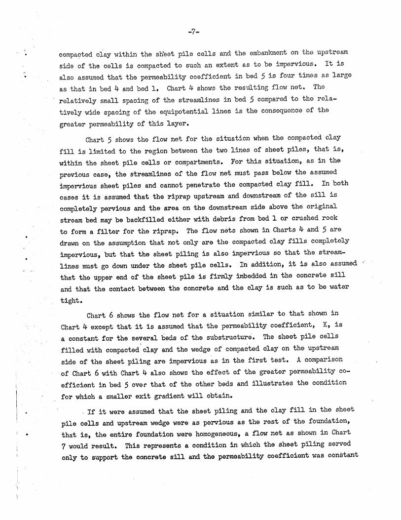
compa9ted clay within the sh~et pile cells and the embanlonent on the upstream side of the cells is compacted to such an extent as to be impervious. It is also assumed that the permeability coefficient in bed 5 is four times as large
as that in bed 4 and bed 1. Chart 4 shows the resulting flow net. The
relatively small spaoing of the streamlines in bed 5 compared to the rela~ tively wide spacing of the eqUipotential lines is the consequence of the
greater permeability of this layer.
Chart 5 shows the flow net for the situation when the compacted clay fill is limited to the region between the two lines of sheet piles~ that is, within the sheet pile cells or compartments. For this situation, as in the previous case, the strenmlines of the flow net must pass below the assumed impervious sheet piles and cannot penetrate the compacted clay fill. In both cases it is assumed that the riprap upstream and downstream of the sill is completely pervious and the area on the downstream side above the original
stream bed may be backfilled either with debris from bed 1 or crushed rock to form a filter for the riprap. The flow nets shown in Charts 4 and 5 are drawn on the assumption that not only are the compacted clay fills completely impervious, but that the sheet piling is also impervious so that the streamlines must go down under the sheet pile cells. In addition, it is also assumed that the upper end of the sheet pile is firmly imbedded in the concrete sill
and that the contact between the concrete and the clay is such as to be water tight.
Chart 6 shows the flow net for a situation similar to that shown in
Chart 4 except that it is assumed that the permeability coefficient, K, is a constant for the several beds of the su.bstru.cture. The sheet pile cells
filled with compacted clay and the wedge of compacted clay on the upstrerum side of the sheet piling are impervious as in the first test. A comparison
of Chart 6 with Chart 4 also shows the effect of the greater permeability coefficient in bed 5 over that of the other beds and illustrates the condition
for which a smaller exit gradient will obtain •
. If it were assumed that the sheet piling and the clay fill in the sheet pile cells and upstream wedge were as pervious as the rest of the foundation, that is, the entire foundation were homogeneous, a flow net as shown in Chart 7 would result. This represents a condition in which the sheet piling served only to support the concrete sill and the permeability ooefficient was constant
'" •
•
•
.$ ...
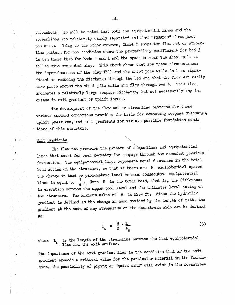
throughout. It will be noted that both the equipotential lines and the
strea.rn1ines are relatively widely separated and form "squares" throughout
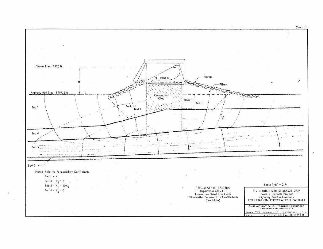
the space. Going to the other extreme, Chart 8 shows the flow net or stream
line pattern for the condition where the permeability ooefficient for bed S
is ten times that for beds 4 and 1 and the spaoe between the sheet pile is
filled with oompacted olay. This chart shows that for these oiroumstanoes
the imperviousness of the olay fill and the sheet pile walls is less signi
fioant in reduoing the disoharge through the bed and that the flow can easily
take plaoe around the sheet pile walls and flow through bed 5. This also,
indioates a relatively large seepage discharge, but not neoessarily any in"
orease in exit gradient or uplift foroes.
The development of the flow net or streamline patterns for these
various assumed oonditions provides the basis for oomputing seepage discharge,
uplift pressures, and exit gradients for various possible foundation condi~
tions of this structure.
"', "i~ .... , ~ Gradients
'" The flow net provides the. pattern of str~amlines and eqUipotential
lines that exist for eaoh geometry for seepage through the somewhat pervious
foundation. The equipotential lines represent equal deoreases in the total
head aoting on the struoture, so that if there are M eqUipotential spaces
the ohange in head or piezometric level between oonseoutive equipotential
lines is equal to *'. ·Here H is the total head, that is, the difference
in elevation between the upper pool level and the tail water level acting on
the struoture. The lllaximUlll value of H is 22.4 ft. Sinoe the hydraulio
gradient is defined as the ohange in heaq. divided by the length of path, the
gradient at the exit of any streamline on the dowpstream side can be defined
as
where Ln is the length of the streamline between the last equipotential line and the exit surfaoe.
(6)
The importanoe of the exit gradient lies in the oondition that if the exit
gradient exceeds a critical value for the partioular material in the founda
tion, the possibility ot piping or "quick sand" will exist .in the downstream
•
•
-9 ...
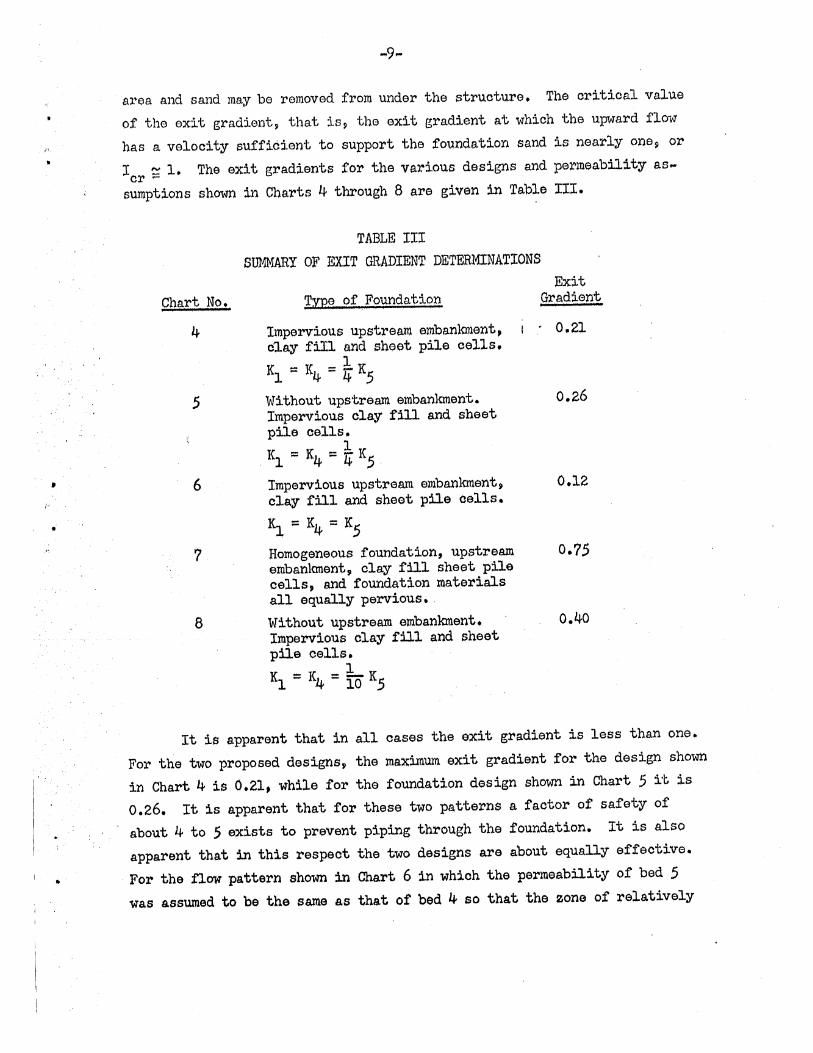
aroa and sand lUay be removed frolU under the structure. The critical value of the exit gradient~ that isp tho exit gradient at which the upward flow has a velocity sufficient to support the foundation sand is nearly one? or
IeI' ~ 1. The exit gradients for the various designs and permeability as ... sumptions shown in Charts 4 through 8 are given in Table III.
Chart No.
4
6
7
8
TABLE III SUMMARY OF EXIT GRADIENT DETERMINATIONS
Exit type of Foundation Gradient
Impervious upstream embanlo.nent. I' 0.21 clay fiIl and sheet pile cells.
Kl ::: K4 ::: ~ K,5
Without upstream embankment. 0.26 Impervious clay fill and sheet pile cells.
1 Kl = K4 = 4 K,5.
Impervious upstream embankment? clay fill and sheet pile cells.
K], ::: K4 = K,5
Homogeneous foundation, upstream embankment, clay fill sheet pile cells, and foundation materials all equally pervious. Without upstream embankment. Impervious clay fill and sheet pile cells.
Kl ::: K4 ::: ~ K.5
0.12
0.7.5
0.40
It is apparent that in all cases the exit gradient is less than one.
For the two proposed designs, the maximum exit gradient for the design shown in Chart 4 is 0.21. while for the foundation design shown in Chart ,5 it. is 0.26. It is apparent that for these two patterns a factor of safety of about 4 to .5 exists to prevent piping through the foundation. It is also apparent that in this respect the two designs are about equally effective. For the flow pattern shown in Chart 6 in which the permeability of bed .5
Was assumed to be the same as that of bed 4 so that the zone of relatively

,
-10 ...
unrestricted flow was eliminated and all the natural foundation material was
homogeneous~ the exit gradient is reduoed to 0.12. In Chart 7~ where it is
assU1ned that the sheet piling and the compacted olay fill are as pervious as
the rest of the foundation material$ the exit gradient is increased to 0.75.
This shows the importanoe of 'the sheet pile cells and the compacted clay fill
in order to decrease the exit gradient and reduce the possibility of piping.
This also emphasizes the necessity of the sheet pile cells being essentially
impervious. The somewhat higher value for the exit gradient for the condition
shown in Chart 8 when compared with that in Chart 4 shows the effect of the
increased permeability of bed 5. A comparison of exit gradient for Charts
6$ 4, and 8 shows clearly the resulting inorease in the exit gradient as the
permeability coefficient of bed 5 is progressively increased. When the
permeability of bed 5, K5, is suocessively equal to K4 and four and ten
times larger than K4$ the exit gradients increase respectively to 0.12, 0.26~
and 0.40.
It is apparent from Table III that the probability of piping occurring
on this structure is rather small. Even so, a filter blanket of material
graded from the foundation material to the size of the riprap should be placed
on the bed downstream of the structure to form a transition from the bed
material to the riprap that forms the lower spillway.
~ Weighted.-Creep }1ethod !2!: Stability
It is of interest at this point to compare the results obtained by the
flow net analysis with the so-called 11weighted ... creepli method for determining
the stability of structures. In this method of analysis [2J it is assumed
that the line of contact between the structure and the f.oundation is the region
most likely to provide a flow path from the upper pool to the tailwater pool.
It appears than that the safety of the structure depends for a given degree of
contact upon the length of this line of contact or creep length as compared to
the head acting on the structure. A study of existing structures led Lane to
.the belief that vertical lines of contact were more effective than horizontal
. lines of contact, so that the horizontal lines were given a weight of only
one-third that of the vertical lines. The magnitude ·of the ratio of length
of creep to the head acting on the structure, taking into account the nature
, ,
Lane, E. M. lOSecurity from. Under .l3eepage, liasonry Dams ,on ,Earth
Foundations.1! Transactions, Ame:i'ioan Society of Civil Engineers,
Vol. lOO,1935,pp. 1235-1351.
Y\
J
•
... 11-
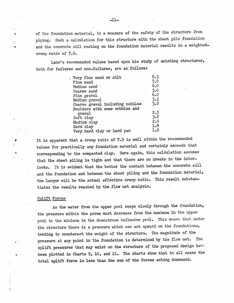
of the foundation material p is a measure of the safety of the struoture from piping. Such a calculation for this structure with the sheet pile foundation and the concrete sill resting on the foundation material results in a weighted. creep ratio of 7.9.
Lanevs recommended ~alues based upon his study of existing structures~
both for failures and non~failures~ are as follows:
\ Very fine sand or silt 8 • .5 Fine sand 7.0 Medium sand 6.0 Coarse sand .5.0 Fine gravel 4.0 Medium gravel 3.5 Coarse gravel including cobbles 3.0 Boulders with some cobbles and
gravel 2 • .5 Soft clay 3.0 Medium clay 2.0 Hard clay 1.8 Very hard clay or hard pan 1.6
It is apparent that a oreep ratio of 7.9 is well within the recommended values for practically any foundation material and certainly exceeds that
corresponding to the compaoted clay. Here again, this calculation assumes that the sheet piling is tight and that there are no breaks in the interlocks. It is evident that the better the oontaot between the ooncrete sill
and the foundation and between the sheet piling and the foundation material~ the larger will be the actual effeotive creep ratio. This result substanw
tiates the results reaohed by the flow net analysis.
Uplift Forces
As the water from the upper pool seeps slowly through the foundation, the pressure within the pores must deorease from the maximum in the upper
pool to tho mll'dmum in tho dOwfwtromll tni1wfl.tor pool. Th1,f.l mOfl.nn -(;111'1.'1', undoX'
the struoture thore is a pressure which can a,ct upward on tho foundations, tending to counteract the weight of the structure. The magnitude of the pressure at any point in the foundation is determined by the flow net. The uplift pressures that may exist on the struoture of the proposed design hav'c;
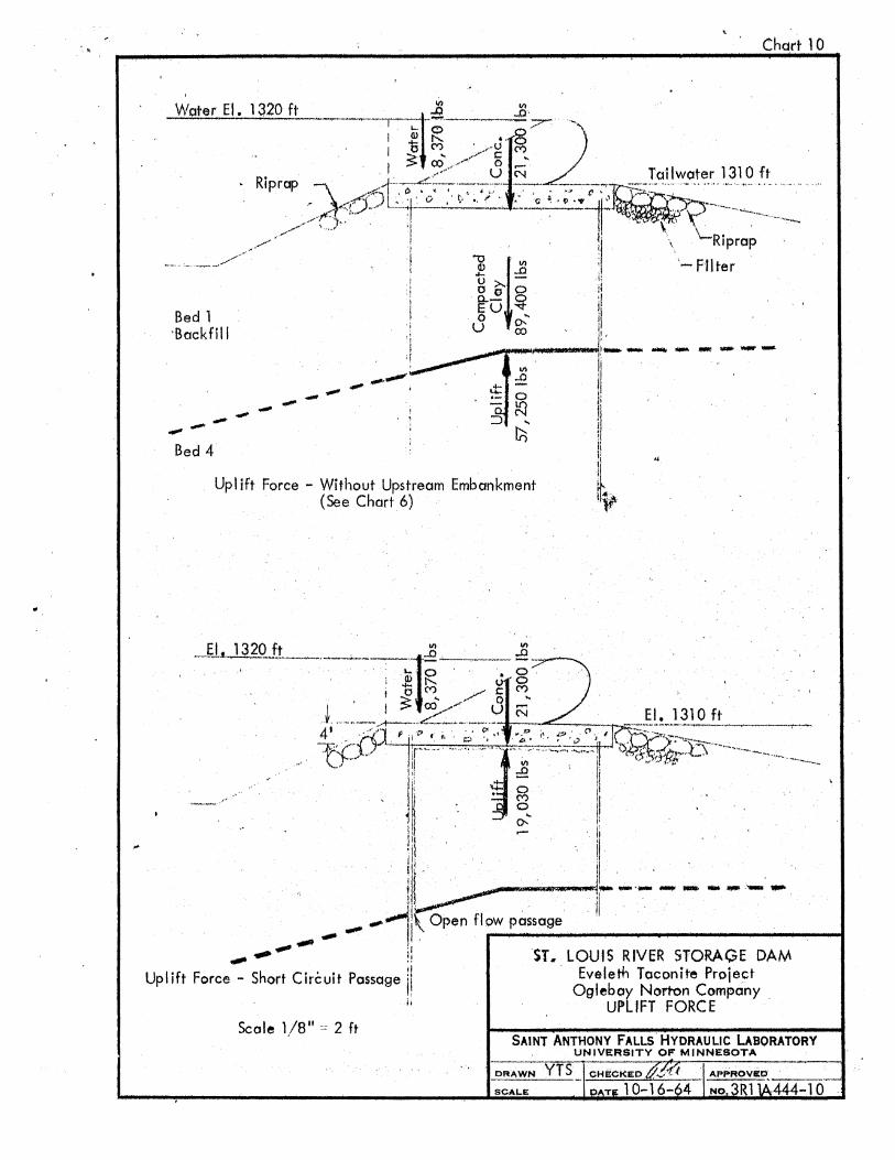
been plotted in Charts 9, 10, and 11. The charts show that in all cases the
total uplift force is less than the sum of the forces acting downward.
• f
... 12-
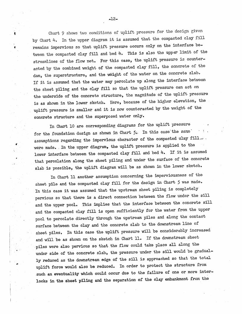
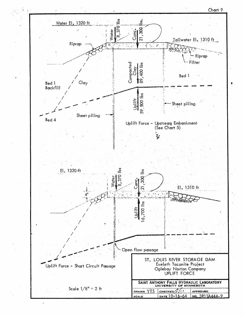
Char"t 9 shows two conditions of uplift pressure for the dosign eiven
by Chart 1+. In the upper diagram it is assumed that the compacted clay fill
remains impervious so that uplift pressure ocours only on the interface be ...
tween the compacted clay fill and bed 4. This is also the upp~ limit of the
streamlines of the flow net. For this case? the uplift pressure is counter ...
acted by the combined weight of the compacted olay fill~ the ooncrete of the
dam? the superstruoture~ and the weight of the water on the ooncrete slab.
If it is assumed that the water may percolate up along the interface between
the sheet piling and the clay fill so that the uplift pl'ess'llre can act on
the underside of the concrete structure~ the magnitude of the uplift pressure
is as shown in the lower sketch. Here, because of the higher elevation? the
uplift pressure is smaller and it is now counteracted by the weight of the
conorete structure and the superposed water only.
In Chart 10 are corresponding diagrams for the uplift pressure
for the foundation design as shown in Chart 5.· In this cass'the same'
assu:mp'bionsregarditlg the impervious character of the compacted 'clay fill .. ".,
were made. ' In the ,upper diagram,. the uplift 'pressure is applied to the
lower interface between the oompacted clay fill and bed 4. If it is assumed
that percolation along the sheet piling and under the surface of the ooncrete
slab is possible, the uplift diagram will be as shown in the lower sketch.
In Chart 11 another assumption concerning the imperviousness of the
sheet pile and the compacted clay fill for the design in Chart 5 was made.
In this case it was assumed that the upstream sheet piling is completely
pervious So that there is a direct connection between the flow under the sill
and the upper pool. This implies that the interface between the concrete sill
and the compacted clay fill is open sufficiently for the water from the upper
pool to percolate directly through the upstream piles and along the contact
surface between the clay and the concrete slab to the downstream line of
~heet piles. In this Case the uplift pressure will be considerably increased
and will be as shown on the sketch in Chal't 11. If the downstream sheet
,piles were also pervious so that the flow oould take place all along the
under side of the concrete slab, the pressure under the sill would be gradual
ly reduced as the downstream edge of the sill is approached so that the total
uplift force would also be reduced. In order to protect the structure from
such an eventuality which could occur due to the failure of one or more inter
locks in the sheet piling and the separation of the clay embankment from the

, ~ill by settling, ~ drain should be located in corner between the concrete sill and the upstrerum side of the downstream line of ~heet piles and oon~
• ' nected by drain pipes to the downstream pool. This would be effective in permitting the p~ssage of any flow occurring along the cont~ct surfaoe to be drained ~way with a consequent reduction in total uplift pressure. This
drain would be of the inverted filter type.
Conolusions ~ Reoommendations
This stuqy of the perco~ation characteristics of the substructure of -----,' theproposedi3.am on the St. ,Louis River shows that either of the proposed de ..
.'
,
signs would be effective in reducing the exit gradient and thus reduce the probability of piping. It appears that the compaoted olay wedge upstream of
,the sheet pile cells does not exhibit sufficient improvement in this respect to justif,y its use. The results also show that the permeability coefficients could be oonsiderably in error without increasing the exit gradient to the point of endangering the structure.
It is recommended that an inverted filter drain be incorporated in the olay fill at the corner of the oonorete slab and the downstream sheet pile wall in order to' provide drainage in the event th~t the upstream sheet pile wall is, in fact, pervious and the olay fill separates from the concrete through settlement of the olay.
Acknowledgements: Dr. Heinz Stefan, Researoll Fellow at the St. AnthonY Falls aydraulic
Laborator,y was instrumen~al in the preparation of the flow nets for the various foundation geometries. 'The charts were prepared by Mr. Y. T. Shen, Researoh Assistant, wille the text was edited and prepared for, reproduction by Mrs. Mary Marsh.
,.
CHART 1
CHART 2
CHART :3
CHART 4
CHART 5
CHART 6
CHART 7
CHART 8
CHART 9
CHART 10
CHART 11
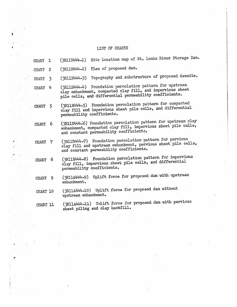
LIST OF CHARTS
(3RIIB444~1) Site location map of st. Louis River Storage Dam.
(3Rll~4-2) P1an of proposed dam.
(3RlIB444-3) Topography and substructure of proposed damsite.
(3RI1B444...4) Foundation percolation pattern for upstream.
clay embankment, compacted clay fill, and impervious sheet
pile cells, and differential permeability coefficients.
(3RIlB444-S) Foundation percolation pattern for compacted
clay fill and impervious sheet pile oe11s, and differential permeability coefficients.
(3R11B444;6) Foundation percolation pattern for upstream. clay
embanlanent, compacted clay fill, impervious sheet pile cells,
and constant permeability coefficients.
(3Rl1B444-7) Foundation percolation pattern for pervious clay fill and upstream embankment, pervious sheet pile cells,
and constant permeability coefficients.
(3Rl1~4-8) Foundation peroo1ation pattern for impervious clay fil1~ impervious sheet pile cells, and differential permeability coefficients.
(3Rl1A~'-9) Uplift force for proposed dam with upstream emba.nkment.
(3R1IAl~-10) Uplift force for proposed dam without upstream embankment.
()Rl1A444-11) Uolift force for proposed dam with pervious
sheet piling and clay backfill.

,.
CHART 1
CHART 2
CHART :3
LIST OF CHARTS
(3RIIJ3l+4~'-I) Site location map of St. Louis RivGr storage Dam.
(3RIIB444-2) Plan of proposed dam.
()RIIB44·4 ... 3) Topography and substructure of proposed damsite.
CHART 4 (3RIIB444-4) Foundation percolation pattern for upstream
clay embanlanent~ compacted clay fillp and impervious sheet ,pile cells, and differential permeability coefficients.
CHART 5 (3RIIB444 ... 5) Foundation percolation pattern for compacted
clay fill and impervious sheet pile cells~ and differential permeability coefficients.
CHART 6 (3R1lB444':6) Foundation percolation pattern for upstream clay
embankment, compacted clay fill, impervious sheet pile cells,
and constant permeability ooefficients.
CHART 7 (3RllB444~7) Foundation percolation pattern for pervious clay fill and upstream embanlanent~ pervious sheet pile cells,
and constant permeability coefficients.
CHART 8
CHART 9
CHART 10
CHART 11
(3RllB444-8) Foundation percolation pattern for impervious
clay fill~ impervious sheet pile cells, and differential permeability coefficients.
(3RlIA~~-9) Uplift force for proposed dam with upstream embankment.
'(3RllA444.l0) Uplift force for proposed dam without upstream embankment.
(JRIlA444-1l) Uulift force tor proposed dam with pervious
sheet piling And clay backfill.
g:\:s: .-: -::::: .- ~ ~,~~';' -' ',.1
0<.,,,,,.-;:::;:::: .;. ~_.~. ~ 1325 \\..._.
m?6 I) li- 1;;
// j;, if
i
c. ,2..__ '_., . '-. '-. 350 -"" .~::.."
---' .- I \ ,--~-'-'------- ;?;;?;
.c~-:.::\:._: :::::: ;.:;:' .~-::. -- -"-. ~ .:::::- <" ~: ~ \ / '- : ' " 36131
\ .•.. ,J,)_ ~ S~I'~:~~T~ -1337-" ~~~ ;:~;;>'-.. "::--.. "-:-~:'.-F.,'.D=~;: ,::;-.):."= .=
1\ .' '. . \S'~ '. ",:,:-::~< : t:;-r;:) .~ r f[' 'l/ .. '· \,'",
2 \1 (,,>~, ".' .
CharI 1
".~"",-
\ l ' " '" \ ' . ~:.~,,:': ~'.-;>,
. '( '-""'---> ~-'·~::(Y \. .'1, ! ..-, \ '.. 1337 \ ,'" -,/ / ,,~.
,/ . )
1347
-- --- '~ _.- - .... - -,' _.-- .-,- -~ ......
~'.~ ' .. ' 1362 / ~"_ /:1350 ---": •. '" I \. ",' '~"-"""'_ ') A 361 . "". ", ./ .~~. /,~~ .>\ ' ..
1336"'\ / (»\ , '" '. \ '" v' . I C \.135~: I ; '" \
I I ~, C ,,\,~
C"
v' (:.'0 . ".
I' , .. . ' ~
1339
, __ I'
I i . /".',"' ,.."\- '\ ,_ .."
f'''' ",\ \ v .'?_~~ : 400 ... ..:..-:.lII.~
o JOn
400 800 ":=J
ST. LOUIS RIVER STORAGE DAM Eveleth Taconite Proi!,ct
OglebllY Norton Comp,Qny SITE LOCATION IV'AP
SAINT ANTHONY FAllS HYDRAULIC LABORATORY UNIVERSITY OF MINNESOTA
--- _.-.--- -.--~--.. ------"r: --- --
C :;::::YJliI-:::;K1Eo':l~~~ __ '1:::R30;t~ B444-1 -flO,

~
r 43' - 1" T 63' - 0" "'t- 63' - 0" + 37' - 6" .
[m rrrniliuriilnni Ilfll)ifi}~~. ,5l1,' IJIIT f' illfrT~li~ ,11, iTit _in 11111] 11" _',:J.'1l,·1111JJjl~_ 'J ;]J'.':, '.u::.::'",ll)j.ill',',I;!;lL!1'\}J,Qi.llfn flT;lhl'1T1ldh:'TI1)1~7,,,'I!>IT~ • .-----. ~~." -.:: : .-: :---- :. ::. ; -:: _. --:--.~ .. -- ~ . _______ c: ·~I' -. ~ __ T ___ '-'_'- _ -
~. ~ t~,»lJ I I ;;1.~ Fl.,. 1320 - • "V 1 Bed 2 I - - <;"., I I Fabridam I I Fabridom , I I I ,~ ••• _.- .~~----- - -- I I S'II EI 1310 I ' ___ J _"-_._"'-""' Bed 3 I I ~. ___ _ __ ~" , __ • _ _ _ ._. __ _ __ ,___ __ _ __ _ _ _ _ __ _ -r---:------r---- -- -.,- c';" 'I, I -
Bed 4
Bed 5
"lj-_, - - -- 1F'Crl' -::. -::-.:---:.- l~-';' f---~ I _ -- -)/', i I ! _ ..... / I ,_.- 1
\., 24" d' 't I ~ ... -~ I -1- ~ , la, p ee 'I I I Steel Short .. -1 _ - - , "I . ~ pl!' - I ~ ,Elev. 1303,5, .' '. __ -1- .J.I'll>J- --, i"""'-'\,! ,,! -+ - - I I V
" I I I ' I ,,/ '\ ' I I ! I .
__ '~, ! _____ ~ ____ iJ -----i-- -- --r-,~<./- - -.- - - - - - - ---'t __________ , ,Ll. ___ . __ ....L ___ _ • .v
'Holes D - 6 , D-3
Bed6 - .... l;iQ1,.t.D - 2 --.~ -- ____ . ___ _ -I..F- - -' - - - - - - - -. - -
--- ...... ------_ ...... D-7 - --_.------1- ___ _ -~-
Elevation of Proposed Dam Scale 1" ~ 24'
r ·34'-6" .. ,·'"
~--~~.--.J-'----~-,...----~ - ~-
/'
/"
EI.1310.00 .. ,i<~~~I.da:,,-., - I'..~~~~~-="'::::l.!_~~...,._:-.
2-1 "" ,,' . '\'Y:'-" n·~'» :t:~>/ ] Compacted 1 \, . li:~'=t~ i ro 11i3?"; 'f Clay II \ I ~ ------
I Ii II \ I Bed 1 , / II ........... - - - _11- - "'- .L - - - __ - _
, AI-
'\. I ~...- II : ,I - II B d 4
Bed 1 )1-"- -- it e
Chart 2
",..-'-"-
Ijole J:l - 4
~~ !! I, _ -Ir- - - - - - - - - - - - -
___ j:_. - -- 'I
----- Bed 5
ST. LOUIS RIVER STORAGE DAM Eveleth Taconite Project
Ogleboy Norton Company PLAN OF PROPOSED DAIv'
General Cross-sect ion Scale 1" -, 24'
----
_l}?Q~
Hole Bed 2 D - 1
=i32IJ~~;= E=::=-" Bed 3 ~!"c
~~QC ~~:2:;.-
Bed 4
§ rp'
E 2,12'1,:>uu
\...,--- -,,/""
"~-HoreD::5--,,-__ --'}50'.
M :r- -",axlm~m,Pool L ..... l',~.;;i_>"'-"" - - --
'Hole .' - ",evel :~-:-J'HQle _ ,ill , D _ 3 RI':.er."._-~~., .~_"",_'<::;;:!'11. Bed 3
L:y.';.l' Bed 1 p: " .... __ ". ".L ~ --..... ". ....... "" .... ~~ _': ,. tf.;E
~~ :2.~ - - - - -:~~ ;_~)d:
--Bed 4
----,:,
:-~) ~ Bed 5
-= -=.. -----.:='~qj. - - - - ..,-';::';;~.;". B;;i ;;- -
Transverse Profile at Domsite Scole Horiz. 1" ~ 100'
Vert. 1" ~ 40'
Topogr,aphy at Dornsite
/
'" c;:;
1320'
,,_1300'
_, __ .1250'
Chort 3
-'f-_ ,1350'
Max imum Pool Leve I 1320'
==~="='=-'''-2'-- _ :=' __ - _=_ =-- .c River Level ?') ';,7. i~' ,-:;" -----,:.:=-=- ---- 1300' ",I ._'" ,' ..• : ,,~~ BedT ,~ \ -" '<1'- -:. ~- - -/ / _ /_, -,:- ,!-"- ,. B d 4 -- -~::;:: -"~ -;;- :',-:-':--
..."....-. ~ l;; 0;:; ""),,61: f>{.' J 0';\0 B _ . ~" " '1_°. ('). 0 '" 0 ed 5 t'Jr.;;o n'~'!;l ... "~~C~ .... t'> :::-::::-:zi.'~'<"'c •• ;,,-;.,. . .:.;,;... . 1250' "':'~~"~S< :,:i,...""o __ "2 ". " "'C>.. . r l .. /Y .... /'f/T· 7
Longitudinal Profile
Scole: Hor1;/:. 1" '" 1 00' Vert. 1" ~ 40'
SAINT ANTHONY FALLS HYDRAULIC LABORATORY UNIVERSITY OF MINNESOTA
-~:::~ YTS l~~:~~: ;{f,r~I:::R;~~~B44"_
Chart
/7i-~:~~':::::~~----'--'~ -... //:1 ~\
. /1/. k/'':'3:0:' /': Rlprap _\ .t:t'~·'tll; ;:~:O'_,~ . .'.:: ;-;: , +... /--RiPra
p
10<~-;-/' . - -,-:-;TI.v~~" " ~-'- , . , /<.:PI I", ;:' ' .,' -, -9;.;- C--F ","' , , i 7f": I ",," - . . ,.iC,.>,"., .",_ I I" C~p~I'" : ",>Jj. . " '/. C~po".d 'Clo, -, ... .- ,.. "'1";",""
,,,"" : 'ook'" I I '" ~i'o, ood" ' , " . ' ) , 'i "S:1'-~ 1297,6(, , " ' ' F: ."" 'I", So.d ",: ' :' ' .. ,WII / 'i----'--
WotM EI ev, 1320 ft
#.e.J:&X, ~e,d EI;\,\1297, 6 ;tL._ ,I ,
\ \ \ , \
•• ,w,·' '
. Bed 1
'i,
H
~'", \'~j~:~':~~:-."-;~~:-~"':"'" ~",/jTf-'-' -..:....-----'------------. __ ..;.....;.. ___ -_...:--..--.. ' " ;' ,i", : , , ' " , , ' 8,
7 ,~ OJ \, ' '" ,~_~i~--· .. Z. ' '"d5' (' ". "I,' /' .~ , ' \ e' i \ .. 'Bed 4
, . 5-
j
,,::.=::;=..... _._____.. j -.---L! " ' '"d,j __ . - i '
, ... _ .. ________ " .--- .;.. • • _ \ OAA ___ '_·_L.-.-,-----_j;.fr~b ""' .... _--
Notes: I. Relative Permeabil ity Coefficients
Bed 1 - KI
Bed 4 - K4" Kl
Bed 5 - K5 ~4KI
Bed 6 - K6 ~ 0
2, tan e 4 ~ K4
tan e s KS
PERCOLATION PATTERN Upstream Cloy Embankment
Compacted Clay Fill Impervious Sheet Pile Cells
Differential Permeability Coefficients (See Notes)
Scale: ,1/8" ~ 2 ft
ST. LOUIS RIVER STORAGE DAM Eveleth Taconite Project
Oglebay Norton Company FOUNDA TlON PERCOLATION PATTERN

\
Water Elev. 1320 fl
t I H
r-----/-~r_--.. -1
_ !I'l~'I'>"'~ -~.. -R'p tIL]! <il:I31~ ~~)j I Riprap "' .~r:'''';:'r-'''_:-'~7::,,::-'-:'-'':'':Tr ;f'~".,'.// ,rap
" ~ 1 \ <~:;.- ," \,,'~',: ~_\._-:~_7:: \~-; -:='-'"11 >--"";"'~~''''' •
e,rlProx
, Bed Elev 1297 6 ft ! ." ..... 1 );,.,i'" ,\ , \ , , '-"'~'Y"- / - Fliter • • y ./;' y' '" " \ ,'. ' \, \ ' . ' ':"'~Z1~"~~ , ,.<'i> J.,,\ \ ,:- '," , .... '." \. i ' '·-')C(3:)::.-"~·-r _ ~ ,I . \. . ..... :>: .,., • .I'1:l-" B d] ",\ Backfill 'I' Compacted "',".,' -l----'-- -- - i ·::'>::':ty~:j "-.--. Elev 1297 6ft , • 'B,d! ; CI"" " .' ' . . ''''9, . .
_\_, . il"'\ ,.,\\ ...... ~ ~~_. __ B~c~fi~~ .. _. Bed 1 . J I \ ',\" ::'." ~ ,>\'.\", \, ,\' ... \,1 , ! . "" ~,.,.!.... I . ", ... \ " ...... '. '.----..,t=!..:!--. ......./..-.-' --,/ ... _--", i
Chart 5
\ - \ '\ ~~~ . ...-- . "-_.,,,,' •.... _...........-...._."---' ,\ ."',, . I .,' ,--
\ ~\ ''. '. ~- .... j. . \ \ \. I, ,,-,,' ;,' ,',/, ; -' .,- " ,,-' , . \', . '\. l \ . I '/ /' ", / Bed 4 ' ' ' .. ". ,'. '; \ l;~ \ . ....i...-.-', .,<- \ '\ -~, ... .,(.;., ...... -..... , -..,;,..--.... \~ .... --'
B.dS ;"" ,/~'", ,,/. '. ,,'~ , .;.: 'il
'" . .'j_1 \ j \"}' ,., \
\\
,. ! 1 I -; \
_ ... -.... --1.--,---- . --C"'L' II .... ··~~··-t·~ j. \ ________ ..... dtt-_,_ • ...-, • ..:::::::::::.:=-- . - -' '-' - ' -' ._-" ....... " _ ... -,..,....,.....,---------_. ..---~.---,.""--~ ....... -...... ------Bed 6 ----.-
Note: 1. Relative Permeab iI ity Coefficients
Bed ]- K1
Bed 4 - K4 ~ K]
Bed 5 - K5~ 4K1
Bed 6 - K6'" 0
)1
PERCOLATION PATTERN Compacted Clay Fill
Impervious Sheet Pile Cells Differential Perrneabil ity Coefficient>
(See Note,) .
Scale 1/8" = 2 ft
5T. LOU IS RIVER STORAGE DAM Eveleth Taconite Proiect
Oglebay Norton Company FOUNDATION PERCOLATION PATTERN
SAtNT ANTHONY FALLS HYDRAULIC LABORATORY Uf>,IlVERSriy Of' MINNESOTA
~;~~:-yliJ~-H~~-;;6-~f -:~:~~, ~~~---' ._--SCALE i DATE 10-21-64 I NO, 3R]1 B444-5
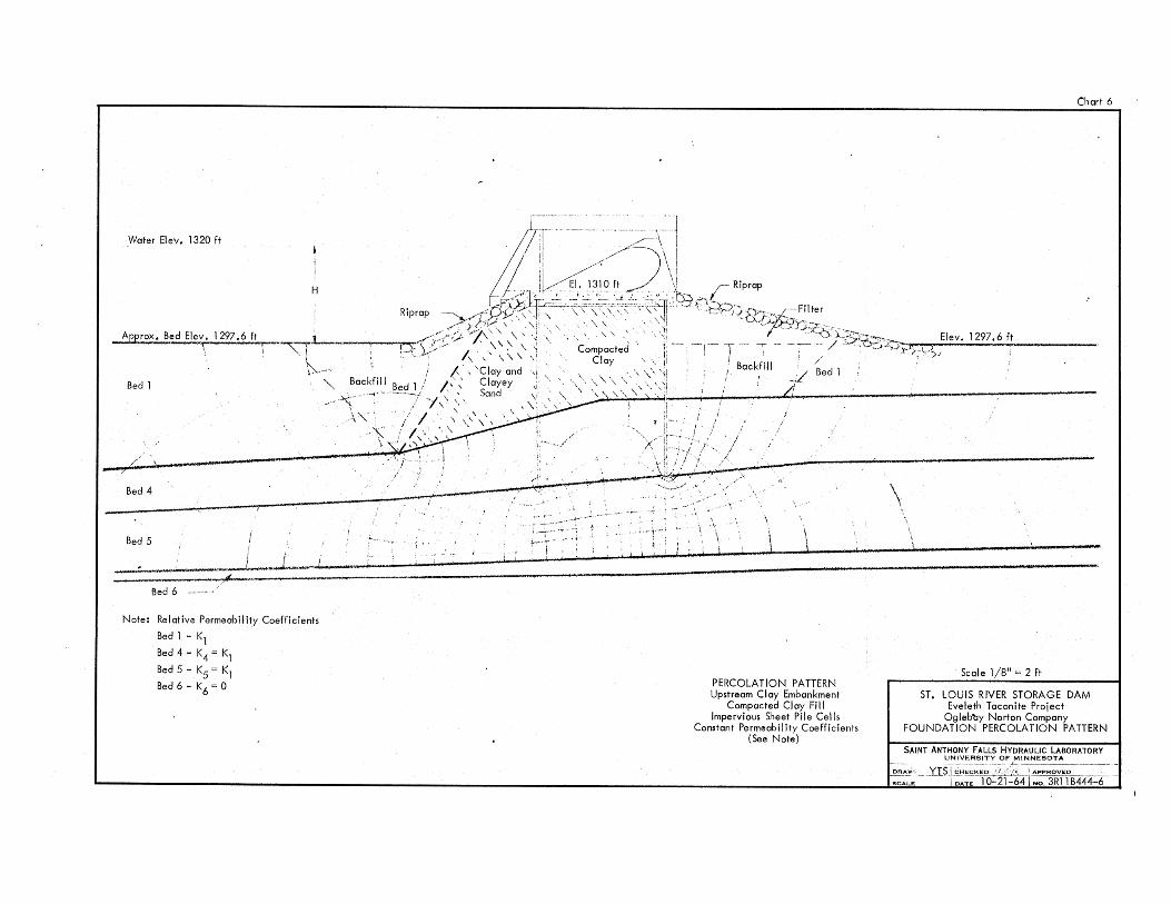
Chart 6
... '. ~
r-- _ -'.\ I , Water Elev. 1320 ft ill!" /'/~\ I
/ / I! /,,/. ) \i _ Riprap
/ ~ Jk/~' 1'}0 "'":C:~;'f't9 ,-' ~~ Ett,~;;;;;;"",,_~_ _._\.!E~le~v:.:,.~1~2~9~7~.~6.1f!.t _____ _ :C' 'y j"-~--,,, " , " , ,'I 1" ,:'/,A ",;;;',,\~~,.:,.!. ... ,')-,r;':./"")j "kJ'1i , , '" -- --~ , , . ,-- ,. HY, ''', 'd , , " -I __ "'i / R,p"p Y),,,, " , ' ' " , ,'>, '7'" \' " Comp~"d" B"kf,1I / B.dI ,/,fV
'\ " , Clo,,' ! , L....-. r;. 10'" I "',,, , " 'I ' __ ----ct.I..', _----~, B.dEl." I 297, U!.,-~ , , , ,~ 'c loy o,d "":..-"'~'i, __ .,....!_ ..
A",~, 'I " , <\ Clo,"
- , ~ 'o,kfill B.d J /' .' So,d
H
Bed'
Bed 4
Bed 5
Bed 6 ,---".
Note: Relative Permeability Coefficients
Bed' • K, Bed 4 - K4 = K,
Bed 5 - K5 "'K1 Bed 6 - K6 = 0
... -"7N,' '" " ):_ !,,' / ' .' I ' , " \ c, I,.", . _
' I, " " \ ii, I ", _
,I,' .. , "\,I"!//_,~' _',';\ " ,\ ~~ ,', ,/\ --- ,-, \ " " , .:>'
~ ... - - ".
~ ...•. - -',
",
-~. -
PERCOLATION PATTERN Upstream Cloy Embankment
Compacted Clay Fill Impervious Sheet Pile Cells
Constant Permeabi I ity Coefficients (See Note)
,.~
\
Seal e 1/8" = 2 ft
ST. LOUIS RIVER STORAGE DAM Eveleth Taconite Project
Ogleb'by Norton Company FOUNDATION PERCOLATION PATTERN
SAINT ANTHONY FALLS HYDRAULIC LABORATORY ~~~v_:~~!_~ __ OF 1!!~NESOTA
~~,. . ___ Yl$J£H~~ED // :'<":L_1 APPROVED ~ SCALE i DATE -ro::IT -64\ NO. 3Rll B444-6

Chart 7
.. WQt~r Elev.13:!Oft
"'r Riprap
- - :::ji:'~:~J<:i~Filter - ___ lli.~)J12~97Z:.!.6Lfllt _____ _ ~~, , , " -" ~C':~'5>;;.6;:g, EI",
-:r- - J ~/
H
~~~: B!,d Elev. 1297.6 ft ,,-'" " \,- / / /'
............. Bedl / , \' \'-.,
'. X~·
\" "'. '-- \ ".
1 . }
"'''. H } ,.~.r . Bed 4 "
," . ,! \ \' /..- i' ·t·, .... , j . ,.,' \
Bed 5 // /1 / '-r . ,.' \
.... '~ .. -'- ... ~ ...
" .... ~ ~ .... " ........
\, ~ ! i; \
,# Bed 6--'
"._'lll L-____ --.~ __ ----______ --------------~~~~:::::::::::::::::.:~,~:~::~:_::,u:.:~:.::::: I •• t.'.
Note: Relative Permeability Coefficients
Bed 1 ~ Kl
Bed 4 ~ K4'" Kl Bed 5 - K5 '" Kj ·
Bed 6 - K6'" 0
PERCOLATION PATTERN Pervious Clay Fill and Upstream Embankment
Pervious Sheet Pile Cells Constant Permeability Coefficients
(See Note)
Scale 1/8" '" 2 ft
ST. LOUIS RIVER STORAGE DAM Eveleth Taconite Project
Oglebay Norton Company FOUNDATION PERCOLATION PATTERN
SAINT ANTHONY FALLS HYDRAULIC LABORATORY UNIVER$ITf OF MIN.::N:.:E:.S::O:.T:.:A.:.... __ _
::~: YTfl::~~jf~6~ 1 ::3Ri18444-7 -
• w.~.ter,~lev. 1320 ft:,
r H
A I <-
I I \ "
... ".~,,1319"=-) ~ :;r~b .. :"""'~'!' ~ _t ,. "",..;....,. it'.
,_2r;r \,\\.,\~\\\ '\ .,c;-,;-y J, ". " \ " • \ .
. .- .... \''.\ \,\,\ I ',' \ \ \ \ \ .', .. !
1\\'" \\\"! Compacted" . \ '
I' ,,\ Clay"'. \. i -~ .
~
Chart 8
.,
' .. '11 .. \ \ \ <I: Backfill i \ " \ \ \ \ \ \ '- \ . I' Bed 1 ,\, . \ \ ' \; . Ie ,9 \ \ ) . · W;--_····j· /, I . : .,', . I:;' /'" 1. 'f'...... .. ••• " ! •
~ f :1--.. ,,· ,I f ~
. \ \
\' \ >1 ,./ i
~~~ ::::~: ;: \ \ ' 'j . 16 / /, ,'.~ ~-:~~:u \=,. . ;,X~. \ _<~\~-4-'1 ~ ... ' .~ .. ':,:.- . / \ ~_~.~,\ BedS "'-.,,. I.. .. .."'" \ .,' 1 \
__ ··v"_ .. _, L, . ------.\ •
\ \
,I
• /'1" U .!R Bed 6 -,.,,/ ..... --- .".-~.~.------
Notel Relative Permeability Corfficlents
Bed 1 - Kl
Bed 4 - K4= Kl
Bed5-KS =10K\
Bed 6 - K6'" 0 PERCOLATION PATTERN
Impervious Clc.y Fill Impervious Sheet Pile Cells
Differential Permeability Coefficients (See Note)
Seale 1/8" = 2 ft
ST. LOUIS RIVER STORAGE DAM Eveleth Taconite Proiect
Oglebay Norton Company FOUNDA TlON PERCOLATION PATTERN
SAINT ANTHONY FALLS HYORAULIC LABORATORY UNIVERSITY OF M_'N~N_E_SO~T_A ___ _
,:::~-Yfst:::;f~3i~~74"1 =R3~ii'B444-~ .
, ,I ~ ; .
Upl iff Force - UpsfTearo Embankment (See Chart 5)
VI • ,
..0 1/1
I J l~'· .... gri /---;. ~,~ _ ~~ ~,.:-,:~:;.:'~"."" d:~: .. , ,L..... EI. 1310 ft 4' 't~;(;.).~ .1 ,'" P '/ O. ~, !'"; ~'.,.. *,' \!' }", f: Co, ~'" \' V .. )-.... ~_
'~h ~7"),')l-<~ \ 1_ 1£" ,''',:-,'',.-', "'~ . Y' "''',-'- •• ;,' .""--', \ ";~ ,
~ .)~ Y J". "l~ \n 1; •. I . 11! -0 I'
,,'/ / ' !~ ~ ;; ;i -~-.. ""' ... -"'/.~' f 1f) - R j
I ,Ii ~.... I I ) ;!2 . , N 1
f tD "
I"
Chort 9
(' * 'I~ I ' ffi \ 1----- -.--II'
I I ;' .."" -~l!\ ' ); '/ .,.""'" #'......, " 'Ii Open flow possage
/ ..", ..-'I' ..... -------------------1 ."". ."". . ' STu LOUIS RIVER STORAGE DAM
~ Uplift Force - Short Circuit Passage Eveleth Taconite Project
Scale 1/811 "" 2 ft
Ogleboy Norton Company UPLIFT FORCE
SAiNT ANTHONY FALLS HYDRAUUC LABORATORY UNIVE~SITY OF MINNESOTA
SCAL..E
..
Chart 10 -'-~--~~-------~I ,
Water EI. 1320 ft
-' ---..... Bed 4
-" -."".." .".. ,
"
i 1
Upl ift force - Without Upstream Embankment (See Chart 6) ", ,
Scale 1/8" := 2 ft

o
, '
..... -----tlr-· - - - - - - - -
C \;
"
I," f' ,
Chart 11 '
Uplift Force .. PerVious Shedt Piling and Clay BackflH
Uplift force
Without drain ... 28,500 Ibs
With droin '," 19,250 ~bs
Scale 1/8 11 = 2 ft
,CALE
ST. LOUtS RIVER STORAGE DAM Eveleth Taconite Project
Ogleboy Nort.on Company UPLIFT FORCE
44-11