Embed Size (px)
Citation preview
NASA-CR-193301
/
,L
Project Report forNASA Grant NAG 9-634
A Vision System Planner forIncreasing the Autonomy of the
Extravehicular Activity Helper/Retriever
submitted by
Dr. Michael MageeComputer Science Department
University of WyomingLaramie, Wyoming 82071-3682
June 1, 1993
(NASA-CR-193301) A VISION SYSTEM
PLANNER FOR INCREASING THE AUTONOMY
OF THE EXTRAVEHICULAR ACTIVITY
HELPER/RETRIEVER (Wyoming Univ.)
54 p
N93-318_4
Unclas
G3/54 0175477
https://ntrs.nasa.gov/search.jsp?R=19930022655 2020-04-25T22:02:35+00:00Z
table of Contents
°
°
.
.
.
.
lntroductio1_ .................................................................... 1-1
Vision System Planner Design Consideration .............................. 2-1
2.1
2.2
2.3
Background for the Initial Design of the VSP ................... 2-1
Scenarios Illustrating the Operation of the VSP ................. 2-3
Deficiencies of the Initial VSP ..................................... 2-6
Implementation and Studies of the Initial VSP .............................. 3-1on a Mobile Robot Platform
3.1 Hardware Implementation of the Initial VSP .................... 3-1
3.2 Complexities Introduced in Scenarios Involving ................ 3-1Actual Color Images
Example Scenarios .................................................. 3-3
Intensity Based Pose Estimation .................................. 3-5
Synthetic Range Image Processing ........................................... 4-1
4.1
4.2
4.3
4.4
Model Feature Learning and Object Recognition Overview .... 4-1
Range Image Processing ........................................... 4-2
Learning Model Features .......................................... _4
Range Image Based Object Recognition ......................... 4-5
Vision System Planner Recommendation ................................... 5-1
Summary and Conclusions ................................................... 6-1
Acknowledgements
References

L, _tof Fig_Jres
Figure1Figure2Figure3
Figure 4aFigure 4bFigure 4cFigure 4d
Figure 5
Figure 6
Figure 7
Figure 8
Figure 9aFigure 9b
Figure 10aFigure 10b
Figure 1 laFigure 1 lb
Figure 12
Figure 14aFigure 14bFigure 14cFigure 14d
Figure 15aFigure 15bFigure 15cFigure 15dFigure 15e
Figure 16aFigure 16bFigure 16cFigure 16d
Figure 17
Figure 18
Figure 19
Figure 20
Planning System A,'chitecture
Vision System Components
Hemispherical Sec:or Search Order
Search of Sector 1 for OKUSearch of Sector 2 for O1;:UFirst Gimbal and Zoom RefmeroentSecond Gimbal and Zoom Refinement
Laser Scanner Range Estimation
Pseudo-Range Estimation
Moving EVAR Toward ORU
Checking for Obstacles Prior to Moving EVAR
The Mobile Robot Platform
The Rotary Carousel with RGB Camera
Truss Coupler Identifier MarkingsActual Truss Coupler with Identifier Markings
Truss Coupler Pose Estimation MarkingsActual Truss Coupler with Pose Estimation Markings
Configuration of MRP Relative to Truss Coupler after Executing VSP Plan
Cube Showing Three Planar FacesCube Showing Surface Normals for Three Planar FacesCube Showing Surface Normals for Two Planar FacesCube Showing Surface Normals for a Single Planar Face
Cut Cylinder Showing One Curved and Two Planar SurfacesCut Cylinder Showing Surface Normals for Two Planar SurfacesCut Cylinder Showing One Planar and One Curved SurfaceCut Cylinder Showing Normals for Visible Planar SurfaceCut Cylinder Showing Surface Normals for Two Visible Planes
Truss Coupler Showing One Planar Face and Curved SurfacesTruss Coupler Showing Surface Normais for Visible Planar FaceTruss Coupler Showing Only Curved SurfacesTruss Coupler Showing Absence of Planar Surface Normals
Object Detection
Object Recognition
Spatial Pose Estimation
Object Detection, Recognition and Pose Estimations
1.0 Introduction
The need for intelligent robots that are able to assist with operations in space will continue to
increase as the human presence in extraterrestrial environments expands.l-6 There are several
reasons why the development of such robotic devices, operating with varying degrees of
autonomy, will be a critical step toward achieving this goal. Foremost among these reasons is that
extended operations in space by humans require complex life support systems and shielding from
hazards such as radiation. This means that the time which an astronaut may devote to tasks outside
an orbiting vehicle or space station is an exceptionally valuable resource that should be allocated to
tasks requiring a high degree of human intelligence.
Many of the tasks that will be required to achieve a particular goal will not demand such high
levels of intelligence, however. For example, a crew member that is servicing a satellite or space
station might need a particular tool or replacement unit to be fetched. This is a task that would be
appropriately delegated to a spatially mobile robot that has the ability to recognize objects, estimate
their spatial poses, grasp, and retrieve them. These are precisely the types of objectives that the
Extravehicular Activity Helper/Retriever (EVAHR) is envisioned to achieve.
The EVAHR is a robotic device currently being developed by the Automation and Robotics
Division at the NASA Johnson Space Center to support activities in the neighborhood of Space
Station Freedom. Its primary responsibilities will be to retrieve tools, equipment, or other objects
which may become detached from the spacecraft, or to rescue a crew member who may have been
inadvertently de-tethered. Later goals will include cooperative operations between a crew member
and the EVAHR, such as holding a light to illuminate a work area, exchanging an Orbital
Replacement Unit (ORU), or maintaining equipment.
In order to be able to perform such tasks, it is clear that the EVAHR must be able to reason
about its operational environment based on the input obtained from one or more sensors. This
input is generally extracted from sensors that are capable of providing intensity and/or range
information, and there are advantages and drawbacks for each of these sensory domains depending
on the processing goal or the types of objects about which reasoning is to be performed. For
example, a laser scanner is directly able to extract three-dimensional coordinates from an observed
object whereas considerable computationally complex processing is necessary if only an intensity
based imaging system is employed using a classical method such as shape-from-shading. These
three-dimensional coordinates can be used to recognize the object based on its geometry or to
estimate its spatial pose (location and orientation). On the other hand, certain objects, such as
those covered with highly reflective material do not provide good return signals for the laser
scanner, thus minimizing its usefulness in such cases. However, there are certain intensity based
algorithms that make the estimation of spatial pose a straightforward and computationaily
inexpensive process if the right geometry exists among four or more extracted features in the
intensity image.
1-1

Theexamplescited in theprecedingparagraphareillustrativeof theneedfor aVisionSystemPlanner(VSP)thatiscapableof selectingasensorbasedonknowledgeof sensorcapabilitiesandobjectcharacteristics.Thejustificationsfor aVSPextendfar beyondsensorselection,however,sinceonceasensorhasbeenselectedit mayneedto bereorientedto obtainabetterviewof atargetobject. In somecases,physicalcharacteristicsof the sensorsuchasscanningrateor effectiveresolutionmayneedto bealteredsothatthedatacanbeacquiredmorerapidlyor suchthatfeaturelocationestimatescan be improved. Once a sensor has been selected and configured for the task at
hand, the VSP should also be capable of selecting an appropriate algorithm to achieve the current
vision system goal based on what is known about the sensor configuration, the characteristics of
the objects being reasoned about, and the state of the operational environment as represented in a
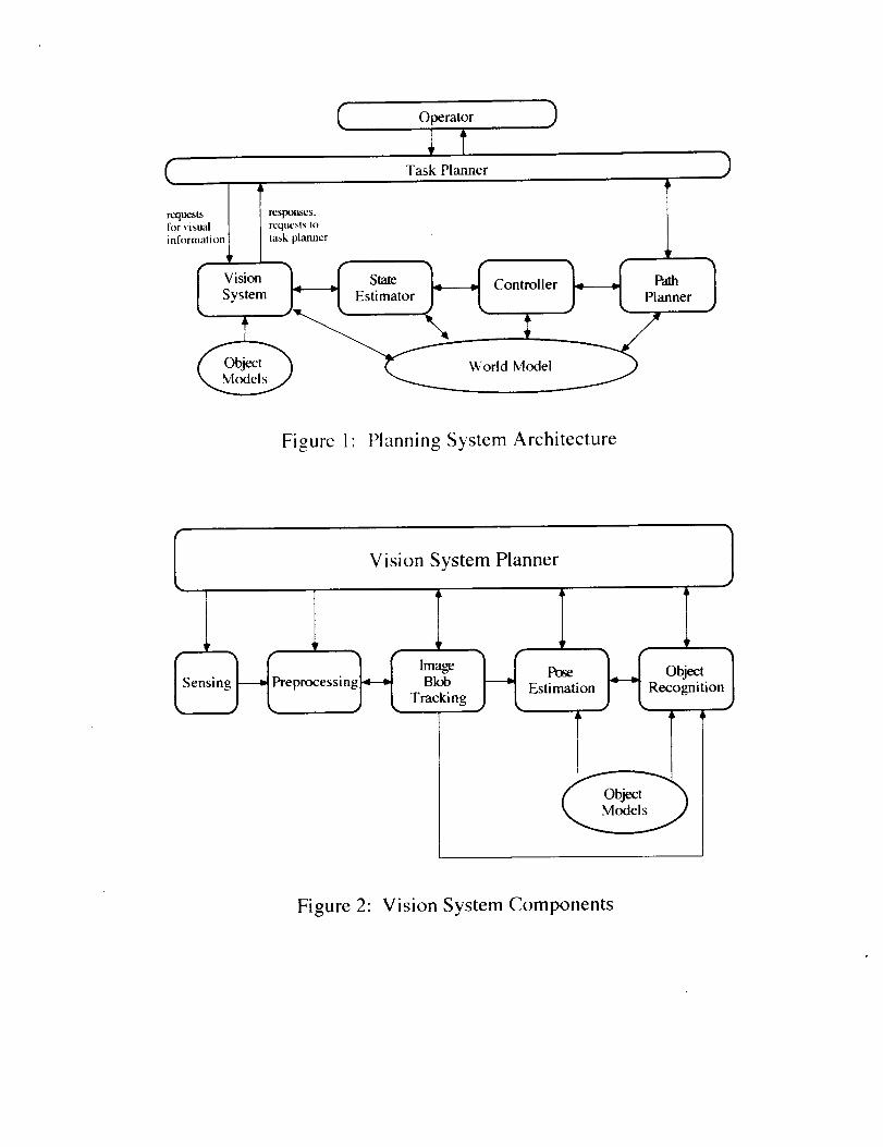
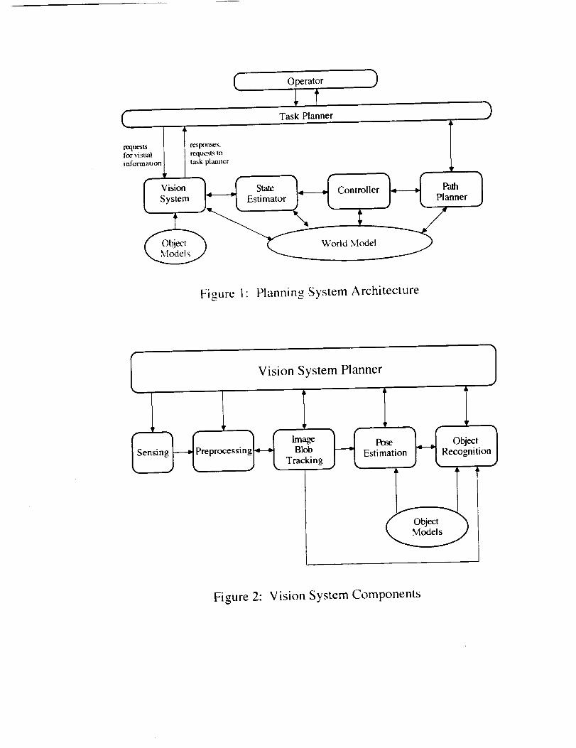
world model. Figures 1 and 2 show the fundamental functional components of the VSP and its
relationship to the higher level Task Planner.
The remainder of this report is divided into four sections that describe research progress toward
the development of such a Vision System Planner and make recommendations for future related
research. Section 2 reviews the initial study of the vision system architecture. The details of the
initial VSP design are documented in a paper entitled "A Vision System Planner for the
Extravehicular Activity Retriever ''7 which was published in the Proceedings of the International
Conferenc'e on Intelligent Autonomou,_ Sy,stems, and thus section 2 may be skipped by the reader
who has read that paper or who is familiar with the research performed during the summer of
1992. Section 3 details the implementation phase of the follow-on research in which many of the
approaches developed in the initial study were realized on available intensity image processing
hardware mounted on a mobile robot platform. Section 4 extends the study of the vision system
architecture beyond the limitations of the available sensory and robotic hardware by incorporating
synthetically generated range images and demonstrates how a moderate amount of range data
processing can facilitate the recognition process. Section 5 discusses how the vision system can
plan sequences of actions relating to object recognition and object pose estimation using
complementary sensors and a variety of algorithmic options to accomplish a current visual
objective and makes recommendations for continuing research relating to the Vision System
Planner.
1-2
Q Operator )
Task Planner )(
requests I responses.
information_ planner
System J_ -L Estimator_ Controller
World Model
Planner
t)
Figure 1" Planning System Architecture
Vision System Planner
ep essin Bk_Tracking
L5 ob_,1j_-tRecognitionJEstimation
Figure 2: Vision System Components
2. Vision System Planner Design Considerations
2.1 Back_,round for the Initial Design of VSP
The planning mechanisms developed for the initial VSP were founded on the assumption that
there should be at least two visual sensors which provide intensity and range images. There are
several reasons why such a multisensory approach is desirable, three of which are particularly
significant. First, the availability of sensors with complementary capabilities permits the VSP to
select a sensor/algorithm combination that is most appropriate for achieving the current visual goal
as specified by the task planner. Second, if the sensor that the VSP would normally select as its
first choice to achieve the goal is either unavailable or inappropriate for usage because of some
current constraint, it may be possible to perform the desired task using the other sensor to achieve
the same goal, albeit perhaps by accepting a penalty in performance. Finally, instances may occur
for which it is desirable to verify results from two different sensory sources rather than relying on
the inferences based on data obtained from a single sensor.
The first of the above motivations addresses the need to achieve the visual goal in the most
effective manner by allowing the VSP to choose among sensors with complementary capabilities.
For example, if it is desired to distinguish between two objects of similar structure with the color
of the objects being the primary differentiating feature, then it is apparent that the color camera
should be used as the primary sensor. On the other hand. if the size and/or geometry of the objects
are most useful for determining identity, then it is important to be able to expeditiously extract and
process three-dimensional coordinates. Clearly, this is a task that would be most properly assigned
to the laser scanner. Similarly, tasks involving pose estimation 8, object tracking 9 and motion
estimation l° would more appropriately involve invoking the laser scanner as the primary sensor.
The initial versions of these submodules are under development and are to be tested in a reduced
gravity environment using NASA's KC-135 aircraft II.
The previous example involving the need for three-dimensional coordinates is illustrative of a
case in which the primary sensor (the laser scanner) is engaged to extract the required information.
However, there may be cases for which the laser scanner cannot be used to obtain range
information because (a) the object to be processed is covered with a highly specularly reflective
material thus preventing acquisition of good return signals, (b) the laser scanner is currently
assigned to another task, or (c) the laser scanner is temporarily not functioning propedy. For such
instances, it is highly desirable to provide a redundant capability by using the other sensor if
possible. The classical method for determining three-dimensional coordinates from intensity
images involves a dual (stereo vision) camera setup in which feature correspondences are
established and the stereo equations are solved for each pair of feature points. Although the
assumed configuration has only one intensity image camera, this alternative mechanism for
computing range values is in fact possible for the VSP to achieve by requesting the task planner to
2-1
repositiontheEVAHRsuchthat the camera'sinitial andfinal positionsareoffset by a knownbaselinedistance, Of course,there is a penalty in performanceif this (pseudo)stereovisionmethodis chosen,since the EVAHRmustbe movedand featurecorrespondencescomputed.However,it is neverthelessimportantto havesucharedundantsensingcapabilityfor thereasonspreviouslymentionedandto beableto independentlyverify theresultsobtainedfrom onesensoror to increasetheconfidenceof thoseresults.
Asidefrom selectinganappropriatesensor,it is mayalsobepossibleto alter certainphysicalcharacteristicsof thesensorsuchastheeffectiveresolutionandscanningrate. In thecaseof thelaserscanner,imagescanbeacquiredat rates(and resolutions) varying between 2.5 frames per
second (256 x 256 pixels) to 10 frames per second (64 x 256 pixels), The capability to select a
faster frame rate with a penalty in resolution becomes significant if it is important to be able to
sense and process data rapidly, as in the case of motion parameter estimation. On the other hand, if
an object is relatively stationary and finer features are to be sensed, then higher resolution with a
lower frame rate would be chosen. Hence, a vision system planner should be able to select a
sensor as well as its relevant parameters (e.g. scanning rate, resolution, zoom factor, orientation).
Once an appropriate sensor has been selected and configured, the next step is to focus attention
on the object(s) and to apply a preprocessing algorithm that will effectively achieve the current
goal. Focusing attention is important because it reduces the amount of image data that must be
processed for the immediate task. If the task is tracking an image blob that corresponds to an
object of interest, and the image blob merges with another blob or disappears due to occlusion,
then the object's predicted location (computed by the adaptive image blob tracker) is central to
assisting in the segmentation of sub-blobs. 9 The selection of a pose estimation algorithm is
directly dependent on the model being processed. 8 There are two fundamental classes of
algorithms that are currently employed, namely object-based and image-based (multi-view) pose
estimation. If an object contains curved surfaces (e.g. a cylinder) then an image-based approach is
taken, by which the occluding contours derived from several views of the object that were recorded
on a tessellated sphere are used as the basis for matching the observed object's outline. If the
object has a polyhedral structure (no curved surfaces) then an object-based pose estimation
algorithm is employed, by which features extracted from images are matched against model
features in a CAD data base. For situations in which the object is very close to the sensor (e.g.
during grasping), the pose may be estimated on subparts of the entire object rather than the entire
object. Similarly, for purposes of recognition, the subset of object features selected and the
algorithm chosen are also a function of the size of objects in images.
Proximity to target objects will affect not only the features selected for recognition and pose
estimation but will strongly influence the confidences associated with the results computed. For
example, a typical scenario might involve a case in which the EVAHR is close enough to a target
object to hypothesize its class based on color, but too far away to definitively recognize its
geometric structure using laser scanner data. In this case, the VSP would tentatively identify the
2-2
object (using color) and would advise the task planner to move closer to the object so that a laser
scanner image with higher resolution can be obtained. The confidence of the initial hypothesis
would then be strengthened (or perhaps weakened) depending on the conclusion reached by
processing the range data at close proximity. This capability is illustrative of the necessity for the
VSP to be able to plan high level vision tasks as well as to be able to interact (interface) with the
higher level task planner in order to reposition the EVAHR. Hence, at the highest level of vision
system planning, the VSP will be responsible for task scheduling and resource planning.
The fundamental architecture for the Vision System includes modules which are designed to
detect, recognize, track, and estimate the pose of objects. Upon receiving a request from the main
task planner to achieve one of these objectives, the Vision System Planner determines an
appropriate sequence of goals and subgoals that, when executed, will accomplish the objective.
The plan generated by the VSP will generally involve (a) choosing an appropriate sensor, (b)
selecting an efficient and effective algorithm to process the image data, (c) communicating the
nominal lexpected) rest, Its to the task planner or informing the task planner of anomalous
(unexpected) conditions or results, and (d) advising the task planner of actions that would assist
the vision system in achieving its objectives. The specific plan generated by the VSP will primarily
depend on knowledge relating to the sensor models (e.g. effective range of operation, image
acquisition rate), the object models (e.g. size, reflectivity, color), and the world model (e.g.
expected distance to and attitude of objects). The next subsection presents the resulting plans
generated by the VSP for several different scenarios.
2.2 Scenarios Illustrating the Operation of the VSP
The operation of the prototype VSP that was initially designed and implemented can best be
understood by examining the plans generated for various scenarios. For purposes of illustration,
the initial state of the world is always assumed to be that there are three objects somewhere in front
of the EVAHR. One of the objects is an Orbital Replacement Unit (ORU) with a known uniform
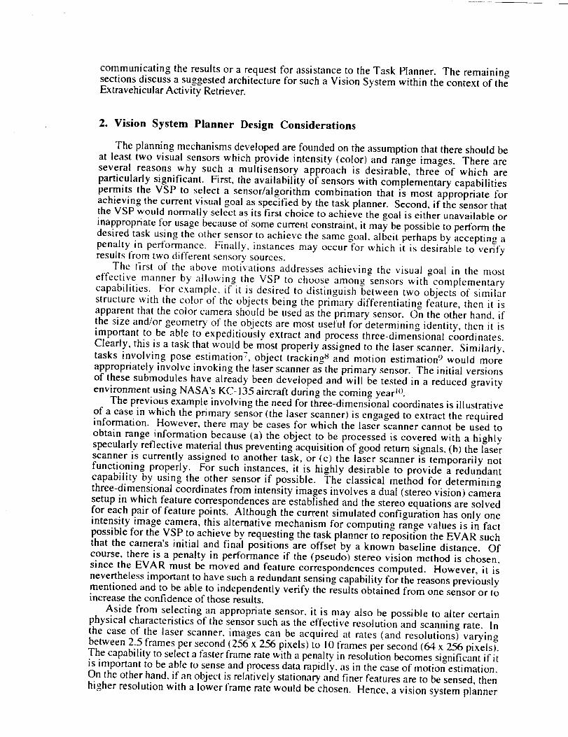
color. For cases in which the EVAHR VSP needs to search for the ORU, the hemisphere in front
of the EVAHR is searched in the spiraling manner shown in Figure 3. The task planner (perhaps in
consultation with the human operator) selects an angular field of view (i.e. zoom factor) for the
color camera which affects (in an inversely proportional manner) the number of hemispherical
sectors that must be searched (i.e. the smaller the angular field of view, the larger the number of
hemispherical sectors). For example, if the angular field of view is chosen to be 45 °, sectors near
the center of the forward hemisphere (sectors 1-6 in Figure 3) are searched and if the ORU is not
found, the extreme sectors (7-14) are searched in that order.
2-3
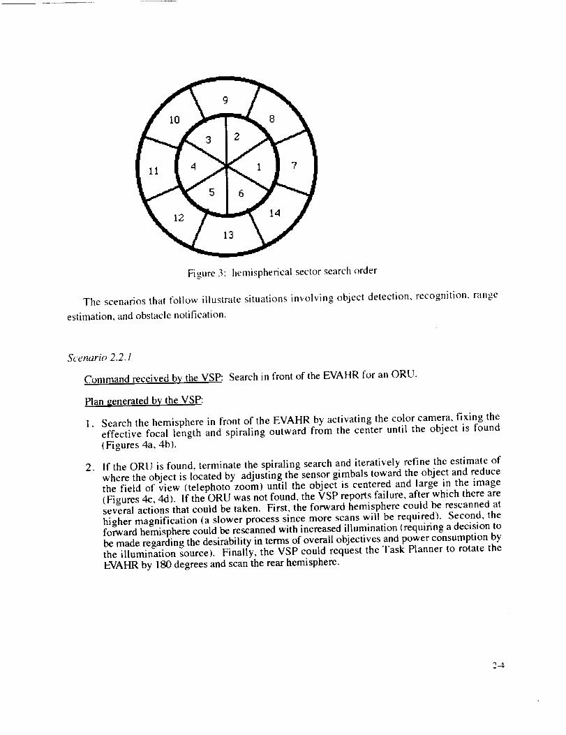
Figure3: hemisphericalsectorsearchorder
The scenariosthatfollow illustratesituationsinvolving object detection,recognition,rangeestimation,andobstaclenotification.
Scenario 2.2.1
Command received by the VSP: Search in front of the EVAHR for an ORU.
Plan generated by the VSP:
o Search the hemisphere in front of the EVAHR by activating the color camera, fixing theeffective focal length and spiraling outward from the center until the object is found(Figures 4a, 4b).
° If the ORU is found, terminate the spiraling search and iteratively refine the estimate ofwhere the object is located by adjusting the sensor gimbals toward the object and reducethe field of view (telephoto zoom) until the object is centered and large in the image(Figures 4c, 4d). If the ORU was not found, the VSP reports failure, after which there areseveral actions that could be taken. First, the forward hemisphere could be rescanned athigher magnification (a slower process since more scans will be required). Second, theforward hemisphere could be rescanned with increased illumination (requiring a decision tobe made regarding the desirability in terms of overall objectives and power consumption bythe illumination source). Finally, the VSP could request the Task Planner to rotate theEVAHR by 180 degrees and scan the rear hemisphere.
2-4

Teleoperator command:
Figure 4a:
RGB search for ORU
Field of view angle = 50 °
Scan angle = 45 °
search of sector 1 for ORU
VSP response:
Figure 4b:
ORU was found in sector 2Area of object was 150 pixels
search of sector 2 for ORU
VSP action: Reorienting camera gimbalsSetting field of view to 7°
Figure 4c: first gimbal and zoom refinement
VSP action: Reorienting camera gimbals
Setting field of view to 40
Figure 4d: second gimbal and zoom refinement
1
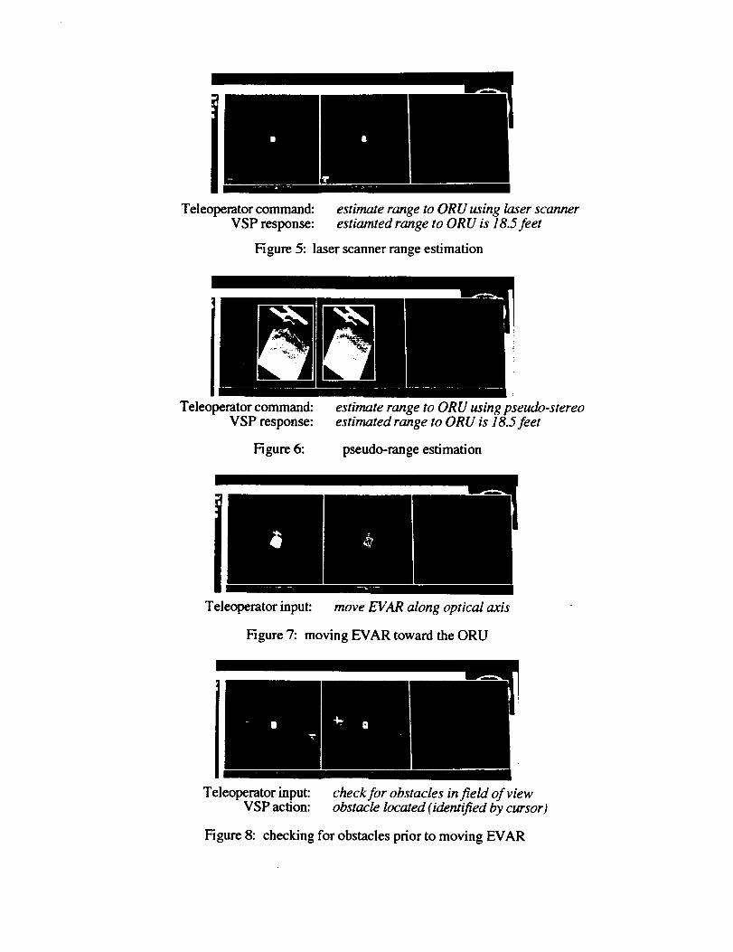
Teleoperator command:
VSP response:
estimate range to ORU using laser scannerestiamted range to ORU is 18.5feet
Figure 5: laser scanner range estimation
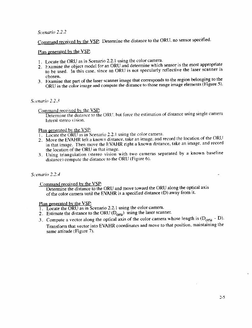
Teleo aerator command:
VSP response:
Figure 6:
estimate range to ORU using pseudo-stereoestimated range to ORU is l&5 feet
pseudo-range estimation
Illl
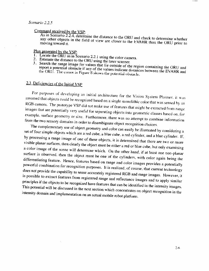
Teleoperator input: move EVAR along optical axis
Figure 7: moving EVAR toward the ORU
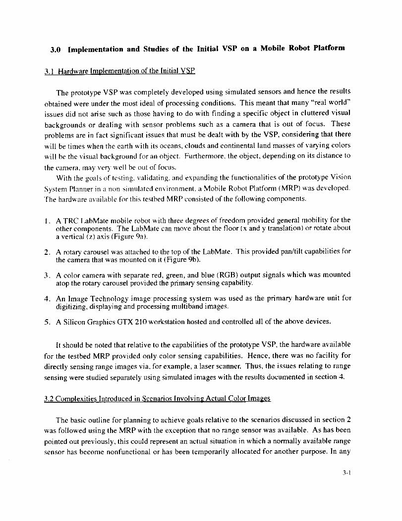
Teleoperator input:VSP action:
check for obstacles infield of viewobstacle located (identified by cursor)
Figure 8: checking for obstacles prior to moving EVAR
Scenario 2.2.2
Command received by the VSP: Determine the distance to the ORU, no sensor specified.
Plan _enerated by the VSP:
1. Locate the ORU as in Scenario 2.2.1 using the color camera.2. Examine the object model for an ORU and determine which sensor is the most appropriate
to be used. In this case, since an ORU is not specularly reflective the laser scanner ischosen.
3. Examine that part of the laser scanner image that corresponds to the region belonging to theORU in the color image and compute the distance to those range image elements (Figure 5).
Scenario 2.2.3
Command received b,_' the VSP:Determine the distance to the ORU, but force the estimation of distance using single cameralateral stereo vision.
Plan generated by the VSP:1. Locate the ORU as in Scenario 2.2.1 using the color camera.2. Move the EVAHR left a known distance, take an image, and record the location of the ORU
in that image. Then move the EVAHR right a known distance, take an image, and recordthe location of the ORU in that image.
3. Using triangulation (stereo vision with two cameras separated by a known baselinedistance) compute the distance to the ORU (Figure 6).
Scenario 2.2.4
Command received by the VSP:Determine the distance to the ORU and move toward the ORU along the optical axisof the color camera until the EVAHR is a specified distance (D) away from it.
Plan _enerated by the VSP:1. Locate the ORU as in Scenario 2.2.1 using the color camera.
2. Estimate the distance to the ORU (Dot u) using the laser scanner.
3. Compute a vector along the optical axis of the color camera whose length is (Dor u - D).
Transform that vector into EVAHR coordinates and move to that position, maintaining the
same attitude (Figure 7).
2-5
Scenario 2.2.5
Command received by the VSP:As in Scenario 2.2.4, determine the distance to the ORU and check to determine whether
any other objects in the field of view are closer to the EVAHR than the ORU prior tomoving toward it.
Plan generated by the VSP:I. Locate the ORU as in Scenario 2.2.1 using the color camera.2. Estimate the distance to the ORU using the laser scanner.3. Search the range image for vaiues that lie outside of the region containing the ORU and
report a potential obstacle if any of the values indicate distances between the EVAHR and• i l-t1 r ! , itn_ Ov,_. Tile cursuI in Figule 8 _how_ the "" ' OI)_t_l_d le.potenual
2.3 Deficiencies of the Initial VSP
For purposes of developing an initial architecture for the Vision System Planner. it was
assumed that objects could be recognized based on a single monolithic color that was sensed b} an
RGB camera. The prototype VSP did not make use of features that might be extracted from range
images that are potentially very useful for separating objects into geometric classes based on, for
example, surface geometry or size. Furthermore, there was no attempt to combine information
from the two sensor), domains in order to disambiguate object recognition choices.
The complementary use of object geometry and color can easily be illustrated by considering a
set of four simple objects which are a red cube, a blue cube, a red cylinder, and a blue cylinder. If,
by processing a range image of one of these objects, it is determined that there are two or more
visible planar surfaces, then clearly the object must be either a red or blue cube, but only examining
a color image of the scene will determine which. On the other hand, if at least one non-planar
surface is observed, then the object must be one of the cylinders, with color again being the
differentiating feature. Hence, features based on range and color images provides a potentially
powerful combination for recognition purposes. It is realized, of course, that current technology
does not provide the capability to sense accurately registered RGB and range images. However, it
is possible to extract features from registered range and reflectance images and to apply similar
principles if the objects to be recognized have features that can be identified in the intensity images.
This potential will be discussed in the next section which concentrates on object recognition in the
intensity domain and implementation on an actual mobile robot platform.
2-6
3.0 Implementation and Studies of the Initial VSP on a Mobile Robot Platform
3.1 Hardware Implementation of the Initial VSP
The prototype VSP was completely developed using simulated sensors and hence the results
obtained were under the most ideal of processing conditions. This meant that many "real world"
issues did not arise such as those having to do with finding a specific object in cluttered visual
backgrounds or dealing with sensor problems such as a camera that is out of focus. These
problems are in fact significant issues that must be dealt with by the VSP, considering that there
will be times when the earth with its oceans, clouds and continental land masses of varying colors
will be the visual background for an object. Furthermore, the object, depending on its distance to
the camera, may very well be out of focus.
With the goals of testing, validating, and expanding the functionalities of the prototype Vision
System Planner in a non-simulated environment, a Mobile Robot Platform (MRP) was developed.
The hardware available for this testbed MRP consisted of the following components.
o
.
.
.
A TRC LabMate mobile robot with three degrees of freedom provided general mobility for the
other components. The LabMate can move about the floor (x and y translation) or rotate abouta vertical (z) axis (Figure 9a).
A rotary carousel was attached to the top of the LabMate. This provided pan/tilt capabilities forthe camera that was mounted on it (Figure 9b).
A color camera with separate red, green, and blue (RGB) output signals which was mounted
atop the rotary carousel provided the primary sensing capability.
An Image Technology image processing system was used as the primary hardware unit fordigitizing, displaying and processing multiband images.
5. A Silicon Graphics GTX 210 workstation hosted and controlled all of the above devices.
It should be noted that relative to the capabilities of the prototype VSP, the hardware available
for the testbed MRP provided only color sensing capabilities. Hence, there was no facility for
directly sensing range images via, for example, a laser scanner. Thus, the issues relating to range
sensing were studied separately using simulated images with the results documented in section 4.
3.2 Complexities Introduced in Scenarios Involving Actual Color Imaaes
The basic outline for planning to achieve goals relative to the scenarios discussed in section 2
was followed using the MRP with the exception that no range sensor was available. As has been
pointed out previously, this could represent an actual situation in which a normally available range
sensor has become nonfunctional or has been temporarily allocated for another purpose. In any
3-1
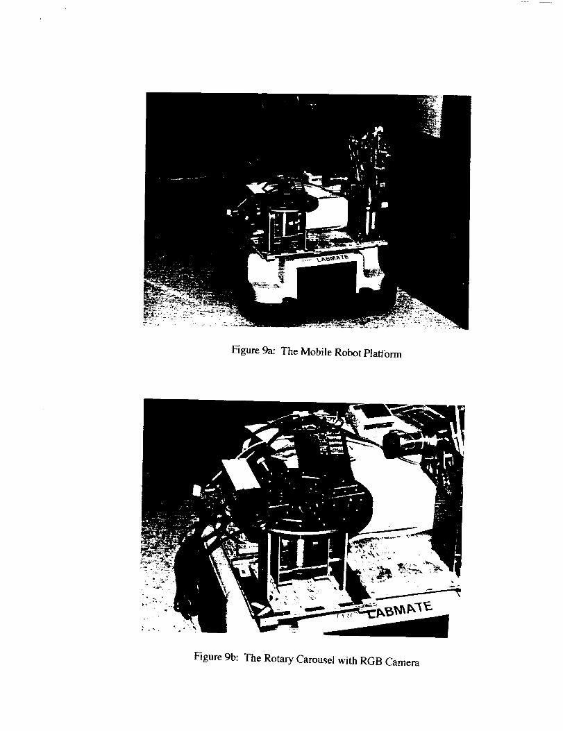
Figure 9a: The Mobile Robot Platform
Figure 9b: The Rotary Carousel with RGB Camera
orange
orange
sen_els
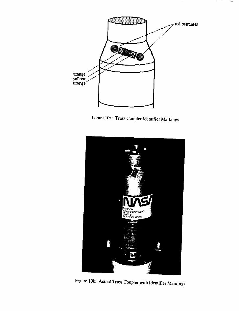
Figure lOa: Truss Coupler Identifier Markings
Figure lOb: Actual Truss Coupler with Identifier Markings
Trl_s
Cone
Tf_3s
Cylinder
®
@
@ @®
@
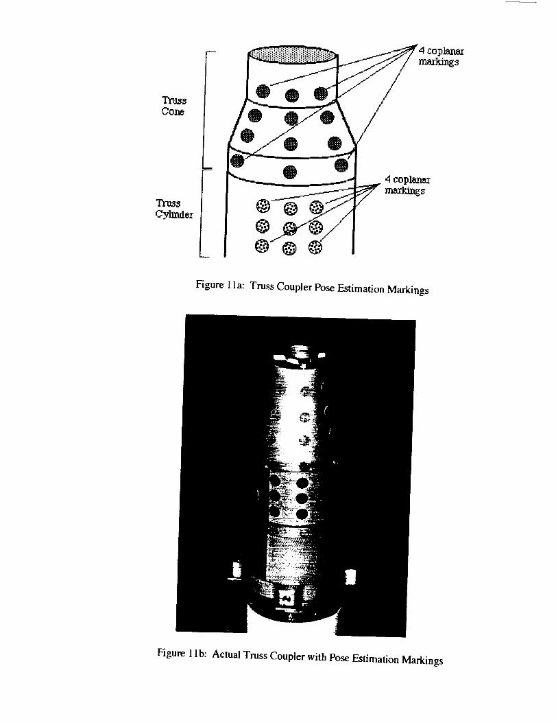
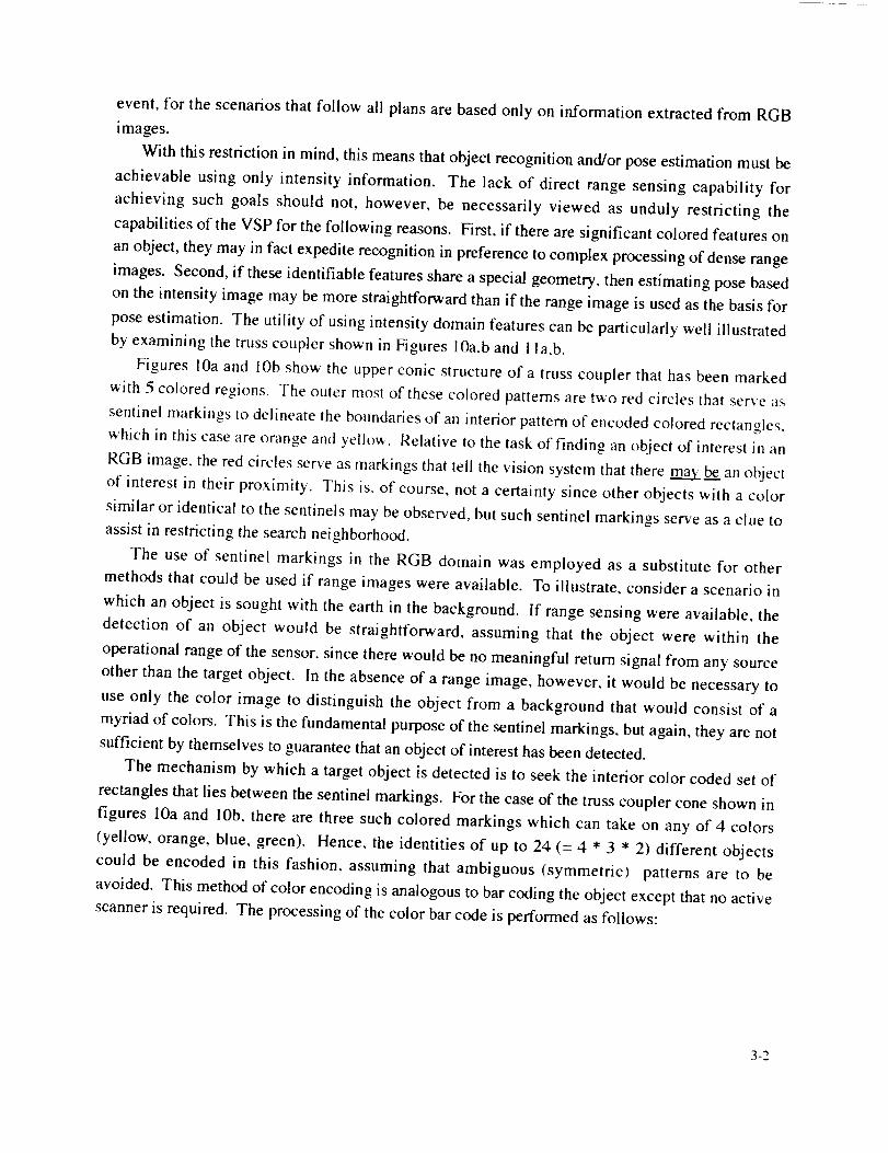
Figure 1la: Truss Coupler Pose Estimation Markings
Figure 1 lb: Actual Truss Coupler with Pose Estimation Markings
event, for the scenarios that follow all plans are based only on information extracted from RGB
images.
With this restriction in mind, this means that object recognition and/or pose estimation must be
achievable using only intensity information. The lack of direct range sensing capability for
achieving such goals should not, however, be necessarily viewed as unduly restricting the
capabilities of the VSP for the following reasons. First, if there are significant colored features on
an object, they may in fact expedite recognition in preference to complex processing of dense range
images. Second, if these identifiable features share a special geometry, then estimating pose based
on the intensity image may be more straightforward than if the range image is used as the basis for
pose estimation. The utility of using intensity domain features can be particularly well illustrated
by examining the truss coupler shown in Figures 10a,b and 1la,b.
Figures iOa and lob show the upper conic structure of a truss coupler that has been marked
with 5 colored regions. The outer most of these colored patterns are two red circles that serve :is
sentinel markings to delineate the boundaries of an interior pattern of encoded colored rectangles.
which in this case are orange and yellow. Relative to the task of finding an object of interest in an
RGB image, the red circles serve as markings that tell the vision system that there m_.m._be an object
of interest in their proximity. This is. of course, not a certainty since other objects with a color
similar or identical to the sentinels may be observed, but such sentinel markings serve as a clue to
assist in restricting the search neighborhood.
The use of sentinel markings in the RGB domain was employed as a substitute for other
methods that could be used if range images were available. To illustrate, consider a scenario in
which an object is sought with the earth in the background. If range sensing were available, the
detection of an object would be straightforward, assuming that the object were within the
operational range of the sensor, since there would be no meaningful return signal from any source
other than the target object. In the absence of a range image, however, it would be necessary to
use only the color image to distinguish the object from a background that would consist of a
myriad of colors. This is the fundamental purpose of the sentinel markings, but again, they are not
sufficient by themselves to guarantee that an object of interest has been detected.
The mechanism by which a target object is detected is to seek the interior color coded set of
rectangles that lies between the sentinel markings. For the case of the truss coupler cone shown in
figures 10a and 10b, there are three such colored markings which can take on any of 4 colors
(yellow, orange, blue, green). Hence, the identities of up to 24 (= 4 * 3 * 2) different objects
could be encoded in this fashion, assuming that ambiguous (symmetric) patterns are to be
avoided. This method of color encoding is analogous to bar coding the object except that no active
scanner is required. The processing of the color bar code is performed as follows:
3-2
.
.
.
.
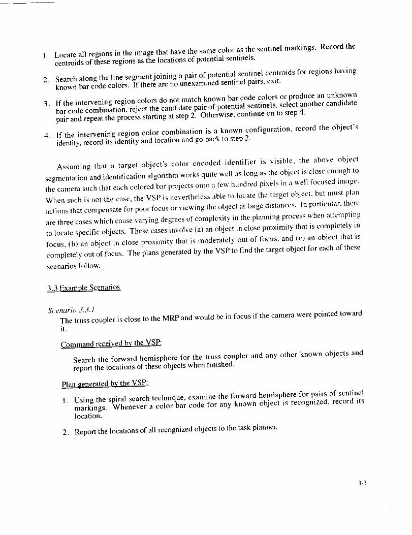
Locate all regions in the image that have the same color as the sentinel markings. Record thecentroids of these regions as the locations of potential sentinels.
Search along the line segment joining a pair of potential sentinel centroids for regions havingknown bar code colors. If there are no unexamined sentinel pairs, exit.
If the intervening region colors do not match known bar code colors or produce an unknownbar code combination, reject the candidate pair of potential sentinels, select another candidatepair and repeat the process starting at step 2. Otherwise. continue on to step 4.
If the intervening region color combination is a known configuration, record the object'sidentity, record its identity and location and go back to step 2.
Assuming that a target object's color encoded identifier is visible, the above object
segmentation and identification algorithm works quite well as long as the object is close enough to
the camera such that each colored bar projects onto a few hundred pixels in a well focused image.
When s_ch is not the case, _he VSP is nevertheless able to locate the target object, bu_ rims! plan
actions that compensate for poor focus or viewing the object at large distances. In particular, there
are three cases which cause varying degrees of complexity in the planning process when attempting
to locate specific objects. These cases involve (a) an object in close proximity that is completely in
focus, (b) an object in close proximity that is moderately out of focus, and (c) an object that is
completely out of focus. The plans generated by the VSP to find the target object for each of these
scenarios follow.
3.3 Example Scenarios
Scenario 3.3. ]
The truss coupler is close to the MRP and would be in focus if the camera were pointed towardit.
Command received by the VSP:
Search the forward hemisphere for the truss coupler and any other known objects andreport the locations of these objects when finished.
Plan generated by the VSP:
° Using the spiral search technique, examine the forward hemisphere for pairs of sentinelmarkings. Whenever a color bar code for any known object is recognized, record itslocation.
2. Report the locations of all recognized objects to the task planner.
3-3

Scenario 3.3.2
The truss coupler is close to the MRP but would be moderately out of focus if the camera werepointed toward it.
Command received by the VSP:
Search the forward hemisphere for the truss coupler and any other known objects andreport the locations of these objects when finished.
Plan generated by the VSP:
I . Using the spiral search technique, examine the forward hemisphere for pairs of sentinelmarkings. Whenever a color bar code for any known object is recognized, record itslocation. For this scenario involving an out of focus target object, however, it is quitepossible that the intervening colors between the sentinel markings will blend together andwill prevent identification of the sought target object even though the sentinel markingswere lbund. In this case, one of two different plans will be generated, depending upon thelevel of atttonomy requested by the task planner. If the task planner permits operatorintervention, the VSP will request that the camera be focussed. It should be noted that in asituation with more sophisticated hardware, this could be done automatically since the VSPcould estimate the distance of the target object with a range finder and then adjust thecamera's focus accordingly. On the other hand, if refocusing is precluded, the VSP willrequest the task planner to move the MRP toward the target object under the assumptionthat the lens focus setting has been fixed at approximately 1 meter. Since the task plannerwill know the locations of all objects in the forward hemisphere (ala Scenario 1 above), thismaneuver can be executed by treating the objects as obstacles to be avoided.
. Upon repositioning the MRP to a location approximately one meter away from the trusscoupler, the VSP again examines the candidate object's color code, which should now be infocus, and reports success or failure in locating it. Figure 12 illustrates a case in which theVSP successfully found an initially out of focus truss coupler after notifying the taskplanner to move the MRP toward it.
3-4
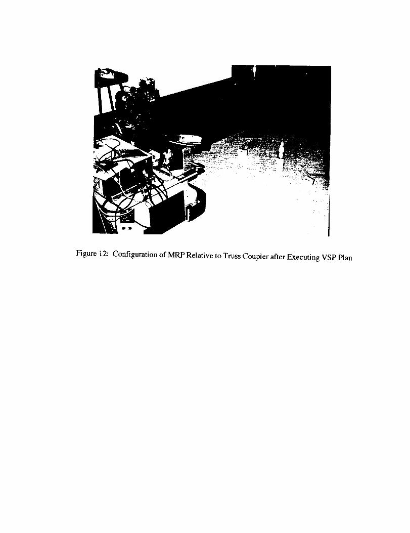
Figure 12: Configuration of MRP Relative to Truss Coupler after Executing VSP Plan
Scenario 3.3.3
The tress coupler would be totally out of focus if the camera were pointed toward it, or too faraway to be identified as even a candidate, or is not in the forward hemisphere of the MRP.
Command received by the VSP:
Search the forward hemisphere for the truss coupler and any other known objects and
report the locations of these objects when finished.
Plan generated by the VSP:
1. As in the previous two scenarios, the truss coupler would be sought by searching for itssentinel markings and the appropriate intervening color code.
. If no candidate sentinels are found, the VSP cannot request the task planner to move theMRP to a more advantageous position with any degree of confidence based on observeddata. Hence, it asks for refocusing of the camera and for the MRP to be pointed in the
general direction of the target object.
3. Once step 2 is performed, the actions outlined in Scenario 2 can be followed to achieve thedesired goal.
The above scenarios illustrate the VSP's ability to plan and execute actions that compensate for
an out of focus camera or an object that is at a distance that makes identification difficult. Inherent
in these actions, however, is the need to be able to estimate the distance to the object so that
refocusing can occur or the MRP can be moved toward the object. For the current implementation,
distance estimation was based on knowledge of the focal length of the camera and the distance
between the sentinel markings on the target objects as embedded in the model knowledge base.
This method suffers from two significant deficiencies, however. First, in order to estimate
distance to the object, the camera must be relatively near the plane that is the perpendicular bisector
of the line joining the sentinel markings. Second, and perhaps more importantly, although two
markings are sufficient to base an estimate of distance upon, at least four markings are required for
complete six degree-of-freedom pose estimates. With this in mind, objects like the truss coupler
were also marked with colored features such as those shown in Figures 11a and 11 b and a study of
the quality of results was undertaken.
3.4 Intensity Based Pose Estimation
The technique for estimating the spatial pose of the truss coupler is based on the algorithm
described by Hung, Yeh and Harwood. 12 This method requires three prerequisite conditions in
order for the algorithm to be applicable. First, the effective focal length of the camera must be
known. Second, the target object must have four coplanar points, no three of which are colinear.
-5
Finally, the distances between each pair of the four points must be known and recorded in the
model. If these prerequisite conditions are met, then the complete six degree-of-freedom spatial
pose of the object can be determined by observing the locations of the four points in the image
plane. The method involves only simple vector inner and cross products and the solution of linear
equations.
For the specific case of the truss coupler shown in Figures 1 la and 1 lb, the markings shown
were placed on non-planar surfaces. However, the four outer markings shown at the corners of
the twelve marker pattern lie in the same three-dimensional plane and therefore meet the criterion
that is necessary to apply the Hung-Yeh-Harwood algorithm.
Nine tests with actual images of the tn_ss coupler were run. These tests were divided into three
groups which varied the pose of the truss coupler by' rotating it about the conic axis, translating it
along the conic axis, and changing its distance from the camera. From these tests, two conclusions
can be drawn that directly affect the architecture of the VSP. First, in order to minimize sensitivity
of the pose estimate to local pixel noise, the target object should fill a large portion of the image
plane. Second, the camera should be positioned relative to the target points such that its optical
axis is perpendicular to the plane containing the four points. The latter condition is particularly
important since on curved objects like the truss coupler, markings on the "horizon" of the surface
produce projected image plane coordinates that are very sensitive to minor variations in their
extracted positions.
These observations are relevant to the Vision System Planner because it is not known in
advance how close the camera should be to the object in order that it should occupy a large region
of the image plane. However, as shown in the initial study, it is possible to use range images to
estimate the distance and to use this estimate as the basis to execute a move toward the target object
to produce a viewpoint that is close enough. The more difficult problem is to achieve a viewpoint
such that the optical axis is nearly perpendicular to the plane of the four markings since this would
involve at least an approximate knowledge of the rotational parameters of the object. However, if
the object possessed multiple quadruplets that could be uniquely identified, then there would be a
redundancy built into the model by which its pose could be estimated. For cylindrical or conic
objects, this technique would be particularly appropriate since their poses are uniquely determined
by the location of a point on the axis and the orientation on the axis itself. Hence, if multiple sets
of points were evenly distributed around the cylindrical or conic section, it would always be
possible to determine the pose of the object by selecting an "inner'set (in the image plane) that is
most likely to satisfy the optical axis perpendicularity constraint. This method of pose estimation
will be discussed within the context of an expanded VSP architecture later.
3-6
4.0 Synthetic Range Image Processing
4.1 Model Feature Learning and Object Recognition Overview
It has been previously pointed out that range image processing can directly provide information
that is useful for recognition, pose estimation and repositioning of the vision system and that there
are both advantages and disadvantages to employing such a sensor. Foremost among the
advantages are the ability to directly extract distances to an object without extensive image
processing (e.g. establishing stereo correspondence in two intensity images). However, higher
level goals such as recognition and pose estimation may still require significant processing of the
range image in order to extract features such as the surface type (planar, conic, cylindrical,
spherical, etc.) The segmentation of objects into their component surfaces is particularly
computationally intensive since multidimensional decoupled Hough transforms are typically
required 13. It is therefore appropriate to consider methods of object classification and pose
estimation that make use of the best elements of each domain considering the following principles:
i . Recognition of objects based only on their geometric or topological characteristics is toodifficult if only intensity images are used due to the three-dimensional transformations to whichthey may be subjected.
2. Certain low level operations in the range domain are relatively inexpensive. Among these arethe computation of local surface normals.
b The general segmentation of an object into all of its component surfaces using range images iscomputationally too expensive, but it is possible to rapidly segment the planar surfaces of theobject.
, Certain objects may be recognized by comparing the number of visible planar and nonplanarsurfaces and the areas of each with those of known models. Hence, such knowledge can beused to constrain the identities of objects in an appropriately structured recognition search tree.
With the above principles in mind, a set of range processing primitives was developed that can
separate observed objects into geometric classes as follows:
°
,
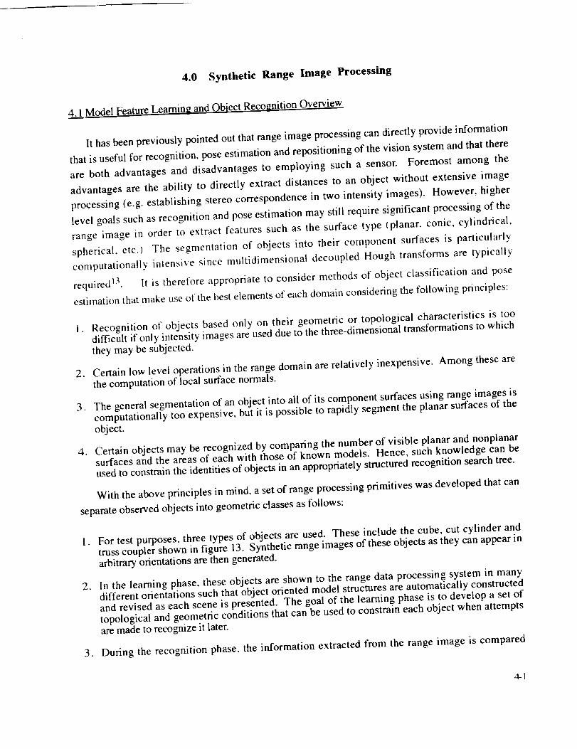
For test purposes, three types of objects are used. These include the cube, cut cylinder andtruss coupler shown in figure 13. Synthetic range images of these objects as they can appear inarbitrary orientations are then generated.
In the learning phase, these objects are shown to the range data processing system in manydifferent orientations such that object oriented model structures are automatically constructedand revised as each scene is presented. The goal of the learning phase is to develop a set oftopological and geometric conditions that can be used to constrain each object when attemptsare made to recognize it later.
3. During the recognition phase, the information extracted from the range image is compared
4-1

againstthat embodiedin the learned object models. Candidate models are then included orexcluded from the potential recognition set based on range data features such as how many
planar surfaces are visible, how many curved surfaces are visible, the size of each planarsurface, the size of the curved surfaces, and the total visible surface area. It should be notedthat because of the computational expense involved, no attempt is made to determine whethercurved surfaces are cylindrical, conic or otherwise. Hence, the algorithms only provide a basisor framework for further refinement of the identities of the objects based on more expensive
range image processing or using features in the intensity image. Because of the extremeexpense of processing the range images, it is believed that the most effective manner to proceedis by combining intensity based features with knowledge gleaned from a rough classificationbased on planar/nonplanar topologies.
J
J
Cube Cut Cylinder Truss Coupler
Figure 13: Models for Range Data Processing
4.2 Range Ima_,e Processing:
In both the learning and recognition phases it is necessary to segment the data into planar and
nonplanar regions so that the number of such regions and their respective areas can be determined.
The way that this is done is as follows:
I . Let each range image value be represented as a homogeneous vector V = Ix y zl. Then, if thisrange value belongs to the plane with equation ax + by + cz - d - 0, clearly P • V = d where
planar normal vector P = lab cl.
4-2
. Now if V l, V 2 ..... V 9 are vectors that represent point coordinates in the 3 X 3 neighborhood
of a central range pixel, and P • V i = d for i = l, 2 ..... 9 it is possible to set up the following
set of linear equations that computes a local planar normal based on this neighborhood:
Let M = [ V 1 V 2 ... V 91 be a 3 row, 9 column matrix of range image values and let
D = [ 1 1 ... 1 ] be a row vector containing 9 l 's.
Then, if the 9 points all belong to the same plane with equation ax + by + cz = d,
[abclM=D
and it is possible to compute a least squares solution for [a b c] by using a pseudo-inverse of Mby observing that
[a bc] M M t = D M t
[abcltMMtt(MMt) -I :DMttMMt)-I
[a b cl = D M t tM Mtl -_
The value ofd can then be computed as d = ax + by+ cz where [x y zl is the value of the centralrange pixel.
In order to determine where there are planar regions within a range image, local plane equations
are computed across a grid that effectively overlays the range image and those range pixels that
contributed to (nearly) identical plane equations are collected into separate lists that support these
individual plane equations. The remaining range pixels that do not strongly support the existence
of a plane equation are grouped into a list of non-planar range pixels that are deemed to support the
existence of one or more curved surfaces. Again, it is important to note that no attempt is made to
perform any surface segmentation that is more sophisticated than separating planar and non-planar
surfaces due to the associated computational costs.
Once a range image has been processed, several useful features relating to the observed object
are recorded. In the learning phase, these features are used as the basis for refining the known
object model. During the recognition phase, the), are used to satisfy constraints that must be met in
order to select a viable model. The specific features computed for an observed object are:
1. the number of visible planar surfaces (_>O)
2. the number of visible curved surfaces (= 0 or 1)
3. the area of the visible planar surface with the smallest area
4. the area of the visible planar surface with the largest area
5. the total visible planar area
6. the total visible surface area for the entire object
4-3
The nextsubsectiondemonstrateshow thesefeaturescanbeusedas the basis for learning
about the topology and geometry of the object.
4.3 Learning model features
The basic philosophy employed for developing models is to embody in the model descriptors
viewpoint dependent constraints that facilitate rapid identification. Hence, no global description of
an object is constructed or used. To illustrate why this is done, consider the three objects in Figure
13. If three planar surfaces are ever viewed, it can be categorically stated that the observed object
is a cube since the maximum number of visible planar surfaces for the cut cylinder and truss
coupler are 2 and 1, respectively. Similarly, if at least one curved surface is observed, then the
object cannot be the cube and it will be necessary to use some other discriminating feature(s) to
determine whether it is the cut cylinder or the truss coupler. For none of these cases is it necessary
to have a global descriptor of each object that describes its entire unified topology and geometr3. It
is, however, important to judiciously select a set of viewpoints that sufficiently constrains the
potentially observable features so that it is known, for example, that a cube will always have at
least 1 and at most 3 visible planar surfaces, while a cut cylinder will have 1 and 2, respectively,
The learning mechanism actually employed can be illustrated by examining the image sequences
shown in Figures 14-16.
Figure 14a shows the unprocessed synthetic image for a cube when three of its planar faces are
visible. After applying the plane extraction algorithm described in section 4.2, three surfaces with
the normals shown in Figure 14b are derived. The areas of these planar faces and the visible area
is recorded in the initial model for the cube. This learning phase is followed by the two examples
shown in Figures 14.c and 14d that demonstrate that certain viewpoints relative to the object may
result in fewer than 3 planar faces being visible.
For the cut cylinder, a similar learning sequence is provided. Figures 15a and 15b cause the
system to learn that at most 2 planar faces and 1 curved surface may be visible. After presenting
the views shown in Figures 15c and 15d, it is learned that as few as 1 planar surface may be
visible and Figure 15e demonstrates that no curved surfaces may be visible. In addition, another
view that presents only the half-cylindrical side refines the model knowledge such that it is known
that no planar regions may be visible. The full learning sequence for a truss coupler, part of which
is illustrated by Figures 16a-16d, produces a model that represents knowledge that one or no
planar or curved surfaces may be visible.
4-4
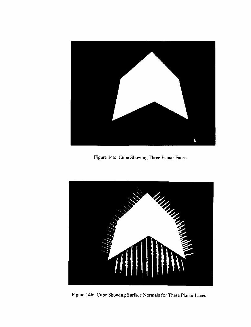
Figure 14a: Cube Showing Three Planar Faces
Figure 14b: Cube Showing Surface Normals for Three Planar Faces
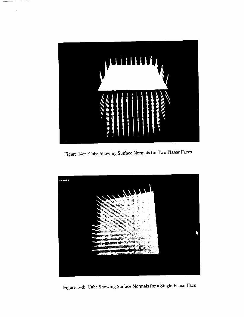
Figure14c: CubeShowingSurfaceNormaisfor Two PlanarFaces
Figure14d: CubeShowingSurfaceNormalsfor a SinglePlanarFace
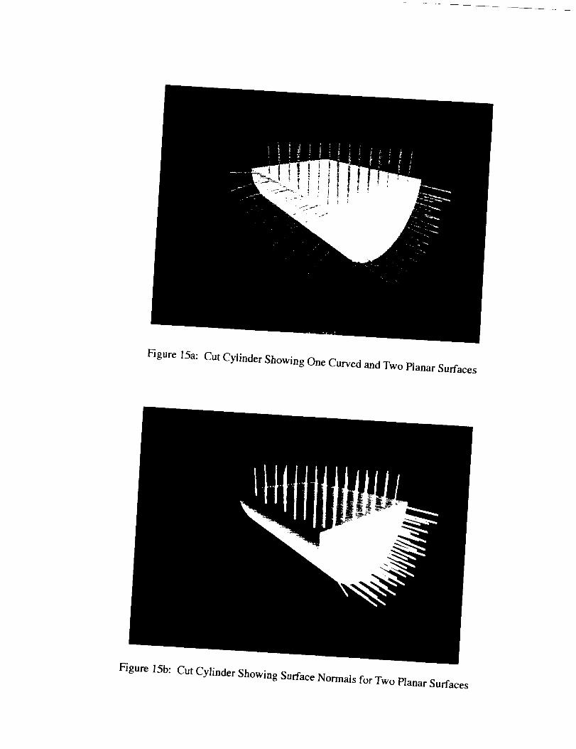
Figure15a:CutCylinderShowingOneCurvedandTwoPlanarSurfaces
Figure 15b: Cut Cylinder Showing Surface Normals for Two Planar Surfaces
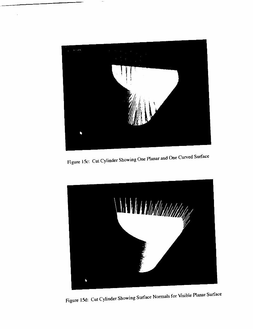
Figure15c: CutCylinderShowingOnePlanarandOneCurvedSurface
Figure 15d:CutCylinderShowingSurfaceNormalsfor VisiblePlanarSurface
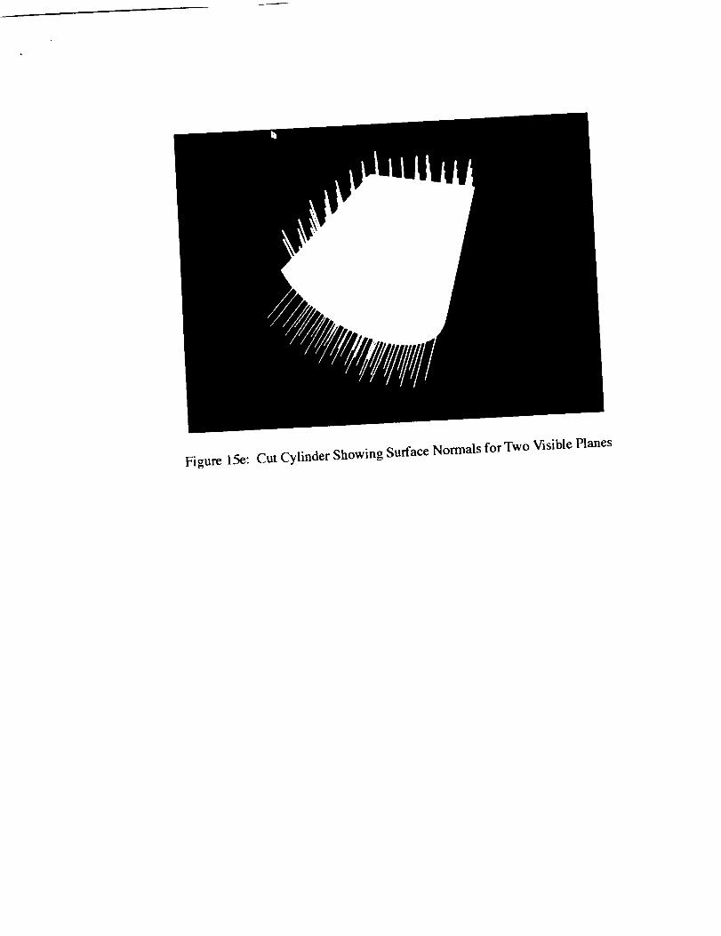
Figure 15e:CutCylinderShowingSurfaceNormalsfor Two VisiblePlanes
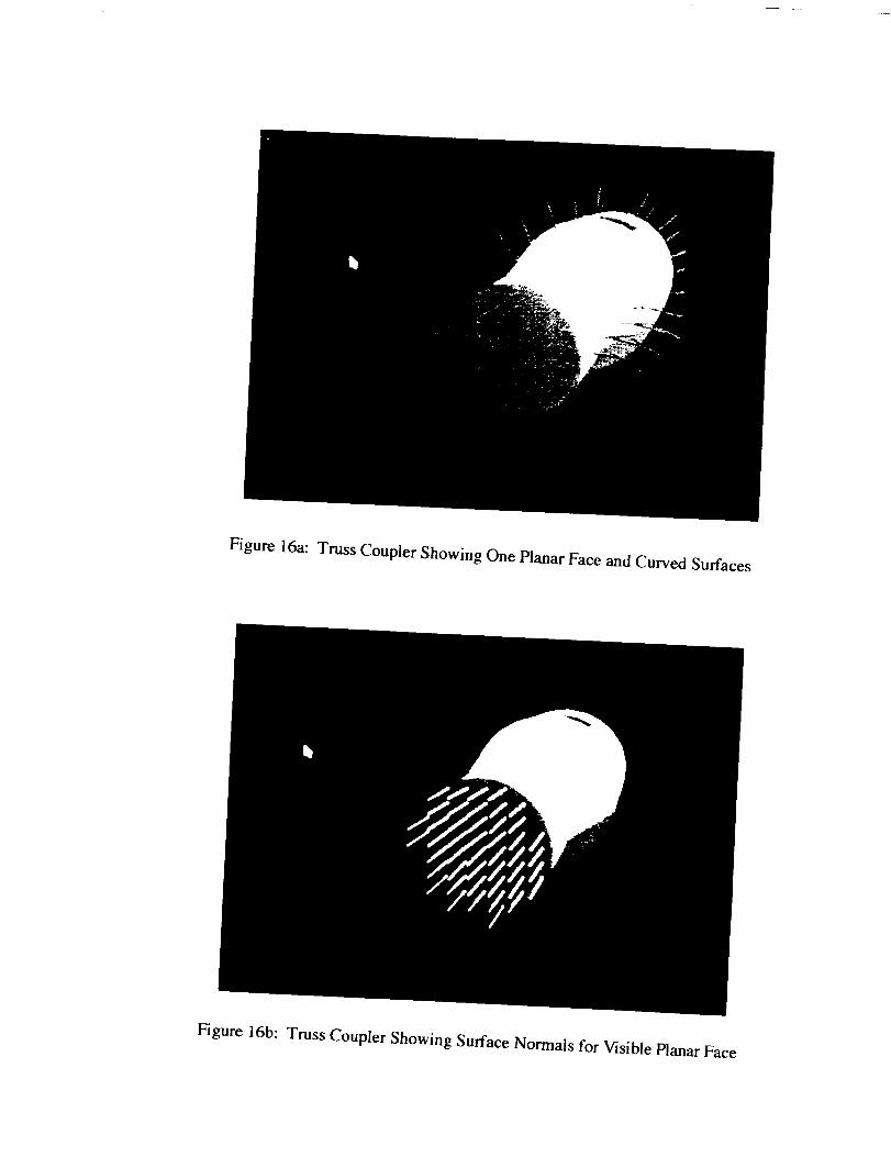
Figure 16a: Truss Coupler Showing One Planar Face and Curved Surfaces
Figure 16b: Truss Coupler Showing Surface Normals for Visible Planar Face
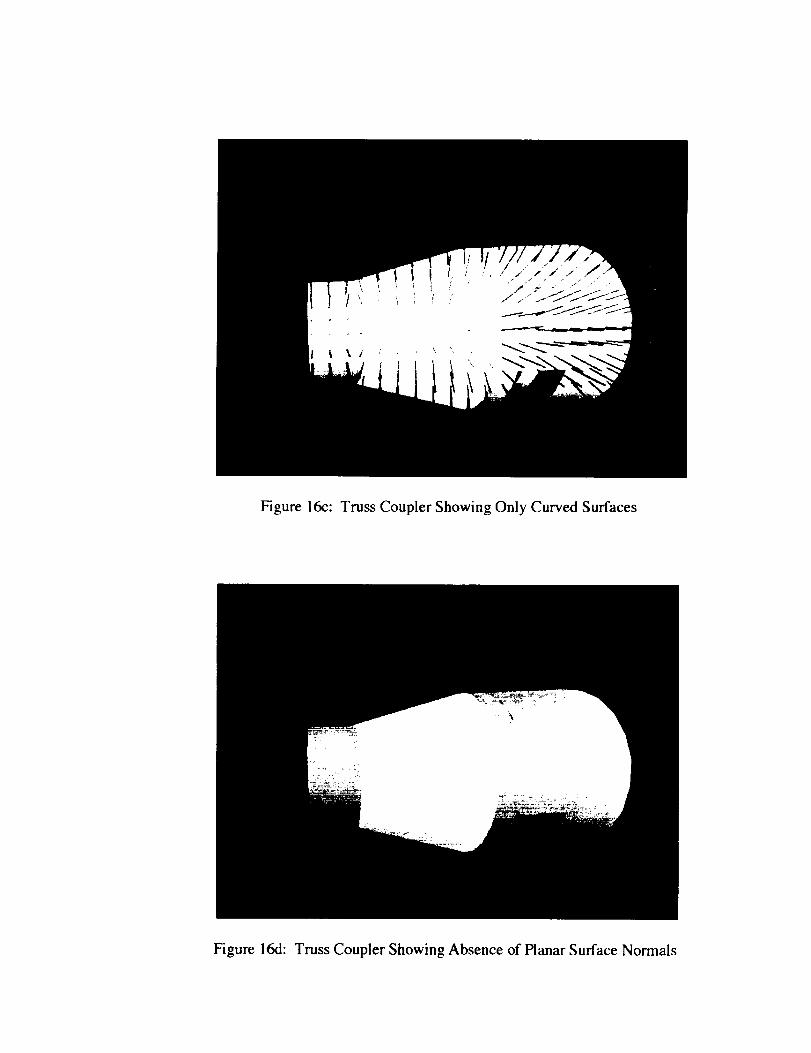
Figure16c: TrussCouplerShowingOnly CurvedSurfaces
Figure16d:TrussCouplerShowingAbsence of Planar Surface Normals
4.4 Ranee Imaoe Based Object Recoonition
The learned features described in section 4.2 were used as the basis for discriminating among
the cube, cut cylinder and truss coupler in various spatial poses like those illustrated by Figures 14-
16. The system performed as expected, with the most useful features being the numbers of visible
planar and curved surfaces and their respective areas. For certain views that did not produce a rich
set of useful features, the system was unable to determine the identity of the viewed object. For
example, the semi-circular planar region of the cut cylinder and the circular region of the truss
coupler are very nearly the same area. Hence, if only these surfaces are visible, the system as it
currently exists cannot distinguish between them and additional differentiators are necessary.
One possibility for such differentiating features would be to examine not only the topology of
each surface but the strt, cture of its bounding edges. Since the cut cylinder face is bounded by
edges that are linear and semi-circular and the truss coupler surface is bounded by circular edges,
these would be sufficient additional features to distinguish between these objects if such limited
viewpoint dependent information were available. For certain cases, however, it will be necessary
to obtain additional views, perhaps using a different sensor, in order to recognize an object or to
estimate its pose. The augmentation of the current system with additiona[ features and viewpoints
and the combining of intentisy and range domains are the subject of the next section.
4-5
S.O Vision System Planner Recommendations
As the result of experiments undertaken with both actual and synthetic sensor data, the
following general principles were developed and used as the basis for recommending modifications
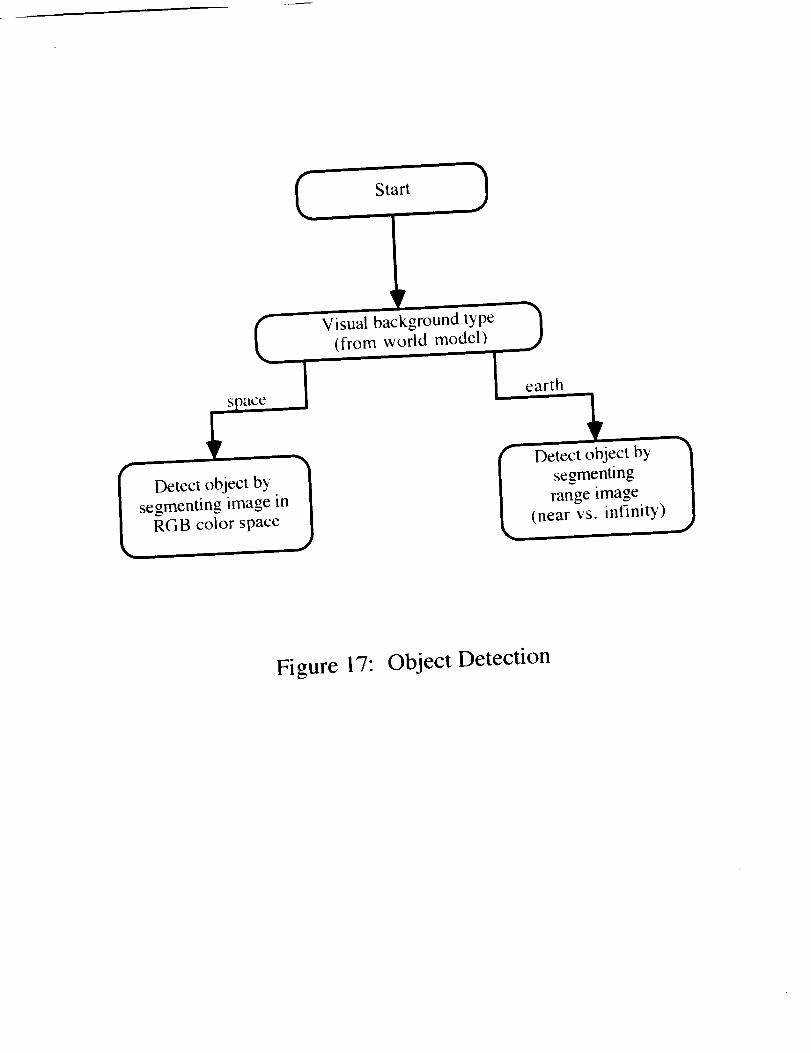
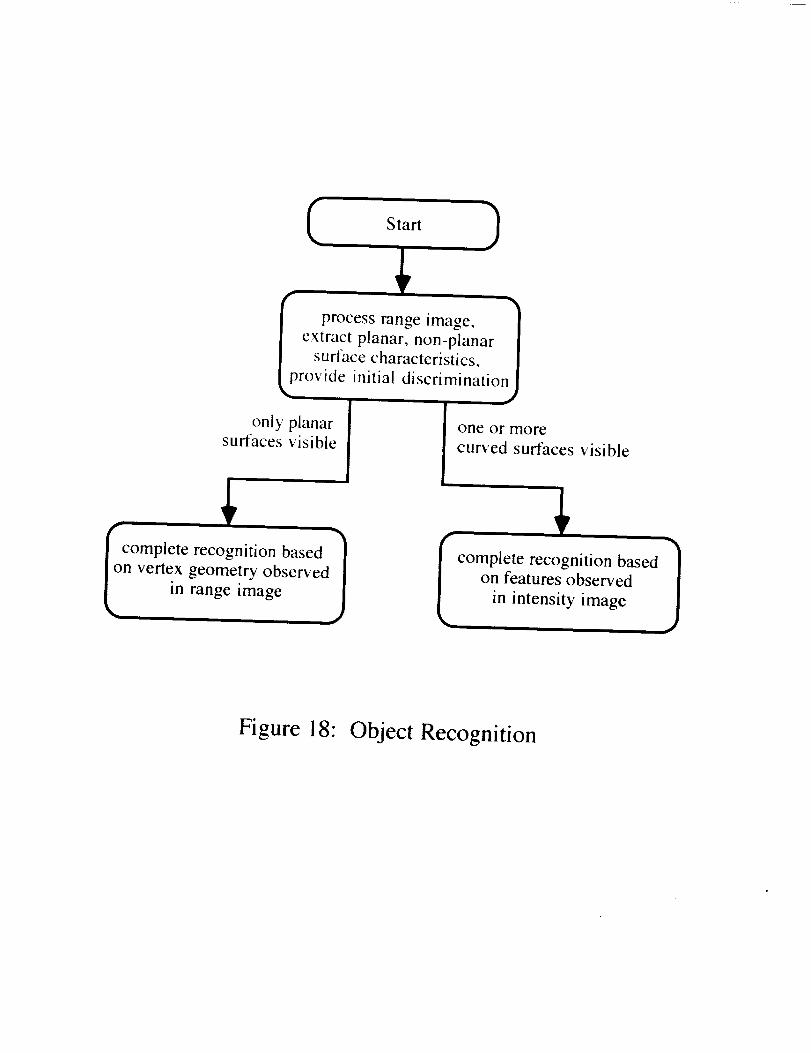
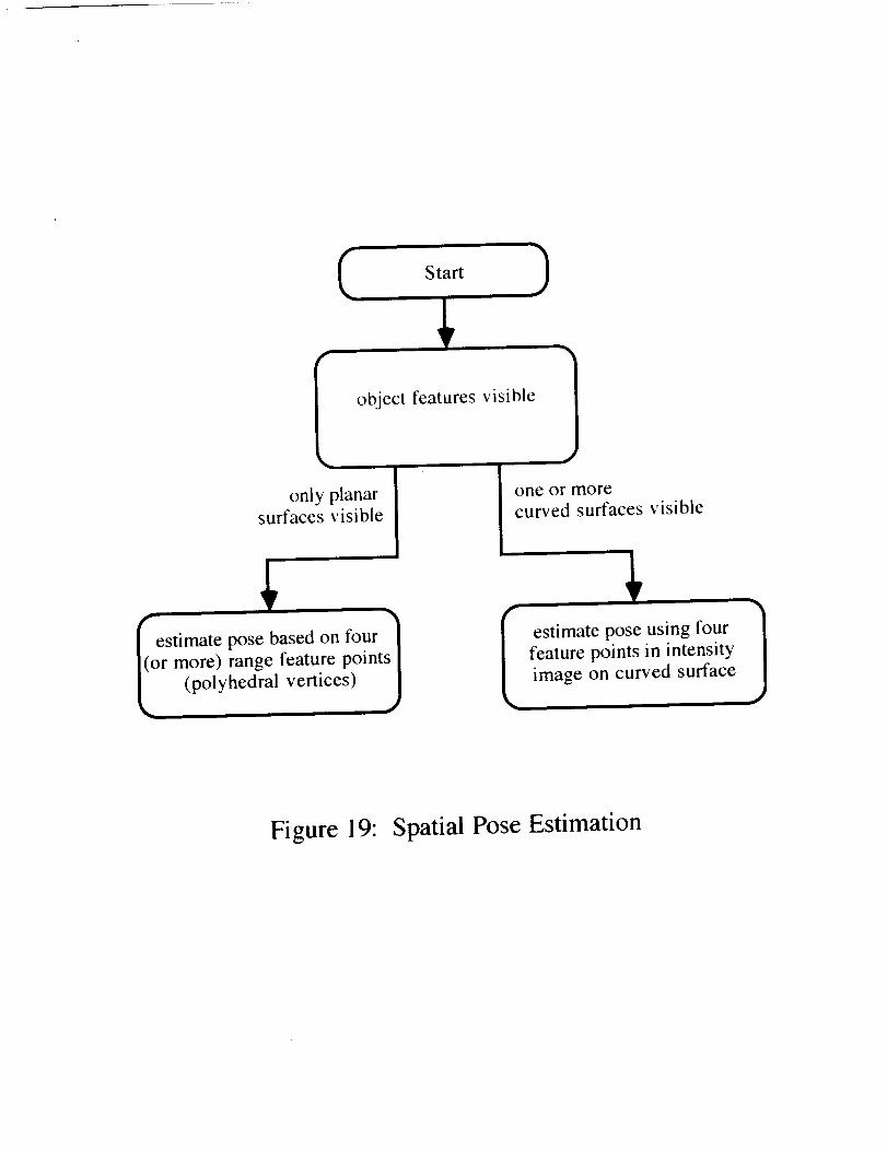
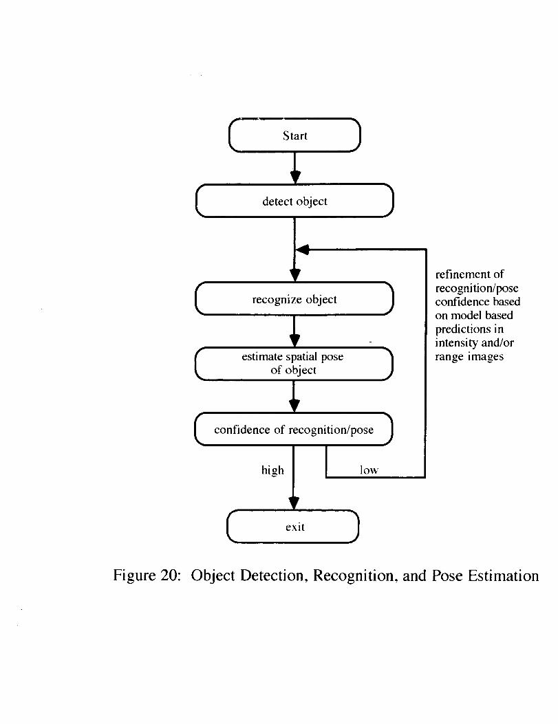
to the Vision System Planner architecture. Figures 17-20 illustrate the basic recommended flows
for sensor/algorithm decisions relating to object detection, recognition, pose estimation and
iteratively improving the confidences of recognition and pose estimation.
.
,
.
.
For the detection of objects without recognition and/or pose estimation, the most appropriatesensor to select under general circumstances is the laser scanner. The primary reason for thisconclusion is that segmentation of objects as viewed by a color camera becomes extremelydifficult if a colorful background (e.g. the earth) is present. Hence. in the most general cases.it is preferable to attempt to detect anomalies in depth data rather than in color images.
For the recognition of objects a two pronged approach that combines range and intensityimages is advantageous. From a geometric structural approach, the recognition of generalizedcurved objects from range images is too computationally expensive, even to perform surfacesegmentation. However. as was shown in the previous section, a limited amount of rangeprocessing to extract the planar surfaces and their areas can provide the basis to group objectsinto broad categories. Once this is done, key intensity features can be examined either in thereflectance image for the laser scanner or in that of the color camera to refine the identity of theobject. For example, suppose that a planar and a non-planar surface are extracted from a rangeimage. This is a situation that could arise if either the cut cylinder and the truss coupler wereviewed as in Figures 15d and 16b. The resulting confusion between the two models could beresolved simply in the intensity image by noting that the planar surface of the truss coupler isnot bounded by any straight line segments, whereas the planar surface of the cut cylinder has asemicircular and a linear boundary. In another case, colored (bar code) patterns could be usedas the discriminating factor. Hence, applying information obtained from both range andintensity domains would differentiate the two models.
The manner by which spatial pose is estimated should be a function of the visible surfacecharacteristics for the observed object. If only planar surfaces are observed, then the vertices atwhich these planar surfaces intersect can provide sufficient features upon which to computepose using the locations of these features as extracted from the range image. For curvedobjects such as the truss coupler, however, computationally difficult problems relating to theextraction of surface type (e.g. cylinder, cone, etc.) arise. It is therefore advisable to considerusing markings on the objects that facilitate applying one or more of the computationally simpleintensity domain pose estimation algorithms such as that of Hung, Yeh and Harwood. Anobject like the truss coupler could be marked redundantly such that at least four coplanarnoncolinear feature points would always be visible. This approach avoids problems associatedwith the computation of parameters for curved surfaces and potential occlusion of a single set(of4) pose estimation feature points.
Finally, there may be cases for which there is a low confidence for the identity or estimatedpose of an object as determined above. This may be due to a goal that minimizes processing inorder to avoid computationally expensive feature extraction during the recognition phase.However, if a reliable pose has been estimated, the location of features in each image may bepredicted and the search space can be considerably constrained. Hence, it is appropriate toloop back through both the recognition and pose estimation phases further refining estimates offeature correspondences and pose parameters based on predicted and verified features.
5-1
Start
space l
, ,jI Detect object by
segmenting image in
RGB color space
Detect object by
segmenting
range image
(near vs. infinity)
Figure 17: Object Detection
p process range image,
extract planar, non-planar
surface characteristics,
rovide initial discrimination
only planarsurfaces visible
1n vertex geometry observed
in range image
one or more
curved surfaces visible
i
i
I complete recognition based 1
on features observed
in intensity image
Figure 18: Object Recognition
Start
object features visible
only planarsurfaces visible
one or more
curved surfaces visible
eStimate pose based on four -')
r more) range feature points I(polyhedral vertices) /
)i
Ie 'ma ef°ur1feature points in intensity
image on curved surface
Figure 19: Spatial Pose Estimation
C
Start )
detect object )
(
C
A
recognize object
estimate spatial pose
of object
confidence of recognition/pose
high
?
C exit )
low
)
)
refinement of
recognition/poseconfidence based
on model based
predictions in
intensity and/or
range images
Figure 20: Object Detection, Recognition, and Pose Estimation
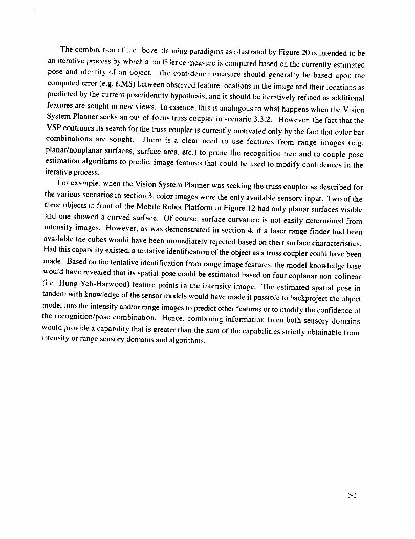
The combin;,tion c f t. e : bc, ge _ia m;ng paradigms as illustrated by Figure 20 is intended to be
an iterative process b_ wb'cF a ;o_ fi, lerce measure is conlputed based on the currently estimated
pose and identity 6f :in t_bject. The conl,denc3 measure should generally be based upon the
computed error (e.g. I_,IS) betv_een observed feature iocat'_ons in the image and their locations as
predicted by the curre'_t pos_,/ident!ty hypothesis, and it should be iteratively refined as additional
features are sought in new s Jews. In essel_ce, this is analogous to what happens when the Vision
System Planner seeks an ou,-of-focus truss coupler in scenario 3.3.2. However, the fact that the
VSP continues its search for the truss coupler is currently motivated only by the fact that color bar
combinations are sought. There is a clear need to use features from range images (e.g.
planar/nonplanar surfaces, surfzce area, etc.) to prune the recognition tree and to couple pose
estimation algorithms to predict image features that could be used to modify confidences in the
iterative process.
For example, when the Vision System Planner was seeking the truss coupler as described for
the various scenarios in section 3, color images were the only available sensory input. Two of the
three objects in front of the Mobile Robot Platform in Figure 12 had only planar surfaces visible
and one showed a curved surface. Of course, surface curvature is not easily determined from
intensity images. However, as was demonstrated in section 4, if a laser range finder had been
available the cubes would have been immediately rejected based on their surface characteristics.
Had this capability existed, a tentative identification of the object as a truss coupler could have been
made. Based on the tentative identification from range image features, the model knowledge base
would have revealed that its spatial pose could be estimated based on four coplanar non-colinear
(i.e. Hung-Yeh-Harwood) feature points in the intensity image. The estimated spatial pose in
tandem with knowledge of the sensor models would have made it possible to backproject the object
model into the intensity and/or range images to predict other features or to modify the confidence of
the recognition/pose combination. Hence, combining information from both sensory domains
would provide a capability that is greater than the sum of the capabilities strictly obtainable from
intensity or range sensory domains and algorithms.
5-2

6.0 Ymlmar' : nO Conclas,ons
In order to increase the autenoiny of the Exlraveh.ct:iar Activity Helper/Retriever, it is
necessary for the Vision System Planae: to be able to select an image sensor or invoke an image
processing algorithm that will achieve z goal in an expeditious manner. The primary criteria for
selecting the sensor or algorithm should be bas,_d upon
a. what is known about the object being sought (the object model),
b. what is known about the operational environment (the world model),
c. what is known about the capabilities of the sensor, and
d. what is known about the capabilities of the processing algorithm.
The results obtained using actual images from a color camera mounted on the Mobile Robot
Platform and synthetically generated range images demonstrate that each sensory domain has
inherent strengths that should be exploited and inherent weaknesses that should be avoided when
circumstances warrant. More important, however, is the capability of each sensory domain to
complement or enhance the capability of the other, particularly if an approach to iteratively refine
the confidences associated with identification and pose is taken.
Acknowledgement
Philip Schlump, who is a first year Ph.D. student in the Computer Science Department at the
University of Wyoming, designed, constructed and programmed the Mobile Robot Platform in
addition to developing and testing the color vision algorithms described in section 3. His dedicated
assistance in this project is _atefully acknowledged.
6-1
References
1. C.R. Weisbin and M.D. Montemerlo, "NASA's Telerobotics Research Program", AppliedIntelligence, Volume 2, Number 2, August, 1992, pp. 113-125.
0 R. Simmons, E. Krotkov, W. Whittaker, B. Albrecht, J. Bares, C. Fedor, R. Hoffman, H.
Pangels, and D. Wettergreen, "Progress Towards Robotic Exploration of Extreme Terrain",Appliedlntelligence, Volume 2, Number 2, August, 1992, pp. 163-180.
3. B.H. Wilcox, "Robotic Vehicles for Planetary Exploration", Appliedlntelligence, Volume 2,Number 2, August, 1992, pp. 181-193.
, G.J. Reuter, C.W. Hess, D.E. Rhoades, L.W. McFadin, K.J. Healey, and J.D. Erickson, "AnIntelligent Free-Flying Robot", SPIE Symposium on Advances in Intelligent Robotic3_vstems, Space Station Automation IV, SPIE 1006-03, Cambridge, Massachusetts, Nov. 6-11, 1988.
. K.A. Grimm. "The Suitability of Transputers for Use In An Autonomous Free-Flying Robot",Tranwuting '_)1, Proceeding_ r
A Vision System Planner for theExtravehicular Activity Retriever t
Michael MageeComputer Science Department
University of WyomingLaramie, Wyoming 82071-3682e-mail: [email protected]
Chiun-Hong ChienIntelligent System Department
Lockheed Engineering & Sciences
Thomas W. PendletonAutomation and Robotics Division
NASA Johnson Space Center
+This research was supported in part by NASA grant NAG-9-634.
Abstract
The Extravehicular Activity Retriever (EVAR) is a robotic device currently beingdeveloped by the Automation and Robotics Division at the NASA Johnson Space Center tosupport activities in the neighborhood of the Space Shuttle or Space Station Freedom. As thename implies, the Retriever's primary function will be to provide the capability to retrievetools and equipment or other objects which have become detached from the spacecraft, but itwill also be able to rescue a crew member who may have become inadvertently de-tethered.Later goals will include cooperative operations between a crew member and the Retrieversuch as fetching a tool that is required for servicing or maintenance operations.
This paper documents a preliminary design for a Vision System Planner (VSP) for theEVAR that is capable of achieving visual objectives provided to it by a high level taskplanner. Typical commands which the task planner might issue to the VSP relate to objectrecognition, object location determination, and obstacle detection. Upon receiving acommand from the task planner, the VSP then plans a sequence of actions to achieve thespecified objective using a model-based reasoning approach. This sequence may involvechoosing an appropriate sensor, selecting an algorithm to process the data, reorienting thesensor, adjusting the effective resolution of the image using lens zooming capability, and/orrequesting the task planner to reposition the EVAR to obtain a different view of the object.
An initial version of the Vision System Planner which realizes the above capabilitiesusing simulated images has been implemented and tested. The remaining sections describethe architecture and capabilities of the VSP and its relationship to the high level task planner.In addition, typical plans that are generated to achieve visual goals for various scenarios arediscussed. Specific topics to be addressed will include object search strategies, repositioningof the EVAR to improve the quality of information obtained from the sensors, andcomplementary usage of the sensors and redundant capabilities.
1. Introduction
There has been considerable research that relates to the development of specialized roboticdevices that are designed to operate in exterrestrial domains. These devices cover a broad
spectrumof operationalcharacteristics.At the lessautonomousendof the spectrumaretelerobotsandtelemanipulatorsthat arecontrolled by a humanoperator,andwhich, to asignificant degree,dependon humanreasoningand intervention in order to be able toaccomplishhigh level tasks,t At themoreautonomousendof the spectrumarerobotsthatmustbeableto senseandreasonabouttheir environments,andwhich will thenplanandachievea goal or set of goals. The degreeof autonomythat is required is frequentlymandatedby the proximity of the humanoperatorto the robotic device, particularly ifsignificanttimedelaysnecessarilyexist in thehuman-robotloop. Forexample,it wouldbeimpracticalfor a walkingroveronthesurfaceof theplanetMarsto dependonateleoperatorto specifyeachstepto betaken,sincetheroundtrip signaltimecanbeup to45minutes.
TheCMU Ambler is onesuchhighly autonomousrobotdesignedto explorethedistantruggedterrain of anotherplanet in a highly mobile, reliableand efficient manner.2 TheAmbler constructsa terrainmapusinga laserrangescannerasits primarysensorandplansthemovementsof its six legsbasedon local three-dimensionalconstraints.Boththemannerof locomotionandtheability to sensetheenvironmentarein contrastto Robby,a planetaryroverthatusesstereovisionto deriveterraininformationandiscapableof navigatingaroundandoverobstaclesusingsixarticulatedwheels.3
The EVA Retriever, on the other hand, is intended to operate in relatively close proximityto a human operator and thus does not have to operate under severe constraints that imposehighly autonomous operation, such as large communication delays. However, it isnevertheless very desirable for the Retriever to exhibit a great degree of autonomy in order toallow the operator to be free to attend to other tasks. Phase I and II studies demonstrated thefundamental design components and capabilities for the EVAR using a Precision Air Bearing
Floor (PABF) to simulate the frictionless environment of space. 4-5 The EVAR demonstratedthat it was capable of self-location (relative to a fixed structure), locating a target object to beretrieved, and grasping and retrieving the target object using a system design that includedfive major functional subsystems which were: perception, world model, reasoning, sensing
and acting. 6The ability to sense and perceive objects in the vicinity of the EVAR is, of course, central
to any interaction with the environment since the EVAR must be able to detect and recognizeobjects prior to reasoning about them and executing actions involving them. It is thereforeimportant for a vision system to provide autonomous or semi-autonomous robots withinformation that describes the surrounding environment, but it should also be able to plan andexecute actions that solve visual problems efficiently and effectively. In order to achieve itsobjectives the Vision System should be able to call on other modules, for example, to requestthat the EVAR be repositioned or reorieted in order to obtain a better view of an object.
The preliminary architecture that has been developed to embody these control objectivesis shown in Figure 1. From a software design standpoint, the highest level or supervisoryplanner is the Task Planner. The Task Planner oversees the actions of several subplanners,one of which is the Vision System Planner. Each of these subplanners can be considered tobe an expert with special knowledge regarding how to solve problems within its particulardomain. When commanded to do so by the Task Planner, a subplanner will determine amethod for achieving the specified goal given its knowledge of the current state of the worldand it will then communicate the result of executing the planned action back to the TaskPlanner.
Although each subplanner is subservient to the Task Planner, it may nevertheless ask forassistance from the Task Planner if such assistance would help it achieve the specified goal.For example, if the Task Planner requests the Vision System Planner to recognize an objectand the robot on which the vision hardware is mounted is poorly positioned to sense theobject, the VSP may request the Task Planner to cause the robot to be moved. If the TaskPlanner honors the request from the VSP, it would then send commands to other subplanners(involving navigation and control) to move the robot so that the Vision System canaccomplish the objective originally requested by the Task Planner.
The Vision System module itself (Figure 2) should be a self-contained entity capable ofaccomplishing many types of objectives such as object detection, recognition, tracking andpose estimation. A typical plan that would be formulated to achieve one of these goals wouldinvolve choosing an appropriate sensor, selecting an algorithm to process the data, and
( Operator
,
requests ] I restw_l'_'
Task Planner
Y )_.. -t Estimator )- -L J L _':""e'
)
Figure I" Planning System Architecture
Vision System Planner
Im%oe Pose ObjectSensing Preprocessin l Blob
Esti marion RecognitionTracking
ObjectModels
Figure 2: Vision System Components
communicating the results or a request for assistance to the Task Planner. The remainingsections discuss a suggested architecture for such a Vision System within the context of theExtravehicular Activity Retriever.
2. Vision System Planner Design Considerations
The planning mechanisms developed are founded on the assumption that there should beat least two visual sensors which provide intensity (color) and range images. There areseveral reasons why such a multisensory approach is desirable, three of which areparticularly significant. First, the availability of sensors with complementary capabilitiespermits the VSP to select a sensor/algorithm combination that is most appropriate forachieving the current visual goal as specified by the task planner. Second, if the sensor thatthe VSP would normally select as its first choice to achieve the goal is either unavailable orinappropriate for usage because of some current constraint, it may be possible to perform thedesired task using the other sensor to achieve the same goal. albeit perhaps by accepting apenalty in performance. Finally, instances may occur for which it is desirable to verifyresults from two different sensory sources.
The first of the above motivations addresses achieving the visual goal in the mosteffective manner by allowing the VSP to choose among sensors with complementarycapabilities. For example, if it is desired to distinguish between two objects of similarstructure with the color of the objects being the primary differentiating feature, then it isapparent that the color camera should be used as the primary sensor. On the other hand, ifthe size and/or geometry of the objects are most useful for determining identity, then it isimportant to be able to expeditiously extract and process three-dimensional coordinates.Clearly, this is a task that would be most properly assigned to the laser scanner. Similarly,
tasks involving pose estimation "r, object tracking 8 and motion estimation 9 would moreappropriately involve invoking the laser scanner as the primary sensor. The initial versionsof these submodules have already been developed and will be tested in a reduced gravity
environment using NASA's KC-135 aircraft during the coming year l°.The previous example involving the need for three-dimensional coordinates is illustrative
of a case in which the primary sensor (the laser scanner) is engaged to extract the requiredinformation. However, there may be cases for which the laser scanner cannot be used to
obtain range information because (a) the object to be processed is covered with a highlyspecularly reflective material thus preventing acquisition of good return signals, (b) the laserscanner is currently assigned to another task, or (c) the laser scanner is temporarily notfunctioning properly. For such instances, it is highly desirable to provide a redundantcapability by using the other sensor if possible. The classical method for determiningthree-dimensional coordinates from intensity images involves a dual (stereo vision.) camerasetup in which feature correspondences are established and the stereo equations are solvedfor each pair of feature points. Although the current simulated configuration has only oneintensity image camera, this alternative mechanism for computing range values is in factpossible for the VSP to achieve by requesting the task planner to reposition the EVAR suchthat the camera's initial and final positions are offset by a known baseline distance. Ofcourse, there is a penalty in performance if the (pseudo) stereo vision method is chosen,since the EVAR must be moved and feature correspondences computed. However, it isnevertheless important to have such a redundant sensing capability for the reasons previouslymentioned and to be able to independently verify the results obtained from one sensor or toincrease the confidence of those results.
Aside from selecting an appropriate sensor, it is may also be possible to alter certainphysical characteristics of the sensor such as the effective resolution and scanning rate. Inthe case of the laser scanner, images can be acquired at rates (and resolutions) varyingbetween 2.5 frames per second (256 x 256 pixels) to 10 frames per second (64 x 256 pixels).The capability to select a faster frame rate with a penalty in resolution becomes significant if itis important to be able to sense and process data rapidly, as in the case of motion estimation.
On the other hand, if an object is relatively stationary and finer features are to be sensed, thenhigher resolution with a lower frame rate would be chosen. Hence, a vision system planner
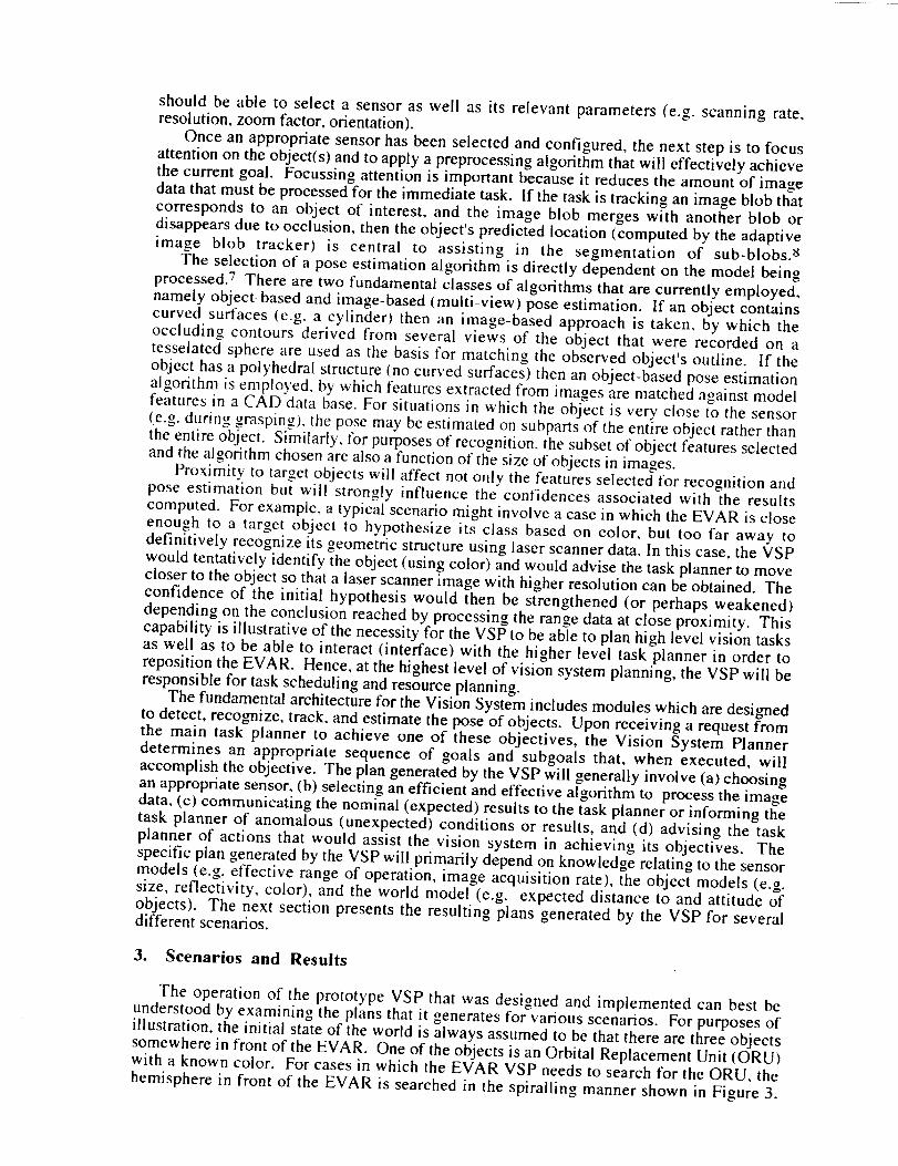
shouldbe able to selecta sensoras well as its relevantparameters(e.g. scanningrate,resolution,zoomfactor,orientation).
Onceanappropriatesensorhasbeenselectedandconfigured,thenext stepis to focusattentionon theobject(s)andto applyapreprocessingalgorithmthatwill effectivelyachievethecurrentgoal. Focussingattentionis importantbecauseit reducestheamountof imagedatathatmustbeprocessedfor theimmediatetask. If thetaskis trackingan imageblobthatcorrespondsto an object of interest, and the image blob mergeswith anotherblob ordisappearsdueto occlusion,thentheobject'spredictedlocation(computedby theadaptiveimage blob tracker) is central to assisting in the segmentation of sub-blobs._
The selectionof a poseestimationalgorithm is directly dependenton the modelbeingprocessed.7 Therearetwo fundamentalclassesof algorithmsthatarecurrentlyemployed,namelyobject-basedandimage-based(multi-view) pose estimation. If an object containscurved surfaces (e.g. a cylinder) then an image-based approach is taken, by which theoccluding contours derived from several views of the object that were recorded on atesselated sphere are used as the basis for matching the observed object's outline. If theobject has a polyhedral structure (no curved surfaces) then an object-based pose estimationalgorithm is employed, by which features extracted from images are matched against modelfeatures in a CAD data base. For situations in which the object is very close to the sensor(e.g. during grasping), the pose may be estimated on subparts of the entire object rather thanthe entire object. Similarly. ibr purposes of recognition, the subset of object features selectedand the algorithm chosen are also a function of the size of objects in images.
Proximity to target objects will affect not only the features selected tbr recognition andpose estimation but will strongly influence the confidences associated with the resultscomputed. For example, a typical scenario might involve a case in which the EVAR is closeenough to a target object to hypothesize its class based on color, but too far away todefinitively recognize its geometric structure using laser scanner data. In this case, the VSPwould tentatively identify the object (using color) and would advise the task planner to movecloser to the object so that a laser scanner image with higher resolution can be obtained. Theconfidence of the initial hypothesis would then be strengthened (or perhaps weakened)depending on the conclusion reached by processing the range data at close proximity. Thiscapability is illustrative of the necessity for the VSP to be able to plan high level vision tasksas well as to be able to interact (interface) with the higher level task planner in order toreposition the EVAR. Hence, at the highest level of vision system planning, the VSP will beresponsible for task scheduling and resource planning.
The fundamental architecture for the Vision System includes modules which are designedto detect, recognize, track, and estimate the pose of objects. Upon receiving a request fromthe main task planner to achieve one of these objectives, the Vision System Plannerdetermines an appropriate sequence of goals and subgoals that, when executed, willaccomplish the objective. The plan generated by the VSP will generally involve (a) choosingan appropriate sensor, (b) selecting an efficient and effective algorithm to process the imagedata, (c) communicating the nominal (expected) results to the task planner or informing thetask planner of anomalous (unexpected) conditions or results, and (d) advising the taskplanner of actions that would assist the vision system in achieving its objectives. Thespecific plan generated by the VSP will primarily depend on knowledge relating to the sensormodels (e.g. effective range of operation, image acquisition rate), the object models (e.g.size, reflectivity, color), and the world model (e.g. expected distance to and attitude ofobjects). The next section presents the resulting plans generated by the VSP for severaldifferent scenarios.
3. Scenarios and Results
The operation of the prototype VSP that was designed and implemented can best beunderstood by examining the plans that it generates for various scenarios. For purposes ofillustration, the initial state of the world is always assumed to be that there are three objects
somewhere in front of the EVAR. One of the objects is an Orbital Replacement Unit (ORU)with a known color. For cases in which the EVAR VSP needs to search for the ORU, the
hemisphere in front of the EVAR is searched in the spiralling manner shown in Figure 3.
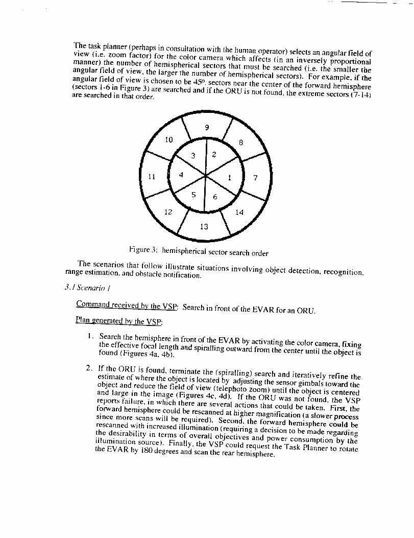
Thetaskplanner(perhapsin consultationwith thehumanoperator) selects an angular field ofview (i.e. zoom factor) for the color camera which affects (in an inversely proportional
manner) the number of hemispherical sectors that must be searched (i.e. the smaller theangular field of view, the larger the number of hemispherical sectors). For example, if the
angular field of view is chosen to be 45 °, sectors near the center of the forward hemisphere(sectors 1-6 in Figure 3) are searched and if the ORU is not found, the extreme sectors (7-14)are searched in that order.
Figure 3: hemispherical sector search order
The scenarios that follow illustrate situations involving object detection, recognition,range estimation, and obstacle notification.
3.1 Scenario 1
Command received by the VSP: Search in front of the EVAR for an ORU.
Plan _enerated by the VSP:
, Search the hemisphere in front of the EVAR by activating the color camera, fixingthe effective focal length and spiralling outward from the center until the object isfound (Figures 4a, 4b).
. If the ORU is found, terminate the (spiralling) search and iteratively refine theestimate of where the object is located by adjusting the sensor gimbals toward theobject and reduce the field of view (telephoto zoom) until the object is centeredand large in the image (Figures 4c, 4d). If the ORU was not found, the VSPreports failure, in which there are several actions that could be taken. First, theforward hemisphere could be rescarmed at higher magnification (a slower processsince more scans will be required). Second, the forward hemisphere could berescanned with increased illumination (requiring a decision to be made regardingthe desirability in terms of overall objectives and power consumption by theillumination source). Finally, the VSP could request the Task Planner to rotatethe EVAR by 180 degrees and scan the rear hemisphere.
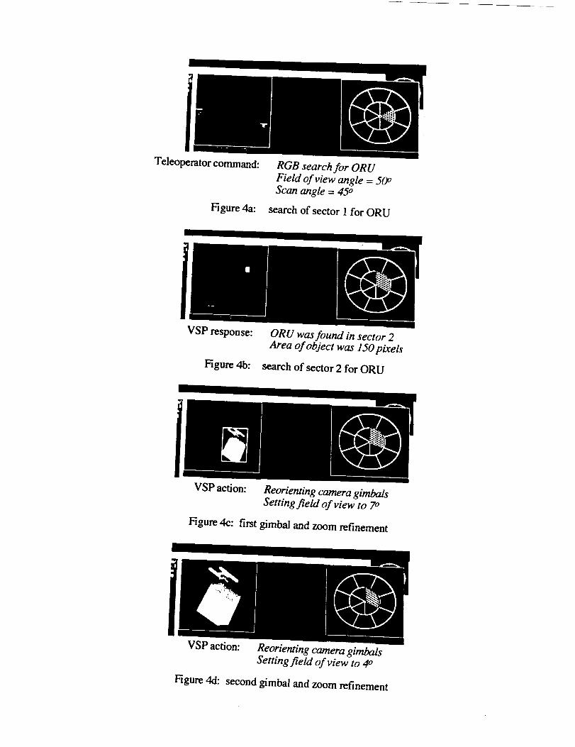
Teleoperator command:
Figure 4a:
RGB search for ORU
Field of view angle = 50 °
Scan angle = 45 °
search of sector 1 for ORU
VSP response:
Figure 4b:
ORU was found in sector 2Area of object was 150 pixels
search of sector 2 for ORU
VSP action: Reorienting camera gimbalsSening field of view to 7o
Figure 4c: first gimbal and zoom refinement
VSP action: Reorienting camera gimbals
Setting field of view to 4o
Figure 4d: second gimbal and zoom refinement
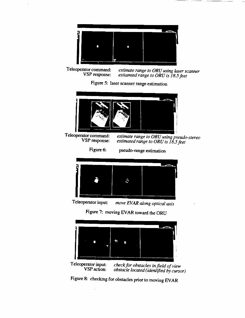
Teleoperator command:VSP response:
Figure 5: laser scanner range estimation
II
estimate range to ORU using laser scannerestiamted range to ORU is 18.5feet
Teleo aerator command:
VSP response:
Figure 6:
estimate range to ORU using pseudo-stereoestimated range to ORU is 18.5 feet
pseudo-range estimation
Teleoperator input:
Figure 7:
move EVAR along optical axis
moving EVAR toward the ORU
I
Teleoperator input: check for obstacles in field of viewVSP action: obstacle located (identified by cursor)
Figure 8: checking for obstacles prior to moving EVAR

3.2 Scenario 2
Command received by the VSP: Determine the distance to the ORU, no sensor specified.
Plan generated by the VSP:1. Locate the ORU as in Scenario 1 using the color camera.2. Examine the object model for an ORU and determine which sensor is the most
appropriate to be used. In this case, since an ORU is not specularly reflective, thelaser scanner is chosen.
3. Examine that part of the laser scanner image that corresponds to the regionbelonging to the ORU in the color image and compute the distance to those rangeimage elements (Figure 5).
3.3 Scenario 3
Command received by the VSP:Determine the distance to the ORU, but force the estimation of distance using singlecamera lateral stereo vision.
Plan generated by the VSP:1. Locate the ORU as in Scenario I using the color camera.2. Move the EVAR left a known distance, take an image, and record the location of
the ORU in that image. Then move the EVAR right a known distance, take animage, and record the location of the ORU in that image.
3. Using triangulation (stereo vision with two cameras separated by a knownbaseline distance) compute the distance to the ORU (Figure 6).
3.4 Scenario 4
Command received by the VSP:Determine the distance to the ORU and move toward the ORU along the optical axisof the color camera until the EVAR is a specified distance (D) away from it.
Plan generated by the VSP:1. Locate the ORU as in Scenario 1 using the color camera.2. Estimate the distance to the ORU (Dor u) using the laser scanner.
3. Compute a vector along the optical axis of the color camera whose length is(Dor u - D). Transform that vector into EVAR coordinates and move to that
position, maintaining the same attitude (Figure 7).
3.5 Scenario 5
Command received by the VSP:As in Scenario 4, determine the distance to the ORU and check to determine whether
any other objects in the field of view are closer to the EVAR than the ORU prior tomoving toward it.
Plan generated by the VSP:1. Locate the ORU as in Scenario I using the color camera.2. Estimate the distance to the ORU using the laser scanner.3. Search the range image for values that lie outside of the region containing the
ORU and report a potential obstacle if any of the values indicate distancesbetween the EVAR and the ORU. The cursor in Figure 8 shows the potentialobstacle.
4. Conclusions and Future Work
An initial version of the Vision System Planner has been implemented and tested usingsimulated input from a color camera and laser scanner. The VSP has been shown to becapable of planning the fundamental tasks required for the vision system, namely objectdetection, recognition, range estimation, obstacle detection and advising the task planner forrepositioning of the EVAR. The next phase of the research will involve implementing theVSP on robotic hardware that is capable of repositioning the sensor(s) and moving about inits environment in a laboratory setting. Beyond this goal of moving from simulatedenvironments to physical domains, the primary goal will be to increase the autonomy of theVSP such that less teleoperator input is required.
References
I. C.R. Weisbin and M.D. Montemerlo, "NASA's Telerobotics Research Program",Applied Intelligence, Volume 2, Number 2, August, 1992, pp. 113-125.
2. R. Simmons, E. Krotkov, W. Whittaker, B. Albrecht, J. Bares, C. Fedor, R.
Hoffman, H. Pangels, and D. Wettergreen, "Progress Towards Robotic Exploration ofExtreme Terrain", Applied Intelligence, Volume 2, Number 2, August, 1992, pp.163-180.
3. B.H. Wilcox, "Robotic Vehicles for Planetary Exploration", Applied Intelligence,Volume 2, Number 2, August, 1992, pp. 181-193.
4. G.J. Reuter, C.W. Hess. D.E. Rhoades, L.W. McFadin, K.J. Healey. and J.D.Erickson, "An Intelligent Free-Flying Robot", SPIE Symposium on Advances inIntelligent Robotic Systems. Space Station Automation IV, SPIE 1006-03, Cambridge,MA, Nov. 6-11, 1988.
5. K.A. Grimm, "The Suitability of Transputers for Use In An Autonomous Free-FlyingRobot", Transputing '91, Proceedings of the World Transputer User GroupConference, April 22-26, 1991, pp. 701-707.
6. J. Erickson, R. Goode, K. Grimm, C. Hess, R. Norsworthy, G. Anderson, L. Merkel,and D. Phinney, "Technology Test Results from an Intelligent Free-Flying Robot forCrew and Equipment Retrieval in Space", SPIE Symposium on Cooperative IntelligentRobotic Systems in Space 11, Boston, MA, November 10-14, 1991.
7. C.H. Ch[en, "Multi-view Based Pose Estimation from Range Images", SpieCooperative Intelligent Robotics in Space 11I, Cambridge, Massachussetts, November,1992.
8. M.L. Littlefield, "Adaptive Tracking of Objects for a Mobile Robot Using RangeImages", Spie Cooperative Intelligent Robotics in Space 111, Cambridge,Massachussetts, November, 1992.
9. L. Hewgiil, "Motion Estimation of a Freely Rotating Body in Earth Orbit", SpieCooperative Intelligent Robotics in Space 111, Cambridge, Massachussetts, November,1992.
10. K.A. Grimm and J.D. Erickson, "An Experiment in Vision Based AutonomousGrasping within a Reduced Gravity Environment", Spie Cooperative IntelligentRobotics in Space !I1, Cambridge, Massachussetts, November, 1992.