Embed Size (px)
Citation preview
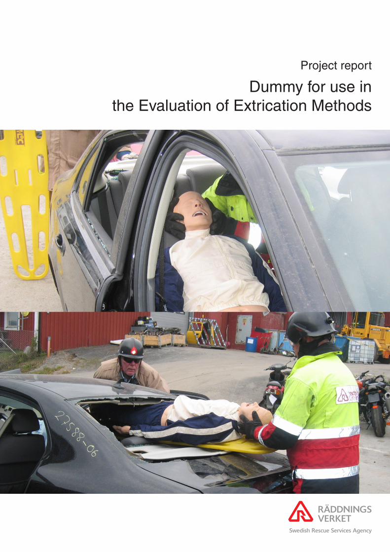
Project report
Dummy for use in the Evaluation of Extrication Methods

2007 Swedish Rescue Services Agency – SkövdeISBN 978-91-7253-371-4
Order number P21-486/072007 edition

Project report:
Dummy for use in the Evaluation of
Extrication Methods
Pontus Albertsson, SRSA Astrid Linder, VTI
Camilla Granström, VTI
SRSA:s corresponding author:
Pontus Albertsson, telephone +46 612 822 26

2
3
Foreword This report is the result of the project “Extrikationsdocka för vetenskaplig utvärdering av losstagningsmetoder“. The authors wish to thank Yvonne Näsman, Dan Wargclou, Göran Valentin, Svante Nordström and all other persons that contributed to this project. Sandö 14th November 2007 Pontus Albertsson, Astrid Linder and Camilla Granström

4
5
Table of contents FOREWORD........................................................................................................................3
SUMMARY ..........................................................................................................................7
1. INTRODUCTION ......................................................................................................8 1.1. METHOD ..............................................................................................................9
2. EXTRICATION TECHNIQUES ............................................................................10
3. INJURY PATTERN .................................................................................................16 3.1. INJURY PATTERN IN GENERAL ............................................................................16 3.2. FRONTAL COLLISIONS ........................................................................................17 3.3. SIDE COLLISIONS................................................................................................18 3.4. INJURIES WITH ENTRAPMENT .............................................................................18
4. EXTRICATION DUMMY FEATURES ................................................................20 4.1. SPINE .................................................................................................................20 4.2. BACK OF THE TORSO ..........................................................................................21 4.3. PELVIS ...............................................................................................................21 4.4. KNEE JOINT........................................................................................................21 4.5. ANKLE JOINT AND FOOT.....................................................................................21 4.6. LOWER LIMB, FROM THE KNEE TO ANKLE (CNEMIS) ..........................................22
5. EXISTING DUMMIES FOR DIFFERENT APPROACHES ..............................23 5.1. HYBRID III 50TH MALE DUMMY ..........................................................................23 5.2. THOR ADVANCED CRASH TEST DUMMY ..........................................................24 5.3. BIORID-II..........................................................................................................25 5.4. ADVANCED DYNAMIC ANTHROPOMORPHIC MANIKIN (ADAM) .......................25 5.5. LIFE/FORM® KERI COMPLETE NURSING SKILLS MANIKIN ...............................25 5.6. FLEXIBLE RESCUE RANDY .................................................................................26 5.7. RESCUE DUMMY GENERAL PURPOSE .................................................................27
6. EXISTING BIOFIDELIC SYSTEMS AND TECHNIQUES OF INTEREST....28 6.1. ADVANCED LOWER EXTREMITY.........................................................................28 6.2. ARTIFICIAL JOINTS AND LEG PROSTHESES..........................................................29 6.2.1. C-LEG................................................................................................................29 6.2.2. C-WALK ............................................................................................................30 6.3. EXOSKELETON ...................................................................................................30 6.4. ANATOMICAL MODELS.......................................................................................31 6.5. VIRTUAL REALITY AND ROBOTICS .....................................................................32
7. APPLICABLE MEASUREMENT TECHNIQUES AND SENSORS..................33 7.1. PRESSURE SENSORS............................................................................................33 7.1.1. K-SCAN, CONFORMAT AND SMART SKIN BY TEKSCAN ...................................33 7.2. MEASUREMENT COMPONENTS FOR DISPLACEMENT AND JOINT ANGLES.............35 7.2.1. STRAIN GAUGES.................................................................................................35 7.2.2. POTENTIOMETERS ..............................................................................................35 7.2.3. MAGNETIC ROTARY SENSOR ..............................................................................35
8. IDEAS AND REFLECTIONS FOR FUTURE TECHNIQUES...........................36
9. SUMMARY AND CONCLUSION .........................................................................38
10. REFERENCES .........................................................................................................39
11. LIST OF ABBREVIATIONS ..................................................................................42

6

7
Summary The extrication of an occupant of a car involved in a road traffic accident (RTA) is a balance between the time needed to extricate and the need for urgent medical care. To increase an occupant's chances of survival, the early treatment of injuries caused by high energy impacts is crucial. The extrica-tion needs to be as quick and gentle as the medical status of the casualty allows without causing any further injuries.
Time is of course very important but the quality of the extrication is also important due to the vulnerability of the casualty. However, questions re-garding quality have been raised, with studies focusing on whether spinal injuries were a result of the extrication process or transportation to hospital.
The Swedish Rescue Services Agency (SRSA) has for many years strived towards an efficient and rapid extrication technique that could be used in the ongoing training of fire & rescue service personnel. In the work to achieve a high quality extrication technique, it has been found necessary to be able to measure and compare whether or not the technique actually maintained a high level of quality. Therefore a question was raised whether an evaluation method with measurable parameters in addition to time could be developed.
The aim of this project is to raise the question and to suggest possible tech-niques helpful as a tool to evaluate critical parts of the extrication process by measurements of quantifiable parameters. This is achieved by describing extrication techniques used in Norway, Sweden and the UK; describing a typical injury pattern among RTA casualties and potential techniques that could be used to quantify critical parts of the extrication process.
The results showed that physical models of the human body, existing dum-mies and technologies could be used in the design of a future extrication dummy. Subsystems, some special parts and components could also be of interest.
Keywords: extrication, injuries, evaluation, quantifiable parameters, extrica-tion dummy.
8
1. Introduction In a serious RTA, especially involving trapped casualties, a rapid extrica-tion is important because of the risk of extensive internal injuries [1-3], uncontrolled bleeding, hypoxia [4, 5] and the risk for accidental hypother-mia [6-9]. One RTA configuration is head-on large overlap collisions with impact directly on the vehicle’s drive train in which the back of the engine and gearbox press the dash panel towards the rear [10].
Rapid care of seriously injured casualties has previously been dealt with starting with R Adams Cowley introducing the Golden Hour and later on the concept of the Platinum Ten Minutes [11]. Today there are a number of different extrication techniques [4, 11-13] all of them focus on reducing the time on scene i.e. rapid care. Team or crew concept with joint training is also essential in all techniques [4, 11-13].
Time is of course very important but the quality during extrication is also important due to the vulnerability of the casualty. Quality methods such as pre-hospital trauma life support (PHTLS) [14] have been implemented among ambulance and fire & rescue personnel in Sweden [15]. Equipment used during extrication such as the Califonia Stif-neck Immobilizing Collar, Kendrik Extrication Device (KED) and Extrication Plus-One has also been evaluated. One example is a radiographic comparison test performed on volunteers in which these prehospital cervical immobilization methods were compared to the short board technique [16]. However, questions regarding quality have been raised, with studies focusing on whether spinal injuries were as a result of the extrication process or transportation to hospital [13, 17, 18].
The Swedish Rescue Services Agency (SRSA) has for many years strived towards an efficient and rapid extrication technique that could be used in the ongoing training of fire & rescue service personnel. In the work to achieve a high quality extrication technique, it has been found necessary to be able to measure and compare whether or not the technique actually maintained a high level of quality. Therefore a question was raised whether an evaluation method with measurable parameters in addition to time could be developed.
The aim of this project is to raise the question and to suggest possible tech-niques helpful as a tool to evaluate critical parts of the extrication process by measurements of quantifiable parameters. This is achieved by describing extrication techniques used in Norway, Sweden and the UK; describing a typical injury pattern among RTA casualties and potential techniques that could be used to quantify critical parts of the extrication process.
9
1.1. Method A literature search was performed in ITRD, (International Transport Re-search Documentation) TRIS (Transportation Research Information Ser-vices databases) MEDLINE (Medical Literature, Analysis, and Retrieval System Online) and PsycINFO® (Psychological Abstracts).
The search in databases included the following words; injur* pattern*, pano-ram*, profile*, polytrauma*, multipl* injur*. Head* or face* and (neck* or cervical*) and (thorax* or chest*) and (abdomen* or pelvis*) and extremit*. Accidents, traffic.
Test dumm* or crash dumm* (Anthropomorphic manikin* or Anthropo-morphic model* or Anthropomorphic dumm*), (Anthropometric dumm* or Anthropometric model* or Anthropometric manikin*) Human model* or Mechanical model* First Technology.
Extricat* or Pull out or pullout* or entrapment* or entrapped*, (rescu* or emergenc*), post crash* or post-crash*, Extricat* and (or entrapment* or entrapped* or rescu* or emergenc*), Extricat* and (vehicle*), Extricat* and (force* or strength or simulat*).
We also searched the internet using www.google.com. In addition, experts in the field were asked to identify relevant references.
10
2. Extrication techniques The following sequence is a short description of three northern European extrication methods when the rest position of the crashed car is standing on its wheels. These methods are used in Norway, Sweden and the UK.
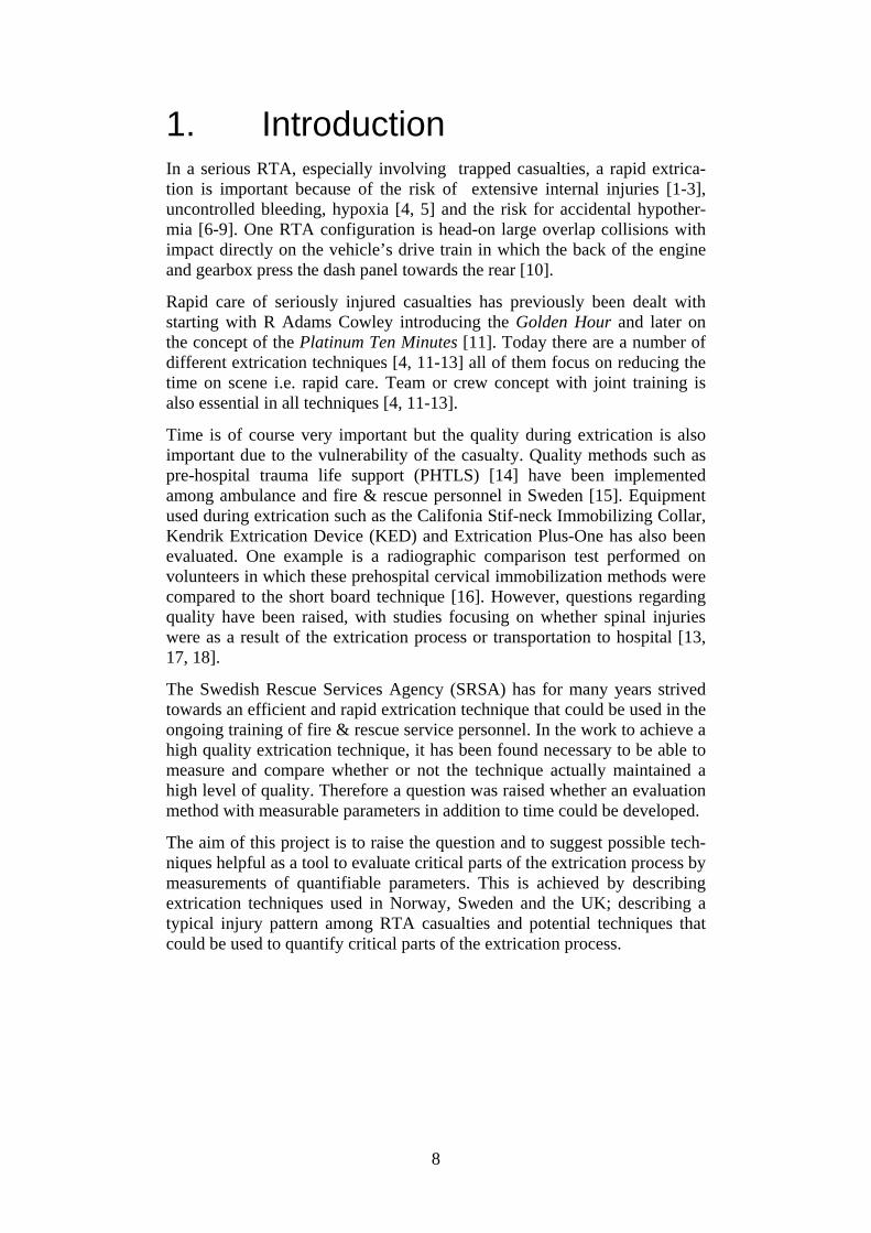
In Norway, one extrication method in use is based on pulling the car open by reversing the original forces which are described by Wik et al. [4].
• One chain is positioned around the steering wheel and around the windscreen (Figure 1).
Figure 1. A chain is positioned around the steering wheel and the base of the A-post [4].
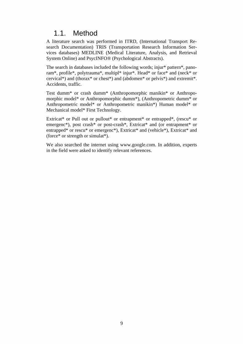
• The rear of the car is anchored through a belt, chain or a wire around the C-posts and anchored lower to avoid lifting of the car (Figure 2).
Figure 2. The winch pulls the steering wheel and dashboard away from the front seat via chains and wire [4].
• The two front chains are connected to a wire fastened to two winches.

11
• Steering wheel and A-post are slowly pulled forward in a controlled manner under command from one person monitoring movement of the vehicle and signs from the paramedic.
• At the same time the spreader is placed to facilitate the opening of the door.
• The pull is finished when the door is open and the casualty is free.
Figure 3. The pull is finished and the space between steering wheel and the dashboard is widened [4].
This Swedish concept is used in all the training at the SRSA colleges where all fire & rescue personnel in Sweden are trained. It is based on a team set-up of one Incident Commander and four firefighters. Depending on the con-dition of the casualty and/or scene safety it is determined if the extrication is to be immediate or controlled [19].
Immediate extrication:
1. Open jammed doors. 2. Airway control, manual stabilization of the casualty’s neck and if
necessary apply a cervical collar. 3. Getting access to casualty through the luggage space and/or rear
window. 4. Cut or pull down the back rest. 5. Extricate the casualty on a spineboard through the rear win-
dow/luggage space.

12
Controlled extrication:
1. Stabilize the vehicle. 2. Cut the power supply /disconnect battery. 3. Primary survey and resuscitation. 4. Remove glass in side door and rear window and protect the casualty
and rescue personnel with plastic shields or blankets. 5. Cut the seat belt. 6. Cut posts near the roof (start with A-post away from the casualty and
proceed with B, C, (D, D) C, B and A-posts). 7. Remove the front window with a glass saw. 8. Lift off the roof 9. Cover sharp edges with protective cover.
If the casualty is extricated: 10. Extricate the casualty on a spineboard lengthwise and backwards as
shown in Figure 4.
Figure 4. The casualty is extricated backwards and lengthwise. If there are indications that an immediate extrication is required the casualty should be extricated through the rear window (Photo: SRSA).
If the casualty is still trapped:
11. Remove doors. 12. Apply hydraulic rams and press the dashboard towards original posi-
tion (Figure 5-6).
13
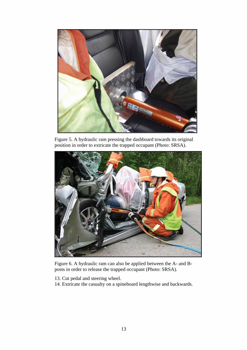
Figure 5. A hydraulic ram pressing the dashboard towards its original position in order to extricate the trapped occupant (Photo: SRSA).
Figure 6. A hydraulic ram can also be applied between the A- and B-posts in order to release the trapped occupant (Photo: SRSA).
13. Cut pedal and steering wheel. 14. Extricate the casualty on a spineboard lengthwise and backwards.

14
In the UK, the overall responsibility for RTAs lies with the police. However, the police will rely on the fire brigade with regard to safety and rescue techniques. Below is an overall description of the rescue technique used, described by Calland. The author points out that a more detailed extrication technique must be developed by the local emergency and rescue services [11].
All RTAs contain the same stages for the emergency operation:
1. “Establishment of scene safety and contact with the casualty to ensure airway control and protection of the cervical spine”.
2. “Stabilisation of the vehicle and glass management”.
3. “Gaining of entry to the vehicle and continuing stabilisation of the casualty”.
4. “Space creation to provide casualty extrication”.
The fire officer decides on medical advice if the release is to be a “snatch extrication” or a “controlled extrication”.
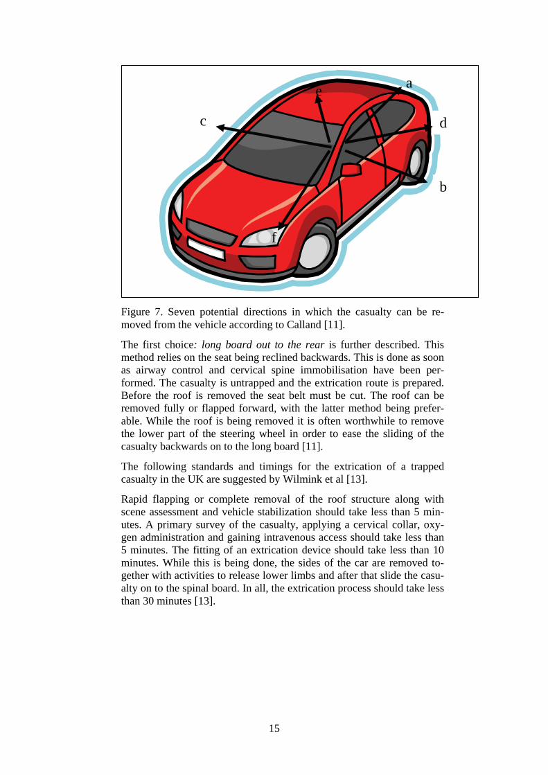
There are seven potential directions in which the casualty can be re-moved from the car (Figure 7). The extrication paths are numbered in order of decreasing ease and favour with the first choice to the rear listed first.
a) “Long board out to the rear”.
b) “Rapid extrication, driver’s door”.
c) “Rapid extrication, opposite door”.
d) “Long board and KED rear quarter oblique”.
e) “Long board and KED rear quarter contra-lateral oblique”.
f) “Long board and KED feet first front quarter oblique”.
g) “Through front wind screen (appropriate for minibuses with-out a front mounted engine)”.
15
Figure 7. Seven potential directions in which the casualty can be re-moved from the vehicle according to Calland [11].
The first choice: long board out to the rear is further described. This method relies on the seat being reclined backwards. This is done as soon as airway control and cervical spine immobilisation have been per-formed. The casualty is untrapped and the extrication route is prepared. Before the roof is removed the seat belt must be cut. The roof can be removed fully or flapped forward, with the latter method being prefer-able. While the roof is being removed it is often worthwhile to remove the lower part of the steering wheel in order to ease the sliding of the casualty backwards on to the long board [11].
The following standards and timings for the extrication of a trapped casualty in the UK are suggested by Wilmink et al [13].
Rapid flapping or complete removal of the roof structure along with scene assessment and vehicle stabilization should take less than 5 min-utes. A primary survey of the casualty, applying a cervical collar, oxy-gen administration and gaining intravenous access should take less than 5 minutes. The fitting of an extrication device should take less than 10 minutes. While this is being done, the sides of the car are removed to-gether with activities to release lower limbs and after that slide the casu-alty on to the spinal board. In all, the extrication process should take less than 30 minutes [13].
c
a
b
d
f
e
16
3. Injury pattern The search for injuries was limited to European data including injury pat-terns in general and AIS 2+ injuries for frontal and side collisions from 2000 onwards.
The Abbreviated Injury Scale (AIS) is used in many reports utilizing hospi-tal data and/or medical records [20]. The maximum injury severity is abbre-viated MAIS. Injury severity according to AIS is, minor injury (AIS =1), moderate injury (AIS =2), serious injury (AIS=3), severe injury (AIS= 4), critical injury (AIS= 5), maximum injury (AIS=6).
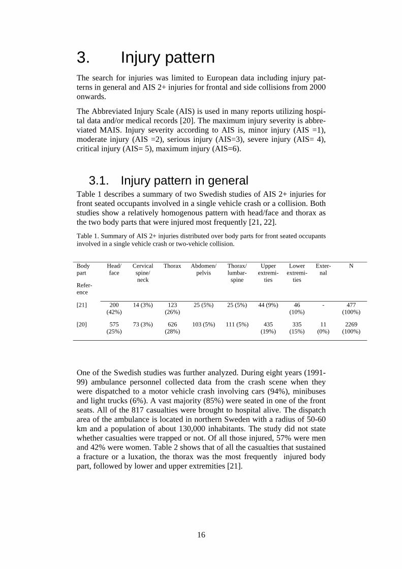
3.1. Injury pattern in general Table 1 describes a summary of two Swedish studies of AIS 2+ injuries for front seated occupants involved in a single vehicle crash or a collision. Both studies show a relatively homogenous pattern with head/face and thorax as the two body parts that were injured most frequently [21, 22].
Table 1. Summary of AIS 2+ injuries distributed over body parts for front seated occupants involved in a single vehicle crash or two-vehicle collision.
One of the Swedish studies was further analyzed. During eight years (1991-99) ambulance personnel collected data from the crash scene when they were dispatched to a motor vehicle crash involving cars (94%), minibuses and light trucks (6%). A vast majority (85%) were seated in one of the front seats. All of the 817 casualties were brought to hospital alive. The dispatch area of the ambulance is located in northern Sweden with a radius of 50-60 km and a population of about 130,000 inhabitants. The study did not state whether casualties were trapped or not. Of all those injured, 57% were men and 42% were women. Table 2 shows that of all the casualties that sustained a fracture or a luxation, the thorax was the most frequently injured body part, followed by lower and upper extremities [21].
Body part
Refer-ence
Head/ face
Cervical spine/ neck
Thorax Abdomen/pelvis
Thorax/ lumbar-
spine
Upper extremi-
ties
Lower extremi-
ties
Exter-nal
N
[21] 200 (42%)
14 (3%) 123 (26%)
25 (5%) 25 (5%) 44 (9%) 46 (10%)
- 477 (100%)
[20] 575 (25%)
73 (3%) 626 (28%)
103 (5%) 111 (5%) 435 (19%)
335 (15%)
11 (0%)
2269 (100%)

17
Table 2. Injury type and localisation among 817 belted and unbelted car and light truck occupants with an AIS 2+ injury that were transported by ambulance to hospital during 1991-1999 [21].
Localisation
Injury type
Head/face Neck Thorax Abdomen/
pelvis
Thorax/
lumbarspine
Upper extremities
Lower extremities
Total
Fracture/luxation 34 14 91 9 25 44 46 263
Concussion 130 - - - - - - 130
Cerebral haemor-rhage
34 - - - - - - 34
Internal thorax - - 32 - - - - 32
Internal abdomen - - - 16 - - - 16
Other injury 2 - - - - - - 2
Total 200 (42%) 14 (3%)
123 (26%)
25 (5%) 25 (5%) 44 (9%) 46 (10%) N=477 (100%)
A study conducted in Greece studied injury profiles of motor vehicle trauma casualties between 1997 and 2000. Of the 730 investigated cases 209 (29%) were car occupants. The injury characteristics for the 209 car occupants were craniocerebral injury 35%, thoracic injury 30%, abdominal injury 21%, spinal cord injury 14%, pelvic injury 13% and extremity injury 37%. The mean injury severity score (ISS) for this group of car occupants was 14.3 [23].
3.2. Frontal collisions Table 3 shows a summary for AIS 2+ injuries distributed over body parts of front seated occupants involved in a frontal collision. The data are derived from studies in the UK and Germany conducted in 2000 and 2002. These two studies also show a relatively homogenous pattern with the thorax and lower extremities as the most frequently injured body parts [24, 25].
Table 3. Summary of AIS 2+ injuries distributed over body parts for front seated occupants involved in a frontal collision [24, 25].
Body part
Refer-ence
Head
/face
Cervical spine/ neck
Thorax Abdo-men/
pelvis
Spine Upper extremi-
ties
Lower extremi-
ties
External N
[23] 29 (15%)
5 (3%) 54 (28%)
23 (12%)
- 31 (16%) 49 (26%) 1 (0%) 191 (100%)
[24] 262 (23%)
35 (3%) 284 (24%)
63 (6%) 30 (3%)
194 (17%) 276 (24%) - 1144 (100%)
18
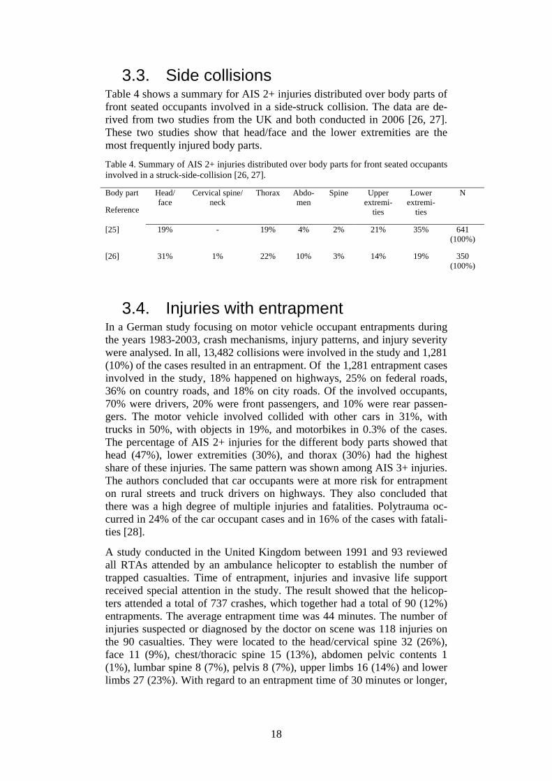
3.3. Side collisions Table 4 shows a summary for AIS 2+ injuries distributed over body parts of front seated occupants involved in a side-struck collision. The data are de-rived from two studies from the UK and both conducted in 2006 [26, 27]. These two studies show that head/face and the lower extremities are the most frequently injured body parts.
Table 4. Summary of AIS 2+ injuries distributed over body parts for front seated occupants involved in a struck-side-collision [26, 27]. Body part
Reference
Head/ face
Cervical spine/neck
Thorax Abdo-men
Spine Upper extremi-
ties
Lower extremi-
ties
N
[25] 19% - 19% 4% 2% 21% 35% 641 (100%)
[26] 31% 1% 22% 10% 3% 14% 19% 350 (100%)
3.4. Injuries with entrapment In a German study focusing on motor vehicle occupant entrapments during the years 1983-2003, crash mechanisms, injury patterns, and injury severity were analysed. In all, 13,482 collisions were involved in the study and 1,281 (10%) of the cases resulted in an entrapment. Of the 1,281 entrapment cases involved in the study, 18% happened on highways, 25% on federal roads, 36% on country roads, and 18% on city roads. Of the involved occupants, 70% were drivers, 20% were front passengers, and 10% were rear passen-gers. The motor vehicle involved collided with other cars in 31%, with trucks in 50%, with objects in 19%, and motorbikes in 0.3% of the cases. The percentage of AIS 2+ injuries for the different body parts showed that head (47%), lower extremities (30%), and thorax (30%) had the highest share of these injuries. The same pattern was shown among AIS 3+ injuries. The authors concluded that car occupants were at more risk for entrapment on rural streets and truck drivers on highways. They also concluded that there was a high degree of multiple injuries and fatalities. Polytrauma oc-curred in 24% of the car occupant cases and in 16% of the cases with fatali-ties [28].
A study conducted in the United Kingdom between 1991 and 93 reviewed all RTAs attended by an ambulance helicopter to establish the number of trapped casualties. Time of entrapment, injuries and invasive life support received special attention in the study. The result showed that the helicop-ters attended a total of 737 crashes, which together had a total of 90 (12%) entrapments. The average entrapment time was 44 minutes. The number of injuries suspected or diagnosed by the doctor on scene was 118 injuries on the 90 casualties. They were located to the head/cervical spine 32 (26%), face 11 (9%), chest/thoracic spine 15 (13%), abdomen pelvic contents 1 (1%), lumbar spine 8 (7%), pelvis 8 (7%), upper limbs 16 (14%) and lower limbs 27 (23%). With regard to an entrapment time of 30 minutes or longer,

19
injuries in lower limbs were most frequently followed by head/cervical spine [13].
20
4. Extrication dummy features To distinguish important and interesting research areas relevant for this pre-study the desired features of the extrication dummy need to be presented. This will help to specify scientific demands and to optimise the information search. If a future extrication dummy is developed it should preferably con-tain a combination of features, features that already exist on different dum-mies developed for other research areas as well as features not yet devel-oped in the dummy and manikin sector. There exist many interesting re-search areas and products that could be adopted in the development of the extrication dummy and thereby enhance the dummy's performance and measurement options. To create a realistic situation in training and the evaluation of extrication techniques the dummy should have a size, shape and weight distribution equal to a human body. Extrication in real life should be possible without any help from the casualty and therefore the dummy should have a body stiffness and joint relaxation similar to a human body in an unconscious state. In addition, the joints of the dummy should have a humanlike range of motion and stiffness. The evaluation of the extrication with such a dummy should be able to measure both total time of extrication and parameters re-lated to body stability during the extrication process. In this study the considered parameters for measurement of body stability are related to applied force, resulting in motion, and applied pressure. Pres-sure measurements are focused on the spine and pelvis as well as on the joints and soft tissue in the lower extremities. By integrating the measure-ment system in the dummy the extrication will not be disturbed by external power supplies and data logging equipment. To protect the dummy's meas-urement system and the dummy itself from being damaged or deformed by heavy loading, a warning system should be developed. Issues of importance to take into consideration in the following sections when designing an extri-cation dummy are described. This description of features, covering six dif-ferent parts of the dummy is not a complete list, but a first attempt to list features of major importance. This will provide a basic design idea before the next chapter describes existing dummies on the market.
4.1. Spine The artificial spine should be as anthropomorphic as possible and provide the dummy with realistic behaviour in the relaxed state. Since the evaluation of the extrication methods are focused on additional injuries on the spinal cord and nerves, the 3D movements of the vertebrae compared to each other are important. The additional pressure between the vertebrae, indirectly caused by the forced body movements, is also of great importance in this investigation.
21
4.2. Back of the torso Preferably the back of the dummy should be able to measure the pressure from tools placed under the casualty during the extrication process to stabi-lise the spine and neck. Such tools are used for stabilisation of the back and neck as well as for support when lifting the casualty out of the vehicle. By measuring the direct pressure on the back of the torso or the pressure against the car seat, different tools and techniques used for approaching, stabilising and extricating a casualty from a vehicle can be evaluated. The dummy should preferably be able to twist the shoulders and upper torso to allow a natural rotational motion of the spine. This type of motion may not be pre-ferred during extrication as body stabilisation is desired. Although this dummy feature is important as this type of motion may occur when the time available to extricate is critical and limited e.g. burning vehicles or massive bleeding.
4.3. Pelvis The features of the dummy's pelvis are mainly related to the ability to change its posture. The dummy needs to in a humanlike manner follow the back support of the car seat which may be changed during the process of extrication. The back support is often lowered to a horizontal position plac-ing the casualty in a lying position. This is done to facilitate the extrication process where a spinal board can be introduced trough the rear of the car. The casualty may also be extricated through the rear. The pelvic features are important even though it may not always be possible to change the position of the casualty’s car seat. This depends on where the casualty is situated in the vehicle, the vehicle design and the damage of the vehicle. With further improvements to the dummy pelvis different injury scenarios could be de-veloped. A fractured pelvis could be complicated to detect by emergency response personnel at the scene and could in the worst case scenario be fatal if the proper care is not administered.
4.4. Knee joint To make the extrication training realistic the knee joint of the dummy should behave as closely to a relaxed human knee as possible. The most important characteristic is the angular extension of the joint. It is desired that the joint is not allowed to bend at unnatural angles. The joint should also be robust enough so that it can sustain heavy loading during the extrica-tion and be reused on later training occasions. However, it is important to be able to detect applied forces on the knee joint that would cause injury to a human knee, even if the dummy does not break. See Figure 8 for possible angle and pressure measurements in the sagittal plane.
4.5. Ankle joint and foot The ankle joint should be able to perform plantar and dorsal flexion resem-bling the degree of flexibility in a human ankle. A vehicle occupant with a trapped leg might suffer from complicated foot and ankle fractures due to

22
the crash, fractures that needs to be handled with care during the extrication. The dummy ankle should have the ability to measure the amount of flexion during extrication and the foot should be equipped with pressure sensors to measure the additional pressure on the foot and toes. Thus, flexion and pres-sure during the extrication could be measured and evaluated. See Figure 8 for relevant angle and pressure measurements in the sagittal plane. For a more complex dummy angle joint the additional inversion/eversion, and internal/external rotation could also be of interest.
4.6. Lower limb, from the knee to ankle (Cnemis)
This part of the dummy represents the bone and the soft tissue of a human leg and should be as anthropomorphic and biofidelic as possible. The lower limb of a human could in a car crash be damaged and trapped by the demol-ished interior of the car. Different techniques for releasing the legs exist that utilise hydraulic cutting tools, telescopic rams or winching. During the ex-trication process the damaged interior might unknowingly be pushed against the limb when its stored energy is released, causing spring effects. The lower limb of the dummy should therefore be able to measure increasing surface pressure on the soft tissue.
Figure 8. A schematic sketch in the sagittal plane giving examples of impor-tant measurement areas under the foot, at the lower extremities and at the knee of the extrication dummy. The knee joint angle is represented by α and β represents the ankle joint angle. The pressure arrows show interesting ar-eas at which to measure external pressure.
23
5. Existing dummies for differ-ent approaches
The market for dummies and manikins offers many different types of design and features. Existing dummies are all designed to fulfil a special demand. Such demands include representing a human body in research and develop-ment, e.g. crash tests and ejection seat testing, or training situations e.g. res-cuing techniques and nursing care. As mentioned earlier the demands on the extrication dummy are twofold i.e. it should register measurement parame-ters as well as represent the human body in a rescue training situation. Crash test dummies have been developed since the 1950s and technology demands placed on the dummies are getting higher and higher as the safety standards of modern vehicles are improved. A modern crash test dummy is designed to represent the human body in specific impact situations and most often of extreme severity. The construction of these dummies therefore needs to be rigid as well as durable to last during many crash tests. These dummies are too rigid in the torso to represent the human body in a relaxed state and the existing design has a pelvis that only allows for a seated pos-ture. In rescue and extrication training the dummies are of a simpler design, usu-ally mainly representing a human body in shape, size and weight. Since the training can be performed under realistic rescue conditions the dummies used are often designed to cope with hazardous environments such as heat, smoke and water. Theses dummies usually don't contain any measurement equipment that can indicate any additional loadings caused by execution of the rescue. Nursing training manikins are also of a simpler design compared to the crash test dummy design but may include technology for medical training. These dummies are lighter but with a more realistic range of motion for the joints so that patient handling and positioning on hospital equipment can be trained. By investigating existing dummies and their features we may find physical models of the human body that could be further developed and integrated with additional measurement technology to create the future extrication dummy. Some of the existing dummies and their features are presented in the following subsections.
5.1. Hybrid III 50th male dummy This is a seated frontal crash test dummy for extreme severity. The neck is of a segmented rubber and aluminium construction with a centre cable. It has steel ribs with polymer based damping and a cylindrical rubber lumbar spine. The torso is designed to provide repeatable test results for extreme severity impacts. The pelvis is made of vinyl skin/urethane foam moulded

24
over an aluminium casting in the seated position. The foot and ankle simu-lates heel compression and ankle range of motion.
Figure 9. Hybrid III 50th male crash test dummy.
5.2. THOR Advanced Crash Test dummy THOR is a 50th percentile male seated frontal crash test dummy for extreme severity impacts. It is built with a metallic/composite endoskeleton with urethane foam flesh/skin. The torso has an elliptical ribcage and additional chest deflection instrumentation. It has instruments in the abdominal region to measure compression and deflection. The spine is metallic with the op-tion to change pitch in neck and lower thoracic spine and equipped with several sensors for measurements of load, acceleration and tilt.
Figure 10. THOR Advanced Crash Test dummy.
25
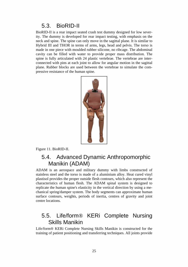
5.3. BioRID-II BioRID-II is a rear impact seated crash test dummy designed for low sever-ity. The dummy is developed for rear impact testing, with emphasis on the neck and spine. The spine can only move in the sagittal plane. It is similar to Hybrid III and THOR in terms of arms, legs, head and pelvis. The torso is made in one piece with moulded rubber silicone, no ribcage. The abdominal cavity can be filled with water to provide proper mass distribution. The spine is fully articulated with 24 plastic vertebrae. The vertebrae are inter-connected with pins at each joint to allow for angular motion in the sagittal plane. Rubber blocks are used between the vertebrae to simulate the com-pressive resistance of the human spine.
Figure 11. BioRID-II.
5.4. Advanced Dynamic Anthropomorphic Manikin (ADAM)
ADAM is an aerospace and military dummy with limbs constructed of stainless steel and the torso is made of a aluminium alloy. Heat cured vinyl plastisol provides the proper outside flesh contours, which also represent the characteristics of human flesh. The ADAM spinal system is designed to replicate the human spine's elasticity in the vertical direction by using a me-chanical spring/damper system. The body segments can approximate human surface contours, weights, periods of inertia, centres of gravity and joint centre locations.
5.5. Life/form® KERi Complete Nursing Skills Manikin
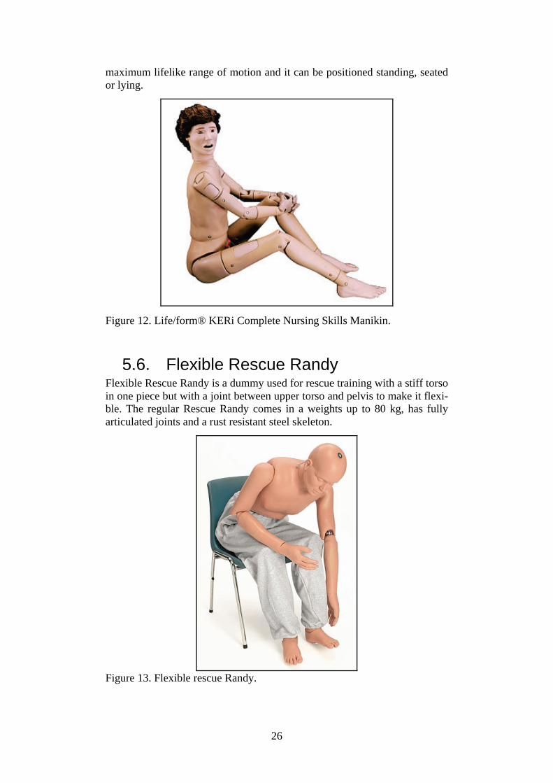
Life/form® KERi Complete Nursing Skills Manikin is constructed for the training of patient positioning and transferring techniques. All joints provide
26
maximum lifelike range of motion and it can be positioned standing, seated or lying.
Figure 12. Life/form® KERi Complete Nursing Skills Manikin.
5.6. Flexible Rescue Randy Flexible Rescue Randy is a dummy used for rescue training with a stiff torso in one piece but with a joint between upper torso and pelvis to make it flexi-ble. The regular Rescue Randy comes in a weights up to 80 kg, has fully articulated joints and a rust resistant steel skeleton.
Figure 13. Flexible rescue Randy.

27
5.7. Rescue dummy General Purpose Rescue dummy is a simple dummy used for rescue training. It is a soft dummy without any joints but with realistic weight distribution. The mate-rial is a stone aggregate inside a nylon overall.
Figure 14. Rescue dummy General Purpose.

28
6. Existing biofidelic systems and techniques of interest
Since no complete solution exists that can fulfil the requirements for the future extrication dummy described in the previous chapter, other existing biofidelic systems and techniques have been studied. The areas are crash test dummy subsystems, artificial joints and prosthesis, anatomical models, virtual reality and robotics. All these areas may contribute with different developed techniques applicable to the extrication dummy. The benefits of using existing suitable subsystems and techniques are the saving of both time and money.
6.1. Advanced lower extremity The NHTSA has directed the development of an advanced lower extremity design, the Thor-Lx, to study vehicle occupant injuries to the lower extremi-ties from frontal collisions. Since the safety of vehicle occupants has in-creased and the survival rate is higher due to seatbelts and airbags the focus on understanding and avoiding complicated injuries to the lower extremities has increased. The Thor-Lx is designed to fit the Hybrid III dummy and provide measurements on loading, movement and acceleration of the upper and lower tibia, knee joint and ankle joint. Figure 15 shows a picture of the Thor-Lx leg without the artificial skin coating. For the future extrication dummy this advanced stand alone leg might offer a technical solution to the design of the knee and ankle joint. The ankle joint is designed to allow mo-tion about three axis of rotation that enables dorsiflexion/plantarflexion, inversion/eversion, and internal/external rotation. This is achieved by three independent rotation points equipped with angle potentiometers for meas-urements of the movements. These rotation points use progressive rubber elements to provide biofidelic behaviour of the joint, however since the Thor-Lx is designed for high impact collisions this design may not corre-spond to the behaviour of a relaxed human joint.
Figure 15 The Thor-Lx leg without artificial skin coating.
29
6.2. Artificial joints and leg prostheses The technology used in artificial joints and leg prostheses can provide solu-tions for the measurement, behaviour and representation of lower extremity of the dummy. Stiff prostheses are not of interest, since they do not provide any advantages over the use of an ordinary manikin. On the other hand, prostheses that are developed to imitate the movement of the human limb, can provide advantages such as ready-made joints and measurements of the angle and movement of the joint. There are a variety of prostheses and arti-ficial joints on the market, ranging from very crude models to advanced micro-process controlled hydraulic systems. The more advanced systems may be too complicated to implement in the dummy as they are, but may provide solutions or subsystems to be used in the development of a dummy specific system. Two prostheses systems related to the knee joint and the ankle joint devel-oped by Otto Bock Healthcare will be overviewed in this section, the C-Leg and the C-walk as can be seen in Figure 16 and 17. These are examples of systems that may not be directly applicable to the dummy, but could provide inspiration or be adapted to the dummy design.
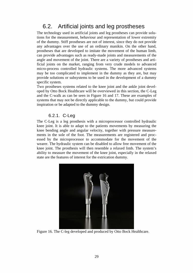
6.2.1. C-Leg The C-Leg is a leg prosthesis with a microprocessor controlled hydraulic knee joint. It is able to adapt to the patients movements by measuring the knee bending angle and angular velocity, together with pressure measure-ments in the sole of the foot. The measurements are registered and proc-essed by the microprocessor to accommodate for the movement of the wearer. The hydraulic system can be disabled to allow free movement of the knee joint. The prosthesis will then resemble a relaxed limb. The system’s ability to measure the movement of the knee joint, especially in the relaxed state are the features of interest for the extrication dummy.
Figure 16. The C-leg developed and produced by Otto Bock Healthcare.
30
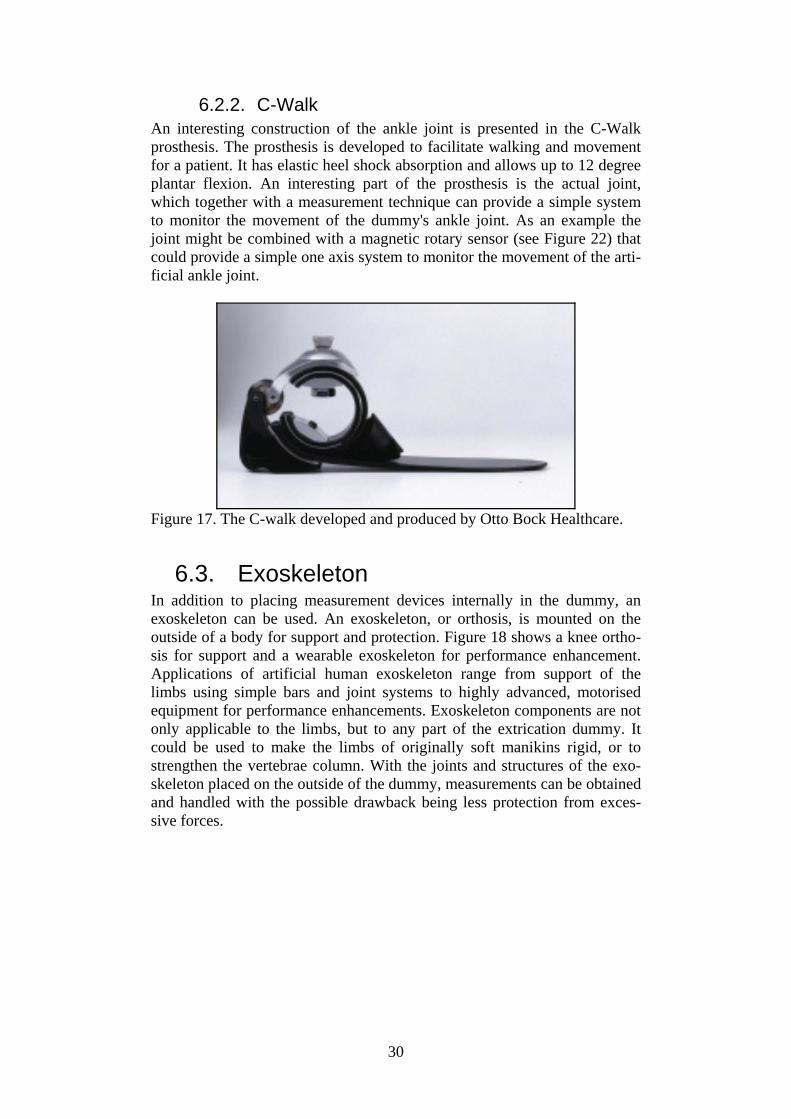
6.2.2. C-Walk An interesting construction of the ankle joint is presented in the C-Walk prosthesis. The prosthesis is developed to facilitate walking and movement for a patient. It has elastic heel shock absorption and allows up to 12 degree plantar flexion. An interesting part of the prosthesis is the actual joint, which together with a measurement technique can provide a simple system to monitor the movement of the dummy's ankle joint. As an example the joint might be combined with a magnetic rotary sensor (see Figure 22) that could provide a simple one axis system to monitor the movement of the arti-ficial ankle joint.
Figure 17. The C-walk developed and produced by Otto Bock Healthcare.
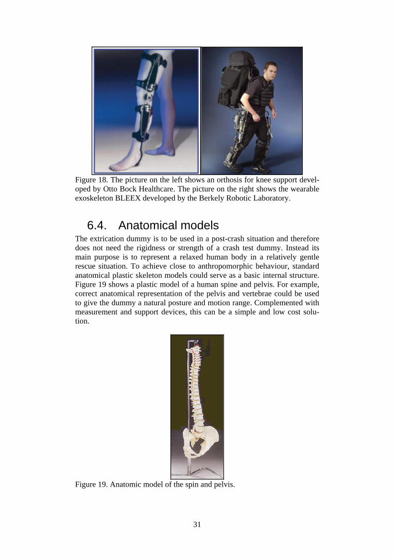
6.3. Exoskeleton In addition to placing measurement devices internally in the dummy, an exoskeleton can be used. An exoskeleton, or orthosis, is mounted on the outside of a body for support and protection. Figure 18 shows a knee ortho-sis for support and a wearable exoskeleton for performance enhancement. Applications of artificial human exoskeleton range from support of the limbs using simple bars and joint systems to highly advanced, motorised equipment for performance enhancements. Exoskeleton components are not only applicable to the limbs, but to any part of the extrication dummy. It could be used to make the limbs of originally soft manikins rigid, or to strengthen the vertebrae column. With the joints and structures of the exo-skeleton placed on the outside of the dummy, measurements can be obtained and handled with the possible drawback being less protection from exces-sive forces.
31
Figure 18. The picture on the left shows an orthosis for knee support devel-oped by Otto Bock Healthcare. The picture on the right shows the wearable exoskeleton BLEEX developed by the Berkely Robotic Laboratory.
6.4. Anatomical models The extrication dummy is to be used in a post-crash situation and therefore does not need the rigidness or strength of a crash test dummy. Instead its main purpose is to represent a relaxed human body in a relatively gentle rescue situation. To achieve close to anthropomorphic behaviour, standard anatomical plastic skeleton models could serve as a basic internal structure. Figure 19 shows a plastic model of a human spine and pelvis. For example, correct anatomical representation of the pelvis and vertebrae could be used to give the dummy a natural posture and motion range. Complemented with measurement and support devices, this can be a simple and low cost solu-tion.
Figure 19. Anatomic model of the spin and pelvis.

32
6.5. Virtual reality and robotics In virtual reality and robotic systems [29] it is common to use real-time measurements of real objects in order to represent them in a computer model. Examples are virtual reality applications in which the users wear sensitive gloves and goggles to "feel" and "see" virtual objects. Complicated structures, such as the individual fingers of a hand, may need to be located and tracked in 3D space. The similar 3D imaging technique can be applied to the dummy during the extrication process, e.g. the 3D movement of indi-vidual vertebrae or limbs. This could be used in a more advanced dummy construction, if there is a desire to reconstruct and study the extrication process in a computer model. The techniques used in virtual reality and ro-botics have not been fully investigated and might deserve more attention since these areas are continuously developing. Disadvantages of using these complex techniques are the possible need of high power consumption and lack of robustness that may be required for an extrication dummy.
33
7. Applicable measurement techniques and sensors
In the previous chapter high-level systems, such as complete dummies and advanced subsystems, were presented. Here the focus is moved to low-level measurement systems and components. For evaluation purposes of the ex-trication methods the effects of the handling of the dummy during the extri-cation process need to be measured. The measured parameters could for example be the movement of joints or pressure applied to different parts of the dummy. These parameters can then be used to analyse and compare dif-ferent extrication methods. For some of the specific areas of interest e.g. spine, knee joint and ankle joint there are already existing sensors and tech-niques that could be used as they are, or modified and integrated into the extrication dummy. This chapter presents some interesting sensors that might be applied for measurements of pressure and displacement at the ear-lier mentioned areas of interest.
7.1. Pressure sensors Pressure sensors can be utilised to measure both internal pressure changes, e.g. between vertebrae and discs in the dummy spine during the extrication, and external pressure changes, e.g. on the lower limbs during application of external forces from pulling the steering wheel back or spreaders pushing the dashboard back in position.
7.1.1. K-scan, CONFORMat and smart skin by Tekscan
Tekscan, Inc has specialised in developing a range of different tactile sen-sors that could be applicable to a dummy. Tekscan has developed matrix-based pressure sensing systems which can provide pressure sensors that are both flexible and thin. These sensors can be both grid-based and single load cell configurations, and are available in a wide range of shapes, sizes and spatial resolutions (sensor spacing). The ranges of measurable pressure of these sensors are from 0-15 kPa to 0-175 MPa. Products of interest are the K-scan system for measurement of joint pressure and force, and the two related systems CONFORMat and Body Pressure Measurement System (BPMS). The K-scan system can be used to determine contact area and pressure distribution in joints by placing a paper-thin, high-resolution sensor between articulating surfaces. Figure 20 shows the usage of the sensor in between vertebrae and in a knee joint. The sensor exists in a variety of shapes and designs depending on the application specifications. The product related software tools are also supplied to provide easy access to the data.

34
Figure 20. Two examples of how the thin pressure sensor K-scan can be applied, in between vertebrae and in a knee joint. The two systems CONFORMat and BPMS are large area pressure meas-urement systems developed for studies and optimisation of seating, cushion-ing and bedding solutions. The sensors are able to follow contours and de-form to enable measurements of e.g. seat cushions. These features provide measurements of locations and the magnitude of peak pressures without altering the support surface, in our case the extrication dummy, or the object causing the pressure. Figure 21 shows the pressure pattern from a human body lying on a BPMS, the red areas indicate high pressure areas. By apply-ing this type of sensor to the back of the extrication dummy, the perform-ance of the spine and neck stabilisation tool could be studied and optimised. Similarly, by fitting a pressure sensor to the lower limbs of the dummy, any objects applying damaging pressure to the dummy during the unfolding of the vehicle could be identified.
Figure 21. Pressure pattern from a lying human body measured by a BPMS. The red areas indicate high pressure areas.

35
7.2. Measurement components for
displacement and joint angles Measurements of the dummy dynamics can be achieved through basic elec-tronic components such as strain gauges and potentiometers, as well as through advanced integrated circuits. The purposes of these systems are to provide reliable measurements to accurately determine the displacement, deformation and movement of limbs and joints. Below follows a short over-view of some of the electronic components and more advanced systems. These are used for example in physical experiments and robotics, and could be applied in an extrication dummy.
7.2.1. Strain gauges Strain gauges are devices used in measurements of deformation of an object. The gauge is attached to the object, and as the object is deformed the foil of the gauge is deformed causing its electrical resistance to change. The change in electrical resistance can be measured and is related to the strain by the gauge factor. The strain gauges could be placed in the soft tissue of the lower limbs of the extrication dummy to provide additional measurements of deformation.
7.2.2. Potentiometers A potentiometer is an electric device that acts as a variable resistor. It can be used to measure movement, either rotational or linear. Linear potentiometers are sensors that produce a resistance output proportional to the displacement or position. Rotational potentiometers provides electrical outputs propor-tional to shaft rotation, either measuring multi-turn motion or angular dis-placement of less than one turn. These devices can be as simple as a sensing element or as complicated as an instrument with local displays, controls and output to a computer. Applications in an extrication dummy are for example to build simple measurement systems that track the motion of joints or limbs during the extrication. A variety of models are available from different elec-tronics suppliers, such as ELFA.
7.2.3. Magnetic rotary sensor Contact-free measurement of joint angles can be realised by magnetic rotary encoders. Such devices have been used for example in robotics [29], and consist of Hall elements placed close to a dipole magnet. The magnet is placed over the axis of rotation, and as the magnet rotate the Hall effect can be exploited to measure the movement. The resolution of the sensors can be as high as 0.35 degrees, corresponding to 1024 bits per revolution. The ro-tary encoders are small in size, typically much less than 1x1 cm, and can measure movements over several revolutions. One provider of such instru-ments is Austriamicrosystems.
36
8. Ideas and reflections for fu-ture techniques
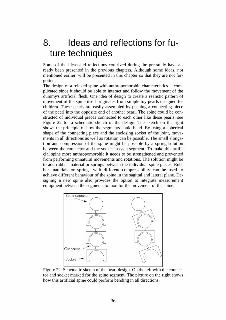
Some of the ideas and reflections contrived during the pre-study have al-ready been presented in the previous chapters. Although some ideas, not mentioned earlier, will be presented in this chapter so that they are not for-gotten. The design of a relaxed spine with anthropomorphic characteristics is com-plicated since it should be able to interact and follow the movement of the dummy's artificial flesh. One idea of design to create a realistic pattern of movement of the spine itself originates from simple toy pearls designed for children. These pearls are easily assembled by pushing a connecting piece of the pearl into the opposite end of another pearl. The spine could be con-structed of individual pieces connected to each other like these pearls, see Figure 22 for a schematic sketch of the design. The sketch on the right shows the principle of how the segments could bend. By using a spherical shape of the connecting piece and the enclosing socket of the joint, move-ments in all directions as well as rotation can be possible. The small elonga-tion and compression of the spine might be possible by a spring solution between the connector and the socket in each segment. To make this artifi-cial spine more anthropomorphic it needs to be strengthened and prevented from performing unnatural movements and rotations. The solution might be to add rubber material or springs between the individual spine pieces. Rub-ber materials or springs with different compressibility can be used to achieve different behaviour of the spine in the sagittal and lateral plane. De-signing a new spine also provides the option to integrate measurement equipment between the segments to monitor the movement of the spine.
Figure 22. Schematic sketch of the pearl design. On the left with the connec-tor and socket marked for the spine segment. The picture on the right shows how this artificial spine could perform bending in all directions.
37
When it comes to instrumentation for the dummy an interesting develop-ment from FTSS should be considered. The iDummy system is an integrated intelligent data acquisition system that can be placed inside any crash test dummy. The cabling and sensors are placed inside the dummy and a battery will keep the system powered for 1h during tests. This type of instrumenta-tion is of interest if an integrated measurement system is demanded for the extrication dummy. Such systems would make the extrication situation more realistic and the dummy easier to handle. Last but not least, an article in the robotic field was found which describes the development of a standard robotic dummy for the evaluation of rescue equipment and skills [30]. The rescue situation in this article is more fo-cused on disaster victims than car occupants in an RTA and the dummy should act as a casualty in training and evaluation situations. The plan for this project was a third prototype to be ready in 2006 for testing and evalua-tion. Unfortunately no further publications related to this research project have been found.

38
9. Summary and conclusion The three presented extrication methods for emergency response personnel are basically based on the same principles i.e. to achieve the goals of scene safety, stabilization, creating access, space, and a patient extrication route. This is achieved together with medical principles for the trauma patient, e.g. PHTLS-principles [14] (airway, breathing, circulation and spinal immobili-zation etc). The main difference between the examined methods is that the Norwegians have chosen a method of pulling the car open instead of cutting the roof. Regardless of which extrication method is used, one critical phase during all three methods is when the casualty is placed on the spine board and there-fore exposed for injurious spinal movements in the sagittal and transverse planes. Another critical phase for the casualty is if there are entrapments and/or entanglements which require the use of cylinders, spreaders and/or cutters. Hopefully, a future extrication dummy can be helpful as a tool for evaluat-ing the aforementioned critical phases or even the evaluation of methods. During the pre-study no dummy was identified that could be used to meas-ure quantifiable parameters of extrication without any modifications. Al-though many dummies developed for other purposes by various manufac-turers might be useful as a basic design or base for the future extrication dummy. We have also seen that there exist many interesting components and measurement techniques that could be adopted. A combination of the design of these dummies and the existing components and measurement techniques provides guidance on how to design and develop an extrication dummy. There still remain, not fully investigated, innovation areas in this study such as ergonomics, robotics and virtual reality that might provide more ideas to technical solutions and future dummy development.

39
10. References 1. Clarke, J.R., et al., Time to laparotomy for intra-abdominal bleeding
from trauma does affect survival for delays up to 90 minutes. J Trauma, 2002. 52(3): p. 420-5.
2. Jones, I.S. and H.R. Champion, Trauma triage: vehicle damage as an estimate of injury severity. J Trauma, 1989. 29(5): p. 646-53.
3. Regel, G., et al., Treatment results of patients with multiple trauma: an analysis of 3406 cases treated between 1972 and 1991 at a Ger-man Level I Trauma Center. J Trauma, 1995. 38(1): p. 70-8.
4. Wik, L., et al., Rapid extrication from a car wreck. Injury, 2004. 35(8): p. 739-45.
5. Willcox, N. and P. Oakley, Survival with an arterial pH of 6.57 fol-lowing major trauma with exsanguinating haemorrhage associated with traumatic amputation. Resuscitation, 2002. 53(2): p. 217-21.
6. Gunning, K.A., et al., Hypothermia and severe trauma. Aust N Z J Surg, 1995. 65(2): p. 80-2.
7. Hohlrieder, M., et al., Management of accidental hypothermia. An-aesthesist, 2007.
8. Helm, M., et al., Accidental hypothermia in trauma patients. Is it relevant to preclinical emergency treatment? Anaesthesist, 1995. 44(2): p. 101-7.
9. Davis, P.R. and M. Byers, Accidental hypothermia. J R Army Med Corps, 2005. 151(4): p. 223-33.
10. Lindquist, M., A.R. Hall, and U. Bjornstig, Kinematics of belted fatalities in frontal collisions: A new approach in deep studies of in-jury mechanisms. J Trauma, 2006. 61(6): p. 1506-16.
11. Calland, V., Extrication of the seriously injured road crash victim. Emerg Med J, 2005. 22(11): p. 817-21.
12. Ersson, A., et al., Extrication of entrapped victims from motor vehi-cle accidents: the crew concept. Eur J Emerg Med, 1999. 6(4): p. 341-7.
13. Wilmink, A.B., et al., Vehicle entrapment rescue and pre-hospital trauma care. Injury, 1996. 27(1): p. 21-5.
14. National Association of Emergency Medical Technicians (U.S.). Prehospital Trauma Life Support Committee. and American College of Surgeons. Committee on Trauma., PHTLS : basic and advanced prehospital trauma life support. 2005, Mosby: St. Louis, Mo. p. xviii, 441.
15. Björnstig, U., Pre-hospital Emergency Care in Sweden - with Spe-cial Emphasis on Care of Traffic Victims. IATSS Research, 2004. 28(2): p. 24-31.
16. Graziano, A.F., et al., A radiographic comparison of prehospital cervical immobilization methods. Ann Emerg Med, 1987. 16(10): p. 1127-31.
17. Hadley, M.N., et al., Guidelines for the management of acute cervi-cal spine and spinal cord injuries. Clin Neurosurg, 2002. 49: p. 407-98.

40
18. Perry, S.D., et al., The efficacy of head immobilization techniques during simulated vehicle motion. Spine, 1999. 24(17): p. 1839-44.
19. Wargclou, D., Räddning vid trafikolycka - personbil [In Swedish], ed. S.R.S. Agency. 2006, Karlstad, Sweden.
20. AAAM, The Abbreviated Injury Scale 2005 revision. 2005, Des Plaines, IL: Association for the Advancement of Automotive Medi-cine.
21. Bylund, P.-O. and U. Björnstig, Bilbältesanvändning hos 817 skada-de bilister – analys utifrån objektiva iakttagelser från ambulanssjuk-vård och sjukvård [In Swedish], OAG-report 103, AKMC, Umeå, Editor. 2000: Umeå.
22. Kullgren, et al. Developments in car safety with respect to disability - injury distributions for car occupants in cars from the 80's and 90's. in IRCOBI Conference. 2002. Munich, Germany: IRCOBI Se-creteriat - Inrets, 25 Av F Mitterand, Bron, 69500 France.
23. Markogiannakis, H., et al., Motor vehicle trauma: Analysis of injury profiles by road-user category. Emergency Medicine Journal, 2006. 23(1): p. 27-31.
24. Hassan, A.M. and M. Mackay. Injuries of moderate severity to re-strained drivers in frontal crashes. in Vehicle Safety 2000. 2000. London: Professional engineering publishing LTD, Northgate ave-nue, Bury St Edmunds, Suffolk IP32 6BW, United Kingdom.
25. Roselt, T., et al. Injury patterns of front seat occupants in frontal car collisions with airbags. in Proceedings of the International IRCOBI Conference held 18-20 September 2002, Munich, Germany. 2002. Munich, Germany: IRCOBI Secretariat- Inrets, 25 Av F Mitternand, Bron, 69500 France.
26. Morris, A., et al. The nature, type and consequences of lower ex-tremity injuries in front and side impacts in pre and post regulatory passenger cars. in 2006 International IRCOBI Conference on the Biomechanics of Impact,. 2006. Madrid, Spain: International Re-search Council on the Biomechanics of Impact (IRCOBI).
27. Hassan, A., A. Morris, and R. Welsh. Some characteristics of side-impact crashes involving modern passenger vehicles. in Proceedings of the International Crashworthiness Conference. 2006. Athens.
28. Westhoff, J., et al., Motor vehicle accidents with entrapment : A medical and technical investigation of crash mechanism, injury pat-tern and severity of entrapment of motor vehicle occupants between 1983 and 2003. Chirurg, 2007. 78(3): p. 246-253.
29. Kargov, A., et al. Modulary designed lightweight antropomorphic robot hand. in Confernece on Multisensor Fusion and Intregation for Intelligent Systems. 2006. Heidelberg, Germany.
30. Masutani, Y., et al. Development of a Standard Robotic Dummy for the Purpose of Evaluating Rescue Equipment ans Skill. in In Pro-ceedings 2003 IEEE/RSJ Intl. Conference on Intelligent Robot and Systems, volume 2, pages , . 2003. Las Vegas, Nevada, USA.

41
Points of contact and additional literature During this pre-study the following people were contacted for consultation and answers.
Dr. Allison Kaigle Holm, Department of Orthopaedics, Sahlgrenska University Hospital. Consulted regarding measurement techniques in the lumbar spine.
Roger Nilsson, CA Mätsystem AB. Consulted regarding pressure sensors from Tekscan.
Listed below is relevant additional literature that was examined in the pre-study. This literature was used for both inspiration and understanding of this research area.
Allison M. Kaigle, Sten H. Holm and Tommy H. Hansson. Kinematic Behaviour of the Porcine Lumbar Spine: A Chronic Lesion Model. 1997. SPINE Volume 22, number 24, pp 2796–2806.
P. C. Ivancic, M. M. Panjabi, S. Ito, P. A. Cripton and J. L. Wang. Biofidelic whole cervical spine model with muscle force replication for whiplash simulation. Eur. Spine. J., 14:346–355, 2005.
Bipedal Walking Robot Lucy. http://lucy.vub.ac.be/
Internet resources austriamicrosystems AG. URL http://www.austriamicrosystems.com. Berkeley Robotics Laboratory. URL http://bleex.me.berkeley.edu/. ELFA. URL http://www.elfa.se. GESAC. Thor-Flx (small female) Hybrid III retrofit, Users Manual. URL http://www-nrd.nhtsa.dot.gov/departments/nrd-51/thor flx/ThorFLx manualNDX.html. Version 1.0. iCrash Technology | iDummy. URL http://www.icrashtech.com/idummy.cfm. Otto Bock HealthCare. URL http://www.ottobock.com. Tekscan, Inc. URL http://www.tekscan.com/.
42
11. List of abbreviations ADAM Advanced Dynamic Anthropomorphic Manikin AIS Abbreviated Injury Scale BPMS Body Pressure Measurement System FTSS First Technology Safety Systems GESAC Inc. General Engineering and Systems Analysis Company, Inc ITRD International Transport Research Documentation KED Kendrick Extrication Device MEDLINE Medical Literature, Analysis, and Retrieval System Online NHTSA National Highway Traffic Safety Administration PsycINFO® Psychological Abstracts PHTLS Pre Hospital Trauma Life Support SAE Society of Automotive Engineers SRL Science Research Laboratory, Inc SRSA Swedish Rescue Services Agency TRIS Transportation Research Information Services databases UMTRI University of Michigan Transportation Research Institute


Swedish Rescue Services Agency, 651 80 Karlstad, SwedenTelephone +46 54 13 50 00, fax +46 54 13 56 00. www.srsa.se
Order number P21-486/07. Fax +46 54 13 56 05 ISBN 978-91-7253-371-4