Embed Size (px)
Citation preview
PROJECT REPORT
Luleå University of Technology, Graphic Production 2016
Seyed Hadi Hoseinie, Uday Kumar
Project leader: Behzad Ghodrati
March 2016
VINNOVA SIP-STRIM
Reliability Centered Maintenance (RCM) forAutomated Mining Machinery
Luleå University of Technology Division of Operation and Maintenance Engineering
Project ReportVINNOVA SIP-STRIM Call 2015
Reliability Centered Maintenance (RCM) forAutomated Mining Machinery
Seyed Hadi Hoseinie, Uday KumarProject leader: Behzad Ghodrati
Division of Operation and Maintenance Engineering
March 2016
ISBN 978-91-7583-555-6 (print)ISBN 978-91-7583-556-3 (pdf)
Luleå University of Technology 2016
Department of Civil, Environmental and Natural Resources EngineeringDivision of Operation and Maintenance Engineering

Project ReportVINNOVA SIP-STRIM Call 2015
Reliability Centered Maintenance (RCM) for Automated Mining Machinery
Seyed Hadi Hoseinie, Uday KumarProject leader: Behzad Ghodrati
Division of Operation and Maintenance Engineering
March 2016
Project ReportVINNOVA SIP-STRIM Call 2015
Reliability Centered Maintenance (RCM) forAutomated Mining Machinery
Seyed Hadi Hoseinie, Uday KumarProject leader: Behzad Ghodrati
Division of Operation and Maintenance Engineering
March 2016
Project ReportVINNOVA SIP-STRIM

Printed by Luleå University of Technology, Graphic Production 2016
ISBN 978-91-7583-555-6 (print)ISBN 978-91-7583-556-3 (pdf)
Luleå 2016
www.ltu.se
3
Acknowledgments
The present research work has been carried out during the years 2015-2016, at the Division of Operation and Maintenance Engineering, Luleå University of Technology, Sweden. The research program was sponsored by the Sweden’s Innovation Agency (VINNOVA) under Grant No. 2015-01348, which is acknowledged.
The support of Boliden AB especially the help of Stig Nilsson - Manager Maintenance Technology Boliden Mines for providing us with all the necessary support during the research is deeply appreciated.
We would like to express our gratitude to our colleagues Prof. Diego Galar, Dr. Alireza Ahmadi and Dr. Amir Hossein Garmabaki for their valuable comments and discussion.

4
5
Abstract
Reliability centered maintenance (RCM) was initiated on 1960s in Boeing company to optimize the maintenance process of aircrafts. Since that date, this method has been applied in wide range of industries and has provided a completely positive results and recommendations for implementation in other industries. RCM is a systematic approach to quantitatively assess and optimize the performance of preventive maintenance tasks and to eliminate non-value adding maintenance actions. It provides considerable cost savings due to optimum maintenance effort, increased safety and productivity.
This research considers the feasibility of applying the RCM methodology to fully-automated underground mining machineries as one of the vital requirement of early future modern mining. For this purpose, a literature review has been done to clarify the advantages, requirements, issues and challenges of RCM in other industries such as aviation, marine, nuclear, oil and gas, and process industries. It has been tried to analyze the RCM procedure in detailed and to have a lookon the adoption issues and requirement for RCM implementation in fully-automated mining. Mainly, in this research, following RCM documents and standards were used for feasibility study:
• Classic RCM in Aviation industry (SAE-JA1011, SAE-JA1012)• NASA RCM guidelines • USA’s military standards MIL-STD-2173• International Atomic Energy Agency (IAEA) RCM document
Using the above mentioned documents, an implementation issues and challenges in developing a RCM program for fully-automated underground mining machineries has been presented. The result of this study shows that RCM is applicable in maintenance planning for fully-automated underground mining machinery. Because, serious safety restrictions are associated with this kind of mining operation and RCM can properly help the engineers to analyze the safety consequences of any failure and make the best decision for maintenance tasks. However, practical application of RCM has some differences in mining context which in this project are discussed in detail. The investigations show the risk priority number is the suitable measure to select the RCM target component/system. Since, there is no operation in site, detective the some evident failures are become impossible in automated mining. Therefore, we have to consider the smartness level and capabilities of agent-based supervisors to get the real feeling of machinery health and operation condition. Internet of Thing platforms are also required in fully automated mine to develop the machine-to-machine communication and to reduce the risk of failures and failure propagation in fleet level. RCM could apply the outcomes of these advanced technologies to optimize the maintenance actions in automated mines.

6
7
Contents 1. Introduction & Background 11
1.1. Automated mining machinery 111.2. Structure and types of automated systems for mines 13
1.2.1 Remote control 131.2.2 Tele-operation 131.2.3 Semi-automated 141.2.4 Full automated 14
1.3. Maintenance challenges in full automated mining machinery 141.3.1. Safety of maintenance crew 161.3.2. Big data handling 161.3.3. Integration of automation system 17
1.4. Maintenance solutions 172. Reliability Centered Maintenance (RCM) 21
2.1 Definition and history 212.2 RCM principles 242.3 RCM procedures 26
2.3.1 Step 1: System selection and information collecting 262.3.2 Step 2: System boundary definition 282.3.3 Step 3: System Description and Functional Block Diagram 292.3.4 Step 4: System Functions and Functional Failure 312.3.5 Step 5: Failure Mode and Effective Analysis (FMEA) 312.3.6 Step 6: Logic Tree Analysis (LTA) 342.3.7 Step 7: Maintenance task selection 36
2.4 RCM applications in different industries 442.4.1 Aviation industry 442.4.2 Marine industry 462.4.3 Nuclear industry 472.4.4 Oil and Gas industry 502.4.5 Process industry 50
3. RCM application on automated underground mining machinery 533.1 Review of RCM application in mining machinery 533.2 RCM adaptation to automated mining machinery 55
3.2.1 Step 1: System selection and information collecting 553.2.2 Step 2: System boundary definition 583.2.3 Step 3: System description and functional block diagram 583.2.4 Step 4: System functions and functional failures 583.2.5 Step 5: Failure mode and effect analysis 603.2.6 Step 6: Logic tree analysis (LTA) 643.2.7 Step 7: Maintenance task selection 66
3.3 Conclusion 673.4 Future work 69
References 69Appendix 75

8
9
Abbreviations CBM Condition Based Maintenance
CM Corrective Maintenance
CMMS Computerized Maintenance Management System
DoD Department of Defense
EPA Emission Protection Agency US
EPRI Electric Power Research Institute
FAA Federal Aviation Administration (USA)
FMEA Failure Mode and Effect Analysis
I&C Instrumentation and Control
IAEA International Atomic Energy Agency
IoT Internet of Things
KPI Key Performance Indicators
LCC Life Cycle Cost
LTA Logic Tree Analysis
M2M Machine-to-Machine
MSG Maintenance Steering Group (UST)
MTBF Mean Time Between Failure
MTTR Mean Time To Repair
P&ID Piping & Instrument
PT&I Predictive Testing & Inspection
RPN Risk Priority Number
RAM Reliability, Availability and Maintenance
SWBS System Work Breakdown S
TBM Time Based Maintenance
TDM Time-Directed Maintenance

10
11
1. Introduction & Background
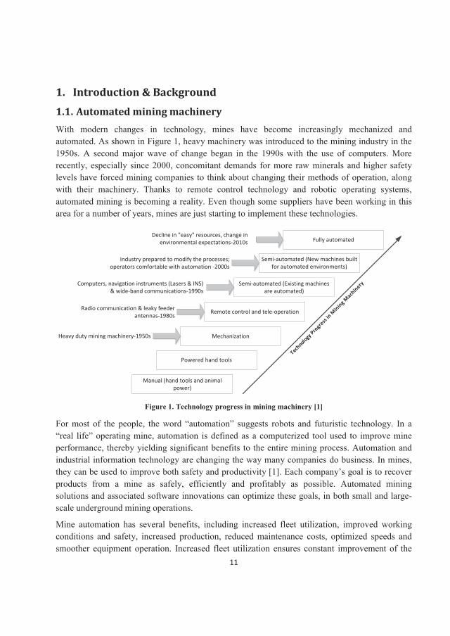
1.1. Automated mining machinery With modern changes in technology, mines have become increasingly mechanized and automated. As shown in Figure 1, heavy machinery was introduced to the mining industry in the 1950s. A second major wave of change began in the 1990s with the use of computers. More recently, especially since 2000, concomitant demands for more raw minerals and higher safety levels have forced mining companies to think about changing their methods of operation, along with their machinery. Thanks to remote control technology and robotic operating systems, automated mining is becoming a reality. Even though some suppliers have been working in this area for a number of years, mines are just starting to implement these technologies.
Mechanization
Remote control and tele-operation
Semi-automated (Existing machines are automated)
Semi-automated (New machines built for automated environments)
Fully automated
Technology
Progress
in Mining M
achinery
Powered hand tools
Manual (hand tools and animal power)
Radio communication & leaky feeder antennas-1980s
Computers, navigation instruments (Lasers & INS) & wide-band communications-1990s
Industry prepared to modify the processes; operators comfortable with automation -2000s
Decline in "easy" resources, change in environmental expectations-2010s
Heavy duty mining machinery-1950s
Figure 1. Technology progress in mining machinery [1]
For most of the people, the word “automation” suggests robots and futuristic technology. In a “real life” operating mine, automation is defined as a computerized tool used to improve mine performance, thereby yielding significant benefits to the entire mining process. Automation and industrial information technology are changing the way many companies do business. In mines, they can be used to improve both safety and productivity [1]. Each company’s goal is to recover products from a mine as safely, efficiently and profitably as possible. Automated mining solutions and associated software innovations can optimize these goals, in both small and large-scale underground mining operations.
Mine automation has several benefits, including increased fleet utilization, improved working conditions and safety, increased production, reduced maintenance costs, optimized speeds and smoother equipment operation. Increased fleet utilization ensures constant improvement of the
12
level of performance and optimum use of the workforce. There are no breaks in production during shift changes, and increased productivity is achieved through a continuous integration of information on-site. An automated system provides “real-time” information to assist with the mine’s planning processes by measuring, controlling and eliminating bottleneck areas; it also gives the supervisors and managers on the surface a complete “window” into the mining operation.
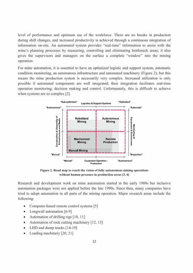
For mine automation, it is essential to have an optimized logistic and support system, automatic condition monitoring, an automatous infrastructure and automated machinery (Figure 2), but this means the mine production system is necessarily very complex. Increased utilization is only possible if automated components are well integrated; their integration facilitates real-time operation monitoring, decision making and control. Unfortunately, this is difficult to achieve when systems are so complex [2].
Figure 2. Road map to reach the vision of fully autonomous mining operations without human presence in production areas [3, 4]
Research and development work on mine automation started in the early 1980s but inclusive automation packages were not applied before the late 1990s. Since then, many companies have tried to adopt automation in all parts of the mining operation. Major research areas include the following:
Computer-based remote control systems [5] Longwall automation [6-9]Automation of drilling rigs [10, 11]Automation of rock cutting machinery [12, 13]LHD and dump trucks [14-19] Loading machinery [20, 21]
13
Risk and safety issues [22-24]Traffic and navigation [25-28]
As the list suggests, much of the literature looks at automation technology from an operation or safety point of view. There are many other areas to consider, however. For instance, the maintenance of automated mining systems and machinery presents a real challenge which has not yet been considered. This project addresses the issues and tries to clarify some practical implementation guidelines.
1.2. Structure and types of automated systems for mines The mining operation of the future is likely to be a bit eerie, combining driverless trucks, drills and haulage trains, with plant controllers monitoring operations remotely from central control stations kilometers away. Mine automation covers everything involved when we try to replace human senses and intelligence with machines, including sensor technology, communication network and devices. The main four subsystems of automation are: control stations,communication systems, safety systems and machinery. Automated mining is an umbrella term that refers to two types of activities. The first deals with data gathering, processes and decision making; the second deals with applying the decisions via robotic technology to mining vehicles and equipment. To address concerns of improving both productivity and safety, some mining companies are turning to equipment automation, including robotic hardware and software technologies that convert vehicles or equipment into autonomous mining units. Automated mine equipment comes in four forms: remote control, tele-operation, semi-automated and full automated [29-31].
1.2.1 Remote control Remote control mining equipment usually refers to mining machinery controlled by a handheld remote control. An operator stands in the line-of-sight and uses remote control to perform the normal vehicle functions. Because visibility and the feel of the machine are heavily reduced, vehicle productivity is generally reduced as well. Remote control technology is used to enable mining equipment to operate in dangerous conditions such as unstable ground, blast areas, areas at high risk of falling debris, or underground mining.
1.2.2 Tele-operation Tele-operated mining machinery refers to mining machines controlled by an operator at a remote location by cameras, sensors, and additional positioning software. Tele-operation allows operators to completely remove themselves from the mining location to control a vehicle from a more protected environment. Joysticks or other handheld controls are used to control the machine’s functions; operators have greater access to vehicle telemetry and positioning data through tele-operation software.
14
1.2.3 Semi-automated Semi-automation refers to partially automated control of mining machines. Only some functions are automated, and operator intervention is needed. For example, in the semi-automated LHD machine, loading and unloading are done and controlled by an operator from a remote location, but the hauling and transportation between these two points are fully automated, and the machine moves and is controlled by itself.
1.2.4 Full automated Full automation refers to the autonomous control of one or more mining machine. Robotic components manage all critical functions, including ignition, steering, transmission, acceleration, braking, and implement control without the need for operator intervention. Fully autonomous mining systems show the most gains in productivity, as software controls one or more mining vehicle, allowing operators to take on the supervisory role of mining facilitators to troubleshoot errors and monitor efficiency.
As the above definitions suggest, each mode of mine automation requires a different mine structure and design, operation size, support and logistics, human resources, maintenance management and safety measures. The failure modes, reliability, efficiency and utilization characteristics are different in various types of automated systems as well. In this report the full automated mining as the future mining technology is considered for RCM implementation.
1.3. Maintenance challenges in full automated mining machinery Maintenance plays an important role in an effective mine. Through short daily inspections, cleaning, lubricating, and making minor adjustments, small problems can be detected and corrected before they become a major problem that can stop production [32]. Maintenance should keep systems functioning so a company’s goals can be achieved. This includes meeting the requirements of CRAMP parameters (Cost, Reliability, Availability, Maintainability, and Productivity) for any automated systems. A holistic approach works best, one able to integrate the evaluations, not only of the systems themselves, but also of their interactions with each other and their environment [33, 34].
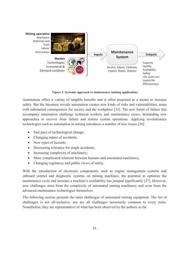
The mining working environment is the harshest of all industries. Heavy duty operation, bad climate, darkness, and geological hazards hurt miners and mining machinery alike. Equipment design, maintenance and operation need to be optimized to facilitate successful and safe mining. As shown in Figure 3, maintenance is a process requiring specific inputs and yielding specific outputs. The inputs in the maintenance of automated machinery differ from those for non-automated machinery (e.g. tools, labor, information, etc.). The same is true of outputs; even the same maintenance operation might result in completely different outputs for automated mining machinery. Another concern is that the complexity of automated machinery in conjunction with the harsh mining environment may reduce the quality of failure detection and repair actions.
15
Maintenance System
Mining operationMachinery
Materials and Tools
LabourInformation
Inputs OutputsMarket
TechnologiesEconomical &
Demand conditionService, Adjust, Calibrate, Inspect, Repair, Replace
CapacityQualityAvailabilitySafetyLife cycle costUseful lifeEffectiveness
Figure 3. Systemic approach to maintenance (mining application)
Automation offers a variety of tangible benefits and is often proposed as a means to increase safety. But the literature reveals automation creates new kinds of risks and vulnerabilities, some with substantial consequences for society and the workplace [35]. The new forms of failure that accompany automation challenge technical workers and maintenance crews, demanding new approaches to recover from failure and restore system operations. Applying revolutionary technologies such as automation in mining introduces a number of new issues [36]:
Fast pace of technological change;Changing nature of accidents;New types of hazards;Decreasing tolerance for single accidents;Increasing complexity of machinery;More complicated relations between humans and automated machinery;Changing regulatory and public views of safety.
With the introduction of electronic components, such as engine management systems and onboard control and diagnostic systems on mining machines, the potential to optimize the maintenance cycle and increase a machine’s availability has jumped significantly [37]. However, new challenges stem from the complexity of automated mining machinery and even from the advanced maintenance technologies themselves.
The following section presents the main challenges of automated mining equipment. The list of challenges is not all-inclusive, nor are all challenges necessarily common to every mine. Nonetheless, they are representative of what has been observed by the authors so far.
16
1.3.1. Safety of maintenance crew Automation considerably increases the mine operation safety, especially by removing the operator from hazardous operation areas. In the case of machinery failure, however, maintenance crews must enter operation areas to fix the problem. There are two safety factors which restrict the maintenance operation in automated mines; 1) there is no powerful ventilation facilities because of human absence in operation and 2) mining areas and support systems are designed by lower safety factors to save the cost of support and infrastructure. Both of the mentioned pointslimit maintenance crew to enter this kind of operation area from safety perspective.
Detecting problems in full-automated machinery or tele-operating ones is difficult (sometimes even impossible) because of absence of driver feeling, darkness or dirty on-board cameras. Therefore, for some inspections or simple check-ups the maintenance crews are supposed to visit the machines by himself/herself. In addition, some software and hardware failures have direct safety consequences which are really dangerous for operation and maintenance crew. This is main reason that entrance of personal to full-automated operation areas is forbidden in mines. As an example of dangerous maintenance experiences in mining, when Bulletins [38] and Sammarco [39] studied the safety issues of programmable electronics (PE), they found that 11 incidents occurred in USA mines during 1995–2001, with four resulting in fatalities. During the same period, 71 similar incidents occurred in underground coal mines in New South Wales, Australia. Most involved sudden start-ups or movements of PE-based mining systems. A study by US Mine Safety and Health Administration (MSHA) on American and Australian longwall equipment reported 35% of sudden movements can be traced to four problems: water ingress, software programming errors, sticking or defective solenoid valves, and operator error [40].
1.3.2. Big data handling Mining operation requires a large fleet of machines distributed in several locations with various operational configurations. In automated mining systems, Information and Communication Technology (ICT) based tools/systems are installed to enable the automation system to properly work, track and optimize the mine production. These systems are very precise, and any interruptions in production are logged with a high level of accuracy. Universally acknowledged key performance indicators, such as availability, mean time between failures or mean time to restore, can be calculated with ease from their data. This knowledge, in turn, can help management develop asset and/or fleet level awareness. Such systems are production-centric; they can record when an asset has broken down and give details on what has happened and where. With the resulting holistic view of its automated mining operation, a company can monitor and improve performance. The systems capture huge amounts of data for furtheranalysis, facilitating the understanding of shortfalls and suggesting areas for improvement in the mining operation [41]. In short, data acquisition, followed by data processing and decision making are the core of maintenance management in automated mining operation.
17
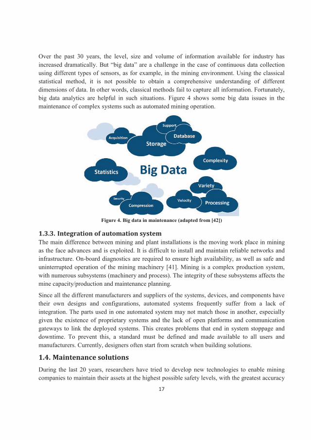
Over the past 30 years, the level, size and volume of information available for industry has increased dramatically. But “big data” are a challenge in the case of continuous data collection using different types of sensors, as for example, in the mining environment. Using the classical statistical method, it is not possible to obtain a comprehensive understanding of different dimensions of data. In other words, classical methods fail to capture all information. Fortunately, big data analytics are helpful in such situations. Figure 4 shows some big data issues in the maintenance of complex systems such as automated mining operation.
Figure 4. Big data in maintenance (adapted from [42])
1.3.3. Integration of automation system The main difference between mining and plant installations is the moving work place in mining as the face advances and is exploited. It is difficult to install and maintain reliable networks and infrastructure. On-board diagnostics are required to ensure high availability, as well as safe and uninterrupted operation of the mining machinery [41]. Mining is a complex production system, with numerous subsystems (machinery and process). The integrity of these subsystems affects the mine capacity/production and maintenance planning.
Since all the different manufacturers and suppliers of the systems, devices, and components have their own designs and configurations, automated systems frequently suffer from a lack of integration. The parts used in one automated system may not match those in another, especially given the existence of proprietary systems and the lack of open platforms and communication gateways to link the deployed systems. This creates problems that end in system stoppage and downtime. To prevent this, a standard must be defined and made available to all users and manufacturers. Currently, designers often start from scratch when building solutions.
1.4. Maintenance solutions During the last 20 years, researchers have tried to develop new technologies to enable mining companies to maintain their assets at the highest possible safety levels, with the greatest accuracy
18
and at the lowest costs. At this point, however, none of the proposed maintenance methods has been adequately tested or totally implemented in automated mining machinery. Given the maintenance challenges in automated mines noted above, any maintenance solution should be based on a comprehensive understanding of automated machinery. This is achieved by building a strong database of failures and performed maintenance actions, as well as designing efficient performance and condition monitoring systems. Two well-known maintenance solutions which may be able to build up a strong database, improve the safety of maintenance, solve big data problems and enhance system integration are: Reliability Centered Maintenance (RCM) and eMaintenance [43]. This research project considers RCM and its possible implementation in mining systems.
Reliability-Centered Maintenance (RCM) is a systematic process integrating Preventive Maintenance (PM), Predictive Testing and Inspection (PT&I), Repair (also called reactive maintenance), and Proactive Maintenance to increase the probability that a machine or component will function in the required manner over its design life-cycle with a minimum amount of maintenance and downtime. The goal of this approach is to reduce the Life-Cycle Cost (LCC) of a facility to a minimum while allowing the facility to function as intended, meeting the required levels of reliability and availability. RCM analysis considers the following questions:
What does the system or equipment do? In other words, what are its functions?What functional failures are likely to occur?What are the likely consequences of these functional failures?What can be done to reduce the probability of failure, identify the onset of failure, or reduce the consequences of failure?
The goal of an RCM approach is to determine the most applicable, most cost-effective maintenance technique to minimize the risk and impact of failure and to create a hazard-free work environment while protecting and preserving capital investments and their capability. Specific RCM objectives, as stated by Nowlan and Heap [44], are as follows:
To ensure realization of the inherent safety and reliability levels of the equipment;To restore the equipment to these inherent levels when deterioration occurs;To obtain the information necessary for design improvement of those items where their inherent reliability proves to be inadequate;To accomplish these goals at a minimum total cost, including maintenance costs, support costs, and economic consequences of operational failures.
RCM places great emphasis on improving equipment reliability through the feedback of maintenance experience and equipment condition data to facility planners, designers, maintenance managers, craftsmen/women, and manufacturers.
The flexibility of the RCM approach ensures the proper type of maintenance is performed on

19
equipment when it is needed. Existing maintenance that is not cost-effective is identified and eliminated. Savings of 30 to 50 percent in the annual maintenance budget are often obtained by introducing a balanced RCM program [45].

20
21
2. Reliability Centered Maintenance (RCM)
2.1 Definition and history With the advent of the widespread use of commercial jetliners in the 1960, the Federal Aviation Association (FAA) became increasingly concerned with safety issues, including programs of Preventive Maintenance (PM) tied to aircraft type. This led the commercial aircraft industry to completely re-evaluate its preventive maintenance strategy, including a review of why maintenance was done and how it could best be accomplished. United Airlines led the way, with Bill Mentzer, Tom Matteson, Stan Nowland, and Howard Heap becoming the pioneers of this type of research [44-46].
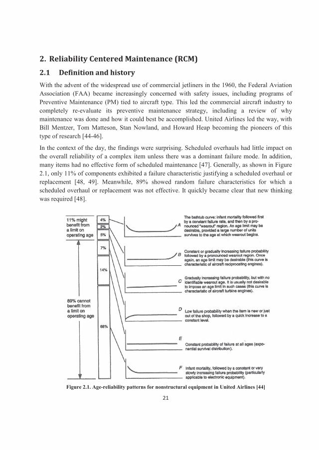
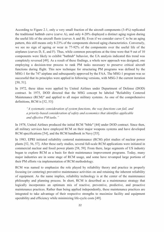
In the context of the day, the findings were surprising. Scheduled overhauls had little impact on the overall reliability of a complex item unless there was a dominant failure mode. In addition, many items had no effective form of scheduled maintenance [47]. Generally, as shown in Figure 2.1, only 11% of components exhibited a failure characteristic justifying a scheduled overhaul or replacement [48, 49]. Meanwhile, 89% showed random failure characteristics for which a scheduled overhaul or replacement was not effective. It quickly became clear that new thinking was required [48].
Figure 2.1. Age-reliability patterns for nonstructural equipment in United Airlines [44]
22
According to Figure 2.1, only a very small fraction of the aircraft components (3-4%) replicated the traditional bathtub curve (curve A), and only 4-20% displayed a distinct aging region during the useful life of the aircraft fleets (curves A and B). Even if we consider curve C to be an aging pattern, this still means only 8-23% of the components showed aging characteristics. Conversely, we see no sign of ageing or wear in 77-92% of the components over the useful life of the airplanes (curves D, E, and F). Thus, while common perceptions at the time were that 9 out of 10 components were likely to exhibit "bathtub" behavior, the UA analysis indicated this trend was completely reversed [49]. As a result of these findings, a whole new approach was designed, one employing a decision-tree process to rank PM tasks necessary to preserve critical aircraft functions during flight. This new technique for structuring PM programs was defined by the MSG-1 for the 747 airplane and subsequently approved by the FAA. The MSG-1 program was so successful that its principles were applied in following versions, with MSG-3 the current iteration [50, 51].
In 1972, these ideas were applied by United Airlines under Department of Defense (DOD) contract. In 1975, DOD directed that the MSG concept be labeled "Reliability Centered Maintenance (RCM)" and applied to all major military systems. As one of the comprehensive definitions, RCM is [52, 53]:
“A systematic consideration of system functions, the way functions can fail, and a priority-based consideration of safety and economics that identifies applicableand effective PM tasks.”
In 1978, United Airlines produced the initial RCM "bible" [44] under DOD contract. Since then, all military services have employed RCM on their major weapons systems and have developed RCM specifications [54], and the RCM handbook in Navy [55].
In 1983, EPRI initiated reliability centered maintenance (RCM) pilot studies of nuclear power plants [52, 56, 57]. After these early studies, several full-scale RCM applications were initiated in commercial nuclear and fossil power plants [58, 59]. From there, large segments of US industry began to explore RCM as a basis for their maintenance improvement programs. Today, many major industries are in some stage of RCM usage, and some have revamped large portions of their PM efforts via implementation of RCM methodology.
RCM was named to emphasize the role played by reliability theory and practice in properly focusing (or centering) preventive maintenance activities on and retaining the inherent reliability of equipment. As the name implies, reliability technology is at the center of the maintenance philosophy and planning process. In short, RCM is described as a maintenance strategy that logically incorporates an optimum mix of reactive, preventive, predictive, and proactive maintenance practices. Rather than being applied independently, these maintenance practices are integrated to take advantage of their respective strengths to maximize facility and equipment operability and efficiency while minimizing life-cycle costs [49].
23
The RCM framework combines various maintenance strategies, including time-directed preventive maintenance, condition based maintenance, run-to-failure, and proactive maintenance techniques in an integrated manner to increase the probability that a system or component willfunction in the required manner in its operating context over its design life-cycle. The goal is to provide the required reliability and availability at the lowest cost. Therefore, RCM is a systematic approach to define a planned maintenance program composed of cost-effective tasks and tries to provide or improve the followings [47, 60]:
1. Maintenance integration2. Maintenance optimization3. Maximized operability and efficiency4. Life-cycle cost control
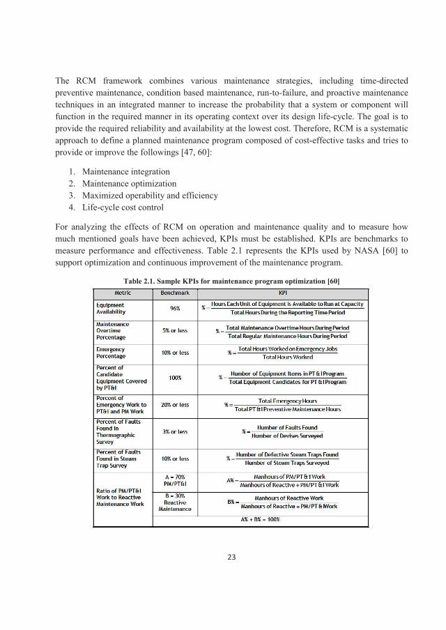
For analyzing the effects of RCM on operation and maintenance quality and to measure how much mentioned goals have been achieved, KPIs must be established. KPIs are benchmarks to measure performance and effectiveness. Table 2.1 represents the KPIs used by NASA [60] to support optimization and continuous improvement of the maintenance program.
Table 2.1. Sample KPIs for maintenance program optimization [60]

24
2.2 RCM principles RCM methodology has been originated based on four main principles which are known as pillars for RCM philosophy. Smith and Hinchcliffe [49] have listed these principles as following:
Preserve system function
This is the most important feature of RCM. It enables us to systematically decide in later stages of the process just what equipment relates to what functions, and not to assume a priori thatevery item of equipment is equally important, a tendency pervades the current PM planning approach.
Identify failure modes that can defeat the functions
As the primary objective is to preserve system function, loss of function or functional failure is the next consideration. Functional failures come in many sizes and shapes and are not always a simple "we have it or we don't" situation. In RCM we have to answer; which specific failure modes in the hardware could potentially produce the unwanted functional failures?
Prioritize function need (via failure modes)
In the RCM process, where our primary objective is to preserve system function, we have the opportunity to decide, in a very systematic way, just what order or priority we wish to assign in allocating budgets and resources. In other words, "all functions are not created equal," and, therefore, all functional failures and their related components and failure modes are not created equal. Thus, we have to prioritize the importance of the failure modes.
Select applicable and effective PM tasks for high priority failure modes
RCM formulates a systematic roadmap that shows where (component), what (failure mode), and the priority with which we should proceed to establish specific PM tasks. All of this is driven by the fundamental premise "preserve function". As a unique feature, in RCM each potential PM task must be judged as "applicable and effective".
The above four features encapsulate the RCM concept; there is nothing more to it and nothing less. For any maintenance analysis process to be labeled RCM, it must contain all four features. But, in NASA guidelines for RCM analysis [60] few secondary principles (or in other words) of RCM have been mentioned as following:
System-Focused: RCM is more concerned with maintaining system function than with individual component function.Reliability-Centered: RCM treats failure statistics in an actuarial manner. The relationship between operating age and the failures experienced is important. RCM is not overly concerned with simple failure rate.
25
Acknowledges Design Limitations: The objective of RCM is to maintain the inherent reliability of the equipment design, recognizing changes in inherent reliability are the province of design rather than maintenance. RCM recognizes that maintenance feedback can lead to improvements in the original design.Safety, Security, and Economics: Safety and security must be ensured at any cost; life-cycle cost-effectiveness is a tertiary criterion.Failure as Unsatisfactory Condition: Failure may be either a loss of function (operation ceases) or a loss of acceptable quality (operation continues). Logic Tree to Screen Maintenance Tasks: This provides a consistent approach to the maintenance of all equipment.
RCM analysis and decision making approach is broken into two main categories [54, 60]: rigorous and intuitive. The decision on how the RCM program is implemented should be made by the end user based on:
Consequences of failureProbability of failureHistorical dataRisk tolerance (mission criticality)
Rigorous RCM analysis was first proposed and documented by F. Stanley Nowlan and Howard F. Heap [44] and later modified by John Moubray [48], Anthony M. Smith, Jack Nicholas [49] and others. A formal rigorous RCM analysis is rarely needed for most facilities and collateral equipment items because their construction and failure modes are well understood [49]. Rigorous RCM is based primarily on the FMEA and includes probabilities of failure and system reliability calculations, with little or no analysis of historical performance data. A rigorous RCM approach should be limited to the following three situations [49]:
Consequences of failure result in catastrophic risk in terms of environment, health, safety, or complete economic failure of the business unit.Resulting reliability and associated maintenance cost is still unacceptable after performing and implementing a streamlined-type FMEA.System or equipment is new to the organization and there is insufficient corporate maintenance and operational knowledge of its function and functional failures.
An intuitive RCM approach is typically more appropriate for facility systems, given the high analysis cost of the rigorous approach, the relatively low impact of failure of most facilities’ systems, the type of systems and components maintained, and the number of redundant systems in place. An intuitive RCM approach identifies and implements obvious, condition-based maintenance tasks with minimal analysis. It is applicable in the following situations [49, 53]:
26
Function of the system/equipment is well understood.Functional failure of the system or equipment will not result in loss of life, catastrophic impact on the environment, or economic failure of the business unit.
2.3 RCM procedures RCM is a step-by-step process, with seven steps proposed to systematically delineate the information required to finalize the maintenance programing [44, 49, 59]:
Step 1: System selection and information collection.Step 2: System boundary definition.Step 3: System description and functional block diagram.Step 4: System functions and functional failures; preserve functions.Step 5: FMEA; identify failure modes that can defeat the functions.Step 6: Logic (decision) tree analysis; prioritize function need via failure modes.Step 7: Task selection; select only applicable and effective PM tasks.
Satisfactory completion of these seven steps will provide a baseline definition of the preferred PM tasks on each system with a well-documented record of exactly how those tasks were selected and why they are considered the best selections among competing alternatives. The steps are explained in more detail in the following subsections.
2.3.1 Step 1: System selection and information collecting When a decision has been made to perform RCM, two immediate questions arise:
1. At what level (component, system or plant) should the analysis be conducted?2. Should the entire plant/facility be involved in the process, and, if not, how are selections
made?
The following describe the levels at which RCM can be applied [44, 49]:
Part (or piece part): the lowest level to which equipment can be disassembled without damage to or destruction of the item involved. Component (or black box): a grouping or collections of piece parts into some identifiable package that will perform at least one significant function as a stand-alone item. Modules, circuit boards, and subassemblies are often defined as intermediate buildup levels between parts and components. System: a logical grouping of components that will perform a series of key functions required by a plant or facility. Plant (or facility): logical grouping of systems that function together to provide an output (e.g., electricity) or product (e.g., ore, mineral) by processing and manipulating various input raw materials and feedstock (e.g., water, crude oil, natural gas, iron ore).
27
When PM planning is approached from the point of view of function, experience suggests the most efficient and meaningful function list for RCM analysis is at the system level [49, 54]. At the component level, it becomes difficult to define the significance of functions and functional failures. It is also sometimes impossible to perform meaningful priority rankings of failure modes competing for limited PM resources. In short, system level analysis is the best approach; component level analysis suffers from the lack of a clearly defined significance of functions and functional failure, while plant level analysis makes the whole analysis intractable. Now, animportant question is raised here; what procedure can be employed to select the systems with the highest potential for benefit from the classical RCM systems analysis process?
The most direct and credible way to answer this question is to invoke the 80/20 rule or Pareto principle [49, 61]. Pareto principle suggests that when a number of factors affect a situation, fewer factors will be accountable for the most of the affect. It is equal to that 80% of the impact is made by 20% of causes. In the maintenance case, the observed effect of interest is the high cost of maintenance and/or a large amount of plant downtime while the available source is one or more of the plant systems (i.e., the bad-actor systems). To use the 80/20 rule as the basis for system selection, we need to assemble data that will represent maintenance costs or downtime on a system-by-system basis, and plot this information in a Pareto diagram (a bar chart plotted in a descending order of value). One or more of the following parameters can be used to construct a Pareto diagram [48]:
Cost of corrective maintenance actions over a recent two-year period. Number of corrective maintenance actions over a recent two-year period.Number of hours attributed to machine outages over a recent two-year period.
In selected cases, we can use all three parameters to construct an 80/20 solution. Point 2, the number of corrective maintenance actions, may be the easiest data to retrieve to construct the Pareto diagram, but some researchers believe other operational or safety aspects could be the selection criteria in Pareto analysis in general or in RCM [62-65]. These include the following:
Systems with a large number of corrective maintenance tasks during recent years;Systems with a large number of preventive maintenance tasks and/or costs during recent years;Systems with a high cost of corrective maintenance tasks during recent years;Systems contributing significantly towards plant outages/shutdowns (full or partial) during recent years;Systems causing high safety concerns; andSystems causing high environmental concerns.
The next step after selecting the system to analyze is collecting information about its operation and maintenance. Some common documents required in a typical RCM study include [47]:
28
System P&ID. System schematic and/or block diagrams: facilitate a good understanding of the main equipment and function features of the system. Individual vendor manuals for the equipment in the system: contain potentially valuable information on the design and operation of the equipment for use in Step 5 (FMEA).Equipment history files: list the actual failures and corrective maintenance actions that have occurred in the facility for documentation in Step 3 and for use in Step 5.System operation manuals: provide valuable details on how the system is intended to function, how it relates to other systems, and what operational limits and ground rules are employed. System design specification and description data: generally support and augment the preceding points and, most importantly, help identify information needed in Step 3-1("System functional description") and Step 4.Functional flow diagram: usually less messy than a P&ID, facilitates understanding of functional features of the system.Other identified sources of information, unique to the plant or organizational structure, including industry data for similar systems.Current maintenance program used with the system: generally not collected before Step 7 to avoid preclusions and biases that may affect the RCM process.
2.3.2 Step 2: System boundary definition Ordinary system definitions serve quite well to initially define the precise boundaries for the RCM analysis. Precise system boundary definition is important in the RCM analysis process for two reasons [49]:
1. There must be precise knowledge of what has or has not been included in the system so an accurate list of components can be identified or, conversely, so the identified components will not overlap with components in an adjacent system.
2. Boundary definition includes system interfaces (both IN and OUT interfaces) and interactions that establish inputs and outputs of a system. An accurate definitions of IN and OUT interfaces is a precondition to fulfilling Steps 3 and 4.
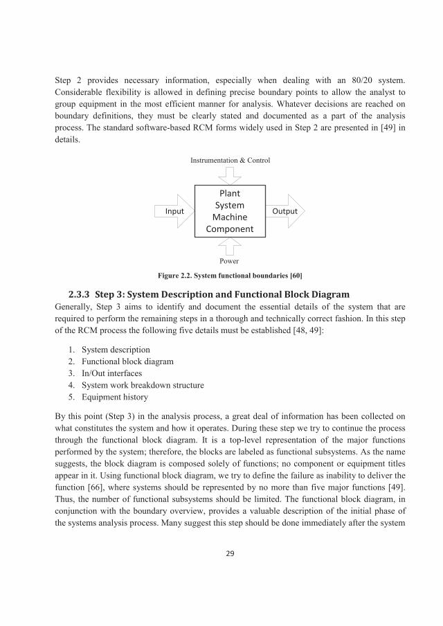
The boundaries are selected as a method of dividing a system into subsystems when its complexity makes analysis by other means difficult. As shown in Figure 2.2, a system boundary or interface definition contains a description of the inputs and outputs across each boundary, as well as the power and I&C requirements.
Failure modes are equipment- and component-specific failures that result in the functional failure of the system or subsystem. These operational requirements should be considered when developing maintenance tasks.
29
Step 2 provides necessary information, especially when dealing with an 80/20 system. Considerable flexibility is allowed in defining precise boundary points to allow the analyst to group equipment in the most efficient manner for analysis. Whatever decisions are reached on boundary definitions, they must be clearly stated and documented as a part of the analysis process. The standard software-based RCM forms widely used in Step 2 are presented in [49] in details.
PlantSystem
MachineComponent
Input Output
Instrumentation & Control
Power
Figure 2.2. System functional boundaries [60]
2.3.3 Step 3: System Description and Functional Block Diagram Generally, Step 3 aims to identify and document the essential details of the system that are required to perform the remaining steps in a thorough and technically correct fashion. In this step of the RCM process the following five details must be established [48, 49]:
1. System description2. Functional block diagram3. In/Out interfaces4. System work breakdown structure 5. Equipment history
By this point (Step 3) in the analysis process, a great deal of information has been collected onwhat constitutes the system and how it operates. During these step we try to continue the process through the functional block diagram. It is a top-level representation of the major functions performed by the system; therefore, the blocks are labeled as functional subsystems. As the name suggests, the block diagram is composed solely of functions; no component or equipment titles appear in it. Using functional block diagram, we try to define the failure as inability to deliver the function [66], where systems should be represented by no more than five major functions [49]. Thus, the number of functional subsystems should be limited. The functional block diagram, in conjunction with the boundary overview, provides a valuable description of the initial phase of the systems analysis process. Many suggest this step should be done immediately after the system
30
boundary overview to reach an early consensus about whether to tackle the entire system or only certain individual subsystems.
The establishment of system boundaries and the definition of functional subsystems allow us to document which elements cross the system boundary (or subsystem boundary if we have elected to analyze at that level). Some elements (electrical power, signals, heat, fluids, gases, etc.) come IN across the boundary; others move OUT to support other systems. OUT interfaces represent what the system produces; these become the focus of the principle to "preserve system function" in Step 4 of RCM analysis. In the systems analysis process, we assume all IN interfaces are always present and available when required [49]. While the IN interfaces are needed to make a system work, the real product of the system is embodied in the OUT interfaces. IN interfaces in one system are OUT interfaces in another system, so if necessary, they can be analyzed as part of another system at a later stage.
SWBS is a carryover from terminology used in US DOD applications of RCM. It is used to describe the compilation of the equipment (component) lists for each of the functional subsystems shown on the functional block diagram. This equipment list is defined at the component level of assembly. It is essential that all components within the system boundary be included on these lists; failure to do so will automatically eliminate those "forgotten" components from any further PM consideration in Steps 4 to 7. A correct P&ID is an excellent source of information for an equipment list. In older plants or facilities, system walk-down can also be performed to ensure the accuracy of the SWBS list [49, 60].
As many systems contain a sizeable number of I&C devices, it may be convenient to group I&C and non-I&C components separately in SWBS analysis. It may be possible simplify the handling of I&C components by categorizing each device as providing (1) control, (2) protection, or (3) status information only.
For RCM purposes, the history of most direct interest is failure over the past two or three years. This failure history is usually derived from work orders for corrective maintenance. The failure mode and failure cause associated with the corrective maintenance action(s) are the primary pieces of information required to complete Step 5, the failure mode and effects analysis (FMEA).
Where do we find this equipment failure history? First, we can draw on the plant-specific data available from the work order records or, if automated, the CMMS files. In some instances, there may be sister plants or component usage in similar facilities accessible from the same work order and CMMS files. In-house or plant-specific data are the most valuable, as the records reflect operating and maintenance procedures that describe the components under investigation in the RCM analysis. In addition, generic failure files may have been compiled on an industry-wide basis containing data of considerable value [49]. The standard software-based RCM forms widely used in Step 3 are presented in [49] in details.
31
2.3.4 Step 4: System Functions and Functional Failure The previous steps have all been directed at developing a set of information that will provide the basis for pursuing the four features of RCM given earlier. This process begins by defining system functions to satisfy the first RCM principle "to preserve system functions." If a function is inadvertently missed, it PM tasks directed at its preservation will not likely be considered. Note that if the decision was made to perform the analysis at the subsystem level, Steps 3 through Step7 in RCM process are at the subsystem level.
Essentially, every OUT interface should be captured in a function statement. Certain OUT interfaces, however, are multiple in nature, and a single function statement will cover all of them. Signals going to other plant systems or a central control room are examples. In addition, OUT interfaces represent active – and therefore readily visible – functions. But some functions are passive and must be recognized as such by the analyst. The most obvious passive functions are structural considerations and include items such as preserving fluid boundary integrity (e.g., pipes) and structural support integrity (e.g., pipe supports).
When the system functions have been defined, the analyst is ready to define the functional failures because function preservation means avoidance of these failures. The goal is to eventually ascertain the actions to prevent, mitigate, or detect onset of function loss. Three things should be kept in mind when defining the functional failures [49]:
1. At this stage of the analysis, the focus is on loss of function, not loss of equipment. Thus, the functional failure statements are not about equipment failures.
2. Functional failures are usually more than just a single, simple statement of function loss. Most functions will have two or more loss conditions. These distinctions are essential so the proper importance ranking can be determined in later portions of the analysis process (not all functional failures are equally important). In addition, these distinctions often lead to different modes of failure in the equipment supporting them, and this needs to be identified in Step 5.
3. An accurate portrayal of functional failures relies heavily on the design parameters of the system.
More detailed information and standard forms for Step 4 are presented in [49].
2.3.5 Step 5: Failure Mode and Effective Analysis (FMEA) Step 5 takes the question of which component failures have the potential to defeat the principal objective of "preserving function." For the first time in the systems analysis process we directly connect the system functions and the system components by identifying specific hardware failure modes that could potentially produce unwanted functional failures. In so doing, we satisfy Feature 2 of the RCM process. One of the major difficulties encountered in early RCM studies was establishing an orderly way to link and track all of the various functional failure-component
32
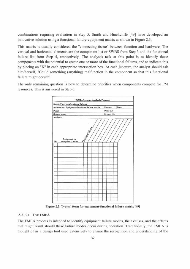
combinations requiring evaluation in Step 5. Smith and Hinchcliffe [49] have developed an innovative solution using a functional failure-equipment matrix as shown in Figure 2.3.
This matrix is usually considered the "connecting tissue" between function and hardware. The vertical and horizontal elements are the component list or SWBS from Step 3 and the functional failure list from Step 4, respectively. The analyst's task at this point is to identify those components with the potential to create one or more of the functional failures, and to indicate this by placing an "X" in each appropriate intersection box. At each juncture, the analyst should ask him/herself, "Could something (anything) malfunction in the component so that this functional failure might occur?"
The only remaining question is how to determine priorities when components compete for PM resources. This is answered in Step 6.
Figure 2.3. Typical form for equipment-functional failure matrix [49]
2.3.5.1 The FMEA The FMEA process is intended to identify equipment failure modes, their causes, and the effects that might result should these failure modes occur during operation. Traditionally, the FMEA is thought of as a design tool used extensively to ensure the recognition and understanding of the
33
weaknesses (i.e., failure modes) inherent to a given design in both its concept and detailed formulation [49, 53]. Armed with such information, design and management personnel are better prepared to determine what, if anything could and should be done to avoid or mitigate the failure modes. This information also provides the basic input for a well-structured reliability model to predict and measure product reliability performance against specified targets and requirements.
FMEAs are frequently extended to include other information for each failure mode, especially when the FMEA is conducted to support a design effort. These additional items of information could include [44]:
failure symptoms;failure detection and isolation steps;failure mechanism data (i.e., microscopic data on the failure mode and/or failure cause);failure rate data on the failure mode (not always available with the required accuracy);recommended corrective/mitigation actions.
Upon completion of the matrix, the analyst must perform the FMEA at every intersection with an X. Past experience in aviation engineering has shown the best way to approach the task is to select the one or two functional failures with the most Xs in their column and initially complete the FMEA form in Figure 2.3 at each X. As each component in the column is completed, its failure modes should be reviewed against the other functional failures with an X to see if they equally apply, in whole or in part. The chances are very good that these failure modes will satisfy at least some of the other functional failures, thus eliminating a need to repeat the FMEA exercise at several locations in the matrix.
Each potential failure mode and effect is rated in each of the following three factors [49]:
1. Severity: the consequence of the failure when it happens (see Table 2.2);2. Occurrence: the probability or frequency of the failure occurring;3. Detection: the probability of the failure being detected before the impact of the effect is
realized.
In another method of selecting the critical failure modes, the above three factors are combined in a RPN to reflect the priority of the failure modes identified. RPN is calculated by multiplying the severity, the occurrence probability, and the detection probability ratings [47, 60].
We could hypothesize several failure modes, but we limit the present analysis to include only dominant failure modes. Dominant failure modes impose two practical restrictions on the creativeability to dissect just what might go wrong with a component [49]:
In the preventive maintenance context, the failure mode must depict a problem that can be realistically addressed with a PM task. The failure mode must not depict an implausible situation.
34
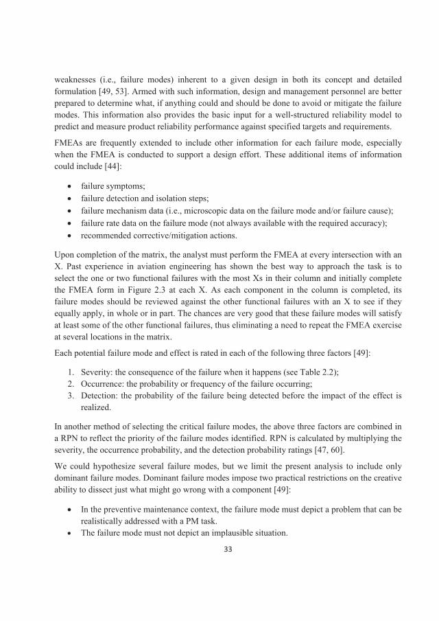
Table 2.2. Criticality/Severity categories for failures [60]
When we finally turn to the question of defining the required PM tasks, our decisions will be linked to these failure modes. In other words, no failure mode leads the RCM to no PM task. Failure modes are generally described in four words or less; Table 2.3 presents a partial listing of commonly used words to describe failure modes.
Table 2.3. Typical descriptors for failure modes [49]abrasion damaged lack of …. rupturedarcing defective leak scoredbackward delaminated loose scratchedout of balance deteriorated lost separatedbent disconnected melted shatteredbinding dirty missing shearedblown disintegrated nicked shortedbroken ductile notched splitbuckled embrittlement open stickingburned eroded overheat tornchafed exploded Over-temp twistedchipped false indication overload unboundedclogged fatigue overstress unstablecollapsed fluctuates overpressure wrappedcut frayed over-speed worncontaminated intermittent pittedcorroded incorrect pluggedcracked jammed punctured
2.3.6 Step 6: Logic Tree Analysis (LTA) The RCM process uses a simple three-question logic or decision structure that permits the analyst to quickly and accurately place each failure mode into one of four categories. As shown in Figure
35
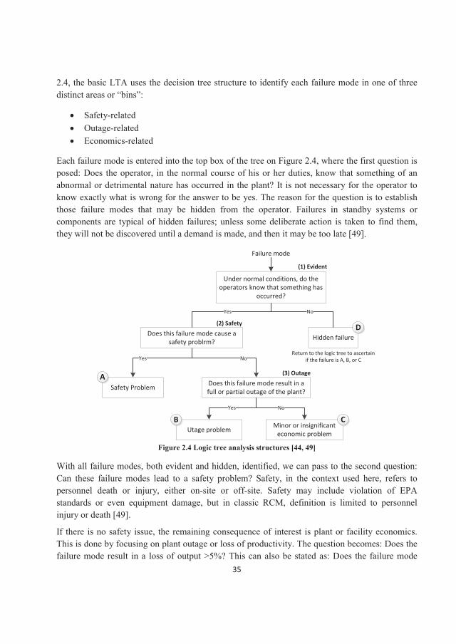
2.4, the basic LTA uses the decision tree structure to identify each failure mode in one of three distinct areas or “bins”:
Safety-relatedOutage-relatedEconomics-related
Each failure mode is entered into the top box of the tree on Figure 2.4, where the first question is posed: Does the operator, in the normal course of his or her duties, know that something of an abnormal or detrimental nature has occurred in the plant? It is not necessary for the operator to know exactly what is wrong for the answer to be yes. The reason for the question is to establish those failure modes that may be hidden from the operator. Failures in standby systems or components are typical of hidden failures; unless some deliberate action is taken to find them, they will not be discovered until a demand is made, and then it may be too late [49].
Failure mode
Under normal conditions, do the operators know that something has
occurred?
Does this failure mode cause a safety problrm? Hidden failure
Safety Problem
Utage problem
Does this failure mode result in a full or partial outage of the plant?
Minor or insignificant economic problem
Yes No
(1) Evident
(2) Safety
(3) OutageA
B C
D
Return to the logic tree to ascertain if the failure is A, B, or CYes No
Yes No
Figure 2.4 Logic tree analysis structures [44, 49]
With all failure modes, both evident and hidden, identified, we can pass to the second question: Can these failure modes lead to a safety problem? Safety, in the context used here, refers to personnel death or injury, either on-site or off-site. Safety may include violation of EPA standards or even equipment damage, but in classic RCM, definition is limited to personnel injury or death [49].
If there is no safety issue, the remaining consequence of interest is plant or facility economics. This is done by focusing on plant outage or loss of productivity. The question becomes: Does the failure mode result in a loss of output >5%? This can also be stated as: Does the failure mode
36
result in a full or partial plant outage (where partial is defined as > 5%)? The selection of the 5% threshold value depends on several variables, so the analyst should adjust this value to suit thesituation at hand. A "yes" answer puts us in bin B, representing outage and signifying a significant loss of income. A "no" answer suggests the economic loss is small and places us in bin C. That is, the failure mode is tolerable until the next opportunity occurs to restore the equipment to its full specified performance. There are many examples of bin-C-type failure modes, including small leaks and degraded heat transfer because of tube scaling.
When the LTA process is concluded, every failure mode passed to the LTA will have been classified as A, B, C, D/A, D/B, or D/C. Therefore, we usually choose to address PM priorities as[49, 54, 60]:
1. A or D/A2. B or D/B3. C or D/C
It should be noted that the evidence is rather strong that bin C should be relegated to the RTF list.Smith and Hinchcliffe [49] recommend all bin C failure modes be designated as RTF and changed only if they do not pass the check in Step 7. In this case, only failure modes with an A or B classification are passed on.
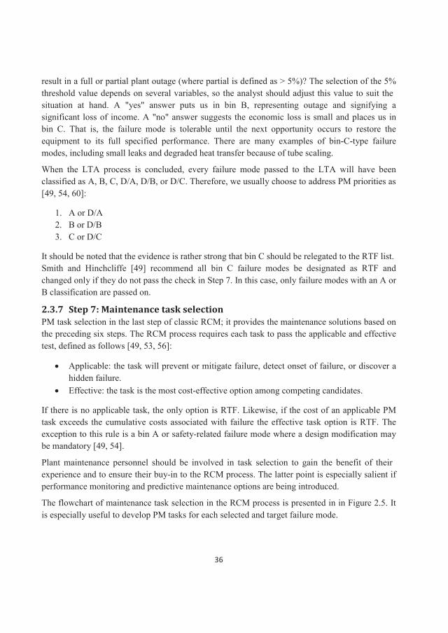
2.3.7 Step 7: Maintenance task selection PM task selection in the last step of classic RCM; it provides the maintenance solutions based on the preceding six steps. The RCM process requires each task to pass the applicable and effective test, defined as follows [49, 53, 56]:
Applicable: the task will prevent or mitigate failure, detect onset of failure, or discover a hidden failure.Effective: the task is the most cost-effective option among competing candidates.
If there is no applicable task, the only option is RTF. Likewise, if the cost of an applicable PM task exceeds the cumulative costs associated with failure the effective task option is RTF. The exception to this rule is a bin A or safety-related failure mode where a design modification may be mandatory [49, 54].
Plant maintenance personnel should be involved in task selection to gain the benefit of theirexperience and to ensure their buy-in to the RCM process. The latter point is especially salient if performance monitoring and predictive maintenance options are being introduced.
The flowchart of maintenance task selection in the RCM process is presented in in Figure 2.5. It is especially useful to develop PM tasks for each selected and target failure mode.
37
Is the age reliability relationship for this failure known?
Are there any applicable time directed tasks?
Specify time-directed tasks
Are there any applicable condition-directed tasks?
Specify condition-directed tasks
Is this category ”D” failure mode?
Are there any applicable failure finding tasks?
Specify failure finding tasks
Are these tasks effective?
Specify the selected tasks Accept failure risks Design modification
Can a design mode eliminate the failure mode or its effects?
No
No
No
Yes
No
Yes
Yes
No Yes
(5)
(4)
(3)
(6)
(1)
(2)
(7)
Can this relationship
be determined with further
analysis?
NoPartialYes
Yes
No
Yes
Yes
No
Figure 2.5. Task selection flowchart in RCM (adapted from [49])
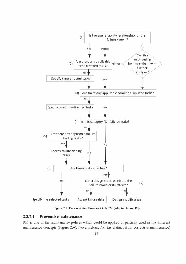
2.3.7.1 Preventive maintenance PM is one of the maintenance polices which could be applied or partially used in the different maintenance concepts (Figure 2.6). Nevertheless, PM (as distinct from corrective maintenance)
38
as is overall goal and core part of RCM process.
Figure 2.6. Actions, policies and concepts in maintenance [67]
Preventive maintenance (PM) can be defined as [44, 49]:
“The performance of inspection and/or servicing tasks that have been preplanned (i.e., scheduled) for accomplishment at specific points in time to retain the functional capabilities of operating equipment or systems”.
The word preplanned is the most important one in the definition; it is the key element in developing a proactive maintenance mode and culture. In other words, PM is [68]:
“An equipment maintenance strategy based on replacing, overhauling or remanufacturing an item at fixed or adaptive intervals, regardless of its condition at the time”.
These maintenance operations models can be characterized as long term maintenance policies that do not take into account instantaneous equipment status. Scheduled restoration tasks and scheduled discard tasks are both examples of preventive maintenance tasks [67, 68].
Considering the PM definition, is defined as the performance of unplanned (i.e., unexpected) maintenance tasks to restore the functional capabilities of failed or malfunctioning equipment or systems [44]. As Smith and Hinchcliffe [49] believe, the entire world of maintenance activity is encompassed in these two definitions. As a general rule, corrective maintenance is more costly than preventive maintenance. In two similar plants or systems, one with a proactive maintenance program and the other using a reactive maintenance program, the former will have lower overall maintenance cost and higher availability.
39
To summarize, preventive maintenance actions can be divided into four possible categories [49]:
1. Prevent (or mitigate) failure2. Detect onset of failure3. Discover hidden failure4. Do nothing, because of valid limitations
By identifying these four factors, we have set the stage for defining the four task categories from which a PM action may be specified. These task categories are universally employed in constructing a PM program, irrespective of the methodology used to decide what PM should be done. The four task categories are as follows [44, 49]:
1. Time based maintenance (TBM): aimed at failure prevention or retardation. The keys to categorize a task as time-directed are: (1) the task action and its periodicity are preset and will occur without any further input when the preset time occurs; (2) the action is known to directly provide failure prevention or retardation benefits; and (3) the task usually requires some form of intrusion into the equipment.
2. Condition based maintenance (CBM): aimed at detecting the onset of a failure or failure symptom. The keys to classifying a task as CBM are: (1) a measurable parameter that correlates with failure onset is definable; (2) a value of that parameter could be specified when action may be taken before full failure occurs; and (3) the task action is nonintrusive with respect to the equipment.
3. Failure-finding (FF): aimed at discovering a hidden failure before an operational demand. In large complex systems and facilities, there are almost always several equipment items or possibly a whole subsystem or system that could experience failure and, in the normal course of operation, no one would know such failure has occurred. this is called “hidden failure”.
4. Run-to-failure (RTF): a deliberate decision to run to failure is made because the other options are not possible or the economics are less favorable.
As discussed earlier, PM is the core of RCM philosophy; nevertheless, sometimes it is impossible to apply it in engineering assets because of following reasons:
We can find no PM task that will do any good irrespective of how much money we might be able to spend.The potential PM task that is available is too expensive. It is less costly to fix the item when it fails, and there is no safety impact at issue in the RTF decision.The equipment failure, should it occur, is too low on the priority list to warrant attention within the allocated PM budget.
Creating a new PM program or upgrading an existing PM program involves essentially the same process. We need to (1) determine what we would ideally like to do in the PM program, and (2)
40
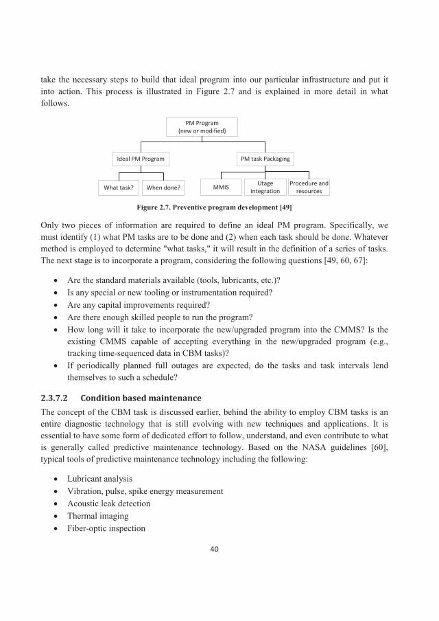
take the necessary steps to build that ideal program into our particular infrastructure and put it into action. This process is illustrated in Figure 2.7 and is explained in more detail in what follows.
PM Program (new or modified)
PM task Packaging
What task? When done? MMIS Utage integration
Procedure and resources
Ideal PM Program
Figure 2.7. Preventive program development [49]
Only two pieces of information are required to define an ideal PM program. Specifically, we must identify (1) what PM tasks are to be done and (2) when each task should be done. Whatever method is employed to determine "what tasks," it will result in the definition of a series of tasks.The next stage is to incorporate a program, considering the following questions [49, 60, 67]:
Are the standard materials available (tools, lubricants, etc.)?Is any special or new tooling or instrumentation required?Are any capital improvements required?Are there enough skilled people to run the program?How long will it take to incorporate the new/upgraded program into the CMMS? Is the existing CMMS capable of accepting everything in the new/upgraded program (e.g., tracking time-sequenced data in CBM tasks)?If periodically planned full outages are expected, do the tasks and task intervals lend themselves to such a schedule?
2.3.7.2 Condition based maintenance The concept of the CBM task is discussed earlier, behind the ability to employ CBM tasks is an entire diagnostic technology that is still evolving with new techniques and applications. It is essential to have some form of dedicated effort to follow, understand, and even contribute to what is generally called predictive maintenance technology. Based on the NASA guidelines [60], typical tools of predictive maintenance technology including the following:
Lubricant analysisVibration, pulse, spike energy measurementAcoustic leak detectionThermal imagingFiber-optic inspection
41
Trace element sensingUltrasonic movement sensingDebris analysisCreep monitoringDynamic radiography measurementStress/strain/torque measurementHyperbolic moisture detectionDye penetrant measurementNonintrusive flow measurementMicroprocessors with expert system softwarePattern recognition
Predictive maintenance or condition monitoring, uses non-intrusive testing techniques, visual inspection, and performance data to assess machinery condition. Continuing analysis of equipment condition-monitoring data allows planning and scheduling of maintenance or repairs in advance of catastrophic and functional failure. PT&I data are used in one of the following ways to determine the condition of the equipment and identify the precursors of failure [60, 66, 69]:
Trend analysisPattern recognitionData comparisonTests of limits and rangesCorrelation of multiple technologiesStatistical process analysis
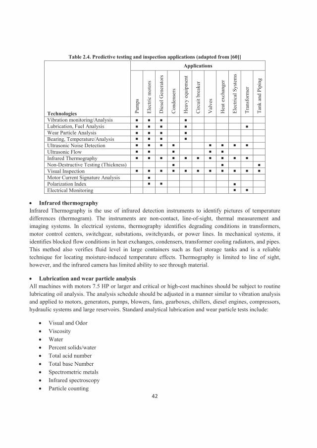
Data acquired from the various PT&I techniques should be correlated to increase the probability of detection. Based on the NASA recommendation, PT&I applications could be in different places and for different purposes as shown in Table 2.4. Some of most important technologies are explained here.
Vibration monitoring Machinery and system vibration is the periodic motion of a body about its equilibrium position. Vibration monitoring helps determine the condition of rotating equipment and the structural stability of a system. It also aids in identifying and localizing airborne noise sources. The effectiveness of vibration monitoring depends on sensor mounting and resolution, the analyst’s knowledge and experience, machine complexity, and data collection techniques. Complex, low speed (<120 RPM), variable speed, and reciprocating machinery are extremely difficult to monitor effectively.
42
Table 2.4. Predictive testing and inspection applications (adapted from [60]]
Technologies
Applications
Pum
ps
Elec
tric
mot
ors
Die
sel G
ener
ator
s
Con
dens
ers
Hea
vy e
quip
men
t
Circ
uit b
reak
er
Val
ves
Hea
t exc
hang
er
Elec
trica
l Sys
tem
s
Tran
sfor
mer
Tank
and
Pip
ing
Vibration monitoring/AnalysisLubrication, Fuel AnalysisWear Particle AnalysisBearing, Temperature/AnalysisUltrasonic Noise DetectionUltrasonic FlowInfrared ThermographyNon-Destructive Testing (Thickness)Visual InspectionMotor Current Signature AnalysisPolarization IndexElectrical Monitoring
Infrared thermography Infrared Thermography is the use of infrared detection instruments to identify pictures of temperature differences (thermogram). The instruments are non-contact, line-of-sight, thermal measurement and imaging systems. In electrical systems, thermography identifies degrading conditions in transformers, motor control centers, switchgear, substations, switchyards, or power lines. In mechanical systems, itidentifies blocked flow conditions in heat exchanges, condensers, transformer cooling radiators, and pipes. This method also verifies fluid level in large containers such as fuel storage tanks and is a reliable technique for locating moisture-induced temperature effects. Thermography is limited to line of sight, however, and the infrared camera has limited ability to see through material.
Lubrication and wear particle analysisAll machines with motors 7.5 HP or larger and critical or high-cost machines should be subject to routine lubricating oil analysis. The analysis schedule should be adjusted in a manner similar to vibration analysis and applied to motors, generators, pumps, blowers, fans, gearboxes, chillers, diesel engines, compressors, hydraulic systems and large reservoirs. Standard analytical lubrication and wear particle tests include:
Visual and OdorViscosityWaterPercent solids/waterTotal acid number Total base Number Spectrometric metalsInfrared spectroscopyParticle counting
43
Direct-Reading ferrographyAnalytical ferrography
Electrical condition monitoringElectrical equipment represents the majority of a facility’s capital investment. From the power distribution system to electric motors, the electrical system’s efficient operation is crucial to maintaining operational capability. Electrical condition monitoring techniques include: Insulation Power Factor, Insulation Oil Analysis, Gas-in-Oil Analysis, Megohmmeter Testing, High Potential Testing (HiPot), Airborne Ultrasonic Noise, Battery Impedance Testing, Surge Testing, Motor Circuit Analysis, Motor Current Signature (Spectrum) Analysis, Very Low Frequency Testing, Circuit Breaker Timing Tests and Circuit Breaker Contact Resistance.
Non-destructive testing Non-destructive testing evaluates material properties and quality of manufacture for high-value or critical components or assemblies without damaging the product or its function. These techniques are used when other testing techniques are expensive or ineffective. Non-destructive testing includes the following: Radiography, Ultrasonic Testing (Imaging), Magnetic Particle, Dye Penetrant, Hydrostatic Testing, Eddy Current Testing.
2.3.7.3 Preventive maintenance interval and age exploration Selecting the correct interval (or frequency or periodicity) at which to perform a preventive maintenance task is the most difficult task of the maintenance technician and analyst. It has been just described a systematic method to select "what" PM tasks should be done, i.e., the RCM systems analysis process. But it has not been yet discussed "when" those tasks should be performed. Determining the task interval is difficult, mainly because it is associated with an elusive parameter – time (or some equivalent, such as cycles, miles, etc.). More precisely, weneed to understand how physical processes and materials change over time, and how those changes ultimately lead to failure modes. In reality, we are dealing with failure rates and the need to know how these failure rates can vary as a function of time (recall Sections 3.4 and 4.2).
We can select the task interval from the existing statistical knowledge by deciding on the level ofrisk we want to accept. We can pick the level of risk by selecting the percentage of area under the failure density function and we can tolerate before taking action. Say we choose 15%. This means there is a 15% chance the failure mode will occur before we take preventive actions. Note that we can choose any percentage value we want; the only question is how much risk we want to take, as decreasing risk leads to more frequent PM actions and higher PM costs. If we use the mean (or MTBF) for the bell-shaped failure density function, there is a 50% chance of failure before we take preventive actions. For other functions, the chance of failure can be as large as 67% when the mean is used. This is clearly not an acceptable level of risk in most circumstances; hence,using an MTBF value is not really a useful technique for selecting task intervals.
44
When good statistical data are not available, using our experience to guess at task intervals is the only option that is initially available. But there is a proven technique we can employ to refine a "guesstimate" over time and predict the correct task interval; this is called “Age Exploration”. Determining the preventive maintenance interval has a number of benefits which all have favorable impacts on cost:
Operational impact Safety impact Logistics impact Configuration impact Administration impact
2.4 RCM applications in different industries Along with providing safety, security, cost reduction, reliability enhancement, maintenance scheduling, and efficiency improvement, RCM is applied in different industries to answer the following questions [60]:
What does the system or equipment do? What are its functions?What functional failures are likely to occur?What are the likely consequences of these functional failures?What can be done to reduce the probability of the failure, identify the onset of failure, or reduce the consequences of the failure?
These questions are common to most industries, but different approaches are taken in different industries to answer them. Reviewing case studies sheds useful light on the use of RCM across industries.
2.4.1 Aviation industry Traditionally, overhaul and retirement intervals are a major emphasis of aircraft maintenance programs to achieve high levels of reliability. As noted earlier in this section, RCM was initiated and developed in the aviation industry to reach this objective and then implemented in other industries based on the outcomes. Failure analysis is the core of RCM methodology and is critical for maintenance planning. In aviation, RCM classifies the consequences of failure into four categories, in descending order of importance [44, 60]:
Safety Consequences: A failure has safety consequences if it could kill or injure someone.Operational Consequences: A failure has operational consequences if it prevents the aircraft from being operated. Hidden Consequences: A failure has hidden consequences if it is not apparent to the flight crew, but could cause a subsequent failure to have more serious consequences (e.g., failure of a standby alternator, voltage regulator or vacuum pump.)
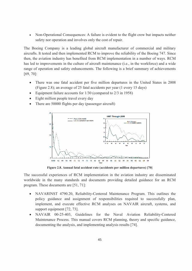
45
Non-Operational Consequences: A failure is evident to the flight crew but impacts neither safety nor operation and involves only the cost of repair.
The Boeing Company is a leading global aircraft manufacturer of commercial and military aircrafts. It tested and then implemented RCM to improve the reliability of the Boeing 747. Since then, the aviation industry has benefited from RCM implementation in a number of ways. RCM has led to improvements in the culture of aircraft maintenance (i.e., in the workforce) and a wide range of operation and safety enhancements. The following is a brief summary of achievements [69, 70]:
There was one fatal accident per five million departures in the United States in 2008(Figure 2.8); an average of 25 fatal accidents per year (1 every 15 days)Equipment failure accounts for 1/30 (compared to 2/3 in 1958) Eight million people travel every day There are 50000 flights per day (passenger aircraft)
Figure 2.8. Annual fatal accident rate (accidents per million departures) [70]
The successful experiences of RCM implementation in the aviation industry are disseminated worldwide in the many standards and documents providing detailed guidance for an RCM program. These documents are [51, 71]:
NAVARINST 4790.20, Reliability-Centered Maintenance Program. This outlines the policy guidance and assignment of responsibilities required to successfully plan, implement, and execute effective RCM analyses on NAVAIR aircraft, systems, and support equipment [72, 73].NAVAIR 00-25-403, Guidelines for the Naval Aviation Reliability-Centered Maintenance Process. This manual covers RCM planning, theory and specific guidance, documenting the analysis, and implementing analysis results [74].
46
MIL-STD-2173 (AS), Reliability-Centered Maintenance Requirements for Naval Aircraft, Weapons Systems and Support Equipment. This standard provides procedures for conducting RCM analyses for naval aircraft, systems, and support equipment [75].
2.4.2 Marine industry Most attempts to implement RCM in the marine industry have focused on enabling the ship staff to use it in their onboard maintenance analysis and daily operations because RCM results are based on the operating context, which keeps changing with the type of cargo, voyage, crew, etc. [76].
Jambulingamf and Jardine [77] report on RCM and LCC analysis in the marine industry. In their study, they integrate the two concepts to determine if the chiller unit (CU) of a destroyer ship required preventive maintenance (inspection, adjustments, etc.) and if so to find the optimal PM interval between CU major overhauls (or refits). By using RCM, the maintenance cost was reduced and the equipment was kept safe. Along with the RCM analysis, the authors address the difficulties encountered in data collection from a ship maintenance management information system and data interpretation.
Mokashi et al. [76] provide a comparative study to identify specific problems likely to be encountered when implementing RCM on ships. The study reveals the cultural differences between the aviation and maritime industries. In the maritime industry, RCM is often considered resource demanding. It is possible to make the project manageable by starting with a critical system. Considerable savings in time and effort can also be achieved by using a reverse logic where the failure modes are identified by analyzing the maintenance tasks. The authors propose a subjective qualitative approach to overcome the limitations of the definitive logic used by thedecision trees and the demand for failure data imposed by quantitative methods. Both classification societies and equipment suppliers appreciate the principles of RCM in the maritime industry. They conclude the application of the RCM concept is feasible, but rather than looking at RCM as a methodology and trying to use it as such, it makes more sense to consider it as a philosophy and use its guiding principles to plan maintenance. Like other managers, a ship manager is concerned with the need to reduce operating costs. This is coupled with pressure to improve safety. RCM has the potential to deliver both [76].
Conachey [78], a researcher at the American Bureau of Shipping, believes over time, as the marine industry becomes familiar with the application of RCM techniques, ship owners/operators will see the same benefits as other industries embracing RCM. Some benefits they can expect are:
An integrated program to address safety and environmental concerns;Increased integrity and reliability of critical machinery and components;More cost-effective maintenance;Improved understanding of equipment failures and their impact on vessel performance.
47
RCM has been applied successfully to advanced maritime equipment. For example, progressive maritime organizations around the world are co-operating to form a global information network, called “reliability, availability, and maintainability information management for the new millennium” (RAM/SHIPNET), to support the optimization of these three key factors throughout all stages of a ship’s lifecycle: RAM. RAM/SHIPNET represents the co-operative effort of owner/operators, government organizations and regulatory agencies [77]. The overall objective is to provide a sound basis for improving the safety, reliability, and cost effectiveness of marine machinery used onboard vessels. Specific objectives of RAM/SHIPNET are summarized as follows [78, 79]:
Capturing RAM data for continuous improvement: to provide additional decision support tools and information on equipment and system RAM by capturing key data mainly on corrective maintenance activities, and to process these failure legacy data with other maintenance, cost, and safety related data to evaluate performance and identify potential areas for improvement. Sharing RAM data: to provide software tools and infrastructure for sharing lessons learned at different levels by linking chief engineers, ship operators-managers, regulatory agencies, equipment manufacturers, and shipyards/designers.Providing RAM data for risk based classification: to provide assistance to migrate prescriptive class survey rules to risk based/reliability centered survey rules by providing RAM data on marine machinery. Technology Demonstration: to demonstrate the added value of using RAM and risk management methodologies by employing pilot studies.
2.4.3 Nuclear industry One of the first sectors to use RCM methodology was the nuclear industry, partly because of its similarities to the aeronautic sector (safety, availability, maintenance costs). RCM is now applied in more than 400 nuclear power plants. Safety rules are very strict, and each nuclear power plant is checked by a specialized association to ensure its safety and reliability. Two successful cases of RCM application in the nuclear industry are the following [71].
In the United States, the nuclear utility industry has taken RCM technology and developed guidelines for its application [80, 81]. For example, the Nuclear Regulatory Commission has issued a book of nuclear regulations, including maintenance. Starting in 1984, the Electric Power Research Institute in San Diego pioneered a number of studies demonstrating the usefulness of RCM as a preventive maintenance optimization technique. Cotaina et al. [71] looked at three initial RCM pilot studies of single nuclear plant systems between 1984 and 1987. They found the feasibility and cost-effectiveness of RCM, particularly in large, multi-system applications at an operating nuclear plant, was not yet fully demonstrated. However, in 1988, two large-scale demonstrations of the use of RCM on multiple systems were initiated at Rochester Gas and Electric's Ginna plant and Edison's San Onofre plant. At Ginna, 21 systems were analyzed and
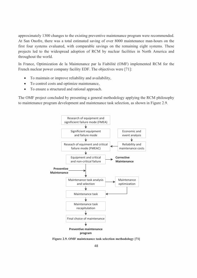
48
approximately 1300 changes to the existing preventive maintenance program were recommended. At San Onofre, there was a total estimated saving of over 8000 maintenance man-hours on the first four systems evaluated, with comparable savings on the remaining eight systems. These projects led to the widespread adoption of RCM by nuclear facilities in North America and throughout the world.
In France, Optimization de la Maintenance par la Fiabilité (OMF) implemented RCM for the French nuclear power company facility EDF. The objectives were [71]:
To maintain or improve reliability and availability,To control costs and optimize maintenance,To ensure a structured and rational approach.
The OMF project concluded by presenting a general methodology applying the RCM philosophy to maintenance program development and maintenance task selection, as shown in Figure 2.9.
Research of equipment and significient failure mode (FMEA)
Significient equipment and failure mode
Reseach of equiment and critical failure mode (FMEAC)
Equipment and critical and non-critical failure
Economic and event analysis
Reliability and maintenance costs
Maintenance task analysis and selection
Corrective Maintenance
Preventive Maintenance
Maintenance task
Maintenance task recapitulation
Final choice of maintenance
Maintenance optimization
Preventive maintenance program
Figure 2.9. OMF maintenance task selection methodology [71]
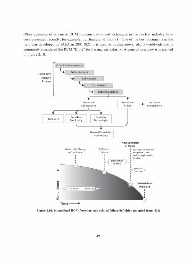
49
Other examples of advanced RCM implementation and techniques in the nuclear industry have been presented recently, for example, by Huang et al. [80, 81]. One of the best documents in the field was developed by IAEA in 2007 [82]. It is used by nuclear power plants worldwide and is commonly considered the RCM “Bible” for the nuclear industry. A general overview is presented in Figure 2.10.
Criticality Determination
Failure Analysis
Risk Analysis
Cost analysis
Detection Method
Preventive Maintenance
Functional Failure
Basic Care Predictive Technologies
Condition Monitoring
Planned (Scheduled) Maintenance
Corrective Maintenance
Cond
ition
er
Time
Detectable Change in Conditioner
PotentialFailure
New Definition of failure
Functionality Failed or equipment is not performing intended function
Old Definition of Failure
Too Much………...Too Early
InterventionWindow
Too LittleToo Late
Initial RCM Analysis Process
Figure 2.10. Streamlined RCM flowchart and related failure definition (adopted from [82])
50
2.4.4 Oil and Gas industry Ensuring reliability in the oil and gas industry is no easy task. Downtime from equipment failures can cost oil and gas companies hundreds of thousands of dollars per day and poses a significant safety risk to operations and maintenance crews. Systems do not break down and fail on a fixed or predetermined schedule, so actively tracking and monitoring the condition of components and systems is at the heart of any RCM process in the oil and gas industry. The condition monitoring approach requires the collection and analysis of significant amounts of operation data and managing that information. This practice closely monitors the “health”, operating metrics, and status of a given component or system to proactively identify any significant changes suggesting a potential future failure. By maintaining or replacing items before they fail, companies can ensure the operation of their assets is safe, efficient, and uninterrupted. This approach can have a significant impact on preventing catastrophic failures, costly downtime and collateral damage to machinery.
In the oil and gas industry, RCM is now the dominant maintenance strategy. The main objective is the cost-effective maintenance to enhance system reliability [83].
2.4.5 Process industry In this report, the process industry is considered to contain both the chemical and the steel industries. In a case of a particular chemical plant, where the operating stream was slurry, a screw conveyor was considered critical equipment.
Failure of the screw because of tripping, shaft failure etc. resulted in the loss of production. Themaintenance program for the screw mostly consisted of a few preventive maintenance tasks and further maintenance upon breakdown. The management reconsidered the problems associated with the screw conveyor using the RCM philosophy. Screw conveyors were analyzed using RCM principles: to eliminate certain causes of failures, mechanical design suitability checks were done for the current operating conditions, and deficiencies were corrected in the mechanical design of the equipment. Their methodology combined RCM and TPM and yielded results that went beyond those that would have been realized by implementing RCM alone [84].
The case studies show that the implementation of RCM improves the standards of maintenance, in terms of improved reliability, maintainability, safety, and profitability in the process industry; this, in turn, will improve sustainability and productivity. It is important for the maintenance engineer to understand the concepts behind the improvements in maintenance management systems. The choice to apply a particular technique depends on the objective. Maintenance management is more effective when the RCM technique is integrated with the system itself [84].
In the steel industry, RCM was applied to a process of vacuum degassing/vacuum oxygen decarburizing in the melting shop of a specific company. Safety was a significant consideration; therefore, by systematically applying the RCM methodology, the company hoped to analyze the failures and failure modes. To preserve system function, preventive maintenance tasks, such as
51
inspection/checking, lubrication, cleaning, adjustment, replacement, were allotted to various failure modes. RCM-based preventive maintenance schedule for the system were formulated and compared to the company’s existing preventive maintenance schedule. For subsystems such as ejectors and water-ring pumps the existing maintenance schedule was conservative. RCM application showed that for the oxygen lance and cooling pumps, maintenance frequency should be increased to quarterly from yearly; for condensers, a bimonthly schedule was recommended (there was no schedule previously); for cooling pumps the schedule remained unchanged. In other words, RCM based tasks do not necessarily increase the frequency of maintenance but can retain or even decrease frequency based on functional priorities. RCM can also recommend additional maintenance tasks [85].
In general, with the application of RCM in the process industry, experience shows the mean time between failures for plant equipment and the probability of sudden equipment failures will both decrease. In addition, a real process industry case study shows the labor cost can decrease about 25% using the proposed maintenance planning, while the total downtime cost can drop by as much as 80%. Finally, plants applying RCM to spare parts can save about 22% of the annual spare parts costs compared to previous maintenance programs [83].

52
53
3. RCM application on automated underground mining machinery Chapter 2 investigated the RCM process and reviewed the extensive literature on RCM implementation in industry. In this chapter, we consider the possibility of adapting the RCM technique to automated underground mining machinery. We begin with a review of RCM application to mining machinery more generally and then discuss its use on automated mining machinery specifically.
3.1 Review of RCM application in mining machinery Reliability and maintenance issues have a significant impact on mine operation and its profitability, so much so that many mining companies have identified maintenance and its management as a strategic area for research and development. Modern production equipment is sophisticated and capital intensive, so keeping standby units often represents a prohibitive cost. As a result, most of the mining systems have little or no redundancy. At the same time, operating conditions, particularly underground, are extremely harsh, with numerous equipment failures that are difficult to predict or prevent. With limited redundancy, many such failures may severely affect mine production and lead to substantial losses. According to Faitakis [86], 5% of North American mining production is lost every year due to unscheduled downtime. About a third of the latter is attributable to equipment failures, some of which may also involve substantial hazards in terms of both safety and environmental impact. Other sources [87-89] say that in open-pit and underground mines in North America, Australia and Chile, direct maintenance costs oftenaccount for over 30% of the total production cost. This is partly because in many mines, particularly underground ones, a substantial part of maintenance is still reactive; sometimes well over 50% [89, 90]. In addition, in many cases, the maintenance schedules and tasksrecommended by the original equipment manufacturers cannot be considered optimal.Manufacturers’ generic maintenance programs do not take into account substantial differencesbetween various mine sites in terms of requirements, operating and service conditions and climate. Consequently, recommended maintenance tasks are often too cumbersome, unnecessarily time-consuming and costly, up to the point where their scope, content, frequency or even pertinence may be questioned. There is also a potential conflict of interest for equipmentmanufacturers between developing an optimal maintenance program for a customer and the one that is the best for them. In this context, mine companies need proper tools, methodologies and processes to rationalize and optimize their maintenance policies and procedures in order to enhance equipment reliability and availability. This is one of the principal conditions to render key production equipment more effective and, consequently, to reduce production cost.
Both classic and advanced maintenance techniques have been applied to mining machinery, with good results worldwide. But more work is required. One suggestion is transferring and adapting successful experiences in other industries, such as nuclear power or aviation. Such knowledge transfer would focus on two main processes [90]: equipment reliability enhancement and PM
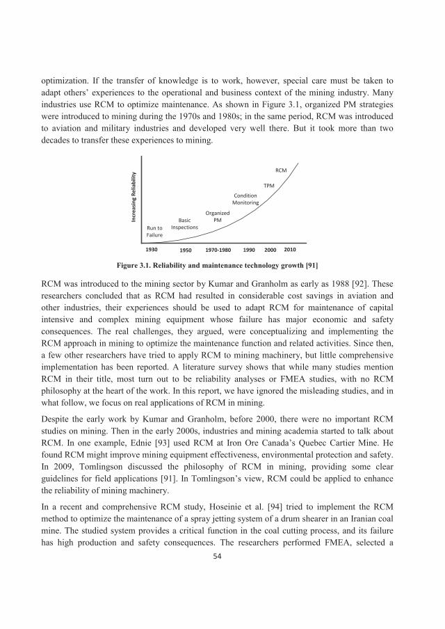
54
optimization. If the transfer of knowledge is to work, however, special care must be taken to adapt others’ experiences to the operational and business context of the mining industry. Manyindustries use RCM to optimize maintenance. As shown in Figure 3.1, organized PM strategies were introduced to mining during the 1970s and 1980s; in the same period, RCM was introduced to aviation and military industries and developed very well there. But it took more than two decades to transfer these experiences to mining.
Run to FailureRun to Failure
BasicInspections
Basic Inspections
OrganizedPM
Organized PM
Condition MonitoringgCondition
Monitoring
TPMTPM
RCMRCM
19301930 19501950 1970-19801970-1980 19901990 20002000 20102010
Incr
easi
ng R
elia
bilit
yIn
crea
sing
Rel
iabi
lity
Figure 3.1. Reliability and maintenance technology growth [91]
RCM was introduced to the mining sector by Kumar and Granholm as early as 1988 [92]. These researchers concluded that as RCM had resulted in considerable cost savings in aviation and other industries, their experiences should be used to adapt RCM for maintenance of capital intensive and complex mining equipment whose failure has major economic and safety consequences. The real challenges, they argued, were conceptualizing and implementing the RCM approach in mining to optimize the maintenance function and related activities. Since then, a few other researchers have tried to apply RCM to mining machinery, but little comprehensive implementation has been reported. A literature survey shows that while many studies mentionRCM in their title, most turn out to be reliability analyses or FMEA studies, with no RCM philosophy at the heart of the work. In this report, we have ignored the misleading studies, and in what follow, we focus on real applications of RCM in mining.
Despite the early work by Kumar and Granholm, before 2000, there were no important RCM studies on mining. Then in the early 2000s, industries and mining academia started to talk about RCM. In one example, Ednie [93] used RCM at Iron Ore Canada’s Quebec Cartier Mine. He found RCM might improve mining equipment effectiveness, environmental protection and safety. In 2009, Tomlingson discussed the philosophy of RCM in mining, providing some clear guidelines for field applications [91]. In Tomlingson’s view, RCM could be applied to enhance the reliability of mining machinery.
In a recent and comprehensive RCM study, Hoseinie et al. [94] tried to implement the RCM method to optimize the maintenance of a spray jetting system of a drum shearer in an Iranian coal mine. The studied system provides a critical function in the coal cutting process, and its failurehas high production and safety consequences. The researchers performed FMEA, selected a
55
maintenance strategy, and developed a cost function to find the optimum (cost-effective) PM scheduling. They concluded RCM is completely applicable to mining machinery and can offer substantial cost and safety improvements if well implemented.
From the industry point of view, some well-known machinery manufacturers such as Joy Global [95] have recently launched RCM based service and support systems. This particular companyhas tried to analyze previous experience along with real-time machine data, using global data and industry-leading technology to recommend and implement the best strategy, i.e., RCM. Their RCM philosophy focuses on lowering the cost per ton, increasing production and supporting a zero harm environment [96]. These kinds of serious industrial efforts are valuable and provide hope for future development. In due course, the mining sector will benefit as much from RCM as other industries.
3.2 RCM adaptation to automated mining machinery In this section, we look at RCM implementation in fully automated mining machinery, drawing on the following documents and standards:
Classic RCM in aviation industry [44, 97, 98]NASA RCM guidelines [60]USA military standards MIL-STD-2173 [75]International Atomic Energy Agency (IAEA) RCM document [82]
3.2.1 Step 1: System selection and information collecting As discussed earlier, fully automated underground mining is the focus of this project. Any application of RCM in such an operation should consider the holistic structure of the systems involved and their components (see Chapter 1). As shown in Figure 3.2, machinery (or fleets of machinery) is a subsystem of the overall system. In this research, we focus on machinery. Other subsystems, such as communication systems, are out of the scope of this research.
Based on the experience in aviation [44, 49, 53] and the maintenance culture in mining, all RCM implementation guidelines and related documents are at the subsystem level (subsystems of machinery); this is equal to the “system” level in standard RCM definitions, as mentioned in Section 2.4.1. As discussed in Chapter 2, the criteria generally used to select the target system for RCM analysis are the following:
Maintenance costs (PM and/or CM) Failure frequency Downtime (hours)SafetyEnvironment
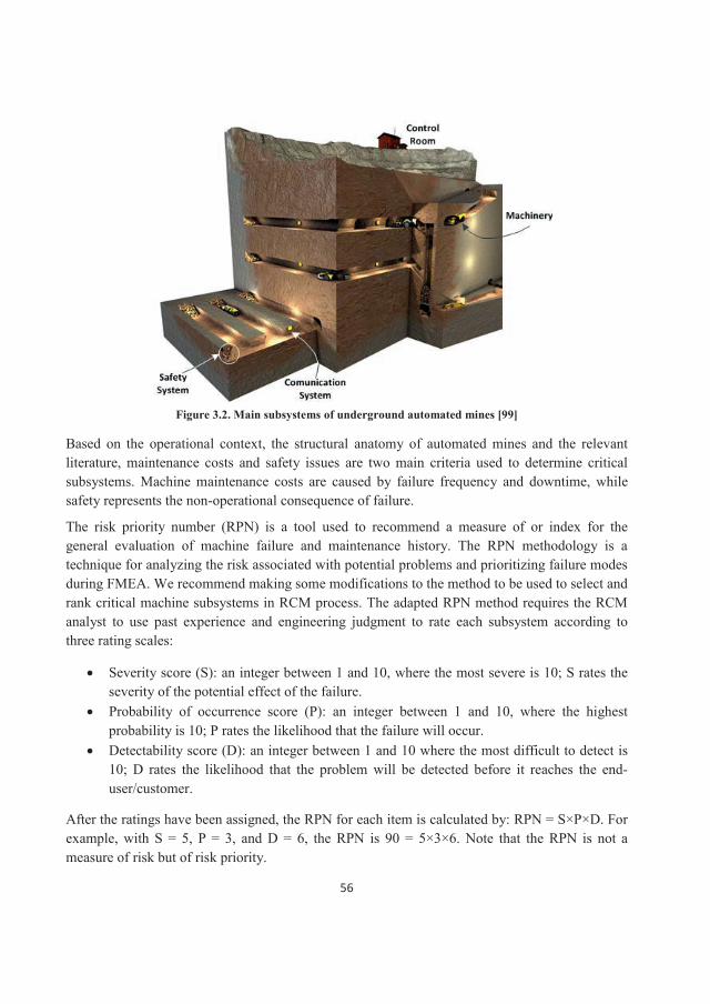
56
Figure 3.2. Main subsystems of underground automated mines [99]
Based on the operational context, the structural anatomy of automated mines and the relevant literature, maintenance costs and safety issues are two main criteria used to determine critical subsystems. Machine maintenance costs are caused by failure frequency and downtime, whilesafety represents the non-operational consequence of failure.
The risk priority number (RPN) is a tool used to recommend a measure of or index for the general evaluation of machine failure and maintenance history. The RPN methodology is a technique for analyzing the risk associated with potential problems and prioritizing failure modes during FMEA. We recommend making some modifications to the method to be used to select and rank critical machine subsystems in RCM process. The adapted RPN method requires the RCM analyst to use past experience and engineering judgment to rate each subsystem according to three rating scales:
Severity score (S): an integer between 1 and 10, where the most severe is 10; S rates the severity of the potential effect of the failure. Probability of occurrence score (P): an integer between 1 and 10, where the highest probability is 10; P rates the likelihood that the failure will occur. Detectability score (D): an integer between 1 and 10 where the most difficult to detect is 10; D rates the likelihood that the problem will be detected before it reaches the end-user/customer.
After the ratings have been assigned, the RPN for each item is calculated by: RPN = S×P×D. For example, with S = 5, P = 3, and D = 6, the RPN is 90 = 5×3×6. Note that the RPN is not a measure of risk but of risk priority.
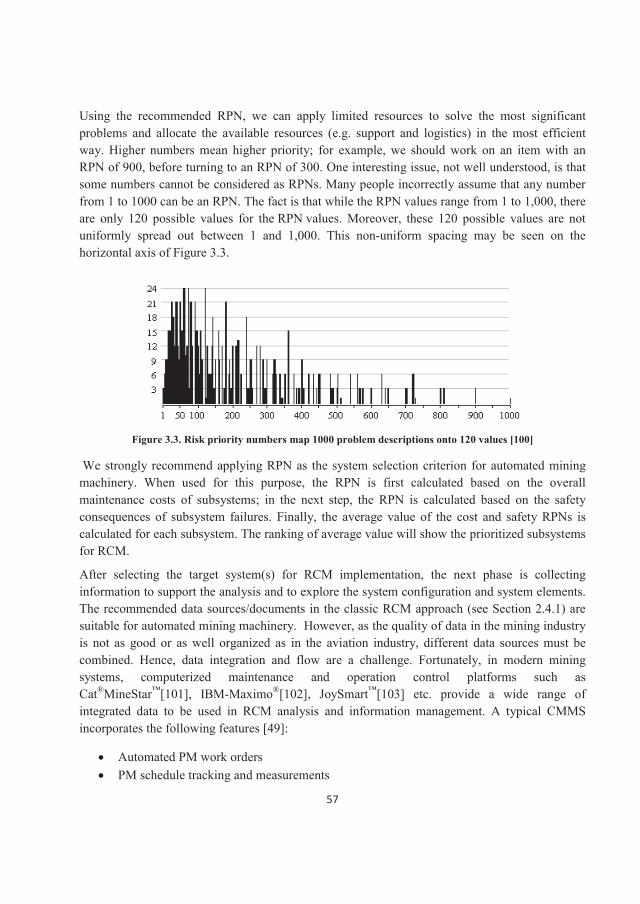
57
Using the recommended RPN, we can apply limited resources to solve the most significant problems and allocate the available resources (e.g. support and logistics) in the most efficient way. Higher numbers mean higher priority; for example, we should work on an item with an RPN of 900, before turning to an RPN of 300. One interesting issue, not well understood, is that some numbers cannot be considered as RPNs. Many people incorrectly assume that any number from 1 to 1000 can be an RPN. The fact is that while the RPN values range from 1 to 1,000, there are only 120 possible values for the RPN values. Moreover, these 120 possible values are not uniformly spread out between 1 and 1,000. This non-uniform spacing may be seen on the horizontal axis of Figure 3.3.
Figure 3.3. Risk priority numbers map 1000 problem descriptions onto 120 values [100]
We strongly recommend applying RPN as the system selection criterion for automated mining machinery. When used for this purpose, the RPN is first calculated based on the overall maintenance costs of subsystems; in the next step, the RPN is calculated based on the safety consequences of subsystem failures. Finally, the average value of the cost and safety RPNs is calculated for each subsystem. The ranking of average value will show the prioritized subsystems for RCM.
After selecting the target system(s) for RCM implementation, the next phase is collecting information to support the analysis and to explore the system configuration and system elements. The recommended data sources/documents in the classic RCM approach (see Section 2.4.1) are suitable for automated mining machinery. However, as the quality of data in the mining industry is not as good or as well organized as in the aviation industry, different data sources must be combined. Hence, data integration and flow are a challenge. Fortunately, in modern mining systems, computerized maintenance and operation control platforms such as Cat®MineStar™[101], IBM-Maximo®[102], JoySmart™[103] etc. provide a wide range of integrated data to be used in RCM analysis and information management. A typical CMMS incorporates the following features [49]:
Automated PM work ordersPM schedule tracking and measurements
58
Corrective maintenance requests and recordsPerformance trendsFailure analysis recordsCondition-directed task measurement, criteria, and alertsEquipment historyIndustry equipment experienceSpares/inventory recordsSkill requirements versus skill availabilityPM and CM cost data
3.2.2 Step 2: System boundary definition As automated systems are often complex and complicated, with many on-board and out-board instruments, defining their boundaries for RCM analysis is critical. In this report, we recommend that to facilitate system analysis and to ensure better maintenance management, system boundaries should be defined for machinery and on-board components. The off-board and communication instruments such as the navigation network are excluded here.
That may not apply to all cases. System A may have control statistics in a plant control room physically separated from it (off-board). But the analyst may believe it is a good idea to include those control room instruments in an analysis of system A. If the control room is later analyzed as a separate system, the previously established boundary for system A will tell the analyst not toinclude those instruments in the control room boundary definition (on-board).
The studied machine should be divided into clear subsystems and the boundaries of target system/systems defined with clear IN and OUT interfaces. This will help us to find the failure modes and effects of each unit in a system and to follow the 80/20 rules. The rest of this step is similar to the classic RCM approach (see Section 2.4.2).
3.2.3 Step 3: System description and functional block diagram In the case of automated mining machinery, this step can be executed as the classic RCM procedure presented in Section 2.4.3. However, since we recommend carrying out the RCM analysis at the subsystem level, steps 3 through 7 should be done at this level. This means the IN and OUT interfaces and functional block diagram need to be developed and analyzed in component-component and subsystem-subsystem interactions.
3.2.4 Step 4: System functions and functional failures Automated machinery may fail because of software or hardware failures. Software failures are due to errors in automation system programming, communication, and data transition, whereas hardware failures are associated with electronic, electrical, and mechanical components.
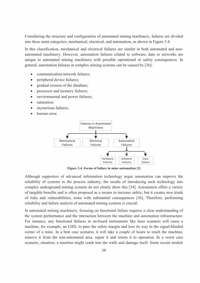
59
Considering the structure and configuration of automated mining machinery, failures are divided into three main categories, mechanical, electrical, and automation, as shown in Figure 3.4.
In this classification, mechanical and electrical failures are similar in both automated and non-automated machinery. However, automation failures related to software, data or networks are unique to automated mining machinery with possible operational or safety consequences. In general, automation failures in complex mining systems can be caused by [36]:
communication network failures;peripheral device failures;gradual erosion of the database;processor and memory failures;environmental and power failures;saturation;mysterious failures;human error.
Failures in Automated Machinery
Mechanical Failures
Automation Failures
Electrical Failures
Hardware Failures
Software Failures
Data Failure
Figure 3.4. Forms of failure in mine automation [3]
Although supporters of advanced information technology argue automation can improve the reliability of systems in the process industry, the results of introducing such technology into complex underground mining systems do not clearly show this [34]. Automation offers a variety of tangible benefits and is often proposed as a means to increase safety, but it creates new kinds of risks and vulnerabilities, some with substantial consequences [36]. Therefore, performing reliability and failure analysis of automated mining systems is crucial.
In automated mining machinery, focusing on functional failure requires a clear understanding of the system performance and the interaction between the machine and automation infrastructure. For instance, any functional failures in on-board instruments like laser scanners will cause a machine, for example, an LHD, to pass the safety margin and lose its way in the signal-blinded corner of a mine. In a best case scenario, it will take a couple of hours to reach the machine, remove it from the non-automated area, repair it and return it to operation. In a worst case scenario, situation, a machine might crash into the walls and damage itself. Some recent models
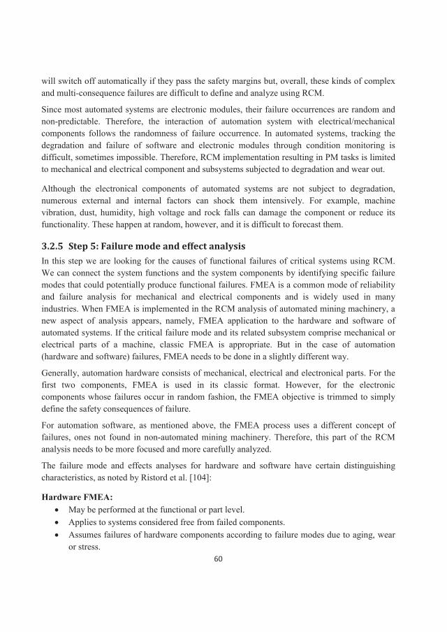
60
will switch off automatically if they pass the safety margins but, overall, these kinds of complex and multi-consequence failures are difficult to define and analyze using RCM.
Since most automated systems are electronic modules, their failure occurrences are random andnon-predictable. Therefore, the interaction of automation system with electrical/mechanical components follows the randomness of failure occurrence. In automated systems, tracking the degradation and failure of software and electronic modules through condition monitoring is difficult, sometimes impossible. Therefore, RCM implementation resulting in PM tasks is limited to mechanical and electrical component and subsystems subjected to degradation and wear out.
Although the electronical components of automated systems are not subject to degradation, numerous external and internal factors can shock them intensively. For example, machine vibration, dust, humidity, high voltage and rock falls can damage the component or reduce its functionality. These happen at random, however, and it is difficult to forecast them.
3.2.5 Step 5: Failure mode and effect analysis In this step we are looking for the causes of functional failures of critical systems using RCM. We can connect the system functions and the system components by identifying specific failure modes that could potentially produce functional failures. FMEA is a common mode of reliability and failure analysis for mechanical and electrical components and is widely used in manyindustries. When FMEA is implemented in the RCM analysis of automated mining machinery, a new aspect of analysis appears, namely, FMEA application to the hardware and software of automated systems. If the critical failure mode and its related subsystem comprise mechanical or electrical parts of a machine, classic FMEA is appropriate. But in the case of automation (hardware and software) failures, FMEA needs to be done in a slightly different way.
Generally, automation hardware consists of mechanical, electrical and electronical parts. For the first two components, FMEA is used in its classic format. However, for the electronic components whose failures occur in random fashion, the FMEA objective is trimmed to simplydefine the safety consequences of failure.
For automation software, as mentioned above, the FMEA process uses a different concept of failures, ones not found in non-automated mining machinery. Therefore, this part of the RCM analysis needs to be more focused and more carefully analyzed.
The failure mode and effects analyses for hardware and software have certain distinguishing characteristics, as noted by Ristord et al. [104]:
Hardware FMEA:May be performed at the functional or part level.Applies to systems considered free from failed components.Assumes failures of hardware components according to failure modes due to aging, wear or stress.
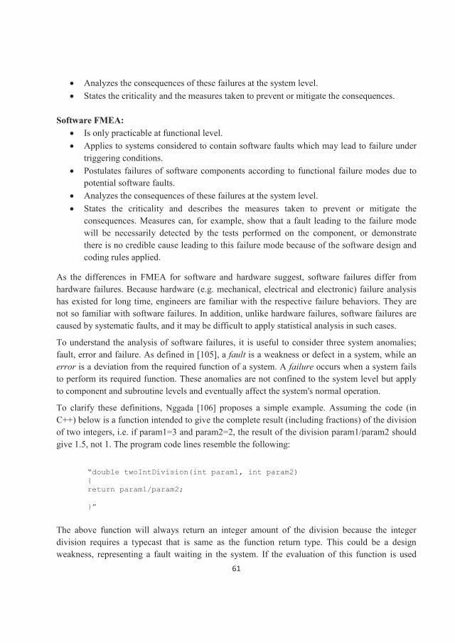
61
Analyzes the consequences of these failures at the system level.States the criticality and the measures taken to prevent or mitigate the consequences.
Software FMEA:Is only practicable at functional level.Applies to systems considered to contain software faults which may lead to failure under triggering conditions.Postulates failures of software components according to functional failure modes due to potential software faults.Analyzes the consequences of these failures at the system level.States the criticality and describes the measures taken to prevent or mitigate the consequences. Measures can, for example, show that a fault leading to the failure mode will be necessarily detected by the tests performed on the component, or demonstrate there is no credible cause leading to this failure mode because of the software design and coding rules applied.
As the differences in FMEA for software and hardware suggest, software failures differ fromhardware failures. Because hardware (e.g. mechanical, electrical and electronic) failure analysis has existed for long time, engineers are familiar with the respective failure behaviors. They are not so familiar with software failures. In addition, unlike hardware failures, software failures are caused by systematic faults, and it may be difficult to apply statistical analysis in such cases.
To understand the analysis of software failures, it is useful to consider three system anomalies; fault, error and failure. As defined in [105], a fault is a weakness or defect in a system, while an error is a deviation from the required function of a system. A failure occurs when a system fails to perform its required function. These anomalies are not confined to the system level but apply to component and subroutine levels and eventually affect the system's normal operation.
To clarify these definitions, Nggada [106] proposes a simple example. Assuming the code (in C++) below is a function intended to give the complete result (including fractions) of the division of two integers, i.e. if param1=3 and param2=2, the result of the division param1/param2 should give 1.5, not 1. The program code lines resemble the following:
“double twoIntDivision(int param1, int param2) {return param1/param2;
}”
The above function will always return an integer amount of the division because the integer division requires a typecast that is same as the function return type. This could be a design weakness, representing a fault waiting in the system. If the evaluation of this function is used
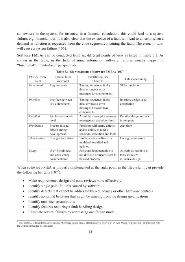
62
somewhere in the system, for instance, in a financial calculation, this could lead to a system failure; e.g. financial loss. It is also clear that the existence of a fault will lead to an error when a demand in function is requested from the code segment containing the fault. The error, in turn,will cause a system failure [106].
Software FMEAs can be conducted from six different points of view as listed in Table 3.1. As shown in the table, in the field of mine automation software, failures usually happen in “functional” or “interface” perspectives.
Table 3.1. Six viewpoints of software FMEAs [107*]
FMEA view point
Product level viewpoint
Identifies failurerelated to:
Life cycle timing
Functional Requirements Timing, sequence, faulty data, erroneous error messages for a component
SRS completion
Interface Interface between two components
Timing, sequence, faulty data, erroneous error messages between two components
Interface design spec completion
Detailed At class or module level
All of the above plus memory management and algorithms
Detailed design or code is complete
Production Process related failure during development
Problems with many defects and/or ability to meet a schedule, execution and tools
Any time
Maintenance Changes to software Problem when software is modified, installed and updated
During maintenance
Usage User friendliness and consistency, documentation
Software/documentation is too difficult or inconsistent to be used properly
As early as possible as these issues will influence design
When software FMEA is properly implemented at the right point in the lifecycle, it can provide the following benefits [107*]:
Make requirements, design and code reviews more effectivelyIdentify single point failures caused by softwareIdentify defects that cannot be addressed by redundancy or other hardware controlsIdentify abnormal behavior that might be missing from the design specificationsIdentify unwritten assumptionsIdentify features requiring a fault handling designEliminate several failures by addressing one failure mode
* This material is taken from a presentation “Software failure modes effects analysis overview” by Ann Marie Neufelder (2010). It is used with the written permission of the author.
63
As the above list suggests, the findings could greatly improve the safety of both automatedsystems and mining machinery. This shows the capabilities of RCM analysis in improvingmaintenance management in automated mines and enhancing maintenance quality. However, in practice, there are two key challenges [107*]:
Finding effective ways of classifying software failures into appropriate failure modesEstimating the likelihood of each failure mode
Note that resources are devoted to single failure occurrences that detrimentally impact function;we do not consider multiple failure scenarios as we do in safety analyses. If redundancy prevents loss of function, then a failure mode thus shielded by redundancy should not be given the same priority or stature as a failure mode that can singly defeat a necessary function. If we think there is a high probability of multiple independent failures in a redundant configuration, what we have identified is a more fundamental design issue, not one that should be addressed by the maintenance program.
When do we invoke the redundancy rule? When listing the failure modes, we do not introduce it, as our objective is to ensure we initially capture each failure mode (protected or not) that can lead to functional failure. Later in the effects analysis, we apply the redundancy rule. If available redundancy essentially eliminates any effect at the system level (and, it will follow, at the plant level also), we drop the failure mode from further consideration and turn to the run-to-failure check described in Step 7. Since automated mining machines are often designed with a host of redundancy features to achieve high levels of safety and productivity, it is not uncommon to find that this initial screening with the redundancy rule could relegate 50% or more of the failure modes to the RTF status [49]. Should we encounter this situation, our maintenance program will likely realize significant cost reductions because of foresight in the design phase (even though that foresight was not, in all likelihood, maintenance driven).
An important exception to the preceding rule involves alarms, inhibited or permissive devices,isolation devices and protection logic devices involving some voting scheme. Here, the rule requires an assumption of multiple failures to properly assess the effects or consequences of redundancy loss. In the case of alarms (as well as isolation, inhibited, and permissive devices), a "failure to operate" is, by itself, not significant. It can become significant, however, if the alarmed or protected component has also failed. We assume the alarmed component has failed so we cangain the proper perspective in our effects analysis. The same principle holds with protection logic, where redundant channels are assumed failed to the extent that the next single failure will wipe out the protection logic. We tend to find protection logic systems when dealing with safety and environmental issues or areas where machines must be "tripped" automatically to preclude widespread damage to automated machinery.
* This material is taken from a presentation “Software failure modes effects analysis overview” by Ann Marie Neufelder (2010). It is used with the written permission of the author.
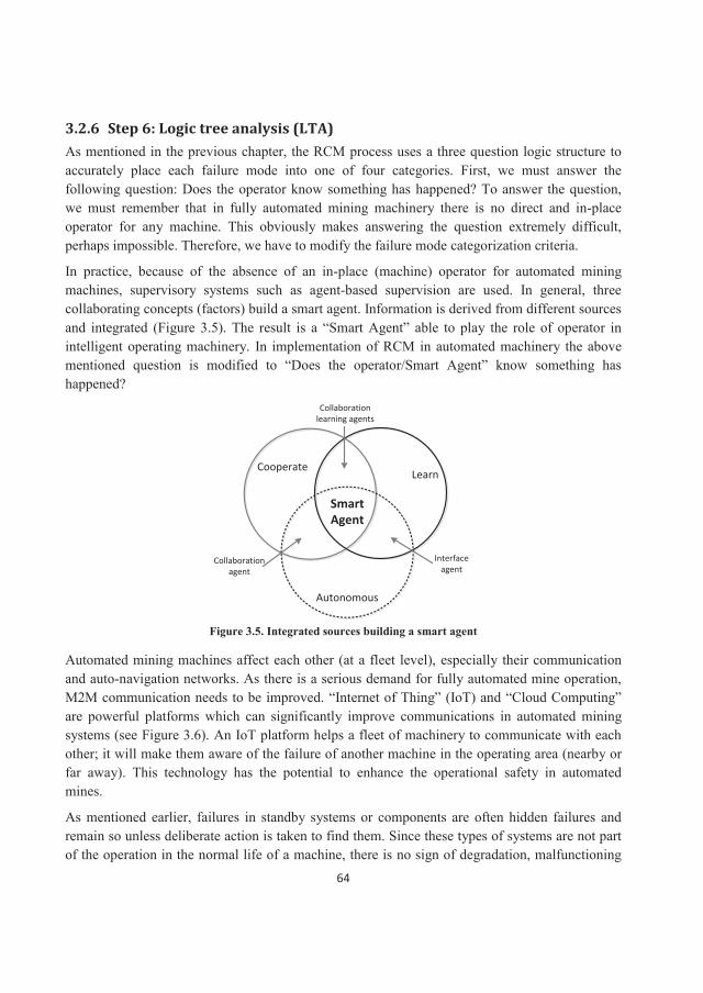
64
3.2.6 Step 6: Logic tree analysis (LTA) As mentioned in the previous chapter, the RCM process uses a three question logic structure to accurately place each failure mode into one of four categories. First, we must answer the following question: Does the operator know something has happened? To answer the question, we must remember that in fully automated mining machinery there is no direct and in-place operator for any machine. This obviously makes answering the question extremely difficult, perhaps impossible. Therefore, we have to modify the failure mode categorization criteria.
In practice, because of the absence of an in-place (machine) operator for automated mining machines, supervisory systems such as agent-based supervision are used. In general, three collaborating concepts (factors) build a smart agent. Information is derived from different sources and integrated (Figure 3.5). The result is a “Smart Agent” able to play the role of operator in intelligent operating machinery. In implementation of RCM in automated machinery the above mentioned question is modified to “Does the operator/Smart Agent” know something has happened?
CooperateLearn
Autonomous
Collaboration agent
Interface agent
Collaboration learning agents
Smart Agent
Figure 3.5. Integrated sources building a smart agent
Automated mining machines affect each other (at a fleet level), especially their communicationand auto-navigation networks. As there is a serious demand for fully automated mine operation, M2M communication needs to be improved. “Internet of Thing” (IoT) and “Cloud Computing” are powerful platforms which can significantly improve communications in automated mining systems (see Figure 3.6). An IoT platform helps a fleet of machinery to communicate with each other; it will make them aware of the failure of another machine in the operating area (nearby or far away). This technology has the potential to enhance the operational safety in automated mines.
As mentioned earlier, failures in standby systems or components are often hidden failures and remain so unless deliberate action is taken to find them. Since these types of systems are not part of the operation in the normal life of a machine, there is no sign of degradation, malfunctioning
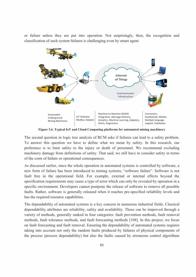
65
or failure unless they are put into operation. Not surprisingly, then, the recognition and classification of such system failures is challenging even by smart agent.
Internet of Things
Communication Infrastructure
Automated Underground Mining Machinery
IoT GatewayModbus Adaptor
Machine-to-Machine (M2M) Integration, Message Delivery, Analytics, Machine Learning, Adapters, Alerts, Diagnostics
Connectors, Dashboards, Mobile, Multiple language support, Databases
Figure 3.6. Typical IoT and Cloud Computing platforms for automated mining machinery
The second question in logic tree analysis of RCM asks if failures can lead to a safety problem.To answer this question we have to define what we mean by safety. In this research, our preference is to limit safety to the injury or death of personnel. We recommend excluding machinery damage from definitions of safety. That said, we still have to consider safety in terms of the costs of failure or operational consequences.
As discussed earlier, since the whole operation in automated systems is controlled by software, a new form of failure has been introduced to mining systems, “software failure”. Software is not fault free in the operational field. For example, external or internal effects beyond the specification requirements may cause a type of error which can only be revealed by operation in aspecific environment. Developers cannot postpone the release of software to remove all possible faults. Rather, software is generally released when it reaches pre-specified reliability levels and has the required resource capabilities.
The dependability of automated systems is a key concern in numerous industrial fields. Classical dependability attributes are reliability, safety and availability. These can be improved through a variety of methods, generally ranked in four categories: fault prevention methods, fault removal methods, fault tolerance methods, and fault forecasting methods [108]. In this project, we focus on fault forecasting and fault removal. Ensuring the dependability of automated systems requires taking into account not only the random faults produced by failures of physical components of the process (process dependability) but also the faults caused by erroneous control algorithms
66
(controller (software) dependability). The latter represent designer error or misinterpretation of the control requirements and behave as systematic faults.
The third question to ask ourselves is this: does a failure mode result in a full or partial outage of production? If we have properly analyzed the target system and have carried out the FMEA accurately, answering this question will not be difficult. If production stops for the whole mine (e.g. when the main shaft and haulage system fail), we see this as an outage problem. If there are partial production stoppages in one or several operation areas or mining levels, we consider this minor, or in a worst case scenario, as high cost failure.
When the LTA process of identifying and classifying the failure modes and their consequences and importance is concluded, every failure mode will have been classified as:
A: Safety problemB: Outage problemC: Minor/insignificant problem
At this point, we recommend addressing PM priorities as in other industries, thereby deriving the following:
1. A or D/A2. B or D/B3. C or D/C
Because safety related problems are so important in mining, eliminating any safety problem is the overall goal of automation and should be considered in all maintenance strategies in automated mines.
3.2.7 Step 7: Maintenance task selection Traditional methods for determining PM tasks start with the issue of preserving equipment operability; such methods tend to focus the entire task selection process on what can be done to the equipment. For the most part, why something should be done is not clearly addressed (or documented if investigated). RCM is a major departure from this traditional practice! Its basic premise is "preserve function" not "preserve equipment." This approach forces the analyst to systematically understand (and document) the system functions that must be preserved without any specific regard initially for the equipment that may be involved.
Task selection in automated mining machines is not so complicated if we have carried out the previous RCM steps properly. We don’t discuss task selection in detail because it might provide misleading information in practice. Each mine and its automation system have specific characteristics and features; therefore, task selection is highly dependent on available maintenance skills and technologies, the financial condition of mining company, mine production rate and even the international market conditions. The most important issue to consider in the task selection process in automated mining is the size of operation and the M2M integration
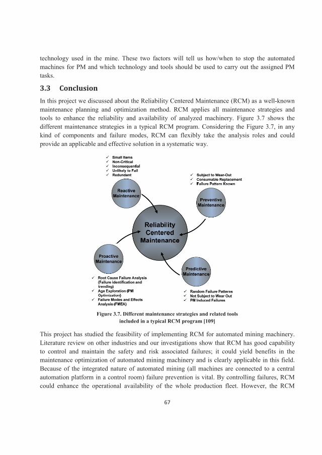
67
technology used in the mine. These two factors will tell us how/when to stop the automated machines for PM and which technology and tools should be used to carry out the assigned PM tasks.
3.3 Conclusion In this project we discussed about the Reliability Centered Maintenance (RCM) as a well-known maintenance planning and optimization method. RCM applies all maintenance strategies and tools to enhance the reliability and availability of analyzed machinery. Figure 3.7 shows the different maintenance strategies in a typical RCM program. Considering the Figure 3.7, in any kind of components and failure modes, RCM can flexibly take the analysis roles and could provide an applicable and effective solution in a systematic way.
Figure 3.7. Different maintenance strategies and related tools included in a typical RCM program [109]
This project has studied the feasibility of implementing RCM for automated mining machinery. Literature review on other industries and our investigations show that RCM has good capability to control and maintain the safety and risk associated failures; it could yield benefits in the maintenance optimization of automated mining machinery and is clearly applicable in this field.Because of the integrated nature of automated mining (all machines are connected to a central automation platform in a control room) failure prevention is vital. By controlling failures, RCM could enhance the operational availability of the whole production fleet. However, the RCM
68
process must be adapted for automated mining production, considering the special characteristics and harsh operating contexts of mining.
The recommendations for adaption and getting better results from RCM analysis are presented here. However, it should be considered that the best and final adaption advises could be presented only by carrying out real case studies in automated mines. Therefore, following comments are just the results of comparative investigations between the basic RCM philosophy, achieved experiences in other industries considering context of automated mining:
As the cost of maintenance and safety are two main factors in maintenance effectiveness, in the first step of the RCM process (system selection) applying RPN as the system selection criterion is suggested. The average value of RPN is calculated based on the maintenance cost and safety consequences of failures. According to the literature, twoyears of failure history data are recommended for failure analysis and reliability modelingto support the RCM process in automated mines.
System boundaries are defined for machinery and on-board components.
RCM implementation in mining automated machinery in case of PM optimization is limited to mechanical and electrical components and subsystems subject to degradation and wear out, which can be monitored.
When applied to the software of automated mining machinery, the FMEA process has a different concept of failure than in hardware systems; this means it needs to be more carefully analyzed. The failure mode and effects analysis for hardware or software have certain distinguishing characteristics. It is important that to remember in the field of mine automation software, failures usually happen in a “functional” or “interface” perspective.
In fully automated mining machinery, there is no operator, so being aware of a failure occurrence can be difficult. Therefore, we have to modify the failure mode categorization criteria, perhaps even change them. The operator can be replaced by supervisory systems such as agent-based supervision, or “Smart Agents” playing the role of operator in intelligent operating machinery.
The use of the “Internet of Things” platform, including eMaintenance and eOperation, is strongly recommended in combination with RCM in automated mining machinery. This enables us to control failure propagation in the mining fleet.
Since a mining operation often has a large inventory, we rarely face a full outage problem. As long as production continues, even at a low rate, any failure is counted as minor, or in a worst case scenario, as a high cost failure.
Safety related problems are very important in mining; therefore, eliminating safety problems is the overall goal of automation, something to consider in all maintenance strategies.
69
3.4 Future work In recent years, as instrumentation and information systems become cheaper and more reliable, CBM becomes an important tool for running the production systems. Traditional CBM is a maintenance program that recommends maintenance actions based on the information collected through condition monitoring. The previous CBM carries out maintenance task that focuses only on condition monitoring and diagnostics. With increasing requirement in predicting future degradation trend of equipment performance, CBM functions extended and a prognostic layer was added. In recent years, a development of CBM called CBM plus (CBM+) is put forward, which is the application and integration of appropriate process, technologies, and knowledge-based capabilities to improve reliability and maintenance effectiveness [11]. At its core, CBM+ is maintenance performed on evidence of need provided by RCM analysis and other enabling processes and technologies.
Since automated mining machinery get benefits of high technologies in condition monitoring and operation control, wide range of machine health data is available for making better maintenance decisions. Therefore, one of the possible and attractive research works which could be carried out on automated (currently semi-automated) mining machines in future, is to develop an advanced CBM+ system that uses RCM mechanism to optimize maintenance cost, and employs data fusion strategy for improving condition monitoring, health assessment, and prognostics.
References [1] V. Schweikart, Automation in Mining, Engineers Australia, file:///C:/Users/hadhos/Downloads/Automation%
20in%20Mining.pdf , taken 2015-03-09[2] http://www.automation.com/library/case-studies/machine-monitoring-control/smart-sensor-and-prognostics-
for-self-maintenance-machines [3] B. Ghodrati, S. H. Hoseinie & A.H.S. Garmabaki, Reliability considerations in automated mining
systems, International Journal of Mining, Reclamation and Environment, Vol. 29, No. 5, September 2015, pages 404-418.
[4] LTU, strategic research and innovation agenda for the swedish mining and metal producing industry (strim),www.ltu.se/cms_fs/1.114292!/file/Agenda-STRIM-LTU-Vinnova.pdf, 2013.
[5] P.A. Lindqvist, Sustainable mining and innovation for the future. Research, development and innovation programme, Nordic Rock Tech Centre,, Luleå, Sweden, 2012.
[6] A.J. Kwitowski, W.H. Lewis, W.D. Mayercheck, and M.C. Leigh, Computer-based remote control of a highwall mining system, 21st Century Higher Production Coal Mining Systems Symposium, Wollongong, New South Wales Australia, 1988.
[7] C.G. Merrimen, The path to successful roof support automation, International Conference on Reliability, Production and Control in Coal Mines, Wollongong, New South Wales Australia, 1991.
[8] R.G. Harris, and P. Smith, Automation and control of longwall mining systems, International Conference on Reliability, Production and Control in Coal Mines, Wollongong, New South Wales Australia, 1991.
[9] S.N. Maity, S.K. Sarkar, and B.B. Dhar, An approach towards full automation in longwall mining by further improvement in the mechanization system, 2nd International Symposium on Mine Mechanization and Automation, Rotterdam, 1993.
70
[10] S. Mundry, M. Gajetzki & S.H. Hoseinie, Longwall automation-productivity and coal quality enhancement, International Journal of Mining, Reclamation and Environment, Vol. 29, No. 5, September 2015, pages 357-367.
[11] M. Pulkkinen, Automation and mechanization of mines, 2nd International Symposium on Mine Mechanization and Automation, Rotterdam, 1993.
[12] M.l. Hopkins, and S.D. Duggan, Automation drilling of surface blast holes using computer control, 2nd International Symposium on Mine Mechanization and Automation, Rotterdam, 1993.
[13] B. Todd, T.M. Tower, and T.H. Wake, Evolution of automation in raiseboring systems, 2nd International Symposium on Mine Mechanization and Automation, Rotterdam, 1993.
[14] G. Schnakenberg, Technology development for remote, computer-assisted operation of a continuous mining machine, Illinois Mining Institute, Champaign, IL (United States), 1993.
[15] D.G. Brophey, and D.W. Euler, The Opti-Trak systems, a system for automating today’s LHD’s and trucks, 2nd International Symposium on Mine Mechanization and Automation, Rotterdam, 1993.
[16] H. Takahashi, H. Kamata, T. Masuyama, and S. Sarata, Autonomous shoveling of rocks by using image vision system on LHD, Proc., International Symposium on Mine Mechanization and Automation, 1995.
[17] J.M. Roberts, E.S. Duff, P. Corke, P. Sikka, G.J. Winstanley, and J. Cunningham, Autonomous control of underground mining vehicles using reactive navigation, Robotics and Automation, 2000. Proceedings. ICRA'00. IEEE International Conference on, 2000.
[18] CSIRO., Load Haul Dump (LHD) Automation,http://research.ict.csiro.au/research/laboratories/autonomous-systems/fieldrobotics/mining-robotics/load-haul-dump-lhd-automation, 2009.
[19] A. Gustafson, H. Schunnesson, D. Galar, and U. Kumar, The influence of the operating environment on manual and automated load-haul-dump machines: a fault tree analysis, International Journal of Mining, Reclamation and Environment 27 (2013), pp. 75-87.
[20] J. Paraszczak, A. Gustafson & H. Schunnesson, Technical and operational aspects of autonomous LHD application in metal mines, International Journal of Mining, Reclamation and Environment, Vol. 29, No. 5, September 2015, pages 391-403
[21] P. Corke, Machine vision feedback control of mining machinery, Proceedings of the International Symposium on Mine Mechanization and Automation, Denver, Colorado, 1995.
[22] S. Sarata, K. Sato, and S. Yuta, Motion control system for autonomous wheel loader operation, Proceedings, International Symposium on Mine Mechanization and Automation, 1995.
[23] G. Atkinson, Automated Mining Machine Safety Investigation. Master Thesis, McGill University, 1996.[24] J. Greberg, and U. Kumar, Selection of maintenance strategy for mechanized and automated systems using risk
analysis, Proceedings from 5th International Symposium on Mine Mechanization and Automation, Laurentian Univ. Sudbury, Canada, June 99, 1999.
[25] B.S. Dhillon, Mine safety: a modern approach, Springer Science & Business Media, 2010.[26] N. Varandas, F. Cordeiro, H. Almeida, N. N. Sousa, P. França, A. Cruz, and J. Oliveira, Underground Mine
Traffic Management and Optimization: An Intelligent Application Based on a Real-Time Localization System, Sixth International Symposium High Performance Mining (AIMS 2014),, Aachen, Germany, 2014.
[27] K. Cameras, E. Chmelina, M. Lammer, and H. Kaufmann, Real-Time Machine Guidance with Tracking Proceeding of the 6th International Symposium High Performance Mining, Aachen, Germany, 2014.
[28] M. Dunn, D. Reid, and J. Ralston, Control of Automated Mining Machinery Using Aided Inertial Navigation,in Machine Vision and Mechatronics in Practice, Springer, 2015, pp. 1-9.
[29] R.L. Wears, R.I. Cook, and S.J. Perry, Automation, interaction, complexity, and failure: A case study,Reliability Engineering & System Safety 91 (2006), pp. 1494-1501.
[30] P. Darling, SME mining engineering handbook, Vol. 1, SME, 2011.[31] S.Y. Nof, Springer handbook of automation, Springer Science & Business Media, 2009.[32] Wikipedia, Automated mining, https://en.wikipedia.org/wiki/Automated_mining
71
[33] S. Krar, “The importance of maintenance (changing from a fail and fix approach to predict and prevent approach)”, available in: http://www.automationmag. com
[34] A. Gustafson, H. Schunnesson, D. Galar, and U. Kumar, “Production and maintenance performance analysis: manual versus semi-automatic LHDs”, Journal of Quality in Maintenance Engineering 19 (2013), pp. 74-88.
[35] H. Erbe, IFAC Professional Brief Technologies for Cost Effective Automation in Manufacturing (Low Cost Automation), available in: http: //www.zmms.tu-berlin.de/LCA
[36] R.L. Wears, R.I. Cook, and S.J. Perry, Automation, interaction, complexity, and failure: A case study,Reliability Engineering & System Safety 91 (2006), pp. 1494-1501.
[37] N. Leveson, A new accident model for engineering safer systems, Safety science 42 (2004), pp. 237-270.[38] G. Morel, M. Suhner, B. Iung, J. B. Léger, “Maintenance holistic framework for optimizing the
cost/availability compromise of manufacturing systems.” In: Proceedings of the sixth IFAC symposium on cost oriented automation. Survey Paper, Berlin, Germany, October, (2001).
[39] F.A. Bulletins, Fatal Grams and Fatal Investigation Reports, Mine Safety and Health Administration (MSHA), Washington, DC (2001).
[40] J. J. Sammarco, “Addressing the safety of programmable electronic mining systems: lessons learned”, Industry Applications Conference, 2002. 37th IAS Annual Meeting. Conference Record of the, (2002).
[41] B. S. Dhillon, “Mining equipment reliability, maintainability, and safety”, Springer Science & Business Media, (2008).
[42] http://www.bigdataanalyticsnews.com/top-10-big-data-predictions-2015[43] S. H. Hoseinie, B. Ghodrati, D. Galar, Smart Maintenance Solutions for Automated Mining Machinery, 3rd
International Conference on Advances in Mechanical and Automation Engineering - MAE2015, 9-10December 2015, Rome, Italy.
[44] F.S. Nowlan and H.F. Heap, Reliability Centered Maintenance, Springfield: National Technical Information Service (NTIS), USA (1978).
[45] National Aeronautics and Space Administration, Reliability Centered Maintenance Guide for Facilities and Collateral Equipment, February 2000.
[46] D.T. Matteson, The Origins of Reliability-Centered Maintenance, Proceedings of the 6 th International Maintenance Conference, Institute of Industrial Engineers, October 1989.
[47] A.W. Siddiqui and M. Ben-Daya, Reliability Centered Maintenance, Handbook of Maintenance Management and Engineering, Ben-Daya, M., Duffuaa, S.O., Raouf, A., Knezevic, J., Ait-Kadi, D. (Eds.), (2009), pp 397-415.
[48] J. Moubray, Reliability-Centered Maintenance; RCM II, Second Edition, Industrial Press, 1997, ISBN 0-8311-3078-4.
[49] A. M. Smith and G.R. Hinchcliffe, RCM - Gateway to World Class Maintenance, Elsevier, USA, (2004), pp. 337.
[50] S.J. Bradbury, MSG-3 Revision 1 as Viewed by the Manufacturer (A Cooperative Effort," Proceedings of the 6 th International Maintenance Conference, Institute of Industrial Engineers, October 1989.
[51] A. Ahmadi, Aircraft Scheduled Maintenance Program Development, PhD thesis, Divisition of Operation and Maintenance Engineering, Luleå University of Technology, Sweden, 2010.
[52] Electric Power Research Institute, Application of Reliability-Centered Maintenance to Component Cooling Water System at Turkey Point Units 3 and 4, EPRI Report NP-4271, October 1985.
[53] M. Rausand, Reliability centered maintenance, Reliability Engineering & System Safety, Vol.60, No.2, May 1998, pp 121-132.
[54] MIL-STD 1843 (USAF), Reliability-Centered Maintenance for Aircraft Engines and Equipment, 8 February 1985.
[55] Reliability-Centered Maintenance Handbook, Department of the Navy, Naval Sea Systems Command, S 9081-AB-GIB-010/MAINT, January 1983 (revised).
[56] EPRI Report NP-4795, Electric Power Research Institute, Use of Reliability-Centered Maintenance for the McGuire Nuclear Station Feed-water System, September 1986.
72
[57] EPRI Report NP-5430A, Electric Power Research Institute, Application of Reliability-Centered Maintenance to San Onofre Units 2 and 3 Auxiliary Feed-water Systems, October 1987.
[58] B.H. Fox, M.G. Snyder, A. M. Smith and R.M. Marshall, Experience with the Use of RCM at Three Mile Island, Proceedings of the 17 th Inter-RAM Conference for the Electric Power Industry, June 1990.
[59] A.M. Paglia, D.D. Barnard, and D.E. Sonnett, A Case Study of the RCM Project at V.C. Summer Nuclear Generating Station, Proceedings of the Inter-RAMQ Conference for the Electric Power Industry, August 1992.
[60] NASA, Reliability Centered Maintenance Guide for Facilities and Collateral Equipment, issued in February 2000.
[61] R. Koch, The 80/20 Principle The Secret of Achieving More with Less, Currency Doubleday, 1998.[62] http://nicoleradziwill.com/r/pareto-charts-75-925-copy.pdf[63] T.I. Schoenfeldt, A Practical Application of Supply Chain Management Principles, ASQ Quality Press, 2008 -
203 pp.[64] L. Wilkinson, Revising the Pareto Chart. The American Statistician 60: (2006), 332–
334. doi:10.1198/000313006x152243[65] K. Black, Business Statistics: Contemporary Decision Making, John Wiley & Sons, (2009), 836 pages.[66] V. Narayan, Effective Maintenance Management: Risk and Reliability Strategies for Optimizing Performance,
Industrial Press Inc., 2004, 246 pages.[67] K.A.H. Kobbacy and D.N.P. Murthy (Editors), Complex System Maintenance Handbook, Springer Series in
Reliability Engineering, Springer-Verlag London Limited , 2008, 657 pages.[68] H.Z. Wang, A Survey of Maintenance Policies of Deteriorating Systems, European Journal of Operational
Research, 139: (2002), pp. 469–489.[69] C.James, Preparation of the correct justified asset maintenance program by the application of reliability
centered maintenance, Course and Workshop Presentation, availabe:http://omaintec.com/app/webroot/js/ckfinder/userfiles/files/Omaintec2015/speeches-/workshops/WORKSHOP%2015%20CHRIS%20.pdf
[70] Boeing Corporation, Statistical Summary of Commercial Jet Airplane Accidents Worldwide Operations 1959-2008, available: http://www.skybrary.aero/index.php/Global_Fatal_Accident_Review_2002-2011
[71] N. Cotaina, F. Matos, J. Chabrol, D. Djeapragache, P. Prete, J. Carretero, F. García, M. Pérez, J.M. Peña, J.M. Pérez, Number FIM/110.1/DATSI/00, Study of existing reliability centered maintenance (RCM), Approaches used in different industries case study industries, Facultad de informática, Madrid Politechnic.
[72] NAVARINST, Reliability-Centered Maintenance Program, Direction of commander, Naval Air Systems command.
[73] NAVARINST, Guidelines for the Naval Aviation Reliability-Centered Maintenance Process, Direction of commander, Naval Air Systems command.
[74] NAVAIR, Guidelines for The Naval Aviation Reliability-Centered Maintenance, Direction of commander, Naval Air Systems Command, 1996.
[75] MIL–STD-2173, Reliability Centered Maintenance. Washington D.C.: Department of Defense (1986).[76] A.J. Mokashia, J. Wanga, and A.K. Vermarb, A study of reliability-centered maintenance in maritime
operations, Marine Policy, Vol. 26 (2002): pp 325–335.[77] N. Jambulingamf and A. K. S. Jardine, Life Cycle Costing Considerations in Reliability Centered
Maintenance: An Application to Maritime, Equipment Reliability Engineering 15 (1986) 307-317.[78] R. M. Conachey, Development of RCM Requirements for the Marine Industry, 2nd International ASRANet
Colloquium, Barcelona, Spain, July 5-7, 2004.[79] B. Inozu, and I. Radovic, Practical Implementation of Shared Reliability and Maintainability Databases on
Ship Machinery: Challenges and Rewards, Transactions of Institute of Marine Engineers, December 1999.[80] L. Huang, H. Jiang, Y. Chen, and S.S. Chen, Using condition-based maintenance and reliability-centered
maintenance to improve maintenance in nuclear power plants, Nuclear Safety and Simulation, Vol. 3, No. 2, June 2012.
73
[81] L. Huang, H. Jiang, Y. Chen and S. Chen, Using Condition-based Maintenance and Reliability-centered Maintenance to Improve Maintenance in Nuclear Power Plants, in Progress of Nuclear Safety for Symbiosis and Sustainability, H. Yoshikawa and Z. Zhang (Eds.), Springer, 2014.Costing Considerations in Reliability
[82] IAEA-TECDOC-1590, International Atomic Energy Agency, Application of Reliability Centred Maintenance to Optimize Operation and Maintenance in Nuclear Power Plants, May 2007.
[83] I.H. Afefy, Reliability-Centered Maintenance Methodology and Application: A Case Study, Engineering, 2010, No. 2, pp. 863-873.
[84] N.K.K. Prasanna and T.N. Desai, Advanced quality management philosophies and techniques - applied to maintenance management in a petrochemical industry, Journal of Engineering Research and Studies, July-September, 2011, pp.10-18
[85] V.S. Deshpande and J.P. Modak, Application of RCM for safety considerations in a steel plant, Reliability Engineering and System Safety, 78 (2002) 325–334.
[86] Y. Faitakis, C. Mackenzie and G.J. Powley, Reducing maintenance cost through predictive fault detection, CIM Bulletin, Vol. 97, No.1076, (2004), pp. 63-66.
[87] P.F. Knights, Analysing Breakdowns, Mining Magazine, Vol. 181, No.3 (September 1999), pp. 165-171.[88] M.W. Lewis, Remote-control monitoring cuts maintenance cost, Mining Engineering, Vol.52, No.8, (2000),
pp. 15-19.[89] P. Knights and P. Oyaneder, Best-in-class maintenance benchmarks in Chilean open-pit mines, CIM Bulletin,
Vol. 98, No.1088, (2005), p. 93.[90] D. Komljenovic, J. Paraszczak and V. Kecojevic, Possibilities for Optimization of Reliability and Maintenance
in Mining Operations based on Experience in Nuclear Industry, Mine Planning and Equipment Selection 2005, Banff, Canada, 2005, pp. 632- 645.
[91] P. D. Tomlingson, Reliability-centered maintenance improves equipment health, Mining Engineering; 61, Dec 2009; pp. 41-49.
[92] U. Kumar and S. Granholm, Reliability centered maintenance: A tool for higher profitability. MAINTENANCE, Vol. 5, No. 3, 1990, pp. 23-26.
[93] H. Ednie, RCM Helps Operations Get the Most Out of Equipment, CIM Bulletin, Vol. 95, No.1065, (2004). pp. 20-25.
[94] S. H. Hoseinie, A. Ahmadi, B. Ghodrati, U. Kumar, Reliability-Centred Maintenance Program Development for the Spray Jets of Coal Shearer Machine, International Journal of Reliability, Quality & Safety Engineering .Vol. 20, No.3, 2013, pp. 1-24.
[95] http://www.joyglobal.com/[96] http://www.joyglobal.com/docs/default-source/non-product-documents/services/life-cycle-management/en-
lcm01-0615-v2.pdf?sfvrsn=18[97] SAE-JA1011, Society of Automotive Engineers, Evaluation Criteria for Reliability-Centered Maintenance
(RCM) Process, 1999.[98] SAE-JA1012, Society of Automotive Engineers, A Guide to the Reliability-Centered Maintenance (RCM)
Standard, 2002.[99] http://www.atlascopco.se/Images/ScooptramAutomationFolder_v7_tcm836-1543703.pdf[100] http://www.cat.com/en_US/support/operations/technology/cat-minestar.html[101] http://www-03.ibm.com/software/products/sv/maximoassetmanagement[102] http://www.joyglobal.com/services/joysmart-solutions[103] L. Ristord and C. Esmenjaud, FMEA Per-oredon the SPINLINE3 Operational System Softwareas part of the
TIHANGE 1 NIS Refurbishment Safety Case. CNRA/CNSI Workshop 2001–Licensing and Operating Experience of Computer Based I&C Systems. Ceské Budejovice, Czecch Republic, September 25–27, 2001.
[104] N. Storey, Safety-Critical Computer Systems, Addison Wesley Longman, London (1996)
74
[105] S.H. Nggada, Software Failure Analysis at Architecture Level using FMEA, International Journal of Software Engineering and Its Applications, Vol. 6, No. 1, January, 2012, pp. 61-73.
[106] A.M. Neufelder, Software failure modes effects analysis overview, 2010, available online:http://www.softrel.com/fmea%20overview.pdf
[107] J.C. Laprie, Dependability: Basic concepts & terminology, Springer-Verlag Editions, 1992. Available online: ISBN: 978-3-7091-9172-9 (Print) 978-3-7091-9170-5
[108] D.J. Wheeler, Problems with Risk Priority Numbers, 2011, available online: http://www.qualitydigest.com/inside/quality-insider-column/problems-risk-priority-numbers.html
[109] T. Jackson, Developing and Implementing RCM for a Limited Staffed Facility, Cohesive Information Solutions, Colorada, USA, available online: www.reliabilityweb.com
[110] J. Bell, Condition based maintenance plus DoD guidebook, October, 2007.[111] G. Niu, B.S. Yang andM. Pecht, Development of an optimized condition-based maintenance system by data
fusion and reliability-centered maintenance, Reliability Engineering and System Safety, 95 (2010) 786–796.
75
Appendix
The attached paper has been presented based on the results of this project:
Smart Maintenance Solutions for Automated Mining Machinery
S. H. Hoseinie, B. Ghodrati, D. Galar
3rd International Conference on Advances in Mechanical and Automation Engineering (MAE 2015), 9-10 December 2015, Rome, Italy
This paper was awarded as the “Best Paper" in this conference.

76
58
Proc. of the Third Intl. Conf. on Advances in Mechanical and Automation Engineering - MAE 2015. Copyright © Institute of Research Engineers and Doctors, USA .All rights reserved.
ISBN: 978-1-63248-080-4 doi: 10.15224/ 978-1-63248-080-4-110
Smart Maintenance Solutions for Automated Mining Machinery
Seyed Hadi Hoseinie, Behzad Ghodrati, Diego Galar
Abstractt—Automation is known as one of the most powerful tools for enhancing the mine productivity and safety. Automated mining machineries are so complex and capital intensive assets which need comprehensive maintenance, support and logistic planning to be able to meet their desired production goals. There are several technical, operational and safety challenges in the maintenance of this kind of machinery which force the mining companies to take the advanced solutions for increasing the maintenance quality and reducing the downtimes as much as possible. In this paper firstly the various automation modes of mining machinery are reviewed briefly. Thereafter, regarding to literature review and some field observation, three maintenance challenges are presented and discussed: safety of maintenance crew, maintenance big data and asset integration problems in mine automation systems. Considering the operational difficulties and safety issues the intelligent Reliability Centered Maintenance (iRCM) and eMaintenance as two advanced applicable methods are recommended for maintenance improvement in automated mining machinery.
Keywords—mining, automation, maintenance, reliability centered maintenance, eMaintenance
I. Introduction Machinery as a key element of mine operation plays a
critical role in productivity and production effectiveness. Technology progress in mining machinery is a long way that has been passed so far and is still on going with implementing the advanced technologies such as automation.
Since 1980s the concomitant demands for more raw minerals and higher safety levels have forced mining companies to think about changing their operation methods along with their machinery. This resulted in the creation of the automated mining. Automation is one of the ways that provides revolutionary improvements in not only mining methods and machinery but also in the operational safety. Mine automation covers everything involved when we try to replace human senses and intelligence with machines, including sensor technology, communication network and devices.
Autonomous mining is an umbrella term that refers to two types of activities. The first deals with data gathering, processes and decision making; the second deals with applying the decisions via robotic technology to mining vehicles and equipment. Getting more automated operation makes the mining systems more complex and capital intensive. The complexity affects the all operation aspects specially the maintenance, support and logistics as well.
Seyed Hadi Hoseinie, Behzad Ghodrati, Diego Galar Division of Operation and Maintenance Engineering, Luleå University of Technology Sweden [email protected]
In the rest of the paper, firstly various automation modes of mining machinery are briefly reviewed and different elements of maintenance management system in mining are discussed. Then, the main operational difficulties and challenges in maintenance of automated machinery are presented. At the end, smart solutions for maintenance improvement in automated mining operation are studied and reviewed.
II. Automation modes of mining machinery
The mining operation of the future is likely to be a bit eerie, combining driverless trucks, drills and haulage trains with plant controllers monitoring operations remotely from central control stations kilometers away. Automated mine equipment comes in four forms: remote control, tele-operation, semi-automation and full automation [1, 2].
Remote control mining machinery usually refers to mining machinery controlled with a handheld remote control. An operator stands in the line-of-sight and uses remote control to perform the normal vehicle functions. Tele-operated mining machinery refers to mining machines controlled by an operator at a remote location with the use of cameras, sensors, and additional positioning software. Tele-operation allows operators to further remove themselves from the mining location to control a vehicle from a more protected environment. Semi-automation refers to partially automated control of mining machines. Only some of the functions are automated, and operator intervention is needed. Neverthless, full automation refers to the autonomous control of one or more mining machines. Robotic components manage all critical functions including ignition, steering, transmission, acceleration, braking, and implement control without the need for operator intervention.
As can be understood from the above definitions, each mode of mine automation requires the different mine structure and design, operation size, supports and logistics, human resources, maintenance management and safety disciplines. The failure modes, reliability, efficiency and utilization characteristics are different in various types of automated systems as well. Since the focus of this research is maintenance, so we consider it more in detail. As shown in Figure 1.
Maintenance is a process which needs specific inputs and provides a sort of outputs. In comparison, all inputs in the maintenance of automated machinery are different from those in non-automated. Even the same maintenance operation might result in completely different output in automated mining machinery. Because, the complexity of machinery especially in a harsh environment such as mining sometimes reduces the quality of failure detection and repair actions.
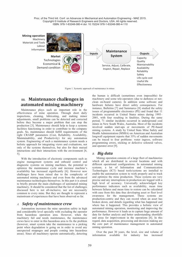
59
Proc. of the Third Intl. Conf. on Advances in Mechanical and Automation Engineering - MAE 2015. Copyright © Institute of Research Engineers and Doctors, USA .All rights reserved.
ISBN: 978-1-63248-080-4 doi: 10.15224/ 978-1-63248-080-4-110
Maintenance System
Mining operationMachinery
Materials and ToolsLabour
InformationInputs Ouputs
Market Technologies
Economical & Demand condition
Service, Adjust, Calibrate, Inspect, Repair, Replace
CapacityQualityMaintainabilityAvailabilityReliabilitySafetyLife cycle costUseful lifeEffectiveness
Figure 1. Systemic approach of maintenance in mines
III. Maintenance challenges in automated mining machinery Maintenance plays such an important role in the
effectiveness of mine operation. Through short daily inspections, cleaning, lubricating, and making minor adjustments, small problems can be detected and corrected before they become a major problem that can stop the production [3]. Maintenance should help to keep a systems facilities functioning in order to contribute to the company goals. So, maintenance should fulfill requirements of the right CRAMP parameters (Cost, Reliability, Availability, Maintainability, and Productivity) for any automation system. Engineering of such a maintenance system needs a holistic approach for integrating views and evaluations, not only of the systems themselves, but also for their mutual interactions and their interactions with the environment [4, 5].
With the introduction of electronic components such as engine management systems and onboard control and diagnostic systems on mining machines, the potential to optimize the maintenance cycle and increase machine’s availability has increased significantly [6]. However new challenges have been raised due to the complexity of automated mining machinery and even from the advanced maintenance technologies themselves. In this part it is aimed to briefly present the main challenges of automated mining machinery. It should be considered that the list of challenges discussed here is not all-inclusive, nor are necessarily common to every mine. But they are thought to represent a mainstream of experiences that have been observed so far.
A. Safety of maintenance crew Automation increases the mine operation safety in high
and considerable level specially with excluding the operator from hazardous operation area. However, when the machinery fail and needs maintenance, the maintenance crews have to enter in this hazardous area to fix the problem (however, smart system take the maintenance to a picking point when degradation is going on in order to avoid any unexpected stoppages and people coming into hazardous areas). Since all machinery operate automatically, detecting
the human is difficult (sometimes even impossible) for machinery and some tele-operators (due to darkness or not-clean on-board camera). In addition some software and hardware failures have direct safety consequences. For instance, Bulletins [7] and Sammarco [8] studied the safety issues of programmable electronics (PE) and found that 11 incidents occurred in United States mines during 1995–2001, with four resulting in fatalities. During the same period, 71 similar incidents occurred in underground coal mines in New South Wales, Australia. Most of the incidents involved sudden start-ups or movements of PE-based mining systems. A study by United Stats Mine Safety and Health Administration (MSHA) on American and Australian longwall equipment reports that 35% of sudden movements can be traced to four problems: water ingress, software programming errors, sticking or defective solenoid valves, and operator error [9].
B. Big data Mining operation consists of a large fleet of machineries
which all are distributed in several locations and with different operational configurations. In automated mining systems, a lot of Information and Communication Technologies (ICT) based tools/systems are installed to enable the automation system to work properly and to track and optimize the mine production. These systems are very precise and any interruptions in production are logged with a high level of accuracy. Universally acknowledged key performance indicators such as availability, mean time between failures and mean time to restore can be calculated with ease from this data thus developing asset or fleet level awareness for the management. These systems are production-centric and they can record when an asset has broken down, and details regarding what has happened and where has it happened. This provides a holistic view of automated mining operation, monitoring and improving the performance. However it leads us to capture huge amount of data for further analysis and better understanding shortfalls and areas for improvement in the operations [6]. In this regard, data acquisition, processing and decision making are the core part of maintenance management in automated mining operation.
Over the past 30 years, the level, size and volume of information available for industry has increased
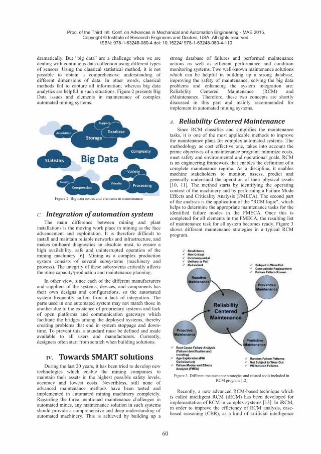
60
Proc. of the Third Intl. Conf. on Advances in Mechanical and Automation Engineering - MAE 2015. Copyright © Institute of Research Engineers and Doctors, USA .All rights reserved.
ISBN: 978-1-63248-080-4 doi: 10.15224/ 978-1-63248-080-4-110
dramatically. But “big data” are a challenge when we are dealing with continuous data collection using different types of sensors. Using the classical statistical method, it is not possible to obtain a comprehensive understanding of different dimensions of data. In other words, classical methods fail to capture all information; whereas big data analytics are helpful in such situations. Figure 2 presents Big Data issues and elements in maintenance of complex automated mining systems.
Figure 2. Big data issues and elements in maintenance
C. Integration of automation system The main difference between mining and plant
installations is the moving work place in mining as the face advancement and exploitation. It is therefore difficult to install and maintain reliable networks and infrastructure, and makes on-board diagnostics an absolute must, to ensure a high availability, safe and uninterrupted operation of the mining machinery [6]. Mining as a complex production system consists of several subsystems (machinery and process). The integrity of these subsystems critically affects the mine capacity/production and maintenance planning.
In other view, since each of the different manufacturers and suppliers of the systems, devices, and components has their own designs and configurations, so the automated system frequently suffers from a lack of integration. The parts used in one automated system may not match those in another due to the existence of proprietary systems and lack of open platforms and communication gateways which facilitate the bridges among the deployed systems, thereby creating problems that end in system stoppage and down-time. To prevent this, a standard must be defined and made available to all users and manufacturers. Currently, designers often start from scratch when building solutions.
IV. Towards SMART solutions During the last 20 years, it has been tried to develop new
technologies which enable the mining companies to maintain their assets in the highest possible safety levels, accuracy and lowest costs. Neverthless, still none of advanced maintenance methods have been tested and implemented in automated mining machinery completely. Regarding the three mentioned maintenance challenges in automated mines, any maintenance solution in such systems should provide a comprehensive and deep understanding of automated machinery. This is achieved by building up a
strong database of failures and performed maintenance actions as well as efficient performance and condition monitoring systems. Two well-known maintenance solutions which can be helpful in building up a strong database, improving the safety of maintenance, solving the big data problems and enhancing the system integration are: Reliability Centered Maintenance (RCM) and eMaintenance. Therefore, these two concepts are shortly discussed in this part and mainly recommended for implement in automated mining systems.
A. Reliability Centered Maintenance Since RCM classifies and simplifies the maintenance
tasks, it is one of the most applicable methods to improve the maintenance plans for complex automated systems. The methodology as cost effective one, takes into account the prime objectives of a maintenance program: minimize costs, meet safety and environmental and operational goals. RCM is an engineering framework that enables the definition of a complete maintenance regime. As a discipline, it enables machine stakeholders to monitor, assess, predict and generally understand the operation of their physical assets [10, 11]. The method starts by identifying the operating context of the machinery and by performing a Failure Mode Effects and Criticality Analysis (FMECA). The second part of the analysis is the application of the "RCM logic", which helps to determine the appropriate maintenance tasks for the identified failure modes in the FMECA. Once this is completed for all elements in the FMECA, the resulting list of maintenance task for all system becomes ready. Figure 3 shows different maintenance strategies in a typical RCM program.
Figure 3. Different maintenance strategies and related tools included in
RCM program [12]
Recently, a new advanced RCM-based technique which is called intelligent RCM (iRCM) has been developed for implementation of RCM in complex systems [13]. In iRCM, in order to improve the efficiency of RCM analysis, case-based reasoning (CBR), as a kind of artificial intelligence
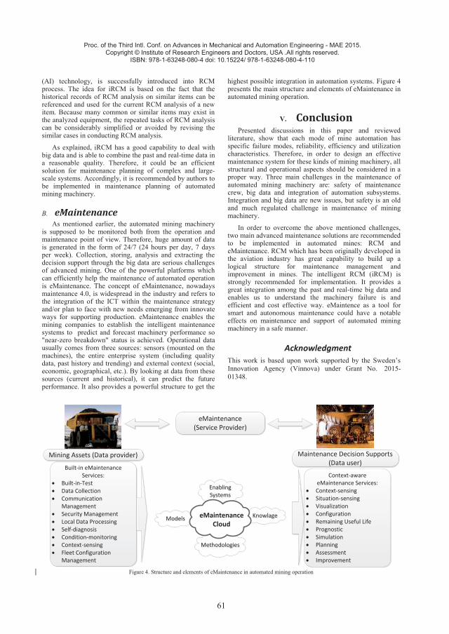
61
Proc. of the Third Intl. Conf. on Advances in Mechanical and Automation Engineering - MAE 2015. Copyright © Institute of Research Engineers and Doctors, USA .All rights reserved.
ISBN: 978-1-63248-080-4 doi: 10.15224/ 978-1-63248-080-4-110
(AI) technology, is successfully introduced into RCM process. The idea for iRCM is based on the fact that the historical records of RCM analysis on similar items can be referenced and used for the current RCM analysis of a new item. Because many common or similar items may exist in the analyzed equipment, the repeated tasks of RCM analysis can be considerably simplified or avoided by revising the similar cases in conducting RCM analysis.
As explained, iRCM has a good capability to deal with big data and is able to combine the past and real-time data in a reasonable quality. Therefore, it could be an efficient solution for maintenance planning of complex and large-scale systems. Accordingly, it is recommended by authors to be implemented in maintenance planning of automated mining machinery.
B. eMaintenance As mentioned earlier, the automated mining machinery
is supposed to be monitored both from the operation and maintenance point of view. Therefore, huge amount of data is generated in the form of 24/7 (24 hours per day, 7 days per week). Collection, storing, analysis and extracting the decision support through the big data are serious challenges of advanced mining. One of the powerful platforms which can efficiently help the maintenance of automated operation is eMaintenance. The concept of eMaintenance, nowadays maintenance 4.0, is widespread in the industry and refers to the integration of the ICT within the maintenance strategy and/or plan to face with new needs emerging from innovate ways for supporting production. eMaintenance enables the mining companies to establish the intelligent maintenance systems to predict and forecast machinery performance so "near-zero breakdown" status is achieved. Operational data usually comes from three sources: sensors (mounted on the machines), the entire enterprise system (including quality data, past history and trending) and external context (social, economic, geographical, etc.). By looking at data from these sources (current and historical), it can predict the future performance. It also provides a powerful structure to get the
highest possible integration in automation systems. Figure 4 presents the main structure and elements of eMaintenance in automated mining operation.
V. Conclusion Presented discussions in this paper and reviewed
literature, show that each mode of mine automation has specific failure modes, reliability, efficiency and utilization characteristics. Therefore, in order to design an effective maintenance system for these kinds of mining machinery, all structural and operational aspects should be considered in a proper way. Three main challenges in the maintenance of automated mining machinery are: safety of maintenance crew, big data and integration of automation subsystems. Integration and big data are new issues, but safety is an old and much regulated challenge in maintenance of mining machinery.
In order to overcome the above mentioned challenges, two main advanced maintenance solutions are recommended to be implemented in automated mines: RCM and eMaintenance. RCM which has been originally developed in the aviation industry has great capability to build up a logical structure for maintenance management and improvement in mines. The intelligent RCM (iRCM) is strongly recommended for implementation. It provides a great integration among the past and real-time big data and enables us to understand the machinery failure is and efficient and cost effective way. eMaintence as a tool for smart and autonomous maintenance could have a notable effects on maintenance and support of automated mining machinery in a safe manner.
Acknowledgment This work is based upon work supported by the Sweden’s Innovation Agency (Vinnova) under Grant No. 2015-01348.
Mining Assets (Data provider)
eMaintenance(Service Provider)
Maintenance Decision Supports (Data user)
Context-aware eMaintenance Services:Context-sensingSituation-sensingVisualization ConfigurationRemaining Useful LifePrognosticSimulationPlanningAssessmentImprovement
ModelsModels
EnablingSystemsEnabling Systems
MethodologiesMethodologies
KnowlageKnowlageeMaintenance Cloud
Built-in eMaintenance Services:
Built-in-TestData CollectionCommunication ManagementSecurity ManagementLocal Data ProcessingSelf-diagnosisCondition-monitoringContext-sensingFleet Configuration Management
Figure 4. Structure and elements of eMaintenance in automated mining operation
62
Proc. of the Third Intl. Conf. on Advances in Mechanical and Automation Engineering - MAE 2015. Copyright © Institute of Research Engineers and Doctors, USA .All rights reserved.
ISBN: 978-1-63248-080-4 doi: 10.15224/ 978-1-63248-080-4-110
References 1. P. Darling, SME mining engineering handbook, Vol. 1,
SME, (2011). 2. S.Y. Nof, Springer handbook of automation, Springer
Science & Business Media, (2009). 3. S. Krar, “The importance of maintenance (changing
from a fail and fix approach to predict and prevent approach)”, available in: http://www.automationmag. com
4. A. Gustafson, H. Schunnesson, D. Galar, and U. Kumar, “Production and maintenance performance analysis: manual versus semi-automatic LHDs”, Journal of Quality in Maintenance Engineering 19 (2013), pp. 74-88.
5. H. Erbe, IFAC Professional Brief Technologies for Cost Effective Automation in Manufacturing (Low Cost Automation), available in: http: //www.zmms.tu-berlin.de/LCA
6. G. Morel, M. Suhner, B. Iung, J. B. Léger, “Maintenance holistic framework for optimizing the cost/availability compromise of manufacturing systems.” In: Proceedings of the sixth IFAC symposium on cost oriented automation. Survey Paper, Berlin, Germany, October, (2001).
7. A. Marek, S.C. Thorley, H. Haubmann, “The age of intelligence. online diagnostic and automated maintenance planning”, 5th Platinum Conference 2012, The Southern African Institute of Mining and Metallurgy, Sun City, South Africa, 18–20 September, (2012).
8. F.A. Bulletins, Fatal Grams and Fatal Investigation Reports, Mine Safety and Health Administration (MSHA), Washington, DC (2001).
9. J. J. Sammarco, “Addressing the safety of programmable electronic mining systems: lessons learned”, Industry Applications Conference, 2002. 37th IAS Annual Meeting. Conference Record of the, (2002).
10. B. S. Dhillon, “Mining equipment reliability, maintainability, and safety”, Springer Science & Business Media, (2008).
11. A. M. Smith and G. R. Hinchcliffe, “RCM- Gateway to World Class Maintenance Hardcover”, Elsevier, Butterworth-Heinemann, (2004), p.360.
12. J. H. Williams, “Condition-Based maintenance and machine diagnostics”, Kluwer Academic Publishers, Londen UK., (1992), p.187.
13. T. Jackson, “Developing and Implementing RCM for a Limited Staffed Facility”, Cohesive Information Solutions, Colorida, USA, available online: www.reliabilityweb.com
14. Z. Cheng, X. Jiab, P. Gaoa, S. Wua, J. Wang, “A framework for intelligent reliability centered maintenance analysis”, Reliability Engineering and System Safety 93 (2008), pp. 784–792.
15. C. Resteanu, I. Vaduva, M. Andreica, “Monte Carlo Simulation for Reliability Centered Maintenance Management”, 6th International Conference, LSSC-2007 Sozopol, Bulgarien, June 5-9, 2007.
About Authors:
Seyed Hadi Hoseinie is an Assistant Professor in Division of Operation and Maintenance Engineering at Luleå University of Technology, Sweden. His research interests are; mining machinery, reliability centered maintenance, mechanical excavation and mine automation. He has published more than 65 articles in international journals conferences proceeding. He currently holds one patent too.
Behzad Ghodrati is Associate Professor of Maintenance and Reliability Engineering at Lulea University of Technology. He obtained his PhD degree on “Spare parts planning” from Lulea University of Technology and he was awarded the Postdoctoral Research Fellowship from University of Toronto in 2008. He has published more than 60 papers in international journals and conference proceedings and a book chapter.
Diego Galar is Professor of Condition Monitoring at Lulea University of Technology. He has obtained his PhD in Industrial Engineering and Telecommunication Engineering from the University of Zaragoza. He has served as professor at several universities including the University of Saragossa or the European University of Madrid, Instituto Politecnico de Braganca IPB, ANANTASA technical director, director of academic innovation and director of international relationship at university. He has published many articles in international journals and conference proceedings.