Embed Size (px)
Citation preview
Project Registration - Kyle Avenue Temporary Liquid Mud Plant
Prepared for: Halliburton Group Canada 16 Panther Place Mount Pearl, NL A1N 5B1
Prepared by: Stantec Consulting Ltd. 141 Kelsey Drive St. John’s, NL A1B 0L2 Tel: (709) 576-1458 Fax: (709) 576-2126
File No: 121414756
Final Report
May 12, 2017
PROJECT REGISTRATION - KYLE AVENUE TEMPORARY LIQUID MUD PLANT
i File No. 121414756
Table of Contents
1.0 INTRODUCTION ............................................................................................................. 1
2.0 GENERAL INFORMATION .............................................................................................. 2 2.1 Geographical Location ................................................................................................... 2 2.2 Undertaking and Proponent ........................................................................................... 2
2.2.1 Undertaking and Location ............................................................................ 2 2.2.2 Proponent Contact Information................................................................... 2 2.2.3 Purpose / Rationale / Need for the Undertaking ....................................... 3
3.0 DESCRIPTION OF THE UNDERTAKING ............................................................................ 4 3.1 Physical Features and Processes Associated with the Undertaking ......................... 4
3.1.1 Physical Features of the Undertaking .......................................................... 4 3.1.2 Alternatives ...................................................................................................... 7 3.1.3 Surrounding Environment .............................................................................. 7
3.2 Construction ...................................................................................................................... 8 3.2.1 Potential Sources of Pollutants and Management Measures
During Construction ....................................................................................... 8 3.3 Operation .......................................................................................................................... 9
3.3.1 Maintenance ................................................................................................ 10 3.3.2 Potential Sources of Pollutants and Management Measures
During Operation .......................................................................................... 10 3.4 Occupations ................................................................................................................... 11 3.5 Related Documents ....................................................................................................... 12 3.6 Approval of the Undertaking ........................................................................................ 12
4.0 SCHEDULE .................................................................................................................... 12
5.0 FUNDING ..................................................................................................................... 12

PROJECT REGISTRATION - KYLE AVENUE TEMPORARY LIQUID MUD PLANT
ii File No. 121414756
LIST OF APPENDICES Appendix A Site Layout Appendix B Mount Pearl Business Park Directory Appendix C 2002 QMAX Solutions Registration for Mixing and Reconditioning Drill Fluids
at 30 Kyle Avenue Appendix D Certificate of Approval, Pardy’s Waste Management and Industrial
Services, 2013-2017 Appendix E Halliburton Global LMP Fluids Manual Appendix F Halliburton Company Policy – Health, Safety, and Environment Appendix G Halliburton Company Policy – Equal Opportunity Employment
LIST OF TABLES
Table 1 Components of the Kyle Avenue LMP .............................................................. 5 Table 2 Primary Materials to be Stored On-site .............................................................. 9 Table 3 Potential Sources of Pollutants and Mitigation/Management
Measures .............................................................................................................. 10 Table 4 Occupations for Temporary Halliburton Drill Mud Plant ................................ 11
LIST OF FIGURES Figure 1 Temporary LMP Location ..................................................................................... 1 Figure 2 Project Site at 30 Kyle Avenue, 05 May 2017 .................................................... 4 Figure 3 Example of a Mixing Tank .................................................................................... 6 Figure 4 Example of a Truck Mounted Elite Pumping Unit ............................................. 6 Figure 5 Nearest Residential Area to the LMP ................................................................. 8

PROJECT REGISTRATION - KYLE AVENUE TEMPORARY LIQUID MUD PLANT
INTRODUCTION May 12, 2017
1 File No. 121414756
1.0 INTRODUCTION
Halliburton Group Canada (Halliburton) is proposing to develop a temporary Liquid Mud Plant (LMP; the Project) at 30 Kyle Avenue, Donovan’s Industrial Park in Mount Pearl, NL (Figure 1) on an existing lot to be leased from Pardy’s Waste Management and Industrial Services (Pardy’s), who currently operates at this location.
This undertaking potentially requires Registration under Section 43(4)(b) Environmental Assessment Regulations of the Newfoundland and Labrador Environmental Protection Act.
The purpose of the Project is to provide drilling mud to the Newfoundland and Labrador offshore oil and gas industry. Halliburton has an initial three-year contract to supply drilling fluids to Suncor, extending from July 2017 to July 2020, to support Suncor’s on-going drilling programs in the Jeanne d’Arc Basin. The LMP will occupy an area of 50 x 100 ft (5,000 ft² or 465 m²) (Figure 1) with capacity of up to 630 m³ of drill mud. Halliburton and Pardy’s have entered into an agreement for use of seven 90m³ vertical above ground storage tanks (total capacity 630 m³), adjacent to the LMP site (Figure 1). Pardy’s will also lease approximately 600 ft² of enclosed warehouse space for storage of base fluids and materials and provide transportation services to Halliburton (delivery of drill mud to client).
The LMP site was registered for environmental assessment in 2002 by QMAX Solutions. The QMAX undertaking was released without further assessment. The site, which at the time of registration was a greenfield site, was permitted for mixing and storage of up to 840 m³ of drill mud, as well are reconditioning / treatment of used muds.
Figure 1 Temporary LMP Location
Temporary LMP Location
Pardy’s Existing Storage Tank Warehouse
PROJECT REGISTRATION - KYLE AVENUE TEMPORARY LIQUID MUD PLANT
GENERAL INFORMATION May 12, 2017
2 File No. 121414756
2.0 GENERAL INFORMATION
This section provides the name of the undertaking being registered for environmental assessment, contact information for the proponent, and an explanation of the need for the undertaking.
2.1 Geographical Location
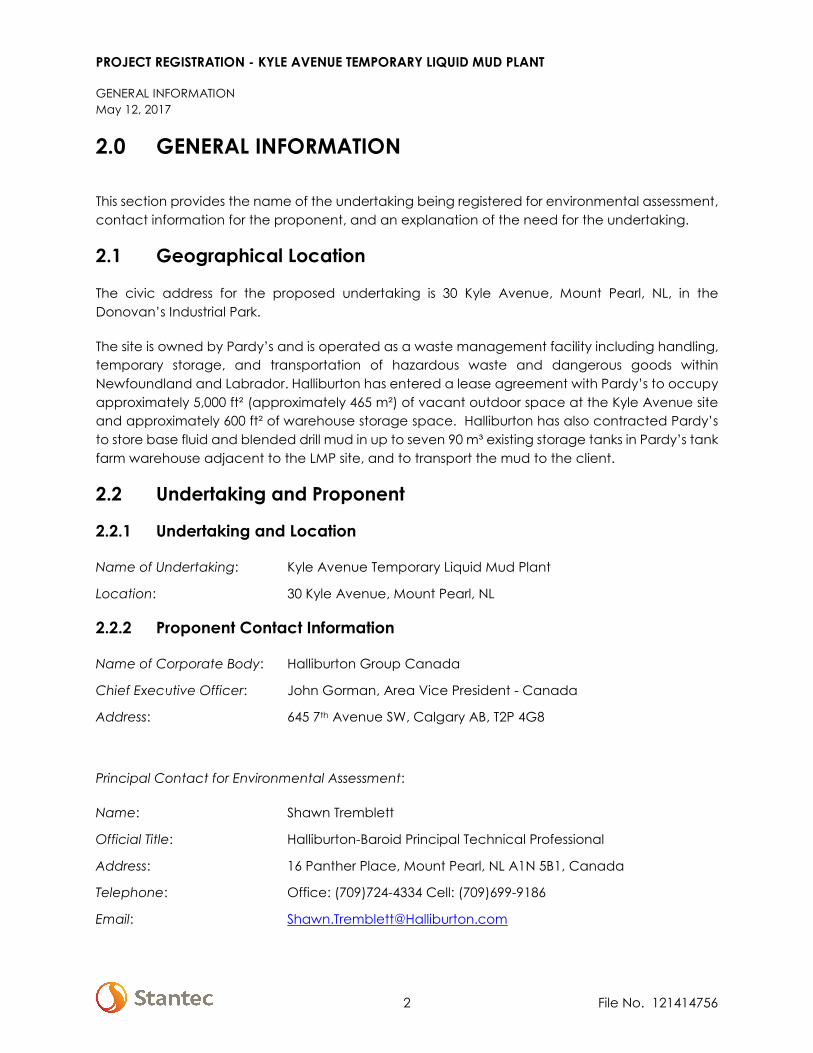
The civic address for the proposed undertaking is 30 Kyle Avenue, Mount Pearl, NL, in the Donovan’s Industrial Park.
The site is owned by Pardy’s and is operated as a waste management facility including handling, temporary storage, and transportation of hazardous waste and dangerous goods within Newfoundland and Labrador. Halliburton has entered a lease agreement with Pardy’s to occupy approximately 5,000 ft² (approximately 465 m²) of vacant outdoor space at the Kyle Avenue site and approximately 600 ft² of warehouse storage space. Halliburton has also contracted Pardy’s to store base fluid and blended drill mud in up to seven 90 m³ existing storage tanks in Pardy’s tank farm warehouse adjacent to the LMP site, and to transport the mud to the client.
2.2 Undertaking and Proponent
2.2.1 Undertaking and Location
Name of Undertaking: Kyle Avenue Temporary Liquid Mud Plant
Location: 30 Kyle Avenue, Mount Pearl, NL
2.2.2 Proponent Contact Information
Name of Corporate Body: Halliburton Group Canada
Chief Executive Officer: John Gorman, Area Vice President - Canada
Address: 645 7th Avenue SW, Calgary AB, T2P 4G8
Principal Contact for Environmental Assessment:
Name: Shawn Tremblett
Official Title: Halliburton-Baroid Principal Technical Professional
Address: 16 Panther Place, Mount Pearl, NL A1N 5B1, Canada
Telephone: Office: (709)724-4334 Cell: (709)699-9186
Email: [email protected]
PROJECT REGISTRATION - KYLE AVENUE TEMPORARY LIQUID MUD PLANT
GENERAL INFORMATION May 12, 2017
3 File No. 121414756
Halliburton has operated in Newfoundland since 1970, providing oil field services for the offshore oil and gas industry.
Halliburton, and its subsidiary, Baroid Industrial Drilling Products is the premier provider of drilling and completion fluids worldwide. For more than 80 years, Halliburton has provided industry-leading drilling and completion fluid products and services tailored to the unique needs of their clients.
Presently located in 40 countries around the world and expanding, Halliburton maintains a consistent focus on planning, design and engineering to deliver optimized fluid performance and equipment standardization. Halliburton’s extensive experience specifically with operators through the years gives Halliburton the confidence in our capability to provide optimum commercial solutions while maintaining the high standards of technical integrity required for this project. Their experience in mobilizing and operating LMPs in other remote locations such as Arctic locations and Russia will help support the work for offshore Newfoundland.
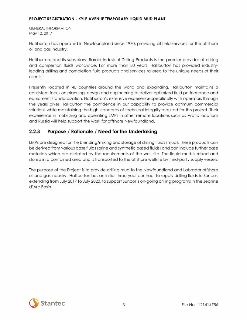
2.2.3 Purpose / Rationale / Need for the Undertaking
LMPs are designed for the blending/mixing and storage of drilling fluids (mud). These products can be derived from various base fluids (brine and synthetic based fluids) and can include further base materials which are dictated by the requirements of the well site. The liquid mud is mixed and stored in a contained area and is transported to the offshore wellsite by third-party supply vessels.
The purpose of the Project is to provide drilling mud to the Newfoundland and Labrador offshore oil and gas industry. Halliburton has an initial three-year contract to supply drilling fluids to Suncor, extending from July 2017 to July 2020, to support Suncor’s on-going drilling programs in the Jeanne d’Arc Basin.

PROJECT REGISTRATION - KYLE AVENUE TEMPORARY LIQUID MUD PLANT
DESCRIPTION OF THE UNDERTAKING May 12, 2017
4 File No. 121414756
3.0 DESCRIPTION OF THE UNDERTAKING
Halliburton will use the LMP to blend base fluids and materials into drill mud to meet the specifications of its customer. This blending/mixing facility will not be manufacturing chemicals; therefore, it does not include processes and equipment that would typically be found in a chemical manufacturing plant. The facility will operate between 8 and 12 days per month, for 6 to 8 hours per day, with a total production capacity of 630 m³ per batch.
Once mud has been mixed, it will be transferred to a third-party (Pardy’s) for storage in their existing storage tank warehouse and delivery to the end-client as needed.
3.1 Physical Features and Processes Associated with the Undertaking
The following describes physical components and processes associated with the LMP and the environment surrounding the site.
3.1.1 Physical Features of the Undertaking
The LMP will occupy an area of approximately 50 ft x 100 ft (5,000 ft² or 465 m²) on Pardy’s property at 30 Kyle Avenue. This area is currently a gravel lot used as a storage / laydown area (Figure 2). Pardy’s overall property has a perimeter fence and monitored access.
Figure 2 Project Site at 30 Kyle Avenue, 05 May 2017
The components of the LMP will be modular and mobile, enabling them to be placed individually and allow for customized layout to meet the site and capacity requirements. The components for use at the Kyle Avenue LMP are provided in Table 1. The conceptual layout of the components is provided in Appendix A.

PROJECT REGISTRATION - KYLE AVENUE TEMPORARY LIQUID MUD PLANT
DESCRIPTION OF THE UNDERTAKING May 12, 2017
5 File No. 121414756
Table 1 Components of the Kyle Avenue LMP
Component Description
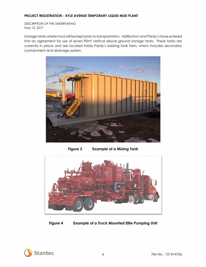
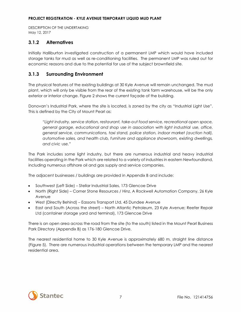
Mixing Tank and Elite Pumping Unit One enclosed 75m³ premix tank for mixing drilling fluid. The mixing tank will be surrounded by a temporary steel containment berm. The Elite Pumping Unit is connected to the mixing tank. The Elite will provide additional shear to increase efficiency of the mixing system. Photographs of the Mixing Tank and Elite Unit are provided in Figures 3 and 4.
Mixing and Transfer Pumps Centrifugal pumps are used for mixing and transferring fluids. These pumps will be electrical with diesel back-up. The amount of diesel stored on-site will be limited to the generator’s tank which has a 100 L capacity.
Dust Collector Bulk materials are pneumatically transferred. Dust generated by transfer of dry bulk materials is controlled and contained in dust collectors. This system is built into the equipment as a standard mitigation for dust.
Mud Mix Hopper The mix hopper is an in-line platform and conical opening for adding materials to the fluid mix. The hopper is installed so that a Venturi effect is created causing materials to be “vacuumed” into the flow stream.
Air Compressor Air compressors are used to blow out lines.
Temporary Office Building A temporary building will be brought to site for day use by Halliburton staff. It will be connected to the local electrical grid, but will not have water / sewer connections. Staff will use bathrooms in-place at Pardy’s existing buildings.
Temporary Containment Berm A temporary surface mounted berm will be installed around the Mixing Tank. Installation of the berm will not require modifications to Pardy’s current layout.
Pardy’s storage Tanks Blended mud will be stored temporarily prior to transportation to clients. Halliburton and Pardy’s have entered into an agreement for use of seven 90m³ vertical above ground storage tanks. These tanks are currently in place and are located inside Pardy’s existing tank farm, which is enclosed and includes secondary containment and drainage system.
Pardy’s warehouse space Materials used in blending drill muds will be stored in existing warehouse space to be leased from Pardy’s. Approximately 600 ft² will be leased.
A piping system will be used to connect the mixing tank, pumps, agitator, and storage tanks. The piping system will have secondary containment to contain the contents in the event of an accident.
Blended mud, as well as base fluids (brine and base oil), will be stored in Pardy’s existing storage tanks inside the tank farm warehouse. Base fluids will be used in the blending of mud. Blended mud will be stored temporarily prior to transportation to clients. LMP operation will rely upon use of leased space in Pardy’s existing warehouse for storage of base fluids and materials, and use of
PROJECT REGISTRATION - KYLE AVENUE TEMPORARY LIQUID MUD PLANT
DESCRIPTION OF THE UNDERTAKING May 12, 2017
6 File No. 121414756
storage tanks where mud will be kept prior to transportation. Halliburton and Pardy’s have entered into an agreement for use of seven 90m³ vertical above ground storage tanks. These tanks are currently in place and are located inside Pardy’s existing tank farm, which includes secondary containment and drainage system.
Figure 3 Example of a Mixing Tank
Figure 4 Example of a Truck Mounted Elite Pumping Unit
PROJECT REGISTRATION - KYLE AVENUE TEMPORARY LIQUID MUD PLANT
DESCRIPTION OF THE UNDERTAKING May 12, 2017
7 File No. 121414756
3.1.2 Alternatives
Initially Halliburton investigated construction of a permanent LMP which would have included storage tanks for mud as well as re-conditioning facilities. The permanent LMP was ruled out for economic reasons and due to the potential for use of the subject brownfield site.
3.1.3 Surrounding Environment
The physical features of the existing buildings at 30 Kyle Avenue will remain unchanged. The mud plant, which will only be visible from the rear of the existing tank farm warehouse, will be the only exterior or interior change. Figure 2 shows the current façade of the building.
Donovan’s Industrial Park, where the site is located, is zoned by the city as “Industrial Light Use”. This is defined by the City of Mount Pearl as:
“Light industry, service station, restaurant, take-out food service, recreational open space, general garage, educational and shop use in association with light industrial use, office, general service, communications, taxi stand, police station, indoor market (auction hall), automotive sales, and health club, furniture and appliance showroom, existing dwellings, and civic use.”
The Park includes some light industry, but there are numerous industrial and heavy industrial facilities operating in the Park which are related to a variety of industries in eastern Newfoundland, including numerous offshore oil and gas supply and service companies.
The adjacent businesses / buildings are provided in Appendix B and include:
• Southwest (Left Side) – Stellar Industrial Sales, 173 Glencoe Drive • North (Right Side) – Corner Stone Resources / Hinz, A Rockwell Automation Company, 26 Kyle
Avenue • West (Directly Behind) – Eassons Transport Ltd, 45 Dundee Avenue • East and South (Across the street) – North Atlantic Petroleum, 23 Kyle Avenue; Reefer Repair
Ltd (container storage yard and terminal), 173 Glencoe Drive
There is an open area across the road from the site (to the south) listed in the Mount Pearl Business Park Directory (Appendix B) as 176-180 Glencoe Drive.
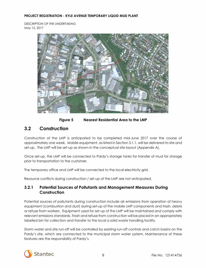
The nearest residential home to 30 Kyle Avenue is approximately 680 m, straight line distance (Figure 5). There are numerous industrial operations between the temporary LMP and the nearest residential area.
PROJECT REGISTRATION - KYLE AVENUE TEMPORARY LIQUID MUD PLANT
DESCRIPTION OF THE UNDERTAKING May 12, 2017
8 File No. 121414756
Figure 5 Nearest Residential Area to the LMP
3.2 Construction
Construction of the LMP is anticipated to be completed mid-June 2017 over the course of approximately one week. Mobile equipment, as listed in Section 3.1.1, will be delivered to site and set-up. The LMP will be set-up as shown in the conceptual site layout (Appendix A).
Once set-up, the LMP will be connected to Pardy’s storage tanks for transfer of mud for storage prior to transportation to the customer.
The temporary office and LMP will be connected to the local electricity grid.
Resource conflicts during construction / set-up of the LMP are not anticipated.
3.2.1 Potential Sources of Pollutants and Management Measures During Construction
Potential sources of pollutants during construction include air emissions from operation of heavy equipment (combustion and dust) during set-up of the mobile LMP components and trash, debris or refuse from workers. Equipment used for set-up of the LMP will be maintained and comply with relevant emissions standards. Trash and refuse from construction will be placed in an appropriately labelled bin for collection and transfer to the local a solid waste handling facility.
Storm water and site run-off will be controlled by existing run-off controls and catch basins on the Pardy’s site, which are connected to the municipal storm water system. Maintenance of these features are the responsibility of Pardy’s.
PROJECT REGISTRATION - KYLE AVENUE TEMPORARY LIQUID MUD PLANT
DESCRIPTION OF THE UNDERTAKING May 12, 2017
9 File No. 121414756
3.3 Operation
Operation at the LMP will consist of blending materials and base fluid into drilling mud, and in the blending of base fluids. The types of operation that will be performed at the LMP include:
• Mixing of mud and/or brine using drummed / sacked materials, oil, and/or water • Blending brine • Addition of base materials or fluids to an existing volume of mud to meet changing customer
needs
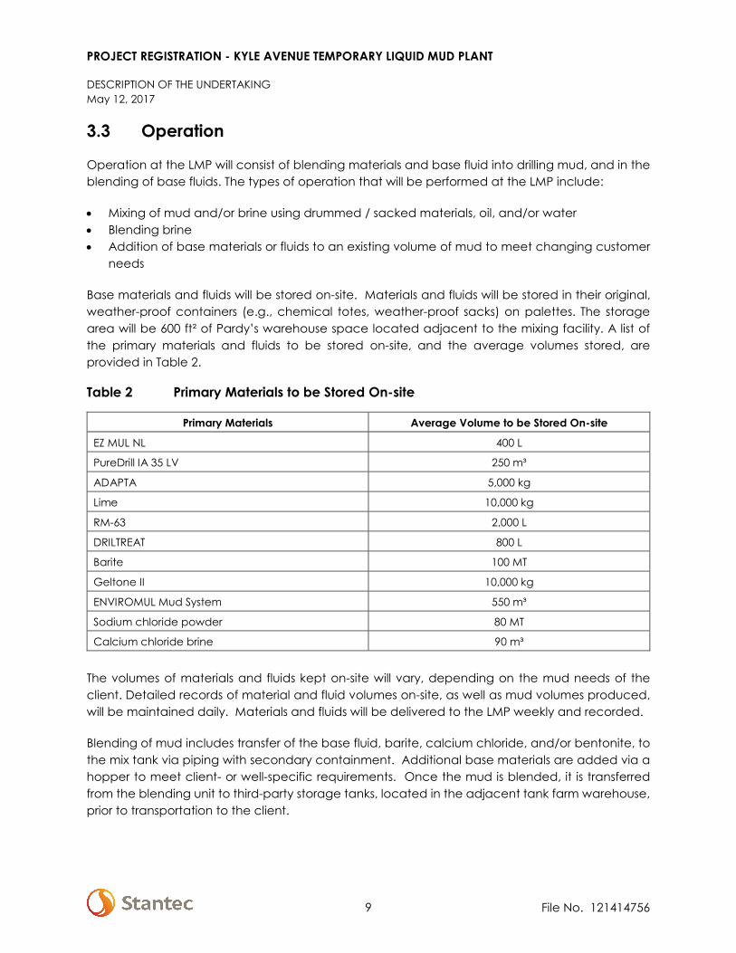
Base materials and fluids will be stored on-site. Materials and fluids will be stored in their original, weather-proof containers (e.g., chemical totes, weather-proof sacks) on palettes. The storage area will be 600 ft² of Pardy’s warehouse space located adjacent to the mixing facility. A list of the primary materials and fluids to be stored on-site, and the average volumes stored, are provided in Table 2.
Table 2 Primary Materials to be Stored On-site
Primary Materials Average Volume to be Stored On-site
EZ MUL NL 400 L
PureDrill IA 35 LV 250 m³
ADAPTA 5,000 kg
Lime 10,000 kg
RM-63 2,000 L
DRILTREAT 800 L
Barite 100 MT
Geltone II 10,000 kg
ENVIROMUL Mud System 550 m³
Sodium chloride powder 80 MT
Calcium chloride brine 90 m³
The volumes of materials and fluids kept on-site will vary, depending on the mud needs of the client. Detailed records of material and fluid volumes on-site, as well as mud volumes produced, will be maintained daily. Materials and fluids will be delivered to the LMP weekly and recorded.
Blending of mud includes transfer of the base fluid, barite, calcium chloride, and/or bentonite, to the mix tank via piping with secondary containment. Additional base materials are added via a hopper to meet client- or well-specific requirements. Once the mud is blended, it is transferred from the blending unit to third-party storage tanks, located in the adjacent tank farm warehouse, prior to transportation to the client.
PROJECT REGISTRATION - KYLE AVENUE TEMPORARY LIQUID MUD PLANT
DESCRIPTION OF THE UNDERTAKING May 12, 2017
10 File No. 121414756
The LMP will be operated by trained workers in compliance with Halliburton’s Global LMP Fluids Manual (MAN-GL-HAL-BAR-002) (Appendix E).
The temporary LMP will begin producing drill muds on 01 July 2017, and will operate for approximately three years. Resource conflicts during operation of the LMP are not anticipated.
3.3.1 Maintenance
The LMP will be subject to a detailed equipment maintenance and calibration program. The Halliburton Preventative Maintenance Standard ST-GL-HAL-HMS-705 prescribes the inspection, calibration, and maintenance schedule for the LMP components.
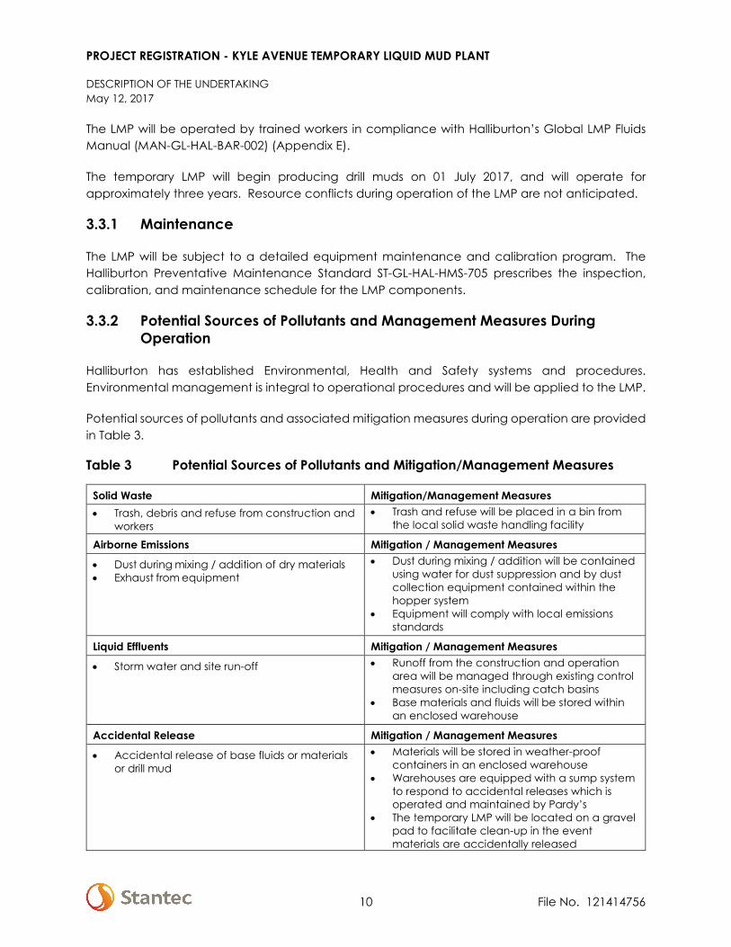
3.3.2 Potential Sources of Pollutants and Management Measures During Operation
Halliburton has established Environmental, Health and Safety systems and procedures. Environmental management is integral to operational procedures and will be applied to the LMP.
Potential sources of pollutants and associated mitigation measures during operation are provided in Table 3.
Table 3 Potential Sources of Pollutants and Mitigation/Management Measures
Solid Waste Mitigation/Management Measures • Trash, debris and refuse from construction and
workers • Trash and refuse will be placed in a bin from
the local solid waste handling facility
Airborne Emissions Mitigation / Management Measures
• Dust during mixing / addition of dry materials • Exhaust from equipment
• Dust during mixing / addition will be contained using water for dust suppression and by dust collection equipment contained within the hopper system
• Equipment will comply with local emissions standards
Liquid Effluents Mitigation / Management Measures
• Storm water and site run-off • Runoff from the construction and operation area will be managed through existing control measures on-site including catch basins
• Base materials and fluids will be stored within an enclosed warehouse
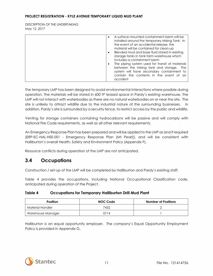
Accidental Release Mitigation / Management Measures
• Accidental release of base fluids or materials or drill mud
• Materials will be stored in weather-proof containers in an enclosed warehouse
• Warehouses are equipped with a sump system to respond to accidental releases which is operated and maintained by Pardy’s
• The temporary LMP will be located on a gravel pad to facilitate clean-up in the event materials are accidentally released
PROJECT REGISTRATION - KYLE AVENUE TEMPORARY LIQUID MUD PLANT
DESCRIPTION OF THE UNDERTAKING May 12, 2017
11 File No. 121414756
• A surface-mounted containment berm will be installed around the temporary Mixing Tank. In the event of an accidental release, the material will be contained for clean-up
• Blended mud and base fluid stored in existing storage tanks in tank farm warehouse which includes a containment berm
• The piping system used for transit of materials between the mixing tank and storage. The system will have secondary containment to contain the contents in the event of an accident
The temporary LMP has been designed to avoid environmental interactions where possible during operation. The materials will be stored in 600 ft² leased space in Pardy’s existing warehouse. The LMP will not interact with waterbodies as there are no natural waterbodies on or near the site. The site is unlikely to attract wildlife due to the industrial nature of the surrounding businesses. In addition, Pardy’s site is surrounded by a security fence, to restrict access by the public and wildlife.
Venting for storage containers containing hydrocarbons will be passive and will comply with National Fire Code requirements, as well as all other relevant requirements.
An Emergency Response Plan has been prepared and will be applied to the LMP as and if required (ERP-EC-HAL-HSE-001 - Emergency Response Plan (Mt Pearl)), and will be consistent with Halliburton’s overall Health, Safety and Environment Policy (Appendix F).
Resource conflicts during operation of the LMP are not anticipated.
3.4 Occupations
Construction / set-up of the LMP will be completed by Halliburton and Pardy’s existing staff.
Table 4 provides the occupations, including National Occupational Classification code, anticipated during operation of the Project.
Table 4 Occupations for Temporary Halliburton Drill Mud Plant
Position NOC Code Number of Positions
Material Handler 7452 2
Warehouse Manager 0714 1
Halliburton is an equal opportunity employer. The company’s Equal Opportunity Employment Policy is provided in Appendix G.
PROJECT REGISTRATION - KYLE AVENUE TEMPORARY LIQUID MUD PLANT
SCHEDULE May 12, 2017
12 File No. 121414756
3.5 Related Documents
Project-related documents include:
• 2002 QMAX Solutions Registration for Mixing and Reconditioning Drill Fluids at 30 Kyle Avenue (Appendix C)
• Certificate of Approval, Pardy’s Waste Management and Industrial Services, 2013-2017 (Appendix D)
• Halliburton Global LMP Fluids Manual (Appendix E) • Halliburton Company Policy – Health, Safety and Environment (Appendix F) • Halliburton Company Policy – Equal Employment Opportunity (Appendix G)
3.6 Approval of the Undertaking
Halliburton is working with the Pollution Prevention Division of the Department of Municipalities and Environment to determine the requirement for a Certificate of Approval for the Project. Alternatives discussed include operating under Pardy’s existing Certificate of Approval for the site, or developing a new Certificate of Approval specific to Halliburton’s Project.
Upon hook-up, the electrical system for the LMP will be inspected by the local municipality.
4.0 SCHEDULE
It is anticipated that mobile equipment and supplies will be delivered to the site and set in place in early-June 2017. Halliburton is contractually obligated to provide drill mud to it’s client on 01 July 2017. Therefore, blending of mud is scheduled to begin no later than 01 July 2017. The temporary drill mud plant will operate for approximately three years (estimated to be mid-June 2020), which is the duration of Halliburton’s contractual obligation to it’s client.
5.0 FUNDING
The Project will be 100% funded privately by Halliburton. Public funding will not be requested to support the Project. The estimated capital cost associated with Project set-up / construction is approximately $600,000 CAN.
Date Signature of Chief Executive Officer (or approved delegate)

PROJECT INFORMATION - KYLE AVENUE TEMPORARY LIQUID MUD PLANT
FUNDING May 12, 2017
Date
() Stantec
Halliburton Group C ada, by its managing partner Halliburton Canada LC.
13
REVIEWED LEGAL~~ DATE {;'/r 2.. 7 1J
FileNo. 121414756
PROJECT REGISTRATION - KYLE AVENUE TEMPORARY LIQUID MUD PLANT
APPENDIX A Site Layout

PROJECT REGISTRATION - KYLE AVENUE TEMPORARY LIQUID MUD PLANT
APPENDIX B Mount Pearl Business Park Directory

Donovans Business Park24/7 Security Services, 27 Clyde Avenue50383 NF & Lab Ltd. (Vachon - Purity Factories),93 Glencoe DriveActive Fibreglass, 9 Sagona AvenueAdvanced Woodwork & Designs Ltd., 82 Glencoe DriveAFA Forest Products Inc., 9 Glencoe DriveAGF Steel Inc., 115 Glencoe DriveAir Liquide Canada (Canadian Liquid Air),52 Dundee AvenueAkita Equipment, 96 Clyde AvenueAll Canada Cranes & Aerials, 111 Glencoe DriveAll Graphic Supplies, 43 Sagona AvenueAllied Label Ltd. (10961 Nfld. Ltd.), 15 Glencoe DriveAllswater Marine Consultants Ltd., 123 Clyde AvenueAl-Pack Enterprises, 117 Clyde AvenueAltera Newfoundland Technology Centre(Formerly Avalon Microelectronics), 58 Glencoe DriveAltimax Courier, 51 Sagona AvenueAmca Sales & Marketing, 157 Glencoe DriveAMI Offshore (Subsea Service Centre Ltd.),12 Corisande DriveAMI Offshore (Subsea Service Centre Ltd.),14 Corisande DriveAriva Paper to Pixels, 14 Clyde AvenueArmour Transport Inc., 35 Glencoe DriveArrow Games Corp. (Formerly Island Bingo & Nevada),51 Sagona AvenueAsco Canada Inc., 7 Clyde AvenueAsco Canada Ltd., 10 Corisande DriveAsco Canada Ltd., 14 Corisande DriveAssociation of Engineering Technicians &Technologists of NL (AETTNL), 22 Sagona AvenueAtlantic Cold Seafoods (Cold North Seafoods),157 Glencoe DriveAtlantic Crane Storage & Materials Handling,17 Dundee AvenueAtlantic Hose & Fittings Ltd., 56 Clyde AvenueAtlantic Industrial & Marine Supplies Ltd. (AIMS),17 Kyle AvenueAtlantic Inspections Services Inc., 130 Clyde AvenueAtlantic Metal Coatings Ltd., 25 Dundee AvenueAtlantic Oilfield & Industrial Support(Atlantic Hardchrome Limited), 82 Glencoe DriveAtlantic Oilfield Service Centre (Atlantic HardbandingTechnology), 138 Clyde AvenueAtlantic Powertrain & Equipment Inc., 30 Glencoe DriveAtlantic Propeller Repairs Ltd., 12 Kyle AvenueAtlantic Spirts & Wines Limited, 126 Glencoe DriveAtlantic Trailer & Equipment Repair, 8 Lintrose PlaceAtlantica Diversified Trans. Systems (ADTS)(Formerly D.D. Transport), 27 Glencoe DriveAvalon Controls Ltd., 12 Panther PlaceAward Flooring, 41 Sagona AvenueAwnpar Awning & Sign Fabrication, 17 Dundee AvenueB.J. Process & Pipeline Services Division, 20 Kyle AvenueBaker Hughes Upstream Chem., 16 Kyle AvenueBaker Hughes, 33 Dundee AvenueBasil Fearn (1993) Ltd., 51 Clyde AvenueBell Aliant, 68 Glencoe DriveBell Logistics, 126 Glencoe DriveBillard's Trucking Ltd., 24 Kyle AvenueBird Stairs Ltd. (J.W. Bird & Co. Ltd.), 153 Glencoe DriveBlack & McDonald, 19 Dundee AvenueBlackhawk Industrial Services Inc., 158 Glencoe DriveBlue Water Newfoundland Ltd./Blue Water Home Heat,85 Glencoe DriveBob LeDrew & Sons Inc., 78 Glencoe DriveBoncor Building Products Company(Global Windows & Doors), 10 Dundee AvenueBren-Kir Industrial Supplies Ltd., 15 Glencoe DriveBrenntag Canada Inc., 90 Clyde AvenueBrinks Canada , 88 Glencoe DriveBrown Offshore Ltd., 130 Clyde AvenueBruce Enterprises Ltd., 6 Kyle AvenueC & W Offshore Ltd., 16 Lintrose PlaceCadillac Services, 97 Clyde AvenueCahill Instrumentation, 2 Southern Cross RoadCameron Canada Corporation, 14 Corisande DriveCampia Gymnastics Club Inc., 60 Clyde AvenueCanada Revenue Agency, 117 Glencoe DriveCanada Revenue Agency, 132 Glencoe DriveCanadian Coast Guard Environmental Response,1 Southern Cross RoadCanadian Industrial Services, 25 Dundee AvenueCanadian Linen & Uniform Service, 103 Glencoe DriveCan-Am Construction, 105 Clyde AvenueCanwel Building Materials, 42 Sagona AvenueCapital Crane Ltd. (CGI Development Inc.),20 Sagona AvenueCapital Fleet Repair & Collision Centre Inc.,30 Sagona AvenueCapital Springs Ltd., 20 Sagona AvenueCargocan Agency Ltd., 21 Glencoe DriveCarlson Stanley Ltd., 110 Glencoe DriveCentral Dairies (Farmer's Dairy Co-Op), 12 Bruce StreetCentura Floor & Wall Fashions, 2 Bruce StreetCentury 2K Cabling Systems, 19 Old Placentia RoadChallenger Construction Limited, 41 Dundee AvenueChandler (A division of J.D. Irving Ltd.), 10 Lintrose PlaceCharles R. Bell Limited, 126 Glencoe DriveCity Thermo Pane Ltd. (Northfield Glass Group),21 Sagona AvenueClarke Road Transport Inc., 20 Old Placentia RoadCMH Construction, 96 Clyde AvenueCMT Inc. (BMS North America), 19 Old Placentia RoadCoast Broadcasting, 126 Glencoe DriveCoastal Door & Frame Inc., 146 Glencoe DriveCoca Cola Refreshments, 51 Sagona AvenueCohen's Home Furnishings, 126 Glencoe DriveCole International Inc., 2 Southern Cross RoadConcord National (Mitchell Agencies), 93 Glencoe DriveCoombs & Associates (Dupree & Associates)Chartered Accountants, 119 Clyde AvenueCornerstone Resources Inc., 26 Kyle AvenueCrane Supply, 31 Clyde AvenueCrawford & Company (Canada) Inc., 96 Clyde AvenueCre8iv Design Studio, 84 Clyde AvenueCrossfit Islander Inc., 127 Clyde AvenueCummins Eastern Canada Ltd., 122 Clyde AvenueD. Kelsey Auto Repairs, 4 Corisande DriveDairy Farmers of Nfld. & Labrador, 27 Sagona AvenueDave Edison Agency Ltd. (DEAL), 17 Dundee AvenueDavis Strait Management Ltd., 26 Old Placentia RoadDay & Ross Inc., 79 Glencoe DriveDel Contracting Ltd., 17 Dundee AvenueDental Supplies Limited, 40 Dundee AvenueDept. of Fisheries & Oceans (Federal), 121 Glencoe DriveDept. of National Defence, 117 Clyde AvenueDistribution Brunet Inc., 5 Kyle AvenueDonovans Irving Convenience Store, 65 Clyde AvenueDonovans Irving Gas Bar, 65 Clyde AvenueDonovans Irving Restaurant (Kariss Enterprises Ltd.),65 Clyde AvenueDonovans Personnel Services Limited, 17 Sagona AvenueDouble H. Electrical , 157 Glencoe DriveDraught Pro NL Inc., 17 Dundee AvenueDrycore Eastern Inc., 10 Panther PlaceEassons Transport Ltd., 45 Dundee AvenueEast Coast Converters, 24 Clyde AvenueEast Coast Hydraulics Nfld. Ltd., 9 Sagona AvenueEast Coast Mobile Medical Inc. & ECMM Innu Inc.,32 Dundee AvenueEastern Canada Response Corporation,3 Old Placentia RoadEastern Health, Special Assistance &Emergency Preparedness, 127 Clyde AvenueEastern Industrial Sales & Service, 109 Clyde AvenueEastern Valve & Control Specialties, 2 Southern Cross RoadEconomy Drywall Supplies (C.N.G. Limited),50 Sagona AvenueElectro Mechanical Services, 92 Glencoe DriveElite Productions, 20 Glencoe DriveEmberley's Transport, 114 Glencoe DriveEmco Offshore/Westlund, 36 Dundee AvenueEmco Retail Services, 18 Bruce StreetEmco Supply, 18 Bruce StreetEnergy Management Services Ltd., 54 Glencoe DriveEngineered Energy Corporation, 19 Clyde AvenueEnvironment Canada, 6 Bruce StreetEnviroshred, 38 Dundee AvenueESL Marine Supplies Ltd, 51 Clyde AvenueEXP Services Inc., 22 Sagona AvenueExtreme Window & Entrance Systems, 41 Sagona AvenueF.I. Oilfield Services Canada, 2 Dundee AvenueF.J. Wadden & Sons Ltd., 51 Glencoe DriveFactory Direct Insulators, 38 Dundee AvenueFastenal Canada Co., 41 Sagona AvenueFire Tech Systems Ltd. (Division of Vipond Inc.),84 Clyde AvenueFMC Technologies - Subsea Services Canada,46 Dundee AvenueFour Quest Energy, 86 Clyde AvenueFurniture House Liquidation Centre, 109 Clyde AvenueG.J. Shortall Ltd., 107 Clyde AvenueGale's Accounting Services Inc., 51 Clyde AvenueGas Tops Ltd. (NL Service Centre), 146 Glencoe DriveGE Oil & Gas (Vetco Gray), 27 Dundee AvenueGenoa Design International Ltd., 117 Glencoe DriveGentek Building Products, 126 Clyde AvenueGeo Glass & Aluminum Ltd., 32 Dundee AvenueGFI Composites Ltd., 9 Sagona AvenueGuardian Homes, 96 Clyde AvenueGuildfords Ltd., 54 Clyde AvenueH & F Electrical Limited, 105 Clyde AvenueH.J. Bartlett Electric, 51 Dundee AvenueHalliburton Group Canada, 16 Panther PlaceHealth Canada, 26 Kyle AvenueHeddle Marine Service (NL) Inc., 30 Dundee AvenueHercules SLR/Stellar Industrial, 173 Glencoe DriveHinz, A Rockwell Automation Company , 26 Kyle AvenueHitech Communications Ltd., 15 Glencoe DriveHorizon Laminates, 47 Sagona AvenueHorizon Machining Inc., 82 Glencoe DriveHot Tub Pros (Sun Heating & Air Conditioning Ltd.),189 Glencoe DriveHousehold Movers & Shippers (North American Van Lines),19 Clyde Avenue
Household Movers & Shippers (North American Van Lines),60 Clyde AvenueHSE Integrated Ltd., 21 Dundee AvenueHurricane Industrial Equipment, 85 Glencoe DriveHyflodraulic Limited, 48 Clyde AvenueImpact Signs (R.W. Parrott's Signs), 22 Sagona AvenueImport Tool Corp. Ltd., 20 Kyle AvenueIndependent Dockside Grading Inc., 19 Old Placentia RoadIndustrial Engineering & Automation Solutions Ltd.(Power and Process Sales Inc.), 82 Clyde AvenueIndustrial Rubber Newfoundland, 44 Clyde AvenueIndustrial Systems Management Inc., 2 Southern Cross RoadInfinity Construction Ltd., 60 Clyde AvenueInmarsat (Stratos Global Corporation Inc.), 34 Glencoe DriveInterex Systems Ltd., 34 Dundee AvenueInternational Association of Bridge, Structural,Ornamental and Reinforcing Iron Workers, 38 Sagona AvenueInterstate Batteries Atlantic Canada, 51 Sagona AvenueIron Mountain Canada Corporation, 45 Sagona AvenueIronworkers Local 746, 38 Sagona AvenueIronworkers Realty Inc., 7 Kyle AvenueIrving Energy, 26 Old Placentia RoadIrving Propane, 63 Clyde AvenueIsland Construction & Environmental Ltd., 18 Dundee AvenueIsland Furniture, 11 Kyle AvenueIsland Furniture, 9 Sagona AvenueJ & T Construction Ltd., 58 Glencoe DriveK & D Pratt Group Inc., 126 Glencoe DriveK C Industries, 152 Glencoe DriveKancote Enterprises Inc., 17 Dundee AvenueKayCan Ltd., 22 Dundee AvenueKeltic Steelworks Ltd. , 37 Dundee AvenueKeltic Transportation Inc., 50 Glencoe DriveKillick Group Ltd., 19 Dundee AvenueKMA Pharmaceuticals, 96 Clyde AvenueLawton's Drug Store (Wholesale Division), 1 Home StreetLeDrew's Express Ltd., 127 Clyde AvenueLife Safety Systems (Atlantic Mechanical Contractors Inc.),78 Clyde AvenueLighting & Traffic Systems Ltd., 12 Kyle AvenueLoblaw Atlantic, 35 Clyde AvenueLoomis Express (DHL Express Canada Ltd.),117 Clyde AvenueLVM Maritime Testing Ltd., 39 Sagona AvenueMadsen Construction Equipment(Formerly Diesel Injection), 141 Glencoe DriveMadsen Construction Equipment, 141 Glencoe DriveMadsen Power Systems, 141 Glencoe DriveMarine Industrial Lighting Systems Ltd., 51 Sagona AvenueMaritime Paper Products, 14 Clyde AvenueMcKesson Canada, 5 Glencoe DriveMechanical Components Limited, 119 Clyde AvenueMechano Construction, 18 Dundee AvenueMedical Mart Supplies Ltd., 127 Clyde AvenueMetabolic Meltdown, 2 Bruce StreetMetal World Inc., 48 Glencoe DriveMetrie Canada , 189 Glencoe DriveMidland Courier, 200 Glencoe DriveMidland Transport, 200 Glencoe DriveMikan Inc., 43 Sagona AvenueMolson Properties Inc., 60 Clyde AvenueMorris Foods Ltd. (Country Pride), 2 Kyle AvenueMount Pearl Recycling Depot (Scotia Recycling),5 Old Placentia RoadMulti-Chem (Division of Halliburton), 16 Panther PlaceMultiglass Insulation, 54 Clyde AvenueNational Energy Equipment Inc., 18 Dundee AvenueNational Heat Treating Inc., 109 Clyde AvenueNational Oilwell Varco Canada, 153 Glencoe DriveNew Glass Ltd. (Division of Economy Glass),21 Sagona AvenueNew Lab Oxygen Limited, 19 Sagona AvenueNew Valve Services & Consulting Inc., 2 Southern Cross RoadNewfoundland and Labrador Employers Council,129 Glencoe DriveNewfoundland Marine Safety Systems, 8 Kyle AvenueNewterm Logistics (Oceanex), 35 Glencoe DriveNL Construction Safety Association, 80 Glencoe Drive
Norampac NL (A Division of Cascades Canada Ulc.),110 Clyde AvenueNord Marine Services, 42 Dundee AvenueNorth Atlantic Lining Ltd., 12 Kyle AvenueNorth Atlantic Petroleum, 23 Kyle AvenueNRG Electrical Ltd., 26 Dundee AvenueNuQuest Distribution, 96 Clyde AvenueO.K. Tire Store (OMB Parts & Industrial Ltd.),13 Sagona AvenueOakland Enterprises Limited, 5 Glencoe DriveOceaneering Canada Limited, 23 Dundee AvenueO'Keefe Agencies, 86 Glencoe DriveOld Dutch Foods Ltd., 93 Glencoe DriveOMNI Laboratories, 26 Old Placentia RoadOP Fiberglass & Marine Supplies, 22 Sagona AvenueOverhead Door (Nfld) Ltd., 99 Clyde AvenueP.S. Atlantic Ltd. (Benjamin Moore Warehouse),102 Clyde AvenuePaperlinx Canada Limited (Spicers Paper), 157 Glencoe DrivePardy's Waste Management, 30 Kyle AvenueParts for Trucks , 4 Corisande DrivePBA Industrial Supplies Ltd., 84 Clyde AvenuePBS Services Ltd., 18 Dundee AvenuePearl Springs, 20 Glencoe DrivePenav Company Limited, 93 Glencoe DrivePepsi-Co Foods Canada, 5 Glencoe DrivePeter Pan Sales, 36 Clyde AvenuePetroleum Measurement Integrators, 26 Old Placentia RoadPhoenix Transportation & Logistics Inc., 152 Glencoe DrivePik-Fast Express Inc., 20 Glencoe DrivePinnacle Agencies (Amercoat Canada) (Belzona Atlantic),19 Old Placentia RoadPioneer Enterprises Ltd. (Electric Motor & Pump Division),26 Glencoe DrivePort Electric Solutions Inc., 119 Clyde AvenuePraxair Canada Inc., 123 Clyde AvenuePrime Fasteners Maritimes Ltd., 2 Bruce StreetProArc Fabricating Ltd., 28 Dundee AvenueProcanna Building Materials, 47 Clyde AvenuePro-Dive Marine Services, 17 Sagona AvenueProTek Industries Ltd., 152 Glencoe DriveProvall Parts Ltd., 43 Sagona AvenuePumps Plus, 10 Panther PlacePW Windows, Doors Hardware, 161 Glencoe DriveReefer Repair Services Ltd.(Newfoundland Container Storage Yard), 172 Glencoe DriveReefer Repair Services Ltd. (The Container Terminal),172 Glencoe DriveRegal Confections, 93 Glencoe DriveReliant Transport Ltd., 12 Bruce StreetRGR Enterprises (Freight Forwarding), 117 Clyde AvenueRJB Warehouse, 103 Clyde AvenueRJS Terminals (Armour Transportation Systems),9 Glencoe DriveRockwater Professional Products (Bilroc Industries Ltd.),5 Panther PlaceRolls-Royce Canada Ltd., 142 Glencoe DriveRoyal Freightliner, 26 Sagona AvenueRoyal Newfoundland Constabulary, 59 Clyde AvenueRussel Metals Inc., 11 Panther PlaceRyder Truck Rentals, 21 Glencoe DriveRyder Truck Rentals, 27 Glencoe DriveS.M.E. Ltd., 116 Glencoe DriveSafway Services Canada Inc., 10 Panther PlaceSameday Right-O-Way Courier (Div. Of Day & Ross),79 Glencoe DriveScale Shop (1985) Ltd., The, 88 Clyde AvenueSchlumberger Canada Limited, 7 Panther PlaceSchlumberger Canada Ltd., 2 Panther PlaceSchool Milk Foundation of Nfld. & Labrador,27 Sagona AvenueScientific Drilling International (Canada) Inc., 84 Glencoe DriveScotia Insulations (Polr Enterprises), 134 Clyde AvenueScotsburn Dairy Group, 22 Clyde AvenueScotsburn Ice Cream, 22 Glencoe DriveSeaForce Diving, 44 Dundee AvenueSeaforce Technologies Inc., 46 Dundee AvenueSears Canada Inc., 9 Glencoe DriveService Master, 24 Old Placentia RoadService NL, OHS Division, 15 Dundee AvenueSheehan's Holdings, 84 Glencoe DriveShred-It International Inc., 109 Clyde Avenue
Signature Kitchens & Bath, 11 Lintrose PlaceSimplex Grinnell (A division of Tyco Fire & Security),153 Glencoe DriveSleipnir Logistics Inc. (Sleipnir Lift Management &Simulation Center), 43 Sagona AvenueSmith, Bussey, Muir Accountants, 2 Bruce StreetSobeys District Office, 63 Glencoe DriveSooley and White, 82 Clyde AvenueSource Energy Atlantic Inc., 127 Clyde AvenueSource Medical (Cardinal Health), 19 Clyde AvenueSouthern Shore Hydraulics Inc., 84 Glencoe DriveSpectra Premium Industries, 102 Clyde AvenueSperry Marine Canada, 17 Dundee AvenueStabil Drill, 106 Clyde AvenueStacey Agencies Ltd. (10961 Newfoundland Ltd.),15 Glencoe DriveSteers Ltd., 103 Glencoe DriveStellar Industrial Sales Ltd., 173 Glencoe DriveStoncor Group, 56 Clyde AvenueStrongco Equipment (formerly Sheridan Equipment),54 Glencoe DriveSULIS Subsea Corporation, 17 Dundee AvenueSurface Experts, 109 Clyde AvenueSustainable Windows , 9 Glencoe DriveSysco Food Service of St. John's, 10 Old Placentia RoadTEAM Industrial Services (TISI Canada), 41 Sagona AvenueTempo Construction Management Inc.(TKN Investments Ltd.), 22 Sagona AvenueTerra Nova Marketing Inc., 119 Clyde AvenueThe Bulb Man, 50 Glencoe DriveThe Toy Box, 15 Old Placentia RoadThinkware Limited (My Telescope.com), 96 Clyde AvenueThomas Glass, 21 Sagona AvenueTire Craft, 116 Glencoe DriveTKN Investments, 22 Sagona AvenueTLC Wholesale, 51 Sagona AvenueTNT Office Group, 5 Glencoe DriveTobin's Auto Sales & Service, 4 Lintrose PlaceTRA-Sobeys Newfoundland Ltd., 63 Glencoe DriveTRC Hydraulics Inc., 84 Glencoe DriveTri Star Mechanical, 26 Dundee AvenueTrident Construction, 21 Dundee AvenueTrimac Transportation & National Tank Services,21 Kyle AvenueTroy Life & Fire Safety Ltd., 150 Glencoe DriveTTL Supply, 51 Sagona AvenueTulk Tire & Service Ltd., 15 Clyde AvenueTwin City Financial, 96 Clyde AvenueUltramar Truck Stop (Young's Truck Stop), 116 Glencoe DriveUnalloy-IWRC (Samuel Manu-Tech Inc.), 111 Glencoe DriveUnisource Canada Inc., 60 Clyde AvenueUnited Association of Journeymen & Apprentices,Local 740 Training Centre, 48 Sagona AvenueUnited Association of Plumbers & Pipefitters Local 740,48 Sagona AvenueUnited Parcel Services (UPS) Canada, 134 Clyde AvenueUnited Rentals of Canada, Inc., 31 Sagona AvenueUrban Flooring Contractors Ltd., 12 Lintrose PlaceVersacold Logistics (Services) Canada Inc., 96 Glencoe DriveViking Fire Protection Inc., 51 Dundee AvenueVipond Fire Protection Inc., 51 Sagona AvenueVision Packaging Supplies Ltd., 13 Old Placentia RoadVisions Employment, 58 Glencoe DriveWajax Equipment, 1 Panther PlaceWajax Power Systems (Formerly Detroit Diesel Allison),1 Panther PlaceWal-Mart Canada, 97 Glencoe DriveWartsila Canada Inc., 27 Sagona AvenueWaterworks, 18 Bruce StreetWell Control Group, 80 Clyde AvenueWestern Hydraulic 2000 Ltd., 10 Sagona AvenueWeston's Bakery Ltd., 17 Bruce StreetWindow Pros Ltd. (Sunserve), 21 Sagona AvenueWindow Shop Inc., The, 129 Glencoe DriveWing'n'It Corporate Office, 157 Glencoe DriveWLH Contracting Limited, 10 Panther PlaceWorkstrings Canada, 106 Clyde Avenue
Kenmount Business ParkAcklands Grainger Inc., 13 Corey King DriveAgility Global Integrated Solutions, 9 Corey King Drive
Anchorage Contracting Ltd. (Division of Moss Groupof Companies), 16 Thomas Byrne DriveAtlantic Recreation Ltd. (Yamaha), 17 Corey King DriveAuto Parts Network (Canadian Auto Recycling Ltd.),6 Corey King DriveBlue Water Marine & Equipment, 16 Allston StreetCoastal Marine Limited, 5 Corey King DriveCycle City & Recreation Ltd. (Mile One Harley Davidson),12 Allston StreetDance Studio East, 28 Allston StreetDOF Subsea Canada Corp., 26 Allston StreetDulux Paints, 32 Allston StreetEastern Contracting (Tyson Properties Inc.),32 Allston StreetEastern Edge Credit Union, 31 Corey King DriveEastern Siding Systems Inc. , 5 Thomas Byrne DriveFast Signs (Canasign Inc.), 9 Allston StreetFleetwood Motors, 6 Corey King DriveFlynn Canada Ltd., 26 Corey King DriveImage Wear (Jacobssons Enterprises Limited),26 Allston StreetInterior Specialties Ltd., 28 Allston StreetIsland Hose & Fittings Ltd., 22 Allston StreetMartin's Fire Safety Ltd. (EMS Services Ltd.),20 Allston StreetNewfoundland Electrical Ltd. (Division of Moss Groupof Companies), 16 Thomas Byrne DriveNewfoundland HVAC Limited (Division of Moss Groupof Companies), 16 Thomas Byrne DriveNortrax (John Deere), 15 Allston StreetPenney Pre-Owned Used Cars & Trucks,27 Corey King DriveRoyal Canadian Mounted Police,31 Allston StreetSeaboard Liquid Carriers (Shannon Trucking),31 Allston StreetSetpoint AE Inc., 9 Allston StreetShamrock Truss, 20 Corey King DriveSpeed Pro Signs (Annmar Holdings), 28 Allston StreetSt. John Ambulance, 8 Thomas Byrne DriveSuperior Woodworking Ltd. , 23A Corey King DriveW.C. Hull Products Inc., 22 Allston StreetWindow World (Division of Eastern Siding Systems Inc.),5 Thomas Byrne DriveWolseley Canada Inc., 9 Corey King Drive
Beclin Business ParkAnixter Canada Inc., 26 Beclin RoadApex Construction Specialties Inc., 41 Beclin RoadBattlefield Equipment Rentals, 6 Beclin RoadBunzl Canada Inc., 22 Beclin RoadCAE (Canadian Aviations Electronics) Inc., 35 Beclin RoadCan Par Transport Limited, 10 Beclin RoadFalck Safety Services, 35 Beclin RoadIntria Corporation (A Division of CIBC), 38 Beclin RoadIPEX Atlantic, 16 Beclin RoadJ.W. Lindsay Enterprises Limited, 22 Beclin RoadNewfoundland Hard-Rok Inc., 41 Beclin RoadSource Atlantic Limited , 38 Beclin RoadTAM International Oil Services Ltd., 22 Beclin RoadTelecommunications Technology Canada Inc.,3 Beclin RoadTrane Atlantic, 22 Beclin Road
!!
!
!!
!!
!!
! !
! !! !
! !
!!
!
!
!!
!!
!!
! ! !!
!!
!!
!!
!
!!
!!
!
!!
!!
!!
!!
!!
!!
!!
!!
!!
!!
!!
!!
!!
!!
!
! !
!
!
!
!
!!
!!!
!!
!!
!
! !!
!!
!!
! !
!!
!!
!
!!
!!
!!
!!
!!
!!
!!
!!
!!
!!
!!
!!
!!
!!
!!
!!
!!
!
!
!
!!
!!
!!
! !
!!
! !
!!
! !
!!
!!
!!
!!
!!
!!
!!
!!
!!
!!
!!
!
!
! !
!
!
!
!!
!
!!
!!
!
! !
!!
!
!!
!!
!!!!
!
!
!
!!
!
!!
!!
! !! ! ! !
!!
!!
!
!!
!!
!!
!!
!!
!!
!!
! !
!
!!
!
!!
!!
!!
!!
!!
!
!
!!! ! ! ! !
!
!
!!
!!
!!
!!
!!
!!
!!
!!
!!
!!
!!
!!
!!
!!
!!
!!
!
!
!!
!!
! !!!
!
!
!!
!
!!
!!
!!
!!
!!
!!
!!
!!
!!
!!
! !
! !
! !
! !!
!
!!
!!
!!
!!
!!
!!
!
!
!
!!!
!
!!
!!
!!
!!
!!
!!
!!
!
!! ! !
!!
!!
!!
!!
!!
!!
!!
! !
!!
!
!!
!!
!!
! !
! !
!
! ! !!
!!
!!
!
!!
!!!
! !
!!
!!
!!
!!
!!
!!
!!
!!
!!
!!
!!
!!
!!
!!
!!
!!
!!
!!
! !
! !
!
!
!!
!!
!!
!!
!!
!!
!!
! !
! !
!! ! !
!!
!!
!!
!!
! !
!!
!!
!
!
!!
!
!
!!
!!
!!
!!
!!
!!
!!
!!
!!
!!
!!
!!
!!
!!
!!
!!
!!
!!
!!
!
!
!
!
!!
!
!
!!
!!
!!
!!
!!
!!
!!
!!
!!
!!
!!!!
!!
!!
!!
!!
!!
!
!
!!!!!!
!!
!!
!!
! ! !!
!!
! !! !
! !!
! !! !
! !! !
! !! !
!
!!
!
!!!!!
!!
!!
!!
!!
!!
!!
!!
! ! ! !
!!
!!
!!
!!
!!
!!
!!
!!
!!
!!
!!
!!
!!
!!
!!
!!
!!
!!
!!
!!
!!
!!
!!
!!
!!
!!
!!
! !! ! ! !
! !! !
!!!!
!!
!!
!
!!
!!
!!
!!
!!
!
!
! !! !
! ! !!
! !
!!
!!
!!
!!
!
! !
!
!
!!
!!
!!
!
!!
! ! ! !! !
SouthernCross RdLintrose Pl
Old Placentia RdDund
ee Av
e
Glenhill
Clyde
Ave
Clyde Ave
Kenmount Rd
Power'sPond
Paradise
St. Jo
hn's
Intern
ation
al Air
port 1
6 km
(Oute
r Ring
Roa
d)
Waterford River
NewfoundlandT'Railway
Topsail Rd
Pitts Memorial Drive
Kenmount Rd
Ruth
Ave
Clyde A
ve
Glenc
oe Dr
Trans
Cana
da Hi
ghwa
y
Sagona Ave
Moores Dr
Michener Ave
Kyle
Ave
Nelde
r Dr
Allston St
Bruce St
Beclin Rd
Olympic Dr
Coris
ande
Dr
Ashford Dr
Sauve St
Donovan St
Panther Pl
CoreyKing
Dr
Trout
Pl
Home St
Medley Pl
Grandy Cres
Grey Pl
Wells Cres
Samson St
Talon
PlLindbergh Cres
Edwards Pl
O'Flaherty CresTh
omas
Byrne Dr
Babb
Cres
Toope PlRideau Pl
Crew
e Pl
Tweed
smuir
PlDarby Pl
Harnum
Cres
Wellington Cres
Armstrong Cres
Massey C
res
Webb Pl
McGrath Cres
Bradley PlPaddon Pl
Cunard Pl McGill Cres
Trudea
u Pl
Bartlett Pl
Osmond Pl
Scammell Cres
Montgomery St
Jacob
s Pl
Bonfoy Pl
Collins Pl
Waterloo Cres
Dollar
d Pl
Bens
on Pl
Paradise
53
2
7
1
2 5
24
2
9
6
8
6
1
6
5
9
2
4
9
5
86
9
8
15
7
35
7
21
2624
1315
20
19
10
10
58
12
16
51
54
253028
229793
88
96
4240
41
38
18
45
26
1123
20 21
22
1719
17
26
27
26
27
51
4341
39
4238
15
30
52
31
35 17
96
9086
8280
1851
1310
54
20
17979979
85
80
86
6563
152022
2621
10
1210
27
21
84
78
63
1014
10
10
56
2719
2436
22
22
1216
16
35
31
44
20
33
31
44
51
17
26
48
4834
16 41
50
14
20
32
1116
28
26
31
50
1612
30
92
12
1512
59
21
13
37
22
6034
15
47
27
11
16
46
96
38
30
8482
68
48
23
4745
24
26
35
172164
105
115 134116
119117
123127
122126
111108110 130
117114
138
126157
121 189
102
107109
110
106
141
132
153
146 152
129
142158
200
103
173161 176-180
2
1
42
60
µKenmountBusiness
Park
BeclinBusiness
Park
DonovansBusiness
Park
Mount PearlBusiness Parks
St. John's
Torbay
Pouch Cove
Paradise
Bell Island
Conception
Bay South
FlatrockBauline
Portu
gal C
ove -
St.
Philip
's
MountPearl
Logy Bay - Middle Cove -
Outer Cove
Petty Harbour - Maddox Cove
CONC
EPTIO
N BA
Y
ATLANTIC OCEAN
Ê
oUPDATED APRIL, 2016
FOR MORE CURRENT INFORMATION,PLEASE SEE THE CITY OF MOUNT PEARL WEBSITE AT
www.mountpearl.ca
LEGENDALLSTON STREETBECLIN ROADBRUCE STREETCLYDE AVENUECOREY KING DRIVECORISANDE DRIVEDUNDEE AVENUEGLENOCE DRIVEHOME STREETKYLE STREETLINTROSE PLACEOLD PLACENTIA ROADPANTHER PLACESAGONA AVENUESOUTHERN CROSS ROADTHOMAS BYRNE DRIVEONE WAY STREET/HIGHWAY RAMPROUTE NUMBERINTERCHANGE NUMBER
! ! ! ! WALKWAYSWATERWAYSOPEN SPACE
2
42
PROJECT REGISTRATION - KYLE AVENUE TEMPORARY LIQUID MUD PLANT
APPENDIX C 2002 QMAX Solutions Registration for Mixing and
Reconditioning Drill Fluids at 30 Kyle Avenue

Registration Pursuant ToSection 43.4(B) of the Environmental
Assessment Regulations 2000
QMAX BuildingDonovan’s Industrial Park
Mount Pearl
November 21, 2002
-1-
PROPONENT:
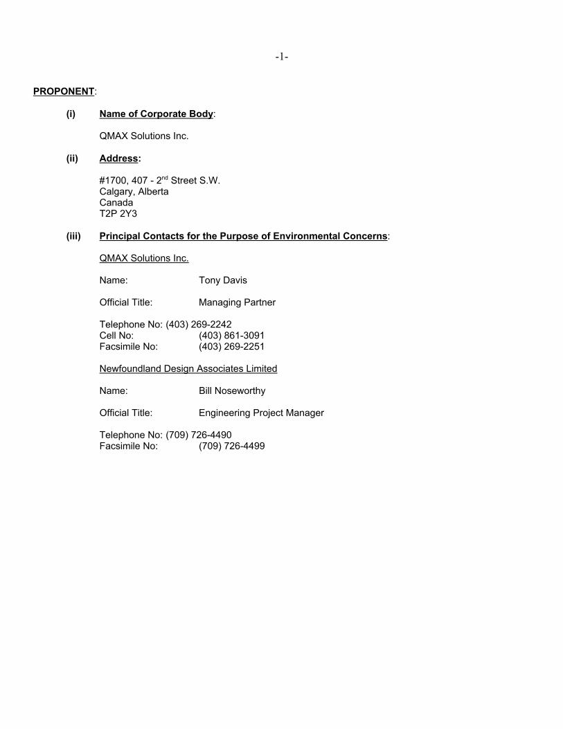
(i) Name of Corporate Body:
QMAX Solutions Inc.
(ii) Address:
#1700, 407 - 2nd Street S.W.Calgary, AlbertaCanadaT2P 2Y3
(iii) Principal Contacts for the Purpose of Environmental Concerns:
QMAX Solutions Inc.
Name: Tony Davis
Official Title: Managing Partner
Telephone No: (403) 269-2242Cell No: (403) 861-3091Facsimile No: (403) 269-2251
Newfoundland Design Associates Limited
Name: Bill Noseworthy
Official Title: Engineering Project Manager
Telephone No: (709) 726-4490Facsimile No: (709) 726-4499
-2-
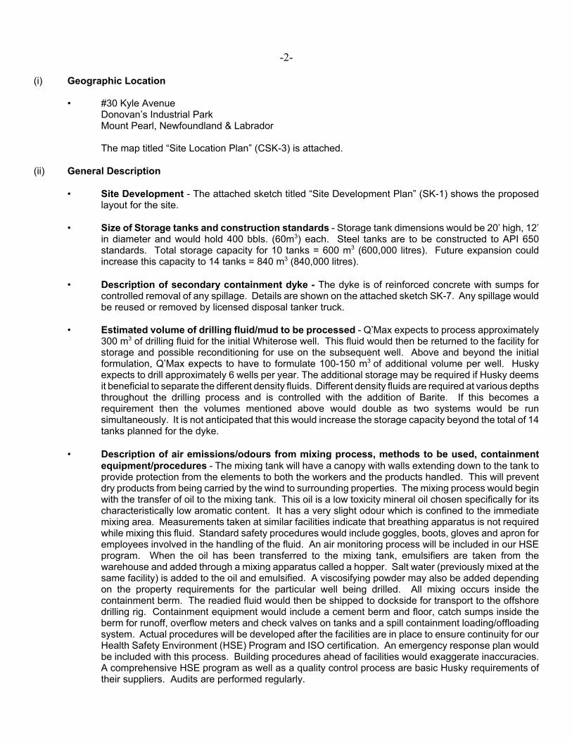
(i) Geographic Location
• #30 Kyle AvenueDonovan’s Industrial ParkMount Pearl, Newfoundland & Labrador
The map titled “Site Location Plan” (CSK-3) is attached.
(ii) General Description
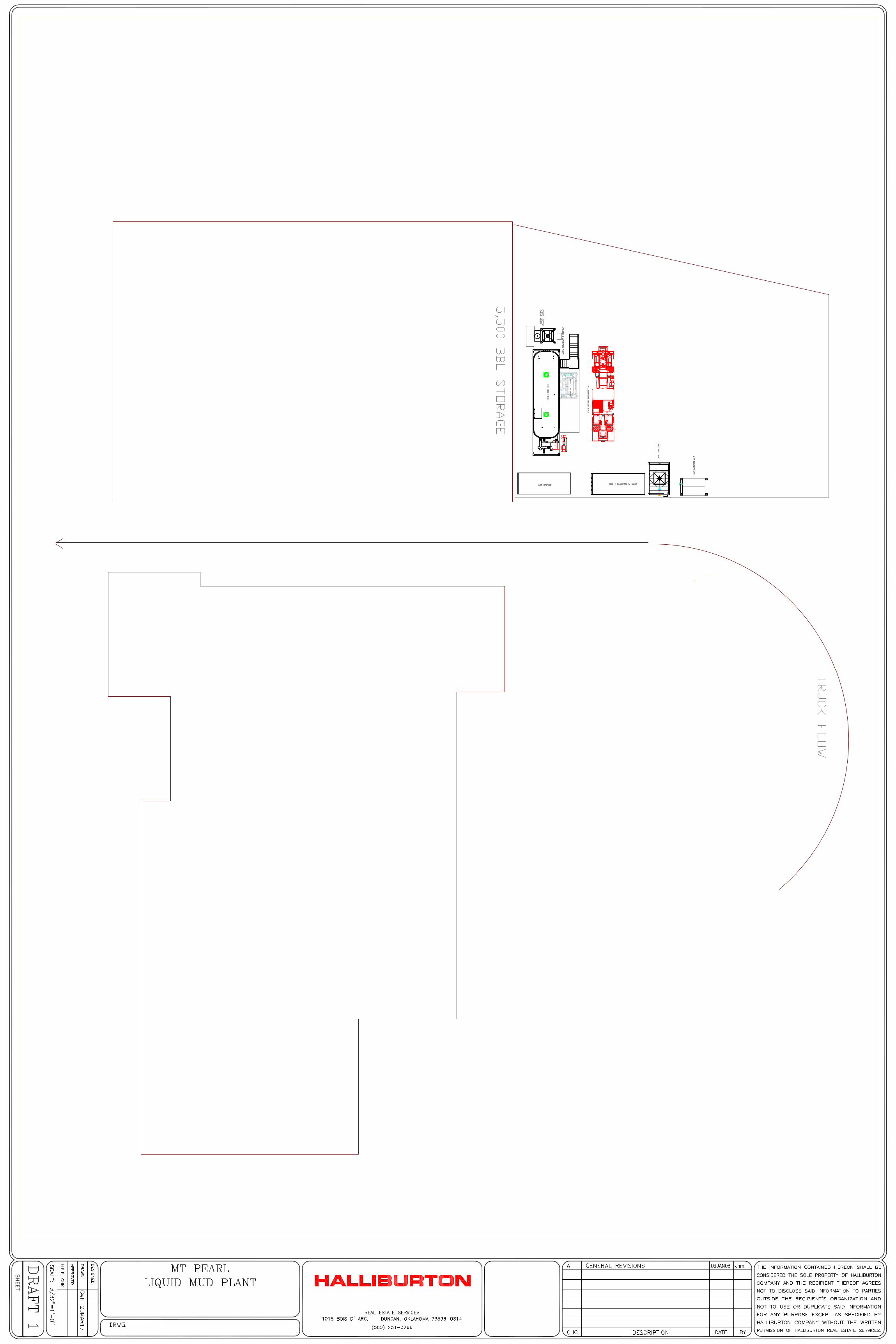
• Site Development - The attached sketch titled “Site Development Plan” (SK-1) shows the proposedlayout for the site.
• Size of Storage tanks and construction standards - Storage tank dimensions would be 20’ high, 12’in diameter and would hold 400 bbls. (60m3) each. Steel tanks are to be constructed to API 650standards. Total storage capacity for 10 tanks = 600 m3 (600,000 litres). Future expansion couldincrease this capacity to 14 tanks = 840 m3 (840,000 litres).
• Description of secondary containment dyke - The dyke is of reinforced concrete with sumps forcontrolled removal of any spillage. Details are shown on the attached sketch SK-7. Any spillage wouldbe reused or removed by licensed disposal tanker truck.
• Estimated volume of drilling fluid/mud to be processed - Q’Max expects to process approximately300 m3 of drilling fluid for the initial Whiterose well. This fluid would then be returned to the facility forstorage and possible reconditioning for use on the subsequent well. Above and beyond the initialformulation, Q’Max expects to have to formulate 100-150 m3 of additional volume per well. Huskyexpects to drill approximately 6 wells per year. The additional storage may be required if Husky deemsit beneficial to separate the different density fluids. Different density fluids are required at various depthsthroughout the drilling process and is controlled with the addition of Barite. If this becomes arequirement then the volumes mentioned above would double as two systems would be runsimultaneously. It is not anticipated that this would increase the storage capacity beyond the total of 14tanks planned for the dyke.
• Description of air emissions/odours from mixing process, methods to be used, containmentequipment/procedures - The mixing tank will have a canopy with walls extending down to the tank toprovide protection from the elements to both the workers and the products handled. This will preventdry products from being carried by the wind to surrounding properties. The mixing process would beginwith the transfer of oil to the mixing tank. This oil is a low toxicity mineral oil chosen specifically for itscharacteristically low aromatic content. It has a very slight odour which is confined to the immediatemixing area. Measurements taken at similar facilities indicate that breathing apparatus is not requiredwhile mixing this fluid. Standard safety procedures would include goggles, boots, gloves and apron foremployees involved in the handling of the fluid. An air monitoring process will be included in our HSEprogram. When the oil has been transferred to the mixing tank, emulsifiers are taken from thewarehouse and added through a mixing apparatus called a hopper. Salt water (previously mixed at thesame facility) is added to the oil and emulsified. A viscosifying powder may also be added dependingon the property requirements for the particular well being drilled. All mixing occurs inside thecontainment berm. The readied fluid would then be shipped to dockside for transport to the offshoredrilling rig. Containment equipment would include a cement berm and floor, catch sumps inside theberm for runoff, overflow meters and check valves on tanks and a spill containment loading/offloadingsystem. Actual procedures will be developed after the facilities are in place to ensure continuity for ourHealth Safety Environment (HSE) Program and ISO certification. An emergency response plan wouldbe included with this process. Building procedures ahead of facilities would exaggerate inaccuracies.A comprehensive HSE program as well as a quality control process are basic Husky requirements oftheir suppliers. Audits are performed regularly.
-3-
• Description of any other operations including cleaning or reconditioning used drilling fluids - Thevast majority of fluid conditioning is performed at the rig site by Q’Max technicians. The fluid arrives atthe site within spec and is returned to our facility for storage within spec. There will be occasionshowever when specifications will change and therefore reconditioning will be required at the plant. Thismay entail minor chemical additions or on a larger scale solids being centrifuged out of the fluid. Whenthis occurs these solids will have the mineral oil attached to them and must be disposed of accordingto environmental regulations. Q’Max has hired Crosbie Industrial to handle any waste productsgenerated at our plant. Because the fluids are reused the only potential waste stream would be if theabove mentioned centrifuging is required. Cleaning of the tanks will not be required as the fluids willhave consistent properties.
• Storm sewer locations - The attached drawing C2 – “Site Development Plan” shows the storm sewerlocations.
• Other dimensions of site- The attached drawing C2 – “Site Development Plan” shows other
dimensions of the site. The site is located in Donovan’s Industrial Park which is zoned industrial. Thearea will have to be cleared and the City of Mount Pearl will have to issue a permit.
(iii) Construction
(a) Construction Schedule:
The site is to be developed and the building constructed by the summer of 2003.
(b) Construction Activities:
The construction activities associated with this project will be no different than any other office orwarehouse constructed in Newfoundland and Labrador.
The activities include:
• Surveying• Brush Clearing• Excavation & Filling• Water & Sewer• Pavement• Concrete & Masonry• Steel• Architectural Finishes• Mechanical Services • Electrical Services
-4-
(c) Potential Sources of Pollutants:
The potential sources of pollutants during the construction period would be no different than thoseencountered on other construction projects in Newfoundland and Labrador. The Contractors involvedwith construction will be required to adhere to Environmental regulations for the disposal of all materials.The requirements for inspection of heavy equipment for hydraulic fluids or hydrocarbon leaks and theremoval of mud prior to driving on pavement will be as per the City of Mount Pearl’s regulations.
(iv) Operation:
The expected operating life of the facility is a minimum of 20 years.
(a) Potential Source of Pollutants:
Potential sources of pollutants as listed below will be limited to those components which will be usedto produce the drilling fluid. The components arrive on site in packages and containers and are storedin the warehouse unopened. As required, these components are moved by forklift to a rectangularmixing tank. This tank, along with 10 cylindrical storage tanks, are contained within a concrete dykewhich is designed to hold spillage and leaks for controlled clean up. All equipment will be inspectedroutinely to ensure that no leaks occur.
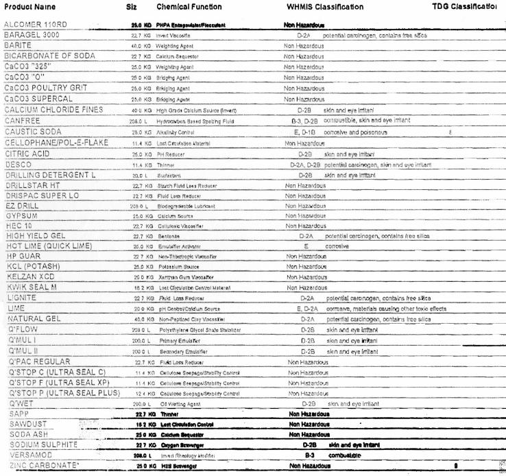
.1 List of Products to be Stored in Warehouse
See list on following page.
.2 List of Products to be Stored in Containers Outside
Barite (BaSO4)Bentonite
(b) Operation:
Certain products to be used in the production of drilling fluids will be delivered by transport trucks to thesite in packages and containers. These products will be stored unopened in the warehouse. Whenrequired, the products will be moved by forklift to the mixing tank contained in the concrete dyke. Theseproducts will then be mixed with salt water and oil held in separate cylindrical storage tanks within thedyke. This mixture will then be transferred to the other cylindrical storage tanks contained within thedyke. Tankers will then load the product for transportation to the harbour front and delivery to the WhiteRose project. Speed bumps will be installed on the tanker ramp to contain any spills duringloading/unloading of the product.
The operation will employ a Manager, Secretary, two or three other office staff and two warehouseworkers. The warehouse will have two loading bays and a drive through for receiving products at thewarehouse. The warehouse will not be connected to the City storm or sewer system.
Description of solid waste management practices (storage, disposal of hazardous products,packaging, etc.) - Q’Max will be supplying Husky with product in three (3) forms. Premixed liquid aspreviously described, bulk Barite and Bentonite in powder form transported by pressured trailer units andpackaged materials that are palletized, double wrapped and placed in water tight containers for shipmentoffshore. The vast majority of products handled by Q’Max at the warehouse facility are never removedfrom their package. The operator receives these products at dockside and are then responsible for thedisposal of packaging after use in accordance with CNOPB guidelines. Materials, wherever possibleare packaged in reusable/recyclable containers. Plastic 20 litre pails and plastic/metal 200 litre drumsof liquid products are reused or recycled if in poor condition. Liquid emulsifiers used by Q’Max arereceived in concentrated form and then diluted to allow for the reuse of drums. Storage and handling

-5-
of products while in the care of Q’Max is strictly governed by WHMIS, TDG and OH & S regulatorybodies. All Q’Max East Coast personnel are required, as a minimum to have training in WHMIS, TDG,First Aid and Hazard Identification to ensure proper handling of materials. The bulk materials (Bariteand Bentonite) eliminate the need for packaging thus reducing pressure on our landfills. Because theyare handled through pressured vessels dust control methods are employed to minimize exposure to theemployees and the community. A stationary dust containment pod will be employed at the warehousebulk storage facility. Barite is an inert material and considered non-hazardous, Bentonite has thepotential to contain free silica and as such is designated as a hazardous substance. Although we donot want to underestimate any potential toxicant, it should be noted that regulations require only a filterstyle dust mask when handling this product, a good indication of the level of risk. It should also be notedthat bulk form materials produce less exposure than liberated bagged materials. All products to be usedfor this project undergo an evaluation process in adherence to the “Chemical Management System.”This system is a risk analysis developed jointly by Husky and the CNOPB.
Estimated shipping schedule - Q’Max is estimating approximately 30 shipments per month onaverage. Busy periods would be at the start and end of each well (each well is approximately 60 daysduration) and can also be dependant on supply boat schedules. Some days could see 4-5 shipmentsand then zero activity for the rest of the week. Shipments would be a mix of Oceanex containers, tractortrailers and bulk trucks. There will also be minor traffic movements from the 7 Q’Max employees.
(c) Occupations:
The occupations required to operate this facility are:
• Office Manager• Secretary• 2 or 3 other Office Staff• 2 Warehouse Workers
(v) Approvals for the Undertaking:
The following is a list of permits, approvals and authorizations, which may be necessary for the proposed project:
(a) Release of the Undertaking under the Environmental Assessment Regulations – issued by the Ministerof the Department of Environment;
(b) Department of Government Services and Lands;
(c) City of Mount Pearl.
(vi) Funding:
This project is privately funded.
PROJECT REGISTRATION - KYLE AVENUE TEMPORARY LIQUID MUD PLANT
APPENDIX D Certificate of Approval, Pardy’s Waste Management and
Industrial Services, 2013-2017
Government of Newfoundland and Labrador
Department of Environment and Conservation
1
CERTIFICATE OF APPROVAL
Pursuant to the Environmental Protection Act, SNL 2002, Sections 16, 78 and 83. Date: October 2, 2013 Approval No. WMS13-010-005 Expiry: October 2, 2017 File #: 842.037.6A Holder: Pardy’s Waste Management & Industrial Services
30 Kyle Ave, Mount Pearl, NL A1N 4R5 Attention: Warren Pardy
Tele: 709-368-4350 Email: [email protected]
Re: Transportation of Hazardous Waste Dangerous Goods: Province-wide -------------------------------------------------------------------------------------------------------------------------------------------- Approval is hereby given for the OPERATION of a waste management system including the handling, temporary storage (less than 96 hours) and transportation of hazardous waste dangerous goods within the Province of Newfoundland and Labrador in accordance with your email received July 31, 2013. This certificate of approval does not release the holder from the obligation to obtain appropriate approvals from other concerned provincial, federal and municipal agencies. Approval from the Department of Environment and Conservation (the Department) shall be obtained prior to any significant change in the operation of the system, including any future expansion of the waste management system. This approval shall not be sold, assigned, transferred, leased, mortgaged, sublet or otherwise alienated by the holder without obtaining prior written approval from the Minister. This approval is subject to the terms and conditions as contained in Appendix ’A’ attached hereto, as may be revised from time to time by the Department. Appendix ‘A’ forms part and parcel of this certificate of approval. Failure to comply with any of the terms and conditions may render this certificate of approval null and void, may require the holder to cease all activities associated with this approval, may place the holder and its agent(s) in violation of the Environmental Protection Act, SNL 2002 and will make the holder responsible for taking such remedial measures as may be prescribed by the Department. The Department reserves the right to make an amendment, addition or deletion to this approval or cancel or suspend it in accordance with the Environmental Protection Act.
MINISTER
2
1.0 GENERAL 1.1 The operation of this waste management system is limited to all equipment and operations for the
collection, handling and transportation of hazardous waste /waste dangerous goods (refer to section 8.0 for a definition) but does not include the storage of any of these wastes on or in properties owned, leased and/or operated by the Certificate Holder.
1.2 For inquiries, notifications, and report submissions associated with this approval, contact shall be made with the Department of Environment and Conservation, Pollution Prevention Division:
Telephone:(709) 729-6483/1771 Fax:(709) 729-6969
1.3 This approval shall only remain in effect while Environmental Liability Impairment Insurance in the amount of at least one million dollars is carried. 1.4 The activities associated with this operation may involve, but is not necessarily limited to, the following
Acts and Regulations; Provincial Legislation
Environmental Protection Act SNL 2002 E.14.2 Air Pollution Control Regulations, 2003
Ozone Depleting Substance Regulations (Halocarbon), 2003 Storage and Handling of Gasoline and Associated Products Regulations NLR, 2003 Used Oil Control Regulations, 2002 Waste Management Regulations, 2003 Storage and Handling of Gasoline and Associated Products Regulations, 2003 Pesticides Control Regulations, 2003 Storage of PCB Waste Regulations, 2003
Occupational Health and Safety Act and Regulations Water Resources Act SNL 2002 W- 4.01 Environmental Control Water and Sewage Regulations, 2003 Federal Legislation
Transportation of Dangerous Goods Act and Regulations as amended Canadian Environmental Protection Act and Regulations (CEPA)
Other Legislation Highways Traffic Act
National Fire Code Fisheries Act
Newfoundland Fire Prevention Act and Regulations
1.5 This approval shall apply to the holder, their employees, contractors, subcontractors and associates engaged in activity described in the application and this approval.
1.6 The Minister may, at any time, require that the holder investigate or conduct studies pursuant to
3
Sections 99 & 102 of the Act. 1.7 All responsible personnel who are directly involved with operation of this waste management system shall
be provided copies of this approval. 1.8 Should the holder wish to continue to operate beyond this expiry date, a written request shall be submitted
to the Department for the renewal of this approval. Such a request shall be made prior to September 15,2017. Renewal is at the discretion of the Department.
1.9 This approval has been prepared based on the information provided in the documentation listed below. The list below shall be referred to herein as "the application":
• Copy of an Emergency Response Plan on file ( July 23, 2013) • Copy of Surety Bond and insurance documents on file
2.0 General Requirements 2.1 The characteristics of the waste product being collected will determine whether or not provisions of
provincial and/or federal dangerous goods regulations apply. Safety standards, placards, labels, tanker truck inspections, etc. under the provisions of the Transportation of Dangerous Goods Act and Regulation shall apply to all transport of waste and hazardous waste dangerous goods of waste and hazardous waste dangerous goods.
2.2 The waste manifesting provisions of the Canadian Environmental Protection Act, Inter- provincial Movement of Hazardous Waste Regulations, are the responsibility of the Waste Management Section, of the Department. Waste manifest forms may be obtained from the Department (Tele - 709-729- 1771). 2.3 Completed hazardous waste transport manifests shall be remitted to the Department either prior to shipment or immediately following each export shipment. 2.4 Hazardous waste transported to “Receivers” for treatment prior to disposal both within Newfoundland & Labrador and Canada must be licensed by the Province having jurisdiction. A copy of the license must be submitted to the Department showing that the Receiver is in good standing with the Province of jurisdiction. 2.5 All motor vehicles used in this operation must be inspected and certified as road worthy by the Motor Registration Division of Service NL. 2.6 The Dangerous Goods Transportation Act and Regulations require that all personnel involved in the handling, offering for transport, and transport of dangerous goods participate in a training program which includes the essential training components as outlined in the federal Transportation of Dangerous Goods Act and Regulations. In addition to these essential components, the training program shall also include relevant waste management legislation, regulations, and guidelines and the major environmental and health and safety concerns for the wastes to be handled, offered for transport, or transported. This training is a requirement of the Certificate-of-Approval.

4
2.7 Municipal and industrial landfills in this province are not permitted to accept hazardous waste materials. Non-hazardous wastes may be disposed of to a landfill with the approval of the GSC and landfill owner/operator. 2.8 All hazardous waste/waste dangerous goods shall be contained in labelled containers or drums. 2.9 All handling and transport operations shall be conducted in a manner that prevents the release of
contaminants into the environment. Measures shall be taken to prevent leakage and spillage of hazardous waste/waste dangerous goods.
2.10 Waste importation is restricted. 2.11 Liquid waste shall be transported in a secure vehicle to prevent any loss during transportation. Care shall be taken during tank pump out procedures to ensure no spillage takes place. 2.12 All non-hazardous waste material shall be disposed of in accordance with the Environmental Protection Act, SNL 2002 and the use of approved waste disposal sites in the Province is dependent on the proponent obtaining the permission of the respective owner/operator of each site. 2.13 The company name, address, and telephone number shall be clearly displayed on every waste collection vehicle. Lettering should be at least 5 centimetres in size. 2.14 Every vehicle used for the hauling, collection and transportation of hazardous waste/waste
dangerous goods shall be operated and marked/placarded in accordance with Federal Transportation of Dangerous Goods Regulations.
2.15 Prior to any expansion or modification, a letter of application and description shall be forwarded to the Department requesting an amendment to this approval. 2.16 Personnel handling hazardous materials should be trained in the use of personal protective
equipment, clean-up equipment and all applicable safety procedures. In addition, sufficient equipment including sorbents, and related clean-up materials shall be kept on hand in the event of a leak or a spill during storage, handling, or transportation
3.0 USED OIL/WASTE OIL 3.1 The Holder shall fully comply with the Used Oil Control Regulations under the Environmental Protection Act, SNL 2002. 3.2 Disposal of waste hydrocarbons shall be through a licensed used oil treatment / recycling facility. 3.3 Stericycle ULC shall analyse all waste oil for PCB, Total Organic Halogens as Chlorine, Arsenic,
Cadmium, Chromium, and Lead. A certified copy from the laboratory of the analysis shall be submitted to the Department before interprovincial transportation can commence.
4.0 POLYCHLORINATED BIPHENYLS (PCBs) 4.1 Transportation of PCB materials must fully comply with the Transportation of Dangerous
5
Goods Act and the Interprovincial Movement of Hazardous Waste Regulations and PCB Regulations under the Canadian Environmental Protection Act. 4.2 PCB fluids, flushing solvents, mineral oil and other liquids contaminated greater than 50 ppm PCB must be placed in 16 gauge steel drums with bungs caulked with a PCB-resistant material. Ten centimetres must be left at the top for expansion due to temperature changes. 4.3 PCB-contaminated soil, small capacitors, and other solids must be contained within bins or closed steel drums with gaskets made of a PCB-resistant material such as nitrile rubber or cork. Capacitors and any similar heavy equipment must also be inside a heavy polyethylene bag or sheeting packed and then packed in sawdust or other sorbent in the shipping container or drum. 4.4 Transformers and capacitors must continue to display their existing serialized PCB warning labels and barrels must have a non-serialized label affixed. 4.5 Movement of PCB waste to the secure site must take place immediately after a cleanup or after equipment is taken out of service. Storage of more than one drum on a separate site for longer than two months is not permitted unless a separate Certificate of Approval is obtained. 4.6 Large volumes (greater than 1000 litres) of fluids from non-PCB transformers must be analysed for PCB content and must meet the requirements of this Department before disposal. 4.7 Stericycle shall accept the return from provincial laboratories for storage, liquid and solid samples submitted for analysis and any PCB wastes resulting from the analyses if the PCB content is determined to be greater than 50 ppm. 4.8 Drums of PCB liquids are not to be stacked. 4.9 Drums of PCB solids are not to be stacked more than two tier high. 4.10 There must be a minimum distance of 500 millimetres between the rows of palletized drums. 4.11 A proposal to decontaminate a transformer and fill with an alternative fluid (a retro-filling proposal) with a
view to returning to service, shall be approved by this Department. 4.12 The Holder shall fully comply with the Storage of PCB Wastes Regulations under the Environmental Protection Act, SNL 2002. 5.0 EMERGENCY RESPONSE 5.1 In the event of an emergencies and/or spill, the operator of the vehicle shall notify the Department immediately by calling:
772-2083 or 1-800-563- 9089 (on a 24 hour basis).
5.2 In an emergency, CANUTEC may be called at 613-996-6666 (24 hours) or * 666 cellular (press * 666, Canada only). In a non emergency situation call the information line @ 613-992- 4624 ( 24 hours).

6
5.3 The Proponent shall maintain an Emergency Response Contingency Plan, specific to operations in Newfoundland and Labrador, and submit an updated copy of this plan to the Department annually. 54 A copy of the holder's current contingency plan, shall be kept in each vehicle used in the operation of this waste management system. Personnel shall be briefed on the contents of the plan and any associated emergency response equipment. 6.0 SAMPLING AND ANALYSIS 6.1 Laboratory analysis shall be conducted in accordance with the Departmental Policy PPD 2001-01 6.2 Quality Assurance / Quality Control (QA/QC) results shall accompany all laboratory test reports submitted
to the Department. 7.0 RECORD KEEPING
7.1 All hazardous waste for transport must be manifested and/or carry shipping documents as per Federal
legislation requirements. 7.2 Records of laboratory testing and manifesting records shall be maintained for a period of at least years and shall be made available to the Department upon request.
8.0 DEFINITIONS
Hazardous Waste/ Waste Dangerous Goods means: a product, substance or organism that is (a) included in any of Classes 2 to 6 and class 8 of the Transportation of Dangerous Goods Regulations, or in Class 9 of those Regulations and destined for disposal; (b) hazardous and intended for disposal (c) listed in the Schedules ( 3- 7 and 10 ) EXPORT AND IMPORT OF HAZARDOUS WASTE AND HAZARDOUS RECYCLABLE MATERIAL REGULATIONS (EIHWHRM) under the Canadian Environmental Protection Act (CEPA) (d) according to information that Canada has received from the United States or in accordance with the Convention, is considered or defined as hazardous under the legislation of the country receiving it and is prohibited by that country from being imported or conveyed in transit.
Leachable Toxic Waste (LTW) means: waste material which, upon laboratory analysis, is shown to contain levels of contaminants that exceed parameters listed in the Canadian Council of Ministers of the Environment (CCME) Canadian Soil Quality Guidelines (CSQG); and/or the
leachate from the material exceeds criteria limits when the material is subjected to the leachate (TCLP) test. Leachate Test - The U.S. EPA Toxicity Characteristic Leaching Procedure (TCLP), Test Method 1311 (asamended) is to be used to determine the leachate toxicity hazard.
The TCLP Canadian Equivalent is a standard designed to determine the mobility of both organic and inorganic analytes present in liquid, solid and multi-phase wastes. If a total analysis of the waste demonstrates that individual analytes are not present in the waste or that they are present but at such low concentrations that the appropriate regulatory levels could not possibly be exceeded, the test need not be run. This test does not apply to metals in non-dispersible form, which are bits and pieces of metal parts,

7
bars, rods, sheets, wires, cables, bales, scrap automobiles (crushed, baled, shredded or otherwise), railroad box cars, used beverage cans, whole television sets and white goods.
“PCB’s” means the chlorobiphenyls that have the molecular formula C12H10-nCln in which “n” is greater than 2;
“PCB liquid” means a liquid containing more than 50 parts per million by weight of chlorobiphenyls;
“PCB solid” means a material or substance other than PCB liquid that contains chlorobiphenyls at a concentration greater than 50 parts per million by weight and includes contaminated materials and solids;
“PCB wastes” include PCB liquids, PCB solid and PCB equipment that have been taken out of service for the purpose of disposal; and
Used oil: means a used lubricating oil or waste oil;
Waste oil: means an oil that as a result of contamination by any means or by its use, is altered so that it is no longer suitable for its intended purpose.
/attachments Leachate Toxic Waste, Guidance Document Accredited & Certified Laboratories, Policy copied to...
Mr. Robert Locke (email) Manager of EP, SNL
Fire Commissioner Pleasantville Fire Station P.O. Box 8700 St. John’s, NL A1B 4J6
PROJECT REGISTRATION - KYLE AVENUE TEMPORARY LIQUID MUD PLANT
APPENDIX E Halliburton Global LMP Fluids Manual

MANUAL
TITLE:
Global LMP Fluids Manual
HALLIBURTON MANAGEMENT SYSTEM
DOCUMENT NUMBER:
MAN-GL-HAL-BAR-002 REGION:
Global
FUNCTION/PSL:
Baroid
OWNER:
Bradley Brown
APPROVED BY:
Keith Terry
JOB REVISION BY:
Brian Jameson
REV. DATE:
12-Oct-15
REV. NO:
F
PAGE:
1 of 46
GLOBAL LIQUID MUD PLANT FLUIDS MANUAL
MANUAL
TITLE:
Global LMP Fluids Manual
HALLIBURTON MANAGEMENT SYSTEM
DOCUMENT NUMBER:
MAN-GL-HAL-BAR-002 REGION:
Global
FUNCTION/PSL:
Baroid
OWNER:
Bradley Brown
APPROVED BY:
Keith Terry
JOB REVISION BY:
Brian Jameson
REV. DATE:
12-Oct-15
REV. NO:
F
PAGE:
2 of 46
Table of Contents
GENERAL SAFETY GUIDELINES ................................................................................. 4 Safety Policy ......................................................................................................... 4 HSE Management ................................................................................................ 4 Safety Training ..................................................................................................... 5 Safety Planning .................................................................................................... 6 Information Resources ......................................................................................... 8
SECTION 1 - INTRODUCTION ..................................................................................... 10 General ............................................................................................................... 10 LMP Description ................................................................................................. 10 Basic Components of an LMP ............................................................................ 10
Mixing Tanks ............................................................................................ 11 Fluid Storage Tanks ................................................................................. 11 Mixing and Transfer Pumps ..................................................................... 12 Dust Collector ......................................................................................... 12 Mud Mix Hopper ...................................................................................... 13 Agitator .................................................................................................... 13 Air Compressor ........................................................................................ 14
SECTION 2 –TRAINING AND COMPETENCY ............................................................ 15 Training .............................................................................................................. 15 Competency ....................................................................................................... 15 Performance Development and Evaluation ........................................................ 16
SECTION 3 – LMP OPERATION AND PROCEDURE BEST PRACTICES ................. 17 Volume Tracking ................................................................................................. 18 Mixing Operations ............................................................................................... 18
Safety Considerations .............................................................................. 18 Mixing New Mud / Brine ........................................................................... 19 Adding Chemicals to the Mixing Tank ...................................................... 20 Sampling Fluid in the Mixing Tank ........................................................... 21 Completing the Mud Mixing Process ....................................................... 21
Transferring Fluid ............................................................................................... 21 Circulating Storage Tanks ........................................................................ 23 Reconditioning Fluids............................................................................... 23
Equipment Operating Guidelines ........................................................................ 23 Chemical Barrel Operating Instructions ................................................... 23 Safety Precautions ................................................................................... 24 Preparation .............................................................................................. 25

MANUAL
TITLE:
Global LMP Fluids Manual
HALLIBURTON MANAGEMENT SYSTEM
DOCUMENT NUMBER:
MAN-GL-HAL-BAR-002 REGION:
Global
FUNCTION/PSL:
Baroid
OWNER:
Bradley Brown
APPROVED BY:
Keith Terry
JOB REVISION BY:
Brian Jameson
REV. DATE:
12-Oct-15
REV. NO:
F
PAGE:
3 of 46
Chemical Barrel Operations ..................................................................... 25 Chemical Splash or Burn ......................................................................... 26 Job Completion ........................................................................................ 26 Reporting ................................................................................................. 26
Blowing Lines Clear with Air ............................................................................... 26 Safety Precautions ................................................................................... 26 Preparation and Startup ........................................................................... 27 Operations ............................................................................................... 28 Risk Involved with Blowing Lines Clear with Air ....................................... 28 Job Completion ........................................................................................ 29 Reporting ................................................................................................. 29
Brine Mixing Requirements in Addition to General LMP Procedures .................. 30 Tank Labeling Requirements ................................................................... 31
Hazard Symbols ............................................................................ 31 Equipment Tag .............................................................................. 32 Confined Space Hatch .................................................................. 32 Product Label ................................................................................ 33 Tank ID Number ............................................................................ 34
Color Coding Best Practices .................................................................... 35 SECTION 4 – INSPECTION & MAINTENANCE .......................................................... 36
LMP Plant Inspection .......................................................................................... 36 Pre-Fluid Transfer Inspection ............................................................................. 36 Typical Equipment Requiring Maintenance ........................................................ 38 Calibrating Equipment ........................................................................................ 39 Tank Inspection Requirements ........................................................................... 39 Tank Cleaning .................................................................................................... 39
SECTION 5 - TROUBLESHOOTING ............................................................................ 40 SECTION 6 – DRAWINGS, DIAGRAMS, AND PLANT LAYOUTS ............................. 42
MANUAL
TITLE:
Global LMP Fluids Manual
HALLIBURTON MANAGEMENT SYSTEM
DOCUMENT NUMBER:
MAN-GL-HAL-BAR-002 REGION:
Global
FUNCTION/PSL:
Baroid
OWNER:
Bradley Brown
APPROVED BY:
Keith Terry
JOB REVISION BY:
Brian Jameson
REV. DATE:
12-Oct-15
REV. NO:
F
PAGE:
4 of 46
GENERAL SAFETY GUIDELINES SAFETY POLICY This manual contains basic safety rules and guidelines for all standard operations at a LMP. These safety rules should be reviewed by each employee before attempting the operation of the LMP. In keeping with Halliburton and Baroid’s commitment to safety, this chapter provides an overview of safety management systems, safety guidelines, and safety training. The information found here is general in nature and is not intended to replace formal safety training or more specific safety information found in other document provided by Halliburton, Baroid or other equipment manufacturers. HSE MANAGEMENT The Halliburton HSE Management System serves to:
a. Communicate the common HSE goals shared by Halliburton Energy Services, our customers and our suppliers.
b. Ensure that HSE performance is maintained on an ongoing basis by designing a HSE Management System that is self-regulating.
The HSE Management System is built upon the following ten principles:
1. Commitment 2. Organization 3. Accountability 4. Management systems and standards 5. Risk Management 6. Legislative compliance 7. Training 8. Environmental aspects 9. Continuous improvement 10. Monitor, audit, and review
More information on the Halliburton HSE Management System is available on the Halliburton website.
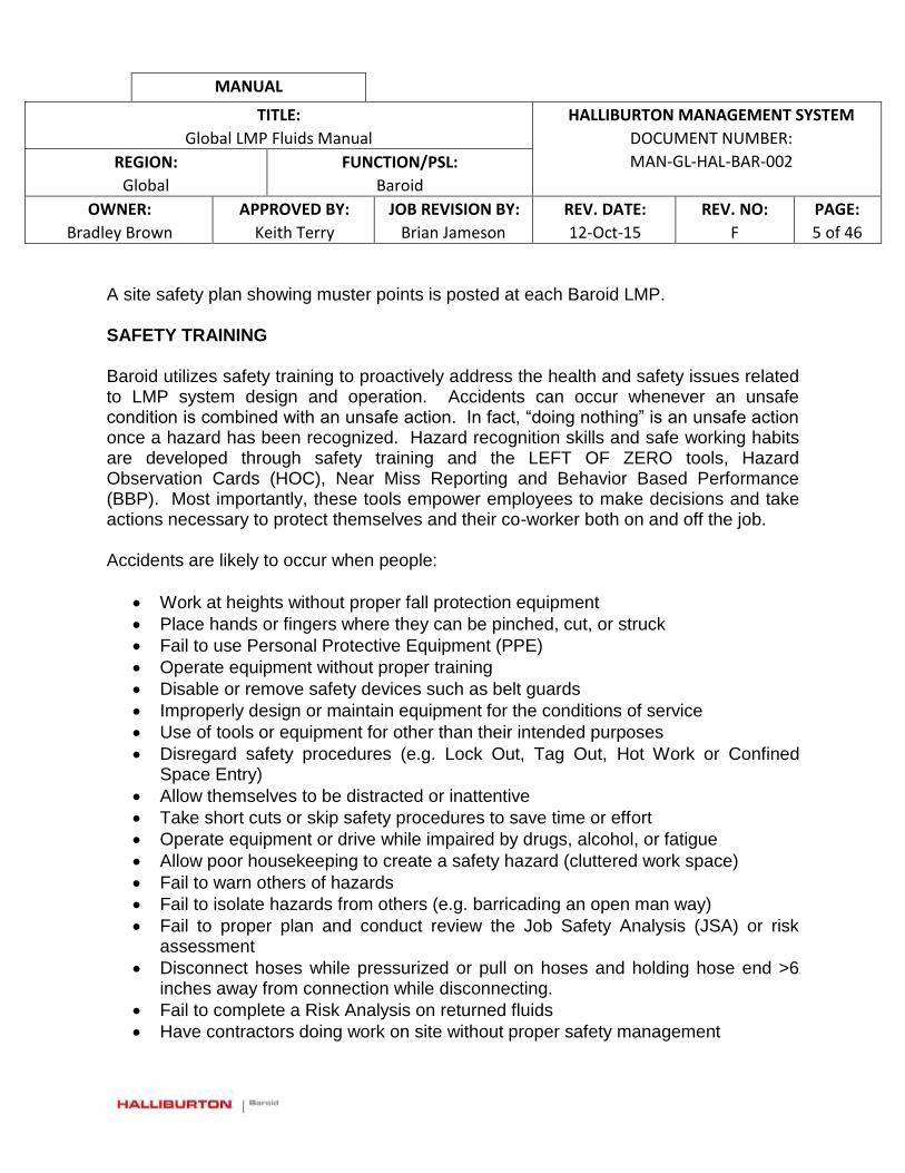
MANUAL
TITLE:
Global LMP Fluids Manual
HALLIBURTON MANAGEMENT SYSTEM
DOCUMENT NUMBER:
MAN-GL-HAL-BAR-002 REGION:
Global
FUNCTION/PSL:
Baroid
OWNER:
Bradley Brown
APPROVED BY:
Keith Terry
JOB REVISION BY:
Brian Jameson
REV. DATE:
12-Oct-15
REV. NO:
F
PAGE:
5 of 46
A site safety plan showing muster points is posted at each Baroid LMP. SAFETY TRAINING Baroid utilizes safety training to proactively address the health and safety issues related to LMP system design and operation. Accidents can occur whenever an unsafe condition is combined with an unsafe action. In fact, “doing nothing” is an unsafe action once a hazard has been recognized. Hazard recognition skills and safe working habits are developed through safety training and the LEFT OF ZERO tools, Hazard Observation Cards (HOC), Near Miss Reporting and Behavior Based Performance (BBP). Most importantly, these tools empower employees to make decisions and take actions necessary to protect themselves and their co-worker both on and off the job. Accidents are likely to occur when people:
Work at heights without proper fall protection equipment
Place hands or fingers where they can be pinched, cut, or struck
Fail to use Personal Protective Equipment (PPE)
Operate equipment without proper training
Disable or remove safety devices such as belt guards
Improperly design or maintain equipment for the conditions of service
Use of tools or equipment for other than their intended purposes
Disregard safety procedures (e.g. Lock Out, Tag Out, Hot Work or Confined Space Entry)
Allow themselves to be distracted or inattentive
Take short cuts or skip safety procedures to save time or effort
Operate equipment or drive while impaired by drugs, alcohol, or fatigue
Allow poor housekeeping to create a safety hazard (cluttered work space)
Fail to warn others of hazards
Fail to isolate hazards from others (e.g. barricading an open man way)
Fail to proper plan and conduct review the Job Safety Analysis (JSA) or risk assessment
Disconnect hoses while pressurized or pull on hoses and holding hose end >6 inches away from connection while disconnecting.
Fail to complete a Risk Analysis on returned fluids
Have contractors doing work on site without proper safety management
MANUAL
TITLE:
Global LMP Fluids Manual
HALLIBURTON MANAGEMENT SYSTEM
DOCUMENT NUMBER:
MAN-GL-HAL-BAR-002 REGION:
Global
FUNCTION/PSL:
Baroid
OWNER:
Bradley Brown
APPROVED BY:
Keith Terry
JOB REVISION BY:
Brian Jameson
REV. DATE:
12-Oct-15
REV. NO:
F
PAGE:
6 of 46
SAFETY PLANNING Job Safety Analyses (JSA’s) are written plans that explain the procedures for safely completing the task at hand. Tasks may be routine or unique. Routine tasks are those for which safety procedures are well known and have previously communicated. Unique tasks are those specific to a job site or outside the scope of standard procedures. If the task is non-routine, a JSA must be created. As a minimum, the steps taken to create JSA must include:
1. Identify and gather interested parties to create a JSA. a. Who will do the work? Who will be affected by the work? b. Who will plan the work and communicate the plan to the affected
personnel? 2. Discuss the procedure.
a. Ask if anyone has experience with similar tasks. b. Ask if permits are required for the procedure. c. Ask what contingencies need to be planned for. d. Ask if anyone sees a better way or has safety concerns.
3. Determine what information, equipment or tools are required a. What PPE is needed? b. Is the PPE in good condition? c. Are the tools available? Are they the right tools for the job? d. Have the MSDS and operations manuals been reviewed?
4. Assess the hazards of the procedure. a. Are pinch points or sharp objects posing hazards to the fingers or hands? b. Is there any exposure to harmful substances, vapors, temperatures, or
noise? c. Are there any falling or moving objects that might strike personnel or
equipment? d. Are there going to be any stressful body positions, heavy lifting or other
over-exertions involved? e. Are there any fire or explosion hazards involved? f. Are there safe entries and exits to and from the work area? g. Is there any trip, slip or fall hazards? h. Are there any energy sources that need to be locked out, tagged out? i. Is there adequate lighting in the work area?

MANUAL
TITLE:
Global LMP Fluids Manual
HALLIBURTON MANAGEMENT SYSTEM
DOCUMENT NUMBER:
MAN-GL-HAL-BAR-002 REGION:
Global
FUNCTION/PSL:
Baroid
OWNER:
Bradley Brown
APPROVED BY:
Keith Terry
JOB REVISION BY:
Brian Jameson
REV. DATE:
12-Oct-15
REV. NO:
F
PAGE:
7 of 46
j. Is adverse weather likely to occur and will it affect the job?
5. Plan for contingencies that would: a. Extend the anticipated work time causing fatigue or a lighting problem at
night. b. Create hazards due to unexpected weather conditions. c. Require additional personnel to be informed as to the conditions outlined
in the JSA or review the JSA with new personnel involved in a crew change.
d. Require different tools or PPE.
6. Contractor Work Safety
In instances where contractor work is necessary at an LMP, the following safety considerations must be taken by local LMP Management:
a. Meet with the job Supervisor/Project Manager to assess the scope of
contractor work
b. Work along with the Supervisor of the work to Identify the need for any
work site permits (e.g., Hot Work Permits, Working at Height Permits,
Lock Out Tag Out, Confined Space Entry or any other permits required)
c. Work along with the Supervisor of the work to Ensure that the area to be
worked is safe to issue permits for the work and that the permitted area is
identified. (e.g., for Hot Work, the area must be tested for explosive gases
and all measures taken to ensure no gases are present or will be present
during the permit period, for Lock Out Tag Out – All energized equipment
must be locked out and de-energized with assurances that this will be
maintained, for Working at Heights – Harnesses and tag lines must be
inspected and the area to be worked checked for safety prior to initiating
work, for Confined Space Entry Work – the area must be checked for H2S
and other harmful gases as well as a buddy system established along with
proper PPE in place)
d. Ensure that Contractors meet with the LMP team daily for the tool box talk
and reveal exactly what areas of the facility they will be working as well as
the work they plan to do. If anything changes, Supervision must clear it
MANUAL
TITLE:
Global LMP Fluids Manual
HALLIBURTON MANAGEMENT SYSTEM
DOCUMENT NUMBER:
MAN-GL-HAL-BAR-002 REGION:
Global
FUNCTION/PSL:
Baroid
OWNER:
Bradley Brown
APPROVED BY:
Keith Terry
JOB REVISION BY:
Brian Jameson
REV. DATE:
12-Oct-15
REV. NO:
F
PAGE:
8 of 46
with LMP Management first before moving forward with any permitted or
other work that was not communicated beforehand
e. If at all possible, the area that the contractor is working in should be shut
down and ensured safe prior to the contractor starting work and only
started back up when work is completed.
f. A Risk Analysis shall be completed for any fluids in tanks where contractor
work will take place. There must be an understanding of risks involved
and mitigations identified and taken prior to authorizing work at any
location within the LMP.
g. As there must be a Supervisor for all Contractor work, there must also be
regular communication between the Supervisor and LMP Management on
site so as to reduce risks for both the contractor and Halliburton
employees during the course of work.
INFORMATION RESOURCES The safety information sources that should be available and kept up to date when working with fluids and fluid processing equipment are:
Installation, Operations, and Maintenance Manuals (IOM) from the manufacturers
Material Safety Data Sheets (MSDS)
Decals, Safety Placards, and/or Warning Signs
Fluids Risk Analysis Make sure that complete and updated copies of the IOMs are kept on the jobsite. IOM manuals should be read by all personnel responsible for operation and maintenance of the equipment. Material Safety Data Sheets contain important information on how to safely handle, use and treat exposures to chemical products found on the job site. MSDS need to be kept on the job site and be up to date. MSDS should be read by everyone who uses or may come in contact with the products. Where required, MSDS, safety placards and warning signs and decals should be translated into any other language commonly used at the job site.
MANUAL
TITLE:
Global LMP Fluids Manual
HALLIBURTON MANAGEMENT SYSTEM
DOCUMENT NUMBER:
MAN-GL-HAL-BAR-002 REGION:
Global
FUNCTION/PSL:
Baroid
OWNER:
Bradley Brown
APPROVED BY:
Keith Terry
JOB REVISION BY:
Brian Jameson
REV. DATE:
12-Oct-15
REV. NO:
F
PAGE:
9 of 46
Many manufacturers deliver new process equipment with installed decals that warn of specific equipment hazards. Additionally, the work place may require the posting of other safety placards (e.g. “Hearing Protection Required”). When working with mud systems, it is particularly important to make sure all warning signs are kept clean and legible. Decals are usually supplied free of charge by manufacturers so that they can be replaced when damaged or washed off the unit from repeated pressure washing of the equipment. Other common warning signs and placards are available from supply stores. The type of Fluids in the LMP must be understood along with the HSE risks with those fluids. This is accomplished by completing a fluids risk analysis. The Risk Analysis should include the identification of risks associated with all fluids contained within the LMP at any point in time. Base fluids should be reviewed for fire and explosion hazards as well as hazards associated with skin and eye contact and fumes. Mixed fluids should be reviewed for additional hazards associated with the additives that have been mixed into the fluids. The MSDS should be consulted when completing a risk analysis on Base Fluids and Mixed fluids. In addition, a complete risk analysis will include an analysis of fluids being returned to the LMP from drilling rigs. These fluids may contain additional products which were added at the rig site or they may contain crude oil or chemical thinning agents used on shakers at the rig. A thorough understanding of the risks of working with and around returned fluids should be gained by the risk analysis so that all employees and contractors are aware of hazards associated with the fluid or the storage of the fluid at the LMP. Any information that is unclear or conflicts with common sense or other safety practices or policies should be discussed with your supervisor prior to working on or with the equipment.

MANUAL
TITLE:
Global LMP Fluids Manual
HALLIBURTON MANAGEMENT SYSTEM
DOCUMENT NUMBER:
MAN-GL-HAL-BAR-002 REGION:
Global
FUNCTION/PSL:
Baroid
OWNER:
Bradley Brown
APPROVED BY:
Keith Terry
JOB REVISION BY:
Brian Jameson
REV. DATE:
12-Oct-15
REV. NO:
F
PAGE:
10 of 46
SECTION 1 - INTRODUCTION
GENERAL This manual is developed to assist liquid mud plant (LMP) employees perform their duties in a safe and professional manner. This guide contains specific operating and general safety guidelines that apply to all LMPs. The purpose of this manual is to discuss the general and specific operating and maintenance practices for standard LMP operations. Liquid mud and completion fluids are mixed and stored at the LMP in a contained area and are transported by truck or boat to drilling operations. Liquid mud plants are used for the following purposes:
Mixing and/or blending of oil and synthetic based fluids (NAF)
Mixing water based fluids
Mixing and/or blending brines
Loading/Unloading of bulk materials and base fluids
LMP DESCRIPTION
Liquid Mud and Completion Fluid Plants (LMPs) provide products and services to the oil and gas drilling industry. The operations are comprised of liquid mud (Oil & Water Based) and/or completion fluids mixing and storage facility. Liquid mud is mixed and stored at the facility in a contained area and are transported to the wellsite by truck, offshore supply vessel or barge.
BASIC COMPONENTS OF AN LMP
The basic components of an LMP may be modular, enabling them to be placed individually and customized to meet the site requirements with regards to capacity and structure of the plant or fixed. Many components are used in LMP Operations; however, not all are required in every location (or in every operation). The components listed below are the baseline components used to perform normal LMP Operations for all locations.
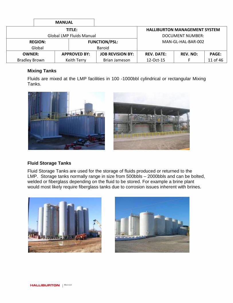
MANUAL
TITLE:
Global LMP Fluids Manual
HALLIBURTON MANAGEMENT SYSTEM
DOCUMENT NUMBER:
MAN-GL-HAL-BAR-002 REGION:
Global
FUNCTION/PSL:
Baroid
OWNER:
Bradley Brown
APPROVED BY:
Keith Terry
JOB REVISION BY:
Brian Jameson
REV. DATE:
12-Oct-15
REV. NO:
F
PAGE:
11 of 46
Mixing Tanks
Fluids are mixed at the LMP facilities in 100 -1000bbl cylindrical or rectangular Mixing Tanks.
Fluid Storage Tanks
Fluid Storage Tanks are used for the storage of fluids produced or returned to the LMP. Storage tanks normally range in size from 500bbls – 2000bbls and can be bolted, welded or fiberglass depending on the fluid to be stored. For example a brine plant would most likely require fiberglass tanks due to corrosion issues inherent with brines.
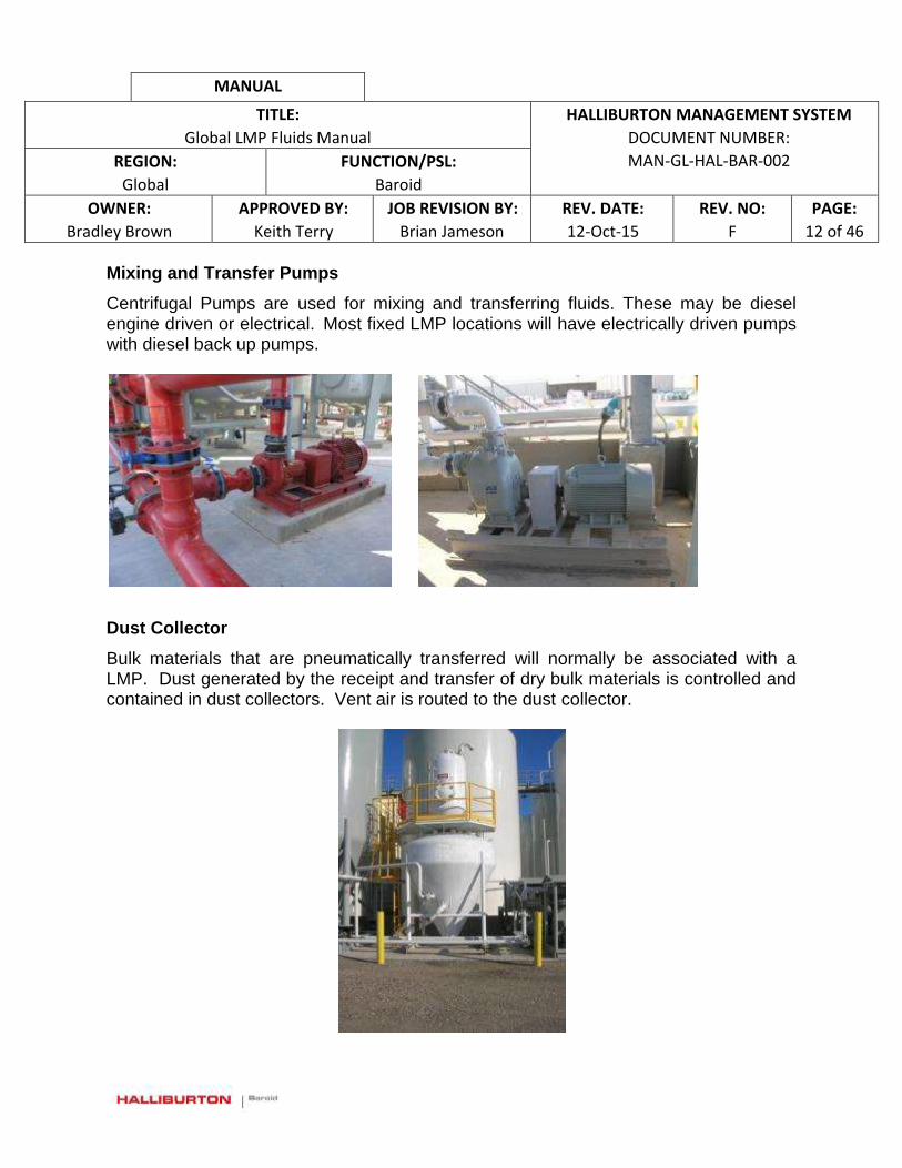
MANUAL
TITLE:
Global LMP Fluids Manual
HALLIBURTON MANAGEMENT SYSTEM
DOCUMENT NUMBER:
MAN-GL-HAL-BAR-002 REGION:
Global
FUNCTION/PSL:
Baroid
OWNER:
Bradley Brown
APPROVED BY:
Keith Terry
JOB REVISION BY:
Brian Jameson
REV. DATE:
12-Oct-15
REV. NO:
F
PAGE:
12 of 46
Mixing and Transfer Pumps
Centrifugal Pumps are used for mixing and transferring fluids. These may be diesel engine driven or electrical. Most fixed LMP locations will have electrically driven pumps with diesel back up pumps.
Dust Collector
Bulk materials that are pneumatically transferred will normally be associated with a LMP. Dust generated by the receipt and transfer of dry bulk materials is controlled and contained in dust collectors. Vent air is routed to the dust collector.
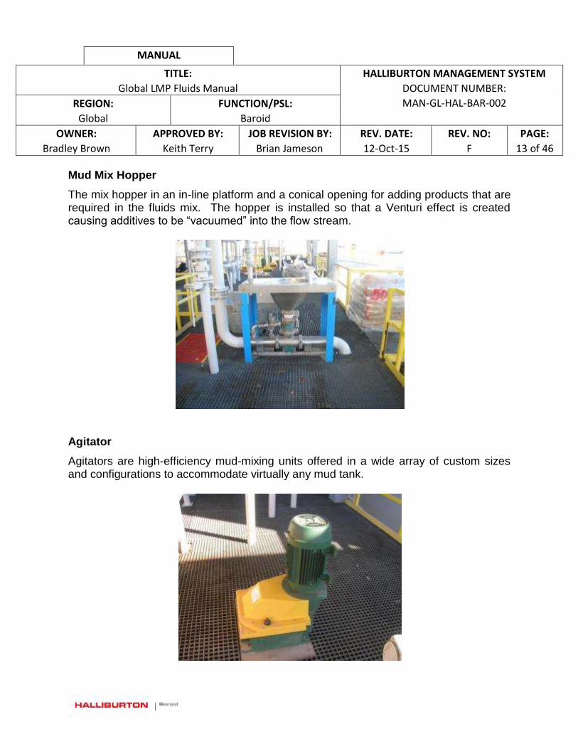
MANUAL
TITLE:
Global LMP Fluids Manual
HALLIBURTON MANAGEMENT SYSTEM
DOCUMENT NUMBER:
MAN-GL-HAL-BAR-002 REGION:
Global
FUNCTION/PSL:
Baroid
OWNER:
Bradley Brown
APPROVED BY:
Keith Terry
JOB REVISION BY:
Brian Jameson
REV. DATE:
12-Oct-15
REV. NO:
F
PAGE:
13 of 46
Mud Mix Hopper
The mix hopper in an in-line platform and a conical opening for adding products that are required in the fluids mix. The hopper is installed so that a Venturi effect is created causing additives to be “vacuumed” into the flow stream.
Agitator
Agitators are high-efficiency mud-mixing units offered in a wide array of custom sizes and configurations to accommodate virtually any mud tank.

MANUAL
TITLE:
Global LMP Fluids Manual
HALLIBURTON MANAGEMENT SYSTEM
DOCUMENT NUMBER:
MAN-GL-HAL-BAR-002 REGION:
Global
FUNCTION/PSL:
Baroid
OWNER:
Bradley Brown
APPROVED BY:
Keith Terry
JOB REVISION BY:
Brian Jameson
REV. DATE:
12-Oct-15
REV. NO:
F
PAGE:
14 of 46
Air Compressor
Most bulk air compressors have dual pressurized air take off points. For example: they produce both bulk air (40 psi) and general purpose air (100 psi). The 100 psi air is for general purpose use, including diaphragm pumps, air-powered tools, valve actuators, spray painting, mud lab tests (API filter press) etc. Blowing down lines is done using low pressure or vacuum trucks when available for reduced risks. Most systems operate at 30-40 psi, but new high delivery rate systems may operate at 50-60 psi.
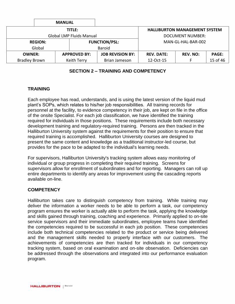
MANUAL
TITLE:
Global LMP Fluids Manual
HALLIBURTON MANAGEMENT SYSTEM
DOCUMENT NUMBER:
MAN-GL-HAL-BAR-002 REGION:
Global
FUNCTION/PSL:
Baroid
OWNER:
Bradley Brown
APPROVED BY:
Keith Terry
JOB REVISION BY:
Brian Jameson
REV. DATE:
12-Oct-15
REV. NO:
F
PAGE:
15 of 46
SECTION 2 – TRAINING AND COMPETENCY
TRAINING
Each employee has read, understands, and is using the latest version of the liquid mud plant’s SOPs, which relates to his/her job responsibilities. All training records for personnel at the facility, to evidence competency in their job, are kept on file in the office of the onsite Specialist. For each job classification, we have identified the training required for individuals in those positions. These requirements include both necessary development training and regulatory-required training. Persons are then tracked in the Halliburton University system against the requirements for their position to ensure that required training is accomplished. Halliburton University courses are designed to present the same content and knowledge as a traditional instructor-led course, but provides for the pace to be adapted to the individual's learning needs.
For supervisors, Halliburton University's tracking system allows easy monitoring of individual or group progress in completing their required training. Screens for supervisors allow for enrollment of subordinates and for reporting. Managers can roll up entire departments to identify any areas for improvement using the cascading reports available on-line.
COMPETENCY
Halliburton takes care to distinguish competency from training. While training may deliver the information a worker needs to be able to perform a task, our competency program ensures the worker is actually able to perform the task, applying the knowledge and skills gained through training, coaching and experience. Primarily applied to on-site service supervisors and their immediate subordinates, employee teams have identified the competencies required to be successful in each job position. These competencies include both technical competencies related to the product or service being delivered and the management skills needed to properly interface with our customers. The achievements of competencies are then tracked for individuals in our competency tracking system, based on oral examination and on-site observation. Deficiencies can be addressed through the observations and integrated into our performance evaluation program.
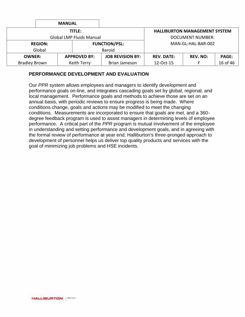
MANUAL
TITLE:
Global LMP Fluids Manual
HALLIBURTON MANAGEMENT SYSTEM
DOCUMENT NUMBER:
MAN-GL-HAL-BAR-002 REGION:
Global
FUNCTION/PSL:
Baroid
OWNER:
Bradley Brown
APPROVED BY:
Keith Terry
JOB REVISION BY:
Brian Jameson
REV. DATE:
12-Oct-15
REV. NO:
F
PAGE:
16 of 46
PERFORMANCE DEVELOPMENT AND EVALUATION
Our PPR system allows employees and managers to identify development and performance goals on-line, and integrates cascading goals set by global, regional, and local management. Performance goals and methods to achieve those are set on an annual basis, with periodic reviews to ensure progress is being made. Where conditions change, goals and actions may be modified to meet the changing conditions. Measurements are incorporated to ensure that goals are met, and a 360-degree feedback program is used to assist managers in determining levels of employee performance. A critical part of the PPR program is mutual involvement of the employee in understanding and setting performance and development goals, and in agreeing with the formal review of performance at year end. Halliburton's three-pronged approach to development of personnel helps us deliver top quality products and services with the goal of minimizing job problems and HSE incidents.
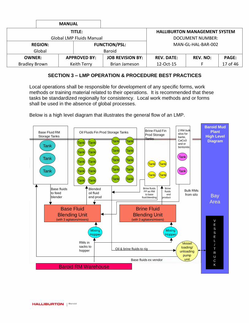
MANUAL
TITLE:
Global LMP Fluids Manual
HALLIBURTON MANAGEMENT SYSTEM
DOCUMENT NUMBER:
MAN-GL-HAL-BAR-002 REGION:
Global
FUNCTION/PSL:
Baroid
OWNER:
Bradley Brown
APPROVED BY:
Keith Terry
JOB REVISION BY:
Brian Jameson
REV. DATE:
12-Oct-15
REV. NO:
F
PAGE:
17 of 46
SECTION 3 – LMP OPERATION & PROCEDURE BEST PRACTICES
Local operations shall be responsible for development of any specific forms, work methods or training material related to their operations. It is recommended that these tasks be standardized regionally for consistency. Local work methods and or forms shall be used in the absence of global processes.
Below is a high level diagram that illustrates the general flow of an LMP.
“Confidential - For Internal Use Only. © 2005 Halliburton. All Rights Reserved.”
2
Bay
Area
Tank
Tank
Tank
Base Fluid RM
Storage Tanks
Tank
Oil Fluids Fin Prod Storage Tanks
Tank
Tank
Brine Fluid Fin
Prod Storage
Tanks
Tank
Tank
Tank
Tank
2 RM bulk
silos for
barite,
CaCo3
and or
bentonite.
Base Fluid
Blending Unit(with 3 agitators/mixers)
Brine Fluid
Blending Unit(with 3 agitators/mixers)
Mixing
Hopper
Mixing
Hopper
Vessel
loading/
unloading
pump
unit
V
E
S
S
E
L
/
T
R
U
C
K
Base fluids ex vendor
Base fluids
to feed
blender
Blended
oil fluid
end prod
Oil & brine fluids to rig
RMs in
sacks to
hopper
Bulk RMs
from silo
RMs like: Geltone II, EZ-Mul, CaCl², Duratone HT, Invermul, Lime etc
Brine fluids
FP as RM
to base
fluid blending
Brine
fluids
end
product
Tank
Tank
Tank
Tank
Tank
Tank
Tank
Tank
Tank
Tank
Tank
Tank Tank
TankTank
TankTank
Tank
Tank
Baroid Mud
Plant
High Level
Diagram
Baroid RM Warehouse

MANUAL
TITLE:
Global LMP Fluids Manual
HALLIBURTON MANAGEMENT SYSTEM
DOCUMENT NUMBER:
MAN-GL-HAL-BAR-002 REGION:
Global
FUNCTION/PSL:
Baroid
OWNER:
Bradley Brown
APPROVED BY:
Keith Terry
JOB REVISION BY:
Brian Jameson
REV. DATE:
12-Oct-15
REV. NO:
F
PAGE:
18 of 46
VOLUME TRACKING
Fluid accountability and volume tracking are very important for Halliburton and Halliburton’s customers. All transfers in and out of the LMP and storage facilities must be documented in accordance with local procedures. MIXING OPERATIONS Types of operations typically performed at the liquid mud plant are:
Manufacture of a specified volume of mud and/or brine using drummed/sacked raw materials, oil and/or water
Blending of brines
Addition of chemicals or other mud materials to an existing volume of mud
Palletized chemicals needed are transported from the warehouse to the plant by forklift. Each of the plant operators and warehouse personnel should have completed an approved forklift operations training course. Pallets are stacked immediately in front of the hopper and the sacks are then lifted to the hopper table. Operators should be wearing steel toed boots and work gloves while handling most mud chemicals. Some materials will require added PPE and should be noted in the JSA. The sacked materials will be cut open with an appropriate tool; knife or craft cutter and the contents are emptied into the hopper. Two operators should be involved in cutting and emptying sacks. Separate PPE requirements for liquid chemicals should be noted in the JSA for the job. Two operators should be involved in handling drum chemicals. Safety Considerations
a. Wear correct PPE at all times.
b. Never eat, smoke or drink in chemical handling areas.
MANUAL
TITLE:
Global LMP Fluids Manual
HALLIBURTON MANAGEMENT SYSTEM
DOCUMENT NUMBER:
MAN-GL-HAL-BAR-002 REGION:
Global
FUNCTION/PSL:
Baroid
OWNER:
Bradley Brown
APPROVED BY:
Keith Terry
JOB REVISION BY:
Brian Jameson
REV. DATE:
12-Oct-15
REV. NO:
F
PAGE:
19 of 46
c. Never lean on guard rails.
d. Use correct manual handling technique for lifting chemical packages. Position
the pallets as close to the hopper table as described above to minimize carrying distances.
e. Use a forklift to keep sack material on pallets at waist height to minimize lifting distances.
f. Never add corrosive chemicals (e.g. Caustic Soda) through a hopper.
g. Guard chains are not an acceptable fall barrier. A full gate with toe plate is required.
h. Exercise care when using a knife to cut sacks. Always push the blade away from one’s body.
i. Dispose of empty packaging in designated waste containers and close dumpster lid after use.
Mixing New Mud/Brine The following procedure will be used to mix and transfer batches of new fluid. This procedure describes mixing new water-based mud (WBM), oil based mud (NAF or OBM), or brines.
MANUAL
TITLE:
Global LMP Fluids Manual
HALLIBURTON MANAGEMENT SYSTEM
DOCUMENT NUMBER:
MAN-GL-HAL-BAR-002 REGION:
Global
FUNCTION/PSL:
Baroid
OWNER:
Bradley Brown
APPROVED BY:
Keith Terry
JOB REVISION BY:
Brian Jameson
REV. DATE:
12-Oct-15
REV. NO:
F
PAGE:
20 of 46
After performing the pre job inspections, new mud is mixed as follows:
1 Ensure that the operators are wearing appropriate PPE.
2 Line up and switch on fume/dust extraction blower fan if available.
3 Line up base fluid supply to the mixing pump and fill the mix tank to the required level. Shut down the pump and close off the base fluid supply lines.
4
Double check the volume of fluid in the mixing tank to see if there is the required amount according to the batch mixing instructions.
5 Confirm that all valves are closed.
6 Confirm that the hopper valve is closed.
7 Open the suction line valves between the mixing tank and the mixing pump.
8 Open the valve to the mixing tank gun lines.
9 Start the pump.
10 Switch on the agitator (Lightning Mixer)
Adding Chemicals to the Mixing Tank
1
The following information with be required by the plant operators: - Chemical to be added to the batch mix and the location of the MSDS - Quantity of material to be added - The order in which the chemicals and base fluids (oil, water, etc.) are to be added - Additional PPE requirements -Time per product addition (minutes per sack) - Sampling requirements
2 Confirm that circulation is established in the mixing tank
3 Open the valve to the mixing hopper
4 Line up hopper, circulate through the hopper and carefully open the hopper throat valve
5 Add liquid chemicals through the hopper or via the tank top at the programmed rate
6 Add powder chemicals via the hopper at the programmed rate
7 Mix the fluid for the time specified.
8 Check the mixing tank volume regularly to make sure that it does not overflow while circulating

MANUAL
TITLE:
Global LMP Fluids Manual
HALLIBURTON MANAGEMENT SYSTEM
DOCUMENT NUMBER:
MAN-GL-HAL-BAR-002 REGION:
Global
FUNCTION/PSL:
Baroid
OWNER:
Bradley Brown
APPROVED BY:
Keith Terry
JOB REVISION BY:
Brian Jameson
REV. DATE:
12-Oct-15
REV. NO:
F
PAGE:
21 of 46
Sampling the Fluid in the Mixing Tank
1 Collect samples and test properties as required.
2 Once the fluid meets specification, close the valves to the hopper system and transfer to storage or retain in the mixing pit for load-out.
3 Collect and label any required quality control (QC) samples.
Completing the Mixing Process
1 To stop mixing, switch off the agitator and the mixing pump
2 Close the suction line valve(s) between the mixing tank and the pump
3 Close off all valves on the gun lines
4 Clean the hopper and connection
5 Pick up all empty bags, collect any tools and place in proper area
New and reconditioned fluid properties should be checked and reported using the appropriate form. TRANSFERRING FLUID This includes:
Mixing to storage
Mixing to transport
Transport to storage
Transport to mixing
Internal tank-to-tank
Before initializing a fluid transfer, review the Pre-Fluid Transfer Inspection Checklist (Section 4) and ensure that all requirements have been completed.

MANUAL
TITLE:
Global LMP Fluids Manual
HALLIBURTON MANAGEMENT SYSTEM
DOCUMENT NUMBER:
MAN-GL-HAL-BAR-002 REGION:
Global
FUNCTION/PSL:
Baroid
OWNER:
Bradley Brown
APPROVED BY:
Keith Terry
JOB REVISION BY:
Brian Jameson
REV. DATE:
12-Oct-15
REV. NO:
F
PAGE:
22 of 46
The plant supervisor will designate which tank(s) will receive the fluid. Throughout the transfer, one operator should be positioned at the storage tank to monitor the volume in the tank. Ensure that the tank contents are going nowhere else by checking the other tanks on the common manifold.
1 Prior to beginning the transfer, confirm that all valves on the plant are closed
2 If the fluid being transferred is to be blended with existing fluid, the operators should confirm with the Plant Supervisor that the two fluids are compatible.
3
Record the volume of fluid in the designated receiving tank(s) as measured by gauges or other indicators. If electronic measuring devices are in place, a manual measurement should be made to confirm that the electronic device is functioning properly
4 Record the volume of fluid in the tank to be transferred.
5 Slowly open the valve(s) from the tank to be transferred to the receiving tank.
6 Start the pump
7 Confirm that fluid is flowing.
8 Manually measure the volumes or check the gauges on the receiving tank(s) to ensure that the contents are not being diverted from the receiving tank(s)
9
When the correct volume of fluid has been transferred (as read by gauge or manual measurement) shut down the pump and close all valves in the transfer line
10 Allow five minutes after shut down of the transfer line before measuring the final volume
11 Record the volume(s) of fluid transferred out or received in.
Note: if transferring to more than one storage tank, slowly open the fill valve to the second tank before the level in the first tank exceeds 90% of capacity. Half shut the fill line valve to the first tank until the correct volume has been transferred to it. This last 10% of volume will be slowed considerably. Once the first tank is filled, shut the fill valve. Repeat this process if additional tanks are involved.
MANUAL
TITLE:
Global LMP Fluids Manual
HALLIBURTON MANAGEMENT SYSTEM
DOCUMENT NUMBER:
MAN-GL-HAL-BAR-002 REGION:
Global
FUNCTION/PSL:
Baroid
OWNER:
Bradley Brown
APPROVED BY:
Keith Terry
JOB REVISION BY:
Brian Jameson
REV. DATE:
12-Oct-15
REV. NO:
F
PAGE:
23 of 46
Circulating Storage Tank(s)
1 Check that all valves on the manifold are closed
2
Confirm the volume of fluid in each tank by gauge or by manual measurement. Make sure that there is enough space to permit circulation without causing spillage through the opening at the top of the tank
3 Open all valves on the suction line from the storage tank to the pump
4 Open all valves on the fill line from the pump to the storage tank
5 Start the pump
6
Check the tank to make sure that circulation has been established. Vibration can usually be felt in the fill line valve handle if that valve is partially closed. Additionally, circulation can be confirmed by checking the pressure gauge on the mixing pump manifold.
7
While circulating a storage tank, monitor the volumes in other storage tanks to ensure that fluid is being confined to the active tank and not leaking into other storage tanks.
8 To stop circulating, shut down the pump and close all valves on the manifold
9 Confirm that the storage tank volume is the same as the volume prior to circulation. If any difference is noted notify the plant supervisor
Reconditioning of Fluids Reconditioning is usually limited to Oil Based Mud and brines. EQUIPMENT OPERATING GUIDELINES (a standalone work WM-GL-HAL-BAR-002 also exists) Chemical Barrel Operating Instructions Certain hazardous chemicals, notably strong alkalis such as caustic soda (NaOH) and potassium hydroxide (KOH) must be mixed and dissolved in water prior to addition to an active mud or brine tank. The pre-mixing is performed in a “chemical barrel” to minimize the risk to personnel.
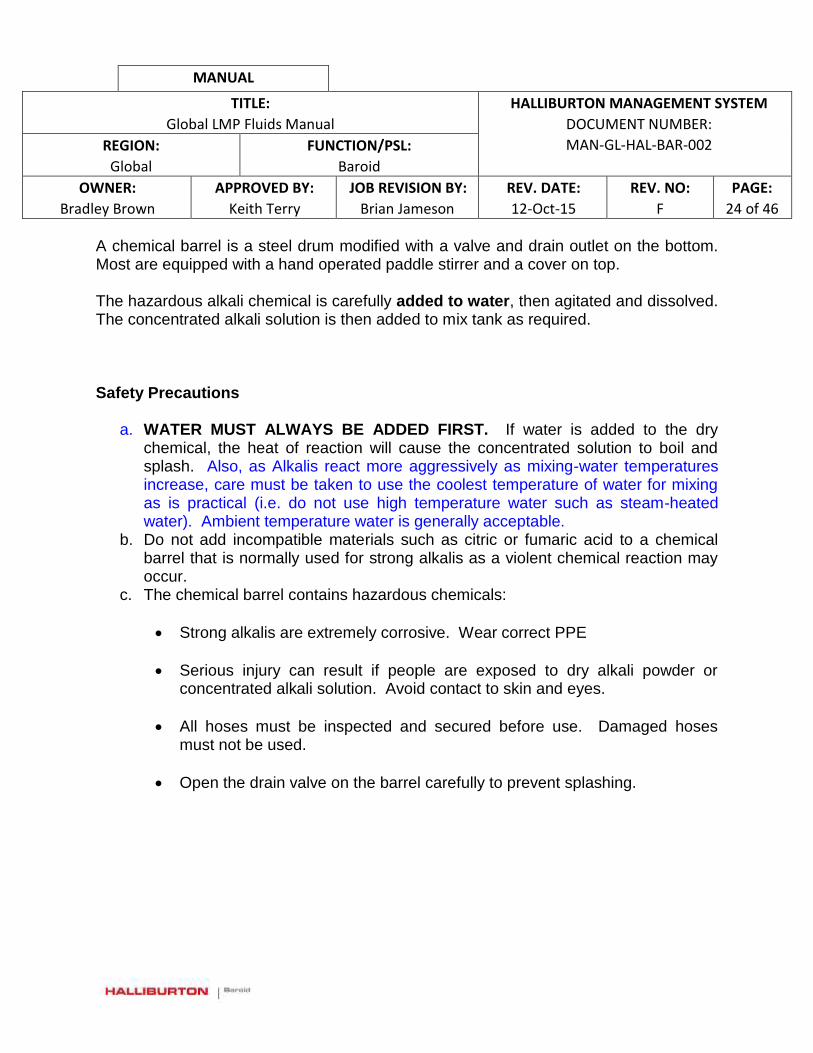
MANUAL
TITLE:
Global LMP Fluids Manual
HALLIBURTON MANAGEMENT SYSTEM
DOCUMENT NUMBER:
MAN-GL-HAL-BAR-002 REGION:
Global
FUNCTION/PSL:
Baroid
OWNER:
Bradley Brown
APPROVED BY:
Keith Terry
JOB REVISION BY:
Brian Jameson
REV. DATE:
12-Oct-15
REV. NO:
F
PAGE:
24 of 46
A chemical barrel is a steel drum modified with a valve and drain outlet on the bottom. Most are equipped with a hand operated paddle stirrer and a cover on top. The hazardous alkali chemical is carefully added to water, then agitated and dissolved. The concentrated alkali solution is then added to mix tank as required. Safety Precautions
a. WATER MUST ALWAYS BE ADDED FIRST. If water is added to the dry chemical, the heat of reaction will cause the concentrated solution to boil and splash. Also, as Alkalis react more aggressively as mixing-water temperatures increase, care must be taken to use the coolest temperature of water for mixing as is practical (i.e. do not use high temperature water such as steam-heated water). Ambient temperature water is generally acceptable.
b. Do not add incompatible materials such as citric or fumaric acid to a chemical barrel that is normally used for strong alkalis as a violent chemical reaction may occur.
c. The chemical barrel contains hazardous chemicals:
Strong alkalis are extremely corrosive. Wear correct PPE
Serious injury can result if people are exposed to dry alkali powder or concentrated alkali solution. Avoid contact to skin and eyes.
All hoses must be inspected and secured before use. Damaged hoses must not be used.
Open the drain valve on the barrel carefully to prevent splashing.
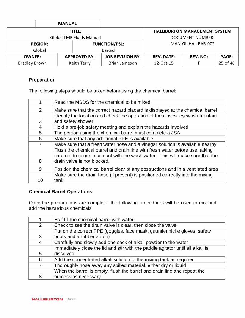
MANUAL
TITLE:
Global LMP Fluids Manual
HALLIBURTON MANAGEMENT SYSTEM
DOCUMENT NUMBER:
MAN-GL-HAL-BAR-002 REGION:
Global
FUNCTION/PSL:
Baroid
OWNER:
Bradley Brown
APPROVED BY:
Keith Terry
JOB REVISION BY:
Brian Jameson
REV. DATE:
12-Oct-15
REV. NO:
F
PAGE:
25 of 46
Preparation The following steps should be taken before using the chemical barrel:
1 Read the MSDS for the chemical to be mixed
2 Make sure that the correct hazard placard is displayed at the chemical barrel
3 Identify the location and check the operation of the closest eyewash fountain and safety shower
4 Hold a pre-job safety meeting and explain the hazards involved
5 The person using the chemical barrel must complete a JSA
6 Make sure that any additional PPE is available
7 Make sure that a fresh water hose and a vinegar solution is available nearby
8
Flush the chemical barrel and drain line with fresh water before use, taking care not to come in contact with the wash water. This will make sure that the drain valve is not blocked.
9 Position the chemical barrel clear of any obstructions and in a ventilated area
10 Make sure the drain hose (if present) is positioned correctly into the mixing tank
Chemical Barrel Operations Once the preparations are complete, the following procedures will be used to mix and add the hazardous chemicals
1 Half fill the chemical barrel with water
2 Check to see the drain valve is clear, then close the valve
3 Put on the correct PPE (goggles, face mask, gauntlet nitrile gloves, safety boots and a rubber apron)
4 Carefully and slowly add one sack of alkali powder to the water
5 Immediately close the lid and stir with the paddle agitator until all alkali is dissolved
6 Add the concentrated alkali solution to the mixing tank as required
7 Thoroughly hose away any spilled material, either dry or liquid
8 When the barrel is empty, flush the barrel and drain line and repeat the process as necessary

MANUAL
TITLE:
Global LMP Fluids Manual
HALLIBURTON MANAGEMENT SYSTEM
DOCUMENT NUMBER:
MAN-GL-HAL-BAR-002 REGION:
Global
FUNCTION/PSL:
Baroid
OWNER:
Bradley Brown
APPROVED BY:
Keith Terry
JOB REVISION BY:
Brian Jameson
REV. DATE:
12-Oct-15
REV. NO:
F
PAGE:
26 of 46
Chemical Splash or Burn If the alkali powder or solution comes in contact with skin or eyes, immediately wash the affected area with water or vinegar solution. Use the closest eye wash fountain or safety shower, if nearby. After washing with large amounts of water or vinegar, immediately seek medical attention. Job Completion At the end of the alkali mixing operations, flush the chemical barrel, valve and drain line with water. Close the valve and secure the lid. Reporting Any problems should be recorded on a CPI report. Any chemical spills or splashes resulting in an injury must be detailed on a Halliburton incident report form BLOWING LINES CLEAR WITH AIR
Best practice is to blow back to mixing system as opposed to blowing back to boat/truck.
During inclement weather and after fluid transfers are complete, the lines may be blown clear of fluid with compressed air. This prevents freezing of water and excessive thickening of oil based mud. Safety Precautions Compressors and the bulk air system are considered to be hazardous equipment:
a. Serious injury can result if personnel are exposed to pressurized fluid or air discharge, or hose whip due to air or fluid pressure.
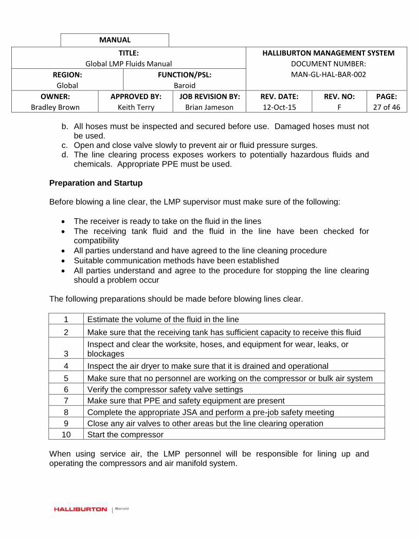
MANUAL
TITLE:
Global LMP Fluids Manual
HALLIBURTON MANAGEMENT SYSTEM
DOCUMENT NUMBER:
MAN-GL-HAL-BAR-002 REGION:
Global
FUNCTION/PSL:
Baroid
OWNER:
Bradley Brown
APPROVED BY:
Keith Terry
JOB REVISION BY:
Brian Jameson
REV. DATE:
12-Oct-15
REV. NO:
F
PAGE:
27 of 46
b. All hoses must be inspected and secured before use. Damaged hoses must not be used.
c. Open and close valve slowly to prevent air or fluid pressure surges. d. The line clearing process exposes workers to potentially hazardous fluids and
chemicals. Appropriate PPE must be used. Preparation and Startup Before blowing a line clear, the LMP supervisor must make sure of the following:
The receiver is ready to take on the fluid in the lines
The receiving tank fluid and the fluid in the line have been checked for compatibility
All parties understand and have agreed to the line cleaning procedure
Suitable communication methods have been established
All parties understand and agree to the procedure for stopping the line clearing should a problem occur
The following preparations should be made before blowing lines clear.
1 Estimate the volume of the fluid in the line
2 Make sure that the receiving tank has sufficient capacity to receive this fluid
3 Inspect and clear the worksite, hoses, and equipment for wear, leaks, or blockages
4 Inspect the air dryer to make sure that it is drained and operational
5 Make sure that no personnel are working on the compressor or bulk air system
6 Verify the compressor safety valve settings
7 Make sure that PPE and safety equipment are present
8 Complete the appropriate JSA and perform a pre-job safety meeting
9 Close any air valves to other areas but the line clearing operation
10 Start the compressor
When using service air, the LMP personnel will be responsible for lining up and operating the compressors and air manifold system.
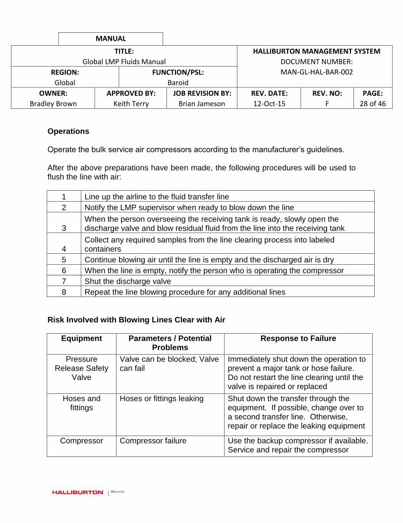
MANUAL
TITLE:
Global LMP Fluids Manual
HALLIBURTON MANAGEMENT SYSTEM
DOCUMENT NUMBER:
MAN-GL-HAL-BAR-002 REGION:
Global
FUNCTION/PSL:
Baroid
OWNER:
Bradley Brown
APPROVED BY:
Keith Terry
JOB REVISION BY:
Brian Jameson
REV. DATE:
12-Oct-15
REV. NO:
F
PAGE:
28 of 46
Operations Operate the bulk service air compressors according to the manufacturer’s guidelines. After the above preparations have been made, the following procedures will be used to flush the line with air:
1 Line up the airline to the fluid transfer line
2 Notify the LMP supervisor when ready to blow down the line
3 When the person overseeing the receiving tank is ready, slowly open the discharge valve and blow residual fluid from the line into the receiving tank
4 Collect any required samples from the line clearing process into labeled containers
5 Continue blowing air until the line is empty and the discharged air is dry
6 When the line is empty, notify the person who is operating the compressor
7 Shut the discharge valve
8 Repeat the line blowing procedure for any additional lines
Risk Involved with Blowing Lines Clear with Air
Equipment Parameters / Potential Problems
Response to Failure
Pressure Release Safety
Valve
Valve can be blocked; Valve can fail
Immediately shut down the operation to prevent a major tank or hose failure. Do not restart the line clearing until the valve is repaired or replaced
Hoses and fittings
Hoses or fittings leaking Shut down the transfer through the equipment. If possible, change over to a second transfer line. Otherwise, repair or replace the leaking equipment
Compressor Compressor failure Use the backup compressor if available. Service and repair the compressor
MANUAL
TITLE:
Global LMP Fluids Manual
HALLIBURTON MANAGEMENT SYSTEM
DOCUMENT NUMBER:
MAN-GL-HAL-BAR-002 REGION:
Global
FUNCTION/PSL:
Baroid
OWNER:
Bradley Brown
APPROVED BY:
Keith Terry
JOB REVISION BY:
Brian Jameson
REV. DATE:
12-Oct-15
REV. NO:
F
PAGE:
29 of 46
Job Completion At the end of the clearing operations, all air pressure should be vented, all valves closed and the compressor(s) shut down. The compressor should be serviced per the manufacturer’s instructions during the shutdown period. Reporting All drilling fluid volumes recovered from the lines should be accounted for on the daily LMP report. Equipment operating time should be reported in the Operations Log. Any failures should be reported on a CPI form.
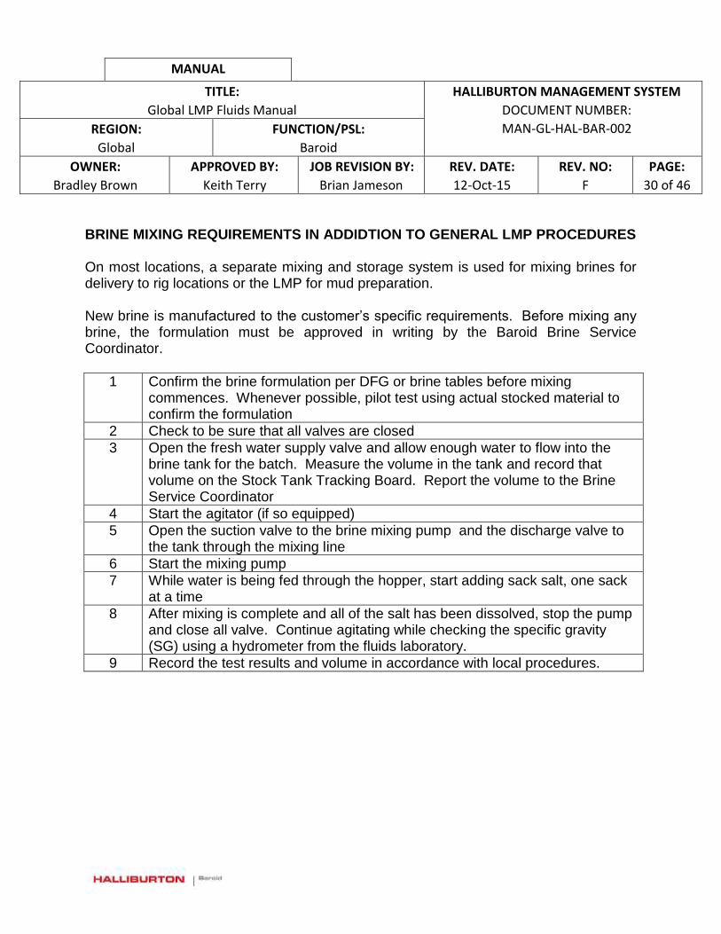
MANUAL
TITLE:
Global LMP Fluids Manual
HALLIBURTON MANAGEMENT SYSTEM
DOCUMENT NUMBER:
MAN-GL-HAL-BAR-002 REGION:
Global
FUNCTION/PSL:
Baroid
OWNER:
Bradley Brown
APPROVED BY:
Keith Terry
JOB REVISION BY:
Brian Jameson
REV. DATE:
12-Oct-15
REV. NO:
F
PAGE:
30 of 46
BRINE MIXING REQUIREMENTS IN ADDIDTION TO GENERAL LMP PROCEDURES On most locations, a separate mixing and storage system is used for mixing brines for delivery to rig locations or the LMP for mud preparation. New brine is manufactured to the customer’s specific requirements. Before mixing any brine, the formulation must be approved in writing by the Baroid Brine Service Coordinator.
1 Confirm the brine formulation per DFG or brine tables before mixing commences. Whenever possible, pilot test using actual stocked material to confirm the formulation
2 Check to be sure that all valves are closed
3 Open the fresh water supply valve and allow enough water to flow into the brine tank for the batch. Measure the volume in the tank and record that volume on the Stock Tank Tracking Board. Report the volume to the Brine Service Coordinator
4 Start the agitator (if so equipped)
5 Open the suction valve to the brine mixing pump and the discharge valve to the tank through the mixing line
6 Start the mixing pump
7 While water is being fed through the hopper, start adding sack salt, one sack at a time
8 After mixing is complete and all of the salt has been dissolved, stop the pump and close all valve. Continue agitating while checking the specific gravity (SG) using a hydrometer from the fluids laboratory.
9 Record the test results and volume in accordance with local procedures.
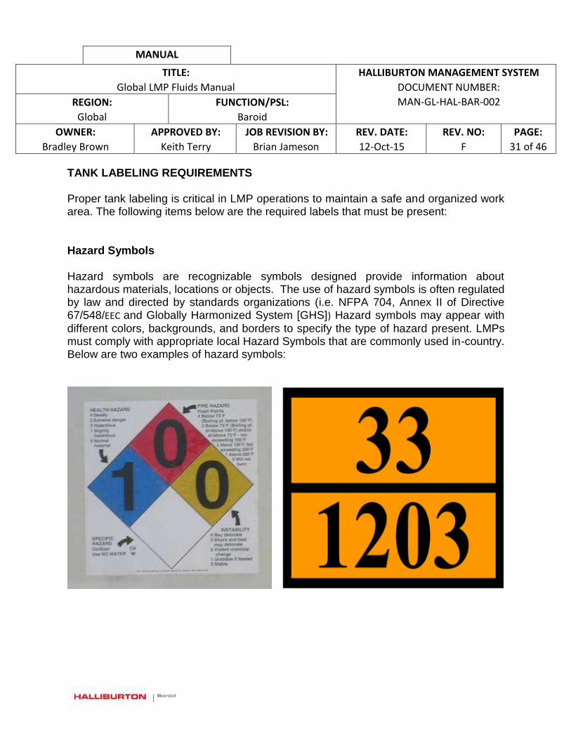
MANUAL
TITLE:
Global LMP Fluids Manual
HALLIBURTON MANAGEMENT SYSTEM
DOCUMENT NUMBER:
MAN-GL-HAL-BAR-002 REGION:
Global
FUNCTION/PSL:
Baroid
OWNER:
Bradley Brown
APPROVED BY:
Keith Terry
JOB REVISION BY:
Brian Jameson
REV. DATE:
12-Oct-15
REV. NO:
F
PAGE:
31 of 46
TANK LABELING REQUIREMENTS Proper tank labeling is critical in LMP operations to maintain a safe and organized work area. The following items below are the required labels that must be present:
Hazard Symbols
Hazard symbols are recognizable symbols designed provide information about hazardous materials, locations or objects. The use of hazard symbols is often regulated by law and directed by standards organizations (i.e. NFPA 704, Annex II of Directive 67/548/EEC and Globally Harmonized System [GHS]) Hazard symbols may appear with
different colors, backgrounds, and borders to specify the type of hazard present. LMPs must comply with appropriate local Hazard Symbols that are commonly used in-country. Below are two examples of hazard symbols:
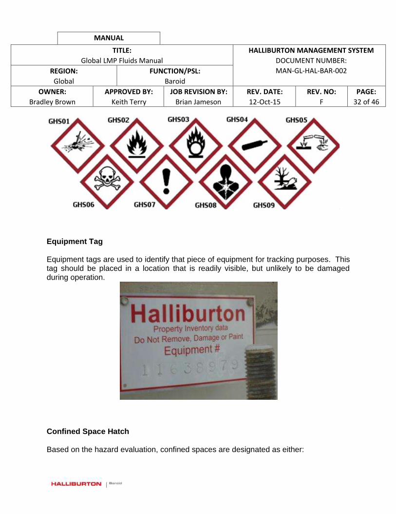
MANUAL
TITLE:
Global LMP Fluids Manual
HALLIBURTON MANAGEMENT SYSTEM
DOCUMENT NUMBER:
MAN-GL-HAL-BAR-002 REGION:
Global
FUNCTION/PSL:
Baroid
OWNER:
Bradley Brown
APPROVED BY:
Keith Terry
JOB REVISION BY:
Brian Jameson
REV. DATE:
12-Oct-15
REV. NO:
F
PAGE:
32 of 46
Equipment Tag Equipment tags are used to identify that piece of equipment for tracking purposes. This tag should be placed in a location that is readily visible, but unlikely to be damaged during operation.
Confined Space Hatch
Based on the hazard evaluation, confined spaces are designated as either:
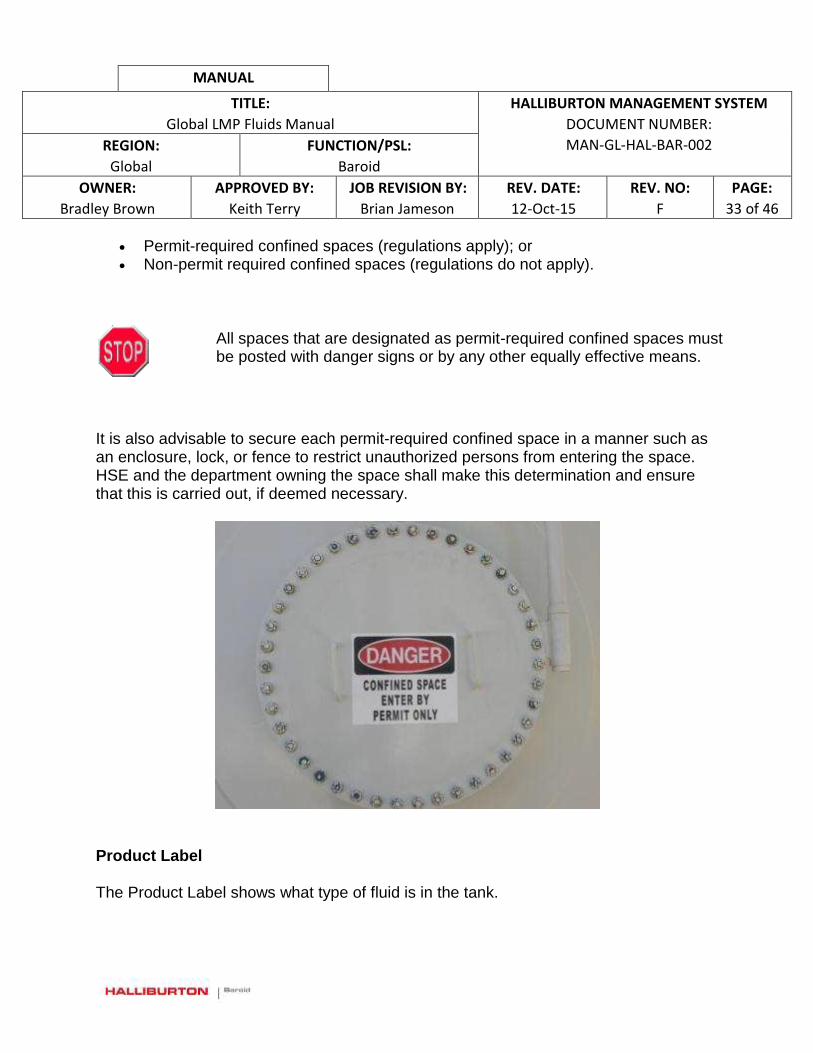
MANUAL
TITLE:
Global LMP Fluids Manual
HALLIBURTON MANAGEMENT SYSTEM
DOCUMENT NUMBER:
MAN-GL-HAL-BAR-002 REGION:
Global
FUNCTION/PSL:
Baroid
OWNER:
Bradley Brown
APPROVED BY:
Keith Terry
JOB REVISION BY:
Brian Jameson
REV. DATE:
12-Oct-15
REV. NO:
F
PAGE:
33 of 46
Permit-required confined spaces (regulations apply); or Non-permit required confined spaces (regulations do not apply).
All spaces that are designated as permit-required confined spaces must be posted with danger signs or by any other equally effective means.
It is also advisable to secure each permit-required confined space in a manner such as an enclosure, lock, or fence to restrict unauthorized persons from entering the space. HSE and the department owning the space shall make this determination and ensure that this is carried out, if deemed necessary.
Product Label The Product Label shows what type of fluid is in the tank.

MANUAL
TITLE:
Global LMP Fluids Manual
HALLIBURTON MANAGEMENT SYSTEM
DOCUMENT NUMBER:
MAN-GL-HAL-BAR-002 REGION:
Global
FUNCTION/PSL:
Baroid
OWNER:
Bradley Brown
APPROVED BY:
Keith Terry
JOB REVISION BY:
Brian Jameson
REV. DATE:
12-Oct-15
REV. NO:
F
PAGE:
34 of 46
Tank ID Number A unique tank numbering system must be developed to ensure clarity in the communication of fluid movements.
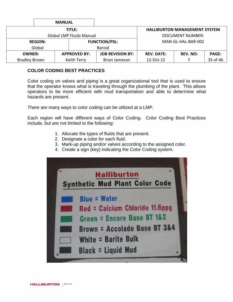
MANUAL
TITLE:
Global LMP Fluids Manual
HALLIBURTON MANAGEMENT SYSTEM
DOCUMENT NUMBER:
MAN-GL-HAL-BAR-002 REGION:
Global
FUNCTION/PSL:
Baroid
OWNER:
Bradley Brown
APPROVED BY:
Keith Terry
JOB REVISION BY:
Brian Jameson
REV. DATE:
12-Oct-15
REV. NO:
F
PAGE:
35 of 46
COLOR CODING BEST PRACTICES Color coding on valves and piping is a great organizational tool that is used to ensure that the operator knows what is traveling through the plumbing of the plant. This allows operators to be more efficient with mud transportation and able to determine what hazards are present. There are many ways to color coding can be utilized at a LMP. Each region will have different ways of Color Coding. Color Coding Best Practices include, but are not limited to the following:
1. Allocate the types of fluids that are present. 2. Designate a color for each fluid. 3. Mark-up piping and/or valves according to the assigned color. 4. Create a sign (key) indicating the Color Coding system.
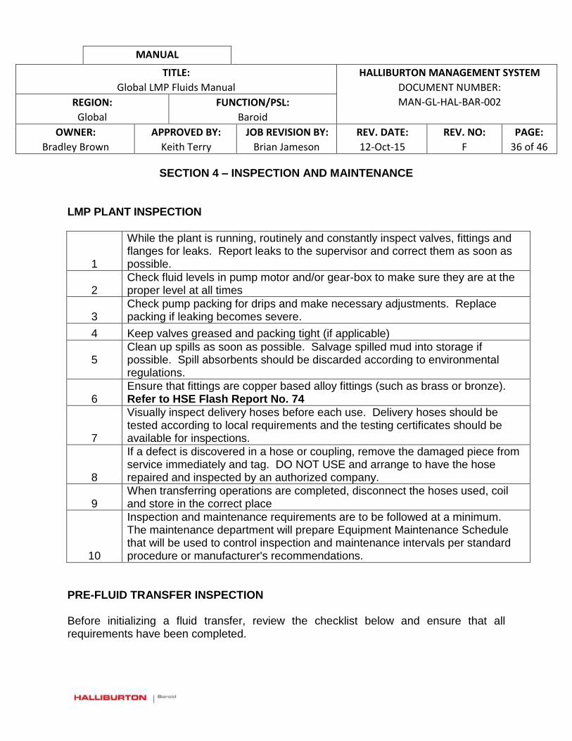
MANUAL
TITLE:
Global LMP Fluids Manual
HALLIBURTON MANAGEMENT SYSTEM
DOCUMENT NUMBER:
MAN-GL-HAL-BAR-002 REGION:
Global
FUNCTION/PSL:
Baroid
OWNER:
Bradley Brown
APPROVED BY:
Keith Terry
JOB REVISION BY:
Brian Jameson
REV. DATE:
12-Oct-15
REV. NO:
F
PAGE:
36 of 46
SECTION 4 – INSPECTION AND MAINTENANCE
LMP PLANT INSPECTION
1
While the plant is running, routinely and constantly inspect valves, fittings and flanges for leaks. Report leaks to the supervisor and correct them as soon as possible.
2 Check fluid levels in pump motor and/or gear-box to make sure they are at the proper level at all times
3 Check pump packing for drips and make necessary adjustments. Replace packing if leaking becomes severe.
4 Keep valves greased and packing tight (if applicable)
5
Clean up spills as soon as possible. Salvage spilled mud into storage if possible. Spill absorbents should be discarded according to environmental regulations.
6 Ensure that fittings are copper based alloy fittings (such as brass or bronze). Refer to HSE Flash Report No. 74
7
Visually inspect delivery hoses before each use. Delivery hoses should be tested according to local requirements and the testing certificates should be available for inspections.
8
If a defect is discovered in a hose or coupling, remove the damaged piece from service immediately and tag. DO NOT USE and arrange to have the hose repaired and inspected by an authorized company.
9 When transferring operations are completed, disconnect the hoses used, coil and store in the correct place
10
Inspection and maintenance requirements are to be followed at a minimum. The maintenance department will prepare Equipment Maintenance Schedule that will be used to control inspection and maintenance intervals per standard procedure or manufacturer's recommendations.
PRE-FLUID TRANSFER INSPECTION Before initializing a fluid transfer, review the checklist below and ensure that all requirements have been completed.

MANUAL
TITLE:
Global LMP Fluids Manual
HALLIBURTON MANAGEMENT SYSTEM
DOCUMENT NUMBER:
MAN-GL-HAL-BAR-002 REGION:
Global
FUNCTION/PSL:
Baroid
OWNER:
Bradley Brown
APPROVED BY:
Keith Terry
JOB REVISION BY:
Brian Jameson
REV. DATE:
12-Oct-15
REV. NO:
F
PAGE:
37 of 46
Appropriate PPE should be worn to ensure personnel safety.
1 Check that all valves on the plant are closed and that no valves or flanges are leaking.
2 Tank contents are measured and recorded on the appropriate form
3 The tank that is to be filled is empty and clean, or contains the same type of fluid as the fluid that is being received.
4 Check that the receiving tank has sufficient capacity for the volume of fluid being transferred
5 Know the exact volume of fluid that is to be transferred
6 Make sure that tank level gauges are working properly
7
Inspect all soft wall transfer hoses and make sure that the certification is in date and the hoses are in good condition; check couplings, hammer lugs and hose wall for damage
8 Make sure that all hard wall hoses are in good condition
9 An adequate supply of spill absorbents and spill equipment is to be available close by to deal with any drilling fluid spillage
Any faulty operation or damage to the plant should be reported to the Plant Supervisor. Work should not re-commence until the problem has been solved. Drilling fluids can present a workplace hazard whenever the fluid comes in contact with areas such as walkways or decking. All decks, walkways, stairways, and ladders are to be cleaned after use. NEVER LEAVE A FLUID TRANSFER OR CIRCULATION OPERATION UNMANNED.
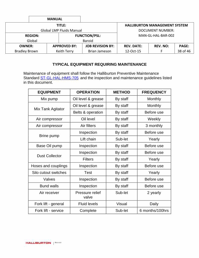
MANUAL
TITLE:
Global LMP Fluids Manual
HALLIBURTON MANAGEMENT SYSTEM
DOCUMENT NUMBER:
MAN-GL-HAL-BAR-002 REGION:
Global
FUNCTION/PSL:
Baroid
OWNER:
Bradley Brown
APPROVED BY:
Keith Terry
JOB REVISION BY:
Brian Jameson
REV. DATE:
12-Oct-15
REV. NO:
F
PAGE:
38 of 46
TYPICAL EQUIPMENT REQUIRING MAINTENANCE
Maintenance of equipment shall follow the Halliburton Preventive Maintenance Standard ST-GL-HAL-HMS-705 and the inspection and maintenance guidelines listed in this document.
EQUIPMENT OPERATION METHOD FREQUENCY
Mix pump Oil level & grease By staff Monthly
Mix Tank Agitator Oil level & grease By staff Monthly
Belts & operation By staff Before use
Air compressor Oil level By staff Weekly
Air compressor Air filters By staff 3 monthly
Brine pump Inspection By staff Before use
Lift chain Sub-let Yearly
Base Oil pump Inspection By staff Before use
Dust Collector Inspection By staff Before use
Filters By staff Yearly
Hoses and couplings Inspection By staff Before use
Silo cutout switches Test By staff Yearly
Valves Inspection By staff Before use
Bund walls Inspection By staff Before use
Air receiver Pressure relief valve
Sub-let 2 yearly
Fork lift - general Fluid levels Visual Daily
Fork lift - service Complete Sub-let 6 months/100hrs
MANUAL
TITLE:
Global LMP Fluids Manual
HALLIBURTON MANAGEMENT SYSTEM
DOCUMENT NUMBER:
MAN-GL-HAL-BAR-002 REGION:
Global
FUNCTION/PSL:
Baroid
OWNER:
Bradley Brown
APPROVED BY:
Keith Terry
JOB REVISION BY:
Brian Jameson
REV. DATE:
12-Oct-15
REV. NO:
F
PAGE:
39 of 46
CALIBRATING EQUIPMENT See ST-GL-HAL-HMS-710 to define calibration requirements on any instrument used for LMP Operations. TANK INSPECTION REQUIREMENTS Baroid shall operate only pressure vessels which have been confirmed to be in good working order. This requires that all Baroid-operated pressure vessels be regularly and periodically inspected and tested to assure that they are in safe operating condition. In many instances, local jurisdictions and/or Baroid’s customers have established requirements for inspecting and testing pressure vessels. In these instances, the requirements of the local jurisdiction and/or the customer(s) shall determine the inspection/testing procedure. In the event no other procedures are available, refer to ST-GL-HAL-BAR-206 to provide acceptable testing/inspection procedures and intervals.
TANK CLEANING Occasionally, it will become necessary to completely empty storage or mixing tanks. On rare occasions, it will become necessary to remove the inspection hatch or a storage tank to allow the removal of settled solids from the bottom of the tank. In this case, it is recommended that specialized tank cleaning contractors with confined space entry training be permitted to enter the tanks. This work must have a Permit to Work for confined space entry that will incorporate a JSA for the tank cleaning.

MANUAL
TITLE:
Global LMP Fluids Manual
HALLIBURTON MANAGEMENT SYSTEM
DOCUMENT NUMBER:
MAN-GL-HAL-BAR-002 REGION:
Global
FUNCTION/PSL:
Baroid
OWNER:
Bradley Brown
APPROVED BY:
Keith Terry
JOB REVISION BY:
Brian Jameson
REV. DATE:
12-Oct-15
REV. NO:
F
PAGE:
40 of 46
SECTION 5 – TROUBLESHOOTING
Throughout mud mixing, reconditioning and transfer operations, the operators should monitor equipment to verify proper performance and to identify problems.
Equipment Parameters / Potential Problems
Response to Failure
Mixing Pump Check operating pressure , excessive vibration or
noise, leaks
Immediately switch the pump off. Change over to backup pump (if available)
Paddle Agitator
Normal tank agitation; Leaking lubricant from
gearbox; Excessive vibration or noise
Call for maintenance as soon as possible
Mixing Tank Tank level too low or too high; Overflow line (if supplied) not blocked
Level is too high: fluid will overflow into the containment area. If this occurs, immediately shut down all mixing and transfer --Identify and document the cause of the overflow Excessive base fluid: water or brine added beyond what is called for in the mixing program. The fluid may have to be reformulated and treated. A fluid sample will be immediately collected and tested for additional treatment Incorrect formulation or volume estimate: correct the mixing procedure In all cases of mix tank overflow: Complete a correction, prevention and improvement (CPI) report and implement the appropriate action to correct the problem.
Chemical Hopper
Hopper throat blocked; Venturi (jet) operating at
correct pressure
Clear the blockage with a cleaning rod. Wear a face mask in addition to normal PPE to protect against fluid splashing into the operators face
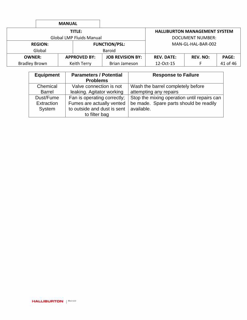
MANUAL
TITLE:
Global LMP Fluids Manual
HALLIBURTON MANAGEMENT SYSTEM
DOCUMENT NUMBER:
MAN-GL-HAL-BAR-002 REGION:
Global
FUNCTION/PSL:
Baroid
OWNER:
Bradley Brown
APPROVED BY:
Keith Terry
JOB REVISION BY:
Brian Jameson
REV. DATE:
12-Oct-15
REV. NO:
F
PAGE:
41 of 46
Equipment Parameters / Potential Problems
Response to Failure
Chemical Barrel
Valve connection is not leaking. Agitator working
Wash the barrel completely before attempting any repairs
Dust/Fume Extraction
System
Fan is operating correctly; Fumes are actually vented to outside and dust is sent
to filter bag
Stop the mixing operation until repairs can be made. Spare parts should be readily available.
MANUAL
TITLE:
Global LMP Fluids Manual
HALLIBURTON MANAGEMENT SYSTEM
DOCUMENT NUMBER:
MAN-GL-HAL-BAR-002 REGION:
Global
FUNCTION/PSL:
Baroid
OWNER:
Bradley Brown
APPROVED BY:
Keith Terry
JOB REVISION BY:
Brian Jameson
REV. DATE:
12-Oct-15
REV. NO:
F
PAGE:
42 of 46
SECTION 6 – LMP DESIGN AND PLANT LAYOUT
The LMP may be located on Customer-provided land or private land. The site is usually a secure facility & LMP personnel will typically require a pass or permit to access the site. Safety induction training is required before personnel are allowed to enter or work at the facility. Design and layout of plants shall follow the requirements listed in the Building & Structure Design page in HMS.
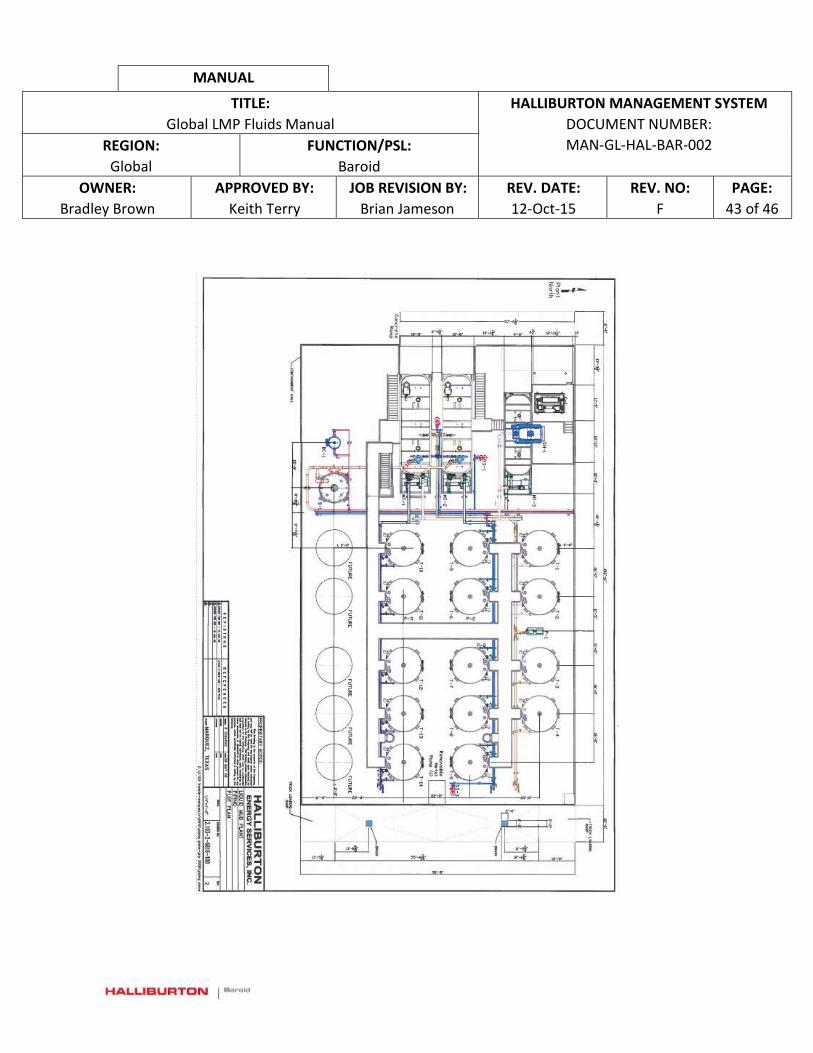
MANUAL
TITLE:
Global LMP Fluids Manual
HALLIBURTON MANAGEMENT SYSTEM
DOCUMENT NUMBER:
MAN-GL-HAL-BAR-002 REGION:
Global
FUNCTION/PSL:
Baroid
OWNER:
Bradley Brown
APPROVED BY:
Keith Terry
JOB REVISION BY:
Brian Jameson
REV. DATE:
12-Oct-15
REV. NO:
F
PAGE:
43 of 46

MANUAL
TITLE:
Global LMP Fluids Manual
HALLIBURTON MANAGEMENT SYSTEM
DOCUMENT NUMBER:
MAN-GL-HAL-BAR-002 REGION:
Global
FUNCTION/PSL:
Baroid
OWNER:
Bradley Brown
APPROVED BY:
Keith Terry
JOB REVISION BY:
Brian Jameson
REV. DATE:
12-Oct-15
REV. NO:
F
PAGE:
44 of 46
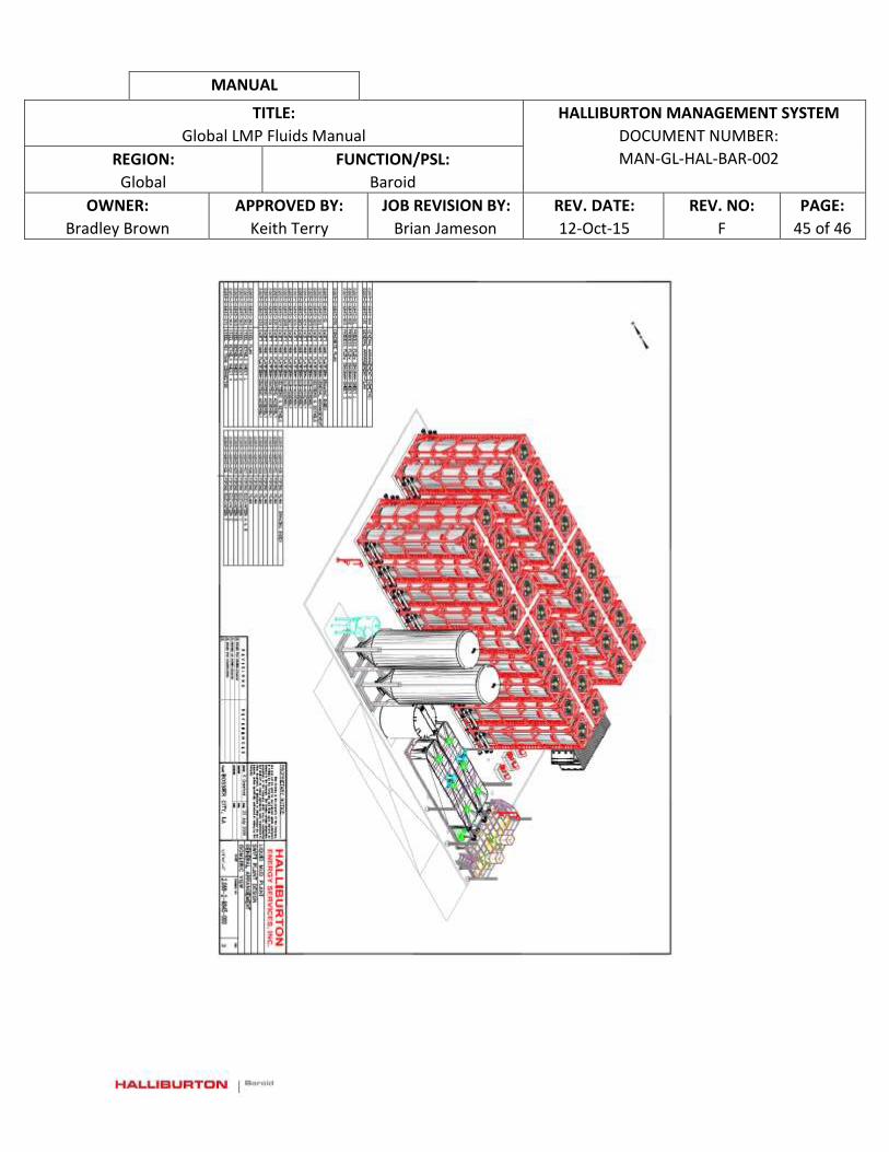
MANUAL
TITLE:
Global LMP Fluids Manual
HALLIBURTON MANAGEMENT SYSTEM
DOCUMENT NUMBER:
MAN-GL-HAL-BAR-002 REGION:
Global
FUNCTION/PSL:
Baroid
OWNER:
Bradley Brown
APPROVED BY:
Keith Terry
JOB REVISION BY:
Brian Jameson
REV. DATE:
12-Oct-15
REV. NO:
F
PAGE:
45 of 46
MANUAL
TITLE:
Global LMP Fluids Manual
HALLIBURTON MANAGEMENT SYSTEM
DOCUMENT NUMBER:
MAN-GL-HAL-BAR-002 REGION:
Global
FUNCTION/PSL:
Baroid
OWNER:
Bradley Brown
APPROVED BY:
Keith Terry
JOB REVISION BY:
Brian Jameson
REV. DATE:
12-Oct-15
REV. NO:
F
PAGE:
46 of 46
Date Issued Rev. No. Summary of Key Revisions
12.Oct.2015 F Added link on page 23 and update a. on page 24
31.Mar.2015 E Added two new bullet items under Safety Training, added Section 6 Contractor Work Safety under Safety Planning and added revision log
16.Oct.2013 D Updated links on page 38 and updated CHS hazard label on page 30
19.Jun.2013 C Added two new bullet items under Safety Training, added sentence on following global standard on PM in Section 4, and added into paragraph in Section 6,
To obtain a copy of a previous version of this document, please contact [email protected]

PROJECT REGISTRATION - KYLE AVENUE TEMPORARY LIQUID MUD PLANT
APPENDIX F Halliburton Company Policy – Health, Safety and
Environment
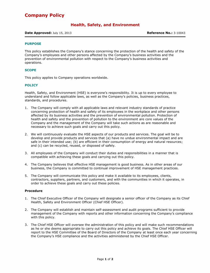
Company Policy
Health, Safety, and Environment
Date Approved: July 15, 2013 Reference No.: 3-10043
Page 1 of 2
PURPOSE This policy establishes the Company’s stance concerning the protection of the health and safety of the Company’s employees and other persons affected by the Company’s business activities and the
prevention of environmental pollution with respect to the Company’s business activities and operations. SCOPE This policy applies to Company operations worldwide.
POLICY
Health, Safety, and Environment (HSE) is everyone’s responsibility. It is up to every employee to understand and follow applicable laws, as well as the Company’s policies, business practices, standards, and procedures. 1. The Company will comply with all applicable laws and relevant industry standards of practice
concerning protection of health and safety of its employees in the workplace and other persons affected by its business activities and the prevention of environmental pollution. Protection of health and safety and the prevention of pollution to the environment are core values of the Company and the management of the Company will take such actions as are reasonable and necessary to achieve such goals and carry out this policy.
2. We will continuously evaluate the HSE aspects of our products and services. The goal will be to develop and provide products and services that (a) have no undue environmental impact and are safe in their intended use; (b) are efficient in their consumption of energy and natural resources;
and (c) can be recycled, reused, or disposed of safely.
3. All employees of the Company will conduct their duties and responsibilities in a manner that is compatible with achieving these goals and carrying out this policy.
4. The Company believes that effective HSE management is good business. As in other areas of our
business, the Company is committed to continual improvement of HSE management practices.
5. The Company will communicate this policy and make it available to its employees, clients, contractors, suppliers, partners, and customers, and with the communities in which it operates, in order to achieve these goals and carry out these policies.
Procedure 1. The Chief Executive Officer of the Company will designate a senior officer of the Company as its Chief
Health, Safety and Environment Officer (Chief HSE Officer).
2. The Company will establish and maintain self-assessment and audit programs sufficient to provide management of the Company with reports and other information concerning the Company’s compliance with this policy.
3. The Chief HSE Officer will oversee the administration of this policy and will make such recommendations as he or she deems appropriate to carry out this policy and achieve its goals. The Chief HSE Officer will report to the HSE Committee of the Board of Directors of the Company at least once each year concerning
the Company’s HSE compliance and the activities administered by the Chief HSE Officer.
Page 2 of 2
For Questions or Assistance
If you have any questions or concerns about how our operations impact human health or the environment, you should speak with your supervisor, or contact an environmental attorney in the Law Department or your
local HSE resource. DEFINITIONS Company means Halliburton Company, a Delaware corporation, its successors and subsidiaries and their divisions.
REFERENCE
Code of Business Conduct
APPROVED BY: Policy Committee DATE LAST REVIEWED: February 7, 2017
Supersedes POLICY STATEMENT OF: January 15, 2016. Administrative change only July 2, 2014, and
August 1, 2013.
For further assistance: FHOUPOLICY
PROJECT REGISTRATION - KYLE AVENUE TEMPORARY LIQUID MUD PLANT
APPENDIX G Halliburton Company Policy – Equal Opportunity
Employment

Company Policy
Equal Employment Opportunity
Date Approved: July 18, 2014 Reference No.: 3-13050
Page 1 of 2
PURPOSE This policy establishes and communicates the Company’s policy regarding equal employment
opportunity. SCOPE This policy applies to Company operations worldwide. POLICY
The Company is committed to providing equal employment opportunity to all qualified individuals in all
of its employment practices. The Company will endeavor to create a workforce that is a reflection of the diverse population of the communities in which it operates. The Company will, in all its operations and employment practices, comply with all applicable laws and regulations governing equal employment opportunities wherever it conducts business to ensure that
there is no unlawful discrimination against any employee or applicant. This policy relates to all phases of employment, including without limitation, recruitment; hiring; placement; promotion; transfer; compensation; benefits; training; educational, social, and recreational programs; the use of Company facilities; disciplinary actions; and termination. It covers all personnel actions in all job categories and at all levels. It is intended to provide employees with a
working environment free of discrimination, harassment, intimidation, and coercion. No employment decisions will be based on discriminatory factors relating directly or indirectly to race, color, religion, disability, genetic information, pregnancy, citizenship, marital status, sex/gender, sexual preference/sexual orientation, age, veteran status, national origin, or any other status protected by
law or regulation. All Directors, all members of management, and other employees will actively support this policy. All
actions and decisions taken by Directors and members of management and their subordinates, will be consistent with this policy and the furtherance of it. Procedure An employee who believes that she or he has been or is being subjected to discrimination should bring this matter to the attention of his or her supervisor, Human Resources, the Global Ethics & Compliance
Practice Group in the Law Department, or the Ethics Helpline. An employee who believes discrimination has occurred or is occurring should report such conduct to one of the above persons regardless of the position of the offending person (e.g., manager, supervisor, fellow employee, customer, etc.). If a complaint of discrimination is received by any manager or supervisor, the manager or supervisor will report the complaint immediately to Human Resources. Nothing in this
policy requires any employee complaining of discrimination against another person to present the
matter to the person who is the subject of the complaint. All complaints of discrimination will be investigated promptly. The privacy of the persons involved will be protected, except to the extent necessary to conduct a proper investigation. If the investigation substantiates the complaint, immediate corrective action will be taken designed to stop the discrimination and prevent its recurrence.
An employee who believes he or she has been or is being subjected to discrimination, or who believes he or she has observed discrimination, and who reports the matter pursuant to this policy will not be retaliated against or adversely treated because of making the report.
Page 2 of 2
DEFINITIONS Company means Halliburton Company, a Delaware corporation, its successors and subsidiaries and
their divisions. Director means someone who sits on the Board of Directors of Halliburton Company. It does not refer to executives or officers who manage the daily business affairs of the Company and have titles such as Financial Director or employees of the Company or any subsidiary who serve on the board of directors of a Company subsidiary of any tier.
REFERENCE
Code of Business Conduct
Company Policy 3-13060, Harassment
APPROVED BY: Policy Committee DATE LAST REVIEWED: September 2, 2016
Supersedes POLICY STATEMENT OF: Code of Business Conduct; Policy 3-0002, “Equal Employment
Opportunity,” April 11, 2013 and February 15, 2007. Administrative change only May 9, 2017; November 23, 2016; August 12, 2015 and August 1, 2013. For further assistance: FHOUPOLICY