Embed Size (px)
Citation preview
Project Proposal Feasibility Study Team 13: Moonrakers Calvin College Engineering 339 Senior Design 12/4/2010
Laura Snyder Alex Verseput Brad Rekman Matt Slater Hannah Gerig
Copyright ©2010
Team 13 - Moonrakers
Calvin College Engineering Department
All rights reserved. No part of this report may be
reproduced in any form, except for the inclusion of
brief quotations in review, without permission in
writing from the author
i
Executive Summary
As space exploration continues to reach new heights, and lunar colonization approaches reality,
a need for harvesting the moon’s resources grows. Oxygen, essential for sustaining life, is
abundant in lunar soil as metal oxides. By utilizing a moon feed, composed largely of iron
oxides and iron titanium oxides, a reduction by hydrogen will be performed creating an
intermediate, water. This water will be processed in an electrolysis unit, creating an oxygen
product and recovering the hydrogen reduction agent.
Team 13, Moonrakers, seeks to design a superior process for the production of oxygen on the
moon. The project so far has included the research of existing technologies and science
regarding reduction reactions and process units. A total of twenty process alternatives were
also considered. A majority of processes were eliminated and only two processes are being
further developed in UNISIM. A preliminary cost analysis for the process as well as alternative
measures is currently underway.
The final design will include a chemical process flow diagram, an optimized design, and an
equipment design. An in depth economic analysis will be performed detailing the costs of the
purchase, installation, and operation of the optimized process, and costs of a contingency
source of oxygen and its storage. Similarly, the alternative of oxygen shipments from the earth
will be investigated and used as a comparison for the optimized design economics.
ii
Table of Contents
1 Introduction .......................................................................................................................................... 1
1.1 Project Statement ......................................................................................................................... 1
1.2 Team Members ............................................................................................................................. 2
2 Project Definition .................................................................................................................................. 4
2.1 Need .............................................................................................................................................. 4
2.2 Approach ....................................................................................................................................... 4
2.3 Benefit ........................................................................................................................................... 5
2.4 Competition .................................................................................................................................. 6
2.5 Purpose ......................................................................................................................................... 6
2.6 Design Goals .................................................................................................................................. 6
2.7 Requirements ................................................................................................................................ 7
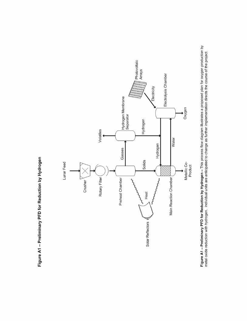
2.8 Plant Process Flow Diagram (see Figure A.1) ................................................................................ 7
3 Project Management ............................................................................................................................ 9
3.1 Team Organization ........................................................................................................................ 9
3.2 Schedule ........................................................................................................................................ 9
3.3 Budget ........................................................................................................................................... 9
4 Design Approach ................................................................................................................................. 10
4.1 Stewardship ................................................................................................................................ 10
4.2 Simplicity ..................................................................................................................................... 10
4.3 Competitive Economy ................................................................................................................. 11
4.4 Process Efficiency ........................................................................................................................ 12
4.5 Trustworthiness .......................................................................................................................... 13
5 Alternatives ......................................................................................................................................... 14
5.1 Solid/Gas Interaction .................................................................................................................. 14
5.1.1 Ilmenite Reduction with Hydrogen ..................................................................................... 14
5.1.2 Ilmenite Reduction with C/CO ............................................................................................ 15
5.1.3 Ilmenite Reduction with Methane ...................................................................................... 16
5.1.4 Glass Reduction with Hydrogen .......................................................................................... 17
5.1.5 Reduction with Hydrogen Sulfide ....................................................................................... 17
5.1.6 Extraction with Fluorine ...................................................................................................... 18
5.1.7 Carbochlorination ............................................................................................................... 19
iii
5.1.8 Chlorine Plasma Reduction ................................................................................................. 20
5.2 Silicate/Oxide Melt ...................................................................................................................... 21
5.2.1 Molten Silicate Electrolysis ................................................................................................. 21
5.2.2 Fluxed Molten Silicate Electrolysis ...................................................................................... 21
5.2.3 Caustic Solution and Electrolysis ......................................................................................... 22
5.2.4 Carbothermal Reduction ..................................................................................................... 23
5.2.5 Magma Partial Oxidation .................................................................................................... 24
5.2.6 Li of Na Reduction ............................................................................................................... 24
5.3 Pyrolysis ...................................................................................................................................... 25
5.3.1 Vapor Phase Reduction ....................................................................................................... 25
5.3.2 Ion (Plasma) Separation ...................................................................................................... 25
5.3.3 Plasma Reduction of Ilmenite ............................................................................................. 26
5.4 Aqueous Solutions ...................................................................................................................... 26
5.4.1 HF Acid Dissolution ............................................................................................................. 27
5.4.2 H2SO4 Acid Dissolution ........................................................................................................ 27
5.5 CO-Product Recovery of Water ................................................................................................... 28
5.5.1 Hydrogen/Helium/Water Production from Soil .................................................................. 28
5.6 Final Decision .............................................................................................................................. 28
6 Implementation .................................................................................................................................. 30
6.1 UNISIM as a Design Tool ............................................................................................................. 30
6.2 UNISIM Hypotheticals ................................................................................................................. 30
6.3 Reaction Kinetics ......................................................................................................................... 31
6.4 Solids Handling ............................................................................................................................ 32
6.5 Electrolysis Chamber ................................................................................................................... 33
6.6 Future Work ................................................................................................................................ 33
7 Business Plan ....................................................................................................................................... 34
7.1 The business plan is forthcoming................................................................................................ 34
8 Safety. ................................................................................................................................................. 35
8.1 Conveyors.................................................................................................................................... 35
8.2 Crusher ........................................................................................................................................ 35
8.3 Preheat Chamber and Main Reaction Chamber ......................................................................... 35
8.4 Electrolysis Chamber ................................................................................................................... 36
iv
8.5 Hydrogen Membrane Safety ....................................................................................................... 36
8.6 General Lunar Safety ................................................................................................................... 36
9 Conclusions ......................................................................................................................................... 38
10 Acknowledgements ......................................................................................................................... 39
11 References ...................................................................................................................................... 40
12 Appendices ...................................................................................................................................... 42

v
Table of Figures
Table 1 ................................................................................................................................................... 5
Figure 1 ............................................................................................................................................... 12
Figure 2 ............................................................................................................................................... 25
Figure 3 ............................................................................................................................................... 32
Page | 1
1 Introduction
1.1 Project Statement
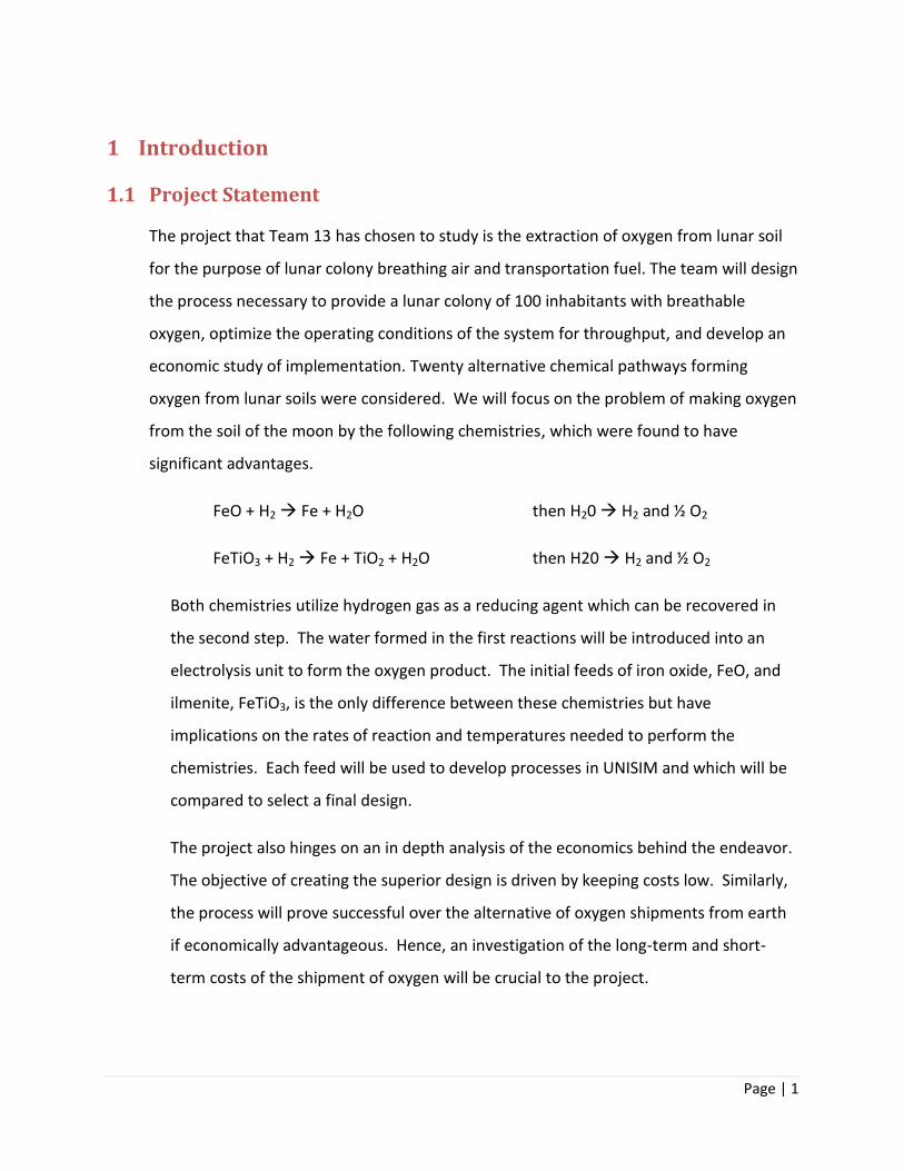
The project that Team 13 has chosen to study is the extraction of oxygen from lunar soil
for the purpose of lunar colony breathing air and transportation fuel. The team will design
the process necessary to provide a lunar colony of 100 inhabitants with breathable
oxygen, optimize the operating conditions of the system for throughput, and develop an
economic study of implementation. Twenty alternative chemical pathways forming
oxygen from lunar soils were considered. We will focus on the problem of making oxygen
from the soil of the moon by the following chemistries, which were found to have
significant advantages.
FeO + H2 Fe + H2O then H20 H2 and ½ O2
FeTiO3 + H2 Fe + TiO2 + H2O then H20 H2 and ½ O2
Both chemistries utilize hydrogen gas as a reducing agent which can be recovered in
the second step. The water formed in the first reactions will be introduced into an
electrolysis unit to form the oxygen product. The initial feeds of iron oxide, FeO, and
ilmenite, FeTiO3, is the only difference between these chemistries but have
implications on the rates of reaction and temperatures needed to perform the
chemistries. Each feed will be used to develop processes in UNISIM and which will be
compared to select a final design.
The project also hinges on an in depth analysis of the economics behind the endeavor.
The objective of creating the superior design is driven by keeping costs low. Similarly,
the process will prove successful over the alternative of oxygen shipments from earth
if economically advantageous. Hence, an investigation of the long-term and short-
term costs of the shipment of oxygen will be crucial to the project.
Page | 2
1.2 Team Members
Laura Snyder is a senior chemical engineering student at Calvin College and will
graduate in May 2011. She grew up in the Detroit Metropolitan area in the township
of Canton. She has gained experience working for General Motors Components
Holdings, LLC from June 2009 until December 2010 in the Materials Lab. She has
learned how to effectively use various pieces of equipment, how to communicate with
many different departments within the company, and how to critically think and
analyze. In the engineering program at Calvin, Laura has taken classes pertaining to
thermodynamics, fluid flow, separations, and reactor design. These classes included
an integrated ethanol production design project from which she gained experience
with the design process. She is excited to use these skills and knowledge in this
forward-looking oxygen production design project.
Alex Verseput is a senior chemical engineering student, with high hopes of getting his
doctorate. Originally from Anchorage, Alaska, he relocated to Grand Rapids, Michigan
to pursue his education at Calvin. His studies have given him the ability to do basic
design in heat exchange, reactors, separations, and fluid flow. These abilities have
been proven in several iterations of an ethanol design project. His studies in the area
of chemistry and biochemistry have also given him an understanding for chemical
systems and principles. His eagerness to see things accomplished allows him to help
the team in moving forward while still giving details the attention they require.
Brad Rekman is a chemical engineering major from Sarnia, Ontario. He is in his fourth
and final year of his Bachelor of Science in Engineering degree. While at Calvin, Brad
has taken a variety of classes related to chemical engineering including,
thermodynamics, fluid flow and heat transfer, reactor design, and separation
processes and principles. The variety of engineering topics that Brad has studied
makes him capable of contributing to a project focused on the production of oxygen
on the moon. Brad hit the senior year with a running start after working the summer
for Bissell Homecare Inc. as an intern in the Chemical Packaging Department. While at
Page | 3
Bissell, Brad gained valuable experience in the design process and what is required to
take a product from an idea to the market.
Matthew Slater, from Cadillac, Michigan, is a senior in Chemical Engineering at Calvin
College in Grand Rapids, MI. He has learned about thermodynamics, systems
processing, optimization, and process feasibility in his years at school as well as
cultured his fascination for space and the possibilities therein. Since January 2010,
Matt has interned with Vertellus Specialties, Inc of Zeeland, MI tracking and optimizing
a variety of chemical processes. His “out of the box” thinking brings a needed
component to any design team, but especially to a project of this nature. He enjoys
working on the oxygen extraction design with the team members and is looking
forward to the end result. His other design project experience includes four
installments of designing a process that synthesizes ethanol by catalytic, gas-phase
hydration of ethylene.
Hannah Gerig, from Lowell, Michigan, is a senior chemical engineering student at
Calvin College in Grand Rapids, MI. Through her education she has learned much about
process design through a four part design of an ethanol plant. In the summer of 2010,
Hannah worked on a research project that helped her to get a more in depth look at
what it takes to design experiments and a first-hand experience of all the things that
can go wrong. The practical one of the group, she is usually the first to point out the
problems with certain assumptions or ideas. Hannah is excited to be working on this
project and is very interested to see how it will turn out.
Page | 4
2 Project Definition
2.1 Need
Mankind is returning to the moon in the next half a century. This next arrival, though, will
be for good. A permanent colony will be established and life-sustaining systems need to
be designed to support it. These systems include waste management, energy production
and distribution, sustainable vegetation, and a livable atmosphere.
2.2 Approach
We are looking at this design a little differently than other chemical plant designs because
of the unusual circumstances surrounding the plant as well as the “first nature” of this
plant. Although some research has been done with the chemistry here on earth, we as
humans have a long way to go before that can be implemented on the moon for the
purpose of sustaining a colony.
The first stage of the design was to research existing information on the subject of
extracting oxygen from iron oxides. Literature was found on the subjects of the different
materials on the moon and different methods of removing oxygen from those materials.
The project has several criterions that we will ensure the final process embodies. The first
is that the system does not need constant input of anything but soil. This is a requirement
because the colony as a whole is trying to avoid regular shipment supplies, increasing its
economic favorability. The second stipulation is that the system we choose operates at
temperatures less than 1200 °C, close to the melting temperature of FeO [15]. A
temperature that is kept below 1200 °C will also increase safety, reduce cost of materials
of construction, and reduce the amount of maintenance needed due to process
conditions. The final requirement of the process is that the chemistry require a simple
process from soil to oxygen. A simple process is one that requires few steps from start to
finish, minimizes material separations stages, and handles many different scenarios with
little to no alteration. After reviewing 20 possible processes, we will choose two
Page | 5
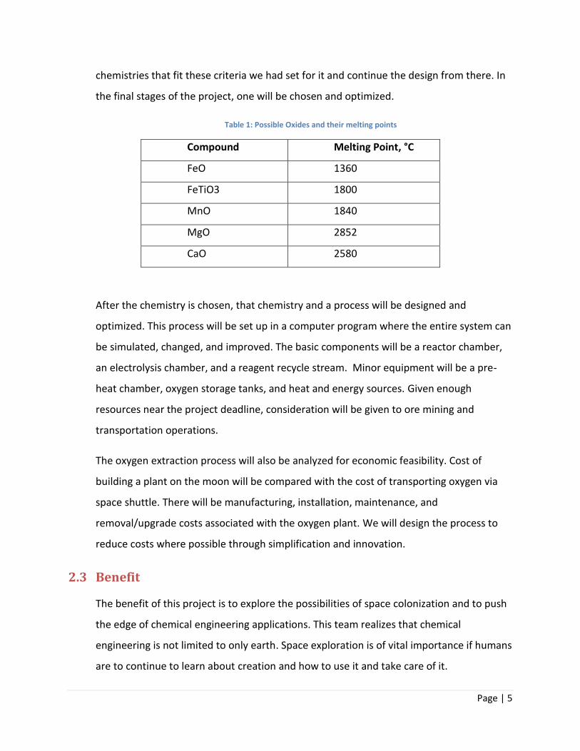
chemistries that fit these criteria we had set for it and continue the design from there. In
the final stages of the project, one will be chosen and optimized.
Table 1: Possible Oxides and their melting points
Compound Melting Point, °C
FeO 1360
FeTiO3 1800
MnO 1840
MgO 2852
CaO 2580
After the chemistry is chosen, that chemistry and a process will be designed and
optimized. This process will be set up in a computer program where the entire system can
be simulated, changed, and improved. The basic components will be a reactor chamber,
an electrolysis chamber, and a reagent recycle stream. Minor equipment will be a pre-
heat chamber, oxygen storage tanks, and heat and energy sources. Given enough
resources near the project deadline, consideration will be given to ore mining and
transportation operations.
The oxygen extraction process will also be analyzed for economic feasibility. Cost of
building a plant on the moon will be compared with the cost of transporting oxygen via
space shuttle. There will be manufacturing, installation, maintenance, and
removal/upgrade costs associated with the oxygen plant. We will design the process to
reduce costs where possible through simplification and innovation.
2.3 Benefit
The benefit of this project is to explore the possibilities of space colonization and to push
the edge of chemical engineering applications. This team realizes that chemical
engineering is not limited to only earth. Space exploration is of vital importance if humans
are to continue to learn about creation and how to use it and take care of it.
Page | 6
2.4 Competition
We believe that a healthy combination of using existing techniques and system
innovation will provide an excellent design of the oxygen extraction plant. Competing
companies include Bechtel, America’s largest engineering company, and Fluor Corp., a
fortune 500 engineering and construction firm. The team’s edge against competition will
be the simplicity of design as they seek to minimize equipment, use reasonable operating
conditions, and make it as easy to operate as possible.
2.5 Purpose
The team chose this project for the purpose of applying their general knowledge of
chemistry and process design to a system for a specific reason. The result of this project
will be a source of oxygen to supply the demand of a long-term colony. Even though a
lunar colony is a few years off, the time for preliminary design is now.
The team enjoys using elements of chemical engineering norms for a process that is not
normal. Modern chemical engineering pioneers new techniques and applications, and we
believe this project is an excellent embodiment of this. We can use existing techniques for
solids handling, solid-gas phase reactions, and electrolysis in our design with integration
between them in a way that has not been done yet.
2.6 Design Goals
Our main design goal is to make a failsafe process capable of being easily maintained and
upgraded. This will be accomplished through redundancy, adaptability, and equipment
quality. The team will also design the system to be automated, using as little of the
colony’s manpower as possible and increasing the ease of use.
Another goal is also not to limit the reaction to only one type of mineral at certain purity
but design it so that it accepts a variety of soil types (see Table 1) and removes oxygen
from whatever it can. The reason for this is that the moon is composed of a variety of
components, many of them oxides. Instead of focusing on separating and purifying the
Page | 7
feed to a specific type, the team wants to design the reaction to handle almost anything
put into it.
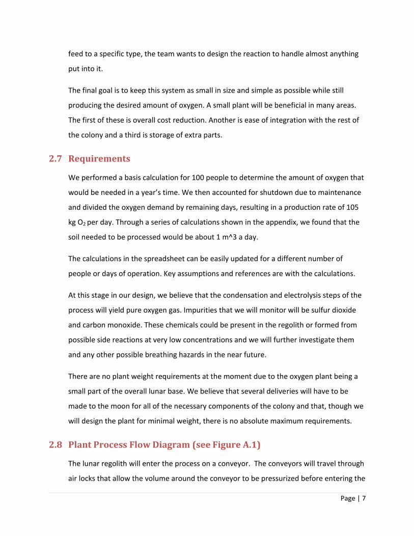
The final goal is to keep this system as small in size and simple as possible while still
producing the desired amount of oxygen. A small plant will be beneficial in many areas.
The first of these is overall cost reduction. Another is ease of integration with the rest of
the colony and a third is storage of extra parts.
2.7 Requirements
We performed a basis calculation for 100 people to determine the amount of oxygen that
would be needed in a year’s time. We then accounted for shutdown due to maintenance
and divided the oxygen demand by remaining days, resulting in a production rate of 105
kg O2 per day. Through a series of calculations shown in the appendix, we found that the
soil needed to be processed would be about 1 m^3 a day.
The calculations in the spreadsheet can be easily updated for a different number of
people or days of operation. Key assumptions and references are with the calculations.
At this stage in our design, we believe that the condensation and electrolysis steps of the
process will yield pure oxygen gas. Impurities that we will monitor will be sulfur dioxide
and carbon monoxide. These chemicals could be present in the regolith or formed from
possible side reactions at very low concentrations and we will further investigate them
and any other possible breathing hazards in the near future.
There are no plant weight requirements at the moment due to the oxygen plant being a
small part of the overall lunar base. We believe that several deliveries will have to be
made to the moon for all of the necessary components of the colony and that, though we
will design the plant for minimal weight, there is no absolute maximum requirements.
2.8 Plant Process Flow Diagram (see Figure A.1)
The lunar regolith will enter the process on a conveyor. The conveyors will travel through
air locks that allow the volume around the conveyor to be pressurized before entering the
Page | 8
plant. This will prevent the vacuum of space from eliminating all breathable oxygen from
inside the plant. The regolith will enter a crusher, in which it will be reduced to fine
particles with an increased surface area where reaction can take place. Another conveyor
will transport the crushed regolith to separation process. Currently, the separation
process is being represented by a rotary filter. The rotary filter will remove large pieces
of regolith, but will not separate out unwanted oxides. A separation unit may be added
to ensure that the feed to the preheat chamber is only iron oxide or ilmenite.
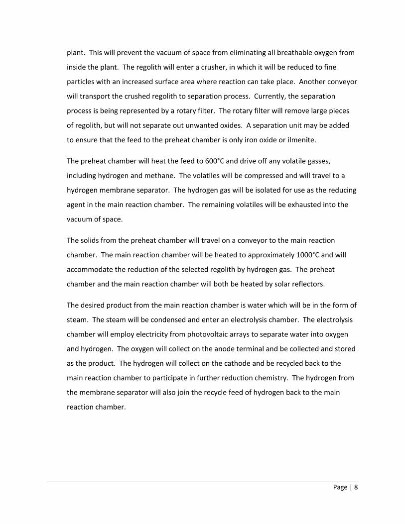
The preheat chamber will heat the feed to 600°C and drive off any volatile gasses,
including hydrogen and methane. The volatiles will be compressed and will travel to a
hydrogen membrane separator. The hydrogen gas will be isolated for use as the reducing
agent in the main reaction chamber. The remaining volatiles will be exhausted into the
vacuum of space.
The solids from the preheat chamber will travel on a conveyor to the main reaction
chamber. The main reaction chamber will be heated to approximately 1000°C and will
accommodate the reduction of the selected regolith by hydrogen gas. The preheat
chamber and the main reaction chamber will both be heated by solar reflectors.
The desired product from the main reaction chamber is water which will be in the form of
steam. The steam will be condensed and enter an electrolysis chamber. The electrolysis
chamber will employ electricity from photovoltaic arrays to separate water into oxygen
and hydrogen. The oxygen will collect on the anode terminal and be collected and stored
as the product. The hydrogen will collect on the cathode and be recycled back to the
main reaction chamber to participate in further reduction chemistry. The hydrogen from
the membrane separator will also join the recycle feed of hydrogen back to the main
reaction chamber.
Page | 9
3 Project Management
3.1 Team Organization
Our team meets every Monday afternoon from 3:30-5:30pm to distribute and work on
the goals we have set for that week. We also meet with each other on Wednesday
afternoons from 3:30-4:00pm and with our team advisor, Professor Wentzheimer from
4:00-4:30pm. Wednesdays are when goals are set to be met by the next Wednesday. If
extra time is needed in any given week, the team arranges another meeting or two.
Team documents, such as figures, reports, research documents, and weekly goal sheets
are kept in a team binder at our station in the engineering building. Electronic copies of
all documentation are kept in our team folder on the college server. The pathway is
S:\Engineering\Teams\Team13.
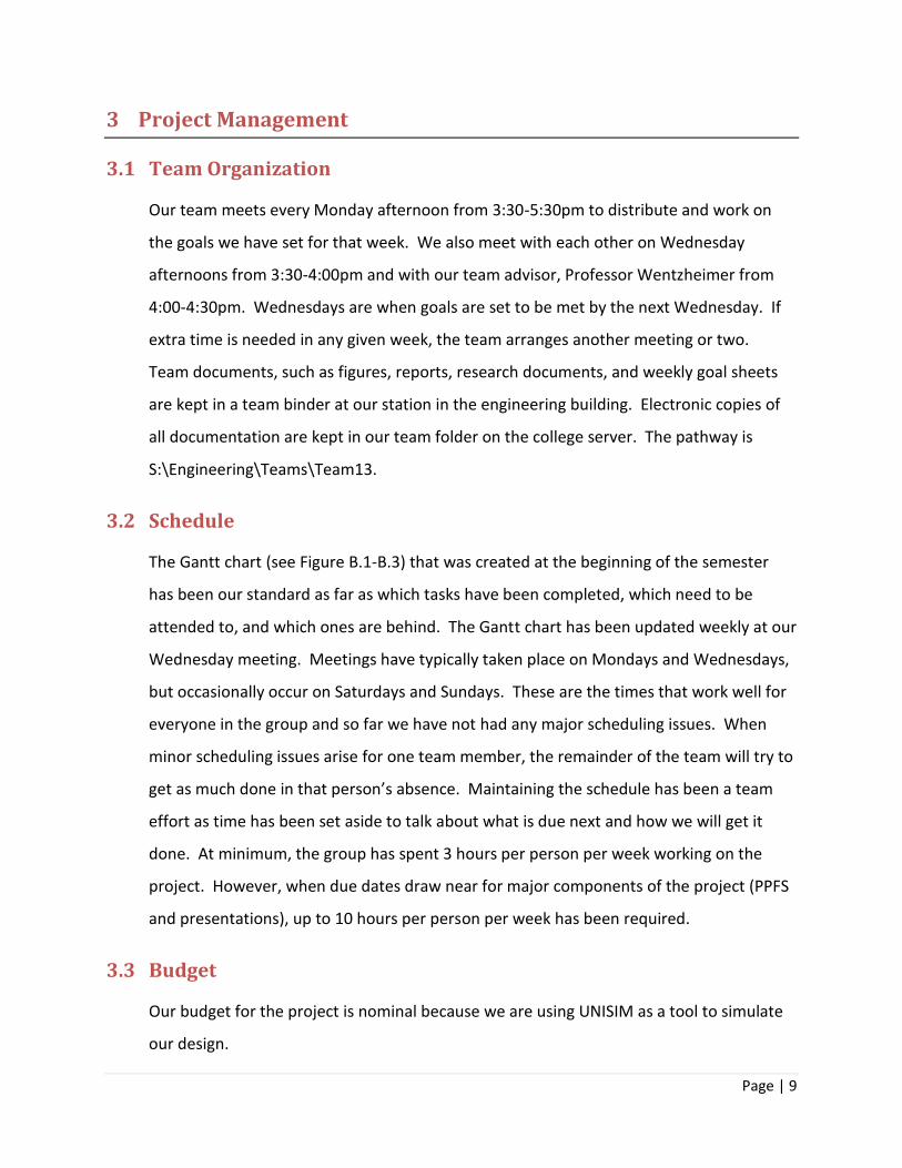
3.2 Schedule
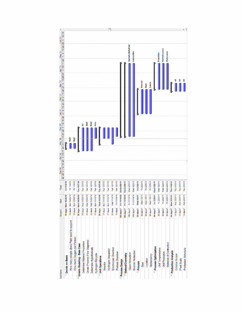
The Gantt chart (see Figure B.1-B.3) that was created at the beginning of the semester
has been our standard as far as which tasks have been completed, which need to be
attended to, and which ones are behind. The Gantt chart has been updated weekly at our
Wednesday meeting. Meetings have typically taken place on Mondays and Wednesdays,
but occasionally occur on Saturdays and Sundays. These are the times that work well for
everyone in the group and so far we have not had any major scheduling issues. When
minor scheduling issues arise for one team member, the remainder of the team will try to
get as much done in that person’s absence. Maintaining the schedule has been a team
effort as time has been set aside to talk about what is due next and how we will get it
done. At minimum, the group has spent 3 hours per person per week working on the
project. However, when due dates draw near for major components of the project (PPFS
and presentations), up to 10 hours per person per week has been required.
3.3 Budget
Our budget for the project is nominal because we are using UNISIM as a tool to simulate
our design.
Page | 10
4 Design Approach
The team is taking a clear-cut approach to designing this complex process. Beginning with a
wide scoping research of the science and technology directly for an oxygen production project
as well as the existing knowledge of chemical engineering technology has given the team an
excellent platform to begin designing their own method. Furthermore, consultation with
Professor Douglas A. Vander Griend, an expert in inorganic chemistry, and Professor Ralph
Stearly, an expert in geology and mineralogy, has confirmed and supplemented the knowledge
needed to approach the design. By using the UNISIM computer program, the team plans to
develop and analyze two designs based on two different chemistries.
Involved in the design and research, several requirements or goals have been specified by the
team. We aim to make the final design keeping the principles of stewardship, simplicity,
competitive economy, process efficiency, and trustworthiness in mind.
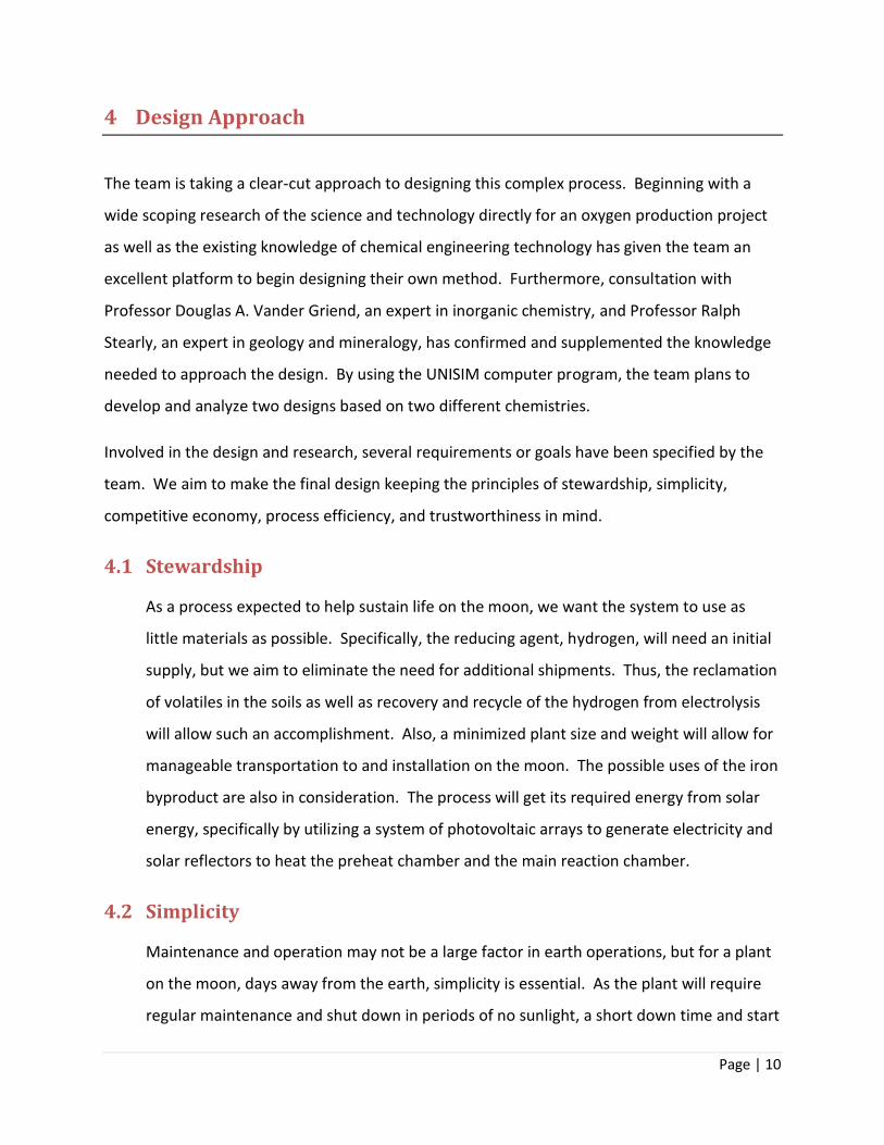
4.1 Stewardship
As a process expected to help sustain life on the moon, we want the system to use as
little materials as possible. Specifically, the reducing agent, hydrogen, will need an initial
supply, but we aim to eliminate the need for additional shipments. Thus, the reclamation
of volatiles in the soils as well as recovery and recycle of the hydrogen from electrolysis
will allow such an accomplishment. Also, a minimized plant size and weight will allow for
manageable transportation to and installation on the moon. The possible uses of the iron
byproduct are also in consideration. The process will get its required energy from solar
energy, specifically by utilizing a system of photovoltaic arrays to generate electricity and
solar reflectors to heat the preheat chamber and the main reaction chamber.
4.2 Simplicity
Maintenance and operation may not be a large factor in earth operations, but for a plant
on the moon, days away from the earth, simplicity is essential. As the plant will require
regular maintenance and shut down in periods of no sunlight, a short down time and start
Page | 11
up will be important. To make such periods possible, the design will include a
contingency of oxygen in storage units. Furthermore, replacing malfunctioning units will
be eased in a simple design. As such, the team hopes to keep the number of units to a
minimum and use operating conditions and procedures so that standard materials of
construction may be used.
4.3 Competitive Economy
For our design to be a viable process, it must have a competitive economy compared to
the alternative of oxygen shipments from earth. Capital and installation costs are
expected to be very high, but we plan to keep operating costs to a minimum. With low
operating costs, we expect to see a long term advantage over the alternative of shipping
oxygen from earth. Our goal is to meet the needs of 100 colonists for ten years at a lower
price than shipping oxygen. Preliminary cost estimates are presented here, but more
accurate calculations will need to be done.
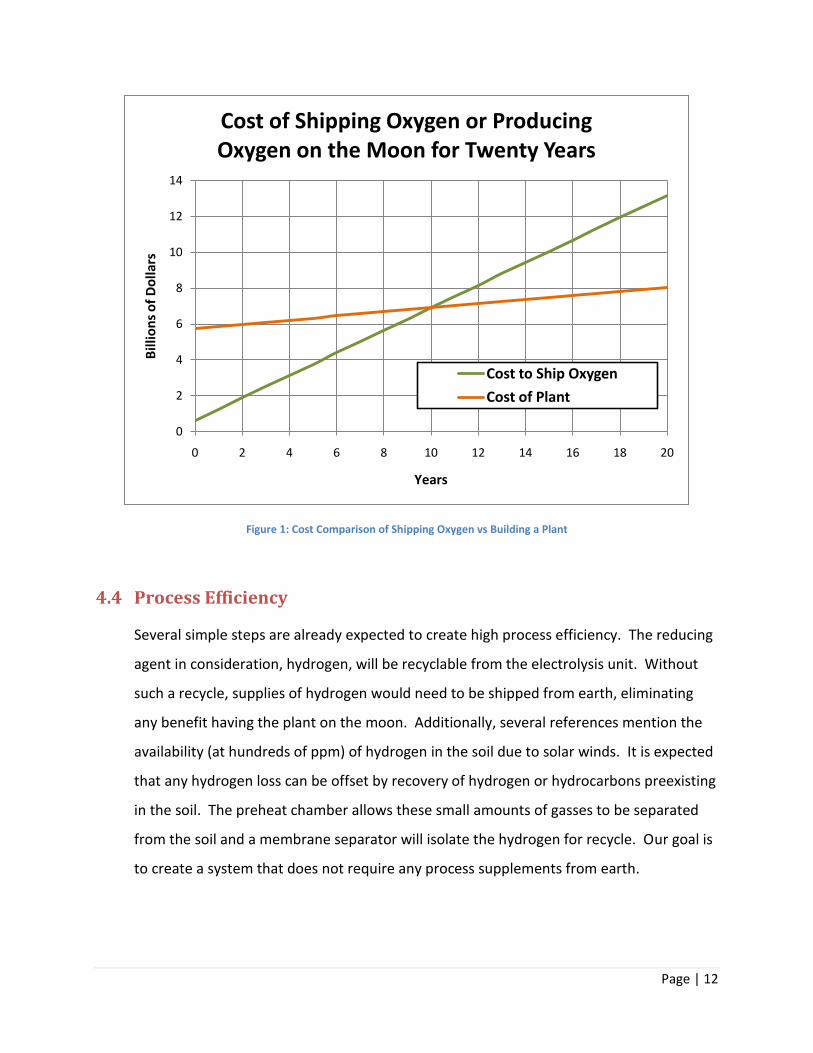
At this point in time, the cost of shipping oxygen to the colony is roughly 630 billion
dollars/yr based on the basis calculation of oxygen consumption and a cost of $20000/kg.
Thus, to meet our goal of designing the plant to be economically viable after only ten
years, a plant weight of about 280,000 kg with about 1.1 billion dollars maintenance a
year was assumed.
Page | 12
Figure 1: Cost Comparison of Shipping Oxygen vs Building a Plant
4.4 Process Efficiency
Several simple steps are already expected to create high process efficiency. The reducing
agent in consideration, hydrogen, will be recyclable from the electrolysis unit. Without
such a recycle, supplies of hydrogen would need to be shipped from earth, eliminating
any benefit having the plant on the moon. Additionally, several references mention the
availability (at hundreds of ppm) of hydrogen in the soil due to solar winds. It is expected
that any hydrogen loss can be offset by recovery of hydrogen or hydrocarbons preexisting
in the soil. The preheat chamber allows these small amounts of gasses to be separated
from the soil and a membrane separator will isolate the hydrogen for recycle. Our goal is
to create a system that does not require any process supplements from earth.
0
2
4
6
8
10
12
14
0 2 4 6 8 10 12 14 16 18 20
Bill
ion
s o
f D
olla
rs
Years
Cost of Shipping Oxygen or Producing Oxygen on the Moon for Twenty Years
Cost to Ship Oxygen
Cost of Plant
Page | 13
4.5 Trustworthiness
Underlying the whole project is a goal to be trusted in what our process can accomplish.
Being held accountable for the oxygen required by the colonists in operating as well as
down times is a formidable objective, but the minimum which must be met. By
incorporating several back up plans, the design will allow for unexpected failures or
complications. Accounting for the need of spare parts and units will allow for such failure
to be fixed without a transportation delay. Furthermore, adequate storage of a
contingency supply of oxygen will be implemented to account for anticipated shut downs
and unforeseen emergencies. Similarly, in the case of an evacuation of the plant, a supply
of oxygen will be accessible at other sites of the colony. Finally, steps will be taken to
ensure the quality of the oxygen is far from unhealthy. The steps to ensure this have not
been decided as of yet, but will include frequent testing of the oxygen product at the
highest standards.
Page | 14
5 Alternatives
Many different processes for producing oxygen from lunar soil have been presented in the
literature, but we only looked in depth into twenty of them. The twenty processes were laid out
in the literature by Taylor [13] and we considered, analyzed, and narrowed them down to four,
and then to the two, which would be designed in more depth. The reasons for accepting or
discarding each process are described in this section. The main criteria that was used for the
decision making was that the process had to have recyclable reactants, a reaction temperature
around 1000 °C, a good reaction rate, and the process could not require more experimental
research to determine feasibility. The processes were grouped into five different categories:
solid/gas interaction, silicate/oxide melt, pyrolysis, aqueous solutions, and co-product recovery.
5.1 Solid/Gas Interaction
The processes that were in this category were ilmenite reduction with hydrogen, ilmenite
reduction with C/CO, ilmenite reduction with methane, glass reduction with hydrogen,
reduction with hydrogen sulfide, extraction with fluorine, carbochlorination, and chlorine
plasma reduction.
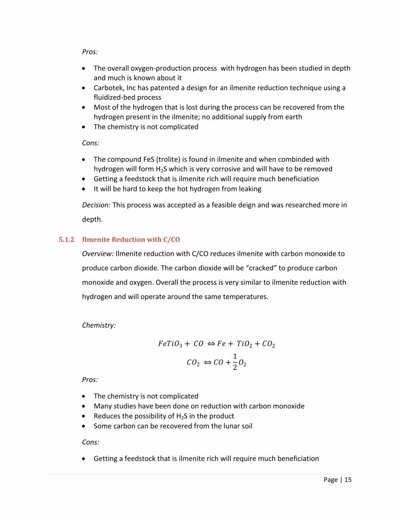
5.1.1 Ilmenite Reduction with Hydrogen
Overview: Ilmenite reduction with hydrogen reduces the compound FeTiO3
(ilmenite) with hydrogen to produce water with reaction temperatures around 700-
1000 °C. The water is then sent to an electrolysis chamber which breaks the water
into hydrogen and oxygen. They hydrogen would be recycled and the oxygen taken
as the product.
Chemistry:
𝐹𝑒𝑇𝑖𝑂3 + 𝐻2 𝐹𝑒 + 𝑇𝑖𝑂2 + 𝐻2𝑂
𝐻2𝑂 𝐻2 +1
2𝑂2
Page | 15
Pros:
The overall oxygen-production process with hydrogen has been studied in depth and much is known about it
Carbotek, Inc has patented a design for an ilmenite reduction technique using a fluidized-bed process
Most of the hydrogen that is lost during the process can be recovered from the hydrogen present in the ilmenite; no additional supply from earth
The chemistry is not complicated
Cons:
The compound FeS (trolite) is found in ilmenite and when combinded with hydrogen will form H2S which is very corrosive and will have to be removed
Getting a feedstock that is ilmenite rich will require much beneficiation
It will be hard to keep the hot hydrogen from leaking
Decision: This process was accepted as a feasible deign and was researched more in
depth.
5.1.2 Ilmenite Reduction with C/CO
Overview: Ilmenite reduction with C/CO reduces ilmenite with carbon monoxide to
produce carbon dioxide. The carbon dioxide will be “cracked” to produce carbon
monoxide and oxygen. Overall the process is very similar to ilmenite reduction with
hydrogen and will operate around the same temperatures.
Chemistry:
𝐹𝑒𝑇𝑖𝑂3 + 𝐶𝑂 𝐹𝑒 + 𝑇𝑖𝑂2 + 𝐶𝑂2
𝐶𝑂2 𝐶𝑂 +1
2𝑂2
Pros:
The chemistry is not complicated
Many studies have been done on reduction with carbon monoxide
Reduces the possibility of H2S in the product
Some carbon can be recovered from the lunar soil
Cons:
Getting a feedstock that is ilmenite rich will require much beneficiation
Page | 16
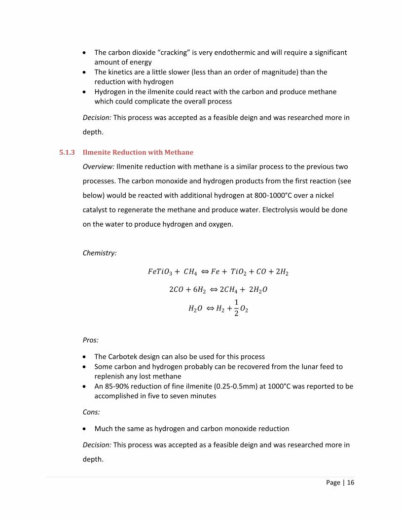
The carbon dioxide “cracking” is very endothermic and will require a significant amount of energy
The kinetics are a little slower (less than an order of magnitude) than the reduction with hydrogen
Hydrogen in the ilmenite could react with the carbon and produce methane which could complicate the overall process
Decision: This process was accepted as a feasible deign and was researched more in
depth.
5.1.3 Ilmenite Reduction with Methane
Overview: Ilmenite reduction with methane is a similar process to the previous two
processes. The carbon monoxide and hydrogen products from the first reaction (see
below) would be reacted with additional hydrogen at 800-1000°C over a nickel
catalyst to regenerate the methane and produce water. Electrolysis would be done
on the water to produce hydrogen and oxygen.
Chemistry:
𝐹𝑒𝑇𝑖𝑂3 + 𝐶𝐻4 𝐹𝑒 + 𝑇𝑖𝑂2 + 𝐶𝑂 + 2𝐻2
2𝐶𝑂 + 6𝐻2 2𝐶𝐻4 + 2𝐻2𝑂
𝐻2𝑂 𝐻2 +1
2𝑂2
Pros:
The Carbotek design can also be used for this process
Some carbon and hydrogen probably can be recovered from the lunar feed to replenish any lost methane
An 85-90% reduction of fine ilmenite (0.25-0.5mm) at 1000°C was reported to be accomplished in five to seven minutes
Cons:
Much the same as hydrogen and carbon monoxide reduction
Decision: This process was accepted as a feasible deign and was researched more in
depth.
Page | 17
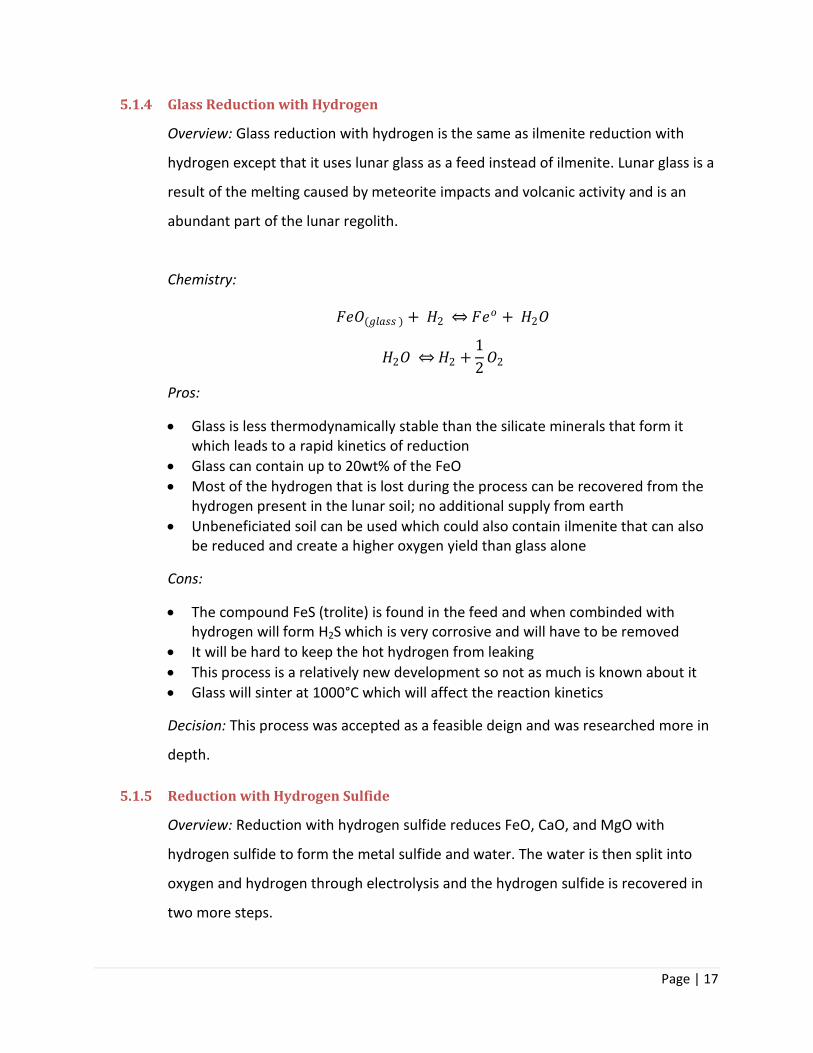
5.1.4 Glass Reduction with Hydrogen
Overview: Glass reduction with hydrogen is the same as ilmenite reduction with
hydrogen except that it uses lunar glass as a feed instead of ilmenite. Lunar glass is a
result of the melting caused by meteorite impacts and volcanic activity and is an
abundant part of the lunar regolith.
Chemistry:
𝐹𝑒𝑂(𝑔𝑙𝑎𝑠𝑠 ) + 𝐻2 𝐹𝑒𝑜 + 𝐻2𝑂
𝐻2𝑂 𝐻2 +1
2𝑂2
Pros:
Glass is less thermodynamically stable than the silicate minerals that form it which leads to a rapid kinetics of reduction
Glass can contain up to 20wt% of the FeO
Most of the hydrogen that is lost during the process can be recovered from the hydrogen present in the lunar soil; no additional supply from earth
Unbeneficiated soil can be used which could also contain ilmenite that can also be reduced and create a higher oxygen yield than glass alone
Cons:
The compound FeS (trolite) is found in the feed and when combinded with hydrogen will form H2S which is very corrosive and will have to be removed
It will be hard to keep the hot hydrogen from leaking
This process is a relatively new development so not as much is known about it
Glass will sinter at 1000°C which will affect the reaction kinetics
Decision: This process was accepted as a feasible deign and was researched more in
depth.
5.1.5 Reduction with Hydrogen Sulfide
Overview: Reduction with hydrogen sulfide reduces FeO, CaO, and MgO with
hydrogen sulfide to form the metal sulfide and water. The water is then split into
oxygen and hydrogen through electrolysis and the hydrogen sulfide is recovered in
two more steps.
Page | 18
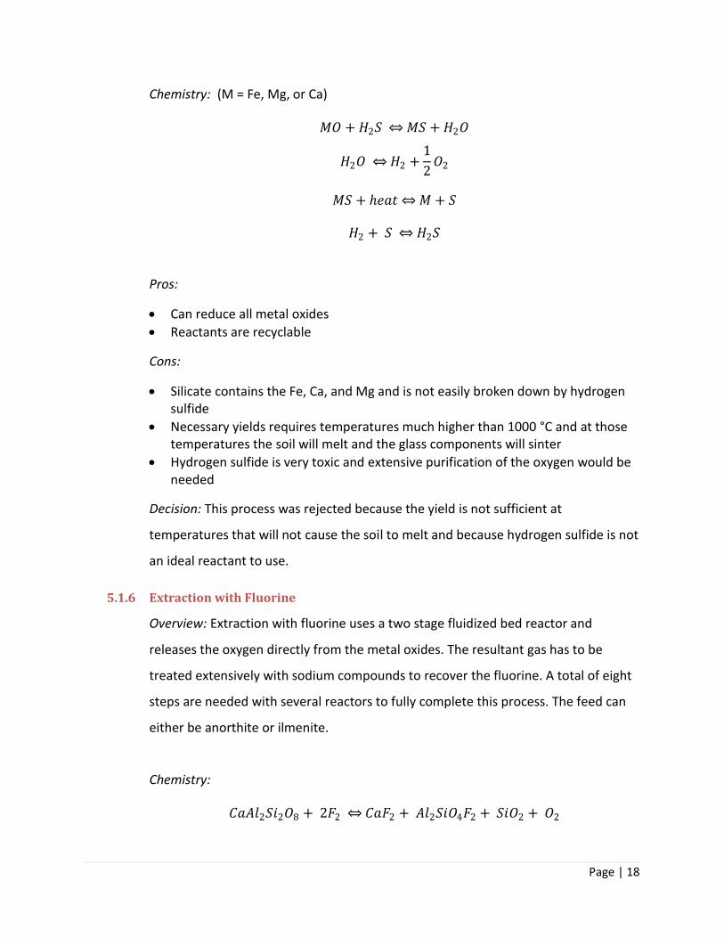
Chemistry: (M = Fe, Mg, or Ca)
𝑀𝑂 + 𝐻2𝑆 𝑀𝑆 + 𝐻2𝑂
𝐻2𝑂 𝐻2 +1
2𝑂2
𝑀𝑆 + ℎ𝑒𝑎𝑡 𝑀 + 𝑆
𝐻2 + 𝑆 𝐻2𝑆
Pros:
Can reduce all metal oxides
Reactants are recyclable
Cons:
Silicate contains the Fe, Ca, and Mg and is not easily broken down by hydrogen sulfide
Necessary yields requires temperatures much higher than 1000 °C and at those temperatures the soil will melt and the glass components will sinter
Hydrogen sulfide is very toxic and extensive purification of the oxygen would be needed
Decision: This process was rejected because the yield is not sufficient at
temperatures that will not cause the soil to melt and because hydrogen sulfide is not
an ideal reactant to use.
5.1.6 Extraction with Fluorine
Overview: Extraction with fluorine uses a two stage fluidized bed reactor and
releases the oxygen directly from the metal oxides. The resultant gas has to be
treated extensively with sodium compounds to recover the fluorine. A total of eight
steps are needed with several reactors to fully complete this process. The feed can
either be anorthite or ilmenite.
Chemistry:
𝐶𝑎𝐴𝑙2𝑆𝑖2𝑂8 + 2𝐹2 𝐶𝑎𝐹2 + 𝐴𝑙2𝑆𝑖𝑂4𝐹2 + 𝑆𝑖𝑂2 + 𝑂2
Page | 19
𝐶𝑎𝐹2 + 𝐴𝑙2𝑆𝑖𝑂4𝐹2 + 𝑆𝑖𝑂2 + 6𝐹2 𝐶𝑎𝐴𝑙𝐹5 + 𝐴𝑙𝐹3 + 2𝑆𝑖𝐹4 + 3𝑂2
Pros:
Releases the oxygen directly; no need for electrolysis
Cons:
The oxygen must be purified extensively
Complete recovery of fluorine is unlikely
Fluorine is very corrosive would require special inert materials supplied from earth
Decision: This process was rejected because inert materials would have to be
supplied from earth and fluorine is dangerous to work with and would be a safety
issue.
5.1.7 Carbochlorination
Overview: Carbochlorination requires a CO-Cl2 gas mixture or Cl2 gas in the presence
of solid carbon to react with the metal oxides in the lunar soil. The feed would be
anorthite or ilmenite and a fluidized-bed reactor at 770 °C would be used. Carbon
acts as a reducing agent, forming CO, while chlorine oxidizes the metal and in this
way there is a new surface continuously being formed for reaction. Several
condensation, hydrolysis, and electrolysis steps would be required to obtain the
oxygen.
Chemistry:
𝐶𝑎𝐴𝑙2𝑆𝑖2𝑂8 + 8𝐶 𝑠 + 8𝐶𝑙2 𝐶𝑎𝐶𝑙2 + 2𝐴𝑙𝐶𝑙3 + 2𝑆𝑖𝐶𝑙4 + 8𝐶𝑂𝐹𝑒𝑇𝑖𝑂3
+ 𝐶 𝑠 +3
2𝐶𝑙2
𝐶𝑎𝐶𝑙2 + 2𝐴𝑙𝐶𝑙3 + 2𝑆𝑖𝐶𝑙4 + 8𝐶𝑂𝐹𝑒𝑇𝑖𝑂3 + 𝐶 𝑠 +3
2𝐶𝑙2 𝐹𝑒𝐶𝑙3 + 𝑇𝑖𝑂2 𝑠
+ 𝐶𝑂
Pros:
Operates at a lower temperature
Can use bulk lunar soil either mare or highlands
Page | 20
Cons:
Carbochlorination can form up to 136 C-Cl-O byproducts
Large number of process steps which adds complications with reliability
Chlorine is hazardous to work with
Recovery of reactants is unlikely without even more steps requiring a large amount of energy
Decision: This process was rejected because of the number of process steps
required, chlorine is a hazardous gas, and the reactants are not easily recyclable.
5.1.8 Chlorine Plasma Reduction
Overview: Chlorine plasma reduction works by creating chlorine plasma within which
stable metal oxides such as ilmenite can undergo chlorination and release oxygen.
The reaction takes place at temperature up to 2000 °C. The chlorine would then
have to be separated from the metal chlorides and used again.
Chemistry: (M = Fe, Mg, or Ca)
𝐶𝑙2 + 𝑀𝑂 𝑀𝐶𝑙2 +1
2𝑂2
Pros:
Produces oxygen directly; no electrolysis is necessary
Cons:
Requires temperatures up to 2000 °C
Not much is known about the reaction kinetics and experimentation is still in progress
Decision: This process was rejected because there is not enough information in the
literature about kinetics and the reaction in general and we do not have the
necessary materials to do any research ourselves.
Page | 21
5.2 Silicate/Oxide Melt
Processes included in this category were molten silicate electrolysis, fluxed molten
silicate electrolysis, caustic solution and electrolysis, carbothermal reduction, magma
partial oxidation, and lithium or sodium reduction of ilmenite.
5.2.1 Molten Silicate Electrolysis
Overview: Molten silicate electrolysis is a one step process that entails the
electrolysis of molten silicate where oxygen would be made at the anode and the
metals at the cathode. No moving parts are required and the reaction would be
done in a single stage.
Pros:
No need for reactants from earth because the electrolysis takes the soil and separates it into oxygen and metals
Oxygen is released directly
According to the literature, the energy requirements are less than for most of the alternatives
Cons:
The electricity needed to release the oxygen is dependent on the concentration of FeO
The life of the electrode is unknown
There is a possibility of corrosion
Not much work has been done with high-temperature silicate melts so the actual design of the electrolysis cell is not well defined and lab experiments cannot be scaled up
Decision: This process was rejected because without the right equipment for
research it would be almost impossible to design the electrolysis chamber at
production size, which is the main component in the reaction.
5.2.2 Fluxed Molten Silicate Electrolysis
Overview: Fluxed molten silicate electrolysis uses the same principle of the molten
silicate electrolysis except that is uses a flux, possibly a fluoride melt, to dissolve the
silicate feed to get rid of some of the difficulties of high temperature corrosion as
well as lower the operation temperatures.
Page | 22
Chemistry:
3𝐶𝑎𝐴𝑙2𝑆𝑖2𝑂8 + 8𝐴𝑙 6𝑆𝑖 + 3𝐶𝑎𝑂 + 7𝐴𝑙2𝑂3
The Si is removed and the rest sent to the electrolysis chamber.
Pros:
No need for reactants from earth because the electrolysis takes the soil and separates it into oxygen and metals
Oxygen is released directly
Less of a possibility of corrosion
According to the literature, the energy requirements are less than for most of the alternatives
Cons:
The electricity needed to release the oxygen is dependent on the concentration of FeO
The life of the electrode is unknown
Not much work has been done with high-temperature silicate melts so the actual design of the electrolysis cell is not well defined and lab experiments cannot be scaled up
Decision: This process was rejected for the same reasons that the molten silicate
electrolysis was rejected.
5.2.3 Caustic Solution and Electrolysis
Overview: Caustic solution and electrolysis uses molten NaOH at 400 °C to dissolve
the lunar soil and then electrolyzed to release the oxygen. The process can be made
continuous if the mixed caustic and solid products are removed from near the
cathode and then another unit is used to separate and recycle the NaOH.
Pros:
Oxygen is released directly
Possible high oxygen yield because it can reduce all oxides except magnesium and calcium oxides
Cons:
Predicted heavy caustic loss through process
Page | 23
Electrode stability is unknown
More experimental research is needed to determine the long-term performance of the electrolysis cell
Decision: This process was rejected because NaOH is hazardous, the recycled
materials will lose a good amount of mass, and more experimentation needs to be
done that cannot be done with the equipment available to us.
5.2.4 Carbothermal Reduction
Overview: Carbothermal processes involve using molten reactant in the production
of oxygen. Chemistry from steel making and from coal-gas forming are combined
with electrolysis or thermolysis.
Chemistry:
𝑀𝑔2𝑆𝑖𝑂4 + 2𝐶𝐻4 2𝑀𝑔𝑂 + 𝑆𝑖 + 4𝐻2 + 2𝐶𝑂
𝐶𝑂 + 3𝐻2 𝐶𝐻4 + 𝐻2𝑂
𝐻2𝑂 𝐻2 +1
2𝑂2
Pros:
High yield of oxygen
This process can be evaluated with present knowledge because there is
considerable experience
Cons:
High energy is needed for many of the steps
More complex than other proposed processes
High temperatures (1600°C) are needed
Decision: This process was rejected because of the complexity of the process and the
great amount of energy that is needed.
Page | 24
5.2.5 Magma Partial Oxidation
Overview: This is a five step process that starts with iron rich soil that is melted. FeO
is separated out, cooled and crystallized, and pulverized. Fe3O4 is extracted and
dissolved and electrolyzed to recover Fe and O2.
Pros:
Seemingly straightforward process
Cons:
No experiments have been conducted to realize the feasibility of a process like
this.
Decision: This process was rejected because the feasibility is unknown and we do not
have the time or resources to determine the feasibility.
5.2.6 Li of Na Reduction
Overview: This process is an indirect electrochemical reduction of lunar oxides.
Lithium or sodium is used to reduce the oxides to metals and Li2O. A sublimation
step, reduction step, and electrolytic cell follow.
Pros:
Bulk lunar soil can be used so the location could be anywhere on the moon
A moderate temperature (727°C) has been proposed
Cons:
Li2O is extremely hard to completely recover
Electrolytic cell needs more research to know about corrosion, degradation of
materials like the anode and cathode, and effects of long term operation
The lithium or sodium supply would have to come from earth
Decision: This process was rejected because little is known about the electrolytic cell
in this process and also the recovery steps are near impossible.
Page | 25
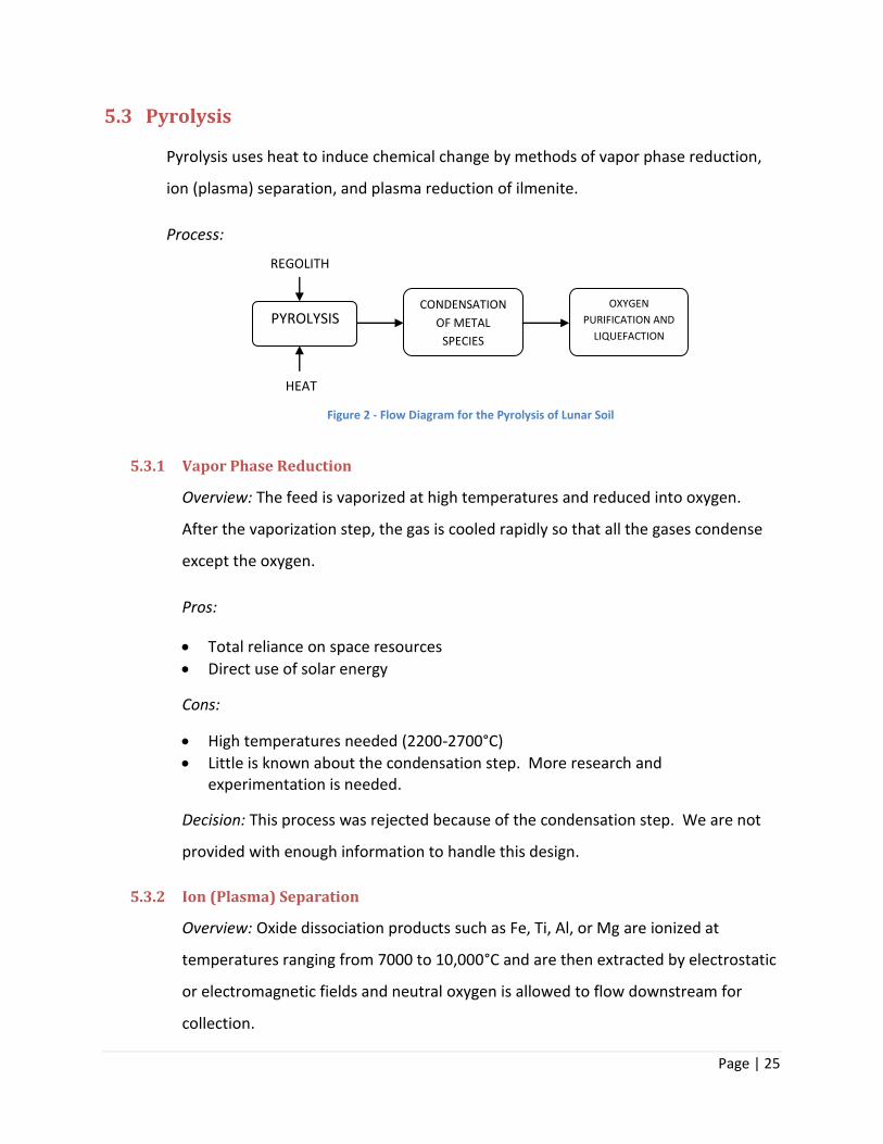
5.3 Pyrolysis
Pyrolysis uses heat to induce chemical change by methods of vapor phase reduction,
ion (plasma) separation, and plasma reduction of ilmenite.
Process:
5.3.1 Vapor Phase Reduction
Overview: The feed is vaporized at high temperatures and reduced into oxygen.
After the vaporization step, the gas is cooled rapidly so that all the gases condense
except the oxygen.
Pros:
Total reliance on space resources
Direct use of solar energy
Cons:
High temperatures needed (2200-2700°C)
Little is known about the condensation step. More research and experimentation is needed.
Decision: This process was rejected because of the condensation step. We are not
provided with enough information to handle this design.
5.3.2 Ion (Plasma) Separation
Overview: Oxide dissociation products such as Fe, Ti, Al, or Mg are ionized at
temperatures ranging from 7000 to 10,000°C and are then extracted by electrostatic
or electromagnetic fields and neutral oxygen is allowed to flow downstream for
collection.
PYROLYSIS CONDENSATION
OF METAL
SPECIES
OXYGEN
PURIFICATION AND
LIQUEFACTION
REGOLITH
HEAT
Figure 2 - Flow Diagram for the Pyrolysis of Lunar Soil
Page | 26
Pros:
High oxygen yields
Cons:
Lack of information and research about the condensing step
High temperatures, energy intensive
Process is largely theoretical
Decision: This process was rejected because of the extreme temperatures involved
and because it is highly theoretical and would therefore be impossible to implement
into our design.
5.3.3 Plasma Reduction of Ilmenite
Overview: Plasma reduction of ilmenite utilizes the same concepts of solid/gas
interaction reactions except that it is performed at temperatures of 3000-6000°C.
Pros:
Ilmenite is completely dissociated into elemental ion, elemental titanium, and
oxygen.
Cons:
Process is still in experimental stage
Components must be selectively condensed
High temperatures
Decision: This process was rejected because it is still in the experimental stage so it
cannot be included in our design.
5.4 Aqueous Solutions
Processes included in the aqueous solutions category are HF acid dissolution and
sulfuric acid dissolution.
Page | 27
5.4.1 HF Acid Dissolution
Overview: Hydrofluoric acid is used to dissolve lunar regolith to make metal fluorides
and water. This process includes several bath-mode and acid-leach reactors, high-
temperature hydrolysis, electrolysis, ion exchange, distillation, centrifuges and
drying steps.
Pros:
Plant location would not be site-specific because any feedstock can be used
Cons:
Overall process is complex
586 tonnes of regolith is needed to produce 1000 tonnes of oxygen per year which is higher than other processes
Automation would be difficult because of batch-mode reactors
Many separate steps are involved that require many small pieces of equipment. This would result in more design, and higher capital costs.
Decision: This process was rejected because of the complexity of the design. This
complexity is unnecessary because it can be avoided.
5.4.2 H2SO4 Acid Dissolution
Overview: In this process, sulfuric acid dissociates to breakdown ilmenite resulting in
a water and 𝐹𝑒𝑆𝑂4 slurry. The slurry enters an electrolysis chamber and the iron
and oxygen are separated.
Chemistry:
𝐹𝑒𝑇𝑖𝑂3 + 𝐻2𝑆𝑂4 𝐹𝑒𝑆𝑂4 + 𝑇𝑖𝑂2
𝐹𝑒𝑆𝑂4 + 𝐻2𝑂 𝐻2𝑆𝑂4 + 𝐹𝑒 +1
2𝑂2
Pros:
This process is based on well known commercial practices and procedures
Cons:
Page | 28
The industrial processes are used to recover Fe and TiO2, not oxygen
Feasibility of recovering oxygen is in experimental stage at NASA
Decision: This process was rejected because it is not yet feasible for obtaining
oxygen since it is used to recover iron and titanium.
5.5 CO-Product Recovery of Water
Only one process was put into this category and it was hydrogen/helium/water
production from soil.
5.5.1 Hydrogen/Helium/Water Production from Soil
Overview: Roasting the lunar soil releases the hydrogen it contains. The hot
hydrogen can react with oxide minerals to produce water.
Pros:
Moderate temperatures (600-900°C)
Cons:
A large quantity of soil must be used to produce a small amount of oxygen.
The main purpose of the process is to gain hydrogen and helium and oxygen is a possible side product.
Decision: This process was rejected because of the great quantities of soil that would
need to be handled for small amounts of oxygen produced.
5.6 Final Decision
The four processes that we decided were the most feasible for the project were 5.1.1: ilmenite
reduction with hydrogen, 5.1.2: ilmenite reduction with C/CO, 5.1.3: ilmenite reduction with
methane, and 5.1.4: glass reduction with hydrogen. These processes are all very similar in
design as well as pros and cons making it a challenge to come up with criteria that would
eliminate two of the processes totally. Out of the three ilmenite reduction processes, we
decided to go with the hydrogen reduction. We chose hydrogen reduction because it is the
Page | 29
process that has the most information in the literature about all the nuances of the process,
which makes the designing process more feasible. The kinetics, yield, and reaction temperature
for the hydrogen reduction of ilmenite process are comparable with the other two so nothing is
lost there. The other process that we chose to design further was glass reduction with
hydrogen. Even though this process is not as well known, the feed for this process does not
have to be purified much, if at all. Also with the unbeneficiated soil, there is a good chance that
ilmenite will also be present which will increase the oxygen yield because we would basically
be doing two processes at once. The ilmenite reduction with hydrogen and glass reduction with
hydrogen will be designed in parallel with each other and a final design will be chosen based on
the economics and feasibility of each.
Page | 30
6 Implementation
6.1 UNISIM as a Design Tool
In order to design effectively, a decision must be made as to which method of oxygen
production from lunar soil is the best. To do this, the two methods that remain after the
preliminary evaluations need to be further critiqued. The best way to critique these
remaining methods is to model each one and use a quantitative analysis to decide which
is the most suitable. Modeling such a process requires a lot of time, effort, and skill. A
simulation tool such as UNISIM can make this modeling process easier as well as more
accurate. It is the standard modern design approach for chemical processes.
UNISIM will be put to use in order to model the process required to isolate oxygen from
lunar moon rocks. It will provide an accurate yield for the amount of oxygen that can be
produced from a given feed of lunar regolith, while providing all molar flows and
compositions of streams. From these, appropriate amounts of feed (lunar moon rock)
and hydrogen (reducing agent) can be deduced that will allow for oxygen to be produced
in the quantity specified by the basis. UNISIM also provides heat duties and energy
requirements for all units including reactors, separation equipment, pumps, and
compressors. Given this information, an accurate economic analysis of the two processes
can be produced. The cost of the process and the yield of oxygen that the process
produces will be two determining factors when it is time to choose the best method.
Therefore, the economic analysis coupled with the performance of each method, in terms
of the yield of oxygen, will provide high quality information with which the optimal
method can be decided upon.
6.2 UNISIM Hypotheticals
UNISIM is an effective tool, but the component database does not include many of the
solid materials that we will need. Our feed is completely composed of solid materials
including iron oxides and iron titanium oxides. To supplement the current database
component package, UNISIM allows the user to construct a “hypothetical” component. A
Page | 31
hypothetical can be constructed by entering key properties including molecular weight,
density, heat of formation, heat of combustion, and specific heat capacity.
Reduction of ilmenite with hydrogen and the reduction of glass (FeO) with hydrogen are
the two cases that will be modeled by UNISIM. The necessary properties for each
compound were found on the website for the National Institute of Standards and
Technology [10]. The heat of formation was the only property found from a different
resource: the book The Planetary Scientist’s Companion [9] referred to us by Professor
Stearley in the geology department. These quantities will be entered into UNISIM’s
hypothetical simulator. Once a hypothetical has been created it can be used in UNISIM
like a normal component would be, allowing for an accurate representation of reaction,
separation and transport processes.
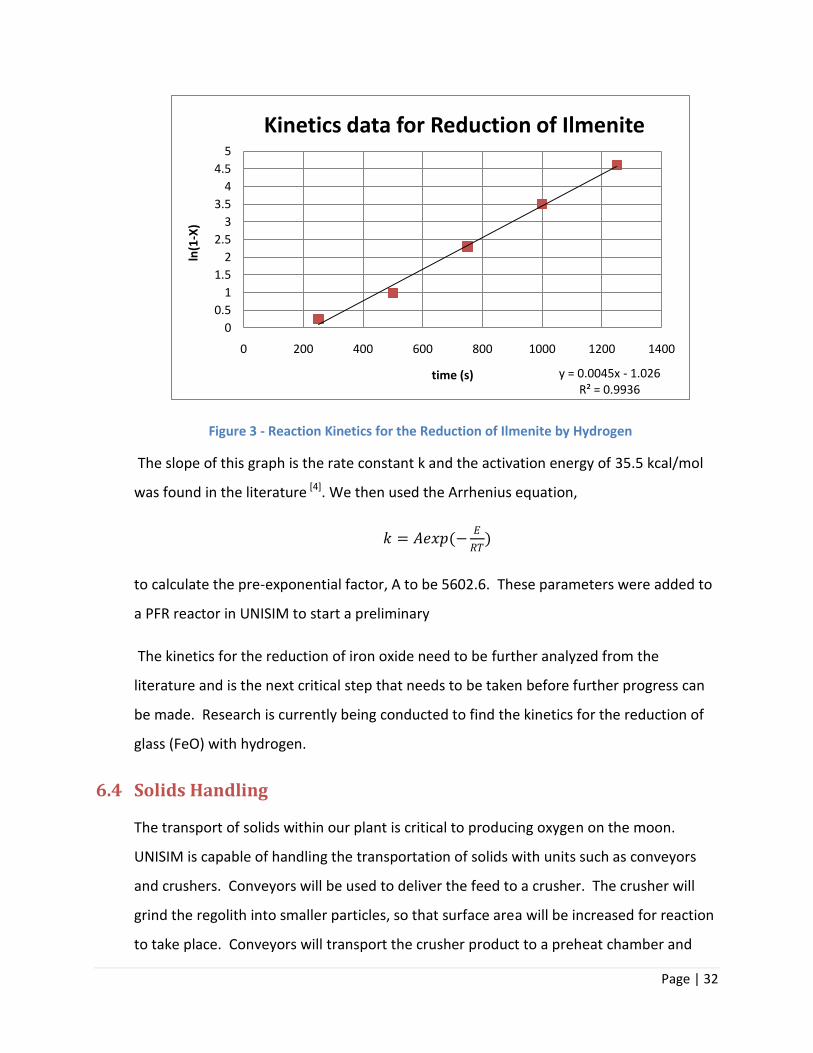
6.3 Reaction Kinetics
UNISIM needs the reaction kinetics to solve the reactor section of the process. Literature
is consulted for the reaction kinetics because it would require a significant amount of
time and resources to be able to experimentally determine the kinetics for the reaction.
UNISIM requires the pre-exponential factor, the activation energy, and the order of the
forward and reverse (if applicable) reactions. The kinetics for the reduction of ilmenite by
hydrogen were found in literature [4] at a temperature of 1273 K by way of conversion of
hydrogen as a function of time data. This data was analyzed and we found that the
reaction is first order as displayed in the graph below.
Page | 32
Figure 3 - Reaction Kinetics for the Reduction of Ilmenite by Hydrogen
The slope of this graph is the rate constant k and the activation energy of 35.5 kcal/mol
was found in the literature [4]. We then used the Arrhenius equation,
𝑘 = 𝐴𝑒𝑥𝑝(−𝐸
𝑅𝑇)
to calculate the pre-exponential factor, A to be 5602.6. These parameters were added to
a PFR reactor in UNISIM to start a preliminary
The kinetics for the reduction of iron oxide need to be further analyzed from the
literature and is the next critical step that needs to be taken before further progress can
be made. Research is currently being conducted to find the kinetics for the reduction of
glass (FeO) with hydrogen.
6.4 Solids Handling
The transport of solids within our plant is critical to producing oxygen on the moon.
UNISIM is capable of handling the transportation of solids with units such as conveyors
and crushers. Conveyors will be used to deliver the feed to a crusher. The crusher will
grind the regolith into smaller particles, so that surface area will be increased for reaction
to take place. Conveyors will transport the crusher product to a preheat chamber and
y = 0.0045x - 1.026R² = 0.9936
0
0.5
1
1.5
2
2.5
3
3.5
4
4.5
5
0 200 400 600 800 1000 1200 1400
ln(1
-X)
time (s)
Kinetics data for Reduction of Ilmenite
Page | 33
also transport the preheat chamber product to the main reaction chamber. Conveyors
will also be used to remove the solid products of the main reaction chamber. The crusher
unit in UNISIM needs to be supplied with parameters for Rousseau’s Model. These
parameters include breakability and the number of sizes of the component. Research will
need to be conducted to find these parameters.
6.5 Electrolysis Chamber
The next unit that needs to be addressed is the electrolysis chamber. As of now, the plan
is to use a conversion reactor to convert water to hydrogen gas and oxygen. Such a
reaction will require energy and UNISIM is capable of calculating this. The size of the
electrolysis chamber will be proportional to the yield of oxygen that is to be achieved.
The cost of such a unit will depend on the size, materials of construction and the energy
required.
6.6 Future Work
Researching kinetics for the reduction or iron oxide will need to be done before the
reactor design can take place. The process flow diagram will also be developed before
optimizing the design of any of the units. This will allow for the affects of each case study
to be evaluated throughout the system. Once the reaction kinetics has been determined
and the PFD developed, the reactor type (Batch, CSTR, PFR, etc.) can be chosen and the
sizing can be determined. The design of the electrolysis chamber will be a primary
objective for the interim semester. A separation process to retrieve hydrogen from other
volatiles that are produced in the reaction of lunar moon soil will also need to be
designed.

Page | 34
7 Business Plan
7.1 The business plan is forthcoming.
Page | 35
8 Safety.
8.1 Conveyors
Moving parts will need to have guards placed on them so that clothing and hair cannot
get caught. Maintenance should not be performed unless the power is off and circuit for
power is disrupted. All operators working around conveyors should be trained in safe
work procedures. Safety shutoff switches will be installed for emergency shutdowns at all
conveyor locations with start-up warning alarms to follow any emergency shutdown. If
conveyors are elevated, maintenance workers will be equipped with safety belts and
lines. All operators will wear hard hats and steel toe boots to avoid injury from rocks
falling from conveyors. Skirt boards will be installed to limit the amount of material
falling from the conveyors.
8.2 Crusher
Loose clothing, long hair, rings, and watches must be avoided because it can be caught in
moving parts. Guards will be placed on moving parts. The instruction manual will be near
or attached to the machinery. Warning and caution plates will be added to prevent
improper contact with the crusher. The electrical service will have a lockout option that
must be activated before maintenance can occur. Relief valves will be installed on all
pressurized lines and hoses. Machinery must be lubricated properly.
8.3 Preheat Chamber and Main Reaction Chamber
Both the preheat chamber and the main reaction chamber will be heated to
temperatures above 600°C. Perimeters must be established around these vessels while
they are in operation to ensure that no personnel come too close. Both vessels will be
insulated to increase efficiency as well as to avoid serious burns if accidental contact
occurs. Rupture disks and relief valves will be installed on these units and others to avoid
pressure build up as steam and volatiles may cause unsafe pressures. Relief valves will be
installed in doubles to account for a failure in one. Process conditions such as
Page | 36
temperature, pressure and molar flows will be recorded in a report that is automatically
taken every hour to enable monitoring of the system. Regular maintenance checks will
occur daily and shutdowns for extensive maintenance will occur every 6 months.
8.4 Electrolysis Chamber
The hydrogen and oxygen gas that is produced from the electrolysis of water will require
careful handling because they are flammable gasses. The oxygen will collect at the anode
terminal and the hydrogen at the cathode terminal. The vacuum of space is available
and, depending on the final optimized design, may be used to create a non-flammable
envelope around the chamber. High pressures can be created inside the chamber so
appropriate amounts of relief valves will be installed. Workers will be trained on the
correct operation of the electrolysis chamber. Electrolysis uses substantial amounts of
electricity so the risk of electrocution will be taken seriously and all terminals and wires
will be isolated from human interaction.
8.5 Hydrogen Membrane Safety
Hydrogen gas is again present in this unit operation which means fires and explosions
could happen if the proper safety precautions are not observed. All heat sources must be
kept away from the unit. Gasses are being dealt with so appropriate amounts of relief
valves will be installed.
8.6 General Lunar Safety
Currently, the plan is to have an enclosed and pressurized plant. This will provide
operators with breathable air and a temperature at which they can function. The idea of
having the plant beneath the surface of the moon has also been brought up. This would
prevent adverse effects of solar storms, due to the lack of a magnetic field, from razing
the oxygen plant. It would also shelter the plant from possible meteor impact and
radiation. All possible safety measures will be taken to avoid disasters caused by the lack
of a breathable atmosphere and fatally cold temperatures. The solar reflectors for the
preheat and the main reaction chambers will need to be monitored closely.
Page | 37
Maintenance will be performed on the reflectors only when they are angled away from
the sun. Normal solar radiation on the moon can cause serious burns and can even blind
individuals. As such, specialized suits and protective eyewear will be necessary for any
workers outside the plant. Furthermore, a system of airlocks will allow for workers to
travel between parts of the plant and the colony as wells as to the lunar environment.
These airlocks will prevent pressure leaks from effecting the entrances and exits of the
plant.

Page | 38
9 Conclusions
Overall, the work done this semester has proven several things. Research regarding the
reactions show that the process is possible and has been studied in many aspects. Similarly,
narrowing down to just two reactions is one representation of the progress we have made this
semester. The reaction kinetics is another big step forward. These models will allow the design
and optimization process to take full pace. Similarly, the work done in UNISIM and on the
preliminary PFD shows the advancement of ideas and concepts put into use. Though the
schedule has changed since first starting the project, and some deadlines have been
rearranged, surprising progress was made. Next semester awaits full of potential for many
changes to take place. Our direction and scope has also been adjusted and now a clear set of
tasks and goals lies ahead of our team.
Page | 39
10 Acknowledgements
We would like to acknowledge several people who assisted us in the progress we were able to
make. Professor Wentzhemier was a crucial part in directing the momentum of both or project
and our team management. His weekly, almost daily advice and guidance was essential to
staying on task and accomplishing our work this semester. Professor VanderGriend and
Professor Stearly were both immensely helpful in identifying some of the key material
properties for use in UNISIM. Glenn Remelts our research consultant at the Hekman library
assisted us in familiarizing ourselves with the literature databases and references. Similarly,
Randy Elenbaas, our industrial consultant, helped us in considering many of the practical
aspects of the project.
Page | 40
11 References
1) Allen, Carlton C., Gary G. Bond, and David S. McKay. "Lunar Oxygen Production - A
Maturing Technology." American Society of Civil Engineers (1994): 1157-66. Print.
2) Allen, Carlton C. "Oxygen Extraction from Lunar Samples." Lockheed Martin Engineering
and Sciences Co., 2006. Web. 15 Nov. 2010.
<http://curator.jsc.nasa.gov/lunar/lnews/lnmar97/oxygen.html>.
3) Bennett, Gregory. "Oxygen Extraction Pilot Plant." The Artemis Project: Private Enterprise
on the Moon. Ed. Jeremy Kraemer. Artemis Society International, 2007. Web. 15 Nov. 2010.
<http://www.asi.org/adb/04/03/10/04/oxygen-extraction.html>.
4) Briggs, R. A., and A. Sacco, Jr. "Hydrogen Reduction Mechanisms of Ilmenite between 823
and 1353 K." Materials Research Society 6.3 (1991): 574-84. Print.
5) "Extracting Oxygen from Moon Rocks." Space Math. NASA, n.d. Web. 15 Nov. 2010.
<http://spacemath.gsfc.nasa.gov/weekly/5Page28.pdf>.
6) Grey, Ian, Ken McDonald, Michael Fisher-White, and Malisja de Vries. "Hydrogen Reduction
of Preoxidised Ilmenite in Fluidized Bed and Packed Bed Reactors." Institute of Materials,
Minerals, and Mining 116.4 (2007): 209-16. Print.
7) "Hypotheticals." Unisim Design Manual. 3-1-3-35. Print.
8) Lindsey, John F. "Development of Soil on the Lunar Surface." Journal of Sedimentary
Petrology 42.4 (1972): 876-88. Web. 12 Nov. 2010.
<http://search.datapages.com/data/sepm/journals/v42-46/data/042/042004/0876.htm>.
9) Lodders, Katharina, and Bruce Fegley, Jr. The Planetary Scientist's Companion. New York:
Oxford University Press, 1998. 48-49. Print.
10) NIST Chemistry WebBook. National Institute of Standards and Technology, 2008. Web. 27
Oct. 2010. <http://webbook.nist.gov/chemistry/>.
Page | 41
11) Ramachandran, Narayanan, Harvey Willenberg, and Martin Volz. "Hydrogen Reduction of
Ilmenite from Lunar Regolith." AIAA (2006): 1-9. Print.
12) Switzerland, Lausanne. "High Temperature Reduction Kinetics of Ilmenite by Hydrogen."
Materials Chemistry and Physics 17.4 (1987): 325-41. Print.
13) Taylor, Lawrence A., and David W. Carrier, III. "Oxygen Production on the Moon: An
Overview and Evaluation." 69-107. Web. 12 Nov. 2010.
<http://www.uapress.arizona.edu/onlinebks/ResourcesNearEarthSpace/resources04.pdf>.
14) Zhao, Y, and F Shadman. "Reduction of Ilmenite with Hydrogen." Industrial Engineering
Chemical Resources (1991): 2080-87. Web. 12 Nov. 2010.
<http://pubs.acs.org/doi/pdf/10.1021/ie00057a005>.
15) Wolfram|Alpha, . Wolfram Alpha Computational Knowledge Engine. Ed. Wolfram Alpha
LLC. N.p., 2010. Web. 28 Sept. 2010.
Page | 42
12 Appendices
Appendix A
Figure A.1 - Preliminary Process Flow Diagram
Appendix B
Figure B.1-3 - Project Schedule
Appendix C
Oxygen Use Basis Calculations
Appendix D
Projected Cost Analysis
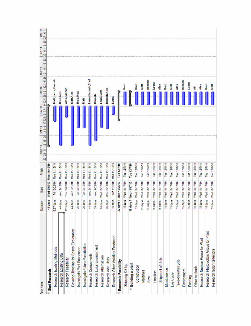
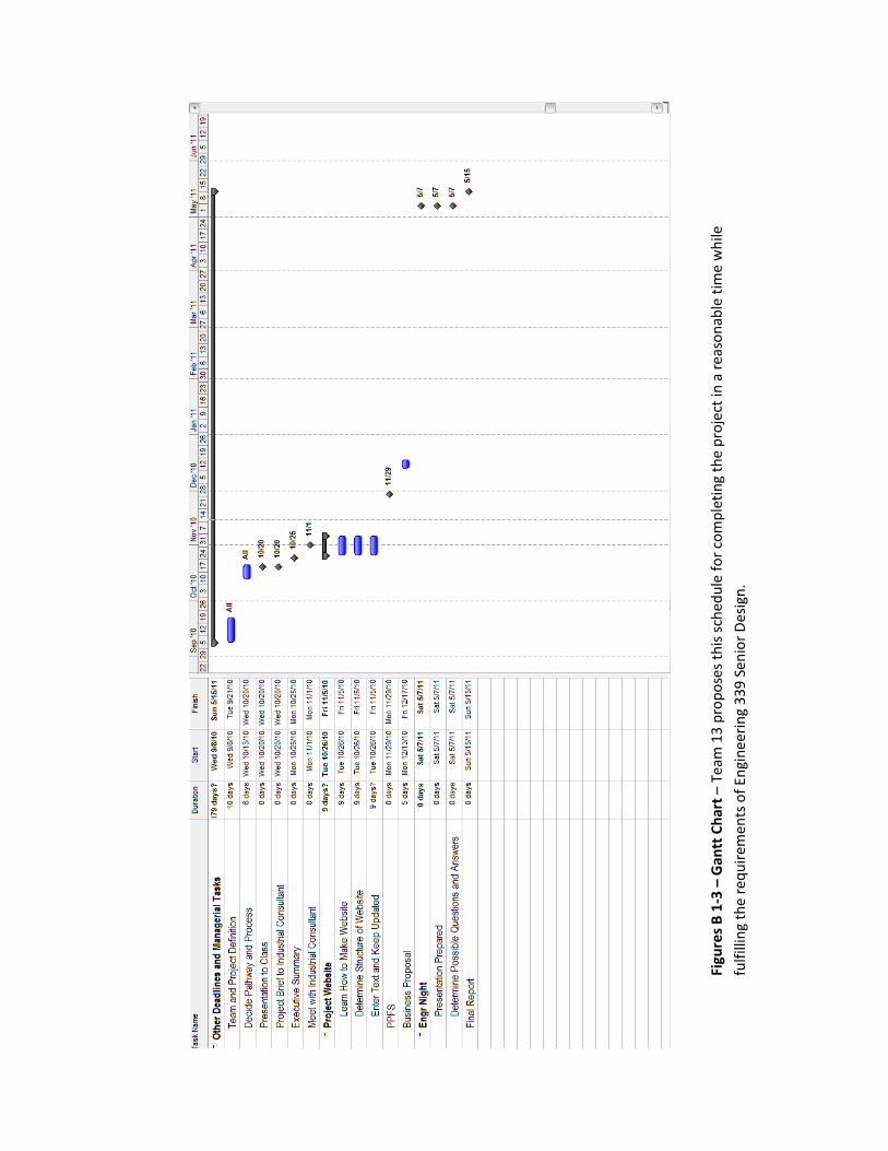
Figu
res
B 1
-3 –
Gan
tt C
har
t –
Team
13
pro
po
ses
this
sch
edu
le f
or
com
ple
tin
g th
e p
roje
ct in
a r
easo
nab
le t
ime
wh
ile
fulf
illin
g th
e re
qu
irem
ents
of
Engi
nee
rin
g 3
39
Sen
ior
Des
ign
.
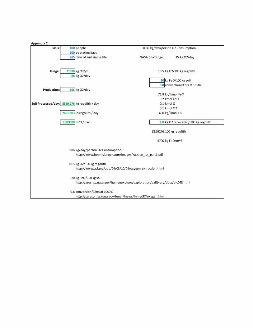
Appendix C
Basis: 100 people 0.86 kg/day/person O2 Consumption
300 operating days
365 days of sustaining life NASA Challenge: 15 kg O2/day
Usage: 31390 kg O2/yr 10.5 kg O2/100 kg regolith
86 kg O2/day
20 kg FeO/100 kg soil
0.8 conversion/3 hrs at 1050 C
Production: 105 kg O2/day
71.8 kg/ kmol FeO
0.2 kmol FeO
Soil Processed/day: 5869.276 kg regolith / day 0.1 kmol O
0.1 kmol O2
2661.803 lb regolith / day 32.0 kg/ kmol O2
1.029698 m^3 / day 1.8 kg O2 recovered/ 100 kg regolith
58.69276 100 kg regolith
5700 kg FeO/m^3
0.86 kg/day/person O2 Consumption
http://www.boomslanger.com/images/russian_lss_part1.pdf
10.5 kg O2/100 kg regolith
http://www.asi.org/adb/04/03/10/04/oxygen-extraction.html
20 kg FeO/100 kg soil
http://ares.jsc.nasa.gov/humanexplore/exploration/exlibrary/docs/eic048.html
0.8 conversion/3 hrs at 1050 C
http://curator.jsc.nasa.gov/lunar/lnews/lnmar97/oxygen.htm
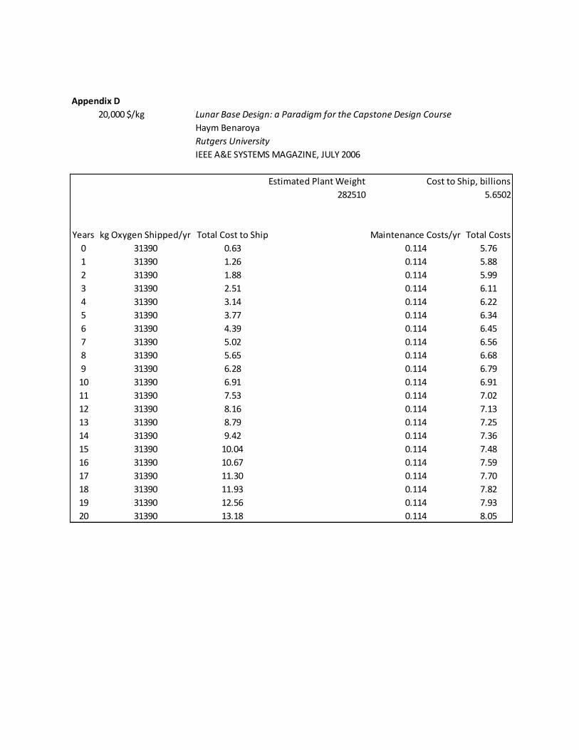
Appendix D
20,000 $/kg Lunar Base Design: a Paradigm for the Capstone Design Course
Haym Benaroya
Rutgers University
IEEE A&E SYSTEMS MAGAZINE, JULY 2006
Cost to Ship, billions
282510 5.6502
Years kg Oxygen Shipped/yr Total Cost to Ship Maintenance Costs/yr Total Costs
0 31390 0.63 0.114 5.76
1 31390 1.26 0.114 5.88
2 31390 1.88 0.114 5.99
3 31390 2.51 0.114 6.11
4 31390 3.14 0.114 6.22
5 31390 3.77 0.114 6.34
6 31390 4.39 0.114 6.45
7 31390 5.02 0.114 6.56
8 31390 5.65 0.114 6.68
9 31390 6.28 0.114 6.79
10 31390 6.91 0.114 6.91
11 31390 7.53 0.114 7.02
12 31390 8.16 0.114 7.13
13 31390 8.79 0.114 7.25
14 31390 9.42 0.114 7.36
15 31390 10.04 0.114 7.48
16 31390 10.67 0.114 7.59
17 31390 11.30 0.114 7.70
18 31390 11.93 0.114 7.82
19 31390 12.56 0.114 7.93
20 31390 13.18 0.114 8.05
Estimated Plant Weight