Embed Size (px)
Citation preview
Project No. 432109
Brent Cross Cricklewood
Phase 1B North – Plot 113
Daylight and Sunlight Availability Study
8th May 2017
For
Waterman Infrastructure
& Environment Ltd.

BMT Fluid Mechanics Limited
Project 432109 Report 4 Release 7 2 of 53 432109rep4v7.docx
Report Title:
Brent Cross Cricklewood Phase 1B North Daylight and Sunlight Availability Study – 113 Plot
Client: Waterman Infrastructure &
Environment Ltd.
Document No: 432109rep4v7 Release: 7 Copy No: 1
Status: Final Report
Report Date: 8th May 2017
Holds:
Name: Signature: Date:
Prepared by: Dr. S. Cunningham
08/05/17
Checked by: Mr. J. Green
08/05/17
Approved by: Mr. S. Cammelli
08/05/17
Distribution: Copy no. to Client
Copy no. to BMT Records
Previous Release
History: Release No: Status: Date:
432109rep4v1 1 Draft Report for Internal Review
14/03/17
432109rep4v2 2 Draft Report for
Client Review 15/03/17
432109rep4v3 3 Draft Report for
Client Review 17/03/17
432109rep4v4 4 Draft Report for Client Review
23/03/17
432109rep4v5 5 Draft Report for
Client Review 21/04/17
432109rep4v6 6 Draft Report for Client Review
28/04/17
BMT Fluid Mechanics Limited
Project 432109 Report 4 Release 7 3 of 53 432109rep4v7.docx
Brent Cross Cricklewood
Phase 1B North
Daylight and Sunlight
Availability Study – Plot 113
Contents
1. Introduction .................................................................................................. 6
2. Daylight and Sunlight Availability .................................................................... 7
3. Site Location & Surrounding Area ................................................................. 10
4. Assessment Methodology ............................................................................. 11
5. Results ........................................................................................................ 13
6. Conclusions ................................................................................................. 20
7. References .................................................................................................. 22
APPENDIX A. Drawing Information ............................................................... 51
APPENDIX B. Assessment Location Schemes ................................................. 52
APPENDIX C. Tabulated Data ....................................................................... 53

BMT Fluid Mechanics Limited
Project 432109 Report 4 Release 7 4 of 53 432109rep4v7.docx
EXECUTIVE SUMMARY
Background
The study provides an assessment of the daylight and sunlight indices,
Vertical Sky Component and Annual Probable Sunlight Hours for the
residential development on Plot 113 for one configuration of the proposed
Phase 1B (North) in the context of the:
Interim Surrounds Configuration – Phase 1B (North) and Phase 1A
(North) in place with the existing surrounds in the absence of further
development
Maximum Parameter Masterplan Configuration – Phase 1B (North)
and Phase 1A (North) in place with the remainder of the Brent Cross
Cricklewod scheme modelled using the maximum parameters (worst
case scenario)
An assessment was also carried out to assess the “sun on the ground” of the
amenity space associated with the Plot 113 residential building.
The following conclusions were drawn from the assessment, and are based
on industry standard guidelines for site layout planning in relation to natural
light.
Daylight
Two indices were used to assess the daylight availability of the Plot 113
residential building, the Vertical Sky Component (VSC), and the Average
Daylight Factor (ADF). For Plot 113 in the context of the interim surrounds,
only 61 (21%) windows do not meet the BRE criteria. Of these 61 windows,
48 windows are located on the eastern side of the plot where obstruction to
daylight is due to the proposed Brent Cross shopping complex massing. The
orientation of the windows should be noted as these are north facing,
therefore reduced daylight is somewhat expected. The remaining 13 windows
are located on the western side of the residential building where obstruction
to daylight is due to the pillars and concrete massing on the third floor
balconies. Other obstructions to daylight on the western side of the building
are caused by shadowing of the protruding walls to the left of the windows
which block the windows path to the sky. The maximum parameter
surrounds have little effect on the daylight for the Plot 113 residential
building. An additional two rooms did not meet the ADF guideline. It should
be noted the maximum parameters are representative of the worst case and
may not be implemented.

BMT Fluid Mechanics Limited
Project 432109 Report 4 Release 7 5 of 53 432109rep4v7.docx
Sunlight
The availability of sunlight to buildings was assessed on the basis of Annual
Probable Sunlight Hours (APSH).
APSH guidelines were met at the vast majority of assessment locations
associated with the Plot 113 residential building. Only 1 window was seen to
fall short of the APSH criteria. The window which does not meet the
recommended level of sunlight is located behind pillars and structure on the
third floor of the western side of the building.
The maximum parameter surrounds provide no effect on the sunlight
associated with the Plot 113 residential building.
The amenity area assessed as part of Plot 113 receives 83% of sun on the
ground and therefore passes the BRE guideline for both the interim
surrounds and maximum parameter surrounds.

BMT Fluid Mechanics Limited
Project 432109 Report 4 Release 7 6 of 53 432109rep4v7.docx
Brent Cross Cricklewood Phase 1B North Daylight and Sunlight Availability Study – Plot 113
1. Introduction
This report presents the results of a daylight and sunlight availability study
commissioned by Waterman Infrastructure & Environment Ltd. The primary
aim of the study was to assess the natural light availability for the proposed
residential development on Plot 113 of Phase 1B (North), of the proposed
Brent Cross Cricklewood scheme. An assessment was also carried out to
assess the “sun on the ground” of the amenity space associated with the Plot
113 residential building.
The study provides an assessment of the main daylight and sunlight indices,
Vertical Sky Component and Annual Probable Sunlight Hours for the
residential development on Plot 113 for one configuration of the proposed
Phase 1B (North) in the context of the:
Interim Surrounds Configuration – Phase 1B (North) and Phase 1A
(North) in place with the existing surrounds in the absence of further
development; and
Maximum Parameter Masterplan Configuration – Phase 1B (North)
and Phase 1A (North) in place with the remainder of the Brent Cross
Cricklewod scheme modelled using the maximum parameters (worst
case scenario) as per the 2014 Permission.
BMT Fluid Mechanics Limited
Project 432109 Report 4 Release 7 7 of 53 432109rep4v7.docx
2. Daylight and Sunlight Availability
Guidelines for assessing the quality of natural light for buildings are outlined
in the BS 8206-2:2008, “Lighting for Buildings – Part 2: Code of Practice for
Daylighting” [2] and the BR 209, “Site Layout Planning for Daylight and
Sunlight” [1]. Daylight and sunlight availability for buildings are principally
assessed in terms of the Vertical Sky Component (VSC) and Annual Probable
Sunlight Hours (APSH) as described below respectively:
Vertical Sky Component (VSC) – is the ratio of direct sky illuminance
at a vertical wall to the simultaneous horizontal illuminance under an
unobstructed sky. VSC provides a measure of daylight availability.
The “Standard Overcast Sky” defined by the CIE (Commission
Internationale de l’Eclairage) is used and the ratio is expressed as a
percentage which can reach a maximum of 40% for a totally
unobstructed facade. Industry best practice guidelines [1]
recommend the VSC for vertical facades should be 27% or above. If
the VSC falls below 27%, then the proposed development should not
cause a reduction to less than 0.8 times the existing value (i.e. a
reduction of no more than 20%).
Annual Probable Sunlight Hours (APSH) – is defined as the duration
for which a location receives direct sunlight. Assessment of APSH
takes into account the cloudiness at the site. Industry best practice
guidelines [1] recommend the APSH be at least 25% on an annual
basis and at least 5% during the winter months (September to
March). For the Northern hemisphere, the sun travels along a
Southerly path relative to the ground. Therefore, planning guidelines
for APSH only apply to facades facing within 90° of South.
If a window does not meet the recommended guidelines from the VSC
assessment, another daylighting index, the Average Daylight Factor (ADF),
may be performed in conjunction with the guidelines for interior daylighting
as described in BR 209 [1].
The criteria for good ADF states if a predominantly daylight appearance is
required, the ADF should be:
5% or more if there is no supplementary electric lighting, or
2% or more if supplementary electric lighting is provided
Table 1 states the minimum ADF values recommended for different types of
dwelling spaces.
BMT Fluid Mechanics Limited
Project 432109 Report 4 Release 7 8 of 53 432109rep4v7.docx
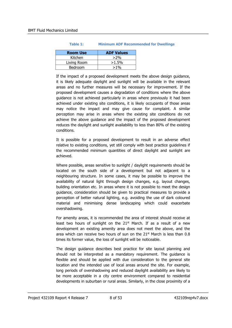
Table 1: Minimum ADF Recommended for Dwellings
Room Use ADF Values
Kitchen >2%
Living Room >1.5%
Bedroom >1%
If the impact of a proposed development meets the above design guidance,
it is likely adequate daylight and sunlight will be available in the relevant
areas and no further measures will be necessary for improvement. If the
proposed development causes a degradation of conditions where the above
guidance is not achieved particularly in areas where previously it had been
achieved under existing site conditions, it is likely occupants of those areas
may notice the impact and may give cause for complaint. A similar
perception may arise in areas where the existing site conditions do not
achieve the above guidance and the impact of the proposed development
reduces the daylight and sunlight availability to less than 80% of the existing
conditions.
It is possible for a proposed development to result in an adverse effect
relative to existing conditions, yet still comply with best practice guidelines if
the recommended minimum quantities of direct daylight and sunlight are
achieved.
Where possible, areas sensitive to sunlight / daylight requirements should be
located on the south side of a development but not adjacent to a
neighbouring structure. In some cases, it may be possible to improve the
availability of natural light through design changes, e.g. layout changes,
building orientation etc. In areas where it is not possible to meet the design
guidance, consideration should be given to practical measures to provide a
perception of better natural lighting, e.g. avoiding the use of dark coloured
material and minimising dense landscaping which could exacerbate
overshadowing.
For amenity areas, it is recommended the area of interest should receive at
least two hours of sunlight on the 21st March. If as a result of a new
development an existing amenity area does not meet the above, and the
area which can receive two hours of sun on the 21st March is less than 0.8
times its former value, the loss of sunlight will be noticeable.
The design guidance describes best practice for site layout planning and
should not be interpreted as a mandatory requirement. The guidance is
flexible and should be applied with due consideration to the general site
location and the intended use of local areas around the site. For example,
long periods of overshadowing and reduced daylight availability are likely to
be more acceptable in a city centre environment compared to residential
developments in suburban or rural areas. Similarly, in the close proximity of a
BMT Fluid Mechanics Limited
Project 432109 Report 4 Release 7 9 of 53 432109rep4v7.docx
development, a car park is likely to be less sensitive to good quality natural
lighting compared to a café area with outdoor seating. The guidelines apply
to areas / buildings where the occupants have a reasonable expectation of
daylight; this would include schools, hospitals, hotels and hostels, and small
workshops.

BMT Fluid Mechanics Limited
Project 432109 Report 4 Release 7 10 of 53 432109rep4v7.docx
3. Site Location & Surrounding Area
3.1. Site Location & Surrounding Area
Phase 1B (North) is part of the Brent Cross Cricklewood scheme. Phase 1B
(North) is located in the London Borough of Barnet, UK. The Phase 1B
(North) is bounded by Hendon Way (A41) to the north-east, the A406 to the
south and the M1 to the west. At present, the existing Phase 1B (North) area
comprises of the existing Brent Cross Shopping Centre and car parking
spaces. The area immediately surrounding Phase 1B (North) principally
comprises low-rise residential buildings and car parks as shown in Figure 1.
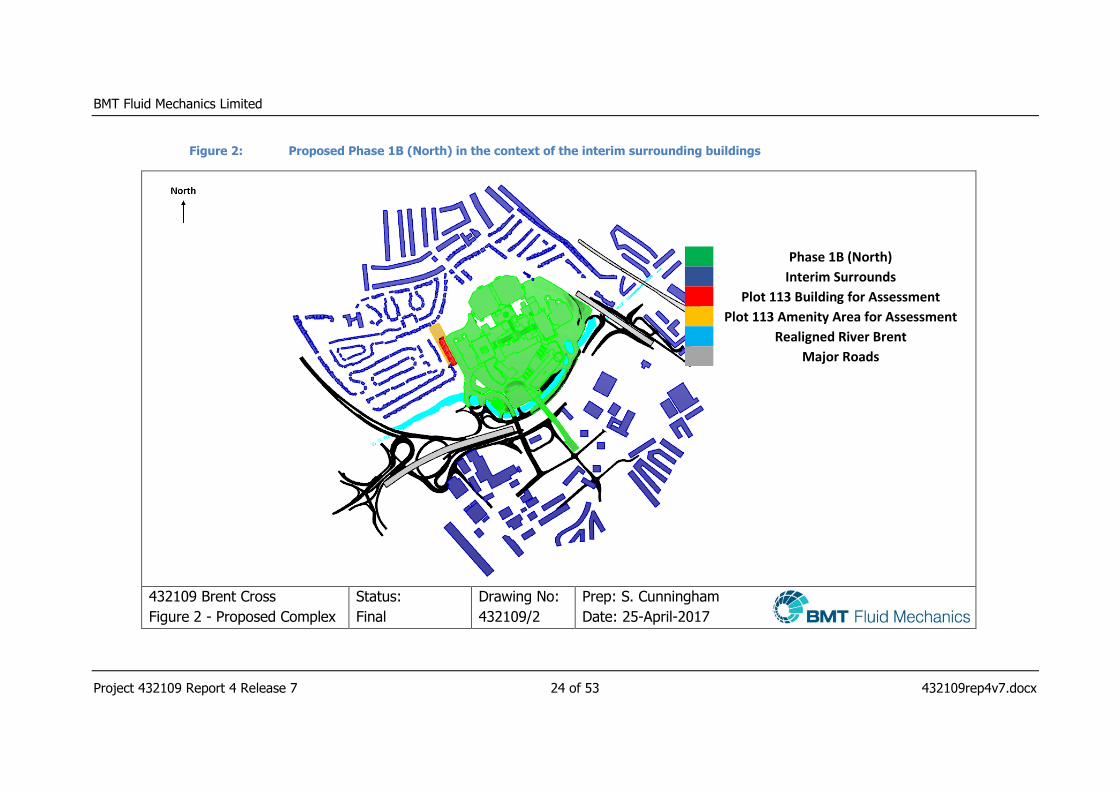
The Phase 1B (North) is presented within the context of the wider interim
surrounds and the maximum parameter surrounds in Figure 2 and Figure 3
respectively.
Two configurations of the surrounding area are considered in the current
study, namely:
Interim Surrounds Configuration - Phase 1B (North) and Phase 1A
(North) in place with the existing surrounds in the absence of further
development; and
Maximum Parameter Masterplan Configuration - Phase 1B (North)
and Phase 1A (North) in place with the remainder of the Brent Cross
scheme modelled using the maximum parameters (worst case
scenario) as per the 2014 Permission.
3.2. Proposed Development
The proposed Phase 1B (North) comprises a number of development plots
which include retail, leisure, food and beverage, hotel, and community
floorspace uses, in addition to an energy centre. The residential development
within Phase 1B (North) will be located on Plot 113. The proposed Phase 1B
(North) will be supported by multi-storey car parks and the enhanced
replacement bus station, threshold spaces/public realm areas, in addition to
the Eastern and Western riverside parks, walkways and nature parks
adjacent to the realigned River Brent, and improvements to Sturgess Park.
Refurbishment works are also proposed within the existing Brent Cross
Shopping Centre.
Models of the proposed Phase 1B (North) in both contexts to be used in the
assessments are presented in Figure 2 and Figure 3.

BMT Fluid Mechanics Limited
Project 432109 Report 4 Release 7 11 of 53 432109rep4v7.docx
4. Assessment Methodology
4.1. Model Detail
A computational model was constructed to represent one configuration of the
proposed Phase 1B (North) within the context of the:
Interim Surrounds Configuration - Phase 1B (North) and Phase 1A
(North) in place with the existing surrounds in the absence of further
development; and
Maximum Parameter Masterplan Configuration - Phase 1B (North)
and Phase 1A (North) in place with the remainder of the Brent Cross
scheme modelled using the maximum parameters (worst case
scenario).
The model includes a detailed representation of the adjacent buildings within
a distance judged to have an influence on the availability of natural light.
The model of the interim surrounds and maximum parameter masterplan
were constructed based on drawing information supplied by Waterman
Infrasructure & Environment Ltd. A full list of drawings supplied to BMT is
provided in APPENDIX A.
4.2. Daylight and Sunlight Analysis
MBS Waldram Tools v2.0 [3] was the daylight and sunlight software used to
undertake the assessment of the proposed Phase 1B (North). It is an
application which runs within an AutoCAD environment designed to process
calculations associated with daylight and sunlight.
Daylight is calculated by constructing a so-called Waldram diagram at each
location of interest. Waldram diagrams plot surrounding obstructions viewed
from that location on a vertical plane. Daylight availability is a function of the
view of the sky on this vertical plane.
Sunlight hours were calculated by simulating the movement of the sun for
each hour of the day, for the full year using accurate sun paths for the
geographical coordinates of the site. Annual and winter sunlight hours were
obtained from the appropriate hours that represent these periods for the city
of London.
The proposed Phase 1B (North) was assessed in accordance with guidelines
for site layout planning for daylight and sunlight [1], a brief synopsis of which
is given in Section 2.
BMT Fluid Mechanics Limited
Project 432109 Report 4 Release 7 12 of 53 432109rep4v7.docx
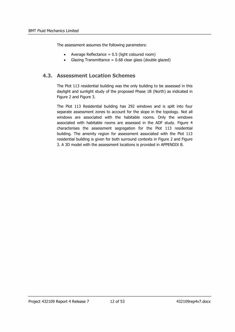
The assessment assumes the following parameters:
Average Reflectance = 0.5 (light coloured room)
Glazing Transmittance = 0.68 clear glass (double glazed)
4.3. Assessment Location Schemes
The Plot 113 residential building was the only building to be assessed in this
daylight and sunlight study of the proposed Phase 1B (North) as indicated in
Figure 2 and Figure 3.
The Plot 113 Residential building has 292 windows and is split into four
separate assessment zones to account for the slope in the topology. Not all
windows are associated with the habitable rooms. Only the windows
associated with habitable rooms are assessed in the ADF study. Figure 4
characterises the assessment segregation for the Plot 113 residential
building. The amenity region for assessment associated with the Plot 113
residential building is given for both surround contexts in Figure 2 and Figure
3. A 3D model with the assessment locations is provided in APPENDIX B.
BMT Fluid Mechanics Limited
Project 432109 Report 4 Release 7 13 of 53 432109rep4v7.docx
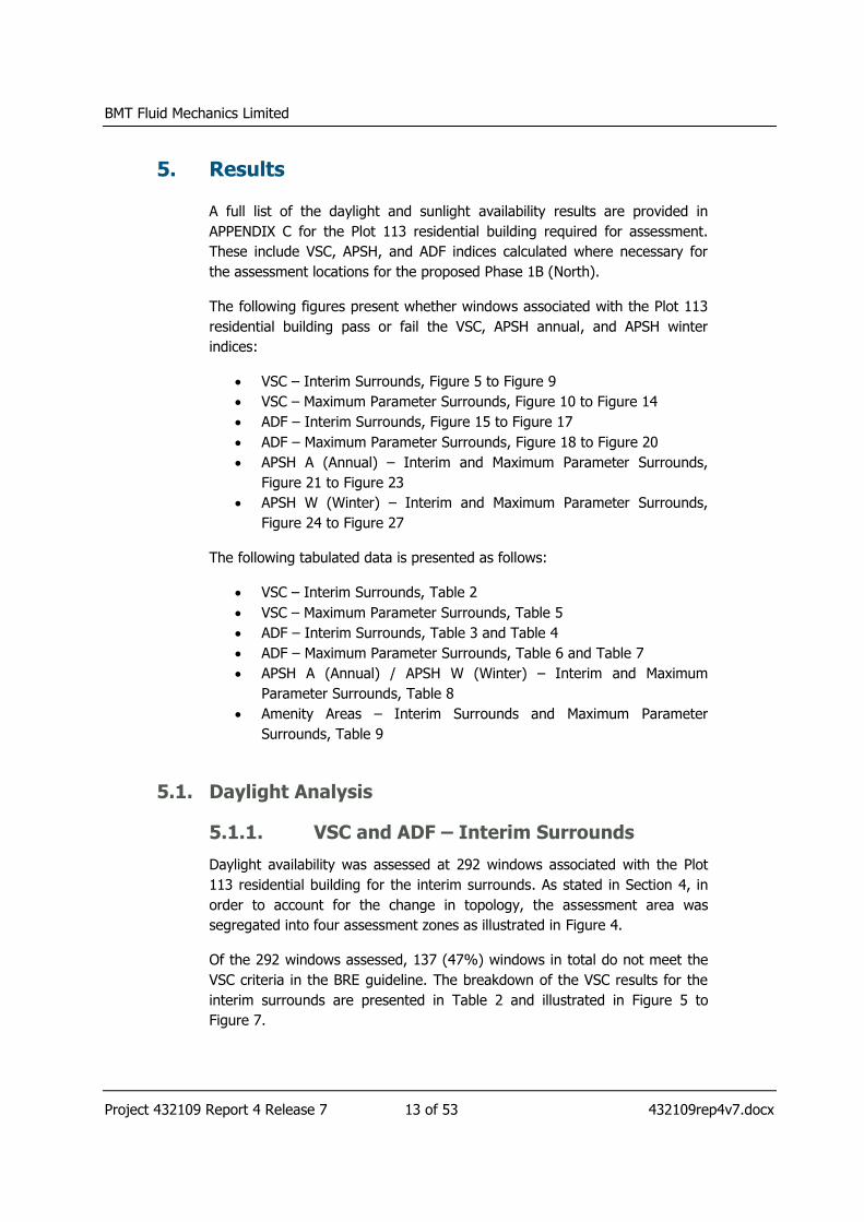
5. Results
A full list of the daylight and sunlight availability results are provided in
APPENDIX C for the Plot 113 residential building required for assessment.
These include VSC, APSH, and ADF indices calculated where necessary for
the assessment locations for the proposed Phase 1B (North).
The following figures present whether windows associated with the Plot 113
residential building pass or fail the VSC, APSH annual, and APSH winter
indices:
VSC – Interim Surrounds, Figure 5 to Figure 9
VSC – Maximum Parameter Surrounds, Figure 10 to Figure 14
ADF – Interim Surrounds, Figure 15 to Figure 17
ADF – Maximum Parameter Surrounds, Figure 18 to Figure 20
APSH A (Annual) – Interim and Maximum Parameter Surrounds,
Figure 21 to Figure 23
APSH W (Winter) – Interim and Maximum Parameter Surrounds,
Figure 24 to Figure 27
The following tabulated data is presented as follows:
VSC – Interim Surrounds, Table 2
VSC – Maximum Parameter Surrounds, Table 5
ADF – Interim Surrounds, Table 3 and Table 4
ADF – Maximum Parameter Surrounds, Table 6 and Table 7
APSH A (Annual) / APSH W (Winter) – Interim and Maximum
Parameter Surrounds, Table 8
Amenity Areas – Interim Surrounds and Maximum Parameter
Surrounds, Table 9
5.1. Daylight Analysis
5.1.1. VSC and ADF – Interim Surrounds
Daylight availability was assessed at 292 windows associated with the Plot
113 residential building for the interim surrounds. As stated in Section 4, in
order to account for the change in topology, the assessment area was
segregated into four assessment zones as illustrated in Figure 4.
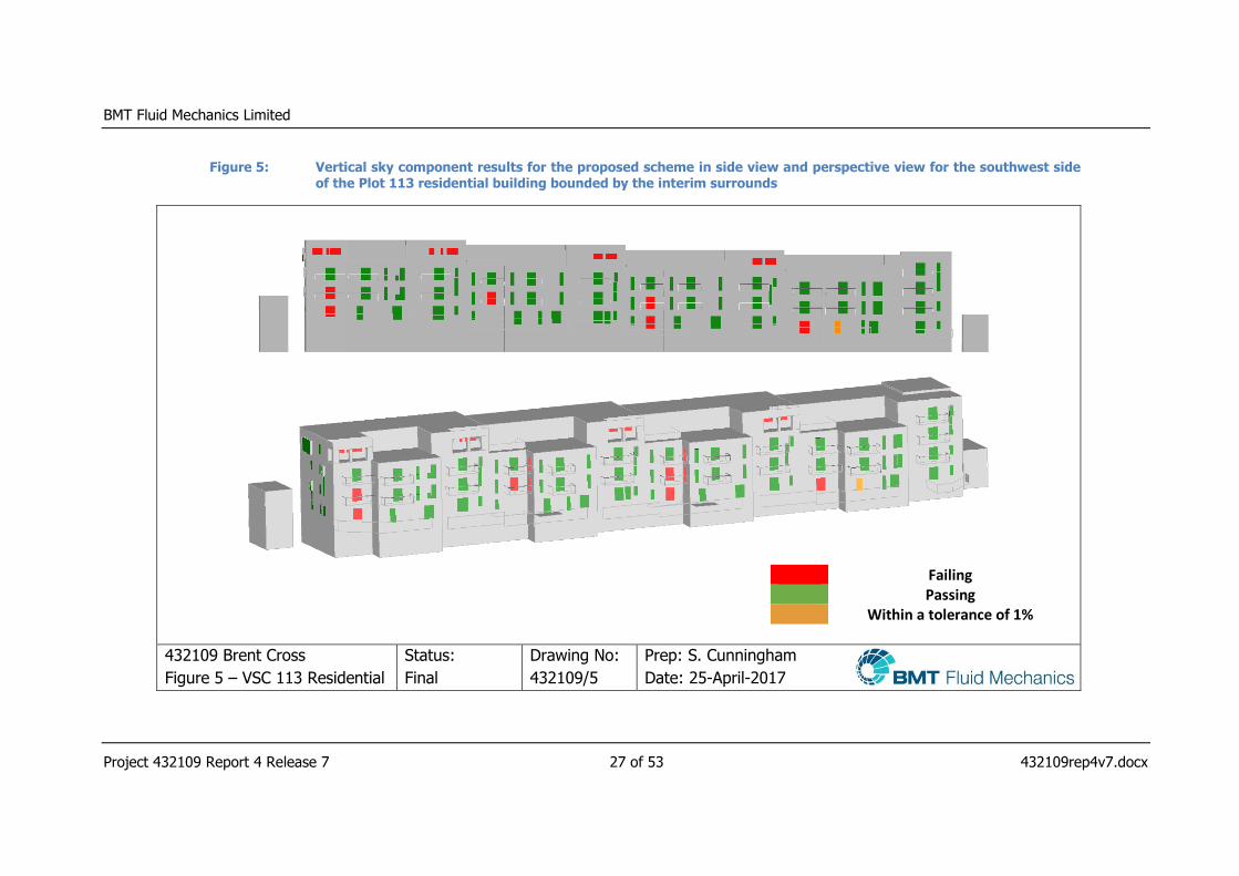
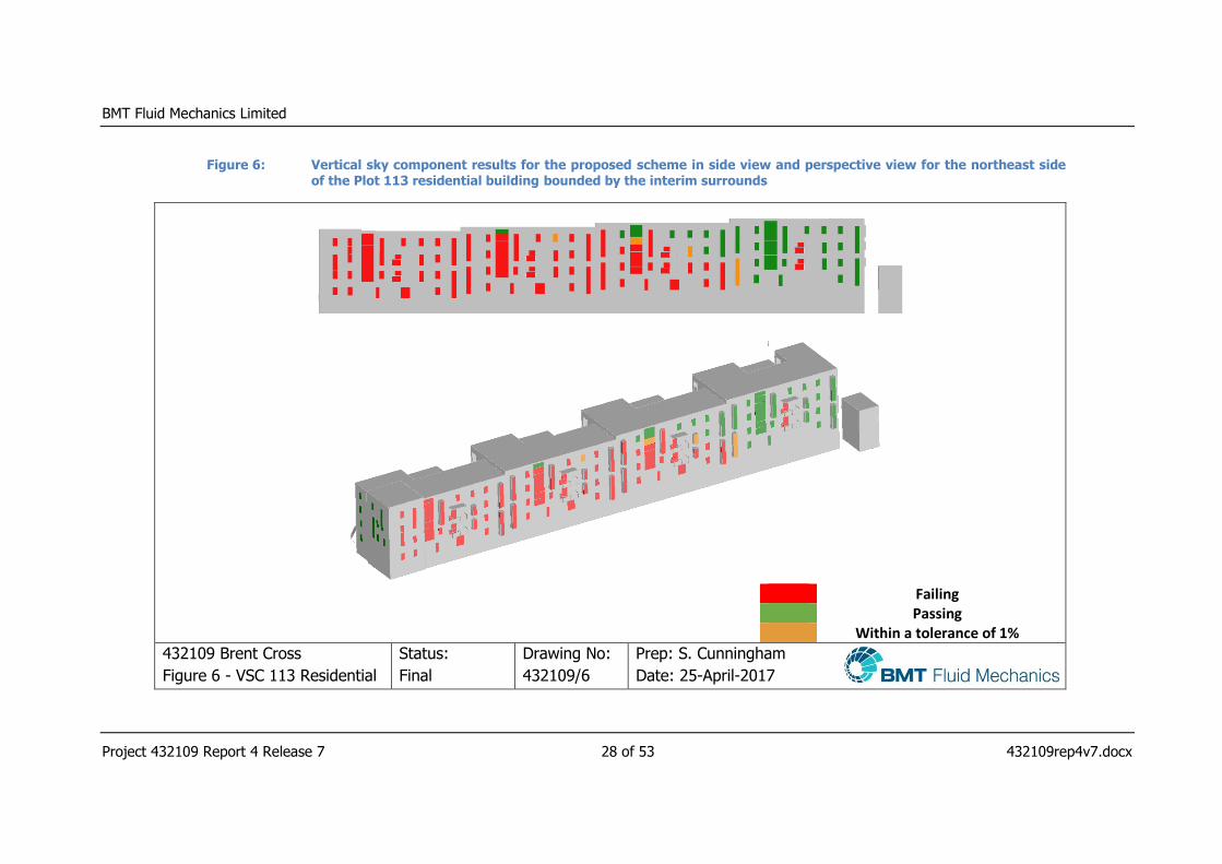
Of the 292 windows assessed, 137 (47%) windows in total do not meet the
VSC criteria in the BRE guideline. The breakdown of the VSC results for the
interim surrounds are presented in Table 2 and illustrated in Figure 5 to
Figure 7.

BMT Fluid Mechanics Limited
Project 432109 Report 4 Release 7 14 of 53 432109rep4v7.docx
Table 2: Windows which do not meet the VSC criteria for the Plot 113 residential building in the context of the interim surrounds
Assessment Zone
Interim Surrounds
Windows
obstructed on the
Eastern side
Windows
obstructed on the
Western side
Plot 113 Resi building 1 7 12
Plot 113 Resi building 2 30 3
Plot 113 Resi building 3 38 4
Plot 113 Resi building 4 41 2
On the eastern side of the residential plot, 116 windows are obstructed
primarily due to the massing of, and close proximity to the Brent Cross
shopping complex. Examples of this obstruction are shown in Figure 8. On
the western side of the residential plot, 21 windows are obstructed due to
the design of the Plot 113 residential building and other existing surrounding
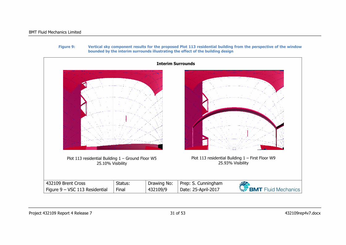
buildings. Examples of these obstructions are shown in Figure 9. The VSC
calculation is a preliminary calculation in order to assess whether further
investigation is required. For windows which do not meet the criteria, a more
in depth ADF analysis was carried out.
At the window locations where the VSC did not achieve the recommended
levels, an ADF (internal daylight assessment) was undertaken to demonstrate
whether the available daylight is sufficient for the room’s intended use. For
the Plot 113 residential building, multiple window locations in some instances
serve a single room. 73 rooms are associated with the 137 windows required
for further assessment within the Plot 113 residential building in the context
of the interim surrounds. The breakdown of the ADF results is given in Table
3 for the Plot 113 residential building in the context of the interim surrounds.
BMT Fluid Mechanics Limited
Project 432109 Report 4 Release 7 15 of 53 432109rep4v7.docx
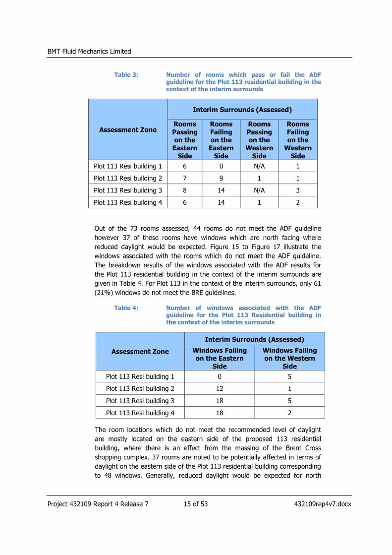
Table 3: Number of rooms which pass or fail the ADF guideline for the Plot 113 residential building in the context of the interim surrounds
Assessment Zone
Interim Surrounds (Assessed)
Rooms
Passing on the
Eastern
Side
Rooms
Failing on the
Eastern
Side
Rooms
Passing on the
Western
Side
Rooms
Failing on the
Western
Side
Plot 113 Resi building 1 6 0 N/A 1
Plot 113 Resi building 2 7 9 1 1
Plot 113 Resi building 3 8 14 N/A 3
Plot 113 Resi building 4 6 14 1 2
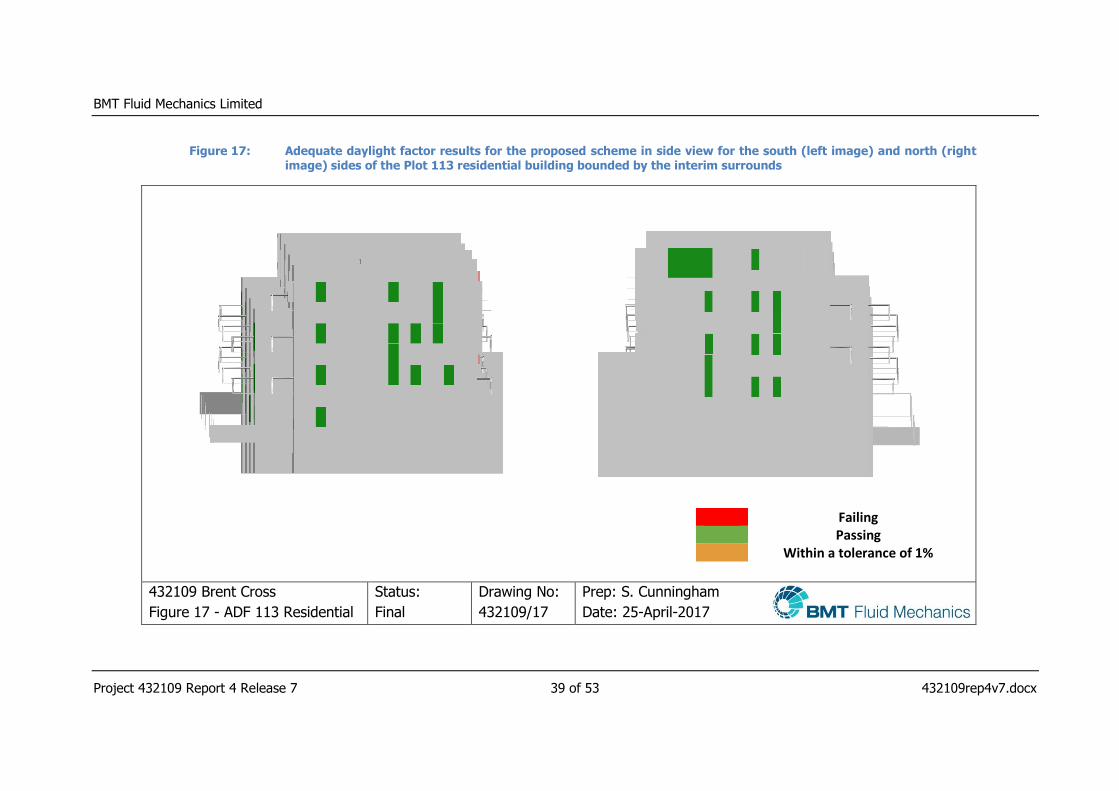
Out of the 73 rooms assessed, 44 rooms do not meet the ADF guideline
however 37 of these rooms have windows which are north facing where
reduced daylight would be expected. Figure 15 to Figure 17 illustrate the
windows associated with the rooms which do not meet the ADF guideline.
The breakdown results of the windows associated with the ADF results for
the Plot 113 residential building in the context of the interim surrounds are
given in Table 4. For Plot 113 in the context of the interim surrounds, only 61
(21%) windows do not meet the BRE guidelines.
Table 4: Number of windows associated with the ADF guideline for the Plot 113 Residential building in the context of the interim surrounds
Assessment Zone
Interim Surrounds (Assessed)
Windows Failing on the Eastern
Side
Windows Failing on the Western
Side
Plot 113 Resi building 1 0 5
Plot 113 Resi building 2 12 1
Plot 113 Resi building 3 18 5
Plot 113 Resi building 4 18 2
The room locations which do not meet the recommended level of daylight
are mostly located on the eastern side of the proposed 113 residential
building, where there is an effect from the massing of the Brent Cross
shopping complex. 37 rooms are noted to be potentially affected in terms of
daylight on the eastern side of the Plot 113 residential building corresponding
to 48 windows. Generally, reduced daylight would be expected for north
BMT Fluid Mechanics Limited
Project 432109 Report 4 Release 7 16 of 53 432109rep4v7.docx
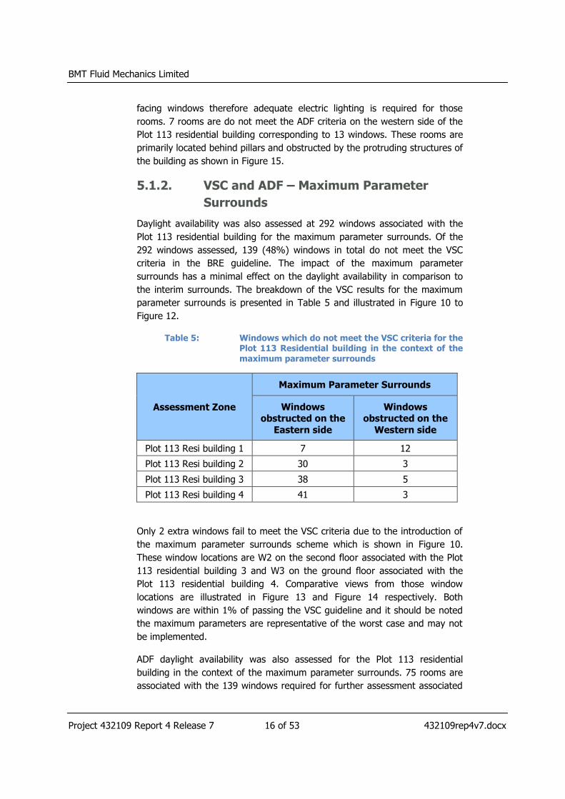
facing windows therefore adequate electric lighting is required for those
rooms. 7 rooms are do not meet the ADF criteria on the western side of the
Plot 113 residential building corresponding to 13 windows. These rooms are
primarily located behind pillars and obstructed by the protruding structures of
the building as shown in Figure 15.
5.1.2. VSC and ADF – Maximum Parameter
Surrounds
Daylight availability was also assessed at 292 windows associated with the
Plot 113 residential building for the maximum parameter surrounds. Of the
292 windows assessed, 139 (48%) windows in total do not meet the VSC
criteria in the BRE guideline. The impact of the maximum parameter
surrounds has a minimal effect on the daylight availability in comparison to
the interim surrounds. The breakdown of the VSC results for the maximum
parameter surrounds is presented in Table 5 and illustrated in Figure 10 to
Figure 12.
Table 5: Windows which do not meet the VSC criteria for the Plot 113 Residential building in the context of the maximum parameter surrounds
Assessment Zone
Maximum Parameter Surrounds
Windows obstructed on the
Eastern side
Windows obstructed on the
Western side
Plot 113 Resi building 1 7 12
Plot 113 Resi building 2 30 3
Plot 113 Resi building 3 38 5
Plot 113 Resi building 4 41 3
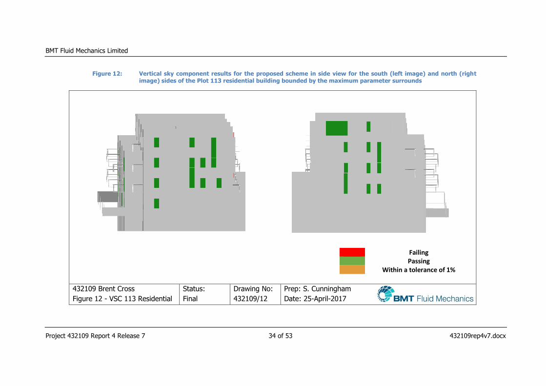
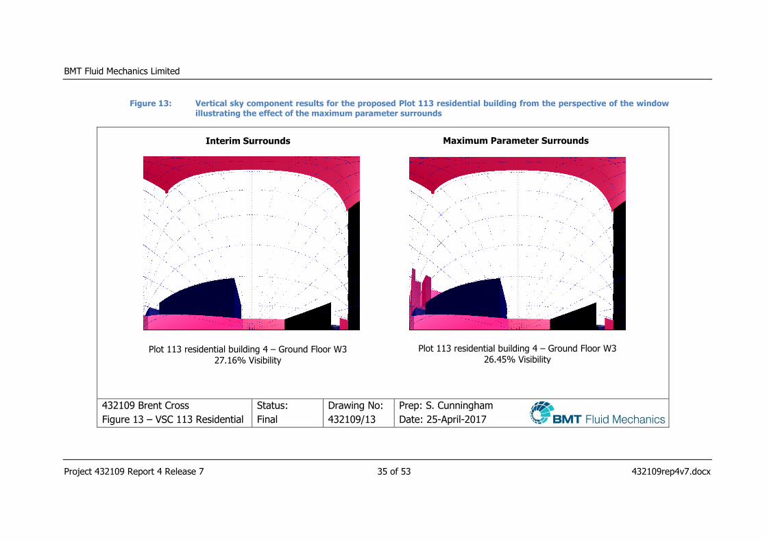
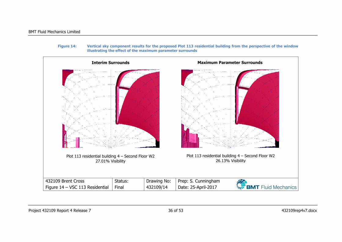
Only 2 extra windows fail to meet the VSC criteria due to the introduction of
the maximum parameter surrounds scheme which is shown in Figure 10.
These window locations are W2 on the second floor associated with the Plot
113 residential building 3 and W3 on the ground floor associated with the
Plot 113 residential building 4. Comparative views from those window
locations are illustrated in Figure 13 and Figure 14 respectively. Both
windows are within 1% of passing the VSC guideline and it should be noted
the maximum parameters are representative of the worst case and may not
be implemented.
ADF daylight availability was also assessed for the Plot 113 residential
building in the context of the maximum parameter surrounds. 75 rooms are
associated with the 139 windows required for further assessment associated

BMT Fluid Mechanics Limited
Project 432109 Report 4 Release 7 17 of 53 432109rep4v7.docx
with the Plot 113 residential in the context of the maximum parameter
surrounds. The breakdown of the ADF results is given in Table 6.
Table 6: Number of rooms which pass or fail the ADF guideline for the Plot 113 Residential building in the context of the maximum parameter surrounds
Assessment Zone
Maximum Parameter Surrounds
(Assessed)
Rooms
Passing on the
Eastern Side
Rooms
Failing on the
Eastern Side
Rooms
Passing on the
Western Side
Rooms
Failing on the
Western Side
Plot 113 Resi building 1 6 0 N/A 1
Plot 113 Resi building 2 7 9 1 1
Plot 113 Resi building 3 8 15 N/A 3
Plot 113 Resi building 4 6 14 1 3
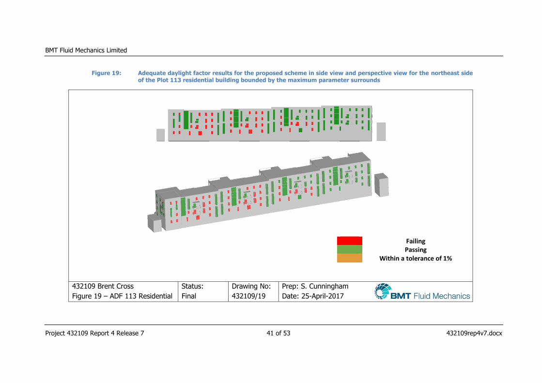
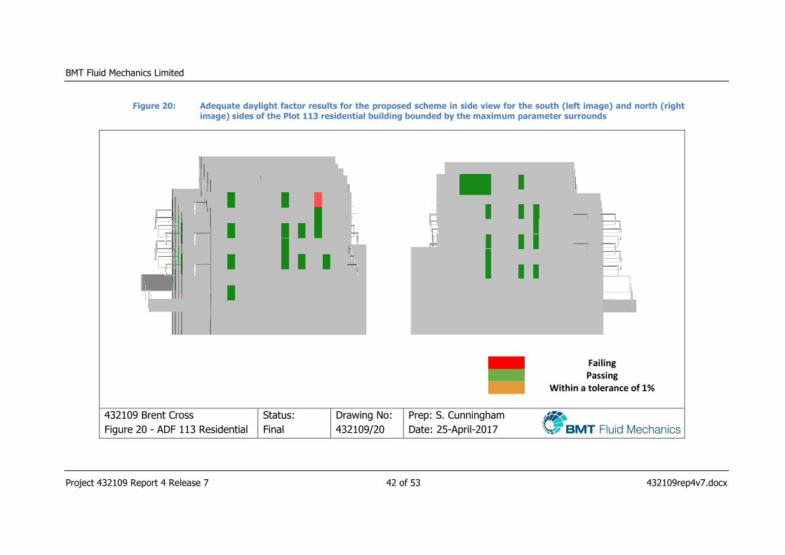
Out of the 75 rooms assessed, 46 rooms do not meet the ADF guideline
however 38 of these rooms have windows which are north facing where
reduced daylight would be expected. Figure 18 to Figure 20 illustrate the
windows associated with the rooms which do not meet the ADF guideline.
The breakdown results of the windows associated with the ADF results for
the Plot 113 residential building in the context of the maximum parameter
surrounds are given in Table 7. For Plot 113 in the context of the maximum
parameter surrounds, only 67 (23%) windows do not meet the BRE criteria.
Table 7: Number of windows associated with the ADF guideline for the Plot 113 Residential building in the context of the maximum parameter surrounds
Assessment Zone
Maximum Parameter Surrounds
(Assessed)
Windows Failing
on the Eastern Side
Windows Failing
on the Western Side
Plot 113 Resi building 1 0 5
Plot 113 Resi building 2 12 1
Plot 113 Resi building 3 19 5
Plot 113 Resi building 4 19 6
As stated in the results for the VSC index, the effect of the maximum
parameter surrounds has a minimal effect on the daylight availability. Only
BMT Fluid Mechanics Limited
Project 432109 Report 4 Release 7 18 of 53 432109rep4v7.docx
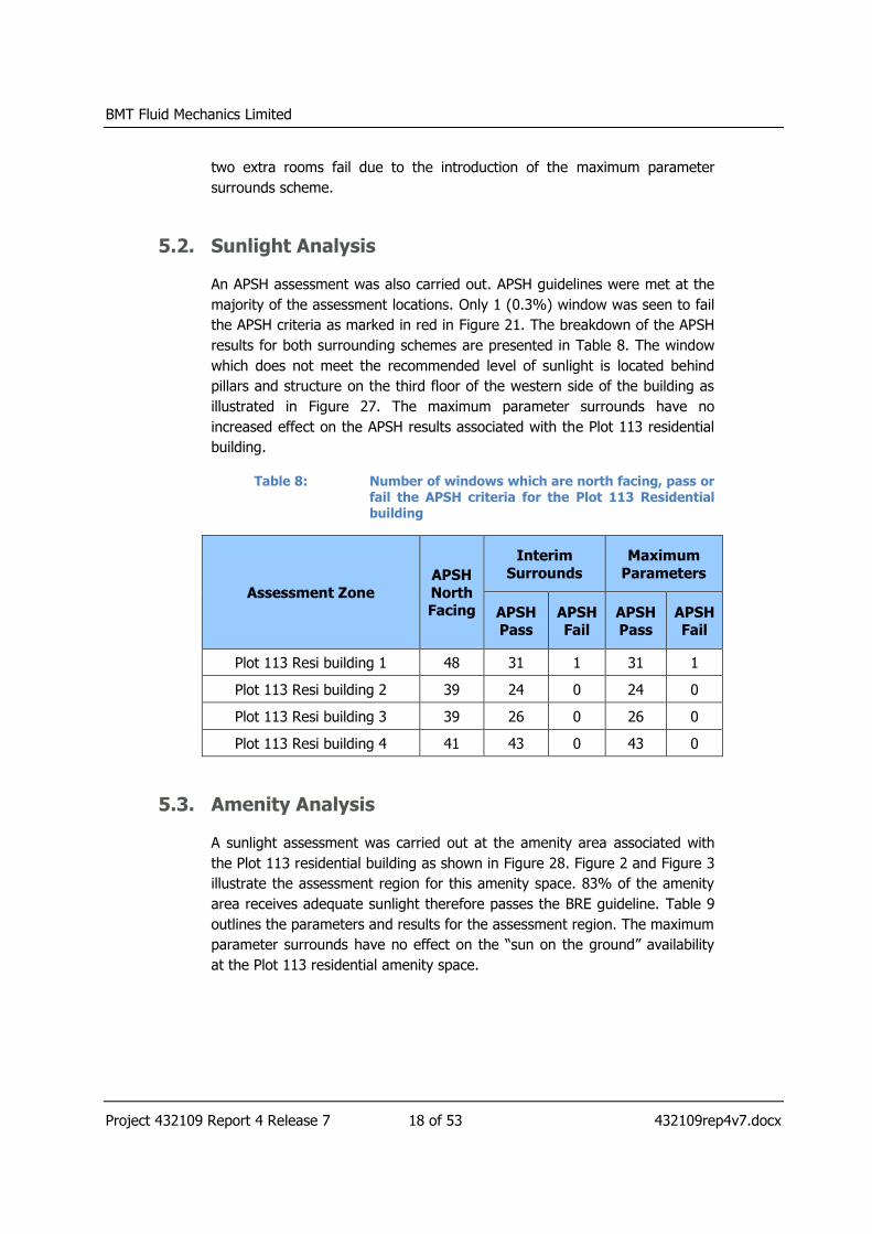
two extra rooms fail due to the introduction of the maximum parameter
surrounds scheme.
5.2. Sunlight Analysis
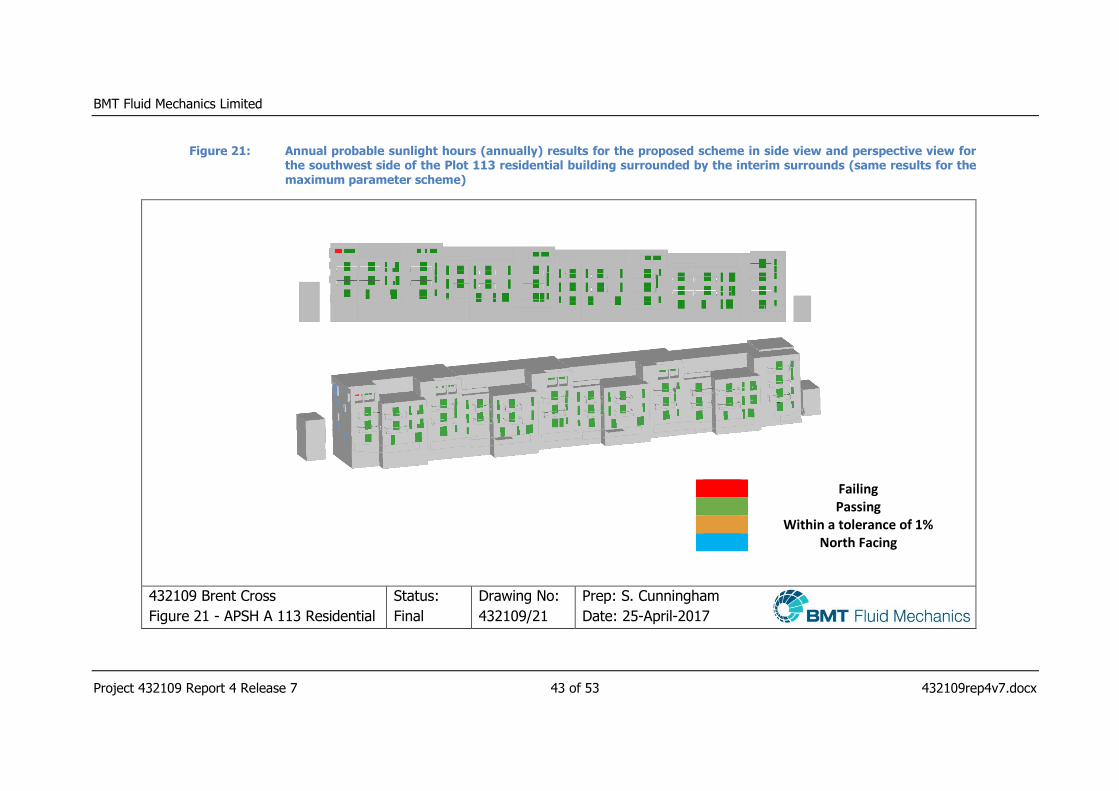
An APSH assessment was also carried out. APSH guidelines were met at the
majority of the assessment locations. Only 1 (0.3%) window was seen to fail
the APSH criteria as marked in red in Figure 21. The breakdown of the APSH
results for both surrounding schemes are presented in Table 8. The window
which does not meet the recommended level of sunlight is located behind
pillars and structure on the third floor of the western side of the building as
illustrated in Figure 27. The maximum parameter surrounds have no
increased effect on the APSH results associated with the Plot 113 residential
building.
Table 8: Number of windows which are north facing, pass or fail the APSH criteria for the Plot 113 Residential building
Assessment Zone
APSH
North Facing
Interim
Surrounds
Maximum
Parameters
APSH Pass
APSH Fail
APSH Pass
APSH Fail
Plot 113 Resi building 1 48 31 1 31 1
Plot 113 Resi building 2 39 24 0 24 0
Plot 113 Resi building 3 39 26 0 26 0
Plot 113 Resi building 4 41 43 0 43 0
5.3. Amenity Analysis
A sunlight assessment was carried out at the amenity area associated with
the Plot 113 residential building as shown in Figure 28. Figure 2 and Figure 3
illustrate the assessment region for this amenity space. 83% of the amenity
area receives adequate sunlight therefore passes the BRE guideline. Table 9
outlines the parameters and results for the assessment region. The maximum
parameter surrounds have no effect on the “sun on the ground” availability
at the Plot 113 residential amenity space.
BMT Fluid Mechanics Limited
Project 432109 Report 4 Release 7 19 of 53 432109rep4v7.docx
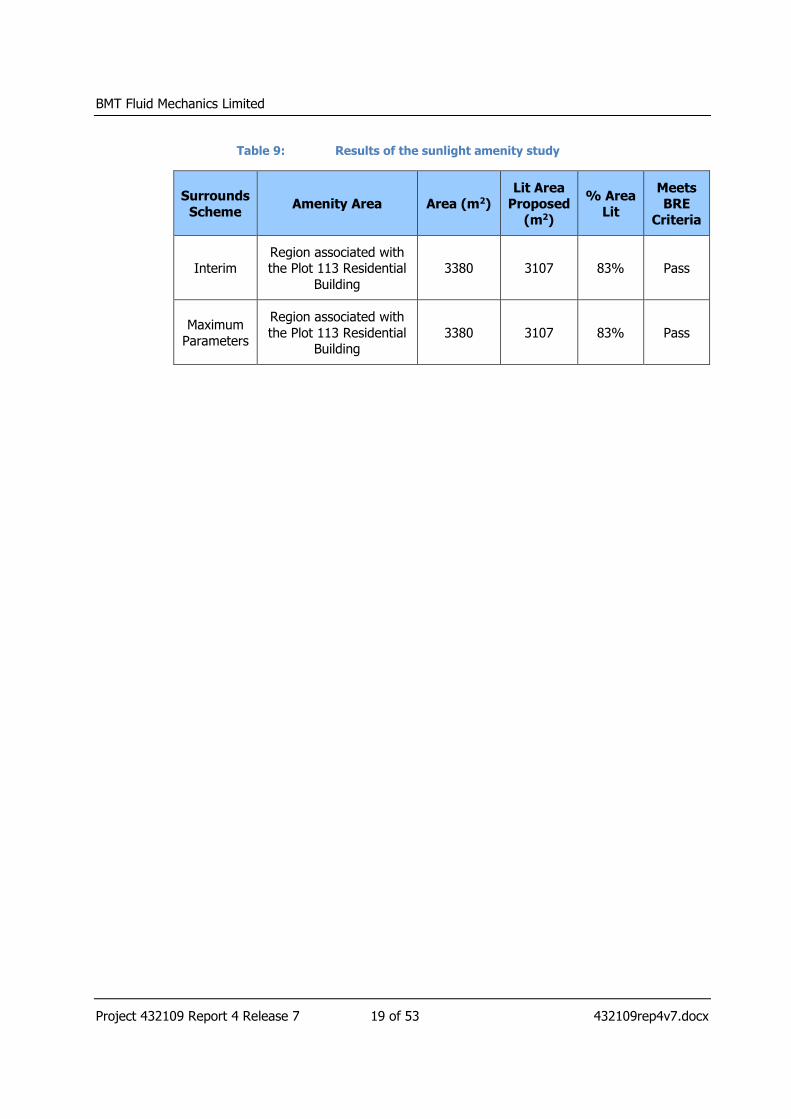
Table 9: Results of the sunlight amenity study
Surrounds
Scheme Amenity Area Area (m2)
Lit Area Proposed
(m2)
% Area
Lit
Meets BRE
Criteria
Interim Region associated with the Plot 113 Residential
Building
3380 3107 83% Pass
Maximum
Parameters
Region associated with
the Plot 113 Residential Building
3380 3107 83% Pass
BMT Fluid Mechanics Limited
Project 432109 Report 4 Release 7 20 of 53 432109rep4v7.docx
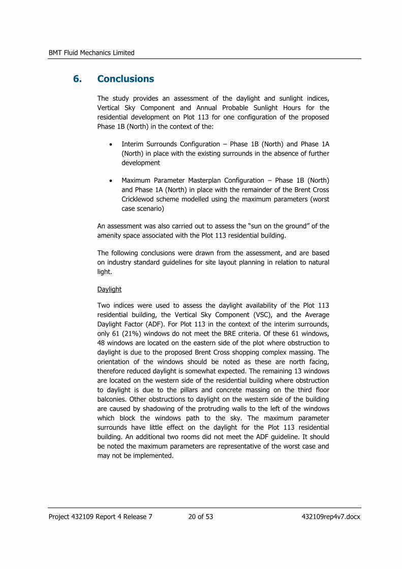
6. Conclusions
The study provides an assessment of the daylight and sunlight indices,
Vertical Sky Component and Annual Probable Sunlight Hours for the
residential development on Plot 113 for one configuration of the proposed
Phase 1B (North) in the context of the:
Interim Surrounds Configuration – Phase 1B (North) and Phase 1A
(North) in place with the existing surrounds in the absence of further
development
Maximum Parameter Masterplan Configuration – Phase 1B (North)
and Phase 1A (North) in place with the remainder of the Brent Cross
Cricklewod scheme modelled using the maximum parameters (worst
case scenario)
An assessment was also carried out to assess the “sun on the ground” of the
amenity space associated with the Plot 113 residential building.
The following conclusions were drawn from the assessment, and are based
on industry standard guidelines for site layout planning in relation to natural
light.
Daylight
Two indices were used to assess the daylight availability of the Plot 113
residential building, the Vertical Sky Component (VSC), and the Average
Daylight Factor (ADF). For Plot 113 in the context of the interim surrounds,
only 61 (21%) windows do not meet the BRE criteria. Of these 61 windows,
48 windows are located on the eastern side of the plot where obstruction to
daylight is due to the proposed Brent Cross shopping complex massing. The
orientation of the windows should be noted as these are north facing,
therefore reduced daylight is somewhat expected. The remaining 13 windows
are located on the western side of the residential building where obstruction
to daylight is due to the pillars and concrete massing on the third floor
balconies. Other obstructions to daylight on the western side of the building
are caused by shadowing of the protruding walls to the left of the windows
which block the windows path to the sky. The maximum parameter
surrounds have little effect on the daylight for the Plot 113 residential
building. An additional two rooms did not meet the ADF guideline. It should
be noted the maximum parameters are representative of the worst case and
may not be implemented.
BMT Fluid Mechanics Limited
Project 432109 Report 4 Release 7 21 of 53 432109rep4v7.docx
Sunlight
The availability of sunlight to buildings was assessed on the basis of Annual
Probable Sunlight Hours (APSH).
APSH guidelines were met at the vast majority of assessment locations
associated with the Plot 113 residential building. Only 1 window was seen to
fall short of the APSH criteria. The window which does not meet the
recommended level of sunlight is located behind pillars and structure on the
third floor of the western side of the building.
The maximum parameter surrounds provide no effect on the sunlight
associated with the Plot 113 residential building.
The amenity area assessed as part of Plot 113 receives 83% of sun on the
ground and therefore passes the BRE guideline for both the interim
surrounds and maximum parameter surrounds.

BMT Fluid Mechanics Limited
Project 432109 Report 4 Release 7 22 of 53 432109rep4v7.docx
7. References
[1] Building Research Establishment Report, “Site Layout Planning for
Daylight and Sunlight: A Guide to Good Practice”, P. Littlefair, Second
Edition, 2011.
[2] BS 8206-2:2008, “Lighting for buildings – Part 2: Code of practice for
daylighting.”, 2008.
[3] MBS Waldram Tools, Daylight / Sunlight Studies & Rights of Light
Assessment within AutoCAD, http://surveymbs.com/our-
software/mbs-waldram-tools, 2016.

BMT Fluid Mechanics Limited
Project 432109 Report 4 Release 7 23 of 53 432109rep4v7.docx
Figure 1: Site location of proposed Brent Cross Phase 1B (North)
432109 Brent Cross
Figure 1 - Site Location
Status:
Final
Drawing No:
432109/1
Prep: S. Cunningham
Date: 25-April-2017
BMT Fluid Mechanics Limited
Project 432109 Report 4 Release 7 24 of 53 432109rep4v7.docx
Figure 2: Proposed Phase 1B (North) in the context of the interim surrounding buildings
Phase 1B (North)
Interim Surrounds
Plot 113 Building for Assessment
Plot 113 Amenity Area for Assessment
Realigned River Brent
Major Roads
432109 Brent Cross
Figure 2 - Proposed Complex
Status:
Final
Drawing No:
432109/2
Prep: S. Cunningham
Date: 25-April-2017

BMT Fluid Mechanics Limited
Project 432109 Report 4 Release 7 25 of 53 432109rep4v7.docx
Figure 3: Proposed Phase 1B (North) in the context of the maximum parameter surrounding buildings
Phase 1B (North)
Interim Surrounds
Plot 113 Building for Assessment
Plot 113 Amenity Area for Assessment
Realigned River Brent
Maximum Parameter Surrounds
Major Roads
432109 Brent Cross
Figure 3 - Proposed Complex
Status:
Final
Drawing No:
432109/3
Prep: S. Cunningham
Date: 25-April-2017

BMT Fluid Mechanics Limited
Project 432109 Report 4 Release 7 26 of 53 432109rep4v7.docx
Figure 4: Plot 113 residential building assessment segregration
432109 Brent Cross
Figure 4 – 113 Residential Split
Status:
Final
Drawing No:
432109/4
Prep: S. Cunningham
Date: 25-April-2017
BMT Fluid Mechanics Limited
Project 432109 Report 4 Release 7 27 of 53 432109rep4v7.docx
Figure 5: Vertical sky component results for the proposed scheme in side view and perspective view for the southwest side of the Plot 113 residential building bounded by the interim surrounds
Failing Passing Within a tolerance of 1%
432109 Brent Cross
Figure 5 – VSC 113 Residential
Status:
Final
Drawing No:
432109/5
Prep: S. Cunningham
Date: 25-April-2017
BMT Fluid Mechanics Limited
Project 432109 Report 4 Release 7 28 of 53 432109rep4v7.docx
Figure 6: Vertical sky component results for the proposed scheme in side view and perspective view for the northeast side of the Plot 113 residential building bounded by the interim surrounds
Failing Passing Within a tolerance of 1%
432109 Brent Cross
Figure 6 - VSC 113 Residential
Status:
Final
Drawing No:
432109/6
Prep: S. Cunningham
Date: 25-April-2017

BMT Fluid Mechanics Limited
Project 432109 Report 4 Release 7 29 of 53 432109rep4v7.docx
Figure 7: Vertical sky component results for the proposed scheme in side view for the south (left image) and north (right image) sides of the Plot 113 residential building bounded by the interim surrounds
Failing Passing Within a tolerance of 1%
432109 Brent Cross
Figure 7 - VSC 113 Residential
Status:
Final
Drawing No:
432109/7
Prep: S. Cunningham
Date: 25-April-2017

BMT Fluid Mechanics Limited
Project 432109 Report 4 Release 7 30 of 53 432109rep4v7.docx
Figure 8: Vertical sky component results for the proposed Plot 113 residential building from the perspective of the window bounded by the interim surrounds illustrating the effect of the Brent Cross shopping complex
432109 Brent Cross
Figure 8 – VSC 113 Residential
Status:
Final
Drawing No:
432109/8
Prep: S. Cunningham
Date: 25-April-2017
Plot 113 residential Building 3 – Ground Floor W11
17.93% Visibility
Plot 113 residential Building 4 – First Floor W16
19.14% Visibility
Interim Surrounds
BMT Fluid Mechanics Limited
Project 432109 Report 4 Release 7 31 of 53 432109rep4v7.docx
Figure 9: Vertical sky component results for the proposed Plot 113 residential building from the perspective of the window bounded by the interim surrounds illustrating the effect of the building design
432109 Brent Cross
Figure 9 – VSC 113 Residential
Status:
Final
Drawing No:
432109/9
Prep: S. Cunningham
Date: 25-April-2017
Plot 113 residential Building 1 – Ground Floor W5
25.10% Visibility
Plot 113 residential Building 1 – First Floor W9
25.93% Visibility
Interim Surrounds

BMT Fluid Mechanics Limited
Project 432109 Report 4 Release 7 32 of 53 432109rep4v7.docx
Figure 10: Vertical sky component results for the proposed scheme in side view and perspective view for the southwest side of the Plot 113 residential building bounded by the maximum parameter surrounds
Failing Passing Within a tolerance of 1%
432109 Brent Cross
Figure 10 – VSC 113 Residential
Status:
Final
Drawing No:
432109/10
Prep: S. Cunningham
Date: 25-April-2017
Two Extra
windows do
not meet the
VSC guideline
due to the
maximum
parameter
surrounds

BMT Fluid Mechanics Limited
Project 432109 Report 4 Release 7 33 of 53 432109rep4v7.docx
Figure 11: Vertical sky component results for the proposed scheme in side view and perspective view for the northwest side of the Plot 113 residential building bounded by the maximum parameter surrounds
Failing Passing Within a tolerance of 1%
432109 Brent Cross
Figure 11 – VSC 113 Residential
Status:
Final
Drawing No:
432109/11
Prep: S. Cunningham
Date: 25-April-2017
BMT Fluid Mechanics Limited
Project 432109 Report 4 Release 7 34 of 53 432109rep4v7.docx
Figure 12: Vertical sky component results for the proposed scheme in side view for the south (left image) and north (right image) sides of the Plot 113 residential building bounded by the maximum parameter surrounds
Failing Passing Within a tolerance of 1%
432109 Brent Cross
Figure 12 - VSC 113 Residential
Status:
Final
Drawing No:
432109/12
Prep: S. Cunningham
Date: 25-April-2017
BMT Fluid Mechanics Limited
Project 432109 Report 4 Release 7 35 of 53 432109rep4v7.docx
Figure 13: Vertical sky component results for the proposed Plot 113 residential building from the perspective of the window illustrating the effect of the maximum parameter surrounds
432109 Brent Cross
Figure 13 – VSC 113 Residential
Status:
Final
Drawing No:
432109/13
Prep: S. Cunningham
Date: 25-April-2017
Plot 113 residential building 4 – Ground Floor W3
27.16% Visibility
Plot 113 residential building 4 – Ground Floor W3
26.45% Visibility
Interim Surrounds Maximum Parameter Surrounds
BMT Fluid Mechanics Limited
Project 432109 Report 4 Release 7 36 of 53 432109rep4v7.docx
Figure 14: Vertical sky component results for the proposed Plot 113 residential building from the perspective of the window illustrating the effect of the maximum parameter surrounds
432109 Brent Cross
Figure 14 – VSC 113 Residential
Status:
Final
Drawing No:
432109/14
Prep: S. Cunningham
Date: 25-April-2017
Plot 113 residential building 4 – Second Floor W2
27.01% Visibility
Plot 113 residential building 4 – Second Floor W2
26.13% Visibility
Interim Surrounds Maximum Parameter Surrounds

BMT Fluid Mechanics Limited
Project 432109 Report 4 Release 7 37 of 53 432109rep4v7.docx
Figure 15: Adequate daylight factor results for the proposed scheme in side view and perspective view for the southwest side of the Plot 113 residential building bounded by the interim surrounds
Failing Passing Within a tolerance of 1%
432109 Brent Cross
Figure 15 – ADF 113 Residential
Status:
Final
Drawing No:
432109/15
Prep: S. Cunningham
Date: 25-April-2017

BMT Fluid Mechanics Limited
Project 432109 Report 4 Release 7 38 of 53 432109rep4v7.docx
Figure 16: Adequate daylight factor results for the proposed scheme in side view and perspective view for the northeast side of the Plot 113 residential building bounded by the interim surrounds
Failing Passing Within a tolerance of 1%
432109 Brent Cross
Figure 16 – ADF 113 Residential
Status:
Final
Drawing No:
432109/16
Prep: S. Cunningham
Date: 25-April-2017
BMT Fluid Mechanics Limited
Project 432109 Report 4 Release 7 39 of 53 432109rep4v7.docx
Figure 17: Adequate daylight factor results for the proposed scheme in side view for the south (left image) and north (right image) sides of the Plot 113 residential building bounded by the interim surrounds
Failing Passing Within a tolerance of 1%
432109 Brent Cross
Figure 17 - ADF 113 Residential
Status:
Final
Drawing No:
432109/17
Prep: S. Cunningham
Date: 25-April-2017

BMT Fluid Mechanics Limited
Project 432109 Report 4 Release 7 40 of 53 432109rep4v7.docx
Figure 18: Adequate daylight factor results for the proposed scheme in side view and perspective view for the southwest side of the Plot 113 residential building bounded by the maximum parameter surrounds
Failing Passing Within a tolerance of 1%
432109 Brent Cross
Figure 18 – ADF 113 Residential
Status:
Final
Drawing No:
432109/18
Prep: S. Cunningham
Date: 25-April-2017
BMT Fluid Mechanics Limited
Project 432109 Report 4 Release 7 41 of 53 432109rep4v7.docx
Figure 19: Adequate daylight factor results for the proposed scheme in side view and perspective view for the northeast side of the Plot 113 residential building bounded by the maximum parameter surrounds
Failing Passing Within a tolerance of 1%
432109 Brent Cross
Figure 19 – ADF 113 Residential
Status:
Final
Drawing No:
432109/19
Prep: S. Cunningham
Date: 25-April-2017
BMT Fluid Mechanics Limited
Project 432109 Report 4 Release 7 42 of 53 432109rep4v7.docx
Figure 20: Adequate daylight factor results for the proposed scheme in side view for the south (left image) and north (right image) sides of the Plot 113 residential building bounded by the maximum parameter surrounds
Failing Passing Within a tolerance of 1%
432109 Brent Cross
Figure 20 - ADF 113 Residential
Status:
Final
Drawing No:
432109/20
Prep: S. Cunningham
Date: 25-April-2017
BMT Fluid Mechanics Limited
Project 432109 Report 4 Release 7 43 of 53 432109rep4v7.docx
Figure 21: Annual probable sunlight hours (annually) results for the proposed scheme in side view and perspective view for the southwest side of the Plot 113 residential building surrounded by the interim surrounds (same results for the maximum parameter scheme)
Failing Passing Within a tolerance of 1% North Facing
432109 Brent Cross
Figure 21 - APSH A 113 Residential
Status:
Final
Drawing No:
432109/21
Prep: S. Cunningham
Date: 25-April-2017

BMT Fluid Mechanics Limited
Project 432109 Report 4 Release 7 44 of 53 432109rep4v7.docx
Figure 22: Annual probable sunlight hours (annually) results for the proposed scheme in side view and perspective view for the northeast side of the Plot 113 residential building surrounded by the interim surrounds (same results for the maximum
Failing Passing Within a tolerance of 1% North Facing
432109 Brent Cross
Figure 22 - APSH A 113 Residential
Status:
Final
Drawing No:
432109/22
Prep: S. Cunningham
Date: 25-April-2017

BMT Fluid Mechanics Limited
Project 432109 Report 4 Release 7 45 of 53 432109rep4v7.docx
Figure 23: Annual probable sunlight hours (annually) results for the proposed scheme in side view for the south (left image) and north (right image) sides of the Plot 113 residential building surrounded by the interim surrounds (same results for the maximum parameter scheme)
Failing Passing Within a tolerance of 1% North Facing
432109 Brent Cross
Figure 23 - APSH A 113 Residential
Status:
Final
Drawing No:
432109/23
Prep: S. Cunningham
Date: 25-April-2017

BMT Fluid Mechanics Limited
Project 432109 Report 4 Release 7 46 of 53 432109rep4v7.docx
Figure 24: Annual probable sunlight hours (winter) results for the proposed scheme in side view and perspective view for the southwest side of the Plot 113 residential building surrounded by the interim surrounds (same results for the maximum parameter scheme)
Failing Passing Within a tolerance of 1% North Facing
432109 Brent Cross
Figure 24 - APSH W 113 Residential
Status:
Final
Drawing No:
432109/24
Prep: S. Cunningham
Date: 25-April-2017

BMT Fluid Mechanics Limited
Project 432109 Report 4 Release 7 47 of 53 432109rep4v7.docx
Figure 25: Annual probable sunlight hours (winter) results for the proposed scheme in side view and perspective view for the northeast side of the Plot 113 residential building surrounded by the interim surrounds (same results for the maximum parameter scheme)
Failing Passing Within a tolerance of 1% North Facing
432109 Brent Cross
Figure 25 - APSH W 113 Residential
Status:
Final
Drawing No:
432109/25
Prep: S. Cunningham
Date: 25-April-2017
BMT Fluid Mechanics Limited
Project 432109 Report 4 Release 7 48 of 53 432109rep4v7.docx
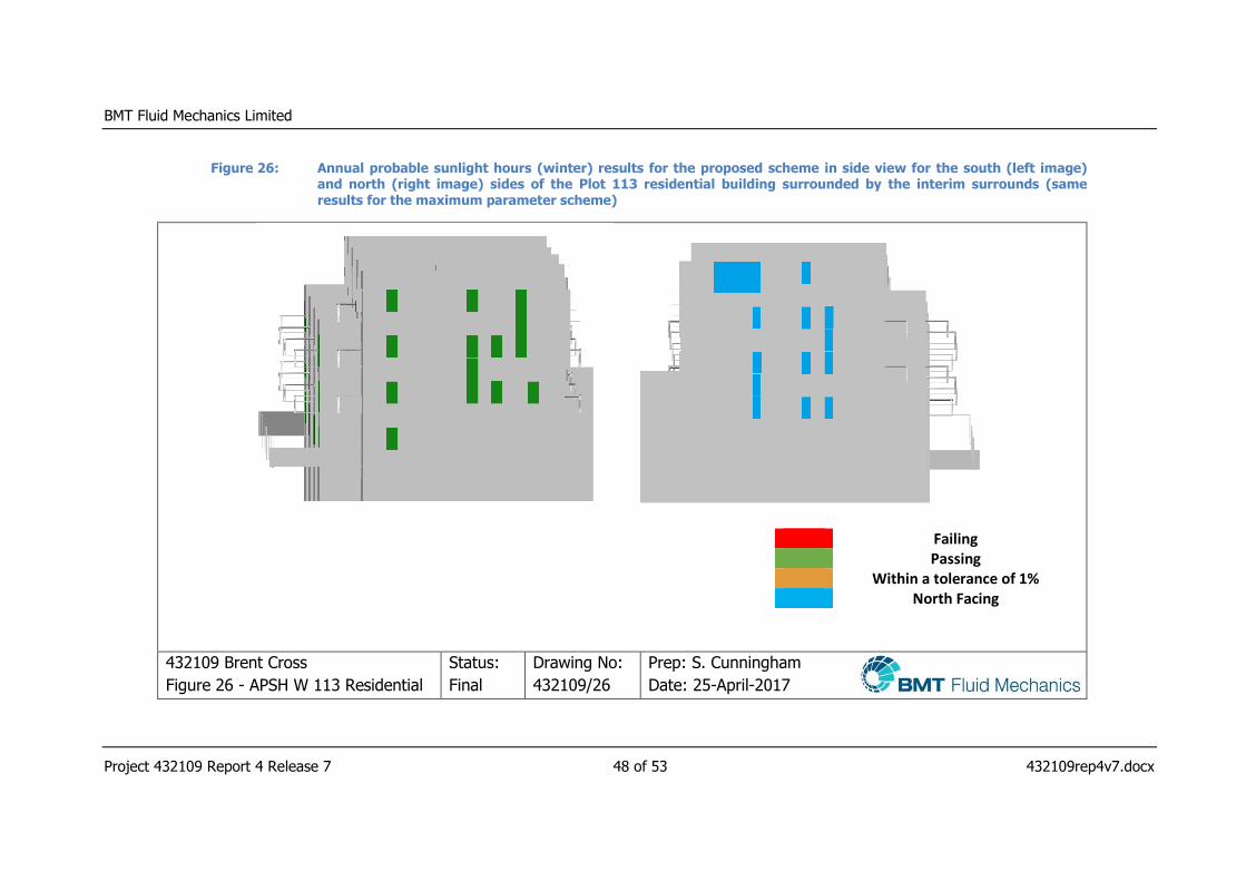
Figure 26: Annual probable sunlight hours (winter) results for the proposed scheme in side view for the south (left image) and north (right image) sides of the Plot 113 residential building surrounded by the interim surrounds (same results for the maximum parameter scheme)
Failing Passing Within a tolerance of 1% North Facing
432109 Brent Cross
Figure 26 - APSH W 113 Residential
Status:
Final
Drawing No:
432109/26
Prep: S. Cunningham
Date: 25-April-2017
BMT Fluid Mechanics Limited
Project 432109 Report 4 Release 7 49 of 53 432109rep4v7.docx
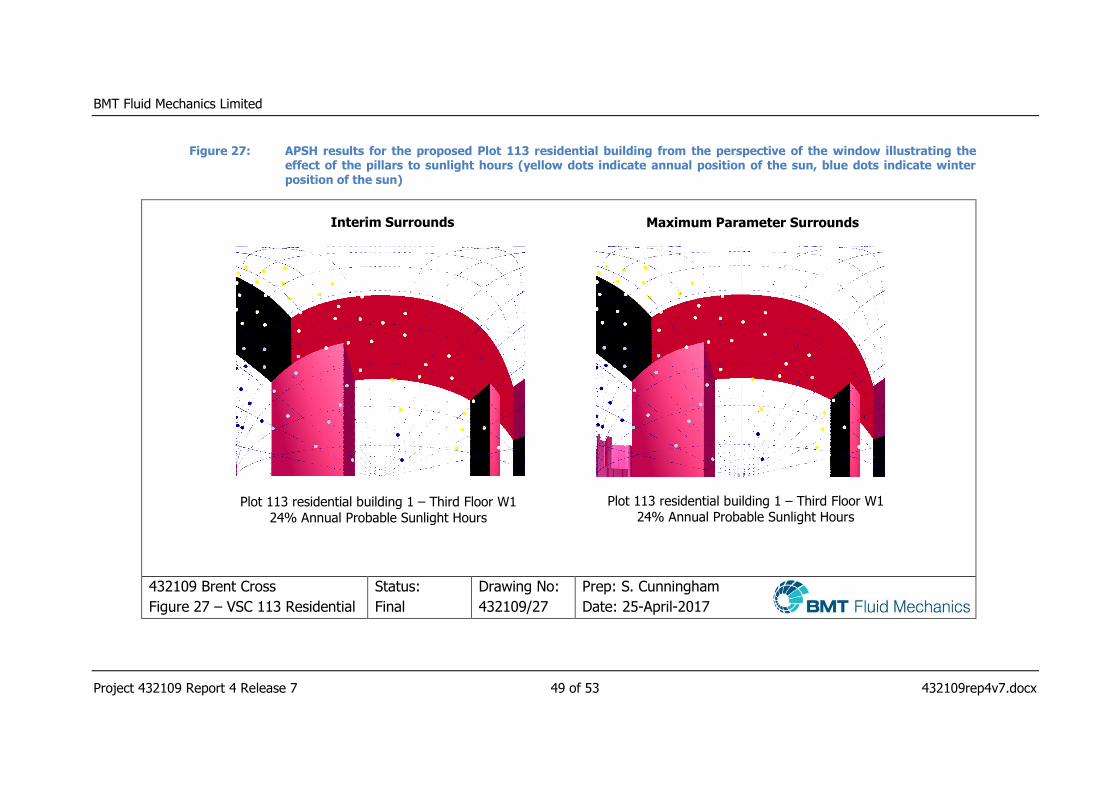
Figure 27: APSH results for the proposed Plot 113 residential building from the perspective of the window illustrating the effect of the pillars to sunlight hours (yellow dots indicate annual position of the sun, blue dots indicate winter position of the sun)
432109 Brent Cross
Figure 27 – VSC 113 Residential
Status:
Final
Drawing No:
432109/27
Prep: S. Cunningham
Date: 25-April-2017
Interim Surrounds Maximum Parameter Surrounds
Plot 113 residential building 1 – Third Floor W1 24% Annual Probable Sunlight Hours
Plot 113 residential building 1 – Third Floor W1 24% Annual Probable Sunlight Hours

BMT Fluid Mechanics Limited
Project 432109 Report 4 Release 7 50 of 53 432109rep4v7.docx
Figure 28: Top view of the amenity area to be assessed associated with Plot 113
432109 Brent Cross
Figure 28 - Plot 113 Amenity Space
Status:
Final
Drawing No:
432109/28
Prep: S. Cunningham
Date: 25-April-2017
Amenity Areas for
assessment as
part of the Plot
113
BMT Fluid Mechanics Limited
Project 432109 Report 4 Release 7 51 of 53 432109rep4v7.docx
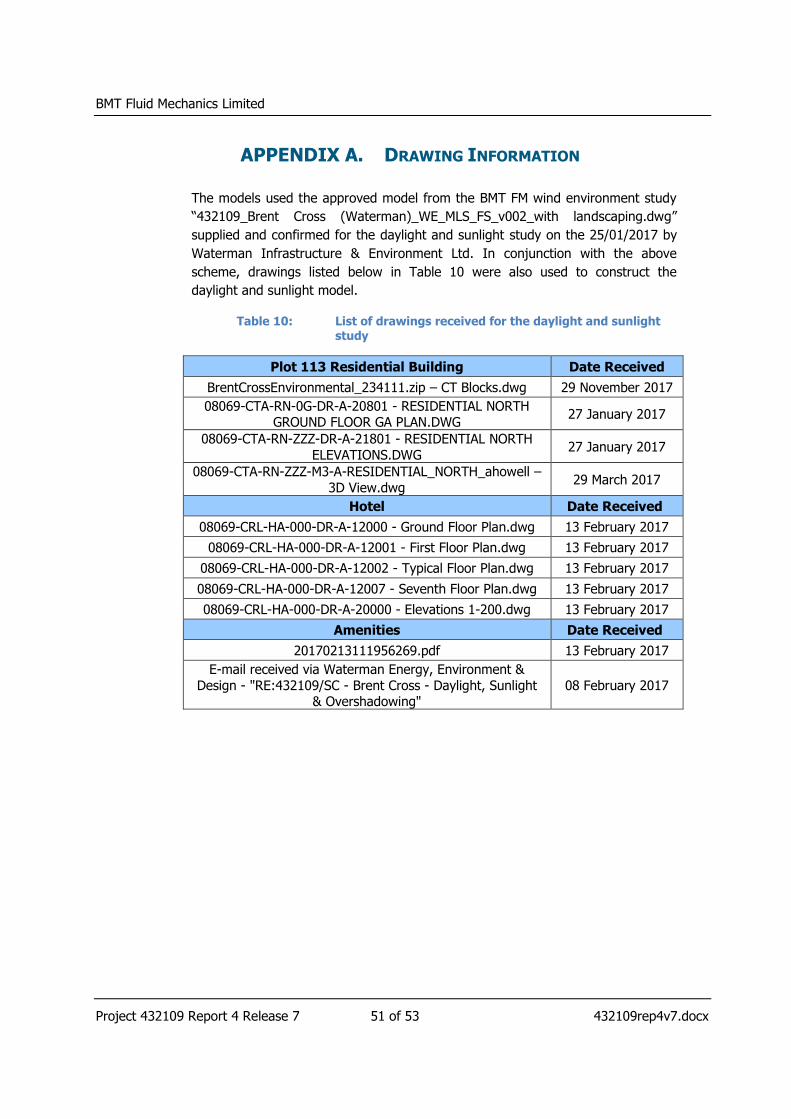
APPENDIX A. DRAWING INFORMATION
The models used the approved model from the BMT FM wind environment study
“432109_Brent Cross (Waterman)_WE_MLS_FS_v002_with landscaping.dwg”
supplied and confirmed for the daylight and sunlight study on the 25/01/2017 by
Waterman Infrastructure & Environment Ltd. In conjunction with the above
scheme, drawings listed below in Table 10 were also used to construct the
daylight and sunlight model.
Table 10: List of drawings received for the daylight and sunlight
study
Plot 113 Residential Building Date Received
BrentCrossEnvironmental_234111.zip – CT Blocks.dwg 29 November 2017
08069-CTA-RN-0G-DR-A-20801 - RESIDENTIAL NORTH GROUND FLOOR GA PLAN.DWG
27 January 2017
08069-CTA-RN-ZZZ-DR-A-21801 - RESIDENTIAL NORTH
ELEVATIONS.DWG 27 January 2017
08069-CTA-RN-ZZZ-M3-A-RESIDENTIAL_NORTH_ahowell –
3D View.dwg 29 March 2017
Hotel Date Received
08069-CRL-HA-000-DR-A-12000 - Ground Floor Plan.dwg 13 February 2017
08069-CRL-HA-000-DR-A-12001 - First Floor Plan.dwg 13 February 2017
08069-CRL-HA-000-DR-A-12002 - Typical Floor Plan.dwg 13 February 2017
08069-CRL-HA-000-DR-A-12007 - Seventh Floor Plan.dwg 13 February 2017
08069-CRL-HA-000-DR-A-20000 - Elevations 1-200.dwg 13 February 2017
Amenities Date Received
20170213111956269.pdf 13 February 2017
E-mail received via Waterman Energy, Environment &
Design - "RE:432109/SC - Brent Cross - Daylight, Sunlight & Overshadowing"
08 February 2017
BMT Fluid Mechanics Limited
Project 432109 Report 4 Release 7 52 of 53 432109rep4v7.docx
APPENDIX B. ASSESSMENT LOCATION SCHEMES
The location scheme for the windows and rooms are provided in the following
electronic appendixes:
See files:
“432109_Brent_Cross_Measurement_Scheme_Plot_113_Resi_Scheme_v002.dwg”
BMT Fluid Mechanics Limited
Project 432109 Report 4 Release 7 53 of 53 432109rep4v7.docx
APPENDIX C. TABULATED DATA
The results of the daylight and sunlight studies are provided in the following electronic
appendixes:
APSH:
“432109_Brent_Cross_113_Residential_Plot_APSH_Results_Existing_Surrounds_v2.xlsx”
“432109_Brent_Cross_113_Residential_Plot_APSH_Results_Maximum_Surrounds_v2.xlsx”
VSC:
“432109_Brent_Cross_113_Residential_Plot_VSC_Results_Existing_Surrounds_v2.xlsx”
“432109_Brent_Cross_113_Residential_Plot_VSC_Results_Maximum_Surrounds_v2.xlsx”
ADF:
“432109_Brent_Cross_113_Residential_Plot_ADF_Results_Existing_Surrounds_v2.xlsx”
“432109_Brent_Cross_113_Residential_Plot_ADF_Results_Maximum_Surrounds_v2.xlsx”


![Brent Cross Cricklewood Compulsory Purchase Order No. 2[1]](https://img.pdfslide.us/doc/110x75/55cf92cc550346f57b999e06/brent-cross-cricklewood-compulsory-purchase-order-no-21.jpg)

![Appendix 1 - Brent Cross South Procurement and Delivery Strategy[1]](https://img.pdfslide.us/doc/110x75/55cf967b550346d0338bc409/appendix-1-brent-cross-south-procurement-and-delivery-strategy1.jpg)


![Fpc 20150122 Part 1 Item09 Brent Cross[1]](https://img.pdfslide.us/doc/110x75/577cc0a21a28aba71190a6c2/fpc-20150122-part-1-item09-brent-cross1.jpg)

![Brent Cross Cricklewood South - Selection of Preferred Partner[1]](https://img.pdfslide.us/doc/110x75/55cf92a9550346f57b9876ec/brent-cross-cricklewood-south-selection-of-preferred-partner1.jpg)