Embed Size (px)
Citation preview

JAA No. A93-102017 .............................................Table of Contents - 1
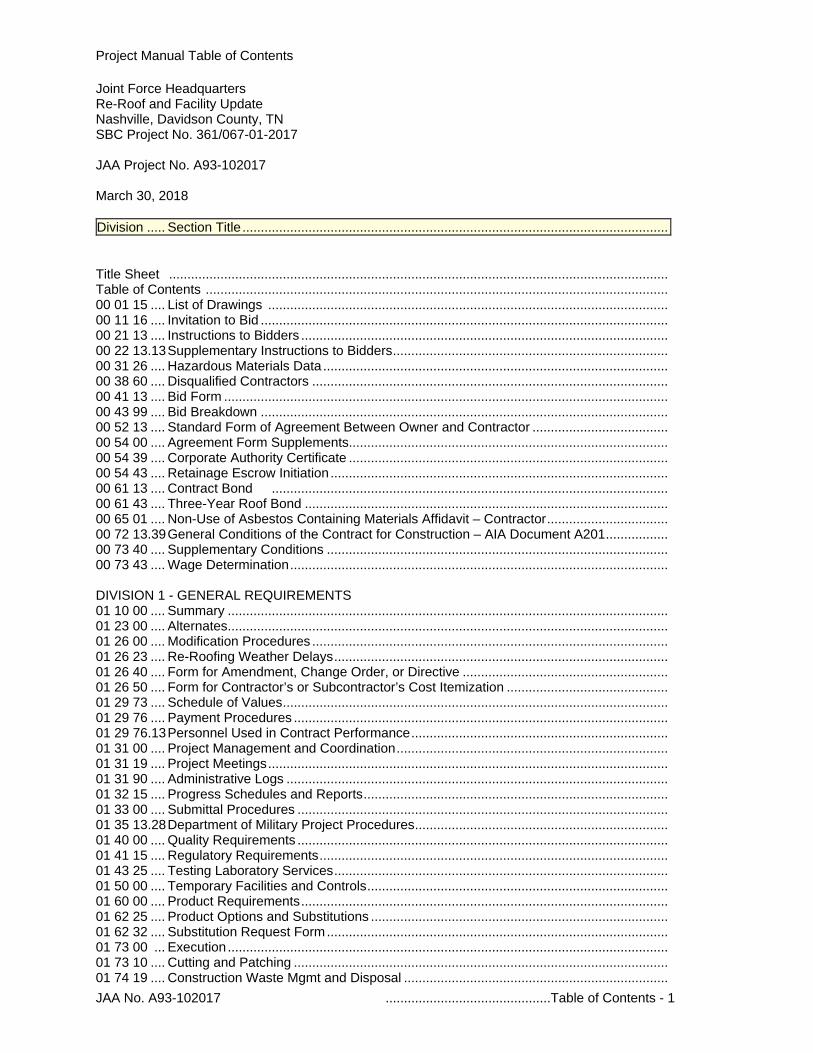
Project Manual Table of Contents
Joint Force Headquarters Re-Roof and Facility Update Nashville, Davidson County, TN SBC Project No. 361/067-01-2017 JAA Project No. A93-102017 March 30, 2018 Division ..... Section Title .................................................................................................................... Title Sheet ........................................................................................................................................ Table of Contents .............................................................................................................................. 00 01 15 .... List of Drawings ............................................................................................................. 00 11 16 .... Invitation to Bid ............................................................................................................... 00 21 13 .... Instructions to Bidders .................................................................................................... 00 22 13.13 Supplementary Instructions to Bidders ........................................................................... 00 31 26 .... Hazardous Materials Data .............................................................................................. 00 38 60 .... Disqualified Contractors ................................................................................................. 00 41 13 .... Bid Form ......................................................................................................................... 00 43 99 .... Bid Breakdown ............................................................................................................... 00 52 13 .... Standard Form of Agreement Between Owner and Contractor ..................................... 00 54 00 .... Agreement Form Supplements ....................................................................................... 00 54 39 .... Corporate Authority Certificate ....................................................................................... 00 54 43 .... Retainage Escrow Initiation ............................................................................................ 00 61 13 .... Contract Bond ............................................................................................................ 00 61 43 .... Three-Year Roof Bond ................................................................................................... 00 65 01 .... Non-Use of Asbestos Containing Materials Affidavit – Contractor ................................. 00 72 13.39 General Conditions of the Contract for Construction – AIA Document A201 ................. 00 73 40 .... Supplementary Conditions ............................................................................................. 00 73 43 .... Wage Determination ....................................................................................................... DIVISION 1 - GENERAL REQUIREMENTS 01 10 00 .... Summary ........................................................................................................................ 01 23 00 .... Alternates ........................................................................................................................ 01 26 00 .... Modification Procedures ................................................................................................. 01 26 23 .... Re-Roofing Weather Delays ........................................................................................... 01 26 40 .... Form for Amendment, Change Order, or Directive ........................................................ 01 26 50 .... Form for Contractor’s or Subcontractor’s Cost Itemization ............................................ 01 29 73 .... Schedule of Values ......................................................................................................... 01 29 76 .... Payment Procedures ...................................................................................................... 01 29 76.13 Personnel Used in Contract Performance ...................................................................... 01 31 00 .... Project Management and Coordination .......................................................................... 01 31 19 .... Project Meetings ............................................................................................................. 01 31 90 .... Administrative Logs ........................................................................................................ 01 32 15 .... Progress Schedules and Reports ................................................................................... 01 33 00 .... Submittal Procedures ..................................................................................................... 01 35 13.28 Department of Military Project Procedures ..................................................................... 01 40 00 .... Quality Requirements ..................................................................................................... 01 41 15 .... Regulatory Requirements ............................................................................................... 01 43 25 .... Testing Laboratory Services ........................................................................................... 01 50 00 .... Temporary Facilities and Controls .................................................................................. 01 60 00 .... Product Requirements .................................................................................................... 01 62 25 .... Product Options and Substitutions ................................................................................. 01 62 32 .... Substitution Request Form ............................................................................................. 01 73 00 ... Execution ........................................................................................................................ 01 73 10 .... Cutting and Patching ...................................................................................................... 01 74 19 .... Construction Waste Mgmt and Disposal ........................................................................
JAA No. A93-102017 .............................................Table of Contents - 2
01 77 70 .... Contract Close-Out ......................................................................................................... 01 78 21 .... Close-Out Submittals ...................................................................................................... 01 78 26 .... Form for Roof Data ......................................................................................................... 01 78 36 .... Total Roofing System Warranty ...................................................................................... 01 78 88 .... Report of Subcontractors and Suppliers ........................................................................ DIVISION 2 – EXISTING CONDITIONS 02 41 00 .... Selective Demolition ....................................................................................................... 02 41 16 .... Demolition ....................................................................................................................... DIVISION 3 – CONCRETE DIVISION 4 – MASONRY 04 20 00 .... Unit Masonry................................................................................................................... 04 50 00 .... Masonry Restoration and Cleaning ................................................................................ DIVISION 5 – METALS 05 50 00 .... Metal Fabrications .......................................................................................................... DIVISION 6 – WOOD, PLASTICS AND COMPOSITES 06 10 53 .... Misc Rough Carpentry .................................................................................................... DIVISION 7 - THERMAL AND MOISTURE PROTECTION 07 13 26 .... Self-Adhering Sheet Waterproofing ................................................................................ 07 21 00 .... Thermal Insulation .......................................................................................................... 07 53 23 .... EPDM Adhered Roofing System .................................................................................... 07 62 00 .... Sheet Metal Flashing and Trim....................................................................................... 07 71 00 .... Roof Specialties .............................................................................................................. 07 72 00 .... Roof Accessories ............................................................................................................ 07 92 00 .... Joint Sealants ................................................................................................................. DIVISION 8 - OPENINGS 08 51 13 .... Aluminum Windows ........................................................................................................ 08 80 00 .... Glazing ............................................................................................................................ DIVISION 9 – FINISHES 09 51 13 .... Acoustical Panel Ceilings ............................................................................................... 09 91 00 .... Painting ........................................................................................................................... 09 96 00 .... Industrial High Performance Coatings ............................................................................ DIVISION 10 – SPECIALTIES DIVISION 11 – EQUIPMENT DIVISION 12 – FURNISHINGS DIVISION 13 – SPECIAL CONSTRUCTION DIVISION 21 – FIRE SUPPRESSION DIVISION 22 – PLUMBING 22 05 17 .... Sleeves and Sleeve Seals for Plumbing Piping ............................................................. 22 10 05 .... Plumbing Piping .............................................................................................................. DIVISION 23 – HEATING, VENTILATING, AND AIR CONDITIONING (HVAC) 23 05 00 .... Common Works Results for HVAC................................................................................. 23 05 17 .... Sleeves and Sleeve Seals for HVAC Piping .................................................................. 23 07 19 .... HVAC Piping Insulation .................................................................................................. 23 23 00 .... Refrigerant Piping ........................................................................................................... DIVISION 26 – ELECTRICAL
JAA No. A93-102017 .............................................Table of Contents - 3
26 05 00 .... Common Work Results for Electrical .............................................................................. 26 05 05 .... Selective Demolition ....................................................................................................... DIVISION 27 – COMMUNICATIONS DIVISION 28 – ELECTRONIC SAFETY AND SECURITY DIVISION 31 – EARTHWORK 31 11 00 .... Clearing and Grubbing ................................................................................................... 31 23 35 .... Excavating and Backfilling for Service Utilities ............................................................... DIVISION 32 – EXTERIOR IMPROVEMENTS DIVISION 33 – UTILITIES 33 40 00 .... Storm Drainage Systems End of Table of Contents
LIST OF DRAWINGS 00 01 15 - 1
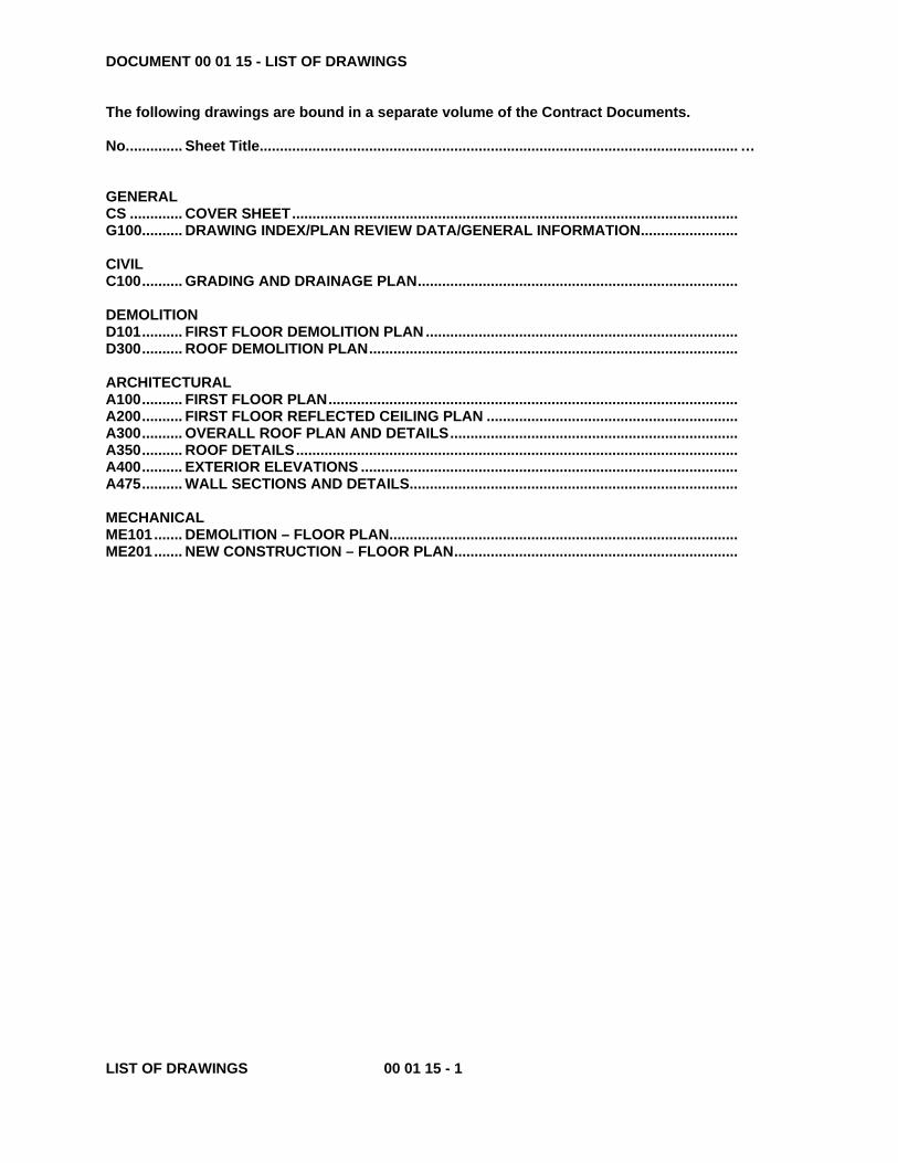
DOCUMENT 00 01 15 - LIST OF DRAWINGS The following drawings are bound in a separate volume of the Contract Documents. No. ............. Sheet Title ...................................................................................................................... … GENERAL CS ............. COVER SHEET .............................................................................................................. G100 .......... DRAWING INDEX/PLAN REVIEW DATA/GENERAL INFORMATION ........................ CIVIL C100 .......... GRADING AND DRAINAGE PLAN ............................................................................... DEMOLITION D101 .......... FIRST FLOOR DEMOLITION PLAN ............................................................................. D300 .......... ROOF DEMOLITION PLAN ........................................................................................... ARCHITECTURAL A100 .......... FIRST FLOOR PLAN ..................................................................................................... A200 .......... FIRST FLOOR REFLECTED CEILING PLAN .............................................................. A300 .......... OVERALL ROOF PLAN AND DETAILS ....................................................................... A350 .......... ROOF DETAILS ............................................................................................................. A400 .......... EXTERIOR ELEVATIONS ............................................................................................. A475 .......... WALL SECTIONS AND DETAILS................................................................................. MECHANICAL ME101 ....... DEMOLITION – FLOOR PLAN ...................................................................................... ME201 ....... NEW CONSTRUCTION – FLOOR PLAN ......................................................................
00 11 16 STREAM June 2014 Std 001116 Invitation to Bid Page 1 of 2
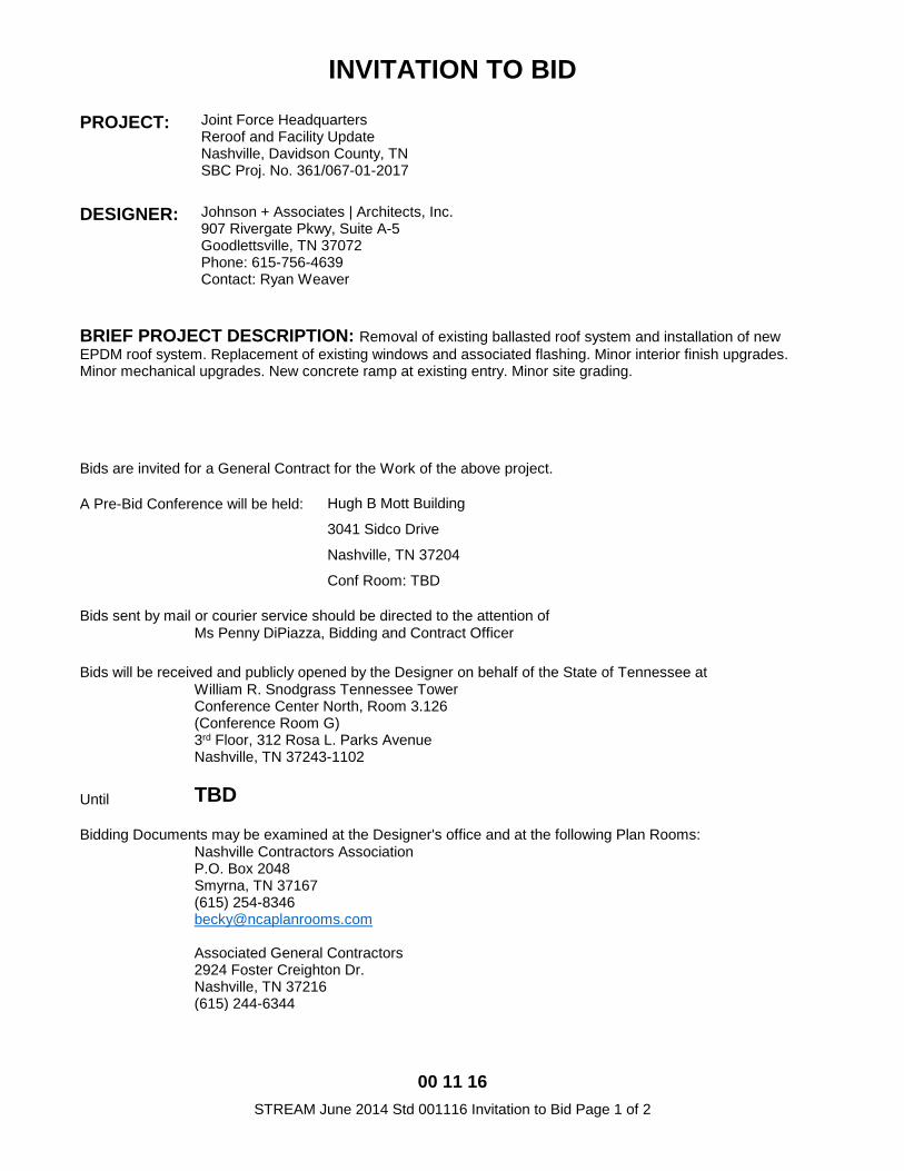
INVITATION TO BID
PROJECT:
Joint Force Headquarters Reroof and Facility Update Nashville, Davidson County, TN SBC Proj. No. 361/067-01-2017
DESIGNER:
Johnson + Associates | Architects, Inc. 907 Rivergate Pkwy, Suite A-5 Goodlettsville, TN 37072 Phone: 615-756-4639 Contact: Ryan Weaver
BRIEF PROJECT DESCRIPTION: Removal of existing ballasted roof system and installation of new EPDM roof system. Replacement of existing windows and associated flashing. Minor interior finish upgrades. Minor mechanical upgrades. New concrete ramp at existing entry. Minor site grading.
Bids are invited for a General Contract for the Work of the above project.
A Pre-Bid Conference will be held: Hugh B Mott Building
3041 Sidco Drive
Nashville, TN 37204
Conf Room: TBD
Bids sent by mail or courier service should be directed to the attention of Ms Penny DiPiazza, Bidding and Contract Officer
Bids will be received and publicly opened by the Designer on behalf of the State of Tennessee at
William R. Snodgrass Tennessee Tower Conference Center North, Room 3.126 (Conference Room G) 3rd Floor, 312 Rosa L. Parks Avenue Nashville, TN 37243-1102
Until TBD
Bidding Documents may be examined at the Designer's office and at the following Plan Rooms:
Nashville Contractors Association P.O. Box 2048 Smyrna, TN 37167 (615) 254-8346 [email protected] Associated General Contractors 2924 Foster Creighton Dr. Nashville, TN 37216 (615) 244-6344
00 11 16 STREAM June 2014 Std 001116 Invitation to Bid Page 2 of 2
Bidding Documents may be obtained from the Designer in accordance with the Instructions to Bidders upon the Designer's receipt of a certified or cashier's check made payable to the State of Tennessee in the amount per set of $200
Bidders submitting bids equal to or greater than $25,000 in value are required to be licensed in accordance with state law. A statement of public contract crime status and minority business status is required in the Bid Form. A five percent (5%) bid security is required.The Owner reserves the right to waive informalities and to reject bids.
00 21 13 STREAM January 2016 Std 002113 Instructions to Bidders Page 1 of 2
INSTRUCTIONS TO BIDDERS BIDDING DOCUMENTS
1.1 Bonafide prime Bidders and major subcontractors may obtain one Bid Pack, including Bidding Documents, Bid Envelope, and Bid Form, in accordance with provisions of the Invitation to Bid. 1.2 Individuals or firms securing Bid Packs become Bidders of Record, are automatically issued subsequent Addenda, and will have deposit refunded upon returning complete Bidding Documents unmarked and in good condition within fifteen (15) days after the scheduled opening of bids. Bidders of Record who do not submit a bid are also required to return the unused Bid Envelope. Upon failure to meet these conditions, deposit shall be forfeited. 1.3 Bidders of record may obtain additional copies of bidding documents at cost from Designer, but costs will not be refundable.
EXAMINATION 2.1 Bidders shall carefully examine site and documents to obtain first-hand knowledge of existing conditions and Work proposed. Copies of standards referenced in Project Manual are available for review through Designer's office. 2.2 Contractor will not be given extra payment for conditions which can be determined by examining site and documents.
QUESTIONS 3.1 Bidders shall submit questions about Bidding Documents to Designer in writing. Replies will be issued to Bidders of Record by Addenda and will become part of Contract Documents. Designer and Owner will not make oral clarifications. 3.2 Questions must be received by Designer at least four (4) calendar days before bid opening date. 3.3 In compliance with Tennessee Code Annotated 12-4-113, no Addenda will be issued less than forty-eight (48) hours of the bid opening, excluding weekends and legal holidays. The exception would be Addenda to extend the bid deadline. 3.4 Normal practice is that no Addenda affecting pricing will be issued less than three (3) calendar days before bid opening date.
SUBSTITUTIONS 4.1 Substitutions before receipt of bids shall be as identified in Conditions and Division 1 specifications. To request pre-bid approval of substitution, data required by Designer for evaluation must be received ten (10) calendar days before date set to receive bids. Acceptable substitutions will be identified in Addenda. 4.2 Bidders submitting bids in reliance upon a substitution when the substitution has not been approved prior to bidding do so at their own risk.
LIQUIDATED DAMAGES AND TIME 5.1 Conditions for liquidated damages are established in the Conditions. Time for completion and amount of liquidated damages are identified in bid form.
LICENSING AND QUALIFICATIONS 6.1 Bidders shall be familiar with the Contractors Licensing Act of 1976, as currently amended (codified in Tennessee Code Annotated Sections 62-6-101, et seq.). A contract will not be awarded to a bidder whose bid is in conflict with state licensing law. 6.2 In compliance with Tennessee Code Annotated Section 50-9-114(a), prospective bidders are advised that the Owner does
not operate a certified drug-free workplace program providing for testing. 6.3 Bids submitted for this project shall not include a contractor or subcontractor that is disqualified from participating in State construction projects under the supervision of the State Building Commission. As a matter of public record, the State Architect maintains a list of those that are disqualified, and the Owner endeavors to include a current copy of that list in the bidding requirements for its projects as Information Available to Bidders. Failure to include a current list shall not negate the effect of disqualification.
PRE-BID CONFERENCE 7.1 Pre-bid conference may be held approximately ten (10) days prior to bid opening date at time and place to be announced. Bidders of Record will be notified in writing whether or not a pre-bid conference will be held.
BID FORM 8.1 Make bids on an unaltered Bid Form furnished by the Designer in Bid Pack and duplicated in Project Manual. Submit one original Bid Form. Failure to completely fill out Bid Form may cause bid to be rejected. 8.2 If a Bidder chooses not to bid an alternate, unit price, or base bid in a multiple base bid project, write "no bid" in the space. To indicate availability of an add alternate at no additional charge, write "no charge" in the space. Additional stipulations or qualifications on Bid Form may cause bid to be rejected. 8.3 Bid Form shall be signed by person or persons legally authorized to bind Bidder to Contract and the original, signed Bid Form shall be submitted.
BID SECURITY 9.1 Bid security is required in the amount of five percent (5%) of total amount bid, including alternates, made payable to State of Tennessee. 9.2 Bid Bonds shall be issued by surety company licensed to do business in Tennessee by Tennessee Department of Commerce and Insurance, and shall have certified and current power-of-attorney for attorney-in-fact attached. The original of the Bid Bond and the certified power of attorney shall be submitted. 9.3 Checks shall be certified or cashier's payable in U.S. dollars drawn on a U.S. bank. Bid security submitted in the form of a check is deposited by the Owner until conditions for a refund are met, and then refunded in accordance with normal State requirements for prompt payment. In order to obtain such a refund, the bidder must submit a completed Substitute W-9 Form, using the form of Section 00 54 35, within thirty (30) days of the bid opening. Bid security that has been deposited is valid for the one bid, and is not transferrable to another bid. 9.4 Owner may retain bid security of bidders to whom award is being considered until either (a) Contract has been executed, or (b) specified time has elapsed so that bid is not binding, or (c) bid has been rejected. If Bidder refuses to enter into Contract or fails to furnish all required attachments properly executed, the amount of bid security shall be forfeited to Owner as liquidated damages, not as penalty.
BID SUBMITTAL 10.1 Submit Bid Form, with required attachments, in Owner's Bid Envelope furnished by Designer in Bid Pack. Bidder shall fill in blank spaces on face of Bid Envelope, except blank provided for Designer's approval. When filling in base bid or alternate(s), bid amount in words takes precedence over the numerical amount.
00 21 13 STREAM January 2016 Std 002113 Instructions to Bidders Page 2 of 2
10.2 If work is required by a subcontractor, of an amount that requires a license, list name, license number, expiration date thereof, and license classification of the contractor that will perform that work. Or, if Bidder will perform work in a category listed on the bid envelope with Bidder’s own forces, fill in Bidder’s name, license number, expiration date thereof, and license classification as appropriate for subcontractor work. 10.3 If no work is required or a licensed contractor is not required in a subcontractor category, write “N/R” (None Required) or “N/A” (Not Applicable). 10.4 Bidders are solely responsible for ensuring that bids are received by the time and at the place identified for receipt of bids. A bid sent by mail shall be enclosed in an envelope clearly marked "Bid Envelope Enclosed". Bids received late will be returned unopened. Please note that some State office buildings x-ray incoming mail and parcels. This could delay receipt of a bid reaching its intended destination in a timely manner.
RECEIPT AND OPENING OF BIDS 11.1 Bids will be received and opened at time and place identified in Invitation to Bid.
WITHDRAWAL AND MODIFICATION PRIOR TO CLOSE OF BIDDING
12.1 Bids, once submitted, may be withdrawn or modified before the scheduled opening time only upon receipt of request signed by a person legally authorized to bind bidder to contract. If bid is withdrawn, it may not be resubmitted. Modification to a bid amount may be made as "add" or "deduct" only. Oral, telephonic, telegraphic or electronic mail withdrawal or modification will not be considered. After time and date designated for receipt of bids, bid may not be modified during time period stipulated in Bid Form.
POST-BID WITHDRAWAL OF BID FROM CONSIDERATION DUE TO MISTAKE
13.1 Request to withdraw bid due to mistake must be in writing to Owner, delivered in person or postmarked certified or registered mail not later than twenty-four (24) hours after the time fixed for receipt and opening of bids. Request shall acknowledge that bidder refuses to enter into contract based on bid and intends to submit original work papers, documents, and materials used in preparation of the bid in like manner within five (5) working days following date of bid opening. 13.2 Bidder making such request will be removed from consideration for award of contract; and, a duly appointed review panel shall consider whether forfeiture of bid security should be waived.
CONSIDERATION OF BIDS 14.1 To be considered, bids shall be made in accordance with these Instructions to Bidders. Failure to comply with these bidding requirements may cause bid to be rejected. 14.2 The Owner reserves right to: reject unit prices proposed in a bid without invalidating other portions of bid; reject a bid which does not provide all required unit prices; waive informalities; and, reject any or all bids. 14.3 It is Owner's intent to award a contract, or multiple contracts in the case of multiple base bids, based upon lowest evaluated responsive bid submitted by responsible bidder for base bid plus alternates (if any) taken in order up to, but not to exceed the bid target. If the base bid of all bidders exceeds the established bid target, the low bidder is determined by the lowest base bid submitted by a responsible bidder irrespective of any alternates (if any) bid. When alternates are included in bidding, bid target will be announced at bid opening prior to opening bids. Alternates may be accepted or rejected at Owner's discretion, provided that final combination of base bid and accepted alternates does not change low bidder as established by above method. 14.4 In the event of tie bids, preference will be given to in-state bidder over out-of-state bidder; and, if a tie still exists, successful bidder will be determined by a public coin toss.
14.5 In the case of a multiple base bid, Owner may award a combined contract for the Work of more than one base bid if the same bidder is the successful low bidder on each.
POST BID INFORMATION 15.1 Should a bidder wish to protest a Bid, the bidder shall submit a Protest Bond to the Owner in the amount of five percent (5%) of the protester’s bid amount within seven (7) calendar days of the Bid opening. An example of Any Bid protests shall be submitted in accordance with SBC By-laws, Policy and Procedure, Item 18. 15.2 Each Bidder shall be prepared, if requested by Owner or Designer, to present evidence, within ten days of the request, of experience, qualifications, and financial ability to carry out the terms of the contract.
BONDS 16.1 Successful bidder shall provide bonds as required by the Bidding Documents and in accordance with paragraph 11.5.1 of the Conditions and paragraph 17.1 below. Bond forms shall be the State of Tennessee standard bond forms, which are sequenced in Project Manual as listed in Table of Contents. Contract Bond, if required, shall be in the amount of one hundred percent (100%) of the Contract sum. Three-Year Roof Bond, if required, shall be in an amount as stipulated on the Bid Form.
EXECUTION OF THE CONTRACT 17.1 If a Bidder is presented the written Agreement Form for signing, then that Bidder shall deliver to the identified Owner's representative, within five (5) calendar days after presentation, the required number of counterparts of the signed Agreement Form, Contract Bond (if required), Roof Bond (if required), certificates of insurance, and an "Authorization Agreement for Automatic Deposits (ACH Credits) Form". 17.2 For the purpose of computing time, the five (5) days referred to in paragraph 17.1 above commence the day after receipt of the Agreement Form by Bidder. Should the fifth day fall on a State holiday, or weekend, Bidder shall provide required documents as directed no later than the next working day; however, regardless of circumstances or causes for Bidder exceeding delivery time, Owner shall be entitled to either require forfeiture of bid security or to add for each day the Bidder exceeds the five (5) day period a corresponding extra day in which to return a fully executed contract, which return will be considered effectuated by mailing Agreement to the Contractor within the required time plus any extensions provided herein.
AWARD OF THE CONTRACT 18.1 Presentation of Agreement Form by Owner to Bidder for signature does not constitute award of Contract. Contract shall not be considered awarded until Bidder has received a fully executed Agreement.
PARTICIPATION OF DIVERSITY-OWNED BUSINESSES
19.1 It is the express desire of the State Building Commission to include an emphasis on diversity in its contractual relationships with contractors for the construction, demolition or renovation of State projects under the jurisdiction of the Commission. The Commission acknowledges that firms who demonstrate and embrace diversity within their programs and policies are assisting the State in achieving its goals in building a more reflective marketplace of the community within this state. 19.2 It is a requirement of all successful bidders on projects under the jurisdiction of the State Building Commission that they report to the Owner the names and amounts of contracts entered into with “Disadvantaged or Diversity-Owned Businesses” on their contract with the Owner in order for the Owner to collect data on such participation.
END OF INSTRUCTIONS TO BIDDERS
00 22 13.13 STREAM June 2014 Federal MIL 002213.13 Supplementary Instructions to Bidders Page 1 of 1
SUPPLEMENTARY INSTRUCTIONS TO BIDDERS
MODIFICATIONS to the
INSTRUCTIONS TO BIDDERS
Following supplements modify, change, delete from or add to Instructions to Bidders. Where an Article, Paragraph, Subparagraph, or Clause thereof is modified or deleted by these Supplementary Instructions to Bidders, unaltered provisions of that Article, Paragraph, Subparagraph, or Clause shall remain in effect.
STREAM Std Instructions to Bidders
BID SUBMITTAL (Add paragraph 10.1.1 to read as follows:) 10.1.1 Along with Bid Form and other required attachments, submit Bid Breakdown Form in Owner's Bid Envelope furnished by Designer in Bid Pack. Bidders shall have until close of the next business day to verify correctness of form schedule of values.
END OF SUPPLEMENTARY INSTRUCTIONS TO BIDDERS
00 31 26 STREAM June 2014 HazMat 003126 Hazardous Materials Data Page 1 of 1
HAZARDOUS MATERIALS DATA
HAZARDOUS MATERIALS INVESTIGATION AND REPORT:
A. An investigation has been performed at the project site to determine the presence and probable extent of hazardous materials in the existing building materials. This investigation was conducted, and a report obtained, solely for design purposes and is not a part of the Contract Documents.
B. The use and interpretation of this information is entirely the responsibility of the using party. The Owner is not responsible for variations in the actual composition of existing materials. Bidders shall decide for themselves the character and quantities of the material to be encountered.
C. The report of the findings of this investigation is on file in the Designer's office, and may be reviewed there by any prospective Bidder of Record. Bidders must call ahead to schedule an appointment.
END OF SECTION

00 41 13 STREAM November 2017 Std 004113 Bid Form Page 1 of 3
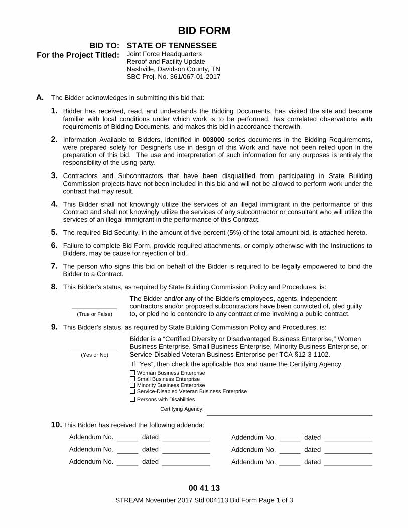
BID FORM BID TO: STATE OF TENNESSEE
For the Project Titled: Joint Force Headquarters Reroof and Facility Update Nashville, Davidson County, TN SBC Proj. No. 361/067-01-2017
A. The Bidder acknowledges in submitting this bid that:
1. Bidder has received, read, and understands the Bidding Documents, has visited the site and become familiar with local conditions under which work is to be performed, has correlated observations with requirements of Bidding Documents, and makes this bid in accordance therewith.
2. Information Available to Bidders, identified in 003000 series documents in the Bidding Requirements, were prepared solely for Designer's use in design of this Work and have not been relied upon in the preparation of this bid. The use and interpretation of such information for any purposes is entirely the responsibility of the using party.
3. Contractors and Subcontractors that have been disqualified from participating in State Building Commission projects have not been included in this bid and will not be allowed to perform work under the contract that may result.
4. This Bidder shall not knowingly utilize the services of an illegal immigrant in the performance of this Contract and shall not knowingly utilize the services of any subcontractor or consultant who will utilize the services of an illegal immigrant in the performance of this Contract.
5. The required Bid Security, in the amount of five percent (5%) of the total amount bid, is attached hereto.
6. Failure to complete Bid Form, provide required attachments, or comply otherwise with the Instructions to Bidders, may be cause for rejection of bid.
7. The person who signs this bid on behalf of the Bidder is required to be legally empowered to bind the Bidder to a Contract.
8. This Bidder's status, as required by State Building Commission Policy and Procedures, is: The Bidder and/or any of the Bidder's employees, agents, independent
contractors and/or proposed subcontractors have been convicted of, pled guilty to, or pled no lo contendre to any contract crime involving a public contract. (True or False)
9. This Bidder’s status, as required by State Building Commission Policy and Procedures, is: Bidder is a “Certified Diversity or Disadvantaged Business Enterprise,” Women
Business Enterprise, Small Business Enterprise, Minority Business Enterprise, or Service-Disabled Veteran Business Enterprise per TCA §12-3-1102. If “Yes”, then check the applicable Box and name the Certifying Agency.
(Yes or No)
Woman Business Enterprise Small Business Enterprise Minority Business Enterprise Service-Disabled Veteran Business Enterprise Persons with Disabilities
Certifying Agency:
10. This Bidder has received the following addenda:
Addendum No. dated Addendum No. dated
Addendum No. dated Addendum No. dated
Addendum No. dated Addendum No. dated
00 41 13 STREAM November 2017 Std 004113 Bid Form Page 2 of 4
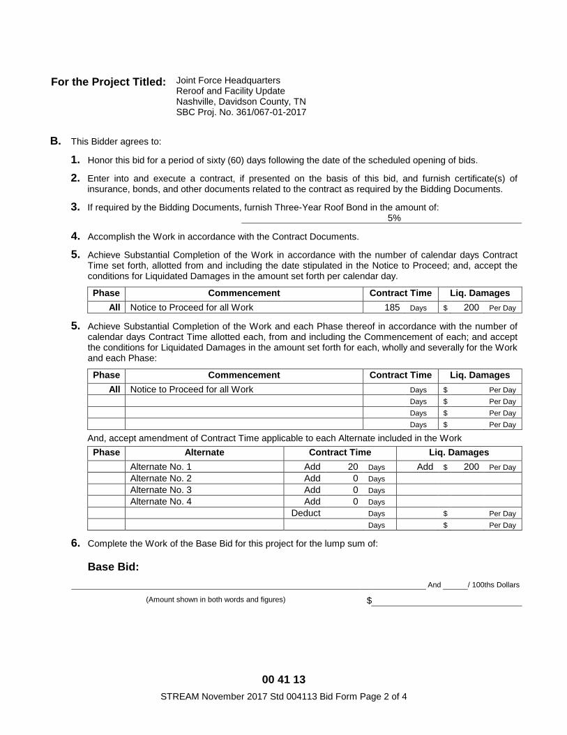
For the Project Titled: Joint Force Headquarters Reroof and Facility Update Nashville, Davidson County, TN SBC Proj. No. 361/067-01-2017
B. This Bidder agrees to:
1. Honor this bid for a period of sixty (60) days following the date of the scheduled opening of bids.
2. Enter into and execute a contract, if presented on the basis of this bid, and furnish certificate(s) of insurance, bonds, and other documents related to the contract as required by the Bidding Documents.
3. If required by the Bidding Documents, furnish Three-Year Roof Bond in the amount of: 5%
4. Accomplish the Work in accordance with the Contract Documents.
5. Achieve Substantial Completion of the Work in accordance with the number of calendar days Contract Time set forth, allotted from and including the date stipulated in the Notice to Proceed; and, accept the conditions for Liquidated Damages in the amount set forth per calendar day.
Phase Commencement Contract Time Liq. Damages All Notice to Proceed for all Work 185 Days $ 200 Per Day
5. Achieve Substantial Completion of the Work and each Phase thereof in accordance with the number of calendar days Contract Time allotted each, from and including the Commencement of each; and accept the conditions for Liquidated Damages in the amount set forth for each, wholly and severally for the Work and each Phase:
Phase Commencement Contract Time Liq. Damages All Notice to Proceed for all Work Days $ Per Day
Days $ Per Day Days $ Per Day Days $ Per Day
And, accept amendment of Contract Time applicable to each Alternate included in the Work Phase Alternate Contract Time Liq. Damages
Alternate No. 1 Add 20 Days Add $ 200 Per Day Alternate No. 2 Add 0 Days Alternate No. 3 Add 0 Days Alternate No. 4 Add 0 Days Deduct Days $ Per Day Days $ Per Day
6. Complete the Work of the Base Bid for this project for the lump sum of:
Base Bid: And / 100ths Dollars
(Amount shown in both words and figures) $
00 41 13 STREAM November 2017 Std 004113 Bid Form Page 3 of 4
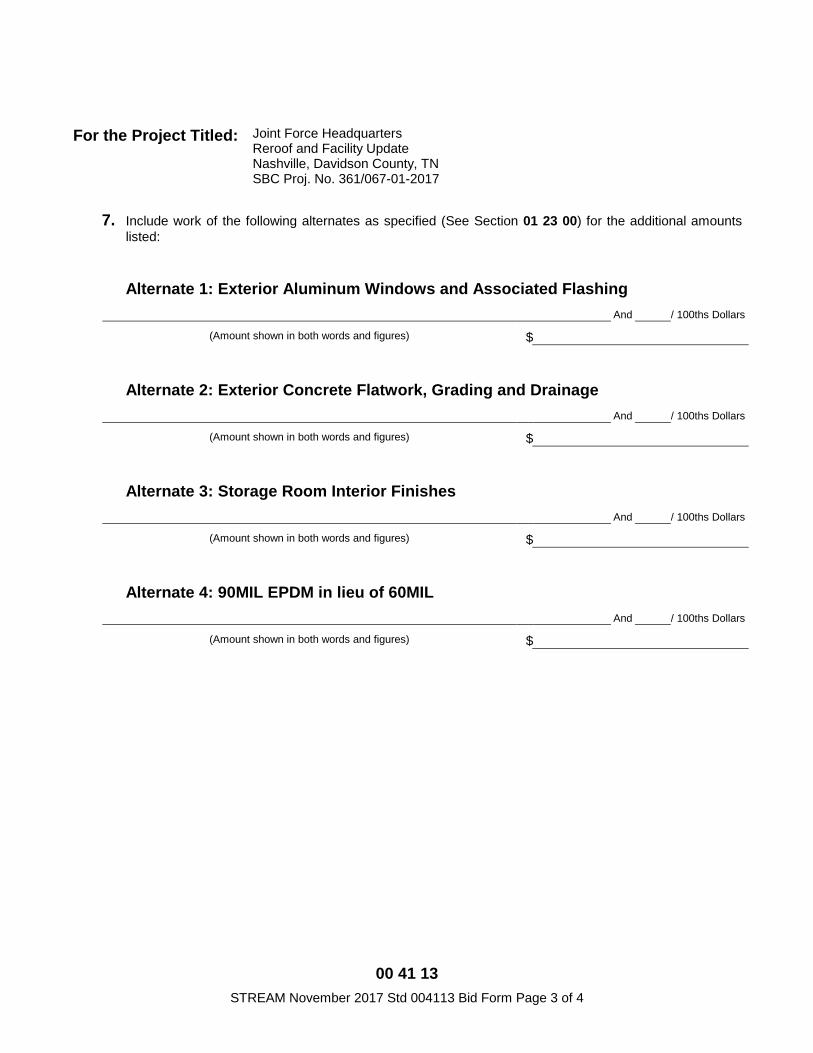
For the Project Titled: Joint Force Headquarters Reroof and Facility Update Nashville, Davidson County, TN SBC Proj. No. 361/067-01-2017
7. Include work of the following alternates as specified (See Section 01 23 00) for the additional amounts listed:
Alternate 1: Exterior Aluminum Windows and Associated Flashing
And / 100ths Dollars
(Amount shown in both words and figures) $
Alternate 2: Exterior Concrete Flatwork, Grading and Drainage
And / 100ths Dollars
(Amount shown in both words and figures) $
Alternate 3: Storage Room Interior Finishes
And / 100ths Dollars
(Amount shown in both words and figures) $
Alternate 4: 90MIL EPDM in lieu of 60MIL
And / 100ths Dollars
(Amount shown in both words and figures) $
00 41 13 STREAM November 2017 Std 004113 Bid Form Page 4 of 4
For the Project Titled: Joint Force Headquarters Reroof and Facility Update Nashville, Davidson County, TN SBC Proj. No. 361/067-01-2017
This bid submitted by:
By submission of this bid, each bidder and each person signing on behalf of any bidders certifies, and in the case of a joint bid each party thereto certifies as to its own organization, under penalty of perjury, that to the best of its knowledge and belief that each bidder is not on the list created pursuant to TCA §12-12-106.
Authorized Signature Date
Name Title
On behalf of: (Name of Bidder)
Federal Employer Identification Number (EIN)
Address (Street & Mailing Address)
Telephone No. Facsimile No.
00 43 99 STREAM June 2014 Federal MIL 004399 Bid Breakdown Page 1 of 2
BID BREAKDOWN
1.01 REFERENCES
Refer to paragraph 10.1.1 of 00 22 13.13 - Supplementary Instructions to Bidders.
1.02 FORM
Use the "BID BREAKDOWN FORM" provided immediately following this page.
1.03 COMPLETION OF FORM
A. Complete form entirely, using the following Item descriptions:
1. GENERAL CONDITIONS
2. MOBILIZATION
3. ROUGH CARPENTRY
4. SINGLE PLY MEMBRANE
5. INSULATION
6. SHEET METAL FLASHING AND TRIM
7. ROOFING SPECIALTIES
B. Person who signs Bid Breakdown Form on behalf of Bidder shall be legally empowered to bind Bidder to Contract.
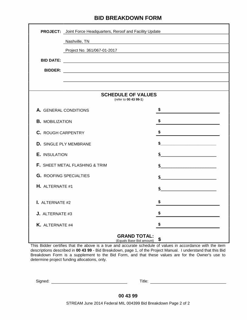
00 43 99 STREAM June 2014 Federal MIL 004399 Bid Breakdown Page 2 of 2
BID BREAKDOWN FORM
PROJECT: Joint Force Headquarters, Reroof and Facility Update
Nashville, TN
Project No. 361/067-01-2017
BID DATE:
BIDDER:
SCHEDULE OF VALUES (refer to 00 43 99-1)
A. GENERAL CONDITIONS $
B. MOBILIZATION $
C. ROUGH CARPENTRY $
D. SINGLE PLY MEMBRANE
E. INSULATION
F. SHEET METAL FLASHING & TRIM
G. ROOFING SPECIALTIES
H. ALTERNATE #1
$_________________________ $_______________________ $_______________________ $_______________________ $_______________________
I. ALTERNATE #2 $
J. ALTERNATE #3 $
K. ALTERNATE #4 $
GRAND TOTAL: (Equals Base Bid amount) $
This Bidder certifies that the above is a true and accurate schedule of values in accordance with the item descriptions described in 00 43 99 - Bid Breakdown, page 1, of the Project Manual. I understand that this Bid Breakdown Form is a supplement to the Bid Form, and that these values are for the Owner's use to determine project funding allocations, only.
Signed: Title:
00 52 13 STREAM June 2014 Std 005213 Owner/Contractor Agreement Page 1 of 4
STATE OF TENNESSEE Real Estate Asset Management (STREAM)
Standard Form of Agreement Between Owner and Contractor
where the Basis of Payment is a STIPULATED SUM
Use only with the coordinated documents identified in the current
Designers' Manual for projects of the State Building Commission of Tennessee
AGREEMENT made as of the day of in the year of
Two Thousand and
BETWEEN the Owner: STATE OF TENNESSEE via the Contracting Agency:
and the Contractor:
the Project:
the Designer:
The Owner and the Contractor agree as set forth below.
00 52 13 STREAM June 2014 Std 005213 Owner/Contractor Agreement Page 2 of 4
ARTICLE 1 THE WORK AND THE CONTRACT DOCUMENTS
1.1 The Contractor shall perform all the Work required by the Contract Documents for the Project identified on page one.
1.2 The Contract Documents are identified in the Conditions of the Contract (General, Supplementary, and other Conditions). These form the Contract and constitute the entire agreement between the Owner and the Contractor, and are as fully a part of the Contract as if attached to this Agreement or repeated herein. An enumeration of the Contract Documents appears in paragraph 1.4.
1.3 Terms used in this Agreement which are defined in the Conditions of the Contract shall have the meanings designated in those Conditions.
1.4 The Contract Documents, except for Modifications issued after execution of this Agreement, are enumerated as follows:

00 52 13 STREAM June 2014 Std 005213 Owner/Contractor Agreement Page 3 of 4
ARTICLE 2 TIME OF COMMENCEMENT AND SUBSTANTIAL COMPLETION
2.1 The Work to be performed under this Contract shall be commenced on the date stipulated in the Notice to Proceed; and, subject to authorized adjustments, Substantial Completion shall be achieved
2.2 Liquidated Damages, as set forth in paragraph 9.12 of the Conditions, are
ARTICLE 3 CONTRACT SUM
3.1 The Owner shall pay the Contractor in current funds for the performance of the Work, subject to additions and deductions by Change Order as provided in the Contract Documents, the Contract Sum of
3.2 The Contract Sum is determined as follows:
3.3 The following Unit Prices will be used as specified:
00 52 13 STREAM June 2014 Std 005213 Owner/Contractor Agreement Page 4 of 4
This instrument may be executed in one or more counterparts. It shall be fully executed when each party whose signature is required has signed at least one (1) counterpart, even though no one (1) counterpart contains the signatures of all the parties to this instrument. Electronic, scanned or facsimile signatures shall have the same force and effect as original signatures. This Agreement entered into as of the day and year first written above as witnessed: BY CONTRACTOR:
Signature:
Name:
Title:
AND BY OWNER: STATE OF TENNESSEE
APPROVED: The State Architect, State Architect (All Contracts)
APPROVED: The Commissioner of General Services (All Contracts that are not Department of
Military) or The Adjutant General, Military (All Department of Military Contracts)
APPROVED: The Comptroller, Comptroller of the Treasury
for compliance with policy and statute (Required if Contract Amount is over $100,000)
APPROVED: The Attorney General, Attorney General
for form and legality (Required if Contract Amount is over $500,000)
END of AGREEMENT FORM for the Project titled:
00 54 39 STREAM June 2014 Federal MIL 005439 Corporate Authority Certificate Page 1 of 1
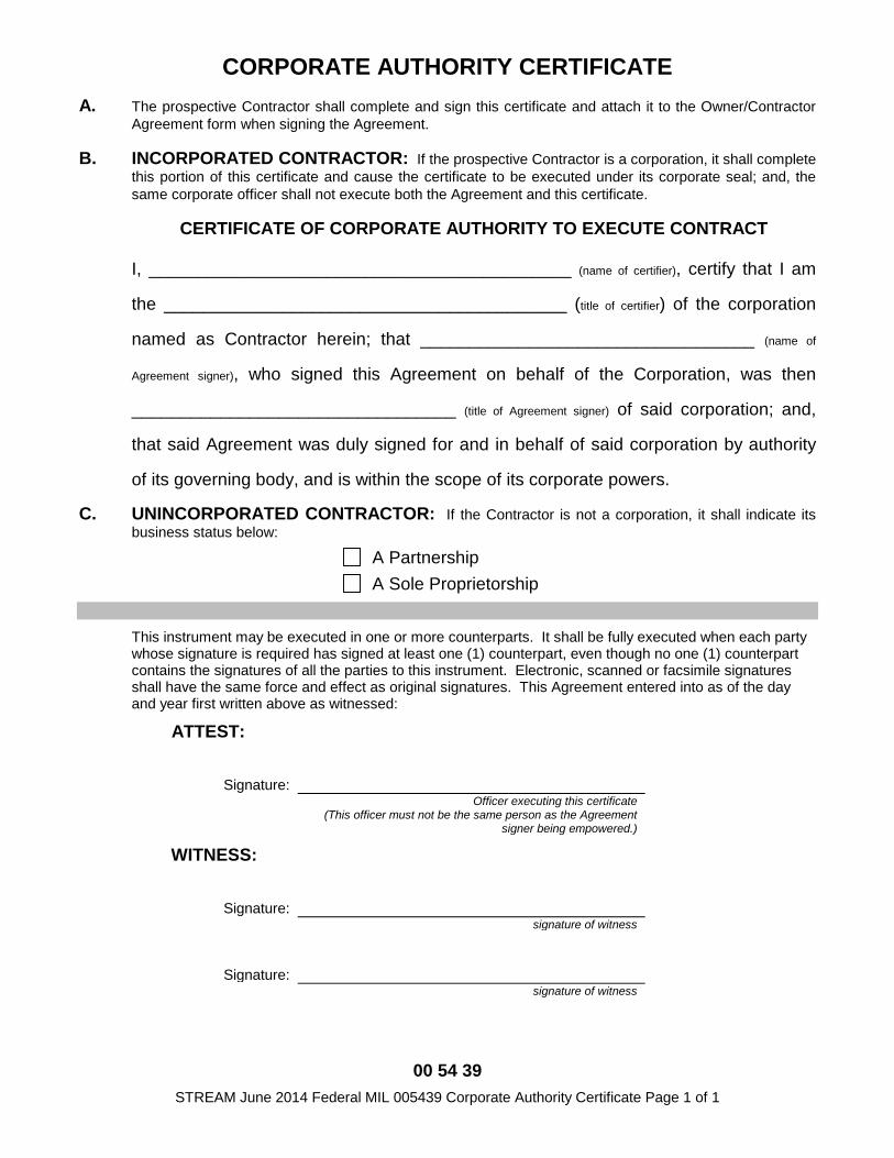
CORPORATE AUTHORITY CERTIFICATE A. The prospective Contractor shall complete and sign this certificate and attach it to the Owner/Contractor
Agreement form when signing the Agreement.
B. INCORPORATED CONTRACTOR: If the prospective Contractor is a corporation, it shall complete this portion of this certificate and cause the certificate to be executed under its corporate seal; and, the same corporate officer shall not execute both the Agreement and this certificate.
CERTIFICATE OF CORPORATE AUTHORITY TO EXECUTE CONTRACT
I, ___________________________________________ (name of certifier), certify that I am
the _________________________________________ (title of certifier) of the corporation
named as Contractor herein; that __________________________________ (name of
Agreement signer), who signed this Agreement on behalf of the Corporation, was then
_________________________________ (title of Agreement signer) of said corporation; and,
that said Agreement was duly signed for and in behalf of said corporation by authority
of its governing body, and is within the scope of its corporate powers.
C. UNINCORPORATED CONTRACTOR: If the Contractor is not a corporation, it shall indicate its business status below:
A Partnership A Sole Proprietorship
This instrument may be executed in one or more counterparts. It shall be fully executed when each party whose signature is required has signed at least one (1) counterpart, even though no one (1) counterpart contains the signatures of all the parties to this instrument. Electronic, scanned or facsimile signatures shall have the same force and effect as original signatures. This Agreement entered into as of the day and year first written above as witnessed:
ATTEST:
Signature: Officer executing this certificate
(This officer must not be the same person as the Agreement signer being empowered.)
WITNESS:
Signature: signature of witness
Signature: signature of witness
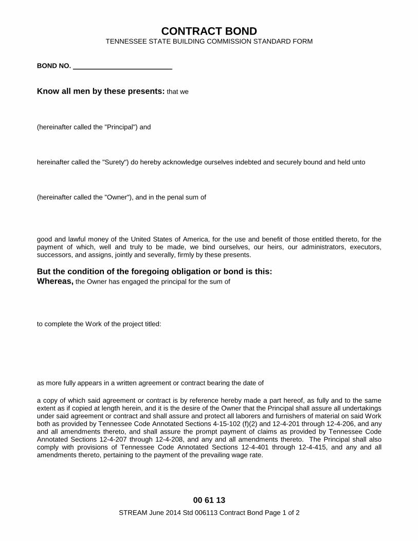
00 61 13 STREAM June 2014 Std 006113 Contract Bond Page 1 of 2
CONTRACT BOND TENNESSEE STATE BUILDING COMMISSION STANDARD FORM
BOND NO.
Know all men by these presents: that we
(hereinafter called the "Principal") and
hereinafter called the "Surety") do hereby acknowledge ourselves indebted and securely bound and held unto
(hereinafter called the "Owner"), and in the penal sum of
good and lawful money of the United States of America, for the use and benefit of those entitled thereto, for the payment of which, well and truly to be made, we bind ourselves, our heirs, our administrators, executors, successors, and assigns, jointly and severally, firmly by these presents. But the condition of the foregoing obligation or bond is this: Whereas, the Owner has engaged the principal for the sum of
to complete the Work of the project titled:
as more fully appears in a written agreement or contract bearing the date of
a copy of which said agreement or contract is by reference hereby made a part hereof, as fully and to the same extent as if copied at length herein, and it is the desire of the Owner that the Principal shall assure all undertakings under said agreement or contract and shall assure and protect all laborers and furnishers of material on said Work both as provided by Tennessee Code Annotated Sections 4-15-102 (f)(2) and 12-4-201 through 12-4-206, and any and all amendments thereto, and shall assure the prompt payment of claims as provided by Tennessee Code Annotated Sections 12-4-207 through 12-4-208, and any and all amendments thereto. The Principal shall also comply with provisions of Tennessee Code Annotated Sections 12-4-401 through 12-4-415, and any and all amendments thereto, pertaining to the payment of the prevailing wage rate.
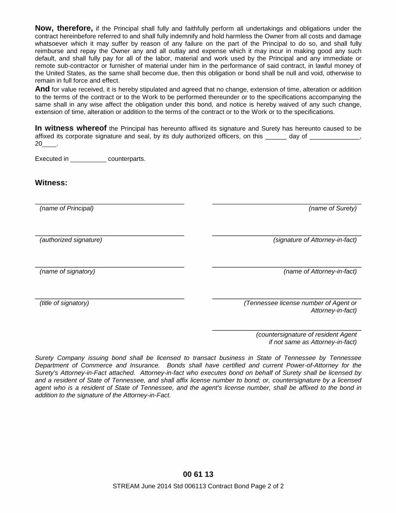
00 61 13 STREAM June 2014 Std 006113 Contract Bond Page 2 of 2
Now, therefore, if the Principal shall fully and faithfully perform all undertakings and obligations under the contract hereinbefore referred to and shall fully indemnify and hold harmless the Owner from all costs and damage whatsoever which it may suffer by reason of any failure on the part of the Principal to do so, and shall fully reimburse and repay the Owner any and all outlay and expense which it may incur in making good any such default, and shall fully pay for all of the labor, material and work used by the Principal and any immediate or remote sub-contractor or furnisher of material under him in the performance of said contract, in lawful money of the United States, as the same shall become due, then this obligation or bond shall be null and void, otherwise to remain in full force and effect. And for value received, it is hereby stipulated and agreed that no change, extension of time, alteration or addition to the terms of the contract or to the Work to be performed thereunder or to the specifications accompanying the same shall in any wise affect the obligation under this bond, and notice is hereby waived of any such change, extension of time, alteration or addition to the terms of the contract or to the Work or to the specifications.
In witness whereof the Principal has hereunto affixed its signature and Surety has hereunto caused to be affixed its corporate signature and seal, by its duly authorized officers, on this ______ day of ______________, 20____.
Executed in __________ counterparts.
Witness:
(name of Principal) (name of Surety)
(authorized signature) (signature of Attorney-in-fact)
(name of signatory) (name of Attorney-in-fact)
(title of signatory) (Tennessee license number of Agent or Attorney-in-fact)
(countersignature of resident Agent if not same as Attorney-in-fact)
Surety Company issuing bond shall be licensed to transact business in State of Tennessee by Tennessee Department of Commerce and Insurance. Bonds shall have certified and current Power-of-Attorney for the Surety's Attorney-in-Fact attached. Attorney-in-fact who executes bond on behalf of Surety shall be licensed by and a resident of State of Tennessee, and shall affix license number to bond; or, countersignature by a licensed agent who is a resident of State of Tennessee, and the agent's license number, shall be affixed to the bond in addition to the signature of the Attorney-in-Fact.
00 61 43 STREAM June 2014 Roof Std 006143 Three-Year Roof Bond Page 1 of 2
THREE-YEAR ROOF BOND TENNESSEE STATE BUILDING COMMISSION STANDARD FORM
BOND NO. ____________________
GENERAL INFORMATION:
Principal:
Surety Name:
& Address:
Building Owner: State of Tennessee
Project:
Project Contract Date:
KNOW ALL MEN BY THESE PRESENTS: That we, the Principal and the Surety, are held and firmly bound unto the Building Owner in the amount of
for the payment thereof in good and lawful money of the United States of America the Principal and the Surety bind themselves, their heirs, executors, administrators, successors, and assigns, jointly and severally, firmly by these presents.
Whereas, Principal has, by written agreement referenced above, entered into a contract (hereinafter referred to as "the Contract" and hereby referenced herein) with the Owner for the construction of the Project identified above.
NOW, THEREFORE, THE CONDITION OF THIS OBLIGATION is such that if the Principal shall fully indemnify the Owner for all loss that the Owner may suffer by reason of any defective material and/or workmanship in the materials furnished for and the installation of the above referenced Project roofing system which become apparent during the period of three (3) years from the date of Substantial Completion of the above referenced Project roofing system, then this obligation shall be null and void; otherwise it shall remain in full force and effect.
Surety hereby agrees that no change, extension of time, alteration or addition to the terms of the contract or to the Work to be performed thereunder or to the specifications accompanying the same shall in any way affect the obligations under this bond, and notice is hereby waived of any such change, extension of time, alteration or addition to the terms of the contract or to the Work or to the specifications.
00 61 43 STREAM June 2014 Roof Std 006143 Three-Year Roof Bond Page 2 of 2
IN WITNESS WHEREOF the Principal has hereunto affixed its signature and Surety has hereunto caused to be affixed its corporate signature and seal, by its duly authorized officers, on this ____ day of __________, 20___.
Executed in __________ counterparts.
Witness:
(name of Principal) (name of Surety)
(authorized signature) (signature of Attorney-in-fact)
(name of signatory) (name of Attorney-in-fact)
(title of signatory) (Tennessee license number of Agent or
Attorney-in-fact)
(countersignature of resident Agent
if not same as Attorney-in-fact)
Surety Company issuing bond shall be licensed to transact business in State of Tennessee by Tennessee Department of Commerce and Insurance. Bonds shall have certified and current Power-of-Attorney for the Surety's Attorney-in-Fact attached. Attorney-in-fact who executes bond on behalf of Surety shall be licensed by and a resident of State of Tennessee, and shall affix license number to bond; or, countersignature by a licensed agent who is a resident of State of Tennessee, and the agent's license number, shall be affixed to the bond in addition to the signature of the Attorney-in-Fact.
00 65 01 STREAM June 2014 Std 006501 Non-Use of Asbestos Containing Material Affidavit – Contractor Page 1 of 1
SECTION 00 65 01 NON-USE OF ASBESTOS CONTAINING MATERIALS AFFIDAVIT - CONTRACTOR
STATE OF TENNESSEE
COUNTY OF:
Project Name:
SBC Project No.: By the signature below, the signatory for the Contractor certifies that neither he/she nor the firm, corporation, partnership or institution represented by the signatory or anyone acting for the firm providing Construction Services for this project, including Subcontractors, have utilized materials, procedures or processes that knowingly or intentionally contain asbestos materials.
Signature: Printed Name:
Title: Company:
Date:
State of Tennessee, County of
Sworn to and subscribed before me on the day of , 20___ by
the undersigned authority on behalf of said Contractor. (name/signature of signer)
Notary Public’s Signature Printed Name
My commission expires: _____________________________
(Personalized Seal)
Document A201TM – 1997 General Conditions of the Contract for Construction
AIA Document A201™ – 1997. Copyright © 1911, 1915, 1918, 1925, 1937, 1951, 1958, 1961, 1963, 1966, 1970, 1976, 1987 and 1997 by The American Institute of Architects. All rights reserved. WARNING: This AIA® Document is protected by U.S. Copyright Law and International Treaties. Unauthorized reproduction or distribution of this AIA® Document, or any portion of it, may result in severe civil and criminal penalties, and will be prosecuted to the maximum extent possible under the law. This draft was produced by AIA software at 13:12:51 on 08/04/2009 under Order No.7876461934_1 which expires on 07/02/2010, and is not for resale. User Notes: July 2009 RPA 00 72 13.39 Fed NGB (1299478385)
1
This document has important legal consequences. Consultation with an attorney is encouraged with respect to its completion or modification.
This document has been approved and endorsed by The Associated General Contractors of America
ELECTRONIC COPYING of any portion of this AIA® Document to another electronic file is prohibited and constitutes a violation of copyright laws as set forth in the footer of this document.
for the following PROJECT: (Name and location or address): all State of Tennessee, Department of Military General Work RPA 00 72 13.39 July 2009 THE OWNER: (Name, legal status and address):State of Tennessee, Department of Military THE ARCHITECT: (Name, legal status and address): THE DESIGNER: as identified in the agreement TABLE OF ARTICLES 1 GENERAL PROVISIONS 2 OWNER 3 CONTRACTOR 4 ADMINISTRATION OF THE CONTRACT 5 SUBCONTRACTORS 6 CONSTRUCTION BY OWNER OR BY SEPARATE CONTRACTORS 7 CHANGES IN THE WORK 8 TIME 9 PAYMENTS AND COMPLETION 10 PROTECTION OF PERSONS AND PROPERTY 11 INSURANCE AND BONDS 12 UNCOVERING AND CORRECTION OF WORK 13 MISCELLANEOUS PROVISIONS 14 TERMINATION OR SUSPENSION OF THE CONTRACT
AIA Document A201™ – 1997. Copyright © 1911, 1915, 1918, 1925, 1937, 1951, 1958, 1961, 1963, 1966, 1970, 1976, 1987 and 1997 by The American Institute of Architects. All rights reserved. WARNING: This AIA® Document is protected by U.S. Copyright Law and International Treaties. Unauthorized reproduction or distribution of this AIA® Document, or any portion of it, may result in severe civil and criminal penalties, and will be prosecuted to the maximum extent possible under the law. This draft was produced by AIA software at 13:12:51 on 08/04/2009 under Order No.7876461934_1 which expires on 07/02/2010, and is not for resale. User Notes: July 2009 RPA 00 72 13.39 Fed NGB (1299478385)
2
INDEX NOTE: Index has not been updated and does not include additions or deletions (Numbers and Topics in Bold are Section Headings) Acceptance of Nonconforming Work 9.6.6, 9.9.3, 12.3 Acceptance of Work 9.6.6, 9.8.2, 9.9.3, 9.10.1, 9.10.3, 12.3 Access to Work 3.16, 6.2.1, 12.1 Accident Prevention 4.2.3, 10 Acts and Omissions 3.2, 3.3.2, 3.12.8, 3.18, 4.2.3, 4.3.8, 4.4.1, 8.3.1, 9.5.1, 10.2.5, 13.4.2, 13.7, 14.1 Addenda 1.1.1, 3.11 Additional Costs, Claims for 4.3.4, 4.3.5, 4.3.6, 6.1.1, 10.3 Additional Inspections and Testing 9.8.3, 12.2.1, 13.5 Additional Time, Claims for 4.3.4, 4.3.7, 8.3.2 ADMINISTRATION OF THE CONTRACT 3.1.3, 4, 9.4, 9.5 Advertisement or Invitation to Bid 1.1.1 Aesthetic Effect 4.2.13, 4.5.1 Allowances 3.8 All-risk Insurance 11.4.1.1 Applications for Payment 4.2.5, 7.3.8, 9.2, 9.3, 9.4, 9.5.1, 9.6.3, 9.7.1, 9.8.5, 9.10, 11.1.3, 14.2.4, 14.4.3 Approvals 2.4, 3.1.3, 3.5, 3.10.2, 3.12, 4.2.7, 9.3.2, 13.4.2, 13.5 Arbitration 4.3.3, 4.4, 4.5.1, 4.5.2, 4.6, 8.3.1, 9.7.1, 11.4.9, 11.4.10 ArchitectDesigner 4.1 Architect, Designer, Definition of 4.1.1 Architect, Designer, Extent of Authority 2.4, 3.12.7, 4.2, 4.3.6, 4.4, 5.2, 6.3, 7.1.2, 7.3.6, 7.4, 9.2, 9.3.1, 9.4, 9.5, 9.8.3, 9.10.1, 9.10.3, 12.1, 12.2.1, 13.5.1, 13.5.2, 14.2.2, 14.2.4 Architect, Designer, Limitations of Authority and Responsibility 2.1.1, 3.3.3, 3.12.4, 3.12.8, 3.12.10, 4.1.2, 4.2.1, 4.2.2, 4.2.3, 4.2.6, 4.2.7, 4.2.10, 4.2.12, 4.2.13, 4.4, 5.2.1, 7.4, 9.4.2, 9.6.4, 9.6.6
Architect’s Designer’s Additional Services and Expenses 2.4, 11.4.1.1, 12.2.1, 13.5.2, 13.5.3, 14.2.4 Architect’s Designer’s Administration of the Contract 3.1.3, 4.2, 4.3.4, 4.4, 9.4, 9.5 Architect’s Designer’s Approvals 2.4, 3.1.3, 3.5.1, 3.10.2, 4.2.7 Architect’s Designer’s Authority to Reject Work 3.5.1, 4.2.6, 12.1.2, 12.2.1 Architect’s Designer’s Copyright 1.6 Architect’s Designer’s Decisions 4.2.6, 4.2.7, 4.2.11, 4.2.12, 4.2.13, 4.3.4, 4.4.1, 4.4.5, 4.4.6, 4.5, 6.3, 7.3.6, 7.3.8, 8.1.3, 8.3.1, 9.2, 9.4, 9.5.1, 9.8.4, 9.9.1, 13.5.2, 14.2.2, 14.2.4 Architect’s Designer’s Inspections 4.2.2, 4.2.9, 4.3.4, 9.4.2, 9.8.3, 9.9.2, 9.10.1, 13.5 Architect’s ’s Instructions 3.2.3, 3.3.1, 4.2.6, 4.2.7, 4.2.8, 7.4.1, 12.1, 13.5.2 Architect’s Designer’s Interpretations 4.2.11, 4.2.12, 4.3.6 Architect’s Designer’s Project Representative 4.2.10 Architect’s Designer’s Relationship with Contractor 1.1.2, 1.6, 3.1.3, 3.2.1, 3.2.2, 3.2.3, 3.3.1, 3.4.2, 3.5.1, 3.7.3, 3.10, 3.11, 3.12, 3.16, 3.18, 4.1.2, 4.1.3, 4.2, 4.3.4, 4.4.1, 4.4.7, 5.2, 6.2.2, 7, 8.3.1, 9.2, 9.3, 9.4, 9.5, 9.7, 9.8, 9.9, 10.2.6, 10.3, 11.3, 11.4.7, 12, 13.4.2, 13.5 Architect’s Designer’s Relationship with Subcontractors 1.1.2, 4.2.3, 4.2.4, 4.2.6, 9.6.3, 9.6.4, 11.4.7 Architect’s Designer’s Representations 9.4.2, 9.5.1, 9.10.1 Architect’s Designer’s Site Visits 4.2.2, 4.2.5, 4.2.9, 4.3.4, 9.4.2, 9.5.1, 9.9.2, 9.10.1, 13.5 Asbestos 10.3.1 Attorneys’ Fees 3.18.1, 9.10.2, 10.3.3 Award of Separate Contracts 6.1.1, 6.1.2 Award of Subcontracts and Other Contracts for Portions of the Work 5.2 Basic Definitions 1.1 Bidding Requirements 1.1.1, 1.1.7, 5.2.1, 11.5.1 Boiler and Machinery Insurance 11.4.2 Bonds, Lien 9.10.2 Bonds, Performance, and Payment
AIA Document A201™ – 1997. Copyright © 1911, 1915, 1918, 1925, 1937, 1951, 1958, 1961, 1963, 1966, 1970, 1976, 1987 and 1997 by The American Institute of Architects. All rights reserved. WARNING: This AIA® Document is protected by U.S. Copyright Law and International Treaties. Unauthorized reproduction or distribution of this AIA® Document, or any portion of it, may result in severe civil and criminal penalties, and will be prosecuted to the maximum extent possible under the law. This draft was produced by AIA software at 13:12:51 on 08/04/2009 under Order No.7876461934_1 which expires on 07/02/2010, and is not for resale. User Notes: July 2009 RPA 00 72 13.39 Fed NGB (1299478385)
3
7.3.6.4, 9.6.7, 9.10.3, 11.4.9, 11.5 Building Permit 3.7.1 Capitalization 1.3 Certificate of Substantial Completion 9.8.3, 9.8.4, 9.8.5 Certificates for Payment 4.2.5, 4.2.9, 9.3.3, 9.4, 9.5, 9.6.1, 9.6.6, 9.7.1, 9.10.1, 9.10.3, 13.7, 14.1.1.3, 14.2.4 Certificates of Inspection, Testing or Approval 13.5.4 Certificates of Insurance 9.10.2, 11.1.3 Change Orders 1.1.1, 2.4.1, 3.4.2, 3.8.2.3, 3.11.1, 3.12.8, 4.2.8, 4.3.4, 4.3.9, 5.2.3, 7.1, 7.2, 7.3, 8.3.1, 9.3.1.1, 9.10.3, 11.4.1.2, 11.4.4, 11.4.9, 12.1.2 Change Orders, Definition of 7.2.1 CHANGES IN THE WORK 3.11, 4.2.8, 7, 8.3.1, 9.3.1.1, 11.4.9 Claim, Definition of 4.3.1 Claims and Disputes 3.2.3, 4.3, 4.4, 4.5, 4.6, 6.1.1, 6.3, 7.3.8, 9.3.3, 9.10.4, 10.3.3 Claims and Timely Assertion of Claims 4.6.5 Claims for Additional Cost 3.2.3, 4.3.4, 4.3.5, 4.3.6, 6.1.1, 7.3.8, 10.3.2 Claims for Additional Time 3.2.3, 4.3.4, 4.3.7, 6.1.1, 8.3.2, 10.3.2 Claims for Concealed or Unknown Conditions 4.3.4 Claims for Damages 3.2.3, 3.18, 4.3.10, 6.1.1, 8.3.3, 9.5.1, 9.6.7, 10.3.3, 11.1.1, 11.4.5, 11.4.7, 14.1.3, 14.2.4 Claims Subject to Arbitration 4.4.1, 4.5.1, 4.6.1 Cleaning Up 3.15, 6.3 Commencement of Statutory Limitation Period 13.7 Commencement of the Work, Conditions Relating to 2.2.1, 3.2.1, 3.4.1, 3.7.1, 3.10.1, 3.12.6, 4.3.5, 5.2.1, 5.2.3, 6.2.2, 8.1.2, 8.2.2, 8.3.1, 11.1, 11.4.1, 11.4.6, 11.5.1 Commencement of the Work, Definition of 8.1.2 Communications Facilitating Contract Administration 3.9.1, 4.2.4 Completion, Conditions Relating to 1.6.1, 3.4.1, 3.11, 3.15, 4.2.2, 4.2.9, 8.2, 9.4.2, 9.8, 9.9.1, 9.10, 12.2, 13.7, 14.1.2 COMPLETION, PAYMENTS AND
9 Completion, Substantial 4.2.9, 8.1.1, 8.1.3, 8.2.3, 9.4.2, 9.8, 9.9.1, 9.10.3, 9.10.4.2, 12.2, 13.7 Compliance with Laws 1.6.1, 3.2.2, 3.6, 3.7, 3.12.10, 3.13, 4.1.1, 4.4.8, 4.6.4, 4.6.6, 9.6.4, 10.2.2, 11.1, 11.4, 13.1, 13.4, 13.5.1, 13.5.2, 13.6, 14.1.1, 14.2.1.3 Concealed or Unknown Conditions 4.3.4, 8.3.1, 10.3 Conditions of the Contract 1.1.1, 1.1.7, 6.1.1, 6.1.4 Consent, Written 1.6, 3.4.2, 3.12.8, 3.14.2, 4.1.2, 4.3.4, 4.6.4, 9.3.2, 9.8.5, 9.9.1, 9.10.2, 9.10.3, 11.4.1, 13.2, 13.4.2 CONSTRUCTION BY OWNER OR BY SEPARATE CONTRACTORS 1.1.4, 6 Construction Change Directive, Definition of 7.3.1 Construction Change Directives 1.1.1, 3.12.8, 4.2.8, 4.3.9, 7.1, 7.3, 9.3.1.1 Construction Schedules, Contractor’s 1.4.1.2, 3.10, 3.12.1, 3.12.2, 4.3.7.2, 6.1.3 Contingent Assignment of Subcontracts 5.4, 14.2.2.2 Continuing Contract Performance 4.3.3 Contract, Definition of 1.1.2 CONTRACT, TERMINATION OR SUSPENSION OF THE 5.4.1.1, 11.4.9, 14 Contract Administration 3.1.3, 4, 9.4, 9.5 Contract Award and Execution, Conditions Relating to 3.7.1, 3.10, 5.2, 6.1, 11.1.3, 11.4.6, 11.5.1 Contract Documents, The 1.1, 1.2 Contract Documents, Copies Furnished and Use of 1.6, 2.2.5, 5.3 Contract Documents, Definition of 1.1.1 Contract Sum 3.8, 4.3.4, 4.3.5, 4.4.5, 5.2.3, 7.2, 7.3, 7.4, 9.1, 9.4.2, 9.5.1.4, 9.6.7, 9.7, 10.3.2, 11.4.1, 14.2.4, 14.3.2 Contract Sum, Definition of 9.1 Contract Time 4.3.4, 4.3.7, 4.4.5, 5.2.3, 7.2.1.3, 7.3, 7.4, 8.1.1, 8.2, 8.3.1, 9.5.1, 9.7, 10.3.2, 12.1.1, 14.3.2 Contract Time, Definition of 8.1.1 CONTRACTOR 3 Contractor, Definition of
AIA Document A201™ – 1997. Copyright © 1911, 1915, 1918, 1925, 1937, 1951, 1958, 1961, 1963, 1966, 1970, 1976, 1987 and 1997 by The American Institute of Architects. All rights reserved. WARNING: This AIA® Document is protected by U.S. Copyright Law and International Treaties. Unauthorized reproduction or distribution of this AIA® Document, or any portion of it, may result in severe civil and criminal penalties, and will be prosecuted to the maximum extent possible under the law. This draft was produced by AIA software at 13:12:51 on 08/04/2009 under Order No.7876461934_1 which expires on 07/02/2010, and is not for resale. User Notes: July 2009 RPA 00 72 13.39 Fed NGB (1299478385)
4
3.1, 6.1.2 Contractor’s Construction Schedules 1.4.1.2, 3.10, 3.12.1, 3.12.2, 4.3.7.2, 6.1.3 Contractor’s Employees 3.3.2, 3.4.3, 3.8.1, 3.9, 3.18.2, 4.2.3, 4.2.6, 10.2, 10.3, 11.1.1, 11.4.7, 14.1, 14.2.1.1, Contractor’s Liability Insurance 11.1 Contractor’s Relationship with Separate Contractors and Owner’s Forces 3.12.5, 3.14.2, 4.2.4, 6, 11.4.7, 12.1.2, 12.2.4 Contractor’s Relationship with Subcontractors 1.2.2, 3.3.2, 3.18.1, 3.18.2, 5, 9.6.2, 9.6.7, 9.10.2, 11.4.1.2, 11.4.7, 11.4.8 Contractor’s Relationship with the ArchitectDesigner 1.1.2, 1.6, 3.1.3, 3.2.1, 3.2.2, 3.2.3, 3.3.1, 3.4.2, 3.5.1, 3.7.3, 3.10, 3.11, 3.12, 3.16, 3.18, 4.1.2, 4.1.3, 4.2, 4.3.4, 4.4.1, 4.4.7, 5.2, 6.2.2, 7, 8.3.1, 9.2, 9.3, 9.4, 9.5, 9.7, 9.8, 9.9, 10.2.6, 10.3, 11.3, 11.4.7, 12, 13.4.2, 13.5 Contractor’s Representations 1.5.2, 3.5.1, 3.12.6, 6.2.2, 8.2.1, 9.3.3, 9.8.2 Contractor’s Responsibility for Those Performing the Work 3.3.2, 3.18, 4.2.3, 4.3.8, 5.3.1, 6.1.3, 6.2, 6.3, 9.5.1, 10 Contractor’s Review of Contract Documents 1.5.2, 3.2, 3.7.3 Contractor’s Right to Stop the Work 9.7 Contractor’s Right to Terminate the Contract 4.3.10, 14.1 Contractor’s Submittals 3.10, 3.11, 3.12, 4.2.7, 5.2.1, 5.2.3, 7.3.6, 9.2, 9.3, 9.8.2, 9.8.3, 9.9.1, 9.10.2, 9.10.3, 11.1.3, 11.5.2 Contractor’s Superintendent 3.9, 10.2.6 Contractor’s Supervision and Construction Procedures 1.2.2, 3.3, 3.4, 3.12.10, 4.2.2, 4.2.7, 4.3.3, 6.1.3, 6.2.4, 7.1.3, 7.3.4, 7.3.6, 8.2, 10, 12, 14 Contractual Liability Insurance 11.1.1.8, 11.2, 11.3 Coordination and Correlation 1.2, 1.5.2, 3.3.1, 3.10, 3.12.6, 6.1.3, 6.2.1 Copies Furnished of Drawings and Specifications 1.6, 2.2.5, 3.11 Copyrights 1.6, 3.17 Correction of Work 2.3, 2.4, 3.7.4, 4.2.1, 9.4.2, 9.8.2, 9.8.3, 9.9.1, 12.1.2, 12.2, 13.7.1.3 Correlation and Intent of the Contract Documents 1.2 Cost, Definition of 7.3.6 Costs
2.4, 3.2.3, 3.7.4, 3.8.2, 3.15.2, 4.3, 5.4.2, 6.1.1, 6.2.3, 7.3.3.3, 7.3.6, 7.3.7, 7.3.8, 9.10.2, 10.3.2, 10.5, 11.3, 11.4, 12.1, 12.2.1, 12.2.4, 13.5, 14 Cutting and Patching 6.2.5, 3.14 Damage to Construction of Owner or Separate Contractors 3.14.2, 6.2.4, 9.2.1.5, 10.2.1.2, 10.2.5, 10.6, 11.1, 11.4, 12.2.4 Damage to the Work 3.14.2, 9.9.1, 10.2.1.2, 10.2.5, 10.6, 11.4, 12.2.4 Damages, Claims for 3.2.3, 3.18, 4.3.10, 6.1.1, 8.3.3, 9.5.1, 9.6.7, 10.3.3, 11.1.1, 11.4.5, 11.4.7, 14.1.3, 14.2.4 Damages for Delay 6.1.1, 8.3.3, 9.5.1.6, 9.7, 10.3.2 Date of Commencement of the Work, Definition of 8.1.2 Date of Substantial Completion, Definition of 8.1.3 Day, Definition of 8.1.4 Decisions of the ArchitectDesigner 4.2.6, 4.2.7, 4.2.11, 4.2.12, 4.2.13, 4.3.4, 4.4.1, 4.4.5, 4.4.6, 4.5, 6.3, 7.3.6, 7.3.8, 8.1.3, 8.3.1, 9.2, 9.4, 9.5.1, 9.8.4, 9.9.1, 13.5.2, 14.2.2, 14.2.4 Decisions to Withhold Certification 9.4.1, 9.5, 9.7, 14.1.1.3 Defective or Nonconforming Work, Acceptance, Rejection and Correction of 2.3, 2.4, 3.5.1, 4.2.6, 6.2.5, 9.5.1, 9.5.2, 9.6.6, 9.8.2, 9.9.3, 9.10.4, 12.2.1, 13.7.1.3 Defective Work, Definition of 3.5.1 Definitions 1.1, 2.1.1, 3.1, 3.5.1, 3.12.1, 3.12.2, 3.12.3, 4.1.1, 4.3.1, 5.1, 6.1.2, 7.2.1, 7.3.1, 7.3.6, 8.1, 9.1, 9.8.1 Delays and Extensions of Time 3.2.3, 4.3.1, 4.3.4, 4.3.7, 4.4.5, 5.2.3, 7.2.1, 7.3.1, 7.4.1, 8.3, 9.5.1, 9.7.1, 10.3.2, 10.6.1, 14.3.2 Disputes 4.1.4, 4.3, 4.4, 4.5, 4.6, 6.3, 7.3.8 Documents and Samples at the Site 3.11 Drawings, Definition of 1.1.5 Drawings and Specifications, Use and Ownership of 1.1.1, 1.3, 2.2.5, 3.11, 5.3 Effective Date of Insurance 8.2.2, 11.1.2 Emergencies 4.3.5, 10.6, 14.1.1.2 Employees, Contractor’s 3.3.2, 3.4.3, 3.8.1, 3.9, 3.18.2, 4.2.3, 4.2.6, 10.2, 10.3, 11.1.1, 11.4.7, 14.1, 14.2.1.1 Equipment, Labor, Materials and

AIA Document A201™ – 1997. Copyright © 1911, 1915, 1918, 1925, 1937, 1951, 1958, 1961, 1963, 1966, 1970, 1976, 1987 and 1997 by The American Institute of Architects. All rights reserved. WARNING: This AIA® Document is protected by U.S. Copyright Law and International Treaties. Unauthorized reproduction or distribution of this AIA® Document, or any portion of it, may result in severe civil and criminal penalties, and will be prosecuted to the maximum extent possible under the law. This draft was produced by AIA software at 13:12:51 on 08/04/2009 under Order No.7876461934_1 which expires on 07/02/2010, and is not for resale. User Notes: July 2009 RPA 00 72 13.39 Fed NGB (1299478385)
5
1.1.3, 1.1.6, 3.4, 3.5.1, 3.8.2, 3.8.3, 3.12, 3.13, 3.15.1, 4.2.6, 4.2.7, 5.2.1, 6.2.1, 7.3.6, 9.3.2, 9.3.3, 9.5.1.3, 9.10.2, 10.2.1, 10.2.4, 14.2.1.2 Execution and Progress of the Work 1.1.3, 1.2.1, 1.2.2, 2.2.3, 2.2.5, 3.1, 3.3, 3.4, 3.5, 3.7, 3.10, 3.12, 3.14, 4.2.2, 4.2.3, 4.3.3, 6.2.2, 7.1.3, 7.3.4, 8.2, 9.5, 9.9.1, 10.2, 10.3, 12.2, 14.2, 14.3 Extensions of Time 3.2.3, 4.3.1, 4.3.4, 4.3.7, 4.4.5, 5.2.3, 7.2.1, 7.3, 7.4.1, 9.5.1, 9.7.1, 10.3.2, 10.6.1, 14.3.2 Failure of Payment 4.3.6, 9.5.1.3, 9.7, 9.10.2, 14.1.1.3, 14.2.1.2, 13.6 Faulty Work (See Defective or Nonconforming Work) Final Completion and Final Payment 4.2.1, 4.2.9, 4.3.2, 9.8.2, 9.10, 11.1.2, 11.1.3, 11.4.1, 11.4.5, 12.3.1, 13.7, 14.2.4, 14.4.3 Financial Arrangements, Owner’s 2.2.1, 13.2.2, 14.1.1.5 Fire and Extended Coverage Insurance 11.4 GENERAL PROVISIONS 1 Governing Law 13.1 Guarantees (See Warranty) Hazardous Materials 10.2.4, 10.3, 10.5 Identification of Contract Documents 1.5.1 Identification of Subcontractors and Suppliers 5.2.1 Indemnification 3.17, 3.18, 9.10.2, 10.3.3, 10.5, 11.4.1.2, 11.4.7 Information and Services Required of the Owner 2.1.2, 2.2, 3.2.1, 3.12.4, 3.12.10, 4.2.7, 4.3.3, 6.1.3, 6.1.4, 6.2.5, 9.3.2, 9.6.1, 9.6.4, 9.9.2, 9.10.3, 10.3.3, 11.2, 11.4, 13.5.1, 13.5.2, 14.1.1.4, 14.1.4 Injury or Damage to Person or Property 4.3.8, 10.2, 10.6 Inspections 3.1.3, 3.3.3, 3.7.1, 4.2.2, 4.2.6, 4.2.9, 9.4.2, 9.8.2, 9.8.3, 9.9.2, 9.10.1, 12.2.1, 13.5 Instructions to Bidders 1.1.1 Instructions to the Contractor 3.2.3, 3.3.1, 3.8.1, 4.2.8, 5.2.1, 7, 12, 8.2.2, 13.5.2 Insurance 3.18.1, 6.1.1, 7.3.6, 8.2.1, 9.3.2, 9.8.4, 9.9.1, 9.10.2, 9.10.5, 11 Insurance, Boiler and Machinery 11.4.2 Insurance, Contractor’s Liability 11.1 Insurance, Effective Date of 8.2.2, 11.1.2 Insurance, Loss of Use
11.4.3 Insurance, Owner’s Liability 11.2 Insurance, Project Management Protective Liability 11.3 Insurance, Property 10.2.5, 11.4 Insurance, Stored Materials 9.3.2, 11.4.1.4 INSURANCE AND BONDS 11 Insurance Companies, Consent to Partial Occupancy 9.9.1, 11.4.1.5 Insurance Companies, Settlement with 11.4.10 Intent of the Contract Documents 1.2.1, 4.2.7, 4.2.12, 4.2.13, 7.4 Interest 13.6 Interpretation 1.2.3, 1.4, 4.1.1, 4.3.1, 5.1, 6.1.2, 8.1.4 Interpretations, Written 4.2.11, 4.2.12, 4.3.6 Joinder and Consolidation of Claims Required 4.6.4 Judgment on Final Award 4.6.6 Labor and Materials, Equipment 1.1.3, 1.1.6, 3.4, 3.5.1, 3.8.2, 3.8.3, 3.12, 3.13, 3.15.1, 42.6, 4.2.7, 5.2.1, 6.2.1, 7.3.6, 9.3.2, 9.3.3, 9.5.1.3, 9.10.2, 10.2.1, 10.2.4, 14.2.1.2 Labor Disputes 8.3.1 Laws and Regulations 1.6, 3.2.2, 3.6, 3.7, 3.12.10, 3.13, 4.1.1, 4.4.8, 4.6, 9.6.4, 9.9.1, 10.2.2, 11.1, 11.4, 13.1, 13.4, 13.5.1, 13.5.2, 13.6, 14 Liens 2.1.2, 4.4.8, 8.2.2, 9.3.3, 9.10 Limitation on Consolidation or Joinder 4.6.4 Limitations, Statutes of 4.6.3, 12.2.6, 13.7 Limitations of Liability 2.3, 3.2.1, 3.5.1, 3.7.3, 3.12.8, 3.12.10, 3.17, 3.18, 4.2.6, 4.2.7, 4.2.12, 6.2.2, 9.4.2, 9.6.4, 9.6.7, 9.10.4, 10.3.3, 10.2.5, 11.1.2, 11.2.1, 11.4.7, 12.2.5, 13.4.2 Limitations of Time 2.1.2, 2.2, 2.4, 3.2.1, 3.7.3, 3.10, 3.11, 3.12.5, 3.15.1, 4.2.7, 4.3, 4.4, 4.5, 4.6, 5.2, 5.3, 5.4, 6.2.4, 7.3, 7.4, 8.2, 9.2, 9.3.1, 9.3.3, 9.4.1, 9.5, 9.6, 9.7, 9.8, 9.9, 9.10, 11.1.3, 11.4.1.5, 11.4.6, 11.4.10, 12.2, 13.5, 13.7, 14 Loss of Use Insurance 11.4.3 Material Suppliers
AIA Document A201™ – 1997. Copyright © 1911, 1915, 1918, 1925, 1937, 1951, 1958, 1961, 1963, 1966, 1970, 1976, 1987 and 1997 by The American Institute of Architects. All rights reserved. WARNING: This AIA® Document is protected by U.S. Copyright Law and International Treaties. Unauthorized reproduction or distribution of this AIA® Document, or any portion of it, may result in severe civil and criminal penalties, and will be prosecuted to the maximum extent possible under the law. This draft was produced by AIA software at 13:12:51 on 08/04/2009 under Order No.7876461934_1 which expires on 07/02/2010, and is not for resale. User Notes: July 2009 RPA 00 72 13.39 Fed NGB (1299478385)
6
1.6, 3.12.1, 4.2.4, 4.2.6, 5.2.1, 9.3, 9.4.2, 9.6, 9.10.5 Materials, Hazardous 10.2.4, 10.3, 10.5 Materials, Labor, Equipment and 1.1.3, 1.1.6, 1.6.1, 3.4, 3.5.1, 3.8.2, 3.8.23, 3.12, 3.13, 3.15.1, 4.2.6, 4.2.7, 5.2.1, 6.2.1, 7.3.6, 9.3.2, 9.3.3, 9.5.1.3, 9.10.2, 10.2.1, 10.2.4, 14.2.1.2 Means, Methods, Techniques, Sequences and Procedures of Construction 3.3.1, 3.12.10, 4.2.2, 4.2.7, 9.4.2 Mechanic’s Lien 4.4.8 Mediation 4.4.1, 4.4.5, 4.4.6, 4.4.8, 4.5, 4.6.1, 4.6.2, 8.3.1, 10.5 Minor Changes in the Work 1.1.1, 3.12.8, 4.2.8, 4.3.6, 7.1, 7.4 MISCELLANEOUS PROVISIONS 13 Modifications, Definition of 1.1.1 Modifications to the Contract 1.1.1, 1.1.2, 3.7.3, 3.11, 4.1.2, 4.2.1, 5.2.3, 7, 8.3.1, 9.7, 10.3.2, 11.4.1 Mutual Responsibility 6.2 Nonconforming Work, Acceptance of 9.6.6, 9.9.3, 12.3 Nonconforming Work, Rejection and Correction of 2.3, 2.4, 3.5.1, 4.2.6, 6.2.5, 9.5.1, 9.8.2, 9.9.3, 9.10.4, 12.2.1, 13.7.1.3 Notice 2.2.1, 2.3, 2.4, 3.2.3, 3.3.1, 3.7.2, 3.7.4, 3.12.9, 4.3, 4.4.8, 4.6.5, 5.2.1, 8.2.2, 9.7, 9.10, 10.2.2, 11.1.3, 11.4.6, 12.2.2, 12.2.4, 13.3, 13.5.1, 13.5.2, 14.1, 14.2 Notice, Written 2.3, 2.4, 3.3.1, 3.9, 3.12.9, 3.12.10, 4.3, 4.4.8, 4.6.5, 5.2.1, 8.2.2, 9.7, 9.10, 10.2.2, 10.3, 11.1.3, 11.4.6, 12.2.2, 12.2.4, 13.3, 14 Notice of Testing and Inspections 13.5.1, 13.5.2 Notice to Proceed 8.2.2 Notices, Permits, Fees and 2.2.2, 3.7, 3.13, 7.3.6.4, 10.2.2 Observations, Contractor’s 1.5.2, 3.2, 3.7.3, 4.3.4 Occupancy 2.2.2, 9.6.6, 9.8, 11.4.1.5 Orders, Written 1.1.1, 2.3, 3.9, 4.3.6, 7, 8.2.2, 11.4.9, 12.1, 12.2, 13.5.2, 14.3.1 OWNER 2 Owner, Definition of 2.1 Owner, Information and Services Required of the
2.1.2, 2.2, 3.2.1, 3.12.4, 3.12.10, 4.2.7, 4.3.3, 6.1.3, 6.1.4, 6.2.5, 9.3.2, 9.6.1, 9.6.4, 9.9.2, 9.10.3, 10.3.3, 11.2, 11.4, 13.5.1, 13.5.2, 14.1.1.4, 14.1.4 Owner’s Authority 1.6, 2.1.1, 2.3, 2.4, 3.4.2, 3.8.1, 3.12.10, 3.14.2, 4.1.2, 4.1.3, 4.2.4, 4.2.9, 4.3.6, 4.4.7, 5.2.1, 5.2.4, 5.4.1, 6.1, 6.3, 7.2.1, 7.3.1, 8.2.2, 8.3.1, 9.3.1, 9.3.2, 9.5.1, 9.9.1, 9.10.2, 10.3.2, 11.1.3, 11.3.1, 11.4.3, 11.4.10, 12.2.2, 12.3.1, 13.2.2, 14.3, 14.4 Owner’s Financial Capability 2.2.1, 13.2.2, 14.1.1.5 Owner’s Liability Insurance 11.2 Owner’s Loss of Use Insurance 11.4.3 Owner’s Relationship with Subcontractors 1.1.2, 5.2, 5.3, 5.4, 9.6.4, 9.10.2, 14.2.2 Owner’s Right to Carry Out the Work 2.4, 12.2.4. 14.2.2.2 Owner’s Right to Clean Up 6.3 Owner’s Right to Perform Construction and to Award Separate Contracts 6.1 Owner’s Right to Stop the Work 2.3 Owner’s Right to Suspend the Work 14.3 Owner’s Right to Terminate the Contract 14.2 Ownership and Use of Drawings, Specifications and Other Instruments of Service 1.1.1, 1.6, 2.2.5, 3.2.1, 3.11.1, 3.17.1, 4.2.12, 5.3 Partial Occupancy or Use 9.6.6, 9.9, 11.4.1.5 Patching, Cutting and 3.14, 6.2.5 Patents 3.17 Payment, Applications for 4.2.5, 7.3.8, 9.2, 9.3, 9.4, 9.5.1, 9.6.3, 9.7.1, 9.8.5, 9.10.1, 9.10.3, 9.10.5, 11.1.3, 14.2.4, 14.4.3 Payment, Certificates for 4.2.5, 4.2.9, 9.3.3, 9.4, 9.5, 9.6.1, 9.6.6, 9.7.1, 9.10.1, 9.10.3, 13.7, 14.1.1.3, 14.2.4 Payment, Failure of 4.3.6, 9.5.1.3, 9.7, 9.10.2, 14.1.1.3, 14.2.1.2, 13.6 Payment, Final 4.2.1, 4.2.9, 4.3.2, 9.8.2, 9.10, 11.1.2, 11.1.3, 11.4.1, 11.4.5, 12.3.1, 13.7, 14.2.4, 14.4.3 Payment Bond, Performance Bond and 7.3.6.4, 9.6.7, 9.10.3, 11.4.9, 11.5 Payments, Progress 4.3.3, 9.3, 9.6, 9.8.5, 9.10.3, 13.6, 14.2.3 PAYMENTS AND COMPLETION 9 Payments to Subcontractors
AIA Document A201™ – 1997. Copyright © 1911, 1915, 1918, 1925, 1937, 1951, 1958, 1961, 1963, 1966, 1970, 1976, 1987 and 1997 by The American Institute of Architects. All rights reserved. WARNING: This AIA® Document is protected by U.S. Copyright Law and International Treaties. Unauthorized reproduction or distribution of this AIA® Document, or any portion of it, may result in severe civil and criminal penalties, and will be prosecuted to the maximum extent possible under the law. This draft was produced by AIA software at 13:12:51 on 08/04/2009 under Order No.7876461934_1 which expires on 07/02/2010, and is not for resale. User Notes: July 2009 RPA 00 72 13.39 Fed NGB (1299478385)
7
5.4.2, 9.5.1.3, 9.6.2, 9.6.3, 9.6.4, 9.6.7, 11.4.8, 14.2.1.2 PCB 10.3.1 Performance Bond and Payment Bond 7.3.6.4, 9.6.7, 9.10.3, 11.4.9, 11.5 Permits, Fees and Notices 2.2.2, 3.7, 3.13, 7.3.6.4, 10.2.2 PERSONS AND PROPERTY, PROTECTION OF 10 Polychlorinated Biphenyl 10.3.1 Product Data, Definition of 3.12.2 Product Data and Samples, Shop Drawings 3.11, 3.12, 4.2.7 Progress and Completion 4.2.2, 4.3.3, 8.2, 9.8, 9.9.1, 14.1.4 Progress Payments 4.3.3, 9.3, 9.6, 9.8.5, 9.10.3, 13.6, 14.2.3 Project, Definition of the 1.1.4 Project Management Protective Liability Insurance 11.3 Project Manual, Definition of the 1.1.7 Project Manuals 2.2.5 Project Representatives 4.2.10 Property Insurance 10.2.5, 11.4 PROTECTION OF PERSONS AND PROPERTY 10 Regulations and Laws 1.6, 3.2.2, 3.6, 3.7, 3.12.10, 3.13, 4.1.1, 4.4.8, 4.6, 9.6.4, 9.9.1, 10.2.2, 11.1, 11.4, 13.1, 13.4, 13.5.1, 13.5.2, 13.6, 14 Rejection of Work 3.5.1, 4.2.6, 12.2.1 Releases and Waivers of Liens 9.10.2 Representations 1.5.2, 3.5.1, 3.12.6, 6.2.2, 8.2.1, 9.3.3, 9.4.2, 9.5.1, 9.8.2, 9.10.1 Representatives 2.1.1, 3.1.1, 3.9, 4.1.1, 4.2.1, 4.2.10, 5.1.1, 5.1.2, 13.2.1 Resolution of Claims and Disputes 4.4, 4.5, 4.6 Responsibility for Those Performing the Work 3.3.2, 3.18, 4.2.3, 4.3.8, 5.3.1, 6.1.3, 6.2, 6.3, 9.5.1, 10 Retainage
9.3.1, 9.6.2, 9.8.5, 9.9.1, 9.10.2, 9.10.3 Review of Contract Documents and Field Conditions by Contractor 1.5.2, 3.2, 3.7.3, 3.12.7, 6.1.3 Review of Contractor’s Submittals by Owner and ArchitectDesigner 3.10.1, 3.10.2, 3.11, 3.12, 4.2, 5.2, 6.1.3, 9.2, 9.8.2 Review of Shop Drawings, Product Data and Samples by Contractor 3.12 Rights and Remedies 1.1.2, 2.3, 2.4, 3.5.1, 3.15.2, 4.2.6, 4.3.4, 4.5, 4.6, 5.3, 5.4, 6.1, 6.3, 7.3.1, 8.3, 9.5.1, 9.7, 10.2.5, 10.3, 12.2.2, 12.2.4, 13.4, 14 Royalties, Patents and Copyrights 3.17 Rules and Notices for Arbitration 4.6.2 Safety of Persons and Property 10.2, 10.6 Safety Precautions and Programs 3.3.1, 4.2.2, 4.2.7, 5.3.1, 10.1, 10.2, 10.6 Samples, Definition of 3.12.3 Samples, Shop Drawings, Product Data and 3.11, 3.12, 4.2.7 Samples at the Site, Documents and 3.11 Schedule of Values 9.2, 9.3.1 Schedules, 1.4.1.2, 3.10, 3.Construction12.1, 3.12.2, 4.3.7.2, 6.1.3 Separate Contracts and Contractors 1.1.4, 3.12.5, 3.14.2, 4.2.4, 4.2.7, 4.6.4, 6, 8.3.1, 11.4.7, 12.1.2, 12.2.5 Shop Drawings, Definition of 3.12.1 Shop Drawings, Product Data and Samples 3.11, 3.12, 4.2.7 Site, Use of 3.13, 6.1.1, 6.2.1 Site Inspections 1.2.2, 3.2.1, 3.3.3, 3.7.1, 4.2, 4.3.4, 9.4.2, 9.10.1, 13.5 Site Visits, Architect’sDesigner’s 4.2.2, 4.2.9, 4.3.4, 9.4.2, 9.5.1, 9.9.2, 9.10.1, 13.5 Special Inspections and Testing 4.2.6, 12.2.1, 13.5 Specifications, Definition of the 1.1.6 Specifications, The 1.1.1, 1.1.6, 1.1.7, 1.2.2, 1.6, 3.11, 3.12.10, 3.17 Statute of Limitations 4.6.3, 12.2.6, 13.7 Stopping the Work 2.3, 4.3.6, 9.7, 10.3, 14.1 Stored Materials
AIA Document A201™ – 1997. Copyright © 1911, 1915, 1918, 1925, 1937, 1951, 1958, 1961, 1963, 1966, 1970, 1976, 1987 and 1997 by The American Institute of Architects. All rights reserved. WARNING: This AIA® Document is protected by U.S. Copyright Law and International Treaties. Unauthorized reproduction or distribution of this AIA® Document, or any portion of it, may result in severe civil and criminal penalties, and will be prosecuted to the maximum extent possible under the law. This draft was produced by AIA software at 13:12:51 on 08/04/2009 under Order No.7876461934_1 which expires on 07/02/2010, and is not for resale. User Notes: July 2009 RPA 00 72 13.39 Fed NGB (1299478385)
8
6.2.1, 9.3.2, 10.2.1.2, 10.2.4, 11.4.1.4 Subcontractor, Definition of 5.1.1 SUBCONTRACTORS 5 Subcontractors, Work by 1.2.2, 3.3.2, 3.12.1, 4.2.3, 5.2.3, 5.3, 5.4, 9.3.1.2, 9.6.7 Subcontractual Relations 5.3, 5.4, 9.3.1.2, 9.6, 9.10 10.2.1, 11.4.7, 11.4.8, 14.1, 14.2.1, 14.3.2 Submittals 1.6, 3.10, 3.11, 3.12, 4.2.7, 5.2.1, 5.2.3, 7.3.6, 9.2, 9.3, 9.8, 9.9.1, 9.10.2, 9.10.3, 11.1.3 Subrogation, Waivers of 6.1.1, 11.4.5, 11.4.7 Substantial Completion 4.2.9, 8.1.1, 8.1.3, 8.2.3, 9.4.2, 9.8, 9.9.1, 9.10.3, 9.10.4.2, 12.2, 13.7 Substantial Completion, Definition of 9.8.1 Substitution of Subcontractors 5.2.3, 5.2.4 Substitution of ArchitectDesigner 4.1.3 Substitutions of Materials 3.4.2, 3.5.1, 7.3.7 Sub-subcontractor, Definition of 5.1.2 Subsurface Conditions 4.3.4 Successors and Assigns 13.2 Superintendent 3.9, 10.2.6 Supervision and Construction Procedures 1.2.2, 3.3, 3.4, 3.12.10, 4.2.2, 4.2.7, 4.3.3, 6.1.3, 6.2.4, 7.1.3, 7.3.6, 8.2, 8.3.1, 9.4.2, 10, 12, 14 Surety 4.4.7, 5.4.1.2, 9.8.5, 9.10.2, 9.10.3, 14.2.2 Surety, Consent of 9.10.2, 9.10.3 Surveys 2.2.3 Suspension by the Owner for Convenience 14.4 Suspension of the Work 5.4.2, 14.3 Suspension or Termination of the Contract 4.3.6, 5.4.1.1, 11.4.9, 14 Taxes 3.6, 3.8.2.1, 7.3.6.4 Termination by the Contractor 4.3.10, 14.1 Termination by the Owner for Cause 4.3.10, 5.4.1.1, 14.2 Termination of the ArchitectDesigner
4.1.3 Termination of the Contractor 14.2.2 TERMINATION OR SUSPENSION OF THE CONTRACT 14 Tests and Inspections 3.1.3, 3.3.3, 4.2.2, 4.2.6, 4.2.9, 9.4.2, 9.8.3, 9.9.2, 9.10.1, 10.3.2, 11.4.1.1, 12.2.1,13.5 TIME 8 Time, Delays and Extensions of 3.2.3, 4.3.1, 4.3.4, 4.3.7, 4.4.5, 5.2.3, 7.2.1, 7.3.1, 7.4.1, 8.3, 9.5.1, 9.7.1, 10.3.2, 10.6.1, 14.3.2 Time Limits 2.1.2, 2.2, 2.4, 3.2.1, 3.7.3, 3.10, 3.11, 3.12.5, 3.15.1, 4.2, 4.3, 4.4, 4.5, 4.6, 5.2, 5.3, 5.4, 6.2.4, 7.3, 7.4, 8.2, 9.2, 9.3.1, 9.3.3, 9.4.1, 9.5, 9.6, 9.7, 9.8, 9.9, 9.10, 11.1.3, 11.4.1.5, 11.4.6, 11.4.10, 12.2, 13.5, 13.7, 14 Time Limits on Claims 4.3.2, 4.3.4, 4.3.8, 4.4, 4.5, 4.6 Title to Work 9.3.2, 9.3.3 UNCOVERING AND CORRECTION OF WORK 12 Uncovering of Work 12.1 Unforeseen Conditions 4.3.4, 8.3.1, 10.3 Unit Prices 4.3.9, 7.3.3.2 Use of Documents 1.1.1, 1.6, 2.2.5, 3.12.6, 5.3 Use of Site 3.13, 6.1.1, 6.2.1 Values, Schedule of 9.2, 9.3.1 Waiver of Claims by the ArchitectDesigner 13.4.2 Waiver of Claims by the Contractor 4.3.10, 9.10.5, 11.4.7, 13.4.2 Waiver of Claims by the Owner 4.3.10, 9.9.3, 9.10.3, 9.10.4, 11.4.3, 11.4.5, 11.4.7, 12.2.2.1, 13.4.2, 14.2.4 Waiver of Consequential Damages 4.3.10, 14.2.4 Waiver of Liens 9.10.2, 9.10.4 Waivers of Subrogation 6.1.1, 11.4.5, 11.4.7 Warranty 3.5, 4.2.9, 4.3.5.3, 9.3.3, 9.8.4, 9.9.1, 9.10.4, 12.2.2, 13.7.1.3 Weather Delays 4.3.7.2
AIA Document A201™ – 1997. Copyright © 1911, 1915, 1918, 1925, 1937, 1951, 1958, 1961, 1963, 1966, 1970, 1976, 1987 and 1997 by The American Institute of Architects. All rights reserved. WARNING: This AIA® Document is protected by U.S. Copyright Law and International Treaties. Unauthorized reproduction or distribution of this AIA® Document, or any portion of it, may result in severe civil and criminal penalties, and will be prosecuted to the maximum extent possible under the law. This draft was produced by AIA software at 13:12:51 on 08/04/2009 under Order No.7876461934_1 which expires on 07/02/2010, and is not for resale. User Notes: July 2009 RPA 00 72 13.39 Fed NGB (1299478385)
9
Work, Definition of 1.1.3 Written Consent 1.6, 3.4.2, 3.12.8, 3.14.2, 4.1.2, 4.3.4, 4.6.4, 9.3.2, 9.8.5, 9.9.1, 9.10.2, 9.10.3, 11.4.1, 13.2, 13.4.2 Written Interpretations 4.2.11, 4.2.12, 4.3.6
Written Notice 2.3, 2.4, 3.3.1, 3.9, 3.12.9, 3.12.10, 4.3, 4.4.8, 4.6.5, 5.2.1, 8.2.2, 9.7, 9.10, 10.2.2, 10.3, 11.1.3, 11.4.6, 12.2.2, 12.2.4, 13.3, 14 Written Orders 1.1.1, 2.3, 3.9, 4.3.6, 7, 8.2.2, 11.4.9, 12.1, 12.2, 13.5.2, 14.3.1
AIA Document A201™ – 1997. Copyright © 1911, 1915, 1918, 1925, 1937, 1951, 1958, 1961, 1963, 1966, 1970, 1976, 1987 and 1997 by The American Institute of Architects. All rights reserved. WARNING: This AIA® Document is protected by U.S. Copyright Law and International Treaties. Unauthorized reproduction or distribution of this AIA® Document, or any portion of it, may result in severe civil and criminal penalties, and will be prosecuted to the maximum extent possible under the law. This draft was produced by AIA software at 13:12:51 on 08/04/2009 under Order No.7876461934_1 which expires on 07/02/2010, and is not for resale. User Notes: July 2009 RPA 00 72 13.39 Fed NGB (1299478385)
10
ARTICLE 1 GENERAL PROVISIONS § 1.1 BASIC DEFINITIONS § 1.1.1 THE CONTRACT DOCUMENTS The Contract Documents consist of the Agreement between Owner and Contractor (hereinafter the Agreement), Conditions of the Contract (General, Supplementary and other Conditions), Drawings, Specifications, Addenda issued prior to execution of the Contract, other documents listed in the Agreement and Modifications issued after execution of the Contract. A Modification is (1) a written amendment to the Contract signed by both parties, (2) a Change Order, (3) a Construction Change Directive or (4) a written order for a minor change in the Work issued by the Architect. Designer. Unless specifically enumerated in the Agreement, the Contract Documents do not include other documents such as bidding requirements (advertisement or invitation to bid, Instructions to Bidders, sample forms, the Contractor’s bid or portions of Addenda relating to bidding requirements). § 1.1.2 THE CONTRACT The Contract Documents form the Contract for Construction. The Contract represents the entire and integrated agreement between the parties hereto and supersedes prior negotiations, representations or agreements, either written or oral. The Contract may be amended or modified only by a Modification. The Contract Documents shall not be construed to create a contractual relationship of any kind (1) between the Architect Designer and Contractor, (2) between the Owner and a Subcontractor or Sub-subcontractor, (3) between the Owner and Architect Designer or (4) between any persons or entities other than the Owner and Contractor. The Architect Designer shall, however, be entitled to performance and enforcement of obligations under the Contract intended to facilitate performance of the Architect’s duties.Designer’s duties. Refer to APPROVAL OF CONTRACT provisions contained in FAR 52.2047-0001, Dec 1991. This contract is subject to the written approval of the Chief, National Guard Bureau or the authorized representative thereof, and shall not be binding until so approved. § 1.1.3 THE WORK The term "Work" means the construction and services required by the Contract Documents, whether completed or partially completed, and includes all other labor, materials, equipment and services provided or to be provided by the Contractor to fulfill the Contractor’s obligations. The Work may constitute the whole or a part of the Project. § 1.1.4 THE PROJECT The Project is the total construction of which the Work performed under the Contract Documents may be the whole or a part and which may include construction by the Owner or by separate contractors. § 1.1.5 THE DRAWINGS The Drawings are the graphic and pictorial portions of the Contract Documents showing the design, location and dimensions of the Work, generally including plans, elevations, sections, details, schedules and diagrams. § 1.1.6 THE SPECIFICATIONS The Specifications are that portion of the Contract Documents consisting of the written requirements for materials, equipment, systems, standards and workmanship for the Work, and performance of related services. § 1.1.7 THE PROJECT MANUAL The Project Manual is a volume or set assembled for the Work which may include the bidding requirements, sample forms, Conditions of the Contract and Specifications.Contract, schedules, tables, drawings, and Specifications. § 1.1.8 PROVIDE OR PROVIDED: "Provide" or "Provided" as used in Contract Documents includes furnishing and installing a thing, product, system or the like. § 1.1.9 STATE The term "State" means the State of Tennessee. § 1.1.10 GOVERNMENT Unless otherwise indicated, the word "Government" shall mean the Government of the State. § 1.1.11 USPFO The term "USPFO" means the United States Property and Fiscal Officer assigned to the State.
AIA Document A201™ – 1997. Copyright © 1911, 1915, 1918, 1925, 1937, 1951, 1958, 1961, 1963, 1966, 1970, 1976, 1987 and 1997 by The American Institute of Architects. All rights reserved. WARNING: This AIA® Document is protected by U.S. Copyright Law and International Treaties. Unauthorized reproduction or distribution of this AIA® Document, or any portion of it, may result in severe civil and criminal penalties, and will be prosecuted to the maximum extent possible under the law. This draft was produced by AIA software at 13:12:51 on 08/04/2009 under Order No.7876461934_1 which expires on 07/02/2010, and is not for resale. User Notes: July 2009 RPA 00 72 13.39 Fed NGB (1299478385)
11
§ 1.1.12 CONTRACTING OFFICER The term "Contracting Officer" means the person executing this contract on behalf of the State and any other officer or civilian employee who is properly designated contracting officer; and the term includes, except as otherwise provided in this contract, the authorized representative of a contracting officer acting within the limits of established authority. § 1.1.13 GOVERNOR The term "Governor" means the Governor of the State or his duly appointed representative, other than the contracting officer. § 1.1.14 "FAR" AND "DFARS" "FAR" refers to Federal Acquisition Regulations. "DFARS" refers to Defense Federal Acquisition Regulation Supplement. FAR and DFARS provisions referenced in Conditions are matters of Public Record and are a part of the Contract Documents the same as if copied verbatim herein. Upon request, the Department of Military, Office of Facilities Engineering will make their text available. § 1.2 CORRELATION AND INTENT OF THE CONTRACT DOCUMENTS § 1.2.1 The intent of the Contract Documents is to include all items necessary for the proper execution and completion of the Work by the Contractor. The Contract Documents are complementary, and what is required by one shall be as binding as if required by all; performance by the Contractor shall be required only to the extent consistent with the Contract Documents and reasonably inferable from them as being necessary to produce the indicated results. § 1.2.2 Organization of the Specifications into divisions, sections and articles, and arrangement of Drawings shall not control the Contractor in dividing the Work among Subcontractors or in establishing the extent of Work to be performed by any trade. § 1.2.3 Unless otherwise stated in the Contract Documents, words which have well-known technical or construction industry meanings are used in the Contract Documents in accordance with such recognized meanings. Refer to DFARS 52.236-7001, Dec 1991. Omission from the drawings or specifications or the misdescription of details of work which are manifestly necessary to carry out the intent of the drawings and specifications, or which are customarily performed, shall not relieve the contractor from performing such omitted or misdescribed details of the work, but they shall be performed as if fully and correctly set forth and described in the drawings and specifications. § 1.2.4 Within the Specifications, the sections of Division One (01) are General Requirements, and apply to all sections of the Specifications. § 1.3 CAPITALIZATION § 1.3.1 Terms capitalized in these General Conditions include those which are (1) specifically defined, (2) the titles of numbered articles or (3) the titles of other documents published by the American Institute of Architects.Designers. § 1.4 INTERPRETATION § 1.4.1 In the interest of brevity the Contract Documents frequently omit modifying words such as "all" and "any" and articles such as "the" and "an," but the fact that a modifier or an article is absent from one statement and appears in another is not intended to affect the interpretation of either statement. § 1.4.2 Refer to DFARS 52.236-7001, Dec 1991. Large scale drawings shall, in general, govern small scale drawings. Figures marked on drawings shall, in general, be followed in preference to scale measurements. § 1.5 EXECUTION OF CONTRACT DOCUMENTS § 1.5.1 The Contract Documents shall be signed by the Owner and Contractor. If either the Owner or Contractor or both do not sign all the Contract Documents, the Architect Designer shall identify such unsigned Documents upon request.

AIA Document A201™ – 1997. Copyright © 1911, 1915, 1918, 1925, 1937, 1951, 1958, 1961, 1963, 1966, 1970, 1976, 1987 and 1997 by The American Institute of Architects. All rights reserved. WARNING: This AIA® Document is protected by U.S. Copyright Law and International Treaties. Unauthorized reproduction or distribution of this AIA® Document, or any portion of it, may result in severe civil and criminal penalties, and will be prosecuted to the maximum extent possible under the law. This draft was produced by AIA software at 13:12:51 on 08/04/2009 under Order No.7876461934_1 which expires on 07/02/2010, and is not for resale. User Notes: July 2009 RPA 00 72 13.39 Fed NGB (1299478385)
12
§ 1.5.2 Execution of the Contract by the Contractor is a representation that the Contractor has visited the site, become generally familiar with local conditions under which the Work is to be performed and correlated personal observations with requirements of the Contract Documents. § 1.6 OWNERSHIP AND USE OF DRAWINGS, SPECIFICATIONS AND OTHER INSTRUMENTS OF SERVICEOWNERSHIP AND USE OF DRAWINGS, SPECIFICATIONS AND OTHER DOCUMENTS § 1.6.1 The Drawings, Specifications and other documents, including those in electronic form, prepared by the Architect Designer and the Architect’s Designer’s consultants are Instruments of Service Documents through which the Work to be executed by the Contractor is described. The Contractor may retain one record set. Neither the Contractor nor any Subcontractor, Sub-subcontractor or material or equipment supplier shall own or claim a copyright in the Drawings, Specifications and other documents prepared by the Architect Designer or the Architect’s Designer’s consultants, and unless otherwise indicated the Architect Designer and the Architect’s Designer’s consultants shall be deemed the authors of them and will retain all common law, statutory and other reserved rights, in addition to the copyrights. All copies of Instruments of Service, them. All copies of Documents, except the Contractor’s record set, shall be returned or suitably accounted for to the Architect, Designer, on request, upon completion of the Work. The Drawings, Specifications and other documents prepared by the Architect Designer and the Architect’s Designer’s consultants, and copies thereof furnished to the Contractor, are for use solely with respect to this Project. They are not to be used by the Contractor or any Subcontractor, Sub-subcontractor or material or equipment supplier on other projects or for additions to this Project outside the scope of the Work without the specific written consent of the Owner, Architect Designer and the Architect’s Designer’s consultants. The Contractor, Subcontractors, Sub-subcontractors and material or equipment suppliers are authorized to use and reproduce applicable portions of the Drawings, Specifications and other documents prepared by the Architect Designer and the Architect’s Designer’s consultants appropriate to and for use in the execution of their Work under the Contract Documents. All copies made under this authorization shall bear the statutory copyright notice, if any, shown on the Drawings, Specifications and other documents prepared by the Architect Designer and the Architect’s Designer’s consultants. Submittal or distribution to meet official regulatory requirements or for other purposes in connection with this Project is not to be construed as publication in derogation of the Architect’s or Architect’s Designer’s or Designer’s consultants’ copyrights or other reserved rights. ARTICLE 2 OWNER § 2.1 GENERAL § 2.1.1 The Owner is the person or entity identified as such in the Agreement and is referred to throughout the Contract Documents as if singular in number. State of Tennessee. The Owner shall designate in writing a representative who shall have express authority to bind the Owner with respect to all matters requiring the Owner’s approval or authorization. or authorization except as otherwise provided in this subparagraph. For the purposes described in this subparagraph relating to approval of modifications described in Article 7, the signature of the following will constitute the signature of the Owner: .1 the State Architect or the head of Tennessee Department of Finance & Administration Real Property
Administration; and, .2 the head, or the designee thereof, of the Contracting Agency identified as such in the Agreement if not
the Department of Finance and Administration. Except as otherwise provided in Section 4.2.1, the Architect Designer does not have such authority. The term "Owner" means the Owner or the Owner’s authorized representative. § 2.1.2 The Owner shall furnish to the Contractor within fifteen days after receipt of a written request, information necessary and relevant for the Contractor to evaluate, give notice of or enforce mechanic’s lien rights. Such information shall include a correct statement of the record legal title to the property on which the Project is located, usually referred to as the site, and the Owner’s interest therein.Public construction projects are not subject to mechanics liens in Tennessee. The remedy afforded to laborers and furnishers of material on State projects is referenced in subparagraph 4.4.8. § 2.1.3 RELATIONSHIP OF THE FEDERAL GOVERNMENT This contract is funded in part by the federal government. The federal government is not party to this contract. As a condition to receiving and expending Federal Funds, there are certain rights of Federal approval of settlements or dispute actions that the Federal Government will exercise prior to authorization of Federal Funds. Therefore, no inspection or acceptance, change, modification, settlement, dispute claim payment, or dispute action will be
AIA Document A201™ – 1997. Copyright © 1911, 1915, 1918, 1925, 1937, 1951, 1958, 1961, 1963, 1966, 1970, 1976, 1987 and 1997 by The American Institute of Architects. All rights reserved. WARNING: This AIA® Document is protected by U.S. Copyright Law and International Treaties. Unauthorized reproduction or distribution of this AIA® Document, or any portion of it, may result in severe civil and criminal penalties, and will be prosecuted to the maximum extent possible under the law. This draft was produced by AIA software at 13:12:51 on 08/04/2009 under Order No.7876461934_1 which expires on 07/02/2010, and is not for resale. User Notes: July 2009 RPA 00 72 13.39 Fed NGB (1299478385)
13
considered binding until the required Federal approval is obtained. The Chief, National Guard Bureau, or his designated representative, is the approval authority. This paragraph does not abrogate any rights conferred on the Federal Government by law or other provision required due to the use of Federal Funding. § 2.2 INFORMATION AND SERVICES REQUIRED OF THE OWNER § 2.2.1 The Owner shall, at the written request of the Contractor, prior to commencement of the Work and thereafter, furnish to the Contractor reasonable evidence that financial arrangements have been made to fulfill the Owner’s obligations under the Contract. Furnishing of such evidence shall be a condition precedent to commencement or continuation of the Work. After such evidence has been furnished, the Owner shall not materially vary such financial arrangements without prior notice to the Contractor.Owner’s project number constitutes verification that funding has been established as a matter of public record. § 2.2.2 Except for permits and fees, including those required under Section 3.7.1, which are the responsibility of the Contractor under the Contract Documents, the Owner shall secure and pay for necessary approvals, easements, assessments and charges required for construction, use or occupancy of permanent structures or for permanent changes in existing facilities. § 2.2.3 The Owner shall furnish surveys describing physical characteristics, legal limitations and utility locations for the site of the Project, and a legal description of the site. The Contractor shall be entitled to rely on the accuracy of information furnished by the Owner but shall exercise proper precautions relating to the safe performance of the Work. § 2.2.4 Information or services required of the Owner by the Contract Documents shall be furnished by the Owner with reasonable promptness. Any other information or services relevant to the Contractor’s performance of the Work under the Owner’s control shall be furnished by the Owner after receipt from the Contractor of a written request for such information or services. § 2.2.5 Unless otherwise provided in the Contract Documents, the Contractor will be furnished, free of charge, such copies of Drawings and Project Manuals as are reasonably necessary for execution of the Work.Refer to SPECIFICATIONS AND DRAWINGS FOR CONSTRUCTION provisions contained in FAR 62.236-0021, Apr 1984. Unless otherwise provided in Contract Documents, Government:
.1 will furnish the Contractor, free of charge, five (5) sets of large-scale contract drawings and specifications except publications incorporated into the technical provisions by reference;
.2 will furnish additional sets on request at the cost of reproduction; and,
.3 may at its option, furnish the contractor one set of reproducible or half size drawings, in lieu of the drawings in clause 2.2.5.1.
§ 2.3 OWNER’S RIGHT TO STOP THE WORK § 2.3.1 If the Contractor fails to correct Work which is not in accordance with the requirements of the Contract Documents as required by Section 12.2 or persistently fails to carry out Work in accordance with the Contract Documents, the Owner may issue a written order to the Contractor to stop the Work, or any portion thereof, until the cause for such order has been eliminated; however, the right of the Owner to stop the Work shall not give rise to a duty on the part of the Owner to exercise this right for the benefit of the Contractor or any other person or entity, except to the extent required by Section 6.1.3. § 2.4 OWNER’S RIGHT TO CARRY OUT THE WORK § 2.4.1 If the Contractor defaults or neglects to carry out the Work in accordance with the Contract Documents and fails within a seven-day period after receipt of written notice from the Owner to commence and continue correction of such default or neglect with diligence and promptness, the Owner may after such seven-day period give the Contractor a second written notice to correct such deficiencies within a three-day period. If the Contractor within such three-day period after receipt of such second notice fails to commence and continue to correct any deficiencies, the Owner may, without prejudice to other remedies the Owner may have, correct such deficiencies. In such case an appropriate Change Order shall Work in accordance with Contract Documents or fails to fulfill requirements of Contract, then Owner may, after ten (10) days written notice to Contractor and without prejudice to any other remedy that Owner may have, make good such deficiencies. In such case, appropriate modification will be issued deducting from payments then or thereafter due the thereafter-due Contractor the reasonable cost of correcting such
AIA Document A201™ – 1997. Copyright © 1911, 1915, 1918, 1925, 1937, 1951, 1958, 1961, 1963, 1966, 1970, 1976, 1987 and 1997 by The American Institute of Architects. All rights reserved. WARNING: This AIA® Document is protected by U.S. Copyright Law and International Treaties. Unauthorized reproduction or distribution of this AIA® Document, or any portion of it, may result in severe civil and criminal penalties, and will be prosecuted to the maximum extent possible under the law. This draft was produced by AIA software at 13:12:51 on 08/04/2009 under Order No.7876461934_1 which expires on 07/02/2010, and is not for resale. User Notes: July 2009 RPA 00 72 13.39 Fed NGB (1299478385)
14
deficiencies, including Owner’s expenses and compensation for the Architect’s costs of Designer’s additional services made necessary by such default, neglect or failure. Such action by the Owner and amounts charged to the Contractor are both subject to prior approval of the Architect. neglect, or failure. Designer will approved both such action and the amount charged to Contractor. If payments then or thereafter due the Contractor are not sufficient to cover such amounts, the Contractor shall pay the difference to the Contractor are insufficient to cover such amount, Contractor shall pay difference to Owner. ARTICLE 3 CONTRACTOR § 3.1 GENERAL § 3.1.1 The Contractor is the person or entity identified as such in the Agreement and is referred to throughout the Contract Documents as if singular in number. The term "Contractor" means the Contractor or the Contractor’s authorized representative. § 3.1.2 The Contractor shall perform the Work in accordance with the Contract Documents. § 3.1.3 The Contractor shall not be relieved of obligations to perform the Work in accordance with the Contract Documents either by activities or duties of the Architect Designer in the Architect’s Designer’s administration of the Contract, or by tests, inspections or approvals required or performed by persons other than the Contractor.
§ 3.1.4 At the time of bid and award, Contractor shall not be currently disqualified from participating in State construction projects under the supervision of the State Building Commission. Such disqualification extends to succeeding or related corporations, partnerships, joint ventures, and other business organizations having substantial factual or legal connections, continuity, or identity with those that have been disqualified. § 3.2 REVIEW OF CONTRACT DOCUMENTS AND FIELD CONDITIONS BY CONTRACTOR § 3.2.1 Since the Contract Documents are complementary, before starting each portion of the Work, the Contractor shall carefully study and compare the various Drawings and other Contract Documents relative to that portion of the Work, as well as the information furnished by the Owner pursuant to Section 2.2.3, shall take field measurements of any existing conditions related to that portion of the Work and shall observe any conditions at the site affecting it. These obligations are for the purpose of facilitating construction by the Contractor and are not for the purpose of discovering errors, omissions, or inconsistencies in the Contract Documents; however, any errors, inconsistencies or omissions discovered by the Contractor shall be reported promptly to the Architect Designer as a request for information in such form as the Architect Designer may require. § 3.2.2 Any design errors or omissions noted by the Contractor during this review shall be reported promptly to the Architect, Designer, but it is recognized that the Contractor’s review is made in the Contractor’s capacity as a contractor and not as a licensed design professional unless otherwise specifically provided in the Contract Documents. The Contractor is not required to ascertain that the Contract Documents are in accordance with applicable laws, statutes, ordinances, building codes, and rules and regulations, but any nonconformity discovered by or made known to the Contractor shall be reported promptly to the Architect.Designer. § 3.2.3 If the Contractor believes that additional cost or time is involved because of clarifications or instructions issued by the Architect Designer in response to the Contractor’s notices or requests for information pursuant to Sections 3.2.1 and 3.2.2, the Contractor shall make Claims as provided in Sections 4.3.6 and 4.3.7. If the Contractor fails to perform the obligations of Sections 3.2.1 and 3.2.2, the Contractor shall pay such costs and damages to the Owner as would have been avoided if the Contractor had performed such obligations. The Contractor shall not be liable to the Owner or Architect for damages resulting from errors, inconsistencies or omissions in the Contract Documents or for differences between field measurements or conditions and the Contract Documents unless the Contractor recognized such error, inconsistency, omission or difference and knowingly failed to report it to the Architect.Owner or Designer for damage resulting from error, inconsistency, or omission in Contract Documents, unless Contractor discovered, or in the exercise of reasonable diligence should have discovered such error, inconsistency, or omission and failed to report it to Designer. If contractor performs construction activity when Contractor knows, or should know in exercise of reasonable diligence that the activity involves error, inconsistency, or omission in Contract Documents, Contractor shall assume responsibility for such performance and shall bear the attributable costs for correction. § 3.2.4 SITE INVESTIGATION AND CONDITIONS AFFECTING THE WORK

AIA Document A201™ – 1997. Copyright © 1911, 1915, 1918, 1925, 1937, 1951, 1958, 1961, 1963, 1966, 1970, 1976, 1987 and 1997 by The American Institute of Architects. All rights reserved. WARNING: This AIA® Document is protected by U.S. Copyright Law and International Treaties. Unauthorized reproduction or distribution of this AIA® Document, or any portion of it, may result in severe civil and criminal penalties, and will be prosecuted to the maximum extent possible under the law. This draft was produced by AIA software at 13:12:51 on 08/04/2009 under Order No.7876461934_1 which expires on 07/02/2010, and is not for resale. User Notes: July 2009 RPA 00 72 13.39 Fed NGB (1299478385)
15
§ 3.2.4.1 Refer to FAR 52.236-0003, Apr 1984 § 3.2.4.2 The contractor acknowledges that it has taken steps reasonably necessary to ascertain the nature and location of the work, and that it has investigated and satisfied itself as to the general and local conditions which can affect the work or its costs, including but not limited to:
.1 conditions bearing upon transportation, disposal, handling, and storage of materials;
.2 the availability of labor, stages, tides, or similar physical conditions at the site;
.3 the conformation and conditions of the ground; and
.4 the character of equipment and facilities needed preliminary to and during work performance. § 3.2.4.3 The contractor also acknowledges that it has satisfied itself as to the character, quality, and quantity of surface and subsurface materials or obstacles to be encountered insofar as this information is reasonably ascertainable from an inspection of the site, including all exploratory work done by the Government, as well as from failure of the Contractor to take the actions described and acknowledged in this paragraph will not relieve the contractor from responsibility for estimating properly the difficulty and cost of successfully performing the work, or for proceeding to successfully perform the work without additional expenses to the Government. § 3.2.4.4 The Government assumes no responsibility for any conclusions or interpretations made by the contractor based on the information made available by the Government. Nor does the Government assume concerning conditions which can affect the work by any of its officers or agents before the execution of this contract, unless that understanding or representation is expressly stated in this contract. § 3.2.5 Refer to DFARS 52.236-7001, Dec 1991. Contractor shall:
.1 Check all drawings furnished immediately upon receipt.
.2 Compare all drawings and verify the figures before laying out the work.
.3 Promptly notify the Contracting Officer of any discrepancies; and
.4 Be responsible for any errors that might have been avoided by complying with this paragraph. § 3.3 SUPERVISION AND CONSTRUCTION PROCEDURES § 3.3.1 The Contractor shall supervise and direct the Work, using the Contractor’s best skill and attention. The Contractor shall be solely responsible for and have control over construction means, methods, techniques, sequences and procedures and for coordinating all portions of the Work under the Contract, unless the Contract Documents give other specific instructions concerning these matters. If the Contract Documents give specific instructions concerning construction means, methods, techniques, sequences or procedures, the Contractor shall evaluate the jobsite safety thereof and, except as stated below, shall be fully and solely responsible for the jobsite safety of such means, methods, techniques, sequences or procedures. If the Contractor determines that such means, methods, techniques, sequences or procedures may not be safe, the Contractor shall give timely written notice and a proposal of corrective changes to the Owner and Architect Designer and shall not proceed with that portion of the Work without further written instructions from the Architect. If the Contractor is then instructed to proceed with the required means, methods, techniques, sequences or procedures without acceptance of changes proposed by the Contractor, the Owner shall be solely responsible for any resulting loss or damage.Designer. § 3.3.2 The Contractor shall be responsible to the Owner for acts and omissions of the Contractor’s employees, Subcontractors and their agents and employees, and other persons or entities performing portions of the Work for or on behalf of the Contractor or any of its Subcontractors. § 3.3.3 The Contractor shall be responsible for inspection of portions of Work already performed to determine that such portions are in proper condition to receive subsequent Work. § 3.4 LABOR AND MATERIALS § 3.4.1 Unless otherwise provided in the Contract Documents, the Contractor shall provide and pay for labor, materials, equipment, tools, construction equipment and machinery, water, heat, utilities, transportation, and other facilities and services necessary for proper execution and completion of the Work, whether temporary or permanent and whether or not incorporated or to be incorporated in the Work.
.1 Contractor shall not receive material nor labor from one who submitted a competing general bid for the same Contract and subsequently withdrew, reneged, or otherwise failed to enter into contract.
.2 refer to BRAND NAME OR EQUAL provisions contained in DFARS 252.0210-7000, Dec 1991.
AIA Document A201™ – 1997. Copyright © 1911, 1915, 1918, 1925, 1937, 1951, 1958, 1961, 1963, 1966, 1970, 1976, 1987 and 1997 by The American Institute of Architects. All rights reserved. WARNING: This AIA® Document is protected by U.S. Copyright Law and International Treaties. Unauthorized reproduction or distribution of this AIA® Document, or any portion of it, may result in severe civil and criminal penalties, and will be prosecuted to the maximum extent possible under the law. This draft was produced by AIA software at 13:12:51 on 08/04/2009 under Order No.7876461934_1 which expires on 07/02/2010, and is not for resale. User Notes: July 2009 RPA 00 72 13.39 Fed NGB (1299478385)
16
.3 refer to BUY AMERICAN ACT – CONSTRUCTION MATERIALS provisions contained in FAR 52.225-0005, Apr 1984.
§ 3.4.2 The Contractor may make substitutions only with the consent of the Owner, after evaluation by the Architect and in accordance with a Change Order.Specified materials, equipment, and systems are essential elements of the Contract. If Contractor desires to use another material, equipment, or system in lieu thereof, Contractor shall request approval in writing and shall submit samples and data as required for Designer’s consideration. Designer and Owner will be final judge of acceptability of substitution. No substitution shall be made without authority in writing from Designer. Not later than twenty-one (21) days after award of contract, Contractor shall provide a list showing names of manufacturers proposed for each specified product, and applicable name of installer, whether Contractor or subcontractor. Designer will within fourteen (14) days reply in writing to Contractor stating whether Owner or Designer, after due investigation, has reasonable objection to any such manufacturer or installer. If adequate data on proposed manufacturer or installer is not available, Designer may state that action will be deferred until Contractor provides further data. Contractor shall not make use of a manufacturer, or installer to which Owner or Designer has reasonably objected. Contractor will receive adjustment in Contract Sum, Contract Time, or both for making such change unless objection was based on failure of manufacturer or installer to meet requirements of Contract Documents, in which case neither Contract Sum nor Contract Time shall be adjusted. Failure to object to a manufacturer shall not constitute waiver of requirements of Contract Documents. Products furnished by listed manufacturers must conform to such requirements. § 3.4.3 The Contractor shall enforce strict discipline and good order among the Contractor’s employees and other persons carrying out the Contract. The Contractor shall not permit employment of unfit persons or persons not skilled in tasks assigned to them. § 3.4.4 Contractor shall disclose existence and extent of financial interests, whether direct or indirect, which Contractor has in proposed subcontractors and material suppliers.
§ 3.4.5 NON-DISCRIMINATION IN EMPLOYMENT: § 3.4.5.1 Contractor shall not discriminate against any employee or applicant for employment because of race, creed, color, religion, sex, age, or national origin as defined in Tennessee Code Annotated (TCA) §4-21-401, et seq., nor because of handicap, in accordance with TCA § 8-50-103. § 3.4.5.2 Contractor shall take affirmative action to ensure that applicants are employed, and that employees are treated during employment without regard to handicap, race, creed, color, religion, sex, age, or national origin, including but not limited to practices in recruitment, recruitment advertising, employment, selection for training or apprenticeship, rates of pay or other forms of compensation, upgrading, demotion, transfer, layoff, or termination. § 3.4.5.3 Contractor shall post in conspicuous places, available to employees and applicants for employment, notices setting forth these policies of non-discrimination. § 3.4.5.4 Solicitations or advertisements for employees placed by or in behalf of Contractor shall state that qualified applicants shall receive consideration for employment without regard to handicap, race, creed, color, religion, sex, age, or national origin. § 3.4.6 PREVAILING WAGE SCALE § 3.4.6.1 Contractor is required to comply with policies, conditions and rules of the Tennessee Department of Labor pursuant to TCA §12-4-401, et seq, which include that if the Contract Sum exceeds fifty thousand dollars ($50,000.00), Contractor is required to pay Prevailing Wage Scale current in the area of the project to laborers and mechanics employed on the Work, as set forth in said rules, policies, and statute, and to furnish weekly payrolls with the decision number noted on each to the Tennessee Department of Labor. § 3.4.6.2 When a Federal Wage Scale will apply to the Project, it will be included in Contract Documents, and Contractor shall pay not less than rates set forth. If both federal and State wage rates apply to project, Contractor shall pay the higher of the two wage scales for each craft or trade. § 3.4.6.3 Current Prevailing Wage Scale Determination(s) for this project will have been bound herein, after the Supplementary Conditions, or issued by addendum, if Owner’s estimate of the value of Work indicates that it is
AIA Document A201™ – 1997. Copyright © 1911, 1915, 1918, 1925, 1937, 1951, 1958, 1961, 1963, 1966, 1970, 1976, 1987 and 1997 by The American Institute of Architects. All rights reserved. WARNING: This AIA® Document is protected by U.S. Copyright Law and International Treaties. Unauthorized reproduction or distribution of this AIA® Document, or any portion of it, may result in severe civil and criminal penalties, and will be prosecuted to the maximum extent possible under the law. This draft was produced by AIA software at 13:12:51 on 08/04/2009 under Order No.7876461934_1 which expires on 07/02/2010, and is not for resale. User Notes: July 2009 RPA 00 72 13.39 Fed NGB (1299478385)
17
required. Failure of Owner or Designer to provide current wage scale decision prior to bidding does not relieve Contractor of obligations set forth above. § 3.4.6.4 If applicability or values of Prevailing Wage Rates applicable to the project change during the course of the Contract, or differ from those provided in Contract Documents, equitable adjustment in Contract Sum shall be made. § 3.4.7 PROHIBITION OF ILLEGAL IMMIGRANTS § 3.4.7.1 The requirements of Public Acts of 2006, Chapter Number 878, of the State of Tennessee, addressing the use of illegal immigrants in the performance of any contract to supply goods or services to the State of Tennessee, shall be a material provision of this Contract, a breach of which shall be grounds for monetary and other penalties, up to and including termination of this Contract. § 3.4.7.2 The Contractor hereby attests, certifies, warrants, and assures that the Contractor shall not knowingly utilize the services of an illegal immigrant in the performance of this Contract and shall not knowingly utilize the services of any subcontractor who will utilize the services of any illegal immigrant in the performance of this Contract. The Contractor shall reaffirm this attestation, in writing, by submitting to the Owner a completed and signed copy of the standard form entitled "Personnel Used in Contract Performance" with each application for payment. This form is provided in the Contract Documents. Such attestations shall be maintained by the Contractor and made available to state officials upon request. § 3.4.7.3 Prior to the use of any subcontractor in the performance of this Contract, and semi-annually thereafter, during the period of this Contract, the Contractor shall obtain and retain a current, written attestation that the subcontractor shall not knowingly utilize the services of an illegal immigrant to perform work relative to this Contract and shall not knowingly utilize the services of any subcontractor who will utilize the services of an illegal immigrant to perform work relative to this Contract. Attestations obtained from such subcontractors shall be maintained by the Contractor and made available to state officials upon request. § 3.4.7.4 The Contractor shall maintain records for all personnel used in the performance of this Contract. Said records shall be subject to review and random inspection at any reasonable time upon reasonable notice by the Owner. § 3.4.7.5 The Contractor understands and agrees that failure to comply with this section will be subject to the sanctions of Public Chapter 878 of 2006 for acts or omissions occurring after its effective date. This law requires the Commissioner of Finance and Administration to prohibit a Contractor from contracting with, or submitting an offer, proposal, or bid to contract with the State of Tennessee to supply goods or services for a period of one year after a Contractor is discovered to have knowingly used the services of illegal immigrants during the performance of this Contract. § 3.4.7.6 For purposes of this Contract, "illegal immigrant" shall be defined as any person who is not either a United States citizen, a Lawful Permanent Resident, or a person whose physical presence in the United States is authorized or allowed by the Department of Homeland Security and who, under Federal immigration laws and/or regulations, is authorized to be employed in the U.S. or is otherwise authorized to provide services under the Contract. § 3.4.8 Refer to CONVICT LABOR provisions contained in FAR 52.222-0003, Apr 1984. § 3.4.8 REPORTING OF SUBCONTRACTORS § 3.4.8.1 If the total Contract Sum equals or exceeds $100,000 (whether under the terms of the original contract or by Amendment), and the time of performance is more than six (6) months, Contractor shall fully comply with its obligations under Tennessee Code Annotated 50-7-404(g) including but not limited to the subcontractor reporting requirements of subsection (g)(1). § 3.5 WARRANTY § 3.5.1 The Contractor warrants to the Owner and Architect Designer that materials and equipment furnished under the Contract will be of good quality and new unless otherwise required or permitted by the Contract Documents, that the Work will be free from defects not inherent in the quality required or permitted, and that the Work will conform to the requirements of the Contract Documents. Work not conforming to these requirements, including substitutions not properly approved and authorized, may be considered defective. The Contractor’s warranty excludes remedy for damage or defect caused by abuse, modifications not executed by the Contractor, improper or insufficient
AIA Document A201™ – 1997. Copyright © 1911, 1915, 1918, 1925, 1937, 1951, 1958, 1961, 1963, 1966, 1970, 1976, 1987 and 1997 by The American Institute of Architects. All rights reserved. WARNING: This AIA® Document is protected by U.S. Copyright Law and International Treaties. Unauthorized reproduction or distribution of this AIA® Document, or any portion of it, may result in severe civil and criminal penalties, and will be prosecuted to the maximum extent possible under the law. This draft was produced by AIA software at 13:12:51 on 08/04/2009 under Order No.7876461934_1 which expires on 07/02/2010, and is not for resale. User Notes: July 2009 RPA 00 72 13.39 Fed NGB (1299478385)
18
maintenance, improper operation, or normal wear and tear and normal usage. If required by the Architect, Designer, the Contractor shall furnish satisfactory evidence as to the kind and quality of materials and equipment. § 3.5.2 Refer to MATERIAL AND WORKMANSHIP provisions contained in FAR 52.236-0005, Apr 1984. § 3.6 TAXES § 3.6.1 The Contractor shall pay sales, consumer, use and similar taxes for the Work provided by the Contractor which are legally enacted when bids are received or negotiations concluded, whether or not yet effective or merely scheduled to go into effect. § 3.6.2 Subparagraph 3.6.1 notwithstanding, if after bids are received or negotiations concluded, the State of Tennessee enacts a change in a sales, consumer, use, or similar state tax for the Work or a portion thereof provided by the Contractor, the Contract Sum shall be accordingly adjusted by appropriate modification or the Owner may make other lawful provision to mitigate the change. § 3.6.3 Neither Contract Sum nor Contract Time shall be adjusted for impacts resulting from a change in a tax by a governmental body other than the State of Tennessee, regardless of when the tax is enacted or goes into effect. § 3.7 PERMITS, FEES AND NOTICES § 3.7.1 Unless otherwise provided in the Contract Documents, the Contractor shall secure and pay for the building permit and other permits and governmental fees, licenses and inspections necessary for proper execution and completion of the Work which are customarily secured after execution of the Contract and which are legally required when bids are received or negotiations concluded. § 3.7.2 The Except as provided in subparagraph 3.7.5, the Contractor shall comply with and give notices required by laws, ordinances, rules, regulations and lawful orders of public authorities applicable to performance of the Work. § 3.7.3 It Except as provided in subparagraph 3.7.5, it is not the Contractor’s responsibility to ascertain that the Contract Documents are in accordance with applicable laws, statutes, ordinances, building codes, and rules and regulations. However, if the Contractor observes that portions of the Contract Documents are at variance therewith, the Contractor shall promptly notify the Architect Designer and Owner in writing, and necessary changes shall be accomplished by appropriate Modification. § 3.7.4 If Except as provided in subparagraph 3.7.5, if the Contractor performs Work knowing it to be contrary to laws, statutes, ordinances, building codes, and rules and regulations without such notice to the Architect Designer and Owner, the Contractor shall assume appropriate responsibility for such Work and shall bear the costs attributable to correction. § 3.7.5 This subparagraph applies to any applicable local governmental permit. The Owner is an agency of state government, and as such has sovereign immunity from the laws, ordinances, rules, regulations and lawful orders of local governments within the state; however, the Contractor shall obtain all normal permits whenever possible as if the Owner had no such immunity. If a delay or denial in securing a local permit occurs, the Contractor shall inform the Designer and the Owner of the situation, propose corrective measures, continue to pursue the customary permits, and continue the Work upon approval of the Designer. § 3.7.6 Refer to PERMITS AND RESPONSIBILITY provisions contained in FAR 52.236-0007, Nov 1991. § 3.8 ALLOWANCES § 3.8.1 The Contractor shall include in the Contract Sum all allowances stated in the Contract Documents. Items covered by allowances shall be supplied for such amounts and by such persons or entities as the Owner may direct, but the Contractor shall not be required to employ persons or entities to whom the Contractor has reasonable objection. § 3.8.2 Unless otherwise provided in the Contract Documents:
.1 allowances shall cover the cost to the Contractor of materials and equipment delivered at the site and all required taxes, less applicable trade discounts;

AIA Document A201™ – 1997. Copyright © 1911, 1915, 1918, 1925, 1937, 1951, 1958, 1961, 1963, 1966, 1970, 1976, 1987 and 1997 by The American Institute of Architects. All rights reserved. WARNING: This AIA® Document is protected by U.S. Copyright Law and International Treaties. Unauthorized reproduction or distribution of this AIA® Document, or any portion of it, may result in severe civil and criminal penalties, and will be prosecuted to the maximum extent possible under the law. This draft was produced by AIA software at 13:12:51 on 08/04/2009 under Order No.7876461934_1 which expires on 07/02/2010, and is not for resale. User Notes: July 2009 RPA 00 72 13.39 Fed NGB (1299478385)
19
.2 Contractor’s costs for unloading and handling at the site, labor, installation costs, overhead, profit and other expenses contemplated for stated allowance amounts shall be included in the Contract Sum but not in the allowances;
.3 whenever costs are more than or less than allowances, the Contract Sum shall be adjusted accordingly by Change Order. Modification. The amount of the Change Order Modification shall reflect (1) the difference between actual costs and the allowances under Section 3.8.2.1 and (2) changes in Contractor’s costs under Section 3.8.2.2.
§ 3.8.3 Materials and equipment under an allowance shall be selected by the Owner in sufficient time to avoid delay in the Work. § 3.9 SUPERINTENDENT § 3.9.1 The Contractor shall employ and designate a competent superintendent and necessary assistants who shall be in attendance at the Project site during performance of the Work. Contractor shall not change such designation without consent of Owner; and, Owner’s consent shall not be unreasonably withheld. The superintendent shall represent the Contractor, and communications given to the superintendent shall be as binding as if given to the Contractor. Important communications shall be confirmed in writing. Other communications shall be similarly confirmed on written request in each case. § 3.9.2 Refer to SUPERINTENDENCE BY THE CONTRACTOR provisions contained in FAR 562.236-0007, Nov 1991. § 3.10 CONTRACTOR’S CONSTRUCTION SCHEDULES § 3.10.1 The Contractor, promptly after being awarded the Contract, shall prepare and submit for the Owner’s and Architect’s Designer’s information a Contractor’s construction schedule for the Work. The schedule shall not exceed time limits current under the Contract Documents, shall be revised at appropriate intervals as required by the conditions of the Work and Project, shall be related to the entire Project to the extent required by the Contract Documents, and shall provide for expeditious and practicable execution of the Work. § 3.10.2 The Contractor shall prepare and keep current, for the Architect’s Designer’s approval, a schedule of submittals which is coordinated with the Contractor’s construction schedule and allows the Architect Designer reasonable time to review submittals. § 3.10.3 The Contractor shall perform the Work in general accordance with the most recent schedules submitted to the Owner and Architect.Designer. § 3.10.4 SCHEDULING AGENT At any time during the course of the Work, Owner may provide the services of a Construction Scheduling Agent. If provided, such services will be set forth in the specification of Progress Schedules. If provided, the purpose of such services is to assist in producing a progress schedule for the Work; however, no express or implied guarantee or warrantee is provided by the Owner regarding the suitability of the derived schedules, and the Contractor retains full responsibility for the suitability of the schedules and for conforming to them. Contractor shall cooperate fully in developing a schedule, and shall require the necessary forces assisting the Contractor to likewise cooperate fully. § 3.10.5 COMMISSIONING AGENT At any time during the course of the Work, Owner may utilize the services of a Commissioning Agent to have selected building systems commissioned. If utilized, such services and systems will be set forth in the specifications of Commissioning Requirements. If utilized, the purpose of such services is to ensure that all building systems perform interactively according to the design intent as indicated by the Contract Documents and the Owner’s operational needs. The Commissioning Agent will direct the commissioning process. Contractor shall cooperate fully in the commissioning process, and shall require the necessary forces assisting the Contractor to likewise cooperate fully. § 3.10.6 HAZARDOUS MATERIALS AGENT At any time during the course of the Work, Owner may utilize the services of a Hazardous Materials Agent to perform assessment of possible hazardous materials encountered by the Contractor in performance of the Work. If utilized, such services will be set forth in the specifications of Hazardous Materials Assessment Requirements. If
AIA Document A201™ – 1997. Copyright © 1911, 1915, 1918, 1925, 1937, 1951, 1958, 1961, 1963, 1966, 1970, 1976, 1987 and 1997 by The American Institute of Architects. All rights reserved. WARNING: This AIA® Document is protected by U.S. Copyright Law and International Treaties. Unauthorized reproduction or distribution of this AIA® Document, or any portion of it, may result in severe civil and criminal penalties, and will be prosecuted to the maximum extent possible under the law. This draft was produced by AIA software at 13:12:51 on 08/04/2009 under Order No.7876461934_1 which expires on 07/02/2010, and is not for resale. User Notes: July 2009 RPA 00 72 13.39 Fed NGB (1299478385)
20
utilized, the purpose of such services is to determine the appropriate course of action to contend with such materials in accordance with the Contract Documents. Contractor shall cooperate fully in the assessment process, and shall require the necessary forces assisting the Contractor to likewise cooperate fully. § 3.10.7 DISASTER RECOVERY AGENT At any time during the course of the Work, Owner may utilize the services of a Disaster Recovery Agent to perform emergency disaster recovery services at the project site relating to Contractor performance of the Work, or other circumstances. Time being of the essence, such work will be to mitigate material damages that has occurred with the intent to lessen costs potentially to the Contractor and Owner. Contractor shall cooperate fully in the disaster recovery process, and shall require the necessary forces assisting the Contractor to likewise cooperate fully. § 3.11 DOCUMENTS AND SAMPLES AT THE SITE § 3.11.1 The Contractor shall maintain at the site for the Owner one record copy of the Drawings, Specifications, Addenda, Change Orders and other Modifications, in good order and marked currently to record field changes and selections made during construction, and one record copy of approved Shop Drawings, Product Data, Samples and similar required submittals. These shall be available to the Architect Designer and shall be delivered to the Architect Designer for submittal to the Owner upon completion of the Work. § 3.12 SHOP DRAWINGS, PRODUCT DATA AND SAMPLES § 3.12.1 Shop Drawings are drawings, diagrams, schedules and other data specially prepared for the Work by the Contractor or a Subcontractor, Sub-subcontractor, manufacturer, supplier or distributor to illustrate some portion of the Work. § 3.12.2 Product Data are illustrations, standard schedules, performance charts, instructions, brochures, diagrams and other information furnished by the Contractor to illustrate materials or equipment for some portion of the Work. § 3.12.3 Samples are physical examples which illustrate materials, equipment or workmanship and establish standards by which the Work will be judged. § 3.12.4 Shop Drawings, Product Data, Samples and similar submittals are not Contract Documents. The purpose of their submittal is to demonstrate for those portions of the Work for which submittals are required by the Contract Documents the way by which the Contractor proposes to conform to the information given and the design concept expressed in the Contract Documents. Review by the Architect Designer is subject to the limitations of Section 4.2.7. Informational submittals upon which the Architect Designer is not expected to take responsive action may be so identified in the Contract Documents. Submittals which are not required by the Contract Documents may be returned by the Architect Designer without action. § 3.12.5 The Contractor shall review for compliance with the Contract Documents, approve and submit to the Architect Designer Shop Drawings, Product Data, Samples and similar submittals required by the Contract Documents with reasonable promptness and in such sequence as to cause no delay in the Work or in the activities of the Owner or of separate contractors. Submittals which are not marked as reviewed for compliance with the Contract Documents and approved by the Contractor may be returned by the Architect Designer without action. § 3.12.6 By approving and submitting Shop Drawings, Product Data, Samples and similar submittals, the Contractor represents that the Contractor has determined and verified materials, field measurements and field construction criteria related thereto, or will do so, prior to providing that which is the subject of the submittal and has checked and coordinated the information contained within such submittals with the requirements of the Work and of the Contract Documents. § 3.12.7 The Contractor shall perform no portion of the Work for which the Contract Documents require submittal and review of Shop Drawings, Product Data, Samples or similar submittals until the respective submittal has been approved by the Architect.Designer. § 3.12.8 The Work shall be in accordance with approved submittals except that the Contractor shall not be relieved of responsibility for deviations from requirements of the Contract Documents by the Architect’s Designer’s approval of Shop Drawings, Product Data, Samples or similar submittals unless the Contractor has specifically informed the Architect Designer in writing of such deviation at the time of submittal and (1) the Architect Designer has given
AIA Document A201™ – 1997. Copyright © 1911, 1915, 1918, 1925, 1937, 1951, 1958, 1961, 1963, 1966, 1970, 1976, 1987 and 1997 by The American Institute of Architects. All rights reserved. WARNING: This AIA® Document is protected by U.S. Copyright Law and International Treaties. Unauthorized reproduction or distribution of this AIA® Document, or any portion of it, may result in severe civil and criminal penalties, and will be prosecuted to the maximum extent possible under the law. This draft was produced by AIA software at 13:12:51 on 08/04/2009 under Order No.7876461934_1 which expires on 07/02/2010, and is not for resale. User Notes: July 2009 RPA 00 72 13.39 Fed NGB (1299478385)
21
written approval to the specific deviation as a minor change in the Work, or (2) a Change Order or Construction Change Directive has been issued authorizing the deviation. The Contractor shall not be relieved of responsibility for errors or omissions in Shop Drawings, Product Data, Samples or similar submittals by the Architect’s Designer’s approval thereof. § 3.12.9 The Contractor shall direct specific attention, in writing or on resubmitted Shop Drawings, Product Data, Samples or similar submittals, to revisions other than those requested by the Architect Designer on previous submittals. In the absence of such written notice the Architect’s Designer’s approval of a resubmission shall not apply to such revisions. § 3.12.10 The Contractor shall not be required to provide professional services which constitute the practice of architecture or engineering unless such services are specifically required by the Contract Documents for a portion of the Work or unless the Contractor needs to provide such services in order to carry out the Contractor’s responsibilities for construction means, methods, techniques, sequences and procedures. The Contractor shall not be required to provide professional services in violation of applicable law. If professional design services or certifications by a design professional related to systems, materials or equipment are specifically required of the Contractor by the Contract Documents, the Owner and the Architect Designer will specify all performance and design criteria that such services must satisfy. The Contractor shall cause such services or certifications to be provided by a properly licensed design professional, whose signature and seal shall appear on all drawings, calculations, specifications, certifications, Shop Drawings and other submittals prepared by such professional. Shop Drawings and other submittals related to the Work designed or certified by such professional, if prepared by others, shall bear such professional’s written approval when submitted to the Architect. Designer. The Owner and the Architect Designer shall be entitled to rely upon the adequacy, accuracy and completeness of the services, certifications or approvals performed by such design professionals, provided the Owner and Architect Designer have specified to the Contractor all performance and design criteria that such services must satisfy. Pursuant to this Section 3.12.10, the Architect will review, approve or take other appropriate action on submittals only for the limited purpose of checking for conformance with information given and the design concept expressed in the Contract Documents. The Contractor shall not be responsible for the adequacy of the performance or design criteria required by the Contract Documents. § 3.12.11 refer to RIGHTS IN SHOP DRAWINGS provisions contained in DFARS 252.227-7033, Apr 1966. § 3.13 USE OF SITE § 3.13.1 The Contractor shall confine operations at the site to areas permitted by law, ordinances, permits and the Contract Documents and shall not unreasonably encumber the site with materials or equipment. § 3.13.2 Refer to OPERATIONS AND STORAGE AREAS provisions contained in FAR 532.236-0012, Apr 1984 § 3.14 CUTTING AND PATCHING § 3.14.1 The Contractor shall be responsible for cutting, fitting or patching required to complete the Work or to make its parts fit together properly. § 3.14.2 The Contractor shall not damage or endanger a portion of the Work or fully or partially completed construction of the Owner or separate contractors by cutting, patching or otherwise altering such construction, or by excavation. The Contractor shall not cut or otherwise alter such construction by the Owner or a separate contractor except with written consent of the Owner and of such separate contractor; such consent shall not be unreasonably withheld. The Contractor shall not unreasonably withhold from the Owner or a separate contractor the Contractor’s consent to cutting or otherwise altering the Work. § 3.15 CLEANING UP § 3.15.1 The Contractor shall keep the premises and surrounding area free from accumulation of waste materials or rubbish caused by operations under the Contract. At completion of the Work, the Contractor shall remove from and about the Project waste materials, rubbish, the Contractor’s tools, construction equipment, machinery and surplus materials.
AIA Document A201™ – 1997. Copyright © 1911, 1915, 1918, 1925, 1937, 1951, 1958, 1961, 1963, 1966, 1970, 1976, 1987 and 1997 by The American Institute of Architects. All rights reserved. WARNING: This AIA® Document is protected by U.S. Copyright Law and International Treaties. Unauthorized reproduction or distribution of this AIA® Document, or any portion of it, may result in severe civil and criminal penalties, and will be prosecuted to the maximum extent possible under the law. This draft was produced by AIA software at 13:12:51 on 08/04/2009 under Order No.7876461934_1 which expires on 07/02/2010, and is not for resale. User Notes: July 2009 RPA 00 72 13.39 Fed NGB (1299478385)
22
§ 3.15.2 If the Contractor fails to clean up as provided in the Contract Documents, the Owner may do so and the cost thereof shall be charged to the Contractor.Refer to CLEANING UP provisions contained in FAR 52.236-0012, Apr 1984, or latest revision. § 3.16 ACCESS TO WORK § 3.16.1 The Contractor shall provide the Owner and Architect Designer access to the Work in preparation and progress wherever located.located, so that each may perform functions and exercise rights under the Contract Documents. § 3.17 ROYALTIES, PATENTS AND COPYRIGHTS § 3.17.1 The Contractor shall pay all royalties and license fees. The Contractor shall shall, subject to approval by the Attorney General of the State of Tennessee with respect to suits or claims against Owner, defend suits or claims for infringement of copyrights and patent rights and shall hold the Owner and Architect Designer harmless from loss on account thereof, but shall not be responsible for such defense or loss when a particular design, process or product of a particular manufacturer or manufacturers is required by the Contract Documents or where the copyright violations are contained in Drawings, Specifications or other documents prepared by the Owner or Architect. Designer. However, if the Contractor knows or has reason to believe that the required design, process or product is an infringement of a copyright or a patent, the Contractor shall be responsible for such loss unless such information is promptly furnished to the Architect.Designer. § 3.18 INDEMNIFICATION § 3.18.1 To the fullest extent permitted by law and to the extent claims, damages, losses or expenses are not covered by Project Management Protective Liability insurance purchased by the Contractor in accordance with Section 11.3, law, the Contractor shall indemnify and hold harmless the Owner, Architect, Architect’s Designer, Designer’s consultants, and agents and employees of any of them from and against claims, damages, losses and expenses, including but not limited to attorneys’ fees, arising out of or resulting from performance of the Work, provided that such claim, damage, loss or expense is attributable to bodily injury, sickness, disease or death, or to injury to or destruction of tangible property (other than the Work itself), property, including loss of use resulting therefrom, but only to the extent caused by willful or the negligent acts or omissions of the Contractor, a Subcontractor, anyone directly or indirectly employed by them or anyone for whose acts they may be liable, regardless of whether or not such claim, damage, loss or expense is caused in part by a party indemnified hereunder. Such obligation shall not be construed to negate, abridge, or reduce other rights or obligations of indemnity which would otherwise exist as to a party or person described in this Section 3.18. § 3.18.2 In claims against any person or entity indemnified under this Section 3.18 by an employee of the Contractor, a Subcontractor, anyone directly or indirectly employed by them or anyone for whose acts they may be liable, the indemnification obligation under Section 3.18.1 shall not be limited by a limitation on amount or type of damages, compensation or benefits payable by or for the Contractor or a Subcontractor under workers’ compensation acts, disability benefit acts or other employee benefit acts. § 3.19 RELATIONS WITH OWNER’S REPRESENTATIVES § 3.19.1 Contractor, subcontractors, material suppliers, and sub-subcontractors shall neither offer nor give a product, service, payment, negotiable instrument, gift, gratuity, or other compensation in connection with this project to a representative or employee of the State of Tennessee, the Designer, or the Designer’s consultants without Owner’s consent. Evidence of a violation of this requirement may be cause for termination of this Contract. § 3.19.2 refer to OFFICIALS NOT TO BENEFIT provisions contained in FAR 52.203-0001, Apr 1984. § 3.19.3 refer to GRATUITIES provisions contained in FAR 52.203-0003, Apr 1984. § 3.19.4 refer to COVENANT AGAINST CONTINGENT FEES provisions contained in FAR 52.203-005, Apr 1984. § 3.19.5 refer to ANTI-KICKBACK PROCEDURES provisions contained in FAR 52.203-0007, Oct 1988. § 3.20 PARTICIPATION OF MINORITY DIVERSITY-OWNED BUSINESSES:
AIA Document A201™ – 1997. Copyright © 1911, 1915, 1918, 1925, 1937, 1951, 1958, 1961, 1963, 1966, 1970, 1976, 1987 and 1997 by The American Institute of Architects. All rights reserved. WARNING: This AIA® Document is protected by U.S. Copyright Law and International Treaties. Unauthorized reproduction or distribution of this AIA® Document, or any portion of it, may result in severe civil and criminal penalties, and will be prosecuted to the maximum extent possible under the law. This draft was produced by AIA software at 13:12:51 on 08/04/2009 under Order No.7876461934_1 which expires on 07/02/2010, and is not for resale. User Notes: July 2009 RPA 00 72 13.39 Fed NGB (1299478385)
23
§ 3.20.1 To the extent that the Contractor or a subcontractor is a Minority Diversity-owned Business, the Contractor shall report to the State its own status in this regard and the names and amounts of contracts entered into with minority diversity-owned businesses on State projects in order for the State to collect data on such participation. § 3.20.2 "Minority Diversity-owned Business" means a business which is solely owned, or at least fifty-one percent (51%) of the assets of outstanding stock of which is owned, by an individual who personally manages and controls the daily operations of such business, and who is impeded from normal entry into the economic mainstream because of past practices of discrimination based on race, religion, ethnic background, sex, or disability. § 3.20.3 To be a "Minority Diversity-owned Business" for the purposes of this contract, a business must be certified as a "Minority Diversity-owned Business" by an agency of the federal government or the government of the State of Tennessee which is normally engaged in the practice of providing such certification. § 3.21 CONTRACT WORK HOURS AND SAFETY STANDARDS ACT – OVERTIME COMPENSATION § 3.21.1 refer to provisions contained in FAR 52.222-0004, Mar 1986. § 3.21.2 OVERTIME REQUIREMENTS: No contractor or subcontractor contracting for any part of the contract work which may require or involve the employment of laborers or mechanics [refer to FAR 22.300] shall require or permit any such laborers or mechanics in any workweek in which the individual is employed on such work to work in excess of 40 hours in such a workweek unless such laborer or mechanic receives compensation at a rate not less then one-and-a-half times the basic rate of pay for all hours worked in excess of 40 hours in such a workweek. § 3.21.3 VIOLATION, LIABILITY FOR UNPAID WAGES, AND LIQUIDATED DAMAGES: In the event of any violation of the provisions set forth in subparagraph 3.21.2, the Contractor and any subcontractor responsible therefore shall be liable for the unpaid wages. In addition such Contractor and subcontractor shall be liable to the United States (in the case of work done under contract for the District of Columbia or a territory, to such District to such territory), for liquidated damages. Such liquidated damages shall be computed with respect to each individual laborer or mechanic employed in violation of the provisions set forth in subparagraph 3.21.2 in the sum of $10 for each calendar day on which such individual was required or permitted to work in excess of the standard workweek of 40 hours without payment of the overtime wages required by provisions set forth in subparagraph 3.21.2. § 3.21.4 WITHHOLDING FOR UNPAID WAGES AND LIQUIDATED DAMAGES: The Contracting Officer shall upon his or her own action or upon written request of an authorized representative of the Department of Labor withhold or cause to be withheld, from any moneys payable on account of work performed by the Contractor or subcontractor under any such contract or any other Federal contract with the same Prime Contractor, or any other Federally-assisted contract subject to the Contract Work Hours and Safety Standards Act which is held by the same Prime Contractor, such as sums as may be determined to be necessary to satisfy any liabilities of such Contractor or subcontractor for unpaid wages and liquidated damages as provided in the provisions set forth in paragraph 3.21.3. § 3.21.5 PAYROLLS AND BASIC RECORDS:
.1 The Contractor or subcontractor shall maintain payrolls and basic records during the course of contract work and shall preserve them for a period of three years from the completion of the contract for all laborers and mechanics working on the contract. Such records shall contain the name and address of each such employee, social security number, correct classifications, hourly rates of wages paid, daily and weekly number of hours worked, deductions made, and actual wages paid. Nothing in this paragraph shall require the duplication of records required to be maintained for construction work by Department of Labor regulations at 29 CFR 5.5(a)(3) implementing the Davis-Bacon Act.
.2 The records to be maintained under clause 3.21.5.1 shall be made available by the Contractor or subcontractor for inspection, copying, or transcription by authorized representatives of the Contracting Officer or the Department of Labor. The Contractor or subcontractor shall permit such representatives to interview employees during working hours on the job.
§ 3.21.6 SUBCONTRACTS Contractor and subcontractors shall insert in subcontracts and sub-subcontracts the provisions set forth in paragraph 3.21 and also a provision requiring the subcontractors and sub-subcontractors to include these provisions in lower
AIA Document A201™ – 1997. Copyright © 1911, 1915, 1918, 1925, 1937, 1951, 1958, 1961, 1963, 1966, 1970, 1976, 1987 and 1997 by The American Institute of Architects. All rights reserved. WARNING: This AIA® Document is protected by U.S. Copyright Law and International Treaties. Unauthorized reproduction or distribution of this AIA® Document, or any portion of it, may result in severe civil and criminal penalties, and will be prosecuted to the maximum extent possible under the law. This draft was produced by AIA software at 13:12:51 on 08/04/2009 under Order No.7876461934_1 which expires on 07/02/2010, and is not for resale. User Notes: July 2009 RPA 00 72 13.39 Fed NGB (1299478385)
24
tier subcontracts. Contractor shall be responsible for compliance by subcontractors and lower tier sub-subcontractors with the provisions set forth in paragraph 3.21. § 3.22 DAVIS-BACON ACT § 3.22.1 refer to provisions contained in FAR 52.222-0006, Feb 1988. § 3.22.2 All laborers and mechanics employed or working upon the site of the work will be paid unconditionally and not less often than once a week, and without subsequent deduction or rebate on any account (except such payroll deductions as are permitted by regulations issued by the Secretary of Labor under the Copeland Act (29 CRF Part 3), the full amount of wages and bona fide fringe benefits (or cash equivalents thereof) due at time of payment computed at rates not less than those contained in the wage determination of the Secretary of Labor which is attached hereto and made a part hereof, regardless of any contractual relationship which may be alleged to exist between the Contractor and such laborers and mechanics. Contributions make or costs reasonably anticipated for bona fide fringes benefits under section 1 (b)(2) of the Davis-Bacon Act on behalf of laborers or mechanics are considered wages paid to such laborers or mechanics, subject to the provisions of subparagraph 3.22.8; also, regular contributions made or costs incurred for more than a weekly period (but not less often than quarterly) under plans, funds, or programs which cover the particular weekly period, are deemed to be constructively made or incurred during such period. Such laborers and mechanics shall be paid not less than the appropriate wage rate and fringe benefits in the wage determination for the classification of work actually performed, without regard to skill, except as provided for Apprentices and Trainees in paragraph 3.25. Laborers or mechanics performing work in more than one classification may be compensated at the rate specified for each classification for the time actually worked therein; provided, that the employers payroll records accurately set forth the time spent in each classification in which work is performed. The wage determination (excluding any additional classifications and wage rates conformed under subparagraphs 3.22.3 through 3.22.6 and the Davis-Bacon poster (WH-1321) shall be posted at all times by the Contractor and its subcontractors at the site of the work in a prominent and accessible place where it can be easily seen by the workers. § 3.22.3 The Contracting Officer shall require than any class of Laborers or mechanics which is not listed in the wage determination and which is to be employed under the contract shall be classified in conformance with the wage determination. The Contracting Officer shall approve an additional classification and wage rate and fringe benefits therefor only when all the following criteria have been met:
.1 The work to be performed by the classification requested is not performed by a classification in the wage determination.
.2 The classification utilized in the area by the construction industry.
.3 The proposed wage rate, including any bona fide fringe benefits, bears a reasonable relationship to the wage rates contained in the wage determination.
§ 3.22.4 If the Contractor and the laborers and mechanics to be employed in the classification (if known), or their representatives, and the Contracting Officer agree on the classification and wage rate (including the amount designated for fringe benefits, where appropriate), a report of the action taken shall be sent by the Contracting Office to the Administrator of the
Wage and Hour Division Employment Standards Administration
U.S. Department of Labor Washington, DC 20210
The administrator or an authorized representative will approve, modify, or disapprove every additional classification action within 30 days of receipt and so advise the Contracting Officer or will notify the Contracting Officer within the 30-day period that additional time is necessary. § 3.22.5 In the event the Contractor, the laborers or mechanics to be employed in the classification or their representatives, and the Contracting Officer do not agree on the proposed classification and wage rate (including the amount designated for fringe benefits, where appropriate), the Contracting Officer shall refer the questions, including the views of all interested parties and the recommendation of the Contracting Officer, the Administrator of the Wage and Hour Division for determination within 30 days of receipt and so advise the Contracting Officer within the 30-day period that additional time is necessary. § 3.22.6 The wage rate (including fringe benefits, where appropriate) determined pursuant to subparagraphs 3.22.4
AIA Document A201™ – 1997. Copyright © 1911, 1915, 1918, 1925, 1937, 1951, 1958, 1961, 1963, 1966, 1970, 1976, 1987 and 1997 by The American Institute of Architects. All rights reserved. WARNING: This AIA® Document is protected by U.S. Copyright Law and International Treaties. Unauthorized reproduction or distribution of this AIA® Document, or any portion of it, may result in severe civil and criminal penalties, and will be prosecuted to the maximum extent possible under the law. This draft was produced by AIA software at 13:12:51 on 08/04/2009 under Order No.7876461934_1 which expires on 07/02/2010, and is not for resale. User Notes: July 2009 RPA 00 72 13.39 Fed NGB (1299478385)
25
and 3.22.5 shall be paid to all workers performing work in the classification under this contract from the first day on which work is performed in the classification. § 3.22.7 Whenever the minimum wage rate prescribed in the contract for a class of laborers or mechanics includes a fringe benefit which is not expressed as an hourly rate, the contractor shall either pay the benefits as stated in the wage determination or shall pay another bona fide fringe benefit or an hourly cash equivalent thereof. § 3.22.8 If the contractor does not make payments to a trustee or other third person, the contractor may consider as part of the wages of any laborer or mechanic the amount of any costs reasonably anticipated in providing bona fide fringe benefits under a plan or program; provided that the Secretary of Labor has found, upon the written request of the contractor, that the applicable standards of the Davis-Bacon Act have been met. The Secretary of Labor may require the contractor to set aside in a separate account asset for the meeting of obligations under the plan or program. § 3.23 WITHHOLDING OF FUNDS § 3.23.1 Refer to provisions contained in FAR 52.222-0007, Feb 1988. § 3.23.2 The Contracting Officer shall, upon his or her own action or upon written request of an authorized representative of the Department of Labor, withhold or cause to be withheld from the Contractor under this contract or any other Federal contract with the same Prime Contractor, or any other Federally assisted contract subject to Davis-Bacon prevailing wage requirements, which is held by the same Prime Contractor, so much of the accrued payments or advances as may be considered necessary to pay laborers and mechanics, including apprentices, trainees, and helpers, employed by the contract. In trainee, or helper, employed or working on the site of the work, all or part of the wages required by the contract, the Contracting Officer may, after written notice to the Contractor, take such action as may be necessary to cause the suspension of any further payment, advance, or guarantee of funds until such violations have ceased. § 3.24 PAYROLLS AND BASIC RECORDS § 3.24.1 Refer to provisions contained in FAR 52.222-0008, Feb 1988. § 3.24.2 Payrolls and basic records relating thereto shall be maintained by the contractor during the course of the work and preserved for a period of three years thereafter for all laborers and mechanics working at the site of the work. Such records shall contain the name, address, and social security number of each worker, his or her correct classification, hourly rates of wages paid (including rates of contributions or costs anticipated for bona fide fringe benefits of cash equivalents thereof of the types described in section (1.b.2.B.) of the Davis-Bacon Act, the Contractor shall maintain records which show that the commitment to provide such benefits is enforceable, that the plan or program is financially responsible, and that the plan or program has been communicated in writing to the laborers or mechanics affected, and records which show the costs anticipated or the actual cost incurred in providing such benefits. Contractors employing apprentices or trainees under approved programs shall maintain written evidence of the registration of apprenticeship programs and certification of trainee programs, the registration of apprentices and trainees, and the ratios and wage rates prescribed in the applicable programs. § 3.24.3 The Contractor shall submit weekly for each week in which any contract work is performed shall set out accurately and completely all of the information required to be maintained under subparagraph 3.24.2. This information may be submitted in any form desired. Optional Form WH-347 (Federal Stock Number 029-005-0014-1) is available for this purpose and may be purchased from the Superintendent of Documents, U.S. Government Printing Office, Washington DC 20402. The Prime Contractor is responsible for the submission of copies of payrolls by all subcontractors. § 3.24.4 Each payroll submitted shall be accompanied by a "Statement of Compliance" signed by the Contractor of subcontractor or his or her agent who pays or supervises the payment of the persons employed under the contract and shall certify:
.1 That the payroll for the payroll period contains the information required to be maintained under subparagraph 3.24.2, and that such information is correct and complete;
.2 That each laborer or mechanic (including each helper, apprentice, and trainee) employed on the contract during the payroll period has been paid the full weekly wages earned, without rebate, either directly or indirectly, and that no deductions have been made either directly or indirectly from the full wages earned,
AIA Document A201™ – 1997. Copyright © 1911, 1915, 1918, 1925, 1937, 1951, 1958, 1961, 1963, 1966, 1970, 1976, 1987 and 1997 by The American Institute of Architects. All rights reserved. WARNING: This AIA® Document is protected by U.S. Copyright Law and International Treaties. Unauthorized reproduction or distribution of this AIA® Document, or any portion of it, may result in severe civil and criminal penalties, and will be prosecuted to the maximum extent possible under the law. This draft was produced by AIA software at 13:12:51 on 08/04/2009 under Order No.7876461934_1 which expires on 07/02/2010, and is not for resale. User Notes: July 2009 RPA 00 72 13.39 Fed NGB (1299478385)
26
other than permissible deductions as set forth in the Regulations, 29CFR Part 3; and .3 That each laborer or mechanic has been paid not less than the applicable wage rates and fringe benefits or
cash equivalents for the classification of work performed, as specified in the applicable wage determination incorporated into the contract
§ 3.24.5 The weekly submission of a properly executed certification set forth on the reverse side of Optional Form WH-347 shall satisfy the requirement for submission of the "Statement of Compliance" required by subparagraph 3.24.4. § 3.24.6 The falsification of any of the certifications required by this paragraph 3.24 may subject the Contractor or subcontractor to civic or criminal prosecution under Section 1001 of Title 18 and Section 3729 of Title 31 of the United States code. § 3.24.7 Contractor and subcontractors shall make the records required under subparagraph 3.24.2 available for inspection, copying, or transcription by the Contracting Officer or authorized representatives of the Contracting Officer to the Department of Labor. The Contractor and subcontractors shall permit the Contracting Officer or representatives of the Contracting Officer or the Department of Labor to interview employees during working hours on the job. If the Contractor or subcontractor fails to submit required records or to make them available, the Contracting Officer may, after written notice to the Contractor, take such action as may be necessary to cause suspension of any further payment. Furthermore, failure to submit the required records upon request or to make such records available may be grounds for debarment action pursuant to 29 CFR 5.12. § 3.25 APPRENTICES AND TRAINEES § 3.25.1 Refer to provisions contained in I.88 52.222-0009, Feb 1988. § 3.25.2 APPRENTICES Apprentices will be permitted to work at less than the predetermined rate for the work they perform when they are employed pursuant to and individually registered in a bona fide apprenticeship program registered with the U.S. Department of Labor, Employment and Training Administration, Bureau of Apprenticeship and Training, or with a State Apprenticeship Agency recognized by the Bureau, or if a person is employed in his or her first 90 days of probationary employment as an apprentice in such an apprenticeship program, who is not individually registered in the program, but who has been certified by the Bureau of Apprenticeship and Training or a State Apprenticeship Agency (where appropriate) to be eligible for probationary employment as an apprentice. The allowable ratio of apprentices to journeymen on the job site in any craft classification shall not be greater than the ratio permitted to the Contractor as to the entire work force under the registered program. Any worker listed on payroll at an apprentice wage rate, who is not registered or otherwise employed as stated in this paragraph, shall be paid not less than the applicable wage determination for the classification of work actually performed. In addition, any apprentice performing work on the job site in excess of the ratio permitted under the registered program shall not be paid not less than the applicable wage rate on the wage determination for the work actually performed. Where a contractor is performing construction on a project in a locality other than that in which its program is registered, the ratios and wage rates (expressed in percentages of the journeymen hour rate) specified in the Contractors or subcontractors registered program shall be observed. Every apprentice must be paid at not less than the rate specified in the registered program for the apprentices level of progress, expressed as a percentage of the journeyman hourly rate specified in the applicable wage determination. Apprentices shall be paid fringe benefits in accordance with the provisions of the apprenticeship program. If the apprenticeship program does not specify fringe benefits, apprentices must be paid the full amount of fringe benefits listed on the wage determination for the applicable classification. If the administrator determines that a different practice prevails for the applicable apprentice classification, fringes shall be paid in accordance with that determination. In the event the Bureau of Apprenticeship and Training, or a State Superinduces Agency recognized by the Bureau, withdraws approval of an apprenticeship program, the Contractor will no longer be permitted to utilize apprentices at less than the applicable predetermined rate for the work performed until an acceptable program is approved. § 3.25.3 TRAINEES Except as provided in 29 CFR 5.16, trainees will not be permitted to work at less than the predetermined rate for the work performed unless they are employed pursuant to an individual registered in a program which has received prior approval, evidenced by formal certification by the U.S. Department of Labor, Employment and Training Administration. Every trainee must be paid at not less than the rate specified in the approved program for the

AIA Document A201™ – 1997. Copyright © 1911, 1915, 1918, 1925, 1937, 1951, 1958, 1961, 1963, 1966, 1970, 1976, 1987 and 1997 by The American Institute of Architects. All rights reserved. WARNING: This AIA® Document is protected by U.S. Copyright Law and International Treaties. Unauthorized reproduction or distribution of this AIA® Document, or any portion of it, may result in severe civil and criminal penalties, and will be prosecuted to the maximum extent possible under the law. This draft was produced by AIA software at 13:12:51 on 08/04/2009 under Order No.7876461934_1 which expires on 07/02/2010, and is not for resale. User Notes: July 2009 RPA 00 72 13.39 Fed NGB (1299478385)
27
trainees level of progress, expressed as a percentage of the journeyman hourly rate specified in the applicable wage determination. Trainees shall be paid fringe benefits in accordance with the provisions of the trainee program. If the trainee program does not mention fringe benefits, trainees shall be paid the full amount of fringe benefits listed in the wage determination unless the Administrator of the Wage and Hour Division determines that there is an apprenticeship program associated with the corresponding journeyman wage rate in the wage determination which provides for less than full fringe benefits for apprentices. Any employee listed on the payroll at a trainee rate who is not registered and participating in a training plan approved by the Employment and Training Administration shall be paid not less than the applicable wage rate in the wage determination for the classification of work actually performed. In addition, any trainee performing work in the job site in excess of the ratio permitted under the registered program shall be paid not less than the applicable wage rate in the wage determination for the work actually performed. In the event the Employment and Training Administration withdraws approval of a training program, the Contractor will not longer be permitted to utilize trainees at less than the applicable predetermined rate for the work performed until an acceptable program is approved. § 3.25.4 EQUAL EMPLOYMENT OPPORTUNITY The utilization of apprentices, trainees, and journeymen under these provisions shall be in conformity with the equal employment opportunity requirements of Executive Order 11246, as amended, and 29 CFR Part 30. § 3.26 EQUAL OPPORTUNITY § 3.26.1 refer to FAR 52.222-0026, Apr 1984 § 3.27 COMPLIANCE WITH COPELAND ACT REQUIRMENTS § 3.27.1 refer to FAR 52.222-0010, Feb 1988. § 3.27.2 Contractor shall comply with requirements of 29 CFR Part 3, which are hereby incorporated by reference in this contract. ARTICLE 4 ADMINISTRATION OF THE CONTRACT § 4.1 ARCHITECTDESIGNER § 4.1.1 The Architect is the person lawfully licensed to practice architecture or an entity lawfully practicing architecture identified as such in the Agreement and is referred to throughout the Contract Documents as if singular in number. The term "Architect" means the Architect or the Architect’s authorized representative. "Designer" is the licensed prime design professional or firm lawfully practicing architecture, landscape architecture, or engineering, identified in the Bidding Documents and Agreement form for project. The term "Designer" means the Designer or the Designer’s authorized representative. § 4.1.2 Duties, responsibilities and limitations of authority of the Architect Designer as set forth in the Contract Documents shall not be restricted, modified or extended without written consent of the Owner, Contractor and Architect. Designer. Consent shall not be unreasonably withheld. § 4.1.3 If the employment of the Architect Designer is terminated, the Owner shall employ a new Architect against whom the Contractor has no reasonable objection and Designer whose status under the Contract Documents shall be that of the former Architect.Designer. § 4.2 ARCHITECT’S ADMINISTRATION OF THE CONTRACTDESIGNER’S ADMINISTRATION OF THE CONTRACT § 4.2.1 The Architect Designer will provide administration of the Contract as described in the Contract Documents, and will be an Owner’s representative (1) during construction, (2) until final payment is due and (3) with the Owner’s concurrence, from time to time at the Owner’s request during the one-year period for correction of Work described in Section 12.2. The Architect Designer will have authority to act on behalf of the Owner only to the extent provided in the Contract Documents, unless otherwise modified in writing in accordance with other provisions of the Contract. § 4.2.2 The Architect, Designer, as a representative of the Owner, will visit the site at intervals appropriate to the stage of the Contractor’s operations (1) to become generally familiar with and to keep the Owner informed about the progress and quality of the portion of the Work completed, (2) to endeavor to guard the Owner against defects and deficiencies in the Work, and (3) to determine in general if the Work is being performed in a manner indicating that the Work, when fully completed, will be in accordance with the Contract Documents. However, the Architect
AIA Document A201™ – 1997. Copyright © 1911, 1915, 1918, 1925, 1937, 1951, 1958, 1961, 1963, 1966, 1970, 1976, 1987 and 1997 by The American Institute of Architects. All rights reserved. WARNING: This AIA® Document is protected by U.S. Copyright Law and International Treaties. Unauthorized reproduction or distribution of this AIA® Document, or any portion of it, may result in severe civil and criminal penalties, and will be prosecuted to the maximum extent possible under the law. This draft was produced by AIA software at 13:12:51 on 08/04/2009 under Order No.7876461934_1 which expires on 07/02/2010, and is not for resale. User Notes: July 2009 RPA 00 72 13.39 Fed NGB (1299478385)
28
Designer will not be required to make exhaustive or continuous on-site inspections to check the quality or quantity of the Work. The Architect Designer will neither have control over or charge of, nor be responsible for, the construction means, methods, techniques, sequences or procedures, or for the safety precautions and programs in connection with the Work, since these all of which are solely the Contractor’s rights and responsibilities under the Contract Documents, except as provided in Section 3.3.1. § 4.2.3 The Architect Designer will not be responsible for the Contractor’s failure to perform the Work in accordance with the requirements of the Contract Documents. The Architect Designer will not have control over or charge of and will not be responsible for acts or omissions of the Contractor, Subcontractors, or their agents or employees, or any other persons or entities performing portions of the Work. § 4.2.4 Communications Facilitating Contract Administration. Except as otherwise provided in the Contract Documents or when direct communications have been specially authorized, the Owner and Contractor shall endeavor to communicate with each other through the Architect Designer about matters arising out of or relating to the Contract. Communications by and with the Architect’s Designer’s consultants shall be through the Architect. Designer. Communications by and with Subcontractors and material suppliers shall be through the Contractor. Communications by and with separate contractors shall be through the Owner.Owner or the Owner’s designee. § 4.2.5 Based on the Architect’s Designer’s evaluations of the Contractor’s Applications for Payment, the Architect Designer will review and certify the amounts due the Contractor and will issue Certificates for Payment in such amounts. § 4.2.6 The Architect Designer will have authority to reject Work that does not conform to the Contract Documents. Whenever the Architect Designer considers it necessary or advisable, the Architect Designer will have authority to require inspection or testing of the Work in accordance with Sections 13.5.2 and 13.5.3, whether or not such Work is fabricated, installed or completed. However, neither this authority of the Architect Designer nor a decision made in good faith either to exercise or not to exercise such authority shall give rise to a duty or responsibility of the Architect Designer to the Contractor, Subcontractors, material and equipment suppliers, their agents or employees, or other persons or entities performing portions of the Work. § 4.2.7 The Architect Designer will review and approve or take other appropriate action upon the Contractor’s submittals such as Shop Drawings, Product Data and Samples, but only for the limited purpose of checking for conformance with information given and the design concept expressed in the Contract Documents. The Architect’s Data, and Samples, checking for compliance with the requirements of, and conformance with the intent of, the Contract Documents. The Designer’s action will be taken with such reasonable promptness as to cause no delay in the Work or in the activities of the Owner, Contractor or separate contractors, while allowing sufficient time in the Architect’s Designer’s professional judgment to permit adequate review. Review of such submittals is not conducted for the purpose of determining the accuracy and completeness of other details such as dimensions and quantities, or for substantiating instructions for installation or performance of equipment or systems, all of which remain the responsibility of the Contractor as required by the Contract Documents. The Architect’s Designer’s review of the Contractor’s submittals shall not relieve the Contractor of the obligations under Sections 3.3, 3.5 and 3.12. The Architect’s Designer’s review shall not constitute approval of safety precautions or, unless otherwise specifically stated by the Architect, Designer, of any construction means, methods, techniques, sequences or procedures. The Architect’s Designer’s approval of a specific item shall not indicate approval of an assembly of which the item is a component. § 4.2.8 The Architect will Designer will help the Owner prepare Change Orders and Construction Change Directives, and may authorize minor changes in the Work as provided in Section 7.4. § 4.2.9 The Architect Designer will conduct inspections to determine the date or dates of Substantial Completion and the date of final completion, will receive and forward to the Owner, for the Owner’s review and records, written warranties and related documents required by the Contract and assembled by the Contractor, and will issue a final Certificate for Payment upon compliance with the requirements of the Contract Documents. § 4.2.10 If the Owner and Architect Designer agree, the Architect Designer will provide one or more project representatives to assist in carrying out the Architect’s Designer’s responsibilities at the site. The duties,

AIA Document A201™ – 1997. Copyright © 1911, 1915, 1918, 1925, 1937, 1951, 1958, 1961, 1963, 1966, 1970, 1976, 1987 and 1997 by The American Institute of Architects. All rights reserved. WARNING: This AIA® Document is protected by U.S. Copyright Law and International Treaties. Unauthorized reproduction or distribution of this AIA® Document, or any portion of it, may result in severe civil and criminal penalties, and will be prosecuted to the maximum extent possible under the law. This draft was produced by AIA software at 13:12:51 on 08/04/2009 under Order No.7876461934_1 which expires on 07/02/2010, and is not for resale. User Notes: July 2009 RPA 00 72 13.39 Fed NGB (1299478385)
29
responsibilities and limitations of authority of such project representatives shall be as set forth in an exhibit to be incorporated in the Contract Documents.incorporated in the Contract Documents if requested by the Contractor. § 4.2.11 The Architect Designer will interpret and decide matters concerning performance under and requirements of, the Contract Documents on written request of either the Owner or Contractor. The Architect’s Designer’s response to such requests will be made in writing within any time limits agreed upon or otherwise with reasonable promptness. If no agreement is made concerning the time within which interpretations required of the Architect Designer shall be furnished in compliance with this Section 4.2, then delay shall not be recognized on account of failure by the Architect Designer to furnish such interpretations until 15 days after written request is made for them. § 4.2.12 Interpretations and decisions of the Architect Designer will be consistent with the intent of and reasonably inferable from the Contract Documents and will be in writing or in the form of drawings. When making such interpretations and initial decisions, the Architect Designer will endeavor to secure faithful performance by both Owner and Contractor, will not show partiality to either and will not be liable for results of interpretations or decisions so rendered in good faith.accordance with a reasonable and professional standard of care. § 4.2.13 The Architect’s Designer’s decisions on matters relating to aesthetic effect will be final if consistent with the intent expressed in the Contract Documents. § 4.3 CLAIMS AND DISPUTES § 4.3.1 Definition. A Claim is a demand or assertion by one of the parties seeking, as a matter of right, adjustment or interpretation of Contract terms, payment of money, extension of time or other relief with respect to the terms of the Contract. The term "Claim" also includes other disputes and matters in question between the Owner and Contractor arising out of or relating to the Contract. Claims must be initiated by written notice. The responsibility to substantiate Claims shall rest with the party making the Claim. § 4.3.2 Time Limits on Claims. Claims by either party party, except claims of Liquidated Damages, must be initiated within 21 days after occurrence of the event giving rise to such Claim or within 21 days after the claimant first recognizes the condition giving rise to the Claim, whichever is later. If the impact of the condition giving rise to the Claim cannot be fully evaluated, a preliminary notice of a pending claim shall be made within the stated time limit subject to further action in a timely manner. Claims must be initiated by written notice to the Architect Designer and the other party. § 4.3.3 Continuing Contract Performance. Pending final resolution of a Claim except as otherwise agreed in writing or as provided in Section 9.7.1 and Article 14, the Contractor shall proceed diligently with performance of the Contract and the Owner shall continue to make payments in accordance with the Contract Documents. § 4.3.4 Claims for Concealed or Unknown Conditions. If conditions are encountered at the site which are (1) subsurface or otherwise concealed physical conditions which differ materially from those indicated in the Contract Documents Documents, taking into account that unless otherwise stipulated in Contract Documents, excavations and other subsurface construction activity shall be considered unclassified down to design depth, regardless of substrate and abandoned or inactive infrastructures or (2) unknown physical conditions of an unusual nature, which differ materially from those ordinarily found to exist and generally recognized as inherent in construction activities of the character provided for in the Contract Documents, then notice by the observing party shall be given to the other party promptly before conditions are disturbed and in no event later than 21 days after first observance of the conditions. The Architect Designer will promptly investigate such conditions and, if they differ materially and cause an increase or decrease in the Contractor’s cost of, or time required for, performance of any part of the Work, will recommend an equitable adjustment in the Contract Sum or Contract Time, or both. If the Architect Designer determines that the conditions at the site are not materially different from those indicated in the Contract Documents and that no change in the terms of the Contract is justified, the Architect Designer shall so notify the Owner and Contractor in writing, stating the reasons. Claims by either party in opposition to such determination must be made within 21 days after the Architect Designer has given notice of the decision. If the conditions encountered are materially different, the Contract Sum and Contract Time shall be equitably adjusted, but if the Owner and Contractor cannot agree on an adjustment in the Contract Sum or Contract Time, the adjustment shall be referred to the Architect Designer for initial determination, subject to further proceedings pursuant to Section 4.4.
AIA Document A201™ – 1997. Copyright © 1911, 1915, 1918, 1925, 1937, 1951, 1958, 1961, 1963, 1966, 1970, 1976, 1987 and 1997 by The American Institute of Architects. All rights reserved. WARNING: This AIA® Document is protected by U.S. Copyright Law and International Treaties. Unauthorized reproduction or distribution of this AIA® Document, or any portion of it, may result in severe civil and criminal penalties, and will be prosecuted to the maximum extent possible under the law. This draft was produced by AIA software at 13:12:51 on 08/04/2009 under Order No.7876461934_1 which expires on 07/02/2010, and is not for resale. User Notes: July 2009 RPA 00 72 13.39 Fed NGB (1299478385)
30
§ 4.3.5 Claims for Additional Cost. If the Contractor wishes to make Claim for an increase in the Contract Sum, written notice as provided herein shall be given before proceeding to execute the Work. the Contractor must give written notice as provided herein, and must receive written acknowledgement of the claim and written authorization to proceed, before the Contractor shall proceed to execute the construction activity giving rise to the claim; thence, the claim shall be addressed under provisions of paragraph 4.4. Prior notice is not required for Claims relating to an emergency endangering life or property arising under Section 10.6. Documentation of claims shall conform to the requirements of Article 7. § 4.3.6 If the Contractor believes additional cost is involved for reasons including but not limited to (1) a written interpretation from the Architect, Designer, (2) an order by the Owner to stop the Work where the Contractor was not at fault, (3) a written order for a minor change in the Work issued by the Architect, Designer, (4) failure of payment by the Owner, (5) termination of the Contract by the Owner, (6) Owner’s suspension or (7) other reasonable grounds, Claim shall be filed in accordance with this Section 4.3. § 4.3.7 Claims for Additional Time § 4.3.7.1 If the Contractor wishes to make Claim for an increase in the Contract Time, written notice as provided herein shall be given. The Contractor’s Claim shall include an estimate of cost and of probable effect of delay on progress of the To make claim for an increase in Contract Time, Contractor shall give written notice as provided herein, and include an estimate of cost, which shall be limited to that allowed by 8.3.3, and an explanation of the cause and probable effect on progress of Work. In the case of a continuing delay only one Claim is necessary.delay, only one claim is necessary, and Contractor shall subsequently detail the full scope of the delay. § 4.3.7.2 If adverse weather conditions are the basis for a Claim for additional time, such Claim shall be documented by data substantiating that weather conditions were abnormal for the period of time, could not have been reasonably anticipated and had an adverse effect on the scheduled construction. § 4.3.8 Injury or Damage to Person or Property. If either party to the Contract suffers injury or damage to person or property because of an act or omission of the other party, or of others for whose acts such party is legally responsible, written notice of such injury or damage, whether or not insured, shall be given to the other party within a reasonable time not exceeding 21 days after discovery. The notice shall provide sufficient detail to enable the other party to investigate the matter. § 4.3.9 If unit prices are stated in the Contract Documents or subsequently agreed upon, and if quantities originally contemplated are materially changed in a proposed Change Order or Construction Change Directive so that application of such unit prices to quantities of Work proposed will cause substantial inequity to the Owner or Contractor, the applicable unit prices shall be equitably adjusted.adjusted subject to limitations and requirements contained in the Contract Documents. § 4.3.10 Claims for Consequential Damages. The Contractor and Owner waive Claims against each other waives claims against the Owner for consequential damages arising out of or relating to this Contract. This mutual waiver includes:
.1 damages incurred by the Owner for rental expenses, for losses of use, income, profit, financing, business and reputation, and for loss of management or employee productivity or of the services of such persons; and
.2 damages incurred by the Contractor for principal office expenses including the compensation of personnel stationed there, for losses of financing, business Contract due to either party’s termination in accordance with Article 14, including principal office expenses, the compensation of personnel stationed at the principal office, and any damages for losses of financing, business, and reputation, and for loss of profit except anticipated profit arising directly from the Work.
This mutual waiver is applicable, without limitation, to all consequential damages due to either party’s termination in accordance with Article 14. Nothing contained in this Section 4.3.10 shall be deemed to preclude an award of liquidated direct damages, when applicable, in accordance with the requirements of the Contract Documents.profit. § 4.4 RESOLUTION OF CLAIMS AND DISPUTES § 4.4.1 Decision of Architect. Designer. Claims, including those alleging an error or omission by the Architect but excluding those arising under Sections 10.3 through 10.5, Designer, shall be referred initially to the Architect
AIA Document A201™ – 1997. Copyright © 1911, 1915, 1918, 1925, 1937, 1951, 1958, 1961, 1963, 1966, 1970, 1976, 1987 and 1997 by The American Institute of Architects. All rights reserved. WARNING: This AIA® Document is protected by U.S. Copyright Law and International Treaties. Unauthorized reproduction or distribution of this AIA® Document, or any portion of it, may result in severe civil and criminal penalties, and will be prosecuted to the maximum extent possible under the law. This draft was produced by AIA software at 13:12:51 on 08/04/2009 under Order No.7876461934_1 which expires on 07/02/2010, and is not for resale. User Notes: July 2009 RPA 00 72 13.39 Fed NGB (1299478385)
31
Designer for decision. An initial decision by the Architect Designer shall be required as a condition precedent to mediation, arbitration or litigation of all Claims between the Contractor and Owner arising prior to the date final payment is due, unless 30 days have passed after the Claim has been referred to the Architect with no decision having been rendered by the Architect. The Architect will not decide disputes between the Contractor and persons or entities other than the Owner.action pursuant to remedies provided by law for claims between Owner and Contractor. § 4.4.2 The Architect Designer will review Claims and within ten days of the receipt of the Claim or information preliminary or pursuant to a Claim or a modification to a Claim, and shall take one or more of the following actions: (1) request additional supporting data from the claimant or a response with supporting data from the other party, (2) reject the Claim in whole or in part, (3) approve the Claim, (4) suggest a compromise, or (5) advise the parties that the Architect Designer is unable to resolve the Claim if the Architect Designer lacks sufficient information to evaluate the merits of the Claim or if the Architect Designer concludes that, in the Architect’s Designer’s sole discretion, it would be inappropriate for the Architect to resolve the Claim.Designer to resolve the Claim. If Designer recommends approval or rejection of the Claim, Owner and Contractor shall have ten (10) days after receipt to protest. If Designer suggests compromise, parties shall have ten (10) days after receipt to protest. If the Designer declines to resolve the claim, the Owner may, but is not obligated to, then take the lead in resolving the claim. § 4.4.3 In evaluating Claims, the Architect Designer may, but shall not be obligated to, consult with or seek information from either party or from persons with special knowledge or expertise who may assist the Architect Designer in rendering a decision. The Architect Designer may request the Owner to authorize retention of such persons at the Owner’s expense. § 4.4.4 If the Architect Designer requests a party to provide a response to a Claim or to furnish additional supporting data, such party shall respond, within ten days after receipt of such request, and shall either provide a response on the requested supporting data, advise the Architect Designer when the response or supporting data will be furnished or advise the Architect Designer that no supporting data will be furnished. Upon receipt of the response or supporting data, if any, the Architect Designer will either reject or approve the Claim in whole or in part. § 4.4.5 The Architect Designer will approve or reject Claims by written decision, which shall state the reasons therefor and which shall notify the parties of any change in the Contract Sum or Contract Time or both. The approval or rejection of a Claim by the Architect Designer shall be final and binding on the parties but subject to mediation and arbitration.with the consent of both parties and to remedies as otherwise provided by law. § 4.4.6 When a written decision of the Architect states that (1) the decision is final but subject to mediation and arbitration and (2) a demand for arbitration of a Claim covered by such decision must be made within 30 days after the date on which the party making the demand receives the final written decision, then failure to demand arbitration within said 30 days’ period shall result in the Architect’s decision becoming final and binding upon the Owner and Contractor. If the Architect renders a decision after arbitration proceedings have been initiated, such decision may be entered as evidence, but shall not supersede arbitration proceedings unless the decision is acceptable to all parties concerned.The State of Tennessee is not subject to arbitration. § 4.4.7 Upon receipt of a Claim against the Contractor or at any time thereafter, the Architect Designer or the Owner may, but is not obligated to, notify the surety, if any, of the nature and amount of the Claim. If the Claim relates to a possibility of a Contractor’s default, the Architect Designer or the Owner may, but is not obligated to, notify the surety and request the surety’s assistance in resolving the controversy. § 4.4.8 If a Claim relates to or is the subject of a mechanic’s lien, the party asserting such Claim may proceed in accordance with applicable law to comply with the lien notice or filing deadlines prior to resolution of the Claim by the Architect, by mediation or by arbitration.As a matter of law, the State of Tennessee and its property are not subject to mechanics’ and materialmen’s liens. Subcontractors, suppliers, and other claimants are protected through the Contract Bond as required by TCA § 12-4-201, et. seq., TCA § 4-15-102 (f)(2), and paragraph 11.5 of these Conditions. Specific requirements for notice of claims on the Bond are set forth in TCA § 12-4-205. § 4.5 THE STATE OF TENNESSEE IS NOT SUBJECT TO MANDATORY MEDIATION
AIA Document A201™ – 1997. Copyright © 1911, 1915, 1918, 1925, 1937, 1951, 1958, 1961, 1963, 1966, 1970, 1976, 1987 and 1997 by The American Institute of Architects. All rights reserved. WARNING: This AIA® Document is protected by U.S. Copyright Law and International Treaties. Unauthorized reproduction or distribution of this AIA® Document, or any portion of it, may result in severe civil and criminal penalties, and will be prosecuted to the maximum extent possible under the law. This draft was produced by AIA software at 13:12:51 on 08/04/2009 under Order No.7876461934_1 which expires on 07/02/2010, and is not for resale. User Notes: July 2009 RPA 00 72 13.39 Fed NGB (1299478385)
32
§ 4.5.1 Any Claim arising out of or related to the Contract, except Claims relating to aesthetic effect and except those waived as provided for in Sections 4.3.10, 9.10.4 and 9.10.5 shall, after initial decision by the Architect or 30 days after submission of the Claim to the Architect, be subject to mediation as a condition precedent to arbitration or the institution of legal or equitable proceedings by either party. § 4.5.2 The parties shall endeavor to resolve their Claims by mediation which, unless the parties mutually agree otherwise, shall be in accordance with the Construction Industry Mediation Rules of the American Arbitration Association currently in effect. Request for mediation shall be filed in writing with the other party to the Contract and with the American Arbitration Association. The request may be made concurrently with the filing of a demand for arbitration but, in such event, mediation shall proceed in advance of arbitration or legal or equitable proceedings, which shall be stayed pending mediation for a period of 60 days from the date of filing, unless stayed for a longer period by agreement of the parties or court order. § 4.5.3 The parties shall share the mediator’s fee and any filing fees equally. The mediation shall be held in the place where the Project is located, unless another location is mutually agreed upon. Agreements reached in mediation shall be enforceable as settlement agreements in any court having jurisdiction thereof. § 4.6 THE STATE OF TENNESSEE IS NOT SUBJECT TO MANDATORY ARBITRATION § 4.7 DISPUTES § 4.7.1 Refer to FAR 52.223-0001, Dec 1991. § 4.8 DISPUTES CONCERNING FEDERAL LABOR STANDARDS § 4.8.1 Refer to FAR 52.222-0014, Feb 1988: § 4.8.2 The United States Department of Labor has set forth in 20 CFR Parts 5, 6, and 7, procedures for resolving disputes concerning labor standards requirements. Such disputes shall be resolved in accordance with those procedures and not the other Disputes provisions of this contract. Disputes within the meaning of this paragraph include disputes between the Contractor (or any of its subcontractors) and the contracting agency, the U.S. Department of Labor, or the employees of their representatives. § 4.6.1 Any Claim arising out of or related to the Contract, except Claims relating to aesthetic effect and except those waived as provided for in Sections 4.3.10, 9.10.4 and 9.10.5, shall, after decision by the Architect or 30 days after submission of the Claim to the Architect, be subject to arbitration. Prior to arbitration, the parties shall endeavor to resolve disputes by mediation in accordance with the provisions of Section 4.5. § 4.6.2 Claims not resolved by mediation shall be decided by arbitration which, unless the parties mutually agree otherwise, shall be in accordance with the Construction Industry Arbitration Rules of the American Arbitration Association currently in effect. The demand for arbitration shall be filed in writing with the other party to the Contract and with the American Arbitration Association, and a copy shall be filed with the Architect. § 4.6.3 A demand for arbitration shall be made within the time limits specified in Sections 4.4.6 and 4.6.1 as applicable, and in other cases within a reasonable time after the Claim has arisen, and in no event shall it be made after the date when institution of legal or equitable proceedings based on such Claim would be barred by the applicable statute of limitations as determined pursuant to Section 13.7. § 4.6.4 Limitation on Consolidation or Joinder. No arbitration arising out of or relating to the Contract shall include, by consolidation or joinder or in any other manner, the Architect, the Architect’s employees or consultants, except by written consent containing specific reference to the Agreement and signed by the Architect, Owner, Contractor and any other person or entity sought to be joined. No arbitration shall include, by consolidation or joinder or in any other manner, parties other than the Owner, Contractor, a separate contractor as described in Article 6 and other persons substantially involved in a common question of fact or law whose presence is required if complete relief is to be accorded in arbitration. No person or entity other than the Owner, Contractor or a separate contractor as described in Article 6 shall be included as an original third party or additional third party to an arbitration whose interest or responsibility is insubstantial. Consent to arbitration involving an additional person or entity shall not constitute consent to arbitration of a Claim not described therein or with a person or entity not named or described therein. The foregoing agreement to arbitrate and other agreements to arbitrate with an additional person or entity

AIA Document A201™ – 1997. Copyright © 1911, 1915, 1918, 1925, 1937, 1951, 1958, 1961, 1963, 1966, 1970, 1976, 1987 and 1997 by The American Institute of Architects. All rights reserved. WARNING: This AIA® Document is protected by U.S. Copyright Law and International Treaties. Unauthorized reproduction or distribution of this AIA® Document, or any portion of it, may result in severe civil and criminal penalties, and will be prosecuted to the maximum extent possible under the law. This draft was produced by AIA software at 13:12:51 on 08/04/2009 under Order No.7876461934_1 which expires on 07/02/2010, and is not for resale. User Notes: July 2009 RPA 00 72 13.39 Fed NGB (1299478385)
33
duly consented to by parties to the Agreement shall be specifically enforceable under applicable law in any court having jurisdiction thereof. § 4.6.5 Claims and Timely Assertion of Claims. The party filing a notice of demand for arbitration must assert in the demand all Claims then known to that party on which arbitration is permitted to be demanded. § 4.6.6 Judgment on Final Award. The award rendered by the arbitrator or arbitrators shall be final, and judgment may be entered upon it in accordance with applicable law in any court having jurisdiction thereof. ARTICLE 5 SUBCONTRACTORS § 5.1 DEFINITIONS § 5.1.1 A Subcontractor is a person or entity who has a direct contract with the Contractor to perform a portion of the Work at the site. The term "Subcontractor" is referred to throughout the Contract Documents as if singular in number and means a Subcontractor or an authorized representative of the Subcontractor. The term "Subcontractor" does not include a separate contractor or subcontractors of a separate contractor. § 5.1.2 A Sub-subcontractor is a person or entity who has a direct or indirect contract with a Subcontractor to perform a portion of the Work at the site. The term "Sub-subcontractor" is referred to throughout the Contract Documents as if singular in number and means a Sub-subcontractor or an authorized representative of the Sub-subcontractor. § 5.2 AWARD OF SUBCONTRACTS AND OTHER CONTRACTS FOR PORTIONS OF THE WORK § 5.2.1 Unless otherwise stated in the Contract Documents or the bidding requirements, the Contractor, as soon as practicable within twenty-one (21) days after award of the Contract, shall furnish in writing to the Owner through the Architect Designer the names of persons or entities (including those who are to furnish materials or equipment fabricated to a special design) proposed for each principal portion of the Work. The Architect Designer will promptly reply to the Contractor in writing stating whether or not the Owner or the Architect, Designer, after due investigation, has reasonable objection to any such proposed person or entity. Failure of the Owner or Architect to reply promptly shall constitute notice of no reasonable objection.No construction activity shall be commenced by a person or entity in question until all objections have been resolved. If required, Contractor shall furnish evidence satisfactory to Designer, showing each proposed subcontractor is competent to execute work covered by the subcontract. Subcontractors identified as a part of Contractor’s bid for this project shall be used in the capacity listed, unless otherwise approved by the Owner in accordance with State Building Commission policy. § 5.2.2 The Contractor shall not contract with a proposed person or entity to whom the Owner or Architect Designer has made reasonable and timely objection. The Contractor shall not be required to contract with anyone to whom the Contractor has made reasonable objection. § 5.2.3 If the Owner or Architect Designer has reasonable objection to a person or entity proposed by the Contractor, the Contractor shall propose another to whom the Owner or Architect Designer has no reasonable objection. If the proposed but rejected Subcontractor was able to meet requirements of Contract Documents and reasonably capable of performing the Work, the Contract Sum and Contract Time shall be increased or decreased by the difference, if any, occasioned by such change, and an appropriate Change Order shall be issued before commencement of the substitute Subcontractor’s Work. However, no increase in the Contract Sum or Contract Time shall be allowed for such change unless the Contractor has acted promptly and responsively in submitting names as required. § 5.2.4 The Contractor shall not change a Subcontractor, person or entity previously selected if the Owner or Architect Designer makes reasonable objection to such substitute. § 5.2.5 Contractor shall not award subcontract to one who submitted a competing general bid for the same Contract and subsequently withdrew, reneged, or otherwise failed to enter into contract. § 5.2.6 Contractor shall not allow work under the Contract to be performed by a contractor or subcontractor that has been disqualified from participating in State construction projects under the supervision of the State Building Commission. Such disqualification extends to succeeding or related corporations, partnerships, joint ventures, and other business organizations having substantial factual or legal connections, continuity, or identity with those that have been disqualified. If such a participant is discovered, Contractor shall immediately discontinue the
AIA Document A201™ – 1997. Copyright © 1911, 1915, 1918, 1925, 1937, 1951, 1958, 1961, 1963, 1966, 1970, 1976, 1987 and 1997 by The American Institute of Architects. All rights reserved. WARNING: This AIA® Document is protected by U.S. Copyright Law and International Treaties. Unauthorized reproduction or distribution of this AIA® Document, or any portion of it, may result in severe civil and criminal penalties, and will be prosecuted to the maximum extent possible under the law. This draft was produced by AIA software at 13:12:51 on 08/04/2009 under Order No.7876461934_1 which expires on 07/02/2010, and is not for resale. User Notes: July 2009 RPA 00 72 13.39 Fed NGB (1299478385)
34
participation and provide a suitable substitute at no additional cost to the Owner, and provide documentation to the Owner of the action taken to comply with this requirement. § 5.3 SUBCONTRACTUAL RELATIONS § 5.3.1 By appropriate agreement, written where legally required for validity, in the written agreement between the Contractor and Subcontractor, the Contractor shall require each Subcontractor, to the extent of the Work to be performed by the Subcontractor, to be bound to the Contractor by terms of the Contract Documents, and to assume toward the Contractor all the obligations and responsibilities, including the responsibility for safety of the Subcontractor’s Work, which the Contractor, by these Documents, assumes toward the Owner and Architect. Designer. Each subcontract agreement shall preserve and protect the rights of the Owner and Architect Designer under the Contract Documents with respect to the Work to be performed by the Subcontractor so that subcontracting thereof will not prejudice such rights, and shall allow to the Subcontractor, unless specifically provided otherwise in the subcontract agreement, the benefit of all rights, remedies and redress against the Contractor that the Contractor, by the Contract Documents, has against the Owner. Where appropriate, the Contractor shall require each Subcontractor to enter into similar agreements with Sub-subcontractors. The Contractor shall make available to each proposed Subcontractor, prior to the execution of the subcontract agreement, copies of the Contract Documents to which the Subcontractor will be bound, and, upon written request of the Subcontractor, identify to the Subcontractor terms and conditions of the proposed subcontract agreement which may be at variance with the Contract Documents. Subcontractors will similarly make copies of applicable portions of such documents available to their respective proposed Sub-subcontractors. In no event shall Subcontractor have any claim against Owner. § 5.4 CONTINGENT ASSIGNMENT OF SUBCONTRACTSSUBCONTRACTS (LABOR STANDARDS) § 5.4.1 Each subcontract agreement for a portion of the Work is assigned by the Contractor to the Owner provided that:
.1 assignment is effective only after termination of the Contract by the Owner for cause pursuant to Section 14.2 and only for those subcontract agreements which the Owner accepts by notifying the Subcontractor and Contractor in writing; and
.2 assignment is subject to the prior rights of the surety, if any, obligated under bond relating to the Contract.
Refer to provisions contained in FAR 52.222-011, Feb 1988. § 5.4.2 Upon such assignment, if the Work has been suspended for more than 30 days, the Subcontractor’s compensation shall be equitably adjusted for increases in cost resulting from the suspension.Contractor and subcontractors shall insert in subcontracts and sub-subcontracts the provisions entitled Davis-Bacon Act, Contract Work Hours and Safety Standards Act - Overtime Compensation, Apprentices and Trainees, Payrolls and Basic Records, Compliance with Copeland Act Requirements, Withholding of Funds, Subcontracts (Labor Standards), Contract Termination and Debarment, disputes concerning Labor Standards, compliance with Davis-Bacon and related acts regulations, and Certification of Eligibility, and such other provisions as the contracting officer may, by appropriate instructions, require, and also a provision requiring subcontractors to include these clauses in lower tier subcontracts. The Contractor shall be responsible for compliance by subcontractors and lower tier sub-subcontractors with provisions cited in this paragraph. § 5.4.3 Within 14 days after award of this contract, Contractor shall deliver to the Contracting Officer a completed statement and acknowledgment form SF 1413 for each subcontract, including subcontractors’ signed and dated acknowledgment that the provisions set forth in subparagraph 5.4.2 have been included in the subcontract. § 5.4.4 Within 14 days after the award of any subsequently awarded subcontract the contractor shall deliver to the contracting officer an updated completed SF 1413 for such additional subcontract. ARTICLE 6 CONSTRUCTION BY OWNER OR BY SEPARATE CONTRACTORS § 6.1 OWNER’S RIGHT TO PERFORM CONSTRUCTION AND TO AWARD SEPARATE CONTRACTS § 6.1.1 The Owner reserves the right to perform construction or operations related to the Project with the Owner’s own forces, and to award separate contracts in connection with other portions of the Project or other construction or operations on the site under Conditions of the Contract identical or substantially similar to these including those portions related to insurance and waiver of subrogation. insurance. If the Contractor claims that delay or additional cost is involved because of such action by the Owner, the Contractor shall make such Claim as provided in Section 4.3.
AIA Document A201™ – 1997. Copyright © 1911, 1915, 1918, 1925, 1937, 1951, 1958, 1961, 1963, 1966, 1970, 1976, 1987 and 1997 by The American Institute of Architects. All rights reserved. WARNING: This AIA® Document is protected by U.S. Copyright Law and International Treaties. Unauthorized reproduction or distribution of this AIA® Document, or any portion of it, may result in severe civil and criminal penalties, and will be prosecuted to the maximum extent possible under the law. This draft was produced by AIA software at 13:12:51 on 08/04/2009 under Order No.7876461934_1 which expires on 07/02/2010, and is not for resale. User Notes: July 2009 RPA 00 72 13.39 Fed NGB (1299478385)
35
§ 6.1.2 When separate contracts are awarded for different portions of the Project or other construction or operations on the site, the term "Contractor" in the Contract Documents in each case shall mean the Contractor who executes each separate Owner-Contractor Agreement. § 6.1.3 The Owner shall provide for coordination of the activities of the Owner’s own forces and of each separate contractor with the Work of the Contractor, who shall cooperate with them. The Contractor shall participate with other separate contractors and the Owner in reviewing their construction schedules when directed to do so. The Contractor shall make any revisions to the construction schedule deemed necessary after a joint review and mutual agreement. The construction schedules shall then constitute the schedules to be used by the Contractor, separate contractors and the Owner until subsequently revised. § 6.1.4 Unless otherwise provided in the Contract Documents, when the Owner performs construction or operations related to the Project with the Owner’s own forces, the Owner shall be deemed to be subject to the same obligations and to have the same rights which apply to the Contractor under the Conditions of the Contract, including, without excluding others, those stated in Article 3, this Article 6 and Articles 10, 11 and 12. § 6.1.5 Refer to OTHER CONTRACTS provisions in FAR 52.236-0008, Apr 1984. § 6.2 MUTUAL RESPONSIBILITY § 6.2.1 The Contractor shall afford the Owner and separate contractors reasonable opportunity for introduction and storage of their materials and equipment and performance of their activities, and shall connect and coordinate the Contractor’s construction and operations with theirs as required by the Contract Documents. § 6.2.2 If part of the Contractor’s Work depends for proper execution or results upon construction or operations by the Owner or a separate contractor, the Contractor shall, prior to proceeding with that portion of the Work, promptly report to the Architect Designer apparent discrepancies or defects in such other construction that would render it unsuitable for such proper execution and results. Failure of the Contractor so to report shall constitute an acknowledgment that the Owner’s or separate contractor’s completed or partially completed construction is fit and proper to receive the Contractor’s Work, except as to defects not then reasonably discoverable. § 6.2.3 The Owner shall be reimbursed by the Contractor for costs incurred by the Owner which are payable to a separate contractor because of delays, improperly timed activities or defective construction of the Contractor. The Owner shall be responsible to the Contractor for costs incurred by the Contractor because of delays, improperly timed construction activities, damage to the Work Work, or defective construction of a separate contractor. § 6.2.4 The Contractor shall promptly remedy damage wrongfully caused by the Contractor to completed or partially completed construction or to property of the Owner or separate contractors as provided in Section 10.2.5. § 6.2.5 The Owner and each separate contractor shall have the same responsibilities for cutting and patching as are described for the Contractor in Section 3.14. § 6.3 OWNER’S RIGHT TO CLEAN UP § 6.3.1 If a dispute arises among the Contractor, separate contractors and the Owner as to the responsibility under their respective contracts for maintaining the premises and surrounding area free from waste materials and rubbish, the Owner may clean up and the Architect Designer will allocate the cost among those responsible. ARTICLE 7 CHANGES IN THE WORK § 7.1 GENERAL § 7.1.1 Changes in the Work may be accomplished after execution of the Contract, and without invalidating the Contract, by Change Order, Construction Change Directive or order for a minor change in the Work, subject to the limitations stated in this Article 7 and elsewhere in the Contract Documents. § 7.1.2 A Change Order shall be based upon agreement among the Owner, Contractor and Architect; Designer; a Construction Change Directive requires agreement by the Owner and Architect Designer and may or may not be agreed to by the Contractor; an order for a minor change in the Work may be issued by the Architect alone.the Designer alone. For the purposes described in this subparagraph and subparagraphs 7.2.1 and 7.3.1, the combined signatures of the following will constitute the signature of the Owner:
AIA Document A201™ – 1997. Copyright © 1911, 1915, 1918, 1925, 1937, 1951, 1958, 1961, 1963, 1966, 1970, 1976, 1987 and 1997 by The American Institute of Architects. All rights reserved. WARNING: This AIA® Document is protected by U.S. Copyright Law and International Treaties. Unauthorized reproduction or distribution of this AIA® Document, or any portion of it, may result in severe civil and criminal penalties, and will be prosecuted to the maximum extent possible under the law. This draft was produced by AIA software at 13:12:51 on 08/04/2009 under Order No.7876461934_1 which expires on 07/02/2010, and is not for resale. User Notes: July 2009 RPA 00 72 13.39 Fed NGB (1299478385)
36
.1 the State Architect or the head of TN F&A Real Property Administration, or the designee of either, with such designee and the limits of authority of such designee having been established in writing; and,
.2 the head of the Owner Agency if not the Department of Finance and Administration, or the designee thereof, with such designee and the limits of authority of such designee having been established in writing.
§ 7.1.3 Changes in the Work shall be performed under applicable provisions of the Contract Documents, and the Contractor shall proceed promptly, unless otherwise provided in the Change Order, Construction Change Directive or order for a minor change in the Work. § 7.1.4 Refer to CHANGES provisions contained in FAR 52.243-0004, Aug 1987. § 7.2 CHANGE ORDERS § 7.2.1 A Change Order is a written instrument prepared by the Architect and signed by the Owner, Contractor and Architect, Designer, stating their agreement upon all of the following:
.1 change in the Work;
.2 the amount of the adjustment, if any, in the Contract Sum; Sum, and that the price includes overhead and profit, and represents all direct and indirect costs associated with the change; and
.3 the extent of the adjustment, if any, in the Contract Time. § 7.2.2 Methods used in determining adjustments to the Contract Sum may include those listed in Section 7.3.3.Unless otherwise agreed in writing by Owner and Contractor, the method of determining adjustments in Contract Sum shall be by one or more of the methods set forth in 7.3.3, and shall be based on reasonable expenditures and savings as set forth in subparagraph 7.3.6. § 7.3 CONSTRUCTION CHANGE DIRECTIVES § 7.3.1 A Construction Change Directive is a written order prepared by the Architect and signed by the Owner and Architect, Designer, directing a change in the Work prior to agreement on adjustment, if any, in the Contract Sum or Contract Time, or both. The Owner may by Construction Change Directive, without invalidating the Contract, order changes in the Work within the general scope of the Contract consisting of additions, deletions or other revisions, the Contract Sum and Contract Time being adjusted accordingly. § 7.3.2 A Construction Change Directive shall be used in the absence of total agreement on the terms of a Change Order. § 7.3.3 If the Construction Change Directive provides for an adjustment to the Contract Sum, the adjustment shall be based on one of the following methods:
.1 mutual acceptance of a lump sum properly itemized and supported by sufficient substantiating data to permit evaluation;
.2 unit prices stated in the Contract Documents or subsequently agreed upon;
.3 cost to be determined in a manner agreed upon by the parties and a mutually acceptable fixed or percentage fee; or
.4 as provided in Section 7.3.6. § 7.3.4 Upon receipt of a Construction Change Directive, the Contractor shall promptly proceed with the change in the Work involved and advise the Architect Designer of the Contractor’s agreement or disagreement with the method, if any, provided in the Construction Change Directive for determining the proposed adjustment in the Contract Sum or Contract Time. § 7.3.5 A Construction Change Directive signed by the Contractor indicates the agreement of the Contractor therewith, including adjustment in Contract Sum and Contract Time or the method for determining them. Such agreement shall be effective immediately and shall be recorded as a Change Order. § 7.3.6 If the Contractor does not respond promptly or disagrees with the method for adjustment in the Contract Sum,
the method and the adjustment shall be determined by the Architect Designer on the basis of reasonable expenditures and savings of those performing the Work attributable to the change, including, in case of an increase in the Contract Sum, a reasonable an allowance for overhead and profit. profit in accordance with
AIA Document A201™ – 1997. Copyright © 1911, 1915, 1918, 1925, 1937, 1951, 1958, 1961, 1963, 1966, 1970, 1976, 1987 and 1997 by The American Institute of Architects. All rights reserved. WARNING: This AIA® Document is protected by U.S. Copyright Law and International Treaties. Unauthorized reproduction or distribution of this AIA® Document, or any portion of it, may result in severe civil and criminal penalties, and will be prosecuted to the maximum extent possible under the law. This draft was produced by AIA software at 13:12:51 on 08/04/2009 under Order No.7876461934_1 which expires on 07/02/2010, and is not for resale. User Notes: July 2009 RPA 00 72 13.39 Fed NGB (1299478385)
37
subparagraph 7.3.10. In such case, and also under Section 7.3.3.3, the Contractor shall keep and present, in such form as the Architect Designer may prescribe, an itemized accounting together with appropriate supporting data. Unless otherwise provided in the Contract Documents, costs for the purposes of this Section 7.3.6 shall be limited to the following:
§ 7.3.6.1 Costs for the purpose of this subparagraph 7.3.6 shall be limited to the following: .1 costs of labor, including social security, old age and unemployment insurance, fringe benefits required
by agreement or custom, and workers’ compensation insurance;Direct Payroll Expense of labor; .2 costs of materials, supplies supplies, and equipment, including cost of transportation, transportation
thereof, whether incorporated or consumed; .3 rental costs of machinery and equipment, exclusive of hand tools, whether rented from the Contractor
or others;equipment rented from others, and not more than eighty percent (80%) of the Associated Equipment Distributors Nationally Averaged Rental Rates for Construction Equipment for machinery and equipment belonging to Contractor;
.4 costs of premiums for all bonds and insurance, permit fees, and sales, use or bonds and insurance to the extent required by Contract Documents, permit fees, and sales, use, or other similar taxes related to the Work and;
.5 additional costs of supervision and field office personnel directly attributable to the change.additional Direct Payroll Expense of superintendence directly attributable to authorized overtime.
§ 7.3.6.2 The following items are "Class 1 Time-Related Expenses", and shall be considered as costs when Contract Time is extended due to additional work or due to a Class 1 cause defined in 8.3, and solely to the extent directly attributable to extension of time. In all other instances, the following items shall be considered fixed costs already included in the general requirements of the Work for the duration of the Contract Time:
.1 On-site field offices, sheds, phones, sanitary facilities, utilities, drinking fountains, cleaning, safety programs, and other construction facilities and temporary controls not specifically required for additional work;
.2 costs of project superintendence;
.3 Superintendent’s and other general use vehicles.
.4 Other general use vehicles, being those requiring a class D, H, or M license, and excluding those requiring a class A, B, or C license, as set forth in the Tennessee Driver Handbook or comparable current successor publication of the Tennessee Department of Safety.
§ 7.3.6.3 Direct payroll expense (DPE) costs delineated in 7.3.6.1.1, 7.3.6.1.5, 7.3.6.1.6, and 7.3.6.2.2 shall be limited to base salary or hourly wage plus a maximum of thirty percent (30%) of base salary or hourly wage, and further limited to a maximum of One hundred twenty-five dollars ($125) per hour, to cover social security, old age and unemployment insurance, fringe benefits required by agreement or custom, and workers’ compensation insurance.
§ 7.3.6.4 Specifically excluded from costs and included in overhead are: .1 Corporate, home office, and branch office overhead, rent, mortgage, off-site utilities, project
management, and personnel not otherwise mentioned; .2 capital expenses and interest on capital; .3 hand tools.
§ 7.3.7 The amount of credit to be allowed by the Contractor to the Owner for a deletion or change which results in a net decrease in the Contract Sum shall be actual net cost as confirmed by the Architect. Designer. When both additions and credits covering related Work or substitutions are involved in a change, the allowance for overhead and profit shall be figured on the basis of net increase, if any, with respect to that change. § 7.3.8 Pending final determination of the total cost of a Construction Change Directive to the Owner, amounts not in dispute for such changes in the Work shall be included in Applications for Payment accompanied by a Change Order indicating the parties’ agreement with part or all of such costs. For any portion of such cost that remains in dispute, the Architect will make an interim determination for purposes of monthly certification for payment for those costs. That determination of cost shall adjust the Contract Sum on the same basis as a Change Order, subject to the right of either party to disagree and assert a claim in accordance with Article 4.eligible amounts included in the Contract Sum by the Construction Change Directive for such changes shall be included in the Schedule of Values.
AIA Document A201™ – 1997. Copyright © 1911, 1915, 1918, 1925, 1937, 1951, 1958, 1961, 1963, 1966, 1970, 1976, 1987 and 1997 by The American Institute of Architects. All rights reserved. WARNING: This AIA® Document is protected by U.S. Copyright Law and International Treaties. Unauthorized reproduction or distribution of this AIA® Document, or any portion of it, may result in severe civil and criminal penalties, and will be prosecuted to the maximum extent possible under the law. This draft was produced by AIA software at 13:12:51 on 08/04/2009 under Order No.7876461934_1 which expires on 07/02/2010, and is not for resale. User Notes: July 2009 RPA 00 72 13.39 Fed NGB (1299478385)
38
§ 7.3.9 When the Owner and Contractor agree with the determination made by the Architect Designer concerning the adjustments in the Contract Sum and Contract Time, or otherwise reach agreement upon the adjustments, such agreement shall be effective immediately and shall be recorded by preparation and execution of an appropriate Change Order. § 7.3.10 In paragraph 7.3, the allowance for overhead and profit, included in the total cost to Owner, shall be limited to the following:
.1 For Contractor performing work with its own forces, or Subcontractor performing work with its own forces or with a sub-subcontractor, allowance shall be 10% overhead and 5% profit.
.2 For Contractor, for Work performed by Contractor’s Subcontractor, allowance shall be 5% profit on the amount due Subcontractor.
.3 Cost to which overhead and profit is to be applied shall be determined in accordance with Subparagraph 7.3.6.
.4 To facilitate checking for increases or decreases in the Contract Sum, proposals shall be accompanied by Contractor’s complete itemization of costs of work including labor, materials and equipment, plus allowance for overhead and profit.
§ 7.4 MINOR CHANGES IN THE WORK § 7.4.1 The Architect Designer will have authority to order minor changes in the Work not involving adjustment in the Contract Sum or extension of the Contract Time and not inconsistent with the intent of the Contract Documents. Such changes shall be effected by written order and shall be binding on the Owner and Contractor. The Contractor shall carry out such written orders promptly. ARTICLE 8 TIME § 8.1 DEFINITIONS § 8.1.1 Unless otherwise provided, Contract Time is the period of time, including authorized adjustments, allotted in the Contract Documents for Substantial Completion of the Work. § 8.1.2 The date of commencement of the Work is the date established in the Agreement. § 8.1.3 The date of Substantial Completion is the date certified by the Architect Designer in accordance with Section 9.8. § 8.1.4 The term "day" as used in the Contract Documents shall mean calendar day unless otherwise specifically defined. § 8.2 PROGRESS AND COMPLETION § 8.2.1 Time limits stated in the Contract Documents are of the essence of the Contract. By executing the Agreement the Contractor confirms that the Contract Time is a reasonable period for performing the Work. § 8.2.2 The Contractor shall not knowingly, except by agreement or instruction of the Owner in writing, prematurely commence operations on the site or elsewhere prior to the effective date of insurance required by Article 11 to be furnished by the Contractor and Owner. The date of commencement of the Work shall not be changed by the effective date of such insurance. Unless the date of commencement is established by the Contract Documents or a notice to proceed given by the Owner, the Contractor shall notify the Owner in writing not less than five days or other agreed period before commencing the Work to permit the timely filing of mortgages, mechanic’s liens and other security interests. § 8.2.3 The Contractor shall proceed expeditiously with adequate forces and shall achieve Substantial Completion within the Contract Time.in accordance with the Agreement. § 8.3 DELAYS AND EXTENSIONS OF TIMEDELAYS, EXTENSIONS OF TIME, AND FORCED ACCELERATION § 8.3.1 If the Contractor is delayed at any time in the commencement or progress of the Work by an act or neglect of the Owner or Architect, or of The basis exists for an extension of time if Contractor is delayed in performing Work, but solely to the extent that delays are unforeseeable, unavoidable, and beyond the control and without fault or negligence, in whole or in part,
AIA Document A201™ – 1997. Copyright © 1911, 1915, 1918, 1925, 1937, 1951, 1958, 1961, 1963, 1966, 1970, 1976, 1987 and 1997 by The American Institute of Architects. All rights reserved. WARNING: This AIA® Document is protected by U.S. Copyright Law and International Treaties. Unauthorized reproduction or distribution of this AIA® Document, or any portion of it, may result in severe civil and criminal penalties, and will be prosecuted to the maximum extent possible under the law. This draft was produced by AIA software at 13:12:51 on 08/04/2009 under Order No.7876461934_1 which expires on 07/02/2010, and is not for resale. User Notes: July 2009 RPA 00 72 13.39 Fed NGB (1299478385)
39
of Contractor, subcontractors, sub-subcontractors, and suppliers at every tier, and said delays directly impact the Contractor’s ability to achieve Substantial Completion in accordance with the Contract Time requirements, and said delays cannot be made up by reasonable efforts otherwise, and said delays stem from the following causes:
.1 Class 1 causes: an act or failure to act on the part of Owner or Designer or an employee of either, or of a separate contractor employed by the Owner, or by changes ordered in the Work, or by labor disputes, fire, unusual delay in deliveries, unavoidable casualties or other causes beyond the Contractor’s control, or by delay authorized by the Owner pending mediation and arbitration, or by other causes which the Architect determines may justify delay, then the Contract Time shall be extended by Change Order for such reasonable time as the Architect may determine.Owner, or an injunction against Owner or Owner’s representatives.
.2 Class 2 causes: abnormal weather, acts of God, riots, civil commotion, acts of War, fire, unavoidable casualties, epidemics, quarantine restrictions, labor disputes, unusual delay in transportation, freight embargoes, or insolvency of subcontractors, sub-subcontractors, or suppliers.
§ 8.3.2 Claims relating to time shall be made in accordance with applicable provisions of Section 4.3.If the basis exists for an extension of time under subparagraph 8.3.1, Owner may at its option:
.1 in the case of additional work or a Class 1 cause, assign the Class 1 Time-Related Expenses, defined in 7.3.6.2, plus the overhead and profit allowed in 7.3.10, to a special allowance that can be earned based upon the extent of actual use of the related Time Extension in completion of the Work;
.2 accept the reasonable and appropriate time extension as determined by Designer to cover such delay, and in the case of a Class 2 cause, there will be no corresponding adjustment in Contract Sum, and the sole recourse of Contractor will be entitlement to time extension as provided by Designer regardless of actual source or cause of delay;
.3 order Contractor to accelerate construction activity by working overtime and by adding extra forces in order to overcome such delays, and adjusting the Contract Sum in accordance with Article 7 to compensate Contractor for such directed acceleration; however, direct costs used in determining such compensation shall be limited to properly substantiated and documented premium or overtime labor costs; or,
.4 employ a combination of the above remedies.
§ 8.3.3 This Section 8.3 does not preclude recovery of damages for delay by either party under other provisions of the Contract Documents.Neither Owner nor Designer will be obligated or liable to Contractor for, and Contractor hereby expressly waives claims against Owner and Designer on account of damages, costs, expenses, or related impacts which Contractor, subcontractors, sub-subcontractors, suppliers, or other persons may incur as a result of a Class 2 cause enumerated in 8.3.1; Contractor’s sole and exclusive remedy and full compensation in such event shall be extension of Contract Time in accordance with provisions of the Contract Documents. Contractor likewise waives claims of damages, costs, or expenses due to a delay resulting from a Class 1 cause except and solely to the extent of costs allowed under 7.3.6. § 8.3.4 Claims relating to time shall be made in accordance with applicable provisions of Paragraph 4.3 or shall receive no consideration. If monthly Weather Delay Reports are required by the specifications, then claims for time extension based upon weather delays will be denied if a submitted report does not corroborate the claim or if no report was submitted when it was required, and Contractor waives the right to such claims. § 8.3.5 Extensions of time shall be implemented in accordance with Article 7. ARTICLE 9 PAYMENTS AND COMPLETION § 9.1 CONTRACT SUM § 9.1.1 The Contract Sum is stated in the Agreement and, including authorized adjustments, is the total amount payable by the Owner to the Contractor for performance of the Work under the Contract Documents. § 9.2 SCHEDULE OF VALUES § 9.2.1 Before the first Application for Payment, the Contractor shall submit to the Architect Designer a schedule of values allocated to various portions of the Work, prepared in such form and supported by such data to substantiate its accuracy as the Architect Designer may require. This schedule, unless objected to by the Architect, Designer, shall be used as a basis for reviewing the Contractor’s Applications for Payment.
AIA Document A201™ – 1997. Copyright © 1911, 1915, 1918, 1925, 1937, 1951, 1958, 1961, 1963, 1966, 1970, 1976, 1987 and 1997 by The American Institute of Architects. All rights reserved. WARNING: This AIA® Document is protected by U.S. Copyright Law and International Treaties. Unauthorized reproduction or distribution of this AIA® Document, or any portion of it, may result in severe civil and criminal penalties, and will be prosecuted to the maximum extent possible under the law. This draft was produced by AIA software at 13:12:51 on 08/04/2009 under Order No.7876461934_1 which expires on 07/02/2010, and is not for resale. User Notes: July 2009 RPA 00 72 13.39 Fed NGB (1299478385)
40
§ 9.3 APPLICATIONS FOR PAYMENT § 9.3.1 At least ten days before Prior to the date established for each progress payment, the Contractor shall submit to the Architect Designer an itemized Application for Payment for operations completed in accordance with the schedule of values. Such application shall be notarized, if required, and notarizedand supported by such data substantiating the Contractor’s right to payment as the Owner or Architect Designer may require, such as copies of requisitions from Subcontractors and material suppliers, and reflecting retainage if provided for in the Contract Documents. § 9.3.1.1 As provided in Section 7.3.8, such applications may include requests for payment on account of changes in the Work which have been properly authorized by Construction Change Directives, or by interim determinations of the Architect, Directives but not yet included in Change Orders. § 9.3.1.2 Such applications may shall not include requests for payment for portions of the Work for which the Contractor does not intend to pay to a Subcontractor or material supplier, unless such Work has been performed by others whom the Contractor intends to pay. § 9.3.2 Unless otherwise provided in the Contract Documents, payments shall be made on account of materials and equipment delivered and suitably stored at the site for subsequent incorporation in the Work. If approved in advance by the Owner, payment may similarly be made for materials and equipment suitably stored off the site at a location agreed upon in writing. Payment for materials and equipment stored on or off the site shall be conditioned upon compliance by the Contractor with procedures satisfactory to the Owner to establish the Owner’s title to such materials and equipment or otherwise protect the Owner’s interest, and shall include the costs of applicable insurance, storage and transportation to the site for such materials and equipment stored off the site.extent those costs have been included in the Contract Sum and actually incurred. Additional costs, which may be attendant to off-site storage, are the responsibility of the Contractor, and cannot be claimed by Contractor against Owner. § 9.3.3 The Contractor warrants that title to all Work covered by an Application for Payment will pass to the Owner no later than the time of payment. at the time payment is received by the Contractor. The Contractor further warrants that upon submittal of an Application for Payment all Work for which Certificates for Payment have been previously issued and payments received from the Owner shall, to the best of the Contractor’s knowledge, information and belief, be free and clear of liens, claims, security interests or encumbrances in favor of the Contractor, Subcontractors, material suppliers, or other persons or entities making a claim by reason of having provided labor, materials and equipment relating to the Work. § 9.4 CERTIFICATES FOR PAYMENT § 9.4.1 The Architect Designer will, within seven days after receipt of the Contractor’s Application for Payment, either issue to the Owner a Certificate for Payment, with a copy to the Contractor, for such amount as the Architect Designer determines is properly due, or notify the Contractor and Owner in writing of the Architect’s Designer’s reasons for withholding certification in whole or in part as provided in Section 9.5.1. § 9.4.2 The issuance of a Certificate for Payment will constitute a representation by the Architect Designer to the Owner, based on the Architect’s Designer’s evaluation of the Work and the data comprising the Application for Payment, that the Work has progressed to the point indicated and that, to the best of the Architect’s Designer’s knowledge, information and belief, the quality of the Work is in accordance with the Contract Documents. The foregoing representations are subject to an evaluation of the Work for conformance with the Contract Documents upon Substantial Completion, to results of subsequent tests and inspections, to correction of minor deviations from the Contract Documents prior to completion and to specific qualifications expressed by the Architect. Designer. The issuance of a Certificate for Payment will further constitute a representation that the Contractor is entitled to payment in the amount certified. However, the issuance of a Certificate for Payment will not be a representation that the Architect Designer has (1) made exhaustive or continuous on-site inspections to check the quality or quantity of the Work, (2) reviewed construction means, methods, techniques, sequences or procedures, (3) reviewed copies of requisitions received from Subcontractors and material suppliers and other data requested by the Owner to substantiate the Contractor’s right to payment, or (4) made examination to ascertain how or for what purpose the Contractor has used money previously paid on account of the Contract Sum.
AIA Document A201™ – 1997. Copyright © 1911, 1915, 1918, 1925, 1937, 1951, 1958, 1961, 1963, 1966, 1970, 1976, 1987 and 1997 by The American Institute of Architects. All rights reserved. WARNING: This AIA® Document is protected by U.S. Copyright Law and International Treaties. Unauthorized reproduction or distribution of this AIA® Document, or any portion of it, may result in severe civil and criminal penalties, and will be prosecuted to the maximum extent possible under the law. This draft was produced by AIA software at 13:12:51 on 08/04/2009 under Order No.7876461934_1 which expires on 07/02/2010, and is not for resale. User Notes: July 2009 RPA 00 72 13.39 Fed NGB (1299478385)
41
§ 9.5 DECISIONS TO WITHHOLD CERTIFICATION § 9.5.1 The Architect Designer may withhold a Certificate for Payment in whole or in part, to the extent reasonably necessary to protect the Owner, if in the Architect’s Designer’s opinion the representations to the Owner required by Section 9.4.2 cannot be made. If the Architect Designer is unable to certify payment in the amount of the Application, the Architect Designer will notify the Contractor and Owner as provided in Section 9.4.1. If the Contractor and Architect Designer cannot agree on a revised amount, the Architect Designer will promptly issue a Certificate for Payment for the amount for which the Architect Designer is able to make such representations to the Owner. The Architect Designer may also withhold a Certificate for Payment or, because of subsequently discovered evidence, may nullify the whole or a part of a Certificate for Payment previously issued, to such extent as may be necessary in the Architect’s Designer’s opinion to protect the Owner from loss for which the Contractor is responsible, including loss resulting from acts and omissions described in Section 3.3.2, because of:
.1 defective Work not remedied;
.2 third party claims filed or reasonable evidence indicating probable filing of such claims unless security acceptable to the Owner is provided by the Contractor;
.3 failure of the Contractor to make payments properly to Subcontractors or for labor, materials or equipment;
.4 reasonable evidence that the Work cannot be completed for the unpaid balance of the Contract Sum;
.5 damage to the Owner or another contractor;
.6 reasonable evidence that the Work will not be completed within the Contract Time, and that the unpaid balance would not be adequate to cover actual or liquidated damages for the anticipated delay; or
.7 persistent failure to carry out the Work in accordance with the Contract Documents. § 9.5.2 When the above reasons for withholding certification are removed, certification will be made for amounts previously withheld. § 9.6 PROGRESS PAYMENTS § 9.6.1 After the Architect Designer has issued a Certificate for Payment, the Owner shall make payment in the manner and within the time provided in the Contract Documents, and shall so notify the Architect.accordance with TCA § 12-4-701 et seq, as may from time to time be amended. § 9.6.1.1 Payment is due not later than forty five (45) days after an undisputed Certificate for Payment has been received by Owner. Owner will endeavor to make payment within twenty-one (21) days, but shall not be obligated to do so. § 9.6.1.2 Based upon Applications for Payment submitted to the Designer by the Contractor and Certificates for Payment issued by the Designer, the Owner shall make progress payments monthly to the Contractor as provided in the Contract Documents as follows: Ninety five percent (95%) of the portion of the Contract Sum properly allocable to labor, materials, and equipment incorporated in the Work and materials and equipment suitably stored in accordance with subparagraph 9.3.2, less the aggregate of previous payments made; and, upon Substantial Completion of the entire Work, a sum sufficient to increase the total payments to ninety eight percent (98%) of the Contract Sum, less such amounts as the Designer shall determine for incomplete work and unsettled claims and liquidated damages. § 9.6.1.3 Refer to PAYMENTS UNDER FIXED-PRICE CONSTRUCTION CONTRACTS provisions contained in FAR 52.232-0005, Apr 1989. § 9.6.1.4 Refer to PROMPT PAYMENT FOR CONSTRUCTION CONTRACTS provisions contained in FAR 52.232-0027, Apr 1989. § 9.6.2 The Contractor shall promptly pay each Subcontractor, upon receipt of payment from the Owner, out of the amount paid to the Contractor on account of such Subcontractor’s portion of the Work, the amount to which said Subcontractor is entitled, reflecting percentages actually retained from payments to the Contractor on account of such Subcontractor’s portion of the Work. The Contractor shall, by appropriate agreement with each Subcontractor, require each Subcontractor to make payments to Sub-subcontractors in a similar manner.

AIA Document A201™ – 1997. Copyright © 1911, 1915, 1918, 1925, 1937, 1951, 1958, 1961, 1963, 1966, 1970, 1976, 1987 and 1997 by The American Institute of Architects. All rights reserved. WARNING: This AIA® Document is protected by U.S. Copyright Law and International Treaties. Unauthorized reproduction or distribution of this AIA® Document, or any portion of it, may result in severe civil and criminal penalties, and will be prosecuted to the maximum extent possible under the law. This draft was produced by AIA software at 13:12:51 on 08/04/2009 under Order No.7876461934_1 which expires on 07/02/2010, and is not for resale. User Notes: July 2009 RPA 00 72 13.39 Fed NGB (1299478385)
42
§ 9.6.3 The Architect Designer will, on request, furnish to a Subcontractor, if practicable, information regarding percentages of completion or amounts applied for by the Contractor and action taken thereon by the Architect Designer and Owner on account of portions of the Work done by such Subcontractor. § 9.6.4 Neither the Owner nor Architect Designer shall have an obligation to pay or to see to the payment of money to a Subcontractor except as may otherwise be required by law. § 9.6.5 Payment to material suppliers shall be treated in a manner similar to that provided in Sections 9.6.2, 9.6.3 and 9.6.4. § 9.6.6 A Certificate for Payment, a progress payment, or partial or entire use or occupancy of the Project by the Owner shall not constitute acceptance of Work not in accordance with the Contract Documents. § 9.6.7 Unless the Contractor provides the Owner with a payment bond in the full penal sum of the Contract Sum, payments received by the Contractor for Work properly performed by Subcontractors and suppliers shall be held by the Contractor for those Subcontractors or suppliers who performed Work or furnished materials, or both, under contract with the Contractor for which payment was made by the Owner. Nothing contained herein shall require money to be placed in a separate account and not commingled with money of the Contractor, shall create any fiduciary liability or tort liability on the part of the Contractor for breach of trust or shall entitle any person or entity to an award of punitive damages against the Contractor for breach of the requirements of this provision.Provisions regarding retainage of TCA § 66-11-144 are applicable to contracts for improvement of real property when Contract Sum is five hundred thousand dollars ($500,000) or more. Contractor shall comply with these provisions and the procedures pursuant thereto established by the Tennessee State Treasurer and Department of Finance & Administration for establishment of an escrow account. § 9.7 FAILURE OF PAYMENT § 9.7.1 If the Architect does not issue a Certificate for Payment, through no fault of the Contractor, within seven days after receipt of the Contractor’s Application for Payment, or if the Owner does not pay the Contractor within seven days after the date established in the Contract Documents the amount certified by the Architect or awarded by arbitration, then the Contractor may, upon seven additional days’ written notice to the Owner and Architect, stop the Work until payment of the amount owing has been received. The Contract Time shall be extended appropriately and the Contract Sum shall be increased by the amount of the Contractor’s reasonable costs of shut-down, delay and start-up, plus interest as provided for in the Contract Documents. § 9.8 SUBSTANTIAL COMPLETION § 9.8.1 Substantial Completion is the stage in the progress of the Work when the Work or designated portion thereof is sufficiently complete in accordance with the Contract Documents so that the Owner can occupy or utilize the Work for its intended use. In order to occupy or utilize the Work for its intended use, Owner must have received complete Product Data, Operating & Maintenance Data, orientation, and training, as may be required by specifications, and use and occupancy permits. § 9.8.2 When the Contractor considers that the Work, or a portion thereof which the Owner agrees to accept separately, is substantially complete, the Contractor shall prepare and submit to the Architect Designer a comprehensive list of items to be completed or corrected prior to final payment. Failure to include an item on such list does not alter the responsibility of the Contractor to complete all Work in accordance with the Contract Documents. § 9.8.3 Upon receipt of the Contractor’s list, the Architect Designer will make an inspection to determine whether the Work or designated portion thereof is substantially complete. If the Architect’s Not later than at the time of this inspection, the Contractor will submit its application for payment commensurate with Substantial Completion. If the Designer’s inspection discloses any item, whether or not included on the Contractor’s list, which is not sufficiently complete in accordance with the Contract Documents so that the Owner can occupy or utilize the Work or designated portion thereof for its intended use, the Contractor shall, before issuance of the Certificate of Substantial Completion, complete or correct such item upon notification by the Architect. Designer. In such case, the Contractor shall then submit a request for another inspection by the Architect Designer to determine Substantial Completion.
AIA Document A201™ – 1997. Copyright © 1911, 1915, 1918, 1925, 1937, 1951, 1958, 1961, 1963, 1966, 1970, 1976, 1987 and 1997 by The American Institute of Architects. All rights reserved. WARNING: This AIA® Document is protected by U.S. Copyright Law and International Treaties. Unauthorized reproduction or distribution of this AIA® Document, or any portion of it, may result in severe civil and criminal penalties, and will be prosecuted to the maximum extent possible under the law. This draft was produced by AIA software at 13:12:51 on 08/04/2009 under Order No.7876461934_1 which expires on 07/02/2010, and is not for resale. User Notes: July 2009 RPA 00 72 13.39 Fed NGB (1299478385)
43
§ 9.8.4 When the Work or designated portion thereof is substantially complete, the Architect Designer will prepare a Certificate of Substantial Completion which shall establish the date of Substantial Completion, shall establish responsibilities of the Owner and Contractor for security, maintenance, heat, utilities, damage to the Work and insurance, and shall fix the time within which the Contractor shall finish all items on the list accompanying the Certificate. the Certificate, subject to the provisions of subparagraph 9.12.2. Warranties required by the Contract Documents shall commence on the date of Substantial Completion of the Work or designated portion thereof unless otherwise provided in the Certificate of Substantial Completion. § 9.8.5 The Certificate of Substantial Completion shall be submitted to the Owner and Contractor for their written acceptance of responsibilities assigned to them in such Certificate. Upon such acceptance and submission by Contractor and certification by Designer of an application for payment with consent of surety, if any, the Owner shall make payment of appropriate reduction in retainage applying to such Work or designated portion thereof. Such payment shall be adjusted for Work that is incomplete or not in accordance with the requirements of the Contract Documents.of it. Such payment shall be in accordance with clause 9.6.1.2. § 9.9 PARTIAL OCCUPANCY OR USE § 9.9.1 The Owner may occupy or use any completed or partially completed portion of the Work at any stage when such portion is designated by separate agreement with the Contractor, provided such occupancy or use is consented to by the insurer as required under Section 11.4.1.5 and authorized by public authorities having jurisdiction over the Work. Such partial occupancy or use may commence whether or not the portion is substantially complete, provided the Owner and Contractor have accepted in writing the responsibilities assigned to each of them for payments, retainage, if any, security, maintenance, heat, utilities, damage to the Work and insurance, and have agreed in writing concerning the period for correction of the Work and commencement of warranties required by the Contract Documents. When the Contractor considers a portion substantially complete, the Contractor shall prepare and submit a list to the Architect Designer as provided under Section 9.8.2. Consent of the Contractor to partial occupancy or use shall not be unreasonably withheld. The stage of the progress of the Work shall be determined by written agreement between the Owner and Contractor or, if no agreement is reached, by decision of the Architect.Designer. § 9.9.2 Immediately prior to such partial occupancy or use, the Owner, Contractor and Architect Designer shall jointly inspect the area to be occupied or portion of the Work to be used in order to determine and record the condition of the Work. § 9.9.3 Unless otherwise agreed upon, partial occupancy or use of a portion or portions of the Work shall not constitute acceptance of Work not complying with the requirements of the Contract Documents. § 9.10 FINAL COMPLETION AND FINAL PAYMENT § 9.10.1 Upon receipt of written notice that the Work is ready for final inspection and acceptance and upon receipt of a final Application for Payment, the Architect Designer will promptly make such inspection and, when the Architect Designer finds the Work acceptable under the Contract Documents and the Contract fully performed, the Architect Designer will promptly issue a final Certificate for Payment stating that to the best of the Architect’s Designer’s knowledge, information and belief, and on the basis of the Architect’s Designer’s on-site visits and inspections, the Work has been completed in accordance with terms and conditions of the Contract Documents and that the entire balance found to be due the Contractor and noted in the final Certificate is due and payable. The Architect’s Designer’s final Certificate for Payment will constitute a further representation that conditions listed in Section 9.10.2 as precedent to the Contractor’s being entitled to final payment have been fulfilled. § 9.10.2 Neither final payment nor any remaining retained percentage shall become due until the Contractor submits to the Architect Designer (1) an affidavit that payrolls, bills for materials and equipment, and other indebtedness connected with the Work for which the Owner or the Owner’s property might be responsible or encumbered (less amounts withheld by Owner) have been paid or otherwise satisfied, (2) a certificate evidencing that insurance required by the Contract Documents to remain in force after final payment is currently in effect and will not be canceled or allowed to expire until at least 30 days’ prior written notice has been given to the Owner, (3) a written statement that the Contractor knows of no substantial reason that the insurance will not be renewable to cover the period required by the Contract Documents, (4) consent of surety, if any, to final payment and (5), if required by the Owner, other data establishing payment or satisfaction of obligations, such as receipts, releases and waivers of liens, waivers, claims, security interests or encumbrances arising out of the Contract, to the extent and in such form as may
AIA Document A201™ – 1997. Copyright © 1911, 1915, 1918, 1925, 1937, 1951, 1958, 1961, 1963, 1966, 1970, 1976, 1987 and 1997 by The American Institute of Architects. All rights reserved. WARNING: This AIA® Document is protected by U.S. Copyright Law and International Treaties. Unauthorized reproduction or distribution of this AIA® Document, or any portion of it, may result in severe civil and criminal penalties, and will be prosecuted to the maximum extent possible under the law. This draft was produced by AIA software at 13:12:51 on 08/04/2009 under Order No.7876461934_1 which expires on 07/02/2010, and is not for resale. User Notes: July 2009 RPA 00 72 13.39 Fed NGB (1299478385)
44
be designated by the Owner. If a Subcontractor refuses to furnish a release or waiver required by the Owner, the Contractor may furnish a bond shall furnish acknowledgement of the matter from the Surety satisfactory to the Owner to indemnify the Owner against such lien. matter. If such lien matter remains unsatisfied after payments are made, the Contractor shall refund to the Owner all money that the Owner may be compelled to pay in discharging such lien, matter, including all costs and reasonable attorneys’ fees. § 9.10.3 If, after Substantial Completion of the Work, final completion thereof is materially delayed through no fault of the Contractor or by issuance of Change Orders affecting final completion, and the Architect Designer so confirms, the Owner shall, upon application by the Contractor and certification by the Architect, Designer, and without terminating the Contract, make payment of the balance due for that portion of the Work fully completed and accepted. If the remaining balance for Work not fully completed or corrected is less than retainage stipulated in the Contract Documents, and if bonds have been furnished, the written consent of surety to payment of the balance due for that portion of the Work fully completed and accepted shall be submitted by the Contractor to the Architect Designer prior to certification of such payment. Such payment shall be made under terms and conditions governing final payment, except that it shall not constitute a waiver of claims. § 9.10.4 The making of final payment shall not constitute a waiver of Claims claims by the Owner except those arising from:for the following:
.1 liens, Claims, security interests or encumbrances arising out of the Contract and unsettled;
.2 failure of the Work to comply with the requirements of the Contract Documents; Documents irrespective of when such failure is discovered; or
.3 terms of special warranties required by the Contract Documents. § 9.10.5 Acceptance of final payment by the Contractor, a Subcontractor or material supplier shall constitute a waiver of claims by that payee except those previously made in writing and identified by that payee as unsettled at the time of final Application for Payment. § 9.10.6 Final Payment constituting the entire unpaid balance of Contract Sum, shall be paid by Owner to Contractor when Work has been completed, the Contract fully performed, and a final Certificate for Payment issued by Designer. § 9.11 METHOD OF PAYMENT § 9.11.1 Payments to Contractor shall be made through Owner’s automated clearinghouse wire transfer system. Contractor shall have completed an Authorization Agreement for Automatic Deposits ACH Credits Form prior to commencing Work and prior to submitting a first application for payment. § 9.11.2 Debit entries to correct errors authorized by the Authorization Agreement for Automatic Deposits ACH Credits Form shall be limited to those errors detected prior to the effective date of the credit entry. The remittance advice shall note that a correcting entry was made. Corrections shall be made within two banking days of the effective date of the original transaction. Other errors detected at a later date shall take the form of a refund, or in some instances, a credit memo if additional payments are to be made. § 9.11.3 The Owner reserves the right to deduct from amounts which are or shall become due and payable to Contractor under this or any contract between the parties any amounts which are or shall become due and payable to the State by the Contractor. § 9.12 LIQUIDATED DAMAGES § 9.12.1 Time being of the essence, Contractor further agrees to accept conditions for liquidated damages in the amount set forth in Contract Documents for each calendar day in excess of allotted time for Substantial Completion, or approved extension thereof, parties agreeing that the amount of damages resulting from delay would be uncertain and difficult to prove, and further agreeing that such liquidated damages set forth in the Owner-Contractor Agreement are a reasonable estimate of those damages which could result from delay. § 9.12.2 If a portion of the Work is certified Substantially Complete, the amount of Liquidated Damages applicable to the remaining Work may be reduced by written mutual agreement. § 9.12.3 Secondary Liquidated Damages shall be twenty-five percent (25%) of that originally required by the Contract Documents, and shall accrue until such time that Work has been completed and the Contract fully
AIA Document A201™ – 1997. Copyright © 1911, 1915, 1918, 1925, 1937, 1951, 1958, 1961, 1963, 1966, 1970, 1976, 1987 and 1997 by The American Institute of Architects. All rights reserved. WARNING: This AIA® Document is protected by U.S. Copyright Law and International Treaties. Unauthorized reproduction or distribution of this AIA® Document, or any portion of it, may result in severe civil and criminal penalties, and will be prosecuted to the maximum extent possible under the law. This draft was produced by AIA software at 13:12:51 on 08/04/2009 under Order No.7876461934_1 which expires on 07/02/2010, and is not for resale. User Notes: July 2009 RPA 00 72 13.39 Fed NGB (1299478385)
45
performed if: .1 the time for completion stipulated in the Certificate of Substantial Completion has passed; or, if no
such time was stipulated, then thirty (30) calendar days has passed following the certified date of Substantial Completion; and,
.2 the Contract Time, including approved extensions, plus thirty (30) calendar days, has passed. § 9.12.4 Refer to FAR 52.0212-0005, Apr 1984. If the Government terminates the contractor’s right to proceed, the resulting damage will consist of liquidated damages until such reasonable time as may be required for final completion of the work together with any increased costs occasioned the Government in completing the work. § 9.12.5 Refer to FAR 52.0212-0005, Apr 1984. If the Government does not terminate the contractor’s right to proceed, the resulting damage will consist of liquidated damages until the work is completed or accepted. ARTICLE 10 PROTECTION OF PERSONS AND PROPERTY § 10.1 SAFETY PRECAUTIONS AND PROGRAMS § 10.1.1 The Contractor shall be responsible for initiating, maintaining and supervising all safety precautions and programs in connection with the performance of the Contract. § 10.2 SAFETY OF PERSONS AND PROPERTY § 10.2.1 The Contractor shall take reasonable precautions for safety of, and shall provide reasonable protection to prevent damage, injury or loss to:
.1 employees on the Work and other persons who may be affected thereby;
.2 the Work and materials and equipment to be incorporated therein, whether in storage on or off the site, under care, custody or control of the Contractor or the Contractor’s Subcontractors or Sub-subcontractors; and
.3 other property at the site or adjacent thereto, such as trees, shrubs, lawns, walks, pavements, roadways, structures and utilities not designated for removal, relocation or replacement in the course of construction.
§ 10.2.2 The Contractor shall give notices and comply with applicable laws, ordinances, rules, regulations and lawful orders of public authorities bearing on safety of persons or property or their protection from damage, injury or loss. § 10.2.3 The Contractor shall erect and maintain, as required by existing conditions and performance of the Contract, reasonable safeguards for safety and protection, including posting danger signs and other warnings against hazards, promulgating safety regulations and notifying owners and users of adjacent sites and utilities. § 10.2.4 When use or storage of explosives or other hazardous materials or equipment or unusual methods are necessary for execution of the Work, the Contractor shall exercise utmost care and carry on such activities under supervision of properly qualified personnel. § 10.2.5 The Contractor shall promptly remedy damage and loss (other than damage or loss insured under property insurance required by the Contract Documents) to property referred to in Sections 10.2.1.2 and 10.2.1.3 caused in whole or in part by the Contractor, a Subcontractor, a Sub-subcontractor, or anyone directly or indirectly employed by any of them, or by anyone for whose acts they may be liable and for which the Contractor is responsible under Sections 10.2.1.2 and 10.2.1.3, except damage or loss attributable to acts or omissions of the Owner or Architect Designer or anyone directly or indirectly employed by either of them, or by anyone for whose acts either of them may be liable, and not attributable to the fault or negligence of the Contractor. The foregoing obligations of the Contractor are in addition to the Contractor’s obligations under Section 3.18. § 10.2.6 The Contractor shall designate a responsible member of the Contractor’s organization at the site whose duty shall be the prevention of accidents. This person shall be the Contractor’s superintendent unless otherwise designated by the Contractor in writing to the Owner and Architect.Designer. § 10.2.7 The Contractor shall not load or permit any part of the construction or site to be loaded so as to endanger its safety.
AIA Document A201™ – 1997. Copyright © 1911, 1915, 1918, 1925, 1937, 1951, 1958, 1961, 1963, 1966, 1970, 1976, 1987 and 1997 by The American Institute of Architects. All rights reserved. WARNING: This AIA® Document is protected by U.S. Copyright Law and International Treaties. Unauthorized reproduction or distribution of this AIA® Document, or any portion of it, may result in severe civil and criminal penalties, and will be prosecuted to the maximum extent possible under the law. This draft was produced by AIA software at 13:12:51 on 08/04/2009 under Order No.7876461934_1 which expires on 07/02/2010, and is not for resale. User Notes: July 2009 RPA 00 72 13.39 Fed NGB (1299478385)
46
§ 10.2.8 Refer to PROTECTION OF EXISTING VEGETATION, STRUCTURES, EQUIPMENT, UTILITIES AND IMPROVEMENTS provisions contained in FAR 52.236-0009, Apr 1984. § 10.3 HAZARDOUS MATERIALS § 10.3.1 If reasonable precautions will be inadequate to prevent foreseeable bodily injury or death to persons resulting from a material or substance, including but not limited to asbestos or polychlorinated biphenyl (PCB), encountered on the site by the Contractor, Contractor which has neither been rendered harmless nor specified as inherent in the Work, the Contractor shall, upon recognizing the condition, immediately stop Work in the affected area and report the condition to the Owner and Architect in writing.Designer in writing. Reasonable precautions shall include, but not be limited to, precautions inherent in the Work. § 10.3.2 Under circumstances described in 10.3.1, Owner will have the option to either terminate the contract as provided in Article 14, proceed with Contractor in a mutually agreed plan of action, or as follows: The Owner shall obtain the services of a licensed laboratory to verify the presence or absence of the material or substance reported by the Contractor and, in the event such material or substance is found to be present, to verify that it has been rendered harmless. Unless otherwise required by the Contract Documents, the Owner shall furnish in writing to the Contractor and Architect Designer the names and qualifications of persons or entities who are to perform tests verifying the presence or absence of such material or substance or who are to perform the task of removal or safe containment of such material or substance. The Contractor and the Architect Designer will promptly reply to the Owner in writing stating whether or not either has reasonable objection to the persons or entities proposed by the Owner. If either the Contractor or Architect Designer has an objection to a person or entity proposed by the Owner, the Owner shall propose another to whom the Contractor and the Architect Designer have no reasonable objection. When the material or substance has been rendered harmless, Work in the affected area shall resume upon written agreement of the Owner and Contractor. The Contract Time shall be extended appropriately and the Contract Sum shall be increased in the amount of the Contractor’s reasonable additional costs of shut-down, delay and start-up, which adjustments shall be accomplished as provided for claims in Article 4 and for changes in the Work in Article 7. § 10.3.3 To the fullest extent permitted by law, the Owner shall indemnify and hold harmless the Contractor, Subcontractors, Architect, Architect’s consultants and agents and employees of any of them from and against claims, damages, losses and expenses, including but not limited to attorneys’ fees, arising out of or resulting from performance of the Work in the affected area if in fact the material or substance presents the risk of bodily injury or death as described in Section 10.3.1 and has not been rendered harmless, provided that such claim, damage, loss or expense is attributable to bodily injury, sickness, disease or death, or to injury to or destruction of tangible property (other than the Work itself) and provided that such damage, loss or expense is not due to the sole negligence of a party seeking indemnity. § 10.4 The Owner shall not be responsible under Section 10.3 for materials and substances brought to the site by the Contractor unless such materials or substances were required by the Contract Documents. § 10.5 If, without negligence on the part of the Contractor, the Contractor is held liable for the cost of remediation of a hazardous material or substance solely by reason of performing Work as required by the Contract Documents, the Owner shall indemnify the Contractor for all cost and expense thereby incurred. § 10.6 EMERGENCIES § 10.6.1 In an emergency affecting safety of persons or property, the Contractor shall act, at the Contractor’s discretion, to prevent threatened damage, injury or loss. Additional compensation or extension of time claimed by the Contractor on account of an emergency shall be determined as provided in Section 4.3 and Article 7. ARTICLE 11 INSURANCE AND BONDS § 11.1 CONTRACTOR’S LIABILITY INSURANCE § 11.1.1 The Contractor shall purchase from and maintain in a company or companies lawfully authorized to do business in the jurisdiction in which the Project is located such insurance as will protect the Contractor and the Owner from claims set forth below which may arise out of or result from the Contractor’s operations under the Contract and for which the Contractor may be legally liable, whether such operations be by the Contractor or by a
AIA Document A201™ – 1997. Copyright © 1911, 1915, 1918, 1925, 1937, 1951, 1958, 1961, 1963, 1966, 1970, 1976, 1987 and 1997 by The American Institute of Architects. All rights reserved. WARNING: This AIA® Document is protected by U.S. Copyright Law and International Treaties. Unauthorized reproduction or distribution of this AIA® Document, or any portion of it, may result in severe civil and criminal penalties, and will be prosecuted to the maximum extent possible under the law. This draft was produced by AIA software at 13:12:51 on 08/04/2009 under Order No.7876461934_1 which expires on 07/02/2010, and is not for resale. User Notes: July 2009 RPA 00 72 13.39 Fed NGB (1299478385)
47
Subcontractor or by anyone directly or indirectly employed by any of them, or by anyone for whose acts any of them may be liable:
.1 claims under workers’ compensation, disability benefit and other similar employee benefit acts which are applicable to the Work to be performed;
.2 claims for damages because of bodily injury, occupational sickness or disease, or death of the Contractor’s employees;
.3 claims for damages because of bodily injury, sickness or disease, or death of any person other than the Contractor’s employees;
.4 claims for damages insured by usual personal injury liability coverage;
.5 claims for damages, other than including to the Work itself, because of injury to or destruction of tangible property, property on or away from the site, including loss of use resulting therefrom;
.6 claims for damages because of bodily injury, death of a person or property damage arising out of ownership, maintenance or use of a motor vehicle;
.7 claims for bodily injury or property damage arising out of completed operations; and
.8 claims involving contractual liability insurance applicable to the Contractor’s obligations under Section 3.18.
§ 11.1.2 The insurance required by Section 11.1.1 shall be written for not less than limits of liability specified in the Contract Documents or required by law, whichever coverage is greater. Coverages, whether written on an occurrence or claims-made basis, shall be maintained without interruption from date of commencement of the Work until date of final payment and termination of any coverage required to be maintained after final payment. Specific lines of coverage and limits of liability provided by Contractor shall be written in a comprehensive form, satisfactory to Owner in the following minimum requirements:
.1 Comprehensive General Liability, including: .a Premises / Operations;
Underground / Explosion / Collapse; Products / Completed Operations; Contractual; Independent Contractors; Owner / Contractor Protective; Broad Form Property Damage; Personal Injury (Employment Exclusion deleted)
.b Combined single limits for bodily injury and property damage: Each Occurrence:$1,000,000 Aggregate:$2,000,000 .c Products and Completed Operations to be maintained for one year after final payment. .d Asbestos Abatement Insurance
.1 Non-friable Asbestos: If removal or abatement of non-friable asbestos is included in the Work, and Contractor’s General Liability Insurance coverage excludes risks associated with asbestos, then Contractor shall provide evidence of a Special Endorsement.
.2 Friable Asbestos: If removal or abatement of friable asbestos is included in the Work, then Contractor shall provide evidence of a Special Endorsement.
.3 Special Endorsement: Evidence of a Special Endorsement shall be in the form of a Certificate of Insurance certifying a special endorsement for asbestos abatement insurance with a minimum $500,000 limit of liability. If Contractor is performing no portion of the asbestos removal or abatement with its own forces, then Contractor, in lieu of its own such endorsement, may substitute a Certificate showing such special endorsement covering the subcontractor or sub-subcontractor actually performing the asbestos removal or abatement.
.2 Comprehensive Automobile Liability: .a Including owned, hired, and non-owned vehicles; or, if there are no owned vehicles, Contractor
may provide written certification of such and provide coverage limited to hired and non-owned vehicles.
.b Bodily injury and property damage combined single limits: Each Occurrence:$500,000
.3 Workers Compensation and Employer’s Liability, (without restriction as to whether covered by Workmen’s Compensation law): .a Workers Compensation:
AIA Document A201™ – 1997. Copyright © 1911, 1915, 1918, 1925, 1937, 1951, 1958, 1961, 1963, 1966, 1970, 1976, 1987 and 1997 by The American Institute of Architects. All rights reserved. WARNING: This AIA® Document is protected by U.S. Copyright Law and International Treaties. Unauthorized reproduction or distribution of this AIA® Document, or any portion of it, may result in severe civil and criminal penalties, and will be prosecuted to the maximum extent possible under the law. This draft was produced by AIA software at 13:12:51 on 08/04/2009 under Order No.7876461934_1 which expires on 07/02/2010, and is not for resale. User Notes: July 2009 RPA 00 72 13.39 Fed NGB (1299478385)
48
according to statute .b Employer’s Liability: $100,000
.4 If an exposure exists, Aircraft and Watercraft Liability (owned & non-owned), with limits approved by Owner, shall be provided.
§ 11.1.3 Certificates of insurance acceptable to the Owner shall be filed with the Owner prior to commencement of the Work. These certificates and the insurance policies required by this Section 11.1 shall contain a provision that coverages afforded under the policies will not be canceled or allowed to expire until at least 30 days’ prior written notice has been given to the Owner. Certificate(s) of insurance provided to attest to coverages shall specifically cite each element of coverage and not less than limits set forth in subparagraph 11.1.2, as confirmation of complete coverage, and shall identify Contractor, Producer, insurance Carrier, Project, and certificate holder, and state Producer’s notice requirements as set forth in 11.1.4. The term "Commercial General Liability" shall mean all of the coverages listed in 11.1.2.1.a unless specifically noted otherwise in the certificate. If any of the foregoing insurance coverages are required to remain in force after final payment and are reasonably available, an additional certificate evidencing continuation of such coverage shall be submitted with the final Application for Payment as required by Section 9.10.2. Information concerning reduction of coverage on account of revised limits or claims paid under the General Aggregate, or both, shall be furnished by the Contractor with reasonable promptness in accordance with the Contractor’s information and belief. § 11.1.4 Contractor shall notify Owner in writing of changes in coverage or carrier not later than ten (10) days after notification of Contractor by Producer, or 10 days before Contractor makes a change, whichever occurs first. Contractor shall require that if policies are cancelled or modified before expiration date thereof, Producer shall endeavor to mail 10 days prior written notice to certificate holder named therein. § 11.2 OWNER’S LIABILITY INSURANCE § 11.2.1 The Owner shall be responsible for purchasing and maintaining the Owner’s usual liability insurance. § 11.3 PROJECT MANAGEMENT PROTECTIVE LIABILITY INSURANCE § 11.3.1 Optionally, the Owner may require the Contractor to purchase and maintain Project Management Protective Liability insurance from the Contractor’s usual sources as primary coverage for the Owner’s, Contractor’s and Architect’s vicarious liability for construction operations under the Contract. Unless otherwise required by the Contract Documents, the Owner shall reimburse the Contractor by increasing the Contract Sum to pay the cost of purchasing and maintaining such optional insurance coverage, and the Contractor shall not be responsible for purchasing any other liability insurance on behalf of the Owner. The minimum limits of liability purchased with such coverage shall be equal to the aggregate of the limits required for Contractor’s Liability Insurance under Sections 11.1.1.2 through 11.1.1.5. § 11.3.2 To the extent damages are covered by Project Management Protective Liability insurance, the Owner, Contractor and Architect waive all rights against each other for damages, except such rights as they may have to the proceeds of such insurance. The policy shall provide for such waivers of subrogation by endorsement or otherwise. § 11.3.3 The Owner shall not require the Contractor to include the Owner, Architect or other persons or entities as additional insureds on the Contractor’s Liability Insurance coverage under Section 11.1. § 11.4 PROPERTY INSURANCE § 11.4.1 Unless otherwise provided, the Owner shall purchase and maintain, in a company or companies lawfully authorized to do business in the jurisdiction in which the Project is located, property insurance written on a builder’s risk "all-risk" or equivalent policy form in the amount of the initial Contract Sum, plus value of subsequent Contract modifications and cost of materials supplied or installed by others, comprising total value for the entire for the covered Project at the site on a replacement cost basis without optional deductibles. basis. Such property insurance shall be maintained, unless otherwise provided in the Contract Documents or otherwise agreed in writing by all persons and entities who are beneficiaries of such insurance, until final payment has been made as provided in Section 9.10 or until no person or entity other than the Owner has an insurable interest in the property required by this Section 11.4 to be covered, whichever is later. This insurance shall include interests of the Owner, the Contractor, Subcontractors and Sub-subcontractors Owner as the named insured, and, the Contractor, Subcontractors and Sub-subcontractors, as additional insureds in the Project.
AIA Document A201™ – 1997. Copyright © 1911, 1915, 1918, 1925, 1937, 1951, 1958, 1961, 1963, 1966, 1970, 1976, 1987 and 1997 by The American Institute of Architects. All rights reserved. WARNING: This AIA® Document is protected by U.S. Copyright Law and International Treaties. Unauthorized reproduction or distribution of this AIA® Document, or any portion of it, may result in severe civil and criminal penalties, and will be prosecuted to the maximum extent possible under the law. This draft was produced by AIA software at 13:12:51 on 08/04/2009 under Order No.7876461934_1 which expires on 07/02/2010, and is not for resale. User Notes: July 2009 RPA 00 72 13.39 Fed NGB (1299478385)
49
§ 11.4.1.1 Property insurance shall be on an "all-risk" or equivalent policy form and shall include, without limitation, insurance against the perils of fire (with extended coverage) and physical loss or damage including, without duplication of coverage, theft, vandalism, malicious mischief, collapse, earthquake, flood, windstorm, falsework, testing and startup, temporary buildings and debris removal including demolition occasioned by enforcement of any applicable legal requirements, and debris removal, and shall cover reasonable compensation for Architect’s and Contractor’s Designer’s services and expenses required as a result of such insured loss. Such insurance carried by the Owner will include a $10,000 deductible clause. The deductible is the responsibility of the Contractor. § 11.4.1.2 If the Owner does not intend to purchase such property insurance required by the Contract and with all of the coverages in the amount described above, the Owner shall so inform the Contractor in writing prior to commencement of the Work. The Contractor may then effect insurance which will protect the interests of the Owner as a named insured, Contractor, Subcontractors and Sub-subcontractors in the Work, and by appropriate Change Order the cost thereof shall be charged to the Owner. If the Contractor is damaged by the failure or neglect of the Owner to purchase or maintain insurance as described above, without so notifying the Contractor in writing, then the Owner shall bear all reasonable costs properly attributable thereto. § 11.4.1.3 If the property insurance requires deductibles, the Owner shall pay costs not covered because of such deductibles. § 11.4.1.4 This property insurance shall cover portions of the Work stored off the site, and also portions of the Work in transit.The Owner’s property insurance shall exclude portions of the Work stored off-site or in transit; and, Contractor shall provide insurance upon such portions to protect the Owner’s interest. § 11.4.1.5 Partial occupancy or use in accordance with Section 9.9 shall not commence until the insurance company or companies providing property insurance have consented to such partial occupancy or use by endorsement or otherwise. The Owner and the Contractor shall take reasonable steps to obtain consent of the insurance company or companies and shall, without mutual written consent, take no action with respect to partial occupancy or use that would cause cancellation, lapse or reduction of insurance. § 11.4.2 Boiler and Machinery Insurance. The Owner shall purchase and maintain boiler and machinery insurance required by the Contract Documents or by law, which shall specifically cover such insured objects during installation and until final acceptance by the Owner; this insurance shall include interests of the Owner, Contractor, Subcontractors and Sub-subcontractors in the Work, and the Owner and Contractor shall be named insureds.Work. § 11.4.3 Loss of Use Insurance. The Owner, at the Owner’s option, may purchase and maintain such insurance as will insure the Owner against loss of use of the Owner’s property due to fire or other hazards, however caused. The Owner waives all rights of action against the Contractor for loss of use of the Owner’s property, including consequential losses due to fire or other hazards however caused. § 11.4.4 If the Contractor requests in writing that insurance for risks other than those described herein or other special causes of loss be included in the property insurance policy, the Owner shall, if possible, include such insurance, and the cost thereof shall be charged to the Contractor by appropriate Change Order. § 11.4.5 If during the Project construction period the Owner insures properties, real or personal or both, at or adjacent to the site by property insurance under policies separate from those insuring the Project, or if after final payment property insurance is to be provided on the completed Project through a policy or policies other than those insuring the Project during the construction period, the Owner shall waive all rights in accordance with the terms of Section 11.4.7 for damages caused by fire or other causes of loss covered by this separate property insurance. All separate policies shall provide this waiver of subrogation by endorsement or otherwise. § 11.4.6 Before an exposure to loss may occur, the Owner shall file with the Contractor a copy of each policy that includes insurance coverages required by this Section 11.4. Each policy shall contain all generally applicable conditions, definitions, exclusions and endorsements related to this Project. Each policy shall contain a provision that the policy will not be canceled or allowed to expire, and that its limits will not be reduced, until at least 30 days’ prior written notice has been given to the Contractor.issuing company will endeavor to mail ten (10) days written
AIA Document A201™ – 1997. Copyright © 1911, 1915, 1918, 1925, 1937, 1951, 1958, 1961, 1963, 1966, 1970, 1976, 1987 and 1997 by The American Institute of Architects. All rights reserved. WARNING: This AIA® Document is protected by U.S. Copyright Law and International Treaties. Unauthorized reproduction or distribution of this AIA® Document, or any portion of it, may result in severe civil and criminal penalties, and will be prosecuted to the maximum extent possible under the law. This draft was produced by AIA software at 13:12:51 on 08/04/2009 under Order No.7876461934_1 which expires on 07/02/2010, and is not for resale. User Notes: July 2009 RPA 00 72 13.39 Fed NGB (1299478385)
50
notice to the Contractor should the policy be canceled prior to the expiration date. Failure to mail such notice shall impose no obligation or liability of any kind upon the Owner or issuing company. § 11.4.7 Waivers of Subrogation. The Owner and Contractor waive all rights against (1) each other and any of their subcontractors, sub-subcontractors, agents and employees, each of the other, and (2) the Architect, Architect’s consultants, separate contractors described in Article 6, if any, and any of their subcontractors, sub-subcontractors, agents and employees, for damages caused by fire or other causes of loss to the extent covered by property insurance obtained pursuant to this Section 11.4 or other property insurance applicable to the Work, except such rights as they have to proceeds of such insurance held by the Owner as fiduciary. The Owner or Contractor, as appropriate, shall require of the Architect, Architect’s consultants, separate contractors described in Article 6, if any, and the subcontractors, sub-subcontractors, agents and employees of any of them, by appropriate agreements, written where legally required for validity, similar waivers each in favor of other parties enumerated herein. The policies shall provide such waivers of subrogation by endorsement or otherwise. A waiver of subrogation shall be effective as to a person or entity even though that person or entity would otherwise have a duty of indemnification, contractual or otherwise, did not pay the insurance premium directly or indirectly, and whether or not the person or entity had an insurable interest in the property damaged. § 11.4.8 A loss insured under Owner’s property insurance shall be adjusted by the Owner as fiduciary and made payable to the Owner as fiduciary for the insureds, as their interests may appear, subject to requirements of any applicable mortgagee clause and of Section 11.4.10. The Contractor shall pay Subcontractors their just shares of insurance proceeds received by the Contractor, and by appropriate agreements, written where legally required for validity, shall require Subcontractors to make payments to their Sub-subcontractors in similar manner. § 11.4.9 If required in writing by a party in interest, the Owner as fiduciary shall, upon occurrence of an insured loss, give bond for proper performance of the Owner’s duties. The cost of required bonds shall be charged against proceeds received as fiduciary. The Owner shall deposit in a separate account proceeds so received, which the Owner shall distribute in accordance with such agreement as the parties in interest may reach, or in accordance with an arbitration award in which case the procedure shall be as provided in Section 4.6. If after such after an insured loss no other special agreement is made and unless the Owner terminates the Contract for convenience, replacement of damaged property shall be performed by the Contractor after notification of a Change in the Work in accordance with Article 7. § 11.4.10 The Owner as fiduciary shall have power to adjust and settle a loss with insurers unless one of the parties in interest shall object in writing within five days after occurrence of loss to the Owner’s exercise of this power; if such objection is made, the dispute shall be resolved as provided in Sections 4.5 and 4.6. The Owner as fiduciary shall, in the case of arbitration, make settlement with insurers in accordance with directions of the arbitrators. If distribution of insurance proceeds by arbitration is required, the arbitrators will direct such distribution.insurers. § 11.5 PERFORMANCE BOND AND PAYMENT BOND § 11.5.1 The Owner shall have the right to require the Contractor to furnish bonds covering faithful performance of the Contract and payment of obligations arising thereunder as stipulated in bidding requirements or specifically required in the Contract Documents on the date of execution of the Contract.If the initial Contract Sum as awarded exceeds $100,000, Contractor shall provide Contract Bond, in the amount of one hundred percent (100%) of Contract Sum covering faithful performance of contract and payment of obligations arising thereunder. If a Contract Bond is required, and a Three-Year Roof Bond is also stipulated in the Bidding Documents, then the Three-Year Roof Bond shall be provided as stipulated. Bond(s) shall be executed on Tennessee State Building Commission Standard Form(s) exhibited in Bidding Documents for project, and subject to provisions of subparagraph 11.5.3. § 11.5.2 Upon the request of any person or entity appearing to be a potential beneficiary of bonds covering payment of obligations arising under the Contract, the Contractor shall promptly furnish a copy of the bonds or shall permit a copy to be made. § 11.5.3 Surety is the person or entity identified as such in a bond and is referred to throughout the Contract Documents as if singular in number. The term "Surety" means the Surety or the Surety’s authorized representative. Surety Company issuing bond shall be licensed to transact business in Tennessee by Department of Commerce and Insurance. Bonds shall have certified and current Power-of-Attorney for the Surety’s Attorney-in-Fact attached. Attorney-in-fact who executes bond on behalf of Surety shall be one who is licensed by Tennessee as a resident
AIA Document A201™ – 1997. Copyright © 1911, 1915, 1918, 1925, 1937, 1951, 1958, 1961, 1963, 1966, 1970, 1976, 1987 and 1997 by The American Institute of Architects. All rights reserved. WARNING: This AIA® Document is protected by U.S. Copyright Law and International Treaties. Unauthorized reproduction or distribution of this AIA® Document, or any portion of it, may result in severe civil and criminal penalties, and will be prosecuted to the maximum extent possible under the law. This draft was produced by AIA software at 13:12:51 on 08/04/2009 under Order No.7876461934_1 which expires on 07/02/2010, and is not for resale. User Notes: July 2009 RPA 00 72 13.39 Fed NGB (1299478385)
51
agent, and shall affix license number to bond; or, countersignature by and license number of a licensed resident agent shall be affixed to the bond in addition to the signature of the Attorney-in-Fact. ARTICLE 12 UNCOVERING AND CORRECTION OF WORK § 12.1 UNCOVERING OF WORK § 12.1.1 If a portion of the Work is covered contrary to the Architect’s Designer’s request or to requirements specifically expressed in the Contract Documents, it must, if required in writing by the Architect, Designer, be uncovered for the Architect’s Designer’s examination and be replaced at the Contractor’s expense without change in the Contract Time. § 12.1.2 If a portion of the Work has been covered which the Architect Designer has not specifically requested to examine prior to its being covered, the Architect Designer may request to see such Work and it shall be uncovered by the Contractor. If such Work is in accordance with the Contract Documents, costs of uncovering and replacement shall, by appropriate Change Order, be at the Owner’s expense. If such Work is not in accordance with the Contract Documents, correction uncovering, correction, and recovering shall be at the Contractor’s expense unless the condition was caused by the Owner or a separate contractor in which event the Owner shall be responsible for payment of such costs. § 12.2 CORRECTION OF WORK § 12.2.1 BEFORE OR AFTER SUBSTANTIAL COMPLETION § 12.2.1.1 The Contractor shall promptly correct Work rejected by the Architect Designer or failing to conform to the requirements of the Contract Documents, whether discovered before or after Substantial Completion and whether or not fabricated, installed or completed. Costs of correcting such rejected Work, including additional testing and inspections and compensation for the Architect’s Designer’s services and expenses made necessary thereby, shall be at the Contractor’s expense. § 12.2.2 AFTER SUBSTANTIAL COMPLETION § 12.2.2.1 In addition to the Contractor’s obligations under Section 3.5, if, within one year after the date of Substantial Completion of the Work or designated portion thereof or after the date for commencement of warranties established under Section 9.9.1, or by terms of an applicable special warranty required by the Contract Documents, any of the Work is found to be not in accordance with the requirements of the Contract Documents, the Contractor shall correct it promptly after receipt of written notice from the Owner to do so unless the Owner has previously given the Contractor a written acceptance of such condition. The Owner shall give such notice promptly after discovery of the condition. During the one-year period for correction of Work, if the Owner fails to notify the Contractor and give the Contractor an opportunity to make the correction, the Owner waives the rights to require correction by the Contractor and to make a claim for breach of warranty. If the Contractor fails to correct nonconforming Work within a reasonable time during that period after receipt of notice from the Owner or Architect, the Owner may correct it in accordance with Section 2.4.Three Year Roof Bond has been provided, then with regard only to the roofing system, its installation, and materials, the one year time period hereunder is extended for two (2) additional years for a total period of three (3) years. Until such time as the three (3) years hereunder have expired, Contractor’s obligations hereunder shall be joint and several with Company as defined and set forth in the Roofing System Warranty. For the purpose of Subparagraph 12.2.2, all of Company’s actions, whether of omission or commission, pursuant to the Roofing System Warranty are likewise actions of Contractor hereunder and shall in no way negate or reduce the responsibilities of Contractor hereunder. § 12.2.2.2 The one-year period for correction of Work shall be extended with respect to portions of Work first performed after Substantial Completion by the period of time between Substantial Completion and the actual performance of the Work. § 12.2.2.3 The one-year period for correction of Work shall not be extended by corrective Work performed by the Contractor pursuant to this Section 12.2. § 12.2.3 The Contractor shall remove from the site portions of the Work which are not in accordance with the requirements of the Contract Documents and are neither corrected by the Contractor nor accepted by the Owner.

AIA Document A201™ – 1997. Copyright © 1911, 1915, 1918, 1925, 1937, 1951, 1958, 1961, 1963, 1966, 1970, 1976, 1987 and 1997 by The American Institute of Architects. All rights reserved. WARNING: This AIA® Document is protected by U.S. Copyright Law and International Treaties. Unauthorized reproduction or distribution of this AIA® Document, or any portion of it, may result in severe civil and criminal penalties, and will be prosecuted to the maximum extent possible under the law. This draft was produced by AIA software at 13:12:51 on 08/04/2009 under Order No.7876461934_1 which expires on 07/02/2010, and is not for resale. User Notes: July 2009 RPA 00 72 13.39 Fed NGB (1299478385)
52
§ 12.2.4 The Contractor shall bear the cost of correcting destroyed or damaged construction, whether completed or partially completed, of the Owner or separate contractors caused by the Contractor’s correction or removal of Work which is not in accordance with the requirements of the Contract Documents. § 12.2.5 Nothing contained in this Section 12.2 shall be construed to establish a period of limitation with respect to other obligations which the Contractor might have under the Contract Documents. Establishment of the one-year period for correction of Work as described in Section 12.2.2 relates 12.2.2, and time periods of applicable special warranties, relate only to the specific obligation of the Contractor to correct the Work, and has no relationship to the time within which the obligation to comply with the Contract Documents may be sought to be enforced, nor to the time within which proceedings may be commenced to establish the Contractor’s liability with respect to the Contractor’s obligations other than specifically to correct the Work. § 12.3 ACCEPTANCE OF NONCONFORMING WORK § 12.3.1 If the Owner prefers to accept Work which is not in accordance with the requirements of the Contract Documents, the Owner may do so instead of requiring its removal and correction, in which case the Contract Sum will be reduced as appropriate and equitable. Such adjustment shall be effected whether or not final payment has been made. ARTICLE 13 MISCELLANEOUS PROVISIONS § 13.1 GOVERNING LAW § 13.1.1 The Contract shall be governed by the law of the place where the Project is located.State of Tennessee. § 13.2 SUCCESSORS AND ASSIGNS § 13.2.1 The Owner and Contractor respectively bind themselves, their partners, successors, assigns and legal representatives to the other party hereto and to partners, successors, assigns and legal representatives of such other party in respect to covenants, agreements and obligations contained in the Contract Documents. Except as provided in Section 13.2.2, neither Neither party to the Contract shall assign the Contract as a whole without written consent of the other. If either party attempts to make such an assignment without such consent, that party shall nevertheless remain legally responsible for all obligations under the Contract. § 13.2.2 The Owner may, without consent of the Contractor, assign the Contract to an institutional lender providing construction financing for the Project. In such event, the lender shall assume the Owner’s rights and obligations under the Contract Documents. The Contractor shall execute all consents reasonably required to facilitate such assignment. § 13.3 WRITTEN NOTICE § 13.3.1 Written notice shall be deemed to have been duly served if delivered in person to the individual or a member of the firm or entity or to an officer of the corporation for which it was intended, or if delivered at or sent by registered or certified mail to the last business address known to the party giving notice. § 13.4 RIGHTS AND REMEDIES § 13.4.1 Duties and obligations imposed by the Contract Documents and rights and remedies available thereunder shall be in addition to and not a limitation of duties, obligations, rights and remedies otherwise imposed or available by law. § 13.4.2 No action or failure to act by the Owner, Architect Designer or Contractor shall constitute a waiver of a right or duty afforded them under the Contract, nor shall such action or failure to act constitute approval of or acquiescence in a breach thereunder, except as may be specifically agreed in writing. § 13.4.3 If normal procedures within the Contract fail to satisfy a claim against the Owner, further action is to be taken up with the Tennessee Claims Commission, pursuant to TCA § 9-8-101, et seq. Damages recoverable against the State shall be limited expressly to claims awarded by the Commission. § 13.5 TESTS AND INSPECTIONS § 13.5.1 Tests, inspections and approvals of portions of the Work required by the Contract Documents or by laws, ordinances, rules, regulations or orders of public authorities having jurisdiction shall be made at an appropriate time.
AIA Document A201™ – 1997. Copyright © 1911, 1915, 1918, 1925, 1937, 1951, 1958, 1961, 1963, 1966, 1970, 1976, 1987 and 1997 by The American Institute of Architects. All rights reserved. WARNING: This AIA® Document is protected by U.S. Copyright Law and International Treaties. Unauthorized reproduction or distribution of this AIA® Document, or any portion of it, may result in severe civil and criminal penalties, and will be prosecuted to the maximum extent possible under the law. This draft was produced by AIA software at 13:12:51 on 08/04/2009 under Order No.7876461934_1 which expires on 07/02/2010, and is not for resale. User Notes: July 2009 RPA 00 72 13.39 Fed NGB (1299478385)
53
Unless otherwise provided, the Contractor shall make arrangements for such tests, inspections and approvals with an independent testing laboratory or entity acceptable to the Owner, or with the appropriate public authority, and shall bear all related costs of tests, inspections and approvals. The Contractor shall give the Architect Designer timely notice of when and where tests and inspections are to be made so that the Architect Designer may be present for such procedures. The Owner shall bear costs of tests, inspections or approvals which do not become requirements until after bids are received or negotiations concluded. § 13.5.2 If the Architect, Designer, Owner or public authorities having jurisdiction determine that portions of the Work require additional testing, inspection or approval not included under Section 13.5.1, the Architect Designer will, upon written authorization from the Owner, instruct the Contractor to make arrangements for such additional testing, inspection or approval by an entity acceptable to the Owner, and the Contractor shall give timely notice to the Architect Designer of when and where tests and inspections are to be made so that the Architect Designer may be present for such procedures. Such costs, except as provided in Section 13.5.3, shall be at the Owner’s expense. § 13.5.3 If such procedures for testing, inspection or approval under Sections 13.5.1 and 13.5.2 reveal failure of the portions of the Work to comply with requirements established by the Contract Documents, all costs made necessary by such failure including those of repeated procedures and compensation for the Architect’s Designer’s services and expenses shall be at the Contractor’s expense. § 13.5.4 Required certificates of testing, inspection or approval shall, unless otherwise required by the Contract Documents, be secured by the Contractor and promptly delivered to the Architect.Designer. § 13.5.5 If the Architect Designer is to observe tests, inspections or approvals required by the Contract Documents, the Architect Designer will do so promptly and, where practicable, at the normal place of testing. § 13.5.6 Tests or inspections conducted pursuant to the Contract Documents shall be made promptly to avoid unreasonable delay in the Work. § 13.5.7 Refer to INSPECTION OF CONSTRUCTION provisions contained in FAR 52.246-0012, July 1986. § 13.6 INTEREST § 13.6.1 Payments due and unpaid under the Contract Documents shall bear interest from the date payment is due at such rate as the parties may agree upon in writing or, in the absence thereof, at the legal rate prevailing from time to time at the place where the Project is located.past due as stated in subparagraph 9.6.1 in accordance with TCA § 12-4-704, as may from time to time be amended. § 13.7 COMMENCEMENT OF STATUTORY LIMITATION PERIODRefer to DESCRIPTIVE LITERATURE provisions contained in FAR 52.214-0021, Apr 1984. § 13.8 Refer to AUDIT-SEALED BIDDING provisions contained in FAR 52.214-0026, Apr 1985. § 13.7.1 As between the Owner and Contractor:
.1 Before Substantial Completion. As to acts or failures to act occurring prior to the relevant date of Substantial Completion, any applicable statute of limitations shall commence to run and any alleged cause of action shall be deemed to have accrued in any and all events not later than such date of Substantial Completion;
.2 Between Substantial Completion and Final Certificate for Payment. As to acts or failures to act occurring subsequent to the relevant date of Substantial Completion and prior to issuance of the final Certificate for Payment, any applicable statute of limitations shall commence to run and any alleged cause of action shall be deemed to have accrued in any and all events not later than the date of issuance of the final Certificate for Payment; and
.3 After Final Certificate for Payment. As to acts or failures to act occurring after the relevant date of issuance of the final Certificate for Payment, any applicable statute of limitations shall commence to run and any alleged cause of action shall be deemed to have accrued in any and all events not later than the date of any act or failure to act by the Contractor pursuant to any Warranty provided under Section 3.5, the date of any correction of the Work or failure to correct the Work by the Contractor
AIA Document A201™ – 1997. Copyright © 1911, 1915, 1918, 1925, 1937, 1951, 1958, 1961, 1963, 1966, 1970, 1976, 1987 and 1997 by The American Institute of Architects. All rights reserved. WARNING: This AIA® Document is protected by U.S. Copyright Law and International Treaties. Unauthorized reproduction or distribution of this AIA® Document, or any portion of it, may result in severe civil and criminal penalties, and will be prosecuted to the maximum extent possible under the law. This draft was produced by AIA software at 13:12:51 on 08/04/2009 under Order No.7876461934_1 which expires on 07/02/2010, and is not for resale. User Notes: July 2009 RPA 00 72 13.39 Fed NGB (1299478385)
54
under Section 12.2, or the date of actual commission of any other act or failure to perform any duty or obligation by the Contractor or Owner, whichever occurs last.
ARTICLE 14 TERMINATION OR SUSPENSION OF THE CONTRACT § 14.1 TERMINATION BY THE CONTRACTOR § 14.1.1 The Contractor may terminate the Contract if the Work is stopped for a period of 30 consecutive days through no act or fault of the Contractor or a Subcontractor, Sub-subcontractor or their agents or employees or any other persons or entities performing portions of the Work under direct or indirect contract with the Contractor, for any of the following reasons:
.1 issuance of an order of a court or other public authority having jurisdiction which requires all Work to be stopped;
.2 an act of government, such as a declaration of national emergency which requires all Work to be stopped; or,
.3 because the Architect Designer has not issued a Certificate for Payment and has not notified the Contractor of the reason for withholding certification as provided in Section 9.4.1, or because the Owner has not made payment on a Certificate for Payment within the time stated in the Contract Documents; or
.4 the Owner has failed to furnish to the Contractor promptly, upon the Contractor’s request, reasonable evidence as required by Section 2.2.1.Documents.
§ 14.1.2 The Contractor may terminate the Contract if, through no act or fault of the Contractor or a Subcontractor, Sub-subcontractor or their agents or employees or any other persons or entities performing portions of the Work under direct or indirect contract with the Contractor, repeated suspensions, delays or interruptions of the entire Work by the Owner as described in Section 14.3 constitute in the aggregate more than 100 percent of the total number of days scheduled for completion, or 120 days in any 365-day period, whichever is less. § 14.1.3 If one of the reasons described in Section 14.1.1 or 14.1.2 exists, the Contractor may, upon seven days’ written notice to the Owner and Architect, Designer, terminate the Contract and recover from the Owner payment for Work executed and for proven loss with respect to materials, equipment, tools, and construction equipment and machinery, including reasonable overhead, profit and damages.costs as defined in 7.3.6. § 14.1.4 If the Work is stopped for a period of 60 consecutive days through no act or fault of the Contractor or a Subcontractor or their agents or employees or any other persons performing portions of the Work under contract with the Contractor because the Owner has persistently failed to fulfill the Owner’s obligations under the Contract Documents with respect to matters important to the progress of the Work, the Contractor may, upon seven additional days’ written notice to the Owner and the Architect, Designer, terminate the Contract and recover from the Owner as provided in Section 14.1.3. § 14.2 TERMINATION BY THE OWNER FOR CAUSE § 14.2.1 The Owner may terminate the Contract if the Contractor:
.1 persistently refuses or repeatedly refuses or fails to supply enough properly skilled workers or proper materials;
.2 fails to make payment to Subcontractors for materials or labor in accordance with the respective agreements between the Contractor and the Subcontractors;
.3 persistently disregards disregards or repeatedly fails to comply with laws, ordinances, or rules, regulations or orders of a public authority having jurisdiction; or
.4 otherwise is guilty of substantial breach of a provision of the Contract Documents. § 14.2.2 When any of the above reasons exist, the Owner, upon certification by the Architect Designer that sufficient cause exists to justify such action, may without prejudice to any other rights or remedies of the Owner and after giving the Contractor and the Contractor’s surety, if any, seven days’ written notice, terminate employment of the Contractor and may, subject to any prior rights of the surety:
.1 take possession of all Work in place and of the site and of all materials, equipment, tools, and construction equipment and machinery thereon owned by the Contractor;
.2 accept assignment of subcontracts pursuant to Section 5.4; and
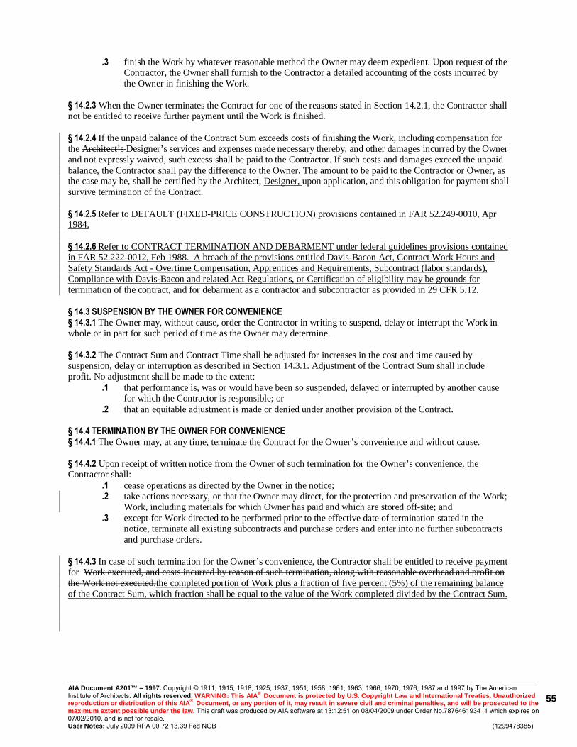
AIA Document A201™ – 1997. Copyright © 1911, 1915, 1918, 1925, 1937, 1951, 1958, 1961, 1963, 1966, 1970, 1976, 1987 and 1997 by The American Institute of Architects. All rights reserved. WARNING: This AIA® Document is protected by U.S. Copyright Law and International Treaties. Unauthorized reproduction or distribution of this AIA® Document, or any portion of it, may result in severe civil and criminal penalties, and will be prosecuted to the maximum extent possible under the law. This draft was produced by AIA software at 13:12:51 on 08/04/2009 under Order No.7876461934_1 which expires on 07/02/2010, and is not for resale. User Notes: July 2009 RPA 00 72 13.39 Fed NGB (1299478385)
55
.3 finish the Work by whatever reasonable method the Owner may deem expedient. Upon request of the Contractor, the Owner shall furnish to the Contractor a detailed accounting of the costs incurred by the Owner in finishing the Work.
§ 14.2.3 When the Owner terminates the Contract for one of the reasons stated in Section 14.2.1, the Contractor shall not be entitled to receive further payment until the Work is finished. § 14.2.4 If the unpaid balance of the Contract Sum exceeds costs of finishing the Work, including compensation for the Architect’s Designer’s services and expenses made necessary thereby, and other damages incurred by the Owner and not expressly waived, such excess shall be paid to the Contractor. If such costs and damages exceed the unpaid balance, the Contractor shall pay the difference to the Owner. The amount to be paid to the Contractor or Owner, as the case may be, shall be certified by the Architect, Designer, upon application, and this obligation for payment shall survive termination of the Contract. § 14.2.5 Refer to DEFAULT (FIXED-PRICE CONSTRUCTION) provisions contained in FAR 52.249-0010, Apr 1984. § 14.2.6 Refer to CONTRACT TERMINATION AND DEBARMENT under federal guidelines provisions contained in FAR 52.222-0012, Feb 1988. A breach of the provisions entitled Davis-Bacon Act, Contract Work Hours and Safety Standards Act - Overtime Compensation, Apprentices and Requirements, Subcontract (labor standards), Compliance with Davis-Bacon and related Act Regulations, or Certification of eligibility may be grounds for termination of the contract, and for debarment as a contractor and subcontractor as provided in 29 CFR 5.12. § 14.3 SUSPENSION BY THE OWNER FOR CONVENIENCE § 14.3.1 The Owner may, without cause, order the Contractor in writing to suspend, delay or interrupt the Work in whole or in part for such period of time as the Owner may determine. § 14.3.2 The Contract Sum and Contract Time shall be adjusted for increases in the cost and time caused by suspension, delay or interruption as described in Section 14.3.1. Adjustment of the Contract Sum shall include profit. No adjustment shall be made to the extent:
.1 that performance is, was or would have been so suspended, delayed or interrupted by another cause for which the Contractor is responsible; or
.2 that an equitable adjustment is made or denied under another provision of the Contract. § 14.4 TERMINATION BY THE OWNER FOR CONVENIENCE § 14.4.1 The Owner may, at any time, terminate the Contract for the Owner’s convenience and without cause. § 14.4.2 Upon receipt of written notice from the Owner of such termination for the Owner’s convenience, the Contractor shall:
.1 cease operations as directed by the Owner in the notice;
.2 take actions necessary, or that the Owner may direct, for the protection and preservation of the Work; Work, including materials for which Owner has paid and which are stored off-site; and
.3 except for Work directed to be performed prior to the effective date of termination stated in the notice, terminate all existing subcontracts and purchase orders and enter into no further subcontracts and purchase orders.
§ 14.4.3 In case of such termination for the Owner’s convenience, the Contractor shall be entitled to receive payment for Work executed, and costs incurred by reason of such termination, along with reasonable overhead and profit on the Work not executed.the completed portion of Work plus a fraction of five percent (5%) of the remaining balance of the Contract Sum, which fraction shall be equal to the value of the Work completed divided by the Contract Sum.
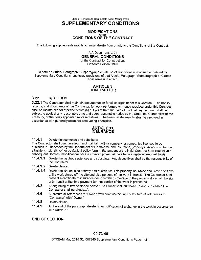

SUPPLEMENTARY CONDITIONS for federal wage rate requirements
Intended for use with OFD Conditions for General Work.
Posted in PDF format General Work with federal wage rates January 2014 OFD s007345 page 1 of 5
Supplementary Conditions: Fed Wages00 73 45 - 1
MODIFICATIONS TO OFD s007213 for General Work
(a modified AIA Document A201-1997)
GENERAL CONDITIONS OF THE CONTRACT FOR CONSTRUCTION
The following supplements modify, change, delete from or add to "General Conditions of the Contract for Construction", and any other Conditions preceding these by section number for this Contract. Where a portion of Conditions is altered by these Conditions, the unaltered portion shall remain in effect.
ADD THE FOLLOWING: 3.4.7.2 Federal Wage Scale 3.4.7.2.1 A Federal Wage Scale applies to the Project, and is included in Contract Documents as an attachment to this Section. Contractor shall pay not less than rates set forth. If both Federal and State wage rates apply to project, Contractor shall pay the higher of the two wage scales for each craft or trade. Failure of Owner or Designer to provide current wage scale decision prior to bidding does not relieve Contractor of obligations set forth above. If applicability or values of Prevailing Wage Rates applicable to the project change during the course of the Contract, or differ from those provided in Contract Documents, equitable adjustment in Contract Sum shall be made.
3.4.7.2.2 SUBCONTRACTS Contractor shall insert these provisions in subcontracts and require subcontractors to include these provisions in any lower tier subcontracts. Contractor shall be responsible for compliance with the provisions set forth herein by direct subcontractors and lower tier subcontractors.
3.4.7.2.3 FEDERAL COMPLIANCE OFFICER The Owner shall identify a Federal Compliance Officer at the institution where the Work is being performed. The Contractor and Designer shall meet with the Federal Compliance Officer to review the Davis-Bacon requirements and establish appropriate processes for transmitting the certified payrolls.
3.4.7.2.4 DAVIS-BACON ACT 3.4.7.2.4.1 Refer to provisions contained in FAR 52.222-6, Feb 1995, or latest revision.
3.4.7.2.4.2 All laborers and mechanics employed or working upon the site of the work will be paid unconditionally and not less often than once a week, and without subsequent deduction or rebate on any account (except such payroll deductions as are permitted by regulations issued by the Secretary of Labor under the Copeland Act (29 CRF Part 3), the full amount of wages and bona fide fringe benefits (or cash equivalents thereof) due at time of payment computed at rates not less than those contained in the wage determination of the Secretary of Labor which is bound herein or issued by addendum, and which is made a part hereof, regardless of any contractual relationship which may be alleged to exist between the Contractor and such laborers and mechanics. Contributions made or costs reasonably anticipated for bona fide fringes benefits under section 1 (b)(2) of the Davis-Bacon Act on behalf of laborers or mechanics are considered wages paid to such laborers or mechanics, subject to the provisions of subparagraph 1.4.8; of this paragraph; also, regular contributions made or costs incurred for more than a weekly period (but not less often than quarterly) under plans, funds, or programs which cover the particular weekly period, are deemed to be constructively made or incurred during such period. Such laborers and mechanics shall be paid not less than the appropriate wage rate and fringe benefits in the wage determination for the classification of work actually performed, without regard to skill, except as provided in the paragraph 1.7. Laborers or mechanics performing work in more than one classification may be compensated at the rate specified for each classification for the time actually worked therein; provided, that the employers payroll records accurately set forth the time spent in each classification in which work is performed. The wage determination (including any additional classifications and wage rates conformed under subparagraph 1.4.3 of this paragraph) and the Davis-Bacon
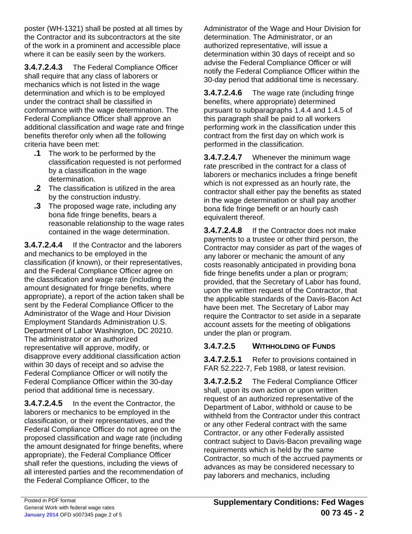
Posted in PDF format General Work with federal wage rates January 2014 OFD s007345 page 2 of 5
Supplementary Conditions: Fed Wages00 73 45 - 2
poster (WH-1321) shall be posted at all times by the Contractor and its subcontractors at the site of the work in a prominent and accessible place where it can be easily seen by the workers.
3.4.7.2.4.3 The Federal Compliance Officer shall require that any class of laborers or mechanics which is not listed in the wage determination and which is to be employed under the contract shall be classified in conformance with the wage determination. The Federal Compliance Officer shall approve an additional classification and wage rate and fringe benefits therefor only when all the following criteria have been met:
.1 The work to be performed by the classification requested is not performed by a classification in the wage determination.
.2 The classification is utilized in the area by the construction industry.
.3 The proposed wage rate, including any bona fide fringe benefits, bears a reasonable relationship to the wage rates contained in the wage determination.
3.4.7.2.4.4 If the Contractor and the laborers and mechanics to be employed in the classification (if known), or their representatives, and the Federal Compliance Officer agree on the classification and wage rate (including the amount designated for fringe benefits, where appropriate), a report of the action taken shall be sent by the Federal Compliance Officer to the Administrator of the Wage and Hour Division Employment Standards Administration U.S. Department of Labor Washington, DC 20210. The administrator or an authorized representative will approve, modify, or disapprove every additional classification action within 30 days of receipt and so advise the Federal Compliance Officer or will notify the Federal Compliance Officer within the 30-day period that additional time is necessary.
3.4.7.2.4.5 In the event the Contractor, the laborers or mechanics to be employed in the classification, or their representatives, and the Federal Compliance Officer do not agree on the proposed classification and wage rate (including the amount designated for fringe benefits, where appropriate), the Federal Compliance Officer shall refer the questions, including the views of all interested parties and the recommendation of the Federal Compliance Officer, to the
Administrator of the Wage and Hour Division for determination. The Administrator, or an authorized representative, will issue a determination within 30 days of receipt and so advise the Federal Compliance Officer or will notify the Federal Compliance Officer within the 30-day period that additional time is necessary.
3.4.7.2.4.6 The wage rate (including fringe benefits, where appropriate) determined pursuant to subparagraphs 1.4.4 and 1.4.5 of this paragraph shall be paid to all workers performing work in the classification under this contract from the first day on which work is performed in the classification.
3.4.7.2.4.7 Whenever the minimum wage rate prescribed in the contract for a class of laborers or mechanics includes a fringe benefit which is not expressed as an hourly rate, the contractor shall either pay the benefits as stated in the wage determination or shall pay another bona fide fringe benefit or an hourly cash equivalent thereof.
3.4.7.2.4.8 If the Contractor does not make payments to a trustee or other third person, the Contractor may consider as part of the wages of any laborer or mechanic the amount of any costs reasonably anticipated in providing bona fide fringe benefits under a plan or program; provided, that the Secretary of Labor has found, upon the written request of the Contractor, that the applicable standards of the Davis-Bacon Act have been met. The Secretary of Labor may require the Contractor to set aside in a separate account assets for the meeting of obligations under the plan or program.
3.4.7.2.5 WITHHOLDING OF FUNDS 3.4.7.2.5.1 Refer to provisions contained in FAR 52.222-7, Feb 1988, or latest revision.
3.4.7.2.5.2 The Federal Compliance Officer shall, upon its own action or upon written request of an authorized representative of the Department of Labor, withhold or cause to be withheld from the Contractor under this contract or any other Federal contract with the same Contractor, or any other Federally assisted contract subject to Davis-Bacon prevailing wage requirements which is held by the same Contractor, so much of the accrued payments or advances as may be considered necessary to pay laborers and mechanics, including

Posted in PDF format General Work with federal wage rates January 2014 OFD s007345 page 3 of 5
Supplementary Conditions: Fed Wages00 73 45 - 3
apprentices, trainees, and helpers, employed by the Contractor or any subcontractor the full amount of wages required by the contract. In the event of failure to pay any laborer or mechanic, including any apprentice, trainee, or helper, employed or working on the site of the work, all or part of the wages required by the contract, the Federal Compliance Officer may, after written notice to the Contractor, take such action as may be necessary to cause the suspension of any further payment, advance, or guarantee of funds until such violations have ceased.
3.4.7.2.6 PAYROLLS AND BASIC RECORDS 3.4.7.2.6.1 The Contractor and its subcontractors shall maintain payrolls and basic payroll records required for construction work by Department of Labor regulations at 29 CFR 5.5(a)(3) implementing the Davis-Bacon Act. Refer to provisions contained in FAR 52.222-8, Feb 1988, or latest revision.
3.4.7.2.6.2 Payrolls and basic records relating thereto shall be maintained by the Contractor during the course of the work and preserved for a period of 3 years thereafter for all laborers and mechanics working at the site of the work. Such records shall contain the name, address, and social security number of each worker, his or her correct classification, hourly rates of wages paid (including rates of contributions or costs anticipated for bona fide fringe benefits or cash equivalents thereof of the types described in section 1.b.2.B. of the Davis-Bacon Act), daily and weekly number of hours worked, deductions made, and actual wages paid. Whenever the Secretary of Labor has found, under subparagraph 1.4.8 above, that the wages of any laborer or mechanic include the amount of any costs reasonably anticipated in providing benefits under a plan or program described in section 1(b)(2)(B) of the Davis-Bacon Act, the Contractor shall maintain records which show that the commitment to provide such benefits is enforceable, that the plan or program is financially responsible, and that the plan or program has been communicated in writing to the laborers or mechanics affected, and records which show the costs anticipated or the actual cost incurred in providing such benefits. Contractors employing apprentices or trainees under approved programs shall maintain written evidence of the registration of apprenticeship programs and certification of trainee programs,
the registration of apprentices and trainees, and the ratio and wage rates prescribed in the applicable programs.
3.4.7.2.6.3 The Contractor shall submit weekly, for each week in which any contract work is performed, a copy of all payrolls to the Federal Compliance Officer. The payrolls submitted shall set out accurately and completely all of the information required to be maintained under subparagraph 1.6.2. above. This information shall be compiled weekly into a single PDF report and transmitted electronically. Optional Form WH-347 (Federal Stock Number 029-005-00014-1) is available for this purpose and may be purchased from the Superintendent of Documents, U.S. Government Printing Office, Washington DC 20402. The Contractor is responsible for the submission of copies of payrolls by all subcontractors.
3.4.7.2.6.4 Each payroll submitted shall be accompanied by a "Statement of Compliance" signed by the Contractor or subcontractor or his or her agent who pays or supervises the payment of the persons employed under the contract and shall certify:
.1 That the payroll for the payroll period contains the information required to be maintained under subparagraph 1.6.2 above, of this paragraph and that such information is correct and complete;
.2 That each laborer or mechanic (including each helper, apprentice, and trainee) employed on the contract during the payroll period has been paid the full weekly wages earned, without rebate, either directly or indirectly, and that no deductions have been made either directly or indirectly from the full wages earned, other than permissible deductions as set forth in the Regulations, 29CFR Part 3; and
.3 That each laborer or mechanic has been paid not less than the applicable wage rates and fringe benefits or cash equivalents for the classification of work performed, as specified in the applicable wage determination incorporated into the contract.
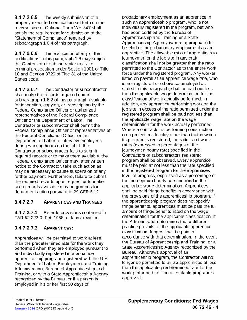
Posted in PDF format General Work with federal wage rates January 2014 OFD s007345 page 4 of 5
Supplementary Conditions: Fed Wages00 73 45 - 4
3.4.7.2.6.5 The weekly submission of a properly executed certification set forth on the reverse side of Optional Form WH-347 shall satisfy the requirement for submission of the "Statement of Compliance" required by subparagraph 1.6.4 of this paragraph.
3.4.7.2.6.6 The falsification of any of the certifications in this paragraph 1.6 may subject the Contractor or subcontractor to civil or criminal prosecution under Section 1001 of Title 18 and Section 3729 of Title 31 of the United States code.
3.4.7.2.6.7 The Contractor or subcontractor shall make the records required under subparagraph 1.6.2 of this paragraph available for inspection, copying, or transcription by the Federal Compliance Officer or authorized representatives of the Federal Compliance Officer or the Department of Labor. The Contractor or subcontractor shall permit the Federal Compliance Officer or representatives of the Federal Compliance Officer or the Department of Labor to interview employees during working hours on the job. If the Contractor or subcontractor fails to submit required records or to make them available, the Federal Compliance Officer may, after written notice to the Contractor, take such action as may be necessary to cause suspension of any further payment. Furthermore, failure to submit the required records upon request or to make such records available may be grounds for debarment action pursuant to 29 CFR 5.12.
3.4.7.2.7 APPRENTICES AND TRAINEES
3.4.7.2.7.1 Refer to provisions contained in FAR 52.222-9, Feb 1988, or latest revision.
3.4.7.2.7.2 APPRENTICES:
Apprentices will be permitted to work at less than the predetermined rate for the work they performed when they are employed pursuant to and individually registered in a bona fide apprenticeship program registered with the U.S. Department of Labor, Employment and Training Administration, Bureau of Apprenticeship and Training, or with a State Apprenticeship Agency recognized by the Bureau, or if a person is employed in his or her first 90 days of
probationary employment as an apprentice in such an apprenticeship program, who is not individually registered in the program, but who has been certified by the Bureau of Apprenticeship and Training or a State Apprenticeship Agency (where appropriate) to be eligible for probationary employment as an apprentice. The allowable ratio of apprentices to journeymen on the job site in any craft classification shall not be greater than the ratio permitted to the Contractor as to the entire work force under the registered program. Any worker listed on payroll at an apprentice wage rate, who is not registered or otherwise employed as stated in this paragraph, shall be paid not less than the applicable wage determination for the classification of work actually performed. In addition, any apprentice performing work on the job site in excess of the ratio permitted under the registered program shall be paid not less than the applicable wage rate on the wage determination for the work actually performed. Where a contractor is performing construction on a project in a locality other than that in which its program is registered, the ratios and wage rates (expressed in percentages of the journeymen hourly rate) specified in the Contractors or subcontractors registered program shall be observed. Every apprentice must be paid at not less than the rate specified in the registered program for the apprentices level of progress, expressed as a percentage of the journeyman hourly rate specified in the applicable wage determination. Apprentices shall be paid fringe benefits in accordance with the provisions of the apprenticeship program. If the apprenticeship program does not specify fringe benefits, apprentices must be paid the full amount of fringe benefits listed on the wage determination for the applicable classification. If the Administrator determines that a different practice prevails for the applicable apprentice classification, fringes shall be paid in accordance with that determination. In the event the Bureau of Apprenticeship and Training, or a State Apprenticeship Agency recognized by the Bureau, withdraws approval of an apprenticeship program, the Contractor will no longer be permitted to utilize apprentices at less than the applicable predetermined rate for the work performed until an acceptable program is approved.
Posted in PDF format General Work with federal wage rates January 2014 OFD s007345 page 5 of 5
Supplementary Conditions: Fed Wages00 73 45 - 5
3.4.7.2.7.3 TRAINEES:
Except as provided in 29 CFR 5.16, trainees will not be permitted to work at less than the predetermined rate for the work performed unless they are employed pursuant to and individually registered in a program which has received prior approval, evidenced by formal certification by the U.S. Department of Labor, Employment and Training Administration. The ratio of trainees to journeymen on the job site shall not be greater than permitted under the plan approved by the Employment and Training Administration. Every trainee must be paid at not less than the rate specified in the approved program for the trainees level of progress, expressed as a percentage of the journeyman hourly rate specified in the applicable wage determination. Trainees shall be paid fringe benefits in accordance with the provisions of the trainee program. If the trainee program does not mention fringe benefits, trainees shall be paid the full amount of fringe benefits listed in the wage determination unless the Administrator of the Wage and Hour Division determines that there is an apprenticeship program associated with the corresponding journeyman wage rate in the wage determination which provides for less than full fringe benefits for apprentices. Any employee listed on the payroll at a trainee rate who is not registered and participating in a training plan approved by the Employment and Training Administration shall be paid not less than the applicable wage rate in the wage determination for the classification of work actually performed. In addition, any trainee performing work on the job site in excess of the ratio permitted under the registered program shall be paid not less than the applicable wage rate in the wage determination for the work actually performed. In the event the Employment and Training Administration withdraws approval of a training program, the Contractor will no longer be permitted to utilize trainees at less than the applicable predetermined rate for the work performed until an acceptable program is approved.
END OF SECTION
SUPPLEMENTARY CONDITIONS for federal wage rate requirements
Intended for use with OFD Conditions for General Work.
Posted in PDF format General Work with federal wage rates January 2014 OFD s007345 page 1 of 5
Supplementary Conditions: Fed Wages00 73 45 - 1
MODIFICATIONS TO OFD s007213 for General Work
(a modified AIA Document A201-1997)
GENERAL CONDITIONS OF THE CONTRACT FOR CONSTRUCTION
The following supplements modify, change, delete from or add to "General Conditions of the Contract for Construction", and any other Conditions preceding these by section number for this Contract. Where a portion of Conditions is altered by these Conditions, the unaltered portion shall remain in effect.
ADD THE FOLLOWING: 3.4.7.2 Federal Wage Scale 3.4.7.2.1 A Federal Wage Scale applies to the Project, and is included in Contract Documents as an attachment to this Section. Contractor shall pay not less than rates set forth. If both Federal and State wage rates apply to project, Contractor shall pay the higher of the two wage scales for each craft or trade. Failure of Owner or Designer to provide current wage scale decision prior to bidding does not relieve Contractor of obligations set forth above. If applicability or values of Prevailing Wage Rates applicable to the project change during the course of the Contract, or differ from those provided in Contract Documents, equitable adjustment in Contract Sum shall be made.
3.4.7.2.2 SUBCONTRACTS Contractor shall insert these provisions in subcontracts and require subcontractors to include these provisions in any lower tier subcontracts. Contractor shall be responsible for compliance with the provisions set forth herein by direct subcontractors and lower tier subcontractors.
3.4.7.2.3 FEDERAL COMPLIANCE OFFICER The Owner shall identify a Federal Compliance Officer at the institution where the Work is being performed. The Contractor and Designer shall meet with the Federal Compliance Officer to review the Davis-Bacon requirements and establish appropriate processes for transmitting the certified payrolls.
3.4.7.2.4 DAVIS-BACON ACT 3.4.7.2.4.1 Refer to provisions contained in FAR 52.222-6, Feb 1995, or latest revision.
3.4.7.2.4.2 All laborers and mechanics employed or working upon the site of the work will be paid unconditionally and not less often than once a week, and without subsequent deduction or rebate on any account (except such payroll deductions as are permitted by regulations issued by the Secretary of Labor under the Copeland Act (29 CRF Part 3), the full amount of wages and bona fide fringe benefits (or cash equivalents thereof) due at time of payment computed at rates not less than those contained in the wage determination of the Secretary of Labor which is bound herein or issued by addendum, and which is made a part hereof, regardless of any contractual relationship which may be alleged to exist between the Contractor and such laborers and mechanics. Contributions made or costs reasonably anticipated for bona fide fringes benefits under section 1 (b)(2) of the Davis-Bacon Act on behalf of laborers or mechanics are considered wages paid to such laborers or mechanics, subject to the provisions of subparagraph 1.4.8; of this paragraph; also, regular contributions made or costs incurred for more than a weekly period (but not less often than quarterly) under plans, funds, or programs which cover the particular weekly period, are deemed to be constructively made or incurred during such period. Such laborers and mechanics shall be paid not less than the appropriate wage rate and fringe benefits in the wage determination for the classification of work actually performed, without regard to skill, except as provided in the paragraph 1.7. Laborers or mechanics performing work in more than one classification may be compensated at the rate specified for each classification for the time actually worked therein; provided, that the employers payroll records accurately set forth the time spent in each classification in which work is performed. The wage determination (including any additional classifications and wage rates conformed under subparagraph 1.4.3 of this paragraph) and the Davis-Bacon

Posted in PDF format General Work with federal wage rates January 2014 OFD s007345 page 2 of 5
Supplementary Conditions: Fed Wages00 73 45 - 2
poster (WH-1321) shall be posted at all times by the Contractor and its subcontractors at the site of the work in a prominent and accessible place where it can be easily seen by the workers.
3.4.7.2.4.3 The Federal Compliance Officer shall require that any class of laborers or mechanics which is not listed in the wage determination and which is to be employed under the contract shall be classified in conformance with the wage determination. The Federal Compliance Officer shall approve an additional classification and wage rate and fringe benefits therefor only when all the following criteria have been met:
.1 The work to be performed by the classification requested is not performed by a classification in the wage determination.
.2 The classification is utilized in the area by the construction industry.
.3 The proposed wage rate, including any bona fide fringe benefits, bears a reasonable relationship to the wage rates contained in the wage determination.
3.4.7.2.4.4 If the Contractor and the laborers and mechanics to be employed in the classification (if known), or their representatives, and the Federal Compliance Officer agree on the classification and wage rate (including the amount designated for fringe benefits, where appropriate), a report of the action taken shall be sent by the Federal Compliance Officer to the Administrator of the Wage and Hour Division Employment Standards Administration U.S. Department of Labor Washington, DC 20210. The administrator or an authorized representative will approve, modify, or disapprove every additional classification action within 30 days of receipt and so advise the Federal Compliance Officer or will notify the Federal Compliance Officer within the 30-day period that additional time is necessary.
3.4.7.2.4.5 In the event the Contractor, the laborers or mechanics to be employed in the classification, or their representatives, and the Federal Compliance Officer do not agree on the proposed classification and wage rate (including the amount designated for fringe benefits, where appropriate), the Federal Compliance Officer shall refer the questions, including the views of all interested parties and the recommendation of the Federal Compliance Officer, to the
Administrator of the Wage and Hour Division for determination. The Administrator, or an authorized representative, will issue a determination within 30 days of receipt and so advise the Federal Compliance Officer or will notify the Federal Compliance Officer within the 30-day period that additional time is necessary.
3.4.7.2.4.6 The wage rate (including fringe benefits, where appropriate) determined pursuant to subparagraphs 1.4.4 and 1.4.5 of this paragraph shall be paid to all workers performing work in the classification under this contract from the first day on which work is performed in the classification.
3.4.7.2.4.7 Whenever the minimum wage rate prescribed in the contract for a class of laborers or mechanics includes a fringe benefit which is not expressed as an hourly rate, the contractor shall either pay the benefits as stated in the wage determination or shall pay another bona fide fringe benefit or an hourly cash equivalent thereof.
3.4.7.2.4.8 If the Contractor does not make payments to a trustee or other third person, the Contractor may consider as part of the wages of any laborer or mechanic the amount of any costs reasonably anticipated in providing bona fide fringe benefits under a plan or program; provided, that the Secretary of Labor has found, upon the written request of the Contractor, that the applicable standards of the Davis-Bacon Act have been met. The Secretary of Labor may require the Contractor to set aside in a separate account assets for the meeting of obligations under the plan or program.
3.4.7.2.5 WITHHOLDING OF FUNDS 3.4.7.2.5.1 Refer to provisions contained in FAR 52.222-7, Feb 1988, or latest revision.
3.4.7.2.5.2 The Federal Compliance Officer shall, upon its own action or upon written request of an authorized representative of the Department of Labor, withhold or cause to be withheld from the Contractor under this contract or any other Federal contract with the same Contractor, or any other Federally assisted contract subject to Davis-Bacon prevailing wage requirements which is held by the same Contractor, so much of the accrued payments or advances as may be considered necessary to pay laborers and mechanics, including
Posted in PDF format General Work with federal wage rates January 2014 OFD s007345 page 3 of 5
Supplementary Conditions: Fed Wages00 73 45 - 3
apprentices, trainees, and helpers, employed by the Contractor or any subcontractor the full amount of wages required by the contract. In the event of failure to pay any laborer or mechanic, including any apprentice, trainee, or helper, employed or working on the site of the work, all or part of the wages required by the contract, the Federal Compliance Officer may, after written notice to the Contractor, take such action as may be necessary to cause the suspension of any further payment, advance, or guarantee of funds until such violations have ceased.
3.4.7.2.6 PAYROLLS AND BASIC RECORDS 3.4.7.2.6.1 The Contractor and its subcontractors shall maintain payrolls and basic payroll records required for construction work by Department of Labor regulations at 29 CFR 5.5(a)(3) implementing the Davis-Bacon Act. Refer to provisions contained in FAR 52.222-8, Feb 1988, or latest revision.
3.4.7.2.6.2 Payrolls and basic records relating thereto shall be maintained by the Contractor during the course of the work and preserved for a period of 3 years thereafter for all laborers and mechanics working at the site of the work. Such records shall contain the name, address, and social security number of each worker, his or her correct classification, hourly rates of wages paid (including rates of contributions or costs anticipated for bona fide fringe benefits or cash equivalents thereof of the types described in section 1.b.2.B. of the Davis-Bacon Act), daily and weekly number of hours worked, deductions made, and actual wages paid. Whenever the Secretary of Labor has found, under subparagraph 1.4.8 above, that the wages of any laborer or mechanic include the amount of any costs reasonably anticipated in providing benefits under a plan or program described in section 1(b)(2)(B) of the Davis-Bacon Act, the Contractor shall maintain records which show that the commitment to provide such benefits is enforceable, that the plan or program is financially responsible, and that the plan or program has been communicated in writing to the laborers or mechanics affected, and records which show the costs anticipated or the actual cost incurred in providing such benefits. Contractors employing apprentices or trainees under approved programs shall maintain written evidence of the registration of apprenticeship programs and certification of trainee programs,
the registration of apprentices and trainees, and the ratio and wage rates prescribed in the applicable programs.
3.4.7.2.6.3 The Contractor shall submit weekly, for each week in which any contract work is performed, a copy of all payrolls to the Federal Compliance Officer. The payrolls submitted shall set out accurately and completely all of the information required to be maintained under subparagraph 1.6.2. above. This information shall be compiled weekly into a single PDF report and transmitted electronically. Optional Form WH-347 (Federal Stock Number 029-005-00014-1) is available for this purpose and may be purchased from the Superintendent of Documents, U.S. Government Printing Office, Washington DC 20402. The Contractor is responsible for the submission of copies of payrolls by all subcontractors.
3.4.7.2.6.4 Each payroll submitted shall be accompanied by a "Statement of Compliance" signed by the Contractor or subcontractor or his or her agent who pays or supervises the payment of the persons employed under the contract and shall certify:
.1 That the payroll for the payroll period contains the information required to be maintained under subparagraph 1.6.2 above, of this paragraph and that such information is correct and complete;
.2 That each laborer or mechanic (including each helper, apprentice, and trainee) employed on the contract during the payroll period has been paid the full weekly wages earned, without rebate, either directly or indirectly, and that no deductions have been made either directly or indirectly from the full wages earned, other than permissible deductions as set forth in the Regulations, 29CFR Part 3; and
.3 That each laborer or mechanic has been paid not less than the applicable wage rates and fringe benefits or cash equivalents for the classification of work performed, as specified in the applicable wage determination incorporated into the contract.

Posted in PDF format General Work with federal wage rates January 2014 OFD s007345 page 4 of 5
Supplementary Conditions: Fed Wages00 73 45 - 4
3.4.7.2.6.5 The weekly submission of a properly executed certification set forth on the reverse side of Optional Form WH-347 shall satisfy the requirement for submission of the "Statement of Compliance" required by subparagraph 1.6.4 of this paragraph.
3.4.7.2.6.6 The falsification of any of the certifications in this paragraph 1.6 may subject the Contractor or subcontractor to civil or criminal prosecution under Section 1001 of Title 18 and Section 3729 of Title 31 of the United States code.
3.4.7.2.6.7 The Contractor or subcontractor shall make the records required under subparagraph 1.6.2 of this paragraph available for inspection, copying, or transcription by the Federal Compliance Officer or authorized representatives of the Federal Compliance Officer or the Department of Labor. The Contractor or subcontractor shall permit the Federal Compliance Officer or representatives of the Federal Compliance Officer or the Department of Labor to interview employees during working hours on the job. If the Contractor or subcontractor fails to submit required records or to make them available, the Federal Compliance Officer may, after written notice to the Contractor, take such action as may be necessary to cause suspension of any further payment. Furthermore, failure to submit the required records upon request or to make such records available may be grounds for debarment action pursuant to 29 CFR 5.12.
3.4.7.2.7 APPRENTICES AND TRAINEES
3.4.7.2.7.1 Refer to provisions contained in FAR 52.222-9, Feb 1988, or latest revision.
3.4.7.2.7.2 APPRENTICES:
Apprentices will be permitted to work at less than the predetermined rate for the work they performed when they are employed pursuant to and individually registered in a bona fide apprenticeship program registered with the U.S. Department of Labor, Employment and Training Administration, Bureau of Apprenticeship and Training, or with a State Apprenticeship Agency recognized by the Bureau, or if a person is employed in his or her first 90 days of
probationary employment as an apprentice in such an apprenticeship program, who is not individually registered in the program, but who has been certified by the Bureau of Apprenticeship and Training or a State Apprenticeship Agency (where appropriate) to be eligible for probationary employment as an apprentice. The allowable ratio of apprentices to journeymen on the job site in any craft classification shall not be greater than the ratio permitted to the Contractor as to the entire work force under the registered program. Any worker listed on payroll at an apprentice wage rate, who is not registered or otherwise employed as stated in this paragraph, shall be paid not less than the applicable wage determination for the classification of work actually performed. In addition, any apprentice performing work on the job site in excess of the ratio permitted under the registered program shall be paid not less than the applicable wage rate on the wage determination for the work actually performed. Where a contractor is performing construction on a project in a locality other than that in which its program is registered, the ratios and wage rates (expressed in percentages of the journeymen hourly rate) specified in the Contractors or subcontractors registered program shall be observed. Every apprentice must be paid at not less than the rate specified in the registered program for the apprentices level of progress, expressed as a percentage of the journeyman hourly rate specified in the applicable wage determination. Apprentices shall be paid fringe benefits in accordance with the provisions of the apprenticeship program. If the apprenticeship program does not specify fringe benefits, apprentices must be paid the full amount of fringe benefits listed on the wage determination for the applicable classification. If the Administrator determines that a different practice prevails for the applicable apprentice classification, fringes shall be paid in accordance with that determination. In the event the Bureau of Apprenticeship and Training, or a State Apprenticeship Agency recognized by the Bureau, withdraws approval of an apprenticeship program, the Contractor will no longer be permitted to utilize apprentices at less than the applicable predetermined rate for the work performed until an acceptable program is approved.

Posted in PDF format General Work with federal wage rates January 2014 OFD s007345 page 5 of 5
Supplementary Conditions: Fed Wages00 73 45 - 5
3.4.7.2.7.3 TRAINEES:
Except as provided in 29 CFR 5.16, trainees will not be permitted to work at less than the predetermined rate for the work performed unless they are employed pursuant to and individually registered in a program which has received prior approval, evidenced by formal certification by the U.S. Department of Labor, Employment and Training Administration. The ratio of trainees to journeymen on the job site shall not be greater than permitted under the plan approved by the Employment and Training Administration. Every trainee must be paid at not less than the rate specified in the approved program for the trainees level of progress, expressed as a percentage of the journeyman hourly rate specified in the applicable wage determination. Trainees shall be paid fringe benefits in accordance with the provisions of the trainee program. If the trainee program does not mention fringe benefits, trainees shall be paid the full amount of fringe benefits listed in the wage determination unless the Administrator of the Wage and Hour Division determines that there is an apprenticeship program associated with the corresponding journeyman wage rate in the wage determination which provides for less than full fringe benefits for apprentices. Any employee listed on the payroll at a trainee rate who is not registered and participating in a training plan approved by the Employment and Training Administration shall be paid not less than the applicable wage rate in the wage determination for the classification of work actually performed. In addition, any trainee performing work on the job site in excess of the ratio permitted under the registered program shall be paid not less than the applicable wage rate in the wage determination for the work actually performed. In the event the Employment and Training Administration withdraws approval of a training program, the Contractor will no longer be permitted to utilize trainees at less than the applicable predetermined rate for the work performed until an acceptable program is approved.
END OF SECTION
01 10 00 STREAM June 2014 Std 011000 Summary Page 1 of 1
SECTION 01 10 00 SUMMARY
PART 1 – GENERAL
1.01 Summary of Work:
A. Exterior envelope repairs including tuck-pointing of existing brick masonry, new brick masonry installation, fence removal, drainage improvements, new EPDM roof sloped to exterior gutters and downspouts, exterior window replacement, interior ceiling within storage space, new paint and sealed concrete floor.
B. Work By Owner – Not Applicable 1.02 Multiple Contracts:
A. Summary of other contracts – Not Applicable B. Work Sequence – Not Applicable C. Construction by Owner – Not Applicable D. Contact Interface and Coordination – Not Applicable
1.03 Work Sequence: GC to coordinate work times and sequencing with facility to maintain normal operating
business hours (8:00am-5:00pm)
1.04 Products:
A. Ordered in Advance – GC to coordinate product lead times to maintain project schedule.
B. Owner Furnished Products – Not Applicable
1.05 Future Work: Not Applicable
1.06 Work Restrictions: (Coordinate with the Special Project Procedures Section, if applicable)
GC to coordinate with the Facility Manager for the items listed below.
A. Site access and security procedures; Site access and security procedures will apply as directed by the
Owner.
B. Work hours and use of premises; Hours will be between the hours of 6:00 a.m. and 5:00 p.m. Work
outside this time-frame are to be approved by the Owner 24 hours in advance.
C. Owner occupancy details; Spaces below the work area will be occupied. There may be times where the
Owner may request the Contractor to work in alternate locations temporarily due to office meetings below.
D. Owner maintenance and operation requirements; and,
E. Adjacent activities to the project site.

01 10 00 STREAM June 2014 Std 011000 Summary Page 2 of 1
1.07 Use of the site:
GC to coordinate with the Facility Manager for the items listed below.
A. By Contractor for Work, including parking and staging; Site laydown area as noted on the document set.
Any changes must be approved by the Owner.
B. By Owner and Owner’s clientele, including egress; and,
C. Project utility sources.
END OF SECTION

01 23 00 STREAM June 2014 Std 012300 Alternates Page 1 of 1
SECTION 01 23 00 ALTERNATES
PART 1 - GENERAL 1.01 SECTION INCLUDES identification of each Alternate by number, and describes the basic changes to be
incorporated into the Work if a particular alternate is made a part of the work by specific provisions in the Agreement between the Owner and the Contractor.
1.02 RELATED SECTIONS are referenced in the definition of each Alternate.
1.03 COORDINATION of related work and modifications to surrounding work as required to properly integrate each Alternate, and to provide the complete construction required by the Contract Documents, is the responsibility of the Contractor.
1.04 DESCRIPTION OF ALTERNATES:
Alternate No.1 – Exterior Aluminum Windows and Associated Flashing
Alternate No.2 – Exterior Concrete Flatwork, Grading and Drainage
Alternate No.3 – Storage Room Interior Finishes
Alternate No.4 – 90MIL EPDM in lieu of 60MIL
END OF SECTION
01 26 00 STREAM June 2014 Std 012600 Modification Procedures Page 1 of 1
SECTION 01 26 00 MODIFICATION PROCEDURES
PART 1 - GENERAL 1.01 SUPPORTING DOCUMENTATION for PROPOSALS or CLAIMS
A. Propose changes to Work in writing, specifically describing proposed change, or briefly describing the proposed change with specific reference to a completely descriptive attachment.
B. Propose changes in Contract Sum in writing, stating briefly the reason for change, and summarizing material, equipment, labor, overhead, and profit factors for Contractor, Subcontractors, and Sub-subcontractors. Unless waived by Owner, attach itemization of values of direct cost on form shown as Section 01 26 50, or similar form which provides same information, citing:
1. Materials: units, costs, quantities, totals;
2. Equipment: hours, rates, totals; and,
3. Labor: hours, rates, totals.
C. Propose changes in Contract Time in writing:
1. Fully describe the reasons for the change and effect of the change on the construction schedule, and attach a revised Progress Schedule; and/or,
2. For a change based on weather-related delay, provide and attach weather data from National Oceanic and Atmospheric Administration (NOAA) as an impartial basis for determining justifiable extensions, or daily work logs which describe actual local weather conditions and impact, subject to approval by Designer. Provide and attach NOAA comparative data on normals, means, and extremes if not already provided in Project Manual.
1.02 FORM for CHANGE ORDERS and CONSTRUCTION CHANGE DIRECTIVES
The form shall be that shown as Section 01 26 40, or a similarly formatted document utilizing the same text. Complete description of change in Work shall be included in the body of the form or in referenced attachment. Change in Contract Sum and Contract Time shall be expressed in the body of the form.
1.03 SIGNATURES:
A. Form shall be signed by authorized representatives of each of the entities required by Conditions of the Contract.
B. Proposed Change Orders will be prepared by Owner or Designer and normally signed by both before being issued to Contractor. Contractor shall sign acceptable proposed Change Orders, or refuse to sign if in disagreement, then shall retain one (1) counterpart and return other counterparts to Designer.
END OF SECTION
01 26 23 STREAM June 2014 Roof Std 012623 Re-roofing Weather Delays Page 1 of 2
SECTION 01 26 23 RE-ROOFING WEATHER DELAYS
PART 1 - GENERAL 1.01 EXTENSIONS OF CONTRACT TIME
If the basis exists for an extension of time in accordance with paragraph 8.3 of the Conditions, an extension of time on the basis of weather may be granted only for the number of Weather Delay Days in excess of the number of days listed as the Standard Baseline for that month.
1.02 STANDARD BASELINE FOR AVERAGE CLIMATIC RANGE
A. The Owner has reviewed weather data available from the National Oceanic and Atmospheric Administration (NOAA) and determined a Standard Baseline of average climatic range for the State of Tennessee.
B. Standard Baseline is defined as the normal number of calendar days for each month during which roofing removal and replacement activity exposed to weather conditions is expected to be prevented and suspended by cause of adverse weather. Suspension of roofing removal and replacement for the number of days each month as listed in the Standard Baseline is included in the Work and is not eligible for extension of Contract Time.
C. Standard Baseline is as follows:
Jan Feb Mar Apr May Jun Jul Aug Sep Oct Nov Dec
12 11 12 11 11 9 10 9 8 7 10 11
1.03 ADVERSE WEATHER and WEATHER DELAY DAYS
A. Adverse Weather is defined as the occurrence of one or more of the following conditions within a twenty-four (24) hour day that prevents roofing removal and replacement activity exposed to weather conditions or access to the site:
1. Precipitation (rain, snow, or ice) in excess of one-hundredth inch (0.01") liquid measure;
2. Temperatures that do not rise above material manufacturers recommended minimum installation temperature; and/or,
3. Sustained wind in excess of fifteen (15) m.p.h.
B. Adverse Weather may include, if appropriate, "dry-out" days:
1. resulting from precipitation days that occur beyond the standard baseline;
2. only if there is a hindrance to site access and Contractor has taken all reasonable accommodations to avoid such hindrance; and,
3. at a rate no greater than one (1) make-up day for each day or consecutive days of precipitation beyond the standard baseline that total five-tenths inch (0.5 “) or more, liquid measure, unless specifically recommended otherwise by the Designer.
C. A Weather Delay Day may be counted if the official local Weather Bureau forecast is predicting a greater than thirty percent (30%) chance of the occurrence of adverse weather thereby causing the Contractor to determine that, in his professional opinion, it would be in the Owner’s best interest not to perform any work that day that could result in possible damage to the interior of the structure or injury to its contents or occupants.
D. A Weather Delay Day may be counted if adverse weather prevents work on the project for fifty percent (50%) or more of the contractor's scheduled work day and critical path construction activities were included in the day’s schedule, including a weekend day or holiday if Contractor has scheduled construction activity that day.
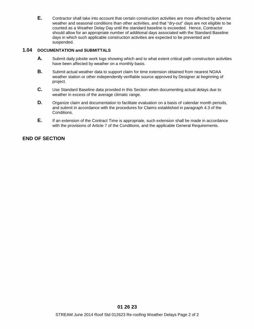
01 26 23 STREAM June 2014 Roof Std 012623 Re-roofing Weather Delays Page 2 of 2
E. Contractor shall take into account that certain construction activities are more affected by adverse weather and seasonal conditions than other activities, and that “dry-out” days are not eligible to be counted as a Weather Delay Day until the standard baseline is exceeded. Hence, Contractor should allow for an appropriate number of additional days associated with the Standard Baseline days in which such applicable construction activities are expected to be prevented and suspended.
1.04 DOCUMENTATION and SUBMITTALS
A. Submit daily jobsite work logs showing which and to what extent critical path construction activities have been affected by weather on a monthly basis.
B. Submit actual weather data to support claim for time extension obtained from nearest NOAA weather station or other independently verifiable source approved by Designer at beginning of project.
C. Use Standard Baseline data provided in this Section when documenting actual delays due to weather in excess of the average climatic range.
D. Organize claim and documentation to facilitate evaluation on a basis of calendar month periods, and submit in accordance with the procedures for Claims established in paragraph 4.3 of the Conditions.
E. If an extension of the Contract Time is appropriate, such extension shall be made in accordance with the provisions of Article 7 of the Conditions, and the applicable General Requirements.
END OF SECTION
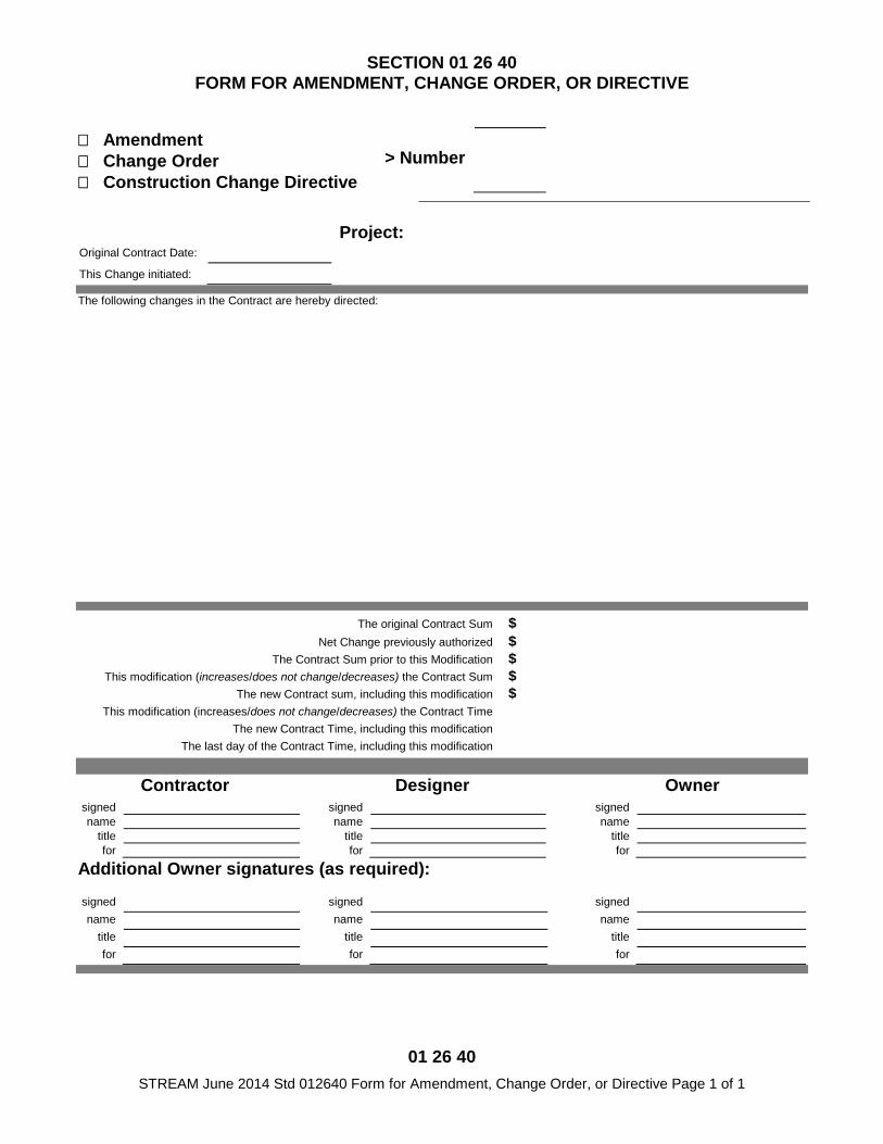
01 26 40 STREAM June 2014 Std 012640 Form for Amendment, Change Order, or Directive Page 1 of 1
SECTION 01 26 40 FORM FOR AMENDMENT, CHANGE ORDER, OR DIRECTIVE
� Amendment � Change Order � Construction Change Directive
> Number
Project:
Original Contract Date:
This Change initiated:
The following changes in the Contract are hereby directed:
The original Contract Sum $
Net Change previously authorized $ The Contract Sum prior to this Modification $
This modification (increases/does not change/decreases) the Contract Sum $ The new Contract sum, including this modification $
This modification (increases/does not change/decreases) the Contract Time The new Contract Time, including this modification
The last day of the Contract Time, including this modification
Contractor Designer Owner
signed signed signed name name name
title title title for for for
Additional Owner signatures (as required):
signed signed signed name name name
title title title for for for
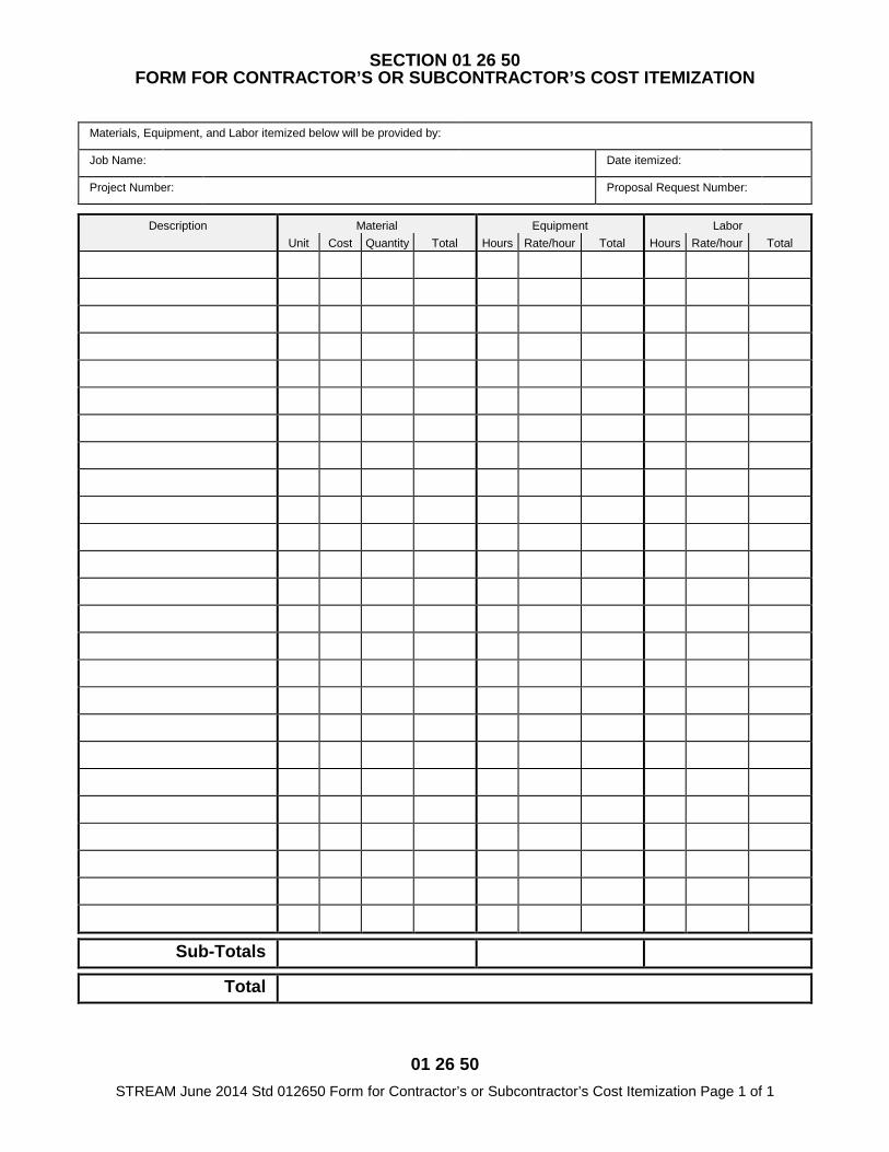
01 26 50 STREAM June 2014 Std 012650 Form for Contractor’s or Subcontractor’s Cost Itemization Page 1 of 1
SECTION 01 26 50 FORM FOR CONTRACTOR’S OR SUBCONTRACTOR’S COST ITEMIZATION
Materials, Equipment, and Labor itemized below will be provided by:
Job Name: Date itemized: Project Number: Proposal Request Number:
Description Material Equipment Labor
Unit Cost Quantity Total Hours Rate/hour Total Hours Rate/hour Total
Sub-Totals
Total

01 29 73 STREAM June 2014 Std 012973 Schedule of Values Page 1 of 1
SECTION 01 29 73 SCHEDULE OF VALUES
PART 1 - GENERAL 1.01 FORM and APPROVAL
A. The form for schedule of values shall be AIA Document G703 Continuation Sheet.
B. If objected to by Designer, revise and resubmit to Designer's satisfaction prior to submitting application for payment.
1.02 ALLOCATION OF VALUES
A. If the Work is divided into defined portions ("Phases"), intended to have distinct commencement, duration, or completion requirements, divide the allocation to correspond to the Phases, then within each Phase, subdivide the allocations as specified in the following paragraphs.
B. Provide a single line item to account for mobilization and general administration, and fulfilling General Requirements.
C. If sitework is included, other than minor sitework incidental to a building or major structure, include sitework in single heading. Subdivide site utilities, roads and parking, and appurtenances according to general type within this division of construction activity.
D. For each involved building or major structure, provide a separate group of line items corresponding to Divisions and Sections of the Specifications. Further subdivide as desired, but maintain a distinct and identifiable correspondence to this allocation.
E. Account for Unit Prices and Allowances with a line item for each, until incorporating each into the appropriate allocations for the final statement of accounting.
F. Account for Modifications with a line item for each, until incorporating each into the appropriate allocations for the final statement of accounting.
END OF SECTION
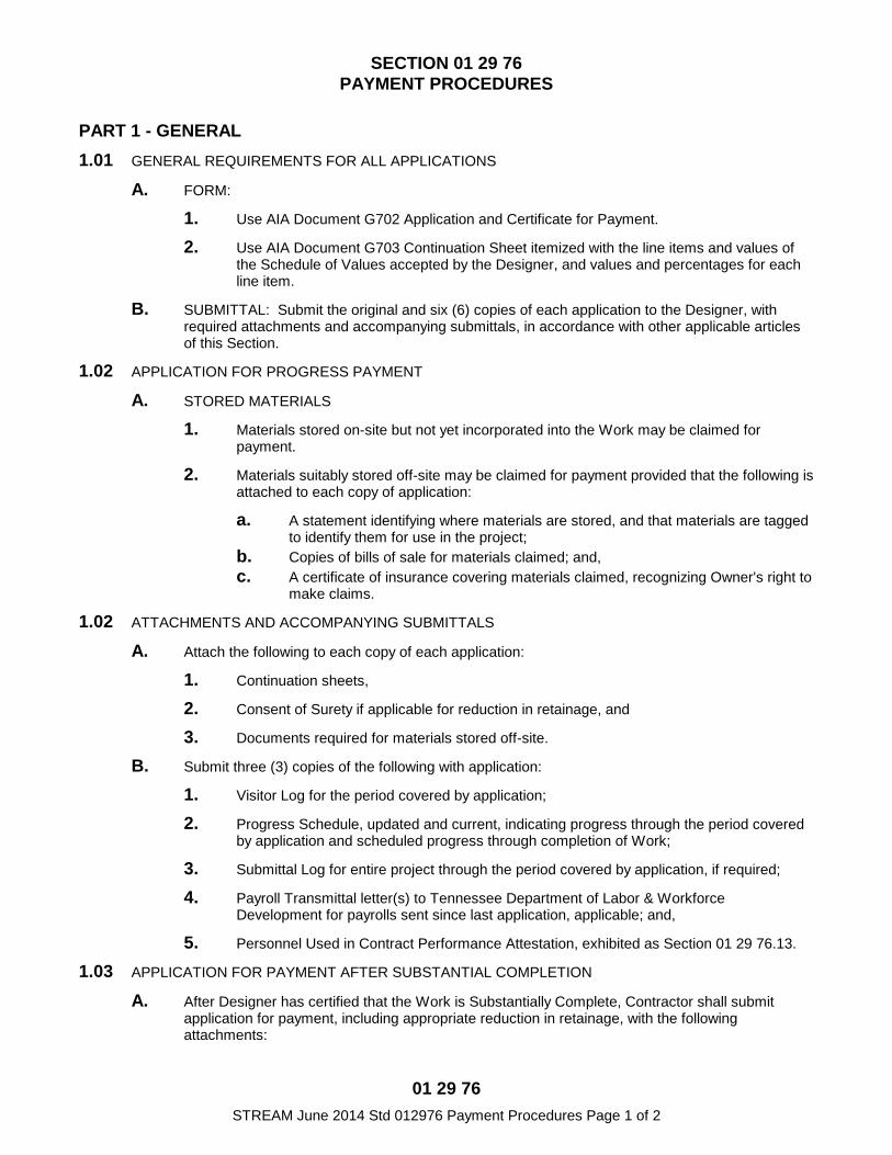
01 29 76 STREAM June 2014 Std 012976 Payment Procedures Page 1 of 2
SECTION 01 29 76 PAYMENT PROCEDURES
PART 1 - GENERAL 1.01 GENERAL REQUIREMENTS FOR ALL APPLICATIONS
A. FORM:
1. Use AIA Document G702 Application and Certificate for Payment.
2. Use AIA Document G703 Continuation Sheet itemized with the line items and values of the Schedule of Values accepted by the Designer, and values and percentages for each line item.
B. SUBMITTAL: Submit the original and six (6) copies of each application to the Designer, with required attachments and accompanying submittals, in accordance with other applicable articles of this Section.
1.02 APPLICATION FOR PROGRESS PAYMENT
A. STORED MATERIALS
1. Materials stored on-site but not yet incorporated into the Work may be claimed for payment.
2. Materials suitably stored off-site may be claimed for payment provided that the following is attached to each copy of application:
a. A statement identifying where materials are stored, and that materials are tagged to identify them for use in the project;
b. Copies of bills of sale for materials claimed; and, c. A certificate of insurance covering materials claimed, recognizing Owner's right to
make claims.
1.02 ATTACHMENTS AND ACCOMPANYING SUBMITTALS
A. Attach the following to each copy of each application:
1. Continuation sheets,
2. Consent of Surety if applicable for reduction in retainage, and
3. Documents required for materials stored off-site.
B. Submit three (3) copies of the following with application:
1. Visitor Log for the period covered by application;
2. Progress Schedule, updated and current, indicating progress through the period covered by application and scheduled progress through completion of Work;
3. Submittal Log for entire project through the period covered by application, if required;
4. Payroll Transmittal letter(s) to Tennessee Department of Labor & Workforce Development for payrolls sent since last application, applicable; and,
5. Personnel Used in Contract Performance Attestation, exhibited as Section 01 29 76.13.
1.03 APPLICATION FOR PAYMENT AFTER SUBSTANTIAL COMPLETION
A. After Designer has certified that the Work is Substantially Complete, Contractor shall submit application for payment, including appropriate reduction in retainage, with the following attachments:
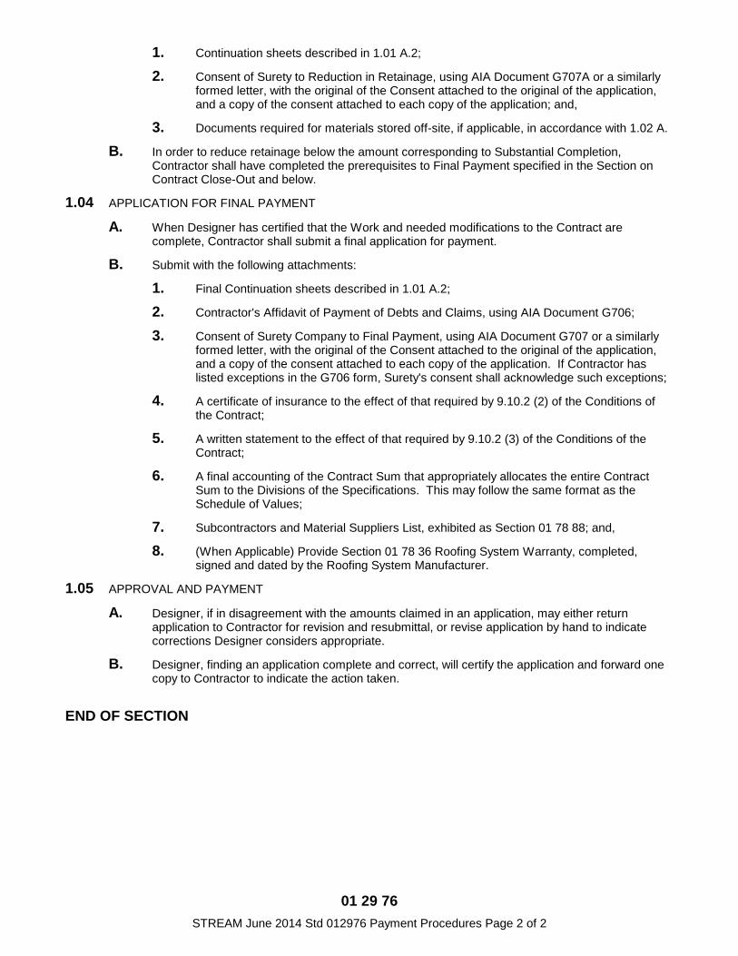
01 29 76 STREAM June 2014 Std 012976 Payment Procedures Page 2 of 2
1. Continuation sheets described in 1.01 A.2;
2. Consent of Surety to Reduction in Retainage, using AIA Document G707A or a similarly formed letter, with the original of the Consent attached to the original of the application, and a copy of the consent attached to each copy of the application; and,
3. Documents required for materials stored off-site, if applicable, in accordance with 1.02 A.
B. In order to reduce retainage below the amount corresponding to Substantial Completion, Contractor shall have completed the prerequisites to Final Payment specified in the Section on Contract Close-Out and below.
1.04 APPLICATION FOR FINAL PAYMENT
A. When Designer has certified that the Work and needed modifications to the Contract are complete, Contractor shall submit a final application for payment.
B. Submit with the following attachments:
1. Final Continuation sheets described in 1.01 A.2;
2. Contractor's Affidavit of Payment of Debts and Claims, using AIA Document G706;
3. Consent of Surety Company to Final Payment, using AIA Document G707 or a similarly formed letter, with the original of the Consent attached to the original of the application, and a copy of the consent attached to each copy of the application. If Contractor has listed exceptions in the G706 form, Surety's consent shall acknowledge such exceptions;
4. A certificate of insurance to the effect of that required by 9.10.2 (2) of the Conditions of the Contract;
5. A written statement to the effect of that required by 9.10.2 (3) of the Conditions of the Contract;
6. A final accounting of the Contract Sum that appropriately allocates the entire Contract Sum to the Divisions of the Specifications. This may follow the same format as the Schedule of Values;
7. Subcontractors and Material Suppliers List, exhibited as Section 01 78 88; and,
8. (When Applicable) Provide Section 01 78 36 Roofing System Warranty, completed, signed and dated by the Roofing System Manufacturer.
1.05 APPROVAL AND PAYMENT
A. Designer, if in disagreement with the amounts claimed in an application, may either return application to Contractor for revision and resubmittal, or revise application by hand to indicate corrections Designer considers appropriate.
B. Designer, finding an application complete and correct, will certify the application and forward one copy to Contractor to indicate the action taken.
END OF SECTION
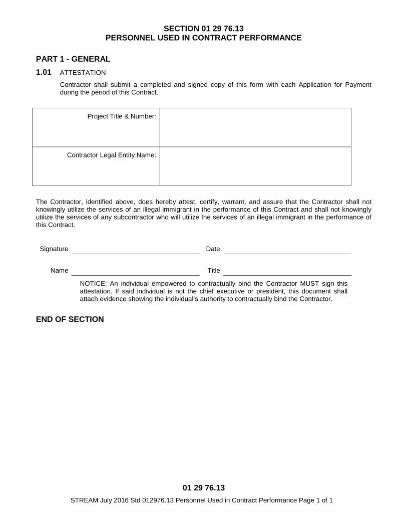
01 29 76.13 STREAM July 2016 Std 012976.13 Personnel Used in Contract Performance Page 1 of 1
SECTION 01 29 76.13 PERSONNEL USED IN CONTRACT PERFORMANCE
PART 1 - GENERAL 1.01 ATTESTATION
Contractor shall submit a completed and signed copy of this form with each Application for Payment during the period of this Contract.
Project Title & Number:
Contractor Legal Entity Name:
The Contractor, identified above, does hereby attest, certify, warrant, and assure that the Contractor shall not knowingly utilize the services of an illegal immigrant in the performance of this Contract and shall not knowingly utilize the services of any subcontractor who will utilize the services of an illegal immigrant in the performance of this Contract.
Signature Date
Name Title NOTICE: An individual empowered to contractually bind the Contractor MUST sign this attestation. If said individual is not the chief executive or president, this document shall attach evidence showing the individual’s authority to contractually bind the Contractor.
END OF SECTION
PROJECT MANAGEMENT AND COORDINATION 01 31 00 - 1
SECTION 01 31 00 - PROJECT MANAGEMENT AND COORDINATION
PART 1 - GENERAL
1.1 RELATED DOCUMENTS
A. Drawings and general provisions of the Contract, including General and SupplementaryConditions and other Division 01 Specification Sections, apply to this Section.
1.2 SUMMARY
A. Section includes administrative provisions for coordinating construction operations on Project including, but not limited to, the following:
1. General coordination procedures.2. Requests for Information (RFIs).
B. Related Requirements:1. Section 01 32 15 "Progress Schedules and Reports" for preparing and submitting
Contractor's construction schedule.2. Section 01 77 70 "Contract Closeout " for coordinating closeout of the Contract.
1.3 DEFINITIONS
A. RFI: Request from Owner, Designer, or Contractor seeking information required by orclarifications of the Contract Documents.
1.4 INFORMATIONAL SUBMITTALS
A. Subcontract List: Prepare a written summary identifying individuals or firms proposed for each portion of the Work, including those who are to furnish products or equipment fabricated to a special design. Use form included in Section 01 78 88 "Report of Subcontractors and Suppliers". Include the following information in tabular form:
1. Name, address, and telephone number of entity performing subcontract or supplying products.
2. Number and title of related Specification Section(s) covered by subcontract.3. Drawing number and detail references, as appropriate, covered by subcontract.
B. Key Personnel Names: Within 7 days of starting construction operations, submit a list of key personnel assignments, including superintendent and other personnel in attendance at Project site. Identify individuals and their duties and responsibilities; list addresses and telephone numbers, including home, office, and cellular telephone numbers and e-mail addresses. Provide names, addresses, and telephone numbers of individuals assigned as alternates in the absence of individuals assigned to Project.
1. Post copies of list in project meeting room, in temporary field office, and by eachtemporary telephone. Keep list current at all times.
1.5 GENERAL COORDINATION PROCEDURES
A. Coordination: Coordinate construction operations included in different Sections of theSpecifications to ensure efficient and orderly installation of each part of the Work. Coordinate
PROJECT MANAGEMENT AND COORDINATION 01 31 00 - 2
construction operations, included in different Sections that depend on each other for proper installation, connection, and operation.
1. Schedule construction operations in sequence required to obtain the best results whereinstallation of one part of the Work depends on installation of other components, beforeor after its own installation.
2. Coordinate installation of different components to ensure maximum performance andaccessibility for required maintenance, service, and repair.
3. Make adequate provisions to accommodate items scheduled for later installation.
B. Prepare memoranda for distribution to each party involved, outlining special proceduresrequired for coordination. Include such items as required notices, reports, and list of attendeesat meetings.
1. Prepare similar memoranda for Owner and separate contractors if coordination of theirWork is required.
C. Administrative Procedures: Coordinate scheduling and timing of required administrativeprocedures with other construction activities to avoid conflicts and to ensure orderly progress ofthe Work. Such administrative activities include, but are not limited to, the following:
1. Preparation of Contractor's construction schedule.2. Preparation of the schedule of values.3. Installation and removal of temporary facilities and controls.4. Delivery and processing of submittals.5. Progress meetings.6. Pre-installation conferences.7. Project closeout activities.8. Startup and adjustment of systems.
D. Conservation: Coordinate construction activities to ensure that operations are carried out withconsideration given to conservation of energy, water, and materials. Coordinate use oftemporary utilities to minimize waste.
1. Salvage materials and equipment involved in performance of, but not actuallyincorporated into, the Work. See other Sections for disposition of salvaged materials thatare designated as Owner's property.
1.6 COORDINATION DRAWINGS
A. Coordination Drawings, General: Prepare coordination drawings according to requirements inindividual Sections, and additionally where installation is not completely shown on ShopDrawings, where limited space availability necessitates coordination, or if coordination isrequired to facilitate integration of products and materials fabricated or installed by more thanone entity.
1. Content: Project-specific information, drawn accurately to a scale large enough toindicate and resolve conflicts. Do not base coordination drawings on standard printeddata. Include the following information, as applicable:
a. Use applicable Drawings as a basis for preparation of coordination drawings.Prepare sections, elevations, and details as needed to describe relationship ofvarious systems and components.
b. Coordinate the addition of trade-specific information to the coordination drawingsby multiple contractors in a sequence that best provides for coordination of the
PROJECT MANAGEMENT AND COORDINATION 01 31 00 - 3
information and resolution of conflicts between installed components before submitting for review.
c. Indicate functional and spatial relationships of components of architectural,structural, civil, mechanical, and electrical systems.
d. Indicate space requirements for routine maintenance and for anticipatedreplacement of components during the life of the installation.
e. Show location and size of access doors required for access to concealed dampers,valves, and other controls.
f. Indicate required installation sequences.g. Indicate dimensions shown on the Drawings. Specifically note dimensions that
appear to be in conflict with submitted equipment and minimum clearancerequirements. Provide alternate sketches to Designer indicating proposedresolution of such conflicts. Minor dimension changes and difficult installations willnot be considered changes to the Contract.
B. Coordination Digital Data Files: Submit or post coordination drawing files using Portable DataFile (PDF) format.
1.7 REQUESTS FOR INFORMATION (RFIs)
A. General: Immediately on discovery of the need for additional information or interpretation of theContract Documents, Contractor shall prepare and submit an RFI in the form specified.
1. Designer will return RFIs with no response when submitted by entities other than theContractor or Owner.
2. Coordinate and submit RFIs in a prompt manner so as to avoid delays in Contractor'swork or work of subcontractors.
B. Content of the RFI: Include a detailed, legible description of item needing information orinterpretation and the following:
1. Project name.2. Project number.3. Date.4. Name of Contractor.5. Name of Designer.6. RFI number, numbered sequentially.7. RFI subject.8. Specification Section number and title and related paragraphs, as appropriate.9. Drawing number and detail references, as appropriate.10. Field dimensions and conditions, as appropriate.11. Contractor's suggested resolution. If Contractor's suggested resolution impacts the
Contract Time or the Contract Sum, Contractor shall state impact in the RFI.12. Contractor's signature.13. Attachments: Include sketches, descriptions, measurements, photos, Product Data,
Shop Drawings, coordination drawings, and other information necessary to fully describeitems needing interpretation.
a. Include dimensions, thicknesses, structural grid references, and details of affectedmaterials, assemblies, and attachments on attached sketches.
C. RFI Forms: AIA Document G716 or comparable form, or a Software-generated form withsubstantially the same content as indicated above, acceptable to Designer.
1. Attachments shall be electronic files in Adobe Acrobat PDF format.
PROJECT MANAGEMENT AND COORDINATION 01 31 00 - 4
D. Designer's Action: Designer will review each RFI, determine action required, and respond.Allow seven working days for Designer's response for each RFI. RFIs received by Designerafter 1:00 p.m. Central Time will be considered as received the following working day.
1. The following Contractor-generated RFIs will be returned without action:
a. Requests for approval of submittals.b. Requests for approval of substitutions.c. Requests for approval of Contractor's means and methods.d. Requests for coordination information already indicated in the Contract
Documents.e. Requests for adjustments in the Contract Time or the Contract Sum.f. Requests for interpretation of Architect's actions on submittals.g. Incomplete RFIs or inaccurately prepared RFIs.
2. Designer's action may include a request for additional information, in which caseDesigner's time for response will date from time of receipt of additional information.
3. Designer's action on RFIs that may result in a change to the Contract Time or theContract Sum may be eligible for Contractor to submit Change Proposal according toDivision 01 Section "Contract Modification Procedures."
a. If Contractor believes the RFI response warrants change in the Contract Time orthe Contract Sum, notify Designer in writing within 10 days of receipt of the RFIresponse.
E. RFI Log: Prepare, maintain, and submit a tabular log of RFIs organized by the RFI number.Submit log monthly at progress meetings. Use CSI Log Form 13.2B or comparable form, or aSoftware-generated form with substantially the same content as indicated below, acceptable toDesigner. Include the following:
1. Project name.2. Name and address of Contractor.3. Name and address of Designer.4. RFI number including RFIs that were returned without action or withdrawn.5. RFI description.6. Date the RFI was submitted.7. Date Designer's response was received.
F. On receipt of Designer's action, update the RFI log and immediately distribute the RFI responseto affected parties. Review response and notify Designer within seven days if Contractordisagrees with response.
1. Identification of related Minor Change in the Work, Construction Change Directive, andProposal Request, as appropriate.
1.8 PROJECT MEETINGS
A. General: Schedule and conduct meetings and conferences at Project site unless otherwiseindicated.
1. Attendees: Inform participants and others involved, and individuals whose presence isrequired, of date and time of each meeting. Notify Owner and Designer of scheduledmeeting dates and times.
2. Agenda: Prepare the meeting agenda. Distribute the agenda to all invited attendees.
PROJECT MANAGEMENT AND COORDINATION 01 31 00 - 5
3. Minutes: Entity responsible for conducting meeting will record significant discussions andagreements achieved. Distribute the meeting minutes to everyone concerned, includingOwner and Designer, within seven days of the meeting.
B. Preconstruction Conference: Designer in cooperation with the Owner, will schedule andconduct a preconstruction conference before starting construction.
C. Pre-installation Conferences: Conduct a pre-installation conference at Project site before eachconstruction activity that requires coordination with other construction.
1. Attendees: Installer and representatives of manufacturers and fabricators involved in oraffected by the installation and its coordination or integration with other materials andinstallations that have preceded or will follow, shall attend the meeting. Advise Designerof scheduled meeting dates.
2. Agenda: Review progress of other construction activities and preparations for theparticular activity under consideration, including requirements for the following:
a. Contract Documents.b. Options.c. Related RFIs.d. Related Change Orders.e. Purchases.f. Deliveries.g. Submittals.h. Review of mockups.i. Possible conflicts.j. Compatibility requirements.k. Time schedules.l. Weather limitations.m. Manufacturer's written instructions.n. Warranty requirements.o. Compatibility of materials.p. Acceptability of substrates.q. Temporary facilities and controls.r. Space and access limitations.s. Regulations of authorities having jurisdiction.t. Testing and inspecting requirements.u. Installation procedures.v. Coordination with other work.w. Required performance results.x. Protection of adjacent work.y. Protection of construction and personnel.
3. Record significant conference discussions, agreements, and disagreements, includingrequired corrective measures and actions.
4. Reporting: Distribute minutes of the meeting to each party present and to other partiesrequiring information.
5. Do not proceed with installation if the conference cannot be successfully concluded.Initiate whatever actions are necessary to resolve impediments to performance of theWork and reconvene the conference at earliest feasible date.
D. Progress Meetings: Conduct two progress meetings monthly.
E. Coordination Meetings: Conduct Project coordination meetings at weekly intervals. Projectcoordination meetings are in addition to specific meetings held for other purposes, such asprogress meetings and pre-installation conferences.
PROJECT MANAGEMENT AND COORDINATION 01 31 00 - 6
1. Attendees: Each subcontractor, supplier, and other entity concerned with currentprogress or involved in planning, coordination, or performance of future activities shall berepresented at these meetings. All participants at the meetings shall be familiar withProject and authorized to conclude matters relating to the Work.
2. Agenda: Review and correct or approve minutes of the previous coordination meeting.Review other items of significance that could affect progress. Include topics fordiscussion as appropriate to status of Project.
a. Combined Contractor's Construction Schedule: Review progress since the lastcoordination meeting. Determine whether each contract is on time, ahead ofschedule, or behind schedule, in relation to combined Contractor's constructionschedule. Determine how construction behind schedule will be expedited; securecommitments from parties involved to do so. Discuss whether schedule revisionsare required to ensure that current and subsequent activities will be completedwithin the Contract Time.
b. Schedule Updating: Revise combined Contractor's construction schedule aftereach coordination meeting where revisions to the schedule have been made orrecognized. Issue revised schedule concurrently with report of each meeting.
c. Review present and future needs of each contractor present, including thefollowing:
1) Interface requirements.2) Sequence of operations.3) Status of submittals.4) Deliveries.5) Off-site fabrication.6) Access.7) Site utilization.8) Temporary facilities and controls.9) Work hours.10) Hazards and risks.11) Progress cleaning.12) Quality and work standards.13) Change Orders.
3. Reporting: Record meeting results and distribute copies to everyone in attendance andto others affected by decisions or actions resulting from each meeting.
PART 2 - PRODUCTS (Not Used)
PART 3 - EXECUTION (Not Used)
END OF SECTION 01 31 00
01 31 19 STREAM June 2014 Std 013119 Project Meetings Page 1 of 1
SECTION 01 31 19 PROJECT MEETINGS
PART 1 - GENERAL 1.01 SCHEDULING AND ATTENDANCE
A. The Designer, in cooperation with the Owner and the Contractor, will schedule and administer a Pre-Construction Conference, periodic Progress Meetings, and other specially called or required meetings.
B. Representatives of the Owner and the Designer will attend.
C. Representatives of the Contractor, subcontractors, and suppliers attending meetings shall be qualified and authorized to act on behalf of the entity each represents.
1.02 PRE-CONSTRUCTION CONFERENCE
A. A Pre-Construction Conference will be scheduled and conducted at the project site prior to the issuance of the Notice to Proceed.
B. The Pre-Construction Conference shall be attended by the Contractor's:
1. (Office) Job Manager,
2. (Field) Job Superintendent,
3. Major subcontractors' representatives,
4. Major suppliers' representatives, and
5. Others, as desired.
C. The Pre-Construction Conference is intended to be an opportunity for the Contractor to review administrative, procedural, and temporary facilities requirements of the Contract Documents, and to ask questions concerning the Work.
1.03 PROGRESS MEETINGS
A. Progress Meetings will be scheduled and conducted at the project site prior to the Contractor's submittal of an application for payment, or when deemed advisable by the Designer.
B. Progress Meetings shall be attended by the Contractor's:
1. (Office) Job Manager,
2. (Field) Job Superintendent,
3. Subcontractors' representatives, as befits the agenda,
4. Suppliers' representatives, as befits the agenda, and
5. Others, as appropriate.
C. Progress Meetings are intended to be a monthly opportunity for the Contractor to review and submit applications for payment, and attachments, and for a general review of the progress of the Work, aimed at identifying and mitigating impediments to timely completion.
END OF SECTION
01 31 90 STREAM June 2014 Std 013190 Administrative Logs Page 1 of 1
SECTION 01 31 90 ADMINISTRATIVE LOGS
PART 1 - GENERAL 1.01 SUBMITTALS LOG
If any shop drawings, product data, or sample submittals are required by the Contract Documents, maintain a submittals log to record the status of submittals made to the Designer.
A. Submit three (3) copies with each application for payment.
B. Clearly identify the Project by Name and SBC Project Number.
C. Record activities with respect to shop drawings, product data, samples, and such other submittals which are required by the Contract Documents.
D. Indicate for each submittal made to date:
1. Title or name, and type of submittal;
2. Date submitted to the Designer;
3. Date returned by the Designer; and,
4. General nature of the Designer's response.
1.02 VISITOR LOG
Maintain visitor log in the field office (or with the Project Superintendent when no field office is required) to record visits by all persons not a part of the Contractor's forces, materials suppliers, or subcontractors' forces.
A. Submit three (3) copies with each application for payment.
B. Clearly identify the Project by Name and SBC Project Number.
C. Indicate:
1. Visitor name and affiliation,
2. Date of visit,
3. Time of arrival and departure, and
4. Company or agency represented and reason for presence.
END OF SECTION
01 32 15 STREAM June 2014 Std 013215 Progress Schedules and Reports Page 1 of 1
SECTION 01 32 15 PROGRESS SCHEDULES AND REPORTS
PART 1 - GENERAL 1.01 INITIAL PROGRESS SCHEDULE
A. Submit within twenty-one (21) days of award of the Contract, and not later than the date of submission of the first application for payment. Clearly identify the Project on the schedule.
B. Outline the orderly progress of the Work as planned from the Notice to Proceed through Substantial Completion on the contractually required date. Categorize the Work by Phase (if Phases are specified), major work area, and distinct trade or team, and divide into individual activities of one month or less duration each. Provide an identifiable relationship to the schedule of values. Identify projected monthly progress, points of fifty percent (50%) completion and Substantial Completion, and other major milestones.
C. A bar chart or critical path method is acceptable, or other method that is approved by the Designer.
1.02 SUBMITTALS SCHEDULE
A. Submit with the initial Progress Schedule. Clearly identify the Project by Name and SBC Project Number, and format in a manner similar to the initial progress schedule, utilizing the same method, or make a part of the initial Progress Schedule.
B. Identify submittals to be made. Show date for submission and date by which Designer should respond, allowing sufficient time for review.
C. Designer may require revision of schedule if times allotted for review are insufficient.
1.03 UPDATED PROGRESS SCHEDULE
A. Submit three (3) copies with each application for payment.
B. Clearly identify the Project by Name and SBC Project Number. Format in a manner similar to the initial progress schedule, utilizing the same method.
C. Indicate:
1. Work as initially scheduled,
2. Actual progress through the period covered by the current application for payment, and
3. Planned progress through Substantial Completion, including extensions of time made by change order or construction change directive.
D. If actual progress falls behind projections, show how the backlog is to be made up so that the Work will be completed on time.
END OF SECTION
SUBMITTAL PROCEDURES 01 33 00 - 1
SECTION 01 33 00 - SUBMITTAL PROCEDURES
PART 1 - GENERAL
1.1 RELATED DOCUMENTS
A. Drawings and general provisions of the Contract, including General and SupplementaryConditions and other Division 1 Specification Sections, apply to this Section.
1.2 SUMMARY
A. This Section includes administrative and procedural requirements for submitting ShopDrawings, Product Data, Samples, and other submittals.
B. Related Sections include the following:
1. Section 01 29 76 "Payment Procedures" for submitting Applications for Payment and theSchedule of Values.
2. Section 01 31 00 "Project Management and Coordination" for submitting and distributingmeeting and conference minutes and for submitting Coordination Drawings.
3. Section 01 40 00 "Quality Requirements" for submitting test and inspection report and formockup requirements.
4. Section 01 78 21 "Closeout Submittals" for submitting warranties.5. Divisions 2 through 9 Sections inclusive for specific requirements for submittals in those
Sections.
1.3 SUBMITTAL PROCEDURES
A. General: Electronic copies of CAD Drawings of the Contract Drawings will not be provided byDesigner for Contractor's use in preparing submittals.
B. Coordination: Coordinate preparation and processing of submittals with performance ofconstruction activities.
1. Coordinate transmittal of different types of submittals for related parts of the Work soprocessing will not be delayed because of need to review submittals concurrently forcoordination.
a. Designer reserves the right to withhold action on a submittal requiring coordinationwith other submittals until related submittals are received.
C. Submittals Schedule: Comply with requirements in Division 1 for list of submittals and timerequirements for scheduled performance of related construction activities.
D. Processing Time: Allow enough time for submittal review, including time for resubmittals, asfollows. Time for review shall commence on Designer's receipt of submittal. No extension ofthe Contract Time will be authorized because of failure to transmit submittals enough inadvance of the Work to permit processing, including resubmittals.
SUBMITTAL PROCEDURES 01 33 00 - 2
1. Allow 15 days for review of each submittal. Allow additional time if coordination with subsequent submittals is required. Architect will advise Contractor when a submittal being processed must be delayed for coordination.
2. Resubmittal Review: Allow 15 days for review of each resubmittal.
E. Identification: Place a permanent label or title block on each submittal for identification.
1. Indicate name of firm or entity that prepared each submittal on label or title block. 2. Provide a space approximately 6 by 8 inches (150 by 200 mm) on label or beside title
block to record Contractor's review and approval markings and action taken by Architect. 3. Include the following information on label for processing and recording action taken:
a. Project name. b. Date. c. Name and address of Designer. d. Name and address of Contractor. e. Name and address of subcontractor. f. Name and address of supplier. g. Name of manufacturer. h. Number and title of appropriate Specification Section. i. Other necessary identification.
F. Deviations: Highlight, encircle, or otherwise specifically identify deviations from the Contract Documents on submittals.
G. Additional Copies: Unless additional copies are required for final submittal, and unless Designer observes noncompliance with provisions in the Contract Documents, initial submittal may serve as final submittal.
H. Transmittal: Package each submittal individually and appropriately for transmittal and handling. Transmit each submittal using a transmittal form. Designer will discard submittals received from sources other than Contractor.
1. Transmittal Form: Provide locations on form for the following information:
a. Project name. b. Date. c. Destination (To:). d. Source (From:). e. Names of subcontractor, manufacturer, and supplier. f. Submittal purpose and description. g. Specification Section number and title. h. Signature of transmitter.
2. On an attached separate sheet, prepared on Contractor's letterhead, record relevant information, requests for data, revisions other than those requested by Designer on previous submittals, and deviations from requirements in the Contract Documents, including minor variations and limitations. Include same label information as related submittal.
I. Resubmittals: Make resubmittals in same form and number of copies as initial submittal.
1. Note date and content of previous submittal. 2. Note date and content of revision in label or title block and clearly indicate extent of
revision.
SUBMITTAL PROCEDURES 01 33 00 - 3
J. Distribution: Furnish copies of final submittals to manufacturers, subcontractors, suppliers, fabricators, installers, authorities having jurisdiction, and others as necessary for performance of construction activities. Show distribution on transmittal forms.
K. Use for Construction: Use only final submittals with mark indicating "No Exceptions Taken” or “Make Corrections Noted” by Designer.
PART 2 - PRODUCTS
2.1 ACTION SUBMITTALS
A. General: Prepare and submit Action Submittals required by individual Specification Sections.
B. Product Data: Collect information into a single submittal for each element of construction and type of product or equipment.
1. If information must be specially prepared for submittal because standard printed data are not suitable for use, submit as Shop Drawings, not as Product Data.
2. Mark each copy of each submittal to show which products and options are applicable. 3. Include the following information, as applicable:
a. Manufacturer's written recommendations. b. Manufacturer's product specifications. c. Manufacturer's installation instructions. d. Standard color charts. e. Manufacturer's catalog cuts. f. Standard product operation and maintenance manuals. g. Testing by recognized testing agency. h. Application of testing agency labels and seals.
4. Submit Product Data before or concurrent with Samples. 5. Number of Copies: Submit 1 PDF copy of Product Data, unless otherwise indicated.
Designer will return 1 copy.
C. Shop Drawings: Prepare Project-specific information, drawn accurately to scale. Do not base Shop Drawings on reproductions of the Contract Documents or standard printed data.
1. Preparation: Fully illustrate requirements in the Contract Documents. Include the following information, as applicable:
a. Dimensions. b. Identification of products. c. Fabrication and installation drawings. d. Roughing-in and setting diagrams. e. Wiring diagrams showing field-installed wiring, including power, signal, and control
wiring. f. Design calculations. g. Compliance with specified standards. h. Notation of dimensions established by field measurement. i. Relationship to adjoining construction clearly indicated. j. Seal and signature of professional engineer if specified. k. Wiring Diagrams: Differentiate between manufacturer-installed and field-installed
wiring.
SUBMITTAL PROCEDURES 01 33 00 - 4
2. Sheet Size: Except for templates, patterns, and similar full-size drawings, submit Shop Drawings on sheets at least 8-1/2 by 11 inches (215 by 280 mm) but no larger than 30 by 40 inches (750 by 1000 mm).
3. Number of Copies: Submit 2 opaque copies and one reproducible copy of each submittal, unless copies are required for operation and maintenance manuals. Submit 5 copies where copies are required for operation and maintenance manuals. Architect will retain 2 copies and return reproducible copy. Submit PDF copy by email where possible.
D. Samples: Submit Samples for review of kind, color, pattern, and texture for a check of these characteristics with other elements and for a comparison of these characteristics between submittal and actual component as delivered and installed.
1. Transmit Samples that contain multiple, related components such as accessories together in one submittal package.
2. Identification: Attach label on unexposed side of Samples that includes the following:
a. Generic description of Sample. b. Product name and name of manufacturer. c. Sample source. d. Number and title of appropriate Specification Section.
3. Disposition: Maintain sets of approved Samples at Project site, available for quality-control comparisons throughout the course of construction activity. Sample sets may be used to determine final acceptance of construction associated with each set.
a. Samples not incorporated into the Work, or otherwise designated as Owner's property, are the property of Contractor.
4. Samples for Initial Selection: Submit manufacturer's color charts consisting of units or sections of units showing the full range of colors, textures, and patterns available.
a. Number of Samples: Submit 2 full set(s) of available choices where color, pattern, texture, or similar characteristics are required to be selected from manufacturer's product line. Architect will return submittal with options selected.
E. Application for Payment: Comply with requirements specified in Section 01 29 76 "Payment Procedures.”
F. Schedule of Values: Comply with requirements specified in Section 01 29 76 "Payment Procedures."
2.2 INFORMATIONAL SUBMITTALS
A. General: Prepare and submit Informational Submittals required by other Specification Sections.
1. Number of Copies: Submit PDF copy by email of each submittal, unless otherwise indicated. Architect will not return copies.
2. Certificates and Certifications: Provide a notarized statement that includes signature of entity responsible for preparing certification. Certificates and certifications shall be signed by an officer or other individual authorized to sign documents on behalf of that entity.
3. Test and Inspection Reports: Comply with requirements specified in Division 1 Section "Quality Requirements."
SUBMITTAL PROCEDURES 01 33 00 - 5
B. Coordination Drawings: Comply with requirements specified in Division 1 Section.
C. Contractor's Construction Schedule: Comply with requirements specified in Division 1.
D. Qualification Data: Prepare written information that demonstrates capabilities and experience of firm or person. Include lists of completed projects with project names and addresses, names and addresses of architects and owners, and other information specified.
E. Installer Certificates: Prepare written statements on manufacturer's letterhead certifying that Installer complies with requirements in the Contract Documents and, where required, is authorized by manufacturer for this specific Project.
F. Manufacturer Certificates: Prepare written statements on manufacturer's letterhead certifying that manufacturer complies with requirements in the Contract Documents. Include evidence of manufacturing experience where required.
G. Product Certificates: Prepare written statements on manufacturer's letterhead certifying that product complies with requirements in the Contract Documents.
H. Material Certificates: Prepare written statements on manufacturer's letterhead certifying that material complies with requirements in the Contract Documents.
I. Material Test Reports: Prepare reports written by a qualified testing agency, on testing agency's standard form, indicating and interpreting test results of material for compliance with requirements in the Contract Documents.
J. Product Test Reports: Prepare written reports indicating current product produced by manufacturer complies with requirements in the Contract Documents. Base reports on evaluation of tests performed by manufacturer and witnessed by a qualified testing agency, or on comprehensive tests performed by a qualified testing agency.
K. Field Test Reports: Prepare reports written by a qualified testing agency, on testing agency's standard form, indicating and interpreting results of field tests performed either during installation of product or after product is installed in its final location, for compliance with requirements in the Contract Documents.
L. Maintenance Data: Prepare written and graphic instructions and procedures for operation and normal maintenance of products and equipment. Comply with requirements specified in Division 1 Section "Close Out Submittals."
M. Design Data: Prepare written and graphic information, including, but not limited to, performance and design criteria, list of applicable codes and regulations, and calculations. Include list of assumptions and other performance and design criteria and a summary of loads. Include load diagrams if applicable. Provide name and version of software, if any, used for calculations. Include page numbers.
N. Manufacturer's Instructions: Prepare written or published information that documents manufacturer's recommendations, guidelines, and procedures for installing or operating a product or equipment. Include name of product and name, address, and telephone number of manufacturer. Include the following, as applicable:
1. Preparation of substrates. 2. Required substrate tolerances. 3. Sequence of installation or erection. 4. Required installation tolerances.
SUBMITTAL PROCEDURES 01 33 00 - 6
5. Required adjustments. 6. Recommendations for cleaning and protection.
O. Manufacturer's Field Reports: Prepare written information documenting factory-authorized service representative's tests and inspections. Include the following, as applicable:
1. Name, address, and telephone number of factory-authorized service representative making report.
2. Statement on condition of substrates and their acceptability for installation of product. 3. Statement that products at Project site comply with requirements. 4. Summary of installation procedures being followed, whether they comply with
requirements and, if not, what corrective action was taken. 5. Results of operational and other tests and a statement of whether observed performance
complies with requirements. 6. Statement whether conditions, products, and installation will affect warranty. 7. Other required items indicated in individual Specification Sections.
P. Insurance Certificates and Bonds: Prepare written information indicating current status of insurance or bonding coverage. Include name of entity covered by insurance or bond, limits of coverage, amounts of deductibles, if any, and term of the coverage.
Q. Construction Photographs and Videotapes: Comply with requirements specified in Division 1 Section.
PART 3 - EXECUTION
3.1 CONTRACTOR'S REVIEW
A. Review each submittal and check for coordination with other Work of the Contract and for compliance with the Contract Documents. Note corrections and field dimensions. Mark with approval stamp before submitting to Designer.
B. Approval Stamp: Stamp each submittal with a uniform, approval stamp. Include Project name and location, submittal number, Specification Section title and number, name of reviewer, date of Contractor's approval, and statement certifying that submittal has been reviewed, checked, and approved for compliance with the Contract Documents.
3.2 ARCHITECT'S ACTION
A. General: Designer will not review submittals that do not bear Contractor's approval stamp and will return them without action.
B. Action Submittals: Designer will review each submittal, make marks to indicate corrections or modifications required, and return it. Architect will stamp each submittal with an action stamp and will mark stamp appropriately to indicate action taken, as follows:
1. Final Unrestricted Release: When the Designer marks a submittal “Approved” or “No Exceptions Taken,” the Work covered by the submittal may proceed provided it complies with requirements of the Contract Documents. Final payment depends on that compliance.
SUBMITTAL PROCEDURES 01 33 00 - 7
2. Final-But-Restricted Release: When the Designer marks a submittal “Approved as Noted,” “Make Corrections Noted” or “Note Markings”, the Work covered by the submittal may proceed provided it complies with notations or corrections on the submittal and requirements of the Contract Documents. Final payment depends on that compliance. a. Do not revise and resubmit the submittal.
3. Returned for Resubmittal: When the Designer marks a submittal “Revise and Resubmit,” do not proceed with Work covered by the submittal, including purchasing, fabrication, delivery, or other activity. Revise or prepare a new submittal according to the notations; resubmit without delay. Repeat if necessary to obtain different action mark.
4. Rejected: When the Designer marks a submittal “Rejected,” do not proceed with Work covered by the submittal, including purchasing, fabrication, delivery, or other activity. Prepare a new submittal for the specified product, material or system; resubmit without delay. Repeat if necessary to obtain different action mark.
5. Do not use, or allow others to use, submittals marked “Revise and Resubmit” or “Rejected” at the Project Site or elsewhere where Work is in progress.
C. Informational Submittals: Designer will review each submittal and will not return it, or will return it if it does not comply with requirements. Designer will forward each submittal to appropriate party.
D. Partial submittals are not acceptable, will be considered nonresponsive, and will be returned without review.
E. Submittals not required by the Contract Documents will not be reviewed and will be discarded.
END OF SECTION 01 33 00
QUALITY REQUIREMENTS 01 40 00 - 1
SECTION 01 40 00 - QUALITY REQUIREMENTS
PART 1 - GENERAL
1.1 RELATED DOCUMENTS
A. Drawings and general provisions of the Contract, including General and SupplementaryConditions and other Division 01 Specification Sections, apply to this Section.
1.2 SUMMARY
A. Section includes administrative and procedural requirements for quality assurance and qualitycontrol.
B. Testing and inspecting services are required to verify compliance with requirements specified orindicated. These services do not relieve Contractor of responsibility for compliance with theContract Document requirements.
1. Specific quality-assurance and -control requirements for individual construction activities arespecified in the Sections that specify those activities. Requirements in those Sections mayalso cover production of standard products.
2. Specified tests, inspections, and related actions do not limit Contractor's other quality-assurance and -control procedures that facilitate compliance with the Contract Documentrequirements.
3. Requirements for Contractor to provide quality-assurance and -control services required byDesigner, Owner, or authorities having jurisdiction are not limited by provisions of thisSection.
C. Related Requirements:
1. Division 01 Section 01 43 25 "Testing Laboratory Services".2. Divisions 02 through 09 Sections for specific test and inspection requirements.
1.3 DEFINITIONS
A. Quality-Assurance Services: Activities, actions, and procedures performed before and duringexecution of the Work to guard against defects and deficiencies and substantiate that proposedconstruction will comply with requirements.
B. Quality-Control Services: Tests, inspections, procedures, and related actions during and afterexecution of the Work to evaluate that actual products incorporated into the Work and completedconstruction comply with requirements. Services do not include contract enforcement activitiesperformed by Designer.
C. Preconstruction Testing: Tests and inspections performed specifically for Project before productsand materials are incorporated into the Work, to verify performance or compliance with specifiedcriteria.
D. Product Testing: Tests and inspections that are performed by a testing agency qualified toconduct product testing and acceptable to authorities having jurisdiction, to establish productperformance and compliance with specified requirements.
E. Source Quality-Control Testing: Tests and inspections that are performed at the source, e.g.,plant, mill, factory, or shop.
F. Field Quality-Control Testing: Tests and inspections that are performed on-site for installation ofthe Work and for completed Work.
QUALITY REQUIREMENTS 01 40 00 - 2
G. Testing Agency: An entity engaged to perform specific tests, inspections, or both. Testinglaboratory shall mean the same as testing agency.
H. Installer/Applicator/Erector: Contractor or another entity engaged by Contractor as an employee,Subcontractor, or Sub-subcontractor, to perform a particular construction operation, includinginstallation, erection, application, and similar operations.
1. Use of trade-specific terminology in referring to a trade or entity does not require that certainconstruction activities be performed by accredited or unionized individuals, or thatrequirements specified apply exclusively to specific trade(s).
I. Experienced: When used with an entity or individual, "experienced" means having successfullycompleted a minimum of five previous projects similar in nature, size, and extent to this Project;being familiar with special requirements indicated; and having complied with requirements ofauthorities having jurisdiction.
1.4 CONFLICTING REQUIREMENTS
A. Referenced Standards: If compliance with two or more standards is specified and the standardsestablish different or conflicting requirements for minimum quantities or quality levels, comply withthe most stringent requirement. Refer conflicting requirements that are different, but apparentlyequal, to Designer for a decision before proceeding.
B. Minimum Quantity or Quality Levels: The quantity or quality level shown or specified shall be theminimum provided or performed. The actual installation may comply exactly with the minimumquantity or quality specified, or it may exceed the minimum within reasonable limits. To complywith these requirements, indicated numeric values are minimum or maximum, as appropriate, forthe context of requirements. Refer uncertainties to Designer for a decision before proceeding.
1.5 INFORMATIONAL SUBMITTALS
A. Contractor's Quality-Control Plan: For quality-assurance and quality-control activities andresponsibilities.
1.6 CONTRACTOR'S QUALITY-CONTROL PLAN
A. Quality-Control Plan, General: Submit quality-control plan within 10 days of Notice to Proceed, and not less than five days prior to preconstruction conference. Submit in format acceptable to Designer Identify personnel, procedures, controls, instructions, tests, records, and forms to be used to carry out Contractor's quality-assurance and quality-control responsibilities. Coordinate with Contractor's construction schedule.
B. Quality-Control Personnel Qualifications: Engage qualified full-time personnel trained and experienced in managing and executing quality-assurance and quality-control procedures similar in nature and extent to those required for Project.
1. Project quality-control manager may also serve as Project superintendent .
C. Submittal Procedure: Describe procedures for ensuring compliance with requirements through review and management of submittal process. Indicate qualifications of personnel responsible for submittal review.
D. Testing and Inspection: In quality-control plan, include a comprehensive schedule of Work requiring testing or inspection, including the following:
1. Contractor-performed tests and inspections including subcontractor-performed tests and inspections. Include required tests and inspections and Contractor-elected tests and inspections.
QUALITY REQUIREMENTS 01 40 00 - 3
E. Continuous Inspection of Workmanship: Describe process for continuous inspection during construction to identify and correct deficiencies in workmanship in addition to testing and inspection specified. Indicate types of corrective actions to be required to bring work into compliance with standards of workmanship established by Contract requirements and approved mockups.
F. Monitoring and Documentation: Maintain testing and inspection reports including log of approved and rejected results. Include work Designer has indicated as nonconforming or defective. Indicate corrective actions taken to bring nonconforming work into compliance with requirements. Comply with requirements of authorities having jurisdiction.
1.7 REPORTS AND DOCUMENTS
A. Test and Inspection Reports: Prepare and submit certified written reports specified in other Sections. Include the following:
1. Date of issue. 2. Project title and number. 3. Name, address, and telephone number of testing agency. 4. Dates and locations of samples and tests or inspections. 5. Names of individuals making tests and inspections. 6. Description of the Work and test and inspection method. 7. Identification of product and Specification Section. 8. Complete test or inspection data. 9. Test and inspection results and an interpretation of test results. 10. Record of temperature and weather conditions at time of sample taking and testing and
inspecting. 11. Comments or professional opinion on whether tested or inspected Work complies with the
Contract Document requirements. 12. Name and signature of laboratory inspector. 13. Recommendations on retesting and re-inspecting.
B. Manufacturer's Technical Representative's Field Reports: Prepare written information documenting manufacturer's technical representative's tests and inspections specified in other Sections. Include the following:
1. Name, address, and telephone number of technical representative making report. 2. Statement on condition of substrates and their acceptability for installation of product. 3. Statement that products at Project site comply with requirements. 4. Summary of installation procedures being followed, whether they comply with requirements
and, if not, what corrective action was taken. 5. Results of operational and other tests and a statement of whether observed performance
complies with requirements. 6. Statement whether conditions, products, and installation will affect warranty. 7. Other required items indicated in individual Specification Sections.
C. Factory-Authorized Service Representative's Reports: Prepare written information documenting manufacturer's factory-authorized service representative's tests and inspections specified in other Sections. Include the following:
1. Name, address, and telephone number of factory-authorized service representative making report.
2. Statement that equipment complies with requirements. 3. Results of operational and other tests and a statement of whether observed performance
complies with requirements. 4. Statement whether conditions, products, and installation will affect warranty. 5. Other required items indicated in individual Specification Sections.
QUALITY REQUIREMENTS 01 40 00 - 4
D. Permits, Licenses, and Certificates: For Owner's records, submit copies of permits, licenses, certifications, inspection reports, releases, jurisdictional settlements, notices, receipts for fee payments, judgments, correspondence, records, and similar documents, established for compliance with standards and regulations bearing on performance of the Work.
1.8 QUALITY ASSURANCE
A. General: Qualifications paragraphs in this article establish the minimum qualification levels required; individual Specification Sections specify additional requirements.
B. Manufacturer Qualifications: A firm experienced in manufacturing products or systems similar to those indicated for this Project and with a record of successful in-service performance, as well as sufficient production capacity to produce required units.
C. Fabricator Qualifications: A firm experienced in producing products similar to those indicated for this Project and with a record of successful in-service performance, as well as sufficient production capacity to produce required units.
D. Installer Qualifications: A firm or individual experienced in installing, erecting, or assembling work similar in material, design, and extent to that indicated for this Project, whose work has resulted in construction with a record of successful in-service performance.
E. Professional Engineer Qualifications: A professional engineer who is legally qualified to practice in jurisdiction where Project is located and who is experienced in providing engineering services of the kind indicated. Engineering services are defined as those performed for installations of the system, assembly, or product that are similar in material, design, and extent to those indicated for this Project.
F. Specialists: Certain Specification Sections require that specific construction activities shall be performed by entities who are recognized experts in those operations. Specialists shall satisfy qualification requirements indicated and shall be engaged for the activities indicated.
1. Requirements of authorities having jurisdiction shall supersede requirements for specialists.
G. Testing Agency Qualifications: An independent agency with the experience and capability to conduct testing and inspecting indicated, as documented according to ASTM E 329; and with additional qualifications specified in individual Sections; and, where required by authorities having jurisdiction, that is acceptable to authorities.
H. Manufacturer's Technical Representative Qualifications: An authorized representative of manufacturer who is trained and approved by manufacturer to observe and inspect installation of manufacturer's products that are similar in material, design, and extent to those indicated for this Project.
I. Factory-Authorized Service Representative Qualifications: An authorized representative of manufacturer who is trained and approved by manufacturer to inspect installation of manufacturer's products that are similar in material, design, and extent to those indicated for this Project.
1.9 QUALITY CONTROL
A. Contractor Responsibilities: Tests and inspections are the Contractor's responsibility. Perform additional quality-control activities required to verify that the Work complies with requirements, whether specified or not.
1. Provide quality-control services specified and those required by authorities having jurisdiction. Perform quality-control services required of Contractor by authorities having jurisdiction, whether specified or not.
2. Engage a qualified testing agency to perform these quality-control services.
QUALITY REQUIREMENTS 01 40 00 - 5
3. Notify testing agencies at least 24 hours in advance of time when Work that requires testing or inspecting will be performed.
4. Where quality-control services are indicated as Contractor's responsibility, submit a certified written report, in duplicate, of each quality-control service.
5. Testing and inspecting requested by Contractor and not required by the Contract Documents are Contractor's responsibility.
6. Submit additional copies of each written report directly to authorities having jurisdiction, when they so direct.
B. Manufacturer's Field Services: Where indicated, engage a factory-authorized service representative to inspect field-assembled components and equipment installation, including service connections. Report results in writing as specified in Division 01 Section "Submittal Procedures."
C. Manufacturer's Technical Services: Where indicated, engage a manufacturer's technical representative to observe and inspect the Work. Manufacturer's technical representative's services include participation in pre-installation conferences, examination of substrates and conditions, verification of materials, observation of Installer activities, inspection of completed portions of the Work, and submittal of written reports.
D. Retesting/Re-inspecting: Regardless of whether original tests or inspections were Contractor's responsibility, provide quality-control services, including retesting and re-inspecting, for construction that replaced Work that failed to comply with the Contract Documents.
E. Testing Agency Responsibilities: Cooperate with Architect and Contractor in performance of duties. Provide qualified personnel to perform required tests and inspections.
F. Associated Services: Cooperate with agencies performing required tests, inspections, and similar quality-control services, and provide reasonable auxiliary services as requested. Notify agency sufficiently in advance of operations to permit assignment of personnel. Provide the following:
1. Access to the Work. 2. Incidental labor and facilities necessary to facilitate tests and inspections. 3. Adequate quantities of representative samples of materials that require testing and
inspecting. Assist agency in obtaining samples. 4. Facilities for storage and field curing of test samples. 5. Preliminary design mix proposed for use for material mixes that require control by testing
agency. 6. Security and protection for samples and for testing and inspecting equipment at Project site.
G. Coordination: Coordinate sequence of activities to accommodate required quality-assurance and -control services with a minimum of delay and to avoid necessity of removing and replacing construction to accommodate testing and inspecting.
1. Schedule times for tests, inspections, obtaining samples, and similar activities.
PART 2 - PRODUCTS (Not Used)
PART 3 - EXECUTION
3.1 TEST AND INSPECTION LOG
A. Test and Inspection Log: Prepare a record of tests and inspections. Include the following:
1. Date test or inspection was conducted. 2. Description of the Work tested or inspected. 3. Date test or inspection results were transmitted to Designer. 4. Identification of testing agency or special inspector conducting test or inspection.
QUALITY REQUIREMENTS 01 40 00 - 6
B. Maintain log at Project site. Post changes and revisions as they occur. Provide access to test and inspection log for Architect's reference during normal working hours.
3.2 REPAIR AND PROTECTION
A. General: On completion of testing, inspecting, sample taking, and similar services, repair damaged construction and restore substrates and finishes.
1. Provide materials and comply with installation requirements specified in other Specification Sections or matching existing substrates and finishes. Restore patched areas and extend restoration into adjoining areas with durable seams that are as invisible as possible. Comply with the Contract Document requirements for cutting and patching in Division 01 Section "Execution."
B. Protect construction exposed by or for quality-control service activities.
C. Repair and protection are Contractor's responsibility, regardless of the assignment of responsibility for quality-control services.
END OF SECTION 01 40 00
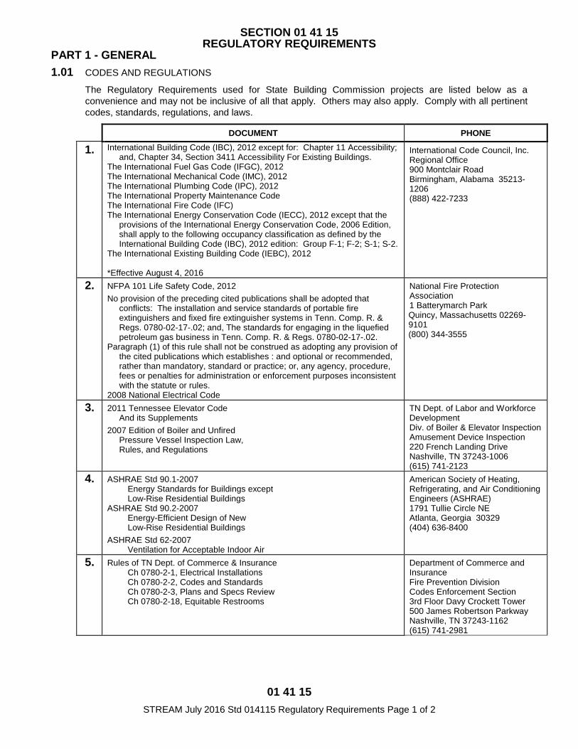
01 41 15 STREAM July 2016 Std 014115 Regulatory Requirements Page 1 of 2
SECTION 01 41 15 REGULATORY REQUIREMENTS
PART 1 - GENERAL 1.01 CODES AND REGULATIONS
The Regulatory Requirements used for State Building Commission projects are listed below as a convenience and may not be inclusive of all that apply. Others may also apply. Comply with all pertinent codes, standards, regulations, and laws.
DOCUMENT PHONE
1. International Building Code (IBC), 2012 except for: Chapter 11 Accessibility; and, Chapter 34, Section 3411 Accessibility For Existing Buildings.
The International Fuel Gas Code (IFGC), 2012 The International Mechanical Code (IMC), 2012 The International Plumbing Code (IPC), 2012 The International Property Maintenance Code The International Fire Code (IFC) The International Energy Conservation Code (IECC), 2012 except that the
provisions of the International Energy Conservation Code, 2006 Edition, shall apply to the following occupancy classification as defined by the International Building Code (IBC), 2012 edition: Group F-1; F-2; S-1; S-2.
The International Existing Building Code (IEBC), 2012 *Effective August 4, 2016
International Code Council, Inc. Regional Office 900 Montclair Road Birmingham, Alabama 35213-1206 (888) 422-7233
2. NFPA 101 Life Safety Code, 2012 No provision of the preceding cited publications shall be adopted that
conflicts: The installation and service standards of portable fire extinguishers and fixed fire extinguisher systems in Tenn. Comp. R. & Regs. 0780-02-17-.02; and, The standards for engaging in the liquefied petroleum gas business in Tenn. Comp. R. & Regs. 0780-02-17-.02.
Paragraph (1) of this rule shall not be construed as adopting any provision of the cited publications which establishes : and optional or recommended, rather than mandatory, standard or practice; or, any agency, procedure, fees or penalties for administration or enforcement purposes inconsistent with the statute or rules.
2008 National Electrical Code
National Fire Protection Association 1 Batterymarch Park Quincy, Massachusetts 02269-9101 (800) 344-3555
3.
2011 Tennessee Elevator Code And its Supplements
2007 Edition of Boiler and Unfired Pressure Vessel Inspection Law, Rules, and Regulations
TN Dept. of Labor and Workforce Development Div. of Boiler & Elevator Inspection Amusement Device Inspection 220 French Landing Drive Nashville, TN 37243-1006 (615) 741-2123
4.
ASHRAE Std 90.1-2007 Energy Standards for Buildings except Low-Rise Residential Buildings
ASHRAE Std 90.2-2007 Energy-Efficient Design of New Low-Rise Residential Buildings
ASHRAE Std 62-2007 Ventilation for Acceptable Indoor Air
American Society of Heating, Refrigerating, and Air Conditioning Engineers (ASHRAE) 1791 Tullie Circle NE Atlanta, Georgia 30329 (404) 636-8400
5. Rules of TN Dept. of Commerce & Insurance Ch 0780-2-1, Electrical Installations Ch 0780-2-2, Codes and Standards Ch 0780-2-3, Plans and Specs Review Ch 0780-2-18, Equitable Restrooms
Department of Commerce and Insurance Fire Prevention Division Codes Enforcement Section 3rd Floor Davy Crockett Tower 500 James Robertson Parkway Nashville, TN 37243-1162 (615) 741-2981
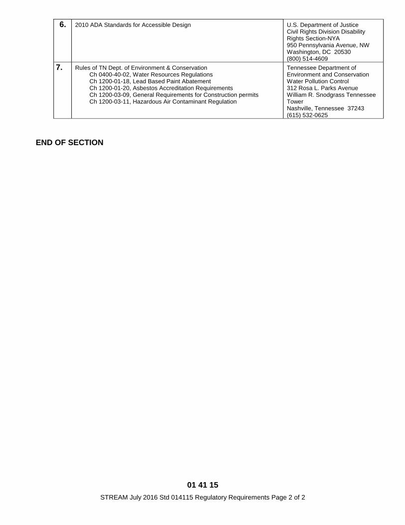
01 41 15 STREAM July 2016 Std 014115 Regulatory Requirements Page 2 of 2
6. 2010 ADA Standards for Accessible Design U.S. Department of Justice Civil Rights Division Disability Rights Section-NYA 950 Pennsylvania Avenue, NW Washington, DC 20530 (800) 514-4609
7. Rules of TN Dept. of Environment & Conservation Ch 0400-40-02, Water Resources Regulations Ch 1200-01-18, Lead Based Paint Abatement Ch 1200-01-20, Asbestos Accreditation Requirements Ch 1200-03-09, General Requirements for Construction permits Ch 1200-03-11, Hazardous Air Contaminant Regulation
Tennessee Department of Environment and Conservation Water Pollution Control 312 Rosa L. Parks Avenue William R. Snodgrass Tennessee Tower Nashville, Tennessee 37243 (615) 532-0625
END OF SECTION

01 43 25 STREAM June 2014 Std 014325 Testing Laboratory Services Page 1 of 1
SECTION 01 43 25 TESTING LABORATORY SERVICES
PART 1 - GENERAL 1.01 CONTRACTOR'S RESPONSIBILITIES
A. Employ and pay for the services of an independent testing laboratory, approved by the Designer, to perform specified services and testing. Employment of laboratory does not relieve Contractor's obligations to perform the Work of the Contract.
B. Coordinate and pay for inspections and testing required by law, ordinance, rules, regulations, orders, or approvals of public authorities as required by the Contract Documents.
1. Furnish copies of Products Test reports as required.
2. Furnish incidental labor and facilities to facilitate inspections and tests and for storage and curing of test samples.
3. Notify the lab sufficiently in advance of operations to allow for laboratory assignment of personnel and scheduling of tests.
4. Make arrangements with lab and pay for additional samples and tests required for Contractor's convenience.
1.02 TESTING LABORATORY A. Qualifications
1. Meet "Recommended Requirements for Independent Laboratory Qualification", published by the American Council of Independent Laboratories, and Basic requirements of ASTM E 329 "Standards of Recommended Practice for Inspection and Testing Agencies for Concrete and Steel as Used in Construction".
2. Be authorized to operate in the State of Tennessee.
3. Submit copies to the Designer of the report of inspection of facilities made by Materials Reference Laboratory of National Bureau of Standards during the most recent tour of inspection with the memorandum of remedies of any deficiencies reported by the inspection.
B. Duties and limitations of authority
1. Perform specified inspections, sampling, and testing of materials and methods of construction and promptly submit five copies of the written report of each test and inspection to the Designer.
2. Laboratory is not authorized to release, revoke, alter or enlarge on requirements of the Contract Documents, approve or accept portions of the Work, or perform duties of the Contractor.
END OF SECTION
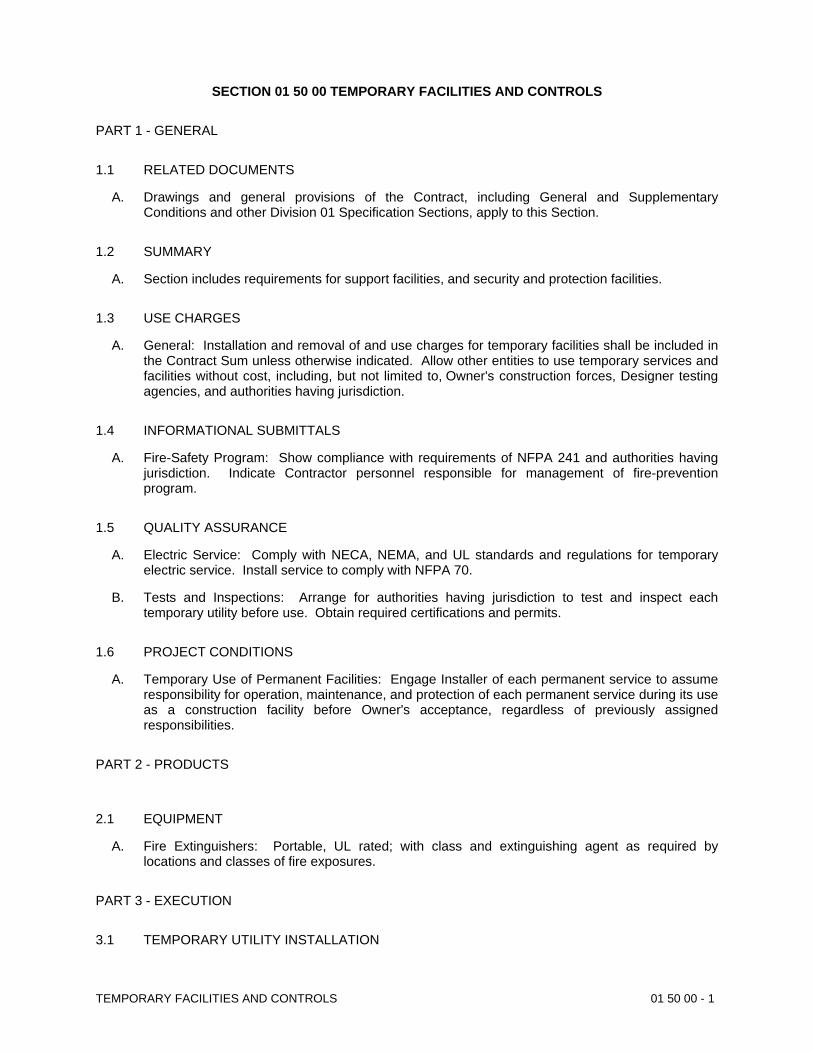
TEMPORARY FACILITIES AND CONTROLS 01 50 00 - 1
SECTION 01 50 00 TEMPORARY FACILITIES AND CONTROLS
PART 1 - GENERAL
1.1 RELATED DOCUMENTS
A. Drawings and general provisions of the Contract, including General and SupplementaryConditions and other Division 01 Specification Sections, apply to this Section.
1.2 SUMMARY
A. Section includes requirements for support facilities, and security and protection facilities.
1.3 USE CHARGES
A. General: Installation and removal of and use charges for temporary facilities shall be included inthe Contract Sum unless otherwise indicated. Allow other entities to use temporary services andfacilities without cost, including, but not limited to, Owner's construction forces, Designer testingagencies, and authorities having jurisdiction.
1.4 INFORMATIONAL SUBMITTALS
A. Fire-Safety Program: Show compliance with requirements of NFPA 241 and authorities havingjurisdiction. Indicate Contractor personnel responsible for management of fire-preventionprogram.
1.5 QUALITY ASSURANCE
A. Electric Service: Comply with NECA, NEMA, and UL standards and regulations for temporaryelectric service. Install service to comply with NFPA 70.
B. Tests and Inspections: Arrange for authorities having jurisdiction to test and inspect eachtemporary utility before use. Obtain required certifications and permits.
1.6 PROJECT CONDITIONS
A. Temporary Use of Permanent Facilities: Engage Installer of each permanent service to assumeresponsibility for operation, maintenance, and protection of each permanent service during its useas a construction facility before Owner's acceptance, regardless of previously assignedresponsibilities.
PART 2 - PRODUCTS
2.1 EQUIPMENT
A. Fire Extinguishers: Portable, UL rated; with class and extinguishing agent as required bylocations and classes of fire exposures.
PART 3 - EXECUTION
3.1 TEMPORARY UTILITY INSTALLATION
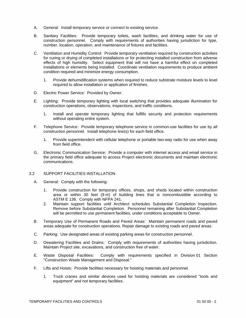
TEMPORARY FACILITIES AND CONTROLS 01 50 00 - 2
A. General: Install temporary service or connect to existing service.
B. Sanitary Facilities: Provide temporary toilets, wash facilities, and drinking water for use ofconstruction personnel. Comply with requirements of authorities having jurisdiction for type,number, location, operation, and maintenance of fixtures and facilities.
C. Ventilation and Humidity Control: Provide temporary ventilation required by construction activitiesfor curing or drying of completed installations or for protecting installed construction from adverseeffects of high humidity. Select equipment that will not have a harmful effect on completedinstallations or elements being installed. Coordinate ventilation requirements to produce ambientcondition required and minimize energy consumption.
1. Provide dehumidification systems when required to reduce substrate moisture levels to levelrequired to allow installation or application of finishes.
D. Electric Power Service: Provided by Owner.
E. Lighting: Provide temporary lighting with local switching that provides adequate illumination forconstruction operations, observations, inspections, and traffic conditions.
1. Install and operate temporary lighting that fulfills security and protection requirementswithout operating entire system.
F. Telephone Service: Provide temporary telephone service in common-use facilities for use by allconstruction personnel. Install telephone line(s) for each field office.
1. Provide superintendent with cellular telephone or portable two-way radio for use when awayfrom field office.
G. Electronic Communication Service: Provide a computer with internet access and email service inthe primary field office adequate to access Project electronic documents and maintain electroniccommunications.
3.2 SUPPORT FACILITIES INSTALLATION
A. General: Comply with the following:
1. Provide construction for temporary offices, shops, and sheds located within constructionarea or within 30 feet (9 m) of building lines that is noncombustible according toASTM E 136. Comply with NFPA 241.
2. Maintain support facilities until Architect schedules Substantial Completion inspection.Remove before Substantial Completion. Personnel remaining after Substantial Completionwill be permitted to use permanent facilities, under conditions acceptable to Owner.
B. Temporary Use of Permanent Roads and Paved Areas: Maintain permanent roads and pavedareas adequate for construction operations. Repair damage to existing roads and paved areas.
C. Parking: Use designated areas of existing parking areas for construction personnel.
D. Dewatering Facilities and Drains: Comply with requirements of authorities having jurisdiction.Maintain Project site, excavations, and construction free of water.
E. Waste Disposal Facilities: Comply with requirements specified in Division 01 Section"Construction Waste Management and Disposal."
F. Lifts and Hoists: Provide facilities necessary for hoisting materials and personnel.
1. Truck cranes and similar devices used for hoisting materials are considered "tools andequipment" and not temporary facilities.
TEMPORARY FACILITIES AND CONTROLS 01 50 00 - 3
3.3 SECURITY AND PROTECTION FACILITIES INSTALLATION
A. Protection of Existing Facilities: Protect existing vegetation, equipment, structures, utilities, andother improvements at Project site and on adjacent properties, except those indicated to beremoved or altered. Repair damage to existing facilities.
B. Environmental Protection: Provide protection, operate temporary facilities, and conductconstruction as required to comply with environmental regulations and that minimize possible air,waterway, and subsoil contamination or pollution or other undesirable effects.
C. Temporary Fire Protection: Install and maintain temporary fire-protection facilities of typesneeded to protect against reasonably predictable and controllable fire losses. Comply withNFPA 241; manage fire-prevention program.
1. Prohibit smoking in construction areas.2. Supervise welding operations, combustion-type temporary heating units, and similar
sources of fire ignition according to requirements of authorities having jurisdiction.3. Develop and supervise an overall fire-prevention and -protection program for personnel at
Project site. Review needs with local fire department and establish procedures to befollowed. Instruct personnel in methods and procedures. Post warnings and information.
3.4 MOISTURE AND MOLD CONTROL
A. Contractor's Moisture-Protection Plan: Avoid trapping water in finished work. Document visiblesigns of mold that may appear during construction.
3.5 OPERATION, TERMINATION, AND REMOVAL
A. Supervision: Enforce strict discipline in use of temporary facilities. To minimize waste and abuse, limit availability of temporary facilities to essential and intended uses.
B. Maintenance: Maintain facilities in good operating condition until removal.
C. Termination and Removal: Remove each temporary facility when need for its service has ended, when it has been replaced by authorized use of a permanent facility, or no later than Substantial Completion. Complete or, if necessary, restore permanent construction that may have been delayed because of interference with temporary facility. Repair damaged Work, clean exposed surfaces, and replace construction that cannot be satisfactorily repaired.
1. Materials and facilities that constitute temporary facilities are property of Contractor. Owner reserves right to take possession of Project identification signs.
2. At Substantial Completion, repair, renovate, and clean permanent facilities used during construction period. Comply with final cleaning requirements specified in Section 01 77 70 "Contract Closeout".
END OF SECTION 01 50 00
PRODUCT REQUIREMENTS 01 60 00 - 1
SECTION 01 60 00 - PRODUCT REQUIREMENTS
PART 1 - GENERAL
1.1 RELATED DOCUMENTS
A. Drawings and general provisions of the Contract, including General and SupplementaryConditions and other Division 01 Specification Sections, apply to this Section.
1.2 SUMMARY
A. Section includes administrative and procedural requirements for selection of products for use in Project; product delivery, storage, and handling; manufacturers' standard warranties on products; special warranties; and comparable products.
B. Related Requirements:1. Division 01 Section 01 62 25 "Product Options and Substitutions" for requests
for substitutions.
1.3 DEFINITIONS
A. Products: Items obtained for incorporating into the Work, whether purchased for Project or takenfrom previously purchased stock. The term "product" includes the terms "material," "equipment,""system," and terms of similar intent.
1. Named Products: Items identified by manufacturer's product name, including make ormodel number or other designation shown or listed in manufacturer's published productliterature, that is current as of date of the Contract Documents.
2. New Products: Items that have not previously been incorporated into another project orfacility. Products salvaged or recycled from other projects are not considered new products.
3. Comparable Product: Product that is demonstrated and approved through substitution andsubmittal process to have the indicated qualities related to type, function, dimension, in-service performance, physical properties, appearance, and other characteristics that equalor exceed those of specified product.
B. Basis-of-Design Product Specification: A specification in which a specific manufacturer's productis named and accompanied by the words "basis-of-design product," including make or modelnumber or other designation, to establish the significant qualities related to type, function,dimension, in-service performance, physical properties, appearance, and other characteristics forpurposes of evaluating comparable products of additional manufacturers named in thespecification.
1.4 ACTION SUBMITTALS
A. Comparable Product Requests: Submit request for substitution of each proposed comparableproduct. Identify product or fabrication or installation method to be replaced. IncludeSpecification Section number and title and Drawing numbers and titles.
1. Include data to indicate compliance with the requirements specified in "ComparableProducts" Article.
2. Architect's Action: If necessary, Architect will request additional information ordocumentation for evaluation within one week of receipt of a comparable product request.Architect will notify Contractor of approval or rejection of proposed comparable productrequest within 15 days of receipt of request, or receipt of additional information ordocumentation, whichever is later.
PRODUCT REQUIREMENTS 01 60 00 - 2
B. Basis-of-Design Product Specification Submittal: Comply with requirements in Division 01Section "Submittal Procedures." Show compliance with requirements.
1.5 QUALITY ASSURANCE
A. Compatibility of Options: If Contractor is given option of selecting between two or more productsfor use on Project, select product compatible with products previously selected, even if previouslyselected products were also options.
1.6 PRODUCT DELIVERY, STORAGE, AND HANDLING
A. Deliver, store, and handle products using means and methods that will prevent damage,deterioration, and loss, including theft and vandalism. Comply with manufacturer's writteninstructions.
B. Delivery and Handling:
1. Schedule delivery to minimize long-term storage at Project site and to prevent overcrowdingof construction spaces.
2. Coordinate delivery with installation time to ensure minimum holding time for items that areflammable, hazardous, easily damaged, or sensitive to deterioration, theft, and other losses.
3. Deliver products to Project site in an undamaged condition in manufacturer's original sealedcontainer or other packaging system, complete with labels and instructions for handling,storing, unpacking, protecting, and installing.
4. Inspect products on delivery to determine compliance with the Contract Documents and todetermine that products are undamaged and properly protected.
C. Storage:
1. Store products to allow for inspection and measurement of quantity or counting of units.2. Store materials in a manner that will not endanger Project structure.3. Store products that are subject to damage by the elements, under cover in a weathertight
enclosure above ground, with ventilation adequate to prevent condensation.4. Protect foam plastic from exposure to sunlight, except to extent necessary for period of
installation and concealment.5. Comply with product manufacturer's written instructions for temperature, humidity,
ventilation, and weather-protection requirements for storage.6. Protect stored products from damage and liquids from freezing.
1.7 PRODUCT WARRANTIES
A. Warranties specified in other Sections shall be in addition to, and run concurrent with, otherwarranties required by the Contract Documents. Manufacturer's disclaimers and limitations onproduct warranties do not relieve Contractor of obligations under requirements of the ContractDocuments.
1. Manufacturer's Warranty: Written warranty furnished by individual manufacturer for aparticular product and specifically endorsed by manufacturer to Owner.
2. Special Warranty: Written warranty required by the Contract Documents to provide specificrights for Owner.
B. Special Warranties: Prepare a written document that contains appropriate terms andidentification, ready for execution.
1. Manufacturer's Standard Form: Modified to include Project-specific information andproperly executed.
2. Specified Form: When specified forms are included with the Specifications, prepare awritten document using indicated form properly executed.
PRODUCT REQUIREMENTS 01 60 00 - 3
3. See Divisions 02 through 33 Sections for specific content requirements and particularrequirements for submitting special warranties.
PART 2 - PRODUCTS
2.1 PRODUCT SELECTION PROCEDURES
A. General Product Requirements: Provide products that comply with the Contract Documents, areundamaged and, unless otherwise indicated, are new at time of installation.
1. Provide products complete with accessories, trim, finish, fasteners, and other items neededfor a complete installation and indicated use and effect.
2. Standard Products: If available, and unless custom products or nonstandard options arespecified, provide standard products of types that have been produced and usedsuccessfully in similar situations on other projects.
3. Owner reserves the right to limit selection to products with warranties not in conflict withrequirements of the Contract Documents.
4. Where products are accompanied by the term "as selected," Architect will make selection.5. Descriptive, performance, and reference standard requirements in the Specifications
establish salient characteristics of products.6. Or Equal: For products specified by name and accompanied by the term "or equal," or "or
approved equal," or "or approved," comply with requirements in "Comparable Products"Article to obtain approval for use of an unnamed product.
B. Product Selection Procedures:
1. Product: Where Specifications name a single manufacturer and product and the phrase “nosubstitutions permitted”, or similar wording, provide the named product that complies withrequirements. Comparable products or substitutions will not be considered.
2. Products:a. Where Specifications include a list of names of both available manufacturers and
products, provide one of the products listed, or an unnamed product, that complieswith requirements. Comply with requirements in "Comparable Products" Article forconsideration of an unnamed product.
3. Manufacturers:a. Where Specifications include a list of available manufacturers, provide a product by
one of the manufacturers listed, or a product by an unnamed manufacturer, thatcomplies with requirements. Comply with requirements in "Comparable Products"Article for consideration of an unnamed manufacturer's product.
4. Basis-of-Design Product: Where Specifications name a product, or refer to a productindicated on Drawings, and include a list of manufacturers, provide the specified orindicated product or a comparable product by one of the other named manufacturers.Drawings and Specifications indicate sizes, profiles, dimensions, and other characteristicsthat are based on the product named. Comply with requirements in "Comparable Products"Article for consideration of an unnamed product by one of the other named manufacturers.
C. Visual Matching Specification: Where Specifications require "match Architect's sample", providea product that complies with requirements and matches Architect's sample. Architect's decisionwill be final on whether a proposed product matches.
1. If no product available within specified category matches and complies with other specifiedrequirements, comply with requirements in Division 01 Section "Substitution Procedures" forproposal of product.
PRODUCT REQUIREMENTS 01 60 00 - 4
D. Visual Selection Specification: Where Specifications include the phrase "as selected by Architect from manufacturer's full range" or similar phrase, select a product that complies with requirements. Architect will select color, gloss, pattern, density, or texture from manufacturer's product line that includes both standard and premium items.
2.2 COMPARABLE PRODUCTS
A. Conditions for Consideration: Architect will consider Contractor's request for comparable product when the following conditions are satisfied. If the following conditions are not satisfied, Architect may return requests without action, except to record noncompliance with these requirements:
1. Evidence that the proposed product does not require revisions to the Contract Documents, that it is consistent with the Contract Documents and will produce the indicated results, and that it is compatible with other portions of the Work.
2. Detailed comparison of significant qualities of proposed product with those named in the Specifications. Significant qualities include attributes such as performance, weight, size, durability, visual effect, and specific features and requirements indicated.
3. Evidence that proposed product provides specified warranty. 4. List of similar installations for completed projects with project names and addresses and
names and addresses of architects and owners, if requested. 5. Samples, if requested.
PART 3 - EXECUTION (Not Used)
END OF SECTION 01 60 00
01 62 25 STREAM June 2014 Std 016225 Product Options and Substitutions Page 1 of 1
SECTION 01 62 25 PRODUCT OPTIONS AND SUBSTITUTIONS
PART 1 - GENERAL 1.01 Environmental Hazardous Products, Materials, or Wastes
A. Do not incorporate in the Work hazardous materials or products as currently defined in the Resource Conservation and Recovery Act of 1976 (RCRA), the Comprehensive Environmental Response, Compensation, and Liability Act of 1980 (CERCLA), or Environmental Protection Agency (EPA) regulations, rules, or requirements, as amended, and/or State and local regulations, rules, or requirements that are equivalent or more stringent than the Federal regulations, rules, or requirements unless the Contract Documents give no other option than to provide a material or product that contains a hazardous material, component, constituent, waste, or leachate. In studying the Contract Documents and carrying out the Work, report at once to the Designer the discovery of a product or material that contains or is suspected to contain hazardous materials, components, constituents, waste, or leachate. The Contractor will certify all equipment and materials used in fulfillment of their Contract Responsibilities are no Asbestos containing materials.
B. Do not incorporate in the Work a product or material that contains concentrations of a constituent, component, or material above the threshold levels which would require adherence to hazardous waste disposal regulations as currently defined, or could cause a release or threat of release of a hazardous substance at a level that would require a remedial response or removal action as currently defined by RCRA, CERCLA, or the EPA.
C. Select materials and products meeting specified requirements that comply with EPA provisions as regards hazardous materials content. In making requests for substitutions, determine that materials and products proposed for substitution comply with RCRA, CERCLA, and EPA requirements, and supply chemical constituent information and/or Material Safety Data Sheets (MSDS) with the substitution request.
1.02 Substitutions
A. Requests for substitutions shall be submitted to Designer on the form exhibited as Section 01 62 32, or in a similar format that provides the same or more information. Substitute products shall not be ordered or installed without written approval or acceptance from Designer. Contractor assumes all risks associated with premature ordering and installation of substitute products.
B. The specifically named manufacturers, products, and systems, and descriptive characteristics used in the Contract Documents normally serve only to establish a level of quality and a performance standard. Unless specific restriction is placed upon an item in the specifications, Contractor may submit proposals for substitutions. The Owner reserves the right to disallow substitutions. Contractor assumes risks associated with possible rejection of proposals for substitution submitted during the life of the contract.
C. Delays caused by tardiness of Contractor in preparing and forwarding submittals do not constitute an acceptable basis for consideration of substitute products. Delays due to factors that were in effect prior to project bidding do not constitute an acceptable basis for consideration of substitute products.
D. When making requests for substitutions, Contractor assumes the following responsibilities:
1. To have personally investigated the proposed substitute product and determined it is equal or superior in all respects to that specified;
2. To provide the same warranty for substitute that Contractor would for that specified;
3. To provide complete cost data, and waive all claims for additional costs related to substitution which subsequently become apparent; and,
4. To coordinate installation of the accepted substitute, making such changes as may be required for Work to be complete in all respects.
END OF SECTION
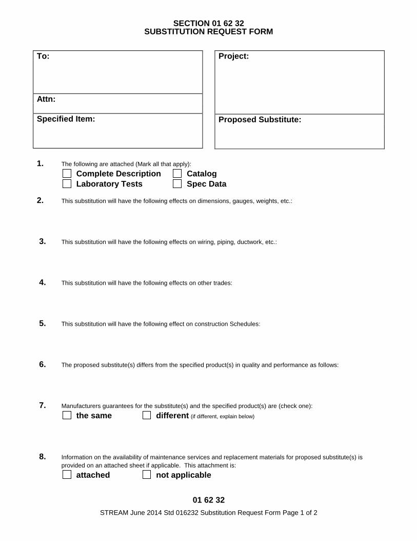
01 62 32 STREAM June 2014 Std 016232 Substitution Request Form Page 1 of 2
SECTION 01 62 32 SUBSTITUTION REQUEST FORM
To:
Attn: Specified Item:
Project:
Proposed Substitute:
1. The following are attached (Mark all that apply): Complete Description Catalog Laboratory Tests Spec Data
2. This substitution will have the following effects on dimensions, gauges, weights, etc.:
3. This substitution will have the following effects on wiring, piping, ductwork, etc.:
4. This substitution will have the following effects on other trades:
5. This substitution will have the following effect on construction Schedules:
6. The proposed substitute(s) differs from the specified product(s) in quality and performance as follows:
7. Manufacturers guarantees for the substitute(s) and the specified product(s) are (check one): the same different (if different, explain below)
8. Information on the availability of maintenance services and replacement materials for proposed substitute(s) is provided on an attached sheet if applicable. This attachment is:
attached not applicable
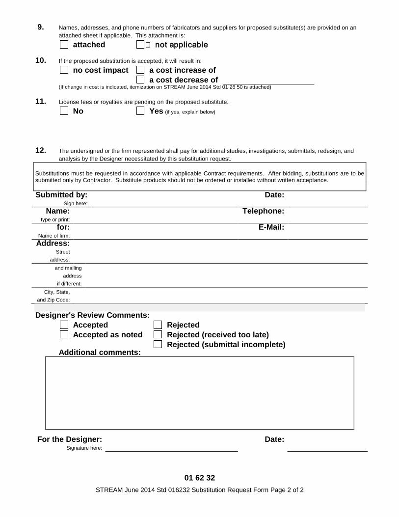
01 62 32 STREAM June 2014 Std 016232 Substitution Request Form Page 2 of 2
9. Names, addresses, and phone numbers of fabricators and suppliers for proposed substitute(s) are provided on an attached sheet if applicable. This attachment is:
attached � not applicable
10. If the proposed substitution is accepted, it will result in: no cost impact a cost increase of
a cost decrease of (If change in cost is indicated, itemization on STREAM June 2014 Std 01 26 50 is attached)
11. License fees or royalties are pending on the proposed substitute. No Yes (if yes, explain below)
12. The undersigned or the firm represented shall pay for additional studies, investigations, submittals, redesign, and analysis by the Designer necessitated by this substitution request.
Substitutions must be requested in accordance with applicable Contract requirements. After bidding, substitutions are to be submitted only by Contractor. Substitute products should not be ordered or installed without written acceptance.
Submitted by:
Sign here: Date:
Name: type or print:
Telephone:
for: Name of firm:
E-Mail:
Address: Street
address:
and mailing address
if different:
City, State, and Zip Code:
Designer's Review Comments:
Accepted Rejected Accepted as noted Rejected (received too late)
Rejected (submittal incomplete) Additional comments:
For the Designer:
Signature here: Date:

EXECUTION 01 73 00 - 1
SECTION 01 73 00 - EXECUTION
PART 1 - GENERAL
1.1 RELATED DOCUMENTS
A. Drawings and general provisions of the Contract, including General and SupplementaryConditions and other Division 01 Specification Sections, apply to this Section.
1.2 SUMMARY
A. Section includes general administrative and procedural requirements governing execution of the Work including, but not limited to, the following:
1. Construction layout.2. Installation of the Work.3. Cutting and patching.4. Coordination of Owner-installed products.5. Progress cleaning.6. Starting and adjusting.7. Protection of installed construction.8. Correction of the Work.
B. Related Requirements:1. Division 01 Section 01 33 00 "Submittal Procedures" for submitting surveys.2. Division 01 Sections 01 77 70 "Contract Close-out" and 01 78 21 “Close-out Submittals
for submitting final property survey with Project Record Documents, recording of Owner-accepted deviations from indicated lines and levels, and final cleaning.
1.3 DEFINITIONS
A. Cutting: Removal of in-place construction necessary to permit installation or performance ofother work.
B. Patching: Fitting and repair work required to restore construction to original conditions afterinstallation of other work.
1.4 INFORMATIONAL SUBMITTALS
A. Certificates: Submit certificate signed by land surveyor certifying that location and elevation ofimprovements comply with requirements.
B. Landfill Receipts: Submit copy of receipts issued by a landfill facility, licensed to accepthazardous materials, for hazardous waste disposal.
1.5 QUALITY ASSURANCE
A. Cutting and Patching: Comply with requirements for and limitations on cutting and patching of construction elements.
1. Structural Elements: When cutting and patching structural elements, notify Designer of locations and details of cutting and await directions from Designer before proceeding. Shore, brace, and support structural elements during cutting and patching. Do not cut and patch structural elements in a manner that could change their load-carrying capacity or increase deflection.
EXECUTION 01 73 00 - 2
2. Operational Elements: Do not cut and patch operating elements and related components ina manner that results in reducing their capacity to perform as intended or that results inincreased maintenance or decreased operational life or safety. Operational elementsinclude the following:
a. Primary operational systems and equipment.b. Fire separation assemblies.c. Air or smoke barriers.d. Fire-suppression systems.e. Mechanical systems piping and ducts.f. Control systems.g. Communication systems.h. Fire-detection and -alarm systems.i. Electrical wiring systems.j. Operating systems of special construction.
3. Other Construction Elements: Do not cut and patch other construction elements orcomponents in a manner that could change their load-carrying capacity, that results inreducing their capacity to perform as intended, or that results in increased maintenance ordecreased operational life or safety. Other construction elements include but are not limitedto the following:
a. Water, moisture, or vapor barriers.b. Membranes and flashings.c. Exterior curtain-wall construction.d. Sprayed fire-resistive material.e. Equipment supports.f. Piping, ductwork, vessels, and equipment.g. Noise- and vibration-control elements and systems.
4. Visual Elements: Do not cut and patch construction in a manner that results in visualevidence of cutting and patching. Do not cut and patch exposed construction in a mannerthat would, in Architect's opinion, reduce the building's aesthetic qualities. Remove andreplace construction that has been cut and patched in a visually unsatisfactory manner.
B. Cutting and Patching Conference: Before proceeding, meet at Project site with parties involved incutting and patching, including mechanical and electrical trades. Review areas of potentialinterference and conflict. Coordinate procedures and resolve potential conflicts beforeproceeding.
C. Manufacturer's Installation Instructions: Obtain and maintain on-site manufacturer's writtenrecommendations and instructions for installation of products and equipment.
PART 2 - PRODUCTS
2.1 MATERIALS
A. General: Comply with requirements specified in other Sections.
B. In-Place Materials: Use materials for patching identical to in-place materials. For exposed surfaces, use materials that visually match in-place adjacent surfaces to the fullest extent possible.
1. If identical materials are unavailable or cannot be used, use materials that, when installed, will provide a match acceptable to Designer for the visual and functional performance of in-place materials.
PART 3 - EXECUTION
EXECUTION 01 73 00 - 3
3.1 EXAMINATION
A. Existing Conditions: The existence and location of underground and other utilities andconstruction indicated as existing are not guaranteed. Before beginning sitework, investigate andverify the existence and location of underground utilities, and other construction affecting theWork.
1. Before construction, verify the location and invert elevation at points of connection ofsanitary sewer, storm sewer, and water-service piping; underground electrical services, andother utilities.
2. Furnish location data for work related to Project that must be performed by public utilitiesserving Project site.
B. Examination and Acceptance of Conditions: Before proceeding with each component of theWork, examine substrates, areas, and conditions, with Installer or Applicator present whereindicated, for compliance with requirements for installation tolerances and other conditionsaffecting performance. Record observations.
1. Examine roughing-in for mechanical and electrical systems to verify actual locations ofconnections before equipment and fixture installation.
2. Examine walls, floors, and roofs for suitable conditions where products and systems are tobe installed.
3. Verify compatibility with and suitability of substrates, including compatibility with existingfinishes or primers.
C. Written Report: Where a written report listing conditions detrimental to performance of the Workis required by other Sections, include the following:
1. Description of the Work.2. List of detrimental conditions, including substrates.3. List of unacceptable installation tolerances.4. Recommended corrections.
D. Proceed with installation only after unsatisfactory conditions have been corrected. Proceedingwith the Work indicates acceptance of surfaces and conditions.
3.2 PREPARATION
A. Field Measurements: Take field measurements as required to fit the Work properly. Recheckmeasurements before installing each product. Where portions of the Work are indicated to fit toother construction, verify dimensions of other construction by field measurements beforefabrication. Coordinate fabrication schedule with construction progress to avoid delaying theWork.
B. Space Requirements: Verify space requirements and dimensions of items shown diagrammatically on Drawings.
C. Review of Contract Documents and Field Conditions: Immediately on discovery of the need for
3.3
clarification of the Contract Documents caused by differing field conditions outside the control of Contractor, submit a request for information to Designer according to requirements in Division 01 Section "Project Management and Coordination."
CONSTRUCTION LAYOUT
A. Verification: Before proceeding to lay out the Work, verify layout information shown on Drawings,in relation to the property survey and existing benchmarks. If discrepancies are discovered, notify Designer promptly.
EXECUTION 01 73 00 - 4
1. Establish benchmarks and control points to set lines and levels at each story of construction and elsewhere as needed to locate each element of Project.
2. Establish limits on use of Project site.3. Establish dimensions within tolerances indicated. Do not scale Drawings to obtain required
dimensions.4. Inform installers of lines and levels to which they must comply.5. Check the location, level and plumb, of every major element as the Work progresses.6. Notify Designer when deviations from required lines and levels exceed allowable tolerances.7. Close site surveys with an error of closure equal to or less than the standard established by
authorities having jurisdiction.
B. Record Log: Maintain a log of layout control work. Record deviations from required lines and
3.4
levels. Include beginning and ending dates and times of surveys, weather conditions, name andduty of each survey party member, and types of instruments and tapes used. Make the logavailable for reference by Designer.
INSTALLATION
A. General: Locate the Work and components of the Work accurately, in correct alignment andelevation, as indicated.
1. Make vertical work plumb and make horizontal work level.2. Where space is limited, install components to maximize space available for maintenance
and ease of removal for replacement.3. Conceal pipes, ducts, and wiring in finished areas unless otherwise indicated.4. Maintain minimum headroom clearance of 96 inches (2440 mm) in occupied spaces and 90
inches (2300 mm) in unoccupied spaces.
B. Comply with manufacturer's written instructions and recommendations for installing products inapplications indicated.
C. Install products at the time and under conditions that will ensure the best possible results.Maintain conditions required for product performance until Substantial Completion.
D. Conduct construction operations so no part of the Work is subjected to damaging operations orloading in excess of that expected during normal conditions of occupancy.
E. Sequence the Work and allow adequate clearances to accommodate movement of constructionitems on site and placement in permanent locations.
F. Tools and Equipment: Do not use tools or equipment that produce harmful noise levels.
G. Templates: Obtain and distribute to the parties involved templates for work specified to be factoryprepared and field installed. Check Shop Drawings of other work to confirm that adequateprovisions are made for locating and installing products to comply with indicated requirements.
H. Attachment: Provide blocking and attachment plates and anchors and fasteners of adequate sizeand number to securely anchor each component in place, accurately located and aligned withother portions of the Work. Where size and type of attachments are not indicated, verify size andtype required for load conditions.
1. Mounting Heights: Where mounting heights are not indicated, mount components atheights directed by Designer.
2. Allow for building movement, including thermal expansion and contraction.3. Coordinate installation of anchorages. Furnish setting drawings, templates, and directions
for installing anchorages, including sleeves, concrete inserts, anchor bolts, and items withintegral anchors, that are to be embedded in concrete or masonry. Deliver such items toProject site in time for installation.
EXECUTION 01 73 00 - 5
I. Joints: Make joints of uniform width. Where joint locations in exposed work are not indicated,arrange joints for the best visual effect. Fit exposed connections together to form hairline joints.
J. Hazardous Materials: Use products, cleaners, and installation materials that are not consideredhazardous.
3.5 CUTTING AND PATCHING
A. Cutting and Patching, General: Employ skilled workers to perform cutting and patching. Proceedwith cutting and patching at the earliest feasible time, and complete without delay.
1. Cut in-place construction to provide for installation of other components or performance ofother construction, and subsequently patch as required to restore surfaces to their originalcondition.
B. Existing Warranties: Remove, replace, patch, and repair materials and surfaces cut or damagedduring installation or cutting and patching operations, by methods and with materials so as not tovoid existing warranties.
C. Temporary Support: Provide temporary support of work to be cut.
D. Protection: Protect in-place construction during cutting and patching to prevent damage. Provideprotection from adverse weather conditions for portions of Project that might be exposed duringcutting and patching operations.
E. Cutting: Cut in-place construction by sawing, drilling, breaking, chipping, grinding, and similaroperations, including excavation, using methods least likely to damage elements retained oradjoining construction. If possible, review proposed procedures with original Installer; complywith original Installer's written recommendations.
1. In general, use hand or small power tools designed for sawing and grinding, not hammeringand chopping. Cut holes and slots neatly to minimum size required, and with minimumdisturbance of adjacent surfaces. Temporarily cover openings when not in use.
2. Finished Surfaces: Cut or drill from the exposed or finished side into concealed surfaces.3. Mechanical and Electrical Services: Cut off pipe or conduit in walls or partitions to be
removed. Cap, valve, or plug and seal remaining portion of pipe or conduit to prevententrance of moisture or other foreign matter after cutting.
4. Proceed with patching after construction operations requiring cutting are complete.
F. Patching: Patch construction by filling, repairing, refinishing, closing up, and similar operationsfollowing performance of other work. Patch with durable seams that are as invisible aspracticable. Provide materials and comply with installation requirements specified in otherSections, where applicable.
1. Inspection: Where feasible, test and inspect patched areas after completion to demonstratephysical integrity of installation.
2. Exposed Finishes: Restore exposed finishes of patched areas and extend finish restorationinto retained adjoining construction in a manner that will minimize evidence of patching andrefinishing.
a. Clean piping, conduit, and similar features before applying paint or other finishingmaterials.
b. Restore damaged pipe covering to its original condition.
3. Ceilings: Patch, repair, or rehang in-place ceilings as necessary to provide an even-planesurface of uniform appearance.
G. Cleaning: Clean areas and spaces where cutting and patching are performed. Remove paint,mortar, oils, putty, and similar materials from adjacent finished surfaces.
EXECUTION 01 73 00 - 6
3.6 OWNER-INSTALLED PRODUCTS
A. Site Access: Provide access to Project site for Owner's construction personnel.
B. Coordination: Coordinate construction and operations of the Work with work performed byOwner's construction personnel.
1. Construction Schedule: Inform Owner of Contractor's preferred construction schedule forOwner's portion of the Work. Adjust construction schedule based on a mutually agreeabletimetable. Notify Owner if changes to schedule are required due to differences in actualconstruction progress.
2. Preinstallation Conferences: Include Owner's construction personnel at preinstallationconferences covering portions of the Work that are to receive Owner's work. Attendpreinstallation conferences conducted by Owner's construction personnel if portions of theWork depend on Owner's construction.
3.7 PROGRESS CLEANING
A. General: Clean Project site and work areas daily, including common areas. Enforce requirements strictly. Dispose of materials lawfully.
1. Comply with requirements in NFPA 241 for removal of combustible waste materials and debris.
2. Do not hold waste materials more than seven days during normal weather or three days if the temperature is expected to rise above 80 deg F (27 deg C).
3. Containerize hazardous and unsanitary waste materials separately from other waste. Mark containers appropriately and dispose of legally, according to regulations.
a. Use containers intended for holding waste materials of type to be stored.
4. Coordinate progress cleaning for joint-use areas where Contractor and other contractors are working concurrently.
B. Site: Maintain Project site free of waste materials and debris.
C. Work Areas: Clean areas where work is in progress to the level of cleanliness necessary for proper execution of the Work.
1. Remove liquid spills promptly.2. Where dust would impair proper execution of the Work, broom-clean or vacuum the entire
work area, as appropriate.
D. Installed Work: Keep installed work clean. Clean installed surfaces according to written instructions of manufacturer or fabricator of product installed, using only cleaning materials specifically recommended. If specific cleaning materials are not recommended, use cleaning materials that are not hazardous to health or property and that will not damage exposed surfaces.
E. Concealed Spaces: Remove debris from concealed spaces before enclosing the space.
F. Exposed Surfaces in Finished Areas: Clean exposed surfaces and protect as necessary to ensure freedom from damage and deterioration at time of Substantial Completion.
G. Waste Disposal: Do not bury or burn waste materials on-site. Do not wash waste materials down sewers or into waterways. Comply with waste disposal requirements in Division 01 Section "Construction Waste Mgmt and Disposal."
H. During handling and installation, clean and protect construction in progress and adjoining materials already in place. Apply protective covering where required to ensure protection from damage or deterioration at Substantial Completion.
EXECUTION 01 73 00 - 7
I. Clean and provide maintenance on completed construction as frequently as necessary throughthe remainder of the construction period. Adjust and lubricate operable components to ensureoperability without damaging effects.
J. Limiting Exposures: Supervise construction operations to assure that no part of the construction,completed or in progress, is subject to harmful, dangerous, damaging, or otherwise deleteriousexposure during the construction period.
3.8 STARTING AND ADJUSTING
3.9
A. Start equipment and operating components to confirm proper operation. Remove malfunctioning units, replace with new units, and retest.
B. Adjust equipment for proper operation. Adjust operating components for proper operation without binding.
C. Test each piece of equipment to verify proper operation. Test and adjust controls and safeties. Replace damaged and malfunctioning controls and equipment.
D. Manufacturer's Field Service: Comply with qualification requirements in Division 01 Section
"Quality Requirements".
PROTECTION OF INSTALLED CONSTRUCTION
A. Provide final protection and maintain conditions that ensure installed Work is without damage ordeterioration at time of Substantial Completion.
B. Comply with manufacturer's written instructions for temperature and relative humidity.
END OF SECTION 01 73 00
CUTTING AND PATCHING 01 73 10 - 1
SECTION 01 73 10 - CUTTING AND PATCHING
PART 1 GENERAL
1.1 RELATED DOCUMENTS
A. Drawings and general provisions of the Contract, including General and SupplementaryConditions and other Division 1 Specification Sections, apply to this Section.
1.2 SUMMARY
A. This Section includes procedural requirements for cutting and patching.
1.3 DEFINITIONS
A. Cutting: Removal of existing construction necessary to permit installation or performance ofother Work.
B. Patching: Fitting and repair work required to restore surfaces to original conditions afterinstallation of other Work.
1.4 QUALITY ASSURANCE
A. Structural Elements: Do not cut and patch structural elements in a manner that could change their load-carrying capacity or load-deflection ratio.
B. Operational Elements: Do not cut and patch operating elements and related components in a manner that results in reducing their capacity to perform as intended or that result in increased maintenance or decreased operational life or safety.
1. Primary operational systems and equipment.2. Air or smoke barriers.3. Fire-protection systems.4. Control systems.5. Communication systems.6. Conveying systems.7. Electrical wiring systems.8. Operating systems of special construction.
C. Miscellaneous Elements: Do not cut and patch the following elements or related components in a manner that could change their load-carrying capacity that results in reducing their capacity to perform as intended, or that result in increased maintenance or decreased operational life or safety.
1. Water, moisture, or vapor barriers.2. Membranes and flashings.3. Equipment supports.4. Piping, ductwork, vessels, and equipment.5. Noise- and vibration-control elements and systems.
D. Visual Requirements: Do not cut and patch construction in a manner that results in visual evidence of cutting and patching. Do not cut and patch construction exposed on the exterior or in occupied spaces in a manner that would, in Designer's opinion, reduce the building's aesthetic qualities. Remove and replace construction that has been cut and patched in a
CUTTING AND PATCHING 01 73 10 - 2
visually unsatisfactory manner.
1.5 WARRANTY
A. Warranties: Remove, replace, patch, and repair materials and surfaces cut or damaged duringcutting and patching operations, by methods and with materials so as not to void warranties.
PART 2 PRODUCTS
2.1 MATERIALS
A. General: Comply with requirements specified in other Sections of these Specifications.
B. Materials: Use materials identical to existing materials. For exposed surfaces, use materialsthat visually match adjacent surfaces to the fullest extent possible.
1. If identical materials cannot be used, use materials that, when installed, will match thevisual and functional performance of existing materials.
PART 3 EXECUTION
3.1 EXAMINATION
A. Examine surfaces to be cut and patched and conditions under which cutting and patching are tobe performed.
1. Compatibility: Before patching, verify compatibility with and suitability of substrates,including compatibility with existing finishes or primers.
2. Proceed with installation only after unsafe or unsatisfactory conditions have beencorrected.
3.2 PREPARATION
A. Temporary Support: Provide temporary support of Work to be cut.
B. Protection: Protect existing construction during cutting and patching to prevent damage.Provide protection from adverse weather conditions for portions of Project that might beexposed during cutting and patching operations.
C. Adjoining Areas: Avoid interference with use of adjoining areas or interruption of free passageto adjoining areas.
3.3 PERFORMANCE
A. General: Employ skilled workers to perform cutting and patching. Proceed with cutting andpatching at the earliest feasible time, and complete without delay.
1. Cut existing construction to provide for installation of other components or performanceof other construction, and subsequently patch as required to restore surfaces to theiroriginal condition.
B. Cutting: Cut existing construction by sawing, drilling, breaking, chipping, grinding, and similaroperations, including excavation, using methods least likely to damage elements retained oradjoining construction. If possible, review proposed procedures with original Installer; complywith original Installer's written recommendations.
CUTTING AND PATCHING 01 73 10 - 3
1. In general, use hand or small power tools designed for sawing and grinding, not hammering and chopping. Cut holes and slots as small as possible, neatly to size required, and with minimum disturbance of adjacent surfaces. Temporarily cover openings when not in use.
2. Existing Finished Surfaces: Cut or drill from the exposed or finished side into concealed surfaces.
3. Proceed with patching after construction operations requiring cutting are complete.
C. Patching: Patch construction by filling, repairing, refinishing, closing up, and similar operations following performance of other Work. Patch with durable seams that are as invisible as possible. Provide materials and comply with installation requirements specified in other Sections of these Specifications.
1. Inspection: Where feasible, test and inspect patched areas after completion to demonstrate integrity of installation.
2. Exposed Finishes: Restore exposed finishes of patched areas and extend finish restoration into retained adjoining construction in a manner that will eliminate evidence of patching and refinishing.
END OF SECTION 01 73 10
CONSTRUCTION WASTE MANAGEMENT AND DISPOSAL 01 74 19 - 1
SECTION 01 74 19 - CONSTRUCTION WASTE MANAGEMENT AND DISPOSAL
PART 1 - GENERAL
1.1 RELATED DOCUMENTS
A. Drawings and general provisions of the Contract, including General and SupplementaryConditions and other Division 01 Specification Sections, apply to this Section.
1.2 SUMMARY
A. Section includes administrative and procedural requirements for the following:
1. Salvaging nonhazardous construction waste.2. Recycling nonhazardous construction waste.3. Disposing of nonhazardous construction waste.
1.3 DEFINITIONS
A. Construction Waste: Building and site improvement materials and other solid waste resultingfrom construction, remodeling, renovation, or repair operations. Construction waste includespackaging.
B. Disposal: Removal off-site of demolition and construction waste and subsequent sale, recycling,reuse, or deposit in landfill or incinerator acceptable to authorities having jurisdiction.
C. Recycle: Recovery of demolition or construction waste for subsequent processing in preparationfor reuse.
D. Salvage: Recovery of demolition or construction waste and subsequent sale or reuse in anotherfacility.
E. Salvage and Reuse: Recovery of demolition or construction waste and subsequent incorporationinto the Work.
1.4 PERFORMANCE REQUIREMENTS
A. General: Practice efficient waste management in the use of materials in the course of the Work.Use all reasonable means to divert construction and demolition waste from landfills andincinerators. Facilitate recycling and salvage of materials, including, but not limited to thefollowing:
1. Construction Waste:a. Metals.b. Brick.c. Gypsum board.d. Packaging.
1.5 QUALITY ASSURANCE
A. Regulatory Requirements: Comply with hauling and disposal regulations of authorities havingjurisdiction.
B. Waste Management Conference: Conduct conference at Project site to comply withrequirements in Division 01 Section "Project Management and Coordination." Review methodsand procedures related to waste management including, but not limited to, the following:
CONSTRUCTION WASTE MANAGEMENT AND DISPOSAL 01 74 19 - 2
1. Review and discuss waste management plan including responsibilities of wastemanagement coordinator.
2. Review requirements for documenting quantities of each type of waste and its disposition.3. Review and finalize procedures for materials separation and verify availability of containers
and bins needed to avoid delays.4. Review procedures for periodic waste collection and transportation to recycling and disposal
facilities.5. Review waste management requirements for each trade.
PART 2 - PRODUCTS (Not Used)
PART 3 - EXECUTION
3.1 PLAN IMPLEMENTATION
A. General: Implement waste management plan. Provide handling, containers, storage, signage, transportation, and other items as required to implement waste management plan during the entire duration of the Contract.
1. Comply with operation, termination, and removal requirements in Division 01 Section 01 50 00 "Temporary Facilities and Controls."
B. Training: Train workers, subcontractors, and suppliers on proper waste management procedures, as appropriate for the Work.
1. Distribute waste management plan to everyone concerned.2. Distribute waste management plan to entities when they first begin work on-site. Review
plan procedures and locations established for salvage, recycling, and disposal.
C. Site Access and Temporary Controls: Conduct waste management operations to ensure minimum interference with roads, streets, walks, walkways, and other adjacent occupied and used facilities.
1. Designate and label specific areas on Project site necessary for separating materials that are to be salvaged, recycled, reused, donated, and sold.
2. Comply with Division 01 Section 01 50 00 "Temporary Facilities and Controls" for controlling dust and dirt, environmental protection, and noise control.
3.2 RECYCLING CONSTRUCTION WASTE, GENERAL
A. General: Recycle paper and beverage containers used by on-site workers.
B. Recycling Incentives: Revenues, savings, rebates, tax credits, and other incentives received forrecycling waste materials shall accrue to Contractor.
C. Preparation of Waste: Prepare and maintain recyclable waste materials according to recycling orreuse facility requirements. Maintain materials free of dirt, adhesives, solvents, petroleumcontamination, and other substances deleterious to the recycling process.
D. Procedures: Separate recyclable waste from other waste materials, trash, and debris. Separaterecyclable waste by type at Project site to the maximum extent practical according to approvedconstruction waste management plan.
1. Provide appropriately marked containers or bins for controlling recyclable waste untilremoved from Project site. Include list of acceptable and unacceptable materials at eachcontainer and bin.
CONSTRUCTION WASTE MANAGEMENT AND DISPOSAL 01 74 19 - 3
a. Inspect containers and bins for contamination and remove contaminated materials iffound.
2. Remove recyclable waste from Owner's property and transport to recycling receiver orprocessor.
3.3 RECYCLING CONSTRUCTION WASTE
A. Packaging:
1. Cardboard and Boxes: Break down packaging into flat sheets. Bundle and store in a drylocation.
2. Polystyrene Packaging: Separate and bag materials.3. Pallets: As much as possible, require deliveries using pallets to remove pallets from Project
site. For pallets that remain on-site, break down pallets into component wood pieces andcomply with requirements for recycling wood.
4. Crates: Break down crates into component wood pieces and comply with requirements forrecycling wood.
B. Gypsum Board: Stack large clean pieces on wood pallets or in container and store in a drylocation.
3.4 DISPOSAL OF WASTE
A. General: Except for items or materials to be salvaged, recycled, or otherwise reused, removewaste materials from Project site and legally dispose of them in a landfill or incinerator acceptableto authorities having jurisdiction.
1. Except as otherwise specified, do not allow waste materials that are to be disposed ofaccumulate on-site.
2. Remove and transport debris in a manner that will prevent spillage on adjacent surfacesand areas.
B. Burning: Do not burn waste materials.
C. Disposal: Remove waste materials from Owner's property and legally dispose of them.
END OF SECTION 01 74 19

01 77 70 STREAM June 2014 Std 017770 Contract Closeout Page 1 of 2
SECTION 01 77 70 CONTRACT CLOSEOUT
PART 1 - GENERAL 1.01 REQUEST FOR CLOSE-OUT INSPECTION
A. SUBSTANTIAL COMPLETION: When Contractor considers Work substantially complete, Contractor shall submit to Designer:
1. Written assertion that Work is Substantially Complete;
2. A list of items to be completed or corrected and dates scheduled for completion or correction of each item;
3. Certification that orientation and training for facility maintenance personnel is complete or will be prior to inspection; and,
4. Written assertion that Operating and Maintenance Data Binders are complete and available or will be prior to inspection.
B. FINAL INSPECTION: When Contractor considers Work complete, Contractor shall submit to Designer:
1. Certification that a qualified person authorized by Contractor has reviewed the Contract Documents and inspected the Work;
2. Written assertion that the Work is complete and in accordance with Contract Documents and ready for Final Inspection;
3. Written assertion that additional materials necessary to augment the Operating and Maintenance Data Binders with instructions for adding these to the Binders, or full replacement Binders, are complete and available or will be prior to inspection; and,
4. Written assertion that Project Data Binders and Construction Record Documents are complete and available or will be prior to inspection.
C. Upon receipt of an appropriate request for close-out inspection, Designer will schedule an inspection meeting with Contractor, and Owner's representatives to determine the status of completion.
1.02 RESULTS OF CLOSE-OUT INSPECTIONS
A. Should the Designer determine that Work is not complete to the degree asserted by Contractor, Designer will promptly notify Contractor in writing stating the deficiencies. Contractor shall take immediate steps to remedy deficiencies and make a request for re-inspection.
B. SUBSTANTIAL COMPLETION: Designer will prepare a Certificate of Substantial Completion on AIA Document G704 accompanied by a list of items to be completed or corrected, and will submit Certificate to Contractor and to Owner for signature with an accounting of Liquidated Damages due, when Designer verifies that:
1. Work is Substantially Complete based on an inspection conducted pursuant to an appropriate request for close-out inspection;
2. Orientation and training for facility maintenance personnel is complete; and,
3. Operating and Maintenance Data Binders are complete and have been delivered to the Owner.
C. FINAL INSPECTION: Designer will certify that the Work is Complete, and will initiate Final Adjustments, when Designer verifies that:
1. Work is complete in accordance with Contract Documents based on an inspection conducted pursuant to an appropriate request for close-out inspection;
01 77 70 STREAM June 2014 Std 017770 Contract Closeout Page 2 of 2
2. Orientation and training for facility maintenance personnel is complete; and,
3. Additional materials necessary to augment the Operating and Maintenance Data Binders with instructions for adding these to the Binders, or full replacement Binders, are complete and have been delivered to the Owner; and,
4. Project Data Binders and Construction Record Documents are complete and have been delivered to the Designer.
1.03 RE-INSPECTION FEES: If the Work fails a close-out inspection, and a subsequent inspection is requested and conducted based on Contractor assertion of the same stage of completion, Owner will compensate Designer for performing such re-inspection as additional services, and deduct the amount of such compensation from the Contract Sum by appropriate modification.
1.04 FINAL ADJUSTMENTS
A. When Designer has certified that the Work is complete, Designer will determine whether modification is needed to reflect appropriate adjustments to Contract Sum that were not previously effected. If such modification is needed, Designer shall prepare it and deliver it to Contractor, who in the case of a change order, shall sign and return it to Designer.
B. When Designer has certified that the Work and needed modifications to the Contract are complete, Designer will request that Contractor submit a final application for payment.
1.05 ONE (1) YEAR CORRECTIVE INSPECTION
A. A One (1) Year Corrective Inspection will be scheduled and conducted at project site prior to one (1) year from date Substantial Completion was achieved, but as close to the end of that year as is reasonably possible.
B. One (1) Year Corrective Inspection will be attended by at least one (1) representative each of Owner, Designer, and Contractor.
C. One (1) Year Corrective Inspection is intended to be an opportunity for Contractor to become aware of any outstanding corrections needed pursuant to the basic first-year warranty of Work.
END OF SECTION
01 78 21 STREAM June 2014 Std 017821 Closeout Submittals Page 1 of 3
SECTION 01 78 21 CLOSEOUT SUBMITTALS
PART 1 - GENERAL 1.01 DATA BINDERS GENERALLY
A. Provide one (1) complete set and two (2) CD’s in portable document file (.pdf) format. Provide commercial quality three ring binders with durable plastic covers. Identify project and type of data on face and side of binder. If multiple binders are required, identify as consecutively numbered volumes, identifying original documents as set number one. Provide information required by Contract Documents organized as outlined below. Include related documents under the heading to which each is most closely related.
B. Provide introductory information
1. Cover sheet giving complete project title and number, Contractor's name, address, phone number, name of project superintendent, and related general information.
2. Table of Contents to generally identify material in Binders. Reference and bind separately any over-size documents that cannot be neatly folded and included in this binder.
1.02 OPERATING & MAINTENANCE DATA BINDERS A. Provide Product Data as outlined below:
1. Detailed Table of Contents for this part,
2. For each system or product: names, addresses, and telephone numbers of supplier, installer, and maintenance service company; drawing and specification reference; building location; manufacturer and model number,
3. Description of unit and component parts, clearly identifying the specific product or part installed. When manufacturer's cut sheets are used for product identification, plainly mark specific items included in Work, and
4. Related information required by Contract Documents, or furnished with items included in Project, that Owner may use for maintenance, operation, repair, renovation, or additions to Work.
B. Provide Operating and Maintenance Data as outlined below for mechanical and electrical systems, equipment, and products
1. Detailed Table of Contents for this part.
2. Manufacturer's printed operating and maintenance instructions supplemented with drawings and text to clearly illustrate proper operation and a logical sequence of maintenance procedures. These shall be the written manufacturer’s data with the model and features of this installation clearly marked and edited to omit reference to products or data not applicable to this installation. This section shall include data on the following:
a. Installation, startup and break-in instructions; b. All starting, normal shutdown, emergency shutdown, manual operation, seasonal
changeover and normal operating procedures and data, including any special limitations;
c. Operating and maintenance and installation instructions that were shipped with the unit;
d. Preventative maintenance and service procedures and schedules; e. Troubleshooting procedures; f. Parts list, illustrations, assembly drawings and diagrams, edited to omit reference
to items that do not apply to this installation;
01 78 21 STREAM June 2014 Std 017821 Closeout Submittals Page 2 of 3
g. List of any special tools required to service or maintain the equipment; h. Performance data, ratings and curves; i. Warranty, which clearly lists conditions to be maintained to keep warranty in
effect and conditions that would affect the validity of the warranty; and, j. Any service contracts issued.
3. As-installed control diagrams by controls manufacturer.
4. Installers' coordination drawings with as-installed color-coded piping diagrams and wiring diagrams.
5. Charts of valve tag numbers with the location and function of each valve.
6. Circuit directories of panel boards.
7. Instructions for care, with a list of manufacturer's recommended types of cleaning agents and methods.
8. List of materials and parts furnished for the Owner's use.
C. Supplemental Data. Provide written text and/or special drawings to provide necessary information, where manufacturer’s standard printed data is not available and information is necessary for a proper understanding and operation and maintenance of equipment or systems, or where it is necessary to provide additional information to supplement data included in the manual or project documents.
D. Condensed Preventive Maintenance Instructions. Provide condensed typewritten excerpts from the manufacturers written instructions for weekly, monthly, quarterly, annual, etc. maintenance. The HVAC mechanical contractor shall prepare this summary with help from the equipment supplier.
E. Condensed Operating Instructions. Provide condensed instructions for start-up, shutdown, emergency operation, safety precautions, unusual features and troubleshooting suggestions. In addition, a copy of these instructions shall be clearly laminated and secured adjacent to the equipment where it can be easily read by operating personnel. These instructions shall be provided for boilers, furnaces, chillers, pumps, heat rejection equipment, large air handling units (greater than 10 tons), heat pump systems, control system, air compressors and dryers.
F. Controls and Test and Balance (TAB) O&M Data. Include control drawings for equipment and its components, including the sequence of operation. The Controls Contractor and TAB Contractor shall provide this data.
G. Commissioning Record and Testing Data. Provide data dedicated to documenting the commissioning process that includes all certifications and testing data.
1.03 PROJECT DATA BINDERS A. Provide required forms completed for supplying data on building systems or assemblies.
B. Provide a complete listing of subcontractors and material suppliers, including dollar amount, company name, address, phone number, local representative, and information regarding diversity-owned business status. This information shall be submitted to Designer on the form exhibited as Section 01 78 88.
C. Provide certificates and acceptance information
1. Detailed Table of Contents for this part.
2. Certificate of Substantial Completion.
3. Use and Occupancy Permits.
4. Required TDEC Permits.
01 78 21 STREAM June 2014 Std 017821 Closeout Submittals Page 3 of 3
5. Certificate(s) of Inspection or letter(s) of acceptance from:
a. Fire Marshal, b. Department of Labor for boilers, pressure vessels, or elevators, c. Public Health Authorities, and d. other governing authorities as apply.
D. Guarantees, Warranties, Bonds, Certifications, and related documents
1. Detailed Table of Contents for this part.
2. Contractor's warranty of the work.
3. Guarantees, warranties, and bonds, executed by the respective vendors, manufacturers, suppliers and subcontractors.
4. Certifications, including, but not limited, Section 00 65 01, Non-Use of Asbestos Containing Materials Affidavit-Contractor.
5. Maintenance Agreements and service contracts.
6. Complete information for each item:
a. Product or work item, and scope of installation; b. Name of provider, with name of responsible principal, address and telephone
number; c. Beginning date and duration; and, d. Information about instances which might affect validity, and proper procedure in
case of failure
1.04 CONSTRUCTION RECORD DOCUMENTS
The record copy of Contract Documents and approved submittals required by paragraph 3.11 of the Conditions shall be kept in good condition for submittal to Designer upon completion of construction activity. In the course of the Work, Contractor shall legibly mark these documents to record actual conditions of Work, including: location, depth, and identification of new and existing underground items, location by dimension and identification of utilities, valves, tap points, equipment, service access, test points, and related features, field changes in dimensions and detail, changes by addenda, change orders, and construction change directives, description and details of features for maintenance, service, replacement, or expansion of the Work.
END OF SECTION


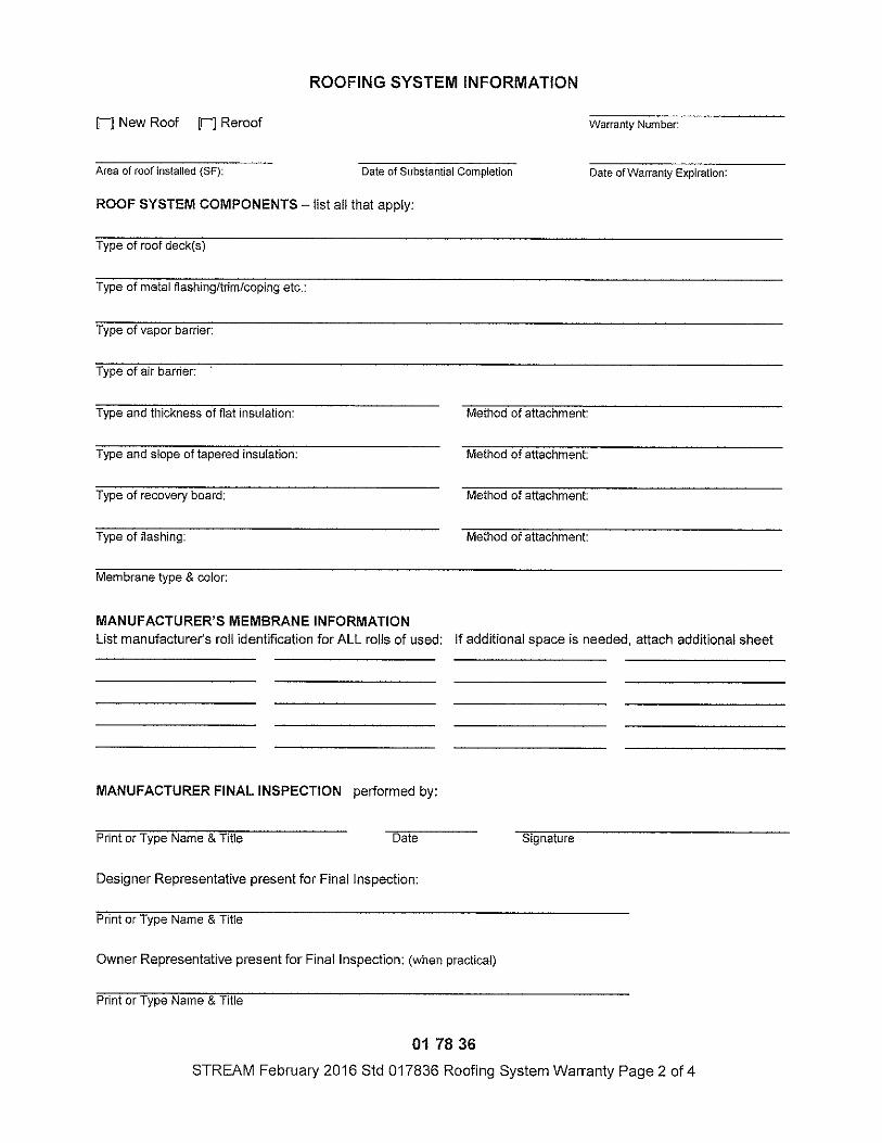
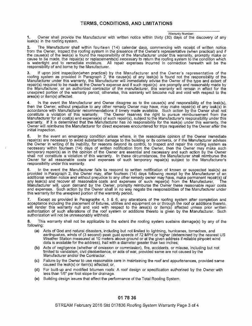
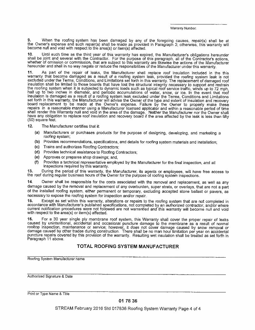
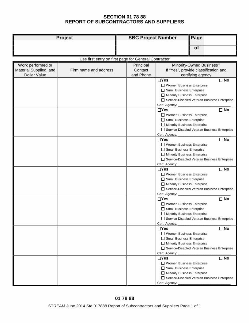
01 78 88 STREAM June 2014 Std 017888 Report of Subcontractors and Suppliers Page 1 of 1
SECTION 01 78 88 REPORT OF SUBCONTRACTORS AND SUPPLIERS
Project SBC Project Number Page of
Use first entry on first page for General Contractor Work performed or
Material Supplied, and Dollar Value
Firm name and address
Principal Contact
and Phone
Minority-Owned Business? If “Yes”, provide classification and
certifying agency Yes No
Women Business Enterprise Small Business Enterprise Minority Business Enterprise Service-Disabled Veteran Business Enterprise
Cert. Agency: _____________________________ Yes No
Women Business Enterprise Small Business Enterprise Minority Business Enterprise Service-Disabled Veteran Business Enterprise
Cert. Agency: _____________________________ Yes No
Women Business Enterprise Small Business Enterprise Minority Business Enterprise Service-Disabled Veteran Business Enterprise
Cert. Agency: _____________________________ Yes No
Women Business Enterprise Small Business Enterprise Minority Business Enterprise Service-Disabled Veteran Business Enterprise
Cert. Agency: _____________________________ Yes No
Women Business Enterprise Small Business Enterprise Minority Business Enterprise Service-Disabled Veteran Business Enterprise
Cert. Agency: _____________________________ Yes No
Women Business Enterprise Small Business Enterprise Minority Business Enterprise Service-Disabled Veteran Business Enterprise
Cert. Agency: _____________________________ Yes No
Women Business Enterprise Small Business Enterprise Minority Business Enterprise Service-Disabled Veteran Business Enterprise
Cert. Agency: _____________________________

SELECTIVE DEMOLITION 02 41 00 - 1
SECTION 02 41 00
SELECTIVE DEMOLITION
PART 1 - GENERAL
1.1 RELATED DOCUMENTS
A. Drawings and general provisions of the Contract, including General and Supplementary Conditions and other Division 1 Specification Sections, apply to this Section.
1.2 SUMMARY
A. This Section includes the following:
1. Demolition and removal of selected portions of a building. 2. Repair procedures for selective demolition operations.
1.3 DEFINITIONS
A. Remove: Detach items from existing construction and legally dispose of them off-site, unless indicated to be removed and salvaged or removed and reinstalled.
B. Remove and Salvage: Detach items from existing construction and deliver them to Owner ready for reuse.
C. Remove and Reinstall: Detach items from existing construction, prepare them for reuse, and reinstall them where indicated.
D. Existing to Remain: Existing items of construction that are not to be removed and that are not otherwise indicated to be removed, removed and salvaged, or removed and reinstalled.
1.4 MATERIALS OWNERSHIP
A. Except for items or materials indicated to be reused, salvaged, reinstalled, or otherwise indicated to remain Owner's property, demolished materials shall become Contractor's property and shall be removed from Project site.
1.5 QUALITY ASSURANCE
A. Regulatory Requirements: Comply with governing EPA notification regulations before beginning selective demolition. Comply with hauling and disposal regulations of authorities having jurisdiction.
B. Standards: Comply with ANSI A10.6 and NFPA 241.
1.6 PROJECT CONDITIONS
SELECTIVE DEMOLITION 02 41 00 - 2
A. Owner assumes no responsibility for condition of areas to be selectively demolished.
B. Hazardous Materials: It is not expected that hazardous materials will be encountered during the work.
1. If materials suspected of containing hazardous materials are encountered unexpectedly,
do not disturb; immediately notify Designer and Owner.
C. Storage or sale of removed items or materials on-site will not be permitted.
D. Utility Service: Maintain existing utilities indicated to remain in service and protect them against damage during selective demolition operations.
1. Maintain fire-protection facilities in service during selective demolition operations.
1.7 WARRANTY
A. Existing Warranties: Remove, replace, patch, and repair materials and surfaces cut or damaged during selective demolition, by methods and with materials so as not to void existing warranties.
PART 2 - PRODUCTS
2.1 REPAIR MATERIALS
A. Use repair materials identical to existing materials.
1. If identical materials are unavailable or cannot be used for exposed surfaces, use materials that visually match existing adjacent surfaces to the fullest extent possible.
2. Use materials whose installed performance equals or surpasses that of existing materials.
B. Comply with material and installation requirements specified in individual Specification Sections.
PART 3 - EXECUTION
3.1 EXAMINATION
A. Verify that utilities have been disconnected and capped.
B. Survey existing conditions and correlate with requirements indicated to determine extent of selective demolition required.
C. Inventory and record the condition of items to be removed and reinstalled and items to be removed and salvaged.

SELECTIVE DEMOLITION 02 41 00 - 3
D. When unanticipated mechanical, electrical, or structural elements that conflict with intended function or design are encountered, investigate and measure the nature and extent of conflict. Promptly submit a written report to Designer.
3.2 UTILITY SERVICES
A. Existing Utilities: Maintain services indicated to remain and protect them against damage during selective demolition operations.
B. Do not interrupt existing utilities serving occupied or operating facilities unless authorized in writing by Owner and authorities having jurisdiction. Provide temporary services during interruptions to existing utilities, as acceptable to Owner and to authorities having jurisdiction.
1. Provide at least 72 hours' notice to Owner if shutdown of service is required during changeover.
C. Utility Requirements: Refer to Division 22 and 26 Sections for shutting off, disconnecting, removing, and sealing or capping utilities. Do not start selective demolition work until utility disconnecting and sealing have been completed and verified in writing.
3.3 PREPARATION
A. Site Access and Temporary Controls: Conduct selective demolition and debris-removal operations to ensure minimum interference with roads, streets, walks, walkways, and other adjacent facilities.
1. Do not close or obstruct streets, walks, walkways, or other adjacent facilities without permission from Owner and authorities having jurisdiction. Provide alternate routes around closed or obstructed traffic ways if required by governing regulations.
2. Protect existing site, appurtenances, and landscaping to remain.
B. Temporary Facilities: Provide temporary barricades and other protection required to prevent injury to people and damage to adjacent buildings and facilities to remain.
1. Provide protection to ensure safe passage of people around selective demolition area. 2. Provide temporary weather protection, during interval between selective demolition of
existing construction on exterior surfaces and new construction, to prevent water leakage and damage to structure and interior areas.
3. Protect walls, ceilings, floors, and other existing finish work that are to remain or that are exposed during selective demolition operations.
4. Cover and protect furniture, furnishings, and equipment that have not been removed.
C. Temporary Enclosures: Provide temporary enclosures for protection of existing building and construction, in progress and completed, from exposure, foul weather, other construction operations, and similar activities. Provide temporary weather tight enclosure for building exterior.
3.4 POLLUTION CONTROLS
A. Dust Control: Use water mist, temporary enclosures, and other suitable methods to limit spread of dust and dirt. Comply with governing environmental-protection regulations.
SELECTIVE DEMOLITION 02 41 00 - 4
B. Disposal: Remove and transport debris in a manner that will prevent spillage on adjacent surfaces and areas.
C. Cleaning: Clean adjacent structures and improvements of dust, dirt, and debris caused by selective demolition operations. Return adjacent areas to condition existing before selective demolition operations began.
3.5 SELECTIVE DEMOLITION
A. General: Demolish and remove existing construction only to the extent required by new construction and as indicated. Use methods required to complete the Work within limitations of governing regulations and as follows:
1. Proceed with selective demolition systematically, from higher to lower level. Complete selective demolition operations above each floor or tier before disturbing supporting members on the next lower level.
2. Neatly cut openings and holes plumb, square, and true to dimensions required. Use cutting methods least likely to damage construction to remain or adjoining construction. Use hand tools or small power tools designed for sawing or grinding, not hammering and chopping, to minimize disturbance of adjacent surfaces. Temporarily cover openings to remain.
3. Cut or drill from the exposed or finished side into concealed surfaces to avoid marring existing finished surfaces.
4. Do not use cutting torches until work area is cleared of flammable materials. At concealed spaces, such as duct and pipe interiors, verify condition and contents of hidden space before starting flame-cutting operations. Maintain fire watch and portable fire-suppression devices during flame-cutting operations.
5. Maintain adequate ventilation when using cutting torches. 6. Remove decayed, vermin-infested, or otherwise dangerous or unsuitable materials and
promptly dispose of off-site. 7. Locate selective demolition equipment and remove debris and materials so as not to
impose excessive loads on supporting walls, floors, or framing. 8. Dispose of demolished items and materials promptly. 9. Return elements of construction and surfaces that are to remain to condition existing
before selective demolition operations began.
B. Existing Facilities: Comply with building Owner’s requirements for using and protecting elevators, stairs, walkways, loading docks, building entries, and other building facilities during selective demolition operations.
C. Removed and Salvaged Items: Comply with the following:
1. Clean salvaged items. 2. Pack or crate items after cleaning. Identify contents of containers. 3. Store items in a secure area until delivery to Owner. 4. Transport items to Owner's storage area designated by Owner. 5. Protect items from damage during transport and storage.
D. Removed and Reinstalled Items: Comply with the following:
1. Clean and repair items to functional condition adequate for intended reuse. Paint equipment to match new equipment.
2. Pack or crate items after cleaning and repairing. Identify contents of containers. 3. Protect items from damage during transport and storage.
SELECTIVE DEMOLITION 02 41 00 - 5
4. Reinstall items in locations indicated. Comply with installation requirements for new materials and equipment. Provide connections, supports, and miscellaneous materials necessary to make item functional for use indicated.
E. Existing Items to Remain: Protect construction indicated to remain against damage and soiling during selective demolition. When permitted by Designer, items may be removed to a suitable, protected storage location during selective demolition and cleaned and reinstalled in their original locations after selective demolition operations are complete.
3.6 PATCHING AND REPAIRS
A. General: Promptly repair damage to adjacent construction caused by selective demolition operations.
B. Patching: Comply with Section 01 73 10 "Cutting and Patching."
3.7 DISPOSAL OF DEMOLISHED MATERIALS
A. General: Promptly dispose of demolished materials. Do not allow demolished materials to accumulate on-site.
B. Burning: Do not burn demolished materials.
C. Disposal: Transport demolished materials off Owner's property and legally dispose of them.
END OF SECTION 02 41 00
Demolition 02 41 16 - 1
SECTION 02 41 16 DEMOLITION
PART 1 GENERAL 1.01 WORK INCLUDED
A. Removal and disposal of designated pavements, concrete, curbs, culverts, utilities, buried pipes, floor slabs, foundations, remnants of current and previous development, and other structures.
1.02 RELATED WORK A. Section 31 11 00: Clearing and Grubbing
1.03 QUALITY ASSURANCE A. Contractor Qualifications: Minimum of 5 years experience in demolition of comparable structures. B. Requirements of Regulatory Agencies:
1. Comply with requirements of codes. 2. Comply with requirements of local Public Health Authority. 3. Comply with local utility companies and/or utility districts.
1.04 SUBMITTALS A. Certificates of severance of utility services. B. Permit for transport and disposal of debris. C. Demolition procedures and operational sequence for review by Owner's Representative
1.05 JOB CONDITIONS A. Protection:
1. Erect barriers, fences, guard rails, enclosures, chutes, and shoring to protect structures, and utilities remaining intact.
2. Protect designated trees and plants from damage. B. Maintaining Traffic:
1. Ensure minimum interference with roads, street, driveways, sidewalks, and adjacent facilities.
2. Do not close or obstruct streets, sidewalks, alleys or passageways without permission from authorities having jurisdiction.
3. If required by governing authorities, provide alternate routes around closed or obstructed traffic ways.
PART 2 PRODUCTS – NOT USED
PART 3 EXECUTION
3.01 PREPARATION A. Prepare adjacent areas to prevent injury, movement or settlement of structures which are to
remain. B. Arrange for, and verify termination of utility services to include removing meters and capping
lines. C. Remove items scheduled to be salvaged for Owner, and place in designated storage area.
3.02 DEMOLITION A. Remove concrete pavement, base, curbs, gutters, sidewalks, driveways, buried pipes, floor slabs,
foundations, remnants of current and previous development, etc. and dispose of as follows: 1. Dispose of items which are not more than two feet below subgrade elevation. 2. Break items more than two feet below subgrade elevation into sizes not to exceed twelve
inches in maximum dimension and leave in place, unless it interferes with succeeding items of construction.
3. Stockpile ballast; gravel other pavement materials when required.
Demolition 02 41 16 - 2
B. Coordinate removal and relocation of power poles, traffic signal poles, street lighting, telephone lines and site lighting, with the local electric utility.
C. Remove existing water services, sanitary sewer and storm drainage pipe and structures as indicated and as necessary to facilitate new construction.
D. Remove old foundations, cisterns, etc., which may be encountered within the building area.
3.03 DEBRIS REMOVAL A. Promptly remove demolition debris from site. B. Obtain permission from applicable regulatory authority for disposal of debris to waste disposal
site. C. Do not store or burn materials on site.
END OF SECTION
UNIT MASONRY
04 20 00 - 1
SECTION 04 20 00 - UNIT MASONRY
PART 1 - GENERAL
1.1 RELATED DOCUMENTS
A. Drawings and general provisions of the Contract, including General and Supplementary Conditions and Division 01 Specification Sections, apply to this Section.
1.2 SUMMARY
A. Section Includes: 1. Face brick. 2. Mortar and grout. 3. Masonry joint reinforcement. 4. Ties and anchors. 5. Embedded flashing. 6. Miscellaneous masonry accessories.
1.3 PERFORMANCE REQUIREMENTS
A. Provide structural unit masonry that develops indicated net-area compressive strengths at 28 days.
1. Determine net-area compressive strength of masonry from average net-area compressive strengths of masonry units and mortar types (unit-strength method) according to Tables 1 and 2 in ACI 530.1/ASCE 6/TMS 602.
1.4 ACTION SUBMITTALS
A. Product Data: For each type of product indicated.
B. Shop Drawings: For the following:
1. Masonry Units: Show sizes, profiles, coursing, and locations of special shapes.
2. Reinforcing Steel: Detail bending and placement of unit masonry reinforcing bars. Comply with ACI 315, "Details and Detailing of Concrete Reinforcement."
C. Samples for Verification: For each type and color of the following: 1. Face brick.
1.5 INFORMATIONAL SUBMITTALS
A. Material Certificates: For each type and size of the following:
1. Masonry units. a. Include material test reports substantiating compliance with requirements.

UNIT MASONRY
04 20 00 - 2
b. For brick, include size-variation data verifying that actual range of sizes falls within specified tolerances.
c. For exposed brick, include test report for efflorescence according to ASTM C 67. d. For masonry units used in structural masonry, include data and calculations
establishing average net-area compressive strength of units. 2. Preblended, dry mortar mixes. Include description of type and proportions of ingredients. 3. Grout mixes. Include description of type and proportions of ingredients. 4. Reinforcing bars. 5. Joint reinforcement. 6. Anchors, ties, and metal accessories.
B. Mix Designs: For each type of mortar and grout. Include description of type and proportions of ingredients.
1. Include test reports for mortar mixes required to comply with property specification. Test according to ASTM C 109/C 109M for compressive strength, ASTM C 1506 for water retention, and ASTM C 91 for air content.
2. Include test reports, according to ASTM C 1019, for grout mixes required to comply with compressive strength requirement.
C. Statement of Compressive Strength of Masonry: For each combination of masonry unit type and mortar type, provide statement of average net-area compressive strength of masonry units, mortar type, and resulting net-area compressive strength of masonry determined according to Tables 1 and 2 in ACI 530.1/ASCE 6/TMS 602.
D. Cold-Weather and Hot-Weather Procedures: Detailed description of methods, materials, and equipment to be used to comply with requirements.
1.6 QUALITY ASSURANCE
A. Source Limitations for Masonry Units: Obtain exposed masonry units of a uniform texture and color, or a uniform blend within the ranges accepted for these characteristics, from single source from single manufacturer for each product required.
B. Source Limitations for Mortar Materials: Obtain mortar ingredients of a uniform quality, including color for exposed masonry, from single manufacturer for each cementitious component and from single source or producer for each aggregate.
C. Masonry Standard: Comply with ACI 530.1/ASCE 6/TMS 602 unless modified by requirements in the Contract Documents.
D. Preinstallation Conference: Conduct conference at Project site to comply with Division 01 requirements.
E. Mock-up Panel: The contractor will be required to construct a sample panel, three fee wide and one foot high, to be located on the east side area-way or as directed by the Owner.
1.7 DELIVERY, STORAGE, AND HANDLING
A. Store masonry units on elevated platforms in a dry location. If units are not stored in an enclosed location, cover tops and sides of stacks with waterproof sheeting, securely tied. If units become wet, do not install until they are dry.
UNIT MASONRY
04 20 00 - 3
B. Store cementitious materials on elevated platforms, under cover, and in a dry location. Do not use cementitious materials that have become damp.
C. Deliver preblended, dry mortar mix in moisture-resistant containers designed for use with dispensing silos. Store preblended, dry mortar mix in delivery containers on elevated platforms, under cover, and in a dry location or in covered weatherproof dispensing silos.
D. Store masonry accessories, including metal items, to prevent corrosion and accumulation of dirt and oil.
1.8 PROJECT CONDITIONS
A. Protection of Masonry: During construction, cover tops of walls, projections, and sills with waterproof sheeting at end of each day's work. Cover partially completed masonry when construction is not in progress.
1. Extend cover a minimum of 24 inches (600 mm) down both sides of walls and hold cover securely in place.
2. Where one wythe of multiwythe masonry walls is completed in advance of other wythes, secure cover a minimum of 24 inches (600 mm) down face next to unconstructed wythe and hold cover in place.
B. Do not apply uniform floor or roof loads for at least 12 hours and concentrated loads for at least three days after building masonry walls or columns.
C. Stain Prevention: Prevent grout, mortar, and soil from staining the face of masonry to be left exposed or painted. Immediately remove grout, mortar, and soil that come in contact with such masonry.
1. Protect base of walls from rain-splashed mud and from mortar splatter by spreading coverings on ground and over wall surface.
2. Protect sills, ledges, and projections from mortar droppings. 3. Protect surfaces of window and door frames, as well as similar products with painted and
integral finishes, from mortar droppings. 4. Turn scaffold boards near the wall on edge at the end of each day to prevent rain from
splashing mortar and dirt onto completed masonry.
D. Cold-Weather Requirements: Do not use frozen materials or materials mixed or coated with ice or frost. Do not build on frozen substrates. Remove and replace unit masonry damaged by frost or by freezing conditions. Comply with cold-weather construction requirements contained in ACI 530.1/ASCE 6/TMS 602.
1. Cold-Weather Cleaning: Use liquid cleaning methods only when air temperature is 40 deg F (4 deg C) and higher and will remain so until masonry has dried, but not less than seven days after completing cleaning.
E. Hot-Weather Requirements: Comply with hot-weather construction requirements contained in ACI 530.1/ASCE 6/TMS 602.
PART 2 - PRODUCTS
UNIT MASONRY
04 20 00 - 4
2.1 BRICK
A. Regional Materials: Brick shall be manufactured within 500 miles of Project site from materials that have been extracted, harvested, or recovered, as well as manufactured, within 500 miles of Project site.
B. General: Provide shapes indicated and as follows, with exposed surfaces matching finish and color of exposed faces of adjacent units:
1. For ends of sills and caps and for similar applications that would otherwise expose unfinished brick surfaces, provide units without cores or frogs and with exposed surfaces finished.
2. Provide special shapes for applications where stretcher units cannot accommodate special conditions, including those at corners, movement joints, bond beams, sashes, and lintels.
3. Provide special shapes for applications requiring brick of size, form, color, and texture on exposed surfaces that cannot be produced by sawing.
4. Provide special shapes for applications where shapes produced by sawing would result in sawed surfaces being exposed to view.
C. Face Brick: Facing brick complying with ASTM C 216 modular size.
1. Grade: SW 2. Type: FBS 3. Initial Rate of Absorption: Less than 30 g/30 sq. in. per minute when tested per
ASTM C 67. 4. Efflorescence: Provide brick that has been tested according to ASTM C 67 and is rated
"not effloresced." 5. Size (Actual Dimensions): 3-5/8 inches wide by 2-1/4 inches high by 8 inches long. 6. Application: Use where brick is exposed unless otherwise indicated.
7. Color and Texture: As selected by Designer.
2.2 MORTAR AND GROUT MATERIALS
A. Regional Materials: Aggregate for mortar and grout, cement, and lime shall be extracted, harvested, or recovered, as well as manufactured, within 500 miles (800 km) of Project site.
B. Portland Cement: ASTM C 150, Type I or II, except Type III may be used for cold-weather construction. Provide natural color or white cement as required to produce mortar color indicated.
C. Hydrated Lime: ASTM C 207, Type S.
D. Portland Cement-Lime Mix: Packaged blend of portland cement and hydrated lime containing no other ingredients.
E. Mortar Pigments: Natural and synthetic iron oxides and chromium oxides, compounded for use in mortar mixes and complying with ASTM C 979. Use only pigments with a record of satisfactory performance in masonry mortar.
F. Aggregate for Mortar: ASTM C 144.
UNIT MASONRY
04 20 00 - 5
1. For mortar that is exposed to view, use washed aggregate consisting of natural sand or crushed stone.
2. For joints less than 1/4 inch (6 mm) thick, use aggregate graded with 100 percent passing the No. 16 (1.18-mm) sieve.
3. Colored-Mortar Aggregates: Natural sand or crushed stone of color necessary to produce required mortar color.
G. Aggregate for Grout: ASTM C 404.
H. Cold-Weather Admixture: Nonchloride, noncorrosive, accelerating admixture complying with ASTM C 494/C 494M, Type C, and recommended by manufacturer for use in masonry mortar of composition indicated.
I. Water-Repellent Admixture: Liquid water-repellent mortar admixture intended for use with CMUs containing integral water repellent by same manufacturer.
J. Water: Potable.
2.3 REINFORCEMENT
A. Uncoated Steel Reinforcing Bars: ASTM A 615/A 615M or ASTM A 996/A 996M, Grade 60 (Grade 420).
B. Masonry Joint Reinforcement, General: ASTM A 951/A 951M.
1. Interior Walls: Mill- galvanized, carbon steel. 2. Exterior Walls: Hot-dip galvanized, carbon steel. 3. Wire Size for Side Rods: 0.187-inch (4.76-mm) diameter. 4. Wire Size for Cross Rods: 0.148-inch (3.77-mm) diameter. 5. Wire Size for Veneer Ties: 0.148-inch (3.77-mm) diameter. 6. Spacing of Cross Rods, Tabs, and Cross Ties: Not more than 16 inches (407 mm) o.c. 7. Provide in lengths of not less than 10 feet (3 m), with prefabricated corner and tee units.
C. Masonry Joint Reinforcement for Single-Wythe Masonry: Either ladder or truss type with single pair of side rods.
2.4 TIES AND ANCHORS
A. Materials: Provide ties and anchors specified in this article that are made from materials that comply with the following unless otherwise indicated.
1. Hot-Dip Galvanized, Carbon-Steel Wire: ASTM A 82/A 82M; with ASTM A 153/A 153M, Class B-2 coating.
2. Steel Sheet, Galvanized after Fabrication: ASTM A 1008/A 1008M, Commercial Steel, with ASTM A 153/A 153M, Class B coating.
3. Steel Plates, Shapes, and Bars: ASTM A 36/A 36M.
B. Adjustable Anchors for Connecting to Concrete: Provide anchors that allow vertical or horizontal adjustment but resist tension and compression forces perpendicular to plane of wall.
1. Connector Section: Dovetail tabs for inserting into dovetail slots in concrete and attached to tie section; formed from 0.060-inch- thick, steel sheet, galvanized after fabrication.
2. Tie Section: Triangular-shaped wire tie, sized to extend within 1 inch of masonry face, made from 0.187-inch- diameter, hot-dip galvanized steel wire.
UNIT MASONRY
04 20 00 - 6
3. Corrugated Metal Ties: Metal strips not less than 7/8 inch wide with corrugations having a wavelength of 0.3 to 0.5 inch and an amplitude of 0.06 to 0.10 inch made from 0.060-inch- thick, steel sheet, galvanized after fabrication with dovetail tabs for inserting into dovetail slots in concrete and sized to extend to within 1 inch of masonry face.
C. Partition Top anchors: 0.105-inch- (2.66-mm-) thick metal plate with 3/8-inch- (9.5-mm-) diameter metal rod 6 inches (152 mm) long welded to plate and with closed-end plastic tube fitted over rod that allows rod to move in and out of tube. Fabricate from steel, hot-dip galvanized after fabrication .
D. Rigid Anchors: Fabricate from steel bars 1-1/2 inches wide by 1/4 inch thick by 24 inches long, with ends turned up 2 inches or with cross pins unless otherwise indicated.
1. Corrosion Protection: Hot-dip galvanized to comply with ASTM A 153/A 153M.
E. Anchor Bolts: Headed or L-shaped steel bolts complying with ASTM A 307, Grade A; with ASTM A 563 hex nuts and, where indicated, flat washers; hot-dip galvanized to comply with ASTM A 153/A 153M, Class C; of dimensions indicated.
2.5 MISCELLANEOUS ANCHORS
A. Anchor Bolts: Headed or L-shaped steel bolts complying with ASTM A 307, Grade A (ASTM F 568M, Property Class 4.6); with ASTM A 563 (ASTM A 563M) hex nuts and, where indicated, flat washers; hot-dip galvanized to comply with ASTM A 153/A 153M, Class C; of dimensions indicated.
B. Postinstalled Anchors: Torque-controlled expansion anchors or chemical anchors.
1. Load Capacity: Capable of sustaining, without failure, a load equal to six times the load imposed when installed in unit masonry and four times the load imposed when installed in concrete, as determined by testing according to ASTM E 488, conducted by a qualified independent testing agency.
2. Material for Interior Locations: Carbon-steel components zinc plated to comply with ASTM B 633 or ASTM F 1941 (ASTM F 1941M), Class Fe/Zn 5 unless otherwise indicated.
3. Material for Exterior Locations and Where Stainless Steel Is Indicated: Alloy Group 1 (A1) stainless-steel bolts, ASTM F 593 (ASTM F 738M), and nuts, ASTM F 594 (ASTM F 836M).
2.6 EMBEDDED FLASHING MATERIALS
A. Metal Flashing: Provide metal flashing complying with Section 076200 "Sheet Metal Flashing and Trim" and as follows:
1. Stainless Steel: ASTM A 240/A 240M, Type 304, 0.016 inch (0.40 mm) thick. 2. Fabricate continuous flashings in sections 96 inches (2400 mm) long minimum, but not
exceeding 12 feet (3.7 m). Provide splice plates at joints of formed, smooth metal flashing.
3. Metal Drip Edge: Fabricate from stainless steel. Extend at least 3 inches (76 mm) into wall and 1/2 inch (13 mm) out from wall, with outer edge bent down 30 degrees and hemmed.
B. Flexible Flashing: Use the following unless otherwise indicated:
UNIT MASONRY
04 20 00 - 7
1. Rubberized-Asphalt Flashing: Composite flashing product consisting of a pliable, adhesive rubberized-asphalt compound, bonded to a high-density, cross-laminated polyethylene film to produce an overall thickness of not less than 0.040 inch (1.02 mm).
a. Accessories: Provide preformed corners, end dams, other special shapes, and seaming materials produced by flashing manufacturer.
C. Application: Unless otherwise indicated, use the following:
1. Where flashing is partly exposed and is indicated to terminate at the wall face, use flexible flashing with a metal drip edge .
2. Where flashing is fully concealed, use flexible flashing.
D. Solder and Sealants for Sheet Metal Flashings:
1. Elastomeric Sealant: ASTM C 920, chemically curing silicone sealant; of type, grade, class, and use classifications required to seal joints in sheet metal flashing and trim and remain watertight.
E. Adhesives, Primers, and Seam Tapes for Flashings: Flashing manufacturer's standard products or products recommended by flashing manufacturer for bonding flashing sheets to each other and to substrates.
2.7 MISCELLANEOUS MASONRY ACCESSORIES
A. Compressible Filler: Premolded filler strips complying with ASTM D 1056, Grade 2A1; compressible up to 35 percent; of width and thickness indicated; formulated from neoprene .
B. Preformed Control-Joint Gaskets: Made from styrene-butadiene-rubber compound, complying with ASTM D 2000, Designation M2AA-805 and designed to fit standard sash block and to maintain lateral stability in masonry wall; size and configuration as indicated.
C. Bond-Breaker Strips: Asphalt-saturated, organic roofing felt complying with ASTM D 226, Type I (No. 15 asphalt felt).
D. Weep/Vent Products: Use the following unless otherwise indicated:
1. Cellular Plastic Weep/Vent: One-piece, flexible extrusion made from UV-resistant polypropylene copolymer, 2-1/4 inch height, full width of head joint and depth 1/8 inch (3 mm) less than depth of outer wythe, in color selected from manufacturer's standard.
E. Cavity Drainage Material: Free-draining mesh, made from polymer strands that will not degrade within the wall cavity.
1. Provide one of the following configurations:
a. Strips, full-depth of cavity and 10 inches (250 mm) high, with dovetail shaped notches 7 inches (175 mm) deep that prevent clogging with mortar droppings.
b. Strips, not less than 1-1/2 inches (38 mm) thick and 10 inches (250 mm) high, with dimpled surface designed to catch mortar droppings and prevent weep holes from clogging with mortar.
F. Reinforcing Bar Positioners: Wire units designed to fit into mortar bed joints spanning masonry unit cells and hold reinforcing bars in center of cells. Units are formed from 0.148-inch (3.77-mm) steel wire, hot-dip galvanized after fabrication. Provide units designed for number of bars indicated.

UNIT MASONRY
04 20 00 - 8
2.8 MASONRY CLEANERS
A. Proprietary Acidic Cleaner: Manufacturer's standard-strength cleaner designed for removing mortar/grout stains, efflorescence, and other new construction stains from new masonry without discoloring or damaging masonry surfaces. Use product expressly approved for intended use by cleaner manufacturer and manufacturer of masonry units being cleaned.
2.9 MORTAR AND GROUT MIXES
A. General: Do not use admixtures, including pigments, air-entraining agents, accelerators, retarders, water-repellent agents, antifreeze compounds, or other admixtures, unless otherwise indicated.
1. Do not use calcium chloride in mortar or grout. 2. Use portland cement-lime mortar unless otherwise indicated.
B. Preblended, Dry Mortar Mix: Furnish dry mortar ingredients in form of a preblended mix. Measure quantities by weight to ensure accurate proportions, and thoroughly blend ingredients before delivering to Project site.
C. Mortar for Unit Masonry: Comply with ASTM C 270, Proportion Specification. Provide the following types of mortar for applications stated unless another type is indicated.
1. For masonry below grade or in contact with earth, use Type M . 2. For exterior, above-grade, load-bearing and non-load-bearing walls and parapet walls; for
interior load-bearing walls; for interior non-load-bearing partitions; and for other applications where another type is not indicated, use Type N.
D. Grout for Unit Masonry: Comply with ASTM C 476.
1. Use grout of type indicated or, if not otherwise indicated, of type (fine or coarse) that will comply with Table 1.15.1 in ACI 530.1/ASCE 6/TMS 602 for dimensions of grout spaces and pour height.
2. Proportion grout in accordance with ASTM C 476, Table 1 or paragraph 4.2.2 for specified 28-day compressive strength indicated, but not less than 2000 psi (14 MPa).
3. Provide grout with a slump of 8 to 11 inches (203 to 279 mm) as measured according to ASTM C 143/C 143M.
PART 3 - EXECUTION
3.1 EXAMINATION
A. Examine conditions, with Installer present, for compliance with requirements for installation tolerances and other conditions affecting performance of the Work.
1. For the record, prepare written report, endorsed by Installer, listing conditions detrimental to performance of work.
2. Verify that foundations are within tolerances specified. 3. Verify that reinforcing dowels are properly placed.
B. Before installation, examine rough-in and built-in construction for piping systems to verify actual locations of piping connections.
C. Proceed with installation only after unsatisfactory conditions have been corrected.

UNIT MASONRY
04 20 00 - 9
3.2 INSTALLATION, GENERAL
A. Thickness: Build cavity and composite walls and other masonry construction to full thickness shown. Build single-wythe walls to actual widths of masonry units, using units of widths indicated.
B. Build chases and recesses to accommodate items specified in this and other Sections.
C. Leave openings for equipment to be installed before completing masonry. After installing equipment, complete masonry to match the construction immediately adjacent to opening.
D. Use full-size units without cutting if possible. If cutting is required to provide a continuous pattern or to fit adjoining construction, cut units with motor-driven saws; provide clean, sharp, unchipped edges. Allow units to dry before laying unless wetting of units is specified. Install cut units with cut surfaces and, where possible, cut edges concealed.
E. Select and arrange units for exposed unit masonry to produce a uniform blend of colors and textures.
1. Mix units from several pallets or cubes as they are placed.
3.3 TOLERANCES
A. Dimensions and Locations of Elements:
1. For dimensions in cross section or elevation do not vary by more than plus 1/2 inch (12 mm) or minus 1/4 inch (6 mm).
2. For location of elements in plan do not vary from that indicated by more than plus or minus 1/2 inch (12 mm).
3. For location of elements in elevation do not vary from that indicated by more than plus or minus 1/4 inch (6 mm) in a story height or 1/2 inch (12 mm) total.
B. Lines and Levels:
1. For bed joints and top surfaces of bearing walls do not vary from level by more than 1/4 inch in 10 feet (6 mm in 3 m), or 1/2 inch (12 mm) maximum.
2. For conspicuous horizontal lines, such as lintels, sills, parapets, and reveals, do not vary from level by more than 1/8 inch in 10 feet (3 mm in 3 m), 1/4 inch in 20 feet (6 mm in 6 m), or 1/2 inch (12 mm) maximum.
3. For vertical lines and surfaces do not vary from plumb by more than 1/4 inch in 10 feet (6 mm in 3 m), 3/8 inch in 20 feet (9 mm in 6 m), or 1/2 inch (12 mm) maximum.
4. For conspicuous vertical lines, such as external corners, door jambs, reveals, and expansion and control joints, do not vary from plumb by more than 1/8 inch in 10 feet (3 mm in 3 m), 1/4 inch in 20 feet (6 mm in 6 m), or 1/2 inch (12 mm) maximum.
5. For lines and surfaces do not vary from straight by more than 1/4 inch in 10 feet (6 mm in 3 m), 3/8 inch in 20 feet (9 mm in 6 m), or 1/2 inch (12 mm) maximum.
6. For vertical alignment of exposed head joints, do not vary from plumb by more than 1/4 inch in 10 feet (6 mm in 3 m), or 1/2 inch (12 mm) maximum.
7. For faces of adjacent exposed masonry units, do not vary from flush alignment by more than 1/16 inch (1.5 mm) except due to warpage of masonry units within tolerances specified for warpage of units.
C. Joints:
UNIT MASONRY
04 20 00 - 10
1. For bed joints, do not vary from thickness indicated by more than plus or minus 1/8 inch (3 mm), with a maximum thickness limited to 1/2 inch (12 mm).
2. For exposed bed joints, do not vary from bed-joint thickness of adjacent courses by more than 1/8 inch (3 mm).
3. For head and collar joints, do not vary from thickness indicated by more than plus 3/8 inch (9 mm) or minus 1/4 inch (6 mm).
4. For exposed head joints, do not vary from thickness indicated by more than plus or minus 1/8 inch (3 mm). Do not vary from adjacent bed-joint and head-joint thicknesses by more than 1/8 inch (3 mm).
5. For exposed bed joints and head joints of stacked bond, do not vary from a straight line by more than 1/16 inch (1.5 mm) from one masonry unit to the next.
3.4 LAYING MASONRY WALLS
A. Lay out walls in advance for accurate spacing of surface bond patterns with uniform joint thicknesses and for accurate location of openings, movement-type joints, returns, and offsets. Avoid using less-than-half-size units, particularly at corners, jambs, and, where possible, at other locations.
B. Bond Pattern for Exposed Masonry: Unless otherwise indicated, lay exposed masonry in running bond; do not use units with less than nominal 4-inch (100-mm) horizontal face dimensions at corners or jambs.
C. Lay concealed masonry with all units in a wythe in running bond or bonded by lapping not less than 4-inches (100-mm). Bond and interlock each course of each wythe at corners. Do not use units with less than nominal 4-inch (100-mm) horizontal face dimensions at corners or jambs.
D. Stopping and Resuming Work: Stop work by racking back units in each course from those in course below; do not tooth. When resuming work, clean masonry surfaces that are to receive mortar, remove loose masonry units and mortar, and wet brick if required before laying fresh masonry.
E. Built-in Work: As construction progresses, build in items specified in this and other Sections. Fill in solidly with masonry around built-in items.
F. Fill space between steel frames and masonry solidly with mortar unless otherwise indicated.
G. Where built-in items are to be embedded in cores of hollow masonry units, place a layer of metal lath, wire mesh, or plastic mesh in the joint below and rod mortar or grout into core.
H. Fill cores in hollow CMUs with grout 24 inches (600 mm) under bearing plates, beams, lintels, posts, and similar items unless otherwise indicated.
I. Build non-load-bearing interior partitions full height of story to 1-inch below underside of solid floor or roof structure above unless otherwise indicated.
1. Install compressible filler in joint between top of partition and underside of structure above.
2. Fasten partition top anchors to structure above and build into top of partition. Grout cells of CMUs solidly around plastic tubes of anchors and push tubes down into grout to provide 1/2-inch (13-mm) clearance between end of anchor rod and end of tube. Space anchors 48 inches (1200 mm) o.c. unless otherwise indicated.
UNIT MASONRY 04 20 00 - 11
3.5 MORTAR BEDDING AND JOINTING
A. Lay hollow CMUs as follows:
1. With face shells fully bedded in mortar and with head joints of depth equal to bed joints.2. With webs fully bedded in mortar in all courses of piers, columns, and pilasters.3. With webs fully bedded in mortar in grouted masonry, including starting course on
footings.4. With entire units, including areas under cells, fully bedded in mortar at starting course on
footings where cells are not grouted.
B. Lay solid masonry units with completely filled bed and head joints; butter ends with sufficientmortar to fill head joints and shove into place. Do not deeply furrow bed joints or slush headjoints.
C. Tool exposed joints slightly concave when thumbprint hard, using a jointer larger than jointthickness unless otherwise indicated.
D. Cut joints flush for masonry walls to receive plaster or other direct-applied finishes (other thanpaint) unless otherwise indicated.
3.6 CAVITY WALLS
A. Bond wythes of cavity walls together using one of the following methods:
1. Masonry Joint Reinforcement: Installed in horizontal mortar joints.a. Use adjustable (two-piece) type reinforcement.
B. Keep cavities clean of mortar droppings and other materials during construction. Bevel beds away from cavity, to minimize mortar protrusions into cavity. Do not attempt to trowel or remove mortar fins protruding into cavity.
C. Parge cavity face of backup wythe in a single coat approximately 3/8 inch (10 mm) thick. Trowel face of parge coat smooth.
D. Installing Cavity-Wall Insulation: Place small dabs of adhesive, spaced approximately 12 inches (300 mm) o.c. both ways, on inside face of insulation boards, or attach with plastic fasteners designed for this purpose. Fit courses of insulation between wall ties and other confining obstructions in cavity, with edges butted tightly both ways. Press units firmly against inside wythe of masonry or other construction as shown.
1. Fill cracks and open gaps in insulation with crack sealer compatible with insulation and masonry.
3.7 ANCHORING MASONRY VENEERS
A. Anchor masonry veneers to concrete and masonry backup with masonry-veneer anchors tocomply with the following requirements:
UNIT MASONRY
04 20 00 - 12
1. Fasten screw-attached anchors to concrete and masonry backup with metal fasteners of type indicated. Use two fasteners unless anchor design only uses one fastener.
2. Embed connector sections and continuous wire in masonry joints. Provide not less than 2 inches (50 mm) of air space between back of masonry veneer and face of sheathing.
3. Locate anchor sections to allow maximum vertical differential movement of ties up and down.
4. Space anchors as indicated, but not more than 16 inches (406 mm) o.c. vertically and 24 inches (610 mm) o.c. horizontally with not less than 1 anchor for each 2.67 sq. ft. (0.25 sq. m) of wall area. Install additional anchors within 12 inches (305 mm) of openings and at intervals, not exceeding 36 inches (914 mm), around perimeter.
3.8 CONTROL AND EXPANSION JOINTS
A. General: Install control and expansion joint materials in unit masonry as masonry progresses. Do not allow materials to span control and expansion joints without provision to allow for in-plane wall or partition movement.
B. Form control joints in concrete masonry as follows : 1. Install preformed control-joint gaskets designed to fit standard sash block.
3.9 LINTELS
A. Install steel lintels where indicated.
B. Provide masonry lintels where shown and where openings of more than 12 inches (305 mm) for brick-size units and 24 inches (610 mm) for block-size units are shown without structural steel or other supporting lintels.
C. Provide minimum bearing of 8 inches (200 mm) at each jamb unless otherwise indicated.
3.10 FLASHING, WEEP HOLES, CAVITY DRAINAGE, AND VENTS
A. General: Install embedded flashing and weep holes in masonry at shelf angles, lintels, ledges, other obstructions to downward flow of water in wall, and where indicated. Install vents at shelf angles, ledges, and other obstructions to upward flow of air in cavities, and where indicated.
B. Install flashing as follows unless otherwise indicated:
1. Prepare masonry surfaces so they are smooth and free from projections that could puncture flashing. Where flashing is within mortar joint, place through-wall flashing on sloping bed of mortar and cover with mortar. Before covering with mortar, seal penetrations in flashing with adhesive, sealant, or tape as recommended by flashing manufacturer.
2. At multiwythe masonry walls, including cavity walls, extend flashing through outer wythe, turned up a minimum of 8 inches (200 mm), and 1-1/2 inches (38 mm) into the inner wythe.
3. At lintels and shelf angles, extend flashing a minimum of 6 inches (150 mm) into masonry at each end. At heads and sills, extend flashing 6 inches (150 mm) at ends and turn up not less than 2 inches (50 mm) to form end dams.
4. Install metal drip edges beneath flexible flashing at exterior face of wall. Stop flexible flashing 1/2 inch (13 mm) back from outside face of wall and adhere flexible flashing to top of metal drip edge.
UNIT MASONRY
04 20 00 - 13
C. Install reglets and nailers for flashing and other related construction where they are shown to be built into masonry.
D. Install weep holes in head joints in exterior wythes of first course of masonry immediately above embedded flashing and as follows:
1. Use specified weep/vent products to form weep holes. 2. Space weep holes 32 inches o.c. unless otherwise indicated.
E. Place cavity drainage material in cavities to comply with configuration requirements for cavity drainage material in "Miscellaneous Masonry Accessories" Article.
F. Install vents in head joints in exterior wythes at spacing indicated. Use specified weep/vent products to form vents.
3.11 FIELD QUALITY CONTROL
A. Testing and Inspecting: Contractor will engage special inspectors to perform tests and inspections and prepare reports. Allow inspectors access to scaffolding and work areas, as needed to perform tests and inspections. Retesting of materials that fail to comply with specified requirements shall be done at Contractor's expense.
B. Inspections: Level 1 special inspections according to the "International Building Code."
1. Begin masonry construction only after inspectors have verified proportions of site-prepared mortar.
2. Place grout only after inspectors have verified compliance of grout spaces and of grades, sizes, and locations of reinforcement.
3. Place grout only after inspectors have verified proportions of site-prepared grout.
C. Testing Prior to Construction: One set of tests.
D. Testing Frequency: One set of tests for each 5000 sq. ft. (464 sq. m) of wall area or portion thereof.
E. Clay Masonry Unit Test: For each type of unit provided, according to ASTM C 67 for compressive strength.
F. Concrete Masonry Unit Test: For each type of unit provided, according to ASTM C 140 for compressive strength.
G. Mortar Aggregate Ratio Test (Proportion Specification): For each mix provided, according to ASTM C 780.
H. Grout Test (Compressive Strength): For each mix provided, according to ASTM C 1019.
3.12 REPAIRING, POINTING, AND CLEANING
A. Remove and replace masonry units that are loose, chipped, broken, stained, or otherwise damaged or that do not match adjoining units. Install new units to match adjoining units; install in fresh mortar, pointed to eliminate evidence of replacement.
B. Pointing: During the tooling of joints, enlarge voids and holes, except weep holes, and completely fill with mortar. Point up joints, including corners, openings, and adjacent
UNIT MASONRY
04 20 00 - 14
construction, to provide a neat, uniform appearance. Prepare joints for sealant application, where indicated.
C. In-Progress Cleaning: Clean unit masonry as work progresses by dry brushing to remove mortar fins and smears before tooling joints.
D. Final Cleaning: After mortar is thoroughly set and cured, clean exposed masonry as follows: 1. Remove large mortar particles by hand with wooden paddles and nonmetallic scrape
hoes or chisels. 2. Test cleaning methods on sample wall panel; leave one-half of panel uncleaned for
comparison purposes. Obtain Architect's approval of sample cleaning before proceeding with cleaning of masonry.
3. Protect adjacent stone and non-masonry surfaces from contact with cleaner by covering them with liquid strippable masking agent or polyethylene film and waterproof masking tape.
4. Wet wall surfaces with water before applying cleaners; remove cleaners promptly by rinsing surfaces thoroughly with clear water.
5. Clean concrete masonry by cleaning method indicated in NCMA TEK 8-2A applicable to type of stain on exposed surfaces.
3.13 MASONRY WASTE DISPOSAL
A. Coordinate with 01 74 19 “Construction Waste Management and Disposal”
END OF SECTION 04 20 00
MASONRY RESTORATION 04 50 00-1
SECTION 04 50 00
MASONRY RESTORATION AND CLEANING
PART 1 GENERAL 1.01 RELATED DOCUMENTS A. Drawings, photos and general provisions of Contract, including General and Supplementary
Conditions and Division-1 Specification sections, apply to work of this section. 1.02 DESCRIPTION OF WORK A. Extent of masonry restoration work is indicated on drawings and photos. B. Masonry restoration work includes the following: 1. Tuckpointing mortar joints where shown. 3. Brick cleaning all surfaces.
4. Brick sealing all surfaces. 5. Finial cleaning
1.03 QUALITY ASSURANCE A. Restoration Specialist: Work must be performed by a firm having not less than 5 years successful
experience in comparable masonry restoration projects and employing personnel skilled in the restoration processes and operations indicated.
B. Repointing: Prepare 2 separate sample areas of approximately 2 feet high by 2 feet wide for each
type of repointing required, one for demonstrating methods and quality of workmanship expected in removal of mortar from joints and the other for demonstrating quality of materials and workmanship expected in pointing mortar joints appearance to adjacent existing joints. The intent of the new pointing work is to match cleaned existing mortar. Newly pointed areas shall be consistent with existing adjacent mortar joints for color and texture.
1.04 SUBMITTALS A. Product Data: Submit manufacturer's technical data for each product indicated including
recommendations for their application and use. Include test reports and certifications substantiating that products comply with requirements.
B. Samples: Submit, for verification purposes, samples of the following: 1. Each new exposed masonry mortar to be used for replacing existing materials. Include in
each set of samples the full range of colors and textures to be expected in completed work. 2. Each type of chemical cleaning material data.
3. Each type of chemical clear sealer provide manufacturers data. 4. Stone masonry patching materials product data and application instructions
1.05 DELIVERY, STORAGE AND HANDLING A. Deliver materials to site in manufacturer's original and unopened containers and packaging, bearing
labels as to type and names of products and manufacturers. B. Protect masonry restoration materials during storage and construction from wetting by rain, snow or
ground water, and from staining or intermixture with earth or other types of materials.

MASONRY RESTORATION 04 50 00-2
C. Protect grout, mortar and other materials from deterioration by moisture and temperature. Store in adry location or in waterproof containers. Keep containers tightly closed and away from open flames.Protect liquid components from freezing. Comply with manufacturer's recommendations forminimum and maximum temperature requirements for storage.
1.06 PROJECT CONDITIONS
A. Do not repoint mortar joints or repair masonry unless air temperatures are between 40 deg.F (4deg.C) and 80 deg.F (27 deg.C) and will remain so for at least 48 hours after completion of work.
B. Prevent grout or mortar used in repointing and repair work from staining face of surroundingmasonry and other surfaces. Remove immediately grout and mortar in contact with exposedmasonry and other surfaces.
C. Protect sills, ledges and projections from mortar droppings.
1.07 SEQUENCING/SCHEDULING
A. Perform masonry restoration work in the following sequence:
1. Rake-out existing mortar from joints indicated to be repointed.2. Repoint existing mortar joints of masonry indicated to be restored.3. Chemically seal brick.
PART 2 PRODUCTS
2.01 MASONRY MATERIALS
A. Mortar materials
1. Portland Cement: ASTM C 150, Type I.2. Hydrated Lime: ASTM C 207, Type S.3. Colored Mortar Aggregate: Natural or manufactured sand selected to produce mortar colorto match adjacent existing mortar color.4. For pointing mortar provide sand with rounded edges.5. Match size, texture and gradation of existing mortar as closely as possible.6. Colored Mortar Pigment: Natural and synthetic iron oxides and chromium oxides,compounded for use in mortar mixes. Use only pigments with record of satisfactory performance inmasonry mortars.7. Water: Clean, free of oils, acids, alkalis and organic matter.
2.02 CLEANING MATERIALS AND EQUIPMENT
A. For Brick Masonry
1. ProsoCo Sure Klean Restoration Cleaner or:
a. EaCo Chem Inc.
b. Diedrich Technologies
B. For spot problem stains where required
C. Water for Cleaning: Clean, potable, free of oils, acids, alkalis, salts, and organic matter.
1. Warm Water: Heat water to temperature of 140 deg.F-180 deg.F (60 deg.C-82 deg.C).
D. Brushes: Fiber bristle only.
MASONRY RESTORATION 04 50 00-3
E. Spray Equipment: Provide equipment for controlled spray application of water and chemicalcleaners, if any, at rates indicated for pressure, measured at spray tip, and for volume.
1. For spray application of chemical cleaners provide low-pressure tank or chemical pumpsuitable for chemical cleaner indicated, equipped with cone-shaped spray-tip.
2. For spray application of water provide fan-shaped spray-tip which disperses water at angleof not less than 15 degrees.
2.03 POINT MORTAR MIXES
A. General:
1. Measurement and Mixing: Measure cementitious and aggregate material in a dry conditionby volume or equivalent weight. Do not measure by shovel, use known measure. Mix materials in aclean mechanical batch mixer.
2. Mixing Pointing Mortar: Thoroughly mix cementitious and aggregate materials togetherbefore adding any water. Then mix again adding only enough water to produce a damp, unworkablemix, which will retain its form when, pressed into a ball. Maintain mortar in this dampened conditionfor 1-to-2 hours. Add remaining water in small portions until mortar of desired consistency isreached. Use mortar within 30 minutes of final mixing; do not re-temper or use partially hardenedmaterial.
3. Colored Mortar: Produce mortar of color required by use of selected ingredients. Do notadjust proportions without Designer’s approval.
2.04 Pointing Mortar for rough cut stone: One part white Portland cement, 1 part lime, 6 parts colored mortar aggregate.
2.05 CHEMICAL SEALERS
A. Chemical penetrating sealer is for brick. Is to be one of the following.
1. ProsoCo Siloxane PD2. Sika Corporation Silane/ Siloxane water repellant3. Throro Silane/siloxane water repellant
PART 3 EXECUTION
3.01 MASONRY CLEANING
A. PREPARATION
1. General: Comply with recommendations of manufacturers of chemical cleaners forprotecting building surfaces against damage from exposure to their products.2. Protect persons, motor vehicles, surrounding surfaces of building whose masonry surfacesare being restored, building site, mask windows and window frames.3. Prevent chemical cleaning solutions from coming into contact with pedestrians, motorvehicles, landscaping, buildings and other surfaces, which could be injured by such contact.4. Do not clean masonry during winds of sufficient force to spread cleaning solutions tounprotected surfaces.5. Dispose of run-off from cleaning operations by legal means and in manner which preventssoil erosion, undermining of paving and foundations, damage to landscaping, and water penetrationinto building interiors.
MASONRY RESTORATION 04 50 00-4
6. Erect temporary protection covers over pedestrian walkways and at points of entrance andexit for persons and vehicles, which must remain in operation during course of masonry restorationwork.7. Protect glass and unpainted metal trim from contact with chemical cleaners by coveringthem with liquid strippable masking agent or polyethylene film and waterproof masking tape. Applymasking agent to comply with manufacturer's recommendations. Do not apply liquid masking agentto painted or porous surfaces.
B. Chemical Cleaner Application Methods:
1.General: Apply chemical cleaners to masonry surfaces to comply with chemicalmanufacturer's recommendations using brush or spray application methods, at Contractor'soption, unless otherwise indicated. Do not allow chemicals to remain on surface for periodslonger than that indicated or recommended by manufacturer.
C. CLEANING ALLICATION FOR BRICK MASONRY
1. Apply chemical cleaner with low pressure sprayer (100 psi)2. Allow to remain on brick for 3 to 5 minutes.3. Scrub tough stains with stiff bristle brush.4. Rinse with high-pressure washer (500 to 1200 psi).
Note: during the entire applications process the lower masonry areas must be continuously rinsed to avoid rundown staining of adjacent brick and stone masonry.
3.02 STONE REPAIR
A. Carefully remove loose stone fragments in areas which are indicated for repair. Reuse only piecesof spalled stone which are in sound condition.
B. Remove soil, loose stone particles, mortar, and other debris and foreign material from surfaces to bebonded of both fragment and building stone from which it was removed by cleaning with stiff brush.
C. Apply adhesive to comply with adhesive manufacturer's directions. Coat bonding surface of buildingstone with stone-to-stone adhesive completely filling all voids and covering all surfaces. Fit stonefragments onto building stone while adhesive is still tacky and hold fragment securely in place untiladhesive has cured.
D. After adhesive has cured fully, further anchor stone fragments larger than 6"x 6" x 6" in anydimension with 1/4" diameter plain stainless steel rods set into 1/4" diameter holes drilled at a 45degree downward angle through face of stone. Center and space anchor rods not more than 5" norless than 3" apart and not less than 2" from any edge. Insert rods not less than 2" into backing stoneand 2" into fragment with end countersunk at least 3/4" from exposed face of stone.
E. Clean any residual adhesive from edges. Wet stone and fill any chipped areas and frill holes withpatching mortar. Avoid featheredging. Finish patched areas to match texture of, and be level withadjoining surrounding stone surfaces. Keep patching mortar damp for 72 hours.
3.03 STONE PATCHING
A. Remove loose particles, soil, debris, oil and other contaminants from existing stone units at locationsindicated by cleaning with stiff brush.
B. Brush coat stone surfaces with mortar-to-stone adhesive to comply with manufacturer's directions.
MASONRY RESTORATION 04 50 00-5
C. Place patching mortar in layers no thicker than 2". Roughen surface of each layer to provide key fornext layer.
D. Keep each layer damp for 72 hours or until mortar has set.
E. Unacceptable patches are defined as those with hairline cracks or showing separation from stone atedges. Remove patches and refill to provide patches free of those defects.
3.04 REPOINTING EXISTING MASONRY
A Joint Raking:
1. Rake out mortar from joints to depths equal to 2-1/2 times their widths but not less than 3/4" nor less than that required to expose sound, unweathered mortar.
2. Remove mortar from masonry surfaces within raked-out joints to provide reveals with square backs and to expose masonry for contact with pointing mortar. Brush, vacuum or flush joints to remove dirt and loose debris.
3. Do not spall edges of masonry units or widen joints. Replace any masonry units, which become damaged.
4. Cut out old mortar by hand with chisel and mallet, unless otherwise indicated.
5. Power operated rotary hand saws and grinders will be permitted but only on specific written approval of Designer based on submission by Contractor of a satisfactory quality control program and demonstrated ability of operators to use tools without damage to masonry. Quality control program shall include provisions for supervising performance and preventing damage due to worker fatigue.
B. Joint Pointing:
1. Rinse masonry joint surfaces with water to remove any dust and mortar particles. Timeapplication of rinsing so that, at time of pointing, excess water has evaporated or run off, and jointsurfaces are damp but free of standing water.
2. Apply first layer of pointing mortar to areas where existing mortar was removed to depthsgreater than surrounding areas. Apply in layers not greater than 3/8" until a uniform depth is formed.Compact each layer thoroughly and allow to become thumbprint-hard before applying next layer.
3. After joints have been filled to a uniform depth, place remaining pointing mortar in 3 layerswith each of first and second layers filling approximately 2/5 of joint depth and third layer theremaining 1/5. Fully compact each layer and allow to become thumbprint hard before applying nextlayer. Where existing bricks have rounded edges recess tool final layer slightly back from face ofbrick. Take care not to spread mortar over edges onto exposed masonry surfaces, or to featheredgemortar.
4. When mortar is thumbprint hard, tool joints to match original appearance of joints, unlessotherwise indicated. Remove excess mortar from edge of joint by brushing.
5. Cure mortar by maintaining in a damp condition for not less than 72 hours.
6. Where repointing work precedes cleaning of existing masonry allow mortar to harden notless than 30 days before beginning cleaning work.
7. Owner shall have the right to perform periodic tests to verify depth of repointing. Contractorshall repair with like materials area where mortar has been removed to ascertain depth of repointing.
MASONRY RESTORATION 04 50 00-6
3.05 FINAL CLEANING
A. After mortar has fully hardened thoroughly clean exposed masonry surfaces of excess mortar andforeign matter using stiff nylon or bristle brushes and clean water, spray applied at low pressure.
B. Use of metal scrapers or brushes will not be permitted.
C. Use of acid or alkali cleaning agents will not be permitted.
3.06 MASONRY SEALING
Protection: mask windows and window frames as sealer is being applied.
A. .Do not apply sealer in windy when air temperature is above 95 degrees F
B. Test each surface to be covered. Wet each surface with as a test too determine suitability andresults. Wet surfaces without creating drip or rundowns.
C. Spray apply from bottom up creating 4 t0 8 inch rundown below the spray contact point. Brush outheavy runs and drips that do not penetrate.
D. Treated surfaces are dry too tough in one hour and protect from rain for six hours followingapplication.
END OF SECTION 04 50 00
METAL FABRICATIONS 05 50 00 - 1
SECTION 05 50 00 - METAL FABRICATIONS
PART 1 - GENERAL
1.1 RELATED DOCUMENTS
A. Drawings and general provisions of the Contract, including General and Supplementary Conditions and Division 01 Specification Sections, apply to this Section.
1.2 SUMMARY
A. Section Includes: 1. Metal ships' ladders and pipe crossovers.
B. Products furnished, but not installed, under this Section include the following:
1. Loose steel lintels. 2. Anchor bolts, steel pipe sleeves, slotted-channel inserts, and wedge-type inserts
indicated to be cast into concrete or built into unit masonry.
1.3 COORDINATION
A. Coordinate selection of shop primers with topcoats to be applied over them. Comply with paint and coating manufacturers' written recommendations to ensure that shop primers and topcoats are compatible with one another.
B. Coordinate installation of metal fabrications that are anchored to or that receive other work. Furnish setting drawings, templates, and directions for installing anchorages, including sleeves, concrete inserts, anchor bolts, and items with integral anchors, that are to be embedded in concrete or masonry. Deliver such items to Project site in time for installation.
1.4 ACTION SUBMITTALS
A. Sustainable Design Submittals:
1. Product Data: For recycled content, indicating postconsumer and pre-consumer recycled content and cost.
B. Shop Drawings: Show fabrication and installation details. Include plans, elevations, sections, and details of metal fabrications and their connections. Show anchorage and accessory items. Provide Shop Drawings for the following: 1. Metal ladders.
C. Delegated-Design Submittal: For ladders, including analysis data signed and sealed by the qualified professional engineer responsible for their preparation.
METAL FABRICATIONS 05 50 00 - 2
1.5 INFORMATIONAL SUBMITTALS
A. Qualification Data: For professional engineer.
B. Welding certificates.
C. Paint Compatibility Certificates: From manufacturers of topcoats applied over shop primers, certifying that shop primers are compatible with topcoats.
1.6 QUALITY ASSURANCE
A. Welding Qualifications: Qualify procedures and personnel according to AWS D1.1/D1.1M, "Structural Welding Code - Steel."
B. Welding Qualifications: Qualify procedures and personnel according to the following:
1. AWS D1.1/D1.1M, "Structural Welding Code - Steel." 2. AWS D1.2/D1.2M, "Structural Welding Code - Aluminum." 3. AWS D1.6/D1.6M, "Structural Welding Code - Stainless Steel."
1.7 FIELD CONDITIONS
A. Field Measurements: Verify actual locations of walls and other construction contiguous with metal fabrications by field measurements before fabrication.
PART 2 - PRODUCTS
2.1 PERFORMANCE REQUIREMENTS
A. Delegated Design: Engage a qualified professional engineer, as defined in Section 01 40 00 "Quality Requirements," to design ladders.
B. Structural Performance of Aluminum Ladders: Aluminum ladders shall withstand the effects of loads and stresses within limits and under conditions specified in ANSI A14.3.
C. Structural Performance of Alternating Tread Devices: Alternating tread devices shall withstand the effects of gravity loads and the following loads and stresses within limits and under conditions indicated.
1. Uniform Load: 100 lbf/sq. ft. (4.79 kN/sq. m). 2. Concentrated Load: 300 lbf (1.33 kN) applied on an area of 4 sq. in. (2580 sq. mm). 3. Uniform and concentrated loads need not be assumed to act concurrently. 4. Alternating Tread Device Framing: Capable of withstanding stresses resulting from railing
loads in addition to loads specified above.
D. Thermal Movements: Allow for thermal movements from ambient and surface temperature changes acting on exterior metal fabrications by preventing buckling, opening of joints, overstressing of components, failure of connections, and other detrimental effects.

METAL FABRICATIONS 05 50 00 - 3
2.2 METALS
A. Metal Surfaces, General: Provide materials with smooth, flat surfaces unless otherwise indicated. For metal fabrications exposed to view in the completed Work, provide materials without seam marks, roller marks, rolled trade names, or blemishes.
B. Recycled Content of Steel Products: Postconsumer recycled content plus one-half of preconsumer recycled content not less than 25 percent.
C. Steel Plates, Shapes, and Bars: ASTM A 36/A 36M.
D. Rolled-Steel Floor Plate: ASTM A 786/A 786M, rolled from plate complying with ASTM A 36/A 36M or ASTM A 283/A 283M, Grade C or D.
E. Rolled-Stainless-Steel Floor Plate: ASTM A 793.
F. Abrasive-Surface Floor Plate: Steel plate.
G. Steel Tubing: ASTM A 500/A 500M, cold-formed steel tubing.
H. Steel Pipe: ASTM A 53/A 53M, Standard Weight (Schedule 40) unless otherwise indicated.
2.3 FASTENERS
A. General: Unless otherwise indicated, provide Type 304 stainless-steel fasteners for exterior use and zinc-plated fasteners with coating complying with ASTM B 633 or ASTM F 1941 (ASTM F 1941M), Class Fe/Zn 5, at exterior walls. Select fasteners for type, grade, and class required.
B. Steel Bolts and Nuts: Regular hexagon-head bolts, ASTM A 325, Type 3 (ASTM A 325M, Type 3); with hex nuts, ASTM A 563, Grade C3 (ASTM A 563M, Class 8S3); and, where indicated, flat washers.
C. Anchor Bolts: ASTM F 1554, Grade 36, of dimensions indicated; with nuts, ASTM A 563 (ASTM A 563M); and, where indicated, flat washers.
1. Hot-dip galvanize or provide mechanically deposited, zinc coating where item being fastened is indicated to be galvanized.
D. Anchors, General: Anchors capable of sustaining, without failure, a load equal to six times the load imposed when installed in unit masonry and four times the load imposed when installed in concrete, as determined by testing according to ASTM E 488/E 488M, conducted by a qualified independent testing agency.
2.4 MISCELLANEOUS MATERIALS
A. Universal Shop Primer: Fast-curing, lead- and chromate-free, universal modified-alkyd primer complying with MPI#79 and compatible with topcoat.
1. Use primer containing pigments that make it easily distinguishable from zinc-rich primer.
METAL FABRICATIONS 05 50 00 - 4
B. Water-Based Primer: Emulsion type, anticorrosive primer for mildly corrosive environments that is resistant to flash rusting when applied to cleaned steel, complying with MPI#107 and compatible with topcoat.
2.5 FABRICATION, GENERAL
A. Shop Assembly: Preassemble items in the shop to greatest extent possible. Disassemble units only as necessary for shipping and handling limitations. Use connections that maintain structural value of joined pieces. Clearly mark units for reassembly and coordinated installation.
B. Cut, drill, and punch metals cleanly and accurately. Remove burrs and ease edges to a radius of approximately 1/32 inch (1 mm) unless otherwise indicated. Remove sharp or rough areas on exposed surfaces.
C. Form bent-metal corners to smallest radius possible without causing grain separation or otherwise impairing work.
D. Form exposed work with accurate angles and surfaces and straight edges.
E. Weld corners and seams continuously to comply with the following:
1. Use materials and methods that minimize distortion and develop strength and corrosion resistance of base metals.
2. Obtain fusion without undercut or overlap. 3. Remove welding flux immediately. 4. At exposed connections, finish exposed welds and surfaces smooth and blended so no
roughness shows after finishing and contour of welded surface matches that of adjacent surface.
F. Form exposed connections with hairline joints, flush and smooth, using concealed fasteners or welds where possible. Where exposed fasteners are required, use Phillips flat-head (countersunk) fasteners unless otherwise indicated. Locate joints where least conspicuous.
G. Fabricate seams and other connections that are exposed to weather in a manner to exclude water.
H. Cut, reinforce, drill, and tap metal fabrications as indicated to receive finish hardware, screws, and similar items.
I. Provide for anchorage of type indicated; coordinate with supporting structure. Space anchoring devices to secure metal fabrications rigidly in place and to support indicated loads.
J. Where units are indicated to be cast into concrete or built into masonry, equip with integrally welded steel strap anchors, 1/8 by 1-1/2 inches (3.2 by 38 mm), with a minimum 6-inch (150-mm) embedment and 2-inch (50-mm) hook, not less than 8 inches (200 mm) from ends and corners of units and 24 inches (600 mm) o.c., unless otherwise indicated.
2.6 MISCELLANEOUS FRAMING AND SUPPORTS
A. General: Provide steel framing and supports not specified in other Sections as needed to complete the Work.
METAL FABRICATIONS 05 50 00 - 5
B. Fabricate units from steel shapes, plates, and bars of welded construction unless otherwise indicated. Fabricate to sizes, shapes, and profiles indicated and as necessary to receive adjacent construction.
1. Fabricate units from slotted channel framing where indicated. 2. Furnish inserts for units installed after concrete is placed.
2.7 METAL LADDERS
A. General:
1. Comply with ANSI A14.3. 2. Safety Cages: Required on ladders over 24 feet (7315 mm) and on all ladders in high or
hazardous areas.
B. Steel Ladders: 1. Siderails: Continuous, 3/8-by-2-1/2-inch (9.5-by-64-mm) steel flat bars, with eased edges. 2. Rungs: 3/4-inch- (19-mm-) diameter steel bars. 3. Fit rungs in centerline of siderails; plug-weld and grind smooth on outer rail faces. 4. Provide nonslip surfaces on top of each rung, either by coating rung with aluminum-oxide
granules set in epoxy-resin adhesive or by using a type of manufactured rung filled with aluminum-oxide grout.
5. Support each ladder at top and bottom and not more than 60 inches (1500 mm) o.c. with welded or bolted steel brackets.
2.8 MISCELLANEOUS STEEL TRIM
A. Unless otherwise indicated, fabricate units from steel shapes, plates, and bars of profiles shown with continuously welded joints and smooth exposed edges. Miter corners and use concealed field splices where possible.
B. Provide cutouts, fittings, and anchorages as needed to coordinate assembly and installation with other work.
1. Provide with integrally welded steel strap anchors for embedding in concrete or masonry construction.
C. Galvanize and prime exterior miscellaneous steel trim.
2.9 LOOSE BEARING AND LEVELING PLATES
A. Provide loose bearing and leveling plates for steel items bearing on masonry or concrete construction. Drill plates to receive anchor bolts and for grouting.
B. Galvanize plates.
C. Prime plates with zinc-rich primer.
2.10 FINISHES, GENERAL
A. Finish metal fabrications after assembly.
METAL FABRICATIONS 05 50 00 - 6
B. Finish exposed surfaces to remove tool and die marks and stretch lines, and to blend into surrounding surface.
PART 3 - EXECUTION
3.1 INSTALLATION, GENERAL
A. Cutting, Fitting, and Placement: Perform cutting, drilling, and fitting required for installing metal fabrications. Set metal fabrications accurately in location, alignment, and elevation; with edges and surfaces level, plumb, true, and free of rack; and measured from established lines and levels.
B. Fit exposed connections accurately together to form hairline joints. Weld connections that are not to be left as exposed joints but cannot be shop welded because of shipping size limitations. Do not weld, cut, or abrade surfaces of exterior units that have been hot-dip galvanized after fabrication and are for bolted or screwed field connections.
C. Field Welding: Comply with the following requirements:
1. Use materials and methods that minimize distortion and develop strength and corrosion resistance of base metals.
2. Obtain fusion without undercut or overlap. 3. Remove welding flux immediately. 4. At exposed connections, finish exposed welds and surfaces smooth and blended so no
roughness shows after finishing and contour of welded surface matches that of adjacent surface.
D. Fastening to In-Place Construction: Provide anchorage devices and fasteners where metal fabrications are required to be fastened to in-place construction. Provide threaded fasteners for use with concrete and masonry inserts, toggle bolts, through bolts, lag screws, wood screws, and other connectors.
E. Provide temporary bracing or anchors in formwork for items that are to be built into concrete, masonry, or similar construction.
F. Corrosion Protection: Coat concealed surfaces of aluminum that come into contact with grout, concrete, masonry, wood, or dissimilar metals with the following:
1. Cast Aluminum: Heavy coat of bituminous paint. 2. Extruded Aluminum: Two coats of clear lacquer.
3.2 INSTALLING MISCELLANEOUS FRAMING AND SUPPORTS
A. General: Install framing and supports to comply with requirements of items being supported, including manufacturers' written instructions and requirements indicated on Shop Drawings.
3.3 INSTALLING METAL LADDERS
A. Install in accordance with manufacturer's instructions and in proper relationship with adjacent construction.
METAL FABRICATIONS 05 50 00 - 7
3.4 ADJUSTING AND CLEANING
A. Touchup Painting: Immediately after erection, clean field welds, bolted connections, and abraded areas. Paint uncoated and abraded areas with the same material as used for shop painting to comply with SSPC-PA 1 for touching up shop-painted surfaces.
1. Apply by brush or spray to provide a minimum 2.0-mil (0.05-mm) dry film thickness.
B. Galvanized Surfaces: Clean field welds, bolted connections, and abraded areas and repair galvanizing to comply with ASTM A 780/A 780M.
END OF SECTION 05 50 00

MISCELLANEOUS ROUGH CARPENTRY 06 10 53 - 1
SECTION 06 10 53
MISCELLANEOUS ROUGH CARPENTRY
PART 1 - GENERAL
1.1 RELATED DOCUMENTS
A. Drawings and general provisions of the Contract, including General and Supplementary Conditions and Division 01 Specification Sections, apply to this Section.
1.2 SUMMARY
A. Section Includes:
1. Wood blocking and nailers. 2. Plywood backing panels.
1.3 ACTION SUBMITTALS
A. Product Data: For each type of process and factory-fabricated product. Indicate component materials and dimensions and include construction and application details.
1. Include data for wood-preservative treatment from chemical treatment manufacturer and certification by treating plant that treated materials comply with requirements. Indicate type of preservative used and net amount of preservative retained.
2. Include data for fire-retardant treatment from chemical treatment manufacturer and certification by treating plant that treated materials comply with requirements. Include physical properties of treated materials based on testing by a qualified independent testing agency.
3. For fire-retardant treatments, include physical properties of treated lumber both before and after exposure to elevated temperatures, based on testing by a qualified independent testing agency according to ASTM D 5664.
4. For products receiving a waterborne treatment, include statement that moisture content of treated materials was reduced to levels specified before shipment to Project site.
5. Include copies of warranties from chemical treatment manufacturers for each type of treatment.
1.4 QUALITY ASSURANCE
A. Testing Agency Qualifications: For testing agency providing classification marking for fire-retardant treated material, an inspection agency acceptable to authorities having jurisdiction that periodically performs inspections to verify that the material bearing the classification marking is representative of the material tested.
1.5 DELIVERY, STORAGE, AND HANDLING
MISCELLANEOUS ROUGH CARPENTRY 06 10 53 - 2
A. Stack lumber flat with spacers beneath and between each bundle to provide air circulation. Protect lumber from weather by covering with waterproof sheeting, securely anchored. Provide for air circulation around stacks and under coverings.
PART 2 - PRODUCTS
2.1 WOOD PRODUCTS, GENERAL
A. Lumber: DOC PS 20 and applicable rules of grading agencies indicated. If no grading agency is indicated, provide lumber that complies with the applicable rules of any rules-writing agency certified by the ALSC Board of Review. Provide lumber graded by an agency certified by the ALSC Board of Review to inspect and grade lumber under the rules indicated.
1. Factory mark each piece of lumber with grade stamp of grading agency. 2. Where nominal sizes are indicated, provide actual sizes required by DOC PS 20 for
moisture content specified. Where actual sizes are indicated, they are minimum dressed sizes for dry lumber.
3. Provide dressed lumber, S4S, unless otherwise indicated.
B. Maximum Moisture Content of Lumber: 19 percent unless otherwise indicated.
2.2 WOOD-PRESERVATIVE-TREATED MATERIALS
A. Preservative Treatment by Pressure Process: AWPA U1; Use Category UC2 for interior construction not in contact with the ground, Use Category UC3b for exterior construction not in contact with the ground, and Use Category UC4a for items in contact with the ground.
1. Preservative Chemicals: Acceptable to authorities having jurisdiction and containing no arsenic or chromium.
2. For exposed items indicated to receive a stained or natural finish, use chemical formulations that do not require incising, contain colorants, bleed through, or otherwise adversely affect finishes.
B. Kiln-dry lumber after treatment to a maximum moisture content of 19 percent. Do not use material that is warped or does not comply with requirements for untreated material.
C. Mark lumber with treatment quality mark of an inspection agency approved by the ALSC Board of Review.
D. Application: Treat items indicated on Drawings, and the following:
1. Nailers, curbs, equipment support bases, blocking, stripping, and similar members in connection with roofing, flashing, vapor barriers, and waterproofing.
2. Wood sills, sleepers, blocking, and similar concealed members in contact with masonry or concrete.
3. Wood framing and furring attached directly to the interior of below-grade exterior masonry or concrete walls.
4. Wood framing members that are less than 18 inches (460 mm) above the ground in crawl spaces or unexcavated areas.
5. Wood floor plates that are installed over concrete slabs-on-grade.
2.3 FIRE-RETARDANT-TREATED MATERIALS

MISCELLANEOUS ROUGH CARPENTRY 06 10 53 - 3
A. General: Where fire-retardant-treated materials are indicated, use materials complying with requirements in this article, that are acceptable to authorities having jurisdiction, and with fire-test-response characteristics specified as determined by testing identical products per test method indicated by a qualified testing agency.
B. Fire-Retardant-Treated Lumber and Plywood by Pressure Process: Products with a flame spread index of 25 or less when tested according to ASTM E 84, and with no evidence of significant progressive combustion when the test is extended an additional 20 minutes, and with the flame front not extending more than 10.5 feet (3.2 m) beyond the centerline of the burners at any time during the test.
1. Use treatment that does not promote corrosion of metal fasteners. 2. Exterior Type: Treated materials shall comply with requirements specified above for fire-
retardant-treated lumber and plywood by pressure process after being subjected to accelerated weathering according to ASTM D 2898. Use for exterior locations and where indicated.
3. Interior Type A: Treated materials shall have a moisture content of 28 percent or less when tested according to ASTM D 3201 at 92 percent relative humidity. Use where exterior type is not indicated.
4. Design Value Adjustment Factors: Treated lumber shall be tested according ASTM D 5664, and design value adjustment factors shall be calculated according to ASTM D 6841.
C. Kiln-dry lumber after treatment to a maximum moisture content of 19 percent. Kiln-dry plywood after treatment to a maximum moisture content of 15 percent.
D. Identify fire-retardant-treated wood with appropriate classification marking of testing and inspecting agency acceptable to authorities having jurisdiction.
E. Application: Treat items indicated on Drawings, and the following:
1. Concealed blocking. 2. Plywood backing panels.
2.4 MISCELLANEOUS LUMBER
A. General: Provide miscellaneous lumber indicated and lumber for support or attachment of other construction, including blocking, nailers, and cants.
B. For items of dimension lumber size, provide Construction or No. 2 grade lumber of any species.
C. For blocking and nailers used for attachment of other construction, select and cut lumber to eliminate knots and other defects that will interfere with attachment of other work.
2.5 PLYWOOD BACKING PANELS
A. Equipment Backing Panels: DOC PS 1, Exposure 1, C-D Plugged, fire-retardant treated, in thickness indicated or, if not indicated, not less than 3/4-inch (19-mm) nominal thickness.
2.6 FASTENERS
A. General: Provide fasteners of size and type indicated that comply with requirements specified in this article for material and manufacture.
MISCELLANEOUS ROUGH CARPENTRY 06 10 53 - 4
1. Where carpentry is exposed to weather, in ground contact, pressure-preservative treated, or in area of high relative humidity, provide fasteners of Type 304 stainless steel.
B. Nails, Brads, and Staples: ASTM F 1667.
C. Wood Screws: ASME B18.6.1.
D. Screws for Fastening to Metal Framing: ASTM C 954, length as recommended by screw manufacturer for material being fastened.
E. Lag Bolts: ASME B18.2.1 (ASME B18.2.3.8M).
F. Bolts: Steel bolts complying with ASTM A 307, Grade A (ASTM F 568M, Property Class 4.6); with ASTM A 563 (ASTM A 563M) hex nuts and, where indicated, flat washers.
PART 3 - EXECUTION
3.1 INSTALLATION, GENERAL
A. Where wood-preservative-treated lumber is installed adjacent to metal decking, install continuous flexible flashing separator between wood and metal decking.
B. Install plywood backing panels by fastening to studs; coordinate locations with utilities requiring backing panels. Install fire-retardant treated plywood backing panels with classification marking of testing agency exposed to view.
C. Do not splice structural members between supports unless otherwise indicated.
D. Provide blocking and framing as indicated and as required to support facing materials, fixtures, specialty items, and trim.
1. Provide metal clips for fastening gypsum board or lath at corners and intersections where framing or blocking does not provide a surface for fastening edges of panels. Space clips not more than 16 inches (406 mm) o.c.
E. Sort and select lumber so that natural characteristics will not interfere with installation or with fastening other materials to lumber. Do not use materials with defects that interfere with function of member or pieces that are too small to use with minimum number of joints or optimum joint arrangement.
F. Comply with AWPA M4 for applying field treatment to cut surfaces of preservative-treated lumber.
1. Use inorganic boron for items that are continuously protected from liquid water. 2. Use copper naphthenate for items not continuously protected from liquid water.
G. Securely attach carpentry work to substrate by anchoring and fastening as indicated, complying with the following: 1. Table 2304.9.1, "Fastening Schedule," in ICC's International Building Code.
3.2 WOOD BLOCKING, AND NAILER INSTALLATION
MISCELLANEOUS ROUGH CARPENTRY 06 10 53 - 5
A. Install where indicated and where required for attaching other work. Form to shapes indicated and cut as required for true line and level of attached work. Coordinate locations with other work involved.
B. Attach items to substrates to support applied loading. Recess bolts and nuts flush with surfaces unless otherwise indicated.
END OF SECTION 06 10 53
SELF-ADHERING SHEET WATERPROOFING 07 13 26 - 1
SECTION 07 13 26 - SELF-ADHERING SHEET WATERPROOFING
PART 1 - GENERAL
1.1 RELATED DOCUMENTS
A. Drawings and general provisions of the Contract, including General and Supplementary Conditions and Division 01 Specification Sections, apply to this Section.
1.2 SUMMARY
A. Section Includes:
1. Modified bituminous sheet waterproofing.
1.3 ACTION SUBMITTALS
A. Product Data: For each type of product.
1. Include construction details, material descriptions, and tested physical and performance properties of waterproofing.
2. Include manufacturer's written instructions for evaluating, preparing, and treating substrate.
1.4 INFORMATIONAL SUBMITTALS
A. Qualification Data: For Installer.
B. Sample Warranties: For special warranties.
1.5 QUALITY ASSURANCE
A. Installer Qualifications: An entity that employs installers and supervisors who are trained and approved by waterproofing manufacturer.
1.6 FIELD CONDITIONS
A. Environmental Limitations: Apply waterproofing within the range of ambient and substrate temperatures recommended by waterproofing manufacturer. Do not apply waterproofing to a damp or wet substrate.
1. Do not apply waterproofing in snow, rain, fog, or mist.
B. Maintain adequate ventilation during preparation and application of waterproofing materials.
1.7 WARRANTY
SELF-ADHERING SHEET WATERPROOFING 07 13 26 - 2
A. Manufacturer's Warranty: Manufacturer's standard materials-only warranty in which manufacturer agrees to furnish replacement waterproofing material for waterproofing that does not comply with requirements or that fails to remain watertight within specified warranty period.
1. Warranty Period: Five year standard limited five year material warranty from date of Substantial Completion.
PART 2 - PRODUCTS
2.1 MATERIALS, GENERAL
A. Source Limitations for Waterproofing System: Obtain waterproofing materials from single source from single manufacturer.
2.2 MODIFIED BITUMINOUS SHEET WATERPROOFING
A. Modified Bituminous Sheet: Minimum 60-mil (1.5-mm) nominal thickness, self-adhering sheet consisting of 56 mils (1.4 mm) of rubberized asphalt laminated on one side to a 4-mil- (0.10-mm-) thick, polyethylene-film reinforcement, and with release liner on adhesive side; formulated for application with primer or surface conditioner that complies with VOC limits of authorities having jurisdiction.
1. Physical Properties:
a. Tensile Strength, Membrane: 250 psi (1.7 MPa) minimum; ASTM D 412, Die C, modified.
b. Ultimate Elongation: 300 percent minimum; ASTM D 412, Die C, modified. c. Low-Temperature Flexibility: Pass at minus 20 deg F (minus 29 deg C);
ASTM D 1970. d. Crack Cycling: Unaffected after 100 cycles of 1/8-inch (3-mm) movement;
ASTM C 836. e. Puncture Resistance: 40 lbf (180 N) minimum; ASTM E 154. f. Water Absorption: 0.2 percent weight-gain maximum after 48-hour immersion at
70 deg F (21 deg C); ASTM D 570. g. Water Vapor Permeance: 0.05 perms (2.9 ng/Pa x s x sq. m) maximum;
ASTM E 96/E 96M, Water Method. h. Hydrostatic-Head Resistance: 200 feet (60 m) minimum; ASTM D 5385.
2.3 AUXILIARY MATERIALS
A. General: Furnish auxiliary materials recommended by waterproofing manufacturer for intended use and compatible with sheet waterproofing.
1. Furnish liquid-type auxiliary materials that comply with VOC limits of authorities having jurisdiction.
B. Primer: Liquid waterborne primer recommended for substrate by sheet-waterproofing material manufacturer.
C. Surface Conditioner: Liquid, waterborne surface conditioner recommended for substrate by sheet-waterproofing material manufacturer.
SELF-ADHERING SHEET WATERPROOFING 07 13 26 - 3
D. Liquid Membrane: Elastomeric, two-component liquid, cold fluid applied, of trowel grade or low viscosity.
E. Substrate Patching Membrane: Low-viscosity, two-component, modified asphalt coating.
F. Metal Termination Bars: Aluminum bars, approximately 1 by 1/8 inch (25 by 3 mm) thick, predrilled at 9-inch (229-mm) centers.
G. Protection Course: Fan folded, with a core of extruded-polystyrene board insulation faced on one side or both sides with plastic film, nominal thickness 1/4 inch (6 mm), with compressive strength of not less than 8 psi (55 kPa) per ASTM D 1621, and maximum water absorption by volume of 0.6 percent per ASTM C 272.
2.4 MOLDED-SHEET DRAINAGE PANELS
A. Nonwoven-Geotextile-Faced, Molded-Sheet Drainage Panel: Composite subsurface drainage panel consisting of a studded, nonbiodegradable, molded-plastic-sheet drainage core; with a nonwoven, needle-punched geotextile facing with an apparent opening size not exceeding No. 70 (0.21-mm) sieve laminated to one side of the core and a polymeric film bonded to the other side; and with a vertical flow rate of 9 to 15 gpm per ft. (112 to 188 L/min. per m).
PART 3 - EXECUTION
3.1 EXAMINATION
A. Examine substrates, areas, and conditions, with Installer present, for compliance with requirements and other conditions affecting performance of the waterproofing.
1. Verify that concrete has cured and aged for minimum time period recommended in writing by waterproofing manufacturer.
2. Verify that substrate is visibly dry and within the moisture limits recommended in writing by manufacturer. Test for capillary moisture by plastic sheet method according to ASTM D 4263.
B. Proceed with installation only after unsatisfactory conditions have been corrected.
3.2 SURFACE PREPARATION
A. Clean, prepare, and treat substrates according to manufacturer's written instructions. Provide clean, dust-free, and dry substrates for waterproofing application.
B. Mask off adjoining surfaces not receiving waterproofing to prevent spillage and overspray affecting other construction.
C. Remove grease, oil, bitumen, form-release agents, paints, curing compounds, and other penetrating contaminants or film-forming coatings from concrete.
D. Remove fins, ridges, mortar, and other projections and fill honeycomb, aggregate pockets, holes, and other voids.
SELF-ADHERING SHEET WATERPROOFING 07 13 26 - 4
E. Prepare, fill, prime, and treat joints and cracks in substrates. Remove dust and dirt from joints and cracks according to ASTM D 4258.
F. Bridge and cover isolation joints, expansion joints and discontinuous deck-to-wall and deck-to-deck joints with overlapping sheet strips of widths according to manufacturer's written instructions.
1. Invert and loosely lay first sheet strip over center of joint. Firmly adhere second sheet strip to first and overlap to substrate.
G. Corners: Prepare, prime, and treat inside and outside corners according to ASTM D 6135.
1. Install membrane strips centered over vertical inside corners. Install 3/4-inch (19-mm) fillets of liquid membrane on horizontal inside corners and as follows:
a. At footing-to-wall intersections, extend liquid membrane in each direction from corner or install membrane strip centered over corner.
H. Prepare, treat, and seal vertical and horizontal surfaces at terminations and penetrations through waterproofing and at drains and protrusions according to ASTM D 6135.
3.3 MODIFIED BITUMINOUS SHEET-WATERPROOFING APPLICATION
A. Install modified bituminous sheets according to waterproofing manufacturer's written instructions and recommendations in ASTM D 6135.
B. Apply primer to substrates at required rate and allow it to dry. Limit priming to areas that will be covered by sheet waterproofing in same day. Reprime areas exposed for more than 24 hours.
C. Apply and firmly adhere sheets over area to receive waterproofing. Accurately align sheets and maintain uniform 2-1/2-inch- (64-mm-) minimum lap widths and end laps. Overlap and seal seams, and stagger end laps to ensure watertight installation.
1. When ambient and substrate temperatures range between 25 and 40 deg F (minus 4 and plus 5 deg C), install self-adhering, modified bituminous sheets produced for low-temperature application. Do not use low-temperature sheets if ambient or substrate temperature is higher than 60 deg F (16 deg C).
D. Apply continuous sheets over already-installed sheet strips, bridging substrate cracks, construction, and contraction joints.
E. Seal edges of sheet-waterproofing terminations with mastic.
F. Repair tears, voids, and lapped seams in waterproofing not complying with requirements. Slit and flatten fishmouths and blisters. Patch with sheet waterproofing extending 6 inches (150 mm) beyond repaired areas in all directions.
G. Immediately install protection course with butted joints over waterproofing membrane.
3.4 MOLDED-SHEET DRAINAGE-PANEL INSTALLATION
A. Place and secure molded-sheet drainage panels, with geotextile facing away from wall or deck substrate, according to manufacturer's written instructions. Use adhesives or other methods
SELF-ADHERING SHEET WATERPROOFING 07 13 26 - 5
that do not penetrate waterproofing. Lap edges and ends of geotextile to maintain continuity. Protect installed molded-sheet drainage panels during subsequent construction.
1. For vertical applications, install protection course before installing drainage panels.
3.5 PROTECTION, REPAIR, AND CLEANING
A. Protect waterproofing from damage and wear during remainder of construction period.
B. Correct deficiencies in or remove waterproofing that does not comply with requirements; repair substrates, reapply waterproofing, and repair sheet flashings.
C. Clean spillage and soiling from adjacent construction using cleaning agents and procedures recommended by manufacturer of affected construction.
END OF SECTION 07 13 26

THERMAL INSULATION 07 21 00 - 1
SECTION 07 21 00
THERMAL INSULATION
PART 1 - GENERAL
1.1 RELATED DOCUMENTS
A. Drawings and general provisions of the Contract, including General and Supplementary Conditions and Division 01 Specification Sections, apply to this Section.
1.2 SUMMARY
A. Section Includes: 1. Glass-fiber blanket insulation. 2. Mineral-wool blanket insulation.
1.3 ACTION SUBMITTALS
A. Product Data: For each type of product indicated.
1.4 INFORMATIONAL SUBMITTALS
A. Certifications for items specified in Quality Assurance article.
1.5 QUALITY ASSURANCE
A. Surface-Burning Characteristics: As determined by testing identical products according to ASTM E 84 by a qualified testing agency. Identify products with appropriate markings of applicable testing agency.
1.6 DELIVERY, STORAGE, AND HANDLING
A. Protect insulation materials from physical damage and from deterioration due to moisture, soiling, and other sources. Store inside and in a dry location. Comply with manufacturer's written instructions for handling, storing, and protecting during installation.
PART 2 - PRODUCTS
2.1 GLASS-FIBER BLANKET INSULATION
A. Unfaced, Glass-Fiber Blanket Insulation: ASTM C 665, Type I; with maximum flame-spread and smoke-developed indexes of 25 and 50, respectively, per ASTM E 84; passing ASTM E 136 for combustion characteristics.
THERMAL INSULATION 07 21 00 - 2
B. Sustainability Requirements: Provide glass-fiber blanket insulation as follows: 1. Low Emitting: Insulation tested according to ASTM D 5116 and shown to emit less than
0.05-ppm formaldehyde.
PART 3 - EXECUTION
3.1 INSTALLATION, GENERAL
A. Comply with insulation manufacturer's written instructions applicable to products and applications indicated.
B. Install insulation that is undamaged, dry, and unsoiled and that has not been left exposed to ice, rain, or snow at any time.
C. Extend insulation to envelop entire area to be insulated. Cut and fit tightly around obstructions and fill voids with insulation. Remove projections that interfere with placement.
D. Provide sizes to fit applications indicated and selected from manufacturer's standard thicknesses, widths, and lengths. Apply single layer of insulation units to produce thickness indicated unless multiple layers are otherwise shown or required to make up total thickness.
3.2 PROTECTION AND CLEANING
A. Protect installed insulation from damage due to harmful weather exposures, physical abuse, and other causes. Provide temporary coverings or enclosures where insulation is subject to abuse and cannot be concealed and protected by permanent construction immediately after installation.
END OF SECTION 07 21 00
EPDM ADHERED ROOFING SYSTEM 07 53 23 - 1
SECTION 07 53 23
EPDM ADHERED ROOFING SYSTEM
PART 1 GENERAL
1.01 SUMMARY
A. Furnish and install elastomeric sheet roofing system, including:1. Roofing manufacturer's requirements for the specified warranty.2. Preparation of roofing substrates.3. Wood nailers for roofing attachment.4. Vapor barrier.5. Insulation.6. Elastomeric EPDM membrane roofing.7. Metal roof edging and copings.8. Flashings.9. Walkway pads.10. Other roofing-related items specified or indicated on the drawings or otherwise necessary to
provide a complete weatherproof roofing system.
B. Disposal of demolition debris and construction waste is the responsibility of Contractor. Performdisposal in manner complying with all applicable federal, state, and local regulations.
C. Comply with the published recommendations and instructions of the roofing membranemanufacturer.
D. Commencement of work by the Contractor shall constitute acknowledgement by the Contractorthat this specification can be satisfactorily executed, under the project conditions and with allnecessary prerequisites for warranty acceptance by roofing membrane manufacturer.
E. Identification plate: Provide an identification plate showing the roofing manufacturer, roof type,installation date, warranty, expiration date, contractor and contact information, designer andcontact information. Information to be engraved on metal or phenolic plate with contrastingcolors.
1. Size: 5” x 7”
2. Mounting location: Top of roof hatch.
1.02 RELATED SECTIONS
A. Section 06 10 53 – Misc Rough Carpentry: Wood nailers associated with roofing and roofinsulation.
B. Section 07 62 00 - Sheet Metal Flashing and Trim: Formed metal flashing and trim itemsassociated with roofing.
C. Section 07 72 00 - Roof Accessories: Roof hatches, vents, and manufactured curbs.
1.03 REFERENCES
A. Referenced Standards: These standards form part of this specification only to the extent they arereferenced as specification requirements.
1. ASTM C 1177/C 1177M - Standard Specification for Glass Mat Gypsum Substrate for Use asSheathing; 2006.
2. ASTM C 1289 - Standard Specification for Faced Rigid Cellular Polyisocyanurate ThermalInsulation Board; 2013.
3. ASTM D 3273 - Standard Test Method for Resistance to Growth of Mold on the Surface of
EPDM ADHERED ROOFING SYSTEM 07 53 23 - 2
Interior Coatings in an Environmental Chamber; 2012.
4. ASTM D 4637 - Standard Specification for EPDM Sheet used in Single-Ply Roof Membrane;2004.
5. ASTM D 4811 - Standard Specification for Nonvulcanized (Uncured) Rubber Sheet Used asRoof Flashing; 2004.
6. ASTM E 84 - Standard Test Method for Surface Burning Characteristics of Building Materials;2013a.
7. ASTM E 136 - Standard Test Method for Behavior of Materials in a Vertical Tube Furnace At750 Degrees C; 2012.
8. FM 1-28 - Design Wind Loads; Factory Mutual System; 2007.
9. FM 1-29 - Roof Deck Securement and Above Deck Roof Components; Factory MutualSystem; 2006.
10. FM 4470 - Approval Standard - Class I Roof Covers; current version.
11. PS 1 - Construction and Industrial Plywood; 2009.
12. PS 20 - American Softwood Lumber Standard; 2010.
13. SPRI ES-1 - Wind Design Standard for Edge Systems Used with Low Slope RoofingSystems; 2007. (ANSI/SPRI ES-1).
1.04 SUBMITTALS
A. Product Data:1. Provide membrane manufacturer's printed data sufficient to show that all components of
roofing system, including insulation and fasteners, comply with the specified requirementsand with the membrane manufacturer's requirements and recommendations for the systemtype specified; include data for each product used in conjunction with roofing membrane.
2. Where UL or FM requirements are specified, provide documentation that shows that theroofing system to be installed is UL-Classified or FM-approved, as applicable; include dataitemizing the components of the classified or approved system.
3. Installation Instructions: Provide manufacturer's instructions to installer, marked up to showexactly how all components will be installed; where instructions allow installation options,clearly indicate which option will be used.
B. Shop Drawings: Provide:1. The roof membrane manufacturer's standard details customized for this project for all
relevant conditions, including flashings, base tie-ins, roof edges, terminations, expansionjoints, penetrations, and drains.
C. Pre-Installation Notice: Copy to show that manufacturer's required pre-installation notice hasbeen accepted and approved by the manufacturer.
D. Executed Warranty as a requirement of project close-out.
1.05 QUALITY ASSURANCE
A. Applicator Qualifications: Roofing installer shall have the following:1. At least five years experience in installing specified system.
B. Pre-Installation Conference: Before start of roofing work, Contractor shall hold a meeting todiscuss the proper installation of materials and requirements to achieve the warranty.1. Require attendance with all parties directly influencing the quality of roofing work or affected
by the performance of roofing work.C. Roofing contractor shall provide minimum 5 projects of similar size and scope completed over the
EPDM ADHERED ROOFING SYSTEM 07 53 23 - 3
past two years.
1.06 DELIVERY, STORAGE AND HANDLING
A. Deliver products in manufacturer's original containers, dry and undamaged, with seals and labelsintact and legible.
B. Store materials clear of ground and moisture with weather protective covering.
C. Keep combustible materials away from ignition sources.
1.07 WARRANTY
A. Comply with all warranty procedures required by manufacturer, including notifications,scheduling, and inspections.
B. Warranty: 20 year warranty covering membrane, roof insulation, and membrane accessories.Minimum membrane thickness required - .060.
PART 2 PRODUCTS
2.01 MANUFACTURERS
A. Acceptable Manufacturer - Roofing System: Firestone Building Products Co., Carmel, IN.www.firestonebpco.com.
B. Carlisle SynTec
C. Or approved equal.
2.02 ROOFING SYSTEM DESCRIPTION
A. Roofing System:1. Membrane: Ethylene propylene diene monomer (EPDM).2. Thickness: As specified elsewhere.3. Membrane Attachment: Fully adhered.4. Color: White5. Comply with applicable local building code requirements.6. Provide assembly having Underwriters Laboratories, Inc. (UL) Class A Fire Hazard
Classification.
B. Vapor Barrier over deck/deck cover:1. Membrane: High density polyethylene sheet with SBS modified bitumen adhesive.2. Attachment: Self adhering.
C. Insulation:1. Total System R Value: Minimum 302. Maximum Board Thickness: 2 inches (50 mm); use as many layers as necessary; stagger
joints in adjacent layers.
D. Cover Board: High Density Polyisocyanurate Cover Board:1. Thickness: 0.5 inch (12.7mm).2. R-Value: 2.5 based on ASTM tests C158 and C177.
a.Attachment: polyurethane adhesive.
2.03 EPDM MEMBRANE MATERIALS
A. Roofing and Flashing Membrane: black cured synthetic single-ply membrane composed of ethylene propylene diene terpolymer (EPDM) with the following properties:1. Thickness: 0.090 inch (1.5 mm).2. Reinforcement: Polyester weft inserted scrim; membrane complying with ASTM D 4637 Type II
EPDM ADHERED ROOFING SYSTEM 07 53 23 - 4
3. Sheet Width: Provide the widest available sheets to minimize field seaming.
B. Membrane Fasteners: Type and size as required by roof membrane manufacturer for roofingsystem and warranty to be provided; use only fasteners furnished by roof membranemanufacturer.
C. Flashing Membrane: Self-curing, non-reinforced membrane composed of nonvulcanized EPDMrubber, complying with ASTM D 4811 Type II, and with the following properties:1. Thickness: 0.055 inch (1.4 mm).2. Color: Same as field membrane
D. Self-Adhesive Flashing Membrane: Semi-cured 45 mil EPDM membrane laminated to 35 mil (0.9mm) EPDM tape adhesive.
E. Pre-Molded Pipe Flashings: EPDM, molded for quick adaptation to different sized pipes;Firestone EPDM Pipe Flashing.
F. Self-Adhesive Lap Splice Tape: 35 mil (0.9 mm) EPDM-based, formulated for compatibility withEPDM membrane and high-solids primer.
G. Splice Adhesive: Synthetic polymer-based, formulated for compatibility with EPDM membraneand metal surfaces; SA-1065 Splice Adhesive.
H. Bonding Adhesive: Neoprene-based, formulated for compatibility with EPDM membrane andwide variety of substrate materials, including masonry, wood, and insulation facings.
I. Adhesive Primer: Synthetic rubber based primer formulated for compatibility with EPDMmembrane and tape adhesive, with VOC content less than 2.1 lb/gal (250 g/L).
J. Low Rise Foam Adhesive: Two-component, low-rise polyurethane adhesive designed to attachpolyisocyanurate insulation to a variety of acceptable substrates.
K. Seam Edge Treatment: EPDM rubber-based sealant, formulated for sealing exposed edges ofmembrane at seams.
L. Pourable Sealer: Two-part polyurethane, two-color for reliable mixing; Pourable Sealer.
M. Water Block Seal: Butyl rubber sealant for use between two surfaces, not exposed..
N. Metal Plates and Strips Used for Fastening Membrane and Insulation: Steel with Galvalumecoating; corrosion-resistance meeting FM 4470 criteria.1. Termination Bars: Aluminum bars with integral caulk ledge; 1.3 inches (33 mm) wide by 0.10
inch (2.5 mm) thick.
O. Roof Walkway Pads: EPDM, 0.30 inch (7.6 mm) thick by 30 by 30 inches (760 by 760 mm) withEPDM tape adhesive strips laminated to the bottom.
2.04 ROOF INSULATION AND COVER BOARDS
A. Polyisocyanurate Board Insulation: Closed cell polyisocyanurate foam with black glass reinforcedmat laminated to faces, complying with ASTM C 1289 Type II Class 1, with the followingadditional characteristics:1. Thickness: As indicated elsewhere.2. Size: 48 inches (1220 mm) by 96 inches (2440 mm), nominal.
a. Exception: Insulation to be attached using adhesive or asphalt may be no larger than 48inches (1220 mm) by 48 inches (1220 mm), nominal.
3. R-Value (LTTR): 1.0 inch (25 mm) Thickness: 5.7, minimum.4. Compressive Strength: 20 psi (138 kPa) when tested in accordance with ASTM C 1289.5. Ozone Depletion Potential: Zero; made without CFC or HCFC blowing agents.6. Recycled Content: 19 percent post-consumer and 15 percent post-industrial, average.
B. High Density Polyisocyanurate Cover Board: Non-combustible, water resistant high density,closed cell polyisocyanurate core with coated glass mat facers, complying with ASTM D 1623,

EPDM ADHERED ROOFING SYSTEM 07 53 23 - 5
and with the following additional characteristics: 1. Size: 48 inches (1220 mm) by 96 inches (2440 mm), nominal.
a. Exception: Board to be attached using adhesive or asphalt may be no larger than 48 inches (1220 mm) by 48 inches (1220 mm), nominal.
2. Thickness: 0.5 inch (12.7mm). 3. R-Value: 2.5 based on ASTM tests C158 and C177. 4. Surface Water Absorption: <3%, maximum, when tested in accordance with ASTM C 209. 5. Compressive Strength: 120psi, when tested in accordance with ASTM 1621. 6. Density: 5pcf, when tested in accordance with ASTM 1622. 7. Factory Mutual approved for use with FM 1-60 and 1-90 rated roofing assemblies. 8. Mold Growth Resistance: Passed, when tested in accordance with ASTM D 3273.
C. Insulation Fasteners: Type and size as required by roof membrane manufacturer for roofing system and warranty to be provided; use only fasteners furnished by roof membrane manufacturer.
D. Adhesive for Insulation Attachment: Type as required by roof membrane manufacturer for roofing system and warranty to be provided; use only adhesives furnished by roof membrane manufacturer.
2.05 VAPOR BARRIER
A. Vapor Barrier Membrane: Comprised of SBS modified bitumen adhesive, factory-laminated to a tri-laminate woven, high-density polyethylene top surface. Release liner protecting adhesive. 1. Intended for use as a direct to deck air/vapor barrier in roofing systems and may be used as
a temporary roof membrane for up to ninety (90) days. 2. Thickness: 0.0325" (0.826 mm) minimum, when tested in accordance with ASTM D 5147. 3. Max Load at Break at 73 °F (23 °C): 64 lbf/in, MD (11 kN/m) 88 lbf/in, XMD (15 kN/m) when
tested in accordance with ASTM D 5147. 4. Low Temperature Flexibility: -30 °F (-34 °C) when tested in accordance with ASTM D 5147. 5. Moisture Vapor Permeance, 0.02 Perms (0.92 Ng/Pa•s•m2) maximum, when tested in
accordance with ASTM E 96. 6. Air Permeability: 0.00114 ft3/min•ft2 (0.007 L/sec•m2) maximum, when tested in accordance
with ASTM E 2178.
2.06 METAL ACCESSORIES
A. Parapet Copings: Formed metal coping with galvanized steel anchor/support cleats for capping any parapet wall; watertight, maintenance free, without exposed fasteners; butt type joints with concealed splice plates; mechanically fastened as indicated. 1. Wind Performance:
a. At least the minimum required when tested in accordance with ANSI/SPRI ES-1 Test Method RE-3, current edition.
b. Provide product listed in current Factory Mutual Research Corporation Approval Guide with at least FM 1-90 rating.
2. Description: Coping sections allowed to expand and contract freely while locked in place on anchor cleats by mechanical pressure from hardened stainless steel springs factory attached to anchor cleats; 8 inch (200 mm) wide splice plates with factory applied dual non-curing sealant strips capable of providing watertight seal.
3. Material and Finish: 24 gage, 0.024 inch (0.06 mm) thick galvanized steel with Kynar 500 finish in manufacturer's standard color; matching concealed joint splice plates; factory-installed protective plastic film.
4. Dimensions: a. Wall Width: As indicated on the drawings. b. Piece Length: Minimum 144 inches (3650 mm). c. Curved Application: Factory fabricated in true radius.
5. Anchor/Support Cleats: 20 gage, 0.036 inch (0.9 mm) thick pre-punched galvanized cleat with 12 inch (305 mm) wide stainless steel spring mechanically locked to cleat at 72 inches (1820 mm) on center.
EPDM ADHERED ROOFING SYSTEM 07 53 23 - 6
6. Special Shaped Components: Provide factory-fabricated pieces necessary for complete installation, including miters, corners, intersections, curves, pier caps, and end caps; minimum 14 inch (355 mm) long legs on corner, intersection, and end pieces.
7. Fasteners: Factory-furnished; electrolytically compatible; minimum pull out resistance of 240 pounds (109 kg) for actual substrate used; no exposed fasteners.
2.07 ACCESSORY MATERIALS
A. Wood Nailers: PS 20 dimension lumber, Structural Grade No. 2 or better Southern Pine, Douglas Fir; or PS 1, APA Exterior Grade plywood; pressure preservative treated. 1. Width: 3-1/2 inches (90 mm), nominal minimum, or as wide as the nailing flange of the roof
accessory to be attached to it. 2. Thickness: Same as thickness of roof insulation.
PART 3 INSTALLATION
3.01 GENERAL
A. Install roofing, insulation, flashings, and accessories in accordance with roofing manufacturer's published instructions and recommendations for the specified roofing system. Where manufacturer provides no instructions or recommendations, follow good roofing practices and industry standards. Comply with federal, state, and local regulations.
B. Obtain all relevant instructions and maintain copies at project site for duration of installation period.
C. Do not start work until Pre-Installation Notice has been submitted to manufacturer as notification that this project requires a manufacturer's warranty.
D. Perform work using competent and properly equipped personnel.
E. Temporary closures, which ensure that moisture does not damage any completed section of the new roofing system, are the responsibility of the applicator. Completion of flashings, terminations, and temporary closures shall be completed as required to provide a watertight condition.
F. Install roofing membrane only when surfaces are clean, dry, smooth and free of snow or ice; do not apply roofing membrane during inclement weather or when ambient conditions will not allow proper application; consult manufacturer for recommended procedures during cold weather. Do not work with sealants and adhesives when material temperature is outside the range of 60 to 80 degrees F (15 to 25 degrees C).
G. Protect adjacent construction, property, vehicles, and persons from damage related to roofing work; repair or restore damage caused by roofing work. 1. Protect from spills and overspray from bitumen, adhesives, sealants and coatings. 2. Particularly protect metal, glass, plastic, and painted surfaces from bitumen, adhesives, and
sealants within the range of wind-borne overspray. 3. Protect finished areas of the roofing system from roofing related work traffic and traffic by
other trades.
H. Until ready for use, keep materials in their original containers as labeled by the manufacturer.
I. Consult membrane manufacturer's instructions, container labels, and Material Safety Data Sheets (MSDS) for specific safety instructions. Keep all adhesives, sealants, primers and cleaning materials away from all sources of ignition.
3.02 EXAMINATION
A. Examine roof deck to determine that it is sufficiently rigid to support installers and their mechanical equipment and that deflection will not strain or rupture roof components or deform deck.
B. Verify that surfaces and site conditions are ready to receive work. Correct defects in the
EPDM ADHERED ROOFING SYSTEM 07 53 23 - 7
substrate before commencing with roofing work.
C. Examine roof substrate to verify that it is properly sloped to drains.
D. Verify that the specifications and drawing details are workable and not in conflict with the roofing manufacturer's recommendations and instructions; start of work constitutes acceptable of project conditions and requirements.
3.03 PREPARATION
A. Take appropriate measures to ensure that fumes from adhesive solvents are not drawn into the building through air intakes.
B. Prior to proceeding, prepare roof surface so that it is clean, dry, and smooth, and free of sharp edges, fins, roughened surfaces, loose or foreign materials, oil, grease and other materials that may damage the membrane.
C. Fill all surface voids in the immediate substrate that are greater than 1/4 inch (6 mm) wide with fill material acceptable insulation to membrane manufacturer.
D. Seal, grout, or tape deck joints, where needed, to prevent bitumen seepage into building.
3.04 VAPOR BARRIER INSTALLATION
A. All deck/deck cover substrates (except metal decks) must be primed prior to application. Use only primer supplied by membrane manufacturer.
B. Expanded Polystyrene, Extruded Polystyrene, Common Polyisocyanurate, Fiberglass, Wood Fiber, Perlite and existing single-ply roofs are not acceptable substrates for SBS bitumen adhesive.
C. Application can be made at ambient temperatures as low as 25 °F (-4 °C) as long as membrane has been stored in a heated area so that it will be between 50 °F (10 °C) and 100 °F (38 °C) at the time of application.
D. Install with minimum 3" (76.2 mm) side laps and 6" (152.4 mm) end laps.
E. Roll in with a 75 lb (34 kg) roller to fully mate each roll to substrate, including all lap areas.
3.05 INSULATION AND COVER BOARD INSTALLATION
A. Install insulation in configuration and with attachment method(s) specified in PART 2, under Roofing System.
B. Install only as much insulation as can be covered with the completed roofing system before the end of the day's work or before the onset of inclement weather.
C. Lay roof insulation in courses parallel to roof edges.
D. Neatly and tightly fit insulation to all penetrations, projections, and nailers, with gaps not greater than 1/4 inch (6 mm). Fill gaps greater than 1/4 inch (6 mm) with acceptable insulation. Do not leave the roofing membrane unsupported over a space greater than 1/4 inch (6 mm).
E. Mechanical Fastening: Using specified fasteners and insulation plates engage fasteners through insulation into deck to depth and in pattern required by Factory Mutual for FM Class specified in PART 2 and membrane manufacturer, whichever is more stringent.
F. Adhesive Attachment: Apply in accordance with membrane manufacturer's instructions and recommendations; "walk-in" individual roof insulation boards to obtain maximum adhesive contact.
3.06 SINGLE-PLY MEMBRANE INSTALLATION
A. Beginning at low point of roof, place membrane without stretching over substrate and allow to relax at least 30 minutes before attachment or splicing; in colder weather allow for longer relax time.
EPDM ADHERED ROOFING SYSTEM 07 53 23 - 8
B. Lay out the membrane pieces so that field and flashing splices are installed to shed water.
C. Install membrane without wrinkles and without gaps or fishmouths in seams; bond and test seams and laps in accordance with membrane manufacturer's instructions and details.
D. Install membrane adhered to the substrate, with edge securement as specified.
E. Adhered Membrane: Bond membrane sheet to substrate using membrane manufacturer's recommended bonding material, application rate, and procedures.
F. Edge Securement: Secure membrane at all locations where membrane terminates or goes through an angle change greater than 2 in 12 inches (1:6 ) using mechanically fastened reinforced perimeter fastening strips, plates, or metal edging as indicated or as recommended by roofing manufacturer. 1. Exceptions: Round pipe penetrations less than 18 inches (460 mm) in diameter and square
penetrations less than 4 inches (200 mm) square. 2. Metal edging is not merely decorative; ensure anchorage of membrane as intended by
roofing manufacturer.
3.07 FLASHING AND ACCESSORIES INSTALLATION
A. Install flashings, including laps, splices, joints, bonding, adhesion, and attachment, as required by membrane manufacturer's recommendations and details.
B. Metal Accessories: Install metal edgings, gravel stops, and copings in locations indicated on the drawings, with horizontal leg of edge member over membrane and flashing over metal onto membrane. 1. Follow roofing manufacturer's instructions. 2. Remove protective plastic surface film immediately before installation. 3. Install water block sealant under the membrane anchorage leg. 4. Flash with manufacturer's recommended flashing sheet unless otherwise indicated. 5. Where single application of flashing will not completely cover the metal flange, install
additional piece of flashing to cover the metal edge. 6. If the roof edge includes a gravel stop and sealant is not applied between the laps in the
metal edging, install an additional piece of self-adhesive flashing membrane over the metal lap to the top of the gravel stop; apply seam edge treatment at the intersections of the two flashing sections.
7. When the roof slope is greater than 1:12, apply seam edge treatment along the back edge of the flashing.
C. Scuppers: Set in sealant and secure to structure; flash as recommended by manufacturer.
D. Roofing Expansion Joints: Install as shown on drawings and as recommended by roofing manufacturer.
E. Flashing at Walls, Curbs, and Other Vertical and Sloped Surfaces: Install weathertight flashing at all walls, curbs, parapets, curbs, skylights, and other vertical and sloped surfaces that the roofing membrane abuts to; extend flashing at least 8 inches (200 mm) high above membrane surface. 1. Use the longest practical flashing pieces. 2. Evaluate the substrate and overlay and adjust installation procedure in accordance with
membrane manufacturer's recommendations. 3. Complete the splice between flashing and the main roof sheet with specified splice adhesive
before adhering flashing to the vertical surface. 4. Provide termination directly to the vertical substrate as shown on roof drawings.
F. Roof Drains: 1. Taper insulation around drain to provide smooth transition from roof surface to drain. Use
specified pre-manufactured tapered insulation with facer or suitable bonding surface to achieve slope; slope not to exceed manufacturer's recommendations.
2. Position membrane, then cut a hole for roof drain to allow 1/2 to 3/4 inch (12 to 19 mm) of membrane to extend inside clamping ring past drain bolts.
EPDM ADHERED ROOFING SYSTEM 07 53 23 - 9
3. Make round holes in membrane to align with clamping bolts; do not cut membrane back to bolt holes.
4. Apply sealant on top of drain bowl where clamping ring seats below the membrane 5. Install roof drain clamping ring and clamping bolts; tighten clamping bolts to achieve constant
compression.
G. Flashing at Penetrations: Flash all penetrations passing through the membrane; make flashing seals directly to the penetration. 1. Pipes, Round Supports, and Similar Items: Flash with specified pre-molded pipe flashings
wherever practical; otherwise use specified self-curing elastomeric flashing. 2. Pipe Clusters and Unusual Shaped Penetrations: Provide penetration pocket at least 2
inches (50 mm) deep, with at least 1 inch (25 mm) clearance from penetration, sloped to shed water.
3. Structural Steel Tubing: If corner radii are greater than 1/4 inch (6 mm) and longest side of tube does not exceed 12 inches (305 mm), flash as for pipes; otherwise, provide a standard curb with flashing.
4. Flexible and Moving Penetrations: Provide weathertight gooseneck set in sealant and secured to deck, flashed as recommended by manufacturer.
3.08 FINISHING AND WALKWAY INSTALLATION
A. Install walkways at access points to the roof, around rooftop equipment that may require maintenance, and where indicated on the drawings. 1. Use specified walkway pads unless otherwise indicated.
B. Walkway Pads: Adhere to the roofing membrane, spacing each pad at minimum of 1.0 inch (25 mm) and maximum of 3.0 inches (75 mm) from each other to allow for drainage. 1. If installation of walkway pads over field fabricated splices or within 6 inches (150 mm) of a
splice edge cannot be avoided, adhere another layer of flashing over the splice and extending beyond the walkway pad a minimum of 6 inches (150 mm) on either side.
2. Prime the membrane, remove the release paper on the pad, press in place, and walk on pad to ensure proper adhesion.
3.09 FIELD QUALITY CONTROL
A. Inspection by Manufacturer: Provide final inspection of the roofing system by a Technical Representative employed by roofing system manufacturer specifically to inspect installation for warranty purposes (i.e. not a sales person).
B. Perform all corrections necessary for issuance of warranty.
3.10 CLEANING
A. Clean all contaminants generated by roofing work from building and surrounding areas, including bitumen, adhesives, sealants, and coatings.
B. Repair or replace building components and finished surfaces damaged or defaced due to the work of this section; comply with recommendations of manufacturers of components and surfaces.
C. Remove leftover materials, trash, debris, equipment from project site and surrounding areas.
3.11 PROTECTION
A. Where construction traffic must continue over finished roof membrane, provide durable protection and replace or repair damaged roofing to original condition.
END OF SECTION – 07 53 23
SHEET METAL FLASHING AND TRIM 07 62 00 - 1
SECTION 07 62 00 - SHEET METAL FLASHING AND TRIM
PART 1 - GENERAL
1.1 RELATED DOCUMENTS
A. Drawings and general provisions of the Contract, including General and Supplementary Conditions and Division 01 Specification Sections, apply to this Section.
1.2 SUMMARY
A. Section Includes:
1. Manufactured Products: a. Manufactured reglets and counterflashing.
2. Formed Products: a. Formed low-slope roof sheet metal fabrications. b. Formed equipment support flashing.
B. Related Sections: 1. Division 07 Section "Roof Accessories" for set-on-type curbs, equipment supports, roof
hatches, vents, and other manufactured roof accessory units.
1.3 PERFORMANCE REQUIREMENTS
A. General: Sheet metal flashing and trim assemblies as indicated shall withstand wind loads, structural movement, thermally induced movement, and exposure to weather without failure due to defective manufacture, fabrication, installation, or other defects in construction. Completed sheet metal flashing and trim shall not rattle, leak, or loosen, and shall remain watertight.
B. Thermal Movements: Provide sheet metal flashing and trim that allows for thermal movements from ambient and surface temperature changes.
1. Temperature Change (Range): 120 deg F (67 deg C), ambient; 180 deg F (100 deg C) , material surfaces.
1.4 ACTION SUBMITTALS
A. Product Data: For each type of product indicated. Include construction details, material descriptions, dimensions of individual components and profiles, and finishes for each manufactured product and accessory.
B. Shop Drawings: Show fabrication and installation layouts of sheet metal flashing and trim, including plans, elevations, expansion-joint locations, and keyed details. Distinguish between shop- and field-assembled work. Include the following:
1. Identification of material, thickness, weight, and finish for each item and location in Project.
SHEET METAL FLASHING AND TRIM 07 62 00 - 2
2. Details for forming sheet metal flashing and trim, including profiles, shapes, seams, and dimensions.
3. Details for joining, supporting, and securing sheet metal flashing and trim, including layout of fasteners, cleats, clips, and other attachments. Include pattern of seams.
4. Details of termination points and assemblies, including fixed points. 5. Details of expansion joints and expansion-joint covers, including showing direction of
expansion and contraction. 6. Details of edge conditions, including eaves, ridges, valleys, rakes, crickets, and counter-
flashings as applicable. 7. Details of special conditions. 8. Details of connections to adjoining work.
1.5 INFORMATIONAL SUBMITTALS
A. Qualification Data: For qualified fabricator.
B. Warranty: Sample of special warranty.
1.6 CLOSEOUT SUBMITTALS
A. Maintenance Data: For sheet metal flashing, trim, and accessories to include in maintenance manuals.
1.7 QUALITY ASSURANCE
A. Fabricator Qualifications: Shop that employs skilled workers who custom fabricate sheet metal flashing and trim similar to that required for this Project and whose products have a record of successful in-service performance.
B. Sheet Metal Flashing and Trim Standard: Comply with SMACNA's "Architectural Sheet Metal Manual" unless more stringent requirements are specified or shown on Drawings.
1.8 DELIVERY, STORAGE, AND HANDLING
A. Do not store sheet metal flashing and trim materials in contact with other materials that might cause staining, denting, or other surface damage. Store sheet metal flashing and trim materials away from uncured concrete and masonry.
B. Protect strippable protective covering on sheet metal flashing and trim from exposure to sunlight and high humidity, except to the extent necessary for the period of sheet metal flashing and trim installation.
1.9 WARRANTY
A. Special Warranty on Finishes: Manufacturer's standard form in which manufacturer agrees to repair finish or replace sheet metal flashing and trim that shows evidence of deterioration of factory-applied finishes within specified warranty period.
1. Exposed Panel Finish: Deterioration includes, but is not limited to, the following:
SHEET METAL FLASHING AND TRIM 07 62 00 - 3
a. Color fading more than 5 Hunter units when tested according to ASTM D 2244. b. Chalking in excess of a No. 8 rating when tested according to ASTM D 4214. c. Cracking, checking, peeling, or failure of paint to adhere to bare metal.
2. Finish Warranty Period: 30 years from date of Substantial Completion.
PART 2 - PRODUCTS
2.1 SHEET METALS
A. General: Protect mechanical and other finishes on exposed surfaces from damage by applying a strippable, temporary protective film before shipping.
B. Aluminum Sheet: ASTM B 209 (ASTM B 209M), alloy as standard with manufacturer for finish required, with temper as required to suit forming operations and performance required. 1. Exposed Coil-Coated Finishes: Kynar 500® PVDF resin-based coating. 2. Color: as selected by Designer from Manufacturer’s available colors. 3. Concealed Finish: Pretreat with manufacturer's standard white or light-colored acrylic or
polyester backer finish, consisting of prime coat and wash coat with a minimum total dry film thickness of 0.5 mil (0.013 mm).
C. Stainless-Steel Sheet: ASTM A 240/A 240M or ASTM A 666, Type 304, dead soft, fully annealed.
1. Finish: 4 (polished directional satin) . 2. Surface: Smooth, flat .
2.2 UNDERLAYMENT MATERIALS
A. Felt: ASTM D 226, Type II (No. 30), asphalt-saturated organic felt, nonperforated.
B. Self-Adhering, High-Temperature Sheet: Minimum 30 to 40 mils (0.76 to 1.0 mm) thick, consisting of slip-resisting polyethylene-film top surface laminated to layer of butyl or SBS-modified asphalt adhesive, with release-paper backing; cold applied. Provide primer when recommended by underlayment manufacturer.
1. Thermal Stability: ASTM D 1970; stable after testing at 240 deg F (116 deg C). 2. Low-Temperature Flexibility: ASTM D 1970; passes after testing at minus 20 deg F (29
deg C).
2.3 MISCELLANEOUS MATERIALS
A. General: Provide materials and types of fasteners, solder, welding rods, protective coatings, separators, sealants, and other miscellaneous items as required for complete sheet metal flashing and trim installation and recommended by manufacturer of primary sheet metal or manufactured item unless otherwise indicated.
B. Fasteners: Wood screws, annular threaded nails, self-tapping screws, self-locking rivets and bolts, and other suitable fasteners designed to withstand design loads and recommended by manufacturer of primary sheet metal or manufactured item.

SHEET METAL FLASHING AND TRIM 07 62 00 - 4
1. General: Blind fasteners or self-drilling screws, gasketed, with hex-washer head.
a. Exposed Fasteners: Heads matching color of sheet metal using plastic caps or factory-applied coating.
b. Blind Fasteners: High-strength aluminum or stainless-steel rivets suitable for metal being fastened.
c. Spikes and Ferrules: Same material as gutter; with spike with ferrule matching internal gutter width.
2. Fasteners for Aluminum Sheet: Aluminum or Series 300 stainless steel. 3. Fasteners for Stainless-Steel Sheet: Series 300 stainless steel. 4. Fasteners for Zinc-Coated (Galvanized) Steel Sheet: Hot-dip galvanized steel according
to ASTM A 153/A 153M or ASTM F 2329 or Series 300 stainless steel.
C. Solder: 1. For Stainless Steel: ASTM B 32, Grade Sn60, with an acid flux of type recommended by
stainless-steel sheet manufacturer.
D. Sealant Tape: Pressure-sensitive, 100 percent solids, gray polyisobutylene compound sealant tape with release-paper backing. Provide permanently elastic, nonsag, nontoxic, nonstaining tape 1/2 inch (13 mm) wide and 1/8 inch (3 mm) thick.
E. Elastomeric Sealant: ASTM C 920, elastomeric polymer sealant; low modulus; of type, grade, class, and use classifications required to seal joints in sheet metal flashing and trim and remain watertight.
F. Butyl Sealant: ASTM C 1311, single-component, solvent-release butyl rubber sealant; polyisobutylene plasticized; heavy bodied for hooked-type expansion joints with limited movement.
G. Bituminous Coating: Cold-applied asphalt emulsion complying with ASTM D 1187.
2.4 FABRICATION, GENERAL
A. General: Custom fabricate sheet metal flashing and trim to comply with recommendations in SMACNA's "Architectural Sheet Metal Manual" that apply to design, dimensions, geometry, metal thickness, and other characteristics of item indicated. Fabricate items at the shop to greatest extent possible.
1. Fabricate sheet metal flashing and trim in thickness or weight needed to comply with performance requirements, but not less than that specified for each application and metal.
2. Obtain field measurements for accurate fit before shop fabrication. 3. Form sheet metal flashing and trim without excessive oil canning, buckling, and tool
marks and true to line and levels indicated, with exposed edges folded back to form hems.
4. Conceal fasteners and expansion provisions where possible. Exposed fasteners are not allowed on faces exposed to view.
B. Fabrication Tolerances: Fabricate sheet metal flashing and trim that is capable of installation to a tolerance of 1/4 inch in 20 feet (6 mm in 6 m) on slope and location lines as indicated and within 1/8-inch (3-mm) offset of adjoining faces and of alignment of matching profiles.
C. Sealed Joints: Form nonexpansion but movable joints in metal to accommodate elastomeric sealant.
SHEET METAL FLASHING AND TRIM 07 62 00 - 5
D. Expansion Provisions: Where lapped expansion provisions cannot be used, form expansion joints of intermeshing hooked flanges, not less than 1 inch (25 mm) deep, filled with butyl sealant concealed within joints.
E. Fabricate cleats and attachment devices from same material as accessory being anchored or from compatible, noncorrosive metal.
F. Fabricate cleats and attachment devices of sizes as recommended by SMACNA's "Architectural Sheet Metal Manual"or application, but not less than thickness of metal being secured.
G. Seams: Fabricate nonmoving seams with flat-lock seams. Tin edges to be seamed, form seams, and solder.
H. Do not use graphite pencils to mark metal surfaces.
2.5 LOW-SLOPE ROOF SHEET METAL FABRICATIONS
A. Base Flashing: Fabricate from the following materials: 1. Stainless Steel: 0.019 inch (0.48 mm) thick.
B. Counterflashing: Fabricate from the following materials: 1. Stainless Steel: 0.019 inch (0.48 mm) thick.
C. Flashing Receivers: Fabricate from the following materials: 1. Stainless Steel: 0.016 inch (0.40 mm) thick.
D. Roof-Penetration Flashing: Fabricate from the following materials: 1. Stainless Steel: 0.019 inch (0.48 mm) thick.
E. Roof-Drain Flashing: Fabricate from the following materials: 1. Stainless Steel: 0.016 inch (0.40 mm) thick.
2.6 MISCELLANEOUS SHEET METAL FABRICATIONS
A. Equipment Support Flashing: Fabricate from the following materials: 1. Stainless Steel: 0.019 inch (0.48 mm) thick.
PART 3 - EXECUTION
3.1 EXAMINATION
A. Examine substrates, areas, and conditions, with Installer present, to verify actual locations, dimensions and other conditions affecting performance of the Work.
1. Verify compliance with requirements for installation tolerances of substrates. 2. Verify that substrate is sound, dry, smooth, clean, sloped for drainage, and securely
anchored.
B. Proceed with installation only after unsatisfactory conditions have been corrected.
SHEET METAL FLASHING AND TRIM 07 62 00 - 6
3.2 UNDERLAYMENT INSTALLATION
A. General: Install underlayment as indicated on Drawings.
B. Felt Underlayment: Install felt underlayment with adhesive for temporary anchorage to minimize use of mechanical fasteners under sheet metal flashing and trim. Apply in shingle fashion to shed water, with lapped joints of not less than 2 inches (50 mm).
C. Self-Adhering Sheet Underlayment: Install self-adhering sheet underlayment, wrinkle free. Apply primer if required by underlayment manufacturer. Comply with temperature restrictions of underlayment manufacturer for installation; use primer rather than nails for installing underlayment at low temperatures. Apply in shingle fashion to shed water, with end laps of not less than 6 inches (150 mm) staggered 24 inches (600 mm) between courses. Overlap side edges not less than 3-1/2 inches (90 mm). Roll laps with roller. Cover underlayment within 14 days.
3.3 INSTALLATION, GENERAL
A. General: Anchor sheet metal flashing and trim and other components of the Work securely in place, with provisions for thermal and structural movement. Use fasteners, solder, welding rods, protective coatings, separators, sealants, and other miscellaneous items as required to complete sheet metal flashing and trim system.
1. Install sheet metal flashing and trim true to line and levels indicated. Provide uniform, neat seams with minimum exposure of solder, welds, and sealant.
2. Install sheet metal flashing and trim to fit substrates and to result in watertight performance. Verify shapes and dimensions of surfaces to be covered before fabricating sheet metal.
3. Space cleats not more than 12 inches (300 mm) apart. Anchor each cleat with two fasteners. Bend tabs over fasteners.
4. Install exposed sheet metal flashing and trim without excessive oil canning, buckling, and tool marks.
5. Install sealant tape where indicated. 6. Torch cutting of sheet metal flashing and trim is not permitted. 7. Do not use graphite pencils to mark metal surfaces.
B. Metal Protection: Where dissimilar metals will contact each other or corrosive substrates, protect against galvanic action by painting contact surfaces with bituminous coating or by other permanent separation as recommended by SMACNA.
1. Coat back side of stainless-steel sheet metal flashing and trim with bituminous coating where flashing and trim will contact wood, ferrous metal, or cementitious construction.
2. Underlayment: Where installing metal flashing directly on cementitious or wood substrates, install a course of felt underlayment and cover with a slip sheet or install a course of polyethylene sheet.
C. Expansion Provisions: Provide for thermal expansion of exposed flashing and trim. Space movement joints at a maximum of 10 feet (3 m) with no joints allowed within 24 inches (600 mm) of corner or intersection. Where lapped expansion provisions cannot be used or would not be sufficiently watertight, form expansion joints of intermeshing hooked flanges, not less than 1 inch (25 mm) deep, filled with sealant concealed within joints.
SHEET METAL FLASHING AND TRIM 07 62 00 - 7
D. Fastener Sizes: Use fasteners of sizes that will penetrate wood sheathing not less than 1-1/4 inches (32 mm) for nails and not less than 3/4 inch (19 mm) for wood screws, metal decking not less than recommended by fastener manufacturer to achieve maximum pull-out resistance.
E. Seal joints as shown and as required for watertight construction.
1. Where sealant-filled joints are used, embed hooked flanges of joint members not less than 1 inch (25 mm) into sealant. Form joints to completely conceal sealant. When ambient temperature at time of installation is moderate, between 40 and 70 deg F (4 and 21 deg C), set joint members for 50 percent movement each way. Adjust setting proportionately for installation at higher ambient temperatures. Do not install sealant-type joints at temperatures below 40 deg F (4 deg C).
2. Prepare joints and apply sealants to comply with requirements in Section 07 62 00 "Joint Sealants."
F. Soldered Joints: Clean surfaces to be soldered, removing oils and foreign matter. Pre-tin edges of sheets to be soldered to a width of 1-1/2 inches (38 mm), except reduce pre-tinning where pre-tinned surface would show in completed Work. 1. Do not use torches for soldering. Heat surfaces to receive solder and flow solder into
joint. Fill joint completely. Completely remove flux and spatter from exposed surfaces. 2. Stainless-Steel Soldering: Tin edges of uncoated sheets using solder recommended for
stainless steel and acid flux. Promptly remove acid flux residue from metal after tinning and soldering. Comply with solder manufacturer's recommended methods for cleaning and neutralization.
3.4 ROOF FLASHING INSTALLATION
A. General: Install sheet metal flashing and trim to comply with performance requirements, sheet metal manufacturer's written installation instructions, and SMACNA's "Architectural Sheet Metal Manual." Provide concealed fasteners where possible, set units true to line, and level as indicated. Install work with laps, joints, and seams that will be permanently watertight and weather resistant.
B. Copings: Anchor to resist uplift and outward forces according to recommendations in FMG Loss Prevention Data Sheet 1-49 for specified wind zone and as indicated.
1. Interlock exterior bottom edge of coping with continuous cleat anchored to substrate at 16-inch (400-mm) centers.
2. Anchor interior leg of coping with screw fasteners and washers at 20-inch (500-mm) centers.
C. Pipe or Post Counterflashing: Install counterflashing umbrella with close-fitting collar with top edge flared for elastomeric sealant, extending a minimum of 4 inches (100 mm) over base flashing. Install stainless-steel draw band and tighten.
D. Counterflashing: Coordinate installation of counterflashing with installation of base flashing. Insert counterflashing in reglets or receivers and fit tightly to base flashing. Extend counterflashing 4 inches (100 mm) over base flashing. Lap counterflashing joints a minimum of 4 inches (100 mm) and bed with sealant. Secure in a waterproof manner by means of snap-in installation and sealant or lead wedges and sealant .
E. Roof-Penetration Flashing: Coordinate installation of roof-penetration flashing with installation of roofing and other items penetrating roof. Seal with butyl sealant and clamp flashing to pipes that penetrate roof.
SHEET METAL FLASHING AND TRIM 07 62 00 - 8
3.5 MISCELLANEOUS FLASHING INSTALLATION
A. Overhead-Piping Safety Pans: Suspend pans independent from structure above as indicated on Drawings. Pipe and install drain line to plumbing waste or drainage system.
B. Equipment Support Flashing: Coordinate installation of equipment support flashing with installation of roofing and equipment. Weld or seal flashing with elastomeric sealant to equipment support member.
3.6 ERECTION TOLERANCES
A. Installation Tolerances: Shim and align sheet metal flashing and trim within installed tolerance of 1/4 inch in 20 feet (6 mm in 6 m) on slope and location lines as indicated and within 1/8-inch (3-mm) offset of adjoining faces and of alignment of matching profiles.
3.7 CLEANING AND PROTECTION
A. Clean exposed metal surfaces of substances that interfere with uniform oxidation and weathering.
B. Clean and neutralize flux materials. Clean off excess solder.
C. Clean off excess sealants.
D. Remove temporary protective coverings and strippable films as sheet metal flashing and trim are installed unless otherwise indicated in manufacturer's written installation instructions. On completion of installation, remove unused materials and clean finished surfaces. Maintain in a clean condition during construction.
E. Replace sheet metal flashing and trim that have been damaged or that have deteriorated beyond successful repair by finish touchup or similar minor repair procedures.
END OF SECTION 07 62 00
ROOF SPECIALTIES 07 71 00 - 1
SECTION 07 71 00 - ROOF SPECIALTIES
PART 1 - GENERAL
1.1 RELATED DOCUMENTS
A. Drawings and general provisions of the Contract, including General and SupplementaryConditions and Division 01 Specification Sections, apply to this Section.
1.2 SUMMARY
A. Section Includes:1. Roof-edge flashings.2. Roof-edge drainage systems.3. Reglets and counterflashings.
B. Related Sections:
1. Section 06 10 53 "Misc Rough Carpentry" for wood nailers, curbs, and blocking.2. Section 07 62 00 "Sheet Metal Flashing and Trim" for custom- and site-fabricated sheet
metal flashing and trim.3. Section 07 92 00 "Joint Sealants" for field-applied sealants between roof specialties and
adjacent materials.
1.3 PERFORMANCE REQUIREMENTS
A. General Performance: Roof specialties shall withstand exposure to weather and resist thermallyinduced movement without failure, rattling, leaking, or fastener disengagement due to defectivemanufacture, fabrication, installation, or other defects in construction.
B. Thermal Movements: Allow for thermal movements from ambient and surface temperaturechanges to prevent buckling, opening of joints, hole elongation, overstressing of components,failure of joint sealants, failure of connections, and other detrimental effects. Provide clips thatresist rotation and avoid shear stress as a result of thermal movements. Base calculations onsurface temperatures of materials due to both solar heat gain and nighttime-sky heat loss.
1. Temperature Change (Range): 120 deg F, ambient; 180 deg F, material surfaces.
1.4 ACTION SUBMITTALS
A. Product Data: For each type of product indicated. Include construction details, materialdescriptions, dimensions of individual components and profiles, and finishes.
B. Shop Drawings: For roof specialties. Include plans, elevations, expansion-joint locations, keyeddetails, and attachments to other work. Distinguish between plant- and field-assembled work.Include the following:
1. Details for expansion and contraction; locations of expansion joints, including direction ofexpansion and contraction.
2. Pattern of seams and layout of fasteners, cleats, clips, and other attachments.3. Details of termination points and assemblies, including fixed points.4. Details of special conditions.
C. Samples for Initial Selection: For each type of roof specialty indicated with factory-applied colorfinishes.
ROOF SPECIALTIES 07 71 00 - 2
1.5 INFORMATIONAL SUBMITTALS
A. Warranty: Sample of special warranty.
1.6 QUALITY ASSURANCE
A. Preinstallation Conference: Conduct conference at Project site.
1. Meet with Installer, and installers whose work interfaces with or affects roof specialtiesincluding installers of roofing materials and accessories.
2. Examine substrate conditions for compliance with requirements, including flatness andattachment to structural members.
3. Review special roof details, roof drainage, and condition of other construction that will affectroof specialties.
1.7 DELIVERY, STORAGE, AND HANDLING
A. Do not store roof specialties in contact with other materials that might cause staining, denting, orother surface damage. Store roof specialties away from uncured concrete and masonry.
B. Protect strippable protective covering on roof specialties from exposure to sunlight and highhumidity, except to extent necessary for the period of roof specialties installation.
1.8 WARRANTY
A. Special Warranty on Painted Finishes: Manufacturer's standard form in which manufactureragrees to repair finish or replace roof specialties that show evidence of deterioration of factory-applied finishes within specified warranty period.
1. Fluoropolymer Finish: Deterioration includes, but is not limited to, the following:
a. Color fading more than 5 Hunter units when tested according to ASTM D 2244.b. Chalking in excess of a No. 8 rating when tested according to ASTM D 4214.c. Cracking, checking, peeling, or failure of paint to adhere to bare metal.
2. Finish Warranty Period: 10 years from date of Substantial Completion.
PART 2 - PRODUCTS
2.1 EXPOSED METALS
A. Aluminum Sheet: ASTM B 209, alloy as standard with manufacturer for finish required, withtemper to suit forming operations and performance required.
1. Surface: Smooth, flat finish.2. Exposed Coil-Coated Finishes: Prepare, pretreat, and apply coating to exposed metal
surfaces to comply with coating and resin manufacturers' written instructions.a. Three-Coat Fluoropolymer: AAMA 620. System consisting of primer, fluoropolymer
color coat, and clear fluoropolymer topcoat, with both color coat and clear topcoatcontaining not less than 70 percent PVDF resin by weight.
B. Aluminum Extrusions: ASTM B 221, alloy and temper recommended by manufacturer for type ofuse and finish indicated, finished as follows:
1. Exposed High-Performance Organic Finish: Prepare, pretreat, and apply coating toexposed metal surfaces to comply with coating and resin manufacturers' written instructions.
ROOF SPECIALTIES 07 71 00 - 3
a. Three-Coat Fluoropolymer: AAMA 2605. System consisting of primer, fluoropolymercolor coat, and clear fluoropolymer topcoat, with both color coat and clear topcoatcontaining not less than 70 percent PVDF resin by weight.
C. Stainless-Steel Sheet: ASTM A 240/A 240M or ASTM A 666, Type 304.
D. Zinc-Coated (Galvanized) Steel Sheet: ASTM A 653/A 653M, G90 coating designation.
1. Surface: Smooth, flat finish.2. Mill-Phosphatized Finish: Manufacturer's standard for field painting.3. Exposed Coil-Coated Finishes: Prepainted by the coil-coating process to comply with
ASTM A 755/A 755M. Prepare, pretreat, and apply coating to exposed metal surfaces tocomply with coating and resin manufacturers' written instructions.a. Three-Coat Fluoropolymer: AAMA 621. System consisting of primer, fluoropolymer
color coat, and clear fluoropolymer topcoat, with both color coat and clear topcoatcontaining not less than 70 percent PVDF resin by weight.
2.2 CONCEALED METALS
A. Aluminum Sheet: ASTM B 209, alloy and temper recommended by manufacturer for type of useand structural performance indicated, mill finished.
B. Aluminum Extrusions: ASTM B 221, alloy and temper recommended by manufacturer for type ofuse and structural performance indicated, mill finished.
C. Stainless-Steel Sheet: ASTM A 240/A 240M or ASTM A 666, Type 304.
D. Zinc-Coated (Galvanized) Steel Sheet: ASTM A 653/A 653M, G90 coating designation.
2.3 UNDERLAYMENT MATERIALS
A. Felt: ASTM D 226, Type II (No. 30), asphalt-saturated organic felt, nonperforated.
B. Self-Adhering, High-Temperature Sheet: Minimum 30 to 40 mils.thick, consisting of slip-resistingpolyethylene-film top surface laminated to layer of butyl or SBS-modified asphalt adhesive, withrelease-paper backing; cold applied. Provide primer when recommended by underlaymentmanufacturer.
1. Thermal Stability: ASTM D 1970; stable after testing at 240 deg F.2. Low-Temperature Flexibility: ASTM D 1970; passes after testing at minus 20 deg F.
C. Polyethylene Sheet: 6-mil- thick polyethylene sheet complying with ASTM D 4397.
D. Slip Sheet: Building paper, 3-lb/100 sq. ft. minimum, rosin sized.
2.4 MISCELLANEOUS MATERIALS
A. General: Provide materials and types of fasteners, protective coatings, sealants, and othermiscellaneous items required by manufacturer for a complete installation.
B. Fasteners: Manufacturer's recommended fasteners, suitable for application and designed tomeet performance requirements. Furnish the following unless otherwise indicated:
1. Exposed Penetrating Fasteners: Gasketed screws with hex washer heads matching colorof sheet metal.
2. Fasteners for Copper Sheet: Copper, hardware bronze, or passivated Series 300 stainlesssteel.
3. Fasteners for Aluminum: Aluminum or Series 300 stainless steel.4. Fasteners for Stainless-Steel Sheet: Series 300 stainless steel.

ROOF SPECIALTIES 07 71 00 - 4
5. Fasteners for Zinc-Coated (Galvanized) Steel Sheet: Series 300 stainless steel or hot-dipzinc-coated steel according to ASTM A 153/A 153M or ASTM F 2329.
C. Elastomeric Sealant: ASTM C 920, elastomeric silicone polymer sealant of type, grade, class,and use classifications required by roofing-specialty manufacturer for each application.
D. Butyl Sealant: ASTM C 1311, single-component, solvent-release butyl rubber sealant;polyisobutylene plasticized; heavy bodied for hooked-type expansion joints with limitedmovement.
2.5 ROOF-EDGE DRAINAGE SYSTEMS
A. Gutters: Manufactured in uniform section lengths not exceeding 12 feet, with matching corner units, ends, outlet tubes, and other accessories. Elevate back edge at least 1 inch above front edge. Furnish flat-stock gutter straps, gutter brackets, expansion joints, and expansion-joint covers fabricated from same metal as gutters.
1. Fabricate from the following exposed metal:a. Formed Aluminum: 0.040 inch thick.
2. Gutter Profile: As indicated on drawings and according to SMACNA's "Architectural Sheet Metal Manual."
3. Applied Fascia Cover (Concealed Gutter): Exposed, formed aluminum, 0.040 inch thick with factory-mitered corners, ends, and concealed splice joints.
4. Corners: Factory mitered and continuously welded.5. Gutter Supports: Manufacturer's standard supports as selected by Designer with finish
matching the gutters.6. Special Fabrications: Radiussed sections7. Gutter Accessories: Continuous hinged leaf guard of solid metal designed to shed leaves.
B. Downspouts: Plain rectangular complete with mitered elbows, manufactured from the following exposed metal. Furnish with metal hangers, from same material as downspouts, and anchors.1. Formed Aluminum: 0.040 inch.2. Cleanouts at all downspouts.
C. Splash Pans: Fabricate from the following exposed metal:1. Formed Aluminum: 0.040 inch thick.
D. Aluminum Finish: Three-coat fluoropolymer.
1. Color: As selected by Designer from manufacturer's full range
2.6 REGLETS AND COUNTERFLASHINGS
A. Reglets: Manufactured units formed to provide secure interlocking of separate reglet andcounterflashing pieces, from the following exposed metal:1. Formed Aluminum: 0.050 inch thick.2. Corners: Factory mitered and soldered.3. Masonry Type, Embedded: Provide reglets with offset top flange for embedment in
masonry mortar joint.
B. Counterflashings: Manufactured units of heights to overlap top edges of base flashings by 4inches and in lengths not exceeding 12 feet designed to snap into reglets or through-wall-flashingreceiver and compress against base flashings with joints lapped, from the following exposedmetal:1. Formed Aluminum: 0.032 inch thick.
C. Accessories:

ROOF SPECIALTIES 07 71 00 - 5
D. Aluminum Finish: Three-coat fluoropolymer.
1. Color: As selected by Designer from manufacturer's full range.
2.7 GENERAL FINISH REQUIREMENTS
A. Comply with NAAMM's "Metal Finishes Manual for Architectural and Metal Products" for recommendations for applying and designating finishes.
B. Protect mechanical and painted finishes on exposed surfaces from damage by applying a strippable, temporary protective covering before shipping.
C. Appearance of Finished Work: Noticeable variations in same piece are not acceptable. Variations in appearance of adjoining components are acceptable if they are within the range of approved Samples and are assembled or installed to minimize contrast.
PART 3 - EXECUTION
3.1 EXAMINATION
A. Examine substrates, areas, and conditions, with Installer present, to verify actual locations, dimensions, and other conditions affecting performance of the Work.
B. Examine walls, roof edges, and parapets for suitable conditions for roof specialties.
C. Verify that substrate is sound, dry, smooth, clean, sloped for drainage, and securely anchored.
D. Proceed with installation only after unsatisfactory conditions have been corrected.
3.2 UNDERLAYMENT INSTALLATION
A. Felt Underlayment: Install with adhesive for temporary anchorage to minimize use of mechanical fasteners under roof specialties. Apply in shingle fashion to shed water, with lapped joints of not less than 2 inches.
B. Self-Adhering Sheet Underlayment: Install wrinkle free. Apply primer if required by underlayment manufacturer. Comply with temperature restrictions of underlayment manufacturer for installation; use primer rather than nails for installing underlayment at low temperatures. Apply in shingle fashion to shed water. Overlap edges not less than 3-1/2 inches. Roll laps with roller. Cover underlayment within 14 days.
C. Polyethylene Sheet: Install with adhesive for temporary anchorage to minimize use of mechanical fasteners under roof specialties. Apply in shingle fashion to shed water, with lapped and taped joints of not less than 2 inches.
D. Slip Sheet: Install with tape or adhesive for temporary anchorage to minimize use of mechanical fasteners under roof specialties. Apply in shingle fashion to shed water, with lapped joints of not less than 2 inches.
3.3 INSTALLATION, GENERAL
A. General: Install roof specialties according to manufacturer's written instructions. Anchor roof specialties securely in place, with provisions for thermal and structural movement. Use fasteners, solder, protective coatings, separators, sealants, and other miscellaneous items as required to complete roof-specialty systems.
1. Install roof specialties level, plumb, true to line and elevation; with limited oil-canning and without warping, jogs in alignment, buckling, or tool marks.
ROOF SPECIALTIES 07 71 00 - 6
2. Provide uniform, neat seams with minimum exposure of solder and sealant. 3. Install roof specialties to fit substrates and to result in watertight performance. Verify
shapes and dimensions of surfaces to be covered before manufacture. 4. Torch cutting of roof specialties is not permitted. 5. Do not use graphite pencils to mark metal surfaces.
B. Metal Protection: Protect metals against galvanic action by separating dissimilar metals from contact with each other or with corrosive substrates by painting contact surfaces with bituminous coating or by other permanent separation as recommended by manufacturer.
1. Coat concealed side of uncoated aluminum and stainless-steel roof specialties with bituminous coating where in contact with wood, ferrous metal, or cementitious construction.
2. Underlayment: Where installing metal flashing directly on cementitious or wood substrates, install a course of self-adhering, high-temperature sheet underlayment] or polyethylene sheet.
3. Bed flanges in thick coat of asphalt roofing cement where required by manufacturers of roof specialties for waterproof performance.
C. Expansion Provisions: Allow for thermal expansion of exposed roof specialties.
1. Space movement joints at a maximum of 12 feet with no joints within 18 inches of corners or intersections unless otherwise shown on Drawings.
2. When ambient temperature at time of installation is between 40 and 70 deg F, set joint members for 50 percent movement each way. Adjust setting proportionately for installation at higher ambient temperatures.
D. Fastener Sizes: Use fasteners of sizes that will penetrate substrate not less than recommended by fastener manufacturer to achieve maximum pull-out resistance.
E. Seal joints with sealant as required by roofing-specialty manufacturer.
F. Seal joints as required for watertight construction. Place sealant to be completely concealed in joint. Do not install sealants at temperatures below 40 deg F.
3.4 ROOF-EDGE FLASHING INSTALLATION
A. Install cleats, cants, and other anchoring and attachment accessories and devices with concealed fasteners.
B. Anchor roof edgings with manufacturer's required devices, fasteners, and fastener spacing to meet performance requirements.
3.5 ROOF-EDGE DRAINAGE-SYSTEM INSTALLATION
A. General: Install components to produce a complete roof-edge drainage system according to manufacturer's written instructions. Coordinate installation of roof perimeter flashing with installation of roof-edge drainage system.
B. Gutters: Join and seal gutter lengths. Allow for thermal expansion. Attach gutters to firmly anchored gutter supports spaced not more than 12 inches apart. Attach ends with rivets and seal with sealant to make watertight. Slope to downspouts.
1. Install gutter with expansion joints at locations indicated but not exceeding 50 feet apart. Install expansion joint caps.
C. Downspouts: Join sections with manufacturer's standard telescoping joints. Provide hangers with fasteners designed to hold downspouts securely to walls and 1 inch away from walls; locate fasteners at top and bottom and at approximately 60 inches o.c.
ROOF SPECIALTIES 07 71 00 - 7
1. Connect downspouts to underground drainage system indicated. Coordinate with drawings.
D. Splash Pans: Install where downspouts discharge on low-slope roofs.
3.6 REGLET AND COUNTERFLASHING INSTALLATION
A. General: Coordinate installation of reglets and counterflashings with installation of base flashings.
B. Embedded Reglets: See Section 04 20 00 "Unit Masonry" for installation of reglets.
C. Counterflashings: Insert counterflashings into reglets or other indicated receivers; ensure that counterflashings overlap 4 inches over top edge of base flashings. Lap counterflashing joints a minimum of 4 inches and bed with sealant. Fit counterflashings tightly to base flashings.
3.7 CLEANING AND PROTECTION
A. Clean exposed metal surfaces of substances that interfere with uniform oxidation and weathering.
B. Clean and neutralize flux materials. Clean off excess solder and sealants.
C. Remove temporary protective coverings and strippable films as roof specialties are installed. On completion of installation, clean finished surfaces including removing unused fasteners, metal filings, pop rivet stems, and pieces of flashing. Maintain roof specialties in a clean condition during construction.
D. Replace roof specialties that have been damaged or that cannot be successfully repaired by finish touchup or similar minor repair procedures.
END OF SECTION 077100
ROOF ACCESSORIES 077200 - 1
SECTION 07 72 00 - ROOF ACCESSORIES
PART 1 - GENERAL
1.1 RELATED DOCUMENTS
A. Drawings and general provisions of the Contract, including General and Supplementary Conditions and Division 01 Specification Sections, apply to this Section.
1.2 SUMMARY
A. Section Includes:
1. Roof curbs. 2. Equipment supports. 3. Roof hatches. 4. Preformed flashing sleeves.
B. Related Sections:
1. Division 07 Section "Sheet Metal Flashing and Trim" for shop- and field-formed metal
flashing, roof-drainage systems, roof expansion-joint covers, and miscellaneous sheet metal trim and accessories.
2. Division 23 Sections for roof-mounted equipment.
1.3 PERFORMANCE REQUIREMENTS
A. General Performance: Roof accessories shall withstand exposure to weather and resist thermally induced movement without failure, rattling, leaking, or fastener disengagement due to defective manufacture, fabrication, installation, or other defects in construction.
1.4 ACTION SUBMITTALS
A. Product Data: For each type of roof accessory indicated. Include construction details, material descriptions, dimensions of individual components and profiles, and finishes.
1.5 INFORMATIONAL SUBMITTALS
A. Coordination Drawings: Roof plans, drawn to scale, and coordinating penetrations and roof-mounted items. Show the following:
1. Size and location of roof accessories specified in this Section. 2. Method of attaching roof accessories to roof or building structure. 3. Other roof-mounted items including mechanical and electrical equipment, ductwork,
piping, and conduit. 4. Required clearances.
ROOF ACCESSORIES 077200 - 2
1.6 CLOSEOUT SUBMITTALS
A. Operation and Maintenance Data: For roof accessories to include in operation and maintenance manuals.
1.7 COORDINATION
A. Coordinate layout and installation of roof accessories with roofing membrane and base flashing and interfacing and adjoining construction to provide a leakproof, weathertight, secure, and noncorrosive installation.
B. Coordinate dimensions with rough-in information or Shop Drawings of equipment to be supported.
PART 2 - PRODUCTS
2.1 METAL MATERIALS
A. Zinc-Coated (Galvanized) Steel Sheet: ASTM A 653/A 653M, G90 (Z275) coating designation.
1. Mill-Phosphatized Finish: Manufacturer's standard for field painting.
B. Aluminum Extrusions and Tubes: ASTM B 221 (ASTM B 221M), manufacturer's standard alloy and temper for type of use, finished to match assembly where used, otherwise mill finished.
C. Stainless-Steel Sheet and Shapes: ASTM A 240/A 240M or ASTM A 666, Type 304.
D. Steel Shapes: ASTM A 36/A 36M, hot-dip galvanized according to ASTM A 123/A 123M unless otherwise indicated.
E. Steel Tube: ASTM A 500, round tube.
F. Galvanized-Steel Tube: ASTM A 500, round tube, hot-dip galvanized according to ASTM A 123/A 123M.
G. Steel Pipe: ASTM A 53/A 53M, galvanized.
2.2 MISCELLANEOUS MATERIALS
A. General: Provide materials and types of fasteners, protective coatings, sealants, and other miscellaneous items required by manufacturer for a complete installation.
B. Glass-Fiber Board Insulation: ASTM C 726, thickness as indicated.
C. Wood Nailers: Softwood lumber, pressure treated with waterborne preservatives for aboveground use, acceptable to authorities having jurisdiction, containing no arsenic or chromium, and complying with AWPA C2; not less than 1-1/2 inches (38 mm) thick.
D. Bituminous Coating: Cold-applied asphalt emulsion complying with ASTM D 1187.
E. Underlayment:
ROOF ACCESSORIES 077200 - 3
1. Felt: ASTM D 226, Type II (No. 30), asphalt-saturated organic felt, nonperforated. 2. Polyethylene Sheet: 6-mil- (0.15-mm-) thick polyethylene sheet complying with
ASTM D 4397. 3. Slip Sheet: Building paper, 3-lb/100 sq. ft. (0.16-kg/sq. m) minimum, rosin sized.
F. Fasteners: Roof accessory manufacturer's recommended fasteners suitable for application and metals being fastened. Match finish of exposed fasteners with finish of material being fastened. Provide nonremovable fastener heads to exterior exposed fasteners. Furnish the following unless otherwise indicated:
1. Fasteners for Zinc-Coated or Aluminum-Zinc Alloy-Coated Steel: Series 300 stainless steel or hot-dip zinc-coated steel according to ASTM A 153/A 153M or ASTM F 2329.
2. Fasteners for Aluminum Sheet: Aluminum or Series 300 stainless steel. 3. Fasteners for Copper Sheet: Copper, hardware bronze, or passivated Series 300
stainless steel. 4. Fasteners for Stainless-Steel Sheet: Series 300 stainless steel.
G. Gaskets: Manufacturer's standard tubular or fingered design of neoprene, EPDM, PVC, or silicone or a flat design of foam rubber, sponge neoprene, or cork.
H. Elastomeric Sealant: ASTM C 920, elastomeric polymer sealant as recommended by roof accessory manufacturer for installation indicated; low modulus; of type, grade, class, and use classifications required to seal joints and remain watertight.
I. Butyl Sealant: ASTM C 1311, single-component, solvent-release butyl rubber sealant; polyisobutylene plasticized; heavy bodied for expansion joints with limited movement.
J. Asphalt Roofing Cement: ASTM D 4586, asbestos free, of consistency required for application.
2.3 ROOF CURBS
A. Roof Curbs: Internally reinforced roof-curb units capable of supporting superimposed live and dead loads, including equipment loads and other construction indicated on Drawings; with welded or mechanically fastened and sealed corner joints, and integrally formed deck-mounting flange at perimeter bottom.
B. Size: Coordinate dimensions with roughing-in information or Shop Drawings of equipment to be supported.
C. Material: Zinc-coated (galvanized) steel sheet, 0.079 inch (2.01 mm) thick.
D. Construction:
1. Insulation: Factory insulated with 1-1/2-inch- (38-mm-) thick glass-fiber board insulation. 2. Liner: Same material as curb, of manufacturer's standard thickness and finish. 3. Factory-installed wood nailer at top of curb, continuous around curb perimeter. 4. Fabricate curbs to minimum height of 12 inches (300 mm) unless otherwise indicated. 5. Top Surface: Level around perimeter with roof slope accommodated by sloping the deck-
mounting flange. 6. Sloping Roofs: Where roof slope exceeds 1:48, fabricate curb with perimeter curb height
tapered to accommodate roof slope so that top surface of perimeter curb is level. Equip unit with water diverter or cricket on side that obstructs water flow.
ROOF ACCESSORIES 077200 - 4
2.4 EQUIPMENT SUPPORTS
A. Equipment Supports: Internally reinforced metal equipment supports capable of supporting superimposed live and dead loads, including equipment loads and other construction indicated on Drawings; with welded or mechanically fastened and sealed corner joints,and integrally formed deck-mounting flange at perimeter bottom.
B. Size: Coordinate dimensions with roughing-in information or Shop Drawings of equipment to be supported.
C. Material: Zinc-coated (galvanized) steel sheet, 0.079 inch (2.01 mm) thick.
D. Construction:
1. Insulation: Factory insulated with 1-1/2-inch- (38-mm-) thick glass-fiber board insulation. 2. Liner: Same material as equipment support, of manufacturer's standard thickness and
finish. 3. Factory-installed continuous wood nailers 3-1/2 inches (90 mm) wide at tops of
equipment supports. 4. Metal Counterflashing: Manufacturer's standard, removable, fabricated of same metal
and finish as equipment support. 5. Fabricate equipment supports to minimum height of 12 inches (300 mm) unless
otherwise indicated. 6. Sloping Roofs: Where roof slope exceeds 1:48, fabricate each support with height to
accommodate roof slope so that tops of supports are level with each other. Equip supports with water diverters or crickets on sides that obstruct water flow.
2.5 ROOF HATCH
A. Roof Hatches: Metal roof-hatch units with lids and insulated walled curbs, welded or mechanically fastened and sealed corner joints, continuous lid-to-curb counterflashing and weathertight perimeter gasketing, and integrally formed deck-mounting flange at perimeter bottom.
B. Manufacturers: Subject to compliance with requirements, provide products by one of the following: 1. Bilco Company. 2. Precision Ladders, LLC. 3. DUR-RED Products.
C. Type and Size: Single-leaf lid, 30 by 36 inches (750 by 900 mm) .
D. Loads: Minimum 40-lbf/sq. ft. (1.9-kPa) external live load and 20-lbf/sq. ft. (0.95-kPa) internal uplift load.
E. Hatch Material: Zinc-coated (galvanized) steel sheet, 0.079 inch (2.01 mm) thick.
F. Construction:
1. Insulation: Glass-fiber board. 2. Hatch Lid: Opaque, insulated, and double walled, with manufacturer's standard metal
liner of same material and finish as outer metal lid. 3. Curb Liner: Manufacturer's standard, of same material and finish as metal curb. 4. Fabricate curbs to minimum height of 12 inches (300 mm) unless otherwise indicated.

ROOF ACCESSORIES 077200 - 5
G. Hardware: Galvanized -steel spring latch with turn handles, butt- or pintle-type hinge system, and padlock hasps inside and outside.
1. Provide two-point latch on lids larger than 84 inches (2130 mm).
H. Safety Railing System: Roof-hatch manufacturer's standard system including rails, clamps, fasteners, safety barrier at railing opening, and accessories required for a complete installation; attached to roof hatch and complying with 29 CFR 1910.23 requirements and authorities having jurisdiction.
1. Height: 42 inches (1060 mm) above finished roof deck. 2. Posts and Rails: Galvanized-steel pipe, 1-1/4 inches (31 mm) in diameter or galvanized-
steel tube, 1-5/8 inches (41 mm) in diameter. 3. Flat Bar: Galvanized steel, 2 inches (50 mm) high by 3/8 inch (9 mm) thick. 4. Maximum Opening Size: System constructed to prevent passage of a sphere 21 inches
(533 mm) in diameter. 5. Chain Passway Barrier: Galvanized proof coil chain with quick link on fixed end. 6. Post and Rail Tops and Ends: Weather resistant, closed or plugged with prefabricated
end fittings. 7. Provide weep holes or another means to drain entrapped water in hollow sections of
handrail and railing members. 8. Fabricate joints exposed to weather to be watertight. 9. Fasteners: Manufacturer's standard, finished to match railing system. 10. Finish: Manufacturer's standard .
I. Ladder-Assist Post: Roof-hatch manufacturer's standard device for attachment to roof-access ladder.
1. Operation: Post locks in place on full extension; release mechanism returns post to closed position.
2. Height: 42 inches (1060 mm) above finished roof deck. 3. Material: Steel tube . 4. Post: 1-5/8-inch- (41-mm-) diameter pipe. 5. Finish: Manufacturer's standard baked enamel or powder coat .
2.6 GENERAL FINISH REQUIREMENTS
A. Comply with NAAMM's "Metal Finishes Manual for Architectural and Metal Products" for recommendations for applying and designating finishes.
B. Appearance of Finished Work: Noticeable variations in same piece are not acceptable. Variations in appearance of adjoining components are acceptable if they are within the range of approved Samples and are assembled or installed to minimize contrast.
PART 3 - EXECUTION
3.1 EXAMINATION
A. Examine substrates, areas, and conditions, with Installer present, to verify actual locations, dimensions, and other conditions affecting performance of the Work.
B. Verify that substrate is sound, dry, smooth, clean, sloped for drainage, and securely anchored.
ROOF ACCESSORIES 077200 - 6
C. Verify dimensions of roof openings for roof accessories.
D. Proceed with installation only after unsatisfactory conditions have been corrected.
3.2 INSTALLATION
A. General: Install roof accessories according to manufacturer's written instructions.
1. Install roof accessories level, plumb, true to line and elevation, and without warping, jogs in alignment, excessive oil canning, buckling, or tool marks.
2. Anchor roof accessories securely in place so they are capable of resisting indicated loads.
3. Use fasteners, separators, sealants, and other miscellaneous items as required to complete installation of roof accessories and fit them to substrates.
4. Install roof accessories to resist exposure to weather without failing, rattling, leaking, or loosening of fasteners and seals.
B. Metal Protection: Protect metals against galvanic action by separating dissimilar metals from contact with each other or with corrosive substrates by painting contact surfaces with bituminous coating or by other permanent separation as recommended by manufacturer.
1. Coat concealed side of uncoated aluminum, stainless-steeL roof accessories with bituminous coating where in contact with wood, ferrous metal, or cementitious construction.
2. Underlayment: Where installing roof accessories directly on cementitious or wood substrates, install a course of felt underlayment and cover with a slip sheet, or install a course of polyethylene sheet.
3. Bed flanges in thick coat of asphalt roofing cement where required by manufacturers of roof accessories for waterproof performance.
C. Roof Curb Installation: Install each roof curb so top surface is level.
D. Equipment Support Installation: Install equipment supports so top surfaces are level with each other.
E. Roof-Hatch Installation:
1. Install roof hatch so top surface of hatch curb is level. 2. Verify that roof hatch operates properly. Clean, lubricate, and adjust operating
mechanism and hardware. 3. Attach safety railing system to roof-hatch curb. 4. Attach ladder-assist post according to manufacturer's written instructions.
F. Preformed Flashing-Sleeve Installation: Secure flashing sleeve to roof membrane according to flashing-sleeve manufacturer's written instructions.
G. Seal joints with elastomeric or butyl sealant as required by roof accessory manufacturer.
3.3 REPAIR AND CLEANING
A. Galvanized Surfaces: Clean field welds, bolted connections, and abraded areas and repair galvanizing according to ASTM A 780.
ROOF ACCESSORIES 077200 - 7
B. Clean exposed surfaces according to manufacturer's written instructions.
C. Clean off excess sealants.
D. Replace roof accessories that have been damaged or that cannot be successfully repaired by finish touchup or similar minor repair procedures.
END OF SECTION 07 72 00
JOINT SEALANTS 07 92 00 - 1
SECTION 07 92 00 - JOINT SEALANTS
PART 1 - GENERAL
1.1 RELATED DOCUMENTS
A. Drawings and general provisions of the Contract, including General and Supplementary Conditions and Division 01 Specification Sections, apply to this Section.
1.2 SUMMARY
A. Section Includes: 1. Latex joint sealants. 2. Acoustical joint sealants.
B. Related Sections: 1. Section 08 80 00 "Glazing" for glazing sealants. 2. Section 09 51 13 "Acoustical Panel Ceilings" for sealing edge moldings at perimeters with
acoustical sealant.
1.3 ACTION SUBMITTALS
A. Product Data: For each joint-sealant product indicated.
B. Samples for Initial Selection: Manufacturer's color charts consisting of strips of cured sealants showing the full range of colors available for each product exposed to view.
1.4 INFORMATIONAL SUBMITTALS
A. Qualification Data: For qualified Installer.
B. Product Certificates: For each kind of joint sealant and accessory, from manufacturer.
C. Product Test Reports: Based on evaluation of comprehensive tests performed by a qualified testing agency, indicating that sealants comply with requirements.
1.5 QUALITY ASSURANCE
A. Installer Qualifications: Manufacturer's authorized representative who is trained and approved for installation of units required for this Project.
B. Source Limitations: Obtain each kind of joint sealant from single source from single manufacturer.
C. Mockups: Install sealant in mockups of assemblies specified in other Sections that are indicated to receive joint sealants specified in this Section. Use materials and installation methods specified in this Section.
1.6 PROJECT CONDITIONS
A. Do not proceed with installation of joint sealants under the following conditions:
1. When ambient and substrate temperature conditions are outside limits permitted by joint-sealant manufacturer or are below 40 deg F (5 deg C).
JOINT SEALANTS 07 92 00 - 2
2. When joint substrates are wet. 3. Where joint widths are less than those allowed by joint-sealant manufacturer for
applications indicated. 4. Where contaminants capable of interfering with adhesion have not yet been removed
from joint substrates.
PART 2 - PRODUCTS
2.1 MATERIALS, GENERAL
A. Compatibility: Provide joint sealants, backings, and other related materials that are compatible with one another and with joint substrates under conditions of service and application, as demonstrated by joint-sealant manufacturer, based on testing and field experience.
B. VOC Content of Interior Sealants: Sealants and sealant primers used inside the weatherproofing system shall comply with the following limits for VOC content when calculated according to 40 CFR 59, Subpart D (EPA Method 24):
1. Architectural Sealants: 250 g/L. 2. Sealant Primers for Nonporous Substrates: 250 g/L. 3. Sealant Primers for Porous Substrates: 775 g/L.
C. Liquid-Applied Joint Sealants: Comply with ASTM C 920 and other requirements indicated for each liquid-applied joint sealant specified, including those referencing ASTM C 920 classifications for type, grade, class, and uses related to exposure and joint substrates.
D. Stain-Test-Response Characteristics: Where sealants are specified to be nonstaining to porous substrates, provide products that have undergone testing according to ASTM C 1248 and have not stained porous joint substrates indicated for Project.
E. Suitability for Contact with Food: Where sealants are indicated for joints that will come in repeated contact with food, provide products that comply with 21 CFR 177.2600.
F. Colors of Exposed Joint Sealants: As selected by Designer from manufacturer's full range.
2.2 SILICONE JOINT SEALANTS
A. Single-Component, Nonsag, Neutral-Curing Silicone Joint Sealant: ASTM C 920, Type S, Grade NS, Class 50, for Use NT.
B. Single-Component, Nonsag, Traffic-Grade, Neutral-Curing Silicone Joint Sealant: ASTM C 920, Type S, Grade NS, Class 100/50, for Use T.
C. Single-Component, Pourable, Traffic-Grade, Neutral-Curing Silicone Joint Sealant: ASTM C 920, Type S, Grade P, Class 100/50, for Use T.
D. Mildew-Resistant, Single-Component, Nonsag, Neutral-Curing Silicone Joint Sealant: ASTM C 920, Type S, Grade NS, Class 25, for Use NT.
2.3 LATEX JOINT SEALANTS
A. Latex Joint Sealant: Acrylic latex or siliconized acrylic latex, ASTM C 834, Type OP, Grade NF.
2.4 SOLVENT-RELEASE-CURING JOINT SEALANTS
JOINT SEALANTS 07 92 00 - 3
A. Butyl-Rubber-Based Joint Sealant: ASTM C 1311.
2.5 ACOUSTICAL JOINT SEALANTS
A. Acoustical Joint Sealant: Manufacturer's standard nonsag, paintable, nonstaining latex sealant complying with ASTM C 834. Product effectively reduces airborne sound transmission through perimeter joints and openings in building construction as demonstrated by testing representative assemblies according to ASTM E 90.
2.6 JOINT SEALANT BACKING
A. General: Provide sealant backings of material that are nonstaining; are compatible with joint substrates, sealants, primers, and other joint fillers; and are approved for applications indicated by sealant manufacturer based on field experience and laboratory testing.
B. Cylindrical Sealant Backings: ASTM C 1330, Type C (closed-cell material with a surface skin), Type B (bicellular material with a surface skin) or any of the preceding types, as approved in writing by joint-sealant manufacturer for joint application indicated, and of size and density to control sealant depth and otherwise contribute to producing optimum sealant performance.
C. Bond-Breaker Tape: Polyethylene tape or other plastic tape recommended by sealant manufacturer for preventing sealant from adhering to rigid, inflexible joint-filler materials or joint surfaces at back of joint. Provide self-adhesive tape where applicable.
2.7 MISCELLANEOUS MATERIALS
A. Primer: Material recommended by joint-sealant manufacturer where required for adhesion of sealant to joint substrates indicated, as determined from preconstruction joint-sealant-substrate tests and field tests.
B. Cleaners for Nonporous Surfaces: Chemical cleaners acceptable to manufacturers of sealants and sealant backing materials, free of oily residues or other substances capable of staining or harming joint substrates and adjacent nonporous surfaces in any way, and formulated to promote optimum adhesion of sealants to joint substrates.
C. Masking Tape: Nonstaining, nonabsorbent material compatible with joint sealants and surfaces adjacent to joints.
PART 3 - EXECUTION
3.1 EXAMINATION
A. Examine joints indicated to receive joint sealants, with Installer present, for compliance with requirements for joint configuration, installation tolerances, and other conditions affecting joint-sealant performance.
B. Proceed with installation only after unsatisfactory conditions have been corrected.
3.2 PREPARATION
A. Surface Cleaning of Joints: Clean out joints immediately before installing joint sealants to comply with joint-sealant manufacturer's written instructions and the following requirements:
JOINT SEALANTS 07 92 00 - 4
1. Remove all foreign material from joint substrates that could interfere with adhesion of joint sealant, including dust, paints (except for permanent, protective coatings tested and approved for sealant adhesion and compatibility by sealant manufacturer), old joint sealants, oil, grease, waterproofing, water repellents, water, surface dirt, and frost.
2. Remove laitance and form-release agents from concrete. 3. Clean nonporous joint substrate surfaces with chemical cleaners or other means that do
not stain, harm substrates, or leave residues capable of interfering with adhesion of joint sealants. Nonporous joint substrates include the following:
a. Metal. b. Glass.
B. Joint Priming: Prime joint substrates where recommended by joint-sealant manufacturer or as indicated by preconstruction joint-sealant-substrate tests or prior experience. Apply primer to comply with joint-sealant manufacturer's written instructions. Confine primers to areas of joint-sealant bond; do not allow spillage or migration onto adjoining surfaces.
C. Masking Tape: Use masking tape where required to prevent contact of sealant or primer with adjoining surfaces that otherwise would be permanently stained or damaged by such contact or by cleaning methods required to remove sealant smears. Remove tape immediately after tooling without disturbing joint seal.
3.3 INSTALLATION OF JOINT SEALANTS
A. General: Comply with joint-sealant manufacturer's written installation instructions for products and applications indicated, unless more stringent requirements apply.
B. Sealant Installation Standard: Comply with recommendations in ASTM C 1193 for use of joint sealants as applicable to materials, applications, and conditions indicated.
C. Install sealant backings of kind indicated to support sealants during application and at position required to produce cross-sectional shapes and depths of installed sealants relative to joint widths that allow optimum sealant movement capability.
1. Do not leave gaps between ends of sealant backings. 2. Do not stretch, twist, puncture, or tear sealant backings. 3. Remove absorbent sealant backings that have become wet before sealant application
and replace them with dry materials.
D. Install bond-breaker tape behind sealants where sealant backings are not used between sealants and backs of joints.
E. Install sealants using proven techniques that comply with the following and at the same time backings are installed:
1. Place sealants so they directly contact and fully wet joint substrates. 2. Completely fill recesses in each joint configuration. 3. Produce uniform, cross-sectional shapes and depths relative to joint widths that allow
optimum sealant movement capability.
F. Tooling of Nonsag Sealants: Immediately after sealant application and before skinning or curing begins, tool sealants according to requirements specified in subparagraphs below to form smooth, uniform beads of configuration indicated; to eliminate air pockets; and to ensure contact and adhesion of sealant with sides of joint.
JOINT SEALANTS 07 92 00 - 5
1. Remove excess sealant from surfaces adjacent to joints. 2. Use tooling agents that are approved in writing by sealant manufacturer and that do not
discolor sealants or adjacent surfaces. 3. Provide concave joint profile per Figure 8A in ASTM C 1193, unless otherwise indicated.
G. Acoustical Sealant Installation: At sound-rated assemblies and elsewhere as indicated, seal construction at perimeters, behind control joints, and at openings and penetrations with a continuous bead of acoustical sealant. Install acoustical sealant at both faces of partitions at perimeters and through penetrations. Comply with ASTM C 919 and with manufacturer's written recommendations.
3.4 CLEANING
A. Clean off excess sealant or sealant smears adjacent to joints as the Work progresses by methods and with cleaning materials approved in writing by manufacturers of joint sealants and of products in which joints occur.
3.5 PROTECTION
A. Protect joint sealants during and after curing period from contact with contaminating substances and from damage resulting from construction operations or other causes so sealants are without deterioration or damage at time of Substantial Completion. If, despite such protection, damage or deterioration occurs, cut out and remove damaged or deteriorated joint sealants immediately so installations with repaired areas are indistinguishable from original work.
3.6 JOINT-SEALANT SCHEDULE
A. Joint-Sealant Application: Exterior joints in vertical surfaces and horizontal nontraffic surfaces. 1. Joint Locations:
a. Perimeter joints between materials listed above and frames of doors, windows, and louvers.
2. Silicone Joint Sealant: Single component, nonsag, neutral curing, Class 50. 3. Joint-Sealant Color: As selected by Designer from manufacturer's full range of colors.
B. Joint-Sealant Application: Interior joints in vertical surfaces and horizontal nontraffic surfaces. 1. Joint Locations:
a. Perimeter joints between interior wall surfaces and frames of interior doors and windows .
2. Joint Sealant: Latex. 3. Joint-Sealant Color: As selected by Designer from manufacturer's full range of colors.
C. Joint-Sealant Application: Mildew-resistant interior joints in vertical surfaces and horizontal nontraffic surfaces. 1. Joint Sealant Location:
a. Joints between plumbing fixtures and adjoining walls, floors, and counters.
2. Joint Sealant: Mildew resistant, single component, nonsag, neutral curing, Silicone. 3. Joint-Sealant Color: As selected by Designer from manufacturer's full range of colors.
END OF SECTION 07 92 00
ALUMINUM WINDOWS 08 51 13 - 1
SECTION 08 51 13 - ALUMINUM WINDOWS
PART 1 - GENERAL
1.1 RELATED DOCUMENTS
A. Drawings and general provisions of the Contract, including General and Supplementary Conditions and Division 01 Specification Sections, apply to this Section.
1.2 SUMMARY
A. Section includes aluminum windows for exterior locations.
1.3 ACTION SUBMITTALS
A. Product Data: For each type of product.
1. Include construction details, material descriptions, glazing and fabrication methods, dimensions of individual components and profiles, hardware, and finishes for aluminum windows.
B. Shop Drawings: Include plans, elevations, sections, hardware, accessories, insect screens, operational clearances, and details of installation, including anchor, flashing, and sealant installation.
C. Samples for Initial Selection: For units with factory-applied color finishes.
1.4 INFORMATIONAL SUBMITTALS
A. Qualification Data: For manufacturer and Installer.
B. Product Test Reports: For each type of aluminum window, for tests performed by a qualified testing agency.
C. Sample Warranties: For manufacturer's warranties.
1.5 QUALITY ASSURANCE
A. Manufacturer Qualifications: A manufacturer capable of fabricating aluminum windows that meet or exceed performance requirements indicated and of documenting this performance by test reports, and calculations.
B. Installer Qualifications: An installer acceptable to aluminum window manufacturer for installation of units required for this Project.
1.6 WARRANTY
A. Manufacturer's Warranty: Manufacturer agrees to repair or replace aluminum windows that fail in materials or workmanship within specified warranty period.
1. Failures include, but are not limited to, the following:
a. Failure to meet performance requirements. b. Structural failures including excessive deflection, water leakage, condensation, and air
infiltration. c. Deterioration of materials and finishes beyond normal weathering.

ALUMINUM WINDOWS 08 51 13 - 2
d. Failure of insulating glass.
2. Warranty Period:
a. Window: 10 years from date of Substantial Completion. b. Glazing Units: 10 years from date of Substantial Completion. c. Aluminum Finish: 10 years from date of Substantial Completion.
PART 2 - PRODUCTS
2.1 MANUFACTURERS
A. Manufacturers: Subject to compliance with requirements, provide products by one of the following: 1. EFCO Corporation; a Pella company. 2. TRACO; a Kawneer company. 3. Wausau Window and Wall Systems.
B. Source Limitations: Obtain aluminum windows from single source from single manufacturer.
2.2 WINDOW PERFORMANCE REQUIREMENTS
A. Product Standard: Comply with AAMA/WDMA/CSA 101/I.S.2/A440 for definitions and minimum standards of performance, materials, components, accessories, and fabrication unless more stringent requirements are indicated.
1. Window Certification: AMMA certified with label attached to each window.
B. Performance Class and Grade: AAMA/WDMA/CSA 101/I.S.2/A440 as follows:
1. Minimum Performance Class: AW . 2. Minimum Performance Grade: 30 TBD.
C. Solar Heat-Gain Coefficient (SHGC): NFRC 200 maximum whole-window SHGC of 0.30
2.3 ALUMINUM WINDOWS
A. Operating Types: Provide the following operating types in locations indicated on Drawings: 1. Fixed.
B. Frames and Sashes: Aluminum extrusions complying with AAMA/WDMA/CSA 101/I.S.2/A440.
1. Thermally Improved Construction: Fabricate frames, sashes, and muntins with an integral, concealed, low-conductance thermal barrier located between exterior materials and window members exposed on interior side in a manner that eliminates direct metal-to-metal contact.
C. Insulating-Glass Units: ASTM E 2190, certified through IGCC as complying with requirements of IGCC.
1. Glass: ASTM C 1036, Type 1, Class 1, q3.
a. Tint: Solar Bronze.
2. Lites: Two. 3. Filling: Fill space between glass lites with argon. 4. Low-E Coating: Pyrolytic on second surface or Sputtered on second or third surface.
D. Glazing System: Manufacturer's standard factory-glazing system that produces weathertight seal
ALUMINUM WINDOWS 08 51 13 - 3
E. Fasteners: Noncorrosive and compatible with window members, trim, hardware, anchors, and other components.
1. Exposed Fasteners: Do not use exposed fasteners to the greatest extent possible.
2.4 FABRICATION
A. Fabricate aluminum windows in sizes indicated. Include a complete system for assembling components and anchoring windows.
B. Glaze aluminum windows in the factory.
C. Weep Holes: Provide weep holes and internal passages to conduct infiltrating water to exterior.
D. Provide water-shed members above lines of natural water penetration.
E. Mullions: Provide mullions and cover plates, matching window units, complete with anchors for support to structure and installation of window units. Allow for erection tolerances and provide for movement of window units due to thermal expansion and building deflections, as indicated. Provide mullions and cover plates capable of withstanding design wind loads of window units.
F. Window Assemblies: Provide fixed units in configuration indicated. Provide window frames and other trim and components necessary for a complete, secure, and weathertight installation.
G. Complete fabrication, assembly, finishing, hardware application, and other work in the factory to greatest extent possible. Disassemble components only as necessary for shipment and installation.
2.5 GENERAL FINISH REQUIREMENTS
A. Comply with NAAMM's "Metal Finishes Manual" for recommendations for applying and designating finishes.
B. Protect mechanical finishes on exposed surfaces from damage by applying a strippable, temporary protective covering before shipping.
C. Appearance of Finished Work: Variations in appearance of abutting or adjacent pieces are acceptable if they are within one-half of the range of approved Samples. Noticeable variations in the same piece are not acceptable. Variations in appearance of other components are acceptable if they are within the range of approved Samples and are assembled or installed to minimize contrast.
2.6 ALUMINUM FINISHES
A. Finish designations prefixed by AA comply with the system established by the Aluminum Association for designating aluminum finishes.
B. High-Performance Organic Finish (Three-Coat Fluoropolymer): AA-C12C40R1x (Chemical Finish: cleaned with inhibited chemicals; Chemical Finish: conversion coatings; Organic Coating: manufacturer's standard three-coat, thermocured system consisting of specially formulated inhibitive primer, fluoropolymer color coat, and clear fluoropolymer topcoat, with both color coat and clear topcoat containing not less than 70 percent polyvinylidene fluoride resin by weight). Prepare, pretreat, and apply coating to exposed metal surfaces to comply with AAMA 2605 and with coating and resin manufacturers' written instructions.
1. Color and Gloss: As selected by Designer from full range of industry colors and color densities.
ALUMINUM WINDOWS 08 51 13 - 4
PART 3 - EXECUTION
3.1 EXAMINATION
A. Examine openings, substrates, structural support, anchorage, and conditions, with Installer present, for compliance with requirements for installation tolerances and other conditions affecting performance of the Work.
B. Verify rough opening dimensions, levelness of sill plate, and operational clearances.
C. Examine wall flashings, vapor retarders, water and weather barriers, and other built-in components to ensure weathertight window installation.
D. Proceed with installation only after unsatisfactory conditions have been corrected.
3.2 INSTALLATION
A. Comply with manufacturer's written instructions for installing windows, hardware, accessories, and other components. For installation procedures and requirements not addressed in manufacturer's written instructions, comply with installation requirements in ASTM E 2112.
B. Install windows level, plumb, square, true to line, without distortion or impeding thermal movement, anchored securely in place to structural support, and in proper relation to wall flashing and other adjacent construction to produce weathertight construction.
C. Install windows and components to drain condensation, water penetrating joints, and moisture migrating within windows to the exterior.
D. Separate aluminum and other corrodible surfaces from sources of corrosion or electrolytic action at points of contact with other materials.
3.3 ADJUSTING, CLEANING, AND PROTECTION
A. Clean exposed surfaces immediately after installing windows. Avoid damaging protective coatings and finishes. Remove excess sealants, glazing materials, dirt, and other substances.
1. Keep protective films and coverings in place until final cleaning.
B. Remove and replace glass that has been broken, chipped, cracked, abraded, or damaged during construction period.
C. Protect window surfaces from contact with contaminating substances resulting from construction operations. If contaminating substances do contact window surfaces, remove contaminants immediately according to manufacturer's written instructions.
END OF SECTION 08 51 13
GLAZING 08 80 00 - 1
SECTION 08 80 00
GLAZING
PART 1 - GENERAL
1.1 RELATED DOCUMENTS
A. Drawings and general provisions of the Contract, including General and Supplementary Conditions and Division 01 Specification Sections, apply to this Section.
1.2 SUMMARY
A. Section includes glazing for the following products and applications, including those specified in other Sections where glazing requirements are specified by reference to this Section: 1. Windows.
1.3 PERFORMANCE REQUIREMENTS
A. General: Installed glazing systems shall withstand normal thermal movement and wind and impact loads (where applicable) without failure, including loss or glass breakage attributable to the following: defective manufacture, fabrication, or installation; failure of sealants or gaskets to remain watertight and airtight; deterioration of glazing materials; or other defects in construction.
B. Delegated Design: Design glass, including comprehensive engineering analysis according to ASTM E 1300 and ICC's 2006 International Building Code by a qualified professional engineer, using the following design criteria:
1. Design Wind Pressures: As indicated on Drawings. 2. Vertical Glazing: For glass surfaces sloped 15 degrees or less from vertical, design glass
to resist design wind pressure based on glass type factors for short-duration load. 3. Maximum Lateral Deflection: For glass supported on all four edges, limit center-of-glass
deflection at design wind pressure to not more than 1/50 times the short-side length or 1 inch (25 mm), whichever is less.
4. Differential Shading: Design glass to resist thermal stresses induced by differential shading within individual glass lites.
C. Thermal Movements: Allow for thermal movements from ambient and surface temperature changes acting on glass framing members and glazing components.
1. Temperature Change: 120 deg F (67 deg C), ambient; 180 deg F (100 deg C), material surfaces.
1.4 ACTION SUBMITTALS
A. Product Data: For each glass product and glazing material indicated.
B. Glazing Schedule: List glass types and thicknesses for each size opening and location.
GLAZING 08 80 00 - 2
1.5 INFORMATIONAL SUBMITTALS
A. Qualification Data: For installers manufacturers of insulating-glass units with sputter-coated, low-e coatings and sealant testing agency.
B. Product Certificates: For glass and glazing products, from manufacturer.
C. Product Test Reports: Based on evaluation of comprehensive tests performed by a qualified testing agency, for coated glass, insulating glass, glazing sealants and glazing gaskets.
1. For glazing sealants, provide test reports based on testing current sealant formulations within previous 36-month period.
D. Warranties: Sample of special warranties.
1.6 QUALITY ASSURANCE
A. Installer Qualifications: A qualified installer who employs glass installers for this Project who are certified under the National Glass Association's Certified Glass Installer Program.
B. Source Limitations for Glazing Accessories: Obtain from single source from single manufacturer for each product and installation method.
C. Safety Glazing Labeling: Where safety glazing labeling is indicated, permanently mark glazing with certification label of the SGCC or another certification agency acceptable to authorities having jurisdiction or the manufacturer. Label shall indicate manufacturer's name, type of glass, thickness, and safety glazing standard with which glass complies.
D. Insulating-Glass Certification Program: Permanently marked either on spacers or on at least one component lite of units with appropriate certification label of IGCC.
1.7 DELIVERY, STORAGE, AND HANDLING
A. Protect glazing materials according to manufacturer's written instructions. Prevent damage to glass and glazing materials from condensation, temperature changes, direct exposure to sun, or other causes.
B. Comply with insulating-glass manufacturer's written recommendations for venting and sealing units to avoid hermetic seal ruptures due to altitude change.
1.8 PROJECT CONDITIONS
A. Environmental Limitations: Do not proceed with glazing when ambient and substrate temperature conditions are outside limits permitted by glazing material manufacturers and when glazing channel substrates are wet from rain, frost, condensation, or other causes.
1. Do not install glazing sealants when ambient and substrate temperature conditions are outside limits permitted by sealant manufacturer or below 40 deg F (4.4 deg C).
PART 2 - PRODUCTS

GLAZING 08 80 00 - 3
2.1 GLASS PRODUCTS, GENERAL
A. Thickness: Where glass thickness is indicated, it is a minimum. Provide glass lites in thicknesses as needed to comply with requirements indicated.
1. Minimum Glass Thickness for Exterior Lites: Not less than 6.0 < mm.
B. Strength: Where float glass is indicated, provide annealed float glass, Kind HS heat-treated float glass, or Kind FT heat-treated float glass as needed to comply with "Performance Requirements" Article. Where heat-strengthened glass is indicated, provide Kind HS heat-treated float glass or Kind FT heat-treated float glass as needed to comply with "Performance Requirements" Article. Where fully tempered glass is indicated, provide Kind FT heat-treated float glass.
C. Thermal and Optical Performance Properties: Provide glass with performance properties specified, as indicated in manufacturer's published test data, based on procedures indicated below:
1. For monolithic-glass lites, properties are based on units with lites 6.0 mm thick . 2. For insulating-glass units, properties are based on units of thickness indicated for overall
unit and for each lite. 3. U-Factors: Center-of-glazing values, according to NFRC 100 and based on LBL's
WINDOW 5.2 computer program, expressed as Btu/sq. ft. x h x deg F (W/sq. m x K). 4. Solar Heat-Gain Coefficient and Visible Transmittance: Center-of-glazing values,
according to NFRC 200 and based on LBL's WINDOW 5.2 computer program. 5. Visible Reflectance: Center-of-glazing values, according to NFRC 300.
2.2 GLASS PRODUCTS
A. Float Glass: ASTM C 1036, Type I, Quality-Q3, Class I (clear) unless otherwise indicated.
B. Heat-Treated Float Glass: ASTM C 1048; Type I; Quality-Q3; Class I (clear) unless otherwise indicated; of kind and condition indicated.
1. Fabrication Process: By horizontal (roller-hearth) process with roll-wave distortion parallel to bottom edge of glass as installed unless otherwise indicated.
2. For uncoated glass, comply with requirements for Condition A. 3. For coated vision glass, comply with requirements for Condition C (other coated glass).
2.3 FIRE-PROTECTION-RATED GLAZING
A. Fire-Protection-Rated Tempered Glass: 1/4-inch- (6.4-mm-) thick, fire-protection-rated tempered glass, complying with testing requirements in 16 CFR 1201 for Category II materials.
2.4 GLAZING GASKETS
A. Dense Compression Gaskets: Molded or extruded gaskets of profile and hardness required to maintain watertight seal, made from one of the following:
1. Neoprene complying with ASTM C 864. 2. EPDM complying with ASTM C 864. 3. Silicone complying with ASTM C 1115. 4. Thermoplastic polyolefin rubber complying with ASTM C 1115.
GLAZING 08 80 00 - 4
B. Soft Compression Gaskets: Extruded or molded, closed-cell, integral-skinned neoprene EPDM silicone or thermoplastic polyolefin rubber gaskets complying with ASTM C 509, Type II, black; of profile and hardness required to maintain watertight seal.
1. Application: Use where soft compression gaskets will be compressed by inserting dense compression gaskets on opposite side of glazing or pressure applied by means of pressure-glazing stops on opposite side of glazing.
C. Lock-Strip Gaskets: Neoprene extrusions in size and shape indicated, fabricated into frames with molded corner units and zipper lock-strips, complying with ASTM C 542, black.
2.5 GLAZING SEALANTS
A. General:
1. Compatibility: Provide glazing sealants that are compatible with one another and with other materials they will contact, including glass products, seals of insulating-glass units, and glazing channel substrates, under conditions of service and application, as demonstrated by sealant manufacturer based on testing and field experience.
2. Suitability: Comply with sealant and glass manufacturers' written instructions for selecting glazing sealants suitable for applications indicated and for conditions existing at time of installation.
3. Sealants used inside the weatherproofing system, shall have a VOC content of not more than 250 g/L when calculated according to 40 CFR 59, Subpart D (EPA Method 24).
B. Glazing Sealant: Neutral-curing silicone glazing sealant complying with ASTM C 920, Type S, Grade NS, Class 50, Use NT.
2.6 GLAZING TAPES
A. Back-Bedding Mastic Glazing Tapes: Preformed, butyl-based, 100 percent solids elastomeric tape; nonstaining and nonmigrating in contact with nonporous surfaces; with or without spacer rod as recommended in writing by tape and glass manufacturers for application indicated; and complying with ASTM C 1281 and AAMA 800 for products indicated below: 1. AAMA 806.3 tape, for glazing applications in which tape is subject to continuous
pressure. 2. AAMA 807.3 tape, for glazing applications in which tape is not subject to continuous
pressure.
B. Expanded Cellular Glazing Tapes: Closed-cell, PVC foam tapes; factory coated with adhesive on both surfaces; and complying with AAMA 800 for the following types:
1. AAMA 810.1, Type 1, for glazing applications in which tape acts as the primary sealant. 2. AAMA 810.1, Type 2, for glazing applications in which tape is used in combination with a
full bead of liquid sealant.
2.7 MISCELLANEOUS GLAZING MATERIALS
A. General: Provide products of material, size, and shape complying with referenced glazing standard, requirements of manufacturers of glass and other glazing materials for application indicated, and with a proven record of compatibility with surfaces contacted in installation.
B. Cleaners, Primers, and Sealers: Types recommended by sealant or gasket manufacturer.
GLAZING 08 80 00 - 5
C. Setting Blocks: Elastomeric material with a Shore, Type A durometer hardness of 85, plus or minus 5.
D. Spacers: Elastomeric blocks or continuous extrusions of hardness required by glass manufacturer to maintain glass lites in place for installation indicated.
E. Edge Blocks: Elastomeric material of hardness needed to limit glass lateral movement (side walking).
F. Cylindrical Glazing Sealant Backing: ASTM C 1330, Type O (open-cell material), of size and density to control glazing sealant depth and otherwise produce optimum glazing sealant performance.
2.8 FABRICATION OF GLAZING UNITS
A. Fabricate glazing units in sizes required to fit openings indicated for Project, with edge and face clearances, edge and surface conditions, and bite complying with written instructions of product manufacturer and referenced glazing publications, to comply with system performance requirements.
B. Clean-cut or flat-grind vertical edges of butt-glazed monolithic lites to produce square edges with slight chamfers at junctions of edges and faces.
C. Grind smooth and polish exposed glass edges and corners.
PART 3 - EXECUTION
3.1 EXAMINATION
A. Examine framing, glazing channels, and stops, with Installer present, for compliance with the following:
1. Manufacturing and installation tolerances, including those for size, squareness, and offsets at corners.
2. Presence and functioning of weep systems. 3. Minimum required face and edge clearances. 4. Effective sealing between joints of glass-framing members.
B. Proceed with installation only after unsatisfactory conditions have been corrected.
3.2 PREPARATION
A. Clean glazing channels and other framing members receiving glass immediately before glazing. Remove coatings not firmly bonded to substrates.
B. Examine glazing units to locate exterior and interior surfaces. Label or mark units as needed so that exterior and interior surfaces are readily identifiable. Do not use materials that will leave visible marks in the completed work.
3.3 GLAZING, GENERAL

GLAZING 08 80 00 - 6
A. Comply with combined written instructions of manufacturers of glass, sealants, gaskets, and other glazing materials, unless more stringent requirements are indicated, including those in referenced glazing publications.
B. Adjust glazing channel dimensions as required by Project conditions during installation to provide necessary bite on glass, minimum edge and face clearances, and adequate sealant thicknesses, with reasonable tolerances.
C. Protect glass edges from damage during handling and installation. Remove damaged glass from Project site and legally dispose of off Project site. Damaged glass is glass with edge damage or other imperfections that, when installed, could weaken glass and impair performance and appearance.
D. Apply primers to joint surfaces where required for adhesion of sealants, as determined by preconstruction testing.
E. Install setting blocks in sill rabbets, sized and located to comply with referenced glazing publications, unless otherwise required by glass manufacturer. Set blocks in thin course of compatible sealant suitable for heel bead.
F. Do not exceed edge pressures stipulated by glass manufacturers for installing glass lites.
G. Provide spacers for glass lites where length plus width is larger than 50 inches (1270 mm).
1. Locate spacers directly opposite each other on both inside and outside faces of glass. Install correct size and spacing to preserve required face clearances, unless gaskets and glazing tapes are used that have demonstrated ability to maintain required face clearances and to comply with system performance requirements.
2. Provide 1/8-inch (3-mm) minimum bite of spacers on glass and use thickness equal to sealant width. With glazing tape, use thickness slightly less than final compressed thickness of tape.
H. Provide edge blocking where indicated or needed to prevent glass lites from moving sideways in glazing channel, as recommended in writing by glass manufacturer and according to requirements in referenced glazing publications.
I. Set glass lites in each series with uniform pattern, draw, bow, and similar characteristics.
J. Set glass lites with proper orientation so that coatings face exterior or interior as specified.
K. Where wedge-shaped gaskets are driven into one side of channel to pressurize sealant or gasket on opposite side, provide adequate anchorage so gasket cannot walk out when installation is subjected to movement.
L. Square cut wedge-shaped gaskets at corners and install gaskets in a manner recommended by gasket manufacturer to prevent corners from pulling away; seal corner joints and butt joints with sealant recommended by gasket manufacturer.
3.4 TAPE GLAZING
A. Position tapes on fixed stops so that, when compressed by glass, their exposed edges are flush with or protrude slightly above sightline of stops.

GLAZING 08 80 00 - 7
B. Install tapes continuously, but not necessarily in one continuous length. Do not stretch tapes to make them fit opening.
C. Cover vertical framing joints by applying tapes to heads and sills first and then to jambs. Cover horizontal framing joints by applying tapes to jambs and then to heads and sills.
D. Place joints in tapes at corners of opening with adjoining lengths butted together, not lapped. Seal joints in tapes with compatible sealant approved by tape manufacturer.
E. Do not remove release paper from tape until right before each glazing unit is installed.
F. Apply heel bead of elastomeric sealant.
G. Center glass lites in openings on setting blocks and press firmly against tape by inserting dense compression gaskets formed and installed to lock in place against faces of removable stops. Start gasket applications at corners and work toward centers of openings.
H. Apply cap bead of elastomeric sealant over exposed edge of tape.
3.5 GASKET GLAZING (DRY)
A. Cut compression gaskets to lengths recommended by gasket manufacturer to fit openings exactly, with allowance for stretch during installation.
B. Insert soft compression gasket between glass and frame or fixed stop so it is securely in place with joints miter cut and bonded together at corners.
C. Installation with Drive-in Wedge Gaskets: Center glass lites in openings on setting blocks and press firmly against soft compression gasket by inserting dense compression gaskets formed and installed to lock in place against faces of removable stops. Start gasket applications at corners and work toward centers of openings. Compress gaskets to produce a weathertight seal without developing bending stresses in glass. Seal gasket joints with sealant recommended by gasket manufacturer.
D. Installation with Pressure-Glazing Stops: Center glass lites in openings on setting blocks and press firmly against soft compression gasket. Install dense compression gaskets and pressure-glazing stops, applying pressure uniformly to compression gaskets. Compress gaskets to produce a weathertight seal without developing bending stresses in glass. Seal gasket joints with sealant recommended by gasket manufacturer.
E. Install gaskets so they protrude past face of glazing stops.
3.6 SEALANT GLAZING (WET)
A. Install continuous spacers, or spacers combined with cylindrical sealant backing, between glass lites and glazing stops to maintain glass face clearances and to prevent sealant from extruding into glass channel and blocking weep systems until sealants cure. Secure spacers or spacers and backings in place and in position to control depth of installed sealant relative to edge clearance for optimum sealant performance.
B. Force sealants into glazing channels to eliminate voids and to ensure complete wetting or bond of sealant to glass and channel surfaces.

GLAZING 08 80 00 - 8
C. Tool exposed surfaces of sealants to provide a substantial wash away from glass.
3.7 LOCK-STRIP GASKET GLAZING
A. Comply with ASTM C 716 and gasket manufacturer's written instructions. Provide supplementary wet seal and weep system unless otherwise indicated.
3.8 CLEANING AND PROTECTION
A. Protect exterior glass from damage immediately after installation by attaching crossed streamers to framing held away from glass. Do not apply markers to glass surface. Remove nonpermanent labels and clean surfaces.
B. Protect glass from contact with contaminating substances resulting from construction operations. If, despite such protection, contaminating substances do come into contact with glass, remove substances immediately as recommended in writing by glass manufacturer.
C. Examine glass surfaces adjacent to or below exterior concrete and other masonry surfaces at frequent intervals during construction, but not less than once a month, for buildup of dirt, scum, alkaline deposits, or stains; remove as recommended in writing by glass manufacturer.
D. Remove and replace glass that is broken, chipped, cracked, or abraded or that is damaged from natural causes, accidents, and vandalism, during construction period.
E. Wash glass on both exposed surfaces in each area of Project not more than four days before date scheduled for inspections that establish date of Substantial Completion. Wash glass as recommended in writing by glass manufacturer.
END OF SECTION 08 80 00

ACOUSTICAL PANEL CEILINGS 09 51 13 - 1
SECTION 09 51 13
ACOUSTICAL PANEL CEILINGS
PART 1 - GENERAL
1.1 RELATED DOCUMENTS
A. Drawings and general provisions of the Contract, including General and Supplementary Conditions and Division 01 Specification Sections, apply to this Section.
1.2 SUMMARY
A. Section includes acoustical panels and exposed suspension systems for ceilings.
1.3 ACTION SUBMITTALS
A. Product Data: For each type of product.
B. Samples for Verification: For each component indicated and for each exposed finish required, prepared on Samples of size indicated below.
1. Acoustical Panel: Set of 6-inch- (150-mm-) square Samples of each type, color, pattern, and texture.
2. Exposed Suspension-System Members, Moldings, and Trim: Set of 6-inch- (150-mm-) long Samples of each type, finish, and color.
1.4 CLOSEOUT SUBMITTALS
A. Maintenance Data: For finishes to include in maintenance manuals.
1.5 DELIVERY, STORAGE, AND HANDLING
A. Deliver acoustical panels, suspension-system components, and accessories to Project site in original, unopened packages and store them in a fully enclosed, conditioned space where they will be protected against damage from moisture, humidity, temperature extremes, direct sunlight, surface contamination, and other causes.
B. Before installing acoustical panels, permit them to reach room temperature and a stabilized moisture content.
C. Handle acoustical panels carefully to avoid chipping edges or damaging units in any way.
1.6 FIELD CONDITIONS
A. Environmental Limitations: Do not install acoustical panel ceilings until spaces are enclosed and weatherproof, wet work in spaces is complete and dry, work above ceilings is complete,
ACOUSTICAL PANEL CEILINGS 09 51 13 - 2
and ambient temperature and humidity conditions are maintained at the levels indicated for Project when occupied for its intended use.
PART 2 - PRODUCTS
2.1 PERFORMANCE REQUIREMENTS
A. Surface-Burning Characteristics: Comply with ASTM E 84; testing by a qualified testing agency. Identify products with appropriate markings of applicable testing agency.
1. Flame-Spread Index: Comply with ASTM E 1264 for Class A materials. 2. Smoke-Developed Index: 50 or less.
2.2 ACOUSTICAL PANELS, GENERAL
A. Source Limitations:
1. Acoustical Ceiling Panel: Obtain each type from single source from single manufacturer. 2. Suspension System: Obtain each type from single source from single manufacturer.
B. Acoustical Panels: Made with binder containing no urea formaldehyde.
C. Acoustical Panel Standard: Provide manufacturer's standard panels of configuration indicated that comply with ASTM E 1264 classifications as designated by types, patterns, acoustical ratings, and light reflectances unless otherwise indicated.
1. Mounting Method for Measuring NRC: Type E-400; plenum mounting in which face of test specimen is 15-3/4 inches (400 mm) away from test surface according to ASTM E 795.
D. Acoustical Panel Colors and Patterns: Match appearance characteristics indicated for each product type.
1. Where appearance characteristics of acoustical panels are indicated by referencing pattern designations in ASTM E 1264 and not manufacturers' proprietary product designations, provide products selected by Architect from each manufacturer's full range that comply with requirements indicated for type, pattern, color, light reflectance, acoustical performance, edge detail, and size.
2.3 ACOUSTICAL PANELS
A. Basis-of-Design Product: Subject to compliance with requirements, provide Certainteed Ceilings, BET-197 (2 x 4) and BET-154 (2 x 2) or comparable product by one of the following: 1. Armstrong World Industries, Inc. Cirrus mineral fiber ceiling . 2. CertainTeed Corp. ceilings Cashmere mineral fiber ceiling .
3. USG Interiors, Inc.; Subsidiary of USG Corporation Eclipse Clima Plus mineral fiber ceil ing or Millenia China Plus.
ACOUSTICAL PANEL CEILINGS 09 51 13 - 3
B. Classification: Provide panels complying with ASTM E 1264 for type, form, and pattern. Type III, Form 2, Pattern C,D.
C. Color: White .
D. LR: Not less than 0.87.
E. NRC: Not less than 0.75.
F. CAC: Not less than 35.
G. Edge/Joint Detail: Square, reveal for 15/16 inches grid, narrow reveal for 9/16 inches grid.
H. Thickness: 5/8 inch (15 mm).
I. Modular Size: 24 by 24 inches and 24 by 48 inches.
J. Broad Spectrum Antimicrobial Fungicide and Bactericide Treatment: Provide acoustical panels treated with manufacturer's standard antimicrobial formulation that inhibits fungus, mold, mildew, and gram-positive and gram-negative bacteria and showing no mold, mildew, or bacterial growth when tested according to ASTM D 3273 and evaluated according to ASTM D 3274 or ASTM G 21.
2.4 METAL SUSPENSION SYSTEMS, GENERAL
A. Metal Suspension-System Standard: Provide manufacturer's standard direct-hung metal suspension systems of types, structural classifications, and finishes indicated that comply with applicable requirements in ASTM C 635/C 635M.
B. Attachment Devices: Size for five times the design load indicated in ASTM C 635/C 635M, Table 1, "Direct Hung," unless otherwise indicated. Comply with seismic design requirements.
C. Wire Hangers, Braces, and Ties: Provide wires complying with the following requirements:
1. Zinc-Coated, Carbon-Steel Wire: ASTM A 641/A 641M, Class 1 zinc coating, soft temper.
2. Size: Select wire diameter so its stress at three times hanger design load (ASTM C 635/C 635M, Table 1, "Direct Hung") will be less than yield stress of wire, but provide not less than 12 gauge wire.
2.5 METAL SUSPENSION SYSTEM
A. Basis-of-Design Product: Subject fo compliance with requirements, provide Armstrong World Industries, Inc. product as scheduled or a comparable product by one of the following. 1. Armstrong World Industries, Inc. 2. CertainTeed Corp. 3. USG Interiors, Inc.; Subsidiary of USG Corporation.
B. Ceiling Grid G-1: Wide-Face, Capped, Double-Web, Steel Suspension System: Main and cross runners roll formed from cold-rolled steel sheet; prepainted, electrolytically zinc coated, or hot-dip galvanized according to ASTM A 653/A 653M, not less than G30 (Z90) coating designation; with prefinished 15/16-inch- (24-mm-) wide metal caps on flanges.
ACOUSTICAL PANEL CEILINGS 09 51 13 - 4
1. Product: Armstrong World Industries, Inc. : Prelude Grid
2. Structural Classification: Heavy-duty system. 3. End Condition of Cross Runners: Override (stepped) or butt-edge type. 4. Face Design: Flat, flush. 5. Cap Material: Steel cold-rolled sheet. 6. Cap Finish: Painted white .
2.6 ACOUSTICAL SEALANT
A. Acoustical Sealant: Manufacturer's standard sealant complying with ASTM C 834 and effective in reducing airborne sound transmission through perimeter joints and openings in building construction as demonstrated by testing representative assemblies according to ASTM E 90.
1. Exposed and Concealed Joints: Nonsag, paintable, nonstaining latex sealant. 2. Acoustical sealant shall have a VOC content of 250 g/L or less when calculated
according to 40 CFR 59, Subpart D (EPA Method 24).
PART 3 - EXECUTION
3.1 EXAMINATION
A. Examine substrates, areas, and conditions, including structural framing to which acoustical panel ceilings attach or abut, with Installer present, for compliance with requirements specified in this and other Sections that affect ceiling installation and anchorage and with requirements for installation tolerances and other conditions affecting performance of acoustical panel ceilings.
B. Examine acoustical panels before installation. Reject acoustical panels that are wet, moisture damaged, or mold damaged.
C. Proceed with installation only after unsatisfactory conditions have been corrected.
3.2 PREPARATION
A. Measure each ceiling area and establish layout of acoustical panels to balance border widths at opposite edges of each ceiling. Avoid using less-than-half-width panels at borders, and comply with layout shown on reflected ceiling plans.
3.3 INSTALLATION
A. General: Install acoustical panel ceilings to comply with ASTM C 636/C 636M and seismic design requirements indicated, according to manufacturer's written instructions and CISCA's "Ceiling Systems Handbook."
B. Suspend ceiling hangers from building's structural members and as follows:
1. Install hangers plumb and free from contact with insulation or other objects within ceiling plenum that are not part of supporting structure or of ceiling suspension system.
ACOUSTICAL PANEL CEILINGS 09 51 13 - 5
2. Splay hangers only where required to miss obstructions; offset resulting horizontal forces by bracing, countersplaying, or other equally effective means.
3. Where width of ducts and other construction within ceiling plenum produces hanger spacings that interfere with location of hangers at spacings required to support standard suspension-system members, install supplemental suspension members and hangers in form of trapezes or equivalent devices.
4. Secure wire hangers to ceiling-suspension members and to supports above with a minimum of three tight turns. Connect hangers directly either to structures or to inserts, eye screws, or other devices that are secure and appropriate for substrate and that will not deteriorate or otherwise fail due to age, corrosion, or elevated temperatures.
5. When steel framing does not permit installation of hanger wires at spacing required, install carrying channels or other supplemental support for attachment of hanger wires.
6. Space hangers not more than 48 inches (1200 mm) o.c. along each member supported directly from hangers unless otherwise indicated; provide hangers not more than 8 inches (200 mm) from ends of each member.
7. Size supplemental suspension members and hangers to support ceiling loads within performance limits established by referenced standards and publications.
C. Install edge moldings and trim of type indicated at perimeter of acoustical ceiling area and where necessary to conceal edges of acoustical panels.
1. Apply acoustical sealant in a continuous ribbon concealed on back of vertical legs of moldings before they are installed.
2. Screw attach moldings to substrate at intervals not more than 16 inches (400 mm) o.c. and not more than 3 inches (75 mm) from ends, leveling with ceiling suspension system to a tolerance of 1/8 inch in 12 feet (3.2 mm in 3.6 m). Miter corners accurately and connect securely.
D. Install suspension-system runners so they are square and securely interlocked with one another. Remove and replace dented, bent, or kinked members.
E. Install acoustical panels with undamaged edges and fit accurately into suspension-system runners and edge moldings. Scribe and cut panels at borders and penetrations to provide a neat, precise fit.
1. For square-edged panels, install panels with edges fully hidden from view by flanges of suspension-system runners and moldings.
2. Paint cut edges of panel remaining exposed after installation; match color of exposed panel surfaces using coating recommended in writing for this purpose by acoustical panel manufacturer.
3.4 CLEANING
A. Clean exposed surfaces of acoustical panel ceilings, including trim, edge moldings, and suspension-system members. Comply with manufacturer's written instructions for cleaning and touchup of minor finish damage. Remove and replace ceiling components that cannot be successfully cleaned and repaired to permanently eliminate evidence of damage.
3.5 ADDITIONAL STOCK
A. Provide one additional un-opened pack for attic stock.
END OF SECTION 09 51 13
PAINTING 09 91 00 - 1
SECTION 09 91 00
PAINTING
PART 1 - GENERAL
1.1 RELATED DOCUMENTS
A. Drawings and general provisions of the Contract, including General and Supplementary Conditions and Division 01 Specification Sections, apply to this Section.
1.2 SUMMARY
A. Section includes surface preparation and the application of paint systems on the following interior substrates: 1. Gypsum board. 2. Concrete. 3. Concrete masonry units (CMU). 4. Steel. 5. Wood.
B. Related Requirements:
1.3 ACTION SUBMITTALS
A. Product Data: For each type of product. Include preparation requirements and application instructions.
B. Samples for Verification: For each type of paint system and in each color and gloss of topcoat.
1. Submit Samples on rigid backing, 8 inches (200 mm) square. 2. Step coats on Samples to show each coat required for system. 3. Label each coat of each Sample. 4. Label each Sample for location and application area.
1.4 DELIVERY, STORAGE, AND HANDLING
A. Store materials not in use in tightly covered containers in well-ventilated areas with ambient temperatures continuously maintained at not less than 45 deg F (7 deg C).
1. Maintain containers in clean condition, free of foreign materials and residue. 2. Remove rags and waste from storage areas daily.
1.5 FIELD CONDITIONS
A. Apply paints only when temperature of surfaces to be painted and ambient air temperatures are between 50 and 95 deg F (10 and 35 deg C).
B. Do not apply interior paints when relative humidity exceeds 85 percent; at temperatures less than 5 deg F (3 deg C) above the dew point; or to damp or wet surfaces.
PAINTING 09 91 00 - 2
PART 2 - PRODUCTS
2.1 MANUFACTURERS
A. Manufacturers: Subject to compliance with requirements, available manufacturers offering products that may be incorporated into the Work include, but are not limited to, the following: 1. Duron, Inc. 2. Benjamin Moore. 3. PPG Architectural Finishes, Inc. 4. Sherwin-Williams Company (The).
2.2 PAINT, GENERAL
A. Material Compatibility:
1. Provide materials for use within each paint system that are compatible with one another and substrates indicated, under conditions of service and application as demonstrated by manufacturer, based on testing and field experience.
2. For each coat in a paint system, provide products recommended in writing by manufacturers of topcoat for use in paint system and on substrate indicated.
B. VOC Content: Products shall comply with VOC limits of authorities having jurisdiction and, for interior paints and coatings applied at Project site, the following VOC limits, exclusive of colorants added to a tint base, when calculated according to 40 CFR 59, Subpart D (EPA Method 24).
1. Flat Paints and Coatings: 50 g/L. 2. Nonflat Paints and Coatings: 150 g/L. 3. Dry-Fog Coatings: 400 g/L. 4. Primers, Sealers, and Undercoaters: 200 g/L. 5. Anticorrosive and Antirust Paints Applied to Ferrous Metals: 250 g/L. 6. Zinc-Rich Industrial Maintenance Primers: 340 g/L. 7. Pretreatment Wash Primers: 420 g/L. 8. Floor Coatings: 100 g/L. 9. Shellacs, Clear: 730 g/L. 10. Shellacs, Pigmented: 550 g/L.
C. Colors: Coordinate with finish plan schedule.
PART 3 - EXECUTION
3.1 EXAMINATION
A. Examine substrates and conditions, with Applicator present, for compliance with requirements for maximum moisture content and other conditions affecting performance of the Work.
B. Maximum Moisture Content of Substrates: When measured with an electronic moisture meter as follows:
1. Concrete: 12 percent. 2. Masonry (Clay and CMU): 12 percent. 3. Wood: 15 percent. 4. Gypsum Board: 12 percent.
PAINTING 09 91 00 - 3
C. Gypsum Board Substrates: Verify that finishing compound is sanded smooth.
D. Verify suitability of substrates, including surface conditions and compatibility with existing finishes and primers.
E. Proceed with coating application only after unsatisfactory conditions have been corrected.
1. Application of coating indicates acceptance of surfaces and conditions.
3.2 PREPARATION
A. Comply with manufacturer's written instructions and recommendations in "MPI Manual" applicable to substrates indicated.
B. Remove hardware, covers, plates, and similar items already in place that are removable and are not to be painted. If removal is impractical or impossible because of size or weight of item, provide surface-applied protection before surface preparation and painting.
1. After completing painting operations, use workers skilled in the trades involved to reinstall items that were removed. Remove surface-applied protection if any.
C. Clean substrates of substances that could impair bond of paints, including dust, dirt, oil, grease, and incompatible paints and encapsulants.
D. Steel Substrates: Remove rust, loose mill scale, and shop primer, if any. Clean using methods recommended in writing by paint manufacturer but not less than the following:
1. SSPC-SP 2, "Hand Tool Cleaning."
E. Shop-Primed Steel Substrates: Clean field welds, bolted connections, and abraded areas of shop paint, and paint exposed areas with the same material as used for shop priming to comply with SSPC-PA 1 for touching up shop-primed surfaces.
3.3 APPLICATION
A. Apply paints according to manufacturer's written instructions and to recommendations in "MPI Manual."
1. Use applicators and techniques suited for paint and substrate indicated. 2. Paint surfaces behind movable equipment and furniture same as similar exposed
surfaces. Before final installation, paint surfaces behind permanently fixed equipment or furniture with prime coat only.
3. Paint both sides and edges of exterior doors and entire exposed surface of exterior door frames.
4. Paint front and backsides of access panels, removable or hinged covers, and similar hinged items to match exposed surfaces.
5. Do not paint over labels of independent testing agencies or equipment name, identification, performance rating, or nomenclature plates.
6. Primers specified in painting schedules may be omitted on items that are factory primed or factory finished if acceptable to topcoat manufacturers.
B. Tint each undercoat a lighter shade to facilitate identification of each coat if multiple coats of same material are to be applied. Tint undercoats to match color of topcoat, but provide sufficient difference in shade of undercoats to distinguish each separate coat.
PAINTING 09 91 00 - 4
C. If undercoats or other conditions show through topcoat, apply additional coats until cured film has a uniform paint finish, color, and appearance.
D. Apply paints to produce surface films without cloudiness, spotting, holidays, laps, brush marks, roller tracking, runs, sags, ropiness, or other surface imperfections. Cut in sharp lines and color breaks.
3.4 CLEANING AND PROTECTION
A. At end of each workday, remove rubbish, empty cans, rags, and other discarded materials from Project site.
B. After completing paint application, clean spattered surfaces. Remove spattered paints by washing, scraping, or other methods. Do not scratch or damage adjacent finished surfaces.
C. Protect work of other trades against damage from paint application. Correct damage to work of other trades by cleaning, repairing, replacing, and refinishing, as approved by Designer, and leave in an undamaged condition.
D. At completion of construction activities of other trades, touch up and restore damaged or defaced painted surfaces.
3.5 INTERIOR PAINTING SCHEDULE
A. Gypsum Board Substrates: Reference finish and color legend on drawing sheet A901A.
1. Latex System:
a. Prime Coat: Primer sealer, latex, interior b. Intermediate Coat: Latex, interior, matching topcoat. c. Topcoat: Latex, interior, (eggshell).
2. Epoxy-Modified Latex System:
a. Prime Coat: Primer sealer, latex, interior. b. Intermediate Coat: Epoxy-modified latex, interior, gloss. c. Topcoat: Epoxy-modified latex, interior, gloss.
3.6 EXTRA STOCK
A. Provide one un-opened gallon of each finish color for attic stock.
END OF SECTION 09 91 00
INDUSTRIAL HIGH PERFORMANCE COATINGS 09 96 00-1
SECTION 09 96 00 INDUSTRIAL HIGH PERFORMANCE COATINGS
PART 1 GENERAL
1.1 SECTION INCLUDES
A. Primers and Surface Preparation.
B. Enamel Coatings.
C. Urethane Coatings.
D. Epoxy Coatings.
E. Electrostatic Coatings.
F. Specialty Application Coatings.
1.2 RELATED SECTIONS
A. Section 05 50 00 - Metal Fabrications.
1.3 REFERENCES
A. Green Seal Standard GS-11; May 20, 1993.
B. MPI (APL) - Master Painters Institute.
C. SCAQMD 1168 - South Coast Air Quality Management District Rule #1168; October 3, 2003.
D. SSPC (PM1) - Steel Structures Painting Manual, Vol. 1, Good Painting Practice; Society for Protective Coatings; 1993, Third Edition.
E. SSPC (PM2) - Steel Structures Painting Manual, Vol. 2, Systems and Specifications; Society for Protective Coatings; 1995, Seventh Edition.
F. 40 CFR 59, Subpart D - National Volatile Organic Compound Emission Standards for Architectural Coatings; U.S. Environmental Protection Agency; current edition.
1.4 DEFINITIONS
A. Paints are available in a wide range of sheens or glosses, as measured by a gloss meter from a 60 degree angle from vertical, as a percentage of the amount of light that is reflected. The following terms are used to describe the gloss of our products. 1. Flat - Less than 5 Percent. 2. Matte - 0 - 10 Percent. 3. Eggshell - 10 - 25 Percent. 4. Satin - 20 - 35 Percent. 5. Semi-Gloss - 35 - 70 Percent. 6. Gloss - 70 - 85 Percent.
1.5 SUBMITTALS
A. Coordinate with Section 01 33 00 – Submittal Procedures.
B. Product Data: Provide a complete list of all products to be used, with the following
INDUSTRIAL HIGH PERFORMANCE COATINGS 09 96 00-2
information for each: 1. Manufacturer's name, product name and/or catalog number, and general product
category. 2. Cross-reference to specified paint system(s) that the product is to be used in; include
description of each system.
C. Samples: Submit three paper samples, 5 inches by 7 inches (127mm x 178mm) in size, illustrating selected colors for each color and system selected with specified coats cascaded.
D. Manufacturer's Instructions: Indicate special surface preparation procedures.
E. Maintenance Data: Submit data on cleaning, touch-up, and repair of painted and coated surfaces.
1.6 DELIVERY, STORAGE, AND HANDLING
A. Store products in manufacturer's unopened packaging until ready for installation.
B. Store and dispose of solvent-based materials, and materials used with solvent-based materials, in accordance with requirements of local authorities having jurisdiction.
C. Disposal: 1. Never pour leftover coating down any sink or drain. Use up material on the job or seal
can and store safely for future use. 2. Do not incinerate closed containers. 3. For specific disposal or recycle guidelines, contact the local waste management agency
or district. Recycle whenever possible.
1.7 PROJECT CONDITIONS
A. Maintain environmental conditions (temperature, humidity, and ventilation) within limits recommended by manufacturer for optimum results. Do not install products under environmental conditions outside manufacturer's absolute limits.
1.8 WARRANTY
A. At project closeout, provide to the Owner or owner's representative an executed copy of the Manufacturer's standard form outlining the terms and conditions of and any exclusions to their Limited Warranty against Manufacturing Defect.
1.9 EXTRA MATERIALS
A. At project closeout, provide the color mixture name and code to the Owner or owner's representative for accurate future color matching. Provide one un-opened gallon for attic stock of each finish color.
PART 2 PRODUCTS
2.1 MANUFACTURERS
A. Acceptable Manufacturer: 1. Benjamin Moore. 2. PPG Architectural Finishes, Inc. 3. Sherwin-Williams Company (The).
B. Requests for substitutions will be considered in accordance with provisions of Section 01 62 32.

INDUSTRIAL HIGH PERFORMANCE COATINGS 09 96 00-3
2.2 MATERIALS - GENERAL
A. Volatile Organic Compound (VOC) Content: 1. Provide coatings that comply with the most stringent requirements specified in the
following: a. 40 CFR 59, Subpart D--National Volatile Organic Compound Emission Standards
for Architectural Coatings. b. Determination of VOC Content: Testing and calculation in accordance with 40
CFR 59, Subpart D (EPA Method 24), exclusive of colorants added to a tint base and water added at project site; or other method acceptable to authorities having jurisdiction.
B. Compatibility: Provide materials that are compatible with one another and the substrates indicated under conditions of service and application, as demonstrated by manufacturer based on testing and field experience.
2.3 MIXING AND TINTING
A. Except where specifically noted in this section, all paint shall be ready-mixed and pre-tinted. Agitate all paint prior to and during application to ensure uniform color, gloss, and consistency.
B. Thinner addition shall not exceed manufacturer's printed recommendations. Do not use kerosene or other organic solvents to thin water-based paints.
C. Where paint is to be sprayed, thin according to manufacturer's current guidelines.
PART 3 EXECUTION
3.1 EXAMINATION
A. Do not begin installation until substrates have been properly prepared.
B. Ensure that surfaces to receive paint are dry immediately prior to application.
C. Ensure that moisture-retaining substrates to receive paint have moisture content within tolerances allowed by coating manufacturer. Where exceeding the following values, promptly notify Designer and obtain direction before beginning work. 1. Concrete and Masonry: 13 percent. Allow new concrete to cure a minimum of 28 days. 2. Exterior Wood: 17 percent. 3. Interior Wood: 15 percent. 4. Interior Finish Detail Woodwork, Including Trim, and Casework: 10 percent. 5. Concrete Slab-On-Grade: Perform calcium chloride test over 24 hour period or other
acceptable test to manufacturer. Verify acceptable moisture transmission and pH levels.
D. Examine surfaces to receive coatings for surface imperfections and contaminants that could impair performance or appearance of coatings, including but not limited to, loose primer, rust, scale, oil, grease, mildew, algae, or fungus, stains or marks, cracks, indentations, or abrasions.
E. Correct conditions that could impair performance or appearance of coatings in accordance with specified surface preparation procedures before proceeding with coating application.
3.2 PREPARATION - GENERAL
A. Clean surfaces thoroughly prior to coating application.
INDUSTRIAL HIGH PERFORMANCE COATINGS 09 96 00-4
B. Do not start work until surfaces to be finished are in proper condition to produce finished surfaces of uniform, satisfactory appearance.
C. Stains and Marks: Remove completely, if possible, using materials and methods recommended by coating manufacturer; cover stains and marks which cannot be completely removed with isolating primer or sealer recommended by coating manufacturer to prevent bleed-through.
D. Remove Mildew, Algae, and Fungus using materials and methods recommended by coating manufacturer.
E. Remove dust and loose particulate matter from surfaces to receive coatings immediately prior to coating application.
F. Remove or protect adjacent hardware, electrical equipment plates, mechanical grilles and louvers, lighting fixture trim, and other items not indicated to receive coatings.
G. Move or protect equipment and fixtures adjacent to surfaces indicated to receive coatings to allow application of coatings.
H. Protect adjacent surfaces not indicated to receive coatings.
I. Prepare surfaces in accordance with manufacturer's instructions for specified coatings and indicated materials, using only methods and materials recommended by coating manufacturer.
3.3 SURFACE PREPARATION
A. Concrete and Concrete Masonry: Clean surfaces free of loose particles, sand, efflorescence, laitance, form oil, curing compounds, and other substances which could impair coating performance or appearance.
B. Concrete Floors: Remove contaminants which could impair coating performance or appearance. Verify moisture transmission and alkaline-acid balance recommended by coating manufacturer; mechanically abrade surface to achieve 80-100 grit medium-sandpaper texture.
C. Existing Coatings: 1. Remove surface irregularities by scraping or sanding to produce uniform substrate for
coating application; apply one coat primer of type recommended by coating manufacturer for maximum coating adhesion.
2. If presence of lead in existing coatings is suspected, cease surface preparation and notify Designer immediately.
D. Masonry Surfaces - Restored: Remove loose particles, sand, efflorescence, laitance, cleaning compounds and other substances that could impair coating performance or appearance.
E. Metals - Aluminum, Mill-Finish: Clean and etch surfaces with a phosphoric acid-water solution or water based industrial cleaner. Flush with clean water and allow to dry, before applying primer coat.
F. Metals - Copper: Clean surfaces with pressurized steam, pressurized water, or solvent washing.
G. Metals - Ferrous, Unprimed: Remove rust or scale, if present, by wire brush cleaning, power tool cleaning, or sandblast cleaning; remove grease, oil, and other contaminants which could impair coating performance or appearance by solvent cleaning, with phosphoric-acid solution
INDUSTRIAL HIGH PERFORMANCE COATINGS 09 96 00-5
cleaning of welds, bolts and nuts; spot-prime repaired welds with specified primer.
H. Metals - Ferrous, Shop-Primed: Remove loose primer and rust, if present, by scraping and sanding, feathering edges of cleaned areas to produce uniform flat surface; solvent-clean surfaces and spot-prime bare metal with specified primer, feathering edges to produce uniform flat surface.
I. Metals - Galvanized Steel (not passivated): Clean with a water-based industrial strength cleaner, apply an adhesion promoter followed by a clean water rinse. Alternately, wipe down surfaces using clean, lint-free cloths saturated with xylene or lacquer thinner; followed by wiping the surface dry using clean, lint-free cloths.
J. Metals - Galvanized Steel, Passivated: Clean with water-based industrial strength cleaner. After the surface has been prepared, apply recommended primer to a small area. Allow primer to cure for 7 days, and test adhesion using the "cross-hatch adhesion tape test" method in accordance with ASTM D 3359. If the adhesion of the primer is positive, proceed with a recommended coating system for galvanized metal.
K. Metals - Stainless Steel: Clean surfaces with pressurized steam, pressurized water, or water-based industrial cleaner.
L. Wood: 1. Seal knots, pitch streaks, and sap areas with sealer recommended by coating
manufacturer; fill nail recesses and cracks with filler recommended by coating manufacturer; sand surfaces smooth.
2. Apply primer coat to back of wood trim and paneling.
3.4 APPLICATION - GENERAL
A. Apply each coat to uniform coating thickness in accordance with manufacturer's instructions, not exceeding manufacturer's specified maximum spread rate for indicated surface; thins, brush marks, roller marks, orange-peel, or other application imperfections are not permitted.
B. Allow manufacturer's specified drying time, and ensure correct coating adhesion, for each coat before applying next coat.
C. Inspect each coat before applying next coat; touch-up surface imperfections with coating material, feathering, and sanding if required; touch-up areas to achieve flat, uniform surface without surface defects visible from 5 feet (1.5 m).
D. Remove dust and other foreign materials from substrate immediately prior to applying each coat.
E. Where application abuts other materials or other coating color, terminate coating with a clean sharp termination line without coating overlap.
F. Where color changes occur between adjoining spaces, through framed openings that are of same color as adjoining surfaces, change color at outside stop corner nearest to face of closed door.
G. Re-prepare and re-coat unsatisfactory finishes; refinish entire area to corners or other natural terminations.
3.5 CLEANING
A. Clean excess coating materials, and coating materials deposited on surfaces not indicated to receive coatings, as construction activities of this section progress; do not allow to dry.

INDUSTRIAL HIGH PERFORMANCE COATINGS 09 96 00-6
B. Re-install hardware, electrical equipment plates, mechanical grilles and louvers, lighting fixture trim, and other items that have been removed to protect from contact with coatings.
C. Reconnect equipment adjacent to surfaces indicated to receive coatings.
D. Relocate to original position equipment and fixtures that have been moved to allow application of coatings.
E. Remove protective materials.
3.6 PROTECTION
A. Protect completed coating applications from damage by subsequent construction activities.
B. Repair to Designer’s acceptance coatings damaged by subsequent construction activities. Where repairs cannot be made to Designer’s acceptance, re-apply finish coating to nearest adjacent change of surface plane, in both horizontal and vertical directions.
END OF SECTION
SLEEVES AND SLEEVE SEALS FOR PLUMBING PIPING 22 05 17 - 1
SECTION 22 05 17SLEEVES AND SLEEVE SEALS FOR PLUMBING PIPING
PART 1 GENERAL1.01 SECTION INCLUDES
A. Pipe sleeves.1.02 SUBMITTALS
A. Shop Drawings: Indicate pipe materials used, jointing methods, supports, floor and wallpenetration seals. Indicate installation, layout, weights, mounting and support details, andpiping connections.
1.03 QUALITY ASSURANCEA. Manufacturer Qualifications: Company specializing in manufacturing the Products specified in
this section with minimum five years documented experience.B. Installer Qualifications: Company specializing in performing work of the type specified this
section.1. Minimum five years experience.2. Approved by manufacturer.
C. Clean equipment, pipes, valves, and fittings of grease, metal cuttings, and sludge that may haveaccumulated from the installation and testing of the system.
1.04 DELIVERY, STORAGE, AND HANDLINGA. Deliver and store sleeve and sleeve seals in shipping containers, with labeling in place.B. Provide temporary protective coating on cast iron and steel sleeves if shipped loose.
PART 2 PRODUCTS2.01 PIPE SLEEVES
A. Pipe Passing Through Exterior Walls:1. Zinc coated or cast iron pipe.2. Provide watertight space with link rubber or modular seal between sleeve and pipe on both
pipe ends.B. Clearances:
1. Provide allowance for insulated piping.2. Wall 1 inch greater than external; pipe diameter.
PART 3 EXECUTION3.01 INSTALLATION
A. Route piping in orderly manner, plumb and parallel to building structure. Maintain gradient.B. Install piping to conserve building space, to not interfere with use of space and other work.C. Install piping and pipe sleeves to allow for expansion and contraction without stressing pipe,
joints, or connected equipment.3.02 CLEANING
A. Upon completion of work, clean all parts of the installation.B. Clean equipment, pipes, valves, and fittings of grease, metal cuttings, and sludge that may have
accumulated from the installation and testing of the system.END OF SECTION
PLUMBING PIPING 22 10 05 - 1
SECTION 22 10 05PLUMBING PIPING
PART 1 GENERAL1.01 SECTION INCLUDES
A. Pipe, pipe fittings, specialties, and connections for piping systems.1. Flanges, unions, and couplings.2. Pipe hangers and supports.
1.02 REFERENCE STANDARDSA. ANSI Z223.1 - National Fuel Gas Code; 2015.B. ASME B16.1 - Gray Iron Pipe Flanges and Flanged Fittings: Classes 25, 125, and 250; 2010.C. ASME B16.3 - Malleable Iron Threaded Fittings: Classes 150 and 300; 2011.D. ASME B16.4 - Gray Iron Threaded Fittings: Classes 125 and 250; 2011.E. ASTM A47/A47M - Standard Specification for Ferritic Malleable Iron Castings; 1999
(Reapproved 2014).F. ASTM A53/A53M - Standard Specification for Pipe, Steel, Black and Hot-Dipped, Zinc-Coated,
Welded and Seamless; 2012.G. ASTM F708 - Standard Practice for Design and Installation of Rigid Pipe Hangers; 1992
(Reapproved 2014).H. ICC-ES AC01 - Acceptance Criteria for Expansion Anchors in Masonry Elements; 2015.I. ICC-ES AC106 - Acceptance Criteria for Predrilled Fasteners (Screw Anchors) in Masonry
Elements; 2012.J. ICC-ES AC193 - Acceptance Criteria for Mechanical Anchors in Concrete Elements; 2015.K. ICC-ES AC308 - Acceptance Criteria for Post-Installed Adhesive Anchors in Concrete
Elements; 2015.L. MSS SP-58 - Pipe Hangers and Supports - Materials, Design, Manufacture, Selection,
Application, and Installation; 2009.1.03 SUBMITTALS
A. Product Data: Provide data on pipe materials, pipe fittings, valves, and accessories. Providemanufacturers catalog information. Indicate valve data and ratings.
B. Welder Certificate: Include welders certification of compliance with ASME BPVC-IX.1.04 QUALITY ASSURANCE
A. Perform work in accordance with applicable codes.B. Valves: Manufacturer's name and pressure rating marked on valve body.C. Welding Materials and Procedures: Conform to ASME BPVC-IX and applicable state labor
regulations.D. Welder Qualifications: Certified in accordance with ASME BPVC-IX.
1.05 DELIVERY, STORAGE, AND HANDLINGA. Accept valves on site in shipping containers with labeling in place. Inspect for damage.B. Provide temporary protective coating on cast iron and steel valves.C. Provide temporary end caps and closures on piping and fittings. Maintain in place until
installation.D. Protect piping systems from entry of foreign materials by temporary covers, completing sections
of the work, and isolating parts of completed system.
PLUMBING PIPING 22 10 05 - 2
PART 2 PRODUCTS2.01 NATURAL GAS PIPING, ABOVE GRADE
A. Steel Pipe: ASTM A53/A53M Schedule 40 black.1. Fittings: ASME B16.3, malleable iron, or ASTM A234/A234M, wrought steel welding type.2. Joints: Threaded or welded to ASME B31.1.
B. All gas piping in the 2 psi system shall be labeled with plastic labels indicating 2 psi at thebeginning of the system, at the end of the system and at intervals not exceeding six feet.
2.02 FLANGES, UNIONS, AND COUPLINGSA. Unions for Pipe Sizes 3 Inches and Under:
1. Ferrous pipe: Class 150 malleable iron threaded unions.B. Flanges for Pipe Size Over 1 Inch:
1. Ferrous Pipe: Class 150 malleable iron threaded or forged steel slip-on flanges;preformed neoprene gaskets.
2.03 PIPE HANGERS AND SUPPORTSA. Provide hangers and supports that comply with MSS SP-58.
1. If type of hanger or support for a particular situation is not indicated, select appropriatetype using MSS SP-58 recommendations.
2. Overhead Supports: Individual steel rod hangers attached to structure or to trapezehangers.
3. Trapeze Hangers: Welded steel channel frames attached to structure.4. Vertical Pipe Support: Steel riser clamp.5. Floor Supports: Concrete pier or steel pedestal with floor flange; fixture attachment.6. Rooftop Supports for Low-Slope Roofs: Steel pedestals with bases that rest on top of
roofing membrane, not requiring any attachment to the roof structure and not penetratingthe roofing assembly, with support fixtures as specified; and as follows:a. Bases: High density polypropylene.b. Base Sizes: As required to distribute load sufficiently to prevent indentation of roofing
assembly.c. Steel Components: Stainless steel, or carbon steel hot-dip galvanized after
fabrication in accordance with ASTM A123/A123M.d. Attachment/Support Fixtures: As recommended by manufacturer, same type as
indicated for equivalent indoor hangers and supports; corrosion resistant material.e. Height: Provide minimum clearance of 6 inches under pipe to top of roofing.
PART 3 EXECUTION3.01 INSTALLATION
A. Install in accordance with manufacturer's instructions.B. Provide non-conducting dielectric connections wherever jointing dissimilar metals.C. Route piping in orderly manner and maintain gradient. Route parallel and perpendicular to
walls.D. Install piping to maintain headroom, conserve space, and not interfere with use of space.E. Group piping whenever practical at common elevations.F. Sleeve pipes passing through walls.
3.02 APPLICATIONA. Install unions downstream of valves and at equipment or apparatus connections.
END OF SECTION

COMMON WORK RESULTS FOR HVAC 23 05 00 - 1
SECTION 23 05 00
COMMON WORK RESULTS FOR HVAC
PART 1 GENERAL
1.01 SCOPE
A. HVAC means Heating, Ventilation and Air Conditioning.
B. Provisions of this Section apply to all HVAC and Building Management and Control System (BMCS) work.
C. Include the provisions of General, Supplementary and Special Conditions and provisions of the Specifications shall apply to and form a part of this Section.
D. Provide all labor, materials, equipment, and services necessary for the completion of all HVAC work shown or specified, except work specifically specified to be done or furnished under other sections of the Specifications. Include performing all operations in connection with the complete HVAC installation in strict accordance with the specification and applicable drawings subject to the terms and conditions of the Contract.
E. Give required notices, file drawings, obtain and pay for permits, deposits and fees necessary for the installation of the HVAC work. Obtain and pay for inspections required by laws, ordinances, rules, regulations or public authority having jurisdiction. Obtain and pay for certificates of such inspections, and file such certificates with Owner.
F. "Provide" means to furnish and install, complete and ready for operation.
G. All equipment shall be U.L. or E.T.L. listed as an assembly.
1.02 DRAWINGS
A. HVAC Drawings are diagrammatic and subject to requirements of Designer Drawings. HVAC Drawings indicate generally the location of components and are not intended to show all fittings or all details of the work. Coordinate with all Building Drawings.
B. Follow the Drawings closely, check dimensions with Designer Drawings and field conditions. DO NOT scale HVAC Drawings for location of system components.
C. Do not scale Drawings to locate ceiling diffusers. Coordinate with lighting, ceiling grids and/or reflected ceiling plans.
1.03 APPLICABLE CODES AND STANDARDS
A. Comply with the current editions of the following Codes and Standards:
1. ANSI/ASHRAE 15 - Code for Building Services Piping.
2. ANSI B9.1 - Safety Code for Mechanical Refrigeration.
3. ASME Boiler and Pressure Vessel Code.
4. NFPA 54 - National Fuel Gas Code.
5. NFPA 30 - Storage of Flammable Liquids.
6. NFPA 31 - Oil Burning Equipment.
7. NFPA 99 - Health Care Facilities.
8. NFPA 70 - National Electrical Code.
9. NFPA 90A - Air Conditioning and Ventilating Systems.
10. NFPA 91 - Blower and Exhaust Systems.
11. NFPA 96 - Commercial Cooking Equipment, Vapor Removal.
12. NFPA 101 - Life Safety Code.
13. Other Standard as referenced in other Sections of Division 23.
14. Local Building Code (International Building Code if no local Building Code in effect).
15. Local Plumbing Code (International Plumbing Code if no local Plumbing Code in effect).
16. Local Gas Code (International Gas Code if no local Gas Code in effect).
17. Local Mechanical Code (International Mechanical Code if no local Code in effect).
1.04 QUALIFICATIONS OF SUBCONTRACTOR
A. The HVAC Contractor shall meet the following qualifications:
COMMON WORK RESULTS FOR HVAC 23 05 00 - 2
1. The HVAC Contractor must be approved by the Designer.
2. The HVAC Contractor shall have been in business as a HVAC Contractor for at least five (5) years prior to Bid Date. The HVAC Contractor shall have held a license from the Tennessee State Licensing Board for General Contractors for at least five (5) years prior to Bid Date.
3. The HVAC Contractor shall have a satisfactory experience record with HVAC installations of character and scope comparable with this project and have completed five projects of the same cost (or more) as the cost of this project, and for at least five (5) years prior to the Bid Date shall have had an established service department capable of providing service inspection or full maintenance contracts.
4. Contractor must have bonding capacity for project of this size and must bond the project.
1.05 CONFLICTS AND INTERFERENCES
A. If systems interfere or conflict, the Designer shall decide which equipment to relocate regardless of which was first installed.
1.06 WORKMANSHIP
A. Do all work in a neat and first-class manner. Remove and replace work not done in such manner as directed by the Designer.
1.07 COOPERATION
A. Cooperate with all other crafts. Perform work in a timely manner. Do not delay the execution of other work.
1.08 VISITING SITE
A. Visit site and become familiar with location and various conditions affecting work. No additional allowance will be granted because of lack of knowledge of such conditions.
1.09 SCHEDULED WORK HOURS AND FACILITY OCCUPANCY
A. The facility will be occupied 24 hours/day.
B. All work should be estimated as overtime.
C. Schedule all connections to existing systems and shutdowns with the Designer/Owner.
PART 2 PRODUCTS
2.01 MATERIALS, SUBSTITUTIONS AND SUBMITTALS
A. Unless otherwise noted, provide new, standard, first-grade materials throughout. Equipment and materials furnished shall be fabricated by manufacturer regularly engaged in their production and shall be the standard and current model for which replacement parts are available. HVAC equipment shall be substantially the same equipment of a given manufacturer which has been in successful commercial use and operation for at least five (5) years.
B. Where materials or products are specified by manufacturer's name, brand, trade name, or catalog reference, such named materials or products shall be the basis of the Bid, without substitution, and shall be furnished under the Contract unless requests for substitutions are approved as noted below. Where two or more brands are named the choice of these shall be optional with the Contractor.
C. Substitutions will be considered only if written request for approval has been received by the Designer ten (10) days prior to the date established for receipt of Proposals. Each request shall include the name of the material or equipment for which substitution is proposed, specification section/paragraph number and a complete description of the proposed substitute including drawings, cuts, performance and test data, samples and any other information necessary for evaluation. A statement setting forth any changes in other materials, equipment or other Work that incorporation of the substitute may require shall be included. The burden of proof of the merit of the proposed substitute is upon the proposer. The Designer's decision of approval or disapproval of a proposed substitution is final.
COMMON WORK RESULTS FOR HVAC 23 05 00 - 3
D. If the Designer approves any proposed substitution prior to receipt of Proposals, approval will be set forth in an Addendum. Do not rely upon approvals made in any other manner. Prior approval to be secured for "equal" or "approved equal" manufacturer.
E. No substitutions will be considered after the Contract has been executed, except as described in the General Conditions.
F. Submittal data and shop drawings, except controls, shall be submitted at one time, partial submittals will not be considered. Provide submittal in three (3) ring binders with tab sheets for each major item of equipment. Before ordering materials and equipment, submit to Designer and obtain his approval of a detailed list showing each item which is to be furnished by make, trade name, catalog number, or the like; together with manufacturer's specifications, certified prints, and other data sufficient for making comparisons with items specified. When approved, such schedule shall be of equal force with these specifications in that no variation there from shall be allowed except with Designer's written approval. Number of Shop Drawings and procedure shall be as directed by the Designer.
G. Designer's approval of submittal data does not relieve the contractor of his responsibility to comply with the contract documents.
H. It is the responsibility of the Mechanical contractor to coordinate all Electrical requirements of the submitted equipment with the Electrical contractor. Any increase in cost due to a variance between the contract documents and the submitted equipment shall be the responsibility of the Mechanical Contractor.
I. All pressure vessels shall be constructed and tested in accordance with applicable ASME Codes and shall bear ASME stamps. Certificates of inspection and approval shall be submitted to Designer.
J. Similar items of equipment shall be the product of the same Manufacturer.
K. See section, "ALTERNATES" in other section of the Specifications and Bid accordingly.
2.02 RECORD DRAWINGS
A. When work starts, obtain white prints of the HVAC Drawings. All corrections, variations, and deviations, including those required by change orders, if any, must be recorded in colored ink or colored pencil at the end of each working day on these drawings. The marked prints shall be available at all times for the Designer's inspection.
B. Prior to examining the request for final payment or making any response thereto, the Designer shall receive from the Contractor one (1) complete set of the white prints, marked as stated above, indicating the actual completed installation of the work included under this Contract.
C. The Designer will forward the marked white prints for review. They will then be returned by the Designer to the Contractor for use in preparing record drawings.
D. When work is completed Contractor shall purchase from the Designer (At Designers' printing cost) one (1) set of mylar reproducible prints of HVAC Drawings for use in preparing record drawings. Contractor shall transfer the information from the marked white prints to the mylar record drawings, removing all superseded data in order to show the actual completed conditions.
1. Accurately shown location, size and elevation of new exterior piping work and its relationship to any existing piping and utilities, obstructions, etc., contiguous to the area of work.
2. Block out areas modified by change-order and identify them by change-order number.
E. Ductwork and Control Drawings may be a set of mylar reproducible shop drawings, up-dated to show actual conditions at completion of work.
F. HVAC piping drawings may be prepared as noted in paragraph "D" above, or HVAC piping may be added to the ductwork shop drawings as noted in paragraph "E" above.
COMMON WORK RESULTS FOR HVAC 23 05 00 - 4
2.03 ACCESS DOORS:
A. Doors in non-fire rated walls and ceilings: 17-gauge steel with hinges and screwdriver latches, Bilco, Milcor, Miami-Carey, or equal. Doors in fire rated walls and ceilings: UL labeled with fire rating equal to fire rating of wall or ceiling. Provide door styles compatible with adjoining surfaces as selected by Designer. Size doors to permit removal of equipment and/or maintenance, minimum size 18" X 18".
B. Mark lay-in ceilings with paper brads at maintenance access points. Bend ends of brads over above ceiling tile.
PART 3 EXECUTION
3.01 PROTECTION OF EQUIPMENT
A. During construction, protect mechanical equipment from damage or deterioration.
B. When installation is complete, clean equipment and make ready for painting.
C. During construction all ductwork, piping, and equipment shall be stored in a clean/dry location. Any ductwork or piping stored outside that is not protected shall be removed from the job site. Installed ductwork and piping shall have open ends covered at the end of each work day to prevent dust, dirt, and water from entering the ductwork and piping.
3.02 INSTALLATION OF EQUIPMENT
A. Install equipment to provide normal service access to all components.
B. Provide sufficient space for removing components, install equipment to provide such clearance.
C. Install equipment in accordance with manufacturer's instructions. If manufacturer's instructions conflict with contract documents, obtain Designer's decision before proceeding.
D. All equipment shall be firmly fastened in place:
1. Roof curbs shall be secured to deck and structure and curb mounted items shall be secured to curbs.
2. Pad mounted equipment shall be secured to pads using poured in place anchor bolts or cinch anchors.
3. Vibration isolators shall be secured to floors, pads or structure and equipment shall be bolted to the isolators.
3.03 EQUIPMENT SUPPORTS
A. Provide supports for ductwork, piping and equipment. Hot dip galvanize after fabrication all grillage, supports, etc., located outdoors.
B. Set all floor-mounted equipment, other than condensate pumps, on concrete pads or rails (as indicated of height shown, but not less than 4" high). Coordinate pad height with condensate drain trap requirements. Chamfer rails and pads 1". Where shown, provide reinforced floating pads mounted on vibration isolators. Form, reinforce and pour any pads and rails required but not shown on Structural and Designer Drawings.
3.04 CUTTING AND PATCHING
A. Set sleeves and inserts and lay-out and form openings in walls, beams, girders and structural floors in this Section.
B. Cut, patch and repair as required to accomplish HVAC Work and finish to match adjacent work. Designer's approval required before cutting any part where strength or appearance of finished work is involved.
3.05 INCIDENTAL WORK
A. Do all control wiring required for Mechanical work.
B. Final water connections to services are included in this Section.
C. Permanent drain connections for AC units, etc., and auto air vents to nearest floor drain are included in this Section.
COMMON WORK RESULTS FOR HVAC 23 05 00 - 5
D. (Healthcare Only) Outside air intakes shall be a minimum of 6'-0" above grade or 3'-0" above the roof.
E. Door louvers are not included in this Section.
F. Items obviously omitted from drawings and/or specifications shall be called to attention of the Designer prior to submitting Bid, after award of Contract any changes or rearrangements necessary to complete Contract shall be at no additional cost to Owner.
3.06 FLASHING
A. General: Furnish all fans curbs, pitch cups, metal base flashing and counter flashing required for HVAC Work. Installation of above items is specified in "ROOFING SECTION" with coordination by HVAC Contractor.
B. Fan curbs for power roof ventilators are specified with the fans.
C. Pitch Cups: 20 gauge galvanized steel, at least 8" deep, bases mitered and soldered and extending at least 4" horizontally.
D. Metal Base Flashing: Galvanized steel for ferrous items, and stainless steel for stainless steel duct and aluminum for aluminum duct. Minimum thickness 22 gauge (0.034") galvanized steel, 20 gauge (0.038") stainless steel, 0.032" aluminum. Bases mitered and soldered extending out at least 4" horizontally and 8" vertically.
E. Metal Counter Flashing: Of material and gauges specified for base flashing, lapping base flashing at least 3".
3.07 DEMOLITION
A. Certain existing HVAC equipment to be removed and/or relocated as shown or noted. Equipment removed will remain the property of the Owner unless designated otherwise. Remove from the premises all items not retained by the Owner.
3.08 CONNECTIONS TO EXISTING SYSTEMS
A. Make connections to existing systems only at time authorized, in writing, by Owner.
B. Do not take heating system out of service during occupied working, office or school hours during heating season.
C. Drain existing systems and fill, vent, test, balance and put existing systems into operation after connections have been made.
D. Repair existing insulation at points of connection to existing work.
3.09 HVAC INSTALLATION OF AND CONNECTIONS TO ITEMS FURNISHED BY OTHERS OR
SPECIFIED IN OTHER SECTIONS
A. Dishwasher: Provide exhaust.
B. Kitchen Hood: Provide exhaust and make-up air
C. Clothes Dryers: Provide Vents.
D. Duct Mounted Smoke Detectors: Install in duct.
E. Domestic Water Heaters: Provide gas flues and combustion air vents.
F. Fume Hoods: Provide exhaust.
3.10 PAINTING
A. Refinish equipment damaged during construction to new condition.
B. Paint all non-potable water pipe and insulation yellow in accordance with Plumbing Code using paint of type specified in Painting Section.
C. Paint un-insulated duct surfaces visible through grilles and registers flat black.
D. Other painting is specified in "PAINTING SECTION, Finishes Division".

COMMON WORK RESULTS FOR HVAC 23 05 00 - 6
3.11 ACCESS DOORS
A. Provide access doors for valves, fire dampers, dampers, controls, air vents, and other items located above non-lift-out ceilings or behind partitions or walls.
3.12 USE OF HVAC SYSTEM DURING CONSTRUCTION
A. Ducted HVAC systems may be used during construction as long as the following conditions are met:
1. All AC units shall have filters installed in the AC units that are equal to the filters that are scheduled for each piece of equipment. The contractor shall be responsible for changing the filters in all AC units during construction at a minimum of every 30 days starting from the day the AC units are started. At the completion of the project, the contractor shall replace all filters.
2. All return air and outside air openings shall be protected with temporary filter media. The temporary filter media shall be changed by the contractor. Temporary filter media is required to protect the installed ductwork. During or after construction, if any ductwork is observed without temporary filter media, the contractor shall be solely responsible for cleaning the entire ductwork system and AC unit. Temporary filter media shall be changed bi-weekly at a minimum.
3. All AC units shall have all correct motor overload elements installed and all safeties shall be wired and operational prior to temporary use of the AC unit.
4. Temporary controls and temporary control sequences may be utilized by the contractor until the permanent controls and control sequences are installed. Temporary control methods shall be the sole responsibility of the contractor.
5. All AC units required to have factory start-up shall have factory start-up completed prior to use.
6. The building envelope for the area served by the AC units shall be substantially complete prior to using the AC units during construction.
B. Ductless split systems shall NOT be used during construction. Protect all indoor sections of ductless split systems during construction to prevent dust, dirt, or water from entering the unit.
3.13 WARRANTY AND INSTRUCTIONS
A. See General Conditions - One-Year Warranty.
B. Contractor shall and hereby does warrant all materials, workmanship and equipment furnished and installed by him to be free from defects for a period of one (1) year after date of substantial completion of the Contract. Should any defects in materials, workmanship, or equipment be made known to Contractor within the one (1) year warranty period, Contractor shall replace such materials, workmanship, or equipment without charge.
C. All centrifugal, reciprocating, screw or scroll type refrigeration compressors shall bear five (5) year non-pro-rated parts warranty.
D. All gas fired air furnaces shall bear ten (10) year prorated heat exchanger warranties.
E. After completion of the work, Contractor shall operate the equipment which he installs for a period of ten (10) working days, as a test of satisfactory operating conditions. During this time, Contractor shall instruct the Owner's operating personnel in the correct operation of the equipment. Furnish necessary oral and written operating instructions to the Owner's representative.
F. Provide five (5) sets of manufacturer's operating and maintenance manuals and parts lists including nearest manufacturer's sales and service representative by name, address and phone for all equipment and materials furnished. Provide a maintenance schedule listing routine maintenance operations and suggested frequency. Include all warranty dates on equipment and guarantees. Include names, address and phone of any subcontractor and work performed. Bind above items in loose leaf three (3) ring binders with tab for each class of equipment.
G. During the period of tests, adjust all controls, regulators, etc., to comply with these Specifications.

COMMON WORK RESULTS FOR HVAC 23 05 00 - 7
H. Supply initial charges of refrigerant, refrigeration lubricating oil; and anti-freeze necessary for the correct operation of the equipment. Maintain these charges during the guarantee period, with no additional cost to the Owner, unless loss of charge is the fault of the Owner.
I. Make available to the Owner, without additional cost, service and adjustment of the equipment for the guarantee period.
1. Service shall include:
a. On call nuisance issues.
b. Replenishing refrigerant and antifreeze if loss occurs due to system failure.
2. Service shall not include:
a. Routine maintenance of the equipment unless specified in specific equipment specification section(s).
3.14 PROJECT CLOSE-OUT DOCUMENTS
A. Prior to the issuance of a certificate for final payment, submit to Designer and obtain his approval of the following:
1. A letter signed by the subcontractors for HVAC, Electrical, and Temperature Control work stating that they have jointly checked each power circuit and control circuit and mutually agrees that controls and power circuits will function properly.
2. Record drawings - piping (reproducible).
2. Equipment warranty dates and guarantees.
END OF SECTION
SLEEVES AND SLEEVE SEALS FOR HVAC PIPING 23 05 17 - 1
SECTION 23 05 17
SLEEVES AND SLEEVE SEALS FOR HVAC PIPING
PART 1 GENERAL
1.01 SECTION INCLUDES
A. Pipe sleeves.
B. Manufactured sleeve-seal systems.
1.02 RELATED REQUIREMENTS
A. Section 23 07 19 - HVAC Piping Insulation.
1.03 REFERENCE STANDARDS
A. ASTM C592 - Standard Specification for Mineral Fiber Blanket Insulation and Blanket-Type Pipe Insulation (Metal-Mesh Covered) (Industrial Type); 2016.
B. ASTM E814 - Standard Test Method for Fire Tests of Penetration Firestop Systems; 2013a.
1.04 SUBMITTALS
A. See Section 01 33 00 – Submittal Procedures, for submittal procedures.
B. Shop Drawings: Indicate pipe materials used, jointing methods, supports, floor and wall penetration seals. Indicate installation, layout, weights, mounting and support details, and piping connections.
1.05 QUALITY ASSURANCE
A. Manufacturer Qualifications: Company specializing in manufacturing the Products specified in this section with minimum five years documented experience.
B. Installer Qualifications: Company specializing in performing work of the type specified this section.
1. Minimum five years experience.
2. Approved by manufacturer.
C. Clean equipment, pipes, valves, and fittings of grease, metal cuttings, and sludge that may have accumulated from the installation and testing of the system.
1.06 DELIVERY, STORAGE, AND HANDLING
A. Deliver and store sleeve and sleeve seals in shipping containers, with labeling in place.
B. Provide temporary protective coating on cast iron and steel sleeves if shipped loose.
1.07 WARRANTY
A. See Section 01 78 21 - Closeout Submittals, for additional warranty requirements.
PART 2 PRODUCTS
2.01 PIPE SLEEVES
A. Manufacturers:
1. Flexicraft Industries; Pipe Wall Sleeve: www.flexicraft.com.
2. Substitutions: See Section 01 60 00 - Product Requirements.
B. Plastic or Sheet Metal: Pipe passing through interior walls, partitions, and floors, unless steel or brass sleeves are specified below.
C. Pipe Passing Through Mechanical, Laundry, and Animal Room Floors above Basement:
1. Galvanized steel pipe or black iron pipe with asphalt coating.
2. Connect sleeve with floor plate except in mechanical rooms.
D. Clearances:
1. Provide allowance for insulated piping.
2. Wall, Floor, Floor, Partitions, and Beam Flanges: 1 inch greater than external; pipe diameter.
SLEEVES AND SLEEVE SEALS FOR HVAC PIPING 23 05 17 - 2
3. All Rated Openings: Caulked tight with fire stopping material conforming to ASTM E814 to prevent the spread of fire, smoke, and gases.
2.02 MANUFACTURED SLEEVE-SEAL SYSTEMS
A. Manufacturers:
1. Flexicraft Industries; PipeSeal: www.flexicraft.com/#sle.
2. Substitutions: See Section 01 60 00 - Product Requirements.
B. Modular/Mechanical Seal:
1. Synthetic rubber interlocking links continuously fill annular space between pipe and wall/casing opening.
2. Provide watertight seal between pipe and wall/casing opening.
3. Elastomer element size and material in accordance with manufacturer's recommendations.
4. Glass reinforced plastic pressure end plates.
PART 3 EXECUTION
3.01 INSTALLERS
3.02 PREPARATION
A. Ream pipe and tube ends. Remove burrs. Bevel plain end ferrous pipe.
B. Remove scale and foreign material, from inside and outside, before assembly.
3.03 INSTALLATION
A. Route piping in orderly manner, plumb and parallel to building structure. Maintain gradient.
B. Install piping to conserve building space, to not interfere with use of space and other work.
C. Install piping and pipe sleeves to allow for expansion and contraction without stressing pipe, joints, or connected equipment.
D. Provide sleeves when penetrating footings, floors, walls, and partitions. Seal pipe including sleeve penetrations to achieve fire resistance equivalent to fire separation required.
1. Aboveground Piping:
a. Pack solid using mineral fiber conforming to ASTM C592.
b. Fill space with an elastomer caulk to a depth of 0.50 inch where penetrations occur between conditioned and unconditioned spaces.
2. All Rated Openings: Caulk tight with fire stopping material conforming to ASTM E814 to prevent the spread of fire, smoke, and gases.
3. Caulk exterior wall sleeves watertight with lead and oakum or mechanically expandable chloroprene inserts with mastic-sealed components.
E. Manufactured Sleeve-Seal Systems:
1. Install manufactured sleeve-seal systems in sleeves located in grade slabs and exterior concrete walls at piping entrances into building.
2. Provide sealing elements of the size, quantity, and type required for the piping and sleeve inner diameter or penetration diameter.
3. Locate piping in center of sleeve or penetration.
4. Install field assembled sleeve-seal system components in annular space between sleeve and piping.
5. Tighten bolting for a water-tight seal.
6. Install in accordance with manufacturer's recommendations.
F. When installing more than one piping system material, ensure system components are compatible and joined to ensure the integrity of the system. Provide necessary joining fittings. Ensure flanges, union, and couplings for servicing are consistently provided.
3.04 CLEANING
A. Upon completion of work, clean all parts of the installation.
SLEEVES AND SLEEVE SEALS FOR HVAC PIPING 23 05 17 - 3
B. Clean equipment, pipes, valves, and fittings of grease, metal cuttings, and sludge that may have accumulated from the installation and testing of the system.
END OF SECTION

HVAC PIPING INSULATION 23 07 19 - 1
SECTION 23 07 19
HVAC PIPING INSULATION
PART 1 GENERAL
1.01 SECTION INCLUDES
A. Piping insulation.
B. Flexible removable and reusable blanket insulation.
C. Jackets and accessories.
D. Designered wall outlet seals and refrigerant piping insulation protection.
1.02 RELATED REQUIREMENTS
A. Section 23 05 00 - Common Work Results for HVAC
B. Section 23 23 00 - Refrigerant Piping: Placement of inserts.
1.03 REFERENCE STANDARDS
A. ASTM B209 - Standard Specification for Aluminum and Aluminum-Alloy Sheet and Plate; 2014.
B. ASTM C177 - Standard Test Method for Steady-State Heat Flux Measurements and Thermal Transmission Properties by Means of the Guarded-Hot-Plate Apparatus; 2013.
C. ASTM C195 - Standard Specification for Mineral Fiber Thermal Insulating Cement; 2007 (Reapproved 2013).
D. ASTM C449 - Standard Specification for Mineral Fiber Hydraulic-Setting Thermal Insulating and Finishing Cement; 2007 (Reapproved 2013).
E. ASTM C518 - Standard Test Method for Steady-State Thermal Transmission Properties by Means of the Heat Flow Meter Apparatus; 2015.
F. ASTM C533 - Standard Specification for Calcium Silicate Block and Pipe Thermal Insulation; 2013.
G. ASTM C534/C534M - Standard Specification for Preformed Flexible Elastomeric Cellular Thermal Insulation in Sheet and Tubular Form; 2016.
H. ASTM C547 - Standard Specification for Mineral Fiber Pipe Insulation; 2015.
I. ASTM C552 - Standard Specification for Cellular Glass Thermal Insulation; 2016a.
J. ASTM C578 - Standard Specification for Rigid, Cellular Polystyrene Thermal Insulation; 2015b.
K. ASTM C585 - Standard Practice for Inner and Outer Diameters of Thermal Insulation for Nominal Sizes of Pipe and Tubing; 2010 (Reapproved 2016).
L. ASTM C795 - Standard Specification for Thermal Insulation for Use in Contact with Austenitic Stainless Steel; 2008 (Reapproved 2013).
M. ASTM E84 - Standard Test Method for Surface Burning Characteristics of Building Materials; 2016.
N. ASTM E96/E96M - Standard Test Methods for Water Vapor Transmission of Materials; 2016.
O. UL 723 - Standard for Test for Surface Burning Characteristics of Building Materials; Current Edition, Including All Revisions.
1.04 SUBMITTALS
A. See Section 01 33 00 – Submittal Procedures, for submittal procedures.
B. Product Data: Provide product description, thermal characteristics, list of materials and thickness for each service, and locations.
C. Manufacturer's Instructions: Indicate installation procedures that ensure acceptable workmanship and installation standards will be achieved.

HVAC PIPING INSULATION 23 07 19 - 2
1.05 QUALITY ASSURANCE
A. Manufacturer Qualifications: Company specializing in manufacturing the Products specified in this section with not less than five years of documented experience.
B. Applicator Qualifications: Company specializing in performing the type of work specified in this section with minimum 5 years of experience.
1.06 DELIVERY, STORAGE, AND HANDLING
A. Accept materials on site, labeled with manufacturer's identification, product density, and thickness.
1.07 FIELD CONDITIONS
A. Maintain ambient conditions required by manufacturers of each product.
B. Maintain temperature before, during, and after installation for minimum of 24 hours.
PART 2 PRODUCTS
2.01 REGULATORY REQUIREMENTS
A. Surface Burning Characteristics: Flame spread index/Smoke developed index of 25/50, maximum, when tested in accordance with ASTM E84 or UL 723.
2.02 GLASS FIBER
A. Manufacturers:
1. CertainTeed Corporation: www.certainteed.com.
2. Johns Manville Corporation: www.jm.com.
3. Knauf Insulation; Earthwool 1000 Degree Pipe Insulation: www.knaufinsulation.com/#sle.
4. Owens Corning Corporation; Fiberglas Pipe Insulation ASJ: www.ocbuildingspec.com/#sle.
5. Owens Corning Corporation; VaporWick Pipe Insulation: www.ocbuildingspec.com/#sle.
B. Insulation: ASTM C547 and ASTM C795; rigid molded, noncombustible, with wicking material to transport condensed water to the outside of the system for evaporation to the atmosphere.
1. 'K' Value: ASTM C177, 0.23 at 75 degrees F.
2. Maximum Service Temperature: 220 degrees F.
3. Maximum Moisture Absorption: 0.2 percent by volume.
C. Vapor Barrier Jacket: White kraft paper with glass fiber yarn, bonded to aluminized film; moisture vapor transmission when tested in accordance with ASTM E96/E96M of 0.02 perm-inches.
D. Vapor Barrier Lap Adhesive: Compatible with insulation.
E. Outdoor Vapor Barrier Mastic: Vinyl emulsion type acrylic or mastic, compatible with insulation, black color.
F. Insulating Cement: ASTM C449.
2.03 CELLULAR GLASS
A. Manufacturers:
1. Pittsburgh Corning Corporation: www.foamglasinsulation.com.
2. Substitutions: See Section 01 6000 - Product Requirements.
B. Insulation: ASTM C552, Type II.
1. 'K' Value: Grade 6, 0.35 at 100 degrees F.
2. Service Temperature: Up to 800 degrees F.
3. Water Vapor Permeability: 0.005 perm inch.
4. Water Absorption: 0.5 percent by volume, maximum.
C. Vapor Barrier Jacket: White kraft paper with glass fiber yarn, bonded to aluminized film; moisture vapor transmission when tested in accordance with ASTM E96/E96M of 0.02 perm-inches.
HVAC PIPING INSULATION 23 07 19 - 3
2.04 HYDROUS CALCIUM SILICATE
A. Insulation: ASTM C533 and ASTM C795; rigid molded, asbestos free, gold color.
1. 'K' Value: 0.40 at 300 degrees F, when tested in accordance with ASTM C177 or ASTM C518.
2. Maximum Service Temperature: 1200 degrees F.
3. Density: 15 lb/cu ft.
B. Insulating Cement: ASTM C449.
2.05 DEFINITIONS
A. Exposed: Exposed to view when construction is complete. Items which are not "exposed" are "concealed".
B. Attic: Any ceiling space that is adjacent to the roof.
PART 3 EXECUTION
3.01 EXAMINATION
A. Verify that piping has been tested before applying insulation materials.
B. Verify that surfaces are clean and dry, with foreign material removed.
3.02 INSTALLATION
A. Install in accordance with manufacturer's instructions.
B. Install in accordance with NAIMA National Insulation Standards.
C. Repair existing insulation at points of connection to existing work.
D. Exposed Piping: Locate insulation and cover seams in least visible locations.
E. Insulated pipes conveying fluids below ambient temperature; insulate entire system including fittings, valves, unions, flanges, strainers, flexible connections, pump bodies, and expansion joints.
F. Glass fiber insulated pipes conveying fluids below ambient temperature:
1. Provide vapor barrier jackets, factory-applied or field-applied; secure with self-sealing longitudinal laps and butt strips with pressure sensitive adhesive. Secure with outward clinch expanding staples and vapor barrier mastic.
2. Insulate fittings, joints, and valves with molded insulation of like material and thickness as adjacent pipe. Finish with glass cloth and vapor barrier adhesive or PVC fitting covers.
G. For hot piping conveying fluids 140 degrees F or less, do not insulate flanges and unions at equipment, but bevel and seal ends of insulation.
H. For hot piping conveying fluids over 140 degrees F, insulate flanges and unions at equipment.
I. Glass fiber insulated pipes conveying fluids above ambient temperature.
1. Provide standard jackets, with or without vapor barrier, factory-applied or field-applied. Secure with self-sealing longitudinal laps and butt strips with pressure sensitive adhesive. Secure with outward clinch expanding staples.
2. Insulate fittings, joints, and valves with insulation of like material and thickness as adjoining pipe. Finish with glass cloth and adhesive or PVC fitting covers.
J. Inserts and Shields:
1. Application: Piping 1-1/2 inches diameter or larger.
2. Shields: Galvanized steel between pipe hangers or pipe hanger rolls and inserts.
3. Insert location: Between support shield and piping and under the finish jacket.
4. Insert Configuration: Minimum 6 inches long, of same thickness and contour as adjoining insulation; may be factory fabricated.
5. Insert Material: Hydrous calcium silicate insulation or other heavy density insulating material suitable for the planned temperature range.
K. Continue insulation through walls, sleeves, pipe hangers, and other pipe penetrations. Finish at supports, protrusions, and interruptions.
HVAC PIPING INSULATION 23 07 19 - 4
L. Pipe Exposed in Mechanical Equipment Rooms or Finished Spaces (less than 10 feet above finished floor): Finish with aluminum jacket.
M. Exterior Applications: Provide vapor barrier jacket. Insulate fittings, joints, and valves with insulation of like material and thickness as adjoining pipe, and finish with glass mesh reinforced vapor barrier cement. Cover with aluminum jacket with seams located on bottom side of horizontal piping. Provide two coats of UV resistant finish for flexible elastomeric cellular insulation without jacketing.
N. Heat Traced Piping: Insulate fittings, joints, and valves with insulation of like material, thickness, and finish as adjoining pipe. Size large enough to enclose pipe and heat tracer. Cover with aluminum jacket with seams located on bottom side of horizontal piping.
3.03 SCHEDULE
A. Refrigerant Suction Lines and Hot Gas Bypass Lines: "Flexible Elastomeric", 1-1/2" thick. Jacket piping located outdoors or exposed to view with aluminum jacket.
B. AC Unit Drain Lines: "Flexible Elastomeric", 3/4" thick. Jacket piping exposed to view with aluminum jacket.
END OF SECTION
REFRIGERANT PIPING 23 23 00 - 1
SECTION 23 23 00
REFRIGERANT PIPING
PART 1 GENERAL
1.01 SECTION INCLUDES
A. Piping.
B. Refrigerant.
C. Moisture and liquid indicators.
D. Valves.
1.02 RELATED REQUIREMENTS
A. Section 23 05 00 - Common Work Results for HVAC
B. Section 23 07 19 - HVAC Piping Insulation.
1.03 REFERENCE STANDARDS
A. AHRI 495 - Performance Rating of Refrigerant Liquid Receivers; 2005.
B. AHRI 730 (I-P) - Flow Capacity Rating of Suction-Line Filters and Suction-Line Filter-Driers; 2013.
C. AHRI 750 - Standard for Thermostatic Refrigerant Expansion Valves; 2007.
D. AHRI 760 - Standard for Performance Rating of Solenoid Valves for Use With Volatile Refrigerants; 2007.
E. ASHRAE Std 15 - Safety Standard for Refrigeration Systems; 2013.
F. ASHRAE Std 34 - Designation and Safety Classification of Refrigerants; 2013.
G. ASME BPVC-VIII-1 - Boiler and Pressure Vessel Code, Section VIII, Division 1 - Rules for Construction of Pressure Vessels; 2015.
H. ASME B16.22 - Wrought Copper and Copper Alloy Solder-Joint Pressure Fittings; 2013.
I. ASME B31.5 - Refrigeration Piping and Heat Transfer Components; 2013.
J. ASME B31.9 - Building Services Piping; 2014.
K. ASTM A123/A123M - Standard Specification for Zinc (Hot-Dip Galvanized) Coatings on Iron and Steel Products; 2015.
L. ASTM B88 - Standard Specification for Seamless Copper Water Tube; 2014.
M. ASTM B88M - Standard Specification for Seamless Copper Water Tube (Metric); 2013.
N. ASTM B280 - Standard Specification for Seamless Copper Tube for Air Conditioning and Refrigeration Field Service; 2016.
O. AWS A5.8M/A5.8 - Specification for Filler Metals for Brazing and Braze Welding; 2011-AMD 1.
P. AWS D1.1/D1.1M - Structural Welding Code - Steel; 2015 (Errata 2016).
Q. MSS SP-58 - Pipe Hangers and Supports - Materials, Design, Manufacture, Selection, Application, and Installation; 2009.
1.04 SYSTEM DESCRIPTION
A. Where more than one piping system material is specified ensure system components are compatible and joined to ensure the integrity of the system is not jeopardized. Provide necessary joining fittings. Ensure flanges, union, and couplings for servicing are consistently provided.
B. Provide pipe hangers and supports in accordance with ASME B31.5 unless indicated otherwise.
C. Liquid Indicators:
1. Use line size liquid indicators in main liquid line leaving condenser.
REFRIGERANT PIPING 23 23 00 - 2
2. If receiver is provided, install in liquid line leaving receiver.
D. Valves:
1. Use service valves on suction and discharge of compressors. Provide tamper resistant caps, and provide tools necessary to user/owner to unlock caps.
E. Filter-Driers:
F. Solenoid Valves:
1. Use in liquid line of single or multiple evaporator systems, and hot gas bypass lines.
G. Receivers:
1. Use on systems with long piping runs.
1.05 SUBMITTALS
A. See Section 01 33 00 – Submittal Procedures, for submittal procedures.
B. Product Data: Provide general assembly of specialties, including manufacturers catalogue information. Provide manufacturers catalog data including load capacity.
C. Shop Drawings: Indicate schematic layout of system, including equipment, critical dimensions, and sizes.
D. Test Reports: Indicate results of leak test, acid test.
E. Project Record Documents: Record exact locations of equipment and refrigeration accessories on record drawings.
F. Maintenance Data: Include instructions for changing cartridges, assembly views, spare parts lists.
1.06 QUALITY ASSURANCE
A. Installer Qualifications: Company specializing in performing the type of work specified in this section, with minimum 5 years of documented experience.
1.07 DELIVERY, STORAGE, AND HANDLING
A. Deliver and store piping and specialties in shipping containers with labeling in place.
B. Protect piping and specialties from entry of contaminating material by leaving end caps and plugs in place until installation.
C. Dehydrate and charge components such as piping and receivers, seal prior to shipment, until connected into system.
PART 2 PRODUCTS
2.01 PIPING
A. Copper Tube: ASTM B280, H58 hard drawn.
1. Fittings: ASME B16.22 wrought copper.
2. Joints: Braze, AWS A5.8M/A5.8 BCuP silver/phosphorus/copper alloy.
B. Copper Tube to 7/8 inch OD: ASTM B88 (ASTM B88M), Type K (A), annealed.
1. Fittings: ASME B16.26 cast copper.
2. Joints: Flared.
C. Pipe Supports and Anchors:
1. Provide hangers and supports that comply with MSS SP-58.
a. If type of hanger or support for a particular situation is not indicated, select appropriate type using MSS SP-58 recommendations.
2. Hangers for Pipe Sizes 1/2 to 1-1/2 Inch: Malleable iron adjustable swivel, split ring.
3. Hangers for Pipe Sizes 2 Inches and Over: Carbon steel, adjustable, clevis.
4. Multiple or Trapeze Hangers: Steel channels with welded spacers and hanger rods.
5. Wall Support for Pipe Sizes to 3 Inches: Cast iron hook.
6. Wall Support for Pipe Sizes 4 Inches and Over: Welded steel bracket and wrought steel clamp.
7. Vertical Support: Steel riser clamp.
REFRIGERANT PIPING 23 23 00 - 3
8. Copper Pipe Support: Carbon steel ring, adjustable, copper plated.
9. Hanger Rods: Mild steel threaded both ends, threaded one end, or continuous threaded.
10. Inserts: Malleable iron case of galvanized steel shell and expander plug for threaded connection with lateral adjustment, top slot for reinforcing rods, lugs for attaching to forms; size inserts to suit threaded hanger rods.
11. Rooftop Supports for Low-Slope Roofs: Steel pedestals with bases that rest on top of roofing membrane, not requiring any attachment to the roof structure and not penetrating the roofing assembly, with support fixtures as specified; and as follows:
a. Bases: High density, UV tolerant, polypropylene or reinforced PVC.
b. Base Sizes: As required to distribute load sufficiently to prevent indentation of roofing assembly.
c. Steel Components: Stainless steel, or carbon steel hot-dip galvanized after fabrication in accordance with ASTM A123/A123M.
d. Attachment/Support Fixtures: As recommended by manufacturer, same type as indicated for equivalent indoor hangers and supports; corrosion resistant material.
e. Height: Provide minimum clearance of 6 inches under pipe to top of roofing.
f. Manufacturers:
1) PHP Systems/Design: www.phpsd.com.
2) Portals Plus; Pedestal Plus: www.portalsplus.com.
3) Or approved equal.
2.02 REFRIGERANT
A. Refrigerant: Use only refrigerants that have ozone depletion potential (ODP) of zero and global warming potential (GWP) of less than 50.
2.03 MOISTURE AND LIQUID INDICATORS
A. Indicators: Single port type, UL listed, with copper or brass body, flared or solder ends, sight glass, color coded paper moisture indicator with removable element cartridge and plastic cap; for maximum temperature of 200 degrees F and maximum working pressure of 500 psi.
2.04 VALVES
A. Service Valves:
1. Forged brass body with copper stubs, tamper proof brass caps, removable valve core, flared or solder ends, for maximum pressure of 500 psi.
2.05 PRESSURE REGULATORS
A. Brass body, stainless steel diaphragm, direct acting, adjustable over 0 to 80 psi range, for maximum working pressure of 450 psi.
2.06 FILTER-DRIERS
A. Performance:
1. Pressure Drop: 2 psi, maximum, when operating at full connected evaporator capacity.
2. Design Working Pressure: 350 psi, minimum.
B. Cores: Molded or loose-fill molecular sieve desiccant compatible with refrigerant, activated alumina, activated charcoal, and filtration to 40 microns; of construction that will not pass into refrigerant lines.
C. Construction: UL listed.
1. Connections: As specified for applicable pipe type.
2.07 SOLENOID VALVES
A. Valve: AHRI 760 I-P, pilot operated, copper, brass or steel body and internal parts, synthetic seat, stainless steel stem and plunger assembly (permitting manual operation in case of coil failure), integral strainer, with flared, solder, or threaded ends; for maximum working pressure of 500 psi.
2.08 EXPANSION VALVES
A. Manufacturers:
REFRIGERANT PIPING 23 23 00 - 4
1. Flow Controls Division of Emerson Electric: www.emersonflowcontrols.com.
2. Parker Hannifin/Refrigeration and Air Conditioning: www.parker.com.
3. Sporlan, a Division of Parker Hannifin: www.parker.com.
B. Angle or Straight Through Type: AHRI 750; design suitable for refrigerant, brass body, internal or external equalizer, mechanical pressure limit (maximum operating pressure MOP feature), adjustable superheat setting, replaceable inlet strainer, with non-replaceable capillary tube and remote sensing bulb and remote bulb well.
C. Selection: Evaluate refrigerant pressure drop through system to determine available pressure drop across valve. Select valve for maximum load at design operating pressure and minimum 10 degrees F superheat. Select to avoid being undersized at full load and excessively oversized at part load.
2.09 RECEIVERS
A. Internal Diameter 6 inch and Smaller:
1. AHRI 495, UL listed, steel, brazed; 400 psi maximum pressure rating, with tappings for inlet, outlet, and pressure relief valve.
B. Internal Diameter Over 6 inch:
1. AHRI 495, welded steel, tested and stamped in accordance with ASME BPVC-VIII-1; 400 psi with tappings for liquid inlet and outlet valves, pressure relief valve, and magnetic liquid level indicator.
PART 3 EXECUTION
3.01 PREPARATION
A. Ream pipe and tube ends. Remove burrs. Bevel plain end ferrous pipe.
B. Remove scale and dirt on inside and outside before assembly.
C. Prepare piping connections to equipment with flanges or unions.
3.02 INSTALLATION
A. Install refrigeration specialties in accordance with manufacturer's instructions.
B. Route piping in orderly manner, with plumbing parallel to building structure, and maintain gradient.
C. Install piping to conserve building space and avoid interference with use of space.
D. Group piping whenever practical at common elevations and locations. Slope piping one percent in direction of oil return.
E. Install piping to allow for expansion and contraction without stressing pipe, joints, or connected equipment.
F. Inserts:
1. Provide inserts for placement in concrete formwork.
2. Provide inserts for suspending hangers from reinforced concrete slabs and sides of reinforced concrete beams.
3. Provide hooked rod to concrete reinforcement section for inserts carrying pipe over 4 inches.
4. Where concrete slabs form finished ceiling, locate inserts flush with slab surface.
5. Where inserts are omitted, drill through concrete slab from below and provide through-bolt with recessed square steel plate and nut above slab.
G. Pipe Hangers and Supports:
1. Install in accordance with ASME B31.5.
2. Support horizontal piping as indicated.
3. Install hangers to provide minimum 1/2 inch space between finished covering and adjacent work.
4. Place hangers within 12 inches of each horizontal elbow.
REFRIGERANT PIPING 23 23 00 - 5
5. Support vertical piping at every other floor. Support riser piping independently of connected horizontal piping.
6. Where several pipes can be installed in parallel and at same elevation, provide multiple or trapeze hangers.
7. Provide rubber in shear isolators at hangers/anchors..
H. Arrange piping to return oil to compressor. Provide traps and loops in piping, and provide double risers as required. Slope horizontal piping 0.40 percent in direction of flow.
I. Provide clearance for installation of insulation and access to valves and fittings.
J. Provide access to concealed valves and fittings.
K. Flood piping system with nitrogen when brazing.
L. Insulate piping; refer to Section.
M. Follow ASHRAE Std 15 procedures for charging and purging of systems and for disposal of refrigerant.
N. Locate expansion valve sensing bulb immediately downstream of evaporator on suction line.
O. Provide external equalizer piping on expansion valves with refrigerant distributor connected to evaporator.
P. Fully charge completed system with refrigerant after testing.
3.03 FIELD QUALITY CONTROL
A. See Section 01 40 00 - Quality Requirements, for additional requirements.
B. Test refrigeration system in accordance with ASME B31.5.
C. Pressure test system with dry nitrogen to 200 psi. Perform final tests at 27 inches vacuum and 200 psi using electronic leak detector. Test to no leakage.
3.04 SCHEDULES
A. Hanger Spacing for Copper Tubing.
1. 1/2 inch, 5/8 inch, and 7/8 inch OD: Maximum span, 5 feet; minimum rod size, 1/4 inch.
2. 1-1/8 inch OD: Maximum span, 6 feet; minimum rod size, 1/4 inch.
3. 1-3/8 inch OD: Maximum span, 7 feet; minimum rod size, 3/8 inch.
4. 1-5/8 inch OD: Maximum span, 8 feet; minimum rod size, 3/8 inch.
5. 2-1/8 inch OD: Maximum span, 8 feet; minimum rod size, 3/8 inch.
END OF SECTION
SECTION 26 05 00
COMMON WORK RESULTS FOR ELECTRICAL
PART 1 GENERAL
1.01 RELATED DOCUMENTS
A. The "General Conditions" and "Special Conditions" of Contract as written and referred tohereinbefore are adopted and made part of Division 26.
1.02 DESCRIPTION OF WORK
A. Provide equipment, labor, etc., required to install complete working electrical system as shownand specified.
B. Provide fixed electrical equipment, except where specifically noted otherwise.
C. Provide portable electrical equipment for complete system.
D. Provide equipment and/or wiring normally furnished or required for complete electrical systemsbut not specifically specified on the drawings or in specifications, as though specified by both.
1.03 WORK NOT INCLUDED
A. Furring for conduit and equipment.
B. Finish painting of conduit and equipment.
C. Installation of motors except where specifically noted.
D. Control wiring for mechanical systems, except where indicated to be provided by ElectricalContractor.
E. Flashing of conduits into roofs and outside walls. Inform General Contractor of number and sizeof roof penetrations prior to bidding.
1.04 REQUIREMENTS OF REGULATORY AGENCIES
A. Obtain and pay for all permits required for the work. Comply with all ordinances pertaining towork described herein.
B. Install work under this Division per drawings, specifications, latest edition of the NationalElectrical Code, Local Building Codes, and any special codes having jurisdiction over specificportions within complete installation. In event of conflict, install work per most stringent coderequirements determined by Designer.
C. Arrange, pay fees for and complete work to pass required tests by agencies having authorityover work. Deliver to Designer Certificates of Inspection and approval issued by authorities.
1.05 QUALIFICATIONS OF CONTRACTOR
A. Has completed minimum two projects same size and scope in past five (5) years.
B. This qualification applies to Sub-Contractors.
C. Use workmen experienced in their respective trade. Submit qualifications of Superintendent forreview.
D. Owner reserves right to reject bid of any Contractor failing to meet these qualifications.
1.06 GENERAL JOB REQUIREMENTS
A. Drawings and Specifications:
1. Electrical work is shown on "E" series drawings inclusive. Follow any supplementarydrawings as though listed above.
2. Drawings and specifications are complementary. Work called for by one is binding as ifcalled for by both.
3. Drawings show general run of circuits and approximate location of equipment. Right isreserved to change location of equipment and devices, and routing of conduits to areasonable extent, without extra cost to Owner.
4. Refer conflicts between drawings and specifications describing electrical work and workunder other Divisions to Designer for remedial action.
5. Use dimensions in figures in preference to scaled dimensions. Do not scale drawings forexact sizes or locations.
6. Execution of Contract is evidence that Contractor has examined all drawings andspecifications related to work, and is informed to extent and character of work. Laterclaims for labor and materials required due to difficulties encountered, which could havebeen foreseen had examination been made, will not be recognized.
7. Charges for extra work not allowed unless work authorized by written order from Designerapproving charge for work.
B. Visit to Site:
1. Visit site to survey existing conditions affecting work. Include necessary materials andlabor to accomplish the electrical work, including relocation of existing services and utilitieson building site in bid. No consideration given to future claims due to existing conditions.
C. Definitions:
1. Provide: Furnish, install and connect complete.
2. Wire: Furnish all necessary wiring and connect complete.
3. Install: Set in place and wire complete.
4. Work: Materials completely installed and connected.
5. AWG: American Wire Gage.
6. NEC: National Electrical Code (latest edition)
7. NFPA: National Fire Protection Association.
8. OSHA: Occupation Safety and Health Administration.
9. UL: Underwriters Laboratories, Inc.
10. NEMA: National Electrical Manufacturers Association.
11. IEEE: Institute of Electrical and Electronic Designers.
D. Workmanship, Guarantee and Approval:
1. Work under this Division shall be first class with emphasis on neatness and workmanship.
2. Install work using competent mechanics, under supervision of foreman, all duly certified bylocal authorities. Installation subject to Designer's constant observation, final approval, andacceptance. Designer may reject unsuitable work.
3. Furnish Designer written guarantee, stating that if workmanship and/or material executedunder this Division is proven defective within one (1) year after final acceptance, suchdefects and other work damaged will be repaired and/or replaced.
4. In event that project is occupied or systems placed in operation in several phases atOwner's request, guarantee will begin on date each system or item of equipment isaccepted by Owner.
E. Observations of Work and Demonstration of Operation:
1. At all observations of work, open panel covers, junction box covers, pull box covers, devicecovers, and other equipment with removable plates for check. Provide sufficient personnelto expedite cover removal and replacement.
2. Contractor to assist Designer in demonstration of operation of new systems to satisfactionof Owner. Contractor to have manufacturer available for demonstration of systems whererequested by Owner.
F. Materials and Substitutions:
1. All material shall be new, with U.L. label where available. If U.L. label is not available,material shall be manufactured in accordance with applicable NEMA; IEEE and FederalStandards.
2. No material shall be substituted for specified, except by prior written approval of Designer.Specified catalog numbers are used for description of equipment and standard of qualityonly. Equivalent material given consideration only if adequate comparison data includingsamples are provided. Approval required prior to bid date. Bid substituted material only ifapproved in writing by Designer.
3. Submit to Designer within 30 days after award of contract a complete list of proposedmaterial manufacturers. List does not preclude submission of shop drawings. Approval ofmanufacturer on list does not constitute approval of specific material or equipment.
G. Cooperation:
1. Carefully coordinate work with other contractors. Refer conflicts between trades toDesigner.
2. Work to be installed as progress of project will allow. Schedule of work determined byGeneral Contractor and/or Designer.
H. Code Compliance:
1. Entire electrical installation shall comply with all aspects of code including localinterpretations. This includes but is not limited to:
a. Installation adjustment to meet all code clearances between electrical such asductwork, other HVAC, plumbing, fire protection, and structural systems.
b. Locations for items such as fire alarm appliances, exit lights, egress lighting,disconnect switches, etc.
2. No additional compensation will be allowed for code compliance. Notify engineer ofdifficulty encountered for assistance.
END OF SECTION
SELECTIVE DEMOLITION FOR ELECTRICAL 26 05 05 - 1
SECTION 26 05 05
SELECTIVE DEMOLITION FOR ELECTRICAL
PART 1 GENERAL
1.01 SECTION INCLUDES
A. Electrical demolition.
PART 2 PRODUCTS
2.01 MATERIALS AND EQUIPMENT
A. Materials and equipment for patching and extending work: As specified in individual sections.
PART 3 EXECUTION
3.01 EXAMINATION
A. Verify field measurements and circuiting arrangements are as indicated.
B. Report discrepancies to Designer before disturbing existing installation.
C. Beginning of demolition means installer accepts existing conditions.
3.02 PREPARATION
A. Disconnect electrical systems in walls, floors, and ceilings to be removed.
3.03 DEMOLITION AND EXTENSION OF EXISTING ELECTRICAL WORK
A. Remove, relocate, and extend existing installations to accommodate new construction.
B. Repair, reterminate, re-support, etc. any damaged circuits.
END OF SECTION

Clearing & Grubbing 31 11 00 - 1
SECTION 31 11 00 CLEARING AND GRUBBING
PART 1 GENERAL
1.01 WORK INCLUDED A. Clearing, grubbing, removal and disposal of vegetation, rocks, roots and debris, stripping surficial
organic-laden soils and topsoil, undercutting unsuitable surface materials within the limits of the work except objects designated on the drawings to remain.
B. Preserve from injury or defacement all vegetation and objects to remain.
1.02 RELATED WORK A. Section 02 41 16: Demolition
1.03 LIMITS OF WORK A. Construction area established by drawings. B. Approved borrow pit areas. C. Designated stockpiles of construction material other than borrow material.
1.04 PROTECTION A. Protect living trees not marked for removal and outside the construction area. Treat cut or scarred
surfaces of trees or shrubs with a paint prepared especially for tree surgery. 1. Trees shall be protected by fencing to be located around the entire perimeter of the tree
at the approximate dripline location. 2. Shrubs and bushes shall be protected by fences or barricades. 3. Shallow-rooted plants shall be protected at ground surface under and in some cases
outside the spread of branches by ground cover protection consisting of 6-inch additional soil or crushed rock to be removed at completion of project.
B. Protect benchmarks and existing structures, roads, sidewalks, paving and curbs against damage from vehicular or foot traffic.
C. Maintain designated temporary roadways, walkways and detours, for vehicular and pedestrian traffic.
PART 2 PRODUCTS A. Fence shall be plywood or dimension lumber; suitable salvaged materials are acceptable. B. Wound paint shall be a standard bituminous product. C. Barricades shall be in accordance with local governing authority.
PART 3 EXECUTION
3.01 PREPARATION A. Maintain benchmarks, monuments and other reference points. Re-establish if disturbed or
destroyed at no cost to Owner.
3.02 CLEARING AND GRUBBING A. Clear and grub areas required for access to site and execution of the work. The clearing
operations shall extend at least ten feet beyond the perimeter of the proposed building and parking/drive areas.
B. Stumps and roots should be completely removed from beneath the proposed building and parking/drive areas, and voids created should be cleaned and backfilled with compacted structural fill.
B. Remove low hanging, unsound or unsightly branches on trees or shrubs designated to remain. C. Trim approximately ten feet. D. Grub borrow pit and stockpile areas of all objectionable material. Strip overburden before placing
material in stockpile areas.
Clearing & Grubbing 31 11 00 - 2
E. Perform clearing and grubbing well in advance of construction or material removal activities.
3.03 PRUNING A. If trees, shrubs and other perennial growth are damaged in the course of Work of this Contract,
prune damaged branches back to the first health (i.e., the nearest undamaged forks in branches or to the trunk) in accordance with standard practices of the industry. 1. Where branches are cut back to the trunks, completely remove branches so there is no
stub to become infected, and so that bark can heal itself over the cut. 2. "Head-Back" cuts (cuts at right angles to the line of growth) of branches away from a fork
will not be permitted. B. Paint wounds over 1 inch in diameter.
3.04 DEBRIS REMOVAL A. Promptly remove cleared debris from site. B. Obtain permission from applicable regulatory authority for disposal of debris to waste disposal
site. C. Do not burn or bury materials on site.
3.05 REPAIRS A. Should utilities to remain or other physical property be damaged by work of this Section, the
damage shall be repaired at the contractor’s expense. B. Backfill all excavations opened as a result of the work of this Section with the type of fill specified
in Section 31 23 40 for the individual locations.
END OF SECTION
Excavating and Backfilling for Service Utilities 31 23 35 - 1
SECTION 31 23 35 EXCAVATING AND BACKFILLING FOR SERVICE UTILITIES
PART 1 - GENERAL
1.01 WORK INCLUDED A. Excavation for piped utility material. B. Provide necessary sheeting, shoring and bracing. C. Prepare trench bottom with appropriate materials. D. Dewater excavation as required. E. Place and compact granular beds, as required, and backfill.
1.02 RELATED WORK A. Division One: Testing Laboratory Services B. Division One: Project Close Out C. Section 31 11 00: Clearing and Grubbing E. Section 33 40 00: Storm Drainage Systems
1.03 TESTS A. Field density testing shall be performed in accordance with ASTM D6938, ASTM D4564, or other
method recommended by the Contractor's testing agency and acceptable to the Owner's Representative.
1.04 PROTECTION A. Protect excavations by shoring, bracing, sheet piling, underpinning, or other methods required to
prevent cave-in or loose soil from falling into excavation. The contractor shall be responsible for the design, installation and maintenance of any excavation support system. The design of the excavation support system shall be in conjunction with the design of any dewatering system.
B. Underpin adjacent structures which may be damaged by excavation work, including service utilities and pipe chases. The contractor shall be responsible for the design, installation and maintenance of any underpinning system.
C. Notify the Designer of unexpected subsurface conditions and discontinue work in affected area until notification to resume work.
D. Provide surface drainage to keep excavations free of water. Grade the top perimeter of excavations to prevent surface water run-off into excavations. Pump if required.
E. Protect bottom of excavations and soil adjacent to and beneath foundations from frost. F. Protect Public utilities at project site property lines to prevent damage.
1.05 QUALITY ASSURANCE A. Comply with requirements of the local department of public works.
1.06 COORDINATION A. Schedule trench excavations so that those pipes passing under foundations are in place and
trench backfill is properly placed and compacted before foundations are placed. B. Coordinate with other trades affected by this work.
PART 2 PRODUCTS
2.01 MATERIALS A. Pipe and structure bedding:
1. Compacted natural ground or Structural Fill as specified Section 31 23 40. 2. Coarse aggregate shall conform to the physical and gradation requirements provided by
the State Highway Specifications Section 901 for No. 57 Stone. 3. Fine aggregate: Clean, natural or manufactured sand, washed, free of silt, loam, friable
or soluble materials, and organic matter, with no more than 15% finer than a No. 200 sieve.
Excavating and Backfilling for Service Utilities 31 23 35 - 2
B. Trench and pit backfill: 1. Structural Fill shall be as specified in Section 31 23 40.
PART 3 EXECUTION
3.01 PREPARATION A. Identify required lines, levels, contours, and datum under provisions of the Division 1 of the
Specifications.
3.02 EXCAVATION A. General:
1. Make excavations sufficiently wide to provide adequate working room for proper installation of pipes, buried structures, and any excavation support system, and to allow for inspection and testing. Hand trim excavation and leave free of loose matter.
2. Remove lumped subsoil, boulders, and rock. 3. Depths: Unless otherwise indicated, excavate to a depth which will allow placement of
pipes below frost line, but in no case less than 2 feet below finished grade. 4. When excavation is in rock, over excavate at least 6 inches and backfill with compacted
Structural Fill for bedding. 5. Do not allow excavation to interfere with normal 45o bearing splay of foundations. 6. Correct unauthorized excavation at no cost to the Owner. Fill over-excavated areas
under pipe bearing surfaces in accordance with direction by the Engineer. 7. Provide separate trenches for water lines and sewer lines. Provide separation specified
in individual utility Sections. 8. Stockpile excavated material in an area designated on the site. Keep material separate
from materials stockpiled for reuse as backfill for structures and lawn areas. Remove excess materials from the site.
9. Do not allow any pipe to be laid in wet, muddy or frozen trenches. B. Trenches:
1. Bell and spigot type piping: a. Excavate trenches wide enough to allow for proper jointing, bedding and visual
inspection of at least the top half of each side of pipe. b. Excavate to a depth below fill aggregate so that tops of all piping is at least one
foot below bottoms of concrete slabs. c. Sewer and drain lines: Unless otherwise indicated, establish uniform rates lines
will have a drop of 1/4 inch per foot inside of the building, and 1/8 inch per foot outside of the building. Excavate so that bottom is uniformly smooth, and with bell holes scooped out so that the barrel of each length of pipe is fully supported.
d. Blocking to raise the pipe to grade shall not be used. 2. Copper pipe, PVC pipe and electrical conduit: a. Excavate to a depth below fill aggregate, or furrow out fill aggregate, as
applicable, so that tops of all runs are at least 6 inches below bottoms of concrete slabs after bedding is accomplished.
b. In earth fill below aggregate, excavate to a depth of at least 6 inches below bottoms of runs in final position and backfill with sand. Tamp sand to settle it and provide a smooth surface to uniformly support runs.
c. In furrowed out fill aggregate, line trenches with a layer of roofing felt. Place at least 3 inches of sand on top of felt and tamp it smooth.
d. Trenches may be narrow provided materials to be installed can be properly bedded, connected and inspected.
C. Pit Excavation: 1. Excavate pits for items such as, but not limited to, manholes, catch basins, and grease
traps to depths required for proper installation of items. 2. Make bottoms smooth and level.
Excavating and Backfilling for Service Utilities 31 23 35 - 3
3. Over excavate sides of pit enough to provide space for construction of forms or masonry work, as required, for proper installation, backfilling and compacting, inspection and testing.
3.03 INSPECTION A. Verify that stockpiled fill is approved. B. Verify that adjacent construction is braced to support surcharge forces imposed by backfilling
operations. C. Verify areas to be backfilled are free of debris, snow, ice or water, and that ground surfaces are
not frozen.
3.04 BACKFILLING A. General:
1. Do not backfill until lines are installed, tested, and approved. 2. Support pipe and conduit during placement and compaction of bedding fill. 3. Backfill to contours and elevations. Backfill systematically, as early as possible, to allow
maximum time for settlement. Do not backfill over porous, wet or spongy surfaces. 4. Place and compact fill materials in continuous layers not exceeding 6 inches in loose
depth. 5. Maintain optimum moisture content of backfill materials to attain required compaction
density. 6. Remove surplus backfill materials from the site. 7. Leave stockpile areas completely free of excess fill materials.
B. Backfilling pipe 4 inches in diameter and larger: 1. Bed pipe a minimum depth of 6 inches and extend pipe springline. Place bedding to
uniformly support pipe along the entire length and tamp to a dense condition. 2. Backfill with approved materials to level of adjacent grades by placing in 6-inch maximum
lifts and compacting each lift as specified herein. C. Backfilling pipe less than 4 inches in diameter:
1. Bed pipe a minimum depth of 3 inches and extend to one foot above top of pipe. Place bedding to uniformly support pipe along the entire length and tamp to a dense condition.
2. Backfill with approved materials to level of adjacent grades by placing in 6-inch maximum lifts and compacting each lift as specified herein.
D. Backfilling pits: 1. Do not backfill pits until items have been completed and tested. 2. Concrete, masonry and cast iron items: Backfill with coarse aggregate. Place aggregate
in one-foot layers and compact each layer after it is placed. 3. Where items are placed in lawn areas, fill aggregate to within 2 ft. Of finished grade, and
finish backfilling to grade with earth fill. Tamp and compact earth fill to the same density as adjacent grade materials.
4. Where items are placed in areas covered by paving or other hard surfaced construction, fill with coarse aggregate to bottom of base course.
3.05 TOLERANCES A. Top surfaces of backfilling: 1 inch.
3.06 COMPACTION A. Structural areas (outside of building pad): Compact each lift to 95% of the modified Proctor
(ASTM D1557) maximum dry density. B. Lawn and landscape areas: Compact to 90% of the modified Proctor (ASTM D1557) maximum
dry density.
3.07 CLEAN-UP A. After work of this Section is completed, leave areas clean and free from debris.

Excavating and Backfilling for Service Utilities 31 23 35 - 4
B. After backfill is complete, remove excess earth fill material and spread on the job site in a designated area. Excess aggregate fill shall be removed from the job site and disposed of in accordance with local regulations.
END OF SECTION
Storm Drainage System 33 40 00 - 1
SECTION 33 40 00 STORM DRAINAGE SYSTEMS
PART 1 - GENERAL
1.01 WORK INCLUDED A. Installation of storm drainage systems.
1.02 RELATED WORK A. Section 31 23 35: Excavating and Backfilling for Service Utilities
1.03 REGULATORY REQUIREMENTS A. Comply with requirements of authorities having jurisdiction for materials and installation of work of
this Section.
1.04 PROJECT RECORD DOCUMENTS A. Submit documents under provisions of Division 1 of the specifications. B. Accurately record locations of pipe runs, connections, catch basins, manholes, clean-outs and
invert elevations. C. Identify and describe discovery of uncharted utilities.
PART 2 - PRODUCTS
2.01 PIPE MATERIALS A. Reinforced concrete pipe: ASTM C76 Class III, with Wall Type B mesh reinforcement, with bell
and spigot end joints, size as indicated. Provide mortar joints. B. PVC pipe: ASTM D3034, SDR of 35 or equal, bell and spigot type, solvent sealed end joints, size
as indicated. C. HDPE pipe shall be corrugated, smooth-wall N-12 pipe with soil-tight joints. D. Fittings: Same material as pipe, molded or formed to suit pipe size and end design, in
configurations required.
2.02 CATCH BASINS A. Lid and frame: Cast iron construction, hinged lid linear grill lid design with lock down fasteners
(as noted on the plans), size as indicated on plans. B. Shaft and cone section:
1. Precast type: Reinforced precast concrete pipe sections of shape and size indicated, lipped male/female dry joints.
2. Cast-in-place type: 3000 psi concrete, detailed as indicated. 3. Masonry type: ASTM C32 Grade MS manhole brick, and ASTM C270 Type S mortar
made with ASTM C150. Type II Portland cement, ASTM C33 sand and potable water. C. Base pad: 3000 psi concrete of type specified in Section 32 05 23, leveled top surface to receive
concrete shaft sections, and sleeved to receive pipe sections. D. Advanced Drainage Systems (ADS) or National Diversified Sales, Inc. (NDS) plastic catch basins
and fittings.
2.03 MANHOLES AND CLEANOUTS A. Lid and frame: Cast iron construction, with removable lockable closed lid, size as indicated on
plans. B. Shaft and cone section:
1. Reinforced precast concrete pipe sections of shape and size indicated, with lipped male/female dry joints.
2. Cast-in-place type: 3000 psi concrete, detailed as indicated. 3. Masonry type: ASTM C32 Grade MS manhole brick, and ASTM C270 Type S mortar
made with ASTM C150. Type II Portland cement, ASTM C33 sand and potable water.
Storm Drainage System 33 40 00 - 2
4. Ladder rungs: 1/2 inch diameter deformed reinforcing steel, grade 60 standards coated with High Impact Copolymer Polypropylene. Step to be placed at 12 inches oc.
C. Base pad: 3000 psi concrete, leveled top surface to receive concrete shaft sections, and sleeved to receive pipe sections.
2.04 HEADWALLS A. Materials: 3000 psi concrete, reinforced as indicated.
2.05 MATERIALS A. Compacted natural ground. B. Coarse aggregate shall conform to the physical and gradation requirements provided by the State
Highway Specifications Section 901 for No. 57 Stone.
PART 3 - EXECUTION
3.01 EXAMINATION A. Verify that excavation is ready to receive work of this Section, and that excavation’s, dimensions
and elevations are as indicated on the Drawings. B. Do not install drainage structure until mass grading has resulted in rough subgrade elevations
through the work area.
3.02 PREPARATION A. Prior to laying pipe, prepare suitable bedding according to Section 31 23 35. B. Before placing pipe in the trench, field inspect for cracks or other defects; remove defective pipe
from the construction site. C. Swab the interior of the pipe to remove all undesirable material. D. Prepare the bell end and remove undesirable material from the gasket and gasket recess.
3.03 INSTALLING STORM SEWER PIPE A. Lay pipe in a straight line on a uniform grade from structure to structure with the bell or groove
end upgrade. B. Firmly support each section throughout its length and form a close concentric joint with the
adjoining pipe. C. Make junctions and turns with standard or special fittings. D. Do not open up more trench at any time than pumping facilities are able to dewater. E. Whenever the work ceases, close the end of the pipe with a tight fitting plug or cover. F. Close all openings provided for future use and abandoned pipe with a tight fitting plug sealed to
avoid leakage. G. When the pipe connects with structures, the exposed ends shall be placed or cut off flush with the
interior face of the structure and satisfactory connections made. H. Any pipe which is not in good alignment or which shows any undue settlement or damage shall
be removed and replaced at the contractor’s expense. I. Laying pipe and sealing joints shall be a continuous operation.
1. Seal all joints during the same day in which the pipe is laid. 2. Construct the joints in such a manner that a watertight joint will result.
J. Joints for rigid pipe: 1. Rubber gaskets; or 2. Other types of joints recommended by the pipe manufacturer and approved.
K. Install rubber ring gaskets to form a flexible watertight seal. L. When other type joints are permitted, install or construct in accordance with the recommendations
of the manufacturer. M. Firmly join flexible pipe by approved coupling bands. N. Inspect the pipe before any backfill is placed. O. When strutting or vertical elongation is required, it shall be performed in accordance with the
details shown on the Plans.
Storm Drainage System 33 40 00 - 3
P. Leave ties and struts in place until the embankment is completed, unless otherwise specified. Q. As the work progresses, clean the interior of all pipe in place. R. Make connections by constructing catchbasins, other structures, or by installing wyes or tees as
shown on the Plans. Wyes and tees for future connections shall be installed as indicated.
3.04 INSTALLING CATCH BASINS, MANHOLES AND CLEANOUTS A. Form bottom of excavation clean and smooth to correct elevation. B. Form and place cast-in-place concrete base pad, with provision for pipe end sections. C. Establish elevations and pipe inverts for inlets and outlets as indicated. The shape of the inverts
shall conform uniformly to inlet and outlet pipe with a smooth finish. D. Mount lid and frame level in grout, secured to top cone section to elevations indicated. Set true to
line and grade and such that the entire surface of the casting is in contact with the bearing surface of the structure.
E. All castings shall be set firm and snug and shall not rattle.
3.05 INSTALLING HEADWALLS A. Form and reinforce as indicated. B. Place and cure. C. Backfill with compacted Structural Fill to level of adjacent subgrade.
3.06 FIELD QUALITY CONTROL A. Prior to backfilling, allow the Owner's Representative to observe installed pipe. B. Comply with requirements of authorities having jurisdiction for their requirements for inspection.
3.07 PROTECTION A. Protect finished installation under provisions of Division 1 of the Specifications. B. Protect pipe and aggregate cover from damage or displacement until backfilling operation begins.
END OF SECTION