Embed Size (px)
Citation preview

211 N. Broadway Green Bay, Wisconsin 54303 (920) 431-3444 (fax) 431-3445 www.dimension-iv.com
PROJECT MANUAL
FOR
DUNKIN’ DONUTS
950 Main Avenue De Pere, Wisconsin
Project Number: G-213585
February 14, 2014 DIMENSION IV

DUNKIN’ BRANDS CONSTRUCTION SPECIFICATIONS April 2013 Revised 7-5-13
Edit for PC 352721, February 14, 2014 NOTE: GENERAL INFORMATION, CONDITIONS OF CONTRACT AND SUPPLEMENTAL CONTRACT CONDITIONS ARE LOCATED IN CONTRACT DOCUMENTS SECTION
DIVISION 00 - PROCUREMENT AND CONTRACTING REQUIREMENTS
NOT APPLICABLE DIVISION 01 - GENERAL REQUIREMENTS
NOT APPLICABLE DIVISION 02 - EXISTING CONDITIONS
02 4116 Structure Demolition DIVISION 03 - CONCRETE
03 3000 Cast-in-Place Concrete DIVISION 04 - MASONRY
04 2000 Unit Masonry DIVISION 05 - METALS
05 1200 Structural Steel Framing 05 5000 Metal Fabrications
DIVISION 06 - WOOD, PLASTICS AND COMPOSITES
06 1100 Framing and Sheathing 06 4100 Architectural Wood Casework 06 4600 Wood Trim
DIVISION 07 - THERMAL AND MOISTURE PROTECTION
07 2115 Batt Insulation 07 2400 Exterior Insulation and Finish System 07 4646 Mineral-Fiber Cement Siding 07 5400 Thermoplastic Membrane Roofing 07 6200 Sheet Metal Flashing and Trim 07 9200 Joint Sealers
DIVISION 08 - OPENINGS
08 1113 Hollow Metal Doors and Frames 08 1416 Flush Wood Doors 08 4113 Aluminum-Framed Entrances and Storefronts 08 5619 Drive-Thru Window 08 7100 Door Hardware 08 8000 Glazing
DIVISION 09 - FINISHES
09 2900 Gypsum Board 09 3000 Tiling 09 5100 Acoustical Ceilings 09 7200 Wall Coverings 09 7733 Sanitary Wall Panels 09 9100 Painting
DIVISION 10 - SPECIALTIES
10 2813 Toilet and Kitchen Accessories 10 7313 Fabric Awnings
DIVISION 11 - EQUIPMENT
NOT APPLICABLE

DIVISION 12 - FURNISHINGS NOT APPLICABLE
DIVISION 13 - SPECIAL CONSTRUCTION
NOT APPLICABLE DIVISION 14 - CONVEYING EQUIPMENT
NOT APPLICABLE DIVISION 22 - PLUMBING
22 1000 Plumbing 22 6000 Water Filter System
DIVISION 23 – HEATING, VENTILATING AND AIR CONDITIONING (HVAC)
23 2000 Heating, Ventilating and Air Conditioning (HVAC) DIVISION 26 – ELECTRICAL
26 1000 Electrical 26 7600 Drive-Thru Wireless Communication System 26 7700 Interior Music System
DIVISION 31 - EARTHWORK
31 1100 Clearing and Grubbing 31 2200 Grading 31 2300 Excavation and Fill
DIVISION 32 - EXTERIOR IMPROVEMENTS
32 1216 Asphalt Paving 32 3113 Chain Link Gates 32 9223 Sodding 32 9300 Trees, Shrubs, and Ground Cover
DIVISION 33 - UTILITIES
NOT APPLICABLE
END OF TABLE OF CONTENTS

SECTION 02 4116
STRUCTURE DEMOLITION
PART 1 GENERAL
1.1 SUMMARY
A. Section Includes: 1. Demolition of designated structures. 2. Demolition of foundations and slabs on grade as required. 3. Disconnection and capping or removal of utilities. 4. Demolition of walks, paving, curbs, gutters, and site improvements. 5. Removal of materials from site.
B. Related Sections:
1. Section 31 2300- Excavation and Fill.
PART 2 PRODUCTS
NOT APPLICABLE
PART 3 EXECUTION
3.1 PREPARATION
A. Prior to beginning demolition, verify that: 1. Structures are unoccupied and removed from service. 2. Temporary controls and devices are in place and operational. 3. Utilities are temporarily or permanently disconnected or relocated as required. 4. Items salvaged for Owner are removed and stored in designated area.
3.2 DEMOLITION
A. Demolish structures in accordance with demolition procedures approved by Architect.
B. Sprinkle debris, and use temporary closures as necessary to limit dust to lowest practical level.
C. Do not use water to extent causing flooding, contaminated runoff, or icing.
D. Begin demolition at top of building and proceed to lowest level, not using explosives.
E. Demolish structure above each floor level before damaging supporting members on lower levels.
F. Remove slabs and foundations to depth indicated.
3.3 MATERIAL DISPOSAL
A. Salvage: Remove, protect, and relocate materials designated to remain property of Owner.
B. Disposal: 1. Materials, equipment, and debris resulting from demolition operations becomes property of
Contractor. Remove debris as soon as practical. 2. Cover debris in trucks to prevent spillage during transportation. 3. Do not store or burn materials on site. 4. Transport debris to off-site disposal area and legally dispose of.
END OF SECTION
SECTION 03 3000
CAST-IN-PLACE CONCRETE
PART 1 GENERAL
1.1 SUMMARY
A. Section Includes: 1. Cast-in-place concrete for foundations and slabs on grade. 2. Equipment pads. 3. Bases for lighting fixtures.
1.2 REFERENCES
A. American Concrete Institute (ACI):
1. 301 - Structural Concrete for Buildings. 2. 318 - Building Code Requirements for Structural Concrete.
B. ASTM International (ASTM):
1. C33 - Standard Specification for Concrete Aggregates. 2. C94 - Standard Specification for Ready-Mixed Concrete. 3. C150 - Standard Specification for Portland Cement. 4. C260 - Standard Specification for Air-Entraining Admixtures for Concrete. 5. C494 - Standard Specification for Chemical Admixtures for Concrete.
PART 2 PRODUCTS
2.1 MANUFACTURERS
NOT APPLICABLE
2.2 MATERIALS
A. Portland Cement: ASTM C150, Type I or III, gray color.
B. Aggregates: 1. Fine: ASTM C33, clean, hard, durable, uncoated natural sand, free from silt, loam, and clay. 2. Coarse: ASTM C33, clean, hard, durable, uncoated crushed stone, maximum size 3/4 inch.
C. Fly Ash: ASTM C618, maximum 2 percent loss on ignition.
2.3 ACCESSORIES
A. Water: Clean and potable.
B. Admixtures: 1. Water reducing or water reducing/set retarding: ASTM C494, Type A or D. 2. Air entraining: ASTM C260.
C. Expansion Joint Filler: ASTM D1752, non-asphaltic type.
D. Bonding Agent: Two component modified epoxy resin.
2.4 MIXES
A. Proportions: In accordance with ACI 301.
B. Design concrete to yield characteristics indicated on Drawings.
C. Air Entrained Concrete: Provide air entraining admixture to produce 4 to 6 percent air by volume of concrete.

D. Use accelerating admixture in cold weather only when approved by Architect. Use of admixtures will not reduce cold weather placement requirements.
E. Fly Ash Content: Minimum percent by weight of cementitious material in mix as shown on drawings.
PART 3 EXECUTION
3.1 PREPARATION
A. Notify Testing Laboratory minimum 24 hours prior to placing concrete.
B. Accurately position anchor bolts, sleeves, conduit, inserts, and accessories. Do not cut reinforcing
steel to facilitate installation of inserts or accessories.
C. Remove water and debris from forms and excavations.
D. Close openings left in forms for cleaning and inspection.
3.2 PLACEMENT OF CONCRETE
A. Place concrete in accordance with ACI 301 and ACI 318.
B. Ensure reinforcement, inserts, and embedded parts are not disturbed during concrete placement.
C. Deposit concrete as nearly as possible in its final position to minimize handling and flowing.
D. Place concrete continuously between predetermined expansion, control, and construction joints.
E. Do not place partially hardened, contaminated, or re-tempered concrete.
F. Do not allow concrete to free fall over 8 feet; provide tremies, chutes, or other means of conveyance.
G. Consolidate concrete with mechanical vibrating equipment. Hand compact in corners and angles of forms.
H. Screed slabs level, to flatness tolerance of 1/8 inch in 10 feet.
3.3 PLACEMENT OF GROUT
A. Remove loose and foreign matter from concrete; lightly roughen bonding surface.
B. Just prior to grouting, thoroughly wet concrete surfaces; remove excess water.
C. Mix grout in accordance with manufacturer's instructions. Do not re-temper.
D. Place grout continuously, by most practical means; avoid entrapped air. Do not vibrate grout.
3.4 PROTECTION
A. Immediately after placement, protect concrete from premature drying, excessively hot or cold temperatures, and mechanical injury.
B. Maintain concrete with minimal moisture loss at relatively constant temperature for period necessary
for hydration of cement and hardening of concrete.
C. Provide artificial heat to maintain temperature of concrete above minimum specified temperature for duration of curing period.
D. Keep forms sufficiently wet to prevent cracking of concrete or loosening of form joints.
3.5 CURING

A. Cure concrete in accordance with ACI 308: 1. Horizontal surfaces:
a. Surfaces to receive additional toppings or setting beds: Use curing paper method. b. Other surfaces: Use either curing paper or curing compound method.
2. Vertical surfaces: Use either wet curing or curing compound method.
B. Curing Compound Method: 1. Spray compound on surfaces in two coats, applying second at right angle to first, at minimum
rate recommended by manufacturer. 2. Restrict traffic on surfaces during curing.
C. Curing Paper Method:
1. Spread curing paper over surfaces, lapping ends and sides minimum 4 inches; maintain in place by use of weights.
2. Remove paper after curing.
D. Wet Curing Method: Spray water over surfaces and maintain wet for 7 days. 3.6 CLEANING
A. Remove efflorescence, stains, oil, grease, and foreign materials from exposed surfaces.
3.7 FIELD QUALITY CONTROL
A. Testing and Inspection Services:
1. Certify each delivery ticket. 2. Record time at which concrete was discharged from truck. 3. Monitor and record amount of water and water reducing admixture added to concrete at project
site. 4. Determine ambient temperature and temperature of concrete sample for each set of test
cylinders. 5. Test cylinders:
a. Make test cylinders in accordance with ASTM C172; one set of 3 cylinders for each 100 cubic yards or fraction thereof placed in any one day, for each different class of concrete.
b. Mold and cure cylinders in accordance with ASTM C31; test cylinders in accordance with ASTM C39; one at 7 days and two at 28 days.
6. Slump tests: Make slump tests at beginning of each day's placement and for each set of test cylinders in accordance with ASTM C143.
7. Air content: Determine total air content of air entrained concrete for each strength test in accordance with ASTM C231.
END OF SECTION

SECTION 04 2000
UNIT MASONRY
PART 1 GENERAL
1.1 SUMMARY
A. Section Includes: 1. Concrete unit masonry.
B. Related Sections:
1. Section 07 9200 - Joint Sealers.
1.2 REFERENCES A. ASTM International (ASTM):
1. C90 - Standard Specification for Hollow Loadbearing Concrete Masonry Units. 2. C780 - Standard Test Method for Preconstruction and Construction Evaluation of Mortars for
Plain and Reinforced Concrete. 3. C1019 - Standard Test Method for Sampling and Testing Grout.
B. The Masonry Society (TMS):
1. 402 - Building Code for Masonry Structures. 2. 602 - Specification for Masonry Structures.
PART 2 PRODUCTS
2.1 MATERIALS
A. Concrete Masonry Units:
1. ASTM C90, hollow load bearing type, normal weight. 2. Size: Nominally 8 inches high x 16 inches long x thickness indicated on drawings.
2.2 ACCESSORIES
A. Single Wythe Joint Reinforcement:
1. Truss type; ASTM A951, hot-dip galvanized steel wire, 9 gage side rods with 9 gage cross ties. 2. Width: Nominal wall thickness less 1-1/2 inches. 3. Corner and tee fittings: Type to match reinforcement.
B. Reinforcing Bars:
1. ASTM A615/A615M, deformed billet steel, Grade 60.
C. Joint Sealer: Specified in Section 07 9200.
PART 3 EXECUTION
3.1 PREPARATION
A. Remove dirt, loose rust, and other foreign matter from reinforcement and anchors.
3.2 INSTALLATION
A. Establish lines, levels and courses indicated. Protect from displacement.
B. Maintain masonry courses to uniform dimensions. Form horizontal and vertical joints of uniform thickness.

C. Lay concrete masonry in running bond. Course one masonry unit and one mortar joint to equal 8 inches.
D. Lay masonry plumb and level. Do not adjust masonry units after mortar has set.
E. Do not butter corners or excessively furrow joints.
F. Machine cut masonry with straight cuts and clean edges; prevent oversized or undersized joints. Discard damaged units. Do not expose cut cells.
G. Isolate masonry from structural members with compressible filler.
H. When joining fresh masonry to partially set masonry, remove loose masonry and mortar; clean and
lightly wet exposed surface of set masonry.
I. Stop horizontal runs by racking back normal bond unit in each course. Toothing not permitted.
J. Control and Expansion Joints: 1. Do not continue horizontal joint reinforcement through joints. 2. Keep joints free from mortar and grout. 3. Install joint backing and joint sealer at control joints in accordance with Section 07 9200. 4. Form expansion joint as indicated on Drawings.
END OF SECTION

SECTION 05 1200
STRUCTURAL STEEL FRAMING PART 1 GENERAL
1.1 SUMMARY
A. Section Includes:
1. Structural steel framing members. 2. Grouting base plates.
1.2 REFERENCES
A. American Institute of Steel Construction (AISC) - Specifications for Structural Steel Buildings.
B. ASTM International (ASTM): 1. A36/A36M - Standard Specification for Carbon Structural Steel.
1.3 SUBMITTALS
A. Provide Shop Drawing of Steel Framing
PART 2 PRODUCTS
2.1 MATERIALS
A. Steel: 1. Shapes, bars, and plates: ASTM A36/A36M, Grade 50. 2. Pipe: ASTM A53/A53M, Grade B.
2.2 FABRICATION
A. Fabricate structural steel in accordance with AISC Manual.
PART 3 EXECUTION
3.1 ERECTION OF STEEL FRAMING
A. Erect structural steel in accordance with AISC Specifications.
B. Accurately assemble to lines and elevations indicated, within specified erection tolerances.
C. Align bearing plates with leveling plates.
D. Clean bearing surfaces and surfaces that will be in permanent contact before members are assembled.
E. Locate splices only where indicated.
F. Installation Tolerances: 1. Maximum variation from level: 1/4 inch in 10 feet, noncumulative. 2. Maximum offset from alignment of adjacent members: 1/4 inch.
END OF SECTION

SECTION 05 5000
METAL FABRICATIONS PART 1 GENERAL
1.1 SUMMARY
A. Section Includes:
1. Bollards. 1.2 REFERENCES
A. ASTM International (ASTM):
1. A36/A36M - Standard Specification for Carbon Structural Steel. 2. A53 / A53M - 12 Standard Specification for Pipe, Steel, Black and Hot-Dipped, Zinc-
Coated, Welded and Seamless 3. A123/A123M - Standard Specification for Zinc (Hot-Galvanized) Coatings on Iron and Steel
Products. PART 2 PRODUCTS
2.1 MATERIALS - STEEL
A. Shapes: ASTM A36/A36M.
B. Pipe Bollards: ASTM A53. 1. 4” Diameter thickness, .432 weight per foot, 28.57 lbs., A.S.A. Schedule 80.
2.2 FABRICATION
A. Grind exposed joints flush and smooth with adjacent finish surface. Make exposed joints butt tight, flush, and hairline. Ease exposed edges to small uniform radius.
B. Supply components required for anchorage of fabrications. Fabricate anchors and related
components of same material and finish as fabrication, except where specifically noted otherwise.
C. Conceal fastenings where possible.
2.3 FINISHES
A. Exterior Ferrous Metal: Galvanized; ASTM A123/A123M, to 1.3 ounces per square foot.
PART 3 EXECUTION
3.1 INSTALLATION
A. Install components plumb, level, and rigid.
3.2 SCHEDULE A. Bollards:
1. Fabricate from steel pipe of sizes indicated. 2. Set into concrete footing. 3. Fill pipe with concrete; rod to consolidate. Dome top to shed water. 4. Pipe to be filled with concrete to a 1.5 inch dome top ground smooth. Concrete to provide a
minimum of 3000 P.S.I. compressive strength. 5. Pipe to be primed with one coat of metal primer iron clad galvanized and provided with a plastic
sleeve – see National Accounts. 6. All pipe bollards should be placed a minimum of 18” below finish grade, have a minimum height
of 36” inches above finished grade and spaced as shown on Site Drawings.
END OF SECTION

SECTION 06 1100
FRAMING AND SHEATHING PART 1 GENERAL
1.1 SUMMARY
A. Section Includes:
1. Roof and wall framing. 2. Roof and wall sheathing. 3. Wood blocking and furring.
B. Related Sections:
1. Division 06 4600 Wood Trim. 1.2 REFERENCES
A. Engineered Wood Association (APA) PRP-108 - Performance Standards and Qualification Policy for
Structural-Use Panels.
B. Northeastern Lumber Manufacturers Association (NELMA) - Standard Grading Rules for Northeastern Lumber.
C. Southern Pine Inspection Bureau (SPIB) - Standard Grading Rules for Southern Pine Lumber.
D. Western Wood Products Association (WWPA) G-5 - Western Lumber Grading Rules.
1.3 QUALITY ASSURANCE
A. Lumber Grading Agency: Certified to NIST PS 20.
B. Identify lumber and sheet products by official grade mark. 1.4 DELIVERY, STORAGE AND HANDLING
A. Store materials minimum 6 inches above ground on framework or blocking and cover with protective
waterproof covering providing for adequate air circulation.
B. Do not store seasoned or treated materials in damp location.
C. Protect edges and corners of sheet materials from damage.
PART 2 PRODUCTS 2.1 MATERIALS
A. Dimension Lumber:
1. Grading rules: NELMA, SPIB or WWPA. 2. Grade: #2 or Select Structural. 3. Surfacing: Surfaced four sides (S4S). 4. Maximum moisture content: 19 percent.
B. Laminated Veneer Lumber:
1. Fabricated by laminating wood veneers under pressure using exterior type adhesive with grain of veneers parallel with length.
2. Veneer: Douglas Fir or Southern Pine.
C. She et Products: 1. Type: APA Plywood or Oriented Strand Board. 2. Panel grade: a. Wall and roof sheathing: APA Rated Sheathing. 3. Exposure: a. Exterior applications: Exposure 1. b. Interior applications: Interior.
PART 3 EXECUTION
3.1 INSTALLATION
A. Set members level, plumb, and rigid.
B. Make provisions for erection loads, and for temporary bracing to maintain structure safe, plumb, and
in true alignment until completion of erection and installation of permanent bracing.
C. Place beams, joists, and rafters with crown edge up.
D. Construct load bearing framing members full length without splices.
E. Stud Framing: 1. Provide single bottom plate and double top plates for load bearing partitions. 2. Provide single bottom and top plates for non-load bearing partitions. 3. Anchor bottom plates to concrete structure with anchor bolts. 4. Triple studs at corners and partition intersections. 5. Frame openings with double studs and headers. Space short studs over and under opening to
stud spacing.
F. Provide blocking, nailers, grounds, furring, and other similar items required to receive and support work.
G. Provide adequate blocking for all wall-mounted units in accordance with plans.
3.2 TOLERANCES
A. Framing Members: 1/4 inch from true position, maximum.
END OF SECTION
SECTION 06 4100
ARCHITECTURAL WOOD CASEWORK
PART 1 GENERAL
1.1 SUMMARY
A. Section Includes: 1. Special fabricated cabinet units. 2. Plastic laminate countertops.
1.2 REFERENCES
A. Architectural Woodwork Institute/Architectural Woodwork Manufacturers of Canada/Woodwork
Institute (AWI/AWMAC/WI) - Architectural Woodwork Standards.
PART 2 PRODUCTS
2.1 MANUFACTURERS
A. Acceptable Manufacturers - Plastic Laminate: 1. Formica Corp. (www.formica.com) 2. Wilsonart International, Inc. (www.wilsonart.com) B.
Substitutions: Not permitted.
2.2 MATERIALS
A. Lumber: 1. Graded in accordance with AWI/AWMAC/WI Architectural Woodwork Standards, Section 3
requirements for quality grade specified, average moisture content of 6 percent. 2. Exposed and semi-exposed locations: Closed grain hardwood, of quality suitable for opaque
finish.
B. Plastic Laminate: NEMA LD-3. 1. High pressure decorative laminate:
a. Horizontal surfaces: 1) Backing sheet: 3 /4 inch INT-APA A-D plywood. b.
Vertical surfaces: 1) Backing sheet: 25/32 inch exterior grade plywood.
2. Colors a. Formica #459-58 “Bright White” Matte Finish b. Formica #909-58 “Black” Matte Finish c. Wilsonart #7560K-18 “Studio Teak” Linearity Finish
2.3 ACCESSORIES
A. Fasteners: Type and size as required by conditions of use.
B. Adhesives:
1. Waterproof, water based type, compatible with backing and laminate materials.
C. Finish Hardware: As scheduled at end of Section.
2.4 FABRICATION
A. Plastic Laminate Countertops: 1. Quality: AWI/AWMAC/WI Architectural Woodwork Standards, Section 11, Premium Grade. 2. Fabricate from sheet product with lumber fronts. 3. Provide holes and cutouts for mounting of accessories.

B. Shop assemble for delivery to project site in units easily handled.
C. Prior to fabrication, field verify dimensions to ensure correct fit.
D. Apply plastic laminate in full uninterrupted sheets; fit corners and joints to hairline. Slightly bevel arises. Apply laminate backing sheet to reverse side of laminate faced surfaces.
E. Where field fitting is required, provide ample allowance for cutting. Provide trim for scribing and site
conditions.
F. Provide cutouts and reinforcement for plumbing, electrical, appliances, and accessories. Prime paint surfaces of cut edges.
PART 3 EXECUTION
3.1 INSTALLATION
A. Install in accordance with AWI/AWMAC/WI Architectural Woodwork Standards.
B. Set plumb, rigid and level.
C. Scribe to adjacent construction with maximum 1/8 inch gaps.
D. Fill joints between tops and adjacent construction with joint sealer as specified in Section 07 9200; finish flush.
3.2 FINISH HARDWARE SCHEDULE
A. Shelves shall be installed on heavy duty, adjustable knife brackets, Knape & Vogt No. 180-12, and
Knape & Vogt No. 80 standards, as noted on Drawings. Standards and brackets to be steel with anochrome finish. Isolated, individual shelves shall be mounted directly to the wall with Knape & Vogt No. 204 steel brackets, anochrome finish, and length as shown on the Drawings.
END OF SECTION

SECTION 06 4600
WOOD TRIM
PART 1 GENERAL
1.1 SUMMARY A. Section Includes:
1. Interior wood trim.
1.2 DELIVERY, STORAGE AND HANDLING
A. Do not deliver materials until proper protection can be provided, and until needed for installation.
1.3 PROJECT CONDITIONS
A. Environmental Requirements: Maintain following conditions in building for minimum 7 days prior to, during, and after installation of interior trim: 1. Temperature: 60 to 80 degrees F. 2. Humidity: 43 to 70 percent.
PART 2 PRODUCTS
2.1 MATERIALS
A. Interior Trim:
1. Graded in accordance with AWI/AWMAC/WI Architectural Woodwork Standards, Section 3 requirements for quality grade specified, average moisture content of 6 percent.
2. Maple species, No. 1 Select, of quality suitable for opaque and transparent finishes.
2.2 ACCESSORIES
A. Fasteners: Type and size as required by conditions of use; plain steel for interior use; hot dip galvanized steel for exterior use.
B. Adhesives:
1. Waterproof, water based type, compatible with trim and substrate materials.
C. Fasteners: Type and size as required by conditions of use; plain steel for interior use; hot dip galvanized steel for exterior use.
2.3 FINISHES
A. Factory Finishing:
1. Paint or stain as indicated on drawings.
PART 3 EXECUTION
3.1 PREPARATION
A. Prior to installation, condition wood to average humidity that will prevail after installation.
3.2 INSTALLATION
A. Install in accordance with AWI/AWMAC/WI Architectural Woodwork Standards.
B. Install in longest practical lengths.
C. Set plumb and level.
D. Miter ends, corners, and intersections.
E. Scribe to adjacent construction with maximum 1/8 inch gaps.
F. Fasten or adhere to supporting construction.
END OF SECTION

SECTION 07 2115
BATT INSULATION PART 1 GENERAL
1.1 SUMMARY
A. Section Includes:
1. Batt insulation in exterior wall. 1.2 REFERENCES
A. ASTM International (ASTM):
1. C665 - Standard Specification for Mineral Fiber Blanket Thermal Insulation for Wood Frame and Light Construction Buildings.
2. E84 - Standard Test Method for Surface Burning Characteristics of Building Materials. 1.3 PROJECT CONDITIONS
A. Do not install until insulation until building is substantially water and weather tight.
PART 2 PRODUCTS
2.1 MATERIALS
A. Thermal Batt Insulation:
1. Type: ASTM C665, glass fiber composition. 2. Facing: Reinforced Kraft paper vapor barrier on one side with stapling flanges or aluminum
foil/scrim/Kraft paper vapor barrier on one side with stapling flanges. 3. Thermal resistance:
a. 3-1/2 inches thick: R-value of 11.00. b. 3-5/8 inches thick: R-value of 13.00. c. 6-1/4 inches thick: R-value of 19.00. d. 6-1/2 inches thick: R-value of 22.0. e. 8-1/2 inches thick: R-value of 25.0. f. 9 inches thick: R-value of 26.0. g. 10 inches thick: R-value of 30.00. h. 12 inches thick: R-value of 38.00.
PART 3 EXECUTION
3.1 INSTALLATION
A. Staple or nail in place at maximum 12 inches on center.
B. Butt insulation to adjacent construction. Butt ends and edges.
C. Carry insulation around pipes, wiring, boxes, and other components.
D. Ensure complete enclosure of spaces without voids.
E. Apply with vapor barrier facing towards exterior or interior of structure based on local climate design requirements.
F. Tape seal lapped flanges, butt ends, and tears and holes in facings.
END OF SECTION

SECTION 07 2400
PART 1 GENERAL
1.1 SUMMARY
EXTERIOR INSULATION AND FINISH SYSTEM
A. Section Includes:
1. Moisture barrier. 2. Composite wall cladding of rigid insulation and applied coating. 3. Trim and accessories.
1.2 REFERENCES
A. American National Standards Institute/EIFS Industry Manufacturers Association (ANSI/EIMA) 99A -
Exterior Insulation and Finish Systems.
B. ASTM International (ASTM): 1. C578 - Standard Specification for Preformed Cellular Polystyrene Thermal Insulation. 2. E84 - Standard Test Method for Surface Burning Characteristics of Building Materials. 3. E2098 - Standard Test Method for Determining Tensile Breaking Strength of Glass Fiber
Reinforcing Mesh for Use in Class PB Exterior Insulation and Finish Systems (EIFS) after Exposure to a Sodium Hydroxide Solution.
C. EIFS Industry Manufacturers Association (EIMA) - Classification Paper.
1.3 SYSTEM DESCRIPTION
A. System Classification: EIMA Class PB, Standard and High impact resistance.
B. Fire Hazard Classification: Maximum flame spread/smoke developed rating of 25/450, tested to
ASTM E84.
1.4 SUBMITTALS
A. Submittals for Review: 1. Shop Drawings: Indicate joint layout and dimensions, system penetration details, and
termination details. 2. Product Data: Include primary and secondary product descriptions, application instructions,
performance criteria, and list of sealants approved for use with system. 3. Samples:
a. 3 x 3 inch finish coat samples for all applicable colors shown on drawings. 4. Warranty: Sample warranty form.
B. Quality Control Submittals:
1. Certificates of Compliance: a. Manufacturer's certification that installed system complies with requirements of Contract
Documents. b. Certificate of approval by Code authorities having jurisdiction over Project. c. Certification from an independent testing laboratory that system meets fire hazard
classification requirements.
1.5 QUALITY ASSURANCE
A. Furnish EIFS system components from single manufacturer. B. Installer Qualifications: Minimum 5 years documented experience in work of this Section.
1.6 DELIVERY, STORAGE AND HANDLING
A. Store adhesives and coatings in protected, dry area until used, at temperature per the Manufacturer’s
product specifications.

1.7 PROJECT CONDITIONS
A. Do not apply adhesives and coatings if: 1. Ambient temperature is below 40 degrees F, or is expected to fall below that temperature within
24 hours after application. 2. Relative humidity is above 85 percent and surface temperature is lower than 5 degrees F below
dew point. 3. Wind velocity is over 20 MPH.
1.8 WARRANTIES
A. Furnish manufacturer’s and applicator’s separate standard warranty providing coverage against air
and water leakage through EIFS system.
PART 2 PRODUCTS
2.1 MANUFACTURERS
A. Acceptable Manufacturers: 1. Dryvit System, Inc. (www.dryvit.com)
B. Substitutions: Allowed upon approval of client or design professional.
2.2 MATERIALS
A. Moisture Barrier: Fluid-applied type; system manufacturer’s standard product.
B. Adhesive: Acrylic based; type recommended by system manufacturer.
C. Finish Coat: EIMA Class PB; polymer base, medium texture, colors as shown on drawings.
D. Rigid Insulation: 1. ASTM C578, Type VI, closed cell extruded polystyrene, slotted on back side for drainage. 2. Edges: Square. 3. Minimum thickness: 2 inches. 4. Thermal resistance: Minimum R value of 10.
E. Reinforcing: Glass fiber mesh, balanced open weave, alkaline resistant, treated for improved bond
with coating, tested to ASTM E2098 and classified to EIMA impact classification. 1. Standard impact mesh: Minimum 4.5 ounces per square yard. 2. High impact mesh: Minimum 14.0 ounces per square yard. 3. Corner mesh: Minimum 20.0 ounces per square yard.
2.3 ACCESSORIES
A. Trim: 1. Extruded PVC, perforated attachment flanges, of longest practical length. 2. Corner bead: Beaded edge, size and profile to suit application. 3. Casing bead: Thickness governed by system thickness, square edge. 4. Drainage casing: Thickness governed by system thickness, square edge, perforated for
drainage. 5. Control joint: Accordion profile with minimum 2 inch flanges each side, with attachment flanges.
B. Insulation Fasteners: Hot-dip galvanized or fluoropolymer coated steel with minimum 1 inch diameter
washers, minimum 5/8 inch penetration into framing, of type recommended by system manufacturer.
C. Trim Fasteners: Hot-dip galvanized or fluoropolymer coated steel, type recommended by system manufacturer.
D. Water: Clean and potable.
2.4 MIXES

A. Base and Finish Coat: In accordance with manufacturer's instructions. PART 3 EXECUTION
3.1 APPLICATION OF MOISTURE BARRIER
A. Apply moisture barrier in accordance with manufacturer's instructions.
B. Apply moisture barrier by roller to continuous and uniform coverage with minimum mil thickness as
recommended by manufacturer.
C. Completely joint compound applied at cracks, joints, perimeter, and penetrations with moisture barrier.
D. Install heavy mesh up to 8 feet above grade or paving.
E. Install corner mesh for minimum 12 inches on both sides of external corners.
F. Install drainage casing at wall base and over openings in walls. Seal corners and intersections.
3.2 APPLICATION OF INSULATION AND REINFORCING
A. Install system in accordance with ANSI/EIMA 99A and manufacturer's instructions.
B. Adhere insulation to substrate with full adhesive bed applied using notched trowel, with drainage
channels running vertically. 1. Install insulation in most economical manner, with joints offset joints from those in substrate. 2. Stagger end joints in adjacent rows minimum 12 inches. 3. Cut panels to fit at perimeter and around penetrations. 4. Press to full contact with adhesive without restricting drainage behind panels.
C. Apply minimum 1/16 inch layer of adhesive over insulation board.
D. Fully embed reinforcement in adhesive, wrinkle free.
E. Lap ends and edges 2 inches minimum.
F. Wrap reinforcement and adhesive around insulation edge at reveals, control joints and where system abuts dissimilar materials or stops with edge exposed except at bottom edges.
3.3 APPLICATION OF FINISH COAT
A. Apply in accordance with manufacturer's instructions.
B. Work in continuous operation in each panel formed by trim and intersections to ensure even texture.
C. Cut edges in clean and sharp where work joins other materials.
D. Apply to uniform texture and color without streaks, laps, heavy buildups, and missed areas.
E. Ensure consistent application and uniform appearance.
3.4 ADJUSTING
A. Touch up finish coat as required to obtain uniform texture.
END OF SECTION
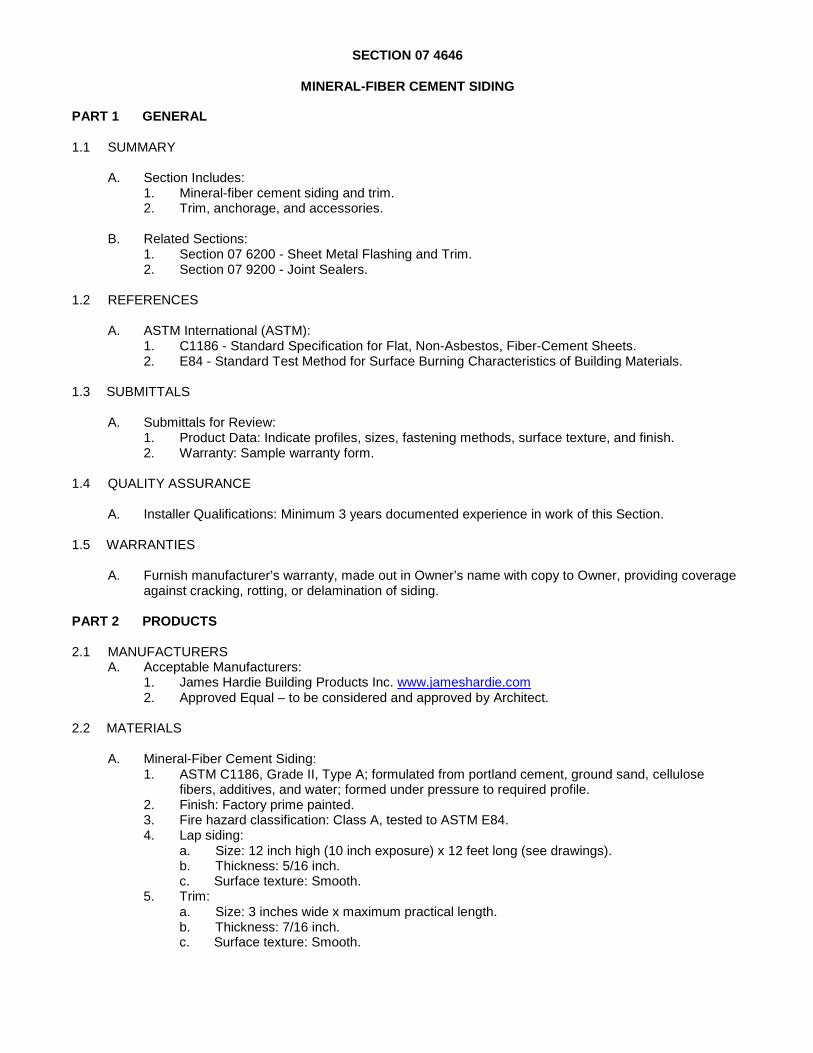
SECTION 07 4646
MINERAL-FIBER CEMENT SIDING
PART 1 GENERAL
1.1 SUMMARY
A. Section Includes: 1. Mineral-fiber cement siding and trim. 2. Trim, anchorage, and accessories.
B. Related Sections:
1. Section 07 6200 - Sheet Metal Flashing and Trim. 2. Section 07 9200 - Joint Sealers.
1.2 REFERENCES
A. ASTM International (ASTM):
1. C1186 - Standard Specification for Flat, Non-Asbestos, Fiber-Cement Sheets. 2. E84 - Standard Test Method for Surface Burning Characteristics of Building Materials.
1.3 SUBMITTALS
A. Submittals for Review:
1. Product Data: Indicate profiles, sizes, fastening methods, surface texture, and finish. 2. Warranty: Sample warranty form.
1.4 QUALITY ASSURANCE
A. Installer Qualifications: Minimum 3 years documented experience in work of this Section.
1.5 WARRANTIES
A. Furnish manufacturer’s warranty, made out in Owner’s name with copy to Owner, providing coverage
against cracking, rotting, or delamination of siding.
PART 2 PRODUCTS
2.1 MANUFACTURERS A. Acceptable Manufacturers:
1. James Hardie Building Products Inc. www.jameshardie.com 2. Approved Equal – to be considered and approved by Architect.
2.2 MATERIALS
A. Mineral-Fiber Cement Siding:
1. ASTM C1186, Grade II, Type A; formulated from portland cement, ground sand, cellulose fibers, additives, and water; formed under pressure to required profile.
2. Finish: Factory prime painted. 3. Fire hazard classification: Class A, tested to ASTM E84. 4. Lap siding:
a. Size: 12 inch high (10 inch exposure) x 12 feet long (see drawings). b. Thickness: 5/16 inch. c. Surface texture: Smooth.
5. Trim: a. Size: 3 inches wide x maximum practical length. b. Thickness: 7/16 inch. c. Surface texture: Smooth.

2.3 ACCESSORIES
A. Fasteners: Type recommended by siding manufacturer.
B. Sheet Metal Flashings and Trim: Specified in Section 07 6200.
C. Joint Sealers: Specified in Section 07 9200.
PART 3 EXECUTION 3.1 INSTALLATION - LAP SIDING
A. Install in accordance with manufacturer's instructions.
B. Install siding with 10 inch exposure (see drawings).
C. Lap siding for natural water shed.
D. Butt joints tight.
E. Set plumb and level.
F. Cut siding to fit at perimeter and around penetrations with maximum 1/4 inch gaps. Smooth cut edges.
G. Position cut ends over bearing surfaces.
H. Install corner strips, closures, and trim as shown on drawings.
I. Fasten at maximum 12 inches on center. Blind nail except trim.
J. Install metal flashings at sills and heads of wall openings. Fasten at 12 inches on center maximum.
K. Apply joint sealer between siding and trim and adjacent surfaces as specified in Section 07 9200. Ensure watertight condition.
3.2 INSTALLATION - TRIM
A. Install in accordance with manufacturer's instructions.
B. Butt joints tight.
C. Set plumb and level.
D. Cut to fit at perimeter and around penetrations with maximum 1/4 inch gaps. Smooth cut edges.
E. Fasten at maximum 16 inches on center.
END OF SECTION
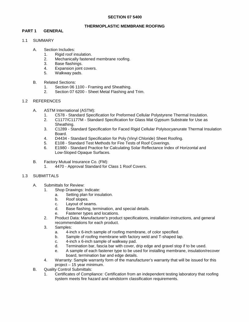
SECTION 07 5400 PART 1 GENERAL
1.1 SUMMARY
THERMOPLASTIC MEMBRANE ROOFING
A. Section Includes:
1. Rigid roof insulation. 2. Mechanically fastened membrane roofing. 3. Base flashings. 4. Expansion joint covers. 5. Walkway pads.
B. Related Sections:
1. Section 06 1100 - Framing and Sheathing. 2. Section 07 6200 - Sheet Metal Flashing and Trim.
1.2 REFERENCES
A. ASTM International (ASTM):
1. C578 - Standard Specification for Preformed Cellular Polystyrene Thermal Insulation. 2. C1177/C1177M - Standard Specification for Glass Mat Gypsum Substrate for Use as
Sheathing. 3. C1289 - Standard Specification for Faced Rigid Cellular Polyisocyanurate Thermal Insulation
Board. 4. D4434 - Standard Specification for Poly (Vinyl Chloride) Sheet Roofing. 5. E108 - Standard Test Methods for Fire Tests of Roof Coverings. 6. E1980 - Standard Practice for Calculating Solar Reflectance Index of Horizontal and
Low-Sloped Opaque Surfaces.
B. Factory Mutual Insurance Co. (FM): 1. 4470 - Approval Standard for Class 1 Roof Covers.
1.3 SUBMITTALS
A. Submittals for Review:
1. Shop Drawings: Indicate: a. Setting plan for insulation. b. Roof slopes. c. Layout of seams. d. Base flashing, termination, and special details. e. Fastener types and locations.
2. Product Data: Manufacturer's product specifications, installation instructions, and general recommendations for each product.
3. Samples: a. 4-inch x 6-inch sample of roofing membrane, of color specified. b. Sample of roofing membrane with factory weld and T-shaped lap. c. 4-inch x 6-inch sample of walkway pad. d. Termination bar, fascia bar with cover, drip edge and gravel stop if to be used. e. A sample of each fastener type to be used for installing membrane, insulation/recover
board, termination bar and edge details. 4. Warranty: Sample warranty form of the manufacturer’s warranty that will be issued for this
project – 15 year minimum. B. Quality Control Submittals:
1. Certificates of Compliance: Certification from an independent testing laboratory that roofing system meets fire hazard and windstorm classification requirements.

A. Rigi d Insulation/Tapered Insulation: 1. Type: ASTM C1289, Type II, rigid polyisocyanurate faced both sides with glass fiber mat facings. 2. Thermal resistance: Minimum R value of 19. B. Ro f Membrane: 1. Type: ASTM D4434, plasticized polyvinyl chloride (PVC), ultraviolet resistant, reinforced. 2. Size: Maximum sheet size permitted by application and job conditions. 3. Thickness: 45 mils. 4. Color: White.
1.4 QUALITY ASSURANCE
A. Installer Qualifications:
1. Licensed or certified by roofing materials manufacturer.
1.5 DELIVERY, STORAGE AND HANDLING
A. Store materials, other than membrane, in protected, dry area, between 60 and 80 degrees F until used; provide proper ventilation.
B. Protect sheet goods from damage and wetting.
1.6 PROJECT CONDITIONS
A. Do not apply roofing to damp or frozen substrate.
B. Do not apply roofing during inclement weather or at temperatures below 40 degrees F, or above 100
degrees F or if freezing weather is anticipated within 24 hours after application. Do not use frozen materials.
1.7 WARRANTIES
A. Furnish applicator’s 2 year warranty providing coverage against water leakage through roofing
system. 1. Make repairs to roofing system required due to defects in materials or workmanship resulting in
water leakage into or through roofing system. 2. Include cost of labor and materials necessary to make required repairs. 3. Cover all roofing system components including roofing membrane, built-up and metal flashings,
high wall waterproof flashings, roof insulation, and preflashed accessories. 4. Not limited to specific dollar amount. 5. Transferable to subsequent building owners during warranty period. 6. Include coverage for wind speeds up to 90 MPH.
PART 2 PRODUCTS
2.1 MANUFACTURERS
A. Acceptable Manufacturers - PVC Roofing System:
1. Duro-Last Roofing
2.2 MATERIALS
o
C. Flashing Sheet: Manufacturer's standard flashing sheet, color to match membrane.
2.3 ACCESSORIES
A. Batten Strips or Fastener Plates: Manufacturer's standard, hard rubber.
B. Accessories: 1. By manufacturer of roofing system, including adhesives, tapes, solvents, sealants, water cutoff
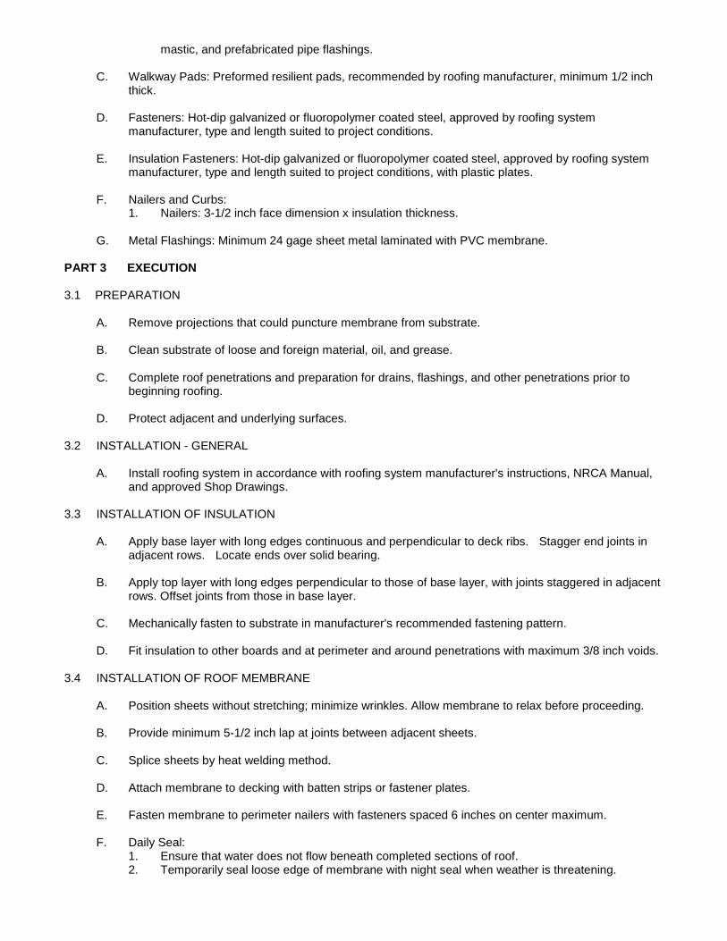
mastic, and prefabricated pipe flashings.
C. Walkway Pads: Preformed resilient pads, recommended by roofing manufacturer, minimum 1/2 inch thick.
D. Fasteners: Hot-dip galvanized or fluoropolymer coated steel, approved by roofing system
manufacturer, type and length suited to project conditions.
E. Insulation Fasteners: Hot-dip galvanized or fluoropolymer coated steel, approved by roofing system manufacturer, type and length suited to project conditions, with plastic plates.
F. Nailers and Curbs:
1. Nailers: 3-1/2 inch face dimension x insulation thickness.
G. Metal Flashings: Minimum 24 gage sheet metal laminated with PVC membrane. PART 3 EXECUTION
3.1 PREPARATION
A. Remove projections that could puncture membrane from substrate.
B. Clean substrate of loose and foreign material, oil, and grease.
C. Complete roof penetrations and preparation for drains, flashings, and other penetrations prior to beginning roofing.
D. Protect adjacent and underlying surfaces.
3.2 INSTALLATION - GENERAL
A. Install roofing system in accordance with roofing system manufacturer's instructions, NRCA Manual,
and approved Shop Drawings. 3.3 INSTALLATION OF INSULATION
A. Apply base layer with long edges continuous and perpendicular to deck ribs. Stagger end joints in
adjacent rows. Locate ends over solid bearing.
B. Apply top layer with long edges perpendicular to those of base layer, with joints staggered in adjacent rows. Offset joints from those in base layer.
C. Mechanically fasten to substrate in manufacturer's recommended fastening pattern.
D. Fit insulation to other boards and at perimeter and around penetrations with maximum 3/8 inch voids.
3.4 INSTALLATION OF ROOF MEMBRANE
A. Position sheets without stretching; minimize wrinkles. Allow membrane to relax before proceeding.
B. Provide minimum 5-1/2 inch lap at joints between adjacent sheets.
C. Splice sheets by heat welding method.
D. Attach membrane to decking with batten strips or fastener plates.
E. Fasten membrane to perimeter nailers with fasteners spaced 6 inches on center maximum.
F. Daily Seal: 1. Ensure that water does not flow beneath completed sections of roof. 2. Temporarily seal loose edge of membrane with night seal when weather is threatening.

3. When work is resumed, pull sheet free before continuing installation.
3.5 INSTALLATION OF FLASHINGS
A. Construct in accordance with roofing system manufacturer's standard details.
B. Juncture of Horizontal and Vertical Surfaces: 1. Use longest practical length flashing to minimize joints. 2. Complete splice between flashing and main roof sheet before bonding flashing to vertical
surface. Extend splice 3 inches beyond fasteners that attach membrane to horizontal surface. 3. Adhere flashing to substrate with full bed of adhesive. 4. Fasten top of flashing at 12 inches on center maximum, under metal flashing.
C. Penetrations through Membrane:
1. Flash pipe with premolded pipe flashings wherever possible. 2. Where molded pipe flashings cannot be installed, use field fabricated pipe seals. 3. Seal clusters of pipes and unusually shaped penetrations with minimum 2 inch high flashing
containing pourable sealer.
D. Expansion Joints: 1. Complete roof membrane and flashing installation prior to installing expansion joint. 2. Set joint cover on top of wood nailers; secure on each side through metal flange. 3. Seal joint cover flanges to membrane as for sheet splice.
E. Roof Drains:
1. Taper insulation around drain to provide smooth transition from roof surface to drain clamping ring.
2. Seal between membrane and drain base with water cutoff mastic.
3.6 INSTALLATION OF WALKWAY PADS
A. Clean underside of pad; set pads in full adhesive bed.
B. Leave 2 inch space between pieces.
END OF SECTION
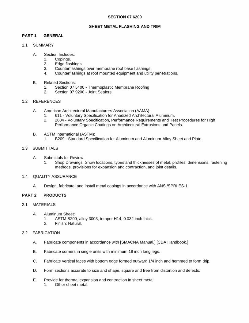
SECTION 07 6200
SHEET METAL FLASHING AND TRIM PART 1 GENERAL
1.1 SUMMARY
A. Section Includes:
1. Copings. 2. Edge flashings. 3. Counterflashings over membrane roof base flashings. 4. Counterflashings at roof mounted equipment and utility penetrations.
B. Related Sections:
1. Section 07 5400 - Thermoplastic Membrane Roofing 2. Section 07 9200 - Joint Sealers.
1.2 REFERENCES
A. American Architectural Manufacturers Association (AAMA):
1. 611 - Voluntary Specification for Anodized Architectural Aluminum. 2. 2604 - Voluntary Specification, Performance Requirements and Test Procedures for High
Performance Organic Coatings on Architectural Extrusions and Panels.
B. ASTM International (ASTM): 1. B209 - Standard Specification for Aluminum and Aluminum-Alloy Sheet and Plate.
1.3 SUBMITTALS
A. Submittals for Review:
1. Shop Drawings: Show locations, types and thicknesses of metal, profiles, dimensions, fastening methods, provisions for expansion and contraction, and joint details.
1.4 QUALITY ASSURANCE
A. Design, fabricate, and install metal copings in accordance with ANSI/SPRI ES-1.
PART 2 PRODUCTS
2.1 MATERIALS
A. Aluminum Sheet:
1. ASTM B209, alloy 3003, temper H14, 0.032 inch thick. 2. Finish: Natural.
2.2 FABRICATION
A. Fabricate components in accordance with [SMACNA Manual.] [CDA Handbook.]
B. Fabricate corners in single units with minimum 18 inch long legs.
C. Fabricate vertical faces with bottom edge formed outward 1/4 inch and hemmed to form drip.
D. Form sections accurate to size and shape, square and free from distortion and defects.
E. Provide for thermal expansion and contraction in sheet metal: 1. Other sheet metal:

a. Provide expansion joints in sheet metal exceeding 15 feet in running length. b. Place expansion joints at 10 feet on center maximum and maximum 2 feet from corners
and intersections. 2. Joint width: Consistent with types and sizes of materials, minimum width 1/4 inch.
F. Fabricate expansion joints in metal copings with backing and cover plates formed to flashing profile,
minimum 8 inches long.
G. Unless otherwise indicated, provide minimum 3/4 inch wide flat lock seams; lap in direction of water flow.
H. Fabricate cleats and starter strips of same material as sheet metal.
PART 3 EXECUTION
3.1 INSTALLATION
A. Install cleats and starter strips before starting installation of sheet metal. Fasten at 6 inches on center
maximum.
B. Expansion Joints in Metal Copings: 1. Center backing plate between flashing pieces at end joints. 2. Apply two continuous beads of joint sealer between backing plate and flashing sections at each
end. 3. Install flashing pieces with ½ inch expansion space at abutting ends; apply sealer to expansion
space. 4. Apply two continuous beads of joint sealer between cover plate and flashing sections at each
end.
C. Secure flashings with concealed fasteners where possible.
D. Apply plastic cement between metal and bituminous flashings.
E. Fit flashings tight, with square corners and surfaces true and straight.
F. Seam and seal field joints.
G. Separate dissimilar metals with bituminous coating or non-absorptive gaskets.
H. Apply joint sealers as specified in Section 07 9200.
3.2 CLEANING
A. Clean sheet metal; remove slag, flux, stains, spots, and minor abrasions without etching surfaces.
END OF SECTION

SECTION 07 9200
JOINT SEALERS
PART 1 GENERAL
1.1 SUMMARY
A. Section Includes: 1. Joint backup materials. 2. Joint sealers.
1.2 REFERENCES
A. ASTM International (ASTM):
1. C510 - Standard Test Method for Staining and Color Change of Single- or Multicomponent Joint Sealants.
2. C834 - Standard Specification for Latex Sealing Compounds. 3. C920 - Standard Specification for Elastomeric Joint Sealants. 4. C1193 - Standard Guide for Use of Joint Sealants.
1.3 SUBMITTALS
A. Submittals for Review:
1. Product Data: Indicate sealers, primers, backup materials, bond breakers, and accessories proposed for use.
1.4 PROJECT CONDITIONS
A. Do not apply sealers at temperatures below 40 degrees F unless approved by sealer manufacturer.
PART 2 PRODUCTS
2.1 MATERIALS
A. Joint Sealer Type 1:
1. ASTM C920, Grade NS, single component butyl rubber type, non sag. 2. Movement capability: Plus or minus 12-1/2 percent. 3. Color: To be selected from manufacturer's full color range, match adjacent finish.
B. Joint Sealer Type 2:
1. ASTM C920, Grade NS, single component silicone, non sag, mildew resistant. 2. Movement capability: Plus or minus 25 percent. 3. Color: To be selected from manufacturer's full color range, match adjacent finish.
2.2 ACCESSORIES
A. Primers, Bondbreakers, and Solvents: As recommended by sealer manufacturer.
B. Joint Backing:

1. ASTM C1330, closed cell polyethylene foam, preformed round joint filler, non absorbing, non staining, resilient, compatible with sealer and primer, recommended by sealer manufacturer for each sealer type.
2. Size: Minimum 1.25 times joint width. PART 3 EXECUTION
3.1 PREPARATION
A. Remove loose and foreign matter that could impair adhesion. If surface has been subject to chemical
contamination, contact sealer manufacturer for recommendation.
B. Clean and prime joints in accordance with manufacturer's instructions.
C. Protect adjacent surfaces with masking tape or protective coverings.
D. Sealer Dimensions: 1. Minimum joint size: 1/4 x 1/4 inch. 2. Joints 1/4 to 1/2 inch wide: Depth equal to width. 3. Joints over 1/2 inch wide: Depth equal to one half of width.
3.2 APPLICATION
A. Apply products in accordance with manufacturer's instructions.
B. Install sealers and accessories in accordance with ASTM C1193.
C. Install joint backing to maintain required sealer dimensions. Compress backing approximately 25
percent without puncturing skin. Do not twist or stretch.
D. Use bondbreaker tape where joint backing is not installed.
E. Fill joints full without air pockets, embedded materials, ridges, and sags.
F. Tool sealer to smooth profile.
G. Apply sealer within manufacturer’s recommended temperature range. 3.3 CLEANING
A. Clean adjacent surfaces.
END OF SECTION

A. Ste l Sheet: 1. ASTM A1008/1008M, cold rolled.
SECTION 08 1113
HOLLOW METAL DOORS AND FRAMES
PART 1 GENERAL
1.1 SUMMARY
A. Section Includes: 1. Hollow steel doors and frames.
B. Related Sections:
1. Section 08 7100 - Door Hardware. 2. Section 08 8000 - Glazing.
1.2 SUBMITTALS
A. Shop Drawings showing product data, size and location.
1.3 QUALITY ASSURANCE
A. Doors: ANSI/SDI A250.8.
1. Grade: II - Heavy Duty – 16 gage 2. Model: 1 - Full Flush. 3. Exterior doors: Maximum thermal transmittance U-value of 0.50, tested to ASTM C518.
B. Frames: ANSI/SDI A250.8, Grade II - Heavy Duty – 16 gage.
1.4 DELIVERY, STORAGE AND HANDLING
A. Ship door frames with removable angle spreader; do not remove until frame is installed.
B. Store doors upright in protected, dry area, off ground or floor, with at least 1/4 inch space between
individual units.
PART 2 PRODUCTS
2.1 MANUFACTURERS
A. Acceptable Manufacturers: 1. Steelcraft. (www.steelcraft.com)
2.2 MATERIALS
e
B. Door Core: 1. Exterior doors: Foamed-in-place polyurethane insulation
2.3 FABRICATION
A. Fabricate doors and frames in accordance with ANSI/SDI A250.8.
B. Fabricate exterior doors and frames from galvanized steel sheet.

C. Doors: 1. Fabricate from minimum 16 gage sheets. 2. Close top and bottom edges of doors with steel channel, minimum 16, gage, extending full
width of door, and spot welded to both faces, with top channel flush and bottom channel recessed.
D. Frames: 1. Fabricate from minimum 16 gage sheets. 2. Provide self-aligning tabs and slots to hold corners in alignment. 3. Anchors:
a. Provide one anchor at each jamb for each 30 inches of door height. b. Provide one floor anchor welded to each jamb.
E. Accurately form to required sizes and profiles.
F. Do not use metallic filler to conceal manufacturing defects.
G. Fabricate with internal reinforcement for hardware specified in Section 08 7100; weld in place.
H. Design Clearances: 1. Between door and frame: Maximum 1/8 inch. 2. Undercut:
a. Non-fire rated doors: Maximum 3/4 inch. 3. Between face of door and stop: 1/16 to 3/32 inch.
I. Manufacturing Tolerances: In accordance with SDI-117.
2.4 FINISHES
A. Dress tool marks and surface imperfections to smooth surfaces.
B. Clean and chemically treat steel surfaces.
C. Touch up damaged metallic coatings.
D. Apply manufacturer's standard rust inhibiting primer paint, air-dried or baked on, meeting requirements of ANSI/SDI A25010.
PART 3 EXECUTION
3.1 INSTALLATION
A. Install doors and frames in accordance with ANSI/SDI A250.11.
B. Set plumb and level.
C. Secure to adjacent construction using fastener type best suited to application.
3.2 ADJUSTING
A. Touch up minor scratches and abrasions in primer paint to match factory finish.
END OF SECTION

SECTION 08 1416 PART 1 GENERAL
1.1 SUMMARY
FLUSH WOOD DOORS
A. Section Includes:
1. Wood veneer faced flush doors.
B. Related Sections: 1. Section 08 7100 - Door Hardware.
1.2 REFERENCES
A. Window and Door Manufacturers Association (WDMA) - I.S.1A - Industry Standard for Architectural
Flush Wood Doors. 1.3 SUBMITTALS
A. Shop Drawings of product data, size and location.
1.4 DELIVERY, STORAGE AND HANDLING
A. Package doors in heavy plastic with identifying marks; slit plastic wrap on site to permit ventilation,
but do not remove from plastic until ready to install.
B. Do not deliver doors until building is substantially water and weather tight.
C. Store doors flat and level, with spacers between doors to allow for air circulation, in protected, dry area.
D. Environmental Requirements: Maintain following conditions in building for minimum 7 days prior to,
during, and after installation of doors: 1. Temperature: 60 to 80 degrees F. 2. Humidity: 25 to 55 percent.
PART 2 PRODUCTS
2.1 MATERIALS
A. Flus h Wood Doors: 1. WDMA I.S.1A. 2. Core type: a. Solid, non-rated: Type PC - Particleboard Core, bonded, 3. Wood veneer faces: a. Closed grain hardwood, of quality suitable for opaque finish. 4. Adhesives: Water Resistant.
2.2 FABRICATION
A. Fabricate doors in accordance with WDMA I.S.1A. 1. Performance duty level: Heavy Duty. 2. Number of plies: 5. 3. Veneer matching:
a. Piece match: Slip.

PART 3 EXECUTION
3.1 PREPARATION
A. Condition doors to average humidity that will be encountered after installation.
3.2 INSTALLATION
A. Install doors in accordance with WDMA I.S.1A.
B. Install doors plumb and level.
C. Field Fitting to Frames: 1. Non-rated doors:
a. Width: Cut hinge and lock edges equally. b. Height: Cut bottom edge only; maximum 3/4 inch.
2. Edge clearances: a. Jambs and head: 1/8 inch maximum between door and frame. b. Sills without thresholds: 1/8 inch maximum between door and top of finish floor.
3. Lock edge: Bevel 1/8 inch in 2 inches. 4. Do not cut doors down to opening sizes smaller than those for which they were manufactured.
D. Installation Tolerances:
1. Warp: Maximum 1/4 inch in any 3'-0" x 7'-0" portion of door, measured with taut string or straight edge on concave face of door.
END OF SECTION
SECTION 08 4113
ALUMINUM-FRAMED ENTRANCES AND STOREFRONTS
PART 1 GENERAL
1.1 SUMMARY
A. Section Includes: 1. Aluminum entrance doors and frames. 2. Aluminum framed glazed storefronts. 3. Glass infill panels. 4. Door hardware.
B. Related Sections:
1. Section 07 9200 - Joint Sealers. 2. Section 08 7100 - Door Hardware. 3. Section 08 8000 - Glazing.
1.2 REFERENCES
A. American Architectural Manufacturers Association (AAMA):
1. 611 - Voluntary Specification for Anodized Architectural Aluminum.
B. ASTM International (ASTM): 1. E283 - Standard Test Method for Rate of Air Leakage through Exterior Windows, Curtain Walls
and Doors. 2. E330 - Standard Test Method for Structural Performance of Exterior Windows, Curtain Walls,
and Doors under the Influence of Wind Loads. 3. E331 - Standard Test Method for Water Penetration of Exterior Windows, Doors, and Curtain
Walls by Uniform Static Air Pressure Differential.
1.3 SYSTEM DESCRIPTION
A. Design Requirements: Design exterior systems to withstand: 1. Design wind pressure in accordance with ASCE 7, Building Code, tested in accordance with
ASTM E330. 2. Movement caused by an ambient temperature range of 120 degrees F and a surface
temperature range of 160 degrees F.
B. Performance Requirements: 1. Air infiltration, tested to ASTM E283.
a. Entrances: 1) Single door: Maximum 0.5 CFM per minute per linear foot of perimeter crack, at
static pressure differential of 6.24 PSF. b. Storefront: 0.06 CFM per square foot of fixed area at static pressure differential of 6.24
PSF. 2. Water infiltration: No uncontrolled water leakage, tested to ASTM E331 at minimum test
pressure of 6.24 PSF for inswing doors and 8.0 PSF for outswing doors and storefront. 3. Uniform structural loading: No glass breakage or permanent damage to fasteners or system
components, tested to ASTM E330 at 1.5 times design pressure. 4. Thermal transmittance due to conduction (Uc): Maximum 0.60, tested to AAMA 1503 on two
6'-0" x 6'-0" units with 1 inch clear insulating glass. 5. Condensation resistance factor (CRF): Minimum 50, tested to AAMA 1503.
C. Color: 1. Dunkin’ Donuts Build Out (Associated with EIFS/Siding) color to be Dark Bronze.
1.4 SUBMITTALS
A. Submittals for Review:
1. Shop Drawings: Indicate system dimensions, framed opening requirements and tolerances, trim, sealers, hardware, and accessories.
2. Remaining Build Outs (Associated with metal cladding panels.): Color to be White.

PART 2 PRODUCTS
2.1 MANUFACTURERS
A. Acceptable Manufacturers: 1. United States Aluminum 2. YKK AP America, Inc. (www.ykkap.com)
2.2 MATERIALS
A. Aluminum:
1. Extrusions: ASTM B221, 6063-T5 alloy and temper. 2. Sheet: ASTM B209, alloy and temper best suited to application.
2.3 COMPONENTS
A. Entrances Doors: Narrow stile configuration with nominal 2 inch vertical stiles and top rail and 10 inch
bottom rail.
B. Storefront: Flush glazing system designed to receive 1 inch glass by means of elastomeric gaskets; 2 inch face width x 4-1/2 inch depth, center glass application, thermally broken.
C. Door Hardware: Specified in Section 08 7100.
2.4 ACCESSORIES
A. Fasteners: 1. Series 300 stainless steel for wet locations and exposed fasteners. 2. Stainless or fluoropolymer coated steel for other locations.
B. Joint Sealers: Specified in Section 07 9200.
C. Glass and Glazing Accessories: Specified in Section 08 8000.
D. Weatherstripping: Replaceable, nonporous synthetic wool pile type.
2.5 FABRICATION
A. Fabricate with minimal clearances and shim spaces around perimeter.
B. Accurately fit and secure joints and intersections. Make joints flush, hairline, and weathertight.
C. Fabricate in largest practical units.
D. Conceal fasteners and attachments from view.
E. Fabricate aluminum components with integral low conductance thermal barrier located between exterior and interior exposed components that eliminates metal-to-metal contact.
F. Doors:
1. Mechanically fastened and welded corner construction. 2. Fabricate stiles and rails of minimum 0.188 inch thick extrusions and glass stops from minimum
0.050 inch thick extrusions. 3. Provide weatherstripping at door head, jambs, meeting stiles, and sills. 4. Prepare with internal reinforcements for door hardware.
2.6 FINISHES

A. Aluminum: AAMA 611, Architectural Class I anodized to 0.0007 inch minimum thickness, clear. PART 3 EXECUTION
3.1 INSTALLATION
A. Install in accordance with manufacturer's instructions and approved Shop Drawings.
B. Install components plumb and level, in proper plane, free from warp and twist.
C. Anchor to supporting construction.
D. Set thresholds and sill members exposed to weather in mastic and secure.
E. Install hardware using templates provided by manufacturer.
F. Install glass and accessories in accordance with Section 08 8000.
G. Installation Tolerances: 1. Maximum variation from plumb or level: 1/8 inch in 3 feet or 1/4 inch in any 10 feet, whichever
is less. 2. Maximum misalignment of members abutting end to end: 1/32 inch. 3. Sealant space between framing members and adjacent construction: 1/2 inch plus or minus 1/8
inch. 3.2 ADJUSTING
A. Adjust hardware for smooth operation.
B. Adjust doors to operate with maximum opening forces[in accordance with applicable accessibility
code. C. Touch up minor scratches and abrasions to match original finish.
D. Adjust weatherstripping to contact appropriate surfaces and form weather seal.
END OF SECTION

SECTION 08 5619
DRIVE-THRU WINDOW PART 1 GENERAL
1.1 WORK INCLUDED
A. Furnish all labor, material, service and equipment necessary to complete the installation of the Drive-Thru
window as detailed on the Drawings and specified in this Section.
B. Related work specified elsewhere 1. Section 16 7600 Approved Drive-Thru Speaker System 2. Section 07 9200 Caulking 3. Section 04 4118 Aluminum Storefront 4. Section 08 8000 Glazing
PART 2 - PRODUCTS
2.1 DRIVE-THRU WINDOW
A. Shall be as manufactured by Ready-Access of West Chicago, Illinois or Quickserve of Houston, TX - See
National Account Source Information for ordering information.
C. Ready-Access Bump-Out 10, shall meet the following criteria: 1. Total overall dimension 53-1/2 in. wide by 48-3/4 in. high. 2. Window opening size 18 in. wide by 23 in. high, adjustable to 12 in. wide x 23 in. high. 3. Clear aluminum extrusions. 4. Continuous extruded head section concealing operating mechanism, track and wheels. 5. Sliding panel supported by high quality ground ball bearing wheels rolling on a replaceable nylon
covered support track. 6. Anti-derailing feature being a continuous extrusion extended full length of window travel. 7. Adjustable astragal with double Mohair weather strip provided on strike rail of sliding panel. 8. Vertical and horizontal rails have Mohair weather stripping. 9. 7 in. smooth sill. 10. Sliding window automatically opens horizontally when the server steps into the range of the
window scan control Window remains open a long as server stays in scan beam. Window closes once server steps away from window scan beam.
11. Window can be opened manually if power goes off. 12. Operator is furnished with a maximum-security bolt lock. 13. Glass shall be 1/4 in. tempered glass as specified in Section 08800. 14. System can include an Autolock and a partial open cutoff switch (for limiting slide opening)
(optional). 15. Installation by local Ready-Access Distributor (optional). 16. One (1) year warranty on parts and labor. 17. Prepaid freight to job site. 18. Color to match storefront
D. Optional models #131-6 (flush mount, bi-parting) and #275 (flush mount, single parting) also available for
situations where bump out model cannot be used. See National Account Source Information for complete specifications.
E. Optional Quickserve model are available – see National Accounts
PART 3 - EXECUTION
3.1 INSTALLATION OF DRIVE-THRU WINDOW
A. Aluminum placed in contact with dissimilar material, including steel, concrete, cinder block, tile or other
masonry material shall be back-painted with an approved bituminous paint.

B. All joints between metal and masonry shall be fully caulked in order to secure a watertight job with Dymeric 511 (multi-component chemically cured polyurethane) as manufactured by Tremco Manufacturing Company, Beechwood, Ohio. Apply in strict accordance with manufacturer's directions. Joints shall be neatly pointed and excess shall be removed. Set filler plates in caulking.
3.2 PROTECTION AND CLEANING
A. Drive-Thru Window shall be protected during construction and after installation to prevent injury and I or
staining. All aluminum work shall be thoroughly cleaned upon completion of the work. Do not use abrasive cleaning agents.
END OF SECTION

SECTION 08 7100
DOOR HARDWARE PART 1 GENERAL
1.1 SUMMARY
A. Section Includes:
1. Hardware for steel, wood, and aluminum doors. 2. Weatherstripping and thresholds. 3. Hardware for other sections referencing this section.
1.2 REFERENCES
A. American National Standards Institute/Builders Hardware Manufacturers Association (ANSI/BHMA):
1. A156.1 - Butts and Hinges. 2. A156.2 - Bored and Preassembled Locks and Latches. 3. A156.3 - Exit Devices. 4. A156.4 - Door Controls - Closers. 5. A156.13 - Mortise Locks and Latches. 6. A156.18 - Materials and Finishes.
PART 2 PRODUCTS
2.1 MANUFACTURERS
A. Acceptable Manufacturers - Butt Hinges:
1. Hager Companies. (www.hagerco.com)
B. Acceptable Manufacturers - Locksets, Latchsets, Deadbolts, and Cylinders: 1. Hager Companies. (www.hagerco.com)
C. Acceptable Manufacturers - Closers:
1. Hager Companies. (www.hagerco.com)
D. Acceptable Manufacturers - Door Seals: 1. Hager Companies. (www.hagerco.com)
2.2 MANUFACTURED UNITS
A. Butt Hinges: 1. Description: ANSI/BHMA A156.1, full mortise type, five knuckle, non-rising pin, hole in bottom
tip for pin removal. 2. Exterior outswinging doors: Provide set screw in barrel making hinge non-removable when door
is closed. 3. Weight: Standard weight. 4. Bearing type: Ball bearing 5. Size: 4-1/2 x 4-1/2 inches.
B. Locksets, Latchsets, Deadbolts, and Cylinders:
1. Locksets and latchsets: a. Type: ANSI/BHMA A156.2, Grade 1, cylindrical, key-in-lever handles.
2. Deadbolts: a. Type: ANSI/BHMA A156.5, cylindrical type with 1 inch bolt throw. b. Functions: As scheduled.
3. Strike plates: Curved lip, minimum lip projection necessary to protect door frame and trim and to conceal edges of strike cutout.
4. Strike boxes: Steel. 5. Cylinders: Six pin, solid brass. 6. Keys: Solid brass or nickel silver. 7. Keying:

a. Construction key locks. b. Key alike, cross key, or otherwise key as directed by Owner. c. Provide four keys for each lock. d. Inscribe keys with lock manufacturer.
C. Closers:
1. Description: ANSI/BHMA A156.4, overhead exposed, field adjustable to door conditions. 2. Construction: Cast aluminum body, rack and pinion operation with compression spring,
fully hydraulic. 3. Closing and latching speeds and backcheck: Controlled by independently adjustable
concealed valves. 4. Mounting: Surface mounted, non-handed with universal regular or parallel arm. Suitable for
mounting on 1-3/4 inch minimum door top rail or transom bar without drop plate. 5. Adjustable opening force and delayed closing in accordance with applicable accessibility
code.
D. Door Stops: Floor mounted, aluminum housing with resilient bumper.
E. Kick Plates: 1. Type: .125 inch plastic laminate, beveled edges, secured with flathead countersunk screws. 2. Size: 8 inches high x door width less 2 inches.
F. Flush Bolts: Manual type, 12 inches long, with dustproof strike.
2.3 FINISHES
A. Finishes: To ANSI/BHMA A156.18.
B. Door Closers: Finish No. 689, silver enamel.
C. Thresholds and Door Seal Housings: Clear anodized.
D. Other: Finish No. 626, satin chrome plated.
PART 3 EXECUTION 3.1 INSTALLATION
A. Install hardware in accordance with approved hardware schedule and manufacturer's instructions.
B. Install mortise items flush with adjacent surfaces.
C. Install locksets, closers, and trim after finish painting.
D. Set thresholds in mastic and secure.
E. Mount closers so that closers and closer arms are not visible on corridor or public side of doors or on exterior of building.
F. Mounting Heights – see Drawings.
3.2 PROTECTION
A. Remove or protect hardware until painting is completed.
3.3 ADJUSTING
A. Test and adjust hardware for quiet, smooth operation, free from binding and rattling.
B. Adjust doors to operate with maximum opening forces in accordance with applicable
accessibility code.

3.4 SCHEDULE
A. Set No. 1 - Door from Sales Area to Exterior. (See door schedule and floor plan for quantity, size and direction of swing.) (Doors 100, 110, 120 and 130)
1. Temporary cylinder, Hager 3901 or 3902 as required. 2. Hager 5200 MLT 1-6 DLY ALM (Handicap Access) door closers 3. Offset pivots 4. Adams Rite MS 1850A deadlock 5. Manufacturer’s standard push/pull hardware. Door 110 is to be prepared for custom
“D” handles. (Dunkin’ build out only.) Refer to National Accounts for ordering and installation information.
6. Hager 404S MIL ½” x 4” threshold
B. Set No. 2a - Interior Door from Vestibule to Dunkin’ Donuts. (Door 111) 1. Hager 5200 MLT 1-6 DLY ALM (Handicap Access) door closers 2. Offset pivots 3. Manufacturer’s standard push/pull hardware. Door 111 is to be prepared for custom
“D” handles. (Dunkin’ build out only.) Refer to National Accounts for ordering and installation information.
Set No. 2b - Interior Doors from Common Corridor to businesses. (Door 102, 103)
1. Temporary cylinder, Hager 3901 or 3902 as required. 2. Offset pivots 3. Adams Rite MS 1850A deadlock 4. Manufacturer’s standard push/pull hardware.
C. Set No. 3 – Service Doors to Exterior. Metal door and frame. (See door schedule and floor plan
for quantity, size and direction of swing.) (Doors 118 and 131) 1. 3 ea. hinges, Hager BB1191 32D 2. 1 lockset, Hager 3495 WTN US26D 3. 1 closer, Hager 5100 PA 1-6 HDHOS ALM 4. 1 threshold, Hager 413S MIL 5. 1 sweep, Hager 802S B Mil 6. 1 holder/stop, Hager 268S US26D 7. 1 set w/stripping, Hager 800S B MIL 8. 1 lock guard, Hager 341D 32D 9. 1 door viewer, Hager 1756 US26D (Door 118 only) 10. Alternate door viewer: Model #L-VGLF-WD, 9” x 5”, National Guard Products
D. Set No. 4 - Doors from Toilets to Hall. (See door schedule and floor plan for quantity, size and
direction of swing.) (Doors 105 and 106) 1. 1-1/2 pair butts, Hager, BB-1279 26D 2. 1 lockset, Hager 3440 WTN US26D 3. 1 wall stop, Hager 234W US26D 4. 1 kick plate, Hager 214S Black 8” x 2” L.W.O.D. Local barrier free code may require larger
kick plates – verify before ordering. 5. 1 closer, Hager 5200 MLT 1-6 ALM
E. Set No. 5 – Conference Room Door (Doors 104)
1. 1-1/2 pair butts, Hager, BB-1279 26D 2. 1 lockset, Hager 3570 US26D 3. 1 closer, Hager 5200 MLT 1-6 ALM
END OF SECTION
SECTION 08 8000
GLAZING
PART 1 GENERAL
1.1 SUMMARY
A. Section Includes: 1. Glass for other sections referencing this Section.
1.2 REFERENCES
A. American National Standards Institute (ANSI) Z97.1 - Safety Performance Specifications and
Methods of Test for Safety Glazing Material Used in Buildings.
B. ASTM International (ASTM): 1. C509 - Standard Specification for Elastomeric Cellular Preformed Gasket and Sealing Material. 2. C1036 - Standard Specification for Flat Glass. 3. C1115 - Standard Specification for Dense Elastomeric Silicone Rubber Gaskets and
Accessories. 4. C1172 - Standard Specification for Laminated Architectural Flat Glass. 5. E2190 - Standard Specification for Insulating Glass Unit Performance and Evaluation.
C. National Fenestration Rating Council (NFRC):
1. 100 - Procedure for Determining Fenestration Product Thermal Properties. 2. 200 - Procedure for Determining Fenestration Product Solar Heat Gain Coefficients at Normal
Incidence.
1.3 SUBMITTALS
A. Product Data
1.4 PROJECT CONDITIONS
A. Perform glazing when ambient temperature is above 40 degrees F.
B. Perform glazing on dry surfaces.
PART 2 PRODUCTS
2.1 MANUFACTURERS
A. Acceptable Manufacturers - Glass: 1. PPG Industries, Inc. (www.ppgglazing.com). 2. Pilkington Architectural. (www.pilkington.com)
2.2 MATERIALS - GLASS
A. Clear Glass: ASTM C1036, Type 1 transparent flat, Class 1 clear, Quality q3 glazing select.
B. Clear Tempered Glass: ASTM C1048, Type 1 transparent flat, Class 1 clear, Quality q3 glazing
select, Kind FT fully tempered.
2.3 ACCESSORIES A. Setting Blocks: ASTM C864, neoprene or EPDM, or ASTM C1115, silicone; 80 to 90 Shore A
durometer hardness.
B. Spacers: ASTM C864, neoprene or EPDM, or ASTM C1115, silicone; 50 to 60 Shore A durometer hardness.

C. Glazing Gaskets:
1. Dense compression gaskets: ASTM C864, neoprene or EPDM, or ASTM C1115, silicone or thermoplastic polyolefin rubber, molded or extruded shape to fit glazing channel retaining slot; black color.
2. Soft compression gaskets: ASTM C509, Type II, black, molded or extruded, neoprene, EPDM, silicone or thermoplastic polyolefin rubber, of profile and hardness required to maintain watertight seal; black color.
2.4 FABRICATION
A. Tempered Glass:
1. Comply with ASTM C1048. 2. Process in horizontal position so that inherent roller distortion will run parallel to building floor
lines after installation.
B. Sealed Insulating Glass: 1. Comply with ASTM E2190. 2. Fabricate spacer bar frame of tubular aluminum filled with desiccant. 3. Bond spacer bar frame to glass panes with twin primary seals. 4. Fill space outside frame to glass edge with elastomeric sealant.
C. Laminated Glass:
1. Comply with ASTM C1172 and ANSI Z97.1. 2. Laminate glass with laminating film by manufacturer's standard heat and pressure process. 3. Cut glass to required size at factory. 4. Discard glass with voids, delamination, or entrapped dirt or foreign matter.
D. Low-E Coated Glass: Apply low-emissivity coating to scheduled glass surface.
PART 3 EXECUTION
3.1 PREPARATION
A. Clean glazing rabbets; remove loose and foreign matter.
B. Remove protective coatings on metal surfaces.
C. Clean glass just prior to installation. 3.2 INSTALLATION - GENERAL
A. Install glass in accordance with glass manufacturer's instructions.
B. Maintain manufacturer's recommended edge and face clearances between glass and frame
members. 3.3 INSTALLATION - GASKET GLAZING METHOD
A. Fabricate gaskets to fit openings; allow for stretching of gaskets during installation.
B. Set soft compression gasket against fixed stop or frame with bonded miter cut joints at corners.
C. Set glass centered in openings on setting blocks.
D. Install removable stops and insert dense compression gaskets at corners, working toward centers of glass, compressing glass against soft compression gaskets to produce weathertight seal.
E. Seal joints in gaskets.
F. Allow gaskets to protrude past face of glazing stops.
3.4 PROTECTION
A. After installation, mark glass with an 'X' using removable plastic tape.
3.5 SCHEDULE
A. All Sales Area Primary Glass - 1 in. insulating glass, 1/2 in. air space with 1/4 in. clear polished
plate for outdoor and indoor lights. B. All Drive-Thru Glazing – ¼ in. Low-E Glass, ½ in. air space with ¼ in. clear float glass for
outboard light. C. Entrance Doors - 1 in. insulated and tempered glass. D. Provide tempered or safety glass for indoor and outdoor glass areas where required by building
codes. E. Insulating glass units shall provide a min. U-value of .49 winter and .56 summer and shall comply with
all requirements of the local governing energy code. F. Completely interior glass doors minimum of tempered glass.
END OF SECTION
SECTION 09 2900
GYPSUM BOARD
PART 1 GENERAL
1.1 SUMMARY
A. Section Includes: 1. Gypsum board. 2. Cementitious panels. 3. Taping and bedding of gypsum board.
B. Related Sections:
1. Section 07 9200 - Joint Sealers.
1.2 REFERENCES
A. ASTM International (ASTM): 1. C475 - Standard Specification for Joint Compound and Joint Tape for Finishing Gypsum Board. 2. C514 - Standard Specification for Nails for the Application of Gypsum Wallboard. 3. C1002 - Standard Specification for Steel Drill Screws for the Application of Gypsum Board. 4. C1047 - Standard Specifications for Accessories for Gypsum Wallboard and Gypsum Veneer
Base. 5. C1178 - Standard Specification for Glass Mat Water-Resistant Gypsum Backing Panel. 6. C1396 - Standard Specification for Gypsum Board. 7. C1629 - Standard Classification for Abuse-Resistant Nondecorated Interior Gypsum Panel
Products and Fiber-Reinforced Cement Panels. 8. D3273 - Standard Test Method for Resistance to Growth of Mold on the Surface of Interior
Coatings in an Environmental Chamber.
B. Gypsum Association (GA): 1. GA-214 - Levels of Gypsum Board Finish. 2. GA-216 - Recommended Specifications for the Application and Finishing of Gypsum Board. 3. GA-600 - Fire Resistance Design Manual.
1.3 PROJECT CONDITIONS
A. Do not install gypsum board until building is substantially weathertight.
B. Maintain temperature in spaces in which work is being performed above 50 degrees F during
and after installation.
PART 2 PRODUCTS
2.1 MANUFACTURERS
A. Acceptable Manufacturers - Gypsum Panels: 1. CertainTeed Gypsum, Inc. (www.certainteed.com) 2. GP Gypsum Corporation. (www.gp.com) 3. National Gypsum Co. (www.nationalgypsum.com) 4. Temple-Inland. (www.templeinland.com) 5. USG Corporation. (www.usg.com)
B. Acceptable Manufacturers - Cementitious Panels:
1. USG Corporation. (www.usg.com)
2.2 MATERIALS - GYPSUM PANELS
A. Regular Gypsum Board: ASTM C1396; 48 inches wide x thickness indicated, maximum practical length, tapered edge.
B. Fire Resistant Gypsum Board: ASTM C1396, Type X; 48 inches wide x thickness indicated,

maximum practical length, tapered edge; apply to fire rated assemblies.
C. Water Resistant Gypsum Board: ASTM C1396; 48 inches wide x thickness indicated, maximum practical length, water resistant; apply to walls to receive tile, sanitary wall panels and walls at locations specified on drawings.
D. Fire Resistant, Water Resistant Gypsum Board: ASTM C1396, Type X; 48 inches wide x[thickness
indicated, maximum practical length, water resistant; apply to walls to receive tile, sanitary wall panels and walls at locations specified on drawings.
2.3 MATERIALS - CEMENTITIOUS PANELS
A. Cementitious Panels: ANSI A 118.9, high density, cementitious with glass fiber reinforcing, 5/8
inch thick x 48 inches wide, maximum practical length, ends and edges square cut; apply to walls in locations as indicated on drawings.
2.4 ACCESSORIES
A. Fasteners: ASTM C1002, Type W screws, minimum 5/8 inch penetration into framing.
B. Adhesive: 1. Type recommended by gypsum panel manufacturer.
C. Trim Accessories: ASTM C1047.
1. Material: Formed steel, minimum 26 gage core steel, hot dip galvanized finish, expanded flanges.
2. Corner reinforcement: GA-216, Type CB-100 x 100. 3. Casing: GA-216, Type LC. 4. Control joint.
D. Joint Treatment Materials:
1. Reinforcing tape and joint compound; ASTM C475.
PART 3 EXECUTION
3.1 INSTALLATION OF GYPSUM PANELS
A. Install panels and accessories in accordance with ASTM C754, GA-216, and manufacturer's instructions.
B. Accurately cut panels to fit around openings and projections. Do not tear face paper or break
gypsum core.
C. Apply panels at non fire-rated assemblies in most economical manner, with ends and edges occurring over supports.
D. Apply panels at fire-rated assemblies as required by design assembly.
E. Stagger joints on opposite sides of partitions.
F. Do not locate joints to align with edges of openings unless a control joint is installed.
G. Mechanically fasten single layer panels to framing. Place fasteners minimum 3/8 inch from edges of panels; drive heads slightly below surface. Stagger fasteners at abutting edges.
H. Apply face layer of double layer applications with joints offset from those in base layer; secure with
mechanical fasteners to framing or with adhesive to base layer.
I. At deflection compensating head tracks, cut panels 1/2 inch short of structure at head; do not secure panels to top runner channel.
J. Treat cut edges and holes in moisture resistant gypsum board with joint sealer.
K. Where recessed items occur in fire rated partitions, box item on all sides with gypsum board as required to maintain continuity of fire rating.
3.2 INSTALLATION OF CEMENTITIOUS PANELS
A. Install in accordance with ANSI A108.11 and manufacturer's instructions.
B. Apply panels horizontally, with ends occurring over supports. Stagger end joints in adjacent rows.
C. Cut panels to fit around openings and projections.
D. Mechanically fasten panels to framing at maximum 12 inches on center.
3.3 INSTALLATION OF ACCESSORIES
A. Install in accordance with manufacturer's instructions.
B. Install corner reinforcement at outside corners. Use single lengths where length of corner does not exceed standard length.
C. Install casings where indicated and where gypsum board abuts dissimilar materials or stops with
edge exposed.
D. Install control joints at walls and partitions: 1. At changes in backup material. 2. At maximum 30 feet on center. 3. Above one jamb of openings in partitions.
3.4 JOINT TREATMENT
A. Treat joints and fasteners in gypsum board in accordance with GA-214.
B. Levels of Finish: 1. Surfaces in service areas: Level 1 finish. 2. Surfaces to receive tile: Level 2 finish. 3. Surfaces to receive wall coverings: Level 4 finish. 4. Surfaces to receive semigloss or gloss paints: Level 5 finish.
END OF SECTION

SECTION 09 3000
TILING PART 1 GENERAL
1.1 SUMMARY
A. Section Includes:
1. Ceramic, Porcelain and Quarry tile floor and wall finishes.
B. Related Sections: 1. Section 03 3000 - Cast-in-Place Concrete 2. Section 07 9200 - Joint Sealers. 3. Section 09 6723 - Resinous Flooring
1.2 QUALITY ASSURANCE
A. Installer Qualifications: Minimum 10 years’ experience in work of this Section.
B. Tile and Trim Units: Meet ANSI A137.1, Standard Grade.
C. Static Coefficient of Friction for Floor Tile: Minimum 0.60, tested to ASTM C1028 in dry condition. 1.3 DELIVERY, STORAGE AND HANDLING
A. Deliver mortar, adhesive, and grout containers bearing hallmark certifying compliance with reference
standards.
B. Protect adhesive containers from freezing and overheating according to manufacturer's instructions. 1.4 PROJECT CONDITIONS
A. Environmental Requirements: Maintain minimum ambient temperature of 50 degrees F during and
after installation. 1.5 MAINTENANCE
A. Extra Materials: 2 percent of each tile.
PART 2 PRODUCTS
2.1 MANUFACTURERS
A. Acceptable Manufacturers - Tile:
1. Dal-Tile Corp. (www.daltileproducts.com)
B. Acceptable Manufacturers - Setting and Grouting Materials: 1. Custom Building Products (www.custombuildingproducts.com)
C. Substitutions: Not permitted.
2.2 MATERIALS
A. Tile: 1. Size: As indicated on drawings. 2. Color: As indicated on drawings. 3. Trim units: Beads, coves, and bullnoses, color to match tile.
2.3 ACCESSORIES
A. Latex-Portland Cement Mortar: ANSI A118.4, polymer modified dry set type.

B. Dry Set Portland Cement Mortar: ANSI A118.1, polymer modified dry set type.
C. Epoxy Adhesive: 1. ANSI A118.3, thin set bond type.
D. Portland Cement: ASTM C150, Type 1, white color.
E. Sand: ASTM C144, clean, free of organic matter.
F. Lime: ASTM C207, Type S, hydrated.
G. Water: Clean, potable.
H. Grout: 1. A118.3, epoxy type. 2. Color: As indicated on drawings.
I. Joint Sealers: Specified in Section 07 9200.
J. Joint Tape: Waterproof, perforated bedding tape.
PART 3 EXECUTION
3.1 PREPARATION
A. Clean surfaces to remove loose and foreign matter that could impair adhesion.
B. Remove ridges and projections. Fill voids and depressions with patching compound compatible with
setting materials.
C. Allowable Substrate Tolerances: 1. Thin set method:
a. Maximum variation in substrate surface: 1/8 inch in 8 feet. b. Maximum height of abrupt irregularities: 1/32 inch.
2. Thick set method: Maximum 1/4 inch in 10 feet variation in substrate surface.
D. Test concrete substrate to ASTM D4263; do not install tile until surfaces are sufficiently dry.
3.2 INSTALLATION
A. Install crack suppression membrane in accordance with manufacturer’s instructions.
B. Methods: 1. Walls: ANSI A108.6, thin set with epoxy adhesive. 2. Floors: ANSI A108.5, thin set with latex-portland cement mortar.
C. Minimize pieces less than one half size. Locate cuts to be inconspicuous.
D. Lay tile to pattern shown on Drawings. Do not interrupt tile pattern through openings.
E. Joint Widths: 1. Ceramic tile: 1/8 inch, plus or minus 1/16 inch. 2. Porcelain and Quarry tile: 1/4 inch, plus or minus 1/8 inch.
F. Make joints watertight, without voids, cracks, excess mortar, or excess grout. Align joints in wall and
floor of same-sized tile.
G. Fit tile around projections and at perimeter. Smooth and clean cut edges. Ensure that trim will completely cover cut edges.

H. Install Trim: 1. Inside corners: Cove units. 2. Outside corners: Bead units. 3. Base: Base units. 4. Exposed tile ends: Bullnose units.
I. Allow tile to set for a minimum of 48 hours before grouting.
J. Grout tile joints in accordance with ANSI A108.10 without excess grout.
K. Control Joints: 1. Provide control joints at:
a. Changes in backup material. b. Changes in plane. c. Over joints in substrate. d. Maximum 24 feet on center at interior locations except maximum 8 feet at surfaces
exposed to direct sunlight. 2. Form joints per TCNA Method EJ-171. 3. Install joint backing and joint sealer as specified in Section 07 9200.
3.3 ADJUSTING
A. Remove and replace pieces that have been damaged during installation.
3.4 PROTECTION
A. Provide protection for completed work using non-staining sheet coverings.
B. Prohibit traffic on tile floors for minimum 3 days after installation.
END OF SECTION

SECTION 09 5100
ACOUSTICAL CEILINGS PART 1 GENERAL
1.1 SUMMARY
A. Section Includes:
1. Suspended metal ceiling grid system. 2. Acoustical panels.
1.2 SUBMITTALS
A. Product Data.
1.3 PROJECT CONDITIONS
A. Environmental Requirements: Install in approximately same conditions of temperature and humidity
as will prevail after installation. 1.4 MAINTENANCE
A. Extra Materials: One unopened carton of each acoustical panel.
PART 2 PRODUCTS
2.1 MANUFACTURERS
A. Acceptable Manufacturers - Suspension System:
1. Armstrong World Industries. (www.armstrong.com)
B. Acceptable Manufacturers - Acoustical Units: 1. Armstrong World Industries. (www.armstrong.com)
C. Substitutions: Not permitted.
2.2 MATERIALS
A. Suspension Grid System:
1. Grid type: Exposed T. 2. Material: Galvanized steel. 3. Runners: 1-1/2 inches high, 15/16 inch exposed width, flush slotted profile. 4. Perimeter molding: Angle shape. 5. Finish: Factory applied enamel paint, sprayed and baked, white. 6. Accessories: Stabilizer bars, clips and splices.
B. Acoustical Panels (Public Areas) :
1. Size: 24 x 48 inches x 3/4 inch thick. 2. Edge configuration: Beveled. 3. Performance requirements: Tested in accordance with ASTM E1264.
a. NRC: 0.55. b. CAC: 35. c. Light reflectance: LR-0.84.
C. Acoustical Panels (Kitchen, Service Line and Food Areas) :
1. Size: 24 x 48 inches x 5/8 inch thick. 2. Edge configuration: Square. 3. Performance requirements: Tested in accordance with ASTM E1264.
a. NRC: N/A

b. CAC: 40. c. Light reflectance: LR-0.80.
2.3 ACCESSORIES
A. Support Channels: Galvanized steel; size and type to suit application.
B. Hanger Wire: 1. ASTM A641, minimum 12 gage galvanized steel.
C. Touch-Up Paint: Color to match acoustical panels and suspension grid.
PART 3 EXECUTION
3.1 INSTALLATION
A. Install ceilings in accordance with ASTM C636 and CISCA Handbook.
B. Minimize panels less than one half size.
C. Install molding around perimeters and abutting surfaces. Miter molding at exterior corners; cut flanges and bend web to form interior corners.
D. Space hanger wires maximum 48 inches on center. Install additional hangers where required to
support light fixtures and ceiling supported equipment.
E. Do not suspend hangers directly from metal deck. Attach steel channel horizontally to adjacent framing members; place hanger at regular spacing.
F. Hang suspension system independent of walls, columns, ducts, pipes, and conduit.
G. Where ducts or other equipment prevent regular spacing of hangers: 1. Reinforce nearest related hangers to span extra distance, or: 2. Suspend steel channel horizontally beneath duct or equipment; place hanger at regular
spacing.
H. Install main tees at maximum 48 inches on center.
I. Install cross tees to form 24 x 48 inch modules. Lock cross tees to main tees.
J. Support ends of tees on flange of perimeter molding.
K. Place acoustical panels with edges resting flat on suspension grid.
L. Cutting Acoustic Units: 1. Cut to fit irregular grid and perimeter edge trim and around penetrations. 2. Locate cuts to be concealed. 3. Cut and field paint exposed edges of reveal edge units to match factory edge.
M. Installation Tolerances: Ceilings level to 1/8 inch in 12 feet measured in any direction.
3.2 ADJUSTING
A. Touch up minor scratches and abrasions to match factory finish.
END OF SECTION

SECTION 09 7200
WALL COVERINGS
PART 1 GENERAL
1.1 SUMMARY A. Section Includes:
1. Vinyl wall coverings.
B. Related Sections: 1. Section 09 7733 – Sanitary Wall Panels. 2. Section 09 9100 – Painting.
1.2 SUBMITTALS
A. Product Data
1.3 QUALITY ASSURANCE
A. Installer Qualifications: Minimum 5 years’ experience in work of this Section.
1.4 DELIVERY, STORAGE AND HANDLING
A. Store materials in clean, dry storage area at minimum 40 degrees F and normal humidity.
B. Do not store rolls in upright position.
1.5 PROJECT CONDITIONS
A. Maintain minimum temperature of 50 degrees F in areas to receive wall covering for three days prior to, during, and after installation.
1.6 MAINTENANCE
A. Extra Materials: 5 percent of each color and pattern.
PART 2 PRODUCTS
2.1 MANUFACTURERS
A. Acceptable Manufacturers:
1. APA Color Graphics. (www.apacolorgraphics.com)
B. Substitutions: Not permitted.
2.2 MATERIALS
A. Vinyl Wall Covering: 1. Manufacturer: See Section 2.1. 2. Pattern and Color: See National Accounts Source Information.
2.3 ACCESSORIES
A. Sealer: Type recommended by wall covering manufacturer.
B. Adhesive: 1. Type recommended by wall covering manufacturer; water based, mildew resistant.
C. Patching Compound: White latex type.

PART 3 EXECUTION 3.1 PREPARATION
A. Prepare substrate to receive wall covering: 1. Remove high spots. 2. Fill holes, cracks, and depressions with patching compound; sand smooth and flush. 3. Remove loose and foreign matter that could impair adhesion. 4. Apply sealer as recommended by wall covering manufacturer.
B. Remove wall covering from packaging, place in installation area, and allow to acclimatize for
minimum 24 hours prior to installation. 3.2 INSTALLATION
A. Install in accordance with manufacturer's instructions.
B. Install panels vertically.
C. Do not locate joints within 6 inches of corners. Horizontal joints not permitted.
D. Smooth wall covering to eliminate bubbles and ensure adhesion. Remove excess adhesive from seams immediately.
E. Use panels in exact order they are cut from roll. Reverse every other panel of non-matching patterns.
F. Fill in above and below openings with panels cut in consecutive order from roll.
G. Install wall covering free from bubbles, wrinkles, open or loose seams, and other visible defects.
END OF SECTION

SECTION 09 7733
SANITARY WALL PANELS PART 1 GENERAL
1.1 SUMMARY
A. Section Includes:
1. Prefinished sanitary wall panels. 2. Trim.
B. Related Sections:
1. Section 07 9200 - Joint Sealers. 2. Section 09 7200 – Wall Coverings.
1.2 SUBMITTALS
A. Product Data
1.3 QUALITY ASSURANCE
A. Installer Qualifications: Minimum 5 years’ experience in work of this Section.
1.4 PROJECT CONDITIONS
A. Do not install products if temperature, humidity, and ventilation requirements are outside limits
recommended by manufacturer. PART 2 PRODUCTS
2.1 MANUFACTURERS
A. Acceptable Manufacturers:
1. Crane Composites. (www.cranecomposites.com) 2. Marlite. (www.marlite.com)
B. Substitutions: Not permitted.
2.2 MATERIALS
A. Sanitary Wall Panels: 1. Type: Glass fiber reinforced plastic, USDA approved for incidental food contact. 2. Size: 3/32 inch thick x 48 inches wide x maximum practical length. 3. Color: As indicated on drawings 4. Surface texture: Low gloss, pebbled.
2.3 ACCESSORIES
A. Trim: 1. One piece extruded PVC, manufacturer's standard profile. 2. Inside and outside corners, division bar, and J-molding. 3. Color: To match panels.
B. Adhesive:
1. Compatible with panels and substrate; recommended by panel manufacturer.
C. Joint Sealer: Specified in Section 07 9200.

D. Patching Compound: White latex type. PART 3 EXECUTION
3.1 PREPARATION
A. Prepare substrate to receive panels:
1. Remove high spots. 2. Fill low spots with patching compound; sand smooth. 3. Remove loose and foreign matter that could impair adhesion.
3.2 INSTALLATION
A. Install in accordance with manufacturer's instructions.
B. Install trim: 1. Panel-to-panel joints: Division bar. 2. Internal and external corners. 3. Exposed edges: J molding. 4. Secure to substrate.
C. Cut panels to fit at perimeter and around penetrations. Ensure that trim will completely cover cut
edges.
D. Maintain 1/8 to 3/16 inch expansion space at perimeter and around penetrations.
E. Adhere panels to substrate with full bed of adhesive.
F. Install continuous bead of joint sealer between panels and trim and between trim and adjacent construction.
END OF SECTION

SECTION 09 9100
PAINTING PART 1 GENERAL
1.1 SUMMARY
A. Section Includes:
1. Texturing of gypsum board. 2. Surface preparation and field application of paints.
B. Related Sections:
1. Section 07 4646 - Mineral-Fiber Cement Siding 2. Section 09 2400 - Portland Cement Plastering 3. Section 09 2900 - Gypsum Board
1.2 DELIVERY, STORAGE AND HANDLING
A. Paint Materials: Store at ambient temperature from 45 to 90 degrees F in ventilated area, or as
required by manufacturer's instructions. 1.3 PROJECT CONDITIONS
A. Do not apply materials when surface and ambient temperatures or relative humidity are outside
ranges required by paint manufacturer.
B. Maintain ambient and substrate temperatures above manufacturer’s minimum requirements for 24 hours before, during and after paint application.
C. Do not apply materials when relative humidity is above 85 percent or when dew point is less than 5
degrees F different than ambient or surface temperature.
D. Provide lighting level of 30 footcandles at substrate surface. 1.4 MAINTENANCE
A. Extra Materials: 1 gallon of each color and sheen.
PART 2 PRODUCTS
2.1 MANUFACTURERS
A. Acceptable Manufacturers:
1. Sherwin Williams. (www.sherwin-williams.com) B. Substitutions: Not permitted.
2.2 MATERIALS
A. Paints: 1. As scheduled at end of Section, or approved substitute. 2. Free from all forms of lead and mercury. 3. All paints used in either food preparation, sales or storage areas must be non-toxic to foods.
2.3 ACCESSORIES
A. Accessory Materials: Paint thinners and other materials required to achieve specified finishes; commercial quality.
B. Patching Materials: Latex filler.
C. Fastener Head Cover Materials: Latex filler.
2.3 MIXES
A. Deliver paints pre-mixed and pre-tinted.
B. Uniformly mix to thoroughly disperse pigments.
C. Do not thin in excess of manufacturer's recommendations.
D. Re-mix paint during application; ensure complete dispersion of settled pigment and uniformity of color
and gloss. PART 2 EXECUTION
3.1 EXAMINATION
A. Test shop applied primer for compatibility with subsequent coatings.
B. Measure moisture content of surfaces using electronic moisture meter. Do not apply coatings unless
moisture content of surfaces are below following maximums: 1. Gypsum board and plaster: 12 percent. 2. Wood: 15 percent, measured to ASTM D4442.
3.2 PREPARATION
A. General: 1. Protect adjacent and underlying surfaces. 2. Remove or mask electrical plates, hardware, light fixture trim, escutcheons, and fittings prior to
preparing surfaces or finishing. 3. Correct defects and clean surfaces capable of affecting work of this section. 4. Seal marks that may bleed through surface finishes with shellac.
B. Impervious Surfaces: Remove mildew by scrubbing with solution of trisodium phosphate and bleach.
Rinse with clean water and allow to dry.
C. Gypsum Board: 1. Fill minor defects with filler compound. Spot prime defects after repair.
D. Plaster:
1. Fill hairline cracks, small holes, and imperfections with latex patching plaster. Finish smooth and flush with adjacent surfaces.
2. Wash and neutralize high alkali surfaces.
E. Aluminum: SSPC Method SP1 - Solvent Cleaning.
F. Uncoated Ferrous Metals: SSPC Method SP2 - Hand Tool Cleaning or Method SP3 - Power Tool Cleaning.
G. Shop Primed Ferrous Metals:
1. SSPC Method SP2 - Hand Tool Cleaning or Method SP3 - Power Tool Cleaning. 2. Feather edges to make patches inconspicuous. 3. Prime bare steel surfaces.
H. Interior Wood:
1. Wipe off dust and grit. 2. Seal knots, pitch streaks, and sappy sections with sealer.

3. Fill nail holes and cracks after primer has dried; sand between coats.
I. Existing Surfaces: 1. Remove loose, flaking, powdery, and peeling paints. 2. Lightly sand glossy painted surfaces. 3. Fill holes, cracks, depressions and other imperfections with patching compound; sand flush with
surface. 4. Remove oil, grease, and wax by scraping; solvent wash and thoroughly rinse. 5. Remove rust by wire brushing to expose base metal.
3.3 APPLICATION
A. Apply paints in accordance with MPI Painting Manual, Premium Grade finish requirements.
B. Apply primer or first coat closely following surface preparation to prevent recontamination.
C. Do not apply finishes to surfaces that are not dry.
D. Apply coatings to minimum dry film thickness recommended by manufacturer.
E. Apply each coat of paint slightly darker than preceding coat unless specified otherwise.
F. Apply coatings to uniform appearance without laps, sags, curtains, holidays, and brush marks.
G. Allow applied coats to dry before next coat is applied.
H. When required on deep and bright colors apply an additional finish coat to ensure color consistency.
I. Continue paint finishes behind wall-mounted accessories.
J. Sand between coats on interior wood and metal surfaces.
K. Match final coat to approved color samples.
L. Where clear finishes are specified, tint fillers to match wood. Work fillers into grain before set. Wipe excess from surface.
M. Prime concealed surfaces of exterior wood and interior wood in contact with masonry or cementitious
materials] with one coat primer paint.
N. Mechanical and Electrical Components: 1. Paint factory primed equipment. 2. Remove unfinished and primed louvers, grilles, covers, and access panels; paint separately. 3. Paint exposed and insulated pipes, conduit, boxes, ducts, hangers, brackets, collars, and
supports unless factory finished. 4. Do not paint name tags or identifying markings. 5. Paint exposed conduit and electrical equipment in finished areas. 6. Paint duct work behind louvers, grills, and diffusers flat black to minimum of 18 inches or
beyond sight line.
O. Do not Paint: 1. Surfaces indicated on Drawings or specified to be unpainted or unfinished. 2. Surfaces with factory applied finish coat or integral finish. 3. Architectural metals, including brass, bronze, stainless steel, and chrome plating.
3.4 ADJUSTING
A. Touch up or refinish disfigured surfaces.
3.5 CLEANING
A. Remove paint from adjacent surfaces.

3.6 NEW BUILDING – EXTERIOR FINISH SCHEDULE
A. Doors and Trim 1. Back Door
Galvanized Iron, New
Primer: Pro Industrial Pro-Cryl Universal Primer, B66-310 series, <100 g/L VOC 1st coat: Pro Industrial Zero VOC Acrylic Semi-Gloss, B66-650 series, 0 g/L VOC 2nd coat: Pro Industrial Zero VOC Acrylic Semi-Gloss, B66-650 series, 0 g/L VOC
2. Aluminum Trim
Prime Coat: S-W DTM Wash Primer, B71Y1 (3.4 mils. wet, 0.7 mils. dry) 1st coat: Pro Industrial Zero VOC Acrylic Semi-Gloss, B66-650 series 0 g/L VOC 2nd coat: Pro Industrial Zero VOC Acrylic Semi-Gloss, B66-650 series 0 g/L VOC
3.7 NEW BUILDING – INTERIOR FINISH SCHEDULE
A. Doors and Trim Galvanized Iron, New
Semi-Gloss Finish Primer: Pro Industrial Pro-Cryl Universal Primer, B66-310 series, <100 g/L VOC 1st coat: Pro Industrial Zero VOC Acrylic Semi-Gloss, B66-650 series 0 g/L VOC 2nd coat: Pro Industrial Zero VOC Acrylic Semi-Gloss, B66-650 series 0 g/L VOC
Wood, New Use three sealant coats of Sherwin Williams #A68 Series waterborne polyurethane semi-gloss or gloss over Sherwin Williams #SWBW “Brighton Walnut” custom DD stain mix.
B. Walls in Sales Area (where wall covering is not used)
Eg-Shel Finish — Low Odor Zero VOC System Primer: ProMar 200 Zero VOC Interior Latex Primer, B28W2600 0 g/L VOC 1st coat: ProMar 200 Zero VOC Eg-Shel B26-2600 series, 0 g/L VOC 2nd coat: ProMar 200 Zero VOC Eg-Shel B26-2600 series, 0 g/L VOC
C. Soffits, Ceilings at Restroom, Drive-Thru, Vestibule
Eg-Shel Finish — Low Odor Zero VOC System Primer: ProMar 200 Zero VOC Interior Latex Primer, B28W2600 0 g/L VOC 1st coat: ProMar 200 Zero VOC Eg-Shel B26-2600 series, 0 g/L VOC 2nd coat: ProMar 200 Zero VOC Eg-Shel B26-2600 series, 0 g/L VOC
James M. Cooley National Account Executive Northeast Region 617-595-7126 [email protected]
END OF SECTION
SECTION 10 2813
TOILET AND KITCHEN ACCESSORIES PART 1 GENERAL
1.1 SUMMARY
A. Section Includes:
1. Toilet accessories. 2. Kitchen accessories
1.2 SUBMITTALS
A. Product Data
1.3 QUALITY ASSURANCE
A. Conform to applicable accessibility code for locating accessories.
1.4 WARRANTIES
PART 2 PRODUCTS
2.1 MANUFACTURERS
A. Acceptable Manufacturers:
1. American Specialties, Inc. (www.americanspecialties.com) 2. Bobrick Washroom Equipment, Inc. (www.bobrick.com) 3. Kimberly-Clark Professional (www.kcprofessional.com) 4. Kay Chemical Company (www.ecolab.com) 5. Excel Dryer Inc. (www.exceldryer.com) 6. Proctor and Gamble (www.pg.com)
B. Substitutions: Not permitted.
2.2 ACCESSORIES
A. Fasteners: Stainless steel where exposed, hot dip galvanized where concealed; type best suited to
substrate conditions.
2.3 FABRICATION
A. Provide hangers, adapters, anchor plates, and accessories required for installation.
PART 3 EXECUTION
3.1 INSTALLATION
A. Install in accordance with manufacturer's instructions.
B. Set plumb, level, square, and rigid.
C. Install wiring between power supply and accessories.
3.2 SCHEDULE
D. Bathroom Hardware (see National Account Source Info for package ordering information) 1. Framed mirrors, ASI 0620-2436 2. Coat hooks - ASI 0751

3. Hand dryer – Excel Dryer XL-BW 4. Soap dispensers – Derma Foam E, Kay Chemical Company 5. Grab bars for each accessible toilet - ASI 3701, 18in, 36in. & 42in. 6. Toilet tissue dispensers - Kimberly Clarke #9551 or as promised by D.C.P. 7. Waste receptacle – ASI 0458 8. Baby changing station – ASI 9012 Horizontal 9. Sanitary Napkin Disposal – ASI 0852 10. Wall Shelf – ASI 0692-516
E. Kitchen and Storage Hardware
1. 2 soap dispensers - Proctor & Gamble Company – see National Account Source Info 2. Chemical dispenser - Proctor & Gamble Company – see National Account Source Info 3. 7 shelf standards - Knape & Vogt, 87 ANO-24 in. 4. 14 shelf brackets - Knape & Vogt, 187LL ANO-12 in. 5. 14 shelf clips - Knape & Vogt, 214 BLK 6. Paper towel holder - American Specialties, Inc., 0245SS
END OF SECTION

SECTION 10 7313
FABRIC AWNINGS
PART 1 GENERAL
1.1 SUMMARY
A. Section Includes: 1. Aluminum framed fabric awnings.
1.2 SYSTEM DESCRIPTION
A. Design Requirements: Design awnings to withstand:
1. Live and dead loads in accordance with ASCE7 and/or applicable Building Code. 2. Movement caused by an ambient temperature range of 120 degrees F and a surface
temperature range of 160 degrees F.
1.3 SUBMITTALS
A. Shop Drawings showing materials, size, shape, attachment.
1.4 QUALITY ASSURANCE
A. Fabricator and Installer Qualifications: Minimum 3 years documented experience in work of this Section.
1.5 WARRANTIES
A. Provide manufacturer’s warranty (see National Accounts) providing coverage against fading and
loss of strength due to exposure to ultraviolet, mildew, and atmospheric chemicals.
PART 2 PRODUCTS
2.1 MANUFACTURERS
A. Acceptable Manufacturers - Fabric: 1. Arlon Corporation (www.arlon.com) 2. 3M (www.3M.com)
B. Substitutions: Not permitted.
2.2 MATERIALS
A. Fabric: 1. Type: See National Accounts. 2. Fire resistant, tested to NFPA 701 under large and small scale tests. 3. Color: See drawings
B. Framing:
1. Aluminum tubing, ASTM B221, minimum 0.125 inch thick.
2.3 FABRICATION OF FRAMING
A. Shop assemble in largest practical sizes for shipment.
B. Make bends uniform, without wrinkles or buckles.

C. Miter and fit intersections and continuously weld. 1. Welding to conform to AWS D1.1. 2. Grind exposed welds and joints flush and smooth.
D. Locate exposed fasteners unobtrusively.
E. Provide anchors and brackets required for attachment of framing, of same material and finish as
framing.
2.4 FABRICATION OF FABRIC
A. Fabricate fabric to be easily removable.
B. Fabricate in largest practical units to minimize seams.
C. Electronically heat seal seams.
D. Reinforce corners with additional layer of fabric.
E. Provide straight, even seams, without wrinkles, puckers, and other defects.
F. Provide grommets for fastening to framing at maximum 6 inches on center.
2.5 FINISHES
A. Aluminum: Chemically clean and apply manufacturer's standard polyester powder coat finish, sprayed and baked, see National Account Source Information for color.
PART 3 EXECUTION
3.1 INSTALLATION
A. Install in accordance with manufacturer’s instructions and approved Shop Drawings.
B. Accurately position frames with horizontal lines level, free from distortion.
C. Secure in place using anchors best suited to substrate.
D. Stretch fabric taut, without wrinkles or folds, and attach to framing.
3.2 ADJUSTING
A. Clean and touch up scratches and abrasions in finish coat with same finish as originally applied.
END OF SECTION

DIVISION 22 – PLUMBING
SECTION 22 1000 PART 1 – GENERAL
1.1 WORK INCLUDED
A. Furnish all labor, material and equipment necessary for the complete installation of the sanitary sewer system (including soil and vent piping), water service, water meter, tap valves, boxes, and cold and hot water supply system including all required 140 degree piping; all hot water heater piping; plumbing fittings and fixtures; and all related fittings and controls; connecting of all kitchen and service area equipment provided by Lessee or Franchise Owner and all other work required for a complete system as detailed on the Drawings or specified in this Section.
1.2 PERMITS AND INSPECTIONS
A. All work shall be installed in strict accordance with State, County and Municipal Ordinances and
Regulations.
B. All permits and fees shall be applied and paid for under this Section, including all required inspections for water, gas and sanitary drainage systems, required water meter and all taps to water mains and connections to sewers.
1.3 LESSEE’S OR FRANCHISE OWNER’S EQUIPMENT
A. Make final connections to all Lessee’s or Franchise Owner’s equipment and furnish and install any
fittings or incidental accessories that may be necessary by job conditions or that may be required by local building or health codes for completing final connections and making equipment ready for operation.
1.4 UNDER-SLAB UTILITIES
A. Dimensions for all under-slab utilities are critical for later equipment installation. Cross-reference all
Drawings with this work, including all elevations, showing dimensional location of this work.
1.5 SHOP DRAWINGS
A. Submit to the Engineer for review, six (6) copies of manufacturer's shop drawings for the following:
1. Plumbing Fixtures & Brass 2. Valves 3. Floor Drains 4. Water Heater 5. Grease Trap
B. CONTRACTOR SHALL REVIEW ALL SHOP DRAWINGS AND STAMP EACH SHOP DRAWING WITH HIS APPROVAL BEFORE SUBMITTING TO THE ARCHITECT. No shop drawings will be reviewed without the Contractor's approval. Submit shop drawings complete in brochures with proper identification. The Contractor submitting shop drawings shall be responsible for the accuracy of the shop drawing material.

PART 2 – PRODUCTS 2.1 MATERIAL
A. Water piping above grade shall be type ”M” hard drawn copper tubing, with wrought copper fittings;
piping below grade shall be type ”K” soft copper tubing, with flared fittings. Sizes are shown on Plumbing Drawings. Piping shall be made up with sweat fittings. Solder shall be 95-50 type. The entire length of all type “K” piping under the slab and penetrating through the slab will be installed in the 1/2 in. thick Armaflex insulation.
B. Building sewer and all underground drainage and vent lines shall be sized as shown on Drawings, or as
required by local codes. They shall be standard weight hub and spigot cast iron pipe and neoprene gasket fittings, unless otherwise shown or noted. Service weight cast iron pipe, if allowed by local codes, may be used.
C. Vents above grade shall be as shown on Drawings and shall be hubless cast iron pipe fittings and
connectors. D. Condensate I.W. drip drains shall be hub drains and floor drains. All condensate drain lines
fromequipment to drain shall be PVC.
2.2 FIXTURES A. Water Closet
1. Water Closet shall be American Standard Elongated Cadet 3 FloWise Right Height Model No. 2835.128 with Elongated Everclean solid plastic open front seat no. 5284.016 in white, without cover and supply.
B. Lavatory
1. Lavatory shall be American Standard Lucerne, 20½” by 18¼”. No. 0355.012 for concealed arms No. 700-E by J. R. Smith Co. (Massachusetts use Model #9141.011) complete with No. 7740 Zurn faucet with grid drain, 3/8 in. chrome supplies with angle stops, adjustable ”P” brass trap to suit grid drain, tubing drain to wall, 1 ¼” inlet, 1 ½”outlet, escutcheon - chrome finish.
2. All lavatory faucets to be equipped with lockable removable aerators.
C. Mop Sink
1. Furnish one molded construction one piece Mop Service basin as manufactured by E.L Mustee & Sons, Model No. 63M, complete with drain body, strainer and lint basket. Fittings shall be Moen Commercial No. 8230 (Chrome). Provide Click and Clean dispensing system by Kay Chemical Company at mop sink. Refer to National Account Source Information for complete details.
D. Back bar fittings and exposed pipe to be chrome plated. Stop valves by American Standard. E. In kitchen, furnish and install three compartment pot sink unit and drain boards as required by local
codes, NSF standards and as specified:
1. Compartment size, drain board size and total dimensions as shown on drawings. Refer to equipment specifications for sink fabrication. Each compartment to have Kohler #8801 brass waste outlet, chrome plated, satin finish, with a 3-1/2 in. diameter stainless steel, perforated, flush strainer plate, threaded for connection to a 2 in. drain line.
2. Fittings shall be T & S B-133 pre-rinse spray with B-107C spray head, B-109 wall bracket, B-156 ADF Add-A-Faucet with 12 in. nozzle and special 4 in. chrome nipple. B-231 sink mixing faucet for three compartment sink.
3. Drain shall include rotary waste valve similar to T & S model B3901 with extended handle and
snap-in stainless steel strainers. Fits drain opening of 3 1/2 inches to 4 1/2 inches.

4. Note: Smaller three compartment sinks may be allowed provided the sink compartment can
accommodate the largest equipment item that will require washing, rinsing, and sanitizing. Sink specification for gauge, type of stainless steel and finish shall be the same as larger three-compartment sink listed below.
5. Provide Click and Clean dispensing system by Kay Chemical Company at three-compartment pot sink. Refer to National Account Source Information for complete details
F. Furnish and install as required by local or state health and plumbing codes, the following items or
equipment:
1. Grease traps ”GT” shall be Josam o r S c h i e r o n - floor grease interceptor, with flow control valve and flush cover and removable bucket. Waste from food disposal shall not run through grease trap. SEE WORKING DRAWINGS FOR GREASE TRAP MAKE, MODEL AND CALCULATIONS.
2.3 ROOF FLASHING
A. Cap flashing for roof vents shall be galvanized metal sleeve, overlapping 4 in. on exterior and turned 2” into stack and closely fitted into interior surface of stack to avoid reducing opening size unnecessarily. A 16 oz. copper flashing shall be provided around the pipe and flashed into the single ply roofing. Coordinate cap flashing with Section 07531 EPDM Elastomeric Membrane Roofing.
2.4 WATER HEATER
A. Install a new Phoenix Model PH-7650 light duty high efficiency modulating sealed combustion water heater, 50 gals, 76,000 BTUH or approved equal. State or A.O. Smith, may be use if submitted on an equal basis.
B. Provide 2” PVC intake and exhaust piping thru the roof per manufacturers requirements.
C. Unit shall be AGA approved and have a minimum 3 Year standard warranty.
PART 3 –EXECUTION
3.1 INSTUATION
A. All piping and equipment shall be installed in accordance with the Drawings and shall comply with all applicable codes, particularly health and plumbing, and standards of good practice. Verify inverts of sewer and drainage connections before installing sewer lines.
3.2 WATER SUPPLY LINES
A. CONNECT TO 2” WATER SERVICE PIPING LEFT 5 FT FROM THE BUILDING BY SITE CONTRACTOR. Water service, located as shown on Site Drawing, shall be installed and tested as required by the local utility company.
B. Piping shall be of minimum sizes shown on Drawings.
C. Provide valves on all lines as shown on drawings and on up-stream and down-stream side of water meter.
Each fixture shall have separate stop and waste valves and all piping shall be concealed except as otherwise indicated on Drawings. Where water pipes and valves are exposed in finished Sales and Toilet areas, piping shall be threaded chrome and shall have chrome plated escutcheons and valve as required. Kitchen and work areas may be copper.
D. Standard air chambers, 20 diameters of pipe high, and one size larger shall be provided above each fixture
outlet and as required elsewhere. WATER PRESSURE AT MAIN IS 57 PSI. If line pressure is greater than

60 pounds at water meter outlet, a pressure reducing valve shall be provided and installed, set at 60 pounds pressure for the complete system. On the cold water supply line to the ice machine, install PRV and set at 20 pounds pressure. Pressure gauge tabs shall be provided. Complete system shall be tested as required by applicable codes.
E. Minimum testing of water piping - maintains 75 psi of air pressure within the entire system for a period of not less than 15 minutes. Provide a thermostatic mixing valve on hot water service to toilet lavatories, Bradley #TMA or Leonard #210.
F. Disinfect all domestic water lines per the Wisconsin Administrative Code. Valve off and fill the system with
a solution containing 50 PPM of chlorine and let stand for 24 hours or a solution containing 200 PPM of chlorine and let stand for 3 hours. Flush with clear water until no chlorine remains and test for bacteria. Submit report on final test indicating water sample free of bacteria.
3.3 INSULATION
A. All domestic hot and cold water lines in corridors/common area ceilings and in the mechanical rooms, shall be insulated with nominal 1/2" wall thickness flexible elastomeric closed cell pipe insulation, Armstrong Armaflex, or approved equal (having flame spread rating of 25 or less).
3.4 VALVES
A. All valves shall be Apollo series 70-200. Crane, Wolverine Brass, Milwaukee Valve Co., or Watts is an acceptable valve manufacture if submitted on an equal basis.
B. ONLY BALL VALVES ARE ALLOWED ON PROJECT (NO GATE OR GLOBE VALVES).
3.5 SANITARY SEWER SYSTEM
A. PLUMBER TO PROVIDE CAMERA INSPECTION OR SMOKE TEST BEFORE STARTING PLUMBING WORK TO MAKE SURE STORM SEWER AND SANITARY SEWERS ARE NOT A COMBINED SEWER. IF A COMBINED SYSTEM IS PRESENT, REPORT THIS TO ENGINEER/ARCHITECT .PLUMBER SHALL ALSO PROVIDE A FINAL CAMERA INSPECTION WITH CD/DVD TO INSURE THAT SYSTEM IS FREE FLOWING. PLUMBER TO MAKE ANY CHANGES REQUIRED TO PROVIDE A FREE FLOWING SYSTEM.
B. Sewer system shall be installed and tested in accordance with all applicable codes and as indicated on the
Drawings and Specifications.
C. Vents shall be sized as shown, or as required or permitted by local codes.
D. Sewer piping shall be properly sloped and all required fittings, vents, traps and cleanouts shall be provided.
E. Minimum testing of waste piping - plug openings and fill the entire system to the top of the vents with water and allow to remain at least 30 minutes.
3.6 FINAL CONNECTIONS
A. Complete the final connections of equipment supplied by the Lessee or Franchise Owner immediately upon its delivery in place.
B. From chrome shut-off valves on back bar wall, provide copper piping to back bar equipment. Some
equipment requires flare fittings – coordinate with equipment specifications. 3.8 GUARANTEE
A. The Plumbing Contractor shall guarantee his work for a period of one year after acceptance of his work by the Owner.
END OF SECTION

SECTION 22 6000
PART 1 - GENERAL 1.1 WORK INCLUDED
WATER FILTER SYSTEM
A. Furnish all labor, material and equipment necessary for the installation of a store-wide filtration system,
to be installed after the meter and backflow preventor. Site Specific conditions may require that a Reverse Osmosis System be installed, refer to Dunkin Brands Design guidance Documents available on the extranet for diagrammatic descriptions of both: (Refer to drawings for type & location)
PART 2 – PRODUCTS
2.1 FILTER INSTALLATION
A. Filtration system to be installed as per manufacturer’s requirements and specifications. B. Filtration system to be as manufactured by 3M or Everpure – refer to National Account Source
Information.
2.2 SERVICE
A. It is the responsibility of the franchisee to provide a continuous service contract for the ongoing maintenance of the water conditioning system. Filter to be replaced as per manufacturer’s recommendation or when the gauge indicates low water pressure.
END OF SECTION

DIVISION 23 – HEATING, VENTILATING AND AIR CONDITIONING
SECTION 23 2000
PART 1 – GENERAL 1.1 WORK INCLUDED
HEATING, VENTILATING AND AIR CONDITIONING
A. Requirements of the general conditions, where applicable, are hereby made part of this Section. B. Furnish all labor, material and equipment necessary for the installation of a complete, automatic, gas
fired, mechanical warm air heating & air conditioning system, fryer exhaust and make-up air system as shown on the Drawings, and as specified in this Section.
C. Contractor to comply with State and Municipal codes, and ordinances, including Health and Mechanical, and applicable codes of the National Fire Protection Association. Pay for all permits and fees as required.
1.2 WARRANTY
A. This contractor shall provide a written guarantee against defects in workmanship or material for one (1) year from date of substantial completion of building. Additional four (4) years factory warranty on motor-compressor assembly shall be provided in writing.
B. Contractor shall properly fill out all warranty cards for heating-air conditioning unit and deliver to the franchisee for processing.
C. Material and equipment package purchased from Captive-Aire Systems, Inc. will contain a one (1) year general equipment warranty. Motor compressors have an additional four (4) year limited material warranty backed by the manufacturer. Gas heat exchangers have an additional nine (9) year limited material warranty backed by the manufacturer.
PART 2 - PRODUCTS 2.1 MATERIALS AND EQUIPMENT
Dunkin’ Brands has nationally accounted two HVAC manufacturers to supply rooftop equipment for the brand. Contact information is as noted for each of the manufacturers below.
TRANE, INC. ACCOUNT REPRESENTATIVE: JONATHAN RALYS P: 781 305 1335 F: 781 938 8912 E: [email protected] WEB: WWW.TRANE.COM
CARRIER CORPORATION ACCOUNT REPRESENTATIVE: PAUL WITZ, CAR P: 315 432 3982 M: 315 317 2481 F: 860 998 1403 E: [email protected]
A. Furnish and install factory assembled rooftop heating and air conditioning unit(s) in the position(s) located on the Drawings and as further specified in this Section.
B. Furnish and install a kitchen exhaust system consisting of a hood, filters, and roof mounted exhaust fan in the position shown on the Drawings and as further specified in this Section.
C. A clearly visible red signal light shall be installed in the fire cabinet to indicate when the kitchen exhaust fans are operating.
D. Furnish and install a roof mounted exhaust fans and curbs with associated ductwork and exhaust grilles for two (2) toilet rooms and bagel toaster as shown on Drawings and as further specified in this section.
2.1 DUCTWORK
A. Black Iron 1. Furnish and install 16-gauge steel exhaust duct for hood exhaust system. All seams and joints
shall have a liquid-tight continuous external weld. 2. Exhaust ductwork shall be within fire enclosure. Fire enclosure furnished and installed by
general contractor. 3. All ductwork for kitchen exhaust system shall conform to SMACNA standards and to N.F.P.A 96
standards for fire protection. B. Flexible Round Fiberglass Duct

1. Flexible ductwork between HVAC units or diffuser drops, plenums, mixing boxes, etc. shall be
Atco series 900 flexible duct or performance equivalent. 2. Each section shall bear a factory applied U.L. 181, class 1 label, static pressure 12 in. W.C.
positive and 1 in. W.C. negative and shall have a thermal conductance of C = 0.26. 3. Provide support at or near every joint and at the midsection when undue sagging occurs. 4. All joints must be sealed for connections to sheet metal such as Tee Wyes, boots boxes. Pull
insulation and install draw bands, screw tight. Seal with a 2 in. wide approved duct tape. C. Diffusers and Registers
1. Furnish and install all supply registers, ceiling diffusers and return air grilles scheduled on Drawings.
D. Sheet Metal 1. Furnish and install all galvanized steel ductwork and housings as shown on drawings. All ducts
shall be in conformance with current SMACNA Standards relative to gauge, bracing, joints, etc. Reinforce all housings and all ducts over 30” with 1-1/4” angles not less than 5’-6” on center, and closer if required for sufficient rigidity to prevent vibration. Provide airtight joints and blade elbows.
2. Provide balancing dampers where shown on drawings and wherever necessary for complete control of air flow. Seal all joints in ductwork as recommended by SMACNA.
E. Insulation 1. Provide duct liner on all supply and return ductwork. Liner shall be ½” thick, three pound density
fiberglass. Certainteed Corp. #300 ”Ultralite”, Owens-Corning ”Aeroflex Duct Liner” or performance equivalent. Install with mastic and mechanical fasteners with vinyl surface on air stream side, according to manufacturer’s instructions. Duct sizes shown on drawings are inside clear air size. Sheet metal must be increased by liner thickness in both directions where liner is installed.
2. Round duct and outside air ducts shall be covered with 1-1/2” thick duct wrap, Certainteed Type IV-4, Owens-Corning or performance equivalent, 3/4 pound density, with heavy-duty Foil-Scrim-Kraft facing, and with all joints taped with 3” wide foil tape.
3. All insulating materials, adhesives, coatings, etc., shall have a flame spread of 25 or less and smoke developed rating not higher than 50. All containers for mastics and adhesives shall have U.L. Label.
2.2 EXHAUST SYSTEMS
A. Oven Hood 1. Hood shall be constructed of 18-gauge stainless steel, liquid tight seam welded throughout,
ground and polished. N.F.P.A. 96 construction, N.S.F. (No. 1362), and carry the following labels: BOCA (Report No. 86-48), SBCCI (Report No. 8469), U.L. Classified (Report No. 91G6).
2. Filter holding racks shall be of low air bypass leakage design allowing for easy removal and replacement of filters.
3. Furnish and install a one (1) pint capacity grease collecting cup at low point of grease cutter. 4. Local codes may require alternative hood requirements.
B. Kitchen Exhaust Fan 1. As specified on the drawings and shall be capable of meeting all performance requirements as
so stated on the Drawings. C. Toilet Exhaust Fan
1. As specified on the drawings and shall be capable of meeting all performance requirements as so stated on the Drawings.
D. Filters and Extractors 1. Grease filters shall be 2 in. thick panel extractor type. Extractor U.L. classified.
E. Blodget Oven Vent 1. Furnish and install Underwriters’ Laboratories Approved 6 in. diameter Metalbestos Double Wall
type B gas vent for Blodget oven from finished ceiling to above finished roof. Furnish and install 6 in. diameter stainless steel gas vent from finished ceiling to draft hood of oven. Exhaust fan for oven to be Penn Fumex Model No. FX08B.
F. Bagel Toaster Vent 1. Exhaust fan over bagel toaster shall be as specified on the drawings and shall be capable of
meeting all performance requirements as so stated on the Drawings. G. Controls
1. System Concept: Provide an HVAC system control panel to interlock heating and cooling roof top units to

outside air into the building to replace the air exhausted from the kitchen and toilet exhaust. 2. Fire Cabinet Control Panel:
- Interlocks kitchen exhaust fan to make up air of HVAC roof top units. Indicator light on surface of panel to indicate when exhaust fan is on.
3. All power wiring, control wiring, and interlock wiring shall be furnished and installed by electrical contractor.
4. Fire cabinet control panel shall be furnished by kitchen hood manufacturer. H. The optional ceiling heater unit over the rear door shall be as specified on the Drawings. I. An optional air curtain is available with the Drive-Thru window. Coordinate this item with the National
Account Source Information and Section 08411. 2.3 ROOF TOP UNIT
A. Contractor shall furnish and install self-contained roof top cooling and natural gas heating unit,
as manufactured by Trane or Carrier or equal as indicated in the following paragraphs. B. Roof top unit shall be designed and built for outdoor service and be factory assembled and
include compressor, air cooled condenser coil with fans and interconnecting refrigerant piping, natural gas heating section pre-wired controls mounted in a corrosion resistant all weather cabinet.
C. Unit shall be shipped fully charged with refrigerant and oil, requiring only electrical, natural gas, and duct connections for operations.
D. The cabinet is to be hot dipped galvanized steel finished with baked enamel over primer mounted on a channel base with rigging brackets on the base rail.
E. Compressor is to be equipped with external and internal overload and overheat protection, crankcase heater and high and low refrigerant pressure cut-outs.
F. Low ambient lockout control prevents compressor from operating below 55 degrees F (during economizer cycle). The control section is to include compressor contactors, condenser and evaporator fan motor relays, 24-volt control circuit transformer with circuit breaker.
G. Natural gas heating section is to have welded tubular aluminized steel heat exchanger, combustion air blower electrical re-ignition, limit switch and vent blower proving switch.
H. Unit is to include filter rack, permanent metal filter frames, modulating infinite position motorized outside air damper, all factory installed. Factory fabricated roof curb to be furnished as specified on Drawings and in this Section of the Specifications.
I. Plastic locking cover; heating/cooling thermostat furnished with unit. 2 stage heating and 2 stage cooling. J. Roof top unit to come complete with disconnect switch for field mounting by electrician. K. Specify and verify voltage available at job site when ordering equipment. L. See HVAC drawings for Rooftop Unit Schedule.
2.4 CURBS
A. Prefabricated curbs are to be supplied by HVAC Contractor and installed under Section 07531. For curb dimensions of applicable fans and units see submittals and/or Drawings. This curb must be set level. General contractor may need to provide wood leveling curb.
PART 3 - EXECUTION 3.1 Roof Opening
A. Heating contractor and general contractor must verify all roof openings in relation to specific units
selected from schedule as shown on the Drawings. B. Coordinate this work with other Sections and make arrangements for framing, openings, spacing, and
duct locations. C. General contractor will provide and patch all duct openings required. Installer will inform the general
contractor of all required duct openings through the roof. Work to be accomplished under Section 07510.
END OF SECTION

DIVISION 26 – ELECTRICAL
SECTION 26 1000
ELECTRICAL
PART 1 - GENERAL
1.1 WORK INCLUDED
A. Furnish all labor, material and equipment necessary for the complete installation of the Electrical System as shown on the Drawings, including final connections to Lessee’s or Franchise Owner’s equipment and signs, as specified herein, in accordance with the National Electrical Code, State Electrical Code, the requirements of the local Utility Company, and all applicable codes and laws.
B. It is the intent of this Section of the Specifications and accompanying Electrical Drawings to require these systems to be furnished complete in every respect, furnish all wiring and equipment needed and usually furnished in connection with such work, whether specifically mentioned or not.
1.2 PERMITS
A. Procure all necessary permits for work installed; pay all fees and charges connected herein. Deliver
certificates of approval by authorities having jurisdiction over work, to the Owner, before the work will be finally accepted.
1.3 FRANCHISE OWNER’S EQUIPMENT AND SIGNS
A. Make final connections to all Lessee’s or Franchise Owner’s signs and equipment and furnish and install
any fittings or incidental accessories that may be necessary or that may be required by local codes for completing final connections and making equipment ready for operation.
B. Coordinate with the approved sign installation company and, in conjunction with the sign company, make final connections to signs at the time of installation.
1.4 UNDER-SLAB UTILITIES
A. Dimensions for all under-slab utilities are critical for later equipment installation. Cross reference all
Drawings and Equipment Specifications with this work including the elevations showing dimensional location of all stubs for equipment.
1.5 ALL-ELECTRICAL BUILDING
A. In areas where no gas service is available and electricity is required for cooking and heating, Architect will
furnish Drawings for an all-electric building, with increased sizing of electric service and equipment to suit.
1.6 GUARANTEES AND INSTRUCTIONS
A. Guarantee all equipment, systems and work furnished and installed under this Section for a period of one (1) year from date of substantial completion thereof, against defects in material, design and workmanship.
B. Failure of any part or parts during guarantee, owing to above causes, shall be replaced promptly upon notice by Architect, without charge to the Owner.
1.7 HEATING, VENTILATING & AIR CONDITIONING & LESSEE’S OR FRANCHISE OWNER’S EQUIPMENT
A. Refer to Section 15200 for Heating, Ventilating & Air Conditioning equipment selected and make whatever
adjustments to wire sizes, breakers and switches necessary for proper operation and as per code or utility company requirements.
B. Electrically operated equipment furnished and installed under other Sections shall be connected under this Section, including heating and air conditioning units, exhaust fans, thermostats, controls, all signs, and Lessee’s or Franchise Owner’s equipment.

C. Refer to the Drawings and provide all power and control wiring to the Roof Top Units, hood exhaust fans, etc. Check with Section 15200 - Heating, Ventilating & Air Conditioning, obtain all information pertaining to this equipment and make all final connections as required.
D. Refer to the Drawings and do all wiring for all exhaust fans as required.
PART 2 - PRODUCTS
2.1 SERVICE MATERIAL
A. Arrange for and install 30 amp. minimum temporary electrical service, 120-208 volts, 3-wire, single phase. Remove from site after permanent service is operating.
B. Furnish and install 120-208 volts, 3 phase, 4-wire, 60-Hertz permanent service. Amperage as indicated on Drawings. Main service switch to be sized and fused compatible with Heating, Ventilating & Air Conditioning unit size. (See Drawings and Section 15200 of Specifications for unit size.)
2.2 WIRES
A. Minimum size for branch circuit wiring shall be No. 12 AWG solid copper for 600 volt service. Where
permitted by Local Code, non-metallic sheathed cable type NMC (Romex) with ground wire may be used. If required by Local Code, use BX armored cable or type THHN wire enclosed in approved metal raceways. Aluminum wire shall not be used.
2.3 CONDUIT
A. Underground conduits for pylon sign, area lighting and drive-thru menu system, as indicated on the Site
Drawing shall be heavy wall, Schedule 40 PVC. Conduit shall be capped during construction to prevent entrance of foreign matter. If the use of PVC is not permitted by Local Codes, all underground conduits shall be rigid steel, heavy wall galvanized. Conduit fittings exposed to weather shall be of a type approved for such use and shall be provided with gaskets or other means of excluding moisture.
B. Conduit clamps shall be of the one screw malleable type with matching clamp backs, Appleton Electric Company or performance equal.
C. ”Swab” conduit dry before pulling wires. Threads shall be protected. Underground conduit in yard runs shall be laid with 2 ft. minimum cover of sand or as required by Local Code. Where required by Local Code, use rigid steel conduit, heavy wall galvanized for all work within building. Otherwise, where raceways are required use thinwall electrical metallic tubing.
D. Sealtite conduit and fittings shall be used for final motor connections. Smallest size conduit for branch circuit wiring shall be ½ inch conduit, unless otherwise noted.
2.4 DISTRIBUTION
A. Service entry equipment and distribution panels shall be as specified and detailed on the Drawings, or
approved equal only, if authorized in writing by the Architect. B. All wiring to and from panel boards, including main service, to be run within the 2 by 6 wall (Chase) as
shown on the Drawings.
2.5 SWITCHES AND OUTLETS
A. All toggl e switches and receptacles shall be flush with the finish wall, unless specifically noted otherwise. 1. Interior flush boxes shall be code grade steel, securely fastened with approved devices to studs or masonry and shall be as manufactured by Raco, or approved equal. 2. Toggle switches shall be Type 54521-2-I (Ivory) as manufactured by Leviton, Inc., and shall be tumbler type 20 amp. quiet type. 3. All indoor convenience outlets shall be Type CR-15 I as manufactured by Leviton. All convenience outlets in the Sales and Dining Areas, are to be Brown if located below chair rail. All others above chair rail to be Bone. 4. Outlet and switch plates shall be of stainless steel - Leviton.
2.6 LIGHTING FIXTURES AND EQUIPMENT

A. Lighting fixtures, including lamps and clocks in kitchen and sales area, shall be as specified and detailed on the Drawings. NO SUBSTITUTIONS will be permitted, unless authorized in writing by the Architect.
1. Furnish and install all lighting fixtures and lamps in accordance with the fixture schedule shown on Drawings, complete with necessary components, mounting and hanging devices required to install the particular fixture in its designated location, completely wired and ready for operation.
2. Kitchen Fryer Exhaust Hood will be furnished with two (2) vapor-proof fixtures. Furnish and install two (2) ”A” type lamps in the fixtures. Install fixtures complete with all accessories such as close nipples, extension couplings, connecting strap and screws, lock nuts, hickeys, plaster rings to form a complete fixture installation for use with any type of standard outlet or switchbox.
3. All fluorescent fixtures shall be supported independent of furred or suspended ceilings to the building structure.
4. Lamps shall be LED, fluorescent and / or incandescent as indicated - 120 volt, Sylvania, Westinghouse, General Electric, or approved equal. Incandescent lamps shall be rated at 130 volts design voltage.
5. Fluorescent fixture ballasts shall be ”P” rated, with power factor, CBM-ETL certified and listed by the Underwriters’ Laboratories. All ballasts to have integral thermal protection with automatic reset, Universal or approved equal.
6. Refer to Drawings for ceiling layout and construction. 7. All sales area lighting to have warm white lamps. Furnish and install in each toilet one (1)
electrical hand dryer as manufactured by Excel Dryer, Inc. (as provided by Newton Distribution- see DBI National Accounts), XL model, white metal cover with Brand approved messaging, 110-120V, 12.5 amps, 60 hz.
2.7 PANELBOARDS
Dunkin’ Brands has a National Account Program for Panelboards with NESCO. Please call NESCO at 800-244-6980 and/or email [email protected].
A. All panelboards shall be dead-front, safety-type equipped with single or multi-pole circuit breakers,
specified in this Section and as scheduled on the Drawings. All panelboards shall be recessed wall mounted with a minimum capacity of 42 circuits.
B. Panelboards shall be suitable for 120-208 volts, three phase, four wire operations as scheduled on the Drawings.
C. All panelboards shall have a circuit directory card mounted in a frame with plastic cover installed on the inside of the door. All directory cards shall be properly filled in ”type written” and indicating areas and devices served by each circuit.
D. All circuit breakers shall be bolted-type, quick-made and quick-break type of manual operation, trip free, and with inverse time characteristics secured through the use of bimetallic thermal-magnetic tripping elements. All multi-pole breakers shall have a simultaneous trip.
E. Single pole, double and three-pole circuit breakers for lighting and power panel boards shall be 240 volts, type THQB from 15 amps through 100 amps, having NEMA interrupting capacity not less than 10,000 amperes a.c. at 240 volts or less.
F. Panelboards shall be type AQ panel boards as manufactured by General Electric or equal, Square ”D” Company, I.T.E., Westinghouse or Peterson.
G. Circuit breakers in lighting panel shall be approved “Switching Type” circuit breakers.
2.8 SAFETY SWITCHES AND FUSES
Dunkin’ Brands has a National Account Program for Switches & Fuses with NESCO. Please call NESCO at 800-244-6980 and/or email [email protected].
A. Safety switches shall be of the fusible type equipped with an external lever or handle for manual operation
with interlocking cover. B. Neutral conductors shall be solid throughout. Safety switches shall be Type TH as manufactured by
General Electric or equal: Square ”D” Company, I.T.E. and Westinghouse. C. All fuses installed in safety switches throughout the Contract shall be non-renewable dual element type.
Fuses shall be as manufactured by Gould Shawmut.

PART 3 - EXECUTION
3.1 SERVICE INSTALLATION
A. Service shall be brought overhead to rear of building without crossing roof of Shop. Provide galvanized pipe and weather head in size as shown on Drawings, bolted to wall with through bolts and plate washers inside (unless otherwise shown on Drawings). Pipe to extend 8 ft. minimum above roof and 6 ft. on wall. Provide additional support to mast, extending above roof, if required, to prevent bending. Pipe to offset if necessary for clearance of structure.
B. See Site Plan for underground service to rear of building. Include any changes required in the Electrical panels, switches, motors, wiring, breaker sizes, and equipment necessary to adapt to the service available, the requirements of the Utility Company, Local Codes or the size of Heating, Ventilating & Air Conditioning equipment specified.
3.2 TELEPHONE INSTALLATION
A. Install concealed telephone conduit including necessary pull boxes and fish wire in accordance with local
telephone company requirements to locations indicated on the Drawings. When called for on the Site Drawing, also provide necessary conduit to outside telephone booth.
3.3 INSTALLATION - GENERAL
A. Cooperate with other Sections for the proper execution of this work. Supply and cooperate in the
placement of inserts, sleeves and other equipment to be installed in masonry. Carefully cut necessary holes for the installation of equipment and patch in such a manner as to match the original work.
B. Make ground connection between all apparatus, signs and conduit and the water piping as required by the National Electrical Code and according to the requirements of local authorities.
3.4 MUSIC SYSTEM - SPEAKERS
A. See Section 16770.
3.5 CASH REGISTERS
A. Provide CAT 5e cable and RJ45 termination points as indicated on Drawings. Pull wire to each terminal, using equal lengths of cable from middle of front counter. Network hub is located at front line (see drawings).
B. Provide isolated second ground for each cash register.
3.6 TESTS
A. After complete connections and installation of all the Lessee’s or Franchise Owner’s equipment, test all work and equipment as required by authorities having jurisdiction, furnish all equipment necessary, personnel, and electrical power. Test the entire installation for shorts, grounds and open circuits, and correct all defects before acceptance of the work. All work shall be demonstrated to be in proper operating condition to the complete satisfaction of the Franchise Owner. Instruct the Owner’s representatives in the care and operation of all apparatus and equipment forming the installation.
3.7 EMERGENCY LIGHTING
A. Furnish and install the emergency lighting unit and remote heads as shown. See Drawings for locations
and type of emergency units.
3.8 EXTERIOR AREA LIGHTING
A. Furnish and install the exterior lighting as indicated by symbols on Site Drawing. Pole and wedge series pole lights shall be manufactured by Villa Lighting or Security Lighting Systems, Inc. (Specify voltage when ordering). See Electrical Plans for building lights.
B. Features:

1. Pole - Square steel pole finished with weatherproof rust preventative paint, four (4) galvanized anchor bolts with galvanized nuts and washers, metal template, hand hole, and decorative anchor bolt cover. Verify dimensions conform to all local code requirements and restrictions before placing order.
2. Fixture - 400-watt high-pressure sodium or metal halide, dark bronze or black finish. A complete mill finished aluminum housing with access to lamp and ballast through hinged door assembly, one-piece tempered glass lens and optical system fabricated of polished alzak aluminum. Also includes adjustable tenon adapter and integral/adjustable light cup of shield.
END OF SECTION
SECTION 26 7600
DRIVE-THRU WIRELESS COMMUNICATION SYSTEM
PART 1 - GENERAL
1.1 WORK INCLUDED
A. Furnish all labor and material necessary for the complete installation of the wireless Drive-thru Communication System shown on the Drawings, as specified in this Section and in the National Account Source Information.
PART 2 - PRODUCTS
2.1 MATERIAL / EQUIPMENT
A. Refer to the National Account Source Information for ordering information, prices, detailed item
descriptions and model numbers.
PART 3 -EXECUTION
3.1 INSTALLATION A. All installation is to be performed by an authorized installer.
END OF SECTION

SECTION 26 7700
INTERIOR MUSIC SYSTEM
PART 1 - GENERAL
1.1 WORK INCLUDED
A. Furnish all labor and material necessary for the complete installation of the interior music system as indicated on the Drawings and as specified in this Section.
PART 2 - PRODUCTS
2.1 CEILING SPEAKERS AND HARDWARE
A. Ceiling speakers and all hardware shall be provided and installed by an approved Music vendor, model
numbers as indicated on National Account Source Information. Install hardware in the office. Coordinate exact location with field representative.
B. All interior speakers to be flush mounted, and white in color. All exterior speakers are to be black in color. C. Furnish volume control device in an area designated by the Owner, with separate volume controls for the
Sales Area speakers, restroom speakers and exterior speakers.
PART 3 - EXECUTION
3.1 INSTALLATION
A. Speakers and grilles shall be installed in accordance with manufacturer’s specifications and as shown on the Architectural Drawings. Speakers are to be located in each restroom, minimum of two in the seating area, at entry to store, and at exterior seating areas where applicable. Provide one exterior speaker adjacent to the rear service door. Do not provide speakers in service areas.
END OF SECTION

SECTION 31 1100
CLEARING AND GRUBBING PART 1 GENERAL
1.1 SUMMARY
A. Section Includes:
1. Removal of surface debris, paving and curbs. 2. Removal of plant life and grass. 3. Grubbing roots. 4. Topsoil excavation.
B. Related Sections:
1. Section 31 2200 - Grading. PART 2 PRODUCTS
NOT APPLICABLE
PART 3 EXECUTION
3.1 SITE CLEARING
A. Remove vegetation, debris, and obstructions from areas of structures, walks, paving and planting
beds.
B. Apply herbicide to remaining stumps and plant life to inhibit growth.
C. Strip existing topsoil from areas of structures, walks, and paving. Stockpile on site for reuse as specified in Section 31 2200.
D. Grub out roots and underground obstructions to minimum depth of 12 inches.
E. Remove waste material from site as it accumulates. Comply with applicable codes and ordinances
regarding waste transportation and disposal.
END OF SECTION

SECTION 31 2200
GRADING
PART 1 GENERAL
1.1 SUMMARY
A. Section Includes: 1. Cutting and grading of site. 2. Topsoil placement.
B. Related Sections:
1. Section 31 1100 - Clearing and Grubbing.
PART 2 PRODUCTS
2.1 MATERIALS
A. Topsoil: 1. Stockpiled on site material, specified in Section 31 1100, supplemented by off-site material if
required. 2. Off-site materials: Natural friable loam of region, free of clay, toxic substances, large or matted
roots, debris, excess weeds, and rocks over 1 inch in any dimension, with acidity range of 5.5 to 7.5.
PART 3 EXECUTION
3.1 CUTTING AND GRADING
A. Excavate expansive subsoils from areas under and to a point 5 feet outside of structures to a
minimum depth as indicated on the drawings.
B. Excavate subsoil to permit placement of structures, paving, and site improvements, and from areas to be regraded.
C. Uniformly grade areas to smooth surface at required grades and elevations. Adjust contours to
eliminate water ponding and provide positive drainage. Make grade changes gradually. Blend slopes into level areas.
D. Leave areas to receive topsoil 4 inches below final required grade.
E. Leave areas to receive planting beds 3 inches below final required grade.
F. Tolerances: Within plus or minus 1 inch of required subgrade elevation.
3.2 TOPSOIL PLACEMENT
A. Place topsoil to 4 inch depth over areas modified by work of this Contract that are not covered by planting beds, structures or paving.
B. Uniformly distribute to required grades; feather back to where grades remain unchanged.

C. Uniformly grade areas to smooth surface at required grades and elevations. Adjust contours to eliminate water ponding and provide positive drainage. Make grade changes gradually. Blend slopes into level areas.
D. Remove rubbish, debris, vegetation, and concentrations of rocks. Rake areas smooth; leave suitable
for seeding or sodding. 3.3 CLEANING
A. Remove surplus materials and those not suitable for reuse from site.
3.4 PROTECTION
A. Protect graded areas from traffic and erosion; keep free of trash and debris.
B. Repair settled, eroded, or rutted areas.
END OF SECTION

SECTION 31 2300
EXCAVATION AND FILL
PART 1 GENERAL
1.1 SUMMARY
A. Section Includes: 1. Excavating for structures and site components. 2. Filling. 3. Trenching. 4. Backfilling.
1.2 SYSTEM DESCRIPTION
A. Limits of Work: Do not extend earthwork beyond areas of excavation or construction shown on
Drawings or reasonably necessary for performance of Work.
B. Contractor is responsible for design of temporary earth retention systems.
PART 2 PRODUCTS
2.1 MATERIALS
A. Engineered Fill: Crushed stone or gravel graded per ASTM C136. Fill used at foundations, stoops and slabs near the building especially at doors to be frost resistant.
B. Sand: Natural river or bank sand, washed, free from silt, clay, loam, friable or soluble materials, and
organic matter, graded per ASTM C136.
C. Common Fill: Reused site or imported soils free from trash, debris, roots over 1 inch in diameter, matted roots, rocks over 3 inches in diameter, topsoil, and other deleterious matter.
2.2 SOURCE QUALITY CONTROL
A. Testing and Inspection Services: Test Engineered Fill prior to placement:
1. Liquid limit, plastic limit, and plasticity index: Test to ASTM D4318. 2. Moisture/density relationship: Test to ASTM D698. 3. Provide soil description; determine compliance with gradation and quality requirements.
PART 3 EXECUTION
3.1 EXCAVATING
A. Excavate to grades and subgrades indicated. Make excavations large enough to permit placing and
inspection of work.
B. Stockpile excavated materials that are suitable for reuse separately from subgrade material.
C. Remove and dispose of excavated material that is unsuitable or not required for backfilling. Remove underground obstructions.

D. Brace sides of excavations where necessary; maintain until permanent construction is in place. Remove temporary shoring and bracing as backfill is placed.
E. Excavation for Structures:
1. Form bottoms of excavations reasonably level. 2. Maintain moisture level in excavations as near their natural level as possible.
F. Correct over-excavation under footings by use of lean concrete. Correct other over-excavation by use
of Engineered Fill, compacted to density of existing subgrade.
G. Keep excavations free of water. 3.2 FILLING
A. Prior to placing fill on existing subsoils:
1. Proof roll to detect soft and weak zones. Remove soft and spongy soils down to firm subsoil. 2. Replace undercut areas with Engineered Fill placed in maximum 8 inch deep loose, even,
horizontal lifts. Compact each lift to 95 percent of ASTM D1557 modified Proctor maximum dry density.
B. Fill low areas outside of structures and under paving with Common Fill to achieve required grades
and elevations. 1. Place fill in maximum 8 inch deep loose, even, horizontal lifts. 2. Compact each lift to 95 percent of ASTM D1557 modified Proctor maximum dry density.
C. Fill under structures with Engineered Fill.
1. Place fill in maximum 8 inch deep loose, even, horizontal lifts. 2. Compact each lift to 95 percent of ASTM D1557 modified Proctor maximum dry density.
D. Do not fill over porous, wet, frozen, or soft subgrades.
E. Bench fill into slopes.
F. When moisture must be added to aid in compaction, uniformly apply water to surface, but do not flood. Free water shall not appear on surface during or after compaction operations.
G. Scarify soil too wet for proper compaction and allow to dry. Replace and recompact.
H. Uniformly grade areas to smooth surface at required grades and elevations. Adjust contours to
eliminate water ponding and provide positive drainage. Make grade changes gradually. Blend slopes into level grades.
I. Tolerances: Within plus or minus 1 inch of required subgrade elevation.
3.3 TRENCHING
A. Cut trenches sufficiently wide to allow for installation of utilities and for inspection of work.
B. Hand trim excavations; remove loose matter.
C. Remove rocks and obstructions.
D. Correct over-excavation by use of lean concrete or pipe bedding material.
E. Keep trenches free of water.
3.4 BACKFILLING
A. Backfill under structures with Engineered Fill. 1. Place backfill in loose, even, horizontal lifts maximum 8 inches deep.
2. Compact each lift to 95 percent of ASTM D1557 modified] Proctor maximum dry density.
B. Backfill outside of structures and under paving with Common Fill. 1. Place backfill in loose, even, horizontal lifts maximum 8 inches deep. 2. Compact each lift to 95 percent of ASTM D1557 modified] Proctor maximum dry density.
3.5 CLEANING
A. Remove surplus materials and those not suitable for reuse from site.
3.6 PROTECTION
A. Protect graded areas from traffic and erosion; keep free of trash and debris.
END OF SECTION

SECTION 32 1216
ASPHALT PAVING PART 1 GENERAL
1.1 SUMMARY
A. Section Includes: 1. Aggregate base course. 2. Asphalt concrete binder and surface courses.
1.2 REFERENCES
A. Asphalt Institute (AI):
1. MS-2 - Mix Design Methods for Asphalt Concrete and Other Hot Mix Types. 2. MS-3 - Asphalt Plant Manual. 3. MS-8 - Asphalt Paving Manual. 4. MS-19 - Basic Asphalt Emulsion Manual.
B. ASTM International (ASTM):
1. C136 - Standard Test Method for Sieve Analysis of Fine and Coarse Aggregate. 2. D946 - Standard Test Method for Penetration-Graded Asphalt Cement for Use in Pavement
Construction. 3. D1188 - Standard Test Method for Bulk Specific Gravity of Compacted Bituminous Mixtures
Using Paraffin-Coated Specimens. 4. D2172 - Standard Test Method for Quantitative Extraction of Bitumen from Bituminous Paving
Mixtures. 5. D2922 - Standard Test Methods for Determining the Density of Soil and Soil Aggregate in
Place by Nuclear Methods (Shallow Depth). 1.3 QUALITY ASSURANCE
A. Perform work in accordance with AI MS-8.
B. Mixing Plant: AI MS-3.
C. Obtain materials from same source throughout work. 1.4 PROJECT CONDITIONS
A. Do not place asphalt when base surface temperature is less than 40 degrees F, or surface is wet or
frozen. PART 2 PRODUCTS
2.1 MATERIALS
A. Asphalt Cement:
1. ASTM D946.
B. Aggregate: Crushed stone and sand, graded in accordance with AI MS-2.
C. Primer: AI MS-19, homogenous, medium curing, cut back liquid asphalt.

D. Tack Coat: AI MS-19, homogenous, rapid curing, cut back liquid asphalt.
2.2 MIXES
A. Asphaltic Concrete: 1. Uniform mixture of coarse and fine aggregate, mineral filler, and asphalt cement, accurately
proportioned by weight in accordance with AI MS-2. 2. Binder course: Coarse graded aggregate, 4.5 to 6.0 percent asphalt cement by weight. 3. Surface course: Fine graded aggregate, 5.0 to 7.0 percent asphalt cement by weight.
PART 3 EXECUTION
3.1 CONSTRUCTION
A. Aggregate Base Course:
1. Place to 6 inch depth after compaction. 2. Roller compact to minimum 95 percent. Add small quantities of fine aggregate if necessary to
aid compaction. 3. Uniformly grade areas to smooth surface at required grades and elevations. Make grade
changes gradually. Blend slopes into level grades. 4. Tolerances: Within plus or minus 1 inch of required elevation.
B. Primer: Apply to base course and contact surfaces of curbs and abutments at minimum rate of 1/2
gallon per square yard.
C. Asphaltic Concrete: 1. Place within 24 hours after applying primer. 2. Minimum compacted thicknesses:
a. Binder course: 2 inches. b. Surface course: 1 inch.
3. Apply tack coat to binder course at minimum rate of 1/2 gallon per square yard. 4. Compact with pneumatic roller, then with steel roller. Do not displace or extrude asphaltic
concrete from position. Hand compact in areas inaccessible to rolling equipment. 5. Roll with consecutive passes to achieve uniform, smooth surface, free from roller marks. 6. Construction joints:
a. Place mixture as nearly continuous as possible. Roll unprotected edge of freshly laid mixture only when laying is discontinued for such length of time as will allow cooling of mixture.
b. When resuming work, cut back previously laid material to produce slightly beveled edge for full depth of course; place fresh mixture against fresh cut.
c. Hot smoothing irons may be used for sealing joints; use care to avoid burning surface. d. Construct joints either parallel to or at right angles to longitudinal axis of work.
D. Installation Tolerances:
1. Maximum surface deviation: Plus or minus ¼ inch in 10 feet, measured parallel to line of drainage.
2. Maximum deviation from specified thickness: Plus or minus 1/4 inch.
END OF SECTION

SECTION 32 3113
CHAIN LINK GATES PART 1 GENERAL
1.1 SUMMARY
A. Section Includes:
1. Fence framework, fabric, and accessories. 2. Excavation for posts. 3. Concrete post foundations. 4. Gates and hardware.
B. Related Sections:
1. Section 03 3000 - Cast-In-Place Concrete. 1.2 SYSTEM DESCRIPTION A.
Fence Height: 6 feet.
1.3 SUBMITTALS
A. Submittals for Review: 1. Shop Drawings: Include layout, spacing of components, post foundation dimensions, hardware,
and schedule of components. PART 2 PRODUCTS
2.1 MANUFACTURERS
A. Acceptable Manufacturers:
1. Master-Halco, Inc. (www.fenceonline.com) 2. Merchants Metals. (www.merchantsmetals.com) 3. Perfection Fence Corp. (www.perfectionfence.com) 4. Southwestern Wire, Inc. (www.southwesternwire.com)
2.2 MATERIALS
A. Materials and Components: Conform to CLFMI Product Manual.
B. Chain Link Fabric: 1. Zinc-coated steel fabric: ASTM A392, hot dipped galvanized before or after weaving, Class 1 -
1.2 ounces per square foot. 2. Fabric selvage:
a. Mesh size 2 inches or more: 1) 72 inches high and over: Knuckle finish one end, twist finish opposite end. 2) Fabric less than 72 inches high: Knuckle finish top and bottom.
3. Wire gage: 6. 4. Mesh size: 2 inches.
C. Framework: 1. Round steel pipe and rail, ASTM F1043, Group IA - Heavy Industrial Fence Framework,
Schedule 40 galvanized pipe per ASTM F1083. 2. Grade: Intermediate Strength. 3. Finish: Exterior zinc coating Type A, interior zinc coating Type A. 4. Sizes:
a. Line posts: 3 inch OD. b. End, corner, pull posts: 3 inch OD. c. Top, brace, bottom, and intermediate rails, 1.660 inches OD.

D. Tension Wire: Metallic coated steel marcelled tension wire: 7 gage, ASTM A824, Type I - Aluminum-Coated (Aluminized) 0.40 ounces per square foot.
E. Fittings:
1. Tension and brace bands: Pressed galvanized steel, ASTM F626, minimum 12 gage, minimum 3/4 inch width, minimum zinc coating of 1.20 ounces per square foot, with 5/16 3/8 inch galvanized steel carriage bolts.
2. Terminal post caps, line post loop tops, rail and brace ends, boulevard clamps, and rail sleeves: ASTM F626, pressed steel galvanized after fabrication, a minimum zinc coating of 1.20 ounces per square foot.
3. Truss rod assembly: ASTM F626, 3/8 inch diameter steel truss rod with pressed steel tightener, minimum zinc coating of 1.2 ounces per square foot, capable of withstanding 2000 pound tension.
4. Tension bars: ASTM F626, galvanized steel, single piece length 2 inches less than fabric height, minimum zinc coating thickness of 1.2 ounces per square foot. a. Bars for 2 and 1-3/4 inch mesh: Minimum cross section of 3/16 x 3/4 inch.
F. Swing Gates:
1. ASTM F900, galvanized steel, welded fabrication, 1.900 inch OD frame members, [ASTM F1043, Group IA, ASTM F1083 Schedule 40 pipe,] [ASTM F1043 Group IC pipe,] spaced maximum 8 feet apart vertically and horizontally.
2. Welded joints protected with zinc-rich paint in accordance with ASTM A780. 3. Positive locking gate latch fabricated from 5/16 inch thick x 1-3/4 inch pressed steel galvanized
after fabrication. 4. Galvanized malleable iron or heavy gage pressed steel post and frame hinges. 5. Fabric to match fencing. 6. Gate posts: ASTM F1043, Group IA, ASTM F1083 Schedule 40 pipe, 3 inch OD, polymer
coated, type and color to match fabric.
G. Concrete: Specified in Section 03 3000. PART 3 EXECUTION
3.1 INSTALLATION
A. Framework:
1. Drill post holes into undisturbed or compacted soil. 2. Set posts in concrete footings in accordance with ASTM F567. 3. Minimum footing depth: 36 inches plus an additional 3 inches for each 1 foot increase in fence
height over 4 feet. 4. Minimum footing diameter: Four times largest cross section of post up to 4.000 inches and
three times largest cross section of posts greater than 4.000 inches. 5. Gate post footings: Comply with minimum requirements listed in ASTM F567. 6. Place concrete around posts in continuous pour, tamp and dome top away from post. Check for
vertical and top alignment; brace posts until concrete has set. 7. Locate top of footing at grade. 8. Brace and truss end, corner, pull and gate posts for fence 6 feet and higher and fences 5 feet and higher without top rail in accordance with ASTM F567. 9. Tension wire:
a. Install tension wire 4 inches up from bottom of fabric [and 4 inches down from top edge of fabric for fences without top rail.
b. Stretch wire taut, independently and prior to fabric, between terminal posts and secure to terminal post using brace band.
c. Secure wire to chain link fabric with 9 gage hog rings spaced maximum 18 inches on center and to each line post with tie wire.
d. Install top tension wire through barbed wire arm loop for fences having barbed wire and no top rail.
B. Fabric:
1. Install fabric to inside of framework. 2. Attach fabric to terminal post by threading tension bar through fabric; secure tension bar to

terminal post with tension bands and 5/16 inch carriage bolts spaced maximum 12 inches on center.
3. For small mesh fabric less than 1 inch, attach to terminal post by sandwiching mesh between post and vertical 2 inch wide x 3/16 inch steel bar using carriage bolts through bar, mesh and post, spaced maximum 15 inches on center.
4. Stretch fabric taut, without sag. Secure fabric to line posts with tie wires spaced maximum 12 inches on center and to rails at maximum 18 inches on center.
5. Secure fabric to tension wire with hog rings spaced maximum 18 inches on center. 6. Wrap tie wire around post or rail and attached to fabric wire picket on each side by twisting tie
wire around fabric wire picket two full turns. Cut off excess wire and bend over. 7. Installed fabric ground clearance: Maximum 2 inches.
C. Swing Gates:
1. Install in accordance with ASTM F567, with gates plumb in closed position and having 3 inch bottom clearance, grade permitting.
2. Maximum hinge and latch offset opening space from gate frame to post: 3 inches in closed position.
3. Set double leaf gate drop bar receivers in concrete footing minimum 6 inch diameter x 24 inches deep.
4. Install gate leaf holdbacks for double leaf gates. 3.2 INSTALLATION TOLERANCES
A. Maximum Variation from Plumb: 1/4 inch in 10 feet.
B. Maximum Offset from True Position: 1 inch.
END OF SECTION

SECTION 32 9223
SODDING
PART 1 GENERAL
1.1 SUMMARY
A. Section Includes: 1. Sod installation. 2. Maintenance. 3. Fertilizing.
1.2 REFERENCES
A. Turfgrass Producers International (TPI) - Guideline Specifications to Sodding.
1.3 QUALITY ASSURANCE
A. Sod: Minimum age of 18 months, with root development that will support its own weight without
tearing, when suspended vertically by holding upper two corners.
1.4 DELIVERY, STORAGE AND HANDLING
A. Deliver sod on pallets. Protect exposed roots from dehydration.
C. Do not deliver more sod than can be installed within 24 hours.
B. Deliver fertilized in waterproof bags showing weight, chemical analysis, and name of manufacturer.
PART 2 PRODUCTS
2.1 MATERIALS
A. Sod: 1. ASPA approved, field grown grade; cultivated grass sod, strong fibrous root system, free of
stones, burned or bare spots; containing no more than 10 weeds per 1000 square feet.
2.2 ACCESSORIES
A. Fertilizer: Type recommended for grass.
B. Water: Clean, fresh and free of substances or matter which could inhibit vigorous growth of grass.
2.3 HARVESTING SOD
A. Machine cut sod and load on pallets in accordance with ASPA Guidelines.
B. Cut sod in area not exceeding 1 square yard, with minimum 1/2 inch and maximum 1 inch topsoil base.
PART 3 EXECUTION
3.1 PREPARATION
A. Prepare subsoil; eliminate uneven areas and low spots.
B. Remove foreign materials and undesirable plants and their roots. Do not bury foreign material
beneath areas to be sodded.

C. Remove contaminated topsoil. 3.2 LAYING SOD
A. Moisten prepared surface immediately prior to laying sod.
B. Lay sod within 24 hours after harvesting to prevent deterioration.
C. Lay sod tight without open joints and without overlapping; stagger end joints 12 inches minimum. Do
not stretch sod pieces.
D. Lay smooth.
E. Place top elevation of sod 1/2 inch below adjoining curbs.
F. On slopes 1:2 and steeper, lay sod perpendicular to slope and secure every row with wooden pegs at maximum 2 feet on center. Drive pegs flush with soil portion of sod.
G. Immediately after installation, roll sod; remove air pockets, voids, and minor depressions and
irregularities.
H. Fill voids between sod pieces with topsoil. Rake excess topsoil into sod but do not smother grass with topsoil.
3.3 WATERING
A. Water sodded areas within 2 hours after installation, to saturation.
B. Continue watering daily using less water; ensure moisture to 4 inch depth but avoid standing water.
C. When root growth is observed by lifting corners of sod, reduce watering to alternating days.
D. After 14 days, if root growth prevents sod corners from being lifted, allow sod to dry to permit mowing. 3.4 MAINTENANCE
A. Maintain lawn areas by watering, mowing, and weeding from date of installation until Substantial
Completion.
B. Water to minimum depth of 2 inches; provide temporary hoses and sprinklers for non-irrigated areas.
C. Mow weekly after grass reaches 2 inch height. Neatly trim edges.
D. Remove clippings immediately after mowing and trimming.
E. Remove weeds and foreign grass weekly. Use herbicides only if approved by Architect. 3.5 FERTILIZING
A. After first mowing, apply fertilizer in accordance with manufacturer's instructions.
B. Lightly water to aid in dissipation of fertilizer.
END OF SECTION

SECTION 32 9300
TREES, SHRUBS AND GROUND COVER
PART 1 GENERAL
1.1 SUMMARY
A. Section Includes: 1. Bed preparation. 2. Plant materials.
B. Related Sections:
1. Section 31 2200 - Grading.
1.2 REFERENCES
A. American National Standards Institute (ANSI) Z60.1 - Nursery Stock.
1.3 SUBMITTALS
A. Plan for plant material, plant description.
1.4 QUALITY ASSURANCE
A. Nursery Qualifications: Company specializing in growing and cultivating plants specified in this Section with minimum three years’ experience.
B. Installer Qualifications: Company specializing in installing plants specified in this Section with
minimum three years’ experience.
C. Maintenance Services: Performed by installer.
D. Regulatory Requirements: Comply with requirements of authorities having jurisdiction for fertilizer and plant materials.
E. Plant Materials: Described by ANSI Z60.1.
1.5 DELIVERY, STORAGE AND HANDLING
A. Deliver fertilizer in waterproof bags showing weight, chemical analysis, and manufacturer.
B. Deliver plant materials immediately prior to installation; keep moist and protect from damage until
planted.
1.6 PROJECT CONDITIONS
A. Environmental Requirements: 1. Do not install plant materials at ambient temperatures below 35 degrees F or above 95 degrees
F. 2. Do not install plants when wind velocity exceeds 30 MPH.
1.7 MAINTENANCE
A. Maintenance Service:
1. Maintain plant life immediately after placement until plants are well established and exhibit vigorous growing condition. Include fertilization, weeding, pruning, and insect and disease control.

B. Pla t Materials: 1. Remove synthetic and treated cloths, twines, and pots. 2. Untreated organic cloths may be left in place; loosen from root collar to prevent girdling. 3. Locate plants and request approval of location by Architect.
2. Replace dead or dying plants with plants of same size and species specified; plant in next growing season.
PART 2 PRODUCTS
2.1 MATERIALS
A. Trees, Shrubs, and Ground Cover:
1. Species and size as indicated in plant schedule; grown in climatic conditions similar to those at site.
2. Free of disease, hazardous insects, and defects including weak or broken limbs, crotches, and damaged trunks, roots, or leaves
B. Backfill: Topsoil as specified in Section 31 2200.
C. Mulch: Shredded Hardwood, free from growth or germination inhibiting ingredients.
D. Fertilizer: General purpose type.
E. Herbicides: 1. Translocating type. 2. Pre-emergent type.
F. Bracing Materials:
1. Stakes: Softwood lumber. 2. Wires: Non-corrosive material. 3. Protectors: Rubber or other suitable material.
2.2 MIXES
A. Prepared Topsoil Mixture: Mix fertilizer with topsoil at rate of 2 pounds per inch of caliper for trees,
and 1/2 pound per container plant. PART 3 EXECUTION
3.1 PREPARATION
A. Bed Preparation:
1. Apply translocating herbicide to grass in areas to be planted. 2. Remove foreign materials, large rocks, and lumps. 3. Mix in 10 pounds of fertilizer per 1000 square feet. Apply pre-emergent herbicide. 4. Till to 6 inch depth, then fine grade to lines and levels indicated. 5. Request approval of bed preparation and location by Architect.
n
3.2 INSTALLATION
A. Dig pits and beds 6 inches larger than plant root system.
B. Set plants vertically; place for best appearance.
C. Set plants in pits or beds, on prepared topsoil mixture. Lay bare-rooted plants so roots lie in natural position.
D. Place prepared topsoil mix around plant; settle with water when hole is half full and again when full;
remove air pockets.

E. Brace plants against wind damage:
F. Install guy wires with protectors where wires contact trees. Stake in position. G. Position
to prevent hazards to pedestrians where possible.
H. Do not restrict plant movement under light wind loads or damage bark.
I. Cover bare soil with minimum 4 inch layer of mulch.
END OF SECTION