Embed Size (px)
Citation preview
NASA / TMm2001-210750
Project integration Architecture:Architectural Overview
William Henry Jones
Glenn Research Center, Cleveland, Ohio
February 2001
https://ntrs.nasa.gov/search.jsp?R=20010047390 2018-07-09T00:07:22+00:00Z

The NASA STI Program Office... in Profile
Since its founding, NASA has been dedicated to
the advancement of aeronautics and spacescience. The NASA Scientific and Technical
Information (STI) Program Office plays a key part
in helping NASA maintain this important role.
The NASA STI Program Office is operated by
Langley Research Center, the Lead Center forNASA's scientific and technical information. The
NASA STI Program Office provides access to the
NASA STI Database, the largest collection ofaeronautical and space science STI in the world.
The Program Office is also NASA's institutional
mechanism for disseminating the results of itsresearch and development activities. These results
are published by NASA in the NASA STI ReportSeries, which includes the following report types:
TECHNICAL PUBLICATION. Reports of
completed research or a major significant
phase of research that present the results ofNASA programs and include extensive data
or theoretical analysis. Includes compilations
of significant scientific and technical data andinformation deemed to be of continuingreference value. NASA's counterpart of peer-
reviewed formal professional papers but
has less stringent limitations on manuscriptlength and extent of graphic presentations.
TECHNICAL MEMORANDUM. Scientific
and technical findings that are preliminary or
of specialized interest, e.g., quick releasereports, working papers, and bibliographiesthat contain minimal annotation. Does not
contain extensive analysis.
CONTRACTOR REPORT. Scientific and
technical findings by NASA-sponsoredcontractors and grantees.
CONFERENCE PUBLICATION. Collected "
papers from scientific and technical
conferences, symposia, seminars, or other
meetings sponsored or cosponsored byNASA.
SPECIAL PUBLICATION. Scientific,technical, or historical information from
NASA programs, projects, and missions,often concerned with subjects having
substantial public interest.
TECHNICAL TRANSLATION. English-
language translations of foreign scientific
and technical material pertinent to NASA'smission.
Specialized sen, ices that complement the STI
Program Office's diverse offerings include
creating custom thesauri, building customizeddata bases, organizing and publishing researchresults.., even providing videos.
For more information about the NASA STI
Program Office, see the following:
• Access the NASA STI Program Home Pageat http://www.sti.nasa.gov
• E-mail your question via the Internet to
• Fax your question to the NASA Access
Help Desk at 301-621-0134
• Telephone the NASA Access Help Desk at301-621-0390
Write to:
NASA Access Help Desk
NASA Center for AeroSpace Information7121 Standard Drive
Hanover, MD 21076
NASA / TMm200 i-210750
Project Integration Architecture:Architectural Overview
William Henry JonesGlenn Research Center, Cleveland, Ohio
Prepared for the
Simulation Interoperability Workshop
sponsored by the Simulation Interoperability Standards OrganizationOrlando, Florida, March 25--30, 2001
National Aeronautics and
Space Administration
Glenn Research Center
February 2001

Available from
NASA Center for Aerospace Information National Technical Information Service "7121 Standard Drive 5285 Port Royal Road
Hanover, MD 21076 Springfield, VA 22100Price Code: A03 Price Code: A03
Available elec_onical]y-at http://gltrs:.g_:ind;a.g-ov/GLT1},S: .......... : " - :;
Project Integration Architecture: Architectural Overview
William Henry Jones
National Aeronautics and Space AdministrationGlenn Research Center
Cleveland, OH 44135216-433-5862
William.H.Jones @grc.nasa.gov
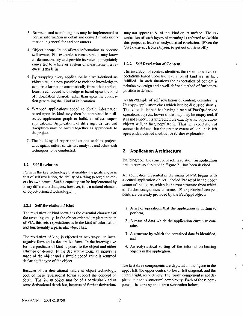
ABSTRACT: The Project Integration Architecture (PIA) implements a flexible, object-oriented, wrapping architecture
which encapsulates all of the information associated with engineering applications. The architecture allows the progress
of a project to be tracked and documented in its entiret3_ By being a single, self-revealing architecture, the ability to
develop single tools, for example a single graphical user interface, to span all applications is enabled. Additionally, by
bringing all of the info#vzation sources and sinks of a project into a single architectural space, the ability to transport
it!fom_ation bem,een those applications becomes possible. Object-encapsulation further allows information to become in
a sense self-aware, knowing things such as its own dimensionality andprovidingfunctionality appropriate to its kind.
1 Introduction 1.1 Goals
In the late 1980's, the Integrated CFD and Experiments
ICE I project [ 1, 2] was carried out with the goal of provid-
ing a single, graphical user interface (GLrl) and data man-
agemcnt environment for a variety of CFD codes and re-
laied experimental data. The intent of the ICE project wasIo ea,_" the difficulties of interacting with and intermingling
these disparate information sources. The project was a suc-ces_ on a research basis; however, on review it was deemed
inappropriate, due to various technical limitations, to ad-
vance the effort beyond the successes achieved.
A re-engineering of the project was initiated in t996. Theeffort was first renamed the Portable, Redesigned Inte-
grated CFD and Experments (PRICE) project and then, as
the _'ide applicability of the concepts came to be appre-
ciated, the Project Integration Architecture (PIA) project.
Two key re-engineering decisions were made: the C lan-
guage used by the ICE project would be abandoned in favorof the now-available C++ object-oriented extension to that
language and the graphical user interface would be elimi-nated as a product element of the project.
During the intervening years, work has proceeded and
an operational demonstration of the PIA project has beenachieved.
Put in simple terms, the basic goal of the PIA effort is to
capture in its entirety the usage of any engineering applica-
tion in a single, useful, well-defined form. This capturing
is not limited to the simple output of the application itself,but further includes coordinating information and the engi-
neer's own insights into the meaning of the information.
The nature of an 'engineering application' is, by project
design, nebulus: it is considered to be any computer-realized 'thing' which provides or generates useful infor-
mation about an engineering project. This may include
CAD information, design code predictions, experimental
data, engineering analysis and simulation, and more.
By bringing all of the information of the engineering pro-cess into one architectural design, a number of advantages
are expected to (and, it is believed, do) accrue.
1. The information about the information (referred to in
some conceptions as the meta-data) is encapsulatedwith the information itself.
2. A common tool set for the use of engineering applica-
tions is possible.
NASA/TM--2001-210750 1
3.
4.
.
6.
.
Browsers and search engines may be implemented toperuse information in detail and convert it into infor-
mation in general for end consumers.
Object encapsulation allows information to become
self-aware. For example, a measurement may know
its dimensionality and provide its value appropriately
converted to whatever system of measurement a re-
quest is made in.
By wrapping every application in a well-defined ,ar-
chitecture, it is now possible to code the knowledge to
acquire information automatically from other applica-
tions. Such coded knowledge is based upon the kind
of information desired, rather than upon the applica-
tion generating that -kind of information.
Wrapped applications coded to obtain information
based upon its kind may then be combined in a di-
rected application graph to build, in effect, super-
applications. Applications of differing fidelities and
disciplines may be mixed together as appropriate tothe project.
The building of super-applications enables project-
wide optimization, sensitivity analysis, and other such
techniques to be conducted.
1.2 Self Revelation
Perhaps the key technology that enables the goals above isthat of self revelation, the ability of a thing to reveal to oth-
ers its own nature. Such a capacity can be implemented by
many different techniques; however, it is a natural element
of object-oriented technology.
1.2.1 Self Revelation of Kind
The revelation of kind identifies the essential character of
the revealing entity. In the object-oriented implementationof PIA, this sets expectations as to the kind of information
and functionality a particular object has.
The revelation of kind is effected in two ways: an inter-
rogative form and a declarative form. In the interrogative
form, a predicate of kind is posed to the object and eitheraffirmed or denied. In the declarative form, an inquiry is
made of the object and a simple coded value is returned
declaring the type of the object.
Because of the derivational nature of object technology,
both of these revelational forms support the concept of
depth. That is, an object may be of a particular kind atsome derivational depth but, because of further derivation,
may not appear to be of that kind on its surface. The ex-
amination of such layers of meaning is referred to (within
this project at least) as ecdysiastical revelation. (From the
Greek ekdysis, from ekdyein, to get out of, strip off.)
1.2.2 Self Revelation of Content
The revelation of content identifies the extent to which ex-
pectations based upon the revelation of kind are, in fact,
fulfilled. In such situations the expectation of content is
nebulus by design and a well-defined method of further ex-
position is defined.
As an example of self revelation of content, consider the
PacAppl application class which is to be discussed shortly.
That class is defined has having a map of PacOp-derived
operations objects; however, the map may be empty and, if
it is not empty, it is unpredictable exactly which operations
objects will, in fact, populate it. Thus, an expectation of
content is defined, but the precise extent of content is left
open with a defined method for further exploration.
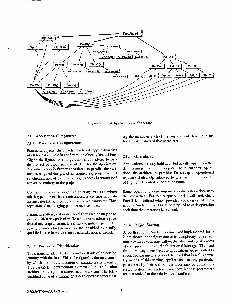
2 Application Architecture
Building upon the concept of self revelation, an application
architecture as depicted in Figure 2.1 has been devised.
An application presented in the image of PIA begins with
a central application object, labeled PacAppl in the upper
center of the figure, which is the root structure from which
all further components emanate. Four principal compo-
nents are currently provided by the PacAppl object:
1.
.
.
4.
A set of operations that the application is willing to
perform,
A mass of data which the application currently con-tains,
A structure by which the contained data is identified,and
An ecdysiastical sorting of the information-bearingobjects in the application.
The first three components are depicted in the figure in the
upper left, the upper central to lower left diagonal, and the
central right, respectively. The fourth component is not de-
picted due to its structural complexity. Each of these com-
ponents is taken up in its own subsection below.
NASA/TM--2001-210750 2
, PacAppl I
Op: Init op_ Run I PacCfg _'A_tC_I7 e/_,/c_, _._l_c/Cr, i<=: lJllll
PacCfg PacCfg: Pacefg
Figure 2.1: PIA Application Architecture
2.1 Application Components
2.1.1 Parameter Configurations
Parameter objects (the objects which hold application data
of all forms) are held in configuration objects, labeled Pac-
Cfg in the figure. A configuration is considered to be a
distinct set of input and output data for the application.
A configuration is further considered to parallel the vari-
ous investigated designs of an engineering project so that
synchronization of the engineering process is maintained
across the entirety of the project.
Configurations are arranged as an n-ary tree and inheritmissing parameters from their ancestors, the most immedi-
ate ancestor taking precedence for a given parameter. Thus,
repetition of unchanging parameters is avoided.
Parameters often exist in structural forms which may be re-
peated within an application. To avoid the needless replica-
tion of unchanged parameters simply to indicate parametric
structure, individual parameters are identified by a fully-
qualified name in which their structuralization is encoded.
2.1.2 Parameter Identification
The parameter identification structure (built of objects be-
ginning with the label Pid in the figure) is the mechanism
by which the structuralization of parameters is revealed.
This parameter identification element of the application
architecture is, again, arranged as an n-ary tree. The fully-
qualified name of a parameter is developed by concatenat-
ing the names of each of the tree elements leading to the
final identification of that parameter.
2.1.3 Operations
Applications not only hold data, but usually operate on that
data, turning inputs into outputs. To reveal these opera-
tions, the architecture provides for a map of operational
objects (labeled Op followed by a name in the upper left
of Figure 2.1) sorted by operation name.
Some operations may require specific interaction withthe researcher. For this purpose, a GUI call-back class,
PacGUI, is defined which provides a known set of inter-
actions. Such an object must be supplied to each operation
each time that operation is invoked.
2.1.4 Object Sorting
A fourth structure has been defined and implemented, but it
is not shown in the figure due to its complexity. The struc-
ture provides a ecdysiastically-exhaustive sorting of objects
of the application by their derivational heritage. The needfor this sorting arises because applications are permitted to
specialize parameters beyond the level that is well known.
By means of this sorting, applications seeking particularparameters by their well-known types may be quickly di-
rected to those parameters, even though those parametersare customized at their derivational surface.
NASA/TM--2001-210750 3
2.2 Operating Context
The parameter identification and application operation ob-
jects both operate in the context of a selected parameter
configuration, a concept shown in the figure by the sweep-
ing curves from those kinds of object to a single config-
uration. These object kinds offer IsVisible and IsEnabled
member functions, respectively, which indicate whether or
not the functionality is active within the context of the se-
lected parameter configuration. This feature allows, for ex-
ample, the internal parameters of an optional analysis com-
ponent to be made invisible when that component has been
disabled in a particular configuration, even though those
parameters might exist in, or be inherited by, that configu-ration.
3 The Base Object
Vet3 ' nearly all of the object classes involved in implement-ing the PIA application architecture described above are de-
rived from a common base class, PacBOhj. Among other
things, this base class provides several key features:
1. The ability to be described,
2. The ability to transmit declared events, and
3. The ability to traverse upward through the applicationslructure.
3.1 Descriptive Capabilities
The abilitx to be described brings a good deal of useful
function to the entirety of the architecture. A wide variety
of dc,,criptions, such as access controls, descriptive texts,
dmicnsionality, and others, are implemented. Indeed, vir-
tualb any sort of descriptive element can be devised and
added to the repertoire. Because not all objects will nec-
essarily have descriptive elements and certainly not all ob-jects will have all descriptive elements, the descriptive sys-tem is one of minimal overhead.
The only limitation of the descriptive system is that, within
a descriptive set, at most one instance of any particular con-trolling descriptive type is permitted. This limitation is off-
set by the fact that the descriptive system is implementedin a layered, hierarchial manner in parallel with the deriva-
tional class hierarchy and that distinct descriptive sets may
exist at each such level. Within this descriptive hierarchy,
the top-most description (that is, the description of the most
derived class level) of any kind is considered to be the pre-
ferred description; however, the facilities exist to reveal the
entirety of the descriptive hierarchy should it be desired.
3.1.1 Engineering Logs
A multi-line, descriptive text form is provided as the possi-
ble basis of an engineering log facility. Here an indefinite,
expandable number of text string elements in an ordered
list can be associated with any PacBObj derived object.
3.1.2 Change Histories
A change history descriptive form is provided. It provides
an implicitly time-stamped, ordered, multi-line descriptive
form. This form is implicitly used by the PacPara (pa-rameter) base class to record parameter modifications as
previous value texts. All currently implemented parame-
ter classes utilize this capability in their corresponding Set-Value services.
3.1.3 Access Controls
An access control descriptive complex is implemented.Any PacBOhj-derived object can attach access control de-
scriptions throughout its descriptive hierarchy. This allows
per-user read, write, execute, and delete controls to be ap-plied on an object-by-object basis.
3.2 Declared Events
A simple subscribe/pubfish event facility is provided by the
PacBObj base class. This facility allows utilizing entities
to attach one or more objects of PacEvent derivati0n toa PacBObj-derived_object_ The PacEventbase _c!ass d_e-
finesa number of different event types-but, asabase Class,provides only a default response should the event be de-
clared. The PacBObj base class implements correspond-ing event functions which, if invoked, will identify each
attached event object and transmit the event declaration toit.
Utilizing code is responsible for developing and attaching
derived event class forms which do something meaningfulshould an event be declared. There is no artificial limita-
tion on the number of event objects that may be attached
to a particular PacBObj object, nor upon the number of
PacBObj objects that may be attached to a particular eventobject.
3.3 Upward Reference
The basic direction of the application architecture is down
from encompassing components to more specific compo-
nents. In implementation, though, it is frequently necessary
NASA/TM--2001-210750 4
totraverseintheoppositedirection.ThisneedismetbyapointermemberandsupportingcodeinthePacBObjclasswhichreferencesthenexthigherlevelelementoftheappli-cationstructure.Implementedfunctionalityallowstraver-salofthisupwardchainofreferenceuntilanobjectof aparticular,specifiedkindis found.Thus, code can be in-
sensitive to the exact placement of its presenting object inthe architectural hierarchy.
4 Parameters
Information is encapsulated in a derivationally-rich set of
parameter objects. The parameter derivational structure isbased upon the PacBObj base class and, thus, all of the
capabilities of that foundation are inherited.
4.1 Dependent Parameters
The parameter base class utilizes the directed graph capa-
bilities inherited by it to implement a dependent parameter
mechanism. Each successor (dependent) in such a graph is
informed of any change in any of its predecessor (benefac-
tor) parameters. This dependency mechanism is accounted
for during the act of parameter replication, causing thereplication of dependent parameters as needed.
4.2 Infusion of Semantic Meaning into Parameter Ob-
jects
The self revelation of kind mechanism is used by the pa-
rameter object hierarchy to infuse semantic meaning into
parameters [3]. The first derivations of parameter ob-
jects specialize parameters by their basic structural forms;
scalar, vector, matrix, organizational, and the like. Further
derivation then associates an atomic kind, long, double,
Boolean, string, and the like, with these forms as appro-priate.
A further specialization of double parameter kinds declares
them to be dimensional in nature, that is being a measure-
ment in a specified system of measurement. (The concepts
of dimensionarity are discussed in greater detail in [4].)
From this point a great majority of engineering parameters
may then be derived.
By setting the dimensional elements to null values, di-
mensional parameters are further specialized to be non-
dimensional. By doing this, non-dimensional parametersmay be freely intermixed with their dimensional counter-
parts in dimensionally-sensitive operations. From this base,
non-dimensional engineering parameters are then derived.
4.2.1 Related Parameters
A related-parameter descriptive mechanism is utilized to
associate other parametric information with semantically-
defined parameter objects. For example a grid of informa-
tion may identify a parameter giving the positions of its grid
coordinates through the related parameter mechansism.
5 Persistence
Saving the state of an encapsulated application was a self-
evident requirement. To achieve this, an object serialization
capability was implemented. Object contents are writtenout to or read back from an archive file under the control of
a Serialize function. An archive object keeps track of what
objects have been serialized or de-serialized so that redun-
dant references to an object are appropriately handled.
The drawback of this serialization is also its strong point: a
Serialize function must be manually coded for every class
that might participate in such an operation. For the most
part such coding amounts to mere tedium; however, it is
in this coding that the groundwork for evolutionary change
can be laid. If one takes the precaution of serializing an
archive version number as the very first step of object se-rialization, then conditional code for the de-serialization of
old object versions can be generated when object revisions
are defined. By this means, old objects may be recovered
even as object coding evolves.
6 Information Propagation
The infusion of semantic meaning into parameter objectsthrough derived class specialization and self revelation
forms the basis for the interapplication transfer of informa-
tion by allowing one application to 'look' at parameters ofanother application and discern the semantic nature of the
observed parameter objects. This basic technology enables
a number of interapplication information transfer modes.
The propagation of parametric information throughout an
application graph is the first form of information transfer
implemented by the PIA project [5]. The goat is to arrange
disparate applications into a cooperative graph whose oper-
ation carries out all of the analyses relevant to an engineer-
ing project as a whole.
The graph of applications is currently constructed by op-
erations of the testbed GUI. The first application created
through the GUI is always made the initial node of an ap-
plication graph. A right crick on that application (or upon
any application subsequently added to the graph) pops up a
NASA/TM--2001-210750 5
menuwithapickforaddingasuccessorapplicationtotheright-clickedapplication.Thestandardselect-applicationdialogisthenexecutedandtheapplication-graphmemberadded.
A basicconceptualviewbehindthearrangementofanap-plicationgraphis thattherealwaysexistssomesourcedef-initionof a proposedconfigurationof theprojectwhichthenfeedsasinputto variousanalysesof thatconfigura-tion. Thoseanalysesthenproduceresultswithtwopo-tentialaspects:intermediatevalueswhichareof useforfurtherformsofanalysisandfinalanswerscontributingto-wardajudgementoftheengineeringmeritofthedesign.
Anotheraspectimplicitin thisviewofinformationpropa-gationthroughoutdirectedapplicationgraphsis thatsuchapplicationsoperateinamodeinwhichasingleoperation(fromanexternalviewpoint)reliablyturnsinputinforma-tionintooutputinformation,asopposedtoa scenarioinwhichthepropagationactmustbeiterativelyperformeduntilparametricvalues,insomesense,reachabalanceorconverge.Note,though,thatsuchaniterativepropagationformisnotprecludedbythePIAarchitecture,butisonlyinoppositiontotheassumptionsoftheinformationpropa-gationformfirstimplementedforstudy.
Informationpropagationaspresentlyimplementedalsoforcesthesynchronizationofparameterconfigurations.Bythis,theconceptof aprojectconfigurationismademorerealand,it isexpected,theproblemofmismatchedconfig-urationswithinaprojectanalysiswillbeeliminated.
Thepropagationimplementationalsorecognizesthatnotall applicationsareentirelyreliablein theiroperation.Todealwiththis,thesupportutilizestheeventmechanismbuiltintothePaeBObjbaseclasstoallowinappropriateoperationstoalertsupposedlycorrectiveentities.Thereis,thus,theabilitytoapplycorrectivemeasuresandre-attemptaparticularoperationin theoverallpropagationactivity.Failingsuchcorrectiveactions,theinformationpropaga-tionsystemwillmarktheaffectedparameterconfigurationsasbeingdefectiveandwillpreventfurtherpropagativeactsbaseduponthoseconfigurations.
Theprocessofinformationpropagationascurrentlyimple-mentedproceedsinthefollowinggeneralmanner.
1. Theprocessisbegunbydeliveringapropagationcom-mandcitingaparameterconfigurationtoanapplica-tionobjectwhichis,typically,theinitialnodeof anapplicationgraph.Theeventis typicallydeliveredfromanexternal,organizingentity,forexampleaper-soncontrollingtheoverallprocessthroughaninter-actingGUI.
2. Theapplicationobjectconvertsinputstooutputsafteritsmanner.
. The application then passes the propagation operation
on to each of its immediate successors in the graph.
The configuration is passed on in this act.
4. Each receiving application establishes or creates a cor-
reponding configuration.
. Each receiving application then examines each of the
parameter objects available in the source configuration
and, based upon the semantic meanings revealed by
those parameters, acquires such information as it may.
Each receiving successor application is free to exam-
ine the extended predecessor applications of its own
propagating immediate predecessor application for in-put information.
6. When each successor has-recelved a propagation act
from each of its own immediate predecessors, it then
operates to convert its own inputs into outputs and
then passes the propagation act on to its immediatesuccessors.
7. The propagation of information continues in this man-
ner throughout the graph until terminal nodes of the
graph are reached and return the propagation act back
up the graphical chain to the originator of the act. UI-"
timately, this rolls up to a single return of control to
the original initiator of the propagation act, indicating
that the operation is complete.
It should be remembered in all of this that it is the technol-
ogy of self-revelation exposing infused semantic meaning
that makes the implementation of information propagation
tenable. Applications wrappers need only be coded to look
for the kinds of information they desire to acquire during
propagation. It is not necessary to code for connection to
a specific source application to obtain an expected kind of
information, nor is it necessary to code for specific topo-
logical arrangements of applications.
7 Documentation
Complete, class-by-class, member-by-member documenta-
tion has been generated in Hyper-Text Markup Language
(HTML) format and placed on a central server at the GlennResearch Center. The root URL for this documentation is
http:llwww.lerc.nasa.gov/WWWIpriceOOO_ndex.html
NASA/TM--2001-210750 6
411 : ° ° a" °" *'_ °'° _'_ _'_°*°_"_*_ "" !
HiuApplI' PacAppn :2 ..................
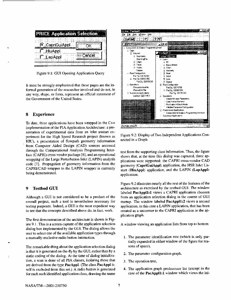
Figure 9.1: GUI Opening Application Query
It must be strongly emphasized that these pages are the in-
formal generation of the researcher involved and do not, in
any way, shape, or form, represent an official statement ofthe Government of the United States.
8 Experience
To date, three applications have been wrapped in the C++
implementation of the PIA Application Architecture: a pre-
sentation of experimental data from an inlet unstart ex-
periment for the High Speed Research project (known as
HIU), a presentation of flowpath geometry informationfrom Computer Aided Design (CAD) sources accessed
through the Computational Analysis Programming Inter-face (CAPRI) cross-vendor package [6], and an operational
wrapping of the Large Perturbation Inlet (LAPIN) analysiscode [7]. Propagation of geometry information from the
CAPRI/CAD wrapper to the LAPIN wrapper is currently
being demonstrated.
9 Testbed GUI
Although a GUI is not considered to be a product of the
overall project, such a tool is nevertheless necessary for
testing purposes. Indeed, a GUI is the most expedient wayto see that the concepts described above do, in fact, work.
The first demonstration of the architecture is shown in Fig-
ure 9.1. This is a screen capture of the application selection
dialog box implemented by the GUI. The dialog allows the
user to select one of the available application types through
a mutually-exclusive radio button interaction.
The remarkable thing about the application selection dialog
is that it is generated on-the-fly by the GUI, rather than by a
static coding of the dialog. At the time of dialog initializa-tion, a scan is done of all PIA classes, isolating those that
are derived from the type PaeAppl. (The class PaeAppl it-self is excluded from this set.) A radio button is generated
for each such identified application class, drawing the name
_L_,_ _..._:_'!_'!'t_:_!_Q '_:_ '_ _ _i_:_ 1_ ................................ ]
IJ :" Capri - - .....
_, Volumel
"_ B oundaliee
: BoundngBox
i)_!Edges
_ Fac_
L_ Node_
Volume
-i Roo_ Conli_ation
PacCIg 02E 107613
:-: PacCIg 02DBD95D
PacClg: 02DF8C60
_i Operalion_
Choo_ea_cNwFila
ChooseCADF_
-] S ucces SOlApplicati_n_
Lal_p_ 132E] 14EO
{£! Lapin
BC
!,. Bypa_d31eed
_£ Cordrl
Geometry
_ Heat
_ Irked
:_ Lo_:
_-: Outpu_
Rool Conf_uraEon
PacCfg: 02E 10760
-'_i PacCfg: 02080950
PacCf_:02DFBC60
i-i 0oelaliom
: Create All Lapin P,_amelers
_ _j , LoedF_w c_Narnes- '- _ _ inlrl t hM
I_ _ _ | : nunL_ Bac ode_i_!_:._?_ : Validate Parameter Configulatiom
..... _ redeces_'o_ Ap_cahon_
_ i_i_i_ | : _ Compur alional Analy _is P,o_ amrr
..... i _ Predeces_ Ap#icationz
: _ Computalion_lAnaly._is Piog_amming Interface- Successo_ App_cation_
Figure 9.2: Display of Two Independent Applications Con-
nected in a Graph
text from the supporting class information. Thus, the figure
shows that, at the time this dialog was captured, three ap-
plications were supported: the CAPRI cross-vendor CAD
geometry (CapriGuiAppl) application, the HSR Inlet Un-start (HiuAppl) application, and the LAPIN (LapAppl)
application.
Figure 9.2 illustrates nearly all the rest of the features of thearchitecture as exercised by the testbed GUI. The window
labeled PaeAppll:l views a CAPRI application choosen
from an application selection dialog in the course of GUI
startup. The window labeled PacApplh2 views a second
application, in this case a LAPIN application, that has beencreated as a successor to the CAPRI application in the ap-
plication graph.
A window viewing an application lists from top to bottom
1. The parameter identification tree (which is only par-
tially expanded in either window of the figure for rea-
sons of space),
2. The parameter configuration graph,
3. The operation tree,
4. The application graph predecessor list (except in thecase of the PaeAppll:l window which views the ini-
NASA/TM--2001-210750 7
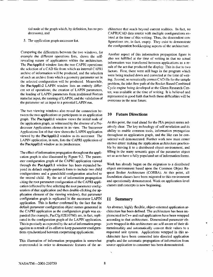
tialnodeofthegraphwhich,bydefinition,hasnopre-decessors),and
5. Theapplicationgraphsuccessorlist.
Comparingthedifferencesbetweenthe two windows, for
example the different operations lists, shows the self-
revealing nature of applications within the architecture.
The PacAppll:l window lists the two CAPRI operations;the selection of a CAD file from which an internal CAPRI
archive of information will be produced, and the selection
of such an archive from which a geometry parameter set in
the selected configuration will be produced. Meanwhile,
the PacAppih2 LAPIN window lists an entirely differ-
ent set of operations; the creation of LAPIN paranaeters,
the loading of LAPIN parameters fromtraditional Fortran
namelist input, the running of LAPIN, and the validation of
the parameter set as input to a potential LAPIN run.
The two viewing windows also reveal the connection be-
tween the two applications as participants in an application
graph. The PaeAppil:l window views the initial node ofthe application graph, as witnessed by the absense of a Pre-
decessor Applications element in its view. The Successor
Applications list of that view shows the LAPIN applicationviewed by the PacAppll'2 window as its successor. The
LAPIN application, in turn, lists the CAPRI application of
the PacAppll:l window as its predecessor.
The effect of information propagation throughout the appli-
cation graph is also illustrated by Figure 9.2. The param-
eter configuration graph of the CAPRI application viewed
through the PaeAppll:l window has been expanded be-
yond its default single-patriarch form to include two child
configurations and a grandchild configuration attached to
the second child. By the act of information propagation
citing the root parameter configuration of the CAPRI appli-
cation (effected by first selecting the root parameter config-
uration of that application and then double-clicking the ap-
plication element of the viewing window), that parameter
configuration graph is replicated in the successor LAPIN
application. This is further confirmed by the fact that the
default parameter configuration object names generated in
the CAPRI application as the configuration graph was ex-
panded (for example, PacCfg:02E10760) are, in fact, repli-
cated in the configuration graph of the LAPIN application.
This is precisely as expected by the act of information prop-
agation as a result of its effort to keep parameter configura-
tions synchronized between cooperating applications.
This illustration of information propagation is somewhatoverextended in order to demonstrate features of the at-
chitecture that reach beyond current realities. In fact, no
CAPRI/CAD data source with multiple configurations ex-
isted at the time of this writing. Thus, the descendent con-
figurations are, in fact, empty. They exist to demonstrate
the configuration bookkeeping aspects of the architecture.
Another aspect of this information propagation figure is
also not fulfilled at the time of writing in that no actual
information was transferred between applications as a re-
sult of the act that produced the display. This is due to two
factors. First, there were still bugs in the program which
were being tracked down and corrected at the time of writ-
ing. Second, no sematically correct CAD file for the sample
problem, the inlet flow path of the Rocket Based Combined
Cycle engine being developed at the Glenn Research Cen-
ter, was available at the time of writing. It is believed and
represented in good faith that both these difficulties will beovercome in the near future.
10 Future Directions
At this point, the road ahead for the PIA project seems rel-
atively clear. The key technology of self-revelation and its
ability to enable common tools, information propagation
throughout an application graph, and the like can be con-sidered well demonstrated. Further work now must center
on two areas: making the application architecture practica-ble by moving it to a distributed object environment, and
filling in the many semantic gaps of the parameter object
set so as to have a fully populated set of information forms.
Work has already begun on the migration to a distributedobject environment based upon the Common Object Re-
quest Broker Architecture (CORBA). At this point, all
foundation classes have been migrated to this environment
and operationally demonstrated. Work on application-level
classes and concepts is now beginning.
11 Summary
An abstract, highly flexible, object-oriented application ar-chitecture has been defined. The architecture has been im-
plemented in C++ and real applications have been wrapped
according to that architecture. Dimensional parameter ob-
jects wrapped in this architecture are self-aware of their di-mensionaility and automatically convert their values to a
requested unit system. Applications wrapped in this ar-
chitectttre have been connected into directed application-
graphs and the automatic propagation of information fromsource application to consumer has been demonstrated.
NASA/TM--2001-210750 8
Author Biography
DR. WILLIAM HENRY JONES is a Computer Engi-
neer at the National Aeronautics and Space Administration,John H. Glenn Research Center at Lewis Field, in Cleve-
land, Ohio. He has been the sole architect for the PIA
Application Architecture since the initiation of the project
in 1996. Dr. Jones also has wide ranging interests in the
computer field including direct computer control of manu-
facturing machinery, specialized CAD/CAM systems, elec-
tronic hardware design and implementation, compiler the-
ory and implementation, object-oriented design, computer
systems security, computational fluid mechanics, and oth-
ers, as well as considerable experience in aeropropulsion
and the practicalities of flight.
References
[1] The American Society of Mechanical Engineers. Inte-
grated CFD and Experiments Real-Time Data Acquisi-
tion Development, number 93-GT-97, 345 E. 47th St.,
New York, N.Y. 10017, May 1993. Presented at the In-
ternational Gas Turbine and Aeroengine Congress and
Exposition; Cincinnati, Ohio.
[2] James Douglas Stegeman. Integrated CFD and Ex-
periments (ICE): Project Summary. Technical mem-
orandum Number not yet assigned, National Aeronau-
tics and Space Administration, Lewis Research Cen-
ter, 21000 Brookpark Road, Cleveland, OH 44135,December 2001.
[3]
[4]
[5]
William Henry Jones. Project Integration Architec-
ture: Formulation of Semantic Parameters. Draft paper
available on central PIA _eb site, January 2000.
William Henry Jones. Project Integration Architecture:Formulation of Dimensionality in Semantic Parame-
ters. Draft paper available on central PIA web site,March 2000.
William Henry Jones. Project Integration Architecture:
Inter-Application Propagation of Information. Draft
paper available on central PIA web site, December1999.
[6] Robert Haimes. Computational Analysis PRogram-
ming Interface (CAPRI): A Solid Modeling Based
Infrastructure for Engineering Analysis and Design.
Cambridge, MA, November 1999. Web Reference:
http:l/raphael.mit.edu/capri/.
[7] M. O. Varner, W. R. Martindale, W. J. Phares, K. R.
Kneile, and J. C. Jr. Adams. Large Pertubation Flow
Field Analysis and Simulation for Supersonic Inlets:
Final Report. Contractor Report NASA CR-174676,
National Aeronautics and Space Administration, Lewis
Research Center, 21000 Brookpark Road, Cleveland,
OH 44135, September 1984.
NASA/TM_2001-210750 9
REPORT DOCUMENTATION PAGE FormApprovedOMB No. 0704-0t88
Public reporting burden for this collection of information is estimated to average 1 hour per response, including the time for reviewing Instructions, searching existing data soumes,
gathering and maintaining the data needed, and completing and reviewing the collection of information. Senrt comments regarding this burden estimate or any other aspect of this
collection of information, including suggestions for reducing this burden, to Washington Headquarters Services, Directorate for Information Operalions and Reports, 1215 Jefferson
Davis Highway, Suite 1204, Adinglon, VA 22202-4302, and to the Office of Management and Budget, Paperwork Reduction Project (0704-0188), Washington, DC 20503.
1. AGENCYUSEONLY (Leaveblank) 2. REPORTDATE
February 200 l4. TITLEANDSUBTITLE
Project Integration Architecture:Architectural Overview"
6. AUTHOR(S)
William Henry Jones
7. PERFORMINGORGANIZATIONNAME(S)AND ADDRESS(ES)
National Aeronautics and Space AdministrationJohn H. Glenn Research Center at Lewis Field
Cleveland, Ohio 44135- 3191
9. SPONSORINC-dMONITORINGAGENCYNAME(S)ANDADDRESS(ES)
National Aeronautics and Space Administration
Washington, DC 20546-0001
3. REPORTTYPEAND DATESCOVERED
Technical Memorandum
5. FUNDINGNUMBERS
WU-704-10-23-00
8. PERFORMINGORGANIZATIONREPORTNUMBER
E-12678
10. SPONSORING/MONITORINGAGENCYREPORTNUMBER
NASA TM--2001-210750
11. SUPPLEMENTARYNOTES
Prepared for the Simulation Interoperability Workshop sponsored by the Simulation Interoperability Standards
Organization, Orlando, Florida, March 25-30, 2001. Responsible person, William Henry Jones, organization code 5880,216-433-5862.
12a. DISTRIBUTION/AVAILABILITYSTATEMENT 12b. DISTRIBUTIONCODE
Unclassified - Unlimited
Subject Category: 63 Distribution: Nonstandard
Available electronically at htm://eltrs._rc.nasa.eov/GLTRS
This publication is available from the NASA Center for AeroSpace Information, 301-621-0390.13. ABSTRACT(Maximum200 words)
The Project Integration Architecture (PIA) implements a flexible, object-oriented, wrapping architecture which encapsu-
lates all of the information associated with engineering applications. The architecture allows the progress of a project to
be tracked and documented in its entirety. By being a single, self-revealing architecture, the ability to develop single
tools, for example a single graphical user interface, to span all applications is enabled. Additionally, by bringing all of
the information sources and sinks of a project into a single architectural space, the ability to transport information
between those applications becomes possible, Object-encapsulation further allows information to become in a sense self-
aware, knowing things such as its own dimensionality and providing functionality appropriate to its kind.
14. SUBJECTTERMS
PIA; PRICE; Application integration; Interapplication propagation of information;
Semantic encapsulation; Multifidelity analysis; Multidisciplinary analysis
17. SECURITYCLASSIFICATIONOFREPORT
Unclassified
18. SECURITYCLASSIFICATIONOFTHIS PAGE
Unclassified
19. SECURITYCLASSIFICATIONOFABSTRACT
Unclassified
15. NUMBEROF PAGES
1,516. PRICECODE
A0320. LIMITATIONOF ABSTRACT
NSN 7540-01-280-5500 Standard Form 298 (Rev. 2-89)Prescribed by ANSI Std. Z39-18
298-102


![[Architecture eBook] Ansorg - Architectural Lighting](https://img.pdfslide.us/doc/110x75/5528a6a249795912048b4aa5/architecture-ebook-ansorg-architectural-lighting.jpg)

![[Architecture eBook] Architectural Rendering Techniques](https://img.pdfslide.us/doc/110x75/55cf8f0e550346703b9880b7/architecture-ebook-architectural-rendering-techniques-56783efcc9ad6.jpg)