Embed Size (px)
Citation preview

Page 1 of 55
PROJECT INFORMATION Template
Enterprise Architecture
Title:
Enterprise Integration Platform & Platinum Services Gateway Pre-
transfer
Unique Identifier: 206-1313
Document Type: ETE
Revision: 3.1
Total pages: 55
Revision date: September 2017
Classification:
PUBLIC/CONFIDENTIAL/ CONTROLLED DISCLOSURE

Page 2 of 55
Table of Contents 1 Project Information ..................................................................................................... 3
1.1 Relevant Business Units ...................................... Error! Bookmark not defined.1.2 List of Attached Supporting Documents ............... Error! Bookmark not defined.
2 Architectural Submission ............................................................................................ 32.1 Introduction ........................................................................................................... 32.2 Scope ................................................................................................................... 32.3 Business Architecture ........................................................................................... 3
2.3.1 Business Strategies and Plans ...................................................................... 32.3.2 Business Processes and Policies .................................................................. 42.3.3 Business Organisation Design ....................................................................... 4
2.4 Business Information Architecture ........................................................................ 42.4.1 Business Information Flow/Inventory ............................................................. 42.4.2 Information Integrity and Custodianship ........................................................ 52.4.3 Information Access and Confidentiality .......................................................... 52.4.4 Information Related Business Continuity ....................................................... 6
2.5 Data Architecture .................................................................................................. 62.5.1 Data Models ................................................................................................... 6
2.6 Application Architecture ........................................................................................ 62.6.1 Application Functional Decomposition ........................................................... 72.6.2 EIP Platform Application Architecture ............................................................ 92.6.3 Application Strategy ..................................................................................... 192.6.4 Application Development ............................................................................. 19
2.7 Integration Architecture ...................................................................................... 192.7.1 Integration Interface Map ............................................................................. 192.7.2 Integration Services Directory ...................................................................... 202.7.3 Data Migration ............................................................................................. 20
2.8 Technical Architecture ........................................................................................ 212.8.1 Basic Infrastructure ...................................................................................... 21
2.9 Network Architecture .......................................................................................... 432.10 Security Architecture ....................................................................................... 47
2.10.1 Transport Layer Security .......................................................................... 502.10.2 File System Security ................................................................................. 502.10.3 EIP Global Access Roles .......................................................................... 51
3 High Availability and Disaster Recovery .................................................................. 524 Oracle Platinum Services Architecture ..................................................................... 545 EIP Platform Tests ................................................................................................... 54

Page 3 of 55
1 Project Information
2 Architectural Submission
2.1 Introduction
The Enterprise Integration Programme (EIP) was launched to replace the legacy integration systems. For more than 10 years, Eskom has utilised SUN Java CAPS as an interface set of processes between applications, across multiple divisions and business areas. In 2010 Oracle acquired SUN and a directive was sent that stipulates that the SUN Java CAPS tooling would be discontinued. In November 2014 Eskom acquired Oracle’s SOA and Weblogic Suites as a replacement for its Seebeyond and JavaCaps interfaces. The purpose of this document is to describe the physical platform and network configuration that was implemented for EIP. It includes the map of the physical application and database server architecture onto specific computing platforms included in the scope of the Oracle Fusion Middleware Platform Application and Technical Architecture process.
2.2 Scope This document will cover the Oracle Fusion Middleware deployment architecture for the products acquired by Eskom. Parts of the Exalogic and Exadata designs will be covered and referenced in this document, but should be used as reference and input into this document. The following topics will be covered as part of this document:
• Oracle Fusion Middleware Deployment Architecture • High Level Overview of Engineered Systems;
o Exalogic o Exadata
• The following environments will be covered; • Production • Disaster Recovery • Pre-Production • Quality Assurance • Development
This document will only focus on the Central deployment architecture covering the Exalogic and Exadata machines within the MegaWatt Park and 141 Sivewright data centres.
2.3 Business Architecture
2.3.1 Business Strategies and Plans

Page 4 of 55
The Enterprise Integration Programme seeks to replace the legacy integration systems. The 2012 Group IT Business Plan - Enterprise Integration Programme initiative is unique and crucial to business success as it underpins the transport of key information in Eskom’s business, including the safety and revenue systems/application The current short –term objective of the EIP platform is to migrate all existing SeeBeyond and Java Caps integration interfaces to the new OFM platform. The in addition to this any new interfaces whether it be a requirement from business as usual projects of new builds these interfaces will be deployed on the EIP platform
2.3.2 Business Processes and Policies The purpose of the platform as previously mentioned will impact the major EHPUM processes and policies due to the fact that it is the primary platform for transporting data between all major systems within the Enterprise.
2.3.3 Business Organisation Design The functional responsibility of the Integration Centre of Excellence (ICoE) is the deliver and maintain the IT systems integration within it the organisation . Hence the business owner of the EIP platform would be the ICoE. The figure below illustrates where the ICoE is placed relative to the rest of the enterprise. The support of the platform will be shared across multiple entities within Group IT in partnership with Oracle and MSA provider. For detail on the support structure please refer to EIP Operations Support Structure document.
Figure 1 :ICoE Business Context
2.4 Business Information Architecture
2.4.1 Business Information Flow/Inventory Reference the paths that will be on the EIP platform

Page 5 of 55
2.4.2 Information Integrity and Custodianship The Table 1: Oracle Fusion Middleware Users, Groups and Roles defines how user access can be restricted on the platform. Please note that these are not application level groups and roles but rather specifies how individuals can access platform from an operational perspective. Table 1: Oracle Fusion Middleware Users, Groups and Roles Group Membership
Administrators By default, this group contains the user information entered as part of the installation process (that is, the Configuration Wizard), and the system user if the WebLogic Server instance is running Compatibility security. Any user assigned to the Administrators group is granted the Admin security role by default.
Deployers By default, this group is empty. Any user assigned to the Deployers group is granted the Deployer security role by default.
Operators By default, this group is empty. Any user assigned to the Operators group is granted the Operator security role by default.
Monitors By default, this group is empty. Any user assigned to the Monitors group is granted the Monitor security role by default.
AppTesters By default, this group is empty. Any user assigned to the AppTesters group is granted the AppTester security role by default.
CrossDomainConnectors By default, this group is empty. Any user assigned to the CrossDomainConnectors group is granted the CrossDomainConnector security role by default.
AdminChannelUsers By default, this group is empty. Any user assigned to the AdminChannelUsers group is granted the AdminChannelUser security role by default.
OracleSystemGroup By default, this group contains the user OracleSystemUser and is granted the OracleSystemRole role by default.
2.4.3 Information Access and Confidentiality The platform itself as previous mentioned is a means to transport data from one enterprise system to therefore minimal enterprise information that will be persisted on it. The only instances where information that would be persisted is,
1) To maintain state of an integration path 2) Error and audit logs
In both instances access to these data stores is restricted by the various out of the box OFM security measures. Data is either persisted in the file system or in data bases and both have restricted access by virtue of user name and password depending on the context of the data store. The section on the EIP Global Access Roles of the platform will detail this further
Page 6 of 55
2.4.4 Information Related Business Continuity The EIP platform is classified as a safety and revenue critical system therefore,
1) It is a 24x7 systems 2) Recovery point objective of data being - 0 hour 3) Recovery time objective of – 2 hours
2.5 Data Architecture
2.5.1 Data Models Please refer to the following documents detailing the data models for the various DB instances
EIP Production piep Schema 1.0 EIP Production prdjms Schema 1.0 EIP Production prdsoa Schema 1.0
2.6 Application Architecture This OFM suite is a purpose built ESB platform that provides industry standard integration bus functionality to the enterprise. The Oracle Engineered Systems was chosen as the hardware platform to host OFM. This suite gives the enterprise the capability to develop different types of middleware applications. This achieved by leveraging components such as,
• Business Process Management • BPEL process manager • Proxy • Technology and vendor adapters (connectors) • Enterprise Service Repository • Web Services Manager • Business Activity Monitoring • Could Management Console
The platform is built on top of the Oracle J2EE application server Weblogic and thus uses this as its runtime environment. In addition to this Weblogic provides the following functionality,
• Clustering • Performance Monitoring • Diagnostics • Java Messaging Services (asynchronous integration) • Diagnostics • Caching Frameworks

Page 7 of 55
2.6.1 Application Functional Decomposition The Enterprise embarked on an unlimited user licences (ULA) agreement with Oracle which allows the organisation to have an unlimited number of instances of a particular application contained in the Oracle ULA. The Figure 2: OFM Suite Decomposition below defines the middleware applications that are covered by the ULA and are deployed by the EIP.
Figure 2: OFM Suite Decomposition
The key solution building blocks that define the define middleware application architecture is defined below,
1. Business Process Management
The Oracle Business Process Management Suite (Oracle BPM Suite) provides a platform to business processes for both structured automated flows as well as dynamic, collaborative case .It provides advanced and complete analytics for operational as well as business performance, operational intelligence.
2. Oracle SOA Suite
o ORACLE SERVICE BUS (OSB)
Oracle Service Bus is an enterprise service bus (ESB) that provides a virtualization layer required for any integration architecture. Using Service Bus, organizations can decouple service consumers from changes that might occur in the backend. They can also hide from developers the often intricate and complex details of underlying implementations of back-end applications, such as legacy protocols
o BUSINESS PROCESS EXECUTION LANGUAGE (BPEL) PROCESS
MANGER – (BPEL-PM)

Page 8 of 55
Oracle BPEL provides a set of discrete services into an end-to-end process flow, reducing the cost and complexity of process integration. It executes standard BPEL processes and provides a “dehydration” capability so that the state of long-running flows is automatically maintained in a database, enabling clustering for both fail-over and scalability. The built-in human workflow capabilities of Oracle SOA Suite allow for people to be included in these processes for approvals and reviews
o ORACLE BUSINESS RULES (OBR)
Oracle Business Rules allows the externalization of specific business logic and parameters. Business analysts can easily define, update, and manage key parameters and decision trees that are likely to change based on business evolution (for instance discount levels, rates, etc.) - without having to involve IT and developers.
o BUSINESS ACTIVITY MONITORING (BAM)
Oracle BAM enables composition of graphical dashboards to gain real-time visibility of performance of business processes. User can also set personalized alert conditions which can be triggered and delivered via convenient channels (email etc.).
o CONNECTORS
Oracle SOA Suite provides a connectivity layer, enabling connectivity to a data source inside as well as outside the enterprise. Oracle Adapters (Database, JMS, file etc.) are available for on-premise applications and technology. In addition, B2B & Managed File Transfer capabilities are included to extend processes to external business partners.
3. Oracle Enterprise Repository (OER)
Oracle Enterprise Repository provides the visibility, feedback, controls, and analytics required to ensure your community of developers and architects maximize the value of internal integration investments. It facilitates to establish consistent processes via SOA Governance for service lifecycle management; Oracle Enterprise Repository will be positioned as a key component for capturing, automating, and centralizing all of the lifecycle management assets.
4. Oracle Web Service Manager (OWSM) Oracle Web Service Manager provides the first line security for client agent and last line security via server agents. Whether services are accessed within the enterprise or externally they may require authentication and authorization in accordance with the organization’s security policy or regulatory compliance. OWSM is centralized, declarative, externalized and consistent.
5. Weblogic Server

Page 9 of 55
Oracle WebLogic Server is a Java Platform, Enterprise Edition (Java EE) application server. The WebLogic Server infrastructure supports Oracle Fusion Middleware and other applications and is a foundation for building SOA based applications.
6. Oracle Enterprise Manager (OEM) Cloud Control
Oracle Enterprise Manager provides visibility into your application servers and their resident applications. Oracle Enterprise Manager and the associated SOA Management Pack plug-in provide these capabilities in an easy to use web console. Using Oracle Enterprise Manager, you can monitor your running servers, applications and service engines: to facilitate trouble-shooting at runtime within your enterprise SOA environment. The SOA Management Packs for Oracle Enterprise Manager 12c introduce the Java VM Diagnostics as a Service capability, which allows applications and middleware administrators to provide Java VM diagnostics capabilities directly to developers and QA engineers on an as needed basis. Users are provisioned automatically and receive their own self-service portal for accessing diagnostics capabilities. Oracle Enterprise Manager does more than provide visibility into your enterprise SOA environment: it also works with Oracle Web Services Manager to allow you to define security policies for your services and components and to apply those security policies as needed. This separates security management from application development, a best practice in the security world. This allows you to evolve and implement your security strategy outside of application development, providing you with greater agility and flexibility
7. SOA Management Pack
SOA Management Pack with Oracle Enterprise Manager Cloud Control facilitates monitoring of Oracle SOA Suite and OSB. It provides administrators of the SOA environment with a consolidated browser-based view of the entire enterprise. This enables administrators to monitor and manage all of their components from a central location. It stores the collected metric and configuration data in a central repository, thereby enabling administrators to analyse metrics through various historical views and facilitate strategic trend analysis and reporting.
8. WebLogic Management Pack
WebLogic Server Management Pack Enterprise Edition greatly improves server as well as application performance by providing unique functionality to automatically detect performance bottlenecks; quickly diagnose these performance problems, and identify their root cause.
WebLogic Server Management Pack Enterprise Edition provides common administration operations - traditionally available from the Oracle Enterprise Manager Fusion Middleware Control console or the WebLogic Server Administration Console – directly from the Cloud Control console. Consequently, a single console can be used to centrally administer multiple domains.
2.6.2 EIP Platform Application Architecture

Page 10 of 55
All Eskom integration requirements are managed by a single governing body, the ICoE (Integration Centre of Excellence). Due to the fact that all integration requirements will follow the same governance and architecture standards the Oracle recommended deployment model was to expose a single Enterprise Service Bus (ESB) with multiple SOA Domains. These logical domains will be used to containerize integration components that require some form of state to be maintained, and it will be split on non-functional requirements such as volumes, payload sizes and transaction times, as shown in Figure 3: SOA Domain Federation
Figure 3: SOA Domain Federation The platform is architecturally comprised of 4 tiers,
1. Application tier – Systems that leverage that integration platform for intra-application communication
2. Middle tier – The integration components are deployed on this tier 3. Monitoring tier- Oracle Enterprise Manager will act as a central monitoring and
management tool for all the databases and middleware components deployed 4. Data tier - Oracle Fusion Middleware is reliant on the database as it uses it to
manage state The above mentioned is depicted in Figure 4 : Platform Application Tiring

Page 11 of 55
Figure 4 : Platform Application Tiring
2.6.2.1 Middleware Tier Domains and Clustering Structure
A domain is an interrelated set of WebLogic Server resources that are managed as a unit. A domain also contains the application components deployed in the domain, and the resources and services required by those application components and the server instances in the domain. In each domain, one WebLogic Server instance acts as the Administration Server - the server instance which configures, manages, and monitors all other server instances and resources in the domain. Each Administration Server manages one domain only
WebLogic Server clusters provide scalability and reliability by distributing the work load among multiple instances of WebLogic Server. Incoming requests can be routed to a WebLogic Server instance in the cluster based on the volume of work being processed. In case of hardware or other failures, session state is available to other cluster nodes that can resume the work of the failed node. Domains can contain both managed servers and clusters.
The server instances that constitute a cluster can run on the same machine, or be located on different machines. You can increase a cluster's capacity by adding additional server instances to the cluster on an existing machine, or you can add machines to the cluster to host the incremental server instances.

Page 12 of 55
All server instances in a cluster must reside in the same domain. Clustered WebLogic Server instances behave similarly to non-clustered instances, except that they provide failover and load balancing. The process and tools used to configure clustered WebLogic Server instances are the same as those used to configure non-clustered instances.
Based on the Federated SOA Domain architecture, two Traffic Director and one Service Bus will be deployed with multiple SOA Domains, each optimized for specific non-functional requirements. These domains will be supplemented by a JMS domain to host all queues and topics and by a NF (non-functional) domain to host Error & Audit as well as any other “non-functional” components and requirements Each of the middleware components in depicted in Figure 4 : Platform Application Tiring are hosted in segregated Weblogic domains. Each of these domains is specialized for its intended purpose of the products deployed in it. The domains for the production and non-production environments are shown in

Page 13 of 55
ExaLogic¼Rack
ExaData½Rack
ExaLogic1/8thRack
ExaData¼Rack
MegaWattPark 141
ZFSReplication
DataGuardReplication
OTD
OSB
SOA1 SOA2
SOA3 SOA4
JMS
NF
SOADB JMSDB
PIEPDB
OTD
OSB
SOA1 SOA2
SOA3 SOA4
JMS
NF
SOADB JMSDB
PIEPDB
OTD OTD
PINTDB PINTDB
BPM BPM
Figure 5: EIP Domain Structure for Prod and DR. In addition to this all the managed servers in the domain are clustered to allow for load balancing and fail over. The main domain sub-divisions are:
• OTD – The OTD domain is specialized for the purposes of Oracle Traffic Director. This will be used for load balancing within the Exalogic system as well as fronting incoming communications.
• OSB – The OSB domain is specialized for Oracle Service Bus. Oracle Service Bus is used for simple mediation, routing and transformation that requires no orchestration.

Page 14 of 55
• SOA – The SOA domains are specialized for SOA Suite. SOA Suite is BPEL-based and hence process-aware. The SOA Suite functionality has been subdivided into four domains optimized for different purposes:
• SOA 1 – Optimized for supporting long running transactions. These require the use of the dehydration store to persist the BPEL process state in the database and these domains are tuned accordingly.
• SOA 2 - Optimized for small payload, high volume and low latency interfaces. • SOA 3 - Optimized for large payloads where streaming will enhance performance
and increase stability. • SOA 4 – This domain will be used where scheduling and managed file transfer
functionality is required • JMS – The JMS domain will be optimized for supporting JMS servers. • NF – The Non-Functional domain hosts non-functional functionality like auditing,
logging

Page 15 of 55
ExaLogic¼Rack
ExaData½Rack
ExaLogic1/8thRack
ExaData¼Rack
MegaWattPark 141
ZFSReplication
DataGuardReplication
OTD
OSB
SOA1 SOA2
SOA3 SOA4
JMS
NF
SOADB JMSDB
PIEPDB
OTD
OSB
SOA1 SOA2
SOA3 SOA4
JMS
NF
SOADB JMSDB
PIEPDB
OTD OTD
PINTDB PINTDB
BPM BPM
Figure 5: EIP Domain Structure for Prod and DR The Table 2 : Summary of EIP Domains summarizes the domains that will be deployed, and the intended use for each domain
Table 2 : Summary of EIP Domains Domain Components Deployed Usage SOA Suite 1 • SOA Suite
• Web Services Manager • Vanilla WebLogic Cluster for
JEE
Domain will be optimised for long running transactions that needs the dehydration store.

Page 16 of 55
SOA Suite 2 • SOA Suite • Web Services Manager • Vanilla WebLogic Cluster for
JEE
Domain will be optimised for small payload, high volume and low latency interfaces
SOA Suite 3 • SOA Suite • Web Services Manager • Vanilla WebLogic Cluster for
JEE
Domain will be optimised for large payloads where streaming will enhance performance and increase stability
SOA Suite 4 • SOA Suite • Web Services Manager • Vanilla WebLogic Cluster for
JEE • Managed File Transfer • Enterprise Scheduling
Service
Domain will be used where scheduling and MFT functionality is required.
OSB • OSB • Web Services Manager
Mediation, Routing and Transformation
JMS • JMS Asynchronous messaging NF • Vanilla Weblogic Non-functional requirements OTD • OTD Used for load balancing within
the Exalogic system.
2.6.2.1.1 OTD Domain An instance of Oracle Traffic Director will be deployed to handle internal communication while a separate instance will be responsible for inbound load balancing requirements. Both instances will be clustered across two compute nodes for HA purposes. The following table details the resource allocation
2.6.2.1.2 OSB Domain OSB will be the entry point for all synchronous integrations within each environment, OSB will be clustered across eight vServers to start off with. Capacity can be increased by scaling the domain horizontally should the need arise. Oracle Web Services Manager (OWSM / WSM) will be deployed as part of the domain in order to enable the service bus to apply security policies to inbound and outbound services. OWSM will be deployed on separate managed servers within a separate cluster as per the recommended approach. This reduces the load on the OSB servers when security has to be applied. The admin server can also be failed over to each of the vServers due to the u01 shared storage that will be hosting the domain and admin server. The following sections will detail the clusters and managed servers will be configured for the OSB domain.
2.6.2.1.3 Oracle SOA Suite Domains

Page 17 of 55
As detailed in the overview of the Application Architecture, multiple SOA domains will be deployed split on non-functional requirements. This allows for specific SOA-INFRA and JVM optimizations to ensure solutions run optimally within the SOA domains.
The following table defines the decision making Table 3 : SOA Domain decision matrix should be used as input when deciding which domain will host a specific solution
Table 3 : SOA Domain decision matrix Domain Payload
Size > 1024 KB
Throughput > 10ms/sec
Transaction Time > 300 sec
File Transfer and Scheduling Needed
Default
prdsoad100 X
prdsoad200 X X
prdsoad300 X
prdsoad400 X
SOA Domains 1, 2 & 3 uses the same Oracle Fusion Middleware components and thus the domain architecture for the domains is the identical. Ports will differ between the 3 domains to simplify the OTD load balancing algorithms. SOA domain 4 also provides MFT (Managed File Transfer) and ESS (Enterprise Scheduling Services) components to support file transfer and scheduling use cases. Again the admin server can be failed over between the vServers for a domain due to the domain and admin server running from shared storage. Oracle Coherence Clusters will be configured as part of the SOA domains to assist with state management and cluster replication.
2.6.2.1.4 BPM Domain A BPM Domain will be deployed and configured as part of the platform rollout although there is not a use case for this as of yet. The domain will host two types of managed servers, a BPM server hosting all Business Processes and an ADF layer to host any custom UI components.
2.6.2.1.5 Non-Functional Domain The intended use of the NF domain is to host all non-functional components like Error & Audit, monitoring scripts and other supporting functions. The reason we split these components away from the other domains is to ensure that non-functional requirements do not impact business. This allows us to isolate components of a similar nature and to mitigate risk.
From a deployment perspective, the NF (Non-Functional) domain will simply be a vanilla Weblogic domain with vanilla Weblogic Java EE managed servers within a cluster.
2.6.2.1.6 JMS Domain

Page 18 of 55
The JMS domain will be responsible for all asynchronous messaging within the integration platform. Two JMS clusters will be deployed within the domain, one dedicated to functional, business impacting messages and the other to non-functional, less critical messages like “error & audit” messages. From a JMS persistence perspective, data tier will be used. Domain level JMS configuration is the highest level of configuration in terms of a JMS with regards to WebLogic. The domain level configuration are broader arching and are categorized as either environmental-related or application-related. Environmental configuration examples are definitions and identification of the JMS servers and data sources, persistent stores and network addresses, JMS Modules, Bridging and Store-And-Forward. These JMS configurations are stored as modules defined in XML similar to standard J2EE and can be deployed as J2EE managed modules or standalone modules within a domain. These specific configurations usually differ between domains.
JMS Servers are targeted at a specific managed server, and all managed servers within a cluster share availability of managed resources, in turn making them available to all deployments within that cluster.
Different JMS Servers are targeted at different Managed Servers. These are also managed from the WebLogic administrator console. JMS Servers are targeted at specific clusters, making them available to all deployments within that cluster.
JMS Modules are the configuration hub for lower level JMS items such as Connection Factories, Queues and Topics and their JNDI contexts. The JMS Modules are all responsible for their security at a module level, which means each module can have specific roles and security policies depending on requirements.
There are different types of Queues and Topics configurations available on WebLogic, such as standard Queues (specific to a module) or a Distributed Queue (which is uniform across a cluster)
Queues and Topics have the lowest level of configuration in the hierarchy, but the most specific. You can configure things such as thresholds and quotas, overrides in terms of delivery, security and control.
2.6.2.2 Data Tier Domain and Cluster Structure
Database tier currently has two functions
1. Maintain state for the OFM components 2. Non-functional integration components such as Error and Audit
The database version Oracle 12.1.0.2.0 will be installed for Eskom. The Table 4: EIP Databases below define the databases that will be deployed per environment. The following Fusion Middleware components interact with the database layer:
• OWSM connect to the database to access the OWSM Repository. The repository stores OWSM metadata, such as policies, policy sets, assertions templates, and policy usage data.
• Managed File Transfer (MFT) stores configuration data in an Oracle Metadata Repository. You can edit, back up, and restore this configuration data

Page 19 of 55
• Oracle Business Process Management (BPM) stores process instance data in a database schema called "SOAINFRA"
• SOA Suite is using the database to store state information. • For Oracle Service Bus (OSB) most of the internal data-structures that are
required by OSB are stored in-memory. Only reporting functionality of OSB requires DB tables to be accessible.
• Weblogic Java Messaging Server (JMS) uses persistent storage (JDBC-accessible database) for storing persistent message data
Table 4: EIP Databases Database Name Database Description
SOA Database will host all the Fusion Middleware Schemas
JMS Used as JMS persistence store.
PIEP Error and Audit database.
PINT Used for mobility and work request
2.6.3 Application Strategy Please refer to Business Strategies and Plans for the migration strategy
2.6.4 Application Development Oracle J Developer will be used as the platform to build OFM components that are going to be deployed in the EIP environments.
2.7 Integration Architecture
2.7.1 Integration Interface Map

Page 20 of 55
Figure 6 : System Integration Map The following Enterprise Systems have been integrated with EIP to deliver the required platform functionality
1) F5 – Load balancing traffic into the OFM environment 2) OEM – Monitoring of the fusion environment 3) netIQ LDAP – Users authentication 4) DNS – Hostname resolution
2.7.2 Integration Services Directory The current 250 candidate interfaces of EIP will be migrated
2.7.3 Data Migration No data will be migrated from the any on the existing databases

Page 21 of 55
2.8 Technical Architecture
2.8.1 Basic Infrastructure Three Exalogic and three Exadata engineered systems will be deployed to support all centrally hosted integration solutions within the Eskom environment. These engineered systems will be responsible for hosting the following environments,
• Production • DR • Non-Production
o Pre-Production o Quality Assurance o Development
The EIP middle tier will be deployed the on Exalogic Engineered hardware as the OFM software has been optimised to integrate natively into the Exabus on the engineered system.Exadata engineered systems will be deployed within the Data Tier to host all
middleware related databases. Oracle Fusion Middleware is very reliant on the database as it uses it to manage state and Metadata. Infiniband will be used between the 2 engineered
systems, ensuring that communication is optimally tuned. The
Figure 7: High-Level Central EIP Hardware Deployment illustrates the physical hardware deployment .
MegaWattPark
Exalogic¼Rack
Exadata½Rack
141Sivewright
Exalogic1/8thRack
Exadata¼Rack
Exalogic¼Rack
Exadata½Rack
Production DR Non-Production
Figure 7: High-Level Central EIP Hardware Deployment

Page 22 of 55
2.8.1.1 Hardware Virtualisation on EIP
• Exalogic Virtualization
Multiple layers will be deployed while provisioning Oracle Fusion Middleware on the Oracle engineered systems, and it’s important that we fully understand how each of these layers fits on top of the next layer. From a deployment architecture perspective, Oracle Fusion Middleware will be deployed on the top layer (Virtual machine or vServer) of the hardware virtualization layer. The Figure 8 : EIP Hardware Virtualization Structure details the relationship between the different layers on the Engineered systems machines
Figure 8 : EIP Hardware Virtualization Structure
Each Rack comprises multiple compute nodes, similar too blade servers, each with CPU’s, Memory and Network interfaces. OVM will be deployed on each of the compute nodes to act as the hypervisor layer where the vServers or Virtual Machines, running Oracle Enterprise Linux or OEL, will be hosted on. Hardware is the only limiting factor when determining how many vServers can be deployed, with the resources assigned to all the
• Exadata Virtualization Consolidated environments running on Exadata can now use Oracle Virtual Machine (OVM) to deliver a high degree of isolation between workloads. This is a very desirable feature for hosted, shared, service provider, and test/dev environments. Using OVM, multiple software clusters can be deployed on the same Exadata Database Machine, which enables consolidation of applications that have specific clusterware version requirements Exadata virtual machines use high speed InfiniBand networking with Single Root IO Virtualization (SR-IOV) to ensure that performance within a virtual. Exadata Smart Scans greatly decrease virtualization overhead compared to other platforms by dramatically

Page 23 of 55
reducing message traffic to virtual machines. Exadata virtual machines can dynamically expand or shrink CPUs and memory based on the workload requirement of the applications running in that virtual machine. Virtual machines on Exadata are considered Trusted Partitions and therefore software can be licensed at the virtual machine level instead of the physical processor level. Without Trusted Partitions, database options and other Oracle software must be licensed at a server or cluster level even though all databases running on that server or cluster may not require a particular option.
Figure 9: Exadata Virtualization
2.8.1.2 EIP Central Hardware Specifications Table 5: Exalogic Hardware Specification Environment Production CPUs 288 cores (576 vCPUs) , 54% usedStorage 80 TB raw / 36 TB net (mirrored) , 66% usedRam 2048 GB, 49% used Environment DR CPUs 144 cores (288 vCPUs), 60% usedStorage 80 TB raw / 36 TB net (mirrored), 38% usedRam 1024 GB, 57% used Environment Non.ProdCPUs 288 cores (576 vCPUs) , 49% usedStorage 80 TB raw / 36 TB net (mirrored) , 51% usedRam 2048 GB, 48% used
DB Server DB Server
DB Server
DB Server
DB Server OVM OVM
OVM
OVM
OVM
Oracle Cluster
DB Instan
ce
DB Instan
ce
DB Instan
ce
DB Instan
ce
DB Instan
ce

Page 24 of 55
Table 6 : Exadata Hardware specification
Environment Production 5 DB Nodes - CPU 72 vcpu, 11% used ( 4 for Dom0 and 4 For DomU) Local Storage 1462 GB , 11.7% used Cell Storage 168 TB, Allocated for OVM 66.6 TB, used 13% (from the allocated
to the OVM) RAM 255 GB, Used space 20.5% Environment DR CPU 72 vcpu, 11% used ( 4 for Dom0 and 4 For DomU) Per Node Local Storage 1462 GB , 11.8% used Per Node Cell Storage 168 TB, Allocated for OVM 66.6 TB, used 13% (from the allocated
to the OVM) RAM 255 GB, Used space 20.5% Environment Non-Prod CPU 72 vcpu, 11% used ( 4 for Dom0 and 10 For DomU) Per Node Local Storage 1462 GB , 16.8% used Per Node Cell Storage 240 TB, Allocated for OVM 177.64 TB, used 10.17% (from the
allocated to the OVM) RAM 255 GB, Used space 21.5%
2.8.1.3 Physical Deployment Architecture
2.8.1.3.1 Production From a domain architecture perspective, the production domains will be double the size of the DR and other domains as Production needs to be able to handle 200% of the load. The rationale behind this was to accommodate for high degree on high-availability of the production environment as compared to the disaster recovery environment which is also setup in an HA configuration . The

Page 25 of 55
ExalogicEngineeredSystem
ComputeNode ComputeNode ComputeNode ComputeNode ComputeNode ComputeNode ComputeNode ComputeNode
OSB–OracleServiceBusDomain
SOA–OracleSOASuiteDomain1 SOA–OracleSOASuiteDomain2
SOA–OracleSOASuiteDomain3 SOA–OracleSOASuiteDomain4
JMS–JavaMessagingServiceDomain
NF–Non-FunctionalWeblogicDomain
OTD–OracleTrafficDirector OTD–OracleTrafficDirector
BPM–OracleBPMDomain
Figure 10: High-Level Production Middle Tier Domain Deployment illustrates how the domains are configured on the production Exalogics
ExalogicEngineeredSystem
ComputeNode ComputeNode ComputeNode ComputeNode ComputeNode ComputeNode ComputeNode ComputeNode
OSB–OracleServiceBusDomain
SOA–OracleSOASuiteDomain1 SOA–OracleSOASuiteDomain2
SOA–OracleSOASuiteDomain3 SOA–OracleSOASuiteDomain4
JMS–JavaMessagingServiceDomain
NF–Non-FunctionalWeblogicDomain
OTD–OracleTrafficDirector OTD–OracleTrafficDirector
BPM–OracleBPMDomain
Figure 10: High-Level Production Middle Tier Domain Deployment
The diagram below depicts the database architecture deployed for the Fusion Middleware 12c Production environment. The Exadata in MWP is 5 Nodes RAC, and we have One OVM per DB Node.

Page 26 of 55
Figure 11: EIP Data Tier Domain Deployment
In the above diagram the clients will connect to the databases using services, the services will be running on the Node with the green color and it will be standby on the node with the orange color; This approach to maintain high availability and load balancing among all the DB nodes in the Oracle RAC. Database PIEP will be available on the all 3 nodes. Database PINT will be available on node 1 and 2 and standby on 3 Database SOA&OSB will be available on node 2 and 3 and standby on 1 Database JMS will be available on node 1 and 3 and standby on 2 The following sections detail the physical deployment and specifications of the domains covered in Middleware Tier Domains and Clustering Structure From a deployment perspective, three different mount points will be created;
• /u01 – To host all installation binaries as well as the domain and admin server configuration files. This mount point will be shared across all the vServers for a specific domain.

Page 27 of 55
• /u02 – This will host all the managed server structures. This is separated from the domain structure in /u01 to facilitate library isolation and to create a split between admin and managed servers.
• /u03 – Dedicated to logging. This enables a central location for all managed server log files on a vServer and reduces the operational overhead of having to navigate to each managed server to view log files.
The following table displays a sample file system structure for a SOA domain. Table 7: Middle tier mount points Mount Point Sample Path Comments /u01 /u01/oracle/products/….. Binary installation path /u01 /u01/oracle/config/domains/prdsoad100/… Domain and admin
server location /u02 /u02/oracle/config/domains/prdsoad100/… Domain location for
managed servers /u03 /u03/oracle/logs Central logging location
for all managed servers
• OTD Deployment ExalogicEngineeredSystem
ComputeNode1 ComputeNode2
vServer vServer
ExternalFacingOTD
OTD1
/u02 /u03
OTD2
/u02 /u03
/u01
ComputeNode3 ComputeNode4
vServer vServer
InternalOTD
OTD1
/u02 /u03
OTD2
/u02 /u03
/u01
Figure 12 : OTD Production Deployment Table 8 : OTD Specifications for managed servers and clusters Environment vServer # CPU’s Memory u01 Shared Storage u02 u03
Production 4 32 GB 250 GB
50 GB 100 GB
4 32 GB 50 GB 100 GB

Page 28 of 55
4 32 GB 250 GB 50 GB 100 GB
4 32 GB 50 GB 100 GB
• OSB Deployment
ExalogicEngineeredSystem
ComputeNode1 ComputeNode2 ComputeNode4ComputeNode3
vServer vServer vServer vServer
ComputeNode5
vServer
ComputeNode6
vServer
ComputeNode7
vServer
ComputeNode8
vServer
OSBDomain
AdminServer(7001)
WLS_OSB1
WLS_WSM1
/u02 /u03
AdminServer(7001)
WLS_OSB2
WLS_WSM2
/u02 /u03
/u01
AdminServer(7001)
WLS_OSB3
WLS_WSM3
/u02 /u03
AdminServer(7001)
WLS_OSB4
WLS_WSM4
/u02 /u03
AdminServer(7001)
WLS_OSB5
WLS_WSM5
/u02 /u03
AdminServer(7001)
WLS_OSB6
WLS_WSM6
/u02 /u03
AdminServer(7001)
WLS_OSB7
WLS_WSM7
/u02 /u03
AdminServer(7001)
WLS_OSB8
WLS_WSM8
/u02 /u03
Figure 13: OSB Production Deployment Table 9: OSB Specifications for managed servers and clusters Environment Domain Cluster Managed
Servers Memory
Production prdosbd100 prdosbcl100 prdosbms101 4 GB prdosbms102 4 GB prdosbms103 4 GB prdosbms104 4 GB prdosbms105 4 GB prdosbms106 4 GB prdosbms107 4 GB prdosbms108 4 GB
prdwsmcl100 prdwsmms101 4 GB prdwsmms102 4 GB prdwsmms103 4 GB prdwsmms104 4 GB prdwsmms105 4 GB prdwsmms106 4 GB prdwsmms107 4 GB prdwsmms108 4 GB
• SOA Suite Deployment

Page 29 of 55
ExalogicEngineeredSystem
ComputeNode1 ComputeNode2
vServervServer
ComputeNode3
vServer
ComputeNode4
vServer
SOADomain1
AdminServer(7001)
WLS_SOA1
WLS_WSM1
/u02 /u03
AdminServer(7001)
WLS_SOA2
WLS_WSM2
/u02 /u03
WLS_EE1 WLS_EE2
/u01
AdminServer(7001)
WLS_SOA3
WLS_WSM3
/u02 /u03
AdminServer(7001)
WLS_SOA4
WLS_WSM4
/u02 /u03
WLS_EE3 WLS_EE4
ComputeNode5 ComputeNode6
vServervServer
ComputeNode7
vServer
ComputeNode8
vServer
SOADomain2
AdminServer(7001)
WLS_SOA1
WLS_WSM1
/u02 /u03
AdminServer(7001)
WLS_SOA2
WLS_WSM2
/u02 /u03
WLS_EE1 WLS_EE2
/u01
AdminServer(7001)
WLS_SOA3
WLS_WSM3
/u02 /u03
AdminServer(7001)
WLS_SOA4
WLS_WSM4
/u02 /u03
WLS_EE3 WLS_EE4
vServervServer vServer vServer
SOADomain3
AdminServer(7001)
WLS_SOA1
WLS_WSM1
/u02 /u03
AdminServer(7001)
WLS_SOA2
WLS_WSM2
/u02 /u03
WLS_EE1 WLS_EE2
/u01
AdminServer(7001)
WLS_SOA3
WLS_WSM3
/u02 /u03
AdminServer(7001)
WLS_SOA4
WLS_WSM4
/u02 /u03
WLS_EE3 WLS_EE4
vServervServer vServer vServer
SOADomain4
AdminServer(7001)
WLS_SOA1
WLS_WSM1
/u02 /u03
AdminServer(7001)
WLS_SOA2
WLS_WSM2
/u02 /u03
WLS_EE1 WLS_EE2
/u01
AdminServer(7001)
WLS_SOA3
WLS_WSM3
/u02 /u03
AdminServer(7001)
WLS_SOA4
WLS_WSM4
/u02 /u03
WLS_EE3 WLS_EE4
WLS_ESS1
WLS_MFT1
WLS_ESS2
WLS_MFT2
WLS_ESS3
WLS_MFT3
WLS_ESS4
WLS_MFT4
Figure 14: SOA Suite Production Deployment Table 10 :SOA Suite Specifications for managed servers and clusters Environment Domain Cluster Name Managed
Servers Memory
Production prdsoad400 prdsoacl100 prdsoams101 4 GB prdsoams102 4 GB prdsoams103 4 GB prdsoams104 4 GB
prdwsmcl100 prdwsmms101 4 GB prdwsmms102 4 GB prdwsmms103 4 GB prdwsmms104 4 GB
prdeecl100 prdeems101 4 GB prdeems102 4 GB prdeems103 4 GB prdeems104 4 GB
prdmftcl100 prdmftms101 4 GB prdmftms102 4 GB prdmftms103 4 GB prdmftms104 4 GB

Page 30 of 55
prdesscl100 prdessms101 4 GB prdessms102 4 GB prdessms103 4 GB prdessms104 4 GB
prdsoad200 prdsoacl200 prdsoams201 4 GB prdsoams202 4 GB prdsoams203 4 GB prdsoams204 4 GB
prdwsmcl200 prdwsmms201 4 GB prdwsmms202 4 GB prdwsmms203 4 GB prdwsmms204 4 GB
prdeecl200 prdeems201 4 GB prdeems202 4 GB prdeems203 4 GB prdeems204 4 GB
prdsoad300 prdsoacl300 prdsoams301 4 GB prdsoams302 4 GB prdsoams303 4 GB prdsoams304 4 GB
prdwsmcl300 prdwsmms301 4 GB prdwsmms302 4 GB prdwsmms303 4 GB prdwsmms304 4 GB
prdeecl300 prdeems301 4 GB prdeems302 4 GB prdeems303 4 GB prdeems304 4 GB
prdsoad400 prdsoacl400 prdsoams401 4 GB prdsoams402 4 GB prdsoams403 4 GB prdsoams404 4 GB
prdwsmcl400 prdwsmms401 4 GB prdwsmms402 4 GB prdwsmms403 4 GB prdwsmms404 4 GB
prdeecl400 prdeems401 4 GB prdeems402 4 GB prdeems403 4 GB prdeems404 4 GB
Table 11: Coherence Specifications for managed servers and clusters Environment Domain Cluster Name Clustering
Mode Transport
Production prdsoad100 prdcoherencecl100 Unicast UDP
prdsoad200 prdcoherencecl200 Unicast UDP
prdsoad300 prdcoherencecl300 Unicast UDP
prdsoad400 prdcoherencecl400 Unicast UDP
• BPM Deployment

Page 31 of 55
ExalogicEngineeredSystem
ComputeNode1 ComputeNode2 ComputeNode4ComputeNode3
vServer vServer vServer vServer
BPMDomain
AdminServer(7001)
WLS_BPM1
WLS_ADF1
/u02 /u03
AdminServer(7001)
WLS_BPM2
WLS_ADF2
/u02 /u03
/u01
AdminServer(7001)
WLS_BPM3
WLS_ADF1
/u02 /u03
AdminServer(7001)
WLS_BPM4
WLS_ADF4
/u02 /u03
Figure 15: BPM Production Deployment Table 12 :BPM Specifications for managed servers and clusters Environment Domain Cluster Name Managed
Servers Memory
Production prdbpmd100 prdbpmcl100 prdbpmms101 4 GB prdbpmms102 4 GB prdbpmms103 4 GB prdbpmms104 4 GB
prdadfcl100 prdadfms101 4 GB prdadfms102 4 GB prdadfms103 4 GB prdadfms104 4 GB
• JMS deployment

Page 32 of 55
ExalogicEngineeredSystem
ComputeNode1 ComputeNode2 ComputeNode4ComputeNode3
vServer vServer vServer vServer
JMSDomain
AdminServer(7001)
WLS_JMS1
/u02 /u03
AdminServer(7001)
WLS_JMS2
/u02 /u03
/u01
AdminServer(7001)
WLS_JMS3
/u02 /u03
AdminServer(7001)
WLS_JMS4
/u02 /u03
ExalogicEngineeredSystem
ComputeNode1 ComputeNode2 ComputeNode4ComputeNode3
vServer vServer vServer vServer
ComputeNode5
vServer
ComputeNode6
vServer
ComputeNode7
vServer
ComputeNode8
vServer
JMSDomain
AdminServer(7001)
WLS_JMS1
/u02 /u03
AdminServer(7001)
WLS_JMS2
/u02 /u03
/u01
AdminServer(7001)
WLS_JMS3
/u02 /u03
AdminServer(7001)
WLS_JMS4
/u02 /u03
AdminServer(7001)
WLS_JMS5
/u02 /u03
AdminServer(7001)
WLS_JMS6
/u02 /u03
AdminServer(7001)
WLS_JMS7
/u02 /u03
AdminServer(7001)
WLS_JMS8
/u02 /u03
Figure 16: JMS Production Deployment Table 13: JMS Specifications for managed servers and clusters Environment Domain Cluster Name Managed
Servers Memory
Production prdjmsd100 prdjmscl100 prdjmsms101 4 GB prdjmsms102 4 GB prdjmsms103 4 GB prdjmsms104 4 GB
prdjmscl200 prdjmsms105 4 GB prdjmsms106 4 GB prdjmsms107 4 GB prdjmsms108 4 GB
• NF Deployment
ExalogicEngineeredSystem
ComputeNode1 ComputeNode2 ComputeNode4ComputeNode3
vServer vServer vServer vServer
JMSDomain
AdminServer(7001)
WLS_JMS1
/u02 /u03
AdminServer(7001)
WLS_JMS2
/u02 /u03
/u01
AdminServer(7001)
WLS_JMS3
/u02 /u03
AdminServer(7001)
WLS_JMS4
/u02 /u03
ExalogicEngineeredSystem
ComputeNode1 ComputeNode2 ComputeNode4ComputeNode3
vServer vServer vServer vServer
ComputeNode5
vServer
ComputeNode6
vServer
ComputeNode7
vServer
ComputeNode8
vServer
NFDomain
AdminServer(7001)
WLS_EE1
/u02 /u03
AdminServer(7001)
WLS_EE2
/u02 /u03
/u01
AdminServer(7001)
WLS_EE3
/u02 /u03
AdminServer(7001)
WLS_EE4
/u02 /u03
AdminServer(7001)
WLS_EE5
/u02 /u03
AdminServer(7001)
WLS_EE6
/u02 /u03
AdminServer(7001)
WLS_EE7
/u02 /u03
AdminServer(7001)
WLS_EE8
/u02 /u03
Figure 17: NF Production Deployment Table 14:NF Specifications for managed servers and clusters Environment Domain Cluster
Name Managed Servers
Memory
Production prdeed100 prdeecl100 prdeems101 4 GB prdeems102 4 GB prdeems103 4 GB prdeems104 4 GB prdeems105 4 GB

Page 33 of 55
prdeems106 4 GB prdeems107 4 GB prdeems108 4 GB
2.8.1.3.2 Non-Production The following section will detail the Oracle Fusion Middleware deployment architecture for the non-production environments. From a domain architecture perspective, all environments will be mirrored, with the only difference being the amount of resources (CPU, Memory and Disk) being assigned to each environment.
ExalogicEngineeredSystem
ComputeNode1 ComputeNode2 ComputeNode3 ComputeNoden
OSB–OracleServiceBusDomain
SOA–OracleSOASuiteDomain1 SOA–OracleSOASuiteDomain2
SOA–OracleSOASuiteDomain3 SOA–OracleSOASuiteDomain4
JMS–JavaMessagingServiceDomain
NF–Non-FunctionalWeblogicDomain
OTD–OracleTrafficDirector OTD–OracleTrafficDirector
BPM–OracleBPMDomain
Figure 18 :High-Level Non Production Middle Tier Domain Deployment

Page 34 of 55
Figure 19 : Non-Production Database Architecture In Figure 19 : Non-Production Database Architecture the clients will connect to the databases using services, the services will be running on the Node with the green color and it will be standby on the node with the orange color; This approach to maintain high availability and load balancing among all the DB nodes in the Oracle RAC. In Non-Production Exadata we have 3 environments Preprod, Development and QA We will have a separate database for each environment for the database PIEP and PINT and one database for SOA, OSB, JMS for each environment Database PREIEP is the preproduction for PIEP Database PREINT is the preproduction for PINT Database DEVPIEP is the development for PIEP
Page 35 of 55
Database DEVINT is the development for PINT Database QAIEP is the QA for PIEP Database QAINT is the QA for PINT Database PRESOA for SOA, OSB and JMS for preprod environment Database DEVSOA for SOA, OSB and JMS for development environment Database QASOA for SOA, OSB and JMS for QA environment The following sections detail the physical deployment and specifications of the domains covered in Middleware Tier Domains and Clustering Structure
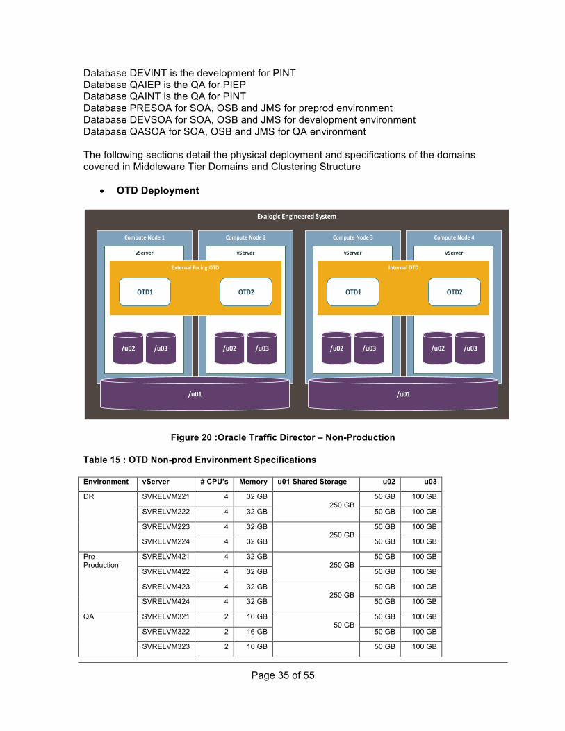
• OTD Deployment
ExalogicEngineeredSystem
ComputeNode1 ComputeNode2
vServer vServer
ExternalFacingOTD
OTD1
/u02 /u03
OTD2
/u02 /u03
/u01
ComputeNode3 ComputeNode4
vServer vServer
InternalOTD
OTD1
/u02 /u03
OTD2
/u02 /u03
/u01
Figure 20 :Oracle Traffic Director – Non-Production
Table 15 : OTD Non-prod Environment Specifications Environment vServer # CPU’s Memory u01 Shared Storage u02 u03
DR SVRELVM221 4 32 GB 250 GB
50 GB 100 GB
SVRELVM222 4 32 GB 50 GB 100 GB
SVRELVM223 4 32 GB 250 GB
50 GB 100 GB
SVRELVM224 4 32 GB 50 GB 100 GB
Pre-Production
SVRELVM421 4 32 GB 250 GB
50 GB 100 GB
SVRELVM422 4 32 GB 50 GB 100 GB
SVRELVM423 4 32 GB 250 GB
50 GB 100 GB
SVRELVM424 4 32 GB 50 GB 100 GB
QA SVRELVM321 2 16 GB 50 GB
50 GB 100 GB
SVRELVM322 2 16 GB 50 GB 100 GB
SVRELVM323 2 16 GB 50 GB 100 GB

Page 36 of 55
SVRELVM324 2 16 GB 50 GB 50 GB 100 GB
Development SVRELVM121 2 16 GB 50 GB
50 GB 100 GB
SVRELVM122 2 16 GB 50 GB 100 GB
SVRELVM123 2 16 GB 50 GB
50 GB 100 GB
SVRELVM124 2 16 GB 50 GB 100 GB
• OSB Deployment
ExalogicEngineeredSystem
ComputeNode1 ComputeNode2 ComputeNode4ComputeNode3
vServer vServer vServer vServer
OSBDomain
AdminServer(7001)
WLS_OSB1
WLS_WSM1
/u02 /u03
AdminServer(7001)
WLS_OSB2
WLS_WSM2
/u02 /u03
/u01
AdminServer(7001)
WLS_OSB1
WLS_WSM1
/u02 /u03
AdminServer(7001)
WLS_OSB2
WLS_WSM2
/u02 /u03
Figure 21: Oracle Service Bus – Non-Production Table 16 : OSB Managed Servers and Clusters Environment Domain Cluster Managed Servers Memory DR prdosbd100 prdosbcl100 prdosbms101 4 GB
prdosbms102 4 GB prdosbms103 4 GB prdosbms104 4 GB
prdwsmcl100 prdwsmms101 4 GB prdwsmms102 4 GB prdwsmms103 4 GB prdwsmms104 4 GB
Pre-Production ppdosbd100 ppdosbcl100 ppdosbms101 4 GB ppdosbms102 4 GB ppdosbms103 4 GB ppdosbms104 4 GB
ppdwsmcl100 ppdwsmms101 4 GB ppdwsmms102 4 GB ppdwsmms103 4 GB ppdwsmms104 4 GB
QA qaosbd100 qaosbcl100 qaosbms101 2 GB qaosbms102 2 GB qaosbms103 2 GB qaosbms104 2 GB
qawsmcl100 qawsmms101 2 GB qawsmms102 2 GB qawsmms103 2 GB qawsmms104 2 GB
Development devosbd100 devosbcl100 devosbms101 2 GB devosbms102 2 GB devosbms103 2 GB

Page 37 of 55
devosbms104 2 GB devwsmcl100 devwsmms101 2 GB
devwsmms102 2 GB devwsmms103 2 GB devwsmms104 2 GB
• SOA Suite Deployment
ExalogicEngineeredSystem
ComputeNodenComputeNodenComputeNoden
ComputeNode1 ComputeNode2 ComputeNode3 ComputeNode4
vServervServer
SOADomain1
AdminServer(7001)
WLS_SOA1
WLS_WSM1
/u02 /u03
AdminServer(7001)
WLS_SOA2
WLS_WSM2
/u02 /u03
WLS_EE1 WLS_EE2
/u01
vServervServer
SOADomain2
AdminServer(7001)
WLS_SOA1
WLS_WSM1
/u02 /u03
AdminServer(7001)
WLS_SOA2
WLS_WSM2
/u02 /u03
WLS_EE1 WLS_EE2
/u01
vServervServer
SOADomain3
AdminServer(7001)
WLS_SOA1
WLS_WSM1
/u02 /u03
AdminServer(7001)
WLS_SOA2
WLS_WSM2
/u02 /u03
WLS_EE1 WLS_EE2
/u01
ComputeNoden
vServer vServer
SOADomain4
AdminServer(7001)
WLS_SOA1
WLS_WSM1
/u02 /u03
AdminServer(7001)
WLS_SOA2
WLS_WSM2
/u02 /u03
WLS_EE1 WLS_EE2
/u01
WLS_ESS1
WLS_MFT1
WLS_ESS2
WLS_MFT2
Figure 22 : SOA Suite Deployment
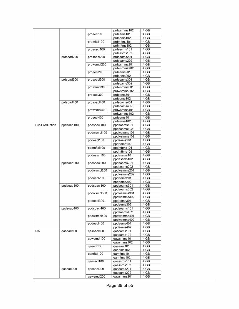
Table 17: SOA Suite Managed Servers and Clusters Specification Environment Domain Cluster Name Managed
Servers Memory
DR prdsoad400 prdsoacl100 prdsoams101 4 GB prdsoams102 4 GB
prdwsmcl100 prdwsmms101 4 GB
Page 38 of 55
prdwsmms102 4 GB prdeecl100 prdeems101 4 GB
prdeems102 4 GB prdmftcl100 prdmftms101 4 GB
prdmftms102 4 GB prdesscl100 prdessms101 4 GB
prdessms102 4 GB prdsoad200 prdsoacl200 prdsoams201 4 GB
prdsoams202 4 GB prdwsmcl200 prdwsmms201 4 GB
prdwsmms202 4 GB prdeecl200 prdeems201 4 GB
prdeems202 4 GB prdsoad300 prdsoacl300 prdsoams301 4 GB
prdsoams302 4 GB prdwsmcl300 prdwsmms301 4 GB
prdwsmms302 4 GB prdeecl300 prdeems301 4 GB
prdeems302 4 GB prdsoad400 prdsoacl400 prdsoams401 4 GB
prdsoams402 4 GB prdwsmcl400 prdwsmms401 4 GB
prdwsmms402 4 GB prdeecl400 prdeems401 4 GB
prdeems402 4 GB Pre-Production ppdsoad100 ppdsoacl100 ppdsoams101 4 GB
ppdsoams102 4 GB ppdwsmcl100 ppdwsmms101 4 GB
ppdwsmms102 4 GB ppdeecl100 ppdeems101 4 GB
ppdeems102 4 GB ppdmftcl100 ppdmftms101 4 GB
ppdmftms102 4 GB ppdesscl100 ppdessms101 4 GB
ppdessms102 4 GB ppdsoad200 ppdsoacl200 ppdsoams201 4 GB
ppdsoams202 4 GB ppdwsmcl200 ppdwsmms201 4 GB
ppdwsmms202 4 GB ppdeecl200 ppdeems201 4 GB
ppdeems202 4 GB ppdsoad300 ppdsoacl300 ppdsoams301 4 GB
ppdsoams302 4 GB ppdwsmcl300 ppdwsmms301 4 GB
ppdwsmms302 4 GB ppdeecl300 ppdeems301 4 GB
ppdeems302 4 GB ppdsoad400 ppdsoacl400 ppdsoams401 4 GB
ppdsoams402 4 GB ppdwsmcl400 ppdwsmms401 4 GB
ppdwsmms402 4 GB ppdeecl400 ppdeems401 4 GB
ppdeems402 4 GB QA qasoad100 qasoacl100 qasoams101 4 GB
qasoams102 4 GB qawsmcl100 qawsmms101 4 GB
qawsmms102 4 GB qaeecl100 qaeems101 4 GB
qaeems102 4 GB qamftcl100 qamftms101 4 GB
qamftms102 4 GB qaesscl100 qaessms101 4 GB
qaessms102 4 GB qasoad200 qasoacl200 qasoams201 4 GB
qasoams202 4 GB qawsmcl200 qawsmms201 4 GB

Page 39 of 55
qawsmms202 4 GB qaeecl200 qaeems201 4 GB
qaeems202 4 GB qasoad300 qasoacl300 qasoams301 4 GB
qasoams302 4 GB qawsmcl300 qawsmms301 4 GB
qawsmms302 4 GB qaeecl300 qaeems301 4 GB
qaeems302 4 GB qasoad400 qasoacl400 qasoams401 4 GB
qasoams402 4 GB qawsmcl400 qawsmms401 4 GB
qawsmms402 4 GB qaeecl400 qaeems401 4 GB
qaeems402 4 GB Development devsoad100 devsoacl100 devsoams101 4 GB
devsoams102 4 GB devwsmcl100 devwsmms101 4 GB
devwsmms102 4 GB deveecl100 deveems101 4 GB
deveems102 4 GB devmftcl100 devmftms101 4 GB
devmftms102 4 GB devesscl100 devessms101 4 GB
devessms102 4 GB devsoad200 devsoacl200 devsoams201 4 GB
devsoams202 4 GB devwsmcl200 devwsmms201 4 GB
devwsmms202 4 GB deveecl200 deveems201 4 GB
deveems202 4 GB devsoad300 devsoacl300 devsoams301 4 GB
devsoams302 4 GB devwsmcl300 devwsmms301 4 GB
devwsmms302 4 GB deveecl300 deveems301 4 GB
deveems302 4 GB devsoad400 devsoacl400 devsoams401 4 GB
devsoams402 4 GB devwsmcl400 devwsmms401 4 GB
devwsmms402 4 GB deveecl400 deveems401 4 GB
deveems402 4 GB Environment Domain Transport
DR prdsoad100 UDP
prdsoad200 UDP
prdsoad300 UDP
prdsoad400 UDP
Pre-Production
ppdsoad100 UDP
ppdsoad200 UDP
ppdsoad300 UDP
ppdsoad400 UDP

Page 40 of 55
QA qasoad100 UDP
qasoad200 UDP
qasoad300 UDP
qasoad400 UDP
Development devsoad100 UDP
devsoad200 UDP
devsoad300 UDP
devsoad400 UDP
Table 18 :Coherence Managed servers and Cluster Specification Environment Domain Cluster Name Clustering
Mode Transport
DR prdsoad100 prdcoherencecl100 Unicast UDP
prdsoad200 prdcoherencecl200 Unicast UDP
prdsoad300 prdcoherencecl300 Unicast UDP
prdsoad400 prdcoherencecl400 Unicast UDP
Pre-Production
ppdsoad100 ppdcoherencecl100 Unicast UDP
ppdsoad200 ppdcoherencecl200 Unicast UDP
ppdsoad300 ppdcoherencecl300 Unicast UDP
ppdsoad400 ppdcoherencecl400 Unicast UDP
QA qasoad100 qacoherencecl100 Unicast UDP
qasoad200 qacoherencecl200 Unicast UDP
qasoad300 qacoherencecl300 Unicast UDP
qasoad400 qacoherencecl400 Unicast UDP
Development devsoad100 devcoherencecl100 Unicast UDP
devsoad200 devcoherencecl200 Unicast UDP
devsoad300 devcoherencecl300 Unicast UDP
devsoad400 devcoherencecl400 Unicast UDP

Page 41 of 55
• BMP Deployment
ExalogicEngineeredSystem
ComputeNode1 ComputeNode2
vServer vServer
BPMDomain
AdminServer(7001)
WLS_BPM1
WLS_ADF1
/u02 /u03
AdminServer(7001)
WLS_BPM2
WLS_ADF2
/u02 /u03
/u01
Figure 23: BMP deployment
Table 19: BMP managed servers and clusters specification Environment Domain Cluster Name Managed
Servers Memory
DR prdbpmd100 prdbpmcl100 prdbpmms101 4 GB prdbpmms102 4 GB
prdadfcl100 prdadfms101 4 GB prdadfms102 4 GB
Pre-Production ppdbpmd100 ppdbpmcl100 ppdbpmms101 4 GB ppdbpmms102 4 GB
ppdadfcl100 ppdadfms101 4 GB ppdadfms102 4 GB
QA qabpmd100 qabpmcl100 qabpmms101 2 GB qabpmms102 2 GB
qaadfcl100 qaadfms101 2 GB qaadfms102 2 GB
Development devbpmd100 devbpmcl100 devbpmms101 2 GB devbpmms102 2 GB

Page 42 of 55
devadfcl100 devadfms101 2 GB devadfms102 2 GB
• JMS Domain
ExalogicEngineeredSystem
ComputeNode1 ComputeNode2 ComputeNode4ComputeNode3
vServer vServer vServer vServer
JMSDomain
AdminServer(7001)
WLS_JMS1
/u02 /u03
AdminServer(7001)
WLS_JMS2
/u02 /u03
/u01
AdminServer(7001)
WLS_JMS3
/u02 /u03
AdminServer(7001)
WLS_JMS4
/u02 /u03
Figure 24: JMS Domain
Table 20: JMS managed servers and clusters specification Environment Domain Cluster Name Managed
Servers Memory
DR prdjmsd100 prdjmscl100 prdjmsms101 4 GB prdjmsms102 4 GB
prdjmscl200 prdjmsms103 4 GB prdjmsms104 4 GB
Pre-Production ppdjmsd100 prdjmscl100 ppdjmsms101 4 GB ppdjmsms102 4 GB
prdjmscl200 ppdjmsms103 4 GB ppdjmsms104 4 GB
QA qajmsd100 prdjmscl100 qajmsms101 2 GB qajmsms102 2 GB
prdjmscl200 qajmsms103 2 GB qajmsms104 2 GB
Development devjmsd100 prdjmscl100 devjmsms101 2 GB devjmsms102 2 GB
prdjmscl200 devjmsms103 2 GB devjmsms104 2 GB

Page 43 of 55
• Non-functional domain ExalogicEngineeredSystem
ComputeNode ComputeNode ComputeNodeComputeNode
vServer vServer vServer vServer
NFDomain
AdminServer(7001)
WLS_EE1
/u02 /u03
AdminServer(7001)
WLS_EE2
/u02 /u03
/u01
AdminServer(7001)
WLS_EE3
/u02 /u03
AdminServer(7001)
WLS_EE4
/u02 /u03
Table 21: Managed Server and Cluster configuration Environment Domain Cluster Name Managed
Servers Memory
DR prdeed100 prdeecl100 prdeems101 4 GB prdeems102 4 GB prdeems103 4 GB prdeems104 4 GB
Pre-Production ppdeed100 ppdeecl100 ppdeems101 4 GB ppdeems102 4 GB ppdeems103 4 GB ppdeems104 4 GB
QA qaeed100 qaeecl100 qaeems101 2 GB qaeems102 2 GB qaeems103 2 GB qaeems104 2 GB
Development deveed100 deveecl100 deveems101 2 GB deveems102 2 GB deveems103 2 GB deveems104 2 GB
2.9 Network Architecture Logical Networks define how the various functional instances within the Exalogic system can be reached either from outside or internally only. These networks will be set up in different VLANs having different IP addresses. The layout will be the same for all environments. Access to applications will be provided via the frontend network. In ESKOM’s Exalogic only the OTD instances will be connected to the frontend network. OTD acts as the load balancer between clients systems and application instances on the Exalogic. Data traffic between application instances will be performed on the internal private application network only. This also applies to network connections between applications on the Exalogic and databases on the Exadata system.

Page 44 of 55
The backend network will be used for administrative purposes (OS configurations, management of applications etc.) Advantages of this design shown in Figure 25 : Exalogic Logical Network: • Inter application traffic will stay within the Exalogic system directly on the
Infiniband network. This traffic will benefit from lower latencies and higher throughput.
• Reduced complexity thru reduced number of network interfaces in application vServers
• Security • Segregation of network traffic
10-GB AccessNetwork
Exalogic virtualized environment
Netwok ServicesDNS, NTP
Exalogic System
Iinfiniband QDR
Ethernet 1 GBit/sEthernet 10 GBit/s
Remote systemsPhysical Components
vServer Groups
Virtualization Layer
vServers
virtual Server
SOA1Exa-Mgmt
Exadata
Frontend Access Network
Exa Mgmt Network
Clients Exa MgmtClients
Private Storage NetworkPrivate App Network
EoIB networks
IPoIB-default NetworkZFS Storage Appliance
Backend Access Network
IB Gateway Switches
Logical Networks
IPoIB Networks
JMS2JMS4
SOA6SOA8OSB2OSB4
SOA4SOA2
OTD2
JMS1JMS3
SOA5SOA7OSB1OSB3
SOA3SOA1
OTD1
EA2EA4
EA1EA3
Figure 25 : Exalogic Logical Network
MegaWatt Park and 141 Sivewright is connected via a WAN connection. Due to bandwidth limitations, cross-site HA is not a viable solution, hence the active-standby architecture. Each of the respective sites has F5 infrastructure to enable load balancing both from the public network as well as the internal network. From a deployment perspective, OTD will be responsible for SSL offloading between the F5 load balancer and the OSB instances for incoming traffic. A different instance OTD will be responsible for internal load balancing between the Oracle Fusion Middleware domains and components. This splits responsibilities and mitigates risk by ensuring

Page 45 of 55
configuration changes on one OTD instance does not impact another, as well as distributing the load between the two instances.
Production/Active–MegaWattPark
F5LoadBalancer
OracleTrafficDirector
BPM SOA JMS NF
DR/Standby–Sivewright
F5LoadBalancer
OracleTrafficDirector
BPM SOA JMS NF
MiddleTier
DiskStorage
ZFS ZFSZFS
DBHost1
DBHost2
DBHost3
DBHost4
DataTier
Database DatabaseDatabase
DiskStorage
ZFS ZFSZFS
DBHost1
DBHost2
DBHost3
DBHost4
Database DatabaseDatabase
ZFSReplication
DataGaurdReplication
EnterpriseApplications
OracleTrafficDirector
OSB
OracleTrafficDirector
OSB
Figure 26: Central Network Architecture
Table 22: Load Balancer Configuration Load balancer Target Host Protocol F5 Internal OTD HTTPS F5 Internal OTD HTTP OTD OSB HTTP OTD SOA HTTP OTD SOA HTTP

Page 46 of 55
OTD SOA HTTP OTD SOA HTTP OTD EE HTTP OTD EE HTTP OTD EE HTTP OTD EE HTTP OTD MFT HTTP OTD MFT HTTP OTD MFT HTTP OTD MFT HTTP OTD ESS HTTP OTD ESS HTTP OTD ESS HTTP OTD ESS HTTP OTD JMS T3 OTD NF HTTP OTD BPM HTTP OTD ADF HTTP As part of the network architecture we deployed Virtual IP’s to enable Admin server failover for all domains. Weblogic managed servers bind and connect to the Admin server on a pre-configured address, so in order for failover to work, the Admin address cannot change when moving between different hosts. This is achieved by binding the host that is hosting the Admin server to the Virtual IP assigned to the Admin server. Table 23: Virtual IP Configuration Environment Servers Production Admin
Admin Admin Admin Admin Admin Admin Admin
DR Admin Admin Admin Admin Admin Admin Admin Admin
Pre-Production Admin Admin Admin Admin Admin

Page 47 of 55
Admin Admin Admin
QA Admin Admin Admin Admin Admin Admin Admin Admin
Development Admin Admin Admin Admin Admin Admin Admin Admin
2.10 Security Architecture The Figure 27: Security Architecture of EIP depicts high level security architecture and all the paths that will be secured
• – When applications outside of the integration platform needs to communicate with the integration layer, communication will happen via the F5 and all communication will be secured using SSL. The application will also provide HTTP basic credentials that will be passed to the Oracle Fusion Middleware layer, where the Weblogic embedded LDAP store will be used to store these credentials.
• – The F5 will load balance the OTD instances using SSL. All communication into the Exa machines needs to be secured using SSL.
• – OTD will load balance both inbound and internal component traffic. The internal traffic will not be secured using SSL as it happens over a secured Infiniband connection, is a separate instance to the external facing one, and is local to the Exalogic.
• (4a) – Operational resources need to login to the vServers via SSH. They will have to authenticate using username and password. Local usernames and passwords will be used, although the option of doing Active Directory or LDAP authentication will be done during the implementation phase.

Page 48 of 55
• (4b) – When operational resources logs into the Weblogic console, they will provide their Active Directory credentials. Weblogic will be configured to authenticate against Active Directory for non-system accounts.
• – Connections to the integration databases will happen via Infiniband and thus no additional security is required.
• – Credentials to connect to the database will be stored within the Weblogic JDBC configuration files. All these credentials will be encrypted using a unique encryption key per domain.
• – Outbound communication to backend systems, like Maximo, will be handled by OSB. If communication to the backend system needs to be secured, the certificates will be stored within the OSB Weblogic keystore. Because the OSB instances are listening for incoming communications on the local Exalogic Infiniband network, this approach does not pose a security thread as OSB will not be reachable from outside the Exalogic.

Page 49 of 55
Exalogic
F5LoadBalancer
vServer
OTD
(2)EnterpriseApplications
(1)
vServer vServer vServer
FMW FMW FMW
(3) (3)
(3)OperationalPerson
(4a)
(4b)
Exadata
vServer vServer vServer
DB DB DB
InfinibandNetwork
(5)
(6)
ActiveDirectory
(4b)
EnterpriseApplications
(7)
Figure 27: Security Architecture of EIP
The following table can be used as a security matrix when trying to determine if security will be applied and how. Connection Method Secured Technologies Inbound Application connectivity
Y • OTD SSL Offloading • HTTP Basic
Authentication • Weblogic embedded
LDAP SSH to vServers Y • Username & Password
• Active Directory Weblogic console login Y • Username & Password
• Weblogic embedded LDAP
• Active Directory OTD Internal Routing Y • Infiniband Secured

Page 50 of 55
Network Database Connectivity Y • Encrypted Uername &
Password • Infiniband Secured
Network OSB Outbound Connectivity Y • SSL
• Certificates imported to keystore
2.10.1 Transport Layer Security As part of the network architecture, both F5 and OTD will be deployed and utilized within the environment. Each of these components have the ability to do SSL offloading and on boarding depending on the requirements. From a security perspective all communication into the integration landscape needs to be secured using SSL. OTD will do SSL offloading and pass unencrypted communication to the OSB instances. All inter-component communication within the Exa engineered systems does not need to be secured as the Infiniband is already secure and no packets can be sniffed from outside the Exa systems. As part of the deployment process, custom keystores will be deployed to store server and client certificates. Weblogic will need a trust store if outbound communication to a backend system needs to be secured with SSL.
2.10.2 File System Security The Oracles Enterprise deployment guides suggests to create 3 mount points. As a result the oracle user owns all three mount points. In order to manage this effectively without the need to use the oracle user the following groups need to be created and assigned to each mount point to be able to administrate the different mount points. A default user “oracle” belongs to default group “oinstall”. This user owns all installed technology and mount points /u01, /u02 and /u03. This user should not be used to login and SSH. This “oracle” user is a local user to each vServer.
Table 24: File system security groups
Groups Mount Comments
Group 1 /u03 and /u02 Used to administrate the Managed Servers and logging.
Group 2 /u03 Used to administrate logging.
oinstall /u01,/u02 and /u03
Default created group. Must only be assigned to administrator with full access.

Page 51 of 55
2.10.3 EIP Global Access Roles The Table 25 : EIP Access Roles details the global roles that WebLogic Server defines in the security realm that it installs. The table also summarizes the access that the default security policies grant to each role and indicates which groups are in each role by default.
Table 25 : EIP Access Roles Global Role Default Policies Grant Access To… Default Conditions
Include This Group…
Admin • View the
server configuration, including the encrypted value of some encrypted attributes.
• Modify the entire server configuration.
• Deploy Enterprise Applications and Web application, EJB, Java EE Connector, and Web Service modules.
• Start, resume, and stop servers.
Administrators
AdminChannelUser Access the administrative channel, AdminChannel AdminChannelUsers, Administrators, Deployers, Operators, Monitors, and AppTesters
Anonymous All users (the group everyone) are granted this global role. Everyone
Deployer • View the
server configuration, including some encrypted attributes related to deployment activities.
• Change startup and shutdown classes, Web applications, JDBC data pool connections, EJB, Java EE Connector, Web Service, and WebLogic Tuxedo Connector components. If applicable, edit deployment descriptors.
• Access deployment operations in the Java EE Deployment Implementation (JSR-88)
Deployers
Operator • View the
server configuration, except for encrypted attributes.
• Start, resume, and stop servers.
Operators
Monitor View the server configuration, except for encrypted Monitors

Page 52 of 55
attributes.
This security role effectively provides read-only access to the WebLogic Server Administration Console, WLST, and MBean APIs.
AppTester Access applications for testing purposes that are running in Administration mode.
AppTesters
CrossDomainConnector Make inter-domain calls from foreign domains. CrossDomainConnectors
OracleSystemRole Assert identity on behalf of users whose WS-Security tokens have been authenticated.
Note: This global role is provided for use by Oracle Web Services Manager.
OracleSystemGroup
3 High Availability and Disaster Recovery From a physical resource mapping perspective, all domains will be deployed across at least two different compute nodes. This approach ensures that we achieve a highly-available architecture in conjunction with Weblogic clustering, if we lose one vServer or even a complete compute node, part of the cluster will continue running on the other compute node.
Another vital part of the architecture is to ensure we have sufficient capacity on each of the compute nodes to facilitate vServer migration in the event of compute node failure. Using the ¼ Rack Exalogic configuration, which have eight compute nodes, we need sufficient capacity if we lose a compute node to migrate all the vServers hosted on that compute node to the other seven compute nodes. The Figure 28: High Availability Architecture provides an illustration of the vServer migration concept we just discussed

Page 53 of 55
ExalogicEngineeredHardware
ComputeNode1 ComputeNode2 ComputeNoden
vServer
vServer
vServer vServer
vServer vServer
vServer vServer
Figure 28: High Availability Architecture Disaster Recovery will be achieved by replicating production, and during the sizing phase it was decided that DR needs to be capable to handle a 100% of the Eskom current work load while production needs to be capable to handle 200% of the current work load. This explains the sizing difference between the 2 environments. From an Oracle Fusion Middleware perspective, DR is achieved by replicating the ZFS file stores over to the DR site. These file stores contain all the configuration information required reproduce the Production configuration. The vServers provisioned within the DR site will then mount the relevant ZFS storage units. From a replication perspective all the relevant information will be there to start the domain. However, due to the sizing differences between production and DR in the number of vServers that can be hosted, due to the difference in the amount of compute nodes, not all of the (multiply redundant) managed servers of each domain will be started. Note: Special care should be taken when scaling clusters horizontally with managed servers that will never be started on DR. Applications should never be pointed to a managed server alone (singleton services) that will not be started on DR. Database replication happens on a data store level and the amount of RAC Nodes within the cluster bears no effect on how DataGuard replication happens. The Figure 29: Example DR Scenario for a Domain details the DR scenarios in more detail. For illustration purposes we are only showing one domain and one database.

Page 54 of 55
ExaLogic¼Rack
ExaData½Rack
ExaLogic1/8thRack
ExaData¼Rack
MegaWattPark 141
DataGuardReplication
vServer vServer vServer vServer
Domain
WLS WLS WLS WLS
ZFS ZFSZFS
vServer vServer
Domain
WLS WLS WLS WLS
ZFS ZFSZFS
ZFSReplication
vServer vServer vServer vServervServer
OracleRealApplicationCluster
RACInstance2
RACInstance3
RACInstance4
RACInstance5
DatabaseStorage
vServer vServer vServer
OracleRealApplicationCluster
RACInstance1
RACInstance2
RACInstance3
DatabaseStorage
RACInstance1
Figure 29: Example DR Scenario for a Domain
4 Oracle Platinum Services Architecture The design of the platinum services gate way is detailed in the OASG platform design document. The only change to the design is the implementation of a phone home service for the storage infrastructure.
5 EIP Platform Tests TestDomain DescriptionExalogic Powercyclecomputenodes-gracefulandungraceful Physicalhardwaretests-rack,power,disk,network Infinibandswitchrestart ZFSstoragetests

Page 55 of 55
Exadata Powercyclecomputenodes-gracefulandungraceful-OVM,OVS,ILOM Physicalhardwaretests-rack,power,disk,network Infinibandswitchrestart Storagecellrestarts Database Coreprocessrestart Replicationtest Individualsolutionverification Fullsitefailover OracleTrafficDirector Failoverofexternalinstances Failoverofinternalinstances OracleFusionMiddleware FailoverofOSBinstances FailoverofSOA1-4instances FailoverofJMSinstances FailoverofNFinstances Security FailureofnetIQagentsfromExalogic FailureofnetIQagentsfromExadata WebLogicLDAPtesting Performance OracleFusionMiddlewarePlatform Solution-V-Model