Embed Size (px)
Citation preview

Project Final Report Internet Ready Refrigerator Inventory Control System
Project Final Report Internet Ready Refrigerator Inventory Control System
April 25, 2006
Dustin Graves, [email protected]
Project Abstract Appliance vendors have started producing internet enabled refrigerators which allow
users to keep track of refrigerator inventory, leave notes and video messages for other
users, browse the internet for recipes, and set custom background images for the touch
screen display. Inventory management for such devices requires that the user manually
enter all product information through a touch screen interface. The internet enabled
refrigerator does not appear to provide more functionality than a standard personal
computer and seems to be nothing more than a very expensive docking station for a tablet
PC. The purpose of this project is to create an internet ready refrigerator control system
with a Z8 Encore! microcontroller. The microcontroller is responsible for reading UPC
data from a barcode scanner, reading temperature data from two I2C sensors, sending
speech data to a speech synthesizer, and transmitting data to a PC through a RS-232
interface. A PC application is responsible for connecting to the internet to retrieve
product data associated with each UPC code, sending speech data to the microcontroller,
and making temperature data and UPC data available through a simple web server.
Status The final project implementation provides all functionality specified by the project
proposal. Some modification to the initial project design was required to facilitate a
simpler project implementation. The two major design changes involved the addition of
a hardware component for text to speech conversion and the replacement of analog
temperature sensors with I2C temperature sensors.
The addition of the text to speech hardware was made to simplify the process for
converting ASCII text phrases to allophones for speech synthesis. Algorithms for fully
functional text to speech conversion require complicated software implementations. The
Dustin Graves Page 1 4/25/2006

Project Final Report Internet Ready Refrigerator Inventory Control System
addition of the text to speech hardware provides a simple method for ASCII text to
allophone conversion, avoiding a complex and lengthy process of software development.
The substitution of I2C temperature sensors for analog temperature sensors was
made because the only temperature sensors that could be found with DIP packaging were
I2C thermostat temperature sensors manufactured by Dallas Semiconductor. There were
no technical reasons behind the substitution. The substitution was simply made because
DIP sensors are easier to prototype with than surface mount sensors as they can be added
to a solderless breadboard.
Implementation and Construction The Internet Ready Refrigerator Inventory Control System combines functionality from a
laptop computer and a Z8 Encore! microcontroller outfitted with various peripheral
devices to track the contents and monitor the status of a common household refrigerator.
The microcontroller makes use of a barcode scanner to read UPC product codes and
transmits the code to the laptop computer which connects to an on-line database to
determine the name of the product specified by the UPC code. The name of the product,
total number of products scanned, and the UPC code for the product are stored by the
laptop computer with a database whose contents can be transmitted to the Z8 upon
command. The Z8 is capable of speaking the name and total number of each item
through a SpeakJet sound synthesizer. Text to SpeakJet code conversion is performed by
a TTS256 text to code IC. Two DS1631 temperature sensors are employed to monitor
the temperature of the refrigerator and freezer. The personal computer makes the
refrigerator inventory and temperature data available to other computers with a web page.
Hardware The project design includes five main hardware components consisting of a Z8 Encore!
microcontroller development kit, a PS/2 CueCat barcode scanner, a SpeakJet sound
synthesizer, a TTS256 text to code IC for the SpeakJet, and a pair of DS1631 high-
precision digital thermometers.
The hardware peripherals are controlled by the microcontroller. The capabilities
of the microcontroller required for peripheral control are UART0, UART1, TIMER0, the
Dustin Graves Page 2 4/25/2006

Project Final Report Internet Ready Refrigerator Inventory Control System
three integrated buttons, the I2C controller, and six interrupt enabled GPIO pins. UART0
provides microcontroller to PC communication. UART1 provides microcontroller to
TTS256 communication. TIMER0 is used to schedule LED display updates, button state
polling, button state debouncing, and SpeakJet status monitoring. Buttons PD3, PF6,
and PF7 are used to select system modes for product entry, product removal, and system
status report. The I2C controller provides microcontroller and DS1631 temperature
sensor interaction. GPIO pins PD0 and PD1 are used to reset the SpeakJet and TTS256.
GPIO pins PC0 and PC1 monitor the SpeakJet Speaking and Ready status pins. GPIO
pins PA0 and PA1 monitor the CueCat clock and data lines.
Barcode Scanner
Speech Processor
Internet
Refrigerator
Temp. Sensor 2
Temp. Sensor 1
I2C/GPIO
Speech Synthesizer
Personal
Computer
RS 232
Z8F6403
Microcontroller
UART0UART1
Figure 1 – General Hardware Block Diagram
The PS/2 CueCat barcode scanner has four pins to be connected with the Z8
microcontroller. The CueCat ground pin must be connected to a ground pin, the CueCat
power pin must be connected to a 5V pin, the CueCat clock pin must be connected to
PA0, and the CueCat data pin must be connected to PA1. Both PA0 and PA1 must be
configured for open drain mode and 10k pull-up resistors must be placed between the 5V
power line and the clock and data lines. PA0 must have its interrupt enabled and
configured for generation on the falling edge. PA1 has its interrupt disabled as its input
state is passively sampled at each PA0 interrupt generation.
The SpeakJet and TTS256 ICs have multiple pins that must be connected with
each other and with the microcontroller. The SpeakJet has eighteen pins which all must
Dustin Graves Page 3 4/25/2006

Project Final Report Internet Ready Refrigerator Inventory Control System
be connected. SpeakJet pins one through nine are connected to ground. SpeakJet pin ten
is connected to the TTS256 transmit pin. SpeakJet pin 11 is connected to PD0 for IC
reset. SpeakJet pin twelve is connected to power through a 10k resistor and SpeakJet pin
thirteen is connected to ground for normal operation. SpeakJet pin 14 is connected to 5V
power. SpeakJet pin 15 is connected to the TTS256 flow control pin. SpeakJet pins 16
and 17 are connected to PC0 and PC1 to monitor the speaking and ready status pins. The
dual-edge interrupts are enabled for both PC0 and PC1 so that a Boolean status variable
can be toggled on state change. SpeakJet Pin 18 is connected to a 1/8” stereo phone jack
for connection with an external speaker. The TTS256 has 28 pins with seven that must
be connected. TTS256 pin 5 is connected to PD4 which is configured for alternate
function mode as the UART1 RX pin. TTS256 pin 14 is connected to ground. TTS256
pin 18 is connected to PD5 which is configured for alternate function mode as the
UART1 TX pin. TTS256 pin 9 is connected to PD1 for IC reset. TTS256 pin 20 is
connected to the SpeakJet buffer half full pin which is pin 15. TTS256 pin 24 is
connected to the SpeakJet RX pin which is pin 10. TTS256 pin 28 is connected to 5V
power.
Figure 2 – Connection Diagram for 5V Devices
The two DS1631 temperature sensors have 7 pins that must be connected.
DS1631 pins one and two are connected to PA7 and PA6. Both PA7 and PA6 must be
Dustin Graves Page 4 4/25/2006
Project Final Report Internet Ready Refrigerator Inventory Control System
configured for alternate function mode as SDA and SCL for the I2C controller. PA7 and
PA6 must also be configured for open drain mode and 10K pull-up resistors must be
placed between the 3.3V power line and the SDA and SCL lines. DS1631 pin 4 is
connected to ground. DS1631 pins 5, 6, and 7 are connected to 3.3V power for the first
temperature sensor and are connected to ground for the second temperature sensor.
DS1631 pin 8 is connected to 3.3V power.
Figure 3 – Connection Diagram Temperature Sensors
The Z8 Encore! microcontroller console port P1 is connected to the PC with a
DB9 RS-232 cable. UART0 is enabled for serial communication with the PC through P1.
Decoupling capacitors are also placed between the ground and both the 3.3V and 5V
power lines that are connected with the hardware peripherals to decouple the DC power
passing to each peripheral.
Software System software consists of two main modules. The microcontroller module provides
peripheral control through software drivers and PC communication through a serial
interface. The PC module provides inventory management trough a simple database, web
based communication through a simple HTTP implementation, and microcontroller
communication through a serial interface.
Dustin Graves Page 5 4/25/2006
Project Final Report Internet Ready Refrigerator Inventory Control System
Peripheral Manager
Button Manager
LED Manager
TIMER0 Interrupt Handler
Button Inputs
Comm Manager
UART0 Interrupt Handler
RS-232 Console Port – P1
TIMER0 Interrupt Handler
Display Driver
TIMER0 Interrupt Handler
Temp Sensors
Speech Synthesizer
Barcode Scanner
GPIO Interrupt Handle
Figure 4 – Microcontroller Software Block Diagram
The microcontroller module implements a simple round robin with interrupts
system control structure with sub-modules that define drivers for each peripheral and a
serial communication protocol for exchanging peripheral data with the PC. It consists of
modules to manage the integrated buttons, LED display, SpeakJet/TTS256, CueCat, and
DS1631 temperature sensors. The two main modules are the SpeakJet/TTS256 module
and the CueCat module.
The button and LED modules are simple software components developed to
control the integrated hardware components of the microcontroller. The button module
provides a method for polling button state with debouncing. TIMER0 is employed to
signal that the main loop should test the button state every four milliseconds. If the
button state remains changed for five consecutive tests, the state is considered changed
and the action associated with the button is executed. The LED module provides
functionality to constantly refresh the display with uniform and consistent brightness.
The rows of each LED array are updated incrementally. The character to display with the
Dustin Graves Page 6 4/25/2006

Project Final Report Internet Ready Refrigerator Inventory Control System
LED array is first selected. A value indicating the current row is then incremented and
the current row is enabled. An update for current row value is scheduled by TIMER0,
and executed by the main loop, with a one millisecond rate. The LED module also
provides functionality for text scrolling by providing a queue for character storage.
TIMER0 is used to signal that the main loop should shift a character from the queue to
the LED array every 250 milliseconds.
The SpeakJet/TTS256 module provides functionality to monitor and control both
the SpeakJet sound synthesizer and the TTS256 text to code IC. Monitoring of the
SpeakJet ready and speaking status pins is performed by interrupt service routines
associated with the PC0 and PC1 GPIO pins. At each interrupt, a value indicating
speaking and ready state is set equal to the PC0 and PC1 input register state. The state is
set to true if the input register contains a one and the state is set to false if the input
register contains a zero. The SpeakJet and the TTS256 are reset by toggling the states of
the PD0 and PD1 output registers. PD0 is set to zero and then to one to reset the
SpeakJet, and PD1 is set to one and then to zero to reset the TTS256. A delay produced
by a ‘for loop’ consisting of 512 iterations is placed between the state transitions for the
SpeakJet and TTS256 reset. UART1 is used to exchange data with the TTS256. ASCII
strings are transmitted to the TTS256 for text to SpeakJet allophone code conversion.
Data is only transmitted if the SpeakJet is not active. If the SpeakJet is active, the
module will wait for the speaking state to indicate false before transmitting the new data.
A carriage return is used to signal that the TTS256 should begin text to code conversion.
The TTS256 will automatically begin text to code conversion if its 256 byte buffer
becomes full. To prevent automatic conversion from occurring, the module implements a
128 byte (127 characters and 1 carriage return) limit for each data segment transmitted to
the TTS256. Each allophone transmitted from the TTS256 to the SpeakJet is also
transmitted to the microcontroller. The module provides functionality to enable the
UART1 RX interrupt and specify a callback to be invoked by the interrupt service routine
that provides the byte received to the main loop for possible display or transmission to
the PC. The current system ignores data received from the TTS256.
The CueCat module provides a simple implementation of the PS/2 protocol to
receive and interpret PS/2 key codes. Monitoring of the CueCat clock line is performed
Dustin Graves Page 7 4/25/2006
Project Final Report Internet Ready Refrigerator Inventory Control System
by an interrupt service routine that is associated with PA0. At each interrupt, the value of
the PA1 input register is read and interpreted for PS/2 key code construction. Each key
code is transmitted as a ten bit value with one bit received at each clock. The first bit is
the start bit which indicates that the module should set the key code variable to 0. The
next eight bits represent the actual key code. When each bit is received it is shifted into
the key code variable. A parity counter is incremented if the bit is equal to one. The
ninth bit is the parity bit which is checked with the parity counter to test for a
transmission error. The tenth bit is the stop bit which indicates that the module should
process the new key code. Complete key values are transmitted as three byte values. The
first byte indicates a key press and contains the actual value for the key pressed. The
second byte is a break code which indicates key release, and is followed by the key code
for the key that has been released. The module ignores the key release break and key
code pair for all key codes except the ALT key code. Each character of the barcode
transmitted by the CueCat is represented by a three digit code with the key code for each
digit represented as a number from the keypad. First the key code for an ALT key press
is received. This is followed by three key codes from the keypad. The ALT key release
is then received to signify end of character. The three keypad values received while ALT
is active are to be interpreted as the decimal value of an ASCII character. The module
creates the ASCII character code with the equation key1 * 100 + key2 * 10 + key3. With
this system for ASCII character specification, the only key codes sent by the CueCat, and
supported by the CueCat module, are ALT, KP_0 through KP_9, and ENTER. Each
ASCII character received is placed at the end of a queue containing barcode data. When
the module receives an ENTER key code, it provides the barcode data contained by the
queue to the main program through a callback that was specified at module initialization.
The DS1631 module provides a simple I2C implementation with support for basic
DS1631 configuration and for DS1631 temperature retrieval. The initialization
functionality provided by the module transmits a code to the DS1631 specifying
continuous 12-bit conversion mode and transmits the initial temperature conversion start
code. The temperature retrieval functionality reads a 12-bit temperature value from the
DS1631. The 12-bit temperature value is shifted four bits to the right and multiplied with
0.0625 to obtain a floating point temperature represented with the Centigrade temperature
Dustin Graves Page 8 4/25/2006

Project Final Report Internet Ready Refrigerator Inventory Control System
scale. The initialization and temperature retrieval functions require a single argument
specifying the address of the temperature sensor with which to communicate through the
I2C bus. The main program assumes the existence of two temperature sensors, with the
address pins for the first temperature sensor all set high and the address pins for the
second temperature sensor all set low.
The main program consists of a function to process barcode data received from
the CueCat, a function to process data received from the PC through UART0, a timer to
schedule button and LED tasks, and a main loop to process button and LED tasks. When
the CueCat function is invoked, the contents of a queue containing barcode data are
transferred to the PC for database addition and to a scrolling display queue to be scrolled
across the LED array. One byte from the scrolling display queue is shifted to the LED
array every 250 milliseconds. Four blank space characters are always added to the end of
the queue after the barcode data to ensure that the display is cleared. The UART0 RX
function receives data sets from the PC and processes each data set based on data set
type. Three major data set types are received from the PC. The first is a request for
temperature which causes the microcontroller to retrieve the temperatures from the two
temperature sensors and transmit them to the PC. The second is a clear to send speech
data request which causes the microcontroller to transmit a ready to send speech data
response to the PC when the SpeakJet state is inactive. The third data set type is a speech
data set which provides ASCII data to be transmitted to the TTS256. The main loop tests
the states of each button and updates the LED display when signaled by TIMER0. When
button one is pressed the microcontroller enters a “scan product to add” state and enables
the CueCat. If the button is pressed a second time, before barcode data is received from
the CueCat, the microcontroller returns to the idle state. When button two is pressed the
microcontroller enters a “scan product to remove” state and enables the CueCat. If the
button is pressed a second time, before barcode data is received from the CueCat, the
microcontroller returns to the idle state. When button three is pressed the microcontroller
enters a status report mode where it speaks and displays the temperature values received
from the two temperature sensors and speaks the product database contents received from
the PC. Product database contents are received from the PC after the microcontroller
sends a request for data to the PC when button three is pressed. LED updates are
Dustin Graves Page 9 4/25/2006
Project Final Report Internet Ready Refrigerator Inventory Control System
performed based on the current state of the microcontroller. When the microcontroller is
set to “scan product to add” or “scan product to remove” the LED is set to display the
word “SCAN”. When the microcontroller is speaking the value of each temperature
sensor, the LED display will also display the value of each temperature sensor. If the
scrolling display is not empty, the contents of the queue will be scrolled across the LED
array with each character shifted to the left every 250 milliseconds.
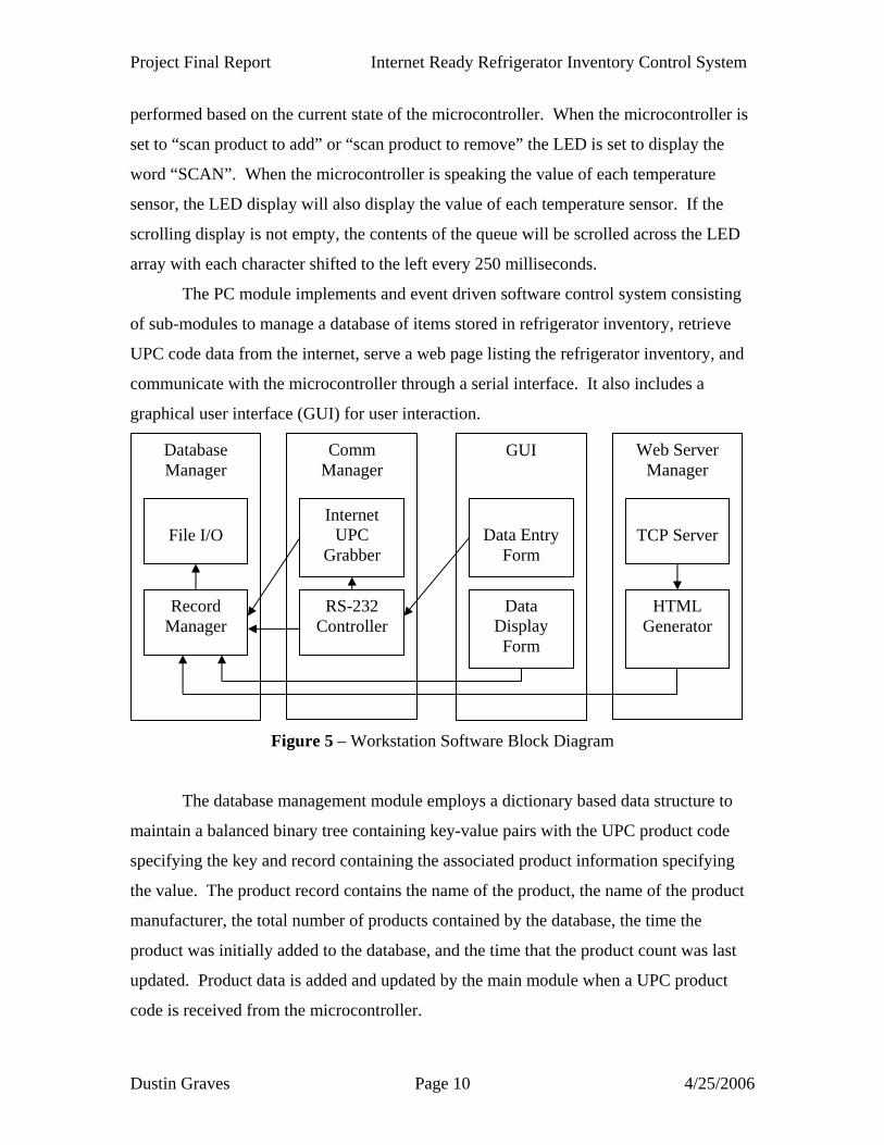
The PC module implements and event driven software control system consisting
of sub-modules to manage a database of items stored in refrigerator inventory, retrieve
UPC code data from the internet, serve a web page listing the refrigerator inventory, and
communicate with the microcontroller through a serial interface. It also includes a
graphical user interface (GUI) for user interaction.
Database Manager
Comm Manager
GUI
File I/O
Record Manager
Internet UPC
Grabber
RS-232 Controller
Web Server Manager
TCP Server
HTML Generator
Data Entry
Form
Data Display Form
Figure 5 – Workstation Software Block Diagram
The database management module employs a dictionary based data structure to
maintain a balanced binary tree containing key-value pairs with the UPC product code
specifying the key and record containing the associated product information specifying
the value. The product record contains the name of the product, the name of the product
manufacturer, the total number of products contained by the database, the time the
product was initially added to the database, and the time that the product count was last
updated. Product data is added and updated by the main module when a UPC product
code is received from the microcontroller.
Dustin Graves Page 10 4/25/2006
Project Final Report Internet Ready Refrigerator Inventory Control System
The UPC data retrieval module provides functionality to retrieve the name of the
product and product manufacturer for a specific UPC code from a free on-line UPC
database. The on-line database is available from an HTTP server accessible from the
http://www.upcdatabase.com URL. The module establishes a connection to the on-line
UPC data base and transmits a simple HTTP GET request which requests information for
a specific UPC code. After transmitting the request, the module reads the HTML data
provided from the server as a response to the request. Regular expressions are used to
extract the product name and manufacturer name from the received HTML data. The
product name and manufacturer data is provided to the main program for addition to the
product database.
The WWW server module creates a TCP server socket that waits for remote
connections. When a connection is received, the module reads the HTTP get request
from the peer. The module then sends formatted HTML data containing the temperatures
read from the two DS1631 temperature sensors and the contents of the product database.
The module contains an HTML template that is used to create the data to be transmitted
by placing the temperature and product data at pre-specified template positions.
The serial communication module communicates with the microcontroller. The
module is mainly responsible for reading temperature data from the microcontroller,
sending speech data to the microcontroller, and processing UPC data received from the
microcontroller. The module employs a one second timer to query the microcontroller
for temperature data. Temperature data received from the microcontroller is compared to
a user defined temperature threshold. If the temperature exceeds the threshold the
module transmits a sound effect code to the microcontroller to make the SpeakJet
generate the “red alert” alarm sound, followed by user defined speech data to announce
that the temperature exceeds normal operating temperature. The default warning
message provided by the module is: “Warning temperature exceeds nominal.” When
speech data is available for transmission to the microcontroller, the module transmits a
ready to send code to the microcontroller. When the microcontroller responds with a
clear to send code, speech data is transmitted to the microcontroller. Speech data is
transmitted as 128 byte blocks. The module repeats the speech data transmission process
until the speech data buffer is empty. When the module receives an add product or
Dustin Graves Page 11 4/25/2006
Project Final Report Internet Ready Refrigerator Inventory Control System
remove product code from the microcontroller, it waits for either a string specifying the
UPC code received by the microcontroller or a cancel code. When the UPC code is
received, the module provides the data to the UPC data retrieval module which will
retrieve product information from the on-line database. When the module receives a
status request code from the microcontroller, speech data describing the contents of the
product database is added to the speech data buffer for transmission to the
microcontroller.
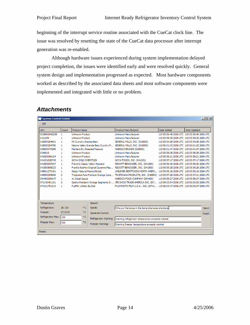
The GUI component of the PC software module provides an interface for user
interaction. The GUI allows the user to specify individual warning messages to be
transmitted to the microcontroller when either of the temperature sensors reports a
temperature that exceeds the normal operating temperature. The GUI also allows the user
to specify two values representing the normal operating temperature for each temperature
sensor. A list describing the products contained by the product database provides the
user with detailed knowledge of the refrigerator inventory.
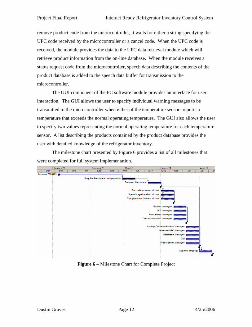
The milestone chart presented by Figure 6 provides a list of all milestones that
were completed for full system implementation.
Figure 6 – Milestone Chart for Complete Project
Dustin Graves Page 12 4/25/2006

Project Final Report Internet Ready Refrigerator Inventory Control System
Retrospective The most important design decisions made for the project involved the selection of
hardware components to replace complicated software modules. The main hardware
component selected for software replacement was the TTS256 text to SpeakJet code IC.
Addition of this component greatly simplified the process for text to speech conversion.
Although addition of the TTS256 reduced the required amount of software
development, it increased the required amount of hardware debugging. The TTS256 does
not have an official data sheet. Connection information for the TTS256 is available from
the vendor website. Information for general use and communication with the TTS256
must be gathered from the SpeakJet Yahoo! Group. The part number for the Cypress
chip used by the TTS256 is printed on the top of the package and was used to locate the
corresponding data sheet, providing important information regarding the chip reset pin
and voltage levels.
Time spent debugging general hardware problems could have been reduced with
better hardware techniques and careful reading of data sheets. Initial implementations of
the SpeakJet/TTS256 hardware experienced constant reset. The SpeakJet operated
correctly without the TTS256 and experienced problems when operating with the
TTS256. Adding a decoupling capacitor between the power and ground lines resolved
the problem. Initial attempts to debug the problem involved software modification to test
different aspects of the hardware. The debugging process could have been accelerated
with the use of an oscilloscope to monitor the voltage levels specified to the SpeakJet and
TTS256 ICs. SpeakJet pin 12 for baud rate configuration is also intended to be connected
to power with a 10K resistor for normal operation. This pin was initially connected
directly to power, which could have contributed to the reset issue encountered by the
SpeakJet and TTS256. The pin 12 connection issue could have been avoided with a more
careful reading of the SpeakJet data sheet.
Problems experienced when disabling and re-enabling interrupt generation for the
CueCat clock line were caused by an issue with the interrupt controller. When the
interrupt was re-enabled, a spurious interrupt was generated. This caused the CueCat
driver to enter a bad state and stop processing data correctly. The cause of the problem
was initially discovered through a debugging process where breakpoints were set at the
Dustin Graves Page 13 4/25/2006
Project Final Report Internet Ready Refrigerator Inventory Control System
beginning of the interrupt service routine associated with the CueCat clock line. The
issue was resolved by resetting the state of the CueCat data processor after interrupt
generation was re-enabled.
Although hardware issues experienced during system implementation delayed
project completion, the issues were identified early and were resolved quickly. General
system design and implementation progressed as expected. Most hardware components
worked as described by the associated data sheets and most software components were
implemented and integrated with little or no problem.
Attachments
Dustin Graves Page 14 4/25/2006

Project Final Report Internet Ready Refrigerator Inventory Control System
Dustin Graves Page 15 4/25/2006

Project Final Report Internet Ready Refrigerator Inventory Control System
Dustin Graves Page 16 4/25/2006