Embed Size (px)
Citation preview

PROJECT FINAL REPORT
(2.nd draft)
Grant Agreement number: 249800
Project acronym: SUNSTORE 4
Project title: Innovative, multi-applicable and cost efficient hybrid solar (55 %) and biomass en-ergy (45 %) large scale (district) heating system with long term heat storage – and Organic Ran-kine Cycle electricity production.
Funding Scheme: Seventh Framework Programme. Theme 5. Energy
Period covered: From 01.07.2010 to 30.06.2014.
Name of the scientific representative of the project's co-ordinator, Title and Organisation: Lasse Kjaergaard (manager) and Niels Aage Jensen (chairman of the board), Marstal Fjernvarme.
Tel: +45 6253 1564
Fax: +45 6253 2564
E-mail: [email protected]
Project website address: www.sunstore4.eu
“This project has received funding from the European Union’s Seventh Framework Pro-gramme for research, technological development and demonstration under grant agreement no 249800”.

The Consortium: Marstal Fjernvarme www.solarmarstal.dk Lasse Kjærgaard Larsen [email protected] Ph.: +45 6253 1564
Advansor www.advansor.dk Jacob Nielsen [email protected] Ph.: +45 2629 2919
Ambiente Italia www.ambienteitalia.it Riccardo Battisti [email protected] Ph.: +39 022 77 441
Bios Bioenergisysteme www.bios-bioenergy.at Alfred Hammerschmid [email protected] Ph.: +43 (316) 481 300-72
AF-CityPlan www.af-cityplan.cz Matej Malu [email protected] Ph.: +420 261 393 330
Energy Management www.energy-management.se Jan-Olof Dalenbäck [email protected] Ph.: +46 31 772 1153
Euroheat & Power www.euroheat.org Nicolas Février [email protected] Ph.: +32 (0)2 7402 110 Euro Therm A/S www.eurotherm.dk Jan Depenau [email protected] Ph.: +45 8629 9299 PlanEnergi www.planenergi.dk Per Alex Sørensen [email protected] Ph.: +45 9682 0402
Solites www.solites.de Thomas Schmidt [email protected] Ph.: +49 (0) 711 673 2000-30

1 Executive Summary The amount of fluctuating electricity production from wind and solar is increasing in Europe and heat production has to gradually be converted to use of renewable fuels. These two prob-lems is the SUNSTORE4 project trying to solve by demonstrating a district heating system that can use electricity in periods with low fluctuating production, produce electricity in periods with high fluctuating production and use 100 % renewable energy. In the SUNSTORE 4 project the system is designed and demonstrated in Marstal, DK and dis-seminated to a number of European countries. Marstal Fjernvarme (Marstal District Heating) had before the SUNSTORE 4 project already im-plemented a solar thermal system covering nearly 30 % of the yearly consumption. To this is in the SUNSTORE4 project added further solar collectors, a pit heat water storage, a heat pump and a wood chip boiler with ORC. Each of these elements are innovative and combining them gives a very flexible energy system. The solar collectors have a 10% higher production, 12% lower price and thus 20 % better price performance than before the project. The pit heat storage is in the first full scale storage of this type. The size is 75,000 m3 and the cost is 35 €/m3 water. The heat pump can at the warm side produce 75oC district heat heating up the return temperature. At the cold side water in the pit heat storage is used as heat supply. The heat pump uses CO2 as refrigerant. The wood chip boiler and ORC system has a total efficiency of more than 100 % and an efficiency of the ORC of more than 19 %. The total system was built from April 2011 to September 2013 by Marstal Fjernvarme and has been running since. A detailed monitoring program follows the projects and shows, that the overall design criterias are met but also, that each of the elements as a main conclusion pro-duces as expected and that the SUNSTORE 4 system can produce heat to a price around 55 €/MWh under Danish conditions and without grants. The SUNSTORE 4 system cannot and shall not be directly copied in other parts of Europe, but it has to be designed according to local conditions. Therefore a part of the project has been to investigate climate conditions in different parts of Europe and to create an excel based tool where the feasibility of different SUNSTORE 4 combinations can be calculated at predesign level. Dissemination of this tool and the concept has been carried out in 10 European countries re-sulting in several “SUNSTORE-followers”. In this final report the design values, monitoring results and dissemination results are summa-rized. More detailed descriptions and results can be found in the project deliverables.

2 Summary description of the project context and objectives
The objective of the SUNSTORE 4 project has been to design and demonstrate the SUNSTORE® concept and disseminate the results making it possible to replicate the project in The European Union. The SUNSTORE® concept The SUNSTORE® concept is developed to at the same time convert to 100 % renewable energy and to integrate fluctuating electricity production from wind and solar in district heating. The elements in the concept are:
A solar thermal system
A thermal storage
An electrical driven heat pump
A CHP-plant connected to district heating. The concept provides the total energy system with flexibility and is adaptable to different regions in Europe with different types of conditions. This includes:
Ability to integrate power and heat production (power to heat in periods with high produc-tion from wind and solar and CHP production in periods with low production from wind and solar)
Flexibility in energy output in terms of heat, cooling, electricity and even desalination ac-cording to the demand
Flexibility in the mix of fuels. Solar thermal, biomass, geothermal energy, excess heat and electricity (for heat pumps) can be utilized related to availability and costs.
Demonstration in Marstal, DK
Host for the demonstration project has been Marstal Fjernvarme (Marstal district heating) in Denmark. The principle diagram in Marstal can be seen in Fig. 2.1.
HP
STORAGE
80 dg
60 dg
40 dg
ORC
300 dg
80 dg
40 dg
Either
pump is
active
Either
pump is
active
Condensing eco.
45 dg
Oil
Wa
ter
250 dg
Wood chip boiler
Figure 2.1: Principle diagram for the plant in Marstal
The solar thermal plant will in the summer period produce hot water direct to district heating and surplus heat will be stored in the water storage. During Autumn the temperature in the

water storage will drop below the flow temperature. The wood chip boiler or the heat pump will then preheat the water from the storage. During winter the wood chip boiler and ORC will run full load and use the storage as buffer and the heat pump will use the lower part of the storage as heat source supplied by solar production at low temperatures. The storage temper-ature will drop to below 20 oC in beginning of February. From April the solar plant again will cover all district heating demand and heat up the water storage. In periods with much wind power the ORC can be bypassed and in periods with no wind power the heat pump can be turned off. When the SUNSTORE 4 project started, Marstal Fjernvarme was equipped with
18,300 m2 solar thermal
18.3 MW bio oil boilers
10,340 m3 pilot pit heat storage
2,100 m3 steel tank And calculations showed that 50 % solar fraction and 100 % RES could be reached by adding
15,000 m2 solar thermal
75,000 m3 pit heat storage
4 MW wood chip boiler and 750 kW ORC
1.5 MWthermal heat pump
Marstal Fjernvarme therefore applied for support from EU 7th Framework programme to de-sign and implement the above mentioned elements in their energy system and to disseminate the results to other European countries. The project was named SUNSTORE 4 (since already three projects with the SUNSTORE name was developed previously and is during the SUNSTORE 4 project registered as trademark) and included the following work according to the demonstration plant: Detailed design of the system and the components: The above mentioned additional ele-ments to the energy system in Marstal was a result of predesign of the system. Detailed design of the system was carried out in an energy system design group including suppliers (Sunmark, Euro Therm, BIOS, Advansor) and designers (PlanEnergi, Energy Management, Steinbeis Inno-vation) and Marstal Fjernvarme. The overall design criteria was supplied by detailed design of each system element (solar col-lectors, storage, wood chip boiler and ORC, heat pump, control system for elements and over-all control system).
Implementation and commissioning of the energy system The implementation of a hybrid energy system like the SUNSTORE 4 system had never been done before and therefore all lessons learned was important to make the next systems cheap-er and even more efficient. The third element in the demonstration plant was measurement and evaluation. A monitoring programme ensuring that all performance indicators for the system and for the different elements could be evaluated therefore was set up. According to dissemination the following work was included: An overall study of feasibility of the concept in an European level, including typical district heating loads in typical European regions, investment costs, energy prices and feasibility of the SUNSTORE 4 concept. This should show major limitations and possibilities for the concept, making it possible to find new demonstration plants in the European countries.

The objectives of the project
General objectives Demonstrate a technical reliable energy system with 100 % RES (55 % solar and 45 % bio-
mass) and a heat production price of 50 – 55 €/MWh
Individual components shall include ORC, an electrical driven heat pump, a full scale pit heat storage, an innovative solar system and an innovative biomass CHP.
Specific objectives
The storage construction must
Prevent assemblance of air under the floating cover
Prevent permanent water upon the floating cover
Use insolation materials able to consist water by leakage
If possible include a new type of liner And the price is expected to be below 35 €/m3 and 30 €/m3 for 50,000 m3 and 100,000 m3 storages respectively.
The solar energy system must
Produce 403 kWh/m2 + 6-8 %
Cost 195 €/m2 – 10 to 15 %
Produce 2 to 4 % more because of anti-mist system
Increase performance up to 10 % and price/performance by more than 15 %
Meet the ESTTP 2030 vision of cost of 3-6 €-cents/kWh heat produced
The heat pump must
Use CO2 as refrigerant
Be able to heat up the district heating return temperature from 35 oC to 75 oC
Be used for regulation of fluctuating electricity production
The Biomass CHP-plant including ORC must
Be designed using CFD-simulations
Have the following baseline for emissions
Emission Standard Objective
CO 625 mg/Nm3 300 mg/Nm3
NOX 300 mg/Nm3 200 mg/NM3
Particles (dust) 100 mg/Nm3 70 mg/NM3
Have a total efficiency of more than 100 % and objective for efficiency of 109.8 % +/- 2 % (by 50 % water content in fuel) based on the low caloferic value
Be able to handle homogeneous small fuel and nonhomogeneous large fuel. A.o. by opti-mising the step-grate.
Be able to use fuel with up to 50 % water content
Have flue gas recycling and air pre-heater
Have an electrical efficiency of 19 % for ORC
For dissemination activities
Elaborate analysis of hybrid systems in an European context including:
Selection of 1-3 typical loads in at least five typical European regions
Selection of 3-5 hybrid system configurations to be included in the feasibility studies
Analysis of the selected hybrid systems and conclusions, recommendations and discus-sions about hybrid systems
European dissemination Before 2013:
20 x SUNSTORE 4 type demonstrations plants in planning progress. 100 % renewable ener-gy systems based on solar thermal (+50 %), biomass/other renewable energy resources and a long term heat storage
Before 2020:
0.9 – 1.8 GWth corresponding to an annual production of 2-4 PJ implemented Long term:
5 – 10 GWth corresponding to an annual production of 10 – 20 PJ implemented

3 Main Scientific and Technical results /foregrounds
The energy system: General objectives
Demonstrate a technical reliable energy system with 100 % RES (55 % solar and 45 % bio-mass) and a heat production price of 50 – 55 €/MWh
Individual components shall include ORC, an electrical driven heat pump, a full scale pit heat storage, an innovative solar system and an innovative biomass CHP.
The energy system design was carried out in an energy system design group including suppliers (Sunmark, Euro Therm and Advansor), experts (PlanEnergi, Bios, Energy Management, Stein-beis) and Marstal district heating. Design calculations were carried out by PlanEnergi in the simulation software TRNSYS. After at first rough calculation a serie of calculations were carried out to optimize the system. A princi-ple diagram for TRNSYS calculations of the total system can be seen in figure 3.1
10.000
m3
75.000
m3
2.100 m3
9.000 m2
9.300 m2
15.000 m2
Load
Old HP
New HP
ORC
Cond.
HX-3
HX-2
HX-1
HX-4 HX-5
HX-6
HX-7
A B
1 2
3
1
2
3
4
C
D
E F
G
1
2
3
4
5
3+4 1+2
Figure 3.1: Diagram for TRNSYS calculations
The amount of customers in Marstal was extended since precalculations for the application. That meant a lower solar fraction, but same expected solar production. The energy system was implemented in the period from April 2011 to September 2012. Expe-riences from the implementation period are explained under the next chapters about the spe-cific elements in the energy system, but it has to be mentioned that commissioning of the con-trol system for a hybrid energy system like Marstal is a challenge, and the operating personel need some years to learn how to operate the plant most efficient. Monitoring of the system performance and of performance of the elements in the energy sys-tem has been carried out by Steinbeis. The monitoring concept can be seen in Figure 3.2:

Figure 3.2: Monitoring concept
The result from the first year of monitoring was for 2013 (MWh/year):
Production part Annex 1 Design calculation Realised
Solar Collectors 12,927 13,400 14,326
Heat pump 2,931 1,262 1,190
Wood chip boiler 11,304 19,476 17,182
Existing oil boiler 190 996 3,794
Heat loss, storages -978 -3,132 -3,093
Electricity production 2,600 3,175 2,133
The wood chip boiler was still not in normal operation in the first months of 2013. That ex-plains the low realized production from boiler and ORC. A Sankey diagram is shown in Figur 3.3:

Figure 3.3: Sankey diagram of calculated and measured energy production
Economy (7.45 DKK = 1 €) Costs for investment and operation of the new energy production system are
Part Investment
1000 DKK Operation 1)
Fuel DKK/MWh
Wood chips boiler 21500 30 DKK/MWh 159
ORC 9000 100,000 DKK/year 1090
Building 21730 1 % of invest./year
Solar collectors 2) 36200 20 DKK/MWh
Pit heat storage 19500 200,000 DKK/year
Heat pump 4600 20 DKK/MWh 1254
Other costs 1350
Total 113880 1) Does not include manpower from Marstal 2) Includes in- and outlet, pipes to heat exchanger, heat exchanger and pumps.
With an average lifetime of 20 respective 25 years and an interest rate of 3 % the heat produc-tion price is calculated to 58.7 €/MWh and 52.5 €/MWh respectively. In the calculation is add-ed an investment of 36 mio. DKK for 18,000 m2 of solar collectors already installed. Are objectives obtained? The demonstration plant use 100 % RES and demonstrates the elements mentioned in the objectives. Also the system works as expected. The calculated heat price is 52.5-58.7 €/MWh depending on calculation period. The solar production is better than expected in Annex 1, but the solar fraction is below 55 % because the heat demand in Marstal is extended in the period since 2009 when the SUNSTORE 4 application was made.
Relevant deliverables: D.2.1, D.3.7, D.4.1, D.4.2, D.4.3 and D.4.1 (see list of deliverables) Lessons learned are mainly concerning the control system. During the design phase more co-operation is needed between suppliers of control systems for wood chip boiler, ORC, heat

pump and supplier of the overall control system and a detailed description has to be carried out showing dividings between the enterprises and explaining communication. In the commissioning phase a systematic test of all parts of the control system has to be de-scribed and carried out. The storage:
The storage construction must: Prevent assemblance of air under the floating cover Prevent permanent water upon the floating cover Use insolation materials able to consist water by leakage If possible include a new type of liner And the price is expected to be below 35 €/m3 and 30 €/m3 for 50,000 m3 storage and 100,000 m3 storages respectively.
PlanEnergi was responsible for the design process. During the process different designs were developed for the lid. The final result can be seen in Figure 3.4:
Figure 3.4: Principle drawings of the implemented lid. a) Top view of the storage showing the layout and dimensions of the weight pipes. b) Section view of the edge of the storage. c) Section view of the manhole and measuring holes through the lid. d) Section view at a vacuum valve.
The weight pipes in the lid construction shall secure that water on the lid will end in the middle of the lid and be pumped away and that air under the lid will end by the edges. The insulation material is a closed cell cross bonded PE (Nomalén), that should be able to consist water. A new type of liner was tested but it was not of better quality compared to the liner in the pilot storage in Marstal.

The implementation of the storage was complicated because of bad weather conditions.
Figure 3.5: Pictures of the excavation process. In the first picture the excavators are preparing the sides for liner implementation. The second picture is a few days after a cloud burst. In the last picture a cable excavator is digging up mud from the bottom while the liner implementation has begun. The excavation, liner work, water filling and lid construction was supposed to be implemented in the period from spring to autumn 2011 but was delayed caused by rain. The liner work was finished end November 2011 and water had to be filled in during the winter. The lid was con-structed in spring 2012. The floating liner was welded section by section on shore and continu-ously pulled out on the water surface until the entire surface was covered. The insulation and the top liner were installed at the same time in a continuous process. Result from the first year of monitoring can be seen in Figure 3.6:
Figure 3.6: Energy flow in the storage
Calculated loss of energy is 2,475 MWh/year, but a leakage caused loss of 20-30 m3 water/day in the Winter 2013/14 and also the heat loss the first year is expected to be higher than aver-age. The total price of the pit heat storage was 2.63 € or 35 €/m3. This is more than expected main-ly because of difficult excavation conditions. Lessons learned Call for tender/contract
Be careful with definition of tolerances for excavation. Especially the upper edge of the storage has to be made with max. deviation of 20 mm.
Define precisely days where weather conditions may stop the work. For excavation: how much rain. For liner work: Max wind 10 m/sec, min. temp. 5o C, no rain.
Get sufficient information about soil and ground water conditions before tendering and define how many days you want dewatering of the excavation.
Ask for the total costs/day of dewatering and price for extra days.
Fines for delay of excavation have to be so large that they can cover a later delay in liner work (as an example because of winter) and delay in running in of the whole plant and start of operation.
Use stainless steel in in- and outlet arrangement

Implementation
Permission is needed to discharge water from dewatering.
Be careful when starting excavation. A land surveyor has to give precise positions and in-structions to the entrepreneur.
Control during excavation by an independent land surveyor is needed. Especially control with the upper edge of the storage.
During excavation ready slopes can be covered with plastic to prevent damage from rain.
The liner entrepreneur has to accept the surface of the excavation before starting the liner work.
Liner work can be tested for leakages continuously and after welding by electricity conduc-tion.
Filling in water
Control the water quality and be aware of risk of corrosion of pipes in in-and outlet and of oxygen content in the water. It can be necessary to remove oxygen to reduce corrosion risk and air production when the water is heated up.
Water might have to be softened to prevent calcium in heat exchangers. If so, be aware that permission has to be given to discharge water from the process.
Salts have to be removed from water (reverse osmosis) and ph has to be raised to 9.8 as for district heating water.
If water has to be filled in during winter ice can break the liner unless water is filled in con-tinuously. Ice must be removed when threatening to damage in- and outlet.
Implementation of lid
If a liner floating on the water is used when building the lid, the edge of the liner has to be raised to prevent incoming water in windy periods.
Incoming water shall be returned to the storage. Not discharged.
It shall be possible to dry insulation material in the lid after the construction period be-cause it is difficult to prevent rain from coming into the construction during implementa-tion.
Operation of storage
Insulation might move resulting in water lakes upon the storage
Leakages can be found and repaired by divers
Water quality has to be controlled frequently
Divers have to control for corrosion etc. every year Relevant deliverables D.2.2, D.3.7, D.4.1, D.4.2, D.4.3 and D.4.4 (See list of deliverables) The solar energy system
The solar energy system must
Produce 403 kWh/m2 + 6-8 %
Cost 195 €/m2 – 10 to 15 %
Produce 2 to 4 % more because of anti-mist system
Increase performance up to 10 % and price/performance by more than 15 %
Meet the ESTTP 2030 vision of cost of 3-6 €-cents/kWh heat produced

Design Sunmark, supplier of the solar collectors was responsible for the design. Sunmark had already a collector for ground mounting at the market. This collector was improved to reach the objec-tives. Fig. 3.6 shows the efficiency curve for the collector before and after redesign.
Figure 3.6: Efficiency curve before and after redesign of solar collectors
The redesign also includes an anti-mist system consisting of two ventilation holes in the bot-tom of the panel and a hole on the top of each side the panel. The theoretical efficiency is im-proved by 10 %. The contract price for the solar collectors is 172 €/m2. A reduction by 12 %. The price/performance is increased by 20 % calculated with the theoretical efficiency. Implementation The construction work as well as the piping work was strongly influenced by the rainy weather in the summer of 2011. Soil excavations was flooded with water and the work had to be post-poned until spring and summer 2012. Monitoring results Result from the first year of monitoring was, that the Sunmark solar collector field delivered 6.654 MWh or 440 kWh/m2. This is strictly less than 403 kWh/m2 + 10 %, but the temperature in the solar collectors was too high caused by dirt in the storage side of the heat exchanger. The temperature difference over the heat exchanger was 10oC compared to calculated 3oC. The heat exchanger is now cleaned and a filter installed, and the temperature difference is as calculated. For the total collector field including pipes to heat exchanger, heat exchanger and pumps the price is 4.86 mio. € or 324 €/m2. For a 20 years annuity loan with 3 % real interest the yearly cost is app. 6.7 % or 21.7 €/m2. With a yearly production of 443 kWh/m2 the production cost is 4.9 € cents/kWh.

Lessons learned For the solar collector part the heat exchanger was the weak point. If connected to a pit heat storage a filter has to be installed preventing dirt from the storage coming into the heat ex-changer. Relevant deliverables D.2.3, D.3.7, D.4.1, D.4.2, D.4.3 and D.4.4 The heat pump
The heat pump must
Use CO2 as refrigerant
Be able to heat up the district heating return temperature from 35 oC to 75 oC
Be used for regulation of fluctuating electricity production
Design The heat pump is designed by Advansor, supplier of heat pumps with CO2 as refrigerant. It was the second of this kind and part of the control strategy was completely new and unproven. Calculation for different operating scenarios was calculated and data sets of guaranteed fig-ures were agreed upon early in the design phase. The unit consists of one large frame with all necessary components being attached to it. Implementation Implementation took place from December 2011 to March 2012 without remarkable prob-lems. Monitoring results The heat pump always delivers heat temperatures around 75oC despite of a large variety of inlet temperatures (25oC – 50oC). For 2013 the energy balance can be seen in Fig. 3.7
Figure 3.7: Heat pump energy flow diagram for 2013
With the numbers a yearly COP of 3.5 can be calculated. This is slightly better than the design value of 3.4. The heat pump can be turned off within seconds when fluctuating electricity production is low. Lessons learned
The oil system must be designed to manage large variations in the compressor oil carryo-ver.

The intern connection between the SCADA system and the heat pump PLC caused a lot of misunderstandings in the startup phase. More details should have been discussed prior to the delivery of the heat pump.
Relevant deliverables D.2.6, D.3.7, D.4.1, D.4.2, D.4.3 and D.4.4 The biomass CHP-plant
The biomass CHP-plant including ORC must
Be designed using CFD-simulations
Have the following baseline for emissions
Emission Standard Objective
CO 625 mg/Nm3 300 mg/Nm3
NoX 300 mg/Nm3 200 mg/NM3
Particles (dust) 100 mg/Nm3 70 mg/NM3
Have a total efficiency of more than 100 % and objective for efficiency of 109.8 % +/- 2 % (by 50 % water content in fuel) based on the low caloferic value
Be able to handle homogeneous small fuel and nonhomogeneous large fuel. A.o. by opti-mising the step-grate.
Be able to use fuel with up to 50 % water content
Have flue gas recycling and air pre-heater
Have an electrical efficiency of 19 % for ORC
Design The biomass CHP-plant including ORC is designed by the supplier of the biomass part, Euro Therm and BIOS. The first step was to identify the parameters determining the construction of the plant. BIOS designed a P&I diagram and made CFD-analysis to determine the temperatures and flow char-acteristics of the flue gas. The plant shall be able to use willow as fuel, so three willow samples were analyzed for mois-ture content, ash content and contents of 27 elements in the ash (a.o.: C, N and K). CFD calculations led to an optimized furnace geometri and the fluegas temperature was simu-lated with a number of fuels resulting in optimal temperatures in the system.

Figure 3.8: Example of furnace geometri for CFD simulations
The system layout of the wood chip boiler can be seen in Fig. 3.9
Figure 3.9: System layout of the wood chip boiler system
The heat transfer from the flue gas to the thermal oil system takes place in the thermal oil boiler and economisers which are installed vertical after the combustion zone. The flue gas from the furnace flows through a 3-pass thermal oil boiler (installed behind the furnace) as well as through the high temperature (HT) thermal oil economizer. Thereby the flue gas tem-perature is reduced to approximately 370oC in the boiler and to 280oC in the HT economizer. Thereafter, the flue gas is cooled down to approximately 200oC in the low temperature (LT) economizer. The installation of thermal oil economisers increases the annual utilization rate of the biomass combustion system by reducing the flue gas temperature from the boiler outlet. Due to the use of relatively wet fuel, a heat exchanger in the flue gas stream is used for pre-heating the combustion air, which will further improve the annual utilization rate, since the flue gas temperature is further reduced down to approx. 159oC before entering the condensing unit. The thermal energy from the furnace (flue gas) is transferred to the ORC unit by the thermal oil cycle. The thermal oil cycle consists of an HT and an LT cycle. The closed thermal oil cycle is operated by thermal oil pumps and includes all necessary equipment such as an expansion tank and a thermal oil storage tank. In addition, the cycle includes a thermal oil / water heat exchanger in order to transfer the energy to the heat distribution system during shut-downs of the ORC. Thus, the heat supply can be guaranteed independently from the operation of the

ORC. The thermal oil cycle comprises an emergency cooling system including emergency cool-ing pumps with emergency power supply and an evaporative cooler. The high temperature loop of the thermal boiler will have a supply temperature of 310oC and a return temperature of 250oC whereas the low temperature loop (split system of the ORC) will have a supply temperature of 250oC and a return temperature of 230oC. The electric efficiency of the ORC related to the thermal oil boiler capacity would be about 19 % (i.e. with a boiler capacity of 4 MW the electric output of the ORC would be about 750 kWel). The corresponding heat output to the water circuit would be about 3,200 kW which can be integrated into the overall hydronic system. The total PI-diagram for the oil-system is shown in figure 3.9. Implementation The building of the plant took place from September 2011 to April 2012 and went more or less according to plan. Monitoring results Emissions was measured by Force (Resumé of report annexed) in November 2012 and the result was:
Emission Standard Objective Measured
CO, mg/Nm3 625 300 8.6
NOx, mg/Nm3 300 200 240
Particles, mg/Nm3 100 70 50
BIOS made tests of the plant during a week in December 2013 to compare performance with design data and concluded, that NOx could be more than 300 mg/Nm3 and particles could be more than 100 mg/Nm3 in periods. The reason for this was, that the fuel was very dry (27 %) causing high furnace temperatures and the content of K in the fuel was two times higher than calculated for willow. BIOS has calculated the combustion temperature to app. 1000oC, but the temperature was between 1063 and 1093oC in the secondary combustion zone. BIOS therefore recommended that the flue gas recirculation ratio should be increased. Euro Therm will install an extra recirculation blower and a better pyrometer to monitor the temper-ature in the combustion zone to solve this problem. The efficiency of the boiler was in January 2013 calculated to 108.09 % by 44.1 % water con-tent in the fuel. The water content was theoretically calculated by the control system. BIOS calculated the total efficiency to 103 – 104 % in December 2013 with 27.4 % water content in the fuel. The objective for the efficiency is therefore met. The fuel inlet system and the stepgrate is designed to handle homogeneous small fuel and nonhomogeneous large fuel, but local willow has not been available, so the fuel used is wood chips from a mixture of poplar, aspen, birch and alder. The boiler system is able to use fuel with up to 50 % water content. Fuel with higher water content than 50 % has not been tested. The boiler system has flue gas recycling and air pre-heater.

The electrical efficiency of the ORC was measured by BIOS in December 2013 and the result was:
Design data Measured (average)
ORC net electrical efficiency, % 1) 18,00 18,60
ORC gross electrical efficiency, % 19,10 19,65 1) Including auxiliary power consumption of ORC module. Lessons learned
Start carefully. Especially if boiler concrete might be exposed to rain.
Control combustion temperatures and recirculation of fluegas carefully and compare to CFD calculations.
Make fuel analysis to compare actual fuel with values used for CFD-calculations.
Combining two control systems (boiler and ORC) can be difficult and three control systems (+ water control) is even more complicated. So the supplier of the overall control system must be able to take care of communications problems.
Relevant deliverables D.2.4, D.2.5, D.3.7, D.4.1, D.4.2, D.4.3 and D.4.4

4 The potential impact
Analysis of hybrid systems Objectives
Analysis of hybrid systems in an European context Elaborate analysis of hybrid system sin an European context including:
Selection of 1-3 typical loads in at least five typical European regions
Selection of 3-5 hybrid system configurations to be included in the feasibility studies Analysis of the selected hybrid systems and conclusions, recommendations and discussions about hybrid systems
Background Analyses are carried out for 5 hybrid concepts including one or several SUNSTORE 4 compo-nents (i.e. solar collectors, storages, boilers, ORC, heat pump) with typical performance and cost data). The analyses are further carried out for 5 European regions (north, south, east, central and western) with their typical climate (available solar radiation) and energy prices. The studied concepts are: 1: Large-module solar collector, seasonal storage (water pit), HP and biomass CHP (using ORC); 2: Large-module solar collector, seasonal storage (water pit), HP and biomass boiler; 3: Large-module solar collector, seasonal storage (water pit) and biomass boiler; 4: Large-module solar collector, seasonal storage (borehole in ground), HP and biomass boiler; 5: Large-module solar collector, short-term storage (water tank) and biomass boiler. Hybrid concept 1 includes all SUNSTORE 4 components and concept 5 is considered as a solar heat reference, as a system with short-term water tank storage should be feasible in all cases considered. Concept 5 can also work as a first step that can be extended to concept 1-4 by adding more solar collectors and a seasonal storage. The analyses are based on an Excel-based “SUNSTORE 4 Feasibility Tool” that, based on default or user input data, calculates the annual heat balance and the levelized heat cost of the chosen hybrid concept for the chosen conditions. Major steps in applying the tool are: 1. Defining the heat demand of the district heating system; 2. Selecting the relevant SUNSTORE 4 concept(s) to be evaluated; 3. Defining the technical input data (climate, component performance); 4. Defining the cost input data (investment costs, interest rate and energy costs); 5. Analyzing the result in the form of levelized solar heat costs, etc.
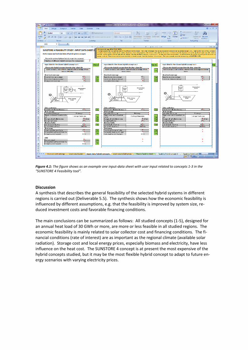
Figure 4.1: The figure shows as an example one input-data sheet with user input related to concepts 1-3 in the “SUNSTORE 4 Feasibility tool”.
Discussion A synthesis that describes the general feasibility of the selected hybrid systems in different regions is carried out (Deliverable 5.5). The synthesis shows how the economic feasibility is influenced by different assumptions, e.g. that the feasibility is improved by system size, re-duced investment costs and favorable financing conditions. The main conclusions can be summarized as follows: All studied concepts (1-5), designed for an annual heat load of 30 GWh or more, are more or less feasible in all studied regions. The economic feasibility is mainly related to solar collector cost and financing conditions. The fi-nancial conditions (rate of interest) are as important as the regional climate (available solar radiation). Storage cost and local energy prices, especially biomass and electricity, have less influence on the heat cost. The SUNSTORE 4 concept is at present the most expensive of the hybrid concepts studied, but it may be the most flexible hybrid concept to adapt to future en-ergy scenarios with varying electricity prices.

European dissemination
European dissemination Before 2013:
20X SUNSTORE 4 type demonstrations plants in planning progress. 100 % renewable en-ergy systems based on solar thermal (+50 %), biomass/other renewable energy resources and a long term heat storage
Before 2020:
0.9 – 1.8 GWth corresponding to an annual production of 2-4 PJ implemented Long term: 5 – 10 GWth corresponding to an annual production of 10 – 20 PJ implemented
For WP6, dissemination and replication activities have been carried out in many EU countries at national level and also at international level. The following are the main results:
29 national articles 5 international articles have been published;
Sunstore4 have been presented in 54 events
a total of about 6,000 people visited the Sunstore4 demonstration plant in 2014 (74 com-mercial and technical visits to the Sunstore4 demonstration plant and open guided tours twice weekly in the summer months);
a European level homepage has been developed by Euroheat & Power: www.sunstore4.eu
Sunstore4 was included as a reference project on:
DHC+ platform: www.dhcplus.eu
Smart Cities Stakeholder Platform: http://eu-smartcities.eu/content/providing-clean-and-cheap-district-heating
“89 ideas for a more intelligent city”, report by Industry Association in Lombardia (Ita-ly) about the Smart City: www.assolombarda.it/servizi/mobilita-e-trasporti/documenti/assolombarda-per-milano-smartcity-89-idee-per-una-citta-piu-intelligente-1
Sunstore4 was awarded with the 3rd Global District Energy Climate Awards: http://sunstore4.eu/download/newsroom/events/Global%20Climate%20Award%20Marstal.mp4
a workshop was carried out in March 2014 in Marstal (DK) with around 50 participants from a number of EU countries and from China;
in June 2014 an international SDH-conference in Hamburg was carried out with SUNSTORE 4 dissemination activities as a side event; about 50 participants attended the Sunstore4 session;
20 feasibility studies have been carried out for potential Sunstore4 replication plants. Regarding the project in progress, the current status is the following:
2 projects are under construction (Denmark);
projects are in the development phase, some of them quite close to the signing of a con-tract (Denmark, Ireland, Italy, Spain);
projects have received a positive feedback from the utility and are now investigating fur-ther details (Germany, Italy, Poland, Spain, Sweden);
3 projects have received a positive feedback from the utility but the conditions for pro-gressing is a support on the investment cost, currently not available (Czech Republic, Po-land);
2 projects have failed.
The main general comments on the projects are:
The full Sunstore4 concept was often considered “too much” for the utilities in the new-comer countries; on the other hand, utilities showed interest on some of the Sunstore4 “blocks” (especially the solar thermal part) and focused on the development of these sec-tions. This is due above all to the specific conditions in the countries.

The main reasons for failure of some projects or for the “waiting effect” shown by some utilities is the high investment cost needed; in times of economic crisis, many utilities are waiting for the right moment, when the national or regional governments are issuing new support schemes for renewable heat.

List of deliverables
Del. no.
Deliverable name
1.1 Homepage of the project
1.2 Periodical technical and financial reports
1.3 Coordination meetings
1.4 Interim Reports
1.5 Publishable Report
2.1 Design of the overall energy system of the demonstration plant of Marstal Fjernvarme
2.2 The design of the long term heat storage
2.3 The design of the solar part of the total energy system
2.4 The design of the biomass boiler part of the total energy system
2.5 The design of the ORC of the total energy system
2.6 The design of the heat pump part of the total energy system
2.7 The detailed design of buildings and piping system of the total energy system
2.8 Getting necessary authorities permissions
2.9 The tendering process of the piping system, other ground works and the building(s)
3.1 Supplying the solar system part of the energy system, including commissioning.
3.2 Supplying the biomass boiler system part of the energy system, including commissioning
3.3 Integration of the ORC system part of the energy system, including commissioning
3.4 The heat pump system of the energy system
3.5 The long term heat storage part of the energy system, including heat pump system
3.6 The total energy demonstration system
3.7 Commissioning Report
4.1 Design of the measurements and evaluation program
4.2 Report on operation experiences and monitoring results – after one year
4.3 Report on operation experiences and monitoring results – after two years
4.4 Presenting the results of (nearly) two years of measurements as part of the Final Technical Report
5.1 Detailed work plan
5.2 Case studies
5.3 Hybrid concepts
5.4 Feasibility/simulation studies
5.5 Hybrid system synthesis report
6.1 WP6 Leadership
6.2 Developing information materials
6.3 Involving WP6-partners from Czech Republic and Poland
6.4 Involving WP6-partners from Germany, Austria and France
6.5 Involving WP6-partners from Denmark, Sweden and UK (Ireland)
6.6 Involving WP6-partners from Italy and Spain
6.7 Workshop in Marstal
6.8 European level dissemination
6.9 National level dissemination in 10 EU-countries including: Austria, Czech Republic, Germany, Denmark, Spain, France, Italy, Sweden, Poland and UK (Ireland)
6.10 Dissemination activities connected to the Marstal demonstration plant presentation