Embed Size (px)
Citation preview

PROJECT FINAL REPORT
Grant Agreement number: 285395
Project acronym: NOVEMOR
Project title: Novel Air Vehicle Configurations: fr om Fluttering Wings to Morphing Flight
Funding Scheme: Collaborative Project: Level 1 (Sma ll-medium scale focused research project)
Period covered: from 01/09/2011 to 28/02/2015
Name of the scientific representative of the projec t's co-ordinator, Title and Organisation: Afzal Suleman, Professor, IST Lisbon
Tel: +351 21 841 73 24/+351 21 841 81 30
Fax:
E-mail: [email protected]
Project website address: http://www.novemor.eu

2
Table of Contents FRONT PAGE ...................................................................................................................................................................... 1
Executive Summary ........................................................................................................................................................... 3
Description of Work .......................................................................................................................................................... 4
Context and Objectives ................................................................................................................................................. 4
Partners ......................................................................................................................................................................... 5
Description of Work ...................................................................................................................................................... 5
Main S&T Results/foregrounds (WP Summaries) ............................................................................................................. 8
WP1 - Project Management, Dissemination and Exploitation ..................................................................................... 8
WP2 – Design of Morphing Concepts and Mechanisms ............................................................................................... 8
Introduction .............................................................................................................................................................. 8
Morphing Wingtips and Morphing Camber .............................................................................................................. 8
Variable Planform and Sweep ................................................................................................................................. 10
Implementation Issues ............................................................................................................................................ 13
Concluding Remarks ................................................................................................................................................ 15
WP3- Novel Configuration, Simulation and Analysis .................................................................................................. 15
Introduction ............................................................................................................................................................ 15
Reference Model Definition .................................................................................................................................... 15
Computational Frameworks ................................................................................................................................... 16
Computational Studies ............................................................................................................................................ 19
Concluding Remarks ................................................................................................................................................ 22
WP4- System Analysis and Integration ....................................................................................................................... 22
Introduction ............................................................................................................................................................ 22
Aeroservoelastic Analysis ........................................................................................................................................ 22
Weight and Energy Balance .................................................................................................................................... 23
System Integration, avionics and telemetry ........................................................................................................... 24
Concluding Remarks ................................................................................................................................................ 24
WP5- Wind Tunnel and Flight Demonstrators for Validation of Morphing Concepts and Joined Wing Configuration
.................................................................................................................................................................................... 26
Introduction ............................................................................................................................................................ 26
Wind Tunnel Tests ................................................................................................................................................... 27
Flight Tests .............................................................................................................................................................. 29
Concluding Remarks ................................................................................................................................................ 29
WP6- Benefit Evaluation in Terms of Impact on Lift, Drag, Weight and Aeroelastic Response ................................. 30
Introduction ............................................................................................................................................................ 30
Aerodynamic Benefits (Lift and Drag) ..................................................................................................................... 30
Weight Savings ........................................................................................................................................................ 30
Aeroelastic Response .............................................................................................................................................. 30
Concluding Remarks ................................................................................................................................................ 31
Potential Impact .............................................................................................................................................................. 32
Tendencies and current aeronautic drives ................................................................................................................. 32
Benefits exploitation for efficient short/mid-range transport aircraft ....................................................................... 32
NOVEMOR technology implementation process ........................................................................................................ 33
Morphing prototype flight test and demonstration project ................................................................................... 33
Implementation of morphing technologies on commercial product ..................................................................... 34
Dissemination ................................................................................................................................................................. 35
Contacts .......................................................................................................................................................................... 42
3
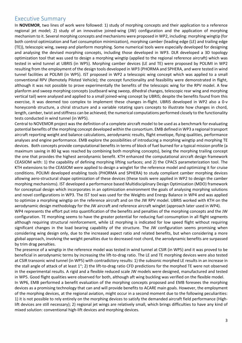
Executive Summary In NOVEMOR, two lines of work were followed: 1) study of morphing concepts and their application to a reference
regional jet model; 2) study of an innovative joined-wing (JW) configuration and the application of morphing
mechanism to it. Several morphing concepts and mechanisms were proposed in WP2, including: morphing wingtip (for
both control optimization and fuel consumption minimization), morphing camber (leading edge (LE) and trailing edge
(TE)), telescopic wing, sweep and planform morphing. Some numerical tools were especially developed for designing
and analysing the devised morphing concepts, including those developed in WP3. DLR developed a 3D topology
optimization tool that was used to design a morphing wingtip (applied to the regional reference aircraft) which was
tested in wind tunnel at UBRIS (in WP5). Morphing camber devices (LE and TE) were proposed by POLIMI in WP2
resulting from the employment of the design tools developed in WP3 (PHORMA and SPHERA, and were tested in wind
tunnel facilities at POLIMI (in WP5). IST proposed in WP2 a telescopic wing concept which was applied to a small
conventional RPV (Remotely Piloted Vehicle); the concept functionality and feasibility were demonstrated in flight,
although it was not possible to prove experimentally the benefits of the telescopic wing for the RPV model. A few
planform and sweep morphing concepts (outboard wing sweep, dihedral changes, telescopic rear wing and morphing
vertical tail) were analysed and applied to a small joined-wing concept by UBRIS; despite the benefits found from this
exercise, it was deemed too complex to implement these changes in-flight. UBRIS developed in WP2 also a 0-ν
honeycomb structure, a chiral structure and a variable rotating spars concepts to illustrate how changes in chord,
length, camber, twist and stiffness can be achieved; the numerical computations performed closely to the functionality
tests conducted in wind tunnel (in WP5).
Central to NOVEMOR project was the definition of a complete aircraft model to be used as a benchmark for evaluating
potential benefits of the morphing concept developed within the consortium. EMB defined in WP3 a regional transport
aircraft reporting weight and balance calculations, aerodynamic results, flight envelope, flying qualities, performance
analyses and engine performance. EMB explore the possibilities of introducing a morphing wingtip and morphing TE
devices. Both concepts provide computational benefits in terms of block of fuel burned for a typical mission profile (a
maximum saving in 80 kg was reached by combining both morphing concepts), being the morphing trailing concept
the one that provides the highest aerodynamic benefit. KTH enhanced the computational aircraft design framework
CEASIOM with: 1) the capability of defining morphing lifting surfaces; and 2) the CPACS parameterization tool. The
KTH extensions to the CEASIOM were applied to design a winglet for the reference model and optimizing it for cruise
conditions. POLIMI developed enabling tools (PHORMA and SPHERA) to study compliant camber morphing devices
allowing aero-structural shape optimization of these devices (these tools were applied in WP2 to design the camber
morphing mechanisms). IST developed a performance based Multidisciplinary Design Optimization (MDO) framework
for conceptual design which incorporates in an optimization environment the goals of analysing morphing solutions
and novel configurations in WP3. The IST tool was used for the Weights and Energy Balance in WP4 and was applied
to optimize a morphing wingtip on the reference aircraft and on the JW RPV model. UBRIS worked with KTH on the
aerodynamic design methodology for the JW aircraft and reference aircraft winglet (approach later used in WP4).
WP4 represents the effort put into quantification of the benefits and penalties of the morphing concepts and the JW
configuration. TE morphing seems to have the greater potential for reducing fuel consumption in all flight segments
although requiring structural reinforcement, while LE morphing is indicated for low speed flight without requiring
significant changes in the load bearing capability of the structure. The JW configuration seems promising when
considering wing design only, due to the increased aspect ratio and related benefits, but when considering a more
global approach, involving the weight penalties due to decreased root chord, the aerodynamic benefits are surpassed
by trim drag penalties.
The presence of a wingtip in the reference model was tested in wind tunnel at CSIR (in WP5) and it was proved to be
beneficial in aerodynamic terms by increasing the lift-to-drag ratio. The LE and TE morphing devices were also tested
at CSIR transonic wind tunnel (in WP5) with contradictory results: 1) the subsonic morphed LE results in an increase in
the stall angle of attack of at least 1°; 2) the lift-to-drag ratio CFD predictions for the morphed TE were not observed
in the experimental results. A rigid and a flexible reduced scale JW models were designed, manufactured and tested
in WP5. Good flight qualities were observed for both, although aft wing buckling was verified on the flexible model.
In WP6, EMB performed a benefit evaluation of the morphing concepts proposed and EMB foresees the morphing
devices as a promising technology that can and will provide benefits to ACARE main goals. However, the employment
of the morphing devices, at the regional aviation, might occur in a second moment due to the following peculiarities:
1) it is not possible to rely entirely on the morphing devices to satisfy the demanded aircraft field performance (High-
lift devices are still necessary); 2) regional jet wings are relatively small, which brings difficulties to have any kind of
mixed solution: conventional high-lift devices and morphing devices.

4
Description of Work Context and Objectives Air transport is increasingly becoming more accessible to a greater number of people who can afford travelling by air,
both inside and outside Europe, for leisure and business purposes. This is evidenced by the fact that last year the
European air transport system moved more than 1 billion passengers and 14 million metric tonnes of freight through
its airports, whilst handling more than 12 million movements over the same period. Despite the effects of 9/11, SARS
and the IRAQ war, the sector forecasts that over the next decade, both passenger and freight traffic is expected to
increase at an average of 4 to 5% p.a., with freight being expected to increase slightly more - both significantly above
global GDP growth. In air transport terms, this implies a doubling of traffic about every 16 years. It is evident that
environmental requirements, such as noise impact and emissions, will play a dominant role in future transport aircraft
development, becoming a driving force for aircraft design. This is the main reason for which ACARE, in the Strategic
Research Agenda, established the so-called greening aircraft as the first objective of future research activities related
to Aeronautics. The adoption of this kind of global requirement has two main consequences: firstly, the greening level
becomes one of the criteria for which a new aircraft has to be judged or selected; and secondly, the aircraft
configuration itself must be defined to fulfil the greening requirements. Since other design targets, such as economic
and technical factors, must be satisfied, new design criteria arising from the greening requirements must be taken into
account right from the beginning of the design cycle.
Looking at actual transport aircraft it is very easy to identify many similarities in shape and configurations of different
airplanes, even if during the last decades great technological improvements have been reached, for example
concerning engine emissions and noise reduction, high-lift device configurations and advanced materials. One of the
reasons is related to the fact that configuration and performance of commercial aircraft, especially fixed-wing aircraft,
have been optimized within a limited range of conditions, especially cruise conditions, in terms of speed and altitude.
Outside this range, aircraft behaviour is less than optimal.
Concurrently, technological developments in materials and computer sciences have evolved to the point where their
synergistic combination has culminated in a new field of multi-disciplinary research in adaptation. Advances in material
sciences provide a comprehensive and theoretical framework for implementing multi-functionality into materials, and
the development of high-speed digital computers has permitted the transformation of that framework into
methodologies for practical design and production. Adaptive structures represent a new approach or design
philosophy that integrates the actions of sensors, actuators and control circuit elements into a single system that can
respond adaptively to environmental changes in a useful manner. These integrated systems possess a functionality
that adds significant value to materials, technologies or end-products, which in turn enables system performance
enhancements that are not possible with traditional conventional approaches.
The aim of the NOVEMOR (NOvel Air VEhicle Configurations: From Fluttering Wings to MORphing Flight) research
project is to investigate novel air vehicle configurations with new lifting concepts and morphing wing solutions to
enable cost-effective air transportation. A multidisciplinary analysis and design optimization environment developed
in an earlier EU Project (SIMSAC) will be used and improved to include analysis of novel configurations, such as the
joined-wing concept for improved lift, and morphing wing solutions to tailor the wing for optimum lift and
manoeuvring capabilities. The design and development of the proposed solutions will be performed an integral part
of the aircraft conceptual design, rather than just as an add-on later in the design cycle, thus enabling innovative
aircraft designs to be made through the use of morphing structures technologies. Such concepts will enable improved
aircraft efficiencies, aerodynamic performance, reduced structural loads and lighter weight structures, leading to
overall lower fuel consumption and therefore improvement on the greening level of the aircraft.
The NOVEMOR project will be focused on the following primary objectives:
1. Design and evaluation of a new aircraft concept, the joined-wing configuration, including structural,
aerodynamic and aeroelastic scaling simulations and analysis, and multidisciplinary design optimization
techniques. This configuration will be evaluated against a reference aircraft.
2. Morphing wing solutions (span and camber strategies and wing-tip devices) will be proposed to enhance lift
capabilities and manoeuvring. These will be considered early in the design process, right from the beginning
of aircraft design cycle, included in the conceptual design.
3. Design, test and evaluate the joined wing configuration and some of the more promising adaptive/morphing
concepts and mechanisms as part of a conceptual design environment, capable of augmenting performance
characteristics in terms of drag reduction, loads reduction, weight and noise impact reduction;
4. To evaluate the overall benefits of these new proposed concepts in terms of reducing operational cost.
5
Partners Organization Name Acronym Scientific Team Leader Country
1 Instituto Superior Técnico (Coordinator) IST Suleman, Prof. Afzal PT
2 Politecnico di Milano POLIMI Ricci, Prof. Sergio, IT
3 University of Liverpool (Terminated) ULIV Cooper, Prof. Jonathan UK
4 Kungliga Tekniska Högskolan KTH Rizzi, Prof. Arthur SWE
5 Deutsches Zentrum für Luft- und Raumfahrt DLR Monner, Dr-Ing Hans Peter DE
6 Centre for Scientific and Industrial Research CSIR Gerryts, Dr. Beeuwen SA
7 EMBRAER S.A. EMB Negrão, Dr. José Ricardo BRA
8 University of Bristol UBRIS Cooper, Prof. Jonathan UK
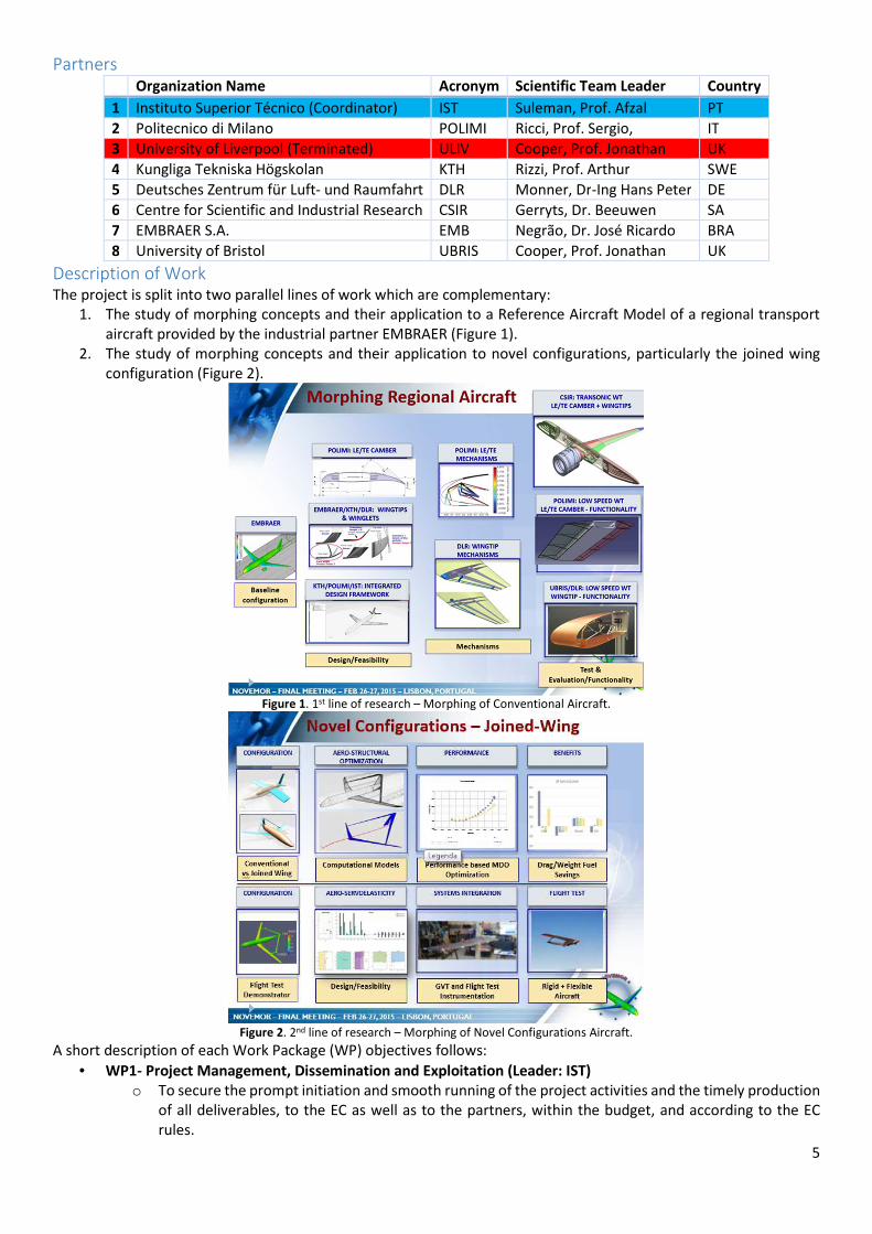
Description of Work The project is split into two parallel lines of work which are complementary:
1. The study of morphing concepts and their application to a Reference Aircraft Model of a regional transport
aircraft provided by the industrial partner EMBRAER (Figure 1).
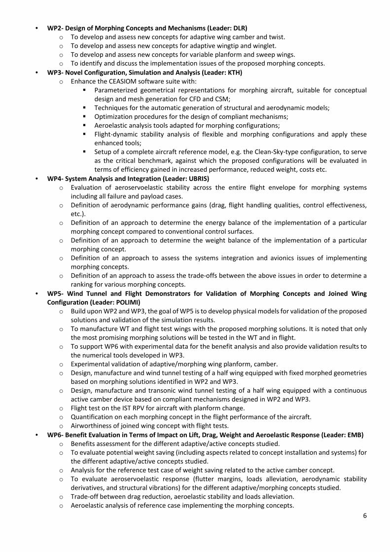
2. The study of morphing concepts and their application to novel configurations, particularly the joined wing
configuration (Figure 2).
Figure 1. 1st line of research – Morphing of Conventional Aircraft.
Figure 2. 2nd line of research – Morphing of Novel Configurations Aircraft.
A short description of each Work Package (WP) objectives follows:
• WP1- Project Management, Dissemination and Exploitation (Leader: IST)
o To secure the prompt initiation and smooth running of the project activities and the timely production
of all deliverables, to the EC as well as to the partners, within the budget, and according to the EC
rules.
6
• WP2- Design of Morphing Concepts and Mechanisms (Leader: DLR)
o To develop and assess new concepts for adaptive wing camber and twist.
o To develop and assess new concepts for adaptive wingtip and winglet.
o To develop and assess new concepts for variable planform and sweep wings.
o To identify and discuss the implementation issues of the proposed morphing concepts.
• WP3- Novel Configuration, Simulation and Analysis (Leader: KTH)
o Enhance the CEASIOM software suite with:
� Parameterized geometrical representations for morphing aircraft, suitable for conceptual
design and mesh generation for CFD and CSM;
� Techniques for the automatic generation of structural and aerodynamic models;
� Optimization procedures for the design of compliant mechanisms;
� Aeroelastic analysis tools adapted for morphing configurations;
� Flight-dynamic stability analysis of flexible and morphing configurations and apply these
enhanced tools;
� Setup of a complete aircraft reference model, e.g. the Clean-Sky-type configuration, to serve
as the critical benchmark, against which the proposed configurations will be evaluated in
terms of efficiency gained in increased performance, reduced weight, costs etc.
• WP4- System Analysis and Integration (Leader: UBRIS)
o Evaluation of aeroservoelastic stability across the entire flight envelope for morphing systems
including all failure and payload cases.
o Definition of aerodynamic performance gains (drag, flight handling qualities, control effectiveness,
etc.).
o Definition of an approach to determine the energy balance of the implementation of a particular
morphing concept compared to conventional control surfaces.
o Definition of an approach to determine the weight balance of the implementation of a particular
morphing concept.
o Definition of an approach to assess the systems integration and avionics issues of implementing
morphing concepts.
o Definition of an approach to assess the trade-offs between the above issues in order to determine a
ranking for various morphing concepts.
• WP5- Wind Tunnel and Flight Demonstrators for Validation of Morphing Concepts and Joined Wing
Configuration (Leader: POLIMI)
o Build upon WP2 and WP3, the goal of WP5 is to develop physical models for validation of the proposed
solutions and validation of the simulation results.
o To manufacture WT and flight test wings with the proposed morphing solutions. It is noted that only
the most promising morphing solutions will be tested in the WT and in flight.
o To support WP6 with experimental data for the benefit analysis and also provide validation results to
the numerical tools developed in WP3.
o Experimental validation of adaptive/morphing wing planform, camber.
o Design, manufacture and wind tunnel testing of a half wing equipped with fixed morphed geometries
based on morphing solutions identified in WP2 and WP3.
o Design, manufacture and transonic wind tunnel testing of a half wing equipped with a continuous
active camber device based on compliant mechanisms designed in WP2 and WP3.
o Flight test on the IST RPV for aircraft with planform change.
o Quantification on each morphing concept in the flight performance of the aircraft.
o Airworthiness of joined wing concept with flight tests.
• WP6- Benefit Evaluation in Terms of Impact on Lift, Drag, Weight and Aeroelastic Response (Leader: EMB)
o Benefits assessment for the different adaptive/active concepts studied.
o To evaluate potential weight saving (including aspects related to concept installation and systems) for
the different adaptive/active concepts studied.
o Analysis for the reference test case of weight saving related to the active camber concept.
o To evaluate aeroservoelastic response (flutter margins, loads alleviation, aerodynamic stability
derivatives, and structural vibrations) for the different adaptive/morphing concepts studied.
o Trade-off between drag reduction, aeroelastic stability and loads alleviation.
o Aeroelastic analysis of reference case implementing the morphing concepts.

7
o The trade-off between the effect on drag reduction, aeroelastic stability and external noise will be
evaluated.
o Benefits assessment for different adaptive/morphing concepts studied when applied to Reference
Aircraft.

8
Main S&T Results/foregrounds (WP Summaries) WP1 - Project Management, Dissemination and Exploitation
All the deliverables were uploaded to the EU platform. The documentation regarding the management (Project
Manual (IST), Dissemination Plan (UBRIS), Technology Implementation Plan (EMB), Internet Page (IST) Progress
Reports (IST), Consortium and Grant Agreements) within the partners is available to them through the website at
www.novemor.eu. The periodic meetings between the partners have also been performed. In the kick-off, 6th month,
12th month, 18th month, 24th moth and final meetings the partners have presented their work and discussed the
action items to the following period of the project. All presentations and meeting minutes are available to the partners
in the website. Besides the periodic meeting also web conferences took place whenever deemed necessary.
Regarding the dissemination of the project results so far several proceedings have been and will be presented in
conferences. A NOVEMOR special session was held place in Aachen, Germany, at the 4th EASN Association
International Workshop on Flight Physics & Aircraft Design.
WP2 – Design of Morphing Concepts and Mechanisms
Introduction
Central to the NOVEMOR project is the investigation into the benefits and relevance of morphing technology in
aircraft. The underlying premise behind morphing is that the aircraft can adapt its shape to best suit the prevailing
conditions, thereby operating at a higher efficiency over the full range of flight conditions in its mission profile. In what
is a multidisciplinary and highly cross-coupled field, the way in which the aircraft structure enables and delivers
morphing is also critical, and assessment can only be made with from an integrated systems point of view. Thus the
design of the morphing structural subsystem and its constituent mechanisms are critical and it is important to develop
appropriate tools for the design of this new class of structure.
Work Package (WP) 2 involved significant efforts by the four work package partners (DLR, POLIMI, UBRIS and IST) in
devising morphing concepts and mechanisms, and developing the software tools used for their designs. Budgeted for
36 person months, this work package was divided into four areas (deliverables):
• Morphing wingtips (D2.1);
• Morphing camber (D2.2);
• Variable planform and sweep
(D2.3);
• Implementation issues (D2.4);
The first three subsections involved
conceptual development, with morphing
wingtips (D2.1) and morphing wing camber
(D2.2) applied to the reference aircraft by
Embraer (defined in WP3), and variable
planform and sweep (D2.3) applied to a
remotely piloted vehicle (RPV). D2.4 was
dedicated to conducting detailed design
and analysis for the ensuing wind tunnel
and flight tests of WP5.
WP2 played a critical role in the NOVEMOR
project as it was a prerequisite for the
experimental work in WP5, with the
success and effectiveness of the wind
tunnel and flight tests made possible by the careful design and planning in this work package. Furthermore, the
assessments of morphing conducted in WP6 required the detailed design information completed in this work package,
as well as the projection of the usefulness of the design tools into the future as TRLs evolve. Overall, the work in this
work package was successfully completed, with the four deliverables met and the four milestones achieved. Key
developments were made to the software design tools and substantial knowledge into the design, analysis,
performance and manufacture considerations of morphing structures and mechanisms was generated in this work
package.
Morphing Wingtips and Morphing Camber
The reference wing of the Embraer regional jetliner was divided into the wing and wingtip regions; the design of a
droop-nose morphing wingtip was conducted by DLR and supported by UBRIS in the experimental stage, whilst the
Figure 3. Workflow schematic comparing the design of the morphing wingtip and
the wing with morphing camber in WP2.
9
design of morphing leading and trailing edge devices in the wing was performed by POLIMI. In this manner, various
design tools and methodologies could be explored and assessed simultaneously, thereby increasing the knowledge
pool. It should be noted that both approaches (i.e. DLR droop nose morphing wingtip and POLIMI variable camber
wing) featured smoothly varying and continuous morphing, being more than just shape change in general. This type
of morphing has added benefits to the general morphing benefits aforementioned, such as flow laminarisation and
reduced airframe noise. Smoothly morphing implies the design of flexible or compliant devices, and as such, both
approaches feature compliant mechanisms in the structural design. The schematic of the parallel effort between these
two approaches in Fig. 3 shows similarities between the two approaches in terms of the overall workflow. However,
the tools developed and used, manufacturing methods and testing aims are largely different, and this parallel effort
forms the scope for further collaborative work.
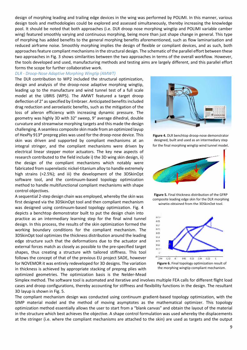
DLR - Droop-Nose Adaptive Morphing Wingtip (AMWT)
The DLR contribution to WP2 included the structural optimization,
design and analysis of the droop-nose adaptive morphing wingtip,
leading up to the manufacture and wind tunnel test of a full scale
model at the UBRIS (WP5). The AMWT featured a target droop
deflection of 2° as specified by Embraer. Anticipated benefits included
drag reduction and aeroelastic benefits, such as the mitigation of the
loss of aileron efficiency with increasing dynamic pressure. The
geometry was highly 3D with 32° sweep, 9° average dihedral, double
curvature and streamwise morphing targets and this made the design
challenging. A seamless composite skin made from an optimized layup
of HexPly 913® prepreg plies was used for the droop-nose device. This
skin was driven and supported by compliant mechanisms at an
integral stringer, and the compliant mechanisms were driven by
electrical linear stepper motor actuators. The key new aspects of
research contributed to the field include i) the 3D wing skin design, ii)
the design of the compliant mechanisms which notably were
fabricated from superelastic nickel-titanium alloy to handle extremely
high strains (>2.5%); and iii) the development of the 3DSkinOpt
software tool, and the continuum-based topology optimization
method to handle multifunctional compliant mechanisms with shape
control objectives.
A sequential 2-step design chain was employed, whereby the skin was
first designed via the 3DSkinOpt tool and then compliant mechanism
was designed using continuum-based topology optimization. Fig. 4
depicts a benchtop demonstrator built to put the design chain into
practice as an intermediary learning step for the final wind tunnel
design. In this process, the results of the skin optimization formed the
working boundary conditions for the compliant mechanism. The
3DSkinOpt tool optimizes the thickness distribution around the leading
edge structure such that the deformations due to the actuator and
external forces match as closely as possible to the pre-specified target
shapes, thus creating a structure with tailored stiffness. This tool
follows the concept of that of the previous EU project SADE, however
for NOVEMOR it was entirely redeveloped for 3D designs. The variation
in thickness is achieved by appropriate stacking of prepreg plies with
optimized geometries. The optimization basis is the Nelder-Mead
Simplex method. The software tool is automated and iterative and involves multiple FEA calls for different flight load
cases and droop configurations, thereby accounting for stiffness and flexibility functions in the design. The resultant
3D layup is shown in Fig. 5. The compliant mechanism design was conducted using continuum gradient-based topology optimization, with the
SIMP material model and the method of moving asymptotes as the mathematical optimizer. This topology
optimization method essentially allows the user to start from a “blank canvas” and obtain the layout of the material
in the structure which best achieves the objective. A shape control formulation was used whereby the displacements
at the stringer (i.e. where the compliant mechanisms are attached to the skin) are used as targets and the output
Figure 4. DLR benchtop droop-nose demonstrator
designed, built and used as an intermediary step
for the final morphing wingtip wind tunnel model.
Figure 5. Final thickness distribution of the GFRP
composite leading edge skin for the DLR morphing
wingtip obtained from the 3DSkinOpt tool.
Figure 6. Final topology optimization result of
the morphing wingtip compliant mechanism.

10
displacements of the compliant mechanism are required to move to these points. A stiffness objective function is also
included to ensure the compliant mechanism is stiff enough to transfer the actuation force onto the skin and also to
resist external forces. The resulting topology in the droop configuration is shown in Fig. 6.
POLIMI - Morphing Camber Devices
The conceptual design of morphing leading and trailing edge devices for the Embraer reference aircraft was performed
by POLIMI in WP2. It was envisaged that these devices can alter the camber of the wing across the span thereby
tailoring the aerodynamic load distribution, thus resulting in higher overall efficiency across the aircraft’s mission. The
contribution of POLIMI to WP2 mainly centred upon the development of tools for the design of morphing structures
based on compliant mechanisms. The work in WP2 built up from past experience in other EU projects with continued
tool development and the application to leading and trailing edge morphing devices of the Embraer reference aircraft
as conceptual design. In addition, the morphing tools were applied to the design of a small scale model for the wind
tunnel tests in WP5. An overview of the approach is presented below.
The general approach is based on geometry parameterization via the Class/Shape function Transformation (CST)
method by Kulfan coupled to a two-level multiphysics optimization procedure. This two-level optimization approach
dedicated to morphing aircraft design, uses the tools PHORMA (Parametrical sHapes for aerOdinamic and stRuctural
Modelling of Aircrafts) and SPHERA (Synthesis of comPliant mecHanisms for EngineeRing Applications) in each level
respectively. In the first level via PHORMA, the best deformed aerofoil shape is determined as the most efficient
aerodynamic shape while concurrently limits the requested energy to deform the aerofoil skin. In the second
optimization level via SPHERA, the best internal structural configuration is obtained using a load path representation
topology optimization tool based on genetic algorithms that synthesizes a compliant structure able to adapt itself for
matching the optimal shape coming out from the first level. At the core of PHORMA is the ability to parameterize
geometries via the CST method (extended to morphing aerofoil design by POLIMI) and due to its analytical basis, it
allows for the fast computation of the derivatives of various geometrical features, such as length and curvature of the
upper and lower aerofoil surfaces, aerofoil area, surface slope etc. This efficient computation of sensitivities makes it
highly suitable for use in shape optimization. Such geometrical features are strictly related to the structural properties
of the morphing skins, with changes in length and curvature correlating to axial and bending stresses in the skin. The
availability of length and curvature variations of the aerofoil’s upper and lower surfaces can then be used as explicit
constraint functions in the shape optimization procedure.
The framework shown in Fig. 7
includes features for the
generation of CAD, CFD, FEM
and load paths models and
contains techniques for the
coupling between the different
models. The parametric shapes
can be combined and directly
used to produce corresponding
mesh, to perform structural
and fluid analyses and to
provide a fast interface to commercial software. The most important parts have been implemented as objects and
classes interacting each other by means of the Object—Oriented Programming (OOP). The OOP concept allows for
independent development of each component and an easy interface with any other application which can take
advantage of its capabilities.
Variable Planform and Sweep
Various strategies have been devised for making changes to the wing planform area and the sweep angle. UBRIS
initially perform several planform change to a small Joined Wing RPV model to enhance flight performance. IST
developed a bend-twist morphing concept and a telescopic wing concept. UBRIS was involved in the development of
a zero Poisson’s ratio (0-v) honeycomb structure, a chiral morphing concept, and a variable stiffness rotating spars
concept.
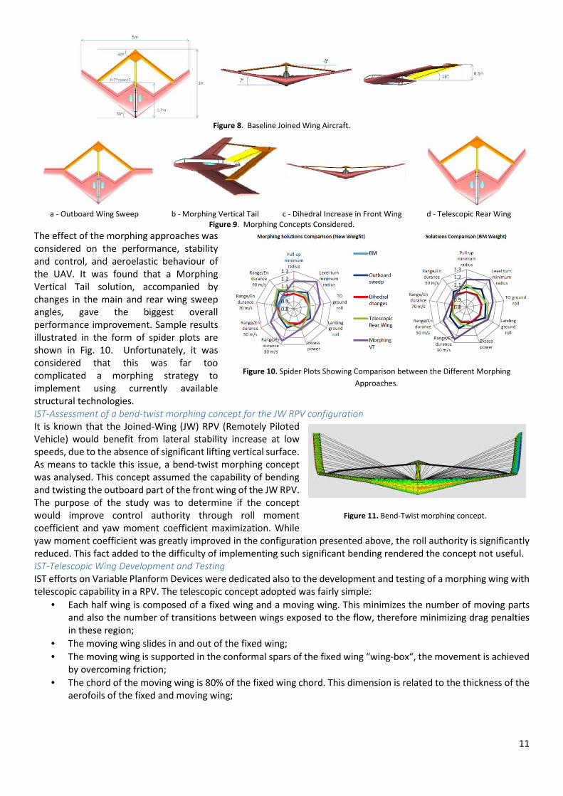
UBRIS - Gross Morphing Geometry Changes for Joined Wing Aircraft
An investigation into the use of global morphing to alter the shape of a baseline 5m span Joined Wing UAV (see Fig. 8)
was performed. Four different global morphing strategies were considered over a typical flight mission that all involved
gross deformation of the Joined Wing configuration planform: Outboard Sweep, Dihedral Changes, Telescopic Rear
Wing and Morphing Vertical Tail, as seen in Figure 9.
Figure 7. 2D (left) and 3D (right) aero-structural shape optimization framework for morphing camber devices.
11
Figure 8. Baseline Joined Wing Aircraft.
a - Outboard Wing Sweep b - Morphing Vertical Tail c - Dihedral Increase in Front Wing d - Telescopic Rear Wing
Figure 9. Morphing Concepts Considered.
The effect of the morphing approaches was
considered on the performance, stability
and control, and aeroelastic behaviour of
the UAV. It was found that a Morphing
Vertical Tail solution, accompanied by
changes in the main and rear wing sweep
angles, gave the biggest overall
performance improvement. Sample results
illustrated in the form of spider plots are
shown in Fig. 10. Unfortunately, it was
considered that this was far too
complicated a morphing strategy to
implement using currently available
structural technologies.
IST-Assessment of a bend-twist morphing concept for the JW RPV configuration
It is known that the Joined-Wing (JW) RPV (Remotely Piloted
Vehicle) would benefit from lateral stability increase at low
speeds, due to the absence of significant lifting vertical surface.
As means to tackle this issue, a bend-twist morphing concept
was analysed. This concept assumed the capability of bending
and twisting the outboard part of the front wing of the JW RPV.
The purpose of the study was to determine if the concept
would improve control authority through roll moment
coefficient and yaw moment coefficient maximization. While
yaw moment coefficient was greatly improved in the configuration presented above, the roll authority is significantly
reduced. This fact added to the difficulty of implementing such significant bending rendered the concept not useful.
IST-Telescopic Wing Development and Testing
IST efforts on Variable Planform Devices were dedicated also to the development and testing of a morphing wing with
telescopic capability in a RPV. The telescopic concept adopted was fairly simple:
• Each half wing is composed of a fixed wing and a moving wing. This minimizes the number of moving parts
and also the number of transitions between wings exposed to the flow, therefore minimizing drag penalties
in these region;
• The moving wing slides in and out of the fixed wing;
• The moving wing is supported in the conformal spars of the fixed wing “wing-box“, the movement is achieved
by overcoming friction;
• The chord of the moving wing is 80% of the fixed wing chord. This dimension is related to the thickness of the
aerofoils of the fixed and moving wing;
Figure 11. Bend-Twist morphing concept.
Figure 10. Spider Plots Showing Comparison between the Different Morphing
Approaches.
12
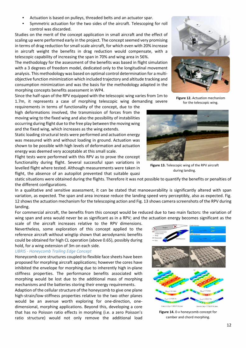
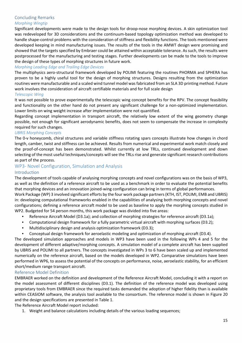
• Actuation is based on pulleys, threaded belts and an actuator spar.
• Symmetric actuation for the two sides of the aircraft. Telescoping for roll
control was discarded.
Studies on the merit of the concept application in small aircraft and the effect of
scaling up were performed early in the project. The concept seemed very promising
in terms of drag reduction for small scale aircraft, for which even with 20% increase
in aircraft weight the benefits in drag reduction would compensate, with a
telescopic capability of increasing the span in 70% and wing area in 56%.
The methodology for the assessment of the benefits was based in flight simulation
with a 3 degrees of freedom model, dedicated only to the longitudinal movement
analysis. This methodology was based on optimal control determination for a multi-
objective function minimization which included trajectory and altitude tracking and
consumption minimization and was the basis for the methodology adapted in the
morphing concepts benefits assessment in WP4.
Since the half-span of the RPV equipped with the telescopic wing varies from 1m to
1.7m, it represents a case of morphing telescopic wing demanding severe
requirements in terms of functionality of the concept, due to the
high deformations involved, the transmission of forces from the
moving wing to the fixed wing and also the possibility of instabilities
occurring during flight due to the free play between the moving wing
and the fixed wing, which increases as the wing extends.
Static loading structural tests were performed and actuation energy
was measured with and without loading in ground. Actuation was
shown to be possible with high levels of deformation and actuation
energy was deemed very acceptable at this small scale.
Flight tests were performed with this RPV as to prove the concept
functionality during flight. Several successful span variations in
levelled flight where tested. Although measurements were taken in
flight, the absence of an autopilot prevented that suitable quasi
static situations were obtained during the flights. Therefore it was not possible to quantify the benefits or penalties of
the different configurations.
In a qualitative and sensitive assessment, it can be stated that manoeuvrability is significantly altered with span
variation, as expected. The span and area increase reduce the landing speed very perceptibly, also as expected. Fig.
12 shows the actuation mechanism for the telescoping action and Fig. 13 shows camera screenshots of the RPV during
landing.
For commercial aircraft, the benefits from this concept would be reduced due to two main factors: the variation of
wing span and area would never be as significant as in a RPV; and the actuation energy becomes significant as the
scale of the aircraft increases relative to the RPV dimensions.
Nevertheless, some exploration of this concept applied to the
reference aircraft without wingtip shown that aerodynamic benefits
could be obtained for high CL operation (above 0.65), possibly during
hold, for a wing extension of 3m on each side.
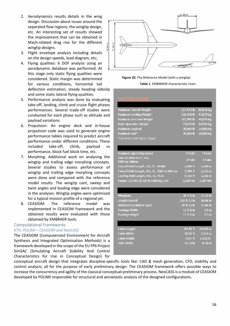
UBRIS - Honeycomb Trailing Edge Concept
Honeycomb core structures coupled to flexible face sheets have been
proposed for morphing aircraft applications; however the cores have
inhibited the envelope for morphing due to inherently high in-plane
stiffness properties. The performance benefits associated with
morphing would be lost due to the additional mass of morphing
mechanisms and the batteries storing their energy requirements.
Adaption of the cellular structure of the honeycomb to give one plane
high-strain/low-stiffness properties relative to the two other planes
would be an avenue worth exploring for one-direction, one-
dimensional, morphing applications. Beyond this, developing a core
that has no Poisson ratio effects in morphing (i.e. a zero Poisson’s
ratio structure) would not only remove the additional load
Figure 12. Actuation mechanism
for the telescopic wing.
Figure 14. 0-ν honeycomb concept for
camber and chord morphing.
Figure 13. Telescopic wing of the RPV aircraft
during landing.

13
requirements associated with non-morphing direction secondary displacements but would make the use of a one-
directional morphing honeycomb more practical in use.
The 0-v honeycomb structure with curved members is shown in Fig. 14. In morphing wing applications, the concept
can be applied to the upper and lower skins. Camber can be varied if differential actuation across the honeycomb
segments is input whilst chord extension is possible with uniform actuation input over the honeycomb segments.
Detailed finite element analyses were conducted to determine the structural performance under transverse loading
in elongated and stowed configurations.
UBRIS - Chiral Morphing Concept
The proposed design features a chiral
structure (Fig. 15) mapped within the
winglet’s aerofoil based on a modified
geometry layout of a periodic chiral
structure where the circular nodes are
replaced by regular hexagons for
manufacturing reasons. The twist of
the wingtip was designed to be
controlled by rotating one of the chiral
nodes in the structure.
A Genetic Algorithm based optimizer was used to optimize the chiral structure to achieve the largest change in rolling
moment for a given actuator sizing. The internal structure of the chiral tip was parameterized in terms of the chiral
parameters r and R as well as the locations of the front and rear spars. The thickness of the chiral hexagonal elements,
the ligaments and skin were set to the minimum printing thickness of 1mm.
UBRIS - Variable Stiffness Rotating Spars Concept
The final morphing concept tested at UBRIS consisted of the design and manufacture of an adaptive stiffness rotating
spar based actuated wing tip in order to control wingtip twist and bending. This approach had not been attempted
before on a swept aerodynamic surface or at such high dynamic pressures. The resulting deformations were then
validated via comparison with NASTRAN based aeroelastic computations and comparison with the other morphing
concepts.
Implementation Issues
The tools mentioned in the above three
sections were applied for the design of
morphing devices for the reference
aircraft and for a RPV as mentioned.
Detailed designs were obtained from
those generated by the software tools
following a number of post-processing
steps and detailed CAD constructions and
finite element analyses.
Morphing Wingtip
Postprocessing was required to convert
the skin and topology optimization results into manufacturable parts. For the skin
design, a postprocessing software tool was also generated which inspected the final
thickness distribution (based on the FEA mesh) and converted the edges of the
different thickness regions into smooth contours. These were then exported into a
CAD program to create the plybook, wherein the stacking sequence of the 32 layers
(0°, ±45°, and 90° orientations) was preset (also used in the FEA calculations). The
topology optimization results were also postprocessed by converting the geometries
into a parametric CAD model which would subsequently be used for wire electric
discharge machining (EDM). This allowed for precise fine tuning of the compliant
mechanism features, in particular the thickness of the different members in the
topology. The skin and compliant mechanism models were then combined into a
high fidelity FEA model with shell elements. This model was then used for aeroelastic
computations conducted by UBRIS. The results were promising and allowed for
continuation into the wind tunnel testing stage. Fig. 16 shows the final CAD assembly
of the leading edge and a snapshot of the detailed FEA results.
Figure 17. CAD models of the
leading and trailing edge wing
camber morphing devices for
manufacture.
Figure 16. CAD final assembly (left) and detailed FEA simulation (right) of the droop-
nose morphing wingtip.
Figure 15. Chiral structure concept for twist morphing.

14
Morphing Camber
Postprocessing was required for the manufacture of the compliant devices and was
performed with Stereolithography (SLA) and selective laser sintering (SLS)
manufacturing techniques in mind. Fig. 17 shows the CAD models of the final
leading and trailing edge devices. Detailed FEA was also conducted for the purpose
of comparison with the wind tunnel test results, as shown in Fig. 18.
Variable Planform and Sweep
Telescopic Wing
The telescopic wing requires lubrication for actuation forces reduction. This could
be an issue if implementation in a commercial aircraft was to be made due to the
direct exposure of the lubricated surface of the moving wing to the flow. Its benefits
are related to span and area increase. As the extension is performed at the tip, the
moving wing interferes with the placement of ailerons, and these reduce
significantly the chord of the moving wing, limiting the benefits. In the RPV, these
issues where tackled by implementing spoilers in the lower surface of the fixed wing, thus reducing the aerodynamic
efficiency and authority of the roll control surfaces. A possible solution could be implementing morphing camber for
roll control.
When retracted, the moving wing is a structure occupying an important volume inside the wing that is usually used
for other purposes, like structural support for aileron actuation systems. The predictable higher actuation forces for a telescopic wing in a transport aircraft would further require more volume
inside the wing for actuation and would possibly require structural reinforcement in the wing structure towards the
tip, otherwise lighter.
UBRIS 0-ν honeycomb, chiral structures and rotating spars concepts
A wind tunnel model wing featuring the 0-v
honeycomb concept was constructed using additive
layer manufacturing to create the wing using 6
controllable trailing edge segments as shown in Fig.
19. The scaling of the wing was based upon a 150%
version of the outer wing section (beyond the join) of
the baseline NOVEMOR joined wing UAV as shown in
Fig. 19. Each trailing edge segment was actuated
independently using micro-linear actuators, which
enabled the angle of the trailing edge to be varied and
also to change the local chord.
Chiral structures have been commonly made from
plastics using rapid prototyping manufacturing
methods and even machined from solid metal. The
rapid prototyping approach has been chosen for the
proposed demonstrator as shown in Fig. 16. One of
the advantages of using the rapid prototyping is that
the design and manufacture can be simplified by
using the same material for the skin and the
demonstrator can be printed as one piece. The model
was made from polyamide printed using selective
laser sintering. The material has a Young’s modulus of
1650MPa and a tensile strength of 48MPa. The
minimum wall thickness that can be printed is 1 mm.
A rotating spar wingtip was designed via structural
optimization resulting in the wing design shown in
Fig. 19. The outside skin of the wing was covered in
solarfilm in order to provide an aerodynamic surface. The spars were controlled via two geared stepper motors, being
able to rotate the spars through 90 degrees in approximately 0.5 second.
Figure 18. Detailed FEA of the final
leading edge wing camber
morphing device.
Figure 19. Implementation of the 0-ν honeycomb, chiral morphing
structure and rotating spars concepts.
15
Concluding Remarks
Morphing Wingtip
Significant developments were made to the design tools for droop-nose morphing devices. A skin optimization tool
was redeveloped for 3D considerations and the continuum-based topology optimization method was developed to
handle shape-control problems with the consideration of stiffness and flexibility functions. The tools mentioned were
developed keeping in mind manufacturing issues. The results of the tools in the AMWT design were promising and
showed that the targets specified by Embraer could be attained within acceptable tolerance. As such, the results were
postprocessed for the manufacturing and testing stages. Further developments can be made to the tools to improve
the design of these types of morphing structures in future work.
Morphing Leading Edge and Trailing Edge Devices
The multiphysics aero-structural framework developed by POLIMI featuring the routines PHORMA and SPHERA has
proven to be a highly useful tool for the design of morphing structures. Designs resulting from the optimization
routines were manufacturable and a scaled wind tunnel model was fabricated from an SLA 3D printing method. Future
work involves the consideration of aircraft certifiable materials and for full scale design
Telescopic Wing
It was not possible to prove experimentally the telescopic wing concept benefits for the RPV. The concept feasibility
and functionality on the other hand do not present any significant challenge for a non-optimized implementation.
Lower limits on wing weight increase after implementation were not quantified.
Regarding concept implementation in transport aircraft, the relatively low extent of the wing geometry change
possible, not enough for significant aerodynamic benefits, does not seem to compensate the increase in complexity
required for such changes.
UBRIS Morphing Concepts
The 0-v honeycomb, chiral structures and variable stiffness rotating spars concepts illustrate how changes in chord
length, camber, twist and stiffness can be achieved. Results from numerical and experimental work match closely and
the proof-of-concept has been demonstrated. Whilst currently at low TRLs, continued development and down
selecting of the most useful techniques/concepts will see the TRLs rise and generate significant research contributions
as part of the process.
WP3- Novel Configuration, Simulation and Analysis
Introduction
The development of tools capable of analysing morphing concepts and novel configurations was on the basis of WP3,
as well as the definition of a reference aircraft to be used as a benchmark in order to evaluate the potential benefits
that morphing devices and an innovation joined-wing configuration can bring in terms of global performances.
Work Package (WP) 3 involved significant efforts by the four work package partners (KTH, IST, POLIMI, EMB and UBRIS)
in: developing computational frameworks enabled in the capabilities of analysing both morphing concepts and novel
configurations; defining a reference aircraft model to be used as baseline to apply the morphing concepts studied in
WP2. Budgeted for 54 person months, this work package was divided into five areas:
• Reference Aircraft Model (D3.1a); and collection of morphing strategies for reference aircraft (D3.1a);
• Computational design framework for a fully parametric virtual aircraft with morphing surfaces (D3.2);
• Multidisciplinary design and analysis optimization framework (D3.3);
• Conceptual design framework for aeroelastic modeling and optimization of morphing aircraft (D3.4).
The developed simulation approaches and models in WP3 have been used in the following WPs 4 and 5 for the
development of different adaptive/morphing concepts. A simulation model of a complete aircraft has been supplied
by UBRIS and POLIMI to all partners. The concepts investigated in WPs 3 to 6 have been scaled up and implemented
numerically on the reference aircraft, based on the models developed in WP2. Comparative simulations have been
performed in WP6, to assess the potential of the concepts on performance, noise, aeroelastic stability, for an efficient
short/medium range transport aircraft.
Reference Model Definition
EMBRAER worked on the definition and development of the Reference Aircraft Model, concluding it with a report on
the model assessment of different disciplines (D3.1). The definition of the reference model was developed using
proprietary tools from EMBRAER since the required tasks demanded the adoption of higher fidelity than is available
within CEASIOM software, the analysis tool available to the consortium. The reference model is shown in Figure 20
and the design specifications are presented in Table 1.
The Reference Aircraft Model report included:
1. Weight and balance calculations including details of the various loading sequences;
16
2. Aerodynamics results details in the wing
design. Discussion about issues around the
separated flow regions, the wingtip design,
etc. An interesting set of results showed
the improvement that can be obtained in
Mach-related drag rise for the different
wingtip designs.
3. Flight envelope analysis including details
on the design speeds, load diagram, etc;
4. Flying qualities: 6 DOF analysis using an
aerodynamic database was performed. At
this stage only static flying qualities were
considered. Static margin was determined
for various conditions, horizontal tail
deflection estimation, steady heading sideslip
and some static lateral flying qualities.
5. Performance analysis was done by evaluating
take-off, landing, climb and cruise flight phases
performances. Several trade-off studies were
conducted for each phase such as altitude and
payload variations.
6. Propulsion: An engine deck and in-house
propulsion code was used to generate engine
performance tables required to predict aircraft
performance under different conditions. These
included take-off, climb, payload vs
performance, block fuel block time, etc.
7. Morphing: Additional work on analysing the
wingtip and trailing edge morphing concepts.
Several studies to assess performance of
wingtip and trailing edge morphing concepts
were done and compared with the reference
model results. The wingtip cant, sweep and
twist angles and leading edge were considered
in the analyses. Wingtip angles were optimized
for a typical mission profile of a regional jet.
8. CEASIOM: The reference model was
implemented in CEASIOM framework and the
obtained results were evaluated with those
obtained by EMBRAER tools.
Computational Frameworks
KTH, POLIMI – CEASIOM and NeoCASS
The CEASIOM (Computerized Environment for Aircraft
Synthesis and Integrated Optimisation Methods) is a
framework developed in the scope of the EU FP6 Project
SimSAC (Simulating Aircraft Stability And Control
Characteristics for Use in Conceptual Design) for
conceptual aircraft design that integrates discipline-specific tools like: CAD & mesh generation, CFD, stability and
control analysis; all for the purpose of early preliminary design. The CEASIOM framework offers possible ways to
increase the concurrency and agility of the classical conceptual-preliminary process. NeoCASS is a module of CEASIOM
developed by POLIMI responsible for structural and aeroelastic analysis of the designed configurations.
Table 1. EMB9MOR characteristic chart.
Figure 20. The Reference Model (with a wingtip).
17
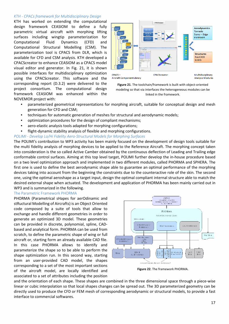
KTH - CPACs framework for Multidisciplinary Design
KTH has worked on extending the computational
design framework CEASIOM to define a fully
parametric virtual aircraft with morphing lifting
surfaces including wingtip parameterization for
Computational Fluid Dynamics (CFD) and
Computational Structural Modelling (CSM). The
parameterization tool is CPACS from DLR, which is
available for CFD and CSM analysis. KTH developed a
CPACScreator to enhance CEASIOM as a CPACS model
visual editor and generator. In Fig. 21, it is shown
possible interfaces for multidisciplinary optimization
using the CPACScreator. This software and the
corresponding report (D.3.2) were delivered to the
project consortium. The computational design
framework CEASIOM was enhanced within the
NOVEMOR project with:
• parameterized geometrical representations for morphing aircraft, suitable for conceptual design and mesh
generation for CFD and CSM;
• techniques for automatic generation of meshes for structural and aerodynamic models;
• optimization procedures for the design of compliant mechanisms;
• aero-elastic analysis tools adapted for morphing configurations;
• flight-dynamic stability analysis of flexible and morphing configurations.
POLIMI - Develop Lo/Hi Fidelity Aero-Structural Models for Morphing Surfaces
The POLIMI’s contribution to WP3 activity has been mainly focused on the development of design tools suitable for
the multi fidelity analysis of morphing devices to be applied to the Reference Aircraft. The morphing concept taken
into consideration is the so called Active Camber obtained by the continuous deflection of Leading and Trailing edge
conformable control surfaces. Aiming at this top level target, POLIMI further develop the in-house procedure based
on a two level optimization approach and implemented in two different modules, called PHORMA and SPHERA. The
first one is used to define the best aerodynamic shape able to guarantee an optimal performance of the morphing
devices taking into account from the beginning the constraints due to the counteractive role of the skin. The second
one, using the optimal aeroshape as a target input, design the optimal compliant internal structure able to match the
desired external shape when actuated. The development and application of PHORMA has been mainly carried out in
WP3 and is summarized in the following.
The Parametric Framework PHORMA
PHORMA (Parametrical sHapes for aerOdinamic and
stRuctural Modelling of Aircrafts) is an Object Oriented
code composed by a suite of tools that allow to
exchange and handle different geometries in order to
generate an optimized 3D model. These geometries
can be provided in discrete, polynomial, spline, CAD-
based and analytical form. PHORMA can be used from
scratch, to define the parametric shape of wing or full
aircraft or, starting form an already available CAD file.
In this case PHORMA allows to identify and
parameterize the shape so to be able to perform the
shape optimization run. In this second way, starting
from an user-provided CAD model, the shapes
corresponding to a set of the most important sections
of the aircraft model, are locally identified and
associated to a set of attributes including the position
and the orientation of each shape. These shapes are combined in the three dimensional space through a piece-wise
linear or cubic interpolation so that local shapes changes can be spread out. The 3D parameterized geometry can be
directly used to produce the CFD or FEM mesh of corresponding aerodynamic or structural models, to provide a fast
interface to commercial softwares.
Figure 21. The toolchain/framework is built with object-oriented
modeling so that via interfaces the heterogeneous modules can be
linked in the framework.
Figure 22. The framework PHORMA.

18
One of the problem in analysing different morphing concepts is related to the need to create in an efficient way all the
necessary morphing geometry models representing the morphing devices in their different status, taking into account
structural and aerodynamic requirements. The approach adopted by POLIMI is based on a procedure developed in a
previous work here tuned for specific morphing devices. The generation of the geometry model of the 3D full wing
corresponding to the different position of the morphing devices is based on the use of PHORMA and it is done in three
steps: a 2D identification of the initial aerofoils, a 2D morphing shape optimization able to introduce the shape changes
under all the design requirements and a 3D propagation to the full wing.
2D and 3D CFD modelling
Aerodynamic loads can be computed by a specific code embedded into the CST tool able to automatically produce a
2D structured mesh around the aerofoils and to perform Navier-Stokes computations. The automatic generation of
the structured mesh around the parameterized aerofoil shape is based on a script for Ansys ICEMCFD. CFD
computations are performed by means of EDGE code. Once the CFD analyses have been performed, the CST tool is
able to extract the results in term of Cp distribution and to spread them along the aerofoil shape used to produce the
load path model.
While the optimal morphing mechanisms is computed at first on the 2D aerofoil, then extended to the full wing, it is
important that the aerodynamic loads considered during the 2D optimization are representative of the 3D wing. For
this reason the aerodynamic loads can be also directly extracted from the 3D CFD computations, performed by.
Afterwards PHORMA is able to extrapolate the aerodynamic results, around one or more sections arbitrarily positioned
and oriented, and to match them to corresponding CST parameterized shapes. Once the 3D model is obtained in a
parametrical way, unstructured surface meshes can be automatically generated without any user intervention.
FEM Modelling
One of the main classes in the framework is the OOP-based PFEM class which incorporates an in-house FEM code able
to handle different types of elements and incorporate different solvers. As well as SPHERA is an object that inherits
the PFEM properties to solve structural problem corresponding to the Load Paths representation, PHORMA is an object
based on different sub-classes which interacts with PFEM methods to generate 3D aeronautical FEM models.
PFEM incorporates modal, buckling, linear and non-linear static analyses, allows to use different types of elements
and provides several methods containing standard tools for the management of a FEM model. In addition to the basic
BAR element and to some isoparametric element, such as Q4 bilinear quadrilateral element, the code includes Finite
Volume Beam element.
Fluid-structure interface
Once the aerodynamic results are computed, a fluid-structure interaction method is used to transfer these loads from
the aerodynamic mesh to the structural grid points placed on the aerofoil skins. For this purpose, a tool based on the
Radial Basis Function (RBF) is available in the procedure. This method ensure the conservation of the energy transfer
between the fluid and the structure. By applying this tool to the trailing and leading edges of morphing aerofoils and
using it as aeroelastic interface, aerodynamic loads are distributed along the beam nodes and reduced to lumped
forces.
Aero-structural Shape Optimization problems
Morphing shape optimizations used to introduce shape
changes into the reference model can be performed by
evaluating the aerodynamic performances in 2D or directly
in 3D space. In both cases, two nested optimization loops are
required: the first one is a 2D structural shape optimization
where only structural constraints are at first satisfied on the
aerofoil skins, in the second one an aerodynamic
optimization is performed starting from physically realizable
aerofoils. In the 2D shape optimization, the process is applied
to each aerofoil shape extracted from the reference CAD
model. After the structural shape optimization, PHORMA
automatically produce the mesh of both clean and morphing
aerofoils, in order to perform as many 2D high–fidelity aerodynamic shape optimizations as the number of identified
sections are. Combining the different optimal aerofoil shapes coming out from the 2D shape optimizations represented
in Fig. 23, the 3D CAD model corresponding to the morphing wing configuration is generated. In the 3D shape
optimization, the process previously described is applied to a set of parameterized aerofoils previously subjected to
the skin constraints via a number of structural shape optimizations equal to the number of identified sections. The
Figure 23. The different LE and TE morphing configurations
investigated.
19
aerodynamic shape optimization directly produce the final 3D morphing model. Figure 23 shows the configuration of
LE and TE morphing control surfaces investigated and applied to the Reference Aircraft.
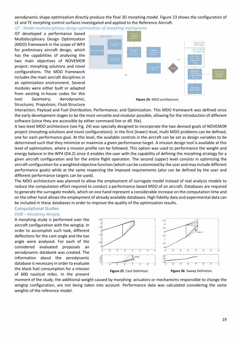
IST - Model multidisciplinary design optimization of morphing mechanisms
IST developed a performance based
Multidisciplinary Design Optimization
(MDO) framework in the scope of WP3
for preliminary aircraft design, which
has the capabilities of analysing the
two main objectives of NOVEMOR
project: morphing solutions and novel
configurations. The MDO framework
includes the main aircraft disciplines in
an optimization environment. Several
modules were either built or adapted
from existing in-house codes for this
tool: Geometry; Aerodynamic;
Structures; Propulsion; Fluid-Structure
Interaction; Payload and Fuel Distribution; Performance; and Optimization. This MDO framework was defined since
the early development stages to be the most versatile and modular possible, allowing for the introduction of different
software (since they are accessible by either command line or dll. file).
A two-level MDO architecture (see Fig. 24) was specially designed to incorporate the two devised goals of NOVEMOR
project (morphing solutions and novel configurations). In the first (lower) level, multi MDO problems can be defined,
one for each performance goal. At this level, the available controls in the aircraft can be set as design variables to be
determined such that they minimize or maximize a given performance target. A mission design tool is available at this
level of optimization, where a mission profile can be followed. This option was used to performance the weight and
energy balance in the WP4 (D4.2) since it enables the user with the capability of defining the morphing strategy for a
given aircraft configuration and for the entire flight operation. The second (upper) level consists in optimizing the
aircraft configuration for a weighted objective function (which can be customized by the user and may include different
performance goals) while at the same respecting the imposed requirements (also can be defined by the user and
different performance targets can be used).
The MDO architecture was planned to allow the employment of surrogate model instead of real analysis models to
reduce the computation effort required to conduct a performance based MDO of an aircraft. Databases are required
to generate the surrogate models, which on one hand represent a considerable increase on the computation time and
on the other hand allows the employment of already available databases. High fidelity data and experimental data can
be included in these databases in order to improve the quality of the optimization results.
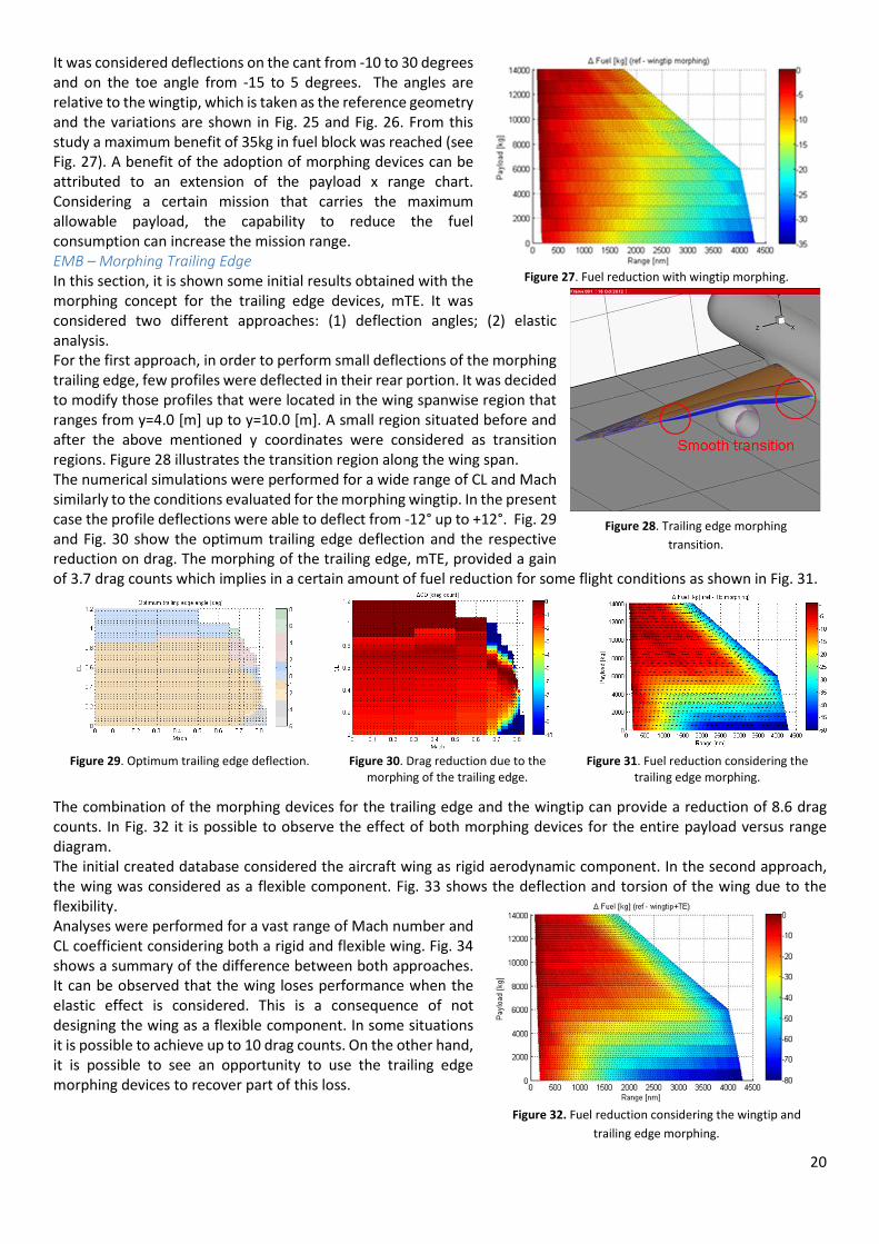
Computational Studies
EMB – Morphing Wingtip
A morphing study is performed over the
aircraft configuration with the wingtip. In
order to accomplish such task, different
deflections for the cant angle and the toe
angle were analysed. For each of the
considered evaluated proposals an
aerodynamic databank was created. The
information about the aerodynamic
database is necessary in order to evaluate
the block fuel consumption for a mission
of 600 nautical miles. In the present
moment of the study, the additional weight caused by morphing actuators or mechanisms responsible to change the
wingtip configuration, are not being taken into account. Performance data was calculated considering the same
weights of the reference model.
Figure 24. MDO architecture.
Figure 25. Cant Definition. Figure 26. Sweep Definition.
20
It was considered deflections on the cant from -10 to 30 degrees
and on the toe angle from -15 to 5 degrees. The angles are
relative to the wingtip, which is taken as the reference geometry
and the variations are shown in Fig. 25 and Fig. 26. From this
study a maximum benefit of 35kg in fuel block was reached (see
Fig. 27). A benefit of the adoption of morphing devices can be
attributed to an extension of the payload x range chart.
Considering a certain mission that carries the maximum
allowable payload, the capability to reduce the fuel
consumption can increase the mission range.
EMB – Morphing Trailing Edge
In this section, it is shown some initial results obtained with the
morphing concept for the trailing edge devices, mTE. It was
considered two different approaches: (1) deflection angles; (2) elastic
analysis.
For the first approach, in order to perform small deflections of the morphing
trailing edge, few profiles were deflected in their rear portion. It was decided
to modify those profiles that were located in the wing spanwise region that
ranges from y=4.0 [m] up to y=10.0 [m]. A small region situated before and
after the above mentioned y coordinates were considered as transition
regions. Figure 28 illustrates the transition region along the wing span.
The numerical simulations were performed for a wide range of CL and Mach
similarly to the conditions evaluated for the morphing wingtip. In the present
case the profile deflections were able to deflect from -12° up to +12°. Fig. 29
and Fig. 30 show the optimum trailing edge deflection and the respective
reduction on drag. The morphing of the trailing edge, mTE, provided a gain
of 3.7 drag counts which implies in a certain amount of fuel reduction for some flight conditions as shown in Fig. 31.
Figure 29. Optimum trailing edge deflection. Figure 30. Drag reduction due to the
morphing of the trailing edge.
Figure 31. Fuel reduction considering the
trailing edge morphing.
The combination of the morphing devices for the trailing edge and the wingtip can provide a reduction of 8.6 drag
counts. In Fig. 32 it is possible to observe the effect of both morphing devices for the entire payload versus range
diagram.
The initial created database considered the aircraft wing as rigid aerodynamic component. In the second approach,
the wing was considered as a flexible component. Fig. 33 shows the deflection and torsion of the wing due to the
flexibility.
Analyses were performed for a vast range of Mach number and
CL coefficient considering both a rigid and flexible wing. Fig. 34
shows a summary of the difference between both approaches.
It can be observed that the wing loses performance when the
elastic effect is considered. This is a consequence of not
designing the wing as a flexible component. In some situations
it is possible to achieve up to 10 drag counts. On the other hand,
it is possible to see an opportunity to use the trailing edge
morphing devices to recover part of this loss.
Figure 27. Fuel reduction with wingtip morphing.
Figure 28. Trailing edge morphing
transition.
Figure 32. Fuel reduction considering the wingtip and
trailing edge morphing.

21
Figure 33. Wing deflection and torsion due to the elastic
effects.
Figure 34. Effect of flexibility on the drag coefficient. (Baseline flexible -
Baseline rigid).
IST – Morphing Wingtip
The performance based MDO framework developed by IST was applied to assess the benefits of introducing morphing
devices on conventional (Reference Aircraft) and unconventional aircraft (Joined-Wing RPV) configurations. The first
problems consists in evaluating the benefits (in terms of fuel consumption) of introducing a morphing wingtip in the
reference model defined by EMBRAER in WP3 (D3.1). The wingtip parameters (span, wingtip chord, cant, toe and
sweep in Fig. 35) were first optimized such that they maximizes the range and then the angles of toe, cant and sweep
were optimized for fuel consumption minimization for climb and hold conditions. No significant benefits were achieved
by enabling the wingtip with morphing capabilities since less than 1% reduction in fuel consumption was obtained (for
both climb and hold). This benefit is deemed insignificant and most probably, the inclusion of the added weight due
to the morphing actuation mechanism (only the wingtip structure with the spar and caps were considered for the
calculations) may lead to a smaller gain or even a decrease in efficiency. In the second problem, a morphing wingtip
concept was purposed to improve the poor lateral-directional stability of the small JW PRV and the results were
discussed in the previous WP summary (WP2).
Figure 35. Wingtip morphing concept.
KTH - Winglet Design of Regional Jet Aircraft
The original reference wing
has a winglet with cant
angle 12 degrees, or, the
folded angle 7 degrees since
the wing has a 5 degrees
dihedral. It shows that for
cruise condition the
reference wing (7 degrees
folded angle) has the
minimum inviscid drag (Fig.
36). The enhancements
performed by KTH to the
CEASIOM software were
tested on the reference
model and a morphing
winglet was optimized for
cruise condition achieving an 8% reduction on the inviscid drag.
Winglet Tip Chord
Toe Angle
Cant Angle
Sweep Angle
Winglet Span
Figure 36. Euler solutions for the reference model with different winglet cant angles at Mach 0.78 and
CL =0.47: Mach contours (left); and inviscid drag coefficients CDinv (right).
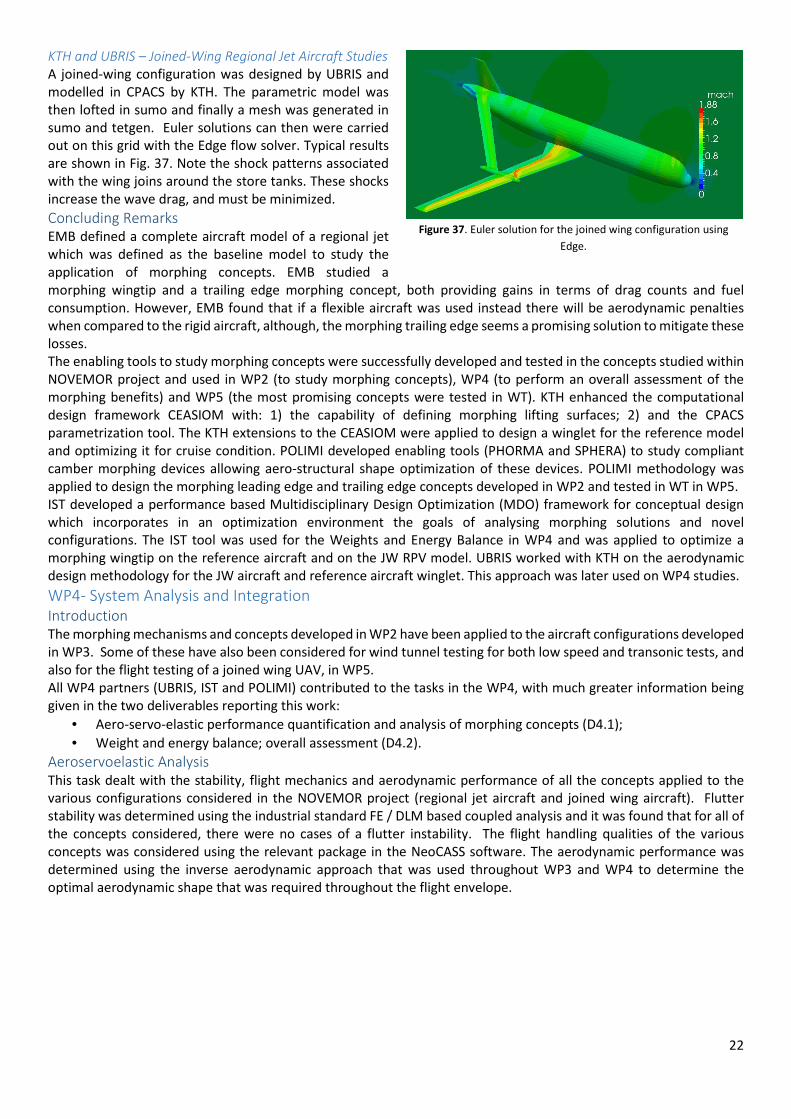
22
KTH and UBRIS – Joined-Wing Regional Jet Aircraft Studies
A joined-wing configuration was designed by UBRIS and
modelled in CPACS by KTH. The parametric model was
then lofted in sumo and finally a mesh was generated in
sumo and tetgen. Euler solutions can then were carried
out on this grid with the Edge flow solver. Typical results
are shown in Fig. 37. Note the shock patterns associated
with the wing joins around the store tanks. These shocks
increase the wave drag, and must be minimized.
Concluding Remarks
EMB defined a complete aircraft model of a regional jet
which was defined as the baseline model to study the
application of morphing concepts. EMB studied a
morphing wingtip and a trailing edge morphing concept, both providing gains in terms of drag counts and fuel
consumption. However, EMB found that if a flexible aircraft was used instead there will be aerodynamic penalties
when compared to the rigid aircraft, although, the morphing trailing edge seems a promising solution to mitigate these
losses.
The enabling tools to study morphing concepts were successfully developed and tested in the concepts studied within
NOVEMOR project and used in WP2 (to study morphing concepts), WP4 (to perform an overall assessment of the
morphing benefits) and WP5 (the most promising concepts were tested in WT). KTH enhanced the computational
design framework CEASIOM with: 1) the capability of defining morphing lifting surfaces; 2) and the CPACS
parametrization tool. The KTH extensions to the CEASIOM were applied to design a winglet for the reference model
and optimizing it for cruise condition. POLIMI developed enabling tools (PHORMA and SPHERA) to study compliant
camber morphing devices allowing aero-structural shape optimization of these devices. POLIMI methodology was
applied to design the morphing leading edge and trailing edge concepts developed in WP2 and tested in WT in WP5.
IST developed a performance based Multidisciplinary Design Optimization (MDO) framework for conceptual design
which incorporates in an optimization environment the goals of analysing morphing solutions and novel
configurations. The IST tool was used for the Weights and Energy Balance in WP4 and was applied to optimize a
morphing wingtip on the reference aircraft and on the JW RPV model. UBRIS worked with KTH on the aerodynamic
design methodology for the JW aircraft and reference aircraft winglet. This approach was later used on WP4 studies.
WP4- System Analysis and Integration
Introduction
The morphing mechanisms and concepts developed in WP2 have been applied to the aircraft configurations developed
in WP3. Some of these have also been considered for wind tunnel testing for both low speed and transonic tests, and
also for the flight testing of a joined wing UAV, in WP5.
All WP4 partners (UBRIS, IST and POLIMI) contributed to the tasks in the WP4, with much greater information being
given in the two deliverables reporting this work:
• Aero-servo-elastic performance quantification and analysis of morphing concepts (D4.1);
• Weight and energy balance; overall assessment (D4.2).
Aeroservoelastic Analysis
This task dealt with the stability, flight mechanics and aerodynamic performance of all the concepts applied to the
various configurations considered in the NOVEMOR project (regional jet aircraft and joined wing aircraft). Flutter
stability was determined using the industrial standard FE / DLM based coupled analysis and it was found that for all of
the concepts considered, there were no cases of a flutter instability. The flight handling qualities of the various
concepts was considered using the relevant package in the NeoCASS software. The aerodynamic performance was
determined using the inverse aerodynamic approach that was used throughout WP3 and WP4 to determine the
optimal aerodynamic shape that was required throughout the flight envelope.
Figure 37. Euler solution for the joined wing configuration using
Edge.

23
There were no flutter stability / divergence issues found within the desired flight envelope for the range of concepts
considered (leading edge and trailing edge morphing, adaptive stiffness morphing). Similarly, there were also no flight
mechanics (i.e. flight handling qualities) issues resulting from application of except for some of the grosser planform
deformations considered for one of the joined wing RPV configurations.
Weight and Energy Balance
This task dealt with the methodology for evaluation of morphing concepts and novel configurations. In the morphing
concepts analysis, the approach is essentially determining the allowable weight penalty due to morphing
implementation before this implementation causes penalty in fuel consumption instead of benefit. In the Joined Wing
configuration analysis, two approaches were followed: 1) the concept is initially optimized for a configuration with
fixed span and lifting area as the sum of main and aft wing surfaces (same as the reference aircraft main wing span
and area) of the main wing using performance based optimization in order to determine the benefits relatively to the
reference aircraft configuration for a specific mission. 2) Parametric studies were performed allowing this time the
main wing span to vary while the lifting area of the main wing is kept constant (same as reference aircraft). For both
Joined Wing analysis approaches, the fuel consumption comparison with the reference aircraft was used as metrics
for the configuration merit.
The methodology behind all the analysis described are based on the calculation of aerodynamic, structural, mass and
inertia and propulsion databases which are used to build surrogate models in order to optimize the controls (including
morphing surfaces/concepts) for a set of flight conditions.
Once this configuration databases are calculated, performance parameters are calculated for an aircraft configuration
(e.g. fuel consumption), for a specific mission or a set of missions.
The optimal configuration is then determined through an optimization process based on the performance parameters
obtained, either inserted in the objective or constraint functions calculation, thus reducing the multidisciplinary
optimization complexity to a set of performance goals.
The morphing Leading Edge (mLE) concept was shown to be beneficial when the aircraft is operating at high angles of
attack. Its aerodynamic benefits come from aligning the LE of the actuated wing segments with the flow without
significant changes in the lift distribution. There is an exchange between reduction of local Angle of Attack (AOA) and
increase in local camber.
The morphing Trailing Edge (mTE) concept shown aerodynamic improvement in all the levelled flight mission
segments. The physics behind the improvement may be due to a reduction in operational AOA, leading to the
alignment of the fuselage with the flow and consequent reduction in fuselage drag or a change in lift distribution and
reduction of wing induced drag or a combination of both.
The calculations performed allow to estimate the consumption as a function of Take Off Weight (TOW) for the
reference and morphing aircrafts and, by doing so, calculate the difference between the morphing aircrafts and the
reference aircraft TOW for the same consumption. This difference was designated here as the Allowable TO Weight
Increase (AWI) and provides an estimate of how much weight one can add to the aircraft with morphing concepts
implementation before benefits turn into penalties.
Figure 38. Sample vg and vω plots for Joined Wing
Aircraft. Figure 39. Phugoid Plot for Sample Joined Wing
Configuration.
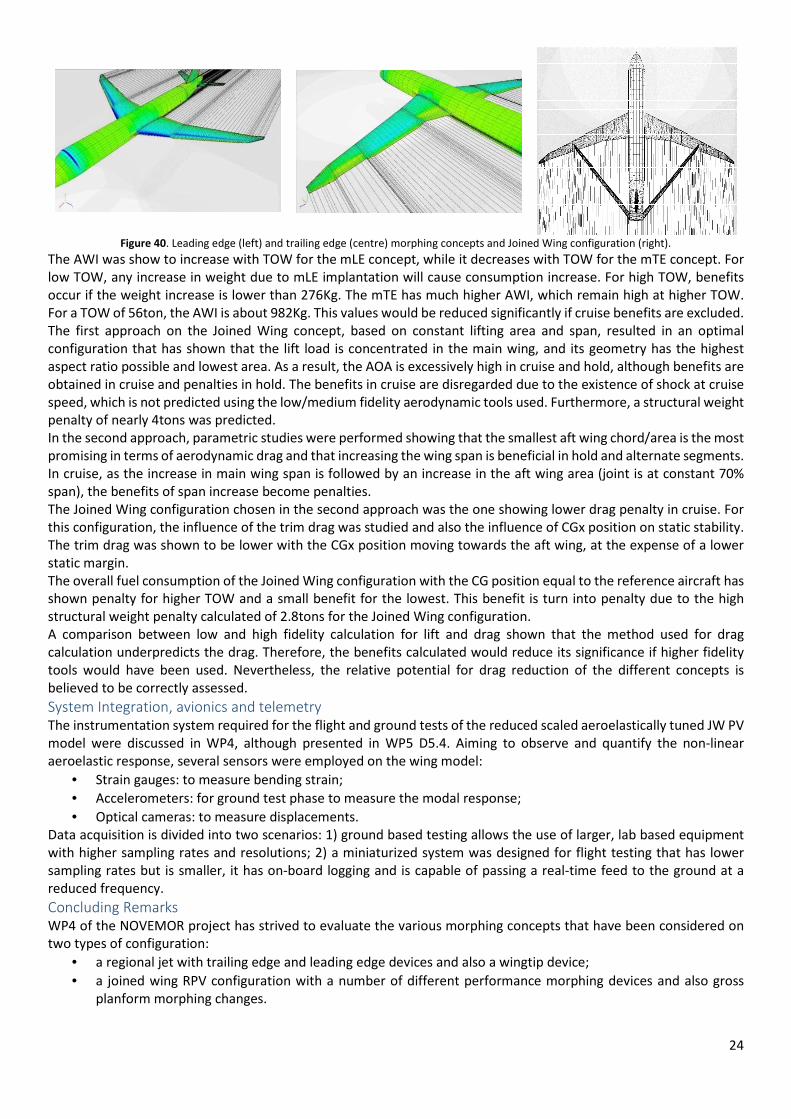
24
Figure 40. Leading edge (left) and trailing edge (centre) morphing concepts and Joined Wing configuration (right).
The AWI was show to increase with TOW for the mLE concept, while it decreases with TOW for the mTE concept. For
low TOW, any increase in weight due to mLE implantation will cause consumption increase. For high TOW, benefits
occur if the weight increase is lower than 276Kg. The mTE has much higher AWI, which remain high at higher TOW.
For a TOW of 56ton, the AWI is about 982Kg. This values would be reduced significantly if cruise benefits are excluded.
The first approach on the Joined Wing concept, based on constant lifting area and span, resulted in an optimal
configuration that has shown that the lift load is concentrated in the main wing, and its geometry has the highest
aspect ratio possible and lowest area. As a result, the AOA is excessively high in cruise and hold, although benefits are
obtained in cruise and penalties in hold. The benefits in cruise are disregarded due to the existence of shock at cruise
speed, which is not predicted using the low/medium fidelity aerodynamic tools used. Furthermore, a structural weight
penalty of nearly 4tons was predicted.
In the second approach, parametric studies were performed showing that the smallest aft wing chord/area is the most
promising in terms of aerodynamic drag and that increasing the wing span is beneficial in hold and alternate segments.
In cruise, as the increase in main wing span is followed by an increase in the aft wing area (joint is at constant 70%
span), the benefits of span increase become penalties.
The Joined Wing configuration chosen in the second approach was the one showing lower drag penalty in cruise. For
this configuration, the influence of the trim drag was studied and also the influence of CGx position on static stability.
The trim drag was shown to be lower with the CGx position moving towards the aft wing, at the expense of a lower
static margin.
The overall fuel consumption of the Joined Wing configuration with the CG position equal to the reference aircraft has
shown penalty for higher TOW and a small benefit for the lowest. This benefit is turn into penalty due to the high
structural weight penalty calculated of 2.8tons for the Joined Wing configuration.
A comparison between low and high fidelity calculation for lift and drag shown that the method used for drag
calculation underpredicts the drag. Therefore, the benefits calculated would reduce its significance if higher fidelity
tools would have been used. Nevertheless, the relative potential for drag reduction of the different concepts is
believed to be correctly assessed.
System Integration, avionics and telemetry
The instrumentation system required for the flight and ground tests of the reduced scaled aeroelastically tuned JW PV
model were discussed in WP4, although presented in WP5 D5.4. Aiming to observe and quantify the non-linear
aeroelastic response, several sensors were employed on the wing model:
• Strain gauges: to measure bending strain;
• Accelerometers: for ground test phase to measure the modal response;
• Optical cameras: to measure displacements.
Data acquisition is divided into two scenarios: 1) ground based testing allows the use of larger, lab based equipment
with higher sampling rates and resolutions; 2) a miniaturized system was designed for flight testing that has lower
sampling rates but is smaller, it has on-board logging and is capable of passing a real-time feed to the ground at a
reduced frequency.
Concluding Remarks
WP4 of the NOVEMOR project has strived to evaluate the various morphing concepts that have been considered on
two types of configuration:
• a regional jet with trailing edge and leading edge devices and also a wingtip device;
• a joined wing RPV configuration with a number of different performance morphing devices and also gross
planform morphing changes.

25
A further consideration of the joined wing design was the conceptual design of commercial jet aircraft using this
configuration.
The main findings from this WP are:
• The configuration of the original reference regional jet aircraft was such that any added wingtips had little
effectiveness regardless of the amount or type of morphing that was applied. Analysis was performed using
an inverse aerodynamic design approach to determine the optimum aerodynamic shape for each
configuration.
• An approach to include morphing devices into the aerodynamics and structural design process, including jig
shape design, was developed. It was shown that the combination of both camber and variable stiffness
morphing provides the most effective way of obtaining the optimal aerodynamic shape throughout the flight
envelope. It was shown that for an aircraft design for a particular range, the use of morphing was beneficial
for missions much shorter than the design range. The effect of uncertainty on the structures and aerodynamics
used throughout the design process was also considered, and the uncertainty in the aerodynamic parameters
was found to have a significant effect upon the structural design robustness.
• A range of different morphing concepts were applied to the baseline joined wing RPV model, including the
wing tip and the front wing. It was shown that leading edge morphing of the front wing was most beneficial.
Figure 41. Sweep Morphing Concepts Applied to Baseline Joined Wing Wingtip.
• The conceptual design of a joined wing regional jet aircraft was investigated and it was shown that such a
design merits serious consideration if much larger aspect ratios are considered than previously investigated.
Figure 42. Joined Wing Regional Jet Designs Considered in this Study.
• A range of different planform morphing concepts were considered to the baseline RPV joined wing design. It
was shown that it is possible to develop a joined wing design with very good characteristics, however the
concepts considered were thought to be of much practical application.
• A number of performance morphing concepts were applied to the wing tip of the baseline joined wing aircraft.
It was shown that the application of a number of different morphing approaches to the outer wing had very
little effect on this baseline configuration, particularly for roll control, and that leading edge / trailing morphing
applied to the forward wing was the most effective, along with a variable twist device applied to the wing tip.
• A buckling alleviation component was developed that has the potential to be used to alleviate the onset of
nonlinear buckling of the rear wing which has proved to be a critical component of joined wing design. Initial
studies have proved very encouraging.
• The overall benefits of the mLE and mTE concepts application to a regional commercial aircraft have shown to
be limited and most probably overestimated. Nevertheless, the relative potential of the two concepts was
evaluated.
• The mLE concept has shown greater potential for benefits in high CL flight conditions, namely Hold stage.
These benefits were calculated to be 2.1% in a 56tons TOW aircraft performing the typical mission of the
reference regional aircraft considered in the NOVEMOR project. The concept virtually does not alter the lift
distribution and therefore does no incur in structural weight penalty.

26
• The AWI of the mLE concept increases as
the TOW increases. Thus, implementing
the concept would require substitution of
the existing LE devices in order not to
penalize consumption in lower TOW
missions.
• The mTE concept has shown potential
benefits in all CL flight conditions. Benefits
calculated range from 4.5% to 6.5% for
different TOW, increasing as TOW
increases. When disregarding cruise
condition gains, benefits range from 1.7%
to 4.3%. This concept incurs in weight
penalty since it alters the lift distribution on
the wing in order to reduce induced drag.
The resulting increase of Root Bending Moment causes a structural weight penalty calculated to be of 218Kg,
with corresponding reduction in range or payload.
• The AWI of the mTE concept decreases as TOW increases. Nevertheless, the calculated AWI is high enough for
high TOWs to accommodate the structural weight penalty of 218Kg and some more weight coming from
mechanism implementation.
• Even though the mTE benefits are shown to be higher and occurring in all regions of the flight envelope, its
implementation conflicts with lift requirements for Take Off as these are not foreseen to be able to substitute
the conventional flap systems.
• From the Joined Wing configurations analysis and optimization, it was not shown that this configuration could
bring significant benefits in the future, mainly due to the high structural weight penalty caused by the
reduction in root chord of the main wing as the Aspect Ratio of the wing is increased. Different degrees of
freedom for the configuration optimization, both aerodynamic and structural, may change this conclusion.
WP5- Wind Tunnel and Flight Demonstrators for Validation of Morphing Concepts and Joined Wing
Configuration
Introduction
The main goal of this WP was the WT and flight testing of developed concepts on physical platforms: subsonic and
transonic WT models and aeroelastically scaled joined-wing RPV
Validation testing is a critical component when developing new aircraft technology. No matter how novel a new
concept may appear, this is not proven useful until a qualified test campaign have been successfully completed. This
is even truer when dealing with concepts that exploit new morphing solutions of the airframe to achieve performance
benefit. The multidisciplinary character of the morphing airframe makes it very difficult to develop simulation models
that are sufficiently accurate and efficient for design purposes. Aerodynamic analysis always poses a significant
challenge, but even the development of an accurate structural model of a real airframe can be a very involved and
time-consuming process. Another problem related to the multidisciplinary character is related to the fact that the
improvement of some performance metric can be accompanied by a loss of performance in another metric, since it is
very difficult to consider all possible correlated effects during the design process. Ultimately, this calls for careful
validation testing under realistic conditions in order to investigate if a concept is feasible or not.
The purpose of this effort is to validate the adaptive/morphing concepts developed in WP2, using wind tunnel testing
and especially to support partners decisions for rejection or further development of the different concepts. Thus, the
principal objectives of this WP have been:
1. Experimental validation (functionality test) of the adaptive morphing Leading Edge, Trailing Edge and Wing tip
developed by DLR, POLIMI, UBRIS and IST in WP2 and 3.
2. Experimental validation of the LE and TE morphing shapes developed by EMBRAER and POLIMI by means of
dedicated WT transonic test carried out at CSIR.
3. Experimental flight test validation of real-time (in-flight) joined-wing aeroelastically scaled RPV to assess
airworthiness and to validate the aeroelastic response on dynamically scaled joined-wing aircraft.
In the following the main outcomes of these activities are highlighted.
Figure 43. Consumption as a function of Mission Take-Off Wright for the
reference and morphed aircraft.

27
Wind Tunnel Tests
UBRIS – Functionality tests
Four sets of low speed wind tunnel tests were performed at the University of Bristol as part of the NOVEMOR research
project. The tests were performed in the 7 feet (2.1m) x 5 feet (1.5m) wind tunnel at UBRIS, see Fig. 44, which has a
top speed of 60 m/s. Each of the sets of wind tunnel tests was focused upon a different morphing concept applied to
a wing-tip, which are described in much greater detail in NOVEMOR deliverables D2.4 and D4.1, with a greater
explanation of the wind tunnel test matrix and results shown in deliverable D5.1. The concepts considered were:
• Droop-Nose Adaptive Morphing Wingtip
• Honeycomb Trailing Edge Concept
• Chiral Wing Tip Concept
• Variable Stiffness Rotating Spars
For the first three of these concepts, this was the first time that a prototype had been designed, manufactured and
wind tunnel tested. Although the rotating spars approach had been implemented in previous work, the concept was
included here in order to compare the variable stiffness methodology with the other concepts; it had not been
previously applied to a swept wing at such a high dynamic pressure.
The drooping morphing leading edge concept was applied to a full scale model of a wing tip of the reference regional
jet aircraft, whereas the other three concepts were applied to a half size model of the wing tip of the joined wing UAV
that was flight tested as part of the NOVEMOR project and described in deliverable D5.4.
Wind Tunnel model of Wingtip with droop nose. Wind tunnel model based on chiral structure
Wing equipped with honeycomb trailing edge. Rotating spar wing structure.
Figure 44. UBRIS wind tunnel models.
The key outcome from these tests was the experimental demonstration of the feasibility of using these morphing
concepts (Fig. 44). Further work is required to continue developing these morphing concepts.
CSIR – Transonic Wind Tunnel Tests
The work package 5.2 focused on the transonic wind tunnel test of the wing body configuration representing a high
speed regional transport aircraft, called Reference Aircraft, developed by EMBRAER in WP3. In particular, the
performances in the baseline configuration and in one equipped with morphing LE and TE have been evaluated to
validate the CFD results. More in details, the objectives of the tests are to characterize the global forces and moments
of the half model reference and morphed configurations for the wing only. The test was executed in accordance with
the test specification.
A full boundary layer simulation exercise was conducted, investigating the effect of different trip locations and total
pressures (Reynolds number sweeps). Laminar to turbulent trip locations were applied at 5%, 20%, 35% of the chord
and also without dots for natural tripping.

28
Finally, different visualizations have been performed to help interpret the global force and moment trends and to
check if the trips were performing their function of tripping the flow.
POLIMI – Functionality Tests
The work package 5.3 focused on the functionality test performed at POLIMI on a small scale (1:10) wing model to
validate the functionality of morphing devices under realistic aerodynamic loads. For this reason not special
aerodynamic indices have been measured, such as aerodynamic forces by means of a dedicated wind tunnel balance.
The POLIMI’s tools PHORMA and SPHERA have been used for the design of morphing mechanisms. Starting from the
morphing configuration already developed in WP3 for the Reference Aircraft. Unfortunately, due to the small scale of
the model, it is impossible to simply scale down the already available solution for the full scale aircraft. For this reason,
a complete new optimization was requested for the redesign of the morphing devices. In the process of transferring
optimal solutions into physical models, many issues emerged during the design of realistic geometries compatible not
only with desired kinematic and structural performance, but also with manufacturing limitations. In this regard, near
prohibitive challenges were posed by the small scale of the wind tunnel test chamber for such morphing devices, in
the individuation of production technologies that could cope with extremely complex compliant mechanism layouts
and their deformation requirements.
3D printing solutions were deemed the most appropriate thanks to their capabilities in terms of complex shape
reproduction and material flexibility for the limited scale of the models. After some failed attempts, PolyJet Modelling
Figure 45. Modular wing model configuration: baseline LE and TE can be substituted by the morphing ones
(left); overview of the full model during the test (right).
Figure 46. Flow visualization (left) and one of the numerical vs. experimental correlation result (right).
-1 0 1 2 3 4 5 6 7-0.1
0
0.1
0.2
0.3
0.4
0.5
0.6
0.7
0.8
Angle of Attack [deg]
CL
EMB
MSWT - Shifted
CSIR-CFD
Figure 47. Simulation model of the morphing LE based on a compliant structures (left); CAD model of the compliant
TE ready for 3D printing (right).
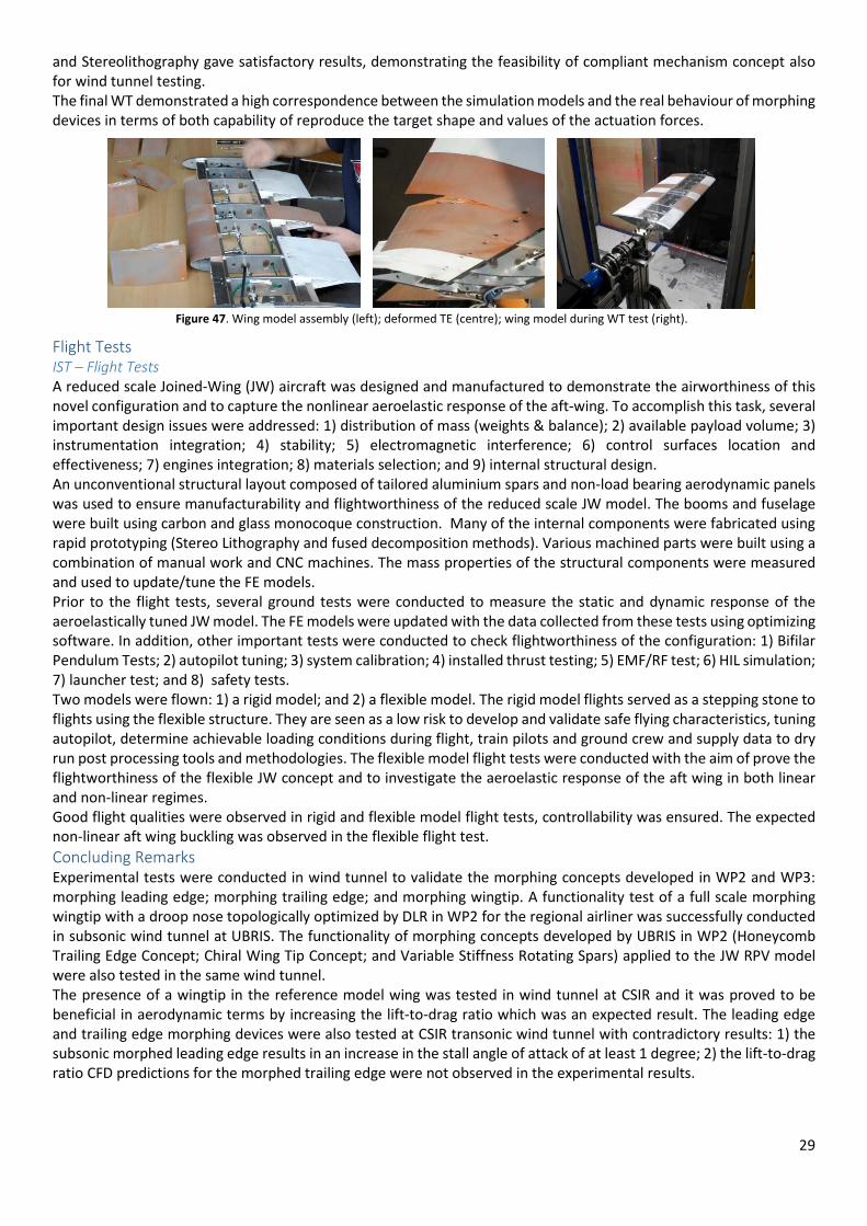
29
and Stereolithography gave satisfactory results, demonstrating the feasibility of compliant mechanism concept also
for wind tunnel testing.
The final WT demonstrated a high correspondence between the simulation models and the real behaviour of morphing
devices in terms of both capability of reproduce the target shape and values of the actuation forces.
Flight Tests
IST – Flight Tests
A reduced scale Joined-Wing (JW) aircraft was designed and manufactured to demonstrate the airworthiness of this
novel configuration and to capture the nonlinear aeroelastic response of the aft-wing. To accomplish this task, several
important design issues were addressed: 1) distribution of mass (weights & balance); 2) available payload volume; 3)
instrumentation integration; 4) stability; 5) electromagnetic interference; 6) control surfaces location and
effectiveness; 7) engines integration; 8) materials selection; and 9) internal structural design.
An unconventional structural layout composed of tailored aluminium spars and non-load bearing aerodynamic panels
was used to ensure manufacturability and flightworthiness of the reduced scale JW model. The booms and fuselage
were built using carbon and glass monocoque construction. Many of the internal components were fabricated using
rapid prototyping (Stereo Lithography and fused decomposition methods). Various machined parts were built using a
combination of manual work and CNC machines. The mass properties of the structural components were measured
and used to update/tune the FE models.
Prior to the flight tests, several ground tests were conducted to measure the static and dynamic response of the
aeroelastically tuned JW model. The FE models were updated with the data collected from these tests using optimizing
software. In addition, other important tests were conducted to check flightworthiness of the configuration: 1) Bifilar
Pendulum Tests; 2) autopilot tuning; 3) system calibration; 4) installed thrust testing; 5) EMF/RF test; 6) HIL simulation;
7) launcher test; and 8) safety tests.
Two models were flown: 1) a rigid model; and 2) a flexible model. The rigid model flights served as a stepping stone to
flights using the flexible structure. They are seen as a low risk to develop and validate safe flying characteristics, tuning
autopilot, determine achievable loading conditions during flight, train pilots and ground crew and supply data to dry
run post processing tools and methodologies. The flexible model flight tests were conducted with the aim of prove the
flightworthiness of the flexible JW concept and to investigate the aeroelastic response of the aft wing in both linear
and non-linear regimes.
Good flight qualities were observed in rigid and flexible model flight tests, controllability was ensured. The expected
non-linear aft wing buckling was observed in the flexible flight test.
Concluding Remarks
Experimental tests were conducted in wind tunnel to validate the morphing concepts developed in WP2 and WP3:
morphing leading edge; morphing trailing edge; and morphing wingtip. A functionality test of a full scale morphing
wingtip with a droop nose topologically optimized by DLR in WP2 for the regional airliner was successfully conducted
in subsonic wind tunnel at UBRIS. The functionality of morphing concepts developed by UBRIS in WP2 (Honeycomb
Trailing Edge Concept; Chiral Wing Tip Concept; and Variable Stiffness Rotating Spars) applied to the JW RPV model
were also tested in the same wind tunnel.
The presence of a wingtip in the reference model wing was tested in wind tunnel at CSIR and it was proved to be
beneficial in aerodynamic terms by increasing the lift-to-drag ratio which was an expected result. The leading edge
and trailing edge morphing devices were also tested at CSIR transonic wind tunnel with contradictory results: 1) the
subsonic morphed leading edge results in an increase in the stall angle of attack of at least 1 degree; 2) the lift-to-drag
ratio CFD predictions for the morphed trailing edge were not observed in the experimental results.
Figure 47. Wing model assembly (left); deformed TE (centre); wing model during WT test (right).

30
At POLIMI wind tunnel a reduced scale morphing leading edge device and a morphing trailing edge device were tested.
Good agreement between simulation and experimental models was observed in terms of both capability of reproduce
the target shape and values of the actuation forces.
A reduced scale JW model was designed, manufactured and tested in ground and flight. It was observed non-linear
aft-wing buckling on the aeroelastically tuned JW model.
WP6- Benefit Evaluation in Terms of Impact on Lift, Drag, Weight and Aeroelastic Response
Introduction
The working scope defined in WP6 was covered on its totality. In order to assess the benefits of the morphing devices
numerical and experimental approaches were employed. The conducted investigations were focused in evaluating the
decrease in the drag coefficient, the improvement in the lift coefficient, the weight increase or decrease and the
aeroelastic behaviour to define the overall benefits.
In the first moment the assessment of the benefits have just considered the aerodynamic point of view. Thereafter,
subsequent analyses, from different technologies, were performed in order to evaluate if a benefit could still be found.
It is worth mentioning that it is not an easy task to define the level of fidelity and details that each analysis must
consider. Certainly each performed analysis, in the present project, could not get into the tiny details up to component
level for each analysed system. Nevertheless, rather than certificating a specific morphing configuration most of the
project objectives lie on a more general feasibility assessment wherein different morphing proposals are evaluated.
Aerodynamic Benefits (Lift and Drag)
The aerodynamic analyses for the reference aircraft and the evaluated morphing devices were performed in
accordance with the adopted strategy defined at the beginning of the project. The definition of the mathematical and
numerical formulations considered the need to have the most adequate approach to capture the pertinent physical
phenomena at the subsonic and transonic regime. Indeed, as expected the transonic regime has demanded the use of
high-fidelity tools to capture the non-linearity of the flow.
The obtained numerical results for the trailing edge morphing devices could not be validated with the wind tunnel
results. It was not possible to observe the numerical morphing benefits reproduced at the wind tunnel. Nevertheless,
the work performed on both numerical and experimental sides has shown how challenging is to measure and validate
small differences for the aerodynamic coefficient. This experience has provided important lessons that address the
following issues:
a) the need to adopt numerical approaches that consider higher order schemes to ensure that the small
measured differences are indeed present;
b) wind tunnel balance with the capacity to measure the small differences in the lift and drag coefficients.
Another important conclusion from the aerodynamic and performance assessment of the morphing devices lies on
the fact that the design process must consider the use of such technology since the earlier design phases.
Weight Savings
For those aircrafts that do not belong to non-conventional category the weight estimation is a consolidated process
due to the vast database from aviation history. However, for aircrafts that employ new technologies such as the
morphing devices this is not an easy task due to the lack of available data in the literature. In terms of weight it was
decided to perform the assessment considering two methods. The first one is called method P0 and it considered the
combination of the morphing devices with the high-lift devices. It was performed an energetic analysis to considered
the maximum allowable weight that would still imply in benefits in performance. The second method, named method
P1, considered the substitution of the high-lift devices by the morphing devices. This method established two metrics:
the weight per length for the leading edge and the weight per area for the trailing edge.
The performed study of the NOVEMOR project about the weight benefits does not allow a conclusive position about
this issue. The results from the method P0 seem optimistic whilst those from the method P1 are not conclusive due to
the dispersion. The weight assessment is not simple because it implies in evaluation of the configuration at the
component level or the use of consolidated database which is not available for the morphing technology. Thereby, in
order to have any sort of weight assessment about the morphing device it is necessary to employ a detailed analysis
about the structural solution, mechanisms and the actuators.
Aeroelastic Response
The aeroelastic results have not shown any type of degradation in the flutter velocity provoked by the adoption of the
morphing devices. A multi-fidelity analysis has been performed with the FEM model.
POLIMI developed an aeroelastic model of the reference aircraft to analyse the aeroelastic behaviour of the reference
model and in particularly to assess the effect of morphing leading edge (mLE) and morphing trailing edge (mTE) devices
in the aeroelastic behaviour of the reference regional aircraft. The analyses were conducted in PyPAD (Python module

31
for Preliminary Aircraft Design) framework developed by POLIMI. This framework includes a Panel Code to model the
aerodynamics and for the aircraft structure a complete FE model is built (including ribs, spars, skin and stringers in the
wings as well as accounting for movable parts such as the mLE and mTE devices).
The effect of deflecting the morphing leading and trailing edge devices was evaluated in terms of trim solutions and
load distributions. The morphing deflection were considered both rigid and flexible. The Mach number were
considered in the calculations: 0.3, 0.5 and 0.7.
The first results suggest that the effect of the morphing on the stability derivatives and on the trim solutions is clearly
influenced by the aeroelastic behaviour of the model which effect increases as Cmy/Morp increases.
By evaluating the CP distributions, a clear difference between the solution with morphing deformation and the one
without for Mach 0.3 is observed, although the difference between rigid and aeroelastic solutions is small. When the
Mach increases the difference between rigid and aeroelastic solutions increases (worth remembering that also the
trim solutions are different) especially in the outboard part of the wing, where the deformations are larger.
The changes in CP distributions also affect the internal loads on the aircraft and in particularly on the wings. The
morphing effect is visible in the torque moment for the Mach 0.3 case: the lift moves back along the chord, increasing
his arm from the shear centre. This behaviour increase in importance by increasing the Mach number. Also by
increasing the Mach number the differences on shear and bending moments increase: globally the loads are lower
when the aeroelastic effects are considered, but the shear at the root increases when the morphing is activated. This
because the angle of attack required to trim the aircraft is lower when the aircraft is morphed and the outboard part
of the wing, due to twist in the airfoils and to elastic deformation has a negative incidence.
Concluding Remarks
EMB foresees the morphing devices as a promising technology that can and will provide benefits to ACARE main goals.
However, the employment of the morphing devices, at the regional aviation, might occur in a second moment due to
the following peculiarities:
• It is not possible to rely entirely on the morphing devices to satisfy the demanded aircraft field performance.
o High-lift devices are still necessary.
• Regional jet wings are relatively small, which brings difficulties to have any kind of mixed solution:
conventional high-lift devices and morphing devices.
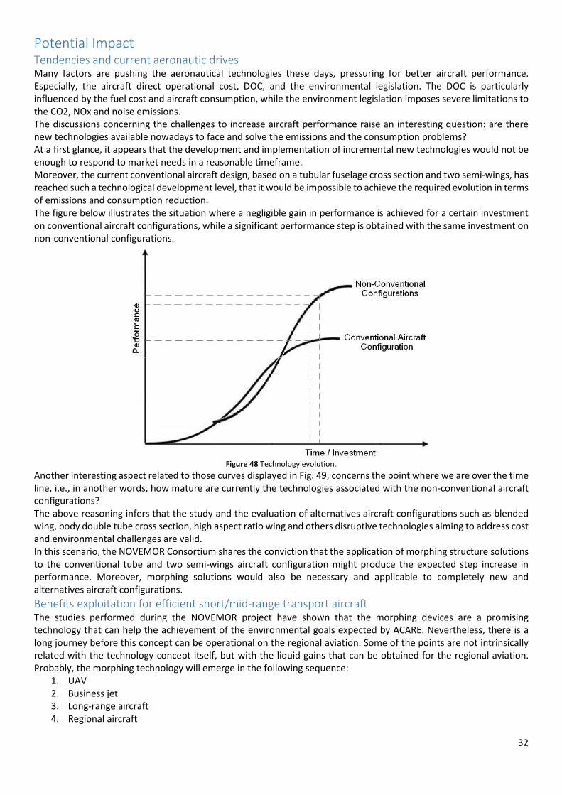
32
Potential Impact Tendencies and current aeronautic drives Many factors are pushing the aeronautical technologies these days, pressuring for better aircraft performance.
Especially, the aircraft direct operational cost, DOC, and the environmental legislation. The DOC is particularly
influenced by the fuel cost and aircraft consumption, while the environment legislation imposes severe limitations to
the CO2, NOx and noise emissions.
The discussions concerning the challenges to increase aircraft performance raise an interesting question: are there
new technologies available nowadays to face and solve the emissions and the consumption problems?
At a first glance, it appears that the development and implementation of incremental new technologies would not be
enough to respond to market needs in a reasonable timeframe.
Moreover, the current conventional aircraft design, based on a tubular fuselage cross section and two semi-wings, has
reached such a technological development level, that it would be impossible to achieve the required evolution in terms
of emissions and consumption reduction.
The figure below illustrates the situation where a negligible gain in performance is achieved for a certain investment
on conventional aircraft configurations, while a significant performance step is obtained with the same investment on
non-conventional configurations.
Figure 48 Technology evolution.
Another interesting aspect related to those curves displayed in Fig. 49, concerns the point where we are over the time
line, i.e., in another words, how mature are currently the technologies associated with the non-conventional aircraft
configurations?
The above reasoning infers that the study and the evaluation of alternatives aircraft configurations such as blended
wing, body double tube cross section, high aspect ratio wing and others disruptive technologies aiming to address cost
and environmental challenges are valid.
In this scenario, the NOVEMOR Consortium shares the conviction that the application of morphing structure solutions
to the conventional tube and two semi-wings aircraft configuration might produce the expected step increase in
performance. Moreover, morphing solutions would also be necessary and applicable to completely new and
alternatives aircraft configurations.
Benefits exploitation for efficient short/mid-range transport aircraft The studies performed during the NOVEMOR project have shown that the morphing devices are a promising
technology that can help the achievement of the environmental goals expected by ACARE. Nevertheless, there is a
long journey before this concept can be operational on the regional aviation. Some of the points are not intrinsically
related with the technology concept itself, but with the liquid gains that can be obtained for the regional aviation.
Probably, the morphing technology will emerge in the following sequence:
1. UAV
2. Business jet
3. Long-range aircraft
4. Regional aircraft

33
Figure 49 depicts a simple analysis wherein the wingtip morphing device is broken up to component level. The idea
behind this exercise is to define the technological readiness level, TRL, for the morphing devices. In order to have any
new technology implemented into the aircraft it is required that the entire system reaches TRL nine and if one single
component does satisfy such requirement the technology is not available.
Figure 49. Example of a simple exercise that goes from the system level up to some component level for one morphing device solution.
Figure 50 shows an example of the estimation exercise to define the TRL level for the wingtip morphing devices. The
columns of the table shown in Figure 50 were filled based on the performed analyses conducted in the NOVEMOR
project. It can be observed that the TRL varies as function of the considered analysis. Based on the overall analysis
performed with the results of the NOVEMOR project it is expected to have TRL nine in approximately 15 years. There
are some topics that are more evolved, but as mentioned before the entire system must have TRL nine. Thus, the most
incipient topic will hold the entire development, unless efforts are directed to the topic with the lowest TRL in order
to accelerate the maturity of the system.
Figure 50. Expected time and investments to have morphing devices ready to be implemented in an aircraft.
NOVEMOR technology implementation process The direct application of those most promised devices to commercial products are, however, not immediate. There is
a considerable risk applying new technologies to commercial products based only on laboratories and representatives
environment results. Additional development will be required to bring such morphing devices to a more mature level,
reducing eventual risks, like system integration, scale problems, uncontrolled parameters on real operational
environment and others issues.
Even that NOVEMOR project results push morphing devices to the TRL 5, additional investments are still needed to
carry it to highest TRL as 8 or 9, before being ready to be implemented on commercial aircrafts.
This way, it is recommended for the NOVEMOR technology implementation plan to be deployed on two subsequent
steps:
Morphing prototype flight test and demonstration project
A posteriori project shall be planned and executed aiming to apply the best solution proposed by NOVEMOR Project
on an actual aircraft, for instance an EJ-170 aircraft. Two major results are expected from this task:
a) The technology should be tested and no further major development shall be required;
34
b) The performance and operation requirement issued from NOVEMOR Project should be validated and the
aircraft operation as intended is demonstrated without significant design problems.
During this project, a cost model shall be developed showing:
a) Devices design and development costs;
b) Components acquisition and integration costs;
c) Maintenance and Direct Operational Costs impacts (DOC).
Other two important results are expected from the project:
a) A supplier and Intellectual Propriety (IP) consortium policy definition;
b) An aircraft certification plan shall be defined for commercial application.
Implementation of morphing technologies on commercial product
The process presented below, as proposed by Sarah Ganly, has been applied by different kinds of enterprise, showing
an important margin of success in the implementation of new technologies on commercial products, and its
deliverable to the market consumption. The implementation process is composed by the following tasks:
Defining goals
Examining in which aircraft the morphing devices improvements provide benefit on the company, defining a direct
explanation of why installing this new system helps the company.
Researching
To conduct internal research that determines the means and methods to reach these goals. To determine:
• cost of various new technology systems and how the cost impacts the company;
• time and money saved by the new technology;
• amount of resources needed to implement the new technology;
• future of the system to be implemented on a short, medium and long term vision.
Analysing information
Allows appropriate decisions to be made when designing the plan:
• what aircraft use resources wisely and provide the company with the most value ;
• how to implement the new technology in regards to employee training and timing.
Deciding on a specific solution
Provides the basic foundation for figuring out the many details of the implementation plan provides the company with
strategy and steps to install the new technology from beginning to finish, determining the training and other resources
utilized. It provides specific details and step-by-step information on how the plan occurs.
Implementing
The new technology requires following through with the plan as it was designed. First, employees should be made
aware of the steps of the implementation plan for the new technology system. Then the plan should be implemented
according to the steps outlined in the detailed description of the plan.
Monitoring
The implementation allows for correction and adjustments to be made to the plan. It also allows the provision of
feedback and show areas where the applicants require extra assistance.
Evaluating of the plan
Requires checking if specific goals have been met. It also allows for new strategies to be determined as well as poor
strategies to be removed from the plan.
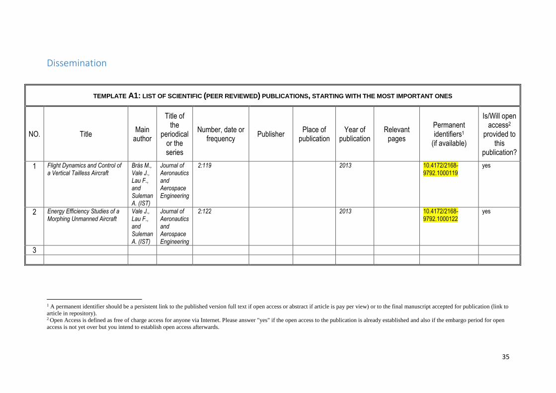
35
Dissemination
TEMPLATE A1: LIST OF SCIENTIFIC (PEER REVIEWED) PUBLICATIONS , STARTING WITH THE MOST IMPORTANT ONES
NO. Title Main
author
Title of the
periodical or the series
Number, date or frequency
Publisher Place of
publication Year of
publication Relevant
pages
Permanent identifiers1
(if available)
Is/Will open access2
provided to this
publication?
1 Flight Dynamics and Control of a Vertical Tailless Aircraft
Brás M., Vale J., Lau F., and Suleman A. (IST)
Journal of Aeronautics and Aerospace Engineering
2:119 2013 10.4172/2168-9792.1000119
yes
2 Energy Efficiency Studies of a Morphing Unmanned Aircraft
Vale J., Lau F., and Suleman A. (IST)
Journal of Aeronautics and Aerospace Engineering
2:122 2013 10.4172/2168-9792.1000122
yes
3
1 A permanent identifier should be a persistent link to the published version full text if open access or abstract if article is pay per view) or to the final manuscript accepted for publication (link to article in repository). 2 Open Access is defined as free of charge access for anyone via Internet. Please answer "yes" if the open access to the publication is already established and also if the embargo period for open access is not yet over but you intend to establish open access afterwards.

36
TEMPLATE A2: LIST OF DISSEMINATION ACTIVITIES
NO. Type of activities Main leader Title Date/Period Place Type of audience
Size of audience
Countries addressed
1 MSc Thesis Cardoso J.(IST)
Performance Evaluation of a Morphing Joined Wing Aircraft Configuration
October 2012 Lisbon, Portugal
2 Conference Falcão L., Gomes M. A., and Suleman A.(IST)
A Tool for the Automated Design of Multistable Composite Parts
8-11 October 2012 Delft, The Netherlands
3 Conference Vale J., Lau F., and Suleman A. (IST)
Static and Dynamic Analysis and Comparison of Fixed and Morphing Wing Equipped UAV Aircraft: Optimal Control Calculation and Energy Estimates Evaluation
8-11 October 2012 Delft, The Netherlands
4 Conference Dale A., Cooper J. E., and Mosquera A. (UBRIS)
Adaptive Camber-Morphing Wing using Zero-Poisson’s ratio Honeycomb
8-11 October 2012 Delft, The Netherlands
5 Workshop Vale J., Lau F., and Suleman A. (IST)
Energy Balance Studies on Aircraft Morphing Technologies
22-24 October 2012 Lisbon, Portugal
6 Workshop Cardoso J., Suleman A. (IST), and Cooper J.E.(UBRIS)
Global Morphing of Joined Wing Aircraft
22-24 October 2012 Lisbon, Portugal
7 MSc Thesis Brás M. Flight Dynamics and Control of a Vertical Tailless Aircraft
November 2012 Lisbon, Portugal

37
8 Conference Cardoso J., Suleman A. (IST), and Cooper J.E.(UBRIS)
Performance Evaluation of a Morphing Joined Wing Aircraft Configuration
8-11 April 2013 Boston, MA, USA
9 Conference Falcão L., Gomes A., and Suleman A.(IST)
Study of an Articulated Winglet Mechanism
8-11 April 2013 Boston, MA, USA
10 Conference Vale J., Lau F., and Suleman A. (IST)
Optimal Control and Energy Balance Evaluation of a Morphing Aircraft
8-11 April 2013 Boston, MA, USA
11 Conference Dale A. S., Cooper J. E., and Mosquera A. (UBRIS)
Adaptive Camber-Morphing Wing using 0-ʋ Honeycomb
8-11 April 2013 Boston, MA, USA
12 Conference De Gaspari A., and Ricci S. (POLIMI)
A Parametric Framework for the Design of Morphing Wings
24-26 June 2013 Torino, Italy
13 Conference Dale A. S., Cooper J. E., and Mosquera A. (UBRIS)
Adaptive Camber and Chord Morphing Wing with 0-ט Honeycomb Compared to Conventional Wing
24-26 June 2013 Bristol, UK
14 Conference De Gaspari A., and Ricci S. (POLIMI)
Active Camber Morphing Wings Based on Compliant Structures
9-12 September 2013 Naples, Italy
15 MSc Thesis Amândio L. Stochastic Optimization in Aircraft Design
October 2013 Lisbon, Portugal
16 MSc Thesis Sousa F.
Topology Optimization of a Wing Structure: Studies on Morphing Compliant Edges
December 2013 Lisbon, Portugal
17 Conference De Gaspari A., Ricci S. (POLIMI), Antunes A., Odaguil F., and Lima G. (EMB)
Application of Active Camber Morphing
13-17 January 2014 National Harbor, MD, USA
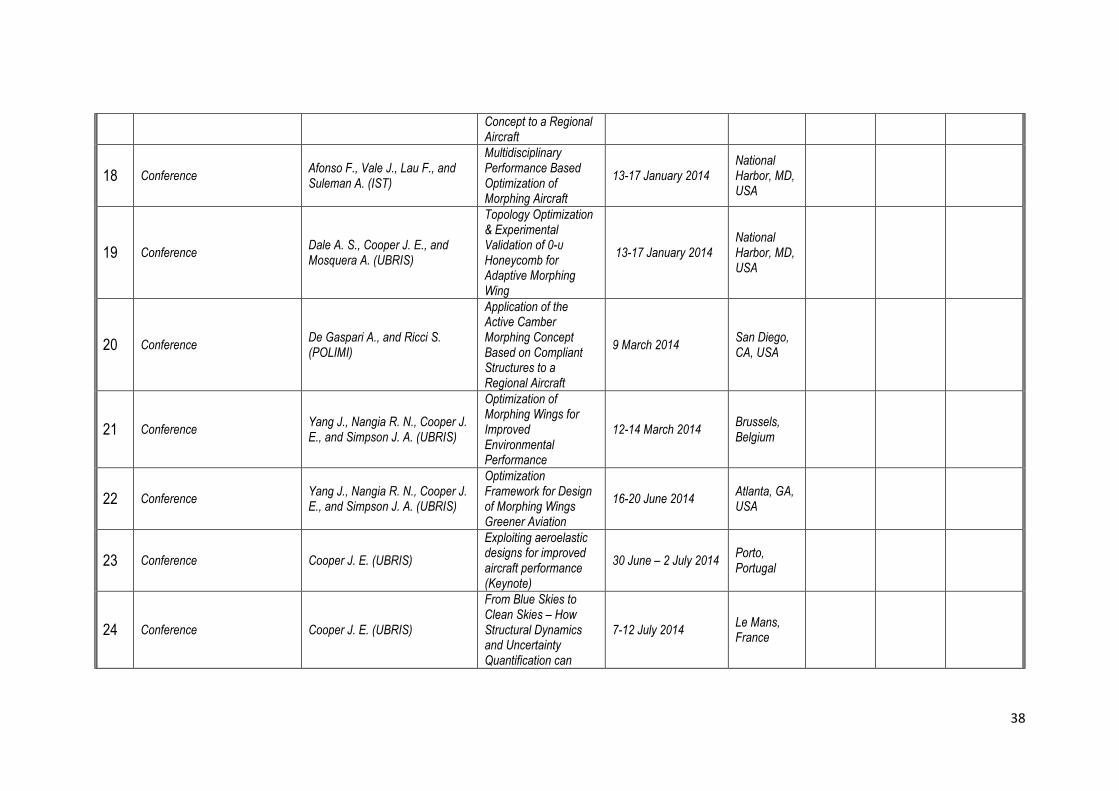
38
Concept to a Regional Aircraft
18 Conference Afonso F., Vale J., Lau F., and Suleman A. (IST)
Multidisciplinary Performance Based Optimization of Morphing Aircraft
13-17 January 2014 National Harbor, MD, USA
19 Conference Dale A. S., Cooper J. E., and Mosquera A. (UBRIS)
Topology Optimization & Experimental Validation of 0-υ Honeycomb for Adaptive Morphing Wing
13-17 January 2014 National Harbor, MD, USA
20 Conference De Gaspari A., and Ricci S. (POLIMI)
Application of the Active Camber Morphing Concept Based on Compliant Structures to a Regional Aircraft
9 March 2014 San Diego, CA, USA
21 Conference Yang J., Nangia R. N., Cooper J. E., and Simpson J. A. (UBRIS)
Optimization of Morphing Wings for Improved Environmental Performance
12-14 March 2014 Brussels, Belgium
22 Conference Yang J., Nangia R. N., Cooper J. E., and Simpson J. A. (UBRIS)
Optimization Framework for Design of Morphing Wings Greener Aviation
16-20 June 2014 Atlanta, GA, USA
23 Conference Cooper J. E. (UBRIS)
Exploiting aeroelastic designs for improved aircraft performance (Keynote)
30 June – 2 July 2014 Porto, Portugal
24 Conference Cooper J. E. (UBRIS)
From Blue Skies to Clean Skies – How Structural Dynamics and Uncertainty Quantification can
7-12 July 2014 Le Mans, France

39
Benefit Future Aircraft Designs (Keynote)
25 Conference
Suleman A., Vale J., Afonso F., Lau F. P. (IST), Ricci S., De Gaspari A., Riccobene L., Cavagna L. (POLIMI), Cooper J., Lambert L., Wales C., Cheung R., Nangia R. (UBRIS), Rizzi A., Zhang M. (KTH), Monner H.-P., de Kamp B. V., Vasista S. (DLR), Moreli, M. (CSIR), Parizi J., Odaguil F., Lima G., and Antunes A. (EMB)
Novel Air Vehicle Con gurations: From Fluttering Wings to Morphing Flight
20-25 July 2014 Barcelona, Spain
26 Conference Yang J., Nangia R. N., Cooper J. E., and Simpson J. A. (UBRIS)
Morphing Wings Designs for Enhancing Performance of Aircraft
22-24 July 2014 Bristol, UK
27 Conference Afonso F., Vale J., Lau F., and Suleman A. (IST)
Multidisciplinary Performance Based Optimization of Aircraft
8-11 September 2014 Lisbon, Portugal
28 Conference Vale J., Afonso F., Lau F., and Suleman A.(IST)
Performance Based MDO of a Regional Transport Aircraft with a Joined Wing Configuration
8-11 September 2014 Lisbon, Portugal
29 Conference Amândio L., Marta A., Afonso F., Vale J., and Suleman A. (IST)
Stochastic Optimization in Aircraft Design
8-11 September 2014 Lisbon, Portugal
30 Conference Vale J., Afonso F., Lau F., and Suleman A. (IST)
Performance Based MDO of a morphing Joined-Wing aircraft concept
6-8 October 2014 The Hague, The Netherlands
31 Conference De Gaspari A., Ricci S., and Riccobene L. (POLIMI)
Design, Manufacturing and Wind Tunnel Validation of an Active Camber Morphing
6-8 October 2014 The Hague, The Netherlands

40
Wing Based on Compliant Structures
32 Workshop Special Session IST, POLIMI, KTH, UBRIS, DLR, CSIR, EMB
NOVEMOR Special Session
27-29 October 2014 Aachen, Germany
33 Flyer IST, POLIMI, KTH, UBRIS, DLR, CSIR, EMB
NOVEMOR: Design, Build, Test, and Fly
27-29 October 2014 Aachen, Germany
34 Workshop, NOVEMOR Session
De Gaspari A., Ricci S. (POLIMI), Antunes A., Odaguil F., Lima G. (EMB), and Morelli M. (CSIR)
Application of Morphing Camber Concept to a Regional Aircraft
27-29 October 2014 Aachen, Germany
35 Workshop, NOVEMOR Session Cooper J.E., Cheung R., Wales C., Lambert L., Dale A., and Yang J. (UBRIS)
Design and Experimental Validation of Morphing Wings
27-29 October 2014 Aachen, Germany
36 Workshop, NOVEMOR Session
Vale J., Afonso F., Lau F., Suleman A. (IST), Antunes A., Odaguil F., Lima G., Parizi J. (EMB), and Cooper J.E. (UBRIS)
Multidisciplinary design optimization of novel and morphing aircraft configurations: computational studies and experimental validation
27-29 October 2014 Aachen, Germany
37 Workshop, NOVEMOR Session Zhang M., Rizzi A. (KTH), and Nangia R. (UBRIS)
Geometry Modeling, Parametrization and Meshing of Conventional and Joined-Wing Aircraft
27-29 October 2014 Aachen, Germany
38 Workshop, NOVEMOR Session Vasista S., Monner H. P. (DLR), De Gaspari A., and Ricci S. (POLIMI)
Morphing Leading Edges for a Wing and Wingtip Based on Compliant Structures
27-29 October 2014 Aachen, Germany
39 Symposium De Gaspari A., Ricci S., and Travaglini L. (POLIMI)
Aeroelastic analysis of a regional aircraft with morphing wing using PyPAD framework
25-27 November 2014 Toulouse, France
40 Conference Vale J., Afonso F., Lau F., and Suleman A.(IST)
Performance Based MDO of a Joined-Wing
5-9 January 2015 Kissimmee, FL, USA
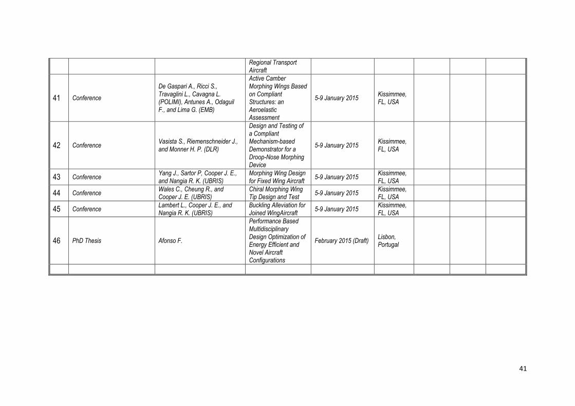
41
Regional Transport Aircraft
41 Conference
De Gaspari A., Ricci S., Travaglini L., Cavagna L. (POLIMI), Antunes A., Odaguil F., and Lima G. (EMB)
Active Camber Morphing Wings Based on Compliant Structures: an Aeroelastic Assessment
5-9 January 2015 Kissimmee, FL, USA
42 Conference Vasista S., Riemenschneider J., and Monner H. P. (DLR)
Design and Testing of a Compliant Mechanism-based Demonstrator for a Droop-Nose Morphing Device
5-9 January 2015 Kissimmee, FL, USA
43 Conference Yang J., Sartor P, Cooper J. E., and Nangia R. K. (UBRIS)
Morphing Wing Design for Fixed Wing Aircraft
5-9 January 2015 Kissimmee, FL, USA
44 Conference Wales C., Cheung R., and Cooper J. E. (UBRIS)
Chiral Morphing Wing Tip Design and Test
5-9 January 2015 Kissimmee, FL, USA
45 Conference Lambert L., Cooper J. E., and Nangia R. K. (UBRIS)
Buckling Alleviation for Joined WingAircraft
5-9 January 2015 Kissimmee, FL, USA
46 PhD Thesis Afonso F.
Performance Based Multidisciplinary Design Optimization of Energy Efficient and Novel Aircraft Configurations
February 2015 (Draft) Lisbon, Portugal
42
Contacts Address: Instituto Superior Técnico, Universidade de Lisboa, Av. Rovisco Pais No. 1, 1049-001,
Lisboa, PORTUGAL
Project Coordinator: Professor Afzal Suleman – [email protected]
Website: http://www.novemor.eu