Embed Size (px)
Citation preview
Final R MAP 023 1
PROJECT ESA-MAP-023 “TERESA” FINAL SCIENTIFIC REPORT (Written by Pr Ph Arbeille - Tours: December 14th 2003)
(PART 1 Ground validation) Developed title: Echographic examination in isolated sites controlled from an expert center using a 2D Echograph guided by a tele-operated robotic arm. Work supported by European Space Agency (ESA) contracts: MAP-023 and SME 99684, and Centre National d’Etude Spatiale (CNES) grant 2001 Contributors: UMPS Pr Philippe Arbeille, Unite Medecine, Physiologie Spatiales Med Nucleaire & Ultrasons. – University C H U TROUSSEAU. 37044 - Tours - France. Tel: + (33) 6 80 10 54 88 - E mail: [email protected] SINTERS : Olivier Merigeaux. Cie: BP 1311 - 5, rue P.Mesple -31106 - Toulouse cx 1 France. Tel: +(33)562111717 - Fax: +(33)562111749 - [email protected] Summary: Objective: The objective of the present project was to design and validate a method for teleoperating (from an expert site) an echographic examination in an isolated site. Method: A dedicated robotic arm holding a real ultrasound probe is remotely controlled from the expert site with a fictive probe, and reproduces on the real probe all the movements of the expert hand. The isolated places, defined as areas with reduced medical facilities, could be secondary hospitals 20 to 50 km from the university hospital, or dispensaries in Africa or Amazonia, or a moving structure like a rescue vehicle or the International Space Station (ISS). These sites are linked to the expert one by ISDN telephone or satellite lines. At the expert center, the ultrasound medical expert moves a fictive probe, connected to a computer (n°1) which sends, the coordinate changes of this probe via an ISDN or satellite line to a second computer (n°2), located at the isolated site, which applies them to the robotic arm holding the real echographic probe. Results: The system was tested at Tours Hospital on 105 patients. A complete investigation (visualization) of all the organs requested for different clinical cases was obtained in 76% of the cases with the robot, and 87% at the reference echography: In 13% of the cases, at least one of the organ visualized at reference echo could not be investigated by the robot, thus thediagnostic was nt done. The number of repositioning was higher for the robot (6.5+/-2) than for the reference examination (5.1+/-2 => 24% more with robot). The duration of the examination was higher with the robot (16+/-10 min) than for the reference echography (11+/-4min => +43% with the robot compare to reference echography). The robotized echography found 26 out of the 35 lesions detected at reference echography, which means that 26% of the lesions were missed. Nevertheless only 9% of them were not found due to the robot movements limitation, the remaining 17% were not identified because of the image grey content degradation between the isolated and expert center. The system was also tested successfully using satellite links in a limited number of cases, in Toulouse between a Maternity 50 km from Toulouse and a downtown hospital, and also between Toulon Hospital and the Sirocco navy rescue ship on the sea.
Final R MAP 023 2
Introduction: Ultrasound imaging is becoming increasingly involved in emergency medical or surgical
decision making, and there is thus a need to have access to this method in the isolated places where humans live. Such isolated places, defined as areas with reduced medical facilities, could be a small secondary hospital 20 to 50 km from the university hospital, or a dispensary in Africa, Amazonia, or polar areas, or a moving structure like a boat, a plane, the International Space Station (ISS) and so on.
Various pathological situations such as abnormal heart rate, pericardial collection, cholecystis, renal lithiasis, normal and ectopic pregnancies, ovarian cyst, acute appendicitis and phlebitis may occur in subjects without any serious medical history; on the other hand, after a trauma, the medical doctor may look for an abdominal organ lesion (liver, kidney, spleen) with blood collection. Ultrasound echography and Doppler are noninvasive methods which are very well suited to the diagnosis of such anomalies and are currently used in hospital emergency departments. One of the major advantages of ultrasound imaging in medicine is the ability to evaluate the degree of emergency for the patient. In routine emergency practice, the physician has to face various problems concerning very different pathologies such as those mentioned above. Unfortunately, many small medical centers and geographically isolated sites do not have an appropriate well-trained sonographer to perform the first echography from which the evaluation of the emergency could be made. In secondaries Hospitals (20-50 km from university Hospital) there is no sonographers during evening and night time. Moreover, because the transfer of the patient from the isolated site (dispensary, space station) to the expert center could be problematic and expensive, the diagnosis has to be reliable and performed as early as possible.
The objective of the present project was to design and validate a method that guarantees a reliable echographic diagnosis in an isolated site by a medical sonographer located at the expert site, which would be the closest university hospital or the NASA control center in the case of the ISS. It was assumed that there is only a non-sonographer person in the isolated site and that there is a transmission system (telephone, satellite) between the two sites for audio, video (echographic and ambient images) and digital data transfer.
Three concepts have been proposed for answering this question: (a) the expert has video control of the echographic image made by the non-sonographer in the isolated site and can assist him or her with audio comments only; (b) the device in the isolated site is a 3D echograph that can capture in a few seconds all the echoes of a volume containing the organ suspected to have a lesion: all this echographic information is sent to the expert center and processed later by the experts (Fig. 1) ; and (c) a robotic arm which holds a conventional 2D echo probe in the isolated site is tele-operated (through telephone or satellite network) from the expert center by an expert in clinical ultrasound (Fig 2).
Option (a), which consists in having a non trained ultrasound operator at the isolated site and conventional video and audio links with the expert center. It is possible to guide, from the expert center, an unskilled operator located at an isolated site by sending vocal instructions. However, although the method does make it possible to locate approximately the probe over the area of interest (organ), it does not allow, most of the time, the operator to reach the specific position needed for the diagnosis. As some degrees of rotation or tilt of the probe are sufficient to obtain or to miss the appropriate position for a safe diagnosis, this solution does not seem applicable for ultrasound diagnosis in emergency situations without an operator sufficiently trained at the isolated site (Beard et al 1993) . Such a method has already been tested in space between the MIR Russian space station and the Toulouse space research center in 1993 (21 d flight), but the tests demonstrated the severe limitations of the method for obtaining very specific views of the organs (personal unpublished data).
Final R MAP 023 3
Option (b), “3D acquisition and processing”, requires a 3D echograph which could be a dedicated 3D acquisition machine (matrix probes: Von Ramm et al 1990, Arbeille et al 2000) or simply a conventional 2D echograph equipped with an motor-powered 2D probe tilting or rotating according to selected sequences. Both systems make it possible to capture all the ultrasound echoes reflected by an organ, the first one in less than 1 s : (Volumetrics Duke University, Durham, USA), the second one within several seconds (Voluson, Kretz, Austria). The images of the whole volume including the organ are sent to the expert center and processed by the expert ; thus the appropriate position will be extracted several minutes after the capture of the ultrasound information. If the volume of acquisition is well positioned over the organ, the expert will find in all cases the views requested for the evaluation of the organ. If only part of the organ is inside the volume of acquisition, the views requested for the diagnosis may not be present in the acquired volume of images; thus, the probe support will have to be moved (translated, rotated) according to the qualitative information provided by the expert and a second acquisition will be performed. Thus, the probe has to be repositioned on another anatomical area and again a 3D capture will begin ; the images will be sent to the expert center and processed (Kratochwil et al 2000, Kontanakis et al 2000, Masuda et al 2001). Finally, the time duration for reaching the diagnostic might be significantly longer than with the real-time robotic image capture. Moreover, the present 3D echographs contain very high technology, and are rather heavy and expensive. Therefore, there is a limited chance that such a device will exist in isolated sites.
Option (c) The present project was based on the use of a robotic arm developed especially for the project by Laboratory Vision and Robotics and manufactured by the Sinters group (Toulouse France).
Among these three approaches mentioned above, various types of scenarios concerning the use of ultrasound techniques have been identified in the literature. Some concerns the use of industrial heavy robots, others use standard communication links to transfer ultrasound data from one clinical expert to another using videoconference links. In 1998, developed under the MIDSTEP project, a laparoscopic examination was guided, using a tele-operated industrial robot holding an ultrasound probe for following the progression of the laparoscop (De Cunha et al 1998). The expert was located at a control desk and the patient was either in an adjacent room or in a different hospital connected via an WAN network. Also in 1998, video-conference was used between two experts, one of whom was performing the echography examination. Both experts could simultaneously discuss the ultrasound image, and the expert, distant from the patient, could suggest a different probe orientation to his peer for better observation and analysis of the area of interest. In 1999, a seven degree-of-freedom spherical industrial robot (Hippocrate), equipped with a force sensor, was controlled to maintain an ultrasound probe in contact with a patient’s carotid. During a necessary learning phase, the robot was guided along the carotid artery by the medical expert. During the second phase the robot was able to follow the same path at a chosen speed and ultrasound topography were recorded to evaluate the arterial wall (diameter, plaque, compliance): the project is currently under clinical evaluation (Pierrot et al 1999). Since 1996, a similar concept had been introduced by Salcudean to provide a better user interface for ultrasound technicians. A safe counterbalanced robot was designed for carotid examination, using visual serving for motion in the plane of ultrasound (Abolmaesumi et al 2002). In 2000, a European Tele In Vivo project developed a similar approach : the echography was performed by a clinical expert standing next to the patient; ultrasound data were sent via satellite to a data base station for processing (Kontaxakis et al 2000).
More recently, a mechanical structure driven by McKibben actuators has been developed to drive a probe holder system for obstetrical applications (Vilchis et al 2001). A parallel
Final R MAP 023 4
robotic structure is also being developed by Masuda, to control over a large body area the ultrasound probe (Masuda et al 2001). However, the two latter structures, even though promising for the tele-echography concept, are still under a research phase and remain cumbersome due to either the heavy pneumatic power system needed to control for the actuators or the chosen mechanical structure itself.
Most of theses systems, except the last two research projects mentioned there above, require the presence of a specialist nearby the patient, or are merely tele-medicine approaches were data are transmitted via communication networks. All these robotic structures used industrial voluminous robots or mechanical structures, some of them being driven by still non-proofed actuators for long duration standard or emergency medical applications. In our case we did not designed a full robotic system, but a robotic arm which induce on the real probe the movements of the expert hand, and which is located and maintained on the patient body by a person. Materials and Methods
Laboratory Vision and Robotics from Orleans University (France) developed a robot (patent 9903736) according to the project users requirements (UMPS, Tours, France). This light weight, portable robot consists of an electric motorized support holding a real ultrasound echo probe, able to orientate the probe in all the directions requested by the medical expert during an echographic examination. Robotic design and performances:
Robotic arm concept. At the isolated site (patient site), the robotic arm, on which the echographic probe is fixed is handled by a non sonographer operator (MD paramedic). The robotic arm reproduces exactly the movement of the hand of the medical doctor who guides the examination from the expert center. At the expert center, the medical doctor moves a fictive probe connected to the computer (n°1). This fictive probe simulates the real echographic probe. Computer n°1 sends the coordinate changes induced by the fictive probe movements to the computer n°2 located at the isolated site via ISDN or satellite links. Computer n°2 controls the robotic arm which reproduces on the ultrasound probe the same movement as the fictive one. At present, the expert cannot translate the probe holder by his own ; the operator at the isolated site translates the probe support, based on vocal instructions given by the medical expert from the expert center, and under video control by the expert (Fig. 2).
Probe holder design. The probe holder is held within a frame to easily hold the overall system on the patient’s body. The bottom ring (7 cm diameter) of the frame maintained in contact with the patient skin by the operator provide a stable contact. In order to be able to reach most organs, including heart and pelvic organs, the system was designed preferably for sector scan echographic probes (mechanical oscillating probe, electronic curved probe or phased array probe). The system accepts probes for detection of superficial (5-10 MHz) and deep (2-5 MHz) organs and probes of various shapes and sizes up to a maximum body probe diameter of 40 mm. The probe head width is limited by the diameter of the ring applied to the patient’s skin.The probe holder weight (2.5 kg) applies a pressure which ensures the contact between the skin and the probe. The expert can apply an additional pressure, limited to 15 N, by pushing on the fictive probe, the maximal displacement of the probe through the ring being 1.5 cm. Such an option is particularly useful when the probe is applied to irregular surfaces like ribs and some abdominal areas. Because of the very limited pressure applied and the short probe displacement there was no feedback control of the force applied to the probe.
Final R MAP 023 5
Movements of the robotic probe holder. It can generate three types of movement (Figs 3, 4, 5): (a) a 360 ° spin rotation of the probe (360° rotation on its own axis) ; (b) a –45° to +45° tilt of the probe from the reference (vertical) axis (nutation) ; and (c) a precession around the same axis at any tilting angle. In fact the robot integrates all these elementary movements to reproduce and apply the complex movements of the expert hand on the real probe. Therefore, the robotic arm applies on the real probe the same movement as the one performed by the expert on the fictive probe. The velocity of the probe movement is calibrated to be the same as on the fictive probe. However because of the latency in the transmission (even lower than 0.5 s by satellite) it is recommended to move the probe slowly in order to have enough time for the expert to receive and integrate the successive 2D images before continuing the movement of the fictive probe.
Communication. The time delay between the fictive probe motion and the reception of the video image (at the expert site) from the isolated site is less than 0.1 s with ISDN (terrestrial) telephone lines and less than 1 s with satellite lines. Procedure for validation at the hospital (ISDN) and in other sites (satellite link).
The expert was in a room at some distance (20 m) from that of the patient. The robot was held on the patient by a non-sonographer whose role was to locate the probe holder on the appropriate area according to the instructions of the expert. The positioning of the probe holder (robot) was controlled in real time by the expert using video images transmitted from the isolated site to the master site by standard visio-conferencing. During this phase, the expert had a real-time ambient video of both the patient (anatomical parts to be investigated: chest, abdomen…), and the real probe position, and also an audio link with the isolated operator. (Fig 5, 6, 7, 8, 9, 10)
The echographic video images were transmitted continuously to the expert center especially during the robotic system pre-positioning phase. At this time the expert asked the operator to adjust the setting of the echograph (gain, depth) depending on the patient’s size and echogenicity. The expert indicates to the isolated operator the appropriate place where to put the robot, by using simple anatomical reference (Mamalian, axillary, umbilical lines…). When the operator had correctly positioned the robotic arm on the desired area (so the expert could at least see part of the organ to be examined), the robotic probe holder system was maintained immobile in the chosen position. The expert then tried to find the correct echographic view needed for the diagnosis, by moving the fictive (master) probe and analyzing the received echographic images. Meanwhile, the expert could improve the search by giving instructions to the distant patient (hold your breath 3 s, take a deep breath). In cases where the expert was unable to obtain the appropriate view, he could ask the operator to move the robotic system to another location on the patient’s skin and try again to find the most appropriate view for the diagnosis.
This echography was followed by a second conventional echography performed by a sonographer of the hospital specialized in the organ to be investigated.
Evaluation of the robotized echography performances:
Each organ had to be visualized continuously from longitudinal to transverse cross section by both method. A serie of organ items were used for assessing the performance of the robotized echography compare to the reference echgography: Liver echogenicity (homogenous or not), biliary ductules (too visible in liver parenchyma or not) gallbladder wall (thin, thick) and content (clear, lithiasis), pancreas contour (regular, or not) and content (homogenous or not), Kidney contour (regular or not) and cavities (no visible or dilated), Spleen content (homogenous or not), Abdominal liquid collection, Uterus size, ovaries sizes, cysts, Left ventricle sizes, valves aspect, Fetal measures (BIP, Abdom diam, femur), Placenta
Final R MAP 023 6
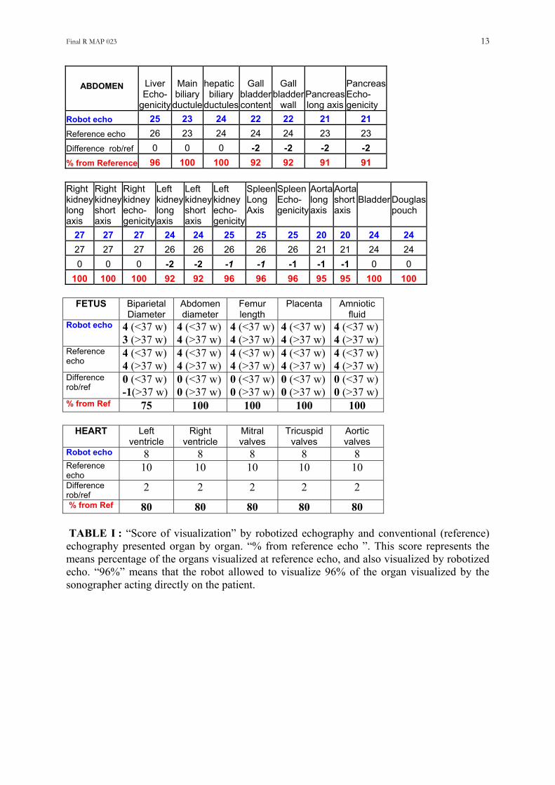
location, amniotic fluid index…(Fig 8). These organ items were used to check the performance of the robotized echography organ by organ (Table I).
In order to perform a validation in a context as close as possible to real medical situations, we tested the device on different groups of organs. One organ is usually not sufficient to make a reliable diagnosis : one has to find the expected abnormalities in one organ and make sure that there is no additional lesion in another organ potentially concerned by the symptoms. We designed four groups of organs corresponding to the minimal request of organ visualization for diagnosis in the most frequent emergency situations: (a) digestive symptoms (liver, gallbladder, pancreas and kidney); (b) after physical trauma such as car accident (aorta, right and left kidney, liver, spleen, bladder); (c) pelvic and urinary symptoms (bladder, kidneys, prostate or uterus and ovaries); (d) cardiac symptoms (cardiac 4 chamber view), (e) the fetus before or after 36 weeks (head, abdomen, femur, placenta, amniotic fluid) (Table II-III-IV). The reliability of the robotized echographic examination was scored according to the results of the conventional echography performed after the robotized one. The score of visualization was expressed as the ratio [(Nr/No)x100] between the number of organs well visualized (continuously from long to transverse cross section) with the robotic system (Nr) and the number of organ well visualized by conventional echography (No) on each clinical case. A score of 100% means that the organs were similarly well visualized by both examinations (robotized or conventional reference echography). Such score measures the performances of the robot in visualizing all the content of a group of organ needed to reach the diagnostic compare to reference echography.
Nevertheless the objective of the robotized is not only to visualize groups organs but also to find lesions and make a reliable diagnostic. Thus in addition to the score of visualization, we designed a score of diagnostic which takes into account both the visualization of the organs and the identification of the lesions. The lesions not found at the robotized echography were identified in 2 groups: those who were not present in the echographic views collected with the robot (robot movement limitation) and taken into account both in the score of visualization and diagnostic) and those not seen because of insufficient grey contrast on the final image, whereas they were present in the views collected by the robot (not taken into account in the score of visualization but in the diagnostic score) (Table III-IV).
Other parameters of the robotized echographic examination were measured: time duration of the examination for each group of organ, number of repositioning of the probe for both the robotized and reference echography (Table III).
The protocol for validation was agreed by the Health Committee of our State (CCPPRB: Comite Consultatif pour la Protection des Personnes en Recherche Bio-medicale : n° 2002/07) and by our University Hospital. The patients were informed about the entire protocol and signed an informed consent form. Tests using satellite links: The system was also tested successfully using satellite links, in Toulouse between Maternity 50 km from Toulouse and a downtown hospital, and also between Toulon Hospital and the Sirocco navy rescue ship on the sea (Fig 7, 9, 10). Results
In vitro validation. The robotic arm was fixed on top of a water tank and a plastic target (2x1 cm² plastic cylinder) was placed in a corner at the bottom of the tank. The expert had to find the positions passing through the target and display both a long and a short axis view of it. Twenty tests (search for these two views) were performed with 20 different placements of
Final R MAP 023 7
the target. The operators found the two target long and short views in all cases. The average time duration was of 5 min +/- 3.
Validation on patients. Echographic examinations assisted by the robotic arm were performed on 105 cases: 87
cases for abdominal echography, 10 cases for cardiac echography, and 8 pregnancies, according to the protocol described above. The patients were submitted first to the robotized examination, second to a conventional echography performed by the medical sonographer.
The audio, video, and robot control information were transferred between the patient and expert rooms using an ISDN terrestrial telephone line. One channel of 64 kbps was a sufficient bandwidth for the robot controls, and 2 channels of 64kbits (128 kbps) were allocated alternatively, on the expert request, to either the ultrasound images or the ambient patient room (Fig 6).
The gall bladder, pancreas, and spleen were not sufficiently visualized in 5 to 10% of the case%. Both the cardiac four chamber, and fetal head (at 36 weeks) views were not obtained in respectively, 20 and 25% of the cases (Table 1).
At the abdominal level a complete investigation (visualization) of all the organs of each group was obtained in 76% of the cases with the robot, and 87% by reference echography: 13% of the groups of organs (clinical cases) were not visualized entirely by the robot compare to the reference echo (Table III). 25% of the fetal biparietal diameter could not be measured because such measurement requested to apply a significant pressure on the echographic probe which cannot be applied by the robot. On the other hand in 20% of the cases the 4 cardiac chambers were not all perfectly visualized because the costal rib did not allow to stabilize correctly the robot. (Table IV).
The number of repositioning was higher for the robot (6.5+/-2) than for the reference examination (5.1+/-2 => 24% more with robot). The duration of the examination was higher with the robot (16+/-10 min) than for the reference echography (11+/-4min => +43% with the robot compare to reference echography) (Table III).
At the abdominl level the robotized echography found 26 out of the 35 lesions detected at
reference echography, which means that 26% of them were missed. Two renal cyst (2-3 mm) and 1 lithiasis (<1mm) were not found because of their relative small dimension and a view of the organ that was not optimal, whereas 6 others were not identified because of their low contrast on the echographic image that reached the expert center. Finally only 9% of them were not found due to the robot movements limitation, the remaining 17% were not identified because of the image degradation between the isolated and expert center. At the cardiac and obstetrical level no abnormality were found probably because of the limited number of cases investigated
Table IV present the score of visualization and the score of diagnostic of the robotized
echography compared with reference echography.
Discussion Robotic-surgery is probably the most popular application of robotics in medicine (De Cunha et al 1998, Abbou et al 2001, Desai et al. 2002). The comparison with tele-surgery is difficult because the problematic is different. The surgical robotic arm is suppose to reproduce very accurately the complex movements of the surgeon’s hands. The robot must explore the 3 directions of space (6 degrees of liberty), whereas the echographic robotic arm has to orientate
Final R MAP 023 8
the probe head at the surface of the patient skin (the probe head remain in the same plan). Moreover there is no translation movements. At last there is a human interface between the robot and the patient as the operator who handle the robotic arm can locate it or remove it from the patient skin at any moment. Consequently there is no risk for the patient to be hurt by the echographic robotic arm as it is handle by the human operator. The echo robotic arm can work with satellite links because an interruption of the data transfer will not be dangerous as for the surgical robot. The in vitro validation was designed both to train the sonographer with the robotic arm system and to check the accuracy and reproducibility of the movements transmitted to the slave probe (rotation, tilting). The procedure to follow was much more simple and easier than the one used in vivo, as the target was in a limited space (tank volume) and there was no structure that could hide the target as in humans (intestinal tract, lungs, respiratory movements etc). Moreover, the robotic arm was fixed on top of the water tank ; thus, the system was perfectly stable. Finally, the operator was certain that the requested positions could be obtained in all cases, as the target was, all the time, inside the cone limiting the extreme movements of the robotic arm. The in vivo validation: In the present project we did not designed a full robotic system, but a robotic arm which induce on the real probe the movements of the expert hand, which is located and maintained on the patient body by a person. There was a human interface between the robot and the patient that guarantee the safety of the system for the patient and made the patient less stressed. None of the patient refused to be investigated with the robotic system, and none of them complained about the system. The video-conferencing link allowed the patient and the doctor to communicate in realtime.
The views collected on the patients allowed to evaluate the gallbladder content and wall thickness, the quality of the hepatic parenchyma, and duct and bile ductules, the morphology and the content of the pancreas, the integrity of the abdominal aorta, the morphology and content of the kidney, the urinary tract, the integrity of the spleen, the absence of peri-hepatic and peri-renal collections, and the absence of liquid into the Douglas pouch, the size and content of the uterus, ovaries and prostate, the cardiac chambers and valves, the fetal head, abdomen, femur and placenta.
Such observations should be sufficient to answer most of the questions rising from an emergency situation requiring ultrasound imaging. Only 3 to 10% of abdominal organs and 25% of the cardiac and fetal ultrasound images could not be obtained by using the robotic arm, which shows that the slave probe could be adequately tele-operated for most of the organs. The lack of abdominal, heart and fetal images in 3 to 25% of the cases was related to the technical limitations of the robotic arm compared with the hand of the sonographer. The pressure to be applied on the skin not sufficient, made difficult sometimes the investigation of the fetus and the spleen whereas the absence of translation of the probe contribute to increase the number of repositioning of the probe holder. The time duration for investigation of each group of organs (16 +/-10 min) was approximately 40% higher than in conventional echography ; the longest maneuver was the prepositioning of the probe over the organ, as this was guided vocally and controlled visually by video by the expert. On the other hand, only a limited number of repositionings were needed before activating the robotic arm (6.4 +/-2 per group of organ). Nevertheless this represents 24% more repositioning with the robot which contribute to increase the duration of the examination.
The robotized echography found 26 out of the 35 lesions detected at reference echography, which means that 26% of them were missed. Two renal cyst (2-3 mm) and 1 lithiasis (<1mm) were not found because of their relative small dimension and a view of the
Final R MAP 023 9
organ that was not optimal, whereas 6 others were not identified because of their low contrast on the echographic image that reached the expert center. Finally only 9% of the lesions were not found due to the robot movements limitation, the remaining 17% were not identified because of the image degradation between the isolated and expert center (image compression)
Finally the mean score of visualization for the robot was 87% for the abdomen, 75% for the heart, 80% for the fetus, whereas the score of diagnostic was 74% (all lesion included) and 91% if we exclude the low grey contrast lesion not visible due to the image degradation.
In addition to the validation in the hospital, the robotic system was tested using satellite links. The first generation robotic system was tested (19 Aout 98) during an expedition in the Himalayas (isolated site); with a mountain climber as the investigated subject the medical doctor controlled the movements of the robotic arm from our Institute in France (Gourdon et al 1999). The audio, video and digital information was sent by satellite link (Inmarsat B), which induced a delay of approximately 2 s between the movement of the master probe and the reception of the image related to this movement. Various views of the left ventricle, gallbladder and right kidney were performed in almost realtime. Despite the significant delay in transferring data through the satellite the time duration for the examination was approximately 10 min per organ. On this first generation model the rotation and tilting of the probe were activated successively which made the orientation rather difficult and time consuming.
In October 2002, several robotized echographic examinations on pregnancies were performed in the maternity of Mazamet (isolated site), from a downtown Hospital distant by 30 miles, using Immarsat satellite links. A demonstration on normal subjects was carried out between “cite de l’Espace” and the Congres hall of Toulouse distant by 5 miles. In both cases the satellite induced time delay being less than 1s, the tele-operated echographic examinations of the fetuses and abdominal organs on normal subjects were performed successfully, quite in realtime.
In December 2003 an echographic examination was tele-operated via a military satellite on a rescue navy ship on the sea, from the Toulon military hospital. These tests confirmed that despite the movement of the ship and the time delay induced by the satellite transmission the echographic examinations could be tele-operated correctly.
Despite the good ergonomy of the robotic system, the use of a fictive probe required the
use of some restrictive procedure compared with the conventional echographies where the sonographer’s hand movements are totally free. The real probe must initially be oriented perpendicular to the skin, as this orientation will help the expert to identify the structures he observes on the initial view. The expert must ask the operator to position the probe head (i.e., acquisition plane) in an orientation that will be the reference position for him or her (along body axis with head on the left of the image, or in a transverse body position with right side on the left of the image, or along the last right costal rib, longitudinal or transverse sub pubic incidence etc). The expert follow this displacement by the ambient video image of both the patient and robotic arm, and on the echographic images. During the robotic arm and probe positioning, video images of low resolution were sufficient ; during this phase, the probe long axis was maintained perpendicular to the patient’s skin (reference position). The expert had to move the fictive probe rather slowly in order to reconstruct in his mind a 3D localization of what he saw on the successive echographic images. This could usually be similar to what the sonographer does in conventional practice with the real probe in his hand, but, in the current scenario, the expert, even very skilled, has to adapt to the manipulation of the fictive probe. Moreover, when moving the fictive probe, he must take into account the delay (even if it is short) between his hand movements and the refreshment of the received echographic image
Final R MAP 023 10
related to this movement. Nevertheless, despite a delay of a fraction of second, the expert could easily identify the image changes in relation with his or her hand movements on the fictive probe. In order to improve the precision of the movement to be applied to the real probe, the bottom part of the fictive probe was fixed on the table at the expert center.
In routine practice, one full year of practice is needed to train a physician to be a reliable sonographer in cardiovascular applications. It requires more time to train him for abdominal organ investigations (liver, kidney, spleen, ovarian, uterus, small parts) and, again, additional training is needed to make him able to investigate the fetus throughout pregnancy. Thus it does not seem reasonable to plan always to have in each isolated site an operator trained sufficiently for all ultrasound applications. The main advantage of the robotic arm is that it allows the expert to select by himself or herself the most appropriate position by orientating the master probe as if the patient were close to him. Finally, the resolution of the probe movement being small (less than 1 degree), the expert can select the most appropriate position very accurately.
The sonographers (radiologists, cardiologists, obstetricians) who participated in the validation took no more than 1 hours to become familiarized with the system. They reported that the robotic arm was “totally transparent” for the sonographer. The system (fictive probe + communication link + robotic arm) acts like an extension of the hand of the sonographer. One may note that none of the experts asked for a feedback force.
The robotic arm was designed with the objective to avoid any mechanical risk for the patient. The solution of having the present robotic arm fixed on a larger supporting arm able to locate the probe at any place on the body was rejected because it would be dangerous for the patient in case of malfunction. During the examination the robotic system is most of the time maintained vertical to the skin, thus the patient was asked to change the position (supine, left side, right side...) depending the organ to be investigated. If the patient cannot be moved (traumatism) the robot is maintained perpendicular to the skin by the operator. The solution of having a light weighted robotic arm maintained on the skin by a system of several belts was also rejected because the pressure applied could not be removed instantaneously if needed and because the patient could feel uncomfortable (or imprisoned) under this pressure system. Finally we chose to have a system handled by a human (doctor or paramedic) which makes the patient much more confident, which applies a force limited to its weight +15 N, and which can be removed instantaneously for any reason. With the probe head remaining in the skin plane +/- 1.5 cm the patient has the same sensations as during an examination performed directly by the sonographer. In conclusion, the safety problems were limited to the ultrasound safety. The present validation is not sufficient for a definitive conclusion on the potential and limitations of a robotic system compared with other methods. The validation will be extended to a larger population of patients, and more sonographers will be trained to practice robotized echography. Nevertheless, as each emergency situation requires a quick and reliable diagnosis and as changes of a few degrees in inclination or rotation of the probe could change a wrong position (no perfect organ view => no diagnosis) to a good one sufficient to make the diagnosis, we believe that the robotic arm system is the best adapted system. The possibility of tele-operating the ultrasound examination from the expert center (via the robotic system) will provide the patients living in isolated sites the same diagnostic performance as at that offered in the main hospital centers where the expert is located. There is a need of such robotic equipment for connecting secondary hospitals in Europ and the University Hospital. Every day the Medical Doctors (general medicine) send 3 to 10 patient to the university hospital for having an echographic examination (abdomen, pelvic, leg pain..) In more than 50% of the cases, the echography do not see any serious damage thus the patient
Final R MAP 023 11
can return to his home. A robotic system installed in most of the secondary hospitals will reduce at least by 50% the transfer by ambulance to the university Hospital which will save money. Conversely patients with positive diagnostic at the robotic echography will be transferred faster. In case of long transmission delay between the isolated and expert center (partial satellite coverage, low speed channels, channel overloaded, temporary interruption of the links, trip to Mars...) the present robotic interactive system cannot be used. In such case a 3D standardized acquisition will be proposed, knowing that the volume of images acquired by 3D will be sent to the expert center and processed later on by the expert. An automated 3D scanning sequence (+/-45° probe tilt) could be implemented on the present robotic system.
***************** Dissemination : Paper published, and oral presentations on this work: Papers published: - Arbeille Ph, S Herault, J Roumy, M Porcher, S Besnard, P Vieyres. 3D realtime echography and echography assisted by a robotic arm for investigating astronauts in the ISS from the ground. J Gravitational Physiology. 8;(1): 143-5. 2001. - P Vieyres , G Poisson, F Courrege, O Merigeaux, Ph Arbeille. The TERESA project : from space research to ground tele-echography. Industrial Robot: An International Journal. 30 (1) : 77 - 82. 2003. - Arbeille Ph, G Poisson, J Ayoub, P Vieyres, M Chevillot, Ph Hervé, M Porcher, JL Boulay. Echographic examination in isolated sites controlled from an expert center using a 2D Echograph guided by a robotic arm. Ultrasound Med Biol. 29 (7): 993-1000. 2003. Oral presentations at meetings and public demonstrations: * 3D realtime echography and echography assisted by a robotic arm for investigating astronauts in the ISS from the ground. Ph Arbeille, S Herald, J Roumy, P Vieyres, M Porcher, S Besnard. 22nd Annual International Gravitational Physiology Meeting: Budapest 23-26 April 01 * Demonstration of a realtime tele-echogaphic examination on MIR station ground mokup tele-operated from Sitef meeting. Ph Arbeille, M Porcher (UMPS), P Vieyres G Poisson (LVR Bourges) O Merigeaux, N Villeroy L Urbain (Sinters Toulouse) National SITEF meeting. Toulouse 23-25 October. 2002. * Tele-operated robotic arm for echographic diagnostic in obstetrics and gynecology. Ph Arbeille, M Chevillot, F Perrotin, Ph Hervé, C Bru, J Arrabal, P Vieyres, G Poisson. International Society of Ultrasound in Obstetrics & Gynecology (ISUOG) New York 2-6 Nov 2002 * Echographic examination in isolated sites controlled from an expert site using a 2D echograph guided by a robotic arm. Ph Arbeille, G Poisson , J Ayoub, P Vieyres, M Chevillot, Ph Hervé, M Porcher, JL Boulay. First Annual Conference of Telemedicine Society of India. Lucknow. November 22-24th 2002. * Demonstration of a realtime tele-echogaphic examination on the war-ship Sirocco tele-operated from St Anne Hospital in Toulon Navy base. Ph Arbeille (UMPS), D Schmitt (ESA), P Vieyres G Poisson (LVR Bourges) O Merigeaux, N Villeroy L Urbain (Sinters Toulouse) French Army meeting “Telemedecine & Technonologies Medicales Avancées des Forces”. Toulon 4-6 December 2002. * Demonstration at Government of MALAYSIA: Prime Minister & Minister of Health, Ph Arbeille (UMPS), L Urbain (Sinters) Kuala Lumpur University campus. March 24th 2003
Final R MAP 023 12
References -Abbou CC, Hoznek A, Salomon L, Olsson LE, Lobontiu A, Saint F, Cicco A, Antiphon P, Chopin D. Laparoscopic radical prostatectomy with a remote controlled robot. J Urol. 2001; 165: 1964-6. -Abolmaesumi P, S.E. Salcudean, W.H. Zhu, M.R. Sirouspour and S.P. DiMaio, “Image Guided Control of a Robot for Medical Ultrasound,” IEEE Transactions on Robotics and Automation, Vol. 18, (1), pp. 11-23, February 2002 -Arbeille Ph, V.Eder, Casset.D, L.Quillet, C.Hudelo, S.Herault. Realtime three dimensional ultrasound acquisition and display for cardiac volume and ejection fraction evaluation. Ultrasound Med Biol 2000; 26: 201-208. - Arbeille Ph, G Poisson, J Ayoub, P Vieyres, M Chevillot, Ph Hervé, M Porcher, JL Boulay. Echographic examination in isolated sites controlled from an expert center using a 2D Echograph guided by a robotic arm. Ultrasound Med Biol. 29 (7) : 993-1000. 2003. -Beard DV, Hemminger BM, Keefe B, Mittelstaedt Pisano ED, Lee JK. Real-time review of remote ultrasound using low-cost video and voice. Invest Radiol. 1993 (8) : 732-4. -De Cunha D, P. Gravez, et al., “The MIDSTEP system for ultrasound guided remote telesurgery,” Proc. Of International Conference of the IEEE Engineering in Medicine and Biology Society, Hong Kong, 1998, pp. 1266-1269. -Desai MM, Gill IS, Kaouk JH, Martin SF, Sung GT, Bravo EL. Robotic assisted laparoscopic adrenalectomy. 2002; 60: 1104-7. -Gourdon A, Vieyres P, Poignet P, Szpieg M, Arbeille P. A tele-scanning robotic system using satellite communication. Proceedings European Medical & Biological Engineering Conference “EMBEC”. Vienna November 1999. vol II: 1402-03. -Kontaxakis G, S. Walter, G. Sakas : EU-TeLeInViVo : an integrated portable telemedicine workstation featuring acquisition, processing and transmission over low bandwidth lines of 3D ultrasound volume images. Third International conference on Information Technology and Biomedicine. (ITABS-IT IS) Washington USA November 9-10, 2000. pp 158-63. -Kratochwil A, Lee A, Schoisswohl A. Networking of three dimensional sonograph volume data. Ultrasound Obstet Gynecol. 2000 16 : 335-40. -Masuda K, E. Kimura, N. Tateishi, and K. Ishihara, “Three dimensional motion mechanism of ultrasound probe and its application for tele-echography system,” Proc. Of International Conference of the IEEE Intelligent Robot and Systems, Maui, 2001, pp. 1112-1116. -Pierrot F., Dombre E., Dégoulange E., Urbain L., Caron P., Boudet S., Gariépy J., and Mégnien J.-L. "Hippocrate: a safe robot arm for medical applications with force feedback", Medical Image Analysis, 1999, vol 3, (3), pp. 285-300. -Poisson G, P. Vieyres, P. Poignet, A. Gourdon: « Robot à trois degrés de liberté et à un point fixe »(Three degree of freedom and one fixed point) ; French Patent n° 9903736, Institut National de la Protection Industrielle « INPI » France -25 March 1999 -Vilchis A, et al., “TER: a system for robotic tele-echography,” Proc. of International Conference of Medical Image Computing and Computer-Assisted Intervention, Utrech, The Netherlands, 14-17 Oct 2001, pp. 326-334. -von Ramm OT, Smith SW. Real-time volumetric ultrasound imaging system. J Digit Imaging 1990; 3: 261-266.
Final R MAP 023 13
ABDOMEN
Liver Echo-
genicity
Main biliary
ductule
hepaticbiliary
ductules
Gall bladder content
Gall bladder
wall Pancreas long axis
Pancreas Echo- genicity
Robot echo 25 23 24 22 22 21 21 Reference echo 26 23 24 24 24 23 23 Difference rob/ref 0 0 0 -2 -2 -2 -2 % from Reference 96 100 100 92 92 91 91 Right kidney long axis
Right kidney kidney short axis
Right
echo- genicity
Left kidney long axis
Left kidney short axis
Left kidney echo- genicity
SpleenLong Axis
Spleen Echo- genicity
Aorta long axis
Aorta shortaxis
Bladder
Douglas pouch
27 27 27 24 24 25 25 25 20 20 24 24 27 27 27 26 26 26 26 26 21 21 24 24 0 0 0 -2 -2 -1 -1 -1 -1 -1 0 0
100 100 100 92 92 96 96 96 95 95 100 100
FETUS Biparietal Diameter
Abdomen diameter
Femur length
Placenta Amniotic fluid
Robot echo 4 (<37 w) 3 (>37 w)
4 (<37 w) 4 (>37 w)
4 (<37 w)4 (>37 w)
4 (<37 w) 4 (>37 w)
4 (<37 w) 4 (>37 w)
Reference echo
4 (<37 w) 4 (>37 w)
4 (<37 w) 4 (>37 w)
4 (<37 w)4 (>37 w)
4 (<37 w) 4 (>37 w)
4 (<37 w) 4 (>37 w)
Difference rob/ref
0 (<37 w) -1(>37 w)
0 (<37 w) 0 (>37 w)
0 (<37 w)0 (>37 w)
0 (<37 w) 0 (>37 w)
0 (<37 w) 0 (>37 w)
% from Ref 75 100 100 100 100
HEART Left ventricle
Right ventricle
Mitral valves
Tricuspid valves
Aortic valves
Robot echo 8 8 8 8 8 Reference echo
10 10 10 10 10 Difference rob/ref
2 2 2 2 2 % from Ref 80 80 80 80 80 TABLE I : “Score of visualization” by robotized echography and conventional (reference) echography presented organ by organ. “% from reference echo ”. This score represents the means percentage of the organs visualized at reference echo, and also visualized by robotized echo. “96%” means that the robot allowed to visualize 96% of the organ visualized by the sonographer acting directly on the patient.
Final R MAP 023 14
Medical context Group of organs Number of cases
Digestive symptoms Liver, gallbladder, biliary ductules, pancreas and right kidney.
27
Post traumat Aorta, kidneys, liver, spleen, bladder 30 Urinary/pelvic symptoms Bladder, kidneys & prostate / uterus & ovaries 30 Cardiac signs Cardiac four chamber view (left right ventricle,
Mitral, Ticuspid, Aortic valves) 8
Fetus (<36 weeks) Head, abdomen, femur, amniot fluid & placenta 4 Fetus (>36 weeks) Head, abdomen, femur, amniot fluid & placenta 4 Table II. Organs investigated in each “clinical group” and number of cases in each category.
105 cases Number of repositionning
Mean duration
Number of echo items
measured
Number of complete
examination (visualization of groups of
organs)
Number of lesions
detected
Robotized echo
6.4+/-2 16+/-10 min 231 76 26
Reference echo
5.1+/-2 11+/-4 min 238 87 35
% difference from
reference
+24% +43% - 3% -13% -26%
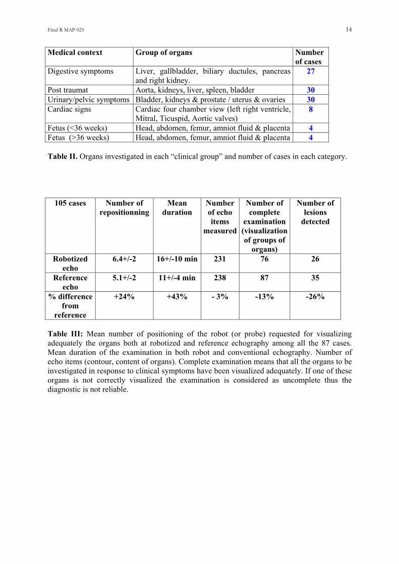
Table III: Mean number of positioning of the robot (or probe) requested for visualizing adequately the organs both at robotized and reference echography among all the 87 cases. Mean duration of the examination in both robot and conventional echography. Number of echo items (contour, content of organs). Complete examination means that all the organs to be investigated in response to clinical symptoms have been visualized adequately. If one of these organs is not correctly visualized the examination is considered as uncomplete thus the diagnostic is not reliable.
Final R MAP 023 15
number patient
Mean number
of organs
per clinical
case
Mean number of items
per clinical
case
Non complete exam (1
organ not visualized)
Complete robot
visualization compare to reference
Complete Robot
visualization but lesion
missed compare to reference
Complete Robot
visualization but low contrast
lesion not visible on
image
Complete Robot
visualization but lesion not found
by operator compare to reference
Digestive symptoms
27 6 7+/-3 4 (15%) 85% 6 (37%) 4 (29%) 2 (22%)
Traumatic symptoms
30 5 11+/-4 4 (13%) 87% 0 (13%) 0 (13%) 0 (13%)
Uninary or pelvic
symptoms
30 4 7+/-2 3 (10%) 90% 2 (17%) 1 (13%) 1 (13%)
Cardiac (4 chambers)
8 5 8-10 2 (25%) 75% 0 (25%) 0 (25%) 0 (25%)
Fetus <37w
4 5 5 0 (0%) 100% 0 (0%) 0 (0%) 0 (0%)
Fetus > 37 w
4 5 4-5 1 (25%) 75% 0 (25%) 0 (25%) 0 (25%)
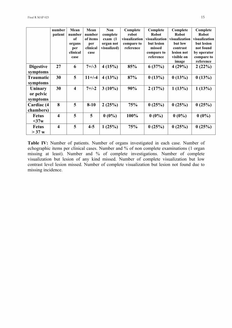
Table IV: Number of patients. Number of organs investigated in each case. Number of echographic items per clinical cases. Number and % of non complete examinations (1 organ missing at least). Number and % of complete investigations. Number of complete visualization but lesion of any kind missed. Number of complete visualization but low contrast level lesion missed. Number of complete visualization but lesion not found due to missing incidence.
Final R MAP 023 16
4096 ultrasound
Fig
Figtranandin rview
128 ultrasoundlines (45 times / s)
lines (25 times / s)
(a) (b) (c)
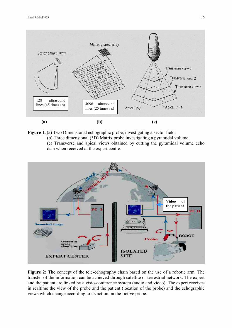
ure 1. (a) Two Dimensional echographic probe, investigating a sector field. (b) Three dimensional (3D) Matrix probe investigating a pyramidal volume. (c) Transverse and apical views obtained by cutting the pyramidal volume echo data when received at the expert centre.
Video ofthe patient
ure 2: The concept of the tele-echography chain based on the use of a robotic arm. The sfer of the information can be achieved through satellite or terrestrial network. The expert the patient are linked by a visio-conference system (audio and video). The expert receives ealtime the view of the probe and the patient (location of the probe) and the echographic
s which change according to its action on the fictive probe.
Final R MAP 023 17
Own
Nutation
Patient’sskin
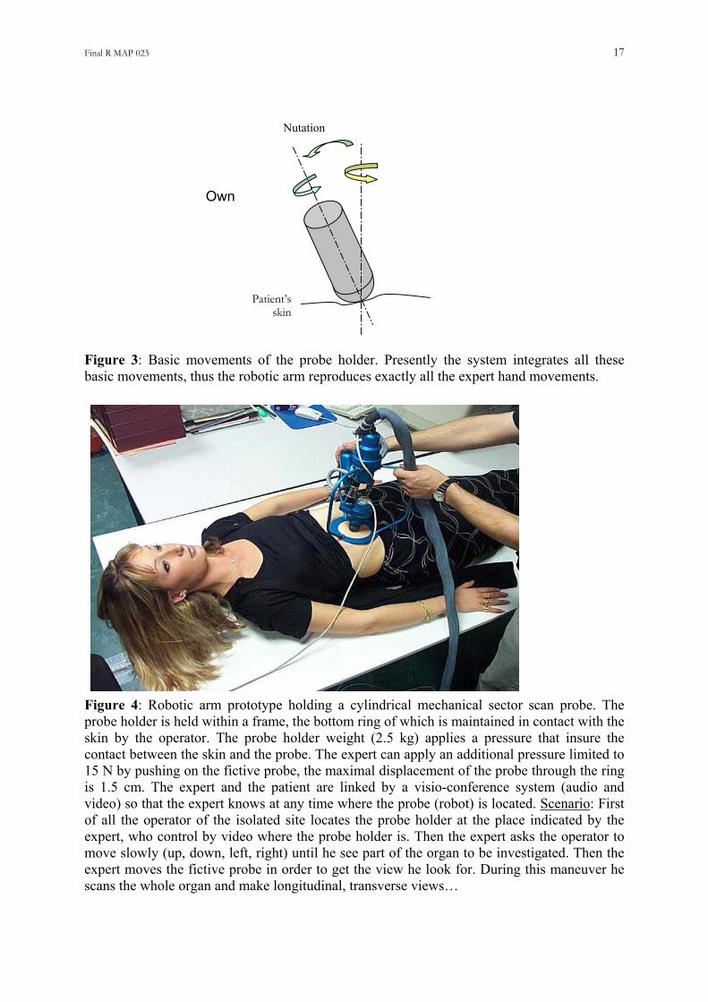
Figure 3: Basic movements of the probe holder. Presently the system integrates all these basic movements, thus the robotic arm reproduces exactly all the expert hand movements. Figure 4: Robotic arm prototype holding a cylindrical mechanical sector scan probe. The probe holder is held within a frame, the bottom ring of which is maintained in contact with the skin by the operator. The probe holder weight (2.5 kg) applies a pressure that insure the contact between the skin and the probe. The expert can apply an additional pressure limited to 15 N by pushing on the fictive probe, the maximal displacement of the probe through the ring is 1.5 cm. The expert and the patient are linked by a visio-conference system (audio and video) so that the expert knows at any time where the probe (robot) is located. Scenario: First of all the operator of the isolated site locates the probe holder at the place indicated by the expert, who control by video where the probe holder is. Then the expert asks the operator to move slowly (up, down, left, right) until he see part of the organ to be investigated. Then the expert moves the fictive probe in order to get the view he look for. During this maneuver he scans the whole organ and make longitudinal, transverse views…
Final R MAP 023 18
(a)
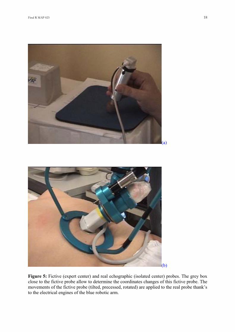
(b) Figure 5: Fictive (expert center) and real echographic (isolated center) probes. The grey box close to the fictive probe allow to determine the coordinates changes of this fictive probe. The movements of the fictive probe (tilted, precessed, rotated) are applied to the real probe thank’s to the electrical engines of the blue robotic arm.
Final R MAP 023 19
(a)
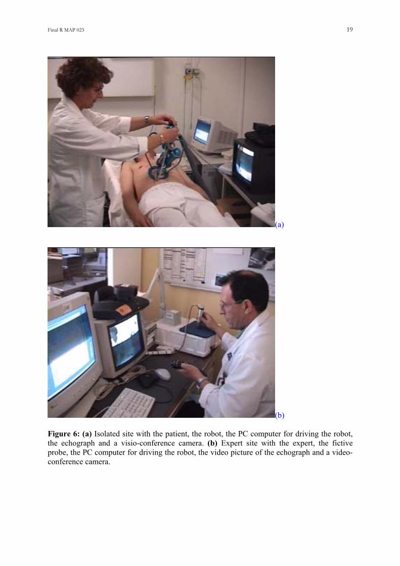
(b) Figure 6: (a) Isolated site with the patient, the robot, the PC computer for driving the robot, the echograph and a visio-conference camera. (b) Expert site with the expert, the fictive probe, the PC computer for driving the robot, the video picture of the echograph and a video-conference camera.
Final R MAP 023 20
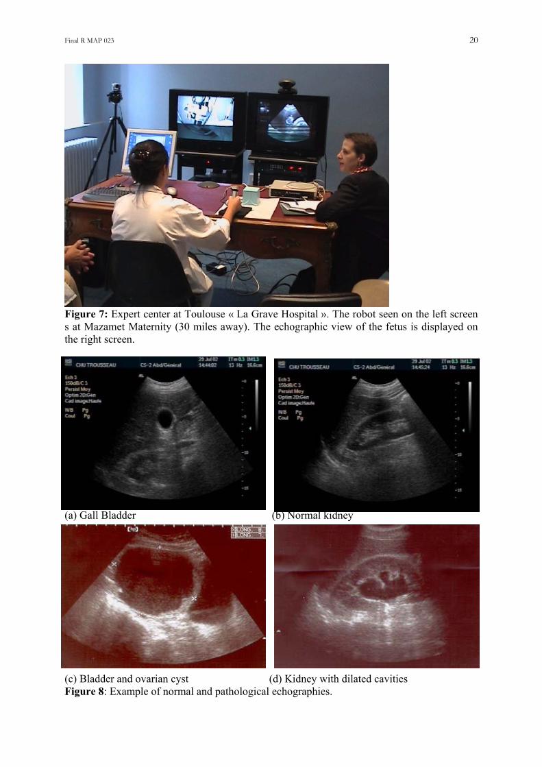
Figure 7: Expert center at Toulouse « La Grave Hospital ». The robot seen on the left screen s at Mazamet Maternity (30 miles away). The echographic view of the fetus is displayed on the right screen. a (a) Gall Bladder (b) Normal kidney (c) Bladder and ovarian cyst (d) Kidney with dilated cavities Figure 8: Example of normal and pathological echographies.
Final R MAP 023 21
(a)
(b)
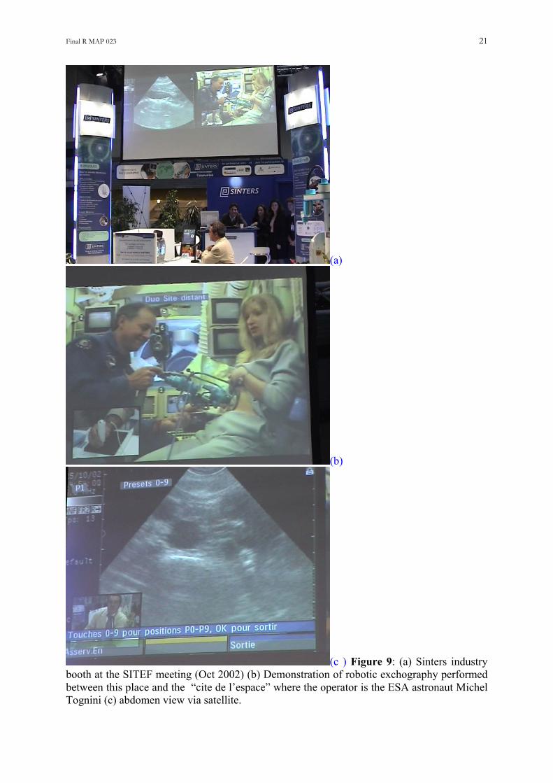
(c ) Figure 9: (a) Sinters industry booth at the SITEF meeting (Oct 2002) (b) Demonstration of robotic exchography performed between this place and the “cite de l’espace” where the operator is the ESA astronaut Michel Tognini (c) abdomen view via satellite.
Final R MAP 023 22
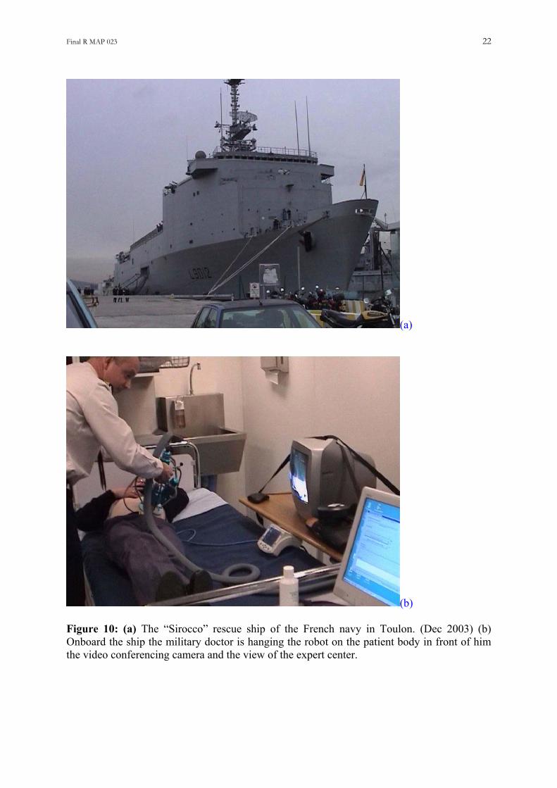
(a)
(b) Figure 10: (a) The “Sirocco” rescue ship of the French navy in Toulon. (Dec 2003) (b) Onboard the ship the military doctor is hanging the robot on the patient body in front of him the video conferencing camera and the view of the expert center.
PROJECT ESA-MAP-023 “TERESA” FINAL SCIENTIFIC REPORT (Written by Pr Ph Arbeille - Tours: December 14th 2003)
(PART 2 Zero G flight validation)
Developed title: Echographic examination in isolated sites controlled from an expert center using a 2D Echograph guided by a tele-operated robotic arm. Work supported by European Space Agency (ESA) contracts: MAP-023 and SME 99684, and Centre National d’Etude Spatiale (CNES) grant 2001 Contributors: UMPS Pr Philippe Arbeille, Unite Medecine, Physiologie Spatiales Med Nucleaire & Ultrasons. – University C H U TROUSSEAU. 37044 - Tours - France. Tel: + (33) 6 80 10 54 88 - E mail: [email protected] SINTERS : Olivier Merigeaux. Cie: BP 1311 - 5, rue P.Mesple -31106 - Toulouse cx 1 France. Tel: +(33)562111717 - Fax: +(33)562111749 - [email protected]
39th Parabolic Flight
TERESA results
N° : 2600-854 Issue A
Prepared by Signature Date
L. URBAIN (SINTERS)
Approved by Signature Date
P. VIEYRES (LVR)
Authorised by Signature Date
P. ARBEILLE (UMPS-CHU TOURS)

39th Parabolic Flight
TERESA results
Page : 3 / 18
�SOCIETE D’INTEGRATION D’ETUDE ET DE RECHERCHE DE SYSTEMES N° 2600-854 ISSUE : A
REVISION LIST
ISSUE DATE PAGE REVISION PREPARED BY A 29/03/04 All Original L. URBAIN
39th Parabolic Flight
TERESA results
Page : 4 / 18
�SOCIETE D’INTEGRATION D’ETUDE ET DE RECHERCHE DE SYSTEMES N° 2600-854 ISSUE : A
TABLE OF CONTENTS
1 SCOPE......................................................................................................................................................................................... 5
2 APPLICABLE DOCUMENTS.................................................................................................................................................. 5
3 PARTNERS TERESA ESA PROJECT.................................................................................................................................... 6
3.1 PARTNERS................................................................................................................................................................................. 6 4.1 PARTICIPANTS........................................................................................................................................................................... 6
5 SYSTEM OVERVIEW AND MAIN OBJECTIVES............................................................................................................... 7
5.1 SYSTEM OVERVIEW................................................................................................................................................................... 7 5.2 MAIN OBJECTIVES..................................................................................................................................................................... 7
6 RESULTS.................................................................................................................................................................................... 8
6.1 ROBOT FUNCTIONING................................................................................................................................................................ 8 6.2 STEP MOVES.............................................................................................................................................................................. 8
6.2.1 Step moves during micro gravity phase.......................................................................................................................... 8 6.2.2 Step moving during 2G phase......................................................................................................................................... 9 6.2.3 Automatic synchronized moves..................................................................................................................................... 10
6.3 SYSTEM ROBUSTNESS ............................................................................................................................................................. 12 6.4 ROBOT BEHAVIOUR DURING MICRO GRAVITY PHASE .............................................................................................................. 12 6.5 SYSTEM FUNCTIONING............................................................................................................................................................ 13 6.6 ROBOT, PATIENT AND ASSISTANT PLACEMENT IN MICRO GRAVITY ......................................................................................... 14 6.7 ORGANS DISPLACEMENT AND ROBOT PLACEMENT ................................................................................................................. 15
7 TECHNICAL PROBLEMS APPEARED AND SOLUTIONS ............................................................................................ 16
7.1 ELECTRIC SWITCHES OFF APPEARED IN THE FIRST TWO DAYS. ................................................................................................ 16 7.2 MOUSE FUNCTIONING IN MICRO GRAVITY............................................................................................................................... 16 7.3 SYSTEMS SET UP ..................................................................................................................................................................... 17 7.4 OPERATORS SICKNESS ............................................................................................................................................................ 17
8 OBJECTIVES OF THE NEXT CAMPAIGN........................................................................................................................ 18
39th Parabolic Flight TERESA results
Page : 5 / 18
�SOCIETE D’INTEGRATION D’ETUDE ET DE RECHERCHE DE SYSTEMES N° 2600-854 ISSUE : A
1 Scope This document presents results performed on TERESA system during the ESA 36th parabolic flight campaign (39th parabolic flight campaign).
2 Applicable Documents NOVESPACE
• 39th VP, Practical and Technical Information; ref: VP39DI/20041 ind. A SINTERS
• 39th VP, technical description of experiment N°7; ref: VP39 ESA EF_technical_description ind. A
39th Parabolic Flight TERESA results
Page : 6 / 18
�SOCIETE D’INTEGRATION D’ETUDE ET DE RECHERCHE DE SYSTEMES N° 2600-854 ISSUE : A
3 Partners Teresa ESA Project Here are the partners who participated to this 39th parabolic flight campaign.
3.1 Partners
4 SINTERS : Olivier Merigeaux, JL. Delouche, Loïc Urbain, N. Villeroy. Cie: BP 1311 - 5, rue
P.Mesplé -31106 - Toulouse cedex 1. France. Tel: +(33)562111717 - Fax: +(33)562111749 -
[email protected], [email protected]
UMPS : Pr Philippe Arbeille. Unité Médecine, & Physiologie Spatiales.
Sce Médecine Nucléaire & Ultrasons - CHU Trousseau – 37044 – TOURS. France.
Tel: (mobile) + (33) 680 10 54 88. Fax : +33 247 47 59 13 [email protected]
LVR : Pierre Vieyres, Gerard Poisson. – laboratoire vision robotique - IUT - Bourges - 18020-
F.Tel:+(33)248238465- Fax:+(33)248238471- [email protected]
4.1 Participants
LVR: • P. VIEYRES, C. NOVALES
UMPS TOURS:
• JL. BOULAY, V. MOREAU, P. KERBECI
SINTERS:
39th Parabolic Flight TERESA results
Page : 7 / 18
�SOCIETE D’INTEGRATION D’ETUDE ET DE RECHERCHE DE SYSTEMES N° 2600-854 ISSUE : A
• N. VILLEROY, JM. DURAND, L. URBAIN
5 System Overview and Main objectives
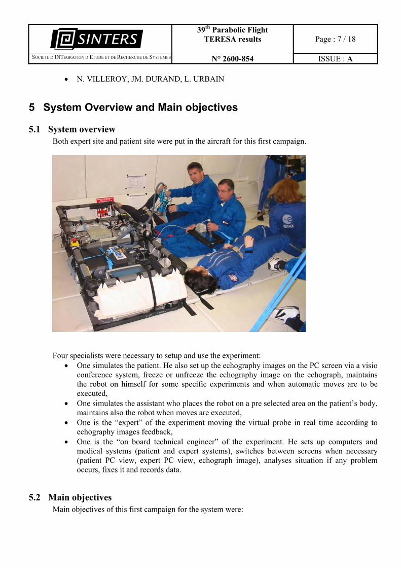
5.1 System overview Both expert site and patient site were put in the aircraft for this first campaign.
Four specialists were necessary to setup and use the experiment:
• One simulates the patient. He also set up the echography images on the PC screen via a visio conference system, freeze or unfreeze the echography image on the echograph, maintains the robot on himself for some specific experiments and when automatic moves are to be executed,
• One simulates the assistant who places the robot on a pre selected area on the patient’s body, maintains also the robot when moves are executed,
• One is the “expert” of the experiment moving the virtual probe in real time according to echography images feedback,
• One is the “on board technical engineer” of the experiment. He sets up computers and medical systems (patient and expert systems), switches between screens when necessary (patient PC view, expert PC view, echograph image), analyses situation if any problem occurs, fixes it and records data.
5.2 Main objectives Main objectives of this first campaign for the system were:
39th Parabolic Flight TERESA results
Page : 8 / 18
�SOCIETE D’INTEGRATION D’ETUDE ET DE RECHERCHE DE SYSTEMES N° 2600-854 ISSUE : A
• To check robot functioning both in a qualitative and a quantitative way, • To check that the robot could move safety in a micro gravity environment (with and without
any human assistance), • To check that an expert can do a robotized tele-echography in micro gravity with this
system, • To check how the contact between the robot and the patient body could be efficiently done, • To check what could be the patient ideal position in micro gravity for robotic echography, • To check how could both patient and assistant be placed in micro gravity to perform a tele
controlled echography, • To look at the displacement of the organs between 1G and 0G in a qualitative way, • To check the mechanical behaviour of the system between 2G, 1G and 0G phases.
6 Results
6.1 Robot functioning We have performed many tests on the robot. The structure has 4 axis, 3 rotations and 1 translation. Rotations are designed with DC brushless motors and the translation with a stepper motor. Usable data have been recorded during micro gravity phase. We have also recorded axis behaviour during 2G phase. Both axis (one axis each time) and synchronized moves have been realized. Robot was positioned vertically and horizontally to prove that orientation had no matter in micro gravity phase and to evaluate the dynamic limits of the structure in 2G phase. Results are presented here after.
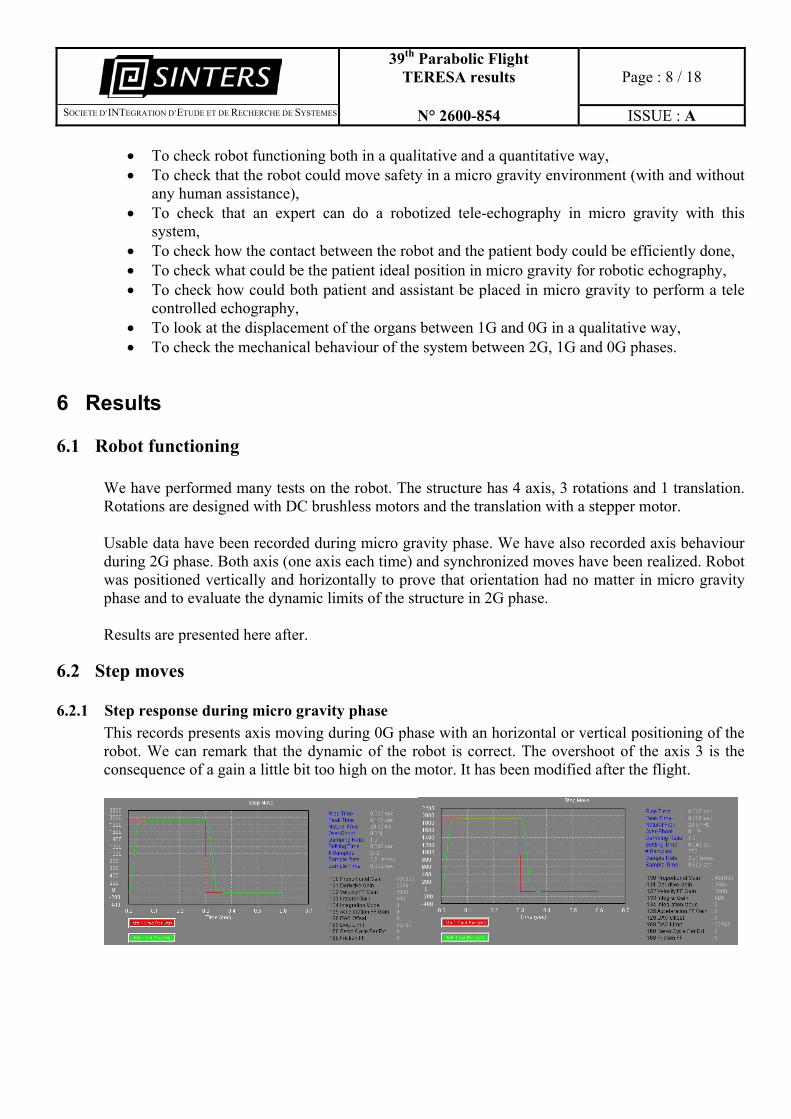
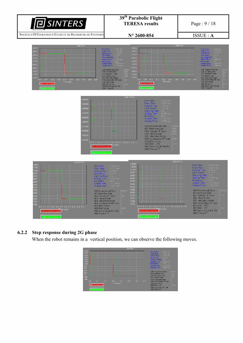
6.2 Step moves
6.2.1 Step response during micro gravity phase This records presents axis moving during 0G phase with an horizontal or vertical positioning of the robot. We can remark that the dynamic of the robot is correct. The overshoot of the axis 3 is the consequence of a gain a little bit too high on the motor. It has been modified after the flight.
39th Parabolic Flight TERESA results
Page : 9 / 18
�SOCIETE D’INTEGRATION D’ETUDE ET DE RECHERCHE DE SYSTEMES N° 2600-854 ISSUE : A
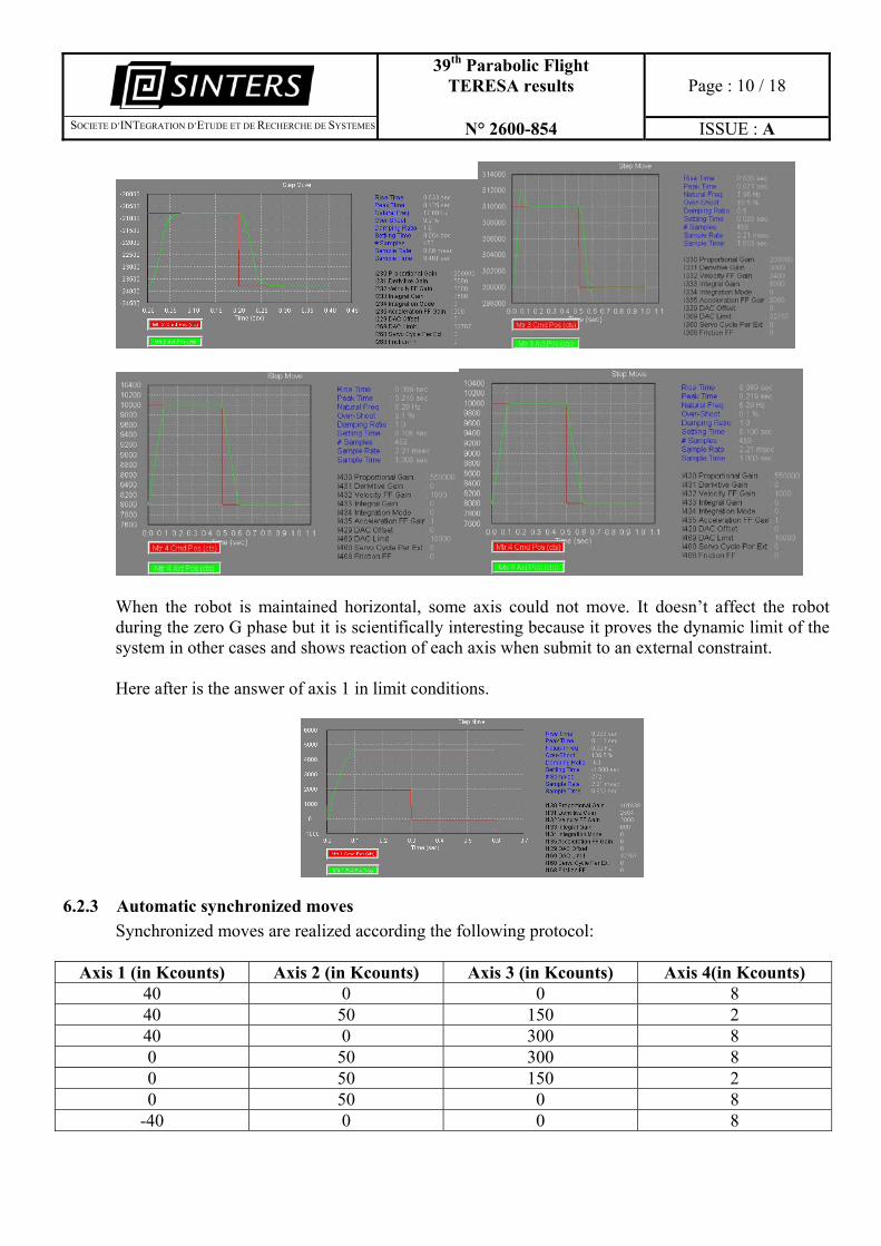
6.2.2 Step response during 2G phase When the robot remains in a vertical position, we can observe the following moves.
39th Parabolic Flight TERESA results
Page : 10 / 18
�SOCIETE D’INTEGRATION D’ETUDE ET DE RECHERCHE DE SYSTEMES N° 2600-854 ISSUE : A
When the robot is maintained horizontal, some axis could not move. It doesn’t affect the robot during the zero G phase but it is scientifically interesting because it proves the dynamic limit of the system in other cases and shows reaction of each axis when submit to an external constraint. Here after is the answer of axis 1 in limit conditions.
6.2.3 Automatic synchronized moves Synchronized moves are realized according the following protocol:
Axis 1 (in Kcounts) Axis 2 (in Kcounts) Axis 3 (in Kcounts) Axis 4(in Kcounts) 40 0 0 8 40 50 150 2 40 0 300 8 0 50 300 8 0 50 150 2 0 50 0 8
-40 0 0 8
39th Parabolic Flight TERESA results
Page : 11 / 18
�SOCIETE D’INTEGRATION D’ETUDE ET DE RECHERCHE DE SYSTEMES N° 2600-854 ISSUE : A
-40 50 150 2 -40 0 300 8
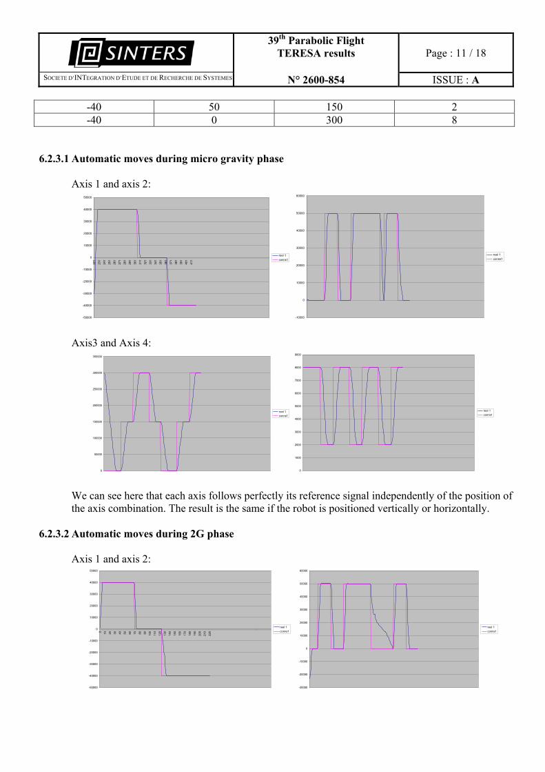
6.2.3.1 Automatic moves during micro gravity phase Axis 1 and axis 2:
-50000
-40000
-30000
-20000
-10000
0
10000
20000
30000
40000
50000
221
231
241
251
261
271
281
291
301
311
321
331
341
351
361
371
381
391
401
411
reel 1conns1
-10000
0
10000
20000
30000
40000
50000
60000
reel 1conns1
Axis3 and Axis 4:
0
50000
100000
150000
200000
250000
300000
350000
reel 1conns1
0
1000
2000
3000
4000
5000
6000
7000
8000
9000
reel 1conns1
We can see here that each axis follows perfectly its reference signal independently of the position of the axis combination. The result is the same if the robot is positioned vertically or horizontally.
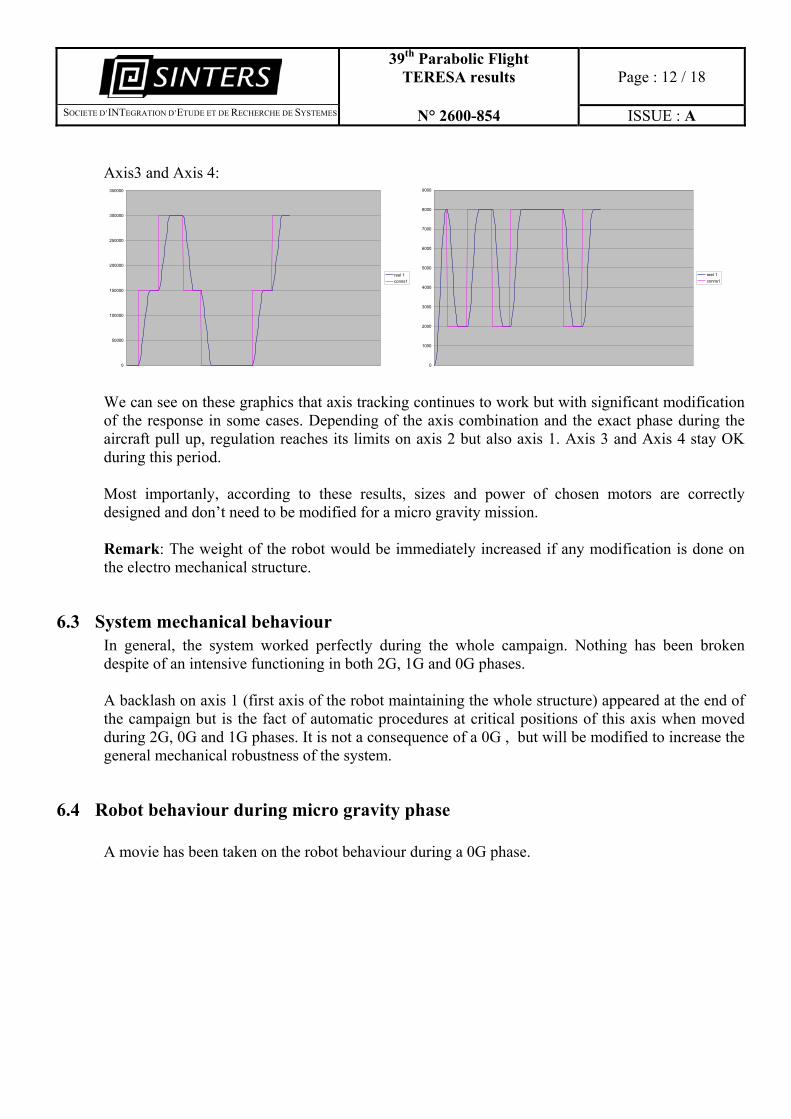
6.2.3.2 Automatic moves during 2G phase Axis 1 and axis 2:
-50000
-40000
-30000
-20000
-10000
0
10000
20000
30000
40000
50000
0 10 20 30 40 50 60 70 80 90 100
110
120
130
140
150
160
170
180
190
200
210
220
reel 1conns1
-30000
-20000
-10000
0
10000
20000
30000
40000
50000
60000
reel 1conns1
39th Parabolic Flight TERESA results
Page : 12 / 18
�SOCIETE D’INTEGRATION D’ETUDE ET DE RECHERCHE DE SYSTEMES N° 2600-854 ISSUE : A
Axis3 and Axis 4:
0
50000
100000
150000
200000
250000
300000
350000
reel 1conns1
0
1000
2000
3000
4000
5000
6000
7000
8000
9000
reel 1conns1
We can see on these graphics that axis tracking continues to work but with significant modification of the response in some cases. Depending of the axis combination and the exact phase during the aircraft pull up, regulation reaches its limits on axis 2 but also axis 1. Axis 3 and Axis 4 stay OK during this period. Most importanly, according to these results, sizes and power of chosen motors are correctly designed and don’t need to be modified for a micro gravity mission. Remark: The weight of the robot would be immediately increased if any modification is done on the electro mechanical structure.
6.3 System mechanical behaviour In general, the system worked perfectly during the whole campaign. Nothing has been broken despite of an intensive functioning in both 2G, 1G and 0G phases. A backlash on axis 1 (first axis of the robot maintaining the whole structure) appeared at the end of the campaign but is the fact of automatic procedures at critical positions of this axis when moved during 2G, 0G and 1G phases. It is not a consequence of a 0G , but will be modified to increase the general mechanical robustness of the system.
6.4 Robot behaviour during micro gravity phase A movie has been taken on the robot behaviour during a 0G phase.
39th Parabolic Flight TERESA results
Page : 13 / 18
�SOCIETE D’INTEGRATION D’ETUDE ET DE RECHERCHE DE SYSTEMES N° 2600-854 ISSUE : A
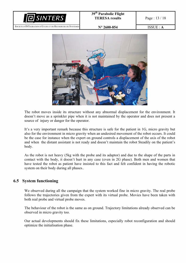
The robot moves inside its structure without any abnormal displacement for the environment. It doesn’t move as a sprinkler pipe when it is not maintained by the operator and does not present a source of injury or danger for the operator. It’s a very important remark because this structure is safe for the patient in 1G, micro gravity but also for the environment in micro gravity when an undesired movement of the robot occurs. It could be the case for instance when the expert on ground controls a displacement of the axis of the robot and when the distant assistant is not ready and doesn’t maintain the robot Steadily on the patient’s body. As the robot is not heavy (5kg with the probe and its adaptor) and due to the shape of the parts in contact with the body, it doesn’t hurt in any case (even in 2G phase). Both men and women that have tested the robot as patient have insisted to this fact and felt confident in having the robotic system on their body during all phases..
6.5 System functioning We observed during all the campaign that the system worked fine in micro gravity. The real probe follows the trajectories given from the expert with its virtual probe. Movies have been taken with both real probe and virtual probe moves. The behaviour of the robot is the same as on ground. Trajectory limitations already observed can be observed in micro gravity too. Our actual developments should fix these limitations, especially robot reconfiguration and should optimize the initialisation phase.
39th Parabolic Flight TERESA results
Page : 14 / 18
�SOCIETE D’INTEGRATION D’ETUDE ET DE RECHERCHE DE SYSTEMES N° 2600-854 ISSUE : A
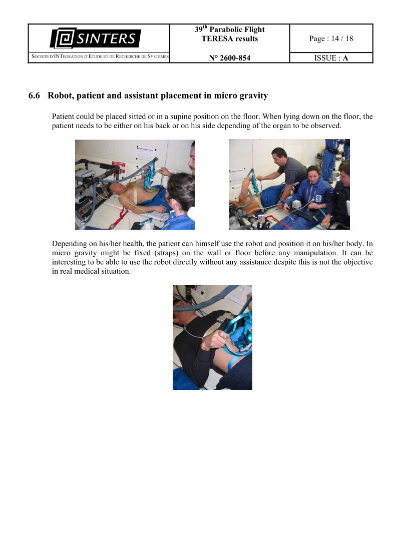
6.6 Robot, patient and assistant placement in micro gravity Patient could be placed sitted or in a supine position on the floor. When lying down on the floor, the patient needs to be either on his back or on his side depending of the organ to be observed.
Depending on his/her health, the patient can himself use the robot and position it on his/her body. In micro gravity might be fixed (straps) on the wall or floor before any manipulation. It can be interesting to be able to use the robot directly without any assistance despite this is not the objective in real medical situation.
39th Parabolic Flight TERESA results
Page : 15 / 18
�SOCIETE D’INTEGRATION D’ETUDE ET DE RECHERCHE DE SYSTEMES N° 2600-854 ISSUE : A
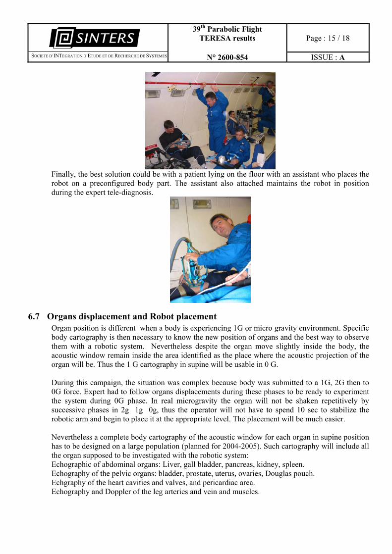
Finally, the best solution could be with a patient lying on the floor with an assistant who places the robot on a preconfigured body part. The assistant also attached maintains the robot in position during the expert tele-diagnosis.
6.7 Organs displacement and Robot placement Organ position is different when a body is experiencing 1G or micro gravity environment. Specific body cartography is then necessary to know the new position of organs and the best way to observe them with a robotic system. Nevertheless despite the organ move slightly inside the body, the acoustic window remain inside the area identified as the place where the acoustic projection of the organ will be. Thus the 1 G cartography in supine will be usable in 0 G.
During this campaign, the situation was complex because body was submitted to a 1G, 2G then to 0G force. Expert had to follow organs displacements during these phases to be ready to experiment the system during 0G phase. In real microgravity the organ will not be shaken repetitively by successive phases in 2g 1g 0g, thus the operator will not have to spend 10 sec to stabilize the robotic arm and begin to place it at the appropriate level. The placement will be much easier. Nevertheless a complete body cartography of the acoustic window for each organ in supine position has to be designed on a large population (planned for 2004-2005). Such cartography will include all the organ supposed to be investigated with the robotic system: Echographic of abdominal organs: Liver, gall bladder, pancreas, kidney, spleen. Echography of the pelvic organs: bladder, prostate, uterus, ovaries, Douglas pouch. Echgraphy of the heart cavities and valves, and pericardiac area. Echography and Doppler of the leg arteries and vein and muscles.
39th Parabolic Flight TERESA results
Page : 16 / 18
�SOCIETE D’INTEGRATION D’ETUDE ET DE RECHERCHE DE SYSTEMES N° 2600-854 ISSUE : A
Another campaign will be suitable within one year approximately to check in zero G, an advanced version of the complete organ supine 1G cartography.
6.8 Organ image stability and quality As mentioned above the operator when entering the 0g phase had first to stabilize the Robot and place it at the dedicated place (10 sec). Then the expert had 15 sec to manipulate the probe and find the appropriate incidence which normally takes in case of diagnostic examination several minute. The organ was found in most of the cases and the image was of good quality for the diagnosis bases on the standard ultrasound device used. Nevertheless it was difficult for the expert to see clearly the image on the video monitor as it was far from him. Also the lightning aboard the ZeroG Airbus was to intense to appreciate the contrast levels of the images. For future zero G flights we suggest to use a small video screen at the level of the fictive probe, like the one of a small digital portable video camera (7x7x5cm – 300 g) which monitor (5 x 4cm) has been proved to be sufficient when investigating leg vein on a standing subject during Bedrest the ultrasound device being far from the operator (The video camcorder is connected to the BNC or cinch echograph video out). The Robotic arm remained stable during the 0g because the subject and the operator were fixed on the bottom floor of the plane. An additional elastic belt suitable to maintain the contact between the robotic arm and the patient in 0g, will not be necessary in 0g because the environment is stable and the operator can easily move it slowly on the body surface.
7 Technical problems and solutions
7.1 Electric switches off appeared in the first two days. One generator on the aircraft has been changed after a failure. Electric components of the system have entirely been verified and screwed again. An electrical surge protection used as a voltage limiter was integrated upstream of the installation. The systems worked perfectly after these modifications.
7.2 Mouse functioning in micro gravity We had put a standard wheel mouse that couldn’t be operative in 0G phase! Then we put an optical mouse that had compatibility problem with windows NT4 and the screen/keyboard/mouse switch used. Then, both the two mouses were set; the wheel mouse for the expert PC and the optical mouse for the robot PC (necessary to be able to record robotic data in micro gravity phase). All data were recorded as expected after this modification. A trackball could be the best solution for use in space.
39th Parabolic Flight TERESA results
Page : 17 / 18
�SOCIETE D’INTEGRATION D’ETUDE ET DE RECHERCHE DE SYSTEMES N° 2600-854 ISSUE : A
7.3 Systems set up If any failure appeared during parabolas, the system had to be set up again. The set up could be just a local initialisation of one component or a general reboot of both the two systems. These set up phases was too long and shall be reduced and simplified. The initialisation robustness of the robot and the virtual probe shall also be increased because they put sometimes the system in an undesired state. This situation shall be corrected for a daily use and before a new campaign.
7.4 Operators sickness Lots operators have been more or less sick during the experiment. Independently of human factors, a lot of displacements are necessary to make the system work. Operators have to move a lot their head to look at screens and to push buttons to verify that device parameters and other operators are OK increasing the possibility to be sick in zero g flights. As soon as an operator was sick and couldn’t perform its task, others had to compensate this situation increasing their potentiality to be also sick.
As some measured were performed automatically, it was possible during this campaign to have sick operators during each flight. Now, we know that for a full medical experiment with an expert and a patient system onboard, four operators are necessary. For an automatic robotic program which constitute only one part of the technical validation of the system, two operators are necessary with at least one senior engineer.
39th Parabolic Flight TERESA results
Page : 18 / 18
�SOCIETE D’INTEGRATION D’ETUDE ET DE RECHERCHE DE SYSTEMES N° 2600-854 ISSUE : A
8 Objectives of the next campaign
According to the results observed during the 39th campaign (36th ESA campaign), we suggest the following plan for future campaign:
A) Check the advanced version of the “all organ acoustic window cartography” Echographic of abdominal organs: Liver, gall bladder, pancreas, kidney, spleen. Echography of the pelvic organs: bladder, prostate, uterus, ovaries, Douglas pouch. Echography of the heart cavities and valves, and pericardic area. Echography and Doppler of the leg arteries and vein and muscles.
B) Confirm, during the Zero G phase, the regulating actions of general software (SW) options concerning the specific PID parameters (dedicated 0g) for the various articulations and the general options of filtering by the Inverse Geometrical Model control. One of the objectives will be to carry out evaluations allowing to measure mechanical criteria of the robot performances in microgravity [performances of the unit step responses of the articulations, (setting time, overshoot, tracking error..), correction of the mechanical play of each axis]. The analysis of these results will make it possible to compare real mechanical behaviours resulting from experiments carried out in microgravity environment with expected behaviours resulting from the theoretical models. The results analyses will enable to enhance the proposed mechanical model for a better performance in the microgravity environment.
C) Validate the theoretical concepts concerning the hardware (HW) choices on the dedicated tele-echography space robot used in contact with human operators. This point will make it possible to define specific design rules for the construction of a future space robot and its functioning in microgravity. Limitation of the driving currents to study the influence of the limited actuators torque (to be considered on each articulation); record reference input responses, under limited current, in articular and working spaces. It is also intended to study the influence of additional masses fixed on the moving parts of the robot in order to evaluate the relationship between the mass value and the performances. The results will lead to “abacus " used to refine ideal automatic models to design robots for zero G environment with reduced embarked mass and volume.