Embed Size (px)
Citation preview

>AWEA WindPower 2011 Best Practices & Challenges
May 23, 2011
Wind Project Construction

2
Moderator: Elling OlsonDirector of Business Development, US WindRenewable Energy Groups
Overview of Mortenson Construction
• Privately held corporation with 55 years in the construction business
• Led by Board Chairman M. A. Mortenson, Jr.• 18th largest general construction firm in the U.S.*• 11th largest energy construction firm in the U.S.* • Upper tier firm in bonding capacity and financial
strength• 100 Wind Farms Constructed• Experience exceeds 10,000 megawatts • 7,000 wind turbine generators installed
*ENR based on 2010 revenues

3
Renewable Energy Groups
enXco, Carrier ClinicBelle Mead, NJ
Westwood Renewables, St. John’s Solar ArrayCollegeville, MN
Kaheawa Wind FarmMaui, HI
Prince Wind ParkSault Ste. Marie, Ontario, Canada
Penascal II Wind FarmSarita, TX
Tessera Solar North America, Maricopa Solar Array – Peoria, AZ

4
Best Practices in Wind Farm Construction related to today’s Trends
Trends• More difficult sites – site optimization necessary • New standards being applied – advance technology• Search is on for cost saving solutions to compete with low
natural gas pricing and a price driven market • Fewer PPA’s, fewer projects available, more competition

5
Panel Expertise
Herb Sargent, President of Sargent Corporation
Kevin Smith, Business Development Leader, DNV Renewables (USA) Inc.
Jim Penman, Independent Site Solutions Consultant
Steve Reutcke, Vice President Construction, RES Canada Construction, LP

AWEAChallenges & Opportunities for
Construction at Extreme Elevations

Challenges• Accuracy of existing topography
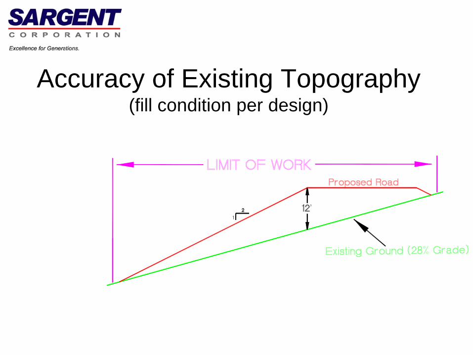
• Accuracy of bedrock profile
• Permit constraints for mitigating Inaccuracies
• Analysis of cuts and fills
Accuracy of Existing Topography(fill condition per design)

Accuracy of Existing Topography(fill condition where existing ground is lower)
Note encroachmentoutside permittedlimit of work

Accuracy of Existing Topography(cut condition by design)

Accuracy of Existing Topography(cut condition where existing ground is higher)
Note encroachmentoutside permittedlimit of work

Accuracy of Bedrock Profile(a note about the phenomena of the “swell” of blasted rock)

Accuracy of Bedrock Profile(blasted rock swells +/- 30% compared to solid rock)

Accuracy of Bedrock ProfileThe phenomena of blasted rock swell exacerbates
the cut & fill “balance” challenge

Accuracy of Bedrock ProfileThe solid rock at 6,200 cy becomes 8,060 of blasted rock
Accuracy of Bedrock ProfileHence, the actual profile of the rock surface has a dramatic
impact on “balance” calculations

Accuracy of Bedrock ProfileThe phenomena of blasted rock swell exacerbates
the cut & fill “balance” challenge

Accuracy of Bedrock ProfileHence, the actual profile of the rock surface has a dramatic
impact on “balance” calculations

Accuracy of Bedrock ProfileHence, the actual profile of the rock surface has a dramatic
impact on “balance” calculations

Permit Constraints to Mitigating Topographic Inaccuracies
• Prescribed horizontal & vertical layout
• Proximity to protected resources

Prescribed Horizontal & Vertical Layout
• May not allow for “Field Fit” to actual conditions
• May increase costs due to unmitigated additional quantities
• May not be “Constructable”, depending on other permit constraints

Proximity to Protected Resources(where protected resources are close to the work area)

Proximity to Protected Resources(Per design with “design” existing topography)

Proximity to Protected Resources(Impact if actual existing conditions vary)
Note impact on protected resources

Opportunities
• Optimization of cuts and fills
• Field collection of data for existing topography
• Collection of actual rock profile
• Field adjusting to performance standard

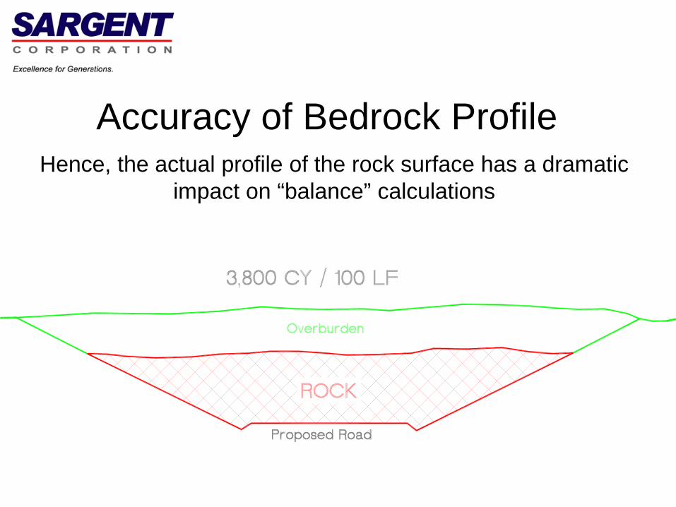
Optimization of Cuts & Fills
• “Balance” cuts and fills– Ensure excavated material has a “home” in
embankments, within the design– The accuracy of rock profile is key to these
calculations
• Balance within optimum proximity– Shortest movement of materials is most efficient

Just getting cuts/fills “in the ballpark” prior to field information
Optimization of Cuts & Fills(nominal project)
Optimization of Cuts & Fills(nominal project)

Optimization of Cuts & Fills(nominal project)

Field Collection of Existing Topography
• As soon as possible after clearing
• Field adjustments based on accurate data

Field Collection of Existing Topography(fill condition by design)
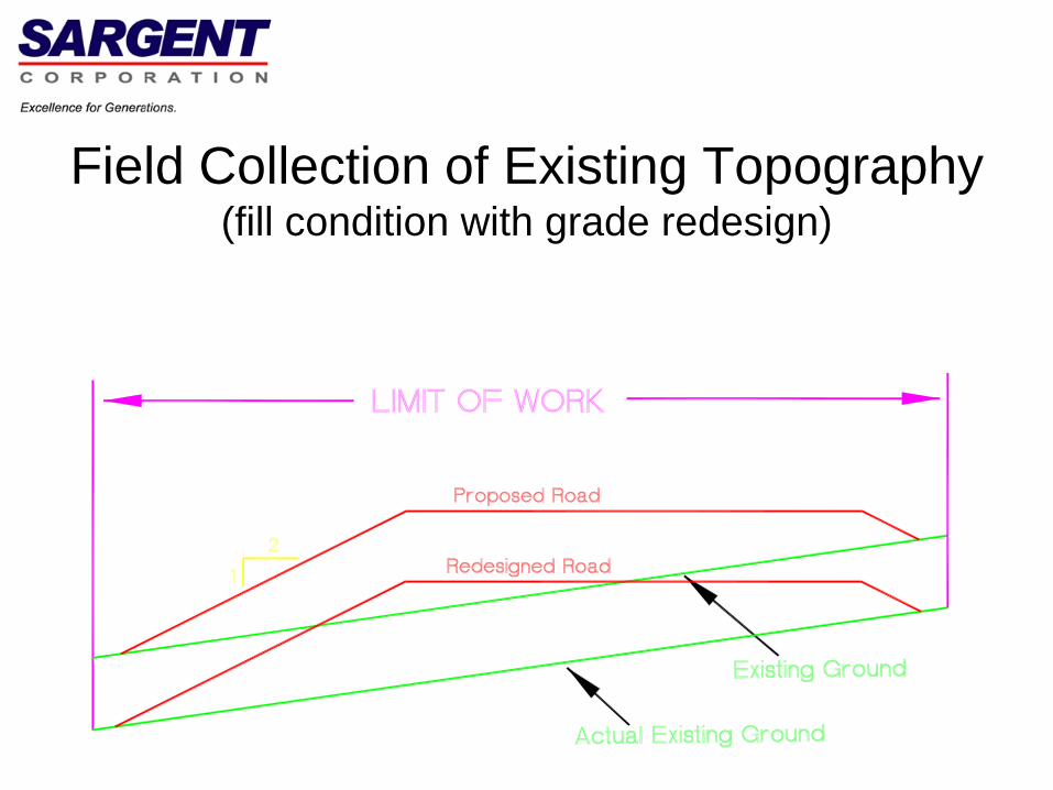
Field Collection of Existing Topography(fill condition with grade redesign)

Field Collection of Existing Topography(cut condition by design)

Field Collection of Existing Topography(cut condition with grade redesign)

Examples of Extreme Terrain


Field Collection of Actual Rock Profile
• Test pits for establishing presence of rock and a rough profile
• Accurate quantity after overburden removal
• Field adjustment for variations in existing ground from that shown on design drawings

Field Collection of Actual Rock Profile(Once overburden is removed, perform field topo of rock surface --
slopes may need to be adjusted)

All rock can’t be avoided!(pictured is a Cat D10 dozer)

Field Adjustment to Performance Standards
• Example performance standards:– Crane path maximum slope = 12%– Horizontal curve = 150’ radius (minimum) – Vertical curve = no more than 6” vertically to 150’
horizontally
• Latitude with design alignment? • Within Limits of Construction only? (or is
adjustment outside LOC allowed)• Adjusting of profile grades• Same principles apply to tower pads

Recommendations
• Be aware of the dramatic impact of variances in actual existing topography versus aerial topography.
• To every extent possible, maintain ability to make field changes in grade & alignment through permitting process
• Engage a constructability review with an experienced entity – focus on:
– Proximity of protected resources to high relief areas– “Balancing” of cuts and fill – optimally to close proximity with
each other – safer, faster, and more efficient

Moderator’s Comments

Windpower 2011
25 May 2011
Survey and Outreach Efforts – Development of U.S. Recommended Practices for Compliance of Large Onshore Wind Turbine Structures
Co-Authors:Kevin J. Smith – DNVRolando Vega – ABS ConsultingJohn Dunlop – American Wind Energy AssociationPaul Veers – National Renewable Energy Laboratory
© Det Norske Veritas AS. All rights reserved.
25 May 2011
45
Presentation Outline
Introduction and Background - “Recommended Practices for Compliance of Large Onshore Wind Turbine Structures”
Discuss Survey and Outreach Efforts
Key Findings from Survey and Outreach
Next Actions for Document Distribution

© Det Norske Veritas AS. All rights reserved.
25 May 2011
46
Introduction to “RP for Compliance of Large Turbine Structures”
Purpose:- To develop documents that clearly identify typical and specific U.S. national wind turbine
design recommendations that are compatible with the International Electrotechnical Commission (IEC) requirements.
History:- Effort authorized by AWEA’s Standard Development Board in 2009- Guideline Subcommittee formed in late 2009- Established 3 working project teams: Structures, Offshore, and Electrical- Meetings held at conferences, monthly conf. calls to establish activities, evaluate progress,
make decisions
Participants:- Open to anyone - Joint effort between AWEA and ASCE- Broad representation across industry, ~50 active participants
Review Panel: ~30 technical experts engaged to provide objective review

© Det Norske Veritas AS. All rights reserved.
25 May 2011
47
Survey and Outreach Efforts
Lack of Authorities Having Jurisdiction (AHJs) and/or local building inspectors on working project team
Mechanisms for AHJ participation were unclear
Structures Team decided to conduct survey - Additional value seen in communicating knowledge about Recommended Practice document
12 questions prepared by team, web based, anonymous responses
Distribution to targeted audience likely to be familiar with local approval process
~6 week response period
NOT intended to be statistically representative of whole industry
Response scale: 1 – 5 to capture degrees of agreement or disagreement

© Det Norske Veritas AS. All rights reserved.
25 May 2011
48
High-Level Summary of Responders
170 responses across 39 states
74% identified as AHJs or Building Inspectors
Met objective for obtaining input from these key stakeholders
CategoryResponse
CountResponse
PercentAuthority Having Jurisdiction 91 54%Developer/Owner/Operator 9 5%Manufacturer 5 3%Building Inspector 34 20%Design Engineer 4 2%Financier/Investor 2 1%Other 25 15%Total 170 100%
© Det Norske Veritas AS. All rights reserved.
25 May 2011
49
Key Findings
Strong support for creation of a Recommended Practice.- Explaining the inter-relationships of various codes used to design and build large wind
turbines was greatly desired.
The audience for the Recommended Practice has a wide range of knowledge on this subject - from expert to beginner. - The guideline needs to accommodate all.
Most wind turbine structural permits have been/are being issued under the existing building permit/review process for code-defined "non-building Structures".
Need to allow local AHJs to adapt the Recommended Practice - Account for local or State level requirements.

© Det Norske Veritas AS. All rights reserved.
25 May 2011
50
Awareness and Familiarity Varies
I (we) am aware that wind turbines have a separate set of internationally recognized design and safety standards which equal or exceed building codes in our jurisdiction.

© Det Norske Veritas AS. All rights reserved.
25 May 2011
51
Awareness and Familiarity Varies
I (we) have a good understanding of areas where different codes overlap (UBC, IBC, ANSI, IEC, etc.) and are familiar with selecting the most applicable codes.

© Det Norske Veritas AS. All rights reserved.
25 May 2011
52
Awareness and Familiarity Varies
I (we) find it difficult to apply our codes and knowledge when needing to make approval decisions for large wind turbines, towers, and foundations.

© Det Norske Veritas AS. All rights reserved.
25 May 2011
53
Technical Approach
I (we) believe that wind turbine structural permits have been/are being issued under the existing building permit/review process for code-defined "non-building Structures". (Example of Non-building Structures included telecommunication towers, elevated storage tanks, vessels, hoppers, industrial frames, stacks, etc.)

© Det Norske Veritas AS. All rights reserved.
25 May 2011
54
Technical Approach
I (we) understand and feel comfortable that the site wind conditions, ground conditions, engineering analysis, and equipment selection in previous projects have been sufficiently documented to support approval process and minimize wind turbine risk.

© Det Norske Veritas AS. All rights reserved.
25 May 2011
55
Need for Recommended Practice Document?
I (we) believe a guidance document that explains the inter-relationships of various codes that have been used to design and build a large wind turbine would be useful to all local jurisdictions.

© Det Norske Veritas AS. All rights reserved.
25 May 2011
56
Need for Recommended Practice Document?
I (we) feel that such a guideline assembled by a broad group of industry experts, developers, trade organizations, standard societies, and local approval representatives would be viewed as an un-biased and trusted source of information.

© Det Norske Veritas AS. All rights reserved.
25 May 2011
57
Need for Recommended Practice Document?
I (we) believe that the consensus within the industry on code provisions, safety margins, and design life will provide needed assurance to project designers and builders as well as owners and investors of wind farm projects.

© Det Norske Veritas AS. All rights reserved.
25 May 2011
58
Next Steps
AWEA and ASCE execute Memorandum of Understanding
Submittal of 100% Complete Draft Document:- To AWEA and ASCE Standards Development Boards- Release to public for comment period
http://www.awea.org/learnabout/awea_standards_program/american_national_standards/index.cfm
Release Final Recommended Practice early November 2011- Based on public comment and review results

© Det Norske Veritas AS. All rights reserved.
25 May 2011
59
Safeguarding life, property and the environment
www.dnv.com

Cheaper, faster, more reliable ways to construct access roads and crane platforms Jim Penman – Site Solutions Consultant
Alpharetta, GA

Contents
Access Roads• Conventional construction practices
• Cheaper, faster construction
• Rigorous (more reliable) design
Crane platform design

Access RoadsConventional Construction Practices

Conventional Construction Practice
Subgrade
8 to 12 inUnbound Aggregate
Separation Geotextile

Conventional Construction Practice
Surface bladed out periodically to backfill any deep ruts
In extreme cases, additional stone added
Subgrade
8 to 12 inUnbound Aggregate

Access RoadsCheaper, Faster Construction

Mechanical Reinforcement

Access Roads – Load Spread
Subgrade
Access Road

Access Roads – Load Spread
Subgrade
Access Road
Geogrid

Reduced Costs, Faster Construction
66% Reduction
6 in.
18 in.

Thickness/Cost Savings
Subgrade CBR (%)
Description
Access Road Thickness (in) Cost
Savings (%)Unreinforced Geogrid
Reinforced
0.6 Soft 28 14 (50%) 39
1.2 Medium 18 6 (66%) 50
2.4 Stiff 14 6 (43%) 36
Assumptions• Installed aggregate cost = $10/ton
Example• 10 miles x 16 ft access roads
• Total cost savings = $94,000 to $375,000

Thickness/Cost Savings
Assumptions• Installed aggregate cost = $20/ton
Example• 10 miles x 16 ft access roads
• Total cost savings = $469,000 to $1,032,000
Subgrade CBR (%)
Description
Access Road Thickness (in) Cost
Savings (%)Unreinforced Geogrid
Reinforced
0.6 Soft 28 14 (50%) 39
1.2 Medium 18 6 (66%) 50
2.4 Stiff 14 6 (43%) 36
Access RoadsMore Reliable Design

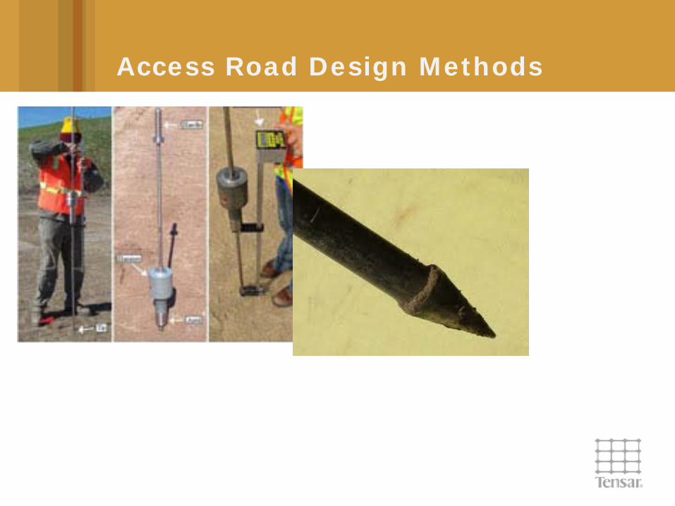
Access Road Design Methods
Various methods available:• AASHTO (1993)
• Giroud and Noiray (1981)
• US Army Corps of Engineers (2001)**
• Giroud and Han (2004)**
• Others
** calibrated based on observed performance

Access Road Design Methods

Access Road Design Methods

Access Road Design Methods

Access Road Design Methods

Access Road Design Methods
Rubbish in – rubbish out concept
Need to know• Trafficking conditions
• Subsoil conditions (shallow soils)
Access Road Design Methods

Access Road Design Methods

Crane Platform Design

These areas are subjected to particularly heavy static loads
BX Geogrids can be used to distribute loads more efficiently
Staging Areas

Staging Areas
Determine critical load

Staging Areas
Granular platform
Soft subgrade
Imposed pressure(Boussinesq)
Determine fill thickness required for appropriate Factor of Safety

Staging Areas
Granular platform
Soft subgrade
Imposed pressure(Boussinesq)
Determine fill thickness required for appropriate Factor of Safety

Staging Areas
Granular platform
Soft subgrade
Imposed pressure(Westergaard)
Determine fill thickness required for appropriate Factor of Safety

Staging Areas
Granular platform
Soft subgrade
Imposed pressure(Westergaard)
Determine fill thickness required for appropriate Factor of Safety
Bottom line – fill thickness reduced by ~ 50%

Case Studies

Soft subgrade (0.8 – 1.6% CBR)Original road section (10” aggregate + geotextile)• Failed after limited number of passes
Giroud-Han method used to design roads• 14” aggregate + geogrid for firmer soils• 22” aggregate + geogrid for softer soils
24 hours from SOS call to final design
Case Study 1: Lowville, NY

Key drivers – schedule, performance, cost
Designs done by DMJM Harris using Giroud-Han
Variable soil conditions:
• Firmer – 25 inch section reduced to 12 inches
• Softer – 52 inch section reduced to 34 inches
Case Study 2: Clinton, NY

Summary
Access roads: geogrids can…• Reduce aggregate thickness by 40 to 60%
• Increase speed of construction by same amount
• Reduce carbon emissions associated with road construction by 20 to 40%
More rigorous design approach avoids surprises (and extra costs) later• Use of proven design methods
• Simple in situ tests at time of construction
Similar savings can be adopted for crane platforms

Session 9A
Project Construction: Best Practices and Challenges
Construction Strategies2012 and Beyond
Steve ReutckeRenewable Energy Systems Americas Inc.May 25, 2011

MARKET – ANNUAL INSTALLED US CAPACITY (MW)
AWEA 2010 Market Report: Jan 2011
67
1693
455
1663
373
2424 2428
5332
8503
9453
53175600
2000 2001 2002 2003 2004 2005 2006 2007 2008 2009 2010 2011

PROJECT OWNERS – US MARKET
IPP57%Other developer
26%
Utility17%
Project Constructed/Under Construction in US (2010 – 2011)
AWEA 2010 Market Report: Jan 2011

PROJECT OWNER REQUIREMENTS
• Competitive RFP process
• Low Cost performance
• Risk aversion
• Open book procurement
• Value engineering
• Schedule compliance
• HSQE

PROJECT CHARACTERISTICS
• Increasingly complex/challenging locations
• Remote/Urban
• Geology
• Interconnection
• Larger
• Turbines/blades
• Larger foundations
• MV Collection systems
• Smaller
• Roads/Crane pads
• MV cable sizes

PROJECT COSTS
2006 2007 2008 2009 2010 2011 2012
BOP Value
Construction Cost


SAFETY
Safety…..Quality…..Value…..Experience…..Accountability
ProgramComprehensive site programsFull time onsite safety supervisors
TrainingSite specific Safety inductions Weekly safety meetings Monthly (min) All- Hands meetings
CompetencyFormal assessment for high risk activities (High Voltage switching, Critical Lifts, etc)
AwarenessDaily/Task tool-box meetingsNear miss identification/tracking
DisciplineThree Strike Rule
AccountabilityMonthly audits

QUALITY
Design
Comprehensive site investigationsExperienced civil and electrical in-house engineersOptimize design to site conditionsEnhanced design evaluation techniquesTurbine siting capability
ConstructionPerformance Specifications Detailed design drawingsExperienced discipline specific inspectorsInspection & Test plansComprehensive Job Books
Safety…..Quality…..Value…..Experience…..Accountability

VALUE
Value Engineering
Equipment suitability
Energy optimization
System loss analyses
Safety…..Quality…..Value…..Experience…..Accountability
Procurement
Vendor qualification
Plant inspections
Supplier relationships
Commodity tracking
Expediting

EXPERIENCE
Erecting turbines
Safety…..Quality…..Value…..Experience…..Accountability
Building in many locations

EXPERIENCE WITH EMERGING RENEWABLES
Safety…..Quality…..Value…..Experience…..Accountability

CIVIL WORKS
Safety…..Quality…..Value…..Experience…..Accountability

ELECTRICAL WORKS
Safety…..Quality…..Value…..Experience…..Accountability

TURBINE WORKS
Safety…..Quality…..Value…..Experience…..Accountability
ACCOUNTABILITY
Safety…..Quality…..Value…..Experience…..Accountability
• Community Involvement
• Environmental Stewardship
• Land Owner Support
• Prompt Warranty Service
• Operations Support


Questions and AnswersPart 1

Questions and AnswersPart 2

Questions and AnswersPart 3