Embed Size (px)
Citation preview

ACCESS CODEUNIQUE CODE INSIDE
Project Based SOLIDWORKS 2020
Kirstie Plantenberg, CSWA
®
SDCP U B L I C AT I O N S www.SDCpublications.com
Better Textbooks. Lower Prices.
Videos
Includes over nine
hours of video instruction

Visit the following websites to learn more about this book:
Powered by TCPDF (www.tcpdf.org)

[ Chapter 2: Connecting Rod Project – Model ]
2 - 1
CHAPTER 2
CONNECTING ROD PROJECT Model
CHAPTER OUTLINE 2.1) PREREQUISITES ..................................................................................................................... 2 2.2) WHAT YOU WILL LEARN ....................................................................................................... 2 2.3) SETTING UP THE PROJECT .................................................................................................. 3 2.4) BASE EXTRUDE ...................................................................................................................... 3 2.5) ADDING FEATURES ............................................................................................................. 10 2.6) ADDING MATERIAL .............................................................................................................. 14 CONNECTING ROD PROJECT (MODEL) PROBLEMS .............................................................. 17 CONNECTING ROD PROJECT (MODEL) QUIZ PROBLEMS .................................................... 27
[ Chapter 2: Connecting Rod Project –Model ]
2 - 2
2.1) PREREQUISITES
Before completing this tutorial, you should have completed the following tutorial and be familiar with the following topics. Pre-requisite Tutorial
• Chapter 1 – Introduction to SOLIDWORKS® Pre-requisite Topics
• Computer navigation. • Passing familiarity with orthographic projection. • Ability to read dimensions.
2.2) WHAT YOU WILL LEARN The objective of this tutorial is to introduce you to creating simple Sketches, Extrudes and Cuts. You will be modeling the connecting rod shown in Figure 2.2-1. Specifically, you will learn the following commands and concepts. Sketching
• Sketch relations • Editing dimensions • Editing sketches • Sketch chamfers • Sketch fillet • Rectangle
Features
• Chamfer • Fillets • Editing a feature
Material and properties
• Applying material • Mass properties
View
• Panning • Rotating

[ Chapter 2: Connecting Rod Project – Model ]
2 - 3
Figure 2.2-1: Connecting rod
2.3) SETTING UP THE PROJECT
1) Start SOLIDWORKS and then start a new part . 2) Set your unit to IPS (i.e. inch, pound, second) and set your Decimals = .12 and your
standard to ANSI (Options – Document Properties – Units)
3) Save your part as CONNECTING ROD.SLDPRT (File – Save). Remember to save often throughout this project.
2.4) BASE EXTRUDE
1) Sketch on the Front Plane.

[ Chapter 2: Connecting Rod Project –Model ]
2 - 4
2) Use the Circle command to sketch two circles as shown below. Make one of the circle centers coincident with the origin. You will know when you have snapped to the origin when a small circle appears. Don’t worry about the circle’s spacing or size at the moment. Just make them about 5 or more diameters apart.
3) Pan your drawing area to center the circles. (See the informational block on Panning.) Panning Method 1 1) Hold down the Ctrl key. 2) Click and hold your middle mouse button. 3) Move your mouse. Method 2
1) Select View – Modify - Pan commands. 2) Click your left mouse button and move the mouse.
4) Use the Line command to sketch the following profile. Be approximate. Don’t worry about getting it exact. Notice that when you are drawing the lines that dashed lines will appear occasionally. These dashed lines allow you to snap to geometric features of the object that have already been drawn or to the origin.

[ Chapter 2: Connecting Rod Project – Model ]
2 - 5
5) Add the following sketch relations. Don’t worry if your drawing goes wonky. Just click and drag the elements into position. (See the informational block on Applying Sketch Relations.) a) If any of the horizontal or vertical lines are not perfectly horizontal or vertical, add
those relations. b) Make the two circle diameters Equal. c) Make the circle centers Horizontal. d) Make the two bottom horizontal lines Collinear. e) Make the two bottom horizontal line lengths Equal. f) Make the two angled line lengths Equal.
Applying sketch relations Sketch relations add geometric constraints between two or more entities. For example, we can make two lines parallel, or two circles concentric. 1) Select one of the elements that you want to apply
the relation to. 2) Hold the Ctrl key and then select the next element
that you want to apply the relation to. 3) Continue selecting elements if you want to apply the
relation to more than two elements. 4) In the Properties window, select the relation that
you wish to apply.

[ Chapter 2: Connecting Rod Project –Model ]
2 - 6
6) View your Sketch Relations. Your geometric relations will show up as symbols inside a green box. (See the informational block on Viewing Relations.)
Viewing relations 1) From the pull-down menu at the top, select View – Hide/Show - Sketch Relations.
7) Add the Dimensions shown in the figure shown below. If your drawing exceeds your viewing area, select the F key to fit all. When dimensioning, it is a good idea to start with the overall dimensions and then work down to the smaller dimensions. Note that if a Make Dimension Driven? window appears, you have an unwanted sketch relation or you have a duplicate dimension. Select Cancel and then search and delete the extra constraint. Note: If, while you are dimensioning the part, the angled lines become parallel, you need to remove the equal constraint and then reapply it after you have adjusted the lines. (See the informational block on Editing Dimensions.)
8) After you are done dimensioning, you should make the left circle and the origin Coincident. Note that there should be no blue lines when you are finished. Blue lines mean that it is under-constrained.

[ Chapter 2: Connecting Rod Project – Model ]
2 - 7
Editing a dimension Method 1 1) Double click the dimension that you wish to edit. 2) Within the Modify window, fill in the correct dimension value and then select the
green check mark .
Method 2 1) Select the dimension that you wish to edit. 2) Features of the dimension may be changed within
the Dimension window that appears on the left.
Dimension name
Reverse direction
Value
Add symbols and text
Value
Dimension name

[ Chapter 2: Connecting Rod Project –Model ]
2 - 8
9) Extrude your sketch to a distance of 2.50 inches.
10) Try zooming in and out by scrolling your middle mouse wheel. Notice that the mouse
location identifies the zooming center. 11) Fit all (F). 12) Edit your sketch. (See the informational block on Editing a Sketch.) Editing a sketch 1) Select the sketch to be edited in the Feature Manager
Design Tree.
2) Select Edit Sketch from the Context toolbar.
13) View your sketch from the normal plane by selecting Ctrl + 8.
Edit sketch

[ Chapter 2: Connecting Rod Project – Model ]
2 - 9
14) Add two 2 x 45o Chamfers
to the top outside corners and two 1 x 45o Chamfers to the bottom outside corners. The Chamfer command is located under the
Fillet command. When applying the 1 x 45o, select Yes in the warning window. Note that this will delete the Equal relation between the two bottom horizontal lines. Reapply the Equal relation after you have applied the chamfer. (See the information block on Sketch Chamfers & Sketch Fillets.) After you reapply the Equal relation, you may be asked to Rebuild and Save.
Sketch Chamfers & Sketch Fillets (located in the Sketch tab)
1) Chamfer: A Chamfer is a beveled corner. It can be defined by selecting a vertex or two edges and then specifying a distance and an angle, or two distances.
2) Fillet: A Fillet is a rounded corner. It is defined by selecting a vertex or two edges and then specifying a radius.
• Note: You should set your fillet or chamfer size before you select the entity. • Note: If a warning window appears, it means that by applying the chamfer or fillet
you will be deleting a sketch relation or dimension. You may need to reapply the constraint.
Chamfer method
Chamfer dimensions
Fillet radius

[ Chapter 2: Connecting Rod Project –Model ]
2 - 10
15) Exit Sketch . 16) View your part from the isometric view (Ctrl + 7). 17) Change the Extrude distance from 2.5 to 2.1 inches. (See the informational block on
Editing a Feature.) Editing a feature 1) Select the feature to be edited in the Feature Manager Design Tree. Right clicking
shows you the full command list. 2) Select Edit Feature from the Context toolbar.
2.5) ADDING FEATURES 1) Sketch on the top face of your part.
2) View the sketch from the normal direction (Ctrl + 8).
Edit feature
Sketch face
[ Chapter 2: Connecting Rod Project – Model ]
2 - 11
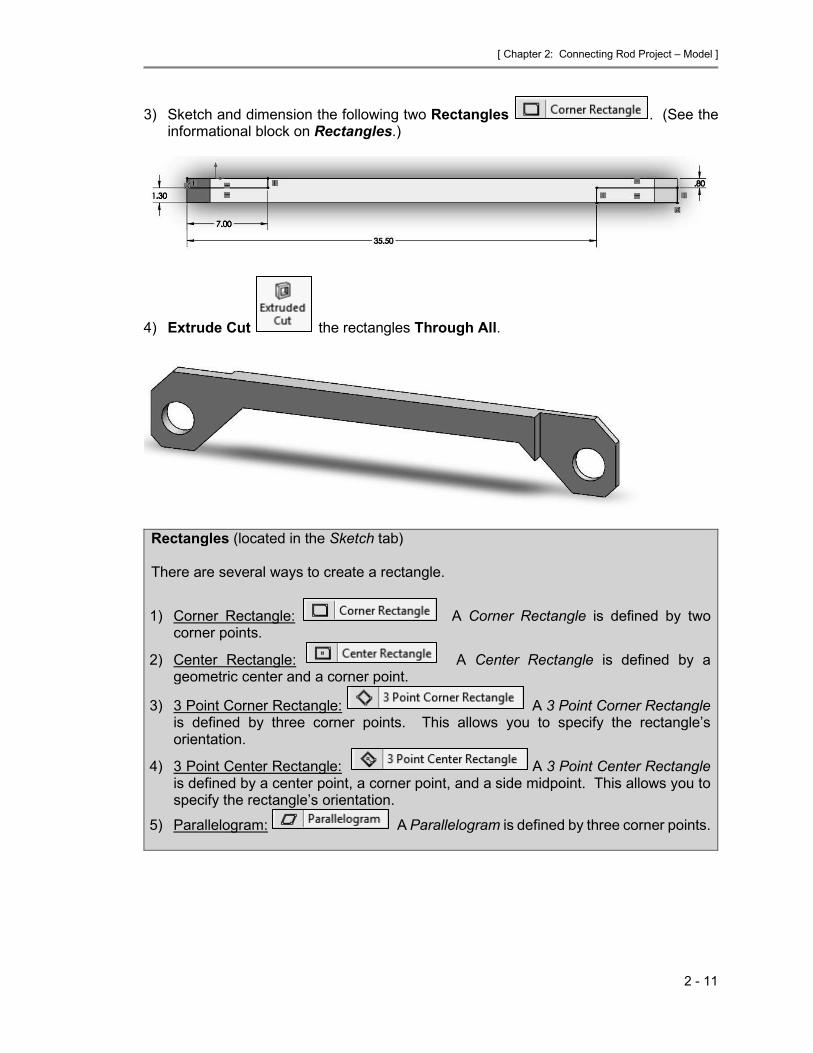
3) Sketch and dimension the following two Rectangles . (See the informational block on Rectangles.)
4) Extrude Cut the rectangles Through All.
Rectangles (located in the Sketch tab) There are several ways to create a rectangle.
1) Corner Rectangle: A Corner Rectangle is defined by two corner points.
2) Center Rectangle: A Center Rectangle is defined by a geometric center and a corner point.
3) 3 Point Corner Rectangle: A 3 Point Corner Rectangle is defined by three corner points. This allows you to specify the rectangle’s orientation.
4) 3 Point Center Rectangle: A 3 Point Center Rectangle is defined by a center point, a corner point, and a side midpoint. This allows you to specify the rectangle’s orientation.
5) Parallelogram: A Parallelogram is defined by three corner points.
[ Chapter 2: Connecting Rod Project –Model ]
2 - 12
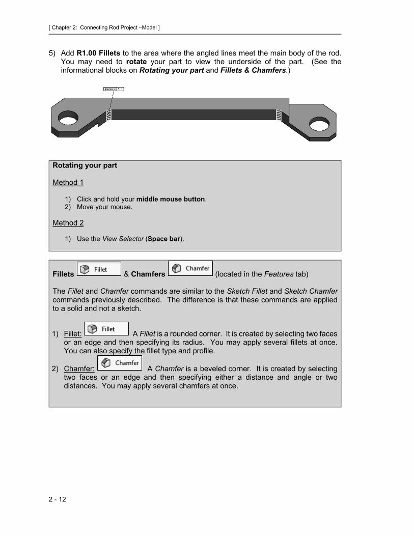
5) Add R1.00 Fillets to the area where the angled lines meet the main body of the rod. You may need to rotate your part to view the underside of the part. (See the informational blocks on Rotating your part and Fillets & Chamfers.)
Rotating your part Method 1
1) Click and hold your middle mouse button. 2) Move your mouse.
Method 2
1) Use the View Selector (Space bar).
Fillets & Chamfers (located in the Features tab) The Fillet and Chamfer commands are similar to the Sketch Fillet and Sketch Chamfer commands previously described. The difference is that these commands are applied to a solid and not a sketch.
1) Fillet: A Fillet is a rounded corner. It is created by selecting two faces or an edge and then specifying its radius. You may apply several fillets at once. You can also specify the fillet type and profile.
2) Chamfer: A Chamfer is a beveled corner. It is created by selecting two faces or an edge and then specifying either a distance and angle or two distances. You may apply several chamfers at once.

[ Chapter 2: Connecting Rod Project – Model ]
2 - 13
Fillets & Chamfers Cont.
Fillet option
Fillet profile
Chamfer type
Chamfer dimensions
Allows you to see a preview before applying the fillet.
Fillet type

[ Chapter 2: Connecting Rod Project –Model ]
2 - 14
6) In your Feature Manager Design Tree, name your features as shown. To name your feature, slowly double click on the name.
7) Save.
2.6) ADDING MATERIAL 1) Apply a material of Aluminum 1060 Alloy to your part. (See
the informational block on Applying Material.) Applying material 1) Right click on Material in the
Feature Manager Design Tree. 2) Select Edit Material. 3) A Material window will appear. 4) Select your desired material. 5) Select Apply. 6) Select Close.
Select material
Units
Material properties

[ Chapter 2: Connecting Rod Project – Model ]
2 - 15
2) Calculate the weight of your part. In the Evaluate tab, select Mass Properties
. In the Mass Properties window note that the mass of your part is 22.22 lb. This is really the weight of your part because of the units. If your weight is not this value, your model is incorrect. This window also gives other physical properties.

[ Chapter 2: Connecting Rod Project –Model ]
2 - 16
NOTES:

[ Chapter 2: Connecting Rod Project – Model ]
2 - 17
CONNECTING ROD PROJECT (MODEL) PROBLEMS P2-1) Create a solid model of the following 1345 Aluminum part and calculate the weight of the part. Dimensions are given in inches.
P2-2) Create a solid model of the following Gray Cast Iron part and calculate the weight of the part. Dimensions are given in inches.
[ Chapter 2: Connecting Rod Project –Model ]
2 - 18
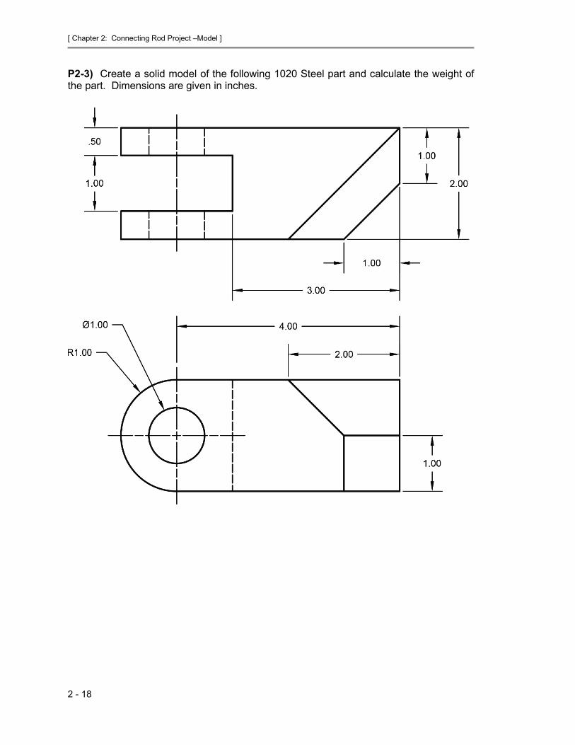
P2-3) Create a solid model of the following 1020 Steel part and calculate the weight of the part. Dimensions are given in inches.

[ Chapter 2: Connecting Rod Project – Model ]
2 - 19
P2-4) Create a solid model of the following ABS plastic part and calculate the weight of the part. Dimensions are given in inches.

[ Chapter 2: Connecting Rod Project –Model ]
2 - 20
P2-5) Create a solid model of the following Brass part and calculate the mass of the part. Dimensions are given in millimeters.

[ Chapter 2: Connecting Rod Project – Model ]
2 - 21
P2-6) Create a solid model of the following Oak part and calculate the weight of the part. Dimensions are given in inches.

[ Chapter 2: Connecting Rod Project –Model ]
2 - 22
P2-7) Use SOLIDWORKS® to create a solid model of the following 1345 Aluminum part. Calculate the weight of your part. Dimensions are given in inches.
P2-8) Use SOLIDWORKS® to create a solid model of the following 6061 Aluminum part. Calculate the weight of your part. Dimensions given in inches.

[ Chapter 2: Connecting Rod Project – Model ]
2 - 23
P2-9) Use SOLIDWORKS® to create a solid model of the following 1020 Steel part. Calculate the weight of your part. Dimensions given in inches.
P2-10) Use SOLIDWORKS® to create a solid model of the following 1020 Steel part. Calculate the weight of your part. Dimensions given in inches.

[ Chapter 2: Connecting Rod Project –Model ]
2 - 24
P2-11) Use SOLIDWORKS® to create a solid model of the following ABS plastic part. Calculate the weight of your part. Dimensions given in millimeters.

[ Chapter 2: Connecting Rod Project – Model ]
2 - 25
P2-12) Use SOLIDWORKS® to create a solid model of the following Oak part. Calculate the mass of your part. Dimensions given in millimeters.

[ Chapter 2: Connecting Rod Project –Model ]
2 - 26
P2-13) Use SOLIDWORKS® to create a solid model of the following Grey Cast Iron. Calculate the mass of your part. Dimensions given in millimeters. Note that all fillets and rounds are R3.

[ Chapter 2: Connecting Rod Project – Model ]
2 - 27
CONNECTING ROD PROJECT (MODEL) QUIZ PROBLEMS Q2-1) Use SOLIDWORKS® to create a solid model of the following 1060 Aluminum Alloy part. Dimensions given in millimeters. a) Calculate the mass of your part and circle the correct answer.
• 1835.02 grams • 1724.08 grams • 1040.73 grams • 998.01 grams • 783.99 grams • 726.04 grams

[ Chapter 2: Connecting Rod Project –Model ]
2 - 28
b) Make the following modifications to your part and calculate the mass. i. Add three R10 fillets as shown. ii. Cut a hexagon through on the right side of the part as shown.
Mass = ______________________ grams