Embed Size (px)
Citation preview

NORWEGIAN UNIVERSITY OF SCIENCE AND TECHNOLOGY
FACULTY OF INFORMATION TECHNOLOGY, MATHEMATICS AND ELECTRICAL ENGINEERING
PROJECT ASSIGNMENT Student's name: Frøydis Ødegaard Course: TTM4725 Title: Location-based services using WLAN Text: Radionor has developed a low-cost WLAN localisation technology named Cordis Access™, which is able to sense WLAN transceivers located within predefined location zones. This could lead to the development of fine-grained, indoor location services. The project assignment is to design and implement a demonstration service utilizing this technology. The service will be available to the user depending on his present location. Ericsson’s ActorFrame/ServiceFrame will be used to develop the service, while WAP Push will deliver and present the service. A cellular phone equipped with a SIM card with an integrated WLAN transceiver will be used for testing and service demonstration. There are several possible application areas for location-based services utilizing WAP Push, leading to interesting business opportunities. This assignment will to some extend identify these opportunities, as well as point out directions for further development. Deadline: December 9, 2005
Handed in:
Carried out at: Department of Telematics
Supervisor: Haldor Samset
Rolv Bræk Professor
NTNU 2005 Location-based services using WLAN
i
Summary Location-based services have received a lot of attention the last few years. The number of publicly available services is rather small today, but both new positioning technologies and services are emerging. It is hard to predict the success of these kinds of services, and “killer-applications” are hard to obtain. Still, the potential of location-based services is believed to be enormous, and service providers are searching for services that will attract new customers. Area for Research on advanced Telecom Services (ARTS) is an ongoing research project that aim at developing advanced and innovative telecom services. NTNU, Telenor, Ericsson and Abelia are collaborating in the project. Recently the project has purchased positioning equipment that provides local positioning to experiment with location-based services. The technology is called Cordis Access™, and is developed by Radionor Communications AS. It provides mechanisms to position WLAN transceivers within pre-defined zones. In this project a service that utilizes the Cordis Access™ positioning technology is designed and implemented. The service is a location-based reminder service. By accessing the service on a web server the user may add new reminders. The service will notify the user with reminders when specific conditions within the reminder are satisfied. These conditions are based on location, as well as a trigger-value (enter or leave) and a lower time-limit in the reminder message. By combining these parameters, the user may specify a complete set of reminders. When designing the reminder service, emphasis was put on designing a general system that provides a set of actors and agents with well-defined responsibilities. Separation of responsibilities decreases the overall complexity and enables reuse of relevant parts of the system. Generality was important to be able to extend the system to provide more services in the future. This project also suggests some possible extensions. By supporting a wide range of services, the system may experiment with different kinds of services, in search of attractive end-services. The system is implemented using Ramses. Ramses is a development tool that supports service development by UML concepts. It is developed at the Department of Telematics at NTNU, and helps the designer focus on design rather than implementation details. The system is designed using UML, and code is generated by a code generator. The implemented system is run on the ActorFrame platform developed by Ericsson. This report presents and discusses the design decisions made in implemented system, and the results achieved. Many details of the implementation have been omitted, because they are considered less interesting to the reader, as most of the system was developed using Ramses. All source code may be found on the enclosed CD.

NTNU 2005 Location-based services using WLAN
ii
Preface The project assignment was written at the Norwegian University of Science and Technology (NTNU) in Trondheim as part of the Master of Science study. It was carried out at Department of Telematics in the 9th semester, fall 2005. The focus of this assignment is service development, even though it is carried out as part of a specialization within tele economics. In this relation the assignment forms an essential background of technical knowledge to be able to investigate commercial aspects and business opportunities of location-based services in the master thesis that will be carried out in the next semester. I would like to thank both Rolv Bræk and Haldor Samset for valuable advises during the work, and helpful comments with the report. Additionally, I would like to Ingebrigt Fuglem at Telenor R&D for useful comments on the current situation of location-based services, and Ottar Dahle at Radionor Communications AS for helpful insight in the operation of Cordis Access™ with positioning. Trondheim, December 9, 2005 Frøydis Ødegaard

NTNU 2005 Location-based services using WLAN
iii
Index 1 INTRODUCTION............................................................................................................................... 7
1.1 BACKGROUND.............................................................................................................................. 7 1.2 SCOPE .......................................................................................................................................... 8 1.3 OUTLINE ...................................................................................................................................... 8
2 LOCATION-BASED SERVICES ................................................................................................... 10 2.1 GENERAL ................................................................................................................................... 10 2.2 POSITIONING TECHNOLOGIES ..................................................................................................... 12 2.3 CURRENT SITUATION.................................................................................................................. 14
3 FOUNDATIONS............................................................................................................................... 17 3.1 CORDIS ACCESS™ WITH POSITIONING ....................................................................................... 17 3.2 THE STATELESS NATURE OF HYPERTEXT TRANSFER PROTOCOL ................................................ 21 3.3 WIRELESS APPLICATION PROTOCOL .......................................................................................... 22
4 SERVICE DEVELOPMENT........................................................................................................... 24 4.1 UML.......................................................................................................................................... 24
4.1.1 Internal structure.................................................................................................................. 24 4.1.2 State machine........................................................................................................................ 25
4.2 ERICSSON’S DEVELOPMENT FRAMEWORK .................................................................................. 27 4.2.1 JavaFrame............................................................................................................................ 27 4.2.2 ActorFrame........................................................................................................................... 27 4.2.3 ServiceFrame........................................................................................................................ 29
4.3 THE DEVELOPMENT TOOL – RAMSES.......................................................................................... 31 4.4 WEB SERVER.............................................................................................................................. 33
4.4.1 Jetty ...................................................................................................................................... 33 4.4.2 Servlets and Java Server Pages ............................................................................................ 33
5 SERVICES USING CORDIS ACCESS POSITIONING.............................................................. 35 5.1 GENERAL ................................................................................................................................... 35 5.2 SCENARIO 1................................................................................................................................ 36 5.3 SCENARIO 2................................................................................................................................ 38 5.4 SCENARIO 3................................................................................................................................ 39
6 DESIGN AND IMPLEMENTATION............................................................................................. 41 6.1 SERVICE CAPABILITIES AND REQUIREMENTS .............................................................................. 41 6.2 SYSTEM STRUCTURE .................................................................................................................. 44
6.2.1 User Agent ............................................................................................................................ 45 6.2.2 Terminal Agent ..................................................................................................................... 45 6.2.3 PositionManager .................................................................................................................. 46 6.2.4 LocationRegister................................................................................................................... 47 6.2.5 ReminderService................................................................................................................... 47
6.3 EXTERNAL INTERFACES.............................................................................................................. 47 6.3.1 CordisAPEdge and CordisServer ......................................................................................... 47 6.3.2 WapEdge............................................................................................................................... 48 6.3.3 HttpEdge and HttpWebServer .............................................................................................. 48
6.4 BEHAVIOR.................................................................................................................................. 49 6.4.1 Log on / log off...................................................................................................................... 50 6.4.2 Adding a new reminder......................................................................................................... 52 6.4.3 Displaying active reminders ................................................................................................. 53 6.4.4 Location update .................................................................................................................... 54 6.4.5 Trigger reminder to the user................................................................................................. 54
6.5 STRUCTURING THE SOURCE CODE .............................................................................................. 57
NTNU 2005 Location-based services using WLAN
iv
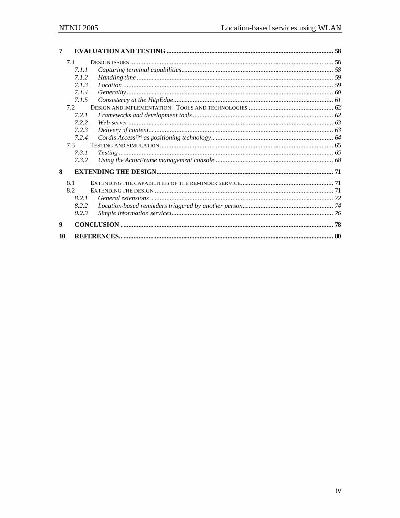
7 EVALUATION AND TESTING ..................................................................................................... 58 7.1 DESIGN ISSUES ........................................................................................................................... 58
7.1.1 Capturing terminal capabilities............................................................................................ 58 7.1.2 Handling time ....................................................................................................................... 59 7.1.3 Location................................................................................................................................ 59 7.1.4 Generality ............................................................................................................................. 60 7.1.5 Consistency at the HttpEdge................................................................................................. 61
7.2 DESIGN AND IMPLEMENTATION - TOOLS AND TECHNOLOGIES ................................................... 62 7.2.1 Frameworks and development tools ..................................................................................... 62 7.2.2 Web server ............................................................................................................................ 63 7.2.3 Delivery of content................................................................................................................ 63 7.2.4 Cordis Access™ as positioning technology.......................................................................... 64
7.3 TESTING AND SIMULATION......................................................................................................... 65 7.3.1 Testing .................................................................................................................................. 65 7.3.2 Using the ActorFrame management console........................................................................ 68
8 EXTENDING THE DESIGN........................................................................................................... 71 8.1 EXTENDING THE CAPABILITIES OF THE REMINDER SERVICE........................................................ 71 8.2 EXTENDING THE DESIGN............................................................................................................. 71
8.2.1 General extensions ............................................................................................................... 72 8.2.2 Location-based reminders triggered by another person....................................................... 74 8.2.3 Simple information services.................................................................................................. 76
9 CONCLUSION ................................................................................................................................. 78 10 REFERENCES.................................................................................................................................. 80
NTNU 2005 Location-based services using WLAN
v
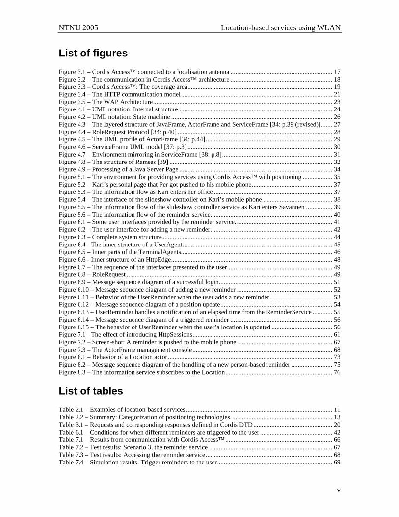
List of figures Figure 3.1 – Cordis Access™ connected to a localisation antenna .............................................................. 17 Figure 3.2 – The communication in Cordis Access™ architecture .............................................................. 18 Figure 3.3 – Cordis Access™: The coverage area........................................................................................ 19 Figure 3.4 – The HTTP communication model............................................................................................ 21 Figure 3.5 – The WAP Architecture............................................................................................................. 23 Figure 4.1 – UML notation: Internal structure ............................................................................................. 24 Figure 4.2 – UML notation: State machine .................................................................................................. 26 Figure 4.3 – The layered structure of JavaFrame, ActorFrame and ServiceFrame [34: p.39 (revised)]....... 27 Figure 4.4 – RoleRequest Protocol [34: p.40] .............................................................................................. 28 Figure 4.5 – The UML profile of ActorFrame [34: p.44]............................................................................. 29 Figure 4.6 – ServiceFrame UML model [37: p.3] ........................................................................................ 30 Figure 4.7 – Environment mirroring in ServiceFrame [38: p.8]................................................................... 31 Figure 4.8 – The structure of Ramses [39] ................................................................................................... 32 Figure 4.9 – Processing of a Java Server Page ............................................................................................. 34 Figure 5.1 – The environment for providing services using Cordis Access™ with positioning .................. 35 Figure 5.2 – Kari’s personal page that Per got pushed to his mobile phone................................................. 37 Figure 5.3 – The information flow as Kari enters her office ........................................................................ 37 Figure 5.4 – The interface of the slideshow controller on Kari’s mobile phone .......................................... 38 Figure 5.5 – The information flow of the slideshow controller service as Kari enters Savannen ................ 39 Figure 5.6 – The information flow of the reminder service.......................................................................... 40 Figure 6.1 – Some user interfaces provided by the reminder service. .......................................................... 41 Figure 6.2 – The user interface for adding a new reminder.......................................................................... 42 Figure 6.3 – Complete system structure ....................................................................................................... 44 Figure 6.4 - The inner structure of a UserAgent........................................................................................... 45 Figure 6.5 – Inner parts of the TerminalAgents............................................................................................ 46 Figure 6.6 - Inner structure of an HttpEdge.................................................................................................. 48 Figure 6.7 – The sequence of the interfaces presented to the user................................................................ 49 Figure 6.8 – RoleRequest ............................................................................................................................. 49 Figure 6.9 – Message sequence diagram of a successful login..................................................................... 51 Figure 6.10 – Message sequence diagram of adding a new reminder .......................................................... 52 Figure 6.11 – Behavior of the UserReminder when the user adds a new reminder...................................... 53 Figure 6.12 – Message sequence diagram of a position update.................................................................... 54 Figure 6.13 – UserReminder handles a notification of an elapsed time from the ReminderService ............ 55 Figure 6.14 – Message sequence diagram of a triggered reminder .............................................................. 56 Figure 6.15 – The behavior of UserReminder when the user’s location is updated ..................................... 56 Figure 7.1 - The effect of introducing HttpSessions..................................................................................... 61 Figure 7.2 – Screen-shot: A reminder is pushed to the mobile phone .......................................................... 67 Figure 7.3 – The ActorFrame management console..................................................................................... 68 Figure 8.1 – Behavior of a Location actor.................................................................................................... 73 Figure 8.2 – Message sequence diagram of the handling of a new person-based reminder ......................... 75 Figure 8.3 – The information service subscribes to the Location................................................................. 76 List of tables Table 2.1 – Examples of location-based services ......................................................................................... 11 Table 2.2 – Summary: Categorization of positioning technologies.............................................................. 13 Table 3.1 – Requests and corresponding responses defined in Cordis DTD................................................ 20 Table 6.1 – Conditions for when different reminders are triggered to the user ............................................ 42 Table 7.1 – Results from communication with Cordis Access™ ................................................................. 66 Table 7.2 – Test results: Scenario 3, the reminder service ........................................................................... 67 Table 7.3 – Test results: Accessing the reminder service............................................................................. 68 Table 7.4 – Simulation results: Trigger reminders to the user...................................................................... 69
NTNU 2005 Location-based services using WLAN
vi
Abbreviations A-GPS Assisted Global Positioning System AP Access Point API Application Program Interface ARTS Area for Research on advanced Telecom Services ASUS Application Support Servers CAP Cordis Access Point CAP POS Cordis Access Point with Positioning CD Compact Disc CPA Content Provider Access DTD Document Type Definition GSM Global System for Mobile communication GPS Global Positioning System HTTP Hypertext Transfer Protocol ISO International Organization for Standardization JDK Java Development Kit JSP Java Server Pages JSTL JSP Standard Tag Library LBS Location-based Service MAC Medium Access Control MDA Model Driven Architecture MIDP Mobile Information Device Profile PAP Push Access Protocol PATS Program for Advanced Telecom Services PC Personal Computer PI Push Initiator POI Point Of Interest PPG Push Proxy Gateway PT Norwegian Post and Telecommunications Authority (Post og Teletilsynet) RFID Radio Frequency Identification SCS Service Capability Servers SI Service Indication SL Service Loading SMS Short Messaging System UML Unified Modeling Language URI Uniform Resource Identifier URL Uniform Resource Locator VAS Value Added Services WAP Wireless Application Protocol WiFi Wireless Fidelity WLAN Wireless Local Area Network WWW World Wide Web XML Extensible Markup Language
NTNU 2005 Location-based services using WLAN
7
1 Introduction This chapter will give a short introduction to the background of the project, a description of the scope of this particular assignment, and an outline of the structure of the report.
1.1 Background Telecommunications has been an area of constant changes during the last decades. One of the major changes is the number of wireless devices, which again increases mobility of users. Mobility has generated new opportunities in service development by creating a market where the demand for new services is increasing. The improvements of obtainable bandwidth within telecommunication networks also adjust for new and innovative services. Even though the opportunities seem clear, killer-applications are hard to obtain. New services must address existent user needs or manage to introduce new ones. Therefore, service providers are constantly searching for new areas to explore. Location-based services represent one type of services that have emerged the last years. The purpose of such services is to utilize positioning information to introduce more sophisticated services to the user. Development of more accurate and reliable positioning technologies has been a major driving force for location-based services. Several technologies that enable positioning of wireless devices are currently available. The technologies have various characteristics, i.e. according to range and accuracy, which implies that different technologies are applicable in different surroundings. The characteristics also affect the services supported by the technology. The demand for location-based services is predicted to be enormous, and the opportunities are believed to improve the services offered to the users. To meet this demand, and to explore and discover the opportunities, there is a need for creativity and efficiency. Frameworks and tools are vital to support rapid service development, as they enable rapid introduction of new services and technologies and may reduce the cost and time required in the development process. Arranging for rapid service development has been one of the areas of research at the Department of Telematics at NTNU for some years. In collaboration with Telenor as a network operator, and other industry actors (Ericsson and Abelia), the university is experimenting with advanced telecommunication services through Area for Research on advanced Telecom Services (ARTS). ARTS is a research project that constitute a part of Program for Advanced Telecom Services (PATS) [1]. Innovative services are considered to be the business drivers of the future, and the purpose of the ARTS project is to stimulate to innovative and creative service development. Recently the ARTS project has purchased local positioning equipment called Cordis Access™ to explore development of location-based services. This equipment is developed by Radionor Communications AS. It is still a prototype, and is currently just used in research communities as it is not yet publicly available.

NTNU 2005 Location-based services using WLAN
8
1.2 Scope This project assignment is related to the ARTS project, and makes use of the Cordis Access™ positioning technology. The purpose of this project is to design and implement a demonstration service utilizing local positioning based on Cordis Access™. The service should clearly demonstrate use of the positioning technology. This led to the decision of designing and implementing a location-based reminder service. Emphasis is also put on generality and reuse in the system providing the service, and service logic becomes a key issue to arrange for future extensions of the system. The system will be developed using Ramses, and run on the ActorFrame development platform. It will be tested in real-time using Cordis Access™ as positioning technology. WAP is used to communicate between the system and the user terminal. WAP also provides mechanisms of providing push services by using WAP push. A small study of location-based services in general is also conducted, but analyzing business opportunities is to a large extend postponed to the master thesis that will be carried out next semester, as it is a wide field to study.
1.3 Outline Chapter 2 gives a short introduction to location-based services. It presents some differences between positioning technologies in relation to their different application areas. Some currently available location-based services within the Norwegian telecommunication market are also identified, in order to capture the status quo on the topic. Chapter 3 presents the foundation technologies used in this assignment. Only the technologies that had special impact on the implemented service are presented. This involves the positioning technology (Cordis Access™) and the delivery mechanism (WAP). Additionally, some remarks about HTTP are added as it needed special attention in the design. Chapter 4 introduces technologies that are directly related to service development and implementation. UML and Ericsson’s development framework form the basis for the design principles. Ramses is used as development tool of the system, while Web Servers makes the service available to the users. Chapter 5 focuses on what kind of services that can be developed using the positioning technology given by Cordis Access™. Three scenarios to exemplify use of such services are also outlined. The third scenario presents a location-based reminder service, which is chosen for further design and implementation in this assignment. Chapter 6 handles the design and implementation of a reminder service. Both internal structure, external interfaces and system behavior is presented.

NTNU 2005 Location-based services using WLAN
9
Chapter 7 presents some possible extensions to the design of the system. Emphasis was put on making a general system in order to ease introduction of new services. Chapter 8 evaluates the work conducted in this assignment. Both the specific design and the tools and technologies used to develop the system are discussed and reasoned about. Additionally, the results from testing the reminder service are presented. Chapter 9 presents the final conclusion and summarizes the achievements.

NTNU 2005 Location-based services using WLAN
10
2 Location-based services Location-based services (LBS) are referred to as “the most exciting features of the next generation of wireless systems” [2], “killer-applications” [3], “value added services”, and “a future technology” [4]. This indicates some of the expectations related to such services. However, even though location-based services may introduce new opportunities, providing such services is seen as a challenging task: “Designing and developing location-aware portable software applications is challenging, since most location estimation methods i) require non standard features either in the mobile terminal or in the network infrastructure, and ii) they are specifically designed for either indoor or outdoor.” [5: p.1]. This chapter introduces some important elements concerning location-based services. The first section covers some general aspects and definitions of location-based services. Thereafter, section 2.2 presents an overview of different types of positioning technologies that can be utilized in such services. A classification of positioning technologies is conducted according to their different features. Section 2.3 handles the current situation of location-based services in Norway, identifying some available location-based services, as well as the different business opportunities in providing such services.
2.1 General A location-based service is a service that somehow makes use of position or location information. Based on the way the information is utilized, a variety of services may be developed. This section tries to identify some of the various needs of different location-based services. First, it is worth noticing that there is a difference between raw positioning data and more descriptive positioning data. The first case includes the user position in terms of e.g. zone or coordinates. Coordinates are usually 2- or 3- dimensional, and can position an object with great accuracy, while zones are used to express the position of the object in terms of the area (or zone) where it is located [5]. Raw positioning data can be mapped to more descriptive positioning data. Typically one or a few zones maps to one descriptive location, whereas several coordinate combinations map to the same description. This description makes it easier to understand the positioning information, e.g. in terms of a building, room number, city, street name, country, etc. In this assignment, the word position refers to raw position parameters, while location is used to describe the position. In [3] the differentiation of position and location is referred to as spatial location and descriptive location. Spatial location refers to the position in terms of coordinates, while descriptive location maps directly to the location-concept in this assignment. Others are inconsistent in the use of position and location, or do not separate between the two terms. However, as position and location may have different meanings and impact on location-based services, it is important to understand the difference between the two terms.
NTNU 2005 Location-based services using WLAN
11
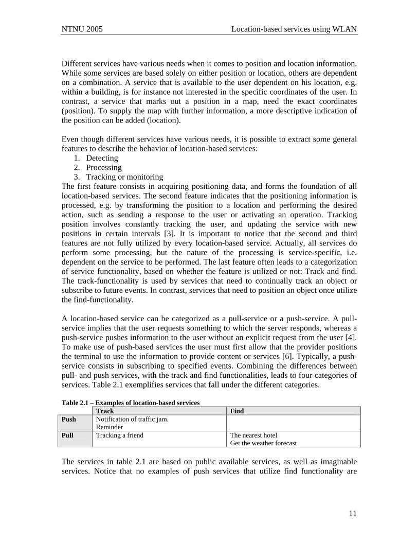
Different services have various needs when it comes to position and location information. While some services are based solely on either position or location, others are dependent on a combination. A service that is available to the user dependent on his location, e.g. within a building, is for instance not interested in the specific coordinates of the user. In contrast, a service that marks out a position in a map, need the exact coordinates (position). To supply the map with further information, a more descriptive indication of the position can be added (location). Even though different services have various needs, it is possible to extract some general features to describe the behavior of location-based services:
1. Detecting 2. Processing 3. Tracking or monitoring
The first feature consists in acquiring positioning data, and forms the foundation of all location-based services. The second feature indicates that the positioning information is processed, e.g. by transforming the position to a location and performing the desired action, such as sending a response to the user or activating an operation. Tracking position involves constantly tracking the user, and updating the service with new positions in certain intervals [3]. It is important to notice that the second and third features are not fully utilized by every location-based service. Actually, all services do perform some processing, but the nature of the processing is service-specific, i.e. dependent on the service to be performed. The last feature often leads to a categorization of service functionality, based on whether the feature is utilized or not: Track and find. The track-functionality is used by services that need to continually track an object or subscribe to future events. In contrast, services that need to position an object once utilize the find-functionality. A location-based service can be categorized as a pull-service or a push-service. A pull-service implies that the user requests something to which the server responds, whereas a push-service pushes information to the user without an explicit request from the user [4]. To make use of push-based services the user must first allow that the provider positions the terminal to use the information to provide content or services [6]. Typically, a push-service consists in subscribing to specified events. Combining the differences between pull- and push services, with the track and find functionalities, leads to four categories of services. Table 2.1 exemplifies services that fall under the different categories. Table 2.1 – Examples of location-based services Track Find Push Notification of traffic jam.
Reminder
Pull Tracking a friend The nearest hotel Get the weather forecast
The services in table 2.1 are based on public available services, as well as imaginable services. Notice that no examples of push services that utilize find functionality are

NTNU 2005 Location-based services using WLAN
12
identified. As push-services often rely on subscribing to specified events, they are usually required to utilize the tracking function to be able to notify the user at the right time. This section has presented some of the differences within location-based services, and pointed out a variety of needs. Even so, the basis of any location-based service is to detect positions. Thereby positioning technologies are needed. As with location-based services, there exist a variety of positioning technologies, which will be outlined in the next section.
2.2 Positioning technologies A variety of different technologies can be used to determine positions. The different technologies can be classified according to several features, e.g. power requirements, physical phenomena used for determining location, required infrastructure, time and space accuracy [5], availability, price and whether the technology is suitable for indoor or outdoor positioning. By classifying the technologies according to physical phenomena used for determining location, three categories may be obtained: Satellite based positioning, network positioning, and local positioning [4]. The other features will be used to identify some of the strengths and weaknesses of the different positioning technologies. Satellite based positioning uses satellites to determine the position. This alternative provides good accuracy, up to an average of 5 meters [4]. However, satellites are expensive, the transmission rate is rather slow, and they have problems with positioning objects indoors. Additionally, requirements are made on both the operator’s infrastructure and the user’s handset to support most satellite based positioning techniques. The most common example of satellite based positioning is GPS (Global Positioning System) and A-GPS. While GPS is purely based on GPS receivers and the satellites, A-GPS tries to overcome some of the limitations of GPS by integrating the GPS receiver and a mobile phone. By introducing an A-GPS server as a link between the satellite and the mobile device, the transmission rate is increased [7]. Additionally, satellite positioning can be aided by network based positioning where the satellite signals are too week (e.g. indoors) [8]. However, both GPS and A-GSP impose heavy power consumption on the wireless devices [9]. Network based positioning covers technologies where the network itself determines the position of the user terminal. Network based positioning can provide positioning information without any additional requirements to the operator’s infrastructure or the user’s handset. However, the accuracy of network based positioning techniques varies dependent on the coverage area at the specified location [4]. The varying accuracy is related to the variety in density of elements within the network that perform the positioning. The most common example of network based positioning is GSM. Within GSM, a variety of methods to perform positioning exist, e.g. cell-id, time of arrival (TOA), time-difference of arrival (TDOA) and angle of arrival (AOA). The methods differ both in accuracy and complexity. The cell-id can be used to identify the cell where
NTNU 2005 Location-based services using WLAN
13
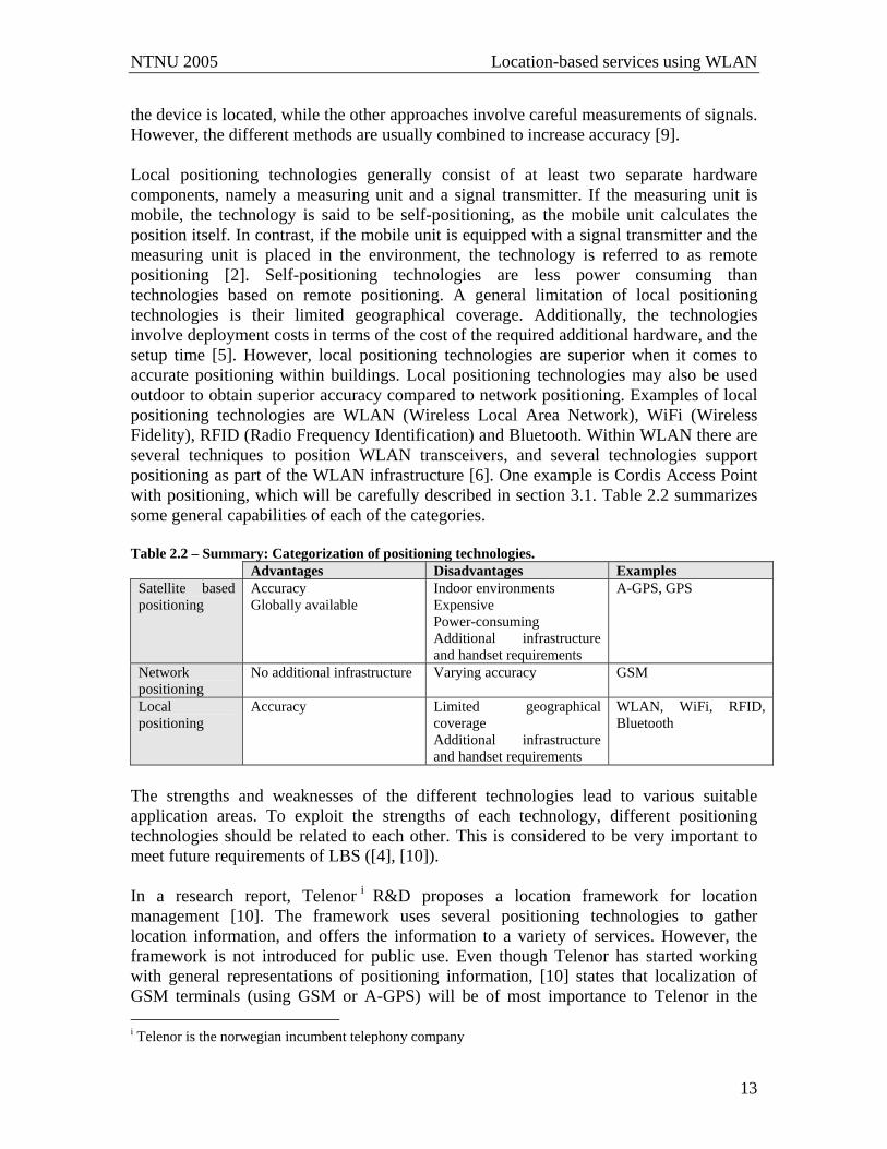
the device is located, while the other approaches involve careful measurements of signals. However, the different methods are usually combined to increase accuracy [9]. Local positioning technologies generally consist of at least two separate hardware components, namely a measuring unit and a signal transmitter. If the measuring unit is mobile, the technology is said to be self-positioning, as the mobile unit calculates the position itself. In contrast, if the mobile unit is equipped with a signal transmitter and the measuring unit is placed in the environment, the technology is referred to as remote positioning [2]. Self-positioning technologies are less power consuming than technologies based on remote positioning. A general limitation of local positioning technologies is their limited geographical coverage. Additionally, the technologies involve deployment costs in terms of the cost of the required additional hardware, and the setup time [5]. However, local positioning technologies are superior when it comes to accurate positioning within buildings. Local positioning technologies may also be used outdoor to obtain superior accuracy compared to network positioning. Examples of local positioning technologies are WLAN (Wireless Local Area Network), WiFi (Wireless Fidelity), RFID (Radio Frequency Identification) and Bluetooth. Within WLAN there are several techniques to position WLAN transceivers, and several technologies support positioning as part of the WLAN infrastructure [6]. One example is Cordis Access Point with positioning, which will be carefully described in section 3.1. Table 2.2 summarizes some general capabilities of each of the categories. Table 2.2 – Summary: Categorization of positioning technologies.
Advantages Disadvantages Examples Satellite based positioning
Accuracy Globally available
Indoor environments Expensive Power-consuming Additional infrastructure and handset requirements
A-GPS, GPS
Network positioning
No additional infrastructure
Varying accuracy GSM
Local positioning
Accuracy Limited geographical coverage Additional infrastructure and handset requirements
WLAN, WiFi, RFID, Bluetooth
The strengths and weaknesses of the different technologies lead to various suitable application areas. To exploit the strengths of each technology, different positioning technologies should be related to each other. This is considered to be very important to meet future requirements of LBS ([4], [10]). In a research report, Telenor i R&D proposes a location framework for location management [10]. The framework uses several positioning technologies to gather location information, and offers the information to a variety of services. However, the framework is not introduced for public use. Even though Telenor has started working with general representations of positioning information, [10] states that localization of GSM terminals (using GSM or A-GPS) will be of most importance to Telenor in the i Telenor is the norwegian incumbent telephony company

NTNU 2005 Location-based services using WLAN
14
short run. This implies that focus on service development will be within location-based services using GSM positioning technology. However, only a few location-based services are currently public and available to the users, even though services using different positioning technologies are being explored. The current situation of location-based services is outlined in the following section.
2.3 Current situation Research within location-based services has been ongoing for several years. By utilizing location information, new services may be introduced, and functionality of existent services may be changed and improved [10]. Location-based services can be classified in four groups according to usage [4]:
• Emergency services • Informational services • Tracking services • Entertainment services
Emergency services include emergency search services, security alerts, public safety, etc. Some emergency services are controlled by governmental regulation. As an example, Telenor is ordered by PT (Norwegian Post and Telecommunications Authority) to provide emergency service centrals (110, 112 and 113) with location information. Additionally, network providers have a social responsibility to provide help within tracking or search in emergencies [10]. Informational services include news, sports, weather, bus routes, etc. Such services are characterized by their simplex communication channels, as the user can not interact with the service. Several media types can be exploited in informational services, such as text, sound, pictures and video, but the bandwidth to mobile devices often places a natural limit on the information flow [6]. Currently Netcomii is providing a simple location-based weather service based on SMS. By sending “VÆR” to 1989 Netcom subscribers receive a weather forecast for the next 24 hours from the area where the SMS was send from [11]. Tracking services includes logistic monitoring and person tracking. Monitoring is exploited in several industries, but the services are only used in limited surroundings, e.g. within a company. Monitoring usually requires high accuracy, and is therefore usually based on local positioning technologies. This implies that the companies must invest in new equipment, and set it up for their own use. However, the number of Norwegian companies employing monitoring is increasing. One example is the food producer, Gilde which uses RFID technology to identify and track sheep on their way to slaughtering [12], [13]. Local positioning technologies may also be used to provide public tracking services. One example is using the mobile phone as a guide in a museum [6]. Such a service using Cordis Access Points developed by Radionor Communication AS to provide local
ii NetCom is a norwegian telephone company

NTNU 2005 Location-based services using WLAN
15
positioning is being developed in a Nordic pilot project, and tested at some selected sights in Norwayiii. The service is called mGuide, and one of the objectives is to enrich the total user experience of the sights by presenting relevant information to the user based on his location. This is realized by using the user’s own location to filter the information that is delivered him. The service is still in its testing phase, and is therefore not yet public. Even so, [6] emphasizes that there is a great market potential for such services. The most common public available tracking services in the Norwegian market has been services that provide functionality to locate friends; so called Buddy services. Telenor used to provide a service called “Kompis” [14] (eng: Buddy), while Netcom currently provides a service called Buddy. Netcoms buddy service contains functionality to set up a buddy list, and localize the persons on the buddy list. The service can be accessed through SMS or WAP [15]. Additionally, Telenor R&D tested a buddy service within six predefined groups for six months in 2003. The experiment aimed at identifying different attitudes towards location-based services. The results indicated that none of the groups were enthusiastic about the buddy service, mainly because the users did not feel the need of the service. However, even though the tested buddy service was a failure, the experiment concluded that both potential and present users considered location-based services in general to be interesting. This implies that location-based services are still believed to provide new opportunities, but the services must address user needs to succeed. A common problem regarding tracking services is the privacy issue. Thereby, such services will be carefully followed by Datatilsynet (eng: Norwegian Data Inspectorate). It is also important that the users trust the service, so that they are willing to be positioned [6]. Protection of privacy will not be further discussed in this assignment, but it is important to be aware of the issues involved. Entertainment services include games, ring tones, etc. A common factor of such services is that they are used merely for spending time [6]. As this category tries to address the usefulness of services, it may sometimes be difficult to place some services in only one category. Even though the mentioned buddy services are tracking services, it could be argued that these services also are entertainment services. The same goes for informational services. Beyond these examples, no currently available location-based entertainment services were identified. In Norway, Telenor tries to motivate development of location-based services by opening up access to GSM positioning. The product provided by Telenor is called “GSM lokasjon” (eng: GSM location), and is currently being used for internal service development, and by third-party developers and emergency service centrals (110,112 and 113) [10]. Third party developers may use the GSM positioning through a CPA (Content Provider Access) agreement called CPA POS (also referred to as “POS Access”). CPA POS provides GSM positioning of mobile phones within Telenor Mobile’s network [16]. By using the positioning information, content providers can offer location-based services, e.g. through SMS or WAP [17]. CPA POS seems to ease development of location-based iii Nidarosdomen and Erkebispegården in Trondheim, and the Nobel Peace Center in Oslo.
NTNU 2005 Location-based services using WLAN
16
services for third-party providers, but a limitation is that only pull-based positioning updates (not push) are supported [18]. This complicates development of tracking services, as the service needs to periodically poll the location server to get the requisite information. In contrast to services based on GSM location, research communities are focusing on local positioning technologies to enable local services. The mGuide is mentioned as an example. As such services require extra infrastructure, they are addressed towards specified environments. However, in the future such services may be exploited by regular users in these environments. Given the evolving research both within positioning technologies and location-based services, several location-based services will probably emerge in the future. The services are identified value added services (VAS), which point at the fact that the services may add value to the total service offering. By increasing the service repertory, the network provider expects to increase the value of the network in terms of increasing traffic. However, for the services to succeed they must address user needs, and additionally efforts must be put on making the users ware of the service. The development goes in the direction of several available services rather than one killer-application.
NTNU 2005 Location-based services using WLAN
17
3 Foundations This chapter presents the technologies that form the basis of the service developed. The purpose of the following sections is to highlight the aspects that are particularly relevant for this assignment, not to give complete presentations of the technologies. The first section introduces Cordis Access™ and Cordis Localisation antenna, which constitute the positioning technology used in this assignment. Section 3.2 gives a short introduction to HTTP, with emphasis of the stateless nature of the protocol. Thereafter, the Wireless Application Protocol (WAP) is introduced. WAP was used to communicate between the system and a user’s mobile phone.
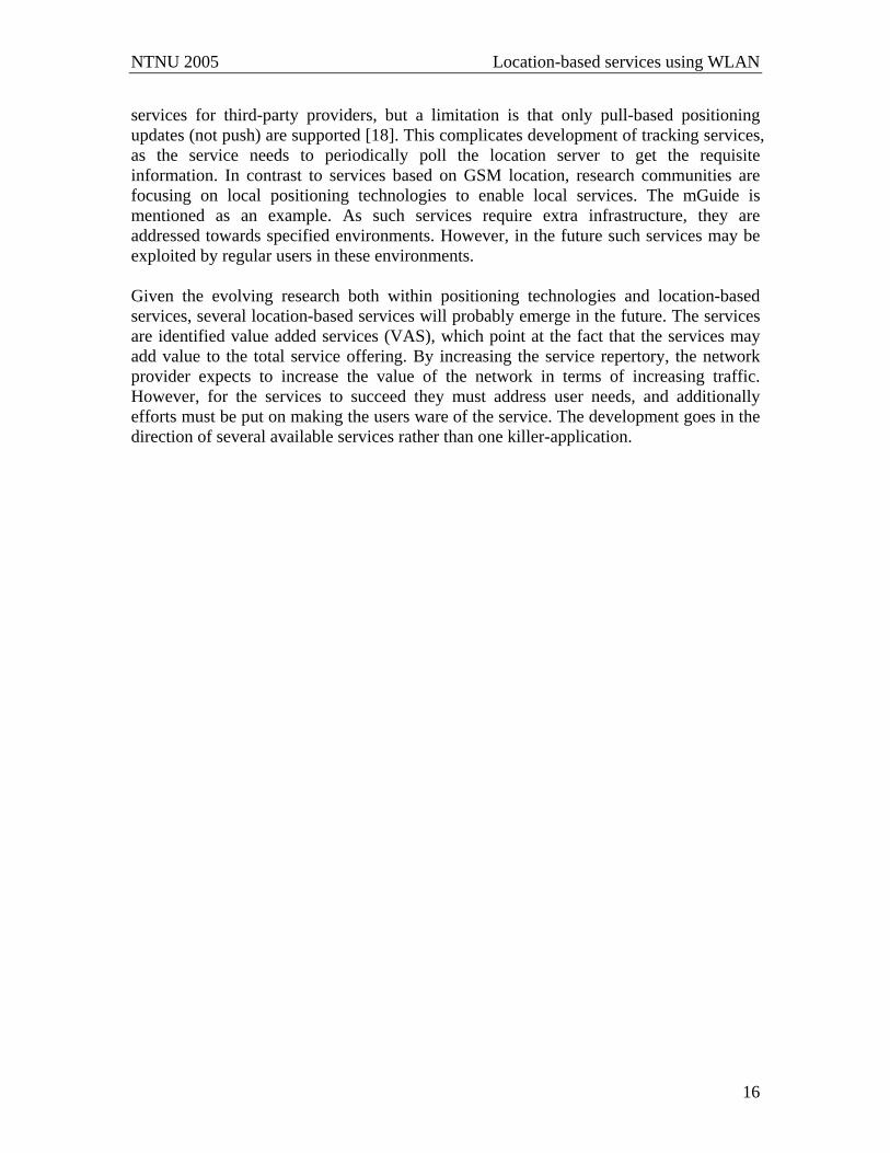
3.1 Cordis Access™ with positioning Cordis Access™ with positioning (CAP POS)iv is a positioning technology developed by Radionor Communications AS, a Norwegian company that focuses on “new features in the Wireless Communication Network” [19]. The technology is capable of detecting network devices with WLAN transceivers, decode their MAC-address, and decide whether the device is inside a given zone. Radionor has also developed another positioning technology called Cordis RadioEye™. This technology is capable of detecting the same devices, and additionally computes their specific positions with 50 cm accuracy [20]. CAP POS is both less expensive and easier to set up and configure than a Cordis RadioEye™. The technologies are based on the same Document Type Description (DTD) for communication, so that they can easily be combined to serve the complete need of an environment [21]. Typically, a RadioEye can be used to provide great accuracy in a big hall, while smaller rooms may be supported by CAP POS. The rest of this section is limited to describing the CAP POS technology. The content is based on information provided by Radionor Communications as well as the experience gained when testing the equipment. CAP POS consists of access points and directional gain antennas, respectively called Cordis Access™ (CAP) and Cordis Access indoor localisation antennas. Error! Reference source not found. illustrates the two components and their connection points.
Figure 3.1 – Cordis Access™ connected to a localisation antenna iv CAP POS is not a public abbreviation, but is used in this assignment to ease readability.
NTNU 2005 Location-based services using WLAN
18
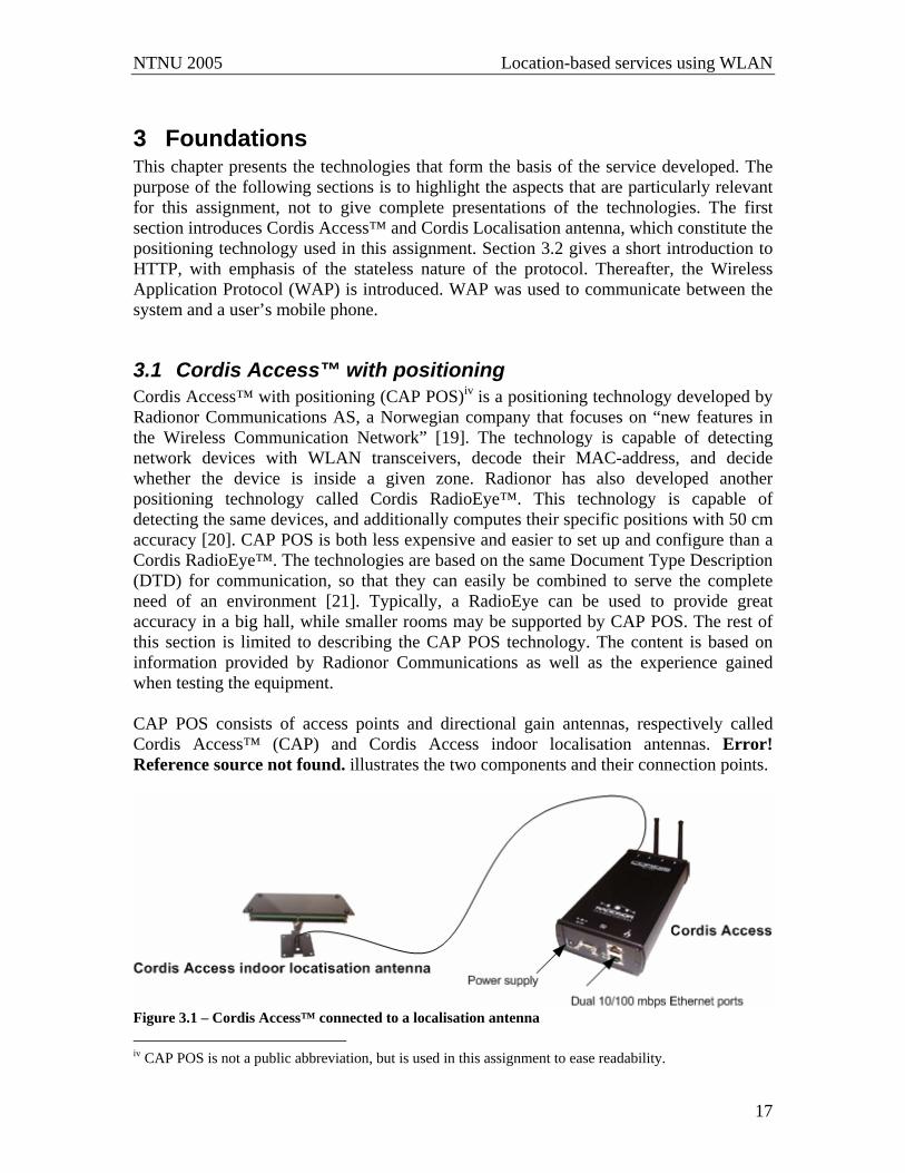
As illustrated in the figure, one CAP is connected to one antenna (the pair is referred to as CAP POS) to provide positioning. Each antenna is capable of covering one zone. To build a system with multiple zones, several CAP POS can be used together, by configuring one of them to be the master [21]. All the other units will then report positions to the master CAP, as illustrated in figure 3.2. The figure also introduces a web server that makes use of the positioning information. As all the positioning units in the system reports to the master, the web server only needs to communicate with the master.
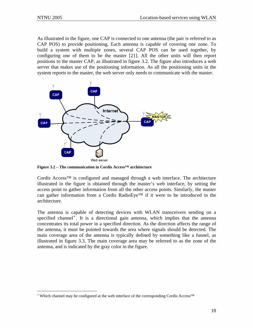
Figure 3.2 – The communication in Cordis Access™ architecture Cordis Access™ is configured and managed through a web interface. The architecture illustrated in the figure is obtained through the master’s web interface, by setting the access point to gather information from all the other access points. Similarly, the master can gather information from a Cordis RadioEye™ if it were to be introduced in the architecture. The antenna is capable of detecting devices with WLAN transceivers sending on a specified channel v . It is a directional gain antenna, which implies that the antenna concentrates its total power in a specified direction. As the direction affects the range of the antenna, it must be pointed towards the area where signals should be detected. The main coverage area of the antenna is typically defined by something like a funnel, as illustrated in figure 3.3. The main coverage area may be referred to as the zone of the antenna, and is indicated by the gray color in the figure.
v Which channel may be configured at the web interface of the corresponding Cordis Access™
NTNU 2005 Location-based services using WLAN
19
Figure 3.3 – Cordis Access™: The coverage area Signals from devices that are within the main coverage area are stronger than signals originating outside the area, but the antenna may also detect devices outside the gray funnel. When the Cordis Access™ is set up, a signal threshold is set to indicate a lower limit on the signal strength that should be reported. So, to some extent, the coverage area also depends on the strength of the particular transceiver on the wireless device: The stronger signals from the transceiver, the further away the device may be detected. Additionally, the range is reduced if there are obstacles in the way, such as walls in a building. If the device is detected by more than one CAP POS, it is positioned to be in the zone where it has the strongest signal intensity. The connection point between the access point and the antenna is in promiscuous mode. In [22] promiscuous is defined as “not carefully chosen”. Related to the CAP POS, this implies that the antenna relays every detected signal to the connected CAP. The access point contains a standard operating system, in addition to some extra software code developed by Radionor Communications. The software code filters the information from the antenna based on “users’” interests. In figure 3.2, the “user” refers to the web server. To ease the communication between the web server and the CAP, the CAP is equipped with a well-defined XML interface called Wireless Positioning Protocol (WPP). By sending XML documents from the web server to the access point, the filtering mechanism of the CAP may be configured to meet the server’s interests. The purpose of such documents can be to define the zone of a CAP POS, subscribe to specified position updates, or query a single position. The response of the CAP also forms an XML document. The formats of available XML documents are specified in a Document Type Description (DTD) [23]. The DTD introduces three main XML documents:
1. Wireless Positioning Protocol Init (wpp_init) 2. Wireless Positioning Protocol Triggered Location Report (push_event) 3. Wireless Positioning Protocol Response (wpp_response)
NTNU 2005 Location-based services using WLAN
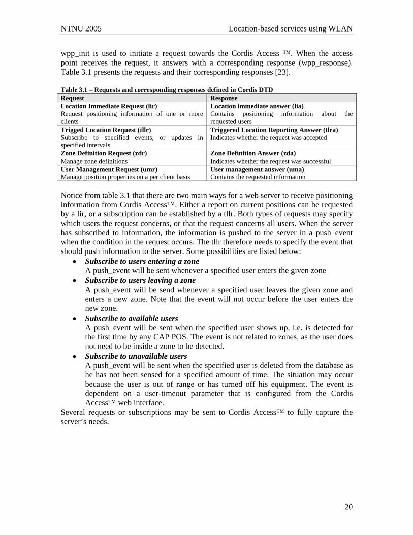
20
wpp_init is used to initiate a request towards the Cordis Access ™. When the access point receives the request, it answers with a corresponding response (wpp_response). Table 3.1 presents the requests and their corresponding responses [23]. Table 3.1 – Requests and corresponding responses defined in Cordis DTD Request Response Location Immediate Request (lir) Request positioning information of one or more clients
Location immediate answer (lia) Contains positioning information about the requested users
Trigged Location Request (tllr) Subscribe to specified events, or updates in specified intervals
Triggered Location Reporting Answer (tlra) Indicates whether the request was accepted
Zone Definition Request (zdr) Manage zone definitions
Zone Definition Answer (zda) Indicates whether the request was successful
User Management Request (umr) Manage position properties on a per client basis
User management answer (uma) Contains the requested information
Notice from table 3.1 that there are two main ways for a web server to receive positioning information from Cordis Access™. Either a report on current positions can be requested by a lir, or a subscription can be established by a tllr. Both types of requests may specify which users the request concerns, or that the request concerns all users. When the server has subscribed to information, the information is pushed to the server in a push_event when the condition in the request occurs. The tllr therefore needs to specify the event that should push information to the server. Some possibilities are listed below:
• Subscribe to users entering a zone A push_event will be sent whenever a specified user enters the given zone
• Subscribe to users leaving a zone A push_event will be send whenever a specified user leaves the given zone and enters a new zone. Note that the event will not occur before the user enters the new zone.
• Subscribe to available users A push_event will be sent when the specified user shows up, i.e. is detected for the first time by any CAP POS. The event is not related to zones, as the user does not need to be inside a zone to be detected.
• Subscribe to unavailable users A push_event will be sent when the specified user is deleted from the database as he has not been sensed for a specified amount of time. The situation may occur because the user is out of range or has turned off his equipment. The event is dependent on a user-timeout parameter that is configured from the Cordis Access™ web interface.
Several requests or subscriptions may be sent to Cordis Access™ to fully capture the server’s needs.

NTNU 2005 Location-based services using WLAN
21
3.2 The stateless nature of Hypertext Transfer Protocol This section gives a short introduction to the Hypertext Transfer Protocol (HTTP) focusing on the stateless nature of the protocol. A full description of HTTP may be found in [24]. The Hypertext Transfer Protocol is an application-layer protocol that forms the basis for the World Wide Web (WWW). The protocol defines a simple communication-pattern between a server and a client. It is based on a simple request-response model, where the client requests resources from the server, and the server then responds to the request. The requested resources may be an html-page, or some other file. Figure 3.4 illustrates the communication model.
Figure 3.4 – The HTTP communication model The request message specifies the identification of the requested resource (in an URI), and a method. The method indicates the method to be performed on the requested resource. Two of the possible methods are GET and POST. While the GET method merely requests a server for a resource, the POST method enables the user to send data to the server. When the server answers with a response, it attaches a status code to indicate the result of the request. The status code may for instance indicate that the request was successfully received and understood, or that errors occurred. HTTP is a stateless protocol, which implies that it does not store any information about the client after processing the request and sending a response in reply. However, applications may need to hold state: When a user logs on to a service, the server needs a connection between the first login process and later requests when using the service. To overcome the stateless nature, the web server may supply additional information along with the requested page. There are three different ways of adding the information to the requested resource: as a cookie, as hidden fields in an html form or by URL rewriting. A cookie is a file or a string that may be attached to the requested page [26]. Cookies are the easiest way to support statelessness. An example of such a cookie is setting a “session-id” to identify a particular session between a client and the server. By sending this cookie with each response from the server and request from the client, the server is able to link several requests coming from the client. Thereby the server is able to act as it “remembers” the user. A requirement for sites that use cookies is that the client’s browser support cookies. The client usually has the ability to disable cookies in their browser. If cookies are disabled, a site that requires cookies would not function properly. [25] An alternative approach is to add information about the user as hidden fields in a form included in the requested page. By adding a unique session id to the requested page, this

NTNU 2005 Location-based services using WLAN
22
alternative serves the same need as the session-id presented with cookies. However, using hidden fields introduces some more work, because every resource must be customized to support the feature [26]. URL rewriting means that state information is encoded in the URL. This implies that the information is added directly in the address field of the client’s browser. Unlike cookies, rewriting does not require anything from the client’s browser [26].
3.3 Wireless Application Protocol Wireless Application Protocol (WAP) was developed to offer Internet capabilities within wireless networks. It consists of a set of specifications that addresses the characteristics of mobile networks. The specifications are defined by the WAP Forum [27]. In 1998, the WAP Forum released the first version of WAP (WAP 1.0), and in 2002 a new version (WAP 2.0) was released [28]. WAP 2.0 is backward compatible with previous versions. As WAP is developed to offer Internet capabilities, the programming model in WAP is very similar to the request-response model used in HTTP, illustrated in the previous section. This model is often referred to as a pull-model. However, an enhancement of the programming model is made by introducing WAP push. Whereas the pull model requires the user to explicitly request the server for a resource, WAP push is server-initiated. This implies that the server may send information to the user without the user requesting it. The WAP standard specifies a new protocol stack. Originally (WAP 1.0) this protocol stack involved Wireless Session Protocol (WSP), Wireless Transaction Protocol (WTP), Wireless Transport Layer Security (WTLS) and Wireless Datagram Protocol (WDP). However, WAP 2.0 introduced support for standard WWW protocols, such as IP, TCP and HTTP [29]. Enhancements of the protocol stack also lead to some changes in the overall WAP architecture. A simplified illustration of the WAP architecture is given in figure 3.5. In previous versions of WAP, all the communication between a client and an application server was required to pass through a WAP proxyvi, to translate between WAP and WWW protocols [29]. As standard WWW protocols became available in WAP 2.0, direct communication between a client and a server is possible. However, the WAP proxy is still an important element of the WAP architecture, because it may both optimize the communication process and offer service enhancements. Additionally, push information always needs to go through the WAP Proxy [28].
vi May also be referred to as a WAP Gateway

NTNU 2005 Location-based services using WLAN
23
Figure 3.5 – The WAP Architecture Figure 3.5 also highlight push specific functionality, namely the Push Proxy Gateway (PPG) and the Push Initiator (PI). Both must be present to enable WAP push, but are usually not represented in separate network elements. The PPG acts as the gateway between the Internet and the mobile network, and may be united with a regular WAP Proxy. The PI is responsible for pushing contents and delivery instructions to the PPG, and is usually realized as an application running on a web server on the Internet. The communication between the PPG and the PI is handled by the Push Access Protocol (PAP), while the Push Over-The-Air (OTA) Protocol is used by the PPG to push content to the client. [27] If WAP Push is used to deliver the content, there are two alternatives when it comes to content types of the push message. Service Indication (SI) is used to send a short notification to the user terminal. The message contains a short message and an URI. After receiving the notification the user must access the URI to execute the service. In contrast, Service Loading (SL) does not require user interaction to execute the service. By SL the service pushed to the user is automatically loaded and executed [30]. Both the pull- and the push variants can be used to provide WAP services. Using pull technology allows the user to access the service whenever he needs to. As pull services does not need to go through the WAP Proxy, such services may be developed independently of any network provider. However, to charge the user of the service, some agreement with a network provider is needed. The push technology allows for a more dynamic appearance of WAP services. To develop such services, access to a WAP Proxy is necessary. The biggest Norwegian telephone company, Telenor, offers access to a WAP proxy to enable content providers to deliver and charge WAP services to Telenor Mobile’s subscribers. The product is called CPA WAP [16].
NTNU 2005 Location-based services using WLAN
24
4 Service development This chapter presents the most important technologies used in the development process. The first section gives a short introduction to the UML concepts that are important for this assignment. Section 4.2 describes the Ericsson development platform, which is a layered structure, consisting in three main layers: JavaFrame, ActorFrame and ServiceFrame. Thereafter Ramses, the development tool used in this assignment, is presented. The last section gives a short introduction to the technologies used to develop web servers in this assignment.
4.1 UML Unified Modeling Language (UML) is a general modeling language used in service development, to “specify, visualize, construct, and document the artifacts of a software system” [19: p.3]. Since 1997 UML has been an Object Management Group (OMG)vii standard. The first version has been further developed, leading to UML 2.0. The specifications of UML 2.0 have been accepted as an ISO standard, and OMG is currently upgrading all of the UML to the new version [31]. UML 2.0 is very similar with UML 1.0 concerning the most central features, but some enhancements are added and some problem areas modified [19]. The enhancements provide more precise definitions of the semantics, which should lead to precise and unambiguous models. This shortens the distance between UML and MDA (Model Driven Architecture), as the models can be more easily translated [32]. This chapter focuses on the features of UML 2.0 that were most relevant for the service development conducted in this assignment. These features include the internal structure (section 4.1.1) and the state machine (section 4.1.2).
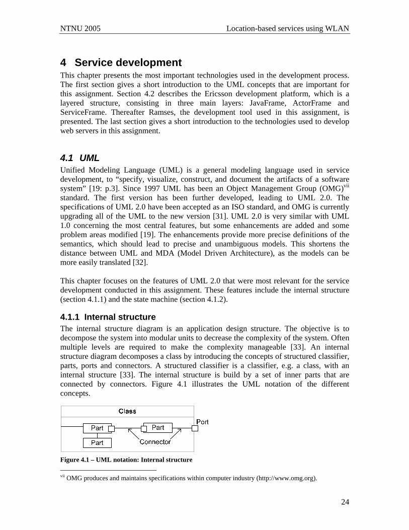
4.1.1 Internal structure The internal structure diagram is an application design structure. The objective is to decompose the system into modular units to decrease the complexity of the system. Often multiple levels are required to make the complexity manageable [33]. An internal structure diagram decomposes a class by introducing the concepts of structured classifier, parts, ports and connectors. A structured classifier is a classifier, e.g. a class, with an internal structure [33]. The internal structure is build by a set of inner parts that are connected by connectors. Figure 4.1 illustrates the UML notation of the different concepts.
Figure 4.1 – UML notation: Internal structure vii OMG produces and maintains specifications within computer industry (http://www.omg.org).
NTNU 2005 Location-based services using WLAN
25
A part may be defined as a property of a class, as “the Part lives and dies as part of the lifetime of an object of the containing class” [34: p.29]. A part is assigned a multiplicity to indicate the number of such parts the specified classifier may contain. The multiplicity may specify an exact number, or an interval that the number must stay within. The format of multiplicities indicating an interval is [n..m], where n specifies the number of instances created as the containing class is created, while m specifies an upper level on the number of such instances that may be created within the containing class [34]. Ports constitute interaction points with well defined interfaces [33], and are introduced to restrict the communication between inner parts and the environment. A port is addressable, meaning that the class can both send and receive signals through a port. A connector may either be directly connected to the part or attached to the port [34]. It often indicates the communication paths between the inner parts of the structures classifier [19].
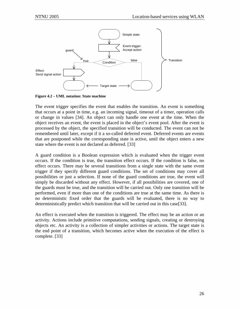
4.1.2 State machine UML defines two kinds of state machines, namely the behavioral state machine and the protocol state machine. A protocol state machine expresses usage protocols [35], while a behavioral state machine models the discrete behavior of a specified object in the design. The object is treated as an isolated entity that communicates with other entities by detecting and responding to events [33]. Only the behavioral state machine is described in this section, and the term state machine refers to the behavioral state machine throughout this assignment. A state diagram consists of states, transitions and activities presented in a graph. A state models a period of time where certain conditions are satisfied. A state may be a simple state, a composite state or a submachine state. A simple state is a state with no sub states, while a composite state is a state with a substructure. A composite state is composed of one or more regions, which consist of a set of states and transitions. A submachine is a state that refers to a different state machine definition, indicating that the state can be substituted by the referred state machine. By using submachine states, the referred submachine may be reused several times. [35] A transition is a connector between two states, and generally has an event trigger, a guard condition, an effect, and a target state. Figure 4.2 illustrates the notation of the concepts.
NTNU 2005 Location-based services using WLAN
26
Simple state
Effect:Send signal action
Event trigger:Accept action
TransitionConditiontrue false
guard
Target state
Figure 4.2 – UML notation: State machine The event trigger specifies the event that enables the transition. An event is something that occurs at a point in time, e.g. an incoming signal, timeout of a timer, operation calls or change in values [34]. An object can only handle one event at the time. When the object receives an event, the event is placed in the object’s event pool. After the event is processed by the object, the specified transition will be conducted. The event can not be remembered until later, except if it a so-called deferred event. Deferred events are events that are postponed while the corresponding state is active, until the object enters a new state where the event is not declared as deferred. [33] A guard condition is a Boolean expression which is evaluated when the trigger event occurs. If the condition is true, the transition effect occurs. If the condition is false, no effect occurs. There may be several transitions from a single state with the same event trigger if they specify different guard conditions. The set of conditions may cover all possibilities or just a selection. If none of the guard conditions are true, the event will simply be discarded without any effect. However, if all possibilities are covered, one of the guards must be true, and the transition will be carried out. Only one transition will be performed, even if more than one of the conditions are true at the same time. As there is no deterministic fixed order that the guards will be evaluated, there is no way to deterministically predict which transition that will be carried out in this case[33]. An effect is executed when the transition is triggered. The effect may be an action or an activity. Actions include primitive computations, sending signals, creating or destroying objects etc. An activity is a collection of simpler activities or actions. The target state is the end point of a transition, which becomes active when the execution of the effect is complete. [33]

NTNU 2005 Location-based services using WLAN
27
4.2 Ericsson’s development framework The need to model complex systems where objects interact asynchronously was the driving force behind Ericsson’s development framework. They started working with their framework in the late 1990’s [34], and it is still under accommodation and improvement. The framework is a layered architecture with UML 2.0 concepts are basic building blocks, as presented in figure 4.3.
ServiceFrameUserAgents, TerminalAgents, CommunityAgents,...
ActorFrameActors, Agents, Roles, Palys,...
JavaFrameCompositeState, StateMachines, Mediators,...
Java Virtual Machine
Application
Provides application domain concepts
Provides role modelling concepts
Provides UML 2.0 concepts
Figure 4.3 – The layered structure of JavaFrame, ActorFrame and ServiceFrame [34: p.39 (revised)] The following sections present the different layers of the development platform, i.e. the three middle layers of figure 4.3. The sections focus on the aspects that are relevant for this particular assignment. JavaFrame constitutes the foundation of ActorFrame and ServiceFrame. Section 4.2.1 confines itself to a short introduction of the concepts JavaFrame offers to these layers. More emphasis is put on the ActorFrame layer, as it is both the run-time platform used in this assignment, and introduces some important concepts used in the design (section 4.2.2). Section 4.2.3 focuses on the key principles of designing services that are the basis of ServiceFrame.
4.2.1 JavaFrame JavaFrame is a framework for development and execution of state machines in Java. State machines are well-known modeling-concepts, as presented in section 4.1.2, and integrating these with Java simplifies the development of complex telecommunication services. JavaFrame introduces active objects that communicate asynchronously by sending messages. The objects communicate through well-described interfaces, which reduces the developer’s need to know the whole system. The behavior of an active object is described by use of state machines [36]. An adapted version of JavaFrame, called EJBFrame, has also been developed to fit the J2EE Platform [34].
4.2.2 ActorFrame ActorFrame is layered on top of JavaFrame and makes use of the modeling-concepts offered by JavaFrame. The basic assumption in ActorFrame is that “actors play roles” [34: p.39]. An Actor is an object with an optional inner structure. The Actors are capable of playing different roles by creating inner actors, one for each role. Every actor instance

NTNU 2005 Location-based services using WLAN
28
has an ActorAddress which is unique in the system. The address consists of an identification of the actor (actorid), combined with the actor type which identifies the class type (actortype). The notation is similar to actorid@actortype. The actor’s behavior is described by a state machine, and actors interact by sending signals to each other. An actor can be addressed either by a special connection point, called port, or by the actor’s actor address. Each actor both inherits a generic behavior, defined in the ActorFrame protocol, and defines its own specific behavior. The ActorFrame protocol contains fundamental functionality like invoking other actors and controlling the actor’s lifecycle: “The basic feature of the protocol is to allow an actor (requestor) to request another actor to play a specific role and to allow the actors to interact to perform a service or a play.” [34: p.41] Through the play one or several services can be offered. Figure 4.4 illustrates the operation mode of the RoleRequestProtocol.
Figure 4.4 – RoleRequest Protocol [34: p.40] The requesting actor requests an actor to play a role by sending a RoleRequestMsg to the specified actor. The message specified the roleid and roletypeviii of the desired role. The requested actor may be capable or incapable of playing the requested role. Figure 4.4 illustrates the first case. In this case the requested actor sends a RolePlayMsg to the specified role-actor. The requested role is invoked by the requested actor by a RolePlayMsg. If the requested role already exists the RolePlayMsg is sent directly to the existent role-actor, otherwise the role-actor is first instantiated. The invoked actor responds by sending a RoleConfirmMsg to the requesting actor, and the play is thereby started. If the requested actor was not capable of playing the requested role, it would send a RoleDeniedMsg back to the requesting actor. [34]
viii The concepts of roleid and roletype correspond to the actorid and actortype
NTNU 2005 Location-based services using WLAN
29
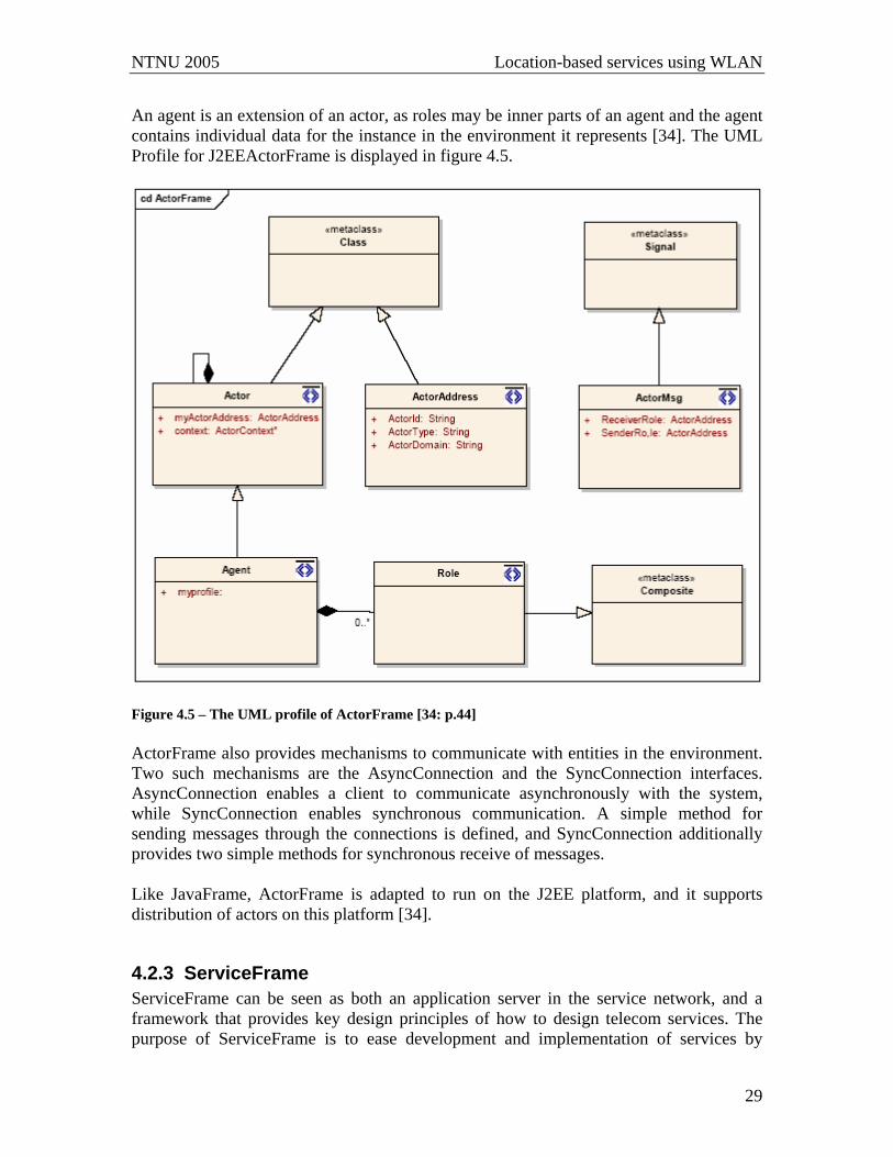
An agent is an extension of an actor, as roles may be inner parts of an agent and the agent contains individual data for the instance in the environment it represents [34]. The UML Profile for J2EEActorFrame is displayed in figure 4.5.
Figure 4.5 – The UML profile of ActorFrame [34: p.44] ActorFrame also provides mechanisms to communicate with entities in the environment. Two such mechanisms are the AsyncConnection and the SyncConnection interfaces. AsyncConnection enables a client to communicate asynchronously with the system, while SyncConnection enables synchronous communication. A simple method for sending messages through the connections is defined, and SyncConnection additionally provides two simple methods for synchronous receive of messages. Like JavaFrame, ActorFrame is adapted to run on the J2EE platform, and it supports distribution of actors on this platform [34].
4.2.3 ServiceFrame ServiceFrame can be seen as both an application server in the service network, and a framework that provides key design principles of how to design telecom services. The purpose of ServiceFrame is to ease development and implementation of services by
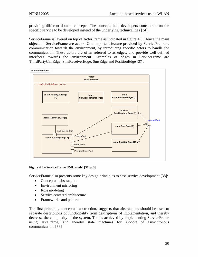
NTNU 2005 Location-based services using WLAN
30
providing different domain-concepts. The concepts help developers concentrate on the specific service to be developed instead of the underlying technicalities [34]. ServiceFrame is layered on top of ActorFrame as indicated in figure 4.3. Hence the main objects of ServiceFrame are actors. One important feature provided by ServiceFrame is communication towards the environment, by introducing specific actors to handle the communication. These actors are often referred to as edges, and provide well-defined interfaces towards the environment. Examples of edges in ServiceFrame are ThirdPartyCallEdge, SmsReceiverEdge, SmsEdge and PositionEdge [37].
cd Serv iceFrame
«Actor»Serv iceFrame
- userProfileDataBase: Vector
externalPort
Users :UserAgent [0..*]
PositionServerPort
smsOutPort
nameServerPort
smsInPort
pms :PositionEdge [1]
agent :NameServ er [1]
sms :SmsEdge [1]
arts :ExtAddressManager [1]
sfw :Serv iceFileWatcher [1]
cc :ThirdPartyCallEdge [1]
receiv er :SmsReceiv erEdge [1]
Figure 4.6 – ServiceFrame UML model [37: p.3] ServiceFrame also presents some key design principles to ease service development [38]:
• Conceptual abstraction • Environment mirroring • Role modeling • Service centered architecture • Frameworks and patterns
The first principle, conceptual abstraction, suggests that abstractions should be used to separate descriptions of functionality from descriptions of implementation, and thereby decrease the complexity of the system. This is achieved by implementing ServiceFrame using JavaFrame, and thereby state machines for support of asynchronous communication. [38]
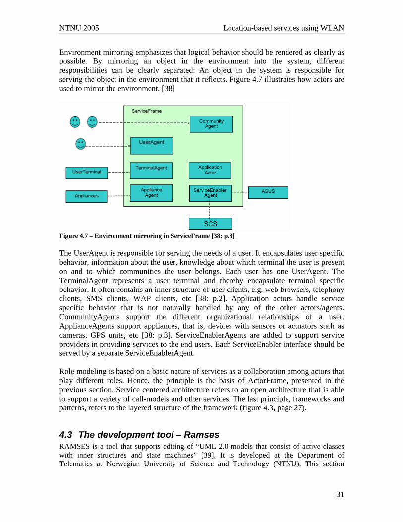
NTNU 2005 Location-based services using WLAN
31
Environment mirroring emphasizes that logical behavior should be rendered as clearly as possible. By mirroring an object in the environment into the system, different responsibilities can be clearly separated: An object in the system is responsible for serving the object in the environment that it reflects. Figure 4.7 illustrates how actors are used to mirror the environment. [38]
Figure 4.7 – Environment mirroring in ServiceFrame [38: p.8] The UserAgent is responsible for serving the needs of a user. It encapsulates user specific behavior, information about the user, knowledge about which terminal the user is present on and to which communities the user belongs. Each user has one UserAgent. The TerminalAgent represents a user terminal and thereby encapsulate terminal specific behavior. It often contains an inner structure of user clients, e.g. web browsers, telephony clients, SMS clients, WAP clients, etc [38: p.2]. Application actors handle service specific behavior that is not naturally handled by any of the other actors/agents. CommunityAgents support the different organizational relationships of a user. ApplianceAgents support appliances, that is, devices with sensors or actuators such as cameras, GPS units, etc [38: p.3]. ServiceEnablerAgents are added to support service providers in providing services to the end users. Each ServiceEnabler interface should be served by a separate ServiceEnablerAgent. Role modeling is based on a basic nature of services as a collaboration among actors that play different roles. Hence, the principle is the basis of ActorFrame, presented in the previous section. Service centered architecture refers to an open architecture that is able to support a variety of call-models and other services. The last principle, frameworks and patterns, refers to the layered structure of the framework (figure 4.3, page 27).
4.3 The development tool – Ramses RAMSES is a tool that supports editing of “UML 2.0 models that consist of active classes with inner structures and state machines” [39]. It is developed at the Department of Telematics at Norwegian University of Science and Technology (NTNU). This section
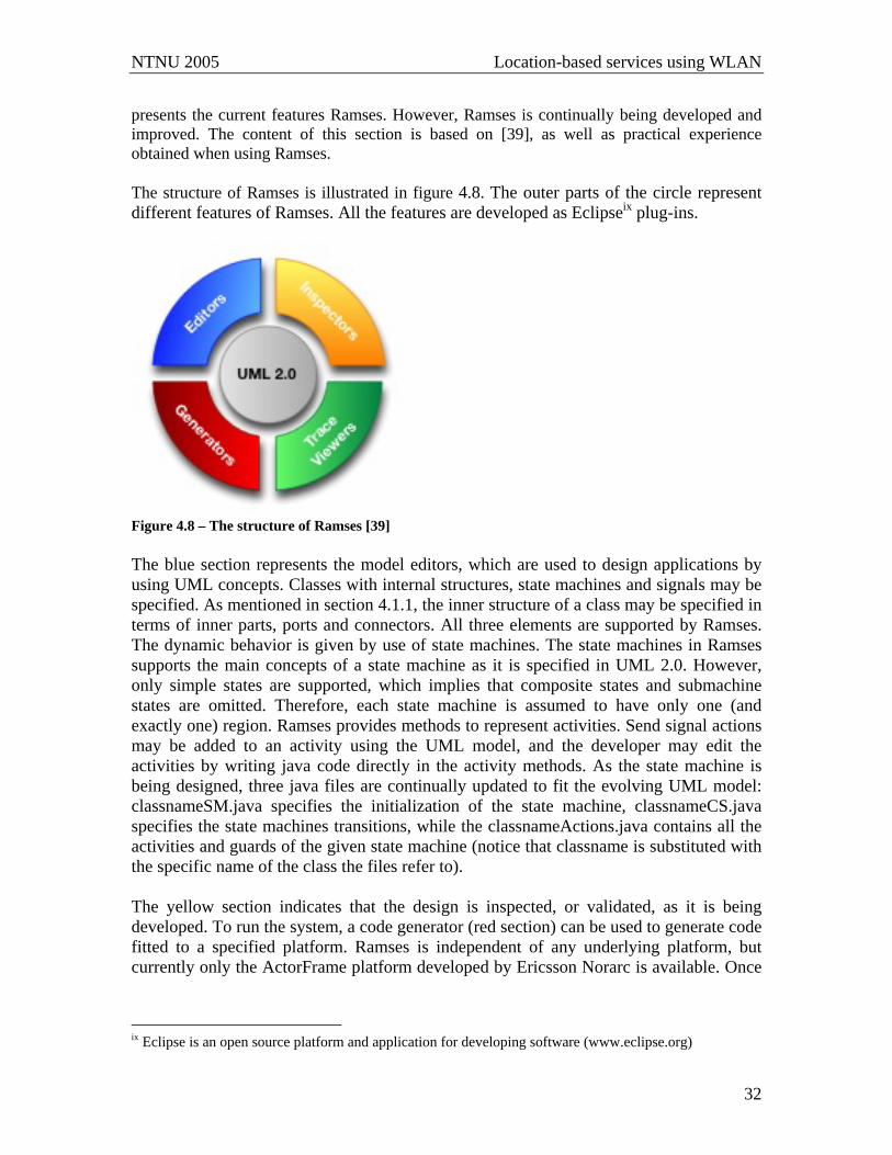
NTNU 2005 Location-based services using WLAN
32
presents the current features Ramses. However, Ramses is continually being developed and improved. The content of this section is based on [39], as well as practical experience obtained when using Ramses. The structure of Ramses is illustrated in figure 4.8. The outer parts of the circle represent different features of Ramses. All the features are developed as Eclipseix plug-ins.
Figure 4.8 – The structure of Ramses [39] The blue section represents the model editors, which are used to design applications by using UML concepts. Classes with internal structures, state machines and signals may be specified. As mentioned in section 4.1.1, the inner structure of a class may be specified in terms of inner parts, ports and connectors. All three elements are supported by Ramses. The dynamic behavior is given by use of state machines. The state machines in Ramses supports the main concepts of a state machine as it is specified in UML 2.0. However, only simple states are supported, which implies that composite states and submachine states are omitted. Therefore, each state machine is assumed to have only one (and exactly one) region. Ramses provides methods to represent activities. Send signal actions may be added to an activity using the UML model, and the developer may edit the activities by writing java code directly in the activity methods. As the state machine is being designed, three java files are continually updated to fit the evolving UML model: classnameSM.java specifies the initialization of the state machine, classnameCS.java specifies the state machines transitions, while the classnameActions.java contains all the activities and guards of the given state machine (notice that classname is substituted with the specific name of the class the files refer to). The yellow section indicates that the design is inspected, or validated, as it is being developed. To run the system, a code generator (red section) can be used to generate code fitted to a specified platform. Ramses is independent of any underlying platform, but currently only the ActorFrame platform developed by Ericsson Norarc is available. Once
ix Eclipse is an open source platform and application for developing software (www.eclipse.org)

NTNU 2005 Location-based services using WLAN
33
the system is running, the actual behavior can be displayed by using different trace mechanisms (green section). [39]
4.4 Web Server A web server may be used to enable external interaction with a system by use of HTTP. The basic operation of a web server is to receive the name of a file to look up, and return the specified file [26]. Hence a web server is a server containing resources that can be obtained by clients by requesting the server. Jetty provides an example of a web server that supports both static and dynamic content. The Jetty Server is presented in section 4.4.1. Dynamic content may for instance be generated by Java Server Pages (JSP) or servlets. These technologies are introduced in section 4.4.2.
4.4.1 Jetty The development of Jetty was originally started by Greg Wilkins of Mort Bay Consulting. It has later evolved to become an open source development developed under guidance of Mort Bay Consulting. The content in this section is based on [40]. Jetty is a 100% Java web server, which makes it easy to use in combination with Java. Two different server alternatives are provided: a core Http server and a complete Jetty server. The core Http server is capable of listening to specified ports, and handle requests on these ports. The complete Jetty Server extends an Http server by introducing a J2EE compliant servlet container, and XML configuration capabilities. Further information about the complete Jetty Server may be found at [40]. An Http Server is specified to listen to a given port. This means that the server can accept and handle requests on this port. To response to requests, the server uses an appropriate HttpHandler. Examples of HttpHandlers are ServletHandler and ResourceHandler. A ServletHandler is used to handle dynamic content, such as Java Server Pages (JSP) or servlet. A ResourceHandler is used to access other static resources available at the server. Jetty provides a full API describing the features and possibilities in greater detail [41].
4.4.2 Servlets and Java Server Pages A servlet may be defined as a small program that runs on a web server [42]. The connection between the web server and the servlet is often referred to as a servlet container. The servlet container is responsible for invoking the requested servlet, forward the client’s request to the servlet, and convert the response from the servlet into an HTTP response message before it is sent back to the client. A servlet created to support HTTP contains java methods to handle different methods of the HTTP request, e.g. POST and GET (see section 3.2). Servlets support both static and dynamic content. The static elements can be developed using any mark up language, e.g. HTML, but java programming must be used to entvine the elements into the servlet methods.
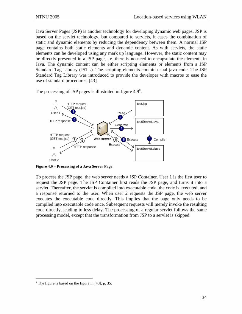
NTNU 2005 Location-based services using WLAN
34
Java Server Pages (JSP) is another technology for developing dynamic web pages. JSP is based on the servlet technology, but compared to servlets, it eases the combination of static and dynamic elements by reducing the dependency between them. A normal JSP page contains both static elements and dynamic content. As with servlets, the static elements can be developed using any mark up language. However, the static content may be directly presented in a JSP page, i.e. there is no need to encapsulate the elements in Java. The dynamic content can be either scripting elements or elements from a JSP Standard Tag Library (JSTL). The scripting elements contain usual java code. The JSP Standard Tag Library was introduced to provide the developer with macros to ease the use of standard procedures. [43] The processing of JSP pages is illustrated in figure 4.9x.
User 1
User 2
test.jsp
testServlet.java
testServlet.class
Web server
Read
Generate
Compile
1
2
3
45 Execute
6HTTP response
7HTTP request (GET test.jsp) 8
Execute
HTTP request (GET test.jsp)
9
HTTP response
Figure 4.9 – Processing of a Java Server Page To process the JSP page, the web server needs a JSP Container. User 1 is the first user to request the JSP page. The JSP Container first reads the JSP page, and turns it into a servlet. Thereafter, the servlet is compiled into executable code, the code is executed, and a response returned to the user. When user 2 requests the JSP page, the web server executes the executable code directly. This implies that the page only needs to be compiled into executable code once. Subsequent requests will merely invoke the resulting code directly, leading to less delay. The processing of a regular servlet follows the same processing model, except that the transformation from JSP to a servlet is skipped.
x The figure is based on the figure in [43], p. 35.
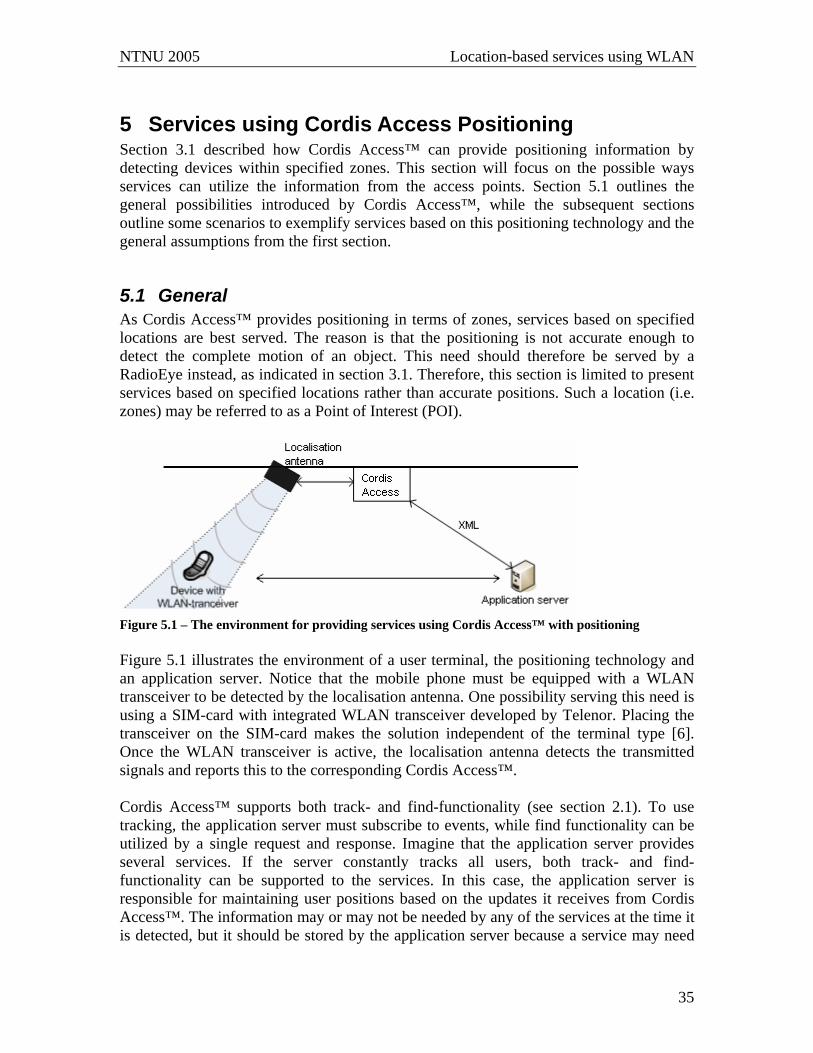
NTNU 2005 Location-based services using WLAN
35
5 Services using Cordis Access Positioning Section 3.1 described how Cordis Access™ can provide positioning information by detecting devices within specified zones. This section will focus on the possible ways services can utilize the information from the access points. Section 5.1 outlines the general possibilities introduced by Cordis Access™, while the subsequent sections outline some scenarios to exemplify services based on this positioning technology and the general assumptions from the first section.
5.1 General As Cordis Access™ provides positioning in terms of zones, services based on specified locations are best served. The reason is that the positioning is not accurate enough to detect the complete motion of an object. This need should therefore be served by a RadioEye instead, as indicated in section 3.1. Therefore, this section is limited to present services based on specified locations rather than accurate positions. Such a location (i.e. zones) may be referred to as a Point of Interest (POI).
Figure 5.1 – The environment for providing services using Cordis Access™ with positioning Figure 5.1 illustrates the environment of a user terminal, the positioning technology and an application server. Notice that the mobile phone must be equipped with a WLAN transceiver to be detected by the localisation antenna. One possibility serving this need is using a SIM-card with integrated WLAN transceiver developed by Telenor. Placing the transceiver on the SIM-card makes the solution independent of the terminal type [6]. Once the WLAN transceiver is active, the localisation antenna detects the transmitted signals and reports this to the corresponding Cordis Access™. Cordis Access™ supports both track- and find-functionality (see section 2.1). To use tracking, the application server must subscribe to events, while find functionality can be utilized by a single request and response. Imagine that the application server provides several services. If the server constantly tracks all users, both track- and find-functionality can be supported to the services. In this case, the application server is responsible for maintaining user positions based on the updates it receives from Cordis Access™. The information may or may not be needed by any of the services at the time it is detected, but it should be stored by the application server because a service may need
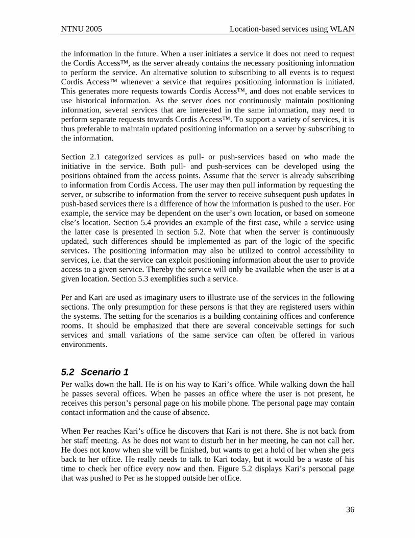
NTNU 2005 Location-based services using WLAN
36
the information in the future. When a user initiates a service it does not need to request the Cordis Access™, as the server already contains the necessary positioning information to perform the service. An alternative solution to subscribing to all events is to request Cordis Access™ whenever a service that requires positioning information is initiated. This generates more requests towards Cordis Access™, and does not enable services to use historical information. As the server does not continuously maintain positioning information, several services that are interested in the same information, may need to perform separate requests towards Cordis Access™. To support a variety of services, it is thus preferable to maintain updated positioning information on a server by subscribing to the information. Section 2.1 categorized services as pull- or push-services based on who made the initiative in the service. Both pull- and push-services can be developed using the positions obtained from the access points. Assume that the server is already subscribing to information from Cordis Access. The user may then pull information by requesting the server, or subscribe to information from the server to receive subsequent push updates In push-based services there is a difference of how the information is pushed to the user. For example, the service may be dependent on the user’s own location, or based on someone else’s location. Section 5.4 provides an example of the first case, while a service using the latter case is presented in section 5.2. Note that when the server is continuously updated, such differences should be implemented as part of the logic of the specific services. The positioning information may also be utilized to control accessibility to services, i.e. that the service can exploit positioning information about the user to provide access to a given service. Thereby the service will only be available when the user is at a given location. Section 5.3 exemplifies such a service. Per and Kari are used as imaginary users to illustrate use of the services in the following sections. The only presumption for these persons is that they are registered users within the systems. The setting for the scenarios is a building containing offices and conference rooms. It should be emphasized that there are several conceivable settings for such services and small variations of the same service can often be offered in various environments.
5.2 Scenario 1 Per walks down the hall. He is on his way to Kari’s office. While walking down the hall he passes several offices. When he passes an office where the user is not present, he receives this person’s personal page on his mobile phone. The personal page may contain contact information and the cause of absence. When Per reaches Kari’s office he discovers that Kari is not there. She is not back from her staff meeting. As he does not want to disturb her in her meeting, he can not call her. He does not know when she will be finished, but wants to get a hold of her when she gets back to her office. He really needs to talk to Kari today, but it would be a waste of his time to check her office every now and then. Figure 5.2 displays Kari’s personal page that was pushed to Per as he stopped outside her office.
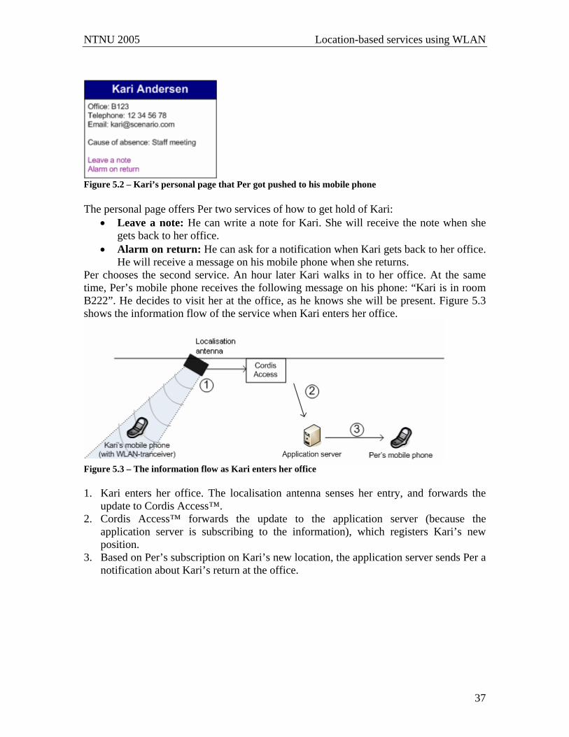
NTNU 2005 Location-based services using WLAN
37
Figure 5.2 – Kari’s personal page that Per got pushed to his mobile phone The personal page offers Per two services of how to get hold of Kari:
• Leave a note: He can write a note for Kari. She will receive the note when she gets back to her office.
• Alarm on return: He can ask for a notification when Kari gets back to her office. He will receive a message on his mobile phone when she returns.
Per chooses the second service. An hour later Kari walks in to her office. At the same time, Per’s mobile phone receives the following message on his phone: “Kari is in room B222”. He decides to visit her at the office, as he knows she will be present. Figure 5.3 shows the information flow of the service when Kari enters her office.
Figure 5.3 – The information flow as Kari enters her office 1. Kari enters her office. The localisation antenna senses her entry, and forwards the
update to Cordis Access™. 2. Cordis Access™ forwards the update to the application server (because the
application server is subscribing to the information), which registers Kari’s new position.
3. Based on Per’s subscription on Kari’s new location, the application server sends Per a notification about Kari’s return at the office.
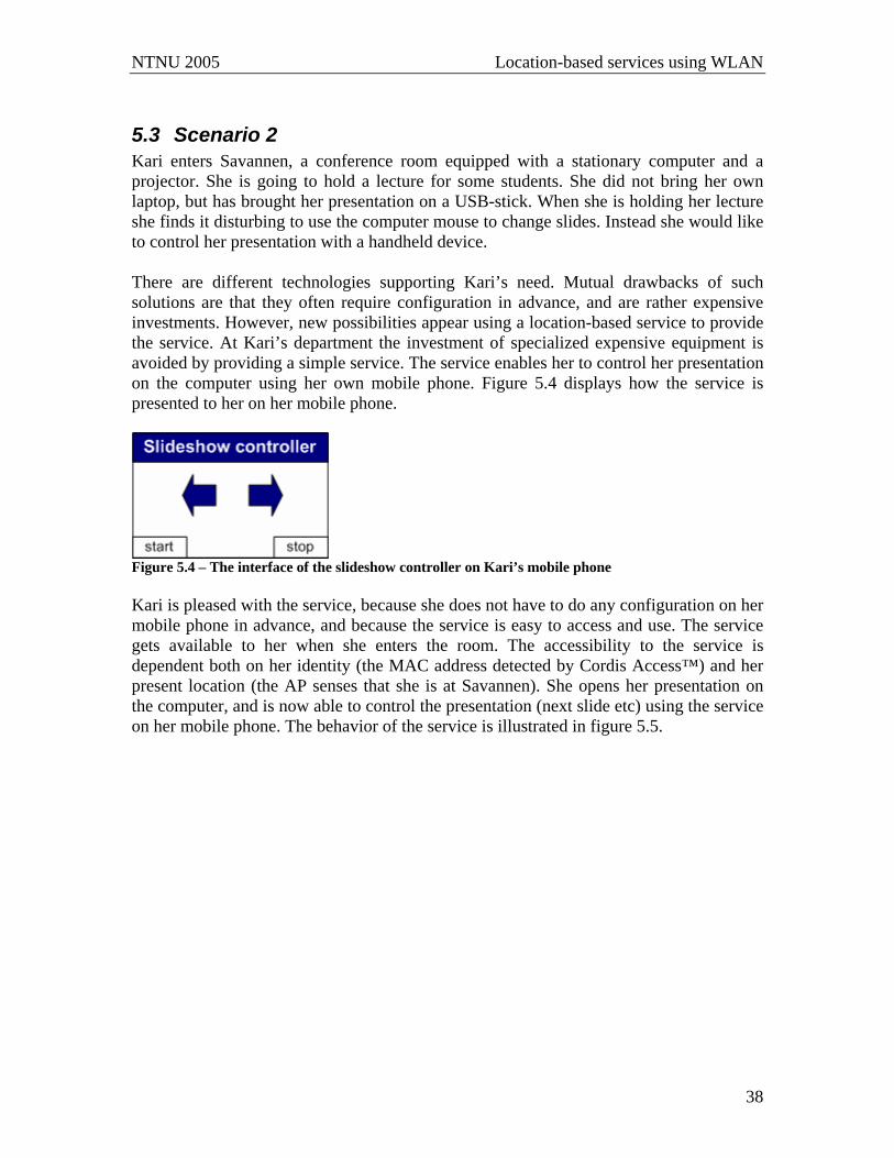
NTNU 2005 Location-based services using WLAN
38
5.3 Scenario 2 Kari enters Savannen, a conference room equipped with a stationary computer and a projector. She is going to hold a lecture for some students. She did not bring her own laptop, but has brought her presentation on a USB-stick. When she is holding her lecture she finds it disturbing to use the computer mouse to change slides. Instead she would like to control her presentation with a handheld device. There are different technologies supporting Kari’s need. Mutual drawbacks of such solutions are that they often require configuration in advance, and are rather expensive investments. However, new possibilities appear using a location-based service to provide the service. At Kari’s department the investment of specialized expensive equipment is avoided by providing a simple service. The service enables her to control her presentation on the computer using her own mobile phone. Figure 5.4 displays how the service is presented to her on her mobile phone.
Figure 5.4 – The interface of the slideshow controller on Kari’s mobile phone Kari is pleased with the service, because she does not have to do any configuration on her mobile phone in advance, and because the service is easy to access and use. The service gets available to her when she enters the room. The accessibility to the service is dependent both on her identity (the MAC address detected by Cordis Access™) and her present location (the AP senses that she is at Savannen). She opens her presentation on the computer, and is now able to control the presentation (next slide etc) using the service on her mobile phone. The behavior of the service is illustrated in figure 5.5.
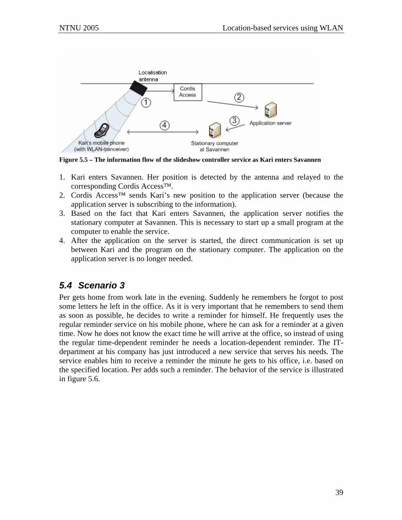
NTNU 2005 Location-based services using WLAN
39
Figure 5.5 – The information flow of the slideshow controller service as Kari enters Savannen 1. Kari enters Savannen. Her position is detected by the antenna and relayed to the
corresponding Cordis Access™. 2. Cordis Access™ sends Kari’s new position to the application server (because the
application server is subscribing to the information). 3. Based on the fact that Kari enters Savannen, the application server notifies the
stationary computer at Savannen. This is necessary to start up a small program at the computer to enable the service.
4. After the application on the server is started, the direct communication is set up between Kari and the program on the stationary computer. The application on the application server is no longer needed.
5.4 Scenario 3 Per gets home from work late in the evening. Suddenly he remembers he forgot to post some letters he left in the office. As it is very important that he remembers to send them as soon as possible, he decides to write a reminder for himself. He frequently uses the regular reminder service on his mobile phone, where he can ask for a reminder at a given time. Now he does not know the exact time he will arrive at the office, so instead of using the regular time-dependent reminder he needs a location-dependent reminder. The IT-department at his company has just introduced a new service that serves his needs. The service enables him to receive a reminder the minute he gets to his office, i.e. based on the specified location. Per adds such a reminder. The behavior of the service is illustrated in figure 5.6.

NTNU 2005 Location-based services using WLAN
40
Figure 5.6 – The information flow of the reminder service 1. Per is at home. He adds a location-based reminder set to trigger at the office. The
reminder is sent to the application server. 2. Per arrives at the office. His location is detected by the antenna at his office, and
relayed to the Cordis Access™ 3. Cordis Access™ relays the information about Per’s new position to the application
server (because the application server is subscribing to the information). 4. The server reacts by sending the reminder to Per. A similar reminder service will be designed and implemented in this assignment.
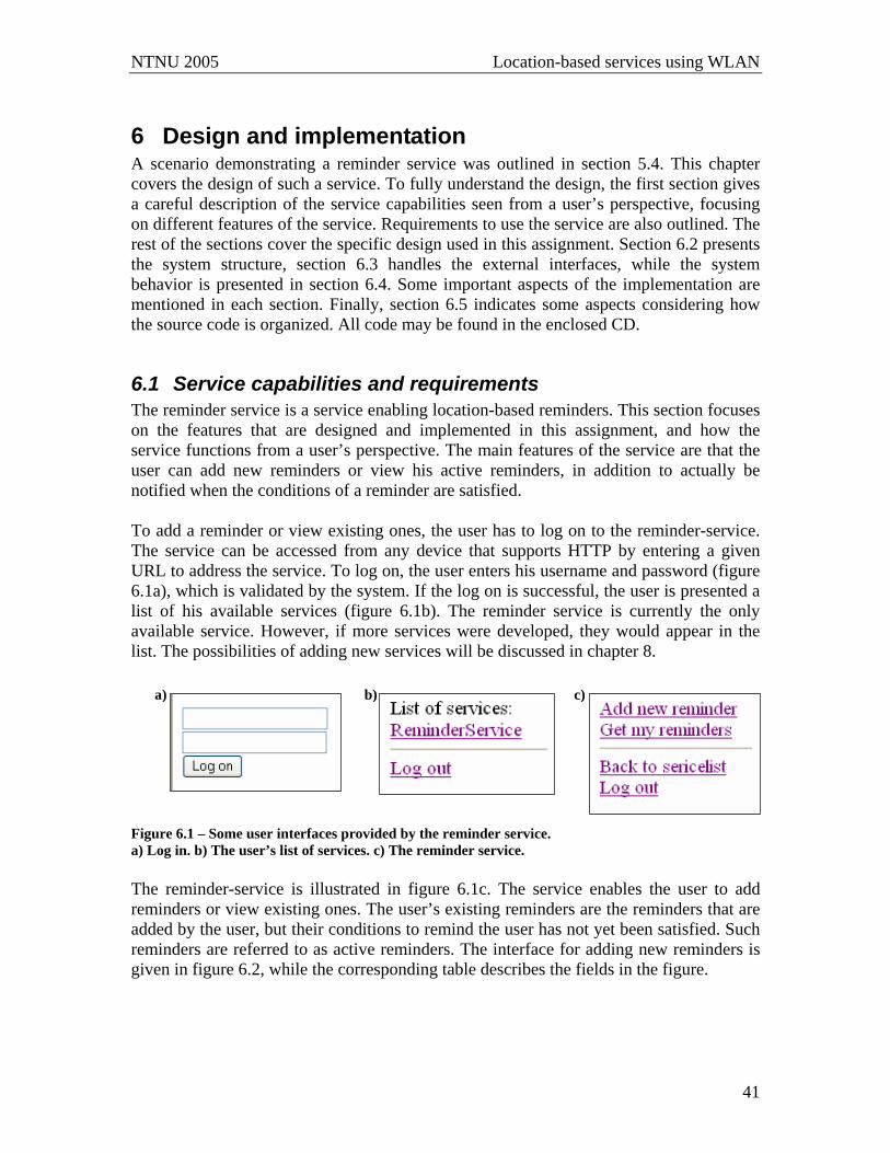
NTNU 2005 Location-based services using WLAN
41
6 Design and implementation A scenario demonstrating a reminder service was outlined in section 5.4. This chapter covers the design of such a service. To fully understand the design, the first section gives a careful description of the service capabilities seen from a user’s perspective, focusing on different features of the service. Requirements to use the service are also outlined. The rest of the sections cover the specific design used in this assignment. Section 6.2 presents the system structure, section 6.3 handles the external interfaces, while the system behavior is presented in section 6.4. Some important aspects of the implementation are mentioned in each section. Finally, section 6.5 indicates some aspects considering how the source code is organized. All code may be found in the enclosed CD.
6.1 Service capabilities and requirements The reminder service is a service enabling location-based reminders. This section focuses on the features that are designed and implemented in this assignment, and how the service functions from a user’s perspective. The main features of the service are that the user can add new reminders or view his active reminders, in addition to actually be notified when the conditions of a reminder are satisfied. To add a reminder or view existing ones, the user has to log on to the reminder-service. The service can be accessed from any device that supports HTTP by entering a given URL to address the service. To log on, the user enters his username and password (figure 6.1a), which is validated by the system. If the log on is successful, the user is presented a list of his available services (figure 6.1b). The reminder service is currently the only available service. However, if more services were developed, they would appear in the list. The possibilities of adding new services will be discussed in chapter 8.
Figure 6.1 – Some user interfaces provided by the reminder service. a) Log in. b) The user’s list of services. c) The reminder service. The reminder-service is illustrated in figure 6.1c. The service enables the user to add reminders or view existing ones. The user’s existing reminders are the reminders that are added by the user, but their conditions to remind the user has not yet been satisfied. Such reminders are referred to as active reminders. The interface for adding new reminders is given in figure 6.2, while the corresponding table describes the fields in the figure.
a) b) c)
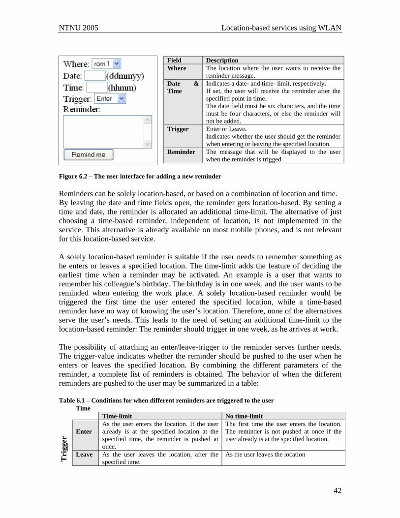
NTNU 2005 Location-based services using WLAN
42
Figure 6.2 – The user interface for adding a new reminder Reminders can be solely location-based, or based on a combination of location and time. By leaving the date and time fields open, the reminder gets location-based. By setting a time and date, the reminder is allocated an additional time-limit. The alternative of just choosing a time-based reminder, independent of location, is not implemented in the service. This alternative is already available on most mobile phones, and is not relevant for this location-based service. A solely location-based reminder is suitable if the user needs to remember something as he enters or leaves a specified location. The time-limit adds the feature of deciding the earliest time when a reminder may be activated. An example is a user that wants to remember his colleague’s birthday. The birthday is in one week, and the user wants to be reminded when entering the work place. A solely location-based reminder would be triggered the first time the user entered the specified location, while a time-based reminder have no way of knowing the user’s location. Therefore, none of the alternatives serve the user’s needs. This leads to the need of setting an additional time-limit to the location-based reminder: The reminder should trigger in one week, as he arrives at work. The possibility of attaching an enter/leave-trigger to the reminder serves further needs. The trigger-value indicates whether the reminder should be pushed to the user when he enters or leaves the specified location. By combining the different parameters of the reminder, a complete list of reminders is obtained. The behavior of when the different reminders are pushed to the user may be summarized in a table: Table 6.1 – Conditions for when different reminders are triggered to the user
Time Time-limit No time-limit Enter
As the user enters the location. If the user already is at the specified location at the specified time, the reminder is pushed at once.
The first time the user enters the location. The reminder is not pushed at once if the user already is at the specified location.
Tri
gger
Leave As the user leaves the location, after the specified time.
As the user leaves the location
Field Description Where The location where the user wants to receive the
reminder message. Date & Time
Indicates a date- and time- limit, respectively. If set, the user will receive the reminder after the specified point in time. The date field must be six characters, and the time must be four characters, or else the reminder will not be added.
Trigger Enter or Leave. Indicates whether the user should get the reminder when entering or leaving the specified location.
Reminder The message that will be displayed to the user when the reminder is trigged.
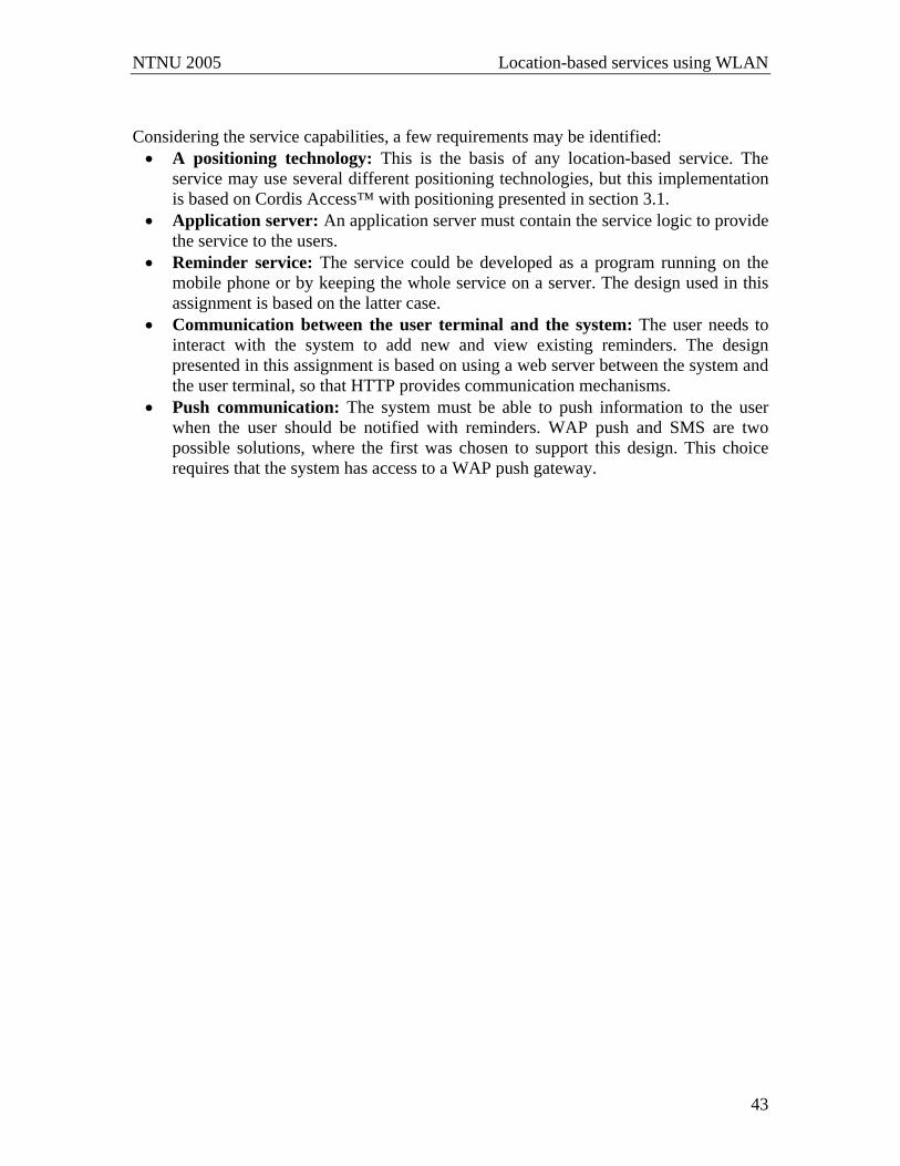
NTNU 2005 Location-based services using WLAN
43
Considering the service capabilities, a few requirements may be identified: • A positioning technology: This is the basis of any location-based service. The
service may use several different positioning technologies, but this implementation is based on Cordis Access™ with positioning presented in section 3.1.
• Application server: An application server must contain the service logic to provide the service to the users.
• Reminder service: The service could be developed as a program running on the mobile phone or by keeping the whole service on a server. The design used in this assignment is based on the latter case.
• Communication between the user terminal and the system: The user needs to interact with the system to add new and view existing reminders. The design presented in this assignment is based on using a web server between the system and the user terminal, so that HTTP provides communication mechanisms.
• Push communication: The system must be able to push information to the user when the user should be notified with reminders. WAP push and SMS are two possible solutions, where the first was chosen to support this design. This choice requires that the system has access to a WAP push gateway.
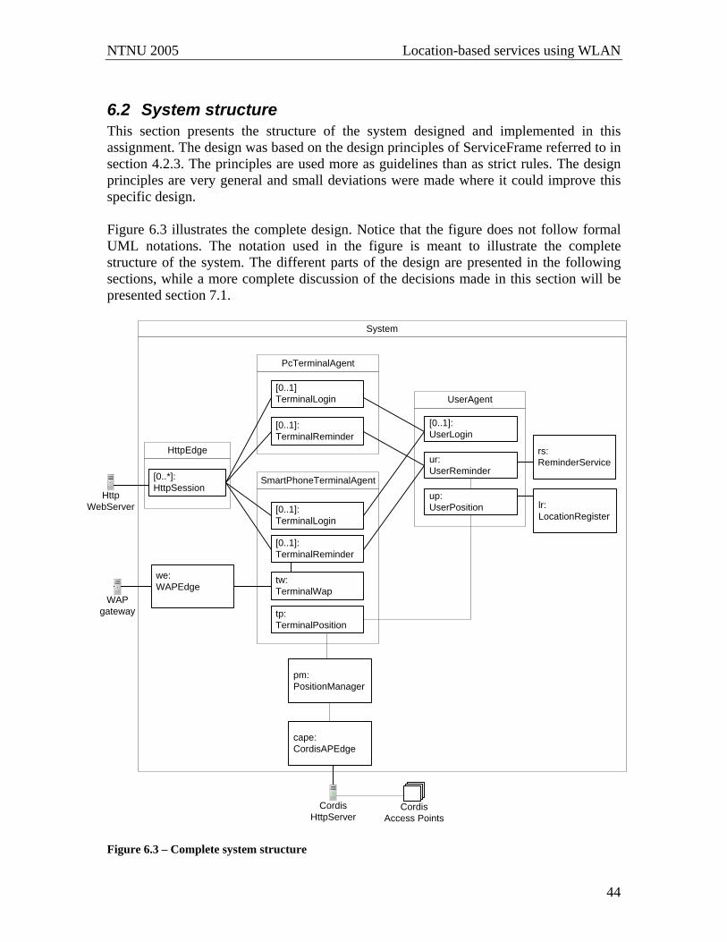
NTNU 2005 Location-based services using WLAN
44
6.2 System structure This section presents the structure of the system designed and implemented in this assignment. The design was based on the design principles of ServiceFrame referred to in section 4.2.3. The principles are used more as guidelines than as strict rules. The design principles are very general and small deviations were made where it could improve this specific design. Figure 6.3 illustrates the complete design. Notice that the figure does not follow formal UML notations. The notation used in the figure is meant to illustrate the complete structure of the system. The different parts of the design are presented in the following sections, while a more complete discussion of the decisions made in this section will be presented section 7.1.
System
SmartPhoneTerminalAgentup:UserPosition
[0..1]:UserLogin
ur:UserReminder
UserAgent
HttpEdge
pm:PositionManager
cape:CordisAPEdge
WAPgateway
HttpWebServer
[0..1]TerminalLogin
[0..1]:TerminalReminder
PcTerminalAgent
[0..1]:TerminalLogin
[0..1]:TerminalReminder
tw:TerminalWap
tp:TerminalPosition
Cordis Access Points
CordisHttpServer
lr:LocationRegister
rs:ReminderService
[0..*]:HttpSession
we:WAPEdge
Figure 6.3 – Complete system structure

NTNU 2005 Location-based services using WLAN
45
6.2.1 User Agent A UserAgent represents a user as presented in section 4.2.3, and is responsible for supporting user specific service behavior [38]. The need of information (e.g. username and password) about users leads to having persistent UserAgents, which implies that UserAgents live in the system at all times.
Figure 6.4 - The inner structure of a UserAgent Figure 6.4 illustrates the inner structure of a UserAgent. Each of the inner actors is assigned well defined responsibilities. UserLogin is responsible for handling the login and logout process. UserReminder is responsible for handling the user’s reminder service. This involves both keeping the user’s reminders, and notifying him at the correct times. The UserReminder organizes the reminders in three different lists, based on the parameters of the reminder: Solely location-based reminders are divided in two lists dependent on their trigger-value (enter or leave), while time-limited reminders are kept in a third list. The differentiation was made to group reminders based on when they should be triggered to the user, as presented in table 6.1 (page 42). A user may have several terminals, and the UserAgent must at all times know at which terminal the user is present. This is referred to as the user’s active terminal. UserPosition is responsible for holding the location of this terminal. Additionally, the UserPosition holds a list of other actors that are interested in the user’s positioning information. The UserPosition relays the information to these subscribers when the user moves.
6.2.2 Terminal Agent TerminalAgents mirror the terminals in the environment. The designed service is accessible from any device compatible with HTTP (Hypertext Transfer Protocol), e.g. both a mobile phone (using WAP) and a PC. Such terminals have different capabilities that should be reflected in the system, and therefore two different types of TerminalAgents are added in the design: The PcTerminalAgent serves the needs of a PC, and the behavior of a mobile phone is supported by a SmartPhoneTerminalAgent. The inner structures of the two TerminalAgents are illustrated in figure 6.5.
[0..1]: UserLogin
UserAgent
up: UserPosition
ur: UserReminder
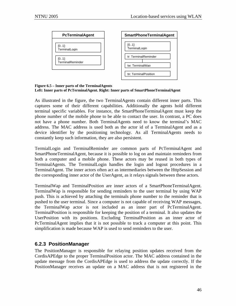
NTNU 2005 Location-based services using WLAN
46
Figure 6.5 – Inner parts of the TerminalAgents Left: Inner parts of PcTerminalAgent. Right: Inner parts of SmartPhoneTerminalAgent As illustrated in the figure, the two TerminalAgents contain different inner parts. This captures some of their different capabilities. Additionally the agents hold different terminal specific variables. For instance, the SmartPhoneTerminalAgent must keep the phone number of the mobile phone to be able to contact the user. In contrast, a PC does not have a phone number. Both TerminalAgents need to know the terminal’s MAC address. The MAC address is used both as the actor id of a TerminalAgent and as a device identifier by the positioning technology. As all TerminalAgents needs to constantly keep such information, they are also persistent. TermialLogin and TerminalReminder are common parts of PcTerminalAgent and SmartPhoneTerminalAgent, because it is possible to log on and maintain reminders from both a computer and a mobile phone. These actors may be reused in both types of TerminalAgents. The TerminalLogin handles the login and logout procedures in a TerminalAgent. The inner actors often act as intermediaries between the HttpSession and the corresponding inner actor of the UserAgent, as it relays signals between these actors. TerminalWap and TerminalPosition are inner actors of a SmartPhoneTerminalAgent. TerminalWap is responsible for sending reminders to the user terminal by using WAP push. This is achieved by attaching the terminals phone number to the reminder that is pushed to the user terminal. Since a computer is not capable of receiving WAP messages, the TerminalWap actor is not included as an inner part of PcTerminalAgent. TerminalPosition is responsible for keeping the position of a terminal. It also updates the UserPosition with its positions. Excluding TerminalPosition as an inner actor of PcTerminalAgent implies that it is not possible to track a computer at this point. This simplification is made because WAP is used to send reminders to the user.
6.2.3 PositionManager The PositionManager is responsible for relaying position updates received from the CordisAPEdge to the proper TerminalPosition actor. The MAC address contained in the update message from the CordisAPEdge is used to address the update correctly. If the PositionManager receives an update on a MAC address that is not registered in the
PcTerminalAgent
SmartPhoneTerminalAgent
[0..1]: TerminalLogin
[0..1]: TerminalReminder
[0..1]: TerminalLogin
tr: TerminalReminder
tp: TerminalPosition
tw: TerminalWap
NTNU 2005 Location-based services using WLAN
47
system, it neglects the update. The interface towards the CordisAPEdge is general to make it possible to replace the access points with another positioning technology.
6.2.4 LocationRegister The LocationRegister contains the references between position and location. More exactly this means that it maps the zone id to a location, e.g. a room or area.
6.2.5 ReminderService The ReminderService is responsible for controlling the time of the time-limited reminders. One single timer that expires every minute is used to check all reminders. If any reminders have elapsed when the timer expires, they are returned to the UserReminder for further handling.
6.3 External interfaces To communicate with the environment the service needs external interfaces. Three external interfaces are included in the design: CordisAPEdge towards the Cordis Access™ positioning technology, HttpEdge towards an HttpWebServer holding the service resources, and WapEdge towards the WAP gateway to enable WAP push. The edge-naming is used to clearly state that the actors are interfaces towards the environment. The edges are illustrated in the system structure in figure 6.3 (page 44). In the following sections the different edge-actors, and their connection to the environment, are described.
6.3.1 CordisAPEdge and CordisServer The CordisAPEdge represents the interface towards the web server communicating with the Cordis Access™ that is configured to be the master (see section 3.1). The web server is realized as a Jetty HttpServer on port 8181, and is started (i.e. created) by the CordisAPEdge. When the servlet on the server receives a response from the access point, it parses the contents of the XML-document, extracts the interesting parameters, and forwards them in an ActorMsg (UpdateReport) to the CordisAPEdge. The communication is possible as the server is given access to the state machine of the CordisAPEdge at startup. The CordisAPEdge forwards the messages from the web server to the PositionManager. To receive the desired information from Cordis Access™, the server requests the information by sending messages in compliance with the Cordis DTD [23]. To specify both enter- and leave-subscriptions, the server needs to send two different messages. Examples of the messages used to set up an access point and enable the reminder service are given in appendix A. Both the server and the edge actor were developed in collaboration with Thomas Senneset, another student working with the same positioning technology this semester. The communication between the access point and the CordisServer was already
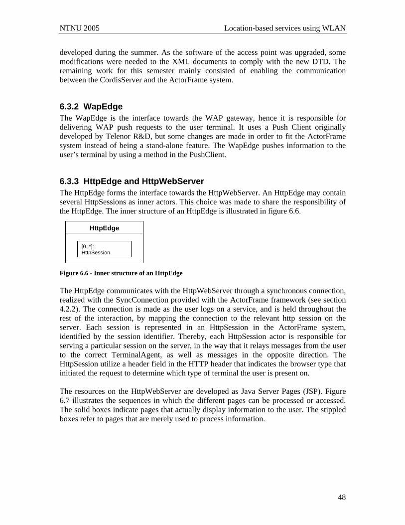
NTNU 2005 Location-based services using WLAN
48
developed during the summer. As the software of the access point was upgraded, some modifications were needed to the XML documents to comply with the new DTD. The remaining work for this semester mainly consisted of enabling the communication between the CordisServer and the ActorFrame system.
6.3.2 WapEdge The WapEdge is the interface towards the WAP gateway, hence it is responsible for delivering WAP push requests to the user terminal. It uses a Push Client originally developed by Telenor R&D, but some changes are made in order to fit the ActorFrame system instead of being a stand-alone feature. The WapEdge pushes information to the user’s terminal by using a method in the PushClient.
6.3.3 HttpEdge and HttpWebServer The HttpEdge forms the interface towards the HttpWebServer. An HttpEdge may contain several HttpSessions as inner actors. This choice was made to share the responsibility of the HttpEdge. The inner structure of an HttpEdge is illustrated in figure 6.6.
Figure 6.6 - Inner structure of an HttpEdge The HttpEdge communicates with the HttpWebServer through a synchronous connection, realized with the SyncConnection provided with the ActorFrame framework (see section 4.2.2). The connection is made as the user logs on a service, and is held throughout the rest of the interaction, by mapping the connection to the relevant http session on the server. Each session is represented in an HttpSession in the ActorFrame system, identified by the session identifier. Thereby, each HttpSession actor is responsible for serving a particular session on the server, in the way that it relays messages from the user to the correct TerminalAgent, as well as messages in the opposite direction. The HttpSession utilize a header field in the HTTP header that indicates the browser type that initiated the request to determine which type of terminal the user is present on. The resources on the HttpWebServer are developed as Java Server Pages (JSP). Figure 6.7 illustrates the sequences in which the different pages can be processed or accessed. The solid boxes indicate pages that actually display information to the user. The stippled boxes refer to pages that are merely used to process information.
HttpEdge
[0..*]: HttpSession
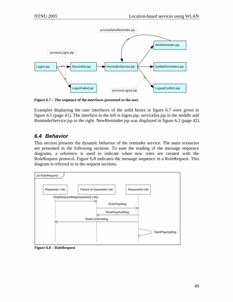
NTNU 2005 Location-based services using WLAN
49
Logon.jsp
NewReminder.jsp
Servicelist.jsp GetMyReminders.jsp
processLogon.jsp
LogoutConfirm.jsp
processNewReminder.jsp
processLogout.jspLogonFailed.jsp
ReminderService.jsp
Figure 6.7 – The sequence of the interfaces presented to the user Examples displaying the user interfaces of the solid boxes in figure 6.7 were given in figure 6.1 (page 41). The interface to the left is logon.jsp, servicelist.jsp in the middle and ReminderService.jsp to the right. NewReminder.jsp was displayed in figure 6.2 (page 42).
6.4 Behavior This section presents the dynamic behavior of the reminder service. The main scenarios are presented in the following sections. To ease the reading of the message sequence diagrams, a reference is used to indicate when new roles are created with the RoleRequest protocol. Figure 6.8 indicates the message sequence in a RoleRequest. This diagram is referred to in the sequent sections.
sd RoleRequest
Requester role Parent of requested role Requested role
RoleRequestMsg(requested role)
RolePlayMsg
RolePlayAckMsg
RoleConfirmMsg
StartPlayingMsg
Figure 6.8 – RoleRequest

NTNU 2005 Location-based services using WLAN
50
6.4.1 Log on / log off As the user enters logon.jsp to log on the service, a synchronous connection between the HttpWebServer and the ActorFrame system is created. This enables the web server to send ActorFrame messages to the system. First, an HttpSession actor is created, and thereafter all communication between the user and the system passes through this actor. Logging on the service introduces three possible situations that need to be handled:
1. The user enters invalid username and is thereby denied access to the system. 2. The user enters invalid password and is thereby denied access to the system. 3. The user enters correct username and password and is thereby given access to the
system. The first alternative implies that the username does not exist in the system, and therefore the user has no TerminalAgents or UserAgents to handle its requests. A non-existent username is discovered already at the HttpEdge and the user is presented an error message that login failed because the username is invalid. The HttpSession is automatically removed from the system. If the user tries to log in again, a new session actor will be created to serve the user. The second and third alternative leads to a validation of username and password. The entered parameters are relayed to the UserLogin in the user’s UserAgent, where the entered password is checked against the user’s valid password. If the passwords are identical, the user is presented a list of his available services. If the password is incorrect, the user is presented an error message instead of the list of services, which informs the user that there was a username and password mismatch. Figure 6.9 demonstrates the sequence of a successful login.
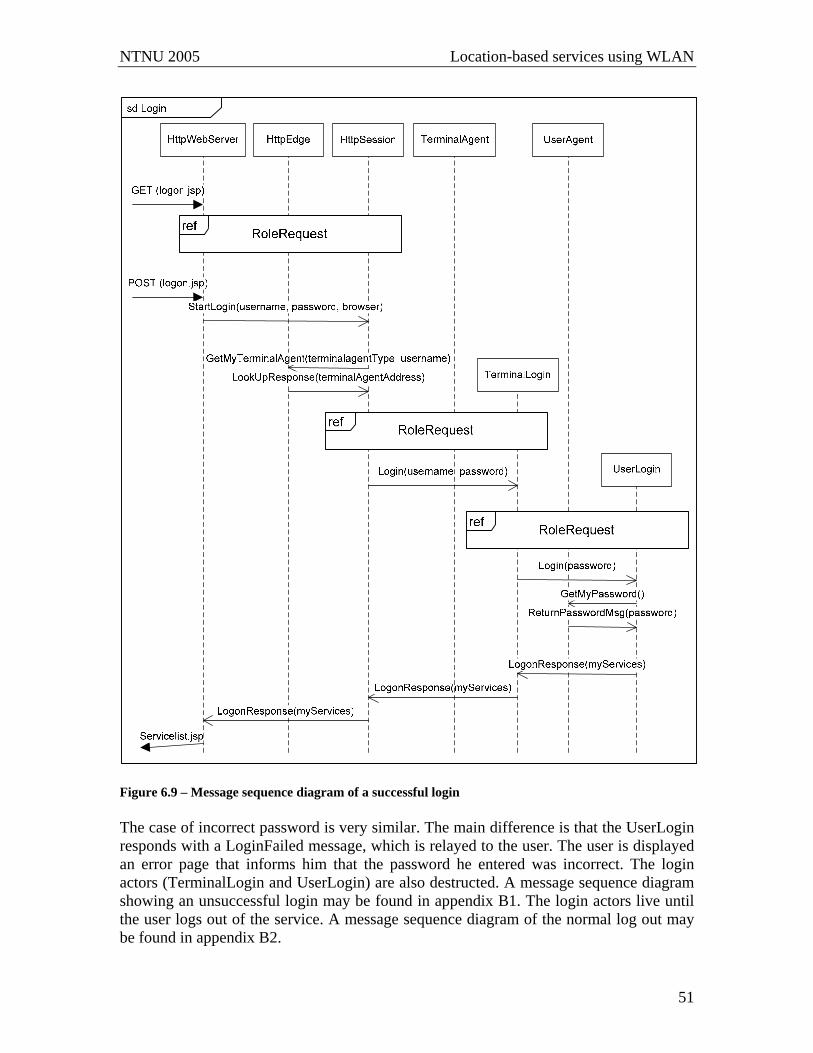
NTNU 2005 Location-based services using WLAN
51
Figure 6.9 – Message sequence diagram of a successful login The case of incorrect password is very similar. The main difference is that the UserLogin responds with a LoginFailed message, which is relayed to the user. The user is displayed an error page that informs him that the password he entered was incorrect. The login actors (TerminalLogin and UserLogin) are also destructed. A message sequence diagram showing an unsuccessful login may be found in appendix B1. The login actors live until the user logs out of the service. A message sequence diagram of the normal log out may be found in appendix B2.

NTNU 2005 Location-based services using WLAN
52
6.4.2 Adding a new reminder Figure 6.10 illustrates the system behavior when a user accesses the reminder service, and adds a new reminder.
Figure 6.10 – Message sequence diagram of adding a new reminder

NTNU 2005 Location-based services using WLAN
53
The new reminder is handled somewhat different whether it is time-limited or purely location-based. This is illustrated with the alternative box in the message sequence diagram. If the reminder is solely location-based, the reminder is completely handled by the UserReminder. In contrast, the ReminderService will be notified if the reminder contains a time-limit, as the responsibility of checking time is allocated to the ReminderService. The ReminderService is responsible for the reminder until the time has elapsed. The UserReminder saves every new reminder in different lists, depending on the parameters in the new reminder. This is illustrated in figure 6.11xi.
idle
NewReminder(message, location, time, trigger, username)
NewReminderOk()
idle
timelimit exist no timelimit
NewTimeLimitedReminder(message,location, time, trigger, identifier)
Id = unique identifiertimeLimitedReminders.put(id,reminder)
trigger = enter trigger = leave
NewReminderOk()
idle
ArrayList a = list of reminders at the locationlocationReminders.put(location, a)
NewReminderOk()
idle
ArrayList b = list of reminders at the locationlocationLeaveReminders.put(location, b)
Check trigger
Check time
Figure 6.11 – Behavior of the UserReminder when the user adds a new reminder When a new reminder arrives, the time is checked. If the reminder is time-limited, it is temporarily saved in the list of time-limited reminders, and forwarded as a NewTimeLimitedReminder to the ReminderService. If the reminder does not have a timelimit, the trigger is checked. Dependent on the trigger value (leave or enter), the reminder is saved in the right list of reminders.
6.4.3 Displaying active reminders After the user has logged in he may retrieve a list of the active reminders. A user’s active reminders are all the reminders he has added, that have yet not triggered. As mentioned earlier, reminders without time-limit is completely handled by the UserReminder, while time-limited reminders are temporarily handled by the ReminderService. However, the UserReminder saves all the reminders, independently of whether they are time-dependent or not. Thereby, the UserReminder is capable of sending a full list of the user’s active
xi A complete state diagram of the UserReminder is given in appendix B5

NTNU 2005 Location-based services using WLAN
54
reminders, whenever it is inquired by the user. A message sequence diagram of how a user can view his reminders is found in appendix B3.
6.4.4 Location update When a user enters or leaves a zone the CordisServer is notified by the Cordis Access Point by an UpdateReport, and reacts by forwarding the information to the CordisAPEdge. Figure 6.12 displays the message sequence of such an update.
Figure 6.12 – Message sequence diagram of a position update The message sequence is rather self-explanatory. Notice that the update that arrives from the TerminalPosition must be from the active terminal if the UserPosition is to update its position parameters and notify the UserReminder. The active terminal is defined as the terminal the user is currently using.
6.4.5 Trigger reminder to the user The UserReminder is responsible for triggering reminders to the user at the right time. This decision is based on both the user’s current location and the relevant parameters in the particular reminder, namely location, time and trigger. As the responsibility of time is allocated to the ReminderService, the UserReminder does not check time-dependent reminders before it is notified by the ReminderService. The ReminderService uses one timer to handle all reminders. Every minute it checks its list of reminders, and triggers those that have elapsed by sending a TimeElapsedReminder signal to the UserReminder. This way it returns the responsibility of the reminder to the UserReminder.

NTNU 2005 Location-based services using WLAN
55
Figure 6.13 xii illustrates the behavior of the UserReminder when it receives a TimeElapsedReminder from the ReminderService.
idle
TimeElapsedReminder(message,location,time,trigger,identifier)
timeLimitedReminders.remove(identifier)
idle
Check TimeElapsed
Trigger
trigger = enter trigger = leave
ArrayList b = list of reminders at the locationlocationLeaveReminders.put(location, b)CheckPresent
LocationuserIsNotAtLocation userIsAtLocation
idle
ReminderPush(message)
idle
ArrayList a = list of reminders at the locationlocationReminders.put(location, a)
Figure 6.13 – UserReminder handles a notification of an elapsed time from the ReminderService The behavior can be compared to receiving a new reminder. However, some differences exist. First, there is no need to check the time as the time-limit already has exceeded. Time is therefore disregarded. Second, the present location of the user must be checked if the trigger is “enter”. It is assumed that the user wants to receive the reminder at once if he already is present at the location, as described in section 6.1. If the user is not at the location specified in the reminder, or the trigger-value in the reminder is “leave”, the reminder is added to the correct list of solely location-based reminders. Solely location-based reminders are triggered to the user based on the user’s position. Figure 6.14 illustrates such an event. The figure may be looked at as a direct continuation of the sequence of position update illustrated in figure 6.12 (page 54).
xii A complete state diagram of the UserReminder is given in appendix B5

NTNU 2005 Location-based services using WLAN
56
Figure 6.14 – Message sequence diagram of a triggered reminder As the UserReminder receives a LocationUpdate indicating that the user has changed his location, it must decide whether the user should be notified with any reminders. The decision is made based on the parameters of the LocationUpdate message, as illustrated in figure 6.15xiii.
idle
LocationUpdate(location, trigger)
trigger=enter
Update Location
Check EnterReminders
Active EnterReminders exist
No active EnterReminders
ReminderPush(message) For all activated reminders
idle
idle
trigger=leave
No active LeaveRemindersCheck
LeaveReminders
Active LeaveReminders exist
ReminderPush(message)
idle
For all activated reminders
idle
Check LocationUpdate
Trigger
Remove reminder from LocationReminder list
Remove reminder from LocationLeaveReminder list
Figure 6.15 – The behavior of UserReminder when the user’s location is updated
xiii A complete state diagram of the UserReminder is given in appendix B5

NTNU 2005 Location-based services using WLAN
57
The analyses of triggering a reminder to the user bring the total presentation of the system’s behavior to an end. All the service logic presented in these sections is also implemented and tested in this project assignment. As previously mentioned, the full source code may be found on the enclosed CD. The next chapter confines itself to point out some general remarks about the structure of the source code.
6.5 Structuring the source code The service presented in the previous sections was implemented in Eclipse using Ramses (see section 4.3). Additionally web servers were realized as Jetty servers and JSP used to develop the user interfaces in the service. Remarks about the implementation of the different parts of the system are mentioned in the previous sections. The different parts of the system are developed in different Eclipse projects. By organizing the parts of the system in separate projects, selected parts of the system can easily be reused. Additional separations were made to be able to reuse signals within this system. A table of the different eclipse projects implemented in this assignment is given in appendix D.

NTNU 2005 Location-based services using WLAN
58
7 Evaluation and testing This chapter considers different aspects of the designed service. In the first section several design issues are presented. Both the structure of the design and the behavior of the service are discussed. Section 7.2 presents some experiences concerning the tools and technologies used in this assignment. The results from testing and simulation of the implemented system are presented in section 7.3.
7.1 Design issues When designing the system, several trade-offs arises. One is the trade off between having a static or dynamic structure of agents and actors. In a static structure all actors are present at all times, whereas in a dynamic system the actors are created only when they are active. The static structure relieves the amount of messages needed to perform a given task, because few signals to create and remove actors are needed. However, in a big system, a complete static structure leads to a huge amount of agents and actors being present at the same time, even though just a few of them are used. Another trade off arises when deciding which actors and agents to include in the design, and additional issues arise when the actors are communicating with the environment. These are some of the issues that are discussed in the following sections.
7.1.1 Capturing terminal capabilities To capture the various capabilities of a PC and a mobile phone, PcTerminalAgents and SmartPhoneTerminalAgents were included in the design. An alternative solution that was evaluated was to define clients in the terminals as separate TerminalAgents instead of encapsulating terminals as TerminalAgents. This could lead to WapTerminalAgents, PcBrowserTerminalAgents and MicroBrowserTerminalAgents, and as a consequence a mobile phone will be served by two TerminalAgents. According to [38] TerminalAgents should reflect user terminals, and can contain user clients as an inner dynamic structure. This statement supports the alternative chosen is the design. Given that the TerminalAgent can contain user clients, inner actors supporting browsers (like WebBrowser in the PcTerminalAgent and MicroBrowser in the SmartPhoneTerminalAgent) could have been included. TerminalLogin and TerminalReminder would then become inner actors of both browser types. However, as it appeared that such user clients did not receive proper responsibilities in this specific design, they were excluded. In contrast, TerminalWap is introduced as an actor to represent the terminals WAP client. As indicated in this section, there are often a number of possible solutions of which actors to include, and choosing one is a matter of considering pros and cons for the different solutions. Representing different terminal types as TerminalAgents was preferred in the implemented design, because it formed a logic and understandable view of the system. By capturing terminal capabilities in inner actors of the different TerminalAgents, reuse of capabilities were also promoted, which will be further evaluated in section 7.1.4.

NTNU 2005 Location-based services using WLAN
59
7.1.2 Handling time As there is no support for absolute time in ActorFrame, time was supported by relative time realized by timers. In the chosen design, a separate actor (ReminderService) was included to reduce the number of timers. A simple solution would be to support every single reminder with its own timer, but this would also cause different timers to run for a very long time before they expired. Imagine that a user adds a reminder that should trigger one week ahead. The corresponding timer must then run for 60.480.000 millisecondsxiv, which forms a somewhat unnatural use of timers. Additionally, numerous timers must be added in the system, as each reminder requires a new timer. An alternative solution to introducing a separate actor to handle time, but still reduce the amount of timers, is to keep the responsibility within the UserReminder. This can be realized by introducing one timer in every UserReminder that is responsible for checking all the time-based reminders for the specified user. Compared to using a separate ReminderService actor this alternative introduces more timers (one per user), and consequently leads to extra signaling. The probability of unnecessary examining of the reminder list, i.e. when there are no reminders to trigger, is also increased as one user has fewer reminders than all the users together. Additionally, exactly the same behavior is performed at the same time by every UserReminder actor. Based on the drawbacks of the extra resources used to control timers, the ReminderService was added to handle time for all users. The ReminderService has one timer that currently expires every minute. The frequent checking is necessary as the user may be constantly moving. By setting the duration of the timer to one minute, the error range is lowered to this time. To check the time in the ReminderService at the exact right moment (i.e. at the first second in every minute), the start up of the timer must be synchronized with the time on the server. However, an error range of one minute to receive reminders is in this system considered to be satisfactory.
7.1.3 Location The LocationRegister is responsible for mapping zones to location descriptions. In the design used in this assignment, the LocationRegister communicates with the UserReminder. It could be argued that the communication with the LocationRegister should be placed at the edge of the system, e.g. by translating from zone to location already at the PositionManager. As Cordis Access™ with positioning only detects zones, not accurate coordinates within the zone, this alternative may be equal to the chosen alternative. However, if the positioning technology was capable of detecting more accurate positions, the chosen alternative is preferable. As presented in section 2.1, different services have various needs when it comes to position and location. If the positioning were given by coordinates, a service may utilize both the coordinates and the location. Hence, placing the LocationRegister inside the system, instead of at the edge, makes the structure more general. More aspects concerning generality are outlined in the next section.
xiv The duration parameter of a timer in ActorFrame is specified in milliseconds
NTNU 2005 Location-based services using WLAN
60
7.1.4 Generality To support a variety of services, both generality within the system and toward the environment must be considered. Generality within the system is important because it should be easy to add new services to the system. One of the generalities to enable this is that the UserPosition has a list of the services that it will update with new positions. Every actor (i.e. service) that wants to be updated with the user’s position can send a signal to the UserPosition to become a member of the list. Generality toward the environment is important to decrease dependency of technologies in the environment. As an example, the PositionManager has a general interface towards the CordisAPEdge. This makes the system independent of positioning technologies, and several other technologies may be used. The only requirement is that the technology must be able to detect position and fill out the parameters of the UpdateTerminalLocationMsg, namely MAC-address, positionxv, timestamp and trigger-value (enter or leave). Similarly, the TerminalReminder is independent of TerminalWap. At start up the TerminalAgent informs TerminalReminder about the address of TerminalWap, so that TerminalReminder can use TerminalWap to push information to the user terminal. If a different communication method is preferred, a new role within the TerminalAgent must be introduced. Thereafter, the TerminalAgent can inform the TerminalReminder of the address of this role, instead of the TerminalWap address. The change does not require any changes of the TerminalReminder actor. Another aspect of generality is reuse. ActorFrame encourages reuse by supporting the UML concept of inner parts. An actor (or role) may be defined as inner part of several other actors. This possibility is exploited in the TerminalAgents, where TerminalLogin and TerminalReminder are inner parts of both PcTerminalAgent and SmartPhoneTerminalAgent. Reuse of the actors is suitable as the terminals have some of the same capabilities. In the present design, the PcTerminalAgent is not capable of sending reminders to the terminal it represents (a PC). Even so, this capability is present in the TerminalReminder, because of the possibilities of introducing new communication methods that a computer supports. For instance, the computer can receive notifications by use of HTTP, by running a small application that listened for such notifications. The HttpEdge and CordisAPEdge use two different web servers. This choice was made to avoid dependency between the two actors, although it could easily be realized by use of one server. The HttpEdge starts up one server, and the CordisAPEdge starts up another server. The dependencies were avoided to make the design as general as possible. The UserAgent keeps a list of services that are available to the specified user. In the present implementation, this list is instantiated as the UserAgent is created, which implies that the list is hard coded and that every UserAgent possess the same available services. This is not a realistic assumption in a real system, and thereby it represents a lack of generality. To provide a more general list of services, the UserAgent should keep a
xv The parameter is called “location” in the implementation. However, based on the differences between position and location presented in section 2.1, the parameter actually refers to position.

NTNU 2005 Location-based services using WLAN
61
personal list of the services that are available to the user. As only one service is available at the moment, emphasis was not put on designing general mechanism to provide different services to the users.
7.1.5 Consistency at the HttpEdge The HttpWebServer is capable of running several threads, and thereby handle several requests simultaneously. To prevent a single HttpEdge from becoming a bottleneck in the system, it was decided that the communication towards the web server should be distributed between more actors. According to the Jetty API [41] the HttpSession interface provides a way for the server to identify a user across subsequent requests. As the concept of http sessions already existed on the web server, dividing the responsibility of the HttpEdge between HttpSession actors seemed like a natural and simplifying choice. Allocating the responsibility also eases the routing of messages to the system, as each HttpSession communicates with a specific TerminalAgent (i.e. PcTerminalAgent or SmartPhoneTerminalAgent). Figure 7.1 illustrates the advantages of including HttpSessions in the HttpEdge, compared to making a single HttpEdge handle all users.
HttpEdge
TerminalAgent
TerminalAgent
TerminalAgent
HttpEdge
TerminalAgent
TerminalAgent
TerminalAgent
HttpSession
HttpSession
HttpSession
a) b)
Figure 7.1 - The effect of introducing HttpSessions During the design it appeared that the HttpSession actors were quite difficult to keep consistent. A complete figure of the state diagram of an HttpSession is given in appendix B6. First, the intension was to capture every action performed by the user in states of the HttpSession actor. This would involve a separate state to render which service the user was presently using, e.g. setting the state to “reminderservice” when the user accesses this service. To decrease the need for signaling between the HttpWebServer and the HttpSessions this solution was not preferred. An additional problem is that it is impossible for the server to have complete knowledge about the users’ actions. The reason is that some behavior is not sent to the server by the browser. For example there is no way for the server to detect if the user uses the back and forward buttons in his browser. To by-pass these problems, idle and ready are the only states where the user can provide the HttpSession with input. An HttpSession is created as the user enters the logon site. Until the user has logged on, the state of the HttpSession is idle. When the user logs on, the state changes to ready. Whenever the HttpSession is in its ready-state, there is a
NTNU 2005 Location-based services using WLAN
62
possibility to receive input from the user. When the HttpWebServer sends a signal into the system, it always waits for a response signal. This signal decides the information that is presented to the user. While waiting for such a response, the HttpSession is in a waiting-state (the waiting state is different based on what the HttpSession is waiting for). Whenever the HttpSession is in a waiting-state, the user is incapable of giving input because the browser on the user’s terminal is waiting for the response. The HttpSession captures the natural behavior of a user, but some problems arise when the user behaves unexpectedly to the system. An example of such “unexpected behavior” is when the user ends the service without logging out. This causes the HttpSession actor and the user’s login actors to remain active in the system. A possible solution to this problem is to automatically log out users that are inactive for a long time. Inactivity can be detected by adding a timer to each HttpSession which expires when the actor is not used for a specified amount of time. To realize this in Ramses, every activity in the HttpSession with an input signal must reset the timer and start it up again. If the timer expires, the HttpSession should be removed. Additionally, it must notify the TerminalLogin, which again notifies the UserLogin, so that these actors also are removed.
7.2 Design and implementation - Tools and technologies The following sections highlight some experiences that were made with the tools and technologies used in the implementation conducted in this assignment. The first section presents the impressions with the frameworks and development tools, focusing on ActorFrame and Ramses. Thereafter, section 7.2.2 presents some remarks about the implementation of the web servers. Section 7.2.3 discusses delivery of content from the system to the user terminal, while section 7.2.4 outlines experiences gained by use of Cordis Access™ as positioning technology.
7.2.1 Frameworks and development tools The system was designed and implemented using the UML concepts provided by Ramses. As the system was run on the ActorFrame platform, different concepts provided by ActorFrame (actor, role, etc.) had great impact on the design. Additionally, the key design principles of ServiceFrame, especially separation of concerns and environment mirroring, were helpful during the design phase. By using the concepts in combination with ActorFrame, responsibility is naturally divided between the actors in the design. The ActorFrame protocols also simplify creation and removal of actors. In my opinion, ActorFrame forms a general and logical framework for service development. Ramses enables the designer to focus on service logic rather than pure programming. Designing state machines and internal structure of the system was easy through graphical interfaces. Some minor problems encountered when using Ramses, e.g. that Eclipse tended to suddenly close down without any warning. This caused some frustration, because such unexpected behavior made the design inconsistent; i.e. sometimes the UML model managed to save the objects, even though they were not yet fully supported in the java-files. Recreating a consistent system did not take too much time, but still it felt time-

NTNU 2005 Location-based services using WLAN
63
consuming when it happened. Additionally, Ramses lack some functionality concerning renaming and changing developed elements. As Ramses is constantly being developed and improved, these problems and limitations may be addressed, to make Ramses even better. By using Ramses I was able to focus on service logic even in the implementation of the system. I believe that Ramses simplified the design and implementation of the service, and decreased the time to develop the service compared to manually write all the code. It thereby served as intended.
7.2.2 Web server The web servers that enable user interaction with the system, as well as communication between the system and Cordis Access™, were realized as Jetty servers (see section 4.4.1). The Jetty technology provided an easy way to set up web servers that were able to communicate with the system. Initially, the user interfaces used in the service were developed using servlets. However, Java Server Pages (JSP) proved to be easier to use when static content (HTML) and dynamic content (java programming) were to be combined in one page, because JSP provides a clear separation of the content types (see section 4.4.2). JSP was also used in pure processing pages (e.g. processLogin.jsp), even though these pages only contained dynamic content. In contrast, the communication between Cordis Access™ and the CordisServer was realized by using a servlet. The experience gained in this assignment, implies that JSP is superior to provide a combination of static content and dynamic content, and provides easy mechanisms to process content of other JSP pages, while a servlet provides well-defined mechanisms for handling other HTTP requests such as updates from Cordis Access™.
7.2.3 Delivery of content In the design, WAP is used to access the service, and WAP push is used to deliver content to the user. The experience is that WAP provides a very easy way to introduce new services. One of the reasons is that the PushClient developed by Telenor was very easy to integrate with the system. Additionally, no programming was needed on the mobile phone. However, the service could have been realized using other technologies, e.g. using SMS as delivery mechanism, or supporting the service by a separate application on the mobile device. The designed service uses Service Indication as content type of the push message (see section 3.3). Service Loading is not supported by the WAP gateway used in this assignment. SMS is used to notify the user with a push message. This constitutes a simple and effective starting point for a push service [44]. Comparing WAP to SMS, the main advantage of WAP is that it enables active content. By using SMS as delivery mechanism for WAP push, the user can directly access the service through the link enclosed in the push message. This will be further discussed in section 8.1. I believe that a general architecture should support both delivery mechanisms. The main argument to additionally support SMS is that some services are not dependent on user interaction, and
NTNU 2005 Location-based services using WLAN
64
sending a regular SMS (without any link) to the user is adequate for such services. SMS could be included by using the SMS Edge provided by Ericsson’s ServiceFrame (see section 4.2.3). The alternatives discussed so far assumes that all the service logic is placed on the server. Another possibility is to develop a separate application that runs directly on the mobile device, in addition to the application running on the server. The service logic is then shared between the server and the mobile device. Such an application can be developed by programming in Java, using the Mobile Information Device Profile (MIDP). The resulting application is called a MIDlet. Both pull and push services can be realized as MIDlets. A MIDlet based on push information may automatically be started up as the device receives a SMS on a specified port [45]. Further communication between the mobile device and the server uses GPRS (General Packet Radio Service). Ericsson has created a development framework similar to ActorFrame called MIDletFrame that is adjusted to fit mobile devices. ActorFrame and MIDletFrame can communicate seamlessly by sending actor messages. This implies that the communication between the mobile device and the server can be realized as pure actor messages. The main advantage of programming directly on the mobile device, is that the service can be accessed without any interaction with the server. Additionally, the service may utilize features that are present on the mobile device (i.e. calendar). To start using a MIDlet application, the user must first download the application to his mobile phone. WAP may be used to offer the service to the user. If the application is dependent on the user’s location, WAP push can notify the user about his possibility to download the application when he is at the right location. Otherwise, regular WAP can be used to offer the download through a specified site. The framework developed in this assignment can be adjusted to serve both these services. Compared to keeping the service on the server, I believe that the main drawback with MIDlets is the need for downloading the application to the mobile phone, because this may cause greater barriers for users to start using the service. Additionally, programming MIDlets requires more time and effort to provide new services. However, I believe that the different technologies should be considered complimentary rather than competitive. Merely using server programming is a good starting point for developing simple location-based services. However, while some services are fully supported by this programming model other services are better supported by an additional application on the mobile device. I believe that a greater variety of services can be supported by utilizing both technologies, and that download of application to the mobile device should be offered through WAP. Therefore, a general system supporting several services, such as the one developed in this assignment, should be extended to support services based on MIDlets as well.
7.2.4 Cordis Access™ as positioning technology Cordis Access™ is a relatively new technology. It is currently used only in research communities, and is not yet publicly available. The technology provides simple

NTNU 2005 Location-based services using WLAN
65
positioning of devices with WLAN transceivers in terms of zones. A limitation seems to be that it is hard to determine fixed boundaries of a zone. Even though zones are defined, the boundary of the zone is somewhat diffuse, as the range is also dependent on the transceiver on the mobile device. The directional nature of the antenna leads to a concentrated range, which hopefully leads to adequate indications of zones. To provide a stable environment for the services based on the positioning technology, some testing should be conducted to realize the actual range of the access points. As indicated in section 3.1, the accuracy may also be configured in a “signal threshold”. As only one Cordis Access™ with positioning was available for testing, it is impossible to conclude about accuracy based on personal experience. A lot of the information about the positioning technology was acquired by testing. When the service was implemented, the DTD [23] formed the entire basis of documentation. Late November (2005) an additional white paper of technical specifications [21] was released. Lack of documentation complicated the development. As an example, it first seemed like the technology offered notifications when the user left a given zone. After consulting Ottar Dahle at Radionor Communications AS, it appeared that a leave notification will only be given if the user simultaneously enters a new zone. This implies that the leave functionality of the reminder service developed in this assignment only is triggered when the user enters a new zone. The leave functionality is therefore only applicable in environments where the zones are rather densely distributed. When the system was tested with the positioning technology some problems with the communication towards Cordis Access™ occurred. The access point seemed to be somewhat unstable, and the power to the access point needed to be shut-down to be able to re-establish the communication path between the server and the access point. The error message on the web interface of the access point was that there was “no value available”. It seemed like the problems were related to when the web server communicating with Cordis Access™ was restarted (i.e. that the system was restarted), but it was impossible to detect exactly what caused the unstableness. When the access point was properly set up, the reminder service developed in this assignment was tested with the access point. Both testing and simulation of the service are further described in the next section.
7.3 Testing and simulation After implementation, the reminder service was both tested in a real environment and simulated on the computer. The testing included the communication with the Cordis Access™ and accessing the service with the different terminal types. Additional simulation to verify triggering of reminders was conducted using the ActorFrame management console. A description of the testing is given in section 7.3.1, while the simulation is described in section 7.3.2
7.3.1 Testing Cordis Access™ with positioning are set up at the Department of Telematics at NTNU. The areas that are covered with positioning are the meeting room Savannen, the entrance

NTNU 2005 Location-based services using WLAN
66
of some selected offices, and a corresponding hallway. However, the full environment was not available for testing by the time this assignment was handed in, because the access points lacked both power supply and network connection. One pair of a Cordis Access™ unit and a localization antenna was available for testing at Savannen, and this was used for testing the service. To test the system, the access point must be set up properly. This is automatically done when the system is started, by sending defined XML documents to the access point. To provide the service in this assignment, three main XML documents are needed: One to set up a zone and two to subscribe to users entering and leaving the zone. The documents that supported these features in this implementation are added in appendix A. As indicated in section 7.2.4, this caused some problems. However, I was able to set it up properly when testing the service. Table 7.1 summarizes the test results from the communication between Cordis Access™ and the CordisServer. Table 7.1 – Results from communication with Cordis Access™ Function tested Expected behavior Result
A zone should be set up at the access point. This should be indicated in the following ways:
(a) The server should receive a Zone Definition Answer about successful set up.
Successful
1 Send Zone Definition Request (appendix A2) to Cordis Access™.
(b) The zone should appear at the web interface of the access point.
Successful
A subscription should be detected by Cordis Access. This should result in:
(a) The server should immediately receive a Triggered Reporting Answer indicating that the subscription is added.
Successful
2 Send Triggered Location Request, with change direction=enter (appendix A3) to Cordis Access™.
(b) The server should receive update in a push_event when a user entered the zone.
Successful
A subscription should be detected by Cordis Access. This should result in:
(a) The server should immediately receive a Triggered Reporting Answer indicating that the subscription is added.
Successful
3 Send Triggered Location Request, with change direction=leave (appendix A4) to Cordis Access™.
(b) The server should receive update in a push_event when a user left the zone and entered a new one.
Not Available
Note that all the functions tested were successful, except for test case 3b. The access point will not notify the server with leave before a user leaves a zone and enters a new zone. As this is impossible to achieve with only one zone available, no indications of users leaving the zone were received. This result was therefore expected. When Cordis Access™ was properly set up, as indicated in the previous table, the reminder service was tested. The goal of the testing was to perform the scenario described in section 5.4, using Savannen as the trigger location (instead of the office as described in the scenario). A PC was used to access the service and add a reminder. After the reminder was added, the mobile phone registered with the user (a Nokia 6680) was

NTNU 2005 Location-based services using WLAN
67
brought into Savannen. As the user entered Savannen, he was notified with the reminder. Table 7.2 summarizes the test case and the corresponding results. Table 7.2 – Test results: Scenario 3, the reminder service Function tested Expected behavior Result
Communication between the http session on the web server and the ActorFrame system should be set up (SyncConnection).
Successful 1 Access the login page
HttpSession should be created in the system Successful TerminalLogin and UserLogin should be created in the system
Successful 2 User1 logged on the service with password p1
The user’s service list should appear Successful TerminalReminder and UserReminder should be created in the system
Successful 3 Access the reminder service
The reminder service should appear Successful
4 Chose to add new reminder The form to add a new reminder should appear Successful The reminder should be added to the system in the correct list (LocationReminders)
Successful 5 Add new reminder: Where: 1 Trigger: enter Message: real-time testing
The ReminderService should appear on the user-interface
Successful
The reminder should be triggered to the user’s mobile phone.
Successful 6 Walk into Savannen (i.e. rom1)
The reminder should be removed from the system Successful A screen-shot of the reminder that was pushed to the mobile phone as the user entered Savannen is given in figure 7.2.
Figure 7.2 – Screen-shot: A reminder is pushed to the mobile phone To be positioned by the localization antenna, the mobile phone should be equipped with a SIM card with a WLAN transceiver. Such a card was available, but as it was not properly registered yet it could not be used. Thereby, the testing was performed using a laptop and a mobile phone. Both were carried with the user when he entered Savannen, pretending that the WLAN signals from the laptop originated from the WLAN transceiver at the SIM card in the mobile phone. Additional testing was conducted to access the service from both a PC and a mobile phone (Nokia 6680). The service proved to function as intended. This implies that the messages were routed to inner parts of the PcTerminalAgent when the service was
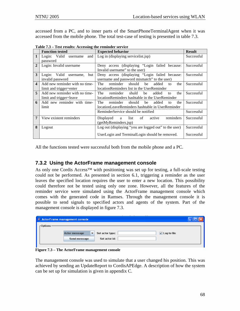
NTNU 2005 Location-based services using WLAN
68
accessed from a PC, and to inner parts of the SmartPhoneTerminalAgent when it was accessed from the mobile phone. The total test-case of testing is presented in table 7.3. Table 7.3 – Test results: Accessing the reminder service Function tested Expected behavior Result 1 Login: Valid username and
password Log in (displaying servicelist.jsp) Successful
2 Login: Invalid username Deny access (displaying “Login failed because: Invalid username” to the user)
Successful
3 Login: Valid username, but invalid password
Deny access (displaying “Login failed because: username and password mismatch” to the user)
Successful
4 Add new reminder with no time-limit and trigger=enter
The reminder should be added to the locationReminders list in the UserReminder
Successful
5 Add new reminder with no time-limit and trigger=leave
The reminder shuld be added to the locationReminders hashtable in the UserReminder
Successful
The reminder should be added to the locationLeaveReminders hashtable in UserReminder
Successful 6 Add new reminder with time-limit
ReminderService should be notified Successful 7 View existent reminders Displayed a list of active reminders
(getMyReminders.jsp) Successful
Log out (displaying “you are logged out” to the user) Successful 8 Logout
UserLogin and TerminalLogin should be removed. Successful
All the functions tested were successful both from the mobile phone and a PC.
7.3.2 Using the ActorFrame management console As only one Cordis Access™ with positioning was set up for testing, a full-scale testing could not be performed. As presented in section 6.1, triggering a reminder as the user leaves the specified location requires the user to enter a new location. This possibility could therefore not be tested using only one zone. However, all the features of the reminder service were simulated using the ActorFrame management console which comes with the generated code in Ramses. Through the management console it is possible to send signals to specified actors and agents of the system. Part of the management console is displayed in figure 7.3.
Figure 7.3 – The ActorFrame management console The management console was used to simulate that a user changed his position. This was achieved by sending an UpdateReport to CordisAPEdge. A description of how the system can be set up for simulation is given in appendix C.
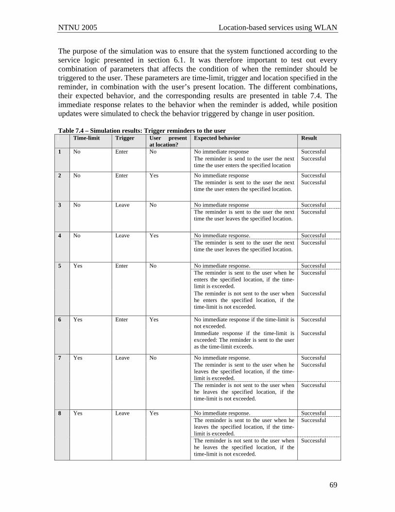
NTNU 2005 Location-based services using WLAN
69
The purpose of the simulation was to ensure that the system functioned according to the service logic presented in section 6.1. It was therefore important to test out every combination of parameters that affects the condition of when the reminder should be triggered to the user. These parameters are time-limit, trigger and location specified in the reminder, in combination with the user’s present location. The different combinations, their expected behavior, and the corresponding results are presented in table 7.4. The immediate response relates to the behavior when the reminder is added, while position updates were simulated to check the behavior triggered by change in user position. Table 7.4 – Simulation results: Trigger reminders to the user Time-limit Trigger User present
at location? Expected behavior Result
No immediate response Successful 1 No Enter No The reminder is send to the user the next time the user enters the specified location
Successful
No immediate response Successful 2 No Enter Yes The reminder is sent to the user the next time the user enters the specified location.
Successful
No immediate response Successful 3 No Leave No The reminder is sent to the user the next time the user leaves the specified location.
Successful
No immediate response. Successful 4 No Leave Yes The reminder is sent to the user the next time the user leaves the specified location.
Successful
No immediate response. Successful The reminder is sent to the user when he enters the specified location, if the time-limit is exceeded.
Successful 5 Yes Enter No
The reminder is not sent to the user when he enters the specified location, if the time-limit is not exceeded.
Successful
No immediate response if the time-limit is not exceeded.
Successful 6 Yes Enter Yes
Immediate response if the time-limit is exceeded: The reminder is sent to the user as the time-limit exceeds.
Successful
No immediate response. Successful The reminder is sent to the user when he leaves the specified location, if the time-limit is exceeded.
Successful 7 Yes Leave No
The reminder is not sent to the user when he leaves the specified location, if the time-limit is not exceeded.
Successful
No immediate response. Successful The reminder is sent to the user when he leaves the specified location, if the time-limit is exceeded.
Successful 8 Yes Leave Yes
The reminder is not sent to the user when he leaves the specified location, if the time-limit is not exceeded.
Successful

NTNU 2005 Location-based services using WLAN
70
When the reminders were triggered to the user, they were also removed from the system. As presented in these sections, both testing and simulation of the service prove that the implemented functions behave as intended. This implies that all the features presented in section 6.1 are fully implemented and may be utilized by the user. The next chapter proceeds by evaluating possible extensions to the design, both concerning the reminder service and the general system.

NTNU 2005 Location-based services using WLAN
71
8 Extending the design This chapter includes some possible extensions of the design presented in this assignment, both concerning the proposed reminder service and the general design. Section 8.1 handles the first case. This mostly includes additional functionality that would make the service more user-friendly. As the extensions do not lead to major design changes, the section will merely present and highlight the possibilities. Section 8.2 discusses on how the design could be extended to support new services.
8.1 Extending the capabilities of the reminder service The ReminderService may be extended in several ways. This section presents some features that would make the service more user-friendly. They were not implemented in the service, because emphasis was put on aspects concerning the location-based nature of the service. One extension involves creating more user-friendly and sophisticated user interfaces. The interfaces could also be differentiated based on the type of terminal the user is present on, as a PC is capable of handling more graphics and more information on one screen. Additionally, the UserReminder could hold a list of the user’s standard reminders, so that such reminders could easily be chosen. The service should also be extended to include functionality to change a reminder after it is added and to delete reminders before they are triggered. As presented in section 7.2.3, the main advantage of WAP push over SMS is that it enables active content. In the current solution the link in the message pushed to the user leads to the logon page. If functionality to change reminders after it is triggered to the user is introduces, the link should lead directly to the alternative of postponing the specific reminder. These extensions do not introduce new actors to the system, but rather introduce new signals and transitions in the existent actors. The extension of changing reminders also leads to a more advanced solution at the web server, because the user needs to be automatically logged in when accessing the link pushed to him by WAP.
8.2 Extending the design To support other services with various needs, some extensions of the existent design are needed. It is a great challenge to make the design general enough to support a variety of services, yet keep the complexity on an appropriate level. The extended design was conducted with the services presented in section 8.2.2 and 8.2.3 in mind, but emphasis was places on the fact that even more services should be supported by the new design. The following (section 8.2.1) therefore presents the general extensions that are required. The system structure of the extended design resulting from the following sections is presented in appendix B7.

NTNU 2005 Location-based services using WLAN
72
8.2.1 General extensions One type of services that is not supported by the current design is services related to specific locations rather than persons. To support such services, different locations should be supported separately. This leads to mirroring the locations into the system by introducing Location actors. The Location actors are responsible for handling available services at the specified location, and to keep track of the users present at the location. The Location actor can support various needs of different services by letting actors subscribe to updates from the specified location. It should be possible to subscribe to every new movement at the location (either enter or leave or both), or send a single message to the location to get the list of present users at a given moment. To support subscriptions, the Location must keep a list of the actors that are interested in different updates, and forward the newly achieved information according to the specified subscriptions. To be able to reproduce a list of the users present at the location, a list of the users must be continually maintained and updated every time the Location actor receives an update. To keep the Location actor updated with which users that are present at the location, the LocationRegister notifies the relevant Location whenever it receives an indication that a user enters or leaves the location. Figure 8.1 displays a somewhat informal state diagram of the Location actor. The state diagram is far from complete; only aspects relevant to how the Location actor is able to update other actors are included. An actor that subscribe to information from the Location actor is referred to as a service, because the actor normally will represent a service that is dependent on the subscribed information. The first transition refers to a service subscribing to the specified event. The details of the subscription are specified in the signal parameters. The type parameter allows the service to specify the user that the subscription concerns. By setting the type to “allusers” it is also possible to subscribe to updated information about all users at the given location. The trigger parameter states whether the subscription concerns user(s) entering or leaving the location. The subscription is registered by the Location actor, and will not cease to exist before the user unsubscribe (not illustrated in the state diagram). The second transition handles the case where a service is interested in which users that are present at the specific point in time. The Location actor will not register this as a subscription, but rather return a list of the users to the interested actor. The third transition illustrates the Location actor’s behavior as it receives a LocationUpdate. First the trigger of the update is checked, and thereafter the active subscriptions are compared to the update. The LocationUpdate is forwarded to all the services that subscribe to the particular update.
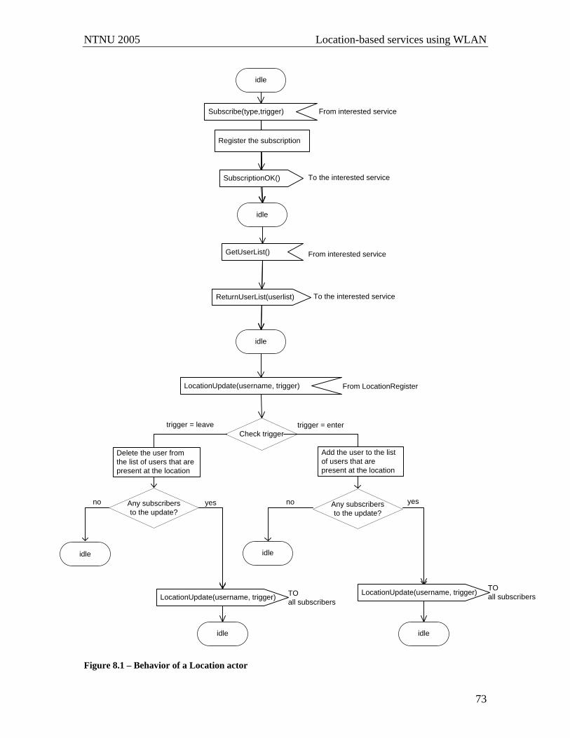
NTNU 2005 Location-based services using WLAN
73
idle
Subscribe(type,trigger)
Check triggertrigger = leave
idle
Delete the user from the list of users that are present at the location
SubscriptionOK()
Register the subscription
From interested service
To the interested service
idle
LocationUpdate(username, trigger)
trigger = enter
Add the user to the list of users that are present at the location
Any subscribers to the update?
yesAny subscribers to the update?
yesno no
idle
LocationUpdate(username, trigger) TOall subscribers
LocationUpdate(username, trigger) TOall subscribers
idle idle
idle
GetUserList()
ReturnUserList(userlist)
From interested service
To the interested service
From LocationRegister
Figure 8.1 – Behavior of a Location actor

NTNU 2005 Location-based services using WLAN
74
Another need that emerges is to support services that need to know every movement of a person, independent of the given location. There are mainly three different alternatives concerning allocation of responsibility of updating such services: Location, LocationRegister or UserPosition. The first alternative implies that a service can subscribe to every location, as described in the previous section. However, as the need is related to the specified user more than to locations, this causes several (possibly superfluous) registration messages, which makes the solution inferior. The alternative of allocating the responsibility to the LocationRegister overcomes some of the problems of the first alternative. The main advantage by using the LocationRegister is that the services only need to communicate with a single actor, as the LocationRegister receives every update concerning every user. Even so, giving the responsibility to the LoationRegister seemed somewhat unnatural, because the LocationRegister would just forward messages that originated in the UserPosition actors. Therefore, the responsibility was given to the UserPosition instead. This alternative also ensures the user more control over his own privacy. By adding a single variable in the UserAgent, the user can control what services he wants to update with his locations, and what services that he wants to prevent from using his positions. The UserPosition actor of the UserAgent already holds a general design, by containing a list of the actors to update with its position. At this moment the UserReminder is the only member of the list, but any service can register itself to the UserPosition to receive position updates. This does not require any changes in the UserPosition, as the general case already is implemented.
8.2.2 Location-based reminders triggered by another person The reminder service presented could be extended to support person-based reminders. Such reminders are triggered by a position update of another person rather than the user’s own motion. A new actor called PersonReminderService is added to the design with the responsibility of handling person-based reminders. The new actor communicates with the UserReminder actor of the UserAgent. UserReminder forwards new person-based reminders to the PersonReminderService actor. The sequence is similar to adding a time-limited reminder. To add a person-based reminder, the user must specify the person the reminder concerns (from here referred to as the reminders active object), at what location the reminder should be triggered and whether he wants to be notified when the person enters or leaves the specified location. When the active object enters or leaves the location, PersonReminderService notifies the UserReminder, which triggers the reminder to the user. To be able to notify the UserReminder, the PersonReminderService must receive position updates on the reminder’s active object. Even though the UserPosition has a general mechanism to update interested actors with new positions, there are some different alternatives of how the PersonReminderSerivce could subscribe to positioning that affects the amount of updates to the service. One extremity is to update the PersonReminderService every time any user moves, while the opposite extremity is to

NTNU 2005 Location-based services using WLAN
75
customize a single subscription for every reminder. While the first alternative leads to a lot of superfluous updates when the user is not an active object for any reminders, the second alternative requires a lot of registrations between actors and allocates some of the responsibility to the UserPosition. To keep all the service logic within the PersonReminderService, and reduce the amount of superfluous messages, the final solution falls somewhere between the extremities: The PersonReminder registers itself to the UserPosition it wants to receive updates from, i.e. the users that are active objects of any reminders. This implies that it is only possible to subscribe to every movement of the user, and the registration process implemented in the UserReminder can be copied by the PersonReminderService.
sd PersonBasedReminder
alt Kari’s new location equals the location in the reminder
alt no subscription on Kari’s positioin exist
per/up@UserPosition PersonReminderService
NewReminder(person,location,trigger)
LocationUpdate(location,trigger)
kari/up@UserPosition
kari/ur@UserReminder
per/ur@UserReminder
NewReminder(reminderID, person,location,trigger)
Check if list of active reminders already contains kari.Add the reminder to the list of reminders
RegisterServiceWithUserPosition()
RegistrationOk()
Check if Kari’s location update should trigger any reminders
PersonReminder(reminderID)
Save the reminder in a list of person-based reminders
Delete the reminder from the list of person-based reminders
ReminderPush(message)
Delete the reminder from the list of reminders
Figure 8.2 – Message sequence diagram of the handling of a new person-based reminder
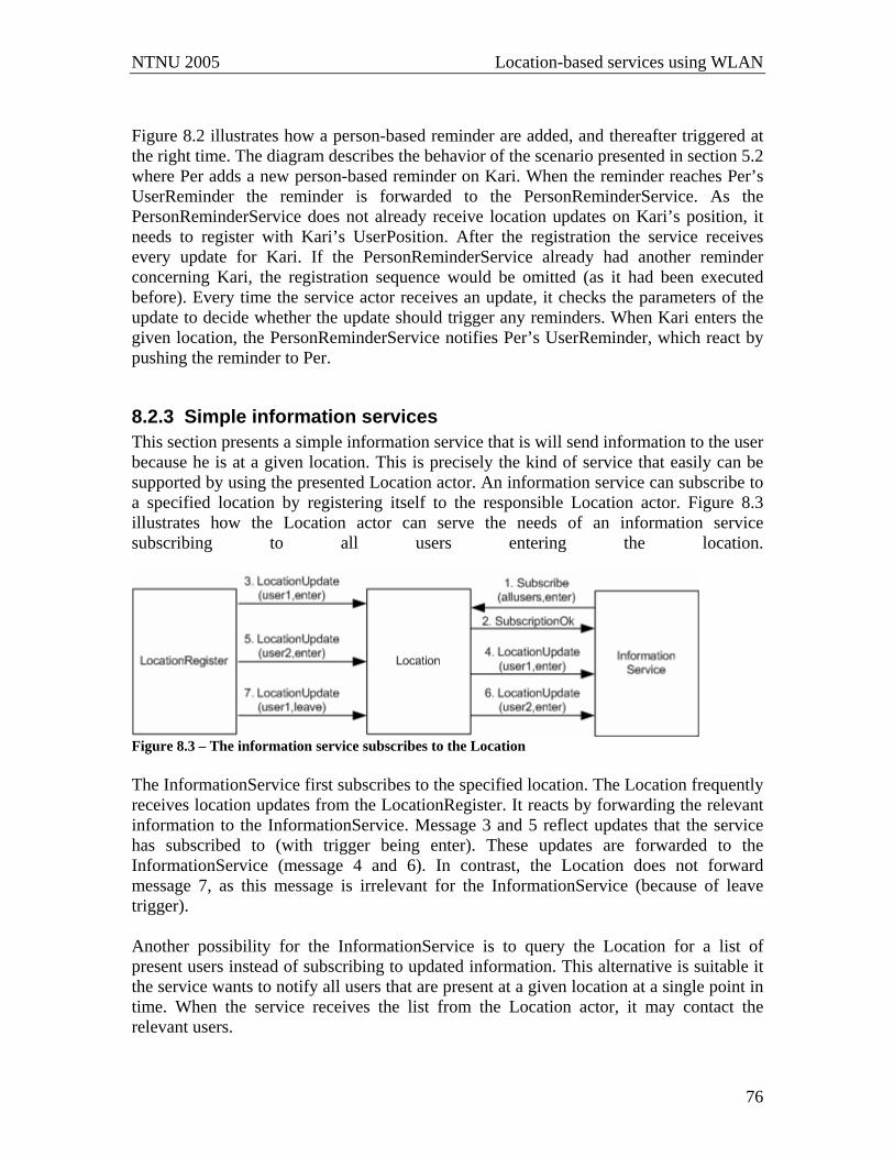
NTNU 2005 Location-based services using WLAN
76
Figure 8.2 illustrates how a person-based reminder are added, and thereafter triggered at the right time. The diagram describes the behavior of the scenario presented in section 5.2 where Per adds a new person-based reminder on Kari. When the reminder reaches Per’s UserReminder the reminder is forwarded to the PersonReminderService. As the PersonReminderService does not already receive location updates on Kari’s position, it needs to register with Kari’s UserPosition. After the registration the service receives every update for Kari. If the PersonReminderService already had another reminder concerning Kari, the registration sequence would be omitted (as it had been executed before). Every time the service actor receives an update, it checks the parameters of the update to decide whether the update should trigger any reminders. When Kari enters the given location, the PersonReminderService notifies Per’s UserReminder, which react by pushing the reminder to Per.
8.2.3 Simple information services This section presents a simple information service that is will send information to the user because he is at a given location. This is precisely the kind of service that easily can be supported by using the presented Location actor. An information service can subscribe to a specified location by registering itself to the responsible Location actor. Figure 8.3 illustrates how the Location actor can serve the needs of an information service subscribing to all users entering the location.
Figure 8.3 – The information service subscribes to the Location The InformationService first subscribes to the specified location. The Location frequently receives location updates from the LocationRegister. It reacts by forwarding the relevant information to the InformationService. Message 3 and 5 reflect updates that the service has subscribed to (with trigger being enter). These updates are forwarded to the InformationService (message 4 and 6). In contrast, the Location does not forward message 7, as this message is irrelevant for the InformationService (because of leave trigger). Another possibility for the InformationService is to query the Location for a list of present users instead of subscribing to updated information. This alternative is suitable it the service wants to notify all users that are present at a given location at a single point in time. When the service receives the list from the Location actor, it may contact the relevant users.

NTNU 2005 Location-based services using WLAN
77
To provide an information service additional actors are included as inner parts of the TerminalAgent and the UserAgentxvi. These actors are responsible for forwarding the information provided by the service to the user. As WAP is the only transmission mode in this specific design, TerminalInformation is only included in the SmartPhoneTerminalAgent, and the actor is connected to the TerminalWap to perform the WAP push to the user.
xvi The actors are added in the system structure of the extended design in appendix B7.
NTNU 2005 Location-based services using WLAN
78
9 Conclusion The basis of this assignment was to develop a location-based service using the Cordis Access™ positioning technology. The service should clearly demonstrate use of positioning, and additionally the system should provide general mechanisms that could be utilized by other services. The design and implementation was performed by using Ramses and ActorFrame concepts, and WAP was used to deliver information to the user. The initial challenge was to come up with an interesting service that demonstrated the relevant aspects. After evaluating how the positioning technology could be utilized for providing services, and exploring some imaginable services in user scenarios, it was decided to proceed with design and implementation of the reminder service. The service manages to demonstrate the effects of a location-based service in a simple and understandable manner. Chapter 2 indicates that location-based services have some general needs and requirements. These needs were identified and made the foundation of a more general system. The purpose of extracting some common needs was to ease further introduction of new services in the system. Therefore emphasis was put on service logic, and several general design principles where important during the design. The designed system succeeds in allocating well-defined responsibilities to each actor and agent. This will ease possible extensions in the future, as the existent actors are available and applicable to new services. Both the general system and the service presented in chapter 6 are fully designed and implemented. The service was tested using a single Cordis Access™, and further simulation was conducted to explore different combinations of parameters in the reminders. The service proved to comply with the specifications given in section 6.1. To complete the general system, chapter 8 proceeds with some possible extensions of the implemented design. The new services reveal some extra features that will enable more service types in the system. The most important addition is mirroring locations into the system. This enables services to relate to users present on given locations. The user is able to communicate with the system using WAP. The experience with this project is that WAP forms an easy way to provide end-services. The major advantage is that it promotes rapid service development. For the services developed and suggested in this assignment, WAP also offer satisfactory flexibility. It is suggested that the system implemented in this assignment should be extended to support more mechanisms to deliver information to the user. The project assignment has been both exciting and informative for the author. I believe that the possibilities within location-based services are huge and to a large extend undiscovered. Developing the service has personally provided a deeper understanding of such services and the related challenges. Because of the total work load, the assignment had to focus on designated areas. Business opportunities were therefore not fully

NTNU 2005 Location-based services using WLAN
79
analyzed. However, the experience and knowledge achieved in this assignment will be useful to perform a master thesis pointed in this direction.

NTNU 2005 Location-based services using WLAN
80
10 References [1] Program for Advanced Telecom Services; http://www.pats.no/ Accessed December 6, 2005. [2] Vossiek M., et.al (2003). Wireless Local Positioning – Concepts, Solutions,
Applications. Radio and Wireless Conference, 2003. Proceedings, 10-13 Aug. 2003 Page(s):219 - 224.
[3] Costa-Requena, J., Tang, H., Espigares, I. (2002). Consistent LBS Solution in Next
Generations of Mobile Networks. Parallel and Distributed Systems, 2002. Proceedings, Ninth International Conference on 17-20 Dec. 2002 Page(s):637 – 642
[4] Mohapatra, D., Suma, S.B. (2005). Survey of Location Based Wireless Services.
Personal Wireless Communications, 2005. ICPWC 2005. 2005 IEEE International Conference on 23-25 Jan. 2005 Page(s):358 - 362.
[5] Flora, C.d., Ficco, M., Russo, S., Vecchio, V. (2005). Indoor and outdoor location
based services for portable wireless devices. Distributed Computing Systems Workshops, 2005. 25th IEEE International Conference on 6-10 June 2005 Page(s):244 - 250.
[6] Stensvold, L.A., Bergvik, S., Brede, S. (2005). mGuide: Lokasjonsbasert guide –
konsept og brukerperspektiv. Telenor Fou, forskningsrapport. http://www.telenor.com/rd/pub/rep05/R_32_2005.pdf [7] Global locate, A-GPS Technology overview; http://www.globallocate.com/A-
GPS/A-GPS_Frameset.htm. Accessed November 19, 2005. [8] Feng, S., Law, C.L. (2002). Assisted GPS and Its Impact on Navigation in
Intelligent Transportation Systems. Intelligent Transportation Systems, 2002. Proceedings. The IEEE 5th International Conference on 2002 Page(s):926 - 931.
[9] Tayal, M. (2005). Location Services in the GSM and UMTS Networks. Personal
Wireless Communications, 2005. ICPWC 2005. 2005 IEEE International Conference on 23-25 Jan. 2005 Page(s):373 - 378.
[10] Fuglem, I., Worren T., Brede S. (2004). De nye lokasjonsteknologiene for
tjenesteproduksjon. Forskningsnotat Telenor FoU. http://www.telenor.com/rd/pub/not04/N_19_04.pdf [11] Netcom. Værvarsel rett på mobilen. https://netcom.no/privat/tjenester/fleretjenster/nytteogunderholdning/varet.html Accessed November 19, 2005.
NTNU 2005 Location-based services using WLAN
81
[12] digi.no. Mange norske RFID-prosjekter i gang. http://www.digi.no/php/art.php?id=210565
Accessed November 10, 2005. [13] digi.no. Gilde sparer millioner på stort RFID-prosjekt.
http://www.digi.no/php/art.php?id=109659. Accessed November 19, 2005. [14] Teleavisen.no. Finn din kompis på mobil. http://www.colibria.com/news/pdf/020704_www.teleavisen.no.pdf?id=958 Accessed November 19, 2005. [15] Netcom. Buddy – finn din nærmeste kompis!
https://netcom.no/privat/tjenester/fleretjenster/nytteogunderholdning/buddy.html Accessed November 19, 2005. [16] Telenor Mobil. Content Provider Access (CPA). http://cpa.telenor.no/cpa/. Accessed November 19, 2005. [17] Telenor Mobil. CPA POS (Positioning). http://cpa.telenor.no/cpa/presentasjonerdoc/CPAwap_smspres_eng.ppt#290,15,CP
A POS (Positioning), Accessed November 20, 2005. [18] Risnes, O. (2002). Location Based Services on Service Platforms with Open
Interfaces. Scientific document. Telenor R&D. http://www.telenor.com/rd/pub/not02/N_67_2002.pdf
[19] Radionor Communications AS. http://www.radionor.no/ Accessed November 9, 2005. [20] Radionor Communcations AS. Cordis RadioEye Locationsation Technology. http://www.radionor.no/Downloads/radionor_white_paper.pdf Accessed November 9, 2005. [21] Radionor Communications AS. Radionor Access. November 2005. To be found on the enclosed CD. [22] Hornby, A.S. (1989) Oxford Advanced Learners Dictionary. Oxford University
Press. [23] Radionor Communications AS. Cordis RadioEye DTD. Last modified October 5,
2005. To be found on the enclosed CD. [24] IETF: The Internet Engineering Task Force, rfc2616: Hypertext Transfer Protocol. Available at: http://www.ietf.org/rfc/rfc2616.txt. Last accessed December 4, 2005. [25] Minq Software. Testing Web Applications.
http://www.minq.se/products/puretest/doc/html/common/webtest/webtest3.html#3.2.State%20Management|outline. Accessed December 4, 2005.
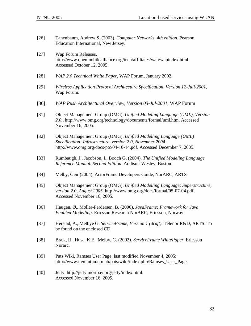
NTNU 2005 Location-based services using WLAN
82
[26] Tanenbaum, Andrew S. (2003). Computer Networks, 4th edition. Pearson
Education International, New Jersey. [27] Wap Forum Releases.
http://www.openmobilealliance.org/tech/affiliates/wap/wapindex.html Accessed October 12, 2005. [28] WAP 2.0 Technical White Paper, WAP Forum, January 2002. [29] Wireless Application Protocol Architecture Specification, Version 12-Juli-2001,
Wap Forum. [30] WAP Push Architectural Overview, Version 03-Jul-2001, WAP Forum [31] Object Management Group (OMG). Unified Modeling Language (UML), Version
2.0., http://www.omg.org/technology/documents/formal/uml.htm, Accessed November 16, 2005.
[32] Object Management Group (OMG). Unified Modelling Language (UML)
Specification: Infrastructure, version 2.0, November 2004. http://www.omg.org/docs/ptc/04-10-14.pdf. Accessed December 7, 2005.
[33] Rumbaugh, J., Jacobson, I., Booch G. (2004). The Unified Modeling Language
Reference Manual. Second Edition. Addison-Wesley, Boston. [34] Melby, Geir (2004). ActorFrame Developers Guide, NorARC, ARTS [35] Object Management Group (OMG). Unified Modelling Language: Superstructure,
version 2.0, August 2005. http://www.omg.org/docs/formal/05-07-04.pdf, Accessed November 16, 2005. [36] Haugen, Ø., Møller-Perdersen, B. (2000). JavaFrame: Framework for Java
Enabled Modelling. Ericsson Research NorARC, Ericsson, Norway. [37] Herstad, A., Melbye G. ServiceFrame, Version 1 (draft). Telenor R&D, ARTS. To
be found on the enclosed CD. [38] Bræk, R., Husa, K.E., Melby, G. (2002). ServiceFrame WhitePaper. Ericsson
Norarc. [39] Pats Wiki, Ramses User Page, last modified November 4, 2005:
http://www.item.ntnu.no/lab/pats/wiki/index.php/Ramses_User_Page [40] Jetty. http://jetty.mortbay.org/jetty/index.html. Accessed November 16, 2005.
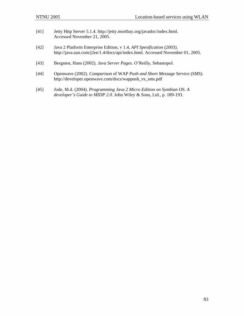
NTNU 2005 Location-based services using WLAN
83
[41] Jetty Http Server 5.1.4. http://jetty.mortbay.org/javadoc/index.html. Accessed November 21, 2005. [42] Java 2 Platform Enterprise Edition, v 1.4, API Spesification (2003),
http://java.sun.com/j2ee/1.4/docs/api/index.html. Accessed November 01, 2005. [43] Bergsten, Hans (2002). Java Server Pages. O’Reilly, Sebastopol. [44] Openwave (2002). Comparison of WAP Push and Short Message Service (SMS). http://developer.openwave.com/docs/wappush_vs_sms.pdf [45] Jode, M.d. (2004). Programming Java 2 Micro Edition on Symbian OS. A
developer’s Guide to MIDP 2.0. John Wiley & Sons, Ltd., p. 189-193.
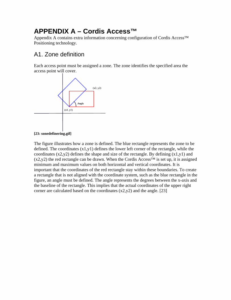
APPENDIX A – Cordis Access™ Appendix A contains extra information concerning configuration of Cordis Access™ Positioning technology. A1. Zone definition Each access point must be assigned a zone. The zone identifies the specified area the access point will cover.
[23: sonedefinering.gif] The figure illustrates how a zone is defined. The blue rectangle represents the zone to be defined. The coordinates (x1,y1) defines the lower left corner of the rectangle, while the coordinates (x2,y2) defines the shape and size of the rectangle. By defining (x1,y1) and (x2,y2) the red rectangle can be drawn. When the Cordis Access™ is set up, it is assigned minimum and maximum values on both horizontal and vertical coordinates. It is important that the coordinates of the red rectangle stay within these boundaries. To create a rectangle that is not aligned with the coordinate system, such as the blue rectangle in the figure, an angle must be defined. The angle represents the degrees between the x-axis and the baseline of the rectangle. This implies that the actual coordinates of the upper right corner are calculated based on the coordinates (x2,y2) and the angle. [23]
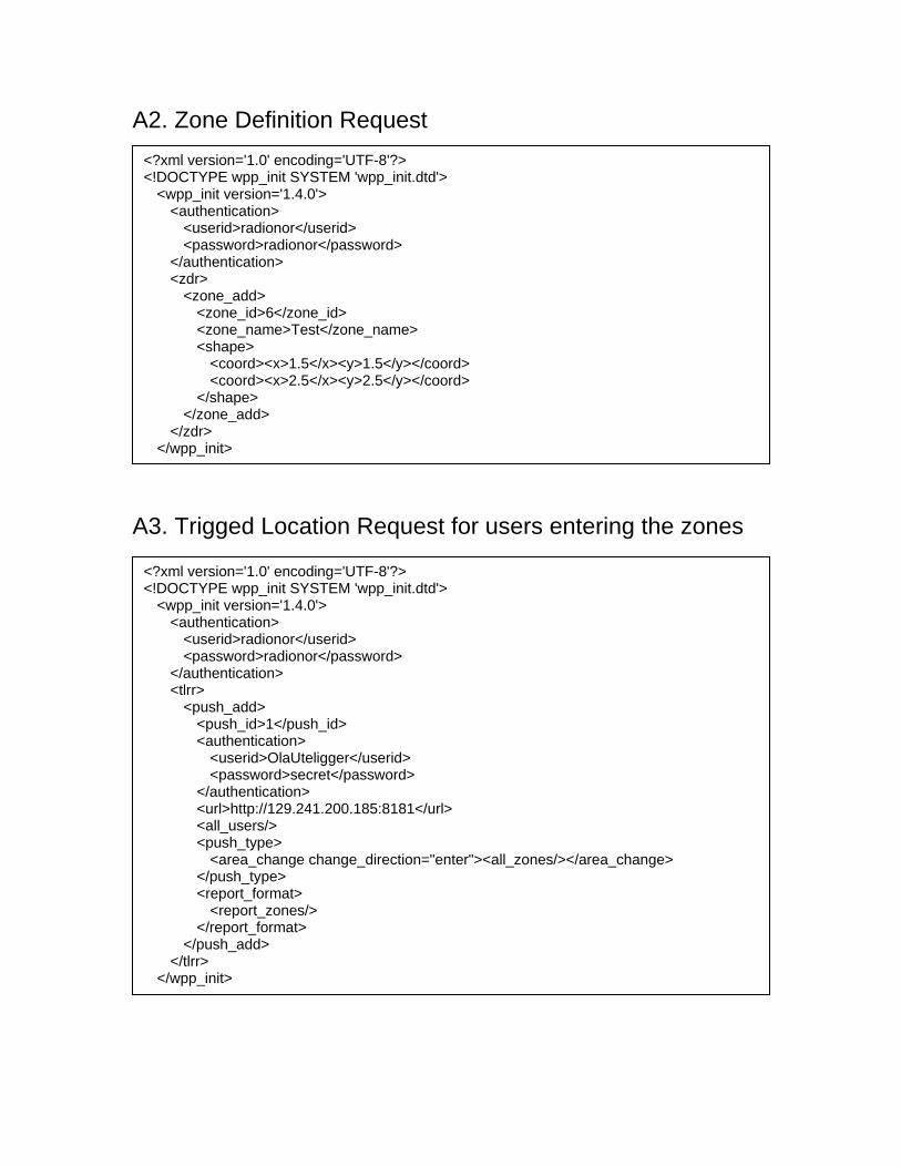
A2. Zone Definition Request
A3. Trigged Location Request for users entering the zones
<?xml version='1.0' encoding='UTF-8'?> <!DOCTYPE wpp_init SYSTEM 'wpp_init.dtd'> <wpp_init version='1.4.0'>
<authentication> <userid>radionor</userid> <password>radionor</password>
</authentication> <zdr>
<zone_add> <zone_id>6</zone_id> <zone_name>Test</zone_name> <shape>
<coord><x>1.5</x><y>1.5</y></coord> <coord><x>2.5</x><y>2.5</y></coord>
</shape> </zone_add>
</zdr> </wpp_init>
<?xml version='1.0' encoding='UTF-8'?> <!DOCTYPE wpp_init SYSTEM 'wpp_init.dtd'> <wpp_init version='1.4.0'>
<authentication> <userid>radionor</userid> <password>radionor</password>
</authentication> <tlrr> <push_add> <push_id>1</push_id> <authentication> <userid>OlaUteligger</userid> <password>secret</password> </authentication> <url>http://129.241.200.185:8181</url> <all_users/> <push_type> <area_change change_direction="enter"><all_zones/></area_change> </push_type> <report_format> <report_zones/> </report_format> </push_add> </tlrr>
</wpp_init>

A4. Trigged Location Request for users leaving the zones <?xml version='1.0' encoding='UTF-8'?> <!DOCTYPE wpp_init SYSTEM 'wpp_init.dtd'> <wpp_init version='1.4.0'>
<authentication> <userid>radionor</userid> <password>radionor</password>
</authentication> <tlrr> <push_add> <push_id>2</push_id> <authentication> <userid>OlaUteligger</userid> <password>secret</password> </authentication> <url>http://129.241.200.185:8181</url> <all_users/> <push_type> <area_change change_direction="leave"><all_zones/></area_change> </push_type> <report_format> <report_zones/> </report_format> </push_add> </tlrr>
</wpp_init>
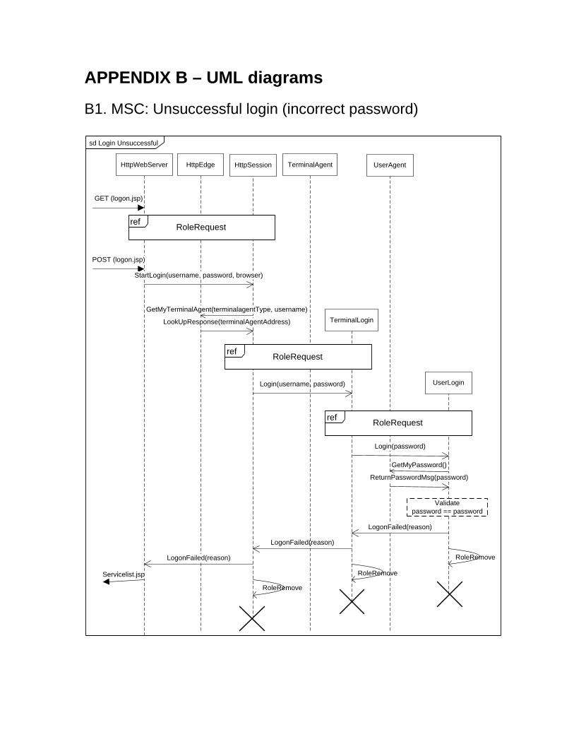
APPENDIX B – UML diagrams B1. MSC: Unsuccessful login (incorrect password)
sd Login Unsuccessful
HttpWebServer HttpSession
UserLogin
GET (logon.jsp)
Servicelist.jsp
HttpEdge
POST (logon.jsp)
TerminalLogin
UserAgent
Login(username, password)
StartLogin(username, password, browser)
GetMyTerminalAgent(terminalagentType, username)
Login(password)
GetMyPassword()
ReturnPasswordMsg(password)
Validatepassword == password
LogonFailed(reason)
LogonFailed(reason)
LogonFailed(reason)
LookUpResponse(terminalAgentAddress)
ref RoleRequest
TerminalAgent
ref RoleRequest
ref RoleRequest
RoleRemove
RoleRemove
RoleRemove
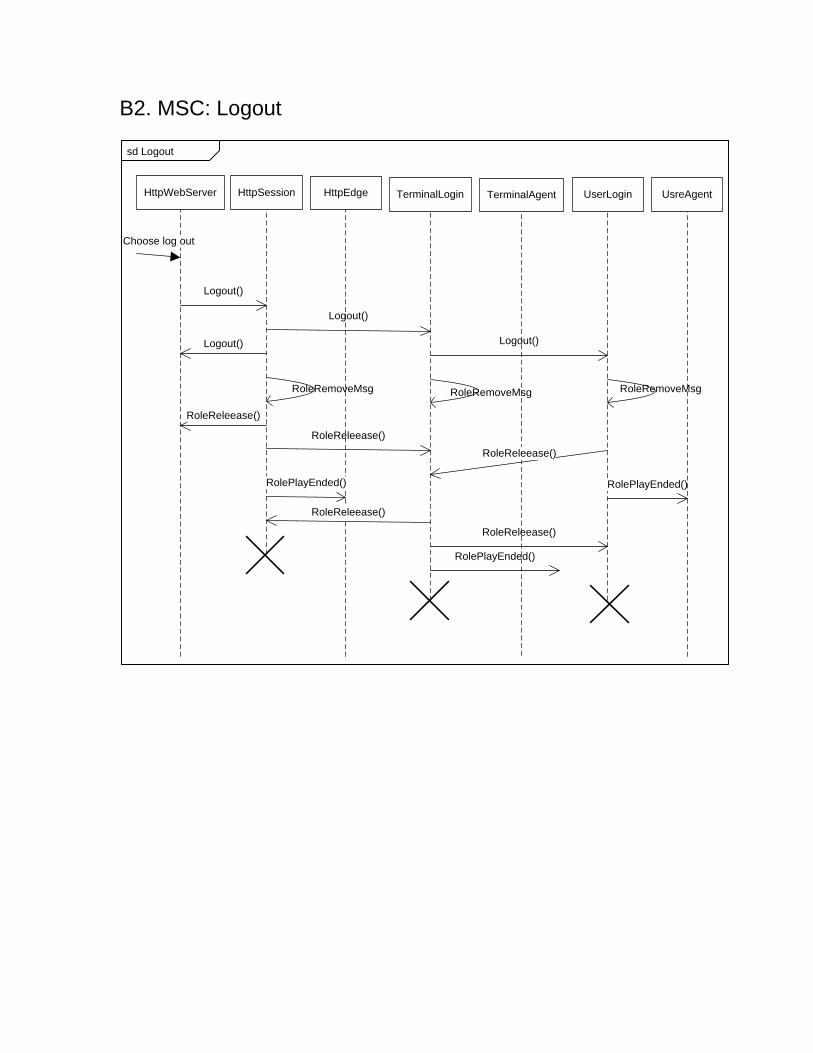
B2. MSC: Logout
sd Logout
HttpWebServer HttpSession UserLogin
Choose log out
TerminalLogin
Logout()
Logout()
Logout()
Logout()
RoleReleease()
RoleReleease()
HttpEdge
RolePlayEnded()
RoleReleease()
RoleReleease()
RolePlayEnded()
TerminalAgent
RolePlayEnded()
RoleReleease()
UsreAgent
RoleRemoveMsgRoleRemoveMsg RoleRemoveMsg
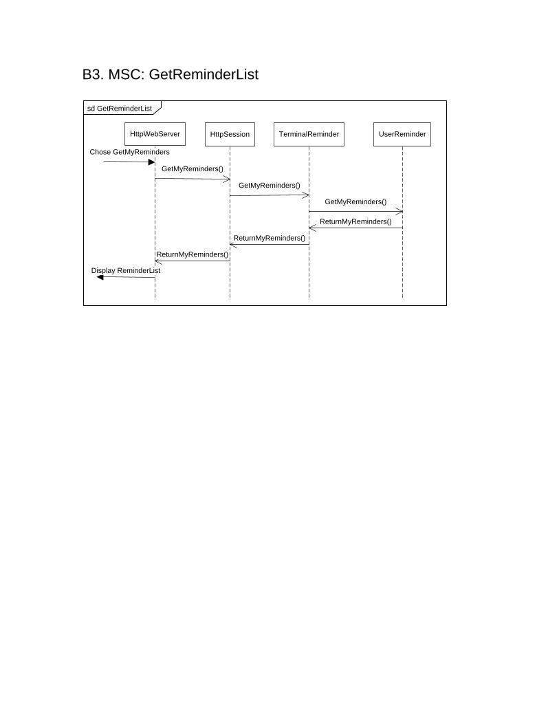
B3. MSC: GetReminderList
sd GetReminderList
HttpWebServer HttpSession UserReminderTerminalReminder
Chose GetMyReminders
GetMyReminders()
GetMyReminders()
ReturnMyReminders()
GetMyReminders()
ReturnMyReminders()
ReturnMyReminders()
Display ReminderList
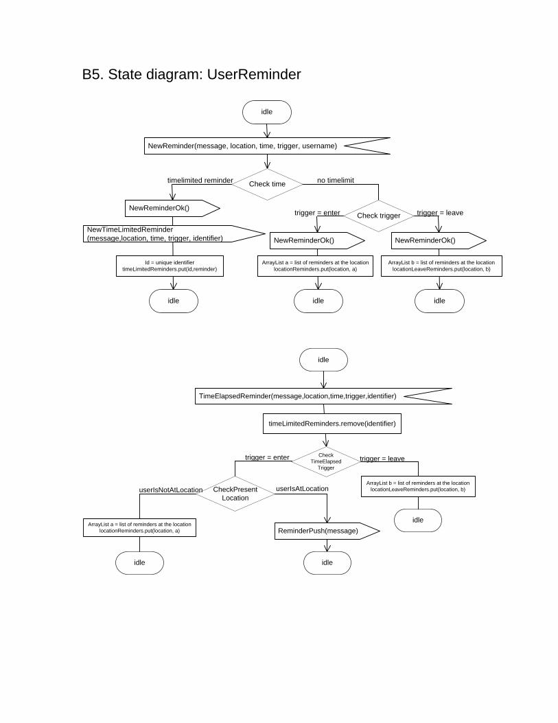
B5. State diagram: UserReminder
idle
NewReminder(message, location, time, trigger, username)
NewReminderOk()
idle
timelimited reminder no timelimit
NewTimeLimitedReminder(message,location, time, trigger, identifier)
Id = unique identifiertimeLimitedReminders.put(id,reminder)
trigger = enter trigger = leave
NewReminderOk()
idle
ArrayList a = list of reminders at the locationlocationReminders.put(location, a)
NewReminderOk()
idle
ArrayList b = list of reminders at the locationlocationLeaveReminders.put(location, b)
Check trigger
Check time
idle
TimeElapsedReminder(message,location,time,trigger,identifier)
timeLimitedReminders.remove(identifier)
idle
Check TimeElapsed
Trigger
trigger = enter trigger = leave
ArrayList b = list of reminders at the locationlocationLeaveReminders.put(location, b)CheckPresent
LocationuserIsNotAtLocation userIsAtLocation
idle
ReminderPush(message)
idle
ArrayList a = list of reminders at the locationlocationReminders.put(location, a)

idle
RegisterServiceWithUserPosition(UserpositionAddress)
RegisterWithUserPosition(UserPositionAddress)
idle
UpdateActiveTerminal
idle
LocationUpdate(location, trigger)
trigger=enter
Update Location
Check EnterReminders
Active EnterReminders exist
No active EnterReminders
ReminderPush(message) For all activated reminders
idle
idle
trigger=leave
No active LeaveRemindersCheck
LeaveReminders
Active LeaveReminders exist
ReminderPush(message)
idle
For all activated reminders
idle
Check LocationUpdate
Trigger
GetMyReminders()
ReturnMyReminders(myReminders)

B6. State diagram of HttpSession

ready
NewReminder GetMyReminders
waitNewReminderResponse
NewReminder TO TerminalReminder
NewReminderOk NewReminderFailed
NewReminderOk NewReminderFailed
readyready
GetMyReminders TO TerminalReminder
ready
ReturnMyReminders
ready
ReturnMyReminders
ready
Logout
Logout
Logout
RoleRemoveMsg
TO TerminalLogin
TO SELF
idle
TO HttpWebServerTO HttpWebServer
TO HttpWebServer
TO HttpWebServer
StartReminderService
RoleRequestMsg TO TerminalAgent
waitRoleConfirm
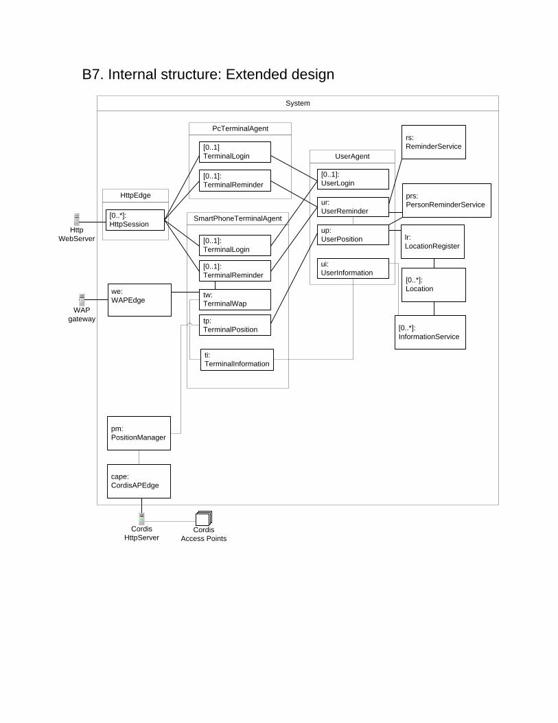
B7. Internal structure: Extended design
System
SmartPhoneTerminalAgentup:UserPosition
[0..1]:UserLogin
ur:UserReminder
UserAgent
HttpEdge
pm:PositionManager
cape:CordisAPEdge
WAPgateway
HttpWebServer
[0..1]TerminalLogin
[0..1]:TerminalReminder
PcTerminalAgent
[0..1]:TerminalLogin
[0..1]:TerminalReminder
tw:TerminalWap
tp:TerminalPosition
Cordis Access Points
CordisHttpServer
lr:LocationRegister
rs:ReminderService
[0..*]:HttpSession
we:WAPEdge
[0..*]:Location
[0..*]:InformationService
ui:UserInformation
ti:TerminalInformation
prs:PersonReminderService

Appendix C – Simulating the system This appendix describes how the system can be simulated using the ActorFrame management console. To simulate the system, start up start.java in the simulation project. A ConfigurationManager is added to the design to ease simulation of the system. To automatically create some terminals and users, send the signal no.ntnu.item.service.position.configuration.StartConfiguration to sys/configuration@ConfigurationManager, as illustrated in the figure below.
The parameters of the users and terminal that are automatically created are given in table. Username Password Phone terminal PC terminal User1 p1 Mac: 00:02:2d:a5:9f:3a
Phonenumber: 97499511 Mac: PC:11
User2 p2 Mac: SP:22 Phonenumber: 95812042
Mac: PC:22
User3 p3
Mac: PC:33
User4 p4
Mac: PC:44
The values of the parameters may be found in the following file: no.ntnu.item.service.position.configuration.configurationmanager.ConfigurationData. To simulate that a user enters a new location: send no.ntnu.item.edge.position.cordisapedge.messages.UpdateReport to sys/cape@CordisAPEdge. The input parameters are MAC address, location (i.e. zone), timestamp and trigger(i.e. enter or leave), respectively. The zone is a number between 1 and 6. The value of the timestamp is irrelevant for further processing at this time. To add three reminders at once send no.ntnu.item.service.position.configuration.AddReminders to sys/configuration@ConfigurationManager. Before the simulation is started, the parameters in the reminders must be set in ReminderData.java.
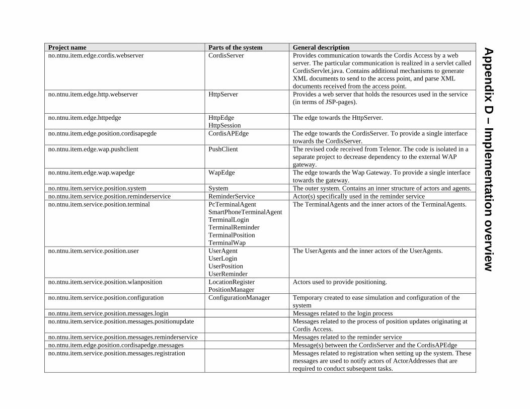
Project name Parts of the system General description no.ntnu.item.edge.cordis.webserver CordisServer Provides communication towards the Cordis Access by a web
server. The particular communication is realized in a servlet called CordisServlet.java. Contains additional mechanisms to generate XML documents to send to the access point, and parse XML documents received from the access point.
no.ntnu.item.edge.http.webserver HttpServer Provides a web server that holds the resources used in the service (in terms of JSP-pages).
no.ntnu.item.edge.httpedge HttpEdge HttpSession
The edge towards the HttpServer.
no.ntnu.item.edge.position.cordisapegde CordisAPEdge The edge towards the CordisServer. To provide a single interface towards the CordisServer.
no.ntnu.item.edge.wap.pushclient PushClient The revised code received from Telenor. The code is isolated in a separate project to decrease dependency to the external WAP gateway.
no.ntnu.item.edge.wap.wapedge WapEdge The edge towards the Wap Gateway. To provide a single interface towards the gateway.
no.ntnu.item.service.position.system System The outer system. Contains an inner structure of actors and agents. no.ntnu.item.service.position.reminderservice ReminderService Actor(s) specifically used in the reminder service no.ntnu.item.service.position.terminal PcTerminalAgent
SmartPhoneTerminalAgent TerminalLogin TerminalReminder TerminalPosition TerminalWap
The TerminalAgents and the inner actors of the TerminalAgents.
no.ntnu.item.service.position.user UserAgent UserLogin UserPosition UserReminder
The UserAgents and the inner actors of the UserAgents.
no.ntnu.item.service.position.wlanposition LocationRegister PositionManager
Actors used to provide positioning.
no.ntnu.item.service.position.configuration ConfigurationManager Temporary created to ease simulation and configuration of the system
no.ntnu.item.service.position.messages.login Messages related to the login process no.ntnu.item.service.position.messages.positionupdate Messages related to the process of position updates originating at
Cordis Access. no.ntnu.item.service.position.messages.reminderservice Messages related to the reminder service no.ntnu.item.edge.position.cordisapedge.messages Message(s) between the CordisServer and the CordisAPEdge no.ntnu.item.service.position.messages.registration Messages related to registration when setting up the system. These
messages are used to notify actors of ActorAddresses that are required to conduct subsequent tasks.
Appendix D
– Implem
entation overview