Embed Size (px)
Citation preview
Pusa Polytechnic
Department of Electronics & Comm. Engg.
MAJOR PROJECT REPORT ON
ADVANCED SECURITY SYSTEM
By
DEEPAK KUMAR
(263811)
Report Submitted in partial fulfillment for the
award of the degree of Diploma in Engineering,
BTE Delhi.
Pusa Polytechnic Pusa Campus, Pusa Campus, New Delhi-110012
This is to certify that Mr. Deepak
Kumar, whose B.T.E. Roll No. is 263811,
have done the major project on the title
“Advanced Security System” under the
guidance of Mr. Shushil Kumar,……………..
This matter embodied in this project is
genuine work done by student and has
not been submitted to any other institute

for the faithfullment of the requirement of
any cause of study.
I wish him all the success in his life.
H.O.D.
Project Guide

AACCKKNNOOWWLLEEDDGGEEMMEENNTT
We are greatly obliged to MR. I.S.
JAGDEVA, A Managing Director and Mr. J.S.
JAGDEVA Director Marketing of TURBO
CONSULTANCY SERVICES PVT. LTD. For their
valuable suggestions and continuous
encouragements and precious guidance all the
way through the itinerancy of this project
works.
We earnestly express our gratitude to MR.
D.S. RAMOLA, MR. SHUSHIL and MR.
PRASHANT for providing incessant help and
benevolent allegiance throughout the training.
We articulate our gratitude to TURBO
CONSULTANCY SERVICES PVT. LTD. for
providing us the prospect to seize out the
project and to all those who were
unswervingly and circuitously influential in
enabling us to remain devoted to the project.
(DEEPAK KUMAR)
Electronics & Communication Engg.
Pusa Polytechnic, Pusa Campus,
New Delhi
CCOONNTTEENNTTSS
Few Words about CCTV System
Application of CCTV System
Basics of CCTV system
Camera Lens Principles
Types of Cameras
PTZ Dome Type Camera
Fixed Type Camera
Camera Assembling and Installation
Power Supply used in Cameras
Monitors
DVR (Digital Video Recorder)
OFC (Optical Fibre Cable)
Advantage of using OFC
Installation and Accessories Required
Installation of DVR System
AABBOOUUTT TTHHEE CCOOMMPPAANNYY
TURBO (Turbo Consultancy Services Pvt. Ltd.):-
As is made known in the professional circles was founded in the
year 1986 with an objective of providing quality electronic safety
products and related services.
Today, we are one of the very few companies in India with
certification for ISO 9002
OUR DEDICATION:-
1. Research and Development
2. Conception and Manufacture
3. Precision and standards
4. People and Implementation
5. Quality and Service
6. Follow-up and Service that’s what keep Turbo, the standards of
excellence in Security Industries.
OUR EXPERTISE:-
Turbo has expertise in designing, developing all kind of security
and surveillance systems. It is engaged in Research and
Developments, manufacturing installation, marketing and
maintenance of CCTV system as turnkey projects. We specialize an all
types of CCTV cameras, Monitors, Multiplexers, TLVCR, Housing-
Explosion Proof, Fire Proof, Weather Proof, Pan & Tilt, P.A. Systems,
Video through Telephone Lines, Control Panels, tailor made system,
Computerized CCTV Control systems, Integrated system for Fire,

Security Access Control & Frequency Jammers, Intruder Alarm
System.
We also have expertise in Traffic Monitoring Systems, Traffic
Speed RADARs, Red Speed Camera systems, and Breath Analyzers
(ALCOMETER), Traffic Enforcement System.
OUR OBJECTIVES:-
“Honesty, Creation, Quality and Satisfaction” are our quality
policy. Turbo always keep in mind these objectives and is all set to
become not only national but international ideal and superlative
company. Turbo’s ambition and reputation are reinforced by a solid
business infrastructure. Our team of highly skilled individuals is
dedicated to providing an exceptional level of service to our
customers. As a manufacturer and supplier, we strive to ensure that
our products are as innovative as our market.
OUR MISSION STATEMENT:-
Turbo will attain a leadership position in the security industry
by profitable supplying globally competitive products and systems. It
will achieve this by attaining the highest levels of organization
productivity, earning the trust of its customers and associates and
providing a fulfilling live hood to its employees.
AAPPLLIICCAATTIIOONNSS OOFF CCCCTTVV SSYYSSTTEEMMSS
Banks and offices: To monitor undisciplined staff, security problems,
unwanted visitors, unsatisfactory customer service and locker room.
Factories and Production Department: To tackle to go slow tactics by
workers, material theft. It can also be used to view a process or operation
where there is no other way of doing it, to ensure safety of operating staff
and to reduce manpower cost. Application areas such as iron ore project,
blast furnace plants, mining and power plants to monitor burners, water
level, and chimney stack.
Medical Hospitals: CCTV assures substantial gain to hospitals, better
patient care, and reduced staff requirement. Better inter department
communications, CCU monitoring to monitor X-Ray, gamma ray or other
radiation treatment without the staff being needlessly exposed to
radiations and to give live telecast from operation theatres for trainee
doctors.
Hotels and Restaurants: For guest security to monitor kitchen activities
and reception, to monitor customer service, undisciplined staff and to relay
stage performances.
Airports, Harbors, Railway Stations, Bus Stations and Cargo: To
display arrival and departure timings, as advertising media, to monitor
crowd, passenger service problems, security problems by terrorists and
anti-social elements and to monitor cargo loading and unloading.
Parking areas: To monitor parking areas at a glance and to divert
vehicles accordingly. CCTV provides assured protection against thefts,
intrusion and sabotage.
Transport and Traffic: Through a network of cameras installed at busy
traffic spots, intersections and squares pictures of impending trouble spots
can be instantly flashed to the control room monitors to plan and order
diversions for the vehicles in time. It is an invaluable aid in recording
evidence of traffic violations or any other unforeseen accidents.
FFEEWW WWOORRDDSS AABBOOUUTT CCCCTTVV SSYYSSTTEEMM
CCTV Equipment is used for security, surveillance and remote
observations all over the world.
Seeing believes hence this is an ideal substitute for human guards.
Any event of vandalism, theft and sabotage can be recorded as proof;
this visual proof facility is not offered by any other security
equipment.
You can catch mischievous and harmful persons in your organization
by monitoring their activities.
It increases efficiency in offices and factories by 30-50%, as workers
are aware of them being watched.
You can claim substantial depreciating yearly.
CCTV system is easy to operate and easy to install.
CCTV is very economical in comparison to monthly overheads,
salaries etc. for security personnel.
CCTV camera can see in complete darkness with low light sensors
and other attachments where human eye cannot see anything.
CCTV system is a result of advance applied technology and you
should utilize this to your advantage.
CCCCTTVV SSYYSSTTEEMM –– BBAASSIICCSS
A close circuit television system consists of video cameras, monitors
and other accessories such as pan and tilt units, video switches remote
control, zoom lenses etc. in a fundamental system CCTV camera sends
video signals through a coaxial cable to a monitor placed at a remote
location. The camera could be rotated or tilted by using remote controlled
pan and tilt unit or just rotated by using a panning unit. The pan/tilt unit
consists of two motors; one in the horizontal direction and one in the
vertical direction. The horizontal motor is used to rotate the camera to
right or to the left whereas the vertical motor is used to move the camera in
upward or downward direction.
When there are number of cameras, there are following possibilities:
Use same number of monitors to display picture from each camera
i.e. if there are four cameras then use four monitors to see pictures.
Use video switches to see pictures of cameras on monitor one by one.
The switcher could be a simple manual switcher or automatic
sequential switchers.
You can see picture of selected cameras in sequence for a time
duration, which is controlled by user.
A quad system may also be used to give up to four pictures from
pictures from different cameras on one monitor at a time in four
quadrants.
There can be a provision for VCR, which can record picture from the
camera.
Function of housing is to protect the camera from dust and adverse
weather conditions. Depending upon the type of application, different
types of housing are used. A zoom lens enables the camera to magnify a
picture area by its zoom power. At wide position of lens you can see more
and in tale position you can enlarge portion of the same area.

TTEELLEEVVIISSIIOONN CCAAMMEERRAA Television camera is used in the transmitter and serves to scan the
optical image of the scene to be televised and develop an output voltage
which varies in accordance with the light intensity of successive elements
of the image i.e. it produces the video signal. The TV camera consists of the
following:
o Camera pick up lens system: - It focuses the light emitted or
reflected from the televised scene or object accurately on the
photosensitive surface of the camera tube.
o Camera tube: - It develops an output voltage, which varies in
accordance with light intensity of the successive elements of the
image formed on it photosensitive surface.
o Video Processing Circuit: - It amplifies the video signal obtained
from the camera tube, provides frequency response compensation.
Aperture correction, gamma correction.
Basic principle of TV camera:
When minute details of a picture are taken into account, any picture
appears to be composed of small elementary areas of light or shade, which
are known as picture elements. The purpose of a TV tube is to sense each
element independently and develop a signal in electrical form proportional
to the brightness of each element. Light from the scene is focused on a
photosensitive surface known as the image plate, and the optical image
thus formed with a lens system represents light intensity variations of the
scene. The photoelectric properties of the image plate then convert
different light intensities into corresponding electrical variations. In
addition to this photoelectric conversion whereby the optical information is
transduced to electrical charge distribution on the photosensitive image
plate, it is necessary to pick this information as fast as possible. Since
simultaneous picker is not possible, scanning by an electron beam is
resorted to. The electron beam moves across the image plate line by line,
and field to field to provide signal variations in successive order. This
scanning process divides image into its basic picture elements.
CCOOMMPPOONNEENNTTSS OOFF AANN IIPP VVIIDDEEOO SSYYSSTTEEMM
Legend IP domes are part of an overall IP video system. Customers
supply the other components of the system, such as network switches, IP
decoders, and power management equipment.
IP Video System=IP Domes + N/W Switches + IP Decoders +
Power Management Equipment
IP Domes are our cameras which may be PTZ or Fixed Type
Network Switches have been tested and found compatible with Legend
IP domes.
D-LinkDES-3526
D-LinkDES-3550
D-LinkDGS-3024
Nortel 425-24T
Nortel425-48T
IP Decoders:
The following IP decoders have been tested and found compatible with
legend IP domes.
SymNet
Power Management Equipment:
Surge Suppressor
Power conditioner
UPS (uninterruptible power supply)
TTYYPPEESS OOFF CCAAMMEERRAASS We categorized cameras on two basis:
I. On the basis of installation:
We have four types of cameras on this basis, namely
a. Outdoor PTZ Dome Camera
b. Indoor PTZ Dome Camera
c. Indoor Fixed Dome Camera
d. Fixed Camera with Verifocal Lens
II. On the basis of technology:
We have two type of cameras on this basis, namely
a. PTZ (Pan/Tilt/Zoom) Camera
b. Fixed Camera
PPTTZZ CCAAMMEERRAA
Legend IPTM is a line of advanced PTZ domes that stream digital
video. Digital video is easier to transmit, share, and store than
conventional analog video signals. Digital video systems also integrate well
into most communications and media networks and are easily operated
from software applications that manage digital video, such as GE’s
SymSecureTM or SymNavTM. SymSecure is CE’s complete digital video
management software. SymNav is GE’s free digital video viewer that is
provided with each dome. Compatible software applications, like these,
allow you to control your domes and video over an IP (Internet Protocol)
network from computers, instead of using analog keypads, recorders,
multiplexers, and switchers.
Legend IP domes use an MPEG-4 video encoder to compress and
digitize streaming video that is of up to 30fps (frames per second) for
NTSC and up to 25 fps for PAL. At the maximum frame rates, the domes
require a bandwidth from 1 to 2 Mbps (Megabits per second). The MPEG-4
video stream that is created is compatible with GE’s SymDec family if
MPEG-4 recorders, SymNet family of MPEG-4 codecs, and Video
NavigatorTM software. The Legend IP interface is open to allow
compatibility with third party software and recording equipment.
Besides their networking ability, Legend IP domes also feature
powerful cameras, SilkTrakTM direct-drive positioning for smoother camera
travel, a graphical programming interface for easier customization of
camera settings, passcodes for protection against unauthorized access, and
the ability to flash software upgrades over your IP network using a
standard web browser.
The Legend IP protocol is backward compatible with the Digiplex
protocol. We can replace older domes in an existing Digiplex system with
Legends IP domes. We must, however, replace the entire dome (camera,
housing, and mounts), because the hardware is not backward compatible.
IINNSSTTAALLLLAATTIIOONN OOFF AA PPTTZZ CCAAMMEERRAA The installation of domes has been made much easier with many of
the innovations that are now available in the Legend IP line of domes. To
start, all cable connections are now built into the housing. The Ethernet
cable provides both video and data. We can also connect UTP and coaxial
cables for analog video and data, if desired. Cameras operate using the
housing’s memory, since programming is now stored in the housing. This
allows you to replace cameras or move them between housings without
having to reprogram them for each new site.
The general steps for installing dome include:
Preparing the mounting surface and installing the mount (if used)
and housing;
Preparing the cables and wiring the housing;
Addressing the camera site, setting the protocol, and setting the
termination;
Installing the camera assembly;
Installing the bubble; and turning on passcodes, if passcodes are to
be used.
FFIIXXEEDD TTYYPPEE CCAAMMEERRAA We used SV-XP1 fixed IP network color camera that combines
XPosure image technology with digital network capability. The SV-XP1 is
equipped with 10/100Base-T (RJ45) interface and a built-in web server.
The SV-XP1 camera uses MPEG-4 compression for efficient distribution
over a network. The camera also incorporates hybrid technology - it
features both digital and analog output for local monitoring and recording.
SV-XP1 camera system consists of the camera, SymNav software CD,
and a RJ45, RS232 cable for changing IP address.
Other required equipments:
We also need some or all of the following equipment for proper
installation and use of this product:
12VDC 1 Amp Power Supply
Lens
PC, to set the IP address and view video with the SymNav user
interface
CCTV for local monitoring
AADDDDRREESSSSIINNGG TTHHEE CCAAMMEERRAA
For PTZ Camera:
Addressing the camera site and setting the protocol:
The dome provides rotary switches for setting the camera’s site
address and communication protocol. Site addresses can be numbered
from 0 to 1599.
To set the camera’s site address and protocol, do the following:
1. Locate the rotary switches. They are on the smallest and lowest
board that is attached to the upper bracket up inside the housing.
This smallest board is the active housing card (AHC).
2. Determine which setting numbers or letters on the three rightmost
switches must be added together to equal the site number.
3. Determine which setting number or letter on the leftmost switch is
needed to set the protocol.
4. Align the needed characters on each switch with the switch’s white
marker. Be careful that any tool we use to turn the rotary switches
does not slip and damage any board components.
For Fixed Type Camera:
Addressing the camera site and setting the protocol:
Using the supplied RS232 Cable:
1. Connect the RJ45 end of the supplied RS232 cable into the RS485
socket on the rear of the camera.
2. Connect the DB9-F end of the cable into the serial port of the PC.
3. Launch Hyper Terminal on the PC by selecting
Start/Programs/Accessories/Communications/HyperTerminal.
4. Type in My IP Camera in the Connection Description dialog box and
click OK.
5. Select the correct COM port and click OK.
6. Power up the camera. IP Camera should display in the window.
7. Enter? to display the menu.
8. Press 1 for the network settings.
9. Press 2 to change the network settings.
10. Enter the new IP addresses and then press enter.
11. After the Gateway address is entered the camera will reboot with the
new IP settings.
CCOONNNNEECCTTIIOONNSS FFOORR CCAAMMEERRAASS
For PTZ Dome Camera:
For basic operation, we need to connect Ethernet and power cables
to the components in the dome shown in Figure.
The Ethernet connection provides both video and data. For advanced
operation, we can also connect any combination of alarm, relay, or analog
data and video cables to the dome. How many cables we will be feeding
into the housing depends upon how many alarms and relays we are
connecting in addition to the Ethernet and power cables.
Wiring the housing board:
To wire the housing board do the following:
1. Connect the facility Ethernet cable for digital video and data.
2. Connect the facility power cable. Make sure that the power cable is
fed over the top of the upper bracket and down beside the power
connector. Use the provided 2-pin terminal strip. If we are using a
heavier gauge cable, ensure that it is properly seated in the
connector. Power in the Legend IP domes is not polarity sensitive.
When power is received by the housing board through the power
connection, the housing board’s diagnostic power LED will appear
orange. There are additional diagnostic LEDs that indicate the
proper installation of the camera assembly.
It should be noted that all Legend IP domes require a 24VAC
power supply to operate the domes.
3. If we areinstalling alarms and relays, connect the alarm and relay
cables to the two provided 12-pin terminal strips. One is blue and
one is green.
Use relays with a maximum operating voltage of 30 VAC, 30 VDC at
0.5 A.
4. If we are installing analog video, connect the facility analog video
cable.
5. If we are installing analog data, connect the facility analog data
cables to the main connections, which are the orange B and A
terminals on the provided green 4-pin terminal strip.
For Fixed Type Camera:
To make general camera connections do the following:
1. Connect a coaxial cable terminated with BNC connectors between
the VIDEO.OUT connector of the camera and the video in connector
on a test or local monitor.
2. Connect a 12 VDC 1Amp power supply.
3. Connect a Cat 5 ethernet cable between the ETHERNET connector of
the camera and a router, multiplexer, or any other network device.
4. As an option connect the supplied RS232 cable to the RS485
connector on the camera and a COM port on our PC to configure our
IP addresses.
DDVVRR--DDIIGGIITTAALL VVIIDDEEOO RREECCOORRDDEERR DX-16-PIN is a 16 channel color digital recorder integrated with a duplex
multiplexer. DX-16P is the PAL version and DX-16-N is the NTSC version.
DVR is the new generation surveillance equipment. This replaces the use of
VCR and multiplexer. Thus avoiding associated compatibility problems
and maintenance headaches.
To increase the versatility of DX-16P ,TCP?IP support is provided for
transferring recorded video clips to a PC over an Ethernet connection. This
facility can be used for backing up and playing of video clips on the PC.
DX-16P can be connected to a 10 base T network using a standard 10 base
Ethernet hub using RJ45 category 2,3,4,or 5 cable. A standard RJ45 port is
provided at the rear of the system for this purpose.
Two sofware modules-DX-FT{ and DX-PLAYER are provided along with
the system. These softwares run on Microsoft Windows 98 operating
system.
Recorded clips can be downloaded from the digital recorder to the PC.
However, the images in the PC cannot be sent to the digital recorder. This
ensures that the image in th erecorder is not altered.
SSYYMMNNEETT:: TTHHEE DDEECCOODDEERR OORR EENNCCOODDEERR The GE SymNet VSC-5RC is the small video streaming unit that is
used for video monitoring and surveillance over IP networks. They use
MPEG-4 compression technologies to deliver high quality video, audio, and
data over 10/100 Base-T networks. The SymNet’s basic function is to either
encode analog video to MPEG-4 digital video or decode MPEG-4 digital
video to analog video.
Power:
It requires the AC power that is stable and within the rated voltage of the
external power supply. If the AC power is likely to have spikes or power
dips, use power line conditioning or an Uninterruptable Power Supply
(UPS).
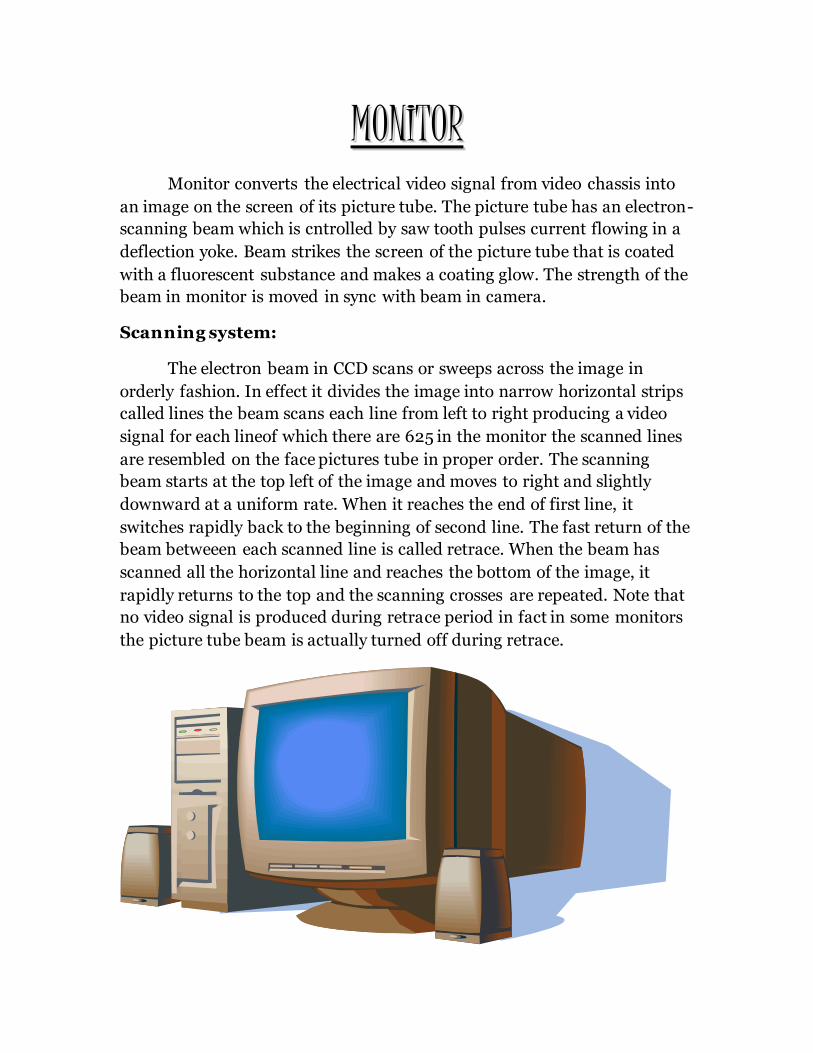
MMOONNIITTOORR
Monitor converts the electrical video signal from video chassis into
an image on the screen of its picture tube. The picture tube has an electron-
scanning beam which is cntrolled by saw tooth pulses current flowing in a
deflection yoke. Beam strikes the screen of the picture tube that is coated
with a fluorescent substance and makes a coating glow. The strength of the
beam in monitor is moved in sync with beam in camera.
Scanning system:
The electron beam in CCD scans or sweeps across the image in
orderly fashion. In effect it divides the image into narrow horizontal strips
called lines the beam scans each line from left to right producing a video
signal for each lineof which there are 625 in the monitor the scanned lines
are resembled on the face pictures tube in proper order. The scanning
beam starts at the top left of the image and moves to right and slightly
downward at a uniform rate. When it reaches the end of first line, it
switches rapidly back to the beginning of second line. The fast return of the
beam betweeen each scanned line is called retrace. When the beam has
scanned all the horizontal line and reaches the bottom of the image, it
rapidly returns to the top and the scanning crosses are repeated. Note that
no video signal is produced during retrace period in fact in some monitors
the picture tube beam is actually turned off during retrace.

NNEETTWWOORRKK A network is a collection of individual computers, connected by some
physical media and networking devices.
![[INSERT PROJECT NAME]€¦ · Project name Project Number [Where applicable] Project Manager Project Controller Project location [Insert brief details of project location, including](https://img.pdfslide.us/doc/110x75/603496f741d854077e52cec0/insert-project-name-project-name-project-number-where-applicable-project-manager.jpg)