Embed Size (px)
Citation preview
Project 2007Project 2007--01: Under01: Under--frequency frequency Load Shedding Standard Load Shedding Standard PRCPRC--006006--1, EOP1, EOP--003003--22
September 17, 2010Rob O’Keefe SDT Chair AEP
Jonathan Glidewell SDT Vice Chair Southern Company
Steve Rueckert WECC Director of Standards
Stephanie Monzon NERC Manager of Regional Standards p g g
Webinar ObjectivesWebinar Objectives2
Review PRC-006-1 History and Next StepsReview PRC 006 1 History and Next Steps
Discuss PRC-006-1 Applicability
Address Issues from Second Ballot
Overview of WECC Variance to PRC-006-1
Questions and Answers
PRCPRC--006006--1 1 History and Next StepsHistory and Next Steps3
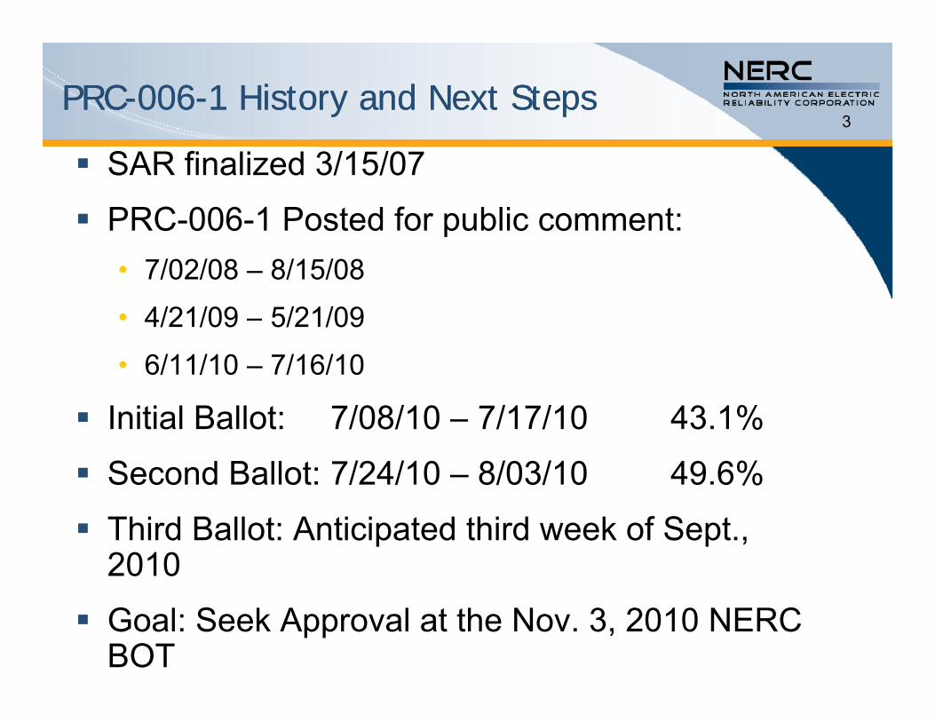
SAR finalized 3/15/07
PRC-006-1 Posted for public comment:PRC 006 1 Posted for public comment:• 7/02/08 – 8/15/08
• 4/21/09 5/21/09• 4/21/09 – 5/21/09
• 6/11/10 – 7/16/10
I iti l B ll t 7/08/10 7/17/10 43 1% Initial Ballot: 7/08/10 – 7/17/10 43.1%
Second Ballot: 7/24/10 – 8/03/10 49.6%
Third Ballot: Anticipated third week of Sept., 2010
Goal: Seek Approval at the Nov. 3, 2010 NERC BOT
ApplicabilityApplicability4
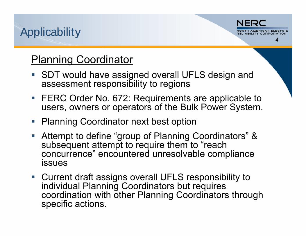
Planning Coordinator SDT would have assigned overall UFLS design and SDT would have assigned overall UFLS design and
assessment responsibility to regions FERC Order No. 672: Requirements are applicable to
users, owners or operators of the Bulk Power System. Planning Coordinator next best option
Att t t d fi “ f Pl i C di t ” & Attempt to define “group of Planning Coordinators” & subsequent attempt to require them to “reach concurrence” encountered unresolvable compliance issuesissues
Current draft assigns overall UFLS responsibility to individual Planning Coordinators but requires
di ti ith th Pl i C di t th hcoordination with other Planning Coordinators through specific actions.

ApplicabilityApplicability5
UFLS Entities(Transmission Owner, Distribution Provider)
In some regions, TOs who do not have end-use load t d t th i l t UFLS t DPconnected to them implement UFLS, not DPs
Separate applicability assigned to TOs for “automatic switching of Elements” where “Elements” are capacitorsswitching of Elements where Elements are capacitors, shunt reactors, transmission lines (R10)
Switching of “Elements” at distribution level not considered significant to BES voltage
Issues from Second BallotIssues from Second Ballot6
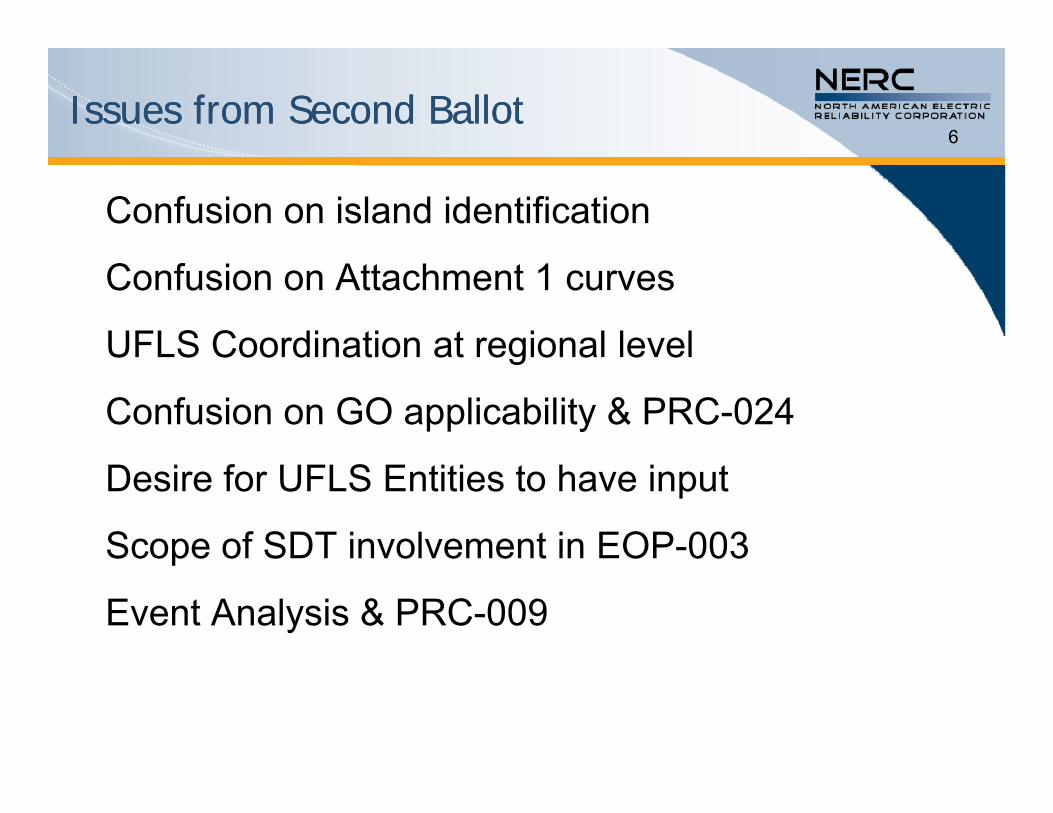
Confusion on island identification
Confusion on Attachment 1 curves
UFLS Coordination at regional levelUFLS Coordination at regional level
Confusion on GO applicability & PRC-024
Desire for UFLS Entities to have input
Scope of SDT involvement in EOP-003p
Event Analysis & PRC-009
Issues from Second BallotIssues from Second Ballot7
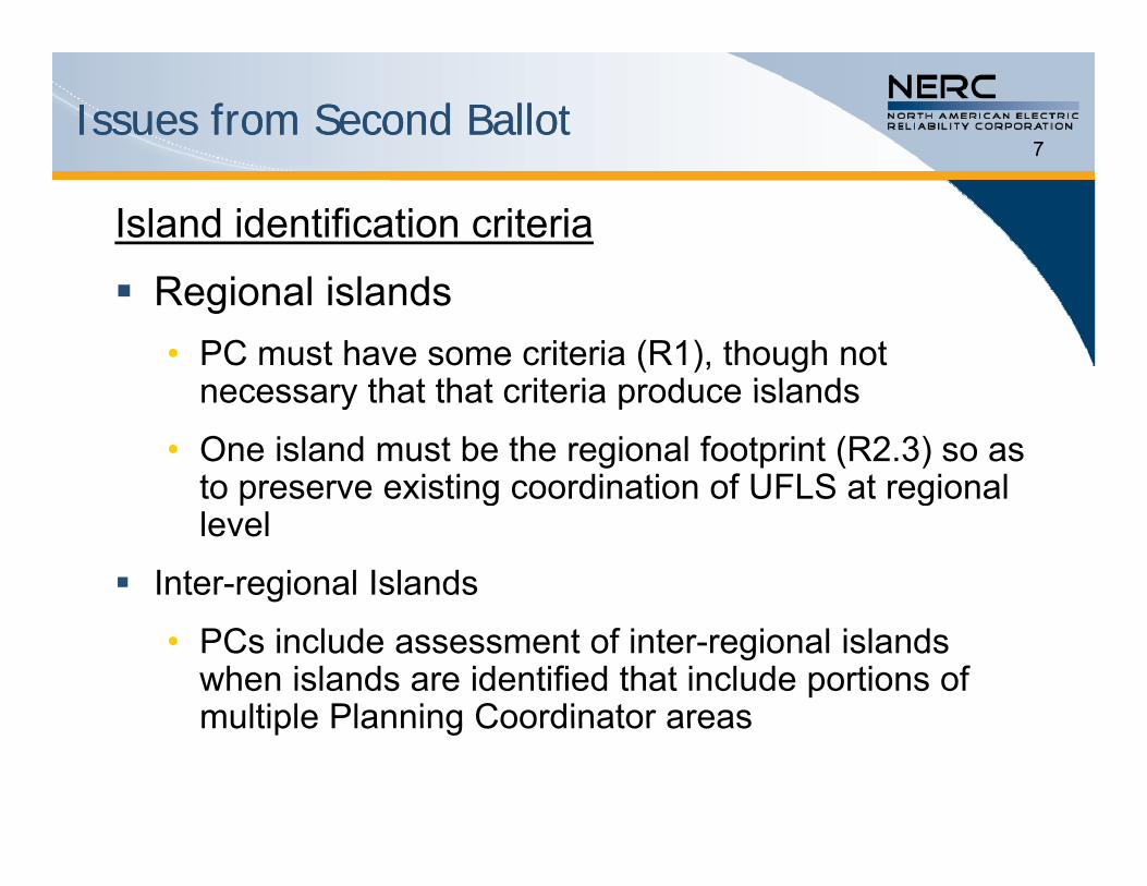
Island identification criteria
Regional islands• PC must have some criteria (R1), though not
necessary that that criteria produce islandsnecessary that that criteria produce islands
• One island must be the regional footprint (R2.3) so as to preserve existing coordination of UFLS at regional p g glevel
Inter-regional Islands
• PCs include assessment of inter-regional islands when islands are identified that include portions of multiple Planning Coordinator areasmultiple Planning Coordinator areas
Issues from Second BallotIssues from Second Ballot8
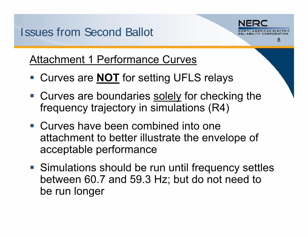
Attachment 1 Performance Curves
C NOT f i UFLS l Curves are NOT for setting UFLS relays
Curves are boundaries solely for checking the f j i i l i (R4)frequency trajectory in simulations (R4)
Curves have been combined into one h b ill h l fattachment to better illustrate the envelope of
acceptable performance
S f Simulations should be run until frequency settles between 60.7 and 59.3 Hz; but do not need to be run longerbe run longer
Issues from Second BallotIssues from Second Ballot9
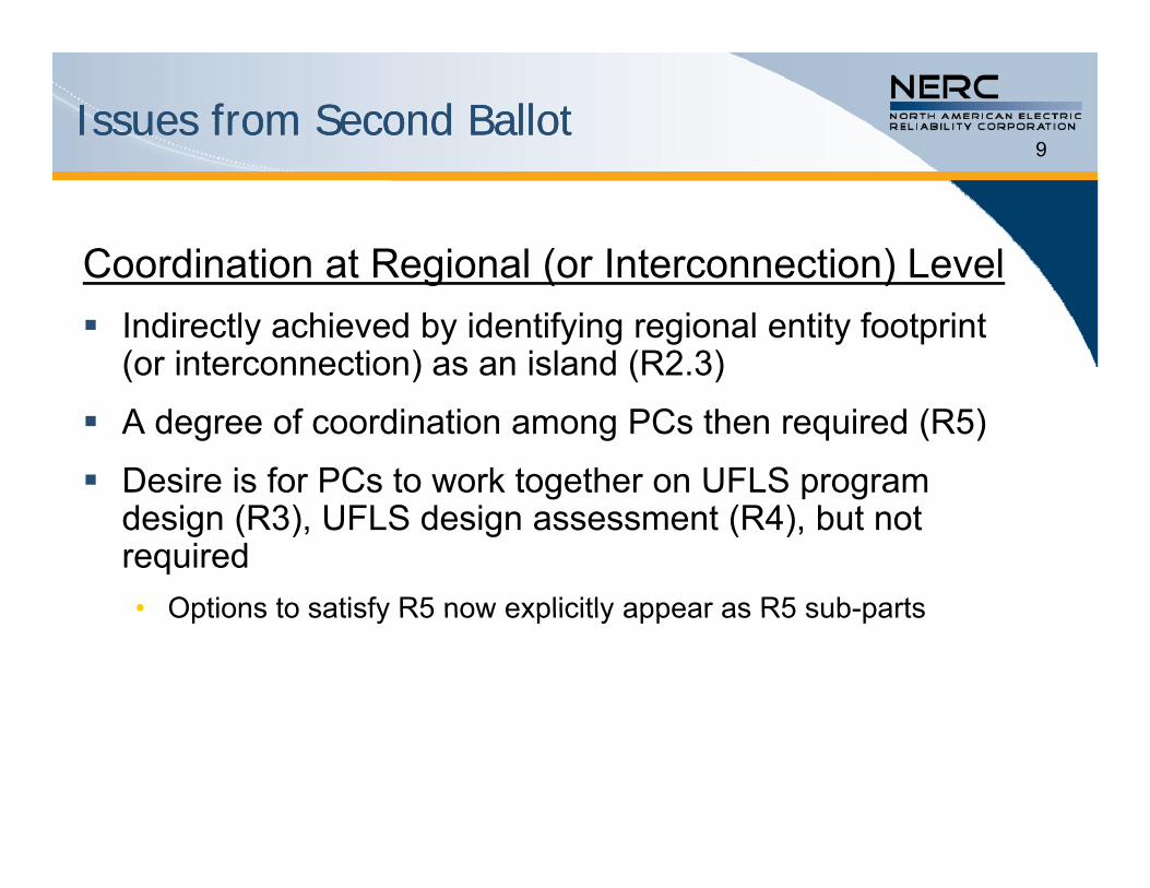
Coordination at Regional (or Interconnection) LevelCoordination at Regional (or Interconnection) Level Indirectly achieved by identifying regional entity footprint
(or interconnection) as an island (R2.3)
A degree of coordination among PCs then required (R5)
Desire is for PCs to work together on UFLS program design (R3), UFLS design assessment (R4), but not required• Options to satisfy R5 now explicitly appear as R5 sub-partsOptions to satisfy R5 now explicitly appear as R5 sub parts
Issues from Second BallotIssues from Second Ballot10
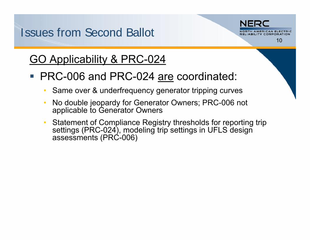
GO Applicability & PRC-024 PRC 006 and PRC 024 are coordinated: PRC-006 and PRC-024 are coordinated:
• Same over & underfrequency generator tripping curves• No double jeopardy for Generator Owners; PRC-006 notNo double jeopardy for Generator Owners; PRC 006 not
applicable to Generator Owners• Statement of Compliance Registry thresholds for reporting trip
settings (PRC-024), modeling trip settings in UFLS design t (PRC 006)assessments (PRC-006)
Issues from Second BallotIssues from Second Ballot11
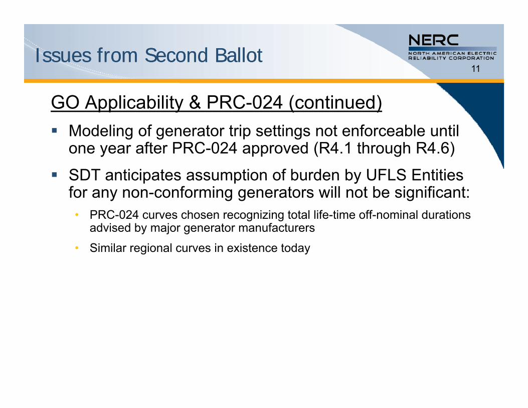
GO Applicability & PRC-024 (continued)M d li f t t i tti t f bl til Modeling of generator trip settings not enforceable until one year after PRC-024 approved (R4.1 through R4.6)
SDT anticipates assumption of burden by UFLS EntitiesSDT anticipates assumption of burden by UFLS Entities for any non-conforming generators will not be significant:• PRC-024 curves chosen recognizing total life-time off-nominal durations
advised by major generator manufacturersadvised by major generator manufacturers
• Similar regional curves in existence today
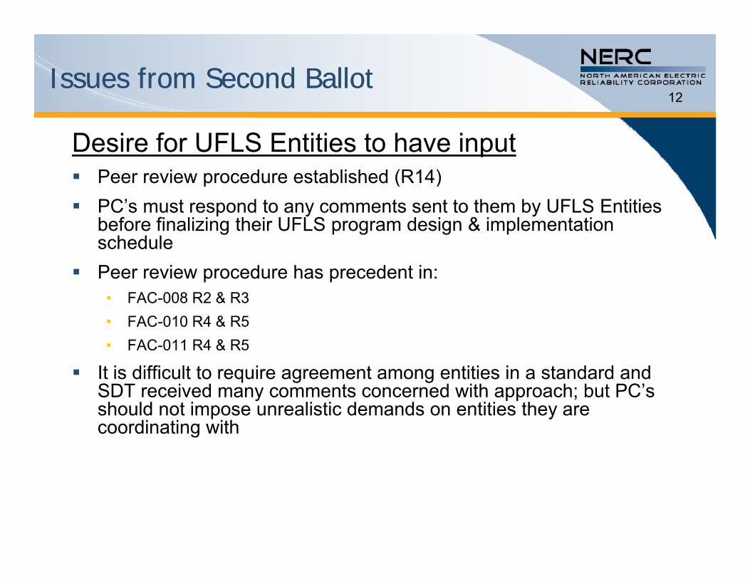
Issues from Second BallotIssues from Second Ballot12
Desire for UFLS Entities to have input Peer review procedure established (R14)Peer review procedure established (R14) PC’s must respond to any comments sent to them by UFLS Entities
before finalizing their UFLS program design & implementation schedule
Peer review procedure has precedent in: • FAC-008 R2 & R3• FAC-010 R4 & R5FAC 010 R4 & R5• FAC-011 R4 & R5
It is difficult to require agreement among entities in a standard and SDT received many comments concerned with approach; but PC’s y pp ;should not impose unrealistic demands on entities they are coordinating with
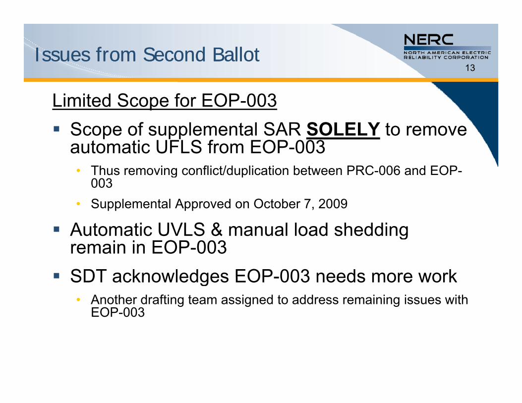
Issues from Second BallotIssues from Second Ballot13
Limited Scope for EOP-003S f l t l SAR SOLELY t Scope of supplemental SAR SOLELY to remove automatic UFLS from EOP-003• Thus removing conflict/duplication between PRC-006 and EOP-g p
003• Supplemental Approved on October 7, 2009
Automatic UVLS & manual load shedding Automatic UVLS & manual load shedding remain in EOP-003
SDT acknowledges EOP-003 needs more work SDT acknowledges EOP-003 needs more work• Another drafting team assigned to address remaining issues with
EOP-003
Issues from Second BallotIssues from Second Ballot14
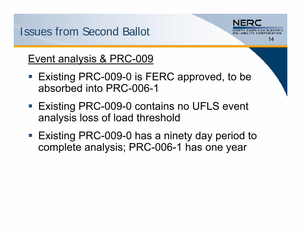
Event analysis & PRC-009
Existing PRC-009-0 is FERC approved, to be absorbed into PRC-006-1
Existing PRC-009-0 contains no UFLS event analysis loss of load threshold
Existing PRC-009-0 has a ninety day period to complete analysis; PRC-006-1 has one year
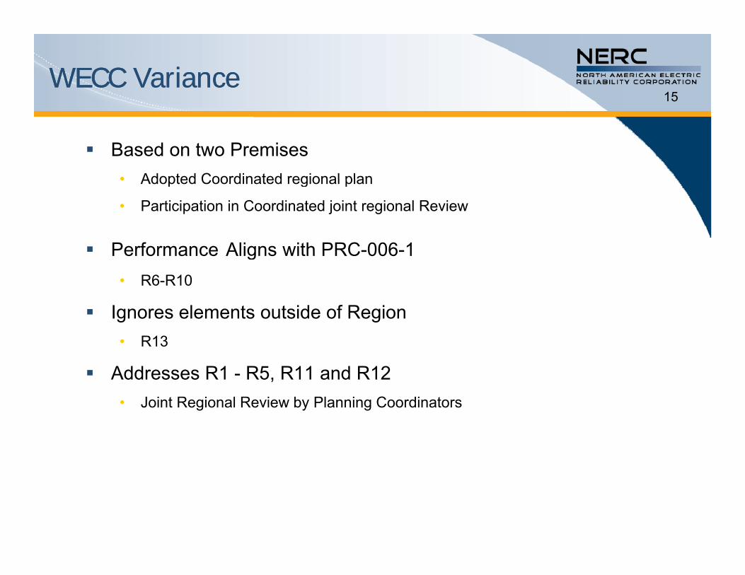
WECC VarianceWECC Variance15
Based on two Premises • Adopted Coordinated regional plan• Adopted Coordinated regional plan
• Participation in Coordinated joint regional Review
Performance Aligns with PRC-006-1 Performance Aligns with PRC-006-1• R6-R10
Ignores elements outside of Region• R13
Addresses R1 - R5, R11 and R12C• Joint Regional Review by Planning Coordinators
Q&AQ&A16
Questions?Questions?
Please Vote Affirmative!!!!!!Please Vote Affirmative!!!!!!
17
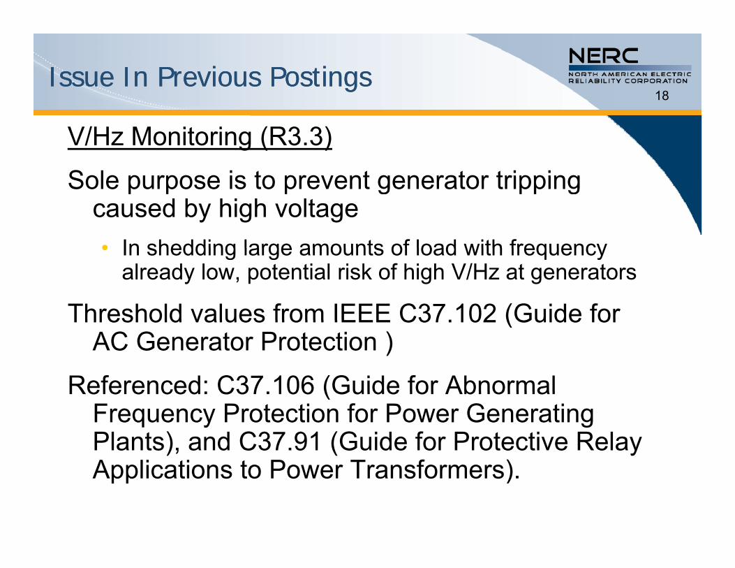
Issue In Previous PostingsIssue In Previous Postings18
V/Hz Monitoring (R3.3)
Sole purpose is to prevent generator trippingSole purpose is to prevent generator tripping caused by high voltage• In shedding large amounts of load with frequency• In shedding large amounts of load with frequency
already low, potential risk of high V/Hz at generators
Threshold values from IEEE C37.102 (Guide forThreshold values from IEEE C37.102 (Guide for AC Generator Protection )
Referenced: C37.106 (Guide for AbnormalReferenced: C37.106 (Guide for Abnormal Frequency Protection for Power Generating Plants), and C37.91 (Guide for Protective Relay A li ti t P T f )Applications to Power Transformers).

REFERENCE REFERENCE –– UFLS StandardUFLS Standard19
R1 Each Planning Coordinator shall develop and document criteria, including consideration of historical events and system studies to select portions of the Bulk Electric System (BES) including interconnected portions of the BESsystem studies, to select portions of the Bulk Electric System (BES), including interconnected portions of the BES in adjacent Planning Coordinator areas and Regional Entity areas that may form islands. [VRF: Medium][Time Horizon: Long-term Planning]
R2 Each Planning Coordinator shall identify one or more islands to serve as a basis for designing its UFLS program including: [VRF: Medium][Time Horizon: Long-term Planning]
2.1 Those islands selected by applying the criteria in Requirement R1, and
2.2 Any portions of the BES designed to detach from the Interconnection (planned islands) as a result of the operation of a relay scheme or Special Protection System, and
2.3 A single island that includes all portions of the BES in either the Regional Entity area or the Interconnection in which the Planning Coordinator’s area resides If a Planning Coordinator’s area resides in multiplein which the Planning Coordinator s area resides. If a Planning Coordinator s area resides in multiple Regional Entity areas, each of those Regional Entity areas shall be identified as an island. Planning Coordinators may adjust island boundaries to differ from regional boundaries by mutual consent where necessary for the sole purpose of producing contiguous regional islands more suitable for simulation.
.
REFERENCE REFERENCE –– UFLS StandardUFLS Standard20
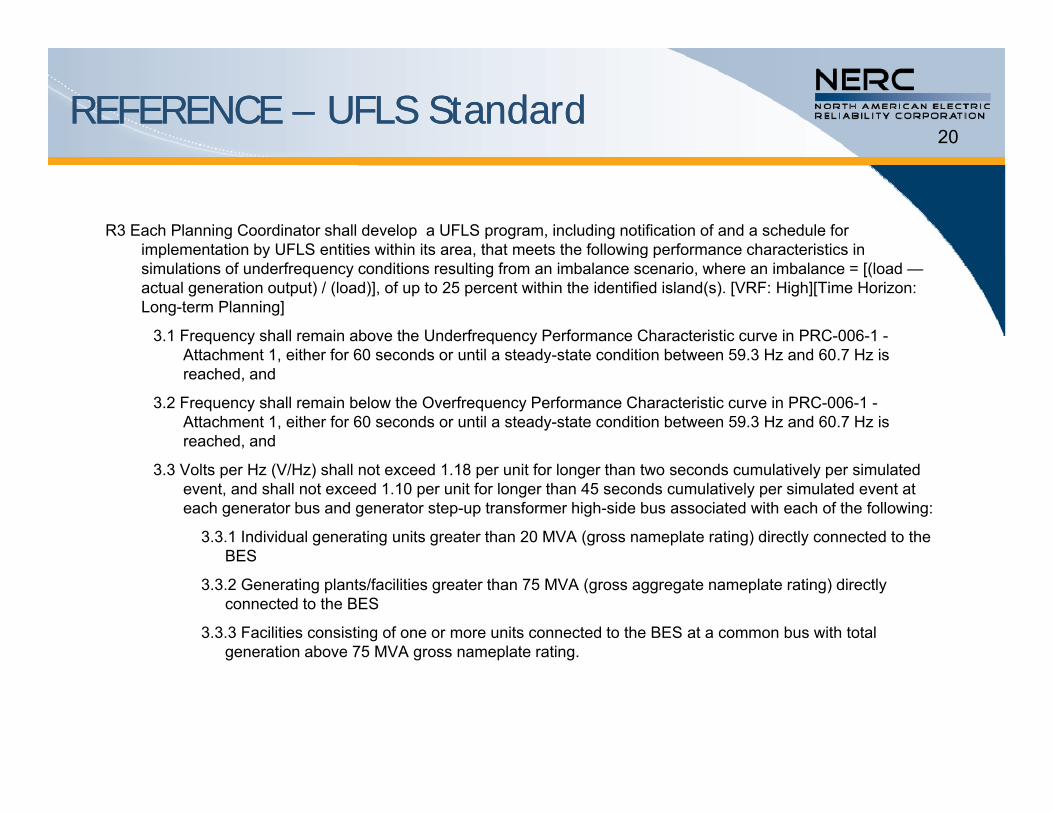
R3 Each Planning Coordinator shall develop a UFLS program, including notification of and a schedule for implementation by UFLS entities within its area that meets the following performance characteristics inimplementation by UFLS entities within its area, that meets the following performance characteristics in simulations of underfrequency conditions resulting from an imbalance scenario, where an imbalance = [(load —actual generation output) / (load)], of up to 25 percent within the identified island(s). [VRF: High][Time Horizon: Long-term Planning]
3.1 Frequency shall remain above the Underfrequency Performance Characteristic curve in PRC-006-1 -Attachment 1 either for 60 seconds or until a steady-state condition between 59 3 Hz and 60 7 Hz isAttachment 1, either for 60 seconds or until a steady-state condition between 59.3 Hz and 60.7 Hz is reached, and
3.2 Frequency shall remain below the Overfrequency Performance Characteristic curve in PRC-006-1 -Attachment 1, either for 60 seconds or until a steady-state condition between 59.3 Hz and 60.7 Hz is reached, and
3.3 Volts per Hz (V/Hz) shall not exceed 1.18 per unit for longer than two seconds cumulatively per simulated event, and shall not exceed 1.10 per unit for longer than 45 seconds cumulatively per simulated event at each generator bus and generator step-up transformer high-side bus associated with each of the following:
3.3.1 Individual generating units greater than 20 MVA (gross nameplate rating) directly connected to the BESBES
3.3.2 Generating plants/facilities greater than 75 MVA (gross aggregate nameplate rating) directly connected to the BES
3.3.3 Facilities consisting of one or more units connected to the BES at a common bus with total generation above 75 MVA gross nameplate rating.
REFERENCE REFERENCE –– UFLS StandardUFLS Standard21
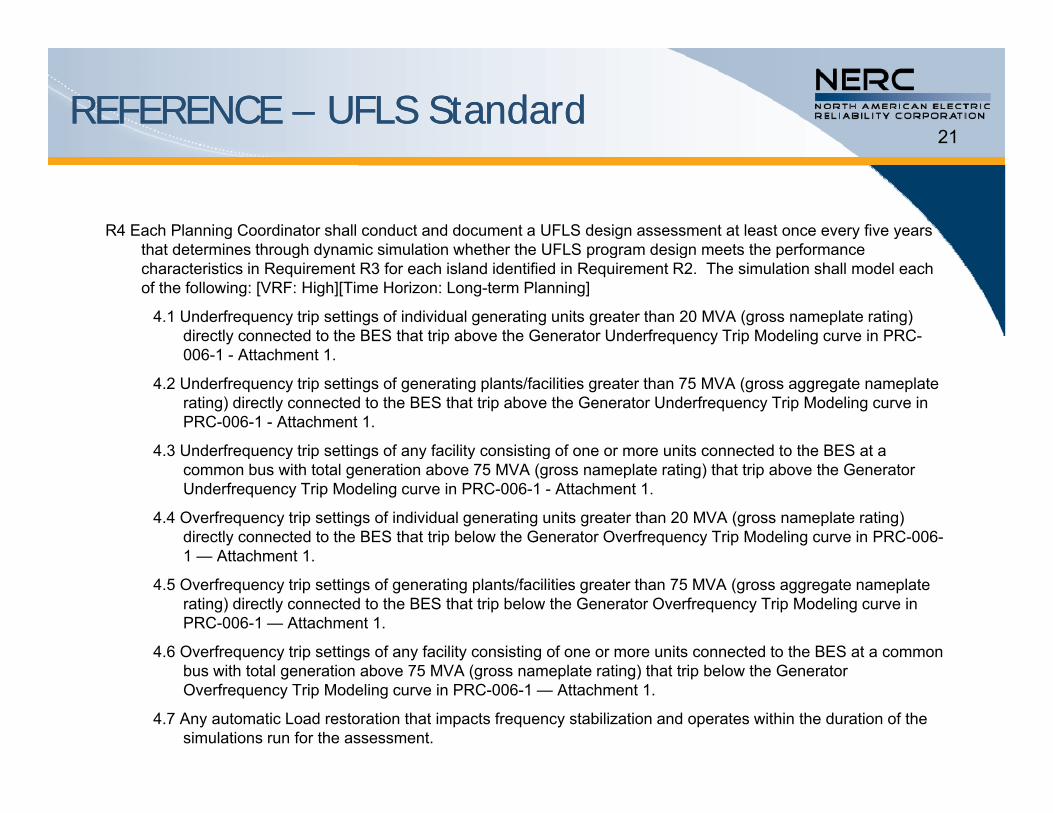
R4 Each Planning Coordinator shall conduct and document a UFLS design assessment at least once every five years that determines through dynamic simulation whether the UFLS program design meets the performancethat determines through dynamic simulation whether the UFLS program design meets the performance characteristics in Requirement R3 for each island identified in Requirement R2. The simulation shall model each of the following: [VRF: High][Time Horizon: Long-term Planning]
4.1 Underfrequency trip settings of individual generating units greater than 20 MVA (gross nameplate rating) directly connected to the BES that trip above the Generator Underfrequency Trip Modeling curve in PRC-006-1 - Attachment 1006-1 - Attachment 1.
4.2 Underfrequency trip settings of generating plants/facilities greater than 75 MVA (gross aggregate nameplate rating) directly connected to the BES that trip above the Generator Underfrequency Trip Modeling curve in PRC-006-1 - Attachment 1.
4.3 Underfrequency trip settings of any facility consisting of one or more units connected to the BES at a q y p g y y gcommon bus with total generation above 75 MVA (gross nameplate rating) that trip above the Generator Underfrequency Trip Modeling curve in PRC-006-1 - Attachment 1.
4.4 Overfrequency trip settings of individual generating units greater than 20 MVA (gross nameplate rating) directly connected to the BES that trip below the Generator Overfrequency Trip Modeling curve in PRC-006-1 — Attachment 1.1 Attachment 1.
4.5 Overfrequency trip settings of generating plants/facilities greater than 75 MVA (gross aggregate nameplate rating) directly connected to the BES that trip below the Generator Overfrequency Trip Modeling curve in PRC-006-1 — Attachment 1.
4.6 Overfrequency trip settings of any facility consisting of one or more units connected to the BES at a common bus with total generation above 75 MVA (gross nameplate rating) that trip below the Generator Overfrequency Trip Modeling curve in PRC-006-1 — Attachment 1.
4.7 Any automatic Load restoration that impacts frequency stabilization and operates within the duration of the simulations run for the assessment.
REFERENCE REFERENCE –– UFLS StandardUFLS Standard22
R5 Each Planning Coordinator, whose area or portions of whose area is part of an island identified by it or another Planning Coordinator which includes multiple Planning Coordinator areas or portions of those areas shallPlanning Coordinator which includes multiple Planning Coordinator areas or portions of those areas, shall coordinate its UFLS program design with all other Planning Coordinators whose areas or portions of whose areas are also part of the same identified island through one of the following: [VRF: Medium][Time Horizon: Long-term Planning]
• Develop a common UFLS program design and schedule for implementation per Requirement R3 among the Planning Coordinators whose areas or portions of whose areas are part of the same identified island orPlanning Coordinators whose areas or portions of whose areas are part of the same identified island, or
• Conduct a joint UFLS design assessment per Requirement R4 among the Planning Coordinators whose areas or portions of whose areas are part of the same identified island, or
• Conduct an independent UFLS design assessment per Requirement R4 for the identified island, and in the event the UFLS design assessment fails to meet Requirement R3, identify modifications to the UFLS g q , yprogram(s) to meet Requirement R3 and report these modifications as recommendations to the other Planning Coordinators whose areas or portions of whose areas are also part of the same identified island and the ERO.
R6 Each Planning Coordinator shall maintain a UFLS database containing data necessary to model its UFLS program for use in event analyses and assessments of the UFLS program at least once each calendar year, with no morefor use in event analyses and assessments of the UFLS program at least once each calendar year, with no more than 15 months between maintenance activities. [VRF: Lower][Time Horizon: Long-term Planning]
R7 Each Planning Coordinator shall provide its UFLS database containing data necessary to model its UFLS program to other Planning Coordinators within its Interconnection within 30 calendar days of a request. [VRF: Lower][Time Horizon: Long-term Planning]
R8 Each UFLS entity shall provide data to its Planning Coordinator(s) according to the format and schedule specified by the Planning Coordinator(s) to support maintenance of each Planning Coordinator’s UFLS database. [VRF: Lower][Time Horizon: Long-term Planning]
REFERENCE REFERENCE –– UFLS StandardUFLS Standard23
R9 Each UFLS entity shall provide automatic tripping of Load in accordance with the UFLS program design and schedule for application determined by its Planning Coordinator(s) in each Planning Coordinator area in which itschedule for application determined by its Planning Coordinator(s) in each Planning Coordinator area in which it owns assets. [VRF: High][Time Horizon: Long-term Planning]
R10 Each Transmission Owner shall provide automatic switching of its existing capacitor banks, Transmission Lines, and reactors to control over-voltage as a result of underfrequency load shedding if required by the UFLS program and schedule for application determined by the Planning Coordinator(s) in each Planning Coordinator area in which the Transmission Owner owns transmission [VRF: High][Time Horizon: Long-term Planning]area in which the Transmission Owner owns transmission. [VRF: High][Time Horizon: Long-term Planning]
R11 Each Planning Coordinator, in whose area a BES islanding event results in system frequency excursions below the initializing set points of the UFLS program, shall conduct and document an assessment of the event within one year of event actuation to evaluate: [VRF: Medium][Time Horizon: Operations Assessment]
11.1 The performance of the UFLS equipment, p q p ,
11.2 The effectiveness of the UFLS program.
R12 Each Planning Coordinator, in whose islanding event assessment (per R11) UFLS program deficiencies are identified, shall conduct and document a UFLS design assessment to consider the identified deficiencies within two years of event actuation. [VRF: Medium][Time Horizon: Operations Assessment]

REFERENCE REFERENCE –– UFLS StandardUFLS Standard24
R13 Each Planning Coordinator, in whose area a BES islanding event occurred that also included the area(s) or portions of area(s) of other Planning Coordinator(s) in the same islanding event and that resulted in systemportions of area(s) of other Planning Coordinator(s) in the same islanding event and that resulted in system frequency excursions below the initializing set points of the UFLS program, shall coordinate its event assessment (per R11) with all other Planning Coordinators whose areas or portions of whose areas were also included in the same islanding event through one of the following: [VRF: Medium][Time Horizon: Operations Assessment]
• Conduct a joint event assessment per Requirement R11 among the Planning Coordinators whose areas or• Conduct a joint event assessment per Requirement R11 among the Planning Coordinators whose areas or portions of whose areas were included in the same islanding event, or
• Conduct an independent event assessment per Requirement R11 that reaches conclusions and recommendations consistent with those of the event assessments of the other Planning Coordinators whose areas or portions of whose areas were included in the same islanding event, or
• Conduct an independent event assessment per Requirement R11 and where the assessment fails to reach conclusions and recommendations consistent with those of the event assessments of the other Planning Coordinators whose areas or portions of whose areas were included in the same islanding event, identify differences in the assessments that likely resulted in the differences in the conclusions and recommendations and report these differences to the other Planning Coordinators whose areas or portions f h i l d d i th i l di t d th EROof whose areas were included in the same islanding event and the ERO.
R14 Each Planning Coordinator shall respond to written comments submitted by UFLS entities and Transmission Owners within its Planning Coordinator area following a comment period and before finalizing its UFLS program, indicating in the written response to comments whether changes will be made or reasons why changes will not be made to the following [VRF: Lower][Time Horizon: Long-term Planning]:
14.1 UFLS program, including a schedule for implementation
14.2 UFLS design assessment
14.3 Format and schedule of UFLS data submittal
REFERENCE REFERENCE –– UFLS StandardUFLS Standard25
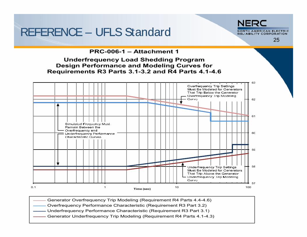
PRC-006-1 – Attachment 1 Underfrequency Load Shedding Program
Design Performance and Modeling Curves for Requirements R3 Parts 3.1-3.2 and R4 Parts 4.1-4.6q
62
63
60
61
59
60
57
58
0.1 1 10 100Time (sec)
Generator Overfrequency Trip Modeling (Requirement R4 Parts 4.4-4.6) Overfrequency Performance Characteristic (Requirement R3 Part 3.2) Underfrequency Performance Characteristic (Requirement R3 Part 3.1) Generator Underfrequency Trip Modeling (Requirement R4 Parts 4.1-4.3)
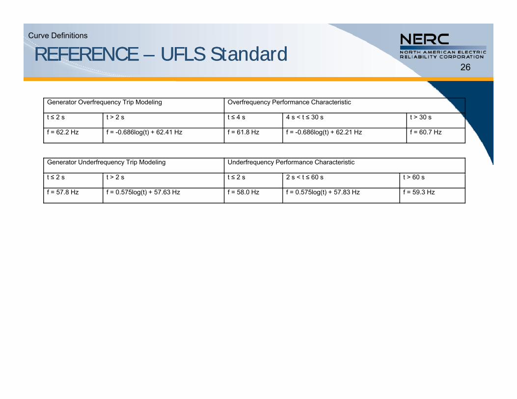
REFERENCE REFERENCE –– UFLS StandardUFLS Standard26
Curve Definitions
Generator Overfrequency Trip Modeling Overfrequency Performance Characteristic
t ≤ 2 s t > 2 s t ≤ 4 s 4 s < t ≤ 30 s t > 30 s
f = 62.2 Hz f = -0.686log(t) + 62.41 Hz f = 61.8 Hz f = -0.686log(t) + 62.21 Hz f = 60.7 Hz
Generator Underfrequency Trip Modeling Underfrequency Performance Characteristic
t ≤ 2 s t > 2 s t ≤ 2 s 2 s < t ≤ 60 s t > 60 s
f = 57.8 Hz f = 0.575log(t) + 57.63 Hz f = 58.0 Hz f = 0.575log(t) + 57.83 Hz f = 59.3 Hz