Embed Size (px)
Citation preview

Project 006 Rotorcraft Noise Abatement Operating
Conditions Modeling
The Pennsylvania State University/Continuum Dynamics, Inc.
Bell Helicopter Textron, Inc./Sikorsky Aircraft Corporation
Project Lead Investigator
Kenneth S. Brentner
Professor of Aerospace Engineering]
Department of Aerospace Engineering
The Pennsylvania State University
233 Hammond Building, University Park, PA
(814)865-6433
University Participants
The Pennsylvania State University
P.I.: Kenneth S. Brentner, Professor of Aerospace Engineering
FAA Award Number: 13-C_AJFE-PSU-006, Amendment No. 6
Period of Performance: August 18, 2014 to January 31, 2016
Task(s):
1. Prediction system development
2. Noise prediction system validation
3. Noise predictions and noise mapping
4. Flight test plan development
5. Determination and development of data path to AEDT
6. Selection and modeling of notional advanced technology rotorcraft
7. Noise predictions and data preparation for AEDT
Project Funding Level
FAA: $250,326; In-Kind Match: (Continuum Dynamics, Inc: $112,500 to PSU and $75,000 to FAA; Bell Helicopter Textron,
Inc.: $37,500; Sikorsky Aircraft Corporation: $37,500)
Investigation Team
Kenneth S. Brentner, PI, The Pennsylvania State University; acoustics predictions lead on all tasks.
Joseph F. Horn, Co-PI, The Pennsylvania State University; flight simulation lead supporting all tasks
Daniel A Wachspress, Co-PI, Continuum Dynamics, Inc.; responsible for rotor loads and wake integration and CHARM
coupling, primarily involved in tasks 1-3, 6, and 7.
Yaowei Li, Graduate Research Assistant, The Pennsylvania State University; primary responsibility for coupling acoustic
code into noise prediction system and acoustic predictions in tasks 1-3.
Willca Villafana, Graduate Research Assistant, The Pennsylvania State University; primary responsibility for model setup
and acoustic predictions in tasks 3, 5-7.
Adam Thorsen, Graduate Research Assistant, The Pennsylvania State University; assisted in development of flight
simulation code in task 1.
Umberto Saetti, Graduate Research Assistant, The Pennsylvania State University; assisted in flight simulation coupling and
performing coupled simulations in tasks 2, 3, and 7.
Benjamin A Goldman, Industrial Partner, Bell Helicopter Textron, Inc.; support Bell 430 model setup and validation of the
noise prediction system in task 1 and 2, provide feedback on all aspects of project, especially tasks 1-4.
Eric Jacobs, Industrial Partner, Sikorsky Aircraft Corporation; primary responsibility for flight test plan development in task
4, provide feedback on all aspects of project, especially tasks 3 and 4.

Project Overview
Rotorcraft noise consists of several components including rotor noise, engine noise, gearbox and transmission noise, etc.
Rotor noise is typically the dominant component of rotorcraft noise that is heard by the community upon takeoff, landing,
and along the flight path of the helicopter. Rotor noise is comprised of several different noise sources including thickness
noise and loading noise (together typically referred to as rotational noise), blade-vortex-interaction (BVI) noise, high-speed-
impulsive (HSI) noise, and broadband noise – with each noise source having its own unique directivity pattern around the
helicopter. Furthermore, any aerodynamic interaction between rotors, interaction of the airframe wake and a rotor, or
unsteady, time-dependent loading generated during maneuvers typically results in significant increases in loading noise.
The combination of all the potential rotor noise sources makes prediction of rotorcraft noise quite complex, even though
not all of the noise sources are present at any given time in the flight (e.g., BVI noise usually occurs during descent and HSI
noise only occurs in high-speed forward flight).
The rotorcraft industry, universities, and government research labs have actively engaged in research activities since the
late 1960’s to understand rotorcraft noise generation mechanisms and mitigation techniques. Both first principles and
semi-empirical prediction tools have been developed as a result of this research. This project will leverage that research
and use tools developed by the research team to develop noise abatement flight procedures and a flight test plan to
evaluate the effectiveness to those procedures. The noise prediction system will also be used to demonstrate its utility in
predicting the noise from advance rotorcraft features and concepts.
OBJECTIVES
There are two main objectives for this project, described as follows:
(1) The first objective of this activity is to develop rotorcraft noise abatement procedures through computational
and analytical modeling, and develop a comprehensive flight test plan to validate the effectiveness of resulting
noise abatement flight procedures. This objective is addressed through the implementation of tasks 1-4 described
below.
(2) The second objective is to use the computational and analytical modeling tools to demonstrate the ability to
provide vehicle noise data for notional vehicles with advanced technology in a manner than can be used in the FAA
Aviation Environmental Design Tool (AEDT). This objected is addressed in tasks 5-7described below.
The approach to developing rotorcraft noise abatement procedures requires the ability to compute the vehicle noise from
the relevant noise sources in level flight, hover, takeoff, and approach. Emphasis will be given to the level flight conditions
for conventional helicopters, but the tools coupled together will be able to predict the noise from tandem, tiltrotor, and
compound rotorcraft as well. In normal civil operations only rotor noise is expected to be a significant source of
community noise. For this reason, engine noise, and other noise sources that are important in the cabin are not planned
for consideration. Furthermore, high-speed-impulsive (HSI) noise during high-speed forward flight should be avoided in
civil operations; therefore, HSI noise will not be considered.
The approach planned to demonstrate computational and analytical modeling tools on advanced rotorcraft designs will
leverage the work done for Objective 1 (tasks 1-3, described below). For this reason, the work on the second objective did
not begin until approximately 6 months into the effort.
Task 1. Prediction System Development
The Pennsylvania State University
Objective(s)
The object of this task is to couple a flight simulator, rotor aerodynamics and wake computation, and a noise prediction
code to form a noise prediction system that will be capable of predicting helicopter noise is various flight operations.
Research Approach
For this effort, the PSU-WOPWOP code will be used for noise prediction, and will be coupled with a MatLab flight simulator
and CHARM (Comprehensive Hierarchical Aeromechanics Rotorcraft Model) to form a rotorcraft noise prediction system.
Both CHARM and PSU-WOPWOP have previously been coupled (individually) to the flight simulation code GENHEL-PSU
(which models helicopters similar to the Sikorsky UH-60); the three codes have not been coupled into a single noise

prediction system. The first major task of this project is to update and enhance the coupling between the three codes. A
newly developed flight simulation code will be used to compute the time-dependent flight state of the aircraft and initial
blade loading and blade motion estimates. These results will be passed to the CHARM code (module) to predict the rotor
wakes and resulting time-dependent blade loads. The loading output of these coupled codes will be input to PSU-WOPWOP
to compute the noise during the helicopter flight operation.
The coupling is time accurate because that is the normal operation mode of each of the codes. The initial coupling will
include multiple rotors (main rotor/tail rotor) and noise computations for noise certification flight conditions and
microphone locations will be demonstrated. Two forms of coupling are used; the first (shown in Fig. 1.1) is a coupling in
which the CHARM airloads computations are decoupled from the flight simulator. In this approach, the airloads and trim
determined by the flight simulator may be different from those computed in CHARM and used in the noise prediction. To
address this potential problem, a fully coupled approach was also developed (shown in Fig. 1.2).
Figure 1.2. Integration Method 2 – CHARM fully coupled with flight simulator.
Bell 430 Simulink Model
Other
Modules
Control
System
S
Equ of
Motion
CHARM
Module
PSU-
WOPWOP
High-Fidelity
Airloads
Swashplate
Angles
Aircraft
State
MR and TR Forces
and Moments from
CHARM
Figure 1.1 Integration Method 1 – CHARM de-coupled from flight simulator.

The noise prediction system is anticipated to be sufficiently fast to predict the noise during an entire operation (several
seconds at least) at a large number of observer locations so that noise contours on the ground can be predicted. The time
accurate nature of the system will enable sweeps of control parameters to be evaluated to eliminate blade-vortex
interaction (BVI) or other high noise conditions. This tool will enable the development and analysis of noise abatement
flight procedures through relatively rapid computations.
The noise prediction system is envisioned to predict only rotor noise, but should be able to predict noise from helicopters,
compound rotorcraft, and tiltrotors (i.e., the number and placement of rotors is not an issue). The system will be able to
predict rotor noise in all normal operating flight conditions, ranging from hover (IGE or OGE), takeoff, level flight,
approach, and maneuvering flight. Engine and related noise sources are not planned in this project.
Milestone(s)
The coupled noise prediction system was largely complete after the first 3 months, but as problems are encountered (i.e.,
software bugs), the system is corrected.
Major Accomplishments
The primary accomplishment of this task is the coupling of the three components (flight simulator, high fidelity rotor
airloads and airwake (CHARM), and noise prediction (PSU-WOPWOP)) is new.
Another accomplishment was the development of the MatLab based flight simulation code (called HeloSim). This flight
simulator is relatively simple because it does not need detailed rotor aerodynamics or wake models – the CHARM rotor
module coupling provides higher fidelity loading to the flight simulator.
Publications
None
Outreach Efforts
None
Awards
None
Student Involvement
Adam Thorsen, Ph.D. student at PSU – provided limited support setting up MatLab based flight simulation tool.
Yaowei Li, M.S. student at PSU – primarily responsible for setting up and making acoustic predictions and analysis of
acoustic data. He was also involved in developing the coupling between codes. Mr. Li graduated August 2015 and his
plans after graduation unrelated to the project.
Plans for Next Period
This task of Project 6 is complete. Any software “bugs” found during the noise predictions in the other tasks will be
corrected as required.

Task 2. Noise Prediction System Validation
The Pennsylvania State University
Objective(s)
This task will validate the noise prediction system to demonstrate that is sufficiently accurate to be used for the
development and analysis of rotorcraft noise abatement flight procedures.
Research Approach
The noise prediction system will be validated through prediction of various flight conditions and comparison with recently
acquired flight test data. NASA, Bell Helicopter, and the U.S. Army recently performed a maneuver acoustics flight test with
the Bell 430 helicopter (Ref. 2.1). The data from this test provides an excellent opportunity to test the maneuver noise
prediction system and demonstrate its accuracy, strengths and weaknesses. Data from this test is publicly available - and
as a partner in this effort, Bell will be able to provide insight into the details of this flight test, which is very valuable in the
validation effort. The primary goal of this validation is to characterize the accuracy of the system (with low to medium
fidelity level), which will provide sufficiently short noise prediction times needed in noise abatement procedure
development. It may also show “gaps” in the system that need to be addressed.
The noise prediction system predictions were compared to measurements from a cooperative flight test conducted by
NASA, Bell Helicopter and the U.S. Army to characterize the steady state acoustics and measure the maneuver noise of a
Bell Helicopter 430 aircraft (Refs. 2.1, 2.2). For the first validation comparison, a level flight “housekeeping condition” is
modeled in which the aircraft was flown several times at nominally the same flight speed (80 kts) over the reference
microphone. For this case the overall sound pressure level (OASPL), plotted as a function of distance along the flight path,
has been compared to the noise prediction system results (shown in Fig. 2.1). In Fig. 2.1, the reference microphone is at
𝑥 = 0 m and the distance on the x-axes indicates the position of the aircraft relative to the reference point. Figure 2.1(a)
shows the OASPL levels as a function of where the helicopter is during the level flyover. The predicted noise is good
(a) OASPL (b) PNLT
Figure 2.1 OASPL and PNLT levels for 80 kts level flight “housekeeping” run. On the right in (a), the thin colored lines
are the experimental data; in (b) the ground is not included in the prediction. (Note: In earlier presentations and reports,
Fig. 2.1(a) did not include the ground plane and the agreement was not as good. This was changed when it was
discovered that the effect of ground reflection was not removed from the flight test data as was previously thought.)
Distance from reference microphone, feet
OA
SP
L,d
B(
re2
0
Pa
)
-2000 -1500 -1000 -500 0 500 1000
75
80
85
90
95
100
105
Thickness
Loading
Total (MR+TR+Ground)
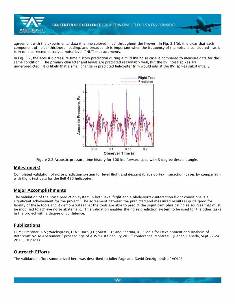
agreement with the experimental data (the line colored lines) throughout the flyover. In Fig. 2.1(b), it is clear that each
component of noise (thickness, loading, and broadband) is important when the frequency of the noise is considered – as it
is in tone corrected perceived noise level (PNLT) measurements.
In Fig. 2.2, the acoustic pressure time history prediction during a mild BVI noise case is compared to measure data for the
same condition. The primary character and levels are predicted reasonably well, but the BVI noise spikes are
underpredicted. It is likely that a small change in predicted helicopter trim would adjust the BVI spikes substantially.
Milestone(s)
Completed validation of noise prediction system for level flight and descent (blade-vortex interaction) cases by comparison
with flight test data for the Bell 430 helicopter.
Major Accomplishments
The validation of the noise prediction system in both level flight and a blade-vortex-interaction flight conditions is a
significant achievement for the project. The agreement between the predicted and measured results is quite good for
fidelity of these tools and it demonstrates that the tools are able to predict the significant physical noise sources that must
be modified to achieve noise abatement. This validation enables the noise prediction system to be used for the other tasks
in the project with a degree of confidence.
Publications
Li, Y.; Brentner, K.S.; Wachspress, D.A.; Horn, J.F.; Saetti, U.; and Sharma, K., “Tools for Development and Analysis of
Rotorcraft Noise Abatement,” proceedings of AHS “Sustainability 2015” conference, Montreal, Quebec, Canada, Sept 22-24,
2015, 10 pages.
Outreach Efforts
The validation effort summarized here was described to Juliet Page and David Senzig, both of VOLPE.
Figure 2.2 Acoustic pressure time history for 100 kts forward sped with 3-degree descent angle.

The validation effort was also highlighted in the conference presentation: Li, Y.; Brentner, K.S.; Wachspress, D.A.; Horn, J.F.;
Saetti, U.; and Sharma, K., “Tools for Development and Analysis of Rotorcraft Noise Abatement,” presented at AHS
“Sustainability 2015,” Montreal, Sept 22-24, 2015, (presented by K.S. Brentner).
Awards
None
Student Involvement
Yaowei Li, M.S. student at PSU – primarily responsible for setting up and making acoustic predictions and analysis of
acoustic data. Mr. Li graduated August 2015 and his plans after graduation unrelated to the project.
Umberto Saetti, M.S. student at PSU – primarily responsible for flight simulation calculations and development and
debugging of the coupling between the flight simulation code and the CHARM rotor module. Mr. Saetti graduated in
August 2016, and is now pursuing a Ph.D. at PSU on another project.
Plans for Next Period
This validation effort is complete. No further work is currently planned for validation.
References
[2.1] Watts, M.E., Greenwood, E., Smith, C.D., Snider, R., and Conner, D. A., “Maneuver Acoustic Flight Test of the Bell 430
Helicopter Data Report,” NASA/TM–2014-218266, May 2014.
[2.2] Snider, R., Samuels, T.O., Goldman, B., and Brentner K. S., “Full-Scale Rotorcraft Broadband Noise Prediction and its
Relevance to Civil Noise Certification Criteria,” Proceedings of American Helicopter Society 69th Annual Forum, Phoenix,
Arizona, May 21–23, 2013.
Task 3. Noise Predictions and Noise Mapping
The Pennsylvania State University
Objective(s)
This object of this task is to examine several flight conditions, consider operational changes, and determine the impact on
the noise levels. The goal of this task is to demonstrate how flight operations can reduce the noise.
Research Approach
In order to demonstrate the impact of noise abatement flight procedures, several simple parametric studies were
performed. According to Helicopter Association International’s “Fly Neighborly Guide”, published report in 2007 (Ref. 3.1),
the simplest way to reduce the rotorcraft noise during overflight is to increase the altitude and fly slower. To examine
these common sense recommendations, the noise prediction system was used to predict the noise for various operating
procedures. These predictions serve two purposes: 1) to develop further confidence that the noise prediction system
captures the important noise characteristic of helicopters in various flight conditions; and 2) to provide detailed
information that explain the mechanisms and directivity of noise changes (hopefully reductions) obtained through noise
abatement flight procedures. Based on this guidance, the noise prediction system was used to predict the noise of the Bell
430 aircraft.
Impact of Altitude

The first case considered was level flyover with the Bell 430 helicopter flown with a velocity of 100 kts at different altitudes
ranging from 150 m to 350 m in 50 m increments. This range of altitudes is arbitrary, but sufficient to demonstrate the
powerful impact that distance makes in reducing noise. The aircraft weight and atmospheric conditions (standard sea level
density and temperature) are held constant for each altitude. In Fig. 3.1, the PNLT is shown for locations directly below the
flight path of the aircraft. In this figure, it is evident that distance plays an important role in the noise level – as was
expected. The peak PNLT level is about 8 dB lower for the 350 m case than for the 150 m altitude.
While the behavior directly below the helicopter is what is expected – increased altitude decreases the noise level – this is
not necessarily the case for observer locations to either side of the aircraft. Furthermore, the flight time over the observer
is not included when considering the PNLT levels alone. To address these issues, the Effective Perceived Noise Levels
(which are based on PNLT) were computed for an area below the aircraft (shown in Fig. 3.2). In Fig. 3.2(a), the EPNL levels
are shown for a single altitude (150m) for approximately 1800m range and 700 m to either side of the flight path. The
EPNL levels are highest directly under the aircraft, as would be expected. Notice that the EPNL levels do not vary with the 𝑥
location because the helicopter is in level flight; thus a more quantitative examination of the results can be done by
comparing the levels at the 𝑥 = 0 positon for different lateral distances from the centerline (shown in Fig. 3.2(b)). Again in
this figure, it is clear that as the altitude of the helicopter increases the noise levels decrease along the centerline. But at
lateral distances greater than 300m (in this case), the noise levels are relatively unaffected and even increase slightly on
the right side of the aircraft (advancing rotor side). Hence, even for a very straightforward approach to noise abatement,
the results will not be the same at all observer positons.
Figure 3.1 PNLT predictions for the Bell 430 helicopter with the aircraft at different flight altitudes.

Impact of Flight Speed
A similar comparison of EPNL levels was performed for the Bell 430 operating at forward speeds ranging from 60 kts to
140 kts in level flight at 150m (shown in Fig. 3.3). It is generally understood that flying slower will reduce the noise levels.
The physics of the source noise mechanisms (in-plane noise in particular) indeed exhibit this behavior. Nevertheless, when
the EPNL is considered, which takes into account the duration of the exposure as well as the level, the levels of EPNL do
not change significantly below the helicopter even though the expected trend is seen away from the centerline (see Fig.
3.3). The reason for this is that while the noise level is lower for low speed (e.g., 60 kts), the exposure time is longer.
Therefore, along the helicopter flight path the EPNL levels are essentially the same for the 60 kts and 140 kts cases.
Impact of Flight Path Angle
The Sound Exposure Level (SEL) contours were also computed for different descent and climb angle (from 6 deg. descent
to 6 deg. climb). When the helicopter is not in level flight, the distance to the ground will be constantly changing and it
has already been shown that increasing distance is an effective noise abatement strategy. Therefore, in these
comparisons, the distance from the measurement plane is the same for 𝑥 = 0 and either farther or closer to the plane
otherwise. The comparison for 6 deg. and 3 deg. descent angle is shown in Fig. 3.4 (along with the level flight case as a
reference). The SEL levels are significantly higher for the 6 deg. descent. For the uprange cases (𝑥 < 0) the impact of
distance should be to reduce the level, but they are higher than the 3 deg. and level flight cases. In addition, it is clear at
𝑥 = 0 that the levels are higher, yet the distance is the same here. Upon closer examination, the 6 deg. descent case has
significantly more BVI than the 3 deg. descent case, and the level flight case does not have any BVI noise. Thus, it is clear
that BVI should be avoided to have the lowest noise (and annoyance) levels.
In Fig. 3.5, the SEL contours for 6 deg. and 3 deg. climb are shown (along with a level flight case for reference). In this
case, the change in SEL levels is primarily due to the distance the helicopter is above the measurement plane. This can be
(a) EPNL contours, 𝑉𝐻 = 100 kts, altitude =150m (b) EPNL at 𝑥 = 0 plane, -700 < 𝑦 < 700 m for various altitudes
Figure 3.2 Effective Perceived Noise Levels for Bell 430 helicopter flying at 100 kts at altitudes from 150m to 350 m.

seen by comparing the values at 𝑥 = 0, which are essentially the same. Therefore, unlike the descent case where BVI noise
was eliminated by changing the descent angle, there is no change in the physics in the climb case. Nevertheless, rapid
climb is an effective means of increasing the distance and thereby reducing the noise.
Figure 3.3 EPNL along 𝑥 = 0 plane, −700 ≤ 𝑦 ≤ 700 m for forward speeds ranging from 60 kts to 140 kts.
Figure 3.4 SEL contour plots for various descent angles.

Milestone(s)
Compute predicted noise for several operating scenarios. This milestone was met by the level flight, descent, and climb
cases studied.
Major Accomplishments
This task has demonstrated the noise prediction system is able to show how different rotorcraft operations can reduce or
increase the noise levels. Furthermore, the predictions have shown that even simple noise abatement strategies, like flying
higher or flying slower, may provide noise reduction in some locations and yet result in increases in other locations. This
task has demonstrated that to understand such complex changes it is important to have a physics-based noise prediction
system so that a detailed investigation of the individual noise components and the noise directivity can be made.
Publications
Li, Y.; Brentner, K.S.; Wachspress, D.A.; Horn, J.F.; Saetti, U.; and Sharma, K., “Tools for Development and Analysis of
Rotorcraft Noise Abatement,” proceedings of AHS “Sustainability 2015” conference, Montreal, Quebec, Canada, Sept 22-24,
2015, 10 pages.
Outreach Efforts
The validation effort summarized here was described to Juliet Page and David Senzig, both of VOLPE.
Figure 3.5 SEL contour plots for various climb angles.

The validation effort was also highlighted in the conference presentation: Li, Y.; Brentner, K.S.; Wachspress, D.A.; Horn, J.F.;
Saetti, U.; and Sharma, K., “Tools for Development and Analysis of Rotorcraft Noise Abatement,” presented at AHS
“Sustainability 2015,” Montreal, Sept 22-24, 2015, (presented by K.S. Brentner).
Awards
None
Student Involvement
Yaowei Li, M.S. student at PSU – primarily responsible for setting up and making acoustic predictions and analysis of
acoustic data for Objective 1. He was also involved in developing the coupling between codes. Mr. Li graduated August
2015 and his plans after graduation unrelated to the project.
Umberto Saetti, M.S. student at PSU – primarily responsible for flight simulation calculations and development and
debugging of the coupling between the flight simulation code and the CHARM rotor module. Mr. Saetti graduated August
2016, and is now pursuing a Ph.D. at PSU on another project.
Plans for Next Period
This task is complete. No additional work is planned, but if support is needed to finish the flight test plan development
(task 4) then noise predictions could be made in support of that task.
References
[3.1] Fly Neighborly Guide, produced by the Helicopter Association International Fly Neighborly Committee, 2007.
(http://www.rotor.org/portals/1/operations/Fly2007.pdf - accessed March 27, 2015)
Task 4. Flight Test Plan Development
The Pennsylvania State University
Objective(s)
This task will develop a draft flight test plan for evaluation of noise abatement procedures.
Research Approach
A draft test plan (or template) to test the effectiveness of various noise abatement procedures has been developed by our
industrial partner Sikorsky Aircraft Corporation (Eric Jacobs). Eric has significant experience in flight testing and has
Sikorsky has strong interest in participating in a proposed noise abatement flight test. The flight test plan will involve two
phases of testing. Phase 1 will include noise characterization and model validation testing. This will provide the baseline
to compare noise abatement procedures against and to determine if changes in the test plan are needed to take into
account noise characteristics that may not be fully account for in the noise modeling. The Phase 2 plan will define the
abatement procedures to be tested and the test conditions required to ensure the test is effective. The draft/template test
plan has several “to be determined” items because the target aircraft and test site are not currently known, but are critical
elements of such a plan. These items will likely not be determined until a specific test is planned (or at least proposed).
Milestone(s)
A flight test plan template has been developed for rotorcraft noise abatement procedure validation.
Major Accomplishments

An outline of the test plan and initial Phase 1 and Phase 2 plans has been drafted.
Publications
None
Outreach Efforts
None
Awards
None
Student Involvement
None
Plans for Next Period
The flight test plan development is complete and a draft/template flight test plan has been delivered to the FAA.
Task 5. Determination and Development of Data Path to AEDT
The Pennsylvania State University
Objective(s)
The object of this task is to develop the necessary noise prediction templates and post processing capabilities to generate
noise with the rotorcraft noise prediction system developing in task 1 and generate the needed data, in the proper format,
to be used in AEDT in lieu of manufacturer provided, or otherwise measured, data.
Research Approach
The first step is to determine the appropriate information that AEDT needs from the rotorcraft noise prediction system.
This includes helicopter noise levels and directivity for various operating conditions and will likely need to be provided in
some form of noise-power-distance (NPD) curves, spectral class data, etc. A different set of NPD data is required for each
flight operational mode. The rotorcraft noise prediction system will have the advantage that for any given flight condition,
the noise can be predicted in any direction (or on a sphere surrounding the vehicle). While such data is not currently used
in AEDT, it can be used to determine if current and any advanced modeling in AEDT are capturing the nature of the
helicopter noise sufficiently. Noise prediction templates will be developed to simplify the process of computing NPD and
spectral class data. Ultimately the goal would be to set up the helicopter model in the rotorcraft noise prediction system,
do some testing to make sure the setup is correct, and then submit a batch job and get out the data needed by AEDT.
Milestone(s)
Review input data requirements for AEDT and develop necessary post processing capabilities to provide any data or data
format as needed. The work on this milestone is complete.
Major Accomplishments
The initial path for the work on this task was to provide data in format that can be used directly by AEDT. Upon
consultation with Juliet Page (Volpe), it was decided that elements not currently included in the PSU noise prediction

system (i.e., ground reflections if the ground is not a hard plane, etc.) can be better handled by the tools that Volpe
already has available. Therefore, the focus in this task is to compute the noise on hemispheres of the format the Volpe’s
software can use with their tools. Then atmospheric attenuation, atmospheric turbulence, and ground reflections can be
performed in a manner consistent with Volpe’s current toolset. Ultimately, this data is used to provide input to AEDT. It is
important to point out that significantly more detail is provided (directivity, noise source identification, etc.) than is
currently used by AEDT, but the ability to compute this data will provide AEDT developers tools to assess modeling choices
and improve rotorcraft noise predictions.
(a)
(b)
Figure 5.1 Typical hemisphere grid used to provide acoustic data that can be used by Volpe to provide data for AEDT.
Positive x-axes is the direction of flight; Helicopter is located at the center of the sphere. (a) example hemisphere grid;
(b) example noise computation plotted on the grid.
Publications
None
Outreach Efforts
We have interacted with Juliet Page, VOLPE, to help us understand the noise inputs requirements of AEDT.
Awards
None
Student Involvement
Willca Villafana, M.S. student at PSU – primarily responsible for acoustic work in Objective 2, i.e., prepared the noise
prediction system to output the necessary data for input to AEDT. Mr. Villafana completed his M.S. degree work in August
2016 and graduated Dec 2016. He is now attending the von Karman Institute in Brussels, Belgium.
Plans for Next Period
This task is complete.

Task 6. Selection and Modeling of Notional Advanced Technology
Rotorcraft
The Pennsylvania State University
Objective(s)
The objective of this task is to select a small number of advanced technology rotorcraft features to demonstrate how the
noise prediction system can help assess the potential for new technology to impact rotorcraft noise abatement or how it
may be assessed as part of the total air transportation system noise through modeling inputs for AEDT (before measured
data would be available).
Research Approach
A limited number of notional rotorcraft with advanced technologies can be studied within the scope of this effort.
Therefore, it is planned to select three new technologies that have a strong potential for noise reduction. These
technologies will be integrated into notional rotorcraft, which in turn will be analyzed as representative cases. Ultimately
the goal is to demonstrate that advanced technology rotorcraft could be studied within the context of AEDT and their noise
impact/noise reduction could be assessed in the broader context provided by AEDT. For this demonstration, it was
decided to pick a technology that would reduce BVI noise, which is a significant noise source upon approach.
Milestone(s)
Develop notional advanced rotorcraft configurations and build the necessary inputs for the rotor noise prediction system.
This milestone is complete.
Major Accomplishments
A demonstration of the capability of the noise prediction system to predict the noise of an advanced technology rotorcraft
for an advanced blade design known to reduce BVI noise (Figure 6.1)[6.1], Airbus Helicopter’s “Blue Edge” blade. The
concept behind this design is described in Ref. [6.2] as: “With a standard blade, air coming off the end of the blade causes
a vortex around the tip. Under certain flight conditions, the advancing blade then hits the vortex of the preceding blade.
This causes a sudden change in the relative angle of attack and thus a change in pressure on the surface of the blade. This
BVI causes the slapping sound ubiquitous to helicopter operations. With Blue Edge technology, the blade tip is swept
forward, then aft. This causes the advancing blade tip to hit the previous blade’s vortex at an oblique angle, reducing the
noise level by 3 to 4 EPNdB.” [6.2] This advanced technology blade design should be a good test of the noise prediction
system.
Three main rotor blade configurations were selected to demonstrate the ability of the new analysis system to predict the
reduction in BVI noise obtained using a Blue Edge-like planform. The three blade geometries were 1) conventional
rectangular blades – nominally the current Bell 430 blade; 2) tapered blades, 3) Blue Edge-like planform with taper and
forward/aft sweep. Figure 6.2 compares the tapered and Blue Edge-like planforms. No optimization of the tapered and
Blue Edge-like planforms was performed to minimize noise. The Blue Edge-like planform forward/aft sweep schedule is
roughly comparable to photographs of the Airbus Blue Edge blade, capturing the key feature of reducing the “parallel”
nature of the BVI.

Figure 6.1. Blue Edge blade concept from
Eurocopter (now Airbus Helicopters). [Ref. 6.1]
Figure 6.2. Tapered and Blue Edge-like planforms.
Publications
None
Outreach Efforts
None
Awards
None
Student Involvement
Willca Villafana, M.S. student at PSU – primarily responsible for acoustic work in Objective 2, i.e., prepared the noise
prediction system to output the necessary data for input to AEDT. Mr. Villafana completed his M.S. degree work in August
2016 and graduated Dec 2016. He is now attending the von Karman Institute in Brussels, Belgium.
Umberto Saetti, M.S. student at PSU – primarily responsible for flight simulation calculations and development and
debugging of the coupling between the flight simulation code and the CHARM rotor module. Mr. Saetti graduated August
2016, and is now pursuing a Ph.D. at PSU on another project.
Plans for Next Period
This task is complete.
References
[6.1] Paur, J. Eurocopter Moves One Step Closer To 'Whisper Mode'. 2010 Feb 25, 2010 [accessed 3/4/2016]; Available
from: http://www.wired.com/2010/02/eurocopter-moves-one-step-closer-to-whisper-mode/
[6.2] Nelms, D. (2015). "New Eco-Friendly Bluecopter Unveiled," Vertiflite 61(5): pp. 26-28.

Task 7. Noise Predictions and Data Preparation for AEDT
The Pennsylvania State University
Objective(s)
The objective of this task is to demonstrate the new capability by preforming the complete set of noise predictions (for the
advanced configurations selected in task 6) necessary to provide inputs to AEDT.
Research Approach
The notional rotorcraft, along with the Bell 430 (time permitting) will be analyzed in the rotorcraft noise prediction system
for all the various operating conditions. The data identified in task 5 will be produced in the appropriate format. This data
will be evaluated and analyzed with tools outside of AEDT to provide detailed information about the noise of the vehicles
and to provide analysis of the data delivered at the end of this task.
Milestone(s)
Predict the noise from the advanced technology configurations, prepare the data for AEDT processing, and document the
data and analysis. This milestone is complete.
Major Accomplishments
Three different rotor configurations were tested on the Bell 430 helicopter model in the noise prediction system: standard
rectangular blades, tapered blades, and Blue Edge-like blades. Each of the configurations were tested in a high BVI noise
condition with forward speed of 68 knots and 6-degree descent angle. First, the sound from the main rotor was predicted
on a plane one-rotor radii below the main rotor. Figure 7.1 shows predictions of both the overall sound pressure level
(OASPL) and the BVI sound pressure level (BVISPL) (harmonics 6-40 in blade passage frequency) for each configuration. The
magnitude and directionality predicted is characteristic of the results seen for BVI-noise dominated descent flight
conditions. The analysis predicts that the taper reduces the peak BVISPL by roughly 2dB and the Blue Edge-like planform
further reduces the peak BVISPL by another 3dB for a total reduction of peak BVISPL of 5dB, thus capturing the documented
benefit of the Blue Edge planform. Figure 7.2 shows the advancing-side BVI for the Blue Edge planform compared with a
rectangular blade as predicted by the CHARM code. Notice in the figure that the tip vortex (the red curved line) is nearly
parallel to the entire length of the blade for the rectangular blade (left), while the shape of the Blue Edge planform (right)
results in an interaction that occurs over a wider range of rotor azimuth angles; hence, it is a much less impulsive
interaction.
Figure 7.3 shows the acoustic pressure time histories for each of the main rotor planforms at a point located on the
hemisphere at an azimuth of 125° and down 45° from the main rotor tip-path plane. Notice in the figure, for each blade
geometry there are 4 very narrow and high amplitude pressure spikes (or group of spikes). These are the BVI from each of
the four blades on the main rotor. The thickness and loading noise of the main rotor also occur approximate the same
time, so they are difficult to see. Comparison of the three different rotor blade geometries shows how the BVI acoustic
pressure spikes amplitude is greatly reduced for the case of the Blue Edge-like rotor. The tapered blade also has a small
reduction in BVI spike amplitude, primarily seen on the positive part of the pressure spike. The other features, i.e., the tail
rotor noise, is essentially unchanged.
The noise comparisons shown in this section demonstrate the utility of the flight simulation, high-fidelity wake, noise
prediction system that has been developed here. Furthermore, design changes to reduce BVI noise – one of the more
challenging components of the noise to predict – show the expected noise reduction trends.

(b) BLUE EDGE-like
(a) RECTANGULAR
Figure 7.2. BVI event as predicted by CHARM for the baseline RECTANGULAR blade and the BLUE EDGE blade.
OASPL (harmonics 0 – 50 BPF)
BVISPL (harmonics 6 – 40 BPF)
(a) RECTANGULAR (b) TAPERED (c) BLUE EDGE-like
Figure 7.1. CHARM/PSU-WOPWOP main rotor OASPL and BVISPL predictions one rotor radius beneath the nominal
Bell 430 rotor for the three blade geometries; s=6 (back), =0.15 and CT=.00143. The black circle represents the
rotor tip – advancing side on the right.

Publications
Saetti, U.; Horn, J.F.; Brentner, K.S.; Villafana, W.R.; and Wachspress, D.A., “Rotorcraft Simulations with Coupled Flight
Dynamics, Free Wake, and Acoustics,” proceedings of the 72nd
AHS International Annual Forum and Technology Display,
West Palm Beach, FL, May 17-19, 2016, 12 pages.
Outreach Efforts
None
Awards
None
Student Involvement
Willca Villafana, M.S. student at PSU – primarily responsible for acoustic work in Objective 2, i.e., preparing the noise
prediction system to output the necessary data for input to AEDT. Work complete, graduation Dec 2016. Now attending
the von Karman Institute in Brussels, Belgium.
Umberto Saetti, M.S. student at PSU – primarily responsible for flight simulation calculations and development and
debugging of the coupling between the flight simulation code and the CHARM rotor module. Graduated August 2016, now
pursuing a Ph.D. at PSU on another project.
Plans for Next Period
This task is complete.
(a) RECTANGULAR (b) TAPERED (c) BLUE EDGE
Figure 7.3. Acoustic pressure time history at azimuth angle 𝜓 = 125, elevation angle 𝜃 = −45° below the rotor
plane, and radius of 30.48m from the helicopter c.g.