Embed Size (px)
Citation preview
00
What is ArduinoProject 0
www.dfrobot.com

What is Arduino?
Arduino is an open-source electronics prototyping platform based on flexible, easy-to-use hardware and software. It is intended for artists, designers, hobbyists and anyone interested in creating interactive objects or developing environments.Arduino can sense its environment by receiving inputs from sensors, and interact with its environment by controlling lights, motors, or other actuators. The Arduino integrated development environment (IDE) is a cross-platform application written in Java, and is derived from the IDE for the Processing programming language and wiringprojects. It can run independently and communicate with other software such as Flash, Processing, MaxMSPand more. Arduino IDE is open source so you can download and share thousands of interactive projects for free!
// make sound notification when coffee is done // email notification via mobile// blinking fluffy toy // Professor X’s steam punk wheel chair with voice recognition and drink serving function// a Star War arm gun // a pulse monitor to store data when biking// a robot that can run in snow and draw pictures on the floor
Here are some Arduino projects just to give your some ideas of tasks it can complete.
www.dfrobot.com 0100. What is Arduino
History
Arduino UNO
Arduino started in 2005 as a project for students at the Interaction Design Institute Ivrea in Ivrea, Italy. At that time, programming students used a "BASIC Stamp" for projects. This was at a cost of $100, considered expensive for students.Massimo Banzi, one of the founders of Arduino, taught at Ivrea. The name "Arduino" comes from a bar in Ivrea where some of the founders of the project used to meet. The bar itself was named after Arduino, Margrave of Ivrea and King of Italy from 1002 to 1014.Colombian student Hernando Barragan contributed a hardware thesis for a wiring design. After the wiringplatform was complete, researchers worked to make it lighter, less expensive, and available to the open source community. The school eventually closed down, so these researchers, including a man called David Cuartielles, promoted the idea. This idea was to become the Arduino as we know it today.
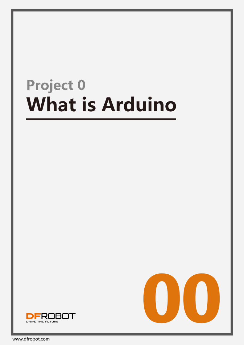
Now let’s take a close look at the Arduino micro-controller and try to locate I/O ports (input/output) and on board LEDs.
www.dfrobot.com
◆ I/ O pins, digital pins 0-13, analog pins 0-5.◆ 2 power sources. One is the USB port that can draw power from the USB connection. Another is power jack that inputs DC power of 6-12 volts.◆ 4 LEDs and reset button. L is the on board LED that connects with digital pin 13. TX and RX are indicators of transmission signal and received signal. When we download a sketch to the Arduino, these two lights blink, indicating that data is being transmitted and received.
0200. What is Arduino
Digital Pins 0~13(PWM Pins 3,5,6,9,10,11)
Power Indicator
Analog Pin 0~53.3V Output
DC Power Jack(6~12V)
Port Communication Indicator
D13 Pin Signal Indicator
USB Port
Reset
5V Output
First Use
1. Download Arduino IDE
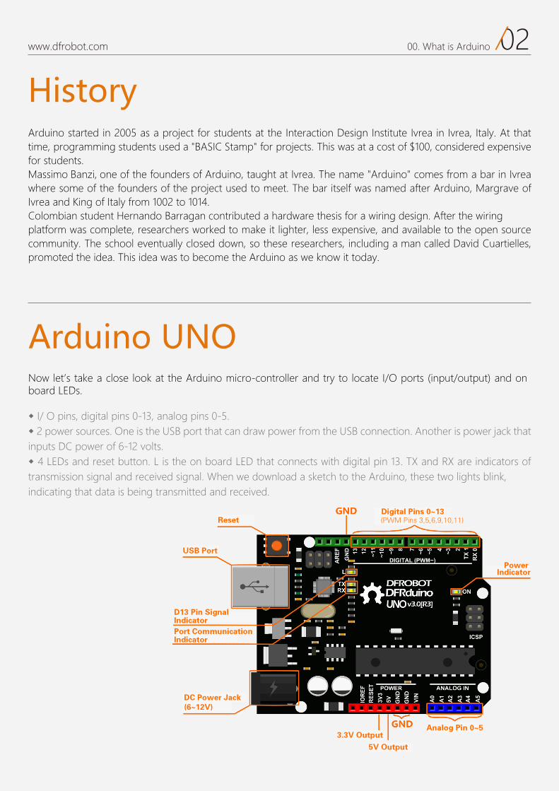
Go tohttp://arduino.cc/en/Main/Software to download the installation file according to your operation system.
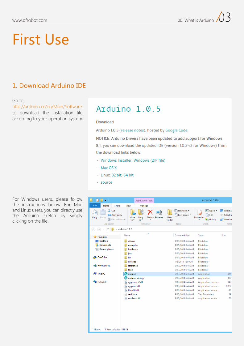
For Windows users, please follow the instructions below. For Mac and Linux users, you can directly use the Arduino sketch by simply clicking on the file.
www.dfrobot.com 0300. What is Arduino
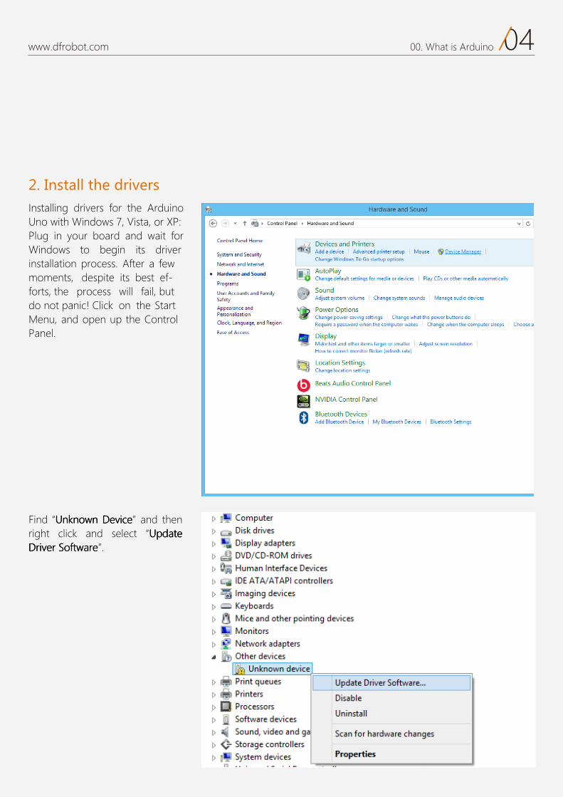
2. Install the driversInstalling drivers for the Arduino
Plug in your board and wait for Windows to begin its driver installation process. After a few moments, despite its best ef-forts, the process will fail, but do not panic! Click on the Start Menu, and open up the Control Panel.
Find nnnUUU kkk ooonnn www nnn DDD vvveee iii eeeccc and then right click and select UUU eeetttaaadddpppDDD rrreeevvviiirrr SSSoooffftttwww eeerrraaa .
www.dfrobot.com
0400. What is Arduino
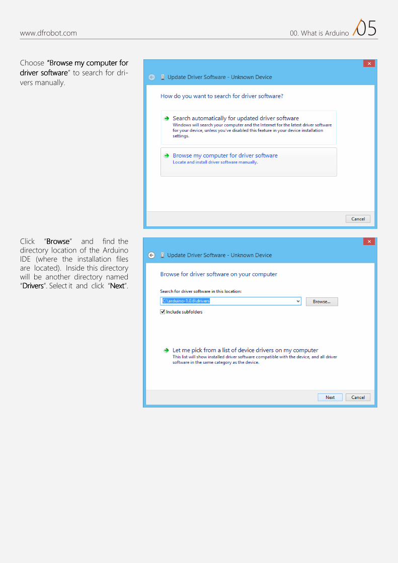
Choose ooorrr www mmmoooccc yyymmm eeesss rrreeetttuuu fff rrroooooosss rrreeevvviiirrrddd ffftttwww eeerrraaa to search for dri-
vers manua y
Click eeessswwwooorrrBBB and find the director location of the ArduinoIDE where the installation files are located . Inside this directorwill be another director named
sssrrreeevvviiirrrDDD . elect it and click tttxxxeeeNNN .
www.dfrobot.com 0500. What is Arduino
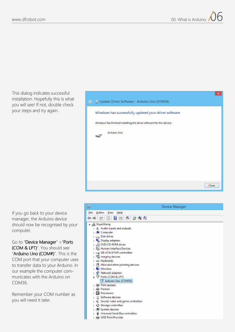
This dialog indicates successful installation. Hopefull this is what ou will see! f not double checkour steps and tr again.
If you go back to your device manager, the Arduino device should now be recognised by your computer.
Go to “ eeeccciiivvveeeDDD rrreeegggaaannnaaaMMM ” >“ tttrrroooPPP sss MMMOOOCCC((( &&& )))TTTPPPLLL ”. You should see
“ ooonnniiiuuudddrrrAAA MMMOOOCCC((( ooonnn ###)))”. This is the COM port that your computer uses to transfer data to your Arduino. In our example the computer com-municates with the Arduino on COM36.
Remember your COM number as you will need it later.
www.dfrobot.com 0600. What is Arduino
0700. What is Arduinowww.dfrobot.com
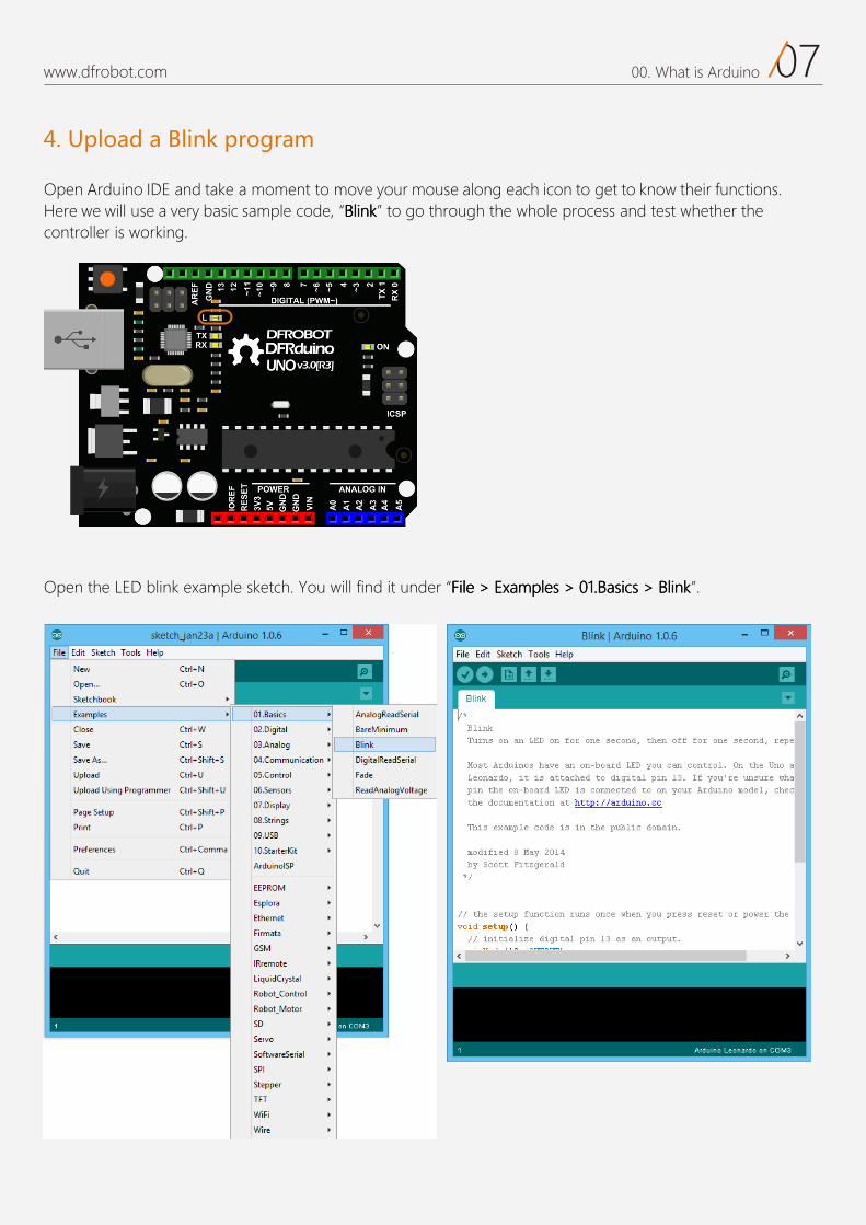
4. Upload a Blink program
Open Arduino IDE and take a moment to move your mouse along each icon to get to know their functions. Here we will use a very basic sample code, BBB kkknnniiilll to go through the whole process and test whether the controller is working.
Open the LED blink example sketch. You will find it under >>> ssseeelllpppmmmaaaxxxEEE >>> eeellliiiFFF 000 kkknnniiilllBBB >>> sssccciiisssaaaBBB...111 .
0700. What is Arduino
www.dfrobot.com
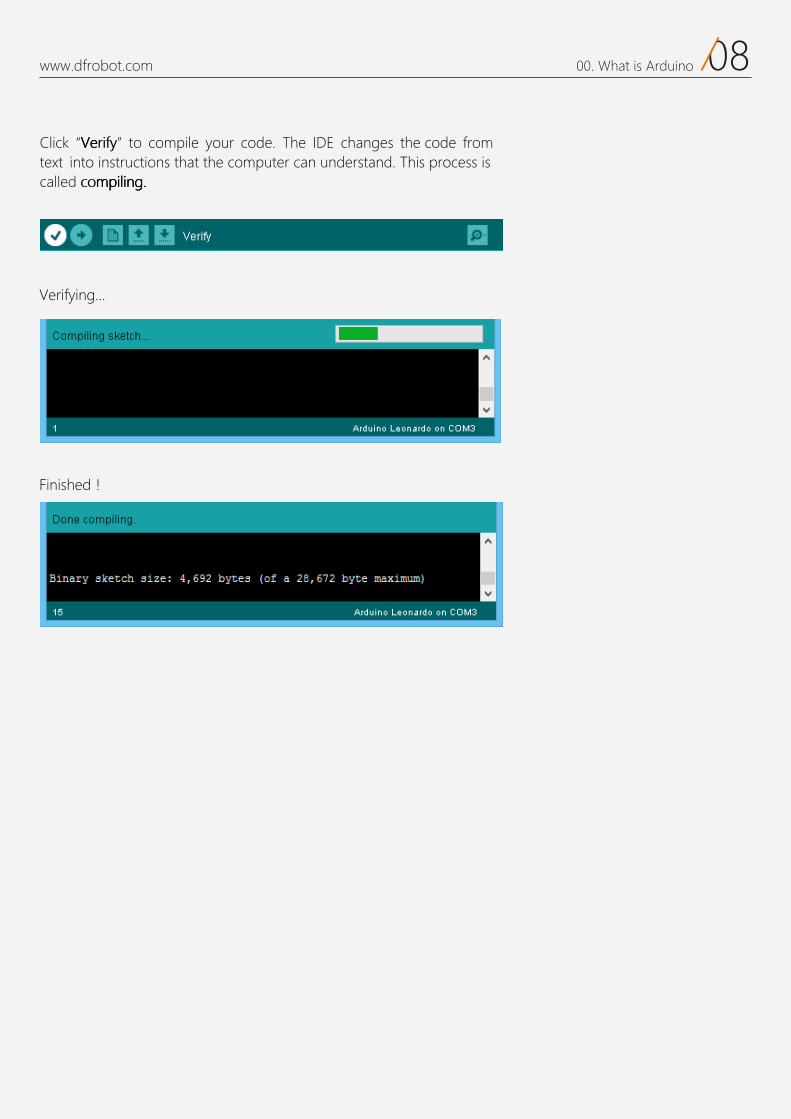
“VVVeee ” from instructions that the computer can understand.
d mmm iiillliiippp nnnggg...
0800. What is Arduino
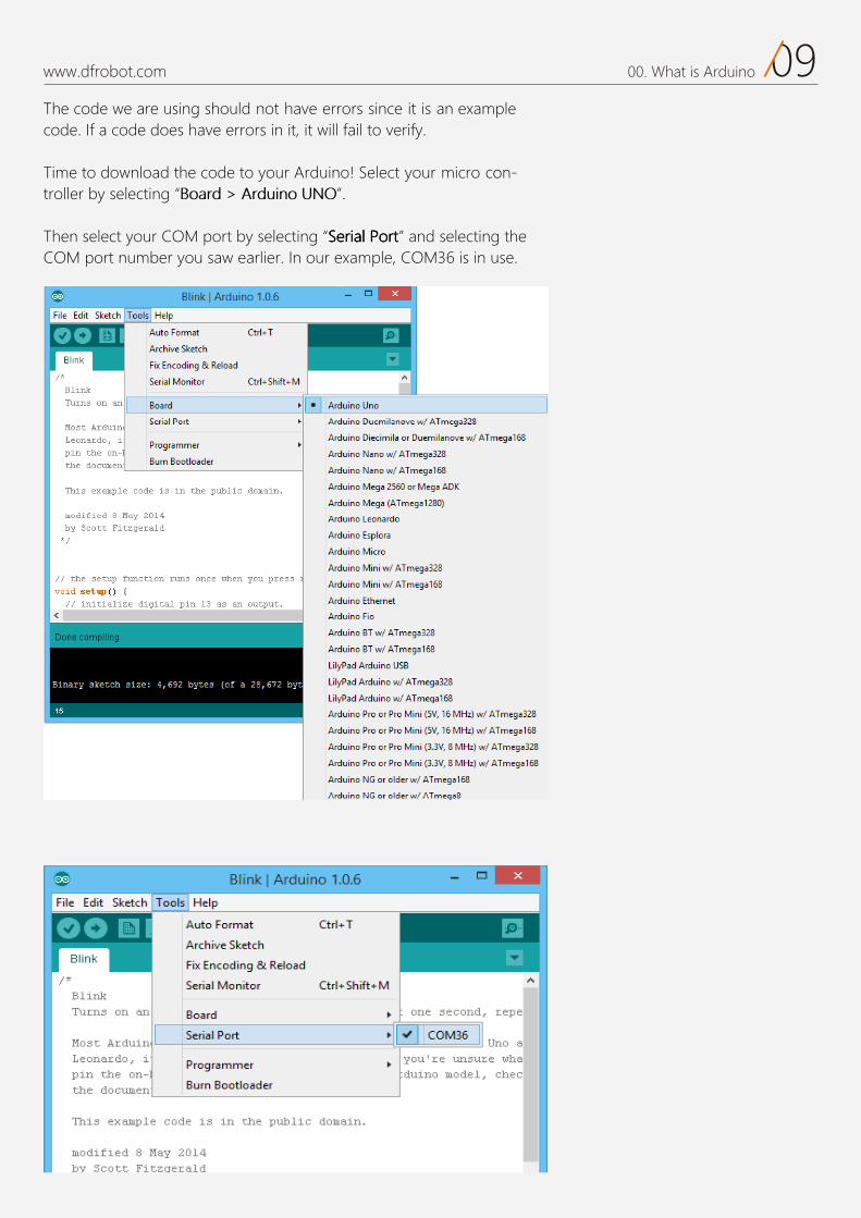
The code we are using should not have errors since it is an examplecode. If a code does have errors in it it will fail to verify.
Time to download the code to your Arduino! Select your micro troller by sele ting “ ”.
Then sele t your C M port by sele ting “ eeeSSS aaaiiirrr lll PPP rrrooo ttt” and sele ting theC M port number you saw earlier. In our example C M36 is in use.
www.dfrobot.com 0900. What is Arduino
10www.dfrobot.com 00. What is Arduino
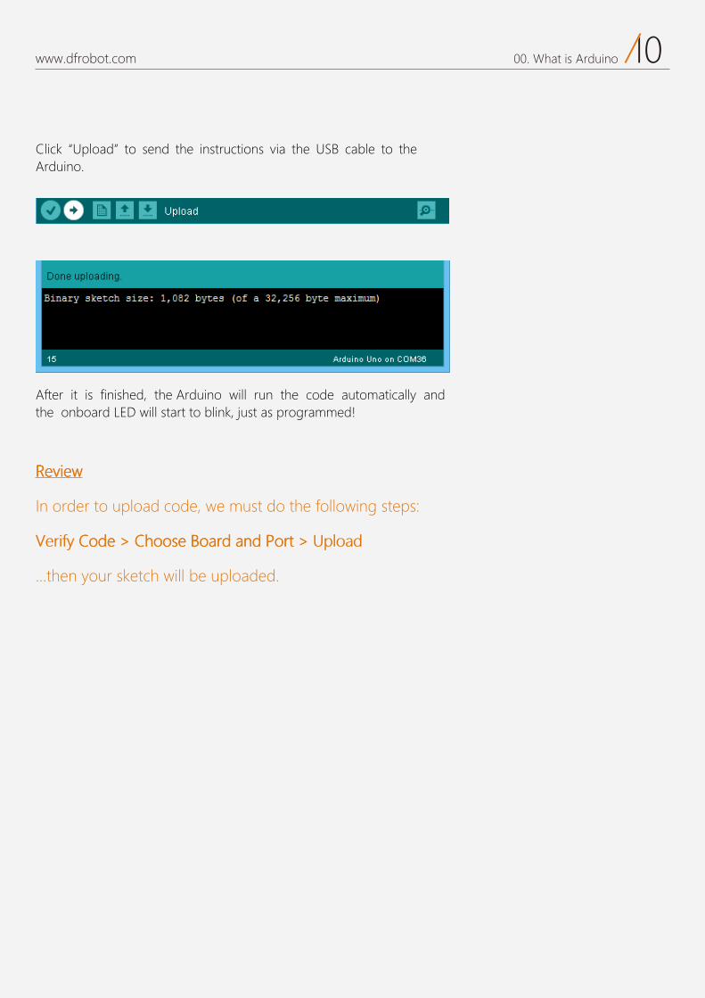
C “ pload”Arduino.
After it is finished, the Arduino will run the code automatically and the onboard LED will start to blink, just as programmed!
RRReeevvv wwweeeiii
In order to upload od must do the following steps:
dddoooCCC eee eeesssoooooohhhCCC >>> BBB dddrrraaaooo dddnnnaaa PPP tttrrrooo >>>
...
01
Project 1LED Flashing
www.dfrobot.com.cn

01www.dfrobot.com 01. LED Flashing
Let's get started! Let’s kickstart our Arduino adventure! In the first lesson, you will learn
the basics of components such as LEDs, buttons and resistors - includ-
ing pull-up and pull-down resistors. Additionally, you will start to write
Arduino sketches to control a LED with your Arduino.
02www.dfrobot.com 01. LED Flashing
LED Flashing In use the Blink on- .
T can have a clear idea of how a LED works and how they can be used in a circuit.
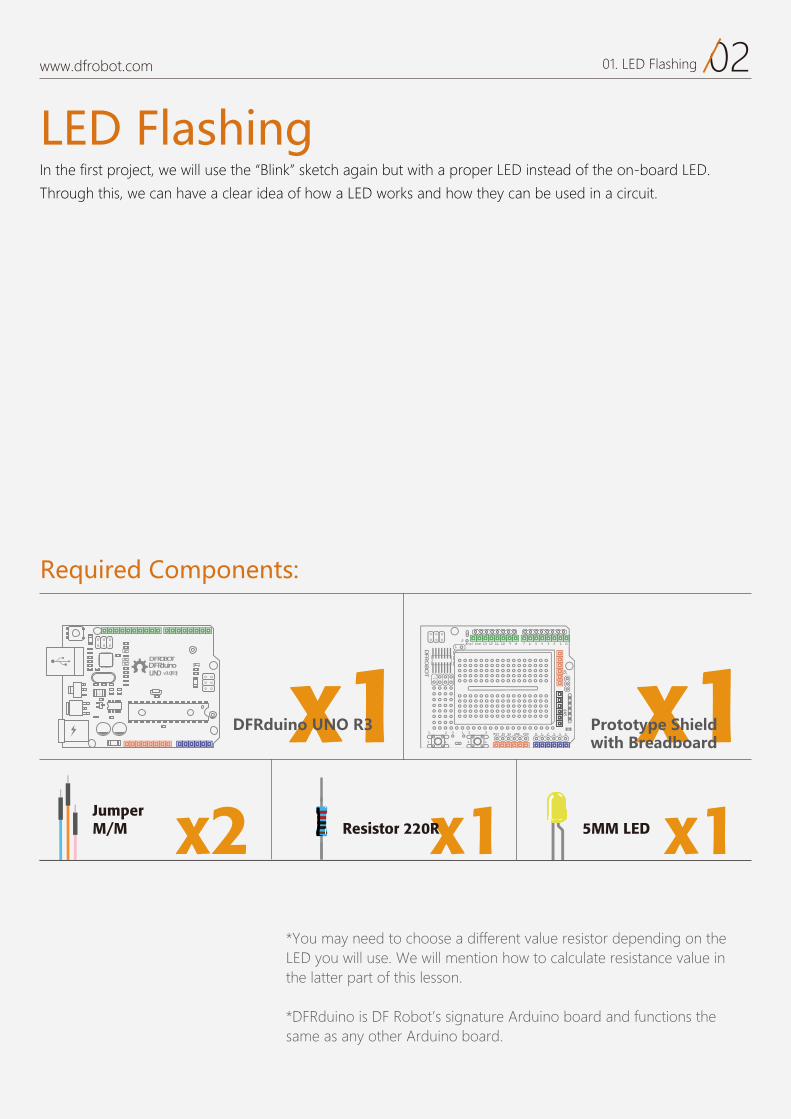
*You may need to choose a different value resistor depending on the LED you will use. We will mention how to calculate resistance value in the latter part of this lesson.
*DFRduino is DF Robot’s signature Arduino board and functions the same as any other Arduino board.
Required Components:
DFRduinoUNO v3.0[R3]
DFROBOT
a050 x1 x1
x1Resistor 220R x15MM LEDx2Jumper M/M
DFRduino UNO R3 Prototype Shieldwith Breadboard
03www.dfrobot.com 01. LED Flashing
Hardware
17 6 5 4 3 2 1 0Aref Gnd 13 12 11 10 9 8
2323 3 1
1414
2
0 1 2 3 4 5RST 3V 5V GND VIN
5VGND
1
+-
-
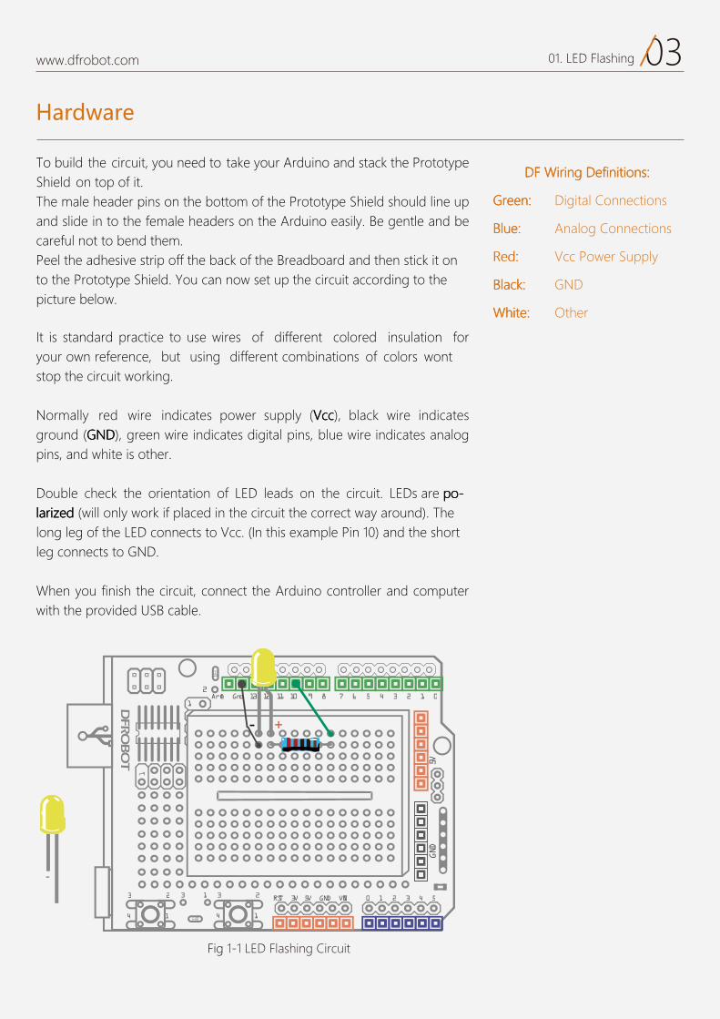
Fig 1-1 LED Flashing Circuit
build the circuit PrototypeShield on top of it.
bottom of the Prototype Shield should line up and slide in to the f . Be gentle and be careful not to bend them.Peel the adhesive strip off the back of the Breadboard and then stick it on to the Prototype Shield. ou can now set up the circuit according to the picture below.
is standard practice to use wires of different colored insulation for your own reference, but using different combinations of colors wontstop the circuit working.
Normally red wire indicates power supply ( ccccccVVV ), black wire indicates ground ( DDDNNNGGG ), green wire indicates digital pins, blue wire indicates analog pins, and white is other.
Double check the orientation of LED leads on the circuit. oooppp era sDEL ---iiirrraaalll zzz .)dnuora yaw tcerroc eht tiucric eht ni decalp fi krow ylno lliw( dddeee he
long leg of the LED connects to Vcc. (In this e ample Pin 10) and the short leg connects to GND.
When you finish the circuit, connect the Arduino controller and computer with the provided
FFFDDD nnnoooiiitttiiinnniiifffeeeDDD gggnnniiirrriiiWWW sss :::
nnneeeeeerrrGGG latigiD::: Connections
eeeuuulllBBB ::: nalog Connections
::: Power Supply
kkkcccaaalllBBB :::
eeetttiiihhhWWW ::: Other
04www.dfrobot.com 01. LED Flashing
Arduino Sketch
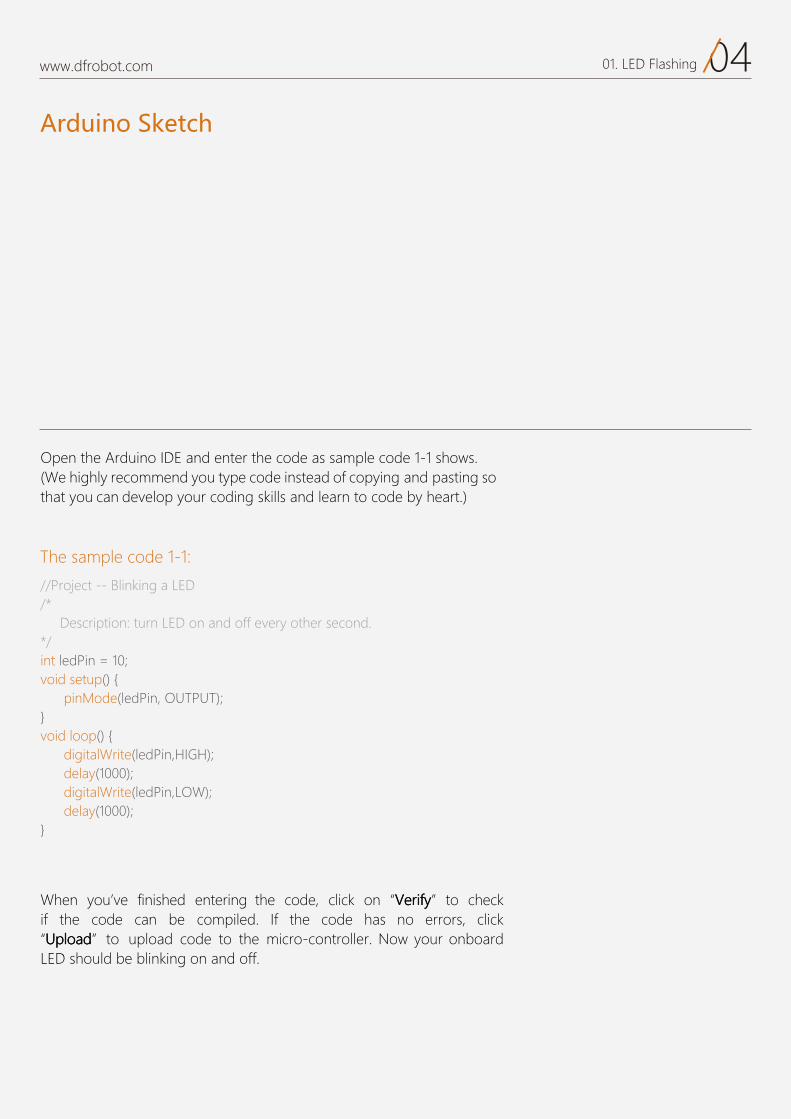
The sample code 1-1:
Open the Arduino IDE and enter the code as sample code 1-1 shows.(We highly recommend you type code instead of copying and pasting so that you can develop your coding skills and learn to code by heart.)
When you ve finished entering the code, click on yyyfffiiirrreeeVVV to check if the code can be compiled. If the code has no errors, click
dddaaaooolllpppUUU to upload code to the micro-controller. Now your onboard LED should be blinking on and off.
//Project -- Blinking a LED /* Description: turn LED on and off every other second. */ int ledPin = 10;void setup() { pinMode(ledPin, OUTPUT);}void loop() { digitalWrite(ledPin,HIGH); delay(1000); digitalWrite(ledPin,LOW); delay(1000);}
05www.dfrobot.com 01. LED Flashing
What is a variable?
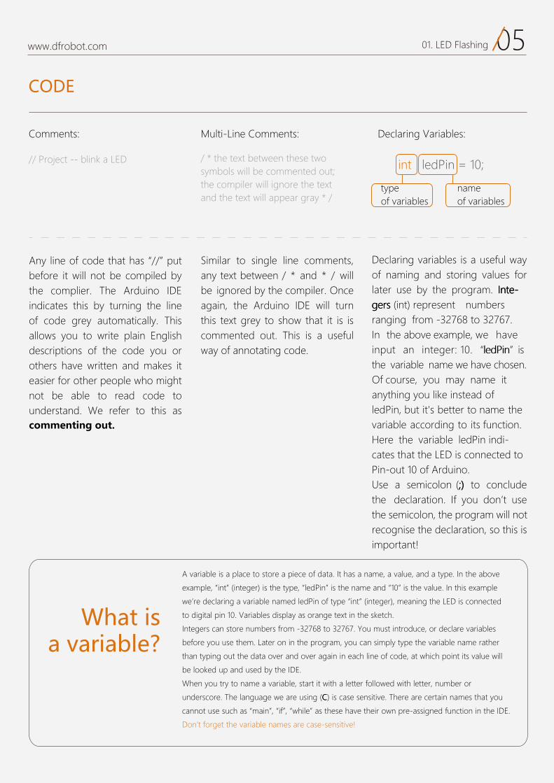
Comments: Multi-Line Comments: Declaring Variables:
A variable is a place to store a piece of data. It has a name, a value, and a type. In the above
e ample, “int” (integer) is the type, “ledPin” is the name and “10” is the value. In this e ample
we’re declaring a variable named ledPin of type “int” (integer), meaning the LED is connected
to digital pin 10. Variables display as orange te t in the sketch.
Integers can store numbers from -32768 to 32767. You must introduce, or declare variables
before you use them. Later on in the program, you can simply type the variable name rather
than typing out the data over and over again in each line of code, at which point its value will
be looked up and used by the IDE.
When you try to name a variable, start it with a letter followed with letter, number or
underscore. T .evitisnes esac si )CCC( gnisu era ew egaugnal eh There are certain names that you
cannot use such as “main”, “if”, “while” as these have their own pre-assigned function in the IDE.
Don’t forget the variable names are case-sensitive!
Similar to single line comments,any text between / * and * / willbe ignored by the compiler. Once again, the Arduino IDE will turn this text grey to show that it is is commented out. This is a useful way of annotating code.
Declaring variables is a useful way of naming and storing values for later use by the program. eeetttnnnIII ---
srebmun tneserper )tni( sssrrreeegggranging from -32768 to 32767.In the above example, we have input an integer: 10. “ ” is the variable name we have chosen.Of course, you may name it anything you like instead of ledPin, but it's better to name the variable according to its function.Here the variable ledPin indi-cates that the LED is connected to Pin-out 10 of Arduino. Use a semicolon (;;;))) to conclude the declaration. If you don’t use the semicolon, the program will not recognise the declaration, so this is important
/ * the text between these two symbols will be commented out; the compiler will ignore the text and the text will appear gray * /
CODE
typeof variables
name of variables
int ledPin = 10;
It is so called variable declaration. A variable is for data storage.In this sample, integers(int) are applied which represent numbers range from -32768 to 32767.The storage content decides the variable type.Here we input 10, an integer.
variable name is the name of the variable, standing for the value.Of course, you may name it at will instead of ledPin), but it's better to name the variable according to its function.lHere the variable ledPin indicates that the LED is connected to Pin-out 10 of Arduino. Please use a ";" to conclude the declaration.The semicolon under English input method is necessary.
Any line of code that has “//” putbefore it will not be compiled bythe complier. The Arduino IDEindicates this by turning the lineof code grey automatically. Thisallows you to write plain Englishdescriptions of the code you orothers have written and makes iteasier for other people who mightnot be able to read code tounderstand. We refer to this ascommenting out.
06www.dfrobot.com 01. LED Flashing
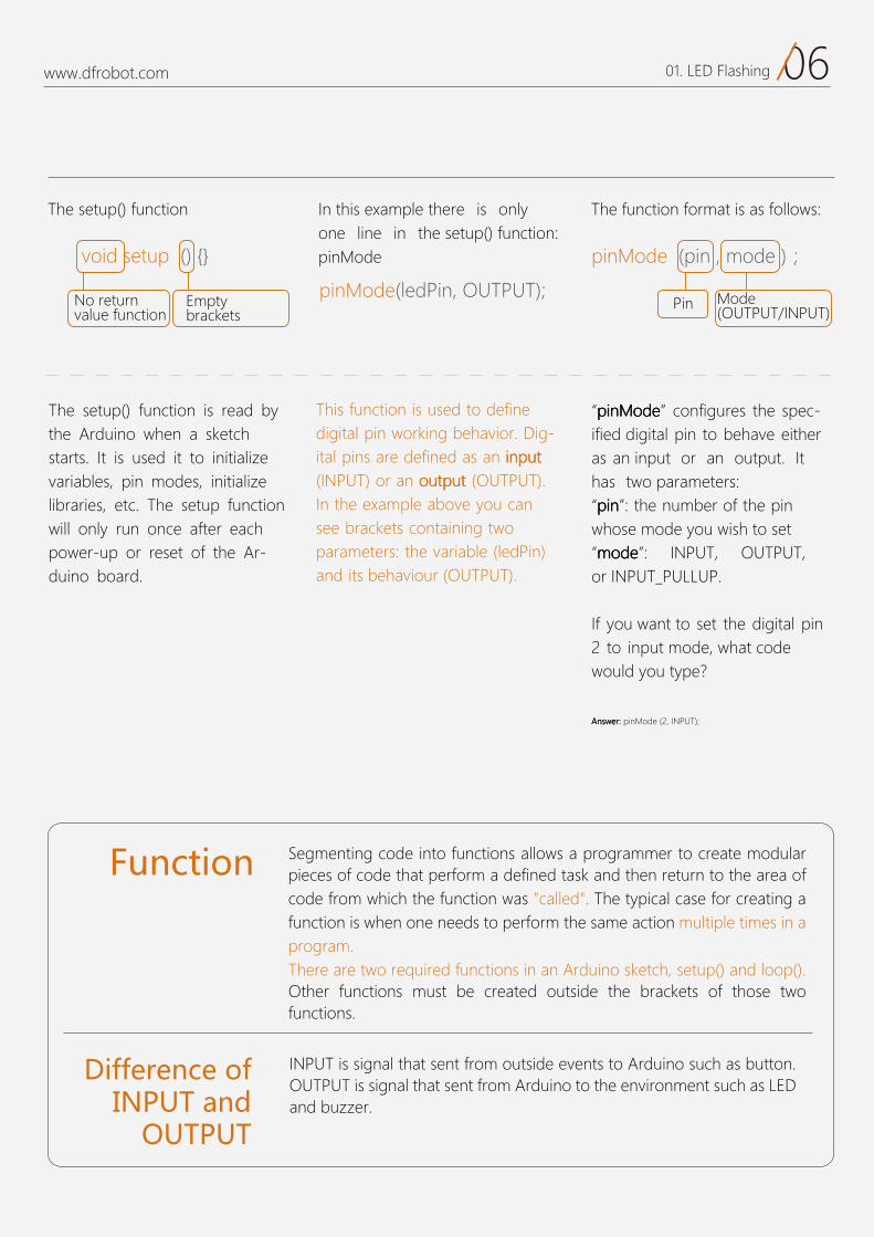
The setup() function The function format is as follows: In this e ple there is only one line in the setup() function:pinMode
This function is used to define digital pin working behavior. Dig-
tttuuupppnnniii na sa denifed era snip lati .)TUPTUO( tttuuuppptttuuuooo na ro )TUPNI(
In the e ample above you can see brackets containing two parameters: the variable (ledPin) and its behaviour (OUTPUT).
The setup() function is read by the Arduino when a sketch starts. It is used it to initialize variables, pin modes, initializelibraries, etc. The setup function will only run once after each power-up or reset of the Ar-duino board.
“ eeedddoooMMMnnniiippp ” configures the spec-ified digital pin to behave either as an input or an output. It has two parameters: “ nnniiippp ”: the number of the pin whose mode you wish to set“ eeedddooommm ”: INPUT, OUTPUT, or INPUT_PULLUP.
If you want to set the digital pin2 to input mode, what codewould you type?
:::rrreeewwwsssnnnAAA pinMode (2, INPUT);
void setup () {}
pinMode(ledPin, OUTPUT);
pinMode
Function Segmenting code into functions allows a programmer to create modular pieces of code that perform a defined task and then return to the area of code from which the function was "called". The typical case for creating a function is when one needs to perform the same action multiple times in a program.There are two required functions in an Arduino sketch, setup() and loop(). Other functions must be created outside the brackets of those two functions.
Difference of INPUT and
OUTPUT
INPUT is signal that sent from outside events to Arduino such as button. OUTPUT is signal that sent from Arduino to the environment such as LED and buzzer.
Empty b kets
Pin Mode (OUTPUT/INPUT)
No return value function
07www.dfrobot.com 01. LED Flashing
digitalWrite(ledPin,HIGH);
The Relation of pinMode(),digitalWrite() and digitalRead()
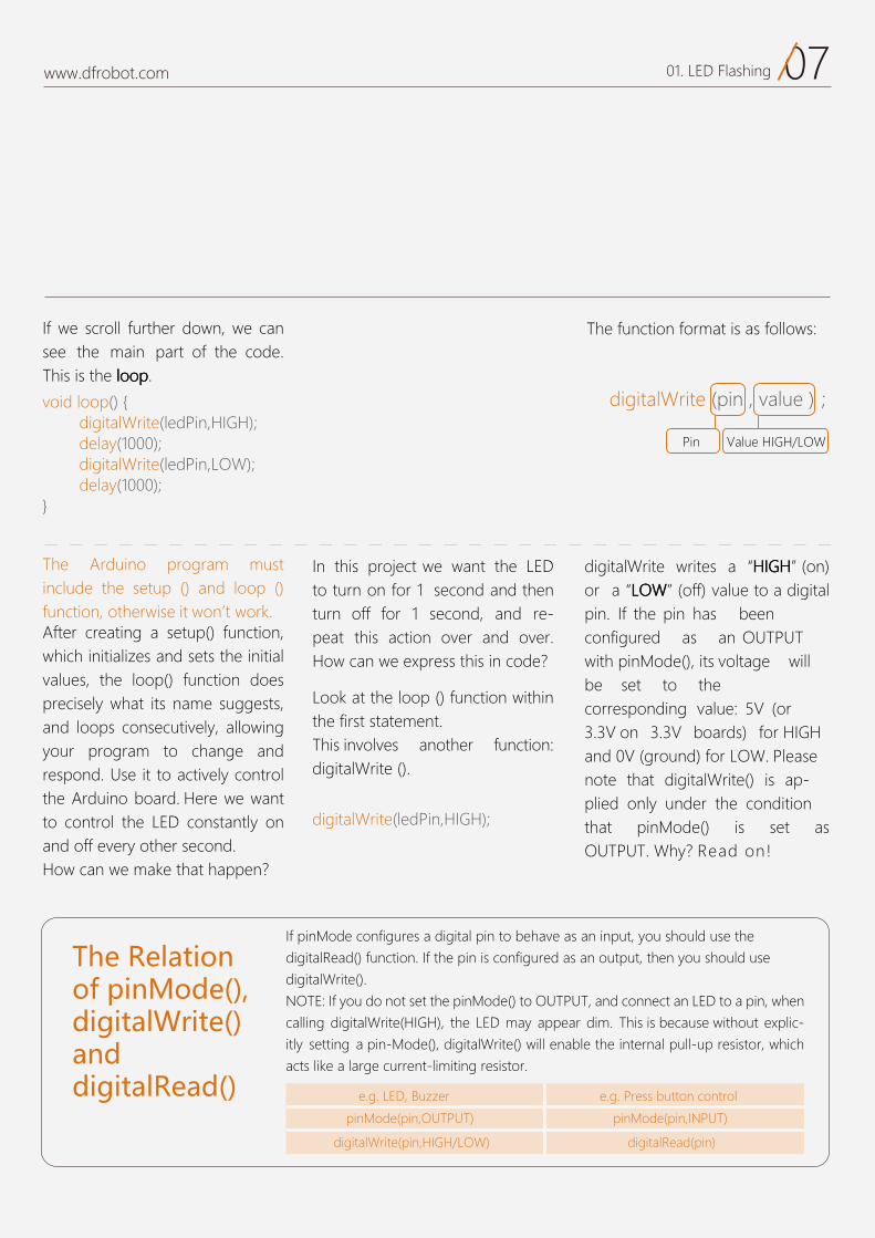
If we scroll further down, we can see the main part of the code.T pppoooooolll eht si sih .
Look at the loop () function within the first statement.This involves another function:digitalWrite ().
The function format is as follows:
The Arduino program must include the setup () and loop () function, otherwise it won t work.After creating a setup() function, which initializes and sets the initial values, the loop() function does precisely what its name suggests, and loops consecutively, allowing your program to change and respond. Use it to actively control the Arduino board. Here we want to control the LED constantly on and off every other second.How can we make that happen?
In this project we want the LED to turn on for 1 second and then turn off for 1 second, and re-peat this action over and over.How can we express this in code?
If pinMode configures a digital pin to behave as an input, you should use thedigitalRead() function. If the pin is configured as an output, then you should use digitalWrite(). NOTE: If you do not set the pinMode() to OUTPUT, and connect an LED to a pin, when calling digitalWrite(HIGH), the LED may appear dim. This is because without explic-itly setting a pin-Mode(), digitalWrite() will enable the internal pull-up resistor, which acts like a large current-limiting resistor.
digitalWrite writes a HHHGGGIIIHHH (on)or a WWWOOOLLL (off) value to a digital pin. If the pin has been configured as an OUTPUT with pinMode(), its voltage will be set to the corresponding value: 5V (or 3.3V on 3.3V boards) for HIGHand 0V (ground) for LOW. Please note that digitalWrite() is ap-plied only under the condition that pinMode() is set as OUTPUT. Why? Read on
void loop() { digitalWrite(ledPin,HIGH); delay(1000); digitalWrite(ledPin,LOW); delay(1000);}
Pin Value HIGH/LOW
digitalWrite (pin , value );
e.g. LED, Buzzer e.g. Press button control
pinMode(pin,OUTPUT)
)nip(daeRlatigid)WOL/HGIH,nip(etirWlatigid
pinMode(pin,INPUT)

08www.dfrobot.com 01. LED Flashing
Next:
delay() pauses the program for the amount of time specified (in miliseconds). (There are 1000 mil-liseconds in 1 second.)
delay(1000);
09www.dfrobot.com 01. LED Flashing
Hardware
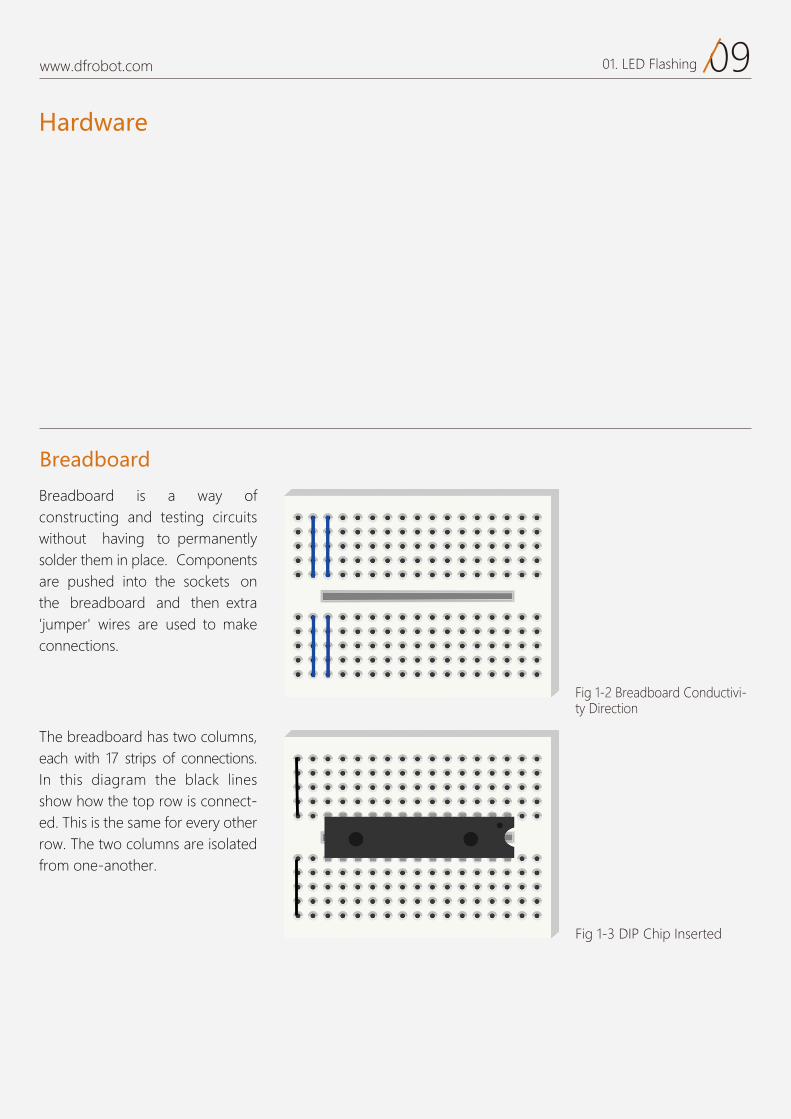
Breadboard
constructing and testing circuits without having to permanentlysolder them in place. Components are pushed into the sockets on the breadboard and then extra
to make connections.
The breadboard has two columns, each with 17 strips of connections.In this diagram the black lines show how the top row is connect-ed. This is the same for every other row. The two columns are isolated from one-another.
vity Direction
Fig 1-3 DIP Chip Inserted
10www.dfrobot.com 01. LED Flashing
The resistor value will be markedon the on the outer package of your resistors, but what should we do in case the label gets lost and there are no measuring tools at hand? The answer is to read the resistor value. This is a group of colored rings around the resistor.Details are available online for those who are interested in having a try.
Here is an online calculator for five-color-ring resistor value calculating: http://www.21ic.com/tools/compo nent/201003/54192.htm
As the name suggests, resistors resist the flow of electricity. Thehigher the value of the resistor, the more resistance it has and the less electrical current will flow through it. The unit of resistance
si hcihw ,mmmhhhOOO eht dellac siusually (letter Omega).Unlike LEDs, resistors arenot polarized (do not have a positive and negative lead) - theycan be connected either way around. Normally a LED needs 2V of voltage and 35 mA cur-rent to be lit, so with a resistor of
would be able to control the flow
you might risk burning it out. Be careful of this because resistors can ge hhh t ooottt!
Resistors Read Resistor Color Rings
If you want to read the resistance value from the resistor color code, visit this website for cal-culation tables: http://www.21ic.com/tools/compo nent/201003/54192.htm
1 1www.dfrobot.com 01. LED Flashing
A light-emitting diode (LED) is a two-lead semiconductor light
diode, which emits light when activated.
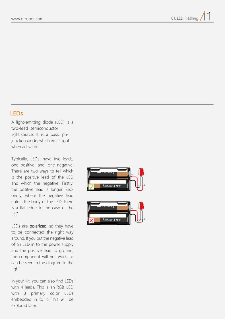
Typically, LEDs have two leads, one positive and one negative.There are two ways to tell which is the positive lead of the LED and which the negative: Firstly, the positive lead is longer. Sec-ondly, where the negative lead enters the body of the LED, there is a flat edge to the case of the LED.
iiirrraaallloooppp era sDEL zzz evah yeht os ,dddeeeto be connected the right way around. If you put the negative lead of an LED in to the power supply and the positive lead to ground, the component will not wor , as can be seen in the diagram to the right.
n your it, you can also find LEDswith 4 leads. This is anwith 3 primary color LEDsembedded in to it. This will be explored later.
LEDs
02
S.O.S distress signal Project 2
www.dfrobot.com.cn
01www.dfrobot.com 02. S.O.S distress signal
Sample code 2-1:
// 3 quick blinks to represent “S” digitalWrite(ledPin,HIGH); delay(150); digitalWrite(ledPin,LOW); delay(100); digitalWrite(ledPin,HIGH); delay(150); digitalWrite(ledPin,LOW); delay(100);
digitalWrite(ledPin,HIGH); delay(150); digitalWrite(ledPin,LOW); delay(100); delay(100); //100 milliseconds as a break of each letter
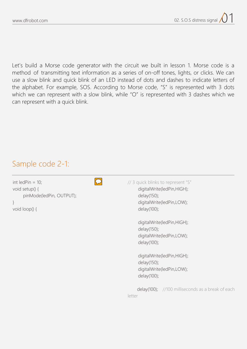
Let’s build a Morse code generator with the circuit we built in lesson 1. Morse code is a method of transmitting text information as a series of on-off tones, lights, or clicks. We can use a slow blink and quick blink of an LED instead of dots and dashes to indicate letters of the alphabet. For example, SOS. According to Morse code, “S” is represented with 3 dots which we can represent with a slow blink, while “O” is represented with 3 dashes which we can represent with a quick blink.
int ledPin = 10;void setup() { pinMode(ledPin, OUTPUT);}void loop() {
// 3 quick blinks to represent “S” digitalWrite(ledPin,HIGH); delay(150); digitalWrite(ledPin,LOW); delay(100); digitalWrite(ledPin,HIGH); delay(150); digitalWrite(ledPin,LOW); delay(100);
digitalWrite(ledPin,HIGH); delay(150); digitalWrite(ledPin,LOW); delay(100); delay(100); //100 milliseconds as a break of each letter
int ledPin = 10;void setup() { pinMode(ledPin, OUTPUT);}void loop() {
//3 quick blinks to represent “0” digitalWrite(ledPin,HIGH); delay(400); digitalWrite(ledPin,LOW); delay(100);
digitalWrite(ledPin,HIGH); delay(400); digitalWrite(ledPin,LOW); delay(100);
digitalWrite(ledPin,HIGH); delay(400); digitalWrite(ledPin,LOW); delay(100); delay(100); // 100 milliseconds delay between each letter
//3 quick blinks to represent “S” again digitalWrite(ledPin,HIGH); delay(150); digitalWrite(ledPin,LOW); delay(100); digitalWrite(ledPin,HIGH); delay(150); digitalWrite(ledPin,LOW); delay(100);
digitalWrite(ledPin,HIGH); delay(150); digitalWrite(ledPin,LOW); delay(100);
;)0005(yaled // wait 5 seconds to repeat the next S. O.S signal}
02www.dfrobot.com 02. S.O.S distress signal
//3 quick blinks to represent “0” digitalWrite(ledPin,HIGH); delay(400); digitalWrite(ledPin,LOW); delay(100);
digitalWrite(ledPin,HIGH); delay(400); digitalWrite(ledPin,LOW); delay(100);
digitalWrite(ledPin,HIGH); delay(400); digitalWrite(ledPin,LOW); delay(100); delay(100); // 100 milliseconds delay between each letter
//3 quick blinks to represent “S” again digitalWrite(ledPin,HIGH); delay(150); digitalWrite(ledPin,LOW); delay(100); digitalWrite(ledPin,HIGH); delay(150); digitalWrite(ledPin,LOW); delay(100);
digitalWrite(ledPin,HIGH); delay(150); digitalWrite(ledPin,LOW); delay(100);
;)0005(yaled // wait 5 seconds to repeat the next S.O.S signal}
//The second project -- S.O.S signalint ledPin = 10;void setup() { pinMode(ledPin, OUTPUT);}void loop() { //3 quick blinks to represent “S” again for(int x=0;x<3;x++){ digitalWrite(ledPin,HIGH); delay(150); digitalWrite(ledPin,LOW); delay(100); } //100 milliseconds delay between of each letter delay(100);
//3 quick blinks to represent “O” for(int x=0;x<3;x++){ digitalWrite(ledPin,HIGH); delay(400); digitalWrite(ledPin,LOW); delay(100); }
//100 milliseconds delay between of each letter delay(100);
03www.dfrobot.com 02. S.O.S distress signal
CODE
Sample code 2-2:
It requires a lot of repetitive work to code like this. Is there a better way? Take a look at the following sample code.
//The second project -- S.O.S signalint ledPin = 10;void setup() { pinMode(ledPin, OUTPUT);}void loop() { //3 quick blinks to represent “S” again for(int x=0;x<3;x++){ digitalWrite(ledPin,HIGH); delay(150); digitalWrite(ledPin,LOW); delay(100); } //100 milliseconds delay between of each letter delay(100);
//3 quick blinks to represent “O” for(int x=0;x<3;x++){ digitalWrite(ledPin,HIGH); delay(400); digitalWrite(ledPin,LOW); delay(100); }
//100 milliseconds delay between of each letter delay(100);
//configure LED on//delay 150 milliseconds //configure LED off//delay 100 milliseconds
//configure LED on//delay 400 milliseconds //configure LED off//delay 100 milliseconds
//The second project -- S.O.S signalint ledPin = 10;void setup() { pinMode(ledPin, OUTPUT);}void loop() { //3 quick blinks to represent “S” again for(int x=0;x<3;x++){ digitalWrite(ledPin,HIGH); delay(150); digitalWrite(ledPin,LOW); delay(100); } //100 milliseconds delay between of each letter delay(100);
//3 quick blinks to represent “O” for(int x=0;x<3;x++){ digitalWrite(ledPin,HIGH); delay(400); digitalWrite(ledPin,LOW); delay(100); }
//100 milliseconds delay between of each letter delay(100);
//The second project -- S.O.S signalint ledPin = 10;void setup() { pinMode(ledPin, OUTPUT);}void loop() { //3 quick blinks to represent “S” again for(int x=0;x<3;x++){ digitalWrite(ledPin,HIGH); delay(150); digitalWrite(ledPin,LOW);
} //100 milliseconds delay between of each letter delay(100);
//3 quick blinks to represent “O” for(int x=0;x<3;x++){ digitalWrite(ledPin,HIGH);
digitalWrite(ledPin,LOW);
}
//100 milliseconds delay between of each letter delay(100);
// 3 quick blinks to represent “S” again for(int x=0;x<3;x++){ digitalWrite(ledPin,HIGH); delay(150); digitalWrite(ledPin,LOW); delay(100); }
// wait 5 seconds to repeat the next S.O.S signal delay(5000); }
// 3 quick blinks to represent “S” again for(int x=0;x<3;x++){ digitalWrite(ledPin,HIGH); delay(150); digitalWrite(ledPin,LOW); delay(100); }
// wait 5 seconds to repeat the next S.O.S signal delay(5000); }
04www.dfrobot.com 02. S.O.S distress signal
After uploading the code, you will see the LED blinking the S.O.S signal and repeating it after 5 seconds. If you were to put the circuit in to a water-proof case, you could use it for sailing or hiking!
// 3 quick blinks to represent “S” again for(int x=0;x<3;x++){ digitalWrite(ledPin,HIGH); delay(150); digitalWrite(ledPin,LOW); delay(100); }
// wait 5 seconds to repeat the next S.O.S signal delay(5000); }
//configure LED on // delay 150 milliseconds //configure LED off //delay 100 milliseconds
// 3 quick blinks to represent “S” again for(int x=0;x<3;x++){ digitalWrite(ledPin,HIGH); delay(150); digitalWrite(ledPin,LOW); delay(100); }
// wait 5 seconds to repeat the next S.O.S signal delay(5000); }
05www.dfrobot.com 02. S.O.S distress signal
CODE
The first part of the two sketches are identical: we have initialized a variable and configured digital pin 10 to carry out the output signal. In the main code loop(), you can find lines similar to the last project to turn the LED on and off. The difference here is that the main code contains 3 independent blocks of statements.
eht ni tnemetats“ ro“f eht rof oS .stod 3 tuptuo ot si kcolb tsrif ehTsketch
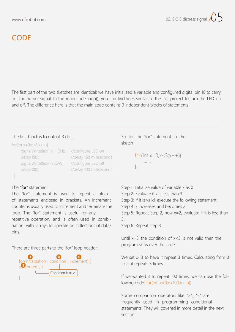
There are three parts to the “for” loop header:
The “ rrrooofff ” statement The “for” statement is used to repeat a block of statements enclosed in brackets. An increment counter is usually used to increment and terminate the loop. The “for” statement is useful for any repetitive operation, and is often used in combi-nation with arrays to operate on collections of data/pins.
Step 1: IStep 2: Evaluate if x is less than 3. Step 3: If it is valid, execute the following statementStep 4: x increases and becomes 2.Step 5: Repeat Step 2 less than 3. Step 6: Repeat step 3
Until x=3, the condition of x<3 is not valid then the program skips over the code.
We set x<3 to have it repeat 3 times. Calculating from 0 to 2, it repeats 3 times.
If we wanted it to repeat 100 times, we can use the fol-lowing code: for(int x=0;x<100;x++){}
Some comparison operators like ">", "<" are frequently used in programming conditional statements. They will covered in more detail in the next section.
for(int x=0;x<3;x++){ digitalWrite(ledPin,HIGH); delay(150); digitalWrite(ledPin,LOW); delay(100); }
for( )
}
Condition is true
for(int x=0;x<3;x++){ ……}
//configure LED on //delay 150 milliseconds//configure LED off //delay 100 milliseconds
1 2 4
3
06www.dfrobot.com 02. S.O.S distress signal
si "<<<" an example of a compar-ison operator. Comparison op-erators allow the Arduino to com-pare two values. Below are some more examples of frequently used comparison operators:
ow you should know how the for loop operates. There are 3 for
loops in the code. The first forloop repeats 3 times and the long-lasting flashing alternates 3 times, giving an output of 3 dotsrepresenting the letter S in Morse code. The second for loop also repeats 3 times and the temporary flashing alternates 3 times, giving an output of 3 dashes , repre-senting the letter O in Morse code.The third for loop is identical to the first, and also outputs an S in Morse code.
Beware of accidentally using asingle equals sign (e.g. if (x = 10) ). The single equals sign is the as-signment operator, and sets x to 10 (puts the value 10 into the variable x). A double equals sign is comparison operator instead(e.g. if (x == 10) ), Also, be careful that there is no space between <= or >=.
You can also use arithmetic operators such as + - * / .
==(equal)!=(not equal)<(less than)>(greater than)<=(less than or equal) >=(greater than or equal)
Here are some common operators that you might use:
You might notice there are various x variables in different blocks of code, but they don’t interfere with each other. Because it has a limited scope in a specific block of function. It is the counterpart of global variables that needs to declare at the top of the code out of setup() and loop()function and you will be able to use it anywhere in the code.
07www.dfrobot.com 02. S.O.S distress signal
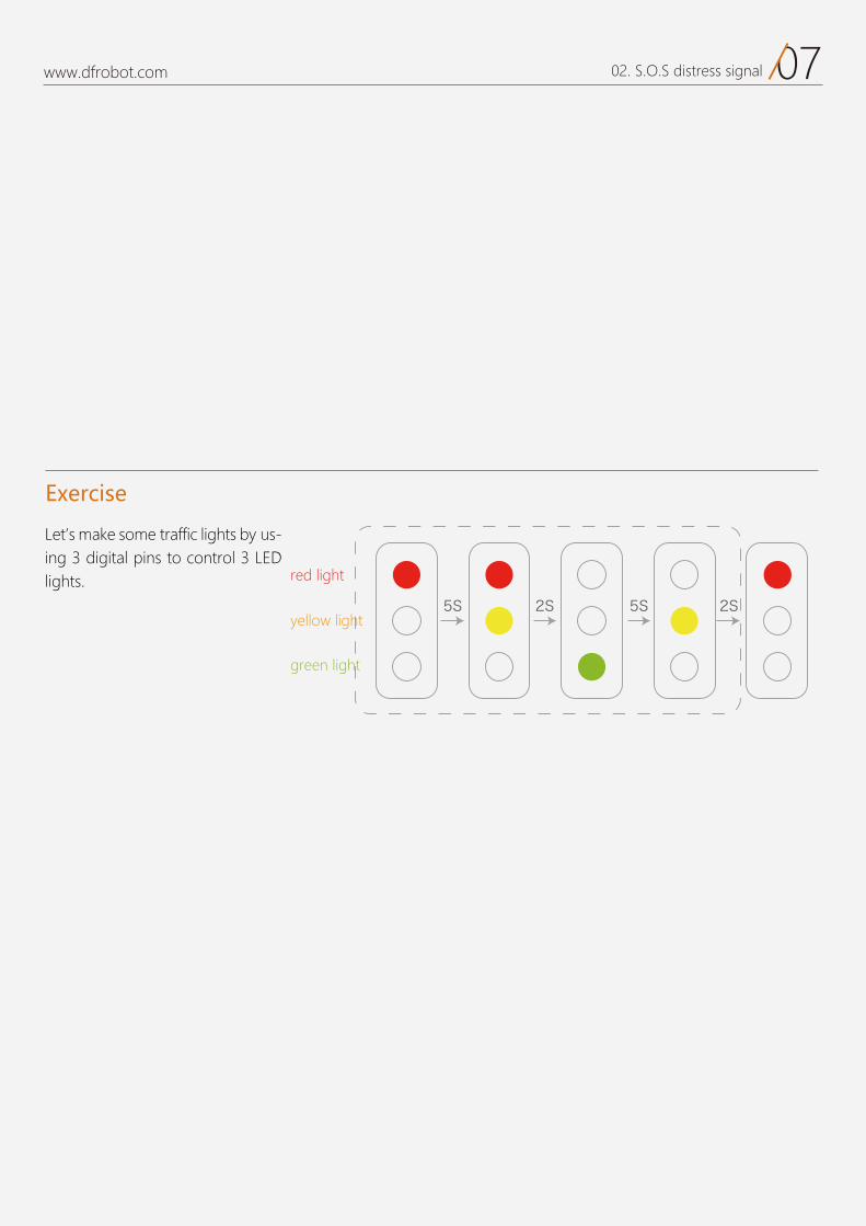
Let’s make some traffic lights by us-ing 3 digital pins to control 3 LED lights.
Exercise
red light
5S 2S 5S 2Syellow light
green light
03
Interactive traffic lights Project 3
www.dfrobot.com
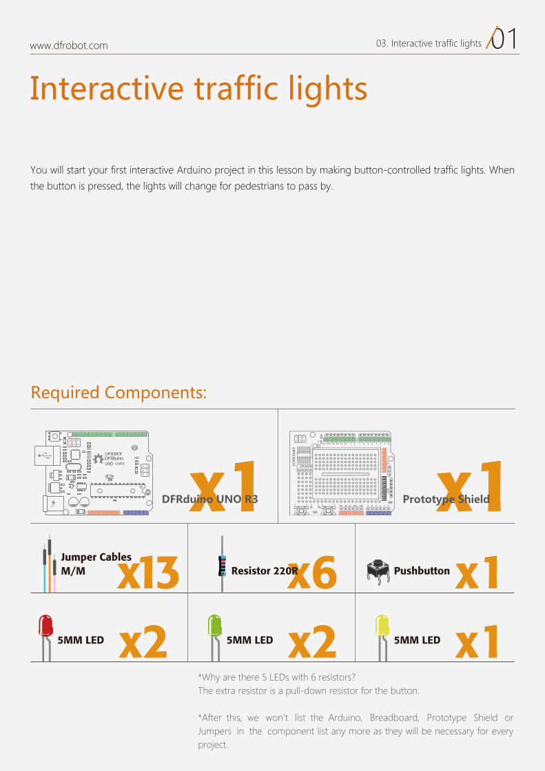
Interactive traffic lights
You will start your first interactive Arduino project in this lesson by making button-controlled traffic lights. When
the button is pressed, the lights will change for pedestrians to pass by.
*Why are there 5 LEDs with 6 resistors?The extra resistor is a pull-down resistor for the button.
*After this, we won t list the Arduino, Breadboard, Prototype Shield orJumpers in the component list any more as they will be necessary for every project.
Required Components:
DFRduinoUNO v3.0[R3]
DFROBOT
a050 x1 x1
x6Resistor 220R x1Pushbuttonx13M/M Jumper Cables
Prototype Shield
x15MM LEDx25MM LED x25MM LED
www.dfrobot.com
DFRduino UNO R3
0103. Interactive traffic lights
17 6 5 4 3 2 1 0Aref Gnd 13 12 11 10 9 8
2323 3 1
1414
2
0 1 2 3 4 5RST 3V 5V GND VIN
5VGND
1
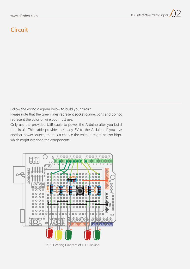
Fig 3-1 Wiring Diagram of LED Blinking
Follow the wiring diagram below to build your circuit.Please note that the green lines represent socket connections and do not represent the color of wire you must use.Only use the provided USB cable to power the Arduino after you build the circuit. This cable provides a steady 5V to the Arduino. If you use another power source, there is a chance the voltage might be too high,which might overload the components.
www.dfrobot.com
Circuit
0203. Interactive traffic lights
Code
Sample code 3-1:
The sketch is originally from “Beginning Arduino”
// PROJECT 3 Interactive Traffic Light int carRed = 12; //configure traffic light int carYellow = 11;int carGreen = 10;int button = 9; //pin of button int pedRed = 8; //configure light for pedestriansint pedGreen = 7;int crossTime = 5000; //time for pedestrians to pass unsigned long changeTime; //time that the button is pressed
void setup() { //configure all LEDs as output pinMode(carRed, OUTPUT); pinMode(carYellow, OUTPUT); pinMode(carGreen, OUTPUT); pinMode(pedRed, OUTPUT); pinMode(pedGreen, OUTPUT); pinMode(button, INPUT); //configure button as input digitalWrite(carGreen, HIGH); //initialize green traffic light on
digitalWrite(pedRed, LOW); //initialize red pedestrian light off }
void loop() { int state = digitalRead(button); // test if the button is pressed and if 5 seconds have passed after it is pressed lately. if(state == HIGH && (millis() - changeTime)> 5000){ //carry out the function of changing LED changeLights(); }}void changeLights() {
www.dfrobot.com 0303. Interactive traffic lights
After uploading the sketch, take a look at how LED changes. First, the green traffic light is on and the red pedestrian light is on to allow cars to pass. Once you press the button, the pedestrian light changes from red to green and the traffic light changes from just green to green and red. There is then a delay allowing time for pedes-trians to cross the street. When the delay comes to the end, the green pedestrian light blinks to notify pedestrians. When this finishes, the lights change back to the initial state with the green traffic light on and red pedestrian light on.
The above codes do look complex, but actually, it is not that difficult to understand the ideas in practice.
If you find it is difficult for you to follow, try to draw a diagram like the one in the homeworkof Project 2. This will helpyou to comprehend the codes a little better. Good luck!
www.dfrobot.com
digitalWrite(carGreen, LOW); //green traffic light off digitalWrite(carYellow, HIGH); //yellow traffic light on delay(2000); //wait for 2 secs digitalWrite(carYellow, LOW); // yellow traffic light off digitalWrite(carRed, HIGH); //red traffic light on delay(1000); // wait for 1 sec for safety reason digitalWrite(pedRed, LOW); //red pedestrian light off digitalWrite(pedGreen, HIGH); //light pedestrian light on
delay(crossTime); // time for crossing street //blink green pedestrian light to notify pedestrians to pass soon for (int x=0; x<10; x++) { digitalWrite(pedGreen, HIGH); delay(250); digitalWrite(pedGreen, LOW); delay(250); } digitalWrite(pedRed, HIGH); //red pedestrian light on delay(500);
digitalWrite(carRed, LOW); //red traffic light off digitalWrite(carYellow, HIGH); //yellow traffic light on delay(1000); delay(1000); digitalWrite(carYellow, LOW); //yellow traffic light off digitalWrite(carGreen, HIGH); //green traffic light on
changeTime = millis() // record the duration since last change //back to the loop of main code}
0403. Interactive traffic lights
Based on the previous 2 projects, most of the codes should make sense for you. The codes start from a set of variable declarations, but we have used a new term. It is e plained below:
Then we enter the setup() function to configure the LED and button.
Code
www.dfrobot.com
unsigned long changeTime; pinMode(button, INPUT);
Can thebox of variablebe infinite big?
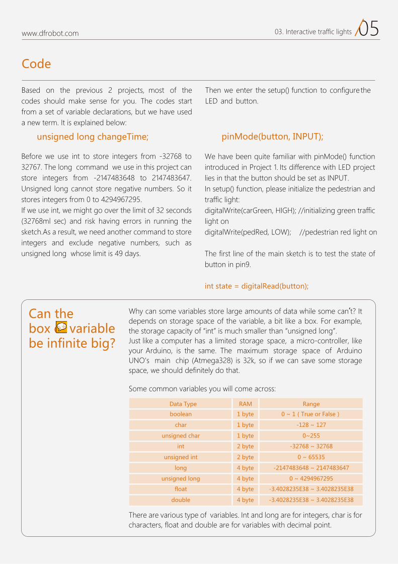
Why can some variables store large amounts of data while some can’t? It depends on storage space of the variable, a bit like a box. For example, the storage capacity of int is much smaller than unsigned long . Just like a computer has a limited storage space, a micro-controller, like your Arduino, is the same. The maximum storage space of Arduino UNO’s main chip (Atmega328 is 32k, so if we can save some storage space, we should definitely do that.
Some common variables you will come across
There are various type of variables. Int and long are for integers, char is for characters, float and double are for variables with decimal point.
Data Type RAM
1 byte
1 byte
1 byte
2 byte
2 byte
4 byte
4 byte
4 byte
4 byte
Range
boolean
char
unsigned char
int
unsigned int
long
unsigned long
float
double
-128 ~ 127
0~255
-32768 ~ 32768
0 ~ 65535
-2147483648 ~ 2147483647
0 ~ 4294967295
-3.4028235E38 ~ 3.4028235E38
-3.4028235E38 ~ 3.4028235E38
0 ~ 1(True or False)
0503. Interactive traffic lights
We have been quite familiar with pinMode() function introduced in Project 1. Its difference with LED project lies in that the button should be set as INPUT.In setup() function, please initialize the pedestrian and traffic light:digitalWrite(carGreen, HIGH); //initializing green traffic light ondigitalWrite(pedRed, LOW); //pedestrian red light on
The first line of the main sketch is to test the state of button in pin9.
int state = digitalRead(button);
Before we use int to store integers from -32768 to 32767. The long command we use in this project can store integers from -2147483648 to 2147483647. Unsigned long cannot store negative numbers. So it stores integers from 0 to 4294967295.If we use int, we might go over the limit of 32 seconds (32768ml sec) and risk having errors in running the sketch.As a result, we need another command to store integers and exclude negative numbers, such as unsigned long whose limit is 49 days.
In the setup() function, there is a new command digitalRead() !
Here we use the if() command to test conditions.
This is a command inside the if()command.
This command is used to read the digital pin’s state, whether high (1) or low (0).The command has one parameter: pin number .
This command passes the signalread to the variable state for tnemgduj rehtruf .
When state value is HIGH or 1, it means that the push button has been pressed.When state value is LOW or 0, it means that the push but-ton hasn't been pressed.
We can check the value of stateto test if the button is pressed.
if(state == HIGH && (millis() changeTime)> 5000) {
//carry out light-changing command changeLights();
}
If the condition specified in the parenthesis is satisfied, it carries out the statement. If not, the program skips over the code.
In other words, if the if expression returns TRUE, the statement is run.If it returns FALSE, the statement is skipped.
In the above codes, the first condition is whether variable state is HIGH (or on). When the push button is pressed, the state turns HIGH. The second condition is that value returns for millis()minus that for change Time is more than 5000.
W e u s e "&&" to connect the two conditions. This is a logical op-erator, showing that we want theabove two conditions met at the same time.
millis() is a command that returns the number of milliseconds since the Arduino board began running the current program. This number will overflow (go back to zero), after approximately 50 days.Here we use it to calculate if thereis a break of more than 5 seconds when pressing button more than once. If shorter than 5 seconds, it skips over the code to avoid errors caused by accidentally pressing the button.
This is a function created outside of loop() function. When we want to use it, we just need to cite the name of the function. It has not returned a value and does not need to pass parameters so it is a void function. When it is used, the pro-gram will run the function and go back to the main code afterwards. Beware not to miss the parenthe-sis when using this function as otherwise it will not be recognised.
www.dfrobot.com
changeLights();
Logical Operators
Some other common boolean operators:
pin
digitalRead (pin) if(condition){ Statement;}
&& ——logic and (True only if both conditions are true)|| —— logic or (True if either condition is true)!—— logic not (True if the condition is false)
0603. Interactive traffic lights
If it reaches the condition in the parenthesis, it carries out the following statement. If not,the program skips over the code.An expression refers to the criterion for judging, which are usually in the form of relation or logic. In addition, it also refers to a value directly.An expression refers to the criterion for judging, which are usually in the form of relation or logic. In addition, it also refers to a value directly.If the IF expression returns TRUE, run if statement. If it returns FALSE, skip if statement.In the above codes, the first condition is whether variable state is HIGH.When the push button is pressed, state turns HIGH.The second condition is that value returns for millis() minus that for change Time is more than 5000.There should be "&&" connecting the two conditions.It is a logical operator, standing for meeting the above two conditions at the same time.Millis() is a command that returns the number of milliseconds since the Arduino board began running the current program. This number will overflow (go back to zero), after approximately 50 days. Here we use it to calculate if there are a break of more than 5 seconds when pressing button more than once.If shorter than 5 seconds, it skips over the code to avoid errors from accidentally pressing button.
www.dfrobot.com
Components
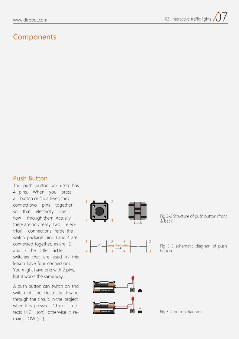
Push Button The push button we used has 4 pins. When you press a button or flip a lever, they connect two pins together so that electricity can flow through them. Actually, there are only really two elec-trical connections; inside the switch package pins 1 and 4 are connected together, as are 2 and 3. The little tactile switches that are used in this lesson have four connections.You might have one with 2 pins,but it works the same way.
A push button can switch on and switch off the electricity flowing through the circuit. In the project,when it is pressed, D9 pin de-tects HIGH (on), otherwise it re-mains LOW (off).
1 2
back
press the button
4 3
1 2
4 3
1 2
4 3
Fig 3-4 button diagram
Fig 3-2 Structure of push button (front & back)
Fig 3-3 schematic diagram of push button
0703. Interactive traffic lights
www.dfrobot.com
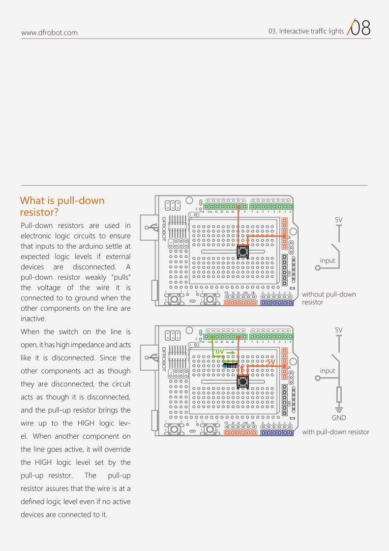
Pull-down resistors are used in electronic logic circuits to ensure that inputs to the arduino settle at expected logic levels if external devices are disconnected. A pull-down resistor weakly "pulls" the voltage of the wire it is connected to to ground when the other components on the line are inactive.
When the switch on the line is
open, it has high impedance and acts
like it is disconnected. Since the
other components act as though
they are disconnected, the circuit
acts as though it is disconnected,
and the pull-up resistor brings the
wire up to the HIGH logic lev-
el. When another component on
the line goes active, it will override
the HIGH logic level set by the
pull-up resistor. The pull-up
resistor assures that the wire is at a
defined logic level even if no active
devices are connected to it.
17 6 5 4 3 2 1 0Aref Gnd 13 12 11 10 9 8
2323 3 1
1414
2
0 1 2 3 4 5RST 3V 5V GND VIN
5VGND
1
0V0V5V5V
input
GND
5V
with pull-down resistor
17 6 5 4 3 2 1 0Aref Gnd 13 12 11 10 9 8
2323 3 1
1414
2
0 1 2 3 4 5RST 3V 5V GND VIN5V
GND
1
input
5V
without pull-down resistor
What is pull-down resistor?
0803. Interactive traffic lights
www.dfrobot.com
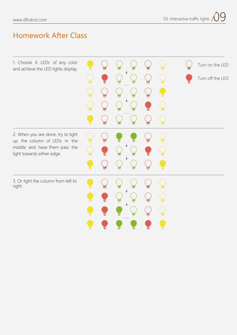
1. of any colorand achieve the LED lights display.
2. up the column of LEDs in the middle and have them pass the light towards either edge.
3 light the column from left to
Homework After Class
Turn off the LED
Turn on the LED
0903. Interactive traffic lights
04
Breathing LEDProject 4
www.dfrobot.com
01www.dfrobot.com 04. Breathing LED
Breathing LED
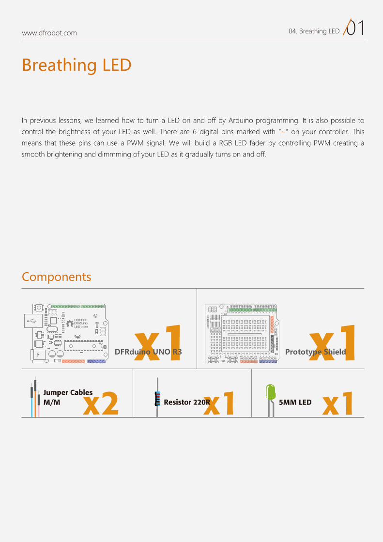
In previous lessons, we learned how to turn a LED on and off by Arduino programming. It is also possible to
control the brightness of your LED as well. There are 6 digital pins marked with “~” on your controller. This
means that these pins can use a PWM signal. We will build a RGB LED fader by controlling PWM creating a
smooth brightening and dimmming of your LED as it gradually turns on and off.
Components
DFRduinoUNO v3.0[R3]
DFROBOT
a050 x1 x1
x1Resistor 220Rx2M/M Jumper Cables
DFRduino UNO R3 Prototype Shield
x15MM LED
02www.dfrobot.com 04. Breathing LED
17 6 5 4 3 2 1 0Aref Gnd 13 12 11 10 9 8
2323 3 1
1414
2
0 1 2 3 4 5RST 3V 5V GND VIN
5VGND
1
+-
Circuit
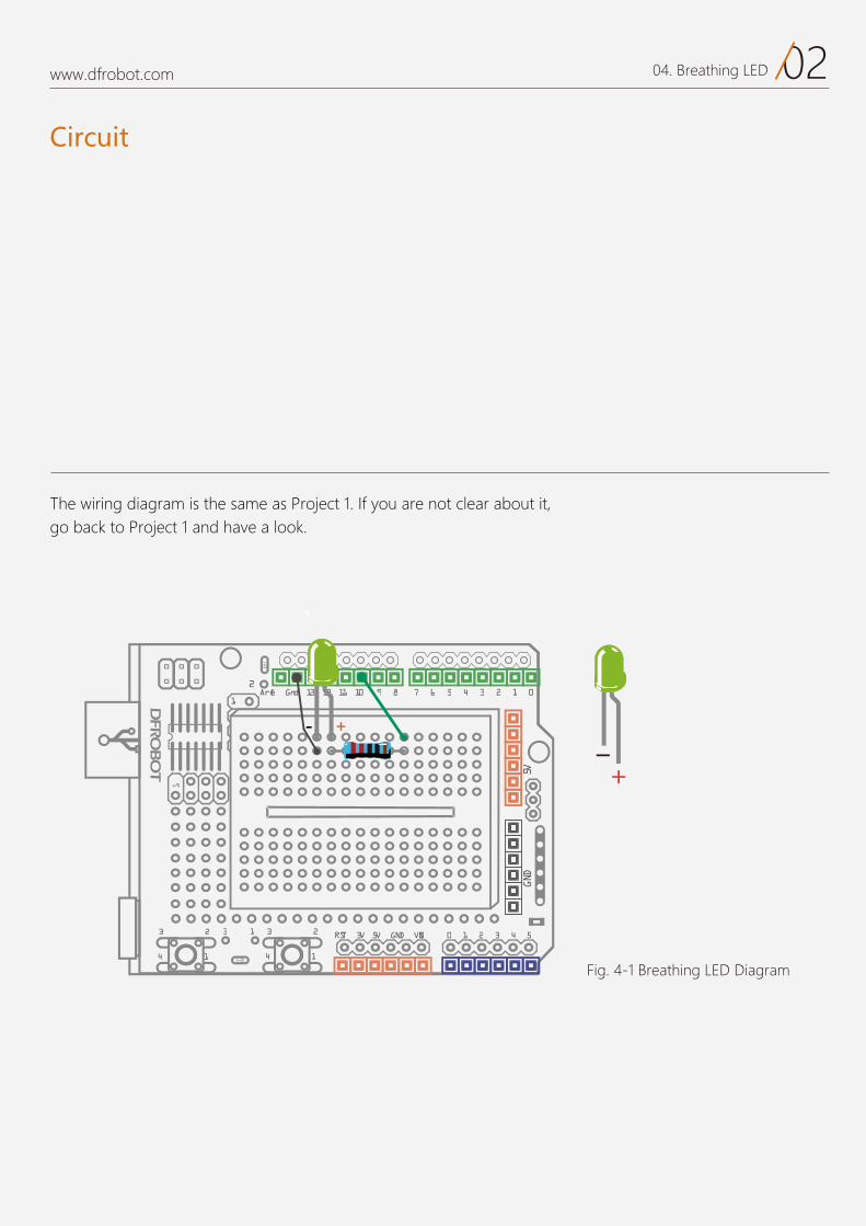
The wiring diagram is the same as Project 1. If you are not clear about it, go back to Project 1 and have a look.
Fig. 4-1 Breathing LED Diagram
03www.dfrobot.com 04. Breathing LED
Arduino Code
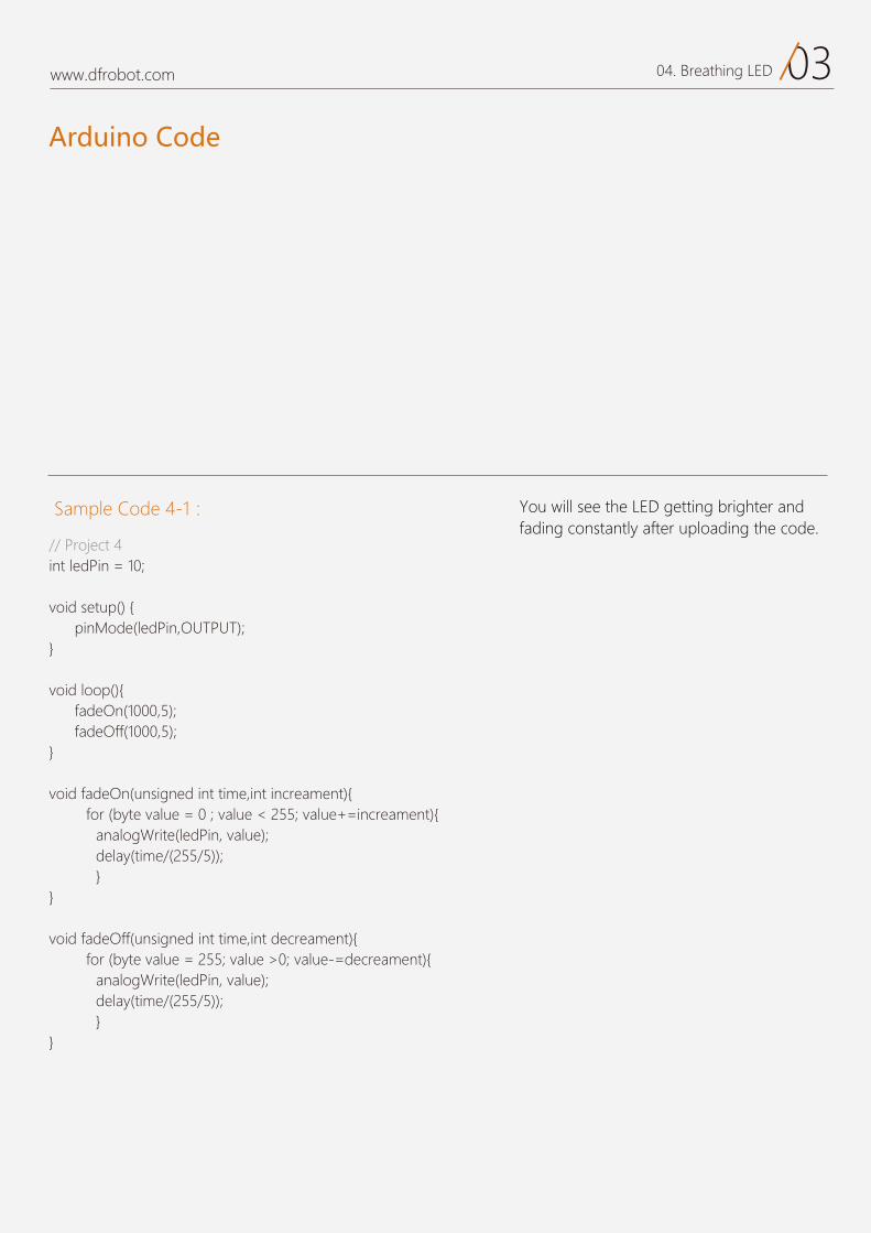
Sample Code 4-1: You will see the LED getting brighter and fading constantly after uploading the code.
// Project 4 int ledPin = 10;
void setup() { pinMode(ledPin,OUTPUT);}
void loop(){ fadeOn(1000,5); fadeOff(1000,5);}
void fadeOn(unsigned int time,int increament){for (byte value = 0 ; value < 255; value+=increament){
analogWrite(ledPin, value); delay(time/(255/5)); } }
void fadeOff(unsigned int time,int decreament){for (byte value = 255; value >0; value-=decreament){
analogWrite(ledPin, value); delay(time/(255/5)); }}
04www.dfrobot.com 04. Breathing LED
Most of the code we are already very familiar with, such as initializing variable declarations, setting pins, setting up the for loop, as well as the function call.
In the main code, we only use 2 functions. You will have a clear idea after checking one of them as below.
This is a new command in the for() function.
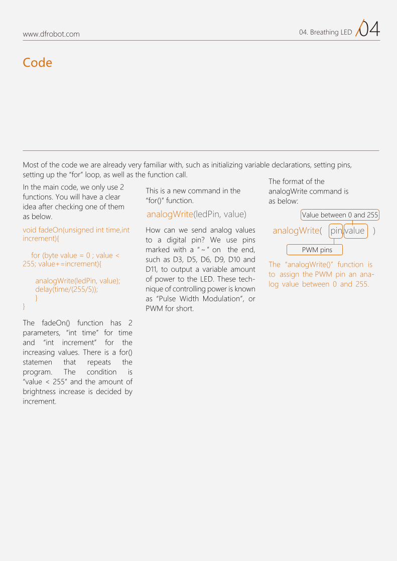
The format of the analogWrite command is as below:
How can we send analog values to a digital pin? We use pins marked with a ~ on the end, such as D3, D5, D6, D9, D10 and D11, to output a variable amount of power to the LED. These tech-nique of controlling power is known as Pulse Width Modulation , or PWM for short.
The analogWrite() function is to assign the PWM pin an ana-log value between 0 and 255.
void fadeOn(unsigned int time,int increment){
for (byte value = 0 ; value < 255; value+=increment){
analogWrite(ledPin, value); delay(time/(255/5)); } }
Code
analogWrite(ledPin, value)
analogWrite( pin,value )
PWM pins
Value between 0 and 255
The fadeOn() function has 2parameters, “int time” for timeand “int increment” for theincreasing values. There is a for()statemen that repeats the program. The condition is“value < 255” and the amount ofbrightness increase is decided byincrement.
05www.dfrobot.com 04. Breathing LED
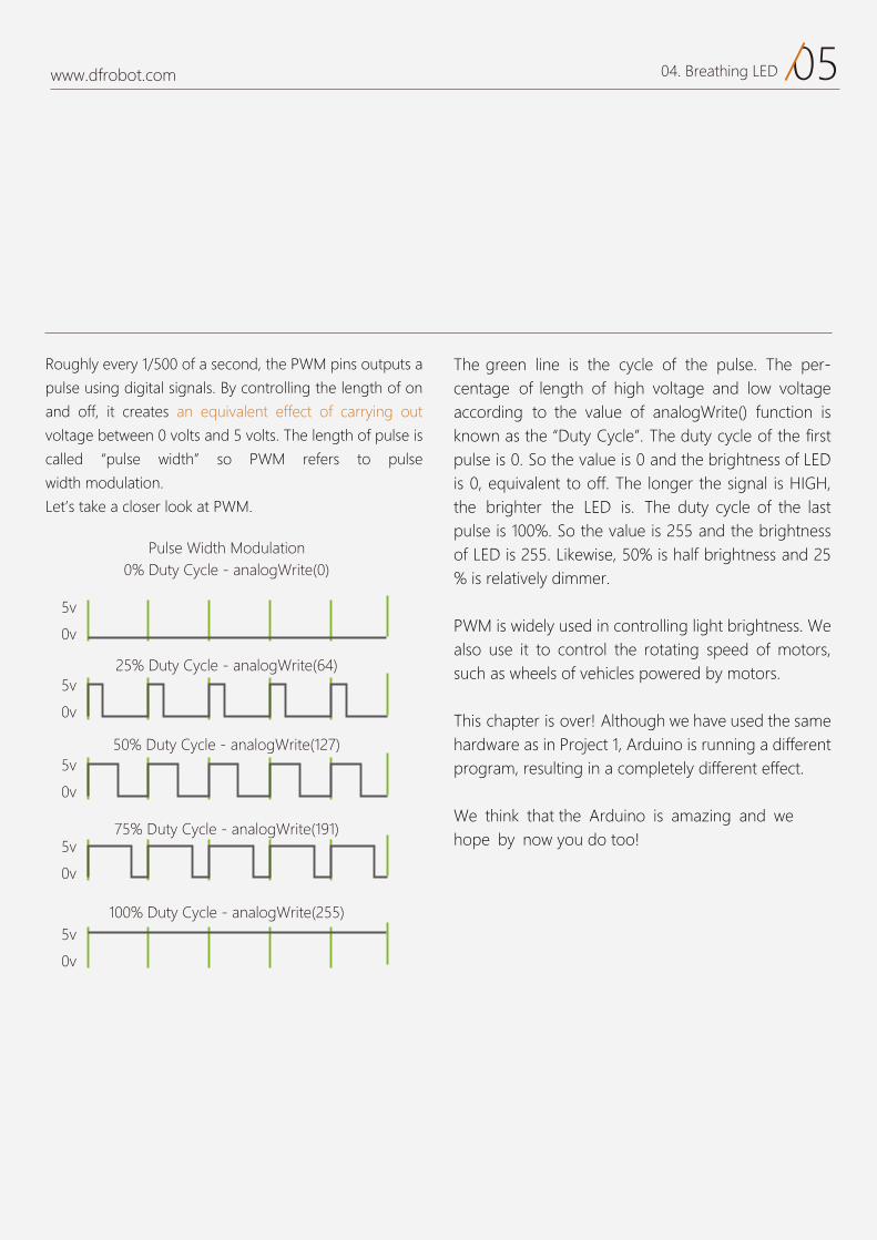
Roughly every 1/500 of a second, the PWM pins outputs a
pulse using digital signals. By controlling the length of on
and off, it creates an equivalent effect of carrying out
voltage between 0 volts and 5 volts. The length of pulse is
called “pulse width” so PWM refers to pulse
width modulation.
Let’s take a closer look at PWM.
The green line is the cycle of the pulse. The per-centage of length of high voltage and low voltage according to the value of analogWrite() function is known as the “Duty Cycle”. The duty cycle of the first pulse is 0. So the value is 0 and the brightness of LED is 0, equivalent to off. The longer the signal is HIGH,the brighter the LED is. The duty cycle of the last pulse is 100%. So the value is 255 and the brightness of LED is 255. Likewise, 50% is half brightness and 25 % is relatively dimmer.
PWM is widely used in controlling light brightness. We also use it to control the rotating speed of motors, such as wheels of vehicles powered by motors.
This chapter is over! Although we have used the same hardware as in Project 1, Arduino is running a different program, resulting in a completely different effect.
We think that the Arduino is amazing and we hope by now you do too!
5v
0v
5v
0v
5v
0v
5v
0v
5v
0v
Pulse Width Modulation0% Duty Cycle - analogWrite(0)
25% Duty Cycle - analogWrite(64)
50% Duty Cycle - analogWrite(127)
75% Duty Cycle - analogWrite(191)
100% Duty Cycle - analogWrite(255)

06www.dfrobot.com 04. Breathing LED
1. Create a flickering flame effect using LEDs by controlling the value of PWM at random. Cover it withpaper and it will become a little lamp at night.
Materials:1 red LED2 1 220
the “random()” suggest you to initialize a brightness level first and let it change within a random value, such as random(120)+135. This way, the LED can change within a small amount just like a real flame
2. Try a more challenging project: Control the LED with 2 buttons, one to make it brighter, the other to make it dimmer.
Reference: http://www.geek-workshop.com/thread-1054-1-1.html
You can look up to the references below for more explanations of various commands.
Exercise
https://www.arduino.cc/en/Reference/HomePage
05
Colour RGB LED Project 5
www.dfrobot.com
01www.dfrobot.com 05. Colourful RGB LED
Color RGB LED
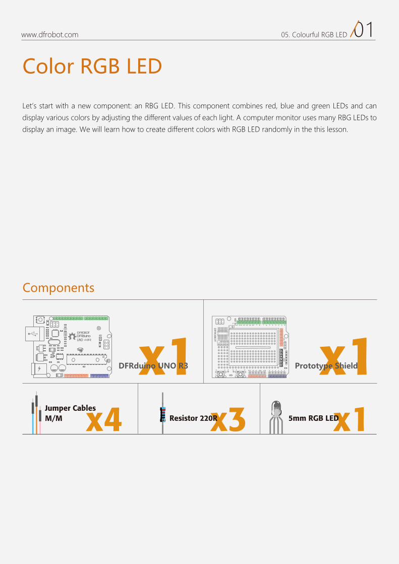
Let’s start with a new component: an RBG LED. This component combines red, blue and green LEDs and can
display various colors by adjusting the different values of each light. A computer monitor uses many RBG LEDs to
display an image. We will learn how to create different colors with RGB LED randomly in the this lesson.
Components
DFRduinoUNO v3.0[R3]
DFROBOT
a050 x1 x1
x3Resistor 220R x15mm RGB LEDx4M/M Jumper Cables
DFRduino UNO R3 Prototype Shield
02www.dfrobot.com 05. Colourful RGB LED
Circuit
17 6 5 4 3 2 1 0Aref Gnd 13 12 11 10 9 8
2323 3 1
1414
2
0 1 2 3 4 5RST 3V 5V GND VIN
5VGND
1
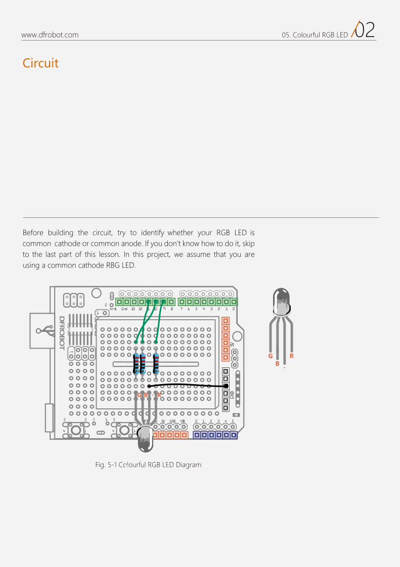
Fig. 5-1 Colourful RGB LED Diagram
Before building the circuit, try to identify whether your RGB LED is common cathode or common anode. If you don’t know how to do it, skip to the last part of this lesson. In this project, we assume that you are using a common cathode RBG LED.
03www.dfrobot.com 05. Colourful RGB LED
Arduino Code
Sample code 5-1:
You should see the RGB LED blinking with random colors after uploading this code.
//PROJECT 5 RGB LED int redPin = 9;int greenPin = 10;int bluePin = 11;
void setup(){ pinMode(redPin, OUTPUT); pinMode(greenPin, OUTPUT); pinMode(bluePin, OUTPUT);
}
void loop(){ //R:0-255 G:0-255 B:0-255 colorRGB(random(0,255),random(0,255),random(0,255)); delay(1000);
}
void colorRGB(int red, int green, int blue){ analogWrite(redPin,constrain(red,0,255)); analogWrite(greenPin,constrain(green,0,255)); analogWrite(bluePin,constrain(blue,0,255));
}
04www.dfrobot.com 05. Colourful RGB LED
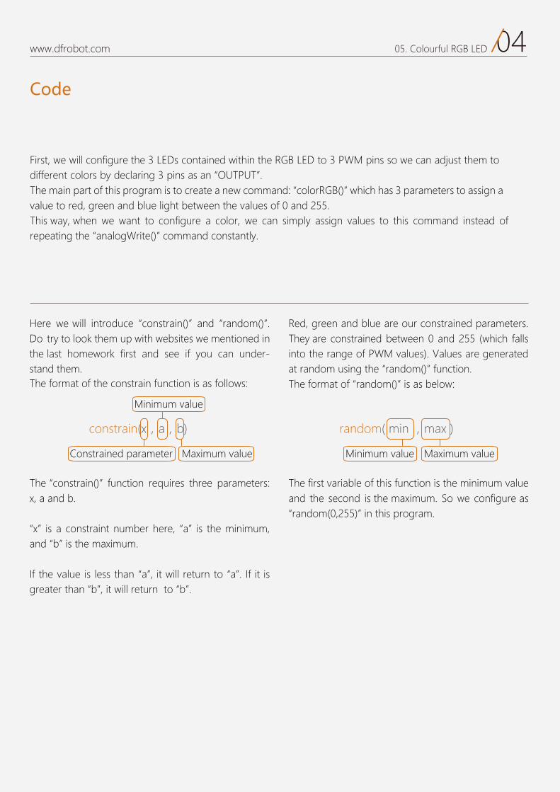
The constrain() function requires three parameters: x, a and b.
x is a constraint number here, a is the minimum,and b is the maximum.
If the value is less than a , it will return to a . If it is greater than b , it will return to b .
The first variable of this function is the minimum value and the second is the maximum. So we configure asrandom(0,255) in this program.
First, we will configure the 3 LEDs contained within the RGB LED to 3 PWM pins so we can adjust them to different colors by declaring 3 pins as an OUTPUT . The main part of this program is to create a new command: colorRGB() which has 3 parameters to assign a value to red, green and blue light between the values of 0 and 255. This way, when we want to configure a color, we can simply assign values to this command instead of repeating the analogWrite() command constantly.
Code
The format of the constrain function is as follows:
Here we will introduce constrain() and random() . Do try to look them up with websites we mentioned in the last homework first and see if you can under-stand them.
Red, green and blue are our constrained parameters.They are constrained between 0 and 255 (which falls into the range of PWM values). Values are generated at random using the random() function.
Maximum value
constrain(x,a,b)
Minimum value
Constrained parameter
The format of random() is as below:
Maximum value
random( min ,max )
Minimum value
05www.dfrobot.com 05. Colourful RGB LED
Components
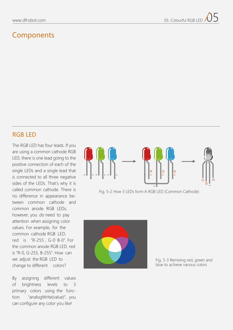
The RGB LED has four leads. If you are using a common cathode RGB LED, there is one lead going to the positive connection of each of the single LEDs and a single lead that is connected to all three negative sides of the LEDs. That’s why it is called common cathode. There is no difference in appearance be-tween common cathode and common anode RGB LEDs, however, you do need to pay attention when assigning colorvalues. For example, for the common cathode RGB red is B-0 . For the common anode RGB LED, redis R-0, G-255, B-255 . How can we adjust the RGB LED tochange to different colors?
By assigning different values of brightness levels to 3 primary colors using the func-tion analogWrite(value) , you can configure any color you like!
RGB LED
Fig. 5-2 How 3 LEDs form A RGB LED (Common Cathode)
Fig. 5-3 Remixing red, green and blue to achieve various colors
06www.dfrobot.com 05. Colourful RGB LED
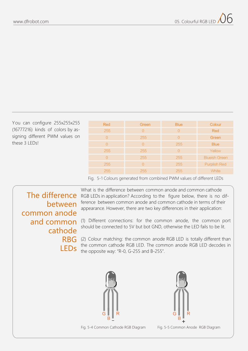
You can configure 255x255x255 (16777216) kinds of colors by as-signing different PWM values on these 3 LEDs
The differencebetween
common anode and common
cathodeRBGLEDs
What is the difference between common anode and common cathodeRGB LEDs in application? According to the figure below, there is no dif-ference between common anode and common cathode in terms of theirappearance. However, there are two key differences in their application:
(1) Different connections: for the common anode, the common port should be connected to 5V but bot GND, otherwise the LED fails to be lit.
(2) Colour matching: the common anode RGB LED is totally different than the common cathode RGB LED. The common anode RGB LED decodes in the opposite way: “R-0, G-255 and B-255”.
Red Green Blue Colour
255
0
0
255
0
255
255
0
255
0
255
255
0
255
0
0
255
0
255
255
255
Red
Green
Blue
Yellow
Blueish Green
Purplish Red
White
Fig. 5-1 Colours generated from combined PWM values of different LEDs
Fig. 5-4 Common Cathode RGB Diagram Fig. 5-5 Common Anode RGB Diagram
07www.dfrobot.com 05. Colourful RGB LED
Exercise
1. Based colors by playing with different values.
fo selbairav egnahc ot deen ylno uoY :PPPIIITTT “colorRGB()”.
2. Take your rainbow se uence LED and make each color fade so that the transition between each color is smoother.
08www.dfrobot.com 05. Colourful RGB LED
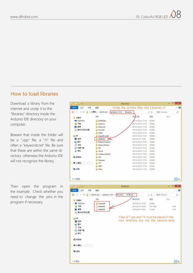
Download a library from the internet and unzip it to thelibraries directory inside the
Arduino IDE directory on your computer.
Beware that inside the folder will be a .cpp file, a .h file and often a keywords.txt file. Be sure that these are within the same di-rectory otherwise the Arduino IDE will not recognize the library.
Then open the program in the example. Check whether youneed to change the pins in the program if necessary.
How to load libraries
Files of *.cpp and *.h must be placed in the root directory but not the second-level
Unzip the archive files into Libraries of
06
Alarm Project 6
www.dfrobot.com
01www.dfrobot.com 06. Alarm
Alarm
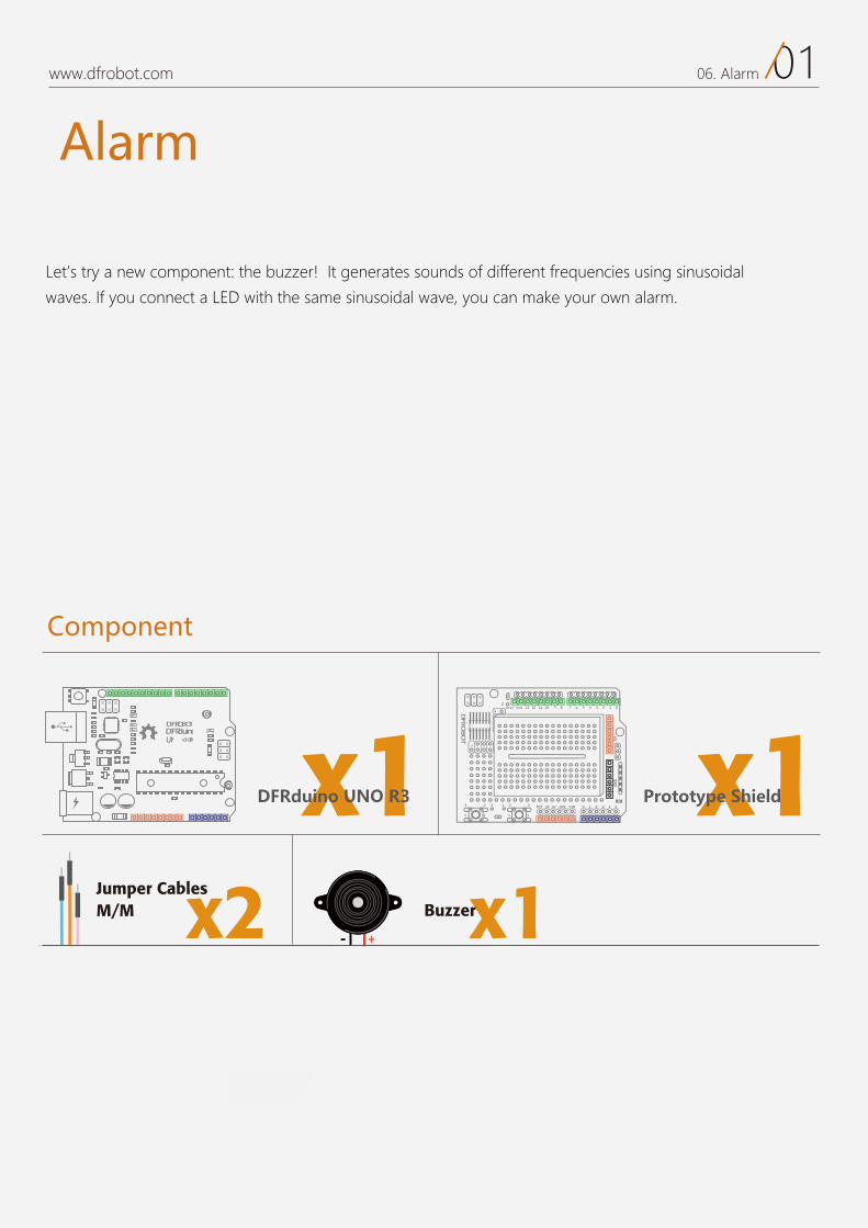
Let’s try a new component: the buzzer! It generates sounds of different frequencies using sinusoidal
waves. If you connect a LED with the same sinusoidal wave, you can make your own alarm.
Component
DFRduinoUNO v3.0[R3]
DFROBOT
a050 x1 x1
x1Buzzerx2M/M Jumper Cables
DFRduino UNO R3 Prototype Shield
Hardware Connections
02www.dfrobot.com 06. Alarm
17 6 5 4 3 2 1 0Aref Gnd 13 12 11 10 9 8
2323 3 1
1414
2
0 1 2 3 4 5RST 3V 5V GND VIN
5VGND
1
Fig. 6-1 Alarm Diagram
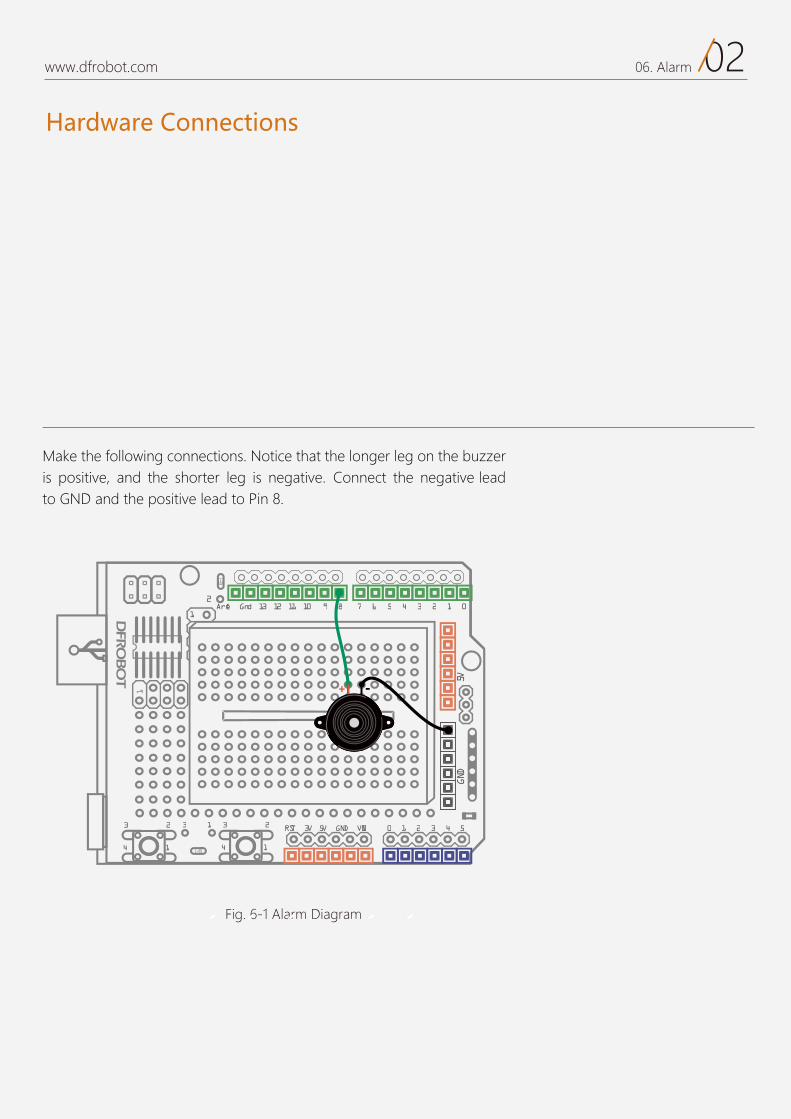
Make the following connections. Notice that the longer leg on the buzzer is positive, and the shorter leg is negative. Connect the negative leadto GND and the positive lead to Pin 8.

03www.dfrobot.com 06. Alarm
Code
Sample code 6-1:
Sample code 6-1 (from “Beginning Arduino”)
// Project 6 Alarm float sinVal;int toneVal;
void setup(){ pinMode(8, OUTPUT);}
void loop(){ for(int x=0; x<180; x++){ //convert angle of sinusoidal to radian measure sinVal = (sin(x*(3.1412/180))); //generate sound of different frequencies by sinusoidal value toneVal = 2000+(int(sinVal*1000)); //Set a frequency for Pin-out 8 tone(8, toneVal); delay(2); } }
You can hear alarm of high and low pitches after uploading thecode.
Code
04www.dfrobot.com 06. Alarm
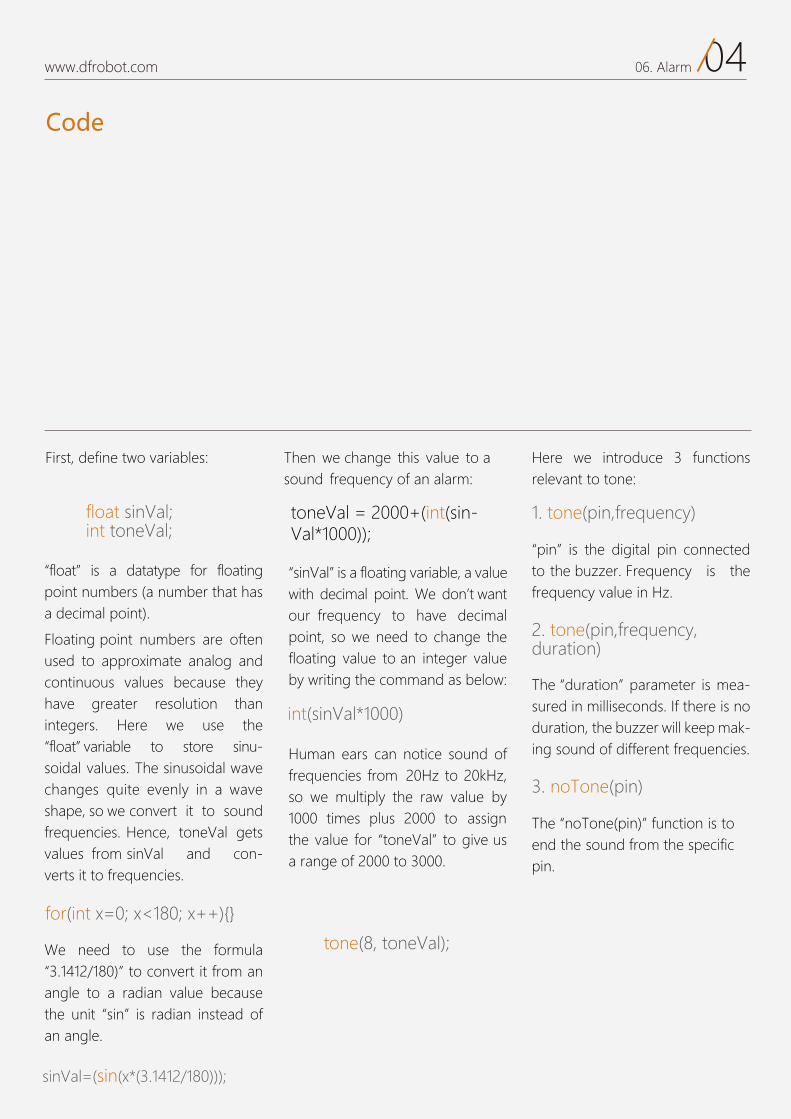
First, define two variables:
toneVal = 2000+(int(sin-Val*1000));
1. tone(pin,frequency)
2. tone(pin,frequency,duration)
“float” is a datatype for floating point numbers (a number that has a decimal point).
Floating point numbers are often used to approximate analog and continuous values because they have greater resolution than integers. Here we use the“float” variable to store sinu-soidal values. The sinusoidal wave changes quite evenly in a wave shape, so we convert it to sound frequencies. Hence, toneVal gets values from sinVal and con-verts it to frequencies.
We need to use the formula “3.1412/180)” to convert it from an angle to a radian value because the unit “sin” is radian instead of an angle.
Then we change this value to asound frequency of an alarm:
Here we introduce 3 functions relevant to tone:
“pin” is the digital pin connected to the buzzer. Frequency is the frequency value in Hz.
The “duration” parameter is mea-sured in milliseconds. If there is no duration, the buzzer will keep mak-ing sound of different frequencies.
3. noTone(pin)
The “noTone(pin)” function is to end the sound from the specific pin.
“sinVal” is a floating variable, a value with decimal point. We don’t want our frequency to have decimal point, so we need to change the floating value to an integer value by writing the command as below:
Human ears can notice sound offrequencies from 20Hz to 20kHz,so we multiply the raw value by 1000 times plus 2000 to assign the value for “toneVal” to give us a range of 2000 to 3000.
float sinVal;int toneVal;
for(int x=0; x<180; x++){}
int(sinVal*1000)
tone(8, toneVal);
sinVal=(sin(x*(3.1412/180)));

Components
05www.dfrobot.com 06. Alarm
A buzzer is an electronic component that can generate sound. There are generally two types: piezo buzzers and magnetic buzzers.
The Buzzer
Piezo and magnetic buzzers are futher categorized in to two types: ac-tive and passive buzzers. The basic difference lies in different demands for their input signal. In this case, “active” and “passive” do not refer to power sources, but oscillation sources.
In this kit, active magnetic buzzers are included.
A passive buzzer has no oscillator of its own, so it needs to use a square wave from 2khz to 5khz to trigger it instead of simply using direct current.Passive buzzers are polarized, so they have to be connected the correct way around: They have a long lead (anode) and short lead (cathode)For a beginner, passive buzzers are easier to work with.
If you want to explore buzzers further, here are some project ideas:
Passive buzzers are good for various musical effects.There are many applications based on buzzers. A lot of buzzer-based gadgets are possible like infrared sensors and ultrasonic sensors for monitoring and alerting approaching objects; temperature sen-sors for excess temperature alarm; gas sensors for gas leakage alarms.Besides alarms, buzzers can also be used as musical instruments usingdifferent frequencies to form different notes.
Aren’t buzzers amazing?
The Difference between Active Buzzers and Passive Buzzers
An active buzzer has its own oscillation source - it buzzes as it is powered on.An active buzzer has a simple oscillator circuit that changes DC current into a pulse signal of a certain frequency. Active buzzers contain a special film called “molybdenum” the The magnetic field from the oscillation of the buzzer. Once powered, it starts to make a sound.Active buzzers are non-polarized meaning that you can connect them any way around and they will work.
Exercise
06www.dfrobot.com 06. Alarm
1. Make an alarm with a red LED.
Set up our circuit so that the LED changes in in unison with the “sin” function so that the light intensit changes with the sound.
2. Using what ou learned in Project 3, can ou make a door bell? When the button is pressed, the buzzer should make a sound.
07
Temperature Alarm Project 7
www.dfrobot.com
01www.dfrobot.com 07. Temperature Alarm
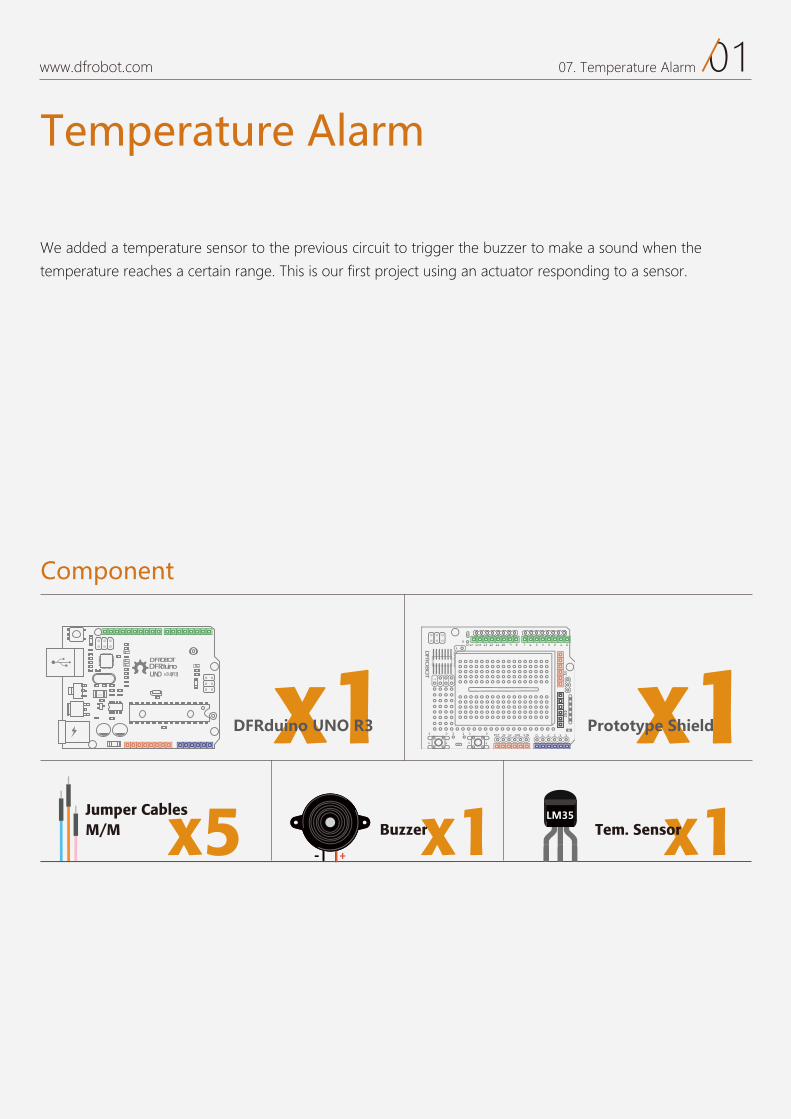
Temperature Alarm
We added a temperature sensor to the previous circuit to trigger the buzzer to make a sound when the
temperature reaches a certain range. This is our first project using an actuator responding to a sensor.
Component
DFRduinoUNO v3.0[R3]
DFROBOT
a050 x1 x1
x1Buzzer x1Tem. Sensorx5M/M Jumper Cables
DFRduino UNO R3 Prototype Shield
Hardware
02www.dfrobot.com 07. Temperature Alarm
17 6 5 4 3 2 1 0Aref Gnd 13 12 11 10 9 8
2323 3 1
1414
2
0 1 2 3 4 5RST 3V 5V GND VIN
5VGND
1
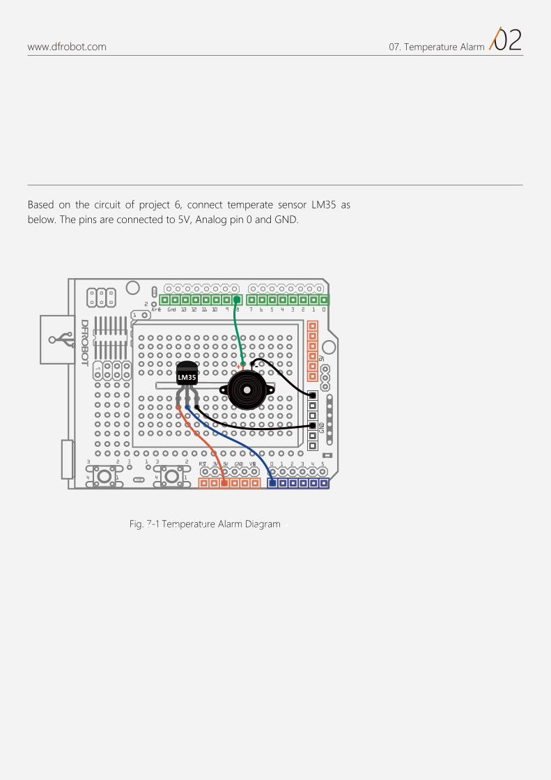
Fig. 7-1 Temperature Alarm Diagram
Based on the circuit of project 6, connect temperate sensor LM35 as below. The pins are connected to 5V, Analog pin 0 and GND.
03www.dfrobot.com 07. Temperature Alarm
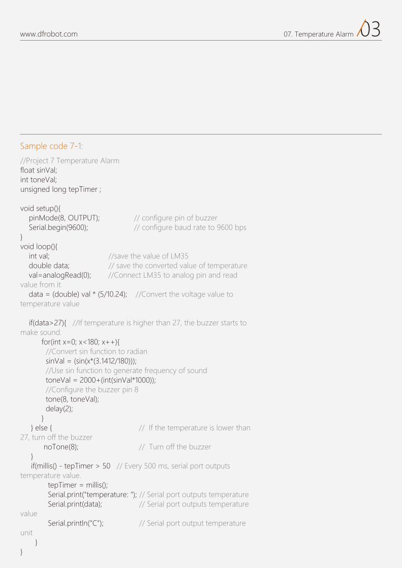
Sample code 7-1:
//Project 7 Temperature Alarmfloat sinVal; int toneVal;unsigned long tepTimer ;
void setup(){ pinMode(8, OUTPUT); // configure pin of buzzer Serial.begin(9600); // configure baud rate to 9600 bps }void loop(){ int val; //save the value of LM35 double data; // save the converted value of temperature val=analogRead(0); //Connect LM35 to analog pin and read value from it data = (double) val * (5/10.24); //Convert the voltage value to temperature value if(data>27){ //If temperature is higher than 27, the buzzer starts to make sound. for(int x=0; x<180; x++){ //Convert sin function to radian sinVal = (sin(x*(3.1412/180))); //Use sin function to generate frequency of sound toneVal = 2000+(int(sinVal*1000)); //Configure the buzzer pin 8 tone(8, toneVal); delay(2); } } else { // If the temperature is lower than 27, turn off the buzzer noTone(8); // Turn off the buzzer } if(millis() - tepTimer > 50 // Every 500 ms, serial port outputs temperature value. tepTimer = millis(); Serial.print("temperature: "); // Serial port outputs temperature Serial.print(data); // Serial port outputs temperature value Serial.println("C"); // Serial port output temperature unit } }
04www.dfrobot.com 07. Temperature Alarm
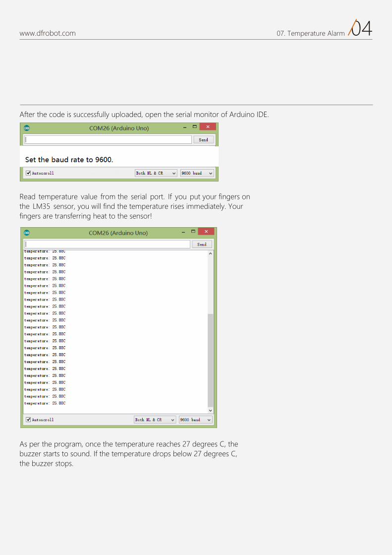
After the code is successfully uploaded, open the serial monitor of Arduino IDE.
Read temperature value from the serial port. If you put your fingers on the LM35 sensor, you will find the temperature rises immediately. Your fingers are transferring heat to the sensor!
As per the program, once the temperature reaches 27 degrees C, the buzzer starts to sound. If the temperature drops below 27 degrees C,the buzzer stops.
05www.dfrobot.com 07. Temperature Alarm
Most of the above codes are the same as those in Project 6. Almost all of the syntax has been mentioned in previous projects. Hopefully you have some understanding about the variables and functions by now.
Serial.begin(9600);
val=analogRead(0);
analogRead(pin)
data = (double) val * (5/10.24);
The third variable “tepTimer” is an unsigned long datatype to store time and output temperature values from serial port.Why “unsigned long”?Since the machine will run for a relatively long time, we choose a long integer and since it can-not store negative numbers, it is unsigned.In the first line of the “setup()”function, why do we only configure the buzzer as output mode and disregard the LM35temperature sensor?The LM35 uses analog values.Analog values don’t need to be configured for “pinmode”. “pinMode” is only used for dig-ital pins.
There are many functions for serial port communication:
We initialize 3 variables at the top of the program.
This is a new function, “analogRead (pin)”.
This function reads a value from the specified analog pin. The digital pins in the Arduino areconnected to a 10 byte analog to digital converter, so the voltage between 0 and 5V is con-verted to a value ranging between 0 and 1023. Each value corresponds to a value of voltage. The voltage value of temperature read here outputs a range between 0 to 1023. Every 10mV corresponds to 1 degree for LM35 temperature sensor.
From the voltage value read via the sensor, the range is from 0 to 1023. So we divide it into 1024 parts and multiply the result by 5 to convert it to voltage value. Since 10mV corresponds to 1 de-gree, we need to multiply that to get a temperature value in double datatype and assign it to a data variable.
This function is to initialize thebaud rate (data transmit rate) of the serial port. Normally the de-fault setting in the serial monitorworks for most applications, but-some wireless modules have a specific baud rate requirement.
In the “loop()” function, we declare 2 variables: “val” and “data” at the top. These are variables in a limited scope so that they only run inside the indi-vidual block of code.
float sinVal; int toneVal;unsigned long tepTimer ;
The Serial Port The serial port allows the Arduino to communicate with the external worldby transmitting and receiving data. There is at least one serial port in each Arduino micro-controller, separately connected to digital pin 0 (RX/data receive) and analog pin 1 (TX/data transmit). Digital pin 1 and 0 cannot be used for I/O function when the serial port is in use. You download code to the Arduino via the serial port. When downloading code, the USB will oc-cupy digital pin RX and analog pin TX. The RX and TX pins can not receive other signals during this, or there will be interference. The best way to use these 2 pins is to insert components after downloading your code.
06www.dfrobot.com 07. Temperature Alarm
In the following program, we evaluate the condition by usingthe “if/else” statement.
If the temperature is higher than 27, The program runs the first part of the program, following the if statement to activate the buzzer.If not, it runs the else statement to stop the buzzer. Apart from detecting temperature change for our alarm, we also need to display the temperature the Arduino reads via the serial port. We need to use the “millis()”function again to send out da-ta every 500ms. (See Project 3 for more details if you are unsure.) After the serial port has receiveddata, how can we display it on the serial monitor?
Is data a character string?Why does it output numbers?
The answer is because we de-clared the variable in the program setup function to assign a number to it.
print() works to convert “val”to a readable ASCII format(standard text) output from the serial port.
There are various formats for this function:1. numbers output as a num-bere.g.: Serial.print(78); outputs “78”
2. floating datatype outputs as floating number with maximum 2 digits after decimal point
e.g. Serial.print(1.23456); outputs“1.23”
This function is known as a condi-tional. It works as follows:An expression is specified. If the conditions of the expression are true, statment 1 is executed and statement 2 is skipped.If the expression is false, statment 2 is executed and statment 1 is skipped.Either statement 1 or 2 is to be executed but simultaneous exe-cution is prevented. Put in simple terms, this is the Arduino makinga decision between two pre determined variables.
3. Add single quotation mark to character and add double quota-tion mark to character string.e.g. Serial.print(‘N’); outputs “N”
Serial.print(“Hello world.”); outputs “Hello world.”
The difference between “println()”and “print()” is that “println()”has a new line character.
Another common command is “Serial.write()”. It does not output in ASCII format but in a byte format. Check the reference on Arduino.cc if you are interested in finding out more.
if (expression) { Statement 1;} else{ Statement 2;}
Serial.print(data);
if(data>27){ for(int x=0; x<180; x++){
…… } } else {
…… }
Serial.print(val);Serial.println(val);
The “if/else” statement format:
Component
07www.dfrobot.com 07. Temperature Alarm
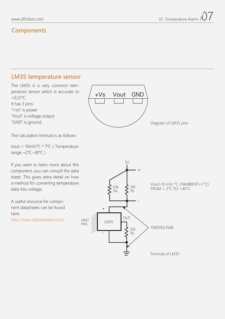
he LM35 is a very common tem-perature sensor which is accurate to
5It has 3 pins:
Vs is powerVout is voltage outputGND is ground.
he calculation formula is as follows:
If you want to learn more about thiscomponent, you can consult the data sheet. his gives extra detail on howa method for converting temperature data into voltage.
A useful resource for compo-nent datasheets can be found here:http://www.alldatasheet.com/
LM35 temperature sensor
Diagram of LM35 pins
Formula of LM35
TWISTED PAIR
OUTLM35
5V
+
-
+
-
FINS
2001%
)C° 1+TNEIBMAT( C° /Vm 01=tuoV
FROM + 2°C TO +40° C2001%
6.8k5%
Components
Exercise
08www.dfrobot.com 07. Temperature Alarm
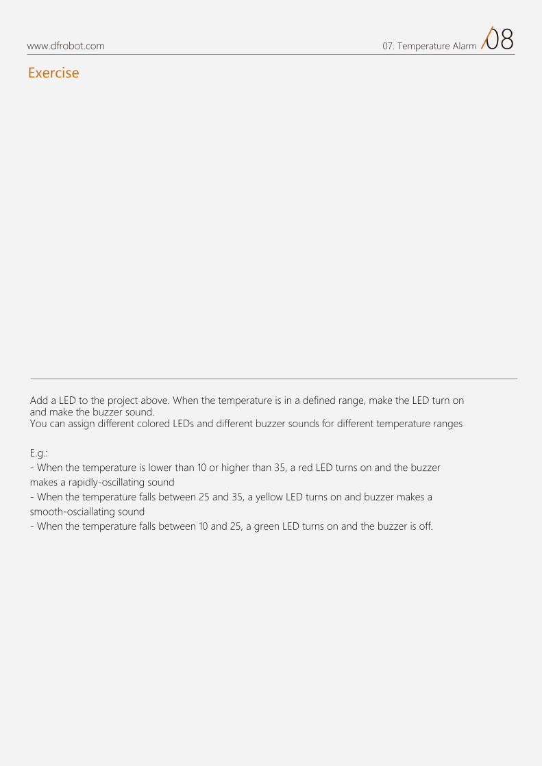
Add a LED to the project above. When the temperature is in a defined range, make the LED turn on and make the buzzer sound.You can assign different colored LEDs and different buzzer sounds for different temperature ranges
E.g.:- When the temperature is lower than 10 or higher than 35, a red LED turns on and the buzzer makes a rapidly-oscillating sound- When the temperature falls between 25 and 35, a yellow LED turns on and buzzer makes a smooth-osciallating sound- When the temperature falls between 10 and 25, a green LED turns on and the buzzer is off.
Exercise
08
Vibration Sensor Project 8
www.dfrobot.com
01www.dfrobot.com 08. Vibration Sensor
Vibration Sensor
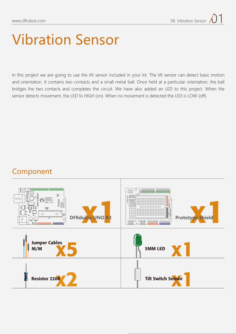
In this project we are going to use the tilt sensor included in your kit. The tilt sensor can detect basic motion
and orientation. It contains two contacts and a small metal ball. Once held at a particular orientation, the ball
bridges the two contacts and completes the circuit. We have also added an LED to this project. When the
sensor detects movement, the LED lis HIGH (on). When no movement is detected the LED is LOW (off).
Component
DFRduinoUNO v3.0[R3]
DFROBOT
a050 x1 x1
x15MM LEDx5M/M Jumper Cables
DFRduino UNO R3 Prototype Shield
x1Tilt Switch Sensorx2Resistor 220R
Circuit
02www.dfrobot.com 08. Vibration Sensor
17 6 5 4 3 2 1 0Aref Gnd 13 12 11 10 9 8
2323 3 1
1414
2
0 1 2 3 4 5RST 3V 5V GND VIN
5VGND
1
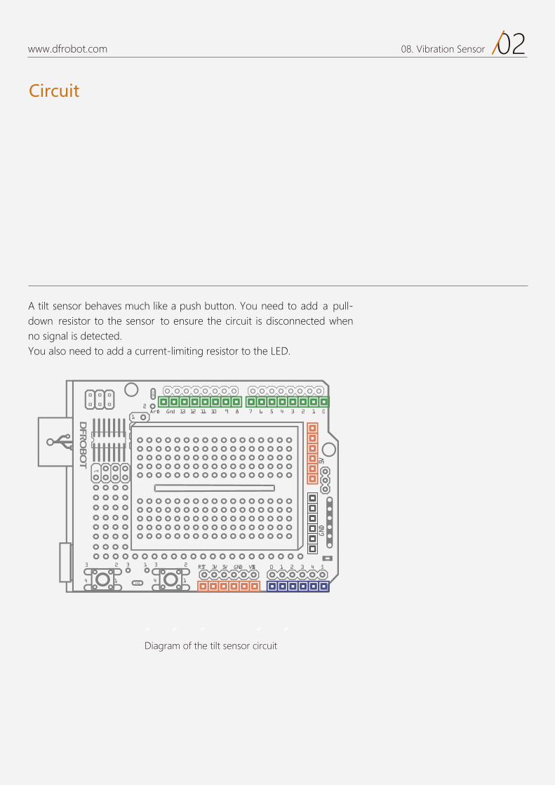
Diagram of the tilt sensor circuit
A tilt sensor behaves much like a push button. You need to add a pull-down resistor to the sensor to ensure the circuit is disconnected when no signal is detected.You also need to add a current-limiting resistor to the LED.
Code
03www.dfrobot.com 08. Vibration Sensor
Sample code 8-1
EEExxx eeeppp ccc aaahhheeebbb dddeeettt vvv oooiii uuurrr:::When we shake the board, theLED is HIGH (on). When we stopshaking, the LED is LOW (off).
//project 8 – Vibration sensor
int SensorLED = 13; //define LED digital pin 13 int SensorINPUT = 3; // connect tilt sensor to interrupt 1 in digital pin 3 unsigned char state = 0;
void setup() { pinMode(SensorLED, OUTPUT); //configure LED as output mode pinMode(SensorINPUT, INPUT); //configure tilt sensor as input mode //when low voltage changes to high voltage, it triggers interrupt 1 and runs the blink function attachInterrupt(1, blink, RISING); }
void loop(){ if(state!=0){ // if state is not 0 state = 0; // assign state value 0 digitalWrite(SensorLED,HIGH); // turn on LED delay(500); // delay for 500ms } else{ digitalWrite(SensorLED,LOW); // if not, turn off LED }}
void blink(){ // interrupt function blink()state++; //once trigger the interrupt, the state keeps increment}
04www.dfrobot.com 08. Vibration Sensor
Code
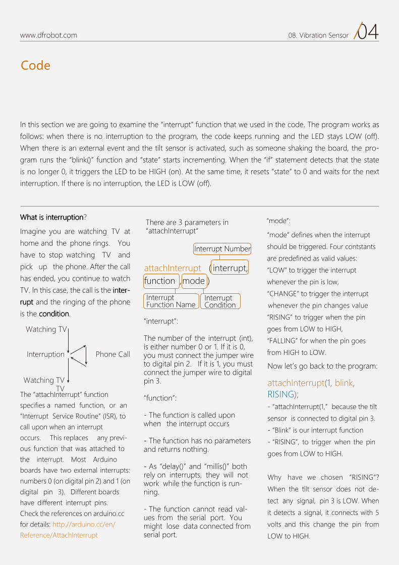
?nnnoooiiitttpppuuurrrrrreeetttnnniii sssiii tttaaahhhWWW
Imagine you are watching TV at
home and the phone rings. You
have to stop watching TV and
pick up the phone. After the call
has ended, you continue to watch
TV. In this case, the call is the rrreeetttnnniii ---
tttpppuuurrr and the ringing of the phone
.nnnoooiiitttiiidddnnnoooccc eht si
- attachInterrupt(1, because the tilt
sensor is connected to digital pin 3.
- Blink is our interrupt function
- RISING , to trigger when the pin
goes from LOW to HIGH.
Why have we chosen RISING ?
When the tilt sensor does not de-
tect any signal, pin 3 is LOW. When
it detects a signal, it connects with 5
volts and this change the pin from
LOW to HIGH.
attachInterrupt ( interrupt, function ,mode )
attachInterrupt(1, blink, RISING);The attachInterrupt function
specifies a named function, or an
Interrupt Service Routine (ISR), to
call upon when an interrupt
occurs. This replaces any previ-
ous function that was attached to
the interrupt. Most Arduino
boards have two external interrupts:
numbers 0 (on digital pin 2) and 1 (on
digital pin 3). Different boards
have different interrupt pins.
Check the references on arduino.cc
for details: http://arduino.cc/en/
Reference/AttachInterrupt
There are 3 parameters in attachInterrupt
Now let’s go back to the program:
In this section we are going to examine the interrupt function that we used in the code. The program works as
follows: when there is no interruption to the program, the code keeps running and the LED stays LOW (off).
When there is an external event and the tilt sensor is activated, such as someone shaking the board, the pro-
gram runs the blink() function and state starts incrementing. When the if statement detects that the state
is no longer 0, it triggers the LED to be HIGH (on). At the same time, it resets state to 0 and waits for the next
interruption. If there is no interruption, the LED is LOW (off).
mode defines when the interrupt
should be triggered. Four contstants
are predefined as valid values:
LOW to trigger the interrupt
whenever the pin is low,
CHANGE to trigger the interrupt
whenever the pin changes value
RISING to trigger when the pin
goes from LOW to HIGH,
FALLING for when the pin goes
from HIGH to LOW.
interrupt :
The number of the interrupt (int),is either number 0 or 1. If it is 0, you must connect the jumper wireto digital pin 2. If it is 1, you mustconnect the jumper wire to digital pin 3.
function :
- The function is called upon when the interrupt occurs
- The function has no parameters and returns nothing.
- As delay() and millis() both rely on interrupts, they will not work while the function is run-ning.
- The function cannot read val-ues from the serial port. You might lose data connected from serial port.
Watching TV
Phone CallInterruption
Watching TVTV
Interrupt Function Name
Interrupt Condition
Interrupt Number
mode :
05www.dfrobot.com 08. Vibration Sensor
Components
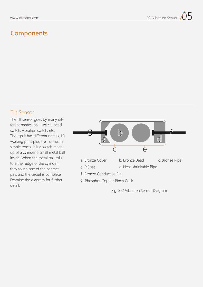
Fig. 8-2 Vibration Sensor Diagram
The tilt sensor goes by many dif-ferent names: ball switch, bead switch, noitarbiv switch, etc.Though it has different names, it’s working principles are same. In simple terms, it is a switch made up of a cylinder a small metal ball inside. When the metal ball rolls to either edge of the cylinder, they touch one of the contact pins and the circuit is complete. Examine the diagram for further detail.
Tilt Sensor
. Phosphor Copper Pinch Cock
a. Bronze Cover b. Bronze Bead c. Bronze Pipe
e. Heat-shrinkable Piped. PC set
f . Bronze Conductive Pin
ggaa
bb
cc eedd
ff
g
09
Light Sensitive LEDProject 9
www.dfrobot.com
01www.dfrobot.com 09. Light Sensitive LED
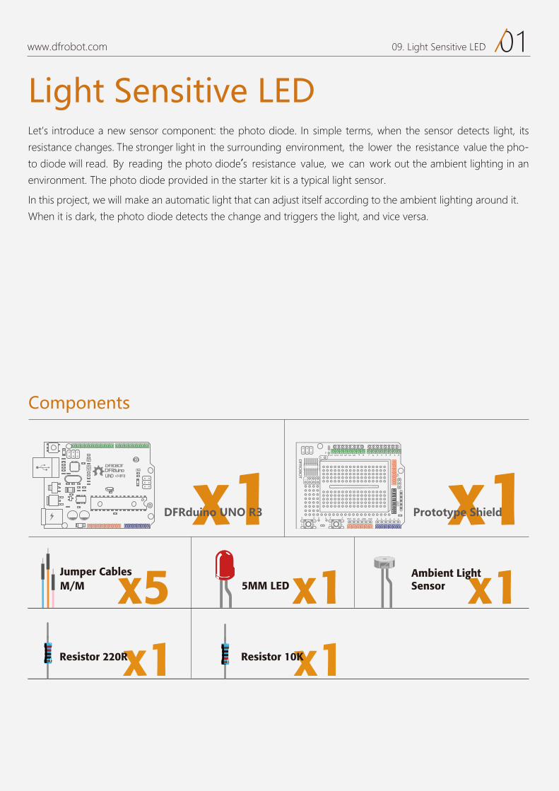
Light Sensitive LEDLet’s introduce a new sensor component: the photo diode. In simple terms, when the sensor detects light, its
resistance changes. The stronger light in the surrounding environment, the lower the resistance value the pho-
to diode will read. By reading the photo diode’s resistance value, we can work out the ambient lighting in an
environment. The photo diode provided in the starter kit is a typical light sensor.
In this project, we will make an automatic light that can adjust itself according to the ambient lighting around it.
When it is dark, the photo diode detects the change and triggers the light, and vice versa.
Components
DFRduinoUNO v3.0[R3]
DFROBOT
a050 x1 x1
x15MM LED x1Ambient LightSensorx5M/M
Jumper Cables
DFRduino UNO R3 Prototype Shield
Resistor 220R Resistor 10K
Circuit
02www.dfrobot.com 09. Light Sensitive LED
17 6 5 4 3 2 1 0Aref Gnd 13 12 11 10 9 8
2323 3 1
1414
2
0 1 2 3 4 5RST 3V 5V GND VIN
5VGND
1
Diagram of the photo diode circuit
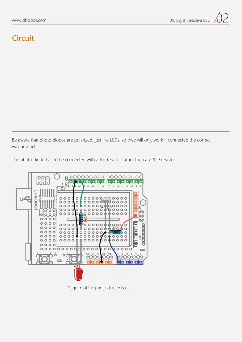
Be aware that photo diodes are polarized, just like LEDs, so they will only work if connected the correct way around.
The photo diode has to be connected with a 10k resistor rather than a 220Ω resistor.
Code
03www.dfrobot.com 09. Light Sensitive LED
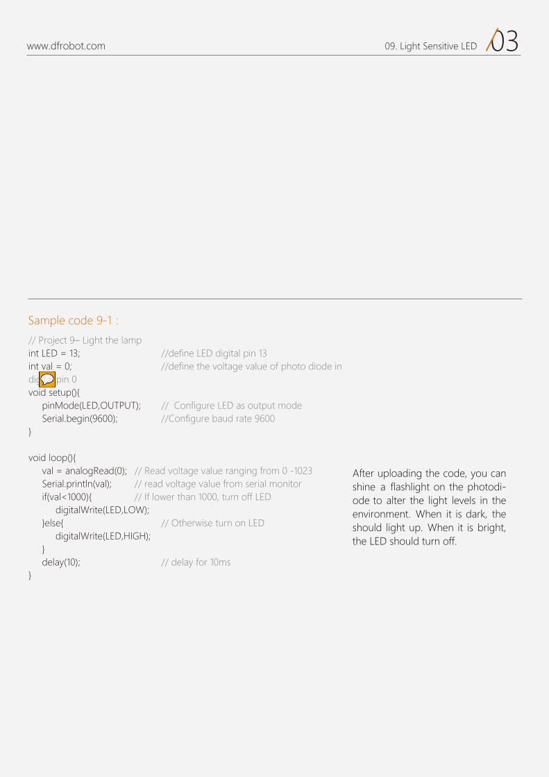
Sample code 9-1:
After uploading the code, you can shine a flashlight on the photodi-ode to alter the light levels in the environment. When it is dark, the should light up. When it is bright,the LED should turn off.
// Project 9– Light the lamp int LED = 13; //define LED digital pin 13 int val = 0; //define the voltage value of photo diode in digital pin 0 void setup(){ pinMode(LED,OUTPUT); // Configure LED as output mode Serial.begin(9600); //Configure baud rate 9600 }
void loop(){ val = analogRead(0); // Read voltage value ranging from 0 -1023 Serial.println(val); // read voltage value from serial monitor if(val<1000){ // If lower than 1000, turn off LED digitalWrite(LED,LOW); }else{ // Otherwise turn on LED digitalWrite(LED,HIGH); } delay(10); // delay for 10ms}

Code
04www.dfrobot.com 09. Light Sensitive LED
A very brief explanation of the program:
Similar to the LM35 temperature sensor, the photo diode reads an
analog signal so we don’t need to define “pinMode” in “serial.begin”.
We take the analog current data from the photodiode and compare it
to a value of 1024 to make it digital. You can change this value if you
like. Try playing with the serial monitor and seeing what outputs the
photodiode gives. Then use this number you get here as the compari-
son number to alter the sensitivity of the circuit.
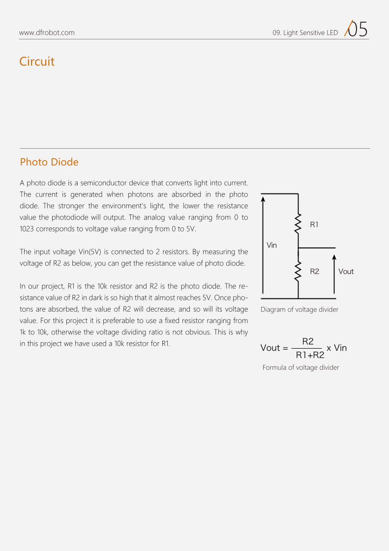
Circuit
05www.dfrobot.com 09. Light Sensitive LED
Diagram of voltage divider
Formula of voltage divider
A photo diode is a semiconductor device that converts light into current.
The current is generated when photons are absorbed in the photo
diode. The stronger the environment’s light, the lower the resistance
value the photodiode will output. The analog value ranging from 0 to
1023 corresponds to voltage value ranging from 0 to 5V.
The input voltage Vin(5V) is connected to 2 resistors. By measuring the
voltage of R2 as below, you can get the resistance value of photo diode.
In our project, R1 is the 10k resistor and R2 is the photo diode. The re-
sistance value of R2 in dark is so high that it almost reaches 5V. Once pho-
tons are absorbed, the value of R2 will decrease, and so will its voltage
value. For this project it is preferable to use a fixed resistor ranging from
1k to 10k, otherwise the voltage dividing ratio is not obvious. This is why
in this project we have used a 10k resistor for R1.
Photo Diode
R1
R2
Vin
Vout
Vout = x VinR2
R1+R2

10
How to Drive A ServoProject 10
www.dfrobot.com
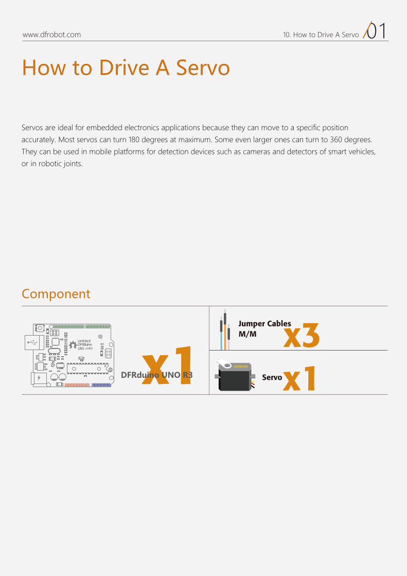
01www.dfrobot.com 10. How to Drive A Servo
How to Drive A Servo
Servos are ideal for embedded electronics applications because they can move to a specific position
accurately. Most servos can turn 180 degrees at maximum. Some even larger ones can turn to 360 degrees.
They can be used in mobile platforms for detection devices such as cameras and detectors of smart vehicles,
or in robotic joints.
Component
DFRduinoUNO v3.0[R3]
DFROBOT
a050 x1
x3M/M Jumper Cables
DFRduino UNO R3 x1Servo
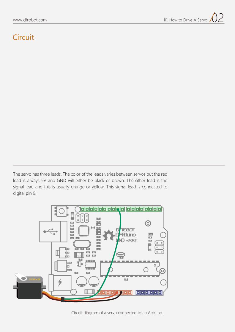
Circuit
02www.dfrobot.com 10. How to Drive A Servo
Circuit diagram of a servo connected to an Arduino
The servo has three leads. The color of the leads varies between servos but the red lead is always 5V and GND will either be black or brown. The other lead is the signal lead and this is usually orange or yellow. This signal lead is connected to digital pin 9.
DFRduinoUNO v3.0[R3]
DFROBOT
a050
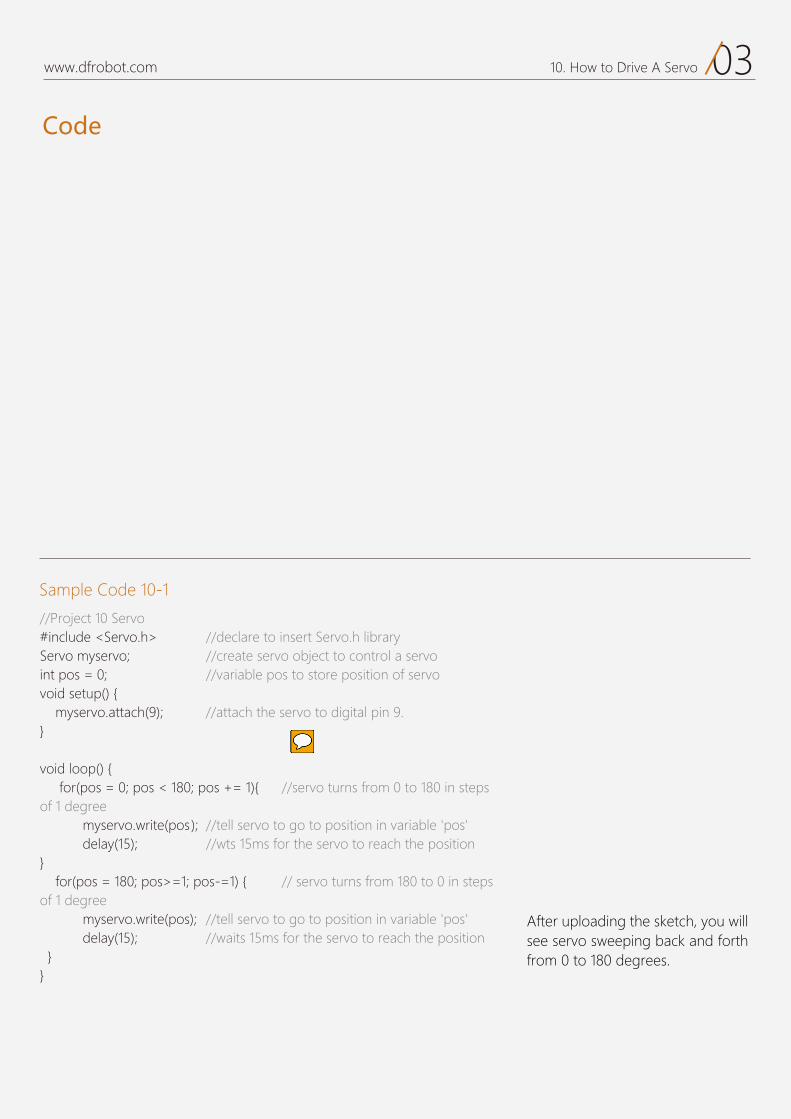
Code
03www.dfrobot.com 10. How to Drive A Servo
Sample Code 10-1
After uploading the sketch, you will see servo sweeping back and forth from 0 to 180 degrees.
//Project 10 Servo#include <Servo.h> //declare to insert Servo.h library Servo myservo; //create servo object to control a servo int pos = 0; //variable pos to store position of servo void setup() { myservo.attach(9); //attach the servo to digital pin 9. } void loop() { for(pos = 0; pos < 180; pos += 1){ //servo turns from 0 to 180 in steps of 1 degree myservo.write(pos); //tell servo to go to position in variable 'pos' delay(15); //wts 15ms for the servo to reach the position } for(pos = 180; pos>=1; pos-=1) { // servo turns from 180 to 0 in steps of 1 degree myservo.write(pos); //tell servo to go to position in variable 'pos' delay(15); //waits 15ms for the servo to reach the position } }
04www.dfrobot.com 10. How to Drive A Servo
The sketch starts from inserting <Servo.h > library.
There is another command in the setup() function.
In the main program, there are 2 for statements. The first one starts
from 0 then spins to 180 degreesin 1 degree increments. The sec-ond one starts from 180 degreesand goes back to 0 in 1 degreeincrements.
Just like the previous command, you have to declare a name for this command. The parameters of this function is an angle. The unit is degrees.
If you want to know more about the functions in the servo library,visit the arduino website:
http://ardui-no.cc/en/reference/servo
or visit the DFRobot website:
www.dfrobot.com attach(pin) assigns the pin. We can use any digital pin, except 0and 1. In this project, we have cho-sen digital pin 9.
Declaring functions in the servo library
is a bit different from declaring other
functions. We need to declare various
functions in the library including
declaring the servo object and defin-
ing the function. Just like in the library,
you need to point out the object so
that the program can identify it. The
format of library function is as
below.
myservo is the servo object we named
before. So the function we invoke is:
This library is already in Arduino IDE. Identify it by opening Arduino-1.0.5/ libraries/ Servo/ Servo.h.
Libraries are collections of new commands that have been packaged together to make it easy to include them in your sketches. Arduino comes with a handful of of useful libraries, such as the servo library used in this example that can be used to interface to more advanced devices.
We need to create a name in the code for the servo:
#include <Servo.h> myservo.attach(9);
myservo.write(pos);
attach(pin );
Servo myservo; // create servo object to control a servo
digital pins
Code
Don't miss the dot sign(".") in between
the word "my servo" and "attach" .
11
Controllable ServoProject 11
www.dfrobot.com

01www.dfrobot.com 11. Controllable Servo
Controllable Servo
We’ve learned to turn the servo to a specific an gleusing an external signal. In the new project, we will use a poten-
tiometer to control a servo. You can also modify this circuit by swapping the potentiometer for a sensor such as
a tilt switch, or changing the actuator to an LED. Get tinkering and use your imagination!
Component
DFRduinoUNO v3.0[R3]
DFROBOT
a050 x1 x1
x3M/M Jumper Cables x3F/M
Jumper Cables
DFRduino UNO R3 Prototype Shield
x1Servo10KPotentiometer
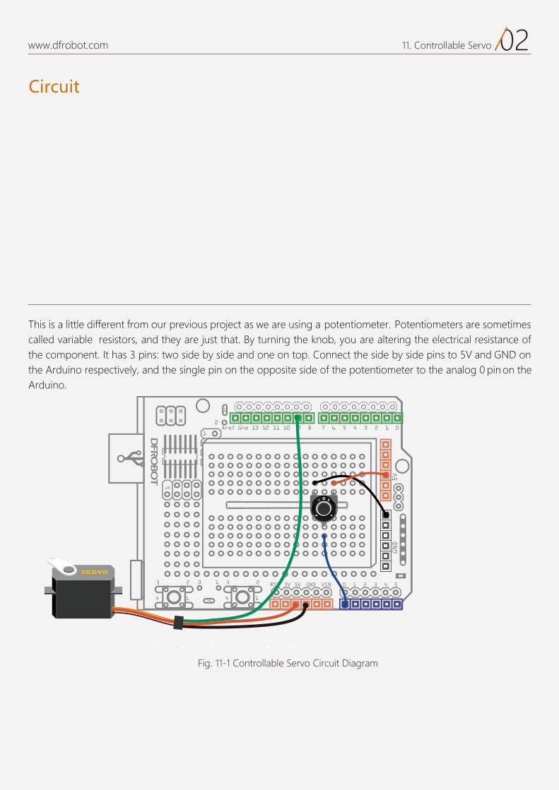
Circuit
02www.dfrobot.com 11. Controllable Servo
Fig. 11-1 Controllable Servo Circuit Diagram
This is a little different from our previous project as we are using a potentiometer. Potentiometers are sometimes called variable resistors, and they are just that. By turning the knob, you are altering the electrical resistance of the component. It has 3 pins: two side by side and one on top. Connect the side by side pins to 5V and GND on the Arduino respectively, and the single pin on the opposite side of the potentiometer to the analog 0 pin on the Arduino.
Code
03www.dfrobot.com 11. Controllable Servo
Sample code 11-1
After uploading the sketch, you can see the servo turn according to the position of the potentiometer.
//Project eleven controllable servo
#include <Servo.h> // insert the Servo.h libraryServo myservo; // create servo object to control servo
int potpin = 0; // connect potentiometer to digital pin0 ;lav tni // variable value to read value from analog pin
void setup() { myservo.attach(9); //Attach the servo on pin 9 to the servo object. }
void loop() { val = analogRead(potpin); //eads the value of the potentiommeter (value between 0 and 1023) val = map(val, 0, 1023, 0, 179); // scale it to use it with the servo (value between 0 and 180) myservo.write(val); // sets the servo position according to the scaled value delay(15); // wait for 15 ms to turn to certain position
}
Code
04www.dfrobot.com 11. Controllable Servo
We declare to insert the <Servo.h> library first and then define the potentiometer on Analog pin 0 to read its value.
Now let’s dig into the “map” function.The format of map function is as below:
Note that the "lower bounds" of either range may be larger or smaller than the "upper bounds" so the “map()”function may be used to reverse a range of numbers, e.g.:
Back to our sketch: we map the analog value from 0to 1023 to a servo value from 0 to 180.
The function also handles negative numbers well, so that this example is also valid and works well:
The “map” function re-maps a number from one range to another. That is, a value of “fromLow”would get mapped to “toLow”, a value of “fromHigh”to “toHigh”, values in-between to values in-between, etc.
Parametersvalue: the number to mapfromLow: the lower bound of the value's current rangefromHigh: the upper bound of the value's current rangetoLow: the lower bound of the value's target rangetoHigh: the upper bound of the value's target range
map(value, fromLow, fromHigh, toLow, toHigh)
y = map(x, 1, 50, 50, 1);
y = map(x, 1, 50, 50, -100); val = map(val, 0, 1023, 0, 179);
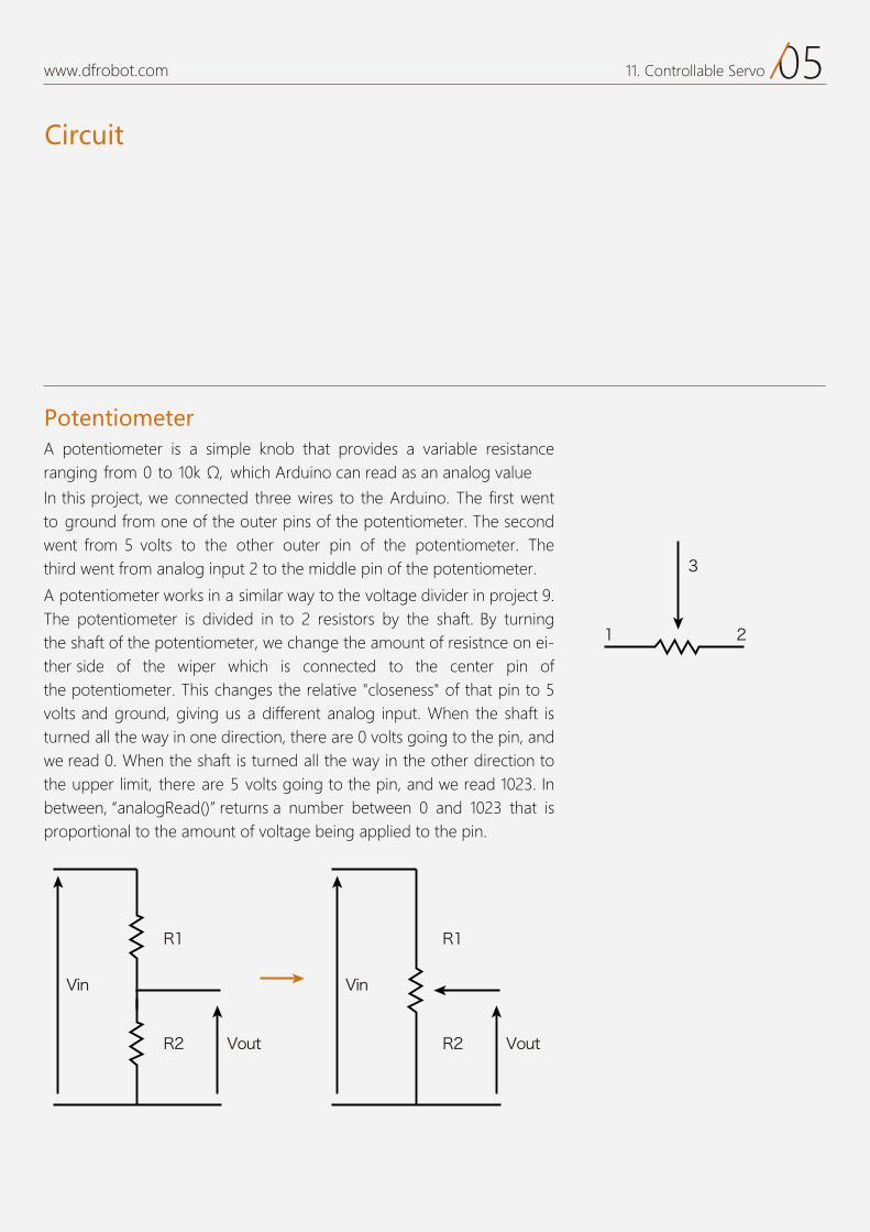
Circuit
05www.dfrobot.com 11. Controllable Servo
A potentiometer is a simple knob that provides a variable resistance which Arduino can read as an analog value
In this proje we connected three wires to the Arduino. The first wentto ground from one of the outer pins of the potentiometer. The second went from 5 volts to the other outer pin of the potentiometer. The third went from analog input 2 to the middle pin of the potentiometer.
A potentiometer works in a similar way to the voltage divider in project 9. The potentiometer is divided in to 2 resistors by the shaft. By turning the shaft of the potentiometer, we change the amount of resistnce on ei-ther side of the wiper which is connected to the center pin of the potentiometer. This changes the relative "closeness" of that pin to 5 volts and ground, giving us a different analog input. When the shaft is turned all the way in one direction, there are 0 volts going to the pin, and we read 0. When the shaft is turned all the way in the other direction to the upper limit, there are 5 volts going to the pin, and we read 1023. In between, “analogRead()” returns a number between 0 and 1023 that is proportional to the amount of voltage being applied to the pin.
Potentiometer
R1
R2
Vin
Vout
R1
R2
Vin
Vout
3
1 2
12
Interactive Adjustable RGB LED
Project 12
www.dfrobot.com
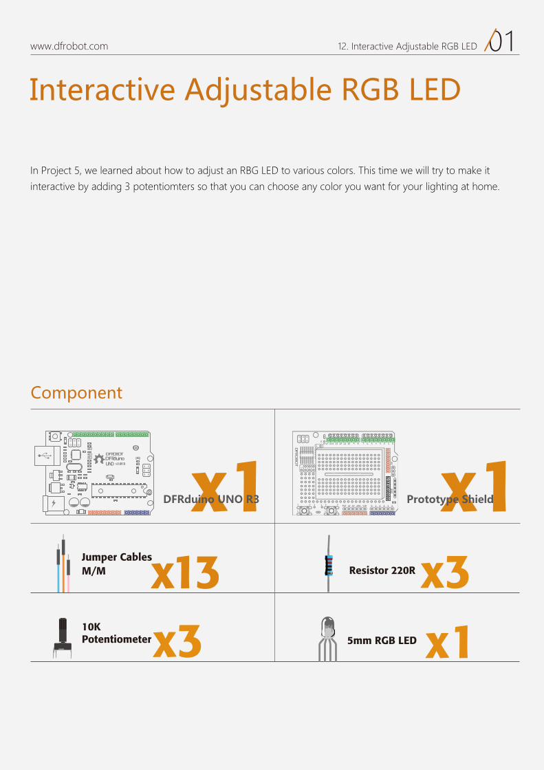
01www.dfrobot.com 12. Interactive Adjustable RGB LED
Interactive Adjustable RGB LED
In Project 5, we learned about how to adjust an RBG LED to various colors. This time we will try to make it
interactive by adding 3 potentiomters so that you can choose any color you want for your lighting at home.
Component
DFRduinoUNO v3.0[R3]
DFROBOT
a050 x1 x1
x13M/M Jumper Cables
x3
DFRduino UNO R3 Prototype Shield
x15mm RGB LED10KPotentiometer
x3Resistor 220R
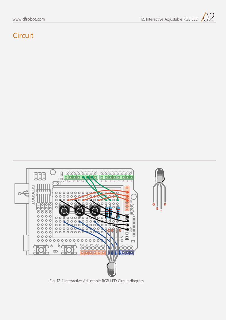
Circuit
02www.dfrobot.com 12. Interactive Adjustable RGB LED
Fig. 12-1 Interactive Adjustable RGB LED Circuit diagram
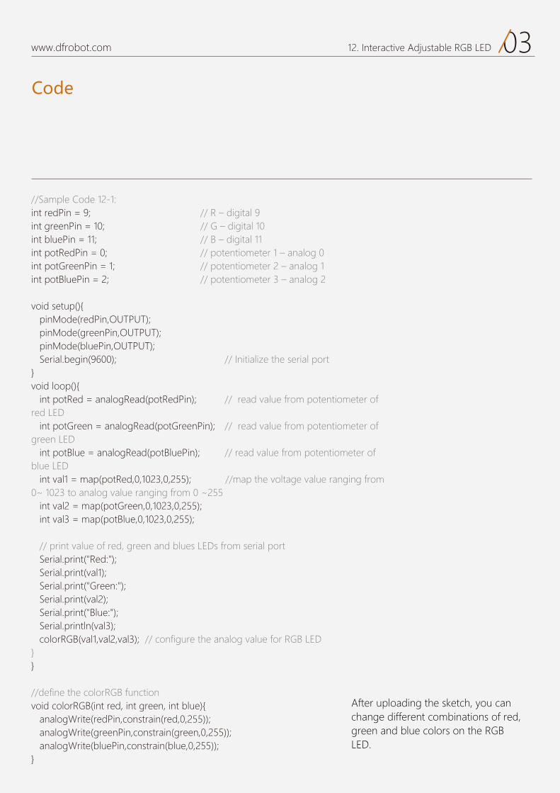
Code
03www.dfrobot.com 12. Interactive Adjustable RGB LED
After uploading the sketch, you can change different combinations of red, green and blue colors on the RGB LED.
//Sample Code 12-1: int redPin = 9; // R – digital 9 int greenPin = 10; // G – digital 10int bluePin = 11; // B – digital 11int potRedPin = 0; // potentiometer 1 – analog 0int potGreenPin = 1; // potentiometer 2 – analog 1int potBluePin = 2; // potentiometer 3 – analog 2
void setup(){ pinMode(redPin,OUTPUT); pinMode(greenPin,OUTPUT); pinMode(bluePin,OUTPUT); Serial.begin(9600); // Initialize the serial port }void loop(){ int potRed = analogRead(potRedPin); // read value from potentiometer of red LED int potGreen = analogRead(potGreenPin); // read value from potentiometer of green LED int potBlue = analogRead(potBluePin); // read value from potentiometer of blue LED int val1 = map(potRed,0,1023,0,255); //map the voltage value ranging from 0~ 1023 to analog value ranging from 0 ~255 int val2 = map(potGreen,0,1023,0,255); int val3 = map(potBlue,0,1023,0,255); // print value of red, green and blues LEDs from serial port Serial.print("Red:"); Serial.print(val1); Serial.print("Green:"); Serial.print(val2); Serial.print("Blue:"); Serial.println(val3); colorRGB(val1,val2,val3); // configure the analog value for RGB LED }}
//define the colorRGB functionvoid colorRGB(int red, int green, int blue){ analogWrite(redPin,constrain(red,0,255)); analogWrite(greenPin,constrain(green,0,255)); analogWrite(bluePin,constrain(blue,0,255));}
13
DIY FanProject 13
www.dfrobot.com
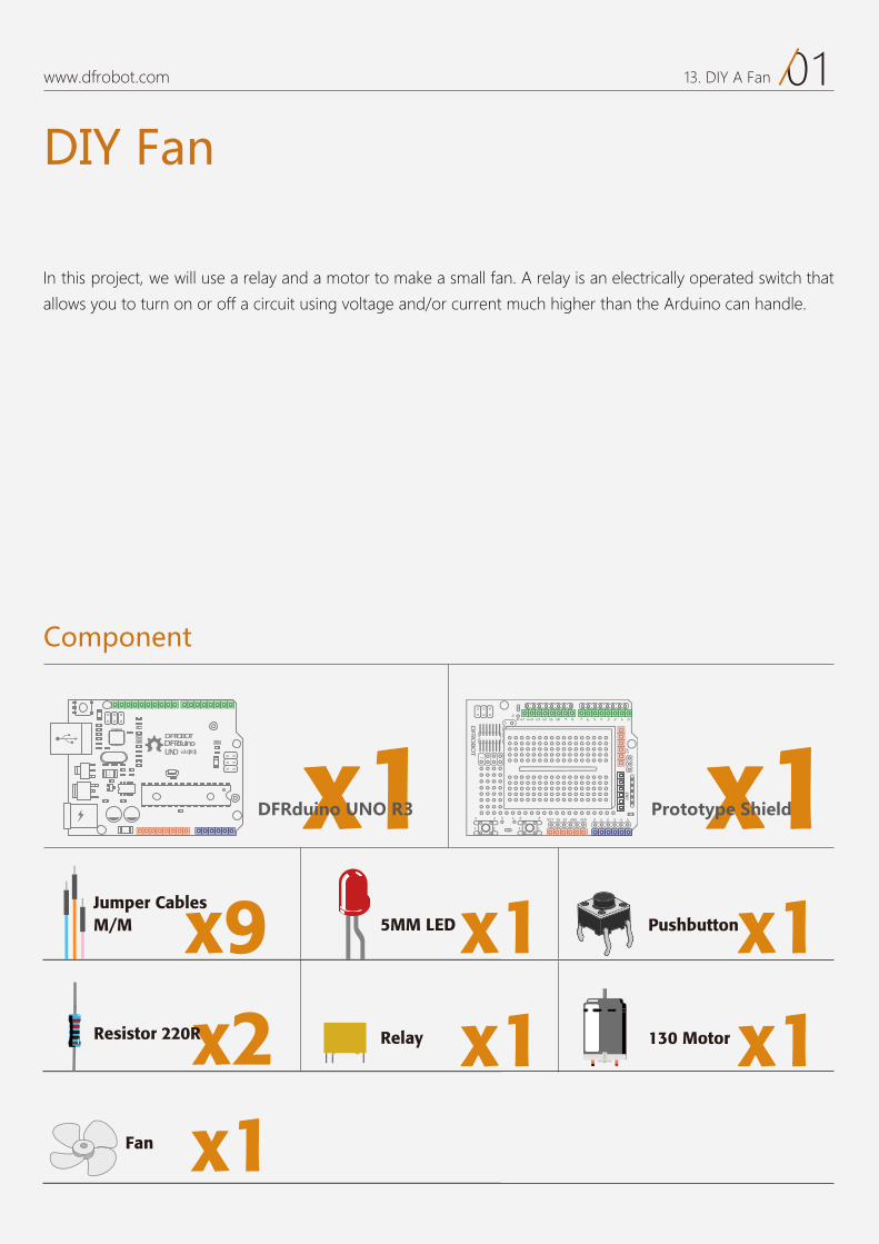
01www.dfrobot.com 13. DIY A Fan
DIY Fan
In this project, we will use a relay and a motor to make a small fan. A relay is an electrically operated switch that
allows you to turn on or off a circuit using voltage and/or current much higher than the Arduino can handle.
Component
DFRduinoUNO v3.0[R3]
DFROBOT
a050 x1 x1
x1x2
5MM LED x1Pushbuttonx9M/M Jumper Cables
DFRduino UNO R3 Prototype Shield
x1Relay x1130 Motor
x1Fan
Resistor 220R
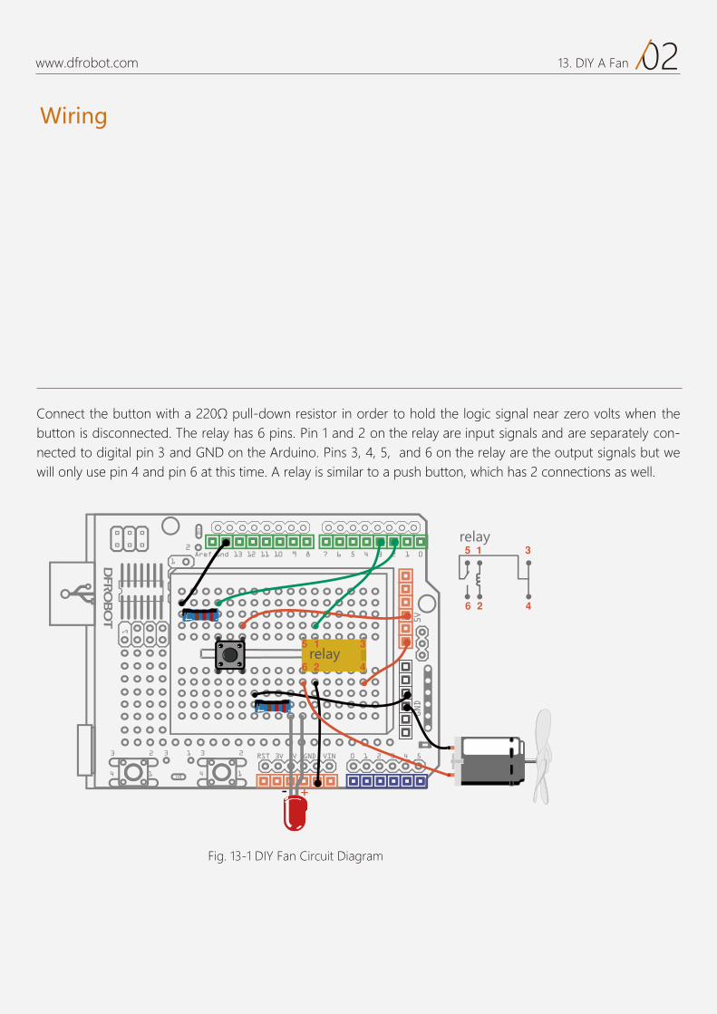
Wiring
02www.dfrobot.com 13. DIY A Fan
Fig. 13-1 DIY Fan Circuit Diagram
Connect the button with a 220Ω pull-down resistor in order to hold the logic signal near zero volts when the button is disconnected. The relay has 6 pins. Pin 1 and 2 on the relay are input signals and are separately con-nected to digital pin 3 and GND on the Arduino. Pins 3, 4, 5, and 6 on the relay are the output signals but we will only use pin 4 and pin 6 at this time. A relay is similar to a push button, which has 2 connections as well.
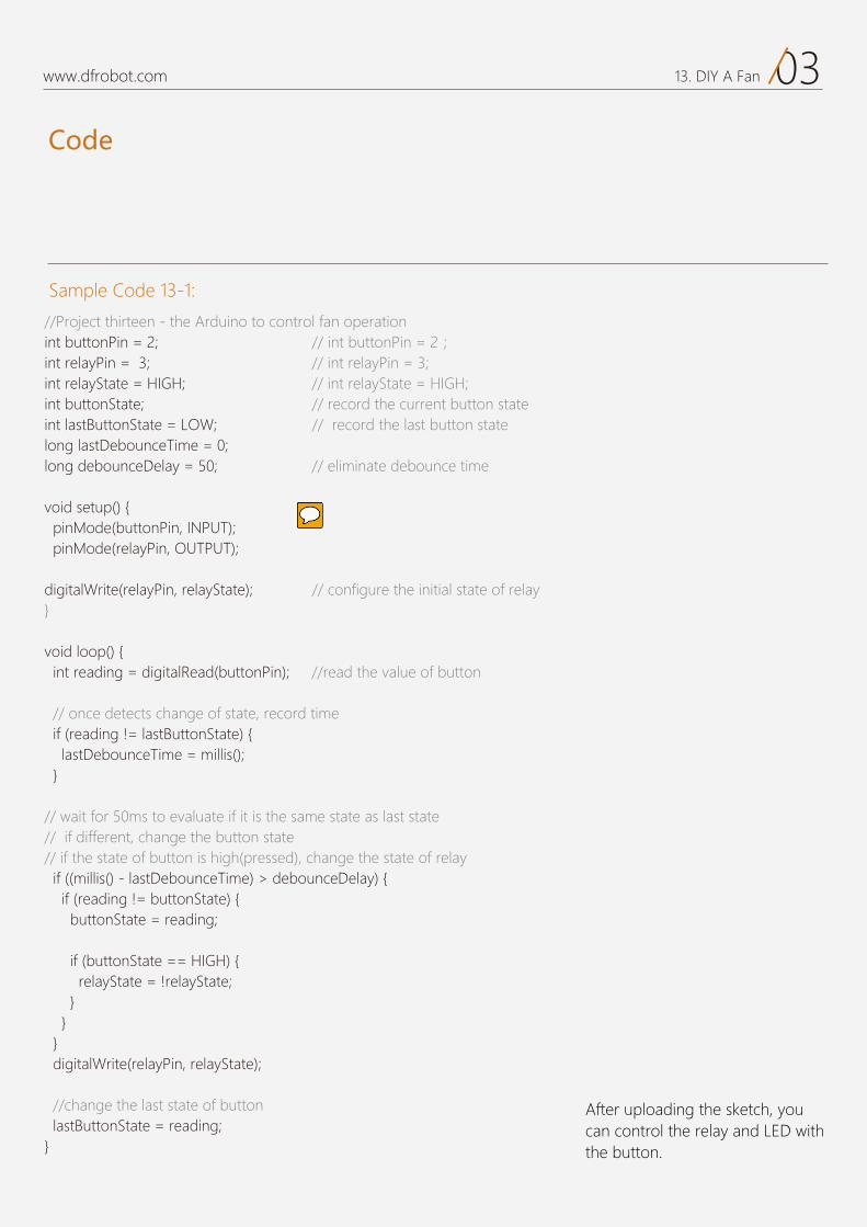
Code
03www.dfrobot.com 13. DIY A Fan
Sample Code 13-1:
After uploading the sketch, you can control the relay and LED with the button.
//Project thirteen - the Arduino to control fan operation int buttonPin = 2; // int buttonPin = 2; int relayPin = 3; // int relayPin = 3; int relayState = HIGH; // int relayState = HIGH; int buttonState; // record the current button state int lastButtonState = LOW; // record the last button state long lastDebounceTime = 0; long debounceDelay = 50; // eliminate debounce time
void setup() { pinMode(buttonPin, INPUT); pinMode(relayPin, OUTPUT); digitalWrite(relayPin, relayState); // configure the initial state of relay }
void loop() { int reading = digitalRead(buttonPin); //read the value of button // once detects change of state, record time if (reading != lastButtonState) { lastDebounceTime = millis(); } // wait for 50ms to evaluate if it is the same state as last state // if different, change the button state // if the state of button is high(pressed), change the state of relay if ((millis() - lastDebounceTime) > debounceDelay) { if (reading != buttonState) { buttonState = reading; if (buttonState == HIGH) { relayState = !relayState; } } } digitalWrite(relayPin, relayState);
//change the last state of button lastButtonState = reading;}
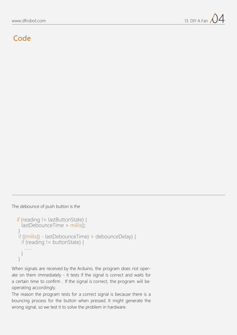
Code
04www.dfrobot.com 13. DIY A Fan
The debounce of push button is the
When signals are received by the Arduino, the program does not oper-ate on them immediately - it tests if the signal is correct and waits for a certain time to confirm . If the signal is correct, the program will be operating accordingly.The reason the program tests for a correct signal is because there is a bouncing process for the button when pressed. It might generate the wrong signal, so we test it to solve the problem in hardware.
if (reading != lastButtonState) { lastDebounceTime = millis(); } if ((millis() - lastDebounceTime) > debounceDelay) { if (reading != buttonState) { …… } }
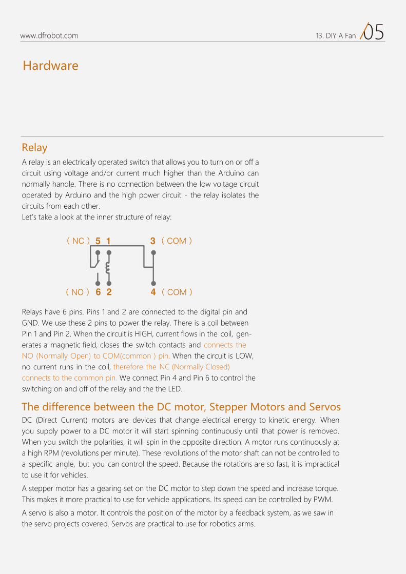
Hardware
05www.dfrobot.com 13. DIY A Fan
A relay is an electrically operated switch that allows you to turn on or off a circuit using voltage and/or current much higher than the Arduino can normally handle. There is no connection between the low voltage circuit operated by Arduino and the high power circuit - the relay isolates thecircuits from each other.Let’s take a look at the inner structure of relay:
Relays have 6 pins. Pins 1 and 2 are connected to the digital pin and GND. We use these 2 pins to power the relay. There is a coil between Pin 1 and Pin 2. When the circuit is HIGH, current flows in the coil, gen-erates a magnetic field, closes the switch contacts and connects the NO (Normally Open) to COM(common)pin. When the circuit is LOW, no current runs in the coil, therefore the NC (Normally Closed) connects to the common pin. We connect Pin 4 and Pin 6 to control the switching on and off of the relay and the the LED.
Relay
DC (Direct Current) motors are devices that change electrical energy to kinetic energy. When you supply power to a DC motor it will start spinning continuously until that power is removed. When you switch the polarities, it will spin in the opposite direction. A motor runs continuously at a high RPM (revolutions per minute). These revolutions of the motor shaft can not be controlled toa specific angle, but you can control the speed. Because the rotations are so fast, it is impractical to use it for vehicles.
A stepper motor has a gearing set on the DC motor to step down the speed and increase torque. This makes it more practical to use for vehicle applications. Its speed can be controlled by PWM.
A servo is also a motor. It controls the position of the motor by a feedback system, as we saw in the servo projects covered. Servos are practical to use for robotics arms.
The difference between the DC motor, Stepper Motors and Servos
( NC ) ( COM )
( NO ) ( COM )
14
IR Remote Controlled LEDProject 14
www.dfrobot.com
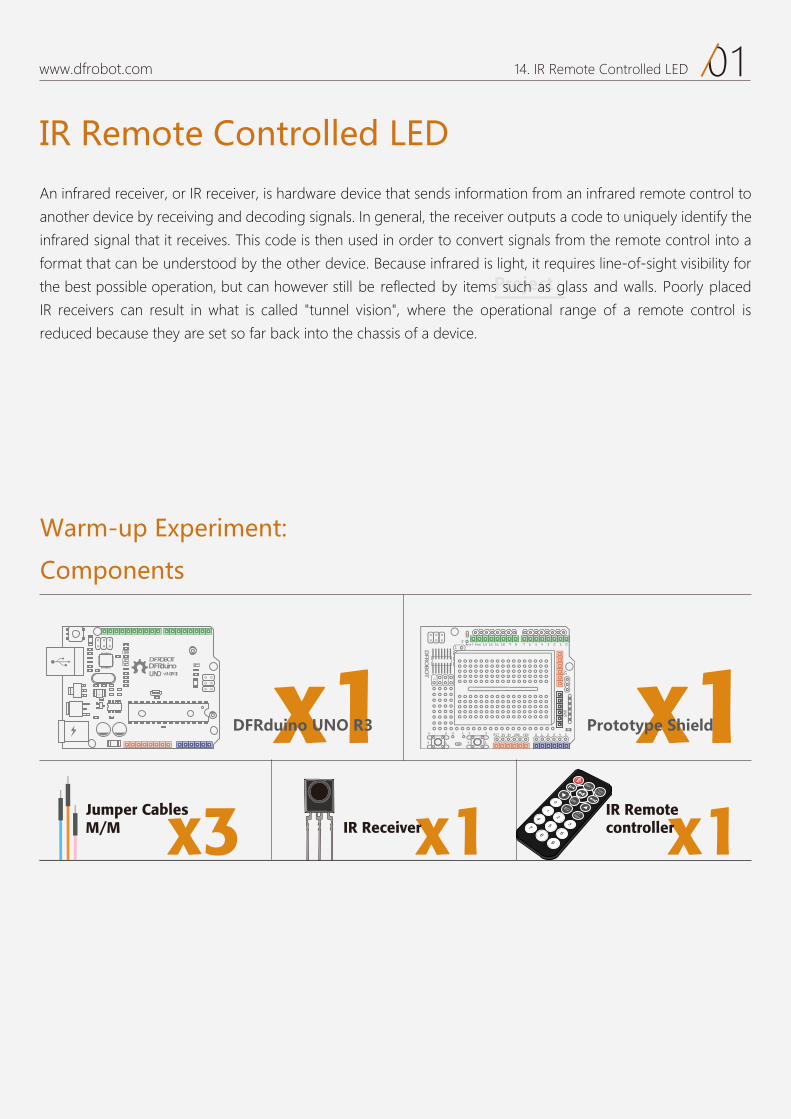
01www.dfrobot.com 14. IR Remote Controlled LED
Project
IR Remote Controlled LED
An infrared receiver, or IR receiver, is hardware device that sends information from an infrared remote control to
another device by receiving and decoding signals. In general, the receiver outputs a code to uniquely identify the
infrared signal that it receives. This code is then used in order to convert signals from the remote control into a
format that can be understood by the other device. Because infrared is light, it requires line-of-sight visibility for
the best possible operation, but can however still be reflected by items such as glass and walls. Poorly placed
IR receivers can result in what is called "tunnel vision", where the operational range of a remote control is
reduced because they are set so far back into the chassis of a device.
Components
Warm-up Experiment:
DFRduinoUNO v3.0[R3]
DFROBOT
a050 x1 x1
x1IR Receiverx3M/M Jumper Cables
DFR dleihS epytotorP3R ONU oniud
VOL +FUNC/STOP
EQST/REPT
0
1
23
45
67
89
VOL -
x1IR Remote controller
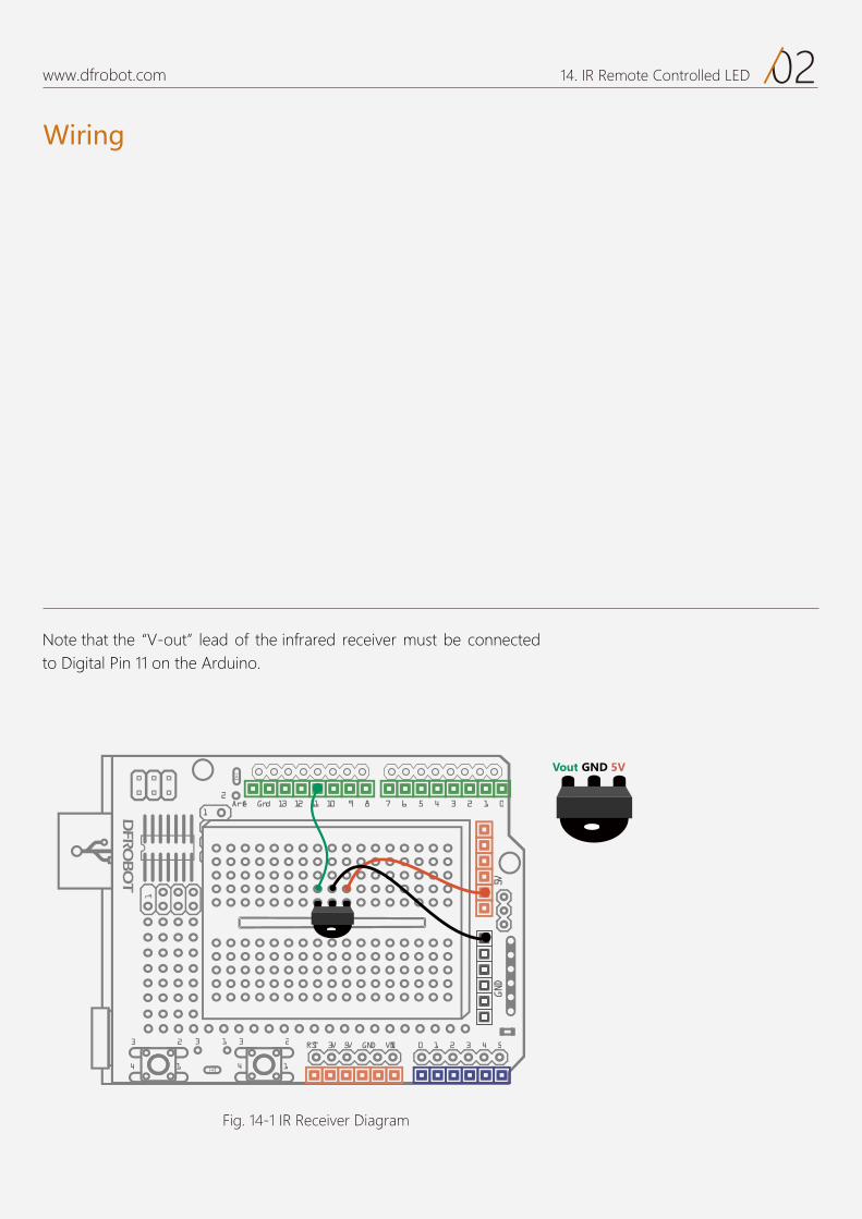
Wiring
02DFRobot 14. IR Remote Controlled LED
17 6 5 4 3 2 1 0Aref Gnd 13 12 11 10 9 8
2323 3 1
1414
2
0 1 2 3 4 5RST 3V 5V GND VIN
5VGND
1
Fig. 14-1 IR Receiver Diagram
Note that the “V-out” lead of the infrared receiver must be connected to Digital Pin 11 on the Arduino.
Vout GND 5V
Wiring
02www.dfrobot.com 14. IR Remote Controlled LED
17 6 5 4 3 2 1 0Aref Gnd 13 12 11 10 9 8
2323 3 1
1414
2
0 1 2 3 4 5RST 3V 5V GND VIN
5VGND
1
Fig. 14-1 IR Receiver Diagram
Note that the “V-out” lead of the infrared receiver must be connected to Digital Pin 11 on the Arduino.
Vout GND 5V
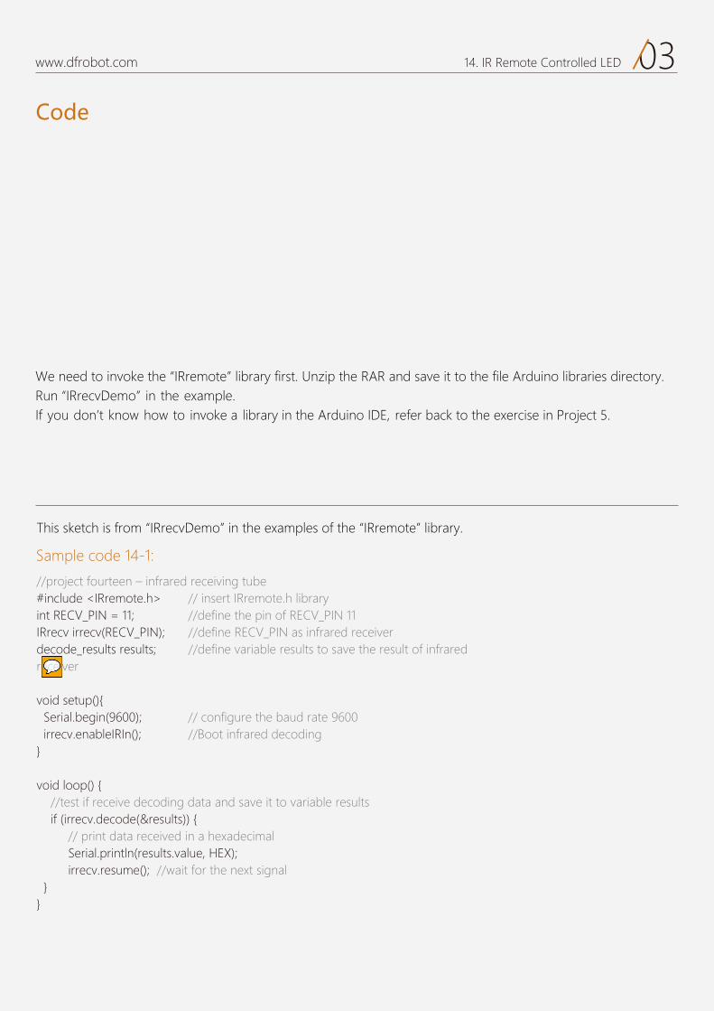
Code
03www.dfrobot.com 14. IR Remote Controlled LED
Sample code 14-1:
This sketch is from “IRrecvDemo” in the examples of the “IRremote” library.
//project fourteen – infrared receiving tube #include <IRremote.h> // insert IRremote.h library int RECV_PIN = 11; //define the pin of RECV_PIN 11 IRrecv irrecv(RECV_PIN); //define RECV_PIN as infrared receiverdecode_results results; //define variable results to save the result of infrared receiver
void setup(){ Serial.begin(9600); // configure the baud rate 9600 irrecv.enableIRIn(); //Boot infrared decoding }
void loop() { //test if receive decoding data and save it to variable results if (irrecv.decode(&results)) { // print data received in a hexadecimal Serial.println(results.value, HEX); irrecv.resume(); //wait for the next signal }}
We need to invoke the “IRremote” library first. Unzip the RAR and save it to the file Arduino libraries directory. Run “IRrecvDemo” in the example.If you don’t know how to invoke a library in the Arduino IDE, refer back to the exercise in Project 5.
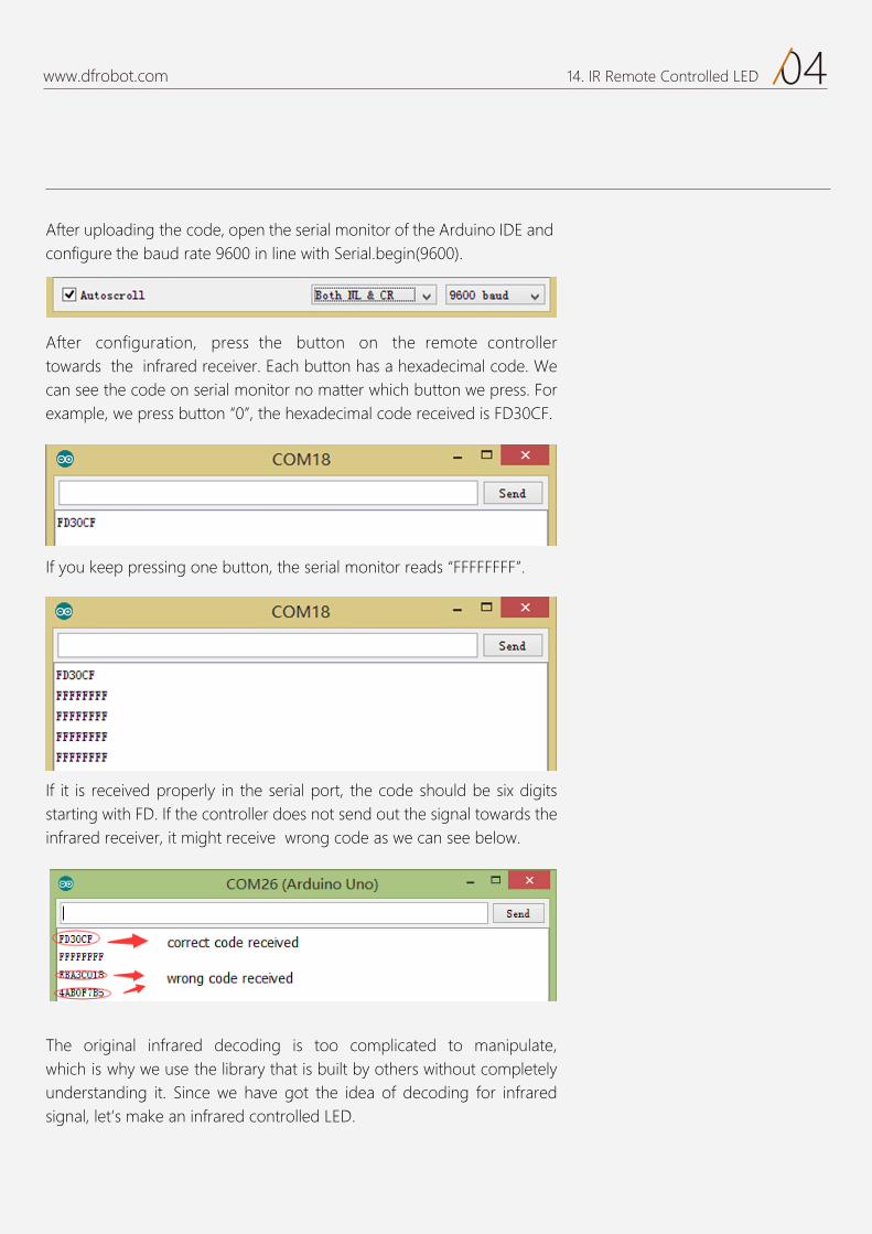
04www.dfrobot.com 14. IR Remote Controlled LED
After uploading the code, open the serial monitor of the Arduino IDE and configure the baud rate 9600 in line with Serial.begin(9600).
After configuration, press the button on the remote controller towards the infrared receiver. Each button has a hexadecimal code. We can see the code on serial monitor no matter which button we press. For example, we press button “0”, the hexadecimal code received is FD30CF.
If it is received properly in the serial port, the code should be six digits starting with FD. If the controller does not send out the signal towards the infrared receiver, it might receive wrong code as we can see below.
The original infrared decoding is too complicated to manipulate, which is why we use the library that is built by others without completely understanding it. Since we have got the idea of decoding for infrared signal, let’s make an infrared controlled LED.
If you keep pressing one button, the serial monitor reads “FFFFFFFF”.
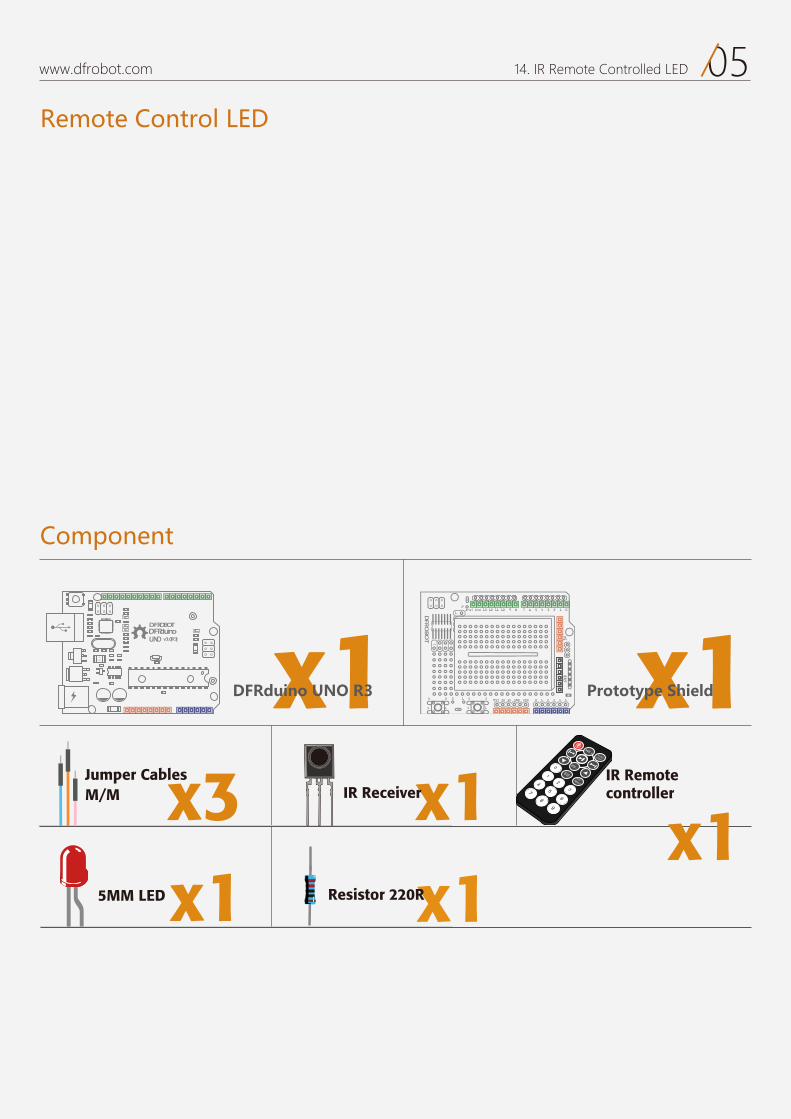
05www.dfrobot.com 14. IR Remote Controlled LED
Remote Control LED
Component
DFRduinoUNO v3.0[R3]
DFROBOT
a050 x1 x1
x1IR Receiverx3M/M Jumper Cables
DFRduino UNO R3 Prototype Shield
VOL +FUNC/STOP
EQST/REPT
0
1
23
45
67
89
VOL -
x1IR Remote controller
x15MM LED Resistor 220R
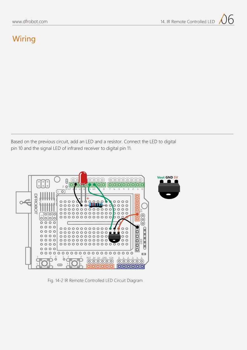
Wiring
06www.dfrobot.com 14. IR Remote Controlled LED
Fig. 14-2 IR Remote Controlled LED Circuit Diagram
Based on the previous circuit, add an LED and a resistor. Connect the LED to digital pin 10 and the signal LED of infrared receiver to digital pin 11.
Vout GND 5V
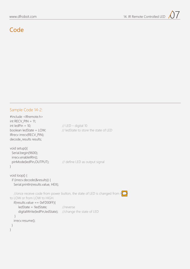
Code
07www.dfrobot.com 14. IR Remote Controlled LED
Sample Code 14-2:
#include <IRremote.h>int RECV_PIN = 11; int ledPin = 10; // LED – digital 10boolean ledState = LOW; // ledState to store the state of LED IRrecv irrecv(RECV_PIN);decode_results results;
void setup(){ Serial.begin(9600); irrecv.enableIRIn(); pinMode(ledPin,OUTPUT); // define LED as output signal }
void loop() { if (irrecv.decode(&results)) { Serial.println(results.value, HEX);
//once receive code from power button, the state of LED is changed from HIGH to LOW or from LOW to HIGH. if(results.value == 0xFD00FF){ ledState = !ledState; //reverse digitalWrite(ledPin,ledState); //change the state of LED } irrecv.resume(); }}
Code
08www.dfrobot.com 14. IR Remote Controlled LED
Defining the infrared receiver is the same as the last sketch.
In the setup() function, we use serial port to boot the infrared decoding and configure pinMode of digital pins. In the main program,
we test if receive infrared signal and store data in the results variable.
Once the Arduino receives data, the program does two things: first it tests whether infrared code is received from the power button.
You might not be so familiar with “!”. “!” is a logical NOT.
“!ledState” is the opposite state of “ledState”. “!” is only used in the variable that only holds 2 states, or boolean type of variable.
Next, the Arduino will wait for the next signal.
The second thing is to make the LED change state.
#include <IRremote.h> //insert IRremote.h library int RECV_PIN = 11; //define the pin of RECV_PIN 11 IRrecv irrecv(RECV_PIN); //define RECV_PIN as infrared receiver
;stluser stluser_edoced //define variable results to save the result of infrared receiverint ledPin = 10; //LED – digital 10boolean ledState = LOW; //Ledstate used to store the LED status
ledState = !ledState; //Flip digitalWrite(ledPin,ledState); //Change corresponding LED status
if (irrecv.decode(&results))
if(results.value == 0xFD00FF)
irrecv.resume();

Exercise
09www.dfrobot.com 14. IR Remote Controlled LED
1. Combine the fan project with the current project. Add one more function to the mini controller to control a LED and a fan.
2. Make a DIY a remote controlled project, e.g.: a small figure that can move with servos controlled by infrared signals.
15
IR Remote Controlled LED Module
Project 15
www.dfrobot.com
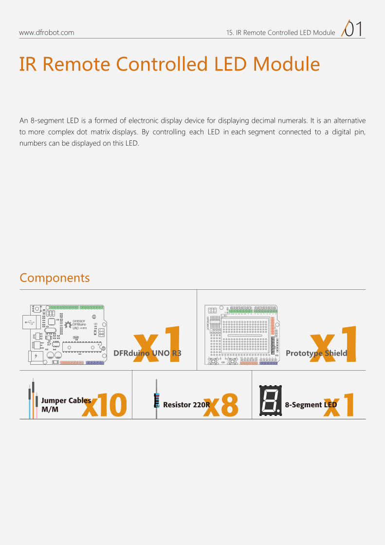
01www.dfrobot.com 15. IR Remote Controlled LED Module
IR Remote Controlled LED Module
An 8-segment LED is a formed of electronic display device for displaying decimal numerals. It is an alternative
to more complex dot matrix displays. By controlling each LED in each segment connected to a digital pin,
numbers can be displayed on this LED.
Components
DFRduinoUNO v3.0[R3]
DFROBOT
a050 x1 x1
x8Resistor 220R x18-Segment LEDx10Jumper CablesM/M
DFRduino UNO R3 Prototype Shield
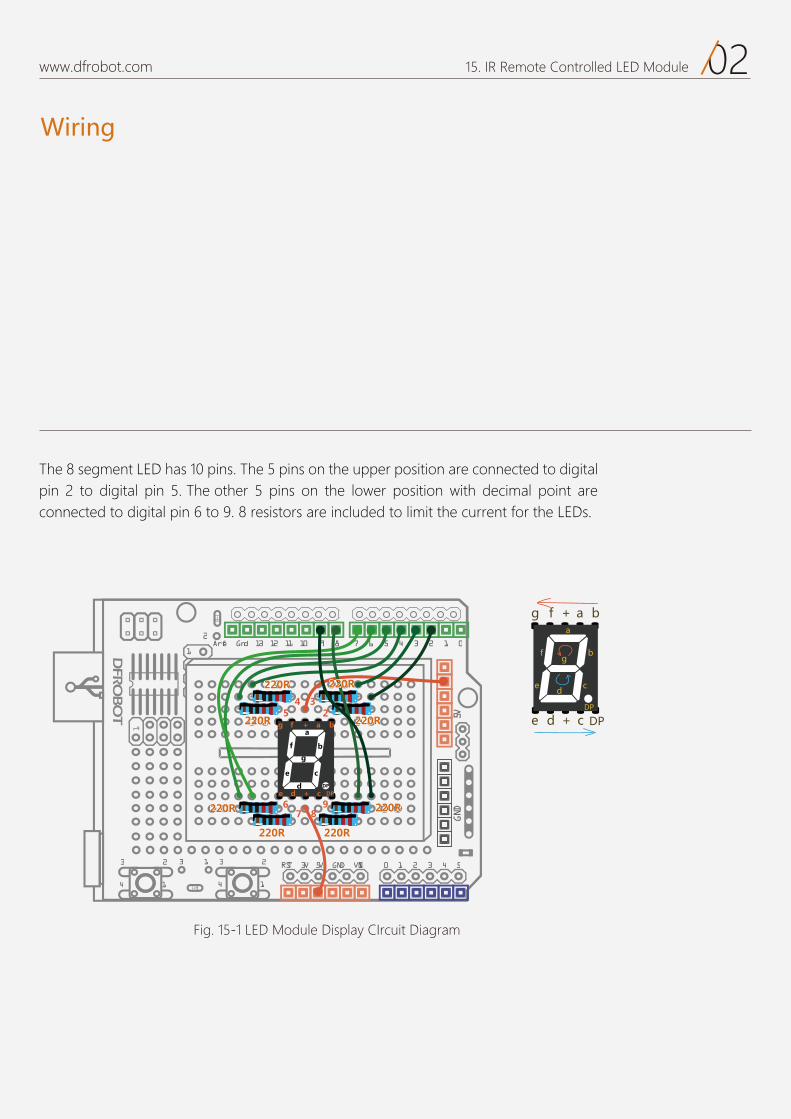
Wiring
02www.dfrobot.com 15. IR Remote Controlled LED Module
17 6 5 4 3 2 1 0Aref Gnd 13 12 11 10 9 8
2323 3 1
1414
2
0 1 2 3 4 5RST 3V 5V GND VIN
5VGND
1
Fig. 15-1 LED Module Display CIrcuit Diagram
The 8 segment LED has 10 pins. The 5 pins on the upper position are connected to digital pin 2 to digital pin 5. The other 5 pins on the lower position with decimal point are connected to digital pin 6 to 9. 8 resistors are included to limit the current for the LEDs.
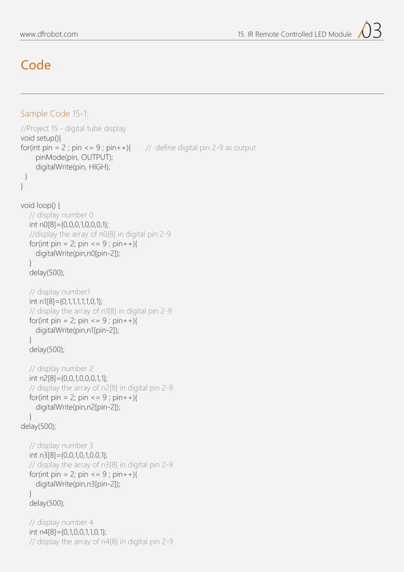
Code
03www.dfrobot.com 15. IR Remote Controlled LED Module
Sample Code 15-1:
//Project 15 - digital tube display void setup(){for(int pin = 2 ; pin <= 9 ; pin++){ // define digital pin 2-9 as output pinMode(pin, OUTPUT); digitalWrite(pin, HIGH); }}
void loop() { // display number 0 int n0[8]={0,0,0,1,0,0,0,1}; //display the array of n0[8] in digital pin 2-9 for(int pin = 2; pin <= 9 ; pin++){ digitalWrite(pin,n0[pin-2]); } delay(500); // display number1 int n1[8]={0,1,1,1,1,1,0,1}; // display the array of n1[8] in digital pin 2-9 for(int pin = 2; pin <= 9 ; pin++){ digitalWrite(pin,n1[pin-2]); } delay(500); // display number 2 int n2[8]={0,0,1,0,0,0,1,1}; // display the array of n2[8] in digital pin 2-9 for(int pin = 2; pin <= 9 ; pin++){ digitalWrite(pin,n2[pin-2]); }delay(500); // display number 3 int n3[8]={0,0,1,0,1,0,0,1}; // display the array of n3[8] in digital pin 2-9 for(int pin = 2; pin <= 9 ; pin++){ digitalWrite(pin,n3[pin-2]); } delay(500); // display number 4 int n4[8]={0,1,0,0,1,1,0,1}; // display the array of n4[8] in digital pin 2-9
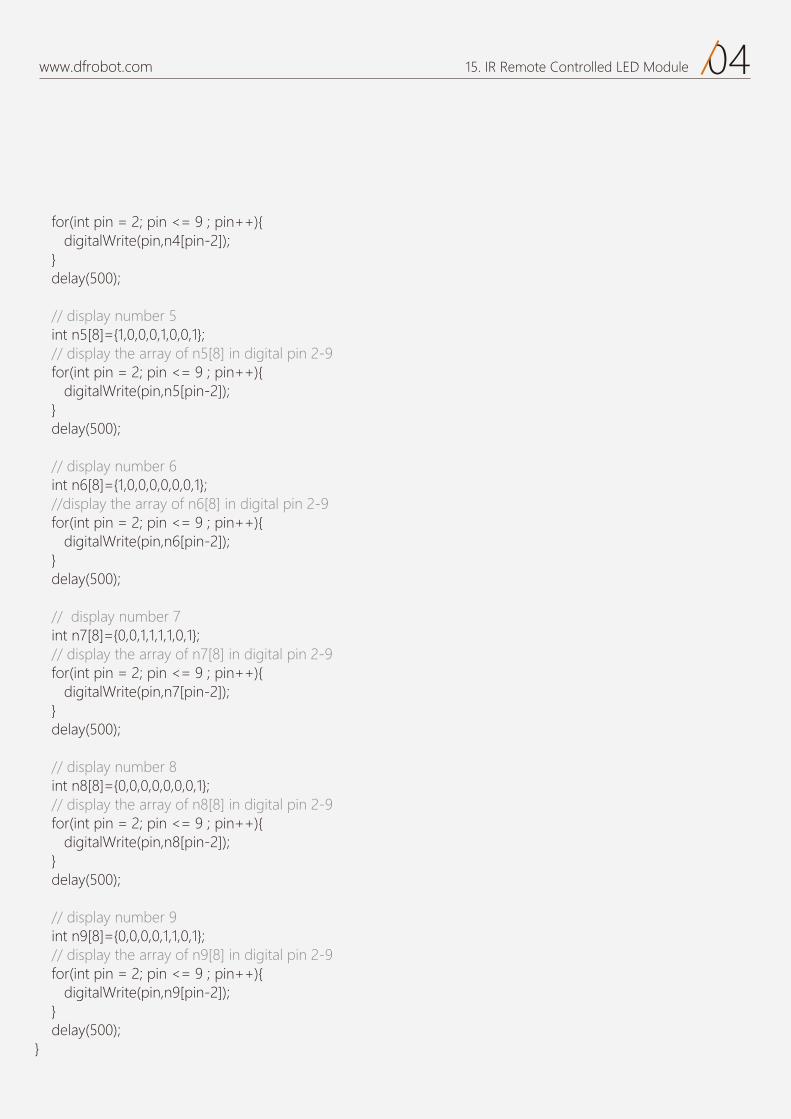
After uploading the sketch, the LED will display 0 to 9 repeatedly. To understand the code, you need to know the structure of 8-segment LED.
04www.dfrobot.com 15. IR Remote Controlled LED Module
for(int pin = 2; pin <= 9 ; pin++){ digitalWrite(pin,n4[pin-2]); } delay(500); // display number 5 int n5[8]={1,0,0,0,1,0,0,1}; // display the array of n5[8] in digital pin 2-9 for(int pin = 2; pin <= 9 ; pin++){ digitalWrite(pin,n5[pin-2]); } delay(500); // display number 6 int n6[8]={1,0,0,0,0,0,0,1}; //display the array of n6[8] in digital pin 2-9 for(int pin = 2; pin <= 9 ; pin++){ digitalWrite(pin,n6[pin-2]); } delay(500); // display number 7 int n7[8]={0,0,1,1,1,1,0,1}; // display the array of n7[8] in digital pin 2-9 for(int pin = 2; pin <= 9 ; pin++){ digitalWrite(pin,n7[pin-2]); } delay(500); // display number 8 int n8[8]={0,0,0,0,0,0,0,1}; // display the array of n8[8] in digital pin 2-9 for(int pin = 2; pin <= 9 ; pin++){ digitalWrite(pin,n8[pin-2]); } delay(500); // display number 9 int n9[8]={0,0,0,0,1,1,0,1}; // display the array of n9[8] in digital pin 2-9 for(int pin = 2; pin <= 9 ; pin++){ digitalWrite(pin,n9[pin-2]); } delay(500);}
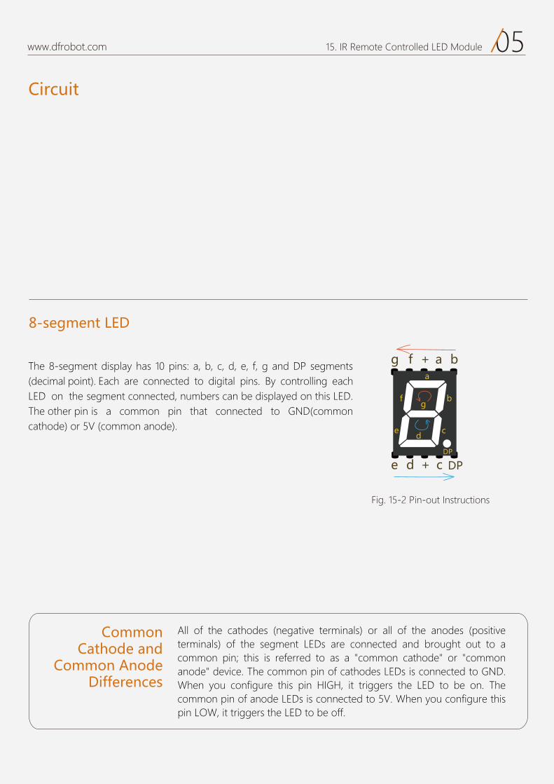
Circuit
05www.dfrobot.com 15. IR Remote Controlled LED Module
The 8-segment display has 10 pins: a, b, c, d, e, f, g and DP segments(decimal point). Each are connected to digital pins. By controlling each LED on the segment connected, numbers can be displayed on this LED. The other pin is a common pin that connected to GND(common cathode) or 5V (common anode).
8-segment LED
CommonCathode and
Common AnodeDifferences
All of the cathodes (negative terminals) or all of the anodes (positive terminals) of the segment LEDs are connected and brought out to a common pin; this is referred to as a "common cathode" or "common anode" device. The common pin of cathodes LEDs is connected to GND. When you configure this pin HIGH, it triggers the LED to be on. The common pin of anode LEDs is connected to 5V. When you configure this pin LOW, it triggers the LED to be off.
Fig. 15-2 Pin-out Instructions
Code
www.dfrobot.com 15. IR Remote Controlled LED Module
with loops to simplify things. Segment b a f g e d c -
a for loop.
for loop
-ray with value 0/LOW. So the b segment is on. When
the a segment is on. the f segment is
etc.
’
pin= 2 n0 [0] b segment on
pin= 3 n0 [1] e a segment on
pin= n0[2] =0 f segment on
pin= 5 0[3] =1 digitalWrite(5 1) g segment off
pin= n0[ ] e 0) e segment on
pin= n0[5] d segment on
pin= 8 n0 0 c segment on
pin= n0 ] =1 e 1)
Now it displays 0. -
tus is clear.
. ll be introduced on the following page.
and initialize .
number Let us take a look at the code of displaying 0.
the concept of an is a collection of variables that are accessed with an
intname it n0that arrays are zero s. When declaring an array of one more element than your initializa-
isbrackets (n0 ) elements.
for(int pinMode ); digitalWrite );}
for(int digitalWrite}
int
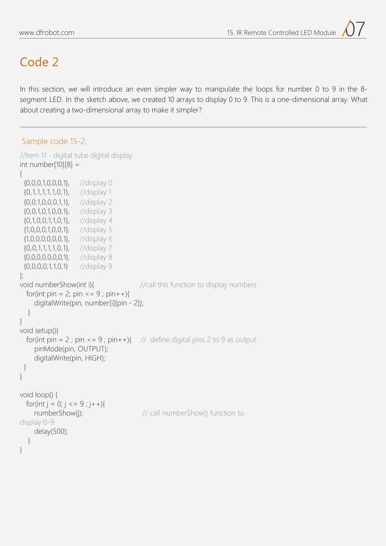
Code 2
07www.dfrobot.com 15. IR Remote Controlled LED Module
In this section, we will introduce an even simpler way to manipulate the loops for number 0 to 9 in the 8-segment LED. In the sketch above, we created 10 arrays to display 0 to 9. This is a one-dimensional array. What about creating a two-dimensional array to make it simpler?
Sample code 15-2: //Item 11 - digital tube digital display int number[10][8] = { {0,0,0,1,0,0,0,1}, //display 0 {0,1,1,1,1,1,0,1}, //display 1 {0,0,1,0,0,0,1,1}, //display 2 {0,0,1,0,1,0,0,1}, //display 3 {0,1,0,0,1,1,0,1}, //display 4 {1,0,0,0,1,0,0,1}, //display 5 {1,0,0,0,0,0,0,1}, //display 6 {0,0,1,1,1,1,0,1}, //display 7 {0,0,0,0,0,0,0,1}, //display 8 {0,0,0,0,1,1,0,1} //display 9};void numberShow(int i){ //call this function to display numbers for(int pin = 2; pin <= 9 ; pin++){ digitalWrite(pin, number[i][pin - 2]); }}void setup(){
for(int pin = 2 ; pin <= 9 ; pin++){ // define digital pins 2 to 9 as output pinMode(pin, OUTPUT); digitalWrite(pin, HIGH); }}
void loop() { for(int j = 0; j <= 9 ; j++){
numberShow(j); // call numberShow() function to display 0-9. delay(500); }}
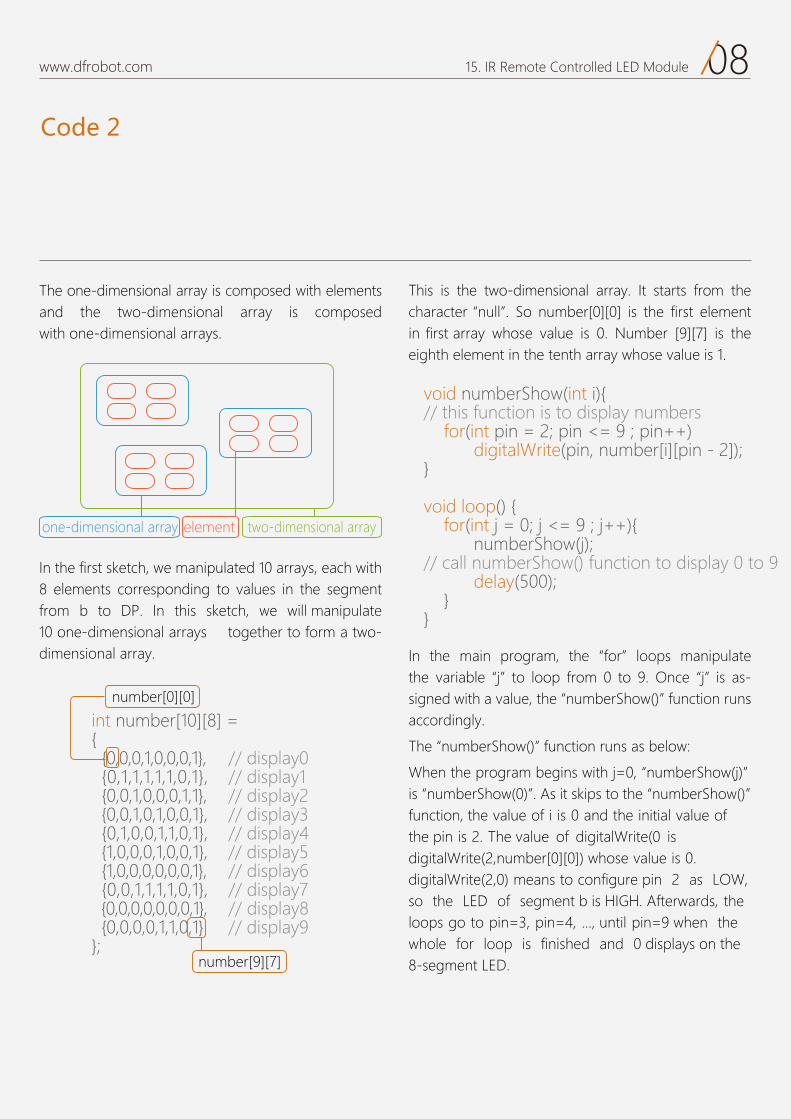
Code 2
08www.dfrobot.com 15. IR Remote Controlled LED Module
al array is composed with elements al array is composed
al arrays.
al the character null .
eighth element in the tenth array whose value is 1.
for loops manipulate the variable is assigned with a value, the function runs accordingly.
The
is . As it skips to the
the
so the LED of segment b is G . Afterwards, the un
whole for loop is finished and
will manipulate dimensional arrays together to form
dimensional array.
int
void numberShow(int
for(int digitalWrite}
void loop for(int
delay }}
number[0][0]
al arrayelemental array
09www.dfrobot.com 15. IR Remote Controlled LED Module
Compare how we displayed 0 in the first sketch.
The principle of assigning value for pin 2 to 9 to control segment from b to DP is the same.
When numberShow(0) loop is finished, it goes back to the for loop function.
1 → numberShow(1) → i =1 → number[1 ][pin-2] → display 1
j=2 → numberShow(2) → i=2 → number[2][pin-2] → display 2
j=3 → numberShow(3) → i=3 → number[3][pin-2] → display 3
……
j=3 → numberShow(9) → i=9 → number[9][pin-2] → displays 9
The above is the analysis for the codes. Just think about the differencesbetween the one dimensional array and the two dimensional array and how the codes operate.
The combined application of the LED module and IR receiver is to be achieved after handling their operating principles. The Arduino com-patible controller processes and delivers the signal transferred from the Mini remote controller to the IR receiver to the LED module.
Numbers from 0 to 9 on the mini remote controller are to be displayed on corresponding positions on the LED module. In addition, decreasing and increasing functions are feasible.
// display number 0 int n0[8]={0,0,0,1,0,0,0,1}; // display the array of n0[8] in digital pin 2-9 for(int pin = 2; pin <= 9 ; pin++){
digitalWrite(pin,n0[pin-2]); }
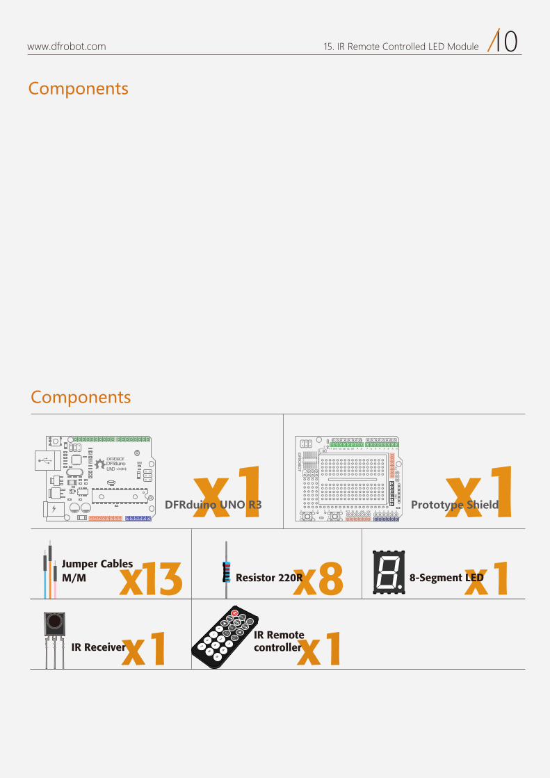
Components
10www.dfrobot.com 15. IR Remote Controlled LED Module
x18-Segment LED
Components
DFRduinoUNO v3.0[R3]
DFROBOT
a050 x1 x1
x8Resistor 220Rx13M/M Jumper Cables
DFRduino UNO R3 Prototype Shield
x1IR Receiver
VOL +FUNC/STOP
EQST/REPT
0
1
23
45
67
89
VOL -
x1IR Remote controller
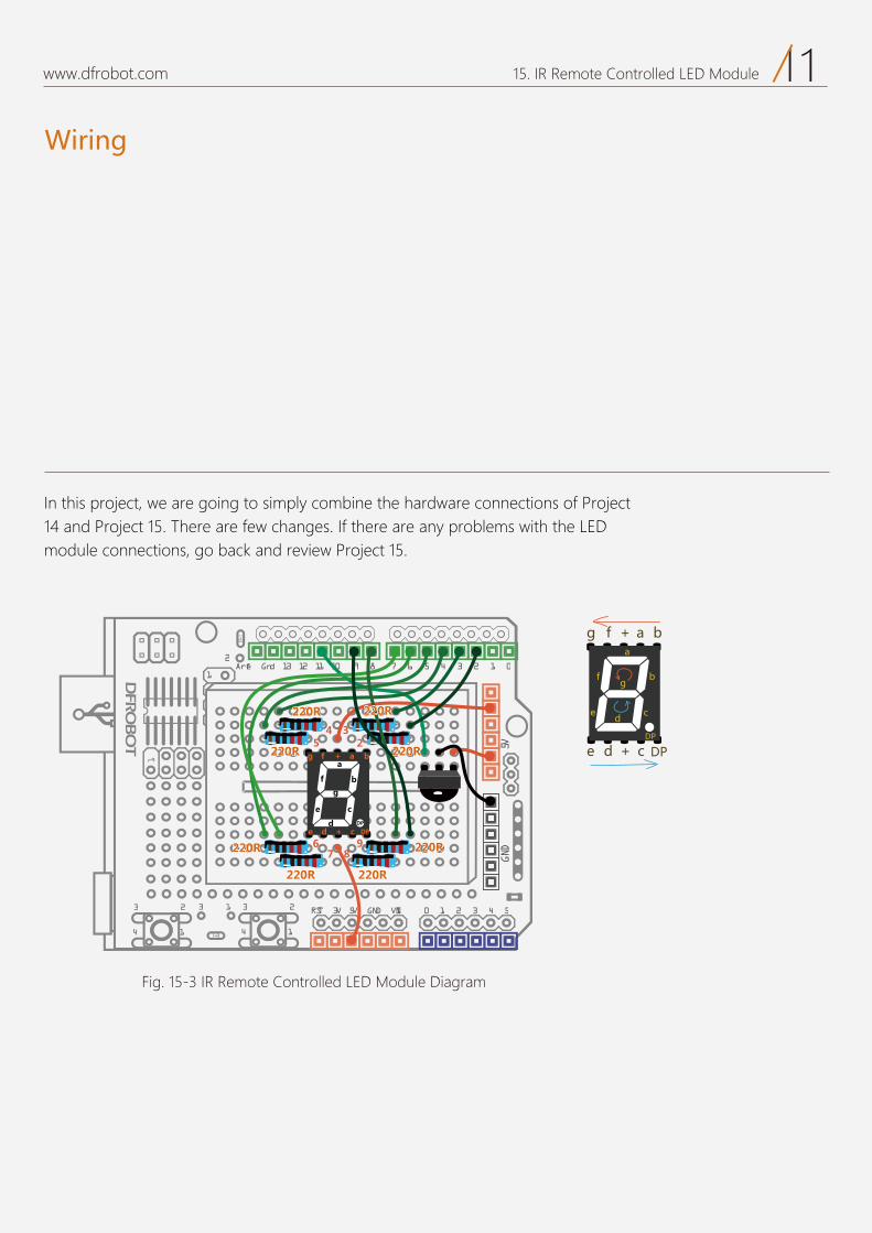
Wiring
11www.dfrobot.com 15. IR Remote Controlled LED Module
17 6 5 4 3 2 1 0Aref Gnd 13 12 11 10 9 8
2323 3 1
1414
2
0 1 2 3 4 5RST 3V 5V GND VIN
5VGND
1
Fig. 15-3 IR Remote Controlled LED Module Diagram
I , we are going to simply combine the hardware connectionsare few changes. If there are any problems with the LED
module connections, go back and review .
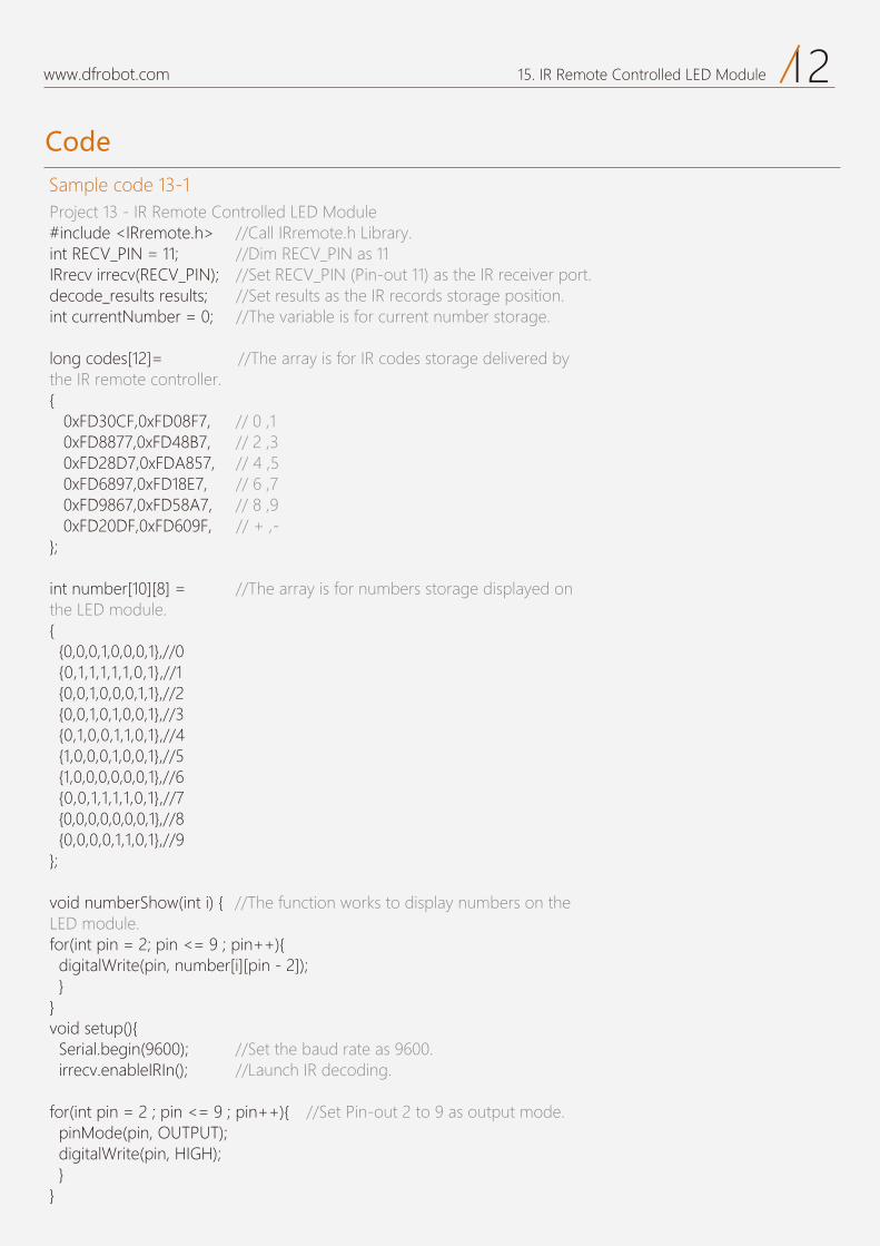
Code
12www.dfrobot.com 15. IR Remote Controlled LED Module
Sample code 13-1Project 13 - IR Remote Controlled LED Module#include <IRremote.h> //Call IRremote.h Library.int RECV_PIN = 11; //Dim RECV_PIN as 11IRrecv irrecv(RECV_PIN); //Set RECV_PIN (Pin-out 11) as the IR receiver port. decode_results results; //Set results as the IR records storage position. int currentNumber = 0; //The variable is for current number storage.
long codes[12]= //The array is for IR codes storage delivered by the IR remote controller.{ 0xFD30CF,0xFD08F7, // 0 ,1 0xFD8877,0xFD48B7, // 2 ,3 0xFD28D7,0xFDA857, // 4 ,5 0xFD6897,0xFD18E7, // 6 ,7 0xFD9867,0xFD58A7, // 8 ,9 0xFD20DF,0xFD609F, // + ,-};
int number[10][8] = //The array is for numbers storage displayed on the LED module.{ {0,0,0,1,0,0,0,1},//0 {0,1,1,1,1,1,0,1},//1 {0,0,1,0,0,0,1,1},//2 {0,0,1,0,1,0,0,1},//3 {0,1,0,0,1,1,0,1},//4 {1,0,0,0,1,0,0,1},//5 {1,0,0,0,0,0,0,1},//6 {0,0,1,1,1,1,0,1},//7 {0,0,0,0,0,0,0,1},//8 {0,0,0,0,1,1,0,1},//9};
void numberShow(int i) { //The function works to display numbers on the LED module.for(int pin = 2; pin <= 9 ; pin++){ digitalWrite(pin, number[i][pin - 2]); }}void setup(){ Serial.begin(9600); //Set the baud rate as 9600. irrecv.enableIRIn(); //Launch IR decoding. for(int pin = 2 ; pin <= 9 ; pin++){ //Set Pin-out 2 to 9 as output mode. pinMode(pin, OUTPUT); digitalWrite(pin, HIGH); }}
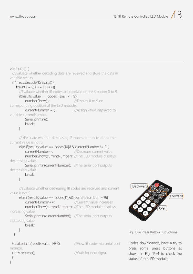
13www.dfrobot.com 15. IR Remote Controlled LED Module
Codes downloaded, have a try to press some press buttons as shown in Fig. 15-4 to check the status of the LED module.
VOL +FUNC/STOP
EQST/REPT
0
1
23
45
67
89
VOL -
void loop() { //Evaluate whether decoding data are received and store the data in variable results. if (irrecv.decode(&results)) { for(int i = 0; i <= 11; i++){ //Evaluate whether IR codes are received of press button 0 to 9. if(results.value == codes[i]&& i <= 9){ numberShow(i); //Display 0 to 9 on corresponding position of the LED module. currentNumber = i; //Assign value displayed to variable currentNumber. Serial.println(i); break; } // /Evaluate whether decreasing IR codes are received and the current value is not 0. else if(results.value == codes[10]&& currentNumber != 0){ currentNumber--; //Decrease current value. numberShow(currentNumber); //The LED module displays decreasing value. Serial.println(currentNumber); //The serial port outputs decreasing value. break; } //Evaluate whether decreasing IR codes are received and current value is not 9. else if(results.value == codes[11]&& currentNumber != 9){ currentNumber++; //Current value increases. numberShow(currentNumber); //The LED module displays increasing value. Serial.println(currentNumber); //The serial port outputs increasing value. break; } } Serial.println(results.value, HEX); //View IR codes via serial port monitor. irrecv.resume(); //Wait for next signal. }}
Fig. 15-4 Press Button Instructions
Forward
0-9
Backward
Code Review
14www.dfrobot.com 15. IR Remote Controlled LED Module
Th ode below starts from the general for the . Project 12.
: “ ”. This variable is A number
“ ” represents a h . additional buttons on the remote controller.
int
int
15www.dfrobot.com 15. IR Remote Controlled LED Module
if is based on whether data is received from results. Value
if evaluates the second condition whether instructions from Backwardnumber displayed is not 0.
if evaluates the third condition whether instructions from
there should be a for loop before the if evaluation to have variableloop among 0 to 11.
the program startsond event. a code following every if statement.
Code introductions are now finished. most difficult section in all of the we have shown and it is difficult to understand
take it easy - practice makes perfect.
if if if
First step:
There are three conditions require consideration. Firstly, the 8-segment LED module should display 0 to 9 when corresponding press buttons are pressed.Secondly, every time Backward is pressed, number displayed decreases by 1 each time until it reaches 0. Thirdly, every time Forward is pressed, number displayed increases by 1 each time until it reaches 0.
To decide for above conditions, we adopt if statement. What differs from previous sample codes is that we use if…else if.iWhat is the difference?An evaluation expression usually follows else if but not for else.However, neither else nor else if fails to work independently but an if statement is a must.Get back to the codes for three conditions mentioned below:
Exercises
16www.dfrobot.com 15. IR Remote Controlled LED Module
Make a DIY remote controller that works based on this project.
Using these applications, you can make a movable toy man. You could use servos, explained in the projects mentioned before, and use different press buttons on the remote controller to have the servos move to various angles. Use your imagination and have fun.