Embed Size (px)
Citation preview
2475
www.ijifr.com Copyright © IJIFR 2015
Original Paper Paper
International Journal of Informative & Futuristic Research ISSN (Online): 2347-1697
Volume 2 Issue 8 April 2015
Abstract
A rational approach to the design of structures resting on soil media should take into account both deformation characteristics of the soil and flexibility of the structures. The analytical treatment of such interaction problems invariably requires a certain amount of mathematical and computational effort involving classical theories of elasticity or plasticity or both. In the conventional method of analysis of Reinforced cement concrete open plane framed structures, the base of the structure is assumed to be fixed. i.e., the flexibility of soil and foundation are ignored. However the foundation and soil material will have flexibility. The type of analysis which considers the flexibility characteristics of foundation and soil is called ‘Interaction Analysis’. Interpretation of interaction results have been achieved in the past by the adoption of relative stiffness ratios for the different components of the total system. The flexural rigidities of the superstructure, foundation elements and stiffness of the soil have been identified as evaluating parameters which assist the interpretation of interaction results. Hear, an attempt has been made to find out the variation in axial forces and moment of the structural elements subjected to general static vertical loading condition over a viable practical ranges of relative stiffness ratios between ‘Superstructure to soil’ and Foundation to soil’ by using Winkler spring model for interaction analysis. Interaction analysis with progressive loading is carried out in the same order to find out the variation. Further, an attempt has been made to arrive at the practical ranges of relative stiffness to be adopted to minimize the variation of axial forces and moments in the structural members.
Progressive Loading and Analysis of
RC-Plane Framed Structures Paper ID IJIFR/ V2/ E8/ 027 Page No. 2475-2486 Research Area Civil Engineering
Key Words Deformation, Flexibility, Interaction analysis, Stiffness, Foundation
SreeKeshava K.S 1 Assistant Professor, Department Of Civil Engineering, Jyothy Institute Of Technology - Bangalore
Dr. B.V.Venkatasubramanya2 Head Of Department, Department Of Civil Engineering, Jyothy Institute Of Technology - Bangalore
2476
ISSN (Online): 2347-1697 International Journal of Informative & Futuristic Research (IJIFR)
Volume - 2, Issue - 8, March 2015 20th Edition, Page No: 2475-2486
SreeKeshava K.S., Dr. B.V.Venkatasubramanya :: Progressive Loading and Analysis of RC-Plane Framed Structures
1. Introduction
Reinforced cement concrete open plane frames (i.e., without considering the infilling walls)
are quite common building structures used for residential flats, commercial complexes and other
public utility buildings. In the conventional method of analysis of these structures, the load
distribution within the building frame is calculated on the assumption that the base of the structure is
fixed allowing no relative displacements between the columns, resulting in uniform or varying soil
pressure distribution. This loading is then used to calculate foundation settlements assuming the
structure to be compatible with the soil settlement profile. The above two assumptions are quite
contradictory. Though in the traditional design methods no relative settlements between the column
footings are allowed, the varying subsurface and loading conditions introduce differential
settlements as had been observed by earlier field and theoretical investigations. Since, unequal
settlements occur in most of the cases, secondary stresses are induced in every member of framed
structure. The ratio of secondary forces and the member end forces obtained in the structure
analyzed under conditions of fully fixity may be described as “Interaction Effects”.
The influence of interaction between a framed structure and the foundation-soil system
beneath it, on the distribution of load between the Columns and the differential settlements, has been
described by many Writers, e.g., Lee and Brown. However in most cases, it has been assumed that
the frame is complete before loading commences, although much of the loading may be applied
progressively during construction. Heil and Goschy both analyze progressive loading, but do not
attempt to quantify the differences between the effect of progressive Loading and loading of the
completed frame. Hence, soil, foundation and superstructure constitute one interacting system and
these are not independent component. Interaction between a framed structure interaction along with
the foundation and the soil below are known to influence the distribution of loads among columns
and the differential settlements of the structure.
Unlike the structural materials viz, concrete and steel, the properties of which are
predictable to an acceptable degree of accuracy, the properties of soil system are often difficult to
access, soil being a natural geological material. Thus it has been customary to assign large factor of
safety to soil stresses when compared to those of superstructure. In such a situation, the soil stresses
generally do not cross the “Elastic range” except probably in the small overstressed zones. Hence in
the present analysis the soil system is assumed to be elastic state. Within the ambit of linear
elasticity, the soil system has been variously modeled, yet the four most common adopted models
are; Winkler springs, two parameters model, Half-Space continuum, Layered continuum. Of these
the layered continuum model establishes the exact distribution of stress and strain within the soil
system. However, the theoretical formulations implicit in such problems are difficult and only a few
closed form solutions are available and only a few closed form solutions are available. As a result,
the first two models, namely Winkler springs and half-space continuums are widely used because of
their simplicity.
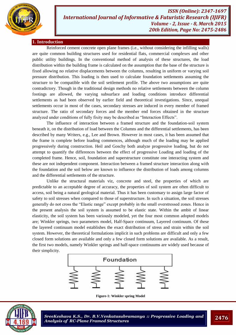
Figure-1: Winkler spring Model
2477
ISSN (Online): 2347-1697 International Journal of Informative & Futuristic Research (IJIFR)
Volume - 2, Issue - 8, March 2015 20th Edition, Page No: 2475-2486
SreeKeshava K.S., Dr. B.V.Venkatasubramanya :: Progressive Loading and Analysis of RC-Plane Framed Structures
The Winkler spring model is the most convenient representation of soil support in the domain of
linear elasticity for framed structure-soil interaction analyses. The closeness of the analytical results
obtained using this model with those corresponding to the elastic half-space continuum has been
investigated in the past for foundation beams. The findings, however, are not applicable to framed
structures founded on beam or strip footings. Moreover, the past investigations employ the concept
of characteristic length which does not adequately account for the stiffness contribution of the
superstructure. A framed structure on beam foundation can be described parametrically by the ratios
of stiffness‟s of superstructure and foundation beams to that of soil. For a practical range of soil
allowable pressures, the ranges of these relative stiffness ratios have been established.
2. Relative Stiffness
The flexible nature of the foundation, the superstructure and the supporting soil medium has great
influence on the behaviour of framed structures. The flexural rigidities of the superstructure and
foundation elements and the stiffness of the soil have been identified as indices for devising
parameters, which assists the interpretation of interaction results, by many earlier investigations.
Currently, the ratios of stiffness of superstructure to soil exist in as parameter for interaction
analysis. While it is generally recognized that these ratios have wide limits few comprehensive
studies have been made to define these limits for different types of structures resting over a wide
range of soils. In this paper, the feasible range of these ratios of stiffness all demarcated for plane
framed reinforced concrete building structure with beam footing resting on soils in which shallow
foundations are feasible.
Absolute stiffness of superstructure, soil and foundation is
Brown and Yu (1986) made the studies on load sequence and soil structure interaction. They used
relative stiffness between „superstructure and soil (Kbs) as the parameters for studying the columns
loads transferred to the foundations, and the differential settlements in the foundation.
The absolute stiffness of the superstructure (Kb), foundation (Kf) have been defined as,
= nE / …..(1)
= E / …. (2)
Ks = Es / (1- ) ….. (3)
Where, n = total number of storeys
E =flexural rigidity of the floor beam
l =length of the bay or floor beam
L=length of the foundation = n,l
n ,= number of bays.
The relative stiffness‟s between the superstructure and soil ( ) and between foundation and soil
( ) have been defined as
= / ------------ (3)
= (16/ )( / ) -------------(4)
The interaction analysis has been carried out over a range of varying between 0.001 to 0.01 and
0.01 to 0.1 respectively. These resemble the factors proposed by sommer (1965) but are more
elegant and convenient to adopt as indices of structures soil interaction.
The absolute stiffness of the soil Ks can be related to the allowable bearing pressure Qa as Ks =
120 QaB KN/ …....………. (5)
Where, B= width of foundation in meters.
2478
ISSN (Online): 2347-1697 International Journal of Informative & Futuristic Research (IJIFR)
Volume - 2, Issue - 8, March 2015 20th Edition, Page No: 2475-2486
SreeKeshava K.S., Dr. B.V.Venkatasubramanya :: Progressive Loading and Analysis of RC-Plane Framed Structures
2.1 Modulus Of Elasticity And Poisson’s Ratio
The modulus of elasticity (Es) is often determined from unconfined triaxial or odemetric
compression tests. Plate load tests and pressure meters tests may also be used to determine the in situ
modulus elasticity of the soil. The modulus of elasticity increases with increase in confining stresses.
For the case where the initial stresses is an isotropic state of stress, the modulus of elasticity
increases approximately as Where varies from 0.1 to 1.0 an average value of =1/2. Owing to the
dependence of Es on the void ratio and the difficulty of obtaining undisturbed sample of granular
soils, it is especially difficult to measure the modulus of elasticity of granular soil reliably. The
modulus of elasticity of cohesive soil has been found to be comparatively insensitive to the effects
confining stress. However the Es of the cohesive soils is found to vary with the void ratio and also
depends on the moisture contents. A comparison of the results of field settlements with those
computed using unconfined compressive test data indicate that the laboratory Es value
underestimates the field Es by a considerable amount (bowles 1977).
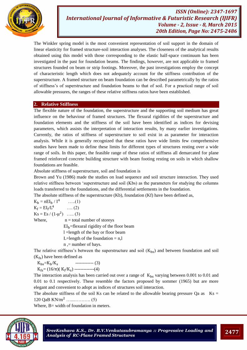
Table-2.1: Typical range of values for Poisson’s (after Bowles, 1977)
Type of soil
Clay-saturated 0.4-0.5
Clay-Unsaturated 0.1-0.3
Sandy Clay 0.2-0.3
Silt 0.3-0.35
Sand dense 0.2-0.4
Coarse 0.15
Fine 0.25
2.2 Modulus Of Subgrade Reaction (Ks)
It is based on the suggestion given by Bowles in 1977.this method is presented on the assumption
that allowable soil pressure is based on some maximum amount of deformation (Si) including on a
factor of safety (Fs). Thus modulus of sub grade reaction is
K‟s = (Fs) Qa / Si
For a settlement of 0.0254m and factor of safety 3, K‟s can be taken as
K‟s= 120 Qa KN/
Typical values for modulus of sub grade reaction are given in table-2.The allowable bearing pressure
of soil (Qa) generally lies between 50KN/ to 200KN/ .The soil stiffness is accounted in terms
of elastic modulus Es and Poisson‟s ratio Vs or in terms of modulus of sub grade reaction K‟s. This
section is primarily concerned with a brief examination of the above factors.
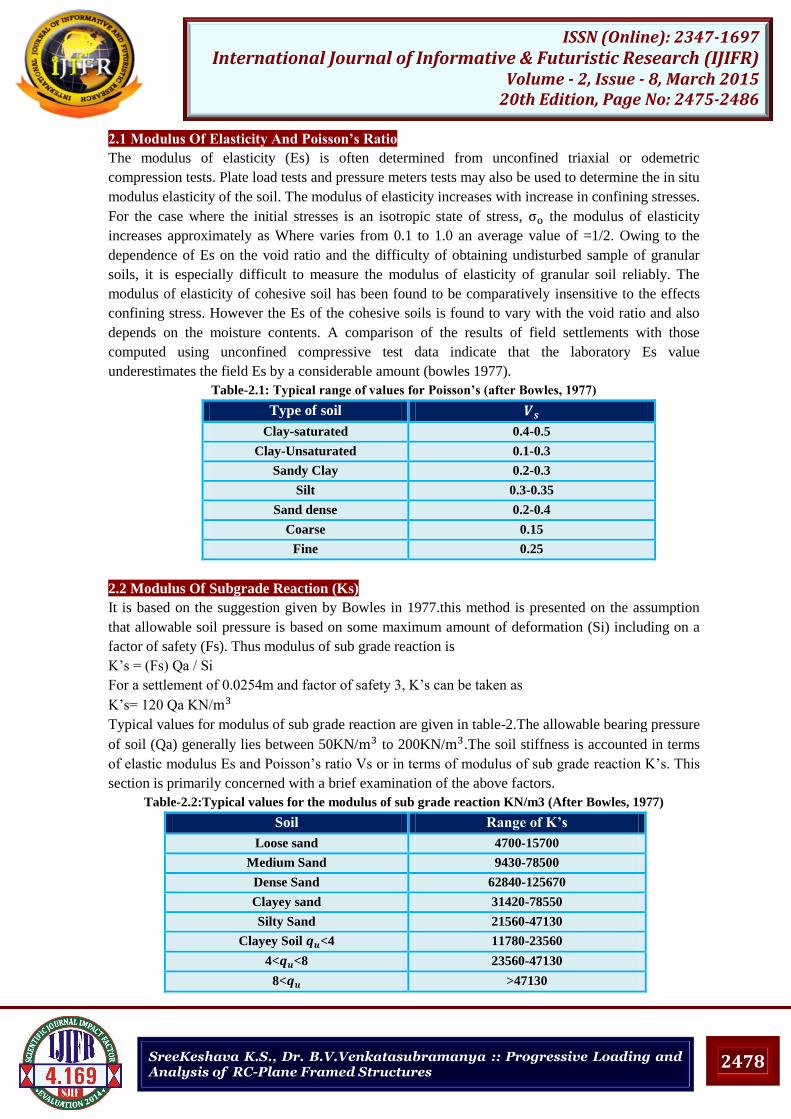
Table-2.2:Typical values for the modulus of sub grade reaction KN/m3 (After Bowles, 1977)
Soil Range of K’s
Loose sand 4700-15700
Medium Sand 9430-78500
Dense Sand 62840-125670
Clayey sand 31420-78550
Silty Sand 21560-47130
Clayey Soil <4 11780-23560
4< <8 23560-47130
8< >47130
2479
ISSN (Online): 2347-1697 International Journal of Informative & Futuristic Research (IJIFR)
Volume - 2, Issue - 8, March 2015 20th Edition, Page No: 2475-2486
SreeKeshava K.S., Dr. B.V.Venkatasubramanya :: Progressive Loading and Analysis of RC-Plane Framed Structures
2.3 Relative Stifness Between Superstructure And Soil (Kbs)
Reinforced cement concrete open plane framed structures are quite common in building structures,
used for residential flats, commercial complexes and other public utility buildings. In this type of
structure, the superstructure floor beams, which are built monolithic with floor slabs, usually have a
higher rigidity than the supporting columns. The filters walls are not rigidly connected to the
supporting beam and do not contribute much to their rigidity. The framed structures of residential
and commercial complexes are subjected to live loads ranging between 2 Kpa to 5 Kpa, and the span
of floor slabs generally ranges between 3m and 10m. Depending on the interframe spacing (s),
which also lies between 3m and 10m, the loading on the superstructure floor beams ranges between
22.5KN/m for small interframe spacing with filler walls. For super structure floor beam, the
span/depth ratio (l/d) usually varies between 10 and 20, and the depth/width ratio(d/b)lies between 1
and 3. The allowable bearing pressure of soil (Qa) generally lies between 50KN/ to 200KN/ .
The absolute stiffness of soil Ks can be related to the allowable bearing pressure Qa as
Ks = 120 QaB KN/ Where B=width of foundation in meters
For beam or strip footing, in order to avoid over lapping of the foundations of adjoining frame, the
maximum foundation width may not exceed 2/3 of the interframe spacing(s), hence the economics
of a raft foundation needs to be examined. The maximum number of floors feasible is governed
mainly by the allowable soil pressure and to some extent it also depends on the interframe spacing.
As the interframe spacing is increased, the number of floors feasible shows a decreasing trend for
lighter live loads on floor beams, whereas for heavier live loads on floor beams, the maximum
number of floors shows an increasing trend. The practical ranges can be obtained using equations
1,2 and 3.
2.4 Relative Stiffness Between Foundation And Soil ( )
The absolute stiffness of foundation, soil and the relative stiffness between foundation and soil are
defined according to the equations 4, 5 &6 respectively. The maximum width of the foundation
beam (B) is restricted to a maximum value of S/2 where S is the inter frame spacing. The span/depth
ratio (l/D) for the foundation beam of the bay can be taken as equal to that of floor beams as between
10 and 20. The depth/width ratio (D/B) of the foundation beam generally lies between 0.15 to 0.5.
The value of depends on the following parameters
Allowable pressure ( )
Length of bay (l)
Length of bay/depth ratio (l/D) of foundation beam.
Number of bays ( )
The number of bays has a greater effect on the value of than other factors. The value of
decreases with increase in allowable soil pressure and bay span, a trend, which is contrary to the
variation of . It is seen from the table that 3.8 to3.10 that for one bay frame lies between
0.001 and 0.785.It has been shown that the maximum interaction effect is felt only in end
bays(Venkatasubramanya 1989).Hence, for an interaction analysis a three-storey structure is found
to be ideal.
3. Problem Considered And Method Of Analysis
The interaction analysis is carried out considering the frame and soil as parts of the single
compatible unit, the soil is represented by Winkler spring model. The bending moments, shear
forces and axial forces of the beam and column elements of the bottom and top storey elements with
different allowable bearing capacities of the soil media are obtained using STAAD-Pro package. The
2480
ISSN (Online): 2347-1697 International Journal of Informative & Futuristic Research (IJIFR)
Volume - 2, Issue - 8, March 2015 20th Edition, Page No: 2475-2486
SreeKeshava K.S., Dr. B.V.Venkatasubramanya :: Progressive Loading and Analysis of RC-Plane Framed Structures
analysis is carried out for the frame with different stages of construction with proper loadings and
also carried out with conventional method which is usual practiced method of construction and these
cases covering the practical ranges of and (0.005 to 0.1).
A three bay, three-storied symmetrical R.C open plane frame having a bay span of 5m and storey
heights of 4m for ground floor and 3m each for first and second floor has been considered. The
modulus of elasticity of concrete is assumed to be 2.2E+07 KN/m2. The moment of inertia of floor
beams and of the columns has been taken as the same so that there is better redistribution of
moments and forces. In the present study dead load of 15 KN/m is considered on the superstructure
beams also the form work is taken as 6 KN/m and live load on floor and roof is taken as 12 and 10
KN/m is applied in proper order. The superstructure rest on a soil media whose allowable bearing
pressure range is 50- 200 KN/m2. The member properties as per codal provisions for a span length
of 8m, the beam dimension as 0.3X0.75m (inclusive of slab thickness) and column dimension as
0.45X0.45m respectively.
The other set of analysis is carried out by considering the relative stiffness and are found to
depend on many parameters i,e. E, , , and . By varying any of these parameters or some of
the parameters together, the required practical ranges of and can be obtained. For the given
soil (known and ) the required practical ranges of and can be obtained by
proportioning different geometrical sizes ( and ) for the foundation and superstructure beams or
for given the structure required ranges of and can be obtained by varying the parameters
and . The former procedure has been adopted here. For the frame and soil selected the absolute
stiffness values of frame. Foundation and soil components are given by,
= nE /
=3*2.2* * /
=50925.93 KN/ = E /
=2.2* * /
=1060.9569
Ks = 120 Qa*B=120*150*1.0= 18000 KN/
The relative stiffness ratio between foundation and soil and between superstructure and soil,
= / , / 18000=2.829
= (16/ )( / ) = (16*1060.9569 / ( )
= 0.3
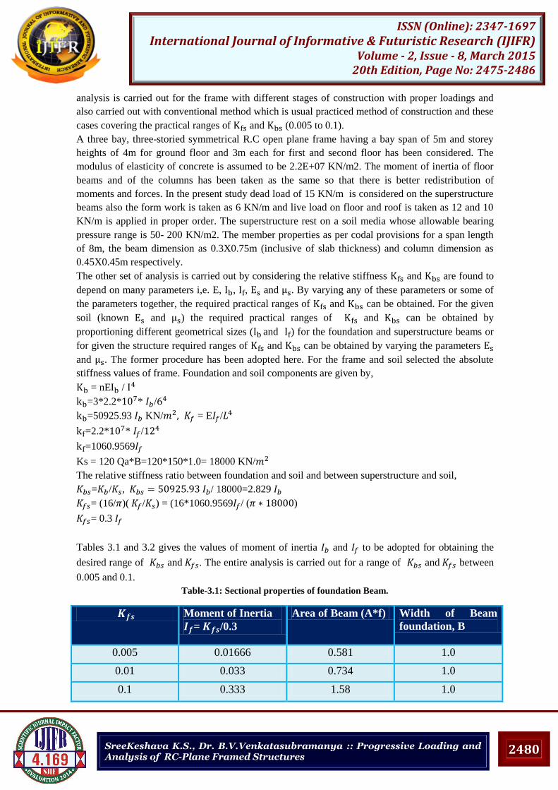
Tables 3.1 and 3.2 gives the values of moment of inertia and to be adopted for obtaining the
desired range of and . The entire analysis is carried out for a range of and between
0.005 and 0.1.
Table-3.1: Sectional properties of foundation Beam.
Moment of Inertia
= /0.3
Area of Beam (A*f) Width of Beam
foundation, B
0.005 0.01666 0.581 1.0
0.01 0.033 0.734 1.0
0.1 0.333 1.58 1.0
2481
ISSN (Online): 2347-1697 International Journal of Informative & Futuristic Research (IJIFR)
Volume - 2, Issue - 8, March 2015 20th Edition, Page No: 2475-2486
SreeKeshava K.S., Dr. B.V.Venkatasubramanya :: Progressive Loading and Analysis of RC-Plane Framed Structures
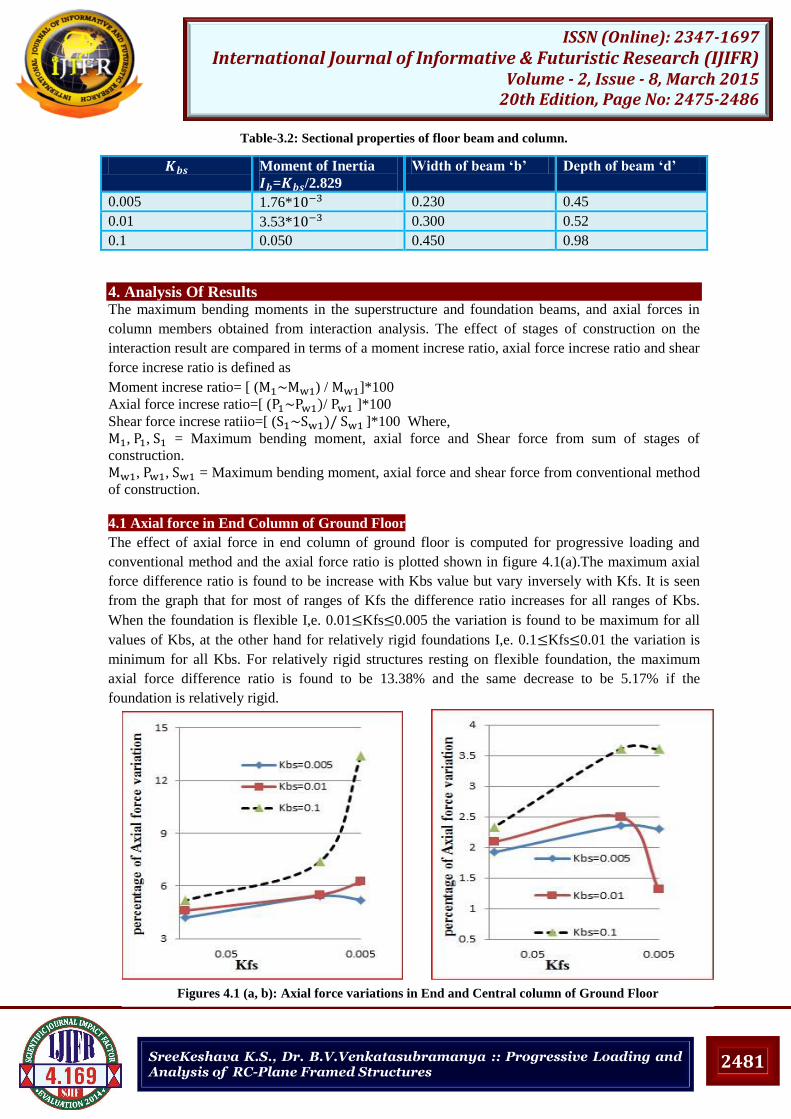
Table-3.2: Sectional properties of floor beam and column.
4. Analysis Of Results The maximum bending moments in the superstructure and foundation beams, and axial forces in
column members obtained from interaction analysis. The effect of stages of construction on the
interaction result are compared in terms of a moment increse ratio, axial force increse ratio and shear
force increse ratio is defined as
Moment increse ratio= [ ( ) / ]*100
Axial force increse ratio=[ ( / ]*100
Shear force increse ratiio=[ ( ]*100 Where,
, , = Maximum bending moment, axial force and Shear force from sum of stages of
construction.
, , = Maximum bending moment, axial force and shear force from conventional method
of construction.
4.1 Axial force in End Column of Ground Floor
The effect of axial force in end column of ground floor is computed for progressive loading and
conventional method and the axial force ratio is plotted shown in figure 4.1(a).The maximum axial
force difference ratio is found to be increase with Kbs value but vary inversely with Kfs. It is seen
from the graph that for most of ranges of Kfs the difference ratio increases for all ranges of Kbs.
When the foundation is flexible I,e. 0.01 Kfs 0.005 the variation is found to be maximum for all
values of Kbs, at the other hand for relatively rigid foundations I,e. 0.1 Kfs 0.01 the variation is
minimum for all Kbs. For relatively rigid structures resting on flexible foundation, the maximum
axial force difference ratio is found to be 13.38% and the same decrease to be 5.17% if the
foundation is relatively rigid.
Moment of Inertia
= /2.829
Width of beam ‘b’ Depth of beam ‘d’
0.005 1.76* 0.230 0.45
0.01 3.53* 0.300 0.52
0.1 0.050 0.450 0.98
Figures 4.1 (a, b): Axial force variations in End and Central column of Ground Floor
2482
ISSN (Online): 2347-1697 International Journal of Informative & Futuristic Research (IJIFR)
Volume - 2, Issue - 8, March 2015 20th Edition, Page No: 2475-2486
SreeKeshava K.S., Dr. B.V.Venkatasubramanya :: Progressive Loading and Analysis of RC-Plane Framed Structures
4.2 Axial force in central Column of Ground Floor
The effect of axial force in central column of ground floor is computed for progressive loading and
conventional method loading and the axial force ratio is plotted in figure 4.1 (b). The maximum
axial force difference ratio is found to be increase with Kbs value but vary inversely with Kfs. For
relatively rigid structures resting on relatively rigid foundations, the maximum axial force difference
ratio is found to be 2.33% and the same increases to be 3.6% if the foundation is relatively flexible.
Similarly, for structure that are relatively flexible, resting on relatively flexible foundations the
maximum axial force difference ratio is found to be 2.3% and the same decreases to 1.92%, if the
foundation is relatively rigid. The axial force obtained by progressive loading is higher compare
with conventional method of interaction analysis.
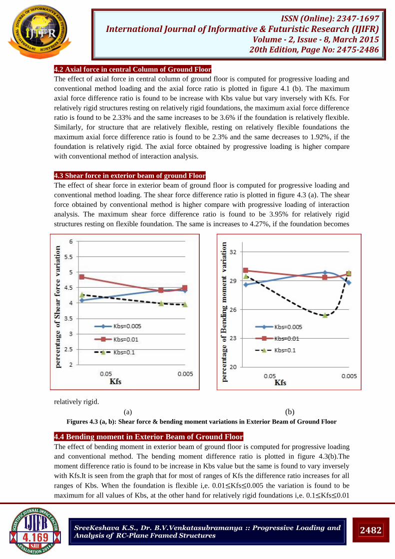
4.3 Shear force in exterior beam of ground Floor
The effect of shear force in exterior beam of ground floor is computed for progressive loading and
conventional method loading. The shear force difference ratio is plotted in figure 4.3 (a). The shear
force obtained by conventional method is higher compare with progressive loading of interaction
analysis. The maximum shear force difference ratio is found to be 3.95% for relatively rigid
structures resting on flexible foundation. The same is increases to 4.27%, if the foundation becomes
relatively rigid.
(a) (b)
Figures 4.3 (a, b): Shear force & bending moment variations in Exterior Beam of Ground Floor
4.4 Bending moment in Exterior Beam of Ground Floor
The effect of bending moment in exterior beam of ground floor is computed for progressive loading
and conventional method. The bending moment difference ratio is plotted in figure 4.3(b).The
moment difference ratio is found to be increase in Kbs value but the same is found to vary inversely
with Kfs.It is seen from the graph that for most of ranges of Kfs the difference ratio increases for all
ranges of Kbs. When the foundation is flexible i,e. 0.01 Kfs 0.005 the variation is found to be
maximum for all values of Kbs, at the other hand for relatively rigid foundations i,e. 0.1 Kfs 0.01
2483
ISSN (Online): 2347-1697 International Journal of Informative & Futuristic Research (IJIFR)
Volume - 2, Issue - 8, March 2015 20th Edition, Page No: 2475-2486
SreeKeshava K.S., Dr. B.V.Venkatasubramanya :: Progressive Loading and Analysis of RC-Plane Framed Structures
the variation is minimum for all KbsWhen the superstructure is relatively regid and the foundation is
relatively flexible the maximum moment difference ratio is found to be 22.70% and the same is
increses to 29.49%, as the foundation becomes relatively rigid. Hence, to minimise the variation, the
foundation is made to be relatively rigid and the super structure to be relatively flexible.
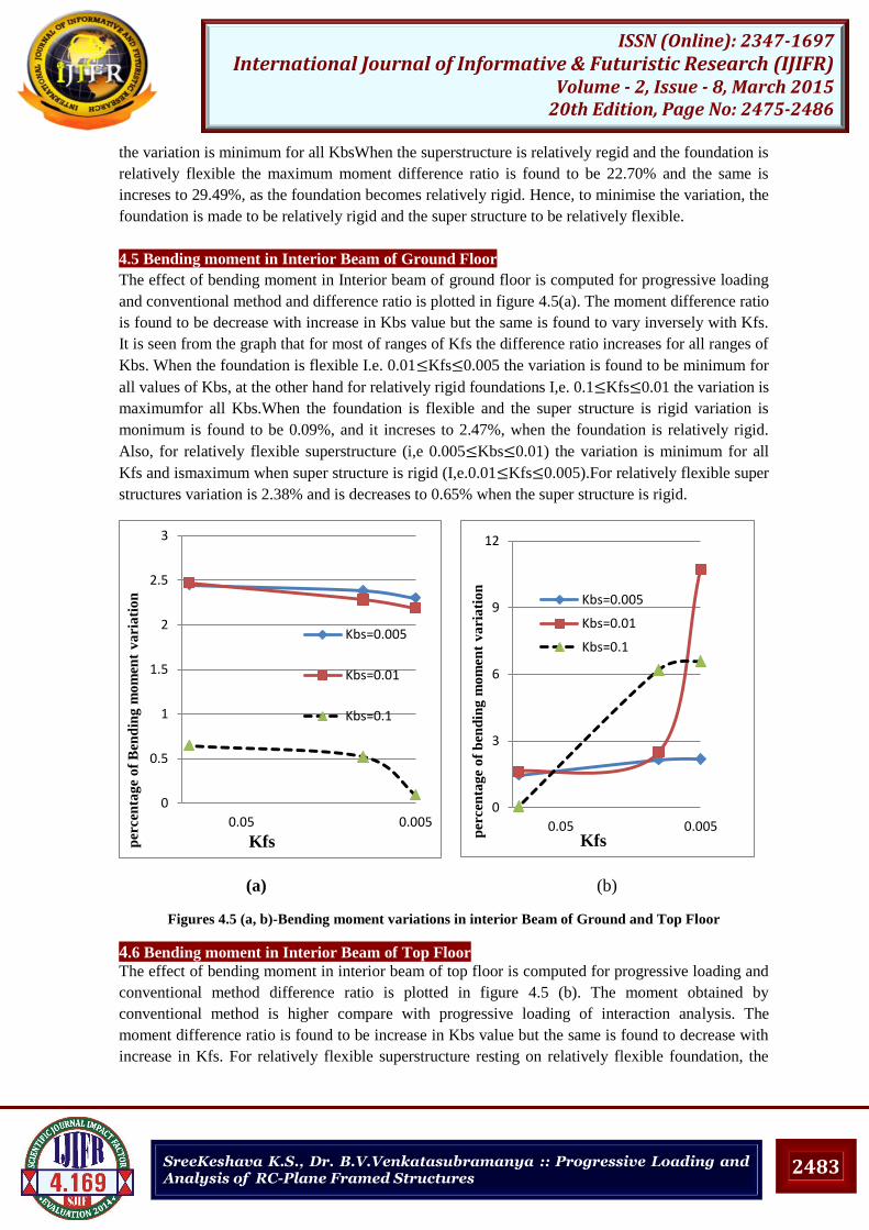
4.5 Bending moment in Interior Beam of Ground Floor
The effect of bending moment in Interior beam of ground floor is computed for progressive loading
and conventional method and difference ratio is plotted in figure 4.5(a). The moment difference ratio
is found to be decrease with increase in Kbs value but the same is found to vary inversely with Kfs.
It is seen from the graph that for most of ranges of Kfs the difference ratio increases for all ranges of
Kbs. When the foundation is flexible I.e. 0.01 Kfs 0.005 the variation is found to be minimum for
all values of Kbs, at the other hand for relatively rigid foundations I,e. 0.1 Kfs 0.01 the variation is
maximumfor all Kbs.When the foundation is flexible and the super structure is rigid variation is
monimum is found to be 0.09%, and it increses to 2.47%, when the foundation is relatively rigid.
Also, for relatively flexible superstructure (i,e 0.005 Kbs 0.01) the variation is minimum for all
Kfs and ismaximum when super structure is rigid (I,e.0.01 Kfs 0.005).For relatively flexible super
structures variation is 2.38% and is decreases to 0.65% when the super structure is rigid.
(a) (b)
Figures 4.5 (a, b)-Bending moment variations in interior Beam of Ground and Top Floor
4.6 Bending moment in Interior Beam of Top Floor
The effect of bending moment in interior beam of top floor is computed for progressive loading and
conventional method difference ratio is plotted in figure 4.5 (b). The moment obtained by
conventional method is higher compare with progressive loading of interaction analysis. The
moment difference ratio is found to be increase in Kbs value but the same is found to decrease with
increase in Kfs. For relatively flexible superstructure resting on relatively flexible foundation, the
0
0.5
1
1.5
2
2.5
3
0.0050.05
Kbs=0.005
Kbs=0.01
Kbs=0.1
Kfs per
cen
tag
e o
f B
end
ing
mo
men
t v
ari
ati
on
0
3
6
9
12
0.0050.05
Kbs=0.005
Kbs=0.01
Kbs=0.1
Kfs p
ercen
tag
e o
f b
end
ing
mo
men
t v
ari
ati
on
2484
ISSN (Online): 2347-1697 International Journal of Informative & Futuristic Research (IJIFR)
Volume - 2, Issue - 8, March 2015 20th Edition, Page No: 2475-2486
SreeKeshava K.S., Dr. B.V.Venkatasubramanya :: Progressive Loading and Analysis of RC-Plane Framed Structures
6
10
14
18
22
26
30
0.0050.05
Kbs=0.005
Kbs=0.01
Kbs=0.1
Kfs
per
cen
tag
e o
f b
end
ing
mo
men
t v
ari
ati
on
-1
2
5
8
11
0.0050.05
Kbs=0.005
Kbs=0.01
Kbs=0.1
Kfs
per
cen
tag
e o
f b
end
ing
mo
men
t v
ari
ati
on
maximum moment ratio is found to be about 10.70% and the same decreases to 1.63%, if the
foundation becomes relatively rigid.
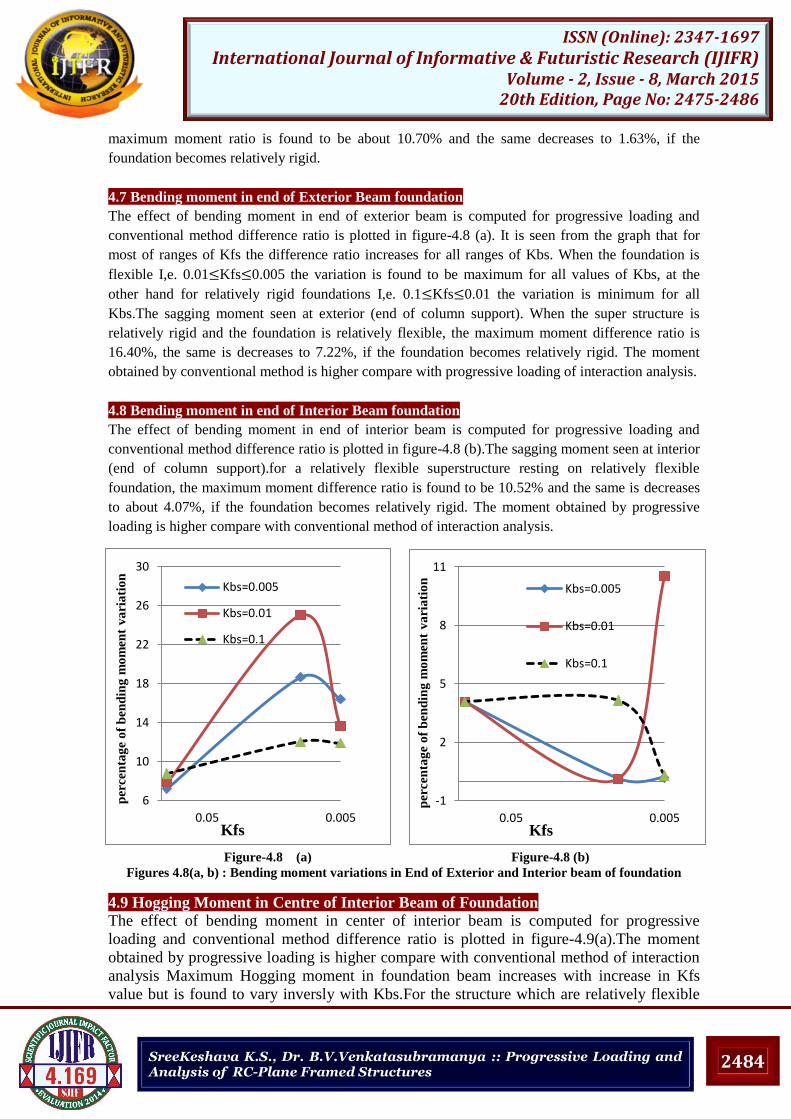
4.7 Bending moment in end of Exterior Beam foundation
The effect of bending moment in end of exterior beam is computed for progressive loading and
conventional method difference ratio is plotted in figure-4.8 (a). It is seen from the graph that for
most of ranges of Kfs the difference ratio increases for all ranges of Kbs. When the foundation is
flexible I,e. 0.01 Kfs 0.005 the variation is found to be maximum for all values of Kbs, at the
other hand for relatively rigid foundations I,e. 0.1 Kfs 0.01 the variation is minimum for all
Kbs.The sagging moment seen at exterior (end of column support). When the super structure is
relatively rigid and the foundation is relatively flexible, the maximum moment difference ratio is
16.40%, the same is decreases to 7.22%, if the foundation becomes relatively rigid. The moment
obtained by conventional method is higher compare with progressive loading of interaction analysis.
4.8 Bending moment in end of Interior Beam foundation
The effect of bending moment in end of interior beam is computed for progressive loading and
conventional method difference ratio is plotted in figure-4.8 (b).The sagging moment seen at interior
(end of column support).for a relatively flexible superstructure resting on relatively flexible
foundation, the maximum moment difference ratio is found to be 10.52% and the same is decreases
to about 4.07%, if the foundation becomes relatively rigid. The moment obtained by progressive
loading is higher compare with conventional method of interaction analysis.
Figure-4.8 (a) Figure-4.8 (b)
Figures 4.8(a, b) : Bending moment variations in End of Exterior and Interior beam of foundation
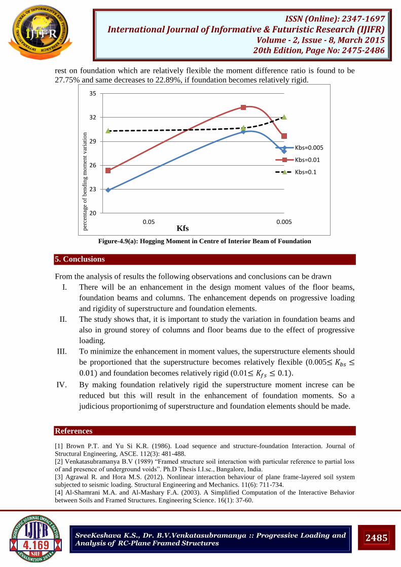
4.9 Hogging Moment in Centre of Interior Beam of Foundation
The effect of bending moment in center of interior beam is computed for progressive
loading and conventional method difference ratio is plotted in figure-4.9(a).The moment
obtained by progressive loading is higher compare with conventional method of interaction
analysis Maximum Hogging moment in foundation beam increases with increase in Kfs
value but is found to vary inversly with Kbs.For the structure which are relatively flexible
2485
ISSN (Online): 2347-1697 International Journal of Informative & Futuristic Research (IJIFR)
Volume - 2, Issue - 8, March 2015 20th Edition, Page No: 2475-2486
SreeKeshava K.S., Dr. B.V.Venkatasubramanya :: Progressive Loading and Analysis of RC-Plane Framed Structures
rest on foundation which are relatively flexible the moment difference ratio is found to be
27.75% and same decreases to 22.89%, if foundation becomes relatively rigid.
Figure-4.9(a): Hogging Moment in Centre of Interior Beam of Foundation
5. Conclusions
From the analysis of results the following observations and conclusions can be drawn
I. There will be an enhancement in the design moment values of the floor beams,
foundation beams and columns. The enhancement depends on progressive loading
and rigidity of superstructure and foundation elements.
II. The study shows that, it is important to study the variation in foundation beams and
also in ground storey of columns and floor beams due to the effect of progressive
loading.
III. To minimize the enhancement in moment values, the superstructure elements should
be proportioned that the superstructure becomes relatively flexible (0.005
and foundation becomes relatively rigid (0.01
IV. By making foundation relatively rigid the superstructure moment increse can be
reduced but this will result in the enhancement of foundation moments. So a
judicious proportionimg of superstructure and foundation elements should be made.
References
[1] Brown P.T. and Yu Si K.R. (1986). Load sequence and structure-foundation Interaction. Journal of
Structural Engineering, ASCE. 112(3): 481-488.
[2] Venkatasubramanya B.V (1989) “Framed structure soil interaction with particular reference to partial loss
of and presence of underground voids”. Ph.D Thesis I.I.sc., Bangalore, India.
[3] Agrawal R. and Hora M.S. (2012). Nonlinear interaction behaviour of plane frame-layered soil system
subjected to seismic loading. Structural Engineering and Mechanics. 11(6): 711-734.
[4] Al-Shamrani M.A. and Al-Mashary F.A. (2003). A Simplified Computation of the Interactive Behavior
between Soils and Framed Structures. Engineering Science. 16(1): 37-60.
20
23
26
29
32
35
0.0050.05
Kbs=0.005
Kbs=0.01
Kbs=0.1
Kfs per
cen
tage
of
ben
din
g m
om
ent
var
iati
on

2486
ISSN (Online): 2347-1697 International Journal of Informative & Futuristic Research (IJIFR)
Volume - 2, Issue - 8, March 2015 20th Edition, Page No: 2475-2486
SreeKeshava K.S., Dr. B.V.Venkatasubramanya :: Progressive Loading and Analysis of RC-Plane Framed Structures
[5] A. Mandal, D. Moitra, and S.C. Dutta, (2000). Soil-structure interaction on building frame: a small scale
model study, Int. J. Struct., 18(2), 92-108.
[6] Colasanti R.J. and Horvath J.S. (2010). Practical Subgrade Model for Improved Soil-Structure Interaction
Analysis: Software Implementation. Practice Periodical on Structural Design and Construction. 15(4): 1-9.
[7] IS:456-2000, “Code of Practice Plain and Reinforced Concrete” , Bureau of Indian Standards, New Delhi,
India.


![International Journal of Informative & Futuristic Research …ijifr.com/pdfsave/02-06-2016771V3-E9-063.pdfThe virtual topology design problem is known to be NP-hard [4], [5]. A survey](https://img.pdfslide.us/doc/110x75/5fef276f21786d11e7244456/international-journal-of-informative-futuristic-research-ijifrcompdfsave02-06-2016771v3-e9-063pdf.jpg)