Embed Size (px)
Citation preview

Progressive Failure Analysis ofComposite/aluminum Riveted Joint Subjected toPull-through Loadingyuxing yang
Dalian Maritime University https://orcid.org/0000-0002-6134-0514Yongjie Bao ( [email protected] )
Marine Engineering College, Dalian Maritime University, Dalian 116026, ChinaXueshu Liu
Dalian University of TechnologyJinlong Wang
Dalian Maritime UniversityFengming Du
Dalian Maritime University
Original Article
Keywords: Composite/metal joint, Pull-through test, Progressive damage model, Failure mechanism
Posted Date: February 4th, 2021
DOI: https://doi.org/10.21203/rs.3.rs-168245/v1
License: This work is licensed under a Creative Commons Attribution 4.0 International License. Read Full License

*Corresponding author:
E-mail: [email protected] (Yongjie Bao)
[email protected] (Yuxing Yang)
Progressive failure analysis of composite/aluminum riveted joint subjected to pull-
through loading
Yuxing Yang1,*, Yongjie Bao1, *, Xueshu Liu2, Jinlong Wang1, Fengming Du1
1 Marine Engineering College, Dalian Maritime University, Dalian 116026, China;
2 School of Automotive Engineering, Dalian University of Technology, Dalian 116024, China.
Abstract
The progressive failure mechanism of composite/aluminum riveted joint subjected to pull-through
loading was investigated by experiments and finite element method. The pull-through tests were
conducted and its load-displacement responses were analysed. A progressive damage model based on the
Hashin-type criteria and zero-thickness cohesive zone method was developed by VUMAT subroutine,
which was validated by both open-hole tensile test and three-point bending test. Load-displacement
response, failure modes and damage propagation were analysed and compared with the experimental
results. Major conclusions: 1) there are 4 obvious characteristic stages on the load-displacement curve:
first load take-up stage, damage stage, second load take-up stage and failure stage; 2) relative error of
stiffness, first load peak and second load peak between finite element method and experiments were 8.1%,
-3.3% and 10.6%, respectively; 3) specimen was mainly broken by rivet-penetration fracture and
delamination of plies of the composite laminate; 4) the material within the scope of the rivet head is more
dangerous with more serious tensile damages than other regions, especially for 90° plies.
Key words: Composite/metal joint; Pull-through test; Progressive damage model; Failure mechanism
1. Introduction
With the continuous improvement of energy-saving, emission-reduction and lightweight

2
requirements around the world, composite materials have gradually become one of the major industrial
manufacturing materials [1], which has the advantages of light weight, high stiffness-to-weight ratio, high
strength-to-weight ratio and superior resistance to fatigue degradation [2, 3]. Nowadays, more and more
complicated composite parts are designed and applied in aerospace industry and marine industry [4, 5],
which makes it a big problem to guarantee connecting performance of the joints during wing box
assembling for airplane. Riveting is one of the widely-used connecting methods in composite components
assembly for airplane [6, 7], which has the advantages of stable and reliable connection performance, easy
automation, wide application range, high reproducibility and fast joining processes [8]. As has been
reported, Italian-based BBA Srl has manufactured a unique riveting method for carbon fiber composite
materials, Bulge Control Technology, which can be used where the hole in the workpiece is up to 0.5 mm
greater than the rivet nut external size [9]. However, riveting requires hole drilling so that reducing the
strength of the connected parts, especially for composite laminates [10, 11]. Meanwhile, mechanical
properties of riveting, especially static strength and fatigue life, is influenced by both geometrical features,
die pressure, shape[12], etc. Therefore, it is necessary to investigate the bearing performance of the
riveting joint in order to guide the riveting design and ensure the safety of the joints.
A lot of research works have been done about composite riveting or composite/metal riveting,
including joint load distribution and joint damage prediction, etc. Sathiya et. al [6, 13] investigated a
composite-metal lap joint for the rivet load distribution and life estimation. It was found that the load
shared by the rivet rows in a composite–metal lap joint was not symmetric and therefore are more
susceptible to cracking and subsequent failure as the unequal distribution can cause some of the rivet loads
to be high. Solmaz et. al [14] used the progressive damage model to analyse the woven-type glass fiber
composite riveted joints and found that the failure occurring in the composite plates began around the rivet
hole and the catastrophic failure of these types of joints resulted from fiber tensile failure. Pramanik et. al
[12] claimed that placing composite sheet on the top of the aluminum alloy sheet during the riveting

3
formation was good to avoid crack growth. It was reported in Rao’s paper [15] that there were two
distinctive failure modes for static loading and cyclic loading: 1) the lap-shear and cross-tension joints
failed due to rivet pullout of the bottom aluminum sheet in quasi-static loading; 2) in cyclic loading, the
lap-shear joints failed due to kinked crack growth in the bottom aluminum sheet, while the cross-tension
joints failed due to rivet pulling out of the top carbon fiber reinforced polymer sheet.
Pull-through performance is an important property for rivet joint, which focus on the through-
thickness stiffness and strength of the joint. Catalanotti et. al [16] conducted an experimental and
numerical study of the pull-through damage in glass–fiber reinforced plastic laminates and concluded that:
1) the type of resin did not affect the mechanical response of the joint when a pull-through test was
performed; 2) delamination of the plies was the main failure mechanism. Gray and McCarthy [17]
developed an analytical bolt tension model for through-thickness stiffness prediction of the composite
joints based on Rize-approximation method, which can predict stiffness well but cannot analyse the stress.
Ma [18] studied the effects of temperature, humidity, thickness, fixture clamp length and bolt head
diameter on the pull-through strength of the braided composite laminates. Liu [19] found that pull-through
ultimate load of the ±45° cross-ply laminate was 25% higher than that of the 0° unidirectional laminate
for glass fiber reinforced aluminum alloy laminates.
In this paper, a composite/aluminum riveted joint subjected to pull-through loading was studied. Both
experiment and finite element method (FEM) were used to analyse the failure mechanism in terms of load-
displacement response, failure modes and damage propagation.
2. Experiment
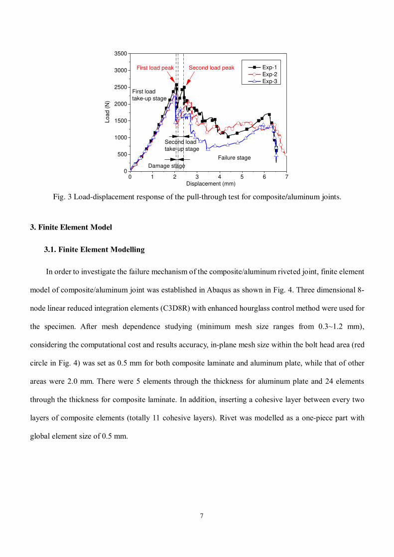
To investigate the riveting performance of composite skin and aluminum rib of airplane wing box, a
pull-through test of the composite-aluminum riveted joint was conducted according to ASTM D7332
standard [20]. As shown in Fig. 1, the specimen was composed of a carbon fiber/epoxy composite laminate
(60 mm x 20 mm x 3.0 mm), a 2A12 aluminum alloy plate (60 mm x 20 mm x 4.0 mm) and a Ti6Al4V

4
titanium alloy rivet (diameter d=4.0 mm). The composite laminate has 24 plies with symmetric lay-up
S
45/-45/90/90/0/90/0/90/90/-45/45/90 , which yielded a laminate thickness of 3.0 mm (single layer
nominal thickness was 0.125 mm). The mechanical properties of the composite laminate, cohesive
interface between plies, 2A12 aluminum alloy and Ti6Al4V titanium alloy were given in Table 1~3. E1,
E2 and E3 are longitudinal modulus, transverse modulus and out-of-plane modulus. G12, G13 and G23 are
three shear modulus. ν12, ν13, and ν23 represent Poisson’s ratios. XT, YT, ZT represent the tensile strengths
in the longitudinal direction, transverse direction, and through-thickness direction, respectively. XC, YC, ZC
represent the compressive strengths in the longitudinal direction, transverse direction, and through-
thickness direction, respectively. S means the shear strength of the laminate. ρ is the density of the material.
Kn, Ks and Kt are slope of the bilinear traction-separation response for the cohesive element. n0, s
0 and
t0 are strength of the cohesive element. GΙC, GΙΙC and GΙΙΙC are fracture toughness. σs and σb are yield
strength and tensile strength for metal material.
The composite/aluminum laminated drilling process was conducted on a 3-axis CNC machine tool
with carbide twist drill. After drilling, the specimens with middle hole diameter of 4.0 mm (tolerance
0~0.03 mm) were selected and detected by the HCT-800 A-scan ultrasonic damage detector (Onend, China,
resolution>45 dB, frequency 0.4~20 MHz, scanning range 0~10 m) to ensure no delamination in the
laminates.
Φ6
Unit: mm
3
Φ6
Φ4
Typical structure
Joint
Metal rib
Composite skin
joint
Wing box
Fig. 1 Composite/aluminum riveted joints specimen of airplane wing box.

5
Table 1 Mechanical properties of the composite laminate [21, 22].
E1
(GPa) E2 (E3)
(GPa) G12 (G13)
(GPa) G23
(GPa) ν12 (ν13) ν23 XT
(MPa) XC
(MPa) YT (ZT) (MPa)
YC (ZC) (MPa)
S
(MPa)
(g/cm3) 130 7.64 3.7 2.65* 0.32 0.44* 1750 1850 80 150 112 1.69
* The value is set according to the transversely isotropic assumption and engineering experience.
Table 2 Material properties of the cohesive interface. Kn
(MPa/mm) Ks (Kt)
(MPa/mm) n
0
(MPa) s
0 (t0)
(MPa) GΙC
(N/mm) GΙΙC (GΙΙΙC)
(N/mm)
(g/cm3) 2170 835 10 28.6 0.3 0.6 1.21
Table 3 Mechanical properties of the 2A12 aluminum alloy and Ti6Al4V titanium alloy. 2A12 aluminum alloy Ti6Al4V titanium alloy
E (GPa) 71.7 E (GPa) 108.0
ν 0.33 ν 0.33
(g/cm3) 2.77 (g/cm3) 4.43
s (MPa) 325
b (MPa) 472
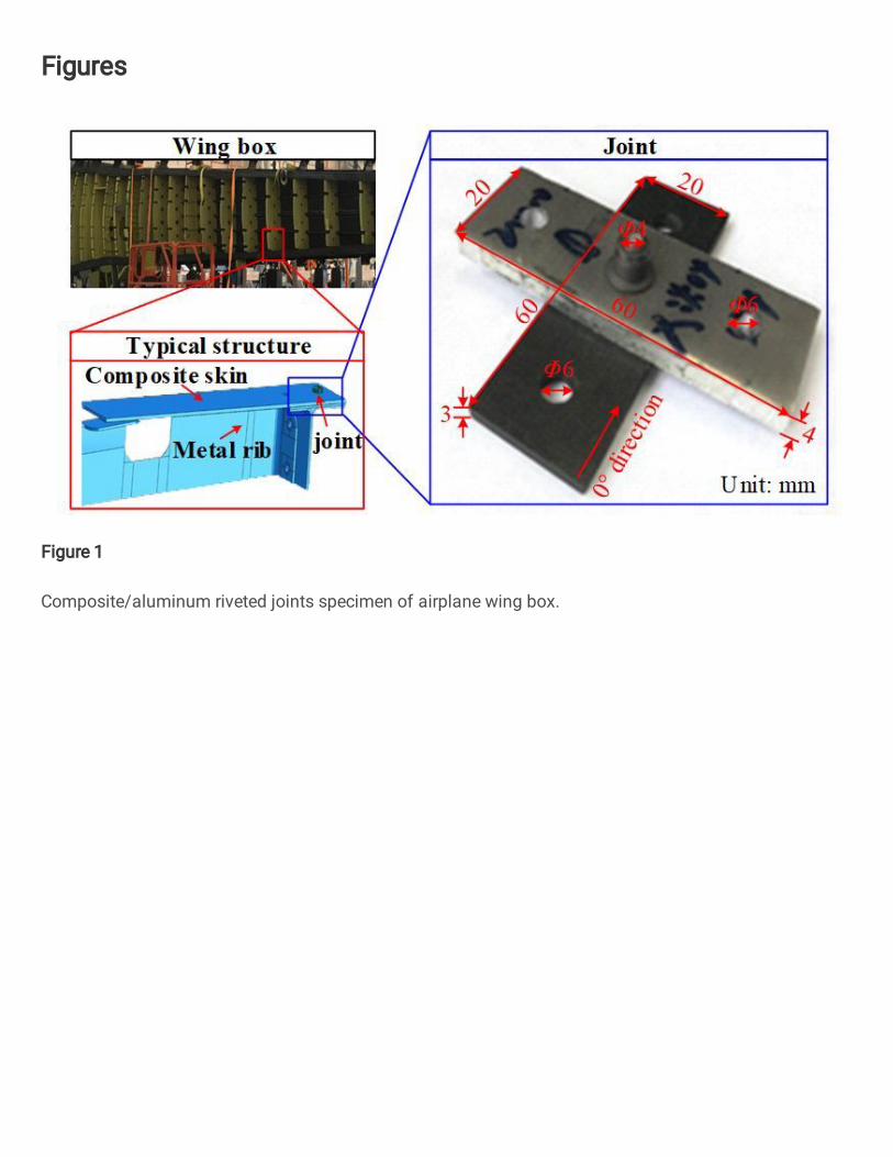
Experiment set-up of the pull-through test reference to ASTM D7332 standard [20] was shown in
Fig. 2. Firstly, the composite laminate and aluminum plate were riveted by the titanium alloy rivet.
Secondly, the specimen was fixed to the fixture by fasteners. Then, the fixture was clamped by the
clamping chuck of the DNS100 electronic universal testing machine (Sinotest Equipment, China,
maximum allowable load 100 kN, relative error of indication ±0.5%). Finally, the tensile load was applied
in the form of displacement load with loading speed of 1.0 mm/min. During testing, both displacement
and load of the specimen were recorded by the testing machine. The damages of the specimen were
observed by the digital microscope VHX-600E (Keyence, Japan, magnification 20X to 5000X).

6
Fixture
Specimen
Fixture
diagram
Fig. 2 Experiment set-up of the pull-through test for composite/aluminum joints.
Three specimens in total were tested, whose load-displacement curves were shown in Fig. 3 with four
obvious characteristic stages (first load take-up stage, damage stage, second load take-up stage and failure
stage). In Fig. 3, slope of the linear load take-up stage represents the stiffness of the specimen, which is
1256.7±61.3 N/mm in average (from 500 N to 2000 N). The first load peak was reached when
displacement was about 2.0 mm, which is 2406.4±124.8 N in average. After the first load peak, it came to
the damage stage. Fiber damages and delamination of the composite laminate occurred close to the
interface of two plates, which caused suddenly load drop on the load-displacement curves. Then the
specimen could still bear loads, and it came to the second load take-up stage with increase in load until it
reached the second load peak (2178.8±279.0 N). Since then, with several smaller load decreasing and
increasing stages, it come to failure stage and the composite laminate was damaged gradually, especially
around the middle hole. At the same time, rivet head began to sink into the composite laminate, which has
positive effect on preventing delamination propagation so that load increases again before final failure.
Finally, as displacement load increases, the specimen could not bear any load because of serious
delamination and rivet-penetration fracture.
7
0 1 2 3 4 5 6 70
500
1000
1500
2000
2500
3000
3500
Second load peakFirst load peak
Second load
take-up stage
Damage stage
Failure stage
Lo
ad
(N
)
Displacement (mm)
Exp-1
Exp-2
Exp-3
First load
take-up stage
Fig. 3 Load-displacement response of the pull-through test for composite/aluminum joints.
3. Finite Element Model
3.1. Finite Element Modelling
In order to investigate the failure mechanism of the composite/aluminum riveted joint, finite element
model of composite/aluminum joint was established in Abaqus as shown in Fig. 4. Three dimensional 8-
node linear reduced integration elements (C3D8R) with enhanced hourglass control method were used for
the specimen. After mesh dependence studying (minimum mesh size ranges from 0.3~1.2 mm),
considering the computational cost and results accuracy, in-plane mesh size within the bolt head area (red
circle in Fig. 4) was set as 0.5 mm for both composite laminate and aluminum plate, while that of other
areas were 2.0 mm. There were 5 elements through the thickness for aluminum plate and 24 elements
through the thickness for composite laminate. In addition, inserting a cohesive layer between every two
layers of composite elements (totally 11 cohesive layers). Rivet was modelled as a one-piece part with
global element size of 0.5 mm.

8
Laminate
RivetMetal plate
Rigid bodyfor loading
F
ox
zy
Fig. 4 Finite element model of three-bolt composite joints.
For convenience and convergence, rigid body method was used to apply boundary conditions. One
circle elements within the fastener head of two loading holes of the composite laminate were constrained
as a rigid body related to a reference point RPc, while that of the metal plate were constrained as another
rigid body related to another reference point RPm. Velocity load was applied to the reference point RPc,
which has no other freedoms. All six freedoms of the reference point RPm were constrained. General
contact for explicit analysis with penalty tangential behavior (friction coefficient of 0.1) was used to
simulate interaction relationships. In addition, to improve calculation efficiency, mass scaling was used
for the whole model based on the restriction that mass changing percent less than 3%.
To reveal the damage propagation mechanism of the composite laminate, progressive damage model
based on VUMAT subroutine was used. Hashin-type criteria and cohesive zone method were used to
predict the damage initiation and failure modes of the composite laminate. Five kinds of failure modes are
considered, which are fiber tensile failure, fiber compressive failure, matrix tensile cracking, matrix tensile
crushing and delamination. To predict the initial damage in composites, the linear elastic failure criteria
are expressed as follows.
Fiber tensile failure (FT), for ( 1 0 ):
22 2
2131 12
FT
T 11 12 44 13 55
+ +/ / /
eX C S C S C
(1)
Fiber compressive failure (FC), for ( 1 0 ):

9
2
21
FC
C 11/e
X C
(2)
Matrix tensile cracking (MT), for (2 0 ):
22 2
2232 12
MT
T 22 12 44 23 66
+ +/ / /
eY C S C S C
(3)
Matrix tensile crushing (MC), for (2 0 ):
2 22
2232 12
MC
C 22 12 44 23 66
+ +/ / /
eY C S C S C
(4)
where i (i = 1, 2, 3) are normal strains, ij (i, j = 1, 2, 3; i ≠ j) are shear strains, Cij (i, j = 1, 2, 3, 4, 5, 6; i
= j) are components of the stiffness matrix. In any of the elements, when the criterion e ≥ 1 is satisfied,
damage variables dk=1 (k=FT, FC, MT, MC) will be satisfied, and the element will be damaged by reducing
the stiffness matrix as shown in Eq. (5). When there were fiber failure or out-of-plane matrix failure, the
element was failed and it will be deleted.
11 FT FC 11
22 FT FC MT MC 22
33 FT FC MT MC 33
12 FT FC MT MC 12
13 FT FC MT MC 13
23 FT FC MT MC
(1 )(1 )
(1 )(1 )(1 )(1 )
(1 )(1 )(1 )(1 )
(1 )(1 )(1 )(1 )
(1 )(1 )(1 )(1 )
(1 )(1 )(1 )(1 )
d
d
d
d
d
d
C d d C
C d d d d C
C d d d d C
C d d d d C
C d d d d C
C d d d d C
23
44 FT FC MT MC 44
55 FT FC MT MC 55
66 FT FC MT MC 66
(1 )(1 )(1 0.9 )(1 0.5 )
(1 )(1 )(1 0.9 )(1 0.5 )
(1 )(1 )(1 0.9 )(1 0.5 )
d
d
d
C d d d d C
C d d d d C
C d d d d C
(5)
In order to simulate the delamination of the composite laminate, zero-thickness cohesive interfaces
were created by offset method with COH3D8 cohesive element. Bilinear traction-separation response was
used for cohesive plies during the simulation. Quadratic nominal stress criterion is used to simulate the
initiation of the mixed-mode delamination. Once the delamination initiation criterion is met, delamination
begins to propagate according to delamination propagation criterion [23, 24]. The delamination status is
represented by the scalar stiffness degradation variable (SDEG) in Abaqus from 0 (no delamination) to 1

10
(delamination). The simulation procedure stops as soon as either displacement load is reached or the
simulation fails to converge prematurely [25].
3.2. Finite Element Method Validation
In order to validate the proposed FEM based on the Hashin-type criteria and zero-thickness cohesive
zone method, typical standard loading tests, including open-hole tensile test according to ASTM D5766
and three-point bending test according to ASTM D7264, were conducted with same materials as described
in section 2, whose stress-strain curves were compared with that of the FEM.
Result comparison of stress-strain curves between the open-hole tensile tests and the FEM are shown
in Fig. 5(a). It is not necessary to add zero-thickness cohesive layers for open-hole tensile model due to
the fact that cohesive layer only affects the mechanical behavior along the out-of-plane direction. In Fig.
5(a), average slope value of the stress-strain curves of the open-hole tensile tests is 53241.4 MPa, while
that of the FEM is 66149.0 MPa with relative error between the FEM and the tests of 24.2%; average
ultimate stress value of the open-hole tensile tests is 563.1 MPa, while that of the FEM is 578.9 MPa with
relative error between the FEM and the tests of 2.8%.
Result comparison of stress-strain curves between the three-point bending tests and the FEM without
cohesive layer and the FEM with cohesive layer are shown in Fig. 5(b). In Fig. 5(b), average slope value
of the stress-strain curves of the three-point bending tests is 84256.5 MPa, while slopes of the FEM without
cohesive layer and that with cohesive layer are 81996.6 MPa (-2.7%) and 81973.4 MPa (-2.7%); average
ultimate stress value of the three-point bending tests is 1016.3 MPa, while that of the FEM without
cohesive layer and that with cohesive layer are 1026.1 MPa (0.96%) and 1021.0 MPa (0.46%).
In summary, it can found that the proposed FEM based on the Hashin-type criteria and zero-thickness
cohesive zone method is effective to analyse the mechanical behaviors of the laminated composites
subjected to tensile loading or flexural loading.

11
0.000 0.003 0.006 0.009 0.0120
200
400
600
Str
ess (
MP
a)
Strain
OHT-FEM
OHT-EXP1
OHT-EXP2
OHT-EXP3
OHT-EXP4
0.000 0.005 0.010 0.015 0.0200
500
1000
1500
Str
ess (
MP
a)
Strain
3PBT-FEM-no cohesive layers
3PBT-FEM-cohesive layers
3PBT-EXP1
3PBT-EXP2
3PBT-EXP3
3PBT-EXP4
(a) (b)
Fig. 5 Result comparison of stress-strain curves between the tests and the FEM for: (a) open-hole tensile
test; (b) three-point bending test.
4. Results and Discussion
4.1. Load-displacement Response and Predicted Damages
The validated finite element method was then used to analyse the mechanical behavior of the
composite/metal riveted joints. The load-displacement curve predicted by the FEM with cohesive layer
was compared with that from the experiments, as shown in Fig. 6. It can be seen that load-displacement
curve from the FEM agrees well with that from the experiments for all 4 characteristic stages exhibited
similar trends. The stiffness of the experiments in average is 1256.7 N/mm, predicted stiffness of the FEM
is 1359.1 N/mm, and the relative error of stiffness between the FEM and experiments is 8.1%. The first
peak load of the experiments in average is 2406.4 N, predicted first peak load from the FEM is 2327.7 N,
and the relative error of ultimate load between the FEM and experiments is -3.3%. The second peak load
of the experiments in average is 2178.8 N, predicted second peak load from the FEM is 2409.9 N, and the
relative error of ultimate load between the FEM and experiments is 10.6%. Above results indicate that the
proposed FEM is effective to predict the load-displacement response of the pull-through test for
composite/metal riveted joints.

12
0 1 2 3 4 50
500
1000
1500
2000
2500
3000
Lo
ad
(N
)
Displacement (mm)
Joint-EXP1
Joint-EXP2
Joint-EXP3
Joint-FEM
Fig. 6 Comparison of load-displacement curves from experiments and finite element method.
Damages of the specimen from the experiment and that from FEM are shown in Fig. 7. The
experiment specimen was mainly broken by rivet-penetration fracture (Region 1) and delamination
(Region 5). There are obviously fiber fracture (Region 2), matrix failure (Region 3) and fiber buckling
(Region 4) in Fig. 7(a). Predicted damages of the laminate from FEM when displacement Uz is equal to
3.4 mm were shown in Fig. 7(b). Rivet-penetration fracture, fiber failure, matrix failure, fiber buckling as
well as delamination can be seen in Fig. 7(b), which have good agreement with experiment results. Fig.
7(c) shows the final failure status of the specimen predicted by the FEM (Uz=5.0 mm), in which hole of
the composite laminate has been totally broken by rivet head and delamination has been propagated to the
whole laminate. The comparison results indicate that the proposed FEM is effective to predict damages of
the pull-through test for composite/metal riveted joints.

13
Rivet-penetration fracture
Fiber & matrix failure
Fiber buckling
1-Rivet-penetration fracture 2-Fiber failure
3-Matrix failure 5-Delamination4-Fiber buckling
1
2
3
4
5
(a) (b)
(c)
Fig. 7 Damages of the experiment specimen and that of the finite element model: (a) damages of the
experiment specimen; (b) damages of the FEM; (c) final failure status of the specimen.
4.2. Progressive Failure Mechanism of the Joint
Based on the proposed FEM, failure mechanism of the composite/aluminum riveted joint subjected
to pull-through loading was investigated.
For first load take-up stage on the load-displacement curve of the FEM, load increases linearly as the
displacement increases from 0 mm to 0.7 mm, and there are no damages for the specimens. As shown in
Fig. 8, matrix tensile cracking (MT) firstly appears when Uz=0.7 mm, and it propagates rapidly along the
radius of the hole in the ply and along the thickness direction outside the ply. After the first load peak point,
matrix tensile cracking has propagated to the transverse edge of the laminate. After the second load peak
point, the rivet head begins to penetrate through the top surface of the laminate, and matrix tensile cracking
propagates more rapidly and almost reaches its maximum value.
Fiber tensile damage (FT) firstly appears close to the interface between the laminate and the
aluminum plate when Uz=1.1 mm, and it propagates very slowly. Until the rivet head penetrates through
the laminate, fiber tensile damage rapidly propagates at the top surface close to the edge of the rivet head,
which is one of the main causes of the suddenly decrease of the load after the second load peak.
Matrix compressive crushing (MC) firstly appears at elements under the edge of the rivet head in the

14
middle plies when Uz=1.4 mm. And it propagates slowly to the top surface through the thickness of the
laminate. Between the first load peak and second load peak, matrix compressive crushing begins
propagating rapidly along the circumferential direction under the edge of the rivet head at the top surface,
which is the main cause of the load fluctuation when displacement reaches 2.1 mm.
Delamination (SDEG) firstly appears at interface between ply-4 and ply-5 with small size when
Uz=1.4 mm. Serious delamination appears at interface between ply-16 and ply-17 as displacement reaches
1.8 mm and propagates very rapidly along the longitudinal direction and transverse direction, which causes
the suddenly load decrease after the first load peak. After the second load peak point, multi-layer
delamination occurs and propagates, which is the other cause of the suddenly decrease of the load after
the second load peak. Then, as the displacement increases from 2.4 mm to 3.0 mm, the rivet head
penetrates through the laminate layer by layer and contacts with the lower layer, which contributes to close
the interface splits caused by delamination so that load increases to another small peak again. Until
displacement reaches 3.4 mm, the rivet head has already penetrated through 8 layers of the laminate, and
the laminate is fractured.
FT
MC
MT
FT
SDEG
SDEG
SDEG MT
0 1 2 3 4 50
500
1000
1500
2000
2500
3000
3500
Lo
ad
(N
)
Displacement (mm)
xz
y
z: Loading directionx: Longitudinal direction
MT MC
FT
SDEG
FT
MT
MC
ply-1
ply-24
Fig. 8 Progressive damage propagation of the specimen from the finite element model.

15
After above analysis, dominant failure modes and their locations in laminate was illustrated in Fig.
9. The length of the line represents the degree of damage. The longer the line, the more serious the damage.
It can be concluded that: 1) the laminate is progressively broken mainly by rivet-penetration fracture and
delamination between ply-16 and ply-17; 2) the material within the scope of the rivet head is more
dangerous with more serious damages; 3) damages are more serious for 90° plies than other plies; 4)
tensile damages are the main failure modes.
45-459090
090
09090
-4545909045
-459090
090
09090
-4545
Rivet
Lo
ad
ing
dir
ecti
on
Longitudinal
direction
4 mm
2 mm
Propagation direction
Delamination
Fracture
Fiber tensile failure
Matrix tensile failure
Radius Circumferential
Composite
laminate
ply-1ply-2
ply-24
Fig. 9 Schematic illustration of dominant failure modes and their locations in laminate.
To validate the predicted damage propagation results, three characteristic points (Uz=1.5 mm, 2.4
mm, and 3.9 mm) on the load-displacement curve were selected, whose damages were compared with the
experiments, as shown in Fig. 10. When Uz=1.5 mm, as Fig. 10(a) shows, the specimen is in the stage of
stiffness and it deforms elastically as the displacement load increases. When Uz=2.4 mm, as Fig. 10(b)

16
shows, the composite laminate begins to delaminate close to the interface of the composite/aluminum
plates due to high tensile stress. When Uz=3.9 mm, the rivet has completely penetrated through the top
surfaces of the composite laminate, and meanwhile the delamination propagates to the whole laminate. At
the three characteristic points, all predicted damages from the FEM are in good agreement with the
experiment results, which indicates that abovementioned progressive failure mechanism results of
composite/metal rivet joint subjected to pull-through loading predicted by the proposed FEM are effective.
(a) Uz=1.5 mm (b) Uz=2.4 mm (c) Uz=3.9 mm
Delamination Rivet penetrationDelamination
Fig. 10 Comparison of damage propagation of the specimens between experiment and finite element
model when displacement Uz is equal to: (a) 1.5 mm; (b) 2.4 mm; (c) 3.9 mm.
Conclusion
In this paper, a composite/aluminum riveted joint of airplane wing box subjected to pull-through
loading was studied. The specimen consists of a carbon fiber/epoxy composite laminate, 2A12 aluminum
plate and Ti6Al4V rivet were tested and their load-displacement responses were analysed according to
characteristic points. To predict the damage initiation and failure modes of the composite laminate, a
progressive damage model, which can predict 5 types of failure modes (fiber tensile failure, fiber
compressive failure, matrix tensile cracking, matrix tensile crushing and delamination), based on the
Hashin-type criteria and zero-thickness cohesive zone method was developed using VUMAT subroutine
in Abaqus and validated by open-hole tensile test and three-point bending test. Load-displacement

17
response, failure modes and damage propagation predicted by the finite element method were all in good
agreement with the experimental results for the composite/metal riveted joint. At last, progressive failure
mechanism was revealed using the proposed finite element method. Major conclusions are as follows:
(1) there are 4 obvious characteristic stages (first load take-up stage, damage stage, second load take-
up stage and failure stage) on the load-displacement curve for the pull-through test of the
composite rivet joint;
(2) the proposed finite element method can predict stiffness, first load peak and second load peak
well with relative error of 8.1%, -3.3% and 10.6% compared to experiment results;
(3) specimen was mainly broken by rivet-penetration fracture and delamination between ply-16 and
ply-17;
(4) the material within the scope of the rivet head is more dangerous with more serious tensile
damages than other regions, especially for 90° plies.
Availability of Data and Materials
The datasets used and/or analysed during the current study are available from the corresponding
author on reasonable request.
Competing Interests
The authors declare that they have no competing interests.
Funding
This work was supported by the China Postdoctoral Science Foundation [Grant No. 2020M680937
& No. 2020M670734] (Equipment support), National Natural Science Foundation of China [Grant No.
51875079] (Data collection), National Key Research and Development Project [Grant
No.2020YFB2009805] (Data analysis), LiaoNing Revitalization Talents Program [Grant No.
XLYC1907196] (Writing support) and National Defense Basic Scientific Research program of China
[Grant No. 2019-JCJQ-JJ-547] (Writing support).

18
Authors’ Contributions
YY write the article and analysed the data. BY proposed the idea of experiments and assisted to
conduct the experiments. LX provided experimental conditions. WJ and DF contributed to review the
article.
Acknowledgements
The authors would like to acknowledge the abovementioned financial support.
References
[1] Zimmermann, N., & Wang, P.H. (2020). A review of failure modes and fracture analysis of aircraft
composite materials. Engineering Failure Analysis, 115, 104692.
[2] Katunin, A., Sul, P., Łasica, A., Dragan, K., Krukiewicz, K. , & Turczyn, R. (2017). Damage resistance
of CSA-doped PANI/epoxy CFRP composite during passing the artificial lightning through the aircraft
rivet. Engineering Failure Analysis, 82, 116-122.
[3] Li, M., Luo, W., Chen, Y., & Yang, X. (2020). Full-field strain distribution and failure characteristics
of CFRP-repaired steel structures. Engineering Failure Analysis, 115, 104664.
[4] Meng, X., Huang, Y., Xie, Y., Li, J., Guan, M., Wan, L., Dong, Z., & Cao, J. (2019). Friction self-
riveting welding between polymer matrix composites and metals. Composites Part A: Applied Science
and Manufacturing, 127, 105624.
[5] Fatt, M.S.H., & Sirivolu, D. (2017). Marine composite sandwich plates under air and water blasts.
Marine Structures, 56, 163-185.
[6] Naarayan, S.S., Kumar, D.V.T.G.P., & Chandra, S. (2009). Implication of unequal rivet load
distribution in the failures and damage tolerant design of metal and composite civil aircraft riveted lap
joints. Engineering Failure Analysis, 16, 2255-2273.
[7] Kharghani, N., Soares, C.G., & Tsouvalis, N.G. (2019). Experimental and numerical study of the bolt
reinforcement of a composite-to-steel butt-joint under three-point bending test. Marine Structures, 63,
384-403.
[8] Gude, M., Hufenbach, W., Kupfer, R., Freund, A., & Vogel, C. (2015). Development of novel form-
locked joints for textile reinforced thermoplastices and metallic components. Journal of Materials
Processing Technology, 216, 140-145.
[9] Aldridge, C. (2016). Riveting technology for carbon fibre and composite material.
https://www.fastfixtechnology.com/automotive/riveting-technology-for-carbon-fibre-and-composite-

19
material. Accessed 05 December 2016.
[10] Thoppul, S.D., Finegan, J., & Gibson, R.F. (2009). Mechanics of mechanically fastened joints in
polymer–matrix composite structures – a review. Composites Science and Technology, 69, 301-329.
[11] Liu, D., Tang, Y., & Cong, W.L. (2012). A review of mechanical drilling for composite laminates.
Composite Structures, 94, 1265-1279.
[12] Pramanik, A., Basak, A.K., Dong, Y., Sarker, P.K., Uddin, M.S., Littlefair, G., Dixit, A.R., &
Chattopadhyaya, S. (2017). Joining of carbon fibre reinforced polymer (CFRP) composites and
aluminium alloys – a review. Composites Part A: Applied Science and Manufacturing, 101, 1-29.
[13] Kumar, D.V.T.G.P., Naarayan, S.S., Sundaram, S.K., & Chandra, S. (2012). Further numerical and
experimental failure studies on single and multi-row riveted lap joints. Engineering Failure Analysis,
20, 9-24.
[14] Solmaz, M.Y., & Topkaya, T. (2013). Progressive failure analysis in adhesively, riveted, and hybrid
bonded double-lap joints. The Journal of Adhesion, 89, 822-836.
[15] Rao, H.M., Kang, J., Huff, G., & Avery, K. (2018). Impact of specimen configuration on fatigue
properties of self-piercing riveted aluminum to carbon fiber reinforced polymer composite.
International Journal of Fatigue, 113, 11-22.
[16] Catalanotti, G., Camanho, P.P., Ghys, P., & Marques, A.T. (2011). Experimental and numerical study
of fastener pull-through failure in GFRP laminates. Composite Structures, 94, 239-245.
[17] Gray, P.J., & McCarthy, C.T. (2012). An analytical model for the prediction of through-thickness
stiffness in tension-loaded composite bolted joints. Composite Structures, 94, 2450-2459.
[18] Ma,W. (2016). Study on the pull-through characteristics of carbon/epoxy braided composite
laminates (in Chinese) [Master's thesis, Nanchang University]. CNKI.
https://kns.cnki.net/kcms/detail/detail.aspx?dbcode=CMFD&dbname=CMFD201701&filename=101
6263258.nh&v=7SHR4JnhdWisLzdYLCLO5sm4ixc7GzlGelGGTG7TWYMeA%25mmd2BxTFd85
ek7L2qH7D5yT.
[19] Liu, Y. (2018). Analysis on mechanical properties of glare laminates with countersunk bolted joints
subjected to out-of-plane loading (in Chinese) [Master's thesis, Harbin Institute of Technology]. CNKI.
https://kns.cnki.net/kcms/detail/detail.aspx?dbcode=CMFD&dbname=CMFD201901&filename=101
8892997.nh&v=1jFtCmu9gdSjZAyb%25mmd2FET6bhuoDmyDfrVdRn2sFhcsJOiBqZxVkP9d04w
%25mmd2BkdpcfVHH.
[20] American Society for Testing and Materials (2016). ASTM D7332/D7332M: Standard test method
for measuring the fastener pull-through resistance of a fiber-reinforced polymer matrix composite.

20
https://www.astm.org. Accessed 18 November 2016.
[21] Shen, Y., & Xiao, Y. (2019). Effects of fretting damage on preload relaxation in bolted composite
joints. Acta Materiae Compositae Sinica, 36, 400-409.
[22] He, Y., Xiao, Y., & Su, Z. (2019). Effects of surface contact on the dynamic responses of delaminated
composite plates. Composite Structures, 229, 111378.
[23] Chen, J.F., Morozov, E.V., & Shankar, K. (2014). Simulating progressive failure of composite
laminates including in-ply and delamination damage effects. Composites Part A: Applied Science and
Manufacturing, 61, 185-200.
[24] Giuliese, G., Palazzetti, R., Moroni, F., Zucchelli, A., & Pirondi, A. (2015). Cohesive zone modelling
of delamination response of a composite laminate with interleaved nylon 6,6 nanofibres. Composites
Part B: Engineering, 78, 384-392.
[25] Kolks, G., & Tserpes, K.I. (2014). Efficient progressive damage modeling of hybrid
composite/titanium bolted joints. Composites Part A: Applied Science and Manufacturing, 56, 51-63.
Figures
Figure 1
Composite/aluminum riveted joints specimen of airplane wing box.
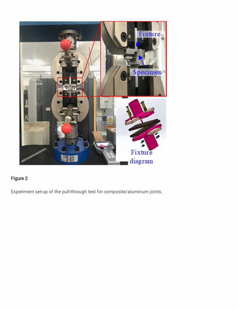
Figure 2
Experiment set-up of the pull-through test for composite/aluminum joints.

Figure 3
Load-displacement response of the pull-through test for composite/aluminum joints.
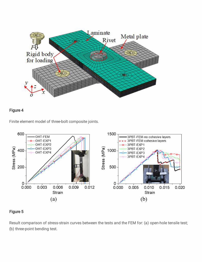
Figure 4
Finite element model of three-bolt composite joints.
Figure 5
Result comparison of stress-strain curves between the tests and the FEM for: (a) open-hole tensile test;(b) three-point bending test.

Figure 6
Comparison of load-displacement curves from experiments and �nite element method.

Figure 7
Damages of the experiment specimen and that of the �nite element model: (a) damages of theexperiment specimen; (b) damages of the FEM; (c) �nal failure status of the specimen.

Figure 8
Progressive damage propagation of the specimen from the �nite element model.
Figure 9
Schematic illustration of dominant failure modes and their locations in laminate.

Figure 10
Comparison of damage propagation of the specimens between experiment and �nite element modelwhen displacement Uz is equal to: (a) 1.5 mm; (b) 2.4 mm; (c) 3.9 mm.