Embed Size (px)
Citation preview
IOSR Journal of Mechanical and Civil Engineering (IOSR-JMCE)
e-ISSN: 2278-1684 Volume 5, Issue 4 (Jan. - Feb. 2013), PP 55-67 www.iosrjournals.org
www.iosrjournals.org 55 | Page
Progressive Collapse Analysis of RC Beams
G.Sukanya1, Dr.C.Natarajan
2, Dr.A.Rajaraman
3
1(Civil Engineering, National Institute of Technology, Tiruchirappalli, India) 2(Civil Engineering, National Institute of Technology, Tiruchirappalli, India)
3(Civil Engineering, Indian Institute of Technology, Madras, India)
Abstract: This paper investigates the nonlinear static analysis for studying the behavior of Progressive failure
of RC beams. Nonlinear static analysis is strongly influenced by basic inputs like stress-strain relationship of
constitutive materials, P-M yield interaction and moment rotation capacity of members. Normal limit state design gives only design equation for ultimate states and not its progress of collapse which gives the
performance of structure like deflection and rotation. Therefore, the actual behavior of the designed singly
reinforced and doubly reinforced section as it progresses to collapse is explained. For a detailed investigation,
the progressive failure of RC beam section with a) the influence of compressive strength of concrete, b) the
influence of amount of reinforcements in a section, c) role of rotation flexibility, d) ductility and energy which is
needed for seismic study and e) system behavior of simply supported beam is done.
Keywords - Decay, Ductility, Energy, Flexibility, Moment, Rotation.
I. INTRODUCTION The interest on research work on the progressive collapse in civil engineering started in the early 1968
after the partial collapse of Ronan Point Apartment building in London, UK. Research efforts led to many
provisions in UK standards. Later, the disproportionate collapse of the Alfred P.Murrah Federal Building
(Oklahoma City, 1995) and the total collapse of the World Trade Center towers (2001), which were caused by
terrorist attacks gained the interest of engineering community in the advanced research.
The term „progressive collapse‟ can be defined as the collapse of all or a large part of a structure
induced by failure or damage of a relatively small part of it. The structure is then forced to seek alternate load paths to redistribute the out-of-balance loads from damaged members. The redistribution of loads is a dynamic
process and will continue until a new equilibrium position is reached by the structure, either by finding a stable
alternate load path or by further shedding of loads as a consequence of collapsed members. For this reason,
beams, columns and frame connections must be analyzed and designed in a way to handle the potential
redistribution of large loads. Progressive collapse can be triggered by man-made, natural, intentional, or
unintentional damage and by different actions like explosions caused by gas or explosives, earthquake, impacts
of vehicles, ships or planes, human errors in the design or construction phase etc. Analyzing a structure and
checking whether a progressive collapse could happen or not depends on many assumptions. These kinds of
difficulties make it clear how effectively a structure should be analyzed and designed for progressive failure.
Progressive collapse analysis is performed to evaluate the likelihood how the initiating damage would propagate
throughout the structure causing major structural failure and the subsequent loss of life. Analysis methods used to evaluate the possibility of progressive collapse vary widely, ranging from the simple two-dimensional linear
elastic static procedure to complex three-dimensional nonlinear time history analysis.
Linear static, nonlinear static, linear dynamic and nonlinear dynamic methods are four basic
approaches for the progressive collapse analysis. Advantages and disadvantages of these analysis approaches
have been discussed by Marjanishvili and Agnew [1]. True response of the structure can be depicted only by
nonlinear analysis. Nonlinear analysis methods like nonlinear static push-over can be used for progressive
collapse analysis which is commonly accepted and recommended as a reliable tool by international codes for
seismic assessment of buildings. This method can be used to determine the ductility measure of the structure for
lateral loading. Ductility is measured as a ratio of ultimate displacement to yield displacement. The building
with large ductility results in better performance under earthquake loading.
Accuracy of the estimate of collapse and seismic capacity strongly depends on input parameters of such
analysis. The basic input parameter namely moment-rotation, moment-curvature characteristics accounting for appropriate nonlinearity of constitutive materials of reinforced concrete elements is very important. Nanci
Buscemi and Shalva Marjanishvili [2] presented a paper on SDOF Model for Progressive Collapse Analysis in
which three different dynamic techniques were discussed considering single degree of freedom model. The
importance of stiffness and initial conditions for progressive failure was described [2]. The effects of plastic
hinge properties in nonlinear analysis of reinforced concrete buildings was conferred by Mehmet Inel and Hayri
Baytan Ozmen[3] which signifies the importance of modeling of hinges of building and point outs that hinges
Progressive Collapse Analysis of RC Beams
www.iosrjournals.org 56 | Page
depends upon the type of element, material properties, longitudinal and transverse steel content, and the axial
load level on the element. Ali Kheyroddin and Hosein Naderpour presented a paper on plastic hinge rotation
capacity of reinforced concrete beams. The plastic hinge rotation capacity and the effect of the loading type on the beam were the two important criteria considered [4]. The influence of the tension reinforcement and the
bending moment distribution (loading type) on the ultimate deformation characteristics of reinforced concrete
(RC) beams for 15 simply supported beams with different amounts of tension reinforcement ratio under three
different loading conditions were compared [4]. Moment curvature of reinforced concrete beams using various
confinement models and experimental validation by M. Srikanth, G. Rajesh Kumar and S. Giri [5] signifies the
effects of confinements in the moment curvature behavior.
Thus progressive collapse analysis is strongly influenced by basic inputs like stress-strain relationship
of constitutive materials, P-M yield interaction and moment rotation capacity of members. So this paper aims to
study the actual behavior of the reinforced concrete beam section with a) the influence of compressive strength
of concrete and b) the influence of reinforcement on the section on account of progressive failure.
II. Moment Rotation Relationship Moment-rotation relationships of RC beams provide an estimate of ductility of beams, which is a
valuable design parameter. The correct estimate of ductility is very important in the context of recent
advancements in design approaches like displacement-based design. The nonlinearity of concrete is given by the
relationship between stress and strain distribution in concrete which is given as parabola in the code IS
456:2000.
Normal limit state design, IS 456:2000 gives only design equation for ultimate state and not its
progress which will give performance like deflection, curvature and rotation. The difference between the design
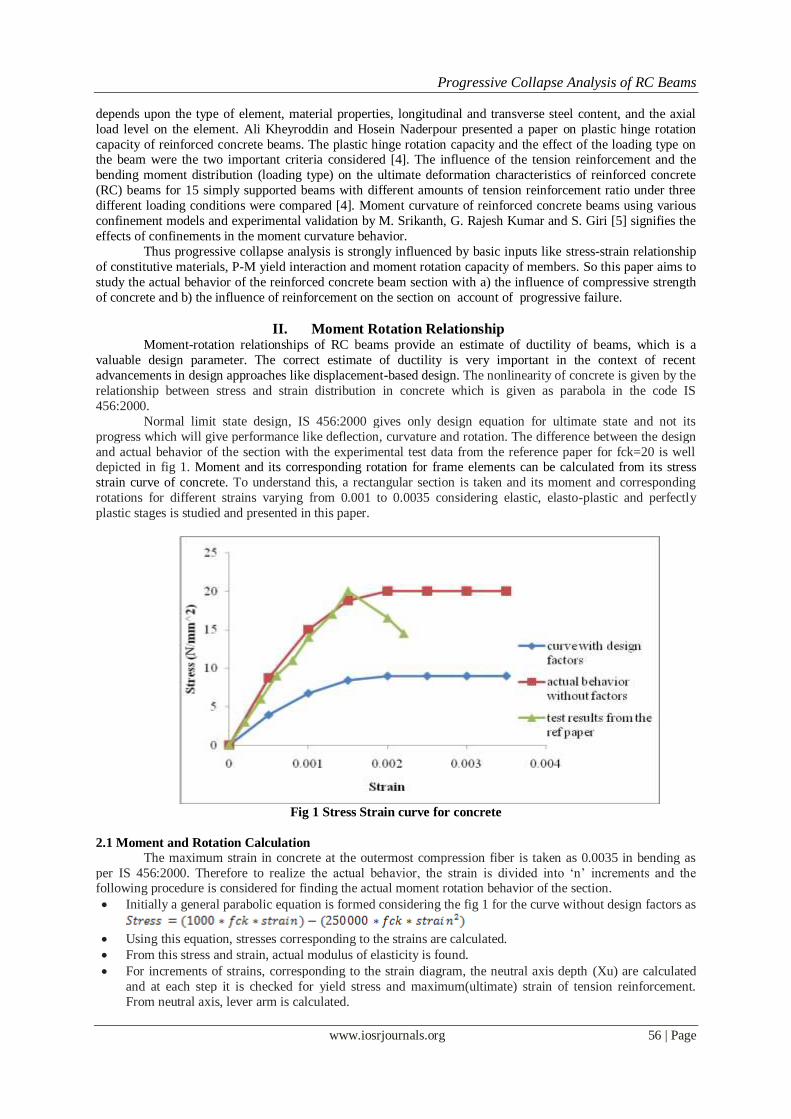
and actual behavior of the section with the experimental test data from the reference paper for fck=20 is well depicted in fig 1. Moment and its corresponding rotation for frame elements can be calculated from its stress
strain curve of concrete. To understand this, a rectangular section is taken and its moment and corresponding
rotations for different strains varying from 0.001 to 0.0035 considering elastic, elasto-plastic and perfectly
plastic stages is studied and presented in this paper.
Fig 1 Stress Strain curve for concrete
2.1 Moment and Rotation Calculation
The maximum strain in concrete at the outermost compression fiber is taken as 0.0035 in bending as
per IS 456:2000. Therefore to realize the actual behavior, the strain is divided into „n‟ increments and the following procedure is considered for finding the actual moment rotation behavior of the section.
Initially a general parabolic equation is formed considering the fig 1 for the curve without design factors as
Using this equation, stresses corresponding to the strains are calculated.
From this stress and strain, actual modulus of elasticity is found.
For increments of strains, corresponding to the strain diagram, the neutral axis depth (Xu) are calculated
and at each step it is checked for yield stress and maximum(ultimate) strain of tension reinforcement.
From neutral axis, lever arm is calculated.
Progressive Collapse Analysis of RC Beams
www.iosrjournals.org 57 | Page
The following study is done by varying one material parameter (fck) and one design parameter (amount
of reinforcement used) for understanding the moment rotation behavior since it determines the plastic hinge
properties. So the study concentrates on the actual behavior of designed section as it progresses to collapse stage, the design factors according to IS 456:2000 are not taken into account in this paper.
And for each of the study considered, the general common parameters considered are as follows,
• Characteristic cube compressive strength of concrete, fck=20N/mm2
• Characteristic strength of steel, fy=415 N/mm2
• Breadth of beam, b=230mm
• Depth of the beam, D=480mm
• Clear cover, cc=20mm
• Diameter of bars used, dia=20mm
• Effective depth of beam, d=450mm
• Span, l=6m
• Area of reinforcement in tension side, Ast=980mm2( which is under-reinforced in both actual and design case)
• Actual balanced Ast =1867 mm2
• Modulus of elasticity of steel, Es=2*105 N/mm2
III. Role Of Compressive Strength Of Concrete On Section Failure The moment rotation behavior of rectangular beam section is studied by varying the material
parameter, i.e., compressive strength of concrete, fck, from 20 to 60 and keeping other parameters constant
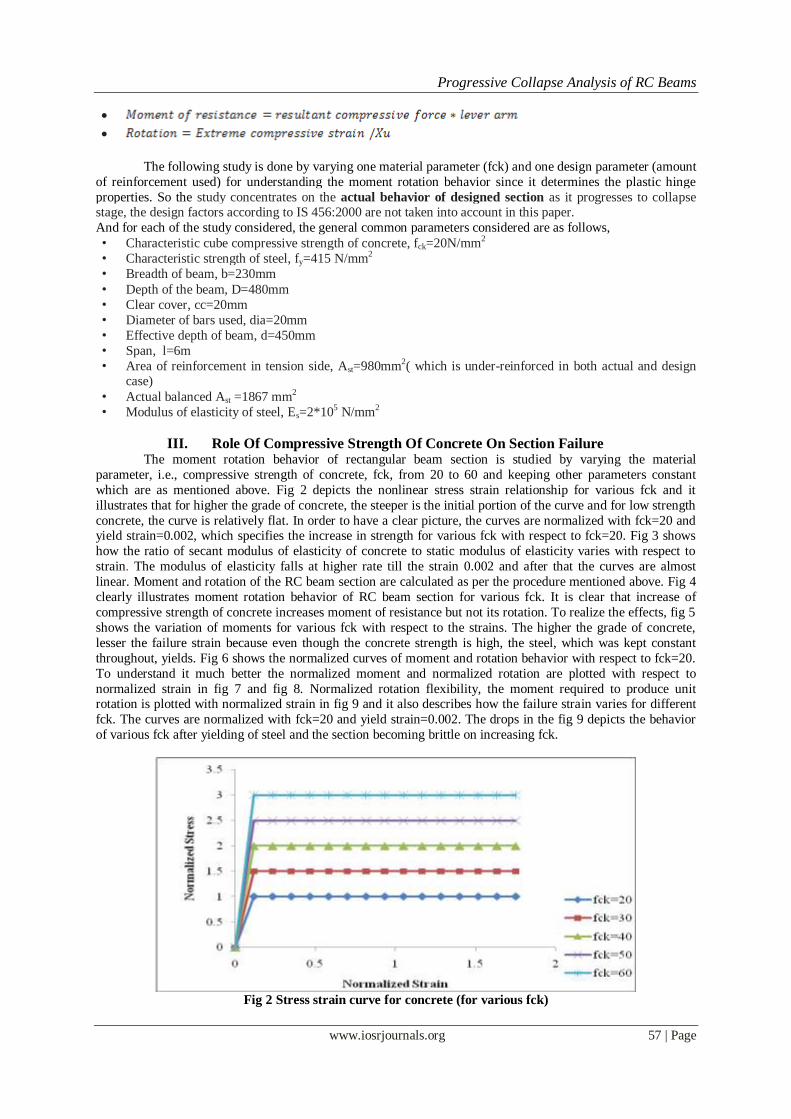
which are as mentioned above. Fig 2 depicts the nonlinear stress strain relationship for various fck and it
illustrates that for higher the grade of concrete, the steeper is the initial portion of the curve and for low strength
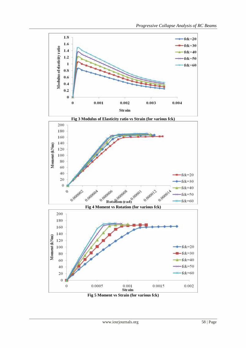
concrete, the curve is relatively flat. In order to have a clear picture, the curves are normalized with fck=20 and yield strain=0.002, which specifies the increase in strength for various fck with respect to fck=20. Fig 3 shows
how the ratio of secant modulus of elasticity of concrete to static modulus of elasticity varies with respect to
strain. The modulus of elasticity falls at higher rate till the strain 0.002 and after that the curves are almost
linear. Moment and rotation of the RC beam section are calculated as per the procedure mentioned above. Fig 4
clearly illustrates moment rotation behavior of RC beam section for various fck. It is clear that increase of
compressive strength of concrete increases moment of resistance but not its rotation. To realize the effects, fig 5
shows the variation of moments for various fck with respect to the strains. The higher the grade of concrete,
lesser the failure strain because even though the concrete strength is high, the steel, which was kept constant
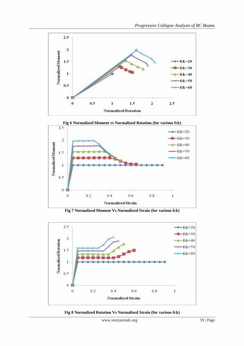
throughout, yields. Fig 6 shows the normalized curves of moment and rotation behavior with respect to fck=20.
To understand it much better the normalized moment and normalized rotation are plotted with respect to
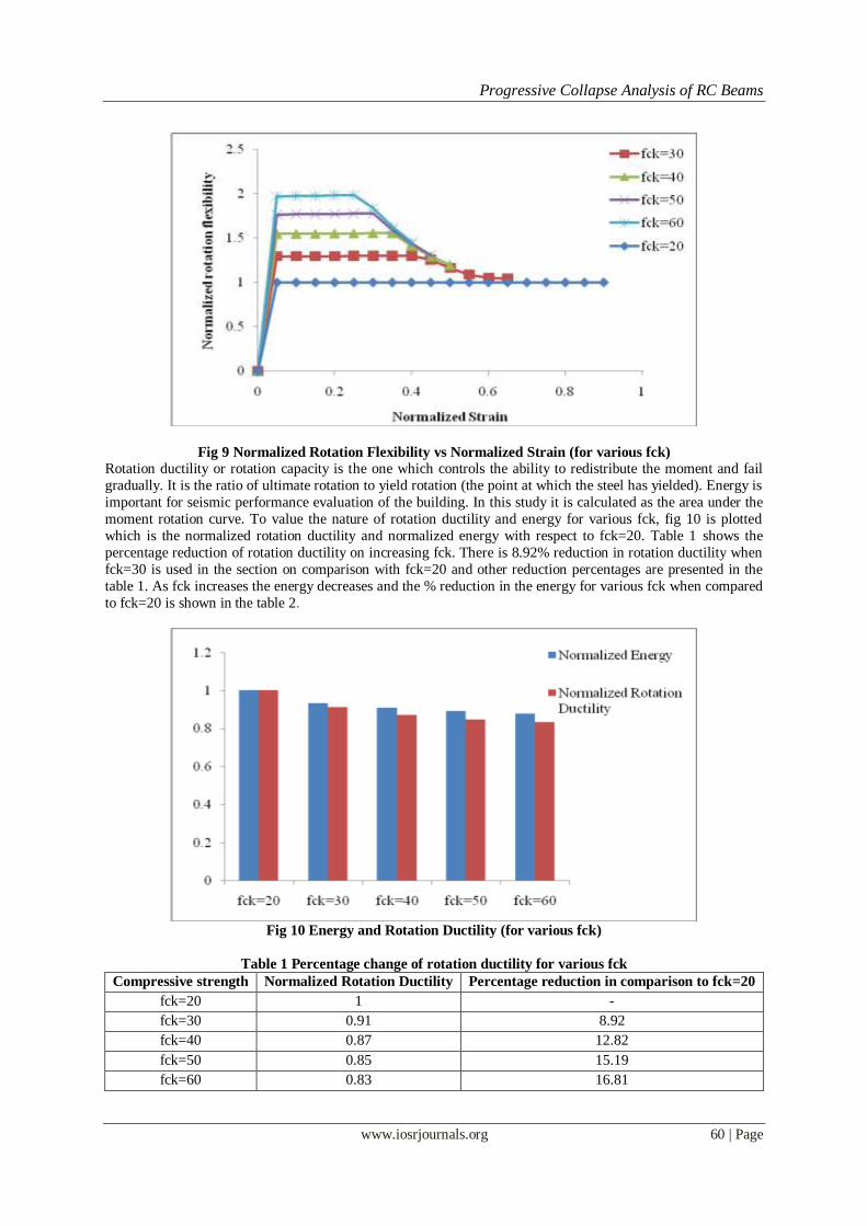
normalized strain in fig 7 and fig 8. Normalized rotation flexibility, the moment required to produce unit rotation is plotted with normalized strain in fig 9 and it also describes how the failure strain varies for different
fck. The curves are normalized with fck=20 and yield strain=0.002. The drops in the fig 9 depicts the behavior
of various fck after yielding of steel and the section becoming brittle on increasing fck.
Fig 2 Stress strain curve for concrete (for various fck)
Progressive Collapse Analysis of RC Beams
www.iosrjournals.org 58 | Page
Fig 3 Modulus of Elasticity ratio vs Strain (for various fck)
Fig 4 Moment vs Rotation (for various fck)
Fig 5 Moment vs Strain (for various fck)
Progressive Collapse Analysis of RC Beams
www.iosrjournals.org 59 | Page
Fig 6 Normalized Moment vs Normalized Rotation (for various fck)
Fig 7 Normalized Moment Vs Normalized Strain (for various fck)
Fig 8 Normalized Rotation Vs Normalized Strain (for various fck)
Progressive Collapse Analysis of RC Beams
www.iosrjournals.org 60 | Page
Fig 9 Normalized Rotation Flexibility vs Normalized Strain (for various fck)
Rotation ductility or rotation capacity is the one which controls the ability to redistribute the moment and fail
gradually. It is the ratio of ultimate rotation to yield rotation (the point at which the steel has yielded). Energy is
important for seismic performance evaluation of the building. In this study it is calculated as the area under the
moment rotation curve. To value the nature of rotation ductility and energy for various fck, fig 10 is plotted
which is the normalized rotation ductility and normalized energy with respect to fck=20. Table 1 shows the
percentage reduction of rotation ductility on increasing fck. There is 8.92% reduction in rotation ductility when
fck=30 is used in the section on comparison with fck=20 and other reduction percentages are presented in the
table 1. As fck increases the energy decreases and the % reduction in the energy for various fck when compared
to fck=20 is shown in the table 2.
Fig 10 Energy and Rotation Ductility (for various fck)
Table 1 Percentage change of rotation ductility for various fck
Compressive strength Normalized Rotation Ductility Percentage reduction in comparison to fck=20
fck=20 1 -
fck=30 0.91 8.92
fck=40 0.87 12.82
fck=50 0.85 15.19
fck=60 0.83 16.81
Progressive Collapse Analysis of RC Beams
www.iosrjournals.org 61 | Page
Table 2 Percentage change of Energy for various fck
Compressive strength Energy Percentage reduction in
comparison to fck=20
fck=20 1 -
fck=30 0.93 6.87
fck=40 0.91 9.30
fck=50 0.89 10.84
fck=60 0.88 12.09
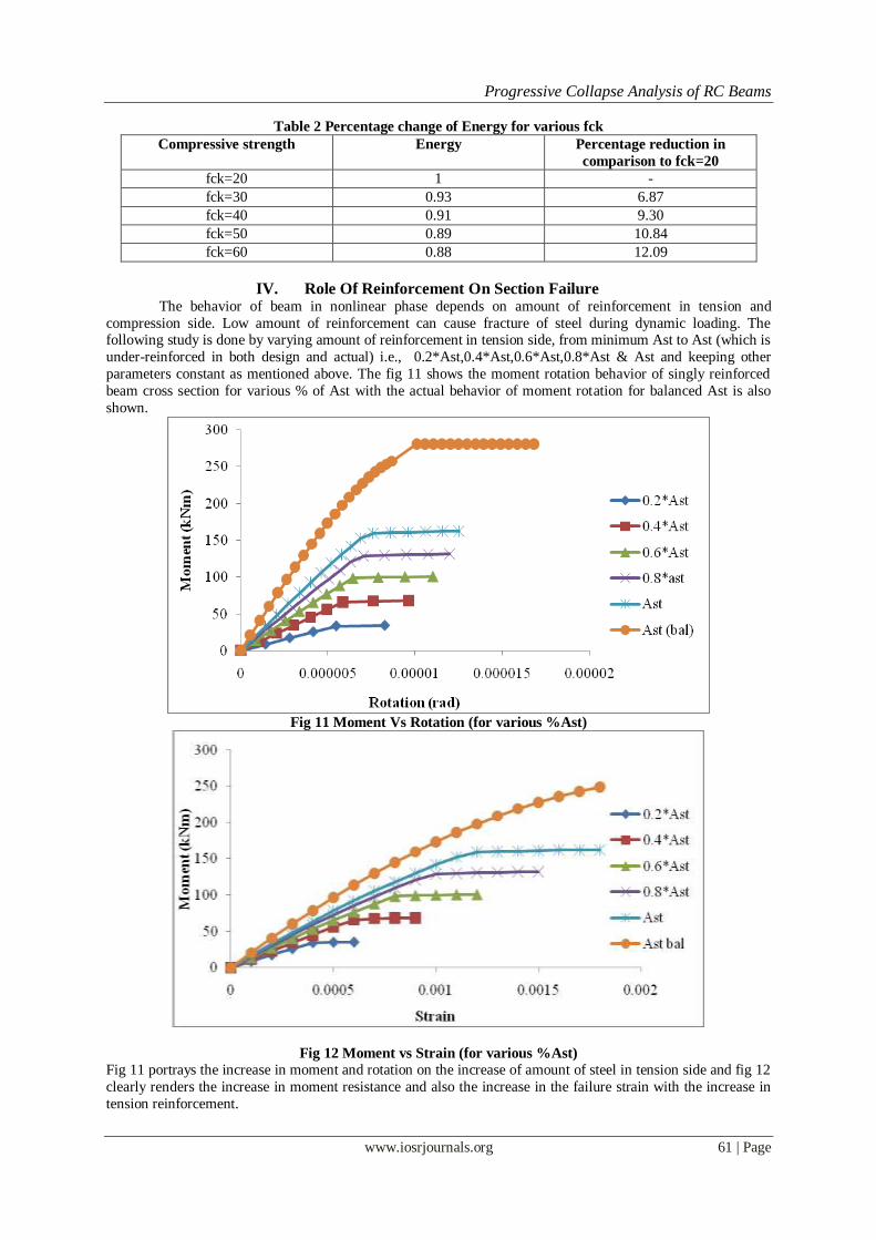
IV. Role Of Reinforcement On Section Failure The behavior of beam in nonlinear phase depends on amount of reinforcement in tension and
compression side. Low amount of reinforcement can cause fracture of steel during dynamic loading. The following study is done by varying amount of reinforcement in tension side, from minimum Ast to Ast (which is
under-reinforced in both design and actual) i.e., 0.2*Ast,0.4*Ast,0.6*Ast,0.8*Ast & Ast and keeping other
parameters constant as mentioned above. The fig 11 shows the moment rotation behavior of singly reinforced
beam cross section for various % of Ast with the actual behavior of moment rotation for balanced Ast is also
shown.
Fig 11 Moment Vs Rotation (for various %Ast)
Fig 12 Moment vs Strain (for various %Ast)
Fig 11 portrays the increase in moment and rotation on the increase of amount of steel in tension side and fig 12
clearly renders the increase in moment resistance and also the increase in the failure strain with the increase in
tension reinforcement.
Progressive Collapse Analysis of RC Beams
www.iosrjournals.org 62 | Page
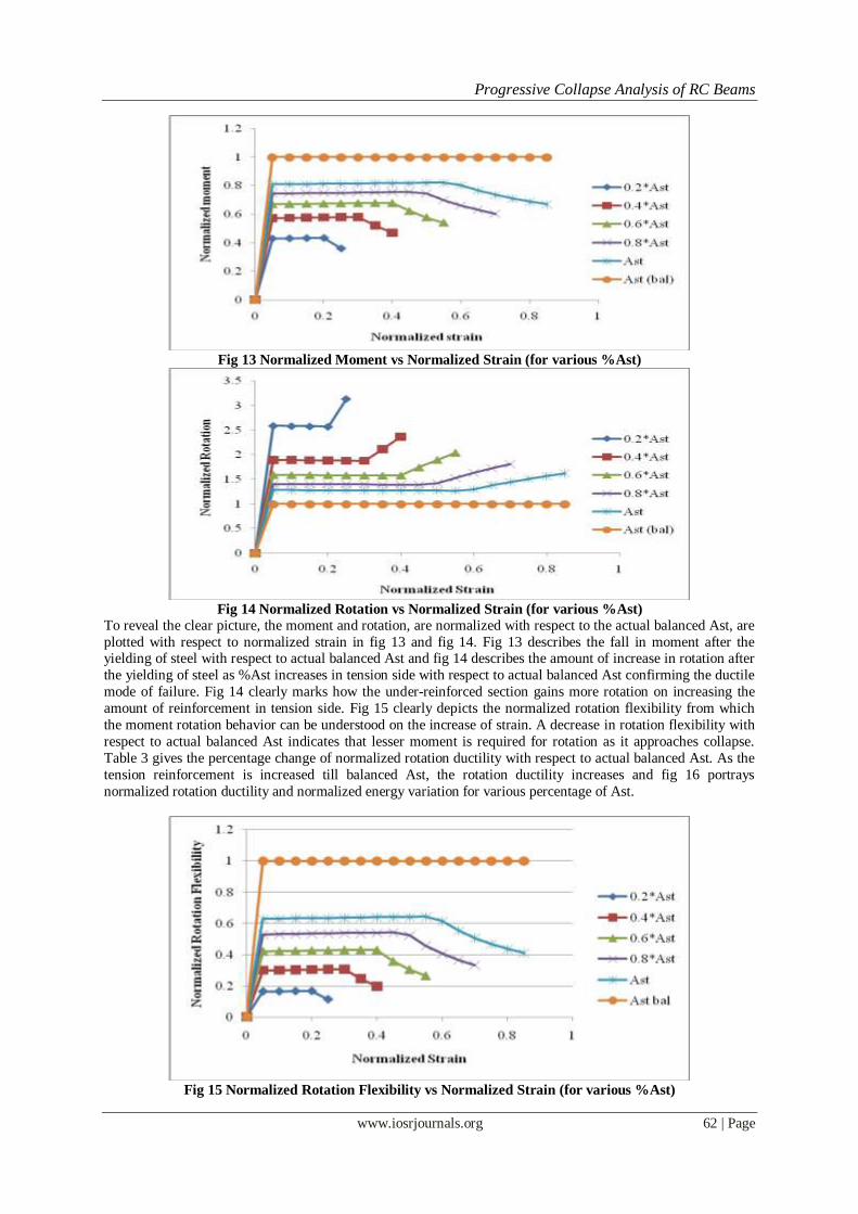
Fig 13 Normalized Moment vs Normalized Strain (for various %Ast)
Fig 14 Normalized Rotation vs Normalized Strain (for various %Ast)
To reveal the clear picture, the moment and rotation, are normalized with respect to the actual balanced Ast, are
plotted with respect to normalized strain in fig 13 and fig 14. Fig 13 describes the fall in moment after the yielding of steel with respect to actual balanced Ast and fig 14 describes the amount of increase in rotation after
the yielding of steel as %Ast increases in tension side with respect to actual balanced Ast confirming the ductile
mode of failure. Fig 14 clearly marks how the under-reinforced section gains more rotation on increasing the
amount of reinforcement in tension side. Fig 15 clearly depicts the normalized rotation flexibility from which
the moment rotation behavior can be understood on the increase of strain. A decrease in rotation flexibility with
respect to actual balanced Ast indicates that lesser moment is required for rotation as it approaches collapse.
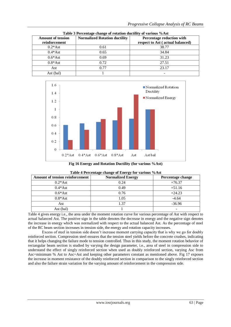
Table 3 gives the percentage change of normalized rotation ductility with respect to actual balanced Ast. As the
tension reinforcement is increased till balanced Ast, the rotation ductility increases and fig 16 portrays
normalized rotation ductility and normalized energy variation for various percentage of Ast.
Fig 15 Normalized Rotation Flexibility vs Normalized Strain (for various %Ast)
Progressive Collapse Analysis of RC Beams
www.iosrjournals.org 63 | Page
Table 3 Percentage change of rotation ductility of various %Ast
Amount of tension
reinforcement
Normalized Rotation ductility Percentage reduction with
respect to Ast ( actual balanced)
0.2*Ast 0.61 38.77
0.4*Ast 0.65 34.84
0.6*Ast 0.69 31.23
0.8*Ast 0.72 27.51
Ast 0.77 23.17
Ast (bal) 1 -
Fig 16 Energy and Rotation Ductility (for various %Ast)
Table 4 Percentage change of Energy for various %Ast
Amount of tension reinforcement Normalized Energy Percentage change
0.2*Ast 0.24 +76.37
0.4*Ast 0.49 +51.16
0.6*Ast 0.76 +24.23
0.8*Ast 1.05 -4.64
Ast 1.37 -36.96
Ast (bal) 1 -
Table 4 gives energy i.e., the area under the moment rotation curve for various percentage of Ast with respect to
actual balanced Ast. The positive sign in the table denotes the decrease in energy and the negative sign denotes
the increase in energy which was normalized with respect to the actual balanced Ast. As the percentage of steel
of the RC beam section increases in tension side, the energy and rotation capacity increases.
Excess of steel in tension side doesn‟t increase moment carrying capacity that is why we go for doubly
reinforced section. Compression steel ensures that the tension steel yields before the concrete crushes, indicating that it helps changing the failure mode to tension controlled. Thus in this study, the moment rotation behavior of
rectangular beam section is studied by varying the design parameter, i.e., area of steel in compression side to
understand the effect of singly reinforced section when used as doubly reinforced section, varying Asc from
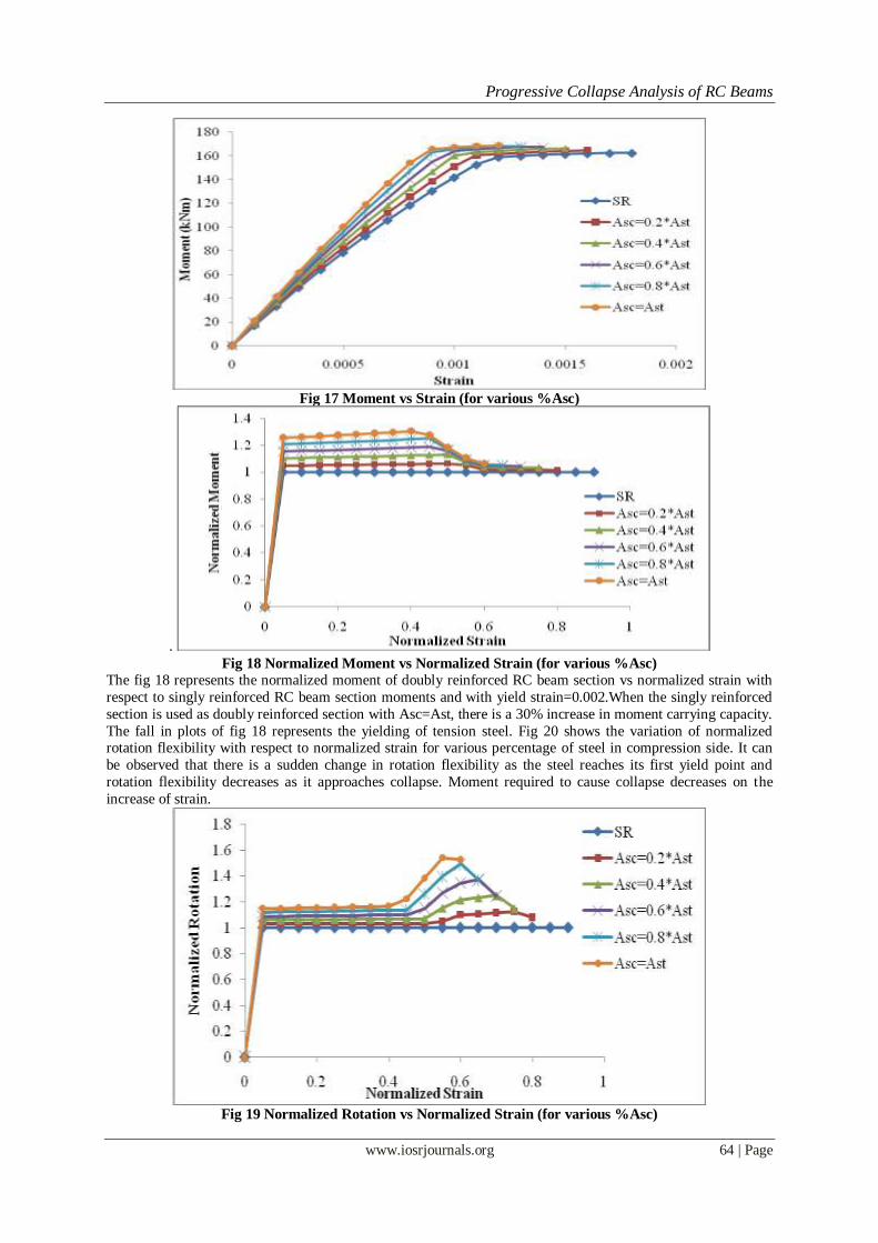
Asc=minimum % Ast to Asc=Ast and keeping other parameters constant as mentioned above. Fig 17 exposes
the increase in moment resistance of the doubly reinforced section in comparison to the singly reinforced section
and also the failure strain variation for the varying amount of reinforcement in the compression side.
Progressive Collapse Analysis of RC Beams
www.iosrjournals.org 64 | Page
Fig 17 Moment vs Strain (for various %Asc)
.
Fig 18 Normalized Moment vs Normalized Strain (for various %Asc)
The fig 18 represents the normalized moment of doubly reinforced RC beam section vs normalized strain with
respect to singly reinforced RC beam section moments and with yield strain=0.002.When the singly reinforced
section is used as doubly reinforced section with Asc=Ast, there is a 30% increase in moment carrying capacity.
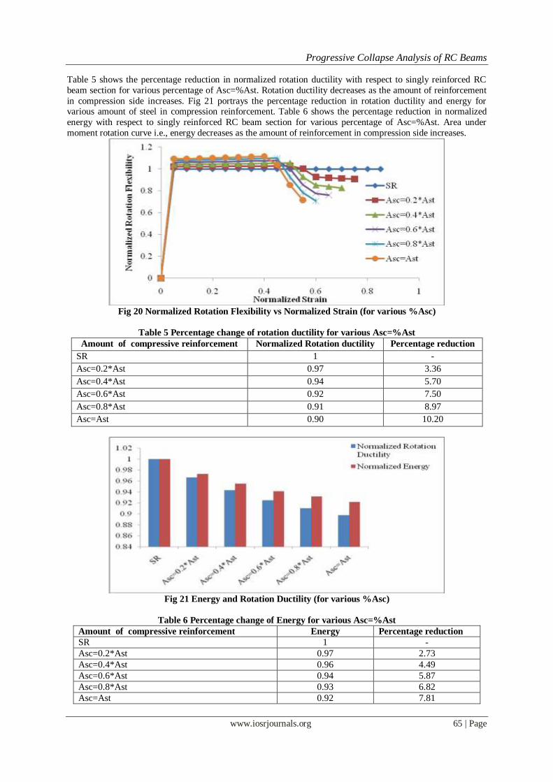
The fall in plots of fig 18 represents the yielding of tension steel. Fig 20 shows the variation of normalized rotation flexibility with respect to normalized strain for various percentage of steel in compression side. It can
be observed that there is a sudden change in rotation flexibility as the steel reaches its first yield point and
rotation flexibility decreases as it approaches collapse. Moment required to cause collapse decreases on the
increase of strain.
Fig 19 Normalized Rotation vs Normalized Strain (for various %Asc)
Progressive Collapse Analysis of RC Beams
www.iosrjournals.org 65 | Page
Table 5 shows the percentage reduction in normalized rotation ductility with respect to singly reinforced RC
beam section for various percentage of Asc=%Ast. Rotation ductility decreases as the amount of reinforcement
in compression side increases. Fig 21 portrays the percentage reduction in rotation ductility and energy for various amount of steel in compression reinforcement. Table 6 shows the percentage reduction in normalized
energy with respect to singly reinforced RC beam section for various percentage of Asc=%Ast. Area under
moment rotation curve i.e., energy decreases as the amount of reinforcement in compression side increases.
Fig 20 Normalized Rotation Flexibility vs Normalized Strain (for various %Asc)
Table 5 Percentage change of rotation ductility for various Asc=%Ast
Amount of compressive reinforcement Normalized Rotation ductility Percentage reduction
SR 1 -
Asc=0.2*Ast 0.97 3.36
Asc=0.4*Ast 0.94 5.70
Asc=0.6*Ast 0.92 7.50
Asc=0.8*Ast 0.91 8.97
Asc=Ast 0.90 10.20
Fig 21 Energy and Rotation Ductility (for various %Asc)
Table 6 Percentage change of Energy for various Asc=%Ast
Amount of compressive reinforcement Energy Percentage reduction
SR 1 -
Asc=0.2*Ast 0.97 2.73
Asc=0.4*Ast 0.96 4.49
Asc=0.6*Ast 0.94 5.87
Asc=0.8*Ast 0.93 6.82
Asc=Ast 0.92 7.81
Progressive Collapse Analysis of RC Beams
www.iosrjournals.org 66 | Page
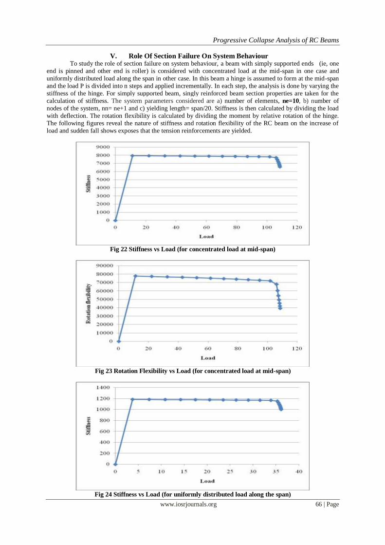
V. Role Of Section Failure On System Behaviour To study the role of section failure on system behaviour, a beam with simply supported ends (ie, one
end is pinned and other end is roller) is considered with concentrated load at the mid-span in one case and
uniformly distributed load along the span in other case. In this beam a hinge is assumed to form at the mid-span
and the load P is divided into n steps and applied incrementally. In each step, the analysis is done by varying the
stiffness of the hinge. For simply supported beam, singly reinforced beam section properties are taken for the
calculation of stiffness. The system parameters considered are a) number of elements, ne=10, b) number of
nodes of the system, nn= ne+1 and c) yielding length= span/20. Stiffness is then calculated by dividing the load
with deflection. The rotation flexibility is calculated by dividing the moment by relative rotation of the hinge.
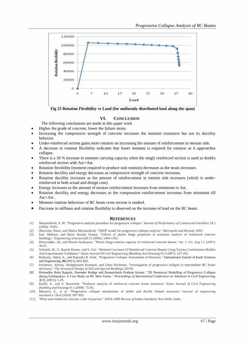
The following figures reveal the nature of stiffness and rotation flexibility of the RC beam on the increase of
load and sudden fall shows exposes that the tension reinforcements are yielded.
Fig 22 Stiffness vs Load (for concentrated load at mid-span)
Fig 23 Rotation Flexibility vs Load (for concentrated load at mid-span)
Fig 24 Stiffness vs Load (for uniformly distributed load along the span)
Progressive Collapse Analysis of RC Beams
www.iosrjournals.org 67 | Page
Fig 25 Rotation Flexibility vs Load (for uniformly distributed load along the span)
VI. CONCLUSION The following conclusions are made in this paper work
Higher the grade of concrete, lower the failure strain.
Increasing the compressive strength of concrete increases the moment resistance but not its ductility
behavior.
Under-reinforced section gains more rotation on increasing the amount of reinforcement in tension side.
A decrease in rotation flexibility indicates that lesser moment is required for rotation as it approaches
collapse.
There is a 30 % increase in moment carrying capacity when the singly reinforced section is used as doubly
reinforced section with Asc=Ast.
Rotation flexibility (moment required to produce unit rotation) decreases as the strain increases.
Rotation ductility and energy decreases as compressive strength of concrete increases.
Rotation ductility increases as the amount of reinforcement in tension side increases (which is under-
reinforced in both actual and design case).
Energy increases as the amount of tension reinforcement increases from minimum to Ast.
Rotation ductility and energy decreases as the compression reinforcement increases from minimum till Asc=Ast .
Moment rotation behaviour of RC beam cross section is studied.
Decrease in stiffness and rotation flexibility is observed on the increase of load on the RC beam.
REFERENCES [1] Marjanishvili, S. M. "Progressive analysis procedure for progressive collapse."Journal of Performance of Constructed Facilities 18.2
(2004): 79-85.
[2] [Buscemi, Nanci, and Shalva Marjanishvili. "SDOF model for progressive collapse analysis." Metropolis and Beyond. 2005.
[3] Inel, Mehmet, and Hayri Baytan Ozmen. "Effects of plastic hinge properties in nonlinear analysis of reinforced concrete
buildings." Engineering structures28.11 (2006): 1494-1502.
[4] Kheyroddin, Ali, and Hosein Naderpour. "Plastic hinge rotation capacity of reinforced concrete beams." Int. J. Civ. Eng 5.1 (2007):
30-47.
[5] Srikanth, M., G. Rajesh Kumar, and S. Giri. "Moment Curvature Of Reinforced Concrete Beams Using Various Confinement Models
And Experimental Validation." Asian Journal Of Civil Engineering (Building And Housing) 8.3 (2007): 247-265.
[6] Kulkarni, Abhay A., and Rajendra R. Joshi. "Progressive Collapse Assessment of Structure." International Journal of Earth Sciences
and Engineering, 04 (2011): 652-655.
[7] Pachenari, Alireza, Abolghassem Keramati, and Zahra Pachenari. "Investigation of progressive collapse in intermediate RC frame
structures." The Structural Design of Tall and Special Buildings (2010).
[8] Harinadha Babu Raparla, Narender Bodige and Ramancharla Pradeep Kumar. “2D Numerical Modelling of Progressive Collapse
during Earthquakes: A Case Study on RC Bare Frame.” Proceedings of International Conference on Advances in Civil Engineering,
ACE, (2011): 1-25.
[9] Kadid, A., and A. Boumrkik. "Pushover analysis of reinforced concrete frame structures." Asian Journal of Civil Engineering
(building and housing) 9.1 (2008): 75-83.
[10] Masoero, E., et al. "Progressive collapse mechanisms of brittle and ductile framed structures." Journal of engineering
mechanics 136.8 (2010): 987-995.
[11] "Plain and reinforced concrete–code of practice." IS456-2000 Bureau of Indian Standard, New Delhi, India.