Embed Size (px)
Citation preview

Progress Reports in ECE 4334
Chad A. B. Wilson, Ph.D.Director of Technical Communications Across the Curriculum
Progress Reports in ECE 4334

Progress Reports in ECE 4334
An overview of today’s presentation on Progress Reports
The Purpose
The Format
The Writing

Progress Reports in ECE 4334
Your supervisor or client uses Progress Reports to help make decisions
Lets your client, associate, or boss knowwhere a project stands.
Informs readers about work that has already been accomplished, problems that have been encountered and plans to solve them, as well as work that is not yet completed.
Updates readers about budgetary and scheduling issues. Explains and justifies changes to either.
What is your boss most interested in?

Progress Reports in ECE 4334
A longer formal Progress Report will generally look like this:
Front MatterLetter of Transmittal
Cover/Title Page
Abstract
Table of Contents
List of Tables and Figures
Back MatterReferences
Appendices
Report BodyProject Summary (Purpose,
Background)
Work Accomplished to Date
Work Remaining
Problems Encountered
Appraisal of Progress to Date
Use lower-case Roman numerals
Use regular Arabic numerals

Progress Reports in ECE 4334
A letter of transmittal will generally accompany a formal progress reportDear Dr. Trombetta:
Enclosed you will find the latest progress report for the Energy Conversion project. The purpose of this project is to teach high school students about alternative/renewable energy through lab kits the team will create. This report goes into further detail regarding the purpose of the project and briefly summarizes past progress while focusing on the progress the team has made since October 25, 2008. Along with the projects goals and milestone progress, I have also included the projected schedule along with the current budget.
As of November 13, 2008, the team has completed two additional milestones. Currently, there are six milestones completely finished with two additional milestones coming close to completion. The first milestone was achieved with an operational dynamo generating 1.5 V and 5.6 [mA] with a 10 [Ω] load. The second milestone was attained by using 1 V and 10 mA to charge a battery and power up a DC motor. The third and fourth milestone incorporated a windmill and a watermill separately to spin the dynamo to create 1.5 V. Lastly, the fifth milestone was reached with a working solar panel that generated 1.5 V and 200 mA and the sixth milestone integrated all of the components of the system to operate a load.
I am pleased to report that the team is very close to completion and still within budget. The team assures you that the project will be completed on schedule and within budget by November 22, 2008.
Sincerely,
Chad A. B. Wilson, Ph.D.Director of Technical Communications Across the CurriculumUniversity of Houston

Progress Reports in ECE 4334
Title pages provide typical information
Project title
Type of document (e.g., Progress Report for the period…)
Team number and members
Course number and title
Semester
Date of submission

Progress Reports in ECE 4334
Abstracts share the vital information
Abstract
The goal of the Energy Conversion project is to teach high school students the concept of creating electrical energy from mechanical energy. The team will create lab kits that will simulate how wind, water, and sun are used to obtain electrical energy in order to help the students understand the energy conversion process. As of November 13, 2006, the team has completed six milestones, which include: designing and building a dynamo that creates 1.5V and 10 mA, charging a battery on 10 mA and 1 V for duration of 15 minutes, operating a DC motor with the stored energy in the battery as well as testing for the minimum voltage requirement for the motor which was found to be 0.4 V and 60 mA, testing solar panels configurations to drive a DC motor, and completing a windmill design that spins the dynamo sufficiently to provide 1.5 V of electrical energy. Furthermore, the team has finished building the watermill and has tested the device; however, the goal of producing at least 1.5 V was not met as it produced 0.85 V. Also, the integration of the complete system has been modified to light an LED rather than to drive a DC motor. The team has conducted a pre-assessment test on the students and is currently assisting the students through the first phase of the project, which is building the dynamo. Presently, the team is under budget by approximately $608 and remains on schedule to complete the project by November 22, 2008.

Progress Reports in ECE 4334
Common pitfalls with abstracts
• Not fully summarizing the entire report• Not focusing on the important parts of the report• Assuming too much knowledge• Providing too much background information• Including tables, figures, equations, acronyms, or
citations• Not proofreading

Progress Reports in ECE 4334
Use headings to guide your reader
Introduction, Background, and Goals
Milestones
Progress Description
Milestones Accomplished
Milestones in Progress
Milestones Remaining
Engineering Constraints
Scheduling
Budget
Conclusions

Progress Reports in ECE 4334
Introduction, Background, and Goals Introduction and BackgroundSuppressing vibration in flexible structures with smart materials is a topic of interest in mechanical engineering. Since flexible structures are lightweight, under damped, and are increasingly being used in aerospace and other industries, the need for active vibration control of these structures is imperative. Smart materials offer a solution to this problem because their properties can be significantly changed by applying external stimuli and it is easy to integrate them into existing structures. Given the importance of this topic in mechanical engineering, Team 4 designed and built a control system to demonstrate the benefits of using smart materials to control vibration of flexible structures.
Dr. Gangbing Song, the sponsor of this project and mechanical engineering professor at University of Houston, will be able to use this project to let his students see for themselves how a piezoelectric sensor can be used as an actuator when voltages are sent to it. The student will be able to select between four resonant frequencies for the beam to vibrate at as well as select any other desired frequency from 0.1[Hz] to 600[Hz] in 0.1[Hz] increments. This project also demonstrates how piezoelectric materials can be used as sensors to suppress the vibration utilizing two different structure control methods (Positive Positioning Feedback and Sliding Mode Control). When using these control methods to suppress the vibration of the beam, the student should be able to recognize the beam coming to a rest more quickly than letting the beam come to rest naturally. In addition to using smart materials to vibrate and suppress the beam, an adjustable rail-mounted laser is included that allows the student to detect the frequency of the beam at desired points as well as its peak-to-peak displacement. This information is displayed with a graph on an LCD screen for the user to see. The system is also operable from a remote location via a network port on the microcontroller. Figures 1 shows how the completed system looks.
Always include an overview diagram!

Progress Reports in ECE 4334
Overview
Micro Processor
Servo
ColorSensor
LineSensor
ShaftEncoders
WeightSensor
Motors
LCDDisplay
WirelessCommunications
Progress Reports in ECE 4334
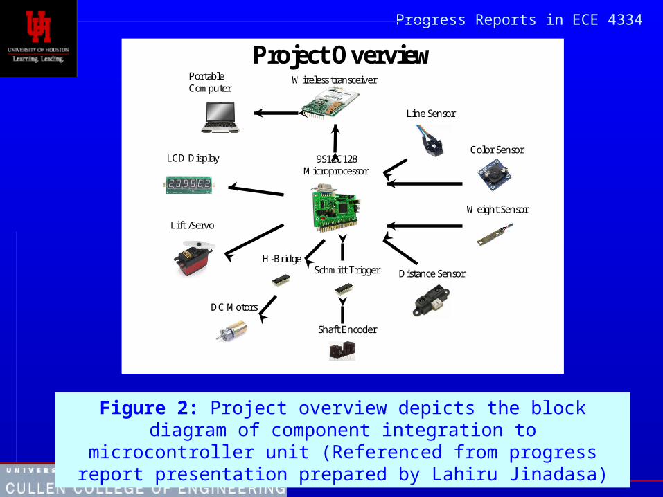
Project OverviewWireless transceiver
9S12C128Microprocessor
Line Sensor
Color Sensor
H-Bridge
DC Motors
Lift /Servo
Weight Sensor
Schmitt Trigger
Shaft Encoder
Distance Sensor
LCD Display
Portable Computer
Figure 2: Project overview depicts the block diagram of component integration to microcontroller unit (Referenced from progress report
presentation prepared by Lahiru Jinadasa)

Progress Reports in ECE 4334
Figure 2: System Overview: A simple overview of how the experiment is conducted.
Progress Reports in ECE 4334
Before you can fully understand progress reports, you need to understand the differences between
Goals
Milestones
Tasks
Progress Reports in ECE 4334
The basic terminology
Goal: What it is you are trying to accomplish; the bottom line.
Milestone: An intermediate accomplishment. It is specific, concrete, verifiable, and important to the project.
Tasks: The things you do to get the job done.
Customer: Who you are doing this for in the first place.
Deliverable: What the customer wants.

Progress Reports in ECE 4334
Milestones act as deliverables on the way to the goals
Research?
Testing?
Demonstrations?
These should be quantifiable
or demonstrable
Demonstrate that circuit configuration fulfills X functions.
Demonstrate interaction between transmitter and computer.
Demonstrate that computer program serves X functions.
Validate communication between satellite and program.
Show that X fulfills X functions.

Progress Reports in ECE 4334
Tasks are the actual work that must be done to complete those milestones
Collect journal articles regarding detection methods
Research microcontrollers to determine best one for satellite communication
Draft literature review
Plan circuit layout
Create testable circuit board
Write detection program

Progress Reports in ECE 4334
Example of Goals, Milestones, and Tasks for a specific project
Goal: Build an autonomous robot that traverses a maze until it locates a STOP sign.
Milestones:– Demonstrate a working vision system that recognizes a
stop sign.– Complete a microprocessor algorithm that enables the
robot to turn at an intersection. Tasks:
– Order parts.– Researching microprocessor possibilities.– Assembling parts.

Progress Reports in ECE 4334
An example of project milestonesDemonstrate a working ADC (Analog to Digital Converter) using MCSH12 Motorola
Chip, and interface it with the wireless transceiver chip.This ADC will be tested by applying an analog signal to the port of the chip, and
monitor the digital output on the computer screen to make sure the signal is converted to digital. Also, the input pin of the transceiver chip will be tested to check if the interface is working as required.
Design and implement a working impedance matching circuit that will enable us to connect the PZT sensor signal with the microcontroller chip.
This circuit will be tested by checking if the PZT sensor is compatible with the microcontroller.
Demonstrate a working receiver and interface it with a computer.This receiver will be tested by receiving the signal transmitted over the required
distance. This signal should also be seen on the computer screen using the hyperterminal.
Demonstrate ability to receive the signals and the ability to generate a signal and send it back by programming Labview software to suit our application.
These abilities will be tested by vibrating the PZT sensor and seeing the equivalent signal on the screen and sending back a signal to vibrate the PZT.
Accomplish the final product by implementing the microcontroller, transceiver, and PZT on one board, and attach them with the small structure building model.
This milestone will be accomplished when the building is impacted by a force, and the resultant voltage signal is shown in Lab view.
The Methodology section will then explain how each of these tasks will be reached.
Progress Reports in ECE 4334
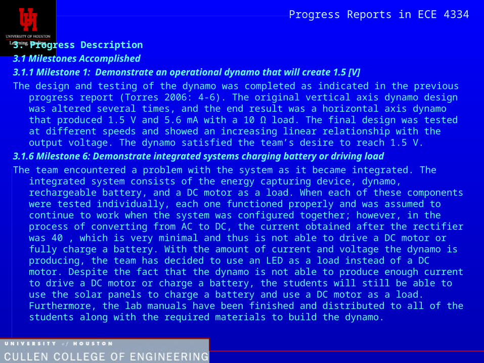
3. Progress Description
3.1 Milestones Accomplished
3.1.1 Milestone 1: Demonstrate an operational dynamo that will create 1.5 [V]
The design and testing of the dynamo was completed as indicated in the previous progress report (Torres 2006: 4-6). The original vertical axis dynamo design was altered several times, and the end result was a horizontal axis dynamo that produced 1.5 V and 5.6 mA with a 10 Ω load. The final design was tested at different speeds and showed an increasing linear relationship with the output voltage. The dynamo satisfied the team’s desire to reach 1.5 V.
3.1.6 Milestone 6: Demonstrate integrated systems charging battery or driving load
The team encountered a problem with the system as it became integrated. The integrated system consists of the energy capturing device, dynamo, rechargeable battery, and a DC motor as a load. When each of these components were tested individually, each one functioned properly and was assumed to continue to work when the system was configured together; however, in the process of converting from AC to DC, the current obtained after the rectifier was 40 , which is very minimal and thus is not able to drive a DC motor or fully charge a battery. With the amount of current and voltage the dynamo is producing, the team has decided to use an LED as a load instead of a DC motor. Despite the fact that the dynamo is not able to produce enough current to drive a DC motor or charge a battery, the students will still be able to use the solar panels to charge a battery and use a DC motor as a load. Furthermore, the lab manuals have been finished and distributed to all of the students along with the required materials to build the dynamo.

Progress Reports in ECE 4334
There were three engineering constraints that our group had to be cautious of while working on this project. Health and safety was of concern since constructing many of the components for the project involved the use of potentially hazardous tools such as soldering irons and wire cutters. Care had to be taken with these tools so that an injury does not occur to any group members. Reliability of the electrical components integrated with the system was another constraint especially during the fabrication stage of our project. Unintentional misuse resulted in chips or ports on the microcontroller being burned out. Work on the project was hindered because of waiting to replace those parts. There was also an economic constraint. The electronic components being used for this system were very expensive including the microcontroller and graphical LCD especially. Great care had to be taken so that while prototyping we did not damage them.
Engineering Constraints

Progress Reports in ECE 4334 There will always be issues and constraints that prevent the project from progressing or not operating efficiently in any give engineering project. The constraints that we have faced are forms of economic restrictions, manufacturing stability and durability of the product.
Economical Constraint/Restrictions
A project; whether it is in engineering or any other field, will frequently be faced with economical constraints. It is always our objective as well as a priority to finish a project within budget. Due to limited budget, we had to constantly concentrate on reducing the cost of the robot. We were encouraged to use parts from the old robots that were used in the previous years. However, there are very high possibilities to obtain damaged parts that would delay the project’s progression. Due to a tight budget, we could not buy more reliable and efficient parts that could improve the timing as well as the efficiency of building the robot.
Manufacturability Constraint
Manufacturability would be another constraint that hindered the progression of our project, since we could not build the desired as well as a competitive design to make the project more dependable and reliable. Since we did not have the necessary tools, we could not manufacture the design concepts that could make the robot more robust. A project also requires enough time to be spent on designing as well as manufacturing. Time constraints also play a big part in delaying the project’s progression by not spending enough time on the project since all the group members (students) have other academic courses to dedicate time to or work a specific amount of hours at their jobs. This can cause the task to have delays and not be completed as efficiently as possible within the available time.
Durability
Due to sensitivity of the microcontroller, extra caution had to be performed before making any contact with it. For instance, we have to make sure that the person handling the microcontroller is properly grounded to prevent any damage from electric static discharge. We also can into the situation where the microcontroller was defective upon receiving it from the manufacturer.

Progress Reports in ECE 4334
There are three main constraints for the project, which are economic feasibility, reliability, and safety. Extreme angular precision comes with a high price; this must be taken into account to determine the most cost effective motor that can deliver the required amount of torque and the highest angular precision for the given budget. Since this apparatus must run multiple trials per experiment for many experiments to verify any obtained results, it must be reliable enough to avoid excessive repairs. Also, the apparatus must be reliable enough to perform consistently. Finally, since there are many electrical leads, some of which are to be connected to a wall outlet, safety is a significant concern. All hazardous electrical leads must be properly covered and concealed so as to help prevent any unfortunate accidents.
Engineering Constraints

Progress Reports in ECE 43344. Engineering Constraints
The following are constraints that might arise during the implementation of the project:
4.1 Health and Safety
Due to the nature of the project the students will be required to handle several tools that might injure them if not used with proper care. Per the customers’ request, the students are required to solder solar panels together which will expose the students to lead and high temperatures that can burn them. The students will also use tools such as a hand saw and a drill to complete the building process of the dynamo and the capturing devices. Despite the students handling dangerous tools, they will be lectured on the importance of safety to avoid any injuries.
4.2 Economic
The customer has limited the team to $50 per kit as he plans to produce 20-25 lab kits for the current semester. Given this constraint, the projects created had to be designed with material that would be cheap and easy to find.
4.3 Reliability
Since the client intends to use these lab kits in the following semesters, the designs created must be made with material that is easily attainable and affordable.

Progress Reports in ECE 4334
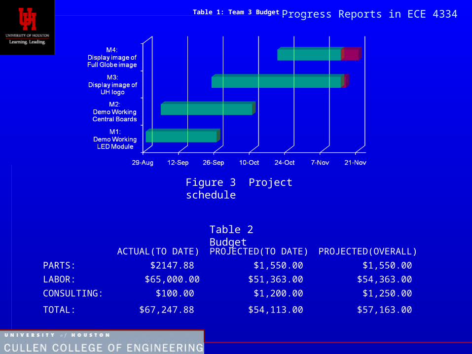
Scheduling and Budget
Follow numbering guidelines for figures and tables.
Figure 7 - Project revived schedule
Progress Reports in ECE 4334
ACTUAL(TO DATE) PROJECTED(TO DATE) PROJECTED(OVERALL)
PARTS: $2147.88 $1,550.00 $1,550.00
LABOR: $65,000.00 $51,363.00 $54,363.00
CONSULTING: $100.00 $1,200.00 $1,250.00
TOTAL: $67,247.88 $54,113.00 $57,163.00
Table 1: Team 3 Budget
Figure 3 Project schedule
Table 2 Budget

Progress Reports in ECE 4334
Progress Reports in ECE 4334
The Conclusion should summarize and appraise your progress
If possible, assure the reader that the problems are being taken care of and that the project will be completed on time. If they cannot be solved, then reassess and recommend changes.
Summarize the goal of the project and your progress toward completing it

Progress Reports in ECE 4334
Use Figures and Tables where appropriate
To convince the reader that the project is being executed appropriately is to include pictures (a copy of the design schematic, a photograph of the prototype, and so on):
work them into the main body of the text
place the pictures immediately after the discussion of the item they illustrate.

Progress Reports in ECE 4334
References and Appendices
Include full bibliographic information for any sources mentioned in your proposal, including the background or literature review sections.
Use documentation guidelines appropriate for your field—ASME, IEEE, etc. If in doubt, use CME.
Include all information that is not absolutely necessary for understanding the project but could be helpful:
• Preliminary data• Lengthy equations
Progress Reports in ECE 4334
Reference all materials you did not create or write
Use IEEE referencing system
Remember: we assume you are the author of everything in your document unless you state otherwise

Progress Reports in ECE 4334
A few writing notes:
– Bad: CBSE(Component-based software engineering)
– Good: Component-Based Software Engineering (CBSE)

Progress Reports in ECE 4334
“We’ll just go with the flow and use the 10 kOhm resistor because it won’t break the bank like the fibrillated googlewazer.”
“The 10 kOhm resistor is much less costly than the fibrillated googlewazer, and a negligible change in the cutoff frequency results from its use in the design.”
“The XYZ widget is very popular because it’s small and cheap, and we like it a lot.”
“We believe that this new design will work really well and that the project will be a big success.”, or “I feel that the XYZ widget is the best on the market.”
From http://www.egr.msu.edu/classes/ece480/
goodman/WritingMistakes.pdf

Progress Reports in ECE 4334
Summary
Provide specifics – avoid relying on vague, overly general statements about the work you've done
Choose technical detail wisely: not too little, not too much
List each problem only in conjunction with a solution
Make good use of figures/ examples
Maintain a positive, encouraging tone