Embed Size (px)
Citation preview

SAUDI ELECTRICITY COMPANY
GENERATION TECHNICAL SUPPORT DEPARTMENT
PROGRESS REPORT
TASK#5 (CONTINUATION 1)
IDENTIFY THE DUTIES AND RESPONSIBILITIES OF OPERATION
SECTION
(GAS TURBINE MS7001E GT-1/2/3)
DONE BY: KHALID ABDULLAH AL-QARNI
LOCATION: ASSER POWER PLANT
DATE: 01/05/16 TO 12/05/16

ENG. KHALID AL-GARNI
____________________________________________________________
2
PROGRESS REPORT: TASK#5 CONTINUE 1
TABLE OF CONTENTS
INTRODUCTION……………………………………..………………………………………………….3
GAS TURBINE MS7001EGT 1/2/3)….………………………………………………………………3
PRE-START CHECK...………………………………………………………………………………………4
FAMILIARZATION WITH GAS TURBINE SYSTEMS…...…………………………………………….5
- LUBE OIL SYSTEM ……………………………………………………………………………………….5-8
- HYDRALLIC OIL SYSTEM………………………………………………………………………………9-11
- TRIP OIL SYSTEM……….…………………...……………………………………………………………...12
NEXT REPORT…...……………………………………………………………………………………...13
CONLUSION……………………………………………………………………………………………...13
REFRENCES……………………………………………………………………………………………...13

ENG. KHALID AL-GARNI
____________________________________________________________
3
PROGRESS REPORT: TASK#5 CONTINUE 1
INTRODUCTION
Since I joined operation section I got to know about organization chart for operation section, duties and
responsibilities of shift supervisors which includes log book, initiate notification through SAP and update the
generation operation information system (GOIS) for units status. currently, I am learning the operation of
GT#1, 2 & 3 through knowing the pre-start check list and also, auxiliary systems. In the following report
specifically, I will write about Pre-start check list, lube oil system, hydraulic system and trip oil system.
GAS TURBINE MS 7001E GT (1/2/3)
Asser Power Plant has a three GE gas turbines frame 7001E (Gt 1, 2 & 3) and each one approximately can
provide up to 50MW. Also, it is an axial flow turbine consists of 17 stages of rotors and stators. In addition,
turbine consists of three stages stators and rotors. The systems in gas turbine are the following:
Lube Oil System
Hydraulic System
Liquid Fuel System
Trip Oil System
Atomizing Air System
Cooling Water System
Cooling and sealing Air System
ENG. KHALID AL-GARNI
____________________________________________________________
4
PROGRESS REPORT: TASK#5 CONTINUE 1
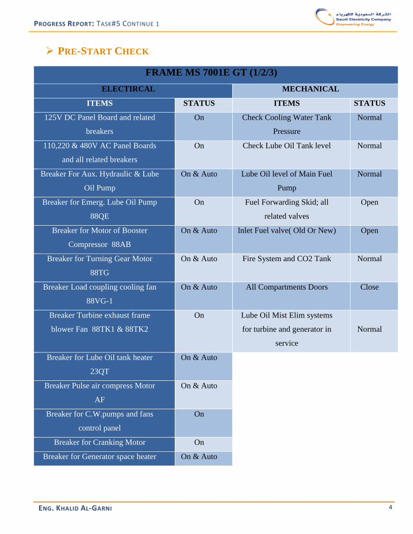
PRE-START CHECK
FRAME MS 7001E GT (1/2/3)
ELECTIRCAL MECHANICAL
ITEMS STATUS ITEMS STATUS
125V DC Panel Board and related
breakers
On Check Cooling Water Tank
Pressure
Normal
110,220 & 480V AC Panel Boards
and all related breakers
On Check Lube Oil Tank level Normal
Breaker For Aux. Hydraulic & Lube
Oil Pump
On & Auto Lube Oil level of Main Fuel
Pump
Normal
Breaker for Emerg. Lube Oil Pump
88QE
On Fuel Forwarding Skid; all
related valves
Open
Breaker for Motor of Booster
Compressor 88AB
On & Auto Inlet Fuel valve( Old Or New) Open
Breaker for Turning Gear Motor
88TG
On & Auto Fire System and CO2 Tank Normal
Breaker Load coupling cooling fan
88VG-1
On & Auto All Compartments Doors Close
Breaker Turbine exhaust frame
blower Fan 88TK1 & 88TK2
On Lube Oil Mist Elim systems
for turbine and generator in
service
Normal
Breaker for Lube Oil tank heater
23QT
On & Auto
Breaker Pulse air compress Motor
AF
On & Auto
Breaker for C.W.pumps and fans
control panel
On
Breaker for Cranking Motor On
Breaker for Generator space heater On & Auto
ENG. KHALID AL-GARNI
____________________________________________________________
5
PROGRESS REPORT: TASK#5 CONTINUE 1
FAMILIARIZATION WITH GAS TURBINE SYSTEMS
As mentioned above Ge frame 7001E has seven systems below are three of them. The remaining
systems I did not take them yet.
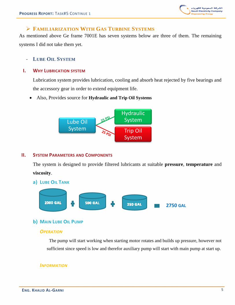
- LUBE OIL SYSTEM
I. WHY LUBRICATION SYSTEM
Lubrication system provides lubrication, cooling and absorb heat rejected by five bearings and
the accessory gear in order to extend equipment life.
Also, Provides source for Hydraulic and Trip Oil Systems
II. SYSTEM PARAMETERS AND COMPONENTS
The system is designed to provide filtered lubricants at suitable pressure, temperature and
viscosity.
a) LUBE OIL TANK
b) MAIN LUBE OIL PUMP
OPERATION
The pump will start working when starting motor rotates and builds up pressure, however not
sufficient since speed is low and therefor auxiliary pump will start with main pump at start up.
INFORMATION
Lube Oil System
Hydraulic System
Trip Oil System
2750 GAL

ENG. KHALID AL-GARNI
____________________________________________________________
6
PROGRESS REPORT: TASK#5 CONTINUE 1
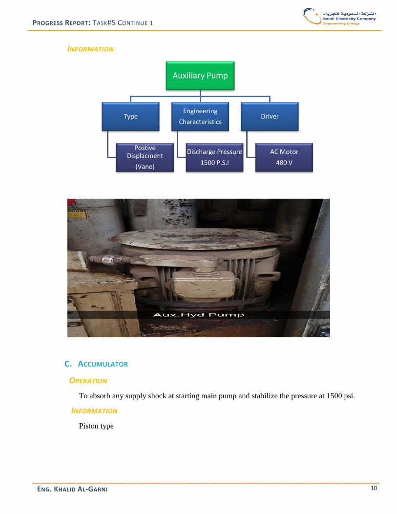
c) AUXILIARY LUBE OIL PUMP
OPERATION
The auxiliary pump starts with the unit up to 95% speed and shut down. Again starts
when speed became 8%.
INFORMATION
Main Lube
Oil Pump
Type
Postive Displacment
(Gear)
Engineering
Characteristics
Discharge Pressure
100 P.S.I
Volume Flow Rate
460 GPM
Driver
Accessory Gear
Auxiliary Pump
Type
Dynamic
(Centrifugal)
Engineering
Characteristics
Discharge Pressure
100 P.S.I
Volume Flow Rate
460 GPM
Driver
AC Motor
460 V

ENG. KHALID AL-GARNI
____________________________________________________________
7
PROGRESS REPORT: TASK#5 CONTINUE 1
d) EMERGENCY LUBE OIL PUMP
OPERATION
The emergency lube oil pump starts when speed of unit became 6%
INFORMATION
Emergency Pump
Type
Dynamic
(Centrifugal)
Engineering
Characteristics
Discharge Pressure
20 P.S.I
Volume Flow Rate
260 GPM
Driver
DC Motor
120 V

ENG. KHALID AL-GARNI
____________________________________________________________
8
PROGRESS REPORT: TASK#5 CONTINUE 1
e) COOLER (HEAT EXCHANGER) i
OPERATION
The cooler function is transferring heat from returning oil and give it to cooing water.
INFORMATION
The cooler is shell and tube type (U)
f) FILTERSii
OPERATION
There are two Filters main function to catch impurities in oil. One in service and other is back up
and at 15 psig the pressure switch alarm activated.
INFORMATION
The type of filter is 5-micron (Nominal) pleated paper
i The cooler located inside the oil tank ii The Filters Located Inside the oil tank

ENG. KHALID AL-GARNI
____________________________________________________________
9
PROGRESS REPORT: TASK#5 CONTINUE 1
- HYDRAULIC OIL SYSTEM
i. WHY HYDRAULIC SYSTEM
Hydraulic system uses fluid power for operating control component. The function of the system is:
1. Operate fuel control valve
2. Fuel oil stop valve
3. Operate IGV
4. Source for trip oil system
ii. SYSTEM PARAMETERS AND COMPONENTS
System parameter is Pressure to be maintained in 1500 psi. The major components of hydraulic
system are:
A. MAIN HYDRAULIC PUMP
OPERATION
The pump will start working when starting motor rotates and builds up pressure from 25 psi up to
1500 psi, however not sufficient since speed is low and therefor auxiliary pump will start with
main pump at start up.
INFORMATION
B. AUXILIARY HYDRAULIC PUMP
OPERATION
The auxiliary pump starts with the unit up to 95% speed and shut down. Again starts when
pressure drop below 1350 psi.
Main Hydraulic
Pump
Type
Postive Displacment
(Piston)
Engineering
Characteristics
Discharge Pressure
1500 P.S.I
Driver
Accessory Gear
ENG. KHALID AL-GARNI
____________________________________________________________
10
PROGRESS REPORT: TASK#5 CONTINUE 1
INFORMATION
C. ACCUMULATOR
OPERATION
To absorb any supply shock at starting main pump and stabilize the pressure at 1500 psi.
INFORMATION
Piston type
Auxiliary Pump
Type
Postive Displacment
(Vane)
Engineering
Characteristics
Discharge Pressure
1500 P.S.I
Driver
AC Motor
480 V

ENG. KHALID AL-GARNI
____________________________________________________________
11
PROGRESS REPORT: TASK#5 CONTINUE 1
D. SYSTEM DIAGRAM

ENG. KHALID AL-GARNI
____________________________________________________________
12
PROGRESS REPORT: TASK#5 CONTINUE 1
- TRIP OIL SYSTEM
A. WHY TRIP OIL SYSTEM
Trip system is the primary protection for gas turbine interface between the turbine control and
protection system circuit.
B. SYSTEM PARAMETERS AND COMPONENTS
System parameter is Pressure to be maintained in 1500 psi to close fuel stop valve from hyd
system and 25 psi from lube oil system. Also, the main components are:
a. SOLENOID VALVE
b. PRESSURE SWITCH
c. INLET GUIDE VANE POSITION SENSORS
d. SYSTEM DIAGRAM

ENG. KHALID AL-GARNI
____________________________________________________________
13
PROGRESS REPORT: TASK#5 CONTINUE 1
NEXT REPORT After two weeks I will write about the other systems such as fuel system and other systems. Also, attend
more start up and shut downs. I have some case studies to be delivered soon.
CONCLUSION At conclusion, I got to know the pre-check list before operation. In according to, systems of gast turbine
frame 7001E specially lube oil, hydraulic and trip oil. In next few weeks I will complete all system for frame
7001 E as per PDP plan at operation section. Finally, I would like to thank engineer Mustafa for great support.
REFERENCE
- Special Thanks to Operation Engineer (Mustafa)
- Operators
- Web sites