Embed Size (px)
Citation preview

Progress reportProgress report
Smart antennas in wireless Smart antennas in wireless communicationscommunications
by Ivan Arkhipov by Ivan Arkhipov
cs603 Wireless Communications & Networkscs603 Wireless Communications & Networks
Instructor: Dr. Ajay GuptaInstructor: Dr. Ajay Gupta

Smart antenna systems combine multiple antenna elements with a signal-processing capability to optimize its radiation and/or reception pattern automatically in response to the signal environment (International Engineering Consortium (n.d.)).
DefinitionDefinition
The basic idea is get bigger beam in a direction towards the userThe basic idea is get bigger beam in a direction towards the user

In my approach I am trying to filter useful signal from a space to In my approach I am trying to filter useful signal from a space to get bigger gain (or SNR) and to change the beam shape that it get bigger gain (or SNR) and to change the beam shape that it would be directive. would be directive.
Example of a pattern Example of a pattern for waveguide antennafor waveguide antenna

To achieve filtering a special shape of antenna is used To achieve filtering a special shape of antenna is used
Lo is the wavelength of the high frequency (hf) signal in open air or Lo/mm = 300 / (f/GHz).Lc is the wavelength of the low cut frequency which depends on tube diameter only Lc = k x D, where k – is a coefficientLg is standing wavelength inside the tube; it is function of both Lo and Lc
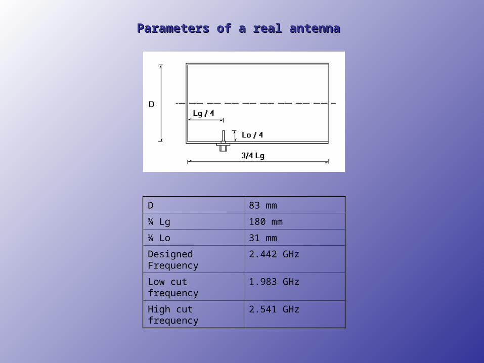
Parameters of a real antennaParameters of a real antenna
D 83 mm
¾ Lg 180 mm
¼ Lo 31 mm
Designed Frequency 2.442 GHz
Low cut frequency 1.983 GHz
High cut frequency 2.541 GHz

Several approaches of increasing SNRSeveral approaches of increasing SNR
Waves are bypassing antenna
Regular can antennaRegular can antenna

Waves are reflecting into antenna
Can antenna with funnelCan antenna with funnel

Combo satellite dish + can antennaCombo satellite dish + can antenna
So we can gain more signal power from the space.So we can gain more signal power from the space.

Simulated azimuth and 3D patternsSimulated azimuth and 3D patternsfor my antenna without canfor my antenna without can

α
Access point in a
zero degree position
Access point in a (0+α)
degree position
Can antenna
Experiment setup for building up azimuth antenna pattern. Experiment setup for building up azimuth antenna pattern.

Experiment setup for measuring SNR of the antenna. Experiment setup for measuring SNR of the antenna.
Access point on Sprau Tower
Antenna positions
For each position I’m planning to make more than 30 measurements to get proper statistical results.

By this time I have some measurements from a point located on stadium drive. These are results with antenna:


Next results when antenna was unplugged:Next results when antenna was unplugged:


![[Arkhipov] How Lawyers Add Value to Game Design (GDC Europe 2014 Submission)](https://img.pdfslide.us/doc/110x75/555c627dd8b42ab6748b4b2e/arkhipov-how-lawyers-add-value-to-game-design-gdc-europe-2014-submission.jpg)