Embed Size (px)
Citation preview
PROGRESS ON THE MICE RF MODULE AT LBNL∗
T. Luo†, A. DeMello, L. Kistulentz, A. Lambert, D. Li,
T. Loew, S. Prestemon, S. Virostek, J. Wallig, LBNL, Berkeley, CA 94720,USA
Y. Torum, IIT, Chicago, IL 60616,USA
T. Anderson, A. Bross, M. Palmer, Fermilab, Batavia, IL 60510,USA
Abstract
The international Muon Ionization Cooling Experiment
aims to demonstrate the transverse cooling of a muon beam
by ionization interaction with absorbers and re-acceleration
in RF cavities. The final MICE cooling channel configura-
tion has two RFmodules, each housing a 201MHz RF cavity
to compensate the longitudinal energy loss in the absorbers.
The RF modules will be assembled and tested at LBNL
before being shipped to and installed at RAL. This paper
reports the recent progress on the manufacturing and testing
of the RF module components, as well as the preparation for
the final module assembly.
INTRODUCTION
The international Muon Ionization Cooling Experiment
(MICE) [1–3] aims to demonstrate the transverse cooling of
a muon beam by ionization interaction with energy absorbers
and re-acceleration in RF cavities [4, 5]. The final MICE
cooling channel configuration, as shown in Figure 1, has
two RF modules, each housing a 201 MHz RF cavity to
compensate the longitudinal energy loss in absorbers [6]. A
detail exploded view of RF module is shown in Figure 2.
Figure 1: MICE beamline layout.
Lawrence Berkeley National Laboratory (LBNL) has
made significant progress on the manufacturing and test-
ing of the RF modules since the last report [7], including the
RF couplers, the frequency tuning system and the vacuum
vessel. Preparation for the RF module assembly is well un-
derway; the vacuum vessels arrived at LBNL in late April
2016. This paper reports on recent progress.
RF COUPLER PRODUCTION AND TEST
The MICE RF coupler is a coax waveguide with a cou-
pling loop at the end, magnetically coupling the RF power
into the cavity. Two couplers are symmetrically placed on
each side of the cavity, each delivering up to 1 MW peak
∗
†
This manuscript has been authored by Fermi Research Alliance, LLC under Contract No. DE-AC02-07CH11359 with the U.S. Dept. of Energy, Office of Science, Office of High Energy [email protected]
Figure 2: RF module exploded view.
power in theMICE experiment. To suppress themultipacting
in the coupler, the inner surface of the coax waveguide outer
conductor and the coupling loop are coated with TiN thin
film, which has a smaller Secondary Electron Yield (SEY)
than copper. The effectiveness of multipacting suppression
by this method has been proven in the previous Single Cav-
ity Module high power test at Fermilab [8]. The TiN thin
film is generated by the sputtering deposition method by
the LBNL Plasma Application Group. The quality of the
resulting coating for the coax waveguide and coupling loop
are shown in Figure 3 and 4 respectively. Both coatings
passed the adhesive tape test.
Figure 3: TiN coating of the inner suface of coax waveguide.
The assembly of the RF couplers was carried out at the
LBNL main machine shop. All the parts, including the coax
outer conductor, inner conductor, Toshiba RF window, adap-
tive bellows and coupling loop are put together following
stringent procedure and with high precision, with several
iterations of welding and cleaning during the process. The
final assembled coupler is shown in Figure 5. After passing
leak checks, two couplers were sent to the Fermilab MTA
for high power RF testing.
MOPMW028 Proceedings of IPAC2016, Busan, Korea
ISBN 978-3-95450-147-2
454Cop
yrig
ht©
2016
CC
-BY-
3.0
and
byth
ere
spec
tive
auth
ors
07 Accelerator Technology
T06 Room Temperature RF
FERMILAB-CONF-16-694-APC
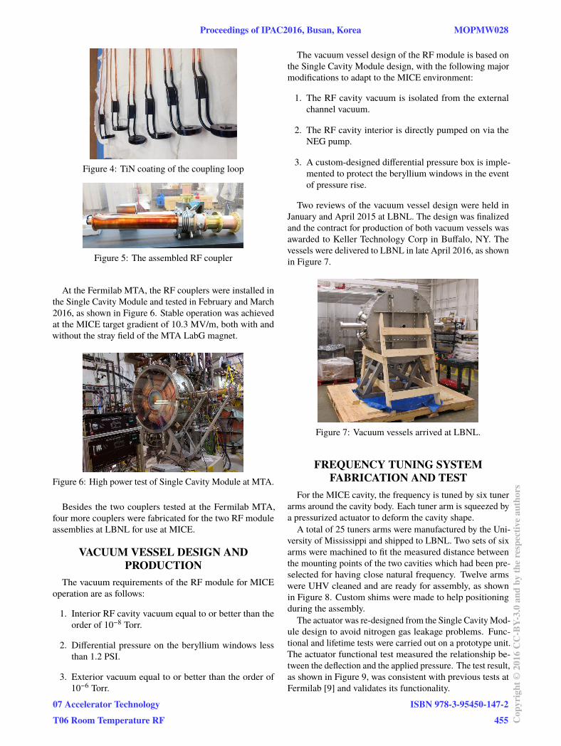
Figure 4: TiN coating of the coupling loop
Figure 5: The assembled RF coupler
At the Fermilab MTA, the RF couplers were installed in
the Single Cavity Module and tested in February and March
2016, as shown in Figure 6. Stable operation was achieved
at the MICE target gradient of 10.3 MV/m, both with and
without the stray field of the MTA LabG magnet.
Figure 6: High power test of Single Cavity Module at MTA.
Besides the two couplers tested at the Fermilab MTA,
four more couplers were fabricated for the two RF module
assemblies at LBNL for use at MICE.
VACUUM VESSEL DESIGN AND
PRODUCTION
The vacuum requirements of the RF module for MICE
operation are as follows:
1. Interior RF cavity vacuum equal to or better than the
order of 10−8 Torr.
2. Differential pressure on the beryllium windows less
than 1.2 PSI.
3. Exterior vacuum equal to or better than the order of
10−6 Torr.
The vacuum vessel design of the RF module is based on
the Single Cavity Module design, with the following major
modifications to adapt to the MICE environment:
1. The RF cavity vacuum is isolated from the external
channel vacuum.
2. The RF cavity interior is directly pumped on via the
NEG pump.
3. A custom-designed differential pressure box is imple-
mented to protect the beryllium windows in the event
of pressure rise.
Two reviews of the vacuum vessel design were held in
January and April 2015 at LBNL. The design was finalized
and the contract for production of both vacuum vessels was
awarded to Keller Technology Corp in Buffalo, NY. The
vessels were delivered to LBNL in late April 2016, as shown
in Figure 7.
Figure 7: Vacuum vessels arrived at LBNL.
FREQUENCY TUNING SYSTEM
FABRICATION AND TEST
For the MICE cavity, the frequency is tuned by six tuner
arms around the cavity body. Each tuner arm is squeezed by
a pressurized actuator to deform the cavity shape.
A total of 25 tuners arms were manufactured by the Uni-
versity of Mississippi and shipped to LBNL. Two sets of six
arms were machined to fit the measured distance between
the mounting points of the two cavities which had been pre-
selected for having close natural frequency. Twelve arms
were UHV cleaned and are ready for assembly, as shown
in Figure 8. Custom shims were made to help positioning
during the assembly.
The actuator was re-designed from the Single CavityMod-
ule design to avoid nitrogen gas leakage problems. Func-
tional and lifetime tests were carried out on a prototype unit.
The actuator functional test measured the relationship be-
tween the deflection and the applied pressure. The test result,
as shown in Figure 9, was consistent with previous tests at
Fermilab [9] and validates its functionality.
Proceedings of IPAC2016, Busan, Korea MOPMW028
07 Accelerator Technology
T06 Room Temperature RF
ISBN 978-3-95450-147-2
455 Cop
yrig
ht©
2016
CC
-BY-
3.0
and
byth
ere
spec
tive
auth
ors
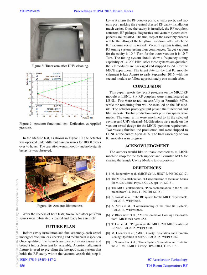
Figure 8: Tuner arm after UHV cleaning.
Figure 9: Actuator functional test: Deflection vs Applied
pressure.
In the lifetime test, as shown in Figure 10, the actuator
was operated under different base pressures for 10000 cycles
over 40 hours. The operation went smoothly and no hystersis
behavior was observed.
Figure 10: Actuator lifetime test.
After the success of both tests, twelve actuators plus four
spares were fabricated, cleaned and ready for assembly.
FUTURE PLAN
Before cavity installation and final assembly, each vessel
undergoes vacuum leak checking and mechanical inspection.
Once qualified, the vessels are cleaned as necessary and
brought into a clean tent for assembly. A custom alignment
fixture is used to pre-align the hexapod strut system that
holds the RF cavity within the vacuum vessel; this step is
key as it aligns the RF coupler ports, actuator ports, and vac-
uum port, making the eventual dressed RF cavity installation
much easier. Once the cavity is installed, the RF couplers,
actuators, RF pickups, diagnostics and vacuum system com-
ponents are installed. The final step of the assembly process
will be the fitting of the beryllium windows, after which the
RF vacuum vessel is sealed. Vacuum system testing and
RF tuning system testing then commences. Target vacuum
for the cavity is 10−8 Torr, for the outer vacuum it is 10−6
Torr. The tuning system should show a frequency tuning
capability of +/- 200 kHz. After these systems are qualified,
the RF modules are packaged and shipped to RAL for the
MICE experiment. The target date for the first RF module
shipment is late August to early September 2016, with the
second module to follow approximately one month after.
CONCLUSION
This paper reports the recent progress on the MICE RF
module at LBNL. Six RF couplers were manufactured at
LBNL. Two were tested successfully at Fermilab MTA,
while the remaining four will be installed on the RF mod-
ule. The actuator prototype unit passed the functional and
lifetime tests. Twelve production units plus four spares were
made. The tuner arms were machined to fit the selected
cavities and UHV cleaned. Modifications were made on the
vacuum vessel design for the MICE operation requirement.
Two vessels finished the production and were shipped to
LBNL at the end of April 2016. The final assembly of two
RF modules is in progress.
ACKNOWLEDGMENT
The authors would like to thank technicians at LBNL
machine shop for the tech support and Fermilab MTA for
sharing the Single Cavity Module test experience.
REFERENCES
[1] M. Bogomilov et al., (MICE Coll.), JINST 7, P05009 (2012).
[2] TheMICE collaboration, "Characterisation of the muon beams
for MICE", Euro. Phys. J. C:, 73, pp1-14, (2013).
[3] The MICE collaboration, "Pion contamination in the MICE
muon beam", J. Inst., 11 P03001 (2016).
[4] K. Ronald et al., "The RF system for the MICE experiment",
IPAC2013, WEPFI066.
[5] A. Moss et al., "Commissioning of the mice RF system",
IPAC2014, WEPME020.
[6] V. Blackmore et al., “ MICE Ionization Cooling Demonstra-
tion”, MICE tech notes 452.
[7] T. Luo et al., "Progress on the MICE 201 MHz cavities at
LBNL", IPAC2015, WEPTY046.
[8] M. Leonova et al., "MICE Cavity Installation and Commis-
sioning/Operation at MTA", IPAC2015, WEPTY032.
[9] L. Somaschin et al., "Tuner System Simulation and Tests for
the 201 MHZ MICE Cavity", IPAC2014, THPRI070.
MOPMW028 Proceedings of IPAC2016, Busan, Korea
ISBN 978-3-95450-147-2
456Cop
yrig
ht©
2016
CC
-BY-
3.0
and
byth
ere
spec
tive
auth
ors
07 Accelerator Technology
T06 Room Temperature RF