Embed Size (px)
Citation preview
PROGRESS ON ESS MEDIUM ENERGY BEAM TRANSPORT
I. Bustinduy∗, J.L. Muñoz, D. Fernández-Cañoto, O. González, S. Varnasseri, A. Ghiglino,R. Vivanco, F. Sordo, M. Magan, P. Gonzalez, N. Garmendia, L. Muguira, Z. Izaola,
I. Madariaga, I. Rueda, ESS-Bilbao, SpainA. Ponton, R. Miyamoto, M. Eshraqui, ESS, Sweden
Abstract
The considered versatile ESS MEBT is being designed to
achieve four main goals: First, to contain a fast chopper and
its correspondent beam dump, that could serve in the com-
missioning as well as in the ramp up phases. Second, to serve
as a halo scraping section by means of various adjustable
blades. Third, to measure the beam phase and profile be-
tween the RFQ and the DTL, along with other beam monitors.
And finally, to match the RFQ output beam characteristics
to the DTL input both transversally and longitudinally. For
this purpose a set of eleven quadrupoles is used to match
the beam characteristics transversally, combined with three
352.2 MHz CCL type buncher cavities, which are used to
adjust the beam in order to fulfil the required longitudinal
parameters. A thorough study on the optimal input beam
parameters will be discussed. Quadrupole design update
will be presented along with new RF measurements over the
buncher prototype. Finally, updated results will be presented
on the chopper and beam-dump system.
LAYOUT
During last year the ESS linac cost was reevaluated, in
order to cope with the cost objective, final energy of the linac
was reduced and both gradients and beam current were in-
creased [1]; as a consequence important modifications were
introduced to the linac design that affected MEBT section.
RFQ output beam energy increased from 3 MeV to 3.62 MeV,
and beam current under nominal conditions was increased
from 50 to 62.5mA. From the envisaged layout [2] most
affected systems were: quadrupole, buncher and chopper
and beam-dump.
Fig. 2 shows the updated layout, where a quadrupole triplet
is still used to focus the beam out of the RFQ. After leaving
the chopper and beam-dump, the beam expands. Another
triplet is used to focus the beam before entering the space for
diagnostic devices. The last set of four quadrupoles is used
to obtain DTL periodic transverse solution; accompanied by
three CCL type buncher cavities for the longitudinal plane.
In both cases, a good compromise in the focusing is required
to prevent beam excursions to non-linear field regions, while
avoiding over-focused bunches that would enhance inner
space-charge repulsive forces [3].
Required Inputs for MEBT
In order to improve MEBT performance, a systematic
approach was conducted to seek best input beam. 2 different
sets of potential RFQ outputs were used as input of the ESS
10 20 30 40 50 600
5
10
15
20
25
30
35
40
Loss
es (
%)
/ Em
ittan
ce in
crea
se (
%)
End cell (mm)
Losses
t
l
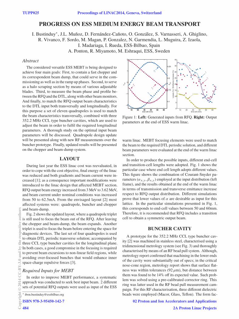
Figure 1: Left: Generated inputs from RFQ. Right: Output
parameters at the end of ESS warm linac.
warm linac. MEBT focusing elements were used to match
the beam to the required DTL periodic solution, and different
beam parameters were evaluated at the end of the warm linac
section.
In order to produce the possible inputs, different end-cell
and transition-cell lengths were adopted. Fig. 1 shows the
particular case where end cell length adopts different values.
This figure shows the combination of Courant-Snyder pa-
rameters (αx ,y , βx ,y ) employed at the input distribution (left
frame), and the results obtained at the end of the warm linac
in terms of transmission and transverse emittance increase
respect to RFQ output distribution. Different simulations
prove that lower values of α are desirable as input for this
lattice. In the particular simulations presented in Fig. 1,
this corresponds to end-cell values between 50 and 60mm.
Therefore, it is recommended that RFQ includes a transition
cell to obtain a symmetric output beam.
BUNCHER CAVITY
A prototype for the 352.2 MHz CCL type buncher cav-
ity [2] was machined in stainless steel, characterised using a
tridimensional metrology system (see Fig. 3) and thoroughly
characterised by means of an RF bead pull system. Although,
metrology report confirmed that machining in the lower ends
of the cavity were substantially out of specs; in the critical
nose-cone region, metrology report shows that surface flat-
ness was within tolerances (92 μm), but distance between
them was found to be 14% off its expected value. Such prob-
lem was solved using a pre-calibrated corrector ring. This
ring was latter used in the RF bead pull measurement cam-
paign. For this RF characterisation, three different dielectric
beads were employed (Macor, Glass, Teflon). The form fac-
TUPP025 Proceedings of LINAC2014, Geneva, Switzerland
ISBN 978-3-95450-142-7
484Cop
yrig
ht©
2014
CC
-BY-
3.0
and
byth
ere
spec
tive
auth
ors
02 Proton and Ion Accelerators and Applications
2A Proton Linac Projects
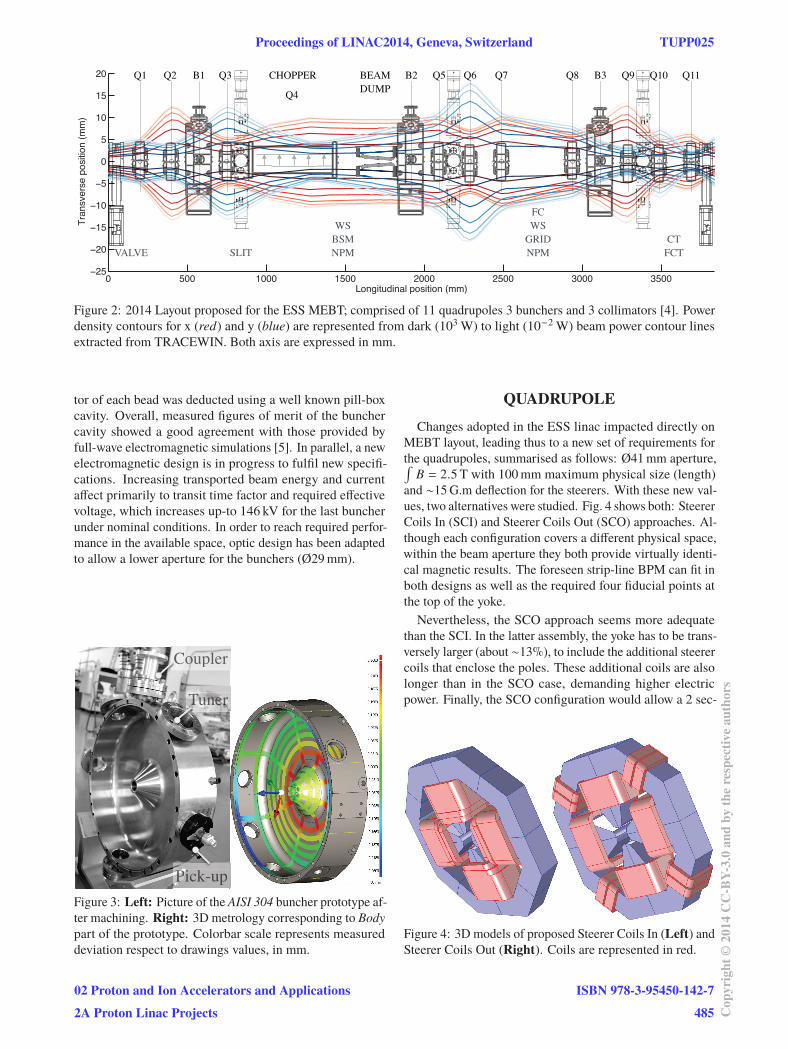
CTFCT
WSBSMNPM
FCWSGRIDNPMVALVE
Q4
BEAMDUMP
B3B1 B2Q1 Q2 Q8 Q9 Q10 Q11Q3 Q5 Q6 Q7CHOPPER
SLIT
Figure 2: 2014 Layout proposed for the ESS MEBT; comprised of 11 quadrupoles 3 bunchers and 3 collimators [4]. Power
density contours for x (red) and y (blue) are represented from dark (103 W) to light (10−2 W) beam power contour lines
extracted from TRACEWIN. Both axis are expressed in mm.
tor of each bead was deducted using a well known pill-box
cavity. Overall, measured figures of merit of the buncher
cavity showed a good agreement with those provided by
full-wave electromagnetic simulations [5]. In parallel, a new
electromagnetic design is in progress to fulfil new specifi-
cations. Increasing transported beam energy and current
affect primarily to transit time factor and required effective
voltage, which increases up-to 146 kV for the last buncher
under nominal conditions. In order to reach required perfor-
mance in the available space, optic design has been adapted
to allow a lower aperture for the bunchers (Ø29 mm).
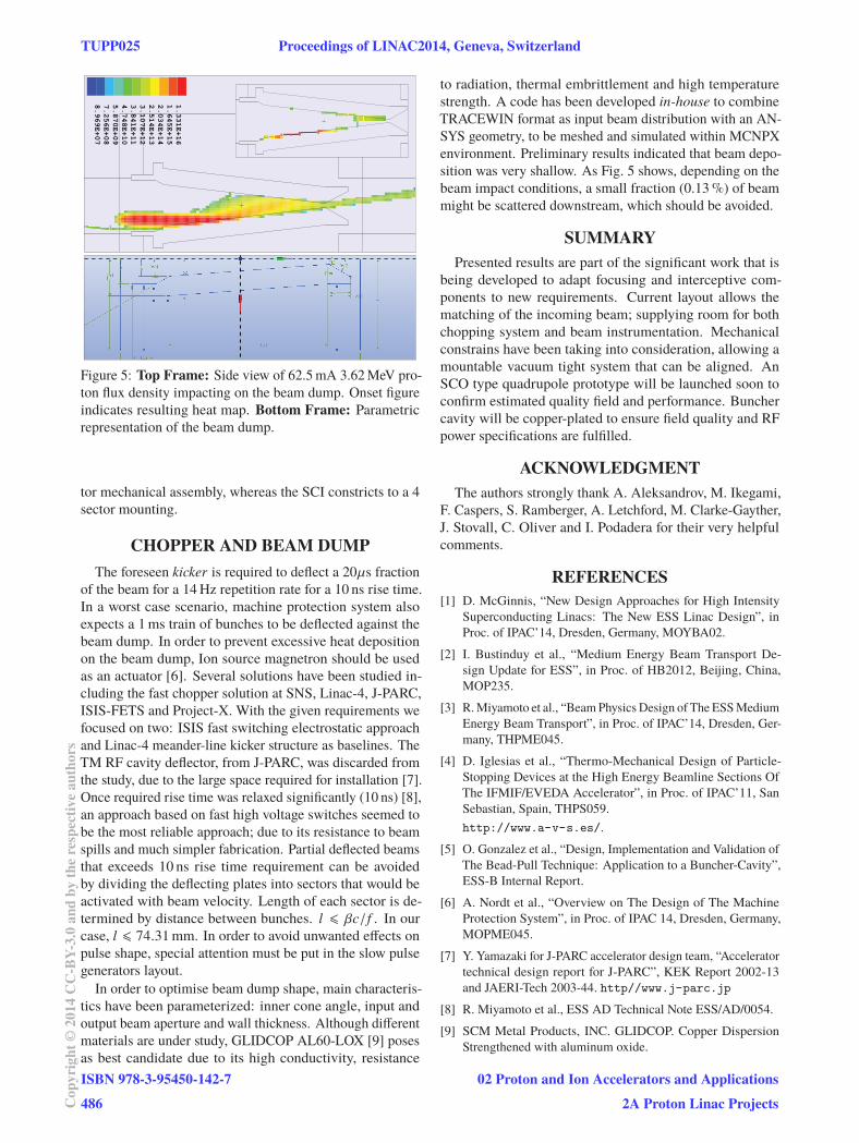
CCCoooooooooouuupplllleerr
PPPPPPPPPPPPPPPPPiiiiiiiiiiiiiiccckkkkk-uuuuupppp
TTTTTTTTTTTTTTTTTuuuuuuuuuuuuuunnnnnnnnnnnnnnnnnnnneeeeeeeeeeeeeeeeeeeeeerrrrrrrrrrrrrrrrr
C
TTTTTTTTTTT
Figure 3: Left: Picture of the AISI 304 buncher prototype af-
ter machining. Right: 3D metrology corresponding to Body
part of the prototype. Colorbar scale represents measured
deviation respect to drawings values, in mm.
QUADRUPOLE
Changes adopted in the ESS linac impacted directly on
MEBT layout, leading thus to a new set of requirements for
the quadrupoles, summarised as follows: Ø41 mm aperture,∫B = 2.5 T with 100 mm maximum physical size (length)
and ∼15 G.m deflection for the steerers. With these new val-
ues, two alternatives were studied. Fig. 4 shows both: Steerer
Coils In (SCI) and Steerer Coils Out (SCO) approaches. Al-
though each configuration covers a different physical space,
within the beam aperture they both provide virtually identi-
cal magnetic results. The foreseen strip-line BPM can fit in
both designs as well as the required four fiducial points at
the top of the yoke.
Nevertheless, the SCO approach seems more adequate
than the SCI. In the latter assembly, the yoke has to be trans-
versely larger (about ∼13%), to include the additional steerer
coils that enclose the poles. These additional coils are also
longer than in the SCO case, demanding higher electric
power. Finally, the SCO configuration would allow a 2 sec-
Figure 4: 3D models of proposed Steerer Coils In (Left) and
Steerer Coils Out (Right). Coils are represented in red.
Proceedings of LINAC2014, Geneva, Switzerland TUPP025
02 Proton and Ion Accelerators and Applications
2A Proton Linac Projects
ISBN 978-3-95450-142-7
485 Cop
yrig
ht©
2014
CC
-BY-
3.0
and
byth
ere
spec
tive
auth
ors
1.331E+16
1.645E+15
2.034E+14
2.514E+13
3.107E+12
3.841E+11
4.748E+10
5.870E+09
7.256E+08
8.969E+07
Figure 5: Top Frame: Side view of 62.5 mA 3.62 MeV pro-
ton flux density impacting on the beam dump. Onset figure
indicates resulting heat map. Bottom Frame: Parametric
representation of the beam dump.
tor mechanical assembly, whereas the SCI constricts to a 4
sector mounting.
CHOPPER AND BEAM DUMP
The foreseen kicker is required to deflect a 20μs fraction
of the beam for a 14 Hz repetition rate for a 10 ns rise time.
In a worst case scenario, machine protection system also
expects a 1 ms train of bunches to be deflected against the
beam dump. In order to prevent excessive heat deposition
on the beam dump, Ion source magnetron should be used
as an actuator [6]. Several solutions have been studied in-
cluding the fast chopper solution at SNS, Linac-4, J-PARC,
ISIS-FETS and Project-X. With the given requirements we
focused on two: ISIS fast switching electrostatic approach
and Linac-4 meander-line kicker structure as baselines. The
TM RF cavity deflector, from J-PARC, was discarded from
the study, due to the large space required for installation [7].
Once required rise time was relaxed significantly (10 ns) [8],
an approach based on fast high voltage switches seemed to
be the most reliable approach; due to its resistance to beam
spills and much simpler fabrication. Partial deflected beams
that exceeds 10 ns rise time requirement can be avoided
by dividing the deflecting plates into sectors that would be
activated with beam velocity. Length of each sector is de-
termined by distance between bunches. l � βc/f . In our
case, l � 74.31 mm. In order to avoid unwanted effects on
pulse shape, special attention must be put in the slow pulse
generators layout.
In order to optimise beam dump shape, main characteris-
tics have been parameterized: inner cone angle, input and
output beam aperture and wall thickness. Although different
materials are under study, GLIDCOP AL60-LOX [9] poses
as best candidate due to its high conductivity, resistance
to radiation, thermal embrittlement and high temperature
strength. A code has been developed in-house to combine
TRACEWIN format as input beam distribution with an AN-
SYS geometry, to be meshed and simulated within MCNPX
environment. Preliminary results indicated that beam depo-
sition was very shallow. As Fig. 5 shows, depending on the
beam impact conditions, a small fraction (0.13 %) of beam
might be scattered downstream, which should be avoided.
SUMMARY
Presented results are part of the significant work that is
being developed to adapt focusing and interceptive com-
ponents to new requirements. Current layout allows the
matching of the incoming beam; supplying room for both
chopping system and beam instrumentation. Mechanical
constrains have been taking into consideration, allowing a
mountable vacuum tight system that can be aligned. An
SCO type quadrupole prototype will be launched soon to
confirm estimated quality field and performance. Buncher
cavity will be copper-plated to ensure field quality and RF
power specifications are fulfilled.
ACKNOWLEDGMENT
The authors strongly thank A. Aleksandrov, M. Ikegami,
F. Caspers, S. Ramberger, A. Letchford, M. Clarke-Gayther,
J. Stovall, C. Oliver and I. Podadera for their very helpful
comments.
REFERENCES
[1] D. McGinnis, “New Design Approaches for High Intensity
Superconducting Linacs: The New ESS Linac Design”, in
Proc. of IPAC’14, Dresden, Germany, MOYBA02.
[2] I. Bustinduy et al., “Medium Energy Beam Transport De-
sign Update for ESS”, in Proc. of HB2012, Beijing, China,
MOP235.
[3] R. Miyamoto et al., “Beam Physics Design of The ESS Medium
Energy Beam Transport”, in Proc. of IPAC’14, Dresden, Ger-
many, THPME045.
[4] D. Iglesias et al., “Thermo-Mechanical Design of Particle-
Stopping Devices at the High Energy Beamline Sections Of
The IFMIF/EVEDA Accelerator”, in Proc. of IPAC’11, San
Sebastian, Spain, THPS059.
http://www.a-v-s.es/.
[5] O. Gonzalez et al., “Design, Implementation and Validation of
The Bead-Pull Technique: Application to a Buncher-Cavity”,
ESS-B Internal Report.
[6] A. Nordt et al., “Overview on The Design of The Machine
Protection System”, in Proc. of IPAC 14, Dresden, Germany,
MOPME045.
[7] Y. Yamazaki for J-PARC accelerator design team, “Accelerator
technical design report for J-PARC”, KEK Report 2002-13
and JAERI-Tech 2003-44. http//www.j-parc.jp
[8] R. Miyamoto et al., ESS AD Technical Note ESS/AD/0054.
[9] SCM Metal Products, INC. GLIDCOP. Copper Dispersion
Strengthened with aluminum oxide.
TUPP025 Proceedings of LINAC2014, Geneva, Switzerland
ISBN 978-3-95450-142-7
486Cop
yrig
ht©
2014
CC
-BY-
3.0
and
byth
ere
spec
tive
auth
ors
02 Proton and Ion Accelerators and Applications
2A Proton Linac Projects