Embed Size (px)
Citation preview

January 12, 2018
Vinit Kumar
(on behalf of Accelerator Physics design team for ISNS)
RRCAT
Progress on Accelerator Physics Studies for Indian
Spallation Neutron Source

Interesting facts about spallation source and reactors
Neutron production via spallation was known before fission was discovered.
Building suitable accelerator was more difficult than reactor!
“At 1 GeV, 1 MW accelerator spallation source produces approximately the same
(time averaged) number of neutrons as a 10 MW research reactor.” (a rule of thumb)
SNS is pulsed, ~ 50-100 ms pulses @ 50-100 Hz peak flux = 100 times average
flux. Thus 1 MW SNS will produce same peak flux as a 1000 MW cw reactor!
Spallation source safer than reactor. Unlike a reactor, no proliferation issue with
spallation source
Developing an SNS will also help in the necessary R&D for sub-critical reactor for
energy production and transmutation of nuclear waste.

ISNS primary parameters
Parameter Value
Proton beam power on target 1 MW
Proton beam kinetic energy on target 1 GeV
Average beam current on target 1 mA
Average linac macropulse current 10 mA
Linac beam macropulse duty factor 10%
Protons per pulse on target 1.25 × 10¹⁴
Proton pulse length on target 680 ns
Ion type (Front end, Linac, HEBT) H-
Ion type (Ring, RTBT, target) proton
Ring circumference 262 m
Ring filling time 2 ms
Ring revolution frequency 1.0 MHz

Schematic of the accelerator for the proposed ISNS
1 GeV, 10 mA pulsed injector linac and accumulator ring
LEBT MEBT
35 keV
325 MHz
RFQ
3 MeV
1 GeV
Accumulator Ring
HEBT
Spallation
Target Pulsed neutrons
Peak flux ~ 1016 cm-2s-1 RTBT
IS
1 GeV
12 MeV 55 MeV 166 MeV
425 MeV
bg = 0.81, 650 MHz
Elliptic Cavity bg = 0.61, 650 MHz
Elliptic Cavity
325 MHz
bg=0.11 SSR0
325 MHz
bg=0.22 SSR1 325 MHz
bg=0.42 SSR2

Details of the pulse structure from linac
2 ms 2000 turns injection into accumulator ring.

Proposed ISNS layout
Length of different sections
LEBT 1.9 m
RFQ 3.49 m
MEBT 3.68 m
Linac 171 m
HEBT 179 m
Accumulator
Ring
262 m
RTBT 150 m (evolving!)

Design criterion: maximization of transmission,
and minimization of the emittance growth. Get
nearly equal emittance in both planes to avoid
fourth order resonance.
Beam dynamics codes: PARMTEQM, LIDOS,
TOUTATIS, TRACEWIN
Design approach: Constant intervane voltage
and average bore radius along the length of
RFQ.
Beam Dynamics Design of 325 MHz RFQ
Macropulse current 15 mA
Input energy 35 keV
et,rms,n (input) 0.35 mm-mrad
Output energy 3 MeV
et,rms,n (output) 0. 31 mm-mrad
el,rms (output) 0.31 MeV-deg
Transmission efficiency 94%
Design Parameters

Geometrical parameters of RFQ quadrant
Breakout Angle, αbk 200
Vane-Blank Half
Width, Bw
8 mm
Vane-Blank Depth, BD 30 mm
Vane Shoulder Half
Width, WS
15 mm
Vane Base Half Width,
Wb
20 mm
Vane angle 1, α1 200
Vane angle 2, α2 200
Corner Radius, Rc 10 mm
Vane height, H 103.38 mm
Vane half width, W 42.82 mm
Paramete
rs
Value
(RMS end)
Value
(exit fringe-field
end)
g 7.09 mm 4.93 mm
h1 101.86 mm 101.86 mm
h2 30.00 mm 30.00 mm
h3 72.25 mm 67.25 mm
d 49.34 mm 42.18 mm
t 10.00 mm 10.00 mm
b 20.00 mm 20.00 mm
Electromagnetic Design of 325 MHz RFQ
Vane cut-back details
Quad. mode frequency
(with tuner insertion =
11 mm)
325 MHz
Structure power loss 385 kW
Total RF power 415 kW
No. of sections 3
Coupling b/w sections Direct,
gap = 0.1 mm
No. of ports 4 (RF), 8(Vacuum)
48 (Tuners)
Tuning Range 316 – 344 MHz
Dipole mode
cut-off frequency
315 MHz
Mode stabilization
scheme
Dipole rods
Cross section details 8 Vacuum ports
4 RF coupling ports
48 Tuner ports
Extensive error studies (geometrical as beam dynamic) have been performed [ID-245]

3D EM simulation of RFQ with vane modulation
Tuning done to take care of field tilt due to vane modulation
Confirmed that field profile from CST is same as the one used in beam dynamics code

Input
ax,y -1 to -3 (-2.5)
bx,y 0.12 to 0.24 mm/
mrad (0.12)
en,rms 0.30 mm-
mrad
Output
ax,y 1.2533
bx,y 0.036 mm/
mrad
en,rms 0.35 mm-
mrad
• Beam dynamics studies done using
BEAMPATH and TRACEWIN.
• Space charge compensation will be
needed to control the emittance
growth for operation at 15 mA.
• A 60 mm long inclined plane deflector
will be used for pre-chopping of the
beam in LEBT .
Physics Design of Low Energy Beam Transport*
3 mA 15 mA

Parameters SSR0
(βg=0.11)
SSR1
(βg=0.22)
SSR2
(βg=0.42)
Ep/Eacc 4.2 3.8 3.5
Bp/Eacc [mT/(MV/m)] 6.4 5.9 5.8
R/Q (ohm) 165 290 304
G (ohm) 62 87 118
Eacc,max (MV/m) 9.4 10.4 11.2
Beam aperture dia (mm) 30.0 30.0 50.0
Cavity Radius (mm) 223.0 253.4 273.4
Cavity length (mm) 200.0 301.6 520.0
Cryogenic load (W) 2 2.8 10.2
Multipacting growth rate (ns-1) 0.05 0.065 0.065
Electromagnetic Design of 325 MHz SSRs*
Geometrical optimization done to (i) minimize Ep/Eacc and Bp/Eacc, and (ii) maximize
R/Q. HOM studies are done using CST-MWS. Multipacting studies done using CST-PS

Quadrupole Asymmetry parameter
Q = ∆𝒑𝒙 𝒓,𝟎 𝒄−∆𝒑𝒚 𝒓,
𝝅
𝟐𝒄
(∆𝒑𝒙 𝒓,𝟎 𝒄+∆𝒑𝒚 𝒓,𝝅
𝟐𝒄)/𝟐
For other higher order
multipole…….
∆𝒑𝑹𝒄 𝒓, 𝜶 = 𝑨𝟎 𝒓 + 𝑨𝒏
∞
𝒏=𝟏
𝒓 𝐜𝐨𝐬 𝒏𝜶 + 𝑩𝒏 𝒓 𝐬𝐢𝐧 𝒏𝜶
S.N. Multipole
Amplitude (An/rn-1 )
SSR0 SSR1 SSR2
1 1st (keV) 0.01209 -0.0648 0.01805
2 2nd(keV/mm) -0.4243 0.9582 -0.24405
3 3rd(keV/mm2) 0.0114 0.00142 0.0014
4 4th(keV/mm3) 0.00133 0.00104 0.00015
5 5th(keV/mm4) 0.00011 4.26E-05 8.27E-06
6 6th(keV/mm5) 6.1E-06 1.18E-05 -1.1E-06
Estimation of quadrupole asymmetry in SSRs
Poster ID-246

SSR0 vs. DTL
ID-254, 256
• Preliminary design of a 3-10 MeV normal conducting DTL has been completed.
• What is the right choice – DTL or SSR0? ~ 4 m long DTL vs. ~ 7 m long SSR0 section ~ 1 RF feed (550 kW) vs. 12 RF feed (~10 kW each) ~ better beam dynamics in DTL

EM Design of bg = 0.61 and bg = 0.81, 5-cell, 650 MHz SCRF cavity*
Parameter
bg = 0.61 cavity bg = 0.81 cavity
Mid-
cell
End-cell
(entry)
End-cell
(exit)
Mid-
cell
End-cell
Riris (mm) 44.00 44.00 44.00 43.9 43.9
Req (mm) 195.591 195.591 195.591 196.92 196.92
L (mm) 70.336 71.55 71.24 93.4 94.8
A (mm) 52.64 52.64 52.25 75.08 75.08
B (mm) 55.55 55.55 55.55 69.0 69.0
a (mm) 15.28 15.28 15.28 13.04 13.04
b (mm) 28.83 28.83 28.83 20.78 20.78
Cell Helium Vessel
Stiffener Ring
Parameter bg = 0.61 bg = 0.81
Eacc (MV/m) 15.4 18.6
Epk/Eacc 2.36 2.15
Bpk/Eacc
[(mT/(MV/m)] 4.56 3.77
kc 0.8% 0.8%
R/Q (W) 328 556.5
Cryogenic load 16 W 21 W
Geometrical parameters
RF parameters
Geometrical parameters optimized
to minimize Bpk/Eacc and Epk/Eacc,
and ensure that there are no trapped
HOMs and no multipacting.
EM design and multipacting studies performed
for of fundamental power couplers ID-250

Studies on the requirement of purity of niobium
ID-269
A magneto-therrmal analysis of breakdown of RF superconductivity has been performed, taking the realistic material parameters into account. The optimum material parameters that maximize the achievable acceleration gradient obtained from this analysis.

Studies on multipacting in elliptic cavities
• Developed a computer code, which simulates this process accurately, but takes less
computational time and requires less computer memory.
• A simplified model has also been worked out for the fast calculation of multipacting
growth rates.
• It has been shown that the cavity can be made mutipacting-free by geometry
modification.

• Total Power loss due to HOM is given by:
𝑃 = 𝑅𝑛
2 𝐻𝑛𝑚
𝑚
2
𝑑𝑠
𝑛
• Voltage amplitude of the mth mode :
𝑉𝑚 =𝜔𝑛𝜔𝑚
𝜔𝑛2 − 𝜔𝑚
2 − 𝑖𝜔𝑛𝜔𝑚𝑄𝑚
• Beam passing thru the axis of the cavity will produce monopole modes given by:
𝑬𝑛𝑚 =𝜔𝑛 𝜔𝑚
𝑖 𝜔𝑛2 − 𝜔𝑚
2 + 𝑖𝜔𝑛𝜔𝑚𝑄𝑚
𝐼 𝑛
2 𝑈𝑚
𝑅
𝑄 𝑚
𝑬 𝑚
𝑯𝑛𝑚 =𝜔𝑛 𝜔𝑚
𝑖 𝜔𝑛2 − 𝜔𝑚
2 + 𝑖𝜔𝑛𝜔𝑚𝑄𝑚
𝐼 𝑛
2 𝑈𝑚
𝑅
𝑄 𝑚
𝑯 𝑚
*Y. Yakovlev eta al., FERMILAB-CONF-11-117-TD
Studies on heat generation due to resonant excitation of HOMs
These formulae are derived in ID-253

Optimized lattice configuration of 1 GeV injector linac
Section Energy (MeV)
Cav
/mag
Focusing
SSR0 3-12.4 12/12 solenoid
SSR1 12.4- 54.5 20/10 solenoid
SSR2 54.5-165.6 24/6 solenoid
MB650 165.6-425 30/10 doublet
HB650 425-1091 42/7 doublet
(1) (20 + 10.5 + 20 + 10.5) cm ≈ 61 cm
(2) (9.53 + 30 + 9.53 + 30 + 9.53 + 30 + 9.53) cm ≈ 128 cm
SSR0 → 12 Sec → 7.32 m
SSR1 → 10 Sec → 12.8 m
(3) 2 × (9.58 + 50.64) cm + (9.58 + 30 + 9.58) cm + 2 × (9.58 + 50.64) cm ≈ 290 cm
SSR2 → 6 Sec → 17.4 m
(4) (35+20+35) cm + 42.48 cm + 3 × (100+42.48) cm ≈ 560 cm
MB 650 → 10 Sec → 56 m
(5) (35+20+35) cm + 29 cm + 6 × (134.5+29) cm ≈ 1100 cm
HB 650 → 7 Sec → 77 m
12 SSR2 cavities + 3 solenoids required to reach 100 MeV
ID-247

RF power requirements per cavity
SSR0
SSR1
SSR2
bg=0.61
bg=0.9
Should add a margin of at least 25% to take care of cavity detuning

Physics Design of MEBT*
R
F
Q
S
S
R
0
Section from RFQ to chopper
Beam Dump Chopper Plates
QF QD QF QF QF QD QD QD
Chopping section Matching section
RB RB RB QD QF QF
• 11 Quads + 3 re-buncher
cavities + Chopper plates
• Length ~ 3.86 m,
• Rms emittance growth < 4%
(3 planes)
• Matching variables: Quad
gradients and buncher
voltage

Some results of end to end beam dynamics simulations
Transverse and longitudinal beam sizes are within the acceptable limits
No significant emittance growth
Lattice footprints are in the safe zone of Hoffmann diagram
Horizontal (X) beam size
Vertical (Y) beam size

Intrabeam stripping in ISNS (H−) LINAC
Power loss due to intrabeam stripping
• It was discovered during the operation of SNS at Oak Ridge that reducing the beam size may sometimes have the disadvantage in terms of increasing the intra-beam stripping.
• For the 1 GeV injector linac, the calculation of beam loss due to intrabeam stripping has
been done. The power loss due to IBS is much less than the acceptable limit of 1 W/m.

Lattice design studies for Accumulator Ring for 1 GeV ISNS
• Design of the linear lattice performed for FODO as well as hybrid
• Studies on linear optics correction schemes performed.
• A code developed to study the longitudinal beam dynamics in the accumulator ring,
being benchmarked with ESME code.
Schematic of the proposed FODO lattice
Parameter FODO
lattice
Hybrid
lattice
Circumference 262.3 m
Periodicity 4
Linac emittance 0.5 mm-mrad
Painted emittance 103 mm-mrad
Dipole magnet length 2.25 m (sector type)
Bending angle 15
No. of dipole magnets 24
No. of quadrupole magnets 48 60
No. of quadrupole families 5 7
Revolution time 1 µs
RF frequency (h = 1) 1 MHz
RF frequency (h = 2) 2 MHz

Lattice parameters of the accumulator ring (FODO lattice)

Preliminary studies on sextupole scheme
Dynamic aperture for Hybrid lattice
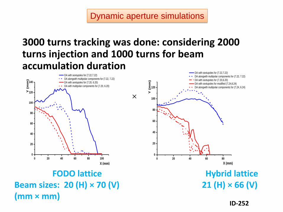
3000 turns tracking was done: considering 2000 turns injection and 1000 turns for beam accumulation duration
0 20 40 60 80 100
0
20
40
60
80
100
120
140
Y (
mm
)
X (mm)
DA with sextupoles for (7.22,7.22)
DA alongwith multipolar components for (7.22, 7.22)
DA with sextupoles for (7.20, 6.20)
DA with multipolar components for (7.20, 6.20)
0 20 40 60 80
0
20
40
60
80
100
120
Y (
mm
)
X (mm)
DA with sextupoles for (7.22,7.22)
DA alongwith multipolar components for (7.22, 7.22)
DA with sextupoles for (7.20,6.20)
DA with sextupoles for modified (7.24,6.24)
DA alongwith multipolar components for (7.24, 6.24)
FODO lattice Hybrid lattice Beam sizes: 20 (H) × 70 (V) 21 (H) × 66 (V) (mm × mm)
×
Dynamic aperture simulations
ID-252

Preliminary Physics Design of HEBT
ID 231

Baem Injection studies
Studies on beam injection and phase space painting for FODO lattice are under progress.
Strength of bumper magnets are obtained on all working points, considering mismatch injection with preferred condition of ainj/binj = aring/bring
ID-230

Beam Injection studies
Major difficulty is the reduction of number of hits on foil per proton. The present optimized
scheme has lesser than 4 hits per proton on the foil (ORBIT simulations). Up to ~6-7 hits
per proton on foil, peak temperature on foil remains below 2000-2100 C (~2300 K).
1 2 3 4 5 6 7 8 9 10 11 121000
1200
1400
1600
1800
2000
2200
2400
Ma
xim
um
Tem
pe
ratu
re (
K)
Number of hits per proton on the foil
0 250 500 750 1000 1250 1500 1750 20000
1
2
3
4
5
6
7
8
9
10
Nu
mb
er
of
hit
s o
n f
oil
per
pro
ton
Turns
Beam in real space after injection painting (2000 turns)

Beam extraction studies
QF_A3
QD_A2 K1-K4 K5-K8 K9-K11
Septum
QF_A3
QD_A3
Quadrupole magnet
Kicker magnet
FODO lattice
QFD
QDA K3-K4 K6-K8 K9-K10
Septum
QF_A3
QDD
K1-K2 K5
QFD1
Hybrid lattice
•Bump of 150 mm is generated
at the location of the extraction
septum
•11 kicker magnets in FODO
lattice and 10 kicker magnets in
Hybrid lattice
•Extraction scheme is able to
work with any two kicker failure
•Maximum kick 4.5 mrad (field <
520 G for 500 mm kicker length)

Preliminary Physics Design of RTBT
Lattice parameters in RTBT
ID-232
Quadrupole AR orbit Ext
Septum (15)
Dipole Magnet
(15)

ID No. Abstract Title
ID-230 Beam Injection Studies for FODO lattice of 1 GeV proton Accumulator Ring
ID-231 Beam optics design studies of the ISNS High Energy Beam Transport line
ID-232 Preliminary optics design of Ring To Target Beam Transport line for a 1GeV Spallation
Neutron Source
ID-245 Error study of a 325 MHz, 3 MeV RFQ for ISNS
ID-246 Field perturbation due to azimuthal asymmetry in SSR cavities
ID-247 Lattice design and beam dynamics simulations for the 1 GeV ISNS SRF LINAC
ID-250 Electromagnetic design studies of fundamental RF power coupler for superconducting
RF cavities
ID-252 Nonlinear studies for lattice of 1GeV Proton Accumulator Ring for Indian Spallation
Neutron Source
ID-253 Analysis of Generation and Effect of Higher Order Modes (HOMs) in Superconducting
Cavities
ID-254 Beam Dynamics Studies on 325 MHz DTL using GenDTL and Tracewin
ID-256 Physics Design Studies of 10 MeV, 325 MHz Drift Tube Linac for the Indian
Spallation Neutron Source
ID-269 On the requirement of high purity level of material for niobium based SRF cavity

Future studies
• Possibility of using a DTL instead of SSRs in the beginning of the injector linac will be
explored with an in-depth study.
• Compact designs of LEBT and MEBT will be explored.
• Detailed beam dynamics studies with realistic 3D field, taking quadrupole asymmetry
and coupler kicks.
• Detailed studies on effect of error in beam injection and positioning and alignment of
lattice elements, along with cavity failure will be performed after finalizing the lattice.
• End to end beam dynamics studies starting from HEBT entrance to beam target
through AR will be performed.
• Detailed studies on beam loss/collimation and beam instability.


![GNP Neuroorthopädie Knecht [Kompatibilitätsmodus] · Duncan – Ely Test Ab welcher Flexion (ROM) hebt sich Gesäss? Normal volle Flexion ohne Gesässanhebung 25 Unterschenkelflexion](https://img.pdfslide.us/doc/110x75/5e1598d589c08477e81c44d3/gnp-neuroorthopdie-knecht-kompatibilittsmodus-duncan-a-ely-test-ab-welcher.jpg)