Embed Size (px)
Citation preview
PROGRAMMING MANUAL
α
PNEUALPHA2
SIMPLE APPLICATION CONTROLLER

α
PneuAlpha2 Simple Application
Foreword
• This manual contains text, diagrams and explanations which will guide the reader in the correct programming and operation of the
α
PneuAlpha2
series controller.• Before attempting to install or use the
α
PneuAlpha2
Series Controller this manual should be read and understood.
• If in doubt at any stage of the installation of the
α
PneuAlpha2
Series Controller always consult a professional electrical engineer who is qualified and trained to local and national standards which apply to the installation site.
• If in doubt about the operation or use of the
α
PneuAlpha2
Series Controller please consult SMC.
• This manual is subject to change without notice.
i
α
PNEUALPHA2 SIMPLE APPLICATION CONTROLLERS
PROGRAMMING MANUAL
Manual number : PROG0903
Manual revision : A
Date : Oct 2003
α
PneuAlpha2 Simple Application Controllers

FAX BACK
SMC Pneumatics has a world wide reputation for its efforts in continually developing and push-ing back the frontiers of industrial automation. What is sometimes overlooked by the user is thecare and attention to detail that is taken with the documentation. However,to continue this pro-cess of improvement, the comments of the SMC users are always welcomed. This page hasbeen designed for you,the reader,to fill in your comments and fax them back to us. We lookforward to hearing from you.
Fax numbers: Your name ...................................................
SMC.... ....................................................................
United Kingdom (01908) 263888
Please tick the box of your choice
What condition did the manual arrive in?
"
Good
"
Minor damage
"
Unusable
Will you be using a folder to store the manual?
"
Yes
"
No
What do you think to the manual presentation?
"
Tidy
"
Un-friendly
Are the explanations understandable?
"
Yes
"
Not too bad
"
Unusable
Which explanation was most difficult to understand: ....................................................................................................................................................................................................................
Are there any diagrams which are not clear?
"
Yes
"
No
If so,which: .................................................................................................................................
What do you think to the manual layout?
"
Good
"
Not too bad
"
Un-helpful
If there one thing you would like to see improved,what is it? ...........................................................................................................................................................................................................................................................................................................................................................
Could you find the information you required easily using the index and/or the contents, ifpossible please identify your experience: ..............................................................................................................................................................................................................................................................................................................................................................................................................................................................................................................................................................................................................................................................................................
Do you have any comments in general about the SMC manuals? ........................................................................................................................................................................................................................................................................................................................................................................................................................................................................................................................................................................................................................................................
Thank you for taking the time to fill out this questionnaire. We hope you found both the productand this manual easy to use.
α
PneuAlpha2
Simple Application Controllers
ii

α
PneuAlpha2 Simple Application Controllers
iii
Guidelines for the safety of the user and protection of
α
PneuAlpha2 s imple Application controllers
This manual provides information for the use of
α
PneuAlpha2 simple Application controllers. The manual has been written to be used by trained and competent personnel. The definition of such a person or persons is as follows;
a ) Any engineer who is responsible for the planning, design and construction of automaticequipment using the product associated with this manual should be of a competentnature, trained and qualified to the local and national standards required to fulfill thatrole. These engineers should be fully aware of all aspects of safety with regards toautomated equipment.
b ) Any commissioning or service engineer must be of a competent nature, trained andqualified to the local and national standards required to fulfill that job. These engineersshould also be trained in the use and maintenance of the completed product. Thisincludes being completely familiar with all associated documentation for the said product.All maintenance should be carried out in accordance with established safety practices.
c ) All operators of the completed equipment should be trained to use that product in a safeand co-ordinated manner in compliance to established safety practices. The operatorsshould also be familiar with documentation which is connected with the actual operationof the completed equipment.
Note :
the term ‘completed equipment’ refers to a third party constructed device whichcontains or uses the product associated with this manual.
Notes on the symbology used in this manual
At various times through out this manual certain symbols will be used to highlight points ofinformation which are intended to ensure the users personal safety and protect the integrity ofequipment. Whenever any of the following symbols are encountered its associated note mustbe read and understood. Each of the symbols used will now be listed with a brief description ofits meaning.
Hardware warnings
1 ) Indicates that the identified danger
WILL
cause physical and property damage.
2 ) Indicates that the identified danger could
POSSIBLY
cause physical and propertydamage.
3 ) Indicates a point of further interest or further explanation.
Software warning
4 ) Indicates special care must be taken when using this element of software.
5 ) Indicates a special point which the user of the associate software element shouldbe aware of.
6 ) Indicates a point of interest or further explanation.

α
PneuAlpha2
Simple Application Controllers
iv

v
Table of Contents
Safety Guidelines ................................................................................ iii
1. Introduction ..............................................................................1-1
1.1 Special Features Display messages and Function Block data ............. 1-11.2 Model Name .......................................................................................... 1-2
2. Function Block Programming ....................................................2-1
2.1 Block Type and the FBD base .............................................................. 2-12.1.1 Inputs ........................................................................................... 2-22.1.2 Front Panel Keys ......................................................................... 2-22.1.3 System Memory Bits .................................................................... 2-32.1.4 Function Blocks ............................................................................ 2-32.1.5 Outputs ........................................................................................ 2-42.1.6 Function Block Diagram (FBD) base ........................................... 2-4
2.2 Programming Methods .......................................................................... 2-52.2.1 Direct Programming ..................................................................... 2-52.2.2 ECC-PNAL-PCS/WIN-E Programming Software Ver 2.00 .......... 2-5
3. System Menu ............................................................................3-1
3.1 Menu Options Instructions .................................................................... 3-13.2 The Stop Mode ..................................................................................... 3-1
3.2.1 Top Menu ..................................................................................... 3-13.2.2 The “Others... ............................................................................... 3-3
3.3 The Run Mode Top Menu ..................................................................... 3-73.4 The Edit Menu ..................................................................................... 3-133.5 The Function Block Edit Menu ............................................................ 3-133.6 Option Screen Setup ........................................................................... 3-13
3.6.1 ProgEdit ..................................................................................... 3-133.6.2 Change the Language Setting ................................................... 3-133.6.3 ClockSET ................................................................................... 3-143.6.4 SummerTime ............................................................................. 3-143.6.5 Password ................................................................................... 3-153.6.6 Serial Com ................................................................................. 3-153.6.7 Memory cassette ........................................................................ 3-16
3.7 LCD Displays ...................................................................................... 3-173.7.1 Image Table ............................................................................... 3-173.7.2 LCD Function ............................................................................. 3-17
3.8 Block Items ......................................................................................... 3-183.8.1 Input Blocks ............................................................................... 3-183.8.2 Function Blocks .......................................................................... 3-183.8.3 Output Blocks ............................................................................. 3-183.8.4 Connected Blocks ...................................................................... 3-18
α
PneuAlpha2 Simple Application Controllers

α
PneuAlpha2
Series Applications Controller
vi
4. Direct Programming ..................................................................4-1
4.1 Block Availability ................................................................................... 4-14.2 Connecting Blocks ................................................................................ 4-1
4.2.1 To connect the blocks from the left block to right block. .............. 4-14.2.2 To connect the blocks from the right block to left block. .............. 4-2
4.3 Disconnect Two Blocks ......................................................................... 4-24.4 Methods to Create a Function Block ..................................................... 4-3
4.4.1 New FB ........................................................................................ 4-34.4.2 AddFB .......................................................................................... 4-3
4.5 Function Block Editing .......................................................................... 4-34.5.1 Setup Function Block ................................................................... 4-34.5.2 Change No. (of a Function Block) ................................................ 4-34.5.3 Delete FB ..................................................................................... 4-3
4.6 Movement between Function Blocks .................................................... 4-44.6.1 Movement Between Unconnected Blocks ................................... 4-44.6.2 Movement Between Connected Blocks ....................................... 4-44.6.3 The Jump Command ................................................................... 4-4
4.7 Using Keys as Inputs ............................................................................ 4-44.8 The Monitor Mode ................................................................................. 4-5
4.8.1 Monitor/Update Function Block Values ........................................ 4-54.8.2 Forcing Outputs ON/OFF ............................................................. 4-64.8.3 Add/Delete Function Blocks in the Monitor Mode ........................ 4-6
5. The Logic Function Blocks ........................................................5-1
5.1 The AND Block ..................................................................................... 5-25.2 The OR Block ........................................................................................ 5-35.3 The NOT Block ..................................................................................... 5-45.4 The XOR Block (Exclusive OR) ............................................................ 5-45.5 The NAND Block (Not AND) ................................................................. 5-55.6 The NOR Block (Not OR) ...................................................................... 5-6
6. Function Blocks .........................................................................6-1
6.1 Definitions ............................................................................................. 6-66.2 Abbreviations ........................................................................................ 6-66.3 Boolean block ....................................................................................... 6-76.4 Set/Reset Block .................................................................................... 6-96.5 Pulse Block ......................................................................................... 6-116.6 Alternate Block .................................................................................... 6-136.7 Delay Block ......................................................................................... 6-146.8 One Shot Block ................................................................................... 6-166.9 Flicker Block ........................................................................................ 6-186.10 TimeSW Block .................................................................................. 6-21
6.10.1 Setting the First Time Switch ................................................... 6-216.10.2 For the Date operation: ............................................................ 6-226.10.3 For the Weekly Operation: ....................................................... 6-226.10.4 To Enter New Time Switches ................................................... 6-226.10.5 To Edit Time Switches ............................................................. 6-236.10.6 To Delete Time Switch Data .................................................... 6-23

α
PneuAlpha2
Series Applications Controller
vii
6.11 Counter Block ................................................................................... 6-246.12 Up/Down Counter Block .................................................................... 6-256.13 Compare Block ................................................................................. 6-276.14 OFFSET Block .................................................................................. 6-296.15 Display Block .................................................................................... 6-32
6.15.1 Displaying Data Onscreen ....................................................... 6-326.15.2 Editing Data Onscreen ............................................................. 6-33
6.16 Zone Compare Block ........................................................................ 6-366.17 Schmitt Trigger Block ........................................................................ 6-386.18 Hour Meter Block .............................................................................. 6-416.19 Speed Detect Block .......................................................................... 6-436.20 Pulse Width Modulation .................................................................... 6-486.21 Retentive Alternate Block .................................................................. 6-506.22 Addition Block ................................................................................... 6-516.23 Subtraction Block .............................................................................. 6-526.24 Multiplication Block ........................................................................... 6-536.25 Division Block .................................................................................... 6-546.26 Calculation Block .............................................................................. 6-556.27 Shift Block ......................................................................................... 6-576.28 GSM SMS Block ............................................................................... 6-59
6.28.1 Input Signal .............................................................................. 6-616.28.2 Output Signal ........................................................................... 6-616.28.3 Word Output ............................................................................. 6-616.28.4 Short Message Service (SMS) ................................................ 6-626.28.5 Comment/Signal Number ......................................................... 6-626.28.6 Setting ...................................................................................... 6-626.28.7 Destination ............................................................................... 6-626.28.8 SMS Setting Dialog Box ........................................................... 6-636.28.9 SMS Service Center ............................................................... 6-636.28.10 Valid Period ............................................................................ 6-636.28.11 Destination ............................................................................. 6-636.28.12 Error Messages ...................................................................... 6-64
6.29 Random One Shot Block .................................................................. 6-706.30 Delayed One Shot Block ................................................................... 6-726.31 Delayed Alternate Block .................................................................... 6-756.32 Retentive Set Reset Block ................................................................ 6-776.33 Control Display Manager .................................................................. 6-79
6.33.1 Operation Image: ..................................................................... 6-806.33.2 To Set Display Manager: ......................................................... 6-81
6.34 Connect Block ................................................................................... 6-87
α
PneuAlpha2
Series Applications Controller
viii
7. Lets Make a Program ................................................................7-1
7.1 Option Settings ..................................................................................... 7-17.2 The Function Block Diagram ................................................................. 7-17.3 Input the Program ................................................................................. 7-2
7.3.1 Adding Function Blocks by the Left to Right method (Section 4.2.1) 7-27.3.2 Scroll through the Function Blocks by Number (Section 4.6.1) ... 7-37.3.3 Use the Jump Command (Section 4.6.3) ..................................... 7-37.3.4 Use the NewFB command ........................................................... 7-47.3.5 Connect the Function Blocks from Right to Left (Section 4.2.2) .. 7-4
7.4 Set up the Function Block Parameters (Section 4.5.1) ......................... 7-57.5 Exit the Function Block Diagram board ................................................. 7-6
8. Appendix ...................................................................................8-1
8.1 Associated Manuals .............................................................................. 8-18.2 System Keys ......................................................................................... 8-28.3 System Bits ........................................................................................... 8-28.4 Boolean Gates ...................................................................................... 8-38.5 Function Blocks ..................................................................................... 8-4

α
PneuAlpha2 Simple Application
Introduction 1
1 - 1
1. Introduction
The
α
PneuAlpha2 Series Controllers provides supervisory control for use in the home, office,
factory or wherever you need it. The
α
PneuAlpha2 series Controllers offers flexible I/O controlfor varied applications:
ApplicationsThe
α
PneuAlpha2 Series is designed to be used for automatic applications including:- Lighting, air-conditioning or watering control- Opening and shutting of gates- Security systems- Domestic systems- Temperature control
However, the
α
PneuAlpha2
Series Controllers is not designed to be used in the followingapplications:
- Applications where high reliabilities such as nuclear power control, railway facilities,airline facilities, vehicles, combustion equipment and medical equipment are required.
- Applications in life critical situations
Please contact SMC Pneumatics for more information.
1.1 Special Features Display messages and Function Block data
1 ) Display messages and Function Block dataThe
α
PneuAlpha2 Series can display the state of operation and the alarm on the LCDscreen as a message. The values of timers and counters can be changed in RUN mode.
- Total characters on LCD display: 12 characters x 4 lines- Display items: Message, values (current or set) of timers and counters, analogue
values, etc.
2 ) Program InputThe user can program directly from the front panel or use the windows basedECC-PNAL-PCS/WIN-E programming software Ver2.00. Pictorial representation of data isused to connect function blocks. Please refer to the
α
PneuAlpha Software Manual.
3 ) Enhancement of clock functionThe weekly and daily calendar timer function allows switch inputs that set the powerfultime dependent control capabilities.
4 ) Analog input, 0-10V/0-500The DC input type for the
α
PneuAlpha2
Series accepts 0-10V signals with a resolution of0-500.
5 ) High Speed Counter, max 1kHzThe
α
PneuAlpha2
Series has two dedicated high speed counters when using ECC-PNAL2-4EX EI1 and EI2.
6 ) High current output Relay output is 8A/COM in the main unit ECC-PNAL2-14MR-*: O01-6, ECC-PNAL2-24MR-D: O01-04 and the transistor output is 1A/point in the extension module.

α
PneuAlpha2 Simple Application
Introduction 1
1 - 2
7 ) GSM FunctionThe
α
PneuAlpha2 Series Controller uses GSM to send a SMS to a mobile phone or adedicated E-mail account via a standard service provider.
8 ) Dedicated ProtocolIntroducing a Communication Device concept in the
α
PneuAlpha2 Series Controllersallowing the user to monitor, modify and enter current and set values in Function Blocksvia dedicated protocol controlled from a personal computer.
9 ) Built-in EEPROMThe built in EEPROM eliminates the need for battery backed data.
10 )Supports 6 languagesThe language option under the TopMenu can be changed to display: English, German,French, Italian, Spanish and Swedish.
11 ) LCD ScreenEnhanced LCD screen size allows the user to view data clearer and permits the
α
PneuAlpha2 Series Controller to display bar graphs and other new intricate data repre-sentation items.
12 )Increased MemoryThe CPU memory for the new
α
PneuAlpha2 Series Controller allows a maximum of 200function blocks to create a program algorithm and contains a 5000 byte capacity memoryon board.
This manual will describe the procedure by which the
α
PneuAlpha2 Series Controllers can beprogrammed from the front panel, the functions of the keys, and the powerful function blockcapabilities.
1.2 Model Name
The
α
PneuAlpha2 Series Controllers can be identified using the following format:
ECC-PNAL2- ** M R - A/D
PNAL2 -
α
PneuAlpha2 Series Controller
**
- Total number of I/O
A - 100~240V AC D - +24V DC
R - Relay Type M -
α
PneuAlpha2in Unit output

α
PneuAlpha2 Simple Application
Function Block Programming 2
2 - 1
2. Function Block Programming
The
α
PneuAlpha2 Series Controller is programmed with a user-friendly method of combiningspecial dedicated purpose function blocks. The task is broken down into various stages whichcan be represented by a number of function blocks. Function Block Programming simplifiesapplication representation but ensures complete process control. The program can bedeveloped in very simple steps but even a complex task can be represented in this way. Forease of use, the function blocks have been preprogrammed to perform certain tasks yet offerflexibility to be tailored to individual requirements.
Figure 1.1: Principle of Function Block Programming
I0n - Input nO0n - Output nOR - OR Boolean Function BlockSR - Set/Reset Function BlockOS - One Shot Function Block
The user can build a complex circuit in small easy steps by starting at the input and workingforward in a logical manner. The
α
PneuAlpha2 will gather and process information and pro-vide the necessary control for the application according to the system algorithm. Each indi-vidual function block provides specific control parameters, accessible by the user, to tailoreach program for complete application suitability. The function blocks are connected togetherto form a circuit using the Function Block Diagram (FBD.)
2.1 Block Type and the FBD base
There are seven sets of items that can be used in the function block program: Inputs, FrontPanel Keys, System Memory Bits, Logic Blocks, Function Blocks, User-defined FunctionBlocks and Outputs. A brief description of each follows.
α
PneuAlpha2 Simple Application
Function Block Programming 2
2 - 2
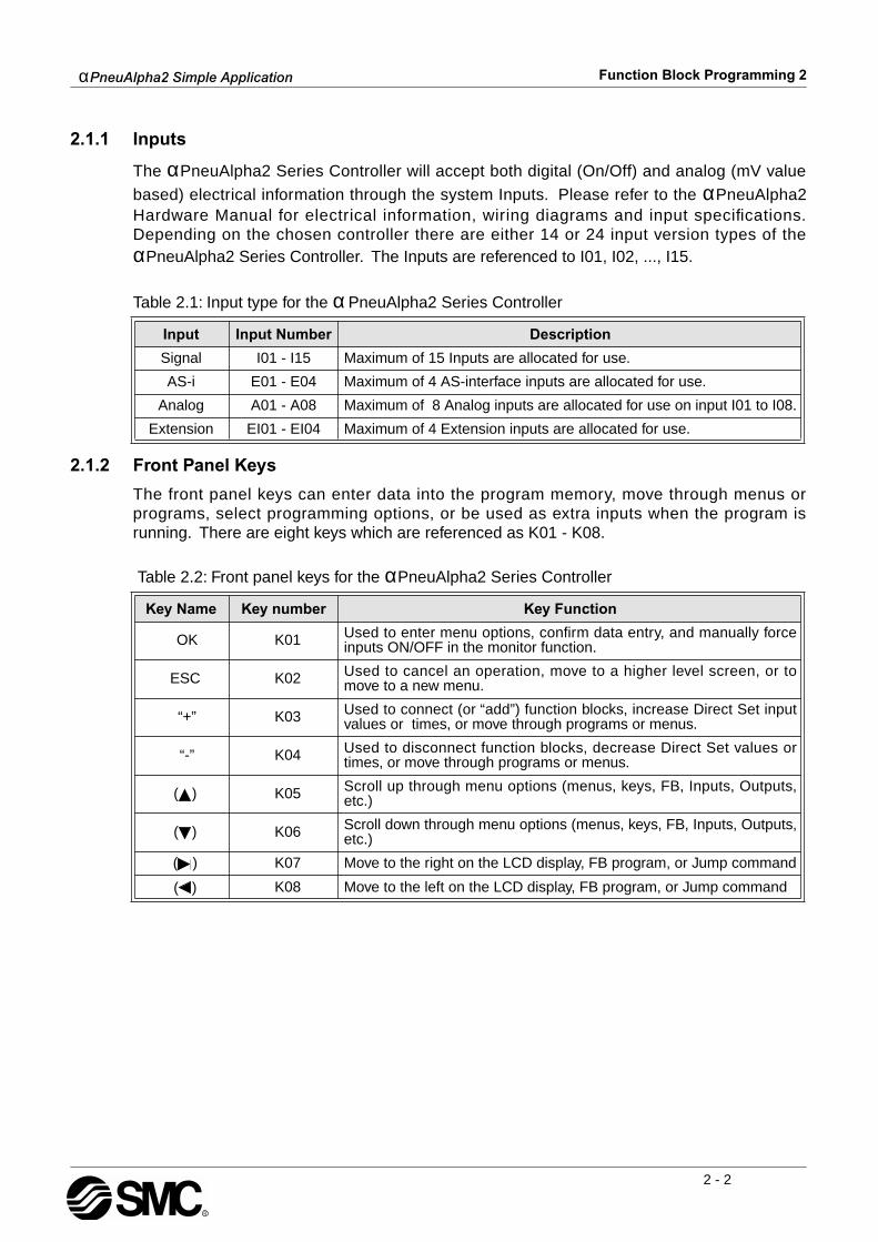
2.1.1 Inputs
The
α
PneuAlpha2 Series Controller will accept both digital (On/Off) and analog (mV value
based) electrical information through the system Inputs. Please refer to the
α
PneuAlpha2Hardware Manual for electrical information, wiring diagrams and input specifications.Depending on the chosen controller there are either 14 or 24 input version types of the
α
PneuAlpha2 Series Controller. The Inputs are referenced to I01, I02, ..., I15.
Table 2.1: Input type for the
α
PneuAlpha2 Series Controller
2.1.2 Front Panel Keys
The front panel keys can enter data into the program memory, move through menus orprograms, select programming options, or be used as extra inputs when the program isrunning. There are eight keys which are referenced as K01 - K08.
Table 2.2: Front panel keys for the
α
PneuAlpha2 Series Controller
Input Input Number Description
Signal I01 - I15 Maximum of 15 Inputs are allocated for use.
AS-i E01 - E04 Maximum of 4 AS-interface inputs are allocated for use.
Analog A01 - A08 Maximum of 8 Analog inputs are allocated for use on input I01 to I08.
Extension EI01 - EI04 Maximum of 4 Extension inputs are allocated for use.
Key Name Key number Key Function
OK K01 Used to enter menu options, confirm data entry, and manually forceinputs ON/OFF in the monitor function.
ESC K02 Used to cancel an operation, move to a higher level screen, or tomove to a new menu.
“+” K03 Used to connect (or “add”) function blocks, increase Direct Set inputvalues or times, or move through programs or menus.
“-” K04 Used to disconnect function blocks, decrease Direct Set values ortimes, or move through programs or menus.
( ) K05 Scroll up through menu options (menus, keys, FB, Inputs, Outputs,etc.)
( ) K06 Scroll down through menu options (menus, keys, FB, Inputs, Outputs,etc.)
( ) K07 Move to the right on the LCD display, FB program, or Jump command
( ) K08 Move to the left on the LCD display, FB program, or Jump command
α
PneuAlpha2 Simple Application
Function Block Programming 2
2 - 3
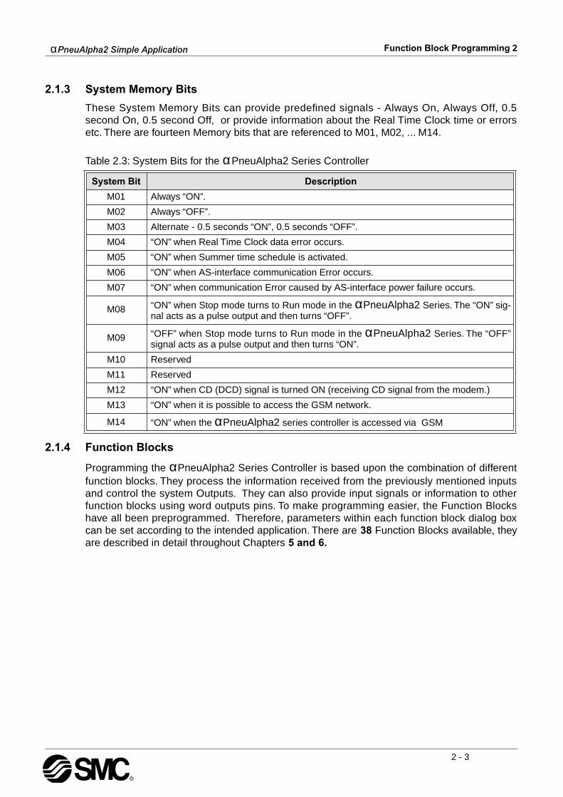
2.1.3 System Memory Bits
These System Memory Bits can provide predefined signals - Always On, Always Off, 0.5second On, 0.5 second Off, or provide information about the Real Time Clock time or errorsetc. There are fourteen Memory bits that are referenced to M01, M02, ... M14.
Table 2.3: System Bits for the
α
PneuAlpha2 Series Controller
2.1.4 Function Blocks
Programming the
α
PneuAlpha2 Series Controller is based upon the combination of differentfunction blocks. They process the information received from the previously mentioned inputsand control the system Outputs. They can also provide input signals or information to otherfunction blocks using word outputs pins. To make programming easier, the Function Blockshave all been preprogrammed. Therefore, parameters within each function block dialog boxcan be set according to the intended application. There are
38
Function Blocks available, theyare described in detail throughout Chapters
5 and 6.
System Bit Description
M01 Always “ON”.
M02 Always “OFF”.
M03 Alternate - 0.5 seconds “ON”, 0.5 seconds “OFF”.
M04 “ON” when Real Time Clock data error occurs.
M05 “ON” when Summer time schedule is activated.
M06 “ON” when AS-interface communication Error occurs.
M07 “ON” when communication Error caused by AS-interface power failure occurs.
M08 “ON” when Stop mode turns to Run mode in the
α
PneuAlpha2
Series. The “ON” sig-nal acts as a pulse output and then turns “OFF”.
M09 “OFF” when Stop mode turns to Run mode in the
α
PneuAlpha2
Series. The “OFF”signal acts as a pulse output and then turns “ON”.
M10 Reserved
M11 Reserved
M12 “ON” when CD (DCD) signal is turned ON (receiving CD signal from the modem.)
M13 “ON” when it is possible to access the GSM network.
M14 “ON” when the
α
PneuAlpha2
series controller is accessed via GSM

α
PneuAlpha2 Simple Application
Function Block Programming 2
2 - 4
2.1.5 Outputs
Table 2.4: Outputs for the
α
PneuAlpha2 Series Controller
Note: *1 When both N02 and N03 are ON and hence the back light is “ON” because N03 isgiven the priority.
2.1.6 Function Block Diagram (FBD) base
The Function Block Diagram provides the base for which all programming actions for the
α
PneuAlpha2 is performed. Both the
α
PneuAlpha2 controller and the ECC-PNAL-PCS/Win-E software use the FBD base. The FBD base contains a Title rectangle on the top, Inputrectangles on the left and Output rectangles on the right. The FBD base is also known as FBDwiring area. All the components should be placed only within the FBD base rectangle exceptfor the input and output signals which can be placed in the FBD wiring area or in the Input orOutput rectangles.
Outputs Description
O01 - 09 Signal output
A01 - 04 AS-interface Output
EO1 - E04 Extension Output
N01ON: Disconnected to AS-interface networkOFF: Connect to AS-interface network
N02*1ON: The back light is “OFF” in LCD.OFF: The back light is controlled by the “Light Time” setting in Menu.
N03*1ON: The back light is “ON” in LCD.OFF: The back light is controlled by the “Light Time” setting in Menu.
N04ON: The user screen is controlled by the setting of “Display Manager” with ECC-
PNAL-PCS/WIN-E.OFF: The user screen is controlled by user program.

α
PneuAlpha2 Simple Application
Function Block Programming 2
2 - 5
2.2 Programming Methods
2.2.1 Direct Programming
Direct Programming uses the keys on the front panel to create the program and enter anyrequired data values. The method for Direct Programming is explained in this manualbeginning at Chapter 4.
2.2.2 ECC-PNAL-PCS/WIN-E Programming Software Ver 2.20
This windows based software allows the user to drag and drop the desired Function Blockicons onto the FBD base and construct a program. The program is downloaded to the
α
PneuAlpha2 controller via the ECC-PNAL-232CAB cable. The visual on-screen connectionsmake the software easy to grasp for beginners and experienced users alike. The ECC-PNAL-PCS/WIN-E Programming Software is fully explained in the
α
Software Manual.
Figure 2.1: ECC-PNAL-PCS/WIN-E Programming Software Ver 2.00
Note: Do not simultaneously program the
α
2
PneuAlpha2 series Controller from the direct programming keys and ECC-PNAL-PCS/WIN-E Ver 2.20 methods as this may cause harm.

α
PneuAlpha2 Simple Application
Function Block Programming 2
2 - 6
MEMO
α
PneuAlpha2 Simple Application
System Menu 3
3 - 1
3. System Menu
3.1 Menu Options Instructions
There are Systems Menus to help guide the user through the options available in the
α
PneuAlpha2. The TopMenu has a Run Mode that is accessed while the
α
PneuAlpha2 is in
operation or a Stop Mode that is accessed when the
α
2
PneuAlpha2 is idle.
The Edit Menu and the Function Block Edit Menu can be accessed when in either ProgEdit orMonitor. These menus can be used to create and/or change programs steps or values.
Use the “OK” key to enter a programming option or to enter data into memory. Set all the data on the screen before using the “OK” key to write the data to the systemmemory. If there are multiple data screens in an option, enter the required data and accepteach screen with the “OK” key.
The “ESC” key will move the screen back to a higher menu option. It will cancel any data inputthat has not been accepted with the “OK” key.
NoteUse the “ESC” key to exit the option to the higher menu; at times, it will be necessary to pressthe “ESC” key a number of times to move to through multiple programming layers.
3.2 The Stop Mode
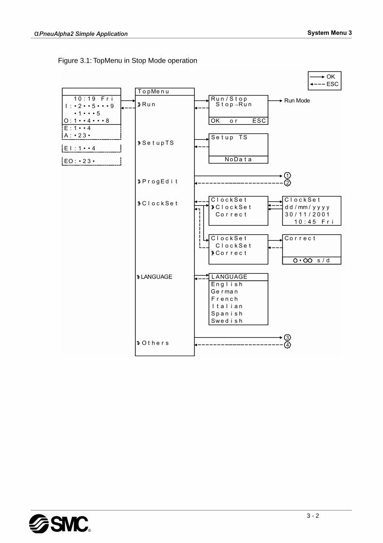
3.2.1 Top Menu
When the
α
PneuAlpha2 is first turned On, the Input/Output Image Table will appear. Pressthe “OK” and “ESC” keys simultaneously to move to the TopMenu. (If the TopMenu cannot be accessed the Menu Key has been set to “Not Use”),
•
Run:
Places the controller in Run mode.
• Setup TS:
Provides a simple method to edit Time Switches from the Top Menu (only selectable if a TSm function block has been chosen.)
•
ProgEdit:
Allows program editing/creation on the display using the front panel keys. The current memory will be overwritten as changes are made to the program. Programs can be saved on an ECC-PNAL2-EEPROM-2 memory cassette or in the ECC-PNAL-PCS/WIN-E soft-ware Version 2.20 or above.
•
ClockSet:
Set the Real Time Clock or input a daily clock adjustment.•
LANGUAGE:
Choose from 6 onscreen languages: English, German, French, Italian, Spanish, or Swedish.
•
Others...
α
PneuAlpha2 Simple Application
System Menu 3
3 - 2
Figure 3.1: TopMenu in Stop Mode operation
•
Run Mode
LANGUAGE
OKESC
1 0 : 1 9 F r iI : R u n
C l o c k S e t
T o pMe n u
S e t u p T S
P r o g E d i t
L ANGUAGE
S e t u p
R u n / S t o p
OK o r ESC
S t o p→R u n
N o D a t a
C l o c k S e tC l o c k S e tC o r r e c t
C l o c k S e tC l o c k S e tC o r r e c t
E n g l i s hGe r ma nF r e n c hI t a l i a nS p a n i s hSw d i s h
C l o c k S e td d / mm / y y y y3 0 / 1 1 / 2 0 0 1
1 0 : 4 5 F r i
C o r r e c t
• s / d
ST
O t h e r s
e
• 2 • • 5 • • 9• 1 • • •
•5
O : 1 • • 4 • • 8•E : 1 • • 4A : • 2 3
E I : • • 41
EO : 2 3 ••
1
2
34

α
PneuAlpha2 Simple Application
System Menu 3
3 - 3
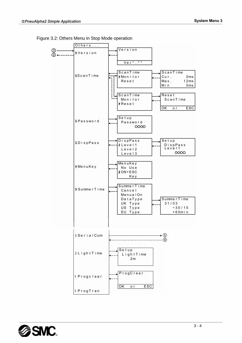
3.2.2 The “Others...
•
Version:
Displays CPU Version of the
α
PneuAlpha2 Series Controller.
• Scan Time:
Monitor the Current, Maximum, or Minimum program scan times. Upon controller reset current, Maximum and Minimum values for scan times are reset to 0.
•
Password:
Restrict entry to the ProgEdit and Monitor mode with a four digit password.
• DispPass:
Set up to three Passwords for Display function blocks. •
Menu Key:
Two settings are possible, “Not Use” or “OK + ESC”. “Not Use” is designed so that unauthorised people cannot access the
α
PneuAlpha2
Top Menu in Run mode. If the “OK + ESC” key setting is selected, simultaneously depress the “OK” and the “ESC” keys to access the Top Menu.
•
Summertime:
Choose the preferred daylight savings time: Cancel, Manual On, Date Type, UK type, US type, or EU type.
•
Serial Com:
Choose the type of communication to be used for the right hand side serial communication port - Not Use, Modem, GSM or Other Com.
•
Light Time:
Set the backlight off delay time.•
ProgClear:
Completely clears the system memory including Password protected programs. Only the active memory is cleared, i.e. if a memory cassette is installed, the memory cassette pro-gram will be erased but the controller memory will be retained.
•
ProgTran. (only appears if a cassette is installed):
Verify,
Cassette
"
(the cassette writes to the
α
PneuAlpha2
), Cassette
#
(the cassette reads from the
α
PneuAlpha2
), and ProtectSW are the options available.
α
PneuAlpha2 Simple Application
System Menu 3
3 - 4
Figure 3.2: Others Menu in Stop Mode operation
O t h e r s . . .
V e r s i o n
S c a n T i me
V e r s i o n
V e r * . * *
S c a n T i meMo n i t o rR e s e t
S c a n T i meC u r . 0msMa x .M i n
1 2ms0ms
S c a n T i meMo n i t o rR e s e t
R e s e tS c a n T i me
OK o r ESC
S e t u pP a s s w o r d
D i s p P a s s
P a s s w o r d
D i s p P a s sL e v e l 1L e v e l 2L e v e l 3
D i s p P a s sL e v e l 1
S e t u p
Me n u K e yMe n u K e y
N oON+
U s eESCK e y
S umme r T i meS umme r T i me
C a n c e lMa n u a l OnD a t a T y p eUK T y p eUS T y p eEU T y p e
S umme r T i me3 1 / 0 3
~ 3 0 / 1 0+ 6 0m i n
3
4
S e r i a l C om
L i g h t T i me
P r o g c l e a rP r o g C l e a r
S e t u pL i g h t T i me
2m
OK o r ESCP r o g T r a n
56
α
PneuAlpha2 Simple Application
System Menu 3
3 - 5
Figure 3.3: Serial Com in Stop Mode operation
Figure 3.4: Communication Format in Stop Mode Operation

α
PneuAlpha2 Simple Application
System Menu 3
3 - 6
Figure 3.5: GSM Menu in Stop Mode operation
Figure 3.6: Communication Format in Stop Mode operation

α
PneuAlpha2 Simple Application
System Menu 3
3 - 7
3.3 The Run Mode Top Menu
When the
α
PneuAlpha2 program is running, the LCD defaults to the Image Table screen.According to the Menu Key setting, proceed to the Stop Mode of the Top Menu by using the“OK” and the “ESC” keys or reset the controller by powering down.
• Stop:
Takes the
α
PneuAlpha2 out of Run mode.
• Setup TS:
Provides a simple method to edit Time Switches from the Top Menu.•
Monitor:
Monitor the program settings while in the Run mode and perform limited editing to FB parameters. The existing programming steps cannot be modified.
• ClockSet:
Set the Real Time Clock or input a daily clock adjustment.
• LANGUAGE:
Choose the on-screen language from English, German, French, Italian, Spanish, or Swedish.
• Others

α
PneuAlpha2 Simple Application
System Menu 3
3 - 8
Figure 3.8: TopMenu in Run Mode Operation

α
PneuAlpha2 Simple Application
System Menu 3
3 - 9
Figure 3.9: Others Menu in Run Mode operation

α
PneuAlpha2 Simple Application
System Menu 3
3 - 10
Figure 3.10: Serial Com in Run Mode operation
Figure 3.11: Communication Format in Run Mode Operation
α
PneuAlpha2 Simple Application
System Menu 3
3 - 11
Figure 3.12: GSM Menu in Run Mode operation
Figure 3.13: Communication Format in Run Mode operation

α
PneuAlpha2 Simple Application
System Menu 3
3 - 12
Figure 3.14: Monitor Screen in Run Mode.

α
PneuAlpha2 Simple Application
System Menu 3
3 - 13
3.4 The Edit Menu
The Edit Menu can be entered when the
α
PneuAlpha2 is in the ProgEdit or Monitor mainprogramming screen. If entering options or connecting FBs, these procedures have to befinished or canceled before the Edit Menu can be entered. Press the “ESC” key at any place inthe main programming screen to enter the Edit Menu.
•
ProgSize:
Shows the numbers of FBs used and percentage of program memory used. •
Jump:
Leads to a screen that shows available places to go in the program. “M” - system bits; “I” - system Inputs; “O” - System Outputs; “K” - Keys (1-8); “E” - ASi Inputs; “A” - ASi Outputs; “N” - Control bits; “EI” - External Board inputs; “EO” - External Board outputs; and “B” - Function Blocks existing in the program. Choose the desired block with the arrow keys and press the “OK” key to jump to that spot in the program.
•
New FB:
Create a new Function Block from one of the available FBs.•
Exit:
Exits to the Top Menu.•
Mnemonic:
Gives a mnemonic display of the current programming rung. Enter the programming mode by pressing the “OK” key or return to the Edit Menu using the “ESC” key. (Not available in Monitor Mode).
3.5 The Function Block Edit Menu
The Function Block Edit Menu can be entered only while in the ProgEdit or Monitor mode.Move to the Function Block to edit and press the “OK” key when the Function Block number isflashing.
•
Setup FB:
Optimise variables in the Function Blocks for your application. See Chapter 6 for more details on each Function Block’s Options. The logic functions in Chapter 5 do not have Setup Options.
•
Change No:
Change the Function Block Number•
Delete FB:
Delete Selected Function Block
3.6 Option Screen Setup
Various options have been provided for ease of use or for safety purposes. Please set as yourneeds require. All of the options in this section can be accessed from either the Run or theStop Menu.
3.6.1 ProgEdit
Refer to the Direct programming chapter 4 for detailed combinations of key presses to be ableto program the
α
PneuAlpha2
Series Controller.
3.6.2 Change the Language Setting
1 ) Turn the αPneuAlpha2 On.2 ) Press the “OK” and “ESC” button to go to the Top Menu or reset the controller.3 ) Scroll to the “LANGUAGE” option and press the “OK” key. The spelling for “LANGUAGE”
does not change.4 ) Scroll to the desired language and press the “OK” key. The languages available are
English, German, French, Italian, Spanish, and Swedish.5 ) Use the “ESC” key to exit to the Topmenu.
αPneuAlpha2 Simple Application System Menu 3
3 - 14
3.6.3 ClockSET
To set the Clock:1 ) From the TopMenu, scroll to “ClockSet” and press the “OK” key.2 ) From the options that appear, choose “ClockSet” and press the “OK” key. 3 ) Use the arrow keys to move an area that needs to be changed.4 ) Adjust with the “+” or “-” keys.5 ) Repeat steps 3-4 until ALL changes have been accomplished.6 ) Press the “OK” key to accept all the changes.7 ) Press the “ESC” key to return to the Top Menu having discarded the clockset options.
To set the daily correction: 1 ) From the TopMenu, scroll to “ClockSet” and press the “OK” key.2 ) From the options that appear, choose “Correct” and press the “OK” key. 3 ) Set the daily correction time with the “+” or “-” keys.4 ) Press the “OK” key to accept the value and press the “ESC” key to return to the Top Menu.
Note: The date setting can be displayed as yyyy/mm/dd, dd/mm/yyyy, or mm/dd/yyyyby manipulating the “+” and “-” keys. The day of the week will update automatically asthe date is changed.
3.6.4 SummerTime
The Summertime menu will display six choices when entered.Cancel - Turns off the Summertime clock setting.Manual On - Moves the clock one hour ahead immediately and will remain ON until cancelled.Date Type - Set the On date, Off date, and Time adjustment.UK Type - Last Sunday of March to the last Sunday of October.US Type - First Sunday of April to the last Sunday of October.EU Type - Last Sunday of March to the last Sunday of October.
The time changes for the UK type take place at 1:00 AM in the Spring and 2:00 AM in theAutumn. Time changes in the EU setting take place at 2:00 AM in the Spring and 3:00 AM inthe Autumn. The date settings are equivalent.If the display time has been adjusted for the Summertime setting, an “s” will precede hournumber on the screen.
How to Set the Summertime Setting:1 ) Select “Others” from the Top Menu. 2 ) Select “Summertime”.3 ) Scroll to the desired setting (see above for information on settings). 4 ) Press the “OK” key to accept.5 ) If the display time has been adjusted, an “s” will precede hour number on the screen. If
the date is outside of the adjustment range, no visible sign will appear.
αPneuAlpha2 Simple Application System Menu 3
3 - 15
3.6.5 Password
The password consists of four digits and will prohibit entry into the ProgEdit, Monitor, DispPass and Serial Com modes only. All other menu options can be accessed when a Passwordis used.
To Enter a Password:1 ) Select “Other” Menu Option.2 ) Select “Password” from the “Other” Menu Options3 ) Use the “+” and “-” keys to enter the desired password.4 ) Press the “OK” key to accept and activate the password.5 ) A key symbol will now be displayed at the top of the αPneuAlpha2 display.
To Cancel a Password:1 ) Select the “Other” Menu Option.2 ) Select “Password” from the “Other” Menu Options. “Cancel Password” should appear on
the top of the screen. 3 ) Use the “+” and “-” keys to enter the current password.4 ) Press the “OK” key to accept and deactivate the password.5 ) The key symbol will be removed from the αPneuAlpha2 display.
Note 1: A Password protected program in an ECC-PNAL2-EEPROM-2 Cassette can be runfrom and be downloaded into the main body of the controller. Note 2: A controller containing a Password protected program can accept or transferprograms to an ECC-PNAL2-EEPROM-2.Note 3: The Password can also be set/deleted from the ECC-PNAL-PCS/WIN-E software ordeleted by the “PROGCLEAR” command.
3.6.6 Serial Com
The modem function capability of the αPneuAlpha2 allows remote monitoring via a PC andprogram upload/download. The communication must take place using the Visual LogicSoftware (VLS) and the communication must be initiated accordingly. (The modem connectedto the αPneuAlpha2 is initialised upon the αPneuAlpha2 start-up. Dialing options from acommand or specific conditions are not available).
Command - Enter the AT command for the modem to be connected to the controller.Reference the Modem User manual for details on that unit’s AT command. Choose the firstletter or symbol by using the ( ) and ( ) arrows. When the symbol is showing in thecommand line, use the ( ) and ( ) arrows to move to adjoining spaces. Enter up to 64 letters/symbols and accept the whole string with the “OK” key when finished inputting the data.(There is no need to accept each letter with the “OK” key).
Delay - The Delay function sets the length of time the αPneuAlpha2 will wait after entering theRun mode before turning on the modem. Choose a value of 0 - 10 seconds using the “+” or “-” keys. The modem connected to the Personal Computer with the VLS software must be setON prior to the αPneuAlpha2 modem turning on.
The GSM function allows a SMS (Short Message Service) message to be sent to either amobile telephone or an email account. The SMS provides the remote user with the identicalLCD screen’s data. Refer to the αPneuAlpha2 Communication Manual for detailed explana-tion concerning GSM parameters.

αPneuAlpha2 Simple Application System Menu 3
3 - 16
The OtherCom function provides the user with an on-line programming feature usingdedicated protocol. Refer to the αPneuAlpha2 Communication Manual for detailed explana-tion concerning Dedicated Protocol parameters.
3.6.7 Memory cassette
The Memory Cassette EEPROM is the active memory whenever it is properly installed inthe αPneuAlpha2 controller. The controller must be Powered down before installing/removing the memory cassette or an error will occur.
To Verify a Program:
1 ) Install the ECC-PNAL2-EEPROM-2. Refer to the ECC-PNAL2-EEPROM-2 instructionmanual.
2 ) Select “Others” in the Top Menu.3 ) Select “ProgTran.”4 ) Select “Verify”.5 ) Choose “OK” to proceed or “ESC” to exit.6 ) If the program is successfully verified, the work “Completed” will blink on screen.7 ) If the programs are not the same, the words “Verify Error” will blink onscreen.
To Transfer a Program from the Cassette to the αPneuAlpha2:
1 ) Install the ECC-PNAL2-EEPROM-2. Refer to the ECC-PNAL2-EEPROM-2 instructionmanual.
2 ) Select “Others” in the Top Menu.3 ) Select “ProgTran.”4 ) Select “Cassette→”.5 ) Choose “OK” to proceed or “ESC” to exit.6 ) When the program is successfully transferred, “Completed” will blink on the display.
To Transfer a Program from the αPneuAlpha2 to the Cassette:
1 ) Install the ECC-PNAL2-EEPROM-2. Refer to the ECC-PNAL2-EEPROM-2 instructionmanual.
2 ) Select “Others” in the Top Menu.3 ) Select “ProgTran.”4 ) Select “Cassette←”.5 ) Choose “OK” to proceed or “ESC” to exit.6 ) When the program is successfully transferred, “Completed” will blink on the display.
To apply the “ProtectSW” Feature:The “ProtectSW” will write protect the program in the memory cassette. The program cannotbe edited nor erased when the feature is ON.
1 ) Install the ECC-PNAL2-EEPROM-2 per the instruction manual.2 ) Select “Others” in the Top Menu.3 ) Select “ProgTran.”4 ) 4. Select “ProtectSW”.5 ) Choose “On“ to activate the feature.
αPneuAlpha2 Simple Application System Menu 3
3 - 17
To Remove the “ProtectSW” Feature:
1 ) Install the ECC-PNAL2-EEPROM-2. Refer to the ECC-PNAL2-EEPROM-2 instructionmanual.
2 ) Select “Others” in the Top Menu.3 ) Select “ProgTran.”4 ) Select “ProtectSW”.5 ) Choose “Off“ to de-activate the feature.
3.7 LCD Displays
There are a number of types of data and/or information that can be displayed on the LCDdisplay besides the menus listed previously.
3.7.1 Image Table
The first LCD display to appear is the Input/Output image table and the Real Time Clock. Theclock shows the current time as Set by the User. The Summertime mode is shown by an “s”preceding the time if activated.
3.7.2 LCD Function
Display up to 12 different letters or characters on each of four lines. Options include characterstrings (design your own message), function block data, or analog data.
αPneuAlpha2 Simple Application System Menu 3
3 - 18
3.8 Block Items
Each block item contains an individual diagram that shows the block number, available numberof input pins, the output pin if applicable, and the block mnemonic. Connections betweenblocks can be viewed at the pin locations when connected blocks are shown individually on theLCD.
3.8.1 Input Blocks
The Input Blocks consist of System Inputs (I01 - I15), Key Inputs (K01-K08), and System Bits(M01-M14). The input number is shown in the top right hand corner, the type of input in thelower right hand corner, and the output pin is shown on the far right of the block. Input Blocksprovide information to the Function Blocks or Outputs.
3.8.2 Function Blocks
The individual Function Blocks are described in detail in Chapters 5 and 6. Function Blockscan have from 0 to 4 input pins shown on the left of the diagram and an output shown on thefar right. Some function blocks have data that can be used for comparison purposes only orare used to display data onscreen. These blocks have no output pins. The number and blockmnemonic are shown in the top right and bottom right locations respectively.
3.8.3 Output Blocks
Output Blocks have one input and one output pin. They only have the capacity for one inputsignal through the input pin. The Output Block number and Mnemonic are shown in the topright and lower right hand corner of the diagram respectively.
3.8.4 Connected Blocks
Blocks that are connected can be shown simultaneously onscreen. The block providing theoutput signal will be shown on the left of the screen. The input pin accepting the signal willflash. Any input pin that is already connected will be shown as a solid triangle.

α
PneuAlpha2 Simple Application
Direct Programming 4
4 - 1
4. Direct Programming
The
α
PneuAlpha2 can be programmed using the front panel keys on the
α
PneuAlpha2 seriescontroller. When the function block diagram is complete, the program can be logically enteredinto the
α
PneuAlpha2. The following sections will describe how to connect/disconnect functionblocks, set program parameters, add Function Blocks, and move around within the program.The ProgEdit mode in the Stop Menu has full programming capability. The Monitor mode in theRun Menu has the capability to manipulate Function Block values and settings but cannot edit,change, or delete the existing program.
4.1 Block Availability
The number of System Inputs and Outputs is determined by the type of controller beingprogrammed. Configurations include 8 In / 6 Out and 15 In / 9 Out. Up to 200 Function Blockscan be used in a program or 5000 bytes of memory. The Function Blocks must be added in thecourse of programming. The 8 Keys and the 14 system M bits are automatically available forevery program. Inputs, Outputs, System Memory Bits, Extended Inputs, Extended Outputs, AS-i Outputs,Control Bits, and Keys do not count in the Function Block total.
4.2 Connecting Blocks
Any block that has an output pin can be connected to any block that has an (unused) input pin.System Inputs, Keys, and Memory M bits have output pins only.Function Blocks and Outputs both contain input and output pins (the Display and TimeSwitchBlocks are exceptions). Blocks can be connected beginning with an output pin, from “left toright” on the display, or beginning with an input pin, from “right to left” on the display.
4.2.1 To connect the blocks from the left (signal provider) block to right (signal receiver) block.
It is necessary to choose the block to provide the output (step 1), the block to accept the signal(step 2), and the pin with which to accept the signal (step 3).
1 ) Step 1: Select the block providing the data to be output and move to the right until theoutput pin is flashing. Press the “+” button to “add” a block.
2 ) Step 2: Choices will appear on the right side of the screen that include System Outputs (ifavailable), existing Function Blocks that have free input pins, and the option to add a newfunction block (AddFB, see section 4.4). Scroll to the preferred option and select using the“OK” key.
α
PneuAlpha2 Simple Application
Direct Programming 4
4 - 2
3 ) Step 3: The block accepting the signal will display as many of its input pins as possible (attimes they will not all fit on-screen). Pins that have been used will show as filledtriangles; pins that are open will show as “>” signs. A “Connect” prompt will appear on-screen, either above or below the left hand block. The current input choice will flash. Scrollto the desired pin and press the “OK” key to accept. The process is complete.
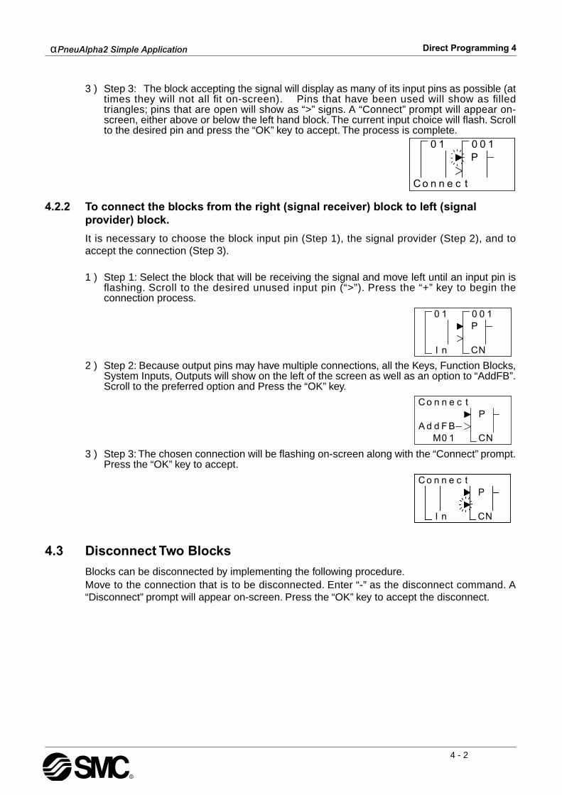
4.2.2 To connect the blocks from the right (signal receiver) block to left (signal provider) block.
It is necessary to choose the block input pin (Step 1), the signal provider (Step 2), and toaccept the connection (Step 3).
1 ) Step 1: Select the block that will be receiving the signal and move left until an input pin isflashing. Scroll to the desired unused input pin (“>”). Press the “+” key to begin theconnection process.
2 ) Step 2: Because output pins may have multiple connections, all the Keys, Function Blocks,System Inputs, Outputs will show on the left of the screen as well as an option to “AddFB”.Scroll to the preferred option and Press the “OK” key.
3 ) Step 3: The chosen connection will be flashing on-screen along with the “Connect” prompt.Press the “OK” key to accept.
4.3 Disconnect Two Blocks
Blocks can be disconnected by implementing the following procedure.Move to the connection that is to be disconnected. Enter “-” as the disconnect command. A“Disconnect” prompt will appear on-screen. Press the “OK” key to accept the disconnect.
nn
nI
P
NC
oC tce

α
PneuAlpha2 Simple Application
Direct Programming 4
4 - 3
4.4 Methods to Create a Function Block
The two methods of creating a Function Block. The New FB option in the Edit Menu andAddFB option when connecting two blocks.
4.4.1 New FB
To use the New FB option, proceed to the Edit Menu (Chapter 3) using the “ESC” key. Scroll tothe New FB option and press the “OK” key. Scroll to the desired Function Block and press the“OK” key to create a New FB. The block will appear on the Function Block Diagram board.
4.4.2 AddFB
When connecting a Function Block, scroll to the AddFB prompt and press the “OK” key. Thisinvokes the Function Block list. Scroll to the desired Function Block and choose by pressingthe “OK” key. The Function Block will be shown on the screen with the connecting block.
4.5 Function Block Editing
To enter the Function Block editing menu (Chapter 3), press the “OK” key when the FunctionBlock number and name is flashing on the screen. Up to three options appear on-screen:Setup FB, Change No, and Delete FB. The Setup Function option is not valid for someFunction blocks and so will not always appear and certain function blocks will also contain aTime unit option (refer to chapter 6 for function block specification).
4.5.1 Setup Function Block
Each Function Block has its own individual parameters outlined in Chapter 6. The FunctionBlocks might have multiple data screens that can be optimised. As with other menu options,the “ESC” key will move the screen back to a higher menu option without changing the optionparameters for that screen. If there are multiple data screens in an option, enter the requireddata and accept each screen using the “OK” key. Use the “ESC” key to exit the Function Block“OK” button.
4.5.2 Change No. (of a Function Block)
Change the number of an existing Function Block with this screen. The current FB number isshown on-screen when the option is entered. Scroll up or down with the “+” or “-” keys to findan open FB number. Press the “OK” key to accept the new number.
4.5.3 Delete FB
This menu option will Delete the current Function Block. After the Delete FB is chosen, confirmthe delete operation with “OK” or use the “ESC” key to cancel the function. All connections tothe Function Block will be removed with the block.
α
PneuAlpha2 Simple Application
Direct Programming 4
4 - 4
4.6 Movement between Function Blocks
There are a number of ways to move from one item to another when in the ProgEdit or Monitormodes.
4.6.1 Movement Between Unconnected Blocks
Movement between System Inputs, System Outputs, Keys, and M bits can be accomplishedwith the “+” and “-” keys. When the block number is flashing on-screen, press the “+” key toscroll to the higher value of the same block type; e.g. move from I01 to I02 to I03...until thehighest value is reached. The scroll will then proceed to the lowest value of the next block type.The same technique will work for the “-” key in the opposite direction.Function Blocks can be scrolled through in the same manner, although only the FunctionBlocks are rotated through in this case.
4.6.2 Movement Between Connected Blocks
The Right arrow moves horizontally (to the right) along the path of connections betweenblocks. If an output pin is connected to multiple input pins, the current path will flash. The Upand Down arrows can be used to choose the desired path. The left arrow will move back alongthe path of the connections to the left.
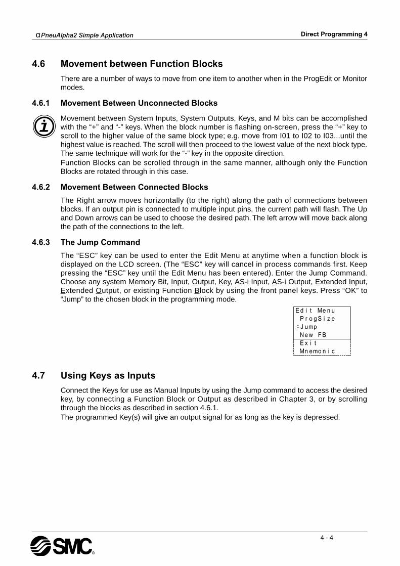
4.6.3 The Jump Command
The “ESC” key can be used to enter the Edit Menu at anytime when a function block isdisplayed on the LCD screen. (The “ESC” key will cancel in process commands first. Keeppressing the “ESC” key until the Edit Menu has been entered). Enter the Jump Command.Choose any system Memory Bit, Input, Output, Key, AS-i Input, AS-i Output, Extended Input,Extended Output, or existing Function Block by using the front panel keys. Press “OK” to“Jump” to the chosen block in the programming mode.
4.7 Using Keys as Inputs
Connect the Keys for use as Manual Inputs by using the Jump command to access the desiredkey, by connecting a Function Block or Output as described in Chapter 3, or by scrollingthrough the blocks as described in section 4.6.1. The programmed Key(s) will give an output signal for as long as the key is depressed.

α
PneuAlpha2 Simple Application
Direct Programming 4
4 - 5
4.8 The Monitor Mode
Function Block values and Output status can be manipulated from the Monitor option.
When placed in the Run mode, the
α
PneuAlpha2 defaults back to the I/O status screen. Pressthe “ESC and OK” keys together to enter the Top Menu and then enter Monitor. The programwill now be displayed on-screen. Movement among the function blocks is the same as in theProgEdit mode.
4.8.1 Monitor/Update Function Block Values
Move to the function block to monitor and enter Setup FB. The Function Block Values can beupdated and monitored. Changes to current values will be valid only while in the MonitorMode. Changes to Set point data and the comparison values will be written to the systemmemory.
(1) It is possible to force ON/OFF, however, the status is decided by hardware control.(2) It is possible to force ON/OFF, however, the status is decided by programming control.(3) It is not possible to force ON/OFF.
Type Abbreviated Terms Forcing Conditions
Input I 1
EI 1
E 2
Output O 2
E0 2
A 2
Key K 3
System bit M 3
Control bit N 2
Function Block B 3
α
PneuAlpha2 Simple Application
Direct Programming 4
4 - 6
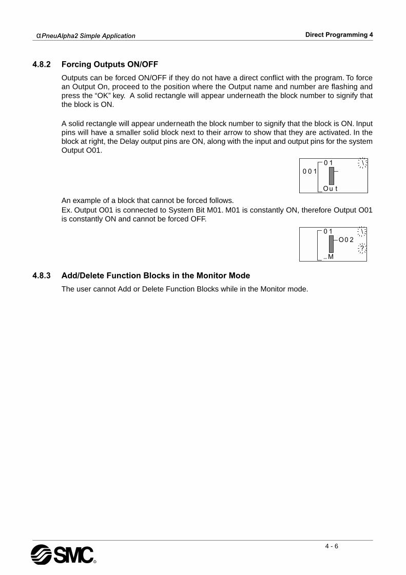
4.8.2 Forcing Outputs ON/OFF
Outputs can be forced ON/OFF if they do not have a direct conflict with the program. To forcean Output On, proceed to the position where the Output name and number are flashing andpress the “OK” key. A solid rectangle will appear underneath the block number to signify thatthe block is ON.
A solid rectangle will appear underneath the block number to signify that the block is ON. Inputpins will have a smaller solid block next to their arrow to show that they are activated. In theblock at right, the Delay output pins are ON, along with the input and output pins for the systemOutput O01.
An example of a block that cannot be forced follows. Ex. Output O01 is connected to System Bit M01. M01 is constantly ON, therefore Output O01is constantly ON and cannot be forced OFF.
4.8.3 Add/Delete Function Blocks in the Monitor Mode
The user cannot Add or Delete Function Blocks while in the Monitor mode.
α
PneuAlpha2 Simple Application
The Logic Function Blocks 5
5 - 1
5. The Logic Function Blocks
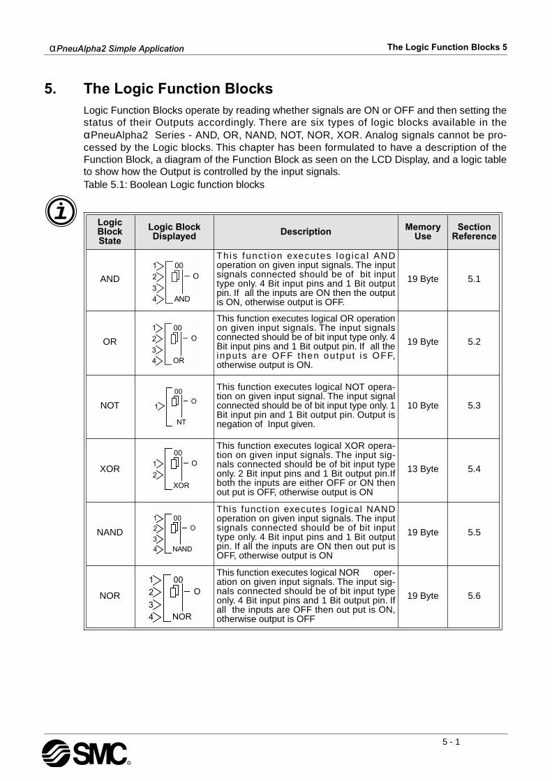
Logic Function Blocks operate by reading whether signals are ON or OFF and then setting thestatus of their Outputs accordingly. There are six types of logic blocks available in the
α
PneuAlpha2 Series - AND, OR, NAND, NOT, NOR, XOR. Analog signals cannot be pro-cessed by the Logic blocks. This chapter has been formulated to have a description of theFunction Block, a diagram of the Function Block as seen on the LCD Display, and a logic tableto show how the Output is controlled by the input signals.Table 5.1: Boolean Logic function blocks
Logic Block State
Logic Block Displayed Description Memory
UseSection
Reference
AND
This funct ion executes log ica l ANDoperation on given input signals. The inputsignals connected should be of bit inputtype only. 4 Bit input pins and 1 Bit outputpin. If all the inputs are ON then the outputis ON, otherwise output is OFF.
19 Byte 5.1
OR
This function executes logical OR operationon given input signals. The input signalsconnected should be of bit input type only. 4Bit input pins and 1 Bit output pin. If all theinputs are OFF then output is OFF,otherwise output is ON.
19 Byte 5.2
NOT
This function executes logical NOT opera-tion on given input signal. The input signalconnected should be of bit input type only. 1Bit input pin and 1 Bit output pin. Output isnegation of Input given.
10 Byte 5.3
XOR
This function executes logical XOR opera-tion on given input signals. The input sig-nals connected should be of bit input typeonly. 2 Bit input pins and 1 Bit output pin.Ifboth the inputs are either OFF or ON thenout put is OFF, otherwise output is ON
13 Byte 5.4
NAND
This function executes logical NANDoperation on given input signals. The inputsignals connected should be of bit inputtype only. 4 Bit input pins and 1 Bit outputpin. If all the inputs are ON then out put isOFF, otherwise output is ON
19 Byte 5.5
NOR
This function executes logical NOR oper-ation on given input signals. The input sig-nals connected should be of bit input typeonly. 4 Bit input pins and 1 Bit output pin. Ifall the inputs are OFF then out put is ON,otherwise output is OFF
19 Byte 5.6

α
PneuAlpha2 Simple Application
The Logic Function Blocks 5
5 - 2
5.1 The AND Block
The AND block comes ON when all the inputs are ON.Any Input that is OFF will keep the Output turned OFF.Unused inputs are considered to be ON.If no Input pins are connected, the block output is OFF.
Table 5.2: AND Logic gate
Input 1 Input 2 Input 3 Input 4 Output
On On On On On
On On On Off Off
On On Off On Off
On Off On On Off
Off On On On Off
On On Off Off Off
On Off Off On Off
Off Off On On Off
Off On On Off Off
On Off On Off Off
Off On Off On Off
On Off Off Off Off
Off On Off Off Off
Off Off On Off Off
Off Off Off On Off
Off Off Off Off Off

α
PneuAlpha2 Simple Application
The Logic Function Blocks 5
5 - 3
5.2 The OR Block
The Output comes ON when any input is ON.The Output remains OFF only if all the inputs are OFF.Unused Inputs are considered to be OFF
Table 5.3: OR Logic gate
Input 1 Input 2 Input 3 Input 4 Output
On On On On On
On On On Off On
On On Off On On
On Off On On On
Off On On On On
On On Off Off On
On Off On Off On
On Off Off On On
Off On On Off On
Off On Off On On
Off Off On On On
On Off Off Off On
Off On Off Off On
Off Off On Off On
Off Off Off On On
Off Off Off Off Off

α
PneuAlpha2 Simple Application
The Logic Function Blocks 5
5 - 4
5.3 The NOT Block
The NOT block takes a signal and inverts it - an Input that is ON has anOutput that is OFF, and vice versa.The Output comes ON when the input is OFF.The Output is OFF when the input is ON.If no Input pin is used, the block output is OFF.The electrical circuit for a NOT block is the same as a Normally Closedinput.Table 5.4: NOT Logic gate
5.4 The XOR Block (Exclusive OR)
The Output comes ON when one input is ON and one is OFF. The Outputremains OFF when both Inputs are equivalent (either both ON or bothOFF).Unused Inputs are considered to be OFF.Table 5.5: XOR Logic gate
Input Output
On Off
Off On
Input 1 Input 2 Output
On On Off
On Off On
Off On On
Off Off Off

α
PneuAlpha2 Simple Application
The Logic Function Blocks 5
5 - 5
5.5 The NAND Block (Not AND)
The Output comes ON if any or all inputs are OFF.If every input is ON, the Output turns OFF.Unused Inputs are considered to be ON.If no Input pin is used, the block output is OFF.(This is equivalent to an AND block followed by a NOT block)
.Table 5.6: NAND Logic gate
Input 1 Input 2 Input 3 Input 4 Output
On On On On Off
Off Off Off Off On
On On On Off On
On On Off On On
On Off On On On
Off On On On On
On On Off Off On
On Off On Off On
On Off Off On On
Off On On Off On
Off On Off On On
Off Off On On On
On Off Off Off On
Off On Off Off On
Off Off On Off On
Off Off Off On On
α
PneuAlpha2 Simple Application
The Logic Function Blocks 5
5 - 6
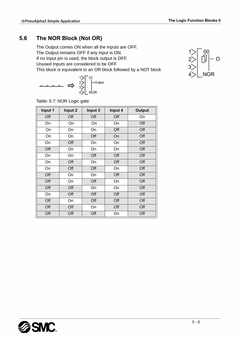
5.6 The NOR Block (Not OR)
The Output comes ON when all the inputs are OFF.The Output remains OFF if any input is ON.If no Input pin is used, the block output is OFF.Unused Inputs are considered to be OFFThis block is equivalent to an OR block followed by a NOT block
Table: 5.7: NOR Logic gate
Input 1 Input 2 Input 3 Input 4 Output
Off Off Off Off On
On On On On Off
On On On Off Off
On On Off On Off
On Off On On Off
Off On On On Off
On On Off Off Off
On Off On Off Off
On Off Off On Off
Off On On Off Off
Off On Off On Off
Off Off On On Off
On Off Off Off Off
Off On Off Off Off
Off Off On Off Off
Off Off Off On Off

α
PneuAlpha2 Simple Application
Function Blocks 6
6 - 1
6. Function Blocks
The
α
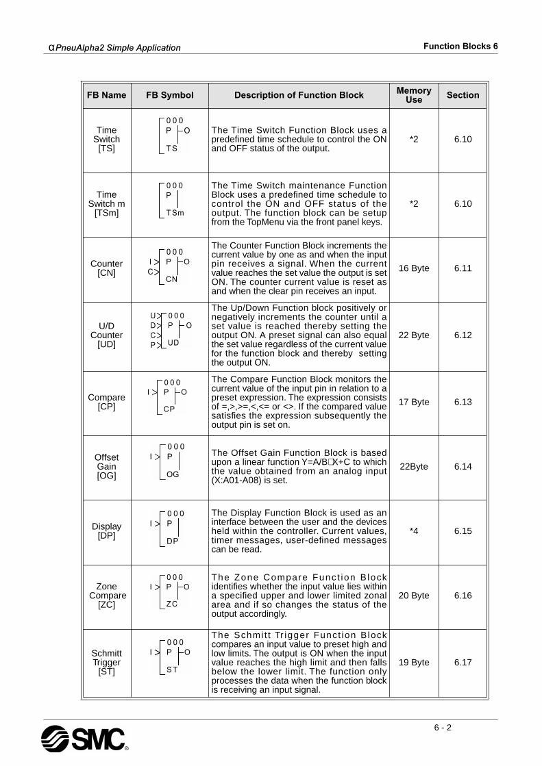
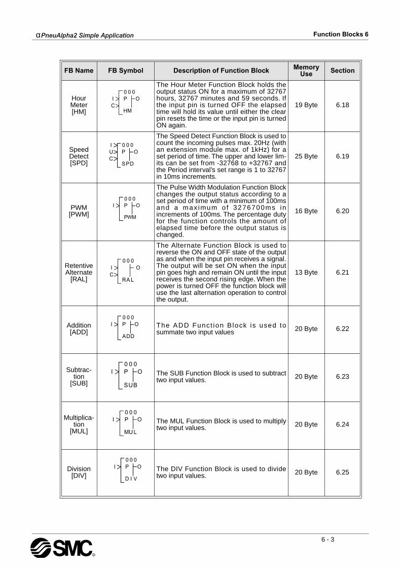
PneuAlpha2 series controller is fundamentally based on function block programming.The blocks provide a wide range of possible operations and have been preprogrammed forease of use. Some Function Blocks have parameters that can be tailored to meet individualrequirements in the programs. Each function block will have a description of the Block’spurpose, a diagram of how the Block will appear on-screen, and a description of the inputs,outputs, and available options.Table 6.1: Function Block List
FB Name FB Symbol Description of Function Block Memory Use Section
Boolean[BL]
The Boolean Function Block uses Booleanalgebra to control the ON/OFF state of anoutput. An operational expression consistsof either the AND, OR, NOR, XOR or NOTform.
*1 6.3
Set/Reset[SR]
The Set/Reset Function Block either holdsan output ON (set) or releases the outputOFF (reset.) Priority can be given to eitherinput pin if both inputs have been energisedsimultaneously. The default priority settingis dedicated to the reset input pin.
14 Byte 6.4
Pulse[PL]
The Pulse Function Block sends a singlepulse to the output pin if the input pinreceives either an “ON to OFF”, “OFF toON” or “ON to OFF And OFF to ON” inputoperation.
10 Byte 6.5
Alternate[AL]
The Alternate Function Block is used toreverse the ON and OFF state of the outputas and when the input pin receives a signal.The output will be set ON when the inputpin goes high and remain ON until the inputreceives the second rising edge.
13 Byte 6.6
Delay[DL]
The Delay Function Block provides an ONdelay timer and an OFF delay timer. Timeintervals for either situation can be set. Thetime unit can be set to 10ms, 100ms or 1sincrements.
19 Byte 6.7
One Shot[OS]
The One Shot Function Block awaits asignal supplied to the input pin thereaftersetting the output according to the specifiedtime. The timing parameters control thestate of the output (depending on thepriority setting). The time unit can be set to10ms, 100ms or 1s increments.
17 Byte 6.8
Flicker[FL]
The Flicker Function Block changes the ONand OFF state of the output according to apreset flicker time. The time unit can be setto 10ms, 100ms or 1s increments.
19 Byte 6.9
α
PneuAlpha2 Simple Application
Function Blocks 6
6 - 2
Time Switch[TS]
The Time Switch Function Block uses apredefined time schedule to control the ONand OFF status of the output.
*2 6.10
Time Switch m
[TSm]
The Time Switch maintenance FunctionBlock uses a predefined time schedule tocontrol the ON and OFF status of theoutput. The function block can be setupfrom the TopMenu via the front panel keys.
*2 6.10
Counter[CN]
The Counter Function Block increments thecurrent value by one as and when the inputpin receives a signal. When the currentvalue reaches the set value the output is setON. The counter current value is reset asand when the clear pin receives an input.
16 Byte 6.11
U/D Counter
[UD]
The Up/Down Function block positively ornegatively increments the counter until aset value is reached thereby setting theoutput ON. A preset signal can also equalthe set value regardless of the current valuefor the function block and thereby settingthe output ON.
22 Byte 6.12
Compare[CP]
The Compare Function Block monitors thecurrent value of the input pin in relation to apreset expression. The expression consistsof =,>,>=,<,<= or <>. If the compared valuesatisfies the expression subsequently theoutput pin is set on.
17 Byte 6.13
Offset Gain[OG]
The Offset Gain Function Block is basedupon a linear function Y=A/B
∗
X+C to whichthe value obtained from an analog input(X:A01-A08) is set.
22Byte 6.14
Display[DP]
The Display Function Block is used as aninterface between the user and the devicesheld within the controller. Current values,timer messages, user-defined messagescan be read.
*4 6.15
Zone Compare
[ZC]
The Zone Compare Func t ion B lockidentifies whether the input value lies withina specified upper and lower limited zonalarea and if so changes the status of theoutput accordingly.
20 Byte 6.16
Schmitt Trigger
[ST]
The Schmi t t Tr igger Funct ion Blockcompares an input value to preset high andlow limits. The output is ON when the inputvalue reaches the high limit and then fallsbelow the lower limit. The function onlyprocesses the data when the function blockis receiving an input signal.
19 Byte 6.17
FB Name FB Symbol Description of Function Block Memory Use Section
α
PneuAlpha2 Simple Application
Function Blocks 6
6 - 3
Hour Meter[HM]
The Hour Meter Function Block holds theoutput status ON for a maximum of 32767hours, 32767 minutes and 59 seconds. Ifthe input pin is turned OFF the elapsedtime will hold its value until either the clearpin resets the time or the input pin is turnedON again.
19 Byte 6.18
Speed Detect[SPD]
The Speed Detect Function Block is used tocount the incoming pulses max. 20Hz (withan extension module max. of 1kHz) for aset period of time. The upper and lower lim-its can be set from -32768 to +32767 andthe Period interval’s set range is 1 to 32767in 10ms increments.
25 Byte 6.19
PWM[PWM]
The Pulse Width Modulation Function Blockchanges the output status according to aset period of time with a minimum of 100msand a max imum o f 3276700ms inincrements of 100ms. The percentage dutyfor the function controls the amount ofelapsed time before the output status ischanged.
16 Byte 6.20
Retentive Alternate
[RAL]
The Alternate Function Block is used toreverse the ON and OFF state of the outputas and when the input pin receives a signal.The output will be set ON when the inputpin goes high and remain ON until the inputreceives the second rising edge. When thepower is turned OFF the function block willuse the last alternation operation to controlthe output.
13 Byte 6.21
Addition[ADD]
The ADD Funct ion Block is used tosummate two input values 20 Byte 6.22
Subtrac-tion
[SUB]
The SUB Function Block is used to subtracttwo input values. 20 Byte 6.23
Multiplica-tion
[MUL]
The MUL Function Block is used to multiplytwo input values. 20 Byte 6.24
Division[DIV]
The DIV Function Block is used to dividetwo input values. 20 Byte 6.25
FB Name FB Symbol Description of Function Block Memory Use Section

α
PneuAlpha2 Simple Application
Function Blocks 6
6 - 4
Calcula-tion
[CAL]
The CAL Function Block is used to performa calculation from the combination ofdifferent Arithmetic function blocks.
*3 6.26
Shift[SFT]
This Shift Function Block is used to transferthe Shift Input status just before the Inputsignal is set ON.It has a bit input pin, a shiftinput pin, a set input pin, a reset input pinand a bit output pin.
19 Byte 6.27
SMS[SMS]
The GSM SMS Function Block sends theLCD screen as a SMS message to either amobile phone handset or an E-mail accountfor remote maintenance purposes.
*6 6.28
Random One Shot
[ROS]
The Random One Shot Function Blockemits a random length single pulse to theoutput.
19 Byte 6.29
Delayed One Shot
[DOS]
The Delayed One Shot Function Blockemits a single pulse after a controlled delayto the output.
20 Byte 6.30
Delayed Alternate
[DAL]
The Delayed Alternate Function Blockalternates the status of the output with eachpulse after a controlled delay.
16 Byte 6.31
Retentive Set/Reset
[RSR]
The Set/Reset Function Block either holdsan output ON (set) or releases the outputOFF (reset.) Priority can be given to eitherinpu t p in i f bo th inpu ts have beenenergised. The default priority setting isdedicated to the reset input pin. When thepower is turned OFF the function block willuse the last set or reset operation to controlthe output.
14 Byte 6.32
Control Display[CDP]
The Control Display Function allows theuser to control the LCD image screens. Thefunc t ion b lock can on ly be se t inECC-PNAL-PCS/WIN-E software for AlphaSeries Controllers. When control bit N04 isON, it then possible to control the displayedUser Screen.
*5 6.33
FB Name FB Symbol Description of Function Block Memory Use Section
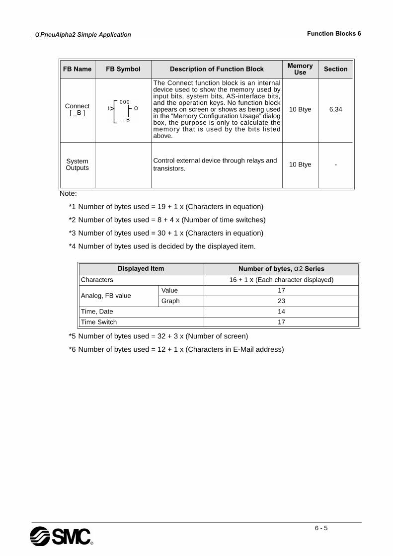
α
PneuAlpha2 Simple Application
Function Blocks 6
6 - 5
Note:
*1 Number of bytes used = 19 + 1 x (Characters in equation)
*2 Number of bytes used = 8 + 4 x (Number of time switches)
*3 Number of bytes used = 30 + 1 x (Characters in equation)
*4 Number of bytes used is decided by the displayed item.
*5 Number of bytes used = 32 + 3 x (Number of screen)
*6 Number of bytes used = 12 + 1 x (Characters in E-Mail address)
Connect[ _B ]
The Connect function block is an internaldevice used to show the memory used byinput bits, system bits, AS-interface bits,and the operation keys. No function blockappears on screen or shows as being usedin the “Memory Configuration Usage” dialogbox, the purpose is only to calculate thememory that is used by the bits listedabove.
10 Btye 6.34
System Outputs
Control external device through relays and transistors.
10 Btye -
Displayed Item Number of bytes,
α
2
Series
Characters 16 + 1
x
(Each character displayed)
Analog, FB valueValue 17
Graph 23
Time, Date 14
Time Switch 17
FB Name FB Symbol Description of Function Block Memory Use Section

α
PneuAlpha2 Simple Application
Function Blocks 6
6 - 6
6.1 Definitions
DirectSet - Enter a value using the “+” and “-” keys.Analog In - An analog input value from a System Input (A01, A02, A03,... A08).FB Value - A value contained in a Function Block (T, t, N, n, Direct set, etc.)Word Comparison - a 16 bit output value from a Function Block.
6.2 Abbreviations
Table 6.2: Abbreviated terms used in describing function block
Note: The following function block information, details specific explanation concerning frontpanel programming using the
α
PneuAlpha2
Series Controller. However, it is assumed the userhas read and understood Direct Programming Chapter 4. Thus, is capable of connectingfunction blocks together using the dedicated front panel keys. Hence, each function blockprovides step by step instructions for direct input having ignored the initial key presses detailedin Chapter 4.
Term Description
I Input pin for function block operation
1,2,3,4 Numbered Input pins for boolean logic type function blocks
O Output pin for function block operation
S Set pin for the function block
R Reset pin for the function block
C Clear pin for the function block
U Increments a positive count to the Up/Down Counter Function Block
D Increments a negative count to the Up/Down Counter Function Block
P Preset signal input pin for the Up/Down Function Block
N The count value set by the user, range: 0 - 32767
n The actual count value. This value can be set to a one t ime offset value,range: 0 - 32767
T
For Shift function block only.
Shift input pin
T User specified Set Time Value, range: 0 - 3276.7sec
t The elapsed time since the function set ON, range: 0 - 32767sec
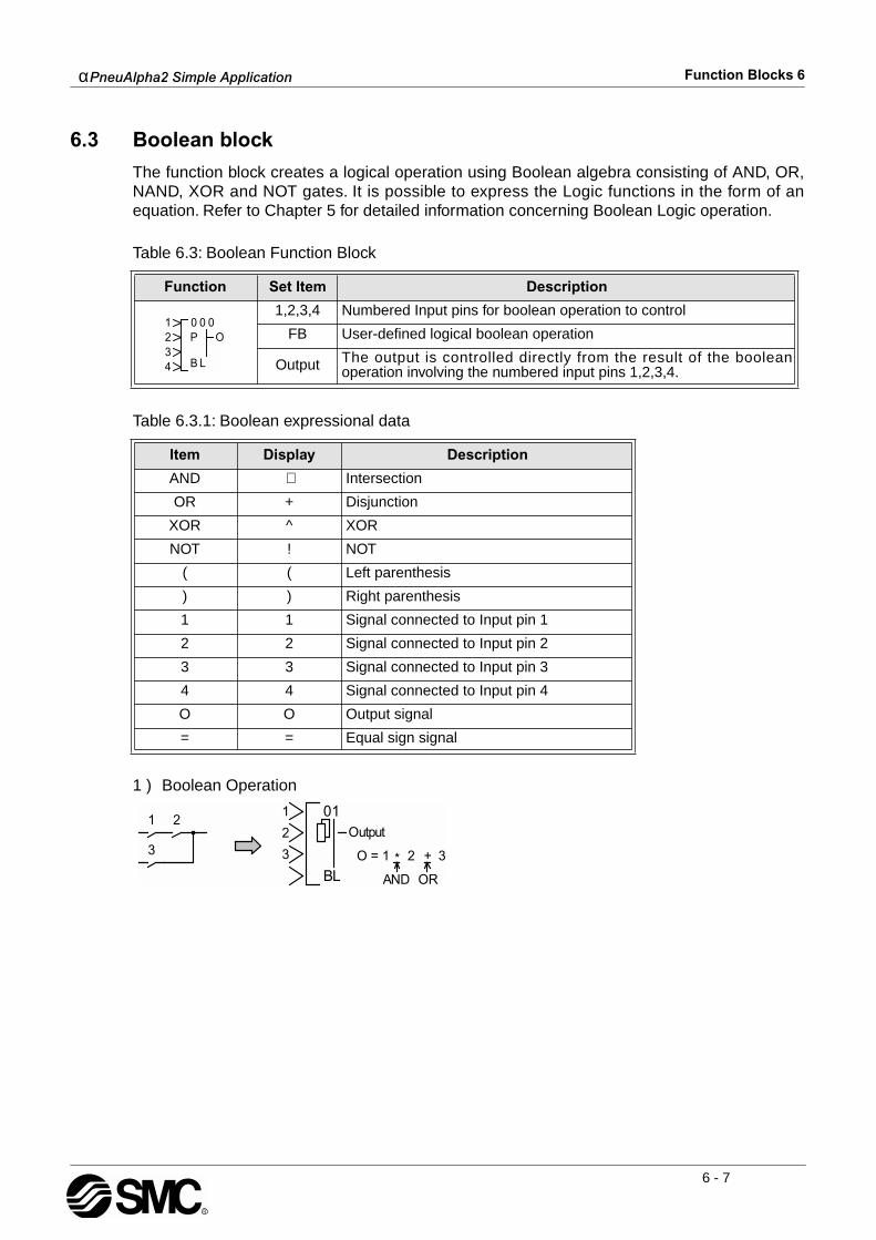
α
PneuAlpha2 Simple Application
Function Blocks 6
6 - 7
6.3 Boolean block
The function block creates a logical operation using Boolean algebra consisting of AND, OR,NAND, XOR and NOT gates. It is possible to express the Logic functions in the form of anequation. Refer to Chapter 5 for detailed information concerning Boolean Logic operation.
Table 6.3: Boolean Function Block
Table 6.3.1: Boolean expressional data
1 ) Boolean Operation
Function Set Item Description
1,2,3,4 Numbered Input pins for boolean operation to control
FB User-defined logical boolean operation
Output The output is controlled directly from the result of the booleanoperation involving the numbered input pins 1,2,3,4.
Item Display Description
AND
∗
Intersection
OR + Disjunction
XOR ^ XOR
NOT ! NOT
( ( Left parenthesis
) ) Right parenthesis
1 1 Signal connected to Input pin 1
2 2 Signal connected to Input pin 2
3 3 Signal connected to Input pin 3
4 4 Signal connected to Input pin 4
O O Output signal
= = Equal sign signal

α
PneuAlpha2 Simple Application
Function Blocks 6
6 - 8
Setup of the Boolean Function Block directly from the
α
PneuAlpha2
Series Controller
1 ) Allocate the input pin to be used for the function block.
2 ) Press the “OK” key with the cursor in the function block. The function block edit screen isdisplayed as shown.
3 ) Select Setup FB using the “ and ” keys and press the “OK” key. The boolean functionblock edit screen is displayed as shown.
4 ) Enter the boolean expression via the “ , , and keys”. A boolean expression isdisplayed as shown.
5 ) Press the “OK” key after entering the boolean expression.

α
PneuAlpha2 Simple Application
Function Blocks 6
6 - 9
6.4 Set/Reset Block
The function block will set or reset an output according to the input condition. When the SETinput is energised, the Output is ON. When the RESET input is energised, the Output is OFF.When both inputs are energised simultaneously, the Output will follow the Priority Settingsignal. A latched Output does not depend on the constant signal to retain its status.Set Priority
- When the Set input comes ON, the Output comes ON and remains ON until theReset pin receives a signal. Once the Output is ON, the Set input signal can turn OFF withouteffecting the Output. If both the Set and Reset pins are ON, the Output is ON.Reset Priority - The operation is the same as the Set Priority except that when both pins areON, the Output is OFF.
Table 6.4: Set/Rest Function Block
1 ) Operation of reset priority
2 ) Operation of set priority
Function Set Item Description
S Set pin for the function block
R Reset pin for the function block
FB Allocates priority to either the set or reset function when both pins areON
Output
The output of the function block operates in either an ON or OFFstate.
1) Set the output ON until the reset pin is ON.
2) Decides the status of the output depending which input pin haspriority.
ONOFF
OFFON
ON OFF
Input pin S
Input pin R
Output

α
PneuAlpha2 Simple Application
Function Blocks 6
6 - 10
Setup of the Set/Reset Function Block directly from the
α
2
PneuAlpha2 Series Controller
1 ) Allocate the set and reset pins for the function block.
2 ) Press the “OK” key with the cursor in the function block. The function block edit screen isdisplayed as shown.
3 ) Select Setup FB using the “ and ” keys and press the “OK” key. The Set/Reset priorityscreen is displayed as shown.
4 ) Select the Set or Reset priority using the “ and ” keys and press the “OK” key to returnto the function block edit screen.
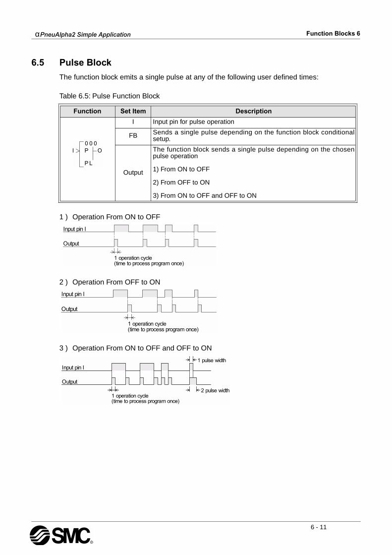
α
PneuAlpha2 Simple Application
Function Blocks 6
6 - 11
6.5 Pulse Block
The function block emits a single pulse at any of the following user defined times:
Table 6.5: Pulse Function Block
1 ) Operation From ON to OFF
2 ) Operation From OFF to ON
3 ) Operation From ON to OFF and OFF to ON
Function Set Item Description
I Input pin for pulse operation
FB Sends a single pulse depending on the function block conditionalsetup.
Output
The function block sends a single pulse depending on the chosenpulse operation
1) From ON to OFF
2) From OFF to ON
3) From ON to OFF and OFF to ON
α
PneuAlpha2 Simple Application
Function Blocks 6
6 - 12
Setup of the Pulse Function Block directly from the
α
PneuAlpha2
Series Controller
1 ) Allocate the input pin to be used for the function block.
2 ) Press the “OK” key with the cursor in the function block. The function block edit screen isdisplayed as shown.
3 ) Select Setup FB using the “ and ” keys and press the “OK” key. Select using the “and ” keys the initiation type for the pulse operation.
4 ) Press the “OK” key to return to the function block edit screen.
α
PneuAlpha2 Simple Application
Function Blocks 6
6 - 13
6.6 Alternate Block
The function block inflicts a reversal of the ON and OFF state of the output as and when theinput is given to the input pin.
Table 6.6: Alternate Function Block
1 ) Alternate Operation
Function Set Item Description
I Input pin for alternation operation
C Clear input pin resets the state of the output regardless of the inputgiven.
FB N/A
Output
The output is affected in the following operation:
1) Reverse the ON/OFF state of the output whenever the inputsignal’s ON/OFF operation to the input pin is turned ON (ON to OFFor OFF to ON)
2) The clear selection resets the output regardless of the input given.

α
PneuAlpha2 Simple Application
Function Blocks 6
6 - 14
6.7 Delay Block
The function block delays the signal to an output for a set length of time. The On or Off delayscan be set individually or in combination. Ex. The On Delay Time is set to 5 seconds. TheDelay Block Input signal comes ON; five seconds later the Delay Block Output will come ON.The Output signal stays ON as long as the Input signal is ON. The Output signal turns OFF atthe same time the Input signal turns OFF. The Clear Input will turn the Output OFF and cancelthe current operation. The Clear pin over-rides the Input pin if both signals are ONsimultaneously.The On Delay option will delay the Output from turning ON for a set time after the Input comesON. The Off Delay will delay the Output from turning OFF for a set time after the Input hasturned OFF.Table 6.7: Delay Timer Function Block
Note: The ON/OFF delay time cannot be less than one scan time for the controller; otherwise,the Delay Function Block will not perform its assigned task for the time specified. Users canmonitor the scan time from the
α
PneuAlpha2
Series Controller. Scan time is dependent on theuser- program; therefore, caution is needed as and when time units are selected.
1 ) Delayed Operation
Function Set Item Description
I Input pin for delay timer operation
C Clear input pin resets the state of the output regardless of the inputgiven.
FB Time units: 10ms, 100ms or 1s (*Note)
Output
The following items are applicable for the delay function block:
1) The lag time setting for energising the output from a given inputsignal can be given a controlled delay time; The starting value has arange from 0s to 32767s
2) The lag time setting for denergising the output from a given inputsignal can be given a controlled delay time; The starting value has arange from 0s to 32767s
3) If the clear signal of the input pin C is turned on while the delayfunction block is in operation consequentially the current value of theON delay timer and OFF delay timer resets to “0.” Thus, the output isturned OFF.
4) The following items are available for other function blocks: a) On Delay b) Current On Delay c) Off Delay d) Current Off Delay
α
PneuAlpha2 Simple Application
Function Blocks 6
6 - 15
2 ) ON delay timer
3 ) OFF delay timer
Setup of the Delay Function Block directly from the
α
2
PneuAlpha2 Series Controller
1 ) Allocate the input pin to be used for the function block.
2 ) Press the “OK” key with the cursor in the function block. The function block edit screen isdisplayed as shown.
3 ) Press the “OK” key to set the Time unit for the delayed output.
4 ) Press the “OK” key having selected the value for the delayed time unit and return to thefunction block edit screen. Using the “ and ” keys highlight the Setup FB and press the“OK” key. The screen displayed is shown.
5 ) Select the On or Off Delay using the “ and ” Keys and press the “OK” key. The Delaytime can be entered using the “+” or “-” keys.
6 ) Press the “OK” key to accept the time figures and subsequently press the “ESC” key toreturn to the function block edit screen.

α
PneuAlpha2 Simple Application
Function Blocks 6
6 - 16
6.8 One Shot Block
The function block gives a single Output pulse for a controlled duration of time. If the Set Timeis 0.0 seconds, the block will function like the Pulse block. The Reset Input returns the Outputto the OFF condition and will override the Input pin.
Table 6.8: One Shot Function Block
Note: The set time cannot be less than one scan time for the controller; otherwise, the OneShot Function Block will not perform its assigned task for the time specified. Users can monitorthe scan time from the
α
PneuAlpha2
Series Controller. Scan time is dependent on the user-program; therefore, caution is needed as and when time units are selected.
One Shot Operation1 ) Time Priority
2 ) Input priority
Function Set Item Description
I Input pin for one shot operation
C Clear input pin resets the state of the output regardless of the input
FB
Time units: 10ms, 100ms or 1s (*Note)
The One Shot time T and t can be set using the chosen time units.
A Time or Input priority can be set.
Output
The following items are applicable for the one shot function block:
1) A period of 0s to 32767s for a single pulse output can be set.
2) The output is turned ON during the single shot time duration as andwhen the input pin receives a signal.
3) The output is cleared as and when the clear pin receives a signal.
4) The following items are available for other function blocks: a) One Shot b) Current One Shot

α
PneuAlpha2 Simple Application
Function Blocks 6
6 - 17
Setup of the One Shot Function Block directly from the
α
PneuAlpha2
Series Controller
1 ) Allocate the input pin to be used for the function block.
2 ) Press the “OK” key with the cursor in the function block. The function block edit screen isdisplayed as shown.
3 ) Press the “OK” key to set the Time unit for the delayed output.
4 ) Press the “OK” key having selected the value for the one shot time unit and return to thefunction block edit screen. Using the “ and ” keys highlight the Setup FB and press the“OK” key. The screen displayed is shown.
5 ) Select the One Shot or Priority option using the “ and ” Keys and press the “OK” key.The One Shot time can be entered using the “+” or “-” keys.
6 ) The Priority can be entered using the “ or ” keys.
7 ) Press the “OK” key to accept the time figures and subsequently press the “ESC” key toreturn to the function block edit screen.

α
PneuAlpha2 Simple Application
Function Blocks 6
6 - 18
6.9 Flicker Block
The function block provides a method to give a patterned ON/OFF Output signal. The user canset independent ON and OFF times for the Output. The output pattern can be dependent onan input signal, or can be performed for a preset cycle time or number of repetitions.
Table 6.9: Flicker Function Block
Note: The set time cannot be less than one scan time for the controller; otherwise, the FlickerFunction Block will not perform its assigned task for the time specified. Users can monitor thescan time from the
α
PneuAlpha2
Series Controller. Scan time is dependent on the user-program; therefore, caution is needed as and when time units are selected.Flicker Operation1 ) Continuous control action
2 ) Frequency control action
Function Set Item Description
I Input pin for flicker operation
FB
The following three set items exist:
1) The applicable range for the turning the output ON is 0s to 32767sTime intervals are 10ms, 100ms or 1s (*Note)
2) The applicable range for the turning the output OFF is 0s to 32767sTime intervals are 10ms, 100ms or 1s (*Note)
3) Blinking operation a) Cycles count (frequency assigned operation) maximum number of cycles to be set is 32767 b) Time count maximum 32767 c) Continuous control
Output
The control operations provides an ON/OFF state for the output.
1) The output state directly reflects the ON and OFF condition of theinput signal at the input pin.
2) The following items are available for other function blocks: a) On Flicker b) Current On Flicker c) Off Flicker d) Current Off Flicker e) Cycle or Time f) Current Cycle or Time
α
PneuAlpha2 Simple Application
Function Blocks 6
6 - 19
3 ) Time control action
Setup of the Flicker Function Block directly from the
α
2
PneuAlpha2 Series Controller
1 ) Allocate the input pin to be used for the function block.
2 ) Press the “OK” key with the cursor in the function block. The function block edit screen isdisplayed as shown.
3 ) Press the “OK” key to set the Time unit for the delayed output.
4 ) Press the “OK” key having selected the value for the flicker time unit and return to the func-tion block edit screen. Using the “ and ” keys highlight the Setup FB and press the “OK”key. The screen displayed is shown.
5 ) Select the On Time, Off Time or Period option using the “ and ” Keys and press the“OK” key. The On Time can be entered using the “+” or “-” keys.
6 ) The OffTime can be entered using the “+” or “-” keys.
7 ) The Period can be entered using the “ and ” Keys.
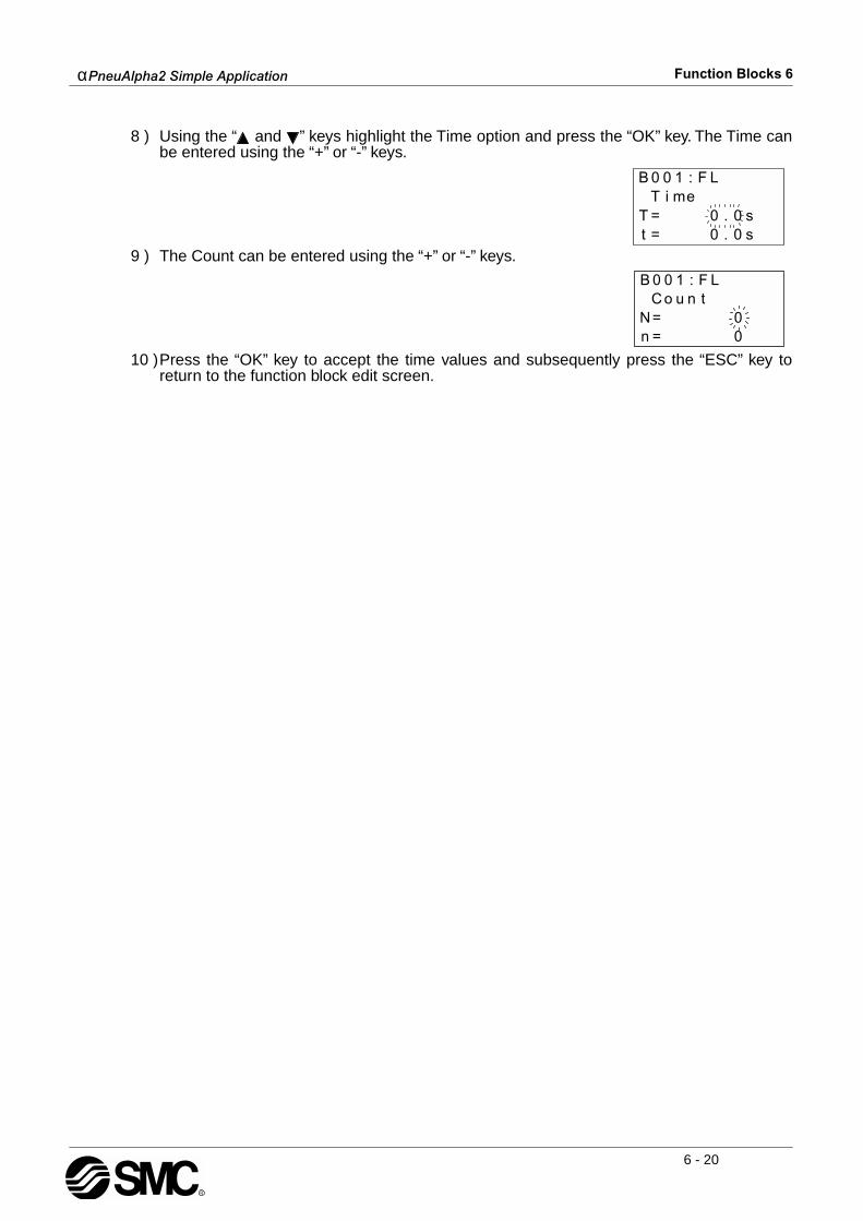
α
PneuAlpha2 Simple Application
Function Blocks 6
6 - 20
8 ) Using the “ and ” keys highlight the Time option and press the “OK” key. The Time canbe entered using the “+” or “-” keys.
9 ) The Count can be entered using the “+” or “-” keys.
10 )Press the “OK” key to accept the time values and subsequently press the “ESC” key toreturn to the function block edit screen.
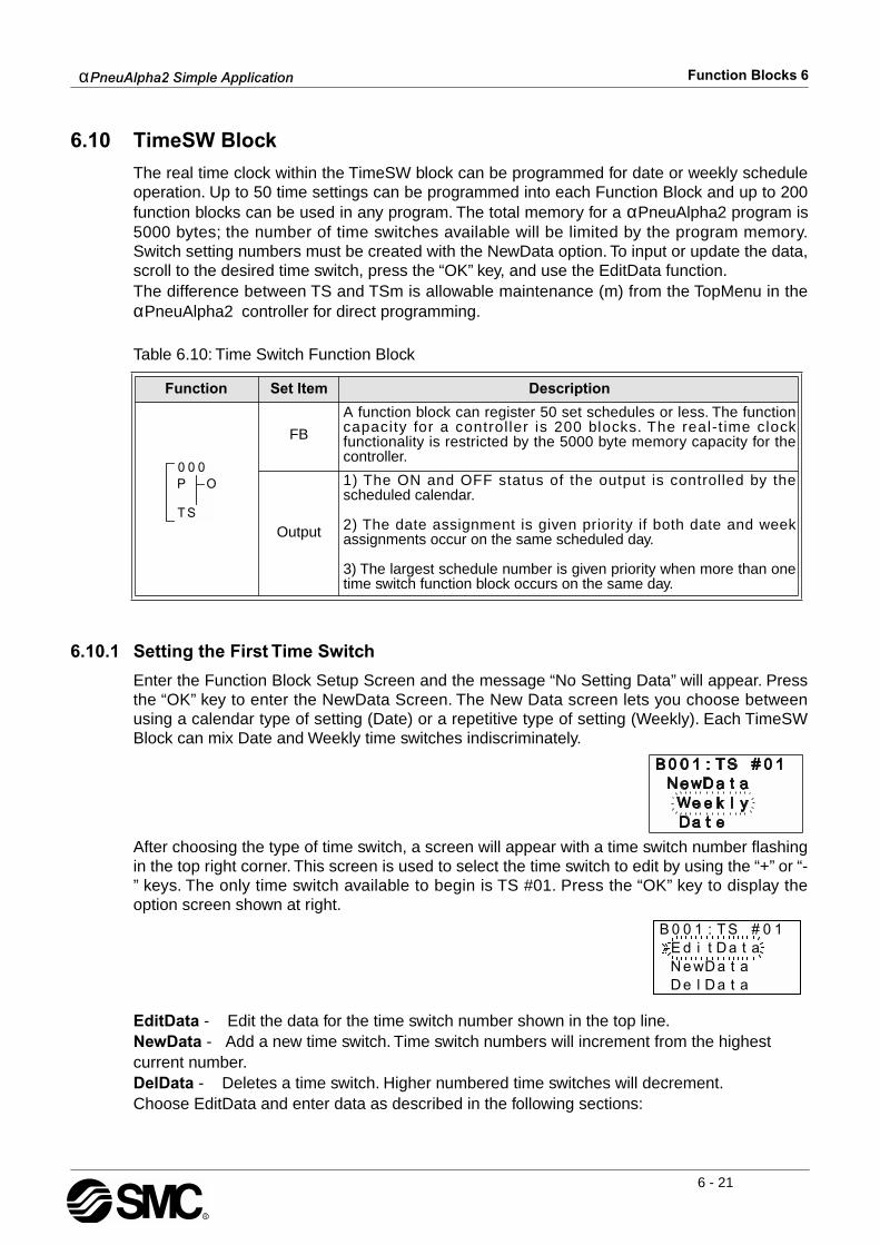
α
PneuAlpha2 Simple Application
Function Blocks 6
6 - 21
6.10 TimeSW Block
The real time clock within the TimeSW block can be programmed for date or weekly scheduleoperation. Up to 50 time settings can be programmed into each Function Block and up to 200function blocks can be used in any program. The total memory for a αPneuAlpha2 program is5000 bytes; the number of time switches available will be limited by the program memory.Switch setting numbers must be created with the NewData option. To input or update the data,scroll to the desired time switch, press the “OK” key, and use the EditData function. The difference between TS and TSm is allowable maintenance (m) from the TopMenu in theαPneuAlpha2 controller for direct programming.
Table 6.10: Time Switch Function Block
6.10.1 Setting the First Time Switch
Enter the Function Block Setup Screen and the message “No Setting Data” will appear. Pressthe “OK” key to enter the NewData Screen. The New Data screen lets you choose betweenusing a calendar type of setting (Date) or a repetitive type of setting (Weekly). Each TimeSWBlock can mix Date and Weekly time switches indiscriminately.
After choosing the type of time switch, a screen will appear with a time switch number flashingin the top right corner. This screen is used to select the time switch to edit by using the “+” or “-” keys. The only time switch available to begin is TS #01. Press the “OK” key to display theoption screen shown at right.
EditData - Edit the data for the time switch number shown in the top line.NewData - Add a new time switch. Time switch numbers will increment from the highest current number.DelData - Deletes a time switch. Higher numbered time switches will decrement.Choose EditData and enter data as described in the following sections:
Function Set Item Description
FB
A function block can register 50 set schedules or less. The functioncapacity for a control ler is 200 blocks. The real-t ime clockfunctionality is restricted by the 5000 byte memory capacity for thecontroller.
Output
1) The ON and OFF status of the output is controlled by thescheduled calendar.
2) The date assignment is given priority if both date and weekassignments occur on the same scheduled day.
3) The largest schedule number is given priority when more than onetime switch function block occurs on the same day.
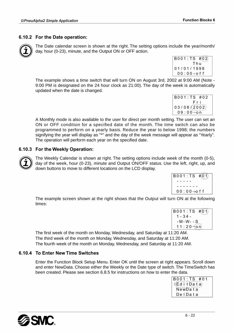
αPneuAlpha2 Simple Application Function Blocks 6
6 - 22
6.10.2 For the Date operation:
The Date calendar screen is shown at the right. The setting options include the year/month/day, hour (0-23), minute, and the Output ON or OFF action.
The example shows a time switch that will turn ON on August 3rd, 2002 at 9:00 AM (Note -9:00 PM is designated on the 24 hour clock as 21:00). The day of the week is automaticallyupdated when the date is changed.
A Monthly mode is also available to the user for direct per month setting. The user can set anON or OFF condition for a specified date of the month. The time switch can also beprogrammed to perform on a yearly basis. Reduce the year to below 1998; the numberssignifying the year will display as "*" and the day of the week message will appear as “Yearly”.The operation will perform each year on the specified date.
6.10.3 For the Weekly Operation:
The Weekly Calendar is shown at right. The setting options include week of the month (0-5),day of the week, hour (0-23), minute and Output ON/OFF status. Use the left, right, up, anddown buttons to move to different locations on the LCD display.
The example screen shown at the right shows that the Output will turn ON at the followingtimes:
The first week of the month on Monday, Wednesday, and Saturday at 11:20 AM.The third week of the month on Monday, Wednesday, and Saturday at 11:20 AM.The fourth week of the month on Monday, Wednesday, and Saturday at 11:20 AM.
6.10.4 To Enter New Time Switches
Enter the Function Block Setup Menu. Enter OK until the screen at right appears. Scroll downand enter NewData. Choose either the Weekly or the Date type of switch. The TimeSwitch hasbeen created. Please see section 6.8.5 for instructions on how to enter the data.
αPneuAlpha2 Simple Application Function Blocks 6
6 - 23
6.10.5 To Edit Time Switches
Enter the Function Block Setup Menu. The currently selected time switch number will beflashing in the top right hand corner. Use the “+” or “-” key to go to the time switch desired toedit and press the “OK” key. Alternately, when the Edit Data screen appears, use the “+” or “-”keys to change the time switch number.
Choose the EditData option to view the selected time switch data.Update data as required and accept with the “OK” key.
6.10.6 To Delete Time Switch Data
Enter the Function Block Setup Menu. The currently selected time switch number will be flashing in the top right hand corner. Use the “+” or “-” key to go to the time switch to be deleted and press the “OK” key. Choose DelData at the bottom of the screen and accept with “OK”.

αPneuAlpha2 Simple Application Function Blocks 6
6 - 24
6.11 Counter Block
The function block counts input pulses and turns the Output ON when a preset limit isreached. The counter counts up only to a maximum value of 32767 and increments on therising pulse. Normal inputs count to a maximum of 20Hz, however, with an extension moduleattached inputs EI1 or EI2 can count to a maximum of 1KHz.Table 6.11: Counter Function Block
Counter Operation
Setup of the Counter Function Block directly from the αPneuAlpha2 Series Controller
1 ) Allocate the input pin to be used for the function block.
2 ) Press the “OK” key with the cursor in the function block. The function block edit screen isdisplayed as shown
3 ) Press the “OK” Key and enter the counter function block settings using the “+, -, and ”keys.
4 ) Press the “OK” Key and return to the function block edit screen.
Function Set Item Description
I Input pin for one shot operation
C Clear input pin resets the state of the output regardless of the inputgiven if reset has been given priority.
FB The counter function block can be incremented to a maximum of32767 counts.
Output
1) When the current incremental value reaches the set value of thecounter function block the status of the output is ON.
2) The clear signal will reset the value of the counter to 0
3) One incremental count is only registered if the input pin locates arising edge.
4) The following items are available for other function blocks: a) Count b) Current Count
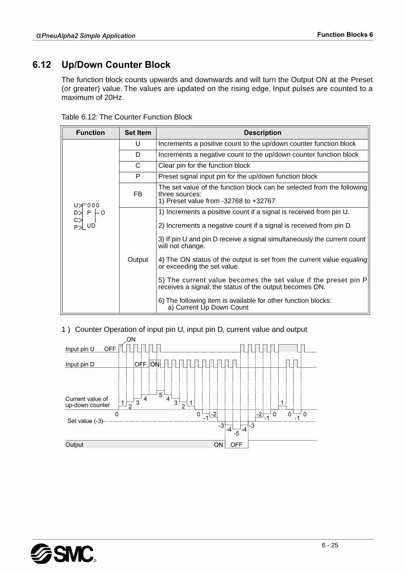
αPneuAlpha2 Simple Application Function Blocks 6
6 - 25
6.12 Up/Down Counter Block
The function block counts upwards and downwards and will turn the Output ON at the Preset(or greater) value. The values are updated on the rising edge. Input pulses are counted to amaximum of 20Hz.
Table 6.12: The Counter Function Block
1 ) Counter Operation of input pin U, input pin D, current value and output
Function Set Item Description
U Increments a positive count to the up/down counter function block
D Increments a negative count to the up/down counter function block
C Clear pin for the function block
P Preset signal input pin for the up/down function block
FBThe set value of the function block can be selected from the followingthree sources:1) Preset value from -32768 to +32767
Output
1) Increments a positive count if a signal is received from pin U.
2) Increments a negative count if a signal is received from pin D.
3) If pin U and pin D receive a signal simultaneously the current count will not change.
4) The ON status of the output is set from the current value equalingor exceeding the set value.
5) The current value becomes the set value if the preset pin Preceives a signal; the status of the output becomes ON.
6) The following item is available for other function blocks: a) Current Up Down Count
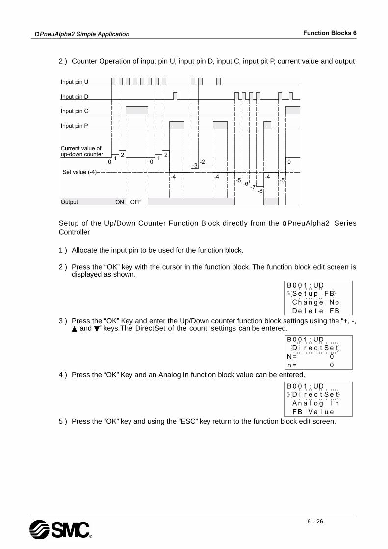
αPneuAlpha2 Simple Application Function Blocks 6
6 - 26
2 ) Counter Operation of input pin U, input pin D, input C, input pit P, current value and output
Setup of the Up/Down Counter Function Block directly from the αPneuAlpha2 SeriesController
1 ) Allocate the input pin to be used for the function block.
2 ) Press the “OK” key with the cursor in the function block. The function block edit screen isdisplayed as shown.
3 ) Press the “OK” Key and enter the Up/Down counter function block settings using the “+, -, and ” keys. The Direct Set of the count s ettings can be entered.
4 ) Press the “OK” Key and an Analog In function block value can be entered.
5 ) Press the “OK” key and using the “ESC” key return to the function block edit screen.

αPneuAlpha2 Simple Application Function Blocks 6
6 - 27
6.13 Compare Block
The function block compares value 1 (V1) with value 2 (V2) using an operational basedinstruction based upon the following conditions: =, >, >=, <, <= or <>. If current values satisfythe operational expression then the output status is ON.
Table 6.13: Compare Function Block
Setup of the Compare Function Block directly from the αPneuAlpha2 Series Controller
1 ) Allocate the input pin to be used for the function block.
2 ) Press the “OK” key with the cursor in the function block. The function block edit screen isdisplayed as shown.
3 ) Press the “OK” Key and enter the function block settings using the “ and ” keys.
4 ) Pressing the “OK” key invokes the menu thats lists the function block input data type.
5 ) Press the “OK” Key and a Direct Set value can be entered..
Function Set Item Description
I Input pin for compare operation
FB
The following three set items exist:
1) Compare Value (V1): a) Constant value set range:-32768 to +32767 with an initial value 0 b) Analogue value set range: A01-A08 c) Output value from a different function block
2) Operational Expression: =, >, >=, <, <=, <>
3) Compare Value (V2): a) Constant value set range:-32768 to +32767 with an initial value 0 b) Analogue value set range: A01-A08 c) Output value from a different function block
Output If Compare value (V1) and Compare value (V2) satisfies theoperational expression the status of the output is ON.
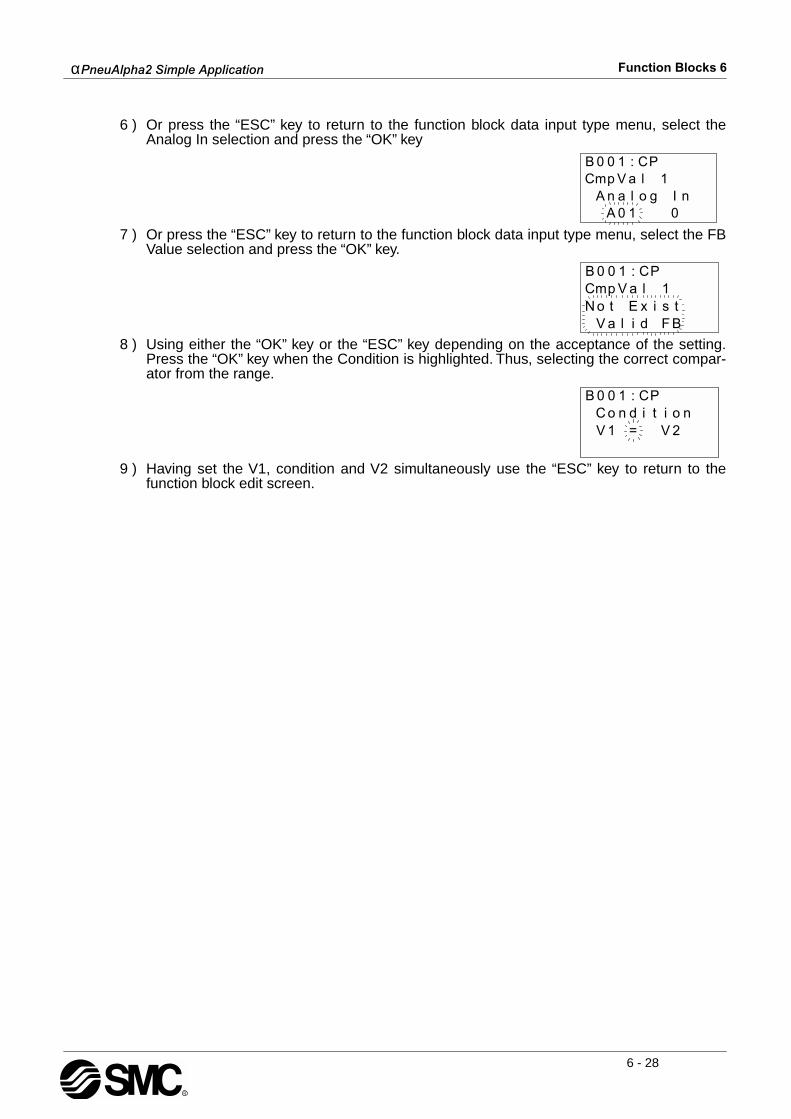
αPneuAlpha2 Simple Application Function Blocks 6
6 - 28
6 ) Or press the “ESC” key to return to the function block data input type menu, select theAnalog In selection and press the “OK” key
7 ) Or press the “ESC” key to return to the function block data input type menu, select the FBValue selection and press the “OK” key.
8 ) Using either the “OK” key or the “ESC” key depending on the acceptance of the setting.Press the “OK” key when the Condition is highlighted. Thus, selecting the correct compar-ator from the range.
9 ) Having set the V1, condition and V2 simultaneously use the “ESC” key to return to thefunction block edit screen.
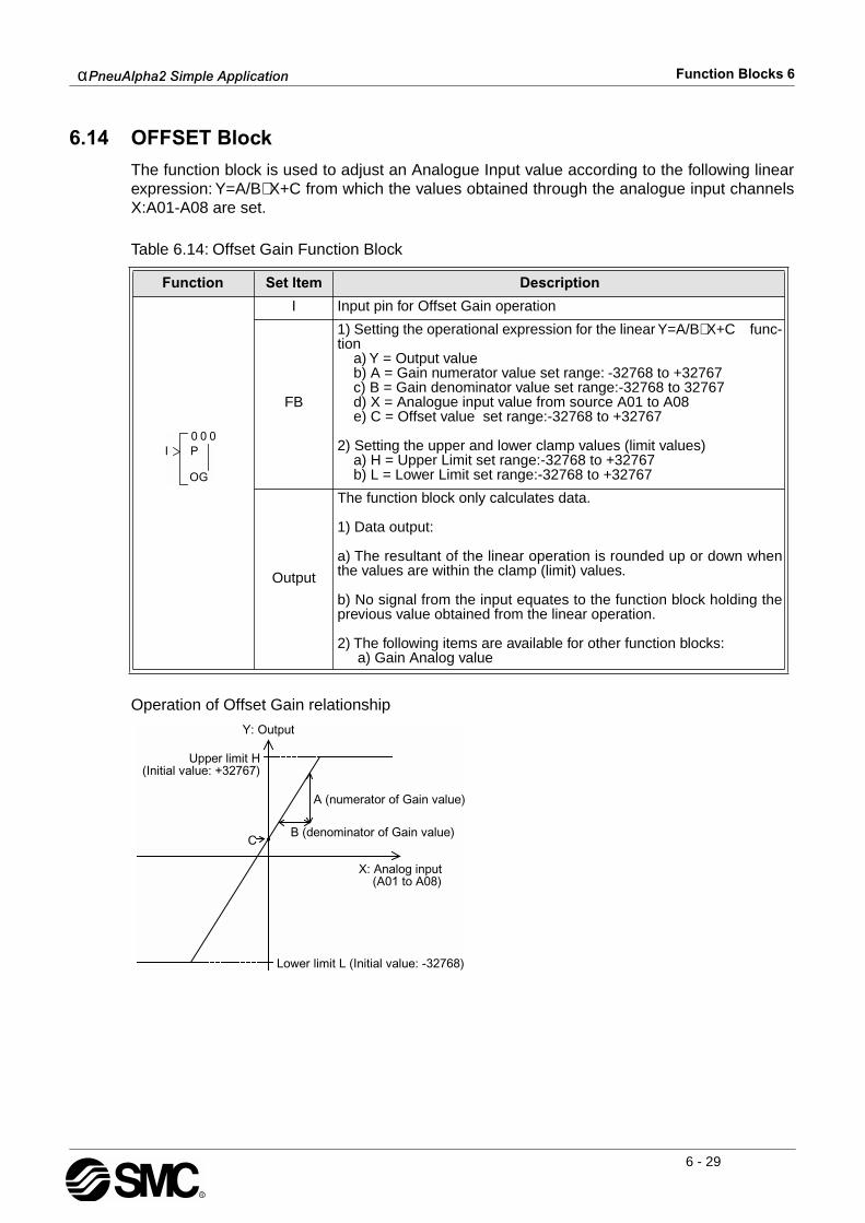
αPneuAlpha2 Simple Application Function Blocks 6
6 - 29
6.14 OFFSET Block
The function block is used to adjust an Analogue Input value according to the following linearexpression: Y=A/B∗ X+C from which the values obtained through the analogue input channelsX:A01-A08 are set.
Table 6.14: Offset Gain Function Block
Operation of Offset Gain relationship
Function Set Item Description
I Input pin for Offset Gain operation
FB
1) Setting the operational expression for the linear Y=A/B∗ X+C func-tion a) Y = Output value b) A = Gain numerator value set range: -32768 to +32767 c) B = Gain denominator value set range:-32768 to 32767 d) X = Analogue input value from source A01 to A08 e) C = Offset value set range:-32768 to +32767
2) Setting the upper and lower clamp values (limit values) a) H = Upper Limit set range:-32768 to +32767 b) L = Lower Limit set range:-32768 to +32767
Output
The function block only calculates data.
1) Data output: a) The resultant of the linear operation is rounded up or down whenthe values are within the clamp (limit) values. b) No signal from the input equates to the function block holding theprevious value obtained from the linear operation.
2) The following items are available for other function blocks: a) Gain Analog value

αPneuAlpha2 Simple Application Function Blocks 6
6 - 30
Setup of the Offset Gain Function Block directly from the αPneuAlpha2 Series Controller
1 ) Allocate the input pin to be used for the function block.
2 ) Press the “OK” key with the cursor in the function block. The function block edit screen isdisplayed as shown.
3 ) Press the “OK” Key and enter the function block settings using the “ and ” keys. Theparameters A, B, X, C, Low limit and High limit have to be specified for the linearexpression to operate correctly..
4 ) Using the “ and ” arrows highlight A and press the “OK” key. A Direct Set using the “+and -” keys can be entered, subsequently press the “OK” key to accept the Direct Setvalue. (Repeat operation for B)
5 ) Highlight X using the “ and ” keys and press the “OK” key to set the Analog In channel.
6 ) The Analog In channel can be selected using the “+ and -” keys, subsequently press the“OK” key to accept the channel.
7 ) Highlight C using the “ and ” keys and press the “OK” key to set the constant value.
8 ) A Direct Set using the “+ and -” keys can be entered, subsequently press the “OK” key toaccept the Direct Set value.

αPneuAlpha2 Simple Application Function Blocks 6
6 - 31
9 ) Using the “ and ” arrows highlight the high and low limit values.
10 )Press the “OK” and a Directset of the Low limit can be entered using the “+ and -” keys.
11 )Press the “OK” key to accept the value and use the “ and ” arrows to highlight the highlimit value. Press the “OK” key and a directset value can be entered using the “+ and -”keys.
12 )Press the “ESC” key until the FBd is displayed.

αPneuAlpha2 Simple Application Function Blocks 6
6 - 32
6.15 Display Block
The function block displays the specified information from the connected function block. Allowsinformation to be displayed on the LCD screen. The Position line sets the starting point for thedata or message to be displayed. There are 12 columns and 4 rows that can be utilised.
Table 6.15: Display Function Block
6.15.1 Displaying Data Onscreen
Character strings (letters, numbers, symbols), Analog values, Function Block values, thecurrent time and date can be viewed on the screen. If two Display blocks contain the samepositioning data, the data from the Function Block with the highest number will be displayed.
Character strings that run over the available number of spaces on a line will show on the nextline down. Function Block values, analog values, date, and time will not be displayed on thenext line. Function Block and analog values will be automatically updated on the screen asthey change.
When entering character strings, choose the desired character with the “ or “ keys. Move tothe left or right with the arrow keys. Accept the data with the “OK” key after all the data hasbeen entered.
The display shows On-screen only when the input is activated.
Function Set Item Description
I Input pin for Display operation
FB
1) The data is positioned using an X,Y plot a) X axis : setting range:1-12 b) Y axis : setting range:1-4 c) Length : setting range:1-12
The following Data items can be viewed using the display functionblock: 1) Strings - number of characters in a string must not exceed 63 a) Fixed b) Flicker : setting range: 1-255 ∗ 100ms Period c) Scroll : setting range: 0-255 ∗ 100ms Interval
2) Analog In a) Value b) Graph : Minimum : -32768 to 32767 Maximum : -32768 to 32767 Length : 1 to 12
3) Function Block Value
4) Time Switch Data
5) Date : mm/dd/yyyy
6) Time : hh:mm
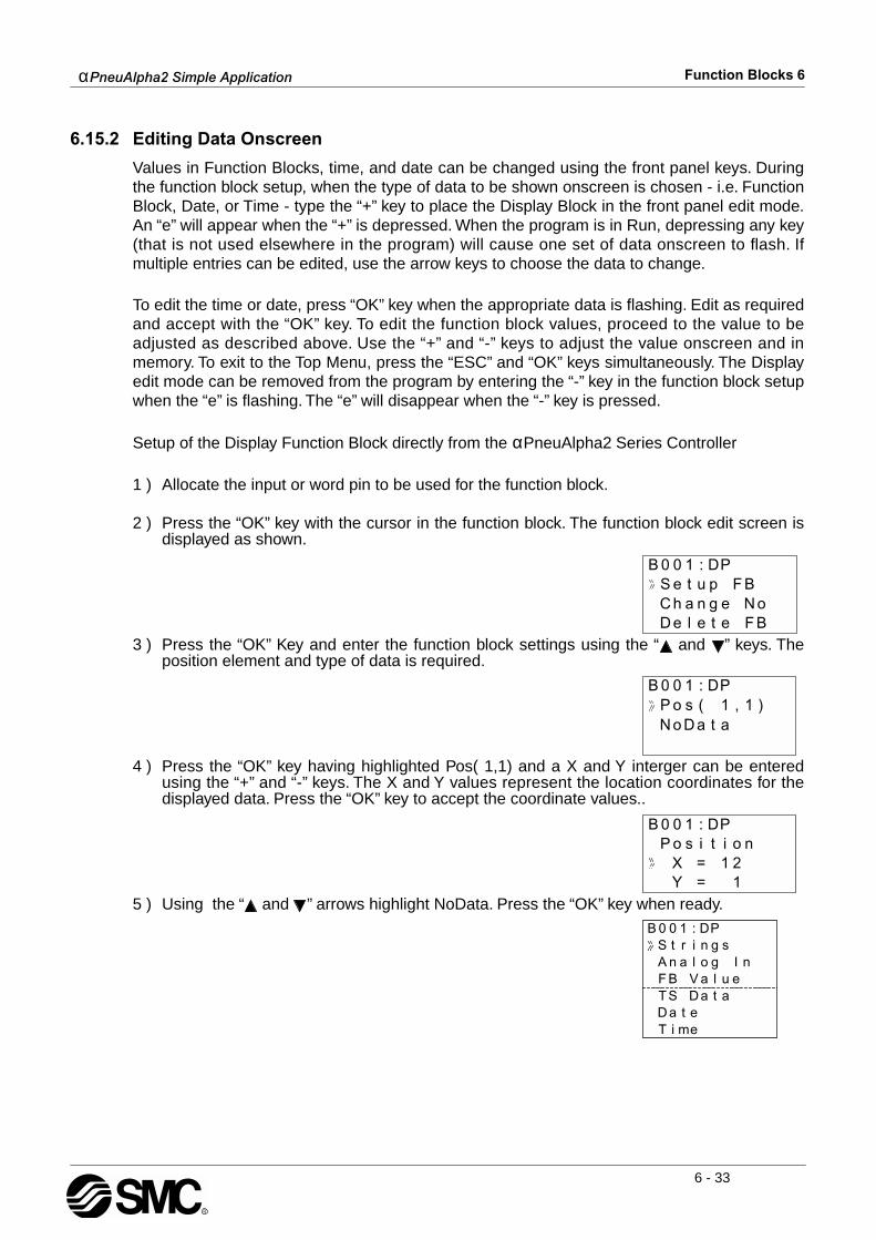
αPneuAlpha2 Simple Application Function Blocks 6
6 - 33
6.15.2 Editing Data Onscreen
Values in Function Blocks, time, and date can be changed using the front panel keys. Duringthe function block setup, when the type of data to be shown onscreen is chosen - i.e. FunctionBlock, Date, or Time - type the “+” key to place the Display Block in the front panel edit mode.An “e” will appear when the “+” is depressed. When the program is in Run, depressing any key(that is not used elsewhere in the program) will cause one set of data onscreen to flash. Ifmultiple entries can be edited, use the arrow keys to choose the data to change.
To edit the time or date, press “OK” key when the appropriate data is flashing. Edit as requiredand accept with the “OK” key. To edit the function block values, proceed to the value to beadjusted as described above. Use the “+” and “-” keys to adjust the value onscreen and inmemory. To exit to the Top Menu, press the “ESC” and “OK” keys simultaneously. The Displayedit mode can be removed from the program by entering the “-” key in the function block setupwhen the “e” is flashing. The “e” will disappear when the “-” key is pressed.
Setup of the Display Function Block directly from the αPneuAlpha2 Series Controller
1 ) Allocate the input or word pin to be used for the function block.
2 ) Press the “OK” key with the cursor in the function block. The function block edit screen isdisplayed as shown.
3 ) Press the “OK” Key and enter the function block settings using the “ and ” keys. Theposition element and type of data is required.
4 ) Press the “OK” key having highlighted Pos( 1,1) and a X and Y interger can be enteredusing the “+” and “-” keys. The X and Y values represent the location coordinates for thedisplayed data. Press the “OK” key to accept the coordinate values..
5 ) Using the “ and ” arrows highlight NoData. Press the “OK” key when ready.
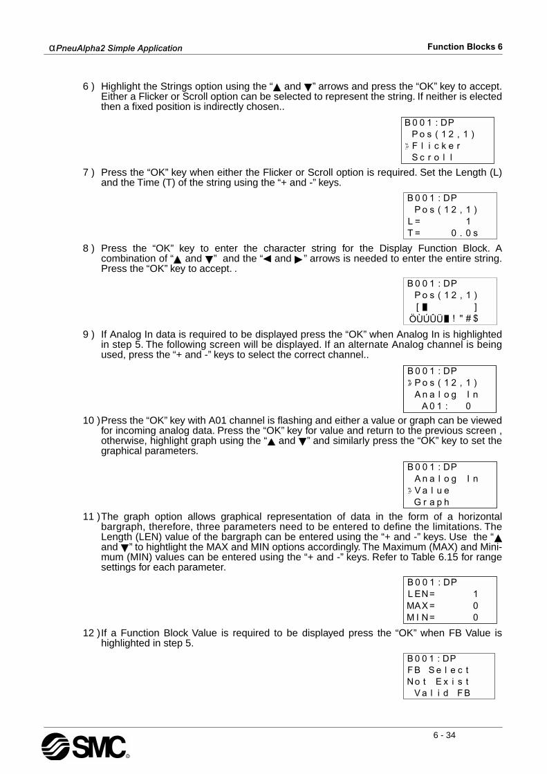
αPneuAlpha2 Simple Application Function Blocks 6
6 - 34
6 ) Highlight the Strings option using the “ and ” arrows and press the “OK” key to accept.Either a Flicker or Scroll option can be selected to represent the string. If neither is electedthen a fixed position is indirectly chosen..
7 ) Press the “OK” key when either the Flicker or Scroll option is required. Set the Length (L)and the Time (T) of the string using the “+ and -” keys.
8 ) Press the “OK” key to enter the character string for the Display Function Block. Acombination of “ and ” and the “ and ” arrows is needed to enter the entire string.Press the “OK” key to accept. .
9 ) If Analog In data is required to be displayed press the “OK” when Analog In is highlightedin step 5. The following screen will be displayed. If an alternate Analog channel is beingused, press the “+ and -” keys to select the correct channel..
10 )Press the “OK” key with A01 channel is flashing and either a value or graph can be viewedfor incoming analog data. Press the “OK” key for value and return to the previous screen ,otherwise, highlight graph using the “ and ” and similarly press the “OK” key to set thegraphical parameters.
11 )The graph option allows graphical representation of data in the form of a horizontalbargraph, therefore, three parameters need to be entered to define the limitations. TheLength (LEN) value of the bargraph can be entered using the “+ and -” keys. Use the “and ” to hightlight the MAX and MIN options accordingly. The Maximum (MAX) and Mini-mum (MIN) values can be entered using the “+ and -” keys. Refer to Table 6.15 for rangesettings for each parameter.
12 )If a Function Block Value is required to be displayed press the “OK” when FB Value ishighlighted in step 5.
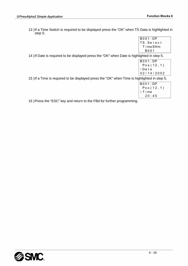
αPneuAlpha2 Simple Application Function Blocks 6
6 - 35
13 )If a Time Switch is required to be displayed press the “OK” when TS Data is highlighted instep 5.
14 )If Date is required to be displayed press the “OK” when Date is highlighted in step 5.
15 )If a Time is required to be displayed press the “OK” when Time is highlighted in step 5.
16 )Press the “ESC” key and return to the FBd for further programming.

αPneuAlpha2 Simple Application Function Blocks 6
6 - 36
6.16 Zone Compare Block
This function checks whether a value is within a specified range. There are three values - theLow Limit (L), Input Value (I), and High Limit (H). These values can be Set Directly, beAnalogue Inputs, or by Function Block values. The Output can be given a Set or Reset priority.
Set Priority - The Output turns ON when the Input Value is equal to or between the High andLow Limits. Reset Priority - The Output turns ON when the Input Value is outside the High and LowLimits.
Table 6.16: Zone Compare Function Block
Function Set Item Description
I Input pin for zone compare operation
FB
The following conditions apply to the function block:
1) Low (compare value L) a) Range: -32768 to +32767 with initial value set at 0 b) Analogue data A01-A08 c) Other function block data
2) Input (input value I) a) Range: -32768 to +32767 with initial value set at 0 b) Analogue data A01-A08 c) Other function block data
3) High (compare value H) a) Range: -32768 to +32767 with initial value set at 0 b) Analogue data A01-A08 c) Other function block data
Output
Output status:
1) ON in the zoneThe value from the input pin is compared with the preset high and lowvalues and sets the output ON when the zonal compare condition issatisfied.Otherwise the output is OFF.
2) OFF in the zoneThe value from the input pin is compared with the preset high and lowvalues and sets the output OFF when the zonal compare condition issatisfied. Otherwise the output is ON.
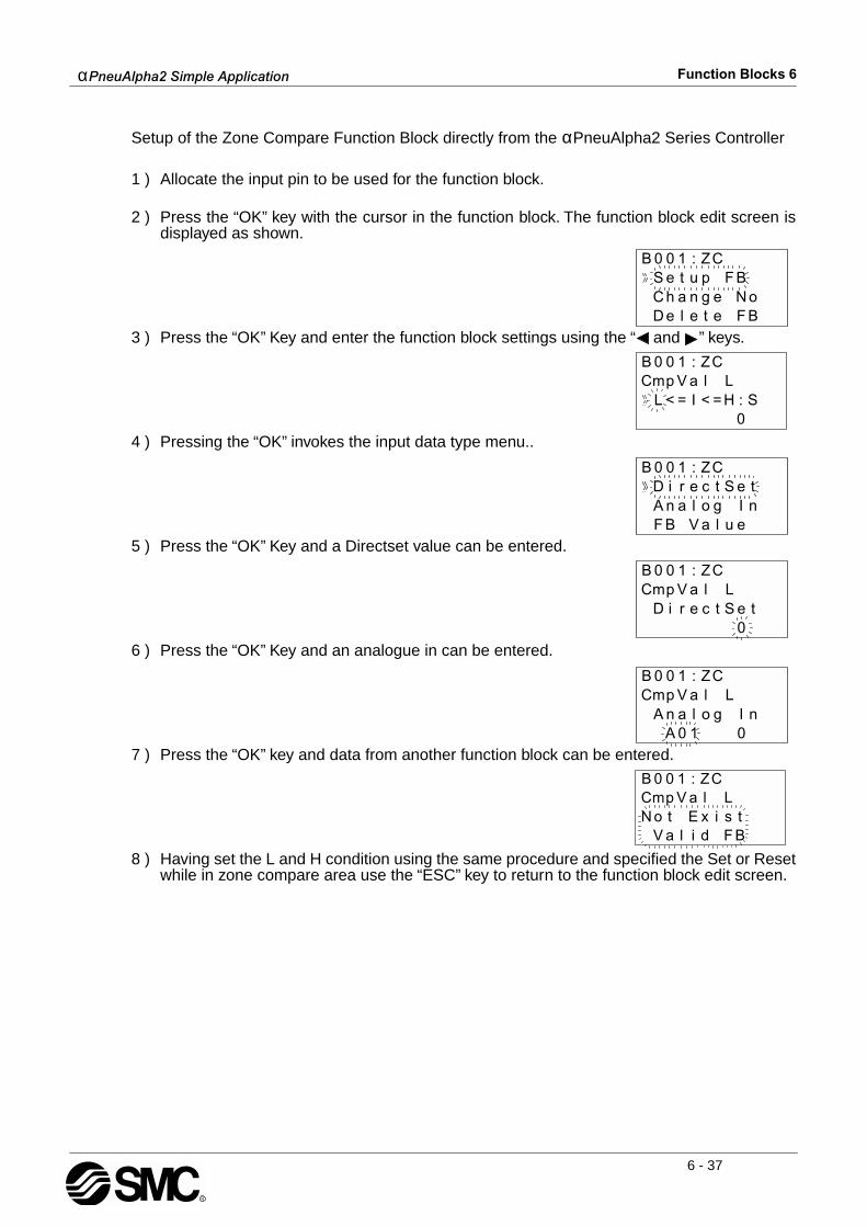
αPneuAlpha2 Simple Application Function Blocks 6
6 - 37
Setup of the Zone Compare Function Block directly from the αPneuAlpha2 Series Controller
1 ) Allocate the input pin to be used for the function block.
2 ) Press the “OK” key with the cursor in the function block. The function block edit screen isdisplayed as shown.
3 ) Press the “OK” Key and enter the function block settings using the “ and ” keys.
4 ) Pressing the “OK” invokes the input data type menu..
5 ) Press the “OK” Key and a Directset value can be entered.
6 ) Press the “OK” Key and an analogue in can be entered.
7 ) Press the “OK” key and data from another function block can be entered.
8 ) Having set the L and H condition using the same procedure and specified the Set or Resetwhile in zone compare area use the “ESC” key to return to the function block edit screen.

αPneuAlpha2 Simple Application Function Blocks 6
6 - 38
6.17 Schmitt Trigger Block
The Schmitt Trigger is used to compare an Input value against a specified high and low limitsthus turn the Output ON/OFF when certain conditions are met. There are three values thatmust be set - the Input Value, the Low Limit and the High Limit. All three values can be eitherDirectSet, Analog In, or Function Block values. When the High Limit value is larger than theLow Limit value, the output will turn ON when the High Limit value is reached or exceeded. TheOutput will turn Off when the Input value is equal to or less than the Low Limit. (The Outputdoes not turn OFF when the Input Value fal ls below the High Limit). Eg. An airconditioner is set to turn ON when the air temperature reaches 23°C and turn OFF when thetemperature reaches 18°C. The air conditioner is not constantly turning ON and OFF overslight temperature fluctuations.
When the High Limit value is less than the Low Limit value, the Output ON/OFF pattern isreversed. When the Input Value is greater than or equal to the Low Limit Value, the Outputturns OFF. When the Input Value is equal to or less than the High Limit value, the Outputcomes ON. The input pin must be ON for the Function Block to register a new value from aFunction Block or Analog Input. Therefore, the input pin must be ON for the status of theOutput to change. The input pin does not have to be ON for the Output to be ON.
Table 6.17: Schmitt Trigger Function Block
Function Set Item Description
I Input pin for Schmitt Trigger operation
FB
The following conditions apply to the function block:
1) Low (compare value L) a) Range: -32768 to +32767 with initial value set at 0 b) Analogue data A01-A08 c) Other function block data
2) Input (input value I) a) Range: -32768 to +32767 with initial value set at 0 b) Analogue data A01-A08 c) Other function block data
3) High (compare value H) a) Range: -32768 to +32767 with initial value set at 0 b) Analogue data A01-A08 c) Other function block data
The compare instruction is only performed if the input signal is ON.
Output Output Status:refer to the operation time charts for schmitt trigger condition.

αPneuAlpha2 Simple Application Function Blocks 6
6 - 39
1 ) High Value > Low Value
2 ) Low value > High value
3 ) High value = Low Value
Note: *1 For Analog or FB value inputs the lower and higher limits are not equal.
αPneuAlpha2 Simple Application Function Blocks 6
6 - 40
Setup of the Schmitt Trigger Function Block directly from the αPneuAlpha2 Series Controller
1 ) Allocate the input pin to be used for the function block.
2 ) Press the “OK” key with the cursor in the function block. The function block edit screen isdisplayed as shown.
3 ) Press the “OK” Key and enter the function block settings using the “ and ” keys.
4 ) Press the “OK” key with the InputVal highlighted and the user can enter a the appropriateInput Val data from either a DirectSet, Analog In or other FB Values.
5 ) The Low and High limit can be given Input Val data from either a DirectSet, Analog In orother FB Values. Press the “ESC” key to return the edit screen for the function block andthe user can change the low or high limits either by DirectSet, Analog In or FB Value.

αPneuAlpha2 Simple Application Function Blocks 6
6 - 41
6.18 Hour Meter Block
The Hour Meter is used to track the amount of time that a device has been in operation. Thiscan be very useful for preventative maintenance schedules or for performing feasibility studies.The timing starts at the receipt of an Input signal and retains the accumulated time throughsystem shutdowns or power failures. When the Set Time value is reached, the block Output willturn ON. The Hour Meter will continue recording time after the Output time is reached. A signalto the Clear pin will reset the current time value to zero.
Table 6.18: Hour Meter Function Block
1 ) Hour operation time chart
Function Set Item Description
I Input pin for hour meter operation
C Clear pin for function block
FB
1) Time units are either hh:mm or mm:ss
2) Time setting range: a) 0-32767 hours with initial value 0 b) 0 - 59 minutes with initial value 0 c) 0 - 59 seconds with initial value 0
Output
1) The output is turned ON after the set time has elapsed.
2) The function block retains the previous value if there is no signalfrom the input pin and restarts with this value when the input is givena signal again.
3) The current time value is reset if the clear pin receives a signal.
4) The following items are available for other function blocks: a) Set Hour b) Current Hour a) Set Minute b) Current Minute

αPneuAlpha2 Simple Application Function Blocks 6
6 - 42
Setup of the Hour Meter Function Block directly from the αPneuAlpha2 Series Controller
1 ) Allocate the input pin to be used for the function block.
2 ) Press the “OK” key with the cursor in the function block. The function block edit screen isdisplayed as shown.
3 ) Press the “OK” key to set the Time unit for the delayed output.
4 ) Press the “OK” key having selected the correct time unit and return to the function blockedit screen. Using the “ and ” keys highlight the Setup FB and press the “OK” key.
5 ) Press the “OK” key with Hour highlighted and using the “ , , + and -” Keys enter the totalhour time for the specified block.
6 ) Press the “OK” key with Minute highlighted and using the “ , , + and -” Keys enter thetotal minute time for the specified block.
αPneuAlpha2 Simple Application Function Blocks 6
6 - 43
6.19 Speed Detect Block
The function block measures the signal input frequency for a set user defined period of time.The frequency is constantly compared to a preset high and low threshold values and theoutput is set ON if the conditions are satisfied. The speed detect function block is used tocount incoming pulses, however, for normal inputs without the ECC-PNAL2-4EX expansionmodule connected the incoming pulses are restricted to 20Hz. The ECC-PNAL2-4EX, withinputs EI1 or EI2, expansion module allows for 1KHz incoming pulses to be measured.
Table 6.19: Speed Detect Function Block
Note: The Speed Detect function (SPD) block can use only 1 high speed frequency(Max.1kHz) in any one program. Subsequent SPD function blocks can only use amaximum of 20Hz for high speeding counting.
Function Set Item Description
I Input pin for speed detect function block
U Count incoming signal
C Clear pin for function block
FB
The function block counts incoming pulses when the input is ON.When the input signal is OFF, the actions to count the pulses of thecounter input and compare the speed with upper and lower thresholdlimit will stop.
1) Speed and output values will not be cleared unless the clear pinreceives a signal to reset the counter.
2) Upper limit> Lower limit:The output signal will be OFF when the speed output value is equal toor less than the lower limit value. If the speed output value is equal toor larger than the upper limit value the output status will be ON. Oth-erwise the output signal does not change.
3) Lower limit > Upper limitThe output signal will be OFF when the speed output value is equal toor larger than the lower limit value. If the speed output value is equalto or less than the upper limit value the output status will be ON. Oth-erwise the output signal does not change.
4) Lower limit = Higher limitThe output status is ON if the Speed Output = Lower limit = Upperlimit. Otherwise the output signal is OFF.
5) Function Block data: a) Period setting value: 1 to 32767
Output
Output status:refer to the speed detect time charts for output status.
1) The following items are available for other function blocks: a) Set Period b) Current Period

αPneuAlpha2 Simple Application Function Blocks 6
6 - 44
1 ) Upper limit > Lower limit
Normal input max. 20Hz
Interrupt input terminal for ECC-PNAL2-4EX max.1kHz
αPneuAlpha2 Simple Application Function Blocks 6
6 - 45
2 ) Upper limit < Lower limit
Normal input max. 20Hz
Interrupt input terminal for ECC-PNAL2-4EX max. 1KHz

αPneuAlpha2 Simple Application Function Blocks 6
6 - 46
3 ) Upper limit = Lower limit
Normal input max. 20Hz
Interrupt input terminal for ECC-PNAL2-4EX max 1KHz

αPneuAlpha2 Simple Application Function Blocks 6
6 - 47
Setup of the Speed Detect Function Block directly from the αPneuAlpha2 Series Controller
1 ) Allocate the input pin to be used for the function block.
2 ) Press the “OK” key with the cursor in the function block. The function block edit screen is displayed as shown.
3 ) Press the “OK” Key and enter the function block settings using the “ and ” keys.
4 ) Press the “OK” key with Period highlighted and the user can enter a T and t value using the“ , , + and -” keys.
5 ) Press the “OK” key to return to the function block settings screen. Highlight theSpeed(L,H) option using the “ and ” keys. The limits can be set by highlighting L or Hand pressing the “OK” key. A Directset value, Analog In or FB value can be entered.
6 ) Press the “ESC” key until the user returns to the function block diagram.

αPneuAlpha2 Simple Application Function Blocks 6
6 - 48
6.20 Pulse Width Modulation
The function block emits a continuous pulse train output when an input is given at a presetduty cycle. Table 6.20: Pulse Width Modulation
Note: The ON/OFF time cannot be less than one scan time for the controller; otherwise, thePWM Function Block will not perform its assigned task for the time specified. Users canmonitor the scan time from the αPneuAlpha2 Series Controller. Scan time is dependent on theuser-program; therefore, caution is needed as and when time units are selected.
1 ) PWM operation time chart.
Note: 10ms step for minimum resolution.
Function Set Item Description
I Input pin for the pulse width modulation function block
FB
1) The PWM function operates concurrently with the input pin statusset ON.
2) The width of the pulse is dominated by the duty and value of theperiod.
3) Duty (setting range:0-100%) a) Constant Value b) Analog In c) FB Value
4) The period is restricted to a setting range: 1 to 32767 x 100ms(*Note)
Output
The function block is used to control the width of the output pulsebased on a specified period of time and duty.
1) The bit output pin is set on for the length of the duty specified.
2) The following items are available for other function blocks: a) Set Period b) Current Period
αPneuAlpha2 Simple Application Function Blocks 6
6 - 49
Setup of the Pulse Width Modulation Function Block directly from the αPneuAlpha2 SeriesController
1 ) Allocate the input pin to be used for the function block.
2 ) Press the “OK” key with the cursor in the function block. The function block edit screen isdisplayed as shown.
3 ) Press the “OK” Key and enter the function block settings using the “Up and Down” keys.
4 ) Press the “OK” key with Period highlighted and the user can enter a T and t value using the“ , , + and -” keys.
5 ) Press the “OK” key to return to the function block settings screen. Highlight the Duty optionusing the “ 0 and ” keys. The Duty can be entered by pressing the “OK” key. A Directsetvalue, Analog In or FB value can be entered.
Press the “ESC” key until the user returns to the function block diagram.
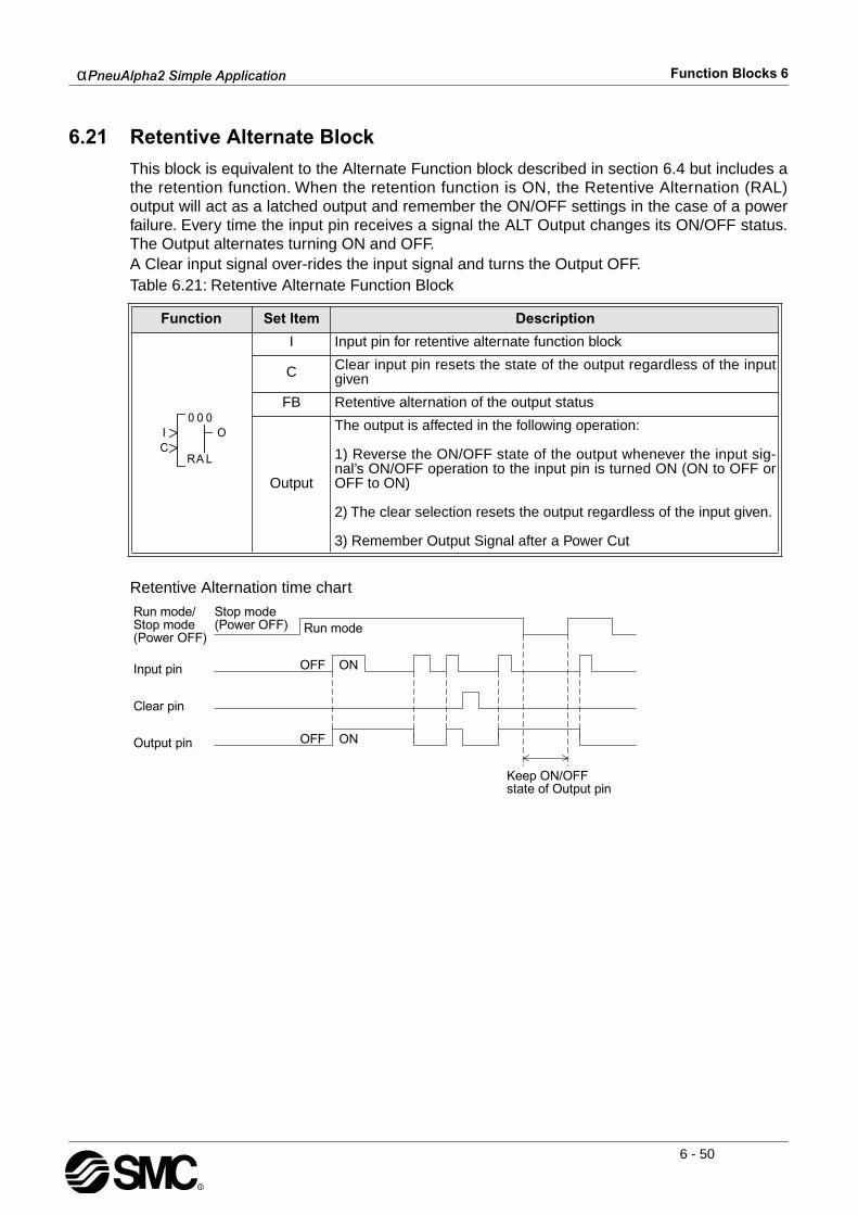
αPneuAlpha2 Simple Application Function Blocks 6
6 - 50
6.21 Retentive Alternate Block
This block is equivalent to the Alternate Function block described in section 6.4 but includes athe retention function. When the retention function is ON, the Retentive Alternation (RAL)output will act as a latched output and remember the ON/OFF settings in the case of a powerfailure. Every time the input pin receives a signal the ALT Output changes its ON/OFF status.The Output alternates turning ON and OFF.A Clear input signal over-rides the input signal and turns the Output OFF.Table 6.21: Retentive Alternate Function Block
Retentive Alternation time chart
Function Set Item Description
I Input pin for retentive alternate function block
C Clear input pin resets the state of the output regardless of the inputgiven
FB Retentive alternation of the output status
Output
The output is affected in the following operation:
1) Reverse the ON/OFF state of the output whenever the input sig-nal’s ON/OFF operation to the input pin is turned ON (ON to OFF orOFF to ON)
2) The clear selection resets the output regardless of the input given.
3) Remember Output Signal after a Power Cut
αPneuAlpha2 Simple Application Function Blocks 6
6 - 51
6.22 Addition Block
The function block is used to summate inputs A and B hence produce the resultant Y.Table 6.22: Addition Function Block
Setup of the Addition Function Block directly from the αPneuAlpha2 Series Controller1 ) Allocate the input pin to be used for the function block. 2 ) Press the “OK” key with the cursor in the function block. The function block edit screen is
displayed as shown.
3 ) Press the “OK” Key and enter the function block settings using the “ and ” keys. TheAddition operation Y=A+B must be specified.
4 ) Using the “ and ” keys highlight Constant A and press the “OK” key to enter either aDirectset, Analog In or FB Value.
5 ) Repeat step 4 for Constant B and return to the FBd using the “ESC” key.
Function Set Item Description
I Input pin for addition function block
FB
This function block operates the expression Y=A+B.
The value of Y,A and B is in the range: -32768 to 32767 a) A,B - Constant value (Setting range:-32768 to 32767 - Analog value - FB value
Output
1) Word OutputWhen the input pin is ON, Y=A+B is executed and the word outputwill be given the result. When the input pin is OFF the expression isnot executed and the Y value will retain the last result.
2) Bit Output- Operation result Y<32768: Output pin turned ON and the operationresult Y will be set to -32767
- Operation result Y>32767: Output pin turned ON and the operationresult Y will be set to 32767

αPneuAlpha2 Simple Application Function Blocks 6
6 - 52
6.23 Subtraction Block
The function block is used to subtract inputs B from A hence produce the resultant Y.Table 6.23: Subtraction Function Block
Setup of the Subtraction Function Block directly from the αPneuAlpha2 Series Controller1 ) Allocate the input pin to be used for the function block.
2 ) Press the “OK” key with the cursor in the function block. The function block edit screen isdisplayed as shown.
3 ) Press the “OK” Key and enter the function block settings using the “ and ” keys. TheSubtraction operation y=A-B must be specified.
4 ) Using the “ and ” keys highlight Constant A and press the “OK” key to enter either aDirectset, Analog In or FB Value.
5 ) Repeat step 4 for Constant B and return to the FBd using the “ESC” key.
Function Set Item Description
I Input pin for subtraction function block
FB
This function block operates the expression Y=A-B.
The value of Y,A and B is in the range: -32768 to 32767 a) A,B - Constant value (Setting range:-32768 to 32767 - Analog value - FB value
Output
1) Word OutputWhen the input pin is ON, Y=A-B is executed and the word output willbe given the result. When the input pin is OFF the expression is notexecuted and the Y value will retain the last result.
2) Bit Output- Operation result Y<32768: Output pin turned ON and the operationresult Y will be set to -32767
- Operation result Y>32767: Output pin turned ON and the operationresult Y will be set to 32767

αPneuAlpha2 Simple Application Function Blocks 6
6 - 53
6.24 Multiplication Block
The function block is used to multiply inputs A and B hence produce the resultant Y.Table 6.24: Multiplication Function Block
Setup of the Multiplication Function Block directly from the αPneuAlpha2 Series Controller1 ) Allocate the input pin to be used for the function block.
2 ) Press the “OK” key with the cursor in the function block. The function block edit screen isdisplayed as shown.
3 ) Press the “OK” Key and enter the function block settings using the “ and ” keys. TheMultiplication operation y=A∗ B must be specified.
4 ) Using the “ and ” keys highlight Constant A and press the “OK” key to enter either aDirectset, Analog In or FB Value.
5 ) Repeat step 4 for Constant B and return to the FBd using the “ESC” key.
Function Set Item Description
I Input pin for multiplication function block
FB
This function block operates the expression Y=A∗ B.
The value of Y,A and B is in the range: -32768 to 32767 a) A,B - Constant value (Setting range:-32768 to 32767 - Analog value - FB value
Output
1) Word OutputWhen the input pin is ON, Y=A∗ B is executed and the word outputwill be given the result. When the input pin is OFF the expression isnot executed and the Y value will retain the last result.
2) Bit Output- Operation result Y<32768: Output pin turned ON and the operationresult Y will be set to -32767
- Operation result Y>32767: Output pin turned ON and the operationresult Y will be set to 32767
D ire c tS e tA n a lo g InFB V a lu e
B 0 0 1 :M LU

αPneuAlpha2 Simple Application Function Blocks 6
6 - 54
6.25 Division Block
The function block is used to divide inputs A and B hence produce the quotient Q andremainder R.Table 6.25: Division Function Block
Setup of the Division Function Block directly from the αPneuAlpha2 Series Controller1 ) Allocate the input pin to be used for the function block.
2 ) Press the “OK” key with the cursor in the function block. The function block edit screen isdisplayed as shown.
3 ) Press the “OK” Key and enter the function block settings using the “ and ” keys. TheDivision operation Q=A/B must be specified.
4 ) Using the “ and ” keys highlight Constant A and press the “OK” key to enter either aDirectset, Analog In or FB Value.
5 ) Repeat step 4 for Constant B and return to the FBd using the “ESC” key.
Function Set Item Description
I Input pin for division function block
FB
This function block operates the expression Q=A/B, R=A%B
The value of Q, R, A and B is in the range: -32768 to 32767 a) A,B - Constant value (Setting range:-32768 to 32767 - Analog value - FB value
Output
1) Word OutputWhen the input pin is ON, Q=A/B, R=A%B and the word output willbe given the result. When the input pin is OFF the expression is notexecuted and the Q and R values will retain the last result.
2) Bit Output- Input value (B) = 0: Output pin is turned ON and the quotient Q andR will reset to 0.
- Quotient (Q) > 32767: Output pin is turned ON and the quotient Qwill be set to 32767.
αPneuAlpha2 Simple Application Function Blocks 6
6 - 55
6.26 Calculation Block
The function block creates an expression using up to four input word data (A, B, C and D)using five operators (+, -, * , /, %) and outputs the calculation result to Y. A maximum of 64terms can be included in the calculation expression. Nesting using parenthesis is available upto 6 times.Table 6.26: Calculation Function Block
Table 6.26.1: Calculation Function Block terms
Function Set Item Description
7 I Input pin for multiplication function block
FB
This function block creates an expression using up to 4 input words(A, B, C, D), 5 operators (+, /, ∗ , /, %) and outputs the calculationresult to Y. A maximum of 64 terms can be included in the calculationexpression. Nesting using parenthesis is available up to a maximumof 6 levels.
Input values A, B, C, and D set the following values - Constant value (Setting range:-32768 to 32767 - Analog value - FB value
Output
1) Word Output (Y)When the input pin is ON, Q=A/B, R=A%B and the word output willbe given the result. When the input pin is OFF the expression is notexecuted and the Q and R values will retain the last result.
2) Bit Output - Operation result Y<-32768: Output pin is turned ON and theQuotient (Q) will be set to -32768. - Operation result Y>32767: Output pin is turned ON and the Quo-tient (Q) will be set to 32767. - The divisor is 0: Output pin is turned ON and the Quotient (Q) willbe reset to 0
Term Description
Y Operation result
A, B, C and D Input value
+ Calculation sign for addition
- Calculation sign for subtraction
∗ Calculation sign for multiplication
/ Calculation sign to request the Quotient
% Calculation sign to request the reminder

αPneuAlpha2 Simple Application Function Blocks 6
6 - 56
Setup of the Calculation Function Block directly from the αPneuAlpha2 Series Controller1 ) Allocate the input pin to be used for the function block.
2 ) Press the “OK” key with the cursor in the function block. The function block edit screen is displayed as shown.
3 ) Press the “OK” Key and enter the function block settings using the “ and ” keys. TheCalculate operation [y= ] must be specified.
4 ) While the cursor is flashing, use the “ and ” keys to select the appropriate character orconstant for your intended calculation. The following items are offered: A, B, C, D, +, -, *, /,%, ( or )
5 ) DirectSet values, Analog In or FB Value can all be entered for each constant.
6 ) Return to the FBd using the “ESC” key.P5656

αPneuAlpha2 Simple Application Function Blocks 6
6 - 57
6.27 Shift Block
The function block uses a shift input signal in correlation with an input signal to set the outputON. The function block can also Set or Reset the status of the output from the dedicated inputpins. The Shift Function block has an inbuilt retentive mode that retains the state of the outputupon the power resetting.Table 6.27: Shift Function Block
1 ) Shift Operation
Function Set Item Description
I Input pin for shift operation function block.
T Shift input pin for shift operation function block
S Set pin for the shift operation function block
R Reset pin for the shift operation function block
FB This function is used to transfer the Shift Input status just before theInput signal is set ON.
Output
1) The output signal will be set to the Input signal status just beforethe Shift input signal is set ON Before one scan the status will beretained.
2) If the Set signal is set ON, the Output signal will be set ON.
3) If the Reset signal is set ON, the Output signal will be reset to OFF.
4) Once both the Set and Reset signals have been set ONsimultaneously, the Set operation will take precedence over the Resetoperation (Set operation has high priority),i.e. Set > Reset > Shift.
αPneuAlpha2 Simple Application Function Blocks 6
6 - 58
2 ) 3 bit shift Operation 1 (1)
3 ) 3bit shift Operation 1 (2)
4 ) 3bit shift operation 2 (1)
5 ) 3bit shift operation 2 (2)

αPneuAlpha2 Simple Application Function Blocks 6
6 - 59
6.28 GSM SMS Block
The function block is used for communication between the αPneuAlpha2 Series Controllerconnected to a GSM modem and a mobile telephone or personal computer via SMS (ShortMessage Service).Table 6.28: GMS Function Block
Function Set Item Description
I Input pin for GSM/SMS function block operation
FB
Refer to the Communication Manual for detailed explanationsconcerning the GSM functionality of the αPneuAlpha2 Seriescontrollers.
1) Detects the high status of an input and subsequently sends theSMS (Short Message Service) to the predefined user destination.
2) The SMS message will continue to send regardless of the outputswitching to a low state.
3) The incoming high input will be ignored: a) During a SMS transmission b) During the waiting period.
4) Communication failure (e.g. busy line) will tell the SMS functionblock to retry on three occasions in a period of two minutes.
5) After the third retry the output status will switch to ON and an errormessage generated through the word pin of the function block.
6) The user may experience incorrect validity period timings. Pleasecheck with your Service Provider.
7) If both the Mobile (SMSC1) and Gateway (SMSC2) numbers areentered the αPneuAlpha2 controller will automatically choose thecorrect path number for the SMS in conjunction with the destinationchosen. The destination being either to a mobile phone or an emailaddress.
Output
1) The output status will set ON: a) In succeeding in sending a SMS message b) In failing to send a SMS message after three retries.
2) If more than one SMS function block exists on the program, a FIFO(First In First Out) sequence is performed.
3) The following items are available for other function blocks: a) Current Status

αPneuAlpha2 Simple Application Function Blocks 6
6 - 60
1 ) GMS Operation
Communication failure will tell the SMS function block to retry on three occasions in a period oftwo minutes.
2 ) SMS- Retry Sending Data
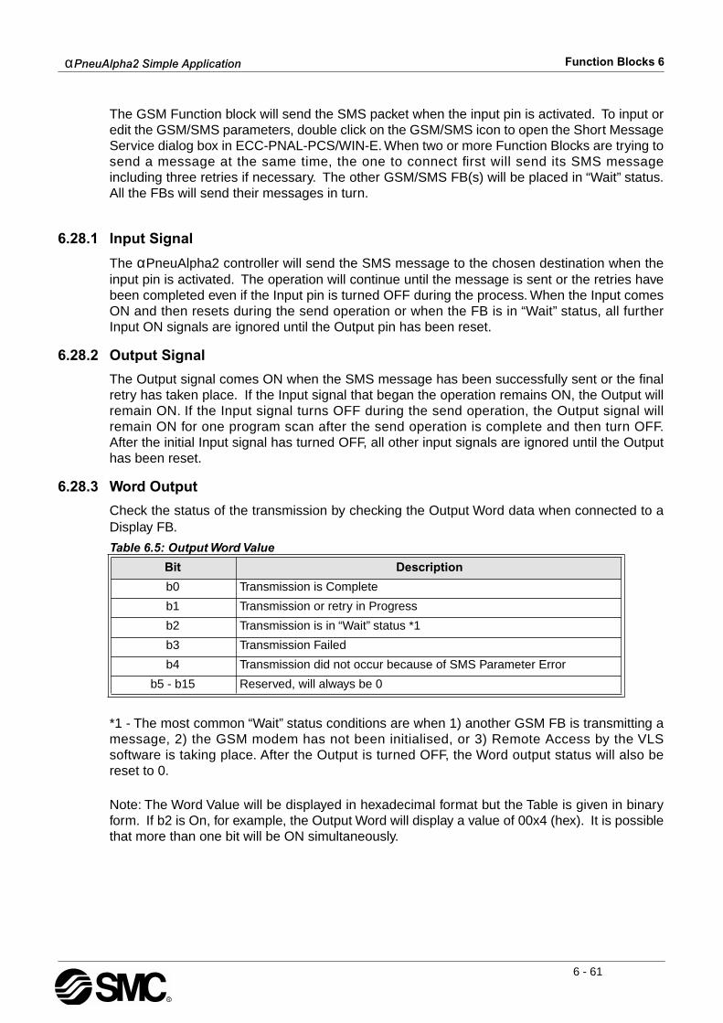
αPneuAlpha2 Simple Application Function Blocks 6
6 - 61
The GSM Function block will send the SMS packet when the input pin is activated. To input oredit the GSM/SMS parameters, double click on the GSM/SMS icon to open the Short MessageService dialog box in ECC-PNAL-PCS/WIN-E. When two or more Function Blocks are trying tosend a message at the same time, the one to connect first will send its SMS messageincluding three retries if necessary. The other GSM/SMS FB(s) will be placed in “Wait” status.All the FBs will send their messages in turn.
6.28.1 Input Signal
The αPneuAlpha2 controller will send the SMS message to the chosen destination when theinput pin is activated. The operation will continue until the message is sent or the retries havebeen completed even if the Input pin is turned OFF during the process. When the Input comesON and then resets during the send operation or when the FB is in “Wait” status, all furtherInput ON signals are ignored until the Output pin has been reset.
6.28.2 Output Signal
The Output signal comes ON when the SMS message has been successfully sent or the finalretry has taken place. If the Input signal that began the operation remains ON, the Output willremain ON. If the Input signal turns OFF during the send operation, the Output signal willremain ON for one program scan after the send operation is complete and then turn OFF.After the initial Input signal has turned OFF, all other input signals are ignored until the Outputhas been reset.
6.28.3 Word Output
Check the status of the transmission by checking the Output Word data when connected to aDisplay FB.
*1 - The most common “Wait” status conditions are when 1) another GSM FB is transmitting amessage, 2) the GSM modem has not been initialised, or 3) Remote Access by the VLSsoftware is taking place. After the Output is turned OFF, the Word output status will also bereset to 0.
Note: The Word Value will be displayed in hexadecimal format but the Table is given in binaryform. If b2 is On, for example, the Output Word will display a value of 00x4 (hex). It is possiblethat more than one bit will be ON simultaneously.
Table 6.5: Output Word Value
Bit Description
b0 Transmission is Complete
b1 Transmission or retry in Progress
b2 Transmission is in “Wait” status *1
b3 Transmission Failed
b4 Transmission did not occur because of SMS Parameter Error
b5 - b15 Reserved, will always be 0
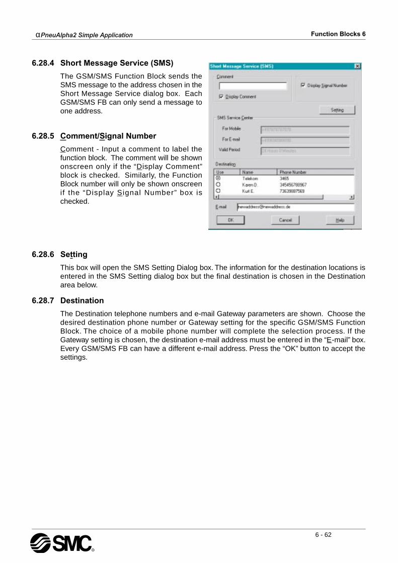
αPneuAlpha2 Simple Application Function Blocks 6
6 - 62
6.28.4 Short Message Service (SMS)
The GSM/SMS Function Block sends theSMS message to the address chosen in theShort Message Service dialog box. EachGSM/SMS FB can only send a message toone address.
6.28.5 Comment/Signal Number
Comment - Input a comment to label thefunction block. The comment will be shownonscreen only if the “Display Comment”block is checked. Similarly, the FunctionBlock number will only be shown onscreenif the “Display Signal Number” box ischecked.
6.28.6 Setting
This box will open the SMS Setting Dialog box. The information for the destination locations isentered in the SMS Setting dialog box but the final destination is chosen in the Destinationarea below.
6.28.7 Destination
The Destination telephone numbers and e-mail Gateway parameters are shown. Choose thedesired destination phone number or Gateway setting for the specific GSM/SMS FunctionBlock. The choice of a mobile phone number will complete the selection process. If theGateway setting is chosen, the destination e-mail address must be entered in the “E-mail” box.Every GSM/SMS FB can have a different e-mail address. Press the “OK” button to accept thesettings.
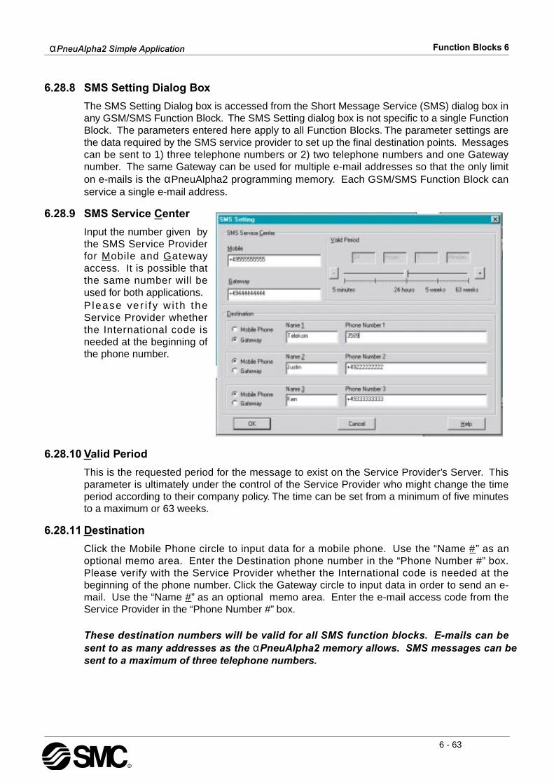
αPneuAlpha2 Simple Application Function Blocks 6
6 - 63
6.28.8 SMS Setting Dialog Box
The SMS Setting Dialog box is accessed from the Short Message Service (SMS) dialog box inany GSM/SMS Function Block. The SMS Setting dialog box is not specific to a single FunctionBlock. The parameters entered here apply to all Function Blocks. The parameter settings arethe data required by the SMS service provider to set up the final destination points. Messagescan be sent to 1) three telephone numbers or 2) two telephone numbers and one Gatewaynumber. The same Gateway can be used for multiple e-mail addresses so that the only limiton e-mails is the αPneuAlpha2 programming memory. Each GSM/SMS Function Block canservice a single e-mail address.
6.28.9 SMS Service Center
Input the number given bythe SMS Service Providerfor Mobile and Gatewayaccess. It is possible thatthe same number will beused for both applications.P lease ver i f y w i th theService Provider whetherthe International code isneeded at the beginning ofthe phone number.
6.28.10 Valid Period
This is the requested period for the message to exist on the Service Provider’s Server. Thisparameter is ultimately under the control of the Service Provider who might change the timeperiod according to their company policy. The time can be set from a minimum of five minutesto a maximum or 63 weeks.
6.28.11 Destination
Click the Mobile Phone circle to input data for a mobile phone. Use the “Name #” as anoptional memo area. Enter the Destination phone number in the “Phone Number #” box.Please verify with the Service Provider whether the International code is needed at thebeginning of the phone number. Click the Gateway circle to input data in order to send an e-mail. Use the “Name #” as an optional memo area. Enter the e-mail access code from theService Provider in the “Phone Number #” box.
These destination numbers will be valid for all SMS function blocks. E-mails can besent to as many addresses as the αPneuAlpha2 memory allows. SMS messages can be sent to a maximum of three telephone numbers.

αPneuAlpha2 Simple Application Function Blocks 6
6 - 64
6.28.12 Error Messages
The Status of the GSM communication can be checked in the right hand side of the“Controller/Diagnosis of Controller” dialog box. This dialog box cannot be accessed while thecontroller is running.
The CME and CMS Error boxes give information to the functioning of Mobile Equipment (ME),please refer to the GSM modem manual for more details.
Modem Settings/Front Panel KeysThe settings required to send SMS packets via a GSM modem or to set up the αPneuAlpha2controller for remote access can be accomplished with the front panel keys. It is possible toperform remote operations with a standard modem but it is not possible to send SMS packets.
The numerous parameters and options for using the GSM modem canbe set using the front panel keys although this procedure issignificantly more difficult than using the ECC-PNAL-PCS/WIN-Esoftware.
To begin the process from the Top Menu, scroll down to “Others/SerialCom/GSM” and view the options shown at right.
Comformat (Communication Format)Upon entering the GSM option, the ComFormat dialog will be the firstoption. The Comformat allows the user to set the communicationsettings for Data Length, Parity, Stop Bit, and Baudrate.
Scroll to the setting to be adjusted.

αPneuAlpha2 Simple Application Function Blocks 6
6 - 65
Data Length Select a Data length send parameter of 7 or 8 bits.
ParitySelect from three options for Parity - None, Odd or Even.
Stop BitsChoose the number of stop bits - 1 bit or 2 bits.
Baud RateSelect the baud rate - 9600 or 19200 bps.
DefaultThe controller can be returned to the default communication settings -DataLength = 8 bits; Parity = None; Stop Bits = 1; and Baud Rate = 9600 bps - by pressing the“OK” when the pointer is on the Default option.
GSM Init Command (GSM Initialisation Command)The GSM modem must have an initialisation command string. Afterchoosing the “GSM Init” option, the Command and Delay Time settingswill appear.
Command Setting Choose “Command” to enter the AT command. Details for the ATcommand should be included in the literature for the modem. Enter thestring by choosing the characters with the “ ” and “ ” arrows. When adesired letter is shown onscreen, move to the right by pressing the “ ”key. The character will remain in the previous cursor space. Do not press the “OK” key until thecommand has been entered in its entirety. Move to the left for editing purposes with the “ ”key.
Delay TimeThe Delay Time Setting will delay the transmission of the initializationcommand while the modem completes its power up. Use the “+” key toincrement the value and the “-” to decrement the value within the rangeof 0 - 10 seconds. Enter the value by pressing the “OK” key.
GSM Remote CommandRemote access from a computer running the VLS software is allowedwhen “Permit” is chosen. SMS packets cannot be sent under the “Permit” setting but can be sentwhen “Forbid” is used.
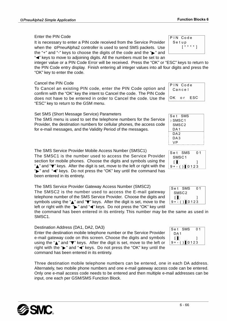
αPneuAlpha2 Simple Application Function Blocks 6
6 - 66
Enter the PIN Code It is necessary to enter a PIN code received from the Service Providerwhen the αPneuAlpha2 controller is used to send SMS packets. Usethe “+” and “-” keys to choose the digits of the code and the “ ” and“ ” keys to move to adjoining digits. All the numbers must be set to aninteger value or a PIN Code Error will be received. Press the “OK” or “ESC” keys to return tothe PIN Code entry display. Finish entering all integer values into all four digits and press the“OK” key to enter the code.
Cancel the PIN CodeTo Cancel an existing PIN code, enter the PIN Code option andconfirm with the “OK” key the intent to Cancel the code. The PIN Codedoes not have to be entered in order to Cancel the code. Use the“ESC” key to return to the GSM menu.
Set SMS (Short Message Service) ParametersThe SMS menu is used to set the telephone numbers for the ServiceProvider, the destination numbers for cellular phones, the access codefor e-mail messages, and the Validity Period of the messages.
The SMS Service Provider Mobile Access Number (SMSC1)The SMSC1 is the number used to access the Service Providersection for mobile phones. Choose the digits and symbols using the“ ” and “ ” keys. After the digit is set, move to the left or right with the“ ” and “ ” keys. Do not press the “OK” key until the command hasbeen entered in its entirety.
The SMS Service Provider Gateway Access Number (SMSC2)The SMSC2 is the number used to access the E-mail gatewaytelephone number of the SMS Service Provider. Choose the digits andsymbols using the “ ” and “ ” keys. After the digit is set, move to theleft or right with the “ ” and “ ” keys. Do not press the “OK” key untilthe command has been entered in its entirety. This number may be the same as used inSMSC1.
Destination Address (DA1, DA2, DA3)Enter the destination mobile telephone number or the Service Providere-mail gateway code on this screen. Choose the digits and symbolsusing the “ ” and “ ” keys. After the digit is set, move to the left orright with the “ ” and “ ” keys. Do not press the “OK” key until thecommand has been entered in its entirety.
Three destination mobile telephone numbers can be entered, one in each DA address.Alternately, two mobile phone numbers and one e-mail gateway access code can be entered.Only one e-mail access code needs to be entered and then multiple e-mail addresses can beinput, one each per GSM/SMS Function Block.

αPneuAlpha2 Simple Application Function Blocks 6
6 - 67
Validity PeriodThe Validity Period is a request to the SMS Service Provider to keepthe message on their Server for a length of time. Each ServiceProvider may have their own policies on the allowable time messagescan be kept. Please check with your local Service Provider to obtainthese details. Use the “+” and “-” keys to change the value within the range of 5 minutes to 63weeks.
GSM Status Check the status of the GSM communication in the followingcategories.
Check the Status of the GSM modem settings and SMS messagetransmissions through the table below.
Note: *1 This bit is not linked to the Remote Access Setting which only enables remoteaccess. This bit checks if Remote Access is currently in progress.
Table 3.1: GSM Modem Status
Bit Status On (1) Off (0)
b0 Error in Connecting to GSM Modem. Yes No
b1 GSM Initialisation Command Normal. Yes No
b2 PIN Code is Setup in the Controller. Yes No
b3 Network Registration. Registered Not Registered
b4 GSM CME Error. Yes No
b5 GSM CSM Error. Yes No
b6 Remote Access In Progress. *1 Yes No
b7-11 Reserved Reserved = 0
b12 SMS Message Contents. Message No Message
b13 SMS Transmission Standby State. Transmitting/Off (1/0) Transmitting Off
b14 SMS Transmission Failed 3 Times. Yes/No (1/0) Yes No
b15 SMS Transmission not sent due to incorrect SMS Func-tion Block Setting. Yes No

αPneuAlpha2 Simple Application Function Blocks 6
6 - 68
CME ErrorThis CME Error status gives information to the functioning of MobileEquipment (ME), please refer to the GSM modem manual for moredetails.
CMS ErrorThis value gives error information relevant to the Mobile Equipment(ME) or Network, please refer to the GSM modem manual for moredetails.
Table 3.2: Mobile Equipment Error Codes
Value Description Value Description
-1 No Error 17 SIM PIN2 Required
0 Phone Failure 18 SIM PUK2 Required
1 No Connection to Phone 20 Memory Full
2 Phone-Adaptor Link Reserved 21 Invalid Index
3 Operation Not Allowed 22 Not Found
4 Operation Not Supported 23 Memory Full
5 PH-SIM PIN Required 24 Text String Too Long
10 SIM Failure 25 Invalid Characters in Text String
11 SIM PIN Required 26 Dial String Too Long
12 SIM PUK Required 27 Invalid Characters in Dial String
13 SIM Failure 30 No Network Service
14 SIM Busy 31 Network Timeout
15 SIM Wrong 100 Unknown
16 Incorrect Password ...256 All other values below 256 are reserved.
Table 3.3: Mobile Equipment and Network Error Codes
Value Description Value Description
-1 No Error 315 SIM Wrong
0 - 127 GSM 04.11 Annex E-2 Values 316 SIM PUK Required
128 - 256 GSM 03.40 Subclause 9.2.3.22values 317 SIM PIN2 Required
300 ME Failure 318 SIM PUK2 Required
301 SMS Service of ME reserved 320 Memory Failure
302 Operation Not Allowed 321 Invalid Memory Index
303 Operation Not Supported 322 Memory Full
304 Invalid PDU Mode Parameter 330 SMSC Address Unknown
305 Invalid Text Mode Parameter 331 No Network Service
310 SIM not Inserted 332 Network Timeout
311 SIM PIN Required 340 No +CNMA acknowledgment expected
312 PH-SIM PIN Required 500 Unknown Error
313 SIM Failure ... 511 Unused Values in the range from 256 to 511are Reserved.
314 SIM Busy 512 (+) Manufacturer Specific

αPneuAlpha2 Simple Application Function Blocks 6
6 - 69
Signal Strength (Sigstreng)Check the signal strength of the GSM modem signal. Generally goodoperation is possible with a signal strength of 10% or more.
Table 3.4: Signal Strength Reference Table
Value % Receiving Level
0 -113 dBm or less
1 -111 dBm
2 - 30 -109 to -53 dBm
31 -51 dBm or greater
99 Not known
αPneuAlpha2 Simple Application Function Blocks 6
6 - 70
6.29 Random One Shot Block
This Function Block is equivalent to the One Shot function block except that the new block hasonly randomly generated pulse time. An Upper and Lower Time Limit value can be set inincrements of 10 ms (0.00 to 327.67 seconds), 100 ms (00.0 - 3267.7 seconds), and 1 second(0 - 32767 seconds) for the random number generation. If the Input signal turns Off during thepulse interval, the Output is Reset along with the pulse time. Table 6.29: Random One Shot function block
Note: The set time cannot be less than one scan time for the controller; otherwise, theRandom One Shot Function Block will not perform its assigned task for the time specified.Users can monitor the scan time from the αPneuAlpha2 Series Controller. Scan time isdependent on the user- program; therefore, caution is needed as and when time units areselected.
Setup of the Random One Shot Function Block directly from the αPneuAlpha2 series Controller1 ) Allocate the input pin to be used for the function block.
2 ) Press the “OK” key with the cursor in the function block. The function block edit screen is displayed as shown.
Function Set Item Description
I Input pin for the random one shot function block
C Clear pin for the random one shot function block
FB
1) A random one shot time is generated between the upper and lowerthreshold values.
2) The random value only occurs in correlation to the ON status of theinput.
3) The clear signal input reset the output, random one shot value andcurrent time.
4) If the Upper threshold is equal to or larger than the lower threshold,the random one shot time is set in the range lower threshold to upperthreshold.
5) If the Upper threshold is less then than the lower threshold, therandom one shot time is set in the range 0 to upper threshold or lowerthreshold to 32767.
6) If the lower threshold = Upper threshold, the random one shot isequal to the upper threshold = lower threshold.
7) Time units: 10ms, 100ms or 1s (*Note)
Output1) The following items are available for other function blocks: a) Random One Shot value b) Current One Shot value

αPneuAlpha2 Simple Application Function Blocks 6
6 - 71
3 ) Press the “OK” key to set the Time unit for the random delayed output.Choose either a 10ms, 100ms or 1s time interval using the “ and ” keys to highlight theoption and press the “OK” key when ready.
4 ) Return to the function block edit screen. Using the “ and ” keys highlight the Setup FBand press the “OK” key.
5 ) A RandomVal in conjunction with the specified time units allocated earlier can be enteredfrom pressing the “OK” key having highlighted the RandomVal option using the “ and ”keys. Press the “ ” key hence highlighting the 0s time value and use the “+ or -” keys toenter a time value. Press the “OK” key to accept and return to the function block settingscreen.
6 ) Highlight the Limit:L,H option and press the “OK” key. A high and low limit can be set forthe Random One Shot function block. Using the “ , , + and -” keys enter values for thehigh and low limits in accordance with the time intervals specified earlier.
7 ) Press the “OK” key to accept the High and Low limit subsequently use the “ESC” key toreturn to the FBd

αPneuAlpha2 Simple Application Function Blocks 6
6 - 72
6.30 Delayed One Shot Block
This block is equivalent to a combination of the Delay and the One Shot function block. Set anON delay for the rising pulse of the Input signal or an OFF delay for the falling pulse. This FBwill process the ON delay time before turning the Output ON for the OneShot pulse time and/ordelay the Output resetting until the OFF delay time has processed. Table 6.30: Delayed One Shot Function Block
Note: The set time cannot be less than one scan time for the controller; otherwise, the DelayedOne Shot Function Block will not perform its assigned task for the time specified. Users canmonitor the scan time from the αPneuAlpha2 Series Controller. Scan time is dependent on theuser- program; therefore, caution is needed as and when time units are selected.
1 ) Delayed One-Shot (Delay starts when OFF to ON)
2 ) Delayed One-Shot (Delay starts when ON to OFF.
Function Set Item Description
I Input pin for the delayed one shot function block
C Clear pin for the delayed one shot function block
FB
1) Delay Time a) OFF to ON b) ON to OFF
2) Delay Time range: 0 to 32767
3) One Shot Time range: 0 to 32767
4) Time units: 10ms, 100ms or 1s (*Note)
5) When the Clear signal is set ON, the current Delay Time, currentOne Shot Time will be cleared. The Output will reset OFF.
Output
The following items are available for another function block:1) Word Output a) Delay b) Current Delay c) One Shot d) Current One Shot
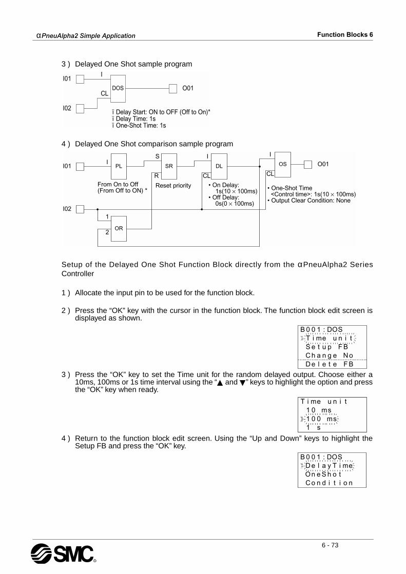
αPneuAlpha2 Simple Application Function Blocks 6
6 - 73
3 ) Delayed One Shot sample program
4 ) Delayed One Shot comparison sample program
Setup of the Delayed One Shot Function Block directly from the αPneuAlpha2 SeriesController
1 ) Allocate the input pin to be used for the function block.
2 ) Press the “OK” key with the cursor in the function block. The function block edit screen isdisplayed as shown.
3 ) Press the “OK” key to set the Time unit for the random delayed output. Choose either a10ms, 100ms or 1s time interval using the “ and ” keys to highlight the option and pressthe “OK” key when ready.
4 ) Return to the function block edit screen. Using the “Up and Down” keys to highlight theSetup FB and press the “OK” key.
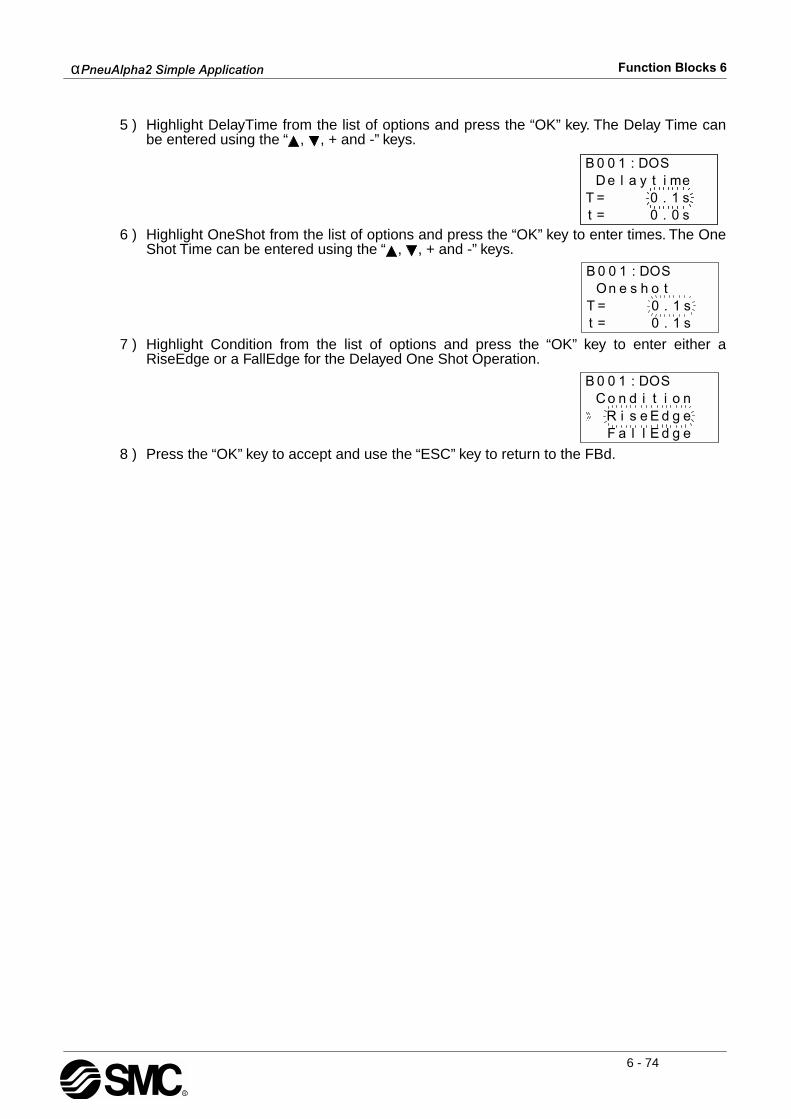
αPneuAlpha2 Simple Application Function Blocks 6
6 - 74
5 ) Highlight DelayTime from the list of options and press the “OK” key. The Delay Time canbe entered using the “ , , + and -” keys.
6 ) Highlight OneShot from the list of options and press the “OK” key to enter times. The OneShot Time can be entered using the “ , , + and -” keys.
7 ) Highlight Condition from the list of options and press the “OK” key to enter either aRiseEdge or a FallEdge for the Delayed One Shot Operation.
8 ) Press the “OK” key to accept and use the “ESC” key to return to the FBd.

αPneuAlpha2 Simple Application Function Blocks 6
6 - 75
6.31 Delayed Alternate Block
The function block is used to generate a delayed alternate pulse to the output pin of thefunction block.Table 6.31: Delayed Alternate Function Block
Note: The delay time cannot be less than one scan time for the controller; otherwise, theDelayed Alternate Function Block will not perform its assigned task for the time specified.Users can monitor the scan time from the αPneuAlpha2 Series Controller. Scan time isdependent on the user-program; therefore, caution is needed as and when time units areselected.
1 ) Delayed Alternate Operation
2 ) Delayed Alternate sample program
3 ) Delayed Alternate comparison sample program
Function Set Item Description
I Input pin for delayed alternate function block
C Clear pin for delayed alternate function block
FB1) Time units: 10ms, 100ms or 1s (*Note)
2) Delay Time range: 0 to 32767
Output
The following items are available for another function block:1) Word Output a) Delay set value b) Current value of delay time
2) Bit output a) The delay action occurs after the function block sees the risingedge of the input signal. b) After the specified Delay time, the Output signal changes state c) When the Clear Input signal sets ON, the Current Delay Time iscleared and the Output signal will reset OFF.

αPneuAlpha2 Simple Application Function Blocks 6
6 - 76
Setup of the Delayed Alternate Function Block directly from the αPneuAlpha2 SeriesController
1 ) Allocate the input pin to be used for the function block.
2 ) Press the “OK” key with the cursor in the function block. The function block edit screen isdisplayed as shown.
3 ) Press the “OK” key to set the Time unit for the delayed alternate output. Choose either a10ms, 100ms or 1s time interval using the “ and ” keys to highlight the option and pressthe “OK” key when ready.
4 ) Return to the function block edit screen. Using the “ and ” keys highlight the Setup FBand press the “OK” key.
5 ) Press the “OK” to accept subsequently use the “ESC” key to return to the FBd.
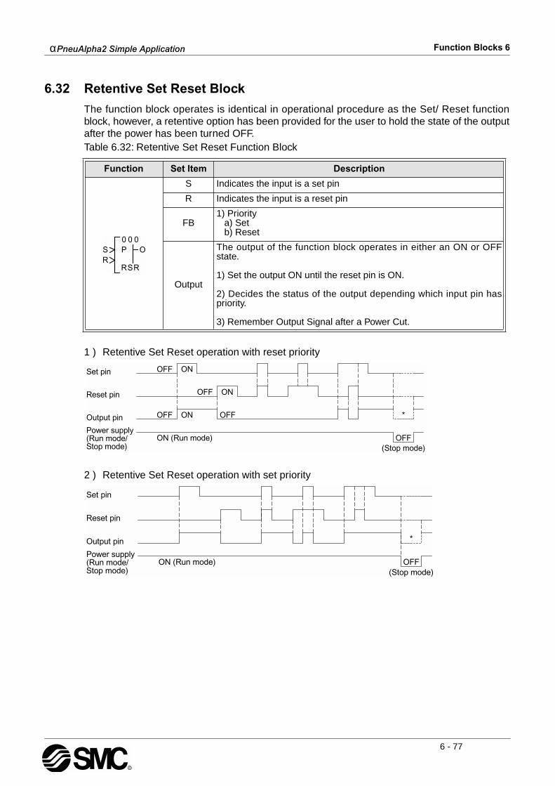
αPneuAlpha2 Simple Application Function Blocks 6
6 - 77
6.32 Retentive Set Reset Block
The function block operates is identical in operational procedure as the Set/ Reset functionblock, however, a retentive option has been provided for the user to hold the state of the outputafter the power has been turned OFF.Table 6.32: Retentive Set Reset Function Block
1 ) Retentive Set Reset operation with reset priority
2 ) Retentive Set Reset operation with set priority
Function Set Item Description
S Indicates the input is a set pin
R Indicates the input is a reset pin
FB1) Priority a) Set b) Reset
Output
The output of the function block operates in either an ON or OFFstate.
1) Set the output ON until the reset pin is ON.
2) Decides the status of the output depending which input pin haspriority.
3) Remember Output Signal after a Power Cut.

αPneuAlpha2 Simple Application Function Blocks 6
6 - 78
Setup of the Retentive Set/Reset Function Block directly from the αPneuAlpha2 SeriesController
1 ) Allocate the input pin to be used for the function block.
2 ) Press the “OK” key with the cursor in the function block. The function block edit screen isdisplayed as shown.
3 ) The function block operates on a Set or Reset priority. Select the priority using the “ and” keys and subsequently press the “OK” key.
4 ) Press the “OK” key and use the “ESC” key to return to the FBd.
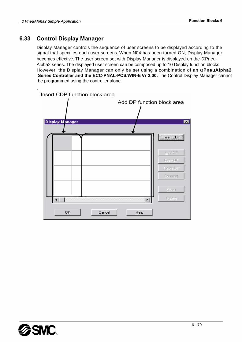
αPneuAlpha2 Simple Application Function Blocks 6
6 - 79
6.33 Control Display Manager
Display Manager controls the sequence of user screens to be displayed according to thesignal that specifies each user screens. When N04 has been turned ON, Display Managerbecomes effective. The user screen set with Display Manager is displayed on the αPneu-Alpha2 series. The displayed user screen can be composed up to 10 Display function blocks. However, the Display Manager can only be set using a combination of an αPneuAlpha2 Series Controller and the ECC-PNAL-PCS/WIN-E Vr 2.00. The Control Display Manager cannot be programmed using the controller alone.
.
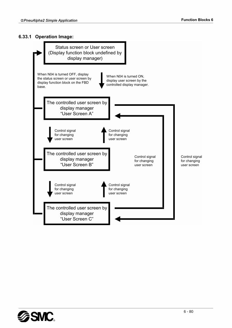
αPneuAlpha2 Simple Application Function Blocks 6
6 - 80
6.33.1 Operation Image:
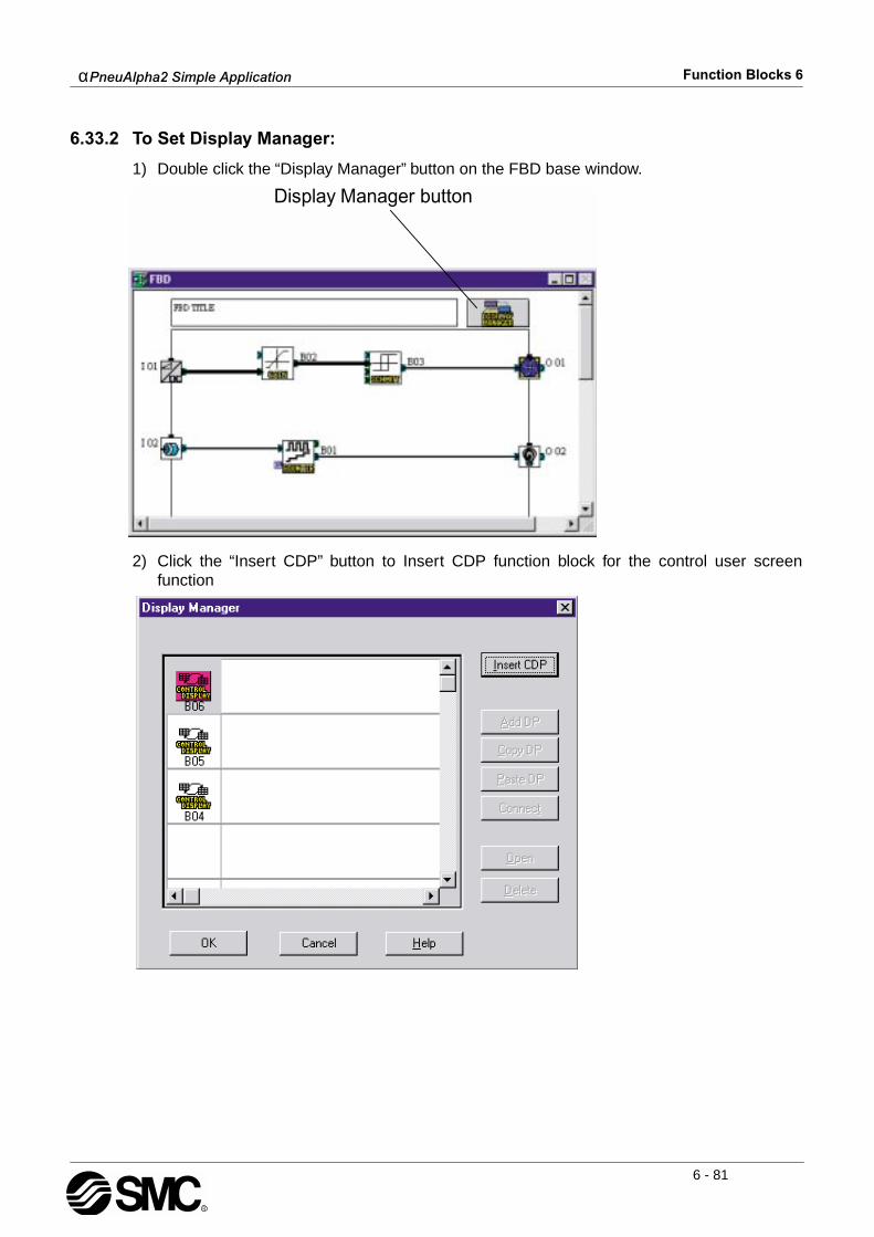
αPneuAlpha2 Simple Application Function Blocks 6
6 - 81
6.33.2 To Set Display Manager:
1) Double click the “Display Manager” button on the FBD base window.
2) Click the “Insert CDP” button to Insert CDP function block for the control user screenfunction
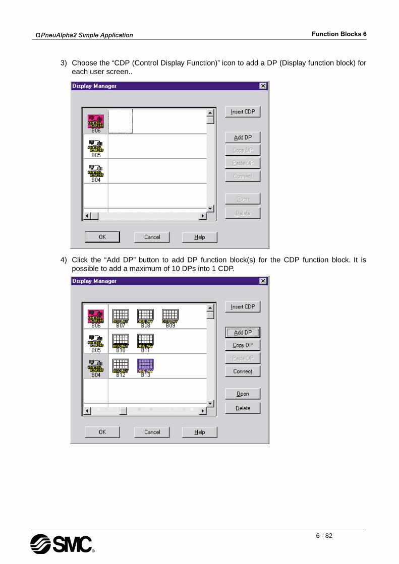
αPneuAlpha2 Simple Application Function Blocks 6
6 - 82
3) Choose the “CDP (Control Display Function)” icon to add a DP (Display function block) foreach user screen..
4) Click the “Add DP” button to add DP function block(s) for the CDP function block. It ispossible to add a maximum of 10 DPs into 1 CDP.

αPneuAlpha2 Simple Application Function Blocks 6
6 - 83
5) Choose the “Display” icon for indication BF (Function Block) or Analog value, and click“Connect” button.When not displaying them, please go to step 7)..
6) Click the “Connect” button to display the FB value or the Analog Input value
- Free: Displays the Text, Date or Time. (Default setting)
- FB Word Output: Displays FB value. Choose function blocks from list.
- Analog Input: Displays Analog Input value. Choose Analog Input port.
When completing connection, click the "OK" button.

αPneuAlpha2 Simple Application Function Blocks 6
6 - 84
7) Double-click the “Display” icon or click the “Open” button to set parameters. Furtherinformation about parameters of the Display function block can be found in theprogramming manual and “Help” on the ECC-PNAL-PCS/WIN-E.On completion of the parameter settings, click the “OK” button.
Choosing “Free” on step 6).

αPneuAlpha2 Simple Application Function Blocks 6
6 - 85
Choosing “FB Word Output” on step 6)
Choosing “Analog Input” on step 6)

αPneuAlpha2 Simple Application Function Blocks 6
6 - 86
8) Double-click the “CDP” icon or click the “Open” button to set parameter.
9) Select the signal for changing user screens from the pull-down menu options.

αPneuAlpha2 Simple Application Function Blocks 6
6 - 87
10)Select the next displayed user screen from the pull-down menu options.When completing the control key setting, click the "OK" button.
11)When completing the control key’s setting, click the “OK” button.
6.34 Connect Block
The Connect function block is an internal device used to show the memory used by input bits,system bits, AS-interface bits, and the operation keys. No function block appears on screen orshows as being used in the “Memory Configuration Usage” dialog box, the purpose is only tocalculate the memory that is used by the bits listed above.Table 6.33: Connect Function Block
Function Set Item Description
I Input pin for the Connect Function Block.
Output
The output ON/OFF status is controlled by the condition of the inputsignal.
1) The output signal will be high if the input signal is ON. The outputsignal will be low if the input signal is OFF.
2) If the input pin is disconnected the ON/OFF status of the outputcan be controlled from ECC-PNAL-PCS/WIN-E installed onto a per-sonal computer.
00
B_
OI0
αPneuAlpha2 Simple Application Function Blocks 6
6 - 88
MEMO
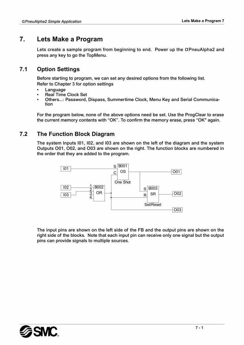
α
PneuAlpha2 Simple Application
Lets Make a Program 7
7 - 1
7. Lets Make a Program
Lets create a sample program from beginning to end. Power up the
α
PneuAlpha2 andpress any key to go the TopMenu.
7.1 Option Settings
Before starting to program, we can set any desired options from the following list.Refer to Chapter 3 for option settings• Language• Real Time Clock Set• Others...: Password, Dispass, Summertime Clock, Menu Key and Serial Communica-
tion
For the program below, none of the above options need be set. Use the ProgClear to erasethe current memory contents with “OK”. To confirm the memory erase, press “OK" again.
7.2 The Function Block Diagram
The system Inputs I01, I02, and I03 are shown on the left of the diagram and the systemOutputs O01, O02, and O03 are shown on the right. The function blocks are numbered inthe order that they are added to the program.
The input pins are shown on the left side of the FB and the output pins are shown on theright side of the blocks. Note that each input pin can receive only one signal but the outputpins can provide signals to multiple sources.
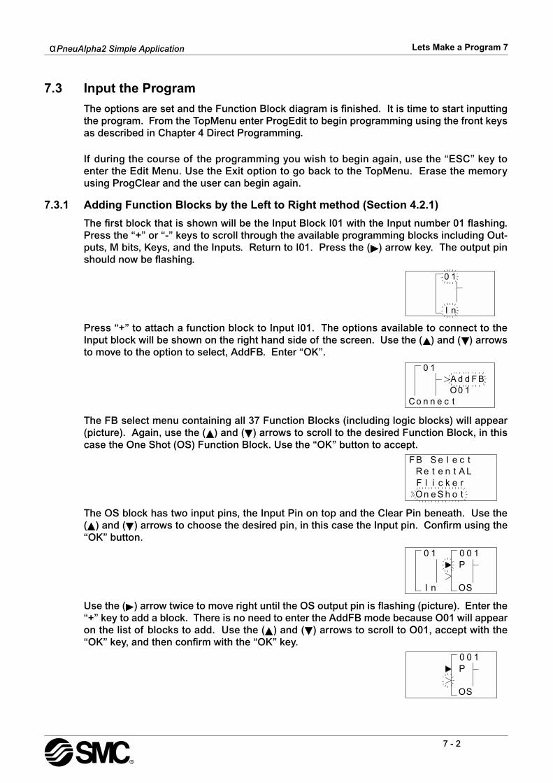
α
PneuAlpha2 Simple Application
Lets Make a Program 7
7 - 2
7.3 Input the Program
The options are set and the Function Block diagram is finished. It is time to start inputtingthe program. From the TopMenu enter ProgEdit to begin programming using the front keysas described in Chapter 4 Direct Programming.
If during the course of the programming you wish to begin again, use the “ESC” key toenter the Edit Menu. Use the Exit option to go back to the TopMenu. Erase the memoryusing ProgClear and the user can begin again.
7.3.1 Adding Function Blocks by the Left to Right method (Section 4.2.1)
The first block that is shown will be the Input Block I01 with the Input number 01 flashing.Press the “+” or “-” keys to scroll through the available programming blocks including Out-puts, M bits, Keys, and the Inputs. Return to I01. Press the ( ) arrow key. The output pinshould now be flashing.
Press “+” to attach a function block to Input I01. The options available to connect to theInput block will be shown on the right hand side of the screen. Use the ( ) and ( ) arrowsto move to the option to select, AddFB. Enter “OK”.
The FB select menu containing all 37 Function Blocks (including logic blocks) will appear(picture). Again, use the ( ) and ( ) arrows to scroll to the desired Function Block, in thiscase the One Shot (OS) Function Block. Use the “OK” button to accept.
The OS block has two input pins, the Input Pin on top and the Clear Pin beneath. Use the( ) and ( ) arrows to choose the desired pin, in this case the Input pin. Confirm using the“OK” button.
Use the ( ) arrow twice to move right until the OS output pin is flashing (picture). Enter the“+” key to add a block. There is no need to enter the AddFB mode because O01 will appearon the list of blocks to add. Use the ( ) and ( ) arrows to scroll to O01, accept with the“OK” key, and then confirm with the “OK” key.
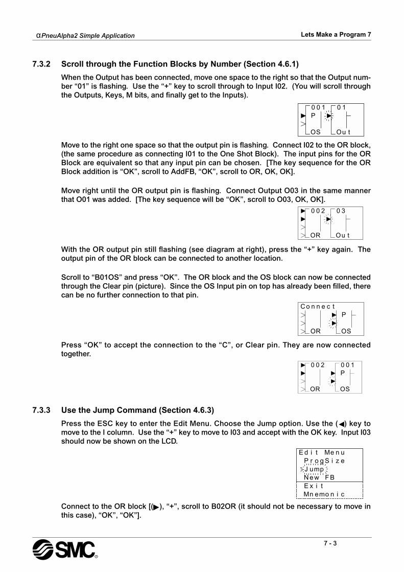
α
PneuAlpha2 Simple Application
Lets Make a Program 7
7 - 3
7.3.2 Scroll through the Function Blocks by Number (Section 4.6.1)
When the Output has been connected, move one space to the right so that the Output num-ber “01” is flashing. Use the “+” key to scroll through to Input I02. (You will scroll throughthe Outputs, Keys, M bits, and finally get to the Inputs).
Move to the right one space so that the output pin is flashing. Connect I02 to the OR block,(the same procedure as connecting I01 to the One Shot Block). The input pins for the ORBlock are equivalent so that any input pin can be chosen. [The key sequence for the ORBlock addition is “OK”, scroll to AddFB, “OK”, scroll to OR, OK, OK].
Move right until the OR output pin is flashing. Connect Output O03 in the same mannerthat O01 was added. [The key sequence will be “OK”, scroll to O03, OK, OK].
With the OR output pin still flashing (see diagram at right), press the “+” key again. Theoutput pin of the OR block can be connected to another location.
Scroll to “B01OS” and press “OK”. The OR block and the OS block can now be connectedthrough the Clear pin (picture). Since the OS Input pin on top has already been filled, therecan be no further connection to that pin.
Press “OK” to accept the connection to the “C”, or Clear pin. They are now connectedtogether.
7.3.3 Use the Jump Command (Section 4.6.3)
Press the ESC key to enter the Edit Menu. Choose the Jump option. Use the ( ) key tomove to the I column. Use the “+” key to move to I03 and accept with the OK key. Input I03should now be shown on the LCD.
Connect to the OR block [( ), “+”, scroll to B02OR (it should not be necessary to move inthis case), “OK”, “OK”].

α
PneuAlpha2 Simple Application
Lets Make a Program 7
7 - 4
7.3.4 Use the NewFB command
Use the “ESC” key to enter the Edit Menu again. On this occasion enter the New FBoption. Scroll to the Set/Reset FB and select with the “OK” button. The SR diagram shouldnow appear on the LCD.
7.3.5 Connect the Function Blocks from Right to Left (Section 4.2.2)
Move to the left until one of the two input pins is flashing. The top pin is the Set pin whichwill be connected to the OS block. The Reset pin on bottom will be connected to the ORblock. Move to the Set pin and press the “+” key; the available blocks to add will be shownon the left of the screen. Scroll down through the choices until B01OS is shown (picture).Use the “OK” to choose the block, then the “OK” key again to confirm the choice.
Use the ( ) arrow to move down to the Reset pin. Connect the OR block using the sameprocedure. [“+”, scroll
(
) to B02OR, “OK”, “OK”]
Move to the SR output pin and connect Output O02 using the Left to Right method of con-necting blocks. [
(
),
(
), “+”, scroll to O02, “OK”, “OK”].Move back to the left one space. The following diagram should now be showing on theLCD.

α
PneuAlpha2 Simple Application
Lets Make a Program 7
7 - 5
7.4 Set up the Function Block Parameters (Section 4.5.1)
The options for the Function Blocks now need to be Set.Move left until the SR Function Block number (03) is flashing. Press the “OK” to enter theFB Edit Menu and OK again to enter the Setup FB option. Choose the Reset option andenter the data into program memory with the “OK” button.
This is the only option in the SR Function Block. Use the “ESC” key to return to the Func-tion Block Diagram board.
The OR Block, like all the Logic Blocks, does not have any parameters that can or need tobe set.
Proceed to the One Shot Function Block. Use either the Jump command, trace the paththrough the Set pin, or simply press the “+” key to scroll through the Function Blocks.Enter the Setup FB option. (When the One Shot Function Block number (01) is flashing,press the “OK” key twice).
The One Shot Function Block allows the for three different time increment settings: 10ms,100ms or 1s.
Press the “OK” key and select the Setup FB option subsequently press the “OK” to enterfunction block settings. There are two option screens to be set. Enter the OneShot optionusing the “OK” button
The One Shot screen has two timers that can be set. The “T” timer is the Set Time for theOne Shot block Output signal. The t timer is the elapsed time or actual time the OneShothas been ON. If a value is input for t, the first time the One Shot block is activated it willbegin timing from the input value.
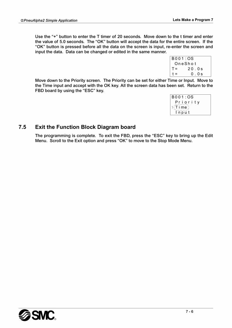
α
PneuAlpha2 Simple Application
Lets Make a Program 7
7 - 6
Use the “+” button to enter the T timer of 20 seconds. Move down to the t timer and enterthe value of 5.0 seconds. The “OK” button will accept the data for the entire screen. If the“OK” button is pressed before all the data on the screen is input, re-enter the screen andinput the data. Data can be changed or edited in the same manner.
Move down to the Priority screen. The Priority can be set for either Time or Input. Move tothe Time input and accept with the OK key. All the screen data has been set. Return to theFBD board by using the “ESC” key.
7.5 Exit the Function Block Diagram board
The programming is complete. To exit the FBD, press the “ESC” key to bring up the EditMenu. Scroll to the Exit option and press “OK” to move to the Stop Mode Menu.

α
PneuAlpha2 Simple Application
Appendix 8
8 - 1
8. Appendix
8.1 Associated Manuals
"
Refer to these manuals.
#
Refer to this manual if necessary.
$
Refer to the content of these manuals if necessary though it is included in
α
PneuAlpha2
Hardware Manual.
Manual Name Manual No. Description
"
α
PneuAlpha2 Hardware Manual
JY992D97901This manual contains hardware explanations of wiring, installation and specification, etc. regarding the
α
PneuAlpha2 Series Controller.
#
α
PneuAlpha Software Manual
<English only>JY992D74001
This manual contains explanations of operation regarding ECC-PNAL-PCS/WIN-E Programming Software.
#
α
PneuAlpha2 Series Communication User’s
Manual<English only>
JY992D97701
This manual contains setup explanations for messaging, diagnostics, bit assignments, etc. for communication using the
α
PneuAlpha2 Series Controller.
$
α
PneuAlpha2 Series Installation Manual
JY992D97501This manual contains hardware explanations for installation regarding the
α
PneuAlpha2 Series Controller.
$
ECC-PNAL2-4EX, ECC-PNAL2-4EX-A2,
ECC-PNAL2-4EYR, ECC-PNAL2-4EYT Installation
Manual
JY992D97401
This manual contains hardware explanations for installation regarding the ECC-PNAL2-4EX, ECC-PNAL2-4EX-A2, ECC-PNAL2-4EYR and ECC-PNAL2-4EYT extension modules.
$
ECC-PNAL2-EEPROM-2Hardware Manual
JY992D96801This manual contains hardware explanations for installation regarding the ECC-PNAL2-EEPROM-2.
$
ECC-PNAL-232CABHardware Manual
JY992D76001This manual contains hardware explanations for installation regarding the ECC-PNAL-232CAB.
$
ECC-PNAL2-GSM-CABHardware Manual
JY992D97201This manual contains hardware explanations for installation regarding the ECC-PNAL2-GSM-CAB.
$
ECC-PNAL-ASI-BD, ECC-PNAL2-ASI-BD
Hardware Manual
JY992D81401JY992D81402
This manual contains hardware explanations for wiring, installation and specification, etc. regarding the ECC-PNAL-ASI-BD and ECC-PNAL2-ASI-BD.
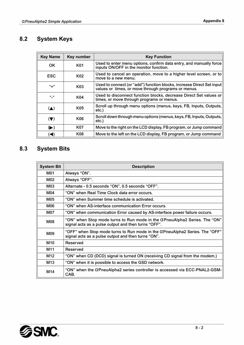
α
PneuAlpha2 Simple Application
Appendix 8
8 - 2
8.2 System Keys
8.3 System Bits
Key Name Key number Key Function
OK K01 Used to enter menu options, confirm data entry, and manually forceinputs ON/OFF in the monitor function.
ESC K02 Used to cancel an operation, move to a higher level screen, or tomove to a new menu.
“+” K03 Used to connect (or “add”) function blocks, increase Direct Set inputvalues or times, or move through programs or menus.
“-” K04 Used to disconnect function blocks, decrease Direct Set values ortimes, or move through programs or menus.
( ) K05 Scroll up through menu options (menus, keys, FB, Inputs, Outputs,etc.)
( ) K06 Scroll down through menu options (menus, keys, FB, Inputs, Outputs,etc.)
( ) K07 Move to the right on the LCD display, FB program, or Jump command
( ) K08 Move to the left on the LCD display, FB program, or Jump command
System Bit Description
M01 Always “ON”.
M02 Always “OFF”.
M03 Alternate - 0.5 seconds “ON”, 0.5 seconds “OFF”.
M04 “ON” when Real Time Clock data error occurs.
M05 “ON” when Summer time schedule is activated.
M06 “ON” when AS-interface communication Error occurs.
M07 “ON” when communication Error caused by AS-interface power failure occurs.
M08 “ON” when Stop mode turns to Run mode in the
α
PneuAlpha2 Series. The “ON”signal acts as a pulse output and then turns “OFF”.
M09 “OFF” when Stop mode turns to Run mode in the
α
PneuAlpha2 Series. The “OFF”signal acts as a pulse output and then turns “ON”.
M10 Reserved
M11 Reserved
M12 “ON” when CD (DCD) signal is turned ON (receiving CD signal from the modem.)
M13 “ON” when it is possible to access the GSD network.
M14 “ON” when the
α
PneuAlpha2 series controller is accessed via ECC-PNAL2-GSM-CAB.

α
PneuAlpha2 Simple Application
Appendix 8
8 - 3
8.4 Boolean Gates
Logic Block State
Logic Block Displayed Description Memory
UseSection
Reference
AND
This function executes logical AND opera-tion on given input signals. The input sig-nals connected should be of bit input typeonly. 4 Bit input pins and 1 Bit output pin. Ifall the inputs are ON then the output is ON,otherwise output is OFF.
19 Byte 5.1
OR
This function executes logical OR operationon given input signals. The input signalsconnected should be of bit input type only. 4Bit input pins and 1 Bit output pin. If all theinputs are OFF then output is OFF, other-wise output is ON.
19 Byte 5.2
NOT
This function executes logical NOT opera-tion on given input signal. The input signalconnected should be of bit input type only. 1Bit input pin and 1 Bit output pin. Output isnegation of Input given.
10 Byte 5.3
XOR
This function executes logical XOR opera-tion on given input signals. The input sig-nals connected should be of bit input typeonly. 2 Bit input pins and 1 Bit output pin.Ifboth the inputs are either OFF or ON thenout put is OFF, otherwise output is ON
13 Byte 5.4
NAND
This function executes logical NAND opera-tion on given input signals. The input sig-nals connected should be of bit input typeonly. 4 Bit input pins and 1 Bit output pin. Ifall the inputs are ON then out put is OFF,otherwise output is ON
19 Byte 5.5
NOR
This function executes logical NOR opera-tion on given input signals. The input sig-nals connected should be of bit input typeonly. 4 Bit input pins and 1 Bit output pin. Ifall the inputs are OFF then out put is ON,otherwise output is OFF
19 Byte 5.6
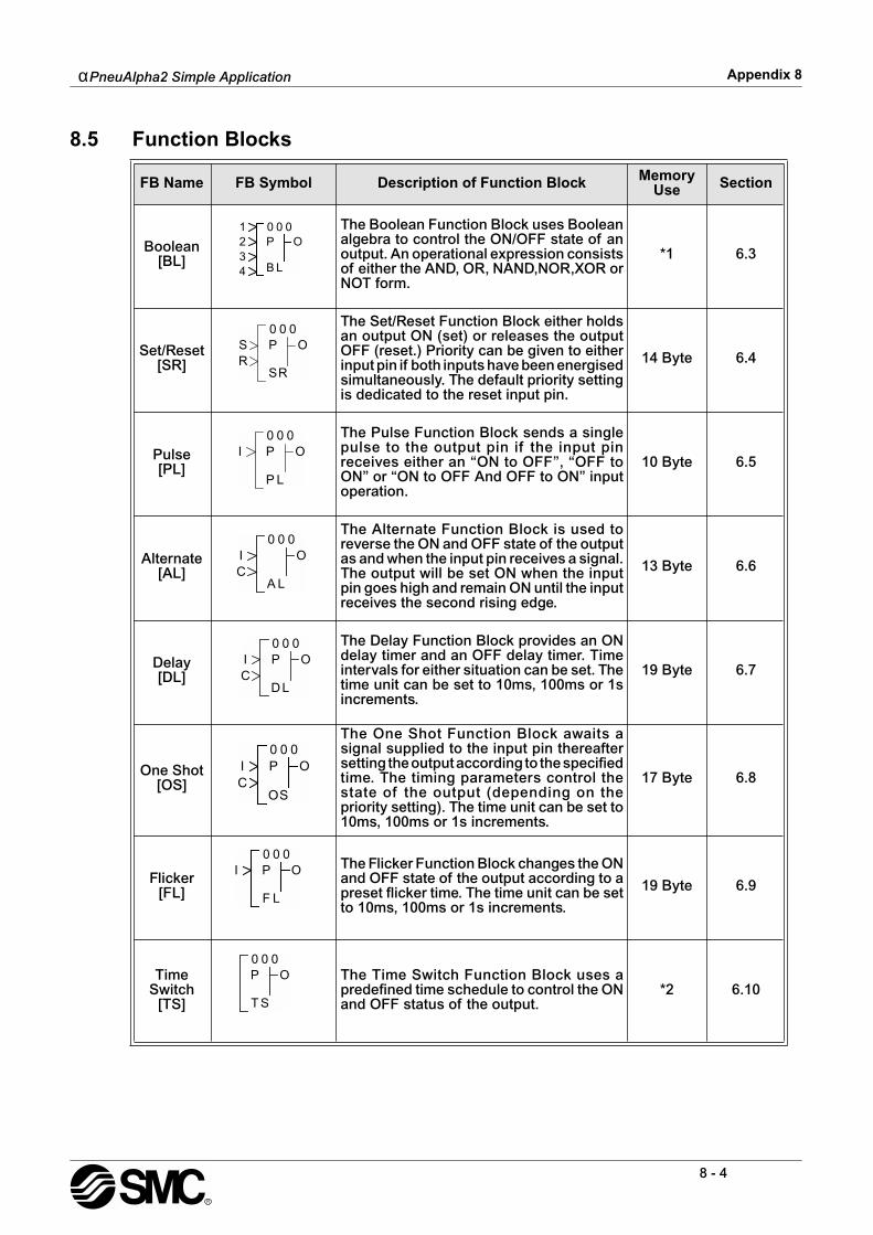
α
PneuAlpha2 Simple Application
Appendix 8
8 - 4
8.5 Function Blocks
FB Name FB Symbol Description of Function Block Memory Use Section
Boolean[BL]
The Boolean Function Block uses Booleanalgebra to control the ON/OFF state of anoutput. An operational expression consistsof either the AND, OR, NAND,NOR,XOR orNOT form.
*1 6.3
Set/Reset[SR]
The Set/Reset Function Block either holdsan output ON (set) or releases the outputOFF (reset.) Priority can be given to eitherinput pin if both inputs have been energisedsimultaneously. The default priority settingis dedicated to the reset input pin.
14 Byte 6.4
Pulse[PL]
The Pulse Function Block sends a singlepulse to the output pin if the input pinreceives either an “ON to OFF”, “OFF toON” or “ON to OFF And OFF to ON” inputoperation.
10 Byte 6.5
Alternate[AL]
The Alternate Function Block is used toreverse the ON and OFF state of the outputas and when the input pin receives a signal.The output will be set ON when the inputpin goes high and remain ON until the inputreceives the second rising edge.
13 Byte 6.6
Delay[DL]
The Delay Function Block provides an ONdelay timer and an OFF delay timer. Timeintervals for either situation can be set. Thetime unit can be set to 10ms, 100ms or 1sincrements.
19 Byte 6.7
One Shot[OS]
The One Shot Function Block awaits asignal supplied to the input pin thereaftersetting the output according to the specifiedtime. The timing parameters control thestate of the output (depending on thepriority setting). The time unit can be set to10ms, 100ms or 1s increments.
17 Byte 6.8
Flicker[FL]
The Flicker Function Block changes the ONand OFF state of the output according to apreset flicker time. The time unit can be setto 10ms, 100ms or 1s increments.
19 Byte 6.9
Time Switch
[TS]
The Time Switch Function Block uses apredefined time schedule to control the ONand OFF status of the output.
*2 6.10
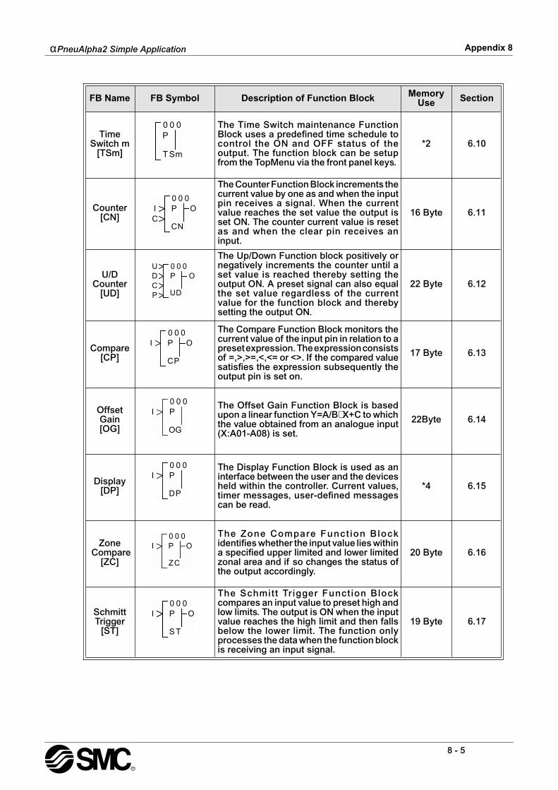
α
PneuAlpha2 Simple Application
Appendix 8
8 - 5
Time Switch m
[TSm]
The Time Switch maintenance FunctionBlock uses a predefined time schedule tocontrol the ON and OFF status of theoutput. The function block can be setupfrom the TopMenu via the front panel keys.
*2 6.10
Counter[CN]
The Counter Function Block increments thecurrent value by one as and when the inputpin receives a signal. When the currentvalue reaches the set value the output isset ON. The counter current value is resetas and when the clear pin receives aninput.
16 Byte 6.11
U/D Counter
[UD]
The Up/Down Function block positively ornegatively increments the counter until aset value is reached thereby setting theoutput ON. A preset signal can also equalthe set value regardless of the currentvalue for the function block and therebysetting the output ON.
22 Byte 6.12
Compare[CP]
The Compare Function Block monitors thecurrent value of the input pin in relation to apreset expression. The expression consistsof =,>,>=,<,<= or <>. If the compared valuesatisfies the expression subsequently theoutput pin is set on.
17 Byte 6.13
Offset Gain[OG]
The Offset Gain Function Block is basedupon a linear function Y=A/B
∗
X+C to whichthe value obtained from an analogue input(X:A01-A08) is set.
22Byte 6.14
Display[DP]
The Display Function Block is used as aninterface between the user and the devicesheld within the controller. Current values,timer messages, user-defined messagescan be read.
*4 6.15
Zone Compare
[ZC]
The Zone Compare Funct ion Blockidentifies whether the input value lies withina specified upper limited and lower limitedzonal area and if so changes the status ofthe output accordingly.
20 Byte 6.16
Schmitt Trigger
[ST]
The Schmitt Trigger Function Blockcompares an input value to preset high andlow limits. The output is ON when the inputvalue reaches the high limit and then fallsbelow the lower limit. The function onlyprocesses the data when the function blockis receiving an input signal.
19 Byte 6.17
FB Name FB Symbol Description of Function Block Memory Use Section

α
PneuAlpha2 Simple Application
Appendix 8
8 - 6
Hour Meter[HM]
The Hour Meter Function Block holds theoutput status ON for a maximum of 32767hours, 32767 minutes and 59 seconds. Ifthe input pin is turned OFF the elapsed timewill hold its value until either the clear pinresets the time or the input pin is turned ONagain.
19 Byte 6.18
Speed Detect[SPD]
The Speed Detect Function Block is usedto count the incoming pulses max. 20Hz(with an extension module max. of 1kHz)for a set period of time. The upper andlower limits can be set from -32768 to+32767 and the Period interval’s set rangeis 1 to 32767 in 10ms increments.
25 Byte 6.19
PWM[PWM]
The Pulse Width Modulation Function Blockchanges the output status according to aset period of time with a minimum of 100msand a max imum of 3276700ms inincrements of 100ms. The percentage dutyfor the function controls the amount ofelapsed time before the output status ischanged.
16 Byte 6.20
Retentive Alternate
[RAL]
The Alternate Function Block is used toreverse the ON and OFF state of the outputas and when the input pin receives a signal.The output will be set ON when the inputpin goes high and remain ON until the inputreceives the second rising edge. When thepower is turned OFF the function block willuse the last alternation operation to controlthe output.
13 Byte 6.21
Addition[ADD]
The ADD Function Block is used tosummate two input values 20 Byte 6.22
Subtrac-tion
[SUB]
The SUB Function Block is used to subtracttwo input values. 20 Byte 6.23
Multiplica-tion
[MUL]
The MUL Function Block is used to multiplytwo input values. 20 Byte 6.24
Division[DIV]
The DIV Function Block is used to dividetwo input values. 20 Byte 6.25
FB Name FB Symbol Description of Function Block Memory Use Section

α
PneuAlpha2 Simple Application
Appendix 8
8 - 7
Calcula-tion
[CAL]
The CAL Function Block is used to performa calculation from the combination ofdifferent Arithmetic function blocks.
*3 6.26
Shift[SFT]
This Shift Function Block is used to transferthe Shift Input status just before the Inputsignal is set ON.It has a bit input pin, a shiftinput pin, a set input pin, a reset input pinand a bit output pin.
19 Byte 6.27
SMS[SMS]
The GSM SMS Function Block sends theLCD screen as a SMS message to either amobile phone handset or an E-mail accountfor remote maintenance purposes.
*6 6.28
Random One Shot
[ROS]
The Random One Shot Function Blockemits a random length single pulse to theoutput.
19 Byte 6.29
Delayed One Shot
[DOS]
The Delayed One Shot Function Blockemits a single pulse after a controlled delayto the output.
20 Byte 6.30
Delayed Alternate
[DAL]
The Delayed Alternate Function Blockalternates the status of the output with eachpulse after a controlled delay.
16 Byte 6.31
Retentive Set/Reset
[RSR]
The Set/Reset Function Block either holdsan output ON (set) or releases the outputOFF (reset.) Priority can be given to eitherinput p in i f both inputs have beenenergised. The default priority setting isdedicated to the reset input pin. When thepower is turned OFF the function block willuse the last set or reset operation to controlthe output.
14 Byte 6.32
Control Display[CDP]
The Control Display Function allows theuser to control the LCD image screens. Thefunct ion b lock can on ly be se t inECC-PNAL-PCS/WIN-E software for AlphaSeries Controllers. When control bit N04 isON, it then possible to control the displayedUser Screen.
*5 6.33
FB Name FB Symbol Description of Function Block Memory Use Section
α
PneuAlpha2 Simple Application
Appendix 8
8 - 8
Note:1 ) Number of bytes used = 19 + 1
∗
(Characters in equation)2 ) Number of bytes used = 8 + 4
∗
(Number of time switches)3 ) Number of bytes used = 30 + 1
∗
(Characters in equation)4 ) Number of bytes used is decided by the displayed item.
5 ) Number of bytes used = 32 + 3
∗
(Number of screen)6 ) Number of bytes used = 12 + 1
∗
(Characters in E-Mail address)
Connect[ _B ]
The Connect function block is an internaldevice used to show the memory used byinput bits, system bits, AS-interface bits,and the operation keys. No function blockappears on screen or shows as being usedin the “Memory Configuration Usage” dialogbox, the purpose is only to calculate thememory that is used by the bits listedabove.
10 Btye 6.34
System Outputs
Control external device through relays and transistors.
10 Btye -
Displayed Item Number of bytes,
α
PneuAlpha2
Series
Characters 16 + 1
×
(Each character displayed)
Analog, FB valueValue 17
Graph 23
Time, Date 14
Time Switch 17
FB Name FB Symbol Description of Function Block Memory Use Section
00
B_
OI0
α
PneuAlpha2
Simple Application
Under no circumstances will SMC Pneumatics be liable or responsible for any con-sequential damage that may arise as a result of the installation or use of this equip-ment.
All examples and diagrams shown in this manual are intended only as an aid tounderstanding the text, not to guarantee operation. SMC Pneumatics will accept noresponsibility for actual use of the product based on these illustrative examples.
Owing to the very great variety in possible application of this equipment, you mustsatisfy yourself as to its suitability for your specific application.

SMC Pneumatics (UK) Limitted, Vincent Avenue, Crownhill, Milton Keynes, Bucks. MK8 0AN
JY992D97101A
Effective Oct 2003