Embed Size (px)
Citation preview

PROGRAMMING MANUAL
Applicable Model
ZL-153, 153MCZL-153S, 153SMCZL-203, 203MCZL-203S, 203SMCZL-253, 253MCZL-253S, 253SMCZT1000YZT1500Y, ZT1500YBZT2500MC, ZT2500Y
Before starting operation, maintenance, or programming, carefully read themanuals supplied by Mori Seiki, the NC unit manufacturer, and equipmentmanufacturers so that you fully understand the information they contain.Keep the manuals carefully so that they will not be lost.
PM-NLTTMSX501-B3EN
Applicable NC Unit
MSX-501MSX-501III

• The contents of this manual are subject to change without notice due to improvements to the machine or in order to improve the manual. Consequently, please bear in mind that there may be slight discrepancies between the contents of the manual and the actual machine. Changes to the instruction manual are made in revised editions which are distinguished from each other by updating the instruction manual number.
• Should you discover any discrepancies between the contents of the manual and the actual machine, or if any part of the manual is unclear, please contact Mori Seiki and clarify these points before using the machine. Mori Seiki will not be liable for any damages occurring as a direct or indirect consequence of using the machine without clarifying these points.
• All rights reserved: reproduction of this instruction manual in any form, in whole or in part, is not permitted without the written consent of Mori Seiki.
The product shipped to you (the machine and accessory equipment) has been manufactured in accordance with the laws and standards that prevail in the relevant country or region. Consequently it cannot be exported, sold, or relocated, to a destination in a country with different laws or standards.
The export of this product is subject to an authorization from the government of the exporting country.
Check with the government agency for authorization.
990730

CONTENTS
SIGNAL WORD DEFINITION
FOR SAFE OPERATION
FOREWORD
BEFORE READING THIS PROGRAMMING MANUAL
A: BEFORE PROGRAMMING
B: G FUNCTIONS
C: M FUNCTIONS
D: T, S, AND F FUNCTIONS
E: AUTOMATIC TOOL NOSE RADIUS OFFSET
F: MANUAL TOOL NOSE RADIUS OFFSET
G: CUTTER RADIUS OFFSET
H: MULTIPLE REPETITIVE CYCLES
I: HOLE MACHINING CANNED CYCLE
J: TOOL LIFE MANAGEMENT B FUNCTION

K: EXAMPLE PROGRAMS
APPENDIX
INDEX

SIGNAL WORD DEFINITION
A variety of symbols are used to indicate different types of warning information and advice.
Learn the meanings of these symbols and carefully read the explanation to ensure safe operation while using this manual.
<Symbols related with warning>
The warning information is classified into three categories, DANGER, WARNING, and CAUTION.
The following symbols are used to indicate the level of danger.
Indicates a potentially hazardous situation which, if not avoided, may result in minor or moderate injury or damages to the machine.
The information described following the caution symbol must be strictly observed.
<Other symbols>
The format identified by this symbol gives information for programming.
Indicates the items that must be taken into consideration.
Indicates useful guidance relating to operations.
Indicates the page number or manual to be referred to.The number in ( ) indicates the section number.
Indicates the procedure used for displaying the required screen.
Indicates the example of operations.
DANGER Indicates an imminently hazardous situation which, if not avoided, will result in death or serious injury.
The information described in the DANGER frame must be strictly observed.
WARNING Indicates a potentially hazardous situation which, if not avoided, could result in death or serious injury.
The information described in the WARNING frame must be strictly observed.
CAUTION
COMMAND
NOTE
Ex.

FOR SAFE OPERATION -1-
FOR SAFE OPERATION
This machine is intended for use by persons who have a basic knowledge of machine tools, including cutting theory, tooling and fixtures. Mori Seiki cannot accept responsibility for accidents that occur as a result of operation or maintenance of the machine by personnel who lack this basic knowledge or sufficient training.
Workpiece materials and shapes vary widely among machine users. Mori Seiki cannot predict the chucking pressure, spindle speed, feedrate, depth of cut, etc., that will be required in each case and it is therefore the user's responsibility to determine the appropriate settings.
Each machine is shipped with a variety of built-in safety devices. However, careless handling of the machine can cause serious accidents. To prevent the occurrence of such accidents, all programmers and other personnel that deal with the machine must carefully read the manuals supplied by Mori Seiki, the NC unit manufacturer, and equipment manufacturers, before attempting to operate, maintain, or program the machine.
Because there are so many "things that cannot be done" and "things that must not be done" when using the machine, it is impossible to cover all of them in the Instruction Manual. Assume that something is impossible unless the manual specifically states that it can be done.
The following manuals are supplied with your NC lathe:
I. Safety Guidelines prepared by Mori Seiki
II. Instruction Manual prepared by Mori Seiki
• MAINTENANCE MANUAL
• OPERATION MANUAL
• PROGRAMMING MANUAL
III. NC unit Operation and Maintenance Manuals prepared by the NC unit manufacturer
IV. Instruction Manuals prepared by equipment manufacturers
In addition to these manuals, ladder diagrams, parameter tables and electrical circuit diagrams are also supplied with the machine to help with electrical maintenance. The ladder diagrams are provided in the document box, parameter tables and electrical circuit diagrams are stored in the document compartment inside the electrical cabinet. Please make use of these materials when carrying out maintenance work.
Fundamental safety information is presented in the following pages.
All cautions on operation must be strictly observed when operating the machine, carrying out maintenance work, or writing programs. Failure to observe fundamental safety information can cause accidents in which the operator or other personnel working near the machine are seriously injured, or the machine is damaged. All personnel that deal with the machine must carefully read and thoroughly understand the information in the following pages before attempting programming or operating the machine.
SO-NL-B16E/P

-2- FOR SAFE OPERATION
The vocabulary and terms used for machine parts and operations in the warnings, cautions and notes are defined or explained in the manual texts and illustrations.
If you are unsure of the meaning of any word or expression, please refer to the corresponding textual explanation or illustration. If you still cannot understand or are unsure of the meaning, contact Mori Seiki for clarification.
"Operator", as used in these cautions, means not only the operator who operates or supervises a machine tool to perform machining, but also any person, including maintenance personnel who maintain and inspect a machine tool or safety device or safety measures provided with it, and the programmers who create programs used for machining, who are engaged in operations which deal with a machine tool.
Therefore, all persons engaged in these operations must carefully read these cautions and related materials, and thoroughly understand the contents before attempting to operate the machine.
SO-NL-B16E/P
FOR SAFE OPERATION -3-
1 CONSIDERATIONS BEFORE OPERATING THE MACHINE
The cautions that must constantly be born in mind when operating the machine are listed below.
Listed below are important cautions that apply to all machine-related work (machine operation, maintenance, inspection, programming, etc.).
DANGER 1. Never touch a switch, button, or key with wet hands.
If it is not properly grounded or is leaking current, you could receive an electric shock.
2. Before starting machine operation, check that there is nobody inside the protective cover or close to rotating or moving parts of the machine. Never touch or stand near the rotating or moving parts of the machine while it is operating; you could be seriously injured by being entangled in the rotating parts or crushed by the moving parts.
3. Never operate the machine with the protective cover removed or while interlocks or other safety devices are ineffective, since the machine could operate in an unexpected manner, causing accidents involving serious injuries.
Contact Mori Seiki, the NC unit manufacturer or relevant equipment manufacturers immediately if the protective cover or safety devices are damaged.
4. Always lock out the power to the machine before carrying out work inside the machine – such as setup work or cleaning the inside of the machine – and before carrying out inspections, repairs, or maintenance work. In addition, set the main switch to the OFF position and lock it, and place "PERSONNEL INSIDE MACHINE" or "UNDER MAINTENANCE" signs around the machine to stop anyone from switching on the power or operating the machine while the work is in progress. If work inside the machine or inspection or maintenance work is carried out with the power switched on, machine elements could be moved, and the personnel carrying out the work could be seriously injured by being entangled in the rotating parts or crushed by the moving parts of the machine.
5. Always switch off the power before carrying out inspection or maintenance work in the electrical cabinet or on motors and transformers. If work has to be done while the power is switched on, it must be carried out by a qualified electrical engineer, taking the proper precautions; there is a danger of electric shock.
6. Cover power supply cables that are run along the floor with rigid insulated plates to prevent them from being damaged. Damage to the insulation of the power supply cable could cause electric shocks.
SO-NL-B16E/P

-4- FOR SAFE OPERATION
DANGER 7. Even after the power is turned off, some devices will remain charged and the temperature of motors, lights inside the machine, etc., will remain high. Make sure that the charge has been discharged or the temperature has fallen before carrying out maintenance work or inspections on these devices. If you touch these devices/units carelessly while they are still charged or while the temperature is still high you could receive an electric shock or be burned.
8. Check that all cables are properly insulated before using the machine. There is considerable danger of electric shock if damaged cables are used.
WARNING 1. Keep the floor area around the machine tidy and clean; do not leave things lying on it, and clean up spilled water or oil immediately. If you fail to do this, plant personnel may injure themselves by tripping over or slipping on the floor.
2. Before operating the machine, check the area where you will have to stand and walk to make sure you can operate the machine safely. If you do not check your footing beforehand, you could loose your balance while working and injure yourself by putting your hands in a dangerous place while trying to find support, or by falling over.
3. Before using a switch, button, or key, check visually that it is the one you intend to use, and then press or set it decisively. Pressing the wrong switch, button, or key by mistake can cause accidents involving serious injuries or damage to the machine.
4. Keep the doors closed during machine operation. Leaving the machine running or operating it with doors open could cause accidents involving serious injuries or damage to the machine; plant personnel could be seriously injured by being entangled in the rotating parts of the machine, crushed by its moving parts, struck by broken tools, workpieces or jaws flying out of the machine, hit by flying chips, or splashed with coolant.
5. The parameters are set on shipment in accordance with the machine specifications; do not change them without first consulting Mori Seiki. If the parameters are changed without consultation, the machine may operate in an unexpected manner, causing accidents involving serious injuries or damage to the machine.
SO-NL-B16E/P

FOR SAFE OPERATION -5-
WARNING 6. The machine specifications are set before shipping so that the machine can deliver its full performance. If the specifications and/or settings have to be changed or the machine has to be modified to meet new machining requirements or due to changes in the operating conditions, consult Mori Seiki. Changing the settings without consultation may lead to accidents involving serious injuries, impaired machine performance, and considerable shortening of the machine service life.
7. Before operating or programming the machine, or performing maintenance work, carefully read the instruction manuals provided by Mori Seiki, the NC unit manufacturer and the equipment manufacturers so that you fully understand the information they contain. Keep these instruction manuals safely so that you do not lose them. If you do lose an instruction manual, contact Mori Seiki, the NC unit manufacturer, or the relevant equipment manufacturer. If you attempt to operate the machine without having carefully read the instruction manuals first, you will perform dangerous and erroneous operations which may cause accidents involving serious injuries or damage to the machine.
8. Always observe the instructions in the caution labels stuck to the machine. Carefully read the Safety Guidelines supplied with the machine so that you fully understand them. If the writing on the labels becomes illegible, or if the labels are damaged or peel off, contact Mori Seiki. Also contact Mori Seiki if you cannot understand any of the labels. If you operate the machine without observing the instructions on the labels, or without understanding them properly, you will perform dangerous and erroneous operations which may cause accidents involving serious injuries or damage to the machine.
9. Never operate, maintain, or program the machine while under the influence of alcohol or drugs. Your concentration will be impaired, you may loose your balance and fall against dangerous parts of the machine, and you may operate the machine incorrectly, causing accidents involving serious injuries or damage to the machine.
10. Machine operators and authorized personnel working inside the plant and in the vicinity of the machine must put their clothing and hair in order so that there is no danger they will be entangled in the machine. If you have uncontrolled long hair or loose clothing and it gets caught in the machine, you will be seriously injured by being entangled in the rotating parts of the machine or crushed by its moving parts. Always wear safety shoes, eye protectors and a helmet.
SO-NL-B16E/P

-6- FOR SAFE OPERATION
WARNING 11. The machine is equipped with interlock functions such as the door interlock, chuck interlock, tailstock spindle interlock (applies only to machines equipped with a tailstock) and electrical cabinet door interlock to ensure the operator's safety. All the interlock functions must be ON when operating the machine. If you have to operate the machine with the interlocks released, you must recognize that there are many hazards involved and pay particular attention to safety while operating the machine in this condition. After finishing the necessary work, you must switch the interlocks back ON.
If the machine is operated with the interlocks released, it may operate in an unexpected manner, causing accidents involving serious injuries or damage to the machine.
12. The door interlock function serves only to protect the machine operator from accidents that can be prevented by inhibiting manual and automatic operation of the spindle, axis movement, and all other operations in automatic operation when the door is opened and while it is open; it will not afford protection against other hazards.
For example, each machine user will machine a variety of workpiece types and use a variety of workpiece holding fixtures, cutting tools, and cutting conditions; you are still responsible for ensuring safety with regard to the hazards that can arise from these user-specific conditions.
13. If the door interlock function is released, the machine is able to operate with some limitations while the door is open, exposing you to danger. In daily production operation, the door interlock function must be set "valid" and the key operating the switch must be removed from the switch and kept safely.
When shaping soft jaws, measuring the tool offset data, program check, test cutting or carrying out other setup work, it may be necessary to release the door interlock function. If you have to carry out work while the interlock function is released, you must recognize that there are many hazards involved and pay particular attention to safety. While the door interlock function is released, the warning lamp blinks in red and the warning buzzer beeps intermittently. You must recognize that the door interlock function is in the released state when the warning lamp is blinking in red and the warning buzzer is beeping intermittently. After finishing the necessary work, you must switch the interlock function back valid.
SO-NL-B16E/P
FOR SAFE OPERATION -7-
WARNING 14. Before operating the machine, memorize the locations of the emergency stop buttons so that you can press one immediately from any location and at any time while operating the machine. The emergency stop buttons are used to stop all operations in the event of an emergency. If there is an obstacle in front of an emergency stop button it will not be possible to press it immediately when an emergency occurs and this could cause accidents involving serious injuries or damage to the machine.
15. Always switch the tailstock spindle interlock function ON before carrying out center-work operations. If this function is OFF, it will be possible to start automatic operation when the tailstock spindle is extended, even though it may not support the workpiece correctly. If automatic operation is started in this condition, the workpiece will fly out, causing serious injuries or damage to the machine. (Applies only to machines equipped with a tailstock.)
16. Adjust the position of the tailstock body so that the workpiece is securely held by the tailstock spindle center when the tailstock spindle is extended.
After making this adjustment, clamp the tailstock body to the bed. If the tailstock body is not clamped to the bed, or if the position of the tailstock body is incorrectly adjusted, it will be possible to start automatic operation when the tailstock spindle is extended, even if the workpiece is not supported by the tailstock spindle center. If machining is carried out while the workpiece is not supported by the tailstock spindle center, the workpiece will fly out, causing serious injuries or damage to the machine. (Applies only to machines equipped with a tailstock.)
17. To prevent hazardous situations, the plant or equipment supervisor must bar entry to the plant or the vicinity of the machine to anyone with insufficient safety training. Allowing persons without sufficient safety training unhindered into the plant and the vicinity of the machine could cause accidents involving serious injuries.
18. Because of the inertia of the moving parts of the machine, they may not be stopped immediately when the emergency stop button is pressed. Always confirm that all operations have stopped before going near these parts. If you approach the moving parts of the machine without due care you may be entangled in them and seriously injured.
SO-NL-B16E/P
-8- FOR SAFE OPERATION
1. User programs stored in the memory, parameters set before shipping, and the offset data input by the user, can be destroyed or lost due to incorrect operation or other causes. To protect data against destruction and loss, back it up using an external I/O device (option), or other device.
If you fail to make backup files, Mori Seiki cannot accept responsibility for any problem resulting from destroyed programs or lost parameter data and/or offset data.
Keep the parameter table supplied with the machine in a safe place. Note that if the data is destroyed it will take some time to set the parameters again.
2. Never touch chips or the cutting edges of tools with your bare hands since you may be injured.
WARNING 19. Do not leave articles such as tools and rags inside the machine. If the machine is operated with such articles inside it they may become entangled with a tool and thrown out of the machine, and this could cause accidents involving serious injuries or damage to the machine.
20. When the machine is running, operating noise may possibly be produced, depending on the cutting conditions and other factors.
When an operator works near the machine, either change cutting conditions to limit generation of noises or the operator must wear protective gear, meeting the level of generated noise, which will not cause inconvenience for performing intended work. Working under noises might impair operator's health, such as hearing.
21. This is not the explosion-proof specification machine. Dangers such as the ejection of a large workpiece or harmful dust or an explosion caused by the machining of metals such as magnesium are not preventable even if the door is closed. Do not rely on door and protective devices alone. Recognition of the dangers involved in machining procedures is required at all times.
22. This machine is equipped with a read-ahead function for the running program, and retains the read-ahead program commands stored in the NC memory during a temporary stop of automatic operation in order to eliminate latency time when restarting. Therefore, check the program commands or present positions of the axes when stopping the machine temporarily. In cases such as when discontinuing the
machining, press the (RESET) key to clear the program
commands stored in the NC if necessary. Changing the program start position after a temporary stop in particular may cause accidents after the machining is restarted since the program commands stored in the NC are activated. Pay extra attention to the difference in the specifications in relation to other manufacturers' machines because the read-ahead program data may be cleared at temporary stops on these machines.
RESET
CAUTION
SO-NL-B16E/P
FOR SAFE OPERATION -9-
3. Take care not to stumble over the footswitch since you may be injured.
4. If it becomes necessary to perform a memory clear operation, contact Mori Seiki first. If a memory clear operation is performed without due care, the entire memory contents may be deleted, making the machine inoperable.
5. The machine operator must have normal sensory perception. If a person who has an abnormality affecting any sense operates the machine, he/she will not be able to accurately confirm the machine status and surrounding conditions by eye/ear/touch. Sensory confirmation is extremely important when operating the machine and an inability to make such confirmations properly could cause accidents involving serious injuries or damage to the machine.
6. Ensure that the workplace is adequately lit. If there is insufficient light, the operator may trip over something or be unable to perform or check work accurately, and this could cause accidents involving serious injuries or damage to the machine.
7. Remove any obstacles around the machine.
Secure adequate space around the machine for working and adequate passageway, considering both ease of operation and safety. If there are any obstacles or if there is insufficient space or passageway, the operator may trip and fall or be unable to work properly, and this could cause accidents involving serious injuries or damage to the machine.
8. Stack products (workpieces) stably. If they are not stacked stably they may fall and injure the machine operator. Unstable stacking may also damage the products (workpieces), causing defects.
9. Keep the area around the machine clean; remove chips and foreign matter near the machine. If left, chips and foreign matter may cause plant personnel to fall and injure themselves.
10. Use a working bench strong and stable enough to support the weight of the workpieces and tools. If an unstable working bench is used the workpieces and tools could fall off and injure the machine operator.
If a machine alarm or NC alarm occurs, check its meaning by referring to the alarm list in the instruction manual or ladder diagram, and take the appropriate action. If this is ineffective, consult Mori Seiki or the NC unit manufacturer and take action only when you understand clearly what to do.
CAUTION
NOTE
SO-NL-B16E/P

-10- FOR SAFE OPERATION
2 SAFETY PRACTICES DURING PROGRAMMING
The safety practices that the programmer must observe while programming are presented below. Read them before attempting programming.
Workpiece shapes and materials vary widely among machine users and, since the workpiece holding fixtures, cutting tools, cutting methods, and machining conditions will also vary accordingly, Mori Seiki cannot predict what factors will apply in individual cases. It is the machine user's responsibility to take these factors into account when creating a program. It is also the machine user's responsibility to ensure safety with respect to the hazards that may arise due to these user-dependent factors.
WARNING 1. Specify a spindle speed limit that is lower than the lowest of the individual allowable speed limits for the chuck, fixture, and cylinder. If you do not follow this instruction, the workpiece could fly out of the machine, causing serious injuries or damage to the machine.
2. Clamp workpieces and cutting tools securely. Determine the depth of cut and cutting feedrate for test cutting with safe operation as the first priority; do not give priority to productivity when making these determinations. If you fail to observe this warning, the tool or workpiece could fly out of the machine, causing serious injuries or damage to the machine.
3. Always select the most appropriate cutting tool and holder for the material and shape of the workpiece to be machined and cutting method, and check that the workpiece can be machined without any problems.
If an inappropriate cutting tool or holder is selected, the workpiece could fly out of the chuck during machining, causing serious injuries or damage to the machine. Machining accuracy will also be adversely affected.
4. Before starting spindle rotation, check that the workpiece is securely clamped. Or, if performing center-work, check that the tailstock spindle center securely supports the workpiece. (Applies only to machines equipped with a tailstock.)
If the workpiece is not securely clamped or supported, it will fly out when the spindle is rotated, causing serious injuries or damage to the machine.
5. Do not insert bar stock into the spindle while the spindle is rotating or you will be entangled in the machine. The length of the bar stock must be shorter than the spindle length unless a bar feeder is used. If the bar stock protrudes from the spindle it will increase spindle runout, and could bend, causing accidents involving serious injuries or damage to the machine.
SO-NL-B16E/P
FOR SAFE OPERATION -11-
WARNING 6. For the machine with the flat type operation panel, always place the operation selection key-switch in the "operation enable" or "operation disable" position after completing program entry. Be aware that the program will be updated if program editing operations are carried out with the operation selection key-switch at the "operation and edit enable" position. If the program is executed after being accidentally updated in this way the machine could operate unexpectedly, causing serious injuries or damage to the machine.
7. For the machine with the discrete type operation panel, always place the edit enable key-switch in the "edit disable" position after completing program entry. Be aware that the program will be updated if program editing operations are carried out with the edit enable key-switch at the "edit enable" position. If the program is executed after being accidentally updated in this way the machine could operate unexpectedly, causing serious injuries or damage to the machine.
8. For the machine with the touch panel, always return the WRITE PROTECT switch (PROGRAM) back to ON after completing program entry. Be aware that the program will be updated if program editing operations are carried out with the WRITE PROTECT switch (PROGRAM) set OFF. If the program is executed after being accidentally updated in this way, the machine could operate unexpectedly, causing serious injuries or damage to the machine.
9. Select the appropriate chucking pressure and tailstock spindle thrust force (applies only to machines equipped with a tailstock) for the workpiece shape and material, and the cutting conditions. If you cannot determine the appropriate chucking pressure, contact the chuck manufacturer or cylinder manufacturer. If you cannot determine the appropriate spindle thrust force (applies only to machines equipped with a tailstock), contact Mori Seiki. If the chucking pressure or spindle thrust force (applies only to machines equipped with a tailstock) is not set appropriately in accordance with the shape and material of the workpiece being machined and the cutting conditions, the workpiece could fly out during machining, causing serious injuries or damage to the machine. Incorrect setting could also distort the workpiece.
SO-NL-B16E/P

-12- FOR SAFE OPERATION
WARNING 10. Give full consideration to the type of chuck and cylinder used when setting the chucking pressure. Even if the same hydraulic pressure is applied to the chuck, the chuck gripping force will vary according to the manufacturer and type of chuck and cylinder.
For details on the chuck gripping force, consult the chuck and cylinder manufacturers.
If the chuck gripping force is different from that intended, the workpiece could fly out when the spindle is started, causing serious injuries or damage to the machine.
11. Workpiece materials and shapes vary widely among machine users. Mori Seiki cannot predict the workpiece clamping method, spindle speed, feedrate, depth of cut, and width of cut, etc., that will be required in each case and it is therefore the user's responsibility to determine the appropriate settings.
Note also that the machining conditions determined in automatic programming are the standard conditions, which are not necessarily the most suitable for the user's purposes and may have to be changed in accordance with the workpiece, chuck, etc. The conditions determined in automatic programming are for reference only and the final responsibility for determining the conditions rests with the user. (Conversational NC specification)
If you have difficulty determining these conditions, consult the chuck and cylinder manufacturers and tool manufacturer. Machining under inappropriate machining conditions can cause the workpiece to fly out of the chuck during machining, causing serious injuries or damage to the machine. It will also adversely affect machining accuracy.
12. While the machine is temporarily stopped during machining –for example when checking a program, performing test cutting, or cleaning chips out of the machine – do not feed the axes or index the turret head in manual operation. Or, if it is absolutely necessary to do so, be sure to return the axes and turret to their original positions before restarting the program. If machining is restarted without returning them to their original positions, the turret will move in unexpected directions, causing collisions between the cutting tools, holders, or turret head and the workpiece, chuck, or tailstock (if featured), which could cause serious operator injuries or damage the machine. The workpiece could also be machined with the wrong tool, and the cutting tool could be damaged.
SO-NL-B16E/P
FOR SAFE OPERATION -13-
WARNING 13. If the program is input to the NC memory not by the programmer but by a machine operator, the operator may misread the numerical values and input incorrect values. This could cause accidents involving serious injuries or damage to the machine: the workpiece could fly out of the chuck during machining, and the cutting tool, holder, or turret head, could interfere with the workpiece, chuck, fixture, or tailstock (if featured). It could also cause the workpiece being machined with the wrong tool, or cause damage to the cutting tool.
14. If you forget to enter a decimal point in a program entry that requires one and start the machine without noticing the error, the turret may move to an unexpected position, causing, causing accidents involving serious injuries or damage to the machine. Check that you have entered decimal points where necessary.
15. Do not change the spindle gear range while a cutting load is applied. The workpiece could fly out of the chuck, causing serious injuries or damage to the machine and the cutting tool. In addition, excessive loads will be applied to the machine motors and machine elements, shortening their service lives. (Applies only to machines equipped with a transmission.)
16. Before starting the spindle, carefully check the workpiece gripping conditions and the machining conditions, including the chucking pressure, spindle speed, cutting feedrate, and depth of cut. If you start the spindle without adequate checking, the workpiece could fly out of the chuck, causing serious injuries or damage to the machine.
17. The chuck gripping force may be reduced due to a malfunction of the chuck or cylinder or a centrifugal force during high-speed spindle rotation. If machining is performed without securing a sufficient gripping force, the workpiece may fly out, causing serious injuries or damage to the machine.
If the chuck gripping force is reduced due to deterioration over time or damage from an accident or inadequate maintenance, contact Mori Seiki Service Department.
To prevent the chuck gripping force from lowering, clean and grease the chuck at regular intervals.
If the gripping force is reduced due to the centrifugal force applied to the jaws during high-speed spindle rotation, readjust the cutting conditions such as chucking pressure, cutting feedrate or cutting amount. Refer to the manuals prepared by the chuck manufacturer and the cylinder manufacturer.
SO-NL-B16E/P
-14- FOR SAFE OPERATION
1. Contact Mori Seiki when cutting cast iron, ceramics, or other materials which generate powder-type chips in dry cutting. If chips are not dealt with in an appropriate manner for the workpiece material, they can cause machine faults.
2. Before starting mass production, always check the program and perform test cutting in the single block mode. If you fail to do this the workpiece could collide with the cutting tool during machining, causing damage to the machine. Machining defects could also be caused.
3. When shifting the coordinate system in order to check a center-work program, set the shift direction and shift amount carefully to avoid interference between the turret and tailstock, which could cause damage to the machine. (Applies only to machines equipped with a tailstock.)
4. You will probably use a variety of workpiece shapes and materials, and the chucking method will differ according to the workpiece type. Therefore, when checking a program with the workpiece clamped in the chuck, check for interference carefully, taking the workpiece shape and material, and the chuck gripping force, into account. Depending on these factors, the cutting tool, holder, or turret head might interfere with the workpiece, chuck, fixture, or tailstock (if featured), causing damage to the machine.
5. When the emergency stop button or reset key has been pressed to stop the machine during a threading operation or a hole machining operation, especially a tapping operation, carefully feed the axes after checking the workpiece and cutting tool carefully for damage. If you feed the axes without due care, the workpiece and cutting tool may collide or interfere with each other, and this could cause damage to the machine.
6. Do not discharge coolant while the spindle is not rotating.
In addition, take measures to ensure that coolant does not enter the spindle bearings when it is discharged while the spindle is rotating. If coolant enters the spindle bearings, the spindle will be damaged.
7. Support the workpiece securely before stepping on the chuck clamp/unclamp footswitch to remove it. If you step on the footswitch without taking this precaution the workpiece will fall and this could cause damage to the machine.
8. If abnormal vibration or chattering is generated during machining due to improper combination among jig, cutting tool, workpiece material, etc., change the machining conditions to proper values. If machining is continued forcibly under the machining conditions with improper values, it will bring critical problems for the machine and accuracy such that the bearings is damaged quickly and cutting tool is worn excessively will take place.
9. If data is set for "COMMON" ("EXT" for MSC-**) on the WORK OFFSET screen by specifying G10 or system variable commands, the workpiece zero point is shifted in the same direction in all of the work coordinate systems, G54 - G59. Careless data setting for COMMON of the WORK OFFSET screen causes the tool or the turret to interfere with the chuck resulting in damage to the machine.
CAUTION
SO-NL-B16E/P
FOR SAFE OPERATION -15-
3 TO ENSURE HIGH ACCURACY
The accuracy of the finished product cannot be maintained unless the following points are observed when operating the machine. Failure to observe these points can also cause serious injuries and damage to the machine. Study these points carefully before operating the machine.
1. When machining bar stock on a machine equipped with a bar feeder or spindle through-hole, use straight workpieces only. When machining bar stock with a diameter smaller than that of the spindle (or draw bar), always use guide bushes in order to prevent vibration. If you use a bent workpiece or fail to use guide bushes, the machine will vibrate and the workpiece will shake; this could cause damage to the machine. It will also seriously affect machining accuracy.
2. When setting the tooling, refer to the turret interference diagram and axis travel diagram in the maintenance manual (DRAWINGS or PARTS LIST l published separately) so as to avoid interference. In the case of machines with two spindles, also make sure there will be no interference during workpiece transfer. Careless tooling will lead to interference between the tools and the workpiece, chuck, chuck jaws, covers, tailstock (if featured) or headstock 2 (if featured), which could cause damage to the machine.
WARNING 1. Provide a chucking allowance that is large enough to ensure that the workpiece will not come out of the chuck due to cutting forces or the centrifugal force generated by spindle rotation. Depending on the shape of the workpiece, it may need to be supported by the tailstock (applies only to machines equipped with a tailstock). If the workpiece flies out of the chuck during machining it could cause serious injuries or damage to the machine.
2. Workpiece materials and shapes vary widely among machine users, and Mori Seiki cannot predict the requirements for individual cases. Give full consideration to the workpiece material and shape in order to set the appropriate machining conditions. If inappropriate settings are used, the workpiece and cutting tool could fly out during machining, causing serious injuries or damage to the machine. Inappropriate settings will also adversely affect machining accuracy.
3. When forged or cast workpieces are used, the cutting allowance with respect to the finished dimensions varies greatly. Either write a program which takes the variation into consideration or perform pre-machining so that a uniform cutting allowance is left on the workpiece. If this caution is not observed, the workpiece could fly out during machining, causing serious injuries or damage to the machine. In addition, an excessive load could be applied to the cutting tool, breaking it.
CAUTION
SO-NL-B16E/P

-16- FOR SAFE OPERATION
1. When chucking or supporting a workpiece, take the rigidity of the workpiece into account when determining the chucking or supporting method and chucking pressure or tailstock thrust force (if a tailstock is featured), so as not to distort the workpiece. If the workpiece is distorted the machining accuracy will be adversely affected.
2. If any chips become entangled with the workpiece or cutting tool, machining accuracy will be adversely affected. Select a cutting tool and machining conditions which do not cause entangling of chips.
NOTE
SO-NL-B16E/P

FOR SAFE OPERATION -17-
4 CAUTIONS RELATING TO SPINDLE SPEED
The cautions that relate to spindle speed are given below. Observe these cautions during programming.
WARNING 1. The spindle speed limit set using G50 must be no higher than the lowest of the individual allowable speed limits for the chuck, fixture, and cylinder. If you set a higher speed the workpiece will fly out of the machine, causing serious injuries or damage to the machine.
2. In the G96 (constant surface speed control) mode, the spindle speed increases as the cutting tool approaches the center of the spindle.
Near the center of the spindle, the spindle speed will reach the allowable maximum speed of the machine. At this speed, the chuck gripping force, cutting force, and centrifugal force cannot be balanced to hold the workpiece securely in the chuck. As a result, the workpiece will fly out of the machine, causing serious injuries or damage to the machine.
The spindle speed limit must always be specified in a part program by using the G50 command in a block preceding the G96 block, in order to clamp the spindle speed at the specified speed.
3. When a G97 speed command is used in a program, specification of the maximum speed with a G50 command will be ignored. Therefore, when specifying the spindle speed with a G97 command, specify a speed no higher than the lowest speed among the allowable speed limits for the chuck, fixture, and cylinder. If you set a higher speed the workpiece will fly out of the machine, causing serious injuries or damage to the machine. (FANUC)
4. The setting of the spindle speed override switch (if there is one) is valid even when a spindle speed limit is set using G50.
If the switch is set to 110% or 120%, for example, the programmed spindle speed will be overridden in accordance with this setting. If this causes the actual spindle speed to exceed the allowable speed of the chuck, fixture, or cylinder, the workpiece will fly out of the chuck during machining, causing serious injuries or damage to the machine.
Therefore, the spindle speed override switch must be set at 100% or lower.
SO-NL-B16E/P

-18- FOR SAFE OPERATION
When the spindle speed control mode is switched from the G96 mode to the G97 mode, if no spindle speed is specified in the G97 block, the spindle speed obtained in the block immediately preceding the G97 block is used as the spindle speed for the G97 mode operation.
Therefore, if no spindle speed is specified in the G97 block, the spindle speed for the G97 mode will depend on the position of the cutting tool in the block preceding the G97 block, and this could adversely affect machining accuracy and shorten the life of the tool.
When switching the spindle speed control mode to the G97 mode, always specify a spindle speed.
5 CAUTIONS RELATING TO THE RAPID TRAVERSE RATE
The cautions that relate to the rapid traverse rate are given below. Observe these cautions during programming.
If X- and Z-axis movements are specified in the same block in the G00 mode, the tool path is not always a straight line from the present position to the programmed end point. Make sure that there are no obstacles in the tool path, remembering that X- and Z-axis movement is at the rapid traverse rate. If the workpiece, fixture or tailstock (if featured) lies in the tool path, it could interfere with the tool, tool holder, or turret head. Depending on the workpiece holding method, there could also be interference with the chuck and chuck jaws. This interference will cause damage to the machine.
WARNING When setting the G00 mode approach to the workpiece, determine the approach paths carefully, taking the workpiece shape and cutting allowance into consideration. The approach point in the Z-axis direction should be more than "chucking allowance + 10 mm" away from the workpiece end face.
When the spindle is rotating, centrifugal force acts on the chuck jaws, reducing the chuck gripping force. This can cause the workpiece to come out of the chuck.
Unless the approach point is at least "chucking allowance + 10 mm" away from the workpiece end face, the cutting tool could strike the workpiece while moving at the rapid traverse rate if the workpiece does come out of the chuck, or if there is a large amount of material to be removed. This could cause accidents involving serious injuries or damage to the machine.
NOTE
CAUTION
SO-NL-B16E/P
FOR SAFE OPERATION -19-
6 CAUTIONS RELATING TO CENTER-WORK
The cautions that apply when carrying out center-work or both-center-work are given below.
Observe these cautions during programming. (Applies only to machines equipped with a tailstock.)
In a center-work program, if you program approach movement by specifying the X-axis and Z-axis commands in the same block in the G00 mode, the cutting tool could strike the tailstock.
For center-work, move the Z-axis first and then the X-axis to position the cutting tool at the approach point.
In the cutting tool retraction operation, retract the cutting tool in the X-axis direction first to a point where continuing cutting tool movement does not result in interference with the tailstock. After that, move the Z-axis to the required retraction position. (Applies only to machines equipped with a tailstock.)
WARNING In machining programs for both-center-work, specify the M11 command to unclamp the chuck before the M30 command to reset and rewind the
program. If the M11 command is not executed and the (START) switch is pressed by mistake, automatic operation will start and the operator may be injured.
However, if the M11 command is executed when the center at the spindle side is held by the chuck during programming, the center will fall or shift, which in turn will cause the workpiece to fall, causing damage to the machine. If the center at the spindle side is held by the chuck, do not execute the M11 command. (Applies only to machines equipped with a tailstock.)
CAUTION
SO-NL-B16E/P
-20- FOR SAFE OPERATION
7 CAUTIONS RELATING TO COORDINATE SYSTEM SETTING
The cautions that apply when setting the coordinate system are given below.
Observe these cautions during programming.
1. When setting the coordinate system using the machine coordinate system setting function, any mistake in specifying the X and Z values in the G50 block will cause interference between the cutting tool, tool holder, or turret head, and the workpiece, chuck, fixture, or tailstock (if featured), damage to the machine, or will cause the cutting tool failing to reach the cutting position.
2. When the coordinate system is set using G50, do not input the tool geometry offset data. If you input this data, the workpiece zero point will be shifted by the amount of the tool geometry offset data, which could cause interference between the cutting tool, holder or turret head and the workpiece, chuck, fixture, or tailstock (if featured), causing damage to the machine.
WARNING When the coordinate system is set using G50, the start and end points of the part program must be the same point.
At the end of a part program, the tool wear offset data of the cutting tool used to set the coordinate system must be canceled.
If you do not cancel the tool wear offset data, the X and Y coordinate values will be shifted by the tool wear offset data each time the program is executed. This will shift the start (end) point of the program, which could cause interference between the cutting tool, holder or turret head and the workpiece, chuck, fixture, or tailstock (if featured), causing accidents involving serious injuries or damage to the machine.
CAUTION
SO-NL-B16E/P
FOR SAFE OPERATION -21-
8 CAUTIONS RELATING TO G CODES
The cautions that relate to G codes (also called "preparatory codes") are given below.
Observe these cautions during programming.
1. Never specify "G28 X0 Z0;" to return the axes to the machine zero point, since the axes will first be positioned at the workpiece zero point (X0, Z0) and then moved to the machine zero point, and this may cause the cutting tool to strike the workpiece.
Instead, specify "G28 U0 W0;" to return the axes directly from the present position to the machine zero point.
2. In the G98 mode, the turret moves at the feedrate specified by the F code even when the spindle is not rotating. Make sure that the cutting tool will not strike the workpiece, etc., since this could cause damage to the machine.
3. When using the stored stroke check function, always execute a machine zero return operation after switching the power ON, otherwise the function will not be valid. If the machine is operated in this condition it will not stop even if the cutting tool enters the prohibited area, and this could cause damage to the machine. (stored stroke check specification)
1. When specifying G codes in a block, they must be placed before the addresses (other than G and M) which are executed under the mode they establish. If a G code is specified after addresses for which it establishes the mode of processing, the mode established by it is not valid to these addresses.
2. When executing a dwell using the G04 command, if the cutting tool is kept in contact with the workpiece at a position such as the bottom of a groove for a long time it will shorten the life of the tool nose as well as adversely affecting machining accuracy.
The dwell period should be the time it takes for the spindle to rotate approximately one turn.
CAUTION
NOTE
SO-NL-B16E/P
-22- FOR SAFE OPERATION
9 CAUTIONS RELATING TO M CODES
The cautions that relate to M codes (also called "miscellaneous codes") are given below. Observe these cautions during programming.
1. Do not stop the spindle or rotary tool (milling specification) by specifying the M05 command while the cutting tool is in contact with the workpiece. If the spindle or rotary tool (milling specification) is stopped while the cutting tool is in contact with the workpiece, the cutting tool could be damaged.
2. Rotate the spindle or rotary tool by executing either M03 or M04 (M13 or M14 for the milling specification) command before the cutting tool comes into contact with the workpiece. If the cutting tool is brought into contact with the workpiece while it is not rotating, the cutting tool could be damaged.
3. Always specify an M05 command to stop spindle rotation before using a pull-out finger or workpiece pusher, etc. If spindle rotation is not stopped the machine could be damaged.
4. Specify the M10 or M11 command in a block without other commands, and specify the G04 command in the next block to allow the chuck to complete the clamp or unclamp operation correctly. Since the time required for the chuck to carry out the clamp or unclamp operation varies depending on the chuck type and chucking pressure, the dwell time should be a little longer than the actual clamp/unclamp time.
If G04 is not specified in the block following the M10 or M11 block, the next block will be executed while the chuck is still opening or closing, and this could cause damage to the machine.
5. When the M73 command is specified, make sure that the turret head or headstock 2 spindle (Applies only to machines equipped with two spindles) is retracted to a position where it will not interfere with the parts catcher when it swings out to the chuck side position. Interference could cause damage to the machine.
6. When the automatic door is closed by specifying the M86 command, make sure that your fingers, etc., do not get caught in the door and that there are no obstacles that will prevent the door from closing. If your fingers are caught in the door you could be injured.
CAUTION
SO-NL-B16E/P

FOR SAFE OPERATION -23-
7. Specify the M25 command (to extend the tailstock spindle) or M26 command (to retract the tailstock spindle) in a block without other commands, and specify the G04 command in the next block to suspend program operation for a period long enough to allow the tailstock spindle to extend and the center to hold the workpiece correctly, or long enough to allow the tailstock spindle to retract into the tailstock correctly.
If G04 is not specified in the block following the M25 or M26 block, the next block will be executed before the workpiece is held by the center properly, or before the tailstock spindle has retracted properly; the tool, holder, or turret head will then interfere with the tailstock spindle or tailstock spindle center, causing damage to the machine.
The period of time specified for suspension of program execution should be longer than the time required to extend or retract the tailstock spindle. (Applies only to machines equipped with a tailstock.)
8. Specify the M73 command (to swing the parts catcher out) or M74 command (to swing the parts catcher in) in a block without other commands, and specify the G04 command in the next block to suspend program operation for a period long enough to allow the parts catcher to complete the swing in/out operation.
If G04 is not specified in the block following the M73 or M74 block, the next block will be executed before the parts catcher has reached the swing in/out end position; the tool, holder, or turret head will then interfere with the parts catcher, causing damage to the machine.
The period of time specified for suspension of program execution should be longer than the time required for the parts catcher to complete the swing IN or swing OUT operation. (Applies only to machines equipped with a parts catcher.)
CAUTION
SO-NL-B16E/P

FOREWORD
Machining workpieces in a NC lathe requires programs.
This manual describes the items that are required to create programs.
An overview of each chapter is given below.
A: BEFORE PROGRAMMING
This chapter describes the basics for creating a program. It is written for beginners who might be creating a program for the first time.
B: G FUNCTIONS
This chapter describes the G functions. The G codes are also called the preparatory functions. The NC determines the machining method and axis control mode for each block according to the specified G code.
C: M FUNCTIONS
This chapter describes the M functions. The M codes are also called the miscellaneous functions. In addition to serving in auxiliary roles when used with G codes, M codes are used to suspend program execution, discharge or stop coolant, etc.
D: T, S, AND F FUNCTIONS
This chapter describes the T, S, and F functions. The T function rotates the turret, indexes the required tool and calls a tool offset number. The S function specifies a spindle speed, rotary tool spindle speed or cutting speed. The F function specifies a feedrate of the cutting tool.
E: AUTOMATIC TOOL NOSE RADIUS OFFSET
This chapter describes how the automatic tool nose radius offset function works. Because the cutting edge of the tool does not come to a sharp point, but is slightly rounded, the position of the tool nose actually engaged in cutting differs slightly from the point assumed for program writing. The error caused by this difference is automatically offset by specifying the appropriate G codes (G41, G42).
F: MANUAL TOOL NOSE RADIUS OFFSET
This chapter describes how the value for tool nose offset is determined. Because the tool edge does not come to a sharp point, but is slightly rounded, the position of the tool nose actually engaged in cutting differs slightly from the point assumed for program writing. By manually calculating the offset data and slightly shifting the tool nose, the programmed tool point (imaginary tool nose) can be offset to coincide with the cutting point.
G: CUTTER RADIUS OFFSET
This chapter describes the cutter radius offset function used by the Y-axis specification machines. Cutter radius offset means the shift of the tool path by the radius amount to the right or left from the programmed path. This function is mainly used for pocket cutting or contouring with the end mill.
H: MULTIPLE REPETITIVE CYCLES
This chapter describes the multiple canned cycles. Using a multiple canned cycle, roughing processes that would otherwise require several blocks of commands can be defined by a single block of commands, preceded by a G code that calls a multiple canned cycle. This is followed by blocks that define the finished shape. The tool paths from rough cutting cycles to finishing cycles are generated automatically.
-1-

I: HOLE MACHINING CANNED CYCLE
This chapter describes hole machining canned cycle function. It specifies hole machining cycle using commands in one block including a G function, which usually requires several blocks.
J: TOOL LIFE MANAGEMENT B FUNCTION
This chapter describes the tool life management B function. The tool life management B function automatically selects an available tool in a registered tool group if the tool called in the same group has been used to the preset life.
K: EXAMPLE PROGRAMS
This chapter describes the programming procedure using several examples.
APPENDIX
The appendix shows a program for center work with consideration given to safety.
Please read this Programming Manual carefully. The manual is written to help you operate your NC lathe more effectively.
-2-

BEFORE READING THIS PROGRAMMING MANUAL
To machine a workpiece in a NC lathe, a program must be created. This manual describes the basic information to be understood before starting programming and several example programs. When reading this manual, always remember the following points.
Also please note that the programs and portions of programs given in this manual are only examples that help readers understand the explanation easier. Therefore, the programs in this manual are not always applicable to actual production. Programming method and numeric values in a program such as machining conditions must be determined meeting actual machine operating environment including the workpiece material and shape.
1. There are two methods for specifying the coordinate values; an absolute command and an incremental command. In this manual, the absolute command is usually being described. Unless otherwise stated, the program can also be created using incremental commands. When a specified method using incremental commands is different from one using absolute commands, or if either an absolute or an incremental command cannot be used, some cautionary notes will be described at that point.
Absolute commands and incremental commands are discussed in detail in CHAPTER A.
Page A-19 (8)
2. The illustrations used in this manual may vary depending on the machine model.
3. The contents of this manual apply to machine tools which conform to JIS standards.
Page A-32 (12)
4. The illustrations of cutting tools in this manual may not indicate the correct setting orientation, since this will differ according to the machine model.
Make sure the correct relationship between the cutting tool mounting position and the workpiece (spindle) rotation direction when writing a program.
WARNING 1. The programmer is requested to read this manual carefully and observe the cautions it contains when creating programs, so as to ensure the safety of the operator during operation. If the cautions in this manual are ignored when creating a program, the machine may operate in an unexpected manner when the program is run, causing accidents involving serious injuries or damage to the machine.
2. Explanation for programs will include the discussion on parameters. The parameters are set on shipment in accordance with the machine specifications; do not change them without first consulting Mori Seiki. If the parameters are changed without consultation, the machine may operate in an unexpected manner, causing accidents involving serious injuries or damage to the machine.
CAUTION
-1-

5. With G and M codes, two types of formats such as standard format (setting made before shipping the machine) and F15 format are available. The programming method varies between these two formats for some of the G and M codes and such differences are explained in the related items in this manual. Pay attention to the difference when creating a program.
6. Please note that all of the functions and optional devices/equipment explained in this manual are not always available with the delivered machine.
Retrofitting of such functions and optional devices/equipment is not always possible. For details, contact Mori Seiki.
In this manual, the various models are classified under the generic names indicated in the table below.
Generic Name Models NC UnitZL series ZL-153, ZL-153MC
ZL-203, ZL-203MC
ZL-253, ZL-253MC
MSX-501/MSX-501III
ZL-S series ZL-153S, ZL-153SMC
ZL-203S, ZL-203SMC
ZL-253S, ZL-253SMC
MSX-501/MSX-501III
ZT series ZT1000Y
ZT1500Y, ZT1500YB
ZT2500MC, ZT2500Y
MSX-501/MSX-501III
CAUTION
NOTE
-2-
CHAPTER ABEFORE PROGRAMMING
This chapter describes the basic considerations for creating a program.

CONTENTS
A : BEFORE PROGRAMMING
1 WHAT IS A PROGRAM?. . . . . . . . . . . . . . . . . . . . . . . . . . . . . . . . . . . . . . . . . . . . . . . . . A-1
2 WHAT IS REQUIRED OF PROGRAMMERS? . . . . . . . . . . . . . . . . . . . . . . . . . . . . . . . . A-1
3 WHAT IS "CREATING A PROGRAM"?. . . . . . . . . . . . . . . . . . . . . . . . . . . . . . . . . . . . . . A-1
4 INPUTTING THE PROGRAM TO THE MACHINE . . . . . . . . . . . . . . . . . . . . . . . . . . . . . A-2
5 FLOW UNTIL THE PRODUCT IS COMPLETED . . . . . . . . . . . . . . . . . . . . . . . . . . . . . . A-3
5-1 Flow of Operation . . . . . . . . . . . . . . . . . . . . . . . . . . . . . . . . . . . . . . . . . . . . . . . . . A-3
5-2 Check Items . . . . . . . . . . . . . . . . . . . . . . . . . . . . . . . . . . . . . . . . . . . . . . . . . . . . . A-4
6 TERMS FOR PROGRAMMING . . . . . . . . . . . . . . . . . . . . . . . . . . . . . . . . . . . . . . . . . . A-10
6-1 Program Number. . . . . . . . . . . . . . . . . . . . . . . . . . . . . . . . . . . . . . . . . . . . . . . . . A-10
6-2 Sequence Number . . . . . . . . . . . . . . . . . . . . . . . . . . . . . . . . . . . . . . . . . . . . . . . A-10
6-3 Part Program. . . . . . . . . . . . . . . . . . . . . . . . . . . . . . . . . . . . . . . . . . . . . . . . . . . . A-11
6-4 Address . . . . . . . . . . . . . . . . . . . . . . . . . . . . . . . . . . . . . . . . . . . . . . . . . . . . . . . . A-11
6-5 Data. . . . . . . . . . . . . . . . . . . . . . . . . . . . . . . . . . . . . . . . . . . . . . . . . . . . . . . . . . . A-11
6-6 Word . . . . . . . . . . . . . . . . . . . . . . . . . . . . . . . . . . . . . . . . . . . . . . . . . . . . . . . . . . A-12
6-7 Block . . . . . . . . . . . . . . . . . . . . . . . . . . . . . . . . . . . . . . . . . . . . . . . . . . . . . . . . . . A-12
6-8 Summary. . . . . . . . . . . . . . . . . . . . . . . . . . . . . . . . . . . . . . . . . . . . . . . . . . . . . . . A-12
7 AXIS CONTROL AND MOVEMENT DIRECTION. . . . . . . . . . . . . . . . . . . . . . . . . . . . . A-13
7-1 Movement along the Controlled Axes . . . . . . . . . . . . . . . . . . . . . . . . . . . . . . . . . A-13
7-1-1 ZL Series . . . . . . . . . . . . . . . . . . . . . . . . . . . . . . . . . . . . . . . . . . . . . . . . A-13
7-1-2 ZL-S Series . . . . . . . . . . . . . . . . . . . . . . . . . . . . . . . . . . . . . . . . . . . . . . A-14
7-1-3 ZT Series . . . . . . . . . . . . . . . . . . . . . . . . . . . . . . . . . . . . . . . . . . . . . . . . A-15
7-2 Expressing Axis Movement in Programming. . . . . . . . . . . . . . . . . . . . . . . . . . . . A-16
8 SPECIFYING THE DIMENSIONS. . . . . . . . . . . . . . . . . . . . . . . . . . . . . . . . . . . . . . . . . A-19
8-1 Absolute Commands. . . . . . . . . . . . . . . . . . . . . . . . . . . . . . . . . . . . . . . . . . . . . . A-19
8-2 Incremental Commands . . . . . . . . . . . . . . . . . . . . . . . . . . . . . . . . . . . . . . . . . . . A-22
8-3 Summary. . . . . . . . . . . . . . . . . . . . . . . . . . . . . . . . . . . . . . . . . . . . . . . . . . . . . . . A-24
9 SPECIFYING THE CUTTING CONDITIONS . . . . . . . . . . . . . . . . . . . . . . . . . . . . . . . . A-25
10 BASIC PATTERN OF PROGRAM. . . . . . . . . . . . . . . . . . . . . . . . . . . . . . . . . . . . . . . . . A-27
10-1 Chuck-Work Programming . . . . . . . . . . . . . . . . . . . . . . . . . . . . . . . . . . . . . . . . . A-27
10-2 Center-Work Programming . . . . . . . . . . . . . . . . . . . . . . . . . . . . . . . . . . . . . . . . . A-28
11 CAUTIONS FOR CREATING A PROGRAM . . . . . . . . . . . . . . . . . . . . . . . . . . . . . . . . . A-29
11-1 Program Number. . . . . . . . . . . . . . . . . . . . . . . . . . . . . . . . . . . . . . . . . . . . . . . . . A-29
11-2 Space between the Words in the Program . . . . . . . . . . . . . . . . . . . . . . . . . . . . . A-29
11-3 Signs and Symbols . . . . . . . . . . . . . . . . . . . . . . . . . . . . . . . . . . . . . . . . . . . . . . . A-29
11-4 Inputting a Decimal Point . . . . . . . . . . . . . . . . . . . . . . . . . . . . . . . . . . . . . . . . . . A-30
11-5 Role of Decimal Point . . . . . . . . . . . . . . . . . . . . . . . . . . . . . . . . . . . . . . . . . . . . . A-31
12 JIS SPECIFICATION AND REVERSE JIS SPECIFICATION . . . . . . . . . . . . . . . . . . . . A-32

BEFORE PROGRAMMING A-1
1 WHAT IS A PROGRAM?
The "program" here is an instruction for machine operation consisting of letters of the alphabet and numerals in combination.
All operations of the machine, including "spindle rotation", "tool movement", or "coolant discharge" can be controlled by a program.
When creating such programs, the information discussed in this manual will be necessary. Please carefully read this manual and thoroughly understand the information before creating a program.
Creating a program is called "programming".
2 WHAT IS REQUIRED OF PROGRAMMERS?
Programmers must have a thorough of knowledge about machining operation. They should write programs and observe the points listed below to ensure accurate, efficient operation with safety.
Programmers must:
1. Develop a knowledge of the theory of cutting.
2. Acquire a good knowledge of workpiece holding tools (chuck, fixtures, tailstock).
3. To prevent accidents which might occur during machining, select appropriate tools taking into consideration the shape and material of workpiece as well as machining conditions, such as spindle speed, feedrate or depth of cut.
4. Understand the machining performance of the machine to be used.
5. Understand the safety devices and interlock functions featured by the machine to be used.
6. Become familiar with the functions related to programming.
3 WHAT IS "CREATING A PROGRAM"?
When creating a program:
1) Check the part print to determine the machining required.
2) Examine the section to be machined, the fixtures and the tools that need to be used.
Creating a program as soon as you see a part print could lead to unproductive and dangerous operation of the machine.
3) Determine the machining processes based on these requirements and the dimensions given on the part print.
4) According to the machining processes required, create a program using letters of the alphabet and numerals.
5) When you have created a program, carefully check its contents.
A-2 BEFORE PROGRAMMING
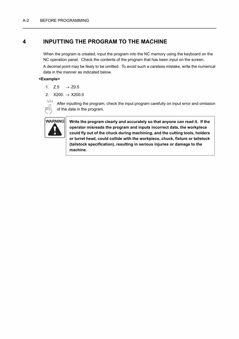
4 INPUTTING THE PROGRAM TO THE MACHINE
When the program is created, input the program into the NC memory using the keyboard on the NC operation panel. Check the contents of the program that has been input on the screen.
A decimal point may be likely to be omitted. To avoid such a careless mistake, write the numerical data in the manner as indicated below.
<Example>
1. Z.5 → Z0.5
2. X200. → X200.0
After inputting the program, check the input program carefully on input error and omission of the data in the program.
WARNING Write the program clearly and accurately so that anyone can read it. If the operator misreads the program and inputs incorrect data, the workpiece could fly out of the chuck during machining, and the cutting tools, holders or turret head, could collide with the workpiece, chuck, fixture or tailstock (tailstock specification), resulting in serious injuries or damage to the machine.

BEFORE PROGRAMMING A-3
5 FLOW UNTIL THE PRODUCT IS COMPLETED
5-1 Flow of Operation
This section describes the flow of operation, including programming. Follow and understand the flow so that the operation can be performed smoothly.
2) Determine the tools to be used
4) Create the program
5) Turn on the power supply
3) Examine the chucking method and the fixtures
7) Check or adjust the chucking pressure
8) Shape soft jaws
10) For the center-work, set the tailstock Check or adjust the tailstock spindle thrust (Tailstock specification)
9) Mount the tools and workpiece to the machine
11) Measure and input the tool geometry offset value
13) Check the program by carrying out dry run operation(Correct the program if necessary)
1) Examine the drawing to determine the machining required
14) Check the machining condition by carrying out test cutting(Correct the program if necessary)(Input the tool wear offset value if necessary)
16) Product is completed
15) Machine the workpiece in automatic operation
12) Set the workpiece zero point
Productionplanning andprogramming
6) Store the program into memory
"TOOLING SYSTEM" in the MAINTENANCE INFORMATION
"TURNING ON THE POWER" in the OPERATION MANUAL
"PROGRAM EDITING" in the OPERATION MANUALInstruction manual supplied by the NC unit manufacturer
"ADJUSTING THE PRESSURE" and "Adjusting the Chucking Pressure" in the OPERATION MANUALInstruction manual supplied by the NC unit manufacturer
"MANUAL OPERATION" in the OPERATION MANUAL "TOOLING SYSTEM" in the MAINTENANCE INFORMATION
"TAILSTOCK OPERATION", "ADJUSTING THE PRESSURE", and "Adjusting the Tailstock Spindle Thrust" in the OPERATION MANUAL
"SETTING OF COORDINATE SYSTEM" in the OPERATION MANUAL
"SETTING OF COORDINATE SYSTEM" in the OPERATION MANUAL
"PREPARATION BEFORE STARTING MASS PRODUCTION" in the OPERATION MANUAL
"PREPARATION BEFORE STARTING MASS PRODUCTION" in the OPERATION MANUAL
Setupoperation
Mass production
"SHAPING SOFT JAWS FOR FINISHING" in the OPERATION MANUAL

A-4 BEFORE PROGRAMMING
5-2 Check Items
The items to be checked in the course of programming and before starting machine operation are summarized in the following tables. Check these items to ensure smooth operation.
(To the next page)
Check Items Check Column
1. Are tolerances readable on the drawing?
2. Are the symbols used to indicate accuracy understandable?
3. Are the shape and material of the workpiece blank made clear?
4. Are the processes before and after the processes to be carried out on the NC lathe made clear?
5. Can the workpiece be machined to the specified accuracies on the NC lathe?
6. Are the keys for machining understandable?
7. Is the use of the workpiece made clear?
8. Have you read all the dimensions and notes on the drawing?
9. Is the drawing kept clean, with no unnecessary information entered on it?
Check Items Check Column
1. Are the order of machining and machining conditions determined in accordance with the shape and material of the workpiece blank?
2. Are the chucking method and chucking pressure setting determined correctly?
3. Are the cutting tools and replaceable tips selected properly?
4. Are the machining processes appropriate for the shape and material of the workpiece blank?
5. Is machining free of interference?
Reading the Drawing
Order and Conditions of
Machining

BEFORE PROGRAMMING A-5
(To the next page)
Check Items Check Column
1. When inputting the program for a particular process, is the program for the next process taken into consideration?
2. Is the program being written to suit the shape and material of the workpiece blank?
3. Is a decimal point entered in all numerical values?
4. Is the sign (+, −) preceding numerical values correct?
5. Are feed modes (rapid traverse and cutting feed) used correctly?
6. Are approach paths and cutting feed identified?
7. Is all input data checked for correctness?
8. Is the program free of errors caused by lack of concentration?
Check Items Check Column
1. Are tool holders and cutting tools cleaned before mounting?
2. Are the replaceable tool tips new?
3. Are the material and shape of replaceable tool tips appropriate?
4. Are replaceable tool tips mounted securely and correctly?
5. Is the tool overhang appropriate?
6. Is the replaceable tool tip mounting angle correct?
7. Are mounting bolts tightened securely and evenly?
8. Is the tool nose center height correct?
Inputting the Program
Mounting the Tools
A-6 BEFORE PROGRAMMING
(To the next page)
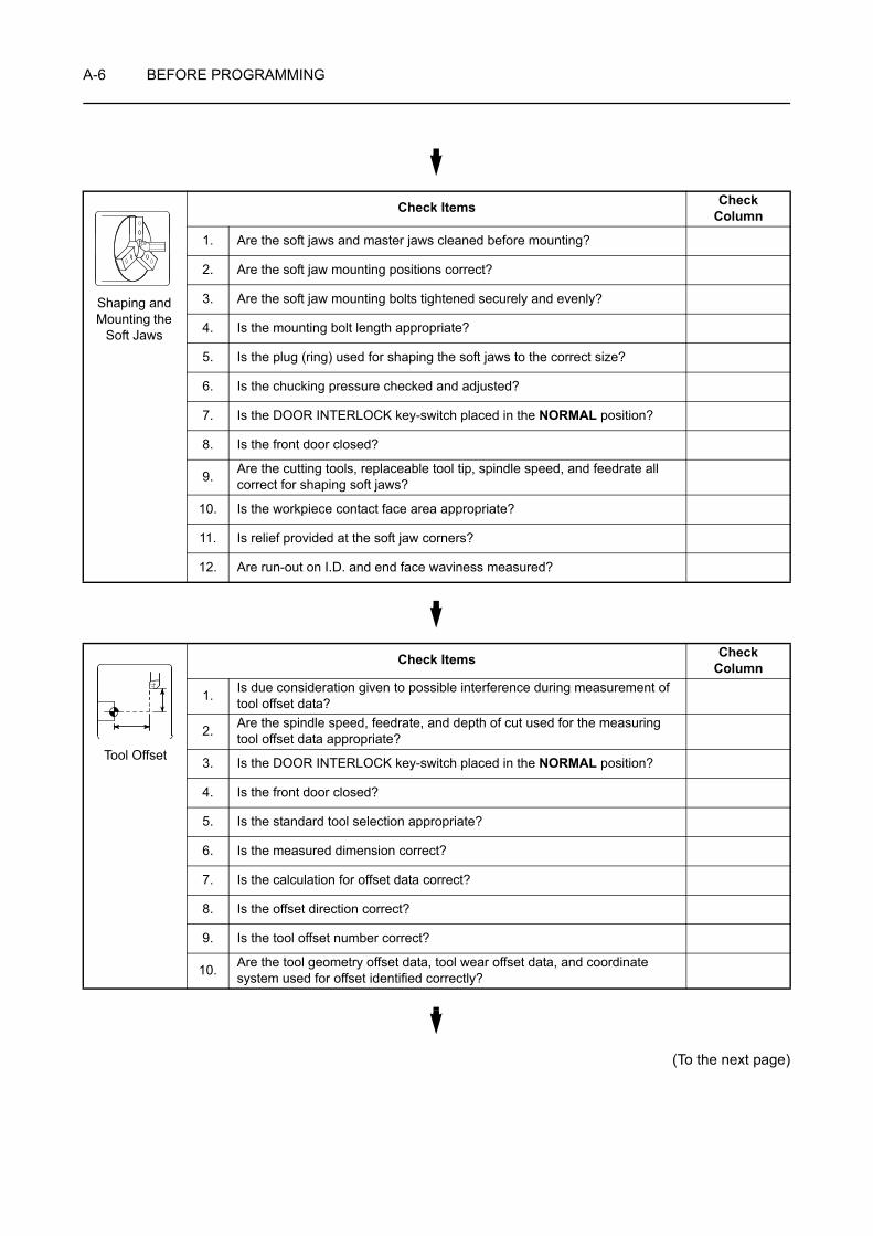
Check Items Check Column
1. Are the soft jaws and master jaws cleaned before mounting?
2. Are the soft jaw mounting positions correct?
3. Are the soft jaw mounting bolts tightened securely and evenly?
4. Is the mounting bolt length appropriate?
5. Is the plug (ring) used for shaping the soft jaws to the correct size?
6. Is the chucking pressure checked and adjusted?
7. Is the DOOR INTERLOCK key-switch placed in the NORMAL position?
8. Is the front door closed?
9. Are the cutting tools, replaceable tool tip, spindle speed, and feedrate all correct for shaping soft jaws?
10. Is the workpiece contact face area appropriate?
11. Is relief provided at the soft jaw corners?
12. Are run-out on I.D. and end face waviness measured?
Check Items Check Column
1. Is due consideration given to possible interference during measurement of tool offset data?
2. Are the spindle speed, feedrate, and depth of cut used for the measuring tool offset data appropriate?
3. Is the DOOR INTERLOCK key-switch placed in the NORMAL position?
4. Is the front door closed?
5. Is the standard tool selection appropriate?
6. Is the measured dimension correct?
7. Is the calculation for offset data correct?
8. Is the offset direction correct?
9. Is the tool offset number correct?
10. Are the tool geometry offset data, tool wear offset data, and coordinate system used for offset identified correctly?
Shaping and Mounting the
Soft Jaws
Tool Offset

BEFORE PROGRAMMING A-7
(To the next page)
Check Items Check Column
1. Is the chucking pressure checked and adjusted?
2.If performing center work, is the tailstock spindle thrust checked and adjusted?Is the tailstock spindle interlock function turned on?
3. Is the DOOR INTERLOCK key-switch placed in the NORMAL position?
4. Is the front door closed?
5. Is the single block function turned on?
6. Are the feedrate and spindle speed appropriate for operation?
7. Are feed modes (rapid traverse and cutting feed) used correctly?
8. Is the tool retraction direction after cutting correct?
9. Is tool movement smooth in the calculated area?
10. Are the tools free of interference with the workpiece, soft jaws, and chuck?
11. Is the turret head indexed at a position where there is no interference with the workpiece?
12. Can the machine be stopped immediately when necessary?
Dry Run Operation

A-8 BEFORE PROGRAMMING
(To the next page)
Check Items Check Column
1. Is the chucking pressure checked and adjusted?
2.If performing center work, is the tailstock spindle thrust checked and adjusted?Is the tailstock spindle interlock function turned on?
3. Is the DOOR INTERLOCK key-switch placed in the NORMAL position?
4. Is the front door closed?
5. Is the single block function turned on?
6. Are the feedrate and spindle speed appropriate for operation?
7. Are the order of machining and machining conditions determined in accordance with the shape and material of the workpiece blank?
8. Are the cutting tools and replaceable tips selected properly?
9. Is the workpiece chucking method correct?
10. Is the progress of cutting observed?
11. Are coolant supply volume and direction correct?
12. Are the cutting tools free of interference with the workpiece, soft jaws and chuck?
13. Are the dimensions measured after the rough cutting process?
14. Are the settings for feed override and rapid traverse override correct?
15. Can the machine be stopped immediately when necessary?
Check Items Check Column
1. Is the measuring instrument functioning correctly?
2. Is the choice of measuring instrument correct?
3. Is the measuring order correct?
4. Is the measuring method appropriate?
5. Is the area to be measured indicated clearly?
6. Is the area to be measured free of chips and coolant?
7. Are the dimensions measured after the rough cutting process?
8. Is the workpiece cool when the dimensions are measured?
Test Cutting
Measuring

BEFORE PROGRAMMING A-9
Check Items Check Column
1. Is the DOOR INTERLOCK key-switch placed in the NORMAL position?
2. Is the front door closed?
3. Are all NC functions such as single block functions used to check the program turned off?
4. Is dimensional variation checked?
5. Are run-out on I.D. and O.D., and end face waviness measured?
6. Is a target work time established on the basis of the machining time for one workpiece?
7. Is tool nose wear observed?
8. Are the dimensions measured after the rough cutting process?
Mass Production
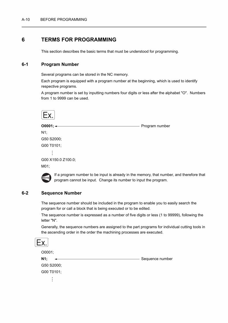
A-10 BEFORE PROGRAMMING
6 TERMS FOR PROGRAMMING
This section describes the basic terms that must be understood for programming.
6-1 Program Number
Several programs can be stored in the NC memory.
Each program is equipped with a program number at the beginning, which is used to identify respective programs.
A program number is set by inputting numbers four digits or less after the alphabet "O". Numbers from 1 to 9999 can be used.
O0001; Program number
N1;
G50 S2000;
G00 T0101;
G00 X150.0 Z100.0;
M01;
If a program number to be input is already in the memory, that number, and therefore that program cannot be input. Change its number to input the program.
6-2 Sequence Number
The sequence number should be included in the program to enable you to easily search the program for or call a block that is being executed or to be edited.
The sequence number is expressed as a number of five digits or less (1 to 99999), following the letter "N".
Generally, the sequence numbers are assigned to the part programs for individual cutting tools in the ascending order in the order the machining processes are executed.
O0001;
N1; Sequence number
G50 S2000;
G00 T0101;
Ex.
NOTE
Ex.
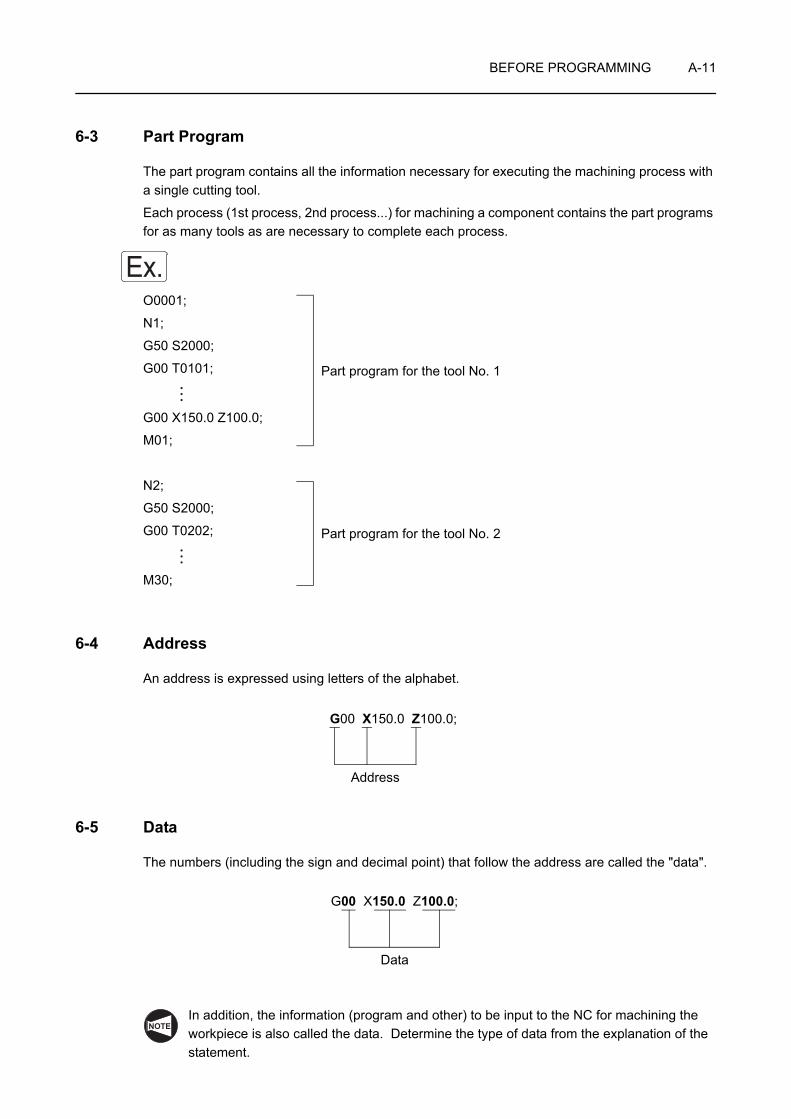
BEFORE PROGRAMMING A-11
6-3 Part Program
The part program contains all the information necessary for executing the machining process with a single cutting tool.
Each process (1st process, 2nd process...) for machining a component contains the part programs for as many tools as are necessary to complete each process.
O0001;
N1;
G50 S2000;
G00 T0101;
G00 X150.0 Z100.0;
M01;
N2;
G50 S2000;
G00 T0202;
M30;
6-4 Address
An address is expressed using letters of the alphabet.
6-5 Data
The numbers (including the sign and decimal point) that follow the address are called the "data".
In addition, the information (program and other) to be input to the NC for machining the workpiece is also called the data. Determine the type of data from the explanation of the statement.
Ex.
Part program for the tool No. 1
Part program for the tool No. 2
G00 X150.0 Z100.0;
Address
G00 X150.0 Z100.0;
Data
NOTE
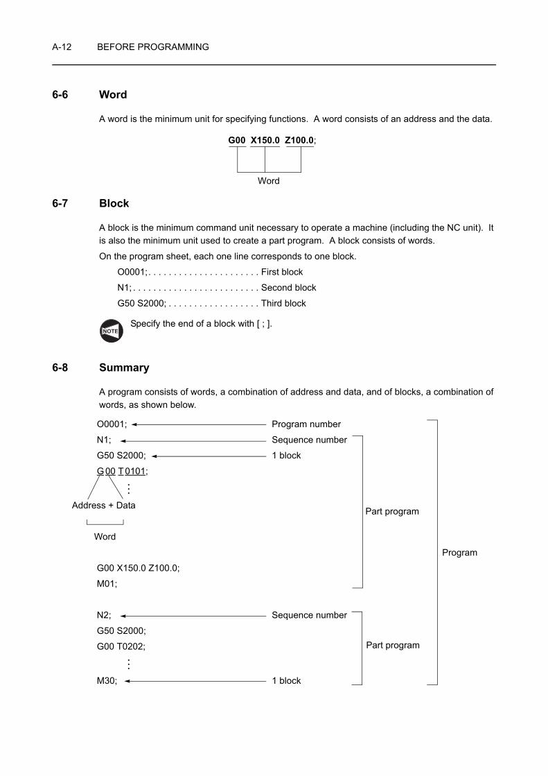
A-12 BEFORE PROGRAMMING
6-6 Word
A word is the minimum unit for specifying functions. A word consists of an address and the data.
6-7 Block
A block is the minimum command unit necessary to operate a machine (including the NC unit). It is also the minimum unit used to create a part program. A block consists of words.
On the program sheet, each one line corresponds to one block.
O0001;. . . . . . . . . . . . . . . . . . . . . . First block
N1; . . . . . . . . . . . . . . . . . . . . . . . . . Second block
G50 S2000; . . . . . . . . . . . . . . . . . . Third block
Specify the end of a block with [ ; ].
6-8 Summary
A program consists of words, a combination of address and data, and of blocks, a combination of words, as shown below.
G00 X150.0 Z100.0;
Word
NOTE
O0001; Program number
N1; Sequence number
G50 S2000; 1 block
G 00 T 0101;
Address + Data
Word
G00 X150.0 Z100.0;
M01;
N2; Sequence number
G50 S2000;
G00 T0202;
M30; 1 block
Part program
Part program
Program

BEFORE PROGRAMMING A-13
7 AXIS CONTROL AND MOVEMENT DIRECTION
This section describes movement along the controlled axes and its relationship with the program.
Knowing the direction of the controlled axes is essential when creating a program.
7-1 Movement along the Controlled Axes
This section deals with the axis definition and how the axis movement is defined in programming.
7-1-1 ZL Series
In the ZL series, the controlled axes and their directions are determined as follows::
For the X-axis reversed JIS specification machine, positive and negative directions of the X-axis are reversed from those applied to conventional specification machines.
Axis Unit + and − Direction
X Turret 1 + direction: The direction in which the machining diameter increases.
Turret 2
Z Turret 1 + direction: The direction in which a cutting tool moves away from the spindle.
Turret 2
C (MC type)
Spindle − direction: The rotation direction in which the right-hand thread advances when viewing a cutting tool from the spindle.
NOTE
Turret 1
Spindle (Spindle 1)
Turret 2
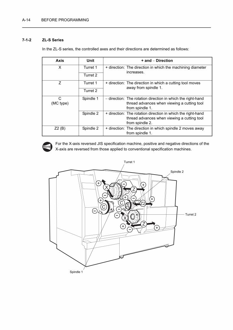
A-14 BEFORE PROGRAMMING
7-1-2 ZL-S Series
In the ZL-S series, the controlled axes and their directions are determined as follows:
For the X-axis reversed JIS specification machine, positive and negative directions of the X-axis are reversed from those applied to conventional specification machines.
Axis Unit + and − Direction
X Turret 1 + direction: The direction in which the machining diameter increases.
Turret 2
Z Turret 1 + direction: The direction in which a cutting tool moves away from spindle 1.
Turret 2
C(MC type)
Spindle 1 − direction: The rotation direction in which the right-hand thread advances when viewing a cutting tool from spindle 1.
Spindle 2 + direction: The rotation direction in which the right-hand thread advances when viewing a cutting tool from spindle 2.
Z2 (B) Spindle 2 + direction: The direction in which spindle 2 moves away from spindle 1.
NOTE
B
Z
C
X Z+ +
+
++
X
C++
Z2
Turret 1
Spindle 1
Spindle 2
Turret 2
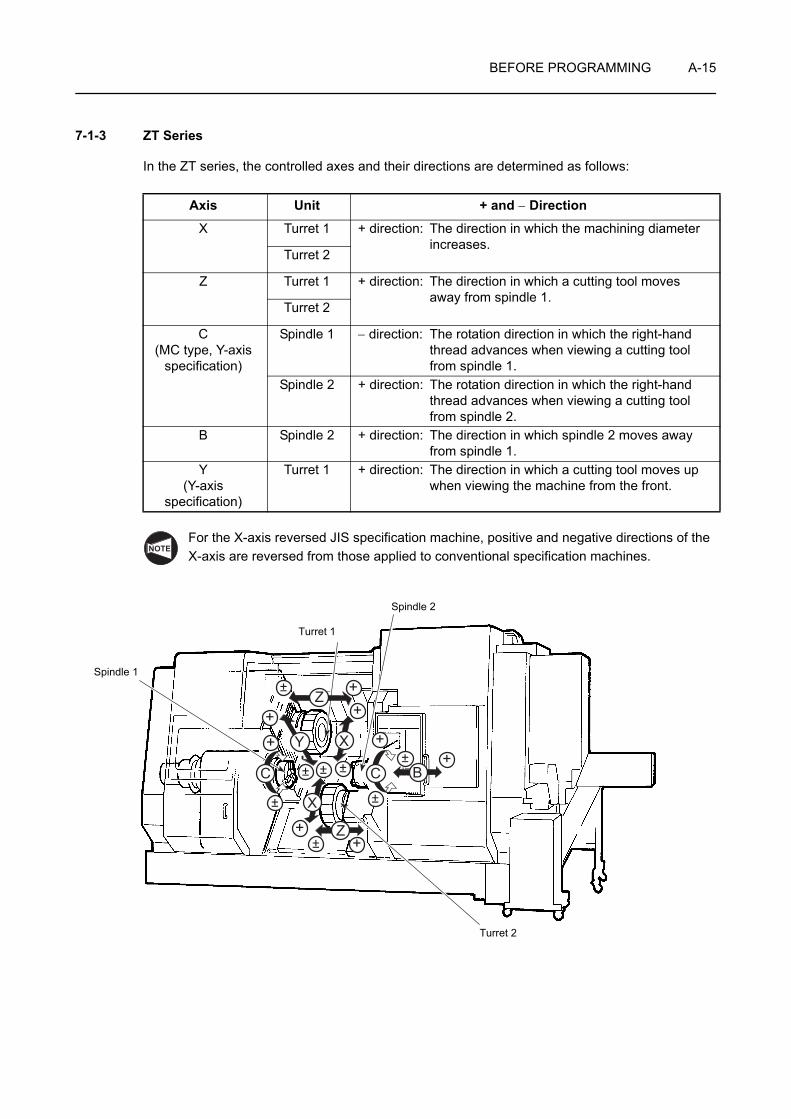
BEFORE PROGRAMMING A-15
7-1-3 ZT Series
In the ZT series, the controlled axes and their directions are determined as follows:
For the X-axis reversed JIS specification machine, positive and negative directions of the X-axis are reversed from those applied to conventional specification machines.
Axis Unit + and − Direction
X Turret 1 + direction: The direction in which the machining diameter increases.
Turret 2
Z Turret 1 + direction: The direction in which a cutting tool moves away from spindle 1.
Turret 2
C(MC type, Y-axis
specification)
Spindle 1 − direction: The rotation direction in which the right-hand thread advances when viewing a cutting tool from spindle 1.
Spindle 2 + direction: The rotation direction in which the right-hand thread advances when viewing a cutting tool from spindle 2.
B Spindle 2 + direction: The direction in which spindle 2 moves away from spindle 1.
Y(Y-axis
specification)
Turret 1 + direction: The direction in which a cutting tool moves up when viewing the machine from the front.
NOTE
X
±
+
+
±
+
±
B+±
Z+±
X
±
+
±
+
± +
Y
Z
CC
Turret 1
Spindle 1
Spindle 2
Turret 2
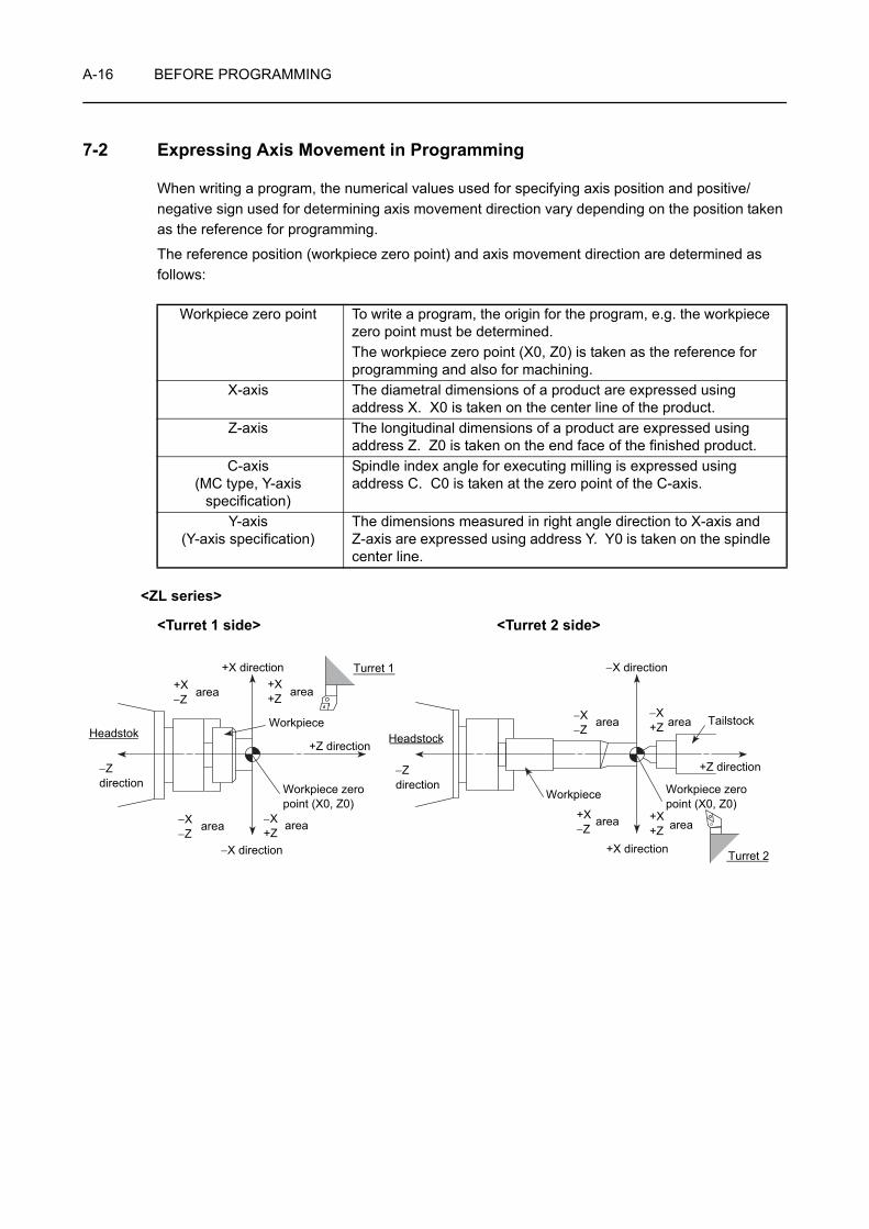
A-16 BEFORE PROGRAMMING
7-2 Expressing Axis Movement in Programming
When writing a program, the numerical values used for specifying axis position and positive/negative sign used for determining axis movement direction vary depending on the position taken as the reference for programming.
The reference position (workpiece zero point) and axis movement direction are determined as follows:
<ZL series>
<Turret 1 side> <Turret 2 side>
Workpiece zero point To write a program, the origin for the program, e.g. the workpiece zero point must be determined.The workpiece zero point (X0, Z0) is taken as the reference for programming and also for machining.
X-axis The diametral dimensions of a product are expressed using address X. X0 is taken on the center line of the product.
Z-axis The longitudinal dimensions of a product are expressed using address Z. Z0 is taken on the end face of the finished product.
C-axis(MC type, Y-axis
specification)
Spindle index angle for executing milling is expressed using address C. C0 is taken at the zero point of the C-axis.
Y-axis(Y-axis specification)
The dimensions measured in right angle direction to X-axis and Z-axis are expressed using address Y. Y0 is taken on the spindle center line.
Headstok Headstock
−Z direction
−Z direction
area
Turret 1
+Z direction
+Z direction
area
area
area
+X direction
−X direction
Workpiece
WorkpieceWorkpiece zero point (X0, Z0)
Workpiece zero point (X0, Z0)
area area
Turret 2
−X direction
area area
Tailstock
+X−Z
−X−Z
+X+Z
−X+Z
−X−Z
+X−Z
+X+Z
+X direction
−X+Z
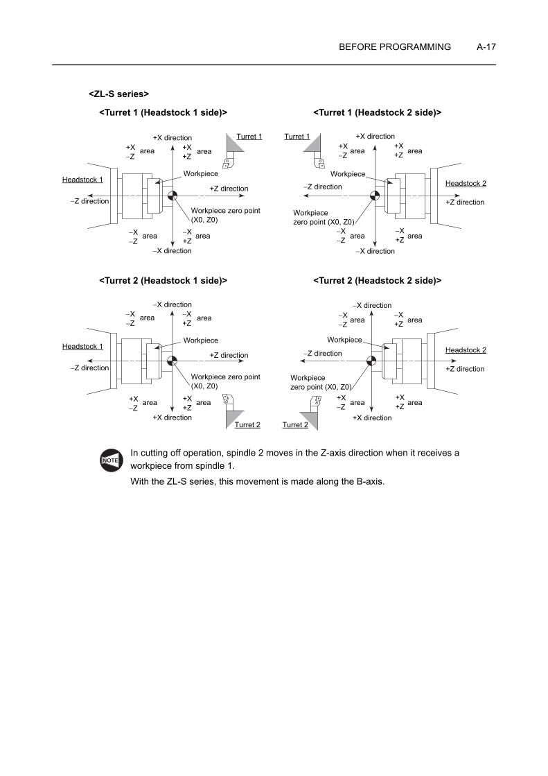
BEFORE PROGRAMMING A-17
<ZL-S series>
<Turret 1 (Headstock 1 side)> <Turret 1 (Headstock 2 side)>
<Turret 2 (Headstock 1 side)> <Turret 2 (Headstock 2 side)>
In cutting off operation, spindle 2 moves in the Z-axis direction when it receives a workpiece from spindle 1.
With the ZL-S series, this movement is made along the B-axis.
Workpiece Workpiece
Turret 1 Turret 1
area area
area area area area
area area
Headstock 1 Headstock 2
Workpiece zero point(X0, Z0)
Workpiece zero point (X0, Z0)
+X direction
−X direction −X direction
−Z direction
+Z direction −Z direction
+Z direction
+X direction+X−Z
−X−Z
+X+Z
−X+Z
+X−Z
−X−Z
+X+Z
−X+Z
Workpiece Workpiece
Turret 2 Turret 2
area area
area area area area
area area
Headstock 1 Headstock 2
Workpiece zero point(X0, Z0)
Workpiece zero point (X0, Z0)
−X direction
+X direction +X direction
−Z direction
+Z direction −Z direction
+Z direction
−X direction−X−Z
+X−Z
−X+Z
+X+Z
−X−Z
+X−Z
−X+Z
+X+Z
NOTE
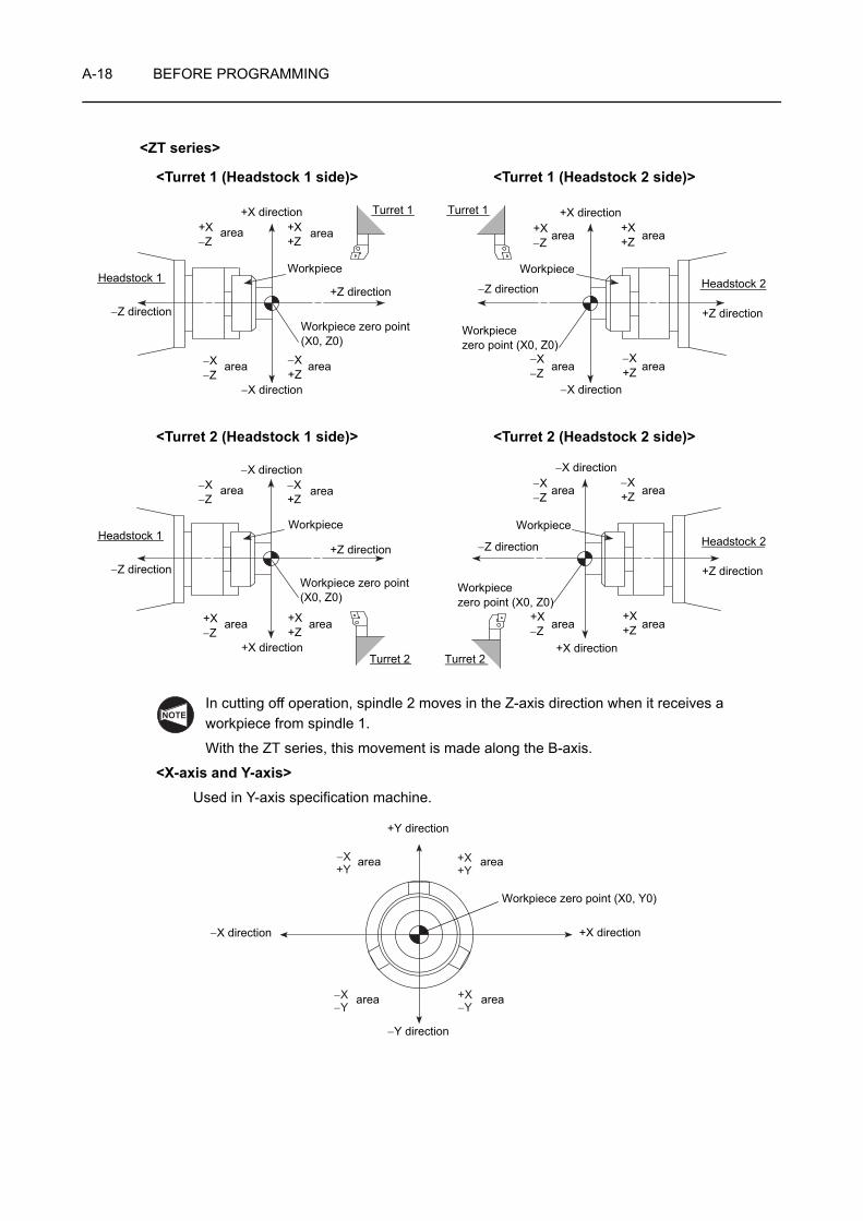
A-18 BEFORE PROGRAMMING
<ZT series>
<Turret 1 (Headstock 1 side)> <Turret 1 (Headstock 2 side)>
<Turret 2 (Headstock 1 side)> <Turret 2 (Headstock 2 side)>
In cutting off operation, spindle 2 moves in the Z-axis direction when it receives a workpiece from spindle 1.
With the ZT series, this movement is made along the B-axis.
<X-axis and Y-axis>Used in Y-axis specification machine.
Workpiece Workpiece
Turret 1 Turret 1
area area
area area area area
area area
Headstock 1 Headstock 2
Workpiece zero point(X0, Z0)
Workpiece zero point (X0, Z0)
+X direction
−X direction −X direction
−Z direction
+Z direction −Z direction
+Z direction
+X direction+X−Z
−X−Z
+X+Z
−X+Z
+X−Z
−X−Z
+X+Z
−X+Z
Workpiece Workpiece
Turret 2 Turret 2
area area
area area area area
area area
Headstock 1 Headstock 2
Workpiece zero point(X0, Z0)
Workpiece zero point (X0, Z0)
−X direction
+X direction +X direction
−Z direction
+Z direction −Z direction
+Z direction
−X direction−X−Z
+X−Z
−X+Z
+X+Z
−X−Z
+X−Z
−X+Z
+X+Z
NOTE
+X+Y
+X−Y
−X−Y
−X+Y
+Y direction
−Y direction
−X direction +X direction
area area
area area
Workpiece zero point (X0, Y0)
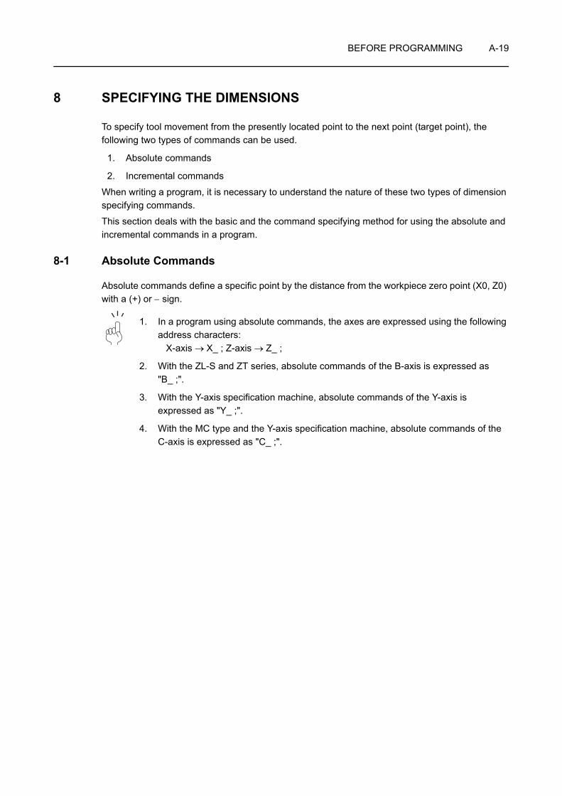
BEFORE PROGRAMMING A-19
8 SPECIFYING THE DIMENSIONS
To specify tool movement from the presently located point to the next point (target point), the following two types of commands can be used.
1. Absolute commands
2. Incremental commands
When writing a program, it is necessary to understand the nature of these two types of dimension specifying commands.
This section deals with the basic and the command specifying method for using the absolute and incremental commands in a program.
8-1 Absolute Commands
Absolute commands define a specific point by the distance from the workpiece zero point (X0, Z0) with a (+) or − sign.
1. In a program using absolute commands, the axes are expressed using the following address characters:
X-axis → X_ ; Z-axis → Z_ ;
2. With the ZL-S and ZT series, absolute commands of the B-axis is expressed as "B_ ;".
3. With the Y-axis specification machine, absolute commands of the Y-axis is expressed as "Y_ ;".
4. With the MC type and the Y-axis specification machine, absolute commands of the C-axis is expressed as "C_ ;".
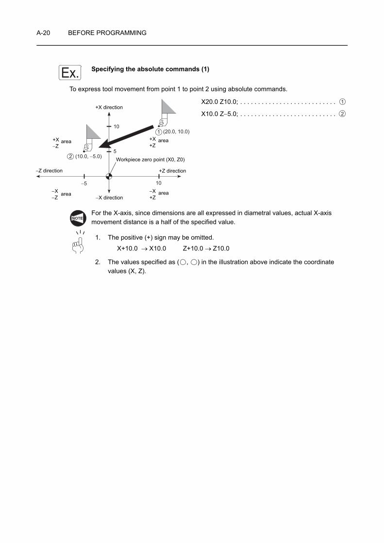
A-20 BEFORE PROGRAMMING
Specifying the absolute commands (1)
To express tool movement from point 1 to point 2 using absolute commands.
X20.0 Z10.0; . . . . . . . . . . . . . . . . . . . . . . . . . . .
X10.0 Z−5.0; . . . . . . . . . . . . . . . . . . . . . . . . . . .
For the X-axis, since dimensions are all expressed in diametral values, actual X-axis movement distance is a half of the specified value.
1. The positive (+) sign may be omitted.
X+10.0 → X10.0 Z+10.0 → Z10.0
2. The values specified as ( , ) in the illustration above indicate the coordinate values (X, Z).
Ex.
10
5
−5 10
(10.0, −5.0)
(20.0, 10.0)
2
1
Workpiece zero point (X0, Z0)
+X direction
−X direction
−Z direction +Z direction
area area
area area
+X−Z
−X−Z
+X+Z
−X+Z
1
2
NOTE
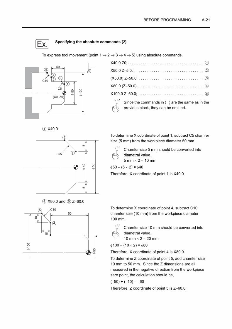
BEFORE PROGRAMMING A-21
Specifying the absolute commands (2)
To express tool movement (point 1 → 2 → 3 → 4 → 5) using absolute commands.
X40.0 Z0; . . . . . . . . . . . . . . . . . . . . . . . . . . . . . . . . . . .
X50.0 Z−5.0; . . . . . . . . . . . . . . . . . . . . . . . . . . . . . . . .
(X50.0) Z−50.0; . . . . . . . . . . . . . . . . . . . . . . . . . . . . . .
X80.0 (Z−50.0); . . . . . . . . . . . . . . . . . . . . . . . . . . . . . .
X100.0 Z−60.0; . . . . . . . . . . . . . . . . . . . . . . . . . . . . . .
Since the commands in ( ) are the same as in the previous block, they can be omitted.
X40.0
To determine X coordinate of point 1, subtract C5 chamfer size (5 mm) from the workpiece diameter 50 mm.
Chamfer size 5 mm should be converted into diametral value.5 mm × 2 = 10 mm
φ50 − (5 × 2) = φ40
Therefore, X coordinate of point 1 is X40.0.
X80.0 and Z−60.0
To determine X coordinate of point 4, subtract C10 chamfer size (10 mm) from the workpiece diameter 100 mm.
Chamfer size 10 mm should be converted into diametral value.10 mm × 2 = 20 mm
φ100 − (10 × 2) = φ80
Therefore, X coordinate of point 4 is X80.0.
To determine Z coordinate of point 5, add chamfer size 10 mm to 50 mm. Since the Z dimensions are all measured in the negative direction from the workpiece zero point, the calculation should be,
(−50) + (−10) = −60
Therefore, Z coordinate of point 5 is Z−60.0.
Ex.
(X0, Z0)
50
C5
C1010
0
50φ φ
1
234
5
1
2
3
4
5
1
C5
50405
5φ φ
1
2
4 5
10
50C105
4
50
100
10
φ
φ
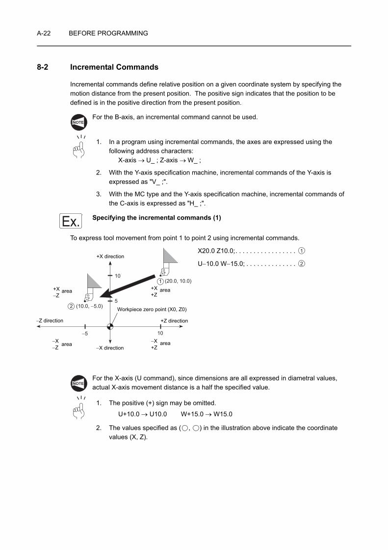
A-22 BEFORE PROGRAMMING
8-2 Incremental Commands
Incremental commands define relative position on a given coordinate system by specifying the motion distance from the present position. The positive sign indicates that the position to be defined is in the positive direction from the present position.
For the B-axis, an incremental command cannot be used.
1. In a program using incremental commands, the axes are expressed using the following address characters:
X-axis → U_ ; Z-axis → W_ ;
2. With the Y-axis specification machine, incremental commands of the Y-axis is expressed as "V_ ;".
3. With the MC type and the Y-axis specification machine, incremental commands of the C-axis is expressed as "H_ ;".
Specifying the incremental commands (1)
To express tool movement from point 1 to point 2 using incremental commands.
X20.0 Z10.0;. . . . . . . . . . . . . . . . .
U−10.0 W−15.0; . . . . . . . . . . . . . .
For the X-axis (U command), since dimensions are all expressed in diametral values, actual X-axis movement distance is a half the specified value.
1. The positive (+) sign may be omitted.
U+10.0 → U10.0 W+15.0 → W15.0
2. The values specified as ( , ) in the illustration above indicate the coordinate values (X, Z).
NOTE
Ex.
10
5
−5 10
(10.0, −5.0)
(20.0, 10.0)
2
1
Workpiece zero point (X0, Z0)
+X direction
−X direction
−Z direction +Z direction
area area
area area
+X−Z
−X−Z
+X+Z
−X+Z
1
2
NOTE
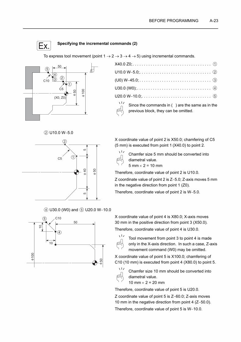
BEFORE PROGRAMMING A-23
Specifying the incremental commands (2)
To express tool movement (point 1 → 2 → 3 → 4 → 5) using incremental commands.
X40.0 Z0; . . . . . . . . . . . . . . . . . . . . . . . . . . . . . . . . . . .
U10.0 W−5.0;. . . . . . . . . . . . . . . . . . . . . . . . . . . . . . . .
(U0) W−45.0; . . . . . . . . . . . . . . . . . . . . . . . . . . . . . . . .
U30.0 (W0); . . . . . . . . . . . . . . . . . . . . . . . . . . . . . . . . .
U20.0 W−10.0;. . . . . . . . . . . . . . . . . . . . . . . . . . . . . . .
Since the commands in ( ) are the same as in the previous block, they can be omitted.
U10.0 W−5.0
X coordinate value of point 2 is X50.0; chamfering of C5 (5 mm) is executed from point 1 (X40.0) to point 2.
Chamfer size 5 mm should be converted into diametral value.5 mm × 2 = 10 mm
Therefore, coordinate value of point 2 is U10.0.
Z coordinate value of point 2 is Z−5.0; Z-axis moves 5 mm in the negative direction from point 1 (Z0).
Therefore, coordinate value of point 2 is W−5.0.
U30.0 (W0) and U20.0 W−10.0
X coordinate value of point 4 is X80.0; X-axis moves 30 mm in the positive direction from point 3 (X50.0).
Therefore, coordinate value of point 4 is U30.0.
Tool movement from point 3 to point 4 is made only in the X-axis direction. In such a case, Z-axis movement command (W0) may be omitted.
X coordinate value of point 5 is X100.0; chamfering of C10 (10 mm) is executed from point 4 (X80.0) to point 5.
Chamfer size 10 mm should be converted into diametral value.10 mm × 2 = 20 mm
Therefore, coordinate value of point 5 is U20.0.
Z coordinate value of point 5 is Z−60.0; Z-axis moves 10 mm in the negative direction from point 4 (Z−50.0).
Therefore, coordinate value of point 5 is W−10.0.
Ex.
(X0, Z0)
50
C5
C1010
0
50φ φ
1
234
51
2
3
4
5
2
C5
50405
5φ φ
1
2
4 5
10
50C105
4
50
100
10
φ
φ

A-24 BEFORE PROGRAMMING
8-3 Summary
Differences between absolute programming and incremental programming are summarized below.
1. Generally, a program is written using absolute commands.
Incremental commands are usually used for tool retraction or chamfering operation.
2. Absolute commands and incremental commands may be specified in the same block such as "X_ W_ ;", "U_ Z_ ;", and "X_ V_ ;".
3. If absolute and incremental commands representing the same axis (X and U, Z and W, Y and V, or C and H) are specified in the same block, the address character specified later becomes valid.
Example: X10.0 U−20.0; → U−20.0 is valid.
Absolute Programming Incremental Programming
Address Characters
X_ Z_ Y_ C_ ; B_ ; U_ W_ V_ H_ ;
Meaning of the Sign (+/−)
The area where the specified point exists.
The direction in which the cutting tool advances.
Meaning of the Numerical Values
Coordinate values (distance from the workpiece zero point, angle of index from the zero point)
Distance of tool movement, angle of spindle index
Reference Point of Commands
Workpiece zero point (X0, Z0, Y0)Zero point (C0) (B0)
Actual positions of tool and spindle
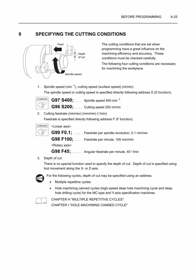
BEFORE PROGRAMMING A-25
9 SPECIFYING THE CUTTING CONDITIONS
The cutting conditions that are set when programming have a great influence on the machining efficiency and accuracy. These conditions must be checked carefully.
The following four cutting conditions are necessary for machining the workpiece.
1. Spindle speed (min−1), cutting speed (surface speed) (m/min)
The spindle speed or cutting speed is specified directly following address S (S function).
G97 S400; . . . . Spindle speed 400 min−1
G96 S200; . . . . Cutting speed 200 m/min
2. Cutting feedrate (mm/rev) (mm/min) (°/min)
Feedrate is specified directly following address F (F function).
<Linear axis>
G99 F0.1; . . . . . Feedrate per spindle revolution, 0.1 mm/rev
G98 F100; . . . . Feedrate per minute, 100 mm/min
<Rotary axis>
G98 F45; . . . . . . Angular feedrate per minute, 45 °/min
3. Depth of cut
There is no special function used to specify the depth of cut. Depth of cut is specified using tool movement along the X- or Z-axis.
For the following cycles, depth of cut may be specified using an address.
• Multiple repetitive cycles
• Hole machining canned cycles (high-speed deep hole machining cycle and deep hole drilling cycle) for the MC type and Y-axis specification machines
CHAPTER H "MULTIPLE REPETITIVE CYCLES"
CHAPTER I "HOLE MACHINING CANNED CYCLE"
Feed
Spindle speed
Depth of cut
COMMAND
COMMAND
NOTE

A-26 BEFORE PROGRAMMING
4. Chuck gripping force
Instruction manuals prepared by the chuck and cylinder manufacturers
WARNING The chuck gripping force is reduced when the spindle is rotated since the rotation applies centrifugal force to the chuck jaws. This reduction of the chuck gripping force could cause the workpiece to fly out of the chuck during machining, causing serious injuries or damage to the machine. Therefore, when checking a program, measure the chuck gripping force that will actually be applied when the spindle is rotated at the speed used for machining by using a gripping force meter. If the measured chuck gripping force value is lower than that required to hold the workpiece safely, change machining conditions such as the chucking pressure, spindle speed, feedrate, and depth of cut.Periodically measure the chuck gripping force with a gripping force meter to make sure that the required gripping force is maintained. If it is not, consult the chuck manufacturer and cylinder manufacturer.For details on the relationship between the spindle rotation speed and chuck gripping force, refer to the instruction manuals prepared by the chuck manufacturer and cylinder manufacturer.
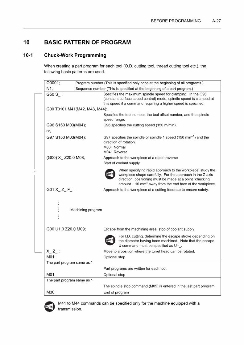
BEFORE PROGRAMMING A-27
10 BASIC PATTERN OF PROGRAM
10-1 Chuck-Work Programming
When creating a part program for each tool (O.D. cutting tool, thread cutting tool etc.), the following basic patterns are used.
M41 to M44 commands can be specified only for the machine equipped with a transmission.
O0001; Program number (This is specified only once at the beginning of all programs.)N1; Sequence number (This is specified at the beginning of a part program.)G50 S_ ; Specifies the maximum spindle speed for clamping. In the G96
(constant surface speed control) mode, spindle speed is clamped at this speed if a command requiring a higher speed is specified.
G00 T0101 M41(M42, M43, M44);Specifies the tool number, the tool offset number, and the spindle speed range.
G96 S150 M03(M04); G96 specifies the cutting speed (150 m/min).or,G97 S150 M03(M04); G97 specifies the spindle or spindle 1 speed (150 min−1) and the
direction of rotation.M03: NormalM04: Reverse
(G00) X_ Z20.0 M08; Approach to the workpiece at a rapid traverseStart of coolant supply
When specifying rapid approach to the workpiece, study the workpiece shape carefully. For the approach in the Z-axis direction, positioning must be made at a point "chucking amount + 10 mm" away from the end face of the workpiece.
G01 X_ Z_ F_ ; Approach to the workpiece at a cutting feedrate to ensure safety.
Machining program
G00 U1.0 Z20.0 M09; Escape from the machining area, stop of coolant supply
For I.D. cutting, determine the escape stroke depending on the diameter having been machined. Note that the escape U command must be specified as U−_.
X_ Z_ ; Move to a position where the turret head can be rotated.M01; Optional stopThe part program same as *
Part programs are written for each tool.
M01; Optional stopThe part program same as *
The spindle stop command (M05) is entered in the last part program.
M30; End of program
* NOTE
NOTE
NOTE
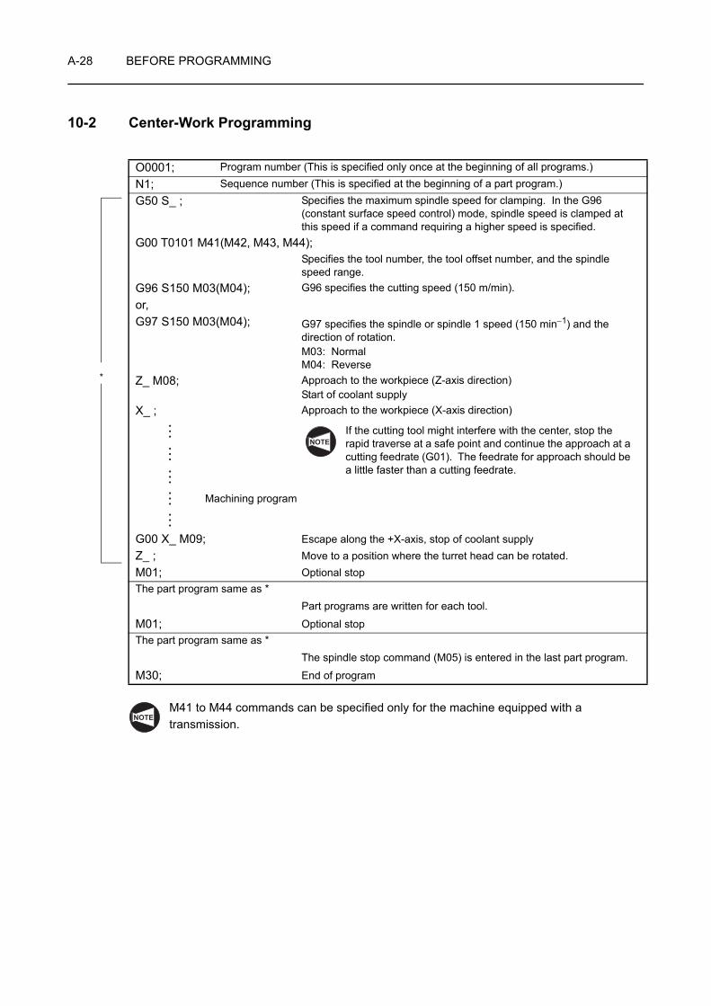
A-28 BEFORE PROGRAMMING
10-2 Center-Work Programming
M41 to M44 commands can be specified only for the machine equipped with a transmission.
O0001; Program number (This is specified only once at the beginning of all programs.)N1; Sequence number (This is specified at the beginning of a part program.)G50 S_ ; Specifies the maximum spindle speed for clamping. In the G96
(constant surface speed control) mode, spindle speed is clamped at this speed if a command requiring a higher speed is specified.
G00 T0101 M41(M42, M43, M44);Specifies the tool number, the tool offset number, and the spindle speed range.
G96 S150 M03(M04); G96 specifies the cutting speed (150 m/min).or,G97 S150 M03(M04); G97 specifies the spindle or spindle 1 speed (150 min−1) and the
direction of rotation.M03: NormalM04: Reverse
Z_ M08; Approach to the workpiece (Z-axis direction)Start of coolant supply
X_ ; Approach to the workpiece (X-axis direction)
If the cutting tool might interfere with the center, stop the rapid traverse at a safe point and continue the approach at a cutting feedrate (G01). The feedrate for approach should be a little faster than a cutting feedrate.
Machining program
G00 X_ M09; Escape along the +X-axis, stop of coolant supplyZ_ ; Move to a position where the turret head can be rotated.M01; Optional stopThe part program same as *
Part programs are written for each tool.
M01; Optional stopThe part program same as *
The spindle stop command (M05) is entered in the last part program.
M30; End of program
*
NOTE
NOTE

BEFORE PROGRAMMING A-29
11 CAUTIONS FOR CREATING A PROGRAM
11-1 Program Number
This manual describes all program numbers in a four digit number. However, it is not necessary to write or enter a program number in a four digit number. A program number specified in less than four digit number is recognized and displayed in a four digit number after it is input to the NC. If "O1" is entered, for example, it is recognized and displayed as "O0001".
An entry of a program number of five or more digits is not permitted.
11-2 Space between the Words in the Program
In this manual, a program is described in the manner as indicated below.
In line , for example, a space is placed between "G50" and "S2000". When entering a program to the NC, the word-to-word space may not be inserted.
When a program is input to the NC memory, a space is automatically inserted.
11-3 Signs and Symbols
A program is expressed in a combination of alphabetic letters, positive/negative (+/−) signs, numerals with/without a decimal point, and the end of block symbol ";".
In addition to these, the block delete symbol "/" as well as the following symbols are also used: "," "*" "[ ]" "( )" "#".
Block delete function:
If the block delete function is on, the commands beginning with the slash "/" are ignored up to the end of block code ";" in the same block. The program is continuously executed from the block not containing the slash.
If the block delete function is off, all blocks (even those preceded by a slash) are executed.
NOTE
O0001;N1;G50 S2000;G00 T0101;
. . . . . . . . . . . . . . . . . . . . . 1
Space
1
NOTE

A-30 BEFORE PROGRAMMING
11-4 Inputting a Decimal Point
For an NC, it is possible to use a decimal point to enter numerical values. A decimal point can be used to express the numerical values that have the unit of "distance", "angle", "time", or "speed".
The addresses which allow the use of a decimal point are indicated below.
Distance or angle: X, Y, Z, C, U, V, W, H, I, J, K, R, B
Time: U, X
Feedrate: F
1. There are limits in the usable units depending on addresses. Setting units are "mm", "inch", "degree" and "second".
X15.0 . . . . . . . X15 mm or X15 inches
G04 U1.0 . . . . Dwell for 1 second
F10.0 . . . . . . . 10 mm/rev, 10 mm/min, 10 inch/rev, or 10 inch/min
2. In the case of a dwell command, a decimal point can be used when address X is used. However, it is not allowed to use a decimal point if address P is used since address P is also used to specify a sequence number.
1. To call for dwell for 1 hour, specify asG04 U3600.0 (X3600.0);
(1 hour = 3600 seconds)
2. In a program, or in a block, it is allowed to specify the commands with and without a decimal point.
X1000 Z23.7;
X10.0 Z22359;
WARNING If you forget to enter a decimal point in a program entry that requires one and start the machine without noticing the error, the turret may move to an unexpected position, damaging the machine. Check that you have entered decimal points where necessary.
"mm" setting (specified by G21)
X1.0 . . . . . . X1 mm
X1. . . . . . . . X0.001 mm or X0.0001 mm
(if a decimal point is not entered, it is assumed that the value is specified in the unit of least input increment.)
"inch" setting (specified by G20)
X1.0 . . . . . . X1 inch
X1. . . . . . . . X0.0001 inch or X0.00001 inch
(if a decimal point is not entered, it is assumed that the value is specified in the unit of least input increment.)
NOTE
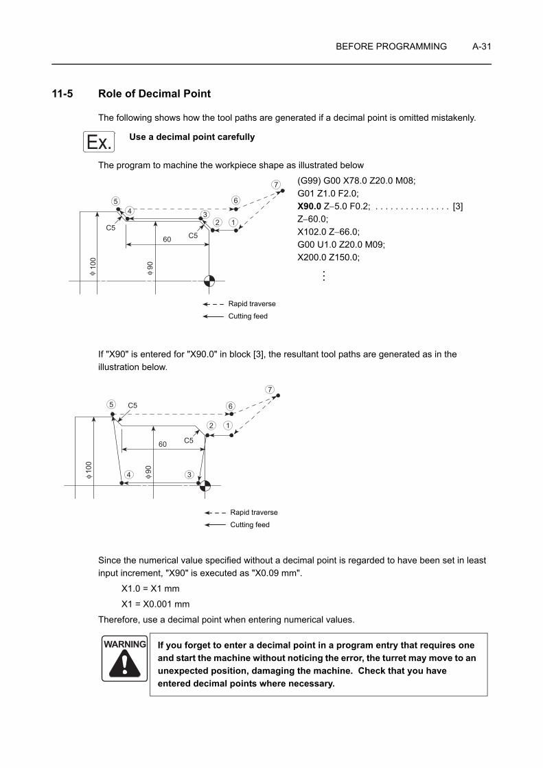
BEFORE PROGRAMMING A-31
11-5 Role of Decimal Point
The following shows how the tool paths are generated if a decimal point is omitted mistakenly.
Use a decimal point carefully
The program to machine the workpiece shape as illustrated below
(G99) G00 X78.0 Z20.0 M08;G01 Z1.0 F2.0;X90.0 Z−5.0 F0.2; . . . . . . . . . . . . . . . [3]Z−60.0;X102.0 Z−66.0;G00 U1.0 Z20.0 M09;X200.0 Z150.0;
If "X90" is entered for "X90.0" in block [3], the resultant tool paths are generated as in the illustration below.
Since the numerical value specified without a decimal point is regarded to have been set in least input increment, "X90" is executed as "X0.09 mm".
X1.0 = X1 mm
X1 = X0.001 mm
Therefore, use a decimal point when entering numerical values.
WARNING If you forget to enter a decimal point in a program entry that requires one and start the machine without noticing the error, the turret may move to an unexpected position, damaging the machine. Check that you have entered decimal points where necessary.
Ex.
60C5
C5
100
90
54 3
2 1
7
6
φφ
Rapid traverse
Cutting feed
60
C5
C5
100
90
12
34
5 6
7
φφ
Rapid traverse
Cutting feed

A-32 BEFORE PROGRAMMING
12 JIS SPECIFICATION AND REVERSE JIS SPECIFICATION
This section explains items to be kept in mind when creating a program in the JIS specification and in the reverse JIS specification.
The following summarizes the items which differ from the programming in the JIS specification when a program is written in the reverse JIS specification.
1. For the X-axis commands, the positive/negative (+/−) sign is reversed.
Addresses for which the sign of the data is reversed: X, U, I
2. In the circular interpolation, G02 calls for rotation in the counterclockwise (CCW) direction and G03 calls for rotation in the clockwise (CW) direction.
JIS Specification Reverse JIS Specification
X100.0 X−100.0
U10.0 U−10.0
I80.0 I−80.0
JIS Specification Reverse JIS Specification
G02 CW CCW
G03 CCW CW
Ex.
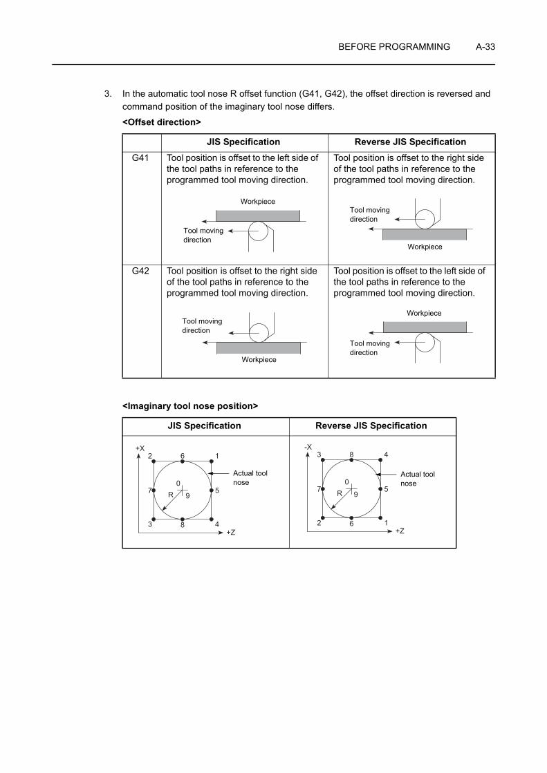
BEFORE PROGRAMMING A-33
3. In the automatic tool nose R offset function (G41, G42), the offset direction is reversed and command position of the imaginary tool nose differs.
<Offset direction>
<Imaginary tool nose position>
JIS Specification Reverse JIS Specification
G41 Tool position is offset to the left side of the tool paths in reference to the programmed tool moving direction.
Tool position is offset to the right side of the tool paths in reference to the programmed tool moving direction.
G42 Tool position is offset to the right side of the tool paths in reference to the programmed tool moving direction.
Tool position is offset to the left side of the tool paths in reference to the programmed tool moving direction.
JIS Specification Reverse JIS Specification
Workpiece
Tool moving direction
Tool moving direction
Workpiece
Tool moving direction
Workpiece
Tool moving direction
Workpiece
162
483
579R
+Z
+X
0
162
483
579R
+Z
+X
0Actual tool nose
483
162
579R
+Z
-X
0Actual tool nose
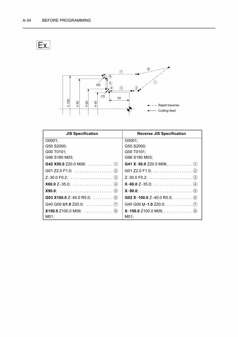
A-34 BEFORE PROGRAMMING
JIS Specification Reverse JIS Specification
O0001;G50 S2000;G00 T0101;G96 S180 M03;
G42 X50.0 Z20.0 M08; . . . . . . . . . . .
G01 Z2.0 F1.0; . . . . . . . . . . . . . . . . .
Z−30.0 F0.2; . . . . . . . . . . . . . . . . . . .
X60.0 Z−35.0; . . . . . . . . . . . . . . . . . .
X90.0; . . . . . . . . . . . . . . . . . . . . . . . .
G03 X100.0 Z−40.0 R5.0; . . . . . . . . .
G40 G00 U1.0 Z20.0; . . . . . . . . . . . .
X150.0 Z100.0 M09; . . . . . . . . . . . . . M01;
O0001;G50 S2000;G00 T0101;G96 S180 M03;
G41 X−50.0 Z20.0 M08; . . . . . . . . . . .
G01 Z2.0 F1.0; . . . . . . . . . . . . . . . . . .
Z−30.0 F0.2; . . . . . . . . . . . . . . . . . . . .
X−60.0 Z−35.0; . . . . . . . . . . . . . . . . . .
X−90.0; . . . . . . . . . . . . . . . . . . . . . . . .
G02 X−100.0 Z−40.0 R5.0; . . . . . . . . .
G40 G00 U−1.0 Z20.0; . . . . . . . . . . . .
X−150.0 Z100.0 M09; . . . . . . . . . . . . .M01;
Ex.
30
R5
C550609010
0
1
2345
67
8φ φ φ φ Rapid traverse
Cutting feed
1
2
3
4
5
6
7
8
1
2
3
4
5
6
7
8

CHAPTER BG FUNCTIONS
This chapter describes the G functions.
The following G functions are only outlined in this chapter and they are explained in details in CHAPTERS E, G, H, and I, respectively.
• Section 10 "G40, G41, G42 AUTOMATIC TOOL NOSE RADIUS OFFSET": CHAPTER E
• Section 11 "G40, G41, G42 CUTTER RADIUS OFFSET": CHAPTER G
• Section 15 "G70 - G76 MULTIPLE REPETITIVE CYCLE": CHAPTER H
• Section 16 "G80, G83 - G85, G87 - G89 HOLE MACHINING CANNED CYCLES": CHAPTER I
The examples of program given in this chapter all assume tool nose R0.
For G codes not explained in this chapter: Instruction manual supplied by the NC unit manufacturer
NOTE
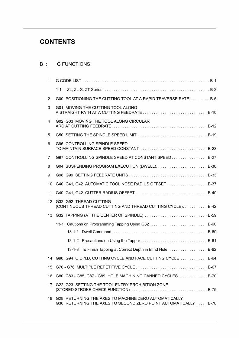
CONTENTS
B : G FUNCTIONS
1 G CODE LIST . . . . . . . . . . . . . . . . . . . . . . . . . . . . . . . . . . . . . . . . . . . . . . . . . . . . . . . . . B-1
1-1 ZL, ZL-S, ZT Series. . . . . . . . . . . . . . . . . . . . . . . . . . . . . . . . . . . . . . . . . . . . . . . . B-2
2 G00 POSITIONING THE CUTTING TOOL AT A RAPID TRAVERSE RATE . . . . . . . . . B-6
3 G01 MOVING THE CUTTING TOOL ALONG A STRAIGHT PATH AT A CUTTING FEEDRATE . . . . . . . . . . . . . . . . . . . . . . . . . . . . . B-10
4 G02, G03 MOVING THE TOOL ALONG CIRCULAR ARC AT CUTTING FEEDRATE. . . . . . . . . . . . . . . . . . . . . . . . . . . . . . . . . . . . . . . . . . . B-12
5 G50 SETTING THE SPINDLE SPEED LIMIT . . . . . . . . . . . . . . . . . . . . . . . . . . . . . . . B-19
6 G96 CONTROLLING SPINDLE SPEED TO MAINTAIN SURFACE SPEED CONSTANT . . . . . . . . . . . . . . . . . . . . . . . . . . . . . . B-23
7 G97 CONTROLLING SPINDLE SPEED AT CONSTANT SPEED . . . . . . . . . . . . . . . . B-27
8 G04 SUSPENDING PROGRAM EXECUTION (DWELL). . . . . . . . . . . . . . . . . . . . . . . B-30
9 G98, G99 SETTING FEEDRATE UNITS . . . . . . . . . . . . . . . . . . . . . . . . . . . . . . . . . . . B-33
10 G40, G41, G42 AUTOMATIC TOOL NOSE RADIUS OFFSET . . . . . . . . . . . . . . . . . . B-37
11 G40, G41, G42 CUTTER RADIUS OFFSET . . . . . . . . . . . . . . . . . . . . . . . . . . . . . . . . B-40
12 G32, G92 THREAD CUTTING (CONTINUOUS THREAD CUTTING AND THREAD CUTTING CYCLE). . . . . . . . . . . B-42
13 G32 TAPPING (AT THE CENTER OF SPINDLE) . . . . . . . . . . . . . . . . . . . . . . . . . . . . B-59
13-1 Cautions on Programming Tapping Using G32. . . . . . . . . . . . . . . . . . . . . . . . . . B-60
13-1-1 Dwell Command. . . . . . . . . . . . . . . . . . . . . . . . . . . . . . . . . . . . . . . . . . . B-60
13-1-2 Precautions on Using the Tapper. . . . . . . . . . . . . . . . . . . . . . . . . . . . . . B-61
13-1-3 To Finish Tapping at Correct Depth in Blind Hole . . . . . . . . . . . . . . . . . B-62
14 G90, G94 O.D./I.D. CUTTING CYCLE AND FACE CUTTING CYCLE . . . . . . . . . . . . B-64
15 G70 - G76 MULTIPLE REPETITIVE CYCLE . . . . . . . . . . . . . . . . . . . . . . . . . . . . . . . . B-67
16 G80, G83 - G85, G87 - G89 HOLE MACHINING CANNED CYCLES . . . . . . . . . . . . . B-70
17 G22, G23 SETTING THE TOOL ENTRY PROHIBITION ZONE (STORED STROKE CHECK FUNCTION) . . . . . . . . . . . . . . . . . . . . . . . . . . . . . . . . . . B-75
18 G28 RETURNING THE AXES TO MACHINE ZERO AUTOMATICALLY, G30 RETURNING THE AXES TO SECOND ZERO POINT AUTOMATICALLY . . . . . B-78
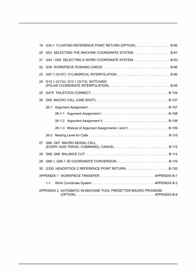
19 G30.1 FLOATING REFERENCE POINT RETURN (OPTION). . . . . . . . . . . . . . . . . . . B-80
20 G53 SELECTING THE MACHINE COORDINATE SYSTEM . . . . . . . . . . . . . . . . . . . . B-81
21 G54 - G59 SELECTING A WORK COORDINATE SYSTEM . . . . . . . . . . . . . . . . . . . . B-83
22 G38 WORKPIECE PUSHING CHECK. . . . . . . . . . . . . . . . . . . . . . . . . . . . . . . . . . . . . B-86
23 G07.1 (G107) CYLINDRICAL INTERPOLATION . . . . . . . . . . . . . . . . . . . . . . . . . . . . . B-90
24 G12.1 (G112), G13.1 (G113) NOTCHING (POLAR COORDINATE INTERPOLATION) . . . . . . . . . . . . . . . . . . . . . . . . . . . . . . . . . B-95
25 G479 TAILSTOCK CONNECT . . . . . . . . . . . . . . . . . . . . . . . . . . . . . . . . . . . . . . . . . . B-104
26 G65 MACRO CALL (ONE-SHOT) . . . . . . . . . . . . . . . . . . . . . . . . . . . . . . . . . . . . . . . B-107
26-1 Argument Assignment . . . . . . . . . . . . . . . . . . . . . . . . . . . . . . . . . . . . . . . . . . . . B-107
26-1-1 Argument Assignment I . . . . . . . . . . . . . . . . . . . . . . . . . . . . . . . . . . . . B-108
26-1-2 Argument Assignment II. . . . . . . . . . . . . . . . . . . . . . . . . . . . . . . . . . . . B-108
26-1-3 Mixture of Argument Assignments I and II . . . . . . . . . . . . . . . . . . . . . . B-109
26-2 Nesting Level for Calls . . . . . . . . . . . . . . . . . . . . . . . . . . . . . . . . . . . . . . . . . . . B-110
27 G66, G67 MACRO MODAL CALL (EVERY AXIS TRAVEL COMMAND), CANCEL . . . . . . . . . . . . . . . . . . . . . . . . . . . . . B-112
28 G68, G69 BALANCE CUT . . . . . . . . . . . . . . . . . . . . . . . . . . . . . . . . . . . . . . . . . . . . . B-114
29 G68.1, G69.1 3D COORDINATE CONVERSION . . . . . . . . . . . . . . . . . . . . . . . . . . . . B-116
30 G330 HEADSTOCK 2 REFERENCE POINT RETURN . . . . . . . . . . . . . . . . . . . . . . . B-120
APPENDIX 1 WORKPIECE TRANSFER . . . . . . . . . . . . . . . . . . . . . . . . . . . . . APPENDIX B-1
1-1 Work Coordinate System . . . . . . . . . . . . . . . . . . . . . . . . . . . . . . . . . APPENDIX B-2
APPENDIX 2 AUTOMATIC IN-MACHINE TOOL PRESETTER MACRO PROGRAM (OPTION) . . . . . . . . . . . . . . . . . . . . . . . . . . . . . . . . . . . . . . . . . . APPENDIX B-6
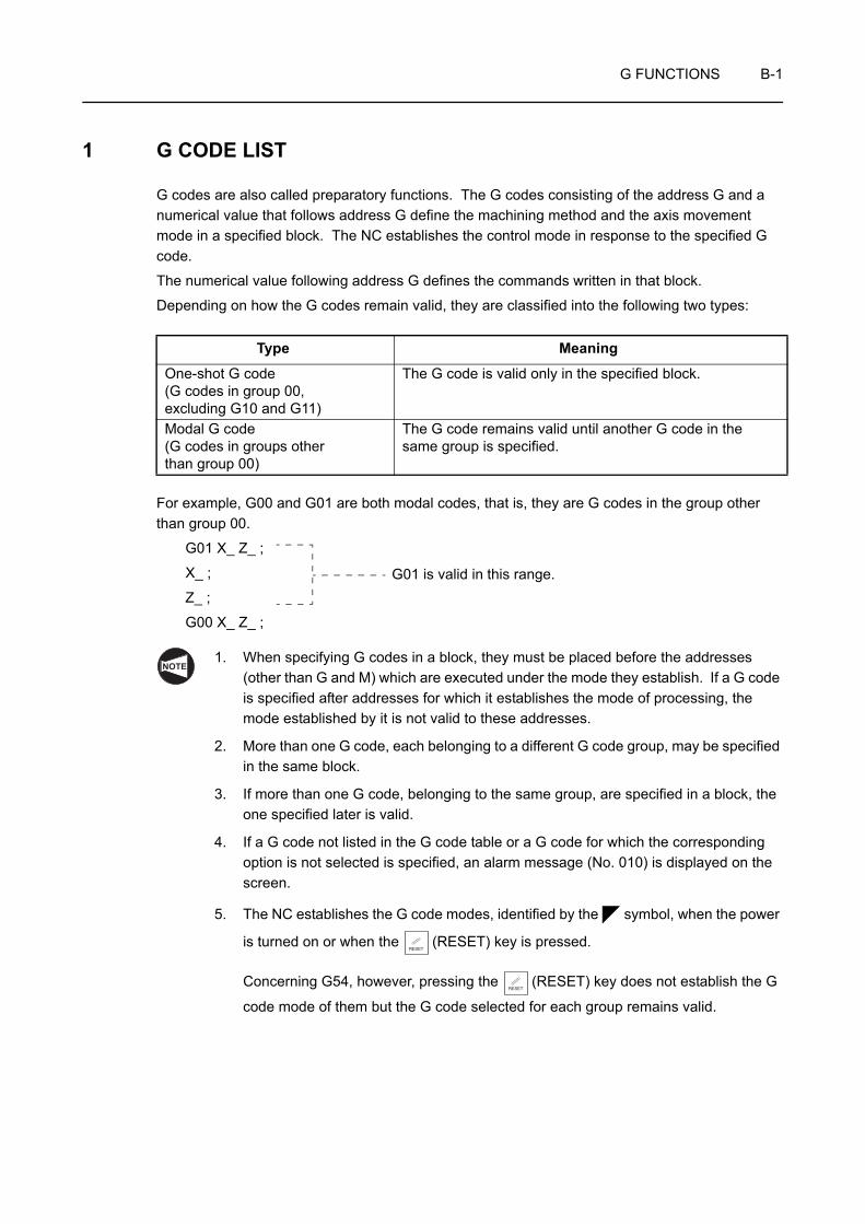
G FUNCTIONS B-1
1 G CODE LIST
G codes are also called preparatory functions. The G codes consisting of the address G and a numerical value that follows address G define the machining method and the axis movement mode in a specified block. The NC establishes the control mode in response to the specified G code.
The numerical value following address G defines the commands written in that block.
Depending on how the G codes remain valid, they are classified into the following two types:
For example, G00 and G01 are both modal codes, that is, they are G codes in the group other than group 00.
G01 X_ Z_ ;
X_ ;
Z_ ;
G00 X_ Z_ ;
1. When specifying G codes in a block, they must be placed before the addresses (other than G and M) which are executed under the mode they establish. If a G code is specified after addresses for which it establishes the mode of processing, the mode established by it is not valid to these addresses.
2. More than one G code, each belonging to a different G code group, may be specified in the same block.
3. If more than one G code, belonging to the same group, are specified in a block, the one specified later is valid.
4. If a G code not listed in the G code table or a G code for which the corresponding option is not selected is specified, an alarm message (No. 010) is displayed on the screen.
5. The NC establishes the G code modes, identified by the symbol, when the power
is turned on or when the (RESET) key is pressed.
Concerning G54, however, pressing the (RESET) key does not establish the G
code mode of them but the G code selected for each group remains valid.
Type Meaning
One-shot G code(G codes in group 00, excluding G10 and G11)
The G code is valid only in the specified block.
Modal G code(G codes in groups other than group 00)
The G code remains valid until another G code in the same group is specified.
G01 is valid in this range.
NOTE
RESET
RESET
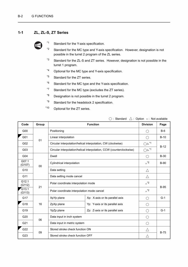
B-2 G FUNCTIONS
1-1 ZL, ZL-S, ZT Series
*1 Standard for the Y-axis specification.*2 Standard for the MC type and Y-axis specification. However, designation is not
possible in the turret 2 program of the ZL series.*3 Standard for the ZL-S and ZT series. However, designation is not possible in the
turret 1 program.*4 Optional for the MC type and Y-axis specification.*5 Standard for the ZT series.*6 Standard for the MC type and the Y-axis specification.*7 Standard for the MC type (excludes the ZT series).*8 Designation is not possible in the turret 2 program.*9 Standard for the headstock 2 specification.
*10 Optional for the ZT series.
: Standard : Option × : Not available
Code Group Function Division Page
G00
01
Positioning B-6
G01 Linear interpolation B-10
G02 Circular interpolation/helical interpolation, CW (clockwise) /×*1
B-12G03 Circular interpolation/helical interpolation, CCW (counterclockwise) /×*1
G04
00
Dwell B-30
G07.1(G107) Cylindrical interpolation ×*2 B-90
G10 Data setting
G11 Data setting mode cancel
G12.1(G112)
21Polar coordinate interpolation mode ×*2
B-95G13.1(G113) Polar coordinate interpolation mode cancel ×*2
G17
16
XpYp plane Xp: X-axis or its parallel axis G-1
G18 ZpXp plane Yp: Y-axis or its parallel axis
G19 YpZp plane Zp: Z-axis or its parallel axis G-1
G2006
Data input in inch system
G21 Data input in metric system
G2209
Stored stroke check function ONB-75
G23 Stored stroke check function OFF
NOTE

G FUNCTIONS B-3
G27
00
Reference point return check
G28 Reference point return B-78
G30 Second/third, fourth reference point return / B-78
G30.1 Floating reference point return B-80
G31 Skip function/Multi-step skip function /
G32
01
Thread cutting B-42
G34 Variable lead thread cutting
G35 Circular thread cutting, CW (clockwise)
G36 Circular thread cutting, CCW (counterclockwise)
G38 00 Workpiece pushing check ×*3 B-86
G39 00 Corner circle interpolation
G40
07
Tool nose radius offset cancel/Cutter radius offset cancel /×*1
B-37G41 Tool nose radius offset, left/Cutter radius offset, left /×*1
G42 Tool nose radius offset, right/Cutter radius offset, right /×*1
G5000
Coordinate system setting/Spindle speed limit setting B-19
G50.3 Work coordinate system preset
G50.2(G250)
20Polygon cutting cancel ×*4
G51.2(G251) Polygon cutting ×*4
G5200
Local coordinate system setting
G53 Machine coordinate system selection B-81
G54
14
Work coordinate system 1 selection
B-83
G55 Work coordinate system 2 selection
G56 Work coordinate system 3 selection
G57 Work coordinate system 4 selection
G58 Work coordinate system 5 selection
G59 Work coordinate system 6 selection
G65 00 Macro call B-107
G6612
Macro modal callB-112
G67 Macro modal call cancel
G6804
Balance cut modeB-114
G69 Balance cut mode cancel
: Standard : Option × : Not available
Code Group Function Division Page
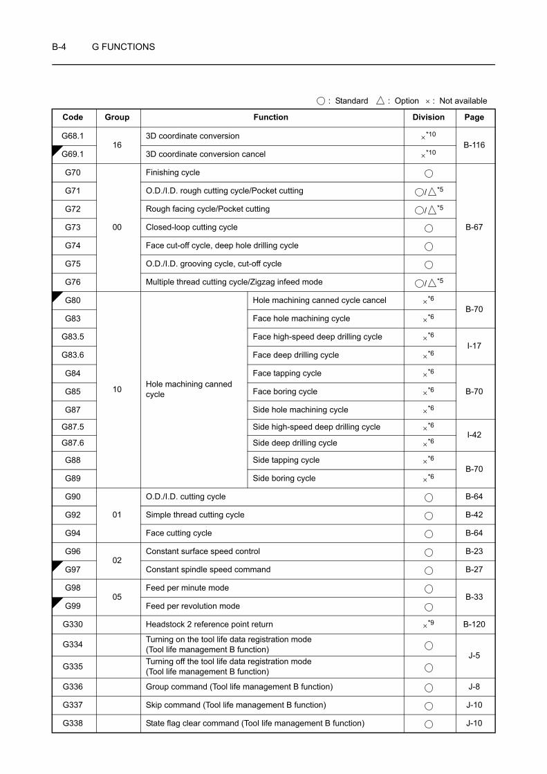
B-4 G FUNCTIONS
G68.116
3D coordinate conversion ×*10
B-116G69.1 3D coordinate conversion cancel ×*10
G70
00
Finishing cycle
B-67
G71 O.D./I.D. rough cutting cycle/Pocket cutting / *5
G72 Rough facing cycle/Pocket cutting / *5
G73 Closed-loop cutting cycle
G74 Face cut-off cycle, deep hole drilling cycle
G75 O.D./I.D. grooving cycle, cut-off cycle
G76 Multiple thread cutting cycle/Zigzag infeed mode / *5
G80
10 Hole machining canned cycle
Hole machining canned cycle cancel ×*6
B-70G83 Face hole machining cycle ×*6
G83.5 Face high-speed deep drilling cycle ×*6
I-17G83.6 Face deep drilling cycle ×*6
G84 Face tapping cycle ×*6
B-70G85 Face boring cycle ×*6
G87 Side hole machining cycle ×*6
G87.5 Side high-speed deep drilling cycle ×*6I-42
G87.6 Side deep drilling cycle ×*6
G88 Side tapping cycle ×*6
B-70G89 Side boring cycle ×*6
G90
01
O.D./I.D. cutting cycle B-64
G92 Simple thread cutting cycle B-42
G94 Face cutting cycle B-64
G9602
Constant surface speed control B-23
G97 Constant spindle speed command B-27
G9805
Feed per minute modeB-33
G99 Feed per revolution mode
G330 Headstock 2 reference point return ×*9 B-120
G334 Turning on the tool life data registration mode (Tool life management B function)
J-5G335 Turning off the tool life data registration mode
(Tool life management B function)
G336 Group command (Tool life management B function) J-8
G337 Skip command (Tool life management B function) J-10
G338 State flag clear command (Tool life management B function) J-10
: Standard : Option × : Not available
Code Group Function Division Page

G FUNCTIONS B-5
G339 Tool life management information reading command (Tool life management B function) J-12
G340 PMC address information reading command (Tool life management B function) J-14
G380 Synchronized tapping cycle cancel ×*7
I-68G384 Synchronized tapping cycle ×*7
G479 Tailstock connect joint (only for the ZL-153, 203 and 253 series) *8 B-104
: Standard : Option × : Not available
Code Group Function Division Page
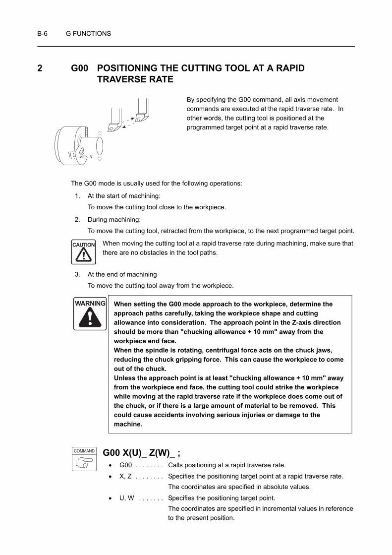
B-6 G FUNCTIONS
2 G00 POSITIONING THE CUTTING TOOL AT A RAPID TRAVERSE RATE
By specifying the G00 command, all axis movement commands are executed at the rapid traverse rate. In other words, the cutting tool is positioned at the programmed target point at a rapid traverse rate.
The G00 mode is usually used for the following operations:
1. At the start of machining:
To move the cutting tool close to the workpiece.
2. During machining:
To move the cutting tool, retracted from the workpiece, to the next programmed target point.
When moving the cutting tool at a rapid traverse rate during machining, make sure that there are no obstacles in the tool paths.
3. At the end of machining
To move the cutting tool away from the workpiece.
G00 X(U)_ Z(W)_ ;• G00 . . . . . . . . Calls positioning at a rapid traverse rate.
• X, Z . . . . . . . . Specifies the positioning target point at a rapid traverse rate.The coordinates are specified in absolute values.
• U, W . . . . . . . Specifies the positioning target point.The coordinates are specified in incremental values in reference to the present position.
WARNING When setting the G00 mode approach to the workpiece, determine the approach paths carefully, taking the workpiece shape and cutting allowance into consideration. The approach point in the Z-axis direction should be more than "chucking allowance + 10 mm" away from the workpiece end face. When the spindle is rotating, centrifugal force acts on the chuck jaws, reducing the chuck gripping force. This can cause the workpiece to come out of the chuck. Unless the approach point is at least "chucking allowance + 10 mm" away from the workpiece end face, the cutting tool could strike the workpiece while moving at the rapid traverse rate if the workpiece does come out of the chuck, or if there is a large amount of material to be removed. This could cause accidents involving serious injuries or damage to the machine.
CAUTION
COMMAND
G FUNCTIONS B-7
1. If X- and Z-axis movements are specified in the same block in the G00 mode, the tool path is not always a straight line from the present position to the programmed end point. Make sure that there are no obstacles in the tool path, remembering that X- and Z-axis movement is at the rapid traverse rate. If the workpiece, fixture or tailstock (if featured) lies in the tool path, it could interfere with the tool, tool holder, or turret head. Depending on the workpiece holding method, there could also be interference with the chuck and chuck jaws. This interference will damage the machine.
Page B-9
2. For center-work, move the Z-axis first and then the X-axis to position the cutting tool at the approach point. In the cutting tool retraction operation, retract the cutting tool in the X-axis direction first to a point where continuing cutting tool movement does not result in interference with the tailstock. After that, move the Z-axis to the required retraction position. (Applies only to machines equipped with a tailstock.)
Page B-9
3. If the Z-axis is moved after the X-axis, or the X-axis is moved after the Z-axis, by a G00 command for example, the tool path will be inside of the specified position. That is, if the tool reaches the specified range, the programming in the next block is executed before reaching the end position of the command (in-position). When creating programs, take interference between the tools and the workpiece into full consideration.
1. Once the G00 command is specified, it remains valid until another G code in the same group is specified. G01, G02, and G03 are examples of G codes which belong to the same group.
G codes which remain valid until another G code in the same group is specified are called modal G codes.
Page B-1 (1)
2. The maximum rapid traverse rate varies among the machine models.
Page D-30 (3-4)
3. The rapid traverse rate is adjustable by using the rapid traverse rate override switch on the machine operation panel.
4. If the rapid traverse rate override switch is set to "0" during automatic operation, the programmed rapid traverse is not executed and the operation enters the feed hold mode.
5. In a block where a T code is specified, G00 should be specified.
This G00 command is necessary to determine the cutting tool movement feedrate to execute offset motion.
CAUTION
NOTE

B-8 G FUNCTIONS
Programming using G00
O0001;
N1;
G50 S2000;
G00 T0101;
G96 S200 M03;
X56.0 Z20.0 M08; . . . . . . . . . . . . . . . . Positioning at point 1 at a rapid traverse rate to move the cutting tool close to the workpiece
G01 Z0 F1.0;. . . . . . . . . . . . . . . . . . . . . Positioning at point 2 at a cutting feedrate, the start point of facing
X30.0 F0.15;
G00 X50.0 W1.0; . . . . . . . . . . . . . . . . . Positioning from point 3 to 4 at a rapid traverse rate to execute O.D. cutting
G01 X54.0 Z−1.0;
Z−5.0;
X56.8;
X59.8 Z−6.5;
Z−23.0 F0.2;
G00 U1.0 Z20.0; . . . . . . . . . . . . . . . . . Positioning at point 5 to move the cutting tool away from the workpiece at a rapid traverse rate
X200.0 Z150.0 M09; . . . . . . . . . . . . . . Positioning at point 6 where the turret head can be rotated
M01;
The G00 mode is used to move the cutting tool close to and away from the workpiece.
Ex.
C1
C1.5
5
25
M60 × P2
54φ
12
3
4
5
6
Rapid traverse
Cutting feed

G FUNCTIONS B-9
If X- and Z-axis movements are specified in the same block in the G00 mode, the tool path is not always a straight line from the present position to the programmed end point. Make sure that there are no obstacles in the tool path, remembering that X- and Z-axis movement is at the rapid traverse rate. If the workpiece, fixture or tailstock (if featured) lies in the tool path, it could interfere with the tool, tool holder, or turret head. Depending on the workpiece holding method, there could also be interference with the chuck and chuck jaws. This interference will damage the machine.
G00 X(U)_ Z(W)_ ;
If the rapid traverse rates of X-axis and Z-axis are:X-axis 18000 mm/minZ-axis 24000 mm/min
When the X-axis and the Z-axis are moved simultaneously, in the G00 mode, the tool moves as illustrated on the right.
The tool path is not necessarily a linear line from the start point to the target point, depending on the positional relationship between the start and target points, as illustrated below.
For center-work, move the Z-axis first and then the X-axis to position the cutting tool at the approach point. In the cutting tool retraction operation, retract the cutting tool in the X-axis direction first to a point where continuing cutting tool movement does not result in interference with the tailstock. After that, move the Z-axis to the required retraction position. (Applies only to machines equipped with a tailstock).
CAUTION
Z (24000)
X(18000)
Start point
Programmed target point
Programmed target point
Start point
CAUTION
1
2

B-10 G FUNCTIONS
3 G01 MOVING THE CUTTING TOOL ALONG A STRAIGHT PATH AT A CUTTING FEEDRATE
By specifying the G01 command, the cutting tool is moved along a straight line to cut a workpiece.
The feedrate is specified with an F code by the distance the cutting tool should be moved while the spindle rotates one turn, or the distance to be moved in a minute.
G01 X(U)_ Z(W)_ F_ ;• G01 . . . . . . . . Calls the linear interpolation mode.
• X, Z . . . . . . . . Specifies the cutting target point.The coordinates are specified in absolute values.
• U, W . . . . . . . Specifies the cutting target point (distance and direction).The coordinates are specified in incremental values in reference to the present position.
• F . . . . . . . . . . Specifies the feedrate in ordinary control.
• In the G99 mode, the feedrate is specified in "mm/rev". F0.2 . . . . . . 0.2 mm/rev
• In the G98 mode, the feedrate is specified in "mm/min". F200 . . . . . 200 mm/min
1. Once the G01 command is specified, it remains valid until another G code in the same group is specified. G00, G02, and G03 are examples of G codes which belong to the same group.
G codes which remain valid until another G code in the same group is specified are called modal G codes.
Page B-1 (1)
2. The cutting feedrate is adjustable by using the feedrate override switch on the machine operation panel in the range of 0 to 200%.
3. The feedrate data is "0" until an F code is specified.
If an axis movement command is read before an F code is specified, the machine does not operate. In this case, an alarm message (No. 011) is displayed on the screen.
4. When the power is turned on, the NC is in the G99 (feed per revolution) mode.
COMMAND
NOTE

G FUNCTIONS B-11
Programming using G01
To move the cutting tool at a cutting feedrate along the paths 2 → 3, and 4 → 5 → 6 → 7 → 8 → 9
O0001;
N1;
G50 S2000;
G00 T0101;
G96 S200 M03;
X56.0 Z20.0 M08; . . . . . . . . . . . . . . . . . Positioning at point 1 at a rapid traverse rate to move the cutting tool close to the workpiece
G01 Z0 F1.0;. . . . . . . . . . . . . . . . . . . . . Positioning at point 2 at a cutting feedrate, the start point of facing
X30.0 F0.15; . . . . . . . . . . . . . . . . . . . . Facing at a feedrate of 0.15 mm/rev
G00 X50.0 W1.0; . . . . . . . . . . . . . . . . . Positioning from point 3 to 4 at a rapid traverse rate to execute O.D. cutting
G01 X54.0 Z−1.0; . . . . . . . . . . . . . . . . Cutting along path 4 → 5 at a feedrate of 0.15 mm/rev
Z−5.0; . . . . . . . . . . . . . . . . . . . . . . . . . Cutting along path 5 → 6 at a feedrate of 0.15 mm/rev
X56.8; . . . . . . . . . . . . . . . . . . . . . . . . . Cutting along path 6 → 7 at a feedrate of 0.15 mm/rev
X59.8 Z−6.5; . . . . . . . . . . . . . . . . . . . . Cutting along path 7 → 8 at a feedrate of 0.15 mm/rev
Z−23.0 F0.2; . . . . . . . . . . . . . . . . . . . . Cutting along path 8 → 9 at a feedrate of 0.2 mm/rev
G00 U1.0 Z20.0; . . . . . . . . . . . . . . . . . . Positioning at point 10 at a rapid traverse rate to move the cutting tool away from the workpiece
X200.0 Z150.0 M09; . . . . . . . . . . . . . . . Positioning at point 11 where the turret head can be rotated
M01;
Ex.
1
4
3
2
C1
C1.5
5
25
M60 × P211
10
5
6
7
89
54φ Rapid traverse
Cutting feed
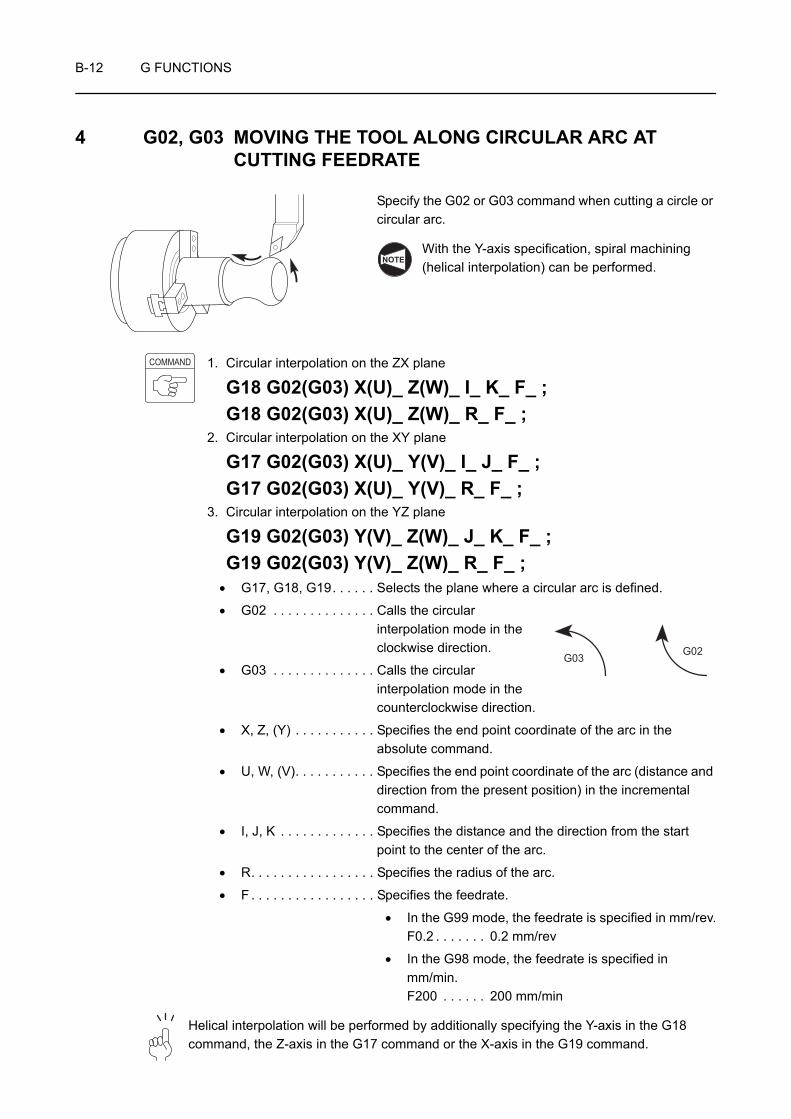
B-12 G FUNCTIONS
4 G02, G03 MOVING THE TOOL ALONG CIRCULAR ARC AT CUTTING FEEDRATE
Specify the G02 or G03 command when cutting a circle or circular arc.
With the Y-axis specification, spiral machining (helical interpolation) can be performed.
1. Circular interpolation on the ZX plane
G18 G02(G03) X(U)_ Z(W)_ I_ K_ F_ ;G18 G02(G03) X(U)_ Z(W)_ R_ F_ ;
2. Circular interpolation on the XY plane
G17 G02(G03) X(U)_ Y(V)_ I_ J_ F_ ;G17 G02(G03) X(U)_ Y(V)_ R_ F_ ;
3. Circular interpolation on the YZ plane
G19 G02(G03) Y(V)_ Z(W)_ J_ K_ F_ ;G19 G02(G03) Y(V)_ Z(W)_ R_ F_ ;
• G17, G18, G19. . . . . . Selects the plane where a circular arc is defined.
• G02 . . . . . . . . . . . . . . Calls the circular interpolation mode in the clockwise direction.
• G03 . . . . . . . . . . . . . . Calls the circular interpolation mode in the counterclockwise direction.
• X, Z, (Y) . . . . . . . . . . . Specifies the end point coordinate of the arc in the absolute command.
• U, W, (V). . . . . . . . . . . Specifies the end point coordinate of the arc (distance and direction from the present position) in the incremental command.
• I, J, K . . . . . . . . . . . . . Specifies the distance and the direction from the start point to the center of the arc.
• R. . . . . . . . . . . . . . . . . Specifies the radius of the arc.
• F . . . . . . . . . . . . . . . . . Specifies the feedrate.
• In the G99 mode, the feedrate is specified in mm/rev.F0.2 . . . . . . . 0.2 mm/rev
• In the G98 mode, the feedrate is specified in mm/min.F200 . . . . . . 200 mm/min
Helical interpolation will be performed by additionally specifying the Y-axis in the G18 command, the Z-axis in the G17 command or the X-axis in the G19 command.
NOTE
COMMAND
G03 G02
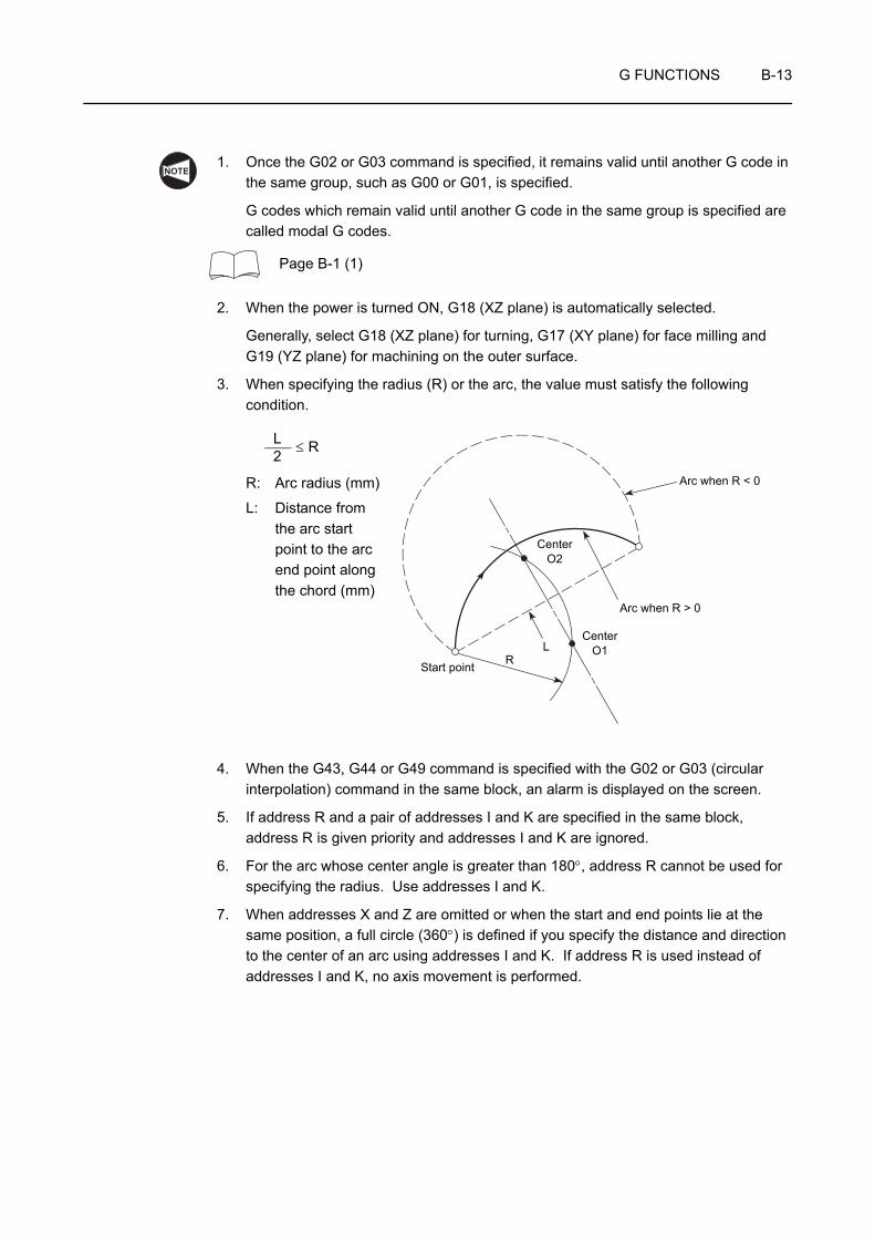
G FUNCTIONS B-13
1. Once the G02 or G03 command is specified, it remains valid until another G code in the same group, such as G00 or G01, is specified.
G codes which remain valid until another G code in the same group is specified are called modal G codes.
Page B-1 (1)
2. When the power is turned ON, G18 (XZ plane) is automatically selected.
Generally, select G18 (XZ plane) for turning, G17 (XY plane) for face milling and G19 (YZ plane) for machining on the outer surface.
3. When specifying the radius (R) or the arc, the value must satisfy the following condition.
R: Arc radius (mm)
L: Distance from the arc start point to the arc end point along the chord (mm)
4. When the G43, G44 or G49 command is specified with the G02 or G03 (circular interpolation) command in the same block, an alarm is displayed on the screen.
5. If address R and a pair of addresses I and K are specified in the same block, address R is given priority and addresses I and K are ignored.
6. For the arc whose center angle is greater than 180°, address R cannot be used for specifying the radius. Use addresses I and K.
7. When addresses X and Z are omitted or when the start and end points lie at the same position, a full circle (360°) is defined if you specify the distance and direction to the center of an arc using addresses I and K. If address R is used instead of addresses I and K, no axis movement is performed.
NOTE
Arc when R < 0
Arc when R > 0
CenterO1
CenterO2
LRStart point
L2 ≤ R

B-14 G FUNCTIONS
8. If the highest point of the 180° arc (semi-circle) is not located in a position of 0°, 90°, 180° or 270° (position 1, 2, 3 or 4 in the illustration), specify the center of the arc using addresses I and K. If the center of the arc is specified using address R, an error in calculation of the center position may be introduced.
9. When viewing the XZ plane from the positive Y-axis direction, the rotation direction of the G02 or G03 command is not changed on spindle 1 or spindle 2. Therefore, to use a program for spindle 1 on spindle 2, it is necessary to change the G02 command to G03, the G03 command to G02. In addition, the positive and negative directions of the Z-axis are reversed. Pay sufficient attention when programming.
NOTE
2
1
4
3
+X +X
−Z +Z
G03G02
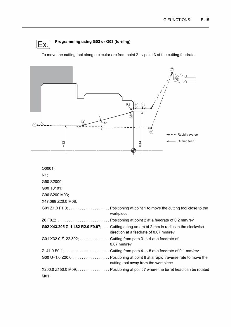
G FUNCTIONS B-15
Programming using G02 or G03 (turning)
To move the cutting tool along a circular arc from point 2 → point 3 at the cutting feedrate
O0001;
N1;
G50 S2000;
G00 T0101;
G96 S200 M03;
X47.069 Z20.0 M08;
G01 Z1.0 F1.0; . . . . . . . . . . . . . . . . . . . Positioning at point 1 to move the cutting tool close to the workpiece
Z0 F0.2; . . . . . . . . . . . . . . . . . . . . . . . . Positioning at point 2 at a feedrate of 0.2 mm/rev
G02 X43.205 Z−1.482 R2.0 F0.07; . . . Cutting along an arc of 2 mm in radius in the clockwise direction at a feedrate of 0.07 mm/rev
G01 X32.0 Z−22.392; . . . . . . . . . . . . . . Cutting from path 3 → 4 at a feedrate of 0.07 mm/rev
Z−41.0 F0.1; . . . . . . . . . . . . . . . . . . . . . Cutting from path 4 → 5 at a feedrate of 0.1 mm/rev
G00 U−1.0 Z20.0; . . . . . . . . . . . . . . . . . Positioning at point 6 at a rapid traverse rate to move the cutting tool away from the workpiece
X200.0 Z150.0 M09; . . . . . . . . . . . . . . . Positioning at point 7 where the turret head can be rotated
M01;
Ex.
R2
15°
4432φ φ
12
3
45
6
7
Rapid traverse
Cutting feed
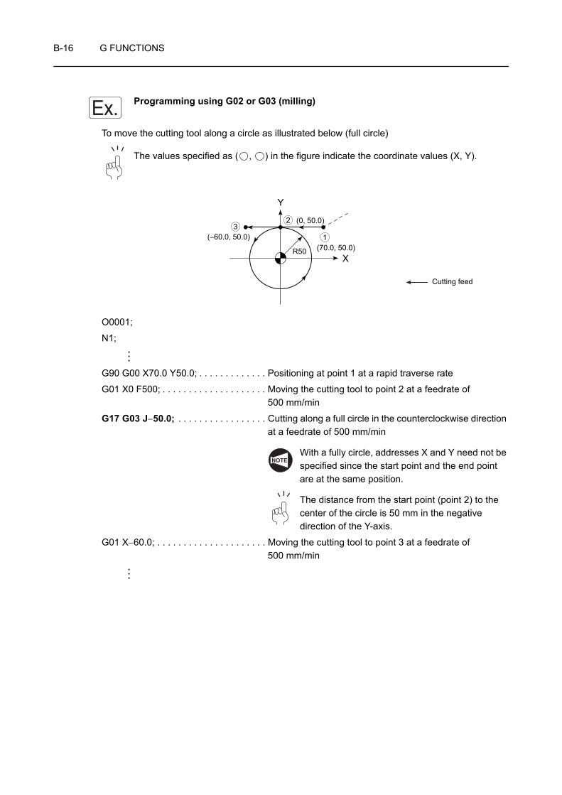
B-16 G FUNCTIONS
Programming using G02 or G03 (milling)
To move the cutting tool along a circle as illustrated below (full circle)
The values specified as ( , ) in the figure indicate the coordinate values (X, Y).
O0001;
N1;
G90 G00 X70.0 Y50.0; . . . . . . . . . . . . . Positioning at point 1 at a rapid traverse rate
G01 X0 F500; . . . . . . . . . . . . . . . . . . . . Moving the cutting tool to point 2 at a feedrate of 500 mm/min
G17 G03 J−50.0; . . . . . . . . . . . . . . . . . Cutting along a full circle in the counterclockwise direction at a feedrate of 500 mm/min
With a fully circle, addresses X and Y need not be specified since the start point and the end point are at the same position.
The distance from the start point (point 2) to the center of the circle is 50 mm in the negative direction of the Y-axis.
G01 X−60.0; . . . . . . . . . . . . . . . . . . . . . Moving the cutting tool to point 3 at a feedrate of 500 mm/min
Ex.
32
1(70.0, 50.0)
(0, 50.0)
(−60.0, 50.0)
R50X
Y
Cutting feed
NOTE
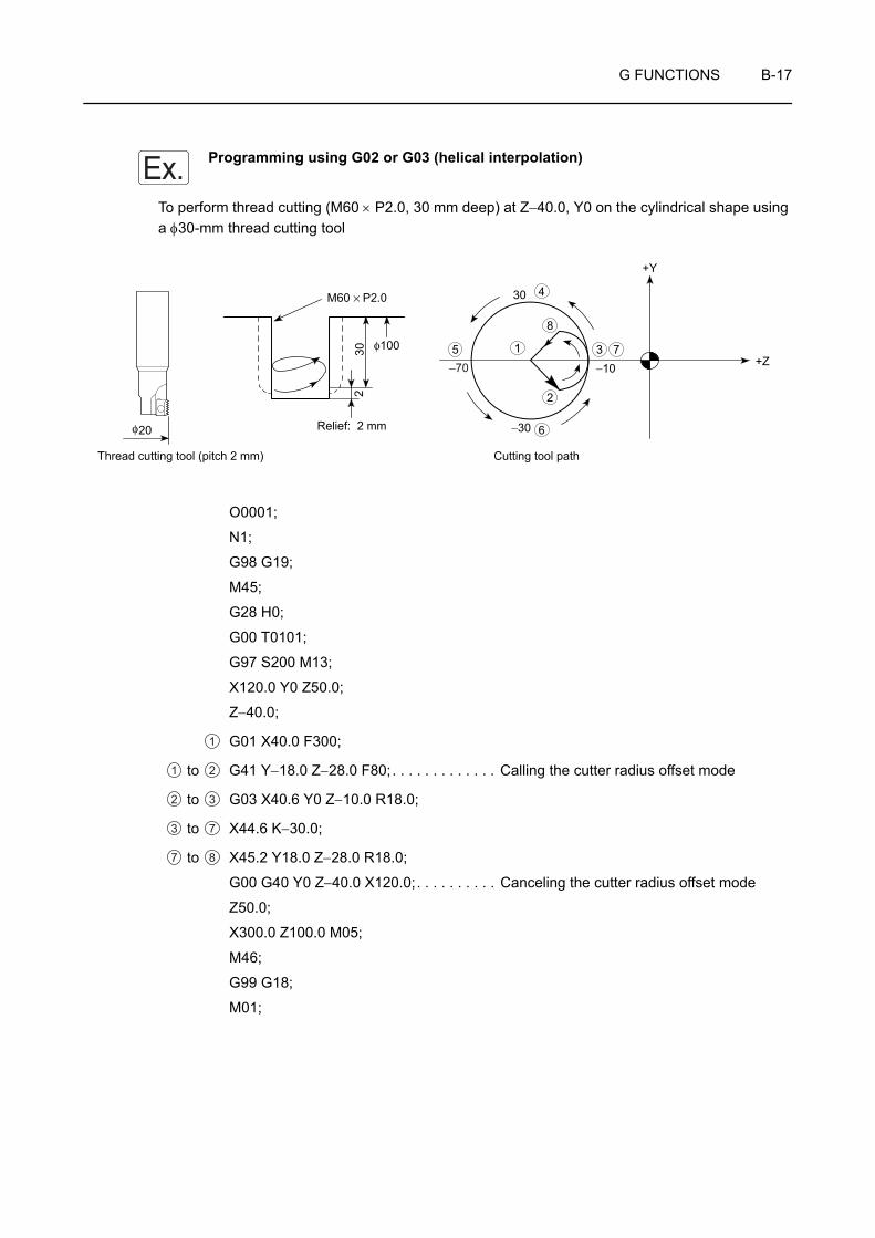
G FUNCTIONS B-17
Programming using G02 or G03 (helical interpolation)
To perform thread cutting (M60 × P2.0, 30 mm deep) at Z−40.0, Y0 on the cylindrical shape using a φ30-mm thread cutting tool
O0001;
N1;
G98 G19;
M45;
G28 H0;
G00 T0101;
G97 S200 M13;
X120.0 Y0 Z50.0;
Z−40.0;
G01 X40.0 F300;
to G41 Y−18.0 Z−28.0 F80;. . . . . . . . . . . . . Calling the cutter radius offset mode
to G03 X40.6 Y0 Z−10.0 R18.0;
to X44.6 K−30.0;
to X45.2 Y18.0 Z−28.0 R18.0;
G00 G40 Y0 Z−40.0 X120.0;. . . . . . . . . . Canceling the cutter radius offset mode
Z50.0;
X300.0 Z100.0 M05;
M46;
G99 G18;
M01;
Ex.
+Y
φ100
−10
−30
30
+Z5
6
3 7
4
1
8
2
M60 × P2.0
30
φ20
−702
Thread cutting tool (pitch 2 mm)
Relief: 2 mm
Cutting tool path
1
1 2
2 3
3 7
7 8
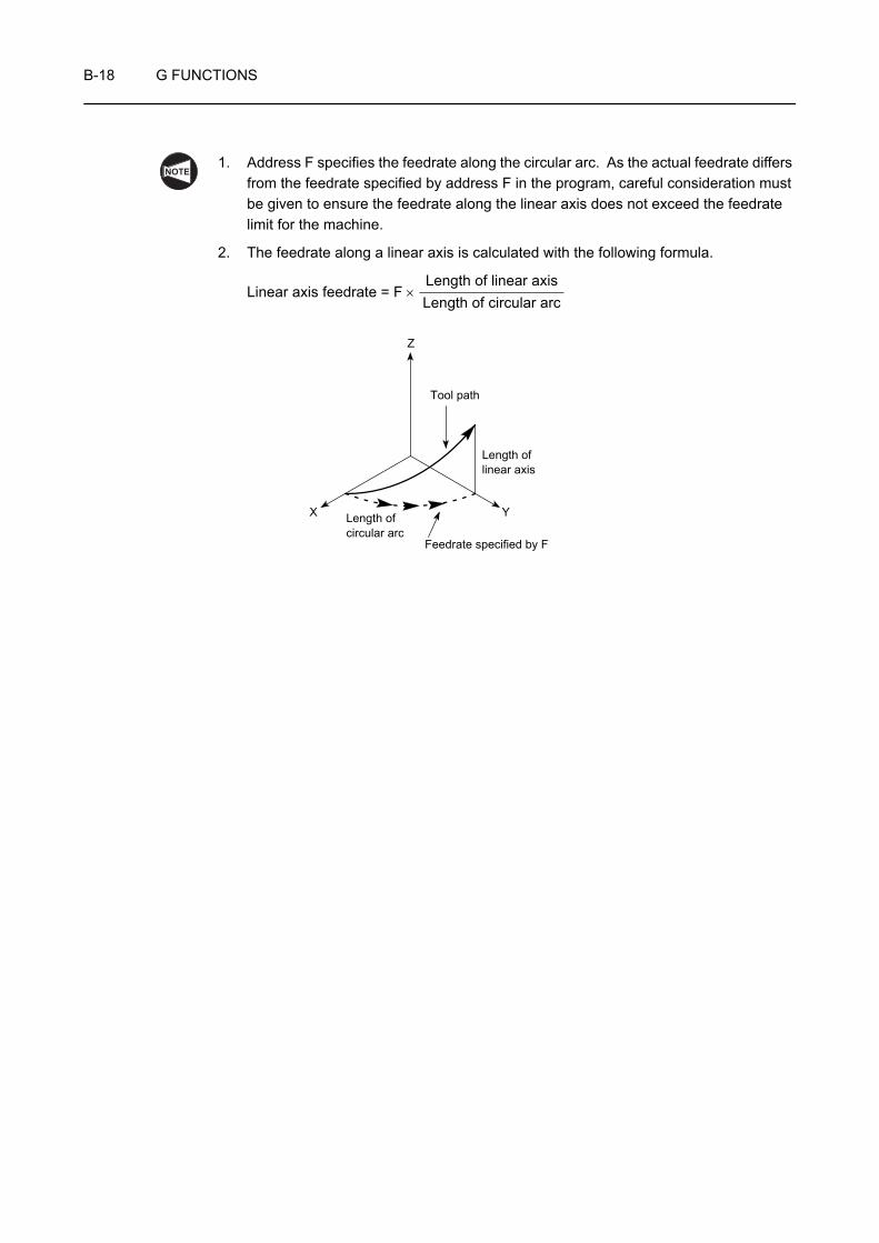
B-18 G FUNCTIONS
1. Address F specifies the feedrate along the circular arc. As the actual feedrate differs from the feedrate specified by address F in the program, careful consideration must be given to ensure the feedrate along the linear axis does not exceed the feedrate limit for the machine.
2. The feedrate along a linear axis is calculated with the following formula.
Linear axis feedrate = F ×
NOTE
Length of linear axisLength of circular arc
Z
X Y
Tool path
Length of linear axis
Length of circular arc
Feedrate specified by F

G FUNCTIONS B-19
5 G50 SETTING THE SPINDLE SPEED LIMIT
The spindle speed limit for an automatic operation is set with the G50 command.
If the programmed spindle speed is faster than the limit value set in the G50 block, actual spindle speed is clamped at the set limit speed.
WARNING 1. The spindle speed limit set using G50 must be no higher than the lowest of the individual allowable speed limits for the chuck, fixture, and cylinder. If you set a higher speed the workpiece will fly out of the machine, causing serious injuries or damage to the machine.
2. In the G96 (constant surface speed control) mode, the spindle speed increases as the cutting tool approaches the center of the spindle.Near the center of the spindle, the spindle speed will reach the allowable maximum speed of the machine. At this speed, the chuck gripping force, cutting force, and centrifugal force cannot be balanced to hold the workpiece securely in the chuck. As a result, the workpiece will fly out of the machine, causing serious injuries or damage to the machine.The spindle speed limit must always be specified in a part program by using the G50 command in a block preceding the G96 block, in order to clamp the spindle speed at the specified speed.

B-20 G FUNCTIONS
G50 S_ ;• G50 . . . . . . . . Calls the mode to specify the spindle speed limit for automatic
operation.
• S . . . . . . . . . . Specifies spindle speed limit (min−1).
1. An alarm message (No. 245) is displayed on the screen if a T command is specified in the G50 block.
2. With the ZL, ZL-S and ZT series, although the spindle speed limit setting command (G50) may be specified in either of the programs (turret 1 program and turret 2 program), the one specified only in the program where the spindle start command (M03, M04) has been specified is regarded the valid command. In other words, the M03 or M04 command determines in which program the G50 command is valid. To set the spindle speed limit by specifying the G50 command, specify it in the program where the M03 or M04 command is specified to start the spindle. The spindle speed limit setting is not executed if the G50 command is specified in the program where the M03 or M04 command has not been specified.
WARNING 1. The setting of the spindle speed override switch (if there is one) is valid even when a spindle speed limit is set using G50.If the switch is set to 110% or 120%, for example, the programmed spindle speed will be overridden in accordance with this setting. If this causes the actual spindle speed to exceed the allowable speed of the chuck, fixture, or cylinder, the workpiece will fly out of the chuck during machining, causing serious injuries or damage to the machine.Therefore, the spindle speed override switch must be set at 100% or lower.
2. When a G97 speed command is used in a program, specification of the maximum speed with a G50 command will be ignored. Therefore, when specifying the spindle speed with a G97 command, specify a speed no higher than the lowest speed among the allowable speed limits for the chuck, fixture, and cylinder. If you set a higher speed the workpiece will fly out of the machine, causing serious injuries or damage to the machine. (FANUC)
COMMAND
NOTE

G FUNCTIONS B-21
Programming using G50 (Setting the spindle speed limit)
To move the cutting tool at a cutting feedrate along the path 2 → 3 to execute facing
O0001;
N1;
G50 S2000; . . . . . . . . . . . . . . . . . . . . . Setting the spindle 1 speed limit for automatic operation at
2000 min−1
G00 T0101;
G96 S200 M03;. . . . . . . . . . . . . . . . . . . Starting spindle 1 in the normal direction; surface speed is 200 m/min The spindle speed is controlled to maintain the surface speed constant at 200 m/min.
X56.0 Z20.0 M08; . . . . . . . . . . . . . . . . . Positioning at point 1 at a rapid traverse rate to move the cutting tool close to the workpiece
G01 Z0 F1.0;. . . . . . . . . . . . . . . . . . . . . Positioning at point 2 at a cutting feedrate, the start point of facing
X30.0 F0.15; . . . . . . . . . . . . . . . . . . . . . Facing at a feedrate of 0.15 mm/revIn order to maintain the surface speed constant, the spindle speed increases as the cutting tool moves closer to the workpiece center to reach the allowable maximum speed of the machine.
However, since spindle speed limit is set at 2000 min−1 in the "G50 S2000;", the spindle speed does not exceed this limit value.
Ex.
C1
C1.5
5
25
M60 × P2
54φ
12
3
4
5
6
Rapid traverse
Cutting feed

B-22 G FUNCTIONS
G00 X50.0 W1.0;
G01 X54.0 Z−1.0;
Machining program
G00 U1.0 Z20.0;
X200.0 Z150.0 M09;
M01;

G FUNCTIONS B-23
6 G96 CONTROLLING SPINDLE SPEED TO MAINTAIN SURFACE SPEED CONSTANT
The G96 command is used to maintain surface speed constant at the specified value.
The surface speed is also called the cutting speed. It indicates the distance the cutting tool moves along the workpiece surface (periphery) per minute.
When the surface speed is specified with the G96 command, the spindle speed is automatically controlled to maintain the surface speed constant as the cutting diameter varies. This mode is used to maintain the cutting conditions constant.
For example, if the cutting speed (V) is specified at 100 m/min to cut a 30 mm diameter (D) workpiece, the spindle speed (N) is calculated as indicated below.
N = = 1061 (min−1)
Therefore, the spindle rotates at 1061 min−1.
Generally, the standard cutting speed is determined according to the material of the workpiece and the cutting tool, the workpiece shape, and the chucking method.
G96 S_ M03(M04);G96 S_ M203(M204);
• G96 . . . . . . . . Calls the constant surface speed control mode.
• S. . . . . . . . . . . Specifies the cutting speed (m/min).
• M03(M04). . . . Specifies spindle or spindle 1 rotation in the normal (reverse) direction.
• M203(M204). . Specifies spindle 2 rotation in the normal (reverse) direction.
The M203 and M204 commands can be used only for the ZL-S and ZT series machines.
WARNING In the G96 (constant surface speed control) mode, the spindle speed increases as the cutting tool approaches the center of the spindle.Near the center of the spindle, the spindle speed will reach the allowable maximum speed of the machine. At this speed, the chuck gripping force, cutting force, and centrifugal force cannot be balanced to hold the workpiece securely in the chuck. As a result, the workpiece will fly out of the machine, causing serious injuries or damage to the machine.The spindle speed limit must always be specified in a part program by using the G50 command in a block preceding the G96 block, in order to clamp the spindle speed at the specified speed.
1000Vπ • D
1000 × 1003.14 × 30
COMMAND
NOTE

B-24 G FUNCTIONS
With the ZL, ZL-S and ZT series, although the constant surface speed control command (G96) may be specified in either of the programs (turret 1 program and turret 2 program), the one specified only in the program where the spindle start command (M03, M04) has been specified is regarded the valid command. In other words, the M03 or M04 command determines in which program the G96 command is valid. To specify the constant surface speed control with the G96 command, specify it in the program where the M03 or M04 command is specified to start the spindle. The constant surface speed control is not executed if the G96 command is specified in the program where the M03 or M04 command has not been specified.
NOTE
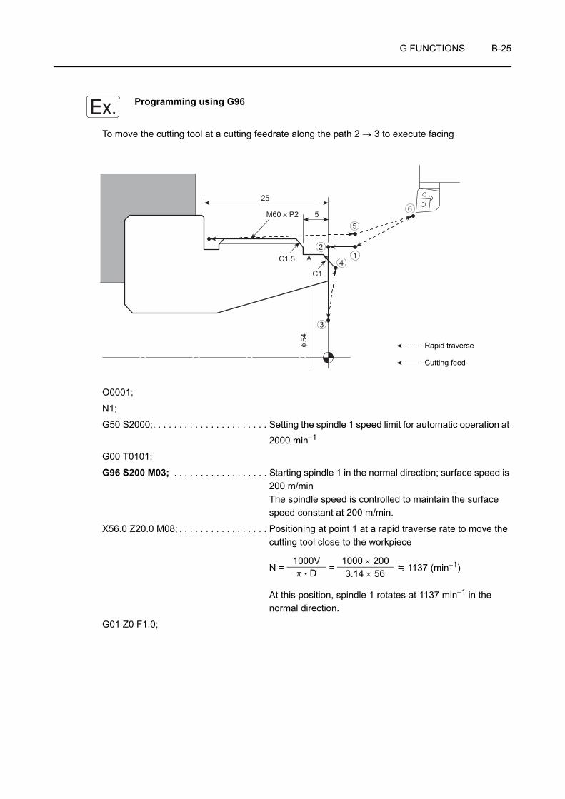
G FUNCTIONS B-25
Programming using G96
To move the cutting tool at a cutting feedrate along the path 2 → 3 to execute facing
O0001;
N1;
G50 S2000;. . . . . . . . . . . . . . . . . . . . . . Setting the spindle 1 speed limit for automatic operation at
2000 min−1
G00 T0101;
G96 S200 M03; . . . . . . . . . . . . . . . . . . Starting spindle 1 in the normal direction; surface speed is 200 m/minThe spindle speed is controlled to maintain the surface speed constant at 200 m/min.
X56.0 Z20.0 M08; . . . . . . . . . . . . . . . . . Positioning at point 1 at a rapid traverse rate to move the cutting tool close to the workpiece
N = = 1137 (min−1)
At this position, spindle 1 rotates at 1137 min−1 in the normal direction.
G01 Z0 F1.0;
Ex.
C1
C1.5
5
25
M60 × P2
54φ
12
3
4
5
6
Rapid traverse
Cutting feed
1000Vπ • D
1000 × 2003.14 × 56
B-26 G FUNCTIONS
X30.0 F0.15; . . . . . . . . . . . . . . . . . . . . . Facing at a feedrate of 0.15 mm/rev
N = = 2123 (min−1)
At this position, spindle 1 should rotate at 2123 min−1 to provide the surface speed of 200 m/min. However, since
the spindle speed limit of 2000 min−1 is set in the "G50 S2000;", the spindle speed does not exceed this limit value.
G00 X50.0 W1.0;
G01 X54.0 Z−1.0;
Machining program
G00 U1.0 Z20.0;
X200.0 Z150.0 M09;
M01;
1000Vπ • D
1000 × 2003.14 × 30

G FUNCTIONS B-27
7 G97 CONTROLLING SPINDLE SPEED AT CONSTANT SPEED
The G97 command is used to call the mode in which a constant spindle speed is maintained.
During automatic operation, the spindle rotates at the programmed speed.
N =
N: Spindle speed (min−1)
V: Cutting speed (m/min)
D: Cutting diameter (mm)
π: Circumference constant
The G97 command must be specified for thread cutting operation and turning drilling operation at the center of workpiece end face.
During thread cutting operation, the thread is cut gradually by changing the cutting diameter for each thread cutting path while maintaining the start point of the thread. Therefore, if the spindle speed is not kept constant, the start point shifts in each thread cutting cycle making thread cutting impossible or tipping the tool nose.
The G97 mode is also specified for carrying out copy turning on straight bar workpiece.
G97 S_ M03(M04);G97 S_ M203(M204);G97 S_ M13(M14);
• G97 . . . . . . . . . . . . . . Calls the constant spindle speed command mode.
• S . . . . . . . . . . . . . . . . Specifies the spindle speed (min−1).
• M03(M04) . . . . . . . . . Specifies spindle or spindle 1 rotation in the normal (reverse) direction.
• M203(M204) . . . . . . . Specifies spindle 2 rotation in the normal (reverse) direction.
• M13(M14). . . . . . . . . . Specifies rotary tool rotation in the normal (reverse) direction.
The M203 and M204 commands can be used only for the ZL-S and ZT series machines.
WARNING When a G97 speed command is used in a program, specification of the maximum speed with a G50 command will be ignored. Therefore, when specifying the spindle speed with a G97 command, specify a speed no higher than the lowest speed among the allowable speed limits for the chuck, fixture, and cylinder. If you set a higher speed the workpiece will fly out of the machine, causing serious injuries or damage to the machine.
1000Vπ • D
NOTE
COMMAND
NOTE

B-28 G FUNCTIONS
1. When the spindle speed control mode is switched from the G96 mode to the G97 mode, if no spindle speed is specified in the G97 block, the spindle speed obtained in the block immediately preceding the G97 block is used as the spindle speed for the G97 mode operation. Therefore, if no spindle speed is specified in the G97 block, the spindle speed for the G97 mode will depend on the position of the cutting tool in the block preceding the G97 block, and this could adversely affect machining accuracy and shorten the life of the tool. When switching the spindle speed control mode to the G97 mode, always specify a spindle speed.
2. With the ZL, ZL-S and ZT series, although the constant spindle speed command (G97) may be specified in either of the programs (turret 1 program and turret 2 program), the one specified only in the program where the spindle start command (M03, M04) has been specified is regarded the valid command. In other words, the M03 or M04 command determines in which program the G97 command is valid. To specify the constant spindle speed with the G97 command, specify it in the program where the M03 or M04 command is specified to start the spindle. The constant spindle speed is not executed if the G97 command is specified in the program where the M03 or M04 command has not been specified.
NOTE

G FUNCTIONS B-29
Programming using G97
To execute O.D. thread cutting
O0001;
N1;
G00 T0101;
G97 S640 M03; . . . . . . . . . . . . . . . . . . Starting spindle 1 at 640 min−1 in the normal direction
X70.0 Z20.0 M08;
G01 Z5.0 F1.0 M24; . . . . . . . . . . . . . . . Positioning at point 1, the start point of the G92 thread cutting cycle
G92 X59.4 Z−24.0 F2.0;
X58.9;
X58.5;
X58.1;
X57.8;
X57.56;
X57.36;
X57.26;
G00 X200.0 Z150.0 M09; . . . . . . . . . . . Positioning at point 5 where the turret head can be rotated
M05;
M30;
Ex.
M60 × P2
24
57.4
φ
1
23
4
5
Rapid traverse
Cutting feed
. . . . . . Execution of the G92 thread cutting cycle(point 1 → 2 → 3 → 4 → 1)

B-30 G FUNCTIONS
8 G04 SUSPENDING PROGRAM EXECUTION (DWELL)
The G04 command is used to suspend program execution during automatic operation for the period specified in the program.
This function is called the dwell function, and is used in operation such as the grooving operation.
If dwell is specified at the bottom of the groove, the tool stops moving. The spindle keeps rotating while the tool stays at the bottom of the groove.
By rotating the spindle one turn while locating the tool at the bottom of the groove, the groove profile accuracy is improved and uncut portion is eliminated. The dwell function is also used for opening and closing the chuck when the machine is equipped with the air blow, the bar feeder or the loader.
When executing a dwell using the G04 command, if the cutting tool is kept in contact with the workpiece at a position such as the bottom of a groove for a long time it will shorten the life of the tool nose as well as adversely affecting machining accuracy.
G04 X_ ;G04 U_ ;G04 P_ ;
• G04 . . . . . . . . Calls the dwell function.
• X, U . . . . . . . . Specifies the period in which the program execution is suspended.The dwell period should be specified in units of seconds with a decimal point.X1.0 (U1.0) . . . . . 1 secX1 (U1) . . . . . . . . 0.001 sec
• P. . . . . . . . . . . Specifies the period in which the program execution is suspended.The dwell period should be specified in units of 0.001 second without a decimal point.P1000 . . . . . . . . . 1 sec
1. A decimal point cannot be used when address P is used.
Dwell for 1.5 seconds . . . . . . G04 P1500;Dwell for 2.3 seconds . . . . . . G04 P2300;
2. Programmable dwell period is 0.001 to 99999.999 seconds.
3. The dwell function is valid only in the specified block.
4. Dwell period per revolution of the spindle is calculated as follows:
t (sec) =
5. An alarm message (No. 245) is displayed on the screen if a T command is specified in the G04 block.
NOTE
COMMAND
NOTE
60 (sec)Spindle speed (min−1)
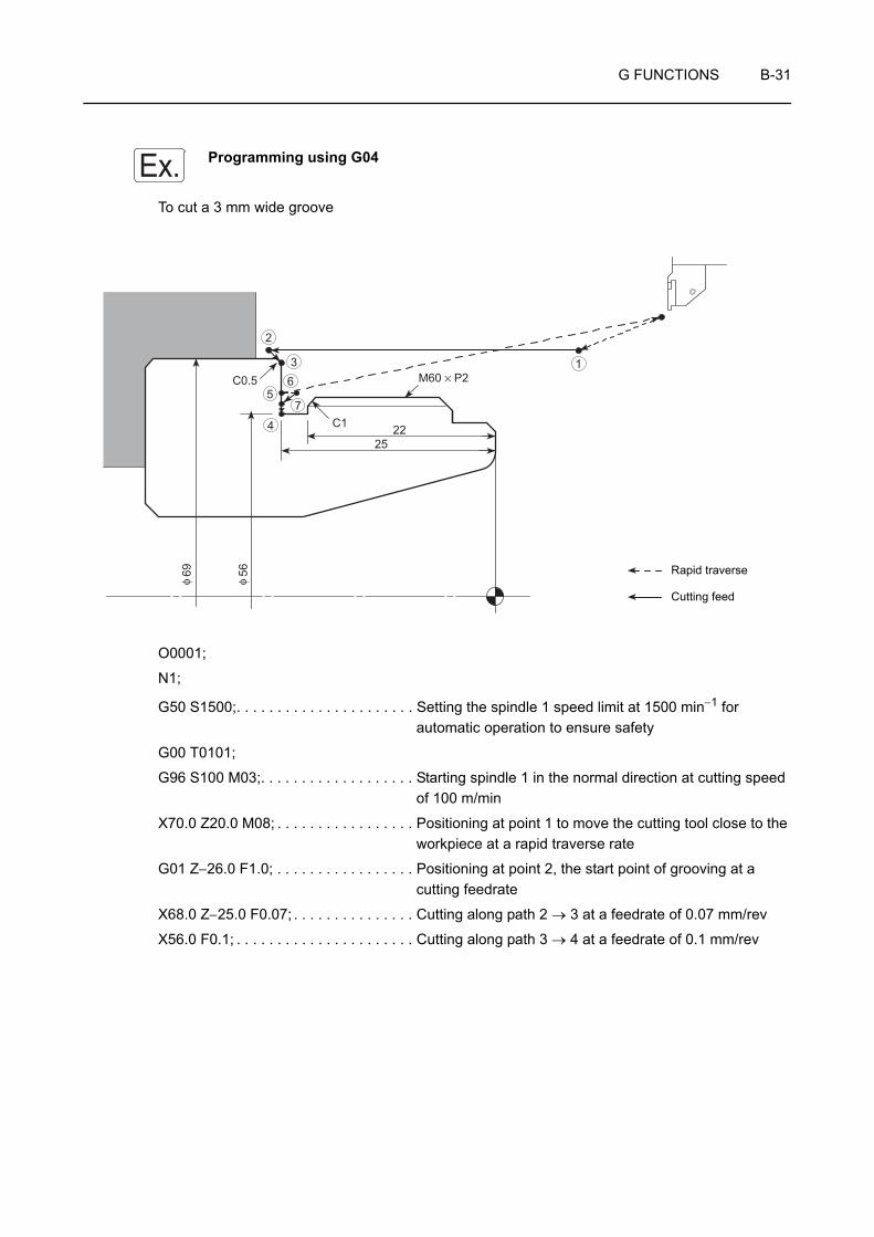
G FUNCTIONS B-31
Programming using G04
To cut a 3 mm wide groove
O0001;
N1;
G50 S1500;. . . . . . . . . . . . . . . . . . . . . . Setting the spindle 1 speed limit at 1500 min−1 for automatic operation to ensure safety
G00 T0101;
G96 S100 M03;. . . . . . . . . . . . . . . . . . . Starting spindle 1 in the normal direction at cutting speed of 100 m/min
X70.0 Z20.0 M08; . . . . . . . . . . . . . . . . . Positioning at point 1 to move the cutting tool close to the workpiece at a rapid traverse rate
G01 Z−26.0 F1.0; . . . . . . . . . . . . . . . . . Positioning at point 2, the start point of grooving at a cutting feedrate
X68.0 Z−25.0 F0.07; . . . . . . . . . . . . . . . Cutting along path 2 → 3 at a feedrate of 0.07 mm/rev
X56.0 F0.1; . . . . . . . . . . . . . . . . . . . . . . Cutting along path 3 → 4 at a feedrate of 0.1 mm/rev
Ex.
M60 × P2
2225
C1
C0.5
5669
φφ
1
2
3
4
56
7
Rapid traverse
Cutting feed

B-32 G FUNCTIONS
G04 U0.2; . . . . . . . . . . . . . . . . . . . . . . Suspending program execution for 0.2 seconds at the bottom of the groove to allow spindle to rotate one turn
Spindle speed at point 4
N = = 569 (min−1)
Period required for the spindle to rotate one turn
= 0.11 (sec)
To suspend program execution at the groove bottom for more than one turn of the spindle, dwell period is determined to 0.2 seconds.
The following program may be used instead of "G04 U0.2;"G04 X0.2; or G04 P200;
G00 X60.8;
Machining program
M01;
1000Vπ • D
1000 × 1003.14 × 56
60569

G FUNCTIONS B-33
9 G98, G99 SETTING FEEDRATE UNITS
Axis feedrate units are determined by specifying the following two G codes:
G98
The G98 command calls the mode in which axis feedrates specified by F codes are interpreted in units of mm per minute (mm/min, °/min).
This mode is used when the bar feeder, the pull-out finger or the rotary tool is used.
G99
The G99 command calls the mode in which the axis feedrates specified by F codes are interpreted in units of mm per revolution (mm/rev).
This mode is used for general turning operations such as O.D. cutting, I.D. cutting, and thread cutting.
In the G98 mode, the turret moves at the feedrate specified by the F code even when the spindle is not rotating. Make sure that the cutting tool will not strike the workpiece, etc., since this could damage the machine.
G98;
G01 Z_ F100.0; . . . . . . . The cutting tool moves at a rate of 100 mm/min even when the spindle is not rotating.
G98; . . . . . . . . . . . Specifies the feedrate per minute (Linear axis: mm/min, rotary axis: °/min).
G99; . . . . . . . . . . . Specifies the feedrate per revolution (mm/rev).
1. The G98 and G99 commands are modal.
Therefore, once the G98 command is specified, it remains valid until the G99 command is specified, or vice versa.
2. When the power is turned on, the NC is in the G99 (feed per revolution) mode.
CAUTION
COMMAND
NOTE
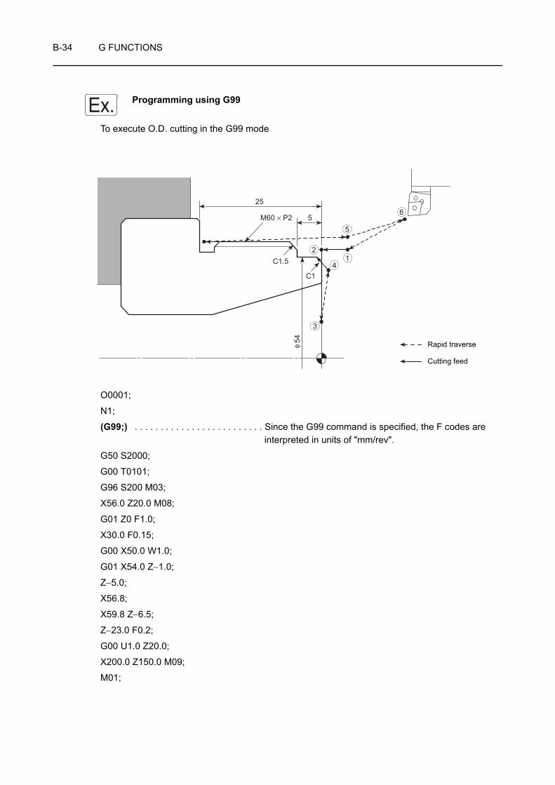
B-34 G FUNCTIONS
Programming using G99
To execute O.D. cutting in the G99 mode
O0001;
N1;
(G99;) . . . . . . . . . . . . . . . . . . . . . . . . . Since the G99 command is specified, the F codes are interpreted in units of "mm/rev".
G50 S2000;
G00 T0101;
G96 S200 M03;
X56.0 Z20.0 M08;
G01 Z0 F1.0;
X30.0 F0.15;
G00 X50.0 W1.0;
G01 X54.0 Z−1.0;
Z−5.0;
X56.8;
X59.8 Z−6.5;
Z−23.0 F0.2;
G00 U1.0 Z20.0;
X200.0 Z150.0 M09;
M01;
Ex.
C1
C1.5
5
25
M60 × P2
54φ
12
3
4
5
6
Rapid traverse
Cutting feed
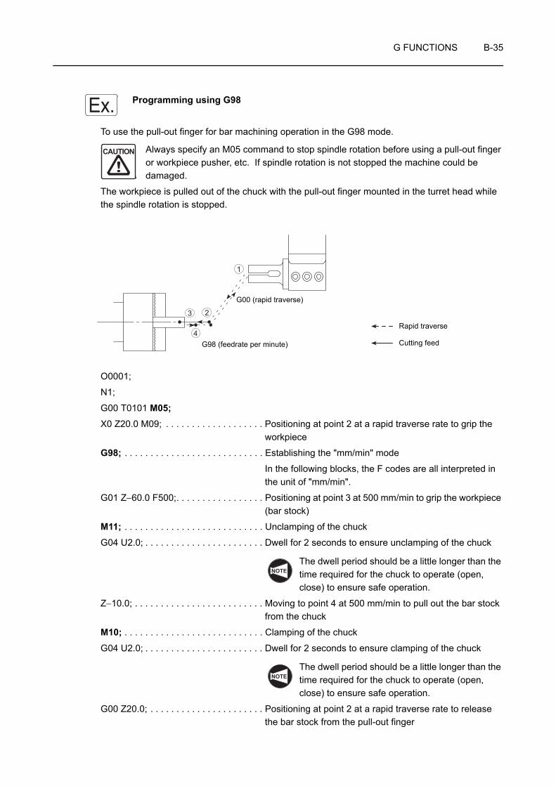
G FUNCTIONS B-35
Programming using G98
To use the pull-out finger for bar machining operation in the G98 mode.
Always specify an M05 command to stop spindle rotation before using a pull-out finger or workpiece pusher, etc. If spindle rotation is not stopped the machine could be damaged.
The workpiece is pulled out of the chuck with the pull-out finger mounted in the turret head while the spindle rotation is stopped.
O0001;
N1;
G00 T0101 M05;X0 Z20.0 M09; . . . . . . . . . . . . . . . . . . . Positioning at point 2 at a rapid traverse rate to grip the
workpiece
G98; . . . . . . . . . . . . . . . . . . . . . . . . . . . Establishing the "mm/min" mode
In the following blocks, the F codes are all interpreted in the unit of "mm/min".
G01 Z−60.0 F500;. . . . . . . . . . . . . . . . . Positioning at point 3 at 500 mm/min to grip the workpiece (bar stock)
M11; . . . . . . . . . . . . . . . . . . . . . . . . . . . Unclamping of the chuck
G04 U2.0; . . . . . . . . . . . . . . . . . . . . . . . Dwell for 2 seconds to ensure unclamping of the chuck
The dwell period should be a little longer than the time required for the chuck to operate (open, close) to ensure safe operation.
Z−10.0; . . . . . . . . . . . . . . . . . . . . . . . . . Moving to point 4 at 500 mm/min to pull out the bar stock from the chuck
M10; . . . . . . . . . . . . . . . . . . . . . . . . . . . Clamping of the chuck
G04 U2.0; . . . . . . . . . . . . . . . . . . . . . . . Dwell for 2 seconds to ensure clamping of the chuck
The dwell period should be a little longer than the time required for the chuck to operate (open, close) to ensure safe operation.
G00 Z20.0; . . . . . . . . . . . . . . . . . . . . . . Positioning at point 2 at a rapid traverse rate to release the bar stock from the pull-out finger
Ex.
CAUTION
1
23
4G98 (feedrate per minute)
G00 (rapid traverse)
Rapid traverse
Cutting feed
NOTE
NOTE

B-36 G FUNCTIONS
X200.0 Z50.0; . . . . . . . . . . . . . . . . . . . . Positioning at point 1 where the turret head can be rotated
G99; . . . . . . . . . . . . . . . . . . . . . . . . . . . Selecting the G99 (mm/rev) mode
In the following blocks, the F codes are all interpreted in the unit of "mm/rev".
M01;
N2;
(G99;)G00 T0202;
G96 S120 M03;
Machining program

G FUNCTIONS B-37
10 G40, G41, G42 AUTOMATIC TOOL NOSE RADIUS OFFSET
The tool nose does not have a sharp edge but is rounded as illustrated on the left. Therefore, the point of the tool nose used for programming is offset from the actual cutting point. The tool nose radius offset function is used to eliminate dimensional errors caused by this difference.
If taper or arc cutting is programmed without taking into consideration the tool nose radius, overcut or undercut will occur.
The G41 and G42 commands are specified in a program to automatically eliminate this overcut or undercut by offsetting for the tool nose radius.
CHAPTER E "AUTOMATIC TOOL NOSE RADIUS OFFSET"
G01(G00) G41 X_ Z_ F_ ;G01(G00) G42 X_ Z_ F_ ;G01(G00) G40 X_ Z_ I_ K_ F_ ;
• G01(G00) . . . . Calls the interpolation mode in which the tool nose radius offset function is specified.G00 . . . . . . Rapid traverseG01 . . . . . . Cutting feed
• G41 . . . . . . . . Calls the tool nose radius offset (left) function.The tool position is offset to the left in reference to the tool advancing direction.
• G42 . . . . . . . . Calls the tool nose radius offset (right) function.The tool position is offset to the right in reference to the tool advancing direction.
• G40 . . . . . . . . Cancels the tool nose radius offset function.
• X, Z. . . . . . . . . Specifies the coordinate values of the end point.
• I, K . . . . . . . . . When making a setting that represents the direction of the workpiece shape in the following block, the direction ratio for this setting is specified as a vector, with "I" as the radius command.
• F . . . . . . . . . . Specifies the feedrate.
R
Programmed pointActual cutting point
R: Tool nose radius
COMMAND
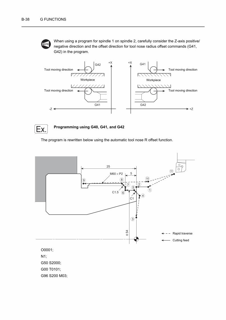
B-38 G FUNCTIONS
When using a program for spindle 1 on spindle 2, carefully consider the Z-axis positive/negative direction and the offset direction for tool nose radius offset commands (G41, G42) in the program.
Programming using G40, G41, and G42
The program is rewritten below using the automatic tool nose R offset function.
O0001;
N1;
G50 S2000;
G00 T0101;
G96 S200 M03;
NOTE
+XG42
G41 G42
G41+X
-Z +Z
Tool moving direction
Tool moving direction
Workpiece
Tool moving direction
Tool moving direction
Workpiece
Ex.
1
4
3
2
C1
C1.5
5
25
M60 × P211
10
5
6
7
89
54φ Rapid traverse
Cutting feed

G FUNCTIONS B-39
G42 X56.0 Z20.0 M08; . . . . . . . . . . . . . Positioning at point 1 at a rapid traverse rate to move the cutting tool close to the workpieceSince the automatic tool nose radius offset (right) function is called by the G42 command, the NC enters the automatic tool nose radius offset mode from this block.
G01 Z0 F1.0;. . . . . . . . . . . . . . . . . . . . . Positioning at point 2 at a cutting feedrate while the tool position is offset to the right
G41 X30.0 F0.15; . . . . . . . . . . . . . . . . Facing at a feedrate of 0.15 mm/revSince the tool position must be offset to the left for this facing operation, the G41 command is specified.
G42 G00 X50.0 W1.0; . . . . . . . . . . . . . Positioning along path 3 → 4 at a rapid traverse rate to execute the O.D. cuttingSince the tool position must be offset to the right for the following O.D. cutting operation, the G42 command is specified.
G01 X54.0 Z−1.0; . . . . . . . . . . . . . . . . . Moving along path 4 → 5 at a cutting feedrate while the tool position is offset to the right
Z−5.0;
X56.8;
X59.8 Z−6.5;
Z−23.0 F0.2;
G40 G00 U1.0 Z20.0; . . . . . . . . . . . . . . Positioning at point 10 to move the cutting tool away from the workpieceThe G40 command cancels the automatic tool nose radius offset mode.
X200.0 Z150.0 M09;
M01;

B-40 G FUNCTIONS
11 G40, G41, G42 CUTTER RADIUS OFFSET
The cutter radius offset means shifting of the tool paths to the right or left by the radius from the programmed paths.
CHAPTER G "CUTTER RADIUS OFFSET"
The cutter radius offset function can be used only for models with the Y-axis specification. This function cannot be used for other machine models.
Generally, when cutting a pocket or carrying out contouring operation using an end mill, the cutter radius offset function is used to finish the workpiece in the shape specified in the drawing.
How the shape in Fig. 1 is finished using the cutter radius offset function is briefly explained below.
Specify the required shape to be finished in the program:
point 1 → 2 → 3 → 4
Since the center of a cutting tool moves along the defined paths, the cutting tool moves along the paths shown in Fig. 2 if the program is created without using the cutter radius offset function.
The workpiece is finished to the shape indicated by broken line in Fig. 2, which is smaller than the required shape indicated in Fig. 1 by the radius of the cutting tool ( ).
To shift the tool paths from the programmed paths, input the radius of the cutting tool as the cutter radius offset data to the GEOMETRY OFFSET screen.
If the cutter radius offset function is used, the tool paths are shifted outside from the programmed paths by the input offset amount as shown in Fig. 3 to finish the required shape.
In this manner, by shifting the tool paths from the programmed paths by using the cutter radius offset function, it is not necessary to obtain the coordinate values using complicated calculation to generate the tool paths to finish the workpiece to the required shape.
NOTE
1
2
3 4
Fig. 1
Workpiece
1
2
3 4
Fig. 2Tool
Workpiece
1
2
3 4
Fig. 3
Workpiece
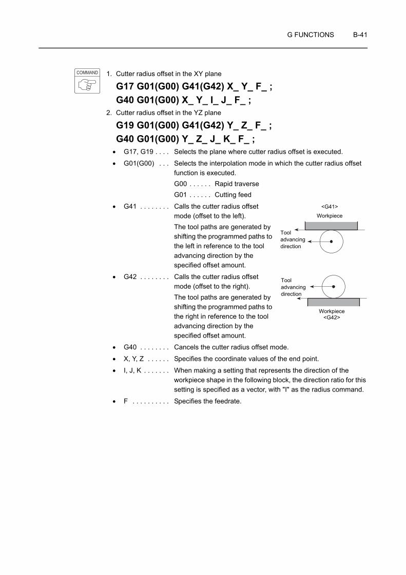
G FUNCTIONS B-41
1. Cutter radius offset in the XY plane
G17 G01(G00) G41(G42) X_ Y_ F_ ;G40 G01(G00) X_ Y_ I_ J_ F_ ;
2. Cutter radius offset in the YZ plane
G19 G01(G00) G41(G42) Y_ Z_ F_ ;G40 G01(G00) Y_ Z_ J_ K_ F_ ;
• G17, G19 . . . . Selects the plane where cutter radius offset is executed.
• G01(G00) . . . Selects the interpolation mode in which the cutter radius offset function is executed.G00 . . . . . . Rapid traverseG01 . . . . . . Cutting feed
• G41 . . . . . . . . Calls the cutter radius offset mode (offset to the left).The tool paths are generated by shifting the programmed paths to the left in reference to the tool advancing direction by the specified offset amount.
• G42 . . . . . . . . Calls the cutter radius offset mode (offset to the right).The tool paths are generated by shifting the programmed paths to the right in reference to the tool advancing direction by the specified offset amount.
• G40 . . . . . . . . Cancels the cutter radius offset mode.
• X, Y, Z . . . . . . Specifies the coordinate values of the end point.
• I, J, K . . . . . . . When making a setting that represents the direction of the workpiece shape in the following block, the direction ratio for this setting is specified as a vector, with "I" as the radius command.
• F . . . . . . . . . . Specifies the feedrate.
COMMAND
Workpiece
Tool advancing direction
<G41>
Workpiece
Tool advancing direction
<G42>
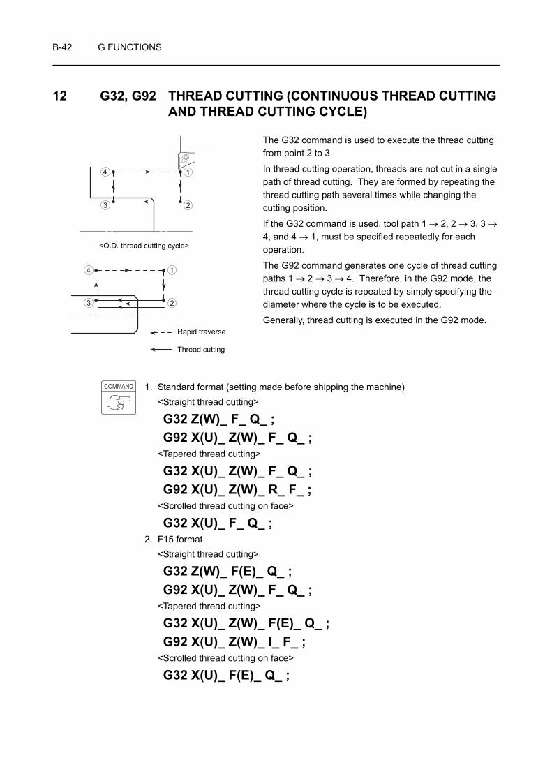
B-42 G FUNCTIONS
12 G32, G92 THREAD CUTTING (CONTINUOUS THREAD CUTTING AND THREAD CUTTING CYCLE)
The G32 command is used to execute the thread cutting from point 2 to 3.
In thread cutting operation, threads are not cut in a single path of thread cutting. They are formed by repeating the thread cutting path several times while changing the cutting position.
If the G32 command is used, tool path 1 → 2, 2 → 3, 3 → 4, and 4 → 1, must be specified repeatedly for each operation.
The G92 command generates one cycle of thread cutting paths 1 → 2 → 3 → 4. Therefore, in the G92 mode, the thread cutting cycle is repeated by simply specifying the diameter where the cycle is to be executed.
Generally, thread cutting is executed in the G92 mode.
1. Standard format (setting made before shipping the machine)<Straight thread cutting>
G32 Z(W)_ F_ Q_ ;G92 X(U)_ Z(W)_ F_ Q_ ;
<Tapered thread cutting>
G32 X(U)_ Z(W)_ F_ Q_ ;G92 X(U)_ Z(W)_ R_ F_ ;
<Scrolled thread cutting on face>
G32 X(U)_ F_ Q_ ;2. F15 format
<Straight thread cutting>
G32 Z(W)_ F(E)_ Q_ ;G92 X(U)_ Z(W)_ F_ Q_ ;
<Tapered thread cutting>
G32 X(U)_ Z(W)_ F(E)_ Q_ ;G92 X(U)_ Z(W)_ I_ F_ ;
<Scrolled thread cutting on face>
G32 X(U)_ F(E)_ Q_ ;
1
23
4
<O.D. thread cutting cycle>
1
23
4
Thread cutting
Rapid traverse
COMMAND
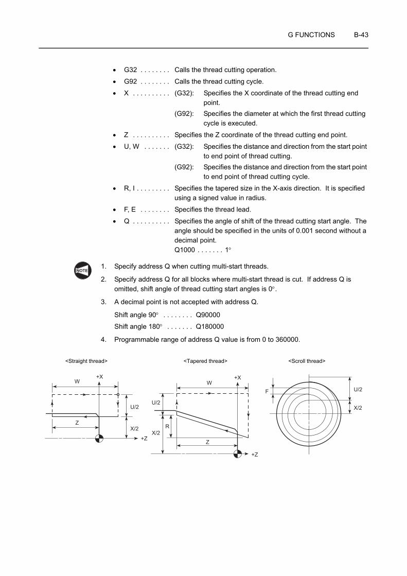
G FUNCTIONS B-43
• G32 . . . . . . . . Calls the thread cutting operation.
• G92 . . . . . . . . Calls the thread cutting cycle.
• X . . . . . . . . . . (G32): Specifies the X coordinate of the thread cutting end point.
(G92): Specifies the diameter at which the first thread cutting cycle is executed.
• Z . . . . . . . . . . Specifies the Z coordinate of the thread cutting end point.
• U, W . . . . . . . (G32): Specifies the distance and direction from the start point to end point of thread cutting.
(G92): Specifies the distance and direction from the start point to end point of thread cutting cycle.
• R, I . . . . . . . . . Specifies the tapered size in the X-axis direction. It is specified using a signed value in radius.
• F, E . . . . . . . . Specifies the thread lead.
• Q . . . . . . . . . . Specifies the angle of shift of the thread cutting start angle. The angle should be specified in the units of 0.001 second without a decimal point.Q1000 . . . . . . . 1°
1. Specify address Q when cutting multi-start threads.
2. Specify address Q for all blocks where multi-start thread is cut. If address Q is omitted, shift angle of thread cutting start angles is 0°.
3. A decimal point is not accepted with address Q.
Shift angle 90° . . . . . . . . Q90000
Shift angle 180° . . . . . . . Q180000
4. Programmable range of address Q value is from 0 to 360000.
NOTE
+XW
U/2
X/2Z
+Z
+Z
Z
X/2
U/2
W+X
R
F U/2
X/2
<Straight thread> <Tapered thread> <Scroll thread>

B-44 G FUNCTIONS
1. Incomplete thread portion
At the start and end of an axis feed, an axis drive servo motor is automatically accelerated or decelerated. Consequently, inaccurate thread leads are generated where thread cutting starts and ends. These areas are referred to as incomplete thread portions.
To explain incomplete thread portions more completely, thread cutting from point A to point B is used as an example.
When thread cutting starts from point A, axis feed is accelerated causing incomplete thread portion for L1. Similarly, incomplete thread portion is generated for L2 because axis feed is decelerated at point B.
Therefore, to obtain the thread length of L, it is necessary to carry out thread cutting in the range of (L1 + L + L2).
B A
L2 L L1
L2 L 1L
End of thread cutting Complete thread portion Start of thread cutting

G FUNCTIONS B-45
2. Calculating the incomplete thread portion
The incomplete thread portions are calculated using the following formula.
In actual programming, the incomplete thread portions should be taken a little larger than the calculated lengths to avoid interference between the cutting tool and the workpiece and to allow for margin for safety.
If the tailstock is used for machining a workpiece, pay sufficient care to avoid interference between the cutting tools or tool holders and the tailstock body, the tailstock spindle or the tailstock spindle center. (Applies only to machines equipped with a tailstock)
3. Precautions on thread cutting operation
When the emergency stop button or (RESET) key has been pressed to stop the
machine during a threading operation, carefully feed the axes after checking the workpiece and cutting tool carefully for damage.
If you feed the axes without due care, the workpiece and cutting tool may collide or interfere with each other, and this could damage the machine.
1. The feedrate (lead) during thread cutting is limited by the value calculated in the following formula.
F: Lead (mm)
N: Spindle speed (min−1)
R: Maximum cutting feedrate (mm/min)(Note that maximum cutting feedrate varies among machine models.)
The lead calculated above is the theoretical value. Depending on the machining conditions, load will become excessive causing a servo alarm or the thread lead cannot be machined accurately. Therefore, it is necessary to determine the machining conditions to meet actual machining status.
Approximation Formula Description
L1 L1 >
L1: Incomplete thread portion(at the start of thread cutting) (mm)
L2: Incomplete thread portion(at the end of thread cutting) (mm)
N: Spindle speed (min−1)P: Lead (mm)
A = In − 1
(ln: Natural logarithm)
L2 L2 >
Thread accuracy
= 1/50 1/100 1/200 1/300
A 2.91 3.61 4.29 4.70
N • P • A1800
1Thread accuracy
N • P1800
∆LT (error in lead)L
CAUTION
CAUTIONRESET
NOTE
RF ≤ N
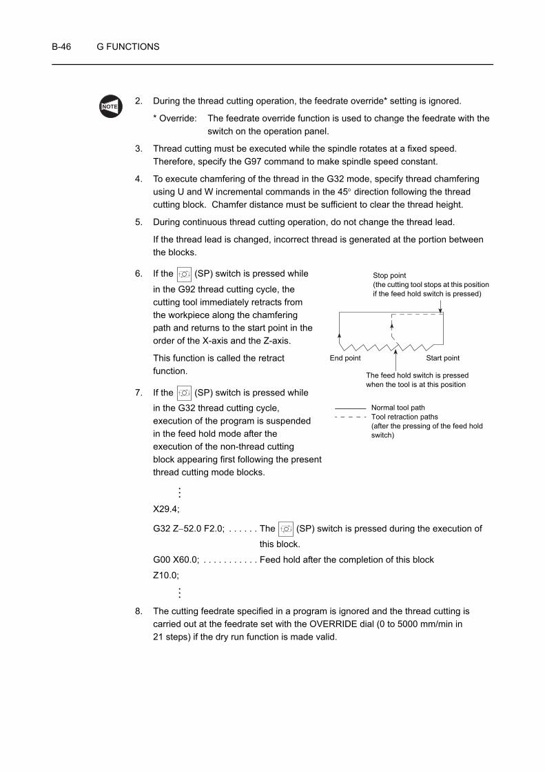
B-46 G FUNCTIONS
2. During the thread cutting operation, the feedrate override* setting is ignored.
* Override: The feedrate override function is used to change the feedrate with the switch on the operation panel.
3. Thread cutting must be executed while the spindle rotates at a fixed speed.Therefore, specify the G97 command to make spindle speed constant.
4. To execute chamfering of the thread in the G32 mode, specify thread chamfering using U and W incremental commands in the 45° direction following the thread cutting block. Chamfer distance must be sufficient to clear the thread height.
5. During continuous thread cutting operation, do not change the thread lead.
If the thread lead is changed, incorrect thread is generated at the portion between the blocks.
6. If the (SP) switch is pressed while
in the G92 thread cutting cycle, the cutting tool immediately retracts from the workpiece along the chamfering path and returns to the start point in the order of the X-axis and the Z-axis.
This function is called the retract function.
7. If the (SP) switch is pressed while
in the G32 thread cutting cycle, execution of the program is suspended in the feed hold mode after the execution of the non-thread cutting block appearing first following the present thread cutting mode blocks.
X29.4;
G32 Z−52.0 F2.0; . . . . . . The (SP) switch is pressed during the execution of
this block.
G00 X60.0; . . . . . . . . . . . Feed hold after the completion of this block
Z10.0;
8. The cutting feedrate specified in a program is ignored and the thread cutting is carried out at the feedrate set with the OVERRIDE dial (0 to 5000 mm/min in 21 steps) if the dry run function is made valid.
NOTE
End point Start point
The feed hold switch is pressed when the tool is at this position
Normal tool pathTool retraction paths (after the pressing of the feed hold switch)
Stop point (the cutting tool stops at this position if the feed hold switch is pressed)
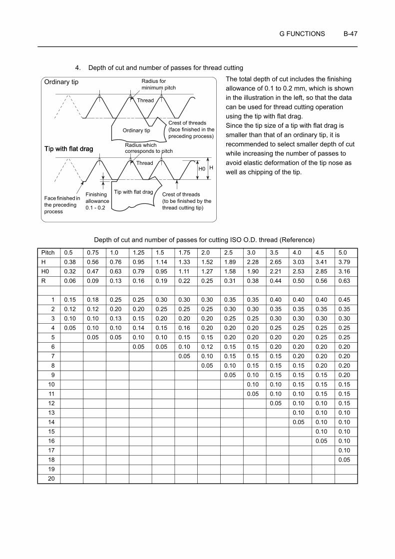
G FUNCTIONS B-47
4. Depth of cut and number of passes for thread cutting
The total depth of cut includes the finishing allowance of 0.1 to 0.2 mm, which is shown in the illustration in the left, so that the data can be used for thread cutting operation using the tip with flat drag. Since the tip size of a tip with flat drag is smaller than that of an ordinary tip, it is recommended to select smaller depth of cut while increasing the number of passes to avoid elastic deformation of the tip nose as well as chipping of the tip.
Depth of cut and number of passes for cutting ISO O.D. thread (Reference)
Pitch 0.5 0.75 1.0 1.25 1.5 1.75 2.0 2.5 3.0 3.5 4.0 4.5 5.0H 0.38 0.56 0.76 0.95 1.14 1.33 1.52 1.89 2.28 2.65 3.03 3.41 3.79H0 0.32 0.47 0.63 0.79 0.95 1.11 1.27 1.58 1.90 2.21 2.53 2.85 3.16R 0.06 0.09 0.13 0.16 0.19 0.22 0.25 0.31 0.38 0.44 0.50 0.56 0.63
1 0.15 0.18 0.25 0.25 0.30 0.30 0.30 0.35 0.35 0.40 0.40 0.40 0.452 0.12 0.12 0.20 0.20 0.25 0.25 0.25 0.30 0.30 0.35 0.35 0.35 0.353 0.10 0.10 0.13 0.15 0.20 0.20 0.20 0.25 0.25 0.30 0.30 0.30 0.304 0.05 0.10 0.10 0.14 0.15 0.16 0.20 0.20 0.20 0.25 0.25 0.25 0.255 0.05 0.05 0.10 0.10 0.15 0.15 0.20 0.20 0.20 0.20 0.25 0.256 0.05 0.05 0.10 0.12 0.15 0.15 0.20 0.20 0.20 0.207 0.05 0.10 0.15 0.15 0.15 0.20 0.20 0.208 0.05 0.10 0.15 0.15 0.15 0.20 0.209 0.05 0.10 0.15 0.15 0.15 0.20
10 0.10 0.10 0.15 0.15 0.1511 0.05 0.10 0.10 0.15 0.1512 0.05 0.10 0.10 0.1513 0.10 0.10 0.1014 0.05 0.10 0.1015 0.10 0.1016 0.05 0.1017 0.1018 0.051920
Ordinary tip Radius for minimum pitch
Thread
Crest of threads (face finished in the preceding process)
Face finished in the preceding process
Tip with flat drag Radius which corresponds to pitch
Thread
Finishing allowance 0.1 - 0.2
Tip with flat drag
H
Ordinary tip
Crest of threads (to be finished by the thread cutting tip)
H0
Tip with flat drag

B-48 G FUNCTIONS
5. Basic profile and dimensions and dimensional deviations of taper pipe threads
(Extract from JIS B 0203-1982)
Basic Profile Applied for Taper External and Taper Internal Threads
Basic Profile Applied for Parallel Internal Threads
Thick continuous line shows basic profile. Thick continuous line shows basic profile.
P =
H = 0.960237 Ph = 0.640327 Pr = 0.137278 P
P =
H' = 0.960491 Ph = 0.640327 Pr' = 0.137329 P
H 2
27.5° 27.5°
55°
H 2
H
h
h 2h 2
r
r
P
90°
16
1Axis of thread90°
P
H'
h 2h 2
H' 6
H' 6
h
r'
r'27.5° 27.5°
55°
D1
D2
D
Axis of thread
NOTE NOTE
25.4n
25.4n
D1 D
2 D
D1 D
2 D
D1 D
2 D
l'
l
t
a f
d d 2 d 1
Fit between taper external thread and taper internal or parallel internal thread
Position of gauge plane
Parallel internal thread
Taper internal thread
Taper internal thread
Taper external thread

G FUNCTIONS B-49
Unit: mm
1. In the Designation of thread column, the symbol given in parentheses is not the one stipulated by the main part of the Standard, but the one stipulated by Annex. This symbol will be repealed in the future.
2. Concerning PT3 1/2 and PT7 to PT12, they are not given in the table above since they are not stipulated by ISO 7/1.
3. Concerning values of "a", "f", and/or "t", if the values specified in the table greatly differ from those stipulated in the standard specific to the part to be machined or those specified in the drawing, use the values stipulated in the standard specific to the part to be machined or those specified in the drawing.
Designation of thread
Thread Gauge dia. Position of gauge plane Tolerance on D, D2 and D1
ofparallel internal thread
±
Length of useful thread (min.) Size of carbon steel pipe for ordinary
piping (Given for reference)
Number of threads
(in 25.4 mm)n
PitchP
(Given for reference)
Height of thread
h
Radiusrorr'
External thread External thread Internal thread
External thread
Internal thread
Major dia.d
Pitch dia.d2
Minor dia.d1
From pipe end A+ pipe end
From position of
gauge plane toward
larger dia. end
f
When there is incomplete thread
part
When there is no incomplete thread part
Internal thread Gauge length
a
Axial tolerance
± b
Axial tolerance
± c
Taper internal thread
Parallel internal thread
Taper internal thread, parallel internal thread
Major dia.D
Pitch dia.D2
Minor dia.D1
From position of
gauge plane toward smaller dia. end
l
From end of pipe
or couplerl'
(Given for reference)
From gauge
plane or end of pipe or coupler
t
Outside dia.
Thickness
R 1/16 28 0.9071 0.581 0.12 7.723 7.142 6.561 3.97 0.91 1.13 0.071 2.5 6.2 7.4 4.4
R (PT) 1/8 28 0.9071 0.581 0.12 9.728 9.147 8.566 3.97 0.91 1.13 0.071 2.5 6.2 7.4 4.4 10.5 2.0
R (PT) 1/4 19 1.3368 0.856 0.18 13.157 12.301 11.445 6.01 1.34 1.67 0.104 3.7 9.4 11.0 6.7 13.8 2.3
R (PT) 3/8 19 1.3368 0.856 0.18 16.662 15.806 14.950 6.35 1.34 1.67 0.104 3.7 9.7 11.4 7.0 17.3 2.3
R (PT) 1/2 14 1.8143 1.162 0.25 20.955 19.793 18.631 8.16 1.81 2.27 0.142 5.0 12.7 15.0 9.1 21.7 2.8
R (PT) 3/4 14 1.8143 1.162 0.25 26.441 25.279 24.117 9.53 1.81 2.27 0.142 5.0 14.1 16.3 10.2 27.2 2.8
R (PT) 1 11 2.3091 1.479 0.32 33.249 31.770 30.291 10.39 2.31 2.89 0.181 6.4 16.2 19.1 11.6 34 3.2
R (PT) 1 1/4 11 2.3091 1.479 0.32 41.910 40.431 38.952 12.70 2.31 2.89 0.181 6.4 18.5 21.4 13.4 42.7 3.5
R (PT) 1 1/2 11 2.3091 1.479 0.32 47.803 46.324 44.845 12.70 2.31 2.89 0.181 6.4 18.5 21.4 13.4 48.6 3.5
R (PT) 2 11 2.3091 1.479 0.32 59.614 58.135 56.656 15.88 2.31 2.89 0.181 7.5 22.8 25.7 16.9 60.5 3.8
R (PT) 2 1/2 11 2.3091 1.479 0.32 75.184 73.705 72.226 17.46 3.46 3.46 0.216 9.2 26.7 30.1 18.6 76.3 4.2
R (PT) 3 11 2.3091 1.479 0.32 87.884 86.405 84.926 20.64 3.46 3.46 0.216 9.2 29.8 33.3 21.1 89.1 4.2
R (PT) 4 11 2.3091 1.479 0.32 113.030 111.551 110.072 25.40 3.46 3.46 0.216 10.4 35.8 39.3 25.9 114.3 4.5
R (PT) 5 11 2.3091 1.479 0.32 138.430 136.951 135.472 28.58 3.46 3.46 0.216 11.5 40.1 43.5 29.3 139.8 4.5
R (PT) 6 11 2.3091 1.479 0.32 163.830 162.351 160.872 28.58 3.46 3.46 0.216 11.5 40.1 43.5 29.3 165.2 5.0
NOTE

B-50 G FUNCTIONS
Programming using G32 or G92 (Straight thread cutting)
<Determining the spindle speed>
Limits due to the workpiece and cutting tool
• N = =
= 1274 (min−1)
Thread cutting is carried out at 1200 min−1.
The above numerical values are only for reference. Depending on the selected cutting conditions, the cutting load may become excessive. If a servo alarm occurs, or if the thread lead cannot be machined correctly, change the cutting conditions.
<Calculating the incomplete thread portions>
• L1 > = = 4.8 mm
• L2 > = = 1.3 mm
If "thread accuracy = 1/100"
Page B-45
When writing a program, L1 and L2 should be longer than the calculated theoretical values. Therefore, L1 and L2 should be set to 10 mm and 2 mm, respectively.
Ex.
L2 L150
6030φ φ
1
23
4
Thread size M30Lead 2 mm
Material AISI 1045 (Carbon steel)
Rapid traverse
Cutting feed
V: Cutting speed (m/min)π: Circumference constantP: Thread diameter (mm)
1000Vπ • D
1000 × 1203.14 × 30
NOTE
N • P • A1800
1200 × 2.0 × 3.611800
N • P1800
1200 × 2.01800
NOTE

G FUNCTIONS B-51
The thread cutting programs in the G32 mode and in the G92 mode are compared below.
<Program in the G32 mode> <Program in the G92 mode>O0001; O0001;N1; N1;G00 T0101; G00 T0101;G97 S1200 M03;. . . . . . . . . . . . . G97 S1200 M03; . . . . . . . . . . Starting spindle 1 in the normal
direction at 1200 min−1
X60.0 Z20.0 M08; X60.0 Z20.0 M08;G01 Z10.0 F1.0; . . . . . . . . . . . . . G01 Z10.0 F1.0 M24; . . . . . . Positioning at point 1, the
thread cutting start point
G00 X29.4; . . . . . . . . G92 X29.4 Z−52.0 F2.0; . . . . Starting the thread cutting oper-ation
G32 Z−52.0 F2.0; . . • X29.4 . . . . Diameter where the first thread cutting cycle is executed
G00 X60.0; . . . . . . . . • Z−52.0 . . . Z coordinate of the thread cutting end point
Z10.0; . . . . . . . . . . . . • F2.0 . . . . . LeadX28.9; X28.9;G32 Z−52.0;G00 X60.0;Z10.0;X28.5; X28.5;G32 Z−52.0;G00 X60.0;Z10.0;X28.1; X28.1;G32 Z−52.0;G00 X60.0;Z10.0;X27.8; X27.8;G32 Z−52.0;G00 X60.0;Z10.0;X27.56; X27.56;G32 Z−52.0;G00 X60.0;Z10.0;
2
3
4
1

B-52 G FUNCTIONS
X27.36; X27.36;G32 Z−52.0;G00 X60.0;Z10.0;X27.26; X27.26; . . . . . . . . . . . . . . . . . . Diameter where the final thread
cutting cycle is executed
G32 Z−52.0;G00 X60.0;
Z10.0;X200.0 Z150.0 M09; . . . . . . . . . . G00 X200.0 Z150.0 M09; . . . . Positioning at a point at a rapid
traverse rate where the turret head can be rotated
M01; M01;
1. The program written in four lines, in the G32 mode, is expressed by the commands in one line in the G92 mode.
2. In the G92 thread cutting cycle, whether the chamfering is executed or not can be selected using the M23 and M24 commands.
M23, M24: Page C-34 (8)
Generally, the start point (X coordinate) for thread cutting is taken at a point more than one pitch away from the thread cutting diameter.
For I.D. thread cutting, the cutting tool may interfere with the workpiece when the I.D. is small if the start point is taken in the manner as indicated above. In this case, determine the start point where interference does not occur.
For details of depth of cut and number of passes, refer to page B-47. Note that the values given in this table are only for reference.
For programming, these values should be determined according to actual machining status. The finished thread should be checked using the thread gage.
CAUTION
NOTE
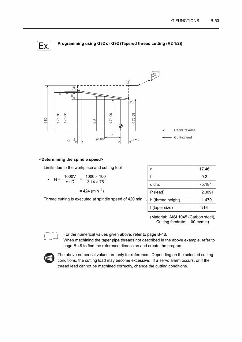
G FUNCTIONS B-53
Programming using G32 or G92 (Tapered thread cutting (R2 1/2))
<Determining the spindle speed>
Limits due to the workpiece and cutting tool
• N = =
= 424 (min−1)
Thread cutting is executed at spindle speed of 420 min−1.
For the numerical values given above, refer to page B-48.When machining the taper pipe threads not described in the above example, refer to page B-48 to find the reference dimension and create the program.
The above numerical values are only for reference. Depending on the selected cutting conditions, the cutting load may become excessive. If a servo alarm occurs, or if the thread lead cannot be machined correctly, change the cutting conditions.
Ex.
aL2 = 2 L1 = 826.66
R
73.5
9
74.0
9
75.7
6
80 d75.8
8
φ φ φ φ φ φ
1
2
3
Rapid traverse
Cutting feed
(Material: AISI 1045 (Carbon steel), Cutting feedrate: 100 m/min)
a 17.46
f 9.2
d dia. 75.184
P (lead) 2.3091
h (thread height) 1.479
t (taper size) 1/16
1000Vπ • D
1000 × 1003.14 × 75
NOTE

B-54 G FUNCTIONS
<Calculating the incomplete thread portions>
• L1 > = = 1.95 mm
• L2 > = = 0.54 mm
If "thread accuracy = 1/100"
Page B-45
When writing a program, L1 and L2 should be longer than the calculated theoretical values. Therefore, L1 and L2 should be set to 8 mm and 2 mm, respectively.For L1, it is recommended to select a multiple of "8", because the taper size is "1/16".
<Program in the G32 mode> <Program in the G92 mode>O0001; O0001;N1; N1;G00 T0101; G00 T0101;G97 S420 M03;. . . . . . . . . . . . . . . . . . . . . G97 S420 M03; . . . . . Starting spindle 1 in the normal
direction at 420 min−1
X80.0 Z20.0 M08; X80.0 Z20.0 M08;G01 Z8.0 F1.0; . . . . . . . . . . . . . . . . . . . . . G01 Z8.0 F1.0 M23;
. . . . . . . . . . . . . . . . . Positioning at point 1, the thread cutting start point
G00 X73.59; . . . . . . . . . . . . . . . . . G92 X75.88 Z−28.66 R−1.15 F2.3091; . . . . . . . . . . . . . . . . . Starting the thread cutting oper-
ation
G32 X75.88 Z−28.66 F2.3091; . .
G00 X80.0; . . . . . . . . . . . . . . . . . .
Z8.0; . . . . . . . . . . . . . . . . . . . . . . .X72.59; X74.88;G32 X74.88 Z−28.66;G00 X80.0;Z8.0;X71.59; X73.88;
G32 X73.88 Z−28.66;G00 X80.0;Z8.0;X70.7; X72.99;G32 X72.99 Z−28.66;G00 X80.0;Z8.0;
N • P • A1800
420 × 2.3091 × 3.611800
N • P1800
420 × 2.30911800
NOTE
2
• X75.88 . . Diameter where the first thread cutting cycle is executed
• Z−28.66 . . Z coordinate of the thread cutting end point
• R−1.15 . . Taper size (distance in the X-axis direction)
R = −
= −1.15
8.0 + 26.66 + 2.032
3
4
1

G FUNCTIONS B-55
X70.64; X72.93;G32 X72.93 Z−28.66;G00 X80.0;Z8.0;X200.0 Z150.0 M09; . . . . . . . . . . . . . . . . . G00 X200.0 Z150.0 M09;
. . . . . . . . . . . . . . . . . Positioning at a point at a rapid traverse rate where the turret head can be rotated
M01; M01;
1. In the example program above, the diameter where the first thread cutting cycle is executed is specified in the outside diameter of the workpiece. In actual programming, the diameter of the first thread cutting path including the depth of cut must be specified.
2. The depth of cut and the number of passes adopted to the example program above are only for reference. For programming, these values should be determined according to actual machining status. The finished thread should be checked using the thread gage.
For the sign to be used for adddress R: Table on page B-65
. . . . . . . . . . . Diameter where the final thread cutting cycle is executed
NOTE
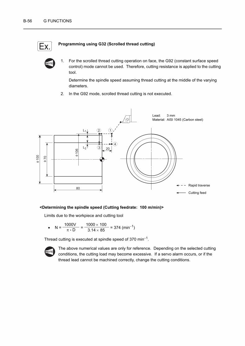
B-56 G FUNCTIONS
Programming using G32 (Scrolled thread cutting)
1. For the scrolled thread cutting operation on face, the G92 (constant surface speed control) mode cannot be used. Therefore, cutting resistance is applied to the cutting tool.
Determine the spindle speed assuming thread cutting at the middle of the varying diameters.
2. In the G92 mode, scrolled thread cutting is not executed.
<Determining the spindle speed (Cutting feedrate: 100 m/min)>
Limits due to the workpiece and cutting tool
• N = = = 374 (min−1)
Thread cutting is executed at spindle speed of 370 min−1.
The above numerical values are only for reference. Depending on the selected cutting conditions, the cutting load may become excessive. If a servo alarm occurs, or if the thread lead cannot be machined correctly, change the cutting conditions.
Ex.NOTE
L1
L2
80
20
70
106
100
φ φ
φ
12
34
Lead: 3 mmMaterial: AISI 1045 (Carbon steel)
Rapid traverse
Cutting feed
1000Vπ • D
1000 × 1003.14 × 85
NOTE
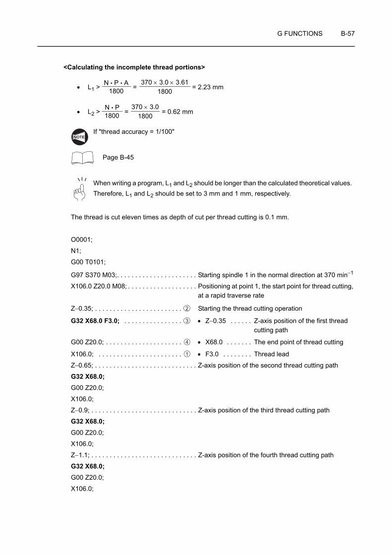
G FUNCTIONS B-57
<Calculating the incomplete thread portions>
• L1 > = = 2.23 mm
• L2 > = = 0.62 mm
If "thread accuracy = 1/100"
Page B-45
When writing a program, L1 and L2 should be longer than the calculated theoretical values. Therefore, L1 and L2 should be set to 3 mm and 1 mm, respectively.
The thread is cut eleven times as depth of cut per thread cutting is 0.1 mm.
O0001;
N1;
G00 T0101;
G97 S370 M03;. . . . . . . . . . . . . . . . . . . . . . Starting spindle 1 in the normal direction at 370 min−1
X106.0 Z20.0 M08; . . . . . . . . . . . . . . . . . . . Positioning at point 1, the start point for thread cutting, at a rapid traverse rate
Z−0.35; . . . . . . . . . . . . . . . . . . . . . . . . Starting the thread cutting operation
G32 X68.0 F3.0; . . . . . . . . . . . . . . . . • Z−0.35 . . . . . . Z-axis position of the first thread cutting path
G00 Z20.0; . . . . . . . . . . . . . . . . . . . . . • X68.0 . . . . . . . The end point of thread cutting
X106.0; . . . . . . . . . . . . . . . . . . . . . . . • F3.0 . . . . . . . . Thread lead
Z−0.65; . . . . . . . . . . . . . . . . . . . . . . . . . . . . Z-axis position of the second thread cutting path
G32 X68.0;G00 Z20.0;
X106.0;
Z−0.9; . . . . . . . . . . . . . . . . . . . . . . . . . . . . . Z-axis position of the third thread cutting path
G32 X68.0;G00 Z20.0;
X106.0;
Z−1.1; . . . . . . . . . . . . . . . . . . . . . . . . . . . . . Z-axis position of the fourth thread cutting path
G32 X68.0;G00 Z20.0;
X106.0;
N • P • A1800
370 × 3.0 × 3.611800
N • P1800
370 × 3.01800
NOTE
2
3
4
1

B-58 G FUNCTIONS
Z−1.3; . . . . . . . . . . . . . . . . . . . . . . . . . . . . . Z-axis position of the fifth thread cutting path
G32 X68.0;G00 Z20.0;
X106.0;
Z−1.45; . . . . . . . . . . . . . . . . . . . . . . . . . . . . Z-axis position of the sixth thread cutting path
G32 X68.0;G00 Z20.0;
X106.0;
Z−1.6; . . . . . . . . . . . . . . . . . . . . . . . . . . . . . Z-axis position of the seventh thread cutting path
G32 X68.0;G00 Z20.0;
X106.0;
Z−1.75; . . . . . . . . . . . . . . . . . . . . . . . . . . . . Z-axis position of the eighth thread cutting path
G32 X68.0;G00 Z20.0;
X106.0;
Z−1.85; . . . . . . . . . . . . . . . . . . . . . . . . . . . . Z-axis position of the ninth thread cutting path
G32 X68.0;G00 Z20.0;
X106.0;
Z−1.95; . . . . . . . . . . . . . . . . . . . . . . . . . . . . Z-axis position of the tenth thread cutting path
G32 X68.0;G00 Z20.0;
X106.0;
Z−2.0; . . . . . . . . . . . . . . . . . . . . . . . . . . . . . Z-axis position of the eleventh thread cutting path
G32 X68.0;G00 Z20.0;
X106.0 M09;
G00 X200.0 Z100.0 M05; . . . . . . . . . . . . . . Positioning at a point where the turret head can be rotated, at a rapid traverse rate
M30;

G FUNCTIONS B-59
13 G32 TAPPING (AT THE CENTER OF SPINDLE)
The G32 command is used to execute a tapping cycle at the center of the spindle (workpiece).
A tapper should be used when executing tapping by specifying the G32 command.
G32 Z(W)_ F_ ;• G32 . . . . . . . . Calls the tapping operation.
• Z . . . . . . . . . . Specifies the Z-coordinate of the tapping end point.
• W . . . . . . . . . . Specifies the distance and direction from the start point to the end point of tapping.
• F . . . . . . . . . . Specifies the lead of thread to be cut (mm).
For the tapping cycle called by G32, a tapper is used. In this case, the return movement of the Z-axis from the bottom of the machined hole is made with the tapper extended. Therefore, the position where the Z-axis reaches in the return movement must be determined taking into consideration the extending length of the tapper. If the return point is determined without taking this length into consideration, the tapping tool and the workpiece may collide or interfere with each other when the tapping tool moves to the next machining position, and the collision or interference could cause damage to the machine.
1. The spindle speed must be kept constant during the execution of a tapping cycle. Therefore, specify the G97 command to keep spindle speed constant.
2. During the execution of a tapping cycle called by G32, feedrate override and spindle speed override values are fixed to 100% because a fixed lead thread cannot be cut if feedrate or spindle speed is changed during the tapping cycle.
3. The cycle does not stop until the Z-axis returns to the specified return point even if
the (SP) switch is pressed during the execution of a tapping cycle.
4. In a tapping cycle called by G32, the spindle must be stopped at the bottom of the machined hole. To extract the tapping tool from the machine hole, specify M04 when cutting a right-hand thread or M03 when cutting a left-hand thread.
5. Specify the pitch of the tap to be used for address F.
NOTE
COMMAND
CAUTION
NOTE

B-60 G FUNCTIONS
13-1 Cautions on Programming Tapping Using G32
13-1-1 Dwell Command
The following explains in what situation the dwell command should be used in the G32 tapping cycle.
Dwell To Be Specified Not Required
Tap hole shape
Blind hole Through hole
Tapper Built-in depth sizing device No special restriction
Tapper extension amount
Tapper is pulled into the hole from the feed stop point of Z-axis by the amount of tapper extension. When the tapper is extended by the set amount, the depth sizing device built in the tapper functions and rotation is not transmitted to the tap, then tapping of specified depth is carried out.
Tapper is extended from the feed stop point of Z-axis.Tapper has allowance to extend 20 to 30 mm. But, actual extension amount cannot be judged.

G FUNCTIONS B-61
13-1-2 Precautions on Using the Tapper
When carrying out tapping in a through hole, extension of tapper tip at the hole bottom can be ignored. However, in the case of a blind hole, if the tapper should extend beyond the depth of the prepared hole, it will cause the tap to be damaged.
To avoid such a problem, use the tapper with built-in depth sizing device for tapping a blind hole.
The following distances of F1, F2, and F3 are specified in the catalog of the tapper with built-in depth sizing device.
F1 Contraction Necessary if the tap fails to be engaged with the workpiece positively at the start of tapping.
F2 Extension amountExtension amount at the hole bottom. This is an extension amount of a tapper in normal spindle rotation (for right-hand thread) or reverse rotation (for left-hand thread).
F3
Extension amount when the tap is pulled out
For right-hand thread:This is an extension amount of a tapper when the tapping tool leaves the workpiece while the spindle is rotating in the reverse direction.For left-hand thread:This is an extension amount of a tapper when the tapping tool leaves the workpiece while the spindle is rotating in the normal direction.
F1F2F3

B-62 G FUNCTIONS
13-1-3 To Finish Tapping at Correct Depth in Blind Hole
When machining a threaded hole with the tapper equipped with depth sizing device, obtain the Z-axis return point and the point of the hole bottom to be specified in a program in the manner indicated below.
The explanation given below shows the theoretical value. The depth of tapped hole will vary depending on workpiece material and prepared hole diameter in actual operation.
• Z-axis return point
Z > F2 + F3
• Hole bottom position
Z = −(Depth of tapping specified in the drawing − F2 + tap engaging length)
F2: Extension amount in normal rotation (right-hand thread), extension amount in reverse rotation (left-hand thread)
F3: Extension amount in reverse rotation (right-hand thread), extension amount in normal rotation (left-hand thread)
NOTE
G FUNCTIONS B-63
Programming using G32 (Tapping)
To carry out tapping of M8 × P1.25, and 20 mm deep at the center of the spindle (workpiece) in the G32 mode
Prepared hole: 6.8 mm dia., depth 30 mmTapper to be used: F2 (extension amount in normal rotation) = 5 mm,
F3 (extension amount in reverse rotation) = 7 mm
Tap engaging length: 5 mm
O0001;
N1;
G00 T0101;
G97 S300 M03; . . . . . . . . . . . . . . . . . . Starting spindle 1 in the normal direction at 300 min−1
X0 Z15.0; . . . . . . . . . . . . . . . . . . . . . . . Positioning at (X0, Z15.0) at a rapid traverse rate
G32 Z−20.0 F1.25; . . . . . . . . . . . . . . . . Executing the tapping cycle (G32)
• Z−20.0 . . . . Z = −("Depth of tap" − F2 + "Tap engaging length")
= −(20 − 5 + 5) = −20 (mm)
• F1.25 . . . . . Pitch 1.25 mmG04 U0.8; . . . . . . . . . . . . . . . . . . . . . . . Dwell at the bottom of the hole to allow the tapper to
extend F2 (extension amount in normal rotation) set by the depth sizing device
• U0.8 . . . . . . Dwell =
= = 0.8 (sec)
M05; . . . . . . . . . . . . . . . . . . . . . . . . . . . Stopping the spindle
Z15.0 M04; . . . . . . . . . . . . . . . . . . . . . . Starting the spindle in the reverse direction and returning the tool to Z15.0
• Z15.0 . . . . . Z > F2 + F3
F2 + F3 = 5 + 7 = 12 (mm)
Since a value greater than "12" must be set for Z, "Z15.0" is specified in the program.
Tapping cycle is executed in this block too since G32 is modal.
G00 X200.0 Z150.0 M05; . . . . . . . . . . . Moving to the position where the turret head can be rotated at a rapid traverse rate
Ex.
60 (sec) × F2FS
60 × 51.25 × 300

B-64 G FUNCTIONS
14 G90, G94 O.D./I.D. CUTTING CYCLE AND FACE CUTTING CYCLE
The G90 and G94 commands are used to call the cycles which simplify programming for straight and tapered cutting on O.D., I.D. and end face.
Usually, these cycle are not used.
Instruction manual supplied by the NC manufacturer
1. Standard format (setting made before shipping the machine)
<Straight cutting>
G90 X(U)_ Z(W)_ F_ ;G94 X(U)_ Z(W)_ F_ ;
<Tapered cutting>
G90 X(U)_ Z(W)_ R_ F_ ;G94 X(U)_ Z(W)_ R_ F_ ;
2. F15 format
<Straight cutting>
G90 X(U)_ Z(W)_ F_ ;G94 X(U)_ Z(W)_ F_ ;
<Tapered cutting>
G90 X(U)_ Z(W)_ I_ F_ ;G94 X(U)_ Z(W)_ K_ F_ ;
• G90, G94 . . . . Calls the O.D./I.D. cutting cycle or the face cutting cycle.
• X, Z . . . . . . . . Specify the coordinate values of the end point of cutting cycle.
• U, W . . . . . . . Specifies the distance and direction from the cutting cycle start point to the cutting cycle end point.
• R . . . . . . . . . . (G90): Specifies the distance of taper in the X-axis direction (signed, in radius).
(G94): Specifies the distance of taper in the Z-axis direction (signed).
• I . . . . . . . . . . . Specifies the distance of taper in the X-axis direction (signed, in radius).
• K . . . . . . . . . . Specifies the distance of taper in the Z-axis direction (signed).
• F . . . . . . . . . . Specifies the feedrate.
G90 O.D./I.D. cutting cycle
G94 Face cutting cycle
COMMAND
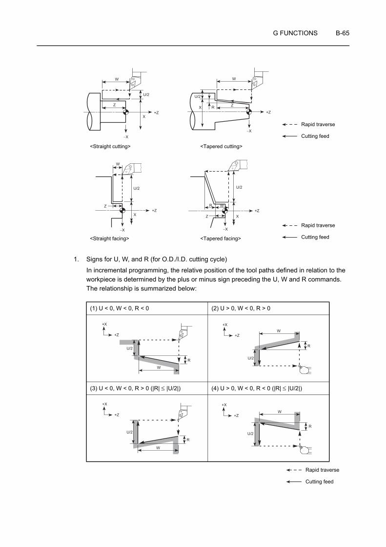
G FUNCTIONS B-65
1. Signs for U, W, and R (for O.D./I.D. cutting cycle)
In incremental programming, the relative position of the tool paths defined in relation to the workpiece is determined by the plus or minus sign preceding the U, W and R commands. The relationship is summarized below:
(1) U < 0, W < 0, R < 0 (2) U > 0, W < 0, R > 0
(3) U < 0, W < 0, R > 0 (|R| ≤ |U/2|) (4) U > 0, W < 0, R < 0 (|R| ≤ |U/2|)
W
U/2
+ZX
−X
Z X Z
+Z
−X
W
R
U/2
W
+Z
−X
Z
U/2 U/2
+ZW
Z
−X
R
X X
<Straight cutting> <Tapered cutting>
<Straight facing> <Tapered facing>
Rapid traverse
Cutting feed
Rapid traverse
Cutting feed
Rapid traverse
Cutting feed
+Z
+X
W
U/2
R U/2
W
R
+Z
+X
U/2
W
R
+Z
+X
U/2
W
R
+Z
+X

B-66 G FUNCTIONS
2. Signs for U, W, and R (for face cutting cycle)
In incremental programming, the relative position of the tool paths defined in relation to the workpiece is determined by the plus or minus sign preceding the U, W and R commands. The relationship is summarized below:
(1) U < 0, W < 0, R < 0 (2) U > 0, W < 0, R > 0
(3) U < 0, W < 0, R > 0 (|R| ≤ |W|) (4) U > 0, W < 0, R > 0 (|R| ≤ |W|)
Rapid traverse
Cutting feed
U/2
R W
+Z
+XW
U/2
R
+Z
+X
U/2
R
W
+Z
+X
U/2
W
R
+Z
+X
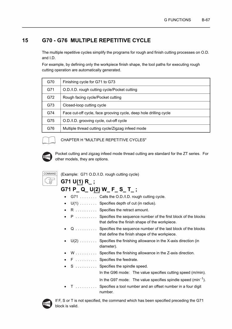
G FUNCTIONS B-67
15 G70 - G76 MULTIPLE REPETITIVE CYCLE
The multiple repetitive cycles simplify the programs for rough and finish cutting processes on O.D. and I.D.
For example, by defining only the workpiece finish shape, the tool paths for executing rough cutting operation are automatically generated.
CHAPTER H "MULTIPLE REPETITIVE CYCLES"
Pocket cutting and zigzag infeed mode thread cutting are standard for the ZT series. For other models, they are options.
(Example: G71 O.D./I.D. rough cutting cycle)
G71 U(1) R_ ;G71 P_ Q_ U(2) W_ F_ S_ T_ ;
• G71 . . . . . . . . Calls the O.D./I.D. rough cutting cycle.
• U(1) . . . . . . . . Specifies depth of cut (in radius).
• R . . . . . . . . . . Specifies the retract amount.
• P . . . . . . . . . . Specifies the sequence number of the first block of the blocks that define the finish shape of the workpiece.
• Q . . . . . . . . . . Specifies the sequence number of the last block of the blocks that define the finish shape of the workpiece.
• U(2) . . . . . . . . Specifies the finishing allowance in the X-axis direction (in diameter).
• W . . . . . . . . . . Specifies the finishing allowance in the Z-axis direction.
• F . . . . . . . . . . Specifies the feedrate.
• S . . . . . . . . . . Specifies the spindle speed.In the G96 mode: The value specifies cutting speed (m/min).
In the G97 mode: The value specifies spindle speed (min−1).
• T . . . . . . . . . . Specifies a tool number and an offset number in a four digit number.
If F, S or T is not specified, the command which has been specified preceding the G71 block is valid.
G70 Finishing cycle for G71 to G73
G71 O.D./I.D. rough cutting cycle/Pocket cutting
G72 Rough facing cycle/Pocket cutting
G73 Closed-loop cutting cycle
G74 Face cut-off cycle, face grooving cycle, deep hole drilling cycle
G75 O.D./I.D. grooving cycle, cut-off cycle
G76 Multiple thread cutting cycle/Zigzag infeed mode
NOTE
COMMAND
NOTE
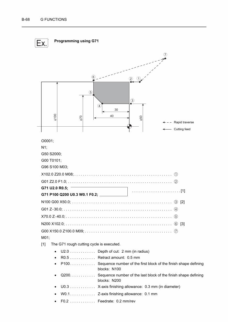
B-68 G FUNCTIONS
Programming using G71
O0001;
N1;
G50 S2000;
G00 T0101;
G96 S100 M03;
X102.0 Z20.0 M08; . . . . . . . . . . . . . . . . . . . . . . . . . . . . . . . . . . . . . . . . . . . . . .
G01 Z2.0 F1.0; . . . . . . . . . . . . . . . . . . . . . . . . . . . . . . . . . . . . . . . . . . . . . . . . .
G71 U2.0 R0.5;G71 P100 Q200 U0.3 W0.1 F0.2;
N100 G00 X50.0; . . . . . . . . . . . . . . . . . . . . . . . . . . . . . . . . . . . . . . . . . . . . . . . [2]
G01 Z−30.0; . . . . . . . . . . . . . . . . . . . . . . . . . . . . . . . . . . . . . . . . . . . . . . . . . . .
X70.0 Z−40.0; . . . . . . . . . . . . . . . . . . . . . . . . . . . . . . . . . . . . . . . . . . . . . . . . . .
N200 X102.0; . . . . . . . . . . . . . . . . . . . . . . . . . . . . . . . . . . . . . . . . . . . . . . . . . . [3]
G00 X150.0 Z100.0 M09; . . . . . . . . . . . . . . . . . . . . . . . . . . . . . . . . . . . . . . . . .
M01;
[1] The G71 rough cutting cycle is executed.
• U2.0 . . . . . . . . . . . . Depth of cut: 2 mm (in radius)• R0.5 . . . . . . . . . . . . Retract amount: 0.5 mm• P100 . . . . . . . . . . . . Sequence number of the first block of the finish shape defining
blocks: N100• Q200. . . . . . . . . . . . Sequence number of the last block of the finish shape defining
blocks: N200• U0.3 . . . . . . . . . . . . X-axis finishing allowance: 0.3 mm (in diameter)
• W0.1 . . . . . . . . . . . . Z-axis finishing allowance: 0.1 mm
• F0.2 . . . . . . . . . . . . Feedrate: 0.2 mm/rev
Ex.φ1
00
φ70
φ5040
30
12
3
4
5
6
7
Rapid traverse
Cutting feed
1
2
. . . . . . . . . . . . . . . . . . . . . . . [1]
3
4
5
6
7

G FUNCTIONS B-69
[2] to [3]
The blocks from sequence number N100 to N200 define the finish shape. These blocks are executed at S100 (100 m/min) and F0.2 (0.2 mm/rev).

B-70 G FUNCTIONS
16 G80, G83 - G85, G87 - G89 HOLE MACHINING CANNED CYCLES
Hole machining operation is programmed using several blocks of commands.
A hole machining canned cycle allows hole machining operation which requires several blocks of commands to be programmed using one block of commands including an appropriate G code.
CHAPTER I "HOLE MACHINING CANNED CYCLE"
1. Hole machining canned cycles can be used only with the MC type or Y-axis specification machines. With the models other than MC type and Y-axis specification, these cycles cannot be used.
2. With the ZL, ZL-S, and ZT series, the face synchronized tapping cycle (M329 G84) can be optionally used for models other than MC type and Y-axis specification. Note that this cycle can be used only at the center of the spindle. With the ZL series, the cycle cannot be used at the turret 2 side. Concerning the ZL-S and ZT series, face synchronized tapping cycle is possible using spindle 1 at the turret 1 side and using spindle 2 at the turret 2 side.
NOTE
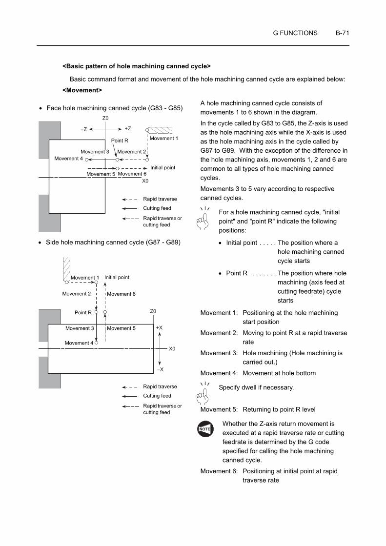
G FUNCTIONS B-71
<Basic pattern of hole machining canned cycle>
Basic command format and movement of the hole machining canned cycle are explained below:
<Movement>
A hole machining canned cycle consists of movements 1 to 6 shown in the diagram.
In the cycle called by G83 to G85, the Z-axis is used as the hole machining axis while the X-axis is used as the hole machining axis in the cycle called by G87 to G89. With the exception of the difference in the hole machining axis, movements 1, 2 and 6 are common to all types of hole machining canned cycles.
Movements 3 to 5 vary according to respective canned cycles.
For a hole machining canned cycle, "initial point" and "point R" indicate the following positions:
• Initial point . . . . . The position where a hole machining canned cycle starts
• Point R . . . . . . . The position where hole machining (axis feed at cutting feedrate) cycle starts
Movement 1: Positioning at the hole machining start position
Movement 2: Moving to point R at a rapid traverse rate
Movement 3: Hole machining (Hole machining is carried out.)
Movement 4: Movement at hole bottom
Specify dwell if necessary.
Movement 5: Returning to point R level
Whether the Z-axis return movement is executed at a rapid traverse rate or cutting feedrate is determined by the G code specified for calling the hole machining canned cycle.
Movement 6: Positioning at initial point at rapid traverse rate
X0
Z0
+Z−Z
Z0
+X
−X
X0
Rapid traverse
Cutting feed
Rapid traverse or cutting feed
Movement 4
• Face hole machining canned cycle (G83 - G85)
Movement 3
Movement 5 Movement 6
Movement 2
Movement 1
Initial point
Point R
• Side hole machining canned cycle (G87 - G89)
Rapid traverse
Cutting feed
Rapid traverse or cutting feed
Movement 4
Movement 3
Initial pointMovement 1
Movement 2 Movement 6
Movement 5
Point R
NOTE

B-72 G FUNCTIONS
1. Face hole machining canned cycle
G83 - G85 X(U)_ C(H)_ Z(W)_ R_ Q_ P_ F_ K_ (M68);G83 - G85 X(U)_ Y(V)_ Z(W)_ R_ Q_ P_ F_ K_ (M68);G80;
• G83 - G85 . . . Calls a face hole machining canned cycle.
Operation mode from movement 3 to movement 5 is determined according the specified G code.
• G80 . . . . . . . . Cancels a hole machining canned cycle.
• X, C, Y . . . . . . Absolute commandSpecifies the hole machining positions. (Movement 1)
• U, H, V . . . . . . Incremental commandSpecifies the distance and direction of the hole machining position in reference to the previous block. (Movement 1)
• Z . . . . . . . . . . Absolute commandSpecifies the hole bottom.
• W . . . . . . . . . . Incremental commandSpecifies the distance and direction of the hole bottom in reference to the point R.
• R . . . . . . . . . . Incremental commandSpecifies the distance and direction of the point R in reference to the initial point.
• Q . . . . . . . . . . Specifies depth of cut per one infeed motion (G83, G83.5, G83.6).
• P . . . . . . . . . . Specifies the period of dwell function executed at the hole bottom.
P1500 → 1.5 sec
• F . . . . . . . . . . Specifies the feedrate.
• K . . . . . . . . . . Specifies the number of repetitions.
If designation of address K is omitted, hole machining cycle is executed once after the positioning at the hole position (equivalent to K1).
K0 . . . . . . . . . . . After the positioning at the specified hole position, hole machining cycle is not executed.
K1 to K9999. . . . Hole machining cycle is repeated by the number of times specified by address K.
• (M68) . . . . . . . Spindle or spindle 1 brake clamp (C-axis clamp or C-axis clamp of spindle 1)
Specify M68 to carry out heavy-duty cutting.
COMMAND
NOTE
NOTE
G FUNCTIONS B-73
2. Side hole machining canned cycle
G87 - G89 Z(W)_ C(H)_ X(U)_ R_ Q_ P_ F_ K_ (M68);G87 - G89 Z(W)_ Y(V)_ X(U)_ R_ Q_ P_ F_ K_ (M68);G80;
• G87 - G89 . . . Calls a side hole machining canned cycle.
Operation mode from movement 3 to movement 5 is determined according the specified G code.
• G80 . . . . . . . . Cancels a hole machining canned cycle.
• Z, C, Y . . . . . . Absolute commandSpecifies the hole machining positions. (Movement 1)
• W, H, V . . . . . Incremental commandSpecifies the distance and direction of the hole machining position in reference to the previous block. (Movement 1)
• X . . . . . . . . . . Absolute commandSpecifies the hole bottom.
• U . . . . . . . . . . Incremental commandSpecifies the distance and direction of the hole bottom in reference to the point R.
• R . . . . . . . . . . Incremental commandSpecifies the distance and direction of the point R in reference to the initial point.
• Q . . . . . . . . . . Specifies depth of cut per one infeed motion (G87, G87.5, G87.6).
• P . . . . . . . . . . Specifies the period of dwell function executed at the hole bottom.
P1500 → 1.5 sec
• F . . . . . . . . . . Specifies the feedrate.
• K . . . . . . . . . . Specifies the number of repetitions.
If designation of address K is omitted, hole machining cycle is executed once after the positioning at the hole position (equivalent to K1).
K0 . . . . . . . . . . . After the positioning at the specified hole position, hole machining cycle is not executed.
K1 to K9999. . . . Hole machining cycle is repeated by the number of times specified by address K.
• (M68) . . . . . . . Spindle or spindle 1 brake clamp (C-axis clamp or C-axis clamp of spindle 1)
Specify M68 to carry out heavy-duty cutting.
COMMAND
NOTE
NOTE

B-74 G FUNCTIONS
1. In the F15 format, use address L to specify the number of repetitions.
2. When the M68 command (spindle or spindle 1 brake clamp (C-axis clamp or C-axis clamp of spindle 1)) is specified, M68 is output before the start of operation 2 and M69 (spindle or spindle 1 brake unclamp (C-axis unclamp or C-axis unclamp of spindle 1)) is output at the completion of operation 5.Dwell is executed for the time set for parameter No. 5111 after that.
NOTE

G FUNCTIONS B-75
17 G22, G23 SETTING THE TOOL ENTRY PROHIBITION ZONE (STORED STROKE CHECK FUNCTION)
The function called by executing the G22 and G23 command is called the stored stroke check function.
When G22 command is executed, if a cutting tool enters to the pre-defined zone, the alarm message is displayed on the screen and the machine stops.
The G22 mode can be canceled by executing the G23 command.
To eliminate interference between the cutting tool and the chuck or a workpiece, set the tool entry prohibition zone using the G22 command.
The G22 and G23 commands are optional.
G22 X_ Z_ I_ K_ ;G23;
• G22 . . . . . . . . Turns on the stored stroke check function.
• G23 . . . . . . . . Turns off the stored stroke check function.
• X, Z. . . . . . . . . Specifies the coordinate values of the point where the tool entry prohibition zone begins.To define the zone, use the distance from the machine zero point. That is, specify the coordinate values in the machine coordinate system which are displayed on the screen.
• I, K . . . . . . . . . Specifies the coordinate values of the point where the tool entry prohibition zone ends.To define the zone, use the distance from the machine zero point. That is, specify the coordinate values in the machine coordinate system which are displayed on the screen.
NOTE
COMMAND
(X, Z)
(I, K)<Tool entry prohibition zone>

B-76 G FUNCTIONS
When using the stored stroke check function, always execute a machine zero return operation after switching the power ON, otherwise the function will not be valid. If the machine is operated in this condition it will not stop even if the cutting tool enters the prohibition zone, and this could damage the machine.
1. When specifying the values for X, Z, I, and K to define the tool entry prohibition zone, the following rule must be followed.
• X > I, Z > K
• X - I > 2 mm, Z - K > 2 mm
To set the zone as illustrated below, for example:
• X100.0 > I80.0 • 100.0 − (80.0) = 20.0 > 2 mm
• Z−40.0 > K−80.0 • −40.0 − (−80.0) = 40.0 > 2 mm
The above indicated conditions are satisfied and the required zone may be set.
2. The tool entry prohibition zone is established "outside" or "inside" the specified zone.
Where the tool entry prohibition zone is set "outside" or "inside" is determined by the setting for parameter No. 1300.0.
3. The G22 and G23 commands must be specified in a block without other commands.
4. If the same values are set for "X_ Z_" and "I_ K_" following the G22 command, the tool entry prohibition zone is not set.
5. Tool entry prohibition zone specified with G22 is set in parameters. The value set in parameters are not lost even if the power is turned off.
Accordingly, unless canceled by G23, the G22 function is valid when the power is turned on.
If a cutting tool enters the tool entry prohibition zone specified with G22, an alarm is displayed on the screen and the machine stops.
In this case, the cutting tool can be moved only in the opposite direction in which the cutting tool has been moved.
The alarm state can be cleared by pressing the (RESET) key on the operation panel
after moving the cutting tool outside the tool entry prohibition zone manually.
CAUTION
NOTE
(I80.0, K-80.0)
(X100, Z-40.0)
+X
+Z
RESET

G FUNCTIONS B-77
Programming using G22 and G23
To set the zone as illustrated below.
O0001;
N1;
G00 G28 U0 W0; . . . . . . . . . . . . . . . . . Machine zero return of the X- and Z-axes
G22 X100.0 Z−40.0 I80.0 K−80.0; . . . . Setting the tool entry prohibition zone as illustrated above
G50 S2000;
T0101;
Machining program
G23; . . . . . . . . . . . . . . . . . . . . . . . . . . . Canceling the tool entry prohibition zone
Ex.
+X
+Z
(X100.0, Z−40.0)
(I80.0, K−80.0)

B-78 G FUNCTIONS
18 G28 RETURNING THE AXES TO MACHINE ZERO AUTOMATICALLY,
G30 RETURNING THE AXES TO SECOND ZERO POINT AUTOMATICALLY
The G28 or G30 command is used to automatically return the axes specified in the G28 block to the machine zero point or the second zero point after positioning it at the specified intermediate point at a rapid traverse rate.
This command is used if the tool and/or tool holder interferes with the workpiece, chuck, or fixture while the turret is rotating, for mounting/removing a workpiece, or for removing chips.
1. Machine zero point
G28 X(U)_ Y(V)_ Z(W)_ ;2. Second zero point
G30 X(U)_ Y(V)_ Z(W)_ ;• G28 . . . . . . . . Calls the machine zero return
mode.
• G30 . . . . . . . . Calls the second zero return mode.
• X, Y, Z . . . . . . Specifies the axes which should be returned to the machine zero point. (absolute command)
Numerical values specified following the addresses X, Y and Z indicate the coordinate values of the intermediate point.
• U, V, W . . . . . Specifies the axes which should be returned to the machine zero point. (incremental command)
Numerical values specified following the addresses U, V and W indicate the distance and direction to the intermediate point.
When returning the axis to the machine zero point or the second zero point from the present positions by using G28 or G30 command, use incremental command such as "G28 U0 W0;". If the absolute command such as "G28 X0 Z0;" is specified, the axes first move to the workpiece zero point before returning to the machine zero point or the second zero point and this may cause interference.
COMMAND
G28 X100.0 Z50.0;
Machine zero point
Intermediate point (X100.0 Z50.0)
Present positionNOTE
NOTE
CAUTION

G FUNCTIONS B-79
1. When the G28 or G30 command is specified, the tool offset and the automatic tool nose R offset functions are canceled.
2. When returning B-axis to the machine zero point, specify the G330 command.
Programming using G28
O0001;
N1;
G50 S2000;
G00 T0101;
Machining program
(G01) X102.0 Z−45.2; . . . . . . . . . . . . . . Cutting up to point 1
G28 X140.0 Z−25.0; . . . . . . . . . . . . . . Returning of the X- and Z-axes to the machine zero point after positioning to the intermediate point 2 (X140.0, Z−25.0) at a rapid traverse rate
M01;
G28 U0 W0;
G28 X0 Z0;
A
Machine zero point
Workpiece zero point (X0, Z0)
NOTE
Ex.14
0
102
45.2
25
φ φ
1
2
Machine zero point
Rapid traverse
Cutting feed

B-80 G FUNCTIONS
19 G30.1 FLOATING REFERENCE POINT RETURN (OPTION)
The G30.1 command is used to automatically return the axes specified in the same block to the floating reference point after positioning the axes to the specified intermediate point at a rapid traverse rate.
Before specifying G30.1, set the floating reference points on the current position (all) screen.
<Procedure>
1) Press the [FRP SETTING] soft-key to display the FLOATING REFERENCE POSITION RETURN field.
2) Select the axis to be set in the FLOATING REFERENCE POSITION RETURN field using the cursor.
3) Input the coordinate by using any of the procedures below:
• Input any required coordinate using the data entry keys and then press the
(INPUT) key or the [EXECUTE] soft-key.
• Move the axis to the desired position and press the [EXECUTE] soft-key to capture the machine coordinate.
1. On inputting a value and then pressing the [+ INPUT] soft-key, the input value is added to the original value.
2. Pressing the [ALL AXES] soft-key brings the machine coordinates of all the axes into the FLOATING REFERENCE POSITION RETURN field.
G30.1 X(U)_ Y(V)_ Z(W)_ ;• G30.1 . . . . . . Floating reference point return
• X, Y, Z. . . . . . . Specifies the axes to be returned to the floating reference points (absolute command)
The numeric value specified following addresses X, Y, and Z indicates the coordinate value of the intermediate point.
• U, V, W . . . . . . Specifies the axes to be returned to the floating reference points (incremental command)
The numeric value specified following addresses U, V, and W indicates the coordinate value of the intermediate point.
1. Before specifying G30.1, cancel any tool offset mode, such as tool radius offset.
2. The floating reference points remain in the memory even after the power is switched off.
3. For the B-axis (ZL-S series, ZT series), only absolute commands are valid.
INPUT
COMMAND
NOTE
NOTE
NOTE
G FUNCTIONS B-81
20 G53 SELECTING THE MACHINE COORDINATE SYSTEM
The machine coordinate system means the coordinate system having its origin at the machine zero point of X- and Z-axes.
It is possible to move a cutting tool to a fixed position at rapid traverse by specifying the G53 command. Also specify the G53 command to retract the turret to the turret rotation position before finishing the machining.
The machine coordinate values of the axes can be confirmed by the present position (machine coordinate) displayed on the screen.
G53 X_ Z_ ;• G53 . . . . . . . . Selects the machine coordinate system.
• X, Z . . . . . . . . Specifies the coordinate values in the machine coordinate system.
1. The G53 command is a "00" group command.
The G53 command is one-shot code. It is valid only in the specified block.
2. The G53 command is valid in the absolute programming mode. If it is specified in the incremental programming mode, it is ignored.
3. Before specifying the G53 command, cancel the automatic tool nose radius offset mode.
COMMAND
NOTE
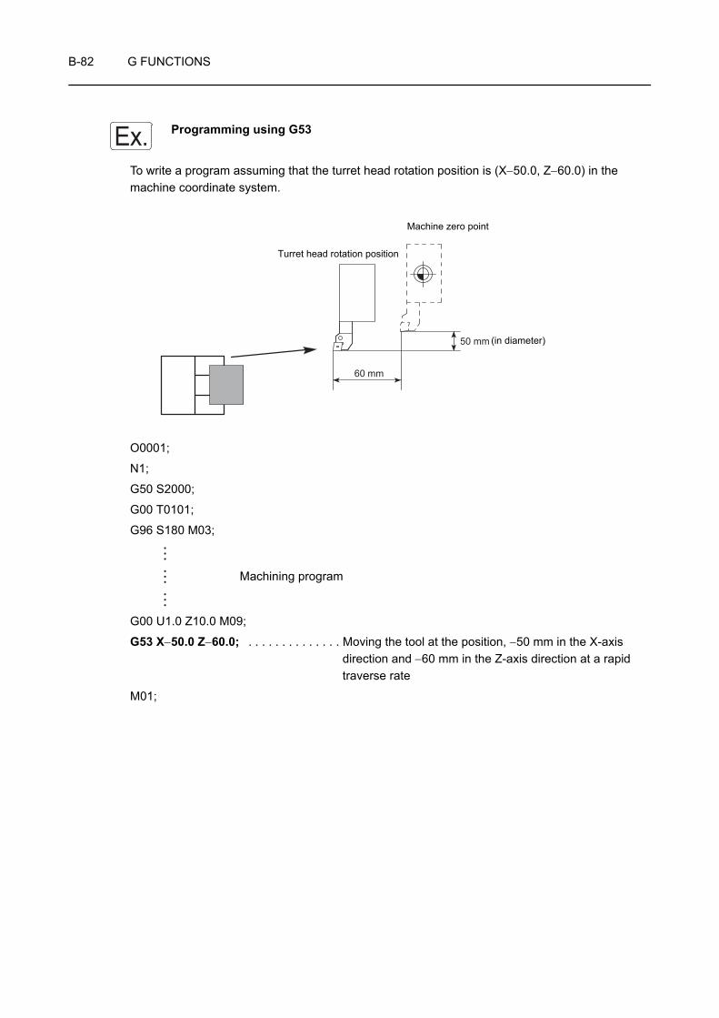
B-82 G FUNCTIONS
Programming using G53
To write a program assuming that the turret head rotation position is (X−50.0, Z−60.0) in the machine coordinate system.
O0001;
N1;
G50 S2000;
G00 T0101;
G96 S180 M03;
Machining program
G00 U1.0 Z10.0 M09;
G53 X−50.0 Z−60.0; . . . . . . . . . . . . . . Moving the tool at the position, −50 mm in the X-axis direction and −60 mm in the Z-axis direction at a rapid traverse rate
M01;
Ex.
60 mm
50 mm
Turret head rotation position
Machine zero point
(in diameter)
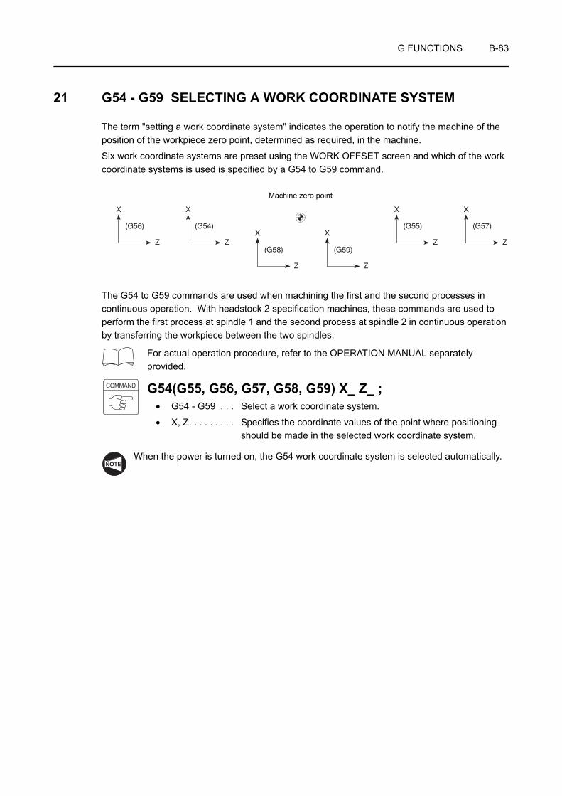
G FUNCTIONS B-83
21 G54 - G59 SELECTING A WORK COORDINATE SYSTEM
The term "setting a work coordinate system" indicates the operation to notify the machine of the position of the workpiece zero point, determined as required, in the machine.
Six work coordinate systems are preset using the WORK OFFSET screen and which of the work coordinate systems is used is specified by a G54 to G59 command.
The G54 to G59 commands are used when machining the first and the second processes in continuous operation. With headstock 2 specification machines, these commands are used to perform the first process at spindle 1 and the second process at spindle 2 in continuous operation by transferring the workpiece between the two spindles.
For actual operation procedure, refer to the OPERATION MANUAL separately provided.
G54(G55, G56, G57, G58, G59) X_ Z_ ;• G54 - G59 . . . Select a work coordinate system.
• X, Z. . . . . . . . . Specifies the coordinate values of the point where positioning should be made in the selected work coordinate system.
When the power is turned on, the G54 work coordinate system is selected automatically.
X
Z
X
ZX
Z
X
Z
X
Z
X
Z
(G56) (G54)
(G58) (G59)
(G55) (G57)
Machine zero point
COMMAND
NOTE

B-84 G FUNCTIONS
Programming positioning using a work coordinate system (G54 to G59)
To carry out continuous operation of the first and second processes using the same chuck jaws and the same O.D. cutting tool
1st process 2nd process
<Preparation>
1. Set the temporary zero point for the first process on the workpiece end face using the tool geometry offset function and the tool wear offset function.
2. Input the distance (2.0 mm) from the workpiece zero point in the G54 work coordinate system to the temporary workpiece zero point, measured along the Z-axis, to "Z" of "G54" displayed on the WORK OFFSET screen, in a negative value.
3. Input the sum (13.5 mm) of the cutting allowance (2.0 mm), to be removed in the first process, the Z-axis distance from the workpiece zero point in the G55 work coordinate system to the workpiece end face (1.5 mm) and the chuck jaw shift amount (10.0 mm) to "Z" of "G55" displayed on the WORK OFFSET screen, in a negative value.
Ex.
2
70 100
φ φ
10
100
2
φ
Workpiece zero point for G54 Workpiece zero point for G55
Temporary zero point
2
Workpiece zero point for G54
10 2
Workpiece zero point for G55

G FUNCTIONS B-85
O0001;
N1;
G54; . . . . . . . . . . . . . . . . . . . . . . . . . . . Selecting the G54 work coordinate system
G50 S2000;
G00 T0101; . . . . . . . . . . . . . . . . . . . . . Rotating the turret to index No. 1 tool
The workpiece zero point for the G54 work coordinate system is set by adding all the following offset data: tool offset data for No. 1 tool, tool offset data for the "G54" and the offset data set for "COMMON" in the WORK OFFSET screen.
Machining program
M00; . . . . . . . . . . . . . . . . . . . . . . . . . . . Stopping the operation
Change or turn the workpiece.
N2;
G55; . . . . . . . . . . . . . . . . . . . . . . . . . . . Selecting the G55 work coordinate system
G50 S2000;
G00 T0101; . . . . . . . . . . . . . . . . . . . . . Rotating the turret to index No. 1 tool
The workpiece zero point for the G55 work coordinate system is set by adding all the following offset data: tool offset data for No. 1 tool, tool offset data for the "G55" and the offset data set for "COMMON" in the WORK OFFSET screen.
Machining program
M30;

B-86 G FUNCTIONS
22 G38 WORKPIECE PUSHING CHECK
The G38 command is specified when transferring the workpiece clamped in chuck 1 to chuck 2.
In the workpiece transfer operation, when the position error of the B-axis servo motor of spindle 2 or the Z-axis servo motor of turret 2 reaches the parameter set value, the workpiece is judged to have been brought into contact with the reference face of chuck 2. Then, chuck 2 is clamped and the program advances to the next block.
1. G38 can be specified only with the ZL-S and ZT series.
2. With the ZL-S and ZT series machines, index No. 1 tool in turret 2 and return the X-axis to the machine zero point before executing the workpiece transfer operation.
If turret 2 is not indexed to No. 1 position or if the X-axis is not at the machine zero point, workpiece transfer operation is not possible.
G38 B(J, V)_ K_ F_ Q_ ;• G38 . . . . . . . . Workpiece pushing check command
• B . . . . . . . . . . Absolute commandSpecifies the B-coordinate of workpiece transfer position on the work coordinate system.
• J . . . . . . . . . . Incremental commandSpecifies the distance and direction of the workpiece transfer position in reference to the preset position.
• V . . . . . . . . . . Coordinate value on the machine coordinate systemSpecifies the coordinate value of the workpiece transfer position on the machine coordinate system.
• K . . . . . . . . . . B-axis retraction stroke (unsigned value)Specifies the stroke through which the B-axis should retract from the position where pushing of a workpiece is detected.
• F . . . . . . . . . . Feedrate (mm/min)Specifies the feedrate for skip feed operation (pushing the workpiece to chuck 2).
• Q . . . . . . . . . . Tolerance for workpiece transfer positionIf the actual workpiece pushing position known from the detection of workpiece pushing and retraction after detection of workpiece pushing is within the range of B (J, V) ± Q, the program advances to the next block.
This detection operation may cause low-strength workpieces such an aluminum workpieces to be deformed or damaged.
Feedrate for skip feed operation should be changed meeting the workpiece material and dimensions.
NOTE
COMMAND
CAUTION

G FUNCTIONS B-87
1. G38 may be specified only in turret 2 program.
2. With the ZL-S and ZT series machines, when address B is used to express the coordinate value of the workpiece transfer position, if no value is set for "B" of "COMMON" in the WORK OFFSET screen, it has the same meaning as "(B = 0), V".
3. If a K command is omitted, the Z-axis is automatically retracted by the servo error amount in the uni-direction positioning mode.
4. If a K command is specified, servo error is not calculated and the Z-axis is retracted by the specified amount.
In this case, retraction is not made in the uni-direction positioning mode.
5. Change the value for a K command according to the strength of the workpiece.
6. If an F command is omitted in a program, feedrate of the B-axis of spindle 2 or the Z-axis of turret 2 is automatically set to 30 mm/min.
7. If the actual Z-axis position after retraction from the workpiece pushing detected position is outside the specified tolerance "B (J, V) ± Q", the pushing detection cycle is repeated again. If the Z-axis is not positioned within the tolerance, an alarm is generated and the machine stops.
8. If a Q command is omitted, the tolerance for workpiece transfer position is 1 mm.
9. The approach point to be specified preceding the G38 command should be taken at a point where the chuck 2 takes more than 1 second to come into contact with the workpiece.
10. With the ZL-S and ZT series machines, use any one of the addresses B, J, and V for specifying the workpiece transfer position.
11. The chuck to workpiece contact position cannot be judged if the feed override setting is changed after executing the G38 block with 0% set for feed override. It is necessary to set a value other than 0% for feed override when executing the G38 block. It must also be remembered it is not allowed to change the feed override setting during the execution of the G38 block.
12. In a G38 block, a decimal point must be entered for all of the values specified in that block.
NOTE

B-88 G FUNCTIONS
Programming using G38 (ZL-S series)
With the ZL-S series machines, a workpiece, machined in spindle 1 is transferred from spindle 1 to spindle 2.
<Turret 1> <Turret 2>O0001; O0002;N1; N1;
G59; . . . . . . . . . . . . . . . . Selecting the G59 work coordinate
system (for workpiece transfer)Machining program
(M246;) . . . . . . . . . . . . . To be specified only for MC type
N7; G00 T3100; . . . . . . . . . . Selecting the No. 1 tool
The tool wear offset cancel
G00 T0101; G28 U0 M05; . . . . . . . . . Returning the X-axis to the machine zero
point
M100;. . . . . . . . . . . . . Synchronization of program execution M100;. . . . . . . . . . . . . . . Synchronization of program execution
M35;. . . . . . . . . . . . . . Speed synchronous operation M35;. . . . . . . . . . . . . . . . Speed synchronous operation
M101;. . . . . . . . . . . . . Synchronization of program execution M101;. . . . . . . . . . . . . . . Synchronization of program execution
G97 S1000 M03; . . . . Speeds of spindle 1 and spindle 2 are
synchronized at 1000 min−1.
M211; . . . . . . . . . . . . . . . Chuck 2 unclamp
G28 U0 M09; . . . . . . . Returning the X-axis to the machine zero point
Z10.0;Z0.3 M51;M102;. . . . . . . . . . . . . Synchronization of program execution M102;. . . . . . . . . . . . . . . Synchronization of program execution
M59; G00 B_ M252; . . . . . . . . Moving headstock 2 to the approach
position B_ (work coordinate system)(First approach)
G98 G01 B_ F1000 M257;. . . . . . . . . . . . . . . . . . . . Approaching of headstock 2 to workpiece
at the feedrate of 1000 mm/min (Second approach)
G38 J_ K_ F_ Q_ ; . . . . Detecting the pushing of workpiece
Chuck 2 clamp operation is included.
M103;. . . . . . . . . . . . . Synchronization of program execution;
program execution is suspended until
completion of "detecting the pushing of work-
piece".
M103;. . . . . . . . . . . . . . . Synchronization of program execution
Machining program (Cutting off of workpiece)
M104;. . . . . . . . . . . . . Synchronization of program execution M104;. . . . . . . . . . . . . . . Synchronization of program execution;
program execution is suspended until
cutting off operation is finished.
G330; . . . . . . . . . . . . . . . Returning the B-axis (spindle 2) to the
machine zero point
M36;. . . . . . . . . . . . . . . . Canceling synchronous operation
M105;. . . . . . . . . . . . . Synchronization of program execution;
program execution is suspended until "returning
the B-axis (spindle 2) to the machine zero point".
M105;. . . . . . . . . . . . . . . Synchronization of program execution
M30; M01;
Ex.
NOTE

G FUNCTIONS B-89
Programming using G38 (ZT series)
With the ZT series machines, a workpiece, machined in spindle 1 is transferred from spindle 1 to spindle 2.
<Turret 1> <Turret 2>O0001; O0002;N1; N1;
G59;. . . . . . . . . . . . . . . . Selecting the G59 work coordinate system (for workpiece transfer)
Machining program
(M246;) . . . . . . . . . . . . . To be specified only for MC type
N7; G00 T3100; . . . . . . . . . . Selecting the No. 1 tool
The tool wear offset cancel
G00 T0101; G28 U0 M05; . . . . . . . . . Returning the X-axis to the machine zero
point
M100;. . . . . . . . . . . . . . . Synchronization of program execution M100; . . . . . . . . . . . . . . Synchronization of program execution
M35;. . . . . . . . . . . . . . . . Speed synchronous operation M35; . . . . . . . . . . . . . . . Speed synchronous operation
M101;. . . . . . . . . . . . . . . Synchronization of program execution M101; . . . . . . . . . . . . . . Synchronization of program execution
G97 S1000 M03; . . . . . . Speeds of spindle 1 and spindle 2 are
synchronized at 1000 min−1.
M211;. . . . . . . . . . . . . . . Chuck 2 unclamp
G28 U0 M09; . . . . . . . . . Returning the X-axis to the machine zero point
Z10.0;Z0.3 M51;M102;. . . . . . . . . . . . . . . Synchronization of program execution M102; . . . . . . . . . . . . . . Synchronization of program execution
M59; M369; . . . . . . . . . . . . . . B-axis unclamp
G00 B_ M252; . . . . . . . . Moving headstock 2 to the approach position B_ (work coordinate system)(First approach)
G98 G01 B_ F1000 M257; . . . . . . . . . . . . . . . . . . . Approaching of headstock 2 to workpiece at
the feedrate of 1000 mm/min (Second approach)
G38 J_ K_ F_ Q_ ; . . . . Detecting the pushing of workpiece
Chuck 2 clamp operation is included.
M103;. . . . . . . . . . . . . . . Synchronization of program execution; program execution is suspended until completion of "detecting the pushing of workpiece".
M103; . . . . . . . . . . . . . . Synchronization of program execution
Machining program (Cutting off of workpiece)
M104;. . . . . . . . . . . . . . . Synchronization of program execution M104; . . . . . . . . . . . . . . Synchronization of program execution; program execution is suspended until cutting off operation is finished.
G330;. . . . . . . . . . . . . . . Returning the B-axis (spindle 2) to the
machine zero point
M36; . . . . . . . . . . . . . . . Canceling synchronous operation
M105;. . . . . . . . . . . . . . . Synchronization of program execution; program execution is suspended until "returning the B-axis (spindle 2) to the machine zero point".
M105; . . . . . . . . . . . . . . Synchronization of program execution
M30; M01;
Ex.
NOTE
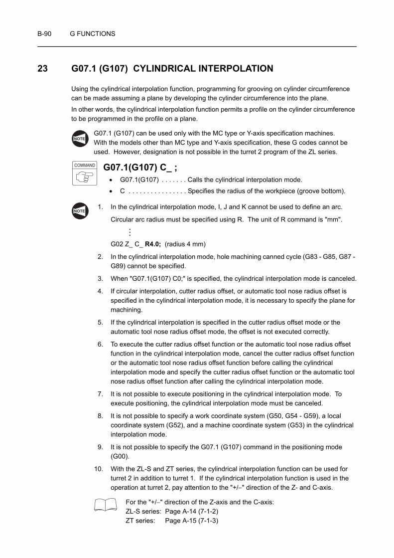
B-90 G FUNCTIONS
23 G07.1 (G107) CYLINDRICAL INTERPOLATION
Using the cylindrical interpolation function, programming for grooving on cylinder circumference can be made assuming a plane by developing the cylinder circumference into the plane.
In other words, the cylindrical interpolation function permits a profile on the cylinder circumference to be programmed in the profile on a plane.
G07.1 (G107) can be used only with the MC type or Y-axis specification machines.With the models other than MC type and Y-axis specification, these G codes cannot be used. However, designation is not possible in the turret 2 program of the ZL series.
G07.1(G107) C_ ;• G07.1(G107) . . . . . . . Calls the cylindrical interpolation mode.
• C . . . . . . . . . . . . . . . . Specifies the radius of the workpiece (groove bottom).
1. In the cylindrical interpolation mode, I, J and K cannot be used to define an arc.
Circular arc radius must be specified using R. The unit of R command is "mm".
G02 Z_ C_ R4.0; (radius 4 mm)
2. In the cylindrical interpolation mode, hole machining canned cycle (G83 - G85, G87 - G89) cannot be specified.
3. When "G07.1(G107) C0;" is specified, the cylindrical interpolation mode is canceled.
4. If circular interpolation, cutter radius offset, or automatic tool nose radius offset is specified in the cylindrical interpolation mode, it is necessary to specify the plane for machining.
5. If the cylindrical interpolation is specified in the cutter radius offset mode or the automatic tool nose radius offset mode, the offset is not executed correctly.
6. To execute the cutter radius offset function or the automatic tool nose radius offset function in the cylindrical interpolation mode, cancel the cutter radius offset function or the automatic tool nose radius offset function before calling the cylindrical interpolation mode and specify the cutter radius offset function or the automatic tool nose radius offset function after calling the cylindrical interpolation mode.
7. It is not possible to execute positioning in the cylindrical interpolation mode. To execute positioning, the cylindrical interpolation mode must be canceled.
8. It is not possible to specify a work coordinate system (G50, G54 - G59), a local coordinate system (G52), and a machine coordinate system (G53) in the cylindrical interpolation mode.
9. It is not possible to specify the G07.1 (G107) command in the positioning mode (G00).
10. With the ZL-S and ZT series, the cylindrical interpolation function can be used for turret 2 in addition to turret 1. If the cylindrical interpolation function is used in the operation at turret 2, pay attention to the "+/−" direction of the Z- and C-axis.
For the "+/−" direction of the Z-axis and the C-axis:ZL-S series: Page A-14 (7-1-2)ZT series: Page A-15 (7-1-3)
NOTE
COMMAND
NOTE
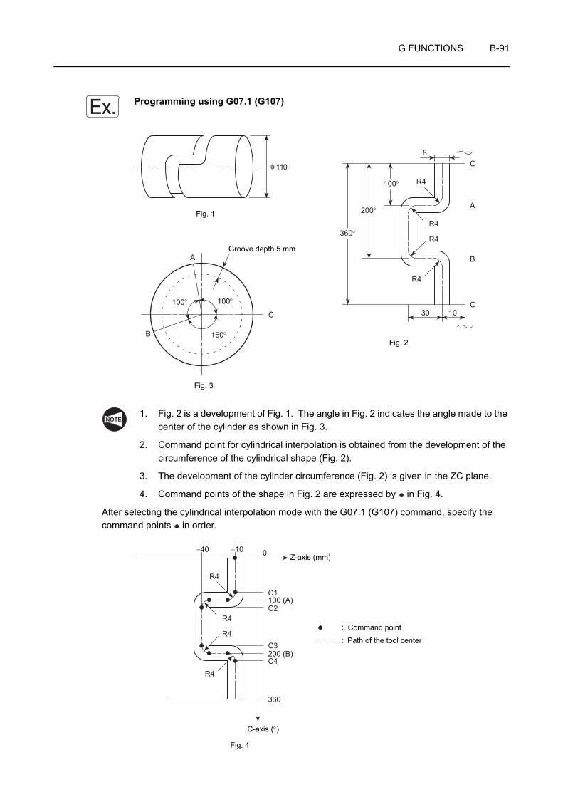
G FUNCTIONS B-91
Programming using G07.1 (G107)
1. Fig. 2 is a development of Fig. 1. The angle in Fig. 2 indicates the angle made to the center of the cylinder as shown in Fig. 3.
2. Command point for cylindrical interpolation is obtained from the development of the circumference of the cylindrical shape (Fig. 2).
3. The development of the cylinder circumference (Fig. 2) is given in the ZC plane.
4. Command points of the shape in Fig. 2 are expressed by in Fig. 4.
After selecting the cylindrical interpolation mode with the G07.1 (G107) command, specify the command points in order.
Ex.
360°
200°
100° R4
R4
R4
R4
30 10C
B
A
C8
110φ
A
B
C
160°
100°100°
Fig. 1
Fig. 3
Fig. 2
Groove depth 5 mm
NOTE
R4
R4
R4
R4
0−10−40
C1100 (A)C2
C3200 (B)C4
360
:
:
Fig. 4
C-axis (°)
Path of the tool center
Command point
Z-axis (mm)
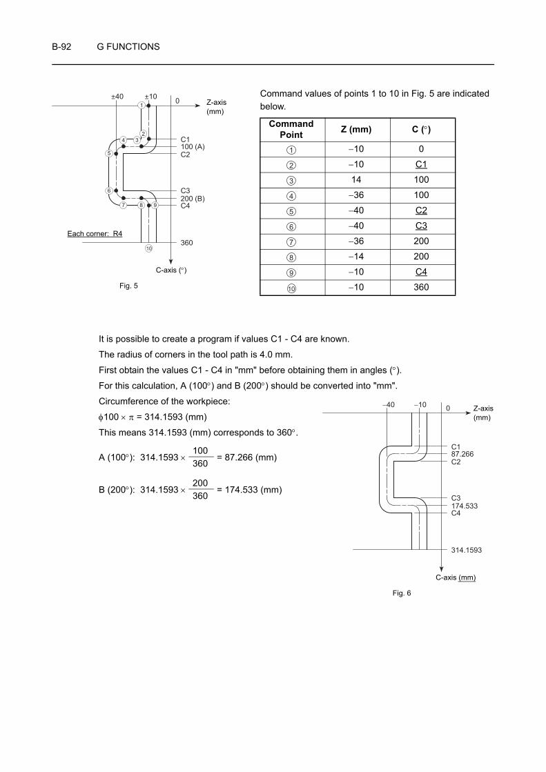
B-92 G FUNCTIONS
Command values of points 1 to 10 in Fig. 5 are indicated below.
It is possible to create a program if values C1 - C4 are known.
The radius of corners in the tool path is 4.0 mm.
First obtain the values C1 - C4 in "mm" before obtaining them in angles (°).
For this calculation, A (100°) and B (200°) should be converted into "mm".
Circumference of the workpiece:
φ100 × π = 314.1593 (mm)
This means 314.1593 (mm) corresponds to 360°.
A (100°): 314.1593 × = 87.266 (mm)
B (200°): 314.1593 × = 174.533 (mm)
CommandPoint Z (mm) C (°)
−10 0
−10 C1
14 100
−36 100
−40 C2
−40 C3
−36 200
−14 200
−10 C4
−10 360
0±10±40
C1100 (A)C2
C3200 (B)C4
360
1
10
234
5
6
7 8 9
Fig. 5
C-axis (°)
Z-axis(mm)
Each corner: R4
1
2
3
4
5
6
7
8
9
10
0−10−40
C187.266C2
C3174.533C4
314.1593
Fig. 6
C-axis (mm)
Z-axis(mm)
100360
200360
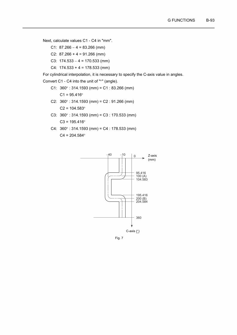
G FUNCTIONS B-93
Next, calculate values C1 - C4 in "mm".
C1: 87.266 − 4 = 83.266 (mm)
C2: 87.266 + 4 = 91.266 (mm)
C3: 174.533 − 4 = 170.533 (mm)
C4: 174.533 + 4 = 178.533 (mm)
For cylindrical interpolation, it is necessary to specify the C-axis value in angles.
Convert C1 - C4 into the unit of "°" (angle).
C1: 360° : 314.1593 (mm) = C1 : 83.266 (mm)
C1 = 95.416°
C2: 360° : 314.1593 (mm) = C2 : 91.266 (mm)
C2 = 104.583°
C3: 360° : 314.1593 (mm) = C3 : 170.533 (mm)
C3 = 195.416°
C4: 360° : 314.1593 (mm) = C4 : 178.533 (mm)
C4 = 204.584°
0−10−40
95.416100 (A)104.583
195.416200 (B)204.584
360
C-axis (°)
Fig. 7
Z-axis(mm)

B-94 G FUNCTIONS
O0001;
N1;
M45;
G28 H0;
G00 T0101;
G97 S100 M13;
X115.0 Z−10.0 S500; . . . . . . . . . . . . . . . . . . . . . . . . . . . . . . . . . . . . . . . . . . . . . . . . . . . .
G98 G01 X100.0 F50;. . . . . . . . . . . . . . . . . . . . . . . . . . . . . . . . . . . . . . . . . . . . . . . . . . . .
G19 W0 H0; . . . . . . . . . . . . . . . . . . . . . . . . . . . . . . . . . . . . . . . . . . . . . . . . . . . . . . . . . . .
G07.1(G107) C50.0; . . . . . . . . . . . . . . . . . . . . . . . . . . . . . . . . . . . . . . . . . . . . . . . . . . . . .
C95.416; . . . . . . . . . . . . . . . . . . . . . . . . . . . . . . . . . . . . . . . . . . . . . . . . . . . . . . . . . . . . . .
G02 Z−14.0 C100.0 R4.0;. . . . . . . . . . . . . . . . . . . . . . . . . . . . . . . . . . . . . . . . . . . . . . . . .
G01 Z−36.0; . . . . . . . . . . . . . . . . . . . . . . . . . . . . . . . . . . . . . . . . . . . . . . . . . . . . . . . . . . .
G03 Z−40.0 C104.583 R4.0;. . . . . . . . . . . . . . . . . . . . . . . . . . . . . . . . . . . . . . . . . . . . . . .
G01 C195.416; . . . . . . . . . . . . . . . . . . . . . . . . . . . . . . . . . . . . . . . . . . . . . . . . . . . . . . . . .
G03 Z−36.0 C200.0 R4.0;. . . . . . . . . . . . . . . . . . . . . . . . . . . . . . . . . . . . . . . . . . . . . . . . .
G01 Z−14.0; . . . . . . . . . . . . . . . . . . . . . . . . . . . . . . . . . . . . . . . . . . . . . . . . . . . . . . . . . . .
G02 Z−10.0 C204.584 R4.0;. . . . . . . . . . . . . . . . . . . . . . . . . . . . . . . . . . . . . . . . . . . . . . .
G01 C360.0; . . . . . . . . . . . . . . . . . . . . . . . . . . . . . . . . . . . . . . . . . . . . . . . . . . . . . . . . . . .
G07.1(G107) C0; . . . . . . . . . . . . . . . . . . . . . . . . . . . . . . . . . . . . . . . . . . . . . . . . . . . . . . .
X115.0;
G00 G99 X200.0 Z100.0 M05;
G18 M46;
M01;
Positioning to the point where grooving is started
Starting of the grooving
Feedrate is 50 mm/min, specified in the G98 (feed per minute) mode.
Selecting the machining plane (ZC plane)
When specifying circular command (G02 or G03) between the rotary axis (C-axis) and linear axis (Z-axis) in the cylindrical interpolation mode, it is necessary to select a plane.
If the Z- and C-axis movements are not required, specify as "G19 W0 H0;". This is necessary because Z- and C-axis commands must be specified after the G19 command.
Calling the cylindrical interpolation mode
As the diameter of the workpiece (groove bottom) is 100 mm, the cylinder radius is 50 mm.
- Machining is carried out by synchronizing spindle rotation (C-axis indexing) and Z-axis movement.
Canceling the cylindrical interpolation mode
1
2
3
4
5
6
7
8
9
10
11
12
13
14
1
2
3
4
5 13
14
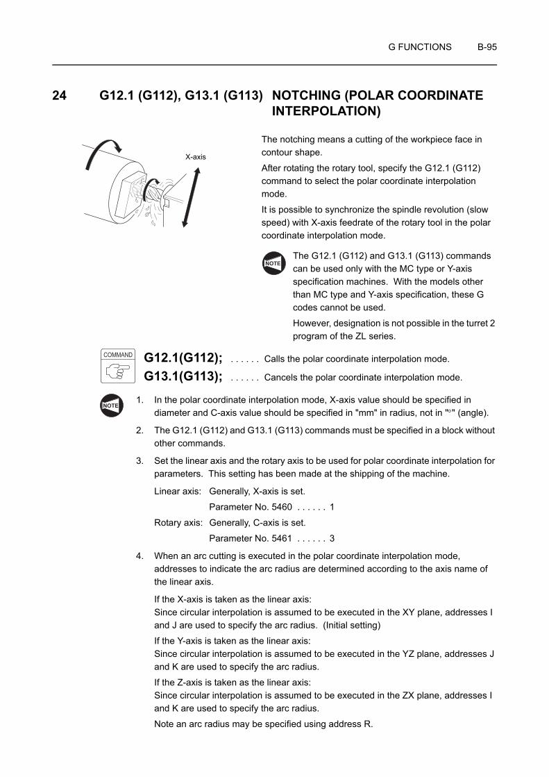
G FUNCTIONS B-95
24 G12.1 (G112), G13.1 (G113) NOTCHING (POLAR COORDINATE INTERPOLATION)
The notching means a cutting of the workpiece face in contour shape.
After rotating the rotary tool, specify the G12.1 (G112) command to select the polar coordinate interpolation mode.
It is possible to synchronize the spindle revolution (slow speed) with X-axis feedrate of the rotary tool in the polar coordinate interpolation mode.
The G12.1 (G112) and G13.1 (G113) commands can be used only with the MC type or Y-axis specification machines. With the models other than MC type and Y-axis specification, these G codes cannot be used.
However, designation is not possible in the turret 2 program of the ZL series.
G12.1(G112); . . . . . . Calls the polar coordinate interpolation mode.
G13.1(G113); . . . . . . Cancels the polar coordinate interpolation mode.
1. In the polar coordinate interpolation mode, X-axis value should be specified in diameter and C-axis value should be specified in "mm" in radius, not in "°" (angle).
2. The G12.1 (G112) and G13.1 (G113) commands must be specified in a block without other commands.
3. Set the linear axis and the rotary axis to be used for polar coordinate interpolation for parameters. This setting has been made at the shipping of the machine.
Linear axis: Generally, X-axis is set.
Parameter No. 5460 . . . . . . 1
Rotary axis: Generally, C-axis is set.
Parameter No. 5461 . . . . . . 3
4. When an arc cutting is executed in the polar coordinate interpolation mode, addresses to indicate the arc radius are determined according to the axis name of the linear axis.
If the X-axis is taken as the linear axis:Since circular interpolation is assumed to be executed in the XY plane, addresses I and J are used to specify the arc radius. (Initial setting)
If the Y-axis is taken as the linear axis:Since circular interpolation is assumed to be executed in the YZ plane, addresses J and K are used to specify the arc radius.
If the Z-axis is taken as the linear axis:Since circular interpolation is assumed to be executed in the ZX plane, addresses I and K are used to specify the arc radius.
Note an arc radius may be specified using address R.
X-axis
NOTE
COMMAND
NOTE
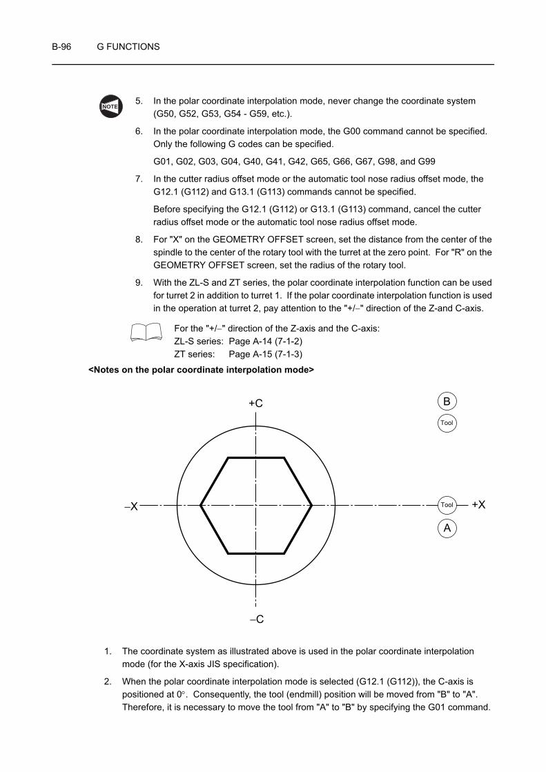
B-96 G FUNCTIONS
5. In the polar coordinate interpolation mode, never change the coordinate system (G50, G52, G53, G54 - G59, etc.).
6. In the polar coordinate interpolation mode, the G00 command cannot be specified. Only the following G codes can be specified.
G01, G02, G03, G04, G40, G41, G42, G65, G66, G67, G98, and G99
7. In the cutter radius offset mode or the automatic tool nose radius offset mode, the G12.1 (G112) and G13.1 (G113) commands cannot be specified.
Before specifying the G12.1 (G112) or G13.1 (G113) command, cancel the cutter radius offset mode or the automatic tool nose radius offset mode.
8. For "X" on the GEOMETRY OFFSET screen, set the distance from the center of the spindle to the center of the rotary tool with the turret at the zero point. For "R" on the GEOMETRY OFFSET screen, set the radius of the rotary tool.
9. With the ZL-S and ZT series, the polar coordinate interpolation function can be used for turret 2 in addition to turret 1. If the polar coordinate interpolation function is used in the operation at turret 2, pay attention to the "+/−" direction of the Z-and C-axis.
For the "+/−" direction of the Z-axis and the C-axis:ZL-S series: Page A-14 (7-1-2)ZT series: Page A-15 (7-1-3)
<Notes on the polar coordinate interpolation mode>
1. The coordinate system as illustrated above is used in the polar coordinate interpolation mode (for the X-axis JIS specification).
2. When the polar coordinate interpolation mode is selected (G12.1 (G112)), the C-axis is positioned at 0°. Consequently, the tool (endmill) position will be moved from "B" to "A". Therefore, it is necessary to move the tool from "A" to "B" by specifying the G01 command.
NOTE
+C
−C
−X +X
A
B
Tool
Tool
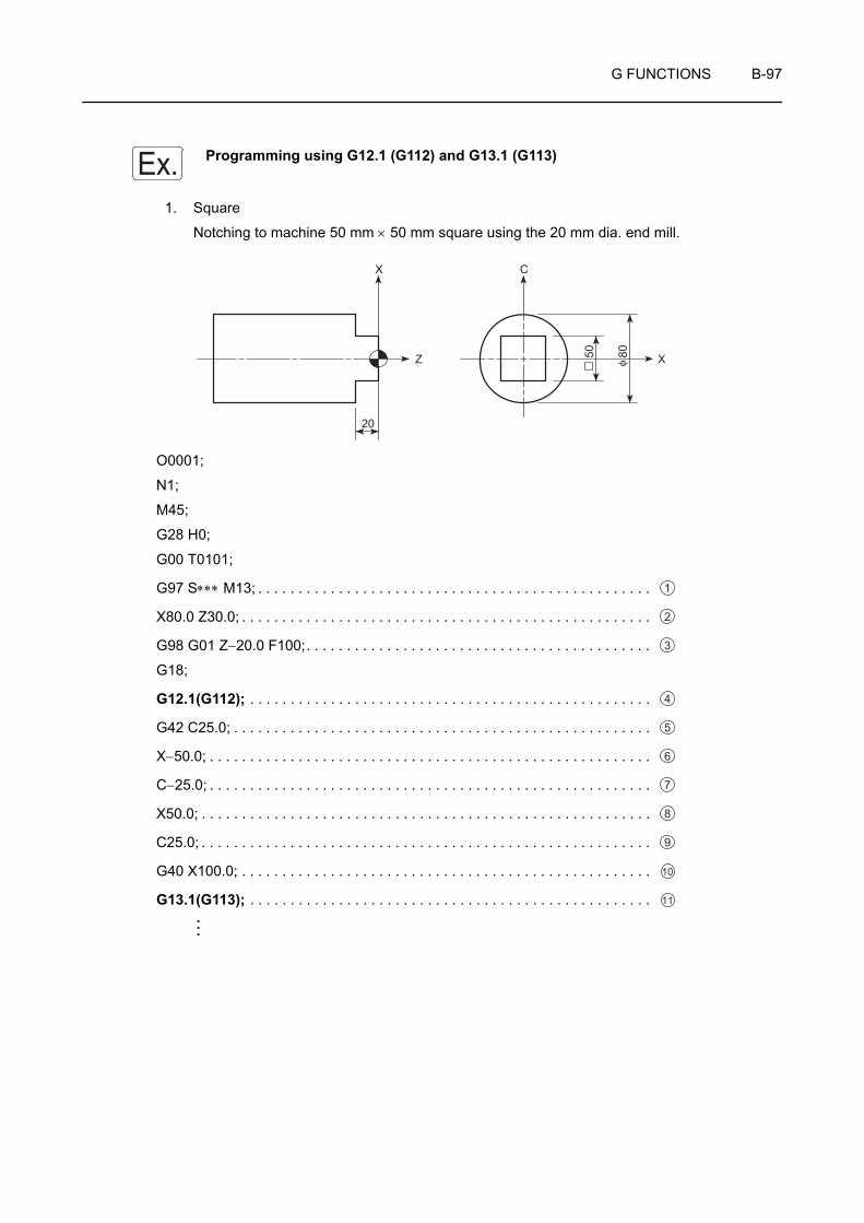
G FUNCTIONS B-97
Programming using G12.1 (G112) and G13.1 (G113)
1. Square
Notching to machine 50 mm × 50 mm square using the 20 mm dia. end mill.
O0001;
N1;
M45;
G28 H0;
G00 T0101;
G97 S∗∗∗ M13; . . . . . . . . . . . . . . . . . . . . . . . . . . . . . . . . . . . . . . . . . . . . . . . . .
X80.0 Z30.0; . . . . . . . . . . . . . . . . . . . . . . . . . . . . . . . . . . . . . . . . . . . . . . . . . . .
G98 G01 Z−20.0 F100;. . . . . . . . . . . . . . . . . . . . . . . . . . . . . . . . . . . . . . . . . . .
G18;
G12.1(G112); . . . . . . . . . . . . . . . . . . . . . . . . . . . . . . . . . . . . . . . . . . . . . . . . . .
G42 C25.0; . . . . . . . . . . . . . . . . . . . . . . . . . . . . . . . . . . . . . . . . . . . . . . . . . . . .
X−50.0; . . . . . . . . . . . . . . . . . . . . . . . . . . . . . . . . . . . . . . . . . . . . . . . . . . . . . . .
C−25.0; . . . . . . . . . . . . . . . . . . . . . . . . . . . . . . . . . . . . . . . . . . . . . . . . . . . . . . .
X50.0; . . . . . . . . . . . . . . . . . . . . . . . . . . . . . . . . . . . . . . . . . . . . . . . . . . . . . . . .
C25.0; . . . . . . . . . . . . . . . . . . . . . . . . . . . . . . . . . . . . . . . . . . . . . . . . . . . . . . . .
G40 X100.0; . . . . . . . . . . . . . . . . . . . . . . . . . . . . . . . . . . . . . . . . . . . . . . . . . . .
G13.1(G113); . . . . . . . . . . . . . . . . . . . . . . . . . . . . . . . . . . . . . . . . . . . . . . . . . .
Ex.
20
X
Z
C
X8050
φ
1
2
3
4
5
6
7
8
9
10
11
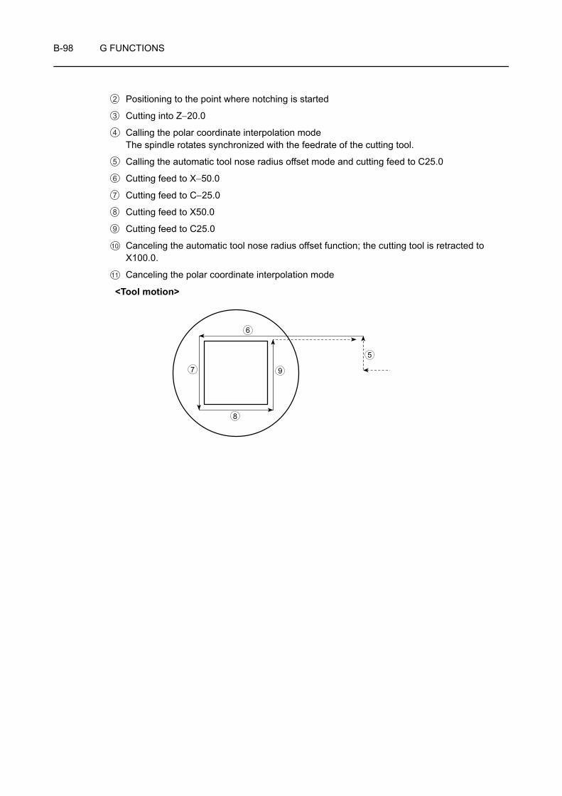
B-98 G FUNCTIONS
Positioning to the point where notching is started
Cutting into Z−20.0
Calling the polar coordinate interpolation modeThe spindle rotates synchronized with the feedrate of the cutting tool.
Calling the automatic tool nose radius offset mode and cutting feed to C25.0
Cutting feed to X−50.0
Cutting feed to C−25.0
Cutting feed to X50.0
Cutting feed to C25.0
Canceling the automatic tool nose radius offset function; the cutting tool is retracted to X100.0.
Canceling the polar coordinate interpolation mode
<Tool motion>
2
3
4
5
6
7
8
9
10
11
7 9
8
6
5
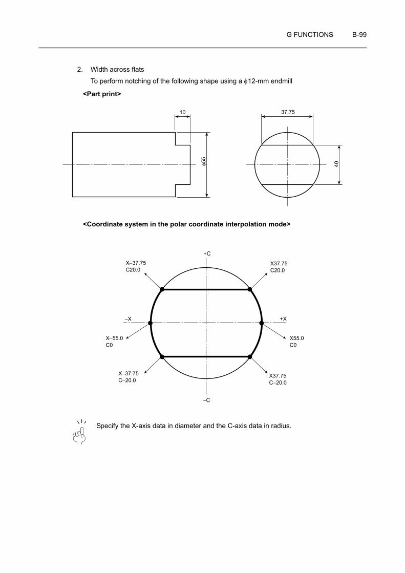
G FUNCTIONS B-99
2. Width across flats
To perform notching of the following shape using a φ12-mm endmill
<Part print>
<Coordinate system in the polar coordinate interpolation mode>
Specify the X-axis data in diameter and the C-axis data in radius.
10
40φ55
37.75
+C
−C
−X +X
X−37.75C20.0
X37.75C20.0
X55.0C0
X37.75C−20.0
X−37.75C−20.0
X−55.0C0

B-100 G FUNCTIONS
O0001;
M45;
G28 H0;
G00 T0101;
G97 S∗∗∗ M13; . . . . . . . . . . . . . . . . . . . . . . . . . . . . .
X80.0 Z10.0; . . . . . . . . . . . . . . . . . . . . . . . . . . . . . . .
G98 G01 Z−10.0 F*1; . . . . . . . . . . . . . . . . . . . . . . . .
G12.1(G112); . . . . . . . . . . . . . . . . . . . . . . . . . . . . . .
G42 G01 X60.0 F*2; . . . . . . . . . . . . . . . . . . . . . . . . .
C20.0 F*2; . . . . . . . . . . . . . . . . . . . . . . . . . . . . . . . . .
X−60.0 F*1; . . . . . . . . . . . . . . . . . . . . . . . . . . . . . . . .
C−20.0 F*2; . . . . . . . . . . . . . . . . . . . . . . . . . . . . . . . .
X60.0 F*1; . . . . . . . . . . . . . . . . . . . . . . . . . . . . . . . . .
C0 F*2; . . . . . . . . . . . . . . . . . . . . . . . . . . . . . . . . . . .
G40 X80.0; . . . . . . . . . . . . . . . . . . . . . . . . . . . . . . . .
G13.1(G113); . . . . . . . . . . . . . . . . . . . . . . . . . . . . . .G00 Z10.0;
X200.0 Z200.0 M05;
M46;
M30;
Specify the cutting feedrate for "*1" and a feedrate higher than "*1" for "*2" (because the G00 command cannot be used in the polar coordinate interpolation mode).
Cutting to Z−10.0
Calling the polar coordinate interpolation mode
Calling the automatic tool nose radius offset mode
Moving to X60.0 at a higher feedrate
Moving to C20.0 at a higher feedrate
Cutting feed to X−60.0
Moving to C−20.0 at a higher feedrate
Cutting feed to X60.0
Moving to C0 at a higher feedrate
Canceling the automatic tool nose radius offset mode
Retracting the tool to X80.0
Canceling the polar coordinate interpolation mode
1
2
Polar coordinate interpolation mode
3
4
5
6
7
8
9
10
11
12
NOTE
+C
−C
−X +X
10
11
5
7
6
8
9
<Tool motion>3
4
5
6
7
8
9
10
11
12
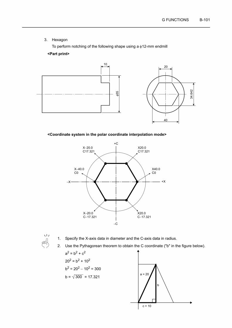
G FUNCTIONS B-101
3. Hexagon
To perform notching of the following shape using a φ12-mm endmill
<Part print>
<Coordinate system in the polar coordinate interpolation mode>
1. Specify the X-axis data in diameter and the C-axis data in radius.
2. Use the Pythagorean theorem to obtain the C coordinate ("b" in the figure below).
a2 = b2 + c2
202 = b2 + 102
b2 = 202 − 102 = 300
b = = 17.321
10
φ55
20
40
34.6
42
+C
−C
−X +X
X−20.0C17.321
X−40.0C0
X−20.0C−17.321
X20.0C17.321
X40.0C0
X20.0C−17.321
c = 10
a = 20
b
300
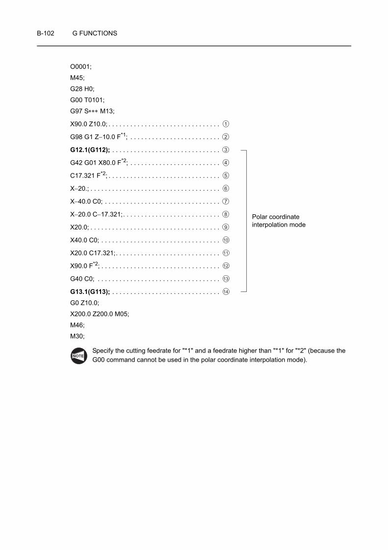
B-102 G FUNCTIONS
O0001;
M45;
G28 H0;
G00 T0101;
G97 S∗∗∗ M13;
X90.0 Z10.0; . . . . . . . . . . . . . . . . . . . . . . . . . . . . . . .
G98 G1 Z−10.0 F*1; . . . . . . . . . . . . . . . . . . . . . . . . .
G12.1(G112); . . . . . . . . . . . . . . . . . . . . . . . . . . . . . .
G42 G01 X80.0 F*2; . . . . . . . . . . . . . . . . . . . . . . . . .
C17.321 F*2; . . . . . . . . . . . . . . . . . . . . . . . . . . . . . . .
X−20.; . . . . . . . . . . . . . . . . . . . . . . . . . . . . . . . . . . . .
X−40.0 C0; . . . . . . . . . . . . . . . . . . . . . . . . . . . . . . . .
X−20.0 C−17.321;. . . . . . . . . . . . . . . . . . . . . . . . . . .
X20.0; . . . . . . . . . . . . . . . . . . . . . . . . . . . . . . . . . . . .
X40.0 C0; . . . . . . . . . . . . . . . . . . . . . . . . . . . . . . . . .
X20.0 C17.321;. . . . . . . . . . . . . . . . . . . . . . . . . . . . .
X90.0 F*2; . . . . . . . . . . . . . . . . . . . . . . . . . . . . . . . . .
G40 C0; . . . . . . . . . . . . . . . . . . . . . . . . . . . . . . . . . .
G13.1(G113); . . . . . . . . . . . . . . . . . . . . . . . . . . . . . .G0 Z10.0;
X200.0 Z200.0 M05;
M46;
M30;
Specify the cutting feedrate for "*1" and a feedrate higher than "*1" for "*2" (because the G00 command cannot be used in the polar coordinate interpolation mode).
1
Polar coordinate interpolation mode
2
3
4
5
6
7
8
9
10
11
12
13
14
NOTE
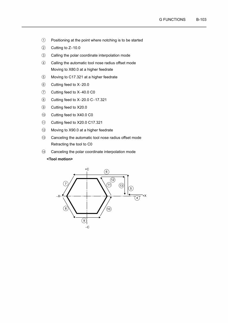
G FUNCTIONS B-103
Positioning at the point where notching is to be started
Cutting to Z−10.0
Calling the polar coordinate interpolation mode
Calling the automatic tool nose radius offset mode
Moving to X80.0 at a higher feedrate
Moving to C17.321 at a higher feedrate
Cutting feed to X−20.0
Cutting feed to X−40.0 C0
Cutting feed to X−20.0 C−17.321
Cutting feed to X20.0
Cutting feed to X40.0 C0
Cutting feed to X20.0 C17.321
Moving to X90.0 at a higher feedrate
Canceling the automatic tool nose radius offset mode
Retracting the tool to C0
Canceling the polar coordinate interpolation mode
<Tool motion>
1
2
3
4
5
6
7
8
9
10
11
12
13
14
+C
−C
−X +X
10
115
7
6
8
4
9
12
13

B-104 G FUNCTIONS
25 G479 TAILSTOCK CONNECT
If G479 V_ is specified in center-work operation, the Z-axis (saddle) automatically moves to the tailstock connection position, and after the tailstock is connected to the saddle, the saddle moves to the specified positioning point (V_).
The G479 command can be used only in the turret 1 program of ZL series.
G479 V_ ;• G479 . . . . . . . Calls the tailstock connect mode.
• V. . . . . . . . . . . Specifies the tailstock positioning point (coordinate value in the machine coordinate system).
1. Specify the G479 command independently in a block without other commands.
2. Specify the coordinate value of the tailstock positioning point (V) in the machine coordinate system.
3. For address V, specify a numeric value with a decimal point.
4. If address V is omitted, the Z-axis only travels to the tailstock/saddle connection position. Therefore, the commands for unclamping the tailstock body, positioning it at the required position, and clamping the tailstock body must be given.
G479;. . . . . . . . . . . . . Moving the Z-axis to the tailstock/saddle connection position
M79; . . . . . . . . . . . . . Unclamping the tailstock body
G00 Z_ ; . . . . . . . . . . Positioning the tailstock body at the required position
M78; . . . . . . . . . . . . . Clamping the tailstock body
5. To execute the G479 command, the following conditions must be satisfied.
• The spindle or the rotary tool is stopped.
• The turret head index has completed.
• The tailstock spindle is in the IN position.
During setup operation, it is recommended to record the position(s) where the tailstock should be positioned and the position where the tailstock should be returned after the completion of machining. The coordinate values must be specified in the machine coordinate system.
NOTE
COMMAND
NOTE

G FUNCTIONS B-105
<Operation flow chart for G479>
By specifying a V command that indicates the required tailstock positioning point, following G479, a series of tailstock positioning operation is executed as indicated below by the macro program.
Positioning of the saddle to the tailstock connection position
<Macro program>
Execution of M79 (tailstock body unclamp; joint pin extends from the tailstock body to connect with the saddle)
V_ (positioning of the tailstock at the position specified by V_ )
Execution of M78 (tailstock body clamp; joint pin extracts from the saddle to release the tailstock body from the saddle)
G479 V_ ;
B-106 G FUNCTIONS
Programming using G479
O0001;
N1;
G479 V_ ; . . . . . . . . . . . . . . . . . . . . . . . Moving the tailstock to the position specified by V_ (machine coordinate value)
M25; . . . . . . . . . . . . . . . . . . . . . . . . . . . The tailstock spindle moves OUT to hold the workpiece by the tailstock spindle center.
G04 U_ ; . . . . . . . . . . . . . . . . . . . . . . . . Calling for dwell to allow positive support of the workpiece by the tailstock spindle center
G50 S1000;
G00 T0101;
G96 S100 M03;
Machining program
G28 U0; . . . . . . . . . . . . . . . . . . . . . . . . Machine zero return of X-axis to avoid interference with the tailstock
M05;
M26; . . . . . . . . . . . . . . . . . . . . . . . . . . . The tailstock spindle moves IN.
G04 U_ ; . . . . . . . . . . . . . . . . . . . . . . . . Calling for dwell to allow tailstock spindle to correctly extract into the tailstock body
G479 V_ ; . . . . . . . . . . . . . . . . . . . . . . Moving the tailstock to the previously located position, specified by V_ (machine coordinate value)
Ex.
G FUNCTIONS B-107
26 G65 MACRO CALL (ONE-SHOT)
When G65 is specified, the custom macro specified at address P is called.
Data (arguments) to be passed to the custom macro program can be assigned.
"G65" must be specified before any argument.
The G65 command can be specified only when the custom macro (option) is installed.
Refer to the instruction manual supplied by the NC manufacturer for details.
G65 P L_ <Argument assignment>;• P . . . . . . . . . . . . . . . . . . . . . Macro program number to be called
Specify M99 in the called program to return to the previous program.
• L . . . . . . . . . . . . . . . . . . . . . Specifies the number of program calls.(If omitted, the call is repeated once.)
Specify a number from 1 to 9999.
• <Argument assignment> . . . Data passed to the macro
By using argument assignment, values can be substituted for the corresponding local variables.
26-1 Argument Assignment
The argument assignment has 2 types, I and II. The type of argument assignment is determined automatically according to the addresses used.
NOTE
COMMAND

B-108 G FUNCTIONS
26-1-1 Argument Assignment I
1. Addresses G, L, N, O and P cannot be used in the argument.
2. Unnecessary addresses can be omitted. Local variables corresponding to an omitted address are set to null.
3. Addresses do not need to be specified in alphabetical order. The addresses conform to word address format.
However, I, J, and K need to be specified in alphabetical order.
26-1-2 Argument Assignment II
In the argument assignment II format, addresses A, B and C are used only once and addresses I, J and K are used in a set up to 10 times. This format is used to pass values such as 3-dimensional coordinate values as the argument.
The subscripts of I, J and K indicating the order of argument assignment are not written in the actual program.
Address Local Variable Number Address Local Variable
Number Address Local Variable Number
A #1 I #4 T #20
B #2 J #5 U #21
C #3 K #6 V #22
D #7 M #13 W #23
E #8 Q #17 X #24
F #9 R #18 Y #25
H #11 S #19 Z #26
Address Local Variable Number Address Local Variable
Number Address Local Variable Number
A #1 K3 #12 J7 #23
B #2 I4 #13 K7 #24
C #3 J4 #14 I8 #25
I1 #4 K4 #15 J8 #26
J1 #5 I5 #16 K8 #27
K1 #6 J5 #17 I9 #28
I2 #7 K5 #18 J9 #29
J2 #8 I6 #19 K9 #30
K2 #9 J6 #20 I10 #31
I3 #10 K6 #21 J10 #32
J3 #11 I7 #22 K10 #33
NOTE
NOTE

G FUNCTIONS B-109
26-1-3 Mixture of Argument Assignments I and II
If both argument assignments I and II are specified, the type of argument assignment specified later takes precedence.
When both "I4.0" and "D5.0" are commanded as in the argument for variable #7 in this example, the latter, "D5.0", is valid.
The units used for argument data passed without a decimal point correspond to the least input increment of each address.
Ex.
G65 A1.0 B2.0 I-3.0 I4.0 D5.0 P1000;
<Variables>#1: 1.0#2: 2.0#3#4: -3.0#5#6#7: 4.0 5.0
NOTE

B-110 G FUNCTIONS
26-2 Nesting Level for Calls
Macro program calls (G65 and G66) can be nested to a depth of up to 4 levels. Subprogram calls can be nested to a depth of up to 8 levels including macro calls.
For details on subprogram calls, refer to page C-76 (23)
Programming using G65
Specify Z or W for the depth of a hole, K for the depth of a cut, and F for the cutting feedrate to drill the hole.
<Program calling a macro program>
O0002;
G00 T0101;
G97 S1000 M03;
G00 X0 Z200.0;
G65 P9100 Z50.0 K20.0 F0.3; . . . . . . . . . . . Macro program call
G00 X100.0 Z200.0 M05;
M30;
Ex.
Z W
K
Cutting Feed
Rapid Traverse
Z: Hole Depth (Absolute Programming)
U: Hole Depth (Incremental Programming)
K: Cutting Amount per CycleF: Cutting Feedrate

G FUNCTIONS B-111
<Macro program (program to be called)>
O9100;
#1=0; . . . . . . . . . . . . . . . . . . . . . . . . . . . . . . . Clears the data for the depth of the current hole.
#2=0; . . . . . . . . . . . . . . . . . . . . . . . . . . . . . . . Clears the data for the depth of the preceding hole.
IF [#23 NE #0] GOTO 1; . . . . . . . . . . . . . . . . In case of incremental programming, jumps to N1.
IF [#26 EQ #0] GOTO 8; . . . . . . . . . . . . . . . . If neither Z nor W is specified, an error occurs.
#23=#5002-#26; . . . . . . . . . . . . . . . . . . . . . . Calculates the depth of the hole.
N1 #1=#1+#6; . . . . . . . . . . . . . . . . . . . . . . . . Calculates the depth of the current hole.
IF [#1 LE #23] GOTO 2; . . . . . . . . . . . . . . . . . If overcut occurs, jumps to N2.
#1=#23; . . . . . . . . . . . . . . . . . . . . . . . . . . . . . Clamps at the depth of the current hole.
N2 G00 W-#2; . . . . . . . . . . . . . . . . . . . . . . . . Moves the tool to the previous depth at a rapid traverse rate.
G01 W-[#1-#2] F#9; . . . . . . . . . . . . . . . . . . . . Drills the hole.
G00 W#1; . . . . . . . . . . . . . . . . . . . . . . . . . . . . Returns the tool to the drilling start point.
IF [#1 GE #23] GOTO 9; . . . . . . . . . . . . . . . . Checks whether drilling is completed.
#2=#1; . . . . . . . . . . . . . . . . . . . . . . . . . . . . . . Stores the depth of the current hole.
GOTO 1;
N9 M99; . . . . . . . . . . . . . . . . . . . . . . . . . . . . . Returns to the program that called the macro program.
N8 #3000=1 (NO Z OR U COMMAND); . . . . . Issues an alarm.
For details on macro statements, refer to the instruction manual supplied by the NC manufacturer.
B-112 G FUNCTIONS
27 G66, G67 MACRO MODAL CALL (EVERY AXIS TRAVEL COMMAND), CANCEL
<G66>
Once G66 (macro modal call) is specified, a macro program is called every time a block containing a travel command is executed. This continues until G67 is specified to cancel the modal macro call.
1. The G66 and G67 commands can be specified only when the custom macro (option) is installed.
2. In a G66 block, no macro program is called.
Local variables (arguments) are set, however.
3. No macro program is called in a block containing commands for compensation functions but no travel commands.
4. The local variables (arguments) are set only in the block specifying the G66 command. Note that local variables are not set each time a modal call is performed.
G66 P L_ <Argument assignment>;G67;
• P . . . . . . . . . . . . . . . . . . . . . Macro program number to be called
Specify M99 in the called program to return to the previous program.
• L . . . . . . . . . . . . . . . . . . . . . Number of macro program calls (If omitted, the call is repeated once.)
Programmable range: 1 - 9999
• <Argument assignment> . . . Data passed to the macro
The argument assignment is the same as G65.
Page B-107 (26-1)
• G67 . . . . . . . . . . . . . . . . . . . Macro modal call cancel
The G66 commands must be specified before any arguments.
For details on the nesting level of macro program calls, refer to Page B-110 (26-2)
NOTE
COMMAND
NOTE

G FUNCTIONS B-113
Programming using G66
This program cuts a groove at the specified positions.
<Program calling a macro program with G66>
O0003;
G00 T0202;
G97 S1000 M03;
G00 X100.0 Z200.0;
G66 P9110 U5.0 F0.5; . . . . . . . . . . . . . . . . . . Assigns 5.0 to #21 and 0.5 to #9 of macro program O9110 and calls the macro program.
G00 X60.0 Z80.0; . . . . . . . . . . . . . . . . . . . . . Executes macro program O9110 at the Z80.0 position.
Z50.0; . . . . . . . . . . . . . . . . . . . . . . . . . . . . . . . Executes macro program O9110 at the Z50.0 position.
Z30.0; . . . . . . . . . . . . . . . . . . . . . . . . . . . . . . . Executes macro program O9110 at the Z30.0 position.
G67; . . . . . . . . . . . . . . . . . . . . . . . . . . . . . . . . Cancels the macro call
G00 X100.0 Z200.0 M05;
M30;
<Macro program (program to be called)>
O9110;
G01 U-#21 F#9; . . . . . . . . . . . . . . . . . . . . . . . Cuts the workpiece.
G00 U#21; . . . . . . . . . . . . . . . . . . . . . . . . . . . Retracts the tool.
M99; . . . . . . . . . . . . . . . . . . . . . . . . . . . . . . . . Ends the macro program
Ex.
U
U: Groove Depth (Incremental Programming)F: Cutting Feedrate for Groove Cutting

B-114 G FUNCTIONS
28 G68, G69 BALANCE CUT
When machining a small-diameter shaft workpiece, it is possible to machine the workpiece by applying cutting tools at both sides of the workpiece simultaneously to prevent the workpiece from deflection during machining, thereby finishing it accurately. If operations of both turrets are not synchronized, however, the workpiece will vibrate and cannot be finished accurately.
By specifying the G68 command in the programs of both turrets, it is possible to synchronize the start of axis movements of both turrets. Thus, the workpiece can be machined accurately without vibration.
The G68 and G69 commands can be specified only for the ZL, ZL-S and ZT series.
By machining a workpiece in the balance cut mode, it is possible to double a feedrate command compared to conventional machining.
G68; . . . . . . . . . . . Calls the balance cut mode.
G69; . . . . . . . . . . . Cancels the balance cut mode.
1. The balance cut command controls only the start of axis movement of both turrets so that both turrets start moving at the same time, but it does not guarantee the operation synchronization after the start of axis movement. To synchronize the axis movement of both turrets, specify the same program for them.
2. Specify the G68 and G69 commands independently without other commands in the same block. If they are specified with other commands in the same block, an alarm message (No. 163) is displayed on the screen.
3. When the G68 or G69 command is specified in either of the program, its execution is suspended until the same G command is read in the other program. If a cutting feed command is specified in either of the programs in the balance cut mode, neither of the turrets moves until a cutting feed command specified in the other program is read.
4. In the balance cut mode, balance cut is not executed for rapid feed commands.
5. If thread cutting is executed in the balance cut cancel mode for the thread which has been cut in the balance cut mode, the thread cutting start position will be shifted.
6. If axis feed is restarted after suspending it during the execution of balance cut, balance cut is not executed until a cutting feed command appears in both of the programs.
WARNING In the balance cut mode, balance cut is executed when programs of both turrets include axis movement commands. Therefore, balance cut is executed even if different axes are specified in two programs. It is also executed for automatic nose-R offset command and tool wear offset commands. Therefore, different axes should not be specified in both programs carelessly, otherwise, the workpiece or the cutting tool will fly out of the machine, causing serious injuries or damage to the machine.
NOTE
COMMAND
NOTE

G FUNCTIONS B-115
7. The machine may stop temporarily at the start of axis feed in the balance cut mode since the start of axis movement of both turrets is synchronized at the start of blocks including an axis movement command.
8. Balance cut is not executed in the state both the dry run function and the machine lock function are valid.
9. The balance cut mode is canceled when the (RESET) key is pressed.
Programming using G68 and G69
<Turret 1> <Turret 2>O0001; O0001;N1; N1;G50 S2000;G00 T0101; G00 T0505;G96 S130 M03; . . . . . . . . . . . . . . . . . Starting the spindle in the
normal direction at
cutting speed of 130 m/min
Z5.0; Z5.0;X80.5 M08; X80.5 M08;Z1.0; Z1.0;G68;. . . . . . . . . . . . . . . . . . . . . . . . . . Calling the balance cut
mode
G68; . . . . . . . . . . . . . . . . . . . . . . . . . . Calling the balance cut
mode
G71 U3.5 R0.5; G71 U3.5 R0.5;G71 P10 Q20 U0.4 W0.1 F0.5; G71 P10 Q20 U0.4 W0.1 F0.5;N10 G00 X55.064; N10 G00 X55.064;G01 X60.0 Z−1.468; G01 X60.0 Z−1.468;Z−300.0; Z−300.0;X65.064; X65.064;X70.0 Z−302.468; X70.0 Z−302.468;Z−450.0; Z−450.0;X78.064; X78.064;N20 X80.5 Z−451.218; N20 X80.5 Z−451.218;G69;. . . . . . . . . . . . . . . . . . . . . . . . . . Canceling the balance
cut mode
G69; . . . . . . . . . . . . . . . . . . . . . . . . . . Canceling the balance
cut mode
G00 X250.0; G00 X250.0;M01; M01;
NOTE
RESET
Ex.
. . . . Executing balance cut in
rough O.D. turning cycleFeedrate: 0.5 mm/rev
. . . . Executing balance cut in
rough O.D. turning cycleFeedrate: 0.5 mm/rev

B-116 G FUNCTIONS
29 G68.1, G69.1 3D COORDINATE CONVERSION
By using the G68.1 command, it is possible to execute coordinate conversion for the program shape, created in the 3D coordinate system, around an optional axis.
The 3D coordinate conversion function is valid when executing machining by using an angle holder.
By using the program created assuming that machining is executed on the ZX plane, the programmed machining can be executed on the plane after rotation by converting the coordinate system by specifying the center of rotation, the direction of the center axis of rotation, and the angle of rotation.
3D synchronized tapping is possible by specifying "M329 G84" or "M329 G88" in the 3D coordinate conversion mode.
For the procedure of specifying "M329 G84": Page I-34 (5)For the procedure of specifying "M329 G88": Page I-61 (9)
<3D coordinate conversion>
T0; . . . . . . . . . . . . Tool offset function cancel
G68.1 X_ Y_ Z_ I_ J_ K_ R_ ;T_ ; . . . . . . . . . . . Tool indexing/offset command
<3D coordinate conversion cancel>
T0; . . . . . . . . . . . . Tool offset function cancel
G69.1;• X, Y, Z. . . . . . . Specifies the coordinate values of the center of rotation
(absolute value).
• I, J, K . . . . . . . Specifies the direction of the axis of center of rotation.
• R . . . . . . . . . . Specifies the angle of rotation.
To set the tool infeed direction of a hole machining tool in the -Z direction, specify the commands as shown below.
<3D coordinate conversion>
T0; . . . . . . . . . . . . Tool offset function cancel
G68.1 X_ Y_ Z_ I0 J1 K0 R_ ;T_ ; . . . . . . . . . . . Tool indexing/offset command
<3D coordinate conversion cancel>
T0; . . . . . . . . . . . . Tool offset function cancel
G69.1;• X, Y, Z. . . . . . . Specifies the coordinate values of the center of rotation
(absolute value).
• R . . . . . . . . . . Angle holder inclination angle
COMMAND
COMMAND

G FUNCTIONS B-117
Before specifying the G68.1 or G69.1 command, cancel the tool offset function. If these G commands are executed without canceling the tool offset function, the coordinate system is shifted during the execution of the G68.1 or G69.1 command, moving the tool spindle in an unexpected direction. This causes interference of the tool, the tool holder and the tool spindle with the workpiece, the chuck, the fixture and the tailstock (tailstock specification), resulting in damage to the machine.
T0; . . . . . . . . . . . . . . . . . . . . . . . . . . . Tool offset function cancel
G68.1 X_ Y_ Z_ I_ J_ K_ R_ ;. . . . . . Calling the 3D coordinate conversation
T_ ; . . . . . . . . . . . . . . . . . . . . . . . . . . Tool indexing/offset command
T0; . . . . . . . . . . . . . . . . . . . . . . . . . . . Tool offset function cancel
G69.1; . . . . . . . . . . . . . . . . . . . . . . . . Canceling the 3D coordinate conversation
1. The 3D coordinate conversion command is not canceled even when the
(RESET) key at the operation panel is pressed. To cancel the 3D coordinate conversion mode, execute the following commands in the MDI mode. Note that these commands must be executed block by block.T0;G69.1;
2. The block which contains the G68.1 command must not contain other G codes. The G69.1 command must be specified in a block without other commands.
3. When the G68.1 command is specified, I, J, K, and R must be specified in the same block. An alarm message (No. 5044) is displayed on the screen if I, J, K, and R are not specified in the block containing the G68.1 command or if the values of I, J, and K are all "0".
4. If manual operation is executed by interrupting automatic operation in the 3D coordinate conversion mode, the 3D coordinate conversion is not executed for the amount the axis has been moved manually.
5. The 3D coordinate conversion is not executed for the positioning executed mechanically, such as G28, G30, and G53 command.
6. Do not specify the G68.1 command three or more times consecutively. If it is specified three times or more consecutively, an alarm message (No. 5043) is displayed on the screen.
7. The cutter radius offset command (G40, G41, G42), tool offset command and the hole machining canned cycle command (G80 - G89) must be specified in blocks between G68.1 and G69.1.Note that the G69.1 command must not be specified in a block with the G40 or G80 command.
8. In the 3D coordinate conversion mode, following operation is not allowed.
• Manual zero return operation
CAUTION
NOTERESET

B-118 G FUNCTIONS
9. The G codes which can be specified in the 3D coordinate conversion mode are indicated below.
• G00 . . . . . . . . . . . . Positioning
• G01 . . . . . . . . . . . . Linear interpolation
• G02 . . . . . . . . . . . . Circular interpolation, CW (clockwise)
• G03 . . . . . . . . . . . . Circular interpolation, CCW (counterclockwise)
• G04 . . . . . . . . . . . . Dwell
• G10 . . . . . . . . . . . . Data setting
• G17 . . . . . . . . . . . . XpYp plane
• G18 . . . . . . . . . . . . ZpXp plane
• G19 . . . . . . . . . . . . YpZp plane
• G28 . . . . . . . . . . . . Automatic zero return
• G30 . . . . . . . . . . . . Second/third, fourth zero return
• G40 . . . . . . . . . . . . Cutter radius offset cancel
• G41 . . . . . . . . . . . . Cutter radius offset, left
• G42 . . . . . . . . . . . . Cutter radius offset, right
• G53 . . . . . . . . . . . . Machine coordinate system setting
• G65 . . . . . . . . . . . . Macro call
• G66 . . . . . . . . . . . . Macro modal call
• G67 . . . . . . . . . . . . Macro modal call cancel
• G80 . . . . . . . . . . . . Hole machining canned cycle cancel
• G83 . . . . . . . . . . . . Face drilling cycle
• G83.5 . . . . . . . . . . . Face high-speed deep drilling cycle
• G83.6 . . . . . . . . . . . Face deep drilling cycle
• G84 . . . . . . . . . . . . Face tapping cycle
• G85 . . . . . . . . . . . . Face boring cycle
• G87 . . . . . . . . . . . . Side drilling cycle
• G87.5 . . . . . . . . . . . Side high-speed deep drilling cycle
• G87.6 . . . . . . . . . . . Side deep drilling cycle
• G88 . . . . . . . . . . . . Side tapping cycle
• G89 . . . . . . . . . . . . Side boring cycle
• G98 . . . . . . . . . . . . Feed per minute mode
• G99 . . . . . . . . . . . . Feed per revolution mode
NOTE
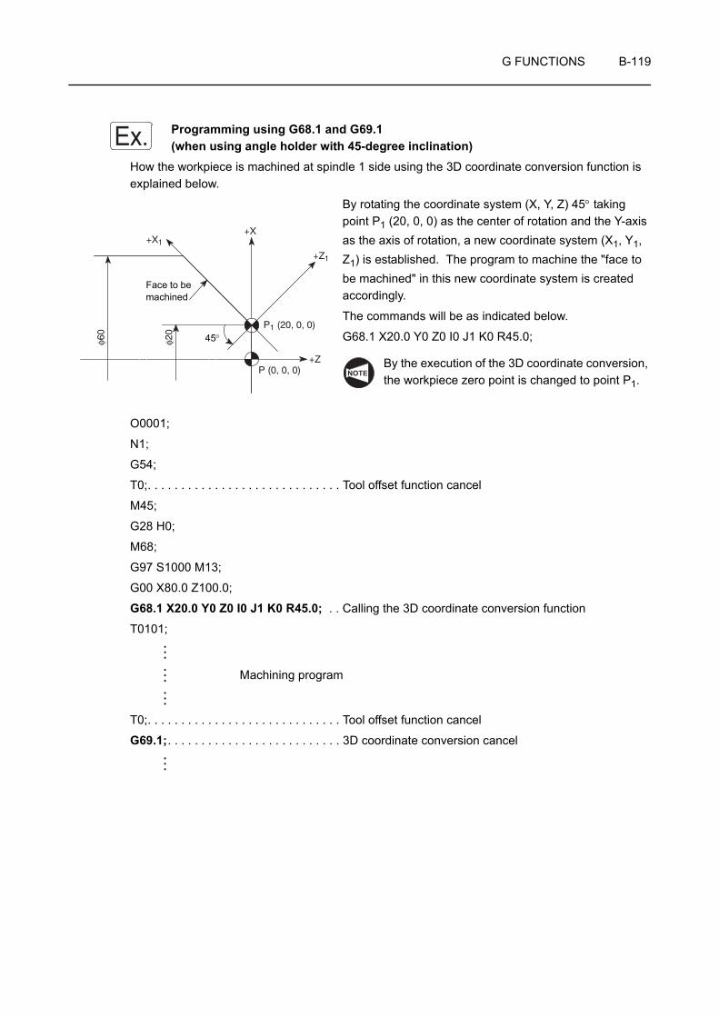
G FUNCTIONS B-119
Programming using G68.1 and G69.1 (when using angle holder with 45-degree inclination)
How the workpiece is machined at spindle 1 side using the 3D coordinate conversion function is explained below.
By rotating the coordinate system (X, Y, Z) 45° taking point P1 (20, 0, 0) as the center of rotation and the Y-axis as the axis of rotation, a new coordinate system (X1, Y1, Z1) is established. The program to machine the "face to be machined" in this new coordinate system is created accordingly.
The commands will be as indicated below.
G68.1 X20.0 Y0 Z0 I0 J1 K0 R45.0;
By the execution of the 3D coordinate conversion, the workpiece zero point is changed to point P1.
O0001;
N1;
G54;
T0;. . . . . . . . . . . . . . . . . . . . . . . . . . . . . Tool offset function cancel
M45;
G28 H0;
M68;
G97 S1000 M13;
G00 X80.0 Z100.0;
G68.1 X20.0 Y0 Z0 I0 J1 K0 R45.0; . . Calling the 3D coordinate conversion function
T0101;
Machining program
T0;. . . . . . . . . . . . . . . . . . . . . . . . . . . . . Tool offset function cancel
G69.1;. . . . . . . . . . . . . . . . . . . . . . . . . . 3D coordinate conversion cancel
Ex.
+X
+Z
+Z1
P1 (20, 0, 0)
P (0, 0, 0)
φ20
φ60
�
+X1
45°
Face to be machined
NOTE
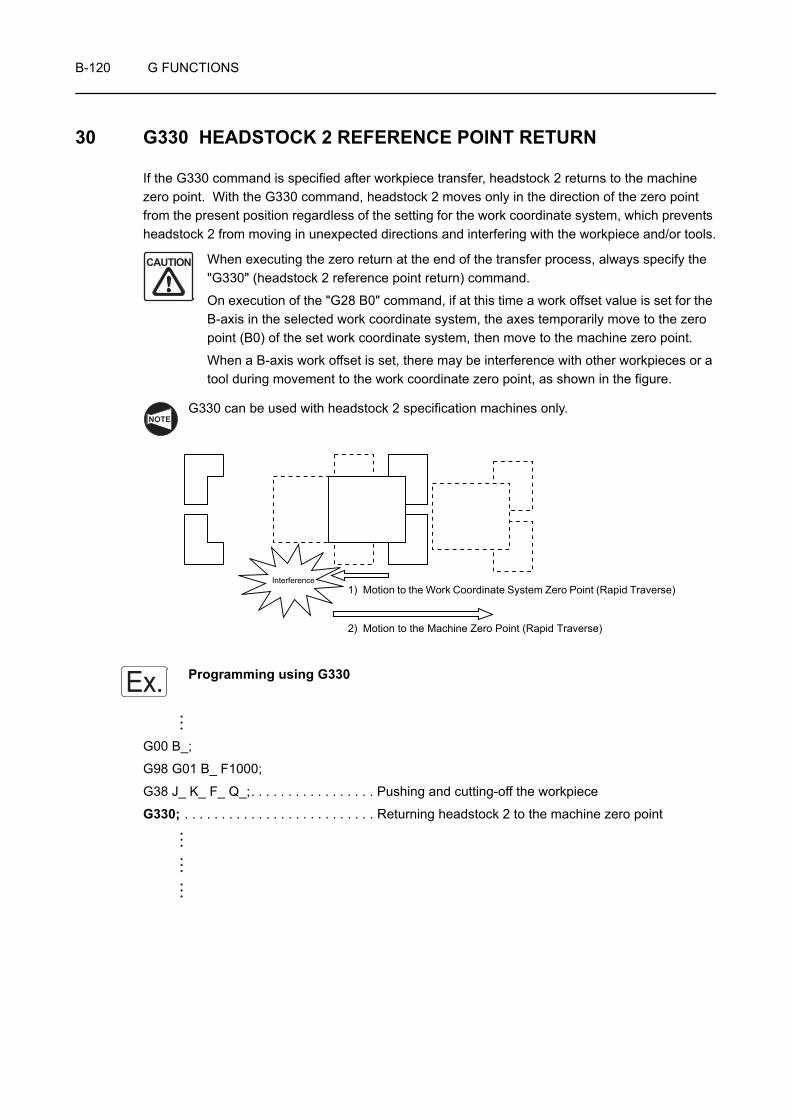
B-120 G FUNCTIONS
30 G330 HEADSTOCK 2 REFERENCE POINT RETURN
If the G330 command is specified after workpiece transfer, headstock 2 returns to the machine zero point. With the G330 command, headstock 2 moves only in the direction of the zero point from the present position regardless of the setting for the work coordinate system, which prevents headstock 2 from moving in unexpected directions and interfering with the workpiece and/or tools.
When executing the zero return at the end of the transfer process, always specify the "G330" (headstock 2 reference point return) command.
On execution of the "G28 B0" command, if at this time a work offset value is set for the B-axis in the selected work coordinate system, the axes temporarily move to the zero point (B0) of the set work coordinate system, then move to the machine zero point.
When a B-axis work offset is set, there may be interference with other workpieces or a tool during movement to the work coordinate zero point, as shown in the figure.
G330 can be used with headstock 2 specification machines only.
Programming using G330
G00 B_;
G98 G01 B_ F1000;
G38 J_ K_ F_ Q_;. . . . . . . . . . . . . . . . . Pushing and cutting-off the workpiece
G330; . . . . . . . . . . . . . . . . . . . . . . . . . . Returning headstock 2 to the machine zero point
CAUTION
NOTE
Interference1) Motion to the Work Coordinate System Zero Point (Rapid Traverse)
2) Motion to the Machine Zero Point (Rapid Traverse)
Ex.

APPENDIX B-1
APPENDIX 1 WORKPIECE TRANSFER
To continuously carry out the first process and second process in a single set up, the workpiece for which the first process has been finished must be passed to chuck 2 where the second process is carried out.
The operation is called "workpiece transfer".
To transfer a workpiece from chuck 1 to chuck 2, it is necessary to move spindle 2 (B-axis) to the workpiece transfer position.
With the ZL-S and ZT series machines, when moving spindle 2 (B-axis), move the turret 1 to the position where interference will not occur between spindle 2 and turret 1. If spindle 2 is moved carelessly, interference will occur with turret 1, which could cause damage to the machine.
1. Workpiece transfer is possible only by the ZL-S or ZT series machines.
2. With the ZL-S and ZT series machines, index No. 1 tool in turret 2 and return the X-axis to the machine zero point before executing the workpiece transfer operation.
If turret 2 is not indexed to No. 1 position or if the X-axis is not at the machine zero point, workpiece transfer operation is not possible.
For the procedure of setting a work coordinate system: OPERATION MANUAL separately provided
CAUTION
NOTE
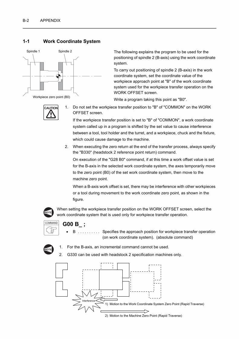
B-2 APPENDIX
1-1 Work Coordinate System
The following explains the program to be used for the positioning of spindle 2 (B-axis) using the work coordinate system.
To carry out positioning of spindle 2 (B-axis) in the work coordinate system, set the coordinate value of the workpiece approach point at "B" of the work coordinate system used for the workpiece transfer operation on the WORK OFFSET screen.
Write a program taking this point as "B0".
1. Do not set the workpiece transfer position to "B" of "COMMON" on the WORK OFFSET screen.
If the workpiece transfer position is set to "B" of "COMMON", a work coordinate system called up in a program is shifted by the set value to cause interference between a tool, tool holder and the turret, and a workpiece, chuck and the fixture, which could cause damage to the machine.
2. When executing the zero return at the end of the transfer process, always specify the "B330" (headstock 2 reference point return) command.
On execution of the "G28 B0" command, if at this time a work offset value is set for the B-axis in the selected work coordinate system, the axes temporarily move to the zero point (B0) of the set work coordinate system, then move to the machine zero point.
When a B-axis work offset is set, there may be interference with other workpieces or a tool during movement to the work coordinate zero point, as shown in the figure.
When setting the workpiece transfer position on the WORK OFFSET screen, select the work coordinate system that is used only for workpiece transfer operation.
G00 B_ ;• B . . . . . . . . . . Specifies the approach position for workpiece transfer operation
(on work coordinate system). (absolute command)
1. For the B-axis, an incremental command cannot be used.
2. G330 can be used with headstock 2 specification machines only.
Spindle 1 Spindle 2
Workpiece zero point (B0)
CAUTION
NOTE
COMMAND
NOTE
Interference1) Motion to the Work Coordinate System Zero Point (Rapid Traverse)
2) Motion to the Machine Zero Point (Rapid Traverse)
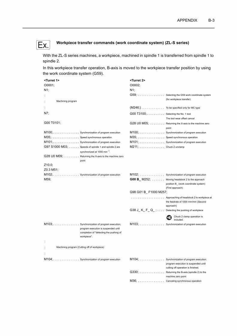
APPENDIX B-3
Workpiece transfer commands (work coordinate system) (ZL-S series)
With the ZL-S series machines, a workpiece, machined in spindle 1 is transferred from spindle 1 to spindle 2.
In this workpiece transfer operation, B-axis is moved to the workpiece transfer position by using the work coordinate system (G59).
<Turret 1> <Turret 2>O0001; O0002;N1; N1;
G59; . . . . . . . . . . . . . . . Selecting the G59 work coordinate system
(for workpiece transfer)Machining program
(M246;) . . . . . . . . . . . . . To be specified only for MC type
N7; G00 T3100;. . . . . . . . . . Selecting the No. 1 tool
The tool wear offset cancel
G00 T0101; G28 U0 M05; . . . . . . . . Returning the X-axis to the machine zero
point
M100;. . . . . . . . . . . . . . . Synchronization of program execution M100; . . . . . . . . . . . . . . Synchronization of program execution
M35;. . . . . . . . . . . . . . . . Speed synchronous operation M35; . . . . . . . . . . . . . . . Speed synchronous operation
M101;. . . . . . . . . . . . . . . Synchronization of program execution M101; . . . . . . . . . . . . . . Synchronization of program execution
G97 S1000 M03; . . . . . . Speeds of spindle 1 and spindle 2 are
synchronized at 1000 min−1.
M211; . . . . . . . . . . . . . . Chuck 2 unclamp
G28 U0 M09; . . . . . . . . . Returning the X-axis to the machine zero
point
Z10.0;Z0.3 M51;M102;. . . . . . . . . . . . . . . Synchronization of program execution M102; . . . . . . . . . . . . . . Synchronization of program execution
M59; G00 B_ M252; . . . . . . . Moving headstock 2 to the approach
position B_ (work coordinate system)(First approach)
G98 G01 B_ F1000 M257; . . . . . . . . . . . . . . . . . . . Approaching of headstock 2 to workpiece at
the feedrate of 1000 mm/min (Second approach)
G38 J_ K_ F_ Q_ ; . . . . Detecting the pushing of workpiece
Chuck 2 clamp operation is included.
M103;. . . . . . . . . . . . . . . Synchronization of program execution;
program execution is suspended until
completion of "detecting the pushing of
workpiece".
M103; . . . . . . . . . . . . . . Synchronization of program execution
Machining program (Cutting off of workpiece)
M104;. . . . . . . . . . . . . . . Synchronization of program execution M104; . . . . . . . . . . . . . . Synchronization of program execution;
program execution is suspended until
cutting off operation is finished.
G330; . . . . . . . . . . . . . . Returning the B-axis (spindle 2) to the
machine zero point
M36; . . . . . . . . . . . . . . . Canceling synchronous operation
Ex.
NOTE

B-4 APPENDIX
M105;. . . . . . . . . . . . . . . Synchronization of program execution;
program execution is suspended until
"returning the B-axis (spindle 2) to the machine zero point".
M105; . . . . . . . . . . . . . . Synchronization of program execution
M30; M01;
<Turret 1> <Turret 2>

APPENDIX B-5
Workpiece transfer commands (work coordinate system) (ZT series)
With the ZT series machines, a workpiece, machined in spindle 1 is transferred from spindle 1 to spindle 2.
In this workpiece transfer operation, B-axis is moved to the workpiece transfer position by using the work coordinate system (G59).
<Turret 1> <Turret 2>O0001; O0002;N1; N1;
G59; . . . . . . . . . . . . . . . Selecting the G59 work coordinate system
(for workpiece transfer)Machining program
(M246;) . . . . . . . . . . . . . To be specified only for MC type
N7; G00 T3100;. . . . . . . . . . Selecting the No. 1 tool
The tool wear offset cancel
G00 T0101; G28 U0 M05; . . . . . . . . Returning the X-axis to the machine zero
point
M100;. . . . . . . . . . . . . . . Synchronization of program execution M100; . . . . . . . . . . . . . . Synchronization of program execution
M35;. . . . . . . . . . . . . . . . Speed synchronous operation M35; . . . . . . . . . . . . . . . Speed synchronous operation
M101;. . . . . . . . . . . . . . . Synchronization of program execution M101; . . . . . . . . . . . . . . Synchronization of program execution
G97 S1000 M03; . . . . . . Speeds of spindle 1 and spindle 2 are
synchronized at 1000 min−1.
M211; . . . . . . . . . . . . . . Chuck 2 unclamp
G28 U0 M09; . . . . . . . . . Returning the X-axis to the machine zero
point
Z10.0;Z0.3 M51;M102;. . . . . . . . . . . . . . . Synchronization of program execution M102; . . . . . . . . . . . . . . Synchronization of program execution
M59; M369; . . . . . . . . . . . . . . B-axis unclamp
G00 B_ M252; . . . . . . . Moving headstock 2 to the approach
position B_ (work coordinate system)
(First approach)
G98 G01 B_ F1000 M257; . . . . . . . . . . . . . . . . . . . Approaching of headstock 2 to workpiece at
the feedrate of 1000 mm/min (Second
approach)
G38 J_ K_ F_ Q_ ; . . . . Detecting the pushing of workpiece
Chuck 2 clamp operation is included.
M103;. . . . . . . . . . . . . . . Synchronization of program execution;
program execution is suspended until completion of "detecting the pushing of
workpiece".
M103; . . . . . . . . . . . . . . Synchronization of program execution
Machining program (Cutting off of workpiece)
M104;. . . . . . . . . . . . . . . Synchronization of program execution M104; . . . . . . . . . . . . . . Synchronization of program execution;
program execution is suspended until cutting off operation is finished.
G330; . . . . . . . . . . . . . . Returning the B-axis (spindle 2) to the
machine zero point
M36; . . . . . . . . . . . . . . . Canceling synchronous operation
M105;. . . . . . . . . . . . . . . Synchronization of program execution;
program execution is suspended until
"returning the B-axis (spindle 2) to the machine zero point".
M105; . . . . . . . . . . . . . . Synchronization of program execution
M30; M01;
Ex.
NOTE
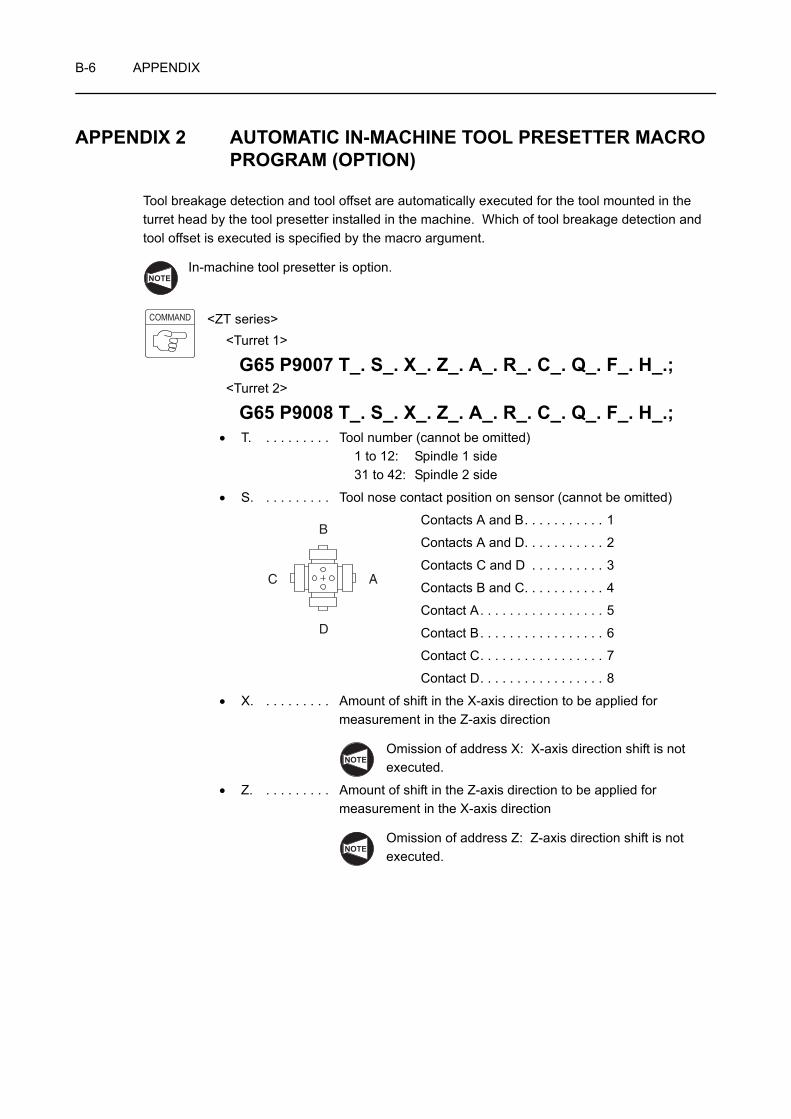
B-6 APPENDIX
APPENDIX 2 AUTOMATIC IN-MACHINE TOOL PRESETTER MACRO PROGRAM (OPTION)
Tool breakage detection and tool offset are automatically executed for the tool mounted in the turret head by the tool presetter installed in the machine. Which of tool breakage detection and tool offset is executed is specified by the macro argument.
In-machine tool presetter is option.
<ZT series><Turret 1>
G65 P9007 T_. S_. X_. Z_. A_. R_. C_. Q_. F_. H_.;<Turret 2>
G65 P9008 T_. S_. X_. Z_. A_. R_. C_. Q_. F_. H_.;• T. . . . . . . . . . Tool number (cannot be omitted)
1 to 12: Spindle 1 side31 to 42: Spindle 2 side
• S. . . . . . . . . . Tool nose contact position on sensor (cannot be omitted)
Contacts A and B. . . . . . . . . . . 1
Contacts A and D. . . . . . . . . . . 2
Contacts C and D . . . . . . . . . . 3
Contacts B and C. . . . . . . . . . . 4
Contact A. . . . . . . . . . . . . . . . . 5
Contact B. . . . . . . . . . . . . . . . . 6
Contact C. . . . . . . . . . . . . . . . . 7
Contact D. . . . . . . . . . . . . . . . . 8
• X. . . . . . . . . . Amount of shift in the X-axis direction to be applied for measurement in the Z-axis direction
Omission of address X: X-axis direction shift is not executed.
• Z. . . . . . . . . . Amount of shift in the Z-axis direction to be applied for measurement in the X-axis direction
Omission of address Z: Z-axis direction shift is not executed.
NOTE
COMMAND
A
B
C
D
NOTE
NOTE
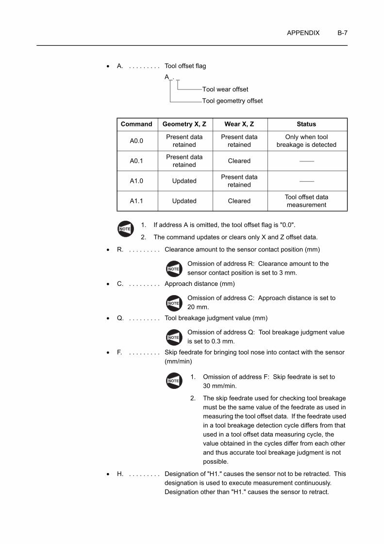
APPENDIX B-7
• A. . . . . . . . . . Tool offset flag
A_. _
1. If address A is omitted, the tool offset flag is "0.0".
2. The command updates or clears only X and Z offset data.
• R. . . . . . . . . . Clearance amount to the sensor contact position (mm)
Omission of address R: Clearance amount to the sensor contact position is set to 3 mm.
• C. . . . . . . . . . Approach distance (mm)
Omission of address C: Approach distance is set to 20 mm.
• Q. . . . . . . . . . Tool breakage judgment value (mm)
Omission of address Q: Tool breakage judgment value is set to 0.3 mm.
• F. . . . . . . . . . Skip feedrate for bringing tool nose into contact with the sensor (mm/min)
1. Omission of address F: Skip feedrate is set to 30 mm/min.
2. The skip feedrate used for checking tool breakage must be the same value of the feedrate as used in measuring the tool offset data. If the feedrate used in a tool breakage detection cycle differs from that used in a tool offset data measuring cycle, the value obtained in the cycles differ from each other and thus accurate tool breakage judgment is not possible.
• H. . . . . . . . . . Designation of "H1." causes the sensor not to be retracted. This designation is used to execute measurement continuously. Designation other than "H1." causes the sensor to retract.
Command Geometry X, Z Wear X, Z Status
A0.0 Present data retained
Present data retained
Only when tool breakage is detected
A0.1 Present data retained Cleared
A1.0 Updated Present data retained
A1.1 Updated Cleared Tool offset data measurement
Tool wear offset
Tool geomettry offset
NOTE
NOTE
NOTE
NOTE
NOTE

B-8 APPENDIX
Before specifying "G65 P9007/G65 P9008", manually measure and set the tool geometry offset data of the tool for which tool breakage detection and tool offset cycle is executed. If "G65 P9007/G65 P9008" is executed without setting the tool geometry offset data, the tool may interfere with the sensor, chuck, fixture, etc. to cause damage to the machine.
1. Do not move turret 1 and turret 2 simultaneously.
2. For all addresses specified following "G65 P9007/G65 P9008", enter a command with a decimal point.
3. G65 P9007/G65 P9008 does not have the function to call a tool. Before executing G65 P9007/G65 P9008, the target tool must be called to the spindle.
4. Set "100" for data table D680 in advance.
5. The program updates or clears the value of only X and Z.
<How to use the program>
1) Call the target tool of measurement.
2) If the tool geometry offset data is not set, measure and set the offset data manually.
3) Set the tool number for which tool geometry offset data is set to address T and execute the macro.
<Tool breakage detection cycle>
Specify A0.0 (or omit address A).
The feedrate to be specified here must be the same value of the feedrate as used in manual measurement. If the sensor contact feedrate differs between the feedrate used in the tool breakage detection cycle and the feedrate used in manual measurement, the obtained measured value differs from each other and thus accurate tool breakage judgment is not possible.
<Tool offset cycle>
Specify A1.1.
To shift the tool nose of such as a milling tool, amount and direction of shift may be specified using address X or Z.
<Alarm>
Alarm No. Message Description
3150 NOT FOUND∗∗∗ ∗∗∗ is not specified.
3151 DATA ERROR∗∗∗ The value of ∗∗∗ is illegal.
3153 CAN NOT APPROACH Approach is not possible.
3157 SKIP SIGNAL NOT ON Skip signal is not turned ON.
3158 SKIP SIGNAL ON Skip signal was turned ON.
3166 ∗∗∗∗∗TOLERANCE OVER Tolerance of ∗∗∗ exceeds the specified allowable limit.
CAUTION
NOTE
NOTE
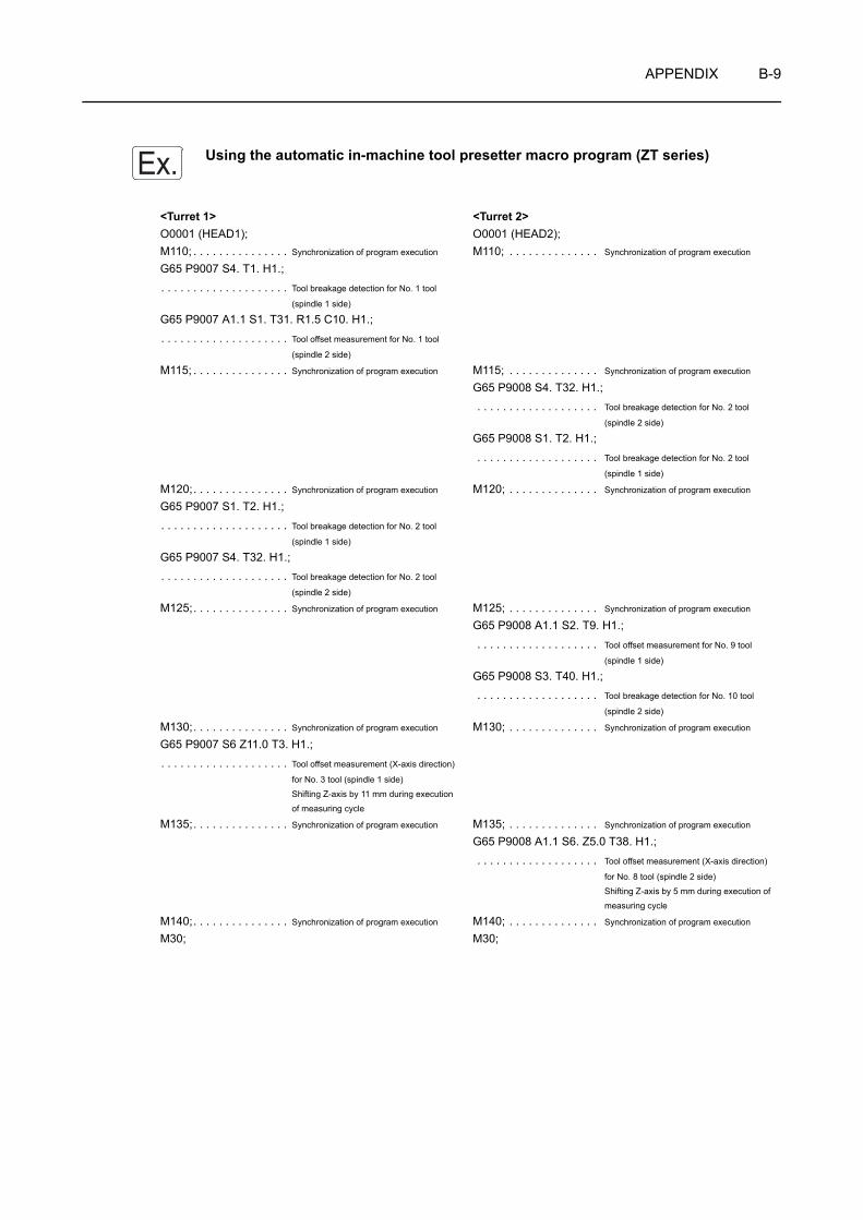
APPENDIX B-9
Using the automatic in-machine tool presetter macro program (ZT series)
<Turret 1> <Turret 2>O0001 (HEAD1); O0001 (HEAD2);M110; . . . . . . . . . . . . . . . Synchronization of program execution M110; . . . . . . . . . . . . . . Synchronization of program execution
G65 P9007 S4. T1. H1.;. . . . . . . . . . . . . . . . . . . . Tool breakage detection for No. 1 tool
(spindle 1 side)
G65 P9007 A1.1 S1. T31. R1.5 C10. H1.;. . . . . . . . . . . . . . . . . . . . Tool offset measurement for No. 1 tool
(spindle 2 side)
M115; . . . . . . . . . . . . . . . Synchronization of program execution M115; . . . . . . . . . . . . . . Synchronization of program execution
G65 P9008 S4. T32. H1.; . . . . . . . . . . . . . . . . . . . Tool breakage detection for No. 2 tool
(spindle 2 side)
G65 P9008 S1. T2. H1.; . . . . . . . . . . . . . . . . . . . Tool breakage detection for No. 2 tool
(spindle 1 side)
M120;. . . . . . . . . . . . . . . Synchronization of program execution M120; . . . . . . . . . . . . . . Synchronization of program execution
G65 P9007 S1. T2. H1.;. . . . . . . . . . . . . . . . . . . . Tool breakage detection for No. 2 tool
(spindle 1 side)
G65 P9007 S4. T32. H1.;. . . . . . . . . . . . . . . . . . . . Tool breakage detection for No. 2 tool
(spindle 2 side)
M125;. . . . . . . . . . . . . . . Synchronization of program execution M125; . . . . . . . . . . . . . . Synchronization of program execution
G65 P9008 A1.1 S2. T9. H1.; . . . . . . . . . . . . . . . . . . . Tool offset measurement for No. 9 tool
(spindle 1 side)
G65 P9008 S3. T40. H1.; . . . . . . . . . . . . . . . . . . . Tool breakage detection for No. 10 tool
(spindle 2 side)
M130;. . . . . . . . . . . . . . . Synchronization of program execution M130; . . . . . . . . . . . . . . Synchronization of program execution
G65 P9007 S6 Z11.0 T3. H1.;. . . . . . . . . . . . . . . . . . . . Tool offset measurement (X-axis direction)
for No. 3 tool (spindle 1 side)
Shifting Z-axis by 11 mm during execution
of measuring cycle
M135;. . . . . . . . . . . . . . . Synchronization of program execution M135; . . . . . . . . . . . . . . Synchronization of program execution
G65 P9008 A1.1 S6. Z5.0 T38. H1.; . . . . . . . . . . . . . . . . . . . Tool offset measurement (X-axis direction)
for No. 8 tool (spindle 2 side)
Shifting Z-axis by 5 mm during execution of measuring cycle
M140;. . . . . . . . . . . . . . . Synchronization of program execution M140; . . . . . . . . . . . . . . Synchronization of program execution
M30; M30;
Ex.
CHAPTER CM FUNCTIONS
This chapter describes the M functions.
The examples of program given in this chapter all assume tool nose R0.NOTE
CONTENTS
C : M FUNCTIONS
1 M CODE LIST . . . . . . . . . . . . . . . . . . . . . . . . . . . . . . . . . . . . . . . . . . . . . . . . . . . . . . . . . C-1
1-1 ZL Series . . . . . . . . . . . . . . . . . . . . . . . . . . . . . . . . . . . . . . . . . . . . . . . . . . . . . . . . C-1
1-2 ZL-S Series . . . . . . . . . . . . . . . . . . . . . . . . . . . . . . . . . . . . . . . . . . . . . . . . . . . . . . C-6
1-3 ZT Series. . . . . . . . . . . . . . . . . . . . . . . . . . . . . . . . . . . . . . . . . . . . . . . . . . . . . . . C-12
2 M00, M01 PROGRAM STOP AND OPTIONAL STOP. . . . . . . . . . . . . . . . . . . . . . . . . C-18
3 M02, M30 PROGRAM END, PROGRAM END AND REWIND . . . . . . . . . . . . . . . . . . C-21
4 M03, M203, M04, M204, M05 SPINDLE START AND STOP . . . . . . . . . . . . . . . . . . . C-24
5 M13, M14, M05 START AND STOP OF ROTARY TOOL ROTATION . . . . . . . . . . . . . C-28
6 M08, M09 COOLANT DISCHARGE ON/OFF . . . . . . . . . . . . . . . . . . . . . . . . . . . . . . . C-31
7 M19 SPINDLE ORIENTATION (SPINDLE 1), M219 SPINDLE ORIENTATION (SPINDLE 2), M319 ROTARY TOOL SPINDLE ORIENTATION. . . . . . . . . . . . . . . . . . . . . . . . . . . . . C-33
8 M23, M24 CHAMFERING ON/OFF . . . . . . . . . . . . . . . . . . . . . . . . . . . . . . . . . . . . . . . C-34
9 M10, M210, M11, M211 CHUCK CLAMP/UNCLAMP . . . . . . . . . . . . . . . . . . . . . . . . . C-37
10 M25, M26 TAILSTOCK SPINDLE IN/OUT . . . . . . . . . . . . . . . . . . . . . . . . . . . . . . . . . . C-41
11 M34, M234, M35, M235, M36 SYNCHRONIZED OPERATION ON/OFF . . . . . . . . . . C-44
12 M45, M245, M46, M246 C-AXIS CONNECTION AND CANCEL . . . . . . . . . . . . . . . . . C-50
13 M47 WORKPIECE EJECTOR OUT . . . . . . . . . . . . . . . . . . . . . . . . . . . . . . . . . . . . . . . C-52
14 M360, M361 WORKPIECE EJECTOR OUT/IN . . . . . . . . . . . . . . . . . . . . . . . . . . . . . . C-54
15 M48, M49 FEEDRATE OVERRIDE CANCEL OFF/ON . . . . . . . . . . . . . . . . . . . . . . . . C-56
16 M68, M268, M69, M269 SPINDLE BRAKE CLAMP AND UNCLAMP . . . . . . . . . . . . . C-58
17 M70, M483, M482 BAR STOCK FEED, BAR STOCK FEED OFF, BAR STOCK CHANGE . . . . . . . . . . . . . . . . . . . . . . . . . . . . . . . . . . . . . . . . . . . . . . . . . C-60
18 M71, M72 AUTOMATIC IN-MACHINE TOOL PRESETTER ARM OUT/IN (OPTION) . . . . . . . . . . . . . . . . . . . . . . . . . . . . . . . . . . . . . . . . . . . . . . . . C-64
19 M73, M74 PARTS CATCHER OUT/IN . . . . . . . . . . . . . . . . . . . . . . . . . . . . . . . . . . . . . C-65
20 M80 WORKPIECE CUT-OFF DETECTION . . . . . . . . . . . . . . . . . . . . . . . . . . . . . . . . . C-69
21 M85, M86 AUTOMATIC DOOR OPEN/CLOSE . . . . . . . . . . . . . . . . . . . . . . . . . . . . . . C-71

22 M89 WORK COUNTER, TOTAL COUNTER . . . . . . . . . . . . . . . . . . . . . . . . . . . . . . . . C-73
23 M98/M198, M99 SUB-PROGRAM CALL AND SUB-PROGRAM END . . . . . . . . . . . . C-76
23-1 Using M98 and M99 Commands. . . . . . . . . . . . . . . . . . . . . . . . . . . . . . . . . . . . . C-76
23-2 Nesting . . . . . . . . . . . . . . . . . . . . . . . . . . . . . . . . . . . . . . . . . . . . . . . . . . . . . . . . C-77
23-3 Repeating Sub-program Calls . . . . . . . . . . . . . . . . . . . . . . . . . . . . . . . . . . . . . . . C-78
23-4 Using M198 and M99 Commands. . . . . . . . . . . . . . . . . . . . . . . . . . . . . . . . . . . . C-80
24 M100 TO M197, M199 OPERATION SYNCHRONIZATION . . . . . . . . . . . . . . . . . . . . C-82
25 M90, M290, M91, M291 SIMULTANEOUS SPINDLE/ROTARY TOOL OPERATION MODE ON/OFF. . . . . . . . . . . . . . . . . . . . . . . . . . . . . . . C-83
26 M28, M29 IN-POSITION CHECK VALID AND IN-POSITION CHECK INVALID . . . . . C-86
27 M200, M201 CHIP CONVEYOR FORWARD ROTATION START, STOP . . . . . . . . . . C-89
28 M314, M315 FEEDRATE OVERRIDE CLAMP ON TURRET 1 SIDE VALID, INVALID (OPTION) . . . . . . . . . . . . . . . . . . . . . . . . . . . . . . . . . . . . . . . . . . . . . . . . . . . . C-89
29 M480, M481 C-AXIS SYNCHRONIZATION MODE ON/OFF. . . . . . . . . . . . . . . . . . . . C-90
30 M368, M369 B-AXIS CLAMP/UNCLAMP (ZT SERIES). . . . . . . . . . . . . . . . . . . . . . . . C-92
31 SUMMARY . . . . . . . . . . . . . . . . . . . . . . . . . . . . . . . . . . . . . . . . . . . . . . . . . . . . . . . . . . C-93
APPENDIX 1 MULTIPLE M CODE FUNCTION . . . . . . . . . . . . . . . . . . . . . . . . APPENDIX C-1
APPENDIX 2 QUICK M CODE FUNCTION . . . . . . . . . . . . . . . . . . . . . . . . . . . APPENDIX C-2

M FUNCTIONS C-1
1 M CODE LIST
M codes are also called the miscellaneous functions. They control program flow, coolant discharge on/off, etc. in addition to realize the functions supplementary to those called by the G codes.
The M codes described in this section are generic ones and all of them are not usable by all machine models or with some models those not specified below may be used. There are also cases that the function of the M code stated below has different function on specific models. For details, refer to the ladder diagram supplied with your machine or contact Mori Seiki.
1-1 ZL Series
: Standard : Option × : Not available
Code Function Description Turret 1
Turret 2 Page
M00 Program stop Suspends program execution temporarily.
C-18M01 Optional stop
Suspends program execution temporarily.Whether the function is valid or not is selectable by a switch on the operation panel.
M02 Program end Ends program execution and resets the NC. C-21
M03 Spindle start (normal)
Starts the spindle in the normal direction.Normal direction:Clockwise rotation, viewing the workpiece from the rear of the spindle.
C-24M04 Spindle start (reverse)
Starts the spindle in the reverse direction.Reverse direction:Counterclockwise rotation, viewing the workpiece from the rear of the spindle.
M05 Spindle (rotary tool) stop Stops spindle rotation.Stops rotary tool rotation.
M08 Coolant ON Starts coolant discharge.C-31
M09 Coolant OFF Stops coolant discharge.
M10 Chuck clamp Opens and closes the chuck.These M codes are used when the machine is equipped with the bar feeder or loader, or for both-center work.
C-37M11 Chuck unclamp
M13 Rotary tool rotation (normal)
Rotates the rotary tool in the clockwise direction, viewing the workpiece from the rear of the rotary tool.(MC specification)
×
C-28
M14 Rotary tool rotation (reverse)
Rotates the rotary tool in the counterclockwise direction, viewing the workpiece from the rear of the rotary tool.(MC specification)
×
NOTE
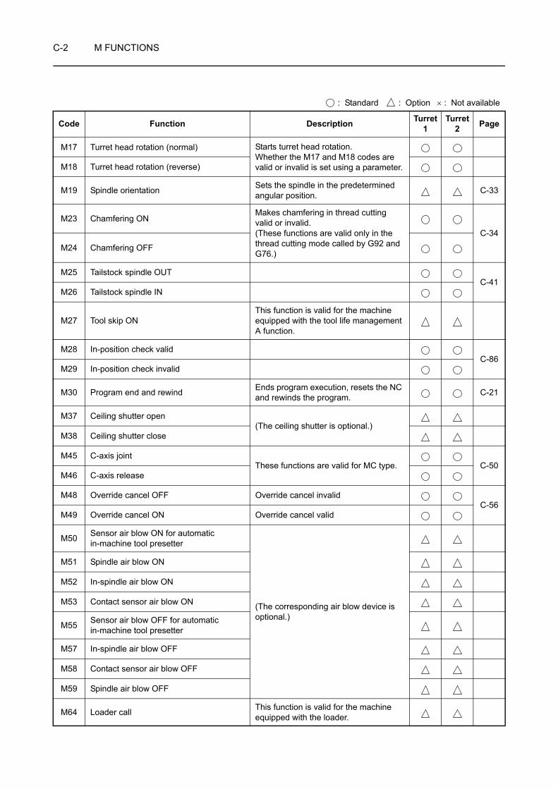
C-2 M FUNCTIONS
M17 Turret head rotation (normal) Starts turret head rotation.Whether the M17 and M18 codes are valid or invalid is set using a parameter.M18 Turret head rotation (reverse)
M19 Spindle orientation Sets the spindle in the predetermined angular position. C-33
M23 Chamfering ONMakes chamfering in thread cutting valid or invalid.(These functions are valid only in the thread cutting mode called by G92 and G76.)
C-34
M24 Chamfering OFF
M25 Tailstock spindle OUTC-41
M26 Tailstock spindle IN
M27 Tool skip ONThis function is valid for the machine equipped with the tool life management A function.
M28 In-position check validC-86
M29 In-position check invalid
M30 Program end and rewind Ends program execution, resets the NC and rewinds the program. C-21
M37 Ceiling shutter open(The ceiling shutter is optional.)
M38 Ceiling shutter close
M45 C-axis jointThese functions are valid for MC type. C-50
M46 C-axis release
M48 Override cancel OFF Override cancel invalidC-56
M49 Override cancel ON Override cancel valid
M50 Sensor air blow ON for automatic in-machine tool presetter
(The corresponding air blow device is optional.)
M51 Spindle air blow ON
M52 In-spindle air blow ON
M53 Contact sensor air blow ON
M55 Sensor air blow OFF for automatic in-machine tool presetter
M57 In-spindle air blow OFF
M58 Contact sensor air blow OFF
M59 Spindle air blow OFF
M64 Loader call This function is valid for the machine equipped with the loader.
: Standard : Option × : Not available
Code Function Description Turret 1
Turret 2 Page

M FUNCTIONS C-3
M68 Spindle brake clamp Clamps and unclamps the spindle brake.These functions are valid for MC type.
C-58M69 Spindle brake unclamp
M70 Bar feeder operation
Feeds the bar stock into the machine.This function is valid for the machine equipped with the bar feeder. (The corresponding signal is output to an external device.)
C-60
M71 Automatic in-machine tool presetter OUT These functions are valid for the machine equipped with the automatic in-machine tool presetter.(The automatic in-machine tool presetter is optional.)
C-64M72 Automatic in-machine tool presetter IN
M73 Parts catcher OUT Moves the parts catcher out/in.These functions are valid for the machine equipped with the parts catcher.
C-65M74 Parts catcher IN
M75 X-axis mirror image OFF
M76 X-axis mirror image ON
M78 Tailstock body clampClamps/unclamps the tailstock body.
×
M79 Tailstock body unclamp ×
M83 Chucking pressure 1 Selects chucking pressure level.These functions are valid for the machine equipped with the chuck high/low pressure system.M84 Chucking pressure 2
M85 Automatic door open Opens/closes the automatic door.These functions are valid for the machine equipped with an automatic door.
C-71M86 Automatic door close
M87 Sensor switching ON Switches the sensors to be used.These functions are valid for the machine equipped with the sensors.M88 Sensor switching OFF
M89 Work counter/total counter C-73
M90Spindle/rotary tool simultaneous operation mode ON
These functions are valid for MC type.×
C-83M91
Spindle/rotary tool simultaneous operation mode OFF ×
M92 Load monitoring (teaching, monitoring) valid
Load monitoring specificationM93 Load monitoring (teaching, monitoring)
invalid
M98 Sub-program call
C-76M99 Sub-program end
Repetition of program
Returns the program flow from the current sub-program to the immediately previous program.
: Standard : Option × : Not available
Code Function Description Turret 1
Turret 2 Page
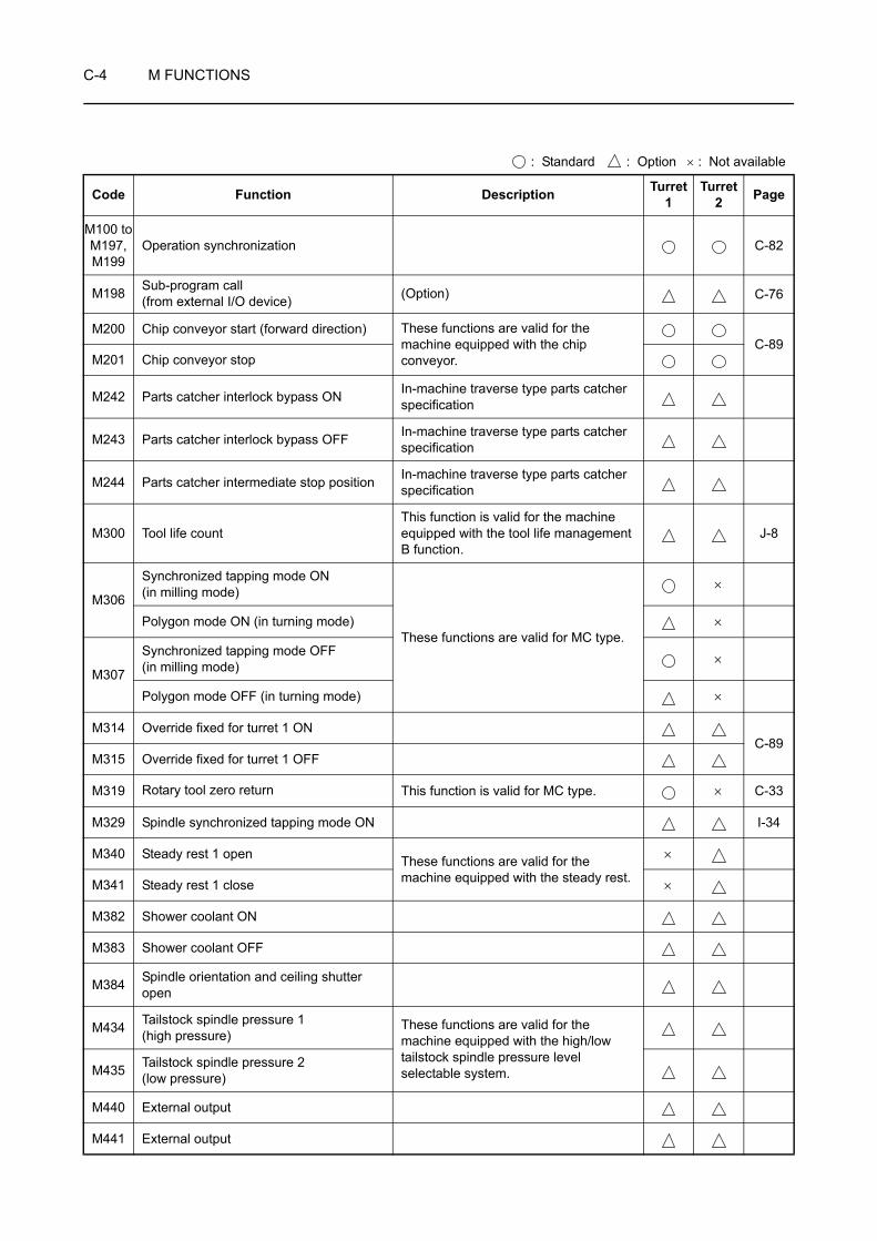
C-4 M FUNCTIONS
M100 toM197, M199
Operation synchronization C-82
M198 Sub-program call (from external I/O device) (Option) C-76
M200 Chip conveyor start (forward direction) These functions are valid for the machine equipped with the chip conveyor.
C-89M201 Chip conveyor stop
M242 Parts catcher interlock bypass ON In-machine traverse type parts catcher specification
M243 Parts catcher interlock bypass OFF In-machine traverse type parts catcher specification
M244 Parts catcher intermediate stop position In-machine traverse type parts catcher specification
M300 Tool life countThis function is valid for the machine equipped with the tool life management B function.
J-8
M306
Synchronized tapping mode ON (in milling mode)
These functions are valid for MC type.
×
Polygon mode ON (in turning mode) ×
M307
Synchronized tapping mode OFF (in milling mode) ×
Polygon mode OFF (in turning mode) ×
M314 Override fixed for turret 1 ONC-89
M315 Override fixed for turret 1 OFF
M319 Rotary tool zero return This function is valid for MC type. × C-33
M329 Spindle synchronized tapping mode ON I-34
M340 Steady rest 1 open These functions are valid for the machine equipped with the steady rest.
×
M341 Steady rest 1 close ×
M382 Shower coolant ON
M383 Shower coolant OFF
M384 Spindle orientation and ceiling shutter open
M434 Tailstock spindle pressure 1 (high pressure)
These functions are valid for the machine equipped with the high/low tailstock spindle pressure level selectable system.M435 Tailstock spindle pressure 2
(low pressure)
M440 External output
M441 External output
: Standard : Option × : Not available
Code Function Description Turret 1
Turret 2 Page
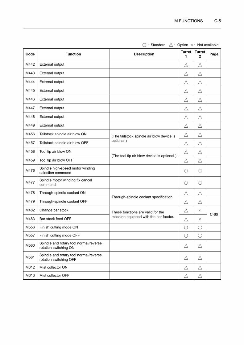
M FUNCTIONS C-5
M442 External output
M443 External output
M444 External output
M445 External output
M446 External output
M447 External output
M448 External output
M449 External output
M456 Tailstock spindle air blow ON (The tailstock spindle air blow device is optional.)M457 Tailstock spindle air blow OFF
M458 Tool tip air blow ON(The tool tip air blow device is optional.)
M459 Tool tip air blow OFF
M476 Spindle high-speed motor winding selection command
M477 Spindle motor winding fix cancel command
M478 Through-spindle coolant ONThrough-spindle coolant specification
M479 Through-spindle coolant OFF
M482 Change bar stock These functions are valid for the machine equipped with the bar feeder.
×C-60
M483 Bar stock feed OFF ×
M556 Finish cutting mode ON
M557 Finish cutting mode OFF
M560 Spindle and rotary tool normal/reverse rotation switching ON
M561 Spindle and rotary tool normal/reverse rotation switching OFF
M612 Mist collector ON
M613 Mist collector OFF
: Standard : Option × : Not available
Code Function Description Turret 1
Turret 2 Page
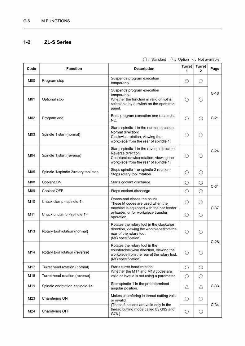
C-6 M FUNCTIONS
1-2 ZL-S Series
: Standard : Option × : Not available
Code Function Description Turret 1
Turret 2 Page
M00 Program stop Suspends program execution temporarily.
C-18M01 Optional stop
Suspends program execution temporarily.Whether the function is valid or not is selectable by a switch on the operation panel.
M02 Program end Ends program execution and resets the NC. C-21
M03 Spindle 1 start (normal)
Starts spindle 1 in the normal direction.Normal direction:Clockwise rotation, viewing the workpiece from the rear of spindle 1.
C-24M04 Spindle 1 start (reverse)
Starts spindle 1 in the reverse directionReverse direction:Counterclockwise rotation, viewing the workpiece from the rear of spindle 1.
M05 Spindle 1/spindle 2/rotary tool stop Stops spindle 1 or spindle 2 rotation.Stops rotary tool rotation.
M08 Coolant ON Starts coolant discharge.C-31
M09 Coolant OFF Stops coolant discharge.
M10 Chuck clamp <spindle 1>Opens and closes the chuck.These M codes are used when the machine is equipped with the bar feeder or loader, or for workpiece transfer operation.
C-37
M11 Chuck unclamp <spindle 1>
M13 Rotary tool rotation (normal)
Rotates the rotary tool in the clockwise direction, viewing the workpiece from the rear of the rotary tool. (MC specification)
C-28
M14 Rotary tool rotation (reverse)
Rotates the rotary tool in the counterclockwise direction, viewing the workpiece from the rear of the rotary tool. (MC specification)
M17 Turret head rotation (normal) Starts turret head rotation.Whether the M17 and M18 codes are valid or invalid is set using a parameter.M18 Turret head rotation (reverse)
M19 Spindle orientation <spindle 1> Sets spindle 1 in the predetermined angular position. C-33
M23 Chamfering ONMakes chamfering in thread cutting valid or invalid.(These functions are valid only in the thread cutting mode called by G92 and G76.)
C-34
M24 Chamfering OFF
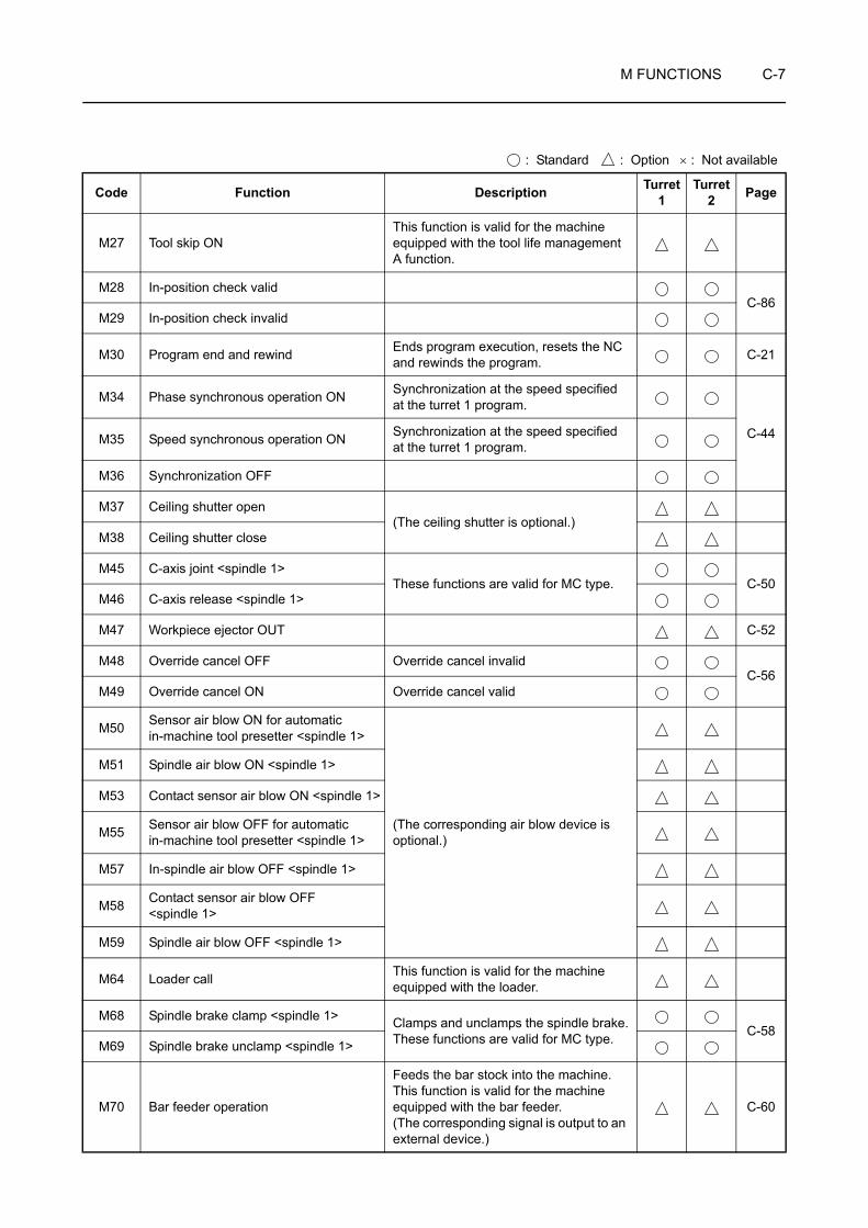
M FUNCTIONS C-7
M27 Tool skip ONThis function is valid for the machine equipped with the tool life management A function.
M28 In-position check validC-86
M29 In-position check invalid
M30 Program end and rewind Ends program execution, resets the NC and rewinds the program. C-21
M34 Phase synchronous operation ON Synchronization at the speed specified at the turret 1 program.
C-44M35 Speed synchronous operation ON Synchronization at the speed specified at the turret 1 program.
M36 Synchronization OFF
M37 Ceiling shutter open(The ceiling shutter is optional.)
M38 Ceiling shutter close
M45 C-axis joint <spindle 1>These functions are valid for MC type. C-50
M46 C-axis release <spindle 1>
M47 Workpiece ejector OUT C-52
M48 Override cancel OFF Override cancel invalidC-56
M49 Override cancel ON Override cancel valid
M50 Sensor air blow ON for automatic in-machine tool presetter <spindle 1>
(The corresponding air blow device is optional.)
M51 Spindle air blow ON <spindle 1>
M53 Contact sensor air blow ON <spindle 1>
M55 Sensor air blow OFF for automatic in-machine tool presetter <spindle 1>
M57 In-spindle air blow OFF <spindle 1>
M58 Contact sensor air blow OFF <spindle 1>
M59 Spindle air blow OFF <spindle 1>
M64 Loader call This function is valid for the machine equipped with the loader.
M68 Spindle brake clamp <spindle 1> Clamps and unclamps the spindle brake.These functions are valid for MC type. C-58
M69 Spindle brake unclamp <spindle 1>
M70 Bar feeder operation
Feeds the bar stock into the machine.This function is valid for the machine equipped with the bar feeder. (The corresponding signal is output to an external device.)
C-60
: Standard : Option × : Not available
Code Function Description Turret 1
Turret 2 Page
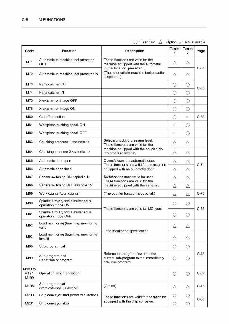
C-8 M FUNCTIONS
M71 Automatic in-machine tool presetter OUT
These functions are valid for the machine equipped with the automatic in-machine tool presetter.(The automatic in-machine tool presetter is optional.)
C-64M72 Automatic in-machine tool presetter IN
M73 Parts catcher OUTC-65
M74 Parts catcher IN
M75 X-axis mirror image OFF
M76 X-axis mirror image ON
M80 Cut-off detection × C-69
M81 Workpiece pushing check ON ×
M82 Workpiece pushing check OFF ×
M83 Chucking pressure 1 <spindle 1> Selects chucking pressure level.These functions are valid for the machine equipped with the chuck high/low pressure system.M84 Chucking pressure 2 <spindle 1>
M85 Automatic door open Opens/closes the automatic door.These functions are valid for the machine equipped with an automatic door.
C-71M86 Automatic door close
M87 Sensor switching ON <spindle 1> Switches the sensors to be used.These functions are valid for the machine equipped with the sensors.M88 Sensor switching OFF <spindle 1>
M89 Work counter/total counter (The counter function is optional.) C-73
M90 Spindle 1/rotary tool simultaneous operation mode ON
These functions are valid for MC type. C-83M91 Spindle 1/rotary tool simultaneous
operation mode OFF
M92 Load monitoring (teaching, monitoring) valid
Load monitoring specificationM93 Load monitoring (teaching, monitoring)
invalid
M98 Sub-program call
C-76M99 Sub-program end
Repetition of program
Returns the program flow from the current sub-program to the immediately previous program.
M100 toM197, M199
Operation synchronization C-82
M198 Sub-program call (from external I/O device) (Option) C-76
M200 Chip conveyor start (forward direction) These functions are valid for the machine equipped with the chip conveyor. C-89
M201 Chip conveyor stop
: Standard : Option × : Not available
Code Function Description Turret 1
Turret 2 Page

M FUNCTIONS C-9
M203 Spindle 2 start (normal)
Starts spindle 2 in the normal direction.Normal direction:Clockwise rotation, viewing the workpiece from the rear of spindle 2.
C-24
M204 Spindle 2 start (reverse)
Starts spindle 2 in the reverse direction.Reverse direction:Counterclockwise rotation, viewing the workpiece from the rear of spindle 2.
M210 Chuck clamp <spindle 2> Opens and closes the chuck.These M codes are used when the machine is equipped with the bar feeder or loader, or for both-center work.
C-37M211 Chuck unclamp <spindle 2>
M219 Spindle orientation <spindle 2> Sets spindle 2 in the predetermined angular position. C-33
M234 Phase synchronous operation ON Synchronization at the speed specified at the turret 2 program.
C-44M235 Speed synchronous operation ON Synchronization at the speed specified
at the turret 2 program.
M242 Parts catcher interlock bypass ON
M243 Parts catcher interlock bypass OFF
M244 Parts catcher intermediate stop position
M245 C-axis joint <spindle 2>This function is valid for MC type. C-50
M246 C-axis release <spindle 2>
M251 Spindle air blow ON <spindle 2>
(The corresponding air blow device is optional.)
M252 In-spindle air blow ON <spindle 2>
M253 Contact sensor air blow ON <spindle 2>
M257 In-spindle air blow OFF <spindle 2>
M258 Contact sensor air blow OFF <spindle 2>
M259 Spindle air blow OFF <spindle 2>
M268 Spindle brake clamp <spindle 2> Clamps and unclamps the spindle brake. These functions are valid for MC type. C-58
M269 Spindle brake unclamp <spindle 2>
M283 Chucking pressure 1 <spindle 2> Selects chucking pressure level.These functions are valid for the machine equipped with the chuck high/low pressure system.M284 Chucking pressure 2 <spindle 2>
M287 Sensor switching ON <spindle 2> Switches the sensors to be used.These functions are valid for the machine equipped with the sensors.M288 Sensor switching OFF <spindle 2>
: Standard : Option × : Not available
Code Function Description Turret 1
Turret 2 Page

C-10 M FUNCTIONS
M290 Spindle 2/rotary tool simultaneous operation mode ON
These functions are valid for MC type. C-83M291 Spindle 2/rotary tool simultaneous
operation mode OFF
M300 Tool life countThis function is valid for the machine equipped with the tool life management B function.
J-8
M306
Synchronized tapping mode ON (in milling mode)
These functions are valid for MC type.Polygon mode ON (in turning mode)
M307
Synchronized tapping mode OFF (in milling mode)
Polygon mode OFF (in turning mode)
M314 Override fixed for turret 1 ONC-89
M315 Override fixed for turret 1 OFF
M319 Rotary tool zero return This function is valid for MC type. C-33
M329 Spindle synchronized tapping mode ON <spindle 1, spindle 2> I-34
M340 Steady rest 1 open These functions are valid for the machine equipped with the steady rest.
×
M341 Steady rest 1 close ×
M382 Shower coolant ON
M383 Shower coolant OFF
M384 Spindle 1 orientation and ceiling shutter open (Spindle 1/spindle 2 orientation and
ceiling shutter open functions are optional.)M387 Spindle 2 orientation and ceiling shutter
open
M438 Cylindrical coordinate system animation mode ON These functions are valid for MC type. ×
M440 External output
M441 External output
M442 External output
M443 External output
M444 External output
M445 External output
M446 External output
M447 External output
: Standard : Option × : Not available
Code Function Description Turret 1
Turret 2 Page

M FUNCTIONS C-11
M448 External output
M449 External output
M458 Tool tip air blow ON(The tool tip air blow device is optional.)
M459 Tool tip air blow OFF
M474 Spindle high-speed motor winding selection command <spindle 2>
M475 Spindle motor winding fix cancel command <spindle 2>
M476 Spindle high-speed motor winding selection command <spindle 1>
M477 Spindle motor winding fix cancel command <spindle 1>
M478 In-spindle coolant ON <spindle 1>Through-spindle coolant specification
M479 In-spindle coolant OFF <spindle 1>
M480 C-axis synchronization mode ON These functions are valid for MC type.C-90
M481 C-axis synchronization mode OFF These functions are valid for MC type.
M482 Change bar stock These functions are valid for the machine equipped with the bar feeder.
×C-60
M483 Bar stock feed OFF ×
M556 Finish cutting mode ON
M557 Finish cutting mode OFF
M560 Spindle and rotary tool normal/reverse rotation switching ON
M561 Spindle and rotary tool normal/reverse rotation switching OFF
M612 Mist collector ON
M613 Mist collector OFF
: Standard : Option × : Not available
Code Function Description Turret 1
Turret 2 Page
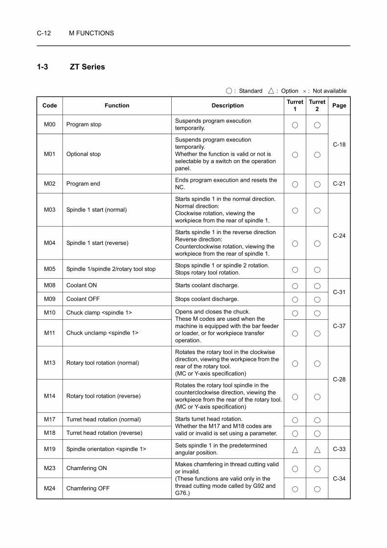
C-12 M FUNCTIONS
1-3 ZT Series
: Standard : Option × : Not available
Code Function Description Turret 1
Turret 2 Page
M00 Program stop Suspends program execution temporarily.
C-18M01 Optional stop
Suspends program execution temporarily.Whether the function is valid or not is selectable by a switch on the operation panel.
M02 Program end Ends program execution and resets the NC. C-21
M03 Spindle 1 start (normal)
Starts spindle 1 in the normal direction.Normal direction:Clockwise rotation, viewing the workpiece from the rear of spindle 1.
C-24M04 Spindle 1 start (reverse)
Starts spindle 1 in the reverse directionReverse direction:Counterclockwise rotation, viewing the workpiece from the rear of spindle 1.
M05 Spindle 1/spindle 2/rotary tool stop Stops spindle 1 or spindle 2 rotation.Stops rotary tool rotation.
M08 Coolant ON Starts coolant discharge.C-31
M09 Coolant OFF Stops coolant discharge.
M10 Chuck clamp <spindle 1> Opens and closes the chuck.These M codes are used when the machine is equipped with the bar feeder or loader, or for workpiece transfer operation.
C-37M11 Chuck unclamp <spindle 1>
M13 Rotary tool rotation (normal)
Rotates the rotary tool in the clockwise direction, viewing the workpiece from the rear of the rotary tool.(MC or Y-axis specification)
C-28
M14 Rotary tool rotation (reverse)
Rotates the rotary tool spindle in the counterclockwise direction, viewing the workpiece from the rear of the rotary tool.(MC or Y-axis specification)
M17 Turret head rotation (normal) Starts turret head rotation.Whether the M17 and M18 codes are valid or invalid is set using a parameter.M18 Turret head rotation (reverse)
M19 Spindle orientation <spindle 1> Sets spindle 1 in the predetermined angular position. C-33
M23 Chamfering ON Makes chamfering in thread cutting valid or invalid.(These functions are valid only in the thread cutting mode called by G92 and G76.)
C-34M24 Chamfering OFF
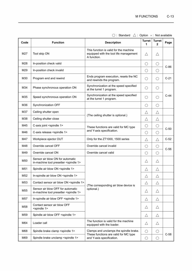
M FUNCTIONS C-13
M27 Tool skip ONThis function is valid for the machine equipped with the tool life management A function.
M28 In-position check validC-86
M29 In-position check invalid
M30 Program end and rewind Ends program execution, resets the NC and rewinds the program. C-21
M34 Phase synchronous operation ON Synchronization at the speed specified at the turret 1 program.
C-44M35 Speed synchronous operation ON Synchronization at the speed specified at the turret 1 program.
M36 Synchronization OFF
M37 Ceiling shutter open(The ceiling shutter is optional.)
M38 Ceiling shutter close
M45 C-axis joint <spindle 1> These functions are valid for MC type and Y-axis specification. C-50
M46 C-axis release <spindle 1>
M47 Workpiece ejector OUT Only for the ZT1000, 1500 series C-52
M48 Override cancel OFF Override cancel invalidC-56
M49 Override cancel ON Override cancel valid
M50 Sensor air blow ON for automatic in-machine tool presetter <spindle 1>
(The corresponding air blow device is optional.)
M51 Spindle air blow ON <spindle 1>
M52 In-spindle air blow ON <spindle 1>
M53 Contact sensor air blow ON <spindle 1>
M55 Sensor air blow OFF for automatic in-machine tool presetter <spindle 1>
M57 In-spindle air blow OFF <spindle 1>
M58 Contact sensor air blow OFF <spindle 1>
M59 Spindle air blow OFF <spindle 1>
M64 Loader call The function is valid for the machine equipped with the loader.
M68 Spindle brake clamp <spindle 1> Clamps and unclamps the spindle brake.These functions are valid for MC type and Y-axis specification.
C-58M69 Spindle brake unclamp <spindle 1>
: Standard : Option × : Not available
Code Function Description Turret 1
Turret 2 Page
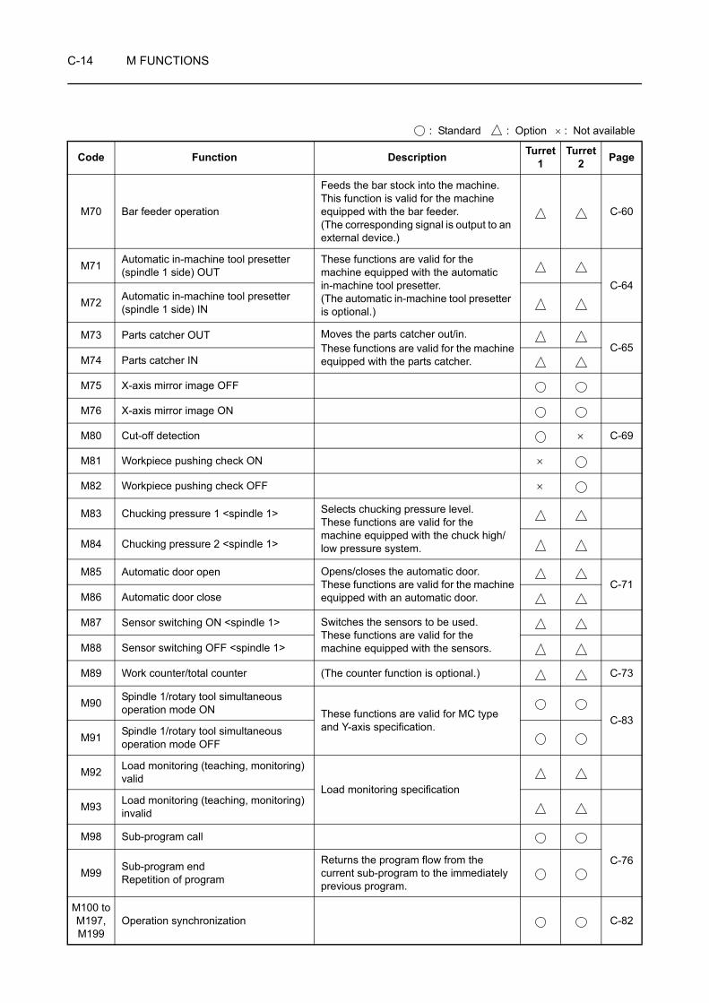
C-14 M FUNCTIONS
M70 Bar feeder operation
Feeds the bar stock into the machine.This function is valid for the machine equipped with the bar feeder. (The corresponding signal is output to an external device.)
C-60
M71 Automatic in-machine tool presetter (spindle 1 side) OUT
These functions are valid for the machine equipped with the automatic in-machine tool presetter.(The automatic in-machine tool presetter is optional.)
C-64M72 Automatic in-machine tool presetter
(spindle 1 side) IN
M73 Parts catcher OUT Moves the parts catcher out/in.These functions are valid for the machine equipped with the parts catcher.
C-65M74 Parts catcher IN
M75 X-axis mirror image OFF
M76 X-axis mirror image ON
M80 Cut-off detection × C-69
M81 Workpiece pushing check ON ×
M82 Workpiece pushing check OFF ×
M83 Chucking pressure 1 <spindle 1> Selects chucking pressure level.These functions are valid for the machine equipped with the chuck high/low pressure system.M84 Chucking pressure 2 <spindle 1>
M85 Automatic door open Opens/closes the automatic door.These functions are valid for the machine equipped with an automatic door.
C-71M86 Automatic door close
M87 Sensor switching ON <spindle 1> Switches the sensors to be used.These functions are valid for the machine equipped with the sensors.M88 Sensor switching OFF <spindle 1>
M89 Work counter/total counter (The counter function is optional.) C-73
M90 Spindle 1/rotary tool simultaneous operation mode ON These functions are valid for MC type
and Y-axis specification. C-83M91 Spindle 1/rotary tool simultaneous
operation mode OFF
M92 Load monitoring (teaching, monitoring) valid
Load monitoring specificationM93 Load monitoring (teaching, monitoring)
invalid
M98 Sub-program call
C-76M99 Sub-program end
Repetition of program
Returns the program flow from the current sub-program to the immediately previous program.
M100 toM197, M199
Operation synchronization C-82
: Standard : Option × : Not available
Code Function Description Turret 1
Turret 2 Page

M FUNCTIONS C-15
M198 Sub-program call (from external I/O device) (Option) C-76
M200 Chip conveyor start (forward direction) These functions are valid for the machine equipped with the chip conveyor. C-89
M201 Chip conveyor stop
M203 Spindle 2 start (normal)
Starts spindle 2 in the normal direction.Normal direction:Clockwise rotation, viewing the workpiece from the rear of spindle 2.
C-24
M204 Spindle 2 start (reverse)
Starts spindle 2 in the reverse direction.Reverse direction:Counterclockwise rotation, viewing the workpiece from the rear of spindle 2.
M210 Chuck clamp <spindle 2> Opens and closes the chuck.These M codes are used when the machine is equipped with the bar feeder or loader, or for both-center work.
C-37M211 Chuck unclamp <spindle 2>
M219 Spindle orientation <spindle 2> Sets spindle 2 in the predetermined angular position. C-33
M220 Automatic door open Opens/closes the automatic door.These functions are valid for the machine equipped with an automatic door.M221 Automatic door close
M222 Work counter (The work counter is optional.)
M234 Phase synchronous operation ON Synchronization at the speed specified at the turret 2 program.
C-44M235 Speed synchronous operation ON Synchronization at the speed specified
at the turret 2 program.
M245 C-axis joint <spindle 2> This function is valid for MC type and Y-axis specification. C-50
M246 C-axis release <spindle 2>
M250 Sensor air blow ON for automatic in-machine tool presetter <spindle 2>
(The corresponding air blow device is optional.)
M251 Spindle air blow ON <spindle 2>
M252 In-spindle air blow ON <spindle 2>
M253 Contact sensor air blow ON <spindle 2>
M255 Sensor air blow OFF for automatic in-machine tool presetter <spindle 2>
M257 In-spindle air blow OFF <spindle 2>
M258 Contact sensor air blow OFF <spindle 2>
M259 Spindle air blow OFF <spindle 2>
M268 Spindle brake clamp <spindle 2> Clamps and unclamps the spindle brake. This function is valid for MC type and Y-axis specification.
C-58M269 Spindle brake unclamp <spindle 2>
: Standard : Option × : Not available
Code Function Description Turret 1
Turret 2 Page

C-16 M FUNCTIONS
M271 Automatic in-machine tool presetter (spindle 2 side) OUT These functions are valid for the
machine equipped with the automatic in-machine tool presetter.M272 Automatic in-machine tool presetter
(spindle 2 side) IN
M283 Chucking pressure 1 <spindle 2> Selects chucking pressure level.These functions are valid for the machine equipped with the chuck high/low pressure system.M284 Chucking pressure 2 <spindle 2>
M287 Sensor switching ON <spindle 2> Switches the sensors to be used.These functions are valid for the machine equipped with the sensors.M288 Sensor switching OFF <spindle 2>
M290Spindle 2/rotary tool simultaneous operation mode ON These functions are valid for MC type
and Y-axis specification. C-83M291
Spindle 2/rotary tool simultaneous operation mode OFF
M300 Tool life countThis function is valid for the machine equipped with the tool life management B function.
J-8
M314 Override fixed for turret 1 ONC-89
M315 Override fixed for turret 1 OFF
M319 Rotary tool zero return This function is valid for MC type and Y-axis specification. C-33
M329
Spindle synchronized tapping mode ON (in turning mode) These functions are valid for MC type
and Y-axis specification. I-34Rotary tool synchronized tapping mode ON (in the milling mode)
M360 Workpiece ejector OUT Only for the ZT2500 seriesC-54
M361 Workpiece ejector IN Only for the ZT2500 series
M368 B-axis clampC-92
M369 B-axis unclamp
M382 Shower coolant ON
M383 Shower coolant OFF
M384 Spindle 1 orientation and ceiling shutter open (Spindle 1/spindle 2 orientation and
ceiling shutter open functions are optional.)M387 Spindle 2 orientation and ceiling shutter
open
M438 Cylindrical coordinate system animation mode ON
This function is valid for MC type and Y-axis specification. ×
M440 External output
M441 External output
: Standard : Option × : Not available
Code Function Description Turret 1
Turret 2 Page

M FUNCTIONS C-17
M442 External output
M443 External output
M444 External output
M445 External output
M446 External output
M447 External output
M448 External output
M449 External output
M458 Tool tip air blow ON(The tool tip air blow device is optional.)
M459 Tool tip air blow OFF
M474 Spindle high-speed motor winding selection command <spindle 2>
M475 Spindle motor winding fix cancel command <spindle 2>
M476 Spindle high-speed motor winding selection command <spindle 1>
M477 Spindle motor winding fix cancel command <spindle 1>
M478 In-spindle coolant ON <spindle 1>Through-spindle coolant specification
M479 In-spindle coolant OFF <spindle 1>
M480 C-axis synchronization mode ON These functions are valid for MC type and Y-axis specification.
C-90M481 C-axis synchronization mode OFF These functions are valid for MC type
and Y-axis specification.
M482 Change bar stock These functions are valid for the machine equipped with the bar feeder.
×C-60
M483 Bar stock feed OFF ×
M565 Blank workpiece loading by in-machine loader
In-machine loader specification
×
M566 In-machine loader retract
M567 Machined workpiece unloading by in-machine loader ×
: Standard : Option × : Not available
Code Function Description Turret 1
Turret 2 Page

C-18 M FUNCTIONS
2 M00, M01 PROGRAM STOP AND OPTIONAL STOP
When the M00 command is executed during program execution, the machine stops temporarily. Spindle or rotary tool rotation, axis movement, and coolant discharge are stopped.
Enter the M00 command in a program at a block where the operation must be suspended.
The M01 command is valid only when the optional stop switch on the operation panel is pressed. When the M01 command is executed while the optional stop function is valid, the machine stops temporarily. Spindle or rotary tool rotation, axis movement, and coolant discharge are stoppped.
Enter the M01 command in a program at a block where the operation should be suspended occasionally as required. For example, use the M01 command when executing the program to machine the first workpiece or for executing test cutting.
<Using the M00 or M01 command>
• To check the dimensions of the machined workpiece
• To check the tool nose
• To remove chips during machining
• To remove or mount a workpiece
With the ZL, ZL-S and ZT series, if M00 or M01 is specified in either of turret 1 or turret 2 program while the other program is executed, execution of M00 or M01 is suspended as long as machining continues at the other turret. Since M00 and M01 have the same function as the program execution synchronization M codes, M00 and M01 must be specified in turret 1 and turret 2 programs in pairs.
M00; . . . . . . . . . . Calls the program stop function.
M01; . . . . . . . . . . Calls the optional stop function.
M00or M01
NOTE
COMMAND

M FUNCTIONS C-19
1. The S code and F code remain in the memory after the execution of the M00 or M01 command. However, to ensure correct operation, it is recommended that these codes be written in the block that follows the block which contains the M00 or M01 command.
2. After the operation is suspended temporarily by the M00 or M01 command, do not rotate the turret head or move an axis manually. If either or both of such manual operations had to be carried out, return the turret head and the axes having been operated to the previous state before manual operation. After that the automatic operation may be restarted. If the automatic operation is restarted without restoring the previous state, interference will occur between the cutting tools or the tool holders and the chuck, workpiece, fixture, or the tailstock (if featured), causing damage to the machine or the workpiece will be machined by a wrong cutting tool, causing cutting tool to be broken.
1. Specify the M00 or M01 command in a block without other commands.
2. When the M00 or M01 command is executed, the machine is stopped temporarily.
The program is continuously executed when the (ST) switch on the operation
panel is pressed.
3. When the M00 or M01 command is executed, the spindle or spindle 1 rotation command (M03, M04), the rotary tool rotation command (M13, M14), the spindle 2 rotation command (M203, M204) and the coolant discharge command (M08) are canceled. Therefore, when specifying the M00 or M01 command in a program, carefully determine the positions where these M commands are programmed.
When restarting the program, specify the spindle or spindle 1 rotation command (M03, M04), the rotary tool rotation command (M13, M14), or the spindle 2 rotation command (M203, M204) in the restarting block. If coolant discharge is required, specify the M08 command as well.
How the M01 command is executed is explained below in relation with the status of the optional stop switch on the operation panel.
• Optional stop switch makes valid:
The M01 command is executed and the program stops after the execution of the block where the M01 command is contained.
• Optional stop switch makes invalid:
The M01 command is ignored and the program is executed continuously.
CAUTION
NOTE
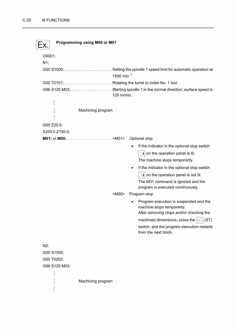
C-20 M FUNCTIONS
Programming using M00 or M01
O0001;
N1;
G50 S1500;. . . . . . . . . . . . . . . . . . . . . . Setting the spindle 1 speed limit for automatic operation at
1500 min−1
G00 T0101;. . . . . . . . . . . . . . . . . . . . . . Rotating the turret to index No. 1 tool
G96 S120 M03;. . . . . . . . . . . . . . . . . . . Starting spindle 1 in the normal direction; surface speed is 120 m/min.
Machining program
G00 Z20.0;
X200.0 Z150.0;
M01; or M00; . . . . . . . . . . . . . . . . . . . . <M01> Optional stop
• If the indicator in the optional stop switch
on the operation panel is lit:
The machine stops temporarily.
• If the indicator in the optional stop switch
on the operation panel is not lit:
The M01 command is ignored and the program is executed continuously.
<M00> Program stop
• Program execution is suspended and the machine stops temporarily.After removing chips and/or checking the
machined dimensions, press the (ST)
switch, and the program execution restarts from the next block.
N2;
G50 S1500;
G00 T0202;
G96 S120 M03;
Machining program
Ex.

M FUNCTIONS C-21
3 M02, M30 PROGRAM END, PROGRAM END AND REWIND
When the M02 or M30 command is executed,
1) All machine operations stop.
• Spindle or rotary tool rotation stops.
• Axis movement stops.
• Coolant discharge stops.
2) The NC is reset.
• In the reset state, the G codes become the same state as those at power turned on.However, G17 to G19, G20/G21, G54 to G59, G96/G97 and the G98/G99 modes remain unchanged.
• Both F and S codes are stored without being canceled.
3) In the case of the M30 command, the cursor returns to the start of the program.
This is called the program rewind function.
The M30 command includes the program rewind function in addition to the functions supported by the M02 command. Since this feature is convenient when machining the same kind of workpieces continuously, the M30 command is usually used at the end of a program. By using the M30 command, the same program is executed
repeatedly by simply pressing the (ST)
switch.
1. For the machine equipped with the door interlock function, an alarm message
(EX1024) is displayed on the screen unless the door is opened/closed if the
(ST) switch is pressed after the completion of the program.
2. With the ZL, ZL-S, ZT series, if M02 or M30 is specified in either of turret 1 or turret 2 program while the other program is executed, execution of M02 or M30 is suspended as long as machining continues at the other turret. Since M02 and M30 have the same function as the program execution synchronization M codes, M02 and M30 must be specified in turret 1 and turret 2 programs in pairs.
+
+
O00001 ;
G50 S
G00 T
O0001 ;• • •
• • •
M02or M30
O 0000G Power ON G codesM Cancel
M30 only
NOTE

C-22 M FUNCTIONS
M02; . . . . . . . . . . Specifies the end of program.The program execution ends and the NC is reset.
M30; . . . . . . . . . . Specifies the end of program and program rewind.The program execution ends, the NC is reset, and the program is rewound.
1. Specify the M02 or M30 command in a block without other commands.
2. The indicator above the (ST) switch goes off when the M02 or M30 command is
executed.
COMMAND
NOTE
M FUNCTIONS C-23
Programming using M02 or M30
O0001;
N1;
G50 S1500;. . . . . . . . . . . . . . . . . . . . . . Setting the spindle 1 speed limit for automatic operation at
1500 min−1
G00 T0101;. . . . . . . . . . . . . . . . . . . . . . Rotating the turret to index No. 1 tool
G96 S120 M03;. . . . . . . . . . . . . . . . . . . Starting spindle 1 in the normal direction; surface speed is 120 m/min.
Machining program
G00 X200.0 Z150.0;
M01; . . . . . . . . . . . . . . . . . . . . . . . . . . . Optional stop
If the indicator in the optional stop switch on the
operation panel is not lit: The M01 command is ignored and the next block is executed continuously.
N2;
G50 S1500;
G00 T0202;. . . . . . . . . . . . . . . . . . . . . . Rotating the turret to index No. 2 tool
G96 S120 M03;
Machining program
G00 X200.0 Z150.0 M09;
M05;
M30; or M02; . . . . . . . . . . . . . . . . . . . . <M02> Ends program execution and automatic operation stops. Although the NC is reset, the cursor stays at this position.
<M30> Ends program execution and automatic operation stops.The NC is reset and the cursor returns to the start of the program (O0001).
Ex.
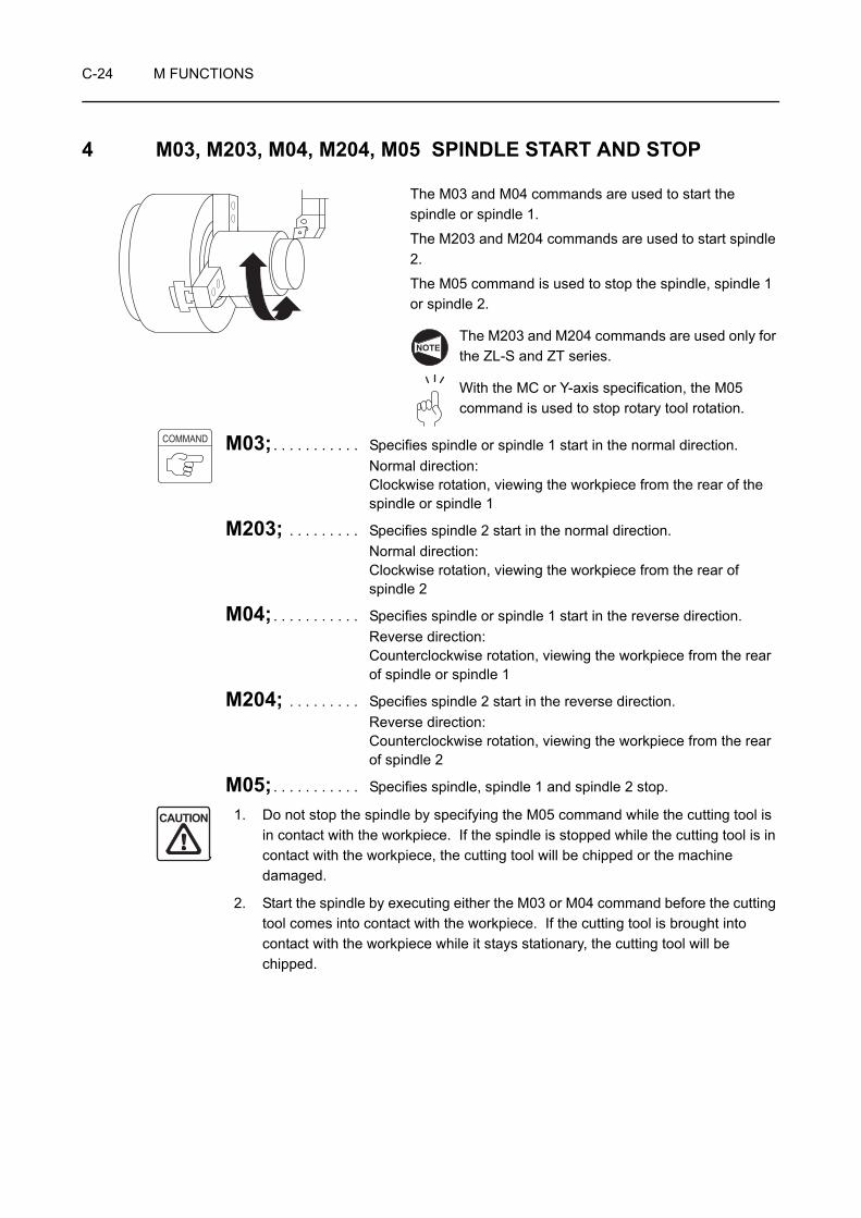
C-24 M FUNCTIONS
4 M03, M203, M04, M204, M05 SPINDLE START AND STOP
The M03 and M04 commands are used to start the spindle or spindle 1.
The M203 and M204 commands are used to start spindle 2.
The M05 command is used to stop the spindle, spindle 1 or spindle 2.
The M203 and M204 commands are used only for the ZL-S and ZT series.
With the MC or Y-axis specification, the M05 command is used to stop rotary tool rotation.
M03; . . . . . . . . . . . Specifies spindle or spindle 1 start in the normal direction.Normal direction:Clockwise rotation, viewing the workpiece from the rear of the spindle or spindle 1
M203; . . . . . . . . . Specifies spindle 2 start in the normal direction.Normal direction:Clockwise rotation, viewing the workpiece from the rear of spindle 2
M04; . . . . . . . . . . . Specifies spindle or spindle 1 start in the reverse direction.Reverse direction:Counterclockwise rotation, viewing the workpiece from the rear of spindle or spindle 1
M204; . . . . . . . . . Specifies spindle 2 start in the reverse direction.Reverse direction:Counterclockwise rotation, viewing the workpiece from the rear of spindle 2
M05; . . . . . . . . . . . Specifies spindle, spindle 1 and spindle 2 stop.
1. Do not stop the spindle by specifying the M05 command while the cutting tool is in contact with the workpiece. If the spindle is stopped while the cutting tool is in contact with the workpiece, the cutting tool will be chipped or the machine damaged.
2. Start the spindle by executing either the M03 or M04 command before the cutting tool comes into contact with the workpiece. If the cutting tool is brought into contact with the workpiece while it stays stationary, the cutting tool will be chipped.
NOTE
COMMAND
CAUTION

M FUNCTIONS C-25
1. Before changing the spindle rotating direction from normal to reverse or from reverse to normal, stop the spindle once by specifying the M05 command. After that specify the M code which calls the spindle to rotate in the opposite direction.
If the spindle rotating direction is changed without specifying the M05 command, an alarm message (EX0401) is displayed on the screen and the spindle stops.
2. The spindle cannot start if the chuck is unclamped.
Before specifying the M03, M203, M04, or M204 command, make sure that the STATUS indicator [CHCL] is lit or the STATUS indicator [CHCL] and the status indicator [HEADSTOCK 2 CHUCK CLAMP] are lit.
3. Before specifying the M03, M203, M04, or M204 command, it is necessary to specify the required spindle speed using an S code.
S code: Page D-17 (2)
4. With the ZL, ZL-S and ZT series, although the spindle stop command (M05) may be specified in either of the programs (turret 1 program and turret 2 program), the one specified only in the program where the spindle start command (M03, M04) has been specified is regarded the valid command. In other words, the M03 or M04 command determines in which program the M05 command is valid. To stop the spindle by specifying the M05 command, specify it in the program where the M03 or M04 command is specified to start the spindle. The spindle does not stop rotating if the M05 command is specified in the program where the M03 or M04 command has not been specified.
5. With the ZL-S and ZT series machines, when executing machining by specifying M03, M04, M203, or M204, the T code to be specified differs depending on which of the turrets and which of the spindles are used for machining. An alarm message (EX1321) is displayed on the screen unless a T code is specified within the range indicated below.
<Executing machining by the combination of turret 1 and spindle 1 by specifying M03/M04 in the turret 1 program>Programmable T code: T0100 to T1200
<Executing machining by the combination of turret 2 and spindle 1 by specifying M03/M04 in the turret 2 program>Programmable T code: T0100 to T1200
<Executing machining by the combination of turret 1 and spindle 2 by specifying M203/M204 in the turret 1 program>Programmable T code: T3100 to T4200
<Executing machining by the combination of turret 2 and spindle 2 by specifying M203/M204 in the turret 2 program>Programmable T code: T3100 to T4200
NOTE

C-26 M FUNCTIONS
Programming using M03, M04, and M05
O0001;
N1;
G50 S1500;. . . . . . . . . . . . . . . . . . . . . . Setting the spindle 1 speed limit for automatic operation at
1500 min−1.
G00 T0101;
G96 S120 M03; . . . . . . . . . . . . . . . . . . Starting spindle 1 in the normal direction; surface speed is 120 m/min.
Machining program
G00 X200.0 Z150.0 M09;
M01; . . . . . . . . . . . . . . . . . . . . . . . . . . . Optional stop
If the indicator in the optional stop switch on the
operation panel is not lit:The M01 command is ignored and the program is executed continuously.
If the M01 command is executed, the spindle or spindle 1 stops rotating. However, if the M01 command is ignored, the spindle or spindle 1 keeps rotating.
N2;
G50 S1500;. . . . . . . . . . . . . . . . . . . . . . Setting the spindle 1 speed limit for automatic operation at
1500 min−1.
G00 T0202;
G96 S120 M03; . . . . . . . . . . . . . . . . . . Starting spindle 1 in the normal direction; surface speed is 120 m/min.Since there are cases that the spindle or spindle 1 is stopped by the execution of the M00 or M01 command, the M03(M04) command must be specified in the "G96 S_" or "G97 S_" block at the beginning of each part program.
Machining program
G00 X200.0 Z150.0 M05; . . . . . . . . . . Stopping the spindle 1 rotation
If the following part program includes the machining which requires the spindle rotation to the reverse direction, the spindle rotation must be stopped by specifying the M05 command.
M01; . . . . . . . . . . . . . . . . . . . . . . . . . . . Optional stop
Ex.
NOTE
M FUNCTIONS C-27
N3;
G50 S1500;
G00 T0303;
G97 S640 M04; . . . . . . . . . . . . . . . . . . Starting spindle 1 in the reverse direction at 640 min−1
(For cutting such as left-hand thread)
X70.0 Z20.0 M08;
G01 Z5.0 F1.0 M24;
G92 X59.1 Z−24.0 F2.0;
Machining program
G00 X200.0 Z150.0 M09;
M05; . . . . . . . . . . . . . . . . . . . . . . . . . . . Stopping the spindle 1 rotation
M30;
The M03(M04) command is usually specified in the "G96 S_" or "G97 S_" block at the beginning of a part program. The M05 command is specified to stop the spindle before changing the spindle rotating direction or at the end of the program.

C-28 M FUNCTIONS
5 M13, M14, M05 START AND STOP OF ROTARY TOOL ROTATION
The M13 and M14 commands are used to rotate the rotary tool.
The M05 command is used to stop rotary tool rotation.
1. The M13 and M14 commands can be used only with the MC type machine or the Y-axis specification machine.
2. With the ZL series, the M13 and M14 commands can be specified only in the turret 1 program.
3. With the ZL-S and ZT series, the M13 or M14 command can be specified in either turret 1 or turret 2 program. Note that if the command is specified in the turret 1 program, only the rotary tool in turret 1 will rotate. Similarly, if it is specified in the turret 2 program, only the rotary tool in turret 2 will rotate.
The M05 command is also used to stop the spindle, spindle 1, or spindle 2.
M13; . . . . . . . . . . . Specifies rotary tool rotation in the normal direction.Normal direction: Clockwise rotation, viewing the workpiece from the rear of the rotary tool
M14; . . . . . . . . . . . Specifies rotary tool rotation in the reverse direction.Reverse direction: Counterclockwise rotation, viewing the workpiece from the rear of the rotary tool
M05; . . . . . . . . . . . Stops rotary tool rotation.The rotary tool stops rotating.
1. Do not stop rotary tool rotation by specifying the M05 command while the cutting tool is in contact with the workpiece. If the rotary tool is stopped while the cutting tool is in contact with the workpiece, the cutting tool could be damaged.
2. Rotate the rotary tool by executing either M13 or M14 command before the cutting tool comes into contact with the workpiece. If the cutting tool is brought into contact with the workpiece while it is not rotating, the cutting tool could be damaged.
3. Before using a rotary tool, the tool must be registered correctly. If tool registration is incorrect, the rotary tool may rotate in the opposite direction. If machining is executed while the rotary tool is rotating in the wrong direction, the rotary tool or the machine could be damaged.
For rotary tool registration: OPERATION MANUAL separately provided
NOTE
COMMAND
CAUTION

M FUNCTIONS C-29
1. Before changing the rotation direction of the rotary tool, stop rotary tool rotation once by specifying the M05 command, and then specify the rotary tool rotation command in the opposite direction.
If the rotation direction is changed without specifying the M05 command, an alarm message (EX0401) is displayed on the screen and rotary tool rotation stops.
2. The rotary tool cannot rotate if the chuck is unclamped.
Before specifying the M13 or M14 command, make sure that the STATUS indicator [CHCL] is lit or the STATUS indicator [CHCL] and the status indicator [HEADSTOCK 2 CHUCK CLAMP] are lit.
3. Before specifying the M13 or M14 command, it is necessary to connect the C-axis by executing the M45 or M245 command, or clamp the spindle by executing M68 or M268.
4. Before specifying the M13 or M14 command, it is necessary to specify the required spindle speed using an S code.
S code: Page D-17 (2)
5. With the ZL-S and ZT series machines, when executing machining by specifying M13 or M14, the T code to be specified differs depending on which of the turrets and which of the spindles are used for machining. An alarm message (EX1321) is displayed on the screen unless a T code is specified within the range indicated below.
<Executing machining by the combination of turret 1 and spindle 1 by specifying M13/M14 in the turret 1 program>Programmable T code: T0100 to T1200
<Executing machining by the combination of turret 2 and spindle 1 by specifying M13/M14 in the turret 2 program>Programmable T code: T0100 to T1200
<Executing machining by the combination of turret 1 and spindle 2 by specifying M13/M14 in the turret 1 program>Programmable T code: T3100 to T4200
<Executing machining by the combination of turret 2 and spindle 2 by specifying M13/M14 in the turret 2 program>Programmable T code: T3100 to T4200
NOTE

C-30 M FUNCTIONS
Programming using M13 or M14
O0001;
N1;
M45;
G28 H0;
G00 T0101;
G97 S600 M13; . . . . . . . . . . . . . . . . . . Rotating the rotary tool in the normal direction at
600 min−1
G98;
Machining program
G00 X200.0 Z150.0 M05; . . . . . . . . . . . Stopping rotary tool rotation
M46;
M30;
Ex.
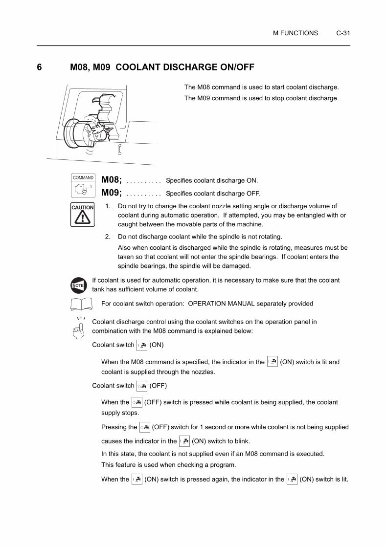
M FUNCTIONS C-31
6 M08, M09 COOLANT DISCHARGE ON/OFF
The M08 command is used to start coolant discharge.
The M09 command is used to stop coolant discharge.
M08; . . . . . . . . . . Specifies coolant discharge ON.
M09; . . . . . . . . . . Specifies coolant discharge OFF.
1. Do not try to change the coolant nozzle setting angle or discharge volume of coolant during automatic operation. If attempted, you may be entangled with or caught between the movable parts of the machine.
2. Do not discharge coolant while the spindle is not rotating.
Also when coolant is discharged while the spindle is rotating, measures must be taken so that coolant will not enter the spindle bearings. If coolant enters the spindle bearings, the spindle will be damaged.
If coolant is used for automatic operation, it is necessary to make sure that the coolant tank has sufficient volume of coolant.
For coolant switch operation: OPERATION MANUAL separately provided
Coolant discharge control using the coolant switches on the operation panel in combination with the M08 command is explained below:
Coolant switch (ON)
When the M08 command is specified, the indicator in the (ON) switch is lit and coolant is supplied through the nozzles.
Coolant switch (OFF)
When the (OFF) switch is pressed while coolant is being supplied, the coolant supply stops.
Pressing the (OFF) switch for 1 second or more while coolant is not being supplied
causes the indicator in the (ON) switch to blink.
In this state, the coolant is not supplied even if an M08 command is executed.
This feature is used when checking a program.
When the (ON) switch is pressed again, the indicator in the (ON) switch is lit.
COMMAND
CAUTION
NOTE
C-32 M FUNCTIONS
Programming using M08 and M09
O0001;
N1;
G50 S1500;
G00 T0101;
G96 S120 M03;
X75.0 Z20.0 M08; . . . . . . . . . . . . . . . . Starting coolant discharge
Machining program
G00 Z20.0;
X200.0 Z150.0;
M01; . . . . . . . . . . . . . . . . . . . . . . . . . . . Optional stop
If the indicator in the optional stop switch on the
operation panel is not lit: The M01 command is ignored and the program is executed continuously. If the M01 command is executed, coolant discharge stops. However, if the M01 command is ignored, coolant is kept discharged.
N2;
G50 S1500;
G00 T0202;
G96 S120 M03;
X33.0 Z20.0 M08; . . . . . . . . . . . . . . . . Starting coolant dischargeSince coolant discharge might have been stopped by the execution of the M00 or M01 command, the M08 command must be specified at the beginning of a part program.
Machining program
G00 X200.0 Z150.0 M09; . . . . . . . . . . Stopping coolant discharge
M05;
M30;
The M08 command is usually specified in the first approach operation in each part program. The M09 command is usually specified when the cutting tool retracts from the workpiece at the end of a program.
Ex.

M FUNCTIONS C-33
7 M19 SPINDLE ORIENTATION (SPINDLE 1), M219 SPINDLE ORIENTATION (SPINDLE 2), M319 ROTARY TOOL SPINDLE ORIENTATION
The spindle, tool-spindle, and rotary tool spindle stop at the specified orientation (angle).
The spindle orientation commands are used for operations such as loading/unloading with the loader or workpiece transfer.
1. M219 is valid for ZL-S series and ZT series.
2. M319 is valid for MC type and Y-axis specifications.NOTE

C-34 M FUNCTIONS
8 M23, M24 CHAMFERING ON/OFF
The M23 and M24 commands indicate whether or not chamfering is carried out in the thread cutting cycle called by the G92 and G76 commands.
If the thread to be cut does not have a groove at the end, as illustrated on the left, the chamfering ON command (M23) is required.
Specify the chamfering OFF command (M24) when the thread has a groove at the end, as illustrated to the left, and chamfering is not necessary.
Distance U/2 must be greater than chamfering distance.
M23; . . . . . . . . . . Specifies chamfering ON.(This mode is selected when the power is turned on.)Calls the chamfering ON mode.
M24; . . . . . . . . . . Specifies chamfering OFF.Cancels the chamfering ON mode.
1. Chamfering angle is 45°.
2. Amount of chamfering (r) should be set for NC parameter No. 5130. Setting is possible in units of "lead/10" (= 1) in the range from 0 to 127. This amount may be set in a program using the format below.
G76 P Q_ R_ ;
Specify a 6-digit number following address P. If the parameter is set in this method, setting range of is from 00 to 99.
U/2
(1) Chamfering ON (M23)
(2) Chamfering OFF (M24)
Rapid traverse
Cutting feed
NOTE
COMMAND
NOTE
45°
r
Thread chamfering amount
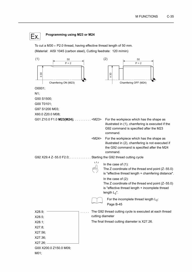
M FUNCTIONS C-35
Programming using M23 or M24
To cut a M30 × P2.0 thread, having effective thread length of 50 mm.
(Material: AISI 1045 (carbon steel), Cutting feedrate: 120 m/min)
O0001;N1;G50 S1500;G00 T0101;G97 S1200 M03;X60.0 Z20.0 M08;G01 Z10.0 F1.0 M23(M24); . . . . . . . . . <M23> For the workpiece which has the shape as
illustrated in (1), chamfering is executed if the G92 command is specified after the M23 command.
<M24> For the workpiece which has the shape as illustrated in (2), chamfering is not executed if the G92 command is specified after the M24 command.
G92 X29.4 Z−55.0 F2.0; . . . . . . . . . . . . Starting the G92 thread cutting cycle
In the case of (1):The Z coordinate of the thread end point (Z−55.0) is "effective thread length + chamfering distance".
In the case of (2):The Z coordinate of the thread end point (Z−55.0) is "effective thread length + incomplete thread length L2".
For the incomplete thread length L2: Page B-45
X28.9;X28.5;X28.1;X27.8;X27.56;X27.36;X27.26;G00 X200.0 Z150.0 M09;M01;
Ex.
P = 2 P = 250 50(1) (2)
30 30φ φ
Chamfering ON (M23) Chamfering OFF (M24)
. . . . . The G92 thread cutting cycle is executed at each thread cutting diameter
The final thread cutting diameter is X27.26.

C-36 M FUNCTIONS
For details of depth of cut and number of passes, refer to page B-47.
However, the values given in the table are only for reference. The depth of cut and the number of passes should be determined according to actual machining status. Use the thread gage to check the machined thread accuracy.
NOTE

M FUNCTIONS C-37
9 M10, M210, M11, M211 CHUCK CLAMP/UNCLAMP
The chuck or the spindle 1 chuck clamps a workpiece when the M10 command is executed.
The spindle 2 chuck clamps a workpiece when the M210 command is executed.
The M11 command is used to unclamp the chuck or the spindle 1 chuck.
For unclamping the spindle 2 chuck, the M211 command is used.
These M codes are used to continuously machine workpieces in the machine equipped with a bar feeder or a loader. They are also used for carrying out both-center work or transferring a workpiece between the spindles.
The M210 and M211 commands are used only for the ZL-S and ZT series machines.
M10; . . . . . . . . . . Specifies chuck or spindle 1 chuck clamp.
The chuck or spindle 1 chuck clamps a workpiece in it.
M210; . . . . . . . . . Specifies spindle 2 chuck clamp.
The spindle 2 chuck clamps a workpiece in it.
M11; . . . . . . . . . . Specifies chuck or spindle 1 chuck unclamp.
The chuck or spindle 1 chuck unclamps a workpiece.
M211; . . . . . . . . . Specifies spindle 2 chuck unclamp.
The spindle 2 chuck unclamps a workpiece.
1. Do not execute the M11 or M211 command when a workpiece is clamped by the chuck with the single block switch set ON. If the M11 or M211 command is executed under such status, the machine stops operating due to the chuck interlock function causing the workpiece to fall which could damage the machine.
2. Specify the M10, M210, M11, or M211 command in a block without other commands, and specify the G04 command in the next block to allow the chuck to complete the clamp or unclamp operation correctly. Since the time required for the chuck to carry out the clamp or unclamp operation varies depending on the chuck type and chucking pressure, the dwell time should be a little longer than the actual clamp/unclamp time.
Unclamp Clamp
NOTE
COMMAND
CAUTION

C-38 M FUNCTIONS
1. At the start of an operation, the workpiece must be clamped manually. This is because the automatic operation cannot be started with the chuck in the unclamp state due to the chuck interlock function.
2. The chucking direction (O.D. chucking, I.D. chucking) can be changed using the "CHUCK DIRECTION" or "CHUCK1 DIRECTION" and "CHUCK2 DIRECTION" on the OPERATION PANEL screen.
For the procedure of changing the chucking direction (I.D. or O.D. chucking): OPERATION MANUAL separately provided
3. Due to the chuck interlock function, the M11 command must not be specified while the spindle or spindle 1 is rotating. Similarly, the M211 command must not be specified while spindle 2 is rotating.
4. Due to the chuck interlock function, the M11 and M211 commands must not be specified while the rotary tool is rotating.
NOTE

M FUNCTIONS C-39
Programming using M10 and M11
An example of machining program used for both-center work of the ZL series.
For both-center work, the M11 command may be used to ensure safe operation.
O0001;
N1;
Machining program
M05; . . . . . . . . . . . . . . . . . . . . . . . . . . . Stopping the spindle rotation
M01;
M11; . . . . . . . . . . . . . . . . . . . . . . . . . . . The chuck unclamps. The STATUS indicator [CHCL] goes off.
M30; . . . . . . . . . . . . . . . . . . . . . . . . . . . Ends program execution and automatic operation stops.The NC is reset and the cursor returns to the start of the program (O0001).
To start the next cycle after changing the workpiece, it is necessary to step on the footswitch to turn on the STATUS indicator [CHCL]. Otherwise, the chuck interlock function disables the cycle start.
As explained above, although the M11 command does not work to clamp/unclamp a workpiece actually, it calls for the chuck interlock function to ensure safe operation.
WARNING In machining programs for both-center-work, specify the M11 command to unclamp the chuck before the M30 command to reset and rewind the
program. If the M11 command is not executed and the (ST) switch is
pressed by mistake, automatic operation will start and the operator may be injured. However, if the M11 command is executed when the center at the spindle side is held by the chuck during programming, the center will fall or shift, which in turn will cause the workpiece to fall, damaging the machine. If the center at the spindle side is held by the chuck, do not execute the M11 command. (Applies only to machines equipped with a tailstock.)
Ex.
Spindle side Tailstock side
NOTE

C-40 M FUNCTIONS
Programming using M10, M210, M11, and M211
For the ZL-S and ZT series machine equipped with a bar feeder:<Turret 1> <Turret 2>O0001; O0002;N1; N1;
G59; . . . . . . . . . . . . . . . Selecting the G59 work coordinate system (for workpiece transfer)
Machining program
(M246;) . . . . . . . . . . . . . To be specified only for MC type
N7; G00 T3100;. . . . . . . . . . Selecting the No.1 toolThe tool wear offset cancel
G00 T0101; G28 U0 M05; . . . . . . . . Returning the X-axis to the machine zero
point
M100;. . . . . . . . . . . . . . . Synchronization of program execution M100; . . . . . . . . . . . . . . Synchronization of program execution
M35;. . . . . . . . . . . . . . . . Speed synchronous operation M35; . . . . . . . . . . . . . . . Speed synchronous operation
M101;. . . . . . . . . . . . . . . Synchronization of program execution M101; . . . . . . . . . . . . . . Synchronization of program execution
G97 S1000 M03; . . . . . . Speeds of spindle 1 and spindle 2 are
synchronized at 1000 min−1M211; . . . . . . . . . . . . . . Chuck 2 unclamp
G28 U0 M09; . . . . . . . . . Returning the X-axis to the machine zero point
Z10.0;Z0.3 M51;M102;. . . . . . . . . . . . . . . Synchronization of program execution M102; . . . . . . . . . . . . . . Synchronization of program execution
Workpiece transfer
Chuck 2 is clamped after the detection of pressing of workpiece.
M103;. . . . . . . . . . . . . . . Synchronization of program execution M103; . . . . . . . . . . . . . . Synchronization of program execution
M11; . . . . . . . . . . . . . . . . Chuck 1 unclamp
G04 U_ ;M104;. . . . . . . . . . . . . . . Synchronization of program execution M104; . . . . . . . . . . . . . . Synchronization of program execution;
program execution is suspended until chuck 1 is unclamped.
M70;. . . . . . . . . . . . . . . . Supplying a bar with the bar feeder G98 G01 Z_ F2000; . . . Pulling the workpiece
M105;. . . . . . . . . . . . . . . Synchronization of program execution; program execution is suspended until the completion of "pulling workpiece".
M105; . . . . . . . . . . . . . . Synchronization of program execution
M10;. . . . . . . . . . . . . . . . Chuck 1 clamp
G04 U_ ;M106;. . . . . . . . . . . . . . . Synchronization of program execution M106; . . . . . . . . . . . . . . Synchronization of program execution;
program execution is suspended until chuck 1 is clamped.
X42.0 M08;G99 G01 X−0.6 F0.08;G53 X0 M09;M80;. . . . . . . . . . . . . . . . Detecting cutting off
M107;. . . . . . . . . . . . . . . Synchronization of program execution M107; . . . . . . . . . . . . . . Synchronization of program execution; program execution is suspended until cutting off operation is finished.
G330; . . . . . . . . . . . . . . Returning the B-axis (spindle 2) to the machine zero point
M36; . . . . . . . . . . . . . . . Canceling synchronous operation
M108;. . . . . . . . . . . . . . . Synchronization of program execution; program execution is suspended until "returning the B-axis (spindle 2) to the machine zero point".
M108; . . . . . . . . . . . . . . Synchronization of program execution
M30; M01;
Ex.
NOTE
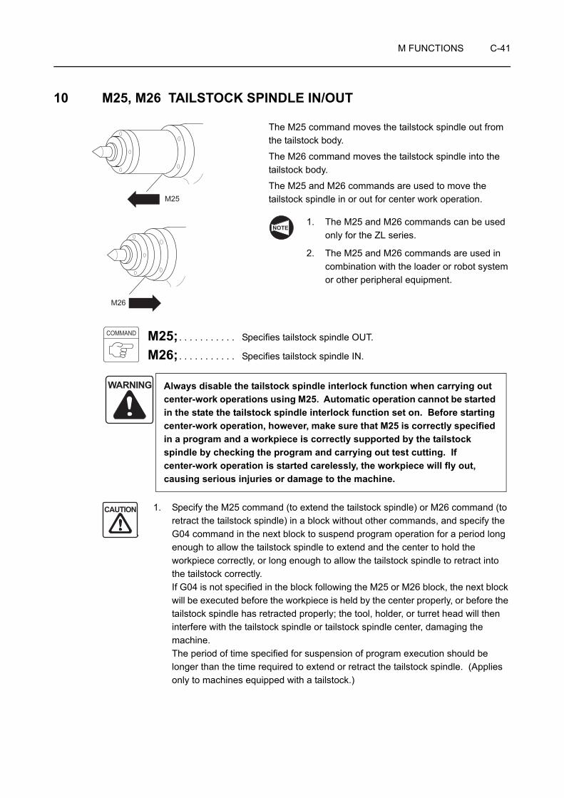
M FUNCTIONS C-41
10 M25, M26 TAILSTOCK SPINDLE IN/OUT
The M25 command moves the tailstock spindle out from the tailstock body.
The M26 command moves the tailstock spindle into the tailstock body.
The M25 and M26 commands are used to move the tailstock spindle in or out for center work operation.
1. The M25 and M26 commands can be used only for the ZL series.
2. The M25 and M26 commands are used in combination with the loader or robot system or other peripheral equipment.
M25; . . . . . . . . . . . Specifies tailstock spindle OUT.
M26; . . . . . . . . . . . Specifies tailstock spindle IN.
1. Specify the M25 command (to extend the tailstock spindle) or M26 command (to retract the tailstock spindle) in a block without other commands, and specify the G04 command in the next block to suspend program operation for a period long enough to allow the tailstock spindle to extend and the center to hold the workpiece correctly, or long enough to allow the tailstock spindle to retract into the tailstock correctly. If G04 is not specified in the block following the M25 or M26 block, the next block will be executed before the workpiece is held by the center properly, or before the tailstock spindle has retracted properly; the tool, holder, or turret head will then interfere with the tailstock spindle or tailstock spindle center, damaging the machine. The period of time specified for suspension of program execution should be longer than the time required to extend or retract the tailstock spindle. (Applies only to machines equipped with a tailstock.)
WARNING Always disable the tailstock spindle interlock function when carrying out center-work operations using M25. Automatic operation cannot be started in the state the tailstock spindle interlock function set on. Before starting center-work operation, however, make sure that M25 is correctly specified in a program and a workpiece is correctly supported by the tailstock spindle by checking the program and carrying out test cutting. If center-work operation is started carelessly, the workpiece will fly out, causing serious injuries or damage to the machine.
M25
M26
NOTE
COMMAND
CAUTION
C-42 M FUNCTIONS
2. When a workpiece is held by the tailstock, execute the M26 command (tailstock spindle IN) after securely supporting the workpiece by the crane or other appropriate means. If the M26 command is carelessly executed although the workpiece is not supported securely by appropriate means, the workpiece is held only by the chuck after the retraction of the tailstock spindle. This could cause the workpiece to fall and damage the machine.
For how to use the tailstock spindle interlock function: OPERATION MANUAL separately provided
Programming using M25 and M26
O0001;
N1;
G50 S1000;
G00 T0101;
G97 S1000 M03;
Facing or center drilling program
G00 X200.0 Z150.0 M09; . . . . . . . . . . . Stopping coolant discharge
M05; . . . . . . . . . . . . . . . . . . . . . . . . . . . Stopping the spindle rotation
M01;
N2;
G479 V_ ; . . . . . . . . . . . . . . . . . . . . . . . Moving the tailstock to the position specified by V_ (machine coordinate value)
M25; . . . . . . . . . . . . . . . . . . . . . . . . . . . The tailstock spindle moves out. The tailstock spindle center pushes the workpiece to hold it.
G04 U_ ; . . . . . . . . . . . . . . . . . . . . . . . . Calling for dwell; program execution is suspended until the workpiece is securely pushed by the tailstock spindle center.
The time required for the tailstock spindle center to hold the workpiece securely varies according to the tailstock spindle thrust and the tailstock body position. Determine the dwell period taking these into consideration.
For the procedure of adjusting the tailstock spindle thrust: OPERATION MANUAL separately provided
CAUTION
Ex.
NOTE

M FUNCTIONS C-43
G50 S1000;
G00 T0202;
G96 S100 M03;
Machining program
G28 U0; . . . . . . . . . . . . . . . . . . . . . . . . Machine zero return of X-axis to avoid interference with the tailstock
M05; . . . . . . . . . . . . . . . . . . . . . . . . . . . Stopping the spindle rotation
M26; . . . . . . . . . . . . . . . . . . . . . . . . . . . The tailstock spindle retracts into the tailstock body.
G04 U_ ; . . . . . . . . . . . . . . . . . . . . . . . . Calling for dwell to allow tailstock spindle to correctly extract into the tailstock body
G479 V_ ; . . . . . . . . . . . . . . . . . . . . . . . Moving the tailstock to the previously located position, specified by V_ (machine coordinate value)
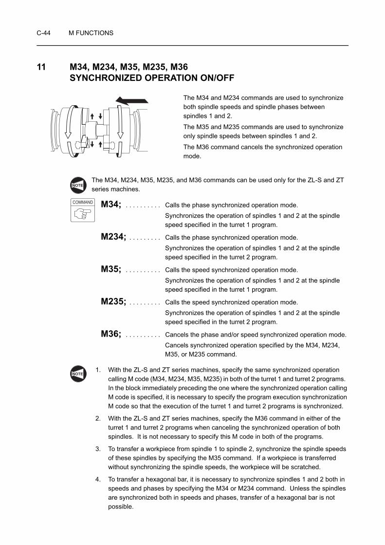
C-44 M FUNCTIONS
11 M34, M234, M35, M235, M36 SYNCHRONIZED OPERATION ON/OFF
The M34 and M234 commands are used to synchronize both spindle speeds and spindle phases between spindles 1 and 2.
The M35 and M235 commands are used to synchronize only spindle speeds between spindles 1 and 2.
The M36 command cancels the synchronized operation mode.
The M34, M234, M35, M235, and M36 commands can be used only for the ZL-S and ZT series machines.
M34; . . . . . . . . . . Calls the phase synchronized operation mode.Synchronizes the operation of spindles 1 and 2 at the spindle speed specified in the turret 1 program.
M234; . . . . . . . . . Calls the phase synchronized operation mode.Synchronizes the operation of spindles 1 and 2 at the spindle speed specified in the turret 2 program.
M35; . . . . . . . . . . Calls the speed synchronized operation mode.Synchronizes the operation of spindles 1 and 2 at the spindle speed specified in the turret 1 program.
M235; . . . . . . . . . Calls the speed synchronized operation mode.Synchronizes the operation of spindles 1 and 2 at the spindle speed specified in the turret 2 program.
M36; . . . . . . . . . . Cancels the phase and/or speed synchronized operation mode.Cancels synchronized operation specified by the M34, M234, M35, or M235 command.
1. With the ZL-S and ZT series machines, specify the same synchronized operation calling M code (M34, M234, M35, M235) in both of the turret 1 and turret 2 programs. In the block immediately preceding the one where the synchronized operation calling M code is specified, it is necessary to specify the program execution synchronization M code so that the execution of the turret 1 and turret 2 programs is synchronized.
2. With the ZL-S and ZT series machines, specify the M36 command in either of the turret 1 and turret 2 programs when canceling the synchronized operation of both spindles. It is not necessary to specify this M code in both of the programs.
3. To transfer a workpiece from spindle 1 to spindle 2, synchronize the spindle speeds of these spindles by specifying the M35 command. If a workpiece is transferred without synchronizing the spindle speeds, the workpiece will be scratched.
4. To transfer a hexagonal bar, it is necessary to synchronize spindles 1 and 2 both in speeds and phases by specifying the M34 or M234 command. Unless the spindles are synchronized both in speeds and phases, transfer of a hexagonal bar is not possible.
NOTE
COMMAND
NOTE

M FUNCTIONS C-45
5. The M36 command should be specified only after the completion of cut-off cycle or when either of spindle 1 or spindle 2 chuck is unclamped. After the execution of the M36 command, the spindle which was controlled in synchronization with the other spindle stops rotating.
6. If the M34 or M234 command is specified while the spindle 2 chuck is clamped, an alarm message (EX2419) is displayed on the screen.
7. Do not specify the M05 command in the phase synchronization operation mode or the speed synchronization operation mode. If the M05 command is specified in these modes, spindles 1 and 2 stop rotating in synchronization and the phase synchronization operation mode or the speed synchronization operation mode is canceled.
8. With the ZL-S and ZT series machines, index No. 1 tool in turret 2 and return the X-axis to the machine zero point before executing the workpiece transfer operation.
If turret 2 is not indexed to No. 1 position or if the X-axis is not at the machine zero point, workpiece transfer operation is not possible.
It is allowed to use the M34 or M234 command for transferring a workpiece having round section shape. However, since spindle speed synchronization control is executed after the completion of phase synchronization, it takes a long time to synchronize both the speeds and phases. To shorten idle time, it is recommended to specify the M35 or M235 command if the workpiece has a round section.
NOTE

C-46 M FUNCTIONS
Programming using M34, M35, and M36 (1) (ZL-S series)
With the ZL-S series machines, a workpiece, machined in spindle 1 is transferred from spindle 1 to spindle 2 by synchronizing the spindles
<Turret 1> <Turret 2>O0001; O0002;N1; N1;
G59; . . . . . . . . . . . . . . . Selecting the G59 work coordinate system
Machining program (for workpiece transfer)
(M246;) . . . . . . . . . . . . . To be specified only for MC type
N7; G00 T3100;. . . . . . . . . . Selecting the No.1 tool
The tool wear offset cancel
G00 T0101; G28 U0 M05; . . . . . . . . Returning the X-axis to the machine zero
point
M100;. . . . . . . . . . . . . . . Synchronization of program execution M100; . . . . . . . . . . . . . . Synchronization of program execution
M34;. . . . . . . . . . . . . . . . Phase synchronous operation M34; . . . . . . . . . . . . . . . Phase synchronous operation
M101;. . . . . . . . . . . . . . . Synchronization of program execution M101; . . . . . . . . . . . . . . Synchronization of program execution
G97 S1000 M03; . . . . . . Speeds of spindle 1 and spindle 2 are
synchronized at 1000 min−1
M211; . . . . . . . . . . . . . . Chuck 2 unclamp
G28 U0 M09; . . . . . . . . . Returning the X-axis to the machine zero
point
Z10.0;Z0.3 M51;M102;. . . . . . . . . . . . . . . Synchronization of program execution M102; . . . . . . . . . . . . . . Synchronization of program execution
M59; G00 B_ M252;. . . . . . . . Moving headstock 2 to the approach
position B_ (work coordinate system)
(First approach)
G98 G01 B_ F1000 M257; . . . . . . . . . . . . . . . . . . . Approaching of headstock 2 to workpiece at
the feedrate of 1000 mm/min
(Second approach)
G38 J_ K_ F_ Q_ ; . . . . Detecting the pushing of workpiece
Chuck 2 clamp operation is included.
M103;. . . . . . . . . . . . . . . Synchronization of program execution:
program execution is suspended until completion of "detecting the pushing of
workpiece".
M103; . . . . . . . . . . . . . . Synchronization of program execution
Machining program (Cutting off of workpiece)
M104;. . . . . . . . . . . . . . . Synchronization of program execution M104; . . . . . . . . . . . . . . Synchronization of program execution;
program execution is suspended until cutting off operation is finished.
G330; . . . . . . . . . . . . . . Returning the B-axis (spindle 2) to the
machine zero point
M36; . . . . . . . . . . . . . . . Canceling synchronous operation
M105;. . . . . . . . . . . . . . . Synchronization of program execution;
program execution is suspended until "returning the B-axis (spindle 2) to the
machine zero point".
M105; . . . . . . . . . . . . . . Synchronization of program execution
M30; M01;
Ex.
NOTE
M FUNCTIONS C-47
Programming using M34, M35, and M36 (2) (ZL-S series)
With the ZL-S series machines, a workpiece, machined in spindle 1 is transferred from spindle 1 to spindle 2 by synchronizing the spindles
<Turret 1> <Turret 2>O0001; O0002;N1; N1;
G59; . . . . . . . . . . . . . . . Selecting the G59 work coordinate system
Machining program (for workpiece transfer)
(M246;) . . . . . . . . . . . . . To be specified only for MC type
N7; G00 T3100;. . . . . . . . . . Selecting the No.1 tool
The tool wear offset cancel
G00 T0101; G28 U0 M05; . . . . . . . . Returning the X-axis to the machine zero
point
M100;. . . . . . . . . . . . . . . Synchronization of program execution M100; . . . . . . . . . . . . . . Synchronization of program execution
M35;. . . . . . . . . . . . . . . . Speed synchronous operation M35; . . . . . . . . . . . . . . . Speed synchronous operation
M101;. . . . . . . . . . . . . . . Synchronization of program execution M101; . . . . . . . . . . . . . . Synchronization of program execution
G97 S1000 M03; . . . . . . Speeds of spindle 1 and spindle 2 are
synchronized at 1000 min−1
M211; . . . . . . . . . . . . . . Chuck 2 unclamp
G28 U0 M09; . . . . . . . . . Returning the X-axis to the machine zero
point
Z10.0;Z0.3 M51;M102;. . . . . . . . . . . . . . . Synchronization of program execution M102; . . . . . . . . . . . . . . Synchronization of program execution
M59; G00 B_ M252;. . . . . . . . Moving headstock 2 to the approach
position B_ (work coordinate system)
(First approach)
G98 G01 B_ F1000 M257; . . . . . . . . . . . . . . . . . . . Approaching of headstock 2 to workpiece at
the feedrate of 1000 mm/min
(Second approach)
G38 J_ K_ F_ Q_ ; . . . . Detecting the pushing of workpiece
Chuck 2 clamp operation is included.
M103;. . . . . . . . . . . . . . . Synchronization of program execution:
program execution is suspended until completion of "detecting the pushing of
workpiece".
M103; . . . . . . . . . . . . . . Synchronization of program execution
Machining program (Cutting off of workpiece)
M104;. . . . . . . . . . . . . . . Synchronization of program execution M104; . . . . . . . . . . . . . . Synchronization of program execution;
program execution is suspended until cutting off operation is finished.
G330; . . . . . . . . . . . . . . Returning the B-axis (spindle 2) to the
machine zero point
M36; . . . . . . . . . . . . . . . Canceling synchronous operation
M105;. . . . . . . . . . . . . . . Synchronization of program execution;
program execution is suspended until "returning the B-axis (spindle 2) to the
machine zero point".
M105; . . . . . . . . . . . . . . Synchronization of program execution
M30; M01;
Ex.
NOTE
C-48 M FUNCTIONS
Programming using M34, M35, and M36 (1) (ZT series)
With the ZT series machines, a workpiece, machined in spindle 1 is transferred from spindle 1 to spindle 2 by synchronizing the spindles
<Turret 1> <Turret 2>O0001; O0002;N1; N1;
G59; . . . . . . . . . . . . . . . Selecting the G59 work coordinate system
(for workpiece transfer)Machining program
(M246;) . . . . . . . . . . . . . To be specified only for MC type
N7; G00 T3100;. . . . . . . . . . Selecting the No.1 tool
The tool wear offset cancel
G00 T0101; G28 U0 M05; . . . . . . . . Returning the X-axis to the machine zero
point
M100;. . . . . . . . . . . . . . . Synchronization of program execution M100; . . . . . . . . . . . . . . Synchronization of program execution
M34;. . . . . . . . . . . . . . . . Phase synchronous operation M34; . . . . . . . . . . . . . . . Phase synchronous operation
M101;. . . . . . . . . . . . . . . Synchronization of program execution M101; . . . . . . . . . . . . . . Synchronization of program execution
G97 S1000 M03; . . . . . . Speeds of spindle 1 and spindle 2 are
synchronized at 1000 min−1
M211; . . . . . . . . . . . . . . Chuck 2 unclamp
G28 U0 M09; . . . . . . . . . Returning the X-axis to the machine zero
point
Z10.0;Z0.3 M51;M102;. . . . . . . . . . . . . . . Synchronization of program execution M102; . . . . . . . . . . . . . . Synchronization of program execution
M59; M369; . . . . . . . . . . . . . . B-axis unclamp
G00 B_ M252;. . . . . . . . Moving headstock 2 to the approach
position B_ (work coordinate system)
(First approach)
G98 G01 B_ F1000 M257; . . . . . . . . . . . . . . . . . . . Approaching of headstock 2 to workpiece at
the feedrate of 1000 mm/min
(Second approach)
G38 J_ K_ F_ Q_ ; . . . . Detecting the pushing of workpiece
Chuck 2 clamp operation is included.
M103;. . . . . . . . . . . . . . . Synchronization of program execution:
program execution is suspended until completion of "detecting the pushing of
workpiece".
M103; . . . . . . . . . . . . . . Synchronization of program execution
Machining program (Cutting off of workpiece)
M104;. . . . . . . . . . . . . . . Synchronization of program execution M104; . . . . . . . . . . . . . . Synchronization of program execution;
program execution is suspended until cutting off operation is finished.
G330; . . . . . . . . . . . . . . Returning the B-axis (spindle 2) to the
machine zero point
B-axis clamp operation is included.
M36; . . . . . . . . . . . . . . . Canceling phase synchronous operation
M105;. . . . . . . . . . . . . . . Synchronization of program execution;
program execution is suspended until
"returning the B-axis (spindle 2) to the
machine zero point".
M105; . . . . . . . . . . . . . . Synchronization of program execution
M30; M01;
Ex.
NOTE
NOTE

M FUNCTIONS C-49
Programming using M34, M35, and M36 (2) (ZT series)
With the ZT series machines, a workpiece, machined in spindle 1 is transferred from spindle 1 to spindle 2 by synchronizing the spindles
<Turret 1> <Turret 2>O0001; O0002;N1; N1;
G59; . . . . . . . . . . . . . . . Selecting the G59 work coordinate system
(for workpiece transfer)Machining program
(M246;) . . . . . . . . . . . . . To be specified only for MC type
N7; G00 T3100;. . . . . . . . . . Selecting the No.1 tool
The tool wear offset cancel
G00 T0101; G28 U0 M05; . . . . . . . . Returning the X-axis to the machine zero
point
M100;. . . . . . . . . . . . . . . Synchronization of program execution M100; . . . . . . . . . . . . . . Synchronization of program execution
M35;. . . . . . . . . . . . . . . . Speed synchronous operation M35; . . . . . . . . . . . . . . . Speed synchronous operation
M101;. . . . . . . . . . . . . . . Synchronization of program execution M101; . . . . . . . . . . . . . . Synchronization of program execution
G97 S1000 M03; . . . . . . Speeds of spindle 1 and spindle 2 are
synchronized at 1000 min−1
M211; . . . . . . . . . . . . . . Chuck 2 unclamp
G28 U0 M09; . . . . . . . . . Returning the X-axis to the machine zero
point
Z10.0;Z0.3 M51;M102;. . . . . . . . . . . . . . . Synchronization of program execution M102; . . . . . . . . . . . . . . Synchronization of program execution
M59; M369; . . . . . . . . . . . . . . B-axis unclamp
G00 B_ M252;. . . . . . . . Moving headstock 2 to the approach
position B_ (work coordinate system)
(First approach)
G98 G01 B_ F1000 M257; . . . . . . . . . . . . . . . . . . . Approaching of headstock 2 to workpiece at
the feedrate of 1000 mm/min
(Second approach)
G38 J_ K_ F_ Q_ ; . . . . Detecting the pushing of workpiece
Chuck 2 clamp operation is included.
M103;. . . . . . . . . . . . . . . Synchronization of program execution:
program execution is suspended until completion of "detecting the pushing of
workpiece".
M103; . . . . . . . . . . . . . . Synchronization of program execution
Machining program (Cutting off of workpiece)
M104;. . . . . . . . . . . . . . . Synchronization of program execution M104; . . . . . . . . . . . . . . Synchronization of program execution;
program execution is suspended until cutting off operation is finished.
G330; . . . . . . . . . . . . . . Returning the B-axis (spindle 2) to the
machine zero point
B-axis clamp operation is included.
M36; . . . . . . . . . . . . . . . Canceling phase synchronous operation
M105;. . . . . . . . . . . . . . . Synchronization of program execution;
program execution is suspended until
"returning the B-axis (spindle 2) to the
machine zero point".
M105; . . . . . . . . . . . . . . Synchronization of program execution
M30; M01;
Ex.
NOTE
NOTE
C-50 M FUNCTIONS
12 M45, M245, M46, M246 C-AXIS CONNECTION AND CANCEL
When the M45 command is specified, the spindle or spindle 1 functions as the C-axis.
When the M245 command is specified, spindle 2 functions as the C-axis.
When the M46 command is specified, the C-axis function of the spindle or spindle 1 is canceled.
When the M246 command is specified, the C-axis function of spindle 2 is canceled.
The M45, M245, M46, and M246 commands can be used only for the MC type or Y-axis specification machines.
However, the M245 and M246 commands can be used only for the following machines.
ZL-S series: MC type machines
ZT series: MC type and Y-axis specification machines
By specifying the M45 or M245 command in the automatic or MDI mode, it is possible to index the spindle, spindle 1, or spindle 2 in the required angular position to carry out hole machining on the workpiece circumference or end face.
In the M45 or M245 mode, it is also possible to control spindle rotation in synchronization with the tool movement to cut notches or grooves.
M45; . . . . . . . . . . Calls C-axis connection for the spindle or spindle 1.
M245; . . . . . . . . . Calls C-axis connection for spindle 2.
M46; . . . . . . . . . . Cancels C-axis connection for the spindle or spindle 1.
M246; . . . . . . . . . Cancels C-axis connection for the spindle 2.
1. Stop the spindle, spindle 1, or spindle 2 by specifying the M05 command before specifying the M45 or M245 command. If the M45 or M245 command is specified although the spindle, spindle 1, or spindle 2 is rotating, the machine stops with alarm message (EX1424) displayed on the screen.
2. Before specifying the M46 or M246 command, it is necessary to stop rotary tool rotation by specifying the M05 command. If the M46 or M246 command is specified when the rotary tool is not stopped, an alarm message (EX1426) is displayed on the screen and the machine stops.
3. After finishing the operation performed in the C-axis connection mode, called by the M45 or M245 command, always specify the M46 or M246 command at the end of a program.
NOTE
COMMAND
NOTE
M FUNCTIONS C-51
Programming using M45 and M46
O0001;
N1;
G98; . . . . . . . . . . . . . . . . . . . . . . . . . . . Specifying the feed per minute mode
M45; . . . . . . . . . . . . . . . . . . . . . . . . . . . Connecting spindle 1 as the C-axis
G28 H0; . . . . . . . . . . . . . . . . . . . . . . . . Returning the C-axis to the machine zero point
G00 T0101;
G97 S500 M13;. . . . . . . . . . . . . . . . . . . Rotating the rotary tool in the normal direction at
500 min−1
Machining program
G28 U0 M05; . . . . . . . . . . . . . . . . . . . . Returning the X-axis to the machine zero pointStopping rotary tool rotation
G28 W0; . . . . . . . . . . . . . . . . . . . . . . . . Returning the Z-axis to the machine zero point
M46; . . . . . . . . . . . . . . . . . . . . . . . . . . . Canceling the C-axis connection
G99; . . . . . . . . . . . . . . . . . . . . . . . . . . . Specifying the feed per revolution mode
M30;
Ex.

C-52 M FUNCTIONS
13 M47 WORKPIECE EJECTOR OUT
The M47 command is used to eject the workpiece, finished at the turret 2 side or in spindle 2, from the chuck.
1. The M47 command can be used only for the ZL-S series or ZT1000, 1500 series machines equipped with the parts catcher.
2. Usually, the M47 command is used in combination with the M73 parts catcher OUT command and M74 parts catcher IN command.
M73, M74: Page C-65 (19)
M47; . . . . . . . . . . Specifies the workpiece ejector OUT.
1. When specifying the M47 command, it is necessary to stop spindle 2 by specifying the M05 command. The workpiece ejector does not start if the spindle is not stopped.
2. The chuck on spindle 2 is automatically unclamped if the M47 command is specified.
NOTE
COMMAND
NOTE

M FUNCTIONS C-53
Programming using M47 (ZL-S series)
With the ZL-S series machines, specify M47 in the turret 2 program to eject the workpiece machined at the spindle 2 side to the parts catcher.
<Turret 2>O0001;
Machining program (machining of a workpiece in spindle 2)
G00 T3100;. . . . . . . . . . . . . . . . . . . . . . Selecting the No. 1 tool
G28 U0 M05; . . . . . . . . . . . . . . . . . . . . Returning the X-axis to the machine zero point Stopping spindle 2
G330; . . . . . . . . . . . . . . . . . . . . . . . . . . Returning the B-axis (spindle 2) to the machine zero point
G53 Z_ ; . . . . . . . . . . . . . . . . . . . . . . . . Moving the Z-axis to the specified position, "Z_" (machine coordinate system)
The position where the Z-axis at the turret 2 side should be moved differs depending on the machine model. For this position, refer to page C-65 (19).Parts catcher OUT operation is not possible unless the Z-axis at the turret 2 side is moved to this position.
M73; . . . . . . . . . . . . . . . . . . . . . . . . . . . Parts catcher OUT
M47; . . . . . . . . . . . . . . . . . . . . . . . . . . . Workpiece ejector OUT
M252; . . . . . . . . . . . . . . . . . . . . . . . . . . Turning ON in-spindle air blow (spindle 2)
G04 U_ ; . . . . . . . . . . . . . . . . . . . . . . . . Dwell
G330; . . . . . . . . . . . . . . . . . . . . . . . . . . Returning the B-axis (spindle 2) to the machine zero point
M74; . . . . . . . . . . . . . . . . . . . . . . . . . . . Parts catcher IN
M257; . . . . . . . . . . . . . . . . . . . . . . . . . . Turning OFF in-spindle air blow (spindle 2)
M251; . . . . . . . . . . . . . . . . . . . . . . . . . . Spindle air blow ON (spindle 2)
G04 U_ ; . . . . . . . . . . . . . . . . . . . . . . . . Dwell
M259; . . . . . . . . . . . . . . . . . . . . . . . . . . Spindle air blow OFF (spindle 2)
Ex.
NOTE
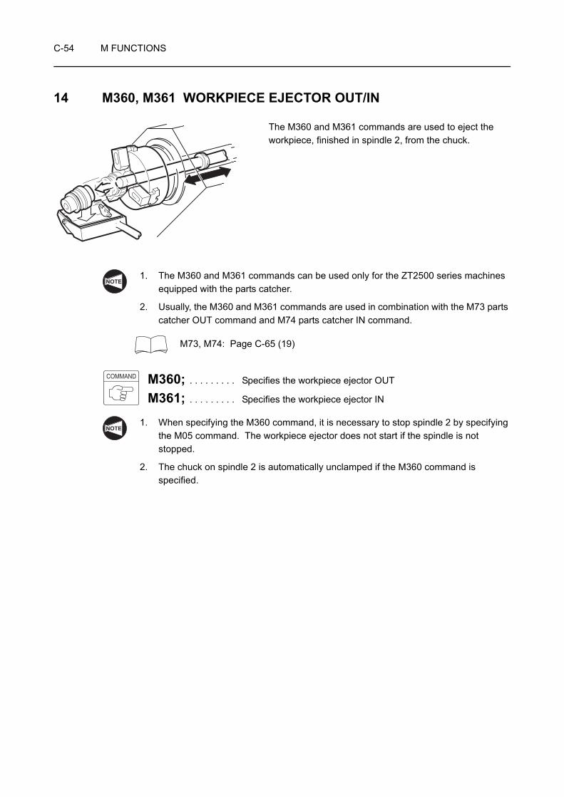
C-54 M FUNCTIONS
14 M360, M361 WORKPIECE EJECTOR OUT/IN
The M360 and M361 commands are used to eject the workpiece, finished in spindle 2, from the chuck.
1. The M360 and M361 commands can be used only for the ZT2500 series machines equipped with the parts catcher.
2. Usually, the M360 and M361 commands are used in combination with the M73 parts catcher OUT command and M74 parts catcher IN command.
M73, M74: Page C-65 (19)
M360; . . . . . . . . . Specifies the workpiece ejector OUT
M361; . . . . . . . . . Specifies the workpiece ejector IN
1. When specifying the M360 command, it is necessary to stop spindle 2 by specifying the M05 command. The workpiece ejector does not start if the spindle is not stopped.
2. The chuck on spindle 2 is automatically unclamped if the M360 command is specified.
NOTE
COMMAND
NOTE
M FUNCTIONS C-55
Programming using M360 and M361
With the ZT series machines, specify M360 in the turret 2 program to eject the workpiece machined at the spindle 2 side to the parts catcher.
To swing out the parts catcher to the chuck side using the program shown below, move the X-axis at the turret 1 side in the positive side from −240 mm (machine coordinate system).
<Turret 2>O0001;
Machining program (machining of a workpiece in spindle 2)
G00 T3100;. . . . . . . . . . . . . . . . . . . . . . Selecting the No. 1 tool
G28 U0 M05; . . . . . . . . . . . . . . . . . . . . Returning the X-axis to the machine zero pointStopping spindle 2
G330; . . . . . . . . . . . . . . . . . . . . . . . . . . Returning the B-axis (spindle 2) to the machine zero point
G53 Z−420.0 ;. . . . . . . . . . . . . . . . . . . . Moving the Z-axis to −420 mm position (machine coordinate system)
Parts catcher OUT operation is not possible unless the Z-axis at the turret 2 side is in the negative side from −400 mm (machine coordinate system).
M73; . . . . . . . . . . . . . . . . . . . . . . . . . . . Parts catcher OUT
M360; . . . . . . . . . . . . . . . . . . . . . . . . . . Workpiece ejector OUT
M252; . . . . . . . . . . . . . . . . . . . . . . . . . . Turning ON in-spindle air blow (spindle 2)
G04 U_ ; . . . . . . . . . . . . . . . . . . . . . . . . Dwell
G330; . . . . . . . . . . . . . . . . . . . . . . . . . . Returning the B-axis (spindle 2) to the machine zero point
M74; . . . . . . . . . . . . . . . . . . . . . . . . . . . Parts catcher IN
M257; . . . . . . . . . . . . . . . . . . . . . . . . . . Turning OFF in-spindle air blow (spindle 2)
M251; . . . . . . . . . . . . . . . . . . . . . . . . . . Spindle air blow ON (spindle 2)
G04 U_ ; . . . . . . . . . . . . . . . . . . . . . . . . Dwell
M259; . . . . . . . . . . . . . . . . . . . . . . . . . . Spindle air blow OFF (spindle 2)
M361; . . . . . . . . . . . . . . . . . . . . . . . . . . Workpiece ejector IN
Ex.
NOTE
NOTE
C-56 M FUNCTIONS
15 M48, M49 FEEDRATE OVERRIDE CANCEL OFF/ON
The override setting for cutting feedrate during automatic operation is canceled when the M49 command is executed. In this mode, axis feedrate is fixed to the one programmed by the F code. Therefore, if the setting for the feedrate override dial on the operation panel is not 100%, the setting is ignored and it is assumed to be 100%.
In daily operation, the M48 and M49 commands are rarely used. In test cut, these M codes may be used. That is, the M48 command is specified in a program so that cutting feedrates may be adjusted to meet actual machining status.
After determining proper feedrates, the M49 command should be specified in a program so that mass production may be executed by using the fixed feedrates.
M48; . . . . . . . . . . Specifies feedrate override cancel OFF.
M49; . . . . . . . . . . Specifies feedrate override cancel ON.
When the M49 command is executed, the setting of the override dial is ignored and actual movement commands are all executed at the programmed feedrates. In this mode, actual feedrates cannot be set faster than the programmed feedrates.
However, if this command is specified in a program, it is impossible to lower the actual feedrate by using the feedrate override dial even if the programmed feedrate seems too fast.
1. During thread cutting, feedrate must be kept constant. The override function is automatically ignored if the G code calling thread cutting operation is executed. Therefore, it is not necessary to specify the M48 and M49 commands in a program for thread cutting operation.
2. During tapping, feedrate must be kept constant. The override function is automatically ignored if the G code calling tapping operation is executed. Therefore, it is not necessary to specify the M48 and M49 commands in a program for tapping operation.
3. The M48 and M49 commands are not valid for rapid traverse operation. Therefore, the rapid traverse rate override switch is operative while the M49 command is valid.
100%
O0001;
M49;G01...F;
...
COMMAND
CAUTION
NOTE
M FUNCTIONS C-57
Programming using M48 and M49
The following program should be executed while the block delete switch on the operation panel is set OFF.
O0001;
N1;
G50 S1500;
G00 T0101;
G96 S120 M03;
Machining program
G00 X70.0 Z20.0;
G01 Z2.0 F0.3;
/M49; . . . . . . . . . . . . . . . . . . . . . . . . . . Making the override for cutting feed invalid Since the slash (/) code is entered, execution of this block
is controlled by the setting of the block delete switch
on the operation panel.
• If the block delete switch is active (the indicator
in the switch is lit):
Ignores this block and therefore the M49 command is not executed. The following blocks are executed with the feedrate override function valid.
• If the block delete switch is not active (the
indicator in the switch is not lit):
Executes the M49 command. According to the execution of the M49 command, the override for cutting feed is made invalid and following blocks are executed with 100% of feedrate.
Z−20.0 F0.2; . . . . . . . . . . . . . . . . . . . . . The feedrate for Z-axis movement is fixed at 0.2 mm/rev and the cutting tool is moved to Z−20.0 along the Z-axis at this feedrate.
X102.0; . . . . . . . . . . . . . . . . . . . . . . . . . Moving the cutting along the X-axis to X102.0 at the fixed feedrate of 0.2 mm/rev
/M48; . . . . . . . . . . . . . . . . . . . . . . . . . . Making override for cutting feed valid After the execution of this command, the override switches on the operation panel are valid.
Ex.NOTE
C-58 M FUNCTIONS
16 M68, M268, M69, M269 SPINDLE BRAKE CLAMP AND UNCLAMP
When the M68 command is specified, the brake of the spindle or spindle 1 is clamped.
When the M268 command is specified, the brake of spindle 2 is clamped.
When the M69 is specified the brake of the spindle or spindle 1 is unclamped.
When the M269 is specified the brake of spindle 2 is unclamped.
The spindle brake holds the spindle in the stopped state.
The M68, M268, M69, and M269 commands can be used only for the MC type or Y-axis specification machines.
However, the M268 and M269 commands can be used only for the following machines.
ZL-S series: MC type machines
ZT series: MC type and Y-axis specification machines
1. When carrying out hole machining or heavy-duty cutting at the desired position in the end face or circumference of the workpiece, specify the M68 or M268 command while the spindle, spindle 1 or spindle 2 is stopped to apply powerful brake.
2. To carry out ordinary turning operation, specify the M69 command to unclamp the brake of the spindle or spindle 1 and the M269 command to unclamp the brake of spindle 2.
M68; . . . . . . . . . . Specifies clamping of the spindle or spindle 1 brake.
M268; . . . . . . . . . Specifies clamping of the spindle 2 brake.
M69; . . . . . . . . . . Specifies unclamping of the spindle or spindle 1 brake.
M269; . . . . . . . . . Specifies unclamping of the spindle 2 brake.
1. When specifying the M68 or M268 command in the state the C-axis is not connected, stop the spindle, spindle 1 or spindle 2 by specifying the M05 command. If the M68 or M268 command is specified although the spindle, spindle 1, or spindle 2 has not stopped, an alarm message (EX1424) is displayed on the screen and the machine stops.
2. When specifying the M69 or M269 command with the C-axis disconnected, stop rotary tool rotation by specifying the M05 command. If the M69 or M269 command is specified when the rotary tool is not stopped, an alarm message (EX1426) is displayed on the screen and the machine stops.
NOTE
COMMAND
NOTE

M FUNCTIONS C-59
Programming using M68 and M69
O0001;
N1;
G98; . . . . . . . . . . . . . . . . . . . . . . . . . . . Specifying the feed per minute mode
M45; . . . . . . . . . . . . . . . . . . . . . . . . . . . Connecting spindle 1 as the C-axis
G28 H0; . . . . . . . . . . . . . . . . . . . . . . . . Returning the C-axis to the machine zero point
G00 T0101;
G97 S500 M13;. . . . . . . . . . . . . . . . . . . Rotating the rotary tool in the normal direction at
500 min−1
Z5.0;
M68; . . . . . . . . . . . . . . . . . . . . . . . . . . . Clamping spindle brake for spindle 1
Machining program
G28 U0 M05; . . . . . . . . . . . . . . . . . . . . Returning the X-axis to the machine zero pointStopping rotary tool rotation
G28 W0 M69; . . . . . . . . . . . . . . . . . . . Returning the Z-axis to the machine zero point Unclamping the spindle 1 brake
M46; . . . . . . . . . . . . . . . . . . . . . . . . . . . Canceling the C-axis connection
G99; . . . . . . . . . . . . . . . . . . . . . . . . . . . Specifying the feed per revolution mode
M30;
Ex.

C-60 M FUNCTIONS
17 M70, M483, M482 BAR STOCK FEED, BAR STOCK FEED OFF, BAR STOCK CHANGE
When the machine is equipped with a bar feeder (single bar stock or multiple bar stocks) of Alps, a bar stock is supplied from the bar feeder into the machine when the M70 command is specified in the turret 1 program.
With the bar feeder (multiple bar stocks) of LNS, when the M70 command is specified in the turret 1 program, a bar stock is supplied from the bar feeder into the machine and bar feed is stopped when the M483 command is specified. The M482 command is used to supply a new bar stock from the stocker to the bar feeder.
1. For the machine equipped with a bar-puller, the M70 command should be specified in the turret 2 program.
2. For the machine equipped with a bar feeder, the M70, M483 and M482 commands should be specified in the turret 1 program. With the ZL, ZL-S and ZT series, the M70 command can be specified also in the turret 2 program.
3. The M70 command can be used only with the bar feeder or bar-puller specification machines.
4. The M482 command can be used to introduce a new bar material from the bar stocker to the bar feeder only when the machine is equipped with Alps's ASQ-80 bar feeder.
M70; . . . . . . . . . . Specifies bar feeder operation.
M483; . . . . . . . . . Specifies bar stock feed OFF.
M482; . . . . . . . . . Specifies bar stock change.
When using a bar feeder, check the length, mass, and diameter of the bar stock to be handled. The bar stock exceeding the capacity of the bar feeder must not be used.
Before feeding a bar stock into the machine by the M70 command, unclamp the chuck by specifying the M11 command. After the bar feeder has fed the bar stock into the machine, clamp the chuck by specifying the M10 command.
NOTE
COMMAND
CAUTION
NOTE
M FUNCTIONS C-61
The following four types of bar feeders are provided.
• Type 1 (Alps, single-stock specification)
• Type 2 (Alps, multi-stock specification)
• Type 3 (LNS, single-stock specification)
• Type 4 (LNS, multi-stock specification)
The correspondence between usable M codes and the bar feeder types is indicated below.
* Only ASQ-80
Programming using M70 (1)
The following is an example program for the ZL series machine equipped with a bar feeder of Alps.
O0001;
N1;
Machining program
M05; . . . . . . . . . . . . . . . . . . . . . . . . . . . Stopping the spindle rotation
M11; . . . . . . . . . . . . . . . . . . . . . . . . . . . Chuck unclamp
G04 U_ ; . . . . . . . . . . . . . . . . . . . . . . . . Calling for dwell; program execution is suspended to allow the chuck to unclamp correctly.
Since the time required for the chuck to carry out unclamp operation varies depending on the chuck type and chucking pressure, the dwell time should be specified meeting actual conditions.
M70; . . . . . . . . . . . . . . . . . . . . . . . . . . . Feeding the bar stock from the bar feeder to the machine
M10; . . . . . . . . . . . . . . . . . . . . . . . . . . . Chuck clamp
G04 U_ ; . . . . . . . . . . . . . . . . . . . . . . . . Calling for dwell; program execution is suspended to allow the chuck to clamp the workpiece correctly.
Since the time required for the chuck to carry out clamp operation varies depending on the chuck type and chucking pressure, the dwell time should be specified meeting actual conditions.
Type 1 Type 2 Type 3 Type 4
M70 ×
M483 × × ×
M482 × * ×
Ex.
NOTE
NOTE
C-62 M FUNCTIONS
/M99 P100; . . . . . . . . . . . . . . . . . . . . . . To carry out mass production, make the block delete function invalid so that the "M99 P100;" block is executed.The "M99 P100;" jumps the program flow to the sequence labeled "N100;". When the block delete function is invalid, the cycle illustrated on the right is repeated to machine workpieces continuously.
To finish automatic continuous operation, make the block delete function valid to skip the "M99 P100;" block.
In this case, the M30 command in the next block is executed, ending the program. The cursor returns to the start of the program and the machine stops.
For how to use the block delete function: OPERATION MANUAL separately provided
M30;
Block delete function invalid
Block delete function valid
O0001;
/M99 P100;N100;
• • •• • •
• • •• • •
O0001;
/M99 P100;M30;
• • •• • •

M FUNCTIONS C-63
Programming using M70 (2)
The following is an example program for the ZL-S and ZT series machine equipped with a bar feeder of Alps.<Turret 1> <Turret 2>O0001; O0002;N1; N1;
G59; . . . . . . . . . . . . . . . Selecting the G59 work coordinate system (for workpiece transfer)
Machining program
(M246;) . . . . . . . . . . . . . To be specified only for MC type
N7; G00 T3100;. . . . . . . . . . Selecting the No.1 toolThe tool wear offset cancel
G00 T0101; G28 U0 M05; . . . . . . . . Returning the X-axis to the machine zero point
M100;. . . . . . . . . . . . . . . Synchronization of program execution M100; . . . . . . . . . . . . . . Synchronization of program execution
M35;. . . . . . . . . . . . . . . . Speed synchronous operation M35; . . . . . . . . . . . . . . . Speed synchronous operation
M101;. . . . . . . . . . . . . . . Synchronization of program execution M101; . . . . . . . . . . . . . . Synchronization of program execution
G97 S1000 M03; . . . . . . Speeds of spindle 1 and spindle 2 are
synchronized at 1000 min−1
M211; . . . . . . . . . . . . . . Chuck 2 unclamp
G28 U0 M09; . . . . . . . . . Returning the X-axis to the machine zero point
Z10.0;Z0.3 M51;M102;. . . . . . . . . . . . . . . Synchronization of program execution M102; . . . . . . . . . . . . . . Synchronization of program execution
Workpiece transfer
Chuck 2 is clamped after the detection of pressing of workpiece.
M103;. . . . . . . . . . . . . . . Synchronization of program execution M103; . . . . . . . . . . . . . . Synchronization of program execution
M11; . . . . . . . . . . . . . . . . Chuck 1 unclamp
G04 U_ ;M104;. . . . . . . . . . . . . . . Synchronization of program execution M104; . . . . . . . . . . . . . . Synchronization of program execution;
program execution is suspended until chuck 1 is unclamped.
M70;. . . . . . . . . . . . . . . . Supplying a bar with the bar feeder G98 G01 Z_ F2000; . . . Pulling the workpiece
M105;. . . . . . . . . . . . . . . Synchronization of program execution; program execution is suspended until the completion of "pulling workpiece".
M105; . . . . . . . . . . . . . . Synchronization of program execution
M10;. . . . . . . . . . . . . . . . Chuck 1 clamp
G04 U_ ;M106;. . . . . . . . . . . . . . . Synchronization of program execution M106; . . . . . . . . . . . . . . Synchronization of program execution;
program execution is suspended until chuck 1 is clamped.
X42.0 M08;G99 G01 X−0.6 F0.08;G53 X0 M09;M80;. . . . . . . . . . . . . . . . Detecting cutting off
M107;. . . . . . . . . . . . . . . Synchronization of program execution M107; . . . . . . . . . . . . . . Synchronization of program execution; program execution is suspended until cutting off operation is finished.
G330; . . . . . . . . . . . . . . Returning the B-axis (spindle 2) to the
machine zero point
M36; . . . . . . . . . . . . . . . Canceling synchronous operation
M108;. . . . . . . . . . . . . . . Synchronization of program execution; program execution is suspended until "returning the B-axis (spindle 2) to the machine zero point".
M108; . . . . . . . . . . . . . . Synchronization of program execution
M30; M01;
Ex.
NOTE

C-64 M FUNCTIONS
18 M71, M72 AUTOMATIC IN-MACHINE TOOL PRESETTER ARM OUT/IN (OPTION)
This command extends or retracts the automatic in-machinetool presetter to/from the measuring position.
M71; . . . . . . . . . . . Automatic in-machine tool presetter OUT
M72; . . . . . . . . . . . Automatic in-machine tool presetter IN
Return the turret 1 and turret 2 to the zero positions before specifying the M71 command, otherwise PLC alarm EX915 "Return the X-, Z-axes to the zero positions" is displayed on the screen.
COMMAND
NOTE
M FUNCTIONS C-65
19 M73, M74 PARTS CATCHER OUT/IN
When the M73 command is executed, the parts catcher swings into the position beneath the chuck where it receives the finished workpiece.
When the M74 command is executed, the parts catcher swings back to the clear position where the finished workpiece is discharged from the parts catcher.
The M73 and M74 commands can be used only for the ZL, ZL-S and ZT series machines equipped with the parts catcher. However, with the ZL-S series, the M73 and M74 commands are standard.
1. With the ZL-S and ZT series machines, a workpiece can be ejected to the parts catcher from either of the spindles since a traveling type parts catcher is used.
2. Two types of the traveling type parts catcher are available for the ZL-S and ZT series. They are bucket specification and hand specification.
M73; . . . . . . . . . . Specifies parts catcher OUT.
M74; . . . . . . . . . . Specifies parts catcher IN.
1. When the M73 command is specified, make sure that the turret head is retracted to a position where it will not interfere with the parts catcher when it swings out to the chuck side position. Interference could damage the machine.
2. If the mass of workpiece exceeds the capacity of the parts catcher, do not use the parts catcher to unload the workpiece from the machine. If such workpieces are handled by the parts catcher, it will damage the machine.
3. With the ZL-S and ZT series, equipped with the hand specification parts catcher, axis movements are enabled even if the parts catcher is OUT to the chuck side. Do not move an axis carelessly in the state the parts catcher is OUT to the chuck side. If an axis is moved in this state, the tool, the tool holder or the turret head could interfere with the parts catcher causing damage to the machine.
1. Specify the M73 and M74 commands independently without other commands.
2. With the ZL series machines, the M73 command cannot be specified unless the Z-axis at the turret 2 side is in the positive side beyond −50 mm (in the machine coordinate system) and the X-axis at the turret 1 is in the positive side beyond −280 mm (in the machine coordinate system).
3. With the ZL-S and ZT series, specify the M73/M74 command as indicated below to operate the parts catcher.
• To operate the parts catcher at the spindle 1 side, specify these M code commands at the turret 1 side.However, it is not possible to operate the parts catcher on the spindle 1 side for ZT1000 with hand specification.
• To operate the parts catcher at the spindle 2 side, specify these M code commands at the turret 2 side.
NOTE
COMMAND
CAUTION
NOTE

C-66 M FUNCTIONS
4. With the ZL-S series, the following conditions must be satisfied to extend the parts catcher to the chuck side by specifying the M73 command.
• The B-axis is returned to the machine zero point.
• The X-axis at the turret 2 side is returned to the machine zero point.
• To extend the parts catcher to the chuck side of spindle 1, the Z-axis at the turret 2 side is in the range indicated below (machine coordinate system) (bucket specification)
• To extend the parts catcher to the chuck side of spindle 2, the Z-axis at the turret 2 side is in the range indicated below (machine coordinate system) (bucket specification)
5. The conditions mentioned in NOTE 4. are ignored between the M242 command (parts catcher interlock bypass ON) and the M243 command (parts catcher interlock bypass OFF). However, there is a possibility that the tool, holder or turret head may interfere with the parts catcher, resulting in damage to the machine. Before specifying the command, ensure that no interference will occur.
It is possible to make the parts catcher stand by in a position closer to the chuck by specifying the M244 (parts catcher intermediate stop position) command. The standby position is determined by the parameter.
6. With the ZT series, the following conditions must be satisfied to extend the parts catcher to the chuck side by specifying the M73 command.
• The B-axis is returned to the machine zero point.
• The Y-axis is returned to the machine zero point.
• The X-axis at the turret 1 side is in the positive side from −380 mm.
This positional restriction of the X-axis at the turret 1 side does not apply when the Z-axis at the turret 1 side is in the negative side from the zero point if the parts catcher is extended to the spindle 2 chuck side.
• To extend the parts catcher to the chuck side of spindle 1, the Z-axis at the turret 2 side is in the positive side from +200 mm (machine coordinate system)
• To extend the parts catcher to the chuck side of spindle 2, the Z-axis at the turret 2 side is in the negative side from −400 mm (machine coordinate system)
• The holding box is in.
• The tool presetter arm is stored at the retracted position.
ZL-153S In the positive side from +180 mm
ZL-203S, ZL-253S In the positive side from +155 mm
ZL-153SMC In the positive side from +220 mm
ZL-203SMC, ZL-253SMC In the positive side from +200 mm
ZL-153S In the negative side from −200 mm
ZL-203S, ZL-253S In the negative side from −250 mm
ZL-153SMC In the negative side from −200 mm
ZL-203SMC, ZL-253SMC In the negative side from −250 mm
NOTE
M FUNCTIONS C-67
7. With the ZL series machines or the bucket specification of the ZL-S series, in the state that the parts catcher is moved out to the chuck side, the Z-axis at the turret 2 side cannot move.
8. When removing the machined workpiece, stop the machine in the feed hold state.
Programming using M73 and M74 (ZL-S series)
For the bucket specification of the ZL-153S series machines; a workpiece machined at the spindle 2 side is ejected to the parts catcher by specifying M73 and M74 commands in the turret 2 program.
<Turret 2>O0001;
Machining program (machining of a workpiece in spindle 2)
G00 T3100;. . . . . . . . . . . . . . . . . . . . . . Selecting the No. 1 tool
G28 U0 M05; . . . . . . . . . . . . . . . . . . . . Returning the X-axis to the machine zero point Stopping spindle 2
G330; . . . . . . . . . . . . . . . . . . . . . . . . . . Returning the B-axis (spindle 2) to the machine zero point
G53 Z−220.0; . . . . . . . . . . . . . . . . . . . . Moving the Z-axis to −220 mm position (machine coordinate system)
The position where the Z-axis at the turret 2 side should be moved differs depending on the machine model. For this position, refer to page C-60 (17).Parts catcher OUT operation is not possible unless the Z-axis at the turret 2 side is moved to this position.
M73; . . . . . . . . . . . . . . . . . . . . . . . . . . . Parts catcher OUT
M47; . . . . . . . . . . . . . . . . . . . . . . . . . . . Workpiece ejector OUT
M252; . . . . . . . . . . . . . . . . . . . . . . . . . . Turning ON in-spindle air blow (spindle 2)
G04 U_ ; . . . . . . . . . . . . . . . . . . . . . . . . Dwell
G330; . . . . . . . . . . . . . . . . . . . . . . . . . . Returning the B-axis (spindle 2) to the machine zero point
M74; . . . . . . . . . . . . . . . . . . . . . . . . . . . Parts catcher IN
M257; . . . . . . . . . . . . . . . . . . . . . . . . . . Turning OFF in-spindle air blow (spindle 2)
M251; . . . . . . . . . . . . . . . . . . . . . . . . . . Spindle air blow ON (spindle 2)
G04 U_ ; . . . . . . . . . . . . . . . . . . . . . . . . Dwell
M259; . . . . . . . . . . . . . . . . . . . . . . . . . . Spindle air blow OFF (spindle 2)
NOTE
Ex.
NOTE

C-68 M FUNCTIONS
Programming using M73 and M74 (ZT series)
For the ZT series machines; a workpiece machined at the spindle 2 side is ejected to the parts catcher by specifying M73 and M74 commands in the turret 2 program.
To swing out the parts catcher to the chuck side using the program shown below, move the X-axis at the turret 1 side in the positive side from −380 mm (machine coordinate system).
<Turret 2>O0001;
Machining program (machining of a workpiece in spindle 2)
G00 T3100;. . . . . . . . . . . . . . . . . . . . . . Selecting the No. 1 tool
G28 U0 M05; . . . . . . . . . . . . . . . . . . . . Returning the X-axis to the machine zero point Stopping spindle 2
G330; . . . . . . . . . . . . . . . . . . . . . . . . . . Returning the B-axis (spindle 2) to the machine zero point
G53 Z−420.0; . . . . . . . . . . . . . . . . . . . . Moving the Z-axis to −420 mm position (machine coordinate system)
Parts catcher OUT operation is not possible unless the Z-axis at the turret 2 side is in the negative side from −400 mm (machine coordinate system).
M73; . . . . . . . . . . . . . . . . . . . . . . . . . . . Parts catcher OUT
M360; . . . . . . . . . . . . . . . . . . . . . . . . . . Workpiece ejector OUT
M252; . . . . . . . . . . . . . . . . . . . . . . . . . . Turning ON in-spindle air blow (spindle 2)
G04 U_ ; . . . . . . . . . . . . . . . . . . . . . . . . Dwell
G330; . . . . . . . . . . . . . . . . . . . . . . . . . . Returning the B-axis (spindle 2) to the machine zero point
M74; . . . . . . . . . . . . . . . . . . . . . . . . . . . Parts catcher IN
M257; . . . . . . . . . . . . . . . . . . . . . . . . . . Turning OFF in-spindle air blow (spindle 2)
M251; . . . . . . . . . . . . . . . . . . . . . . . . . . Spindle air blow ON (spindle 2)
G04 U_ ; . . . . . . . . . . . . . . . . . . . . . . . . Dwell
M259; . . . . . . . . . . . . . . . . . . . . . . . . . . Spindle air blow OFF (spindle 2)
M361; . . . . . . . . . . . . . . . . . . . . . . . . . . Workpiece ejector IN
Ex.
NOTE
NOTE

M FUNCTIONS C-69
20 M80 WORKPIECE CUT-OFF DETECTION
The M80 command is used to check if the cut-off cycle, executed after the transfer of the workpiece clamped in the chuck of spindle 1 to the chuck of spindle 2, has been completed.
Completion of cutting off is confirmed by detecting the spindle speeds of spindles 1 and 2. If spindle 2 does not follow spindle 1 when the spindle speed of spindle 1 is changed, cutting off is judged to have completed.
M80; . . . . . . . . . . . Detects the completion of cut-off cycle.
1. The M80 command can be specified only in the turret 1 program of ZL-S and ZT series.
2. If the completion of the cut-off cycle is not detected after the execution of the M80 command, both spindle 1 and spindle 2 stop rotating with the alarm message (EX0035) displayed on the screen.
3. Although the execution of the M80 command cancels the synchronized operation of spindles 1 and 2, the synchronized operation mode is not canceled. Always specify the M36 command after specifying the M80 command.
COMMAND
NOTE
C-70 M FUNCTIONS
Programming using M80 (ZL-S and ZT series)
<Turret 1> <Turret 2>O0001; O0002;N1; N1;
G59; . . . . . . . . . . . . . . . Selecting the G59 work coordinate system (for workpiece transfer)
Machining program
(M246;) . . . . . . . . . . . . . To be specified only for MC type
N7; G00 T3100;. . . . . . . . . . Selecting the No.1 toolThe tool wear offset cancel
G00 T0101; G28 U0 M05; . . . . . . . . Returning the X-axis to the machine zero point
M100;. . . . . . . . . . . . . . . Synchronization of program execution M100; . . . . . . . . . . . . . . Synchronization of program execution
M35;. . . . . . . . . . . . . . . . Speed synchronous operation M35; . . . . . . . . . . . . . . . Speed synchronous operation
M101;. . . . . . . . . . . . . . . Synchronization of program execution M101; . . . . . . . . . . . . . . Synchronization of program execution
G97 S1000 M03; . . . . . . Speeds of spindle 1 and spindle 2 are
synchronized at 1000 min−1M211; . . . . . . . . . . . . . . Chuck 2 unclamp
G28 U0 M09; . . . . . . . . . Returning the X-axis to the machine zero point
Z10.0;Z0.3 M51;M102;. . . . . . . . . . . . . . . Synchronization of program execution M102; . . . . . . . . . . . . . . Synchronization of program execution
Workpiece transfer
Chuck 2 is clamped after the detection of pressing of workpiece.
M103;. . . . . . . . . . . . . . . Synchronization of program execution M103; . . . . . . . . . . . . . . Synchronization of program execution
M11; . . . . . . . . . . . . . . . . Chuck 1 unclamp
G04 U_ ;M104;. . . . . . . . . . . . . . . Synchronization of program execution M104; . . . . . . . . . . . . . . Synchronization of program execution;
program execution is suspended until chuck 1 is unclamped.
M70;. . . . . . . . . . . . . . . . Supplying a bar with the bar feeder G98 G01 Z_ F2000; . . . Pulling the workpiece
M105;. . . . . . . . . . . . . . . Synchronization of program execution; program execution is suspended until the completion of "pulling workpiece".
M105; . . . . . . . . . . . . . . Synchronization of program execution
M10;. . . . . . . . . . . . . . . . Chuck 1 clamp
G04 U_ ;M106;. . . . . . . . . . . . . . . Synchronization of program execution M106; . . . . . . . . . . . . . . Synchronization of program execution;
program execution is suspended until chuck 1 is clamped.
X42.0 M08;G99 G01 X−0.6 F0.08;G53 X0 M09;M80;. . . . . . . . . . . . . . . . Detecting cutting off
M107;. . . . . . . . . . . . . . . Synchronization of program execution M107; . . . . . . . . . . . . . . Synchronization of program execution; program execution is suspended until cutting off operation is finished.
G330; . . . . . . . . . . . . . . Returning the B-axis (spindle 2) to the machine zero point
M36; . . . . . . . . . . . . . . . Canceling synchronous operation
M108;. . . . . . . . . . . . . . . Synchronization of program execution; program execution is suspended until "returning the B-axis (spindle 2) to the machine zero point".
M108; . . . . . . . . . . . . . . Synchronization of program execution
M30; M01;
Ex.
NOTE

M FUNCTIONS C-71
21 M85, M86 AUTOMATIC DOOR OPEN/CLOSE
When the M85 command is executed, the automatic door opens.
When the M86 command is executed, the automatic door closes.
1. The M85 and M86 commands can be used only for the machines equipped with the automatic door.
2. The M85 and M86 commands are usually used in combination with the loader, robot system, or other automatic workpiece loading/unloading equipment.
M85; . . . . . . . . . . . Specifies the automatic door open.
M86; . . . . . . . . . . . Specifies the automatic door close.
When the automatic door is closed by specifying the M86 command, make sure that your fingers, etc., do not get caught in the door and that there are no obstacles that will prevent the door from closing. If your fingers are caught in the door you could be injured.
1. Before opening the door by specifying the M85 command, make sure that you stop spindle rotation, rotary tool rotation, turret head rotation, axis movement, and coolant discharge.
2. Specify the M86 command to close the automatic door at the start of the program.
Although automatic operation can be executed while the door is open, only the following M codes are executable until the door is closed: M00, M01, M02, M30, and automatic door open/close M codes (M85, M86) Other commands such as S codes, T codes, and axis movement commands are not executable until the door is closed.
WARNING For the machines equipped with the robot system, if the door is opened by the execution of the M85 command during automatic operation (including the MDI operation), the operation is continuously executed. Therefore, pay sufficient care so that you will not touch or stand near the rotating or moving parts of the machine. Otherwise, you could sustain injuries or the machine could be damaged due to entangling by the rotating parts, crushed by the moving parts, flying out of the workpiece, and/or splashing of chips and coolant.
NOTE
COMMAND
CAUTION
NOTE

C-72 M FUNCTIONS
Programming using M85 and M86
O0001;
N1;
M86; . . . . . . . . . . . . . . . . . . . . . . . . . . . Closing the automatic door
G50 S1500;
G00 T0101;
G96 S120 M03;
X75.0 Z20.0 M08;
Machining program
G00 X200.0 Z150.0 M09; . . . . . . . . . . . After the completion of cutting, the cutting tool moves away from the workpiece.
Stopping coolant discharge
M05; . . . . . . . . . . . . . . . . . . . . . . . . . . . Stopping the spindle rotation
M85; . . . . . . . . . . . . . . . . . . . . . . . . . . . Opening the automatic door
M30; . . . . . . . . . . . . . . . . . . . . . . . . . . . Ends program execution.
The automatic door close command (M86) is specified at the start of the program and the automatic door open command (M85) is specified at the end of a program.
Ex.

M FUNCTIONS C-73
22 M89 WORK COUNTER, TOTAL COUNTER
Each time the M89 command written in a program is read, the count data of the work counter increases "1".
Set the number of times the cycle should be repeated on the PC WORK COUNTER screen (option).
Suppose "100" is set for the work counter. If the M89 command has been executed 100 times as the program is executed repeatedly, the NC will be placed in the cycle start interlocked state or the block delete valid state according to your selection.
1. The M89 command is optional.
2. The work counter is used for tool life management function as well as to control the number of finished workpieces. In comparison to the work counter, the total counter is used for simply counting the number.
M89; . . . . . . . . . . . Specifies counting of work counter and total counter.
How the cycle start interlock state and the block delete valid state differ from each other is explained below.
• Cycle start interlocked state: When the M89 command has been executed by the preset number of times, cycle start of automatic operation is disabled.In other words, the program is not executed even
when the (ST) switch is pressed.
• Block delete valid state: The block delete function is invalid until the M89 command is executed by the preset number of times. After the count-up of the counter, the block delete function becomes valid.
For the block delete function: OPERATION MANUAL separately provided
Whether the work counter function is used or not is set on the OPERATION PANEL screen.
For how to use the work counter function: OPERATION MANUAL separately provided
NOTE
COMMAND
NOTE

C-74 M FUNCTIONS
Programming using M89 (1)
The cycle start interlocked state is selected for the count-up state.
"100" is set for the work counter.
O0001;
M89; . . . . . . . . . . . . . . . . . . . . . . . . . . . The work counter increases "1" each time program O0001 is executed.
N1;
G50 S1500;
G00 T0101;
Machining program
G00 X200.0 Z150.0 M05;
M30; . . . . . . . . . . . . . . . . . . . . . . . . . . . When the cursor has returned to the start of the program after the execution of the program 100 times, the program cannot be started even if
the (ST) switch is pressed.
Ex.
O0001;
M89;
M30;
M FUNCTIONS C-75
Programming using M89 (2)
The program is executed in the block delete function valid state.
"100" is set for the work counter.
O0001;
M89; . . . . . . . . . . . . . . . . . . . . . . . . . . . The work counter increases "1" each time program O0001 is executed.
Machining program
/M99;. . . . . . . . . . . . . . . . . . . . . . . . . . . Until the program O0001 is executed 100 times, the block delete function is invalid and the "M99;" block is executed. The cursor returns to "O0001", the start of the program and the program is executed continuously.
For the function of the M99 command: Page C-77
In the execution of the program at the 100th time, the block delete function is made valid and the "M30;" block is executed by skipping the "M99;" block.
M30;
Specify the M89 command at the start of the program which is executed repeatedly so that the execution of the program is correctly counted by the work counter.
Ex.
O0001;M89;
/M99;M30;
1 - 99100
NOTE
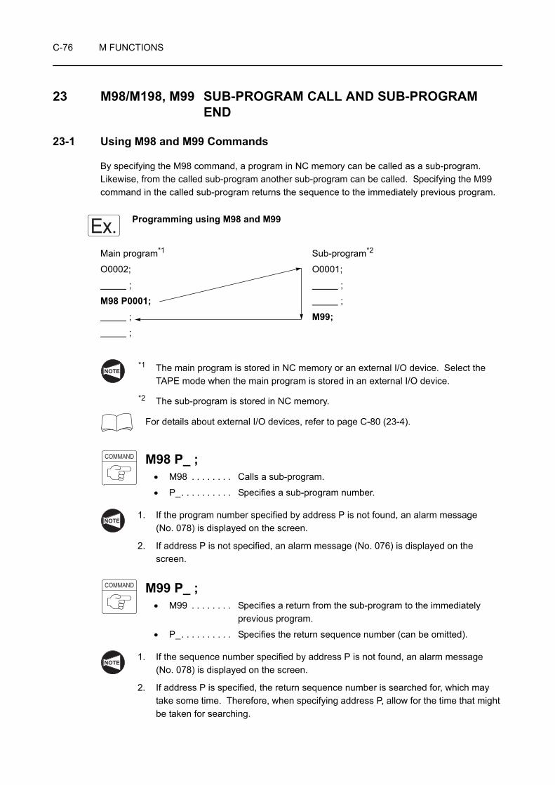
C-76 M FUNCTIONS
23 M98/M198, M99 SUB-PROGRAM CALL AND SUB-PROGRAM END
23-1 Using M98 and M99 Commands
By specifying the M98 command, a program in NC memory can be called as a sub-program. Likewise, from the called sub-program another sub-program can be called. Specifying the M99 command in the called sub-program returns the sequence to the immediately previous program.
Programming using M98 and M99
Main program*1 Sub-program*2
O0002; O0001;
; ;
M98 P0001; ;
; M99; ;
*1 The main program is stored in NC memory or an external I/O device. Select the TAPE mode when the main program is stored in an external I/O device.
*2 The sub-program is stored in NC memory.
For details about external I/O devices, refer to page C-80 (23-4).
M98 P_ ;• M98 . . . . . . . . Calls a sub-program.
• P_. . . . . . . . . . Specifies a sub-program number.
1. If the program number specified by address P is not found, an alarm message (No. 078) is displayed on the screen.
2. If address P is not specified, an alarm message (No. 076) is displayed on the screen.
M99 P_ ;• M99 . . . . . . . . Specifies a return from the sub-program to the immediately
previous program.
• P_. . . . . . . . . . Specifies the return sequence number (can be omitted).
1. If the sequence number specified by address P is not found, an alarm message (No. 078) is displayed on the screen.
2. If address P is specified, the return sequence number is searched for, which may take some time. Therefore, when specifying address P, allow for the time that might be taken for searching.
Ex.
NOTE
COMMAND
NOTE
COMMAND
NOTE

M FUNCTIONS C-77
1. If address P is omitted, the sequence returns to the block next to the block in which the sub-program call was specified.
2. When the M99 command is specified in the main program, the sequence returns to the sequence number specified by address P.
If address P is omitted, the sequence rewinds the main program to the top, and execution of the program is repeated.
Programming using M99
O0001;
N1;
N2;
/N7 M99; . . . . . . . . . . . . . . . . . . . . When the block delete function is invalid:The "N7 M99;" command is executed and the program flow returns to the start of the program. The program is repeated endlessly between N1 and N7 blocks.When the block delete function is valid:The "N7 M99;" command is ignored and the program is executed continuously to the following blocks.
N8;
M30; . . . . . . . . . . . . . . . . . . . . . . . . . . . Ends program execution.
This programming is used for executing the same program repeatedly in such as a warm up program.
23-2 Nesting
It is possible to specify the M98 command (sub-program call) from one sub-program to an other as illustrated below. This is called nesting and allowable nesting level is four. If sub-program call exceeds this limit, alarm number (No. 077) is displayed.
Ex.
1st call 2nd call 3rd call 4th callMain program
Sub-program 3
Sub-program 4
Sub-program 1
Sub-program 2
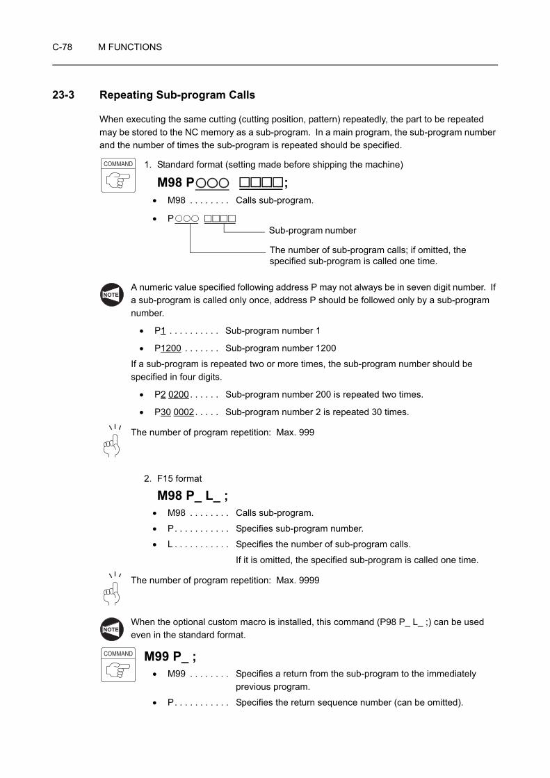
C-78 M FUNCTIONS
23-3 Repeating Sub-program Calls
When executing the same cutting (cutting position, pattern) repeatedly, the part to be repeated may be stored to the NC memory as a sub-program. In a main program, the sub-program number and the number of times the sub-program is repeated should be specified.
1. Standard format (setting made before shipping the machine)
M98 P ;• M98 . . . . . . . . Calls sub-program.
• P
A numeric value specified following address P may not always be in seven digit number. If a sub-program is called only once, address P should be followed only by a sub-program number.
• P1 . . . . . . . . . . Sub-program number 1
• P1200 . . . . . . . Sub-program number 1200
If a sub-program is repeated two or more times, the sub-program number should be specified in four digits.
• P2 0200. . . . . . Sub-program number 200 is repeated two times.
• P30 0002. . . . . Sub-program number 2 is repeated 30 times.
The number of program repetition: Max. 999
2. F15 format
M98 P_ L_ ;• M98 . . . . . . . . Calls sub-program.
• P. . . . . . . . . . . Specifies sub-program number.
• L . . . . . . . . . . . Specifies the number of sub-program calls.
If it is omitted, the specified sub-program is called one time.
The number of program repetition: Max. 9999
When the optional custom macro is installed, this command (P98 P_ L_ ;) can be used even in the standard format.
M99 P_ ;• M99 . . . . . . . . Specifies a return from the sub-program to the immediately
previous program.
• P. . . . . . . . . . . Specifies the return sequence number (can be omitted).
COMMAND
The number of sub-program calls; if omitted, the specified sub-program is called one time.
Sub-program number
NOTE
NOTE
COMMAND
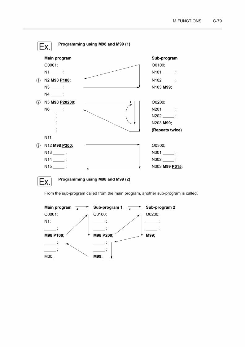
M FUNCTIONS C-79
Programming using M98 and M99 (1)
Main program Sub-programO0001; O0100;
N1 ; N101 ;
N2 M98 P100; N102 ;
N3 ; N103 M99;N4 ;
N5 M98 P20200; O0200;
N6 ; N201 ;N202 ;
N203 M99;(Repeats twice)
N11;
N12 M98 P300; O0300;
N13 ; N301 ;
N14 ; N302 ;
N15 ; N303 M99 P015;
Programming using M98 and M99 (2)
From the sub-program called from the main program, another sub-program is called.
Main program Sub-program 1 Sub-program 2O0001; O0100; O0200;
N1; ; ;
; ; ;
M98 P100; M98 P200; M99; ; ;
; ;
M30; M99;
Ex.
1
2
3
Ex.

C-80 M FUNCTIONS
23-4 Using M198 and M99 Commands
By specifying the M198 command, a program in an external I/O device* (user memory area, data server, memory card, etc.) can be called as a sub-program.
Specify the M198 command in the NC program in the MEMORY mode and specify the M99 command in the sub-program in the external I/O device.
* The external I/O device can be selected by setting the I/O channel and the parameter. When the MAPPS parameter setting has been changed, turn the power off and back it on.
For the procedure of switching the I/O channel, refer to the MAPPS II/III Operation Manual separately provided.
Programming using M198 and M99
Main program*1 Sub-program*2
O0001; O0002;
N1 ; ;
; ;
M198 P0002; M99; ;
;
1. *1 The main program is stored in NC memory.
*2 The sub-program is stored in an external I/O device.
2. When calling a sub-program by specifying M198, the called program name, file name, must be O + 4 digits (or 7 digits) number. When specifying "M198 P100;" to call the program, the file name must be shown below.
• O0100
• O0000100 (program number 8 digits specifications only)
3. The M198 command cannot be executed in the DNC operation.
4. The M198 command is not available with the RS232C interface in the electrical cabinet.
5. It is not possible to call a program in an external I/O device by specifying the M198 command in another program in the external I/O device.
I/O Channel MAPPS ParameterNo. 1978 External I/O Device
151 User memory area
0 Memory card
5 Data server
NOTE
Ex.
NOTE

M FUNCTIONS C-81
When the main program is stored in NC memory as shown in the example program shown in 23-3 "Repeating Sub-program Calls", the M198 command can be specified in the MEMORY mode. Note that, however, it is not possible to call another program from the called program (nesting).
M198 P_ ;• M198 . . . . . . . Calls a sub-program.
• P_. . . . . . . . . . Specifies a sub-program number.
M99 P_ ;• M99 . . . . . . . . Specifies a return from the sub-program to the immediately
previous program.
• P_. . . . . . . . . . Specifies the return sequence number (can be omitted).
COMMAND
COMMAND

C-82 M FUNCTIONS
24 M100 TO M197, M199 OPERATION SYNCHRONIZATION
By specifying the identical M code (M100 to M197, M199) in both of the turret 1 and turret 2 programs, execution of the programs can be synchronized at the blocks containing such M codes.
If an operation synchronization M code is executed in one of the programs of turret 1 and turret 2, execution of that program is suspended until the identical M code is executed in the other program. The programs advance to the next block only after the identical M codes in them have been executed.
M100;to . . . . . . . . . . . . Operation synchronization
M197;M199;
1. The M codes used to call operation synchronization must be specified in a block without other commands.
2. When one of the programs of turret 1 and turret 2 execution is suspended by the execution of an operation synchronization M code, if an operation synchronization M code of different M code number is executed in the other program, an alarm message (No. 160) is displayed on the screen.
To execute operation synchronization, the identical M codes must be specified in the two programs.
<Turret1> <Turret2>
O0001; O0002;
M100; M100; . . . . Since the same M code is specified in the two programs, the blocks following the M100 block are executed simultaneously.
M101; M105; . . . . Since the specified M codes are different between the two programs, an alarm message (No. 160) is displayed on the screen.
COMMAND
NOTE
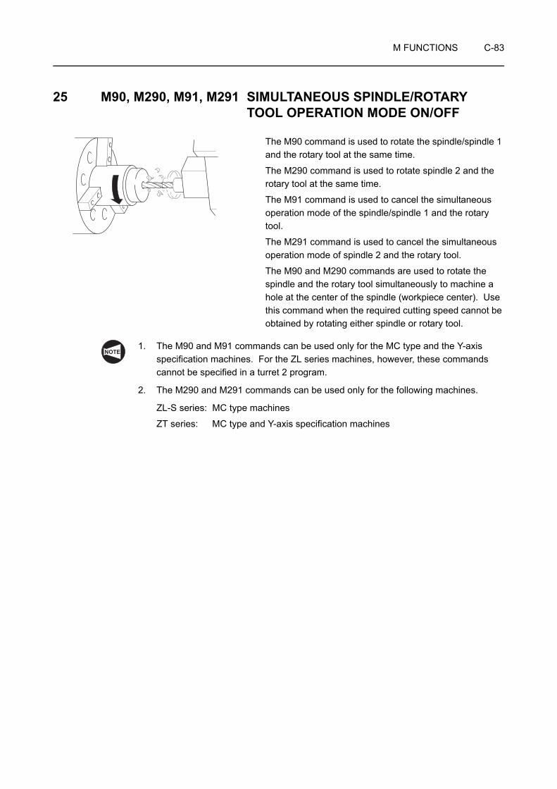
M FUNCTIONS C-83
25 M90, M290, M91, M291 SIMULTANEOUS SPINDLE/ROTARY TOOL OPERATION MODE ON/OFF
The M90 command is used to rotate the spindle/spindle 1 and the rotary tool at the same time.
The M290 command is used to rotate spindle 2 and the rotary tool at the same time.
The M91 command is used to cancel the simultaneous operation mode of the spindle/spindle 1 and the rotary tool.
The M291 command is used to cancel the simultaneous operation mode of spindle 2 and the rotary tool.
The M90 and M290 commands are used to rotate the spindle and the rotary tool simultaneously to machine a hole at the center of the spindle (workpiece center). Use this command when the required cutting speed cannot be obtained by rotating either spindle or rotary tool.
1. The M90 and M91 commands can be used only for the MC type and the Y-axis specification machines. For the ZL series machines, however, these commands cannot be specified in a turret 2 program.
2. The M290 and M291 commands can be used only for the following machines.
ZL-S series: MC type machines
ZT series: MC type and Y-axis specification machines
NOTE

C-84 M FUNCTIONS
3. The M90, M91, M290 and M291 commands can be specified in both the turret 1 and turret 2 side programs with the following machines.
ZL-S series: MC type machines
ZT series: MC type and Y-axis specification machines
However, the control differs depending on which of M code commands is specified in which of the programs. How the control is executed is indicated below.
<Turret 1>M90 . . . . . . Simultaneous spindle 1/rotary tool (in turret 1) operation mode ON
M91 . . . . . . Simultaneous spindle 1/rotary tool (in turret 1) operation mode OFF
M290 . . . . . Simultaneous spindle 2/rotary tool (in turret 1) operation mode ON
M291 . . . . . Simultaneous spindle 2/rotary tool (in turret 1) operation mode OFF
<Turret 2>M90 . . . . . . Simultaneous spindle 1/rotary tool (in turret 2) operation mode ON
M91 . . . . . . Simultaneous spindle 1/rotary tool (in turret 2) operation mode OFF
M290 . . . . . Simultaneous spindle 2/rotary tool (in turret 2) operation mode ON
M291 . . . . . Simultaneous spindle 2/rotary tool (in turret 2) operation mode OFF
M90 S_ ;M91;M290 S_ ;M291;
• M90 . . . . . . . . Turns the simultaneous spindle/rotary tool operation mode ON.Turns the simultaneous spindle 1/rotary tool operation mode ON.
• M290 . . . . . . . Turns the simultaneous spindle 2/rotary tool operation mode ON.
• S. . . . . . . . . . . Specifies the rotary tool spindle speed (min−1).
• M91 . . . . . . . . Turns the simultaneous spindle/rotary tool operation mode OFF.Turns the simultaneous spindle 1/rotary tool operation mode OFF.
• M291 . . . . . . . Turns the simultaneous spindle 2/rotary tool operation mode OFF.
1. When determining the feedrate of the rotary tool, sum up the spindle speed and the rotary tool spindle speed, and based on this speed, perform a calculation.
2. The block where the M90 or M290 command is specified must contain the rotary tool spindle speed command. Unless the rotary tool spindle speed is specified in the M90 or M290 block, the rotary tool rotates at the speed specified in the previous block.
3. Stop the spindle and the rotary tool by specifying the M05 command before specifying the M91 or M291 command. If the M91 or M291 command is specified when the spindle and the rotary tool are not stopped, an alarm message (EX1424) is displayed on the screen and the machine stops.
NOTE
COMMAND
NOTE

M FUNCTIONS C-85
Programming using M90 and M91
The program for executing hole machining operation (10 mm deep) at the center of the workpiece
(spindle) at the spindle speed of 2000 min−1 and the rotary tool spindle speed of 3000 min−1.
O0001;
N1;
G00 T0101;
M90 S3000; . . . . . . . . . . . . . . . . . . . . . Turning the simultaneous spindle 1/rotary tool operation mode ON
Setting the rotary tool spindle speed at 3000 min−1
G97 S2000 M03;. . . . . . . . . . . . . . . . . . Rotating spindle 1 in the normal direction at 2000 min−1
Rotating the rotary tool in the normal direction at
3000 min−1
X0 Z30.0 M08; . . . . . . . . . . . . . . . . . . . Positioning of the tool to the center of the workpiece (spindle) at a rapid traverse rate
Z3.0;
G98 G01 Z−10.0 F500;. . . . . . . . . . . . . Specifying the feed per minute mode Machining a hole (10 mm deep) at the feedrate of 500 mm/min
Determine the feedrate based on 5000 min−1,
which is the sum of 3000 min−1 (spindle speed)
and 2000 min−1 (rotary tool spindle speed).
G00 Z10.0 M09;
G99 X200.0 Z150.0 M05; . . . . . . . . . . . Stopping rotation of spindle 1 and the rotary toolSpecifying the feed per revolution mode
M91; . . . . . . . . . . . . . . . . . . . . . . . . . . . Turning the simultaneous spindle 1/rotary tool operation mode OFF
M01;
Ex.
NOTE

C-86 M FUNCTIONS
26 M28, M29 IN-POSITION CHECK VALID AND IN-POSITION CHECK INVALID
If the M28 command is specified, axis movement specified in the same block is decelerated before stopped at the end point. The M28 command calls the function which checks whether the cutting tool has been positioned exactly as specified.
If cutting tool movement of A → B, B → C is specified in the M28 mode, the corner may be slightly rounded as indicated by broken lines. To finish the corner sharp, the M28 command is used.
In the G01 mode, when axis movement is decelerated before stopping at the programmed end point, it is also accelerated automatically to start the axis movement command specified in the next block.
The M28 mode is valid for cutting feed (G01, G02, G03).
It is used to make the corner of the workpiece sharp in the G01 cutting feed mode, for example.
M28; . . . . . . . . . . In-position check valid
M29; . . . . . . . . . . In-position check invalid
C
A
B
Tool path programmed in the G01 modeActual tool path
NOTE
COMMAND

M FUNCTIONS C-87
Programming using M28 and M29
Using the M28 command for movement in point 4 → 5 → 6 → 7 → 8 in the following illustration
O0001;
N1;
G50 S2000;
G00 T0101;
G96 S200 M03;
X56.0 Z20.0 M08; . . . . . . . . . . . . . . . . . Positioning at point 1 at a rapid traverse rate to move the cutting tool close to the workpiece
G01 Z0 F1.0;. . . . . . . . . . . . . . . . . . . . . Positioning at point 2 at a cutting feedrate
X30.0 F0.15;
G00 X50.0 W1.0; . . . . . . . . . . . . . . . . . Positioning from point 3 to 4 at a rapid traverse rate
M28; . . . . . . . . . . . . . . . . . . . . . . . . . . . In-position check valid
G01 X54.0 Z−1.0;
Z−5.0;
X56.8;
X59.8 Z−6.5;
M29; . . . . . . . . . . . . . . . . . . . . . . . . . . . In-position check invalid
Z−23.0 F0.2; . . . . . . . . . . . . . . . . . . . . . Moving the cutting tool to point 8 → 9 at a feedrate of 0.2 mm/revWithout deceleration at point 9, the cutting tool starts executing the command in the next block.
Ex.
1
4
3
2
C1
C1.5
5
25
M60 × P211
10
5
6
7
89
54φ Rapid traverse
Cutting feed
. . . . . . . . . . . Moving the cutting tool to point 4 → 5 → 6 → 7 → 8 at a feedrate of 0.15 mm/rev
The exact positioning at the each end point 5 → 6 → 7 → 8 of movement is checked by the NC.Before starting the movement commands in the next block, the feed stops at the each end point of movement 5 → 6 → 7 → 8 once.

C-88 M FUNCTIONS
G00 U1.0 Z20.0; . . . . . . . . . . . . . . . . . . Positioning at point 10 at a rapid traverse rate to move the cutting tool away from the workpiece
X200.0 Z150.0 M09; . . . . . . . . . . . . . . . Positioning at point 11 where the turret head can be rotated
M01;
M FUNCTIONS C-89
27 M200, M201 CHIP CONVEYOR FORWARD ROTATION START, STOP
Keep the chip conveyor operating during automatic operation. If chips accumulate on the chip conveyor, it cannot discharge the chips, and the chip conveyor will be damaged.
28 M314, M315 FEEDRATE OVERRIDE CLAMP ON TURRET 1 SIDE VALID, INVALID (OPTION)
Feedrates can be set independently in each of the programs, the turret 1 and turret 2. When there is a requirement to control both turret (HEAD) sides at the same feedrate, such as in simultaneous machining, specify the M314 command to clamp the feedrate override at the turret 1 side and ignore the feedrate override on the turret 2 side.
1. Normally, feedrate override clamp on turret 1 side invalid (M315) is set by default.
2. The M314 mode is valid only for automatic cutting feed, and does not affect other functions of the feedrate override switch such as a manual jog feedrate override and feedrate override during no-load operation.
3. The M314 mode can be canceled by pressingthe the (RESET) key or the Emergency Stop button.
WARNING Do not attempt to reach inside the chip conveyor or put your feet in it while it is operating. If attempted, you may be entangled with or caught between the movable parts of the machine.
CAUTION
NOTE
RESET

C-90 M FUNCTIONS
29 M480, M481 C-AXIS SYNCHRONIZATION MODE ON/OFF
The M480 command is used to synchronize the C-axis indexing between spindles 1 and 2.
The M481 command is used to cancel synchronization of C-axis indexing between spindles 1 and 2.
Specify the M480 command for executing C-axis machining by clamping a workpiece in both spindles 1 and 2.
The M480 and M481 commands can be used only for the following machines.
ZL-S series: MC type machines
ZT series: MC type and Y-axis specification machines
M480; . . . . . . . . . Calls the C-axis synchronized operation mode
M481; . . . . . . . . . Cancels the C-axis synchronized operation mode
1. Before specifying the M480 command, connect the spindles 1 and 2 as the C-axis by specifying the M45 and M245 commands and return the C-axis to the machine zero point.
2. Specify the M480 command in both of turret 1 and turret 2 programs. In the block preceding the one containing the M480 command, it is necessary to specify a program execution synchronization M code so that execution of the programs is synchronized.
3. In the C-axis synchronization mode, index the C-axis by the commands in turret 1 side program.
4. To cancel the C-axis synchronization mode, specify the M481 command in either of the turret 1 and turret 2 programs. It is not necessary to specify it in both programs.
5. If the M480 command is specified although the spindles 1 and 2 are not connected for the C-axis, an alarm message (EX4411) is displayed on the screen and the machine stops.
6. If the M480 or M481 command is specified while indexing the C-axis, an alarm message (EX4412) is displayed on the screen and the machine stops.
7. If the M46 or M246 command is specified in the C-axis synchronization mode, an alarm message (EX4413) is displayed on the screen and the machine stops.
8. If the M480 command is specified although the C-axis is not at the machine zero point, an alarm message (EX4414) is displayed on the screen and the machine stops.
NOTE
COMMAND
NOTE
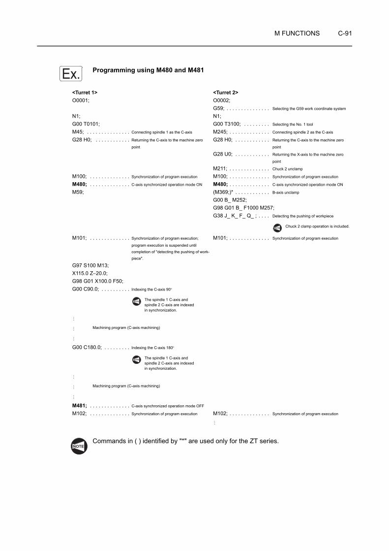
M FUNCTIONS C-91
Programming using M480 and M481
Commands in ( ) identified by "*" are used only for the ZT series.
<Turret 1> <Turret 2>O0001; O0002;
G59; . . . . . . . . . . . . . . . Selecting the G59 work coordinate system
N1; N1;G00 T0101; G00 T3100; . . . . . . . . . Selecting the No. 1 tool
M45; . . . . . . . . . . . . . . . Connecting spindle 1 as the C-axis M245; . . . . . . . . . . . . . . Connecting spindle 2 as the C-axis
G28 H0; . . . . . . . . . . . . Returning the C-axis to the machine zero
point
G28 H0; . . . . . . . . . . . . Returning the C-axis to the machine zero
point
G28 U0; . . . . . . . . . . . . Returning the X-axis to the machine zero
point
M211; . . . . . . . . . . . . . . Chuck 2 unclamp
M100; . . . . . . . . . . . . . . Synchronization of program execution M100; . . . . . . . . . . . . . . Synchronization of program execution
M480; . . . . . . . . . . . . . . C-axis synchronized operation mode ON M480; . . . . . . . . . . . . . . C-axis synchronized operation mode ON
M59; (M369;)* . . . . . . . . . . . . B-axis unclamp
G00 B_ M252;G98 G01 B_ F1000 M257;G38 J_ K_ F_ Q_ ; . . . . Detecting the pushing of workpiece
Chuck 2 clamp operation is included.
M101; . . . . . . . . . . . . . . Synchronization of program execution;
program execution is suspended until completion of "detecting the pushing of work-
piece".
M101; . . . . . . . . . . . . . . Synchronization of program execution
G97 S100 M13;X115.0 Z−20.0;G98 G01 X100.0 F50;G00 C90.0; . . . . . . . . . . Indexing the C-axis 90°
The spindle 1 C-axis and spindle 2 C-axis are indexed in synchronization.
Machining program (C-axis machining)
G00 C180.0; . . . . . . . . . Indexing the C-axis 180°
The spindle 1 C-axis and spindle 2 C-axis are indexed in synchronization.
Machining program (C-axis machining)
M481; . . . . . . . . . . . . . . C-axis synchronized operation mode OFF
M102; . . . . . . . . . . . . . . Synchronization of program execution M102; . . . . . . . . . . . . . . Synchronization of program execution
Ex.
NOTE
NOTE
NOTE
NOTE

C-92 M FUNCTIONS
30 M368, M369 B-AXIS CLAMP/UNCLAMP (ZT SERIES)
When the M368 command is executed, the B-axis is clamped.
When the M369 command is executed, the B-axis is unclamped and can be moved.
These M codes can be used as the B-axis clamp/unclamp commands only for the ZT series machines.
M368; . . . . . . . . . Specifies B-axis clamping
M369; . . . . . . . . . Specifies B-axis unclamping
Before moving the B-axis, unclamp the B-axis by executing the M369 command.
1. If a cut-off cycle is executed when transferring a workpiece, it is not necessary to unclamp the B-axis.
2. When "G330;" is executed or if the B-axis is manually returned to the machine zero point, it is not necessary to specify the M368 command to clamp the B-axis since the B-axis is automatically clamped when it reaches the machine zero point.
3. The B-axis is automatically unclamped when the power is turned on.
NOTE
COMMAND
NOTE
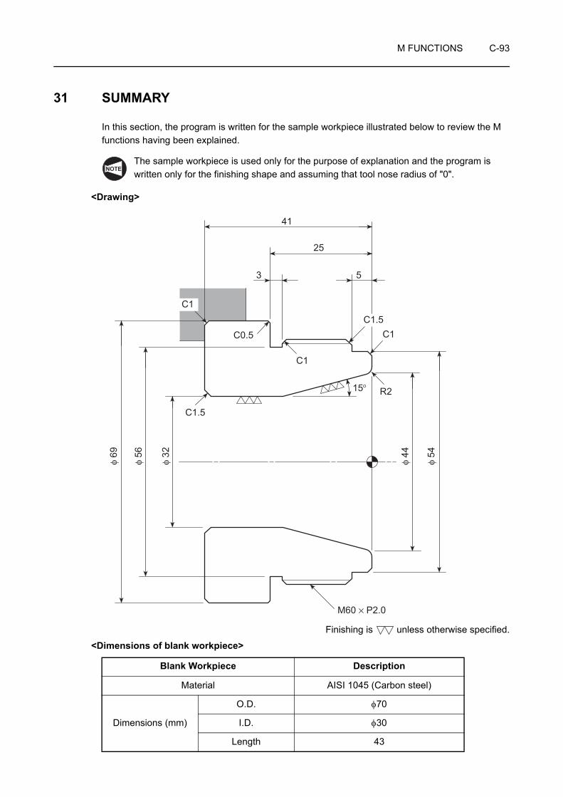
M FUNCTIONS C-93
31 SUMMARY
In this section, the program is written for the sample workpiece illustrated below to review the M functions having been explained.
The sample workpiece is used only for the purpose of explanation and the program is written only for the finishing shape and assuming that tool nose radius of "0".
<Drawing>
Finishing is unless otherwise specified.
<Dimensions of blank workpiece>
Blank Workpiece Description
Material AISI 1045 (Carbon steel)
Dimensions (mm)
O.D. φ70
I.D. φ30
Length 43
NOTE
41
25
3 5
C1.5C1
15°� R2
C1
C0.5
C1
C1.5
M60 × P2.0
φ 44
φ 54
φ 32
φ 56
φ 69
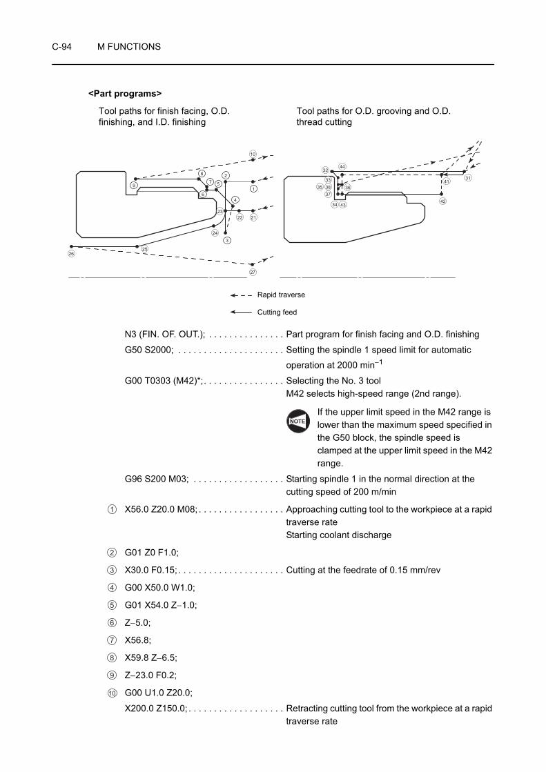
C-94 M FUNCTIONS
<Part programs>
N3 (FIN. OF. OUT.); . . . . . . . . . . . . . . . Part program for finish facing and O.D. finishing
G50 S2000; . . . . . . . . . . . . . . . . . . . . . Setting the spindle 1 speed limit for automatic
operation at 2000 min−1
G00 T0303 (M42)*;. . . . . . . . . . . . . . . . Selecting the No. 3 toolM42 selects high-speed range (2nd range).
If the upper limit speed in the M42 range is lower than the maximum speed specified in the G50 block, the spindle speed is clamped at the upper limit speed in the M42 range.
G96 S200 M03; . . . . . . . . . . . . . . . . . . Starting spindle 1 in the normal direction at the cutting speed of 200 m/min
X56.0 Z20.0 M08; . . . . . . . . . . . . . . . . . Approaching cutting tool to the workpiece at a rapid traverse rateStarting coolant discharge
G01 Z0 F1.0;
X30.0 F0.15; . . . . . . . . . . . . . . . . . . . . . Cutting at the feedrate of 0.15 mm/rev
G00 X50.0 W1.0;
G01 X54.0 Z−1.0;
Z−5.0;
X56.8;
X59.8 Z−6.5;
Z−23.0 F0.2;
G00 U1.0 Z20.0;
X200.0 Z150.0; . . . . . . . . . . . . . . . . . . . Retracting cutting tool from the workpiece at a rapid traverse rate
Tool paths for finish facing, O.D. finishing, and I.D. finishing
Tool paths for O.D. grooving and O.D. thread cutting
42
4131
36
4334
373833
3244
351
3
9
4
57
8
6
2
2526
10
27
24
232122
Rapid traverse
Cutting feed
NOTE
1
2
3
4
5
6
7
8
9
10
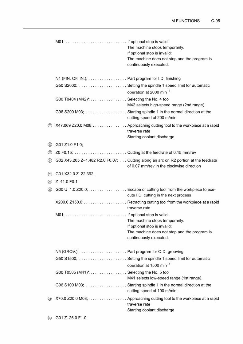
M FUNCTIONS C-95
M01; . . . . . . . . . . . . . . . . . . . . . . . . . . . If optional stop is valid:The machine stops temporarily.If optional stop is invalid:The machine does not stop and the program is continuously executed.
N4 (FIN. OF. IN.); . . . . . . . . . . . . . . . . . Part program for I.D. finishing
G50 S2000; . . . . . . . . . . . . . . . . . . . . . Setting the spindle 1 speed limit for automatic
operation at 2000 min−1
G00 T0404 (M42)*;. . . . . . . . . . . . . . . . Selecting the No. 4 toolM42 selects high-speed range (2nd range).
G96 S200 M03; . . . . . . . . . . . . . . . . . . Starting spindle 1 in the normal direction at the cutting speed of 200 m/min
X47.069 Z20.0 M08; . . . . . . . . . . . . . . . Approaching cutting tool to the workpiece at a rapid traverse rateStarting coolant discharge
G01 Z1.0 F1.0;
Z0 F0.15; . . . . . . . . . . . . . . . . . . . . . . . Cutting at the feedrate of 0.15 mm/rev
G02 X43.205 Z−1.482 R2.0 F0.07; . . . Cutting along an arc on R2 portion at the feedrate of 0.07 mm/rev in the clockwise direction
G01 X32.0 Z−22.392;
Z−41.0 F0.1;
G00 U−1.0 Z20.0; . . . . . . . . . . . . . . . . . Escape of cutting tool from the workpiece to exe-cute I.D. cutting in the next process
X200.0 Z150.0; . . . . . . . . . . . . . . . . . . . Retracting cutting tool from the workpiece at a rapid traverse rate
M01; . . . . . . . . . . . . . . . . . . . . . . . . . . . If optional stop is valid:The machine stops temporarily.If optional stop is invalid:The machine does not stop and the program is continuously executed.
N5 (GROV.); . . . . . . . . . . . . . . . . . . . . . Part program for O.D. grooving
G50 S1500; . . . . . . . . . . . . . . . . . . . . . Setting the spindle 1 speed limit for automatic
operation at 1500 min−1
G00 T0505 (M41)*;. . . . . . . . . . . . . . . . Selecting the No. 5 toolM41 selects low-speed range (1st range).
G96 S100 M03; . . . . . . . . . . . . . . . . . . Starting spindle 1 in the normal direction at the cutting speed of 100 m/min.
X70.0 Z20.0 M08; . . . . . . . . . . . . . . . . . Approaching cutting tool to the workpiece at a rapid traverse rateStarting coolant discharge
G01 Z−26.0 F1.0;
21
22
23
24
25
26
27
31
32

C-96 M FUNCTIONS
X68.0 Z−25.0 F0.07;. . . . . . . . . . . . . . . Cutting at the feedrate of 0.07 mm/rev
X56.0 F0.1;
G04 U0.2; . . . . . . . . . . . . . . . . . . . . . . . Dwell for 0.2 seconds (Program execution is suspended while the spindle keeps rotating)
G00 X60.8;
Z−23.6;
G01 X58.0 Z−25.0;
G00 X60.8;
X200.0 Z150.0; . . . . . . . . . . . . . . . . . . . Retracting cutting tool from the workpiece at a rapid traverse rate
M01; . . . . . . . . . . . . . . . . . . . . . . . . . . . If optional stop is valid:The machine stops temporarily.If optional stop is invalid:The machine does not stop and the program is continuously executed.
N6 (THREAD.);. . . . . . . . . . . . . . . . . . . Part program for O.D. thread cutting
G50 S1500;
G00 T0606 (M41)*;. . . . . . . . . . . . . . . . Selecting the No. 6 toolM41 selects low-speed range (1st range).
G97 S640 M03; . . . . . . . . . . . . . . . . . . Starting spindle 1 in the normal direction at
640 min−1
X70.0 Z20.0 M08; . . . . . . . . . . . . . . . . . Starting coolant discharge
G01 Z5.0 F1.0 M24; . . . . . . . . . . . . . . . Positioning of the cutting tool at the start point for thread cutting at a rapid traverse rateChamfering OFF
, , , G92 X59.1 Z−24.0 F2.0;
X58.6;
X58.2;
X57.9;
X57.7;
X57.54;
X57.44;
X57.4;
G00 X200.0 Z150.0 M09; . . . . . . . . . . . Retracting cutting tool from the workpiece at a rapid traverse rateStopping coolant discharge
M05; . . . . . . . . . . . . . . . . . . . . . . . . . . . Stopping the spindle rotation
M30; . . . . . . . . . . . . . . . . . . . . . . . . . . . End of program and program rewind
Commands in ( ) identified by "*" are used only for the machine equipped with a transmission.
33
34
35
36
37
38
41
. . . . Execution of thread cutting cycle in the G92 modeA series of thread cutting operation of point 41 → 42 → 43 → 44 → 41 is executed repeatedly.
42 43 44 41
NOTE

APPENDIX C-1
APPENDIX 1 MULTIPLE M CODE FUNCTION
The multiple M code function allows entry of a maximum of three M codes in a block.
By using the multiple M code function for the robot or the loader specification, cycle time can be reduced.
The multiple M code function can use the M codes indicated below as multiple M code function M codes.
<Multiple M code>
• M10 . . . . . . . . Chuck clamp/Chuck clamp <spindle 1>
• M11 . . . . . . . . Chuck unclamp/Chuck unclamp <spindle 1>
• M210 . . . . . . . Chuck clamp <spindle 2>
• M211 . . . . . . . Chuck unclamp <spindle 2>
• M19 . . . . . . . . Spindle orientation/Spindle orientation <spindle 1>
• M219 . . . . . . . Spindle orientation <spindle 2>
• M25 . . . . . . . . Tailstock spindle OUT
• M26 . . . . . . . . Tailstock spindle IN
• M85, M220 . . Automatic door open
• M86, M221 . . Automatic door close
• M37 . . . . . . . . Ceiling shutter open
• M38 . . . . . . . . Ceiling shutter close
The multiple M code function simultaneously executes up to three M codes specified in the same block. Therefore, operations called out by these M codes and the combination of them must be carefully examined. If M codes are specified in improper combinations, it may cause damage to the machine.
1. Although the first M code among the two or three M codes specified in a block may be other than the M code allowed to be used by the multiple M code function, the second and the third M code must be the multiple M code function M codes.
2. The spindle (or rotary tool) rotation command (M03, M04, M13, M14) must not be specified with a multiple M code function M code in the same block.
CAUTION
NOTE

C-2 APPENDIX
APPENDIX 2 QUICK M CODE FUNCTION
The quick M Code function allows you to execute the next block motion without a wait for completion of the M code motion.
1. There is a possibility of collisions. Pay careful attention when using this function.
When using the quick M code function, check any possible collisions or motion timing in the following blocks and ensure that each motion can be made at the correct timing.
2. In principle, specify a quick M code in a block without other commands.
3. When a quick M code is used, specify the corresponding ordinary M code (subtracting 1000 from the quick M code number) to confirm the completion of the movement.
If there is a possibility of collisions or off-timing that might occur in the block following the quick M code, specify an ordinary M code immediately before this position. In this case, a wait for completion of the motion takes place before starting the motion of the next block.
The following M codes can be used for the quick M code function.
• M1003, M1004, M1005, M1019. . . . . . . Spindle commands
• M1010/M1011 . . . . . . . . . . . . . . . . . . . . Chuck clamp/unclamp
• M1013/M1014 . . . . . . . . . . . . . . . . . . . . Rotary tool normal/reverse rotation
• M1019/M1219 . . . . . . . . . . . . . . . . . . . . Spindle 1/spindle 2 orientation
• M1037/M1038 . . . . . . . . . . . . . . . . . . . . Ceiling shutter open/close
• M1071/M1072 . . . . . . . . . . . . . . . . . . . . Automatic in-machine tool presetter arm DOWN/UP
• M1073/M1074 . . . . . . . . . . . . . . . . . . . . Parts catcher OUT/IN
• M1078/M1079 . . . . . . . . . . . . . . . . . . . . Tailstock clamp/unclamp
• M1085/M1086 . . . . . . . . . . . . . . . . . . . . Automatic door open/close
• M1203/M1204 . . . . . . . . . . . . . . . . . . . . Spindle 2 normal/reverse rotation
• M1210/M1211 . . . . . . . . . . . . . . . . . . . . Chuck clamp/unclamp <spindle 2>
• M1220/M1221 . . . . . . . . . . . . . . . . . . . . Automatic door open/close
• M1319 . . . . . . . . . . . . . . . . . . . . . . . . . . Rotary tool zero return
• M1340/M1341 . . . . . . . . . . . . . . . . . . . . Steady rest 1 open/close
• M1368/M1369 . . . . . . . . . . . . . . . . . . . . B-axis clamp/unclamp (ZT series)
• M1384 . . . . . . . . . . . . . . . . . . . . . . . . . . Spindle orientation <spindle 1> & ceiling shutter open
• M1387 . . . . . . . . . . . . . . . . . . . . . . . . . . Spindle orientation <spindle 2> & ceiling shutter open
• M1440 to M1449 . . . . . . . . . . . . . . . . . . External output
NOTE

CHAPTER DT, S, AND F FUNCTIONS
This chapter describes the T function that rotates the turret, indexes the required tool and calls the tool offset number, the S function that specifies the spindle speed or the rotary tool spindle speed, and the F function that specifies the feedrate.
The examples of program given in this chapter all assume tool nose R0.NOTE
CONTENTS
D : T, S, AND F FUNCTIONS
1 T FUNCTION. . . . . . . . . . . . . . . . . . . . . . . . . . . . . . . . . . . . . . . . . . . . . . . . . . . . . . . . . . D-1
1-1 Tool Numbers . . . . . . . . . . . . . . . . . . . . . . . . . . . . . . . . . . . . . . . . . . . . . . . . . . . . D-4
1-2 Tool Geometry Offset . . . . . . . . . . . . . . . . . . . . . . . . . . . . . . . . . . . . . . . . . . . . . . D-6
1-3 Tool Wear Offset . . . . . . . . . . . . . . . . . . . . . . . . . . . . . . . . . . . . . . . . . . . . . . . . . . D-9
2 S FUNCTION. . . . . . . . . . . . . . . . . . . . . . . . . . . . . . . . . . . . . . . . . . . . . . . . . . . . . . . . . D-17
2-1 Specifying the Spindle Speed or the Rotary Tool Spindle Speed (G97 S_ ) . . . . D-17
2-2 Specifying the Cutting Speed (G96 S_ ) . . . . . . . . . . . . . . . . . . . . . . . . . . . . . . . D-19
2-3 Specifying the Spindle Speed Limit for Automatic Operation (G50 S_ ) . . . . . . . D-20
2-4 Relationship of the Cutting Speed, Diameter, and Spindle Speed . . . . . . . . . . . D-23
2-5 Workpiece Materials and Cutting Speeds . . . . . . . . . . . . . . . . . . . . . . . . . . . . . . D-24
3 F FUNCTION. . . . . . . . . . . . . . . . . . . . . . . . . . . . . . . . . . . . . . . . . . . . . . . . . . . . . . . . . D-25
3-1 Feed per Spindle Revolution (G99 F_ ). . . . . . . . . . . . . . . . . . . . . . . . . . . . . . . . D-25
3-2 Feed per Minute (G98 F_ ) . . . . . . . . . . . . . . . . . . . . . . . . . . . . . . . . . . . . . . . . . D-27
3-3 Feedrate for Finishing . . . . . . . . . . . . . . . . . . . . . . . . . . . . . . . . . . . . . . . . . . . . . D-29
3-4 Table of Rapid Traverse Rates . . . . . . . . . . . . . . . . . . . . . . . . . . . . . . . . . . . . . . D-30
3-5 Table of Maximum Cutting Feedrate . . . . . . . . . . . . . . . . . . . . . . . . . . . . . . . . . . D-31
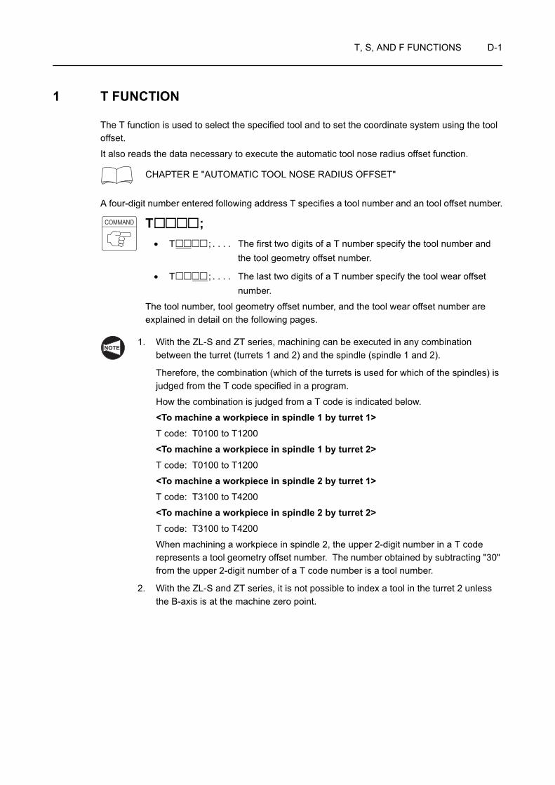
T, S, AND F FUNCTIONS D-1
1 T FUNCTION
The T function is used to select the specified tool and to set the coordinate system using the tool offset.
It also reads the data necessary to execute the automatic tool nose radius offset function.
CHAPTER E "AUTOMATIC TOOL NOSE RADIUS OFFSET"
A four-digit number entered following address T specifies a tool number and an tool offset number.
T ;• T ; . . . . The first two digits of a T number specify the tool number and
the tool geometry offset number.
• T ; . . . . The last two digits of a T number specify the tool wear offset number.
The tool number, tool geometry offset number, and the tool wear offset number are explained in detail on the following pages.
1. With the ZL-S and ZT series, machining can be executed in any combination between the turret (turrets 1 and 2) and the spindle (spindle 1 and 2).
Therefore, the combination (which of the turrets is used for which of the spindles) is judged from the T code specified in a program.
How the combination is judged from a T code is indicated below.
<To machine a workpiece in spindle 1 by turret 1>T code: T0100 to T1200
<To machine a workpiece in spindle 1 by turret 2>T code: T0100 to T1200
<To machine a workpiece in spindle 2 by turret 1>T code: T3100 to T4200
<To machine a workpiece in spindle 2 by turret 2>T code: T3100 to T4200
When machining a workpiece in spindle 2, the upper 2-digit number in a T code represents a tool geometry offset number. The number obtained by subtracting "30" from the upper 2-digit number of a T code number is a tool number.
2. With the ZL-S and ZT series, it is not possible to index a tool in the turret 2 unless the B-axis is at the machine zero point.
COMMAND
NOTE

D-2 T, S, AND F FUNCTIONS
Using T function (1)
The program for executing machining at spindle 1.
O0001;
N1;
G50 S2000;
G00 T0101; . . . . . . . . . . . . . . . . . . . . . T0101 . . . . . Calls the No. 1 tool. The offset data entered in field No. 1 of the GEOMETRY OFFSET screen is used.
T0101 . . . . The offset data entered in field No.1 of the TOOL TOOL WEAR OFFSET screen is used.
G96 S200 M03;
X100.0 Z20.0 M08;
Machining program
M01;
Ex.
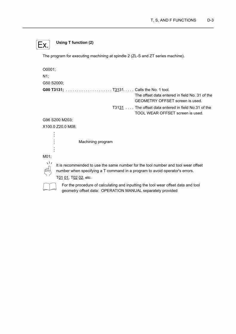
T, S, AND F FUNCTIONS D-3
Using T function (2)
The program for executing machining at spindle 2 (ZL-S and ZT series machine).
O0001;
N1;
G50 S2000;
G00 T3131; . . . . . . . . . . . . . . . . . . . . . T3131 . . . . . Calls the No. 1 tool. The offset data entered in field No. 31 of the GEOMETRY OFFSET screen is used.
T3131 . . . . The offset data entered in field No.31 of the TOOL WEAR OFFSET screen is used.
G96 S200 M203;
X100.0 Z20.0 M08;
Machining program
M01;
It is recommended to use the same number for the tool number and tool wear offset number when specifying a T command in a program to avoid operator's errors.
T01 01, T02 02, etc.
For the procedure of calculating and inputting the tool wear offset data and tool geometry offset data: OPERATION MANUAL separately provided
Ex.
D-4 T, S, AND F FUNCTIONS
1-1 Tool Numbers
A tool number indicates a particular station number in the turret head.
By reading a tool number specified in a T code, the NC rotates the turret head accordingly to bring the corresponding station into the cutting position.
A 12-station turret, for example, has 12 station numbers from "1" to "12".
With the ZL-S and ZT series machines, if machining is executed for spindle 2, the upper 2-digit number in a T code is not a tool number. The number obtained by subtracting 30 from the upper 2-digit number of a T code number is a tool number.
Specifying the tool numbers (1)
The program for executing machining at spindle 1.
O0001;
N1;
G50 S2000;
G00 T0101; . . . . . . . . . . . . . . . . . . . . . Selecting the No. 1 tool
G96 S120 M03;
Machining program
M01;
N2;
G50 S2500;
G00 T0202; . . . . . . . . . . . . . . . . . . . . . Selecting the No. 2 tool
G96 S200 M03;
Machining program
M30;
NOTE
Ex.
T, S, AND F FUNCTIONS D-5
Specifying the tool numbers (2)
The program for executing machining at spindle 2 (ZL-S and ZT series machine).
O0001;
N1;
G50 S2000;
G00 T3131; . . . . . . . . . . . . . . . . . . . . . Selecting the No. 1 tool
The number obtained by subtracting "30" from "31" is the tool number.
G96 S120 M203;
Machining program
M01;
N2;
G50 S2500;
G00 T3232; . . . . . . . . . . . . . . . . . . . . . Selecting the No. 2 tool
The number obtained by subtracting "30" from "32" is the tool number.
G96 S200 M203;
Machining program
M30;
Ex.
NOTE
NOTE
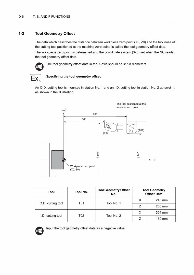
D-6 T, S, AND F FUNCTIONS
1-2 Tool Geometry Offset
The data which describes the distance between workpiece zero point (X0, Z0) and the tool nose of the cutting tool positioned at the machine zero point, is called the tool geometry offset data.
The workpiece zero point is determined and the coordinate system (X-Z) set when the NC reads the tool geometry offset data.
The tool geometry offset data in the X-axis should be set in diameters.
Specifying the tool geometry offset
An O.D. cutting tool is mounted in station No. 1 and an I.D. cutting tool in station No. 2 at turret 1, as shown in the illustration.
Input the tool geometry offset data as a negative value.
Tool Tool No. Tool Geometry Offset No.
Tool Geometry Offset Data
O.D. cutting tool T01 Tool No. 1X 240 mm
Z 200 mm
I.D. cutting tool T02 Tool No. 2X 304 mm
Z 160 mm
NOTE
Ex.
160
200+X
(T01)(T02)
+Z
304
240
φ φ
The tool positioned at the machine zero point
Workpiece zero point(X0, Z0)
NOTE
T, S, AND F FUNCTIONS D-7
O0001;
N1; (O.D.)
G50 S2000;
G00 T0101; . . . . . . . . . . . . . . . . . . . . . With the "T0101" command, the workpiece zero point is set at the position which is away from the programmed point (tool nose) of tool No. 1, positioned at the machine zero point, by the tool geometry offset data of tool No. 1 in the GEOMETRY OFFSET screen.
G96 S120 M03;
Machining program
M01;
N2; (I.D.)
G50 S2500;
G00 T0202; . . . . . . . . . . . . . . . . . . . . . With the "T0202" command, the workpiece zero point is set at the position which is away from the programmed point (tool nose) of tool No. 2, positioned at the machine zero point, by the tool geometry offset data of tool No. 2 in the GEOMETRY OFFSET screen.
G96 S200 M03;
Machining program
M30;
It is not necessary to cancel the tool geometry offset data for each cutting tool; the offset data is automatically canceled when the tool geometry offset command (T command) is read for the next tool.
NOTE
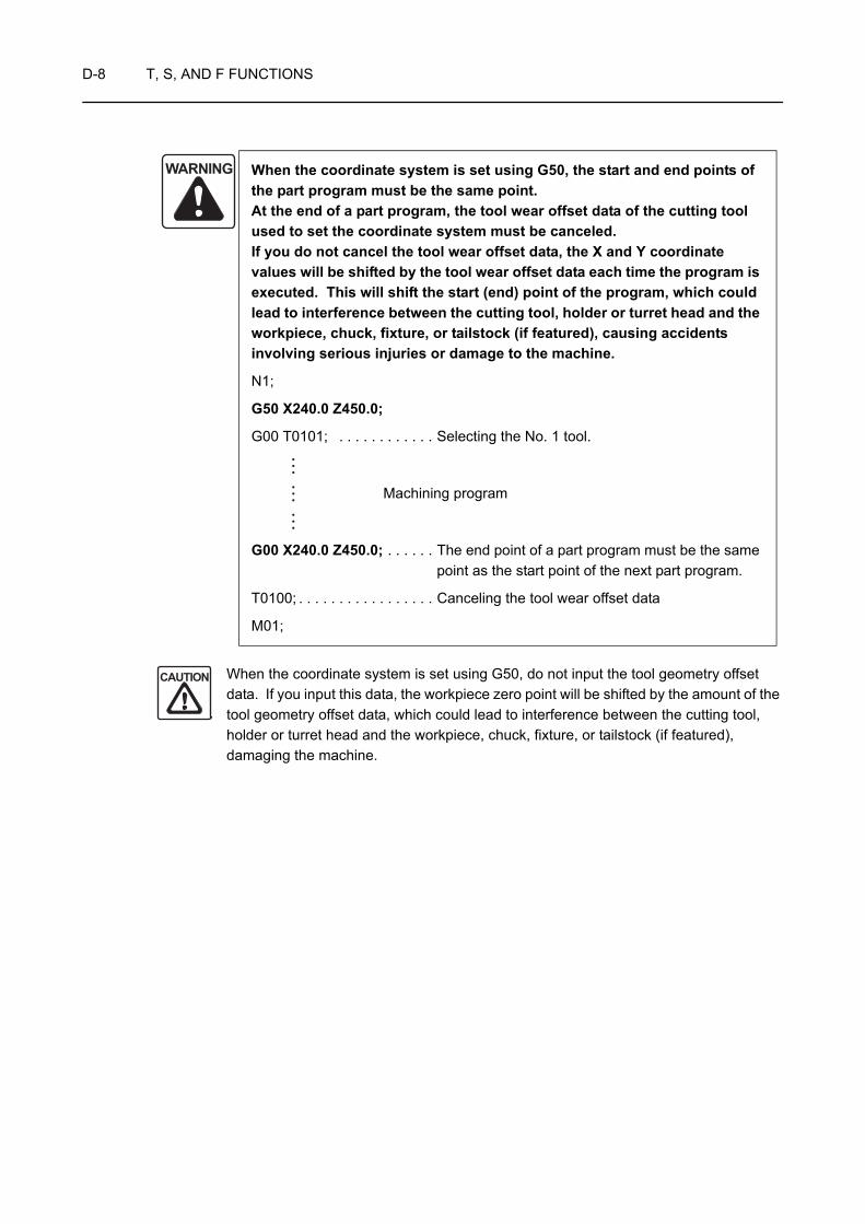
D-8 T, S, AND F FUNCTIONS
When the coordinate system is set using G50, do not input the tool geometry offset data. If you input this data, the workpiece zero point will be shifted by the amount of the tool geometry offset data, which could lead to interference between the cutting tool, holder or turret head and the workpiece, chuck, fixture, or tailstock (if featured), damaging the machine.
WARNING When the coordinate system is set using G50, the start and end points of the part program must be the same point. At the end of a part program, the tool wear offset data of the cutting tool used to set the coordinate system must be canceled. If you do not cancel the tool wear offset data, the X and Y coordinate values will be shifted by the tool wear offset data each time the program is executed. This will shift the start (end) point of the program, which could lead to interference between the cutting tool, holder or turret head and the workpiece, chuck, fixture, or tailstock (if featured), causing accidents involving serious injuries or damage to the machine.
N1;
G50 X240.0 Z450.0;
G00 T0101; . . . . . . . . . . . . Selecting the No. 1 tool.
Machining program
G00 X240.0 Z450.0; . . . . . . The end point of a part program must be the same point as the start point of the next part program.
T0100; . . . . . . . . . . . . . . . . . Canceling the tool wear offset data
M01;
CAUTION
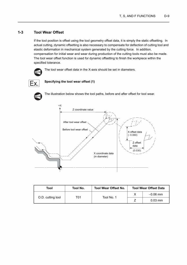
T, S, AND F FUNCTIONS D-9
1-3 Tool Wear Offset
If the tool position is offset using the tool geometry offset data, it is simply the static offsetting. In actual cutting, dynamic offsetting is also necessary to compensate for deflection of cutting tool and elastic deformation in mechanical system generated by the cutting force. In addition, compensation for initial wear and wear during production of the cutting tools must also be made. The tool wear offset function is used for dynamic offsetting to finish the workpiece within the specified tolerance.
The tool wear offset data in the X-axis should be set in diameters.
Specifying the tool wear offset (1)
The illustration below shows the tool paths, before and after offset for tool wear.
Tool Tool No. Tool Wear Offset No. Tool Wear Offset Data
O.D. cutting tool T01 Tool No. 1X −0.06 mm
Z 0.03 mm
NOTE
Ex.NOTE
+X
(0.030)
(−0.060)
Z coordinate value
After tool wear offset
Before tool wear offset
X coordinate data (in diameter)
X offset data
Z offset data
D-10 T, S, AND F FUNCTIONS
O0001;
N1; (O.D.)
G50 S2500;
G00 T0101; . . . . . . . . . . . . . . . . . . . . . With "T0101" command, the tool position is offset by the offset data of tool No. 1 in the TOOL WEAR OFFSET screen.
G96 S120 M03;
Machining program
M01;
N2; (I.D.)
G50 S2000;
G00 T0202; . . . . . . . . . . . . . . . . . . . . . With "T0202" command, the tool position is offset by the offset data of tool No. 2 in the TOOL WEAR OFFSET screen.
G96 S200 M03;
Machining program
M30;
The same procedure is used for other tools. In a program, only the tool wear offset number is specified in a T command. The actual offset data to be input must be found by the operator.
It is not necessary to cancel the tool wear offset data for each cutting tool; the offset data is automatically canceled when the tool wear offset command (T command) is read for the next tool.
NOTE
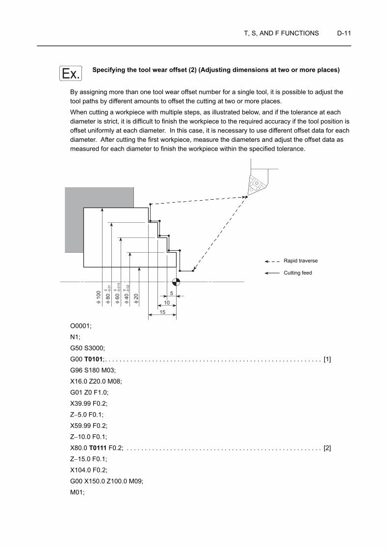
T, S, AND F FUNCTIONS D-11
Specifying the tool wear offset (2) (Adjusting dimensions at two or more places)
By assigning more than one tool wear offset number for a single tool, it is possible to adjust the tool paths by different amounts to offset the cutting at two or more places.
When cutting a workpiece with multiple steps, as illustrated below, and if the tolerance at each diameter is strict, it is difficult to finish the workpiece to the required accuracy if the tool position is offset uniformly at each diameter. In this case, it is necessary to use different offset data for each diameter. After cutting the first workpiece, measure the diameters and adjust the offset data as measured for each diameter to finish the workpiece within the specified tolerance.
O0001;
N1;
G50 S3000;
G00 T0101;. . . . . . . . . . . . . . . . . . . . . . . . . . . . . . . . . . . . . . . . . . . . . . . . . . . . . . . . . . . . [1]
G96 S180 M03;
X16.0 Z20.0 M08;
G01 Z0 F1.0;
X39.99 F0.2;
Z−5.0 F0.1;
X59.99 F0.2;
Z−10.0 F0.1;
X80.0 T0111 F0.2; . . . . . . . . . . . . . . . . . . . . . . . . . . . . . . . . . . . . . . . . . . . . . . . . . . . . . . [2]
Z−15.0 F0.1;
X104.0 F0.2;
G00 X150.0 Z100.0 M09;
M01;
Ex.
5
10
15
100
800 −0.0
1
600 −0.0
15
400 −0.0
2
20
φ φ φ φ φ
Cutting feed
Rapid traverse
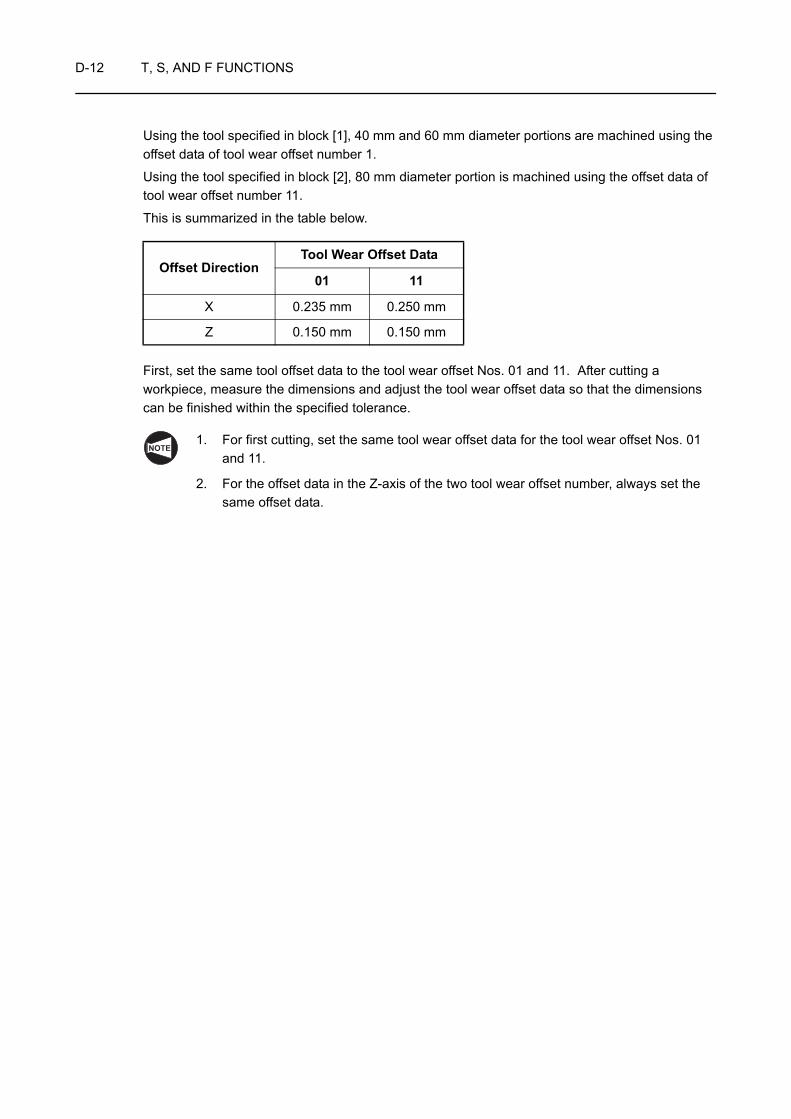
D-12 T, S, AND F FUNCTIONS
Using the tool specified in block [1], 40 mm and 60 mm diameter portions are machined using the offset data of tool wear offset number 1.
Using the tool specified in block [2], 80 mm diameter portion is machined using the offset data of tool wear offset number 11.
This is summarized in the table below.
First, set the same tool offset data to the tool wear offset Nos. 01 and 11. After cutting a workpiece, measure the dimensions and adjust the tool wear offset data so that the dimensions can be finished within the specified tolerance.
1. For first cutting, set the same tool wear offset data for the tool wear offset Nos. 01 and 11.
2. For the offset data in the Z-axis of the two tool wear offset number, always set the same offset data.
Offset DirectionTool Wear Offset Data
01 11
X 0.235 mm 0.250 mm
Z 0.150 mm 0.150 mm
NOTE

T, S, AND F FUNCTIONS D-13
Specifying the tool wear offset (3) (Adjusting a taper angle)
The tool wear offset data may be used in a special method. Check the cut taper with a gage. It is possible to adjust the finished taper using the results obtained from checking the contact between the cut taper and the gage.
O0001;
N1;
G50 S2000;
G00 T0101;. . . . . . . . . . . . . . . . . . . . . . . . . . . . . . . . . . . . . . . . . . . . . . . . . . . . . . . . . . . . [1]
G96 S180 M03;
X40.0 Z20.0 M08;
G01 Z0 F1.0;
X76.375 F0.2;
X106.375 Z−120.0 T0111 F0.05; . . . . . . . . . . . . . . . . . . . . . . . . . . . . . . . . . . . . . . . . . . . [2]
X130.0 F0.25;
G00 X250.0 Z100.0 M09;
M01;
Ex.
120
106.
37+
0.01
0
45φφ
1
2
11
22
Taper 1/4
<To adjust the taper angle>
• Change the X value of point 1 • Change the Z value of point 2
Cutting feed
Rapid traverse

D-14 T, S, AND F FUNCTIONS
Using the tool specified in block [1], ordinary offset for dimensions is made.
Using the tool specified in block [2], taper angle is adjusted.
This is summarized in the table below.
First, set the same tool offset data to the tool wear offset Nos. 01 and 11. After cutting a workpiece, measure the dimensions and adjust the tool wear offset data so that the dimensions can be finished within the specified tolerance.
1. For first cutting, set the same tool wear offset data for the tool wear offset Nos. 01 and 11.
2. Specify the new offset data (11) without canceling the existing offset data (01).
3. Specify the new offset number (11) at the taper cutting command point.
4. Since either of the X or Z offset data of the two tool wear offset numbers is taken as the reference of the taper, always specify the same data for both offset numbers (01, 11).
5. The program is created assuming that tool nose R is R0.
Offset DirectionTool Wear Offset Data
01 11
X 0.196 mm 0.199 mm
Z 0.270 mm 0.270 mm
NOTE

T, S, AND F FUNCTIONS D-15
Specifying the tool wear offset (4) (Adjusting the groove width)
In a grooving operation, the cut groove width might fall outside the specified tolerance due to tool wear. To offset, the groove width can be adjusted by setting different tool wear offset data for the right side wall and for the left side wall.
O0001;
N1;
G50 S500;
G00 T0101;. . . . . . . . . . . . . . . . . . . . . . . . . . . . . . . . . . . . . . . . . . . . . . . . . . . . . . . [1]
G96 S80 M03;
X110.0 Z20.0 M08;
G01 Z−19.5 F2.0;
X102.0; . . . . . . . . . . . . . . . . . . . . . . . . . . . . . . . . . . . . . . . . . . . . . . . . . . . . . . .
X95.1 F0.1; . . . . . . . . . . . . . . . . . . . . . . . . . . . . . . . . . . . . . . . . . . . . . . . . . . . .
X102.0 F0.5; . . . . . . . . . . . . . . . . . . . . . . . . . . . . . . . . . . . . . . . . . . . . . . . . . . .
Z−22.0; . . . . . . . . . . . . . . . . . . . . . . . . . . . . . . . . . . . . . . . . . . . . . . . . . . . . . . .
X98.0 Z−20.0 F0.07; . . . . . . . . . . . . . . . . . . . . . . . . . . . . . . . . . . . . . . . . . . . . .
X95.0; . . . . . . . . . . . . . . . . . . . . . . . . . . . . . . . . . . . . . . . . . . . . . . . . . . . . . . . .
X102.0 W0.1 F0.5; . . . . . . . . . . . . . . . . . . . . . . . . . . . . . . . . . . . . . . . . . . . . . .
Z−17.0 F1.0 T0111;. . . . . . . . . . . . . . . . . . . . . . . . . . . . . . . . . . . . . . . . . . . . . . [2]
X98.0 Z−19.0 F0.07; . . . . . . . . . . . . . . . . . . . . . . . . . . . . . . . . . . . . . . . . . . . . .
X95.0; . . . . . . . . . . . . . . . . . . . . . . . . . . . . . . . . . . . . . . . . . . . . . . . . . . . . . . . .
Z−20.0 T0101 F0.1; . . . . . . . . . . . . . . . . . . . . . . . . . . . . . . . . . . . . . . . . . . . . . [3]
G00 X110.0 W0.5;
Z20.0;
Ex.
620
5
C1C1
5
100
95
76
3
4
5 92
8
1
φφ
Cutting feed
Rapid traverse
1
2
1
3
4
5
6
7
8
9
5
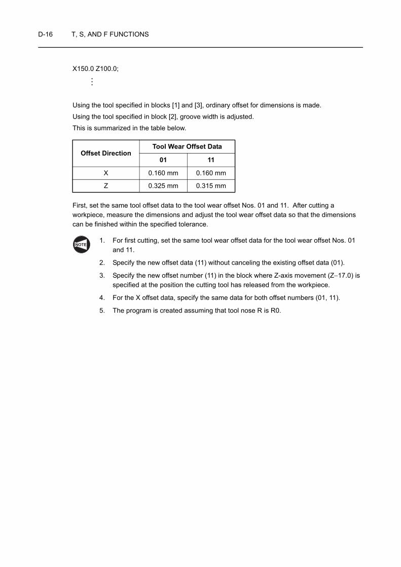
D-16 T, S, AND F FUNCTIONS
X150.0 Z100.0;
Using the tool specified in blocks [1] and [3], ordinary offset for dimensions is made.
Using the tool specified in block [2], groove width is adjusted.
This is summarized in the table below.
First, set the same tool offset data to the tool wear offset Nos. 01 and 11. After cutting a workpiece, measure the dimensions and adjust the tool wear offset data so that the dimensions can be finished within the specified tolerance.
1. For first cutting, set the same tool wear offset data for the tool wear offset Nos. 01 and 11.
2. Specify the new offset data (11) without canceling the existing offset data (01).
3. Specify the new offset number (11) in the block where Z-axis movement (Z−17.0) is specified at the position the cutting tool has released from the workpiece.
4. For the X offset data, specify the same data for both offset numbers (01, 11).
5. The program is created assuming that tool nose R is R0.
Offset DirectionTool Wear Offset Data
01 11
X 0.160 mm 0.160 mm
Z 0.325 mm 0.315 mm
NOTE

T, S, AND F FUNCTIONS D-17
2 S FUNCTION
The S function controls spindle rotation or rotary tool rotation. A number of four or less digits following address S specifies the spindle speed, the rotary tool spindle speed, or the cutting (surface) speed.
The S code defines the following in combination with a G code specified in the same block:
1. Spindle speed or rotary tool spindle speed (min−1 ) . . . . . . . . . . . G97 S_
2. Cutting (surface) speed (m/min) . . . . . . . . . . . . . . . . . . . . . . . . . . G96 S_
3. Maximum spindle speed for automatic operation (min−1) . . . . . . . G50 S_
2-1 Specifying the Spindle Speed or the Rotary Tool Spindle Speed (G97 S_ )
The G97 mode is used for turning a workpiece of a uniform diameter, thread cutting, drilling, and milling with a rotary tool.
G97 S_ M03(M04);G97 S_ M203(M204);G97 S_ M13(M14);
• G97 . . . . . . . . Calls the constant spindle speed command mode.
• S. . . . . . . . . . . Specifies the spindle speed (min−1).
• M03(M04). . . . Specifies spindle or spindle 1 rotation in the normal (reverse) direction.
• M203(M204). . Specifies spindle 2 rotation in the normal (reverse) direction.
• M13(M14). . . . Specifies rotary tool rotation in the normal (reverse) direction.
WARNING When a G97 speed command is used in a program, specification of the maximum speed with a G50 command will be ignored. Therefore, when specifying the spindle speed with a G97 command, specify a speed no higher than the lowest speed among the allowable speed limits for the chuck, fixture, and cylinder. If you set a higher speed the workpiece will fly out of the machine, causing serious injuries or damage to the machine.
COMMAND
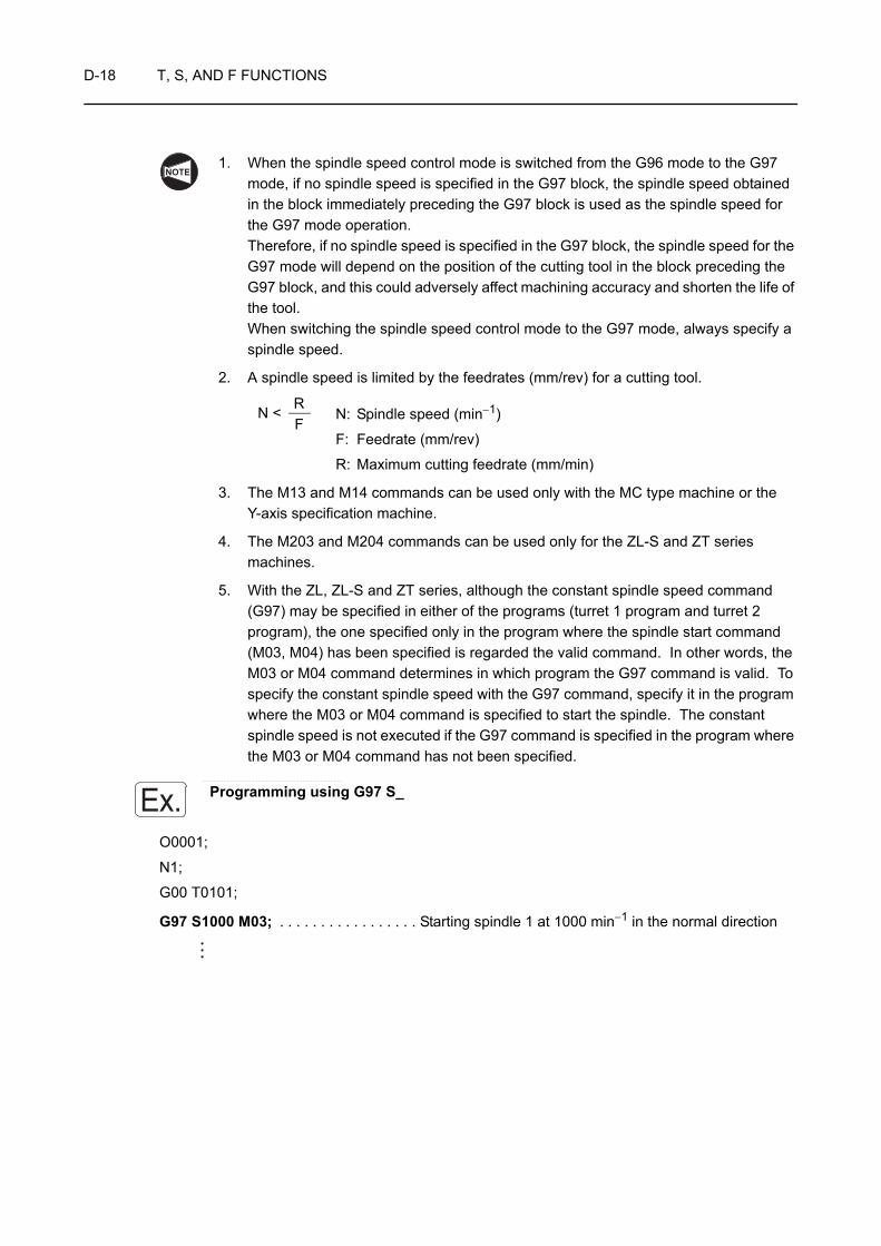
D-18 T, S, AND F FUNCTIONS
1. When the spindle speed control mode is switched from the G96 mode to the G97 mode, if no spindle speed is specified in the G97 block, the spindle speed obtained in the block immediately preceding the G97 block is used as the spindle speed for the G97 mode operation. Therefore, if no spindle speed is specified in the G97 block, the spindle speed for the G97 mode will depend on the position of the cutting tool in the block preceding the G97 block, and this could adversely affect machining accuracy and shorten the life of the tool. When switching the spindle speed control mode to the G97 mode, always specify a spindle speed.
2. A spindle speed is limited by the feedrates (mm/rev) for a cutting tool.
N: Spindle speed (min−1)
F: Feedrate (mm/rev)
R: Maximum cutting feedrate (mm/min)
3. The M13 and M14 commands can be used only with the MC type machine or the Y-axis specification machine.
4. The M203 and M204 commands can be used only for the ZL-S and ZT series machines.
5. With the ZL, ZL-S and ZT series, although the constant spindle speed command (G97) may be specified in either of the programs (turret 1 program and turret 2 program), the one specified only in the program where the spindle start command (M03, M04) has been specified is regarded the valid command. In other words, the M03 or M04 command determines in which program the G97 command is valid. To specify the constant spindle speed with the G97 command, specify it in the program where the M03 or M04 command is specified to start the spindle. The constant spindle speed is not executed if the G97 command is specified in the program where the M03 or M04 command has not been specified.
. . . . . . . . . . . . . . . . . . . . . . . . . . . . . . . . . . . . . . . . . . . . . . . . . . . . . . . . . . . . . . . . . . . . . . . . . . . . . . . . . . . . .
Programming using G97 S_
O0001;
N1;
G00 T0101;
G97 S1000 M03; . . . . . . . . . . . . . . . . . Starting spindle 1 at 1000 min−1 in the normal direction
NOTE
RF
N <
Ex.
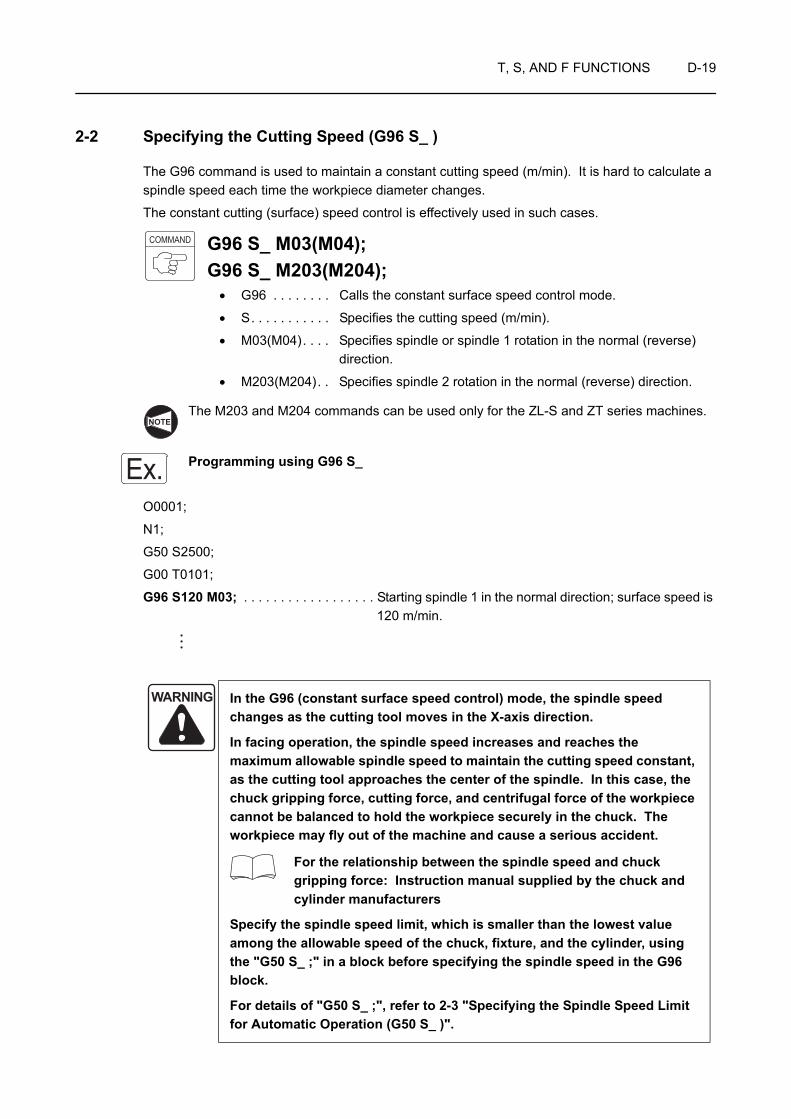
T, S, AND F FUNCTIONS D-19
2-2 Specifying the Cutting Speed (G96 S_ )
The G96 command is used to maintain a constant cutting speed (m/min). It is hard to calculate a spindle speed each time the workpiece diameter changes.
The constant cutting (surface) speed control is effectively used in such cases.
G96 S_ M03(M04);G96 S_ M203(M204);
• G96 . . . . . . . . Calls the constant surface speed control mode.
• S. . . . . . . . . . . Specifies the cutting speed (m/min).
• M03(M04). . . . Specifies spindle or spindle 1 rotation in the normal (reverse) direction.
• M203(M204). . Specifies spindle 2 rotation in the normal (reverse) direction.
The M203 and M204 commands can be used only for the ZL-S and ZT series machines.
Programming using G96 S_
O0001;
N1;
G50 S2500;
G00 T0101;
G96 S120 M03; . . . . . . . . . . . . . . . . . . Starting spindle 1 in the normal direction; surface speed is 120 m/min.
WARNING In the G96 (constant surface speed control) mode, the spindle speed changes as the cutting tool moves in the X-axis direction.
In facing operation, the spindle speed increases and reaches the maximum allowable spindle speed to maintain the cutting speed constant, as the cutting tool approaches the center of the spindle. In this case, the chuck gripping force, cutting force, and centrifugal force of the workpiece cannot be balanced to hold the workpiece securely in the chuck. The workpiece may fly out of the machine and cause a serious accident.
For the relationship between the spindle speed and chuck gripping force: Instruction manual supplied by the chuck and cylinder manufacturers
Specify the spindle speed limit, which is smaller than the lowest value among the allowable speed of the chuck, fixture, and the cylinder, using the "G50 S_ ;" in a block before specifying the spindle speed in the G96 block.
For details of "G50 S_ ;", refer to 2-3 "Specifying the Spindle Speed Limit for Automatic Operation (G50 S_ )".
COMMAND
NOTE
Ex.
D-20 T, S, AND F FUNCTIONS
With the ZL, ZL-S and ZT series, although the constant surface speed control command (G96) may be specified in either of the programs (turret 1 program and turret 2 program), the one specified only in the program where the spindle start command (M03, M04) has been specified is regarded the valid command. In other words, the M03 or M04 command determines in which program the G96 command is valid. To specify the constant surface speed control with the G96 command, specify it in the program where the M03 or M04 command is specified to start the spindle. The constant surface speed control is not executed if the G96 command is specified in the program where the M03 or M04 command has not been specified.
2-3 Specifying the Spindle Speed Limit for Automatic Operation (G50 S_ )
When facing a workpiece in the G96 constant cutting speed mode, the spindle speed will increase to "infinite" speed if the cutting tool is moved to X0.
Therefore, the spindle speed limit must be specified to prevent chuck gripping force from being lowered due to centrifugal force, when cutting a workpiece in the G96 mode.
WARNING 1. The spindle speed limit set using G50 must be no higher than the lowest of the individual allowable speed limits for the chuck, fixture, and cylinder. If you set a higher speed the workpiece will fly out of the machine, causing serious injuries or damage to the machine.
2. In the G96 (constant surface speed control) mode, the spindle speed increases as the cutting tool approaches the center of the spindle. Near the center of the spindle, the spindle speed will reach the allowable maximum speed of the machine. At this speed, the chuck gripping force, cutting force, and centrifugal force cannot be balanced to hold the workpiece securely in the chuck. As a result, the workpiece will fly out of the machine, causing serious injuries or damage to the machine. The spindle speed limit must always be specified in a part program by using the G50 command in a block preceding the G96 block, in order to clamp the spindle speed at the specified speed.
NOTE
T, S, AND F FUNCTIONS D-21
G50 S_ ;• G50 . . . . . . . . Calls the mode to specify the spindle speed limit for automatic
operation.
• S. . . . . . . . . . . Specifies spindle speed limit (min−1).
With the ZL, ZL-S and ZT series, although the spindle speed limit setting command (G50) may be specified in either of the programs (turret 1 program and turret 2 program), the one specified only in the program where the spindle start command (M03, M04) has been specified is regarded the valid command. In other words, the M03 or M04 command determines in which program the G50 command is valid. To set the spindle speed limit by specifying the G50 command, specify it in the program where the M03 or M04 command is specified to start the spindle. The spindle speed limit setting is not executed if the G50 command is specified in the program where the M03 or M04 command has not been specified.
WARNING 1. The setting of the spindle speed override switch (if there is one) is valid even when a spindle speed limit is set using G50. If the switch is set to 110% or 120%, for example, the programmed spindle speed will be overridden in accordance with this setting. If this causes the actual spindle speed to exceed the allowable speed of the chuck, fixture, or cylinder, the workpiece will fly out of the chuck during machining, causing serious injuries or damage to the machine. Therefore, the spindle speed override switch must be set at 100% or lower.
2. When a G97 speed command is used in a program, specification of the maximum speed with a G50 command will be ignored. Therefore, when specifying the spindle speed with a G97 command, specify a speed no higher than the lowest speed among the allowable speed limits for the chuck, fixture, and cylinder. If you set a higher speed the workpiece will fly out of the machine, causing serious injuries or damage to the machine.
COMMAND
NOTE

D-22 T, S, AND F FUNCTIONS
Programming using G50 S_
O0001;
N1;
G50 S2000; . . . . . . . . . . . . . . . . . . . . . Setting the spindle 1 speed limit for automatic operation at
2000 min−1
G00 T0101;
G96 S100 M03;. . . . . . . . . . . . . . . . . . . Starting spindle 1 in the normal direction at the cutting speed of 100 m/min
Machining program
G00 X100.0 Z50.0;
M01;
N2;
G00 T0202;
G97 S800 M03;. . . . . . . . . . . . . . . . . . . Starting spindle 1 in the normal direction at 800 min−1
The setting of 2000 min−1 for the allowable maximum spindle speed that is applied for automatic operation is disregarded.
Machining program
G00 X150.0 Z50.0;
M01;
N3;
G50 S1000; . . . . . . . . . . . . . . . . . . . . . Setting the spindle 1 speed limit for automatic operation at
1000 min−1
G00 T0303;
G96 S200 M03;. . . . . . . . . . . . . . . . . . . Starting spindle 1 in the normal direction at the cutting speed of 200 m/min
Machining program
G00 X150.0 Z50.0 M05;
M30;
Ex.
NOTE
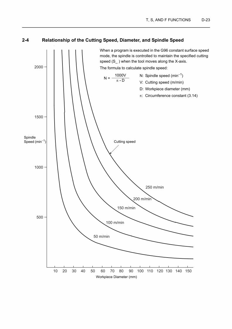
T, S, AND F FUNCTIONS D-23
2-4 Relationship of the Cutting Speed, Diameter, and Spindle Speed
10 20 30 40 50 60 70 80 90 100 110 120 130 140 150
500
1000
1500
2000
50 m/min
100 m/min
150 m/min
200 m/min
250 m/min
When a program is executed in the G96 constant surface speed mode, the spindle is controlled to maintain the specified cutting speed (S_ ) when the tool moves along the X-axis.
The formula to calculate spindle speed:
N: Spindle speed (min−1)
V: Cutting speed (m/min)
D: Workpiece diameter (mm)
π: Circumference constant (3.14)
1000Vπ • DN =
Cutting speedSpindle Speed (min−1)
Workpiece Diameter (mm)
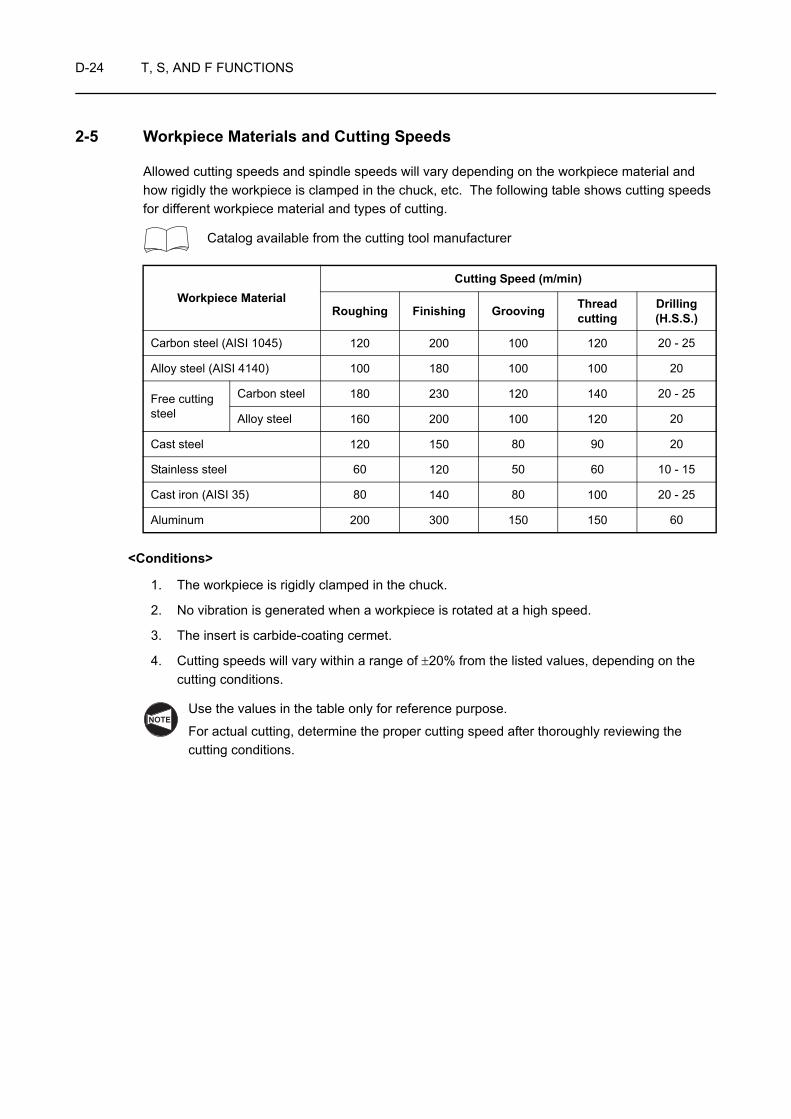
D-24 T, S, AND F FUNCTIONS
2-5 Workpiece Materials and Cutting Speeds
Allowed cutting speeds and spindle speeds will vary depending on the workpiece material and how rigidly the workpiece is clamped in the chuck, etc. The following table shows cutting speeds for different workpiece material and types of cutting.
Catalog available from the cutting tool manufacturer
<Conditions>
1. The workpiece is rigidly clamped in the chuck.
2. No vibration is generated when a workpiece is rotated at a high speed.
3. The insert is carbide-coating cermet.
4. Cutting speeds will vary within a range of ±20% from the listed values, depending on the cutting conditions.
Use the values in the table only for reference purpose.
For actual cutting, determine the proper cutting speed after thoroughly reviewing the cutting conditions.
Workpiece MaterialCutting Speed (m/min)
Roughing Finishing Grooving Threadcutting
Drilling (H.S.S.)
Carbon steel (AISI 1045) 120 200 100 120 20 - 25
Alloy steel (AISI 4140) 100 180 100 100 20
Free cutting steel
Carbon steel 180 230 120 140 20 - 25
Alloy steel 160 200 100 120 20
Cast steel 120 150 80 90 20
Stainless steel 60 120 50 60 10 - 15
Cast iron (AISI 35) 80 140 80 100 20 - 25
Aluminum 200 300 150 150 60
NOTE
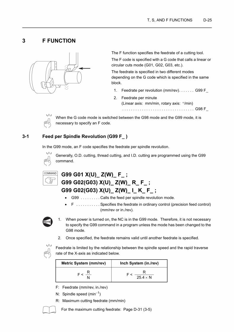
T, S, AND F FUNCTIONS D-25
3 F FUNCTION
The F function specifies the feedrate of a cutting tool.
The F code is specified with a G code that calls a linear or circular cuts mode (G01, G02, G03, etc.).
The feedrate is specified in two different modes depending on the G code which is specified in the same block.
1. Feedrate per revolution (mm/rev). . . . . . . G99 F_
2. Feedrate per minute (Linear axis: mm/min, rotary axis: °/min). . . . . . . . . . . . . . . . . . . . . . . . . . . . . . . . . G98 F_
When the G code mode is switched between the G98 mode and the G99 mode, it is necessary to specify an F code.
3-1 Feed per Spindle Revolution (G99 F_ )
In the G99 mode, an F code specifies the feedrate per spindle revolution.
Generally, O.D. cutting, thread cutting, and I.D. cutting are programmed using the G99 command.
G99 G01 X(U)_ Z(W)_ F_ ;G99 G02(G03) X(U)_ Z(W)_ R_ F_ ;G99 G02(G03) X(U)_ Z(W)_ I_ K_ F_ ;
• G99 . . . . . . . . . Calls the feed per spindle revolution mode.
• F . . . . . . . . . . . Specifies the feedrate in ordinary control (precision feed control) (mm/rev or in./rev).
1. When power is turned on, the NC is in the G99 mode. Therefore, it is not necessary to specify the G99 command in a program unless the mode has been changed to the G98 mode.
2. Once specified, the feedrate remains valid until another feedrate is specified.
Feedrate is limited by the relationship between the spindle speed and the rapid traverse rate of the X-axis as indicated below.
F: Feedrate (mm/rev, in./rev)
N: Spindle speed (min−1)
R: Maximum cutting feedrate (mm/min)
For the maximum cutting feedrate: Page D-31 (3-5)
Metric System (mm/rev) Inch System (in./rev)
COMMAND
NOTE
RN
F < RF <25.4 × N

D-26 T, S, AND F FUNCTIONS
Programming using G99 F_
To carry out I.D. cutting by changing feedrates
O0001;
N1;
G50 S2000;
G00 T0101;
G96 S200 M03;
X47.069 Z20.0 M08;
G01 Z1.0 F1.0; . . . . . . . . . . . . . . . . . . . Positioning at point 1 to move the cutting tool close to the workpiece
Z0 F0.2; . . . . . . . . . . . . . . . . . . . . . . . . Positioning at point 2 at a feedrate of 0.2 mm/rev
G02 X43.205 Z−1.482 R2.0 F0.07; . . . Cutting an arc of 0.2 mm radius in the clockwise direction at a feedrate of 0.07 mm/rev
G01 X32.0 Z−22.392; . . . . . . . . . . . . . . Cutting along path 3 → 4 at a feedrate of 0.07 mm/rev
Z−41.0 F0.1; . . . . . . . . . . . . . . . . . . . . Cutting along path 4 → 5 at a feedrate of 0.1 mm/rev
G00 U−1.0 Z20.0; . . . . . . . . . . . . . . . . . Positioning at point 6 at a rapid traverse rate to move the cutting tool away from the workpiece
X200.0 Z150.0 M09; . . . . . . . . . . . . . . . Positioning at point 7 where the turret head can be rotated
M01;
Ex.
R2
15°
4432φ φ
12
3
45
6
7
Cutting feed
Rapid traverse

T, S, AND F FUNCTIONS D-27
3-2 Feed per Minute (G98 F_ )
In the G98 mode, an F code specifies the feedrate per minute.
This mode is used to write a program for pull-out finger operation or rotary tool.
<Linear axis (X-, Y- and Z-axes>
G98 G01 X(U)_ Y(V)_ Z(W)_ F_ ;G98 G02(G03) X(U)_ Z(W)_ R_ F_ ;G98 G02(G03) X(U)_ Z(W)_ I_ K_ F_ ;
• G98 . . . . . . . . . Calls the feed per minute mode.
• F . . . . . . . . . . . Specifies the feedrate (mm/min or in/min).
<Rotary axis (C-axis)>
G98 G01 C_ F_ ;• G98 . . . . . . . . . Calls the feed per minute mode.
• F . . . . . . . . . . . . Specifies the angular feedrate of a tool (°/min).
In the G98 mode, the turret moves at the feedrate specified by the F code even when the spindle is not rotating. Make sure that the cutting tool will not strike the workpiece, etc., since this could damage the machine.
G98;G01 Z_ F100.0; . . . . . The turret moves at a rate of 100 mm/min even when the
spindle is not rotating.
1. The G98 command cannot be used for thread cutting operation.
2. Once specified, the feedrate remains valid until another feedrate is specified.
COMMAND
CAUTION
NOTE
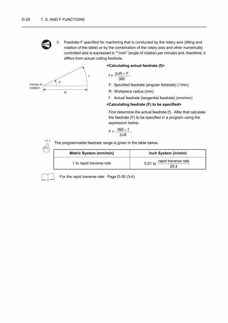
D-28 T, S, AND F FUNCTIONS
3. Feedrate F specified for machining that is conducted by the rotary axis (tilting and rotation of the table) or by the combination of the rotary axis and other numerically controlled axis is expressed in "°/min" (angle of rotation per minute) and, therefore, it differs from actual cutting feedrate.
<Calculating actual feedrate (f)>
f =
F: Specified feedrate (angular feedrate) (°/min)
R: Workpiece radius (mm)
f: Actual feedrate (tangential feedrate) (mm/min)
<Calculating feedrate (F) to be specified>
First determine the actual feedrate (f). After that calculate the feedrate (F) to be specified in a program using the expression below.
F =
The programmable feedrate range is given in the table below.
For the rapid traverse rate: Page D-30 (3-4)
Metric System (mm/min) Inch System (in/min)
1 to rapid traverse rate 0.01 to
NOTE
R
Center ofrotation
F
f2πR × F
360
360 × f2πR
rapid traverse rate25.4

T, S, AND F FUNCTIONS D-29
3-3 Feedrate for Finishing
Feedrates for finishing are determined based on the nose radius of the cutting tool to be used and the surface roughness specified on the drawing.
<Ideal surface roughness for finishing>
Rmax =
Rmax: Maximum value of ideal finish surface roughness (Rmax = Ry)
f: Feedrate (mm/rev)
Nr: Tool nose radius (mm)
(mm/rev)
The values indicated above are theoretical values obtained in calculation. During actual cutting, the specified surface roughness may not be achieved, depending on various factors. Factors that can effect finishing accuracy include how far the tool projects, how the workpiece is clamped or vibration.
Surface Roughness
SymbolIndication Rmax (mm)
Nr
0.4 0.5 0.8 1.0
25-S Max. 0.025 0.2828 0.3162 0.4000 0.4472
18-S Max. 0.018 0.2400 0.2683 0.3394 0.3794
12-S Max. 0.012 0.1959 0.2190 0.2771 0.3098
6-S Max. 0.006 0.1385 0.1549 0.1959 0.2190
3-S Max. 0.003 0.0979 0.1095 0.1385 0.1549
1.5-S Max. 0.0015 0.0692 0.0774 0.0979 0.1095
0.8-S Max. 0.0008 0.0506 0.0565 0.0715 0.0800
0.4-S Max. 0.0004 0.0357 0.0400 0.0505 0.0565
Nr
f
Rmax
Insert
f2
8 • Nr
NOTE

D-30 T, S, AND F FUNCTIONS
3-4 Table of Rapid Traverse Rates
The rapid traverse rates of the individual axes are indicated below.
* With the high output specification, C-axis rapid traverse rate is 100 min−1.
Rapid Traverse Rate
Machine Model X-axis Z-axis Y-axis B-axis C-axis
mm/min mm/min mm/min mm/min min−1
ZL-153ZL-153MC 18000 24000 200*
ZL-153SZL-153SMC 18000 24000 24000 200*
ZL-203ZL-203MC 18000 24000 150
ZL-203SZL-203SMC 18000 24000 24000 150
ZL-253ZL-253MC 18000 24000 100
ZL-253SZL-253SMC 18000 24000 24000 100
ZT1000YZT1500YZT1500YB
18000 24000 6000 24000 400
ZT2500MCZT2500Y 24000 24000 12000 24000 300
NOTE
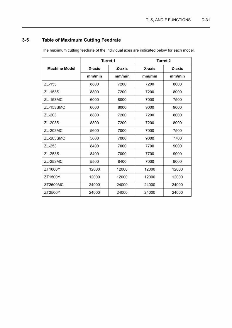
T, S, AND F FUNCTIONS D-31
3-5 Table of Maximum Cutting Feedrate
The maximum cutting feedrate of the individual axes are indicated below for each model.
Turret 1 Turret 2
Machine Model X-axis Z-axis X-axis Z-axis
mm/min mm/min mm/min mm/min
ZL-153 8800 7200 7200 8000
ZL-153S 8800 7200 7200 8000
ZL-153MC 6000 8000 7000 7500
ZL-153SMC 6000 8000 9000 9000
ZL-203 8800 7200 7200 8000
ZL-203S 8800 7200 7200 8000
ZL-203MC 5600 7000 7000 7500
ZL-203SMC 5600 7000 9000 7700
ZL-253 8400 7000 7700 9000
ZL-253S 8400 7000 7700 9000
ZL-253MC 5500 8400 7000 9000
ZT1000Y 12000 12000 12000 12000
ZT1500Y 12000 12000 12000 12000
ZT2500MC 24000 24000 24000 24000
ZT2500Y 24000 24000 24000 24000

CHAPTER EAUTOMATIC TOOL NOSE
RADIUS OFFSET
This chapter describes how the automatic tool nose radius offset function works.
Because the cutting edge of the tool is rounded, the actual cutting point differs from the point specified in a program. Therefore, if a program is written based on the points known from a part drawing, the workpiece is not finished to the dimensions specified on the drawing. To finish the workpiece precisely to the dimensions specified on the drawing, the points to be specified in the program must be calculated taking the difference between the programmed point and actual cutting point. The automatic tool nose radius offset function generates the tool paths to finish the workpiece correctly to the dimensions specified on the drawing from the program in which the points specified on the drawing are directly used.
Since there are a number of tool patterns which will be used for actual machining and they will differ among users, it is not possible to explain all of the tool patterns in this manual. The explanation given in this chapter is concentrated on the basic tool path patterns along with the cautions to be taken into consideration for programming so that the readers will be able to acquire basic knowledge of the automatic tool nose radius offset function.
Instruction manual supplied by the NC manufacturer
NOTE

CONTENTS
E : AUTOMATIC TOOL NOSE RADIUS OFFSET
1 GENERAL . . . . . . . . . . . . . . . . . . . . . . . . . . . . . . . . . . . . . . . . . . . . . . . . . . . . . . . . . . . . E-1
2 CONDITIONS FOR USE OF THE AUTOMATIC TOOL NOSE RADIUS OFFSET FUNCTION . . . . . . . . . . . . . . . . . . . . . . . . . . . . . . . . . E-5
2-1 Imaginary Tool Tip Position . . . . . . . . . . . . . . . . . . . . . . . . . . . . . . . . . . . . . . . . . . E-6
2-2 Setting Tool Nose Radius . . . . . . . . . . . . . . . . . . . . . . . . . . . . . . . . . . . . . . . . . . E-10
2-3 Specifying the Offset Direction . . . . . . . . . . . . . . . . . . . . . . . . . . . . . . . . . . . . . . E-10
3 TECHNICAL TERMS USED IN THE EXPLANATION OF THE AUTOMATIC TOOL NOSE RADIUS OFFSET FUNCTION . . . . . . . . . . . . . . . . . . . . . . . . . . . . . . . . E-11
3-1 Start-up . . . . . . . . . . . . . . . . . . . . . . . . . . . . . . . . . . . . . . . . . . . . . . . . . . . . . . . . E-12
3-2 Offset Mode. . . . . . . . . . . . . . . . . . . . . . . . . . . . . . . . . . . . . . . . . . . . . . . . . . . . . E-14
3-3 Cancel Mode . . . . . . . . . . . . . . . . . . . . . . . . . . . . . . . . . . . . . . . . . . . . . . . . . . . . E-16
4 GENERAL CAUTIONS ON THE AUTOMATIC TOOL NOSE RADIUS OFFSET FUNCTION . . . . . . . . . . . . . . . . . . . . . . . . . . . . . . . . E-19
4-1 If a Wall Lies at the End of Cutting . . . . . . . . . . . . . . . . . . . . . . . . . . . . . . . . . . . E-19
4-2 Overcut in the Automatic Tool Nose Radius Offset Mode . . . . . . . . . . . . . . . . . . E-23
5 EXAMPLE PROGRAMS . . . . . . . . . . . . . . . . . . . . . . . . . . . . . . . . . . . . . . . . . . . . . . . . E-26
5-1 Basic Programs. . . . . . . . . . . . . . . . . . . . . . . . . . . . . . . . . . . . . . . . . . . . . . . . . . E-26
5-2 Recommended Example Programs . . . . . . . . . . . . . . . . . . . . . . . . . . . . . . . . . . E-39
5-3 Programming for a Sample Workpiece . . . . . . . . . . . . . . . . . . . . . . . . . . . . . . . . E-43

AUTOMATIC TOOL NOSE RADIUS OFFSET E-1
1 GENERAL
The tool nose does not have a sharp edge but is slightly rounded (tool nose radius) as illustrated below. Therefore, the point of the tool nose used for programming differs from the actual cutting point. The tool nose radius offset function is used to eliminate dimensional errors caused by this difference.
If a program is created without taking the nose radius into consideration, it will cause excessive or insufficient cutting.
The automatic tool nose radius offset function is used to eliminate excessive or insufficient cutting.
Workpiece zero point Programmed point • Actual cutting point
1. Facing carried out perpendicular to the spindle center line (cutting in the X-axis direction)
There is no uncut material left since the programmed point and the actual cutting point lie on the same line.
2. O.D. or I.D. cutting carried out in parallel with the spindle center line (cutting in the Z-axis direction)
There is no uncut material left since the programmed point and the actual cutting point lie on the same line.
Actual cutting point
Programmed point

E-2 AUTOMATIC TOOL NOSE RADIUS OFFSET
Reasons why excessive (overcut) or insufficient (undercut) cutting occurs:
The program used for machining along paths "1 → 2" and "3 → 4 → 5 → 6" is used for the example.
3. Taper cutting If taper cutting, including chamfering, is programmed without taking into consideration the radius of the tool nose, dimensional errors will occur due to overcut or undercut as illustrated on the left.
4. Arc cutting If arc cutting is programmed without taking into consideration the radius of the tool nose, dimensional errors will occur due to overcut or undercut as illustrated on the left.
Undercut portion
Overcut portion
Undercut portion
C1C2
C2
10
φ30
φ50
2
1
3
45
6
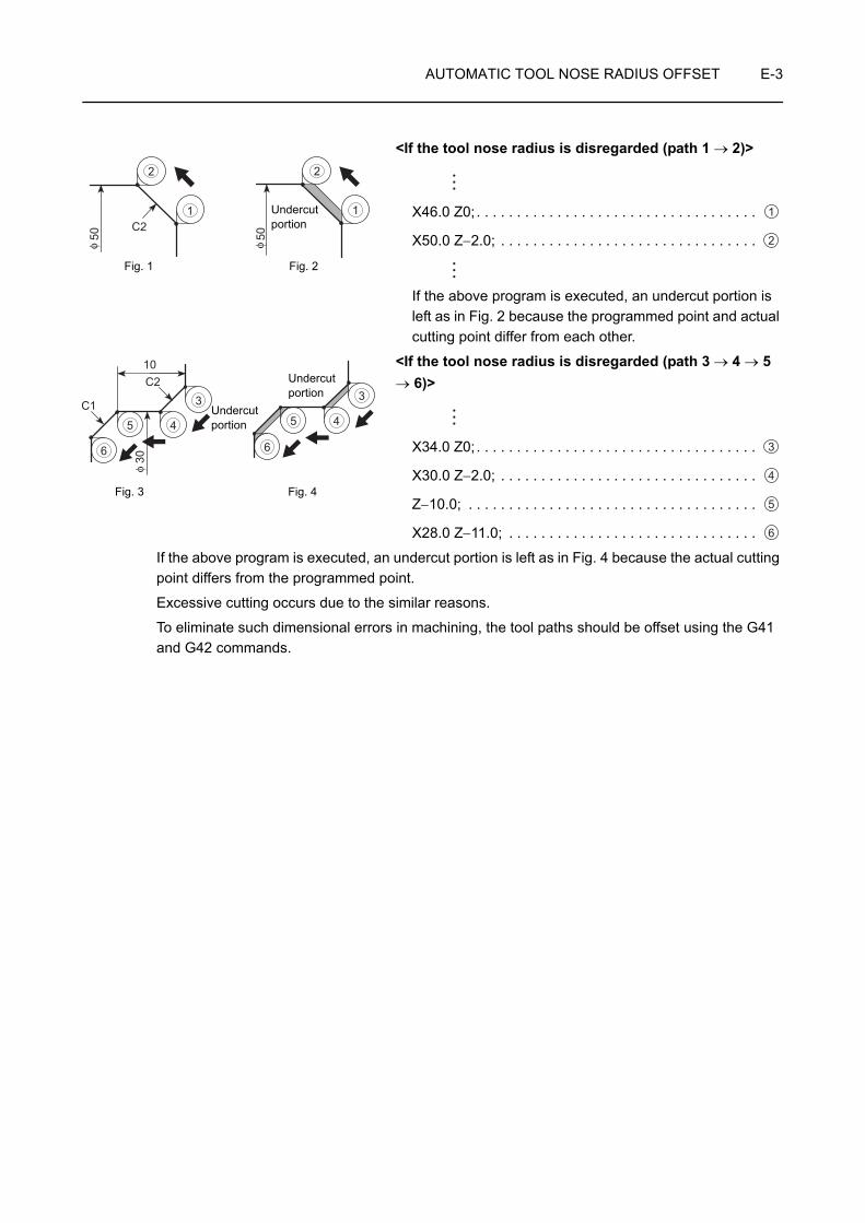
AUTOMATIC TOOL NOSE RADIUS OFFSET E-3
<If the tool nose radius is disregarded (path 1 → 2)>
X46.0 Z0; . . . . . . . . . . . . . . . . . . . . . . . . . . . . . . . . . . .
X50.0 Z−2.0; . . . . . . . . . . . . . . . . . . . . . . . . . . . . . . . .
If the above program is executed, an undercut portion is left as in Fig. 2 because the programmed point and actual cutting point differ from each other.
<If the tool nose radius is disregarded (path 3 → 4 → 5 → 6)>
X34.0 Z0; . . . . . . . . . . . . . . . . . . . . . . . . . . . . . . . . . . .
X30.0 Z−2.0; . . . . . . . . . . . . . . . . . . . . . . . . . . . . . . . .
Z−10.0; . . . . . . . . . . . . . . . . . . . . . . . . . . . . . . . . . . . .
X28.0 Z−11.0; . . . . . . . . . . . . . . . . . . . . . . . . . . . . . . .
If the above program is executed, an undercut portion is left as in Fig. 4 because the actual cutting point differs from the programmed point.
Excessive cutting occurs due to the similar reasons.
To eliminate such dimensional errors in machining, the tool paths should be offset using the G41 and G42 commands.
C2
5050φ φ
1 1
2 2
Undercutportion
Fig. 1 Fig. 2
1
2
C2
C1
10
30φ
3
45
6
3
45
6
Fig. 3 Fig. 4
Undercutportion
Undercutportion
3
4
5
6

E-4 AUTOMATIC TOOL NOSE RADIUS OFFSET
G01(G00) G41 X_ Z_ F_ ;G01(G00) G42 X_ Z_ F_ ;G01(G00) G40 X_ Z_ I_ K_ F_ ;
• G01(G00) . . . . Calls the interpolation mode in which the tool nose radius offset function is specified.G00 . . . . . . . . . Rapid traverseG01 . . . . . . . . . Cutting feed
• G41 . . . . . . . . Calls the tool nose radius offset (left) function. The tool position is offset to the left in reference to the tool advancing direction.
• G42 . . . . . . . . Calls the tool nose radius offset (right) function. The tool position is offset to the right in reference to the tool advancing direction.
• G40 . . . . . . . . Cancels the tool nose radius offset function.
• X, Z. . . . . . . . . Specifies the coordinate values of the end point.
• I, K . . . . . . . . . When making a setting that represents the direction of the workpiece shape in the following block, the direction ratio for this setting is specified as a vector, with "I" as the radius command.
• F . . . . . . . . . . . Specifies the feedrate.
The programmer must thoroughly understand the nature of the G41 and G42 functions as well as the tool paths to be generated. If the G41 and G42 commands are used improperly, the cutting tool might be fed into or hit against the workpiece to be machined to cause breakage of the cutting tool or defective machining.
COMMAND
G42
G41
Tool advancing direction
Tool advancing direction
Workpiece
CAUTION

AUTOMATIC TOOL NOSE RADIUS OFFSET E-5
2 CONDITIONS FOR USE OF THE AUTOMATIC TOOL NOSE RADIUS OFFSET FUNCTION
The operations required to use the automatic tool nose radius offset function are indicated below:
1) Setting the imaginary tip position
Set the code number from 0 to 9 (see the Figure to the left), which represents the direction of the tip position of the cutting tool to be used, in field "C" on the TOOL WEAR OFFSET screen.
For an O.D. cutting tool, for example, input "3".
2) Setting the nose radius of the cutting tools to be used
Set the nose radius of the cutting tool to be used to the R column in the TOOL WEAR OFFSET screen.
Setting the nose radius of the cutting tool to the R column in the GEOMETRY OFFSET screen is also possible. However, if the nose radius is set to the R column in both of the GEOMETRY OFFSET and TOOL WEAR OFFSET screens, offset is made by both of the input data, causing excessive or insufficient cutting.
For the tool having nose radius of 0.8 mm, for example, input "0.8".
3) Determining the offset direction
Decide the direction (right or left) in which the tool should be offset in reference to the direction the tool will advance.
G41 Offset to the left G42 Offset to the right
162
483
57
0, 9
C = 3
NOTE
R = 0.8
0.8

E-6 AUTOMATIC TOOL NOSE RADIUS OFFSET
2-1 Imaginary Tool Tip Position
To identify the point which is used for programming, the term "imaginary tool tip position" is used.
It is necessary to set the code number (0 to 9) which represents the imaginary tool tip position to the C column displayed on the TOOL WEAR OFFSET screen.
The imaginary tool tip position, in reference to the center of the tool nose, is determined according to the tool shape and the tool mounting method in the turret head. The imaginary tool tip position data must be set in advance as with tool offset data.
The number of tool offset data pairs will vary according to the machine model and the NC and machine specifications.
C Imaginary Tool Tip Position Examples
0
In normal operation, the center of the tool nose is not specified as the imaginary tool tip position.
1
NOTE
62
3
1
4
5
1
4
57
2
3
7
8
6
6 6
8
57
12
3 48 8
R
09
R
09
R
09
R
09
+X
+Z
+X
−Z
57
12
3 4
+X +X0 to 9: Imaginary tool tip position
<For spindle 1> <For spindle 2>
NOTE

AUTOMATIC TOOL NOSE RADIUS OFFSET E-7
2
3
4
5
In normal operation, to specify such point is really rare.
6
7
8
9
Same as in the case of "0".
C Imaginary Tool Tip Position Examples
.Workpiece

E-8 AUTOMATIC TOOL NOSE RADIUS OFFSET
The number indicated above for the imaginary tool tip position (T number) is for general applications and, in some cases, specifying a T number different from this indication might give better results.
The most appropriate T number should be determined and specified on the process sheet by a programmer when he/she creates the tooling sheet.
The imaginary tool tip position is explained below using an O.D. cutting tool and an I.D. cutting tool as examples.
<O.D. cutting tool>
For example, the imaginary tool tip position number for spindle 1 is "3" as shown in the illustration above.
The imaginary tool tip position code number (T number) should be set for offset number that corresponds to the last two digits of a T code.
When setting the selected T number for "T0202" tool, set "3" to the C column for offset number "2" on the TOOL WEAR OFFSET screen.
NOTE
6
8
6
6 6
8
12
3 4
57
57
12
3 48 8
12
3 4
57
57
12
3 4
<For spindle 1> <For spindle 2>
Imaginary tooltip position
Imaginary tooltip position
TurretTurret
Imaginary tool tip position
Imaginary tool tip position
TurretTurret

AUTOMATIC TOOL NOSE RADIUS OFFSET E-9
<I.D. cutting tool>
For example, the imaginary tool tip position number for spindle 1 is "2" as shown in the illustration above.
The imaginary tool tip position code number (T number) should be set for offset number that corresponds to the last two digits of a T code.
When setting the selected T number for "T0303" tool, set "2" to the C column for offset number "3" on the TOOL WEAR OFFSET screen.
6
8
6
6 6
8
12
3 4
57
57
12
3 48 8
12
3 4
57
57
12
3 4
<For spindle 1> <For spindle 2>
Imaginary tooltip position
Imaginary tooltip position
TurretTurret
Imaginary tool tip position
Imaginary tool tip position
TurretTurret

E-10 AUTOMATIC TOOL NOSE RADIUS OFFSET
2-2 Setting Tool Nose Radius
When the automatic tool nose radius offset function, called by the G41 or G42 is used, it is necessary to set the tool nose radius to the R column in either the GEOMETRY OFFSET or TOOL WEAR OFFSET screen.
The offset number for which the nose radius is set should correspond to the offset number which is specified in a T code.
T code: Page D-1 (1)
If the nose radius is set to the R column in both of the GEOMETRY OFFSET and TOOL WEAR OFFSET screens, offset is made by both of the input data, causing excessive or insufficient cutting.
2-3 Specifying the Offset Direction
The tool paths are offset either to the left (G41) or to the right (G42) in reference to the direction the cutting tool will advance.
When the direction the tool paths should be offset is determined, enter the corresponding G code to the program.
The location where the G code should be entered in a program and related cautions are explained in the following sections.
NOTE
Tool nose radius
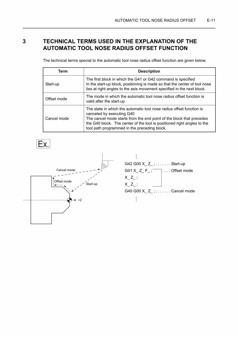
AUTOMATIC TOOL NOSE RADIUS OFFSET E-11
3 TECHNICAL TERMS USED IN THE EXPLANATION OF THE AUTOMATIC TOOL NOSE RADIUS OFFSET FUNCTION
The technical terms special to the automatic tool nose radius offset function are given below.
G42 G00 X_ Z_ ; . . . . . . . Start-up
G01 X_ Z_ F_ ; . . . . Offset mode
X_ Z_ ;
X_ Z_ ;
G40 G00 X_ Z_ ; . . . . . . . Cancel mode
Term Description
Start-upThe first block in which the G41 or G42 command is specified In the start-up block, positioning is made so that the center of tool nose lies at right angles to the axis movement specified in the next block.
Offset mode The mode in which the automatic tool nose radius offset function is valid after the start-up
Cancel mode
The state in which the automatic tool nose radius offset function is canceled by executing G40The cancel mode starts from the end point of the block that precedes the G40 block. The center of the tool is positioned right angles to the tool path programmed in the preceding block.
Ex.
+Z
Cancel mode
Offset modeStart-up
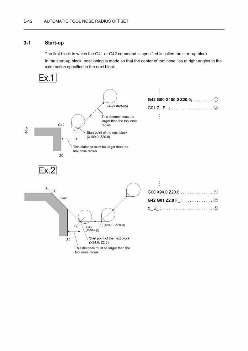
E-12 AUTOMATIC TOOL NOSE RADIUS OFFSET
3-1 Start-up
The first block in which the G41 or G42 command is specified is called the start-up block.
In the start-up block, positioning is made so that the center of tool nose lies at right angles to the axis motion specified in the next block.
G42 G00 X100.0 Z20.0; . . . . . . . .
G01 Z_ F_ ; . . . . . . . . . . . . . . . . . .
G00 X94.0 Z20.0;. . . . . . . . . . . . . .
G42 G01 Z2.0 F_ ; . . . . . . . . . . . .
X_ Z_ ; . . . . . . . . . . . . . . . . . . . . . .
Ex.1
G42
Z0
G42
12
(start-up)
This diatance must be larger than the tool nose radius
Start point of the next block (X100.0, Z20.0)
This diatance must be larger than the tool nose radius
1
2
Ex.2
G42
(X94.0, Z20.0)
Z0
G42 12
3
(start-up)
Start point of the next block (X94.0, Z2.0)
This diatance must be larger than the tool nose radius
1
2
3

AUTOMATIC TOOL NOSE RADIUS OFFSET E-13
G00 X50.0 Z20.0;. . . . . . . . . . . . . .
G41 G01 Z2.0 F_ ; . . . . . . . . . . . .
X_ Z_ ; . . . . . . . . . . . . . . . . . . . . . .
When specifying the start-up, the following two conditions must be satisfied.
1. The start-up block must include an axis movement command; the called distance must be larger than the offset amount (tool nose radius).
2. The start-up must be specified in the G00 or G01 (linear motion) mode. Do not specify the start-up in the G02 or G03 mode. If the start-up is specified in such a mode, an alarm is generated, the corresponding alarm message (No. 034) is displayed on the screen and the machine stops operating.
Ex.3
(X50.0, Z20.0)
G41
12
3
(start-up)
Start point of the next block(X50.0, Z2.0)
This diatance must be larger than the tool nose radius
1
2
3
NOTE

E-14 AUTOMATIC TOOL NOSE RADIUS OFFSET
3-2 Offset Mode
The mode in which the automatic tool nose radius offset function is valid, after the start-up, is called the offset mode.
1. Behavior when the direction of tool offset (right, left) is not changed
The tool moves along the workpiece shape with its nose in contact with the shape.
G42 G00 X70.0 Z20.0; . . . . . . . . . . . . (Start-up)
G01 Z−20.0 F_ ; . . . . . . . . . . . . . . . . . .
X80.0; . . . . . . . . . . . . . . . . . . . . . . . . . .
G03 X100.0 Z–30.0 R10.0;. . . . . . . . . . Offset mode
G01 Z−45.0; . . . . . . . . . . . . . . . . . . . . .
X_ Z_ ; . . . . . . . . . . . . . . . . . . . . . . . . .
Ex.1
12
3
45
6
(X70.0, Z20.0)(X70.0, Z−20.0)
(X80.0, Z−20.0)
(X100.0, Z−30.0)(X100.0, Z−45.0)
1
2
3
4
5
6
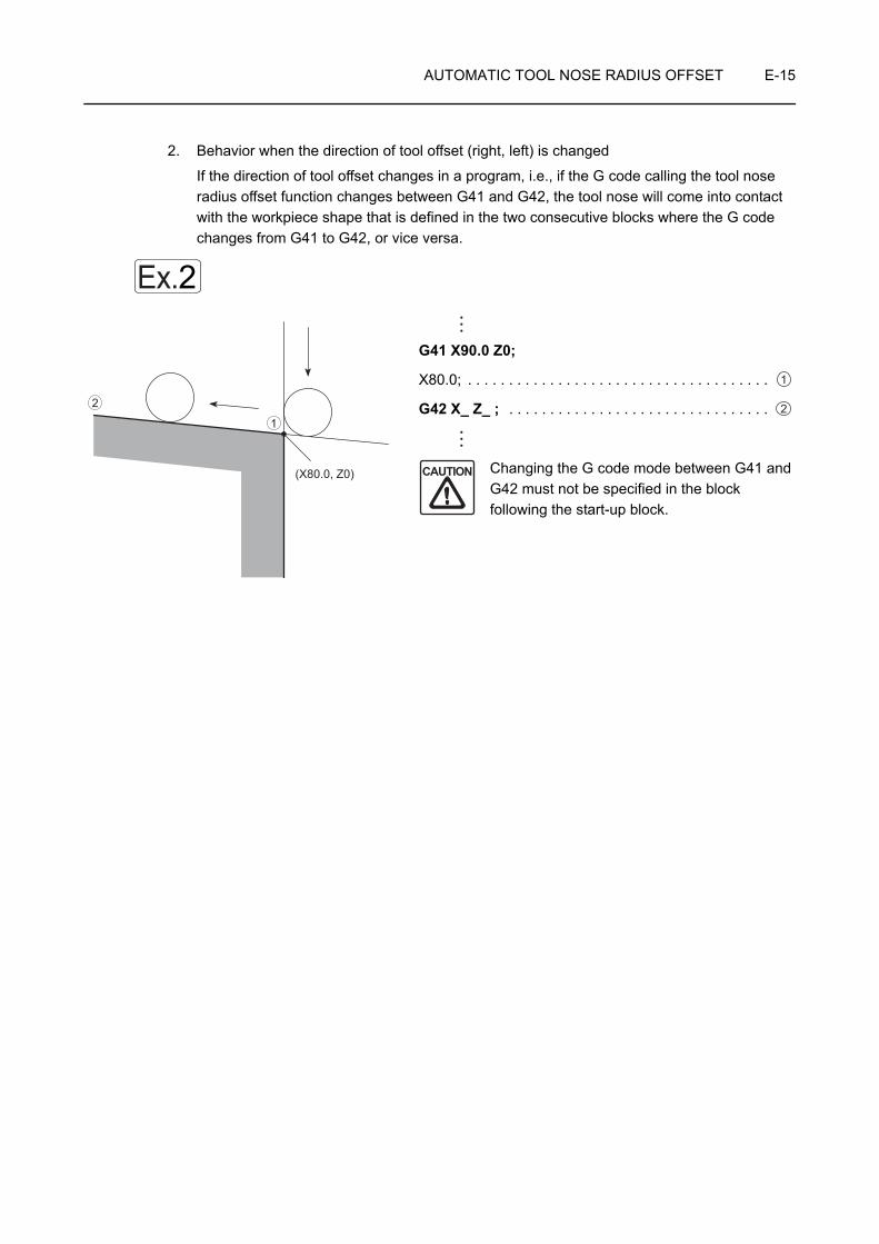
AUTOMATIC TOOL NOSE RADIUS OFFSET E-15
2. Behavior when the direction of tool offset (right, left) is changed
If the direction of tool offset changes in a program, i.e., if the G code calling the tool nose radius offset function changes between G41 and G42, the tool nose will come into contact with the workpiece shape that is defined in the two consecutive blocks where the G code changes from G41 to G42, or vice versa.
G41 X90.0 Z0;
X80.0; . . . . . . . . . . . . . . . . . . . . . . . . . . . . . . . . . . . . .
G42 X_ Z_ ; . . . . . . . . . . . . . . . . . . . . . . . . . . . . . . . .
Changing the G code mode between G41 and G42 must not be specified in the block following the start-up block.
Ex.2
(X80.0, Z0)
1
2
1
2
CAUTION

E-16 AUTOMATIC TOOL NOSE RADIUS OFFSET
3-3 Cancel Mode
The G40 command, specified in the offset mode, cancels the tool nose radius offset function.
The cancel mode starts from the end point of the block that precedes the G40 block. The center of the tool nose lies at right angles to the tool path programmed in reference to block.
(G42) X100.0 Z−50.0; . . . . . . . . . . . . . .
G40 G00 X150.0 Z100.0; . . . . . . . . . . (Cancel mode)
(G42) X90.0 Z−5.0; . . . . . . . . . . . . . . . .
G40 G00 X150.0 Z100.0; . . . . . . . . . .
Ex.1
(X150.0, Z100.0)
(X100.0 Z−50.0)1
2
(Cancel mode)
Start-up
1
2
Ex.2
(X90.0 Z−5.0)
(X150.0, Z100.0)
2
1
1
2
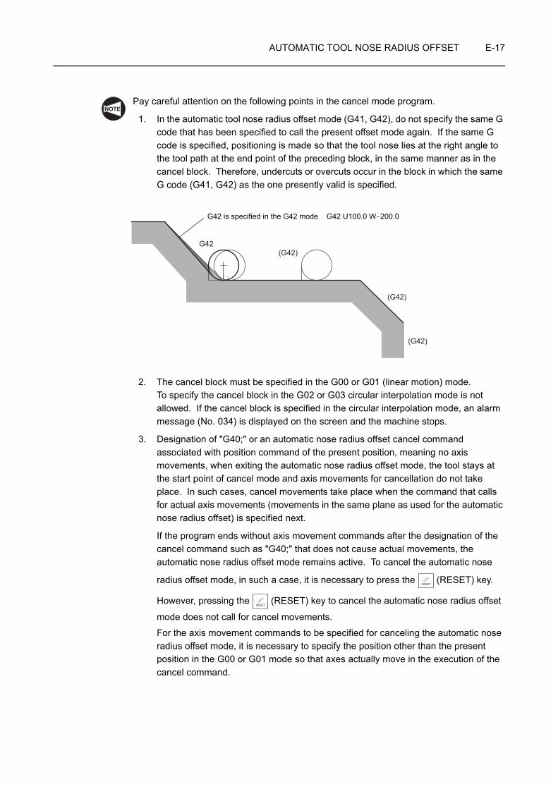
AUTOMATIC TOOL NOSE RADIUS OFFSET E-17
Pay careful attention on the following points in the cancel mode program.
1. In the automatic tool nose radius offset mode (G41, G42), do not specify the same G code that has been specified to call the present offset mode again. If the same G code is specified, positioning is made so that the tool nose lies at the right angle to the tool path at the end point of the preceding block, in the same manner as in the cancel block. Therefore, undercuts or overcuts occur in the block in which the same G code (G41, G42) as the one presently valid is specified.
2. The cancel block must be specified in the G00 or G01 (linear motion) mode. To specify the cancel block in the G02 or G03 circular interpolation mode is not allowed. If the cancel block is specified in the circular interpolation mode, an alarm message (No. 034) is displayed on the screen and the machine stops.
3. Designation of "G40;" or an automatic nose radius offset cancel command associated with position command of the present position, meaning no axis movements, when exiting the automatic nose radius offset mode, the tool stays at the start point of cancel mode and axis movements for cancellation do not take place. In such cases, cancel movements take place when the command that calls for actual axis movements (movements in the same plane as used for the automatic nose radius offset) is specified next.
If the program ends without axis movement commands after the designation of the cancel command such as "G40;" that does not cause actual movements, the automatic nose radius offset mode remains active. To cancel the automatic nose
radius offset mode, in such a case, it is necessary to press the (RESET) key.
However, pressing the (RESET) key to cancel the automatic nose radius offset
mode does not call for cancel movements.
For the axis movement commands to be specified for canceling the automatic nose radius offset mode, it is necessary to specify the position other than the present position in the G00 or G01 mode so that axes actually move in the execution of the cancel command.
NOTE
G42(G42)
(G42)
(G42)
G42 is specified in the G42 mode G42 U100.0 W−200.0
RESET
RESET

E-18 AUTOMATIC TOOL NOSE RADIUS OFFSET
Conditions in which the offset mode is canceled:
• Execution of the G40 command
• The initial state established when the power is turned on.
• Reset state; the (RESET) key is pressed.
• Program end; the program ends when the M02 or M30 command is executed.
NOTE
RESET

AUTOMATIC TOOL NOSE RADIUS OFFSET E-19
4 GENERAL CAUTIONS ON THE AUTOMATIC TOOL NOSE RADIUS OFFSET FUNCTION
4-1 If a Wall Lies at the End of Cutting
If the workpiece wall lies in a direction independent of the direction of tool motion specified by the commands in the G40 block:
Specify the workpiece wall's direction (workpiece shape) with vectors (I, K). Use incremental values for I and K commands; the I command should be specified in radius.
1. The workpiece is cut until the tool nose comes into contact with the wall. The I and K commands, used to define the vectors that represent the workpiece wall direction, should be specified in the G40 block that appears first after entry into the offset mode.
• Valid • InvalidG42 X_ Z_ ;X_ Z_ ;
Offset mode
G40 G00 X_ Z_ I_ K_ ;
G42 X_ Z_ ;
Offset mode
G40 X_ Z_ ;
Cancel mode
G40 G00 X_ Z_ I_ K_ ;
Ignored
I, K
5
4
G40(200, −30)
(G42)G40 G00 X200.0 Z−30.0 I5.0 K−4.0;+I
+K
Wall
Actual tool motion commands
The workpiece is cut until the tool nose comes into contact with the wall.
NOTE

E-20 AUTOMATIC TOOL NOSE RADIUS OFFSET
2. If "I_ K_ " is not specified in the G40 block, the offset mode cancel point is set at the end point of the preceding block; at this end point, the tool nose center lies at right angles to the tool path generated by the commands in reference to block. This causes an overcut on the wall.
G40 G00 X_ Z_ ;
NOTE
G40
(G42)
Overcuts occur.
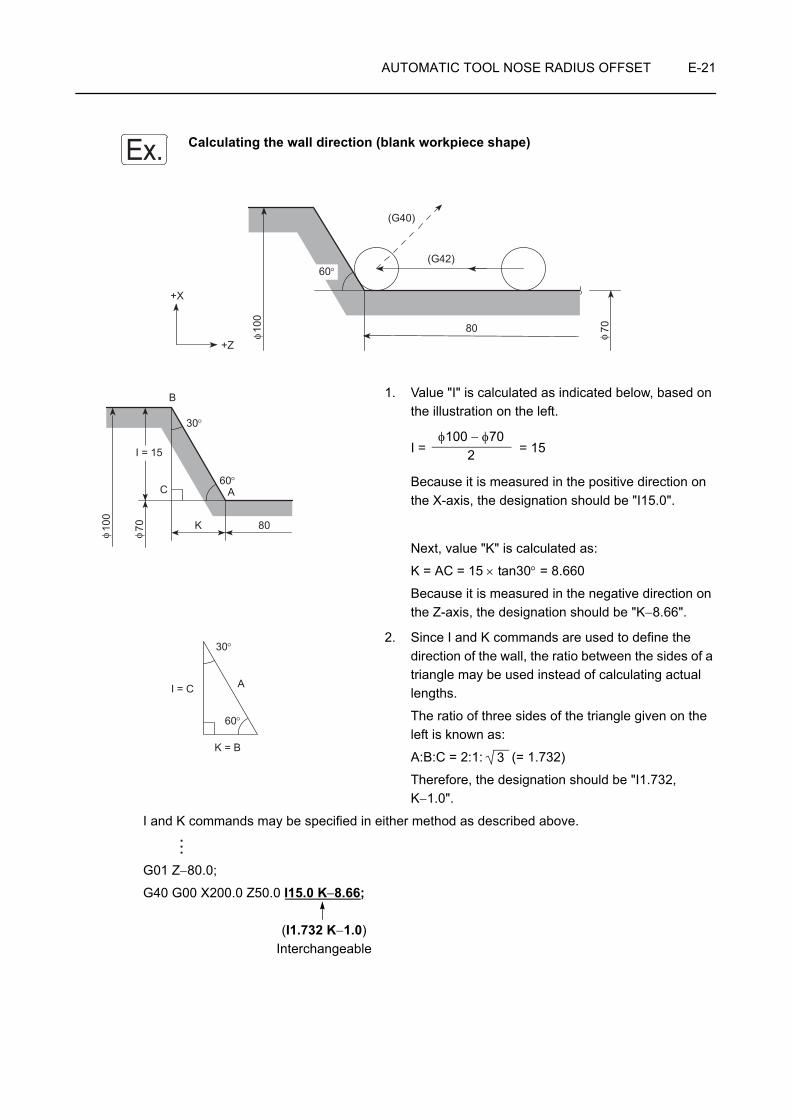
AUTOMATIC TOOL NOSE RADIUS OFFSET E-21
Calculating the wall direction (blank workpiece shape)
1. Value "I" is calculated as indicated below, based on the illustration on the left.
I = = 15
Because it is measured in the positive direction on the X-axis, the designation should be "I15.0".
Next, value "K" is calculated as:
K = AC = 15 × tan30° = 8.660
Because it is measured in the negative direction on the Z-axis, the designation should be "K−8.66".
2. Since I and K commands are used to define the direction of the wall, the ratio between the sides of a triangle may be used instead of calculating actual lengths.
The ratio of three sides of the triangle given on the left is known as:
A:B:C = 2:1: (= 1.732)
Therefore, the designation should be "I1.732, K−1.0".
I and K commands may be specified in either method as described above.
G01 Z−80.0;
G40 G00 X200.0 Z50.0 I15.0 K−8.66;
(I1.732 K−1.0)Interchangeable
Ex.
(G40)
(G42)60°
80100
70
+X
+Z
φ φ
30°
60°C
I = 15
K 80
B
A
100
70
φ φ
φ100 − φ702
30°
60°
I = C
K = B
A
3
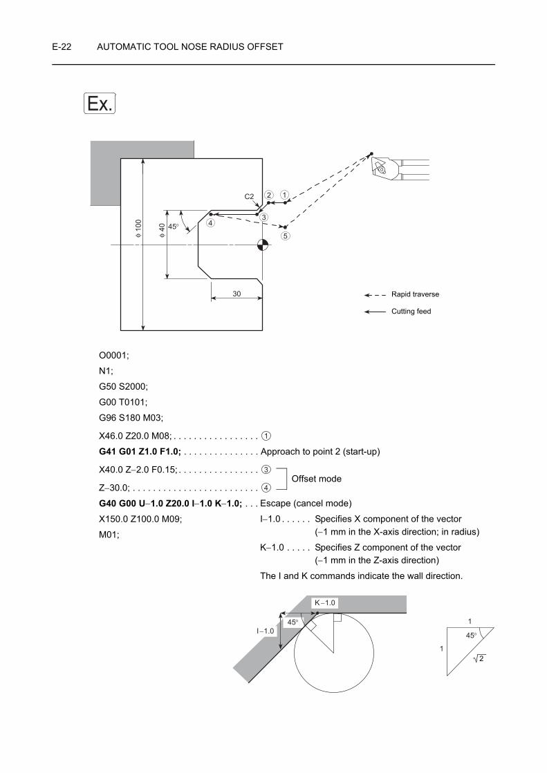
E-22 AUTOMATIC TOOL NOSE RADIUS OFFSET
O0001;
N1;
G50 S2000;
G00 T0101;
G96 S180 M03;
X46.0 Z20.0 M08; . . . . . . . . . . . . . . . . .
G41 G01 Z1.0 F1.0; . . . . . . . . . . . . . . . Approach to point 2 (start-up)
X40.0 Z−2.0 F0.15; . . . . . . . . . . . . . . . .
Z−30.0; . . . . . . . . . . . . . . . . . . . . . . . . .
G40 G00 U−1.0 Z20.0 I−1.0 K−1.0; . . .X150.0 Z100.0 M09;
M01;
Ex.
45°
C2
30
100
40
φ φ
12
34
5
Cutting feed
Rapid traverse
1
Offset mode3
4
Escape (cancel mode)
I−1.0 . . . . . . Specifies X component of the vector(−1 mm in the X-axis direction; in radius)
K−1.0 . . . . . Specifies Z component of the vector (−1 mm in the Z-axis direction)
The I and K commands indicate the wall direction.
45°
1
1
45°
K −1.0
I −1.0
2

AUTOMATIC TOOL NOSE RADIUS OFFSET E-23
4-2 Overcut in the Automatic Tool Nose Radius Offset Mode
1. Cutting an inside an arc whose radius is smaller than the tool nose radius
If cutting an inside arc whose radius is smaller than the tool nose radius is called in a program, overcuts will occur. The alarm indicator is displayed on the screen just after the start of the block that precedes that block containing the arc command and the machine stops. Just after the completion of corner interpolation motion if motion for corner interpolation was generated.
If a single block function is called during the execution of the preceding block, the axes are fed to the end point of that block, causing overcuts.
NOTE
Tool nose center path
Programmed tool path
Arc with radius smaller than the tool nose
Overcuts occur if the axes move as programmed
Alarm-stop in a single block stop operation
Machine stops due to the alarm
Corner motion

E-24 AUTOMATIC TOOL NOSE RADIUS OFFSET
2. Cutting a groove whose width is narrower than the width of tool nose
Since overcuts occur if the tool nose radius center path is generated in the direction opposite to the path specified in the program as the result of automatic tool nose radius offset, an alarm occurs just after the start of the block that precedes the one causing overcuts. The corresponding alarm number is displayed and the machine stops.
3. Cutting an arc-shaped step whose height is smaller than the tool nose radius
If cutting an arc-shaped step whose height is smaller than the tool nose is called in a program, the tool nose center path generated by the tool nose radius offset might cause axis motion in the direction opposite to the programmed tool path direction. In such a case, the first vector is ignored and the tool moves along the straight line to the tip point of the second vector.Although the operation is continued without causing an alarm, undercut portion is left in the workpiece.
Alarm/stop point in a single block stop operationTool nose center path
Programmed tool path
Machine stops due to the alarm
Overcuts occur if the axes move as programmed
Programmed tool path
Tool nose center path
Tool motion along a straight line
ArcUndercut amount

AUTOMATIC TOOL NOSE RADIUS OFFSET E-25
4. No axis motion commands being specified in two or more consecutive blocks:
If no axis motion commands are specified in two or more consecutive blocks while in the offset mode, overcuts could occur as indicated below since buffering of two blocks is not possible.
(G42 mode)
X30.0 Z−20.0; . . . . . . . . . . . . . . . . . . . . . . . . . . . . . . . [1]
X60.0; . . . . . . . . . . . . . . . . . . . . . . . . . . . . . . . . . . . . . [2]
Z−25.0; . . . . . . . . . . . . . . . . . . . . . . . . . . . . . . . . . . . . [3]
Tool paths are offset correctly due to the 2-block buffering function.
(G42 mode)
X30.0 Z−20.0; . . . . . . . . . . . . . . . . . . . . . . . . . . . . . . . [1]
X60.0; . . . . . . . . . . . . . . . . . . . . . . . . . . . . . . . . . . . . . [2]
M_ ;S_ ;Z−25.0; . . . . . . . . . . . . . . . . . . . . . . . . . . . . . . . . . . . . [3]
Overcuts occur as illustrated above. This is because the center of the tool nose is positioned, when the preceding block [2] is executed, at the right angle to the tool path called by the commands in reference to this block.
(X60.0, Z−25.0) (X60.0, Z−20.0)
(X30.0, Z−20.0)
3 2
1
(X60.0, Z−25.0) (X60.0, Z−20.0)
(X30.0, Z−20.0)1
23
Overcut
No axis movement commands in these blocks
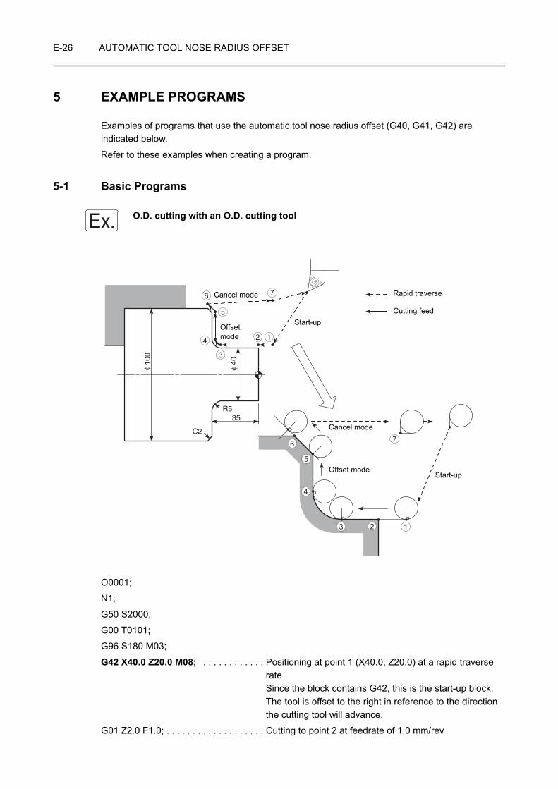
E-26 AUTOMATIC TOOL NOSE RADIUS OFFSET
5 EXAMPLE PROGRAMS
Examples of programs that use the automatic tool nose radius offset (G40, G41, G42) are indicated below.
Refer to these examples when creating a program.
5-1 Basic Programs
O.D. cutting with an O.D. cutting tool
O0001;
N1;
G50 S2000;
G00 T0101;
G96 S180 M03;
G42 X40.0 Z20.0 M08; . . . . . . . . . . . . Positioning at point 1 (X40.0, Z20.0) at a rapid traverse rateSince the block contains G42, this is the start-up block. The tool is offset to the right in reference to the direction the cutting tool will advance.
G01 Z2.0 F1.0; . . . . . . . . . . . . . . . . . . . Cutting to point 2 at feedrate of 1.0 mm/rev
Ex.
35
C2
R5
100
40
φ φ
1
12
2
3
3
4
4
5
6
5
6
7
7
Cancel mode
Cancel mode
Offset mode
Start-up
Offset modeStart-up
Cutting feed
Rapid traverse

AUTOMATIC TOOL NOSE RADIUS OFFSET E-27
Z−30.0 F0.15; . . . . . . . . . . . . . . . . . . . . Cutting to point 3 at feedrate of 0.15 mm/rev
G02 X50.0 Z−35.0 R5.0;. . . . . . . . . . . . Cutting to point 4 along a circle of 5 mm radius in the clockwise direction
G01 X96.0; . . . . . . . . . . . . . . . . . . . . . . Cutting to point 5 along a straight line
X102.0 Z−38.0; . . . . . . . . . . . . . . . . . . . Cutting to point 6 to allow the cutting tool to be completely off the workpiece
G40 G00 Z20.0; . . . . . . . . . . . . . . . . . . Positioning at point 7 at a rapid traverse rate to retract cutting tool from the workpieceSince the block contains G40, this block cancels the offset mode.
X150.0 Z100.0 M09;
M01;
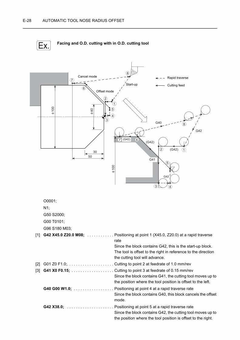
E-28 AUTOMATIC TOOL NOSE RADIUS OFFSET
Facing and O.D. cutting with in O.D. cutting tool
O0001;
N1;
G50 S2000;
G00 T0101;
G96 S180 M03;[1] G42 X45.0 Z20.0 M08; . . . . . . . . . . . . Positioning at point 1 (X45.0, Z20.0) at a rapid traverse
rateSince the block contains G42, this is the start-up block.The tool is offset to the right in reference to the direction the cutting tool will advance.
[2] G01 Z0 F1.0;. . . . . . . . . . . . . . . . . . . . . Cutting to point 2 at feedrate of 1.0 mm/rev[3] G41 X0 F0.15; . . . . . . . . . . . . . . . . . . . Cutting to point 3 at feedrate of 0.15 mm/rev
Since the block contains G41, the cutting tool moves up to the position where the tool position is offset to the left.
G40 G00 W1.0; . . . . . . . . . . . . . . . . . . Positioning at point 4 at a rapid traverse rateSince the block contains G40, this block cancels the offset mode.
G42 X38.0; . . . . . . . . . . . . . . . . . . . . . Positioning at point 5 at a rapid traverse rateSince the block contains G42, the cutting tool moves up to the position where the tool position is offset to the right.
Ex.
3050
100
40
G40
G42
(G42)
G41
G42
(G42)(G42)
100
φ φ
φ
1
1
2
2
3
3
4
4
5
5
6
6
7
7
8
8
Cancel mode
Offset mode
Start-up Cutting feed
Rapid traverse

AUTOMATIC TOOL NOSE RADIUS OFFSET E-29
G01 X100.0 Z−30.0; . . . . . . . . . . . . . . . Cutting to point 6 at a feedrate of 0.15 mm/rev
Z−50.0; . . . . . . . . . . . . . . . . . . . . . . . . . Cutting to point 7 along a straight line
G40 G00 U1.0 Z20.0; . . . . . . . . . . . . . Positioning at point 8 at a rapid traverse rate to retract cutting tool from the workpieceSince the block contains G40, this block cancels the offset mode.
X150.0 Z100.0 M09;
M01;
Blocks [1], [2], and [3] may be specified as indicated below.
[1] X45.0 Z20.0;. . . . . . . . . . . Positioning at point 1 (X45.0, Z20.0) at a rapid traverse rate
[2] G41 G01 Z0 F1.0; . . . . . . Cutting to point 2 at feedrate of 1.0 mm/revSince the block contains G41, this is the start-up block.The tool is offset to the left in reference to the direction the cutting tool will advance.
[3] X0 F0.15; . . . . . . . . . . . . . Cutting to point 3 at feedrate of 0.15 mm/rev
The tool paths for these blocks are shown in the illustration above.
In this program, although block [2] specifies only Z-axis movement, the X-axis also moves since this is the start-up block.
Here, the X-axis moves in the negative direction by the tool nose radius.
Therefore, specify the X coordinate value in block [1] so that interference can be avoided.
12
3
8
6
G40
G41
(G41)
G42
(G42)7 (G42)
100
4
5
φ
NOTE
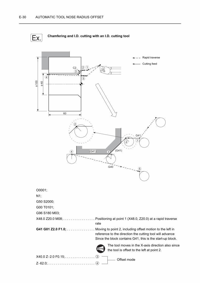
E-30 AUTOMATIC TOOL NOSE RADIUS OFFSET
Chamfering and I.D. cutting with an I.D. cutting tool
O0001;
N1;
G50 S2000;
G00 T0101;
G96 S180 M03;
X48.0 Z20.0 M08; . . . . . . . . . . . . . . . . . Positioning at point 1 (X48.0, Z20.0) at a rapid traverse rate
G41 G01 Z2.0 F1.0; . . . . . . . . . . . . . . . Moving to point 2, including offset motion to the left in reference to the direction the cutting tool will advanceSince the block contains G41, this is the start-up block.
The tool moves in the X-axis direction also since the tool is offset to the left at point 2.
X40.0 Z−2.0 F0.15; . . . . . . . . . . . . . . . .
Z−62.0; . . . . . . . . . . . . . . . . . . . . . . . . .
Ex.
60
C2
G41
(G41)(G41)
G40
40100
φ φ
1
1
2
2
3
3
4
4
5
5
2
Cutting feed
Rapid traverse
NOTE
Offset mode3
4

AUTOMATIC TOOL NOSE RADIUS OFFSET E-31
G40 G00 U−1.0 Z20.0; . . . . . . . . . . . . Positioning at point 5 at a rapid traverse rate to retract cutting tool from the workpieceSince the block contains G40, this block cancels the offset mode.At the start point of the cancel mode, the center of the nose circle is positioned right angle to the programmed path in reference to the block at the end point 4 of the preceding block.
X150.0 Z100.0 M09;
M01;

E-32 AUTOMATIC TOOL NOSE RADIUS OFFSET
Arc → O.D. → Arc cutting with an O.D. cutting tool
O0001;
N1;
G50 S2000;
G00 T0101;
G96 S180 M03;[1] X40.0 Z20.0 M08; . . . . . . . . . . . . . . . . . Positioning at point 1 (X40.0, Z20.0) at a rapid traverse
rate
G42 G01 Z0 F0.15; . . . . . . . . . . . . . . . Moving to point 2, including offset motion to the right in reference to the direction the cutting tool will advanceSince the block contains G42, this is the start-up block.
The tool moves in the X-axis direction also since the tool is offset to the right at point 2.
Ex.
G42
(G42)
(G42)
(G42)
R3
40
80
R5
90 50
G40
(G42)
φ φ
1
1
2
2
3
3
4
4
5
5
6
6
7
7
8
8
Cutting feed
Rapid traverse
NOTE
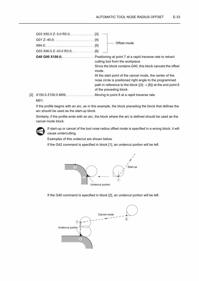
AUTOMATIC TOOL NOSE RADIUS OFFSET E-33
G03 X50.0 Z−5.0 R5.0;. . . . . . . . . . . . . [3]
G01 Z−40.0; . . . . . . . . . . . . . . . . . . . . . [4]
X84.0; . . . . . . . . . . . . . . . . . . . . . . . . . . [5]
G03 X90.0 Z−43.0 R3.0;. . . . . . . . . . . . [6]
G40 G00 X100.0; . . . . . . . . . . . . . . . . . Positioning at point 7 at a rapid traverse rate to retract cutting tool from the workpieceSince the block contains G40, this block cancels the offset mode.At the start point of the cancel mode, the center of the nose circle is positioned right angle to the programmed path in reference to the block ([3] → [6]) at the end point 6 of the preceding block.
[2] X150.0 Z100.0 M09; . . . . . . . . . . . . . . . Moving to point 8 at a rapid traverse rate
M01;
If the profile begins with an arc, as in this example, the block preceding the block that defines the arc should be used as the start-up block.
Similarly, if the profile ends with an arc, the block where the arc is defined should be used as the cancel mode block.
If start-up or cancel of the tool nose radius offset mode is specified in a wrong block, it will cause undercutting.
Examples of this undercut are shown below.
If the G42 command is specified in block [1], an undercut portion will be left.
If the G40 command is specified in block [2], an undercut portion will be left.
Offset mode
NOTE
12
3
Undercut portion
Start-up
87
6
Undercut portion
Cancel mode

E-34 AUTOMATIC TOOL NOSE RADIUS OFFSET
General start-up patterns are summarized below. Cautions to be taken into consideration when creating a program are specified for the related tool paths.
Chuck work (1) (Tool nose radius: 0.4 mm)
O0001;
N1;
G50 S2000;
G00 T0101;
G96 S150 M03;
G42 X50.0 Z3.0 M08; . . . . . . . .
G01 Z−30.0 F0.15; . . . . . . . . . . .
Chuck work (2) (Tool nose radius: 0.4 mm)
O0001;
N1;
G50 S2000;
G00 T0101;
G96 S150 M03;
G42 X50.0 Z20.0 M08; . . . . . . .
G01 Z3.0 F1.0; . . . . . . . . . . . . . . Z−30.0 F0.15;
Ex.
3
G00G42
G01 (G42)
50φ
12
Start point
Programmed point (at start-up)
At the end of this start-up block, the center of the tool nose is positioned at a point which is at a right angle to the path to be generated by the commands in the next block.
Imaginary tool tip position
Generally, at the start of a program, the programmed point and the imaginary tool tip position are at the same position.
Taking into account tool motion in the start-up block, allow a distance that is equal to, or larger than the tool nose radius so that the cutting tool will not be hit against the workpiece.
1
2
Ex.
3 G01
G00G42
50φ
12
Allow a distance that is equal to, or larger than the tool nose radius so that the cutting tool will not be hit against the workpiece.
Second approach at a faster cutting feedrate
First approach at a rapid traverse rate 1
2
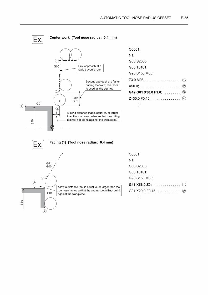
AUTOMATIC TOOL NOSE RADIUS OFFSET E-35
Center work (Tool nose radius: 0.4 mm)
O0001;
N1;
G50 S2000;
G00 T0101;
G96 S150 M03;
Z3.0 M08; . . . . . . . . . . . . . . . . . .
X50.0; . . . . . . . . . . . . . . . . . . . . .
G42 G01 X30.0 F1.0; . . . . . . . .
Z−30.0 F0.15; . . . . . . . . . . . . . . .
Facing (1) (Tool nose radius: 0.4 mm)
O0001;
N1;
G50 S2000;
G00 T0101;
G96 S150 M03;
G41 X56.0 Z0; . . . . . . . . . . . . . .
G01 X20.0 F0.15; . . . . . . . . . . . .
Ex.
3
G01
G42G01
G00
30φ
1
2
34
Allow a distance that is equal to, or larger than the tool nose radius so that the cutting tool will not be hit against the workpiece.
Second approach at a faster cutting feedrate; this block is used as the start-up
First approach at a rapid traverse rate
1
2
3
4
Ex.
3
G41G00
G01
50φ
1
2
Allow a distance that is equal to, or larger than the tool nose radius so that the cutting tool will not be hit against the workpiece.
1
2

E-36 AUTOMATIC TOOL NOSE RADIUS OFFSET
Facing (2) (Tool nose radius: 0.4 mm)
O0001;
N1;
G50 S2000;
G00 T0101;
G96 S150 M03;
X56.0 Z20.0; . . . . . . . . . . . . . . . .
G41 G01 Z0 F1.0; . . . . . . . . . . .
X30.0 F0.15; . . . . . . . . . . . . . . . .
Facing (3) (Tool nose radius: 0.4 mm)
In this example, positioning in the start-up block requires corner interpolation motion.
The program should use the G41 command, instead of the G42 command used in "Chuck work (1) (Tool nose radius: 0.4 mm)."
O0001;
N1;
G50 S2000;
G00 T0101;
G96 S150 M03;
G41 X56.0 Z20.0 M08; . . . . . . .
G01 Z0 F1.0;. . . . . . . . . . . . . . . .
X30.0 F0.15; . . . . . . . . . . . . . . . .
Ex.
3
G41G01
G00
G01
50φ
12
3
Allow a distance that is equal to, or larger than the tool nose radius so that the cutting tool will not be hit against the workpiece. 1
2
3
Ex.NOTE
G01
3
G01
G41G00
50φ
12
3
Allow a distance that is equal to, or larger than two times the tool nose radius so that the cutting tool will not be hit against the workpiece.
Corner interpolation motion
At the end of this start-up block, the center of the tool nose is positioned at a point which is at a right angle to the path generated by the commands in the next block. Then, corner interpolation motion is inserted so that the tool nose comes into contact with the tool path generated by the commands in the next block.
1
2
3
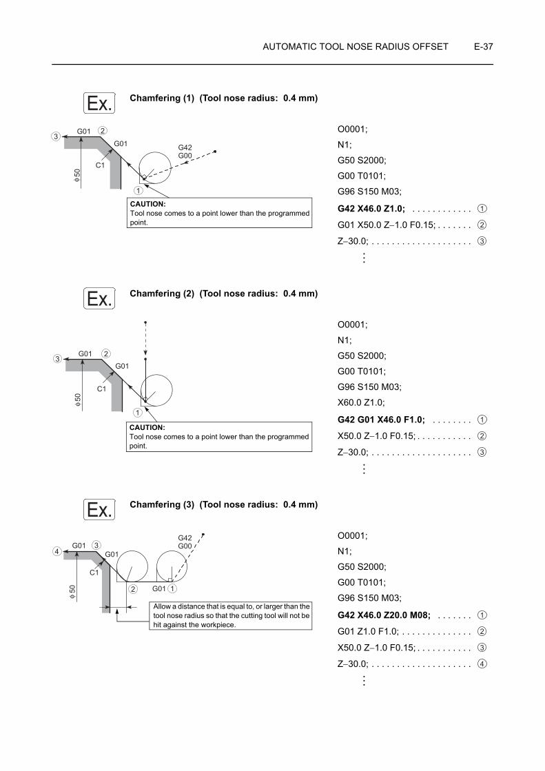
AUTOMATIC TOOL NOSE RADIUS OFFSET E-37
Chamfering (1) (Tool nose radius: 0.4 mm)
O0001;
N1;
G50 S2000;
G00 T0101;
G96 S150 M03;
G42 X46.0 Z1.0; . . . . . . . . . . . .
G01 X50.0 Z−1.0 F0.15; . . . . . . .
Z−30.0; . . . . . . . . . . . . . . . . . . . .
Chamfering (2) (Tool nose radius: 0.4 mm)
O0001;
N1;
G50 S2000;
G00 T0101;
G96 S150 M03;
X60.0 Z1.0;
G42 G01 X46.0 F1.0; . . . . . . . .
X50.0 Z−1.0 F0.15; . . . . . . . . . . .
Z−30.0; . . . . . . . . . . . . . . . . . . . .
Chamfering (3) (Tool nose radius: 0.4 mm)
O0001;
N1;
G50 S2000;
G00 T0101;
G96 S150 M03;
G42 X46.0 Z20.0 M08; . . . . . . .
G01 Z1.0 F1.0; . . . . . . . . . . . . . .
X50.0 Z−1.0 F0.15; . . . . . . . . . . .
Z−30.0; . . . . . . . . . . . . . . . . . . . .
Ex.
C1
G01
G01
G42G00
50φ
1
23
CAUTION: Tool nose comes to a point lower than the programmed point.
1
2
3
Ex.
C1
G01
G01
50φ
1
23
CAUTION: Tool nose comes to a point lower than the programmed point.
1
2
3
Ex.G01
G01
C1
G01
G42G00
50φ
12
34
Allow a distance that is equal to, or larger than the tool nose radius so that the cutting tool will not be hit against the workpiece.
1
2
3
4
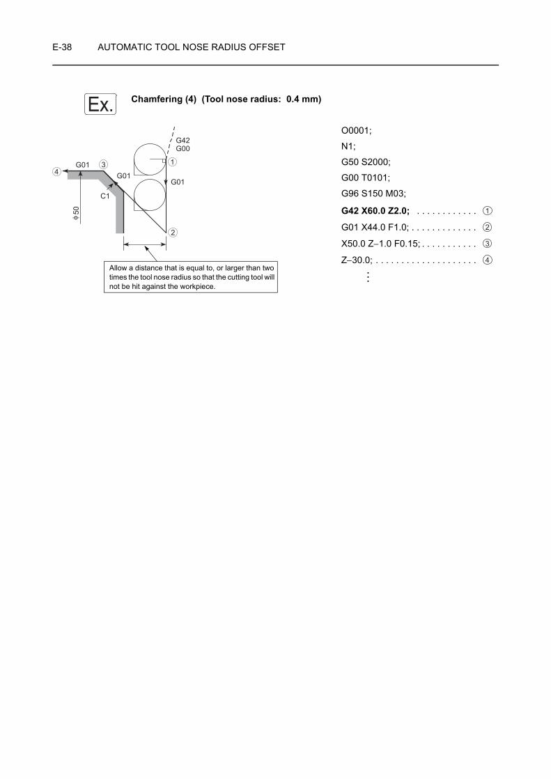
E-38 AUTOMATIC TOOL NOSE RADIUS OFFSET
Chamfering (4) (Tool nose radius: 0.4 mm)
O0001;
N1;
G50 S2000;
G00 T0101;
G96 S150 M03;
G42 X60.0 Z2.0; . . . . . . . . . . . .
G01 X44.0 F1.0; . . . . . . . . . . . . .
X50.0 Z−1.0 F0.15; . . . . . . . . . . .
Z−30.0; . . . . . . . . . . . . . . . . . . . .
Ex.
C1
G01G01
G42G00
G01
50φ
1
2
34
Allow a distance that is equal to, or larger than two times the tool nose radius so that the cutting tool will not be hit against the workpiece.
1
2
3
4
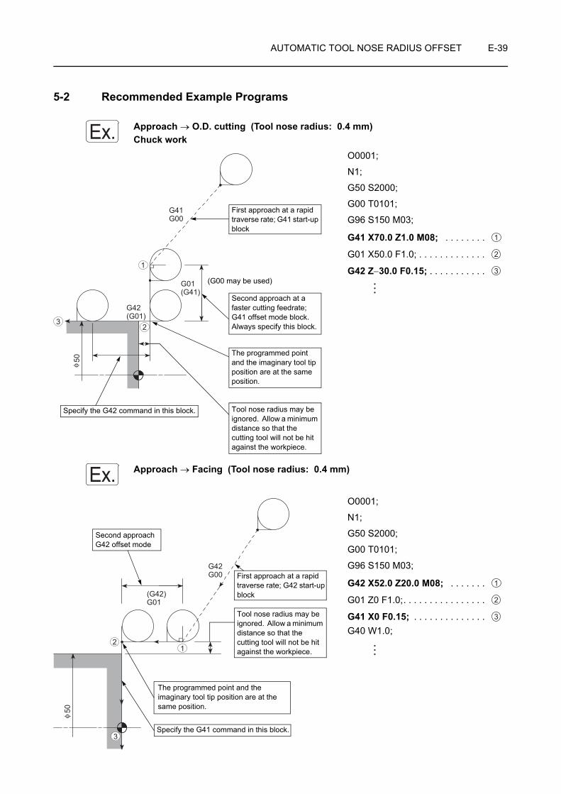
AUTOMATIC TOOL NOSE RADIUS OFFSET E-39
5-2 Recommended Example Programs
Approach → O.D. cutting (Tool nose radius: 0.4 mm)Chuck work
O0001;
N1;
G50 S2000;
G00 T0101;
G96 S150 M03;
G41 X70.0 Z1.0 M08; . . . . . . . .
G01 X50.0 F1.0; . . . . . . . . . . . . .
G42 Z−30.0 F0.15; . . . . . . . . . . .
Approach → Facing (Tool nose radius: 0.4 mm)
O0001;
N1;
G50 S2000;
G00 T0101;
G96 S150 M03;
G42 X52.0 Z20.0 M08; . . . . . . .
G01 Z0 F1.0;. . . . . . . . . . . . . . . .
G41 X0 F0.15; . . . . . . . . . . . . . . G40 W1.0;
Ex.
G41G00
G01(G41)
G42(G01)
50φ
1
23
First approach at a rapid traverse rate; G41 start-up block
Second approach at a faster cutting feedrate; G41 offset mode block. Always specify this block.
(G00 may be used)
Specify the G42 command in this block. Tool nose radius may be ignored. Allow a minimum distance so that the cutting tool will not be hit against the workpiece.
The programmed point and the imaginary tool tip position are at the same position.
1
2
3
Ex.
G42G00
(G42)G01
50φ
12
3
Tool nose radius may be ignored. Allow a minimum distance so that the cutting tool will not be hit against the workpiece.
First approach at a rapid traverse rate; G42 start-up block
The programmed point and the imaginary tool tip position are at the same position.
Specify the G41 command in this block.
Second approachG42 offset mode
1
2
3
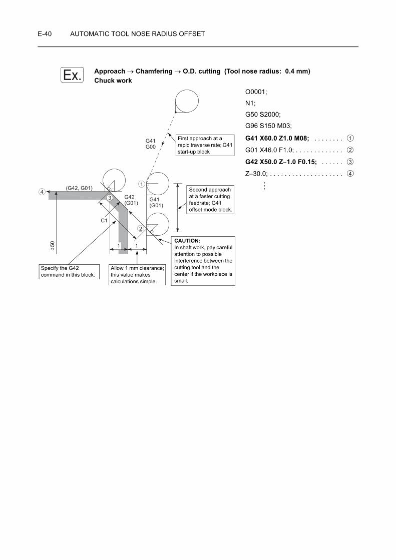
E-40 AUTOMATIC TOOL NOSE RADIUS OFFSET
Approach → Chamfering → O.D. cutting (Tool nose radius: 0.4 mm)Chuck work
O0001;
N1;
G50 S2000;
G96 S150 M03;
G41 X60.0 Z1.0 M08; . . . . . . . .
G01 X46.0 F1.0; . . . . . . . . . . . . .
G42 X50.0 Z−1.0 F0.15; . . . . . .
Z−30.0; . . . . . . . . . . . . . . . . . . . .
Ex.
G41G00
G41(G01)
G42(G01)
(G42, G01)
C1
50 1 1φ
1
2
34
First approach at a rapid traverse rate; G41 start-up block
Second approach at a faster cutting feedrate; G41 offset mode block.
CAUTION:In shaft work, pay careful attention to possible interference between the cutting tool and the center if the workpiece is small.
Specify the G42 command in this block.
Allow 1 mm clearance; this value makes calculations simple.
1
2
3
4
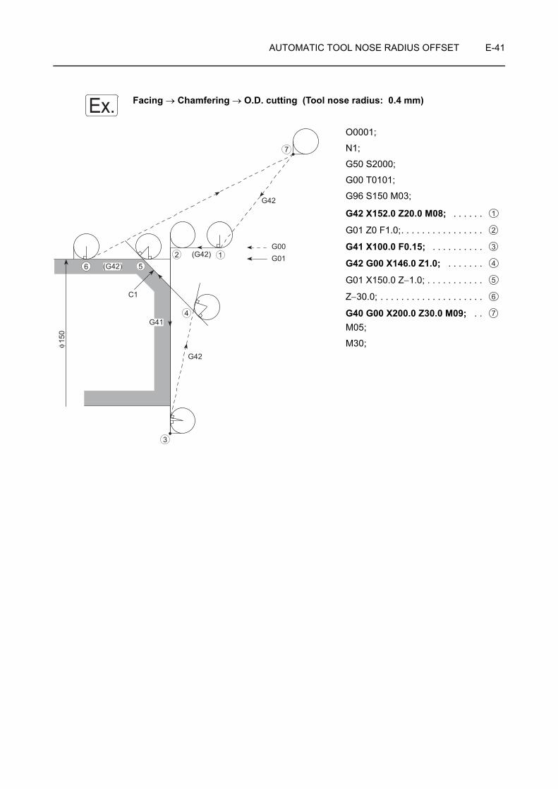
AUTOMATIC TOOL NOSE RADIUS OFFSET E-41
Facing → Chamfering → O.D. cutting (Tool nose radius: 0.4 mm)
O0001;
N1;
G50 S2000;
G00 T0101;
G96 S150 M03;
G42 X152.0 Z20.0 M08; . . . . . .
G01 Z0 F1.0;. . . . . . . . . . . . . . . .
G41 X100.0 F0.15; . . . . . . . . . .
G42 G00 X146.0 Z1.0; . . . . . . .
G01 X150.0 Z−1.0; . . . . . . . . . . .
Z−30.0; . . . . . . . . . . . . . . . . . . . .
G40 G00 X200.0 Z30.0 M09; . . M05;
M30;
Ex.
G42
C1
(G42)(G42)
G41
G42
G00G01
150
φ
12
3
4
56
7
1
2
3
4
5
6
7
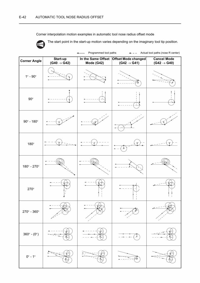
E-42 AUTOMATIC TOOL NOSE RADIUS OFFSET
Corner interpolation motion examples in automatic tool nose radius offset mode
The start point in the start-up motion varies depending on the imaginary tool tip position.
Programmed tool paths Actual tool paths (nose R center)
Corner Angle Start-up(G40 → G42)
In the Same Offset Mode (G42)
Offset Mode changed (G42 → G41)
Cancel Mode(G42 → G40)
1° - 90°
90°
90° - 180°
180°
180° - 270°
270°
270° - 360°
360° - (0°)
0° - 1°
NOTE

AUTOMATIC TOOL NOSE RADIUS OFFSET E-43
5-3 Programming for a Sample Workpiece
The part programs for the facing, O.D. finishing, and I.D. finishing are written for the sample workpiece illustrated below.
Compare the part program with the one created in 31 "SUMMARY" of CHAPTER C.
<Drawing>
Finishing is unless otherwise specified.
<Dimensions of blank workpiece>
Blank Workpiece Description
Material AISI 1045 (Carbon steel)
Dimensions (mm)
O.D. φ70
I.D. φ30
Length 43
41
25
3 5
C1.5C1
15°� R2
C1
C0.5
C1
C1.5
M60 × P2.0
φ 44
φ 54
φ 32
φ 56
φ 69

E-44 AUTOMATIC TOOL NOSE RADIUS OFFSET
<Preparation for using the automatic tool nose radius offset function>
1) Set the imaginary tool tip position code to the C column in the TOOL WEAR OFFSET screen.
2) Set the nose radius of the tool in the R column, corresponding to the offset number specified by the T code in the TOOL WEAR OFFSET screen.
Setting the nose radius of the cutting tool to the R column in the GEOMETRY OFFSET screen is also possible. However, if the nose radius is set to the R column in both of the GEOMETRY OFFSET and TOOL WEAR OFFSET screens, offset is made by both of the input data, causing excessive or insufficient cutting.
<Part programs for facing, O.D. finishing and I.D. finishing>
N3(FIN. OF. OUT.); . . . . . . . . . . . . . . . . Part programs for finish facing and O.D. finishing (tool nose radius: 0.4 mm)
G50 S2000;. . . . . . . . . . . . . . . . . . . . . . Setting the spindle 1 speed limit for automatic operation at
2000 min−1
G00 T0303 (M42)*; . . . . . . . . . . . . . . . . Selecting the No. 3 tool
G96 S200 M03;. . . . . . . . . . . . . . . . . . . Starting spindle 1 in the normal direction at the cutting speed of 200 m/min
G42 X56.0 Z20.0 M08; . . . . . . . . . . . . Moving to point 1, including offset motion to the right in reference to the direction the cutting tool will advance (start-up motion)
G01 Z0 F1.0;
G41 X30.0 F0.15; . . . . . . . . . . . . . . . . Moving to the position where the offset is made to the left
G42 G00 X50.0 W1.0; . . . . . . . . . . . . . Moving to the position where the offset is made to the right
G01 X54.0 Z−1.0;
Z−5.0;
X56.8;
X59.8 Z−6.5;
NOTE
25
1
26
22 2123
10
2
4
324
6
578
9
27
Cutting feed
Rapid traverse
1
2
3
4
5
6
7
8
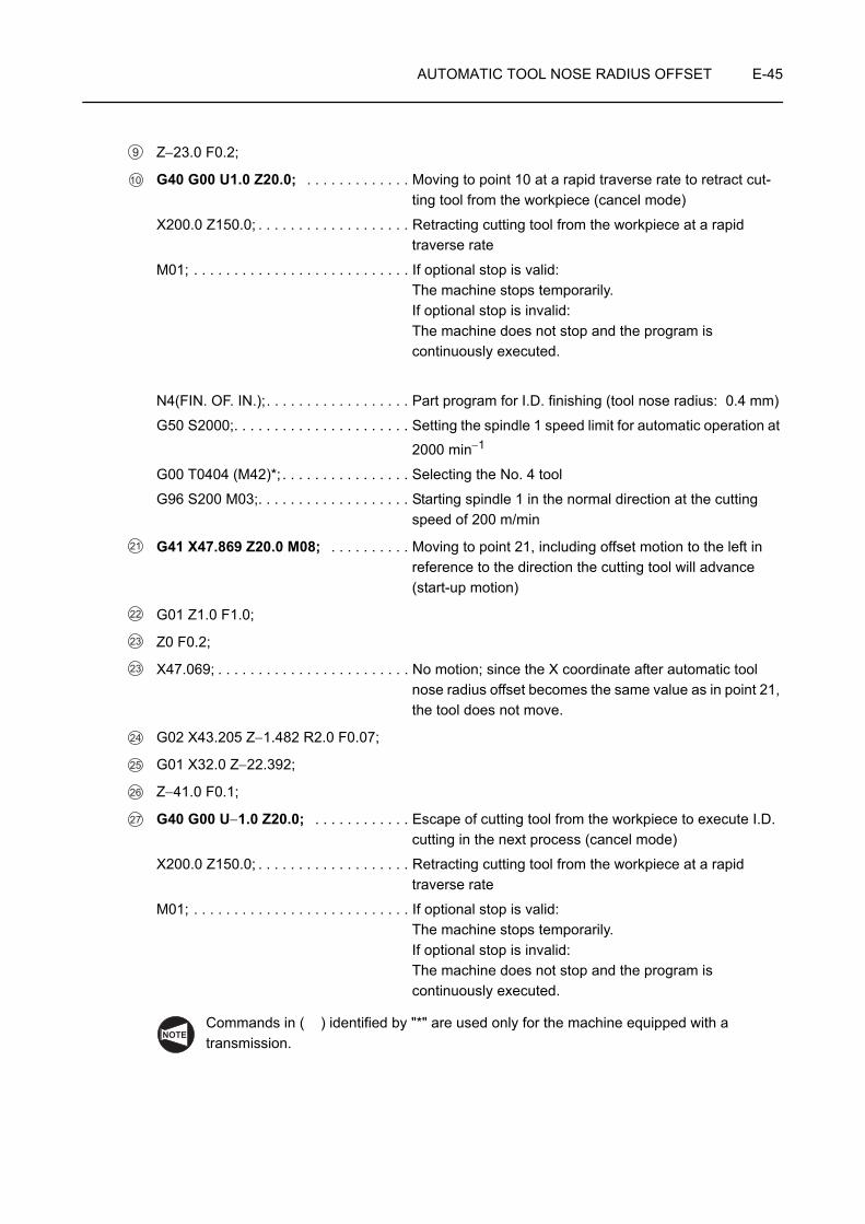
AUTOMATIC TOOL NOSE RADIUS OFFSET E-45
Z−23.0 F0.2;
G40 G00 U1.0 Z20.0; . . . . . . . . . . . . . Moving to point 10 at a rapid traverse rate to retract cut-ting tool from the workpiece (cancel mode)
X200.0 Z150.0; . . . . . . . . . . . . . . . . . . . Retracting cutting tool from the workpiece at a rapid traverse rate
M01; . . . . . . . . . . . . . . . . . . . . . . . . . . . If optional stop is valid:The machine stops temporarily.If optional stop is invalid:The machine does not stop and the program is continuously executed.
N4(FIN. OF. IN.);. . . . . . . . . . . . . . . . . . Part program for I.D. finishing (tool nose radius: 0.4 mm)
G50 S2000;. . . . . . . . . . . . . . . . . . . . . . Setting the spindle 1 speed limit for automatic operation at
2000 min−1
G00 T0404 (M42)*; . . . . . . . . . . . . . . . . Selecting the No. 4 tool
G96 S200 M03;. . . . . . . . . . . . . . . . . . . Starting spindle 1 in the normal direction at the cutting speed of 200 m/min
G41 X47.869 Z20.0 M08; . . . . . . . . . . Moving to point 21, including offset motion to the left in reference to the direction the cutting tool will advance (start-up motion)
G01 Z1.0 F1.0;
Z0 F0.2;
X47.069; . . . . . . . . . . . . . . . . . . . . . . . . No motion; since the X coordinate after automatic tool nose radius offset becomes the same value as in point 21, the tool does not move.
G02 X43.205 Z−1.482 R2.0 F0.07;
G01 X32.0 Z−22.392;
Z−41.0 F0.1;
G40 G00 U−1.0 Z20.0; . . . . . . . . . . . . Escape of cutting tool from the workpiece to execute I.D. cutting in the next process (cancel mode)
X200.0 Z150.0; . . . . . . . . . . . . . . . . . . . Retracting cutting tool from the workpiece at a rapid traverse rate
M01; . . . . . . . . . . . . . . . . . . . . . . . . . . . If optional stop is valid:The machine stops temporarily.If optional stop is invalid:The machine does not stop and the program is continuously executed.
Commands in ( ) identified by "*" are used only for the machine equipped with a transmission.
9
10
21
22
23
23
24
25
26
27
NOTE

CHAPTER FMANUAL TOOL NOSE
RADIUS OFFSET
This chapter describes how the manual tool nose radius offset function works.
Because the tool edge does not come to a sharp point, but is slightly rounded, the point of the tool nose actually engaged with cutting differs slightly from the point assumed for writing a program. By calculating the offset data manually and shifting the tool nose, the programmed point (imaginary tool nose) can be made to coincide with the cutting point.

CONTENTS
F : MANUAL TOOL NOSE RADIUS OFFSET
1 GENERAL . . . . . . . . . . . . . . . . . . . . . . . . . . . . . . . . . . . . . . . . . . . . . . . . . . . . . . . . . . . . F-1
2 OFFSET FOR TAPER CUTTING AND CHAMFERING . . . . . . . . . . . . . . . . . . . . . . . . . F-2
2-1 Offset Method . . . . . . . . . . . . . . . . . . . . . . . . . . . . . . . . . . . . . . . . . . . . . . . . . . . . F-2
2-2 Calculating Offset Data . . . . . . . . . . . . . . . . . . . . . . . . . . . . . . . . . . . . . . . . . . . . . F-4
2-3 Offset Direction and Calculation of Coordinate Values . . . . . . . . . . . . . . . . . . . . . F-6
2-3-1 Offset Direction . . . . . . . . . . . . . . . . . . . . . . . . . . . . . . . . . . . . . . . . . . . . F-6
2-3-2 Calculating Coordinate Values . . . . . . . . . . . . . . . . . . . . . . . . . . . . . . . . . F-7
2-4 Example Programs . . . . . . . . . . . . . . . . . . . . . . . . . . . . . . . . . . . . . . . . . . . . . . . F-10
2-5 Offset Data Table. . . . . . . . . . . . . . . . . . . . . . . . . . . . . . . . . . . . . . . . . . . . . . . . . F-13
3 OFFSET IN CIRCULAR INTERPOLATION. . . . . . . . . . . . . . . . . . . . . . . . . . . . . . . . . . F-17
3-1 Convex Arc . . . . . . . . . . . . . . . . . . . . . . . . . . . . . . . . . . . . . . . . . . . . . . . . . . . . . F-17
3-2 Concave Arc . . . . . . . . . . . . . . . . . . . . . . . . . . . . . . . . . . . . . . . . . . . . . . . . . . . . F-17
3-3 Calculating the Coordinate Values to be Specified in a Program . . . . . . . . . . . . F-18
3-4 Example Programs . . . . . . . . . . . . . . . . . . . . . . . . . . . . . . . . . . . . . . . . . . . . . . . F-19
4 PROGRAMMING FOR A SAMPLE WORKPIECE . . . . . . . . . . . . . . . . . . . . . . . . . . . . F-21
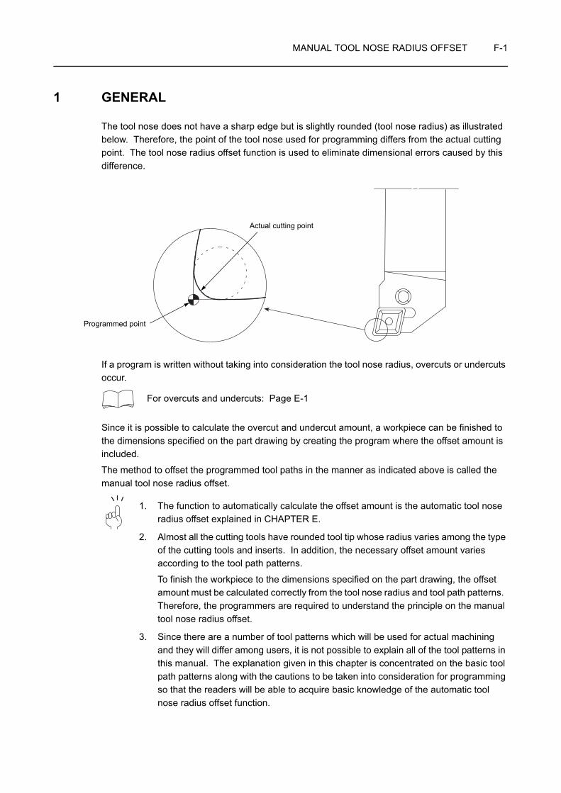
MANUAL TOOL NOSE RADIUS OFFSET F-1
1 GENERAL
The tool nose does not have a sharp edge but is slightly rounded (tool nose radius) as illustrated below. Therefore, the point of the tool nose used for programming differs from the actual cutting point. The tool nose radius offset function is used to eliminate dimensional errors caused by this difference.
If a program is written without taking into consideration the tool nose radius, overcuts or undercuts occur.
For overcuts and undercuts: Page E-1
Since it is possible to calculate the overcut and undercut amount, a workpiece can be finished to the dimensions specified on the part drawing by creating the program where the offset amount is included.
The method to offset the programmed tool paths in the manner as indicated above is called the manual tool nose radius offset.
1. The function to automatically calculate the offset amount is the automatic tool nose radius offset explained in CHAPTER E.
2. Almost all the cutting tools have rounded tool tip whose radius varies among the type of the cutting tools and inserts. In addition, the necessary offset amount varies according to the tool path patterns.
To finish the workpiece to the dimensions specified on the part drawing, the offset amount must be calculated correctly from the tool nose radius and tool path patterns. Therefore, the programmers are required to understand the principle on the manual tool nose radius offset.
3. Since there are a number of tool patterns which will be used for actual machining and they will differ among users, it is not possible to explain all of the tool patterns in this manual. The explanation given in this chapter is concentrated on the basic tool path patterns along with the cautions to be taken into consideration for programming so that the readers will be able to acquire basic knowledge of the automatic tool nose radius offset function.
Actual cutting point
Programmed point

F-2 MANUAL TOOL NOSE RADIUS OFFSET
2 OFFSET FOR TAPER CUTTING AND CHAMFERING
2-1 Offset Method
In O.D. cutting, the program is first created assuming the imaginary tool tip as the point to move on the programmed path. It is shown as points 1 and 2 in the illustration below. If the program is created in this manner, undercut portion is left. Therefore, points 1' and 2' which are offset points from 1 and 2 taking nose radius into consideration must be obtained to finish the tapered portion correctly.
X50.0 Z0; . . . . . . . . . . . . . . . . . . . . . . . . . . . . . . . . .
X80.0 Z−15.0; . . . . . . . . . . . . . . . . . . . . . . . . . . . . .
Calculate the offset data (Xc, Zc) and add this offset to the original program (point 1, 2) to eliminate undercutting.
X(50.0 − 2 × Xc) Z0; . . . . . . . . . . . . . . . . . . . . . . . . '
X80.0 Z(−15.0 − Zc); . . . . . . . . . . . . . . . . . . . . . . . . '
Z0
15
80
φ50
φ
1
2
Undercut portion
1
2
Zc
Xc
15
Z0
80 50
'
'
φφ
1
2
1
2

MANUAL TOOL NOSE RADIUS OFFSET F-3
In I.D. cutting, the program is first created assuming the imaginary tool tip as the point to move on the programmed path. It is shown as points 1 and 2 in the illustration below. If the program is created in this manner, undercut portion is left. Therefore, points 1' and 2' which are offset points from 1 and 2 taking nose radius into consideration must be obtained to finish the tapered portion correctly.
X54.0 Z0; . . . . . . . . . . . . . . . . . . . . . . . . . . . . . . . . .
X50.0 Z−3.0; . . . . . . . . . . . . . . . . . . . . . . . . . . . . . .
Calculate the offset data (Xc, Zc) and add this offset to the original program (point 1, 2) to eliminate undercutting.
X(54.0 + 2 × Xc) Z0; . . . . . . . . . . . . . . . . . . . . . . . . '
X50.0 Z(−3.0 − Zc); . . . . . . . . . . . . . . . . . . . . . . . . . '
The procedure used to calculate Xc and Zc is explained below.
Z03
50 54φφ
1
2
Undercut portion
1
2
Zc
Xc
3Z0
50 54
'
'
φφ
1
2
1
2

F-4 MANUAL TOOL NOSE RADIUS OFFSET
2-2 Calculating Offset Data
1. For undercutting
The additional movement along an axis required to eliminate undercut portions is called the offset data or additional cutting amount.
The following shows the diagrams and formulas used to calculate the offset data Xc and Zc required to eliminate undercutting.
<O.D. taper cutting><Calculating Xc and Zc>
• Xc
Xc = Zc × tanθ = (Rn − a) × tanθ = Rn × {1 − tan(θ/2)} × tanθ . . . . . . Formula 1
• Zc
Zc = Rn − a = Rn − Rn × tan(θ/2) = Rn × {1 − tan(θ/2)} . . . . . . . . . . . . Formula 2
The offset data calculated using the formulas 1 and 2 is summarized in the table in 2-5 "Offset Data Table" in this chapter.
<I.D. taper cutting><Calculating Xc and Zc>
• Xc
Xc = Zc × tanθ = Rn × {1 − tan(θ/2)} × tanθ . . . . . . Formula 1
• Zc
Zc = Rn − a = Rn − Rn × tan(θ/2) = Rn × {1 − tan(θ/2)} . . . . . . . . . . . . Formula 2
The offset data calculated using the formulas 1 and 2 is summarized in the table in 2-5 "Offset Data Table" in this chapter.
Rn: Tool nose radius
Xc: Offset data, X-axis
Zc: Offset data, Z-axis
θ: Taper angle, measured from the Z-axis
Rn
+Z
+X
Zc
Zc a
Rn
/2/2Xc
θ
θθ
θ
Zc
Zc a
Rn
/2 /2XcRn
+Z
+X
θθ θ
θ

MANUAL TOOL NOSE RADIUS OFFSET F-5
2. For overcutting
The additional movement along an axis required to eliminate overcut portions is called the offset data or additional cutting amount.
The following shows the diagrams and formulas used to calculate the offset data Xc and Z'c required to eliminate overcutting.
<O.D. taper cutting><Calculating Xc and Z'c>
• Xc
Xc = Zc × tanθ = Rn × {1 − tan(θ/2)} × tanθ . . . . . . Formula 1
• Z'c
Z'c= Rn + a = Rn × {1 + tan(θ/2)} . . . . Formula 2
or
Z'c= 2 × Rn − Zc . . . . . . . . . . . . . . . . . Formula 2'
To use the offset data table, use the formula 2' to calculate the offset data.
The offset data Xc, calculated using formula 1, and the temporary offset data Zc, used for calculating the offset data Z'c by formula 2' are summarized in the table in 2-5 "Offset Data Table" in this chapter.
<I.D. taper cutting><Calculating Xc and Z'c>
• Xc
Xc = Zc × tanθ= Rn × {1 − tan(θ/2)} × tanθ . . . . . . Formula 1
• Z'c
Z'c= Rn + a = Rn × {1 + tan(θ/2)} . . . . Formula 2
or
Z'c= 2 × Rn − Zc . . . . . . . . . . . . . . . . . Formula 2'
To use the offset data table, use the formula 2' to calculate the offset data.
The offset data Xc, calculated using formula 1, and the temporary offset data Zc, used for calculating the offset data Z'c by formula 2' are summarized in the table in 2-5 "Offset Data Table" in this chapter.
Rn: Tool nose radius
Xc: Offset data, X-axis
Z'c: Offset data, Z-axis (Additional cutting amount)
Zc: Offset data for angle θ (data in offset data table)
θ: Taper angle, measured from the Z-axis
Zc
a
Z'c
/2/2
Xc
Rn
+Z
+X
θ θ θ
NOTE
Zc
a
Z'c
/2
Rn
Xc
Xc
+Z
+X
/2
θθ
θ
NOTE

F-6 MANUAL TOOL NOSE RADIUS OFFSET
2-3 Offset Direction and Calculation of Coordinate Values
2-3-1 Offset Direction
The programmed shape is obtained if the imaginary tool nose moves along the path indicated by the dotted lines.
In the following diagrams, "A" represents O.D. cutting while "B" represents I.D. cutting.
Offset direction
NOTE
Zc
Xc
Xc
Zc
θ
θ
1-A
1-B
Zc
Zc
Zc
Zc
θ
θ
2-A
2-B
Xc
Xc
Xc
Xc
θ
θ
3-A
3-B
Xc
Zc
Zc
Xc
θ
θ
4-A
4-B
Z'c
Xc
Z'c
Xc
θ
θ
5-A
5-B
Z'c
Z'c
Z'c
Z'c
θ
θ
6-A
6-B
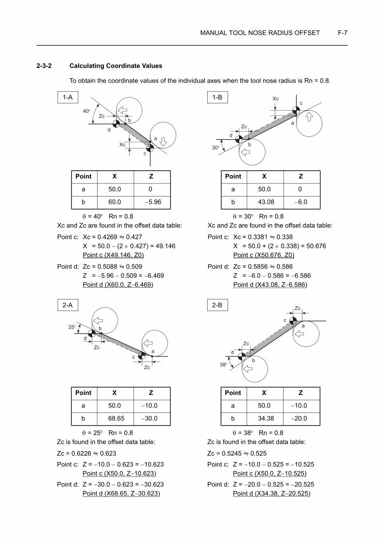
MANUAL TOOL NOSE RADIUS OFFSET F-7
2-3-2 Calculating Coordinate Values
To obtain the coordinate values of the individual axes when the tool nose radius is Rn = 0.8.
Xcc
Zc
d
30° b
a
θ = 40° Rn = 0.8 Xc and Zc are found in the offset data table:
Point c: Xc = 0.4269 0.427 X = 50.0 − (2 × 0.427) = 49.146 Point c (X49.146, Z0)
Point d: Zc = 0.5088 0.509 Z = −5.96 − 0.509 = −6.469
Point d (X60.0, Z−6.469)
Point X Z
a 50.0 0
b 60.0 −5.96
θ = 30° Rn = 0.8 Xc and Zc are found in the offset data table:
Point c: Xc = 0.3381 0.338 X = 50.0 + (2 × 0.338) = 50.676 Point c (X50.676, Z0)
Point d: Zc = 0.5856 0.586 Z = −6.0 − 0.586 = −6.586 Point d (X43.08, Z−6.586)
Point X Z
a 50.0 0
b 43.08 −6.0
40°Zc
d
Xc
c
a
b
1-A 1-B
Zc
Zc
25° b
d
ca
Zc
Zc
ca
bd
38°
θ = 25° Rn = 0.8 Zc is found in the offset data table:
Zc = 0.6226 0.623
Point c: Z = −10.0 − 0.623 = −10.623Point c (X50.0, Z−10.623)
Point d: Z = −30.0 − 0.623 = −30.623Point d (X68.65, Z−30.623)
Point X Z
a 50.0 −10.0
b 68.65 −30.0
θ = 38° Rn = 0.8 Zc is found in the offset data table:
Zc = 0.5245 0.525
Point c: Z = −10.0 − 0.525 = −10.525Point c (X50.0, Z−10.525)
Point d: Z = −20.0 − 0.525 = −20.525Point d (X34.38, Z−20.525)
Point X Z
a 50.0 −10.0
b 34.38 −20.0
2-A 2-B
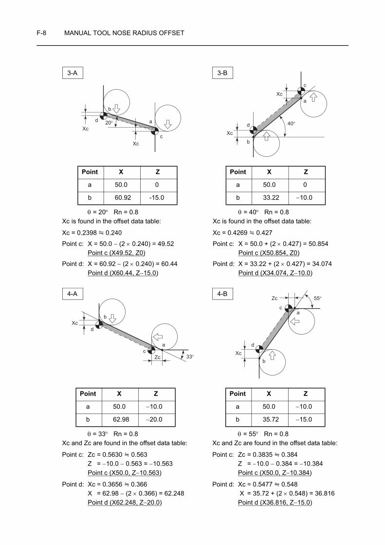
F-8 MANUAL TOOL NOSE RADIUS OFFSET
Xc
Xc
40°
b
d
c
a
θ = 20° Rn = 0.8 Xc is found in the offset data table:
Xc = 0.2398 0.240
Point c: X = 50.0 − (2 × 0.240) = 49.52Point c (X49.52, Z0)
Point d: X = 60.92 − (2 × 0.240) = 60.44Point d (X60.44, Z−15.0)
Point X Z
a 50.0 0
b 60.92 -15.0
θ = 40° Rn = 0.8 Xc is found in the offset data table:
Xc = 0.4269 0.427
Point c: X = 50.0 + (2 × 0.427) = 50.854Point c (X50.854, Z0)
Point d: X = 33.22 + (2 × 0.427) = 34.074Point d (X34.074, Z−10.0)
Point X Z
a 50.0 0
b 33.22 −10.0
Xc
Xc
20°d a
c
b
3-A 3-B
Xc
Zc
b
a
33°c
d
Zc
Xcd
ca
55°
b
θ = 33° Rn = 0.8 Xc and Zc are found in the offset data table:
Point c: Zc = 0.5630 0.563Z = −10.0 − 0.563 = −10.563
Point c (X50.0, Z−10.563)
Point d: Xc = 0.3656 0.366X = 62.98 − (2 × 0.366) = 62.248Point d (X62.248, Z−20.0)
Point X Z
a 50.0 −10.0
b 62.98 −20.0
θ = 55° Rn = 0.8 Xc and Zc are found in the offset data table:
Point c: Zc = 0.3835 0.384Z = −10.0 − 0.384 = −10.384Point c (X50.0, Z−10.384)
Point d: Xc = 0.5477 0.548 X = 35.72 + (2 × 0.548) = 36.816Point d (X36.816, Z−15.0)
Point X Z
a 50.0 −10.0
b 35.72 −15.0
4-A 4-B
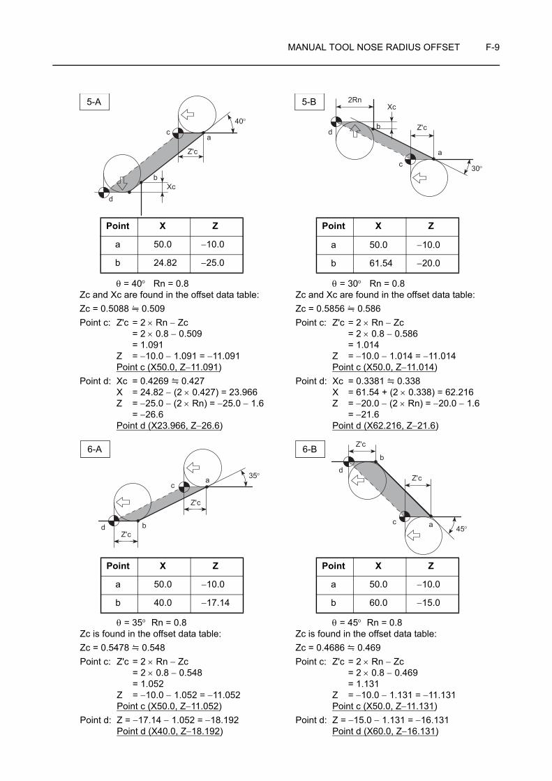
MANUAL TOOL NOSE RADIUS OFFSET F-9
Z'c
Xc
40°c
a
b
d
Z'c
Xc
30°
ac
d
2Rn
b
θ = 40° Rn = 0.8 Zc and Xc are found in the offset data table:Zc = 0.5088 0.509Point c: Z'c = 2 × Rn − Zc
= 2 × 0.8 − 0.509= 1.091
Z = −10.0 − 1.091 = −11.091Point c (X50.0, Z−11.091)
Point d: Xc = 0.4269 0.427X = 24.82 − (2 × 0.427) = 23.966Z = −25.0 − (2 × Rn) = −25.0 − 1.6
= −26.6Point d (X23.966, Z−26.6)
Point X Z
a 50.0 −10.0
b 24.82 −25.0
θ = 30° Rn = 0.8 Zc and Xc are found in the offset data table:Zc = 0.5856 0.586Point c: Z'c = 2 × Rn − Zc
= 2 × 0.8 − 0.586 = 1.014
Z = −10.0 − 1.014 = −11.014Point c (X50.0, Z−11.014)
Point d: Xc = 0.3381 0.338X = 61.54 + (2 × 0.338) = 62.216Z = −20.0 − (2 × Rn) = −20.0 − 1.6 = −21.6Point d (X62.216, Z−21.6)
Point X Z
a 50.0 −10.0
b 61.54 −20.0
5-A 5-B
Z'c
Z'c
d b
ca 35°
θ = 35° Rn = 0.8Zc is found in the offset data table:Zc = 0.5478 0.548Point c: Z'c = 2 × Rn − Zc
= 2 × 0.8 − 0.548 = 1.052 Z = −10.0 − 1.052 = −11.052
Point c (X50.0, Z−11.052)Point d: Z = −17.14 − 1.052 = −18.192
Point d (X40.0, Z−18.192)
Point X Z
a 50.0 −10.0
b 40.0 −17.14
θ = 45° Rn = 0.8Zc is found in the offset data table:Zc = 0.4686 0.469Point c: Z'c = 2 × Rn − Zc
= 2 × 0.8 − 0.469= 1.131
Z = −10.0 − 1.131 = −11.131Point c (X50.0, Z−11.131)
Point d: Z = −15.0 − 1.131 = −16.131Point d (X60.0, Z−16.131)
Point X Z
a 50.0 −10.0
b 60.0 −15.0
6-A 6-B Z'c
Z'c
45°
d
b
c a

F-10 MANUAL TOOL NOSE RADIUS OFFSET
2-4 Example Programs
O.D. and I.D. cutting
<Tool nose is disregarded> <Tool nose radius = 0.4 mm>O0001; O0001;
N1; N1;
G50 S2000;. . . . . . . . . . . . . . . . . . . . . . . . . . . . . G50 S2000;
G00 T0101; G00 T0101;
G96 S180 M03; G96 S180 M03;
X46.0 Z20.0 M08; . . . . . . . . . . . . . . . . . . . . . . . . X46.0 Z20.0 M08;
G01 Z0 F1.0;. . . . . . . . . . . . . . . . . . . . . . . . . . . . G01 Z0 F1.0;
X20.0 F0.15; . . . . . . . . . . . . . . . . . . . . . . . . . . . . X20.0 F0.15;
G00 X34.0 Z1.0; . . . . . . . . . . . . . . . . . . . . . . . . . G00 X33.532 Z1.0;
G01 X40.0 Z−2.0; . . . . . . . . . . . . . . . . . . . . . . . . G01 X40.0 Z−2.234;
Z−15.0; . . . . . . . . . . . . . . . . . . . . . . . . . . . . . . . . Z−15.0;
X42.679; . . . . . . . . . . . . . . . . . . . . . . . . . . . . . . . X42.094;
X60.0 Z−20.0; . . . . . . . . . . . . . . . . . . . . . . . . . . . X60.0 Z−20.169;
G00 X200.0 Z100.0; . . . . . . . . . . . . . . . . . . . . . . G00 X200.0 Z100.0;M01; M01;
N2; N2;
G50 S2500;. . . . . . . . . . . . . . . . . . . . . . . . . . . . . G50 S2500;
G00 T0202; G00 T0202;
G96 S200 M03; G96 S200 M03;
Ex.
15
20
15
C2
30°
111 199
8
7
63
5
413 12
1817
16 15 1415254060
30°
10
2
T01
T02
φ φ φ φ
Rapid traverse
Cutting feed
1
2
3
4
5
6
7
8
9
10
11
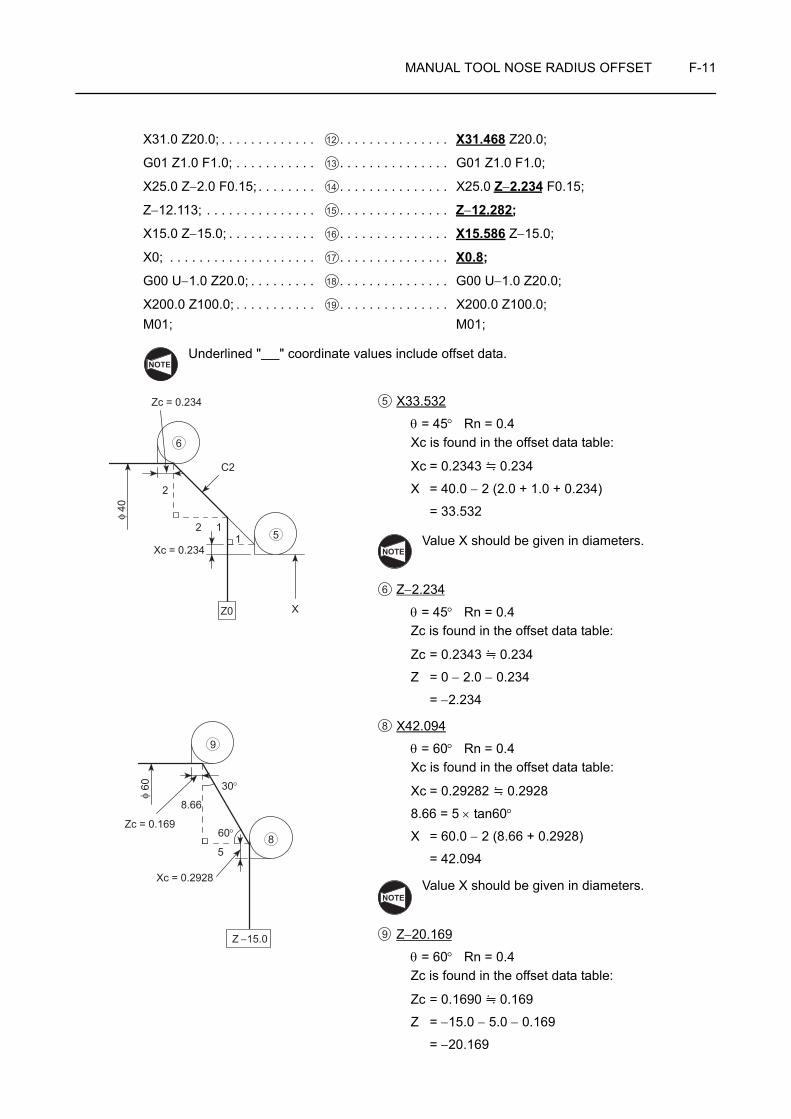
MANUAL TOOL NOSE RADIUS OFFSET F-11
X31.0 Z20.0; . . . . . . . . . . . . . . . . . . . . . . . . . . . . X31.468 Z20.0;
G01 Z1.0 F1.0; . . . . . . . . . . . . . . . . . . . . . . . . . . G01 Z1.0 F1.0;
X25.0 Z−2.0 F0.15; . . . . . . . . . . . . . . . . . . . . . . . X25.0 Z−2.234 F0.15;
Z−12.113; . . . . . . . . . . . . . . . . . . . . . . . . . . . . . . Z−12.282;
X15.0 Z−15.0; . . . . . . . . . . . . . . . . . . . . . . . . . . . X15.586 Z−15.0;
X0; . . . . . . . . . . . . . . . . . . . . . . . . . . . . . . . . . . . X0.8;
G00 U−1.0 Z20.0; . . . . . . . . . . . . . . . . . . . . . . . . G00 U−1.0 Z20.0;
X200.0 Z100.0; . . . . . . . . . . . . . . . . . . . . . . . . . . X200.0 Z100.0;M01; M01;
Underlined " " coordinate values include offset data.
X33.532
θ = 45° Rn = 0.4Xc is found in the offset data table:
Xc = 0.2343 0.234
X = 40.0 − 2 (2.0 + 1.0 + 0.234)
= 33.532
Value X should be given in diameters.
Z−2.234
θ = 45° Rn = 0.4Zc is found in the offset data table:
Zc = 0.2343 0.234
Z = 0 − 2.0 − 0.234
= −2.234
X42.094
θ = 60° Rn = 0.4Xc is found in the offset data table:
Xc = 0.29282 0.2928
8.66 = 5 × tan60°
X = 60.0 − 2 (8.66 + 0.2928)
= 42.094
Value X should be given in diameters.
Z−20.169
θ = 60° Rn = 0.4Zc is found in the offset data table:
Zc = 0.1690 0.169
Z = −15.0 − 5.0 − 0.169
= −20.169
12
13
14
15
16
17
18
19
NOTE
2
2 11
XZ0
Xc = 0.234
C2
Zc = 0.234
40φ
5
6
5
NOTE
6
Z −15.0
8.66
5
30°
60°
Xc = 0.2928
Zc = 0.169
60φ
8
9
8
NOTE
9
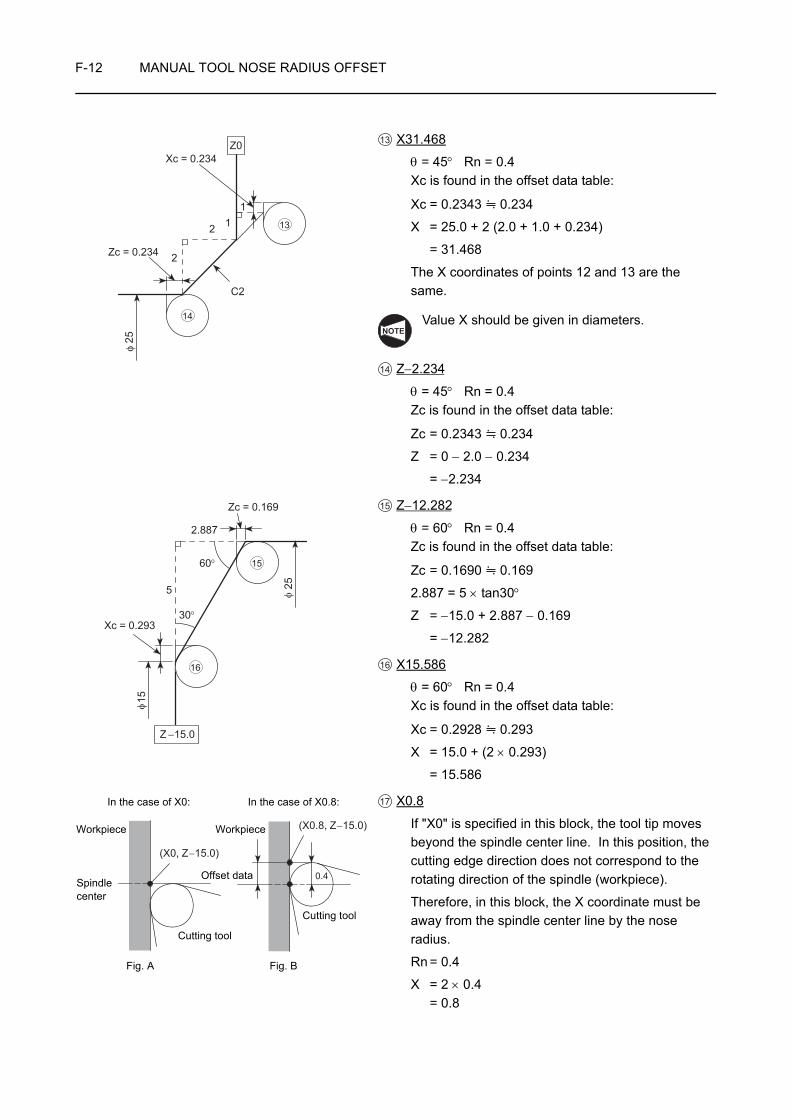
F-12 MANUAL TOOL NOSE RADIUS OFFSET
X31.468
θ = 45° Rn = 0.4Xc is found in the offset data table:
Xc = 0.2343 0.234
X = 25.0 + 2 (2.0 + 1.0 + 0.234)
= 31.468
The X coordinates of points 12 and 13 are the same.
Value X should be given in diameters.
Z−2.234
θ = 45° Rn = 0.4Zc is found in the offset data table:
Zc = 0.2343 0.234
Z = 0 − 2.0 − 0.234
= −2.234
Z−12.282
θ = 60° Rn = 0.4Zc is found in the offset data table:
Zc = 0.1690 0.169
2.887 = 5 × tan30°
Z = −15.0 + 2.887 − 0.169
= −12.282
X15.586
θ = 60° Rn = 0.4Xc is found in the offset data table:
Xc = 0.2928 0.293
X = 15.0 + (2 × 0.293)
= 15.586
X0.8
If "X0" is specified in this block, the tool tip moves beyond the spindle center line. In this position, the cutting edge direction does not correspond to the rotating direction of the spindle (workpiece).
Therefore, in this block, the X coordinate must be away from the spindle center line by the nose radius.
Rn = 0.4
X = 2 × 0.4= 0.8
2
2 11
Z0Xc = 0.234
C2
Zc = 0.234
25φ
13
14
13
NOTE
14
Z −15.0
Xc = 0.293
Zc = 0.169
2.887
60°
30°
5
15
25
φ
φ
15
16
15
16
(X0, Z−15.0)
(X0.8, Z−15.0)
0.4
In the case of X0:
Fig. A
Spindlecenter
Workpiece
In the case of X0.8:
Fig. B
Workpiece
Offset data
Cutting tool
Cutting tool
17

MANUAL TOOL NOSE RADIUS OFFSET F-13
2-5 Offset Data Table
Find the required offset data.Use the left column Nose R (X, Z) if the taper angle is 1° to 45°.Use the right column Nose R (Z, X) if the taper angle is 45° to 89°.
θ Nose R 0.4 0.5 0.8 1.0 1.2 Nose R θ
1°X .006921 .008651 .013842 .017303 .020763 Z
89°Z .396509 .495636 .793019 .991273 1.189528 X
1°30'X .010337 .012922 .020675 .025843 .031012 Z
88°30'Z .394764 .493455 .789527 .986909 1.184291 X
2°X .013724 .017156 .027449 .034311 .041173 Z
88°Z .393018 .491272 .786036 .982545 1.179054 X
2°30'X .017083 .021354 .034167 .042708 .051250 Z
87°30'Z .391272 .489090 .782544 .978180 1.173816 X
3°X .020414 .025518 .040828 .051035 .061243 Z
87°Z .389526 .486907 .779051 .973814 1.168577 X
3°30'X .023718 .029647 .047435 .059294 .071153 Z
86°30'Z .387779 .484724 .775558 .969447 1.163337 X
4°X .026994 .033742 .053988 .067485 .080982 Z
86°Z .386032 .482540 .772063 .965079 1.158095 X
4°30'X .030244 .037805 .060488 .075610 .090731 Z
85°30'Z .384284 .480355 .768568 .960710 1.152852 X
5°X .033468 .041834 .066935 .083669 .100403 Z
85°Z .382536 .478170 .765071 .956339 1.147607 X
5°30'X .036666 .045832 .073331 .091664 .109997 Z
84°30'Z .380787 .475983 .761573 .951967 1.142360 X
6°X .039838 .049798 .079677 .099596 .119515 Z
84°Z .379037 .473796 .758074 .947592 1.137111 X
6°30'X .042986 .053733 .085973 .107466 .128959 Z
83°30'Z .377286 .471608 .754573 .943216 1.131859 X
7°X .046110 .057637 .092220 .115275 .138330 Z
83°Z .375535 .469419 .751070 .938837 1.126605 X
7°30'X .049209 .061512 .098419 .123024 .147628 Z
82°30'Z .373783 .467228 .747565 .934457 1.121348 X
8°X .052285 .065357 .104571 .130713 .156856 Z
82°Z .372029 .465037 .744059 .930073 1.116088 X
8°30'X .055338 .069172 .110676 .138345 .166014 Z
81°30'Z .370275 .472844 .740550 .925687 1.110825 X
9°X .058368 .072960 .116735 .145919 .175103 Z
81°Z .368519 .460649 .737039 .921298 1.105558 X
9°30'X .061375 .076719 .122750 .153438 .184125 Z
80°30'Z .366763 .458453 .733525 .916906 1.100288 X
10°X .064360 .080450 .128720 .160900 .193080 Z
80°Z .365005 .456256 .730009 .912511 1.095014 X
10°30'X .067324 .084154 .134647 .168309 .201971 Z
79°30'Z .363245 .454056 .726490 .908113 1.089735 X
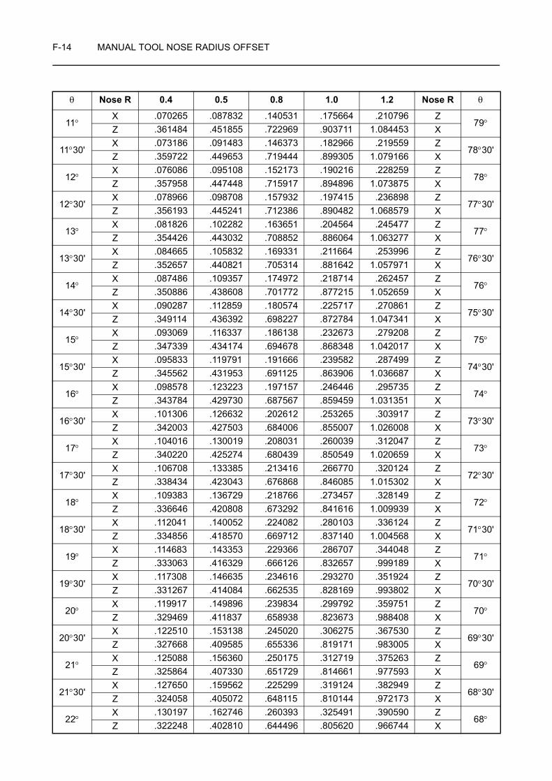
F-14 MANUAL TOOL NOSE RADIUS OFFSET
11°X .070265 .087832 .140531 .175664 .210796 Z
79°Z .361484 .451855 .722969 .903711 1.084453 X
11°30'X .073186 .091483 .146373 .182966 .219559 Z
78°30'Z .359722 .449653 .719444 .899305 1.079166 X
12°X .076086 .095108 .152173 .190216 .228259 Z
78°Z .357958 .447448 .715917 .894896 1.073875 X
12°30'X .078966 .098708 .157932 .197415 .236898 Z
77°30'Z .356193 .445241 .712386 .890482 1.068579 X
13°X .081826 .102282 .163651 .204564 .245477 Z
77°Z .354426 .443032 .708852 .886064 1.063277 X
13°30'X .084665 .105832 .169331 .211664 .253996 Z
76°30'Z .352657 .440821 .705314 .881642 1.057971 X
14°X .087486 .109357 .174972 .218714 .262457 Z
76°Z .350886 .438608 .701772 .877215 1.052659 X
14°30'X .090287 .112859 .180574 .225717 .270861 Z
75°30'Z .349114 .436392 .698227 .872784 1.047341 X
15°X .093069 .116337 .186138 .232673 .279208 Z
75°Z .347339 .434174 .694678 .868348 1.042017 X
15°30'X .095833 .119791 .191666 .239582 .287499 Z
74°30'Z .345562 .431953 .691125 .863906 1.036687 X
16°X .098578 .123223 .197157 .246446 .295735 Z
74°Z .343784 .429730 .687567 .859459 1.031351 X
16°30'X .101306 .126632 .202612 .253265 .303917 Z
73°30'Z .342003 .427503 .684006 .855007 1.026008 X
17°X .104016 .130019 .208031 .260039 .312047 Z
73°Z .340220 .425274 .680439 .850549 1.020659 X
17°30'X .106708 .133385 .213416 .266770 .320124 Z
72°30'Z .338434 .423043 .676868 .846085 1.015302 X
18°X .109383 .136729 .218766 .273457 .328149 Z
72°Z .336646 .420808 .673292 .841616 1.009939 X
18°30'X .112041 .140052 .224082 .280103 .336124 Z
71°30'Z .334856 .418570 .669712 .837140 1.004568 X
19°X .114683 .143353 .229366 .286707 .344048 Z
71°Z .333063 .416329 .666126 .832657 .999189 X
19°30'X .117308 .146635 .234616 .293270 .351924 Z
70°30'Z .331267 .414084 .662535 .828169 .993802 X
20°X .119917 .149896 .239834 .299792 .359751 Z
70°Z .329469 .411837 .658938 .823673 .988408 X
20°30'X .122510 .153138 .245020 .306275 .367530 Z
69°30'Z .327668 .409585 .655336 .819171 .983005 X
21°X .125088 .156360 .250175 .312719 .375263 Z
69°Z .325864 .407330 .651729 .814661 .977593 X
21°30'X .127650 .159562 .225299 .319124 .382949 Z
68°30'Z .324058 .405072 .648115 .810144 .972173 X
22°X .130197 .162746 .260393 .325491 .390590 Z
68°Z .322248 .402810 .644496 .805620 .966744 X
θ Nose R 0.4 0.5 0.8 1.0 1.2 Nose R θ
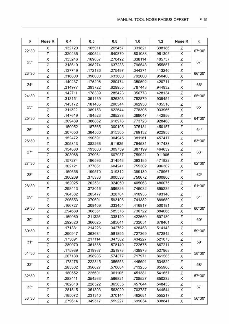
MANUAL TOOL NOSE RADIUS OFFSET F-15
22°30'X .132729 .165911 .265457 .331821 .398186 Z
67°30'Z .320435 .400544 .640870 .801088 .961305 X
23°X .135246 .169057 .270492 .338114 .405737 Z
67°Z .318619 .398274 .637238 .796548 .955857 X
23°30'X .137749 .172186 .275497 .344371 .413246 Z
66°30'Z .316800 .396000 .633600 .792000 .950400 X
24°X .140237 .175296 .280474 .350592 .420711 Z
66°Z .314977 .393722 .629955 .787443 .944932 X
24°30'X .142711 .178389 .285423 .356778 .428134 Z
65°30'Z .313151 .391439 .626303 .782879 .939454 X
25°X .145172 .181465 .290344 .362930 .435516 Z
65°Z .311322 .389153 .622644 .778305 .933966 X
25°30'X .147619 .184523 .295238 .369047 .442856 Z
64°30'Z .309489 .386862 .618978 .773723 .928468 X
26°X .150052 .187565 .300105 .375131 .450157 Z
64°Z .307653 .384566 .615305 .769132 .922958 X
26°30'X .152472 .190591 .304945 .381181 .457417 Z
63°30'Z .305813 .382266 .611625 .764531 .917438 X
27°X .154880 .193600 .309759 .387199 .464639 Z
63°Z .303968 .379961 .607937 .759921 .911905 X
27°30'X .157274 .196593 .314548 .393185 .471822 Z
62°30'Z .302121 .377651 .604241 .755302 .906362 X
28°X .159656 .199570 .319312 .399139 .478967 Z
62°Z .300269 .375336 .600538 .750672 .900806 X
28°30'X .162025 .202531 .324050 .405063 .486075 Z
61°30'Z .298413 .373016 .596826 .746032 .895239 X
29°X .164382 .205477 .328764 .410955 .493146 Z
61°Z .296553 .370691 .593106 .741382 .889659 X
29°30'X .166727 .208409 .333454 .416817 .500181 Z
60°30'Z .294689 .368361 .589378 .736722 .884066 X
30°X .169060 .211325 .338120 .422650 .507180 Z
60°Z .292820 .366025 .585641 .732051 .878461 X
30°30'X .171381 .214226 .342762 .428453 .514143 Z
59°30'Z .290947 .363684 .581895 .727369 .872842 X
31°X .173691 .217114 .347382 .434227 .521073 Z
59°Z .289070 .361338 .578140 .722675 .867211 X
31°30'X .175989 .219987 .351978 .439973 .527968 Z
58°30'Z .287188 .358985 .574377 .717971 .861565 X
32°X .178276 .222845 .356553 .445691 .534829 Z
58°Z .285302 .356627 .570604 .713255 .855906 X
32°30'X .180552 .225691 .361105 .451381 .541657 Z
57°30'Z .283411 .354263 .566821 .708527 .850232 X
33°X .182818 .228522 .365635 .457044 .548453 Z
57°Z .281515 .351893 .563029 .703787 .844544 X
33°30'X .185072 .231340 .370144 .462681 .555217 Z
56°30'Z .279614 .349517 .559227 .699034 .838841 X
θ Nose R 0.4 0.5 0.8 1.0 1.2 Nose R θ
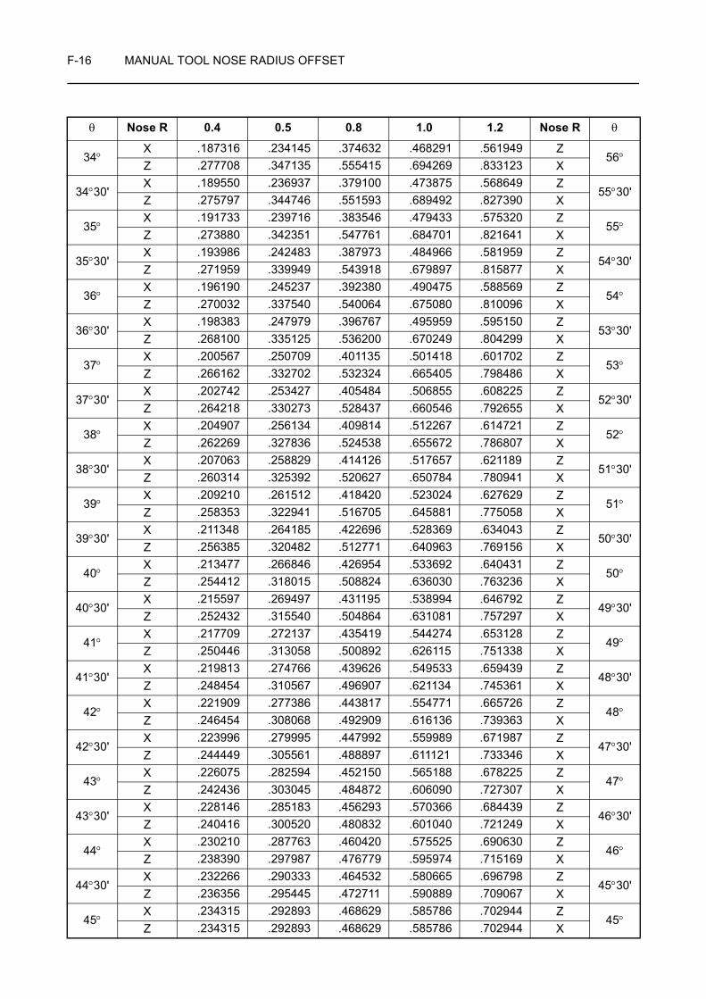
F-16 MANUAL TOOL NOSE RADIUS OFFSET
34°X .187316 .234145 .374632 .468291 .561949 Z
56°Z .277708 .347135 .555415 .694269 .833123 X
34°30'X .189550 .236937 .379100 .473875 .568649 Z
55°30'Z .275797 .344746 .551593 .689492 .827390 X
35°X .191733 .239716 .383546 .479433 .575320 Z
55°Z .273880 .342351 .547761 .684701 .821641 X
35°30'X .193986 .242483 .387973 .484966 .581959 Z
54°30'Z .271959 .339949 .543918 .679897 .815877 X
36°X .196190 .245237 .392380 .490475 .588569 Z
54°Z .270032 .337540 .540064 .675080 .810096 X
36°30'X .198383 .247979 .396767 .495959 .595150 Z
53°30'Z .268100 .335125 .536200 .670249 .804299 X
37°X .200567 .250709 .401135 .501418 .601702 Z
53°Z .266162 .332702 .532324 .665405 .798486 X
37°30'X .202742 .253427 .405484 .506855 .608225 Z
52°30'Z .264218 .330273 .528437 .660546 .792655 X
38°X .204907 .256134 .409814 .512267 .614721 Z
52°Z .262269 .327836 .524538 .655672 .786807 X
38°30'X .207063 .258829 .414126 .517657 .621189 Z
51°30'Z .260314 .325392 .520627 .650784 .780941 X
39°X .209210 .261512 .418420 .523024 .627629 Z
51°Z .258353 .322941 .516705 .645881 .775058 X
39°30'X .211348 .264185 .422696 .528369 .634043 Z
50°30'Z .256385 .320482 .512771 .640963 .769156 X
40°X .213477 .266846 .426954 .533692 .640431 Z
50°Z .254412 .318015 .508824 .636030 .763236 X
40°30'X .215597 .269497 .431195 .538994 .646792 Z
49°30'Z .252432 .315540 .504864 .631081 .757297 X
41°X .217709 .272137 .435419 .544274 .653128 Z
49°Z .250446 .313058 .500892 .626115 .751338 X
41°30'X .219813 .274766 .439626 .549533 .659439 Z
48°30'Z .248454 .310567 .496907 .621134 .745361 X
42°X .221909 .277386 .443817 .554771 .665726 Z
48°Z .246454 .308068 .492909 .616136 .739363 X
42°30'X .223996 .279995 .447992 .559989 .671987 Z
47°30'Z .244449 .305561 .488897 .611121 .733346 X
43°X .226075 .282594 .452150 .565188 .678225 Z
47°Z .242436 .303045 .484872 .606090 .727307 X
43°30'X .228146 .285183 .456293 .570366 .684439 Z
46°30'Z .240416 .300520 .480832 .601040 .721249 X
44°X .230210 .287763 .460420 .575525 .690630 Z
46°Z .238390 .297987 .476779 .595974 .715169 X
44°30'X .232266 .290333 .464532 .580665 .696798 Z
45°30'Z .236356 .295445 .472711 .590889 .709067 X
45°X .234315 .292893 .468629 .585786 .702944 Z
45°Z .234315 .292893 .468629 .585786 .702944 X
θ Nose R 0.4 0.5 0.8 1.0 1.2 Nose R θ

MANUAL TOOL NOSE RADIUS OFFSET F-17
3 OFFSET IN CIRCULAR INTERPOLATION
When cutting an arc, it is possible to cut the arc as specified on a drawing by offsetting the tool position.
3-1 Convex Arc
By specifying the arc, shown by the dotted lines, it is possible to cut an arc as specified on the drawing.
Programmed arc radius (R)
= Radius (r) of the arc specified on the drawing+ Tool nose radius (Rn)
3-2 Concave Arc
By specifying the arc, shown by the dotted lines, it is possible to cut an arc as specified on the drawing.
Programmed arc radius (R)
= Radius (r) of the arc specified on the drawing− Tool nose radius (Rn)
r: Arc radius (specified on drawing)
Rn: Tool nose radius
O: Arc center (specified on drawing)
O': Arc center (for programmed arc)
r
O
O'Rn
Rn
R = r + Rn
Rn
Workpiece
Arc specified on a drawing
Arc to be programmed
r
O
O'
Rn
Rn
R = r − Rn
RnArc specifiedon a drawing
Arc to be programmed

F-18 MANUAL TOOL NOSE RADIUS OFFSET
3-3 Calculating the Coordinate Values to be Specified in a Program
The coordinate values to be specified in a program to offset for the tool nose radius are explained below.
1. Calculating the required coordinate values directly
When calculating the required coordinate values, assume the shape shown by the dotted lines. The center of the arc specified on a drawing and the center of the arc to be programmed will differ from each other.
2. Calculating the required coordinate values after calculating the tool nose center
In this method, the coordinate values of the tool nose center is calculated first. After that, the programmed points are calculated by adding or subtracting the tool nose radius to, or from, the calculated center of the arc.
In the following examples, the tool nose center is calculated using method 2.
Programmed point
Arc center (on drawing)
Arc center (on program)
Arc center (on drawing)Calculated value
Tool nose center
Programmed point
NOTE
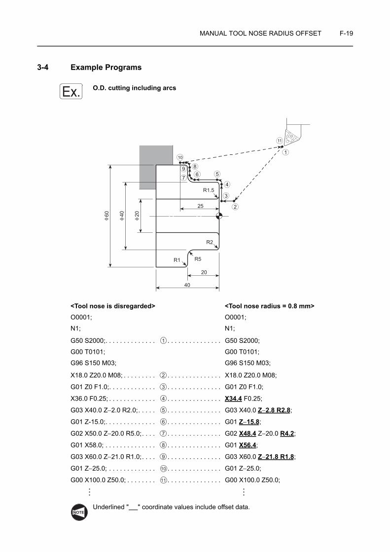
MANUAL TOOL NOSE RADIUS OFFSET F-19
3-4 Example Programs
O.D. cutting including arcs
<Tool nose is disregarded> <Tool nose radius = 0.8 mm>O0001; O0001;
N1; N1;
G50 S2000;. . . . . . . . . . . . . . . . . . . . . . . . . . . . . G50 S2000;
G00 T0101; G00 T0101;
G96 S150 M03; G96 S150 M03;
X18.0 Z20.0 M08; . . . . . . . . . . . . . . . . . . . . . . . . X18.0 Z20.0 M08;
G01 Z0 F1.0;. . . . . . . . . . . . . . . . . . . . . . . . . . . . G01 Z0 F1.0;
X36.0 F0.25; . . . . . . . . . . . . . . . . . . . . . . . . . . . . X34.4 F0.25;
G03 X40.0 Z−2.0 R2.0;. . . . . . . . . . . . . . . . . . . . G03 X40.0 Z−2.8 R2.8;
G01 Z-15.0;. . . . . . . . . . . . . . . . . . . . . . . . . . . . . G01 Z−15.8;
G02 X50.0 Z−20.0 R5.0;. . . . . . . . . . . . . . . . . . . G02 X48.4 Z−20.0 R4.2;
G01 X58.0; . . . . . . . . . . . . . . . . . . . . . . . . . . . . . G01 X56.4;
G03 X60.0 Z−21.0 R1.0;. . . . . . . . . . . . . . . . . . . G03 X60.0 Z−21.8 R1.8;
G01 Z−25.0; . . . . . . . . . . . . . . . . . . . . . . . . . . . . G01 Z−25.0;
G00 X100.0 Z50.0; . . . . . . . . . . . . . . . . . . . . . . . G00 X100.0 Z50.0;
Underlined " " coordinate values include offset data.
Ex.
40
20
R5R1
R1.5
R2
25
6
101
2
3
4
57
9 8
11204060
φφφ
1
2
3
4
5
6
7
8
9
10
11
NOTE
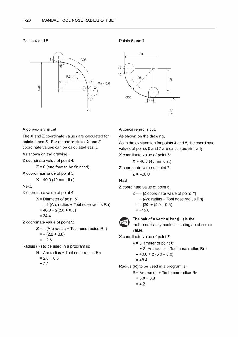
F-20 MANUAL TOOL NOSE RADIUS OFFSET
Points 4 and 5 Points 6 and 7
A convex arc is cut.
The X and Z coordinate values are calculated for points 4 and 5. For a quarter circle, X and Z coordinate values can be calculated easily.
As shown on the drawing,Z coordinate value of point 4:
Z = 0 (end face to be finished),X coordinate value of point 5:
X = 40.0 (40 mm dia.)Next,X coordinate value of point 4:
X = Diameter of point 5'− 2 (Arc radius + Tool nose radius Rn)
= 40.0 − 2(2.0 + 0.8)= 34.4
Z coordinate value of point 5:Z = − (Arc radius + Tool nose radius Rn)
= − (2.0 + 0.8) = − 2.8
Radius (R) to be used in a program is:R= Arc radius + Tool nose radius Rn
= 2.0 + 0.8= 2.8
A concave arc is cut.
As shown on the drawing,
As in the explanation for points 4 and 5, the coordinate values of points 6 and 7 are calculated similarly.X coordinate value of point 6:
X = 40.0 (40 mm dia.)Z coordinate value of point 7:
Z = −20.0Next,Z coordinate value of point 6:
Z = − |Z coordinate value of point 7'|− (Arc radius − Tool nose radius Rn)
= − |20| + (5.0 − 0.8) = −15.8
The pair of a vertical bar (| |) is the mathematical symbols indicating an absolute value.
X coordinate value of point 7:X = Diameter of point 6'
+ 2 (Arc radius − Tool nose radius Rn) = 40.0 + 2 (5.0 − 0.8) = 48.4
Radius (R) to be used in a program is:R= Arc radius + Tool nose radius Rn
= 5.0 − 0.8= 4.2
RR5
G02
20
'
'
40φ
6 6
7
7
R2R
Z0
G03
Rn = 0.8'
'
40φ
4
4
5
5
NOTE
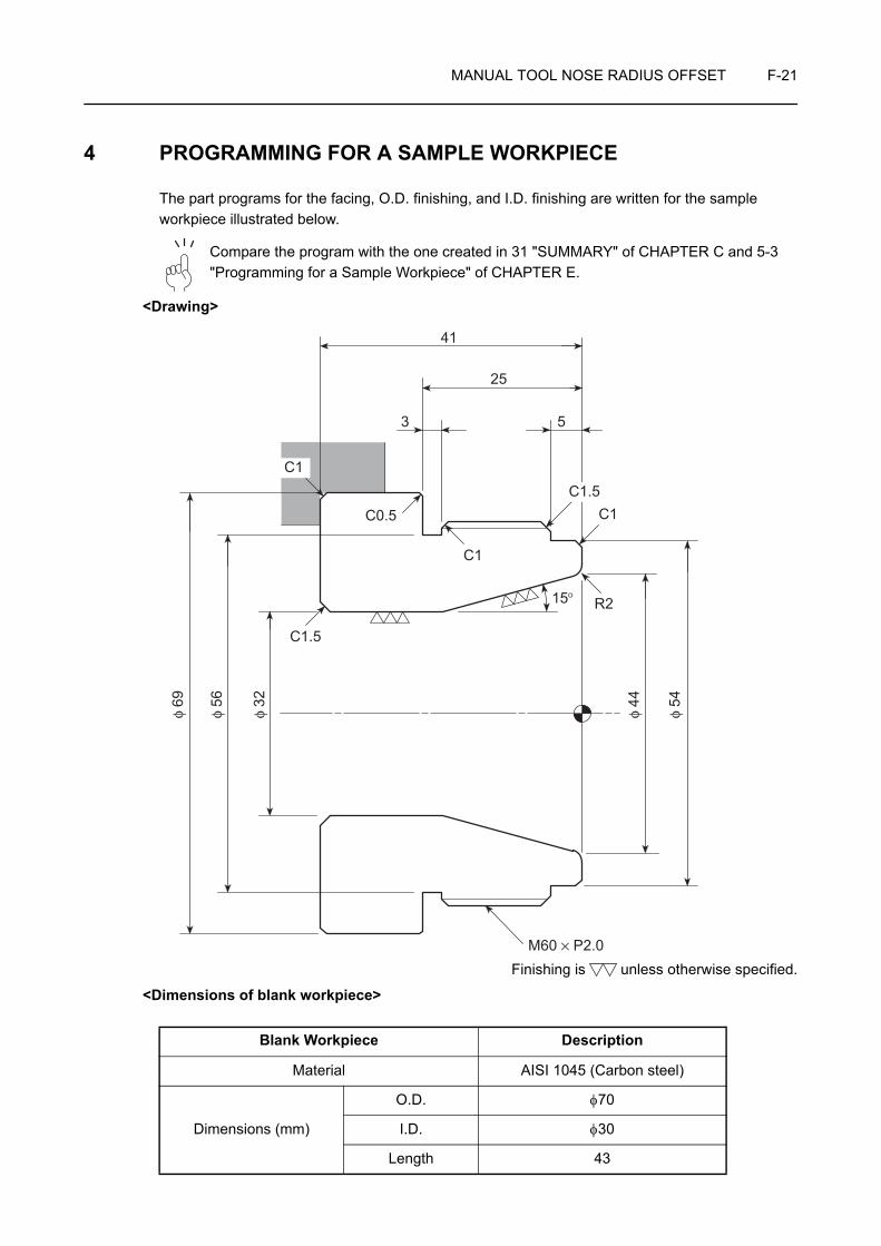
MANUAL TOOL NOSE RADIUS OFFSET F-21
4 PROGRAMMING FOR A SAMPLE WORKPIECE
The part programs for the facing, O.D. finishing, and I.D. finishing are written for the sample workpiece illustrated below.
Compare the program with the one created in 31 "SUMMARY" of CHAPTER C and 5-3 "Programming for a Sample Workpiece" of CHAPTER E.
<Drawing>
Finishing is unless otherwise specified.
<Dimensions of blank workpiece>
Blank Workpiece Description
Material AISI 1045 (Carbon steel)
Dimensions (mm)
O.D. φ70
I.D. φ30
Length 43
41
25
3 5
C1.5C1
15°� R2
C1
C0.5
C1
C1.5
M60 × P2.0
φ 44
φ 54
φ 32
φ 56
φ 69
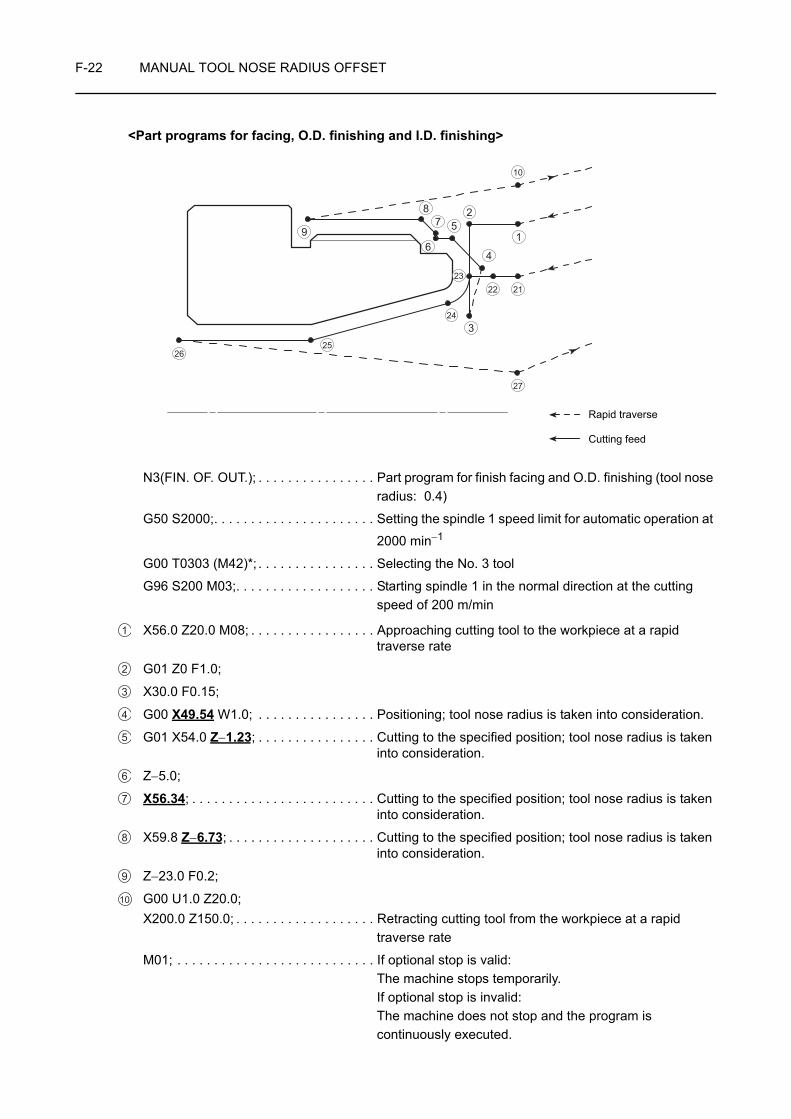
F-22 MANUAL TOOL NOSE RADIUS OFFSET
<Part programs for facing, O.D. finishing and I.D. finishing>
N3(FIN. OF. OUT.); . . . . . . . . . . . . . . . . Part program for finish facing and O.D. finishing (tool nose radius: 0.4)
G50 S2000;. . . . . . . . . . . . . . . . . . . . . . Setting the spindle 1 speed limit for automatic operation at
2000 min−1
G00 T0303 (M42)*; . . . . . . . . . . . . . . . . Selecting the No. 3 tool
G96 S200 M03;. . . . . . . . . . . . . . . . . . . Starting spindle 1 in the normal direction at the cutting speed of 200 m/min
X56.0 Z20.0 M08; . . . . . . . . . . . . . . . . . Approaching cutting tool to the workpiece at a rapid traverse rate
G01 Z0 F1.0;
X30.0 F0.15;
G00 X49.54 W1.0; . . . . . . . . . . . . . . . . Positioning; tool nose radius is taken into consideration.
G01 X54.0 Z−1.23; . . . . . . . . . . . . . . . . Cutting to the specified position; tool nose radius is taken into consideration.
Z−5.0;
X56.34; . . . . . . . . . . . . . . . . . . . . . . . . . Cutting to the specified position; tool nose radius is taken into consideration.
X59.8 Z−6.73; . . . . . . . . . . . . . . . . . . . . Cutting to the specified position; tool nose radius is taken into consideration.
Z−23.0 F0.2;
G00 U1.0 Z20.0;X200.0 Z150.0; . . . . . . . . . . . . . . . . . . . Retracting cutting tool from the workpiece at a rapid
traverse rate
M01; . . . . . . . . . . . . . . . . . . . . . . . . . . . If optional stop is valid:The machine stops temporarily.If optional stop is invalid:The machine does not stop and the program is continuously executed.
25
1
26
22 2123
10
2
4
324
6
578
9
27
Rapid traverse
Cutting feed
1
2
3
4
5
6
7
8
9
10

MANUAL TOOL NOSE RADIUS OFFSET F-23
N4(FIN. OF. IN.);. . . . . . . . . . . . . . . . . . Part program for I.D. finishing (tool nose radius: 0.4)
G50 S2000;. . . . . . . . . . . . . . . . . . . . . . Setting the spindle 1 speed limit for automatic operation at
2000 min−1
G00 T0404 (M42)*; . . . . . . . . . . . . . . . . Selecting the No. 4 tool
G96 S200 M03;. . . . . . . . . . . . . . . . . . . Starting spindle 1 in the normal direction at the cutting speed of 200 m/min
X47.869 Z20.0 M08; . . . . . . . . . . . . . . . Positioning of only X-axis; tool nose radius is taken into consideration.
G01 Z1.0 F1.0;
Z0 F0.2;
G02 X43.233 Z−1.779 R2.4 F0.07;. . . . Circular cutting in the clockwise direction in 2.4 mm radius; tool nose radius is taken into consideration.
G01 X32.0 Z−22.74; . . . . . . . . . . . . . . . Cutting to the specified position; tool nose radius is taken into consideration.
Z−41.0 F0.1;
G00 U−1.0 Z20.0; . . . . . . . . . . . . . . . . . Escape of cutting tool from the workpiece to execute I.D. cutting in the next process (cancel mode)
X200.0 Z150.0; . . . . . . . . . . . . . . . . . . . Retracting cutting tool from the workpiece at a rapid traverse rate
M01; . . . . . . . . . . . . . . . . . . . . . . . . . . . If optional stop is valid:The machine stops temporarily.If optional stop is invalid:The machine does not stop and the program is continuously executed.
1. Underlined " " coordinate values include offset data.
2. Commands in ( ) identified by "*" are used only for the machine equipped with a transmission.
<O.D. finishing>
The programmed points 4, 5, 6, 7, and 8 in the part program are explained below.
21
22
23
24
25
26
27
NOTE
Rn0.4
Rn0.4
Zc
C154
Xc
1.0
φ
A
B
Rn: Tool nose radiusRn: Tool nose radius

F-24 MANUAL TOOL NOSE RADIUS OFFSET
1) Point A is taken at a point 1 mm away from the Z position where facing is carried out.
Calculate the X coordinate value of point A.
Therefore, the coordinate values of point A are: X49.54, W1.0 (Z1.0)
2) Calculate the Z coordinate value of point B.
Therefore, the coordinate values of point B are: X54.0 Z−1.23
3) Point C is not influenced by the tool nose radius. Specify the coordinate values found on the part drawing.
Therefore, the Z coordinate value of point C is: Z−5.0
4) Calculate the X coordinate value of point D.
Therefore, the coordinate value of point D is: X56.34
5) Calculate the Z coordinate value of point E.
Therefore, the coordinate values of point E are: X59.8, Z−6.73
X = φD − 2 × (C + Xc + a) φD: Outside diameter= 54.0 − 2 × (1.0 + 0.23 + 1.0) C: Chamfer size= 49.54 Xc: Offset data in the X-axis direction
a: Distance away from workpiece
Z = −(C + Zc) C: Chamfer size= −(1.0 + 0.23) = −1.23 Zc: Offset data in the Z-axis direction
X = 54.0
X = φD − 2 × (C + Xc) φD: Outside diameter= 59.8 − 2 × (1.5 + 0.23) C: Chamfer size= 56.34 Xc: Offset data in the X-axis direction
Z = −(5.0 + C + Zc) C: Chamfer size= −(5.0 + 1.5 + 0.23) = −6.73 Zc: Offset data in the Z-axis direction
X = 59.8
Zc
1.559.8 Rn0.4
Rn0.4
Z-5.0
Xcφ
C
D
E
Rn: Tool nose radius

MANUAL TOOL NOSE RADIUS OFFSET F-25
<I.D. finishing>
The programmed points 23, 24 and 25 in the part program are explained below.
1) Calculate the X coordinate value of the center of arc R2.
a) Draw the line from the center O to point A.
Length H of side AB of a right angled triangle ABO should be calculated. For this calculation either ∠BOA or ∠BAO must first be calculated.
b) ABO and ACO are congruent.
Therefore,
∠AOB = 37.5°
∠OAB = 52.5°
c) Now, calculate length H.
tan37.5° =
H = 2 × tan37.5 ° = 1.5346
The X coordinate value of the center of arc R2 can be calculated from "H".
d) The X coordinate value of the center of arc R2 is calculated in the following manner:
X = 44.0 + 2 × H*
= 44.0 + 2 × 1.5346 = 47.069
Therefore, the coordinate values of the center of arc R2 are: X47.069, Z−2.0
* Value "H" must be doubled because X coordinate values are all expressed in diameter.
44
Rn0.4R2
XZ −2.0
15° φ
G
F
Center of arc
Rn: Tool nose radius
OR2
B
H
A
φ44
D
C
15°
O37.5°
75°
105°
52.5°
75°
52.5°
R2
Hφ
44
D
A
15°
C
B
2H
NOTE

F-26 MANUAL TOOL NOSE RADIUS OFFSET
e) Next, calculate the X coordinate value of point F.
X = 47.069 + 2 × Rn= 47.069 + 2 × 0.4 = 47.869 Rn: Tool nose radius
Z = 0
Therefore, the coordinate values of point F are: X47.869, Z0
2) Calculate the coordinate values of the center F of tool nose.
a) Draw the line from F, the center of the tool nose, perpendicular to side BO. Take the point of intersection as G.
b) In the right angled triangle FGO, calculate length I and length K of side FG and side GO, respectively.
Hypotenuse OF = Radius R (specified on the drawing) + Tool nose radius= 2.0 + 0.4 = 2.4
sin75° = I = 2.4 × sin75° = 2.318
cos75° = K = 2.4 × cos75° = 0.621
c) Calculate the coordinate values of the center F of the tool nose.
X = 47.069 − 2 × I= 47.069 − 2 × 2.318 = 42.433
Z = −(2.0 − K)= −(2.0 − 0.621) = −1.379
Therefore, the coordinate values of the center F of the tool nose are:X42.433, Z−1.379
d) Calculate the coordinate values of point G.
X = 42.433 + 2 × Rn= 42.433 + 2 × 0.4 = 43.233 Rn: Tool nose radius
Z = −(1.379 + Rn)= −(1.379 + 0.4) = −1.779
Therefore, the coordinate values of point G are: X43.233, Z−1.779
A
B
F
I
2.4
GO
75°
KX47.069Z -2.0
Coordinate values of the center
2.4I
2.4K
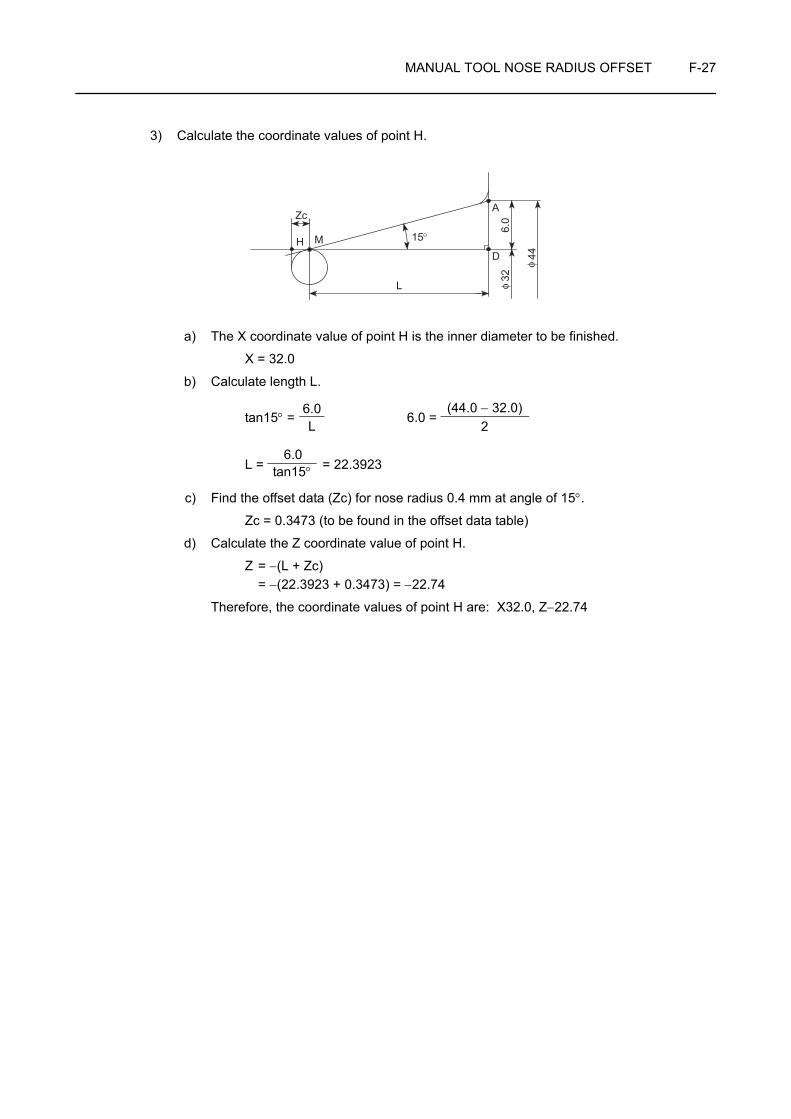
MANUAL TOOL NOSE RADIUS OFFSET F-27
3) Calculate the coordinate values of point H.
a) The X coordinate value of point H is the inner diameter to be finished.
X = 32.0
b) Calculate length L.
tan15° = 6.0 =
L = = 22.3923
c) Find the offset data (Zc) for nose radius 0.4 mm at angle of 15°.
Zc = 0.3473 (to be found in the offset data table)
d) Calculate the Z coordinate value of point H.
Z = −(L + Zc) = −(22.3923 + 0.3473) = −22.74
Therefore, the coordinate values of point H are: X32.0, Z−22.74
15°
L
6.0
44
32
A
DM
Zc
φ
φ
H
L6.0 (44.0 − 32.0)
2
tan15°6.0
CHAPTER GCUTTER RADIUS OFFSET
This chapter describes the cutter radius offset function.
The cutter radius offset means shifting of the tool paths to the right or left by the radius from the programmed paths.
This function is mainly used for pocket cutting or contouring with an end mill.
Since there are a number of tool patterns which will be used for actual machining and they will differ among users, it is not possible to explain all of the tool patterns in this manual. The explanation given in this chapter is concentrated on the basic programming so that the readers will be able to acquire basic knowledge of the cutter radius offset function.
Instruction manual supplied by the NC manufacturer
NOTE

CONTENTS
G : CUTTER RADIUS OFFSET
1 GENERAL . . . . . . . . . . . . . . . . . . . . . . . . . . . . . . . . . . . . . . . . . . . . . . . . . . . . . . . . . . . G-1
2 REQUIREMENT FOR USING THE CUTTER RADIUS OFFSET FUNCTION . . . . . . . G-3
3 TECHNICAL TERMS USED IN THE EXPLANATION OF THE CUTTER RADIUS OFFSET FUNCTION . . . . . . . . . . . . . . . . . . . . . . . . . . . . G-4
3-1 Start-up . . . . . . . . . . . . . . . . . . . . . . . . . . . . . . . . . . . . . . . . . . . . . . . . . . . . . . . . G-5
3-2 Offset Mode. . . . . . . . . . . . . . . . . . . . . . . . . . . . . . . . . . . . . . . . . . . . . . . . . . . . . G-6
3-3 Cancel Mode . . . . . . . . . . . . . . . . . . . . . . . . . . . . . . . . . . . . . . . . . . . . . . . . . . . . G-8
4 GENERAL CAUTIONS ON THE OFFSET FUNCTION . . . . . . . . . . . . . . . . . . . . . . . G-10
4-1 If a Wall Lies at the End of Cutting . . . . . . . . . . . . . . . . . . . . . . . . . . . . . . . . . . G-10
4-2 Positive (+) and Negative (−) Designation for Cutter Radius Offset Amount and Tool Paths . . . . . . . . . . . . . . . . . . . . . . . G-13
4-3 Overcut in the Cutter Radius Offset Mode . . . . . . . . . . . . . . . . . . . . . . . . . . . . G-14
5 EXAMPLE PROGRAMS . . . . . . . . . . . . . . . . . . . . . . . . . . . . . . . . . . . . . . . . . . . . . . . G-18
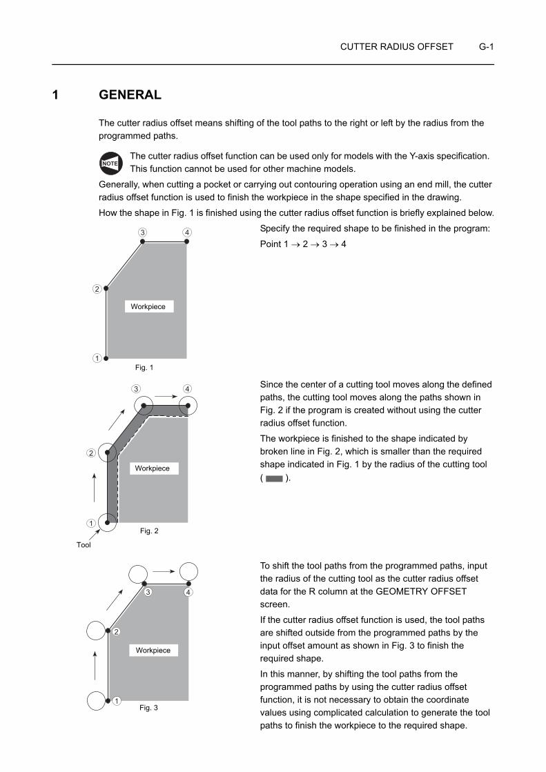
CUTTER RADIUS OFFSET G-1
1 GENERAL
The cutter radius offset means shifting of the tool paths to the right or left by the radius from the programmed paths.
The cutter radius offset function can be used only for models with the Y-axis specification. This function cannot be used for other machine models.
Generally, when cutting a pocket or carrying out contouring operation using an end mill, the cutter radius offset function is used to finish the workpiece in the shape specified in the drawing.
How the shape in Fig. 1 is finished using the cutter radius offset function is briefly explained below.
Specify the required shape to be finished in the program:
Point 1 → 2 → 3 → 4
Since the center of a cutting tool moves along the defined paths, the cutting tool moves along the paths shown in Fig. 2 if the program is created without using the cutter radius offset function.
The workpiece is finished to the shape indicated by broken line in Fig. 2, which is smaller than the required shape indicated in Fig. 1 by the radius of the cutting tool ( ).
To shift the tool paths from the programmed paths, input the radius of the cutting tool as the cutter radius offset data for the R column at the GEOMETRY OFFSET screen.
If the cutter radius offset function is used, the tool paths are shifted outside from the programmed paths by the input offset amount as shown in Fig. 3 to finish the required shape.
In this manner, by shifting the tool paths from the programmed paths by using the cutter radius offset function, it is not necessary to obtain the coordinate values using complicated calculation to generate the tool paths to finish the workpiece to the required shape.
NOTE
1
2
3 4
Fig. 1
Workpiece
1
2
3 4
Fig. 2
Tool
Workpiece
1
2
3 4
Fig. 3
Workpiece

G-2 CUTTER RADIUS OFFSET
1. Cutter radius offset in the XY plane
G17 G01(G00) G41(G42) X_ Y_ F_ ;G40 G01(G00) X_ Y_ I_ J_ F_ ;
2. Cutter radius offset in the YZ plane
G19 G01(G00) G41(G42) Y_ Z_ F_ ;G40 G01(G00) Y_ Z_ J_ K_ F_ ;
• G17, G19 . . . . Selects the plane where cutter radius offset is executed.
• G01(G00) . . . . Selects the interpolation mode in which the cutter radius offset function is executed.G00 . . . . . . Rapid traverseG01 . . . . . . Cutting feed
• G41 . . . . . . . . Calls the cutter radius offset mode (offset to the left).The tool paths are generated by shifting the programmed paths to the left in reference to the tool advancing direction by the specified offset amount.
• G42 . . . . . . . . Calls the cutter radius offset mode (offset to the right).The tool paths are generated by shifting the programmed paths to the right in reference to the tool advancing direction by the specified offset amount.
• G40 . . . . . . . . Cancels the cutter radius offset mode.
• X, Y, Z. . . . . . . Specifies the coordinate values of the end point.
• I, J, K . . . . . . . When making a setting that represents the direction of the workpiece shape in the following block, the direction ratio for this setting is specified as a vector, with "I" as the radius command.
• F . . . . . . . . . . . Specifies the feedrate.
The programmer must thoroughly understand the nature of the G41 and G42 functions as well as the tool paths to be generated. If the G41 and G42 commands are used improperly, the cutting tool might be fed into or hit against the workpiece to be machined to cause breakage of the cutting tool or defective machining.
COMMAND
Workpiece
Tool advancing direction
<G41>
Workpiece
Tool advancing direction
<G42>
CAUTION

CUTTER RADIUS OFFSET G-3
2 REQUIREMENT FOR USING THE CUTTER RADIUS OFFSET FUNCTION
To use the cutter radius offset function (G40, G41, or G42), how the cutter radius offset data is input must be understood correctly.
<Input of cutter radius offset amount>
To use the cutter radius offset function (G41, G42), it is necessary to set the tool radius for the R column at the GEOMETRY OFFSET screen.
Set the cutter radius corresponding to the offset number to be specified in T code.
RR
Cutter radius offset amount (Cutter radius value)
End mill and other tools
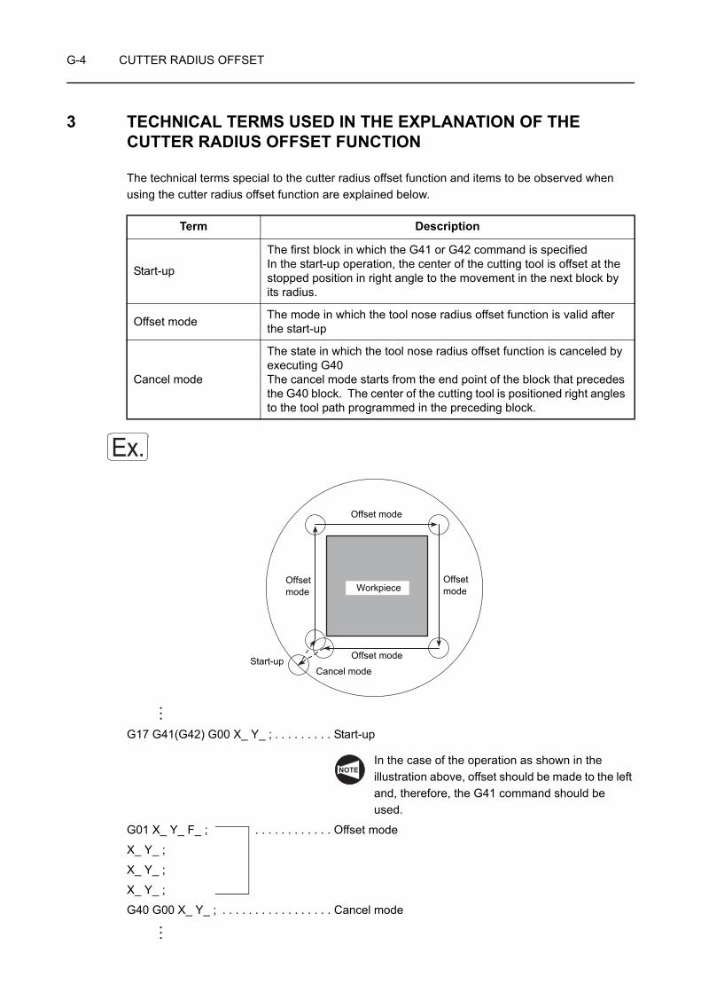
G-4 CUTTER RADIUS OFFSET
3 TECHNICAL TERMS USED IN THE EXPLANATION OF THE CUTTER RADIUS OFFSET FUNCTION
The technical terms special to the cutter radius offset function and items to be observed when using the cutter radius offset function are explained below.
G17 G41(G42) G00 X_ Y_ ; . . . . . . . . . Start-up
In the case of the operation as shown in the illustration above, offset should be made to the left and, therefore, the G41 command should be used.
G01 X_ Y_ F_ ; . . . . . . . . . . . . Offset mode
X_ Y_ ;
X_ Y_ ;
X_ Y_ ;
G40 G00 X_ Y_ ; . . . . . . . . . . . . . . . . . Cancel mode
Term Description
Start-up
The first block in which the G41 or G42 command is specifiedIn the start-up operation, the center of the cutting tool is offset at the stopped position in right angle to the movement in the next block by its radius.
Offset mode The mode in which the tool nose radius offset function is valid after the start-up
Cancel mode
The state in which the tool nose radius offset function is canceled by executing G40 The cancel mode starts from the end point of the block that precedes the G40 block. The center of the cutting tool is positioned right angles to the tool path programmed in the preceding block.
Ex.
Offset mode
Offset mode
Offset mode
Offset mode
Cancel modeStart-up
Workpiece
NOTE
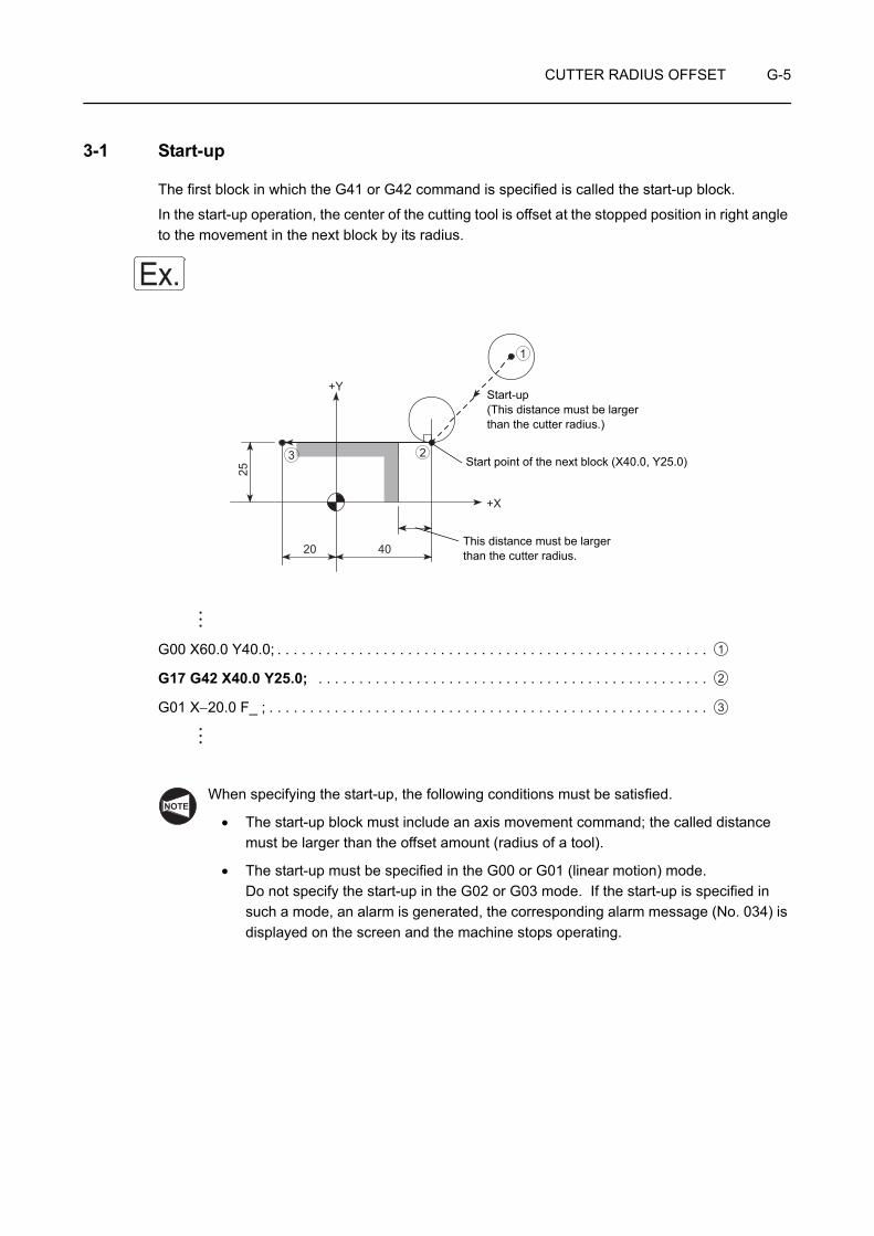
CUTTER RADIUS OFFSET G-5
3-1 Start-up
The first block in which the G41 or G42 command is specified is called the start-up block.
In the start-up operation, the center of the cutting tool is offset at the stopped position in right angle to the movement in the next block by its radius.
G00 X60.0 Y40.0; . . . . . . . . . . . . . . . . . . . . . . . . . . . . . . . . . . . . . . . . . . . . . . . . . . . . .
G17 G42 X40.0 Y25.0; . . . . . . . . . . . . . . . . . . . . . . . . . . . . . . . . . . . . . . . . . . . . . . . .
G01 X−20.0 F_ ; . . . . . . . . . . . . . . . . . . . . . . . . . . . . . . . . . . . . . . . . . . . . . . . . . . . . . .
When specifying the start-up, the following conditions must be satisfied.
• The start-up block must include an axis movement command; the called distance must be larger than the offset amount (radius of a tool).
• The start-up must be specified in the G00 or G01 (linear motion) mode. Do not specify the start-up in the G02 or G03 mode. If the start-up is specified in such a mode, an alarm is generated, the corresponding alarm message (No. 034) is displayed on the screen and the machine stops operating.
Ex.
20 40
25
+X
+Y
1
23
Start-up(This distance must be larger than the cutter radius.)
This distance must be largerthan the cutter radius.
Start point of the next block (X40.0, Y25.0)
1
2
3
NOTE
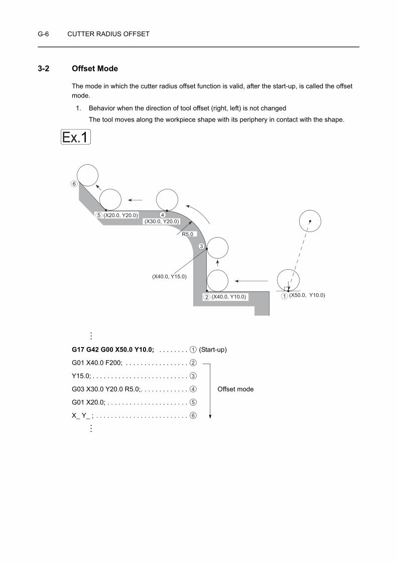
G-6 CUTTER RADIUS OFFSET
3-2 Offset Mode
The mode in which the cutter radius offset function is valid, after the start-up, is called the offset mode.
1. Behavior when the direction of tool offset (right, left) is not changed
The tool moves along the workpiece shape with its periphery in contact with the shape.
G17 G42 G00 X50.0 Y10.0; . . . . . . . . (Start-up)
G01 X40.0 F200; . . . . . . . . . . . . . . . . .
Y15.0; . . . . . . . . . . . . . . . . . . . . . . . . . .
G03 X30.0 Y20.0 R5.0;. . . . . . . . . . . . . Offset mode
G01 X20.0; . . . . . . . . . . . . . . . . . . . . . .
X_ Y_ ; . . . . . . . . . . . . . . . . . . . . . . . . .
Ex.1
(X50.0, Y10.0) (X40.0, Y10.0)
R5.0
(X40.0, Y15.0)
(X20.0, Y20.0)(X30.0, Y20.0)
12
3
45
6
1
2
3
4
5
6

CUTTER RADIUS OFFSET G-7
1. At the start-up and in the offset mode, two blocks of commands are buffered. In the offset mode, blocks not containing an axis movement command, a block only with an M command or G04 dwell block, for example, must not be specified continuously. A block containing 0 axis movement is not allowed, either. If such blocks are specified, it will cause excessive or insufficient cutting since two blocks of commands cannot be buffered. It will also cause overload to the tool and the tool might be damaged.
2. If an attempt is made to cut the inside of an arc whose radius is smaller than the radius of the tool or to cut a groove whose width is smaller than the radius of the tool, an alarm message is displayed to avoid excessive cutting. If this occurs while the program is executed in the single block mode, excessive cutting occurs to produce a defective workpiece since the program is executed to the end of the block causing the alarm before it stops.
3. Do not change the plane with G17 or G19 in the offset mode. If changed, an alarm occurs, and an alarm message (No. 037) is displayed on the screen and the machine stops operating.
2. Behavior when the direction of tool offset (right, left) is changed
If the direction of offset changes in a program, as illustrated below, i.e., if the G code calling the cutter offset function changes between G41 and G42, the periphery will come into contact with the workpiece shape that is defined in the two consecutive blocks where the G code changes from G41 to G42, or vice versa.
G17 G41 X35.0 Y30.0;
Y20.0; . . . . . . . . . . . . . . . . . . . . . . . . . . . . . . . . . . . . . . . . . . . . . . . . . . . . . . . . . . . . . .
G42 X_ Y_ ; . . . . . . . . . . . . . . . . . . . . . . . . . . . . . . . . . . . . . . . . . . . . . . . . . . . . . . . . .
Changing the G code mode between G41 and G42 cannot be specified in the next block of the start-up block.
NOTE
Ex.2
(X35.0, Y20.0)
12
1
2
CAUTION

G-8 CUTTER RADIUS OFFSET
3-3 Cancel Mode
The G40 command, specified in the offset mode, cancels the cutter radius offset function.
The cancel mode starts from the end point of the block that precedes the G40 block. The center of the cutting tool lies at right angles to the tool path programmed in the preceding block.
G17 (G41) X50.0 Y25.0;
X30.0; . . . . . . . . . . . . . . . . . . . . . . . . . . . . . . . . . . . . . . . . . . . . . . . . . . . .
G40 G00 X20.0 Y10.0; . . . . . . . . . . . . . . . . . . . . . . . . . . . . . . . . . . . . . . (Cancel mode)
Ex.
(X20.0, Y10.0)
(X50.0, Y25.0)(X30.0, Y25.0) 1
2
Cancel mode
1
2

CUTTER RADIUS OFFSET G-9
In the cancel mode, the following items must be carefully attended to:
1. The cutter radius offset function is canceled by pressing the (RESET) key on the
operation panel in addition to the execution of the G40 command.
2. The cancel block must be specified in the G00 or G01 (linear motion) mode. To specify the cancel block in the G02 or G03 circular interpolation mode is not allowed. If the cancel block is specified in the circular interpolation mode, an alarm message (No. 034) is displayed on the screen and the machine stops.
3. Designation of "G40;" or a cutter radius offset cancel command associated with position command of the present position, meaning no axis movements, when exiting the cutter radius offset mode, the tool stays at the start point of cancel mode and axis movements for cancellation do not take place. In such cases, cancel movements take place when the command that calls for actual axis movements (movements in the same plane as used for the cutter radius offset) is specified next.
If the program ends without axis movement commands after the designation of the cancel command such as "G40;" that does not cause actual movements, the cutter radius offset mode remains active. To cancel the cutter radius offset mode, in such a
case, it is necessary to press the (RESET) key. However, pressing the
(RESET) key to cancel the cutter radius offset mode does not call for cancel movements.
For the axis movement commands to be specified for canceling the cutter radius offset mode, it is necessary to specify the position other than the present position in the G00 or G01 mode so that axes actually move in the execution of the cancel command.
NOTE
RESET
RESET RESET
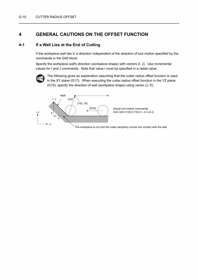
G-10 CUTTER RADIUS OFFSET
4 GENERAL CAUTIONS ON THE OFFSET FUNCTION
4-1 If a Wall Lies at the End of Cutting
If the workpiece wall lies in a direction independent of the direction of tool motion specified by the commands in the G40 block:
Specify the workpiece wall's direction (workpiece shape) with vectors (I, J). Use incremental values for I and J commands. Note that value I must be specified in a radial value.
The following gives an explanation assuming that the cutter radius offset function is used in the XY plane (G17). When executing the cutter radius offset function in the YZ plane (G19), specify the direction of wall (workpiece shape) using vector (J, K).
NOTE
I, J
5
4
G40
(100, 30)
(G42)
G40 G00 X100.0 Y30.0 I−4.0 J5.0;+J
+I
Wall
Actual tool motion commands
The workpiece is cut until the cutter periphery comes into contact with the wall.

CUTTER RADIUS OFFSET G-11
1. The workpiece is cut until the cutter periphery comes into contact with the wall. The I and J commands, used to define the vectors that represent the workpiece wall direction, should be specified in the G40 block that appears first after entry into the offset mode.
2. If "I_ J_" is not specified in the G40 block, the offset mode cancel point is set at the end point of the preceding block; at this end point, the center of the tool lies at right angles to the tool path generated by the commands in the preceding block. This causes an overcut on the wall.
G40 G00 X_ Y_ ;
• Valid • InvalidG42 X_ Y_ ;X_ Y_ ;
Offset mode
G40 G00 X_ Y_ I_ J_ ;
G42 X_ Y_ ;
Offset mode
G40 X_ Y_ ;
Cancel mode
G40 G00 X_ Y_ I_ J_ ;
Ignored
NOTE
G40
(G42)
Overcuts occur.

G-12 CUTTER RADIUS OFFSET
Calculating the wall direction (blank workpiece shape)
1. Value "J" is indicated below, based on the illustration on the left.
J = 15
Because it is measured in the positive direction of Y, the designation should be "J15.0".
Next, value "I" is calculated as:
I = AC = 15 × tan30° = 8.660
Because it is measured in the negative direction on the X-axis, the designation should be "I−8.66".
2. Since I and J commands are used to define the direction of the wall, the ratio between the sides of a triangle may be used instead of calculating actual lengths.
The ratio of three sides of the triangle given on the left is known as:
A:B:C = 2:1: (= 1.732)
Therefore, the designation should be "I−1.0 J1.732".
I and J commands may be specified in either method as described above.
G01 X−40.0;
G40 G00 X−20.0 Y40.0 I−8.66 J15.0;
(I−1.0 J1.732)Interchangeable
Ex.
(G40)
(G42)60°
40
30 15
+Y
+X
30°
60°C
J = 15
I 40
B
A
30 15
30°
60°°
J = C
I = B
A
3

CUTTER RADIUS OFFSET G-13
4-2 Positive (+) and Negative (−) Designation for Cutter Radius Offset Amount and Tool Paths
Generally, a program is created assuming that the cutter radius offset amount is set in a positive value.
If an offset amount is set in a negative value, tool paths are generated as if G41 and G42 are entirely exchanged with each other. The paths having been generated outside the programmed profile will be generated inside the profile and those having been generated inside the programmed profile will be generated outside the profile.
If a negative value is set for the offset amount while the tool paths as shown in Fig. 1 are specified in a program, the cutting tool moves along the paths shown in Fig. 2.
Conversely, if a negative value is set for the offset amount when the tool paths shown in Fig. 2 are specified in a program, the cutting tool moves along the paths shown in Fig. 1.
Fig. 1 Fig. 2
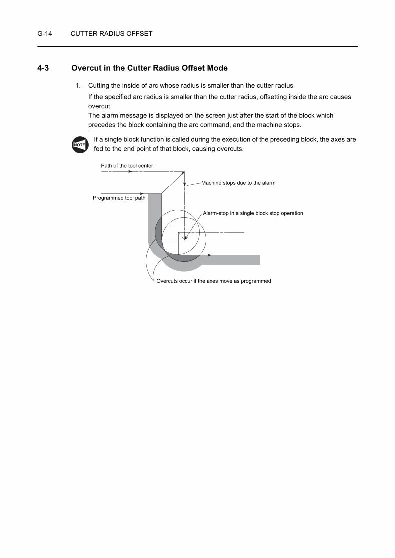
G-14 CUTTER RADIUS OFFSET
4-3 Overcut in the Cutter Radius Offset Mode
1. Cutting the inside of arc whose radius is smaller than the cutter radius
If the specified arc radius is smaller than the cutter radius, offsetting inside the arc causes overcut. The alarm message is displayed on the screen just after the start of the block which precedes the block containing the arc command, and the machine stops.
If a single block function is called during the execution of the preceding block, the axes are fed to the end point of that block, causing overcuts.
NOTE
Alarm-stop in a single block stop operation
Path of the tool center
Programmed tool path
Machine stops due to the alarm
Overcuts occur if the axes move as programmed
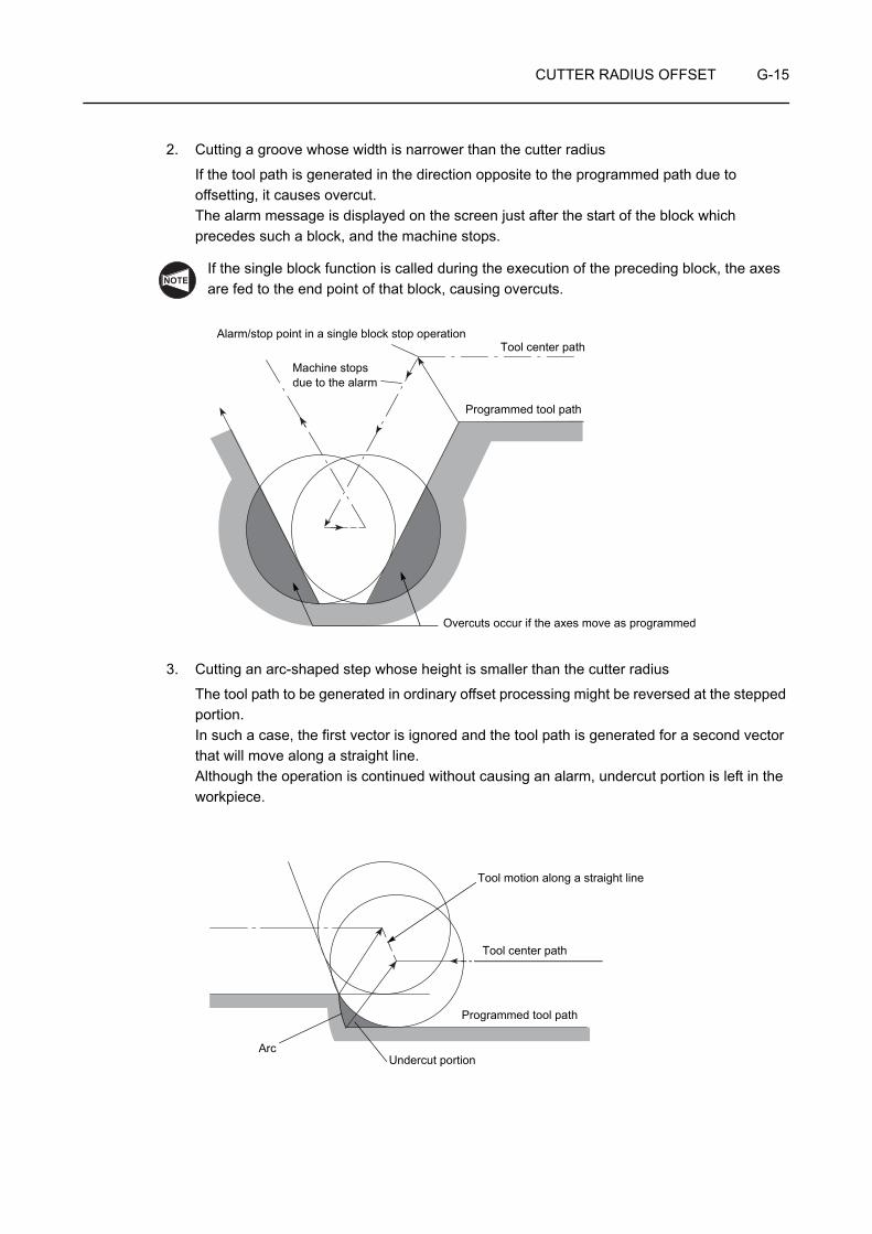
CUTTER RADIUS OFFSET G-15
2. Cutting a groove whose width is narrower than the cutter radius
If the tool path is generated in the direction opposite to the programmed path due to offsetting, it causes overcut. The alarm message is displayed on the screen just after the start of the block which precedes such a block, and the machine stops.
If the single block function is called during the execution of the preceding block, the axes are fed to the end point of that block, causing overcuts.
3. Cutting an arc-shaped step whose height is smaller than the cutter radius
The tool path to be generated in ordinary offset processing might be reversed at the stepped portion.In such a case, the first vector is ignored and the tool path is generated for a second vector that will move along a straight line.Although the operation is continued without causing an alarm, undercut portion is left in the workpiece.
NOTE
Alarm/stop point in a single block stop operationTool center path
Programmed tool path
Machine stops due to the alarm
Overcuts occur if the axes move as programmed
Programmed tool path
Tool center path
Tool motion along a straight line
ArcUndercut portion

G-16 CUTTER RADIUS OFFSET
4. No X- and Y-axis movement is specified in more than two blocks
When the XY plane is selected, for example, the cutter radius offset function is valid only for the X- and Y-axes.
The cutter radius offset function is valid only for the Y- and Z-axes in the YZ plane.
If there are two or more blocks, which contains neither X- nor Y-axis movement commands, given in succession, overcut may occur since buffering is not possible.
(G42 mode)
X30.0 Y15.0;. . . . . . . . . . . . . . . . . . . . . . . . . . . [1]
Y25.0; . . . . . . . . . . . . . . . . . . . . . . . . . . . . . . . . [2]
X10.0; . . . . . . . . . . . . . . . . . . . . . . . . . . . . . . . . [3]
Tool paths are offset correctly due to the 2-block buffering function.
(G42 mode)
X30.0 Y15.0;. . . . . . . . . . . . . . . . . . . . . . . . . . . [1]
Y25.0; . . . . . . . . . . . . . . . . . . . . . . . . . . . . . . . . [2]
M_ ;Z−_ ;X10.0; . . . . . . . . . . . . . . . . . . . . . . . . . . . . . . . . [3]
Overcuts occur as illustrated above. This is because the center of the tool is positioned, when the preceding block [2] is executed, at the right angle to the tool path called by the commands in this block.
NOTE
(X10.0, Y25.0) (X30.0, Y25.0)
(X30.0, Y15.0)1
23
(X10.0, Y25.0) (X30.0, Y25.0)
(X30.0, Y15.0)1
23
Overcut
No X- or Y-axis movement commands in two or more blocks

CUTTER RADIUS OFFSET G-17
Pay attention when a sub-program is called from a main program.
Main program
G17 G41 G01 X_ Y_ ;M98 P1; . . . . . . . . . . . . . . . . . . . . . . . . . . . . . . . . . . . . . . . . . . . . . . . . . . . . . . . . . . . . [1]
Sub-program (O0001)
O0001; . . . . . . . . . . . . . . . . . . . . . . . . . . . . . . . . . . . . . . . . . . . . . . . . . . . . . . . . . . . . . [2]
X_ Y_ ;
X_ Y_ ;
M99;
By the call of a sub-program from a main program, two blocks [1] and [2] are executed in succession; these blocks do not contain X- or Y-axis movement commands.
Therefore, the program should be created in the following manner.
Main program
X_ Y_ ;
M98 P1;
Sub-program (O0001)
O0001;
G17 G41 G01 X_ Y_ ;X_ Y_ ;
G40 X_ Y_ ;M99;
NOTE
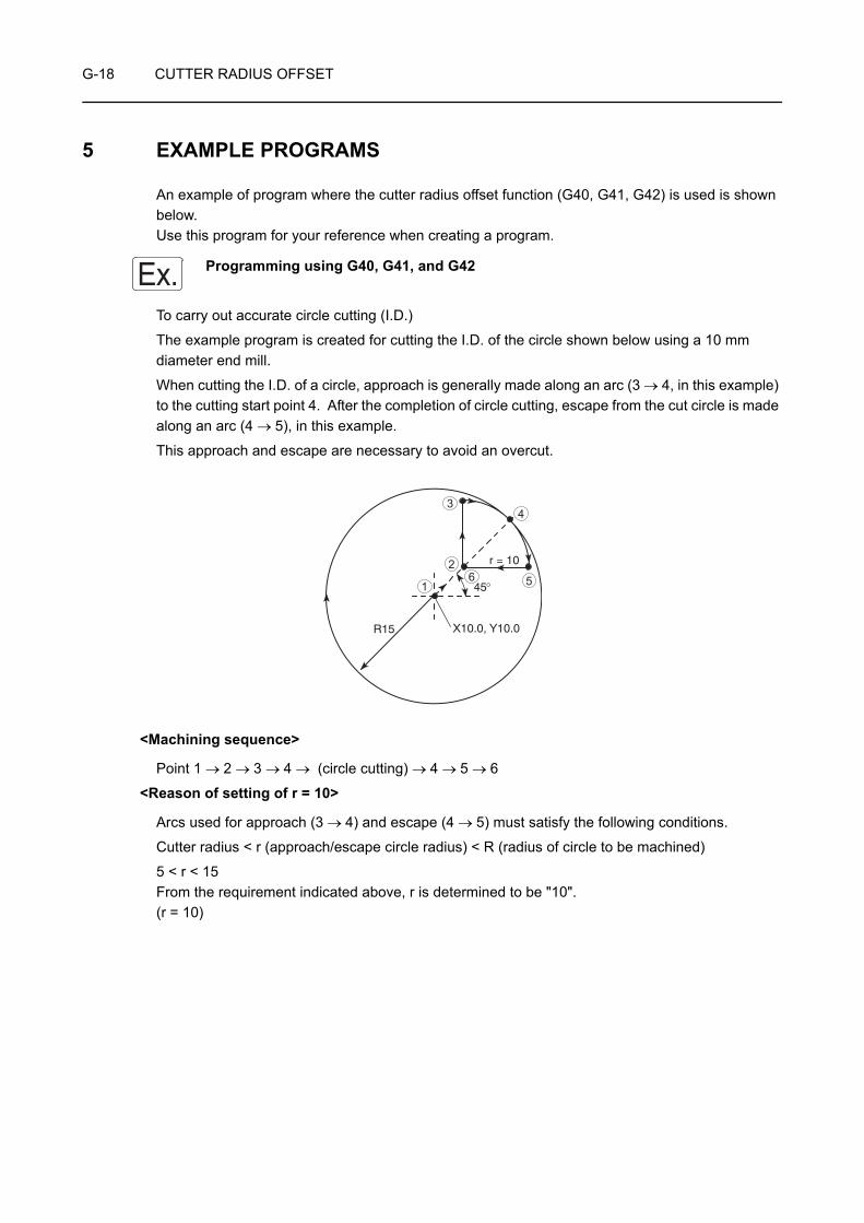
G-18 CUTTER RADIUS OFFSET
5 EXAMPLE PROGRAMS
An example of program where the cutter radius offset function (G40, G41, G42) is used is shown below. Use this program for your reference when creating a program.
Programming using G40, G41, and G42
To carry out accurate circle cutting (I.D.)
The example program is created for cutting the I.D. of the circle shown below using a 10 mm diameter end mill.
When cutting the I.D. of a circle, approach is generally made along an arc (3 → 4, in this example) to the cutting start point 4. After the completion of circle cutting, escape from the cut circle is made along an arc (4 → 5), in this example.
This approach and escape are necessary to avoid an overcut.
<Machining sequence>
Point 1 → 2 → 3 → 4 → (circle cutting) → 4 → 5 → 6
<Reason of setting of r = 10>
Arcs used for approach (3 → 4) and escape (4 → 5) must satisfy the following conditions.
Cutter radius < r (approach/escape circle radius) < R (radius of circle to be machined)
5 < r < 15From the requirement indicated above, r is determined to be "10".(r = 10)
Ex.
R15
45°
X10.0, Y10.0
r = 10
1
2
34
56
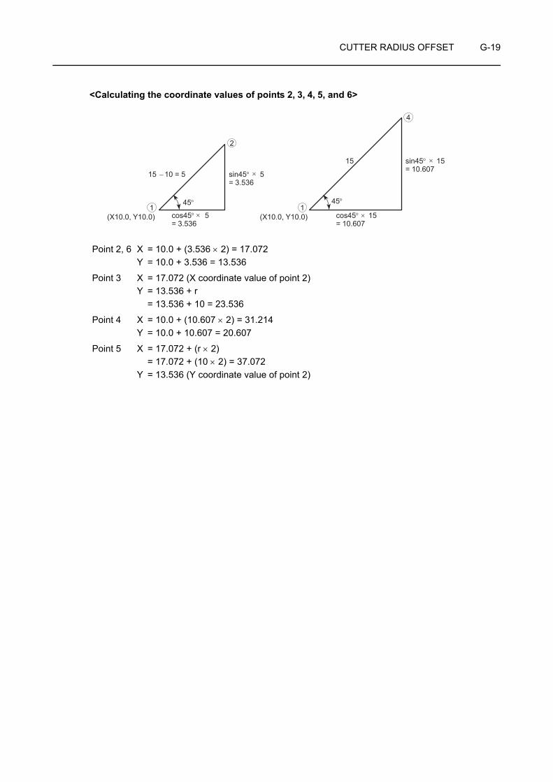
CUTTER RADIUS OFFSET G-19
<Calculating the coordinate values of points 2, 3, 4, 5, and 6>
Point 2, 6 X = 10.0 + (3.536 × 2) = 17.072Y = 10.0 + 3.536 = 13.536
Point 3 X = 17.072 (X coordinate value of point 2)Y = 13.536 + r = 13.536 + 10 = 23.536
Point 4 X = 10.0 + (10.607 × 2) = 31.214Y = 10.0 + 10.607 = 20.607
Point 5 X = 17.072 + (r × 2) = 17.072 + (10 × 2) = 37.072Y = 13.536 (Y coordinate value of point 2)
15
15 − 10 = 5 sin45° 5= 3.536
sin45° 15= 10.607
(X10.0, Y10.0) cos45° 5= 3.536
(X10.0, Y10.0) cos45° 15= 10.607
45°1 1
2
4
45°
×
×
×
×
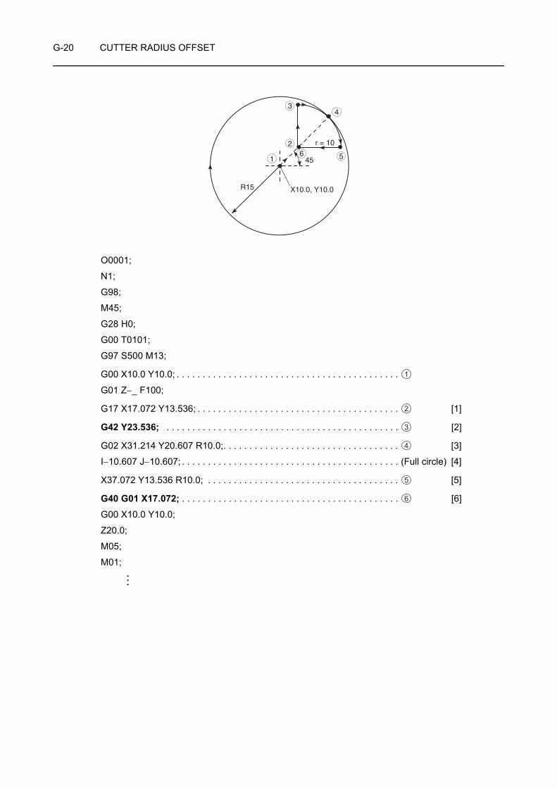
G-20 CUTTER RADIUS OFFSET
O0001;
N1;
G98;
M45;
G28 H0;
G00 T0101;
G97 S500 M13;
G00 X10.0 Y10.0; . . . . . . . . . . . . . . . . . . . . . . . . . . . . . . . . . . . . . . . . . . .
G01 Z−_ F100;
G17 X17.072 Y13.536; . . . . . . . . . . . . . . . . . . . . . . . . . . . . . . . . . . . . . . . [1]
G42 Y23.536; . . . . . . . . . . . . . . . . . . . . . . . . . . . . . . . . . . . . . . . . . . . . . [2]
G02 X31.214 Y20.607 R10.0;. . . . . . . . . . . . . . . . . . . . . . . . . . . . . . . . . . [3]
I−10.607 J−10.607; . . . . . . . . . . . . . . . . . . . . . . . . . . . . . . . . . . . . . . . . . . (Full circle) [4]
X37.072 Y13.536 R10.0; . . . . . . . . . . . . . . . . . . . . . . . . . . . . . . . . . . . . . [5]
G40 G01 X17.072; . . . . . . . . . . . . . . . . . . . . . . . . . . . . . . . . . . . . . . . . . . [6]
G00 X10.0 Y10.0;
Z20.0;
M05;
M01;
R15
45�
X10.0, Y10.0
r = 10
1 5
2
34
6
1
2
3
4
5
6
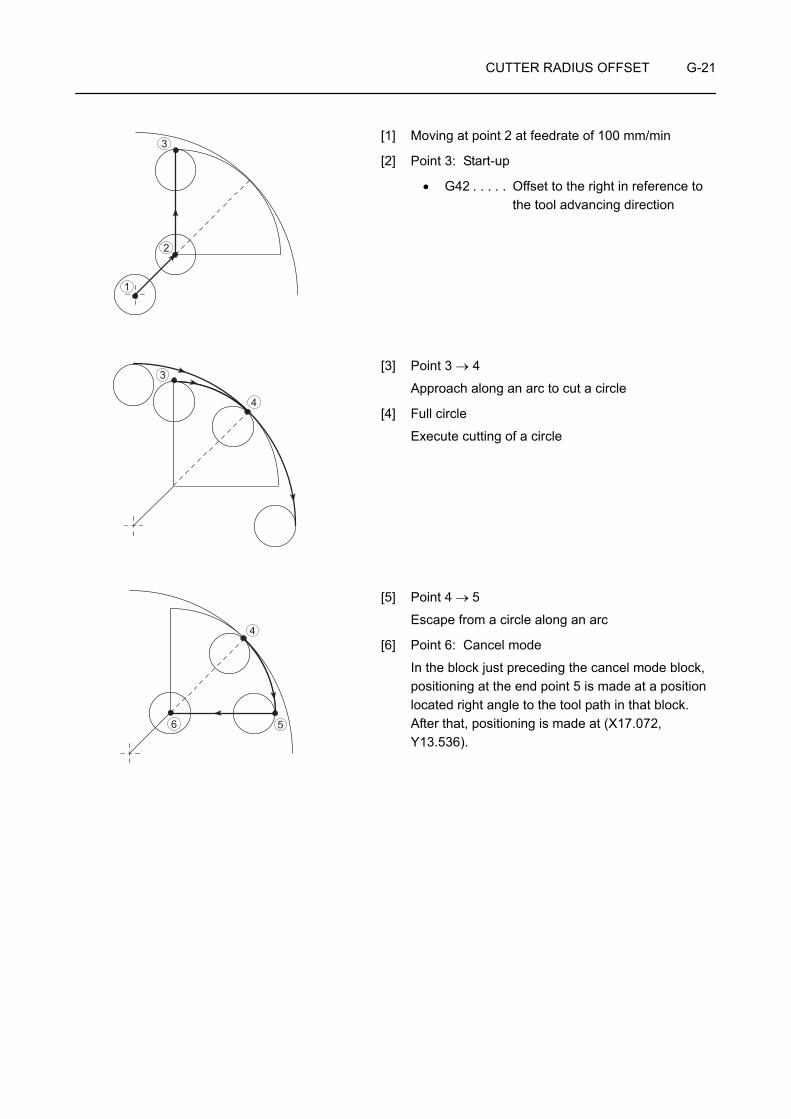
CUTTER RADIUS OFFSET G-21
[1] Moving at point 2 at feedrate of 100 mm/min
[2] Point 3: Start-up
• G42 . . . . . Offset to the right in reference to the tool advancing direction
[3] Point 3 → 4
Approach along an arc to cut a circle
[4] Full circle
Execute cutting of a circle
[5] Point 4 → 5
Escape from a circle along an arc
[6] Point 6: Cancel mode
In the block just preceding the cancel mode block, positioning at the end point 5 is made at a position located right angle to the tool path in that block. After that, positioning is made at (X17.072, Y13.536).
1
2
3
3
4
4
56
CHAPTER HMULTIPLE REPETITIVE
CYCLES
This chapter describes the multiple repetitive cycles.
Using a multiple repetitive cycle, roughing processes that require several blocks of commands can be defined by a single block of commands preceded by a G code calling a multiple repetitive cycle, and blocks that define the finished shape. The tool paths for rough cutting cycles are automatically determined.
When specifying a multiple repetitive cycle, two types of format (standard format and F15 format) are used. If the command format differs between the standard format and F15 format, the difference is explained in the related G code items. Pay sufficient care to the difference when creating a program.
Instruction manual supplied by the NC manufacturer
NOTE

CONTENTS
H : MULTIPLE REPETITIVE CYCLES
1 GENERAL . . . . . . . . . . . . . . . . . . . . . . . . . . . . . . . . . . . . . . . . . . . . . . . . . . . . . . . . . . . . H-1
2 G71 O.D./I.D. ROUGH CUTTING CYCLE . . . . . . . . . . . . . . . . . . . . . . . . . . . . . . . . . . . H-5
3 G72 ROUGH FACING CYCLE. . . . . . . . . . . . . . . . . . . . . . . . . . . . . . . . . . . . . . . . . . . H-11
4 G73 CLOSED-LOOP CUTTING CYCLE . . . . . . . . . . . . . . . . . . . . . . . . . . . . . . . . . . . H-17
5 CAUTIONS ON USING THE G71, G72, AND G73 CYCLES . . . . . . . . . . . . . . . . . . . . H-22
6 G70 FINISHING CYCLE. . . . . . . . . . . . . . . . . . . . . . . . . . . . . . . . . . . . . . . . . . . . . . . . H-25
7 G74 FACE CUT-OFF, GROOVING CYCLE AND DEEP HOLE DRILLING CYCLE. . . . . . . . . . . . . . . . . . . . . . . . . . . . . . . . . . . . . . H-27
8 G75 O.D./I.D. GROOVING CYCLE, CUT-OFF CYCLE . . . . . . . . . . . . . . . . . . . . . . . . H-31
9 G76 MULTIPLE THREAD CUTTING CYCLE. . . . . . . . . . . . . . . . . . . . . . . . . . . . . . . . H-35
9-1 Infeed Mode . . . . . . . . . . . . . . . . . . . . . . . . . . . . . . . . . . . . . . . . . . . . . . . . . . . . H-37
9-2 Cautions on the G76 Multiple Thread Cutting Cycle . . . . . . . . . . . . . . . . . . . . . . H-38
9-3 The Relationship between Depth of Cut for the First Path and the Number of Thread Cutting Paths to be Generated (Fixed Metal Removal Rate and Straight Feed along the Thread Face) . . . . . . . H-41
9-3-1 Calculating the Number of Thread Cutting Paths when the Depth of Cut for the First Path is Given . . . . . . . . . . . . . . . . . H-41
9-3-2 Calculating the Depth of Cut for the First Path when the Number of Thread Cutting Paths is Given . . . . . . . . . . . . . . . H-41

MULTIPLE REPETITIVE CYCLES H-1
1 GENERAL
The multiple repetitive cycles simplify the programs for rough and finish cutting processes on O.D. and I.D.
For example, by defining only the workpiece finish shape, the tool paths for executing rough cutting operation are automatically generated.
The table below lists the multiple repetitive cycles:
G71 O.D./I.D. rough cutting cycle(Cutting along the Z-axis, infeed along the X-axis)In O.D./I.D. cutting operation, when the finish shape is defined in the program, the workpiece is machined to the shape which includes a finishing allowance on the defined shape.The tool paths used for rough cutting are automatically determined.
G72 Rough facing cycle(Cutting along the X-axis, infeed along the Z-axis)In facing operation, when the finish shape is defined in the program, the workpiece is machined to the shape which includes a finishing allowance on the defined shape.The tool paths used for rough cutting are automatically determined.
G73 Closed-loop cutting cycleThe workpiece is machined to the defined shape by executing the fixed pattern repeatedly.
G70 Finishing cycleAfter completing a rough cutting cycle for O.D., I.D., or end face, called by the G71, G72, or G73 command, the shape is finished by the G70 cycle.
G74 Face cut-off cycle, face grooving cycle, deep hole drilling cycleInfeed is made along the Z-axis intermittently.If a command for the depth of cut along the X-axis is omitted, the deep hole drilling cycle is called.
G75 O.D./I.D. grooving cycle, O.D. cut-off cycleInfeed is made along the X-axis intermittently.If a command for the depth of cut along the Z-axis direction is omitted, the O.D. cut-off cycle is called.
Intermittent feed
Intermittent feed

H-2 MULTIPLE REPETITIVE CYCLES
G76 Multiple thread cutting cycleThe thread cutting pattern is repeated by gradually infeeding the cutting tool.

MULTIPLE REPETITIVE CYCLES H-3
To explain how the multiple repetitive cycle function simplifies programming, the rough cutting cycle for the shape illustrated below is programmed with and without using the G71 cycle.
In the programming, tool nose radius is assumed to be "0".
O0001; O0001;
G00 X96.0 Z20.0 M08; . . . . G00 X100.0 Z20.0 M08; . . . . . . . . . . . . . . . . .G01 Z2.0 F2.0; . . . . . . . . . . G01 Z2.0 F2.0; . . . . . . . . . . . . . . . . . . . . . . . .Z−64.9 F0.3; . . . . . . . . . . . . G71 U2.0 R0.5; . . . . . . . . . . [1]G00 U1.0 Z2.0; . . . . . . . . . . G71 P100 Q200 U0.3 W0.1 F0.3;X92.0; . . . . . . . . . . . . . . . . . N100 G00 X80.0; . . . . . . . . . . . . . . . . . . . . . . . [2]G01 Z−64.9; . . . . . . . . . . . . G01 Z−60.0; . . . . . . . . . . . . . . . . . . . . . . . . . .G00 U1.0 Z2.0; . . . . . . . . . . X90.0 Z−65.0; . . . . . . . . . . . . . . . . . . . . . . . . .X88.0; . . . . . . . . . . . . . . . . . N200 X102.0; . . . . . . . . . . . . . . . . . . . . . . . . . . [3]G01 Z−63.9; . . . . . . . . . . . . G00 X200.0 Z100.0 M09; . . . . . . . . . . . . . . . .G00 U1.0 Z2.0; . . . . . . . . . .X84.0; . . . . . . . . . . . . . . . . .G01 Z−61.9; . . . . . . . . . . . .G00 U1.0 Z2.0; . . . . . . . . . .X80.3; . . . . . . . . . . . . . . . . .G01 Z−60.0; . . . . . . . . . . . .X90.1 Z−64.9; . . . . . . . . . . .X102.0; . . . . . . . . . . . . . . . .G00 U1.0 Z10.0 M09; . . . . .X200.0 Z100.0; . . . . . . . . . .
<Programming without usingthe multiple repetitive cycle>
<Programming using the multiplerepetitive cycle (G71)>
NOTE
60
65 8090100
φ φ φ
Cutting allowance
Depth of cut per pass: 4 mm (in diameter)Finishing allowance (X): 0.3 mm (in diameter)Finishing allowance (Z): 0.1 mm
1 1
2 2
3
4
5 3
6 4
7 5
8 6
9 7
10
[1] Executes the O.D. rough cutting cycle (G71).• G71 . . . . Calls the O.D. rough cutting cycle.• U2.0 . . . . Specifies the depth of cut (in radius).• R0.5 . . . . Specifies the relief amount
(in radius).• P100 . . . . Specifies the sequence number of
the first block of the blocks that define the finish shape of the workpiece.
• Q200 . . . Specifies the sequence number of the last block of the blocks that define the finish shape of the workpiece.
• U0.3 . . . . Specifies the finishing allowance in the X-axis direction (in diameter).
• W0.1 . . . . Specifies the finishing allowance in the Z-axis direction.
• F0.3 . . . . Specifies the feedrate.[2] to [3]
The blocks from sequence number N100 to N200 define the finish shape.
11
12
13
14
15
16
17
18
19

H-4 MULTIPLE REPETITIVE CYCLES
From the comparison of the two programs shown above, it is known that the programming is simplified by using the multiple repetitive cycle function.
Since programming is simplified, programming error can be reduced accordingly.
60 0.3
65
0.1
60 0.3
65
0.11
7
2
34
5
61
15
24
7
10
13
12
3 5
8
11
14
19
16
9
6
18
17
8090
100
8090100
φ φ φ φ φ
φ
(in diameter) (in diameter)
By specifying the data for finishing such as finishing allowance and depth of cut in the G71 block, the cycles as indicated above are executed by the commands written in the seven lines of the program (point 1 to 7).
Cutting feed
Rapid traverse

MULTIPLE REPETITIVE CYCLES H-5
2 G71 O.D./I.D. ROUGH CUTTING CYCLE
The O.D./I.D. rough cutting cycle is used for workpieces which have monotonously varying shapes both in the X- and Z-axis directions.
When the finish shape (A → A' → B) is defined in a program, rough cutting paths are automatically generated leaving allowance of U(2)/2 and W for finishing on the workpiece circumference and end face, respectively. The depth of cut for rough cutting cycle is U(1).
Generally, a finishing cycle called by the G70 command is used to finish the workpiece after completing the G71 O.D./I.D. rough cutting cycle.
1. Standard format (setting made before shipping the machine)
G71 U(1) R_ ;G71 P_ Q_ U(2) W_ F_ S_ T_ ;
2. F15 format
G71 P_ Q_ U(2) W_ I_ K_ D_ F_ S_ T_ ;• G71 . . . . . . . . Calls the O.D./I.D. rough cutting cycle.
• U(1) . . . . . . . . Specifies depth of cut (X-axis direction) (unsigned, in radius).
Since this command is modal, it remains valid until it is replaced with the value specified next. This value can also be set for parameter No. 5132; the value set for the parameter is changed according to the value specified in the program.
• R . . . . . . . . . . Specifies the relief amount (in radius).
Since this command is modal, it remains valid until it is replaced with the value specified next. This value can also be set for parameter No. 5133; the value set for the parameter is changed according to the value specified in the program.
• P . . . . . . . . . . Specifies the sequence number of the first block of the blocks that define the finish shape of the workpiece.
• Q . . . . . . . . . . Specifies the sequence number of the last block of the blocks that define the finish shape of the workpiece.
• U(2) . . . . . . . . Specifies the distance and direction of the finishing allowance in the X-axis direction (in diameter).
• W . . . . . . . . . . Specifies the distance and direction of the finishing allowance in the Z-axis direction.
X
Z A'W
U(1)B
CA
R
45°
U(2)/2
Cutting feed
Rapid traverse
Finishing allowance
(R: Relief amount, to be set for parameter No. 5133)
COMMAND
NOTE
NOTE

H-6 MULTIPLE REPETITIVE CYCLES
• I . . . . . . . . . . . Specifies the distance and direction of rough finishing allowance in the X-axis direction (in radius).
The command is disregarded even if specified.
• K . . . . . . . . . . Specifies the distance and direction of rough finishing allowance in the Z-axis direction.
The command is disregarded even if specified.
• D . . . . . . . . . . Specifies the depth of cut (X-axis direction) (unsigned, in radius).
Input of a decimal point is not allowed.
• F . . . . . . . . . . Specifies feedrate to be adopted for the G71 cycle.
• S . . . . . . . . . . Specifies spindle speed control to be adopted for the G71 cycle.
In the G96 mode:The value specifies cutting speed (m/min).
In the G97 mode:
The value specifies spindle speed (min−1).
• T . . . . . . . . . . Specifies a tool number and the tool offset number in a four digit number.
1. If no F, S, or T command is specified, the command which has been specified preceding the G71 block is valid.
2. In the first block of the blocks defining the finish shape, as specified by the P command in the "G71 P_ Q_ ...;" block, take the following items into consideration.
• Always specify either the G00 or G01 command. If neither G00 nor G01 command is specified, an alarm message (No. 065) is displayed on the screen.
G00 . . . . . . . Infeed in the G71 cycle is made at a rapid traverse rate.
G01 . . . . . . . Infeed in the G71 cycle is made at a cutting feedrate.
NOTE
NOTE
NOTE
NOTE
NOTE

MULTIPLE REPETITIVE CYCLES H-7
3. The workpiece shape must be monotonously increasing or decreasing pattern in the Z-axis direction as shown in the illustration below.
The pattern to be generated must monotonously increases or decreases both in the X- and Z-axis directions as illustrated on the left.
In this case, the first block of the blocks used to define the finish shape must contain only either X(U) or Z(W) axis.
G71 U2.0 R0.5;
G71 P100 Q200 U0.3 W0.1 F0.3;
N100 G00 X(U)_ ;
Even if the finish shape is not a monotonously increasing or decreasing pattern, machining is possible if the number of pockets included in the shape is 10 or less.
In this case, the first block of the blocks used to define the finish shape must contain both X(U) and Z(W) axes. Even if either of them does not move in the first block, it is necessary to specify U0 or W0.
This function is optional for other than the ZT series.
G71 U2.0 R0.5;
G71 P100 Q200 U0.3 W0.1 F0.3;
N100 G00 X(U)_ Z(W)_ ;
4. For O.D. rough cutting cycle, it is necessary to move the tool along the X-axis to a point which is larger than the workpiece material diameter before specifying the G71 command.
For I.D. rough cutting cycle, it is necessary to move the tool along the X-axis to a point which is smaller than the workpiece material inside hole diameter before specifying the G71 command.
NOTE
B
A'X-axis direction
Z-axis direction

H-8 MULTIPLE REPETITIVE CYCLES
Programming using G71
To finish the shape illustrated below by using the G71 O.D./I.D. rough cutting cycle and the G70 finishing cycle (Nose radius of finishing tool: 0.4 mm)
O0001;
N1 (ROUGH. OF OUT); . . . . . . . . . . . . Part program for face and O.D. rough cutting
G50 S1500;
G00 T0101;
G96 S120 M03;
X75.0 Z20.0 M08;
G01 Z0.1 F1.0;
X25.0 F0.25;
G00 X70.0 Z1.0; . . . . . . . . . . . . . . . . . . Positioning at point 1, the start point of the O.D. rough cutting cycle (G71)
Ex.
C1
C1.5
5
25
M60 × P2
546932
C0.5
φ φ φ
1
2
3
4
5
67
8
9

MULTIPLE REPETITIVE CYCLES H-9
G71 U2.0 R0.5;G71 P100 Q200 U0.3 W0.1 F0.3;
N100 G00 X49.54;
G01 X54.0 Z−1.23 F0.15;
Z−5.0;
X56.34;
X59.8 Z−6.73;
Z−25.0;
X67.54;
N200 X70.0 Z−26.23;
G00 X200.0 Z150.0;
M01;
N2 (FIN. OF OUT); . . . . . . . . . . . . . . . . Part program for face and O.D. finishing
G50 S2000;
G00 T0202;
G96 S200 M03;
X56.0 Z20.0 M08;
G01 Z0 F1.0;
X30.0 F0.15;
G00 X70.0 Z1.0; . . . . . . . . . . . . . . . . . . Positioning at point 1, the start point of the finishing cycle (G70)
G70 P100 Q200;. . . . . . . . . . . . . . . . . . Execution of the finishing cycle (G70) Finish cutting is executed for the shape defined by the blocks from N100 to N200.
Cutting conditions for finishing: Cutting speed . . . . . S200 (200 m/min)Feedrate . . . . . . . . . F0.15 (0.15 mm/rev)
G00 X200.0 Z150.0;
M01;
. . . Execution of the O.D. rough cutting cycle (G71)
• U2.0 . . . . . . Depth of cut: 2 mm (in radius)
• R0.5 . . . . . . Relief amount: 0.5 mm
• P100 . . . . . . The sequence number of the first block of the blocks defining the finish shape: N100
• Q200 . . . . . . The sequence number of the last block of the blocks defining the finish shape: N200
• U0.3 . . . . . . Finishing allowance in the X-axis direction: 0.3 mm (in diameter)
• W0.1 . . . . . . Finishing allowance in the Z-axis direction: 0.1 mm
• F0.3. . . . . . . Feedrate: 0.3 mm/rev
. . . . The blocks from N100 to N200 define the finish shape including points 2 to 9.
1. The command values in these blocks are determined taking into consideration the tool nose radius (0.4 mm) of the finishing tool.
2. The feedrate command "F0.15" specified in these blocks is ignored for rough cutting cycle. Feedrate during rough cutting cycle is F0.3 (0.3 mm/rev).
NOTE
NOTE

H-10 MULTIPLE REPETITIVE CYCLES
<Tool paths for rough cutting cycle>
W
U/2
Start from the point shifted by U/2, W
(X70.0, Z1.0)1

MULTIPLE REPETITIVE CYCLES H-11
3 G72 ROUGH FACING CYCLE
The rough facing cycle is used for workpieces which have monotonously varying shapes both in the X- and Z-axis directions.
When the finish shape (A → A' → B) is defined in a program, rough cutting paths are automatically generated leaving allowance of U/2 and W(2) for finishing on the workpiece circumference and end face, respectively. The depth of cut for rough cutting cycle is W(1).
Generally, a finishing cycle called by the G70 command is used to finish the workpiece after completing the rough facing cycle.
1. Standard format (setting made before shipping the machine)
G72 W(1) R_ ;G72 P_ Q_ U_ W(2) F_ S_ T_ ;
2. F15 format
G72 P_ Q_ U_ W(2) I_ K_ D_ F_ S_ T_ ;• G72 . . . . . . . . Calls the rough facing cycle.
• W(1) . . . . . . . Specifies depth of cut (Z-axis direction) (unsigned).
Since this command is modal, it remains valid until it is replaced with the value specified next. This value can also be set for parameter No. 5132; the value set for the parameter is changed according to the value specified in the program.
• R . . . . . . . . . . Specifies the relief amount.
Since this command is modal, it remains valid until it is replaced with the value specified next. This value can also be set for parameter No. 5133; the value set for the parameter is changed according to the value specified in the program.
• P . . . . . . . . . . Specifies the sequence number of the first block of the blocks that define the finish shape of the workpiece.
• Q . . . . . . . . . . Specifies the sequence number of the last block of the blocks that define the finish shape of the workpiece.
• U . . . . . . . . . . Specifies the distance and direction of the finishing allowance in the X-axis direction (in diameter).
• W(2) . . . . . . . Specifies the distance and direction of the finishing allowance in the Z-axis direction.
X
Z
W(1)
R
45°
W(2)
U/2
AC
B
A'
Finishing allowance
(R: Relief amount, to be set for parameter No. 5133)
Cutting feed
Rapid traverse
COMMAND
NOTE
NOTE

H-12 MULTIPLE REPETITIVE CYCLES
• I . . . . . . . . . . . Specifies the distance and direction of rough finishing allowance in the X-axis direction (in radius).
The command is disregarded even if specified.
• K . . . . . . . . . . Specifies the distance and direction of rough finishing allowance in the Z-axis direction.
The command is disregarded even if specified.
• D . . . . . . . . . . Specifies the depth of cut (Z-axis direction) (unsigned).
Input of a decimal point is not allowed.
• F . . . . . . . . . . Specifies feedrate to be adopted for the G72 cycle.
• S . . . . . . . . . . Specifies spindle speed control to be adopted for the G72 cycle.
In the G96 mode:The value specifies cutting speed (m/min).
In the G97 mode:
The value specifies spindle speed (min−1).
• T . . . . . . . . . . Specifies a tool number and the tool offset number in a four digit number.
NOTE
NOTE
NOTE
NOTE

MULTIPLE REPETITIVE CYCLES H-13
1. If no F, S, or T command is specified, the command which has been specified preceding the G72 block is valid.
2. In the first block of the blocks defining the finish shape, as specified by the P command in the "G72 P_ Q_ ...;" block, take the following items into consideration.
• Always specify either the G00 or G01 command. If neither G00 nor G01 command is specified, an alarm message (No. 065) is displayed on the screen.
G00 . . . . Infeed in the G72 cycle is made at a rapid traverse rate.
G01 . . . . Infeed in the G72 cycle is made at a cutting feedrate.
3. The workpiece shape must be monotonously increasing or decreasing pattern in the X-axis direction as shown in the illustration below.
The pattern to be generated must monotonously increases or decreases both in the X- and Z-axis directions as illustrated on the left.
In this case, the first block of the blocks used to define the finish shape must contain only either X(U) or Z(W) axis.
G72 W2.0 R0.5;
G72 P100 Q200 U0.3 W0.1 F0.3;
N100 G00 Z(W)_ ;
Even if the finish shape is not a monotonously increasing or decreasing pattern, machining is possible if the number of pockets included in the shape is 10 or less.
In this case, the first block of the blocks used to define the finish shape must contain both X(U) and Z(W) axes. Even if either of them does not move in the first block, it is necessary to specify U0 or W0.
This function is optional for other than the ZT series.
G72 W2.0 R0.5;
G72 P100 Q200 U0.3 W0.1 F0.3;
N100 G00 X(U)_ Z(W)_ ;
NOTE
B
A'
X-axis direction
Z-axis direction

H-14 MULTIPLE REPETITIVE CYCLES
Programming using G72
To finish the shape illustrated below by using the G72 rough facing cycle and the G70 finishing cycle (Nose radius of finishing tool: 0.4 mm)
O0001;
N1 (ROUGH. OF OUT); . . . . . . . . . . . . Part program for face and O.D. rough cutting
G50 S1500;
G00 T0101;
G96 S120 M03;
X75.0 Z20.0 M08;
G01 X72.0 Z1.0 F1.0; . . . . . . . . . . . . . . Positioning at point 1, the start point of the rough facing cycle (G72)
Ex.
C1
C1.5
5
25
M60 × P2
546932
C0.5
φ φ φ
12
3
45
6
7
8
9
10 11
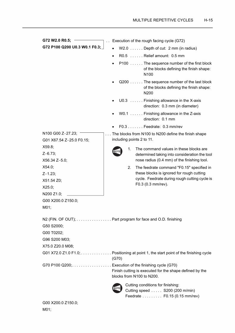
MULTIPLE REPETITIVE CYCLES H-15
G72 W2.0 R0.5;G72 P100 Q200 U0.3 W0.1 F0.3;
N100 G00 Z−27.23;
G01 X67.54 Z−25.0 F0.15;
X59.8;
Z−6.73;
X56.34 Z−5.0;
X54.0;
Z−1.23;
X51.54 Z0;
X25.0;
N200 Z1.0;
G00 X200.0 Z150.0;
M01;
N2 (FIN. OF OUT); . . . . . . . . . . . . . . . . Part program for face and O.D. finishing
G50 S2000;
G00 T0202;
G96 S200 M03;
X75.0 Z20.0 M08;
G01 X72.0 Z1.0 F1.0; . . . . . . . . . . . . . . Positioning at point 1, the start point of the finishing cycle (G70)
G70 P100 Q200;. . . . . . . . . . . . . . . . . . Execution of the finishing cycle (G70) Finish cutting is executed for the shape defined by the blocks from N100 to N200.
Cutting conditions for finishing: Cutting speed . . . . . S200 (200 m/min) Feedrate . . . . . . . . . F0.15 (0.15 mm/rev)
G00 X200.0 Z150.0;
M01;
. . Execution of the rough facing cycle (G72)
• W2.0 . . . . . . Depth of cut: 2 mm (in radius)
• R0.5 . . . . . . Relief amount: 0.5 mm
• P100 . . . . . . The sequence number of the first block of the blocks defining the finish shape: N100
• Q200 . . . . . . The sequence number of the last block of the blocks defining the finish shape: N200
• U0.3 . . . . . . Finishing allowance in the X-axis direction: 0.3 mm (in diameter)
• W0.1 . . . . . . Finishing allowance in the Z-axis direction: 0.1 mm
• F0.3 . . . . . . . Feedrate: 0.3 mm/rev
. . . The blocks from N100 to N200 define the finish shape including points 2 to 11.
1. The command values in these blocks are determined taking into consideration the tool nose radius (0.4 mm) of the finishing tool.
2. The feedrate command "F0.15" specified in these blocks is ignored for rough cutting cycle. Feedrate during rough cutting cycle is F0.3 (0.3 mm/rev).
NOTE
NOTE
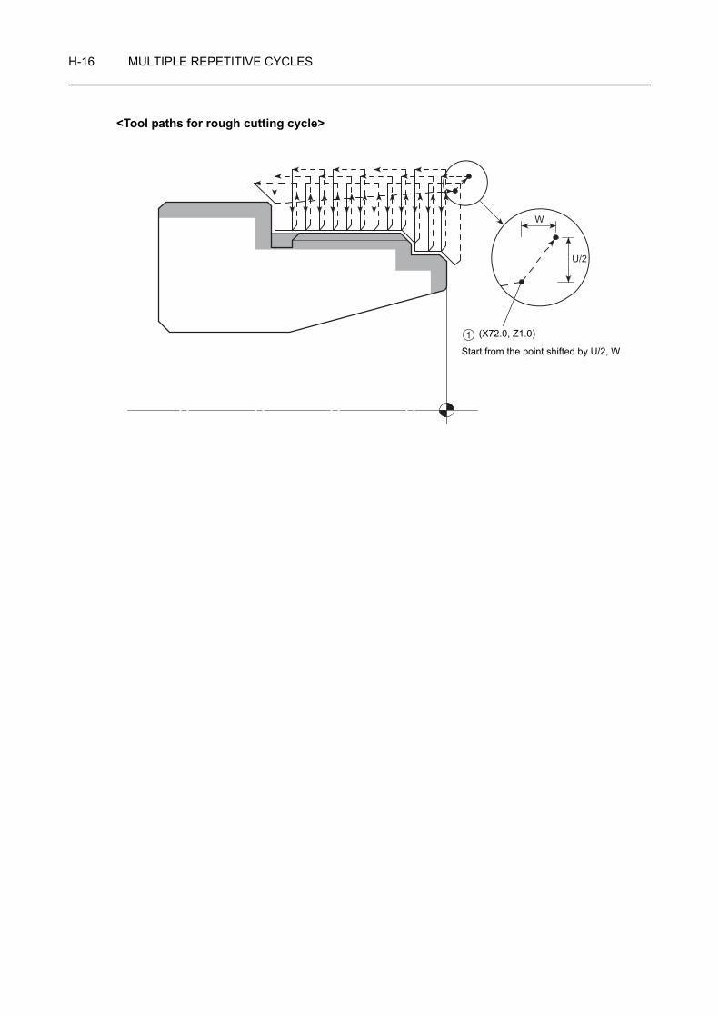
H-16 MULTIPLE REPETITIVE CYCLES
<Tool paths for rough cutting cycle>
W
U/2
Start from the point shifted by U/2, W
(X72.0, Z1.0)1

MULTIPLE REPETITIVE CYCLES H-17
4 G73 CLOSED-LOOP CUTTING CYCLE
In the G73 closed-loop cutting cycle, the defined pattern is repeated while it is being shifted to finish the workpiece.
By specifying the finish shape, A → A' → B, in the illustration on the left, the workpiece is machined by executing the specified pattern repeatedly until the finishing allowance of U(2)/2 and W(2) is left on the finish shape.
This cycle is used to efficiently machine workpieces that have uniform stock to be removed, such as forged or cast workpieces.
Generally, a finishing cycle called by the G70 command which is explained later is used to finish the workpiece after completing the rough cutting using the G73 closed-loop cutting cycle.
1. Standard format (setting made before shipping the machine)
G73 U(1) W(1) R_ ;G73 P_ Q_ U(2) W(2) F_ S_ T_ ;
2. F15 format
G73 P_ Q_ U(2) W(2) I_ K_ D_ F_ S_ T_ ;• G73 . . . . . . . . Calls the closed-loop cutting cycle.
• U(1) . . . . . . . . Specifies the distance and direction of entire stock for rough cutting in the X-axis direction (in radius).
Since this command is modal, it remains valid until it is replaced with the value specified next. This value can also be set for parameter No. 5135; the value set for the parameter is changed according to the value specified in the program.
• W(1) . . . . . . . Specifies the distance and direction of entire stock for rough cutting in the Z-axis direction.
Since this command is modal, it remains valid until it is replaced with the value specified next. This value can also be set for parameter No. 5136; the value set for the parameter is changed according to the value specified in the program.
• R, D . . . . . . . . Specifies the number of divisions in which rough machining is executed.
Since this command is modal, it remains valid until it is replaced with the value specified next. This value can also be set for parameter No. 5137; the value set for the parameter is changed according to the value specified in the program.
X
Z
A
A'
B
U(1)
U(2)/2
W(1)W(2)
Cutting feed
Rapid traverse
Finishing allowance
COMMAND
NOTE
NOTE
NOTE

H-18 MULTIPLE REPETITIVE CYCLES
• P . . . . . . . . . . Specifies the sequence number of the first block of the blocks that define the finish shape of the workpiece.
• Q . . . . . . . . . . Specifies the sequence number of the last block of the blocks that define the finish shape of the workpiece.
• U(2) . . . . . . . . Specifies the distance and direction of the finishing allowance in the X-axis direction (in diameter).
• W(2) . . . . . . . Specifies the distance and direction of the finishing allowance in the Z-axis direction.
• I . . . . . . . . . . . Specifies the distance and direction of entire stock for rough cutting in the X-axis direction (in radius).
• K . . . . . . . . . . Specifies the distance and direction of entire stock for rough cutting in the Z-axis direction.
• F . . . . . . . . . . Specifies feedrate to be adopted for the G73 cycle.
• S . . . . . . . . . . Specifies spindle speed control to be adopted for the G73 cycle.
In the G96 mode:The value specifies cutting speed (m/min).
In the G97 mode:
The value specifies spindle speed (min−1).
• T . . . . . . . . . . Specifies a tool number and the tool offset number in a four digit number.
1. If no F, S, or T command is specified, the command which has been specified preceding the G73 block is valid.
2. In the first block of the blocks defining the finish shape, as specified by the P command in the "G73 P_ Q_ ...;" block, take the following items into consideration.
• Always specify either the G00 or G01 command. If neither G00 nor G01 command is specified, an alarm message (No. 065) is displayed on the screen.
G00 . . . . . . . Infeed in the G73 cycle is made at a rapid traverse rate.
G01 . . . . . . . Infeed in the G73 cycle is made at a programmed feedrate.
NOTE
NOTE

MULTIPLE REPETITIVE CYCLES H-19
Programming using G73
To finish the shape illustrated below by using the G73 closed-loop rough cutting cycle and the G70 finishing cycle (Nose radius of finishing tool: 0.4 mm)
O0001;
N1 (ROUGH. OF OUT); . . . . . . . . . . . . Part program for face and O.D. rough cutting
G50 S1500;
G00 T0101;
G96 S120 M03;
X75.0 Z20.0 M08;
G01 Z0.1 F1.0;
X25.0 F0.25;
G00 X75.0 Z10.0; . . . . . . . . . . . . . . . . . Positioning at point 1, the start point of the closed-loop rough cutting cycle (G73)
Ex.
C1
C1.5
5
25
M60 × P2
546932
C0.5
φ φ φ
1
2
3
4
5
67
8
9
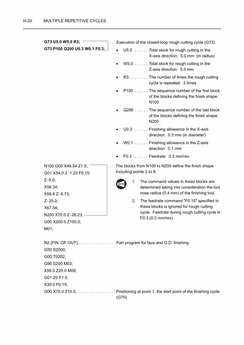
H-20 MULTIPLE REPETITIVE CYCLES
G73 U5.0 W5.0 R3;G73 P100 Q200 U0.3 W0.1 F0.3;
N100 G00 X49.54 Z1.0;
G01 X54.0 Z−1.23 F0.15;
Z−5.0;
X56.34;
X59.8 Z−6.73;
Z−25.0;
X67.54;
N200 X70.0 Z−26.23;
G00 X200.0 Z150.0;
M01;
N2 (FIN. OF OUT); . . . . . . . . . . . . . . . . Part program for face and O.D. finishing
G50 S2000;
G00 T0202;
G96 S200 M03;
X56.0 Z20.0 M08;
G01 Z0 F1.0;
X30.0 F0.15;
G00 X75.0 Z10.0; . . . . . . . . . . . . . . . . . Positioning at point 1, the start point of the finishing cycle (G70)
. . Execution of the closed-loop rough cutting cycle (G73)
• U5.0 . . . . . . Total stock for rough cutting in the X-axis direction: 5.0 mm (in radius)
• W5.0 . . . . . . Total stock for rough cutting in the Z-axis direction: 5.0 mm
• R3 . . . . . . . . The number of times the rough cutting cycle is repeated: 3 times
• P100 . . . . . . The sequence number of the first block of the blocks defining the finish shape: N100
• Q200 . . . . . . The sequence number of the last block of the blocks defining the finish shape: N200
• U0.3 . . . . . . Finishing allowance in the X-axis direction: 0.3 mm (in diameter)
• W0.1 . . . . . . Finishing allowance in the Z-axis direction: 0.1 mm
• F0.3 . . . . . . Feedrate: 0.3 mm/rev
. . The blocks from N100 to N200 define the finish shape including points 2 to 9.
1. The command values in these blocks are determined taking into consideration the tool nose radius (0.4 mm) of the finishing tool.
2. The feedrate command "F0.15" specified in these blocks is ignored for rough cutting cycle. Feedrate during rough cutting cycle is F0.3 (0.3 mm/rev).
NOTE
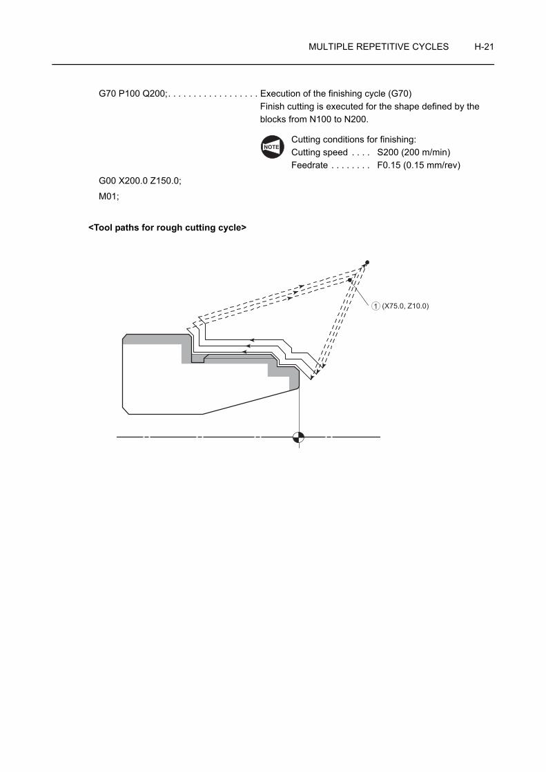
MULTIPLE REPETITIVE CYCLES H-21
G70 P100 Q200;. . . . . . . . . . . . . . . . . . Execution of the finishing cycle (G70) Finish cutting is executed for the shape defined by the blocks from N100 to N200.
Cutting conditions for finishing: Cutting speed . . . . S200 (200 m/min)Feedrate . . . . . . . . F0.15 (0.15 mm/rev)
G00 X200.0 Z150.0;
M01;
<Tool paths for rough cutting cycle>
NOTE
(X75.0, Z10.0)1
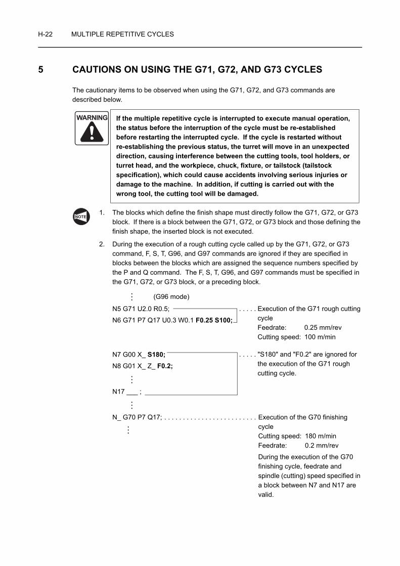
H-22 MULTIPLE REPETITIVE CYCLES
5 CAUTIONS ON USING THE G71, G72, AND G73 CYCLES
The cautionary items to be observed when using the G71, G72, and G73 commands are described below.
1. The blocks which define the finish shape must directly follow the G71, G72, or G73 block. If there is a block between the G71, G72, or G73 block and those defining the finish shape, the inserted block is not executed.
2. During the execution of a rough cutting cycle called up by the G71, G72, or G73 command, F, S, T, G96, and G97 commands are ignored if they are specified in blocks between the blocks which are assigned the sequence numbers specified by the P and Q command. The F, S, T, G96, and G97 commands must be specified in the G71, G72, or G73 block, or a preceding block.
(G96 mode)
N5 G71 U2.0 R0.5;
N6 G71 P7 Q17 U0.3 W0.1 F0.25 S100;
N7 G00 X_ S180;N8 G01 X_ Z_ F0.2;
N17 ___ ;
N_ G70 P7 Q17; . . . . . . . . . . . . . . . . . . . . . . . . . Execution of the G70 finishing cycleCutting speed: 180 m/minFeedrate: 0.2 mm/rev
During the execution of the G70 finishing cycle, feedrate and spindle (cutting) speed specified in a block between N7 and N17 are valid.
WARNING If the multiple repetitive cycle is interrupted to execute manual operation, the status before the interruption of the cycle must be re-established before restarting the interrupted cycle. If the cycle is restarted without re-establishing the previous status, the turret will move in an unexpected direction, causing interference between the cutting tools, tool holders, or turret head, and the workpiece, chuck, fixture, or tailstock (tailstock specification), which could cause accidents involving serious injuries or damage to the machine. In addition, if cutting is carried out with the wrong tool, the cutting tool will be damaged.
NOTE
. . . . . Execution of the G71 rough cutting cycleFeedrate: 0.25 mm/revCutting speed: 100 m/min
. . . . . "S180" and "F0.2" are ignored for the execution of the G71 rough cutting cycle.

MULTIPLE REPETITIVE CYCLES H-23
3. The following G and M codes must not be specified in the blocks between those specified by the P and Q commands.
• G codes in group 00 (one-shot G codes) with an exception of G04 (dwell)
• G codes in group 01 with an exception of G00, G01, G02, and G03
• G codes in group 06
• M98 and M99
4. It is not allowed to specify the G71, G72, and G73 commands in the MDI mode. An alarm message (No. 067) is displayed on the screen if the G71, G72, or G73 command is specified in the MDI mode.
5. It is not allowed to specify the M98 and M99 commands in the block that contains the G71, G72, or G73 command, and the blocks that are assigned the sequence numbers specified by the P and Q commands.
6. The last axis movement specified in the blocks that are assigned the sequence numbers specified by the P and Q commands must not be chamfering or corner rounding.
If such commands are specified, an alarm message (No. 069) is displayed on the screen.
7. For the G71, G72, or G73 cycle, the automatic tool nose radius offset function is invalid.
NOTE
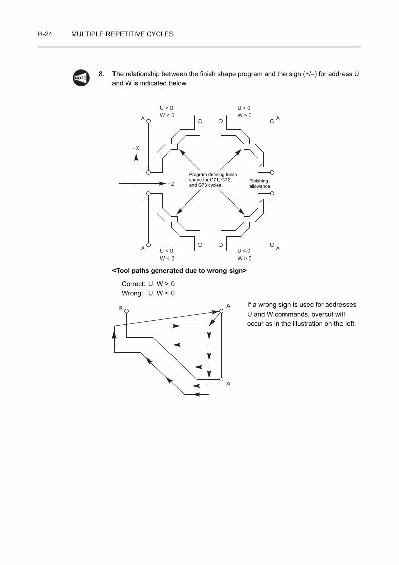
H-24 MULTIPLE REPETITIVE CYCLES
8. The relationship between the finish shape program and the sign (+/−) for address U and W is indicated below.
<Tool paths generated due to wrong sign>
Correct: U, W > 0 Wrong: U, W < 0
If a wrong sign is used for addresses U and W commands, overcut will occur as in the illustration on the left.
NOTE
+X
+Z
U > 0W < 0
U > 0
A
A
A
A
W > 0
U < 0W < 0
U < 0W > 0
Program defining finish shape for G71, G72, and G73 cycles
Finishing allowance
A'
AB

MULTIPLE REPETITIVE CYCLES H-25
6 G70 FINISHING CYCLE
After the completion of rough cutting cycle, called by the G71, G72 or G73 command, the workpiece is finished by calling the G70 finishing cycle.
After the cutting tool is returned to point A, specified in a program, finishing cycle is executed along the finish shape A' → B defined in the blocks which follow the G71, G72, or G73 block.
For the finishing cycle called by the G70 command, the finish shape program specified in the G71, G72, or G73 block is used.
G70 P_ Q_ ;• G70 . . . . . . . . Calls the finishing cycle.
• P . . . . . . . . . . Specifies the sequence number of the first block of the blocks that define the finish shape of the workpiece.
• Q . . . . . . . . . . Specifies the sequence number of the last block of the blocks that define the finish shape of the workpiece.
WARNING If the multiple repetitive cycle is interrupted to execute manual operation, the status before the interruption of the cycle must be re-established before restarting the interrupted cycle. If the cycle is restarted without re-establishing the previous status, the turret will move in an unexpected direction, causing interference between the cutting tools, tool holders, or turret head, and the workpiece, chuck, fixture, or tailstock (tailstock specification), which could cause accidents involving serious injuries or damage to the machine. In addition, if cutting is carried out with the wrong tool, the cutting tool will be damaged.
A
A'
B
X
Z
Cutting feed
Rapid traverse
NOTE
COMMAND

H-26 MULTIPLE REPETITIVE CYCLES
1. During the execution of the finishing cycle called up by G70, the F, S, and T commands specified in the G71, G72, or G73 block are ignored, but the F, S, and T commands specified in the blocks between those assigned the sequence numbers specified by the P and Q commands are used.
(G96 mode)
N5 G71 U2.0 R0.5;
N6 G71 P7 Q17 U0.3 W0.1 F0.25 S100;
N7 G00 X_ S180;N8 G01 X_ Z_ F0.2;
N17___ ;
N_ G70 P7 Q17; . . . . . . . . . . . . . . . . . . . . . . . . . Execution of the G70 finishing cycleCutting speed: 180 m/minFeedrate: 0.2 mm/rev
During the execution of the G70 finishing cycle, feedrate and spindle (cutting) speed specified in a block between N7 and N17 are valid.
2. The following G and M codes must not be specified in the blocks between those specified by the P and Q commands.
• G codes in group 00 (one-shot G codes) with an exception of G04 (dwell)
• G codes in group 01 with an exception of G00, G01, G02, and G03
• G codes in group 06
• M98, M99
3. The last axis movement specified in the blocks that are assigned the sequence numbers specified by the P and Q commands must not be chamfering or corner rounding.
If such commands are specified, an alarm message (No. 069) is displayed on the screen.
NOTE
. . . . . Execution of the G71 rough cutting cycleFeedrate: 0.25 mm/revCutting speed: 100 m/min
. . . . . "S180" and "F0.2" are ignored for the execution of the G71 rough cutting cycle.
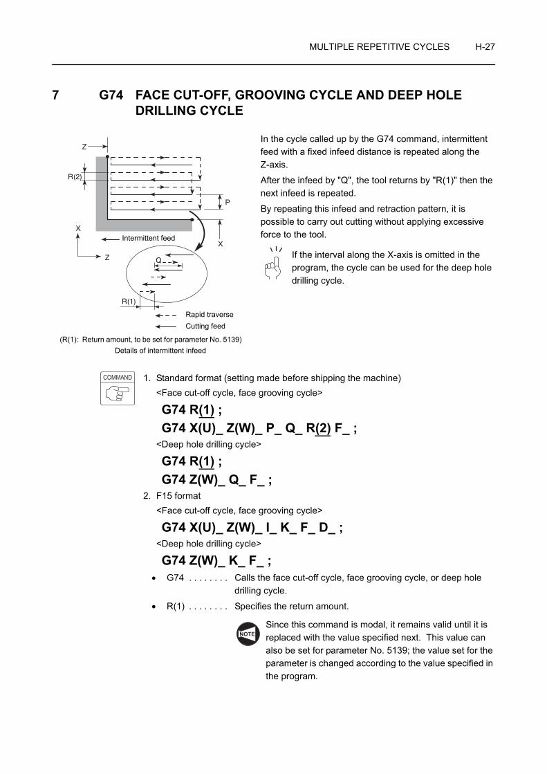
MULTIPLE REPETITIVE CYCLES H-27
7 G74 FACE CUT-OFF, GROOVING CYCLE AND DEEP HOLE DRILLING CYCLE
In the cycle called up by the G74 command, intermittent feed with a fixed infeed distance is repeated along the Z-axis.
After the infeed by "Q", the tool returns by "R(1)" then the next infeed is repeated.
By repeating this infeed and retraction pattern, it is possible to carry out cutting without applying excessive force to the tool.
If the interval along the X-axis is omitted in the program, the cycle can be used for the deep hole drilling cycle.
1. Standard format (setting made before shipping the machine)<Face cut-off cycle, face grooving cycle>
G74 R(1) ;G74 X(U)_ Z(W)_ P_ Q_ R(2) F_ ;
<Deep hole drilling cycle>
G74 R(1) ;G74 Z(W)_ Q_ F_ ;
2. F15 format<Face cut-off cycle, face grooving cycle>
G74 X(U)_ Z(W)_ I_ K_ F_ D_ ;<Deep hole drilling cycle>
G74 Z(W)_ K_ F_ ;• G74 . . . . . . . . Calls the face cut-off cycle, face grooving cycle, or deep hole
drilling cycle.
• R(1) . . . . . . . . Specifies the return amount.
Since this command is modal, it remains valid until it is replaced with the value specified next. This value can also be set for parameter No. 5139; the value set for the parameter is changed according to the value specified in the program.
X
Z Q
R(1)
R(2)
Z
P
XIntermittent feed
(R(1): Return amount, to be set for parameter No. 5139)Details of intermittent infeed
Cutting feedRapid traverse
COMMAND
NOTENOTE

H-28 MULTIPLE REPETITIVE CYCLES
• X. . . . . . . . . . . Specifies the cutting end point in the X-axis direction.
• Z . . . . . . . . . . . Specifies the bottom of cutting in the Z-axis direction.
• U. . . . . . . . . . . Specifies the distance and direction from the cutting start point to the cutting end point in the X-axis direction (in diameter).
• W . . . . . . . . . . Specifies the distance and direction from the cutting start point to the cutting end point in the Z-axis direction.
• P, I . . . . . . . . . Specifies the distance in X-axis movement (unsigned value, in radius).
• Q, K . . . . . . . . Specifies the depth of cut in the Z-axis direction (unsigned).
• R(2), D . . . . . . Escape at the bottom
• F . . . . . . . . . . . Specifies the feedrate.
1. If no F command is specified in the G74 block, the one valid before the execution of the G74 block becomes valid for the execution of the cutting defined by the commands in the G74 block.
2. The cycle starts from and ends at the position, where the cutting tool is positioned right before the execution of the G74 block.
3. For the G74 cycle, the automatic tool nose radius offset function is invalid.
WARNING If the multiple repetitive cycle is interrupted to execute manual operation, the status before the interruption of the cycle must be re-established before restarting the interrupted cycle. If the cycle is restarted without re-establishing the previous status, the turret will move in an unexpected direction, causing interference between the cutting tools, tool holders, or turret head, and the workpiece, chuck, fixture, or tailstock (tailstock specification), which could cause accidents involving serious injuries or damage to the machine. In addition, if cutting is carried out with the wrong tool, the cutting tool will be damaged.
NOTE

MULTIPLE REPETITIVE CYCLES H-29
Programming using G74 (Face cut-off cycle)
To create a program using the G74 face cut-off cycle
O0001;
N1;
G50 S1500;
G00 T0101;
G96 S100 M03;
X100.0 Z20.0 M08;
G01 Z3.0 F1.0; . . . . . . . . . . . . . . . . . . . Positioning at the start point (X100.0, Z3.0) for the face cut-off cycle (G74)
G74 R0.1; . . . . . . . . . . . . . . . . . . . . . . . Setting of the parameter used for the face cut-off cycle (G74)
• R0.1. . . . . . Return amount in intermittent feed: 0.1
G74 X70.0 Z−40.0 P3000 Q10000 R1.0 F0.25; . . . . . . . . . . . . . . . . . . . . . . . . . . . . . . . Execution of the face cut-off cycle (G74)
• X70.0 . . . . Cutting end point in the X-axis direction
• Z−40.0 . . . Bottom of cutting in the Z-axis direction
• P3000 . . . . Interval in the X-axis direction movement (in radius): 3 mm
• Q10000 . . . Infeed amount per intermittent infeed operation in the Z-axis direction: 10 mm
• R1.0 . . . . . Escape at the bottom of cutting: 1 mm
• F0.25 . . . . Feedrate: 0.25 mm/rev
At the completion of the cycle, the cutting tool returns to the start point of the cycle (X100.0, Z3.0), at a rapid traverse rate.
G00 X200.0 Z150.0;
M01;
Ex.
3 (P)
3
1
1
1(X70.0, Z-40.0)
φ110
φ70
40
R(2)
4
Intermittent feed
Rapid traverse
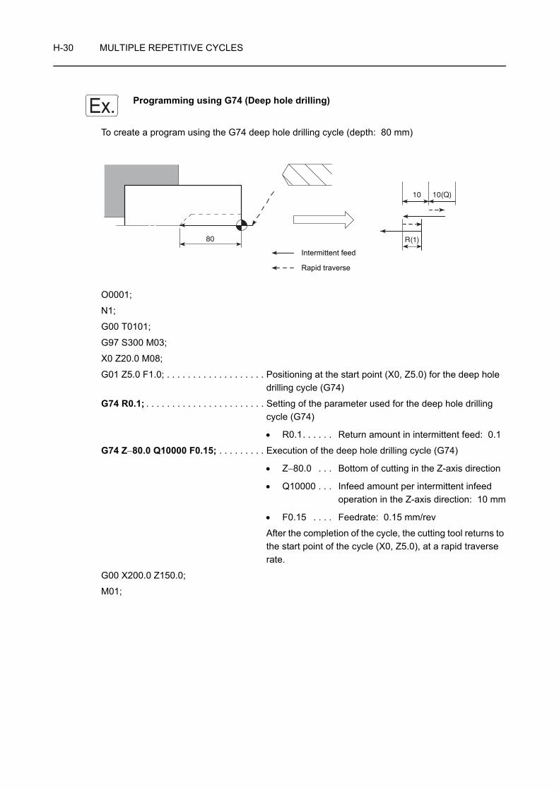
H-30 MULTIPLE REPETITIVE CYCLES
Programming using G74 (Deep hole drilling)
To create a program using the G74 deep hole drilling cycle (depth: 80 mm)
O0001;
N1;
G00 T0101;
G97 S300 M03;
X0 Z20.0 M08;
G01 Z5.0 F1.0; . . . . . . . . . . . . . . . . . . . Positioning at the start point (X0, Z5.0) for the deep hole drilling cycle (G74)
G74 R0.1; . . . . . . . . . . . . . . . . . . . . . . . Setting of the parameter used for the deep hole drilling cycle (G74)
• R0.1. . . . . . Return amount in intermittent feed: 0.1
G74 Z−80.0 Q10000 F0.15; . . . . . . . . . Execution of the deep hole drilling cycle (G74)
• Z−80.0 . . . Bottom of cutting in the Z-axis direction
• Q10000 . . . Infeed amount per intermittent infeed operation in the Z-axis direction: 10 mm
• F0.15 . . . . Feedrate: 0.15 mm/rev
After the completion of the cycle, the cutting tool returns to the start point of the cycle (X0, Z5.0), at a rapid traverse rate.
G00 X200.0 Z150.0;
M01;
Ex.
80
10
R(1)
10(Q)
Intermittent feed
Rapid traverse

MULTIPLE REPETITIVE CYCLES H-31
8 G75 O.D./I.D. GROOVING CYCLE, CUT-OFF CYCLE
In the cycle called up by the G75 command, intermittent feed with a fixed infeed distance is repeated along the X-axis.
After the infeed by "P", the tool returns by "R(1)" then the next infeed is repeated.
By repeating this infeed and retraction pattern, it is possible to carry out cutting without applying excessive force to the tool.
If the interval along the Z-axis is omitted in the program, the cycle can be used for the cut-off cycle.
1. Standard format (setting made before shipping the machine)<O.D./I.D. grooving cycle>
G75 R(1);G75 X(U)_ Z(W)_ P_ Q_ R(2) F_ ;
<O.D. cut-off cycle>
G75 R(1);G75 X(U)_ P_ F_ ;
2. F15 format<O.D./I.D. grooving cycle>
G75 X(U)_ Z(W)_ I_ K_ F_ D_ ;<O.D. cut-off cycle>
G75 X(U)_ I_ F_ ;• G75 . . . . . . . . Calls the O.D./I.D. grooving cycle or O.D. cut-off cycle.
• R(1) . . . . . . . . Specifies the return amount.
Since this command is modal, it remains valid until it is replaced with the value specified next. This value can also be set for parameter No. 5139; the value set for the parameter is changed according to the value specified in the program.
P
X
Z
X
R(2)
ZQ
R(1)
Intermittent feed
(R(1): Return amount, to be set for parameter No. 5139)Details of intermittent infeed
Cutting feedRapid traverse
COMMAND
NOTE

H-32 MULTIPLE REPETITIVE CYCLES
• X . . . . . . . . . . Specifies the bottom of cutting in the X-axis direction.
• Z . . . . . . . . . . Specifies the cutting end point in the Z-axis direction.
• U . . . . . . . . . . Specifies the distance and direction from the cutting start point to the cutting end point in the X-axis direction (in diameter).
• W . . . . . . . . . . Specifies the distance and direction from the cutting start point to the cutting end point in the Z-axis direction.
• P, I . . . . . . . . . Specifies the depth of cut in the X-axis direction (unsigned value, in radius).
• Q, K . . . . . . . . Specifies the distance in Z-axis movement (unsigned).
• R(2), D . . . . . . Escape at the bottom
• F . . . . . . . . . . Specifies the feedrate.
1. If no F command is specified in the G75 block, the one valid before the execution of the G75 block becomes valid for the execution of the cutting defined by the commands in the G75 block.
2. The cycle starts from and ends at the position, where the cutting tool is positioned right before the execution of the G75 block.
3. For the G75 cycle, the automatic tool nose radius offset function is invalid.
4. Do not specify a relief amount R(2) command for O.D. or I.D. grooving operation. If the R(2) command is specified for such operations, the tool shifts by the amount specified by the R(2) command at the bottom to cause the interference between the tool and the workpiece, which will result in damage to the tool.
Specify the R(2) command for a workpiece having the shape as illustrated on the right.
WARNING If the multiple repetitive cycle is interrupted to execute manual operation, the status before the interruption of the cycle must be re-established before restarting the interrupted cycle. If the cycle is restarted without re-establishing the previous status, the turret will move in an unexpected direction, causing interference between the cutting tools, tool holders, or turret head, and the workpiece, chuck, fixture, or tailstock (tailstock specification), which could cause accidents involving serious injuries or damage to the machine. In addition, if cutting is carried out with the wrong tool, the cutting tool will be damaged.
NOTE

MULTIPLE REPETITIVE CYCLES H-33
Programming using G75 (O.D./I.D. grooving cycle)
To create a program using the G75 O.D. grooving cycle
O0001;
N1;
G50 S1500;
G00 T0101;
G96 S100 M03;
X120.0 Z20.0 M08;
G01 Z−45.0 F1.0; . . . . . . . . . . . . . . . . . Positioning at the start point (X120.0, Z−45.0) for the O.D. grooving cycle (G75)
G75 R0.1; . . . . . . . . . . . . . . . . . . . . . . . Setting of the parameter used for the O.D. grooving cycle (G75)
• R0.1. . . . . . Return amount in intermittent feed: 0.1
G75 X100.0 Z−80.0 P2000 Q4500 F0.15; . . . . . . . . . . . . . . . . . . . . . . . . . . . . . . . Execution of the O.D. grooving cycle (G75)
• X100.0 . . . Bottom of cutting in the X-axis direction
• Z−80.0 . . . Cutting end point in the Z-axis direction
• P2000 . . . . Infeed amount per intermittent infeed operation in the X-axis direction: 2 mm
• Q4500 . . . . Interval in the Z-axis direction movement: 4.5 mm
• F0.15 . . . . Feedrate: 0.15 mm/rev
At the completion of the cycle, the cutting tool returns to the start point of the cycle (X120.0, Z−45.0), at a rapid traverse rate.
G00 X200.0 Z150.0;
M01;
Ex.
40
80 4.5 4.5(Q) (Q)
0 R(2)
φ110
φ100
5
6
Intermittent feed
Rapid traverse
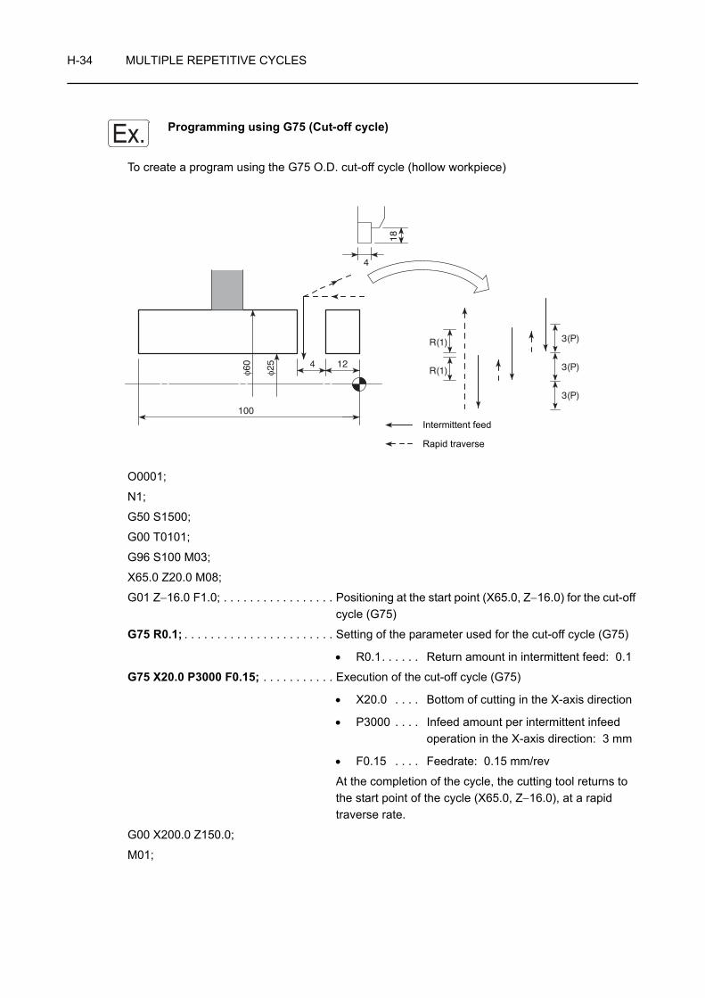
H-34 MULTIPLE REPETITIVE CYCLES
Programming using G75 (Cut-off cycle)
To create a program using the G75 O.D. cut-off cycle (hollow workpiece)
O0001;
N1;
G50 S1500;
G00 T0101;
G96 S100 M03;
X65.0 Z20.0 M08;
G01 Z−16.0 F1.0; . . . . . . . . . . . . . . . . . Positioning at the start point (X65.0, Z−16.0) for the cut-off cycle (G75)
G75 R0.1; . . . . . . . . . . . . . . . . . . . . . . . Setting of the parameter used for the cut-off cycle (G75)
• R0.1. . . . . . Return amount in intermittent feed: 0.1
G75 X20.0 P3000 F0.15; . . . . . . . . . . . Execution of the cut-off cycle (G75)
• X20.0 . . . . Bottom of cutting in the X-axis direction
• P3000 . . . . Infeed amount per intermittent infeed operation in the X-axis direction: 3 mm
• F0.15 . . . . Feedrate: 0.15 mm/rev
At the completion of the cycle, the cutting tool returns to the start point of the cycle (X65.0, Z−16.0), at a rapid traverse rate.
G00 X200.0 Z150.0;
M01;
Ex.
φ60
φ25 4 12
100
R(1)
R(1)
3(P)
3(P)
3(P)
4
18
Intermittent feed
Rapid traverse

MULTIPLE REPETITIVE CYCLES H-35
9 G76 MULTIPLE THREAD CUTTING CYCLE
The G76 command calls the thread cutting cycle, shown in the illustration on the left. The required thread height is obtained by executing the thread cutting pattern repeatedly in the range from point 2 to 3 along the angle of the thread.
1. Standard format (setting made before shipping the machine)
G76 P(1) Q(1) R(1);G76 X(U)_ Z(W)_ R(2) P(2) Q(2) F_ ;
2. F15 format
G76 X(U)_ Z(W)_ I_ K_ D_ F_ A_ P_ ;• G76 . . . . . . . . Calls the multiple thread cutting cycle.
• P(1) . . . . . . . . Specifies how the thread should be machined with a 6-digit number.
P
: The number of finish cuts to be repeated. Range: 1 - 99
Since this command is modal, it remains valid until it is replaced with the value specified next. This value can also be set for parameter No. 5142; the value set for the parameter is changed according to the value specified in the program.
: Thread chamfering size
Thread chamfering size can be specified in the range from 0.0L to 9.9L in increments of 0.1L (L: thread lead). In a program, specification is made in a 2-digit number of 00 to 99.
Since this command is modal, it remains valid until it is replaced with the value specified next. This value can also be set for parameter No. 5130; the value set for the parameter is changed according to the value specified in the program.
1
23
4
5
Cutting feedRapid traverse
COMMAND
NOTE
NOTE

H-36 MULTIPLE REPETITIVE CYCLES
: Thread angle
Thread angle can be selected from the following six options: 80°, 60°, 55°, 30°, 29°, and 0°.In a program, the selected angle is directly specified in a 2-digit number.
Since this command is modal, it remains valid until it is replaced with the value specified next. This value can also be set for parameter No. 5143; the value set for the parameter is changed according to the value specified in the program.
P021260
This P command specifies the following:
Finish cut is repeated two times,
Thread chamfering size is 1.2L, and
Thread angle is 60°.
• Q(1) . . . . . . . . Specifies the minimum depth of cut.
If depth of cut per path ( d − d ) becomes
smaller than dmin, depth of cut is clamped at dmin.Since this command is modal, it remains valid until it is replaced with the value specified next. This value can also be set for parameter No. 5140; the value set for the parameter is changed according to the value specified in the program.
• R(1) . . . . . . . . Specifies the finishing allowance.
Since this command is modal, it remains valid until it is replaced with the value specified next. This value can also be set for parameter No. 5141; the value set for the parameter is changed according to the value specified in the program.
• X, Z. . . . . . . . . Specify the X and Z coordinates of the thread cutting end point.
• U, W . . . . . . . . Specify the distance and direction from the thread cutting start point to the end point along the X-axis and the Z-axis, respectively (in diameter for U).
• R(2), I . . . . . . . Specifies the distance of taper in the X-axis direction (signed value, in radius).
If this command is omitted, straight thread is cut.
• P(2), K . . . . . . Specifies the thread height (in radius, unsigned value).
• Q(2), D . . . . . . Specifies the depth of cut for the first thread cutting path (in radius, unsigned value).
• F . . . . . . . . . . . Specifies the lead of thread.
NOTE
Ex.
NOTEn n−1
NOTE
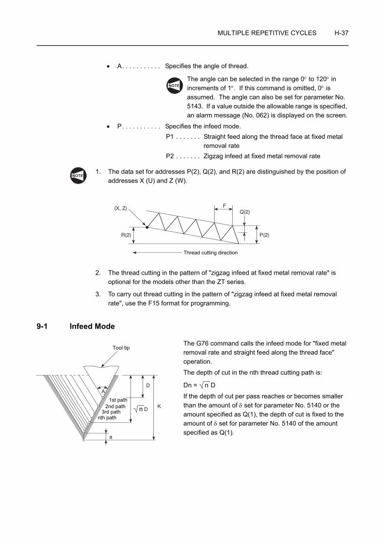
MULTIPLE REPETITIVE CYCLES H-37
• A. . . . . . . . . . . Specifies the angle of thread.
The angle can be selected in the range 0° to 120° in increments of 1°. If this command is omitted, 0° is assumed. The angle can also be set for parameter No. 5143. If a value outside the allowable range is specified, an alarm message (No. 062) is displayed on the screen.
• P. . . . . . . . . . . Specifies the infeed mode.P1 . . . . . . . Straight feed along the thread face at fixed metal
removal rateP2 . . . . . . . Zigzag infeed at fixed metal removal rate
1. The data set for addresses P(2), Q(2), and R(2) are distinguished by the position of addresses X (U) and Z (W).
2. The thread cutting in the pattern of "zigzag infeed at fixed metal removal rate" is optional for the models other than the ZT series.
3. To carry out thread cutting in the pattern of "zigzag infeed at fixed metal removal rate", use the F15 format for programming.
9-1 Infeed Mode
The G76 command calls the infeed mode for "fixed metal removal rate and straight feed along the thread face" operation.
The depth of cut in the nth thread cutting path is:
Dn = D
If the depth of cut per pass reaches or becomes smaller than the amount of δ set for parameter No. 5140 or the amount specified as Q(1), the depth of cut is fixed to the amount of δ set for parameter No. 5140 of the amount specified as Q(1).
NOTE
NOTE
R(2)
(X, Z) FQ(2)
P(2)
Thread cutting direction
A
D
D
K
a
Tool tip
1st path2nd path
3rd pathnth path
n
n

H-38 MULTIPLE REPETITIVE CYCLES
9-2 Cautions on the G76 Multiple Thread Cutting Cycle
The cautions indicated for the G32 and G92 thread cutting cycles also apply to the thread cutting cycle called by the G76 command.
For precautions on thread cutting operation: Page B-45
Chamfering mode for thread cutting is valid when the power is turned on.
M23 . . . . . . . . Chamfering ON (initial status when the power is turned on.)
M24 . . . . . . . . Chamfering OFF
WARNING If the multiple repetitive cycle is interrupted to execute manual operation, the status before the interruption of the cycle must be re-established before restarting the interrupted cycle. If the cycle is restarted without re-establishing the previous status, the turret will move in an unexpected direction, causing interference between the cutting tools, tool holders, or turret head, and the workpiece, chuck, fixture, or tailstock (tailstock specification), which could cause accidents involving serious injuries or damage to the machine. In addition, if cutting is carried out with the wrong tool, the cutting tool will be damaged.
NOTE

MULTIPLE REPETITIVE CYCLES H-39
Programming using G76
To execute thread cutting using the G76 multiple thread cutting cycle
O0001;
N1;
G00 T0101;
G97 S640 M03;
X70.0 Z20.0 M08;
G01 Z5.0 F1.0 M24; . . . . . . . . . . . . . . . Positioning at the start point (X70.0, Z5.0) for the multiple thread cutting cycle (G76)
The M24 command makes chamfering invalid in the next thread cutting.
Ex.
M60 × P2
25
φ69
C13C1.5
C0.5
φ54
2 2
1.3
60°
5Details of thread
Cutting feed
Rapid traverse
NOTE

H-40 MULTIPLE REPETITIVE CYCLES
G76 P010060;G76 X57.4 Z−24.0 P1300 Q350 F2.0; . . . . . . . . . . . . . . . . . . . . . . . . . . . . . . . Execution of the multiple thread cutting cycle (G76)
• P010060 . . . . Finish cycle execution: OnceThread chamfering amount: 0Thread angle: 60°
• X57.4 . . . . . . . The diameter of the last thread cutting path
• Z−24.0 . . . . . . The Z coordinate of the thread cutting end point (includes incomplete thread length of 2 mm).
• P1300 . . . . . . Thread height: 1.3 mm
• Q350 . . . . . . . Depth of cut for the first thread cutting path: 0.35 mm
• F2.0 . . . . . . . . Thread pitch: 2 mm
G00 X200.0 Z150.0 M09;
M05;
M30;
The thread height and the depth of cut for the first path are specified only for reference.NOTE

MULTIPLE REPETITIVE CYCLES H-41
9-3 The Relationship between Depth of Cut for the First Path and the Number of Thread Cutting Paths to be Generated (Fixed Metal Removal Rate and Straight Feed along the Thread Face)
9-3-1 Calculating the Number of Thread Cutting Paths when the Depth of Cut for the First Path is Given
n = + 1
Assume that: D = 0.35 K = 1.3 a = 0.05,
then, number of thread cutting paths (n) are calculated as follows:
n = + 1
= 12.76 + 1
14 ("12.76" is rounded up to "13".)
Therefore, the thread cutting pattern is repeated 14 times to generate the required thread.
9-3-2 Calculating the Depth of Cut for the First Path when the Number of Thread Cutting Paths is Given
D =
Assume that: K = 1.3 a = 0.05 n = 14,
then depth of cut for the first path (D) is calculated as follows:
D =
= 0.346...
0.35
Therefore, the depth of cut for the first path is 0.35 mm.
D: Depth of cut for the first path (in radius)
K: Thread height (in radius)
a: Depth of cut for the last path
n: Number of thread cutting paths
K − aD
2
Ex.
1.3 − 0.050.35
2
n: Number of thread cutting paths
K: Thread height (in radius)
a: Depth of cut for the last path
D: Depth of cut for the first path (in radius)
K − an − 1
Ex.
1.3 − 0.0514 − 1
CHAPTER IHOLE MACHINING CANNED
CYCLE
This chapter describes hole machining canned cycles.
Since different patterns of tool movement are available to cover various hole machining requirements, choose the most proper cycle for intended operation.
A hole machining cycle specifies operation sequence to be specified in several blocks by the commands in a single block containing a G code.
When specifying a hole machining canned cycle, two types of format (standard format and F15 format) are used.
This manual gives explanation based on the standard format. However, for the G codes which allow the use of the F15 format, related command format is also explained. Note that the F15 format is different from standard format.
Instruction manual supplied by the NC manufacturer
NOTE
CONTENTS
I : HOLE MACHINING CANNED CYCLE
1 GENERAL . . . . . . . . . . . . . . . . . . . . . . . . . . . . . . . . . . . . . . . . . . . . . . . . . . . . . . . . . . . . I-1
1-1 Number of Repetitions "K". . . . . . . . . . . . . . . . . . . . . . . . . . . . . . . . . . . . . . . . . . . I-5
1-2 Operation Methods in Hole Machining Canned Cycles (G Codes) . . . . . . . . . . . . I-7
1-2-1 Face Hole Machining Canned Cycle . . . . . . . . . . . . . . . . . . . . . . . . . . . . I-7
1-2-2 Side Hole Machining Canned Cycle . . . . . . . . . . . . . . . . . . . . . . . . . . . . I-9
2 G80 HOLE MACHINING CANNED CYCLE CANCEL . . . . . . . . . . . . . . . . . . . . . . . . . I-14
3 G83, G83.5, G83.6 FACE DRILLING CYCLE . . . . . . . . . . . . . . . . . . . . . . . . . . . . . . . I-17
3-1 G83, G83.5 Face High-speed Deep Hole Drilling Cycle . . . . . . . . . . . . . . . . . . I-17
3-2 G83, G83.6 Face Deep Hole Drilling Cycle . . . . . . . . . . . . . . . . . . . . . . . . . . . . I-21
3-3 G83 Face Spot Drilling Cycle . . . . . . . . . . . . . . . . . . . . . . . . . . . . . . . . . . . . . . . I-25
3-4 G83 Face Spot Drilling Cycle (Dwell) . . . . . . . . . . . . . . . . . . . . . . . . . . . . . . . . . I-27
4 G84 FACE TAPPING CYCLE. . . . . . . . . . . . . . . . . . . . . . . . . . . . . . . . . . . . . . . . . . . . I-30
5 M329 G84 FACE SYNCHRONIZED TAPPING CYCLE . . . . . . . . . . . . . . . . . . . . . . . . I-34
6 G85 FACE BORING CYCLE . . . . . . . . . . . . . . . . . . . . . . . . . . . . . . . . . . . . . . . . . . . . I-39
7 G87, G87.5, G87.6 SIDE DRILLING CYCLE . . . . . . . . . . . . . . . . . . . . . . . . . . . . . . . . I-42
7-1 G87, G87.5 Side High-speed Deep Hole Drilling Cycle . . . . . . . . . . . . . . . . . . . I-42
7-2 G87, G87.6 Side Deep Hole Drilling Cycle. . . . . . . . . . . . . . . . . . . . . . . . . . . . . I-46
7-3 G87 Side Spot Drilling Cycle . . . . . . . . . . . . . . . . . . . . . . . . . . . . . . . . . . . . . . . I-50
7-4 G87 Side Spot Drilling Cycle (Dwell) . . . . . . . . . . . . . . . . . . . . . . . . . . . . . . . . . I-53
8 G88 SIDE TAPPING CYCLE . . . . . . . . . . . . . . . . . . . . . . . . . . . . . . . . . . . . . . . . . . . . I-57
9 M329 G88 SIDE SYNCHRONIZED TAPPING CYCLE . . . . . . . . . . . . . . . . . . . . . . . . I-61
10 G89 SIDE BORING CYCLE . . . . . . . . . . . . . . . . . . . . . . . . . . . . . . . . . . . . . . . . . . . . . I-65
11 G384, G380 SYNCHRONIZED TAPPING CYCLE. . . . . . . . . . . . . . . . . . . . . . . . . . . . I-68
12 CAUTIONS ON PROGRAMMING USING G84 AND G88 . . . . . . . . . . . . . . . . . . . . . . I-75
12-1 Dwell Command . . . . . . . . . . . . . . . . . . . . . . . . . . . . . . . . . . . . . . . . . . . . . . . . . I-75
12-2 Precautions on Using the Tapper . . . . . . . . . . . . . . . . . . . . . . . . . . . . . . . . . . . . I-76
12-3 To Finish Tapping at Correct Depth in Blind Hole . . . . . . . . . . . . . . . . . . . . . . . . I-77
HOLE MACHINING CANNED CYCLE I-1
1 GENERAL
Hole machining operation is programmed using several blocks of commands.
A hole machining canned cycle allows hole machining operation which requires several blocks of commands to be programmed using one block of commands including an appropriate G code.
1. Hole machining canned cycles can be used only with the MC type or Y-axis specification machines. With the models other than MC type and Y-axis specification, these cycles cannot be used.
2. Synchronized tapping is possible only for the MC type or Y-axis specification machines.
3. With the ZL, ZL-S, and ZT series, the face synchronized tapping cycle (M329 G84) can be optionally used for models other than MC type and Y-axis specification. Note that this cycle can be used only at the center of the spindle. With the ZL series, the cycle cannot be used at the turret 2 side. Concerning the ZL-S and ZT series, face synchronized tapping cycle is possible using spindle 1 at the turret 1 side and using spindle 2 at the turret 2 side.
4. The G384 and G380 commands can be used only for the MC type of ZL and ZL-S series machines.
5. With the ZL series, the G384 and G380 commands can be specified only in the turret 1 program.
NOTE

I-2 HOLE MACHINING CANNED CYCLE
<Basic pattern of hole machining canned cycle>
Basic command format and movement of the hole machining canned cycle are explained below:
<Movement>
A hole machining canned cycle consists of movements 1 to 6 shown in the diagram.
In the cycle called by G83 to G85, the Z-axis is used as the hole machining axis while the X-axis is used as the hole machining axis in the cycle called by G87 to G89. With the exception of the difference in the hole machining axis, movements 1, 2 and 6 are common to all types of hole machining canned cycles.
Movements 3 to 5 vary according to respective canned cycles.
For a hole machining canned cycle, "initial point" and "point R" indicate the following positions:
• Initial point . . . . . The position where a hole machining canned cycle starts
• Point R . . . . . . . The position where hole machining (axis feed at cutting feedrate) cycle starts
Movement 1: Positioning at the hole machining start position
Movement 2: Moving to point R at a rapid traverse rate
Movement 3: Hole machining (Hole machining is carried out.)
Movement 4: Movement at hole bottom
Specify dwell if necessary.
Movement 5: Returning to point R level
Whether the Z-axis return movement is executed at a rapid traverse rate or cutting feedrate is determined by the G code specified for calling the hole machining canned cycle.
Movement 6: Positioning at initial point at rapid traverse rate
X0
Z0
+Z−Z
Z0
+X
−X
X0
Rapid traverse
Cutting feed
Rapid traverse or cutting feed
Movement 4
• Face hole machining canned cycle (G83 - G85)
Movement 3
Movement 5 Movement 6
Movement 2
Movement 1
Initial pointPoint R
• Side hole machining canned cycle (G87 - G89)
Initial pointMovement 1
Movement 2 Movement 6
Movement 3 Movement 5
Movement 4
Point R
Rapid traverse
Cutting feed
Rapid traverse or cutting feed
NOTE

HOLE MACHINING CANNED CYCLE I-3
1. Face hole machining canned cycle
G83 - G85 X(U)_ C(H)_ Z(W)_ R_ Q_ P_ F_ K_ (M68);G83 - G85 X(U)_ Y(V)_ Z(W)_ R_ Q_ P_ F_ K_ (M68);G80;
• G83 - G85 . . . Calls a face hole machining canned cycle.
Operation mode from movement 3 to movement 5 is determined according the specified G code.
• G80 . . . . . . . . Cancels a hole machining canned cycle.
• X, C, Y . . . . . . Absolute commandSpecifies the hole machining positions. (Movement 1)
• U, H, V . . . . . . Incremental commandSpecifies the distance and direction of the hole machining position in reference to the previous block. (Movement 1)
• Z . . . . . . . . . . Absolute commandSpecifies the hole bottom.
• W . . . . . . . . . . Incremental commandSpecifies the distance and direction of the hole bottom in reference to the point R.
• R . . . . . . . . . . Incremental commandSpecifies the distance and direction of the point R in reference to the initial point.
• Q . . . . . . . . . . Specifies depth of cut per one infeed motion (G83, G83.5, G83.6).
• P . . . . . . . . . . Specifies the period of dwell function executed at the hole bottom.
P1500 → 1.5 sec
• F . . . . . . . . . . Specifies the feedrate.
• K . . . . . . . . . . Specifies the number of repetitions.
If designation of address K is omitted, hole machining cycle is executed once after the positioning at the hole position (equivalent to K1).
K0 . . . . . . . . . . . After the positioning at the specified hole position, hole machining cycle is not executed.
K1 to K9999 . . . Hole machining cycle is repeated by the number of times specified by address K.
• (M68) . . . . . . . Spindle or spindle 1 brake clamp (C-axis clamp or C-axis clamp of spindle 1)
Specify M68 to carry out heavy-duty cutting.
COMMAND
NOTE
NOTE

I-4 HOLE MACHINING CANNED CYCLE
2. Side hole machining canned cycle
G87 - G89 Z(W)_ C(H)_ X(U)_ R_ Q_ P_ F_ K_ (M68);G87 - G89 Z(W)_ Y(V)_ X(U)_ R_ Q_ P_ F_ K_ (M68);G80;
• G87 - G89 . . . Calls a side hole machining canned cycle.
Operation mode from movement 3 to movement 5 is determined according the specified G code.
• G80 . . . . . . . . Cancels a hole machining canned cycle.
• Z, C, Y . . . . . . Absolute commandSpecifies the hole machining positions. (Movement 1)
• W, H, V . . . . . Incremental commandSpecifies the distance and direction of the hole machining position in reference to the previous block. (Movement 1)
• X . . . . . . . . . . Absolute commandSpecifies the hole bottom.
• U . . . . . . . . . . Incremental commandSpecifies the distance and direction of the hole bottom in reference to the point R.
• R . . . . . . . . . . Incremental commandSpecifies the distance and direction of the point R in reference to the initial point.
• Q . . . . . . . . . . Specifies depth of cut per one infeed motion (G87, G87.5, G87.6).
• P . . . . . . . . . . Specifies the period of dwell function executed at the hole bottom.
P1500 → 1.5 sec
• F . . . . . . . . . . Specifies the feedrate.
• K . . . . . . . . . . Specifies the number of repetitions.
If designation of address K is omitted, hole machining cycle is executed once after the positioning at the hole position (equivalent to K1).
K0 . . . . . . . . . . . After the positioning at the specified hole position, hole machining cycle is not executed.
K1 to K9999 . . . Hole machining cycle is repeated by the number of times specified by address K.
• (M68) . . . . . . . Spindle or spindle 1 brake clamp (C-axis clamp or C-axis clamp of spindle 1)
Specify M68 to carry out heavy-duty cutting.
COMMAND
NOTE
NOTE

HOLE MACHINING CANNED CYCLE I-5
1. In the F15 format, use address L to specify the number of repetitions.
2. When the M68 command (spindle or spindle 1 brake clamp (C-axis clamp or C-axis clamp of spindle 1)) is specified, M68 is output before the start of operation 2 and M69 (spindle or spindle 1 brake unclamp (C-axis unclamp or C-axis unclamp of spindle 1)) is output at the completion of operation 5.Dwell is executed for the time set for parameter No. 5111 after that.
1-1 Number of Repetitions "K"
When machining the holes of the same dimensions, arranged in equal intervals, it is possible to repeat the same hole machining canned cycle by specifying the number of repetitions following address K. Therefore, the use of a K command can simplify programming.
K1When K1 is specified, hole machining cycle is executed once at the specified position.
"K1" is omissible. If no K command is specified, it is equivalent to the designation of "K1".
G83 X150.0 C30.0 Z−18.0 R−27.0 F100 (K1); . . . . . . . . . . . . . . . . . . . . . . . . . . . . . . . After positioning at (X150.0, C30.0), hole machining cycle
is executed.
C90.0;
C150.0;
K2 to K9999When Kn (n = 2 to 9999) is specified, the specified hole machining cycle is repeated by the specified number of times.
This is used for machining holes arranged in the same intervals.
If Kn (n = 2 to 9999) is specified, specify the position of the first hole in an incremental mode command.
If an absolute mode command is used to specify the position of the first hole, hole machining cycle is repeated by the specified number of times at the first hole position.
NOTE
. . . . . . . . . . . . . . . . . . . . . After positioning at the specified position, hole machining cycle is executed.
NOTE
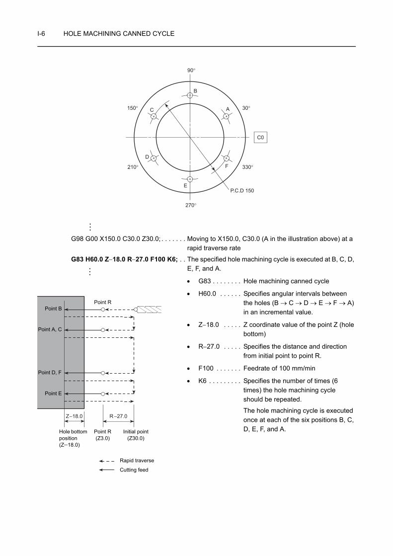
I-6 HOLE MACHINING CANNED CYCLE
G98 G00 X150.0 C30.0 Z30.0; . . . . . . . Moving to X150.0, C30.0 (A in the illustration above) at a rapid traverse rate
G83 H60.0 Z−18.0 R−27.0 F100 K6; . . The specified hole machining cycle is executed at B, C, D, E, F, and A.
• G83 . . . . . . . . Hole machining canned cycle
• H60.0 . . . . . . Specifies angular intervals between the holes (B → C → D → E → F → A) in an incremental value.
• Z−18.0 . . . . . Z coordinate value of the point Z (hole bottom)
• R−27.0 . . . . . Specifies the distance and direction from initial point to point R.
• F100 . . . . . . . Feedrate of 100 mm/min
• K6 . . . . . . . . . Specifies the number of times (6 times) the hole machining cycle should be repeated.
The hole machining cycle is executed once at each of the six positions B, C, D, E, F, and A.
P.C.D 150
210°
150°
330°
30°
C0
90°
270°
B
A
F
E
D
C
Z−18.0 R −27.0
Rapid traverse
Cutting feed
Point R
Hole bottom position(Z−18.0)
Point B
Point A, C
Point E
Point R(Z3.0)
Initial point(Z30.0)
Point D, F

HOLE MACHINING CANNED CYCLE I-7
1-2 Operation Methods in Hole Machining Canned Cycles (G Codes)
The patterns and operation methods called by the hole machining canned cycle G codes are briefly explained below using diagrams.
Typical applications and cautions are also described.
1-2-1 Face Hole Machining Canned Cycle
The face hole machining canned cycle indicates the canned cycle in which hole machining is executed by the Z-axis with positioning executed by the combination of X- and C-axes or X- and Y-axes.
Rapid traverse Cutting feed
G83, G83.5 High-speed deep hole drilling
G83, G83.6 Deep hole drilling G83 Spot drilling
<XC plane>G83(G83.5) X(U)_ C(H)_ Z(W)_
R_ Q_ P_ F_ ;<XY plane>
G83(G83.5) X(U)_ Y(V)_ Z(W)_ R_ Q_ P_ F_ ;
<XC plane>G83(G83.6) X(U)_ C(H)_ Z(W)_
R_ Q_ P_ F_ ;<XY plane>
G83(G83.6)X(U)_ Y(V)_ Z(W)_ R_ Q_ P_ F_ ;
<XC plane>G83 X(U)_ C(H)_ Z(W)_ R_ F_ ;
<XY plane>G83 X(U)_ Y(V)_ Z(W)_ R_ F_ ;
[G83]Parameter No. 5101.2 = 0(Setting made before shipping the machine)
[G83.5]Parameter No. 5161.0 = 1(Setting made before shipping the machine)
[G83]Parameter No. 5101.2 = 1
[G83.6]Parameter No. 5161.0 = 1(Setting made before shipping the machine)
Deep hole drillingQ: Depth of cut per pass d: Retraction stroke
Deep hole drillingQ: Depth of cut per pass d: Clearance amount
CenteringDrilling shallow holes
d
Q Q Q
Point R
Initial point
Dwell d
QQQ
Point R
Initial point
Dwell
Point R
Initial point
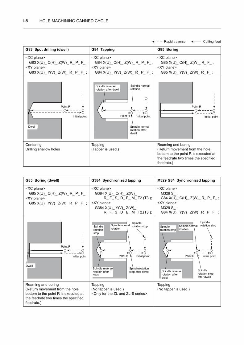
I-8 HOLE MACHINING CANNED CYCLE
Rapid traverse Cutting feed
G83 Spot drilling (dwell) G84 Tapping G85 Boring
<XC plane>G83 X(U)_ C(H)_ Z(W)_ R_ P_ F_ ;
<XY plane>G83 X(U)_ Y(V)_ Z(W)_ R_ P_ F_ ;
<XC plane>G84 X(U)_ C(H)_ Z(W)_ R_ P_ F_ ;
<XY plane>G84 X(U)_ Y(V)_ Z(W)_ R_ P_ F_ ;
<XC plane>G85 X(U)_ C(H)_ Z(W)_ R_ F_ ;
<XY plane>G85 X(U)_ Y(V)_ Z(W)_ R_ F_ ;
CenteringDrilling shallow holes
Tapping(Tapper is used.)
Reaming and boring(Return movement from the hole bottom to the point R is executed at the feedrate two times the specified feedrate.)
G85 Boring (dwell) G384 Synchronized tapping M329 G84 Synchronized tapping
<XC plane>G85 X(U)_ C(H)_ Z(W)_ R_ P_ F_ ;
<XY plane>G85 X(U)_ Y(V)_ Z(W)_ R_ P_ F_ ;
<XC plane>G384 X(U)_ C(H)_ Z(W)_
R_ F_ S_ D_ E_ M_ T2.(T3.);<XY plane>
G384 X(U)_ Y(V)_ Z(W)_R_ F_ S_ D_ E_ M_ T2.(T3.);
<XC plane>M329 S_ ;G84 X(U)_ C(H)_ Z(W)_ R_ P_ F_ ;
<XY plane>M329 S_ ;G84 X(U)_ Y(V)_ Z(W)_ R_ P_ F_ ;
Reaming and boring(Return movement from the hole bottom to the point R is executed at the feedrate two times the specified feedrate.)
Tapping(No tapper is used.)<Only for the ZL and ZL-S series>
Tapping(No tapper is used.)
Point R
Initial point
Dwell
Point R Initial point
Spindle normal rotation
Spindle normal rotation after dwell
Spindle reverse rotation after dwell
Point R
Initial point
Point R
Initial point
Dwell
Point R Initial point
Spindle rotation stop
Spindle rotation stop after dwell
Spindle reverse rotation after dwell
Spindle normal rotation
Spindle rotation stop
Point R Initial point
Spindle rotation stop
Spindle rotation stop after dwell
Spindle reverse rotation after dwell
Spindle rotation stop
Spindle normal rotation

HOLE MACHINING CANNED CYCLE I-9
1-2-2 Side Hole Machining Canned Cycle
The side hole machining canned cycle indicates the canned cycle in which hole machining is executed by the X-axis with positioning executed by the combination of Z- and C-axes or Z- and Y-axes.
Rapid traverse Cutting feed
G87, G87.5 High-speed deep hole drilling
G87, G87.6 Deep hole drilling G87 Spot drilling
<ZC plane>G87(G87.5) Z(W)_ C(H)_ X(U)_
R_ Q_ P_ F_ ;<ZY plane>
G87(G87.5) Z(W)_ Y(V)_ X(U)_ R_ Q_ P_ F_ ;
<ZC plane>G87(G87.6) Z(W)_ C(H)_ X(U)_
R_ Q_ P_ F_ ;<ZY plane>
G87(G87.6) Z(W)_ Y(V)_ X(U)_ R_ Q_ P_ F_ ;
<ZC plane>G87 Z(W)_ C(H)_ X(U)_ R_ F_ ;
<ZY plane>G87 Z(W)_ Y(V)_ X(U)_ R_ F_ ;
[G87]Parameter No. 5101.2 = 0(Setting made before shipping the machine)
[G87.5]Parameter No. 5161.0 = 1(Setting made before shipping the machine)
[G87]Parameter No. 5101.2 = 1
[G87.6]Parameter No. 5161.0 = 1(Setting made before shipping the machine)
Deep hole drillingQ: Depth of cut per pass d: Retraction stroke
Deep hole drillingQ: Depth of cut per pass d: Clearance amount
CenteringDrilling shallow holes
d
Q
Q
Q
Point R
Dwell
Initial point
d
Q
Q
Q
Point R
Dwell
Initial point
Point R
Initial point

I-10 HOLE MACHINING CANNED CYCLE
Rapid traverse Cutting feed
G87 Spot drilling (dwell) G88 Tapping G89 Boring
<ZC plane>G87 Z(W)_ C(H)_ X(U)_ R_ P_ F_ ;
<ZY plane>G87 Z(W)_ Y(V)_ X(U)_ R_ P_ F_ ;
<ZC plane>G88 Z(W)_ C(H)_ X(U)_ R_ P_ F_ ;
<ZY plane>G88 Z(W)_ Y(V)_ X(U)_ R_ P_ F_ ;
<ZC plane>G89 Z(W)_ C(H)_ X(U)_ R_ F_ ;
<ZY plane>G89 Z(W)_ Y(V)_ X(U)_ R_ F_ ;
CenteringDrilling shallow holes
Tapping(Tapper is used.)
Reaming and boring(Return movement from the hole bottom to the point R is executed at the feedrate two times the specified feedrate.)
G89 Boring (dwell) G384 Synchronized tapping M329 G88 Synchronized tapping
<ZC plane>G89 Z(W)_ C(H)_ X(U)_ R_ P_ F_ ;
<ZY plane>G89 Z(W)_ Y(V)_ X(U)_ R_ P_ F_ ;
<ZC plane>G384 Z(W)_ C(H)_ X(U)_
R_ F_ S_ D_ E_ M_ T1.(T4.);<ZY plane>
G384 Z(W)_ Y(V)_ X(U)_R_ F_ S_ D_ E_ M_ T1.(T4.);
<ZC plane>M329 S_ ;G88 Z(W)_ C(H)_ X(U)_ R_ P_ F_ ;
<ZY plane>M329 S_ ;G88 Z(W)_ Y(V)_ X(U)_ R_ P_ F_ ;
Reaming and boring(Return movement from the hole bottom to the point R is executed at the feedrate two times the specified feedrate.)
Tapping(No tapper is used.)<Only for the ZL and ZL-S series>
Tapping(No tapper is used.)<Only for ZT series>
Point R
Dwell
Initial point
Point R
Initial point
Spindle normal rotation after dwellSpindle normal
rotation
Spindle reverse rotation after dwell
Point R
Initial point
Point R
Dwell
Initial point
Point R
Initial point
Spindle rotation stop after dwell
Spindle normal rotation
Spindle rotation stop
Spindle rotation stop
Spindle reverse rotation after dwell
Point R
Initial point
Spindle normal rotation
Spindle rotation stop Spindle rotation
stop after dwell
Spindle rotation stop
Spindle reverse rotation after dwell
HOLE MACHINING CANNED CYCLE I-11
1. For the tapping cycle called by G84 or G88, a tapper is used. In this case, the return movement from the bottom of the machined hole to the point R level is made with the tapper extended. Therefore, the point R level must be specified larger value than tapper extending length. If the smaller value is specified, the cutting tool and workpiece may collide or interfere with each other, and this could damage the machine when moving to next machining position.
2. When the emergency stop button or the (RESET) key has been pressed to
stop the machine during a tapping operation, carefully move the axes after checking the workpiece and cutting tool carefully for damage. If you move the axes without due care, the workpiece and cutting tool may collide or interfere with each other, and this could cause damage to the machine.
1. If a hole machining canned cycle is interrupted by the emergency stop operation or
by pressing the (RESET) key, although the hole machining mode, hole
machining data, and hole position data are retained, the number of repetitions is cleared.
2. When calling a hole machining canned cycle, select the feed per minute mode by specifying the G98 command, and specify the spindle speed of the rotary tool in the G97 mode.
3. The number of times the called hole machining canned cycle should be repeated is required only when the cycle should be executed repeatedly. Although feedrate value is retained when the hole machining canned cycle is canceled, the repeat number data is not retained.
4. Before calling a hole machining canned cycle, rotate the rotary tool by specifying the M13 or M14 command (except for the synchronized tapping cycle).
<Good example>
S_ M13;. . . . . . . . . . . . . . . . . . . . . Rotating the rotary tool in the normal direction
G83 X_ C_ Z_ R_ Q_ P_ F_ ; . . . . Good
<Bad example>
M05; . . . . . . . . . . . . . . . . . . . . . . . Stopping rotary tool rotation
G83 X_ C_ Z_ R_ Q_ P_ F_ ; . . . . Not good
5. In the hole machining canned cycle mode, if any data of X, Y, Z, C, U, V, W, H, R, or additional axis is specified in a block, the called hole machining cycle is executed. In the block that does not contain any of X, Y, Z, C, U, V, W, H, R, or additional axis, the hole machining cycle is not executed. However, even if an X command is specified, the hole machining cycle is not executed if it is specified following the G04 command which calls the dwell function.
CAUTION
RESET
NOTE
RESET
I-12 HOLE MACHINING CANNED CYCLE
6. After the completion of hole machining operation executed using a hole machining canned cycle, cancel the hole machining canned cycle by specifying G80 or a G code in 01 group (G00, G01, G02, G03, etc.).
7. If the hole bottom position is specified using an incremental command, the following value must be specified.
With an R command . . . . . . . . . . . Distance and direction from the point R to the hole bottom
Without an R command. . . . . . . . . Distance and direction from the initial point to the hole bottom
8. The hole machining canned cycle mode is canceled by the G80 command or a G code of group 01 (G00, G01, G02, G03, etc.).
G83 X_ C_ Z_ R_ Q_ P_ F_ ;
G00 Z_ C_ ; . . . . . . . . . . . . . . . . . Only Z- and C-axes are moved, the canned cycle is not executed.
G83 X_ C_ Z_ R_ Q_ P_ F_ ;
Z_ C_ ; . . . . . . . . . . . . . . . . . . . . . The called canned cycle is executed.
9. If the distance between the hole positions or the distance from the initial point to the point R is short and the tapping cycle (G84 or G88) is continuously executed, there may be cases where the rotary tool fails to reach the required speed before starting tapping operation. If such a problem is anticipated, enter the dwell command (G04) between tapping operations without specifying the number of repetitions as shown in the following program.
G84 X_ C_ Z_ R_ P_ F_ ;
G04 P_ ; . . . . . . . . . . . . . . . . . . . . Executes dwell and suspends tapping operation
C_ ;
G04 P_ ; . . . . . . . . . . . . . . . . . . . . Executes dwell and suspends tapping operation
C_ ;
10. When miscellaneous function is specified with a G code which calls a hole machining canned cycle in the same block, the M code is output at the first positioning. After the completion of positioning, the next hole machining cycle is started after checking the M code completion signal (FIN). If the number of repetitions is specified, the M code is output only in the first cycle and is not output after that.
11. During the tapping cycle, feedrate override and rotary tool spindle speed override are fixed to 100% because a fixed lead thread cannot be cut if the feedrate or rotary tool spindle speed is changed during tapping cycle.
12. If G80 is specified, the hole machining data and the hole position data are canceled in addition to the G code (G83, G83.5, G83.6, G84, G85, G87, G87.5, G87.6, G88, and G89) calling for a hole machining canned cycle.
13. The dry run function is invalid during the execution of a synchronized tapping cycle (G384).
NOTE
HOLE MACHINING CANNED CYCLE I-13
14. When a synchronized tapping cycle is executed by specifying the G384 command, the G384 command must be specified in all blocks that call for a synchronized tapping cycle. The synchronized tapping cycle is not executed unless the G384 command is specified. In the second and subsequent synchronized tapping cycle call blocks, specify only the positions where the cycle is executed. These blocks must not include addresses R, F, S, D, E, M, and T.
15. After the execution of a synchronized tapping cycle by specifying the G384 command, cancel the synchronized tapping cycle by specifying the G380 command. If a hole machining canned cycle other than the synchronized tapping cycle is specified without canceling the synchronized tapping cycle by specifying the G380 command, an alarm message (3041) is displayed on the screen. It is not allowed to index the turret by a T command during the execution of a synchronized tapping cycle.
16. When specifying the synchronizedsynchronized tapping cycle (G384), it is not allowed to specify the number of repetition times.
NOTE

I-14 HOLE MACHINING CANNED CYCLE
2 G80 HOLE MACHINING CANNED CYCLE CANCEL
The G80 command is used to cancel a hole machining canned cycle (G83, G83.5, G83.6, G84, G85, G87, G87.5, G87.6, G88, and G89) and to allow ordinary operation to be executed.
Since a hole machining canned cycle is modal, once it is specified, the canned cycle mode remains valid until it is canceled with the G80 command. Therefore, after completing the process to be executed in the hole machining canned cycle mode, specify the G80 command in the next block before executing an axis movement command.
G80; . . . . . . . . . . Cancels a hole machining canned cycle.
1. The hole machining canned cycle mode is also canceled if a G code of group 01 (G00, G01, G02, G03, etc.) is executed.
2. If G80 is specified, the hole machining data and the hole position data are canceled in addition to the G code (G83, G83.5, G83.6, G84, G85, G87, G87.5, G87.6, G88, and G89) calling for a hole machining canned cycle.
COMMAND
NOTE

HOLE MACHINING CANNED CYCLE I-15
Programming using G80
To carry out the face spot drilling cycle (G83) at points 1 to 6
O0001;
N1;
G98; . . . . . . . . . . . . . . . . . . . . . . . . . . . Calling the feed per minute mode
M45; . . . . . . . . . . . . . . . . . . . . . . . . . . . Connecting spindle 1 as the C-axis
G28 H0; . . . . . . . . . . . . . . . . . . . . . . . . Returning the C-axis to the machine zero point
G00 T0101;
G97 S1000 M13;. . . . . . . . . . . . . . . . . . Rotating the rotary tool in the normal direction at
1000 min−1
X150.0 Z30.0 C30.0;. . . . . . . . . . . . . . . Positioning at point 1 (X150.0, C30.0) and initial point (Z30.0) at a rapid traverse rate
G83 Z−5.0 R−27.0 F100; . . . . . . . . . . . Executing the face spot drilling cycle (G83) at point 1
• Z−5.0 . . . Z coordinate value of the point Z (hole bottom)
• R−27.0 . . Distance and direction from the initial point to the point R
• F100 . . . Feedrate of 100 mm/min
C90.0;
C150.0;
C210.0;
C270.0;
C330.0;
Ex.
6
5
4
3
2
1
P.C.D 150
210°
150°
330°
30°
C0
90°
270°
5
Rapid traverse
Cutting feed
Z3.0 (Point R)
Movement by G83 at points 1 to 6
Z30.0(Initial point)
. . . . . . . . . . . . . . . . . Executing the face spot drilling cycle (G83) at points 2 to 6

I-16 HOLE MACHINING CANNED CYCLE
G80; . . . . . . . . . . . . . . . . . . . . . . . . . . . Canceling the face spot drilling cycle mode (G83)
If "G00 X_ Y_ ;" is specified, the hole machining canned cycle mode is canceled.
This is because the G00 command, a G code belonging to 01 group, is specified.
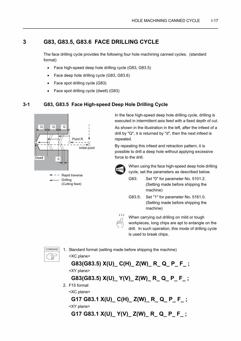
HOLE MACHINING CANNED CYCLE I-17
3 G83, G83.5, G83.6 FACE DRILLING CYCLE
The face drilling cycle provides the following four hole machining canned cycles. (standard format)
• Face high-speed deep hole drilling cycle (G83, G83.5)
• Face deep hole drilling cycle (G83, G83.6)
• Face spot drilling cycle (G83)
• Face spot drilling cycle (dwell) (G83)
3-1 G83, G83.5 Face High-speed Deep Hole Drilling Cycle
In the face high-speed deep hole drilling cycle, drilling is executed in intermittent axis feed with a fixed depth of cut.
As shown in the illustration in the left, after the infeed of a drill by "Q", it is returned by "d", then the next infeed is repeated.
By repeating this infeed and retraction pattern, it is possible to drill a deep hole without applying excessive force to the drill.
When using the face high-speed deep hole drilling cycle, set the parameters as described below.
G83: Set "0" for parameter No. 5101.2.(Setting made before shipping the machine)
G83.5: Set "1" for parameter No. 5161.0.(Setting made before shipping the machine)
When carrying out drilling on mild or tough workpieces, long chips are apt to entangle on the drill. In such operation, this mode of drilling cycle is used to break chips.
1. Standard format (setting made before shipping the machine)<XC plane>
G83(G83.5) X(U)_ C(H)_ Z(W)_ R_ Q_ P_ F_ ;<XY plane>
G83(G83.5) X(U)_ Y(V)_ Z(W)_ R_ Q_ P_ F_ ;2. F15 format
<XC plane>
G17 G83.1 X(U)_ C(H)_ Z(W)_ R_ Q_ P_ F_ ;<XY plane>
G17 G83.1 X(U)_ Y(V)_ Z(W)_ R_ Q_ P_ F_ ;
d
Q Q Q
Point R
Rapid traverseDrilling(Cutting feed)
Initial point
Dwell
NOTE
COMMAND

I-18 HOLE MACHINING CANNED CYCLE
• G17 . . . . . . . . . . . . . . Selects the machining plane (XC, XY plane).
The Z-axis is used as the hole machining axis.
• G83, G83.5, G83.1. . . Calls the face high-speed deep hole drilling cycle.
• X, C, Y . . . . . . . . . . . . Absolute commandSpecifies the hole machining positions.
• U, H, V . . . . . . . . . . . . Incremental commandSpecifies the distance and direction from the end point of the previous block to the hole position.
• Z . . . . . . . . . . . . . . . . Absolute commandSpecifies the hole bottom position.
• W . . . . . . . . . . . . . . . . Incremental commandSpecifies the distance and direction from the point R to the hole bottom.
• R . . . . . . . . . . . . . . . . <Standard format>Specifies the distance and direction from the initial point to the point R (incremental command).<F15 format>Specifies the point R position (absolute command).
• Q . . . . . . . . . . . . . . . . Specifies the depth of cut per one infeed motion (unsigned value).To be specified in units of 0.001 mm without using a decimal point.
• P . . . . . . . . . . . . . . . . Specifies the period of dwell function executed at the hole bottom.
P1000 → 1 sec
• F . . . . . . . . . . . . . . . . Specifies the feedrate (mm/min).
1. The return amount "d" is set for parameter No. 5114.
The default setting is "100" (= 0.1 mm).
2. Specify address Q in the block in which hole machining operation is specified.
3. If a negative value is specified for address Q, it is invalid. Always specify a positive value for address Q.
NOTE
NOTE
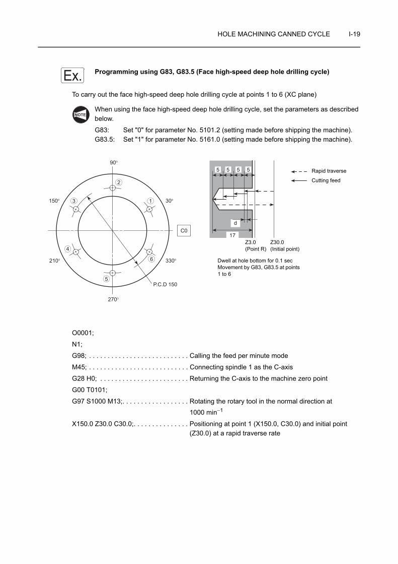
HOLE MACHINING CANNED CYCLE I-19
Programming using G83, G83.5 (Face high-speed deep hole drilling cycle)
To carry out the face high-speed deep hole drilling cycle at points 1 to 6 (XC plane)
When using the face high-speed deep hole drilling cycle, set the parameters as described below.
G83: Set "0" for parameter No. 5101.2 (setting made before shipping the machine).G83.5: Set "1" for parameter No. 5161.0 (setting made before shipping the machine).
O0001;
N1;
G98; . . . . . . . . . . . . . . . . . . . . . . . . . . . Calling the feed per minute mode
M45; . . . . . . . . . . . . . . . . . . . . . . . . . . . Connecting spindle 1 as the C-axis
G28 H0; . . . . . . . . . . . . . . . . . . . . . . . . Returning the C-axis to the machine zero point
G00 T0101;
G97 S1000 M13;. . . . . . . . . . . . . . . . . . Rotating the rotary tool in the normal direction at
1000 min−1
X150.0 Z30.0 C30.0;. . . . . . . . . . . . . . . Positioning at point 1 (X150.0, C30.0) and initial point (Z30.0) at a rapid traverse rate
Ex.
NOTE
6
5
4
3
2
1
P.C.D 150
210°
150°
330°
30°
C0
90°
270°
17
d
5 5 5 5 Rapid traverse
Cutting feed
Z3.0 (Point R)
Dwell at hole bottom for 0.1 secMovement by G83, G83.5 at points 1 to 6
Z30.0(Initial point)
I-20 HOLE MACHINING CANNED CYCLE
G83(G83.5) Z−17.0 R−27.0 Q5000 P100 F100; . . . . . . . . . . . . . . . . . . . . . . . . . . . . . . . Executing the face high-speed deep hole drilling cycle at
point 1
• Z−17.0 . . Z coordinate value of the point Z (hole bottom)
• R−27.0 . . Distance and direction from the initial point to the point R
• Q5000 . . Depth of cut per one infeed motion: 5 mm
• P100. . . . Dwell period at hole bottom for 0.1 secTime per rotary tool rotation (sec)
=
= 0.06 < 0.1 (sec)Thus, the rotary tool makes more than one rotation.
• F100 . . . Feedrate of 100 mm/min
C90.0 Q5000;
C150.0 Q5000;
C210.0 Q5000;
C270.0 Q5000;
C330.0 Q5000;
G80; . . . . . . . . . . . . . . . . . . . . . . . . . . . Canceling the face high-speed deep hole drilling cycle mode
G00 X200.0 Z100.0 M05; . . . . . . . . . . . Stopping rotary tool rotation
M46; . . . . . . . . . . . . . . . . . . . . . . . . . . . Canceling the C-axis connection
G99; . . . . . . . . . . . . . . . . . . . . . . . . . . . Calling the feed per revolution mode
M01;
60 (sec)Spindle speed (min−1)
. . . . . . . . . . . Executing the face high−speed deep hole drilling cycle at points 2 to 6
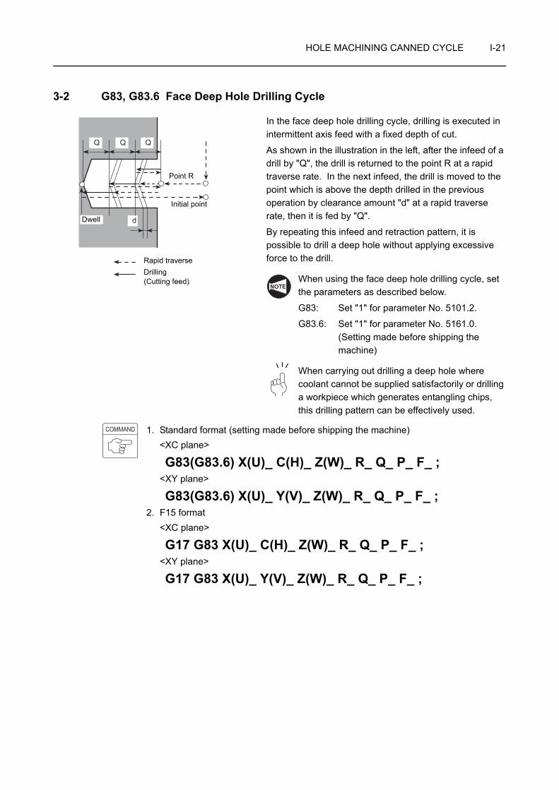
HOLE MACHINING CANNED CYCLE I-21
3-2 G83, G83.6 Face Deep Hole Drilling Cycle
In the face deep hole drilling cycle, drilling is executed in intermittent axis feed with a fixed depth of cut.
As shown in the illustration in the left, after the infeed of a drill by "Q", the drill is returned to the point R at a rapid traverse rate. In the next infeed, the drill is moved to the point which is above the depth drilled in the previous operation by clearance amount "d" at a rapid traverse rate, then it is fed by "Q".
By repeating this infeed and retraction pattern, it is possible to drill a deep hole without applying excessive force to the drill.
When using the face deep hole drilling cycle, set the parameters as described below.
G83: Set "1" for parameter No. 5101.2.
G83.6: Set "1" for parameter No. 5161.0.(Setting made before shipping the machine)
When carrying out drilling a deep hole where coolant cannot be supplied satisfactorily or drilling a workpiece which generates entangling chips, this drilling pattern can be effectively used.
1. Standard format (setting made before shipping the machine)<XC plane>
G83(G83.6) X(U)_ C(H)_ Z(W)_ R_ Q_ P_ F_ ;<XY plane>
G83(G83.6) X(U)_ Y(V)_ Z(W)_ R_ Q_ P_ F_ ;2. F15 format
<XC plane>
G17 G83 X(U)_ C(H)_ Z(W)_ R_ Q_ P_ F_ ;<XY plane>
G17 G83 X(U)_ Y(V)_ Z(W)_ R_ Q_ P_ F_ ;
d
QQQ
Point R
Initial point
Rapid traverseDrilling(Cutting feed)
Dwell
NOTE
COMMAND
I-22 HOLE MACHINING CANNED CYCLE
• G17 . . . . . . . . Selects the machining plane (XC, XY plane).
The Z-axis is used as the hole machining axis.
• G83, G83.6. . . Calls the face deep hole drilling cycle.
• X, C, Y . . . . . . Absolute commandSpecifies the hole machining positions.
• U, H, V . . . . . . Incremental commandSpecifies the distance and direction from the end point of the previous block to the hole position.
• Z . . . . . . . . . . Absolute commandSpecifies the hole bottom position.
• W . . . . . . . . . . Incremental commandSpecifies the distance and direction from the point R to the hole bottom.
• R . . . . . . . . . . <Standard format>Specifies the distance and direction from the initial point to the point R (incremental command).<F15 format>Specifies the point R position (absolute command).
• Q . . . . . . . . . . Specifies the depth of cut per one infeed motion (unsigned value).To be specified in units of 0.001 mm without using a decimal point.
• P . . . . . . . . . . Specifies the period of dwell function executed at the hole bottom.
P1000 → 1 sec
• F . . . . . . . . . . Specifies the feedrate (mm/min).
1. The clearance amount "d" is set for parameter No. 5114.
The default setting is "100" (= 0.1 mm).
2. Specify address Q in the block in which hole machining operation is specified.
3. If a negative value is specified for address Q, it is invalid. Always specify a positive value for address Q.
NOTE
NOTE
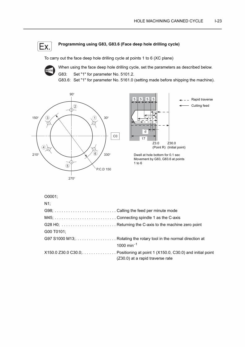
HOLE MACHINING CANNED CYCLE I-23
Programming using G83, G83.6 (Face deep hole drilling cycle)
To carry out the face deep hole drilling cycle at points 1 to 6 (XC plane)
When using the face deep hole drilling cycle, set the parameters as described below.
G83: Set "1" for parameter No. 5101.2.G83.6: Set "1" for parameter No. 5161.0 (setting made before shipping the machine).
O0001;
N1;
G98; . . . . . . . . . . . . . . . . . . . . . . . . . . . Calling the feed per minute mode
M45; . . . . . . . . . . . . . . . . . . . . . . . . . . . Connecting spindle 1 as the C-axis
G28 H0; . . . . . . . . . . . . . . . . . . . . . . . . Returning the C-axis to the machine zero point
G00 T0101;
G97 S1000 M13;. . . . . . . . . . . . . . . . . . Rotating the rotary tool in the normal direction at
1000 min−1
X150.0 Z30.0 C30.0;. . . . . . . . . . . . . . . Positioning at point 1 (X150.0, C30.0) and initial point (Z30.0) at a rapid traverse rate
Ex.
NOTE
6
5
4
3
2
1
P.C.D 150
210°
150°
330°
30°
C0
90°
270°
17
d
5 5 5 5 Rapid traverse
Cutting feed
Z3.0 (Point R)
Dwell at hole bottom for 0.1 secMovement by G83, G83.6 at points 1 to 6
Z30.0(Initial point)
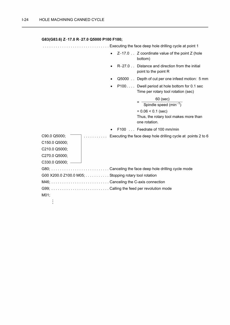
I-24 HOLE MACHINING CANNED CYCLE
G83(G83.6) Z−17.0 R−27.0 Q5000 P100 F100; . . . . . . . . . . . . . . . . . . . . . . . . . . . . . . . Executing the face deep hole drilling cycle at point 1
• Z−17.0 . . Z coordinate value of the point Z (hole bottom)
• R−27.0 . . Distance and direction from the initial point to the point R
• Q5000 . . Depth of cut per one infeed motion: 5 mm
• P100. . . . Dwell period at hole bottom for 0.1 secTime per rotary tool rotation (sec)
=
= 0.06 < 0.1 (sec)Thus, the rotary tool makes more than one rotation.
• F100 . . . Feedrate of 100 mm/min
C90.0 Q5000;
C150.0 Q5000;
C210.0 Q5000;
C270.0 Q5000;
C330.0 Q5000;
G80; . . . . . . . . . . . . . . . . . . . . . . . . . . . Canceling the face deep hole drilling cycle mode
G00 X200.0 Z100.0 M05; . . . . . . . . . . . Stopping rotary tool rotation
M46; . . . . . . . . . . . . . . . . . . . . . . . . . . . Canceling the C-axis connection
G99; . . . . . . . . . . . . . . . . . . . . . . . . . . . Calling the feed per revolution mode
M01;
60 (sec)Spindle speed (min−1)
. . . . . . . . . . . Executing the face deep hole drilling cycle at points 2 to 6
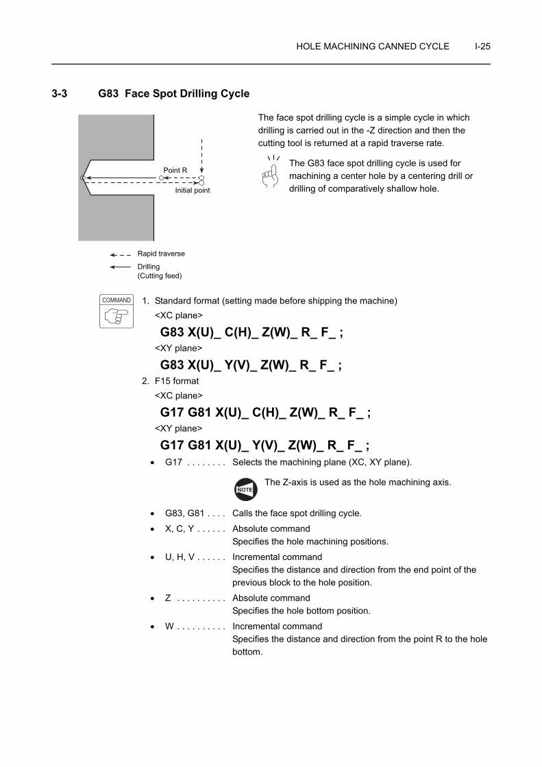
HOLE MACHINING CANNED CYCLE I-25
3-3 G83 Face Spot Drilling Cycle
The face spot drilling cycle is a simple cycle in which drilling is carried out in the -Z direction and then the cutting tool is returned at a rapid traverse rate.
The G83 face spot drilling cycle is used for machining a center hole by a centering drill or drilling of comparatively shallow hole.
1. Standard format (setting made before shipping the machine)<XC plane>
G83 X(U)_ C(H)_ Z(W)_ R_ F_ ;<XY plane>
G83 X(U)_ Y(V)_ Z(W)_ R_ F_ ;2. F15 format
<XC plane>
G17 G81 X(U)_ C(H)_ Z(W)_ R_ F_ ;<XY plane>
G17 G81 X(U)_ Y(V)_ Z(W)_ R_ F_ ;• G17 . . . . . . . . Selects the machining plane (XC, XY plane).
The Z-axis is used as the hole machining axis.
• G83, G81 . . . . Calls the face spot drilling cycle.
• X, C, Y . . . . . . Absolute commandSpecifies the hole machining positions.
• U, H, V . . . . . . Incremental commandSpecifies the distance and direction from the end point of the previous block to the hole position.
• Z . . . . . . . . . . Absolute commandSpecifies the hole bottom position.
• W . . . . . . . . . . Incremental commandSpecifies the distance and direction from the point R to the hole bottom.
Point R
Rapid traverse
Drilling(Cutting feed)
Initial point
COMMAND
NOTE

I-26 HOLE MACHINING CANNED CYCLE
• R . . . . . . . . . . <Standard format>Specifies the distance and direction from the initial point to the point R (incremental command).<F15 format>Specifies the point R position (absolute command).
• F . . . . . . . . . . Specifies the feedrate (mm/min).
Programming using G83 (Face spot drilling cycle)
To carry out the face spot drilling cycle at points 1 to 6 (XC plane)
O0001;
N1;
G98; . . . . . . . . . . . . . . . . . . . . . . . . . . . Calling the feed per minute mode
M45; . . . . . . . . . . . . . . . . . . . . . . . . . . . Connecting spindle 1 as the C-axis
G28 H0; . . . . . . . . . . . . . . . . . . . . . . . . Returning the C-axis to the machine zero point
G00 T0101;
G97 S1000 M13;. . . . . . . . . . . . . . . . . . Rotating the rotary tool in the normal direction at
1000 min−1
X150.0 Z30.0 C30.0;. . . . . . . . . . . . . . . Positioning at point 1 (X150.0, C30.0) and initial point (Z30.0) at a rapid traverse rate
G83 Z−5.0 R−27.0 F100; . . . . . . . . . . . Executing the face spot drilling cycle at point 1
• Z−5.0 . . . Z coordinate value of the point Z (hole bottom)
• R−27.0 . . Distance and direction from the initial point to the point R
• F100 . . . Feedrate of 100 mm/min
Ex.
6
5
4
3
2
1
P.C.D 150
210°
150°
330°
30°
C0
90°
270°
5
Rapid traverseCutting feed
Z3.0 (Point R)
Movement by G83 at points 1 to 6
Z30.0(Initial point)
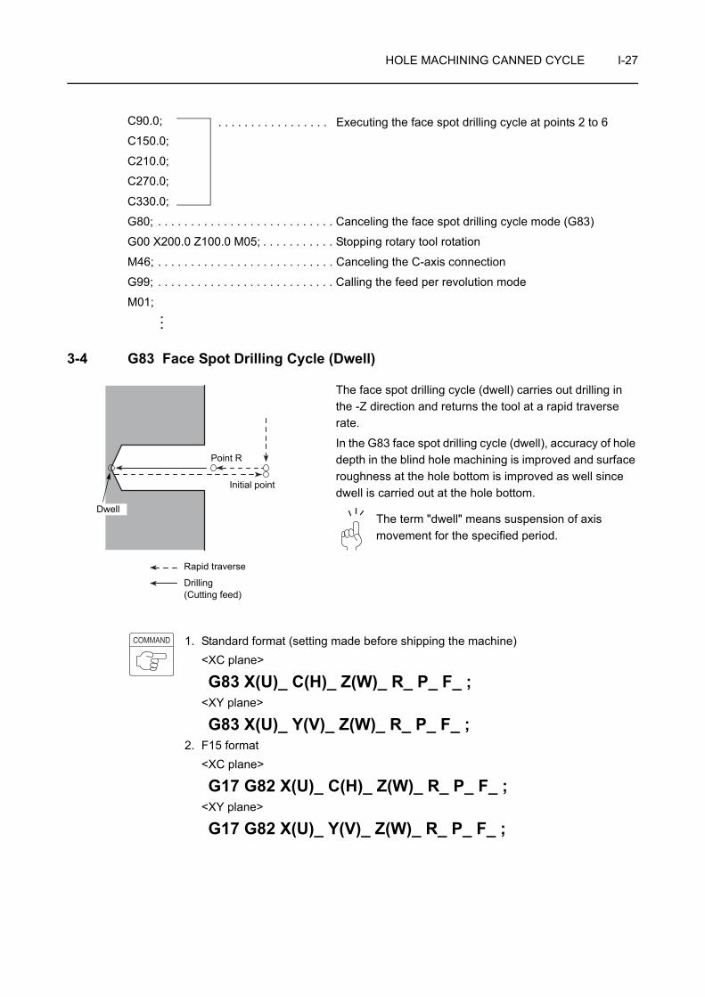
HOLE MACHINING CANNED CYCLE I-27
C90.0;
C150.0;
C210.0;
C270.0;
C330.0;
G80; . . . . . . . . . . . . . . . . . . . . . . . . . . . Canceling the face spot drilling cycle mode (G83)
G00 X200.0 Z100.0 M05; . . . . . . . . . . . Stopping rotary tool rotation
M46; . . . . . . . . . . . . . . . . . . . . . . . . . . . Canceling the C-axis connection
G99; . . . . . . . . . . . . . . . . . . . . . . . . . . . Calling the feed per revolution mode
M01;
3-4 G83 Face Spot Drilling Cycle (Dwell)
The face spot drilling cycle (dwell) carries out drilling in the -Z direction and returns the tool at a rapid traverse rate.
In the G83 face spot drilling cycle (dwell), accuracy of hole depth in the blind hole machining is improved and surface roughness at the hole bottom is improved as well since dwell is carried out at the hole bottom.
The term "dwell" means suspension of axis movement for the specified period.
1. Standard format (setting made before shipping the machine)<XC plane>
G83 X(U)_ C(H)_ Z(W)_ R_ P_ F_ ;<XY plane>
G83 X(U)_ Y(V)_ Z(W)_ R_ P_ F_ ;2. F15 format
<XC plane>
G17 G82 X(U)_ C(H)_ Z(W)_ R_ P_ F_ ;<XY plane>
G17 G82 X(U)_ Y(V)_ Z(W)_ R_ P_ F_ ;
. . . . . . . . . . . . . . . . . Executing the face spot drilling cycle at points 2 to 6
Point R
Rapid traverse
Drilling(Cutting feed)
Dwell
Initial point
COMMAND

I-28 HOLE MACHINING CANNED CYCLE
• G17 . . . . . . . . Selects the machining plane (XC, XY plane).
The Z-axis is used as the hole machining axis.
• G83, G82 . . . . Calls the face spot drilling cycle (dwell).
• X, C, Y . . . . . . Absolute commandSpecifies the hole machining positions.
• U, H, V . . . . . . Incremental commandSpecifies the distance and direction from the end point of the previous block to the hole position.
• Z . . . . . . . . . . Absolute commandSpecifies the hole bottom position.
• W . . . . . . . . . . Incremental commandSpecifies the distance and direction from the point R to the hole bottom.
• R . . . . . . . . . . <Standard format>Specifies the distance and direction from the initial point to the point R (incremental command).<F15 format>Specifies the point R position (absolute command).
• P . . . . . . . . . . Specifies the period of dwell function executed at the hole bottom.
P1000 → 1 sec
• F . . . . . . . . . . Specifies the feedrate (mm/min).
Programming using G83 (Face spot drilling cycle (dwell))
To carry out the face spot drilling cycle (dwell) at points 1 to 6 (XC plane)
NOTE
Ex.
6
5
4
3
2
1
P.C.D 150
210°
150°
330°
30°
C0
90°
270°
5
Rapid traverseCutting feed
Z3.0 (Point R)
Z30.0(Initial point)
Dwell at hole bottom for 0.1 secMovement by G83 at points 1 to 6
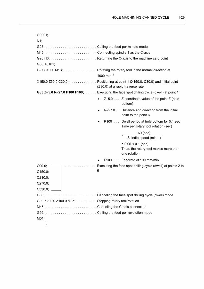
HOLE MACHINING CANNED CYCLE I-29
O0001;
N1;
G98; . . . . . . . . . . . . . . . . . . . . . . . . . . . Calling the feed per minute mode
M45; . . . . . . . . . . . . . . . . . . . . . . . . . . . Connecting spindle 1 as the C-axis
G28 H0; . . . . . . . . . . . . . . . . . . . . . . . . Returning the C-axis to the machine zero point
G00 T0101;
G97 S1000 M13;. . . . . . . . . . . . . . . . . . Rotating the rotary tool in the normal direction at
1000 min−1
X150.0 Z30.0 C30.0;. . . . . . . . . . . . . . . Positioning at point 1 (X150.0, C30.0) and initial point (Z30.0) at a rapid traverse rate
G83 Z−5.0 R−27.0 P100 F100; . . . . . . Executing the face spot drilling cycle (dwell) at point 1
• Z−5.0 . . . Z coordinate value of the point Z (hole bottom)
• R−27.0 . . Distance and direction from the initial point to the point R
• P100. . . . Dwell period at hole bottom for 0.1 secTime per rotary tool rotation (sec)
=
= 0.06 < 0.1 (sec)Thus, the rotary tool makes more than one rotation.
• F100 . . . Feedrate of 100 mm/min
C90.0;
C150.0;
C210.0;
C270.0;
C330.0;
G80; . . . . . . . . . . . . . . . . . . . . . . . . . . . Canceling the face spot drilling cycle (dwell) mode
G00 X200.0 Z100.0 M05; . . . . . . . . . . . Stopping rotary tool rotation
M46; . . . . . . . . . . . . . . . . . . . . . . . . . . . Canceling the C-axis connection
G99; . . . . . . . . . . . . . . . . . . . . . . . . . . . Calling the feed per revolution mode
M01;
60 (sec)Spindle speed (min−1)
. . . . . . . . . . . . . . . . Executing the face spot drilling cycle (dwell) at points 2 to 6

I-30 HOLE MACHINING CANNED CYCLE
4 G84 FACE TAPPING CYCLE
The G84 face tapping cycle is used for machining thread using a tap.
When a cutting tool rotating in the normal direction reaches the specified bottom position, the cutting tool rotating direction is reversed automatically to return to the specified level.
To use this face tapping cycle, a tapper is used.
1. Standard format (setting made before shipping the machine)<XC plane>
G84 X(U)_ C(H)_ Z(W)_ R_ P_ F_ ;<XY plane>
G84 X(U)_ Y(V)_ Z(W)_ R_ P_ F_ ;2. F15 format
<XC plane>
G17 G84 X(U)_ C(H)_ Z(W)_ R_ P_ F_ ;<XY plane>
G17 G84 X(U)_ Y(V)_ Z(W)_ R_ P_ F_ ;• G17 . . . . . . . . Selects the machining plane (XC, XY plane).
The Z-axis is used as the hole machining axis.
• G84 . . . . . . . . Calls the face tapping cycle.
• X, C, Y . . . . . . Absolute commandSpecifies the hole machining positions.
• U, H, V . . . . . . Incremental commandSpecifies the distance and direction from the end point of the previous block to the hole position.
• Z . . . . . . . . . . Absolute commandSpecifies the hole bottom position.
• W . . . . . . . . . . Incremental commandSpecifies the distance and direction from the point R to the hole bottom.
Point R Initial point
Rapid traverseCutting feed
Spindle normal rotation
Spindle normal rotation after dwell
Spindle reverse rotation after dwell
NOTE
COMMAND
NOTE
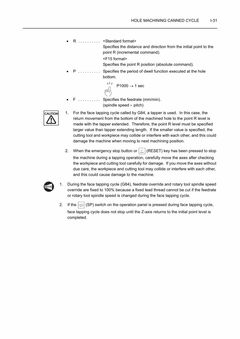
HOLE MACHINING CANNED CYCLE I-31
• R . . . . . . . . . . <Standard format>Specifies the distance and direction from the initial point to the point R (incremental command).<F15 format>Specifies the point R position (absolute command).
• P . . . . . . . . . . Specifies the period of dwell function executed at the hole bottom.
P1000 → 1 sec
• F . . . . . . . . . . Specifies the feedrate (mm/min).(spindle speed × pitch)
1. For the face tapping cycle called by G84, a tapper is used. In this case, the return movement from the bottom of the machined hole to the point R level is made with the tapper extended. Therefore, the point R level must be specified larger value than tapper extending length. If the smaller value is specified, the cutting tool and workpiece may collide or interfere with each other, and this could damage the machine when moving to next machining position.
2. When the emergency stop button or (RESET) key has been pressed to stop
the machine during a tapping operation, carefully move the axes after checking the workpiece and cutting tool carefully for damage. If you move the axes without due care, the workpiece and cutting tool may collide or interfere with each other, and this could cause damage to the machine.
1. During the face tapping cycle (G84), feedrate override and rotary tool spindle speed override are fixed to 100% because a fixed lead thread cannot be cut if the feedrate or rotary tool spindle speed is changed during the face tapping cycle.
2. If the (SP) switch on the operation panel is pressed during face tapping cycle,
face tapping cycle does not stop until the Z-axis returns to the initial point level is completed.
CAUTION
RESET
NOTE
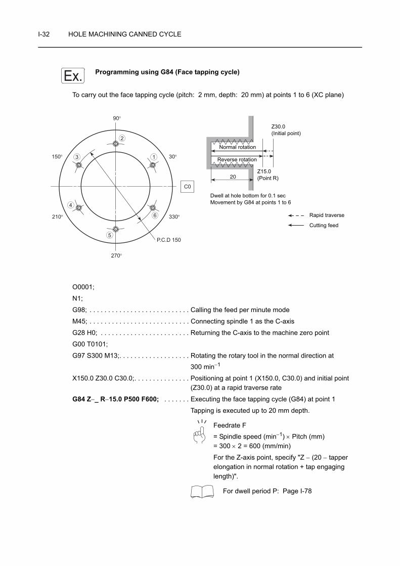
I-32 HOLE MACHINING CANNED CYCLE
Programming using G84 (Face tapping cycle)
To carry out the face tapping cycle (pitch: 2 mm, depth: 20 mm) at points 1 to 6 (XC plane)
O0001;
N1;
G98; . . . . . . . . . . . . . . . . . . . . . . . . . . . Calling the feed per minute mode
M45; . . . . . . . . . . . . . . . . . . . . . . . . . . . Connecting spindle 1 as the C-axis
G28 H0; . . . . . . . . . . . . . . . . . . . . . . . . Returning the C-axis to the machine zero point
G00 T0101;
G97 S300 M13;. . . . . . . . . . . . . . . . . . . Rotating the rotary tool in the normal direction at
300 min−1
X150.0 Z30.0 C30.0;. . . . . . . . . . . . . . . Positioning at point 1 (X150.0, C30.0) and initial point (Z30.0) at a rapid traverse rate
G84 Z−_ R−15.0 P500 F600; . . . . . . . Executing the face tapping cycle (G84) at point 1
Tapping is executed up to 20 mm depth.
Feedrate F
= Spindle speed (min−1) × Pitch (mm)= 300 × 2 = 600 (mm/min)
For the Z-axis point, specify "Z − (20 − tapper elongation in normal rotation + tap engaging length)".
For dwell period P: Page I-78
Ex.
20
6
5
4
3
2
1
P.C.D 150
210°
150°
330°
30°
C0
90°
270°
Rapid traverse
Cutting feed
Z15.0(Point R)
Dwell at hole bottom for 0.1 secMovement by G84 at points 1 to 6
Z30.0(Initial point)
Normal rotation
Reverse rotation

HOLE MACHINING CANNED CYCLE I-33
C90.0;
C150.0;
C210.0;
C270.0;
C330.0;
G80; . . . . . . . . . . . . . . . . . . . . . . . . . . . Canceling the face tapping cycle mode (G84)
G00 X200.0 Z100.0 M05; . . . . . . . . . . . Stopping rotary tool rotation
M46; . . . . . . . . . . . . . . . . . . . . . . . . . . . Canceling the C-axis connection
G99; . . . . . . . . . . . . . . . . . . . . . . . . . . . Calling the feed per revolution mode
M01;
. . . . . . . . . . . . . . . . . Executing the face tapping cycle at points 2 to 6
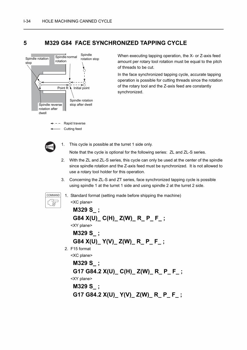
I-34 HOLE MACHINING CANNED CYCLE
5 M329 G84 FACE SYNCHRONIZED TAPPING CYCLE
When executing tapping operation, the X- or Z-axis feed amount per rotary tool rotation must be equal to the pitch of threads to be cut.
In the face synchronized tapping cycle, accurate tapping operation is possible for cutting threads since the rotation of the rotary tool and the Z-axis feed are constantly synchronized.
1. This cycle is possible at the turret 1 side only.
Note that the cycle is optional for the following series: ZL and ZL-S series.
2. With the ZL and ZL-S series, this cycle can only be used at the center of the spindle since spindle rotation and the Z-axis feed must be synchronized. It is not allowed to use a rotary tool holder for this operation.
3. Concerning the ZL-S and ZT series, face synchronized tapping cycle is possible using spindle 1 at the turret 1 side and using spindle 2 at the turret 2 side.
1. Standard format (setting made before shipping the machine)<XC plane>
M329 S_ ;G84 X(U)_ C(H)_ Z(W)_ R_ P_ F_ ;
<XY plane>
M329 S_ ;G84 X(U)_ Y(V)_ Z(W)_ R_ P_ F_ ;
2. F15 format<XC plane>
M329 S_ ;G17 G84.2 X(U)_ C(H)_ Z(W)_ R_ P_ F_ ;
<XY plane>
M329 S_ ;G17 G84.2 X(U)_ Y(V)_ Z(W)_ R_ P_ F_ ;
Point R Initial point
Rapid traverse
Cutting feed
Spindle rotation stop after dwell
Spindle rotation stopSpindle rotation
stop
Spindle normal rotation
Spindle reverse rotation after dwell
NOTE
COMMAND

HOLE MACHINING CANNED CYCLE I-35
• M329 . . . . . . . Synchronized tapping command
• S . . . . . . . . . . Specifies the spindle speed (min−1).
• G17 . . . . . . . . Selects the machining plane (XC, XY plane).
The Z-axis is used as the hole machining axis.
• G84 . . . . . . . . Calls the face tapping cycle.
• G84.2 . . . . . . Calls the synchronized tapping cycle
• X, C, Y . . . . . . Absolute commandSpecifies the hole machining positions.
• U, H, V . . . . . . Incremental commandSpecifies the distance and direction from the end point of the previous block to the hole position.
• Z . . . . . . . . . . Absolute commandSpecifies the hole bottom position.
• W . . . . . . . . . . Incremental commandSpecifies the distance and direction from the point R to the hole bottom.
• R . . . . . . . . . . <Standard format>Specifies the distance and direction from the initial point to the point R (incremental command).<F15 format>Specifies the point R position (absolute command).
• P . . . . . . . . . . Specifies the period of dwell function executed at the hole bottom.
P1000 → 1 sec
• F . . . . . . . . . . <Feed per minute mode (G98)>Specifies the feedrate (mm/min).(spindle speed × pitch)<Feed per revolution mode (G99)>Specifies the feedrate (mm/rev).(pitch)
When the emergency stop button or (RESET) key has been pressed to stop the
machine during a face synchronized tapping operation, carefully move the axes after checking the workpiece and cutting tool carefully for damage. If you move the axes without due care, the workpiece and cutting tool may collide or interfere with each other, and this could cause damage to the machine.
NOTE
CAUTIONRESET
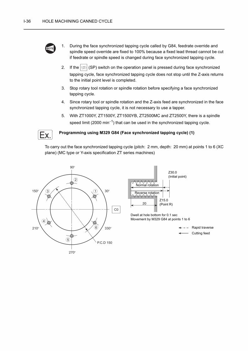
I-36 HOLE MACHINING CANNED CYCLE
1. During the face synchronized tapping cycle called by G84, feedrate override and spindle speed override are fixed to 100% because a fixed lead thread cannot be cut if feedrate or spindle speed is changed during face synchronized tapping cycle.
2. If the (SP) switch on the operation panel is pressed during face synchronized
tapping cycle, face synchronized tapping cycle does not stop until the Z-axis returns to the initial point level is completed.
3. Stop rotary tool rotation or spindle rotation before specifying a face synchronized tapping cycle.
4. Since rotary tool or spindle rotation and the Z-axis feed are synchronized in the face synchronized tapping cycle, it is not necessary to use a tapper.
5. With ZT1000Y, ZT1500Y, ZT1500YB, ZT2500MC and ZT2500Y, there is a spindle
speed limit (2000 min−1) that can be used in the synchronized tapping cycle.
Programming using M329 G84 (Face synchronized tapping cycle) (1)
To carry out the face synchronized tapping cycle (pitch: 2 mm, depth: 20 mm) at points 1 to 6 (XC plane) (MC type or Y-axis specification ZT series machines)
NOTE
Ex.
Dwell at hole bottom for 0.1 secMovement by M329 G84 at points 1 to 6
20
6
5
4
3
2
1
P.C.D 150
210°
150°
330°
30°
C0
90°
270°
Rapid traverse
Cutting feed
Z15.0(Point R)
Z30.0(Initial point)
Normal rotation
Reverse rotation

HOLE MACHINING CANNED CYCLE I-37
O0001;
N1;
G98 (G99); . . . . . . . . . . . . . . . . . . . . . . Calling the feed per minute mode
The command in ( ) is for the feed per revolution mode.
M45; . . . . . . . . . . . . . . . . . . . . . . . . . . . Connecting the spindle as the C-axis
G28 H0; . . . . . . . . . . . . . . . . . . . . . . . . Returning the C-axis to the machine zero point
G00 T0101;
G97; . . . . . . . . . . . . . . . . . . . . . . . . . . . Calling the constant spindle speed control
X150.0 Z30.0 C30.0;. . . . . . . . . . . . . . . Positioning at point 1 (X150.0, C30.0) and initial point (Z30.0) at a rapid traverse rate
Rotary tool rotation is stopped.
M329 S300; . . . . . . . . . . . . . . . . . . . . . Calling the synchronized tapping cycle
G84 Z−_ R−15.0 F600 (F2.0); . . . . . . . Executing the face synchronized tapping cycle at point 1
1. Feedrate F
= Spindle speed (min−1) × Pitch (mm)= 300 × 2 = 600 (mm/min)For the Z-axis point, specify "Z − (20 + tap engaging length)".
2. Rotary tool rotation is stopped between the initial point and the point R.
The command in ( ) is for the feed per revolution mode.
Feedrate F = Pitch (mm)
C90.0;
C150.0;
C210.0;
C270.0;
C330.0;
G80; . . . . . . . . . . . . . . . . . . . . . . . . . . . Canceling the face synchronized tapping cycle mode
G00 X200.0 Z100.0 M05; . . . . . . . . . . . Stopping rotary tool rotation
M46; . . . . . . . . . . . . . . . . . . . . . . . . . . . Canceling the C-axis connection
G99; . . . . . . . . . . . . . . . . . . . . . . . . . . . Calling the feed per revolution mode
This command is necessary only for the feed per minute mode.
M01;
NOTE
NOTE
NOTE
. . . . . . . . . . . . . . . . . Executing the face synchronized tapping cycle at points 2 to 6
NOTE
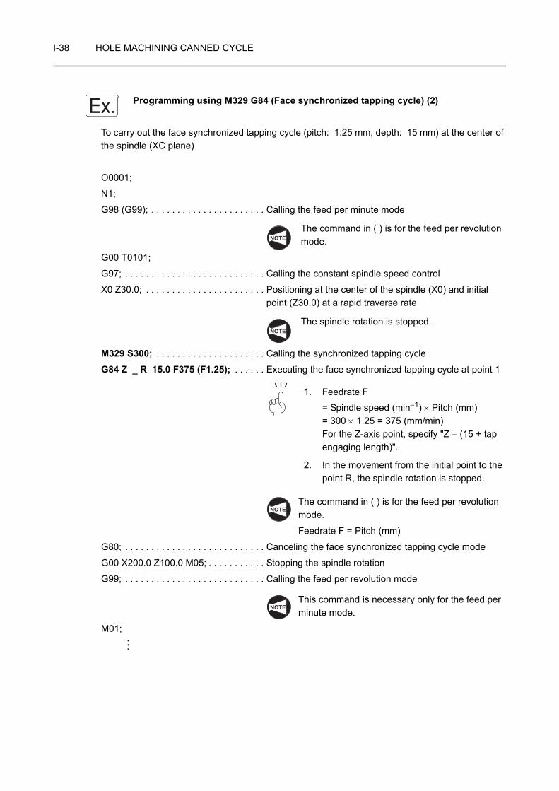
I-38 HOLE MACHINING CANNED CYCLE
Programming using M329 G84 (Face synchronized tapping cycle) (2)
To carry out the face synchronized tapping cycle (pitch: 1.25 mm, depth: 15 mm) at the center of the spindle (XC plane)
O0001;
N1;
G98 (G99); . . . . . . . . . . . . . . . . . . . . . . Calling the feed per minute mode
The command in ( ) is for the feed per revolution mode.
G00 T0101;
G97; . . . . . . . . . . . . . . . . . . . . . . . . . . . Calling the constant spindle speed control
X0 Z30.0; . . . . . . . . . . . . . . . . . . . . . . . Positioning at the center of the spindle (X0) and initial point (Z30.0) at a rapid traverse rate
The spindle rotation is stopped.
M329 S300; . . . . . . . . . . . . . . . . . . . . . Calling the synchronized tapping cycle
G84 Z−_ R−15.0 F375 (F1.25); . . . . . . Executing the face synchronized tapping cycle at point 1
1. Feedrate F
= Spindle speed (min−1) × Pitch (mm)= 300 × 1.25 = 375 (mm/min)For the Z-axis point, specify "Z − (15 + tap engaging length)".
2. In the movement from the initial point to the point R, the spindle rotation is stopped.
The command in ( ) is for the feed per revolution mode.
Feedrate F = Pitch (mm)
G80; . . . . . . . . . . . . . . . . . . . . . . . . . . . Canceling the face synchronized tapping cycle mode
G00 X200.0 Z100.0 M05; . . . . . . . . . . . Stopping the spindle rotation
G99; . . . . . . . . . . . . . . . . . . . . . . . . . . . Calling the feed per revolution mode
This command is necessary only for the feed per minute mode.
M01;
Ex.
NOTE
NOTE
NOTE
NOTE

HOLE MACHINING CANNED CYCLE I-39
6 G85 FACE BORING CYCLE
The face boring cycle carries out drilling in the -Z direction and returns the tool at a cutting feedrate.
Return movement from the hole bottom to the point R is executed at the feedrate two times the specified cutting feedrate.
The G85 face boring cycle is usually used for reaming and boring operation.
1. Standard format (setting made before shipping the machine)<XC plane>
G85 X(U)_ C(H)_ Z(W)_ R_ P_ F_ ;<XY plane>
G85 X(U)_ Y(V)_ Z(W)_ R_ P_ F_ ;2. F15 format
<XC plane>
G17 G89 X(U)_ C(H)_ Z(W)_ R_ P_ F_ ;<XY plane>
G17 G89 X(U)_ Y(V)_ Z(W)_ R_ P_ F_ ;• G17 . . . . . . . . Selects the machining plane (XC, XY plane).
The Z-axis is used as the hole machining axis.
• G85, G89 . . . . Calls the face boring cycle.
• X, C, Y . . . . . . Absolute commandSpecifies the hole machining positions.
• U, H, V . . . . . . Incremental commandSpecifies the distance and direction from the end point of the previous block to the hole position.
• Z . . . . . . . . . . Absolute commandSpecifies the hole bottom position.
• W . . . . . . . . . . Incremental commandSpecifies the distance and direction from the point R to the hole bottom.
Point R
Initial point
Rapid traverse
Cutting feed
Dwell
NOTE
COMMAND
NOTE
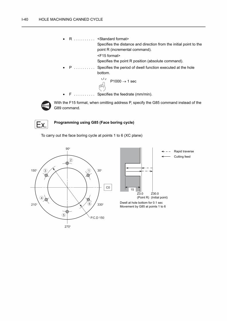
I-40 HOLE MACHINING CANNED CYCLE
• R . . . . . . . . . . <Standard format>Specifies the distance and direction from the initial point to the point R (incremental command).<F15 format>Specifies the point R position (absolute command).
• P . . . . . . . . . . Specifies the period of dwell function executed at the hole bottom.
P1000 → 1 sec
• F . . . . . . . . . . Specifies the feedrate (mm/min).
With the F15 format, when omitting address P, specify the G85 command instead of the G89 command.
Programming using G85 (Face boring cycle)
To carry out the face boring cycle at points 1 to 6 (XC plane)
NOTE
Ex.
6
5
4
3
2
1
P.C.D 150
210°
150°
330°
30°
C0
90°
270°
15
Rapid traverse
Cutting feed
Z3.0 (Point R)
Dwell at hole bottom for 0.1 secMovement by G85 at points 1 to 6
Z30.0(Initial point)

HOLE MACHINING CANNED CYCLE I-41
O0001;
N1;
G98; . . . . . . . . . . . . . . . . . . . . . . . . . . . Calling the feed per minute mode
M45; . . . . . . . . . . . . . . . . . . . . . . . . . . . Connecting spindle 1 as the C-axis
G28 H0; . . . . . . . . . . . . . . . . . . . . . . . . Returning the C-axis to the machine zero point
G00 T0101;
G97 S1000 M13;. . . . . . . . . . . . . . . . . . Rotating the rotary tool in the normal direction at
1000 min−1
X150.0 Z30.0 C30.0;. . . . . . . . . . . . . . . Positioning at point 1 (X150.0, C30.0) and initial point (Z30.0) at a rapid traverse rate
G85 Z−15.0 R−27.0 P100 F100; . . . . . Executing the face boring cycle at point 1
• Z−15.0 . . Z coordinate value of the point Z (hole bottom)
• R-27.0 . . Distance and direction from the initial point to the point R
• P100. . . . Dwell period at hole bottom for 0.1 secTime per rotary tool rotation (sec)
=
= 0.06 < 0.1 (sec)Thus, the rotary tool makes more than one rotation.
• F100 . . . Feedrate of 100 mm/min
C90.0;
C150.0;
C210.0;
C270.0;
C330.0;
G80; . . . . . . . . . . . . . . . . . . . . . . . . . . . Canceling the face boring cycle
G00 X200.0 Z100.0 M05; . . . . . . . . . . . Stopping rotary tool rotation
M46; . . . . . . . . . . . . . . . . . . . . . . . . . . . Canceling the C-axis connection
G99; . . . . . . . . . . . . . . . . . . . . . . . . . . . Calling the feed per revolution mode
M01;
60 (sec)Spindle speed (min−1)
. . . . . . . . . . . . . . . . . . Executing the face boring cycle at points 2 to 6

I-42 HOLE MACHINING CANNED CYCLE
7 G87, G87.5, G87.6 SIDE DRILLING CYCLE
The side drilling cycle provides the following four hole machining canned cycles. (standard format)
• Side high-speed deep hole drilling cycle (G87, G87.5)
• Side deep hole drilling cycle (G87, G87.6)
• Side spot drilling cycle (G87)
• Side spot drilling cycle (dwell) (G87)
7-1 G87, G87.5 Side High-speed Deep Hole Drilling Cycle
In the side high-speed deep hole drilling cycle, drilling is executed in intermittent axis feed with a fixed depth of cut.
As shown in the illustration in the left, after the infeed of a drill by "Q", it is returned by "d", then the next infeed is repeated.
By repeating this infeed and retraction pattern, it is possible to drill a deep hole without applying excessive force to the drill.
When using the side high-speed deep hole drilling cycle, set the parameters as described below.
G87: Set "0" for parameter No. 5101.2. (Setting made before shipping the machine)
G87.5: Set "1" for parameter No. 5161.0. (Setting made before shipping the machine)
When carrying out drilling on mild or tough workpieces, long chips are apt to entangle on the drill. In such operation, this mode of drilling cycle is used to break chips.
1. Standard format (setting made before shipping the machine)<ZC plane>
G87(G87.5) Z(W)_ C(H)_ X(U)_ R_ Q_ P_ F_ ;<ZY plane>
G87(G87.5) Z(W)_ Y(V)_ X(U)_ R_ Q_ P_ F_ ;2. F15 format
<ZC plane>
G19 G83.1 Z(W)_ C(H)_ X(U)_ R_ Q_ P_ F_ ;<ZY plane>
G19 G83.1 Z(W)_ Y(V)_ X(U)_ R_ Q_ P_ F_ ;
d
Q
Q
Q
Point R
Dwell
Initial point
Rapid traverseDrilling(Cutting feed)
NOTE
COMMAND

HOLE MACHINING CANNED CYCLE I-43
• G19 . . . . . . . . . . . . . . Selects the machining plane (ZC, ZY plane).
The X-axis is used as the hole machining axis.
• G87, G87.5, G83.1. . . Calls the side high-speed deep hole drilling cycle.
• Z, C, Y . . . . . . . . . . . . Absolute commandSpecifies the hole machining positions.
• W, H, V . . . . . . . . . . . Incremental commandSpecifies the distance and direction from the end point of the previous block to the hole position.
• X . . . . . . . . . . . . . . . . Absolute commandSpecifies the hole bottom position.
• U . . . . . . . . . . . . . . . . Incremental commandSpecifies the distance and direction from the point R to the hole bottom (in diameter).
• R . . . . . . . . . . . . . . . . <Standard format>Specifies the distance and direction from the initial point to the point R (in radius) (incremental command).<F15 format>Specifies the point R position (in diameter) (absolute command).
• Q . . . . . . . . . . . . . . . . Specifies the depth of cut per one infeed motion (unsigned value, in radius)To be specified in units of 0.001 mm without using a decimal point.
• P . . . . . . . . . . . . . . . . Specifies the period of dwell function executed at the hole bottom.
P1000 → 1 sec
• F . . . . . . . . . . . . . . . . Specifies the feedrate (mm/min).
1. The return amount "d" is set for parameter No. 5114.
The default setting is "100" (= 0.1 mm).
2. Specify address Q in the block in which hole machining operation is specified.
3. If a negative value is specified for address Q, it is invalid. Always specify a positive value for address Q.
NOTE
NOTE
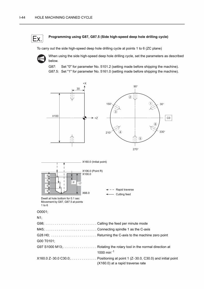
I-44 HOLE MACHINING CANNED CYCLE
Programming using G87, G87.5 (Side high-speed deep hole drilling cycle)
To carry out the side high-speed deep hole drilling cycle at points 1 to 6 (ZC plane)
When using the side high-speed deep hole drilling cycle, set the parameters as described below.
G87: Set "0" for parameter No. 5101.2 (setting made before shipping the machine).G87.5: Set "1" for parameter No. 5161.0 (setting made before shipping the machine).
O0001;
N1;
G98; . . . . . . . . . . . . . . . . . . . . . . . . . . . Calling the feed per minute mode
M45; . . . . . . . . . . . . . . . . . . . . . . . . . . . Connecting spindle 1 as the C-axis
G28 H0; . . . . . . . . . . . . . . . . . . . . . . . . Returning the C-axis to the machine zero point
G00 T0101;
G97 S1000 M13;. . . . . . . . . . . . . . . . . . Rotating the rotary tool in the normal direction at
1000 min−1
X160.0 Z−30.0 C30.0;. . . . . . . . . . . . . . Positioning at point 1 (Z−30.0, C30.0) and initial point (X160.0) at a rapid traverse rate
Ex.
NOTE
17d
5
5
5
5
100
30
+X
+Zφ
C0
210°
150° 30°
90°
270°
3
2
1
4
5
6
330°
Rapid traverse
Cutting feed
X160.0 (Initial point)
X106.0 (Point R)
Dwell at hole bottom for 0.1 secMovement by G87, G87.5 at points 1 to 6
X100.0
X66.0

HOLE MACHINING CANNED CYCLE I-45
G87(G87.5) X66.0 R−27.0 Q5000 P100 F100; . . . . . . . . . . . . . . . . . . . . . . . . . . . . . . . Executing the side high-speed deep hole drilling cycle at
point 1
• X66.0 . . . X coordinate value of the point X (hole bottom)
• R−27.0 . . Distance and direction from the initial point to the point R (in radius)
• Q5000 . . Depth of cut per one infeed motion: 5 mm
• P100. . . . Dwell period at hole bottom for 0.1 secTime per rotary tool rotation (sec)
=
= 0.06 < 0.1 (sec)Thus, the rotary tool makes more than one rotation.
• F100 . . . Feedrate of 100 mm/min
C90.0 Q5000;
C150.0 Q5000;
C210.0 Q5000;
C270.0 Q5000;
C330.0 Q5000;
G80; . . . . . . . . . . . . . . . . . . . . . . . . . . . Canceling the side high-speed deep hole drilling cycle mode
G00 X200.0 Z100.0 M05; . . . . . . . . . . . Stopping rotary tool rotation
M46; . . . . . . . . . . . . . . . . . . . . . . . . . . . Canceling the C-axis connection
G99; . . . . . . . . . . . . . . . . . . . . . . . . . . . Calling the feed per revolution mode
M01;
60 (sec)Spindle speed (min−1)
. . . . . . . . . . . Executing the side high-speed deep hole drilling cycle (G87) at points 2 to 6

I-46 HOLE MACHINING CANNED CYCLE
7-2 G87, G87.6 Side Deep Hole Drilling Cycle
In the side deep hole drilling cycle, drilling is executed in intermittent axis feed with a fixed depth of cut.
As shown in the illustration in the left, after the infeed of a drill by "Q", the drill is returned to the point R at a rapid traverse rate. In the next infeed, the drill is moved to the point which is above the depth drilled in the previous operation by clearance amount "d" at a rapid traverse rate, then it is fed by "Q".
By repeating this infeed and retraction pattern, it is possible to drill a deep hole without applying excessive force to the drill.
When using the side high-speed deep hole drilling cycle, set the parameters as described below.
G87: Set "1" for parameter No. 5101.2.
G87.6: Set "1" for parameter No. 5161.0. (Setting made before shipping the machine)
When carrying out drilling a deep hole where coolant cannot be supplied satisfactorily or drilling a workpiece which generates entangling chips, this drilling pattern can be effectively used.
1. Standard format (setting made before shipping the machine)<ZC plane>
G87(G87.6) Z(W)_ C(H)_ X(U)_ R_ Q_ P_ F_ ;<ZY plane>
G87(G87.6) Z(W)_ Y(V)_ X(U)_ R_ Q_ P_ F_ ;2. F15 format
<ZC plane>
G19 G83 Z(W)_ C(H)_ X(U)_ R_ Q_ P_ F_ ;<ZY plane>
G19 G83 Z(W)_ Y(V)_ X(U)_ R_ Q_ P_ F_ ;• G19 . . . . . . . . . . . . . . Selects the machining plane (ZC, ZY plane).
The X-axis is used as the hole machining axis.
• G87, G87.6, G83 . . . . Calls the side deep hole drilling cycle.
• Z, C, Y . . . . . . . . . . . . Absolute commandSpecifies the hole machining positions.
• W, H, V . . . . . . . . . . . Incremental commandSpecifies the distance and direction from the end point of the previous block to the hole position.
d
Q
Q
Q
Point R
Dwell
Initial point
Rapid traverseDrilling(Cutting feed)
NOTE
COMMAND
NOTE
HOLE MACHINING CANNED CYCLE I-47
• X . . . . . . . . . . . . . . . . Absolute commandSpecifies the hole bottom position.
• U . . . . . . . . . . . . . . . . Incremental commandSpecifies the distance and direction from the point R to the hole bottom (in diameter).
• R . . . . . . . . . . . . . . . . <Standard format>Specifies the distance and direction from the initial point to the point R (in radius) (incremental command).<F15 format>Specifies the point R position (in diameter) (absolute command).
• Q . . . . . . . . . . . . . . . . Specifies the depth of cut per one infeed motion (unsigned value, in radius).To be specified in units of 0.001 mm without using a decimal point.
• P . . . . . . . . . . . . . . . . Specifies the period of dwell function executed at the hole bottom.
P1000 → 1 sec
• F . . . . . . . . . . . . . . . . Specifies the feedrate (mm/min).
1. The clearance amount "d" is set for parameter No. 5114.
The default setting is "100" (= 0.1 mm).
2. Specify address Q in the block in which hole machining operation is specified.
3. If a negative value is specified for address Q, it is invalid. Always specify a positive value for address Q.
NOTE

I-48 HOLE MACHINING CANNED CYCLE
Programming using G87, G87.6 (Side deep hole drilling cycle)
To carry out the side deep hole drilling cycle at points 1 to 6 (ZC plane)
When using the side high-speed deep hole drilling cycle, set the parameters as described below.
G87: Set "1" for parameter No. 5101.2.G87.6: Set "1" for parameter No. 5161.0 (setting made before shipping the machine).
O0001;
N1;
G98; . . . . . . . . . . . . . . . . . . . . . . . . . . . Calling the feed per minute mode
M45; . . . . . . . . . . . . . . . . . . . . . . . . . . . Connecting spindle 1 as the C-axis
G28 H0; . . . . . . . . . . . . . . . . . . . . . . . . Returning the C-axis to the machine zero point
G00 T0101;
G97 S1000 M13;. . . . . . . . . . . . . . . . . . Rotating the rotary tool in the normal direction at
1000 min−1
X160.0 Z−30.0 C30.0;. . . . . . . . . . . . . . Positioning at point 1 (Z−30.0, C30.0) and initial point (X160.0) at a rapid traverse rate
Ex.
NOTE
17d
5
5
5
5
C0
210°
150° 30°
90°
270°
3
2
1
4
5
6
330°
100
30
+X
+Zφ
Rapid traverse
Cutting feed
X160.0 (Initial point)
X106.0 (Point R)
Dwell at hole bottom for 0.1 secMovement by G87, G87.6 at points 1 to 6
X100.0
X66.0
HOLE MACHINING CANNED CYCLE I-49
G87(G87.6) X66.0 R−27.0 Q5000 P100 F100; . . . . . . . . . . . . . . . . . . . . . . . . . . . . . . . Executing the side deep hole drilling cycle at point 1
• X66.0 . . . X coordinate value of the point X (hole bottom)
• R−27.0 . . Distance and direction from the initial point to the point R (in radius)
• Q5000 . . Depth of cut per one infeed motion: 5 mm
• P100. . . . Dwell period at hole bottom for 0.1 secTime per rotary tool rotation (sec)
=
= 0.06 < 0.1 (sec)Thus, the rotary tool makes more than one rotation.
• F100 . . . Feedrate of 100 mm/min
C90.0 Q5000;
C150.0 Q5000;
C210.0 Q5000;
C270.0 Q5000;
C330.0 Q5000;
G80; . . . . . . . . . . . . . . . . . . . . . . . . . . . Canceling the side deep hole drilling cycle mode
G00 X200.0 Z100.0 M05; . . . . . . . . . . . Stopping rotary tool rotation
M46; . . . . . . . . . . . . . . . . . . . . . . . . . . . Canceling the C-axis connection
G99; . . . . . . . . . . . . . . . . . . . . . . . . . . . Calling the feed per revolution mode
M01;
60 (sec)Spindle speed (min−1)
. . . . . . . . . . . Executing the side deep hole drilling cycle at points 2 to 6
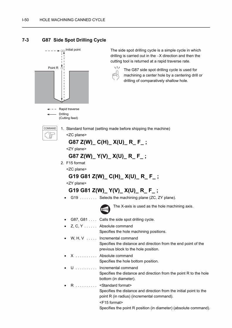
I-50 HOLE MACHINING CANNED CYCLE
7-3 G87 Side Spot Drilling Cycle
The side spot drilling cycle is a simple cycle in which drilling is carried out in the −X direction and then the cutting tool is returned at a rapid traverse rate.
The G87 side spot drilling cycle is used for machining a center hole by a centering drill or drilling of comparatively shallow hole.
1. Standard format (setting made before shipping the machine)<ZC plane>
G87 Z(W)_ C(H)_ X(U)_ R_ F_ ;<ZY plane>
G87 Z(W)_ Y(V)_ X(U)_ R_ F_ ;2. F15 format
<ZC plane>
G19 G81 Z(W)_ C(H)_ X(U)_ R_ F_ ;<ZY plane>
G19 G81 Z(W)_ Y(V)_ X(U)_ R_ F_ ;• G19 . . . . . . . . Selects the machining plane (ZC, ZY plane).
The X-axis is used as the hole machining axis.
• G87, G81 . . . . Calls the side spot drilling cycle.
• Z, C, Y . . . . . . Absolute commandSpecifies the hole machining positions.
• W, H, V . . . . . Incremental commandSpecifies the distance and direction from the end point of the previous block to the hole position.
• X . . . . . . . . . . Absolute commandSpecifies the hole bottom position.
• U . . . . . . . . . . Incremental commandSpecifies the distance and direction from the point R to the hole bottom (in diameter).
• R . . . . . . . . . . <Standard format>Specifies the distance and direction from the initial point to the point R (in radius) (incremental command).<F15 format>Specifies the point R position (in diameter) (absolute command).
Point R
Initial point
Rapid traverseDrilling(Cutting feed)
COMMAND
NOTE
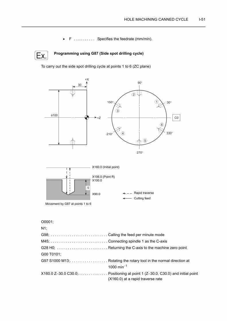
HOLE MACHINING CANNED CYCLE I-51
• F . . . . . . . . . . Specifies the feedrate (mm/min).
Programming using G87 (Side spot drilling cycle)
To carry out the side spot drilling cycle at points 1 to 6 (ZC plane)
O0001;
N1;
G98; . . . . . . . . . . . . . . . . . . . . . . . . . . . Calling the feed per minute mode
M45; . . . . . . . . . . . . . . . . . . . . . . . . . . . Connecting spindle 1 as the C-axis
G28 H0; . . . . . . . . . . . . . . . . . . . . . . . . Returning the C-axis to the machine zero point
G00 T0101;
G97 S1000 M13;. . . . . . . . . . . . . . . . . . Rotating the rotary tool in the normal direction at
1000 min−1
X160.0 Z−30.0 C30.0;. . . . . . . . . . . . . . Positioning at point 1 (Z−30.0, C30.0) and initial point (X160.0) at a rapid traverse rate
Ex.
5
100
30
+X
+Zφ
C0
210°
150° 30°
90°
270°
3
2
1
4
5
6
330°
Rapid traverse
Cutting feed
X160.0 (Initial point)
X106.0 (Point R)
Movement by G87 at points 1 to 6
X100.0
X90.0

I-52 HOLE MACHINING CANNED CYCLE
G87 X90.0 R−27.0 F100; . . . . . . . . . . . Executing the side spot drilling cycle at point 1
• X90.0 . . . X coordinate value of the point X (hole bottom)
• R−27.0 . . Distance and direction from the initial point to the point R (in radius)
• F100 . . . Feedrate of 100 mm/min
C90.0;
C150.0;
C210.0;
C270.0;
C330.0;
G80; . . . . . . . . . . . . . . . . . . . . . . . . . . . Canceling the side spot drilling cycle mode
G00 X200.0 Z100.0 M05; . . . . . . . . . . . Stopping rotary tool rotation
M46; . . . . . . . . . . . . . . . . . . . . . . . . . . . Canceling the C-axis connection
G99; . . . . . . . . . . . . . . . . . . . . . . . . . . . Calling the feed per revolution mode
M01;
. . . . . . . . . . . . . . . . Executing the side spot drilling cycle at points 2 to 6

HOLE MACHINING CANNED CYCLE I-53
7-4 G87 Side Spot Drilling Cycle (Dwell)
The side spot drilling cycle (dwell) carries out drilling in the −X direction and returns the tool at a rapid traverse rate.
In the G87 side spot drilling cycle (dwell), accuracy of hole depth in the blind hole machining is improved and surface roughness at the hole bottom is improved as well since dwell is carried out at the hole bottom.
The term "dwell" means suspension of axis movement for the specified period.
1. Standard format (setting made before shipping the machine)<ZC plane>
G87 Z(W)_ C(H)_ X(U)_ R_ P_ F_ ;<ZY plane>
G87 Z(W)_ Y(V)_ X(U)_ R_ P_ F_ ;2. F15 format
<ZC plane>
G19 G82 Z(W)_ C(H)_ X(U)_ R_ P_ F_ ;<ZY plane>
G19 G82 Z(W)_ Y(V)_ X(U)_ R_ P_ F_ ;• G19 . . . . . . . . Selects the machining plane (ZC, ZY plane).
The X-axis is used as the hole machining axis.
• G87, G82 . . . . Calls the side spot drilling cycle (dwell).
• Z, C, Y . . . . . . Absolute commandSpecifies the hole machining positions.
• W, H, V . . . . . Incremental commandSpecifies the distance and direction from the end point of the previous block to the hole position.
• X . . . . . . . . . . Absolute commandSpecifies the hole bottom position.
• U . . . . . . . . . . Incremental commandSpecifies the distance and direction from the point R to the hole bottom (in diameter).
Point R
Dwell
Initial point
Rapid traverse
Drilling(Cutting feed)
COMMAND
NOTE

I-54 HOLE MACHINING CANNED CYCLE
• R . . . . . . . . . . <Standard format>Specifies the distance and direction from the initial point to the point R (in radius) (incremental command).<F15 format>Specifies the point R position (in diameter) (absolute command).
• P. . . . . . . . . . . Specifies the period of dwell function executed at the hole bottom.
P1000 → 1 sec
• F . . . . . . . . . . . Specifies the feedrate (mm/min).
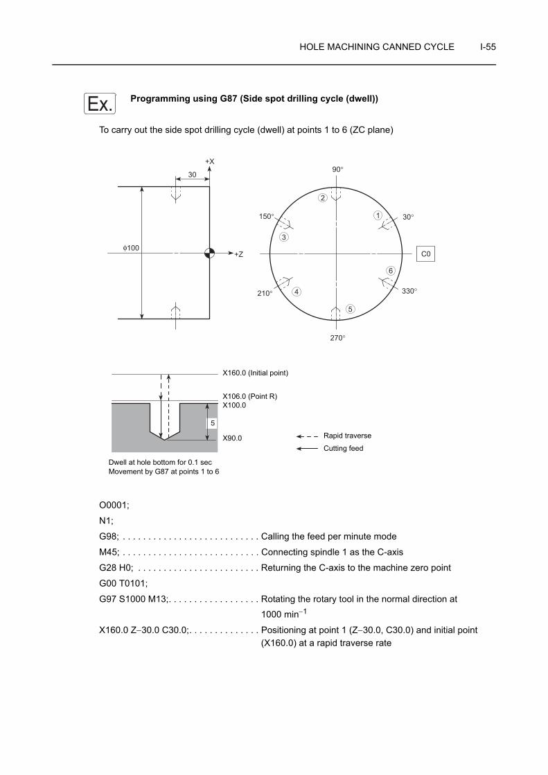
HOLE MACHINING CANNED CYCLE I-55
Programming using G87 (Side spot drilling cycle (dwell))
To carry out the side spot drilling cycle (dwell) at points 1 to 6 (ZC plane)
O0001;
N1;
G98; . . . . . . . . . . . . . . . . . . . . . . . . . . . Calling the feed per minute mode
M45; . . . . . . . . . . . . . . . . . . . . . . . . . . . Connecting spindle 1 as the C-axis
G28 H0; . . . . . . . . . . . . . . . . . . . . . . . . Returning the C-axis to the machine zero point
G00 T0101;
G97 S1000 M13;. . . . . . . . . . . . . . . . . . Rotating the rotary tool in the normal direction at
1000 min−1
X160.0 Z−30.0 C30.0;. . . . . . . . . . . . . . Positioning at point 1 (Z−30.0, C30.0) and initial point (X160.0) at a rapid traverse rate
Ex.
Dwell at hole bottom for 0.1 secMovement by G87 at points 1 to 6
5
100
30
+X
+Zφ
C0
210°
150° 30°
90°
270°
3
2
1
4
5
6
330°
Rapid traverse
Cutting feed
X160.0 (Initial point)
X106.0 (Point R)X100.0
X90.0

I-56 HOLE MACHINING CANNED CYCLE
G87 X90.0 R−27.0 P100 F100; . . . . . . Executing the side spot drilling cycle (dwell) at point 1
• X90.0 . . . X coordinate value of the point X (hole bottom)
• R−27.0 . . Distance and direction from the initial point to the point R (in radius)
• P100. . . . Dwell period at hole bottom for 0.1 secTime per rotary tool rotation (sec)
=
= 0.06 < 0.1 (sec)Thus, the rotary tool makes more than one rotation.
• F100 . . . Feedrate of 100 mm/min
C90.0;
C150.0;
C210.0;
C270.0;
C330.0;
G80; . . . . . . . . . . . . . . . . . . . . . . . . . . . Canceling the side spot drilling cycle (dwell) mode
G00 X200.0 Z100.0 M05; . . . . . . . . . . . Stopping rotary tool rotation
M46; . . . . . . . . . . . . . . . . . . . . . . . . . . . Canceling the C-axis connection
G99; . . . . . . . . . . . . . . . . . . . . . . . . . . . Calling the feed per revolution mode
M01;
60 (sec)Spindle speed (min−1)
. . . . . . . . . . . . . . . . Executing the side spot drilling cycle (dwell) at points 2 to 6
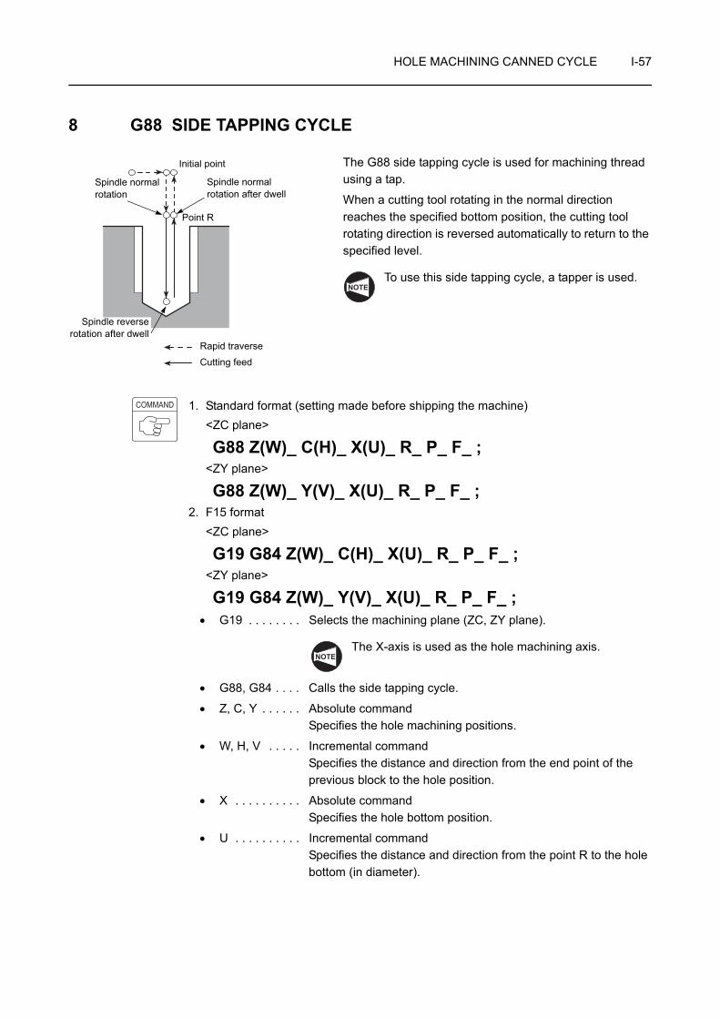
HOLE MACHINING CANNED CYCLE I-57
8 G88 SIDE TAPPING CYCLE
The G88 side tapping cycle is used for machining thread using a tap.
When a cutting tool rotating in the normal direction reaches the specified bottom position, the cutting tool rotating direction is reversed automatically to return to the specified level.
To use this side tapping cycle, a tapper is used.
1. Standard format (setting made before shipping the machine)<ZC plane>
G88 Z(W)_ C(H)_ X(U)_ R_ P_ F_ ;<ZY plane>
G88 Z(W)_ Y(V)_ X(U)_ R_ P_ F_ ;2. F15 format
<ZC plane>
G19 G84 Z(W)_ C(H)_ X(U)_ R_ P_ F_ ;<ZY plane>
G19 G84 Z(W)_ Y(V)_ X(U)_ R_ P_ F_ ;• G19 . . . . . . . . Selects the machining plane (ZC, ZY plane).
The X-axis is used as the hole machining axis.
• G88, G84 . . . . Calls the side tapping cycle.
• Z, C, Y . . . . . . Absolute commandSpecifies the hole machining positions.
• W, H, V . . . . . Incremental commandSpecifies the distance and direction from the end point of the previous block to the hole position.
• X . . . . . . . . . . Absolute commandSpecifies the hole bottom position.
• U . . . . . . . . . . Incremental commandSpecifies the distance and direction from the point R to the hole bottom (in diameter).
Point R
Initial point
Rapid traverse
Cutting feed
Spindle normal rotation after dwell
Spindle normal rotation
Spindle reverserotation after dwell
NOTE
COMMAND
NOTE

I-58 HOLE MACHINING CANNED CYCLE
• R . . . . . . . . . . <Standard format>Specifies the distance and direction from the initial point to the point R (in radius) (incremental command).<F15 format>Specifies the point R position (in diameter) (absolute command).
• P . . . . . . . . . . Specifies the period of dwell function executed at the hole bottom.
P1000 → 1 sec
• F . . . . . . . . . . Specifies the feedrate (mm/min). (spindle speed × pitch)
1. For the side tapping cycle called by G88, a tapper is used. In this case, the return movement from the bottom of the machined hole to the point R level is made with the tapper extended. Therefore, the point R level must be specified larger value than tapper extending length. If the smaller value is specified, the cutting tool and workpiece may collide or interfere with each other, and this could damage the machine when moving to next machining position.
2. When the emergency stop button or (RESET) key has been pressed to stop
the machine during a tapping operation, carefully move the axes after checking the workpiece and cutting tool carefully for damage. If you move the axes without due care, the workpiece and cutting tool may collide or interfere with each other, and this could cause damage to the machine.
1. During the side tapping cycle called by G88, feedrate override and spindle speed override are fixed to 100% because a fixed lead thread cannot be cut if feedrate or spindle speed is changed during side tapping cycle.
2. If the (SP) switch on the operation panel is pressed during side tapping cycle,
side tapping cycle does not stop until the X-axis returns to the initial point level is completed.
CAUTION
RESET
NOTE

HOLE MACHINING CANNED CYCLE I-59
Programming using G88 (Side tapping cycle)
To carry out the side tapping cycle (pitch: 2 mm, depth: 20 mm) at points 1 to 6 (ZC plane)
O0001;
N1;
G98; . . . . . . . . . . . . . . . . . . . . . . . . . . . Calling the feed per minute mode
M45; . . . . . . . . . . . . . . . . . . . . . . . . . . . Connecting spindle 1 as the C-axis
G28 H0; . . . . . . . . . . . . . . . . . . . . . . . . Returning the C-axis to the machine zero point
G00 T0101;
G97 S300 M13;. . . . . . . . . . . . . . . . . . . Rotating the rotary tool in the normal direction at
300 min−1
X160.0 Z−30.0 C30.0;. . . . . . . . . . . . . . Positioning at point 1 (Z−30.0, C30.0) and initial point (X160.0) at a rapid traverse rate
Ex.
20
100
30
+X
+Zφ
C0
210°
150° 30°
90°
270°
3
2
1
4
5
6
330°
Rapid traverseCutting feed
X160.0 (Initial point)
X130.0 (Point R)
Dwell at hole bottom for 0.1 secMovement by G88 at points 1 to 6
X100.0
X60.0
Reverse rotation
Normal rotation
I-60 HOLE MACHINING CANNED CYCLE
G88 X_ R−15.0 P500 F600; . . . . . . . . Executing the side tapping cycle at point 1Tapping is executed up to 20 mm depth.
Feedrate F
= Spindle speed (min−1) × Pitch (mm) = 300 × 2 = 600 (mm/min)
For the X-axis point, specify "X(100 − 2 × (20 − tapper elongation in normal rotation + tap engaging length))".
For dwell period P: Page I-78
C90.0;
C150.0;
C210.0;
C270.0;
C330.0;
G80; . . . . . . . . . . . . . . . . . . . . . . . . . . . Canceling the side tapping cycle mode
G00 X200.0 Z100.0 M05; . . . . . . . . . . . Stopping rotary tool rotation
M46; . . . . . . . . . . . . . . . . . . . . . . . . . . . Canceling the C-axis connection
G99; . . . . . . . . . . . . . . . . . . . . . . . . . . . Calling the feed per revolution mode
M01;
. . . . . . . . . . . . . . . . Executing the side tapping cycle at points 2 to 6

HOLE MACHINING CANNED CYCLE I-61
9 M329 G88 SIDE SYNCHRONIZED TAPPING CYCLE
When executing tapping operation, the X- or Z-axis feed amount per rotary tool rotation must be equal to the pitch of threads to be cut.
With the side synchronized tapping cycle, accurate tapping operation is possible for cutting threads since rotary tool rotation and the X-axis feed are constantly synchronized.
This cycle can be used only for the MC type or Y-axis specification ZT series machines.
1. Standard format (setting made before shipping the machine)<ZC plane>
M329 S_ ;G88 Z(W)_ C(H)_ X(U)_ R_ P_ F_ ;
<ZY plane>
M329 S_ ;G88 Z(W)_ Y(V)_ X(U)_ R_ P_ F_ ;
2. F15 format<ZC plane>
M329 S_ ;G19 G84.2 Z(W)_ C(H)_ X(U)_ R_ P_ F_ ;
<ZY plane>
M329 S_ ;G19 G84.2 Z(W)_ Y(V)_ X(U)_ R_ P_ F_ ;
• M329 . . . . . . . Synchronized tapping command
• S . . . . . . . . . . Specifies the spindle speed (min−1).
• G19 . . . . . . . . Selects the machining plane (ZC, ZY plane).
The X-axis is used as the hole machining axis.
• G88 . . . . . . . . Calls the side tapping cycle.
• G84.2 . . . . . . Calls the synchronized tapping cycle.
• Z, C, Y . . . . . . Absolute commandSpecifies the hole machining positions.
• W, H, V . . . . . Incremental commandSpecifies the distance and direction from the end point of the previous block to the hole position.
Point R
Initial point
Rapid traverseCutting feed
Spindle normal rotation
Spindle rotation stop after dwell
Spindle rotation stop
Spindle rotation stop
Spindle reverse rotation after dwell
NOTE
COMMAND
NOTE

I-62 HOLE MACHINING CANNED CYCLE
• X . . . . . . . . . . Absolute commandSpecifies the hole bottom position.
• U . . . . . . . . . . Incremental commandSpecifies the distance and direction from the point R to the hole bottom (in diameter).
• R . . . . . . . . . . <Standard format>Specifies the distance and direction from the initial point to the point R (in radius) (incremental command).<F15 format>Specifies the point R position (in diameter) (absolute command).
• P . . . . . . . . . . Specifies the period of dwell function executed at the hole bottom.
P1000 → 1 sec
• F . . . . . . . . . . <Feed per minute mode (G98)>Specifies the feedrate (mm/min).(spindle speed × pitch)<Feed per revolution mode (G99)>Specifies the feedrate (mm/rev).(pitch)
When the emergency stop button or (RESET) key has been pressed to stop the
machine during a side synchronized tapping operation, carefully move the axes after checking the workpiece and cutting tool carefully for damage. If you move the axes without due care, the workpiece and cutting tool may collide or interfere with each other, and this could cause damage to the machine.
1. During the side synchronized tapping cycle, feedrate override and spindle speed override are fixed to 100% because a fixed lead thread cannot be cut if feedrate or spindle speed is changed during side synchronized tapping cycle.
2. If the (SP) switch on the operation panel is pressed during side synchronized
tapping cycle, side synchronized tapping cycle does not stop until the X-axis returns to the initial point level is completed.
3. Stop rotary tool rotation before specifying a side synchronized tapping cycle.
4. Since rotary tool rotation and the X-axis feed are synchronized in the side synchronized tapping cycle, it is not necessary to use a tapper.
5. With ZT1000Y, ZT1500Y, ZT1500YB, ZT2500MC and ZT2500Y, there is a spindle
speed limit (2000 min−1) that can be used in the synchronized tapping cycle.
CAUTIONRESET
NOTE
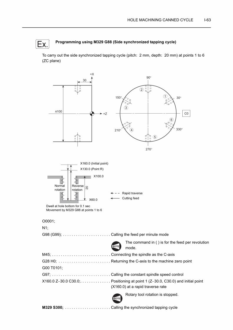
HOLE MACHINING CANNED CYCLE I-63
Programming using M329 G88 (Side synchronized tapping cycle)
To carry out the side synchronized tapping cycle (pitch: 2 mm, depth: 20 mm) at points 1 to 6 (ZC plane)
O0001;
N1;
G98 (G99); . . . . . . . . . . . . . . . . . . . . . . Calling the feed per minute mode
The command in ( ) is for the feed per revolution mode.
M45; . . . . . . . . . . . . . . . . . . . . . . . . . . . Connecting the spindle as the C-axis
G28 H0; . . . . . . . . . . . . . . . . . . . . . . . . Returning the C-axis to the machine zero point
G00 T0101;
G97; . . . . . . . . . . . . . . . . . . . . . . . . . . . Calling the constant spindle speed control
X160.0 Z−30.0 C30.0;. . . . . . . . . . . . . . Positioning at point 1 (Z−30.0, C30.0) and initial point (X160.0) at a rapid traverse rate
Rotary tool rotation is stopped.
M329 S300; . . . . . . . . . . . . . . . . . . . . . Calling the synchronized tapping cycle
Ex.
Dwell at hole bottom for 0.1 secMovement by M329 G88 at points 1 to 6
20
100
30
+X
+Zφ
C0
210°
150° 30°
90°
270°
3
2
1
4
5
6
330°
Rapid traverseCutting feed
X160.0 (Initial point)
X130.0 (Point R)
X100.0
X60.0
Reverse rotation
Normal rotation
NOTE
NOTE

I-64 HOLE MACHINING CANNED CYCLE
G88 X_ R−15.0 F600 (F2.0); . . . . . . . . Executing the side synchronized tapping cycle at point 1
1. Feedrate F
= Spindle speed (min−1) × Pitch (mm) = 300 × 2 = 600 (mm/min)
For the X-axis point, specify "X(100 − 2 × (20 + tap engaging length))".
2. Rotary tool rotation is stopped between the initial point and the point R.
The command in ( ) is for the feed per revolution mode.
Feedrate F = Pitch (mm)
C90.0;
C150.0;
C210.0;
C270.0;
C330.0;
G80; . . . . . . . . . . . . . . . . . . . . . . . . . . . Canceling the side synchronized tapping cycle mode
G00 X200.0 Z100.0 M05; . . . . . . . . . . . Stopping rotary tool rotation
M46; . . . . . . . . . . . . . . . . . . . . . . . . . . . Canceling the C-axis connection
G99; . . . . . . . . . . . . . . . . . . . . . . . . . . . Calling the feed per revolution mode
This command is necessary only for the feed per minute mode.
M01;
NOTE
. . . . . . . . . . . . . . . . Executing the side synchronized tapping cycle at points 2 to 6
NOTE

HOLE MACHINING CANNED CYCLE I-65
10 G89 SIDE BORING CYCLE
The side boring cycle carries out drilling in the −X direction and returns the tool at a cutting feedrate.
Return movement from the hole bottom to the point R is executed at the feedrate twice the specified cutting feedrate.
The G89 side boring cycle is usually used for reaming and boring operation.
1. Standard format (setting made before shipping the machine)<ZC plane>
G89 Z(W)_ C(H)_ X(U)_ R_ P_ F_ ;<ZY plane>
G89 Z(W)_ Y(V)_ X(U)_ R_ P_ F_ ;2. F15 format
<ZC plane>
G19 G89 Z(W)_ C(H)_ X(U)_ R_ P_ F_ ;<ZY plane>
G19 G89 Z(W)_ Y(V)_ X(U)_ R_ P_ F_ ;• G19 . . . . . . . . Selects the machining plane (ZC, ZY plane).
The X-axis is used as the hole machining axis.
• G89 . . . . . . . . Calls the side boring cycle.
• Z, C, Y . . . . . . Absolute commandSpecifies the hole machining positions.
• W, H, V . . . . . Incremental commandSpecifies the distance and direction from the end point of the previous block to the hole position.
• X . . . . . . . . . . Absolute commandSpecifies the hole bottom position.
• U . . . . . . . . . . Incremental commandSpecifies the distance and direction from the point R to the hole bottom (in diameter).
Point R
Dwell
Initial point
Rapid traverseCutting feed
NOTE
COMMAND
NOTE

I-66 HOLE MACHINING CANNED CYCLE
• R . . . . . . . . . . <Standard format>Specifies the distance and direction from the initial point to the point R (in radius) (incremental command).<F15 format>Specifies the point R position (in diameter) (absolute command).
• P . . . . . . . . . . Specifies the period of dwell function executed at the hole bottom.
P1000 → 1 sec
• F . . . . . . . . . . Specifies the feedrate (mm/min).
With the F15 format, when omitting address P, specify the G85 command instead of the G89 command.
Programming using G89 (Side boring cycle)
To carry out the side boring cycle at points 1 to 6 (ZC plane)
NOTE
Ex.
15
100
30
+X
+Zφ C0
210°
150° 30°
90°
270°
3
2
1
4
5
6
330°
Rapid traverse
Cutting feed
X160.0 (Initial point)
X106.0 (Point R)
Dwell at hole bottom for 0.1 secMovement by G89 at points 1 to 6
X100.0
X70.0
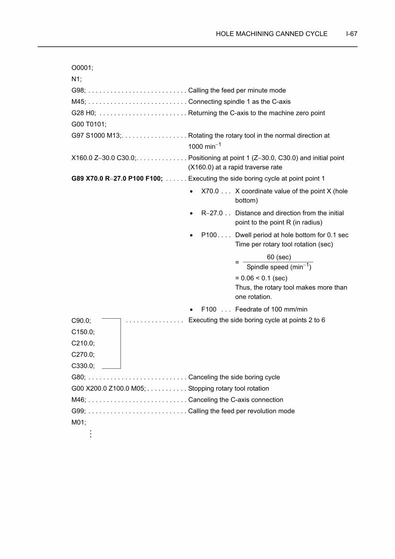
HOLE MACHINING CANNED CYCLE I-67
O0001;
N1;
G98; . . . . . . . . . . . . . . . . . . . . . . . . . . . Calling the feed per minute mode
M45; . . . . . . . . . . . . . . . . . . . . . . . . . . . Connecting spindle 1 as the C-axis
G28 H0; . . . . . . . . . . . . . . . . . . . . . . . . Returning the C-axis to the machine zero point
G00 T0101;
G97 S1000 M13;. . . . . . . . . . . . . . . . . . Rotating the rotary tool in the normal direction at
1000 min−1
X160.0 Z−30.0 C30.0;. . . . . . . . . . . . . . Positioning at point 1 (Z−30.0, C30.0) and initial point (X160.0) at a rapid traverse rate
G89 X70.0 R−27.0 P100 F100; . . . . . . Executing the side boring cycle at point point 1
• X70.0 . . . X coordinate value of the point X (hole bottom)
• R−27.0 . . Distance and direction from the initial point to the point R (in radius)
• P100. . . . Dwell period at hole bottom for 0.1 secTime per rotary tool rotation (sec)
=
= 0.06 < 0.1 (sec)Thus, the rotary tool makes more than one rotation.
• F100 . . . Feedrate of 100 mm/min
C90.0;
C150.0;
C210.0;
C270.0;
C330.0;
G80; . . . . . . . . . . . . . . . . . . . . . . . . . . . Canceling the side boring cycle
G00 X200.0 Z100.0 M05; . . . . . . . . . . . Stopping rotary tool rotation
M46; . . . . . . . . . . . . . . . . . . . . . . . . . . . Canceling the C-axis connection
G99; . . . . . . . . . . . . . . . . . . . . . . . . . . . Calling the feed per revolution mode
M01;
60 (sec)Spindle speed (min−1)
. . . . . . . . . . . . . . . . Executing the side boring cycle at points 2 to 6

I-68 HOLE MACHINING CANNED CYCLE
11 G384, G380 SYNCHRONIZED TAPPING CYCLE
When executing tapping operation, the X- or Z-axis feed amount per rotary tool rotation must be equal to the pitch of threads to be cut.
When the G384 command is specified, accurate tapping operation is possible for cutting threads since rotation of the rotary tool and the Z-axis feed are constantly synchronized.
The synchronized tapping cycle is canceled when the G380 command is specified.
1. The G384 and G380 commands can be used only for the MC type ZL and ZL-S series machines.
2. With the ZL and ZL-S series, the G384 and G380 commands can be specified only in the turret 1 program.
1. Face synchronized tapping cycle<XC plane>
G384 X(U)_ C(H)_ Z(W)_ R_ F_ S_ D_ E_ M_ T2.(T3.);<XY plane>
G384 X(U)_ Y(V)_ Z(W)_ R_ F_ S_ D_ E_ M_ T2.(T3.);G380;
2. Side synchronized tapping cycle<ZC plane>
G384 Z(W)_ C(H)_ X(U)_ R_ F_ S_ D_ E_ M_ T1.(T4.);<ZY plane>
G384 Z(W)_ Y(V)_ X(U)_ R_ F_ S_ D_ E_ M_ T1.(T4.);G380;
Point R
Initial point
Rapid traverse
Cutting feed
Spindle normalrotation
Spindle rotation stop after dwell
Spindle rotation stop
Spindle rotation stop
Spindle reverse rotation after dwell NOTE
COMMAND
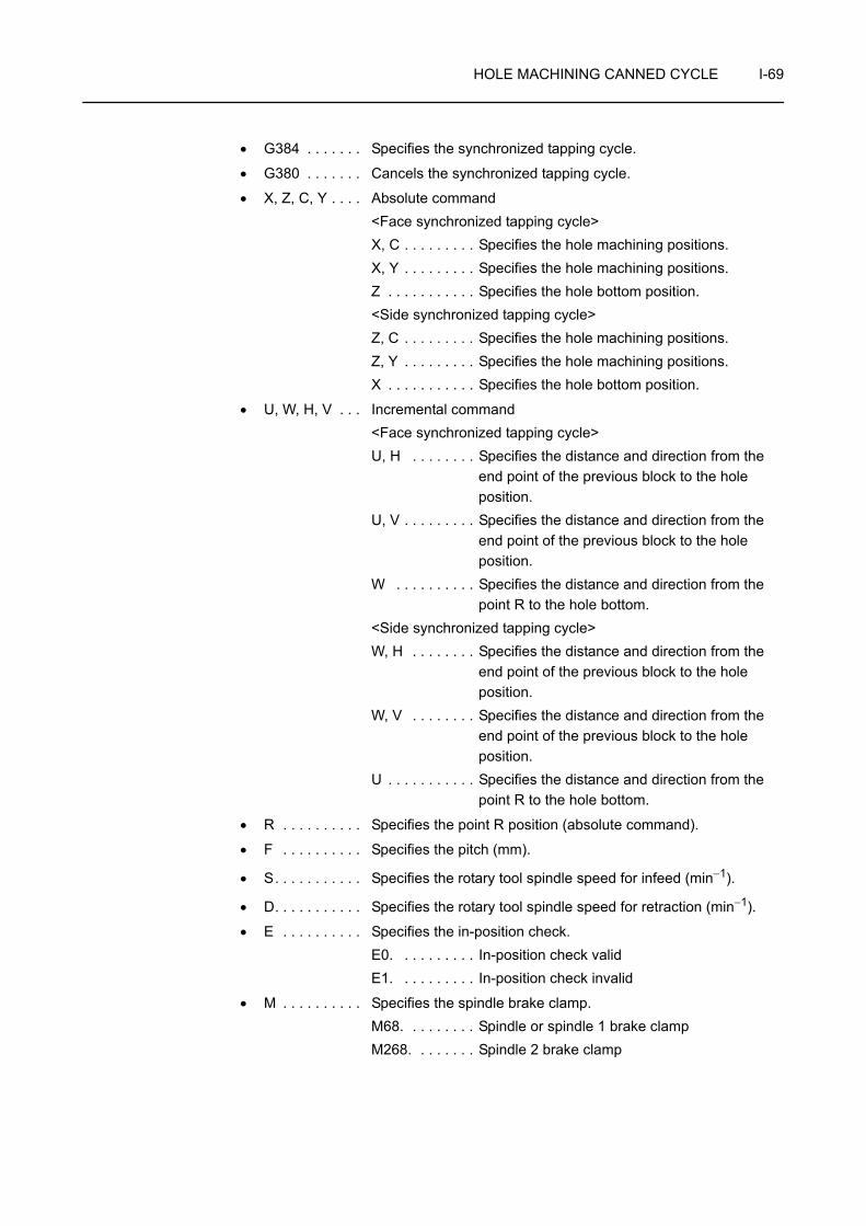
HOLE MACHINING CANNED CYCLE I-69
• G384 . . . . . . . Specifies the synchronized tapping cycle.
• G380 . . . . . . . Cancels the synchronized tapping cycle.
• X, Z, C, Y . . . . Absolute command<Face synchronized tapping cycle>X, C . . . . . . . . . Specifies the hole machining positions.X, Y . . . . . . . . . Specifies the hole machining positions.Z . . . . . . . . . . . Specifies the hole bottom position.<Side synchronized tapping cycle>Z, C . . . . . . . . . Specifies the hole machining positions.Z, Y . . . . . . . . . Specifies the hole machining positions.X . . . . . . . . . . . Specifies the hole bottom position.
• U, W, H, V . . . Incremental command<Face synchronized tapping cycle>U, H . . . . . . . . Specifies the distance and direction from the
end point of the previous block to the hole position.
U, V . . . . . . . . . Specifies the distance and direction from the end point of the previous block to the hole position.
W . . . . . . . . . . Specifies the distance and direction from the point R to the hole bottom.
<Side synchronized tapping cycle>W, H . . . . . . . . Specifies the distance and direction from the
end point of the previous block to the hole position.
W, V . . . . . . . . Specifies the distance and direction from the end point of the previous block to the hole position.
U . . . . . . . . . . . Specifies the distance and direction from the point R to the hole bottom.
• R . . . . . . . . . . Specifies the point R position (absolute command).
• F . . . . . . . . . . Specifies the pitch (mm).
• S. . . . . . . . . . . Specifies the rotary tool spindle speed for infeed (min−1).
• D. . . . . . . . . . . Specifies the rotary tool spindle speed for retraction (min−1).
• E . . . . . . . . . . Specifies the in-position check.E0. . . . . . . . . . In-position check validE1. . . . . . . . . . In-position check invalid
• M . . . . . . . . . . Specifies the spindle brake clamp.M68. . . . . . . . . Spindle or spindle 1 brake clampM268. . . . . . . . Spindle 2 brake clamp
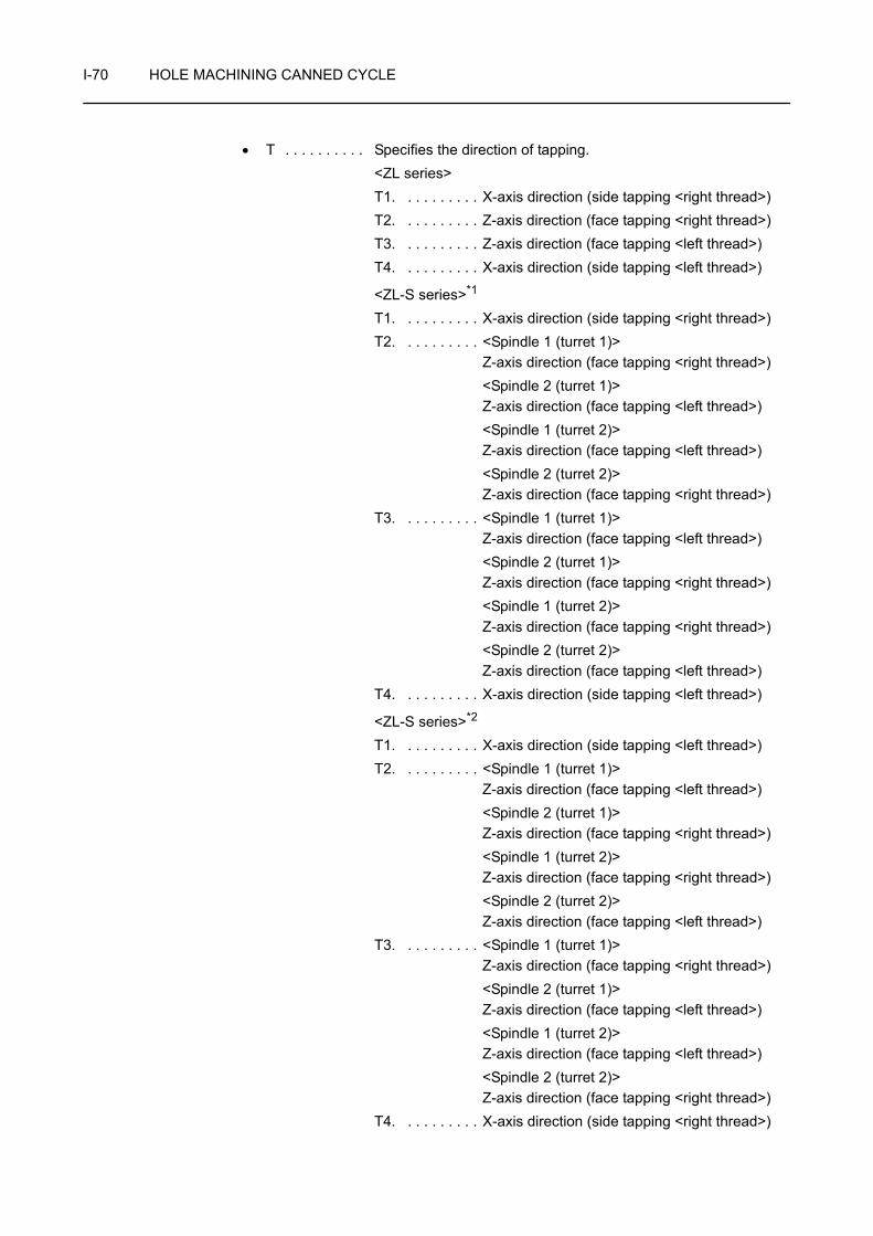
I-70 HOLE MACHINING CANNED CYCLE
• T . . . . . . . . . . Specifies the direction of tapping.<ZL series>T1. . . . . . . . . . X-axis direction (side tapping <right thread>)T2. . . . . . . . . . Z-axis direction (face tapping <right thread>)T3. . . . . . . . . . Z-axis direction (face tapping <left thread>)T4. . . . . . . . . . X-axis direction (side tapping <left thread>)
<ZL-S series>*1
T1. . . . . . . . . . X-axis direction (side tapping <right thread>)T2. . . . . . . . . . <Spindle 1 (turret 1)>
Z-axis direction (face tapping <right thread>)<Spindle 2 (turret 1)> Z-axis direction (face tapping <left thread>)<Spindle 1 (turret 2)>Z-axis direction (face tapping <left thread>)<Spindle 2 (turret 2)>Z-axis direction (face tapping <right thread>)
T3. . . . . . . . . . <Spindle 1 (turret 1)> Z-axis direction (face tapping <left thread>)<Spindle 2 (turret 1)> Z-axis direction (face tapping <right thread>)<Spindle 1 (turret 2)>Z-axis direction (face tapping <right thread>)<Spindle 2 (turret 2)>Z-axis direction (face tapping <left thread>)
T4. . . . . . . . . . X-axis direction (side tapping <left thread>)
<ZL-S series>*2
T1. . . . . . . . . . X-axis direction (side tapping <left thread>)T2. . . . . . . . . . <Spindle 1 (turret 1)>
Z-axis direction (face tapping <left thread>)<Spindle 2 (turret 1)> Z-axis direction (face tapping <right thread>)<Spindle 1 (turret 2)>Z-axis direction (face tapping <right thread>)<Spindle 2 (turret 2)>Z-axis direction (face tapping <left thread>)
T3. . . . . . . . . . <Spindle 1 (turret 1)> Z-axis direction (face tapping <right thread>)<Spindle 2 (turret 1)> Z-axis direction (face tapping <left thread>)<Spindle 1 (turret 2)>Z-axis direction (face tapping <left thread>)<Spindle 2 (turret 2)>Z-axis direction (face tapping <right thread>)
T4. . . . . . . . . . X-axis direction (side tapping <right thread>)
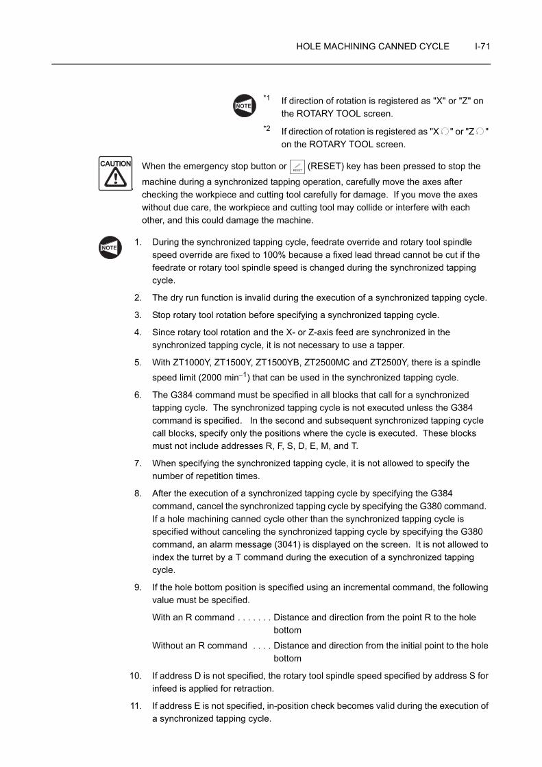
HOLE MACHINING CANNED CYCLE I-71
*1 If direction of rotation is registered as "X" or "Z" on the ROTARY TOOL screen.
*2 If direction of rotation is registered as "X " or "Z " on the ROTARY TOOL screen.
When the emergency stop button or (RESET) key has been pressed to stop the
machine during a synchronized tapping operation, carefully move the axes after checking the workpiece and cutting tool carefully for damage. If you move the axes without due care, the workpiece and cutting tool may collide or interfere with each other, and this could damage the machine.
1. During the synchronized tapping cycle, feedrate override and rotary tool spindle speed override are fixed to 100% because a fixed lead thread cannot be cut if the feedrate or rotary tool spindle speed is changed during the synchronized tapping cycle.
2. The dry run function is invalid during the execution of a synchronized tapping cycle.
3. Stop rotary tool rotation before specifying a synchronized tapping cycle.
4. Since rotary tool rotation and the X- or Z-axis feed are synchronized in the synchronized tapping cycle, it is not necessary to use a tapper.
5. With ZT1000Y, ZT1500Y, ZT1500YB, ZT2500MC and ZT2500Y, there is a spindle
speed limit (2000 min−1) that can be used in the synchronized tapping cycle.
6. The G384 command must be specified in all blocks that call for a synchronized tapping cycle. The synchronized tapping cycle is not executed unless the G384 command is specified. In the second and subsequent synchronized tapping cycle call blocks, specify only the positions where the cycle is executed. These blocks must not include addresses R, F, S, D, E, M, and T.
7. When specifying the synchronized tapping cycle, it is not allowed to specify the number of repetition times.
8. After the execution of a synchronized tapping cycle by specifying the G384 command, cancel the synchronized tapping cycle by specifying the G380 command. If a hole machining canned cycle other than the synchronized tapping cycle is specified without canceling the synchronized tapping cycle by specifying the G380 command, an alarm message (3041) is displayed on the screen. It is not allowed to index the turret by a T command during the execution of a synchronized tapping cycle.
9. If the hole bottom position is specified using an incremental command, the following value must be specified.
With an R command . . . . . . . Distance and direction from the point R to the hole bottom
Without an R command . . . . Distance and direction from the initial point to the hole bottom
10. If address D is not specified, the rotary tool spindle speed specified by address S for infeed is applied for retraction.
11. If address E is not specified, in-position check becomes valid during the execution of a synchronized tapping cycle.
NOTE
CAUTIONRESET
NOTE

I-72 HOLE MACHINING CANNED CYCLE
12. If the M68. or M268. command is not specified, spindle brake clamp operation is not executed.
13. Use the data with a decimal point for all addresses specified in the G384 block.
14. Alarms related to the synchronized tapping cycle are indicated below.
Alarm No. Message Description
3041 CYCLE NOT FINISHAfter specifying G384, other type of synchronized tapping cycle is specified without specifying G380.
3042 ILLEGAL COMMANDThere is an error in arguments.Check the arguments specified in the G384 block.
3043 TOO MANY ADDRESS
In the designation of synchronized tapping cycle positions, both absolute and incremental address characters are specified for the same axis.
NOTE

HOLE MACHINING CANNED CYCLE I-73
Programming using G384 and G380
To carry out the synchronized tapping cycle (pitch: 2 mm, depth: 20 mm) at points 1 to 6 (XC plane)
Length of engaging length: 5 mm
O0001;
N1;
G98; . . . . . . . . . . . . . . . . . . . . . . . . . . . Calling the feed per minute mode
M45; . . . . . . . . . . . . . . . . . . . . . . . . . . . Connecting the spindle or spindle 1 as the C-axis
G28 H0; . . . . . . . . . . . . . . . . . . . . . . . . Returning the C-axis to the machine zero point
G00 T0101;
G97; . . . . . . . . . . . . . . . . . . . . . . . . . . . Calling the constant spindle speed control
X150.0 Z30.0 C30.0;. . . . . . . . . . . . . . . Positioning at point 1 (X150.0, C30.0) and initial point (Z30.0) at a rapid traverse rate
Rotary tool rotation is stopped.
Ex.
Dwell at hole bottom for 0.1 secMovement by G384 at points 1 to 6
20
6
5
4
3
2
1
P.C.D 150
210°
150°
330°
30°
C0
90°
270°
Rapid traverse
Cutting feed
Z15.0(Point R)
Z30.0(Initial point)
Normal rotation
Reverse rotation
NOTE

I-74 HOLE MACHINING CANNED CYCLE
G384 Z−25.0 R15.0 F2.0 S300. D600. (E0.) M68. T2.; . . . . . . . . . . . . . . . . . . . . . . . . . . . . . . . Executing the synchronized tapping cycle at point 1
• Z−25.0 . . Z coordinate value of the point Z (hole bottom)
Z = −(depth of tap + tap engaging length) = −(20 + 5) = −25 mm
• R15.0 . . . Position of R point
• F2.0 . . . . Pitch: 2 mm
• S300. . . Rotary tool spindle speed for infeed:
300 min−1
• D600. . . Rotary tool spindle speed for retraction:
600 min−1
• (E0.) . . . . In-position check valid
• M68. . . . Spindle or spindle 1 brake clamp
• T2. . . . . Direction of tapping(Z-axis direction <right thread>)
Rotary tool rotation is stopped between the initial point and the point R.
G384 C90.0;G384 C150.0;G384 C210.0;G384 C270.0;G384 C330.0;G380; . . . . . . . . . . . . . . . . . . . . . . . . . . Canceling the synchronized tapping cycle
G00 X200.0 Z100.0 M05; . . . . . . . . . . . Stopping rotary tool rotation
M46; . . . . . . . . . . . . . . . . . . . . . . . . . . . Canceling the C-axis connection
G99; . . . . . . . . . . . . . . . . . . . . . . . . . . . Calling the feed per revolution mode
M01;
. . . . . . . . . . . Executing the synchronized tapping cycle at points 2 to 6
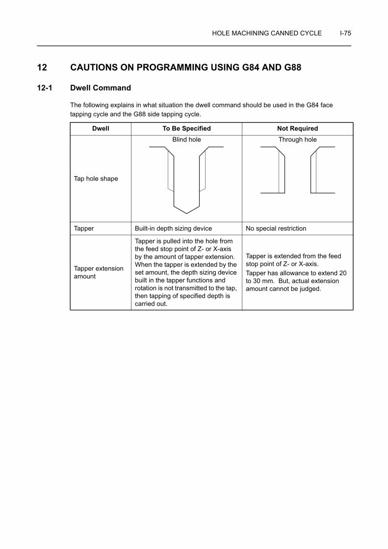
HOLE MACHINING CANNED CYCLE I-75
12 CAUTIONS ON PROGRAMMING USING G84 AND G88
12-1 Dwell Command
The following explains in what situation the dwell command should be used in the G84 face tapping cycle and the G88 side tapping cycle.
Dwell To Be Specified Not Required
Tap hole shape
Blind hole Through hole
Tapper Built-in depth sizing device No special restriction
Tapper extension amount
Tapper is pulled into the hole from the feed stop point of Z- or X-axis by the amount of tapper extension. When the tapper is extended by the set amount, the depth sizing device built in the tapper functions and rotation is not transmitted to the tap, then tapping of specified depth is carried out.
Tapper is extended from the feed stop point of Z- or X-axis.Tapper has allowance to extend 20 to 30 mm. But, actual extension amount cannot be judged.

I-76 HOLE MACHINING CANNED CYCLE
12-2 Precautions on Using the Tapper
When carrying out tapping in a through hole, extension of tapper tip at the hole bottom can be ignored. However, in the case of a blind hole, if the tapper should extend beyond the depth of the prepared hole, it will cause the tap to be damaged.
To avoid such a problem, use the tapper with built-in depth sizing device for tapping a blind hole.
The following distances of F1, F2, and F3 are specified in the catalog of the tapper with built-in depth sizing device.
F1 Contraction Necessary if the tap fails to be engaged with the workpiece positively at the start of tapping.
F2 Extension amount Extension amount at the hole bottom. This is an extension amount of a tapper in normal spindle rotation.
F3
Extension amount when the tap is pulled out
This is the extension amount when the tapper leaves the workpiece while the spindle is rotating in the reverse direction.
F1F2F3

HOLE MACHINING CANNED CYCLE I-77
12-3 To Finish Tapping at Correct Depth in Blind Hole
When machining a threaded hole with the tapper equipped with depth sizing device, obtain the point R and the point of the hole bottom to be specified in a program as indicated below:
The explanation given below shows the theoretical value. The depth of tapped hole will vary depending on workpiece material and prepared hole diameter in actual operation.
• Position of point R
• Hole bottom position
F2: Extension amount at normal rotation
F3: Extension amount at reverse rotation
Standard format F15 format
G84 R > F2 + F3 − "initial point" R > F2 + F3
G88R > F2 + F3
−("initial point" − "machining diameter") / 2R > "Machining diameter"
+ 2 (F2 + F3)
Standard format, F15 format
G84Z = −("Depth of tapping specified in the drawing" − F2
+ "tap engaging length")
G88X = "Machining diameter" − 2 ("depth of tap specified in the drawing" − F2
+ "tap engaging length")
NOTE

I-78 HOLE MACHINING CANNED CYCLE
To carry out tapping of M8 × P1.25, and 20 mm deep threaded hole in the face tapping cycle (G84)
Prepared hole: 6.8 mm dia., depth 30 mm
Tapper to be used: F2 (extension amount at normal rotation) = 5 mmF3 (extension amount at reverse rotation) = 7 mm
Tap engaging length: 5 mm
G97 S300 M13;. . . . . . . . . . . . . . . . . . . Rotating the rotary tool in the normal direction at
300 min−1
Z30.0; . . . . . . . . . . . . . . . . . . . . . . . . . . Positioning at initial point (Z30.0) at a rapid traverse rate
G84 X_ C_ Z−20.0 R−15.0 P800 F375; . . . . . . . . . . . . . . . . . . . . . . . . . . . . . . . Executing the face tapping cycle (G84)
• Z−20.0 . . . . . Z = −("Depth of tap" − F2 + "tap engaging length")
= −(20 − 5 + 5) = −20 (mm)
• R−15.0 . . . . . R > F2 + F3 − "initial point"
F2 + F3 − "initial point" = 5 + 7 − 30 = −18 (mm)
Because the value to be set for the point R must be larger than −18 mm, R−15.0 is specified.
• F375 . . . . . . F = Spindle speed (min−1) × pitch (mm)
= 300 × 1.25 = 375 (mm/min)
• P800 . . . . . . Dwell =
= = 0.8 (sec)
Executing the dwell at the bottom of the hole to allow the tapper to extend F2 (extension amount at normal rotation) set by the depth sizing device.
Ex.
60 (sec) × F2F (mm/min)
60 × 5375

CHAPTER JTOOL LIFE MANAGEMENT
B FUNCTION
This chapter describes the tool life management B function. The tool life management B function automatically selects an available tool in a registered tool group if the tool called in the same group has been used to the preset life.
CONTENTS
J : TOOL LIFE MANAGEMENT B FUNCTION
1 GENERAL . . . . . . . . . . . . . . . . . . . . . . . . . . . . . . . . . . . . . . . . . . . . . . . . . . . . . . . . . . . . J-1
2 SETTING TOOL LIFE MANAGEMENT DATA. . . . . . . . . . . . . . . . . . . . . . . . . . . . . . . . . J-2
2-1 Displayed Items on the TOOL LIFE MANAGE Screen . . . . . . . . . . . . . . . . . . . . . J-2
2-2 Setting Tool Life Management Data . . . . . . . . . . . . . . . . . . . . . . . . . . . . . . . . . . . J-3
2-3 Changing Tool Life Management Data . . . . . . . . . . . . . . . . . . . . . . . . . . . . . . . . . J-4
2-4 Setting the Tool Life Data in Program . . . . . . . . . . . . . . . . . . . . . . . . . . . . . . . . . . J-5
3 TOOL LIFE MANAGEMENT UTILITY FUNCTIONS . . . . . . . . . . . . . . . . . . . . . . . . . . . . J-7
3-1 Selecting the Tool Life Management Utility Function. . . . . . . . . . . . . . . . . . . . . . . J-7
3-2 TOOL LIFE SETTINGS . . . . . . . . . . . . . . . . . . . . . . . . . . . . . . . . . . . . . . . . . . . . . J-7
3-3 LOAD TOOL SKIP FUNC.. . . . . . . . . . . . . . . . . . . . . . . . . . . . . . . . . . . . . . . . . . . J-7
3-4 TOOL LIFE OPT. STOP . . . . . . . . . . . . . . . . . . . . . . . . . . . . . . . . . . . . . . . . . . . . J-7
3-5 TL OFST SHIFT FUNC. . . . . . . . . . . . . . . . . . . . . . . . . . . . . . . . . . . . . . . . . . . . . J-7
4 SPECIFICATION IN MACHINING PROGRAM . . . . . . . . . . . . . . . . . . . . . . . . . . . . . . . . J-8
4-1 T Command. . . . . . . . . . . . . . . . . . . . . . . . . . . . . . . . . . . . . . . . . . . . . . . . . . . . . . J-8
4-2 Group Command. . . . . . . . . . . . . . . . . . . . . . . . . . . . . . . . . . . . . . . . . . . . . . . . . . J-8
4-3 Life Count M Code . . . . . . . . . . . . . . . . . . . . . . . . . . . . . . . . . . . . . . . . . . . . . . . . J-8
5 COUNTING THE TOOL LIFE . . . . . . . . . . . . . . . . . . . . . . . . . . . . . . . . . . . . . . . . . . . . . J-9
6 SKIP COMMAND . . . . . . . . . . . . . . . . . . . . . . . . . . . . . . . . . . . . . . . . . . . . . . . . . . . . . J-10
7 STATE FLAG CLEAR COMMAND . . . . . . . . . . . . . . . . . . . . . . . . . . . . . . . . . . . . . . . . J-10
8 NEW TOOL SELECTION FLAG AND TOOL LIFE EXPIRED FLAG . . . . . . . . . . . . . . J-11
8-1 New Tool Selection Flag . . . . . . . . . . . . . . . . . . . . . . . . . . . . . . . . . . . . . . . . . . . J-11
8-2 Tool Life Expired Flag . . . . . . . . . . . . . . . . . . . . . . . . . . . . . . . . . . . . . . . . . . . . . J-11
9 READING THE TOOL LIFE MANAGEMENT INFORMATION . . . . . . . . . . . . . . . . . . . J-12
10 READING THE PMC ADDRESS INFORMATION. . . . . . . . . . . . . . . . . . . . . . . . . . . . . J-14
11 ALARM TABLE . . . . . . . . . . . . . . . . . . . . . . . . . . . . . . . . . . . . . . . . . . . . . . . . . . . . . . . J-16
12 PARAMETERS . . . . . . . . . . . . . . . . . . . . . . . . . . . . . . . . . . . . . . . . . . . . . . . . . . . . . . . J-17

TOOL LIFE MANAGEMENT B FUNCTION J-1
1 GENERAL
If a tool, registered as a group tool, has been used to the preset life (life-expiration status), the function selects a spare tool in the same group.
The tool usable life (tool life data) and the registration number of tools are shown below.
<The tool usable life (tool life data)>
<The registration number of tools>
1. Although the number of registration groups can be changed in the range of the maximum number of groups, it is necessary to clear the tool life data after changing the number of registration groups.
2. Tape storage length is not influenced even when the number of registration groups is changed.
Item Number of machined workpieces (tool use count)
Length of tool use time (tool used time)
Unit Times Minutes
Setting range 1 - 99999 times 1 - 99999 minutes
Number of tools in a group 10 tools
Number of groups 64 groups (Max.)
NOTE

J-2 TOOL LIFE MANAGEMENT B FUNCTION
2 SETTING TOOL LIFE MANAGEMENT DATA
The data required for tool life management is set on the TOOL LIFE MANAGE screen.
Function selection key (OFFSET) [T-LIFE MANAGE]
TOOL LIFE MANAGE screen
The data can be set in the program.
Instruction manual supplied by the NC manufacturer
2-1 Displayed Items on the TOOL LIFE MANAGE Screen
• CHANGE T. GROUP: Tool group in which all the registered tools have reached the end of their lives.
<Group list information>
• GROUP: Tool group number
• TYPE: Tool life counting conditionTIMES: 1 to 99999 times
TIME: 1 to 99999 min
• SET VAL.: Initial setting of tool life data
• PRNT VAL: Current counted tool life data
• PRE VAL: PLC alarm occurs when a count reaches the designated value. Use this function to check tools before reaching tool life limit.
• SEL TOOL: Tool number of the presently used tool ("IN USE") or tool number of the tool to be called by the next T command
• REMAINS: The number of usable tools ("USABLE") except for the presently used tool ("IN USE") "**" is displayed when all the tools in the group have been used to the preset tool life.
<Group information>
• TL No.: All the tool numbers in the same group are registered.
• LIFE: The maximum setting value for "TIMES" is "99999" times; that for "TIME" is "99999" minutes.
• STATE: The tool state (usable, being used, life expired, skip) is indicated.
OFFSET

TOOL LIFE MANAGEMENT B FUNCTION J-3
<Soft-keys>
Group list mode
Group detail mode
2-2 Setting Tool Life Management Data
It is not allowed to input data during automatic operation.
1) Register the tool group.
Enter the group number [NEW GROUP] enter the tool number
(INPUT)
Move the cursor down and enter all the tool numbers to be registered in the group.
2) Set the tool life counting condition.
[GROUP DETAIL] [TYPE SETTING] select either [TIMES] or [TIME]
The setting is available only when all the tools in the group are "USABLE".
3) Set the setting value.
[LIST GROUPS] move the cursor to "SET VAL." enter the desired value
(INPUT)
[GROUP SEARCH] The tool life management detail data of the specified group is displayed.
[NEW GROUP] The specified group number is registered and the tool number of the first tool can be set.
[RESET GROUP] The tool state of the displayed group is reset to "USABLE".
[SKIP] The "IN USE" tool in the cursor located group is skipped.
[GROUP DETAIL] The group detail mode is selected and the cursor moves to "GRP INFO".
[>] → [DELETE GROUP] The cursor located group is deleted.
[>] → [UNDO] The entered data is canceled and the data before entry is set again.
[TYPE SETTING] The tool life counting condition can be set.
[CHANGE STATE] The registered tool state can be changed. It is possible to change the registered tool state even during automatic operation.
[LIST GROUPS] The group list mode is selected and the cursor moves to "GROUP LIST INFORMATION".
[>] → [FUNCTION SETTING] The tool life management function selection screen is displayed.
NOTE
INPUT
NOTE
INPUT

J-4 TOOL LIFE MANAGEMENT B FUNCTION
2-3 Changing Tool Life Management Data
<Changing the tool number>
[GROUP DETAIL] move the cursor to the tool number to be changed
enter the desired tool number (INPUT)
1. It is not allowed to input data during automatic operation.
2. Inputting a number other than "0" changes the state of all the tools to "USABLE".
3. Inputting "0" deletes the tool number and the related data (STATE, H, D).
<Changing the state>
[GROUP DETAIL] move the cursor to the tool number the state of which is to be changed [CHANGE STATE] select [USABLE], [EXPIRE] or [SKIP]
1. When the state of a tool is changed to "USABLE", the number of times or the length of time the tool has been used is initialized.
2. When the state of a tool is changed to "LIFE", the number of times or the length of time the tool has been used is reset to the setting value.
3. The state of the "IN USE" tool cannot be changed. The "IN USE" tool refers to the tool that has been called once or more and has not reached the preset tool life.
4. When all tools in a group have been used up to the preset tool life, the state of any tool in this group cannot be changed. To reset, press the [RESET GROUP] soft-key.
INPUT
NOTE
NOTE

TOOL LIFE MANAGEMENT B FUNCTION J-5
2-4 Setting the Tool Life Data in Program
For each tool group, it is possible to register the tools and the tool life data in a program by using the format indicated below.
G334 F_.;A_. B_. C_.;T_.;G335;
• G334 . . . . . . . . Registration mode ON (modal G code)
• G335 . . . . . . . . Registration mode OFF (modal cancel)
• F. . . . . . . . . . . Selects the initialization mode at tool registration.F0. . . . . . . Initialization for all groups is not made at tool
registration.F1. . . . . . . Initialization for all groups is made at tool
registration.
• A. . . . . . . . . . . Specifies a tool group number.Range: 1 - the number of used groups
• B. . . . . . . . . . . Specifies a tool life counting condition.B1. . . . . . . TimesB2. . . . . . . Minutes
• C. . . . . . . . . . . Specifies initial data.Range: 1 - 99999
• T. . . . . . . . . . . Specifies a registration tool number.
Setting the tool life data
O0001;
G334 F1.; . . . . . . . . . . . . . . . . . . . . . . . Calling the tool life data registration mode
A1. B1. C100.; . . . . . . . . . . . . . . . . . . . Group No. 1, management by "TIMES", tool life setting 100 times
T101.;T202.;T303.;A2. B2. C300.; . . . . . . . . . . . . . . . . . . . Group No. 2, management by "TIME", tool life setting
300 minutes
T404.;T505.;G335; . . . . . . . . . . . . . . . . . . . . . . . . . . Canceling the tool life data registration mode
M30;
COMMAND
Ex.

J-6 TOOL LIFE MANAGEMENT B FUNCTION
<Operation>
1) Store the program into memory.
2) Press the (ST) switch in the memory (MEM) mode.
The data in the program is stored in the tool life management area of the memory.
1. The same tool number can be specified in the setting data as many time as required either for the same group or different groups. Combination of upper two digits and lower two digits of the tool number may be selected as required.
2. Up to 10 tools can be registered. The registered tools are selected in the order they are specified in the program.
NOTE

TOOL LIFE MANAGEMENT B FUNCTION J-7
3 TOOL LIFE MANAGEMENT UTILITY FUNCTIONS
3-1 Selecting the Tool Life Management Utility Function
Select the utilities for efficient use of the tool life management function on the TOOL LIFE MANAGEMENT FUNCTION SELECT screen.
Function selection key (OFFSET) [T-LIFE MANAGE]
[GROUP DETAIL] [>] [FUNCTION SETTING]<Key operation>
1. Cursor control keys
The cursor control keys and are used to move the cursor.
Set VALID/INVALID for the individual tool life management utility functions by using the
cursor control keys and .
2. Soft-keys
When the [EXIT] soft-key is pressed, the screen returns to the group list information and the group information of the TOOL LIFE MANAGE screen.
3-2 TOOL LIFE SETTINGS
When this function is made valid, tool life can be set for the tools in a group one by one.
The function is used when tools having different tool lives belong to the same tool group.
3-3 LOAD TOOL SKIP FUNC.
When this function is made valid, the status of the tool for which the load monitor function detected the load exceeding the warning level load is changed to "skip".
3-4 TOOL LIFE OPT. STOP
When this function is made valid, the optional stop function becomes valid when all tools in a tool group have reached the life. In this state, operation can be suspended at a desired position by specifying the M1 command in a program.
3-5 TL OFST SHIFT FUNC.
When this function is made valid, it is possible to use multiple offset data sets using the tool group command of the tool life management function.
Page J-8 (4-2)
OFFSET
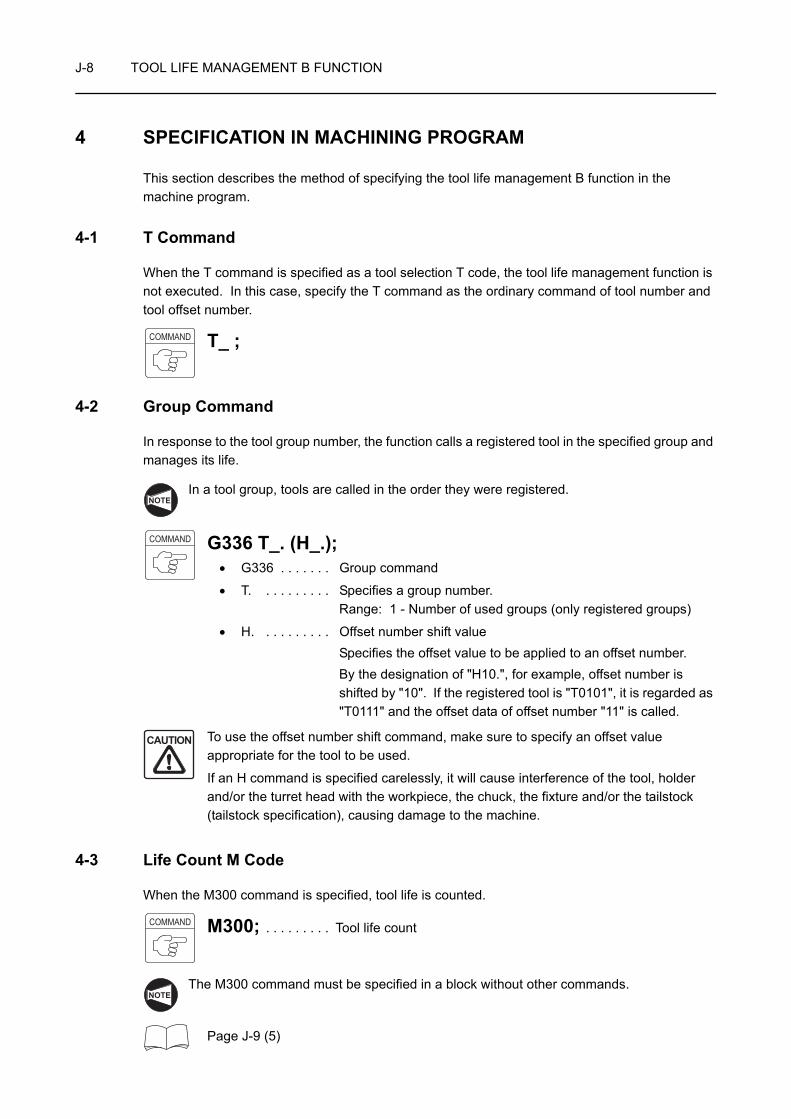
J-8 TOOL LIFE MANAGEMENT B FUNCTION
4 SPECIFICATION IN MACHINING PROGRAM
This section describes the method of specifying the tool life management B function in the machine program.
4-1 T Command
When the T command is specified as a tool selection T code, the tool life management function is not executed. In this case, specify the T command as the ordinary command of tool number and tool offset number.
T_ ;
4-2 Group Command
In response to the tool group number, the function calls a registered tool in the specified group and manages its life.
In a tool group, tools are called in the order they were registered.
G336 T_. (H_.);• G336 . . . . . . . Group command
• T. . . . . . . . . . Specifies a group number.Range: 1 - Number of used groups (only registered groups)
• H. . . . . . . . . . Offset number shift valueSpecifies the offset value to be applied to an offset number.By the designation of "H10.", for example, offset number is shifted by "10". If the registered tool is "T0101", it is regarded as "T0111" and the offset data of offset number "11" is called.
To use the offset number shift command, make sure to specify an offset value appropriate for the tool to be used.
If an H command is specified carelessly, it will cause interference of the tool, holder and/or the turret head with the workpiece, the chuck, the fixture and/or the tailstock (tailstock specification), causing damage to the machine.
4-3 Life Count M Code
When the M300 command is specified, tool life is counted.
M300; . . . . . . . . . Tool life count
The M300 command must be specified in a block without other commands.
Page J-9 (5)
COMMAND
NOTE
COMMAND
CAUTION
COMMAND
NOTE

TOOL LIFE MANAGEMENT B FUNCTION J-9
5 COUNTING THE TOOL LIFE
<When tool life is set in "time">
1. The counter of the tool group is incremented by "1" for the tool groups called in a program from the cycle start to the execution of M300. If the same tool group is specified repeatedly until the execution of M300, counter data is incremented "1" independent of the number of called times.
2. If the NC enters the reset state before the execution of M300, the counter of the tool groups used from the cycle start to the reset state of the process program is incremented "1". The counter is incremented when the tool group is called; the function ignores whether or not the called tool is used for cutting.
3. The maximum setting value for "SET" is "99999 times".
<When tool life is set in "minute">
1. For the counter of the tool groups which are called in a program from the cycle start to the execution of M300, the time used in the cutting mode is added. If the same tool group is specified repeatedly until the execution of M300, total cutting time is added to the counter of the called tool group.
2. Although setting and display are given in units of "minutes", actual counting is made in units of "seconds".
3. Even if a tool is called, the time spent for single block stop, feed hold, rapid traverse, dwell and waiting for operation completion is ignored.
4. If the operation is suspended due to axis interlock during the execution of cutting blocks, such time is added.
5. If the NC enters the reset state before the execution of M300, the cutting time of the individual tool groups used from the cycle start to the reset state of the process program is added to the individual counters.
6. The maximum setting value for "SET" is "99999 minutes".
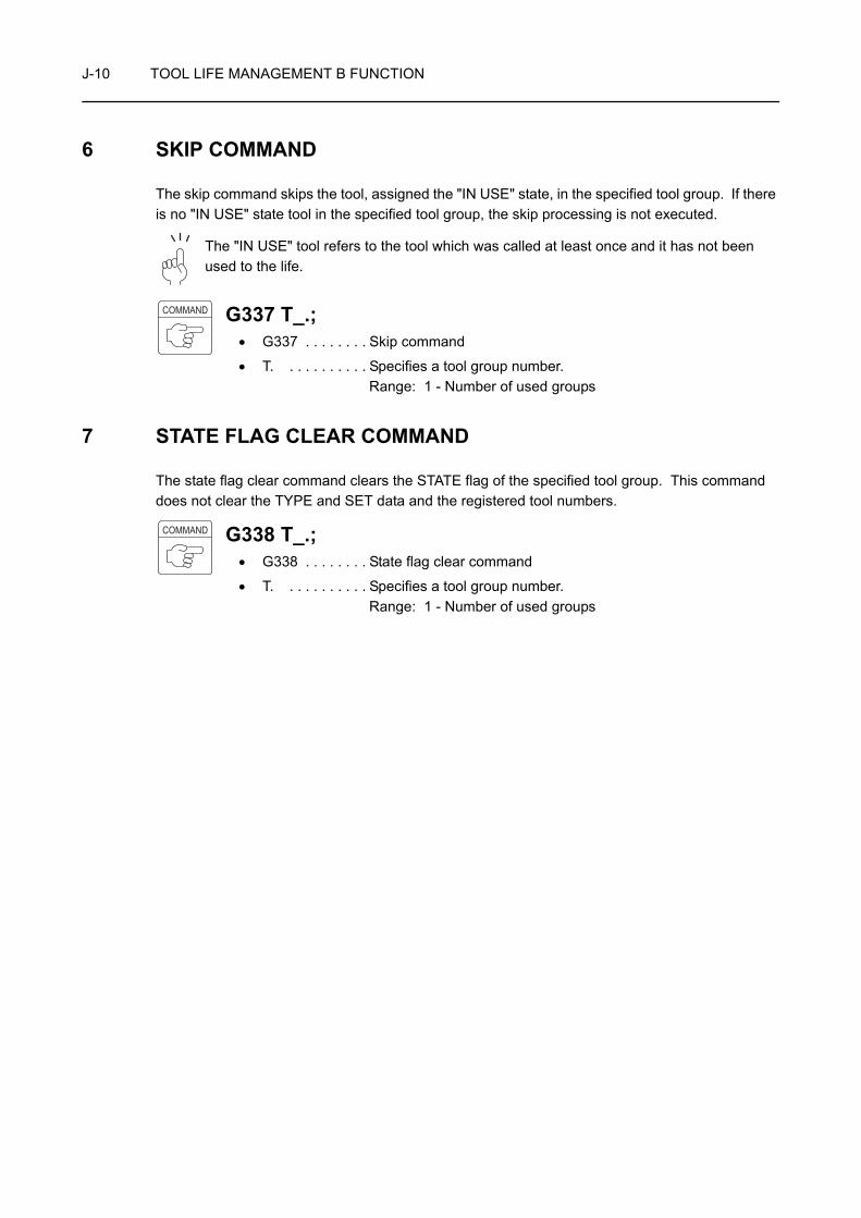
J-10 TOOL LIFE MANAGEMENT B FUNCTION
6 SKIP COMMAND
The skip command skips the tool, assigned the "IN USE" state, in the specified tool group. If there is no "IN USE" state tool in the specified tool group, the skip processing is not executed.
The "IN USE" tool refers to the tool which was called at least once and it has not been used to the life.
G337 T_.;• G337 . . . . . . . . Skip command
• T. . . . . . . . . . . Specifies a tool group number.Range: 1 - Number of used groups
7 STATE FLAG CLEAR COMMAND
The state flag clear command clears the STATE flag of the specified tool group. This command does not clear the TYPE and SET data and the registered tool numbers.
G338 T_.;• G338 . . . . . . . . State flag clear command
• T. . . . . . . . . . . Specifies a tool group number.Range: 1 - Number of used groups
COMMAND
COMMAND

TOOL LIFE MANAGEMENT B FUNCTION J-11
8 NEW TOOL SELECTION FLAG AND TOOL LIFE EXPIRED FLAG
This section describes the new tool selection flag and tool life expired flag.
8-1 New Tool Selection Flag
1. If a new tool is selected in the specified tool group, the new tool selection flag is set ("1" is set) at the same time the tool group command is executed.
2. This flag can be used to execute the automatic measuring of the offset data of the newly called tool, for example.
3. The new tool selection flag remains valid until the next group command (G336) or tool use data count M code (M300) is specified, or until the NC is reset.
4. The new tool selection flag is output to the common variable of custom macro. The variable number where the flag is output is set for PC parameter "D602".
If the new tool selection flag is not used setting for D602 should be "D602 = 0".
8-2 Tool Life Expired Flag
1. If all tools in the specified tool group have been used to the life, the tool life expired flag is set ("1" is set).
The tool life expired flag cannot be reset to "0" unless the tool life expired state of all the tools in that group is cleared either by program or by an operation at the screen.
2. The tool life expired flag is output to the common variable of custom macro. The variable number where the flag is output is set for PC parameter "D604".
If the tool life expiration flag is not used setting for D604 should be "D604 = 0".
3. The tool life expired flag is output to PMC, too. The PMC executes the following processing when it receives the tool life expired flag.
• Displays the message, indicating that tool life has been expired.
• Prohibits execution of automatic operation (set for PC parameter "D134 (bit 6)").
• Prohibits turret indexing (set for PC parameter "D134 (bit 5)").
NOTE
NOTE
NOTE
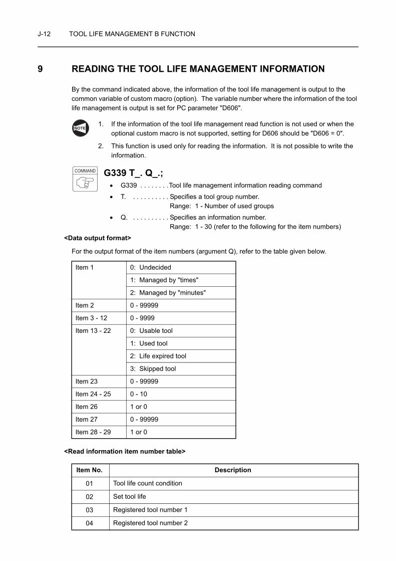
J-12 TOOL LIFE MANAGEMENT B FUNCTION
9 READING THE TOOL LIFE MANAGEMENT INFORMATION
By the command indicated above, the information of the tool life management is output to the common variable of custom macro (option). The variable number where the information of the tool life management is output is set for PC parameter "D606".
1. If the information of the tool life management read function is not used or when the optional custom macro is not supported, setting for D606 should be "D606 = 0".
2. This function is used only for reading the information. It is not possible to write the information.
G339 T_. Q_.;• G339 . . . . . . . .Tool life management information reading command
• T. . . . . . . . . . . Specifies a tool group number.Range: 1 - Number of used groups
• Q. . . . . . . . . . . Specifies an information number.Range: 1 - 30 (refer to the following for the item numbers)
<Data output format>
For the output format of the item numbers (argument Q), refer to the table given below.
<Read information item number table>
Item 1 0: Undecided
1: Managed by "times"
2: Managed by "minutes"
Item 2 0 - 99999
Item 3 - 12 0 - 9999
Item 13 - 22 0: Usable tool
1: Used tool
2: Life expired tool
3: Skipped tool
Item 23 0 - 99999
Item 24 - 25 0 - 10
Item 26 1 or 0
Item 27 0 - 99999
Item 28 - 29 1 or 0
Item No. Description
01 Tool life count condition
02 Set tool life
03 Registered tool number 1
04 Registered tool number 2
NOTE
COMMAND
TOOL LIFE MANAGEMENT B FUNCTION J-13
05 Registered tool number 3
06 Registered tool number 4
07 Registered tool number 5
08 Registered tool number 6
09 Registered tool number 7
10 Registered tool number 8
11 Registered tool number 9
12 Registered tool number 10
13 State of registered tool number 1
14 State of registered tool number 2
15 State of registered tool number 3
16 State of registered tool number 4
17 State of registered tool number 5
18 State of registered tool number 6
19 State of registered tool number 7
20 State of registered tool number 8
21 State of registered tool number 9
22 State of registered tool number 10
23 Present counted tool life
24 Selected tool number(Registered tool number of the presently selected tool)
25 Remaining number of registered tools(The total number of usable tools in the specified tool group)
26 Execution flag("1" if the specified tool is called in the presently executed program)
27 Accumulated cutting time (minutes)(Total length of cutting time the tool in the specified group has been used)
28 Life expired flag("1" if tool life of all tools in the specified group has been expired.)
29 Life annunciation flag("1" if a new tool is selected when the tool group is specified next)
30 Spare
Item No. Description
J-14 TOOL LIFE MANAGEMENT B FUNCTION
10 READING THE PMC ADDRESS INFORMATION
By the command indicated below, information of the specified PMC address is output to the common variable of custom macro. The variable number where the information of the specified PMC address is output is set for PC parameter "D608".
1. If the PMC address read function is not used, setting for D608 should be "D608 = 0".
2. This function is used only for reading the information. It is not possible to write the information.
G340 F_. A_. Q_.;• G340 . . . . . . . . PMC address information reading command
• F. . . . . . . . . . . Specifies the number of bytes.F0. . . . . . . Specifies bit.F1. . . . . . . Specifies 1 byte.F2. . . . . . . Specifies 2 bytes.F4. . . . . . . . Specifies 4 bytes.
• A. . . . . . . . . . . Specifies the address.A0. . . . . . . Specifies "R".A1. . . . . . . Specifies "D".A2. . . . . . . Specifies "C".A3. . . . . . . Specifies "K".A4. . . . . . . Specifies "X".A5. . . . . . . Specifies "Y".A6. . . . . . . Specifies "F".A7. . . . . . . Specifies "G".
• Q. . . . . . . . . . . Specifies the address number.When a bit is specified, specification must be made up to one place right to a decimal point.When a byte is specified, specification of a number right to a decimal point is not allowed.
1. The output format to the macro variable is indicated below.
Bit specification 0 or 1
1-byte specification . . . . . Integer (−128 - 127)
2-byte specification . . . . . Integer (−32,768 - 32,767)
4-byte specification . . . . . Integer (−2,147,483,648 - 2,147,483,647)
NOTE
COMMAND
NOTE

TOOL LIFE MANAGEMENT B FUNCTION J-15
2. For the designation of an address, the following restrictions apply.
R . . . . . . . Bit, 1 byte, 2 bytes, 4 bytes
D . . . . . . . Bit, 1 byte, 2 bytes, 4 bytes
C . . . . . . . Bit, 1 byte, 2 bytes, 4 bytes
K . . . . . . . Bit, 1 byte, 2 bytes, 4 bytes
X . . . . . . . Bit only
Y . . . . . . . Bit only
F . . . . . . . Bit only
G . . . . . . . Bit only
1. Bit specification, R120.3
G340 F0. A0. Q120.3;
2. 2-byte specification, D80
G340 F2. A1. Q80.;
NOTE
Ex.

J-16 TOOL LIFE MANAGEMENT B FUNCTION
11 ALARM TABLE
If there is an error with the tool life management related commands, message is displayed. Refer to the following table to find the cause of the error.
Macro Alarm No. Message Description
3015 TOOL ENTRY FORMAT ERROR
The tool life data registration format has an error. Check the registration program.
3016 TOOL ENTRY DATA ERROR When registering the tool life data, the data contents have an error. Check the specified data.
3017 TOOL ENTRY T DATA OVER When registering the tool life data, the number of registration tools is greater than 10. Check the registration program.
3018 GROUP CALL FORMAT ERROR
The tool group call command format has an error. Check the machining program.
3019 CALL GROUP DATA ERROR
When calling a tool group, the data contents have an error. Check the specified data.
3020 CALL GROUP NOT REGISTERED
When calling a tool group, the specified tool group has not been registered. Register the tool group.
3021 TOOL LIFE OVER When calling a tool group, tool life of all tools in the called group has been expired. Change the tools.
3022 TOOL SKIP FORMAT ERROR
The skip command format has an error. Check the machining program.
3023 SKIP TOOL DATA ERROR In the skip command, the data contents have an error. Check the specified data.
3024 T-LIFE RESET FORMAT ERROR
The reset command format has an error. Check the machining program.
3025 T-LIFE RESET T-DATA ERROR
In the reset command, the data contents have an error. Check the specified data.
3026 DATA IN TOOL GROUP ERROR
The tool life management data has an error. Register the data again.
3027 DATA READ FORMAT ERROR
The tool life management data read command format has an error. Check the machining program.
3028 READ DATA ERROR In the tool life management data read command, the data contents have an error. Check the specified data.
3029 FORMAT ERROR The PMC address read command format has an error. Check the machining program.
3030 DATA ERROR In the PMC address read command, the data contents have an error. Check the specified data.
TOOL LIFE MANAGEMENT B FUNCTION J-17
12 PARAMETERS
The PMC parameters related with the tool life management function are indicated below.
D600 . . . . . . . . . . Setting of the total number of tool groups
If the setting for D600 is changed, the tool life data must be registered again. If the function is used without registering the tool life data again, it might cause troubles.
D602 . . . . . . . . . . Macro variable number for outputting the new tool selection flag
Pay attention to the common variable range. (#100 - #131 only)
D604 . . . . . . . . . . Macro variable number for outputting the tool life expired flag
Pay attention to the common variable range. (#100 - #131 only)
D606 . . . . . . . . . . Macro variable number for outputting the tool life information
Pay attention to the common variable range. (#100 - #131 only)
D608 . . . . . . . . . . Macro variable number for outputting the PMC address
Pay attention to the common variable range. (#100 - #131 only)
D253 (bit 1) . . . . . . 1: For the tool group where all tools have been used to the tool life, the last tool is called in the next T command.
0: For the tool group where all tools have been used to the tool life, an alarm occurs when the next T command is specified.
NOTE
NOTE
NOTE
NOTE
NOTE

CHAPTER KEXAMPLE PROGRAMS
This chapter describes the programming procedure using several example programs.
CONTENTS
K : EXAMPLE PROGRAMS
1 PROGRAMMING STEPS . . . . . . . . . . . . . . . . . . . . . . . . . . . . . . . . . . . . . . . . . . . . . . . . K-1
2 EXAMPLE PROGRAMS . . . . . . . . . . . . . . . . . . . . . . . . . . . . . . . . . . . . . . . . . . . . . . . . . K-2
2-1 Chuck-Work Programming (1). . . . . . . . . . . . . . . . . . . . . . . . . . . . . . . . . . . . . . . . K-2
2-2 Chuck-Work Programming (2). . . . . . . . . . . . . . . . . . . . . . . . . . . . . . . . . . . . . . . K-17
2-2-1 1st Process . . . . . . . . . . . . . . . . . . . . . . . . . . . . . . . . . . . . . . . . . . . . . . K-18
2-2-2 2nd Process . . . . . . . . . . . . . . . . . . . . . . . . . . . . . . . . . . . . . . . . . . . . . . K-23
2-3 Various Part Programs . . . . . . . . . . . . . . . . . . . . . . . . . . . . . . . . . . . . . . . . . . . . K-28
2-3-1 Grooving . . . . . . . . . . . . . . . . . . . . . . . . . . . . . . . . . . . . . . . . . . . . . . . . K-28
2-3-2 I.D. Deep Hole Drilling . . . . . . . . . . . . . . . . . . . . . . . . . . . . . . . . . . . . . . K-29
2-4 Milling 1 (Drilling on End Face) . . . . . . . . . . . . . . . . . . . . . . . . . . . . . . . . . . . . . . K-30
2-5 Milling 2 (Hole Machining on Workpiece Circumference and End Face, and Workpiece Transfer) . . . . . . . . . . . . . . . . . . . . . . . . . . . . . . . . . . . . . . . . . . . K-34
2-6 Milling 3 . . . . . . . . . . . . . . . . . . . . . . . . . . . . . . . . . . . . . . . . . . . . . . . . . . . . . . . . K-51
2-7 Balance Cut. . . . . . . . . . . . . . . . . . . . . . . . . . . . . . . . . . . . . . . . . . . . . . . . . . . . . K-55

EXAMPLE PROGRAMS K-1
1 PROGRAMMING STEPS
The steps to complete a program are summarized below.
When writing a program from the part drawing, refer to the flow chart shown below.
1) Determine which side to be machined and which side to be chucked. (Determination of the 1st and 2nd processes)
2) Translate the part drawing into the drawing for NC operation/programming. (This step may be omitted if the workpiece is simple.)
3) Study the cutting allowance. (Draw the blank workpiece if necessary.)
4) Determine the tools to be used. (Creating the tooling sheet)
5) Determine the finishing conditions (cutting speeds, feedrates), and create the part program for finishing.
6) Determine the finishing allowance and the rough cutting conditions (depth of cuts, cutting speeds, and feedrates), and create the part program for rough cutting.
7) Create the part program for other processes such as grooving and thread cutting.
8) Arrange the part programs of individual processes to complete the program.
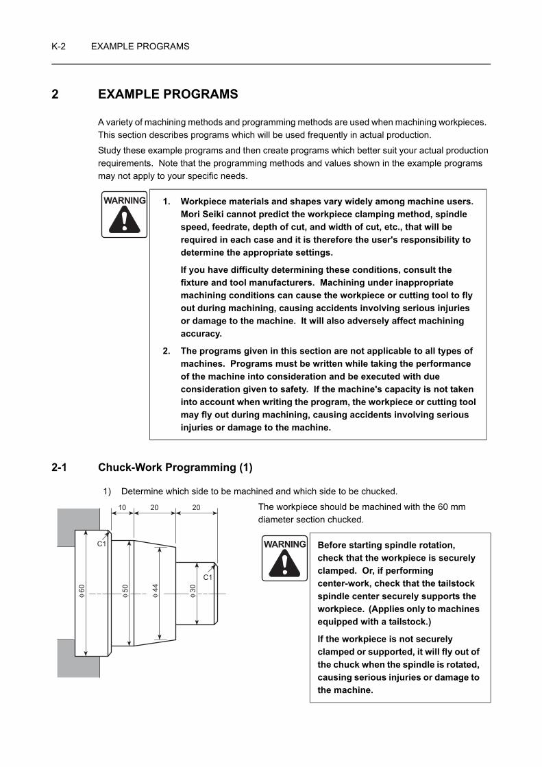
K-2 EXAMPLE PROGRAMS
2 EXAMPLE PROGRAMS
A variety of machining methods and programming methods are used when machining workpieces. This section describes programs which will be used frequently in actual production.
Study these example programs and then create programs which better suit your actual production requirements. Note that the programming methods and values shown in the example programs may not apply to your specific needs.
2-1 Chuck-Work Programming (1)
1) Determine which side to be machined and which side to be chucked.
The workpiece should be machined with the 60 mm diameter section chucked.
WARNING 1. Workpiece materials and shapes vary widely among machine users. Mori Seiki cannot predict the workpiece clamping method, spindle speed, feedrate, depth of cut, and width of cut, etc., that will be required in each case and it is therefore the user's responsibility to determine the appropriate settings.
If you have difficulty determining these conditions, consult the fixture and tool manufacturers. Machining under inappropriate machining conditions can cause the workpiece or cutting tool to fly out during machining, causing accidents involving serious injuries or damage to the machine. It will also adversely affect machining accuracy.
2. The programs given in this section are not applicable to all types of machines. Programs must be written while taking the performance of the machine into consideration and be executed with due consideration given to safety. If the machine's capacity is not taken into account when writing the program, the workpiece or cutting tool may fly out during machining, causing accidents involving serious injuries or damage to the machine.
WARNING Before starting spindle rotation, check that the workpiece is securely clamped. Or, if performing center-work, check that the tailstock spindle center securely supports the workpiece. (Applies only to machines equipped with a tailstock.)
If the workpiece is not securely clamped or supported, it will fly out of the chuck when the spindle is rotated, causing serious injuries or damage to the machine.
C1
C1
10 20 20
4450 3060φ φ φ φ
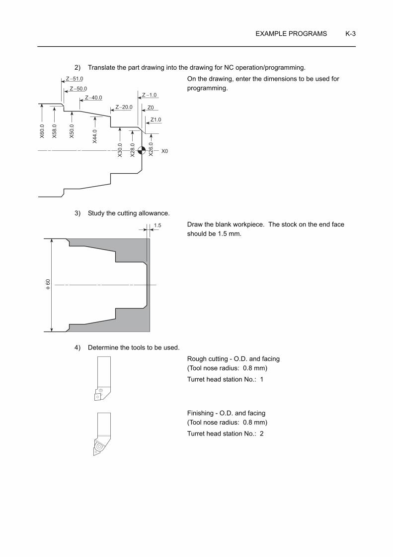
EXAMPLE PROGRAMS K-3
2) Translate the part drawing into the drawing for NC operation/programming.
On the drawing, enter the dimensions to be used for programming.
3) Study the cutting allowance.
Draw the blank workpiece. The stock on the end face should be 1.5 mm.
4) Determine the tools to be used.
Rough cutting - O.D. and facing (Tool nose radius: 0.8 mm)
Turret head station No.: 1
Finishing - O.D. and facing (Tool nose radius: 0.8 mm)
Turret head station No.: 2
X60
.0
X58
.0
X50
.0
X44
.0
X30
.0
X28
.0
X26
.0
Z −51.0
Z −50.0
Z−40.0
Z−20.0
Z −1.0
Z0
Z1.0
X0
1.5
60φ

K-4 EXAMPLE PROGRAMS
5) Determine the finishing conditions (cutting speeds, feedrates), and create the part program for finishing. (Tool nose radius: 0)
N2;
G50 S2000;. . . . . . . . . . . . . . . . . . . . . . Setting the spindle 1 speed limit for automatic operation at
2000 min−1
G00 T0202 (M42)*; . . . . . . . . . . . . . . . . Selecting the No. 2 tool
G96 S180 M03;. . . . . . . . . . . . . . . . . . . Starting spindle 1 in the normal direction at the cutting speed of 180 m/min
X34.0 Z20.0;
G01 Z0 F1.0;
X0 F0.15;
G00 X26.0 Z1.0;
G01 X30.0 Z−1.0 F0.2;
Z−20.0;
X44.0;
X50.0 Z−40.0;
Z−50.0;
X58.0;
X62.0 Z−52.0;
G00 U1.0 Z20.0 M09;
X100.0 Z100.0 M05; . . . . . . . . . . . . . . . Moving to a position where the turret head can be rotated; the spindle stops.
M30;
Commands in ( ) identified by "*" are used only for the machine equipped with a transmission.
X60
.0
X58
.0
X50
.0
X44
.0
X30
.0
X28
.0
X26
.0
Z −51.0
Z −50.0
Z−40.0
Z−20.0
Z −1.0
Z0
Z1.0
X0
. . . . . . . Program for finishing
• Feedrate for facing: 0.15 mm/rev
• Feedrate for O.D. cutting: 0.2 mm/rev
NOTE
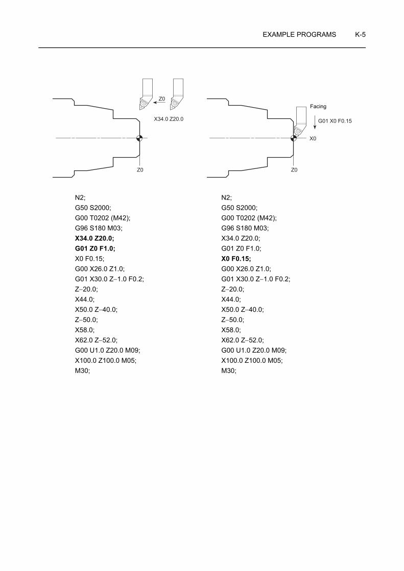
EXAMPLE PROGRAMS K-5
N2; N2;G50 S2000; G50 S2000;G00 T0202 (M42); G00 T0202 (M42);G96 S180 M03; G96 S180 M03;X34.0 Z20.0; X34.0 Z20.0;G01 Z0 F1.0; G01 Z0 F1.0;X0 F0.15; X0 F0.15;G00 X26.0 Z1.0; G00 X26.0 Z1.0;G01 X30.0 Z−1.0 F0.2; G01 X30.0 Z−1.0 F0.2;Z−20.0; Z−20.0;X44.0; X44.0;X50.0 Z−40.0; X50.0 Z−40.0;Z−50.0; Z−50.0;X58.0; X58.0;X62.0 Z−52.0; X62.0 Z−52.0;G00 U1.0 Z20.0 M09; G00 U1.0 Z20.0 M09;X100.0 Z100.0 M05; X100.0 Z100.0 M05;M30; M30;
Z0
Z0 Z0
X34.0 Z20.0 G01 X0 F0.15
X0
Facing

K-6 EXAMPLE PROGRAMS
N2; N2;G50 S2000; G50 S2000;G00 T0202 (M42); G00 T0202 (M42);G96 S180 M03; G96 S180 M03;X34.0 Z20.0; X34.0 Z20.0;G01 Z0 F1.0; G01 Z0 F1.0;X0 F0.15; X0 F0.15;G00 X26.0 Z1.0; G00 X26.0 Z1.0;G01 X30.0 Z−1.0 F0.2; G01 X30.0 Z−1.0 F0.2;Z−20.0; Z−20.0;X44.0; X44.0;X50.0 Z−40.0; X50.0 Z−40.0;Z−50.0; Z−50.0;X58.0; X58.0;X62.0 Z−52.0; X62.0 Z−52.0;G00 U1.0 Z20.0 M09; G00 U1.0 Z20.0 M09;X100.0 Z100.0 M05; X100.0 Z100.0 M05;M30; M30;
Z0
G00 X26.0 Z1.0
G01 X30.0 Z−1.0 F0.2
X0X30.0
Z−1.0
Chamfering
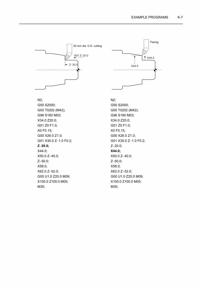
EXAMPLE PROGRAMS K-7
N2; N2;G50 S2000; G50 S2000;G00 T0202 (M42); G00 T0202 (M42);G96 S180 M03; G96 S180 M03;X34.0 Z20.0; X34.0 Z20.0;G01 Z0 F1.0; G01 Z0 F1.0;X0 F0.15; X0 F0.15;G00 X26.0 Z1.0; G00 X26.0 Z1.0;G01 X30.0 Z−1.0 F0.2; G01 X30.0 Z−1.0 F0.2;Z−20.0; Z−20.0;X44.0; X44.0;X50.0 Z−40.0; X50.0 Z−40.0;Z−50.0; Z−50.0;X58.0; X58.0;X62.0 Z−52.0; X62.0 Z−52.0;G00 U1.0 Z20.0 M09; G00 U1.0 Z20.0 M09;X100.0 Z100.0 M05; X100.0 Z100.0 M05;M30; M30;
G01 Z−20.0
Z−20.0 X44.0
X44.0
Facing30 mm dia. O.D. cutting

K-8 EXAMPLE PROGRAMS
N2; N2;G50 S2000; G50 S2000;G00 T0202 (M42); G00 T0202 (M42);G96 S180 M03; G96 S180 M03;X34.0 Z20.0; X34.0 Z20.0;G01 Z0 F1.0; G01 Z0 F1.0;X0 F0.15; X0 F0.15;G00 X26.0 Z1.0; G00 X26.0 Z1.0;G01 X30.0 Z−1.0 F0.2; G01 X30.0 Z−1.0 F0.2;Z−20.0; Z−20.0;X44.0; X44.0;X50.0 Z−40.0; X50.0 Z−40.0;Z−50.0; Z−50.0;X58.0; X58.0;X62.0 Z−52.0; X62.0 Z−52.0;G00 U1.0 Z20.0 M09; G00 U1.0 Z20.0 M09;X100.0 Z100.0 M05; X100.0 Z100.0 M05;M30; M30;
Z−40.0
X50.0
X50.0 Z−40.0
Z−50.0
Z−50.0
Z0
Taper cutting 50 mm dia. O.D. cutting
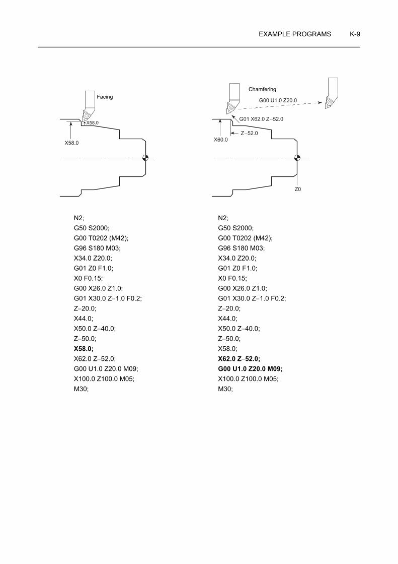
EXAMPLE PROGRAMS K-9
N2; N2;G50 S2000; G50 S2000;G00 T0202 (M42); G00 T0202 (M42);G96 S180 M03; G96 S180 M03;X34.0 Z20.0; X34.0 Z20.0;G01 Z0 F1.0; G01 Z0 F1.0;X0 F0.15; X0 F0.15;G00 X26.0 Z1.0; G00 X26.0 Z1.0;G01 X30.0 Z−1.0 F0.2; G01 X30.0 Z−1.0 F0.2;Z−20.0; Z−20.0;X44.0; X44.0;X50.0 Z−40.0; X50.0 Z−40.0;Z−50.0; Z−50.0;X58.0; X58.0;X62.0 Z−52.0; X62.0 Z−52.0;G00 U1.0 Z20.0 M09; G00 U1.0 Z20.0 M09;X100.0 Z100.0 M05; X100.0 Z100.0 M05;M30; M30;
X58.0
Z−52.0
Z0
X58.0
X60.0
G00 U1.0 Z20.0
G01 X62.0 Z−52.0
FacingChamfering

K-10 EXAMPLE PROGRAMS
6) Determine the finishing allowance and the rough cutting conditions (depth of cuts, cutting speeds, and feedrates), and create the part program for rough cutting.
N1;
G50 S2000;. . . . . . . . . . . . . . . . . . . . . . Setting the spindle 1 speed limit for automatic operation at
2000 min−1
G00 T0101 (M41)*; . . . . . . . . . . . . . . . . Selecting the No. 1 tool
G96 S120 M03;. . . . . . . . . . . . . . . . . . . Starting spindle 1 in the normal direction; surface speed is 120 m/min.
X68.0 Z20.0 M08;G01 Z0.1 F1.0;X10.0 F0.2;X0 F0.1;G00 X52.0 Z1.0;G01 Z−49.9 F0.25;G00 U2.0 Z1.0;X44.0;G01 Z−19.9;G00 U2.0 Z1.0;X36.0;G01 Z−19.9;G00 U2.0 Z1.0;X26.3;G01 X30.3 Z−1.0;Z−19.9;X44.3;X50.3 Z−39.9;Z−49.9;X58.3;X62.3 Z−51.9;G00 U1.0 Z20.0;X100.0 Z100.0; . . . . . . . . . . . . . . . . . . . Moving to a position where the turret head can be rotated
M01;
Commands in ( ) identified by "*" are used only for the machine equipped with a transmission.
. . . . . . . Program for rough cutting
• Feedrate for facing: 0.2 mm/rev up to X10.0 0.1 mm/rev up to X0
In the constant cutting speed mode, the spindle speed increases as the cutting tool moves closer to the center. However, since the spindle speed is clamped at the value specified with "G50 S_ ;", the cutting speed will be lowered near the center of the spindle. Due to this, higher load is applied to the tool tip causing the insert to be broken.Therefore, the feedrate must be lowered near the spindle center to reduce load applied to the tool tip.
• Feedrate for O.D. cutting: 0.25 mm/rev
• Finishing allowance (X): 0.3 mm (in diameter)
• Finishing allowance (Z): 0.1 mm
NOTE
NOTE
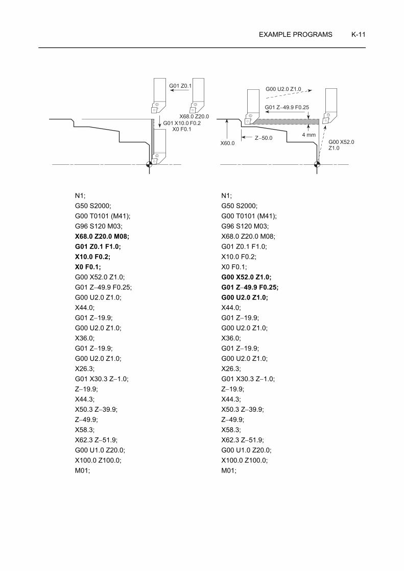
EXAMPLE PROGRAMS K-11
N1; N1;G50 S2000; G50 S2000;G00 T0101 (M41); G00 T0101 (M41);G96 S120 M03; G96 S120 M03;X68.0 Z20.0 M08; X68.0 Z20.0 M08;G01 Z0.1 F1.0; G01 Z0.1 F1.0;X10.0 F0.2; X10.0 F0.2;X0 F0.1; X0 F0.1;G00 X52.0 Z1.0; G00 X52.0 Z1.0;G01 Z−49.9 F0.25; G01 Z−49.9 F0.25;G00 U2.0 Z1.0; G00 U2.0 Z1.0;X44.0; X44.0;G01 Z−19.9; G01 Z−19.9;G00 U2.0 Z1.0; G00 U2.0 Z1.0;X36.0; X36.0;G01 Z−19.9; G01 Z−19.9;G00 U2.0 Z1.0; G00 U2.0 Z1.0;X26.3; X26.3;G01 X30.3 Z−1.0; G01 X30.3 Z−1.0;Z−19.9; Z−19.9;X44.3; X44.3;X50.3 Z−39.9; X50.3 Z−39.9;Z−49.9; Z−49.9;X58.3; X58.3;X62.3 Z−51.9; X62.3 Z−51.9;G00 U1.0 Z20.0; G00 U1.0 Z20.0;X100.0 Z100.0; X100.0 Z100.0;M01; M01;
G01 Z0.1
X60.0Z−50.0 4 mm
G01 Z−49.9 F0.25
G00 U2.0 Z1.0
G00 X52.0 Z1.0
X68.0 Z20.0G01 X10.0 F0.2
X0 F0.1
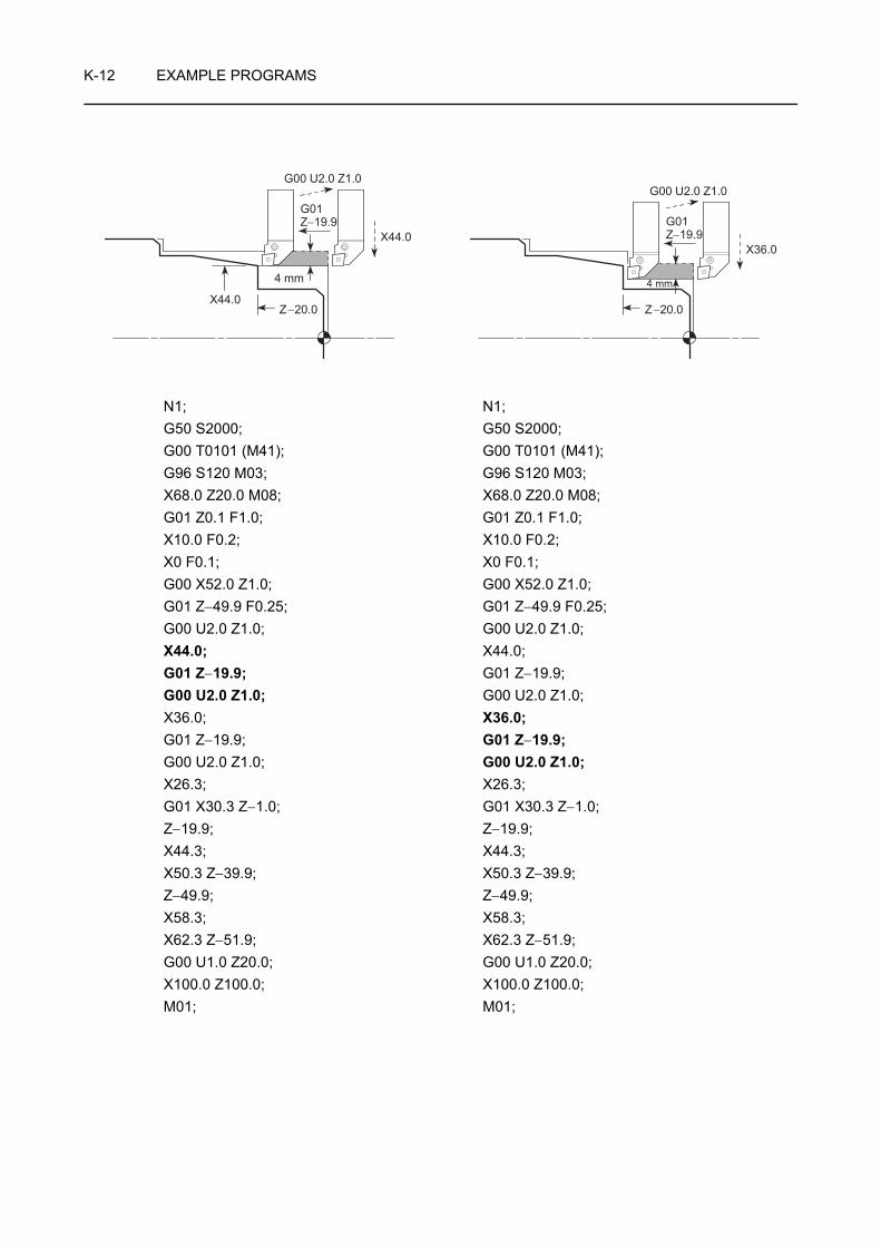
K-12 EXAMPLE PROGRAMS
N1; N1;G50 S2000; G50 S2000;G00 T0101 (M41); G00 T0101 (M41);G96 S120 M03; G96 S120 M03;X68.0 Z20.0 M08; X68.0 Z20.0 M08;G01 Z0.1 F1.0; G01 Z0.1 F1.0;X10.0 F0.2; X10.0 F0.2;X0 F0.1; X0 F0.1;G00 X52.0 Z1.0; G00 X52.0 Z1.0;G01 Z−49.9 F0.25; G01 Z−49.9 F0.25;G00 U2.0 Z1.0; G00 U2.0 Z1.0;X44.0; X44.0;G01 Z−19.9; G01 Z−19.9;G00 U2.0 Z1.0; G00 U2.0 Z1.0;X36.0; X36.0;G01 Z−19.9; G01 Z−19.9;G00 U2.0 Z1.0; G00 U2.0 Z1.0;X26.3; X26.3;G01 X30.3 Z−1.0; G01 X30.3 Z−1.0;Z−19.9; Z−19.9;X44.3; X44.3;X50.3 Z−39.9; X50.3 Z−39.9;Z−49.9; Z−49.9;X58.3; X58.3;X62.3 Z−51.9; X62.3 Z−51.9;G00 U1.0 Z20.0; G00 U1.0 Z20.0;X100.0 Z100.0; X100.0 Z100.0;M01; M01;
4 mm
Z−20.0X44.0
G01 Z−19.9
G00 U2.0 Z1.0
X44.0
4 mm
Z−20.0
G01 Z−19.9
G00 U2.0 Z1.0
X36.0

EXAMPLE PROGRAMS K-13
N1; N1;G50 S2000; G50 S2000;G00 T0101 (M41); G00 T0101 (M41);G96 S120 M03; G96 S120 M03;X68.0 Z20.0 M08; X68.0 Z20.0 M08;G01 Z0.1 F1.0; G01 Z0.1 F1.0;X10.0 F0.2; X10.0 F0.2;X0 F0.1; X0 F0.1;G00 X52.0 Z1.0; G00 X52.0 Z1.0;G01 Z−49.9 F0.25; G01 Z−49.9 F0.25;G00 U2.0 Z1.0; G00 U2.0 Z1.0;X44.0; X44.0;G01 Z−19.9; G01 Z−19.9;G00 U2.0 Z1.0; G00 U2.0 Z1.0;X36.0; X36.0;G01 Z−19.9; G01 Z−19.9;G00 U2.0 Z1.0; G00 U2.0 Z1.0;X26.3; X26.3;G01 X30.3 Z−1.0; G01 X30.3 Z−1.0;Z−19.9; Z−19.9;X44.3; X44.3;X50.3 Z−39.9; X50.3 Z−39.9;Z−49.9; Z−49.9;X58.3; X58.3;X62.3 Z−51.9; X62.3 Z−51.9;G00 U1.0 Z20.0; G00 U1.0 Z20.0;X100.0 Z100.0; X100.0 Z100.0;M01; M01;
28.5mm
X30.0Z−20.0
Z−50.0
Z−19.9
X28.0 Z1.0G01 X30.3 Z−1.0 X50.0
Z−40.0
X44.0
X44.3
Z−49.9
X50.3Z−39.9

K-14 EXAMPLE PROGRAMS
N1;
G50 S2000;
G00 T0101 (M41);
G96 S120 M03;
X68.0 Z20.0 M08;
G01 Z0.1 F1.0;
X10.0 F0.2;
X0 F0.1;
G00 X52.0 Z1.0;
G01 Z−49.9 F0.25;
G00 U2.0 Z1.0;
X44.0;
G01 Z−19.9;
G00 U2.0 Z1.0;
X36.0;
G01 Z−19.9;
G00 U2.0 Z1.0;
X26.3;
G01 X30.3 Z−1.0;
Z−19.9;
X44.3;
X50.3 Z−39.9;
Z−49.9;
X58.3;X62.3 Z−51.9;G00 U1.0 Z20.0;X100.0 Z100.0;
M01;
X60.0
X58.0
Z−50.0
Z−51.0
X62.3 Z−51.9
G00 U1.0 Z20.0

EXAMPLE PROGRAMS K-15
7) Create the part program for other processes such as grooving and thread cutting.
In this example operation, there are no other processes.
8) Arrange the part programs of individual processes to complete the program.
O0001;
N1; N2;
G50 S2000 G50 S2000;
G00 T0101 (M41)*; G00 T0202 (M42)*;
G96 S120 M03; G96 S180 M03;
X68.0 Z20.0 M08; X34.0 Z20.0;
G01 Z0.1 F1.0; G01 Z0 F1.0;
X10.0 F0.2; X0 F0.15;
X0 F0.1; G00 X26.0 Z1.0;
G00 X52.0 Z1.0; G01 X30.0 Z−1.0 F0.2;
G01 Z−49.9 F0.25; Z−20.0;
G00 U2.0 Z1.0; X44.0;
X44.0; X50.0 Z−40.0;
G01 Z−19.9; Z−50.0;
G00 U2.0 Z1.0; X58.0;
X36.0; X62.0 Z−52.0;
G01 Z−19.9; G00 U1.0 Z20.0 M09;
G00 U2.0 Z1.0; X100.0 Z100.0 M05;
X26.3; M30;
G01 X30.3 Z−1.0;
Z−19.9;
X44.3;
X50.3 Z−39.9;
Z−49.9;
X58.3;
X62.3 Z−51.9;
G00 U1.0 Z20.0;
X100.0 Z100.0;
M01;
Commands in ( ) identified by "*" are used only for the machine equipped with a transmission.
. . . . Part program for rough cutting
. . . . Part program for finishing
NOTE

K-16 EXAMPLE PROGRAMS
In actual cutting, tool nose radius must be taken into consideration. (Tool nose radius: 0.8 mm)
The program using the manual tool nose radius offset function is shown below.
O0001;
N1; N2;
G50 S2000; G50 S2000;
G00 T0101 (M41); G00 T0202 (M42);
G96 S120 M03; G96 S180 M03;
X68.0 Z20.0 M08; X34.0 Z20.0;
G01 Z0.1 F1.0; G01 Z0 F1.0;
X10.0 F0.2; X−1.6 F0.15;
X−1.6 F0.1; G00 X25.06 Z1.0;
G00 X52.0 Z1.0; G01 X30.0 Z−1.47 F0.2;
G01 Z−49.9 F0.25; Z−20.0;
G00 U2.0 Z1.0; X43.779;X44.0; X50.0 Z−40.740;G01 Z−19.9; Z−50.0;
G00 U2.0 Z1.0; X57.06;X36.0; X62.0 Z−52.47;G01 Z−19.9; G00 U1.0 Z20.0 M09;
G00 U2.0 Z1.0; X100.0 Z100.0 M05;
X26.3; M30;
G01 X30.3 Z−1.0;
Z−19.9;
X44.3;
X50.3 Z−39.9;
Z−49.9;
X58.3;
X62.3 Z−51.9;
G00 U1.0 Z20.0;
X100.0 Z100.0;
M01;
NOTE
. . . . Part program for rough cutting
. . . Part program for finishing

EXAMPLE PROGRAMS K-17
2-2 Chuck-Work Programming (2)
<Blank workpiece drawing> <Part drawing>
<Dimensions of blank workpiece>
Blank Workpiece Description
Material AISI 1045 (Carbon steel)
Dimensions (mm)
O.D. φ75
I.D. φ25
Length 43
20
C1 C1
C1 C1C1
40
3070 502575
43
φ φ φ φ φ
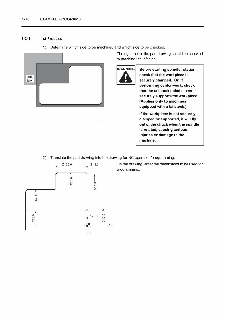
K-18 EXAMPLE PROGRAMS
2-2-1 1st Process
1) Determine which side to be machined and which side to be chucked.
The right side in the part drawing should be chucked to machine the left side.
2) Translate the part drawing into the drawing for NC operation/programming.
On the drawing, enter the dimensions to be used for programming.
WARNING Before starting spindle rotation, check that the workpiece is securely clamped. Or, if performing center-work, check that the tailstock spindle center securely supports the workpiece. (Applies only to machines equipped with a tailstock.)
If the workpiece is not securely clamped or supported, it will fly out of the chuck when the spindle is rotated, causing serious injuries or damage to the machine.
Soft jaw
Z−20.0 Z−1.0
X68
.0
Z−1.0
X32
.0
X0
Z0
X30
.0X
50.0
X70
.0
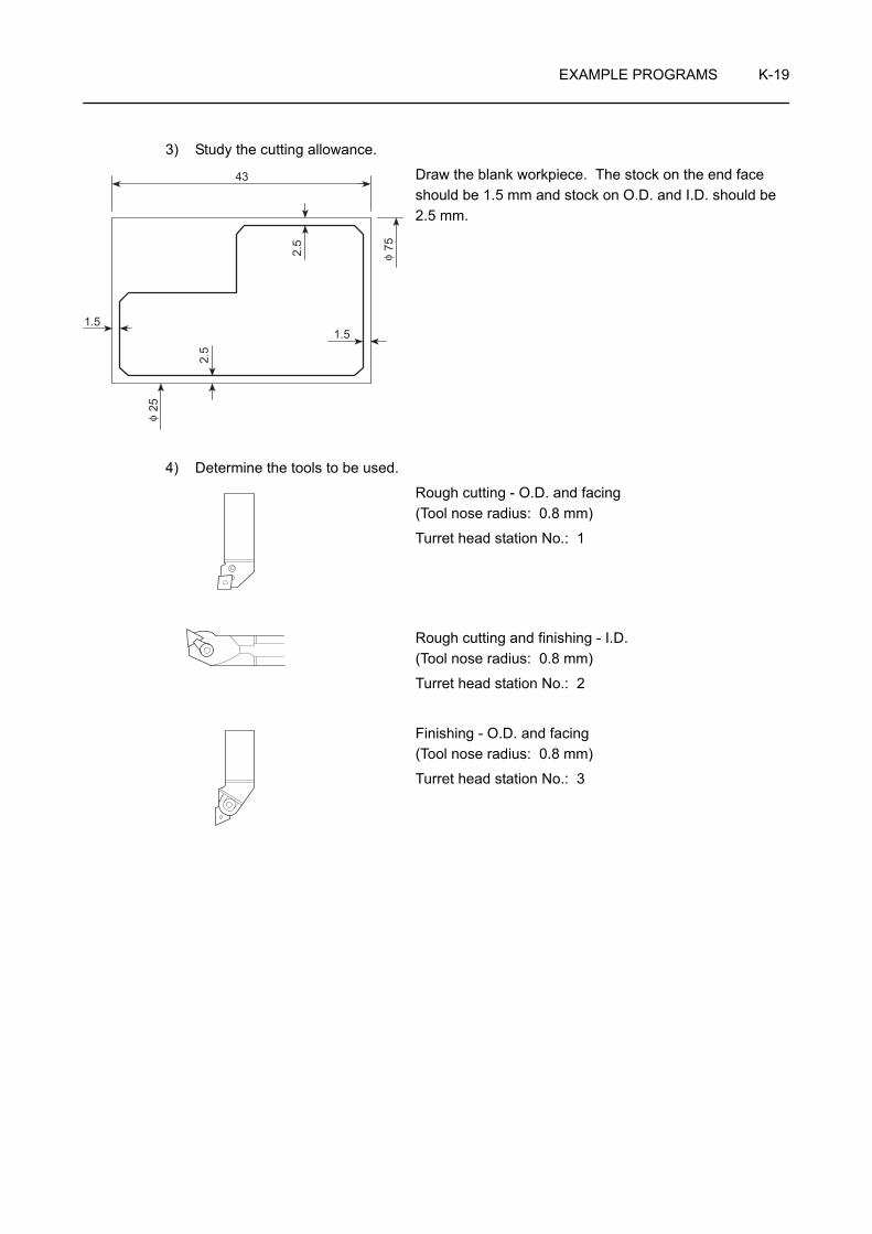
EXAMPLE PROGRAMS K-19
3) Study the cutting allowance.
Draw the blank workpiece. The stock on the end face should be 1.5 mm and stock on O.D. and I.D. should be 2.5 mm.
4) Determine the tools to be used.
Rough cutting - O.D. and facing (Tool nose radius: 0.8 mm)
Turret head station No.: 1
Rough cutting and finishing - I.D. (Tool nose radius: 0.8 mm)
Turret head station No.: 2
Finishing - O.D. and facing (Tool nose radius: 0.8 mm)
Turret head station No.: 3
1.5
43
1.5
2.5
2.5 75
25φ
φ

K-20 EXAMPLE PROGRAMS
5) Determine the finishing conditions (cutting speeds, feedrates), and create the part program for finishing. (Tool nose radius: 0.8 mm)
N3;
G50 S2500;. . . . . . . . . . . . . . . . . . . . . . Setting the spindle 1 speed limit for automatic operation at
2500 min−1
G00 T0303 (M42)*; . . . . . . . . . . . . . . . . Selecting the No. 3 tool
G96 S180 M03;. . . . . . . . . . . . . . . . . . . Starting spindle 1 in the normal direction at the cutting speed of 180 m/min
X74.0 Z20.0;
G01 Z0 F1.0;
X28.0 F0.2;
G00 X65.06 Z1.0;
G01 X70.0 Z−1.47;Z−21.0 F0.25;
G00 U1.0 Z20.0 M09;
X100.0 Z100.0 M05; . . . . . . . . . . . . . . . Moving to a position where the turret head can be rotated; the spindle stops.
M30;
Commands in ( ) identified by "*" are used only for the machine equipped with a transmission.
Z−20.0 Z−1.0
X68
.0
Z−1.0
X32
.0
X0
Z0
X30
.0X
50.0
X70
.0
. . . . . . . . . Program for finishing using the manual tool nose radius offset function
• Feedrate for facing: 0.2 mm/rev
• Feedrate for O.D. cutting: 0.25 mm/rev
NOTE

EXAMPLE PROGRAMS K-21
6) Determine the finishing allowance and the rough cutting conditions (depth of cuts, cutting speeds, and feedrates), and create the part program for rough cutting. (Tool nose radius: 0.8 mm)
N1;
G50 S2000;. . . . . . . . . . . . . . . . . . . . . . Setting the spindle 1 speed limit for automatic operation at
2000 min−1
G00 T0101 (M41)*; . . . . . . . . . . . . . . . . Selecting the No. 1 tool
G96 S120 M03;. . . . . . . . . . . . . . . . . . . Starting spindle 1 in the normal direction; surface speed is 120 m/min.
X84.0 Z20.0 M08;
G01 Z0.1 F1.0;
X20.0 F0.25;
G00 X66.3 Z1.0;
G01 X70.3 Z−1.0;
Z−22.0 F0.3;
G00 U1.0 Z20.0;
X100.0 Z100.0; . . . . . . . . . . . . . . . . . . . Moving to a position where the turret head can be rotated
M01;
N2;
G00 T0202 (M42)*; . . . . . . . . . . . . . . . . Selecting the No. 2 tool
G97 S1000 M03;. . . . . . . . . . . . . . . . . . Starting spindle 1 in the normal direction at 1000 min−1 (cutting speed: 94 m/min)
X29.7 Z20.0;
G01 Z2.0 F1.0;
Z−42.0 F0.2;
G00 U−1.0 Z1.0;
X34.94;G01 X29.0 Z−1.97;G00 Z20.0;
X100.0 Z100.0; . . . . . . . . . . . . . . . . . . . Moving to a position where the turret head can be rotated
M01;
Commands in ( ) identified by "*" are used only for the machine equipped with a transmission.
7) Create the part program for other processes such as grooving and thread cutting.
In this example operation, there are no other processes.
. . . . . . . Program for rough cutting
• Feedrate for facing: 0.25 mm/rev
• Feedrate for O.D. cutting: 0.3 mm/rev
. . . . . . . I.D. rough cutting program and finish chamfering program using the manual tool nose radius offset function
• Feedrate: 0.2 mm/rev
NOTE

K-22 EXAMPLE PROGRAMS
8) Arrange the part programs of individual processes to complete the program.
Commands in ( ) identified by "*" are used only for the machine equipped with a transmission.
O0001;N1; N3;G50 S2000; G50 S2500;G00 T0101 (M41)*; G00 T0303 (M42)*;G96 S120 M03; G96 S180 M03;X84.0 Z20.0 M08; X74.0 Z20.0;G01 Z0.1 F1.0; G01 Z0 F1.0;X20.0 F0.25; X28.0 F0.2;G00 X66.3 Z1.0; G00 X65.06 Z1.0;G01 X70.3 Z−1.0; G01 X70.0 Z−1.47;Z−22.0 F0.3; Z−21.0 F0.25;G00 U1.0 Z20.0; G00 U1.0 Z20.0 M09;X100.0 Z100.0; X100.0 Z100.0 M05;M01; M30;
N2;G00 T0202 (M42)*;G97 S1000 M03;X29.7 Z20.0;G01 Z2.0 F1.0;Z−42.0 F0.2;G00 U−1.0 Z1.0;X34.94;G01 X29.0 Z−1.97;G00 Z20.0;X100.0 Z100.0;M01;
NOTE

EXAMPLE PROGRAMS K-23
2-2-2 2nd Process
1) Determine which side to be machined and which side to be chucked.
The left side in the part drawing should be chucked to machine the right side.
Since the left side in the part drawing was machined in the 1st process, the right side is machined in the 2nd process.
2) Translate the part drawing into the drawing for NC operation/programming.
On the drawing, enter the dimensions to be used for programming.
WARNING Before starting spindle rotation, check that the workpiece is securely clamped. Or, if performing center-work, check that the tailstock spindle center securely supports the workpiece. (Applies only to machines equipped with a tailstock.)
If the workpiece is not securely clamped or supported, it will fly out of the chuck when the spindle is rotated, causing serious injuries or damage to the machine.
Soft jaw
Z −40.0X70.0 Z−21.0
Z−20.0X68.0 Z−20.0
X50.0 Z
X48.0 Z0
−1.0
X32.0 Z0
X0 Z0
X30.0 Z−1.0
X50.0 Z−20.0
X70
.0
X50
.0
X30
.0
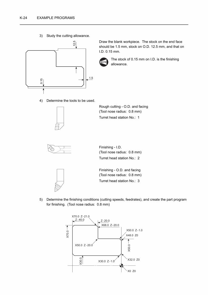
K-24 EXAMPLE PROGRAMS
3) Study the cutting allowance.
Draw the blank workpiece. The stock on the end face should be 1.5 mm, stock on O.D. 12.5 mm, and that on I.D. 0.15 mm.
The stock of 0.15 mm on I.D. is the finishing allowance.
4) Determine the tools to be used.
Rough cutting - O.D. and facing (Tool nose radius: 0.8 mm)
Turret head station No.: 1
Finishing - I.D. (Tool nose radius: 0.8 mm)
Turret head station No.: 2
Finishing - O.D. and facing (Tool nose radius: 0.8 mm)
Turret head station No.: 3
5) Determine the finishing conditions (cutting speeds, feedrates), and create the part program for finishing. (Tool nose radius: 0.8 mm)
12.5
0.15
1.5
NOTE
Z −40.0X70.0 Z−21.0
Z−20.0X68.0 Z−20.0
X50.0 Z
X48.0 Z0
−1.0
X32.0 Z0
X0 Z0
X30.0 Z−1.0
X50.0 Z−20.0
X70
.0
X50
.0
X30
.0

EXAMPLE PROGRAMS K-25
N2;
G00 T0202 (M42)*; . . . . . . . . . . . . . . . . Selecting the No. 2 tool
G97 S1500 M03;. . . . . . . . . . . . . . . . . . Starting spindle 1 in the normal direction at 1500 min−1 (cutting speed: 165 m/min)
X34.94 Z20.0;
G01 Z1.0 F1.0;
X30.0 Z−1.47 F0.15;
Z−41.0;
G00 U−1.0 Z20.0;
X100.0 Z100.0; . . . . . . . . . . . . . . . . . . . Moving to a position where the turret head can be rotated
M01;
N3;
G50 S2500;. . . . . . . . . . . . . . . . . . . . . . Setting the spindle 1 speed limit for automatic operation at
2500 min−1
G00 T0303 (M42)*; . . . . . . . . . . . . . . . . Selecting the No. 3 tool
G96 S180 M03;. . . . . . . . . . . . . . . . . . . Starting spindle 1 in the normal direction at the cutting speed of 180 m/min
X54.0 Z20.0;
G01 Z0 F1.0;
X28.0 F0.2;
G00 X45.06 Z1.0;
G01 X50.0 Z−1.47;
Z−20.0 F0.25;
X67.06;
X72.0 Z−22.47 F0.2;
G00 U1.0 Z20.0 M09;
X100.0 Z100.0 M05; . . . . . . . . . . . . . . . Moving to a position where the turret head can be rotated; the spindle stops.
M30;
Commands in ( ) identified by "*" are used only for the machine equipped with a transmission.
. . . . . Program for finishing using the manual tool nose radius offset function
• Feedrate for I.D. cutting: 0.15 mm/rev
. . . . . Program for finishing using the manual tool nose radius offset function
• Feedrate for facing: 0.2 mm/rev
• Feedrate for O.D. cutting: 0.25 mm/rev
NOTE
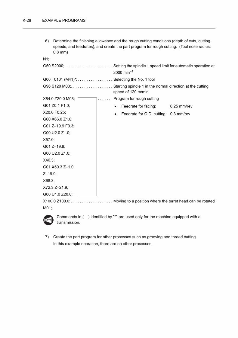
K-26 EXAMPLE PROGRAMS
6) Determine the finishing allowance and the rough cutting conditions (depth of cuts, cutting speeds, and feedrates), and create the part program for rough cutting. (Tool nose radius: 0.8 mm)
N1;
G50 S2000;. . . . . . . . . . . . . . . . . . . . . . Setting the spindle 1 speed limit for automatic operation at
2000 min−1
G00 T0101 (M41)*; . . . . . . . . . . . . . . . . Selecting the No. 1 tool
G96 S120 M03;. . . . . . . . . . . . . . . . . . . Starting spindle 1 in the normal direction at the cutting speed of 120 m/min
X84.0 Z20.0 M08;
G01 Z0.1 F1.0;
X20.0 F0.25;
G00 X66.0 Z1.0;
G01 Z−19.9 F0.3;
G00 U2.0 Z1.0;
X57.0;
G01 Z−19.9;
G00 U2.0 Z1.0;
X46.3;
G01 X50.3 Z−1.0;
Z−19.9;
X68.3;
X72.3 Z−21.9;
G00 U1.0 Z20.0;
X100.0 Z100.0; . . . . . . . . . . . . . . . . . . . Moving to a position where the turret head can be rotated
M01;
Commands in ( ) identified by "*" are used only for the machine equipped with a transmission.
7) Create the part program for other processes such as grooving and thread cutting.
In this example operation, there are no other processes.
. . . . . . Program for rough cutting
• Feedrate for facing: 0.25 mm/rev
• Feedrate for O.D. cutting: 0.3 mm/rev
NOTE

EXAMPLE PROGRAMS K-27
8) Arrange the part programs of individual processes to complete the program.
Commands in ( ) identified by "*" are used only for the machine equipped with a transmission.
O0002;N1; N2;G50 S2000; G00 T0202 (M42)*;G00 T0101 (M41)*; G97 S1500 M03;G96 S120 M03; X34.94 Z20.0;X84.0 Z20.0 M08; G01 Z1.0 F1.0;G01 Z0.1 F1.0; X30.0 Z−1.47 F0.15;X20.0 F0.25; Z−41.0;G00 X66.0 Z1.0; G00 U1.0 Z20.0;G01 Z−19.9 F0.3; X100.0 Z100.0;G00 U2.0 Z1.0; M01;X57.0;G01 Z−19.9; N3;G00 U2.0 Z1.0; G50 S2500;X46.3; G00 T0303 (M42)*;G01 X50.3 Z−1.0; G96 S180 M03;Z−19.9; X54.0 Z20.0;X68.3; G01 Z0 F1.0;X72.3 Z−21.9; X28.0 F0.2;G00 U1.0 Z20.0; G00 X45.06 Z1.0;X100.0 Z100.0; G01 X50.0 Z−1.47;M01; Z−20.0 F0.25;
X67.06;X72.0 Z−22.47 F0.2;G00 U1.0 Z20.0 M09;X100.0 Z100.0 M05;M30;
NOTE

K-28 EXAMPLE PROGRAMS
2-3 Various Part Programs
2-3-1 Grooving
O0001;
N1;
G00 T0101 (M41)*;
G97 S600 M03;
X54.0 Z20.0 M08;
G01 Z−20.0 F1.0;
X40.0 F0.1;
G04 U0.2;. . . . . . . Dwell: 0.2 sec
G00 X52.0;
W−2.0;
G01 X48.0 Z−20.0;
G00 X52.0;
W2.0;
G01 X48.0 Z−20.0;
G00 X60.0;
Z20.0;
X100.0 Z100.0 M05;
M30;
1. To finish the bottom of the groove in flat, it is necessary to suspend axis movement for a period to allow the spindle to rotate approximately one turn.
In this example,
t = = 0.1 sec
By setting 0.1 second for a dwell period, the spindle can rotate one turn.
2. The program is created assuming that tool nose R is 0.
3. Commands in ( ) identified by "*" are used only for the machine equipped with a transmission.
20
4C1 C1
45040
12
11 12
586 9
7
3 4
10
φ φ1
2
3
4
5
6
7
8
9
10
11
12
NOTE
60 sec600 min−1

EXAMPLE PROGRAMS K-29
2-3-2 I.D. Deep Hole Drilling
O0001;N1;G50 S500;G00 T0101 (M41)*;G96 S80 M03;X55.0 Z20.0 M08;G01 Z1.0 F3.0;Z−50.0 F0.3;G00 U−2.0 Z1.0;X65.0;G01 Z−50.0;G00 U−2.0 Z1.0;X74.8;G01 Z−50.0;G00 U−2.0 Z200.0;X150.0;M00;G00 X55.0 Z10.0 M03;Z−42.0 M08;G01 Z−90.0 F0.3;G00 U−2.0 Z−42.0;X65.0;G01 Z−90.0;
G00 U−2.0 Z20.0 M09;X200.0 Z50.0;M00;
Finishing
Commands in ( ) identified by "*" are used only for the machine equipped with a transmission.NOTE
The tool is moved to the position where the tool nose can be easily checked, or where the chips can be discharged without being interrupted.
Rough cutting is temporarily stopped to check the tool nose and to discharge the chips.
Again specify the commands for spindle or spindle 1 rotation and for coolant discharge.
After the chips have been discharged, the finishing allowance is checked.

K-30 EXAMPLE PROGRAMS
2-4 Milling 1 (Drilling on End Face)
The following program can be used only by the MC type machines or Y-axis specification machines.
<Part drawing>
<Cutting conditions>
Length of M8 × P1.25 tap engaging length is 5 mm.
O0001; . . . . . . . . . . . . . . . . . . . . . . . . . Program number
N1 (CENTER DRILL);. . . . . . . . . . . . . . Drilling with center drilling
G98; . . . . . . . . . . . . . . . . . . . . . . . . . . . Calling the feed per minute mode
M45; . . . . . . . . . . . . . . . . . . . . . . . . . . . Connecting spindle 1 as the C-axis
G28 H0; . . . . . . . . . . . . . . . . . . . . . . . . Returning the C-axis to the machine zero point
G00 T0101;. . . . . . . . . . . . . . . . . . . . . . Selecting the No. 1 tool
G97 S2000 M13;. . . . . . . . . . . . . . . . . . Rotating the rotary tool in the normal direction at
2000 min−1
Process T code Tool NameSpindle Speed
(min−1)Feedrate(mm/min)
Tool Offset Number
N1 T0101 Center drill 2000 150 1
N2 T0202 6.8 mm dia. drill 1300 200 2
N3 T0303 M8 × P1.25 Tap 400 500 3
NOTE
200
P.C
.D. 1
50
121
40
P.C.D 150
210°
150°
330°
30°
C0
90°
270°
B
A
F
E
D
C
φ φ
6 equal parts, M8 × P1.25, depth 15prepared hole φ6.8 drill, depth 25
NOTE
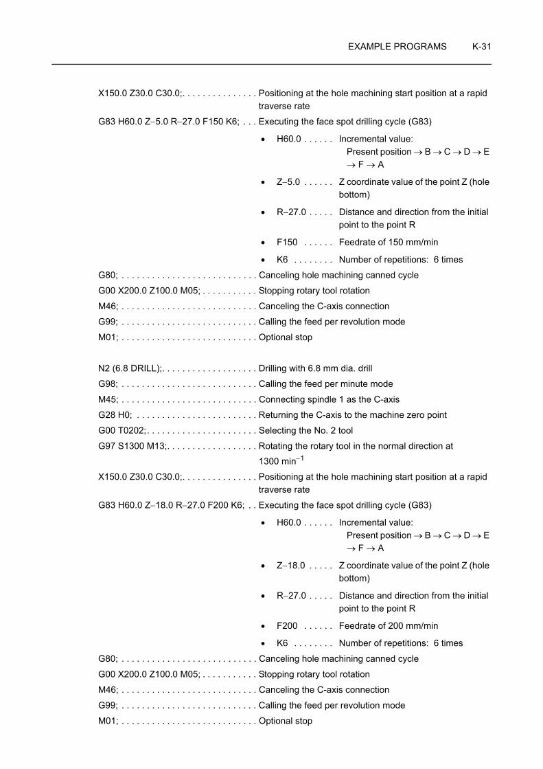
EXAMPLE PROGRAMS K-31
X150.0 Z30.0 C30.0;. . . . . . . . . . . . . . . Positioning at the hole machining start position at a rapid traverse rate
G83 H60.0 Z−5.0 R−27.0 F150 K6; . . . Executing the face spot drilling cycle (G83)
• H60.0 . . . . . . Incremental value: Present position → B → C → D → E → F → A
• Z−5.0 . . . . . . Z coordinate value of the point Z (hole bottom)
• R−27.0 . . . . . Distance and direction from the initial point to the point R
• F150 . . . . . . Feedrate of 150 mm/min
• K6 . . . . . . . . Number of repetitions: 6 times
G80; . . . . . . . . . . . . . . . . . . . . . . . . . . . Canceling hole machining canned cycle
G00 X200.0 Z100.0 M05; . . . . . . . . . . . Stopping rotary tool rotation
M46; . . . . . . . . . . . . . . . . . . . . . . . . . . . Canceling the C-axis connection
G99; . . . . . . . . . . . . . . . . . . . . . . . . . . . Calling the feed per revolution mode
M01; . . . . . . . . . . . . . . . . . . . . . . . . . . . Optional stop
N2 (6.8 DRILL);. . . . . . . . . . . . . . . . . . . Drilling with 6.8 mm dia. drill
G98; . . . . . . . . . . . . . . . . . . . . . . . . . . . Calling the feed per minute mode
M45; . . . . . . . . . . . . . . . . . . . . . . . . . . . Connecting spindle 1 as the C-axis
G28 H0; . . . . . . . . . . . . . . . . . . . . . . . . Returning the C-axis to the machine zero point
G00 T0202;. . . . . . . . . . . . . . . . . . . . . . Selecting the No. 2 tool
G97 S1300 M13;. . . . . . . . . . . . . . . . . . Rotating the rotary tool in the normal direction at
1300 min−1
X150.0 Z30.0 C30.0;. . . . . . . . . . . . . . . Positioning at the hole machining start position at a rapid traverse rate
G83 H60.0 Z−18.0 R−27.0 F200 K6; . . Executing the face spot drilling cycle (G83)
• H60.0 . . . . . . Incremental value: Present position → B → C → D → E → F → A
• Z−18.0 . . . . . Z coordinate value of the point Z (hole bottom)
• R−27.0 . . . . . Distance and direction from the initial point to the point R
• F200 . . . . . . Feedrate of 200 mm/min
• K6 . . . . . . . . Number of repetitions: 6 times
G80; . . . . . . . . . . . . . . . . . . . . . . . . . . . Canceling hole machining canned cycle
G00 X200.0 Z100.0 M05; . . . . . . . . . . . Stopping rotary tool rotation
M46; . . . . . . . . . . . . . . . . . . . . . . . . . . . Canceling the C-axis connection
G99; . . . . . . . . . . . . . . . . . . . . . . . . . . . Calling the feed per revolution mode
M01; . . . . . . . . . . . . . . . . . . . . . . . . . . . Optional stop

K-32 EXAMPLE PROGRAMS
N3 (M8 × P1.25 TAP);. . . . . . . . . . . . . . Tapping with M8 × P1.25 tap
G98; . . . . . . . . . . . . . . . . . . . . . . . . . . . Calling the feed per minute mode
M45; . . . . . . . . . . . . . . . . . . . . . . . . . . . Connecting spindle 1 as the C-axis
G28 H0; . . . . . . . . . . . . . . . . . . . . . . . . Returning the C-axis to the machine zero point
G00 T0303;. . . . . . . . . . . . . . . . . . . . . . Selecting the No. 3 tool
G97; . . . . . . . . . . . . . . . . . . . . . . . . . . . Calling the constant spindle speed control
X150.0 Z30.0 C30.0;. . . . . . . . . . . . . . . Positioning at the hole machining start position at a rapid traverse rate
G384 Z−20.0 R5.0 F1.25 S400. D600. (E0.) M68. T2.;
. . . . . . . . . . . . . . . . . . . . . . . . . . . . . . . Executing the synchronized tapping cycle (G384) at point A
• Z−20.0 . . . . . Z coordinate value of the point Z (hole bottom)
Z = −(depth of tap + tap engaging length)
= −(15 + 5) = −20 mm
• R5.0 . . . . . . . Z coordinate value of the point R
• F1.25 . . . . . . Pitch: 1.25 mm
• S400. . . . . . Spindle speed for infeed: 400 min−1
• D600. . . . . . Spindle speed for tool retraction:
600 min−1
• (E0.) . . . . . . . In-position check valid
• M68. . . . . . . Spindle 1 brake clamp
• T2. . . . . . . . Direction of tapping
G384 C90.0; . . . . . . . . . . . . . . . . . . . . . Executing the synchronized tapping cycle (G384) at point B
G384 C150.0; . . . . . . . . . . . . . . . . . . . . Executing the synchronized tapping cycle (G384) at point C
G384 C210.0; . . . . . . . . . . . . . . . . . . . . Executing the synchronized tapping cycle (G384) at point D
G384 C270.0; . . . . . . . . . . . . . . . . . . . . Executing the synchronized tapping cycle (G384) at point E
G384 C330.0; . . . . . . . . . . . . . . . . . . . . Executing the synchronized tapping cycle (G384) at point F
G380; . . . . . . . . . . . . . . . . . . . . . . . . . . Cancelling the synchronized tapping cycle (G384)
G00 X200.0 Z100.0 M05; . . . . . . . . . . . Stopping rotary tool rotation
M46; . . . . . . . . . . . . . . . . . . . . . . . . . . . Canceling the C-axis connection
G99; . . . . . . . . . . . . . . . . . . . . . . . . . . . Calling the feed per revolution mode
M30; . . . . . . . . . . . . . . . . . . . . . . . . . . . Program end
*

EXAMPLE PROGRAMS K-33
For the ZT series machines, modify the commands in the blocks indicated by "*" as shown below.
M329 S400; . . . . . . . . . . . . . . . . . . . . . Calling a synchronized tapping cycle
G84 Z−20.0 R−25.0 F500; . . . . . . . . . . Executing the face synchronized tapping cycle at point A
• Z−20.0 . . . . . Z coordinate value of the point Z (hole bottom)
Z = −(depth of tap + tap engaging length)
= −(15 + 5) = −20 mm
• R−25.0 . . . . . Distance and direction from the initial point (Z30.0) to point R (Z5.0)
• F500 . . . . . . Feedrate of 500 mm/min
Feedrate
= Spindle speed (min−1) × Pitch (mm)= 400 × 1.25 = 500 mm/min
C90.0;
C150.0;
C210.0;
C270.0;
C330.0;
G80; . . . . . . . . . . . . . . . . . . . . . . . . . . .Canceling the face synchronized tapping cycle (M329 G84)
NOTE
. . . . . . . . . . . . . . . . . . Executing the face synchronized tapping cycle (M329 G84) at points B to F

K-34 EXAMPLE PROGRAMS
2-5 Milling 2 (Hole Machining on Workpiece Circumference and End Face, and Workpiece Transfer)
The following program can be used only by the following machines.
ZL-S series: MC type machines
ZT series: MC type and Y-axis specification machines
Note that the machine must be equipped with a bar feeder.
<Part drawing>
<Dimensions of blank workpiece>
Blank Workpiece Description
Material SCM415
Dimensions (mm) O.D. 25
NOTE
C0.3C0.3
2.5 16 18.5
37
12.1
R1.5
φ24
φ14
.5
φ15
.41
M5 × P0.8 depth 12prepared hole φ4.3 depth 17 φ1.5 drill through
(C0.2 at entry)
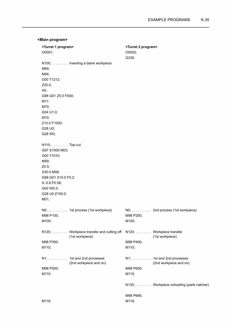
EXAMPLE PROGRAMS K-35
<Main program>
<Turret 1 program> <Turret 2 program>O0001; O0002;
G330;N100; . . . . . . . . Inserting a blank workpieceM69;M46;G00 T1212;Z20.0;X0;G98 G01 Z5.0 F500;M11;M70;G04 U1.0;M10;Z10.0 F1000;G28 U0;G28 W0;
N110; . . . . . . . . Top-cutG97 S1500 M03;G00 T1010;M59;Z0.5;X30.0 M08;G99 G01 X10.0 F0.2;X−0.8 F0.08;G00 W0.5;G28 U0 Z150.0;M01;
N0; . . . . . . . . . . 1st process (1st workpiece) N0; . . . . . . . . . . 2nd process (1st workpiece)M98 P100; M98 P200;M100; M100;
N120; . . . . . . . . Workpiece transfer and cutting off (1st workpiece)
N120; . . . . . . . . Workpiece transfer (1st workpiece)
M98 P300; M98 P400;M110; M110;
N1; . . . . . . . . . . 1st and 2nd processes (2nd workpiece and on)
N1; . . . . . . . . . . 1st and 2nd processes (2nd workpiece and on)
M98 P500; M98 P600;M115; M115;
N130; . . . . . . . . Workpiece unloading (parts catcher)
M98 P666;M116; M116;
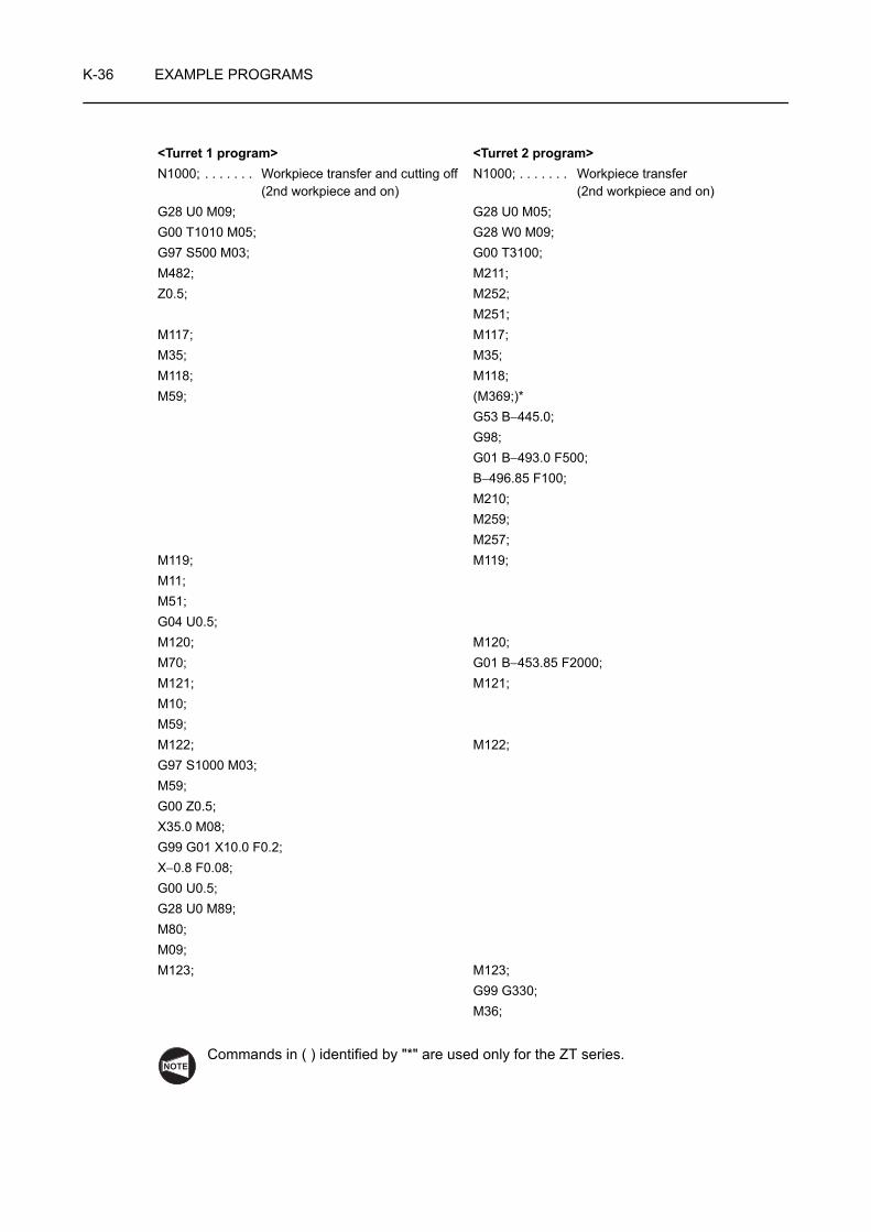
K-36 EXAMPLE PROGRAMS
Commands in ( ) identified by "*" are used only for the ZT series.
<Turret 1 program> <Turret 2 program>N1000; . . . . . . . Workpiece transfer and cutting off
(2nd workpiece and on)N1000; . . . . . . . Workpiece transfer
(2nd workpiece and on)G28 U0 M09; G28 U0 M05;G00 T1010 M05; G28 W0 M09;G97 S500 M03; G00 T3100;M482; M211;Z0.5; M252;
M251;M117; M117;M35; M35;M118; M118;M59; (M369;)*
G53 B−445.0;G98;G01 B−493.0 F500;B−496.85 F100;M210;M259;M257;
M119; M119;M11;M51;G04 U0.5;M120; M120;M70; G01 B−453.85 F2000;M121; M121;M10;M59;M122; M122;G97 S1000 M03;M59;G00 Z0.5;X35.0 M08;G99 G01 X10.0 F0.2;X−0.8 F0.08;G00 U0.5;G28 U0 M89;M80;M09;M123; M123;
G99 G330;M36;
NOTE

EXAMPLE PROGRAMS K-37
Commands in ( ) identified by "*" are used only for the ZT series.
<Turret 1 program> <Turret 2 program>M124; M124;G28 W0 M05;M125; M125;M01; M05;
M01;M126; M126;/2 GOTO1; . . . . Checking the end of bar material /2 GOTO1; . . . . Checking the end of bar material
N2000; . . . . . . . 1st process (last workpiece), ejecting the remainder of bar
N2000; . . . . . . . 2nd process (last workpiece), ejecting the remainder of bar Workpiece unloading (parts catcher)
G00 T0303; M98 P800;G96 S140 M03;Z10.0 M08;X35.0;X20.0 Z2.0;G01 Z−21.5 F0.25;G00 U2.0 Z1.0;X15.41;G01 Z−21.5;X30.0;G00 U2.0 W1.0;G28 U0;G28 W0;M05;M127; M127;M98 P700;M128; M128;M01; M01;
M98 P666;M129; M129;G00 T1212; G28 U0;Z10.0; G28 W0;
G330;G00 T3100;(M369;)*G53 B−450.0;G01 G98 B−482.0 F1000;
M130; M130;M210;
M131; M131;M11;G04 U1.0;
NOTE

K-38 EXAMPLE PROGRAMS
Commands in ( ) identified by "*" are used only for the ZT series.
<Turret 1 program> <Turret 2 program>M132; M132;
G330;M133; M133;G28 W0; G53 Z220.0;
M73;(M369;)*G53 B−300.0;G01 G98 B−315.0 F300;M47;G330;M74;
M134; M134;GOTO100; M01;M30; GOTO0;
M30;
NOTE
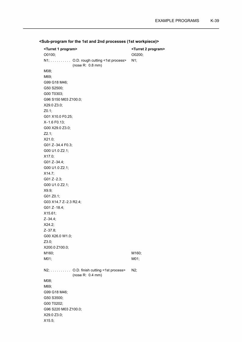
EXAMPLE PROGRAMS K-39
<Sub-program for the 1st and 2nd processes (1st workpiece)>
<Turret 1 program> <Turret 2 program>O0100; O0200;N1; . . . . . . . . . . O.D. rough cutting <1st process>
(nose R: 0.8 mm)N1;
M08;M69;G99 G18 M46;G50 S2500;G00 T0303;G96 S150 M03 Z100.0;X29.0 Z3.0;Z0.1;G01 X10.0 F0.25;X−1.6 F0.13;G00 X29.0 Z3.0;Z2.1;X21.0;G01 Z−34.4 F0.3;G00 U1.0 Z2.1;X17.0;G01 Z−34.4;G00 U1.0 Z2.1;X14.7;G01 Z−2.3;G00 U1.0 Z2.1;X9.9;G01 Z0.1;G03 X14.7 Z−2.3 R2.4;G01 Z−18.4;X15.61;Z−34.4;X24.2;Z−37.8;G00 X26.0 W1.0;Z3.0;X200.0 Z100.0;M160; M160;M01; M01;
N2; . . . . . . . . . . O.D. finish cutting <1st process> (nose R: 0.4 mm)
N2;
M08;M69;G99 G18 M46;G50 S3500;G00 T0202;G96 S220 M03 Z100.0;X29.0 Z3.0;X15.5;

K-40 EXAMPLE PROGRAMS
<Turret 1 program> <Turret 2 program>Z0;G01 X−0.8 F0.14;G00 X10.7 Z2.0;G01 Z0 F0.1;G03 X14.5 Z−1.9 R1.9;G01 Z−18.5;X15.41;Z−34.5;X22.932;X24.0 Z−34.034 F0.06;Z−37.4;G00 X26.0 W1.0;Z3.0;X200.0 Z100.0 M09;M05;M161; M161;M01; M01;
N3; . . . . . . . . . . Side face center drilling<1st process>
N3;
G98;G00 T0707;M45;G28 H0;G97 S200 M13 Z100.0;X35.0 Z0 S3000 M08;Z−22.4 C0;X17.0;G01 X14.3 F150;G00 X35.0;X200.0 Z100.0 M09;G99 M05;M46;M162; M162;M01; M01;
N4; . . . . . . . . . . Drilling on side face (1.5 mm dia.) N4;G98;G00 T0606;M45;G28 H0;G97 S200 M13 Z100.0;X35.0 Z0 S3000 M08;Z−22.4 C0;G87 X2.0 R−9.0 Q1000 P500 F300;G80;G00 X200.0 Z100.0 M09;G99 G28 U0 W0 M05;M46;

EXAMPLE PROGRAMS K-41
<Turret 1 program> <Turret 2 program>M163; M163;M01; M01;M99; M99;

K-42 EXAMPLE PROGRAMS
<Sub-program for workpiece transfer (1st workpiece)>
Commands in ( ) identified by "*" are used only for the ZT series.
<Turret 1 program> <Turret 2 program>O0300; O0400;N1; . . . . . . . . . . Cutting off (nose R: 0.4 mm) N1;M09; G28 U0 M05;G00 T1010 M05; G28 W0 M09;G28 U0; G00 T3100;G97 S500 M03; M211;M482; M252;Z0.5; M251;M101; M101;M35; M35;M102; M102;M59; (M369;)*
G53 B−445.0;G98;G01 B−493.0 F500;B−496.85 F100;M210;M259;M257;
M103; M103;M11;G04 U1.0;M104; M104;M70; G01 B−453.85 F2000;M105; M105;M10;M59;M106; M106;G97 S1000 M03;M59;G00 Z0.5;X30.0 M08;G99 G01 X10.0 F0.15;X−0.8 F0.08;G00 U0.5;G28 U0 M89;M80;M09;M107; M107;
G99 G330;M36;
M108; M108;G28 W0 M05;
NOTE

EXAMPLE PROGRAMS K-43
<Turret 1 program> <Turret 2 program>M109; M109;M01; M05;M99; M01;
M99;
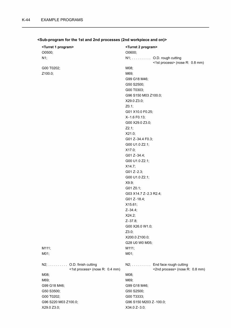
K-44 EXAMPLE PROGRAMS
<Sub-program for the 1st and 2nd processes (2nd workpiece and on)>
<Turret 1 program> <Turret 2 program>O0500; O0600;N1; N1; . . . . . . . . . . O.D. rough cutting
<1st process> (nose R: 0.8 mm)G00 T0202; M08;Z100.0; M69;
G99 G18 M46;G50 S2500;G00 T0303;G96 S150 M03 Z100.0;X29.0 Z3.0;Z0.1;G01 X10.0 F0.25;X−1.6 F0.13;G00 X29.0 Z3.0;Z2.1;X21.0;G01 Z−34.4 F0.3;G00 U1.0 Z2.1;X17.0;G01 Z−34.4;G00 U1.0 Z2.1;X14.7;G01 Z−2.3;G00 U1.0 Z2.1;X9.9;G01 Z0.1;G03 X14.7 Z−2.3 R2.4;G01 Z−18.4;X15.61;Z−34.4;X24.2;Z−37.8;G00 X26.0 W1.0;Z3.0;X200.0 Z100.0;G28 U0 W0 M05;
M111; M111;M01; M01;
N2; . . . . . . . . . . O.D. finish cutting <1st process> (nose R: 0.4 mm)
N2; . . . . . . . . . . End face rough cutting <2nd process> (nose R: 0.8 mm)
M08; M08;M69; M69;G99 G18 M46; G99 G18 M46;G50 S3500; G50 S2500;G00 T0202; G00 T3333;G96 S220 M03 Z100.0; G96 S150 M203 Z−100.0;X29.0 Z3.0; X34.0 Z−3.0;
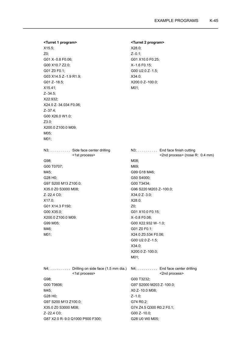
EXAMPLE PROGRAMS K-45
X15.5; X28.0;Z0; Z−0.1;G01 X−0.8 F0.06; G01 X10.0 F0.25;G00 X10.7 Z2.0; X−1.6 F0.15;G01 Z0 F0.1; G00 U2.0 Z−1.5;G03 X14.5 Z−1.9 R1.9; X34.0;G01 Z−18.5; X200.0 Z−100.0;X15.41; M01;Z−34.5;X22.932;X24.0 Z−34.034 F0.06;Z−37.4;G00 X26.0 W1.0;Z3.0;X200.0 Z100.0 M09;M05;M01;
N3; . . . . . . . . . . Side face center drilling <1st process>
N3; . . . . . . . . . . End face finish cutting <2nd process> (nose R: 0.4 mm)
G98; M08;G00 T0707; M69;M45; G99 G18 M46;G28 H0; G50 S4000;G97 S200 M13 Z100.0; G00 T3434;X35.0 Z0 S3000 M08; G96 S220 M203 Z−100.0;Z−22.4 C0; X34.0 Z−3.0;X17.0; X28.0;G01 X14.3 F150; Z0;G00 X35.0; G01 X10.0 F0.15;X200.0 Z100.0 M09; X−0.8 F0.08;G99 M05; G00 X22.932 W−1.0;M46; G01 Z0 F0.1;M01; X24.0 Z0.534 F0.06;
G00 U2.0 Z−1.5;X34.0;X200.0 Z−100.0;M01;
N4; . . . . . . . . . . Drilling on side face (1.5 mm dia.) <1st process>
N4; . . . . . . . . . . End face center drilling <2nd process>
G98; G00 T3232;G00 T0606; G97 S2000 M203 Z−100.0;M45; X0 Z−10.0 M08;G28 H0; Z−1.0;G97 S200 M13 Z100.0; G74 R0.2;X35.0 Z0 S3000 M08; G74 Z4.5 Q300 R0.2 F0.1;Z−22.4 C0; G00 Z−10.0;G87 X2.0 R−9.0 Q1000 P500 F300; G28 U0 W0 M05;
<Turret 1 program> <Turret 2 program>

K-46 EXAMPLE PROGRAMS
For the ZT series machines, modify the commands in the blocks indicated by "*" as shown below.
G80; M09;G00 X200.0 Z100.0 M09; G00 T3100;G99 G28 U0 W0 M05;M46;M112; M112;M01; M01;
N5; . . . . . . . . . . Drilling on end face (4.3 mm dia.) <2nd process>
N5;
G98;G00 T3535;M245;G28 H0;G97 S200 M13 Z−100.0;X0 Z−10.0 C0 S3000 M08;G83 Z17.0 R9.0 Q3000 P500 F300;G80;G00 X200.0 Z−100.0 M09;M05;M246;M113; M113;M01; M01;
N6; . . . . . . . . . . Synchronized tapping on end face (M5 × P0.8) <2nd process>
N6;
G98;G00 T3838;M245;G28 H0;G97;X0 Z−30.0 C0 M08;G384 Z15.0 R−10.0 F0.8 S400. D500.T3.;G380;G00 X200.0 Z−100.0 M09;G99 G28 U0 W0 M05;M246;G00 T0100;M114; M114;M01; M01;M99; M99;
<Turret 1 program> <Turret 2 program>
*
NOTE

EXAMPLE PROGRAMS K-47
M329 S400; . . . . . . . . . . . . . . . . . . . . . Calling a synchronized tapping cycle
G84 Z15.0 R20.0 F320; . . . . . . . . . . . . Executing the face synchronized tapping cycle
• Z15.0 . . . . . . Z coordinate value of the point Z (hole bottom)
• R20.0 . . . . . . Distance and direction from the initial point (Z−30.0) to point R (Z−10.0)
• F320 . . . . . . . Feedrate of 320 mm/min
Feedrate
= Spindle speed (min−1) × Pitch (mm)= 400 × 0.8 = 320 mm/min
G80; . . . . . . . . . . . . . . . . . . . . . . . . . . . Canceling the face synchronized tapping cycle (M329 G84)
<Sub-program for workpiece ejection and parts catcher operation>
Commands in ( ) identified by "*" are used only for the ZT series.
<Turret 2 program>O0666;G28 U0 M09;G53 Z220.0 M05;M73;(M369;)*G53 B−310.0;G01 G98 B−325.0 F300;M47;G330;M74;M01;M99;
NOTE
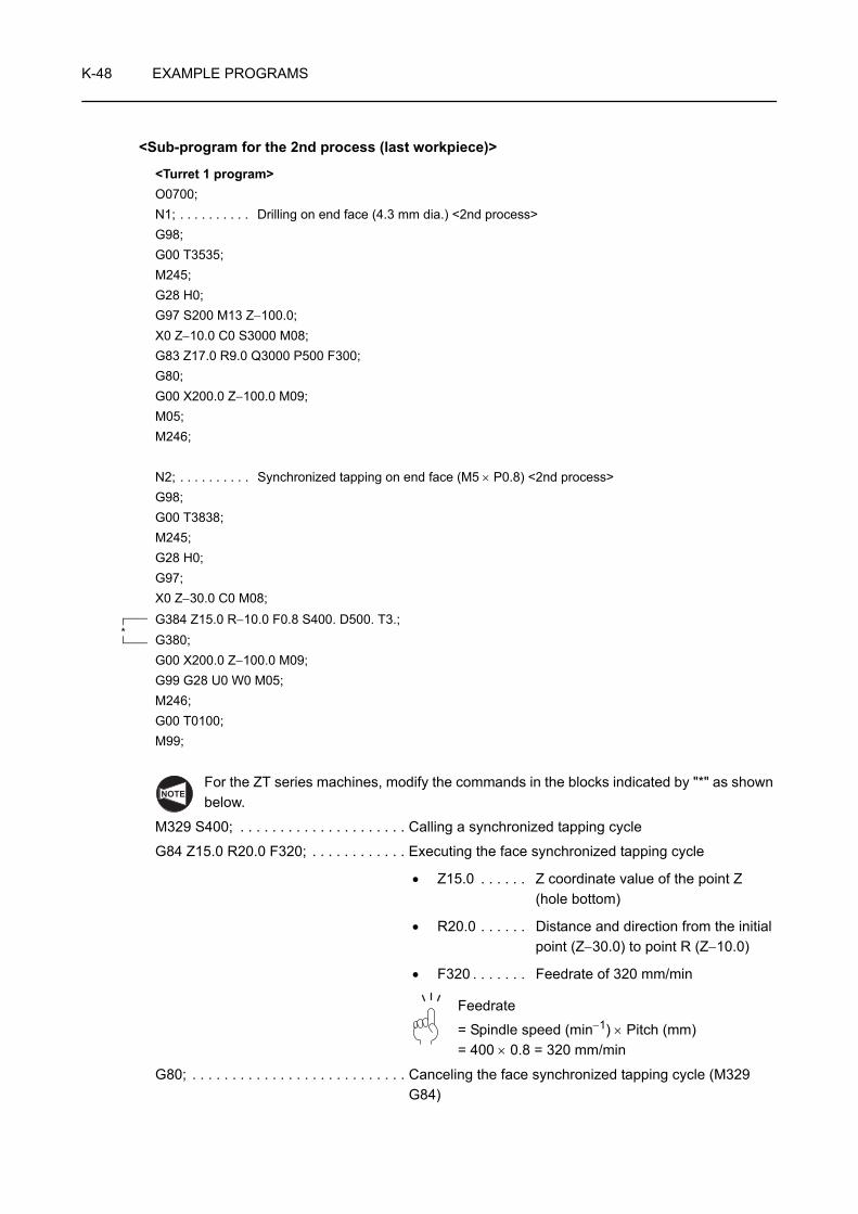
K-48 EXAMPLE PROGRAMS
<Sub-program for the 2nd process (last workpiece)>
For the ZT series machines, modify the commands in the blocks indicated by "*" as shown below.
M329 S400; . . . . . . . . . . . . . . . . . . . . . Calling a synchronized tapping cycle
G84 Z15.0 R20.0 F320; . . . . . . . . . . . . Executing the face synchronized tapping cycle
• Z15.0 . . . . . . Z coordinate value of the point Z (hole bottom)
• R20.0 . . . . . . Distance and direction from the initial point (Z−30.0) to point R (Z−10.0)
• F320 . . . . . . . Feedrate of 320 mm/min
Feedrate
= Spindle speed (min−1) × Pitch (mm)= 400 × 0.8 = 320 mm/min
G80; . . . . . . . . . . . . . . . . . . . . . . . . . . . Canceling the face synchronized tapping cycle (M329 G84)
<Turret 1 program>O0700;N1; . . . . . . . . . . Drilling on end face (4.3 mm dia.) <2nd process>G98;G00 T3535;M245;G28 H0;G97 S200 M13 Z−100.0;X0 Z−10.0 C0 S3000 M08;G83 Z17.0 R9.0 Q3000 P500 F300;G80;G00 X200.0 Z−100.0 M09;M05;M246;
N2; . . . . . . . . . . Synchronized tapping on end face (M5 × P0.8) <2nd process>G98;G00 T3838;M245;G28 H0;G97;X0 Z−30.0 C0 M08;G384 Z15.0 R−10.0 F0.8 S400. D500. T3.;G380;G00 X200.0 Z−100.0 M09;G99 G28 U0 W0 M05;M246;G00 T0100;M99;
*
NOTE
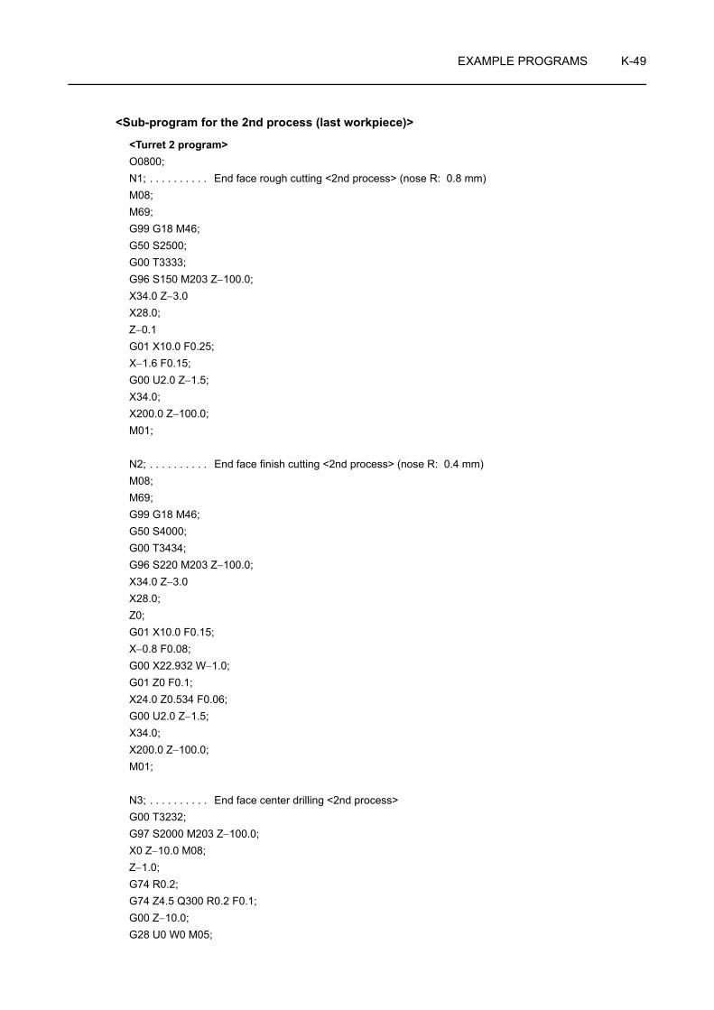
EXAMPLE PROGRAMS K-49
<Sub-program for the 2nd process (last workpiece)>
<Turret 2 program>O0800;N1; . . . . . . . . . . End face rough cutting <2nd process> (nose R: 0.8 mm)M08;M69;G99 G18 M46;G50 S2500;G00 T3333;G96 S150 M203 Z−100.0;X34.0 Z−3.0X28.0;Z−0.1G01 X10.0 F0.25;X−1.6 F0.15;G00 U2.0 Z−1.5;X34.0;X200.0 Z−100.0;M01;
N2; . . . . . . . . . . End face finish cutting <2nd process> (nose R: 0.4 mm)M08;M69;G99 G18 M46;G50 S4000;G00 T3434;G96 S220 M203 Z−100.0;X34.0 Z−3.0X28.0;Z0;G01 X10.0 F0.15;X−0.8 F0.08;G00 X22.932 W−1.0;G01 Z0 F0.1;X24.0 Z0.534 F0.06;G00 U2.0 Z−1.5;X34.0;X200.0 Z−100.0;M01;
N3; . . . . . . . . . . End face center drilling <2nd process>G00 T3232;G97 S2000 M203 Z−100.0;X0 Z−10.0 M08;Z−1.0;G74 R0.2;G74 Z4.5 Q300 R0.2 F0.1;G00 Z−10.0;G28 U0 W0 M05;

K-50 EXAMPLE PROGRAMS
M09;G00 T3100;M01;M99;
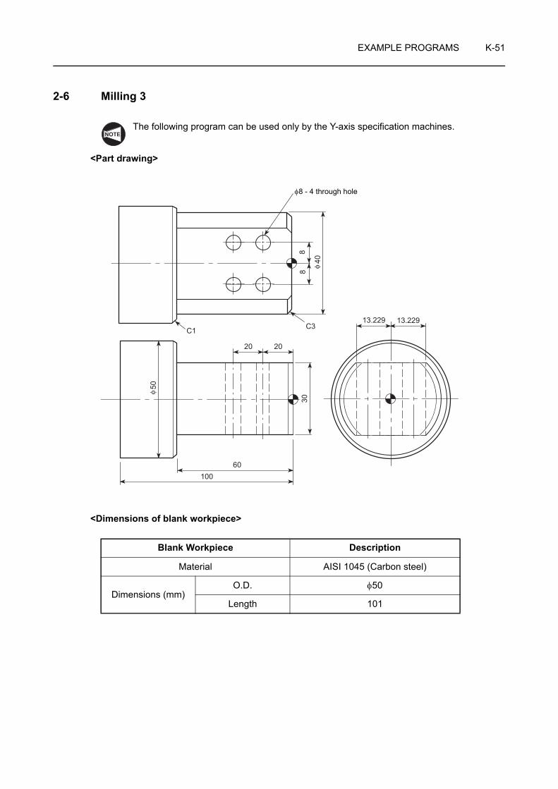
EXAMPLE PROGRAMS K-51
2-6 Milling 3
The following program can be used only by the Y-axis specification machines.
<Part drawing>
<Dimensions of blank workpiece>
Blank Workpiece Description
Material AISI 1045 (Carbon steel)
Dimensions (mm)O.D. φ50
Length 101
NOTE
88
40C3C1
13.229 13.229
20
60100
50
30
20
φ
φ
φ8 - 4 through hole

K-52 EXAMPLE PROGRAMS
<Chucking diagram>
The chucking depth is 30 mm.
30

EXAMPLE PROGRAMS K-53
O0001;G28 V0;
N1; . . . . . . Face and O.D. rough cuttingG99 M46;G50 S2000;G00 T0101;G96 S120 M03;X55.0 Z10.0 M08;G01 Z0.1 F1.0;X10.0 F0.2;X−1.6 F0.1;G00 X45.0 W1.0;G01 Z−59.9 F0.25;G00 U2.0 Z1.0;X40.3;Z−3.468;G00 U2.0 Z1.0;X31.364;G01 X40.3 Z−3.468;Z−59.9;X47.832;U4.0 W−2.0;G00 Z10.0;G53 X0 Z0 M05;M01;
N2; . . . . . . Face and O.D. finishingG99 M46;G50 S2000;G00 T0202;G96 S200 M03;X50.0 Z10.0 M08;G01 Z0 F1.0;X−0.8 F0.12;G00 X31.532 W1.0;G01 X40.0 Z−3.234 F0.15;Z−60.0;X47.532;U4.0 W−2.0;G00 Z10.0;G53 X0 Z0 M05;M01;
N3; . . . . . . 13 dia. end milling (shoulder cutting)G98 M45;G28 U0 W0 H0;G00 T0303;C0;M68;G97 S500 M13;
X50.0 Z20.0 M08;Y11.0;M98 P1000;M69;C180.0;M68;M98 P1000;G99 G00 X50.0 Z20.0 M69;G28 V0;G53 X0 Z0 M05;M01;
N4; . . . . . . Center drillingG98 M45;G00 T0404;C0;M68;G97 S1500 M13;X50.0 Z20.0 M08;G01 X40.0 Z−20.0 F750;G87 X24.0 Y8.0 R−7.0 F75;W−20.0;Y−8.0;W20.0;G99 G00 X50.0 Z20.0 M69;G28 V0;G53 X0 Z0 M05;M01;
N5; . . . . . . 8 dia. drillingG98 M45;G00 T0505;C0;M68;G97 S1200 M13;X50.0 Z20.0 M08;G01 X40.0 Z−20.0 F600;G87 X−38.0 Y8.0 R−7.0 Q4000 F144;W−20.0 Q4000;Y−8.0 Q4000;W20.0 Q4000;G99 G00 X50.0 Z20.0 M09;G28 V0;G53 X0 Z0 M05;G00 T0100 M69;M46;M30;

K-54 EXAMPLE PROGRAMS
O1000; . . . Sub-program (13 dia. end milling)G01 X34.0 Z10.0 F500;Z−53.5 F75;Y0;Z10.0;Y−11.0;Z−53.5;Y20.0;G00 X35.0 Z10.0;Y9.0;G01 X30.0 F500;Z−53.5 F75;Y−3.0;Z10.0;Y−15.0;Z−53.5;Y20.0;G00 X50.0 Z20.0;Y11.0;M99;

EXAMPLE PROGRAMS K-55
2-7 Balance Cut
The programs can be used only for the ZL-series.
<Part drawing>
<Dimensions of blank workpiece>
Blank Workpiece Description
Material AISI 1045 (Carbon steel)
Dimensions (mm)O.D. φ80
Length 500
<Turret 1 program> <Turret 2 program>
O0001; O0001;N1; . . . . . . . . . . O.D. rough cutting N1; . . . . . . . . . . O.D. rough cuttingG50 S2000;G00 T0101; G00 T0505;G96 S130 M03; G96 S130 M03;Z5.0; Z5.0;X80.5 M08; X80.5 M08;Z1.0; Z1.0;G68; G68;G71 U3.5 R0.5; G71 U3.5 R0.5;G71 P10 Q20 U0.4 W0.1 F0.5; G71 P10 Q20 U0.4 W0.1 F0.5;N10 G00 X55.064; N10 G00 X55.064;G01 X60.0 Z−1.468; G01 X60.0 Z−1.468;Z−300.0; Z−300.0;X65.064; X65.064;X70.0 Z−302.468; X70.0 Z−302.468;Z−450.0; Z−450.0;X78.064; X78.064;N20 X80.5 Z−451.218; N20 X80.5 Z−451.218;
NOTE
500
50 150
95
300
C1C2
M70 × P2.0C0.5
φ80
φ70 φ6
0

K-56 EXAMPLE PROGRAMS
G69; G69;G00 X250.0; G00 X250.0;M01; M01;
N2; . . . . . . . . . . O.D. finish cutting N2; . . . . . . . . . . O.D. finish cuttingG50 S2000;G00 T0202; G00 T0202;M100; M100;G96 S200 M03;Z5.0; Z−299.0;X80.0 M08; X81.0 M08;X55.532; G01 X63.532 F1.0;G01 Z1.0 F1.0; X70.0 Z−302.234 F0.15;X60.0 Z−1.234 F0.15; Z−450.0;Z−300.0; X78.532;X71.0; X81.0 Z−451.234;G00 X250.0; G00 X250.0 M09;Z5.0; Z5.0;M01; M01;
N3; . . . . . . . . . . M70 × P2.0 O.D. thread cuttingG00 T0303;M101; M101;G97 S650 M03;Z−290.0 M08;X90.0 M23;G92 X69.4 Z−400.0 F2.0;X68.9;X68.5;X68.1;X67.8;X67.56;X67.36;X67.26;G00 X300.0 M09;Z5.0 M05;M102; M102;M30; M30;
<Turret 1 program> <Turret 2 program>

APPENDIX
This appendix describes the interlock functions that ensure safe operation.(Tailstock specification)
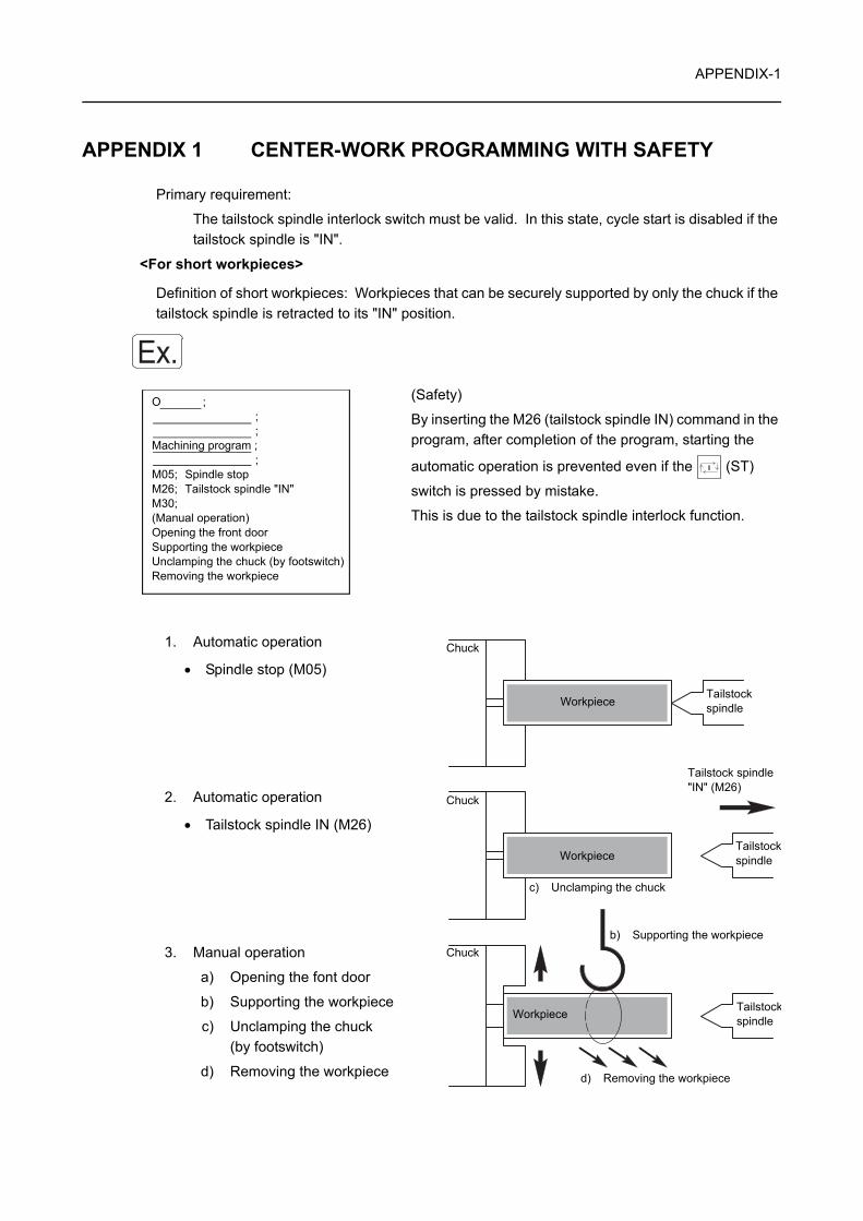
APPENDIX-1
APPENDIX 1 CENTER-WORK PROGRAMMING WITH SAFETY
Primary requirement:
The tailstock spindle interlock switch must be valid. In this state, cycle start is disabled if the tailstock spindle is "IN".
<For short workpieces>
Definition of short workpieces: Workpieces that can be securely supported by only the chuck if the tailstock spindle is retracted to its "IN" position.
(Safety)
By inserting the M26 (tailstock spindle IN) command in the program, after completion of the program, starting the
automatic operation is prevented even if the (ST)
switch is pressed by mistake.
This is due to the tailstock spindle interlock function.
1. Automatic operation
• Spindle stop (M05)
2. Automatic operation
• Tailstock spindle IN (M26)
3. Manual operation
a) Opening the font door
b) Supporting the workpiece
c) Unclamping the chuck (by footswitch)
d) Removing the workpiece
Ex.O ; ; ;Machining program ; ;M05; Spindle stopM26; Tailstock spindle "IN"M30;(Manual operation)Opening the front doorSupporting the workpieceUnclamping the chuck (by footswitch)Removing the workpiece
Chuck
Chuck
Chuck
Workpiece
Workpiece
Workpiece
Tailstock spindle
Tailstockspindle
Tailstockspindle
Tailstock spindle "IN" (M26)
c) Unclamping the chuck
d) Removing the workpiece
b) Supporting the workpiece

APPENDIX-2
<For long workpiece>
Definition of long workpieces: Workpieces that cannot be securely supported by only the chuck. Secure support of such workpieces requires the use of the center (tailstock spindle) or other proper means.
(Safety)
In this program, the M11 (chuck unclamp) command, to be executed after the spindle stops, unclamps the chuck.
If the (ST) switch or the (NOR) or (REV)
switch is pressed by mistake, the cycle start or the spindle rotation will not be enabled, due to the chuck interlock function.
(If a hydraulic chuck is not used, the internal signal is set to the chuck unclamp state so that the chuck interlock function is made valid. In such a case, if the footswitch is stepped on to set the internal signal to the chuck clamp state, both the cycle start and spindle rotation start are enabled.)
1. Automatic operation
• Spindle stop (M05)
2. Automatic operation
• Chuck unclamp (M11)
3. Manual operation
a) Opening the font door
b) Supporting the workpiece
c) Retracting the tailstock spindle "IN" by
pressing the (TSI) switch.
d) Removing the workpiece
Ex.O ; ; ;Machining program ; ;M05; Spindle stopM11; Chuck unclampM30;(Manual operation)Opening the front doorSupporting the workpiecePressing the (TSI) switch to retract the tailstock spindle into the tailstock bodyRemoving the workpiece
Chuck
Chuck
Chuck
Workpiece
Workpiece
Workpiece
Tailstock spindle
Tailstock spindle
Tailstock spindle
c) Tailstock spindle "IN"
Chuck unclamp (M11)
d) Removing the workpiece
b) Supporting the workpiece
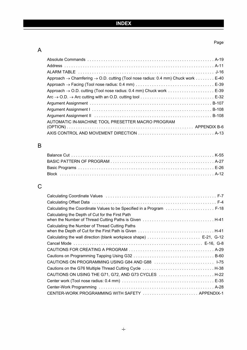
INDEX
Page
AAbsolute Commands . . . . . . . . . . . . . . . . . . . . . . . . . . . . . . . . . . . . . . . . . . . . . . . . . . . . . . . A-19Address . . . . . . . . . . . . . . . . . . . . . . . . . . . . . . . . . . . . . . . . . . . . . . . . . . . . . . . . . . . . . . . . . A-11ALARM TABLE . . . . . . . . . . . . . . . . . . . . . . . . . . . . . . . . . . . . . . . . . . . . . . . . . . . . . . . . . . . J-16Approach → Chamfering → O.D. cutting (Tool nose radius: 0.4 mm) Chuck work . . . . . . . . E-40Approach → Facing (Tool nose radius: 0.4 mm) . . . . . . . . . . . . . . . . . . . . . . . . . . . . . . . . . . E-39Approach → O.D. cutting (Tool nose radius: 0.4 mm) Chuck work . . . . . . . . . . . . . . . . . . . . E-39Arc → O.D. → Arc cutting with an O.D. cutting tool . . . . . . . . . . . . . . . . . . . . . . . . . . . . . . . . E-32Argument Assignment . . . . . . . . . . . . . . . . . . . . . . . . . . . . . . . . . . . . . . . . . . . . . . . . . . . . . B-107Argument Assignment I . . . . . . . . . . . . . . . . . . . . . . . . . . . . . . . . . . . . . . . . . . . . . . . . . . . . B-108Argument Assignment II . . . . . . . . . . . . . . . . . . . . . . . . . . . . . . . . . . . . . . . . . . . . . . . . . . . B-108AUTOMATIC IN-MACHINE TOOL PRESETTER MACRO PROGRAM (OPTION) . . . . . . . . . . . . . . . . . . . . . . . . . . . . . . . . . . . . . . . . . . . . . . . . . . . . . . . APPENDIX B-6AXIS CONTROL AND MOVEMENT DIRECTION . . . . . . . . . . . . . . . . . . . . . . . . . . . . . . . . . A-13
BBalance Cut . . . . . . . . . . . . . . . . . . . . . . . . . . . . . . . . . . . . . . . . . . . . . . . . . . . . . . . . . . . . . . K-55BASIC PATTERN OF PROGRAM . . . . . . . . . . . . . . . . . . . . . . . . . . . . . . . . . . . . . . . . . . . . . A-27Basic Programs . . . . . . . . . . . . . . . . . . . . . . . . . . . . . . . . . . . . . . . . . . . . . . . . . . . . . . . . . . . E-26Block . . . . . . . . . . . . . . . . . . . . . . . . . . . . . . . . . . . . . . . . . . . . . . . . . . . . . . . . . . . . . . . . . . . A-12
CCalculating Coordinate Values . . . . . . . . . . . . . . . . . . . . . . . . . . . . . . . . . . . . . . . . . . . . . . . . F-7Calculating Offset Data . . . . . . . . . . . . . . . . . . . . . . . . . . . . . . . . . . . . . . . . . . . . . . . . . . . . . . F-4Calculating the Coordinate Values to be Specified in a Program . . . . . . . . . . . . . . . . . . . . . F-18Calculating the Depth of Cut for the First Path when the Number of Thread Cutting Paths is Given . . . . . . . . . . . . . . . . . . . . . . . . . . . . . . . H-41Calculating the Number of Thread Cutting Paths when the Depth of Cut for the First Path is Given . . . . . . . . . . . . . . . . . . . . . . . . . . . . . . . . . H-41Calculating the wall direction (blank workpiece shape) . . . . . . . . . . . . . . . . . . . . . . . E-21, G-12Cancel Mode . . . . . . . . . . . . . . . . . . . . . . . . . . . . . . . . . . . . . . . . . . . . . . . . . . . . . . . . E-16, G-8CAUTIONS FOR CREATING A PROGRAM . . . . . . . . . . . . . . . . . . . . . . . . . . . . . . . . . . . . . A-29Cautions on Programming Tapping Using G32 . . . . . . . . . . . . . . . . . . . . . . . . . . . . . . . . . . . B-60CAUTIONS ON PROGRAMMING USING G84 AND G88 . . . . . . . . . . . . . . . . . . . . . . . . . . I-75Cautions on the G76 Multiple Thread Cutting Cycle . . . . . . . . . . . . . . . . . . . . . . . . . . . . . . . H-38CAUTIONS ON USING THE G71, G72, AND G73 CYCLES . . . . . . . . . . . . . . . . . . . . . . . . H-22Center work (Tool nose radius: 0.4 mm) . . . . . . . . . . . . . . . . . . . . . . . . . . . . . . . . . . . . . . . . E-35Center-Work Programming . . . . . . . . . . . . . . . . . . . . . . . . . . . . . . . . . . . . . . . . . . . . . . . . . . A-28CENTER-WORK PROGRAMMING WITH SAFETY . . . . . . . . . . . . . . . . . . . . . . . . APPENDIX-1
-i-

INDEX
Page
CChamfering (1) (Tool nose radius: 0.4 mm) . . . . . . . . . . . . . . . . . . . . . . . . . . . . . . . . . . . . . . E-37Chamfering (2) (Tool nose radius: 0.4 mm) . . . . . . . . . . . . . . . . . . . . . . . . . . . . . . . . . . . . . . E-37Chamfering (3) (Tool nose radius: 0.4 mm) . . . . . . . . . . . . . . . . . . . . . . . . . . . . . . . . . . . . . . E-37Chamfering (4) (Tool nose radius: 0.4 mm) . . . . . . . . . . . . . . . . . . . . . . . . . . . . . . . . . . . . . . E-38Chamfering and I.D. cutting with an I.D. cutting tool . . . . . . . . . . . . . . . . . . . . . . . . . . . . . . . E-30Changing Tool Life Management Data . . . . . . . . . . . . . . . . . . . . . . . . . . . . . . . . . . . . . . . . . . J-4Check Items . . . . . . . . . . . . . . . . . . . . . . . . . . . . . . . . . . . . . . . . . . . . . . . . . . . . . . . . . . . . . . . A-4Chuck work (1) (Tool nose radius: 0.4 mm) . . . . . . . . . . . . . . . . . . . . . . . . . . . . . . . . . . . . . . E-34Chuck work (2) (Tool nose radius: 0.4 mm) . . . . . . . . . . . . . . . . . . . . . . . . . . . . . . . . . . . . . . E-34Chuck-Work Programming . . . . . . . . . . . . . . . . . . . . . . . . . . . . . . . . . . . . . . . . . . . . . . . . . . A-27Chuck-Work Programming (1) . . . . . . . . . . . . . . . . . . . . . . . . . . . . . . . . . . . . . . . . . . . . . . . . . K-2Chuck-Work Programming (2) . . . . . . . . . . . . . . . . . . . . . . . . . . . . . . . . . . . . . . . . . . . . . . . . K-17Concave Arc . . . . . . . . . . . . . . . . . . . . . . . . . . . . . . . . . . . . . . . . . . . . . . . . . . . . . . . . . . . . . F-17CONDITIONS FOR USE OF THE AUTOMATIC TOOL NOSE RADIUS OFFSET FUNCTION . . . . . . . . . . . . . . . . . . . . . . . . . . . . . . . . . . . . . E-5Convex Arc . . . . . . . . . . . . . . . . . . . . . . . . . . . . . . . . . . . . . . . . . . . . . . . . . . . . . . . . . . . . . . F-17COUNTING THE TOOL LIFE . . . . . . . . . . . . . . . . . . . . . . . . . . . . . . . . . . . . . . . . . . . . . . . . . J-9
DData . . . . . . . . . . . . . . . . . . . . . . . . . . . . . . . . . . . . . . . . . . . . . . . . . . . . . . . . . . . . . . . . . . . . A-11Displayed Items on the TOOL LIFE MANAGE Screen . . . . . . . . . . . . . . . . . . . . . . . . . . . . . . J-2Dwell Command . . . . . . . . . . . . . . . . . . . . . . . . . . . . . . . . . . . . . . . . . . . . . . . . . . . . . B-60, I-75
EEXAMPLE PROGRAMS . . . . . . . . . . . . . . . . . . . . . . . . . . . . . . . . . . . . . . . . . . E-26, G-18, K-2Example Programs . . . . . . . . . . . . . . . . . . . . . . . . . . . . . . . . . . . . . . . . . . . . . . . . . . . F-10, F-19Expressing Axis Movement in Programming . . . . . . . . . . . . . . . . . . . . . . . . . . . . . . . . . . . . . A-16
FF FUNCTION . . . . . . . . . . . . . . . . . . . . . . . . . . . . . . . . . . . . . . . . . . . . . . . . . . . . . . . . . . . . . D-25Face Hole Machining Canned Cycle . . . . . . . . . . . . . . . . . . . . . . . . . . . . . . . . . . . . . . . . . . . . I-7Facing (1) (Tool nose radius: 0.4 mm) . . . . . . . . . . . . . . . . . . . . . . . . . . . . . . . . . . . . . . . . . . E-35Facing (2) (Tool nose radius: 0.4 mm) . . . . . . . . . . . . . . . . . . . . . . . . . . . . . . . . . . . . . . . . . . E-36Facing (3) (Tool nose radius: 0.4 mm) . . . . . . . . . . . . . . . . . . . . . . . . . . . . . . . . . . . . . . . . . . E-36Facing and O.D. cutting with in O.D. cutting tool . . . . . . . . . . . . . . . . . . . . . . . . . . . . . . . . . . E-28Facing → Chamfering → O.D. cutting (Tool nose radius: 0.4 mm) . . . . . . . . . . . . . . . . . . . . E-41Feed per Minute (G98 F_ ) . . . . . . . . . . . . . . . . . . . . . . . . . . . . . . . . . . . . . . . . . . . . . . . . . . D-27
-ii-

INDEX
Page
FFeed per Spindle Revolution (G99 F_ ) . . . . . . . . . . . . . . . . . . . . . . . . . . . . . . . . . . . . . . . . . D-25Feedrate for Finishing . . . . . . . . . . . . . . . . . . . . . . . . . . . . . . . . . . . . . . . . . . . . . . . . . . . . . . D-291st process . . . . . . . . . . . . . . . . . . . . . . . . . . . . . . . . . . . . . . . . . . . . . . . . . . . . . . . . . . . . . . K-18Flow of Operation . . . . . . . . . . . . . . . . . . . . . . . . . . . . . . . . . . . . . . . . . . . . . . . . . . . . . . . . . . A-3FLOW UNTIL THE PRODUCT IS COMPLETED . . . . . . . . . . . . . . . . . . . . . . . . . . . . . . . . . . A-3
GG CODE LIST . . . . . . . . . . . . . . . . . . . . . . . . . . . . . . . . . . . . . . . . . . . . . . . . . . . . . . . . . . . . . B-1G00 POSITIONING THE CUTTING TOOL AT A RAPID TRAVERSE RATE . . . . . . . . . . . . . B-6G01 MOVING THE CUTTING TOOL ALONG A STRAIGHT PATH AT A CUTTING FEEDRATE . . . . . . . . . . . . . . . . . . . . . . . . . . . . . . . . . . . . . . . . . . . . B-10G02, G03 MOVING THE TOOL ALONG CIRCULAR ARC AT CUTTING FEEDRATE . . . . B-12G04 SUSPENDING PROGRAM EXECUTION (DWELL) . . . . . . . . . . . . . . . . . . . . . . . . . . . B-30G07.1 (G107) CYLINDRICAL INTERPOLATION . . . . . . . . . . . . . . . . . . . . . . . . . . . . . . . . . B-90G12.1 (G112), G13.1 (G113) NOTCHING (POLAR COORDINATE INTERPOLATION) . . . . . . . . . . . . . . . . . . . . . . . . . . . . . . . . . . . . . B-95G22, G23 SETTING THE TOOL ENTRY PROHIBITION ZONE (STORED STROKE CHECK FUNCTION) . . . . . . . . . . . . . . . . . . . . . . . . . . . . . . . . . . . . . . B-75G28 RETURNING THE AXES TO MACHINE ZERO AUTOMATICALLY, G30 RETURNING THE AXES TO SECOND ZERO POINT AUTOMATICALLY . . . . . . . . . B-78G30.1 FLOATING REFERENCE POINT RETURN (OPTION) . . . . . . . . . . . . . . . . . . . . . . . B-80G32 TAPPING (AT THE CENTER OF SPINDLE) . . . . . . . . . . . . . . . . . . . . . . . . . . . . . . . . . B-59G32, G92 THREAD CUTTING (CONTINUOUS THREAD CUTTING AND THREAD CUTTING CYCLE) . . . . . . . . . . . . . . . B-42G38 WORKPIECE PUSHING CHECK . . . . . . . . . . . . . . . . . . . . . . . . . . . . . . . . . . . . . . . . . B-86G40, G41, G42 AUTOMATIC TOOL NOSE RADIUS OFFSET . . . . . . . . . . . . . . . . . . . . . . B-37G40, G41, G42 CUTTER RADIUS OFFSET . . . . . . . . . . . . . . . . . . . . . . . . . . . . . . . . . . . . . B-40G50 SETTING THE SPINDLE SPEED LIMIT . . . . . . . . . . . . . . . . . . . . . . . . . . . . . . . . . . . . B-19G53 SELECTING THE MACHINE COORDINATE SYSTEM . . . . . . . . . . . . . . . . . . . . . . . . B-81G54 - G59 SELECTING A WORK COORDINATE SYSTEM . . . . . . . . . . . . . . . . . . . . . . . . B-83G65 MACRO CALL (ONE-SHOT) . . . . . . . . . . . . . . . . . . . . . . . . . . . . . . . . . . . . . . . . . . . . B-107G66, G67 MACRO MODAL CALL (EVERY AXIS TRAVEL COMMAND), CANCEL . . . . . . B-112G68, G69 BALANCE CUT . . . . . . . . . . . . . . . . . . . . . . . . . . . . . . . . . . . . . . . . . . . . . . . . . . B-114G68.1, G69.1 3D COORDINATE CONVERSION . . . . . . . . . . . . . . . . . . . . . . . . . . . . . . . . B-116G70 FINISHING CYCLE . . . . . . . . . . . . . . . . . . . . . . . . . . . . . . . . . . . . . . . . . . . . . . . . . . . . H-25G70 - G76 MULTIPLE REPETITIVE CYCLE . . . . . . . . . . . . . . . . . . . . . . . . . . . . . . . . . . . . B-67G71 O.D./I.D. ROUGH CUTTING CYCLE . . . . . . . . . . . . . . . . . . . . . . . . . . . . . . . . . . . . . . . . H-5G72 ROUGH FACING CYCLE . . . . . . . . . . . . . . . . . . . . . . . . . . . . . . . . . . . . . . . . . . . . . . . H-11G73 CLOSED-LOOP CUTTING CYCLE . . . . . . . . . . . . . . . . . . . . . . . . . . . . . . . . . . . . . . . . H-17
-iii-
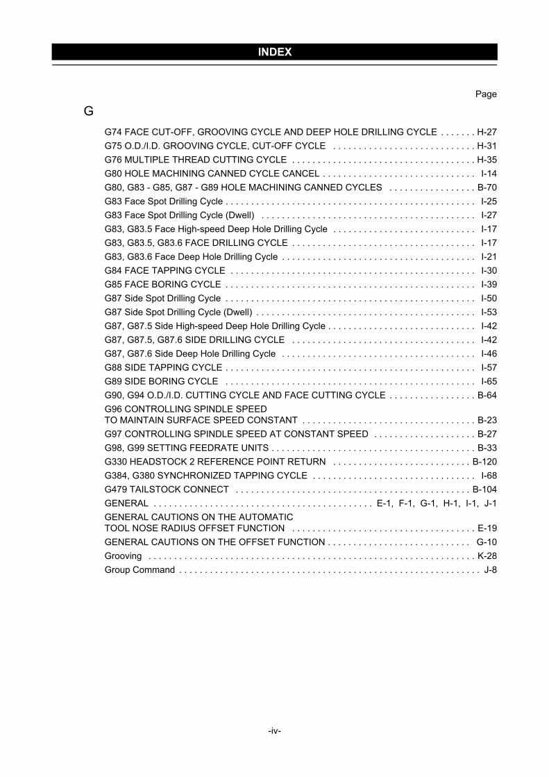
INDEX
Page
GG74 FACE CUT-OFF, GROOVING CYCLE AND DEEP HOLE DRILLING CYCLE . . . . . . . H-27G75 O.D./I.D. GROOVING CYCLE, CUT-OFF CYCLE . . . . . . . . . . . . . . . . . . . . . . . . . . . . H-31G76 MULTIPLE THREAD CUTTING CYCLE . . . . . . . . . . . . . . . . . . . . . . . . . . . . . . . . . . . . H-35G80 HOLE MACHINING CANNED CYCLE CANCEL . . . . . . . . . . . . . . . . . . . . . . . . . . . . . . I-14G80, G83 - G85, G87 - G89 HOLE MACHINING CANNED CYCLES . . . . . . . . . . . . . . . . . B-70G83 Face Spot Drilling Cycle . . . . . . . . . . . . . . . . . . . . . . . . . . . . . . . . . . . . . . . . . . . . . . . . . I-25G83 Face Spot Drilling Cycle (Dwell) . . . . . . . . . . . . . . . . . . . . . . . . . . . . . . . . . . . . . . . . . . I-27G83, G83.5 Face High-speed Deep Hole Drilling Cycle . . . . . . . . . . . . . . . . . . . . . . . . . . . . I-17G83, G83.5, G83.6 FACE DRILLING CYCLE . . . . . . . . . . . . . . . . . . . . . . . . . . . . . . . . . . . . I-17G83, G83.6 Face Deep Hole Drilling Cycle . . . . . . . . . . . . . . . . . . . . . . . . . . . . . . . . . . . . . . I-21G84 FACE TAPPING CYCLE . . . . . . . . . . . . . . . . . . . . . . . . . . . . . . . . . . . . . . . . . . . . . . . . I-30G85 FACE BORING CYCLE . . . . . . . . . . . . . . . . . . . . . . . . . . . . . . . . . . . . . . . . . . . . . . . . . I-39G87 Side Spot Drilling Cycle . . . . . . . . . . . . . . . . . . . . . . . . . . . . . . . . . . . . . . . . . . . . . . . . . I-50G87 Side Spot Drilling Cycle (Dwell) . . . . . . . . . . . . . . . . . . . . . . . . . . . . . . . . . . . . . . . . . . . I-53G87, G87.5 Side High-speed Deep Hole Drilling Cycle . . . . . . . . . . . . . . . . . . . . . . . . . . . . . I-42G87, G87.5, G87.6 SIDE DRILLING CYCLE . . . . . . . . . . . . . . . . . . . . . . . . . . . . . . . . . . . . I-42G87, G87.6 Side Deep Hole Drilling Cycle . . . . . . . . . . . . . . . . . . . . . . . . . . . . . . . . . . . . . . I-46G88 SIDE TAPPING CYCLE . . . . . . . . . . . . . . . . . . . . . . . . . . . . . . . . . . . . . . . . . . . . . . . . . I-57G89 SIDE BORING CYCLE . . . . . . . . . . . . . . . . . . . . . . . . . . . . . . . . . . . . . . . . . . . . . . . . . I-65G90, G94 O.D./I.D. CUTTING CYCLE AND FACE CUTTING CYCLE . . . . . . . . . . . . . . . . . B-64G96 CONTROLLING SPINDLE SPEED TO MAINTAIN SURFACE SPEED CONSTANT . . . . . . . . . . . . . . . . . . . . . . . . . . . . . . . . . . B-23G97 CONTROLLING SPINDLE SPEED AT CONSTANT SPEED . . . . . . . . . . . . . . . . . . . . B-27G98, G99 SETTING FEEDRATE UNITS . . . . . . . . . . . . . . . . . . . . . . . . . . . . . . . . . . . . . . . . B-33G330 HEADSTOCK 2 REFERENCE POINT RETURN . . . . . . . . . . . . . . . . . . . . . . . . . . . B-120G384, G380 SYNCHRONIZED TAPPING CYCLE . . . . . . . . . . . . . . . . . . . . . . . . . . . . . . . . I-68G479 TAILSTOCK CONNECT . . . . . . . . . . . . . . . . . . . . . . . . . . . . . . . . . . . . . . . . . . . . . . B-104GENERAL . . . . . . . . . . . . . . . . . . . . . . . . . . . . . . . . . . . . . . . . . . . E-1, F-1, G-1, H-1, I-1, J-1GENERAL CAUTIONS ON THE AUTOMATIC TOOL NOSE RADIUS OFFSET FUNCTION . . . . . . . . . . . . . . . . . . . . . . . . . . . . . . . . . . . . E-19GENERAL CAUTIONS ON THE OFFSET FUNCTION . . . . . . . . . . . . . . . . . . . . . . . . . . . . G-10Grooving . . . . . . . . . . . . . . . . . . . . . . . . . . . . . . . . . . . . . . . . . . . . . . . . . . . . . . . . . . . . . . . . K-28Group Command . . . . . . . . . . . . . . . . . . . . . . . . . . . . . . . . . . . . . . . . . . . . . . . . . . . . . . . . . . . J-8
-iv-
INDEX
Page
II.D. Deep Hole Drilling . . . . . . . . . . . . . . . . . . . . . . . . . . . . . . . . . . . . . . . . . . . . . . . . . . . . . . K-29If a Wall Lies at the End of Cutting . . . . . . . . . . . . . . . . . . . . . . . . . . . . . . . . . . . . . . E-19, G-10Imaginary Tool Tip Position . . . . . . . . . . . . . . . . . . . . . . . . . . . . . . . . . . . . . . . . . . . . . . . . . . . E-6Incremental Commands . . . . . . . . . . . . . . . . . . . . . . . . . . . . . . . . . . . . . . . . . . . . . . . . . . . . . A-22Infeed Mode . . . . . . . . . . . . . . . . . . . . . . . . . . . . . . . . . . . . . . . . . . . . . . . . . . . . . . . . . . . . . . H-37Inputting a Decimal Point . . . . . . . . . . . . . . . . . . . . . . . . . . . . . . . . . . . . . . . . . . . . . . . . . . . . A-30INPUTTING THE PROGRAM TO THE MACHINE . . . . . . . . . . . . . . . . . . . . . . . . . . . . . . . . . A-2
JJIS SPECIFICATION AND REVERSE JIS SPECIFICATION . . . . . . . . . . . . . . . . . . . . . . . . A-32
LLife Count M Code . . . . . . . . . . . . . . . . . . . . . . . . . . . . . . . . . . . . . . . . . . . . . . . . . . . . . . . . . . J-8LOAD TOOL SKIP FUNC. . . . . . . . . . . . . . . . . . . . . . . . . . . . . . . . . . . . . . . . . . . . . . . . . . . . . J-7
MM CODE LIST . . . . . . . . . . . . . . . . . . . . . . . . . . . . . . . . . . . . . . . . . . . . . . . . . . . . . . . . . . . . . C-1M00, M01 PROGRAM STOP AND OPTIONAL STOP . . . . . . . . . . . . . . . . . . . . . . . . . . . . . C-18M02, M30 PROGRAM END, PROGRAM END AND REWIND . . . . . . . . . . . . . . . . . . . . . . . C-21M03, M203, M04, M204, M05 SPINDLE START AND STOP . . . . . . . . . . . . . . . . . . . . . . . . C-24M08, M09 COOLANT DISCHARGE ON/OFF . . . . . . . . . . . . . . . . . . . . . . . . . . . . . . . . . . . . C-31M10, M210, M11, M211 CHUCK CLAMP/UNCLAMP . . . . . . . . . . . . . . . . . . . . . . . . . . . . . . C-37M13, M14, M05 START AND STOP OF ROTARY TOOL ROTATION . . . . . . . . . . . . . . . . . C-28M19 SPINDLE ORIENTATION (SPINDLE 1), M219 SPINDLE ORIENTATION (SPINDLE 2), M319 ROTARY TOOL SPINDLE ORIENTATION . . . . . . . . . . . . . . . . . . . . . . . . . . . . . . . . . C-33M23, M24 CHAMFERING ON/OFF . . . . . . . . . . . . . . . . . . . . . . . . . . . . . . . . . . . . . . . . . . . . C-34M25, M26 TAILSTOCK SPINDLE IN/OUT . . . . . . . . . . . . . . . . . . . . . . . . . . . . . . . . . . . . . . C-41M28, M29 IN-POSITION CHECK VALID AND IN-POSITION CHECK INVALID . . . . . . . . . . C-86M34, M234, M35, M235, M36 SYNCHRONIZED OPERATION ON/OFF . . . . . . . . . . . . . . . C-44M45, M245, M46, M246 C-AXIS CONNECTION AND CANCEL . . . . . . . . . . . . . . . . . . . . . C-50M47 WORKPIECE EJECTOR OUT . . . . . . . . . . . . . . . . . . . . . . . . . . . . . . . . . . . . . . . . . . . C-52M48, M49 FEEDRATE OVERRIDE CANCEL OFF/ON . . . . . . . . . . . . . . . . . . . . . . . . . . . . . C-56M68, M268, M69, M269 SPINDLE BRAKE CLAMP AND UNCLAMP . . . . . . . . . . . . . . . . . . C-58M70, M483, M482 BAR STOCK FEED, BAR STOCK FEED OFF, BAR STOCK CHANGE . . . . . . . . . . . . . . . . . . . . . . . . . . . . . . . . . . . . . . . . . . . . . . . . . . . . . C-60M71, M72 AUTOMATIC IN-MACHINE TOOL PRESETTER ARM OUT/IN (OPTION) . . . . . C-64M73, M74 PARTS CATCHER OUT/IN . . . . . . . . . . . . . . . . . . . . . . . . . . . . . . . . . . . . . . . . . C-65
-v-
INDEX
Page
MM80 WORKPIECE CUT-OFF DETECTION . . . . . . . . . . . . . . . . . . . . . . . . . . . . . . . . . . . . . C-69M85, M86 AUTOMATIC DOOR OPEN/CLOSE . . . . . . . . . . . . . . . . . . . . . . . . . . . . . . . . . . C-71M89 WORK COUNTER, TOTAL COUNTER . . . . . . . . . . . . . . . . . . . . . . . . . . . . . . . . . . . . C-73M90, M290, M91, M291 SIMULTANEOUS SPINDLE/ROTARY TOOL OPERATION MODE ON/OFF . . . . . . . . . . . . . . . . . . . . . . . . . . . . . . . . . . C-83M98/M198, M99 SUB-PROGRAM CALL AND SUB-PROGRAM END . . . . . . . . . . . . . . . . . C-76M100 TO M197, M199 OPERATION SYNCHRONIZATION . . . . . . . . . . . . . . . . . . . . . . . . . C-82M200, M201 CHIP CONVEYOR FORWARD ROTATION START, STOP . . . . . . . . . . . . . . C-89M314, M315 FEEDRATE OVERRIDE CLAMP ON TURRET 1 SIDE VALID, INVALID (OPTION) . . . . . . . . . . . . . . . . . . . . . . . . . . . . . . . . . . . . . . . . . . . . . . . . . . . . . . . . C-89M329 G84 FACE SYNCHRONIZED TAPPING CYCLE . . . . . . . . . . . . . . . . . . . . . . . . . . . . I-34M329 G88 SIDE SYNCHRONIZED TAPPING CYCLE . . . . . . . . . . . . . . . . . . . . . . . . . . . . . I-61M360, M361 WORKPIECE EJECTOR OUT/IN . . . . . . . . . . . . . . . . . . . . . . . . . . . . . . . . . . . C-54M368, M369 B-AXIS CLAMP/UNCLAMP (ZT SERIES) . . . . . . . . . . . . . . . . . . . . . . . . . . . . C-92M480, M481 C-AXIS SYNCHRONIZATION MODE ON/OFF . . . . . . . . . . . . . . . . . . . . . . . . C-90Milling 1 (Drilling on End Face) . . . . . . . . . . . . . . . . . . . . . . . . . . . . . . . . . . . . . . . . . . . . . . . K-30Milling 2 (Hole Machining on Workpiece Circumference and End Face, and Workpiece Transfer) . . . . . . . . . . . . . . . . . . . . . . . . . . . . . . . . . . . . . . . . . . . . . . . . . . . . K-34Milling 3 . . . . . . . . . . . . . . . . . . . . . . . . . . . . . . . . . . . . . . . . . . . . . . . . . . . . . . . . . . . . . . . . . K-51Mixture of Argument Assignments I and II . . . . . . . . . . . . . . . . . . . . . . . . . . . . . . . . . . . . . . B-109Movement along the Controlled Axes . . . . . . . . . . . . . . . . . . . . . . . . . . . . . . . . . . . . . . . . . . A-13MULTIPLE M CODE FUNCTION . . . . . . . . . . . . . . . . . . . . . . . . . . . . . . . . . . . . APPENDIX C-1
NNesting . . . . . . . . . . . . . . . . . . . . . . . . . . . . . . . . . . . . . . . . . . . . . . . . . . . . . . . . . . . . . . . . . C-77Nesting Level for Calls . . . . . . . . . . . . . . . . . . . . . . . . . . . . . . . . . . . . . . . . . . . . . . . . . . . . . B-110New Tool Selection Flag . . . . . . . . . . . . . . . . . . . . . . . . . . . . . . . . . . . . . . . . . . . . . . . . . . . . J-11NEW TOOL SELECTION FLAG AND TOOL LIFE EXPIRED FLAG . . . . . . . . . . . . . . . . . . . J-11Number of Repetitions "K" . . . . . . . . . . . . . . . . . . . . . . . . . . . . . . . . . . . . . . . . . . . . . . . . . . . . I-5
OO.D. and I.D. cutting . . . . . . . . . . . . . . . . . . . . . . . . . . . . . . . . . . . . . . . . . . . . . . . . . . . . . . . F-10O.D. cutting including arcs . . . . . . . . . . . . . . . . . . . . . . . . . . . . . . . . . . . . . . . . . . . . . . . . . . . F-19O.D. cutting with an O.D. cutting tool . . . . . . . . . . . . . . . . . . . . . . . . . . . . . . . . . . . . . . . . . . . E-26Offset Data Table . . . . . . . . . . . . . . . . . . . . . . . . . . . . . . . . . . . . . . . . . . . . . . . . . . . . . . . . . . F-13Offset Direction . . . . . . . . . . . . . . . . . . . . . . . . . . . . . . . . . . . . . . . . . . . . . . . . . . . . . . . . . . . . F-6Offset Direction and Calculation of Coordinate Values . . . . . . . . . . . . . . . . . . . . . . . . . . . . . . F-6OFFSET FOR TAPER CUTTING AND CHAMFERING . . . . . . . . . . . . . . . . . . . . . . . . . . . . . F-2
-vi-
INDEX
Page
OOFFSET IN CIRCULAR INTERPOLATION . . . . . . . . . . . . . . . . . . . . . . . . . . . . . . . . . . . . . . F-17Offset Method . . . . . . . . . . . . . . . . . . . . . . . . . . . . . . . . . . . . . . . . . . . . . . . . . . . . . . . . . . . . . F-2Offset Mode . . . . . . . . . . . . . . . . . . . . . . . . . . . . . . . . . . . . . . . . . . . . . . . . . . . . . . . . . E-14, G-6Operation Methods in Hole Machining Canned Cycles (G Codes) . . . . . . . . . . . . . . . . . . . . . I-7Overcut in the Automatic Tool Nose Radius Offset Mode . . . . . . . . . . . . . . . . . . . . . . . . . . . E-23Overcut in the Cutter Radius Offset Mode . . . . . . . . . . . . . . . . . . . . . . . . . . . . . . . . . . . . . . G-14
PPARAMETERS . . . . . . . . . . . . . . . . . . . . . . . . . . . . . . . . . . . . . . . . . . . . . . . . . . . . . . . . . . . J-17Part Program . . . . . . . . . . . . . . . . . . . . . . . . . . . . . . . . . . . . . . . . . . . . . . . . . . . . . . . . . . . . . A-11Positive (+) and Negative (−) Designation for Cutter Radius Offset Amount and Tool Paths . . . . . . . . . . . . . . . . . . . . . . . . . . . . . . . . G-13Precautions on Using the Tapper . . . . . . . . . . . . . . . . . . . . . . . . . . . . . . . . . . . . . . . . B-61, I-76Program Number . . . . . . . . . . . . . . . . . . . . . . . . . . . . . . . . . . . . . . . . . . . . . . . . . . . . A-10, A-29PROGRAMMING FOR A SAMPLE WORKPIECE . . . . . . . . . . . . . . . . . . . . . . . . . . . . . . . . F-21Programming for a Sample Workpiece . . . . . . . . . . . . . . . . . . . . . . . . . . . . . . . . . . . . . . . . . E-43Programming positioning using a work coordinate system (G54 to G59) . . . . . . . . . . . . . . . B-84PROGRAMMING STEPS . . . . . . . . . . . . . . . . . . . . . . . . . . . . . . . . . . . . . . . . . . . . . . . . . . . . K-1Programming using G00 . . . . . . . . . . . . . . . . . . . . . . . . . . . . . . . . . . . . . . . . . . . . . . . . . . . . . B-8Programming using G01 . . . . . . . . . . . . . . . . . . . . . . . . . . . . . . . . . . . . . . . . . . . . . . . . . . . . B-11Programming using G02 or G03 (helical interpolation) . . . . . . . . . . . . . . . . . . . . . . . . . . . . . B-17Programming using G02 or G03 (milling) . . . . . . . . . . . . . . . . . . . . . . . . . . . . . . . . . . . . . . . B-16Programming using G02 or G03 (turning) . . . . . . . . . . . . . . . . . . . . . . . . . . . . . . . . . . . . . . . B-15Programming using G04 . . . . . . . . . . . . . . . . . . . . . . . . . . . . . . . . . . . . . . . . . . . . . . . . . . . . B-31Programming using G07.1 (G107) . . . . . . . . . . . . . . . . . . . . . . . . . . . . . . . . . . . . . . . . . . . . . B-91Programming using G12.1 (G112) and G13.1 (G113) . . . . . . . . . . . . . . . . . . . . . . . . . . . . . . B-97Programming using G22 and G23 . . . . . . . . . . . . . . . . . . . . . . . . . . . . . . . . . . . . . . . . . . . . . B-77Programming using G28 . . . . . . . . . . . . . . . . . . . . . . . . . . . . . . . . . . . . . . . . . . . . . . . . . . . . B-79Programming using G32 (Scrolled thread cutting) . . . . . . . . . . . . . . . . . . . . . . . . . . . . . . . . . B-56Programming using G32 (Tapping) . . . . . . . . . . . . . . . . . . . . . . . . . . . . . . . . . . . . . . . . . . . . B-63Programming using G32 or G92 (Straight thread cutting) . . . . . . . . . . . . . . . . . . . . . . . . . . . B-50Programming using G32 or G92 (Tapered thread cutting (R2 1/2)) . . . . . . . . . . . . . . . . . . . B-53Programming using G38 (ZL-S series) . . . . . . . . . . . . . . . . . . . . . . . . . . . . . . . . . . . . . . . . . B-88Programming using G38 (ZT series) . . . . . . . . . . . . . . . . . . . . . . . . . . . . . . . . . . . . . . . . . . . B-89Programming using G40, G41, and G42 . . . . . . . . . . . . . . . . . . . . . . . . . . . . . . . . . . B-38, G-18Programming using G50 (Setting the spindle speed limit) . . . . . . . . . . . . . . . . . . . . . . . . . . . B-21Programming using G50 S_ . . . . . . . . . . . . . . . . . . . . . . . . . . . . . . . . . . . . . . . . . . . . . . . . . D-22Programming using G53 . . . . . . . . . . . . . . . . . . . . . . . . . . . . . . . . . . . . . . . . . . . . . . . . . . . . B-82
-vii-
INDEX
Page
PProgramming using G65 . . . . . . . . . . . . . . . . . . . . . . . . . . . . . . . . . . . . . . . . . . . . . . . . . . . B-110Programming using G66 . . . . . . . . . . . . . . . . . . . . . . . . . . . . . . . . . . . . . . . . . . . . . . . . . . . B-113Programming using G68 and G69 . . . . . . . . . . . . . . . . . . . . . . . . . . . . . . . . . . . . . . . . . . . . B-115Programming using G68.1 and G69.1 (when using angle holder with 45-degree inclination) . . . . . . . . . . . . . . . . . . . . . . . . . . . . . B-119Programming using G71 . . . . . . . . . . . . . . . . . . . . . . . . . . . . . . . . . . . . . . . . . . . . . . . B-68, H-8Programming using G72 . . . . . . . . . . . . . . . . . . . . . . . . . . . . . . . . . . . . . . . . . . . . . . . . . . . . H-14Programming using G73 . . . . . . . . . . . . . . . . . . . . . . . . . . . . . . . . . . . . . . . . . . . . . . . . . . . . H-19Programming using G74 (Deep hole drilling) . . . . . . . . . . . . . . . . . . . . . . . . . . . . . . . . . . . . . H-30Programming using G74 (Face cut-off cycle) . . . . . . . . . . . . . . . . . . . . . . . . . . . . . . . . . . . . H-29Programming using G75 (Cut-off cycle) . . . . . . . . . . . . . . . . . . . . . . . . . . . . . . . . . . . . . . . . H-34Programming using G75 (O.D./I.D. grooving cycle) . . . . . . . . . . . . . . . . . . . . . . . . . . . . . . . H-33Programming using G76 . . . . . . . . . . . . . . . . . . . . . . . . . . . . . . . . . . . . . . . . . . . . . . . . . . . . H-39Programming using G80 . . . . . . . . . . . . . . . . . . . . . . . . . . . . . . . . . . . . . . . . . . . . . . . . . . . . I-15Programming using G83 (Face spot drilling cycle) . . . . . . . . . . . . . . . . . . . . . . . . . . . . . . . . I-26Programming using G83 (Face spot drilling cycle (dwell)) . . . . . . . . . . . . . . . . . . . . . . . . . . I-28Programming using G83, G83.5 (Face high-speed deep hole drilling cycle) . . . . . . . . . . . . I-19Programming using G83, G83.6 (Face deep hole drilling cycle) . . . . . . . . . . . . . . . . . . . . . . I-23Programming using G84 (Face tapping cycle) . . . . . . . . . . . . . . . . . . . . . . . . . . . . . . . . . . . I-32Programming using G85 (Face boring cycle) . . . . . . . . . . . . . . . . . . . . . . . . . . . . . . . . . . . . I-40Programming using G87 (Side spot drilling cycle) . . . . . . . . . . . . . . . . . . . . . . . . . . . . . . . . . I-51Programming using G87 (Side spot drilling cycle (dwell)) . . . . . . . . . . . . . . . . . . . . . . . . . . . I-55Programming using G87, G87.5 (Side high-speed deep hole drilling cycle) . . . . . . . . . . . . . I-44Programming using G87, G87.6 (Side deep hole drilling cycle) . . . . . . . . . . . . . . . . . . . . . . I-48Programming using G88 (Side tapping cycle) . . . . . . . . . . . . . . . . . . . . . . . . . . . . . . . . . . . . I-59Programming using G89 (Side boring cycle) . . . . . . . . . . . . . . . . . . . . . . . . . . . . . . . . . . . . . I-66Programming using G96 . . . . . . . . . . . . . . . . . . . . . . . . . . . . . . . . . . . . . . . . . . . . . . . . . . . . B-25Programming using G96 S_ . . . . . . . . . . . . . . . . . . . . . . . . . . . . . . . . . . . . . . . . . . . . . . . . . D-19Programming using G97 . . . . . . . . . . . . . . . . . . . . . . . . . . . . . . . . . . . . . . . . . . . . . . . . . . . . B-29Programming using G97 S_ . . . . . . . . . . . . . . . . . . . . . . . . . . . . . . . . . . . . . . . . . . . . . . . . . D-18Programming using G98 . . . . . . . . . . . . . . . . . . . . . . . . . . . . . . . . . . . . . . . . . . . . . . . . . . . . B-35Programming using G99 . . . . . . . . . . . . . . . . . . . . . . . . . . . . . . . . . . . . . . . . . . . . . . . . . . . . B-34Programming using G99 F_ . . . . . . . . . . . . . . . . . . . . . . . . . . . . . . . . . . . . . . . . . . . . . . . . . . D-26Programming using G330 . . . . . . . . . . . . . . . . . . . . . . . . . . . . . . . . . . . . . . . . . . . . . . . . . . B-120Programming using G384 and G380 . . . . . . . . . . . . . . . . . . . . . . . . . . . . . . . . . . . . . . . . . . . I-73Programming using G479 . . . . . . . . . . . . . . . . . . . . . . . . . . . . . . . . . . . . . . . . . . . . . . . . . . B-106Programming using M00 or M01 . . . . . . . . . . . . . . . . . . . . . . . . . . . . . . . . . . . . . . . . . . . . . . C-20Programming using M02 or M30 . . . . . . . . . . . . . . . . . . . . . . . . . . . . . . . . . . . . . . . . . . . . . . C-23Programming using M03, M04, and M05 . . . . . . . . . . . . . . . . . . . . . . . . . . . . . . . . . . . . . . . . C-26
-viii-

INDEX
Page
PProgramming using M08 and M09 . . . . . . . . . . . . . . . . . . . . . . . . . . . . . . . . . . . . . . . . . . . . . C-32Programming using M10 and M11 . . . . . . . . . . . . . . . . . . . . . . . . . . . . . . . . . . . . . . . . . . . . . C-39Programming using M10, M210, M11, and M211 . . . . . . . . . . . . . . . . . . . . . . . . . . . . . . . . . C-40Programming using M13 or M14 . . . . . . . . . . . . . . . . . . . . . . . . . . . . . . . . . . . . . . . . . . . . . . C-30Programming using M23 or M24 . . . . . . . . . . . . . . . . . . . . . . . . . . . . . . . . . . . . . . . . . . . . . . C-35Programming using M25 and M26 . . . . . . . . . . . . . . . . . . . . . . . . . . . . . . . . . . . . . . . . . . . . . C-42Programming using M28 and M29 . . . . . . . . . . . . . . . . . . . . . . . . . . . . . . . . . . . . . . . . . . . . . C-87Programming using M34, M35, and M36 (1) (ZL-S series) . . . . . . . . . . . . . . . . . . . . . . . . . . C-46Programming using M34, M35, and M36 (1) (ZT series) . . . . . . . . . . . . . . . . . . . . . . . . . . . . C-48Programming using M34, M35, and M36 (2) (ZL-S series) . . . . . . . . . . . . . . . . . . . . . . . . . . C-47Programming using M34, M35, and M36 (2) (ZT series) . . . . . . . . . . . . . . . . . . . . . . . . . . . . C-49Programming using M45 and M46 . . . . . . . . . . . . . . . . . . . . . . . . . . . . . . . . . . . . . . . . . . . . . C-51Programming using M47 (ZL-S series) . . . . . . . . . . . . . . . . . . . . . . . . . . . . . . . . . . . . . . . . . C-53Programming using M48 and M49 . . . . . . . . . . . . . . . . . . . . . . . . . . . . . . . . . . . . . . . . . . . . . C-57Programming using M68 and M69 . . . . . . . . . . . . . . . . . . . . . . . . . . . . . . . . . . . . . . . . . . . . . C-59Programming using M70 (1) . . . . . . . . . . . . . . . . . . . . . . . . . . . . . . . . . . . . . . . . . . . . . . . . . C-61Programming using M70 (2) . . . . . . . . . . . . . . . . . . . . . . . . . . . . . . . . . . . . . . . . . . . . . . . . . C-63Programming using M73 and M74 (ZL-S series) . . . . . . . . . . . . . . . . . . . . . . . . . . . . . . . . . . C-67Programming using M73 and M74 (ZT series) . . . . . . . . . . . . . . . . . . . . . . . . . . . . . . . . . . . C-68Programming using M80 (ZL-S and ZT series) . . . . . . . . . . . . . . . . . . . . . . . . . . . . . . . . . . . C-70Programming using M85 and M86 . . . . . . . . . . . . . . . . . . . . . . . . . . . . . . . . . . . . . . . . . . . . . C-72Programming using M89 (1) . . . . . . . . . . . . . . . . . . . . . . . . . . . . . . . . . . . . . . . . . . . . . . . . . C-74Programming using M89 (2) . . . . . . . . . . . . . . . . . . . . . . . . . . . . . . . . . . . . . . . . . . . . . . . . . C-75Programming using M90 and M91 . . . . . . . . . . . . . . . . . . . . . . . . . . . . . . . . . . . . . . . . . . . . . C-85Programming using M98 and M99 . . . . . . . . . . . . . . . . . . . . . . . . . . . . . . . . . . . . . . . . . . . . . C-76Programming using M98 and M99 (1) . . . . . . . . . . . . . . . . . . . . . . . . . . . . . . . . . . . . . . . . . . C-79Programming using M98 and M99 (2) . . . . . . . . . . . . . . . . . . . . . . . . . . . . . . . . . . . . . . . . . . C-79Programming using M99 . . . . . . . . . . . . . . . . . . . . . . . . . . . . . . . . . . . . . . . . . . . . . . . . . . . . C-77Programming using M198 and M99 . . . . . . . . . . . . . . . . . . . . . . . . . . . . . . . . . . . . . . . . . . . . C-80Programming using M329 G84 (Face synchronized tapping cycle) (1) . . . . . . . . . . . . . . . . . I-36Programming using M329 G84 (Face synchronized tapping cycle) (2) . . . . . . . . . . . . . . . . . I-38Programming using M329 G88 (Side synchronized tapping cycle) . . . . . . . . . . . . . . . . . . . . I-63Programming using M360 and M361 . . . . . . . . . . . . . . . . . . . . . . . . . . . . . . . . . . . . . . . . . . . C-55Programming using M480 and M481 . . . . . . . . . . . . . . . . . . . . . . . . . . . . . . . . . . . . . . . . . . . C-91
QQUICK M CODE FUNCTION . . . . . . . . . . . . . . . . . . . . . . . . . . . . . . . . . . . . . . . APPENDIX C-2
-ix-
INDEX
Page
RREADING THE PMC ADDRESS INFORMATION . . . . . . . . . . . . . . . . . . . . . . . . . . . . . . . . . J-14READING THE TOOL LIFE MANAGEMENT INFORMATION . . . . . . . . . . . . . . . . . . . . . . . J-12Recommended Example Programs . . . . . . . . . . . . . . . . . . . . . . . . . . . . . . . . . . . . . . . . . . . . E-39Relationship of the Cutting Speed, Diameter, and Spindle Speed . . . . . . . . . . . . . . . . . . . . D-23Repeating Sub-program Calls . . . . . . . . . . . . . . . . . . . . . . . . . . . . . . . . . . . . . . . . . . . . . . . . C-78REQUIREMENT FOR USING THE CUTTER RADIUS OFFSET FUNCTION . . . . . . . . . . . G-3Role of Decimal Point . . . . . . . . . . . . . . . . . . . . . . . . . . . . . . . . . . . . . . . . . . . . . . . . . . . . . . A-31
SS FUNCTION . . . . . . . . . . . . . . . . . . . . . . . . . . . . . . . . . . . . . . . . . . . . . . . . . . . . . . . . . . . . . D-172nd process . . . . . . . . . . . . . . . . . . . . . . . . . . . . . . . . . . . . . . . . . . . . . . . . . . . . . . . . . . . . . . K-23Selecting the Tool Life Management Utility Function . . . . . . . . . . . . . . . . . . . . . . . . . . . . . . . . J-7Sequence Number . . . . . . . . . . . . . . . . . . . . . . . . . . . . . . . . . . . . . . . . . . . . . . . . . . . . . . . . . A-10Setting the tool life data . . . . . . . . . . . . . . . . . . . . . . . . . . . . . . . . . . . . . . . . . . . . . . . . . . . . . . J-5Setting the Tool Life Data in Program . . . . . . . . . . . . . . . . . . . . . . . . . . . . . . . . . . . . . . . . . . . J-5SETTING TOOL LIFE MANAGEMENT DATA . . . . . . . . . . . . . . . . . . . . . . . . . . . . . . . . . . . . J-2Setting Tool Life Management Data . . . . . . . . . . . . . . . . . . . . . . . . . . . . . . . . . . . . . . . . . . . . J-3Setting Tool Nose Radius . . . . . . . . . . . . . . . . . . . . . . . . . . . . . . . . . . . . . . . . . . . . . . . . . . . E-10Side Hole Machining Canned Cycle . . . . . . . . . . . . . . . . . . . . . . . . . . . . . . . . . . . . . . . . . . . . I-9Signs and Symbols . . . . . . . . . . . . . . . . . . . . . . . . . . . . . . . . . . . . . . . . . . . . . . . . . . . . . . . . A-29SKIP COMMAND . . . . . . . . . . . . . . . . . . . . . . . . . . . . . . . . . . . . . . . . . . . . . . . . . . . . . . . . . . J-10Space between the Words in the Program . . . . . . . . . . . . . . . . . . . . . . . . . . . . . . . . . . . . . . A-29SPECIFICATION IN MACHINING PROGRAM . . . . . . . . . . . . . . . . . . . . . . . . . . . . . . . . . . . . J-8Specifying the absolute commands (1) . . . . . . . . . . . . . . . . . . . . . . . . . . . . . . . . . . . . . . . . . A-20Specifying the absolute commands (2) . . . . . . . . . . . . . . . . . . . . . . . . . . . . . . . . . . . . . . . . . A-21SPECIFYING THE CUTTING CONDITIONS . . . . . . . . . . . . . . . . . . . . . . . . . . . . . . . . . . . . A-25Specifying the Cutting Speed (G96 S_ ) . . . . . . . . . . . . . . . . . . . . . . . . . . . . . . . . . . . . . . . . D-19SPECIFYING THE DIMENSIONS . . . . . . . . . . . . . . . . . . . . . . . . . . . . . . . . . . . . . . . . . . . . . A-19Specifying the incremental commands (1) . . . . . . . . . . . . . . . . . . . . . . . . . . . . . . . . . . . . . . . A-22Specifying the incremental commands (2) . . . . . . . . . . . . . . . . . . . . . . . . . . . . . . . . . . . . . . . A-23Specifying the Offset Direction . . . . . . . . . . . . . . . . . . . . . . . . . . . . . . . . . . . . . . . . . . . . . . . E-10Specifying the Spindle Speed Limit for Automatic Operation (G50 S_ ) . . . . . . . . . . . . . . . . D-20Specifying the Spindle Speed or the Rotary Tool Spindle Speed (G97 S_ ) . . . . . . . . . . . . . D-17Specifying the tool geometry offset . . . . . . . . . . . . . . . . . . . . . . . . . . . . . . . . . . . . . . . . . . . . . D-6Specifying the tool numbers (1) . . . . . . . . . . . . . . . . . . . . . . . . . . . . . . . . . . . . . . . . . . . . . . . . D-4Specifying the tool numbers (2) . . . . . . . . . . . . . . . . . . . . . . . . . . . . . . . . . . . . . . . . . . . . . . . . D-5Specifying the tool wear offset (1) . . . . . . . . . . . . . . . . . . . . . . . . . . . . . . . . . . . . . . . . . . . . . . D-9Specifying the tool wear offset (2) (Adjusting dimensions at two or more places) . . . . . . . . . D-11
-x-
INDEX
Page
SSpecifying the tool wear offset (3) (Adjusting a taper angle) . . . . . . . . . . . . . . . . . . . . . . . . . D-13Specifying the tool wear offset (4) (Adjusting the groove width) . . . . . . . . . . . . . . . . . . . . . . D-15Start-up . . . . . . . . . . . . . . . . . . . . . . . . . . . . . . . . . . . . . . . . . . . . . . . . . . . . . . . . . . . . E-12, G-5STATE FLAG CLEAR COMMAND . . . . . . . . . . . . . . . . . . . . . . . . . . . . . . . . . . . . . . . . . . . . J-10SUMMARY . . . . . . . . . . . . . . . . . . . . . . . . . . . . . . . . . . . . . . . . . . . . . . . . . . . . . . . . . . . . . . C-93Summary . . . . . . . . . . . . . . . . . . . . . . . . . . . . . . . . . . . . . . . . . . . . . . . . . . . . . . . . . . A-12, A-24
TT Command . . . . . . . . . . . . . . . . . . . . . . . . . . . . . . . . . . . . . . . . . . . . . . . . . . . . . . . . . . . . . . . J-8T FUNCTION . . . . . . . . . . . . . . . . . . . . . . . . . . . . . . . . . . . . . . . . . . . . . . . . . . . . . . . . . . . . . . D-1Table of Maximum Cutting Feedrate . . . . . . . . . . . . . . . . . . . . . . . . . . . . . . . . . . . . . . . . . . . D-31Table of Rapid Traverse Rates . . . . . . . . . . . . . . . . . . . . . . . . . . . . . . . . . . . . . . . . . . . . . . . D-30TECHNICAL TERMS USED IN THE EXPLANATION OF THE AUTOMATIC TOOL NOSE RADIUS OFFSET FUNCTION . . . . . . . . . . . . . . . . . . E-11TECHNICAL TERMS USED IN THE EXPLANATION OF THE CUTTER RADIUS OFFSET FUNCTION . . . . . . . . . . . . . . . . . . . . . . . . . . . . . . . . . G-4TERMS FOR PROGRAMMING . . . . . . . . . . . . . . . . . . . . . . . . . . . . . . . . . . . . . . . . . . . . . . . A-10The Relationship between Depth of Cut for the First Path and the Number of Thread Cutting Paths to be Generated (Fixed Metal Removal Rate and Straight Feed along the Thread Face) . . . . . . . . . . . . . . . . H-41TL OFST SHIFT FUNC. . . . . . . . . . . . . . . . . . . . . . . . . . . . . . . . . . . . . . . . . . . . . . . . . . . . . . . J-7To Finish Tapping at Correct Depth in Blind Hole . . . . . . . . . . . . . . . . . . . . . . . . . . . . B-62, I-77Tool Geometry Offset . . . . . . . . . . . . . . . . . . . . . . . . . . . . . . . . . . . . . . . . . . . . . . . . . . . . . . . D-6Tool Life Expired Flag . . . . . . . . . . . . . . . . . . . . . . . . . . . . . . . . . . . . . . . . . . . . . . . . . . . . . . J-11TOOL LIFE MANAGEMENT UTILITY FUNCTIONS . . . . . . . . . . . . . . . . . . . . . . . . . . . . . . . . J-7TOOL LIFE OPT. STOP . . . . . . . . . . . . . . . . . . . . . . . . . . . . . . . . . . . . . . . . . . . . . . . . . . . . . J-7TOOL LIFE SETTINGS . . . . . . . . . . . . . . . . . . . . . . . . . . . . . . . . . . . . . . . . . . . . . . . . . . . . . . J-7Tool Numbers . . . . . . . . . . . . . . . . . . . . . . . . . . . . . . . . . . . . . . . . . . . . . . . . . . . . . . . . . . . . . D-4Tool Wear Offset . . . . . . . . . . . . . . . . . . . . . . . . . . . . . . . . . . . . . . . . . . . . . . . . . . . . . . . . . . . D-9
UUse a decimal point carefully . . . . . . . . . . . . . . . . . . . . . . . . . . . . . . . . . . . . . . . . . . . . . . . . . A-31Using M98 and M99 Commands . . . . . . . . . . . . . . . . . . . . . . . . . . . . . . . . . . . . . . . . . . . . . . C-76Using M198 and M99 Commands . . . . . . . . . . . . . . . . . . . . . . . . . . . . . . . . . . . . . . . . . . . . . C-80Using T function (1) . . . . . . . . . . . . . . . . . . . . . . . . . . . . . . . . . . . . . . . . . . . . . . . . . . . . . . . . . D-2Using T function (2) . . . . . . . . . . . . . . . . . . . . . . . . . . . . . . . . . . . . . . . . . . . . . . . . . . . . . . . . . D-3Using the automatic in-machine tool presetter macro program (ZT series) . . . . . APPENDIX B-9
-xi-
INDEX
Page
VVarious Part Programs . . . . . . . . . . . . . . . . . . . . . . . . . . . . . . . . . . . . . . . . . . . . . . . . . . . . . K-28
WWHAT IS "CREATING A PROGRAM"? . . . . . . . . . . . . . . . . . . . . . . . . . . . . . . . . . . . . . . . . . . A-1WHAT IS A PROGRAM? . . . . . . . . . . . . . . . . . . . . . . . . . . . . . . . . . . . . . . . . . . . . . . . . . . . . . A-1WHAT IS REQUIRED OF PROGRAMMERS? . . . . . . . . . . . . . . . . . . . . . . . . . . . . . . . . . . . . A-1Word . . . . . . . . . . . . . . . . . . . . . . . . . . . . . . . . . . . . . . . . . . . . . . . . . . . . . . . . . . . . . . . . . . . A-12Work Coordinate System . . . . . . . . . . . . . . . . . . . . . . . . . . . . . . . . . . . . . . . . . . . APPENDIX B-2Workpiece Materials and Cutting Speeds . . . . . . . . . . . . . . . . . . . . . . . . . . . . . . . . . . . . . . . D-24WORKPIECE TRANSFER . . . . . . . . . . . . . . . . . . . . . . . . . . . . . . . . . . . . . . . . . APPENDIX B-1Workpiece transfer commands (work coordinate system) (ZL-S series) . . . . . . . APPENDIX B-3Workpiece transfer commands (work coordinate system) (ZT series) . . . . . . . . APPENDIX B-5
ZZL Series . . . . . . . . . . . . . . . . . . . . . . . . . . . . . . . . . . . . . . . . . . . . . . . . . . . . . . . . . . . A-13, C-1ZL, ZL-S, ZT Series . . . . . . . . . . . . . . . . . . . . . . . . . . . . . . . . . . . . . . . . . . . . . . . . . . . . . . . . . B-2ZL-S Series . . . . . . . . . . . . . . . . . . . . . . . . . . . . . . . . . . . . . . . . . . . . . . . . . . . . . . . . . A-14, C-6ZT Series . . . . . . . . . . . . . . . . . . . . . . . . . . . . . . . . . . . . . . . . . . . . . . . . . . . . . . . . . . A-15, C-12
-xii-

Date:
To improve this manual, we invite you to make comments on any insufficient description or errors in this manual. We want to know how you think we can make this manual better. Please restrict your comments to those concerning this manual only. Comments can also be submitted using the company website at http://www.moriseiki.com.
Name of Manual PROGRAMMING MANUAL
Number of Revisions PM-NLTTMSX501-B3EN (2007.9)
Name Company
Department Telephone
Address
Chapter Page Line Comments/Requests
For Mori Seiki's Use - Do not write below this line.
Description Reception No. Received by
Comment Form
Printed in Japan
http://www.moriseiki.com
MORI SEIKI CO., LTD.Nagoya Head Office
2-35-16 Meieki, Nakamura-ku, Nagoya City, Aichi 450-0002, JapanPhone: (052) 587-1811 Fax.: (052) 587-1818
Nara Campus362 Idono-cho, Yamato-Koriyama City, Nara 639-1183, JapanPhone: (0743) 53-1121106 Kita Koriyama-cho, Yamato-Koriyama City, Nara 639-1160, JapanPhone: (0743) 53-1125
Iga Campus201 Midai, Iga City, Mie 519-1414, JapanPhone: (0595) 45-4151
Chiba Campus488-19 Suzumi-cho, Funabashi City, Chiba 274-0052, JapanPhone: (047) 410-8800
MORI SEIKI U.S.A., INC.Head Office
5655 Meadowbrook Drive, Rolling Meadows, Illinois 60008Phone: (1)-847-593-5400 Fax.: (1)-847-593-5433
Administrative Department2100 Golf Road Suite 300, Rolling Meadows, Illinois 60008Phone: (1)-847-290-8535 Fax.: (1)-847-290-5500
Technical CentersChicago, Dallas, Los Angeles, Detroit, Cincinnati, Boston, New Jersey
Representative OfficeCharlotte, San Francisco
MORI SEIKI MEXICO, S.A. DE C.V.Head Office & Technical Center
Montecito 38 Piso 12-38 Col. Napoles 03810 México D.F.Phone: (52)-55-9000-3276 Fax.: (52)- 55-9000-3279
MORI SEIKI BRASIL LTDA.Head Office & Technical Center
Rua República do Iraque, 1432 2 and, Campo Belo 04611-002 São Paulo - SP, BrasilPhone: (55)-11-5543-1762 Fax.: (55)-11-5543-1948
MORI SEIKI GmbHHead Office
Antoniusstrasse 14, 73249 Wernau, GermanyPhone: (49)-7153-934-0 Fax.: (49)-7153-934-220
Technical CentersStuttgart, Istanbul, Prague, München, Hamburg, Düsseldorf
MORI SEIKI (UK) LTD.Head Office
202 Bedford Avenue, Slough SL1 4RY, EnglandPhone: (44)-1753 526518 Fax.: (44)-1753 524695
Technical CentersLondon, Birmingham
Representative OfficeLeicester
MORI SEIKI FRANCE S.A.S.Head Office & Technical Center
Parc du Moulin, 1 Rue du Noyer BP 19326 Roissy en France 95705 Roissy CDG Cedex, FrancePhone: (33)-1-39-94-68-00 Fax.: (33)-1-39-94-68-59
Technical CentersToulouse, MS SYFRAMO S.A.S.
MORI SEIKI ITALIANA S.R.L.Head Office & Technical Center
Via Riccardo Lombardi N. 10, 20153 Milano, ItalyPhone: (39)-02-4894921 Fax.: (39)-02-48914448
MORI SEIKI ESPAÑA S.A.Head Office & Technical Center
Calle de la Electrónica, Bloque B, Nave 9 Poligono Industrial "La Ferreria" 08110 Montcada I Reixac (Barcelona), SpainPhone: (34)-935-75-36-46 Fax.: (34)-935-75-08-47
MORI SEIKI SINGAPORE PTE LTDHead Office & Technical Center
3 Toh Guan Road East, Singapore 608835Phone: (65)-6560-5011 Fax.: (65)-6567-6234
Technical CenterMALAYSIA BRANCH
MORI SEIKI (THAILAND) CO., LTD.Head Office & Technical Center
119/2 Moo 8, Bangnathani Building 1st Floor A1, Bangna-Trad KM.3 Road Kwaeng Bangna, Khet Bangna, Bangkok 10260, ThailandPhone: (66)-2-361-3700-5 Fax.: (66)-2-361-3706
MORI SEIKI (TAIWAN) CO., LTD.Head Office & Technical Center
No. 8, Kong 8th Road, Linkou No. 2 Industrial District, Linkou Hsiang, Taipei Hsien, Taiwan, R.O.C.Phone: (886)-2-2603-1701 Fax.: (886)-2-2603-1706
MORI SEIKI HONG KONG LIMITEDHead Office & Technical Center
Unit 02, 8/F., Vicwood Plaza, 199 Des Voeux Road, Central, Hong KongPhone: (852)-2757-8910 Fax.: (852)-2757-7839
MORI SEIKI (SHANGHAI) CO., LTD.Head Office
Room 4301, 4307, Maxdo Center, No.8 Xing Yi Rd., HongQiao Development Zone, Shanghai 200336, ChinaPhone: (86)-21-5208-0270 Fax.: (86)-21-5208-0273
Technical CenterShanghai, Beijing, Tianjin, Dalian, Shenzhen, Chongqing, Guangzhou
MORI SEIKI KOREA CO., LTD.Head Office & Technical Center
A-101, 2 SK TWIN TECH TOWER, 345-9 Kasan-dong, Kumcheon-Ku, Seoul, KoreaPhone: (82)-2-862-0925 Fax.: (82)-2-862-0928
PT. MORI SEIKI INDONESIAHead Office & Technical Center
Komplek Gading Bukit Indah Blok M/01 J1. Bukit Gading Raya, Kalapa Gading, Jakarta Utara, 14240 IndonesiaPhone: (62)-21-453-1199 Fax.: (62)-21-4585-7414
MORI SEIKI CO., LTD. India BranchHead Office & Technical Center
India Branch: 404 A World Trade Centre, Babar Rd. Connaught Place,New Delhi - 110001, India
Phone: (91)-11-4152-8520 Fax.: (91)-11-4152-8530
MORI SEIKI AUSTRALIA PTY LTDHead Office
6/6 Garden Road Clayton VIC 3168, AustraliaPhone: (61)-3-8545-0900 Fax.: (61)-3-9561-4999
Technical CentersMelbourne, Sydney
The export of this product is subject to an authorization from the government of the exporting country.Check with the government agency for authorization.
061110