Embed Size (px)
Citation preview

PEC017 5/3/2018
Programming Guide EPA 2017
PEC017 5/3/2018 Page 2 of 105
Table of Contents
1.0 Introduction .......................................................................................................................... 3
2.0 References .......................................................................................................................... 3
3.0 How to Read This Document ............................................................................................... 3
4.0 Engine Ratings .................................................................................................................... 5
5.0 General Settings ................................................................................................................ 12
6.0 Idle Settings ....................................................................................................................... 14
Engine Idle Speed ...................................................................................................................... 14
Engine Idle Shutdown Timer (EIST) .......................................................................................... 14
Fast Idle Control (FIC) ............................................................................................................... 22
7.0 Fan Clutch Control ............................................................................................................. 24
8.0 Cruise Control (CC) ........................................................................................................... 25
9.0 Vehicle Speed Limiter ........................................................................................................ 29
10.0 Engine Protection System ................................................................................................. 32
11.0 PACCAR Engine Brake ..................................................................................................... 37
12.0 Power Take-Off (PTO) Mode Engine Speed Control ........................................................ 45
13.0 Application Road Speed Limiter ........................................................................................ 65
14.0 Driveline Protection............................................................................................................ 66
15.0 Speed Control Management (SCM) .................................................................................. 67
16.0 Engine Recorder ................................................................................................................ 74
17.0 Driver Shift Aid (DSA) ........................................................................................................ 76
18.0 Driver Reward .................................................................................................................... 79
19.0 Ether Starting Aid ............................................................................................................... 85
20.0 Manual HC Desorb ............................................................................................................ 86
21.0 Automatic HC Desorb ........................................................................................................ 87
22.0 Parameters ........................................................................................................................ 90
23.0 Troubleshooting Errors in PACCAR Vehicle Pro ............................................................. 103
24.0 Document Change Notes ................................................................................................ 105

PEC017 5/3/2018 Page 3 of 105
1.0 Introduction
The purpose of this guide is to help dealers assist customers in making informed decisions regarding the programming of their 2017 model year engine.
2.0 References
PACCAR Vehicle Pro (PVP) is a North American software application used for making changes or adjusting engine parameters.
3.0 How to Read This Document
The programming guide is divided into several sections; each section represents a programmable feature offered with the engine. The sections are divided into subsections to organize the details of each feature: Overview, Standard Feature, Feature Options, Orderable Feature & Options, Programmable Parameters, Nonprogrammable Parameters, ON/OFF Requirements, Activate/Deactivate Requirements, and Additional Information.
Overview
The feature is summarized focusing on the customer benefits, options, and functionality.
Standard Feature
This subsection provides details of the stock or standard feature available with the engine.
Feature Options
This subsection provides details of the optional features available with the engine.
Orderable Feature Options & Sales Codes
Features and options that require action during the ordering or the aftermarket parameter setting change processes are detailed in a reference table. The table is divided into three columns: Feature and Peterbilt/Kenworth Sales Codes. The “Feature” column identifies the feature. The “Sales Code” columns provide the division-specific sales code used to identify a feature option during the ordering process.
Feature
Feature Name Kenworth Sales Code Peterbilt Sales Code

PEC017 5/3/2018 Page 4 of 105
Programmable Parameters
Some features have individual parameters that are customizable; the details of these programmable parameters are given in a reference table. The reference table is divided into three columns: “Parameter Name,” “Number,” and “Min/Max/Default/Unit”. The “Number” column references a code number to identify the parameter during the ordering or the aftermarket parameter setting change processes. The “Min/Max/Default/Unit” column defines the minimum and maximum values of the parameter setting. If the parameter is not altered during specification of the vehicle, the default setting is delivered from the factory. The units associated with a parameter are labeled after the value of the parameter.
N-Code Page Number Min Default Max Units
Parameter Name Minimum Default Maximum Units
* Explanatory notes or potential programming conflicts/requirements
Nonprogrammable Parameters
Unchangeable parameters, also known as nonprogrammable parameters, are used to assist in the explanation of a feature. A reference table is provided which is divided into two columns: “Parameter Name” and “Default/Unit”. The “Parameter Name” column identifies the parameter. The “Default/Unit” column defines the default or standard value and unit associated with it.
Parameter Name Default/Units
Parameter Name DEFAULT = Value (Unit)
ON/OFF Requirements
To define when a feature is enabled/ON or disabled/OFF, a reference table is used to detail the required conditions. The table is divided into two columns: ON and OFF. In each column, there is a list of conditions that must be met for the feature to be ON or OFF. In addition, both columns include a stipulation of “All” or “Any” in parentheses. “All” indicates that every condition listed in the column is required to turn the feature ON or OFF. “Any” indicates that only one of the conditions listed in the column is required to turn the feature ON or OFF.
ON (All/Any) OFF (All/Any)
Setting Setting

PEC017 5/3/2018 Page 5 of 105
4.0 Engine Ratings
Overview
The engine rating states the peak power and torque of the engine. The engine is available with several power ratings, allowing the engine to provide the correct amount of power to complete the job while limiting the torque within driveline component limitations. Increasing the power rating may put main driveline components at risk for premature wear or damage.
Two MX-13 ratings and one MX-11 rating are available with Multi-Torque; these ratings are identified by the MT in the option name. Multi-Torque engine ratings provide an increased maximum torque output in the top two gears of rated transmissions. The increased torque delivery from Multi-Torque is represented in Graph 4.2 and Graph 4.4 as dashed lines.
Two refuse engine configurations are available for the MX-11, which provide specific turbocharger and engine brake control strategies to allow for quieter operation.
MX-13 Standard Feature
Maximum Horsepower Maximum Torque
405 HP @ 1,600 RPM 1,450 lbf-ft @ 900 RPM
MX-13 Feature Options
Maximum Horsepower Maximum Torque
405 HP @ 1,600 RPM 1,450 lbf-ft @ 900 RPM
MT 430 HP @ 1,600 RPM 1,450 - 1,650 lbf-ft @ 900 RPM
430 HP @ 1,600 RPM 1,550 lbf-ft @ 900 RPM
MT 455 HP @ 1,600 RPM 1,550 / 1,750 lbf-ft @ 900 RPM
455 HP @ 1,600 RPM 1,650 lbf-ft @ 900 RPM
485 HP @ 1,600 RPM 1,650 lbf-ft @ 1,000 RPM
510 HP @ 1,600 RPM 1,850 lbf-ft @ 1,000 RPM
Note: Due to differences in engine hardware on the MX-13, re-rating engine horsepower cannot be performed between engines with ratings of 455 HP or less and engines of 485 HP or more.
PEC017 5/3/2018 Page 6 of 105
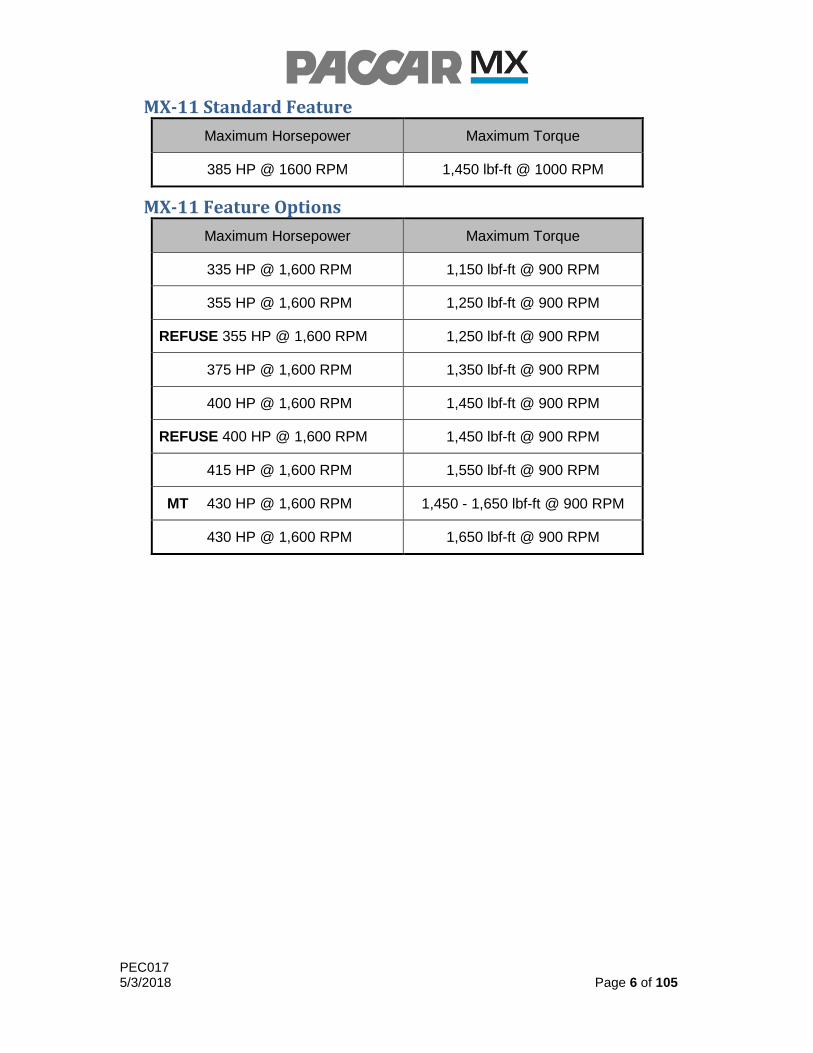
MX-11 Standard Feature
Maximum Horsepower Maximum Torque
385 HP @ 1600 RPM 1,450 lbf-ft @ 1000 RPM
MX-11 Feature Options
Maximum Horsepower Maximum Torque
335 HP @ 1,600 RPM 1,150 lbf-ft @ 900 RPM
355 HP @ 1,600 RPM 1,250 lbf-ft @ 900 RPM
REFUSE 355 HP @ 1,600 RPM 1,250 lbf-ft @ 900 RPM
375 HP @ 1,600 RPM 1,350 lbf-ft @ 900 RPM
400 HP @ 1,600 RPM 1,450 lbf-ft @ 900 RPM
REFUSE 400 HP @ 1,600 RPM 1,450 lbf-ft @ 900 RPM
415 HP @ 1,600 RPM 1,550 lbf-ft @ 900 RPM
MT 430 HP @ 1,600 RPM 1,450 - 1,650 lbf-ft @ 900 RPM
430 HP @ 1,600 RPM 1,650 lbf-ft @ 900 RPM

PEC017 5/3/2018 Page 7 of 105
MX-13 Orderable Options & Sales Codes
Feature
405 HP / 1,450 lbf-ft 0700607 2072717
MT 430 HP / 1,450-1,650 lbf-ft 0700633 2072718
430 HP / 1,550 lbf-ft 0700632 2072719
MT 455 HP / 1,550-1,750 lbf-ft 0700657 2072822
455 HP / 1,650 lbf-ft 0700656 2072820
485 HP / 1,650 lbf-ft 0700686 2072823
510 HP / 1,850 lbf-ft 0700701 2072824
MX-11 Orderable Options & Sales Codes
Feature
355 HP / 1,150 lbf-ft 0700191 2072404
355 HP / 1,250 lbf-ft 0700192 2072504
REFUSE 355 HP / 1,250 lbf-ft 0700198 2072503
375 HP / 1,350 lbf-ft 0700193 2072607
400 HP / 1,450 lbf-ft 0700194 2072610
REFUSE 400 HP / 1,450 lbf-ft 0700199 2072608
415 HP / 1,550 lbf-ft 0700195 2072720
MT 430 HP / 1,450 - 1,650 lbf-ft 0700196 2072722
430 HP / 1,650 lbf-ft 0700197 2072723

PEC017 5/3/2018 Page 8 of 105
Additional Information Graph 4.1 and Graph 4.2 show power and torque curves of the MX-13 engine.
Graph 4.1 – MX-13 Power and Torque Curves for Standard Ratings

PEC017 5/3/2018 Page 9 of 105
Graph 4.2 - MX-13 Power and Torque Curves for Multi-Torque Ratings

PEC017 5/3/2018 Page 10 of 105
Graph 4.3 and Graph 4.4 show power and torque curves of the MX-11 engine.
Graph 4.3 – MX-11 Power and Torque Curves

PEC017 5/3/2018 Page 11 of 105
Graph 4.4 - MX-11 Power and Torque Curves for Multi-Torque Ratings

PEC017 5/3/2018 Page 12 of 105
5.0 General Settings
Overview
Basic engine parameters
Standard Feature
High Exhaust System Temperature (HEST) Warning
Fuel Density
The High Exhaust System Temperature (HEST) warning indicator allows the engine to inform the driver when the exhaust temperature exceeds HEST Warning Temperature Activation Limit and the vehicle speed is less than Minimum Speed for High Exhaust Temp Warning (N065). The warning indicator will turn off once the exhaust temperature falls below the HEST Warning Temperature Deactivation Limit.
Fuel Density (N051) allows the customer to reprogram the engine controller with a fuel density that more precisely represents the local fuel variation used in their vehicles, which will improve the accuracy of the controller’s calculated fuel economy.
Programmable Parameters
HEST Warning
N065 Page 12 Min Default Max Units
Minimum Speed for High Exhaust Temp Warning 5 5 50 MPH
Fuel Density
N051 Page 12 Min Default Max Units
Fuel Density 780 855 950 g/L
PEC017 5/3/2018 Page 13 of 105
Nonprogrammable Parameters
HEST Warning
Parameter Name Default/Units
HEST Warning Temperature Activation Limit DEFAULT = 842 °(F)
HEST Warning Temperature Deactivation Limit DEFAULT = 833 °(F)
Activate/Deactivate Requirements
HEST Warning
ON (All) OFF (Any)
Exhaust Temperature > HEST Warning Temperature Activation Limit
Exhaust Temperature < HEST Warning Temperature Deactivation Limit
Vehicle speed < HEST Warning Minimum Vehicle Speed
Vehicle speed > HEST Warning Maximum Vehicle Speed
Additional information
HEST Warning on the Driver Display
Figure 5.1 shows an example of the indicator on the driver display when the HEST warning is ON.
Figure 5.1 – HEST Warning Light

PEC017 5/3/2018 Page 14 of 105
6.0 Idle Settings
Engine Idle Speed
Overview
Engine Idle Speed (N052) defines the minimum engine operating speed. The engine idle speed is defaulted to 650 RPM from the factory, and is adjustable to a maximum speed of 700 RPM.
Programmable Parameters
N052 Page 14 Min Default Max Units
Engine Idle Speed 650 650 700 RPM
Engine Idle Shutdown Timer (EIST)
Overview
The engine Idle Shutdown Timer (EIST) is a valuable tool fleet owners may use to impose limits on engine idling time to improve overall fuel economy. The EIST has several customizable options to meet the needs of any application. EIST may be overruled by fuel temperature or engine coolant and oil temperature for uninterrupted engine warm-up intervals and allows for separate timer intervals dependent on the engagement of the parking brake. EIST may also be configured with an independent timer or disabled completely while the engine is in Power Take-Off (PTO) mode.
Standard Feature
EIST
EIST Low Battery Voltage Overrule
EIST initiates when engine speed is at idle, the vehicle is stationary, and the accelerator pedal is motionless or not depressed. Within the standard feature, there are many programmable parameters:
Timer Durations and Enablement Conditions
Coolant, Oil, and Fuel Temperature Overrule
Programmable resets
Idle Time w/ Parking Brake Set (N187) specifies the timer duration until the engine shuts down while the parking brake is engaged, while Idle Time w/ Parking Brake Released (N188) specifies the timer duration until the engine shuts down while the parking brake is disengaged. Once the timer has expired, a warning message in the truck’s driver display will indicate that shutdown is imminent. Idle Timer Shutdown Warning Duration (N194) determines the duration of the idle shutdown timer warning before the engine is shut down. Allow Idle Timer Reset During Warning (N178) specifies if the driver will be able to reset the idle timer by performing one of the programmable reset conditions during the idle shutdown warning period. Otherwise,
PEC017 5/3/2018 Page 15 of 105
the driver may reset the idle timer at any time by performing one of the programmable reset conditions.
Temperature Overrules are available to allow the engine to idle while coolant, oil and fuel temperatures are below calibrated settings.
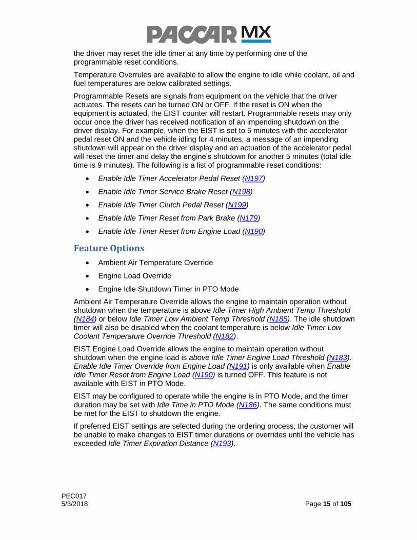
Programmable Resets are signals from equipment on the vehicle that the driver actuates. The resets can be turned ON or OFF. If the reset is ON when the equipment is actuated, the EIST counter will restart. Programmable resets may only occur once the driver has received notification of an impending shutdown on the driver display. For example, when the EIST is set to 5 minutes with the accelerator pedal reset ON and the vehicle idling for 4 minutes, a message of an impending shutdown will appear on the driver display and an actuation of the accelerator pedal will reset the timer and delay the engine’s shutdown for another 5 minutes (total idle time is 9 minutes). The following is a list of programmable reset conditions:
Enable Idle Timer Accelerator Pedal Reset (N197)
Enable Idle Timer Service Brake Reset (N198)
Enable Idle Timer Clutch Pedal Reset (N199)
Enable Idle Timer Reset from Park Brake (N179)
Enable Idle Timer Reset from Engine Load (N190)
Feature Options
Ambient Air Temperature Override
Engine Load Override
Engine Idle Shutdown Timer in PTO Mode
Ambient Air Temperature Override allows the engine to maintain operation without shutdown when the temperature is above Idle Timer High Ambient Temp Threshold (N184) or below Idle Timer Low Ambient Temp Threshold (N185). The idle shutdown timer will also be disabled when the coolant temperature is below Idle Timer Low Coolant Temperature Override Threshold (N182).
EIST Engine Load Override allows the engine to maintain operation without shutdown when the engine load is above Idle Timer Engine Load Threshold (N183). Enable Idle Timer Override from Engine Load (N191) is only available when Enable Idle Timer Reset from Engine Load (N190) is turned OFF. This feature is not available with EIST in PTO Mode.
EIST may be configured to operate while the engine is in PTO Mode, and the timer duration may be set with Idle Time in PTO Mode (N186). The same conditions must be met for the EIST to shutdown the engine.
If preferred EIST settings are selected during the ordering process, the customer will be unable to make changes to EIST timer durations or overrides until the vehicle has exceeded Idle Timer Expiration Distance (N193).

PEC017 5/3/2018 Page 16 of 105
Orderable Feature Options & Sales Codes
Feature
Enable Engine Idle Shutdown Timer 1000857 2091305
Disable Engine Idle Shutdown Timer 1000858 2091310
Enable Idle Shutdown Timer in PTO Mode 1000860 2091320
Enable Idle Timer Ambient Temperature Overrule 1000859 2091315
Enable Idle Timer Battery Voltage Overrule 8178354 7331000
Programmable Parameters
EIST
N178 Page 14 Min Default Max Units
Allow Idle Timer Reset During Warning OFF (0) ON (1) ON (1) ON/OFF
N187 Page 14 Min Default Max Units
Idle Time w/ Parking Brake Set 1 5 1092 MIN
N188 Page 14 Min Default Max Units
Idle Time w/ Parking Brake Released 1 5 1092 MIN
N193 Page 15 Min Default Max Units
Idle Timer Expiration Distance 0 500,000 1,259,000 MILES
N194 Page 14 Min Default Max Units
Idle Timer Shutdown Warning Duration 30 60 255 SEC
EIST Resets and Overrides
N179 Page 16 Min Default Max Units
Enable Idle Timer Reset from Park Brake OFF (0) ON (1) ON (1) ON/OFF

PEC017 5/3/2018 Page 17 of 105
N182 Page 15 Min Default Max Units
Idle Timer Low Coolant Temperature Override Threshold 2 30 260 °F
N183 Page 15 Min Default Max Units
Idle Timer Engine Load Threshold 0 35 100 %
N184 Page 15 Min Default Max Units
Idle Timer High Ambient Temp Threshold -40 80 490 °F
N185 Page 15 Min Default Max Units
Idle Timer Low Ambient Temp Threshold -40 39 490 °F
N190 Page 15 Min Default Max Units
Enable Idle Timer Reset from Engine Load OFF (0) ON (1) ON (1) ON/OFF
* Requires Enable Idle Timer Override from Engine Load (N191) to be disabled
N191 Page 15 Min Default Max Units
Enable Idle Timer Override from Engine Load OFF (0) ON (1) ON (1) ON/OFF
* Requires Enable Idle Timer Reset from Engine Load (N190) to be disabled
* Not Available in PTO Mode
N197 Page 15 Min Default Max Units
Enable Idle Timer Accelerator Pedal Reset OFF (0) ON (1) ON (1) ON/OFF
N198 Page 15 Min Default Max Units
Enable Idle Timer Service Brake Reset OFF (0) ON (1) ON (1) ON/OFF
N199 Page 15 Min Default Max Units
Enable Idle Timer Clutch Pedal Reset OFF (0) ON (1) ON (1) ON/OFF

PEC017 5/3/2018 Page 18 of 105
EIST with PTO Mode
N186 Page 15 Min Default Max Units
Idle Time in PTO Mode 1 5 1092 MIN
Non-Programmable Parameters
Parameter Name Number Min/Max/Default/Units
EIST Low Oil Temperature Overrule Limit
N195 DEFAULT = 30 °(F)
EIST Low Fuel Temperature Overrule Limit
N196 DEFAULT = 23 °(F)
Note Regarding Preferred Settings
If the customer accepts the preferred EIST settings within Prospector, they will be unable to make changes to the following parameters until they exceed the expiration distance specified on the order:
Timer Setting Non-PTO Mode With Park Brake Set
Timer Setting PTO Mode w/o Park Brake Set
Expiration Distance
Reset EIST Timer Based on Engine Load
Low Ambient Temperature Overrule
High Ambient Temperature Overrule
Overrule EIST Timer Based on Engine Load – No Shutdown
ON/OFF Requirements
EIST
ON OFF
EIST Enabled EIST Disabled
Vehicle Speed = 0 MPH Vehicle Speed > 0 MPH
Outside Ambient Air Temperature Override
ON OFF
Enable Ambient Overrule Temperature = Yes
Enable Ambient Overrule Temperature = No

PEC017 5/3/2018 Page 19 of 105
EIST with PTO Mode
ON OFF
Allow EIST Timer Overrules in PTO Mode = Yes
Allow EIST Timer Overrules in PTO Mode = No
Engine Load Override
ON OFF
Overrule EIST Timer Based on Engine Load – No Shutdown = Yes
Overrule EIST Timer Based on Engine Load – No Shutdown = No
Activate/Deactivate Requirements
EIST
Activate (All) Deactivate (Any)
EIST Idle Time Limit Elapsed EIST Idle Time Reset
EIST Idle Time Overruled
Outside Ambient Air Temperature Override
Activate (Any) Deactivate (All)
Outside ambient air temperature < Low Ambient Air Temperature Overrule
Outside ambient air temperature > Low Ambient Air Temperature Overrule
Outside ambient air temperature > High Ambient Air Temperature Overrule
Outside ambient air temperature < High Ambient Air Temperature Overrule
EIST with PTO Mode
Activate (All) Deactivate (Any)
All EIST Conditions All EIST Conditions
Timer Setting When in PTO Elapsed Timer Setting When in PTO Mode Reset
Timer Setting When in PTO Mode Overruled

PEC017 5/3/2018 Page 20 of 105
Engine Load Override
Activate Deactivate
Engine Load > Engine Load Threshold Engine Load < Engine Load Threshold
Additional Information
The EIST will be overruled if any of the following conditions are present:
Coolant temperature is lower than Idle Timer Low Coolant Temperature Override Threshold (N182)
Oil temperature is lower than EIST Low Oil Temp Limit
Fuel temperature is lower than EIST Low Fuel Temp Limit
Ambient temperature is less than Idle Timer Low Ambient Temp Threshold (N185)
Ambient temperature is greater than Idle Timer High Ambient Temp Threshold (N184)
Engine load is greater than Idle Timer Engine Load Threshold (N183), if enabled
DPF regeneration is in progress
The engine is in Service Mode
Figure 6.1 shows how the low coolant temperature limit and low and high ambient air temperature limits (if enabled) will affect the EIST.
Figure 6.1 – EIST Coolant and Ambient Air Temperature Limits
PEC017 5/3/2018 Page 21 of 105
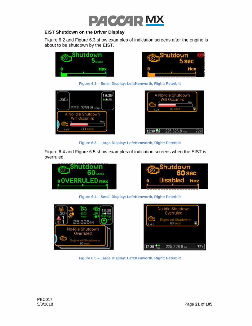
EIST Shutdown on the Driver Display
Figure 6.2 and Figure 6.3 show examples of indication screens after the engine is about to be shutdown by the EIST.
Figure 6.2 – Small Display: Left:Kenworth, Right: Peterbilt
Figure 6.3 – Large Display: Left:Kenworth, Right: Peterbilt
Figure 6.4 and Figure 6.5 show examples of indication screens when the EIST is overruled.
Figure 6.4 – Small Display: Left:Kenworth, Right: Peterbilt
Figure 6.5 – Large Display: Left:Kenworth, Right: Peterbilt

PEC017 5/3/2018 Page 22 of 105
Fast Idle Control (FIC)
Overview
The Fast Idle Control (FIC) functionality allows adjustment of engine idle speed within preprogrammable limits. This allows the driver to adapt to changing engine speed requirements. For example, the driver can raise engine speed for faster engine warm-up on a cold day. Raising the idle can improve HVAC performance in extreme conditions while parked, and may be helpful for other service operations such as charging the batteries or air system. Fleet managers may find that altering some of the FIC settings may yield better fuel economy when the application requires extended idle operations. The FIC module allows a fleet owner to set limits in order to enhance overall operating economy. FIC is a standard feature of the engine, but can be disabled to ensure that engine idle speed cannot be altered.
The default FIC settings are useful for the majority of applications, so modifications of the default settings typically are not necessary. Before changing the default parameters, it is strongly recommended to consult the customer and/or body builder to determine the specific vehicle application.
Standard Feature
FIC
FIC becomes active and allows the driver to control the engine speed with the Set/Accel and Resume/Decel switches when all of the following conditions are met:
The Cruise Control switch is in the ON position
The vehicle is stationary
The transmission is in neutral
The parking brake is set
FIC may be enabled or disabled with Enable Fast Idle Control (N071) and the maximum FIC engine speed can be limited by Maximum Engine Speed in Fast Idle Control (N072).
FIC will be overruled if the accelerator pedal request exceeds the FIC request, at which point the accelerator pedal will control engine speed. FIC will automatically deactivate if the clutch pedal or the service brake pedal are depressed.
The Set/Accel switch allows the driver to increase the engine speed. When FIC is active and the Set/Accel switch is pressed, the engine speed will increase by Engine Speed Ramp-Up w/ Set/Accel (N107). When FIC is active and the Set/Accel switch is pressed and held, the engine speed will increase at Engine Speed Increase w/ Set/Accel (N103).
The Resume/Decel switch allows the driver to decrease the engine speed. When FIC is active and the Resume/Decel switch is pressed, the engine speed will decrease by Engine Speed Ramp-down w/ Res/Decel (N105). When FIC is active and the Resume/Decel switch is pressed and held, the engine speed will decrease at Engine Speed Decrease w/ Res/Decel (N104).

PEC017 5/3/2018 Page 23 of 105
Programmable Parameters
N071 Page 22 Min Default Max Units
Enable Fast Idle Control OFF (0) ON (1) ON (1) ON/OFF
N072 Page 22 Min Default Max Units
Maximum Engine Speed in Fast Idle Control 650 1900 1900 RPM
N103 Page 22 Min Default Max Units
Engine Speed Increase w/ Set/Accel 10 250 1000 RPM
N104 Page 22 Min Default Max Units
Engine Speed Decrease w/ Res/Decel 10 250 1000 RPM
N105 Page 22 Min Default Max Units
Engine Speed Ramp-down w/ Res/Decel 10 100 1900 RPM/SEC
N107 Page 22 Min Default Max Units
Engine Speed Ramp-Up w/ Set/Accel 10 100 1900 RPM/SEC
ON/OFF Requirements
ON (All) OFF (Any)
CC switch is in the ON position CC switch is in the OFF position
Parking brake is set Parking brake is not set
Vehicle speed = Stationary Vehicle speed = Non-Stationary
Transmission is in neutral if equipped Transmission is not in neutral if equipped
Clutch pedal is NOT depressed if equipped
Clutch pedal is depressed if equipped
Service brake pedal is NOT depressed Service brake pedal is depressed

PEC017 5/3/2018 Page 24 of 105
7.0 Fan Clutch Control
Overview
The Fan Clutch Control controls the fan clutch based on various engine temperatures.
Standard Feature
Fan Clutch Control
Fan Clutch Control allows the engine to control the fan clutch based on coolant, charge air cooler, and power steering fluid temperatures. These temperatures are not programmable.
Feature Options
Minimum Fan Clutch Engagement Time
Minimum Fan Clutch Engagement Time (N057) allows customization of the minimum amount of time the fan clutch is engaged before it can become disengaged.
Programmable Parameters
N057 Page 24 Min Default Max Units
Minimum Fan Clutch Engagement Time 30 30 60 SEC
Additional Information
Fan Clutch Control on the RPM Gauge
Figure 7.1 shows an example of the Fan Indication on the RPM Gauge.
Figure 7.1 – Fan Indication (Kenworth Only)
PEC017 5/3/2018 Page 25 of 105
8.0 Cruise Control (CC)
Overview
The Cruise Control (CC) functionality allows the driver to set a target vehicle speed and then adjust it within programmable limits. This allows the driver to adapt to changing vehicle speed requirements. For example, the driver can increase or decrease speed by briefly pressing or pressing and holding the Cruise Control switches on the dashboard or steering wheel. The vehicle must be within the programmed limits to activate and maintain Cruise Control.
The Cruise Control module allows a fleet owner to set preprogrammed limits in order to enhance overall operating economy. CC is a standard feature of the engine, and the default CC settings are useful for a majority of applications. Before changing the default parameters, it is strongly recommended to consult the customer and/or body builder to review the Cruise Control options.
Standard Feature
Cruise Control
Cruise Control ON/OFF switch
Set/Accel switch
Resume/Decel switch
CC regulates engine torque to maintain the desired vehicle speed. CC ON/OFF, Set/Accel, and Resume/Decel are in-cab switches that allow the driver to operate CC.
The CC ON/OFF switch allows the driver to control the vehicle speed if the switch is in the ON position. When the switch is in the OFF position, CC is deactivated and the engine will not automatically maintain an driver-desired vehicle speed.
The Set/Accel switch allows the driver to activate CC when the CC is ON, which assigns the current vehicle speed as the Cruise Control target speed. The vehicle speed must be at or above Minimum Speed to Enable Cruise Control (N002) to activate cruise control. While CC is active, the driver is free from having to control the vehicle speed using the accelerator pedal. While CC is actively controlling vehicle speed, briefly pressing the Set/Accel switch will cause the vehicle speed to increase by the value of Vehicle Speed Increase w/Set/Accel (N005). While CC is actively controlling vehicle speed, and the Set/Accel switch is pressed and held, the vehicle will accelerate until the switch is released or the Maximum Cruise Control Target Speed (N006) is reached.
While Cruise Control is ON, the Resume/Decel switch allows the driver to activate CC and resume maintaining a previously set Cruise Control vehicle speed. The stored target vehicle speed is reset with an ignition key cycle. While CC is actively controlling vehicle speed, briefly pressing the Resume/Decel switch will cause the vehicle speed to decrease by the value of Vehicle Speed Decrease w/Res/Decel (N004). While CC is actively controlling vehicle speed, and the Resume/Decel switch is pressed and held, the vehicle will decelerate until the switch is released or the Minimum Cruise Control Target Speed (N003) is reached. If the vehicle speed falls below Minimum Speed to Disable Cruise Control (N001), then CC will become inactive.
PEC017 5/3/2018 Page 26 of 105
Feature Options
Adaptive Cruise Control (ACC)
Cruise Control Multi-Torque Mode
Adaptive Cruise Control (ACC) can overrule CC in order to maintain a set following distance to a target vehicle. ACC is not described in this document. Refer to the Original Equipment Manufacturer’s (OEM) documentation for a detailed description of ACC functionality.
For engines with a multi-torque engine rating, Multi-Torque Only when Cruise Active (N039) is an option that allows the fleet owner to specify when the extra torque available from the multi-torque rating will be available. When this option is enabled, the extra torque will only be available when the Cruise Control is actively controlling vehicle speed. When the Cruise Control Multi-Torque Mode is disabled, the extra torque will be available with or without Cruise Control.
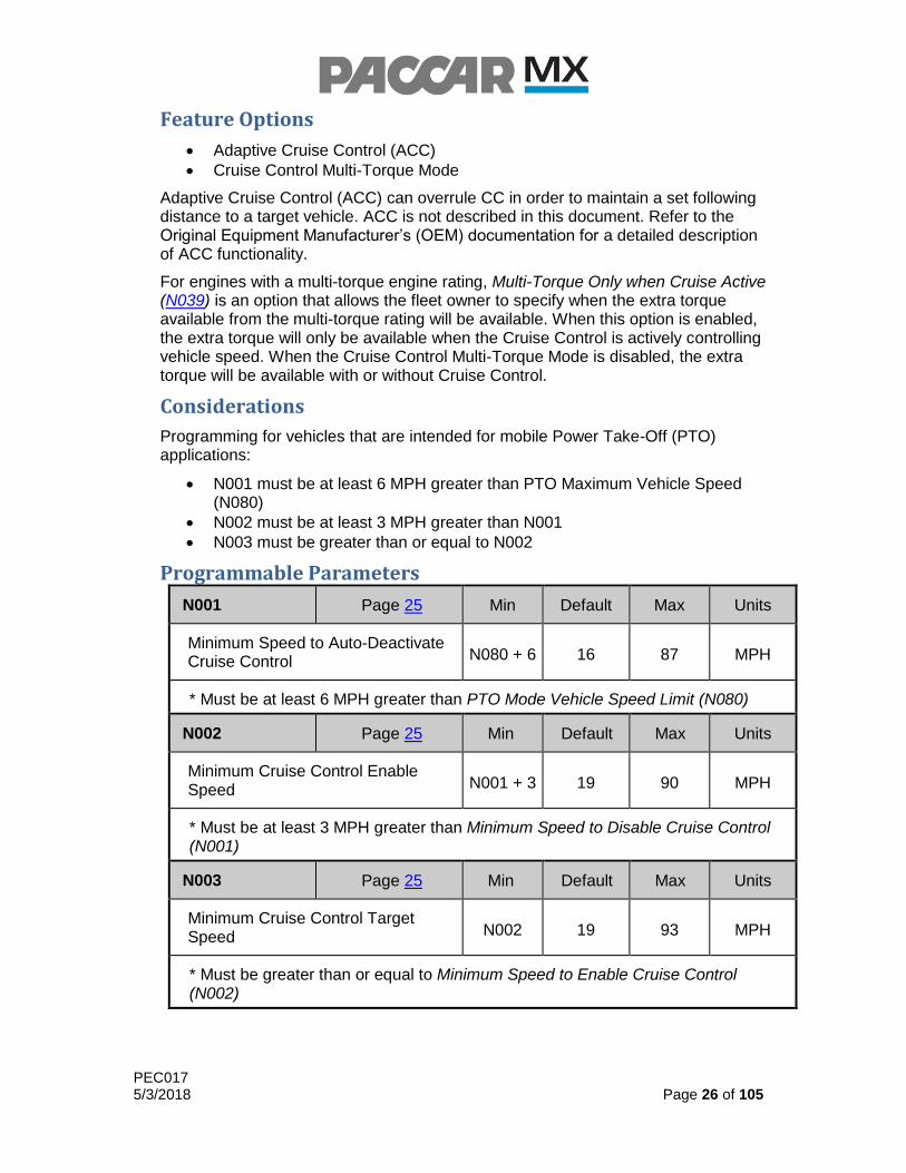
Considerations
Programming for vehicles that are intended for mobile Power Take-Off (PTO) applications:
N001 must be at least 6 MPH greater than PTO Maximum Vehicle Speed (N080)
N002 must be at least 3 MPH greater than N001
N003 must be greater than or equal to N002
Programmable Parameters
N001 Page 25 Min Default Max Units
Minimum Speed to Auto-Deactivate Cruise Control N080 + 6 16 87 MPH
* Must be at least 6 MPH greater than PTO Mode Vehicle Speed Limit (N080)
N002 Page 25 Min Default Max Units
Minimum Cruise Control Enable Speed N001 + 3 19 90 MPH
* Must be at least 3 MPH greater than Minimum Speed to Disable Cruise Control (N001)
N003 Page 25 Min Default Max Units
Minimum Cruise Control Target Speed N002 19 93 MPH
* Must be greater than or equal to Minimum Speed to Enable Cruise Control (N002)
PEC017 5/3/2018 Page 27 of 105
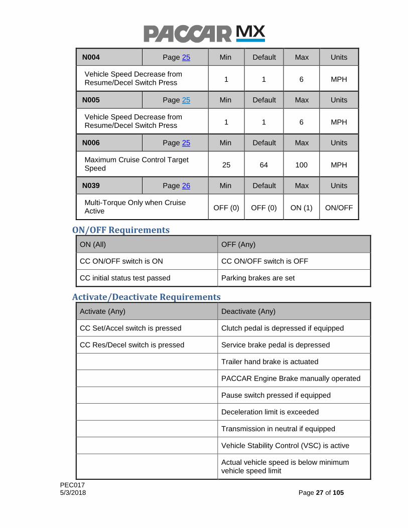
N004 Page 25 Min Default Max Units
Vehicle Speed Decrease from Resume/Decel Switch Press 1 1 6 MPH
N005 Page 25 Min Default Max Units
Vehicle Speed Decrease from Resume/Decel Switch Press 1 1 6 MPH
N006 Page 25 Min Default Max Units
Maximum Cruise Control Target Speed 25 64 100 MPH
N039 Page 26 Min Default Max Units
Multi-Torque Only when Cruise Active OFF (0) OFF (0) ON (1) ON/OFF
ON/OFF Requirements
ON (All) OFF (Any)
CC ON/OFF switch is ON CC ON/OFF switch is OFF
CC initial status test passed Parking brakes are set
Activate/Deactivate Requirements
Activate (Any) Deactivate (Any)
CC Set/Accel switch is pressed Clutch pedal is depressed if equipped
CC Res/Decel switch is pressed Service brake pedal is depressed
Trailer hand brake is actuated
PACCAR Engine Brake manually operated
Pause switch pressed if equipped
Deceleration limit is exceeded
Transmission in neutral if equipped
Vehicle Stability Control (VSC) is active
Actual vehicle speed is below minimum vehicle speed limit
PEC017 5/3/2018 Page 28 of 105
Activate (Any) Deactivate (Any)
Maximum vehicle speed limit exceeded
Maximum ASR time limit exceeded
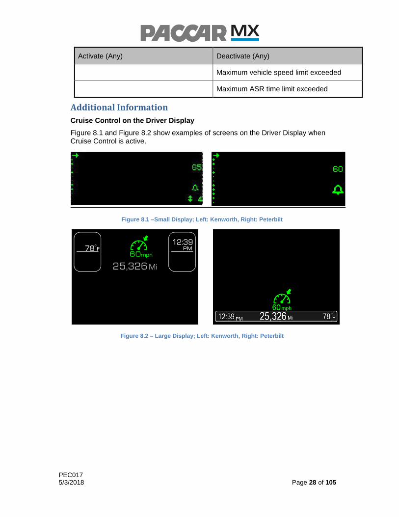
Additional Information
Cruise Control on the Driver Display
Figure 8.1 and Figure 8.2 show examples of screens on the Driver Display when Cruise Control is active.
Figure 8.1 –Small Display; Left: Kenworth, Right: Peterbilt
Figure 8.2 – Large Display; Left: Kenworth, Right: Peterbilt

PEC017 5/3/2018 Page 29 of 105
9.0 Vehicle Speed Limiter
Overview
The Vehicle Speed Limiter functionality is designed to improve fuel economy by reducing the maximum vehicle speed and limiting the maximum vehicle acceleration.
Standard Feature
Without Vehicle Speed Limiter
The speed of the vehicle will be limited to the maximum value of Maximum Accelerator Pedal Vehicle Speed (N162) or Maximum Cruise Control Target Speed (N006).
Feature Options
Vehicle Speed Limiter
Vehicle Acceleration Limiter
Vehicle Speed Limiter
On Greenhouse Gas (GHG) compliant vehicles, GHG Maximum Speed Limit (N170) will limit the overall maximum speed of the vehicle, until the GHG Expiration Distance (N169) has been exceeded. The GHG expiration mileage is available in the chassis information within PVP, and may not be changed. For example, if Maximum Accelerator Pedal Vehicle Speed (N162) is set to 55 mph, Maximum Cruise Control Target Speed (N006) is set to 70 mph, and Maximum Vehicle Speed Limit (N170) is set to 64 mph, the vehicle can be driven to a maximum speed of 55 mph with the pedal. If Cruise Control is enabled the vehicle speed may be increased to a maximum of 64 mph, as the vehicle will not exceed the value of Maximum Vehicle Speed Limit (N170) when the engine is fueled.
For non-GHG compliant vehicles, or vehicles that have exceeded the GHG expiration mileage, GHG Maximum Speed Limit (N170) is ignored, allowing Maximum Accelerator Pedal Vehicle Speed (N162) and Maximum Cruise Control Target Speed (N006) to determine the overall maximum speed of the vehicle. Table 8.1 illustrates how the overall maximum vehicle speed is determined.
W/ Driver Reward (S218) & W/O GHG Maximum Speed Limit (N170)
Driver Reward Offset Mode (N219) Maximum Vehicle Speed Limit
1 (Pedal Control)
Maximum value of: Maximum Cruise Control Target Speed (N006)
OR Maximum Accelerator Pedal Vehicle Speed (N162) +
Driver Reward Maximum Bonus (N224)
2 (Cruise Control)
Maximum value of: Maximum Cruise Control Target Speed (N006) +
Driver Reward Maximum Bonus (N224) OR
Maximum Accelerator Pedal Vehicle Speed (N162)

PEC017 5/3/2018 Page 30 of 105
3 (Pedal and Cruise Control)
Maximum value of: Maximum Accelerator Pedal Vehicle Speed (N162) +
Driver Reward Maximum Bonus (N224) OR
Maximum Cruise Control Target Speed (N006) + Driver Reward Maximum Bonus (N224)
W/ Driver Reward (S218) & W/ GHG Maximum Speed Limit (N170)
Driver Reward Offset Mode (N219) Maximum Vehicle Speed Limit
1 (Pedal Control)
GHG Maximum Speed Limit (N170) Requires:
Maximum Accelerator Pedal Vehicle Speed (N162) + Driver Reward Maximum Bonus (N224) ≤
GHG Maximum Speed Limit (N170)
2 (Cruise Control)
GHG Maximum Speed Limit (N170) Requires:
Maximum Cruise Control Target Speed (N006) + Driver Reward Maximum Bonus (N224) ≤
GHG Maximum Speed Limit (N170)
3 (Pedal and Cruise Control)
GHG Maximum Speed Limit (N170) Requires maximum value of:
Maximum Accelerator Pedal Vehicle Speed (N162) + Driver Reward Maximum Bonus (N224)
AND Maximum Cruise Control Target Speed (N006) +
Driver Reward Maximum Bonus (N224) ≤
GHG Maximum Speed Limit (N170)
W/O Driver Reward (S218) & W/O GHG Maximum Speed Limit (N170)
Driver Reward Offset Mode (N219) Maximum Vehicle Speed Limit
0 (No Reward)
Maximum value of: Maximum Cruise Control Target Speed (N006)
OR Maximum Accelerator Pedal Vehicle Speed (N162)
W/O Driver Reward (S218) & W/ GHG Maximum Speed Limit (N170)
Driver Reward Offset Mode (N219) Maximum Vehicle Speed Limit
0 (No Reward) GHG Maximum Speed Limit (N170)
Table 8.1 – Determination of Maximum Vehicle Speed Limit
Vehicle Acceleration Limiter
The vehicle acceleration limiter’s Scale Acceleration Target (N296) parameter may be modified from the NORMAL setting to increase performance or increase fuel economy. Selecting SLOW will decrease the vehicle’s acceleration capabilities, while selecting FAST will increase the vehicle’s acceleration capabilities over the NORMAL setting.
PEC017 5/3/2018 Page 31 of 105
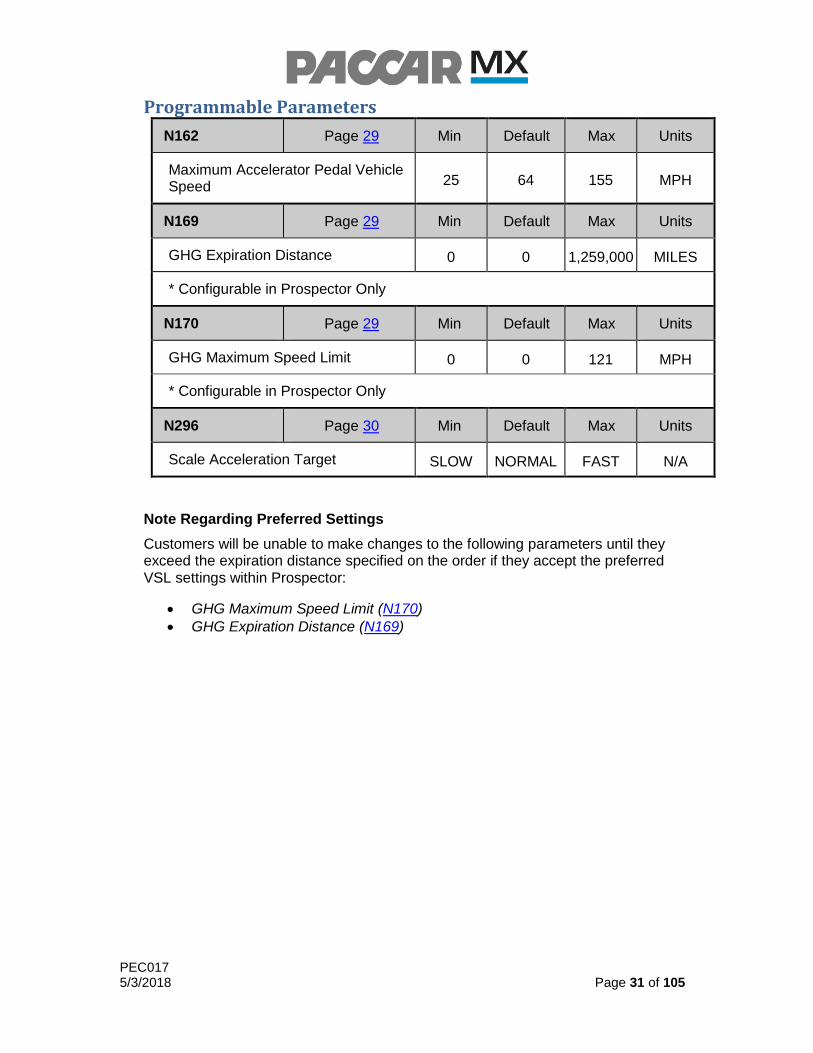
Programmable Parameters
N162 Page 29 Min Default Max Units
Maximum Accelerator Pedal Vehicle Speed 25 64 155 MPH
N169 Page 29 Min Default Max Units
GHG Expiration Distance 0 0 1,259,000 MILES
* Configurable in Prospector Only
N170 Page 29 Min Default Max Units
GHG Maximum Speed Limit 0 0 121 MPH
* Configurable in Prospector Only
N296 Page 30 Min Default Max Units
Scale Acceleration Target SLOW NORMAL FAST N/A
Note Regarding Preferred Settings
Customers will be unable to make changes to the following parameters until they exceed the expiration distance specified on the order if they accept the preferred VSL settings within Prospector:
GHG Maximum Speed Limit (N170)
GHG Expiration Distance (N169)
PEC017 5/3/2018 Page 32 of 105
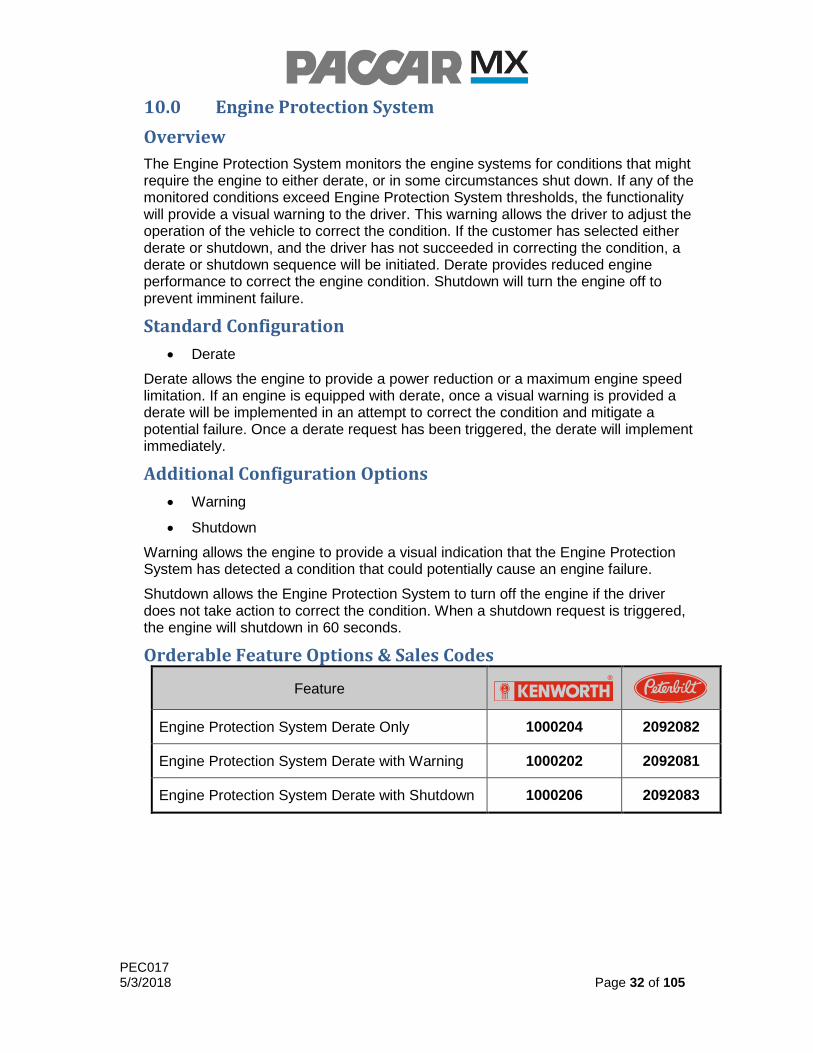
10.0 Engine Protection System
Overview
The Engine Protection System monitors the engine systems for conditions that might require the engine to either derate, or in some circumstances shut down. If any of the monitored conditions exceed Engine Protection System thresholds, the functionality will provide a visual warning to the driver. This warning allows the driver to adjust the operation of the vehicle to correct the condition. If the customer has selected either derate or shutdown, and the driver has not succeeded in correcting the condition, a derate or shutdown sequence will be initiated. Derate provides reduced engine performance to correct the engine condition. Shutdown will turn the engine off to prevent imminent failure.
Standard Configuration
Derate
Derate allows the engine to provide a power reduction or a maximum engine speed limitation. If an engine is equipped with derate, once a visual warning is provided a derate will be implemented in an attempt to correct the condition and mitigate a potential failure. Once a derate request has been triggered, the derate will implement immediately.
Additional Configuration Options
Warning
Shutdown
Warning allows the engine to provide a visual indication that the Engine Protection System has detected a condition that could potentially cause an engine failure.
Shutdown allows the Engine Protection System to turn off the engine if the driver does not take action to correct the condition. When a shutdown request is triggered, the engine will shutdown in 60 seconds.
Orderable Feature Options & Sales Codes
Feature
Engine Protection System Derate Only 1000204 2092082
Engine Protection System Derate with Warning 1000202 2092081
Engine Protection System Derate with Shutdown 1000206 2092083

PEC017 5/3/2018 Page 33 of 105
Thresholds and Reactions
Thresholds Value “Warning” Reaction
“Derate” Reaction
“Shutdown” Reaction
Coolant Temperature
Above 237 ˚F
Stop Engine Light
Stop Engine Light
Vehicle Speed Limit and Engine Shutdown
Coolant Level Below
0% Stop Engine
Light Stop Engine
Light Vehicle Speed Limit and
Engine Shutdown
Oil Pressure Below
9 psi Stop Engine
Light Stop Engine
Light Vehicle Speed Limit and
Engine Shutdown
Oil Temperature Above
266 ˚F Stop Engine
Light Stop Engine
Light Vehicle Speed Limit and
Engine Shutdown
Battery Voltage Below
6 V Stop Engine
Light Stop Engine
Light Vehicle Speed Limit and
Engine Shutdown
Coolant Pump Stall
- Stop Engine
Light Torque Derate
Torque Derate
Aftertreatment Limp Home
Soot Load >8.2 g/L
Torque Derate
Torque Derate
Torque Derate and Vehicle Speed Limit
Soot Load >9.2 g/L
Torque Derate
Torque Derate
Torque Derate and Vehicle Speed Limit
Driving > 5 mph during HC
Desorb Request
Torque Derate
Torque Derate
Torque Derate and Vehicle Speed Limit
Aftertreatment Shutdown Request
DOC Outlet > 800˚C OR
DOC Outlet – DOC Inlet >
500˚C
Torque Derate
Torque Derate
Torque Derate, Vehicle Speed Limit, and Engine
Shutdown
DOC Inlet > 687˚C
Torque Derate
Torque Derate
Torque Derate, Vehicle Speed Limit, and Engine
Shutdown
DOC Outlet > 650˚C
Torque Derate
Torque Derate
Torque Derate, Vehicle Speed Limit, and Engine
Shutdown

PEC017 5/3/2018 Page 34 of 105
Thresholds Value “Warning” Reaction
“Derate” Reaction
“Shutdown” Reaction
Aftertreatment Shutdown Request
DOC Outlet – DOC Inlet >
365˚C
Torque Derate
Torque Derate
Torque Derate, Vehicle Speed Limit, and Engine
Shutdown
DPF Outlet – DOC Outlet >
540˚C
Torque Derate
Torque Derate
Torque Derate, Vehicle Speed Limit, and Engine
Shutdown
DOC Outlet > 800˚C
Torque Derate
Torque Derate
Torque Derate, Vehicle Speed Limit, and Engine
Shutdown
DPF Outlet > 687˚C OR
DPF Outlet – DOC Outlet >
300˚C
Torque Derate
Torque Derate
Torque Derate, Vehicle Speed Limit, and Engine
Shutdown
SCR Outlet > 650˚C
Torque Derate
Torque Derate
Torque Derate, Vehicle Speed Limit, and Engine
Shutdown

PEC017 5/3/2018 Page 35 of 105
Additional Information
Engine Protection System on the Driver Display
Figure 10.1 and Figure 10.2 show examples of Engine Protection System warning screens on the Driver Display.
Figure 10.1 – NAMUX 2 & 3; Left: Kenworth, Right: Peterbilt
Figure 10.2 – Large Display; Left: Kenworth, Right: Peterbilt
Figure 10.3 and Figure 10.4 show examples of Engine Protection System derate screens on the Driver Display.
Figure 10.3 – NAMUX 2 & 3; Left: Kenworth, Right: Peterbilt
Figure 10.4 – Large Display; Left: Kenworth, Right: Peterbilt

PEC017 5/3/2018 Page 36 of 105
Figure 10.5 and Figure 10.6 show examples of Engine Protection System impending shutdown screens on the Driver Display.
Figure 10.5 – NAMUX 2 & 3; Left: Kenworth, Right: Peterbilt
Figure 10.6 – Large Display; Left: Kenworth, Right: Peterbilt
Figure 10.7 and Figure 10.8 show examples of Engine Protection System shutdown screens on the Driver Display.
Figure 10.7 – NAMUX 2 & 3; Left: Kenworth, Right: Peterbilt
Figure 10.8 - Large Display; Left: Kenworth, Right: Peterbilt

PEC017 5/3/2018 Page 37 of 105
11.0 PACCAR Engine Brake
Overview
The PACCAR Engine Brake is a fully integrated engine compression brake that provides braking forces through the driveline. It reduces wear on the service brakes and improves vehicle control in deceleration events when active. The PACCAR Engine Brake operates using standard dash switches, and is customizable to meet the requirements of the driver or fleet.
Standard Feature
PACCAR Engine Brake ON/OFF Switch
Retarder Select Switch
Manual Mode (both with cruise control turned ON and OFF)
The PACCAR Engine Brake ON/OFF switch allows the driver to turn retarder ON and OFF.
The default setting for the PACCAR Engine Brake is Manual Mode. Manual Mode allows the engine to provide braking when the PACCAR Engine Brake switch is in the ON position, the engine is not being fueled, and the cruise control is inactive. The driver may use the Retarder Select Switch to select from three levels of braking power: Low (33%), Medium (66%), and High (100%).
When the PACCAR Engine Brake switch is in the ON position, the driver will be notified by an indicator the driver display. Examples of the notification are provided in the Additional Information portion of this section.
Feature Options
Engine Brake Engagement Delay
Minimum Vehicle Speed to Enable Engine Brake
Engine Brake Disable when Out of Gear
Engine Brake Behavior When Cruise Control is ON:
o Manual Mode
o Coast Mode
o Latch Mode
Downhill Speed Control (Auto-Retard in Cruise Control)
Downhill Speed Limiter (DSL)
The customer has the option to select from three operating modes for the PACCAR Engine Brake when the PACCAR Engine Brake ON/OFF switch is ON and cruise control is ON and inactive. The three operating modes are mutually exclusive of one another:

PEC017 5/3/2018 Page 38 of 105
Manual Mode is the default setting for the PACCAR Engine Brake when the PACCAR Engine Brake ON/OFF switch is ON and cruise control is ON and inactive. It behaves the same way as the Manual Mode described in Standard Features portion of this section.
Coast Mode allows the engine to provide braking when the PACCAR Engine Brake ON/OFF switch is ON, the Cruise Control is ON and inactive, and the service brake is applied. The PACCAR Engine Brake will de-activate in Coast Mode when the service brake pedal is released or cruise control is activated.
Latch Mode allows the engine to provide braking when the PACCAR Engine Brake ON/OFF switch is ON, cruise control is ON and inactive, and the service brake pedal is applied. Latch Mode will continue to provide braking after the service brake pedal is released and will de-activate when the accelerator pedal is applied or cruise control is activated.
The engine can be programmed to delay the activation of the engine brake, if needed, using Time Delay for Retarder Activation (N019). For example, the driver may wish to deactivate Cruse Control by quickly pressing the brake pedal without activating the engine brake when using Coast or Latch mode. Specifying a delay would allow this to occur, but still provide engine braking when the driver presses the brake pedal for a prolonged period during a braking event. The engine brake may also be programmed to be disabled when the transmission is out of gear with Engine Brake Disabled When Out of Gear (N015) to assist the driver while shifting.
The engine brake will become disabled when the vehicle speed falls below Minimum Vehicle Speed for Engine Brake Activation (N026).
Downhill Speed Control allows the engine to provide braking when the PACCAR Engine Brake ON/OFF switch is ON, Cruise Control is active and the vehicle speed exceeds the Cruise Control target speed plus the Auto-Retarder Vehicle Speed Offset (N014). A large offset will reduce engine brake usage, while a lower offset will increase engine brake usage. A lower offset is recommended for vehicles operating in steep terrain. Downhill Speed Control will deactivate when the vehicle speed has been reduced to the Cruise Control target speed or when Cruise Control is deactivated. Downhill Speed Control will function independently of all other PACCAR Engine Brake parameters.
The Downhill Speed Limiter (DSL) allows the engine to provide braking when the PACCAR Engine Brake ON/OFF switch is ON and the vehicle speed exceeds the Maximum Accelerator Pedal Vehicle Speed (N162) plus the Downhill Speed Limiter Vehicle Speed Offset (N013), The Downhill Speed Limiter will function independently of all other PACCAR Engine Brake parameters.
In Manual Mode, the Downhill Speed Limiter will activate if the vehicle speed exceeds the Maximum Accelerator Pedal Vehicle Speed (N162) plus the Downhill Speed Limiter Vehicle Speed Offset (N013). If the Downhill Speed Limiter is already active, the PACCAR Engine Brake power will be increased, but if the Downhill Speed Limiter is already at maximum capacity, the Downhill Speed Limiter will have no effect on the PACCAR Engine Brake. The Downhill Speed Limiter will automatically deactivate when the vehicle speed has been reduced to the Maximum Accelerator Pedal Vehicle Speed (N162).

PEC017 5/3/2018 Page 39 of 105
Orderable Feature Options & Sales Codes
Feature
Engine Brake Behavior – Manual Mode 1000282 2092027
Engine Brake Behavior – Coast Mode 1000283 2092028
Engine Brake Behavior – Latch Mode 1000284 2092029
Downhill Speed Control – Auto-Retard 1000285 2092075
Downhill Speed Limiter 1000287 2092077
Programmable Parameters
Global
N015 Page 38 Min Default Max Units
Engine Brake Disabled When Out of Gear OFF (0) ON (1) ON (1) ON/OFF
N019 Page 38 Min Default Max Units
Time Delay for Retarder Activation 0.1 0.1 3 SEC
N026 Page 38 Min Default Max Units
Minimum Vehicle Speed for Engine Brake Activation 1 1 30 MPH
Auto-Retard
N014 Page 38 Min Default Max Units
Auto-Retarder Vehicle Speed Offset 2 4 6 MPH
Downhill Speed Limiter
N013 Page 38 Min Default Max Units
Downhill Speed Limiter Vehicle Speed Offset 2 4 6 MPH

PEC017 5/3/2018 Page 40 of 105
Activate/Deactivate Requirements
Global
Activate (All) Deactivate (Any)
PACCAR Engine Brake ON/OFF switch is ON
ABS system is ON
Transmission (Manual) in gear if equipped
Engine speed is less than 1000 RPM
PTO switch is in ON position
Torque converter is not locked (Automatic) transmissions only)
Accelerator pedal is depressed
Manual Mode (cruise control off)
Activate (All) Deactivate (Any)
Cruise control OFF Cruise control ON
Global engagement requirements met Cruise control is active
Global disengagement requirements met
Manual Mode (Cruise Control On)
Activate (All) Deactivate (Any)
Cruise control ON Cruise control is active
Accelerator pedal deactivated Accelerator pedal is depressed
Global activation requirements met Global deactivation requirements met
Coast Mode
Activate (All) Deactivate (Any)
Cruise control ON Cruise control OFF
Service brake pedal is depressed Cruise control active
Global activation requirements met Service brake pedal is released
Global deactivation requirements met

PEC017 5/3/2018 Page 41 of 105
Latch Mode
Activate (All) Deactivate (Any)
Cruise control ON Cruise control OFF
Service brake pedal is depressed Cruise control active
Global activation requirements met Accelerator pedal is depressed
Global deactivation requirements met
Auto-Retard Mode
Activate (All) Deactivate (Any)
Cruise control ON Cruise control OFF
Cruise control active Cruise control inactive
Vehicle speed exceeds max vehicle cruise speed + DSC offset
Vehicle speed is equal to or below max vehicle cruise speed
Global activation requirements met Global deactivation requirements met
Downhill Speed Limiter
Activate (All) Deactivate (Any)
Vehicle speed exceeds maximum vehicle speed limit + DSL offset speed
Vehicle speed is equal to or below max vehicle speed + DSL offset speed
Global activation requirements met Global deactivation requirements met

PEC017 5/3/2018 Page 42 of 105
Additional Information
Graph 11.1 and Graph 11.2 show engine braking performance for the MX engines.
Graph 11.1 – MX-13 Engine Brake Performance Curves

PEC017 5/3/2018 Page 43 of 105
Graph 11.2 – MX-11 Engine Brake Performance Curves

PEC017 5/3/2018 Page 44 of 105
PACCAR Engine Brake on the Driver Display
Figure 11.1 and Figure 11.2 show examples of screens on the driver display when the PACCAR Engine Brake ON/OFF switch is in the ON position.
Figure 11.1 – NAMUX 2 & 3; Left: Kenworth, Right: Peterbilt
Figure 11.2 – Large Display; Left: Kenworth, Right: Peterbilt
Figure 11.3 and Figure 11.4 show examples of screens on the Driver Display when the PACCAR Engine Brake is activated by Downhill Speed Limiter.
Figure 11.3 – NAMUX 2 & 3; Left: Kenworth, Right: Peterbilt
Figure 11.4 – Large Display; Left: Kenworth, Right: Peterbilt

PEC017 5/3/2018 Page 45 of 105
12.0 Power Take-Off (PTO) Mode Engine Speed Control
Overview
Power Take-Off (PTO) Mode provides engine speed controls in addition to configurable interlocks that are available to restrict PTO Mode (if required.) PTO Mode is fully customizable with multiple programmable engine and vehicle speed parameters and safety interlocks.
The MX engines are suitable for use in many applications requiring auxiliary PTO-driven equipment. The engine PTO controls are flexible with many customizable features, which allow for configurations to meet the needs of many different vehicle applications. PTO Mode can make the operation of PTO-driven equipment safer and more convenient for the driver, and can protect both the chassis drivetrain and PTO-driven auxiliary equipment from misuse and potential damage. The Engine Idle Shutdown Timer (EIST) may also be disabled in PTO Mode to allow for extended operations with the engine at idle. The engine is also capable of logging time and fuel consumption in PTO Mode separately from non-PTO operation.
While the engine is in PTO mode, many different limitations can be imposed by software in the engine controller. These limitations may include:
Engine Speed
Engine Speed Ramp-Up/Ramp-Down Rates
Maximum Engine Torque Output
Vehicle Speed
Engine Idle Time
Safety Interlocks
The purpose of this section is to describe the engine PTO Mode programming features and capabilities. The default PTO settings will support many applications. For fine-tuning of the features, it is strongly recommended that the body builder and/or customer be consulted for their specific requirements. If no PTO is anticipated for the vehicle or the PTO operation will not require the engine to go into PTO Mode for specific engine speed controls or safety interlocks, no action is required at order entry. The special features associated with PTO Mode operation may be specified during the vehicle order process, and changes to the factory settings may be made post-delivery via a PRS file from the PACCAR Engine Support Center.
Additional transmission configuration may be necessary depending on the equipped transmission and/or transfer case. PACCAR recommends consulting the transmission manufacturer for information related to specific wiring harnesses and transmission programming requirements for proper PTO functionality. The following references may also assist in properly configuring the transmission for PTO use:
Allison 5th Generation Controls 1000/2000/3000/4000 Product Families – Controls Installation Manual
Eaton PTO Information Guide
PTO Control via CAN Communication
PACCAR MX engines support remote PTO Mode controls via the B-CAN network. Signal Source for Remote Main Switch (N102) may be configured to allow for PTO

PEC017 5/3/2018 Page 46 of 105
engagement communications between the remote PTO module and the cab electronic control unit (CECU) or via legacy hardwired connection directly from the PTO device to the engine controller. Remote switch and remote throttle signal types must be specified within the drivetrain parameters on the CECU. Additional networking interface parameter changes are required within the CECU depending on the application requirements in order to allow remote PTO control modules to function properly via the B-CAN network. For additional information about the required changes to the CECU parameters, consult the appropriate body builder manual for the vehicle.
PACCAR MX engines allow for remote engine speed control functionality via TSC1 messaging from remote control modules by configuring Enable Engine Speed Control via TSC1 (N306). In addition, a hardwired or CAN PTO engagement feedback signal must be provided to allow the engine to enter PTO mode to enable PTO engine speed control and safety interlocks, and Signal Source for Remote Main Switch (N102) must be configured according to the signal source of the PTO mode request. TSC1 messages must be broadcast from source address 36 (0x24) to destination address 0 (0x00). Messages must also specify control purpose P3: PTO Governor to allow the engine controller to respond to TSC1 requests.
The following table describes the J1939 PTO, EEC2 and TSC1 messages supported by the MX engines while programmed with Remote PTO configurations:
PTO (PGN 65264) – PTO On/Off and Engine Speed Controls
Name SPN SB L Description
Engine PTO Governor Enable Switch 980 40 2 Switch signal which indicates that the PTO governor toggle switch is in the enabled (ON) position 0 = Off 1 = On 2 = Error 3 = Not available
Engine PTO Governor Set Switch 984 48 2 Switch signal of the PTO control activator which indicates that the activator is in the position to "set" the engine PTO governor set speed. 0 = Off 1 = On 2 = Error 3 = Not available
Engine PTO Governor Resume Switch 982 52 2 Switch signal of the PTO control activator which indicates that the activator is in the position to "resume" a previously established PTO governor set speed. 0 = Off 1 = On 2 = Error 3 = Not available

PEC017 5/3/2018 Page 47 of 105
Remote PTO Governor Preprogrammed Speed Control Switch #1
979 42 2 Switch signal which indicates that the remote PTO governor toggle switch #1 is in the enabled (ON) position. If the toggle switch is enabled and other conditions are satisfied then the remote PTO governor feature is activated and the PTO governor will control at the preprogrammed speed #1. 0 = Off 1 = On 2 = Error 3 = Not available
Remote PTO Governor Preprogrammed Speed Control Switch #2
3447 58 2 Switch signal which indicates that the remote PTO governor toggle switch #2 is in the enabled (ON) position. If the toggle switch is enabled and other conditions are satisfied then the remote PTO governor control feature is activated and the PTO governor will control at the preprogrammed speed #2. 0 = Off 1 = On 2 = Error 3 = Not available
EEC2 (PGN 61443) – PTO Mode Remote Throttle
Name SPN SB L Description
Remote Accelerator Pedal Position 974 24 8 The ratio of actual position of the remote analog engine speed/torque request input device (such as an accelerator pedal or throttle lever) to the maximum position of the input device. (0% to 100%)
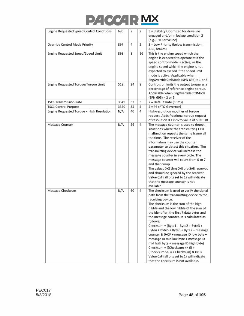
TSC1 (PGN 0) – Torque/Speed Control Name SPN SB L Description
Engine Override Control Mode 695 0 2 0 = Override disabled - Disable any existing control commanded by the source of this command. Required before stopping transmission of TSC1 message to avoid TSC1 low rate faults. 1 = Speed control - Govern speed to the included “desired speed” value (SPN 898). In this mode, engine speed will be limited to Maximum Engine Speed using Switch Inputs (N086). 2 = Torque control - Control torque to the included “desired torque” value (SPN 518). In this mode, engine speed will be limited to Maximum Engine Speed using Pedal Input (N076). 3 = Speed/torque limit control - Limit speed and/or torque based on the included limit values. In this mode, engine speed will be limited to Maximum Engine Speed using Switch Inputs (N086).
PEC017 5/3/2018 Page 48 of 105
Engine Requested Speed Control Conditions 696 2 2 3 = Stability Optimized for driveline engaged and/or in lockup condition 2 (e.g., PTO driveline)
Override Control Mode Priority 897 4 2 3 = Low Priority (below transmission, ABS, brakes)
Engine Requested Speed/Speed Limit 898 8 16 This is the engine speed which the engine is expected to operate at if the speed control mode is active, or the engine speed which the engine is not expected to exceed if the speed limit mode is active. Applicable when EngOverrideCtrlMode (SPN 695) = 1 or 3
Engine Requested Torque/Torque Limit 518 24 8 Controls or limits the output torque as a percentage of reference engine torque. Applicable when EngOverrideCtrlMode (SPN 695) = 2 or 3
TSC1 Transmission Rate 3349 32 3 7 = Default Rate (10ms)
TSC1 Control Purpose 3350 35 5 2 = P3 (PTO Governor)
Engine Requested Torque - High Resolution N/A 40 4 High-resolution modifier of torque request. Adds fractional torque request of resolution 0.125% to value of SPN 518
Message Counter N/A 56 4 The message counter is used to detect situations where the transmitting ECU malfunction repeats the same frame all the time. The receiver of the information may use the counter parameter to detect this situation. The transmitting device will increase the message counter in every cycle. The message counter will count from 0 to 7 and then wrap. The values 0x8 thru 0xE are SAE reserved and should be ignored by the receiver. Value 0xF (all bits set to 1) will indicate that the message counter is not available.
Message Checksum N/A 60 4 The checksum is used to verify the signal path from the transmitting device to the receiving device. The checksum is the sum of the high nibble and the low nibble of the sum of the identifier, the first 7 data bytes and the message counter. It is calculated as follows: Checksum = (Byte1 + Byte2 + Byte3 + Byte4 + Byte5 + Byte6 + Byte7 + message counter & 0x0F + message ID low byte + message ID mid low byte + message ID mid high byte + message ID high byte) Checksum = ((Checksum >> 6) + (Checksum >>3) + Checksum) & 0x07 Value 0xF (all bits set to 1) will indicate that the checksum is not available.

PEC017 5/3/2018 Page 49 of 105
Particular applications will require the use of a split-shaft transfer case to decouple the drive axles and fully divert engine power to auxiliary equipment. The Split Shaft PTO Installed parameter must be enabled in the CECU using the Electronic Service Analyst (ESA) tool. Enabling this parameter will allow the transmission to be in gear while the parking brake is engaged without displaying the associated warnings and audible alarms. PACCAR recommends consulting the transmission and/or transfer case manufacturer for details on proper configuration for split-shaft PTO devices.
Note: PTO functionality for remote station controls and hardwired PTO engagement feedback is not currently available for vehicles equipped with Allison and Ultrashift transmissions in applications which require the transmission to be in-gear during PTO operation. Vehicles with these configurations and requirements must rely on in-cab control configurations to allow PTO mode functionality, or provide J1939 PTO message to request the engine to enter PTO mode.

PEC017 5/3/2018 Page 50 of 105
PTO Speed Control Configuration
The standard engine programming is without PTO engine speed controls. Without PTO Mode allows the engine to operate normally without any PTO engine speed controls or restrictions. If the vehicle application will require the engine to go into PTO Mode for specific throttle controls or interlocks, one of the control configurations listed in Figure 12.1 must be selected. The following flow chart may be used to program the required and user configurable parameters to properly configure the vehicle to suit particular applications:
Mobile or Stationary PTO?
Mobile (Cab Only) Stationary
Type of PTO Controls?
PTO Control Location?
Type of PTO Controls? Type of PTO Controls?
Accelerator
and Switches
Accelerator
Only
Accelerator
and Switches
Switches
Only Accelerator
and Switches
Switches
Only
Remote Station Cab
Stationary Cab Station Accelerator
and Switches KW: 1000294 PB: 2092049
Stationary Cab Station
Switches Only
KW: 1000293 PB: 2092048
Stationary Remote Station
Accelerator and Switches KW: 1000296 PB: 2092053
Stationary Remote Station
Switches Only
KW: 1000295 PB: 2092052
Mobile Cab Station Accelerator
and Switches KW:1000292 PB: 2092047
Mobile Cab Station Accelerator KW: 1000291 PB: 2092046
Figure 12.1 – PTO Control Configuration Flow Chart

PEC017 5/3/2018 Page 51 of 105
The following tables provide information relating to each of the six selectable control configurations, including sales codes, required parameter settings, and an indication to which control station inputs are enabled. The listed parameters in each table are automatically selected and/or required by the sales code, and deviating from these required parameter values will likely cause errors when processing changes in PACCAR Vehicle Pro.
PTO Control Configuration
In-Cab Throttle Pedal
In-Cab Set &
Resume Switches
Remote Throttle Control
Remote Set &
Resume Switches
Mobile Cab Station
Accelerator Only 2092046 1000291 Enabled Disabled Disabled Disabled
Parameter Number
Parameter Description Required Value
N078 Disable PTO Mode w/Clutch Depressed OFF
N079 Require Parking Brake for PTO Mode OFF
N086 Maximum Engine Speed using Switch Inputs IDLE (N052)
N089 Neutral Required for PTO Mode OFF
N110 Engine Speed Capture or Engine Speed Preset w/ Set
Switch CAPTURE (1)
N102 Signal Source for Remote Main Switch 0
N306 Enable Engine Speed Control via TSC1 OFF
N307 Disable In-Cab Accelerator Pedal in Remote PTO OFF
Table 12.1 – Mobile Cab Station Accelerator Only Configuration

PEC017 5/3/2018 Page 52 of 105
PTO Control Configuration
In-Cab Throttle Pedal
In-Cab Set &
Resume Switches
Remote Throttle Control
Remote Set &
Resume Switches
Mobile Cab Station Accelerator and
Switches 2092047 1000292 Enabled Enabled Disabled Disabled
Parameter Number
Parameter Description Required Value
N078 Disable PTO Mode w/Clutch Depressed OFF
N079 Require Parking Brake for PTO Mode OFF
N089 Neutral Required for PTO Mode OFF
N101 Disable PTO Mode w/ Brake Depressed ON
N102 Signal Source for Remote Main Switch 0
N110 Engine Speed Capture or Engine Speed Preset w/ Set
Switch CAPTURE (1)
N306 Enable Engine Speed Control via TSC1 OFF
Table 12.2 – Mobile Cab Station Accelerator and Switches Configuration
PTO Control Configuration
In-Cab Throttle Pedal
In-Cab Set &
Resume Switches
Remote Throttle Control
Remote Set &
Resume Switches
Stationary Cab Station
Switches Only 2092048 1000293 Disabled Enabled Disabled Disabled
Parameter Number
Parameter Description Required Value
N079 Require Parking Brake for PTO Mode ON
N102 Signal Source for Remote Main Switch 0
N306 Enable Engine Speed Control via TSC1 OFF
Table 12.3 – Stationary Cab Station Switches Only Configuration

PEC017 5/3/2018 Page 53 of 105
PTO Control Configuration
In-Cab Throttle Pedal
In-Cab Set &
Resume Switches
Remote Throttle Control
Remote Set &
Resume Switches
Stationary Cab Station Switches and Accelerator
2092049 1000294 Enabled Enabled Disabled Disabled
Parameter Number
Parameter Description Required Value
N079 Require Parking Brake for PTO Mode ON
N102 Signal Source for Remote Main Switch 0
N306 Enable Engine Speed Control via TSC1 OFF
Table 12.4 – Stationary Cab Station Switches and Accelerator Configuration
PTO Control Configuration
In-Cab Throttle Pedal
In-Cab Set &
Resume Switches
Remote Throttle Control
Remote Set &
Resume Switches
Stationary Remote Station Switches
Only 2092052 1000295
Optional (N307)
Disabled Disabled Enabled
Parameter Number
Parameter Description Required Value
N079 Require Parking Brake for PTO Mode ON
Table 12.5 – Stationary Remote Station Switches Only
PTO Control Configuration
In-Cab Throttle Pedal
In-Cab Set &
Resume Switches
Remote Throttle Control
Remote Set &
Resume Switches
Stationary Remote Station Switches and Accelerator
2092053 1000296 Optional (N307)
Disabled Enabled Enabled
Parameter Number
Parameter Description Required Value
N079 Require Parking Brake for PTO Mode ON
N306 Enable Engine Speed Control via TSC1 OFF
Table 12.6 – Stationary Remote Station Switches and Accelerator
Feature Options
1 Programmable Preset Engine Speeds in Remote PTO Mode

PEC017 5/3/2018 Page 54 of 105
2 Programmable Preset Engine Speeds in Remote PTO Mode
Enable DPF Regeneration in PTO Mode
Enable Fan Assist during DPF Regeneration in PTO Mode
PTO Mode Interlocks
PTO interlocks provide an extra level of component protection when operating the engine in PTO Mode. The engine enters PTO Mode when the engine receives a signal via hardwired engagement feedback or a signal from a body controller via BCAN. If an interlock condition exists, the engine will not enter PTO Mode until the interlock condition is eliminated. An existing interlock condition does NOT prevent the PTO from mechanically engaging or cause the PTO device to disengage and will only prevent the engine from entering PTO Mode. When in PTO Mode, if one of the interlock conditions occur, the engine control unit (ECU) reverts back to normal driving mode and all controls, logic, and limits related to PTO Mode will become inactive. This includes limits related to minimum engine speed, maximum engine speed, maximum vehicle speed, and maximum engine torque. Other PTO Mode features, such as disabling the idle shutdown timer and logging PTO Mode hours and fuel usage will also become inactive.
The following list describes the available PTO Mode interlocks and the conditions that will prevent the engine from entering PTO Mode, or cause the engine to exit PTO Mode:
Disable PTO Mode w/Clutch Depressed (N078) – When this interlock is enabled, operating the clutch pedal will cause the engine to exit PTO Mode.
o Disabled for mobile applications
Disable PTO Mode w/ Brake Depressed (N101) – When this interlock is enabled, operating the service brake pedal will cause the engine to exit PTO Mode.
o Required for Mobile Cab Station Accelerator and Switches configuration when PTO Mode Vehicle Speed Limit (N080) is greater than 3 MPH
o May be disabled for Mobile Cab Station Accelerator Only and all Remote station configurations
Require Parking Brake for PTO Mode (N079) – When this interlock is enabled, disengaging the parking brake will cause the engine to exit PTO Mode, or prevent the engine from entering PTO Mode.
o This interlock is automatically configured based on the selected configuration and is required for all stationary PTO applications.
Neutral Required for PTO Mode (N089) – When this interlock is enabled, the transmission must be in neutral to allow the engine to enter PTO Mode. With this interlock enabled, shifting the transmission out of the neutral position will cause the engine to exit PTO Mode.
o This interlock is disabled for mobile applications.
PTO Mode Vehicle Speed Limit (N080) – While in PTO Mode, the vehicle will not accelerate past the Maximum Vehicle Speed During PTO Operation

PEC017 5/3/2018 Page 55 of 105
(N080). If the vehicle exceeds this speed limit by more than 6 MPH, the engine will exit PTO Mode. This may happen in a downhill scenario or when an external force or input (such as an incline or pushing/towing the vehicle) causes the vehicle speed to increase.
o PTO Mode Vehicle Speed Limit (N080) must be at least 6MPH less than Minimum Speed to Disable Cruise Control (N001). See the section on Cruise Control for more detailed information on avoiding conflicts between PTO Mode and Cruise Control.
NOTE: When an interlock condition occurs, the engine will exit PTO Mode and will disable engine speed controls and protections, but will not cause the PTO device to mechanically disengage from the powertrain. The PTO device will only be mechanically disengaged by toggling the PTO On/Off Switch.
When all interlock conditions are removed, and the engine is receiving a signal that the PTO is mechanically engaged, the engine will return to PTO Mode automatically and the engine speed will return to the PTO Mode Minimum Engine Speed (N106). If the Resume/Decel switch is the first switch pressed after entering PTO mode, the engine speed will increase to the previously stored engine speed prior to exiting PTO Mode. Otherwise, the engine speed can be increased with the Set/Accel switch.
PTO Mode Limits and Set Points
PTO Engine Speed Control has many programmable parameters that may be adjusted to tailor PTO Mode performance to protect specific PTO-driven equipment from damage or misuse.
When PTO switch is in the ON position, if the PTO device is mechanically engaged and the interlock conditions are met, the engine enters PTO Mode automatically and the engine speed will increase to the PTO Mode Minimum Engine Speed (N106).
Maximum Engine Speed using Switch Inputs (N086) may be programmed to prevent the engine from exceeding a specified RPM while using the Set/Accel or Resume/Decel switches to protect speed sensitive PTO-driven equipment from damage due to overspeed while changing the target engine speed. Likewise, Maximum Engine Speed using Pedal Input (N076) defines the maximum achievable engine speed while using the accelerator pedal. These parameters can be programmed independently, but Maximum Engine Speed using Pedal Input (N076) must be greater than or equal to PTO Mode Minimum Engine Speed (N106). For PTO Mode configured with remote controls, Maximum Engine Speed using Switch Inputs (N086) should be programmed as the customer’s absolute maximum engine speed.
The engine speed can be controlled by briefly pressing, or pressing and holding the specified switches. With the PTO Mode configured for in-cab controls, these are the cruise control Set/Accel and Resume/Decel switches. In the case of the remote PTO control station mode, these switches are provided by the body builder and are functionally equivalent to the in-cab control switches.
In PTO Mode, a throttle control input is available. When PTO Mode controls are configured in the cab, the accelerator pedal is used for throttle control in PTO Mode. For a remote PTO Mode control station, this would be supplied by the body builder and may be a pedal, hand lever, or similar input device.

PEC017 5/3/2018 Page 56 of 105
When in PTO Mode, pressing the Set/Accel switch momentarily will cause the engine speed to increase by Engine Speed Increase w/ Set/Accel (In-Cab) (N083). For PTO Mode configured with remote controls, Engine Speed Increase w/Set/Accel (Remote) (N092) should be programmed instead. Each press of the Set/Accel switch will increase engine speed by this increment, up to the Maximum Engine Speed using Switch Inputs (N086).
When in PTO Mode, pressing the Resume/Decel switch momentarily will cause the engine speed to decrease by Engine Speed Decrease w/ Res/Decel (In-Cab) (N082). For PTO Mode configured with remote controls, Engine Speed Decrease w/Res/Decel (Remote) (N090) should be programmed instead. Each press of the Resume/Decel switch will decrease engine speed by this decrement, down to the PTO Mode Minimum Engine Speed (N106).
When in PTO Mode, pressing and holding the Set/Accel switch will cause the engine speed to increase at the rate of Engine Speed Ramp-Up w/Set/Accel (In-Cab) (N085), until Maximum Engine Speed using Switch Inputs (N086) has been reached. For PTO Mode configured with remote controls, Maximum Engine Speed using Switch Inputs (N086) should be programmed as the customer’s absolute maximum engine speed. Pressing and holding the Resume/Decel switch will cause the engine speed to decrease at the rate of Engine Speed Ramp-down w/Res/Decel (In-Cab) (N084), until the PTO Mode Minimum Engine Speed (N106) has been reached. For PTO Mode configured with remote controls, Engine Speed Ramp-Up w/Set/Accel (Remote) (N093) and Engine Speed Ramp-down w/Res/Decel (Remote) (N091) should be programmed instead.
In the event the engine speed request is canceled either manually or by interlock and the engine returns to PTO mode, the engine can be commanded to return to the previously stored engine speed by pressing the Resume/Decel switch.
Two methods of engine speed control are available when using the Set/Accel switch, and are selected using Engine Speed Capture or Engine Speed Preset w/ Set Switch (N110):
Programmable Preset Engine Speed
Capture and Hold Current Engine Speed
When Engine Speed Capture or Engine Speed Preset w/ Set Switch (N110) is OFF, pressing the Set/Accel switch immediately after the engine enters PTO Mode will cause the engine speed will increase to PTO Mode Preset Engine Speed (In-Cab) (N087).
When Engine Speed Capture or Engine Speed Preset w/ Set Switch (N110) is ON, the programmable preset engine speed functionality is replaced with engine speed capture functionality. In this configuration the Set/Accel switch may be pressed to capture and maintain the current engine speed.
PTO Mode Maximum Engine Speed Rate of Change (N081) limits the maximum rate at which the engine speed increases after a momentary operation of a PTO speed control switch. This is intended to protect equipment that is sensitive to rapid changes in engine speed. To utilize this limiter, Enable PTO Mode Engine Ramp Rate Limiter (N109) must be enabled.
Maximum Engine Torque in PTO Mode (N077) may be used to limit the torque produced by the engine while in PTO Mode. The torque value programmed is gross

PEC017 5/3/2018 Page 57 of 105
torque produced; this includes the internal calculated torque from the engine. The torque transmitted to the driveline will be lower than the programmed value.
When Remote PTO Engine Speed Control is configured with one preprogrammed preset speed, pressing Remote Set momentarily after entering PTO mode will cause the engine speed to increase to Remote PTO Preset Engine Speed 1 (N055). This functionality is not time dependent, and may be triggered at any time after entering PTO Mode, provided the Remote Set switch is momentarily pressed before any other input. If Remote Set is pressed a second time, or if any other switch is used first upon entering PTO mode, the engine will revert to normal PTO operation.
When Remote PTO Speed Control is enabled with two preprogrammed preset speeds, momentarily pressing Remote Set will cause the engine speed to increase to Remote PTO Preset Engine Speed 1 (N055). Pressing Remote Set again will cause the engine speed to increase to Remote PTO Preset Engine Speed 2 (N056). Subsequent presses of the Remote Set switch will cause the engine speed to increase beyond the second preset engine speed. Pressing and holding Remote Set will cause the engine speed to steadily increase by the preprogrammed rate. The Remote Resume switch functions normally. If it is desirable for the Remote Set switch to always cause the engine to jump to a single predefined speed, both Remote PTO Preset Engine Speed 1 (N055) and Remote PTO Preset Engine Speed 2 (N056) may be programmed to the same value.
When programming remote preset engine speeds, ensure that Remote PTO Preset Engine Speed 1 (N055) is greater than or equal to PTO Mode Minimum Engine Speed (N106), and Remote PTO Preset Engine Speed 2 (N056) is greater than or equal to Remote PTO Preset Engine Speed 1 (N055) and less than or equal to Maximum Engine Speed using Switch Inputs (N086). Figure 12.1 illustrates a general overview of how specific engine speed parameters must be programmed to prevent errors from occurring during the programming process within PACCAR Vehicle Pro. The parameters shown may be programmed to the same value as their neighboring parameters, but if they are programmed as separate values they must not deviate from the displayed order from least to greatest value.
Figure 12.2 – PTO Engine Speed Limits and Set Points for Cab PTO
Note: The Remote PTO Preset Engine Speed feature requires the PTO Preprogrammed Speed Setting functionality to be properly configured as One Speed or Two Speeds in the CECU software.

PEC017 5/3/2018 Page 58 of 105
Disable In-Cab Accelerator Pedal in Remote PTO (N307) may be enabled to cause the the in-cab accelerator pedal to be disabled when operating the remote station engine speed controls. The accelerator pedal mode can be configured to behave as a linear engine speed pedal or a torque demand pedal using Accelerator Pedal Type in PTO Mode (N073).
Note: When Remote Station controls are selected, enabling the linear engine speed pedal option will cause the in-cab accelerator pedal to be disabled.
Remote PTO in Vehicle Parked State (N088) will specify if the engine, when configured for a Remote PTO configuration, will require the vehicle to be considered parked before the engine will enter PTO mode. This will require the parking brake to be engaged while stationary, and automated manual and automatic transmissions must not be in gear. If this parameter is not enabled, then the engine will require a CAN signal to request PTO mode. This parameter should only be disabled for remote applications configured for TSC1, and the body controller is providing a CAN-based signal for PTO mode request.
DPF Regeneration in PTO Mode
Regen in PTO Mode allows the engine to perform DPF regenerations while PTO Mode is active or while the vehicle speed is greater than 5 mph, allowing the engine to run continuously without the need to exit PTO Mode to perform a stationary DPF regeneration. This functionality is not California Air Resources Board (CARB) compliant for MX engines manufactured prior to June 2015.
It is important to carefully evaluate the application of the vehicle prior to selecting the Regen in PTO Mode option. There exist certain limitations on when DPF regeneration can occur, and it may be determined that Regen in PTO Mode is not required, or will not be beneficial to the vehicle. Refer to Table 12.7 to determine if the application is suitable for DPF Regeneration in PTO Mode.
1) Will the vehicle be operating in PTO Mode for durations longer than 2 hours?
No DPF Regeneration in PTO Mode is not recommended
Yes Continue to #2
2) Does the application allow the driver to exit PTO Mode on demand?
No Continue to #3
Yes DPF Regeneration in PTO Mode is not recommended
3) Will the customer be operating in the upper (green) region in Graph 12.1?
No DPF Regeneration in PTO Mode is not recommended
Yes DPF Regeneration in PTO Mode is recommended for this application
Table 12.7 – Regen in PTO Mode Application Suitability

PEC017 5/3/2018 Page 59 of 105
Graph 12.1 – Regen in PTO Mode Capability Map (ISO Conditions)
Graph 12.1 indicates when DPF regeneration can occur. If the engine is operated in the green region, a DPF regen will likely be successful and Regen in PTO Mode will be beneficial to the vehicle. If the engine is operated in the blue region, a DPF regen is not likely to be successful and the engine should not be programmed with the Regen in PTO mode option. For additional information or ordering assistance, please contact the Engine Support Center.
The engine may also be configured to engage the engine fan during active DPF regenerations while in PTO mode. Engaging the fan can provide additional engine load and exhuast heat, which may result in more effective DPF regeneration. The engine fan can also provided additional cooling capacity during DPF regenerations.
Orderable Feature Options & Sales Codes
Feature
Mobile Cab Station Accelerator Only 1000291 2092046
Mobile Cab Station Accelerator + Switches 1000292 2092047
Stationary Cab Station Switches Only 1000293 2092048
Stationary Cab Station Switches + Accelerator 1000294 2092049
Stationary Remote Station Switches + Accelerator 1000295 2092052
Stationary Remote Station Switches Only 1000296 2092053
1 Remote PTO Preset Engine Speed 1000051 2140360
2 Remote PTO Preset Engine Speeds 1000052 2140370
Enable Regen in PTO Mode 1000174 2092089
Engine Fan Assist during Active Regen in PTO 1000176 2092091

PEC017 5/3/2018 Page 60 of 105
Programmable Parameters
Interlocks
N078 Page 54 Min Default Max Units
Disable PTO Mode w/Clutch Depressed OFF (0) ON (1) ON (1) ON/OFF
N079 Page 54 Min Default Max Units
Require Parking Brake for PTO Mode OFF (0) OFF (0) ON (1) ON/OFF
N080 Page 54 Min Default Max Units
PTO Mode Vehicle Speed Limit 1 1 N001 - 6 MPH
* Must be at least 6 MPH less than Minimum Speed to Disable Cruise Control (N001)
N089 Page 54 Min Default Max Units
Neutral Required for PTO Mode OFF (0) ON (1) ON (1) ON/OFF
* With UltraShift transmissions, N089 = 0
N101 Page 54 Min Default Max Units
Disable PTO Mode w/ Brake Depressed OFF (0) ON (1) ON (1) ON/OFF
* Required for Mobile Cab Station w/ Accelerator and Switches configurations
* Required if PTO Mode Vehicle Speed Limit (N080) is greater than 3 MPH
Global Limits and Set Points
N076 Page 55 Min Default Max Units
Maximum Engine Speed using Pedal Input N106 2000 2000 RPM
* Must be greater than or equal to PTO Mode Minimum Engine Speed (N106)
N077 Page 56 Min Default Max Units
Maximum Engine Torque in PTO Mode 148 1902 1902 LB-FT
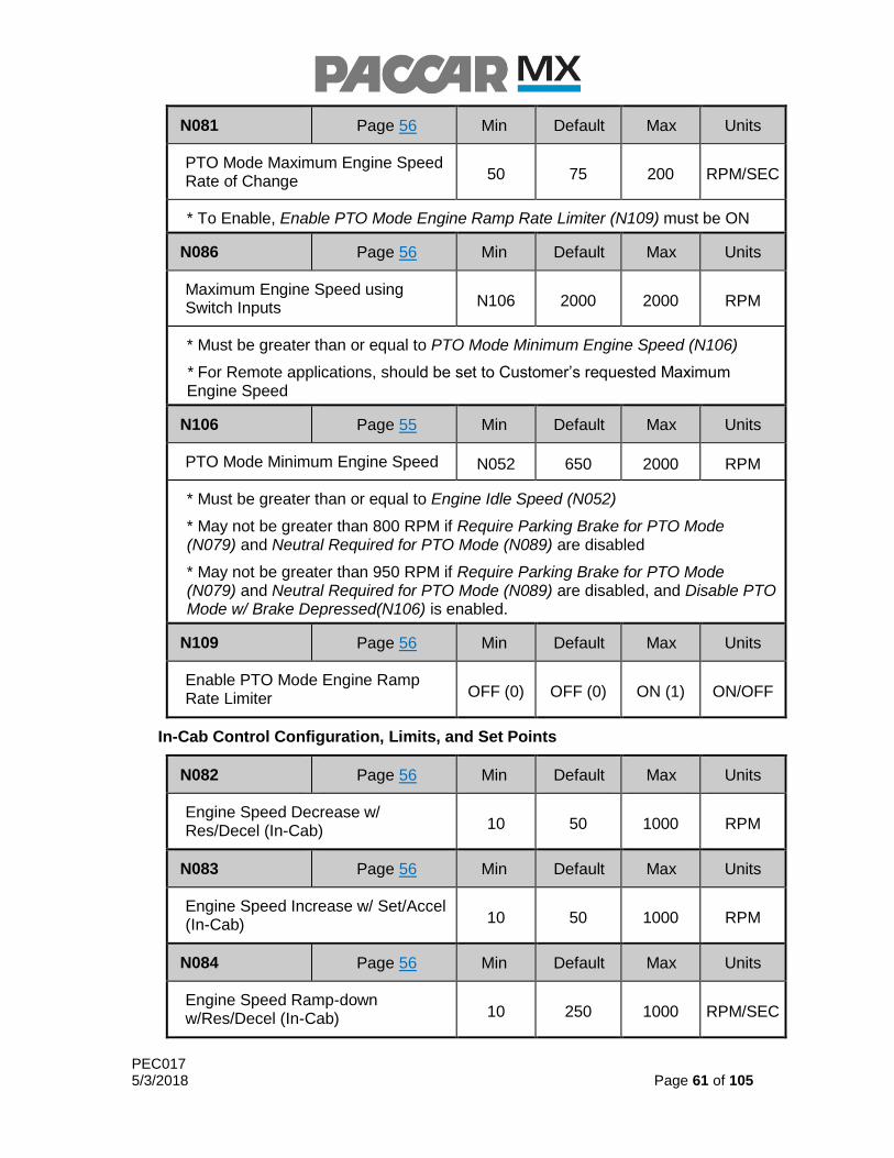
PEC017 5/3/2018 Page 61 of 105
N081 Page 56 Min Default Max Units
PTO Mode Maximum Engine Speed Rate of Change 50 75 200 RPM/SEC
* To Enable, Enable PTO Mode Engine Ramp Rate Limiter (N109) must be ON
N086 Page 56 Min Default Max Units
Maximum Engine Speed using Switch Inputs N106 2000 2000 RPM
* Must be greater than or equal to PTO Mode Minimum Engine Speed (N106)
* For Remote applications, should be set to Customer’s requested Maximum Engine Speed
N106 Page 55 Min Default Max Units
PTO Mode Minimum Engine Speed N052 650 2000 RPM
* Must be greater than or equal to Engine Idle Speed (N052)
* May not be greater than 800 RPM if Require Parking Brake for PTO Mode (N079) and Neutral Required for PTO Mode (N089) are disabled
* May not be greater than 950 RPM if Require Parking Brake for PTO Mode (N079) and Neutral Required for PTO Mode (N089) are disabled, and Disable PTO Mode w/ Brake Depressed(N106) is enabled.
N109 Page 56 Min Default Max Units
Enable PTO Mode Engine Ramp Rate Limiter OFF (0) OFF (0) ON (1) ON/OFF
In-Cab Control Configuration, Limits, and Set Points
N082 Page 56 Min Default Max Units
Engine Speed Decrease w/ Res/Decel (In-Cab) 10 50 1000 RPM
N083 Page 56 Min Default Max Units
Engine Speed Increase w/ Set/Accel (In-Cab) 10 50 1000 RPM
N084 Page 56 Min Default Max Units
Engine Speed Ramp-down w/Res/Decel (In-Cab) 10 250 1000 RPM/SEC
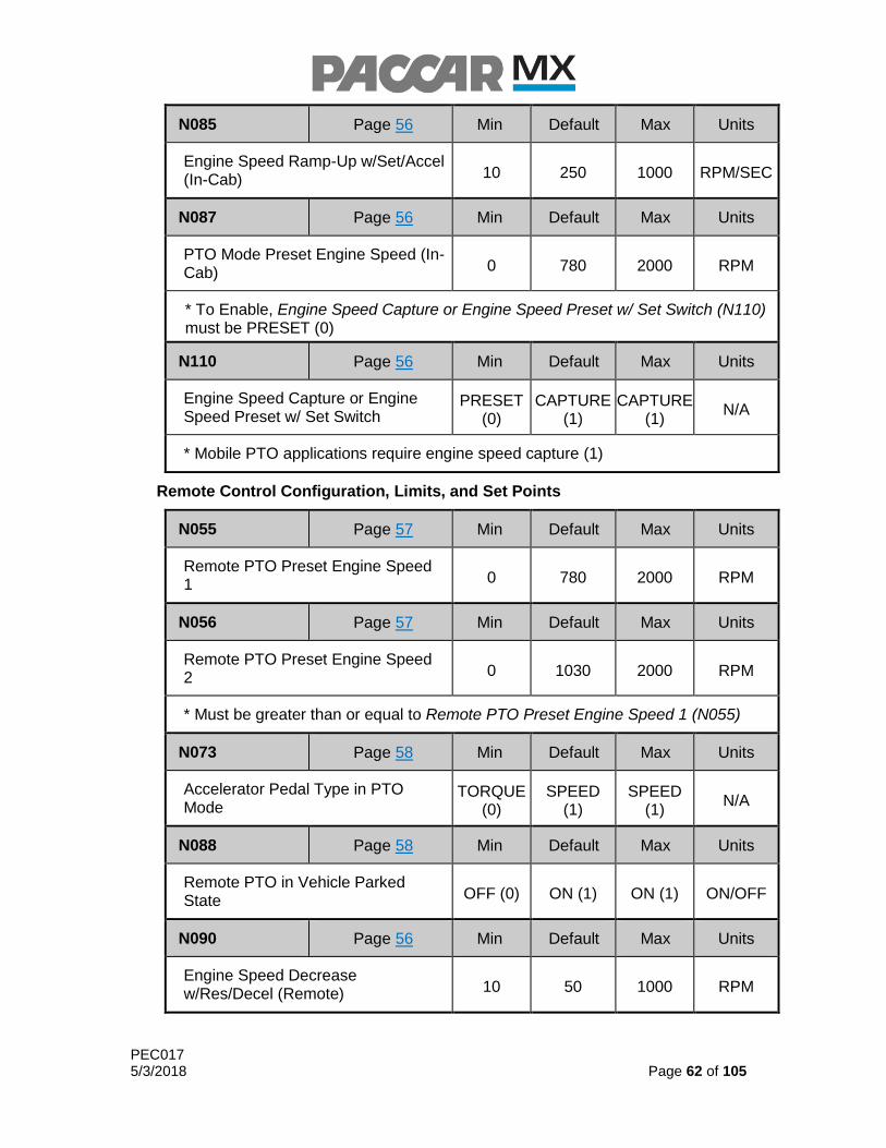
PEC017 5/3/2018 Page 62 of 105
N085 Page 56 Min Default Max Units
Engine Speed Ramp-Up w/Set/Accel (In-Cab) 10 250 1000 RPM/SEC
N087 Page 56 Min Default Max Units
PTO Mode Preset Engine Speed (In-Cab) 0 780 2000 RPM
* To Enable, Engine Speed Capture or Engine Speed Preset w/ Set Switch (N110) must be PRESET (0)
N110 Page 56 Min Default Max Units
Engine Speed Capture or Engine Speed Preset w/ Set Switch
PRESET (0)
CAPTURE (1)
CAPTURE (1)
N/A
* Mobile PTO applications require engine speed capture (1)
Remote Control Configuration, Limits, and Set Points
N055 Page 57 Min Default Max Units
Remote PTO Preset Engine Speed 1 0 780 2000 RPM
N056 Page 57 Min Default Max Units
Remote PTO Preset Engine Speed 2 0 1030 2000 RPM
* Must be greater than or equal to Remote PTO Preset Engine Speed 1 (N055)
N073 Page 58 Min Default Max Units
Accelerator Pedal Type in PTO Mode
TORQUE (0)
SPEED (1)
SPEED (1)
N/A
N088 Page 58 Min Default Max Units
Remote PTO in Vehicle Parked State OFF (0) ON (1) ON (1) ON/OFF
N090 Page 56 Min Default Max Units
Engine Speed Decrease w/Res/Decel (Remote) 10 50 1000 RPM

PEC017 5/3/2018 Page 63 of 105
N091 Page 56 Min Default Max Units
Engine Speed Ramp-down w/Res/Decel (Remote) 10 250 1000 RPM/SEC
N092 Page 56 Min Default Max Units
Engine Speed Increase w/Set/Accel (Remote) 10 50 1000 RPM
N093 Page 56 Min Default Max Units
Engine Speed Ramp-Up w/Set/Accel (Remote) 10 250 1000 RPM/SEC
N102 Page 45 Min Default Max Units
Signal Source for Remote Main Switch 0 0 1 N/A
* 0 = Hardwired 12V
1 = CAN Signal
N306 Page 46 Min Default Max Units
Enable Engine Speed Control via TSC1 OFF (0) OFF (0) ON (1) ON/OFF
N307 Page 58 Min Default Max Units
Disable In-Cab Accelerator Pedal in Remote PTO OFF (0) OFF (0) ON (1) ON/OFF
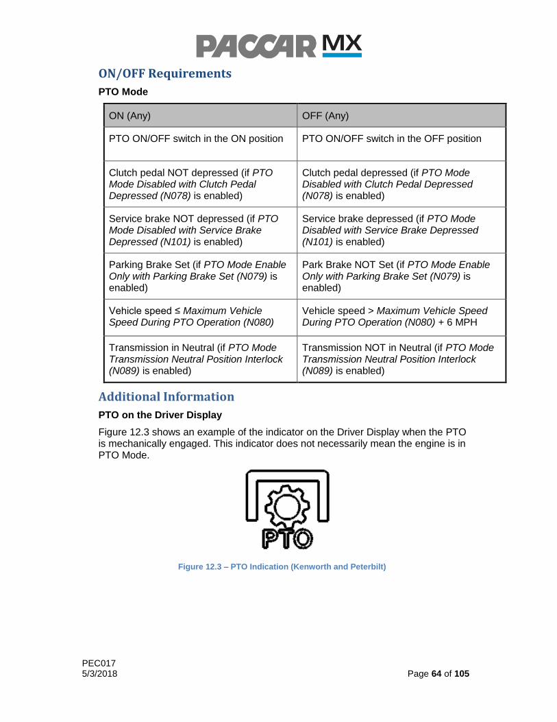
PEC017 5/3/2018 Page 64 of 105
ON/OFF Requirements
PTO Mode
ON (Any) OFF (Any)
PTO ON/OFF switch in the ON position PTO ON/OFF switch in the OFF position
Clutch pedal NOT depressed (if PTO Mode Disabled with Clutch Pedal Depressed (N078) is enabled)
Clutch pedal depressed (if PTO Mode Disabled with Clutch Pedal Depressed (N078) is enabled)
Service brake NOT depressed (if PTO Mode Disabled with Service Brake Depressed (N101) is enabled)
Service brake depressed (if PTO Mode Disabled with Service Brake Depressed (N101) is enabled)
Parking Brake Set (if PTO Mode Enable Only with Parking Brake Set (N079) is enabled)
Park Brake NOT Set (if PTO Mode Enable Only with Parking Brake Set (N079) is enabled)
Vehicle speed ≤ Maximum Vehicle Speed During PTO Operation (N080)
Vehicle speed > Maximum Vehicle Speed During PTO Operation (N080) + 6 MPH
Transmission in Neutral (if PTO Mode Transmission Neutral Position Interlock (N089) is enabled)
Transmission NOT in Neutral (if PTO Mode Transmission Neutral Position Interlock (N089) is enabled)
Additional Information
PTO on the Driver Display
Figure 12.3 shows an example of the indicator on the Driver Display when the PTO is mechanically engaged. This indicator does not necessarily mean the engine is in PTO Mode.
Figure 12.3 – PTO Indication (Kenworth and Peterbilt)
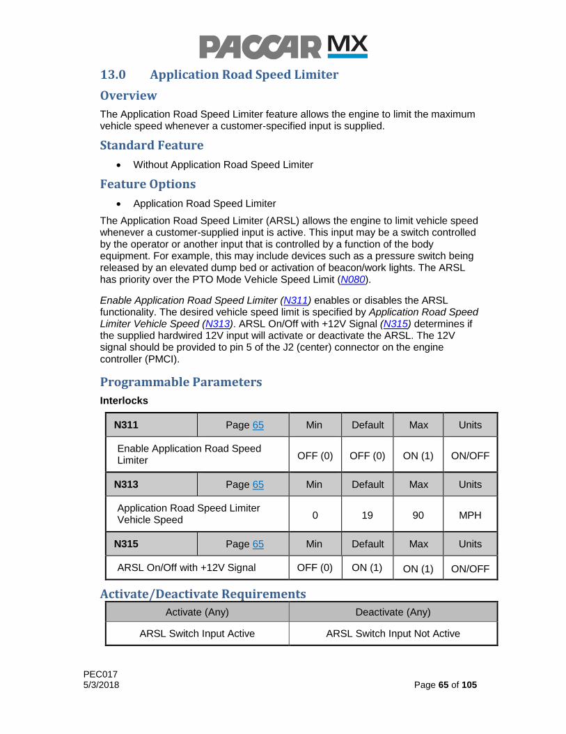
PEC017 5/3/2018 Page 65 of 105
13.0 Application Road Speed Limiter
Overview
The Application Road Speed Limiter feature allows the engine to limit the maximum vehicle speed whenever a customer-specified input is supplied.
Standard Feature
Without Application Road Speed Limiter
Feature Options
Application Road Speed Limiter
The Application Road Speed Limiter (ARSL) allows the engine to limit vehicle speed whenever a customer-supplied input is active. This input may be a switch controlled by the operator or another input that is controlled by a function of the body equipment. For example, this may include devices such as a pressure switch being released by an elevated dump bed or activation of beacon/work lights. The ARSL has priority over the PTO Mode Vehicle Speed Limit (N080).
Enable Application Road Speed Limiter (N311) enables or disables the ARSL functionality. The desired vehicle speed limit is specified by Application Road Speed Limiter Vehicle Speed (N313). ARSL On/Off with +12V Signal (N315) determines if the supplied hardwired 12V input will activate or deactivate the ARSL. The 12V signal should be provided to pin 5 of the J2 (center) connector on the engine controller (PMCI).
Programmable Parameters
Interlocks
N311 Page 65 Min Default Max Units
Enable Application Road Speed Limiter OFF (0) OFF (0) ON (1) ON/OFF
N313 Page 65 Min Default Max Units
Application Road Speed Limiter Vehicle Speed 0 19 90 MPH
N315 Page 65 Min Default Max Units
ARSL On/Off with +12V Signal OFF (0) ON (1) ON (1) ON/OFF
Activate/Deactivate Requirements
Activate (Any) Deactivate (Any)
ARSL Switch Input Active ARSL Switch Input Not Active
PEC017 5/3/2018 Page 66 of 105
14.0 Driveline Protection
Overview
The Driveline Protection feature allows the engine to reduce the maximum torque output in order to protect driveline components when the drivetrain reduction is calculated to be above a calibrated ratio.
Standard Feature
Standard
Standard provides normal operation of the advertised torque curve.
Feature Options
Driveline Protection
Driveline Protection allows the engine to reduce the maximum available torque to 950 lbf-ft when it detects a transmission gear reduction greater than the calibrated value. This functionality provides the rated torque in all conditions, and only reduces torque output if one or both of the following conditions are met:
The vehicle has an auxiliary transmission with gear ratio greater than 1.0:1
Vehicle has a transmission in a forward or reverse gear with a gear ratio equal to or greater than 13.0:1
Driveline protection is automatically included within the programming for all multi-torque engine ratings, as it utilizes the same software functions to enable the higher torque values of the multi-torque rating.
Orderable Feature Options & Sales Codes
Feature
Enable Driveline Protection 1000239 2092074
Activate/Deactivate Requirements
Driveline Protection
Activate (Any) Deactivate (Any)
Gear ratio > 13.0:1 Gear ratio < 13.0:1
Aux. trans. gear ratio > 1.0:1 Aux. trans. gear ratio < 1.0:1

PEC017 5/3/2018 Page 67 of 105
15.0 Speed Control Management (SCM)
Overview
The Speed Control Management (SCM) feature is intended to help encourage fuel-efficient shifting habits by reducing engine performance or restricting vehicle speed at elevated engine speeds. Speed Control Management consists of two control strategies: Progressive Shift (PGS) and Gear Down Protection (GDP), which may be enabled separately or in combination.
PACCAR offers pre-approved and validated PGS and GDP settings for most manual and automated-manual transmission powertrain configurations. Upon selection of at least one of the SCM features, optimized shift points and the gears in which SCM functionality will be active are identified by PACCAR and programmed into the vehicle. These shift points are based on the customer’s powertrain configuration and requested performance optimization goals.
Standard Feature
Without SCM
Feature Options
Progressive Shift
Gear Down Protection
Progressive Shift and Gear Down Protection
Progressive Shift (PGS)
The Progressive Shift module is typically used to encourage earlier shifts in lower gears to improve fuel economy. By shifting earlier, the engine speed is reduced, improving fuel economy. PGS is a “soft” RPM limit that restricts the rate of engine acceleration when the engine speed is above a predefined engine speed limit. This provides a balance between encouraging a driver to shift at lower engine speeds and the driver’s needs to remain in a gear longer to execute a shift under heavy load and/or on a hill. The driver’s perception of the restricted engine acceleration gives a clear indication to execute an upshift. Full engine acceleration is restored after the driver executes a shift where the engine speed falls below the customer-defined limit in the next gear. Along with limiting engine acceleration, this function also provides a visual notification to the driver to shift via the driver display.
The Progressive Shift module will provide up to two engine speed limits, allowing customers to use a more aggressive limit in lower gears and a less aggressive limit in higher gears. 10-speed and 13-speed transmissions will receive a two-step engine speed limit, and 18-speed transmissions will receive a single step. The first and last gear in which each progressive shift range is programmed ensuring it is properly configured to the customer’s application and for the specified powertrain components.
PGS Speed Step Count (PS25) specifies the number of distinct speed steps desired. PGS First Limit Gear Min (PS26) indicates the first gear number in which PGS will become active and PGS First Limit Gear Max (PS28) indicates the last gear the the first PGS step will be active. PGS Second Engine Speed Limit (PS29) defines the engine speed threshold for the shift advisor. PGS Highest Gear (PS30) specifies the

PEC017 5/3/2018 Page 68 of 105
last gear that the second step of PGS will be active. While PGS is active, engine speed will be “soft” limited to PGS First Engine Speed Limit (PS27) or PGS Second Engine Speed Limit (PS29) depending on the currently selected gear and the defined gear ranges for each step.
Gear Down Protection (GDP)
The Gear Down Protection module encourages the driver to shift into top gear when operating the vehicle at the target operating speed. This is done by restricting the road speed in gears below top gear. When enabled, GDP restricts operation of the vehicle at the target operating speed when not in top gear. This effectively prevents engine operation at excessive RPMs and, as a result, helps to improve fuel economy. GDP is a “hard” limit. The engine RPM, and therefore vehicle speed, will be limited to a specified value in the specified gears. Along with limiting engine RPM and vehicle speed, this function also provides a visual notification to the driver to shift via the driver display.
The gear down protection module offers a single programmable engine speed limit. Selection of the GDP module will automatically set the engine speed limit at one or two gears below top gear depending upon the combination of transmission, rear axle ratio, and equipped tires. Changes to the factory settings can be made post-delivery via a PRS file from the PACCAR Engine Support Center.
GDP First Gear Active (GP11) specifies the first selected gear in which the GDP “hard” engine speed limiter will become active, while GDP Last Gear Active (GP13) specifies the last selected gear that the GDP engine speed limiter will remain active. GDP Active Gear Count (GP14) is the number of gears that GDP will restrict engine speed to a maximum of GDP Engine Speed (GP12).
Application Guidelines
The SCM features are intended to be used with manual and automated-manual transmissions while operating in manual mode. The SCM feature is not available with 2-speed rear axles, auxiliary transmissions, Allison transmissions, or multi-speed transfer cases. A full list of application guidelines includes:
Transmissions o Available on chassis equipped with Eaton 9, 10, 11, 13, or 18-speed
manual transmissions o Available on chassis equipped with Eaton Ultrashift automated-
manual transmissions (while operating in manual mode) o Not available on chassis equipped with Allison transmissions o Not available on chassis with auxiliary transmissions
Rear Axle Ratio o Available on chassis with 2.53 to 4.33 rear axle ratios o Not available on chassis equipped with multi-speed rear axles
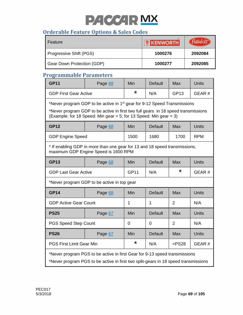
PEC017 5/3/2018 Page 69 of 105
Orderable Feature Options & Sales Codes
Feature
Progressive Shift (PGS) 1000276 2092084
Gear Down Protection (GDP) 1000277 2092085
Programmable Parameters
GP11 Page 68 Min Default Max Units
GDP First Gear Active * N/A GP13 GEAR #
*Never program GDP to be active in 1st gear for 9-12 Speed Transmissions
*Never program GDP to be active in first two full gears in 18 speed transmissions (Example: for 18 Speed: Min gear = 5; for 13 Speed: Min gear = 3)
GP12 Page 68 Min Default Max Units
GDP Engine Speed 1500 1680 1700 RPM
* If enabling GDP in more than one gear for 13 and 18 speed transmissions, maximum GDP Engine Speed is 1600 RPM
GP13 Page 68 Min Default Max Units
GDP Last Gear Active GP11 N/A * GEAR #
*Never program GDP to be active in top gear
GP14 Page 68 Min Default Max Units
GDP Active Gear Count 1 1 2 N/A
PS25 Page 67 Min Default Max Units
PGS Speed Step Count 0 0 2 N/A
PS26 Page 67 Min Default Max Units
PGS First Limit Gear Min * N/A <PS28 GEAR #
*Never program PGS to be active in first Gear for 9-13 speed transmissions
*Never program PGS to be active in first two split-gears in 18 speed transmissions

PEC017 5/3/2018 Page 70 of 105
PS27 Page 68 Min Default Max Units
PGS First Engine Speed Limit 1400 N/A PS29 RPM
*Minimum engine speed limit is 1400 RPM to ensure proper control system stability when PGS is active
*Maximum engine speed limit is 1650 RPM to ensure the proper balance between fuel economy shifting and providing power while accelerating
PS28 Page 67 Min Default Max Units
PGS First Limit Gear Max >PS26 N/A <PS30 GEAR #
*Never program PGS to be active in top gear
PS29 Page 67 Min Default Max Units
PGS Second Engine Speed Limit PS27 N/A 1800 RPM
*The minimum RPM after a shift in any gear should not fall below 1100 RPM
PS30 Page 67 Min Default Max Units
PGS Highest Gear >PS30 N/A * GEAR #
*Never program PGS to be active in top gear
ON/OFF Requirements
Progressive Shift
ON OFF
ENTER SALES CODE
(Progressive Shift ON)
No Sales Code
(Progressive Shift OFF)
GDP
ON OFF
ENTER SALES CODE
(Gear Down Protection ON)
No Sales Code
(Gear Down Protection OFF)
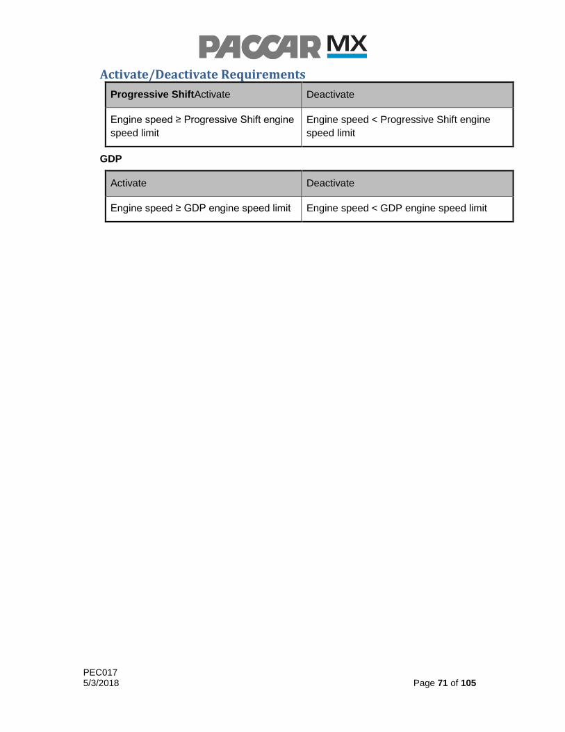
PEC017 5/3/2018 Page 71 of 105
Activate/Deactivate Requirements
Progressive ShiftActivate Deactivate
Engine speed ≥ Progressive Shift engine
speed limit
Engine speed < Progressive Shift engine
speed limit
GDP
Activate Deactivate
Engine speed ≥ GDP engine speed limit Engine speed < GDP engine speed limit

PEC017 5/3/2018 Page 72 of 105
Additional Information
Progressive Shift Threshold Graphs
The black line in Graph 15.1 illustrates the Progressive Shift limit if applicable.
Graph 15.1 - One Engine Speed Control Limit
The blue line in Graph 15.2 illustrates the 1st Progressive Shift limit if applicable. The black line illustrates the 2nd Progressive Shift limit if applicable.
Graph 15.2 – Two Engine Speed Control Limits

PEC017 5/3/2018 Page 73 of 105
Gear Down Protection Threshold Chart
The red line in Graph 15.3 illustrates Gear Down Protection in the gear below top gear.
Graph 15.3 – Gear Down Protection

PEC017 5/3/2018 Page 74 of 105
16.0 Engine Recorder
Overview
The Engine Recorder records three types of engine-sensor and calculated-output data over the life of the vehicle, between reset and defined durations. Each type of data record is stored independently and depending on the type, multiple records might be stored. The records for the three recorders are retrievable with the DAVIE service tool.
Standard Feature
Combined Trip/Chart Recorder
Snapshot Recorder
Faststop Recorder
The Combined Trip/Chart Recorder allows the engine to store data over the life of the vehicle as well as to store data between resets. When the trip reset is triggered, the record is discarded and new data is collected.
The Snapshot Recorder allows the driver to trigger a recording event. Details on triggering the Snapshot Recorder are available in Engine Rapido. The Snapshot Recorder will record data 10 seconds before and 5 seconds after the trigger. Three Snapshot Recorder events will be stored.
Faststop Recorder allows the engine to trigger a recording event when vehicle deceleration is greater than Faststop Recorder Threshold (N064). The Faststop Recorder will record data 5 seconds before and 5 seconds after the trigger. Three Faststop Recorder events will be stored.
Feature Options
Without Faststop Recorder
The Faststop recorder is enabled by default. Customers may disable the Faststop recorder at the time of production by selecting the appropriate sales code.
Orderable Feature Options & Sales Codes
Feature
With Faststop Recorder 1000280 2092036
Without Faststop Recorder 1000281 2092037

PEC017 5/3/2018 Page 75 of 105
Programmable Parameters
Faststop Recorder
N064 Page 74 Min Default Max Units
Faststop Recorder Threshold 2.24 8.95 15.65 MPH/SEC
ON/OFF Requirements
Faststop Recorder
ON OFF
Faststop Recorder ON Faststop Recorder OFF
Activate/Deactivate Requirements
Faststop Recorder
Activate Deactivate
Vehicle deceleration rate is ≥ Deceleration Rate to Trigger Faststop Recorder
Vehicle deceleration rate is < Deceleration Rate to Trigger Faststop Recorder
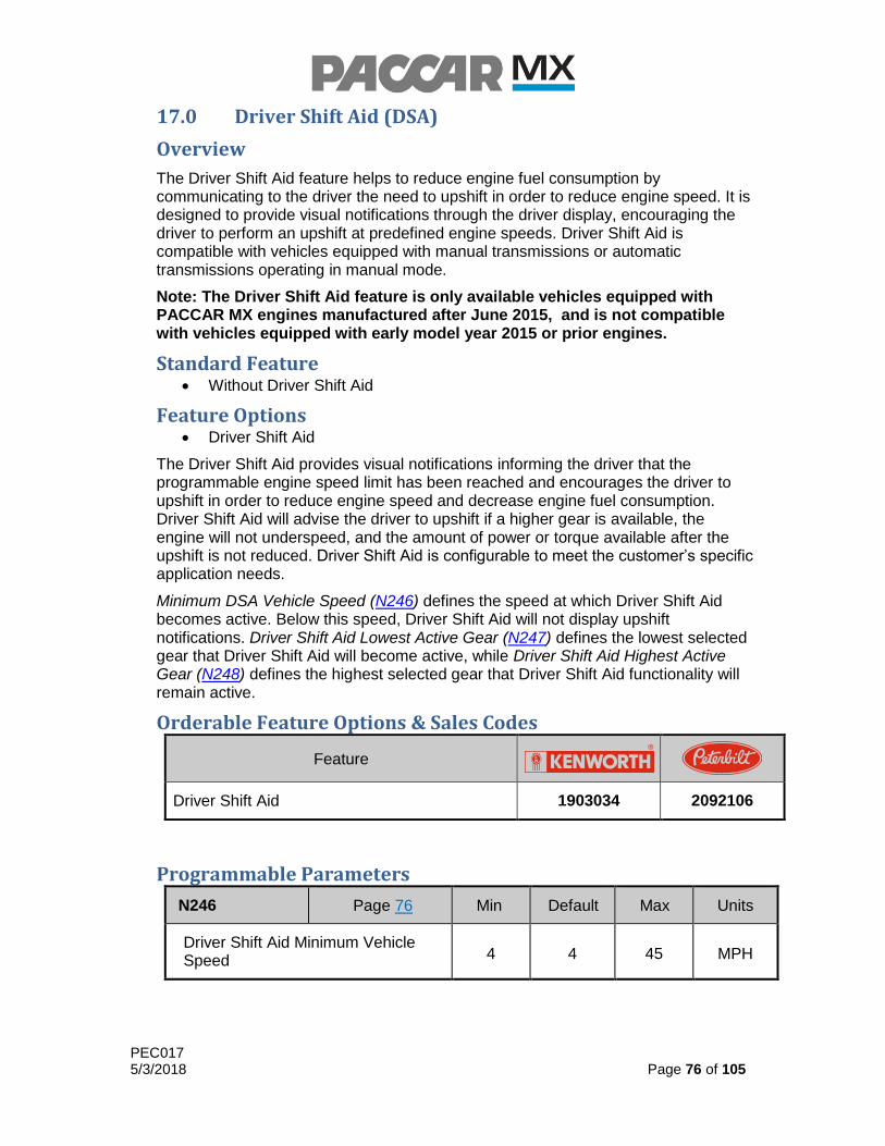
PEC017 5/3/2018 Page 76 of 105
17.0 Driver Shift Aid (DSA)
Overview
The Driver Shift Aid feature helps to reduce engine fuel consumption by communicating to the driver the need to upshift in order to reduce engine speed. It is designed to provide visual notifications through the driver display, encouraging the driver to perform an upshift at predefined engine speeds. Driver Shift Aid is compatible with vehicles equipped with manual transmissions or automatic transmissions operating in manual mode.
Note: The Driver Shift Aid feature is only available vehicles equipped with PACCAR MX engines manufactured after June 2015, and is not compatible with vehicles equipped with early model year 2015 or prior engines.
Standard Feature Without Driver Shift Aid
Feature Options Driver Shift Aid
The Driver Shift Aid provides visual notifications informing the driver that the programmable engine speed limit has been reached and encourages the driver to upshift in order to reduce engine speed and decrease engine fuel consumption. Driver Shift Aid will advise the driver to upshift if a higher gear is available, the engine will not underspeed, and the amount of power or torque available after the upshift is not reduced. Driver Shift Aid is configurable to meet the customer’s specific application needs.
Minimum DSA Vehicle Speed (N246) defines the speed at which Driver Shift Aid becomes active. Below this speed, Driver Shift Aid will not display upshift notifications. Driver Shift Aid Lowest Active Gear (N247) defines the lowest selected gear that Driver Shift Aid will become active, while Driver Shift Aid Highest Active Gear (N248) defines the highest selected gear that Driver Shift Aid functionality will remain active.
Orderable Feature Options & Sales Codes
Feature
Driver Shift Aid 1903034 2092106
Programmable Parameters
N246 Page 76 Min Default Max Units
Driver Shift Aid Minimum Vehicle Speed 4 4 45 MPH

PEC017 5/3/2018 Page 77 of 105
N247 Page 76 Min Default Max Units
Driver Shift Aid Lowest Active Gear 1 1 4 GEAR #
N248 Page 76 Min Default Max Units
Driver Shift Aid Highest Active Gear 5
TOP GEAR
TOP GEAR
GEAR #

PEC017 5/3/2018 Page 78 of 105
Additional Information
Driver Shift Aid on the Driver Display
Figure 17.1 and Figure 17.2 show examples of the dedicated Driver Shift Aid screens on the driver display, when an upshift is recommended from a known gear.
Figure 17.1 – NAMUX 2 & 3; Left: Kenworth, Right: Peterbilt
Figure 17.2 – Large Display; Left: Kenworth, Right: Peterbilt
Figure 17.3 and Figure 17.4 show examples of the dedicated Driver Shift Aid screens on the driver display, when an upshift is recommended from an unknown gear.
Figure 17.3 – NAMUX 2 & 3; Left: Kenworth, Right: Peterbilt
Figure 17.4 – Large Display; Left: Kenworth, Right: Peterbilt
PEC017 5/3/2018 Page 79 of 105
18.0 Driver Reward
Overview
The Driver Reward feature is designed to improve fuel economy by providing incentive for drivers to meet customer-defined goals for fuel economy and idle time. The vehicle speed limit may be lowered when goals are not met, or increased to reward drivers for meeting the goals.
Note: The Driver Reward feature is only available vehicles equipped with PACCAR MX engines manufactured after June 2015, and is not compatible with vehicles equipped with early model year 2015 or prior engines.
Standard Feature Without Driver Reward
Feature Options Fuel Economy Evaluation
Idle Time Evaluation
The Driver Reward feature provides the driver with increased vehicle speed for meeting customer-defined fuel consumption and idle time goals. The customer has the option of evaluating driver performance based on Fuel Economy, Idle Time Percentage, or both. Driver Reward Offset Mode (N219) may also be configured to apply vehicle speed rewards to the cruise control vehicle speed limit, the accelerator pedal vehicle speed limit, or both.
The Fuel Economy option allows the engine to monitor and compare actual fuel economy to Fuel Efficiency Expected Threshold (N232), which is the threshold at which neither a reward nor penalty will be imposed on the driver. The Driver Reward Maximum Bonus (N224) will be applied if the measured fuel economy is greater than or equal to Fuel Efficiency Bonus Threshold (N231). The Driver Reward Maximum Penalty (N227) will be applied if the measured fuel economy is less than or equal to Fuel Efficiency Penalty Threshold (N233). As the driver improves the measured fuel economy, the maximum vehicle speed will increase with the driver’s performance, until the Driver Reward Maximum Bonus (N224) has been reached. As the driver decreases the measured fuel economy, the vehicle speed penalty will gradually increase with the driver’s performance, until the Driver Reward Maximum Penalty (N227) has been reached.
The Percent Idle Time option allows the engine to monitor the percentage of engine idle time and compare it to Idle Time Expected Threshold (N236), which is the threshold at which neither a reward nor penalty will be imposed on the driver. The Driver Reward Maximum Bonus (N224) will be applied if the recorded percentage of idle time is less than or equal to Idle Time Bonus Threshold (N235). The Driver Reward Maximum Penalty (N227) will be applied if the recorded percentage of idle time is greater than or equal to Idle Time Penalty Threshold (N237). As the driver decreases the recorded percentage of idle time, the maximum vehicle speed will increase until the Driver Reward Maximum Bonus (N224) has been reached. As the driver decreases the recorded percentage of idle time, the vehicle speed penalty will gradually increase until the Driver Reward Maximum Penalty (N227) has been reached.

PEC017 5/3/2018 Page 80 of 105
If Fuel Economy and Percent Idle Time are both enabled, the Driver Reward performance criteria are evaluated individually and the overall vehicle speed bonus or penalty will be determined from the lowest individual bonus or penalty.
The following figures may help to illustrate how the Driver Reward feature functions under different configurations and scenarios.
Figure 18.1 – Example Driver Reward Scenario #1
Figure 18.2 - Example Driver Reward Scenario #2
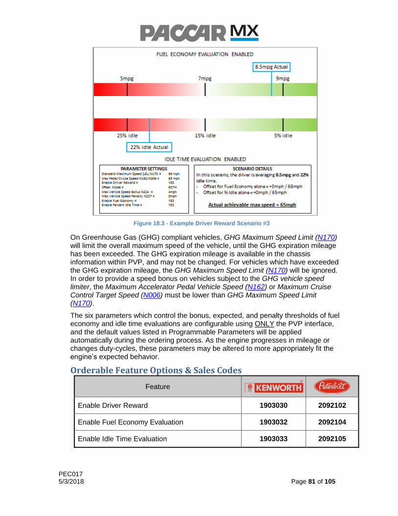
PEC017 5/3/2018 Page 81 of 105
Figure 18.3 - Example Driver Reward Scenario #3
On Greenhouse Gas (GHG) compliant vehicles, GHG Maximum Speed Limit (N170) will limit the overall maximum speed of the vehicle, until the GHG expiration mileage has been exceeded. The GHG expiration mileage is available in the chassis information within PVP, and may not be changed. For vehicles which have exceeded the GHG expiration mileage, the GHG Maximum Speed Limit (N170) will be ignored. In order to provide a speed bonus on vehicles subject to the GHG vehicle speed limiter, the Maximum Accelerator Pedal Vehicle Speed (N162) or Maximum Cruise Control Target Speed (N006) must be lower than GHG Maximum Speed Limit (N170).
The six parameters which control the bonus, expected, and penalty thresholds of fuel economy and idle time evaluations are configurable using ONLY the PVP interface, and the default values listed in Programmable Parameters will be applied automatically during the ordering process. As the engine progresses in mileage or changes duty-cycles, these parameters may be altered to more appropriately fit the engine’s expected behavior.
Orderable Feature Options & Sales Codes
Feature
Enable Driver Reward 1903030 2092102
Enable Fuel Economy Evaluation 1903032 2092104
Enable Idle Time Evaluation 1903033 2092105

PEC017 5/3/2018 Page 82 of 105
Programmable Parameters
N219 Page 79 Min Default Max Units
Driver Reward Offset Mode 0 3 3 N/A
* 0 = No Driver Rewards
1 = Only During Accelerator Pedal Control
2 = Only While Cruise Control Active
3 = Always On
N224 Page 79 Min Default Max Units
Maximum Vehicle Speed Bonus 0 2 4 MPH
N227 Page 79 Min Default Max Units
Maximum Vehicle Speed Penalty 0 - 2 - 4 MPH
N231 Page 79 Min Default Max Units
Fuel Economy Threshold for Vehicle Speed Bonus 0 9.0 25.8 MPG
* Programmable only in PACCAR Vehicle Pro
N232 Page 79 Min Default Max Units
Expected Fuel Economy 0 7.0 21.1 MPG
* Programmable only in PACCAR Vehicle Pro
N233 Page 79 Min Default Max Units
Fuel Economy Threshold for Vehicle Speed Penalty 0 5.0 16.4 MPG
* Programmable only in PACCAR Vehicle Pro
N235 Page 79 Min Default Max Units
Idle Time Threshold for Vehicle Speed Bonus
0 5 100 %
* Programmable only in PACCAR Vehicle Pro

PEC017 5/3/2018 Page 83 of 105
N236 Page 79 Min Default Max Units
Expected Vehicle Idle Time 0 15 100 %
* Programmable only in PACCAR Vehicle Pro
N237 Page 79 Min Default Max Units
Idle Time Threshold for Vehicle Speed Penalty
0 25 100 %
* Programmable only in PACCAR Vehicle Pro
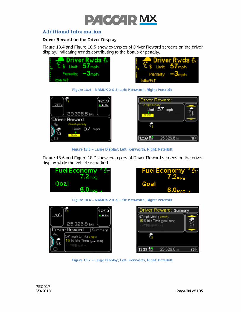
PEC017 5/3/2018 Page 84 of 105
Additional Information
Driver Reward on the Driver Display
Figure 18.4 and Figure 18.5 show examples of Driver Reward screens on the driver display, indicating trends contributing to the bonus or penalty.
Figure 18.4 – NAMUX 2 & 3; Left: Kenworth, Right: Peterbilt
Figure 18.5 – Large Display; Left: Kenworth, Right: Peterbilt
Figure 18.6 and Figure 18.7 show examples of Driver Reward screens on the driver display while the vehicle is parked.
Figure 18.6 – NAMUX 2 & 3; Left: Kenworth, Right: Peterbilt
Figure 18.7 – Large Display; Left: Kenworth, Right: Peterbilt

PEC017 5/3/2018 Page 85 of 105
19.0 Ether Starting Aid
Overview
The Ether Starting Aid is a fully integrated system that provides increased starting capabilities for extreme cold weather conditions. This feature is controlled by the engine and will inject ether into the air-intake system when required to start the engine.
Standard Feature
Without Ether Starting Aid
Without Ether Starting Aid allows the engine to start normally.
Feature Options
Ether Starting Aid
Ether Starting Aid allows the engine to control when ether will be injected into the intake system to assist in the starting of the engine in extreme cold weather conditions.
Orderable Feature Options & Sales Codes
Feature
With Ether Starting Aid 1502060 N/A

PEC017 5/3/2018 Page 86 of 105
20.0 Manual HC Desorb
Overview
HC Desorb functionality is necessary to protect the aftertreatment from damage after extended idling. Idling a truck results in low exhaust temperatures and low exhaust flows, which promotes unburned hydrocarbons in the exhaust to absorb onto catalysts in the aftertreatment. Extended idling presents a risk for aftertreatment damage because if the aftertreatment catalysts and adsorbed hydrocarbons are brought to high enough temperatures (by driving the truck) after extended idling, there is a risk of uncontrolled temperature increase and thermal damage to the aftertreatment catalysts. After the truck has idled for long enough, there will be enough hydrocarbons accumulated that is not safe to drive the truck and an HC Desorb will be required. HC Desorb functionality protects the aftertreatment using controlled exhaust temperature increase to remove accumulated hydrocarbons in a slow and controlled manner, allowing the truck to be safely driven after completion.
A Manual HC desorb request, along with a “DO NOT DRIVE” notification, will be displayed on the dash after the truck has idled long enough that a dangerous amount of hydrocarbons have accumulated and the truck is NOT safe to drive. At this point, a Manual HC Desorb must be fully completed to safely remove accumulated hydrocarbons before the truck can be driven. Failure to comply will result in a P3880 fault and risk of aftertreatment damage.
Manual HC Desorbs are performed by the driver by pressing the regen switch when the request is displayed on the highline Drivers must complete a Manual HC Desorb before driving the vehicle if requested. As long as there is a “DO NOT DRIVE” notification, do not drive the truck.
All Manual HC Desorb notifications refer to HC Desorb as a “Regeneration” or “Regen”. HC Desorb differs from DPF Regenerations in that there is no additional fuel dosing during an HC Desorb. As a result, tailpipe temperatures will remain below 500 °F (260 °C).
Desorb Notifications on the Driver Display
Figure 20.3 shows an example of the notification displayed when a Manual HC Desorb is required before driving. If this message is displayed on the dash, the driver must complete the Mnaual HC Desorb before driving the truck. This applies to both Peterbilt and Kenworth on non-VECU, NAMUX 2 & 3 trucks.
Figure 20.3 – NAMUX 2 & 3 Manual HC Desorb Required Notification; Left: Kenworth, Right: Peterbilt
PEC017 5/3/2018 Page 87 of 105
21.0 Automatic HC Desorb
Overview
Automatic HC Desorb (N318) functionality provides the truck with the ability to perform an HC Desorb (hydrocarbon desorption) automatically during extended idling. This feature is fully integrated into the aftertreatment system and will perform an HC Desorb when the truck is idling, conditions are met, and without any driver inputs, potentially eliminating the need for a Manual HC Desorb.
Prior to Auto HC Desorb functionality, customers had to perform a Manual HC Desorb before driving after idling for an extended amount of time.
Auto HC Desorb functions by periodically increasing engine speed and exhaust temperatures to maintain a low level of HC accumulation in the aftertreatment during extended idle. This operation will maintain a level of accumulated hydrocarbons so that the truck is always safe to be driven and there is minimal risk of aftertreatment damage. Drivers may experience unexpected changes in engine speed when Auto Desorbs occur, sometimes without notification depending on NAMUX version. When the Auto Desorb has completed, engine speed will return to the previous set speed.
Standard Feature
With Auto HC Desorb
Enabling Auto HC Desorb allows the truck to perform a hydrocarbon desorption automatically during extended idling. This reduces the likelihood of the driver having to perform a Manual HC Desorb after extended idling.
Feature Options
Without Auto HC Desorb
Disabling Auto HC Desorb may cause the driver to perform a Manual HC Desorb before driving, after idling for an extended period.
Programmable Parameters
N318 Page 87 Min Default Max Units
Enables the Auto HC Desorb functionality
0 (OFF) 0 (OFF) 1 (ON) ON/OFF
ON/OFF Requirements
ON OFF
Auto HC Desorb ON Auto HC Desorb OFF

PEC017 5/3/2018 Page 88 of 105
Activate/Deactivate Requirements
Activate Deactivate
Accelerator pedal not pressed Accelerator pedal pressed
Foot brake not pressed Foot brake pressed
Clutch pedal not pressed if equipped Clutch pressed if equipped
Vehicle in neutral Vehicle not in neutral
Parking brake set Parking brake not set
DPF regen switch is not set to ‘inhibit’ DPF regen switch set to ‘inhibit’
Vehicle speed = 0 Vehicle speed > 0
No related engine or aftertreatment faults
Related engine or aftertreatment faults, ie: BPV, VGT, aftertreatment overtemps, pre-DOC temp etc.
Coolant at operating temp Coolant not at operating temp
Engine load less than 600 lb-ft* Engine load greater than 600 lb-ft*
If PTO active, engine speed greater than 900 RPM**
If PTO active, engine speed less than 900 RPM**
* Engine load threshold varies based on engine speed
** Engine speed threshold varies based on ambient conditions
Additional Information
Even with Auto HC Desorb enabled, Manual HC Desorb functionality is still available. If Auto HC Desorbs are not successful or are aborted by the user, it is possible that a Manual HC Desorb will be requested on the dash and a driver must complete the Manual HC Desorb before driving. Occurrences of Auto HC Desorb or Manual HC Desorb are normal and do not indicate any issues with the truck.
If an Auto HC Desorb is occurring, the driver is able to cancel the Auto HC Desorb by pressing the brake pedal and drive the truck. As long as there is a “DO NOT DRIVE” notification, do not drive the truck.
If an Auto HC Desorb is aborted by the user (for example, by pressing the service brake), another Auto HC Desorb will restart 10 minutes later if all enable conditions are met again. If Auto HC Desorbs are not desired by the customer, they can be inhibited by using the regen inhibit switch or disabled via PVP. If the regen inhibit switch is used, the driver must remember to un-inhibit the regen switch before starting to drive.
Depending on NAMUX version and software level, some vehicles may display a notification of a pending Auto HC Desorb and during an active Auto HC Desorb. If Auto HC Desorb notifications are available, a 2-minute countdown will be initiated prior to the Auto HC Desorb to alert the driver an Auto HC Desorb is being initiated.
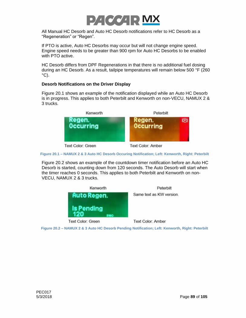
PEC017 5/3/2018 Page 89 of 105
All Manual HC Desorb and Auto HC Desorb notifications refer to HC Desorb as a “Regeneration” or “Regen”.
If PTO is active, Auto HC Desorbs may occur but will not change engine speed. Engine speed needs to be greater than 900 rpm for Auto HC Desorbs to be enabled with PTO active.
HC Desorb differs from DPF Regenerations in that there is no additional fuel dosing during an HC Desorb. As a result, tailpipe temperatures will remain below 500 °F (260 °C).
Desorb Notifications on the Driver Display
Figure 20.1 shows an example of the notification displayed while an Auto HC Desorb is in progress. This applies to both Peterbilt and Kenworth on non-VECU, NAMUX 2 & 3 trucks.
Figure 20.1 – NAMUX 2 & 3 Auto HC Desorb Occuring Notification; Left: Kenworth, Right: Peterbilt
Figure 20.2 shows an example of the countdown timer notification before an Auto HC Desorb is started, counting down from 120 seconds. The Auto Desorb will start when the timer reaches 0 seconds. This applies to both Peterbilt and Kenworth on non-VECU, NAMUX 2 & 3 trucks.
Figure 20.2 – NAMUX 2 & 3 Auto HC Desorb Pending Notification; Left: Kenworth, Right: Peterbilt

PEC017 5/3/2018 Page 90 of 105
22.0 Parameters
The following table of parameters is listed in numeric order.
Comprehensive Parameter List
N001 Page 25 Min Default Max Units
Minimum Speed to Disable Cruise Control N080 + 6 16 87 MPH
* Must be at least 6 MPH greater than PTO Mode Vehicle Speed Limit (N080)
N002 Page 25 Min Default Max Units
Minimum Speed to Enable Cruise Control N001 + 3 19 90 MPH
* Must be at least 3 MPH greater than Minimum Speed to Disable Cruise Control (N001)
N003 Page 25 Min Default Max Units
Minimum Cruise Control Target Speed N002 19 93 MPH
* Must be greater than or equal to Minimum Speed to Enable Cruise Control (N002)
N004 Page 25 Min Default Max Units
Vehicle Speed Decrease w/Res/Decel 1 1 6 MPH
N005 Page 25 Min Default Max Units
Vehicle Speed Increase w/Set/Accel 1 1 6 MPH
N006 Page 25 Min Default Max Units
Maximum Cruise Control Target Speed 25 64 100 MPH
N013 Page 38 Min Default Max Units
Downhill Speed Limiter Vehicle Speed Offset 2 4 6 MPH
N014 Page 38 Min Default Max Units
Auto-Retarder Vehicle Speed Offset 2 4 6 MPH

PEC017 5/3/2018 Page 91 of 105
Comprehensive Parameter List
N015 Page 38 Min Default Max Units
Engine Brake Disabled When Out of Gear OFF (0) ON (1) ON (1) ON/OFF
N019 Page 38 Min Default Max Units
Time Delay for Retarder Activation 0.1 0.1 3 SEC
N026 Page 38 Min Default Max Units
Minimum Vehicle Speed for Engine Brake Activation 1 1 30 MPH
N039 Page 26 Min Default Max Units
Multi-Torque Only when Cruise Active OFF (0) OFF (0) ON (1) ON/OFF
N051 Page 12 Min Default Max Units
Fuel Density 780 855 950 g/L
N052 Page 14 Min Default Max Units
Engine Idle Speed 650 650 700 RPM
N055 Page 57 Min Default Max Units
Remote PTO Preset Engine Speed 1 0 780 2000 RPM
N056 Page 57 Min Default Max Units
Remote PTO Preset Engine Speed 2 0 1030 2000 RPM
N057 Page 24 Min Default Max Units
Minimum Fan Clutch Engagement Time 30 30 60 SEC
N064 Page 74 Min Default Max Units
Faststop Recorder Threshold 2.24 8.95 15.65 MPH/SEC

PEC017 5/3/2018 Page 92 of 105
Comprehensive Parameter List
N065 Page 12 Min Default Max Units
Minimum Speed for High Exhaust Temp Warning 5 5 50 MPH
N071 Page 22 Min Default Max Units
Enable Fast Idle Control OFF (0) ON (1) ON (1) ON/OFF
N072 Page 22 Min Default Max Units
Maximum Engine Speed in Fast Idle Control 650 1900 1900 RPM
N073 Page 58 Min Default Max Units
Accelerator Pedal Type in PTO Mode
TORQUE (0)
SPEED (1)
SPEED (1)
N/A
N076 Page 55 Min Default Max Units
Maximum Engine Speed using Pedal Input N106 2000 2000 RPM
* Must be greater than or equal to PTO Mode Minimum Engine Speed (N106)
N077 Page 56 Min Default Max Units
Maximum Engine Torque in PTO Mode 148 1902 1902 LB-FT
N078 Page 54 Min Default Max Units
Disable PTO Mode w/Clutch Depressed OFF (0) ON (1) ON (1) ON/OFF
N079 Page 54 Min Default Max Units
Require Parking Brake for PTO Mode OFF (0) OFF (0) ON (1) ON/OFF

PEC017 5/3/2018 Page 93 of 105
N080 Page 54 Min Default Max Units
PTO Mode Vehicle Speed Limit 1 1 N001 - 6 MPH
* Must be at least 6 MPH less than Minimum Speed to Disable Cruise Control (N001)
N081 Page 56 Min Default Max Units
PTO Mode Maximum Engine Speed Rate of Change 50 75 200 RPM/SEC
* To Enable, Enable PTO Mode Engine Ramp Rate Limiter(N109) must be ON (1)
N082 Page 56 Min Default Max Units
Engine Speed Decrease w/ Res/Decel (In-Cab) 10 50 1000 RPM
N083 Page 56 Min Default Max Units
Engine Speed Increase w/ Set/Accel (In-Cab) 10 50 1000 RPM
N084 Page 56 Min Default Max Units
Engine Speed Ramp-down w/Res/Decel (In-Cab) 10 250 1000 RPM/SEC
N085 Page 56 Min Default Max Units
Engine Speed Ramp-Up w/Set/Accel (In-Cab) 10 250 1000 RPM/SEC
N086 Page 56 Min Default Max Units
Maximum Engine Speed using Switch Inputs
N106 2000 2000 RPM
* Must be greater than or equal to PTO Mode Minimum Engine Speed (N106)
* For Remote applications, should be set to Customer’s requested Maximum Engine Speed
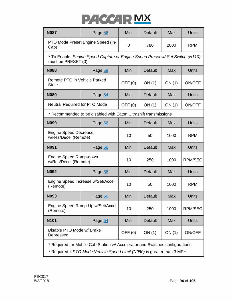
PEC017 5/3/2018 Page 94 of 105
N087 Page 56 Min Default Max Units
PTO Mode Preset Engine Speed (In-Cab) 0 780 2000 RPM
* To Enable, Engine Speed Capture or Engine Speed Preset w/ Set Switch (N110) must be PRESET (0)
N088 Page 58 Min Default Max Units
Remote PTO in Vehicle Parked State OFF (0) ON (1) ON (1) ON/OFF
N089 Page 54 Min Default Max Units
Neutral Required for PTO Mode OFF (0) ON (1) ON (1) ON/OFF
* Recommended to be disabled with Eaton Ultrashift transmissions
N090 Page 56 Min Default Max Units
Engine Speed Decrease w/Res/Decel (Remote) 10 50 1000 RPM
N091 Page 56 Min Default Max Units
Engine Speed Ramp-down w/Res/Decel (Remote) 10 250 1000 RPM/SEC
N092 Page 56 Min Default Max Units
Engine Speed Increase w/Set/Accel (Remote) 10 50 1000 RPM
N093 Page 56 Min Default Max Units
Engine Speed Ramp-Up w/Set/Accel (Remote) 10 250 1000 RPM/SEC
N101 Page 54 Min Default Max Units
Disable PTO Mode w/ Brake Depressed
OFF (0) ON (1) ON (1) ON/OFF
* Required for Mobile Cab Station w/ Accelerator and Switches configurations
* Required if PTO Mode Vehicle Speed Limit (N080) is greater than 3 MPH

PEC017 5/3/2018 Page 95 of 105
N102 Page 45 Min Default Max Units
Signal Source for Remote Main Switch 0 0 1 N/A
* 0 = Hardwired 12V
1 = CAN Signal
N103 Page 22 Min Default Max Units
Engine Speed Increase w/ Set/Accel 10 250 1000 RPM/SEC
N104 Page 22 Min Default Max Units
Engine Speed Decrease w/ Res/Decel 10 250 1000 RPM/SEC
N105 Page 22 Min Default Max Units
Engine Speed Ramp-down w/ Res/Decel 10 100 1900 RPM
N106 Page 55 Min Default Max Units
PTO Mode Minimum Engine Speed N052 650 2000 RPM
* Must be greater than or equal to Engine Idle Speed (N052)
* May not be greater than 800 RPM if Require Parking Brake for PTO Mode (N079) and Neutral Required for PTO Mode (N089) are disabled
* May not be greater than 950 RPM if Require Parking Brake for PTO Mode (N079) and Neutral Required for PTO Mode (N089) are disabled, and Disable PTO Mode w/ Brake Depressed(N106) is enabled.
N107 Page 22 Min Default Max Units
Engine Speed Ramp-Up w/ Set/Accel 10 100 1900 RPM
N109 Page 56 Min Default Max Units
Enable PTO Mode Engine Ramp Rate Limiter OFF (0) OFF (0) ON (1) ON/OFF

PEC017 5/3/2018 Page 96 of 105
N102 Page 45 Min Default Max Units
Signal Source for Remote Main Switch 0 0 1 N/A
N110 Page 56 Min Default Max Units
Engine Speed Capture or Engine Speed Preset w/ Set Switch
PRESET (0)
CAPTURE (1)
CAPTURE (1)
N/A
* In-Cab use only
* Not available with mobile applications
N162 Page 29 Min Default Max Units
Maximum Accelerator Pedal Vehicle Speed 25 64 155 MPH
N169 Page 29 Min Default Max Units
GHG Expiration Distance 0 0 1,259,000 MILES
* Configurable in Prospector Only
N170 Page 29 Min Default Max Units
GHG Maximum Speed Limit 0 121 121 MPH
* Configurable in Prospector Only
N178 Page 14 Min Default Max Units
Allow Idle Timer Reset During Warning OFF (0) ON (1) ON (1) ON/OFF
N179 Page 15 Min Default Max Units
Enable Idle Timer Reset from Park Brake OFF (0) ON (1) ON (1) ON/OFF
N182 Page 15 Min Default Max Units
Idle Timer Low Coolant Temperature Override Threshold 2 30 260 °F
N183 Page 15 Min Default Max Units
Idle Timer Engine Load Threshold 0 35 100 %

PEC017 5/3/2018 Page 97 of 105
N102 Page 45 Min Default Max Units
Signal Source for Remote Main Switch 0 0 1 N/A
N184 Page 15 Min Default Max Units
Idle Timer High Ambient Temp Threshold -40 80 490 °F
N185 Page 15 Min Default Max Units
Idle Timer Low Ambient Temp Threshold -40 39 490 °F
N186 Page 15 Min Default Max Units
Idle Time in PTO Mode 1 5 1092 MIN
N187 Page 14 Min Default Max Units
Idle Time w/ Parking Brake Set 1 5 1092 MIN
N188 Page 14 Min Default Max Units
Idle Time w/ Parking Brake Released 1 5 1092 MIN
N190 Page 15 Min Default Max Units
Enable Idle Timer Reset from Engine Load OFF (0) ON (1) ON (1) ON/OFF
* Requires Enable Idle Timer Override from Engine Load (N191) to be disabled
N191 Page 15 Min Default Max Units
Enable Idle Timer Override from Engine Load OFF (0) ON (1) ON (1) ON/OFF
* Requires Enable Idle Timer Reset from Engine Load (N190) to be disabled
* Not Available in PTO Mode
N193 Page 15 Min Default Max Units
Idle Timer Expiration Distance 0 500,000 1,259,000 MILES
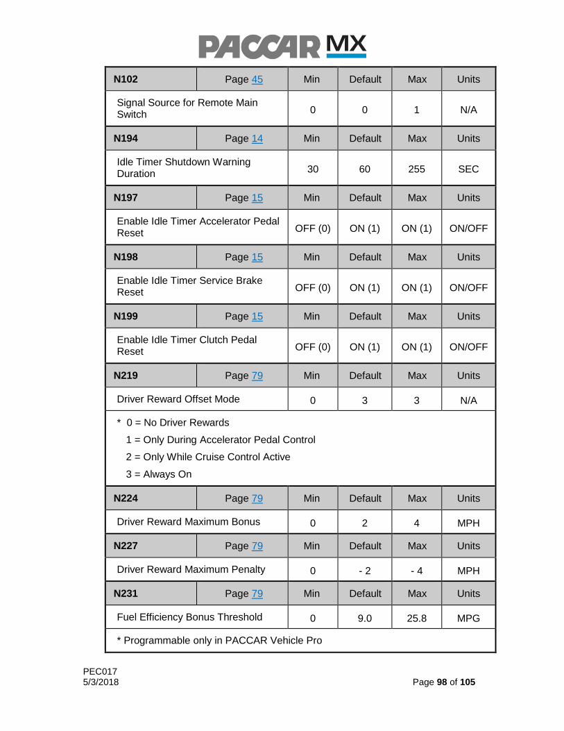
PEC017 5/3/2018 Page 98 of 105
N102 Page 45 Min Default Max Units
Signal Source for Remote Main Switch 0 0 1 N/A
N194 Page 14 Min Default Max Units
Idle Timer Shutdown Warning Duration 30 60 255 SEC
N197 Page 15 Min Default Max Units
Enable Idle Timer Accelerator Pedal Reset OFF (0) ON (1) ON (1) ON/OFF
N198 Page 15 Min Default Max Units
Enable Idle Timer Service Brake Reset OFF (0) ON (1) ON (1) ON/OFF
N199 Page 15 Min Default Max Units
Enable Idle Timer Clutch Pedal Reset OFF (0) ON (1) ON (1) ON/OFF
N219 Page 79 Min Default Max Units
Driver Reward Offset Mode 0 3 3 N/A
* 0 = No Driver Rewards
1 = Only During Accelerator Pedal Control
2 = Only While Cruise Control Active
3 = Always On
N224 Page 79 Min Default Max Units
Driver Reward Maximum Bonus 0 2 4 MPH
N227 Page 79 Min Default Max Units
Driver Reward Maximum Penalty 0 - 2 - 4 MPH
N231 Page 79 Min Default Max Units
Fuel Efficiency Bonus Threshold 0 9.0 25.8 MPG
* Programmable only in PACCAR Vehicle Pro

PEC017 5/3/2018 Page 99 of 105
N102 Page 45 Min Default Max Units
Signal Source for Remote Main Switch 0 0 1 N/A
N232 Page 79 Min Default Max Units
Fuel Efficiency Expected Threshold 0 7.0 21.1 MPG
* Programmable only in PACCAR Vehicle Pro
N233 Page 79 Min Default Max Units
Fuel Efficiency Penalty Threshold 0 5.0 16.4 MPG
* Programmable only in PACCAR Vehicle Pro
N235 Page 79 Min Default Max Units
Idle Time Bonus Threshold 0 5 100 %
* Programmable only in PACCAR Vehicle Pro
N236 Page 79 Min Default Max Units
Idle Time Expected Threshold 0 15 100 %
* Programmable only in PACCAR Vehicle Pro
N237 Page 79 Min Default Max Units
Idle Time Penalty Threshold 0 25 100 %
* Programmable only in PACCAR Vehicle Pro
N246 Page 76 Min Default Max Units
Minimum DSA Vehicle Speed 4 4 45 MPH
N247 Page 76 Min Default Max Units
Driver Shift Aid Lowest Active Gear 1 1 4 GEAR #
N248 Page 76 Min Default Max Units
Driver Shift Aid Highest Active Gear 5
TOP GEAR
TOP GEAR
GEAR #

PEC017 5/3/2018 Page 100 of 105
N102 Page 45 Min Default Max Units
Signal Source for Remote Main Switch 0 0 1 N/A
N296 Page 30 Min Default Max Units
Scale Acceleration Target SLOW NORMAL FAST N/A
N306 Page 46 Min Default Max Units
Enable Engine Speed Control via TSC1
OFF (0) OFF (0) ON (1) ON/OFF
N307 Page 58 Min Default Max Units
Disable In-Cab Accelerator Pedal in Remote PTO
OFF (0) OFF (0) ON (1) ON/OFF
N311 Page 58 Min Default Max Units
Enable Application Road Speed Limiter
OFF (0) OFF (0) ON (1) ON/OFF
N313 Page 58 Min Default Max Units
Application Road Speed Limiter Vehicle Speed
0 19 155 MPH
N315 Page 58 Min Default Max Units
ARSL On/Off with +12V Signal OFF (0) ON (1) ON (1) ON/OFF
N318 Page 87 Min Default Max Units
Enables the Auto HC-Desorb functionality
OFF (0) ON (1) ON (1) ON/OFF
GP11 Page 68 Min Default Max Units
GDP First Gear Active 1 N/A GP13 GEAR #
GP12 Page 68 Min Default Max Units
GDP Engine Speed 1500 1680 1700 RPM

PEC017 5/3/2018 Page 101 of 105
N102 Page 45 Min Default Max Units
Signal Source for Remote Main Switch 0 0 1 N/A
GP13 Page 68 Min Default Max Units
GDP Last Gear Active GP11 N/A
NOT TOP
GEAR GEAR #
GP14 Page 68 Min Default Max Units
GDP Active Gear Count N/A N/A N/A N/A
PS25 Page 67 Min Default Max Units
PGS Speed Step Count 0 N/A 2 N/A
PS26 Page 67 Min Default Max Units
PGS First Limit Gear Min 1 N/A <PS28 GEAR #
PS27 Page 68 Min Default Max Units
PGS First Engine Speed Limit 1400 N/A PS29 RPM
PS28 Page 67 Min Default Max Units
PGS First Limit Gear Max >PS26 N/A <PS30 GEAR #
PS29 Page 67 Min Default Max Units
PGS Second Engine Speed Limit PS27 N/A 1800 RPM
PS30 Page 67 Min Default Max Units
PGS Highest Gear >PS30 N/A
TOP GEAR
GEAR #

PEC017 5/3/2018 Page 102 of 105
PS29 Page 67 Min Default Max Units
PGS Second Engine Speed Limit PS27 N/A 1800 RPM
PS30 Page 67 Min Default Max Units
PGS Highest Gear >PS30 N/A
TOP GEAR
GEAR #

PEC017 5/3/2018 Page 103 of 105
23.0 Troubleshooting Errors in PACCAR Vehicle Pro
When changing parameters in PACCAR Vehicle Pro, errors may occur when paramters are configured outside of their intended ranges or if conflicts exist between paramters. Programming rules are enforced when submitting new software configurations, and error messages may appear. The following table is intended to provide clarification of commonly encountered error messages and requirements to resolve them:
Error Message
N006~MUST~BE~GTE~N003~PLUS~5MPH
The Maximum Cruise Control Target Speed (N006) must be at least 5 MPH greater than Minimum Cruise Control Target Speed (N003)
N055~MUST~BE~LESS~THAN~N056
Remote PTO Preset Engine Speed 1 (N055) must be less than Remote PTO Preset Engine Speed 2 (N056)
N055~MUST~BE~WITHIN~N106~AND~N056
Remote PTO Preset Engine Speed 1 (N055) must be greater than or equal to PTO Mode Minimum Engine Speed (N106), and also less than or equal to Remote PTO Preset Engine Speed 2 (N056)
N056~MUST~BE~WITHIN~N055~AND~N086
Remote PTO Preset Engine Speed 2 (N056) must be greather than or equal to Remote PTO Preset Engine Speed 1 (N055), and also less than or equal to Maximum Engine Speed using Switch Inputs (N086)
N076~MUST~BE~GTE~MIN~PTO~ESPD~N106
Maximum Engine Speed using Pedal Input (N076) must be greater than or equal to PTO Mode Minimum Engine Speed (N106)
N078~MUST~BE~DISABLED~IF~N079~~~EQ~~~0
Disable PTO Mode w/Clutch Depressed (N079) must be disabled if Require Parking Brake for PTO Mode (N079) is disabled
N079~MUST~BE~DISABLED~FOR~MOBILE~PTO
Require Parking Brake for PTO Mode (N079) must be disabled for Mobile PTO control type selections
N079~MUST~BE~ENABLED~FOR~REMOTE~PTO
Require Parking Brake for PTO Mode (N079) must be enabled for Remote PTO control type selections
N079~MUST~BE~ENABLED~FOR~STATIONARY~PTO
Require Parking Brake for PTO Mode (N079) must be enabled for Stationary PTO control type selections
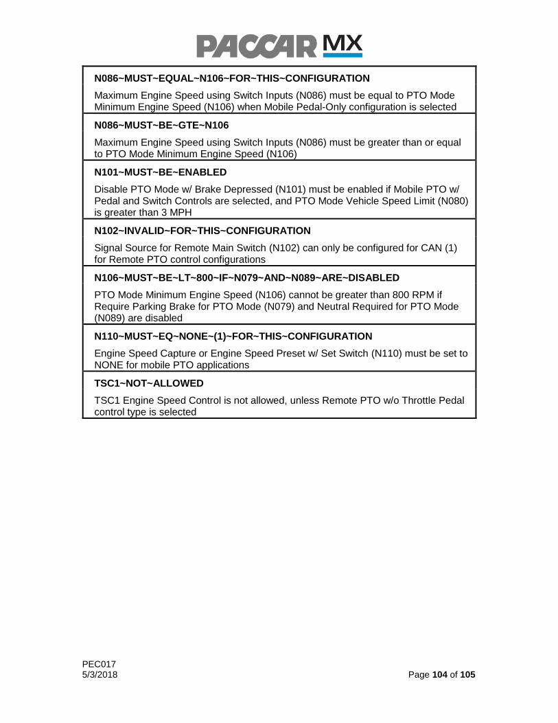
PEC017 5/3/2018 Page 104 of 105
N086~MUST~EQUAL~N106~FOR~THIS~CONFIGURATION
Maximum Engine Speed using Switch Inputs (N086) must be equal to PTO Mode Minimum Engine Speed (N106) when Mobile Pedal-Only configuration is selected
N086~MUST~BE~GTE~N106
Maximum Engine Speed using Switch Inputs (N086) must be greater than or equal to PTO Mode Minimum Engine Speed (N106)
N101~MUST~BE~ENABLED
Disable PTO Mode w/ Brake Depressed (N101) must be enabled if Mobile PTO w/ Pedal and Switch Controls are selected, and PTO Mode Vehicle Speed Limit (N080) is greater than 3 MPH
N102~INVALID~FOR~THIS~CONFIGURATION
Signal Source for Remote Main Switch (N102) can only be configured for CAN (1) for Remote PTO control configurations
N106~MUST~BE~LT~800~IF~N079~AND~N089~ARE~DISABLED
PTO Mode Minimum Engine Speed (N106) cannot be greater than 800 RPM if Require Parking Brake for PTO Mode (N079) and Neutral Required for PTO Mode (N089) are disabled
N110~MUST~EQ~NONE~(1)~FOR~THIS~CONFIGURATION
Engine Speed Capture or Engine Speed Preset w/ Set Switch (N110) must be set to NONE for mobile PTO applications
TSC1~NOT~ALLOWED
TSC1 Engine Speed Control is not allowed, unless Remote PTO w/o Throttle Pedal control type is selected

PEC017 5/3/2018 Page 105 of 105
24.0 Document Change Notes
1/11/2018 Added N296 (Scale Acceleration Target) parameter and description
Updated all references from PACCAR Engine Pro to PACCAR Vehicle Pro
Added table 9.1 to determine overall maximum vehicle speed limit
based on vehicle configuration
Added Section 21.0 PVP error troubleshooting guide to address
common configuration errors
Section 19.0 re-introduced for Ether Start Aid functionality
o mistakenly retracted from some previous revisions
Labeled In-Cab Throttle Pedal as optional in Remote PTO configuration
tables, as they are configurable in PVP
Added sales codes for “With FastStop Recorder” (default option) in
section 16.0
Increased maximum values for N001, N002, N003 to resolve overlap
issues with Maximum PTO Vehicle Speed
4/11/2018 Section 21.0 introduced for Auto Desorb functionality
o New functionality introduced
Added N318 (Auto Desorb) parameter and description
Added comments to N086
Section 20.0 intoduced for Manual Desorb