Embed Size (px)
Citation preview

I
Programming
Embedded
Systems
A 10-week course, using C
40
39
38
37
36
35
34
1234567
‘8051’
8910
33
32
31
30
29
28
27
26
25
24
11
12
13
14
15
16
17
18
19
20
23
22
21
P3.0
P1.7
RS
T
P1.6
P1.5
P1.4
P1.2
P1.3
P1.1
P1.0
VS
S
XT
L2
XT
L1
P3.7
P3.6
P3.5
P3.3
P3.4
P3.2
P3.1
/ EA
P0.6
P0.7
P0.5
P0.4
P0.3
P0.1
P0.2
P0.0
VC
C
P2.0
P2.2
P2.1
P2.3
P2.4
P2.5
P2.7
P2.6
/ PS
EN
ALE
Michael J. Pont
[v1.4a]
Further info: http://www.safetty.net/training/beginners
II
Copyright © Michael J. Pont, 2002-2013
This document may be freely distributed and copied, provided that copyright notice at
the foot of each OHP page is clearly visible in all copies.

III
Seminar 1: “Hello, Embedded World” 1
Overview of this seminar 2
Overview of this course 3
By the end of the course … 4
Main course textbook 5
Why use C? 6
Pre-requisites! 7
The 8051 microcontroller 8
The “super loop” software architecture 9
Strengths and weaknesseses of “super loops” 10
Example: Central-heating controller 11
Reading from (and writing to) port pins 12
SFRs and ports 13
SFRs and ports 14
Creating and using sbit variables 15
Example: Reading and writing bytes 16
Creating “software delays” 17
Using the performance analyzer to test software delays 18
Strengths and weaknesses of software-only delays 19
Preparation for the next seminar 20

IV
Seminar 2: Basic hardware foundations (resets, oscillators and port I/O) 21
Review: The 8051 microcontroller 22
Review: Central-heating controller 23
Overview of this seminar 24
Oscillator Hardware 25
How to connect a crystal to a microcontroller 27
Oscillator frequency and machine cycle period 28
Keep the clock frequency as low as possible 29
Stability issues 30
Improving the stability of a crystal oscillator 31
Overall strengths and weaknesses 32
Reset Hardware 34
More robust reset circuits 35
Driving DC Loads 36
Use of pull-up resistors 38
Driving a low-power load without using a buffer 39
Using an IC Buffer 40
Example: Buffering three LEDs with a 74HC04 41
What is a multi-segment LED? 42
Driving a single digit 43
Preparation for the next seminar 44

V
Seminar 3: Reading Switches 45
Introduction 46
Review: Basic techniques for reading from port pins 47
Example: Reading and writing bytes (review) 48
Example: Reading and writing bits (simple version) 49
Example: Reading and writing bits (generic version) 51
The need for pull-up resistors 56
The need for pull-up resistors 57
The need for pull-up resistors 58
Dealing with switch bounce 59
Example: Reading switch inputs (basic code) 61
Example: Counting goats 68
Conclusions 74
Preparation for the next seminar 75

VI
Seminar 4: Adding Structure to Your Code 77
Introduction 78
Object-Oriented Programming with C 79
Example of “O-O C” 82
The Project Header (Main.H) 85
The Port Header (Port.H) 92
Re-structuring a “Hello World” example 96
Example: Re-structuring the Goat-Counting Example 104
Preparation for the next seminar 114

VII
Seminar 5: Meeting Real-Time Constraints 115
Introduction 116
Creating “hardware delays” 118
The TCON SFR 119
The TMOD SFR 120
Two further registers 121
Example: Generating a precise 50 ms delay 122
Example: Creating a portable hardware delay 126
The need for ‘timeout’ mechanisms - example 129
Creating loop timeouts 130
Example: Testing loop timeouts 132
Example: A more reliable switch interface 134
Creating hardware timeouts 135
Conclusions 137
Preparation for the next seminar 138

VIII
Seminar 6: Creating an Embedded Operating System 139
Introduction 140
Timer-based interrupts (the core of an embedded OS) 144
The interrupt service routine (ISR) 145
Automatic timer reloads 146
Introducing sEOS 147
Introducing sEOS 148
Tasks, functions and scheduling 153
Setting the tick interval 154
Saving power 157
Using sEOS in your own projects 158
Is this approach portable? 159
Example: Milk pasteurization 160
Conclusions 174
Preparation for the next seminar 175

IX
Seminar 7: Multi-State Systems and Function Sequences 177
Introduction 178
Implementing a Multi-State (Timed) system 180
Example: Traffic light sequencing 181
Example: Animatronic dinosaur 189
Implementing a Multi-State (Input/Timed) system 195
Example: Controller for a washing machine 197
Conclusions 208
Preparation for the next seminar 209

X
Seminar 8: Using the Serial Interface 211
Overview of this seminar 212
What is ‘RS-232’? 213
Basic RS-232 Protocol 214
Asynchronous data transmission and baud rates 215
RS-232 voltage levels 216
The software architecture 217
Overview 218
Using the on-chip U(S)ART for RS-232 communications 219
Serial port registers 220
Baud rate generation 221
Why use 11.0592 MHz crystals? 222
PC Software 223
What about printf()? 224
RS-232 and 8051: Overall strengths and weaknesses 225
Example: Displaying elapsed time on a PC 226
Example: Data acquisition 235
Conclusions 239
Preparation for the next seminar 240

XI
Seminar 9: Case Study: Intruder Alarm System 241
Introduction 242
System Operation 243
Key software components used in this example 244
Running the program 245
The software 246
Extending and modifying the system 260
Conclusions 261
XII
Seminar 10: Case Study: Controlling a Mobile Robot 263
Overview 264
What can the robot do? 265
The robot brain 266
How does the robot move? 267
Pulse-width modulation 268
Software PWM 269
The resulting code 270
More about the robot 271
Conclusions 272

www.SafeTTy.net
COPYRIGHT © MICHAEL J. PONT, 2001-2013. Contains material from:
Pont, M.J. (2002) “Embedded C”, Addison-Wesley. PES I - 1
Seminar 1: “Hello, Embedded
World”
B
E
C
5.5V, 0.3A lamp
ZTX751
4V - 6V (battery)
10 K
10 µF
4 MHz
20
19
18
17
16
15
14
1
2
3
4
5
6
7
Atm
el
20
51
8
9
10
13
12
11GND
P3.4
P3.5
P3.3
P3.2
XTL1
P3.1
XTL2
P3.0
RST
P3.7
P1.1
P1.0
P1.2
P1.3
P1.4
P1.6
P1.5
P1.7
VCC
40
39
38
37
36
35
34
1234567
‘8051’
8910
33
32
31
30
29
28
27
26
25
24
11
12
13
14
15
16
17
18
19
20
23
22
21
P3
.0
P1
.7
RS
T
P1
.6
P1
.5
P1
.4
P1
.2
P1
.3
P1
.1
P1
.0
VS
S
XT
L2
XT
L1
P3
.7
P3
.6
P3
.5
P3
.3
P3
.4
P3
.2
P3
.1
/ EA
P0
.6
P0
.7
P0
.5
P0
.4
P0
.3
P0
.1
P0
.2
P0
.0
VC
C
P2
.0
P2
.2
P2
.1
P2
.3
P2
.4
P2
.5
P2
.7
P2
.6
/ PS
EN
AL
E

www.SafeTTy.net
COPYRIGHT © MICHAEL J. PONT, 2001-2013. Contains material from:
Pont, M.J. (2002) “Embedded C”, Addison-Wesley. PES I - 2
Overview of this seminar
This introductory seminar will:
Provide an overview of this course
Introduce the 8051 microcontroller
Present the “Super Loop” software architecture
Describe how to use port pins
Consider how you can generate delays (and why you might
need to).

www.SafeTTy.net
COPYRIGHT © MICHAEL J. PONT, 2001-2013. Contains material from:
Pont, M.J. (2002) “Embedded C”, Addison-Wesley. PES I - 3
Overview of this course
This course is concerned with the implementation of software (and
a small amount of hardware) for embedded systems constructed
using a single microcontroller.
The processors examined in detail are from the 8051 family
(including both ‘Standard’ and ‘Small’ devices).
All programming is in the ‘C’ language.

www.SafeTTy.net
COPYRIGHT © MICHAEL J. PONT, 2001-2013. Contains material from:
Pont, M.J. (2002) “Embedded C”, Addison-Wesley. PES I - 4
By the end of the course …
By the end of the course, you will be able to:
1. Design software for single-processor embedded applications
based on small, industry standard, microcontrollers;
2. Implement the above designs using a modern, high-level
programming language (‘C’), and
3. Begin to understand issues of reliability and safety and how
software design and programming decisions may have a
positive or negative impact in this area.

www.SafeTTy.net
COPYRIGHT © MICHAEL J. PONT, 2001-2013. Contains material from:
Pont, M.J. (2002) “Embedded C”, Addison-Wesley. PES I - 5
Main course textbook
Throughout this course, we will be making heavy use of this book:
Embedded C
by Michael J. Pont (2002)
Addison-Wesley
[ISBN: 0-201-79523X]

www.SafeTTy.net
COPYRIGHT © MICHAEL J. PONT, 2001-2013. Contains material from:
Pont, M.J. (2002) “Embedded C”, Addison-Wesley. PES I - 6
Why use C?
It is a ‘mid-level’, with ‘high-level’ features (such as support
for functions and modules), and ‘low-level’ features (such as
good access to hardware via pointers);
It is very efficient;
It is popular and well understood;
Even desktop developers who have used only Java or C++
can soon understand C syntax;
Good, well-proven compilers are available for every
embedded processor (8-bit to 32-bit or more);
Experienced staff are available;
Books, training courses, code samples and WWW sites
discussing the use of the language are all widely available.
Overall, C may not be an perfect language for developing embedded
systems, but it is a good choice (and is unlikely that a ‘perfect’ language
will ever be created).

www.SafeTTy.net
COPYRIGHT © MICHAEL J. PONT, 2001-2013. Contains material from:
Pont, M.J. (2002) “Embedded C”, Addison-Wesley. PES I - 7
Pre-requisites!
Throughout this course, it will be assumed that you have had
previous programming experience: this might be in - for
example - Java or C++.
For most people with such a background, “getting to grips”
with C is straightforward.

www.SafeTTy.net
COPYRIGHT © MICHAEL J. PONT, 2001-2013. Contains material from:
Pont, M.J. (2002) “Embedded C”, Addison-Wesley. PES I - 8
The 8051 microcontroller
40
39
38
37
36
35
34
1234567
‘8051’
8910
33
32
31
30
29
28
27
26
25
24
11
12
13
14
15
16
1718
19
20
23
22
21
P3.0
P1.7
RS
T
P1.6
P1.5
P1.4
P1.2
P1.3
P1.1
P1.0
VS
S
XT
L2
XT
L1
P3.7
P3.6
P3.5
P3.3
P3.4
P3.2
P3.1
/ EA
P0.6
P0.7
P0.5
P0.4
P0.3
P0.1
P0.2
P0.0
VC
C
P2.0
P2.2
P2.1
P2.3
P2.4
P2.5
P2.7
P2.6
/ PS
EN
ALE
Typical features of a modern 8051:
Thirty-two input / output lines.
Internal data (RAM) memory - 256 bytes.
Up to 64 kbytes of ROM memory (usually flash)
Three 16-bit timers / counters
Nine interrupts (two external) with two priority levels.
Low-power Idle and Power-down modes.
The different members of this family are suitable for everything from
automotive and aerospace systems to TV “remotes”.

www.SafeTTy.net
COPYRIGHT © MICHAEL J. PONT, 2001-2013. Contains material from:
Pont, M.J. (2002) “Embedded C”, Addison-Wesley. PES I - 9
The “super loop” software architecture
Problem
What is the minimum software environment you need to create an
embedded C program?
Solution
void main(void)
{
/* Prepare for task X */
X_Init();
while(1) /* 'for ever' (Super Loop) */
{
X(); /* Perform the task */
}
}
Crucially, the ‘super loop’, or ‘endless loop’, is required because we
have no operating system to return to: our application will keep looping
until the system power is removed.

www.SafeTTy.net
COPYRIGHT © MICHAEL J. PONT, 2001-2013. Contains material from:
Pont, M.J. (2002) “Embedded C”, Addison-Wesley. PES I - 10
Strengths and weaknesseses of “super loops”
The main strength of Super Loop systems is their simplicity. This
makes them (comparatively) easy to build, debug, test and maintain.
Super Loops are highly efficient: they have minimal hardware
resource implications.
Super Loops are highly portable.
BUT:
If your application requires accurate timing (for example, you need to
acquire data precisely every 2 ms), then this framework will not
provide the accuracy or flexibility you require.
The basic Super Loop operates at ‘full power’ (normal operating
mode) at all times. This may not be necessary in all applications, and
can have a dramatic impact on system power consumption.
[As we will see in Seminar 6, a scheduler can address these
problems.]

www.SafeTTy.net
COPYRIGHT © MICHAEL J. PONT, 2001-2013. Contains material from:
Pont, M.J. (2002) “Embedded C”, Addison-Wesley. PES I - 11
Example: Central-heating controller
Central
heating
controller
Boiler
Temperature
sensor
Temperature
dial
void main(void)
{
/* Init the system */
C_HEAT_Init();
while(1) /* 'for ever' (Super Loop) */
{
/* Find out what temperature the user requires
(via the user interface) */
C_HEAT_Get_Required_Temperature();
/* Find out what the current room temperature is
(via temperature sensor) */
C_HEAT_Get_Actual_Temperature();
/* Adjust the gas burner, as required */
C_HEAT_Control_Boiler();
}
}

www.SafeTTy.net
COPYRIGHT © MICHAEL J. PONT, 2001-2013. Contains material from:
Pont, M.J. (2002) “Embedded C”, Addison-Wesley. PES I - 12
Reading from (and writing to) port pins
Problem
How do you write software to read from and /or write to the ports
on an (8051) microcontroller?
Background
The Standard 8051s have four 8-bit ports.
All of the ports are bidirectional: that is, they may be used for both
input and output.
www.SafeTTy.net
COPYRIGHT © MICHAEL J. PONT, 2001-2013. Contains material from:
Pont, M.J. (2002) “Embedded C”, Addison-Wesley. PES I - 13
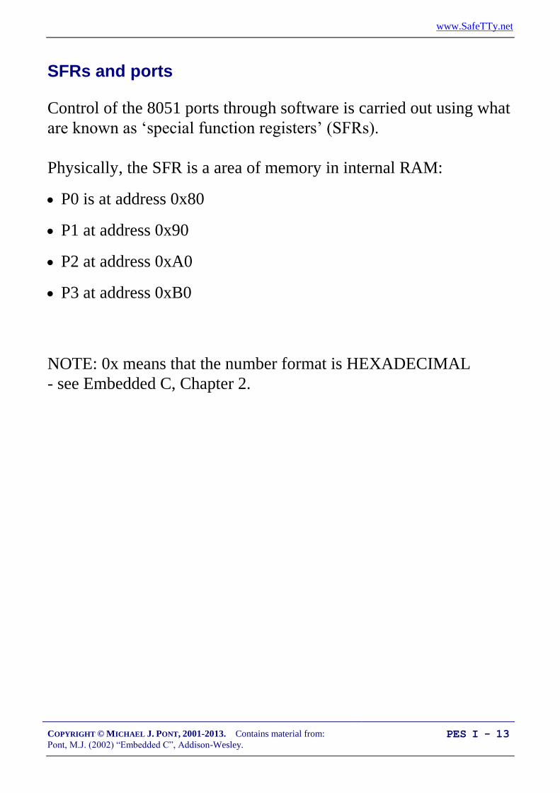
SFRs and ports
Control of the 8051 ports through software is carried out using what
are known as ‘special function registers’ (SFRs).
Physically, the SFR is a area of memory in internal RAM:
P0 is at address 0x80
P1 at address 0x90
P2 at address 0xA0
P3 at address 0xB0
NOTE: 0x means that the number format is HEXADECIMAL
- see Embedded C, Chapter 2.

www.SafeTTy.net
COPYRIGHT © MICHAEL J. PONT, 2001-2013. Contains material from:
Pont, M.J. (2002) “Embedded C”, Addison-Wesley. PES I - 14
SFRs and ports
A typical SFR header file for an 8051 family device will contain the
lines:
sfr P0 = 0x80;
sfr P1 = 0x90;
sfr P2 = 0xA0;
sfr P3 = 0xB0;
Having declared the SFR variables, we can write to the ports in a
straightforward manner. For example, we can send some data to
Port 1 as follows:
unsigned char Port_data;
Port_data = 0x0F;
P1 = Port_data; /* Write 00001111 to Port 1 */
Similarly, we can read from (for example) Port 1 as follows:
unsigned char Port_data;
P1 = 0xFF; /* Set the port to ‘read mode’ */
Port_data = P1; /* Read from the port */
Note that, in order to read from a pin, we need to ensure that the last
thing written to the pin was a ‘1’.

www.SafeTTy.net
COPYRIGHT © MICHAEL J. PONT, 2001-2013. Contains material from:
Pont, M.J. (2002) “Embedded C”, Addison-Wesley. PES I - 15
Creating and using sbit variables
To write to a single pin, we can make use of an sbit variable in the
Keil (C51) compiler to provide a finer level of control.
Here’s a clean way of doing this:
#define LED_PORT P3
#define LED_ON 0 /* Easy to change the logic here */
#define LED_OFF 1
...
sbit Warning_led = LED_PORT^0; /* LED is connected to pin 3.0 */
...
Warning_led = LED_ON;
... /* delay */
Warning_led = LED_OFF;
... /* delay */
Warning_led = LED_ON;
... /* etc */

www.SafeTTy.net
COPYRIGHT © MICHAEL J. PONT, 2001-2013. Contains material from:
Pont, M.J. (2002) “Embedded C”, Addison-Wesley. PES I - 16
Example: Reading and writing bytes
The input port
The output port
void main (void)
{
unsigned char Port1_value;
/* Must set up P1 for reading */
P1 = 0xFF;
while(1)
{
/* Read the value of P1 */
Port1_value = P1;
/* Copy the value to P2 */
P2 = Port1_value;
}
}

www.SafeTTy.net
COPYRIGHT © MICHAEL J. PONT, 2001-2013. Contains material from:
Pont, M.J. (2002) “Embedded C”, Addison-Wesley. PES I - 17
Creating “software delays”
Problem
How do you create a simple delay without using any hardware
(timer) resources?
Solution
Loop_Delay()
{
unsigned int x,y;
for (x=0; x <= 65535; x++)
{
y++;
}
}
Longer_Loop_Delay()
{
unsigned int x, y, z;
for (x=0; x<=65535; x++)
{
for (y=0; y<=65535; y++);
{
z++;
}
}
}

www.SafeTTy.net
COPYRIGHT © MICHAEL J. PONT, 2001-2013. Contains material from:
Pont, M.J. (2002) “Embedded C”, Addison-Wesley. PES I - 18
Using the performance analyzer to test software delays

www.SafeTTy.net
COPYRIGHT © MICHAEL J. PONT, 2001-2013. Contains material from:
Pont, M.J. (2002) “Embedded C”, Addison-Wesley. PES I - 19
Strengths and weaknesses of software-only delays
SOFTWARE DELAY can be used to produce very short delays.
SOFTWARE DELAY requires no hardware timers.
SOFTWARE DELAY will work on any microcontroller.
BUT:
It is very difficult to produce precisely timed delays.
The loops must be re-tuned if you decide to use a different processor,
change the clock frequency, or even change the compiler optimisation
settings.

www.SafeTTy.net
COPYRIGHT © MICHAEL J. PONT, 2001-2013. Contains material from:
Pont, M.J. (2002) “Embedded C”, Addison-Wesley. PES I - 20
Preparation for the next seminar
In the lab session associated with this seminar, you will use a
hardware simulator to try out the techniques discussed here. This
will give you a chance to focus on the software aspects of
embedded systems, without dealing with hardware problems.
In the next seminar, we will prepare to create your first test systems
on “real hardware”.
Please read Chapters 1, 2 and 3
before the next seminar
www.SafeTTy.net
COPYRIGHT © MICHAEL J. PONT, 2001-2013. Contains material from:
Pont, M.J. (2002) “Embedded C”, Addison-Wesley. PES I - 21
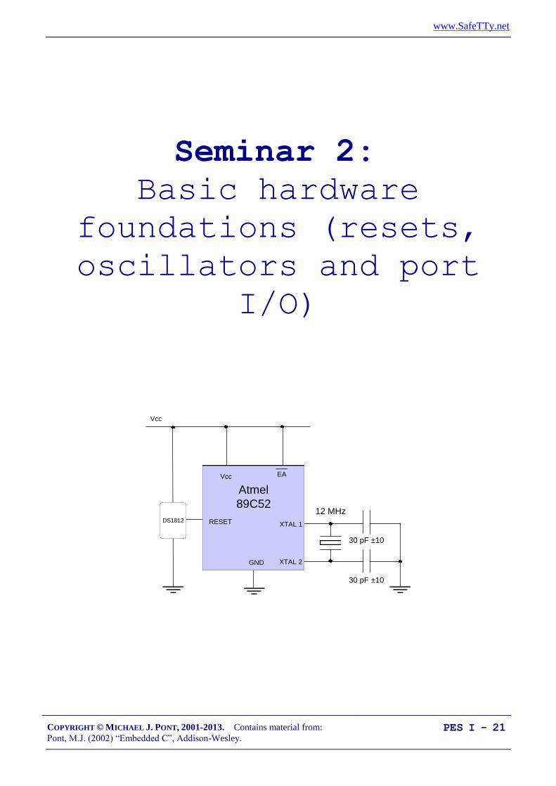
Seminar 2: Basic hardware
foundations (resets,
oscillators and port
I/O)
Atmel
89C52
Vcc
RESET
GND
Vcc
EA
30 pF ±10
30 pF ±10
XTAL 2
XTAL 1
DS1812
12 MHz
www.SafeTTy.net
COPYRIGHT © MICHAEL J. PONT, 2001-2013. Contains material from:
Pont, M.J. (2002) “Embedded C”, Addison-Wesley. PES I - 22
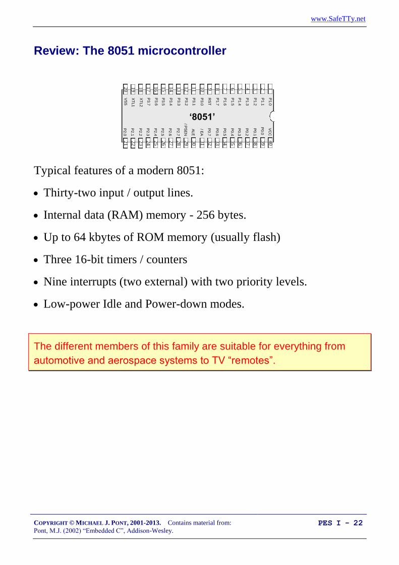
Review: The 8051 microcontroller
40
39
38
37
36
35
34
1234567
‘8051’
8910
33
32
31
30
29
28
27
26
25
24
11
12
13
14
15
16
1718
19
20
23
22
21
P3.0
P1.7
RS
T
P1.6
P1.5
P1.4
P1.2
P1.3
P1.1
P1.0
VS
S
XT
L2
XT
L1
P3.7
P3.6
P3.5
P3.3
P3.4
P3.2
P3.1
/ EA
P0.6
P0.7
P0.5
P0.4
P0.3
P0.1
P0.2
P0.0
VC
C
P2.0
P2.2
P2.1
P2.3
P2.4
P2.5
P2.7
P2.6
/ PS
EN
ALE
Typical features of a modern 8051:
Thirty-two input / output lines.
Internal data (RAM) memory - 256 bytes.
Up to 64 kbytes of ROM memory (usually flash)
Three 16-bit timers / counters
Nine interrupts (two external) with two priority levels.
Low-power Idle and Power-down modes.
The different members of this family are suitable for everything from
automotive and aerospace systems to TV “remotes”.

www.SafeTTy.net
COPYRIGHT © MICHAEL J. PONT, 2001-2013. Contains material from:
Pont, M.J. (2002) “Embedded C”, Addison-Wesley. PES I - 23
Review: Central-heating controller
Central
heating
controller
Boiler
Temperature
sensor
Temperature
dial
void main(void)
{
/* Init the system */
C_HEAT_Init();
while(1) /* 'for ever' (Super Loop) */
{
/* Find out what temperature the user requires
(via the user interface) */
C_HEAT_Get_Required_Temperature();
/* Find out what the current room temperature is
(via temperature sensor) */
C_HEAT_Get_Actual_Temperature();
/* Adjust the gas burner, as required */
C_HEAT_Control_Boiler();
}
}

www.SafeTTy.net
COPYRIGHT © MICHAEL J. PONT, 2001-2013. Contains material from:
Pont, M.J. (2002) “Embedded C”, Addison-Wesley. PES I - 24
Overview of this seminar
This seminar will:
Consider the techniques you need to construct your first
“real” embedded system (on a breadboard).
Specifically, we’ll look at:
Oscillator circuits
Reset circuits
Controlling LEDs

www.SafeTTy.net
COPYRIGHT © MICHAEL J. PONT, 2001-2013. Contains material from:
Pont, M.J. (2002) “Embedded C”, Addison-Wesley. PES I - 25
Oscillator Hardware
All digital computer systems are driven by some form of
oscillator circuit.
This circuit is the ‘heartbeat’ of the system and is crucial to
correct operation.
For example:
If the oscillator fails, the system will not function at all.
If the oscillator runs irregularly, any timing calculations
performed by the system will be inaccurate.

www.SafeTTy.net
COPYRIGHT © MICHAEL J. PONT, 2001-2013. Contains material from:
Pont, M.J. (2002) “Embedded C”, Addison-Wesley. PES I - 26
CRYSTAL OSCILLATOR
Crystals may be used to generate a popular form of oscillator circuit
known as a Pierce oscillator.
C
Crystal
R
JFET
L
Vcc
Oscillator output
(to microcontroller)
A variant of the Pierce oscillator is common in the 8051
family. To create such an oscillator, most of the components
are included on the microcontroller itself.
The user of this device must generally only supply the
crystal and two small capacitors to complete the oscillator
implementation.
www.SafeTTy.net
COPYRIGHT © MICHAEL J. PONT, 2001-2013. Contains material from:
Pont, M.J. (2002) “Embedded C”, Addison-Wesley. PES I - 27
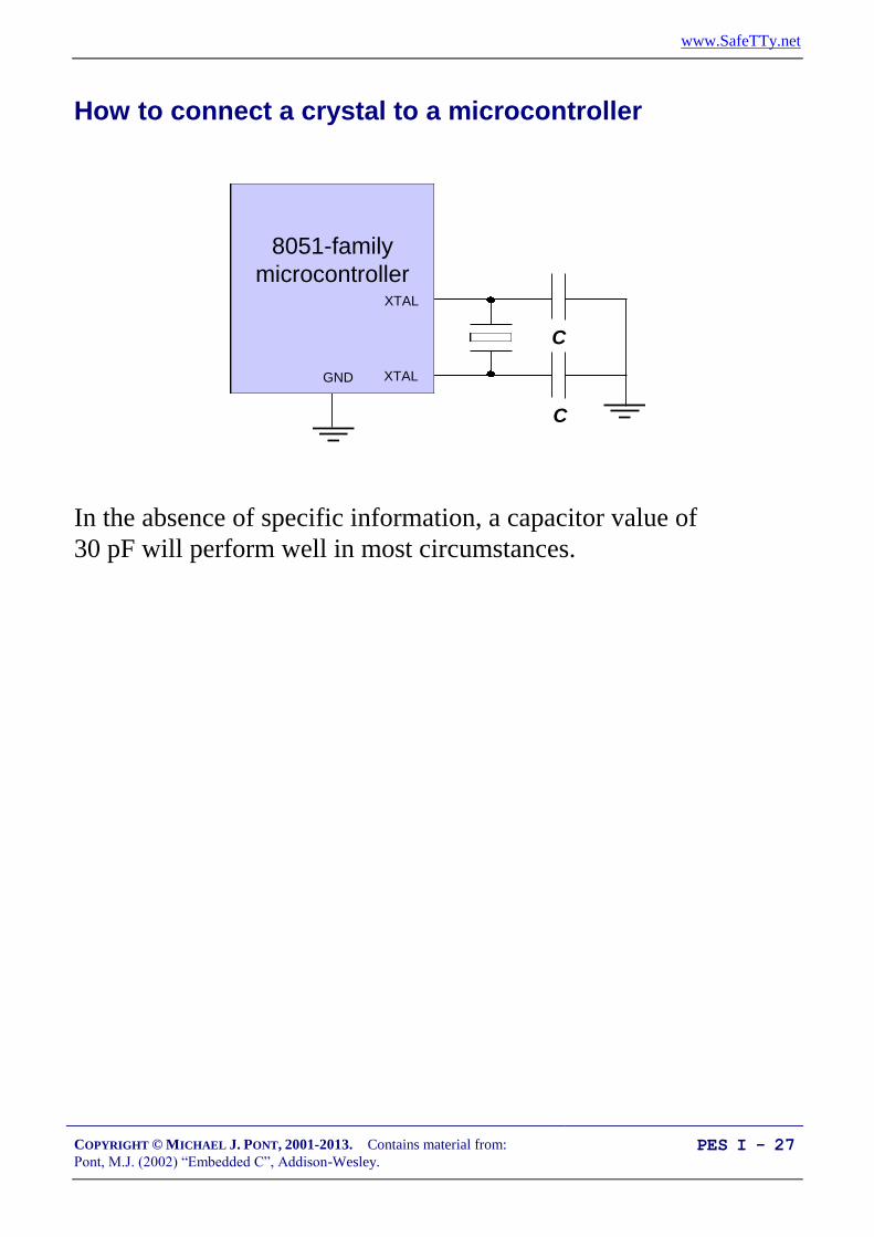
How to connect a crystal to a microcontroller
C
C
8051-family
microcontroller
GND XTAL
XTAL
In the absence of specific information, a capacitor value of
30 pF will perform well in most circumstances.

www.SafeTTy.net
COPYRIGHT © MICHAEL J. PONT, 2001-2013. Contains material from:
Pont, M.J. (2002) “Embedded C”, Addison-Wesley. PES I - 28
Oscillator frequency and machine cycle period
In the original members of the 8051 family, the machine
cycle takes twelve oscillator periods.
In later family members, such as the Infineon C515C, a
machine cycle takes six oscillator periods; in more recent
devices such as the Dallas 89C420, only one oscillator
period is required per machine cycle.
As a result, the later members of the family operating at the
same clock frequency execute instructions much more
rapidly.

www.SafeTTy.net
COPYRIGHT © MICHAEL J. PONT, 2001-2013. Contains material from:
Pont, M.J. (2002) “Embedded C”, Addison-Wesley. PES I - 29
Keep the clock frequency as low as possible
Many developers select an oscillator / resonator frequency that is at
or near the maximum value supported by a particular device.
This can be a mistake:
Many application do not require the levels of performance
that a modern 8051 device can provide.
The electromagnetic interference (EMI) generated by a
circuit increases with clock frequency.
In most modern (CMOS-based) 8051s, there is an almost
linear relationship between the oscillator frequency and the
power-supply current. As a result, by using the lowest
frequency necessary it is possible to reduce the power
requirement: this can be useful in many applications.
When accessing low-speed peripherals (such as slow
memory, or LCD displays), programming and hardware
design can be greatly simplified - and the cost of peripheral
components, such as memory latches, can be reduced - if the
chip is operating more slowly.
In general, you should operate at the lowest possible oscillator
frequency compatible with the performance needs of your application.

www.SafeTTy.net
COPYRIGHT © MICHAEL J. PONT, 2001-2013. Contains material from:
Pont, M.J. (2002) “Embedded C”, Addison-Wesley. PES I - 30
Stability issues
A key factor in selecting an oscillator for your system is the
issue of oscillator stability. In most cases, oscillator stability
is expressed in figures such as ‘±20 ppm’: ‘20 parts per
million’.
To see what this means in practice, consider that there are
approximately 32 million seconds in a year. In every million
seconds, your crystal may gain (or lose) 20 seconds. Over
the year, a clock based on a 20 ppm crystal may therefore
gain (or lose) about 32 x 20 seconds, or around 10 minutes.
Standard quartz crystals are typically rated from ±10 to ±100 ppm, and
so may gain (or lose) from around 5 to 50 minutes per year.

www.SafeTTy.net
COPYRIGHT © MICHAEL J. PONT, 2001-2013. Contains material from:
Pont, M.J. (2002) “Embedded C”, Addison-Wesley. PES I - 31
Improving the stability of a crystal oscillator
If you want a general crystal-controlled embedded system to
keep accurate time, you can choose to keep the device in an
oven (or fridge) at a fixed temperature, and fine-tune the
software to keep accurate time. This is, however, rarely
practical.
‘Temperature Compensated Crystal Oscillators’ (TCXOs)
are available that provide - in an easy-to-use package - a
crystal oscillator, and circuitry that compensates for changes
in temperature. Such devices provide stability levels of up to
±0.1 ppm (or more): in a clock circuit, this should gain or
lose no more than around 1 minute every 20 years.
TCXOs can cost in excess of $100.00 per unit...
One practical alternative is to determine the temperature-
frequency characteristics for your chosen crystal, and include
this information in your application.
For the cost of a small temperature sensor (around $2.00),
you can keep track of the temperature and adjust the timing
as required.

www.SafeTTy.net
COPYRIGHT © MICHAEL J. PONT, 2001-2013. Contains material from:
Pont, M.J. (2002) “Embedded C”, Addison-Wesley. PES I - 32
Overall strengths and weaknesses
Crystal oscillators are stable. Typically ±20-100 ppm = ±50 mins per
year (up to ~1 minute / week).
The great majority of 8051-based designs use a variant of the simple
crystal-based oscillator circuit presented here: developers are
therefore familiar with crystal-based designs.
Quartz crystals are available at reasonable cost for most common
frequencies. The only additional components required are usually two
small capacitors. Overall, crystal oscillators are more expensive than
ceramic resonators.
BUT:
Crystal oscillators are susceptible to vibration.
The stability falls with age.

www.SafeTTy.net
COPYRIGHT © MICHAEL J. PONT, 2001-2013. Contains material from:
Pont, M.J. (2002) “Embedded C”, Addison-Wesley. PES I - 33
CERAMIC RESONATOR
Overall strengths and weaknesses
Cheaper than crystal oscillators.
Physically robust: less easily damage by physical vibration (or
dropped equipment, etc) than crystal oscillator.
Many resonators contain in-built capacitors, and can be used without
any external components.
Small size. About half the size of crystal oscillator.
BUT:
Comparatively low stability: not general appropriate for use where
accurate timing (over an extended period) is required. Typically ±5000
ppm = ±2500 min per year (up to ~50 minutes / week).

www.SafeTTy.net
COPYRIGHT © MICHAEL J. PONT, 2001-2013. Contains material from:
Pont, M.J. (2002) “Embedded C”, Addison-Wesley. PES I - 34
Reset Hardware
The process of starting any microcontroller is a non-trivial
one.
The underlying hardware is complex and a small,
manufacturer-defined, ‘reset routine’ must be run to place
this hardware into an appropriate state before it can begin
executing the user program. Running this reset routine takes
time, and requires that the microcontroller’s oscillator is
operating.
An RC reset circuit is usually the simplest way of controlling
the reset behaviour.
Example:
30 pF ±10
30 pF ±10
AT89C2051
Vcc
RESET
GND
Vcc
10 K
10 uF
XTAL 2
XTAL 1

www.SafeTTy.net
COPYRIGHT © MICHAEL J. PONT, 2001-2013. Contains material from:
Pont, M.J. (2002) “Embedded C”, Addison-Wesley. PES I - 35
More robust reset circuits
Example:
Atmel
89C52
Vcc
RESET
GND
Vcc
EA
30 pF ±10
30 pF ±10
XTAL 2
XTAL 1
DS1812
12 MHz

www.SafeTTy.net
COPYRIGHT © MICHAEL J. PONT, 2001-2013. Contains material from:
Pont, M.J. (2002) “Embedded C”, Addison-Wesley. PES I - 36
Driving DC Loads
The port pins on a typical 8051 microcontroller can be set at
values of either 0V or 5V (or, in a 3V system, 0V and 3V)
under software control.
Each pin can typically sink (or source) a current of around
10 mA.
The total current we can source or sink per microcontroller
(all 32 pins, where available) is typically 70 mA or less.

www.SafeTTy.net
COPYRIGHT © MICHAEL J. PONT, 2001-2013. Contains material from:
Pont, M.J. (2002) “Embedded C”, Addison-Wesley. PES I - 37
NAKED LED
Logic 0 (0v)
to light LED
Vcc
Rled
diode
diodeccled
I
VVR
8051 Device
PX.Y
Connecting a single LED directly to a microcomputer port is
usually possible.
Supply voltage, Vcc = 5V,
LED forward voltage, Vdiode = 2V,
Required diode current, Idiode = 15 mA (note that the data
sheet for your chosen LED will provide this information).
This gives a required R value of 200.

www.SafeTTy.net
COPYRIGHT © MICHAEL J. PONT, 2001-2013. Contains material from:
Pont, M.J. (2002) “Embedded C”, Addison-Wesley. PES I - 38
Use of pull-up resistors
To adapt circuits for use on pins without internal pull-up resistors is
straightforward: you simply need to add an external pull-up resistor:
Logic 0
to light LED
Vcc
Rled
8051 Device
PX.Y
Rpull-up
The value of the pull-up resistor should be between 1K and 10K.
This requirement applies to all of the examples on this course.
NOTE:
This is usually only necessary on Port 0
(see Seminar 3 for further details).

www.SafeTTy.net
COPYRIGHT © MICHAEL J. PONT, 2001-2013. Contains material from:
Pont, M.J. (2002) “Embedded C”, Addison-Wesley. PES I - 39
Driving a low-power load without using a buffer
Logic 0 (0v)
to drive load
Vcc
R
load
loadcc
I
VVR
8051 Device
PX.Y
Load
Logic 0 (0v) to sound buzzer
Vcc
Piezo-electric
buzzer
8051 Device
PX.Y
See “PATTERNS FOR TIME-TRIGGERED EMBEDDED SYSTEMS”, p.115
(NAKED LOAD)

www.SafeTTy.net
COPYRIGHT © MICHAEL J. PONT, 2001-2013. Contains material from:
Pont, M.J. (2002) “Embedded C”, Addison-Wesley. PES I - 40
Using an IC Buffer
8051 Device
Pin X.Y
R
5V
Bu
ffer
(CM
OS
)
“Low” output = 0V LED is (fully) ON
“High” output = 5V LED is OFF
Using a CMOS buffer.
8051 Device
Pin X.Y
R
5V
Bu
ffer
(TT
L)
“Low” output = ~1V LED is ON
“High” output = 5V LED is OFFRpull-up
Using a TTL buffer.
It makes sense to use CMOS logic in your buffer designs wherever
possible. You should also make it clear in the design
documentation that CMOS logic is to be used.
See “PATTERNS FOR TIME-TRIGGERED EMBEDDED SYSTEMS”, p.118 (IC
BUFFER)

www.SafeTTy.net
COPYRIGHT © MICHAEL J. PONT, 2001-2013. Contains material from:
Pont, M.J. (2002) “Embedded C”, Addison-Wesley. PES I - 41
Example: Buffering three LEDs with a 74HC04
This example shows a 74HC04 buffering three LEDs. As discussed
in Solution, we do not require pull-up resistors with the HC
(CMOS) buffers.
In this case, we assume that the LEDs are to be driven at 15 mA
each, which is within the capabilities (50 mA total) of the buffer.
200R 200R 200R
(PX.a) (PX.b) (PX.c)
8051 Device
Port X
5V
74
HC
04
(PX.a,
PX.b,
PX.c)
(Red) (Amber) (Green)
Logic 1
to light
LED
See “PATTERNS FOR TIME-TRIGGERED EMBEDDED SYSTEMS”, p.123

www.SafeTTy.net
COPYRIGHT © MICHAEL J. PONT, 2001-2013. Contains material from:
Pont, M.J. (2002) “Embedded C”, Addison-Wesley. PES I - 42
What is a multi-segment LED?
Multiple LEDs are often arranged as multi-segment displays:
combinations of eight segments and similar seven-segment displays
(without a decimal point) are particularly common.
8 a
b
c
d
e
fg
Such displays are arranged either as ‘common cathode’ or ‘common
anode’ packages:
Cathode (-)
Anode (+)
The required current per segment varies from about 2 mA (very
small displays) to about 60 mA (very large displays, 100mm or
more).

www.SafeTTy.net
COPYRIGHT © MICHAEL J. PONT, 2001-2013. Contains material from:
Pont, M.J. (2002) “Embedded C”, Addison-Wesley. PES I - 43
Driving a single digit
In most cases, we require some form of buffer or driver IC
between the port and the MS LED.
For example, we can use UDN2585A.
Each of the (8) channels in this buffer can simultaneously
source up to 120 mA of current (at up to 25V): this is
enough, for example, for even very large LED displays.
10
Vcc
a
b
dp
UDN
2585A
c
g 8 PX.0
PX.7R
9
10
Note that this is an inverting (current source) buffer. Logic 0
on the input line will light the corresponding LED segment.

www.SafeTTy.net
COPYRIGHT © MICHAEL J. PONT, 2001-2013. Contains material from:
Pont, M.J. (2002) “Embedded C”, Addison-Wesley. PES I - 44
Preparation for the next seminar
Please read Chapter 4
before the next seminar

www.SafeTTy.net
COPYRIGHT © MICHAEL J. PONT, 2001-2013. Contains material from:
Pont, M.J. (2002) “Embedded C”, Addison-Wesley. PES I - 45
Seminar 3: Reading Switches
To pin on:
Port 1,
Port 2,
or
Port 3.

www.SafeTTy.net
COPYRIGHT © MICHAEL J. PONT, 2001-2013. Contains material from:
Pont, M.J. (2002) “Embedded C”, Addison-Wesley. PES I - 46
Introduction
Embedded systems usually use switches as part of their user
interface.
This general rule applies from the most basic remote-control
system for opening a garage door, right up to the most
sophisticated aircraft autopilot system.
Whatever the system you create, you need to be able to
create a reliable switch interface.
1 32
0
4 65
7 98
Enter ><
1 2 3 4 5
StartOffOn
STOP
Engage AP
Temporary Manual
Up and Around
Disengage AP
In this seminar, we consider how you can read inputs from
mechanical switches in your embedded application.
Before considering switches themselves, we will consider the
process of reading the state of port pins.

www.SafeTTy.net
COPYRIGHT © MICHAEL J. PONT, 2001-2013. Contains material from:
Pont, M.J. (2002) “Embedded C”, Addison-Wesley. PES I - 47
Review: Basic techniques for reading from port pins
We can send some data to Port 1 as follows:
sfr P1 = 0x90; /* Usually in header file */
P1 = 0x0F; /* Write 00001111 to Port 1 */
In exactly the same way, we can read from Port 1 as follows:
unsigned char Port_data;
P1 = 0xFF; /* Set the port to ‘read mode’ */
Port_data = P1; /* Read from the port */

www.SafeTTy.net
COPYRIGHT © MICHAEL J. PONT, 2001-2013. Contains material from:
Pont, M.J. (2002) “Embedded C”, Addison-Wesley. PES I - 48
Example: Reading and writing bytes (review)
The input port
The output port
void main (void)
{
unsigned char Port1_value;
/* Must set up P1 for reading */
P1 = 0xFF;
while(1)
{
/* Read the value of P1 */
Port1_value = P1;
/* Copy the value to P2 */
P2 = Port1_value;
}
}

www.SafeTTy.net
COPYRIGHT © MICHAEL J. PONT, 2001-2013. Contains material from:
Pont, M.J. (2002) “Embedded C”, Addison-Wesley. PES I - 49
Example: Reading and writing bits (simple version)
/*-------------------------------------------------------------*-
Bits1.C (v1.00)
-*-------------------------------------------------------------*/
#include <Reg52.H>
sbit Switch_pin = P1^0;
sbit LED_pin = P1^1;
/* ............................................................... */
void main (void)
{
bit x;
/* Set switch pin for reading */
Switch_pin = 1;
while(1)
{
x = Switch_pin; /* Read Pin 1.0 */
LED_pin = x; /* Write to Pin 1.1 */
}
}
/*-------------------------------------------------------------*-
---- END OF FILE ---------------------------------------
-*-------------------------------------------------------------*/
www.SafeTTy.net
COPYRIGHT © MICHAEL J. PONT, 2001-2013. Contains material from:
Pont, M.J. (2002) “Embedded C”, Addison-Wesley. PES I - 50
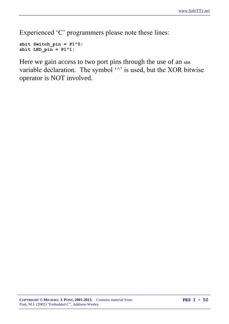
Experienced ‘C’ programmers please note these lines:
sbit Switch_pin = P1^0;
sbit LED_pin = P1^1;
Here we gain access to two port pins through the use of an sbit
variable declaration. The symbol ‘^’ is used, but the XOR bitwise
operator is NOT involved.

www.SafeTTy.net
COPYRIGHT © MICHAEL J. PONT, 2001-2013. Contains material from:
Pont, M.J. (2002) “Embedded C”, Addison-Wesley. PES I - 51
Example: Reading and writing bits (generic version)
The six bitwise operators:
Operator Description & Bitwise AND | Bitwise OR (inclusive OR) ^ Bitwise XOR (exclusive OR) << Left shift >> Right shift ~ One’s complement
A B A AND B A OR B A XOR B
0 0 0 0 0
0 1 0 1 1
1 0 0 1 1
1 1 1 1 0
www.SafeTTy.net
COPYRIGHT © MICHAEL J. PONT, 2001-2013. Contains material from:
Pont, M.J. (2002) “Embedded C”, Addison-Wesley. PES I - 52
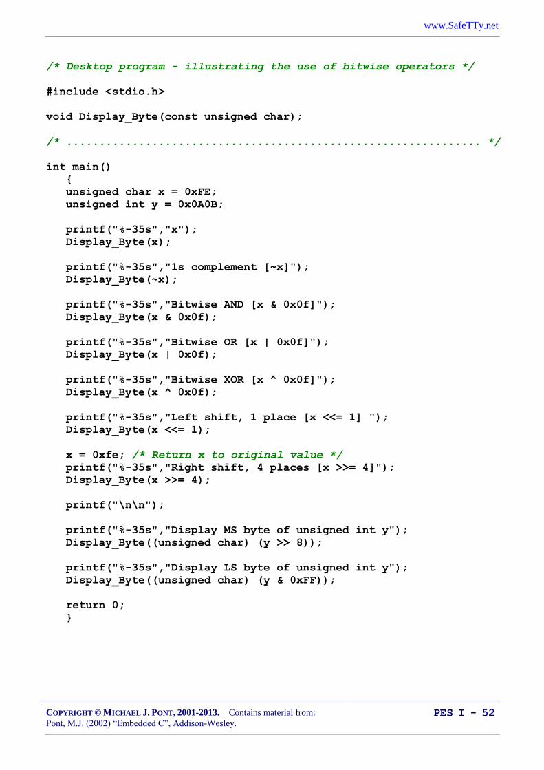
/* Desktop program - illustrating the use of bitwise operators */
#include <stdio.h>
void Display_Byte(const unsigned char);
/* ............................................................... */
int main()
{
unsigned char x = 0xFE;
unsigned int y = 0x0A0B;
printf("%-35s","x");
Display_Byte(x);
printf("%-35s","1s complement [~x]");
Display_Byte(~x);
printf("%-35s","Bitwise AND [x & 0x0f]");
Display_Byte(x & 0x0f);
printf("%-35s","Bitwise OR [x | 0x0f]");
Display_Byte(x | 0x0f);
printf("%-35s","Bitwise XOR [x ^ 0x0f]");
Display_Byte(x ^ 0x0f);
printf("%-35s","Left shift, 1 place [x <<= 1] ");
Display_Byte(x <<= 1);
x = 0xfe; /* Return x to original value */
printf("%-35s","Right shift, 4 places [x >>= 4]");
Display_Byte(x >>= 4);
printf("\n\n");
printf("%-35s","Display MS byte of unsigned int y");
Display_Byte((unsigned char) (y >> 8));
printf("%-35s","Display LS byte of unsigned int y");
Display_Byte((unsigned char) (y & 0xFF));
return 0;
}

www.SafeTTy.net
COPYRIGHT © MICHAEL J. PONT, 2001-2013. Contains material from:
Pont, M.J. (2002) “Embedded C”, Addison-Wesley. PES I - 53
/* --------------------------------------------------------------- */
void Display_Byte(const unsigned char CH)
{
unsigned char i, c = CH;
unsigned char Mask = 1 << 7;
for (i = 1; i <= 8; i++)
{
putchar(c & Mask ? '1' : '0');
c <<= 1;
}
putchar('\n');
}
x 11111110
1s complement [~x] 00000001
Bitwise AND [x & 0x0f] 00001110
Bitwise OR [x | 0x0f] 11111111
Bitwise XOR [x ^ 0x0f] 11110001
Left shift, 1 place [x <<= 1] 11111100
Right shift, 4 places [x >>= 4] 00001111
Display MS byte of unsigned int y 00001010
Display LS byte of unsigned int y 00001011

www.SafeTTy.net
COPYRIGHT © MICHAEL J. PONT, 2001-2013. Contains material from:
Pont, M.J. (2002) “Embedded C”, Addison-Wesley. PES I - 54
/*-------------------------------------------------------------*-
Reading and writing individual port pins.
NOTE: Both pins on the same port
-*-------------------------------------------------------------*/
#include <reg52.H>
void Write_Bit_P1(const unsigned char, const bit);
bit Read_Bit_P1(const unsigned char);
/* ............................................................... */
void main (void)
{
bit x;
while(1)
{
x = Read_Bit_P1(0); /* Read Port 1, Pin 0 */
Write_Bit_P1(1,x); /* Write to Port 1, Pin 1 */
}
}
/* --------------------------------------------------------------- */
void Write_Bit_P1(const unsigned char PIN, const bit VALUE)
{
unsigned char p = 0x01; /* 00000001 */
/* Left shift appropriate number of places */
p <<= PIN;
/* If we want 1 output at this pin */
if (VALUE == 1)
{
P1 |= p; /* Bitwise OR */
return;
}
/* If we want 0 output at this pin */
p = ~p; /* Complement */
P1 &= p; /* Bitwise AND */
}

www.SafeTTy.net
COPYRIGHT © MICHAEL J. PONT, 2001-2013. Contains material from:
Pont, M.J. (2002) “Embedded C”, Addison-Wesley. PES I - 55
/* --------------------------------------------------------------- */
bit Read_Bit_P1(const unsigned char PIN)
{
unsigned char p = 0x01; /* 00000001 */
/* Left shift appropriate number of places */
p <<= PIN;
/* Write a 1 to the pin (to set up for reading) */
Write_Bit_P1(PIN, 1);
/* Read the pin (bitwise AND) and return */
return (P1 & p);
}
/*-------------------------------------------------------------*-
---- END OF FILE ---------------------------------------
-*-------------------------------------------------------------*/

www.SafeTTy.net
COPYRIGHT © MICHAEL J. PONT, 2001-2013. Contains material from:
Pont, M.J. (2002) “Embedded C”, Addison-Wesley. PES I - 56
The need for pull-up resistors
To pin on:
Port 1,
Port 2,
or
Port 3.
This hardware operates as follows:
When the switch is open, it has no impact on the port pin.
An internal resistor on the port ‘pulls up’ the pin to the
supply voltage of the microcontroller (typically 5V). If we
read the pin, we will see the value ‘1’.
When the switch is closed (pressed), the pin voltage will be
0V. If we read the the pin, we will see the value ‘0’.

www.SafeTTy.net
COPYRIGHT © MICHAEL J. PONT, 2001-2013. Contains material from:
Pont, M.J. (2002) “Embedded C”, Addison-Wesley. PES I - 57
The need for pull-up resistors
We briefly looked at pull-up resistors in Seminar 2.
With pull-ups:
Vcc Vcc
Switch released:
Reads ‘1’
Switch pressed:
Reads ‘0’
Without pull-ups:
Vcc Vcc
Switch released:
Reads ‘0’
Switch pressed:
Reads ‘0’

www.SafeTTy.net
COPYRIGHT © MICHAEL J. PONT, 2001-2013. Contains material from:
Pont, M.J. (2002) “Embedded C”, Addison-Wesley. PES I - 58
The need for pull-up resistors
Vcc
10K
To pin on:
Port 0.

www.SafeTTy.net
COPYRIGHT © MICHAEL J. PONT, 2001-2013. Contains material from:
Pont, M.J. (2002) “Embedded C”, Addison-Wesley. PES I - 59
Dealing with switch bounce
In practice, all mechanical switch contacts bounce (that is, turn on
and off, repeatedly, for a short period of time) after the switch is
closed or opened.
+5v
Voltage
Timet1 t2
+5v
As far as the microcontroller is concerned, each ‘bounce’ is
equivalent to one press and release of an ‘ideal’ switch. Without
appropriate software design, this can give rise to a number of
problems, not least:
Rather than reading ‘A’ from a keypad, we may read
‘AAAAA’
Counting the number of times that a switch is pressed
becomes extremely difficult.
If a switch is depressed once, and then released some time
later, the ‘bounce’ may make it appear as if the switch has
been pressed again (at the time of release).

www.SafeTTy.net
COPYRIGHT © MICHAEL J. PONT, 2001-2013. Contains material from:
Pont, M.J. (2002) “Embedded C”, Addison-Wesley. PES I - 60
Creating some simple software to check for a valid switch input is
straightforward:
1. We read the relevant port pin.
2. If we think we have detected a switch depression, we wait for
20 ms and then read the pin again.
3. If the second reading confirms the first reading, we assume
the switch really has been depressed.
Note that the figure of ‘20 ms’ will, of course, depend on the switch
used.

www.SafeTTy.net
COPYRIGHT © MICHAEL J. PONT, 2001-2013. Contains material from:
Pont, M.J. (2002) “Embedded C”, Addison-Wesley. PES I - 61
Example: Reading switch inputs (basic code)
This switch-reading code is adequate if we want to perform
operations such as:
Drive a motor while a switch is pressed.
Switch on a light while a switch is pressed.
Activate a pump while a switch is pressed.
These operations could be implemented using an electrical switch,
without using a microcontroller; however, use of a microcontroller
may well be appropriate if we require more complex behaviour.
For example:
Drive a motor while a switch is pressed
Condition: If the safety guard is not in place, don’t turn the
motor. Instead sound a buzzer for 2 seconds.
Switch on a light while a switch is pressed
Condition: To save power, ignore requests to turn on the
light during daylight hours.
Activate a pump while a switch is pressed
Condition: If the main water reservoir is below 300 litres,
do not start the main pump: instead, start the reserve pump
and draw the water from the emergency tank.

www.SafeTTy.net
COPYRIGHT © MICHAEL J. PONT, 2001-2013. Contains material from:
Pont, M.J. (2002) “Embedded C”, Addison-Wesley. PES I - 62
/*-------------------------------------------------------------*-
Switch_read.C (v1.00)
--------------------------------------------------------
A simple 'switch input' program for the 8051.
- Reads (and debounces) switch input on Pin 1^0
- If switch is pressed, changes Port 3 output
-*-------------------------------------------------------------*/
#include <Reg52.h>
/* Connect switch to this pin */
sbit Switch_pin = P1^0;
/* Display switch status on this port */
#define Output_port P3
/* Return values from Switch_Get_Input() */
#define SWITCH_NOT_PRESSED (bit) 0
#define SWITCH_PRESSED (bit) 1
/* Function prototypes */
void SWITCH_Init(void);
bit SWITCH_Get_Input(const unsigned char DEBOUNCE_PERIOD);
void DISPLAY_SWITCH_STATUS_Init(void);
void DISPLAY_SWITCH_STATUS_Update(const bit);
void DELAY_LOOP_Wait(const unsigned int DELAY_MS);

www.SafeTTy.net
COPYRIGHT © MICHAEL J. PONT, 2001-2013. Contains material from:
Pont, M.J. (2002) “Embedded C”, Addison-Wesley. PES I - 63
/* ---------------------------------------------------------------- */
void main(void)
{
bit Sw_state;
/* Init functions */
SWITCH_Init();
DISPLAY_SWITCH_STATUS_Init();
while(1)
{
Sw_state = SWITCH_Get_Input(30);
DISPLAY_SWITCH_STATUS_Update(Sw_state);
}
}
/*-------------------------------------------------------------*-
SWITCH_Init()
Initialisation function for the switch library.
-*-------------------------------------------------------------*/
void SWITCH_Init(void)
{
Switch_pin = 1; /* Use this pin for input */
}

www.SafeTTy.net
COPYRIGHT © MICHAEL J. PONT, 2001-2013. Contains material from:
Pont, M.J. (2002) “Embedded C”, Addison-Wesley. PES I - 64
/*-------------------------------------------------------------*-
SWITCH_Get_Input()
Reads and debounces a mechanical switch as follows:
1. If switch is not pressed, return SWITCH_NOT_PRESSED.
2. If switch is pressed, wait for the DEBOUNCE_PERIOD (in ms).
Then:
a. If switch is no longer pressed, return SWITCH_NOT_PRESSED.
b. If switch is still pressed, return SWITCH_PRESSED
See Switch_Wait.H for details of return values.
-*-------------------------------------------------------------*/
bit SWITCH_Get_Input(const unsigned char DEBOUNCE_PERIOD)
{
bit Return_value = SWITCH_NOT_PRESSED;
if (Switch_pin == 0)
{
/* Switch is pressed */
/* Debounce - just wait... */
DELAY_LOOP_Wait(DEBOUNCE_PERIOD);
/* Check switch again */
if (Switch_pin == 0)
{
Return_value = SWITCH_PRESSED;
}
}
/* Now return switch value */
return Return_value;
}

www.SafeTTy.net
COPYRIGHT © MICHAEL J. PONT, 2001-2013. Contains material from:
Pont, M.J. (2002) “Embedded C”, Addison-Wesley. PES I - 65
/*-------------------------------------------------------------*-
DISPLAY_SWITCH_STATUS_Init()
Initialization function for the DISPLAY_SWITCH_STATUS library.
-*-------------------------------------------------------------*/
void DISPLAY_SWITCH_STATUS_Init(void)
{
Output_port = 0xF0;
}
/*-------------------------------------------------------------*-
DISPLAY_SWITCH_STATUS_Update()
Simple function to display data (SWITCH_STATUS)
on LEDs connected to port (Output_Port)
-*-------------------------------------------------------------*/
void DISPLAY_SWITCH_STATUS_Update(const bit SWITCH_STATUS)
{
if (SWITCH_STATUS == SWITCH_PRESSED)
{
Output_port = 0x0F;
}
else
{
Output_port = 0xF0;
}
}

www.SafeTTy.net
COPYRIGHT © MICHAEL J. PONT, 2001-2013. Contains material from:
Pont, M.J. (2002) “Embedded C”, Addison-Wesley. PES I - 66
/*-------------------------------------------------------------*-
DELAY_LOOP_Wait()
Delay duration varies with parameter.
Parameter is, *ROUGHLY*, the delay, in milliseconds,
on 12MHz 8051 (12 osc cycles).
You need to adjust the timing for your application!
-*-------------------------------------------------------------*/
void DELAY_LOOP_Wait(const unsigned int DELAY_MS)
{
unsigned int x, y;
for (x = 0; x <= DELAY_MS; x++)
{
for (y = 0; y <= 120; y++);
}
}

www.SafeTTy.net
COPYRIGHT © MICHAEL J. PONT, 2001-2013. Contains material from:
Pont, M.J. (2002) “Embedded C”, Addison-Wesley. PES I - 67
The input portThe output port

www.SafeTTy.net
COPYRIGHT © MICHAEL J. PONT, 2001-2013. Contains material from:
Pont, M.J. (2002) “Embedded C”, Addison-Wesley. PES I - 68
Example: Counting goats
With the simple code in the previous example, problems can
arise whenever a switch is pressed for a period longer than
the debounce interval.
This is a concern, because in many cases, users will press
switches for at least 500 ms (or until they receive feedback
that the system has detected the switch press). As a result, a
user typing “Hello” on a keypad may see:
“HHHHHHHHHeeeeeeeeellllllllllllllllooooooooooo”
appear on the screen.
One consequence is that this code is not suitable for applications
where we need to count the number of times that a switch is pressed
and then released.

www.SafeTTy.net
COPYRIGHT © MICHAEL J. PONT, 2001-2013. Contains material from:
Pont, M.J. (2002) “Embedded C”, Addison-Wesley. PES I - 69
Mechanical sensor
at goat body
height
Sensor
Goat detected
If we try to use the code in the previous example, the goat sensor
will not allow us to count the number of goats but will instead
provide an indication of the time taken for the goats to pass the
sensor.

www.SafeTTy.net
COPYRIGHT © MICHAEL J. PONT, 2001-2013. Contains material from:
Pont, M.J. (2002) “Embedded C”, Addison-Wesley. PES I - 70
/*-------------------------------------------------------------*-
A 'goat counting' program for the 8051...
-*-------------------------------------------------------------*/
#include <Reg52.h>
/* Connect switch to this pin */
sbit Switch_pin = P1^0;
/* Display count (binary) on this port */
#define Count_port P3
/* Return values from Switch_Get_Input() */
#define SWITCH_NOT_PRESSED (bit) 0
#define SWITCH_PRESSED (bit) 1
/* Function prototypes */
void SWITCH_Init(void);
bit SWITCH_Get_Input(const unsigned char DEBOUNCE_PERIOD);
void DISPLAY_COUNT_Init(void);
void DISPLAY_COUNT_Update(const unsigned char);
void DELAY_LOOP_Wait(const unsigned int DELAY_MS);
/* ---------------------------------------------------------------- */
void main(void)
{
unsigned char Switch_presses = 0;
/* Init functions */
SWITCH_Init();
DISPLAY_COUNT_Init();
while(1)
{
if (SWITCH_Get_Input(30) == SWITCH_PRESSED)
{
Switch_presses++;
}
DISPLAY_COUNT_Update(Switch_presses);
}
}

www.SafeTTy.net
COPYRIGHT © MICHAEL J. PONT, 2001-2013. Contains material from:
Pont, M.J. (2002) “Embedded C”, Addison-Wesley. PES I - 71
/*-------------------------------------------------------------*/
void SWITCH_Init(void)
{
Switch_pin = 1; /* Use this pin for input */
}
/*-------------------------------------------------------------*-
SWITCH_Get_Input()
Reads and debounces a mechanical switch as follows:
1. If switch is not pressed, return SWITCH_NOT_PRESSED.
2. If switch is pressed, wait for the DEBOUNCE_PERIOD (in ms).
Then:
a. If switch is no longer pressed, return SWITCH_NOT_PRESSED.
b. If switch is still pressed, wait (indefinitely) for
switch to be released, *then* return SWITCH_PRESSED
See Switch_Wait.H for details of return values.
-*-------------------------------------------------------------*/
bit SWITCH_Get_Input(const unsigned char DEBOUNCE_PERIOD)
{
bit Return_value = SWITCH_NOT_PRESSED;
if (Switch_pin == 0)
{
/* Switch is pressed */
/* Debounce - just wait... */
DELAY_LOOP_Wait(DEBOUNCE_PERIOD);
/* Check switch again */
if (Switch_pin == 0)
{
/* Wait until the switch is released. */
while (Switch_pin == 0);
Return_value = SWITCH_PRESSED;
}
}
/* Now (finally) return switch value */
return Return_value;
}

www.SafeTTy.net
COPYRIGHT © MICHAEL J. PONT, 2001-2013. Contains material from:
Pont, M.J. (2002) “Embedded C”, Addison-Wesley. PES I - 72
/*-------------------------------------------------------------*-
DISPLAY_COUNT_Init()
Initialisation function for the DISPLAY COUNT library.
-*-------------------------------------------------------------*/
void DISPLAY_COUNT_Init(void)
{
Count_port = 0x00;
}
/*-------------------------------------------------------------*-
DISPLAY_COUNT_Update()
Simple function to display tByte data (COUNT)
on LEDs connected to port (Count_Port)
-*-------------------------------------------------------------*/
void DISPLAY_COUNT_Update(const unsigned char COUNT)
{
Count_port = COUNT;
}
/*-------------------------------------------------------------*-
DELAY_LOOP_Wait()
Delay duration varies with parameter.
Parameter is, *ROUGHLY*, the delay, in milliseconds,
on 12MHz 8051 (12 osc cycles).
You need to adjust the timing for your application!
-*-------------------------------------------------------------*/
void DELAY_LOOP_Wait(const unsigned int DELAY_MS)
{
unsigned int x, y;
for (x = 0; x <= DELAY_MS; x++)
{
for (y = 0; y <= 120; y++);
}
}

www.SafeTTy.net
COPYRIGHT © MICHAEL J. PONT, 2001-2013. Contains material from:
Pont, M.J. (2002) “Embedded C”, Addison-Wesley. PES I - 73
The switch input (Pin 1.0)
The number of goats (in binary)

www.SafeTTy.net
COPYRIGHT © MICHAEL J. PONT, 2001-2013. Contains material from:
Pont, M.J. (2002) “Embedded C”, Addison-Wesley. PES I - 74
Conclusions
The switch interface code presented and discussed in this seminar
has allowed us to do two things:
To perform an activity while a switch is depressed;
To respond to the fact that a user has pressed – and then
released – a switch.
In both cases, we have illustrated how the switch may be
‘debounced’ in software.

www.SafeTTy.net
COPYRIGHT © MICHAEL J. PONT, 2001-2013. Contains material from:
Pont, M.J. (2002) “Embedded C”, Addison-Wesley. PES I - 75
Preparation for the next seminar
In the next seminar, we turn our attention to techniques that can
help you re-use the code you develop in subsequent projects.
Please read Chapter 5
before the next seminar

www.SafeTTy.net
COPYRIGHT © MICHAEL J. PONT, 2001-2013. Contains material from:
Pont, M.J. (2002) “Embedded C”, Addison-Wesley. PES I - 76

www.SafeTTy.net
COPYRIGHT © MICHAEL J. PONT, 2001-2013. Contains material from:
Pont, M.J. (2002) “Embedded C”, Addison-Wesley. PES I - 77
Seminar 4: Adding Structure to
Your Code
Port Header (Port.H)
DownUp
// Pins 3.0 and 3.1 used
// for RS-232 interface
// Switches
sbit Sw_up = P1^2;
sbit Sw_down = P1^3;

www.SafeTTy.net
COPYRIGHT © MICHAEL J. PONT, 2001-2013. Contains material from:
Pont, M.J. (2002) “Embedded C”, Addison-Wesley. PES I - 78
Introduction
We will do three things in this seminar:
1. We will describe how to use an object-oriented style of
programming with C programs, allowing the creation of
libraries of code that can be easily adapted for use in
different embedded projects;
2. We will describe how to create and use a ‘Project Header’
file. This file encapsulates key aspects of the hardware
environment, such as the type of processor to be used, the
oscillator frequency and the number of oscillator cycles
required to execute each instruction. This helps to document
the system, and makes it easier to port the code to a different
processor.
3. We will describe how to create and use a ‘Port Header’ file.
This brings together all details of the port access from the
whole system. Like the Project Header, this helps during
porting and also serves as a means of documenting important
system features.
We will use all three of these techniques in the code examples
presented in subsequent seminars.

www.SafeTTy.net
COPYRIGHT © MICHAEL J. PONT, 2001-2013. Contains material from:
Pont, M.J. (2002) “Embedded C”, Addison-Wesley. PES I - 79
Object-Oriented Programming with C
Language generation Example languages
- Machine Code
First-Generation Language
(1GL)
Assembly
Language.
Second-Generation Languages
(2GLs)
COBOL,
FORTRAN
Third-Generation Languages
(3GLs)
C, Pascal, Ada 83
Fourth-Generation Languages
(4GLs)
C++, Java, Ada 95
www.SafeTTy.net
COPYRIGHT © MICHAEL J. PONT, 2001-2013. Contains material from:
Pont, M.J. (2002) “Embedded C”, Addison-Wesley. PES I - 80
Graham notes1
:
“[The phrase] ‘object-oriented’ has become almost
synonymous with modernity, goodness and worth in
information technology circles.”
Jalote notes2
:
“One main claimed advantage of using object orientation
is that an OO model closely represents the problem
domain, which makes it easier to produce and understand
designs.”
O-O languages are not readily available for small embedded systems,
primarily because of the overheads that can result from the use of some
of the features of these languages.
1
Graham, I. (1994) “Object-Oriented Methods,” (2nd Ed.) Addison-Wesley. Page
1.
2
Jalote, P. (1997) “An Integrated Approach to Software Engineering”, (2nd Ed.)
Springer-Verlag. Page 273.

www.SafeTTy.net
COPYRIGHT © MICHAEL J. PONT, 2001-2013. Contains material from:
Pont, M.J. (2002) “Embedded C”, Addison-Wesley. PES I - 81
It is possible to create ‘file-based-classes’ in C without imposing a
significant memory or CPU load.
All
program
code
in a
single
source
file
All
program
code
in a
single
source
file
Header file
Serial.CSerial.C
Header file
Switch.CSwitch.C
Header file
sEOS.C sEOS.C
www.SafeTTy.net
COPYRIGHT © MICHAEL J. PONT, 2001-2013. Contains material from:
Pont, M.J. (2002) “Embedded C”, Addison-Wesley. PES I - 82
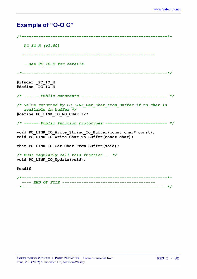
Example of “O-O C”
/*-------------------------------------------------------------*-
PC_IO.H (v1.00)
--------------------------------------------------------
- see PC_IO.C for details.
-*-------------------------------------------------------------*/
#ifndef _PC_IO_H
#define _PC_IO_H
/* ------ Public constants ------------------------------------ */
/* Value returned by PC_LINK_Get_Char_From_Buffer if no char is
available in buffer */
#define PC_LINK_IO_NO_CHAR 127
/* ------ Public function prototypes -------------------------- */
void PC_LINK_IO_Write_String_To_Buffer(const char* const);
void PC_LINK_IO_Write_Char_To_Buffer(const char);
char PC_LINK_IO_Get_Char_From_Buffer(void);
/* Must regularly call this function... */
void PC_LINK_IO_Update(void);
#endif
/*-------------------------------------------------------------*-
---- END OF FILE ---------------------------------------
-*-------------------------------------------------------------*/

www.SafeTTy.net
COPYRIGHT © MICHAEL J. PONT, 2001-2013. Contains material from:
Pont, M.J. (2002) “Embedded C”, Addison-Wesley. PES I - 83
/*-------------------------------------------------------------*-
PC_IO.C (v1.00)
--------------------------------------------------------
[INCOMPLETE - STRUCTURE ONLY - see EC Chap 9 for complete library]
-*-------------------------------------------------------------*/
#include "Main.H"
#include "PC_IO.H"
/* ------ Public variable definitions ------------------------- */
tByte In_read_index_G; /* Data in buffer that has been read */
tByte In_waiting_index_G; /* Data in buffer not yet read */
tByte Out_written_index_G; /* Data in buffer that has been written */
tByte Out_waiting_index_G; /* Data in buffer not yet written */
/* ------ Private function prototypes ------------------------- */
static void PC_LINK_IO_Send_Char(const char);
/* ------ Private constants ----------------------------------- */
/* The receive buffer length */
#define RECV_BUFFER_LENGTH 8
/* The transmit buffer length */
#define TRAN_BUFFER_LENGTH 50
#define XON 0x11
#define XOFF 0x13
/* ------ Private variables ----------------------------------- */
static tByte Recv_buffer[RECV_BUFFER_LENGTH];
static tByte Tran_buffer[TRAN_BUFFER_LENGTH];
/*-------------------------------------------------------------*/
void PC_LINK_IO_Update(...)
{
...
}

www.SafeTTy.net
COPYRIGHT © MICHAEL J. PONT, 2001-2013. Contains material from:
Pont, M.J. (2002) “Embedded C”, Addison-Wesley. PES I - 84
/*-------------------------------------------------------------*/
void PC_LINK_IO_Write_Char_To_Buffer(...)
{
...
}
/*-------------------------------------------------------------*/
void PC_LINK_IO_Write_String_To_Buffer(...)
{
...
}
/*-------------------------------------------------------------*/
char PC_LINK_IO_Get_Char_From_Buffer(...)
{
...
}
/*-------------------------------------------------------------*/
void PC_LINK_IO_Send_Char(...)
{
...
}

www.SafeTTy.net
COPYRIGHT © MICHAEL J. PONT, 2001-2013. Contains material from:
Pont, M.J. (2002) “Embedded C”, Addison-Wesley. PES I - 85
The Project Header (Main.H)
Project Header (Main.H)
11.0592 MHz #include <AT89S53.H>
...
#define OSC_FREQ (11059200UL)
...
typedef unsigned char tByte;
...

www.SafeTTy.net
COPYRIGHT © MICHAEL J. PONT, 2001-2013. Contains material from:
Pont, M.J. (2002) “Embedded C”, Addison-Wesley. PES I - 86
/*-------------------------------------------------------------*-
Main.H (v1.00)
-*-------------------------------------------------------------*/
#ifndef _MAIN_H
#define _MAIN_H
/*--------------------------------------------------------
WILL NEED TO EDIT THIS SECTION FOR EVERY PROJECT
-------------------------------------------------------- */
/* Must include the appropriate microcontroller header file here */
#include <reg52.h>
/* Oscillator / resonator frequency (in Hz) e.g. (11059200UL) */
#define OSC_FREQ (12000000UL)
/* Number of oscillations per instruction (12, etc)
12 - Original 8051 / 8052 and numerous modern versions
6 - Various Infineon and Philips devices, etc.
4 - Dallas 320, 520 etc.
1 - Dallas 420, etc. */
#define OSC_PER_INST (12)
/* --------------------------------------------------------
SHOULD NOT NEED TO EDIT THE SECTIONS BELOW
-------------------------------------------------------- */
/* Typedefs (see Chap 5) */
typedef unsigned char tByte;
typedef unsigned int tWord;
typedef unsigned long tLong;
/* Interrupts (see Chap 7) */
#define INTERRUPT_Timer_0_Overflow 1
#define INTERRUPT_Timer_1_Overflow 3
#define INTERRUPT_Timer_2_Overflow 5
#endif
/*-------------------------------------------------------------*-
---- END OF FILE ---------------------------------------
-*-------------------------------------------------------------*/

www.SafeTTy.net
COPYRIGHT © MICHAEL J. PONT, 2001-2013. Contains material from:
Pont, M.J. (2002) “Embedded C”, Addison-Wesley. PES I - 87
The device header
/*----------------------------------------------------------
REG515C.H
Header file for the Infineon C515C
Copyright (c) 1995-1999 Keil Elektronik GmbH All rights reserved.
----------------------------------------------------------------*/
...
/* A/D Converter */
sfr ADCON0 = 0xD8;
...
/* Interrupt System */
sfr IEN0 = 0xA8;
...
/* Ports */
sfr P0 = 0x80;
sfr P1 = 0x90;
sfr P2 = 0xA0;
sfr P3 = 0xB0;
sfr P4 = 0xE8;
sfr P5 = 0xF8;
sfr P6 = 0xDB;
sfr P7 = 0xFA;
...
/* Serial Channel */
sfr SCON = 0x98;
...
/* Timer0 / Timer1 */
sfr TCON = 0x88;
...
/* CAP/COM Unit / Timer2 */
sfr CCEN = 0xC1;
...

www.SafeTTy.net
COPYRIGHT © MICHAEL J. PONT, 2001-2013. Contains material from:
Pont, M.J. (2002) “Embedded C”, Addison-Wesley. PES I - 88
Oscillator frequency and oscillations per instruction
/* Oscillator / resonator frequency (in Hz) e.g. (11059200UL) */
#define OSC_FREQ (12000000UL)
/* Number of oscillations per instruction (12, etc)
12 - Original 8051 / 8052 and numerous modern versions
6 - Various Infineon and Philips devices, etc.
4 - Dallas 320, 520 etc.
1 - Dallas 420, etc. */
#define OSC_PER_INST (12)
We demonstrate how to use this information:
For creating delays (Embedded C, Chapter 6),
For controlling timing in an operating system (Chapter 7),
and,
For controlling the baud rate in a serial interface (Chapter 9).

www.SafeTTy.net
COPYRIGHT © MICHAEL J. PONT, 2001-2013. Contains material from:
Pont, M.J. (2002) “Embedded C”, Addison-Wesley. PES I - 89
Common data types
typedef unsigned char tByte;
typedef unsigned int tWord;
typedef unsigned long tLong;
In C, the typedef keyword allows us to provide aliases for data
types: we can then use these aliases in place of the original types.
Thus, in the projects you will see code like this:
tWord Temperature;
Rather than:
unsigned int Temperature;
The main reason for using these typedef statements is to simplify -
and promote - the use of unsigned data types.
The 8051 does not support signed arithmetic and extra code
is required to manipulate signed data: this reduces your
program speed and increases the program size.
Use of bitwise operators generally makes sense only with
unsigned data types: use of ‘typedef’ variables reduces the
likelihood that programmers will inadvertently apply these
operators to signed data.
Finally, as in desktop programming, use of the typedef keyword in
this way can make it easier to adapt your code for use on a different
processor.

www.SafeTTy.net
COPYRIGHT © MICHAEL J. PONT, 2001-2013. Contains material from:
Pont, M.J. (2002) “Embedded C”, Addison-Wesley. PES I - 90
Interrupts
As we noted in “Embedded C” Chapter 2, interrupts are a key
component of most embedded systems.
The following lines in the Project Header are intended to make it
easier for you to use (timer-based) interrupts in your projects:
#define INTERRUPT_Timer_0_Overflow 1
#define INTERRUPT_Timer_1_Overflow 3
#define INTERRUPT_Timer_2_Overflow 5
We discuss how to make use of this facility in Embedded C, Ch. 7.

www.SafeTTy.net
COPYRIGHT © MICHAEL J. PONT, 2001-2013. Contains material from:
Pont, M.J. (2002) “Embedded C”, Addison-Wesley. PES I - 91
Summary: Why use the Project Header?
Use of PROJECT HEADER can help to make your code more
readable, not least because anyone using your projects knows where
to find key information, such as the model of microcontroller and
the oscillator frequency required to execute the software.
The use of a project header can help to make your code more easily
portable, by placing some of the key microcontroller-dependent
data in one place: if you change the processor or the oscillator used
then - in many cases - you will need to make changes only to the
Project Header.

www.SafeTTy.net
COPYRIGHT © MICHAEL J. PONT, 2001-2013. Contains material from:
Pont, M.J. (2002) “Embedded C”, Addison-Wesley. PES I - 92
The Port Header (Port.H)
Port Header (Port.H)
DownUp
// Pins 3.0 and 3.1 used
// for RS-232 interface
// Switches
sbit Sw_up = P1^2;
sbit Sw_down = P1^3;

www.SafeTTy.net
COPYRIGHT © MICHAEL J. PONT, 2001-2013. Contains material from:
Pont, M.J. (2002) “Embedded C”, Addison-Wesley. PES I - 93
The Port Header file is simple to understand and easy to apply.
Consider, for example, that we have three C files in a project (A, B,
C), each of which require access to one or more port pins, or to a
complete port.
File A may include the following:
/* File A */
sbit Pin_A = P3^2;
...
File B may include the following:
/* File B */
#define Port_B = P0;
...
File C may include the following:
/* File C */
sbit Pin_C = P2^7;
...
In this version of the code, all of the port access requirements are
spread over multiple files.

www.SafeTTy.net
COPYRIGHT © MICHAEL J. PONT, 2001-2013. Contains material from:
Pont, M.J. (2002) “Embedded C”, Addison-Wesley. PES I - 94
There are many advantages obtained by integrating all port access
in a single Port.H header file:
/* ----- Port.H ----- */
/* Port access for File B */
#define Port_B = P0;
/* Port access for File A */
sbit Pin_A = P3^2;
/* Port access for File C */
sbit Pin_C = P2^7;
...

www.SafeTTy.net
COPYRIGHT © MICHAEL J. PONT, 2001-2013. Contains material from:
Pont, M.J. (2002) “Embedded C”, Addison-Wesley. PES I - 95
/*-------------------------------------------------------------*-
Port.H (v1.01)
--------------------------------------------------------
'Port Header' (see Chap 5) for project DATA_ACQ (see Chap 9)
-*-------------------------------------------------------------*/
#ifndef _PORT_H
#define _PORT_H
#include "Main.H"
/* ------ Menu_A.C ----------------------------------------- */
/* Uses whole of Port 1 and Port 2 for data acquisition */
#define Data_Port1 P1
#define Data_Port2 P2
/* ------ PC_IO.C ------------------------------------------ */
/* Pins 3.0 and 3.1 used for RS-232 interface */
#endif
/*-------------------------------------------------------------*-
---- END OF FILE ---------------------------------------
-*-------------------------------------------------------------*/
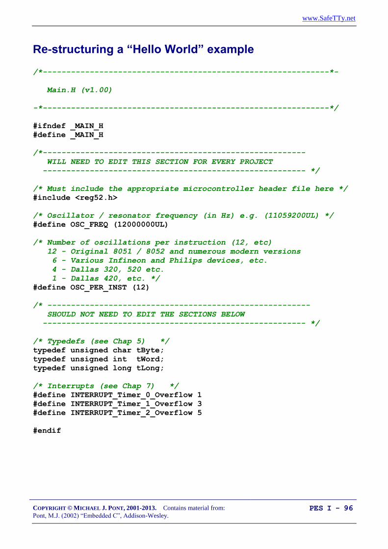
www.SafeTTy.net
COPYRIGHT © MICHAEL J. PONT, 2001-2013. Contains material from:
Pont, M.J. (2002) “Embedded C”, Addison-Wesley. PES I - 96
Re-structuring a “Hello World” example
/*-------------------------------------------------------------*-
Main.H (v1.00)
-*-------------------------------------------------------------*/
#ifndef _MAIN_H
#define _MAIN_H
/*--------------------------------------------------------
WILL NEED TO EDIT THIS SECTION FOR EVERY PROJECT
-------------------------------------------------------- */
/* Must include the appropriate microcontroller header file here */
#include <reg52.h>
/* Oscillator / resonator frequency (in Hz) e.g. (11059200UL) */
#define OSC_FREQ (12000000UL)
/* Number of oscillations per instruction (12, etc)
12 - Original 8051 / 8052 and numerous modern versions
6 - Various Infineon and Philips devices, etc.
4 - Dallas 320, 520 etc.
1 - Dallas 420, etc. */
#define OSC_PER_INST (12)
/* --------------------------------------------------------
SHOULD NOT NEED TO EDIT THE SECTIONS BELOW
-------------------------------------------------------- */
/* Typedefs (see Chap 5) */
typedef unsigned char tByte;
typedef unsigned int tWord;
typedef unsigned long tLong;
/* Interrupts (see Chap 7) */
#define INTERRUPT_Timer_0_Overflow 1
#define INTERRUPT_Timer_1_Overflow 3
#define INTERRUPT_Timer_2_Overflow 5
#endif

www.SafeTTy.net
COPYRIGHT © MICHAEL J. PONT, 2001-2013. Contains material from:
Pont, M.J. (2002) “Embedded C”, Addison-Wesley. PES I - 97
/*-------------------------------------------------------------*-
Port.H (v1.00)
--------------------------------------------------------
'Port Header' for project HELLO2 (see Chap 5)
-*-------------------------------------------------------------*/
#ifndef _PORT_H
#define _PORT_H
/* ------ LED_Flash.C ----------------------------------------- */
/* Connect LED to this pin, via appropriate resistor */
sbit LED_pin = P1^5;
#endif
/*-------------------------------------------------------------*-
---- END OF FILE ---------------------------------------
-*-------------------------------------------------------------*/

www.SafeTTy.net
COPYRIGHT © MICHAEL J. PONT, 2001-2013. Contains material from:
Pont, M.J. (2002) “Embedded C”, Addison-Wesley. PES I - 98
/*-------------------------------------------------------------*-
Main.C (v1.00)
--------------------------------------------------------
A "Hello Embedded World" test program for 8051.
(Re-structured version - multiple source files)
-*-------------------------------------------------------------*/
#include "Main.H"
#include "Port.H"
#include "Delay_Loop.h"
#include "LED_Flash.h"
void main(void)
{
LED_FLASH_Init();
while(1)
{
/* Change the LED state (OFF to ON, or vice versa) */
LED_FLASH_Change_State();
/* Delay for *approx* 1000 ms */
DELAY_LOOP_Wait(1000);
}
}
/*-------------------------------------------------------------*-
---- END OF FILE ---------------------------------------
-*-------------------------------------------------------------*/

www.SafeTTy.net
COPYRIGHT © MICHAEL J. PONT, 2001-2013. Contains material from:
Pont, M.J. (2002) “Embedded C”, Addison-Wesley. PES I - 99
/*-------------------------------------------------------------*-
LED_flash.H (v1.00)
--------------------------------------------------------
- See LED_flash.C for details.
-*-------------------------------------------------------------*/
#ifndef _LED_FLASH_H
#define _LED_FLASH_H
/* ------ Public function prototypes -------------------------- */
void LED_FLASH_Init(void);
void LED_FLASH_Change_State(void);
#endif
/*-------------------------------------------------------------*-
---- END OF FILE ---------------------------------------
-*-------------------------------------------------------------*/

www.SafeTTy.net
COPYRIGHT © MICHAEL J. PONT, 2001-2013. Contains material from:
Pont, M.J. (2002) “Embedded C”, Addison-Wesley. PES I - 100
/*-------------------------------------------------------------*-
LED_flash.C (v1.00)
--------------------------------------------------------
Simple 'Flash LED' test function.
-*-------------------------------------------------------------*/
#include "Main.H"
#include "Port.H"
#include "LED_flash.H"
/* ------ Private variable definitions ------------------------ */
static bit LED_state_G;
/*-------------------------------------------------------------*-
LED_FLASH_Init()
Prepare for LED_Change_State() function - see below.
-*-------------------------------------------------------------*/
void LED_FLASH_Init(void)
{
LED_state_G = 0;
}

www.SafeTTy.net
COPYRIGHT © MICHAEL J. PONT, 2001-2013. Contains material from:
Pont, M.J. (2002) “Embedded C”, Addison-Wesley. PES I - 101
/*-------------------------------------------------------------*-
LED_FLASH_Change_State()
Changes the state of an LED (or pulses a buzzer, etc) on a
specified port pin.
Must call at twice the required flash rate: thus, for 1 Hz
flash (on for 0.5 seconds, off for 0.5 seconds) must call
every 0.5 seconds.
-*-------------------------------------------------------------*/
void LED_FLASH_Change_State(void)
{
/* Change the LED from OFF to ON (or vice versa) */
if (LED_state_G == 1)
{
LED_state_G = 0;
LED_pin = 0;
}
else
{
LED_state_G = 1;
LED_pin = 1;
}
}
/*-------------------------------------------------------------*-
---- END OF FILE ---------------------------------------
-*-------------------------------------------------------------*/

www.SafeTTy.net
COPYRIGHT © MICHAEL J. PONT, 2001-2013. Contains material from:
Pont, M.J. (2002) “Embedded C”, Addison-Wesley. PES I - 102
/*-------------------------------------------------------------*-
Delay_Loop.H (v1.00)
--------------------------------------------------------
- See Delay_Loop.C for details.
-*-------------------------------------------------------------*/
#ifndef _DELAY_LOOP_H
#define _DELAY_LOOP_H
/* ------ Public function prototype --------------------------- */
void DELAY_LOOP_Wait(const tWord DELAY_MS);
#endif
/*-------------------------------------------------------------*-
---- END OF FILE ---------------------------------------
-*-------------------------------------------------------------*/

www.SafeTTy.net
COPYRIGHT © MICHAEL J. PONT, 2001-2013. Contains material from:
Pont, M.J. (2002) “Embedded C”, Addison-Wesley. PES I - 103
/*-------------------------------------------------------------*-
Delay_Loop.C (v1.00)
--------------------------------------------------------
Create a simple software delay using a loop.
-*-------------------------------------------------------------*/
#include "Main.H"
#include "Port.H"
#include "Delay_loop.h"
/*-------------------------------------------------------------*-
DELAY_LOOP_Wait()
Delay duration varies with parameter.
Parameter is, *ROUGHLY*, the delay, in milliseconds,
on 12MHz 8051 (12 osc cycles).
You need to adjust the timing for your application!
-*-------------------------------------------------------------*/
void DELAY_LOOP_Wait(const tWord DELAY_MS)
{
tWord x, y;
for (x = 0; x <= DELAY_MS; x++)
{
for (y = 0; y <= 120; y++);
}
}
/*-------------------------------------------------------------*-
---- END OF FILE ---------------------------------------
-*-------------------------------------------------------------*/

www.SafeTTy.net
COPYRIGHT © MICHAEL J. PONT, 2001-2013. Contains material from:
Pont, M.J. (2002) “Embedded C”, Addison-Wesley. PES I - 104
Example: Re-structuring the Goat-Counting Example
/*-------------------------------------------------------------*-
Main.H (v1.00)
-*-------------------------------------------------------------*/
#ifndef _MAIN_H
#define _MAIN_H
/*--------------------------------------------------------
WILL NEED TO EDIT THIS SECTION FOR EVERY PROJECT
-------------------------------------------------------- */
/* Must include the appropriate microcontroller header file here */
#include <reg52.h>
/* Oscillator / resonator frequency (in Hz) e.g. (11059200UL) */
#define OSC_FREQ (12000000UL)
/* Number of oscillations per instruction (12, etc)
12 - Original 8051 / 8052 and numerous modern versions
6 - Various Infineon and Philips devices, etc.
4 - Dallas 320, 520 etc.
1 - Dallas 420, etc. */
#define OSC_PER_INST (12)
/* --------------------------------------------------------
SHOULD NOT NEED TO EDIT THE SECTIONS BELOW
-------------------------------------------------------- */
/* Typedefs (see Chap 5) */
typedef unsigned char tByte;
typedef unsigned int tWord;
typedef unsigned long tLong;
/* Interrupts (see Chap 7) */
#define INTERRUPT_Timer_0_Overflow 1
#define INTERRUPT_Timer_1_Overflow 3
#define INTERRUPT_Timer_2_Overflow 5
#endif
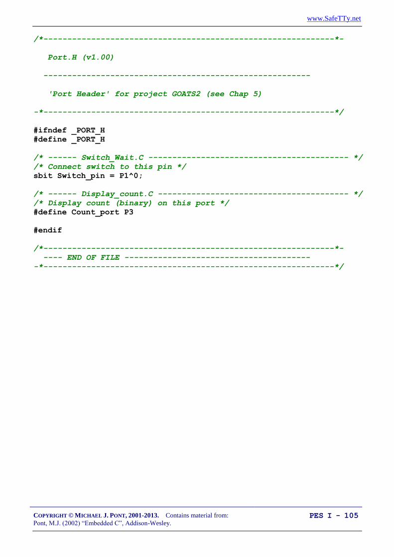
www.SafeTTy.net
COPYRIGHT © MICHAEL J. PONT, 2001-2013. Contains material from:
Pont, M.J. (2002) “Embedded C”, Addison-Wesley. PES I - 105
/*-------------------------------------------------------------*-
Port.H (v1.00)
--------------------------------------------------------
'Port Header' for project GOATS2 (see Chap 5)
-*-------------------------------------------------------------*/
#ifndef _PORT_H
#define _PORT_H
/* ------ Switch_Wait.C ------------------------------------------ */
/* Connect switch to this pin */
sbit Switch_pin = P1^0;
/* ------ Display_count.C ---------------------------------------- */
/* Display count (binary) on this port */
#define Count_port P3
#endif
/*-------------------------------------------------------------*-
---- END OF FILE ---------------------------------------
-*-------------------------------------------------------------*/

www.SafeTTy.net
COPYRIGHT © MICHAEL J. PONT, 2001-2013. Contains material from:
Pont, M.J. (2002) “Embedded C”, Addison-Wesley. PES I - 106
/*-------------------------------------------------------------*-
Main.C (v1.00)
--------------------------------------------------------
A 'switch count' program for the 8051.
-*-------------------------------------------------------------*/
#include "Main.H"
#include "Port.H"
#include "Switch_wait.H"
#include "Display_count.H"
/* ---------------------------------------------------------------- */
void main(void)
{
tByte Switch_presses = 0;
/* Init functions */
SWITCH_Init();
DISPLAY_COUNT_Init();
while(1)
{
if (SWITCH_Get_Input(30) == SWITCH_PRESSED)
{
Switch_presses++;
}
DISPLAY_COUNT_Update(Switch_presses);
}
}
/*-------------------------------------------------------------*-
---- END OF FILE ---------------------------------------
-*-------------------------------------------------------------*/

www.SafeTTy.net
COPYRIGHT © MICHAEL J. PONT, 2001-2013. Contains material from:
Pont, M.J. (2002) “Embedded C”, Addison-Wesley. PES I - 107
/*-------------------------------------------------------------*-
Switch_wait.H (v1.00)
--------------------------------------------------------
- See Switch_wait.C for details.
-*-------------------------------------------------------------*/
#ifndef _SWITCH_WAIT_H
#define _SWITCH_WAIT_H
/* ------ Public constants ------------------------------------ */
/* Return values from Switch_Get_Input() */
#define SWITCH_NOT_PRESSED (bit) 0
#define SWITCH_PRESSED (bit) 1
/* ------ Public function prototype --------------------------- */
void SWITCH_Init(void);
bit SWITCH_Get_Input(const tByte DEBOUNCE_PERIOD);
#endif
/*-------------------------------------------------------------*-
---- END OF FILE ---------------------------------------
-*-------------------------------------------------------------*/

www.SafeTTy.net
COPYRIGHT © MICHAEL J. PONT, 2001-2013. Contains material from:
Pont, M.J. (2002) “Embedded C”, Addison-Wesley. PES I - 108
/*-------------------------------------------------------------*-
Switch_Wait.C (v1.00)
--------------------------------------------------------
Simple library for debouncing a switch input.
NOTE: Duration of function is highly variable!
-*-------------------------------------------------------------*/
#include "Main.H"
#include "Port.H"
#include "Switch_wait.h"
#include "Delay_loop.h"
/*-------------------------------------------------------------*-
SWITCH_Init()
Initialisation function for the switch library.
-*-------------------------------------------------------------*/
void SWITCH_Init(void)
{
Switch_pin = 1; /* Use this pin for input */
}

www.SafeTTy.net
COPYRIGHT © MICHAEL J. PONT, 2001-2013. Contains material from:
Pont, M.J. (2002) “Embedded C”, Addison-Wesley. PES I - 109
/*-------------------------------------------------------------*-
SWITCH_Get_Input()
Reads and debounces a mechanical switch as follows:
1. If switch is not pressed, return SWITCH_NOT_PRESSED.
2. If switch is pressed, wait for DEBOUNCE_PERIOD (in ms).
a. If switch is not pressed, return SWITCH_NOT_PRESSED.
b. If switch is pressed, wait (indefinitely) for
switch to be released, then return SWITCH_PRESSED
See Switch_Wait.H for details of return values.
-*-------------------------------------------------------------*/
bit SWITCH_Get_Input(const tByte DEBOUNCE_PERIOD)
{
bit Return_value = SWITCH_NOT_PRESSED;
if (Switch_pin == 0)
{
/* Switch is pressed */
/* Debounce - just wait... */
DELAY_LOOP_Wait(DEBOUNCE_PERIOD);
/* Check switch again */
if (Switch_pin == 0)
{
/* Wait until the switch is released. */
while (Switch_pin == 0);
Return_value = SWITCH_PRESSED;
}
}
/* Now (finally) return switch value */
return Return_value;
}
/*-------------------------------------------------------------*-
---- END OF FILE ---------------------------------------
-*-------------------------------------------------------------*/

www.SafeTTy.net
COPYRIGHT © MICHAEL J. PONT, 2001-2013. Contains material from:
Pont, M.J. (2002) “Embedded C”, Addison-Wesley. PES I - 110
/*-------------------------------------------------------------*-
Display_count.H (v1.00)
--------------------------------------------------------
- See Display_count.C for details.
-*-------------------------------------------------------------*/
#ifndef _DISPLAY_COUNT_H
#define _DISPLAY_COUNT_H
/* ------ Public function prototypes -------------------------- */
void DISPLAY_COUNT_Init(void);
void DISPLAY_COUNT_Update(const tByte);
#endif
/*-------------------------------------------------------------*-
---- END OF FILE ---------------------------------------
-*-------------------------------------------------------------*/

www.SafeTTy.net
COPYRIGHT © MICHAEL J. PONT, 2001-2013. Contains material from:
Pont, M.J. (2002) “Embedded C”, Addison-Wesley. PES I - 111
/*-------------------------------------------------------------*-
Display_count.C (v1.00)
--------------------------------------------------------
Display an unsigned char on a port.
-*-------------------------------------------------------------*/
#include "Main.H"
#include "Port.H"
#include "Display_Count.H"
/*-------------------------------------------------------------*-
DISPLAY_COUNT_Init()
Initialisation function for the DISPLAY COUNT library.
-*-------------------------------------------------------------*/
void DISPLAY_COUNT_Init(void)
{
Count_port = 0x00;
}
/*-------------------------------------------------------------*-
DISPLAY_COUNT_Update()
Simple function to display tByte data (COUNT)
on LEDs connected to port (Count_Port)
-*-------------------------------------------------------------*/
void DISPLAY_COUNT_Update(const tByte COUNT)
{
Count_port = COUNT;
}
/*-------------------------------------------------------------*-
---- END OF FILE ---------------------------------------
-*-------------------------------------------------------------*/
www.SafeTTy.net
COPYRIGHT © MICHAEL J. PONT, 2001-2013. Contains material from:
Pont, M.J. (2002) “Embedded C”, Addison-Wesley. PES I - 112
/*-------------------------------------------------------------*-
Delay_Loop.H (v1.00)
--------------------------------------------------------
- See Delay_Loop.C for details.
-*-------------------------------------------------------------*/
#ifndef _DELAY_LOOP_H
#define _DELAY_LOOP_H
/* ------ Public function prototype --------------------------- */
void DELAY_LOOP_Wait(const tWord DELAY_MS);
#endif
/*-------------------------------------------------------------*-
---- END OF FILE ---------------------------------------
-*-------------------------------------------------------------*/

www.SafeTTy.net
COPYRIGHT © MICHAEL J. PONT, 2001-2013. Contains material from:
Pont, M.J. (2002) “Embedded C”, Addison-Wesley. PES I - 113
/*-------------------------------------------------------------*-
Delay_Loop.C (v1.00)
--------------------------------------------------------
Create a simple software delay using a loop.
-*-------------------------------------------------------------*/
#include "Main.H"
#include "Port.H"
#include "Delay_loop.h"
/*-------------------------------------------------------------*-
DELAY_LOOP_Wait()
Delay duration varies with parameter.
Parameter is, *ROUGHLY*, the delay, in milliseconds,
on 12MHz 8051 (12 osc cycles).
You need to adjust the timing for your application!
-*-------------------------------------------------------------*/
void DELAY_LOOP_Wait(const tWord DELAY_MS)
{
tWord x, y;
for (x = 0; x <= DELAY_MS; x++)
{
for (y = 0; y <= 120; y++);
}
}
/*-------------------------------------------------------------*-
---- END OF FILE ---------------------------------------
-*-------------------------------------------------------------*/

www.SafeTTy.net
COPYRIGHT © MICHAEL J. PONT, 2001-2013. Contains material from:
Pont, M.J. (2002) “Embedded C”, Addison-Wesley. PES I - 114
Preparation for the next seminar
Please read Chapter 6
before the next seminar

www.SafeTTy.net
COPYRIGHT © MICHAEL J. PONT, 2001-2013. Contains material from:
Pont, M.J. (2002) “Embedded C”, Addison-Wesley. PES I - 115
Seminar 5: Meeting Real-Time
Constraints

www.SafeTTy.net
COPYRIGHT © MICHAEL J. PONT, 2001-2013. Contains material from:
Pont, M.J. (2002) “Embedded C”, Addison-Wesley. PES I - 116
Introduction
In this seminar, we begin to consider the issues involved in the
accurate measurement of time.
These issues are important because many embedded systems must
satisfy real-time constraints.
Rudder
r
Elevator
e
Aileron
a
p
r
q
x,
y,
z,
x, y, z = position coordinates
= velocity cordinates
p = roll rate
q = pitch rate
r = yaw rate
Aircraft
Autopilot
System
Position
sensors
(GPS)
Velocity
sensors
(3 axes)
Yaw (rate)
sensor
Pitch
(rate)
sensor
Roll
(rate)
sensor
Main
pilot
controls
Rudder
Elevator
Aileron
Main engine
(fuel)
controllers

www.SafeTTy.net
COPYRIGHT © MICHAEL J. PONT, 2001-2013. Contains material from:
Pont, M.J. (2002) “Embedded C”, Addison-Wesley. PES I - 117
bit SWITCH_Get_Input(const tByte DEBOUNCE_PERIOD)
{
tByte Return_value = SWITCH_NOT_PRESSED;
if (Switch_pin == 0)
{
/* Switch is pressed */
/* Debounce - just wait... */
DELAY_LOOP_Wait(DEBOUNCE_PERIOD); /* POTENTIAL PROBLEM */
/* Check switch again */
if (Switch_pin == 0)
{
/* Wait until the switch is released. */
while (Switch_pin == 0); /* POTENTIAL CATASTROPHE */
Return_value = SWITCH_PRESSED;
}
}
/* Now (finally) return switch value */
return Return_value;
}
The first problem is that we wait for a ‘debounce’ period in order to
confirm that the switch has been pressed. Because this delay is
implemented using a software loop it may not be very precisely
timed.
The second problem is even more serious in a system with real-time
characteristics: we cause the system to wait - indefinitely - for the
user to release the switch.
We’ll see how to deal with both of these problems in this seminar

www.SafeTTy.net
COPYRIGHT © MICHAEL J. PONT, 2001-2013. Contains material from:
Pont, M.J. (2002) “Embedded C”, Addison-Wesley. PES I - 118
Creating “hardware delays”
All members of the 8051 family have at least two 16-bit timer /
counters, known as Timer 0 and Timer 1.
These timers can be used to generate accurate delays.
/* Configure Timer 0 as a 16-bit timer */
TMOD &= 0xF0; /* Clear all T0 bits (T1 left unchanged) */
TMOD |= 0x01; /* Set required T0 bits (T1 left unchanged) */
ET0 = 0; /* No interrupts */
/* Values for 50 ms delay */
TH0 = 0x3C; /* Timer 0 initial value (High Byte) */
TL0 = 0xB0; /* Timer 0 initial value (Low Byte) */
TF0 = 0; /* Clear overflow flag */
TR0 = 1; /* Start Timer 0 */
while (TF0 == 0); /* Loop until Timer 0 overflows (TF0 == 1) */
TR0 = 0; /* Stop Timer 0 */
Now let’s see how this works…

www.SafeTTy.net
COPYRIGHT © MICHAEL J. PONT, 2001-2013. Contains material from:
Pont, M.J. (2002) “Embedded C”, Addison-Wesley. PES I - 119
The TCON SFR
Bit 7
(msb)
6 5 4 3 2 1 0
(lsb)
NAME TF1 TR1 TF0 TR0 IE1 IT1 IE0 IT0
TF1 Timer 1 overflow flag
Set by hardware on Timer 1 overflow.
(Cleared by hardware if processor vectors to interrupt routine.)
TR1 Timer 1 run control bit
Set / cleared by software to turn Timer 1 either ‘ON’ or ‘OFF’.
TF0 Timer 0 overflow flag
Set by hardware on Timer 0 overflow.
(Cleared by hardware if processor vectors to interrupt routine.)
TR0 Timer 0 run control bit
Set / cleared by software to turn Timer 0 either ‘ON’ or ‘OFF’.
Note that the overflow of the timers can be used to generate an
interrupt. We will not make use of this facility in the Hardware Delay
code.
To disable the generation of interrupts, we can use the C statements:
ET0 = 0; /* No interrupts (Timer 0) */
ET1 = 0; /* No interrupts (Timer 1) */

www.SafeTTy.net
COPYRIGHT © MICHAEL J. PONT, 2001-2013. Contains material from:
Pont, M.J. (2002) “Embedded C”, Addison-Wesley. PES I - 120
The TMOD SFR
Bit 7 6 5 4 3 2 1 0
NAME Gate C / T
M1 M0 Gate C / T
M1 M0
Timer 1 Timer 0
Mode 1 (M1 = 0; M0 = 1)
16-bit timer/counter (with manual reload)
Mode 2 (M1 = 1; M0 = 0)
8-bit timer/counter (with 8-bit auto-reload)
GATE Gating control
When set, timer/counter “x” is enabled only while “INT x” pin is high and “TRx”
control bit is set. When cleared timer “x” is enabled whenever “TRx” control bit
is set.
C / T Counter or timer select bit
Set for counter operation (input from “Tx” input pin).
Cleared for timer operation (input from internal system clock).

www.SafeTTy.net
COPYRIGHT © MICHAEL J. PONT, 2001-2013. Contains material from:
Pont, M.J. (2002) “Embedded C”, Addison-Wesley. PES I - 121
Two further registers
Before we can see how this hardware can be used to create delays,
you need to be aware that there are an additional two registers
associated with each timer: these are known as TL0 and TH0, and
TL1 and TH1.

www.SafeTTy.net
COPYRIGHT © MICHAEL J. PONT, 2001-2013. Contains material from:
Pont, M.J. (2002) “Embedded C”, Addison-Wesley. PES I - 122
Example: Generating a precise 50 ms delay
/*-------------------------------------------------------------*-
Hardware_Delay_50ms.C (v1.00)
--------------------------------------------------------
A test program for hardware-based delays.
-*-------------------------------------------------------------*/
#include <reg52.h>
sbit LED_pin = P1^5;
bit LED_state_G;
void LED_FLASH_Init(void);
void LED_FLASH_Change_State(void);
void DELAY_HARDWARE_One_Second(void);
void DELAY_HARDWARE_50ms(void);
/*..................................................................*/
void main(void)
{
LED_FLASH_Init();
while(1)
{
/* Change the LED state (OFF to ON, or vice versa) */
LED_FLASH_Change_State();
/* Delay for approx 1000 ms */
DELAY_HARDWARE_One_Second();
}
}

www.SafeTTy.net
COPYRIGHT © MICHAEL J. PONT, 2001-2013. Contains material from:
Pont, M.J. (2002) “Embedded C”, Addison-Wesley. PES I - 123
/*-------------------------------------------------------------*-
LED_FLASH_Init()
Prepare for LED_Change_State() function - see below.
-*-------------------------------------------------------------*/
void LED_FLASH_Init(void)
{
LED_state_G = 0;
}
/*-------------------------------------------------------------*-
LED_FLASH_Change_State()
Changes the state of an LED (or pulses a buzzer, etc) on a
specified port pin.
Must call at twice the required flash rate: thus, for 1 Hz
flash (on for 0.5 seconds, off for 0.5 seconds) must call
every 0.5 seconds.
-*-------------------------------------------------------------*/
void LED_FLASH_Change_State(void)
{
/* Change the LED from OFF to ON (or vice versa) */
if (LED_state_G == 1)
{
LED_state_G = 0;
LED_pin = 0;
}
else
{
LED_state_G = 1;
LED_pin = 1;
}
}

www.SafeTTy.net
COPYRIGHT © MICHAEL J. PONT, 2001-2013. Contains material from:
Pont, M.J. (2002) “Embedded C”, Addison-Wesley. PES I - 124
/*-------------------------------------------------------------*-
DELAY_HARDWARE_One_Second()
Hardware delay of 1000 ms.
*** Assumes 12MHz 8051 (12 osc cycles) ***
-*-------------------------------------------------------------*/
void DELAY_HARDWARE_One_Second(void)
{
unsigned char d;
/* Call DELAY_HARDWARE_50ms() twenty times */
for (d = 0; d < 20; d++)
{
DELAY_HARDWARE_50ms();
}
}
/*-------------------------------------------------------------*-
DELAY_HARDWARE_50ms()
*** Assumes 12MHz 8051 (12 osc cycles) ***
-*-------------------------------------------------------------*/
void DELAY_HARDWARE_50ms(void)
{
/* Configure Timer 0 as a 16-bit timer */
TMOD &= 0xF0; /* Clear all T0 bits (T1 left unchanged) */
TMOD |= 0x01; /* Set required T0 bits (T1 left unchanged) */
ET0 = 0; /* No interrupts */
/* Values for 50 ms delay */
TH0 = 0x3C; /* Timer 0 initial value (High Byte) */
TL0 = 0xB0; /* Timer 0 initial value (Low Byte) */
TF0 = 0; /* Clear overflow flag */
TR0 = 1; /* Start timer 0 */
while (TF0 == 0); /* Loop until Timer 0 overflows (TF0 == 1) */
TR0 = 0; /* Stop Timer 0 */
}

www.SafeTTy.net
COPYRIGHT © MICHAEL J. PONT, 2001-2013. Contains material from:
Pont, M.J. (2002) “Embedded C”, Addison-Wesley. PES I - 125
In this case, we assume - again - the standard 12 MHz / 12
oscillations-per-instruction microcontroller environment.
We require a 50 ms delay, so the timer requires the following
number of increments before it overflows:
10000001000
50
ms
ms= 50000 increments.
The timer overflows when it is incremented from its maximum
count of 65535.
Thus, the initial value we need to load to produce a 50 ms delay is:
65536 - 50000 = 15536 (decimal) = 0x3CB0

www.SafeTTy.net
COPYRIGHT © MICHAEL J. PONT, 2001-2013. Contains material from:
Pont, M.J. (2002) “Embedded C”, Addison-Wesley. PES I - 126
Example: Creating a portable hardware delay
/*-------------------------------------------------------------*-
Main.C (v1.00)
--------------------------------------------------------
Flashing LED with hardware-based delay (T0).
-*-------------------------------------------------------------*/
#include "Main.H"
#include "Port.H"
#include "Delay_T0.h"
#include "LED_Flash.h"
void main(void)
{
LED_FLASH_Init();
while(1)
{
/* Change the LED state (OFF to ON, or vice versa) */
LED_FLASH_Change_State();
/* Delay for *approx* 1000 ms */
DELAY_T0_Wait(1000);
}
}
/*-------------------------------------------------------------*-
---- END OF FILE ---------------------------------------
-*-------------------------------------------------------------*/

www.SafeTTy.net
COPYRIGHT © MICHAEL J. PONT, 2001-2013. Contains material from:
Pont, M.J. (2002) “Embedded C”, Addison-Wesley. PES I - 127
/* Timer preload values for use in simple (hardware) delays
- Timers are 16-bit, manual reload ('one shot').
NOTE: These values are portable but timings are *approximate*
and *must* be checked by hand if accurate timing is required.
Define Timer 0 / Timer 1 reload values for ~1 msec delay
NOTE: Adjustment made to allow for function call overheard etc. */
#define PRELOAD01 (65536 - (tWord)(OSC_FREQ / (OSC_PER_INST * 1020)))
#define PRELOAD01H (PRELOAD01 / 256)
#define PRELOAD01L (PRELOAD01 % 256)
/*-------------------------------------------------------------*/
void DELAY_T0_Wait(const tWord N)
{
tWord ms;
/* Configure Timer 0 as a 16-bit timer */
TMOD &= 0xF0; /* Clear all T0 bits (T1 left unchanged) */
TMOD |= 0x01; /* Set required T0 bits (T1 left unchanged) */
ET0 = 0; /* No interrupts */
/* Delay value is *approximately* 1 ms per loop */
for (ms = 0; ms < N; ms++)
{
TH0 = PRELOAD01H;
TL0 = PRELOAD01L;
TF0 = 0; /* Clear overflow flag */
TR0 = 1; /* Start timer 0 */
while (TF0 == 0); /* Loop until Timer 0 overflows (TF0 == 1) */
TR0 = 0; /* Stop Timer 0 */
}
}

www.SafeTTy.net
COPYRIGHT © MICHAEL J. PONT, 2001-2013. Contains material from:
Pont, M.J. (2002) “Embedded C”, Addison-Wesley. PES I - 128
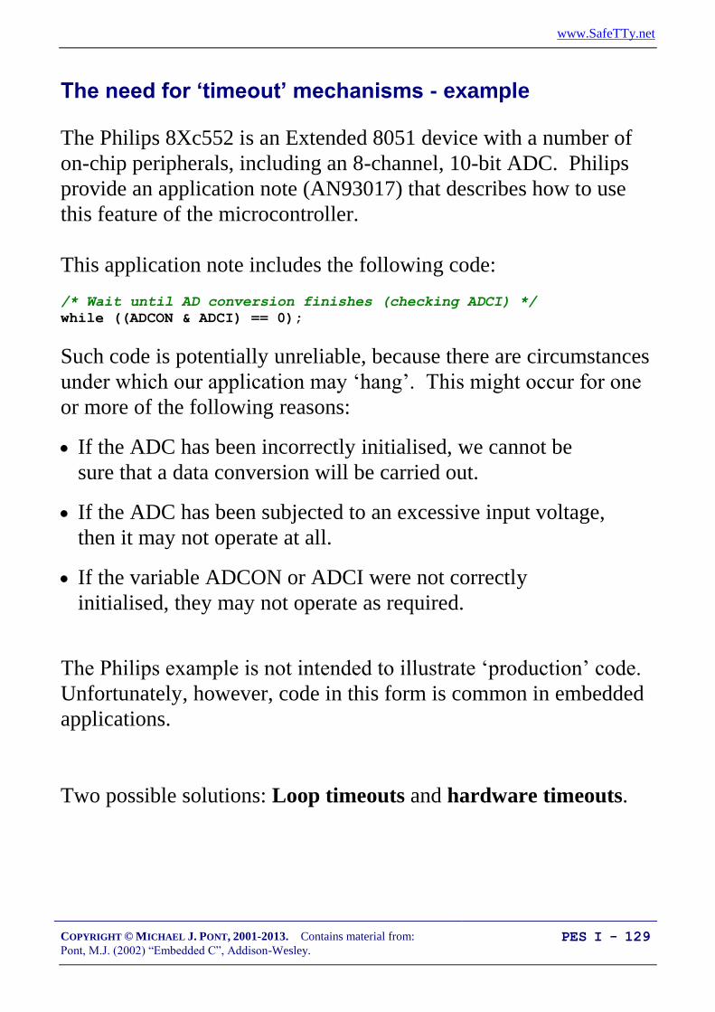
www.SafeTTy.net
COPYRIGHT © MICHAEL J. PONT, 2001-2013. Contains material from:
Pont, M.J. (2002) “Embedded C”, Addison-Wesley. PES I - 129
The need for ‘timeout’ mechanisms - example
The Philips 8Xc552 is an Extended 8051 device with a number of
on-chip peripherals, including an 8-channel, 10-bit ADC. Philips
provide an application note (AN93017) that describes how to use
this feature of the microcontroller.
This application note includes the following code:
/* Wait until AD conversion finishes (checking ADCI) */
while ((ADCON & ADCI) == 0);
Such code is potentially unreliable, because there are circumstances
under which our application may ‘hang’. This might occur for one
or more of the following reasons:
If the ADC has been incorrectly initialised, we cannot be
sure that a data conversion will be carried out.
If the ADC has been subjected to an excessive input voltage,
then it may not operate at all.
If the variable ADCON or ADCI were not correctly
initialised, they may not operate as required.
The Philips example is not intended to illustrate ‘production’ code.
Unfortunately, however, code in this form is common in embedded
applications.
Two possible solutions: Loop timeouts and hardware timeouts.
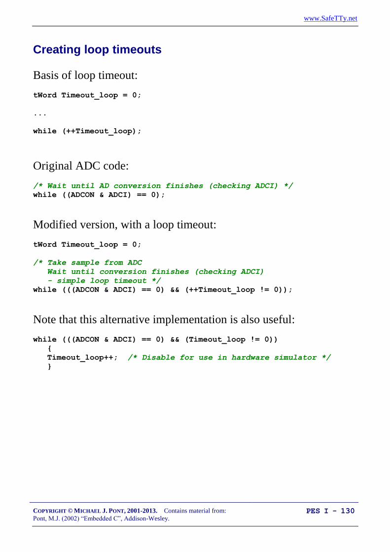
www.SafeTTy.net
COPYRIGHT © MICHAEL J. PONT, 2001-2013. Contains material from:
Pont, M.J. (2002) “Embedded C”, Addison-Wesley. PES I - 130
Creating loop timeouts
Basis of loop timeout:
tWord Timeout_loop = 0;
...
while (++Timeout_loop);
Original ADC code:
/* Wait until AD conversion finishes (checking ADCI) */
while ((ADCON & ADCI) == 0);
Modified version, with a loop timeout:
tWord Timeout_loop = 0;
/* Take sample from ADC
Wait until conversion finishes (checking ADCI)
- simple loop timeout */
while (((ADCON & ADCI) == 0) && (++Timeout_loop != 0));
Note that this alternative implementation is also useful:
while (((ADCON & ADCI) == 0) && (Timeout_loop != 0))
{
Timeout_loop++; /* Disable for use in hardware simulator */
}

www.SafeTTy.net
COPYRIGHT © MICHAEL J. PONT, 2001-2013. Contains material from:
Pont, M.J. (2002) “Embedded C”, Addison-Wesley. PES I - 131
/*-------------------------------------------------------------*-
TimeoutL.H (v1.00)
--------------------------------------------------------
Simple software (loop) timeout delays for the 8051 family.
* THESE VALUES ARE NOT PRECISE - YOU MUST ADAPT TO YOUR SYSTEM *
-*-------------------------------------------------------------*/
#ifndef _TIMEOUTL_H
#define _TIMEOUTL_H
/* ------ Public constants ------------------------------------ */
/* Vary this value to change the loop duration
THESE ARE APPROX VALUES FOR VARIOUS TIMEOUT DELAYS
ON 8051, 12 MHz, 12 Osc / cycle
*** MUST BE FINE TUNED FOR YOUR APPLICATION ***
*** Timings vary with compiler optimisation settings *** */
/* tWord */
#define LOOP_TIMEOUT_INIT_001ms 65435
#define LOOP_TIMEOUT_INIT_010ms 64535
#define LOOP_TIMEOUT_INIT_500ms 14535
/* tLong */
#define LOOP_TIMEOUT_INIT_10000ms 4294795000UL
#endif
/*-------------------------------------------------------------*-
---- END OF FILE ---------------------------------------
-*-------------------------------------------------------------*/

www.SafeTTy.net
COPYRIGHT © MICHAEL J. PONT, 2001-2013. Contains material from:
Pont, M.J. (2002) “Embedded C”, Addison-Wesley. PES I - 132
Example: Testing loop timeouts
/*-------------------------------------------------------------*-
Main.C (v1.00)
-*-------------------------------------------------------------*/
#include <reg52.H>
#include "TimeoutL.H"
/* Typedefs (see Chap 5) */
typedef unsigned char tByte;
typedef unsigned int tWord;
typedef unsigned long tLong;
/* Function prototypes */
void Test_Timeout(void);
/*-------------------------------------------------------------*/
void main(void)
{
while(1)
{
Test_Timeout();
}
}
/*-------------------------------------------------------------*/
void Test_Timeout(void)
{
tLong Timeout_loop = LOOP_TIMEOUT_INIT_10000ms;
/* Simple loop timeout... */
while (++Timeout_loop != 0);
}

www.SafeTTy.net
COPYRIGHT © MICHAEL J. PONT, 2001-2013. Contains material from:
Pont, M.J. (2002) “Embedded C”, Addison-Wesley. PES I - 133
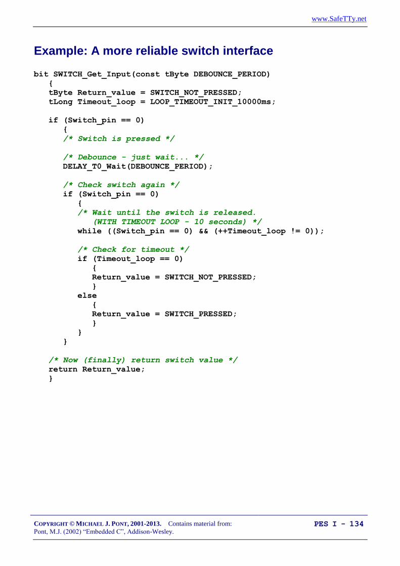
www.SafeTTy.net
COPYRIGHT © MICHAEL J. PONT, 2001-2013. Contains material from:
Pont, M.J. (2002) “Embedded C”, Addison-Wesley. PES I - 134
Example: A more reliable switch interface
bit SWITCH_Get_Input(const tByte DEBOUNCE_PERIOD)
{
tByte Return_value = SWITCH_NOT_PRESSED;
tLong Timeout_loop = LOOP_TIMEOUT_INIT_10000ms;
if (Switch_pin == 0)
{
/* Switch is pressed */
/* Debounce - just wait... */
DELAY_T0_Wait(DEBOUNCE_PERIOD);
/* Check switch again */
if (Switch_pin == 0)
{
/* Wait until the switch is released.
(WITH TIMEOUT LOOP - 10 seconds) */
while ((Switch_pin == 0) && (++Timeout_loop != 0));
/* Check for timeout */
if (Timeout_loop == 0)
{
Return_value = SWITCH_NOT_PRESSED;
}
else
{
Return_value = SWITCH_PRESSED;
}
}
}
/* Now (finally) return switch value */
return Return_value;
}

www.SafeTTy.net
COPYRIGHT © MICHAEL J. PONT, 2001-2013. Contains material from:
Pont, M.J. (2002) “Embedded C”, Addison-Wesley. PES I - 135
Creating hardware timeouts
/* Configure Timer 0 as a 16-bit timer */
TMOD &= 0xF0; /* Clear all T0 bits (T1 left unchanged) */
TMOD |= 0x01; /* Set required T0 bits (T1 left unchanged) */
ET0 = 0; /* No interrupts */
/* Simple timeout feature - approx 10 ms */
TH0 = PRELOAD_10ms_H; /* See Timeout.H for PRELOAD details */
TL0 = PRELOAD_10ms_L;
TF0 = 0; /* Clear flag */
TR0 = 1; /* Start timer */
while (((ADCON & ADCI) == 0) && !TF0);

www.SafeTTy.net
COPYRIGHT © MICHAEL J. PONT, 2001-2013. Contains material from:
Pont, M.J. (2002) “Embedded C”, Addison-Wesley. PES I - 136
/*-------------------------------------------------------------*-
TimeoutH.H (v1.00)
-*-------------------------------------------------------------*/
#ifndef _TIMEOUTH_H
#define _TIMEOUTH_H
/* ------ Public constants ------------------------------------ */
/* Timer T_ values for use in simple (hardware) timeouts */
- Timers are 16-bit, manual reload ('one shot'). */
NOTE: These macros are portable but timings are *approximate*
and *must* be checked by hand for accurate timing. */
/* Define initial Timer 0 / Timer 1 values for ~50 µs delay */
#define T_50micros (65536 - (tWord)((OSC_FREQ /
26000)/(OSC_PER_INST)))
#define T_50micros_H (T_50micros / 256)
#define T_50micros_L (T_50micros % 256)
...
/* Define initial Timer 0 / Timer 1 values for ~10 msec delay */
#define T_10ms (65536 - (tWord)(OSC_FREQ / (OSC_PER_INST * 100)))
#define T_10ms_H (T_10ms / 256)
#define T_10ms_L (T_10ms % 256)
/* Define initial Timer 0 / Timer 1 values for ~15 msec delay */
#define T_15ms (65536 - (tWord)(OSC_FREQ / (OSC_PER_INST * 67)))
#define T_15ms_H (T_15ms / 256)
#define T_15ms_L (T_15ms % 256)
/* Define initial Timer 0 / Timer 1 values for ~20 msec delay */
#define T_20ms (65536 - (tWord)(OSC_FREQ / (OSC_PER_INST * 50)))
#define T_20ms_H (T_20ms / 256)
#define T_20ms_L (T_20ms % 256)
/* Define initial Timer 0 / Timer 1 values for ~50 msec delay */
#define T_50ms (65536 - (tWord)(OSC_FREQ / (OSC_PER_INST * 20)))
#define T_50ms_H (T_50ms / 256)
#define T_50ms_L (T_50ms % 256)
#endif

www.SafeTTy.net
COPYRIGHT © MICHAEL J. PONT, 2001-2013. Contains material from:
Pont, M.J. (2002) “Embedded C”, Addison-Wesley. PES I - 137
Conclusions
The delay and timeout considered in this seminar are widely used in
embedded applications.
In the next seminar we go on to consider another key software
component in many embedded applications: the operating system.

www.SafeTTy.net
COPYRIGHT © MICHAEL J. PONT, 2001-2013. Contains material from:
Pont, M.J. (2002) “Embedded C”, Addison-Wesley. PES I - 138
Preparation for the next seminar
Please read Chapter 7
before the next seminar

www.SafeTTy.net
COPYRIGHT © MICHAEL J. PONT, 2001-2013. Contains material from:
Pont, M.J. (2002) “Embedded C”, Addison-Wesley. PES I - 139
Seminar 6: Creating an Embedded
Operating System
Milk pasteurisation systemMilk pasteurisation system
Determine flow rate from pulse stream

www.SafeTTy.net
COPYRIGHT © MICHAEL J. PONT, 2001-2013. Contains material from:
Pont, M.J. (2002) “Embedded C”, Addison-Wesley. PES I - 140
Introduction
void main(void)
{
/* Prepare run function X */
X_Init();
while(1) /* 'for ever' (Super Loop) */
{
X(); /* Run function X */
}
}
A particular limitation with this architecture is that it is very
difficult to execute function X() at precise intervals of time: as we
will see, this is a very significant drawback.
For example …

www.SafeTTy.net
COPYRIGHT © MICHAEL J. PONT, 2001-2013. Contains material from:
Pont, M.J. (2002) “Embedded C”, Addison-Wesley. PES I - 141
“Item 345 was painted by Selvio Guaranteen early in the 16th century. At this time,
Guaranteen, who is generally known as a member of the Slafordic School, was …”
“Now turn to your left, and locate Item 346, a small painting which was until recently also
thought to have been painted by Guarateen but which is now …”.

www.SafeTTy.net
COPYRIGHT © MICHAEL J. PONT, 2001-2013. Contains material from:
Pont, M.J. (2002) “Embedded C”, Addison-Wesley. PES I - 142
Consider a collection of requirements assembled from a range of
different embedded projects (in no particular order):
The current speed of the vehicle must be measured at 0.5
second intervals.
The display must be refreshed 40 times every second
The calculated new throttle setting must be applied every 0.5
seconds.
A time-frequency transform must be performed 20 times
every second.
The engine vibration data must be sampled 1000 times per
second.
The frequency-domain data must be classified 20 times
every second.
The keypad must be scanned every 200 ms.
The master (control) node must communicate with all other
nodes (sensor nodes and sounder nodes) once per second.
The new throttle setting must be calculated every 0.5
seconds
The sensors must be sampled once per second
In practice, many embedded systems must be able to support this
type of ‘periodic function’.

www.SafeTTy.net
COPYRIGHT © MICHAEL J. PONT, 2001-2013. Contains material from:
Pont, M.J. (2002) “Embedded C”, Addison-Wesley. PES I - 143
void main(void)
{
Init_System();
while(1) /* 'for ever' (Super Loop) */
{
X(); /* Call the function (10 ms duration) */
Delay_50ms(); /* Delay for 50 ms */
}
}
This will be fine, if:
1. We know the precise duration of function X(), and,
2. This duration never varies.

www.SafeTTy.net
COPYRIGHT © MICHAEL J. PONT, 2001-2013. Contains material from:
Pont, M.J. (2002) “Embedded C”, Addison-Wesley. PES I - 144
Timer-based interrupts (the core of an embedded OS)
#define INTERRUPT_Timer_2_Overflow 5
...
void main(void)
{
Timer_2_Init(); /* Set up Timer 2 */
EA = 1; /* Globally enable interrupts */
while(1); /* An empty Super Loop */
}
void Timer_2_Init(void)
{
/* Timer 2 is configured as a 16-bit timer,
which is automatically reloaded when it overflows
This code (generic 8051/52) assumes a 12 MHz system osc.
The Timer 2 resolution is then 1.000 µs
Reload value is FC18 (hex) = 64536 (decimal)
Timer (16-bit) overflows when it reaches 65536 (decimal)
Thus, with these setting, timer will overflow every 1 ms */
T2CON = 0x04; /* Load T2 control register */
TH2 = 0xFC; /* Load T2 high byte */
RCAP2H = 0xFC; /* Load T2 reload capt. reg. high byte */
TL2 = 0x18; /* Load T2 low byte */
RCAP2L = 0x18; /* Load T2 reload capt. reg. low byte */
/* Timer 2 interrupt is enabled, and ISR will be called
whenever the timer overflows - see below. */
ET2 = 1;
/* Start Timer 2 running */
TR2 = 1;
}
void X(void) interrupt INTERRUPT_Timer_2_Overflow
{
/* This ISR is called every 1 ms */
/* Place required code here... */
}

www.SafeTTy.net
COPYRIGHT © MICHAEL J. PONT, 2001-2013. Contains material from:
Pont, M.J. (2002) “Embedded C”, Addison-Wesley. PES I - 145
The interrupt service routine (ISR)
The interrupt generated by the overflow of Timer 2, invokes the
ISR:
/* --------------------------------------------------------------- */
void X(void) interrupt INTERRUPT_Timer_2_Overflow
{
/* This ISR is called every 1 ms */
/* Place required code here... */
}
The link between this function and the timer overflow is made using
the Keil keyword interrupt:
void X(void) interrupt INTERRUPT_Timer_2_Overflow
…plus the following #define directive:
#define INTERRUPT_Timer_2_Overflow 5
Interrupt source Address IE Index
Power On Reset 0x00 -
External Interrupt 0 0x03 0
Timer 0 Overflow 0x0B 1
External Interrupt 1 0x13 2
Timer 1 Overflow 0x1B 3
UART Receive/Transmit 0x23 4
Timer 2 Overflow 0x2B 5

www.SafeTTy.net
COPYRIGHT © MICHAEL J. PONT, 2001-2013. Contains material from:
Pont, M.J. (2002) “Embedded C”, Addison-Wesley. PES I - 146
Automatic timer reloads
/* Preload values for 50 ms delay */
TH0 = 0x3C; /* Timer 0 initial value (High Byte) */
TL0 = 0xB0; /* Timer 0 initial value (Low Byte) */
TF0 = 0; /* Clear overflow flag */
TR0 = 1; /* Start timer 0 */
while (TF0 == 0); /* Loop until Timer 0 overflows (TF0 == 1) */
TR0 = 0; /* Stop Timer 0 */
For our operating system, we have slightly different requirements:
We require a long series of interrupts, at precisely-
determined intervals.
We would like to generate these interrupts without imposing
a significant load on the CPU.
Timer 2 matches these requirements precisely.
In this case, the timer is reloaded using the contents of the ‘capture’
registers (note that the names of these registers vary slightly
between chip manufacturers):
RCAP2H = 0xFC; /* Load T2 reload capt. reg. high byte */
RCAP2L = 0x18; /* Load T2 reload capt. reg. low byte */
This automatic reload facility ensures that the timer keeps
generating the required ticks, at precise 1 ms intervals, with very
little software load, and without any intervention from the user’s
program.

www.SafeTTy.net
COPYRIGHT © MICHAEL J. PONT, 2001-2013. Contains material from:
Pont, M.J. (2002) “Embedded C”, Addison-Wesley. PES I - 147
Introducing sEOS
void main(void)
{
Init_System();
while(1) /* 'for ever' (Super Loop) */
{
X(); /* Call the function (10 ms duration) */
Delay_50ms(); /* Delay for 50 ms */
}
}
In this case:
We use a Super Loop and delay code
We call X() every 60 ms - approximately.
Now let’s look at a better way of doing this …
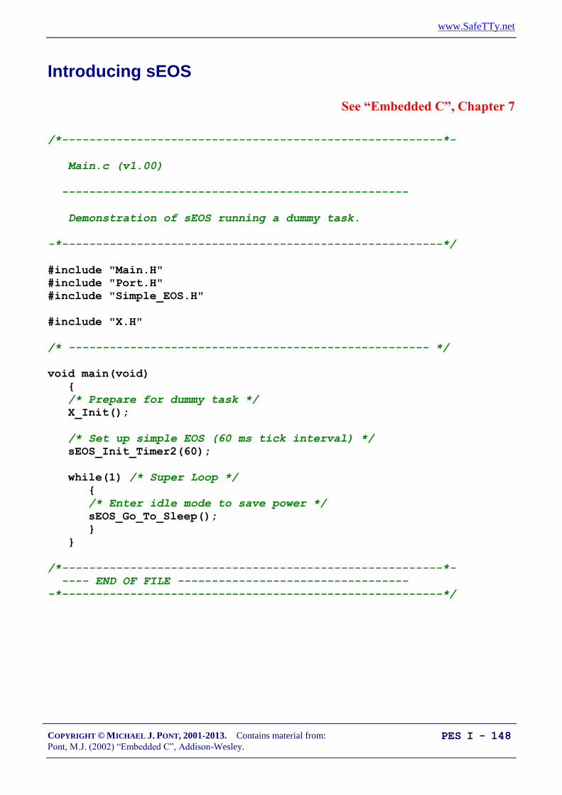
www.SafeTTy.net
COPYRIGHT © MICHAEL J. PONT, 2001-2013. Contains material from:
Pont, M.J. (2002) “Embedded C”, Addison-Wesley. PES I - 148
Introducing sEOS
See “Embedded C”, Chapter 7
/*--------------------------------------------------------*-
Main.c (v1.00)
---------------------------------------------------
Demonstration of sEOS running a dummy task.
-*--------------------------------------------------------*/
#include "Main.H"
#include "Port.H"
#include "Simple_EOS.H"
#include "X.H"
/* ----------------------------------------------------- */
void main(void)
{
/* Prepare for dummy task */
X_Init();
/* Set up simple EOS (60 ms tick interval) */
sEOS_Init_Timer2(60);
while(1) /* Super Loop */
{
/* Enter idle mode to save power */
sEOS_Go_To_Sleep();
}
}
/*--------------------------------------------------------*-
---- END OF FILE ----------------------------------
-*--------------------------------------------------------*/
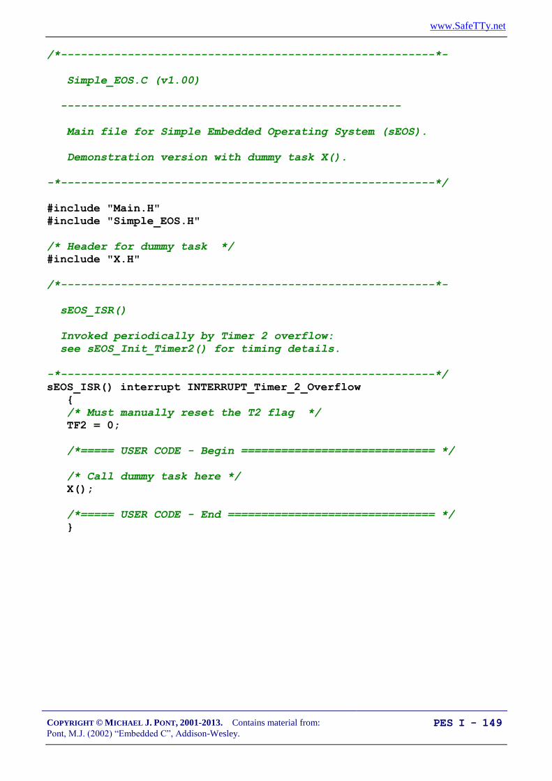
www.SafeTTy.net
COPYRIGHT © MICHAEL J. PONT, 2001-2013. Contains material from:
Pont, M.J. (2002) “Embedded C”, Addison-Wesley. PES I - 149
/*--------------------------------------------------------*-
Simple_EOS.C (v1.00)
---------------------------------------------------
Main file for Simple Embedded Operating System (sEOS).
Demonstration version with dummy task X().
-*--------------------------------------------------------*/
#include "Main.H"
#include "Simple_EOS.H"
/* Header for dummy task */
#include "X.H"
/*--------------------------------------------------------*-
sEOS_ISR()
Invoked periodically by Timer 2 overflow:
see sEOS_Init_Timer2() for timing details.
-*--------------------------------------------------------*/
sEOS_ISR() interrupt INTERRUPT_Timer_2_Overflow
{
/* Must manually reset the T2 flag */
TF2 = 0;
/*===== USER CODE - Begin ============================= */
/* Call dummy task here */
X();
/*===== USER CODE - End =============================== */
}

www.SafeTTy.net
COPYRIGHT © MICHAEL J. PONT, 2001-2013. Contains material from:
Pont, M.J. (2002) “Embedded C”, Addison-Wesley. PES I - 150
/*--------------------------------------------------------*-
sEOS_Init_Timer2()
-*--------------------------------------------------------*/
void sEOS_Init_Timer2(const tByte TICK_MS)
{
tLong Inc;
tWord Reload_16;
tByte Reload_08H, Reload_08L;
/* Timer 2 is configured as a 16-bit timer,
which is automatically reloaded when it overflows */
T2CON = 0x04; /* Load T2 control register */
/* Number of timer increments required (max 65536) */
Inc = ((tLong)TICK_MS * (OSC_FREQ/1000)) /
(tLong)OSC_PER_INST;
/* 16-bit reload value */
Reload_16 = (tWord) (65536UL - Inc);
/* 8-bit reload values (High & Low) */
Reload_08H = (tByte)(Reload_16 / 256);
Reload_08L = (tByte)(Reload_16 % 256);
/* Used for manually checking timing (in simulator) */
/*P2 = Reload_08H; */
/*P3 = Reload_08L; */
TH2 = Reload_08H; /* Load T2 high byte */
RCAP2H = Reload_08H; /* Load T2 reload capt. reg h byte */
TL2 = Reload_08L; /* Load T2 low byte */
RCAP2L = Reload_08L; /* Load T2 reload capt. reg l byte */
/* Timer 2 interrupt is enabled, and ISR will be called
whenever the timer overflows. */
ET2 = 1;
/* Start Timer 2 running */
TR2 = 1;
EA = 1; /* Globally enable interrupts */
}

www.SafeTTy.net
COPYRIGHT © MICHAEL J. PONT, 2001-2013. Contains material from:
Pont, M.J. (2002) “Embedded C”, Addison-Wesley. PES I - 151
/*--------------------------------------------------------*-
sEOS_Go_To_Sleep()
This operating system enters 'idle mode' between clock ticks
to save power. The next clock tick will return processor
to the normal operating state.
-*--------------------------------------------------------*/
void sEOS_Go_To_Sleep(void)
{
PCON |= 0x01; /* Enter idle mode (generic 8051 version) */
}
/*--------------------------------------------------------*-
---- END OF FILE ----------------------------------
-*--------------------------------------------------------*/

www.SafeTTy.net
COPYRIGHT © MICHAEL J. PONT, 2001-2013. Contains material from:
Pont, M.J. (2002) “Embedded C”, Addison-Wesley. PES I - 152
/*--------------------------------------------------------*-
X.C (v1.00)
---------------------------------------------------
Dummy task to introduce sEOS.
-*--------------------------------------------------------*/
#include "X.H"
/*--------------------------------------------------------*-
X_Init()
Dummy task init function.
-*--------------------------------------------------------*/
void X_Init(void)
{
/* Dummy task init... */
}
/*--------------------------------------------------------*-
X()
Dummy task called from sEOS ISR.
-*--------------------------------------------------------*/
void X(void)
{
/* Dummy task... */
}
/*--------------------------------------------------------*-
---- END OF FILE ----------------------------------
-*--------------------------------------------------------*/
www.SafeTTy.net
COPYRIGHT © MICHAEL J. PONT, 2001-2013. Contains material from:
Pont, M.J. (2002) “Embedded C”, Addison-Wesley. PES I - 153
Tasks, functions and scheduling
In discussions about embedded systems, you will frequently
hear and read about ‘task design’, ‘task execution times’ and
‘multi-tasking’ systems.
In this context, the term ‘task’ is usually used to refer to a
function that is executed on a periodic basis.
In the case of sEOS, the tasks will be implemented using
functions which are called from the timer-driven
interrupt service routine.
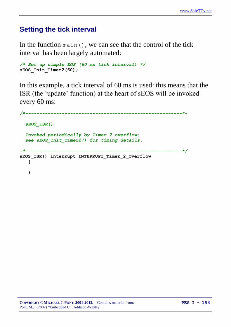
www.SafeTTy.net
COPYRIGHT © MICHAEL J. PONT, 2001-2013. Contains material from:
Pont, M.J. (2002) “Embedded C”, Addison-Wesley. PES I - 154
Setting the tick interval
In the function main(), we can see that the control of the tick
interval has been largely automated:
/* Set up simple EOS (60 ms tick interval) */
sEOS_Init_Timer2(60);
In this example, a tick interval of 60 ms is used: this means that the
ISR (the ‘update’ function) at the heart of sEOS will be invoked
every 60 ms:
/*--------------------------------------------------------*-
sEOS_ISR()
Invoked periodically by Timer 2 overflow:
see sEOS_Init_Timer2() for timing details.
-*--------------------------------------------------------*/
sEOS_ISR() interrupt INTERRUPT_Timer_2_Overflow
{
…
}

www.SafeTTy.net
COPYRIGHT © MICHAEL J. PONT, 2001-2013. Contains material from:
Pont, M.J. (2002) “Embedded C”, Addison-Wesley. PES I - 155
The ‘automatic’ tick interval control is achieved using the C pre-
processor, and the information included in the project header file
(Main.H):
/* Oscillator / resonator frequency (in Hz) e.g. (11059200UL) */
#define OSC_FREQ (12000000UL)
/* Number of oscillations per instruction (12, etc) */
...
#define OSC_PER_INST (12)
This information is then used to calculate the required timer reload
values in Simple_EOS.C as follows:
/* Number of timer increments required (max 65536) */
Inc = ((tLong)TICK_MS * (OSC_FREQ/1000)) / (tLong)OSC_PER_INST;
/* 16-bit reload value */
Reload_16 = (tWord) (65536UL - Inc);
/* 8-bit reload values (High & Low) */
Reload_08H = (tByte)(Reload_16 / 256);
Reload_08L = (tByte)(Reload_16 % 256);
…
TH2 = Reload_08H; /* Load T2 high byte */
RCAP2H = Reload_08H; /* Load T2 reload capt. reg h byte */
TL2 = Reload_08L; /* Load T2 low byte */
RCAP2L = Reload_08L; /* Load T2 reload capt. reg l byte */

www.SafeTTy.net
COPYRIGHT © MICHAEL J. PONT, 2001-2013. Contains material from:
Pont, M.J. (2002) “Embedded C”, Addison-Wesley. PES I - 156
If using a 12 MHz oscillator, then accurate timing can
usually be obtained over a range of tick intervals from 1 ms
to 60 ms (approximately).
If using other clock frequencies (e.g. 11.0592 MHz), precise
timing can only be obtained at a much more limited range of
tick intervals.
If you are developing an application where precise timing is
required, you must check the timing calculations by hand.
/* Used for manually checking timing (in simulator) */
P2 = Reload_08H;
P3 = Reload_08L;

www.SafeTTy.net
COPYRIGHT © MICHAEL J. PONT, 2001-2013. Contains material from:
Pont, M.J. (2002) “Embedded C”, Addison-Wesley. PES I - 157
Saving power
Using sEOS, we can reduce the power consumption of the
application by having the processor enter idle mode when it finishes
executing the ISR.
This is achieved through the function sEOS_Go_To_Sleep():
/*--------------------------------------------------------*-
sEOS_Go_To_Sleep()
This operating system enters 'idle mode' between clock ticks
to save power. The next clock tick will return processor
to the normal operating state.
-*--------------------------------------------------------*/
void sEOS_Go_To_Sleep(void)
{
PCON |= 0x01; /* Enter idle mode (generic 8051 version) */
}
Note that the processor will automatically return to ‘Normal’ mode
when the timer next overflows (generating an interrupt).
Device Normal Idle Power Down
Atmel 89S53 11 mA 2 mA 60 A

www.SafeTTy.net
COPYRIGHT © MICHAEL J. PONT, 2001-2013. Contains material from:
Pont, M.J. (2002) “Embedded C”, Addison-Wesley. PES I - 158
Using sEOS in your own projects
When using sEOS in your own applications, you will need to
include a copy of the files Simple_EOS.C and Simple_EOS.H in your
project: the .C file will then need to be edited - in the area indicated
below - in order to match your requirements:
sEOS_ISR() interrupt INTERRUPT_Timer_2_Overflow
{
/* Must manually reset the T2 flag */
TF2 = 0;
/*===== USER CODE - Begin ============================= */
/* ADD YOUR FUNCTION (TASK) CALLS HERE... */
/*===== USER CODE - End =============================== */
}

www.SafeTTy.net
COPYRIGHT © MICHAEL J. PONT, 2001-2013. Contains material from:
Pont, M.J. (2002) “Embedded C”, Addison-Wesley. PES I - 159
Is this approach portable?
The presence of an on-chip timer which can be used to
generate interrupts in this way is by no means restricted to
the 8051 family: almost all processors intended for use in
embedded applications have timers which can be used in a
manner very similar to that described here.
For example, similar timers are included on other 8-bit
microcontrollers (e.g. Microchip PIC family, the Motorola
HC08 family), and also on 16-bit devices (e.g. the Infineon
C167 family) as well as on 32-bit processors (e.g. the ARM
family, the Motorola MPC500 family).

www.SafeTTy.net
COPYRIGHT © MICHAEL J. PONT, 2001-2013. Contains material from:
Pont, M.J. (2002) “Embedded C”, Addison-Wesley. PES I - 160
Example: Milk pasteurization
Milk pasteurisation systemMilk pasteurisation system
Determine flow rate from pulse stream

www.SafeTTy.net
COPYRIGHT © MICHAEL J. PONT, 2001-2013. Contains material from:
Pont, M.J. (2002) “Embedded C”, Addison-Wesley. PES I - 161
/*-------------------------------------------------------------*-
Port.H (v1.00)
--------------------------------------------------------
Port Header file for the milk pasteurization example
(“Embedded C” Chapter 7)
-*-------------------------------------------------------------*/
/* ------ Pulse_Count.C ---------------------------------- */
/* Connect pulse input to this pin - debounced in software */
sbit Sw_pin = P3^0;
/* Connect alarm to this pin (set if pulse is below threshold) */
sbit Alarm_pin = P3^7;
/* ------ Bargraph.C -------------------------------------- */
/* Bargraph display on these pins (the 8 port pins may be
distributed over several ports, if required). */
sbit Pin0 = P1^0;
sbit Pin1 = P1^1;
sbit Pin2 = P1^2;
sbit Pin3 = P1^3;
sbit Pin4 = P1^4;
sbit Pin5 = P1^5;
sbit Pin6 = P1^6;
sbit Pin7 = P1^7;
/*-------------------------------------------------------------*-
---- END OF FILE ---------------------------------------
-*-------------------------------------------------------------*/

www.SafeTTy.net
COPYRIGHT © MICHAEL J. PONT, 2001-2013. Contains material from:
Pont, M.J. (2002) “Embedded C”, Addison-Wesley. PES I - 162
/*-------------------------------------------------------------*-
Main.c (v1.00)
--------------------------------------------------------
Milk pasteurization example.
-*-------------------------------------------------------------*/
#include "Main.H"
#include "Port.H"
#include "Simple_EOS.H"
#include "Bargraph.H"
#include "Pulse_Count.H"
/* --------------------------------------------------------------- */
void main(void)
{
PULSE_COUNT_Init();
BARGRAPH_Init();
/* Set up simple EOS (30ms tick interval) */
sEOS_Init_Timer2(30);
while(1) /* Super Loop */
{
/* Enter idle mode to save power */
sEOS_Go_To_Sleep();
}
}
/*-------------------------------------------------------------*-
---- END OF FILE ---------------------------------------
-*-------------------------------------------------------------*/

www.SafeTTy.net
COPYRIGHT © MICHAEL J. PONT, 2001-2013. Contains material from:
Pont, M.J. (2002) “Embedded C”, Addison-Wesley. PES I - 163
/*-------------------------------------------------------------*-
Simple_EOS.C (v1.00)
--------------------------------------------------------
Main file for Simple Embedded Operating System (sEOS) for 8051.
-- This version for milk-flow-rate monitoring.
-*-------------------------------------------------------------*/
#include "Main.H"
#include "Simple_EOS.H"
#include "Pulse_count.H"
/*-------------------------------------------------------------*-
sEOS_ISR()
Invoked periodically by Timer 2 overflow:
see sEOS_Init_Timer2() for timing details.
-*-------------------------------------------------------------*/
sEOS_ISR() interrupt INTERRUPT_Timer_2_Overflow
{
/* Must manually reset the T2 flag */
TF2 = 0;
/*===== USER CODE - Begin ================================== */
/* Call 'Update' function here */
PULSE_COUNT_Update();
/*===== USER CODE - End ==================================== */
}
www.SafeTTy.net
COPYRIGHT © MICHAEL J. PONT, 2001-2013. Contains material from:
Pont, M.J. (2002) “Embedded C”, Addison-Wesley. PES I - 164
/*-------------------------------------------------------------*-
sEOS_Init_Timer2()
...
-*-------------------------------------------------------------*/
void sEOS_Init_Timer2(const tByte TICK_MS)
{
tLong Inc;
tWord Reload_16;
tByte Reload_08H, Reload_08L;
/* Timer 2 is configured as a 16-bit timer,
which is automatically reloaded when it overflows */
T2CON = 0x04; /* Load T2 control register */
/* Number of timer increments required (max 65536) */
Inc = ((tLong)TICK_MS * (OSC_FREQ/1000)) / (tLong)OSC_PER_INST;
/* 16-bit reload value */
Reload_16 = (tWord) (65536UL - Inc);
/* 8-bit reload values (High & Low) */
Reload_08H = (tByte)(Reload_16 / 256);
Reload_08L = (tByte)(Reload_16 % 256);
/* Used for manually checking timing (in simulator) */
/*P2 = Reload_08H; */
/*P3 = Reload_08L; */
TH2 = Reload_08H; /* Load T2 high byte */
RCAP2H = Reload_08H; /* Load T2 reload capt. reg. high byte */
TL2 = Reload_08L; /* Load T2 low byte */
RCAP2L = Reload_08L; /* Load T2 reload capt. reg. low byte */
/* Timer 2 interrupt is enabled, and ISR will be called
whenever the timer overflows. */
ET2 = 1;
/* Start Timer 2 running */
TR2 = 1;
EA = 1; /* Globally enable interrupts */
}

www.SafeTTy.net
COPYRIGHT © MICHAEL J. PONT, 2001-2013. Contains material from:
Pont, M.J. (2002) “Embedded C”, Addison-Wesley. PES I - 165
/*-------------------------------------------------------------*-
sEOS_Go_To_Sleep()
This operating system enters 'idle mode' between clock ticks
to save power. The next clock tick will return the processor
to the normal operating state.
-*-------------------------------------------------------------*/
void sEOS_Go_To_Sleep(void)
{
PCON |= 0x01; /* Enter idle mode (generic 8051 version) */
}
/*-------------------------------------------------------------*-
---- END OF FILE ---------------------------------------
-*-------------------------------------------------------------*/

www.SafeTTy.net
COPYRIGHT © MICHAEL J. PONT, 2001-2013. Contains material from:
Pont, M.J. (2002) “Embedded C”, Addison-Wesley. PES I - 166
/*-------------------------------------------------------------*-
Pulse_Count.C (v1.00)
--------------------------------------------------------
Count pulses from a mechanical switch or similar device.
___
Responds to falling edge of pulse: |___
-*-------------------------------------------------------------*/
#include "Main.H"
#include "Port.H"
#include "Bargraph.H"
#include "Pulse_Count.H"
/* ------ Private function prototypes ------------------------- */
void PULSE_COUNT_Check_Below_Threshold(const tByte);
/* ------ Public variable declarations ------------------------ */
/* The data to be displayed */
extern tBargraph Data_G;
/* ------ Public variable definitions -------------------------- */
/* Set only after falling edge is detected */
bit Falling_edge_G;
/* ------ Private variable definitions ------------------------- */
/* The results of successive tests of the pulse signal */
/* (NOTE: Can't have arrays of bits...) */
static bit Test4, Test3, Test2, Test1, Test0;
static tByte Total_G = 0;
static tWord Calls_G = 0;
/* ------ Private constants ----------------------------------- */
/* Allows changed of logic without hardware changes */
#define HI_LEVEL (0)
#define LO_LEVEL (1)
www.SafeTTy.net
COPYRIGHT © MICHAEL J. PONT, 2001-2013. Contains material from:
Pont, M.J. (2002) “Embedded C”, Addison-Wesley. PES I - 167
/*-------------------------------------------------------------*-
PULSE_COUNT_Init()
Initialisation function for the switch library.
-*-------------------------------------------------------------*/
void PULSE_COUNT_Init(void)
{
Sw_pin = 1; /* Use this pin for input */
/* The tests (see text) */
Test4 = LO_LEVEL;
Test3 = LO_LEVEL;
Test2 = LO_LEVEL;
Test1 = LO_LEVEL;
Test0 = LO_LEVEL;
}
/*-------------------------------------------------------------*-
PULSE_COUNT_Check_Below_Threshold()
Checks to see if pulse count is below a specified
threshold value. If it is, the alarm is sounded.
-*-------------------------------------------------------------*/
void PULSE_COUNT_Check_Below_Threshold(const tByte THRESHOLD)
{
if (Data_G < THRESHOLD)
{
Alarm_pin = 0;
}
else
{
Alarm_pin = 1;
}
}

www.SafeTTy.net
COPYRIGHT © MICHAEL J. PONT, 2001-2013. Contains material from:
Pont, M.J. (2002) “Embedded C”, Addison-Wesley. PES I - 168
/*-------------------------------------------------------------*-
PULSE_COUNT_Update()
This is the main switch function.
It should be called every 30 ms
(to allow for typical 20ms debounce time).
-*-------------------------------------------------------------*/
void PULSE_COUNT_Update(void)
{
/* Clear timer flag */
TF2 = 0;
/* Shuffle the test results */
Test4 = Test3;
Test3 = Test2;
Test2 = Test1;
Test1 = Test0;
/* Get latest test result */
Test0 = Sw_pin;
/* Required result:
Test4 == HI_LEVEL
Test3 == HI_LEVEL
Test1 == LO_LEVEL
Test0 == LO_LEVEL */
if ((Test4 == HI_LEVEL) &&
(Test3 == HI_LEVEL) &&
(Test1 == LO_LEVEL) &&
(Test0 == LO_LEVEL))
{
/* Falling edge detected */
Falling_edge_G = 1;
}
else
{
/* Default */
Falling_edge_G = 0;
}

www.SafeTTy.net
COPYRIGHT © MICHAEL J. PONT, 2001-2013. Contains material from:
Pont, M.J. (2002) “Embedded C”, Addison-Wesley. PES I - 169
/* Calculate average every 45 calls to this task
- maximum count over this period is 9 pulses
if (++Calls_G < 45) */
/* 450 used here for test purposes (in simulator)
[Because there is a limit to how fast you can simulate pulses
by hand...] */
if (++Calls_G < 450)
{
Total_G += (int) Falling_edge_G;
}
else
{
/* Update the display */
Data_G = Total_G; /* Max is 9 */
Total_G = 0;
Calls_G = 0;
PULSE_COUNT_Check_Below_Threshold(3);
BARGRAPH_Update();
}
}
/*-------------------------------------------------------------*-
---- END OF FILE ---------------------------------------
-*-------------------------------------------------------------*/

www.SafeTTy.net
COPYRIGHT © MICHAEL J. PONT, 2001-2013. Contains material from:
Pont, M.J. (2002) “Embedded C”, Addison-Wesley. PES I - 170
/*-------------------------------------------------------------*-
Bargraph.h (v1.00)
--------------------------------------------------------
- See Bargraph.c for details.
-*-------------------------------------------------------------*/
#include "Main.h"
/* ------ Public data type declarations ----------------------- */
typedef tByte tBargraph;
/* ------ Public function prototypes -------------------------- */
void BARGRAPH_Init(void);
void BARGRAPH_Update(void);
/* ------ Public constants ------------------------------------ */
#define BARGRAPH_MAX (9)
#define BARGRAPH_MIN (0)
/*-------------------------------------------------------------*-
---- END OF FILE ---------------------------------------
-*-------------------------------------------------------------*/

www.SafeTTy.net
COPYRIGHT © MICHAEL J. PONT, 2001-2013. Contains material from:
Pont, M.J. (2002) “Embedded C”, Addison-Wesley. PES I - 171
/*-------------------------------------------------------------*-
Bargraph.c (v1.00)
--------------------------------------------------------
Simple bargraph library.
-*-------------------------------------------------------------*/
#include "Main.h"
#include "Port.h"
#include "Bargraph.h"
/* ------ Public variable declarations ------------------------ */
/* The data to be displayed */
tBargraph Data_G;
/* ------ Private constants ----------------------------------- */
#define BARGRAPH_ON (1)
#define BARGRAPH_OFF (0)
/* ------ Private variables ----------------------------------- */
/* These variables store the thresholds
used to update the display */
static tBargraph M9_1_G;
static tBargraph M9_2_G;
static tBargraph M9_3_G;
static tBargraph M9_4_G;
static tBargraph M9_5_G;
static tBargraph M9_6_G;
static tBargraph M9_7_G;
static tBargraph M9_8_G;

www.SafeTTy.net
COPYRIGHT © MICHAEL J. PONT, 2001-2013. Contains material from:
Pont, M.J. (2002) “Embedded C”, Addison-Wesley. PES I - 172
/*-------------------------------------------------------------*-
BARGRAPH_Init()
Prepare for the bargraph display.
-*-------------------------------------------------------------*/
void BARGRAPH_Init(void)
{
Pin0 = BARGRAPH_OFF;
Pin1 = BARGRAPH_OFF;
Pin2 = BARGRAPH_OFF;
Pin3 = BARGRAPH_OFF;
Pin4 = BARGRAPH_OFF;
Pin5 = BARGRAPH_OFF;
Pin6 = BARGRAPH_OFF;
Pin7 = BARGRAPH_OFF;
/* Use a linear scale to display data
Remember: *9* possible output states
- do all calculations ONCE */
M9_1_G = (BARGRAPH_MAX - BARGRAPH_MIN) / 9;
M9_2_G = M9_1_G * 2;
M9_3_G = M9_1_G * 3;
M9_4_G = M9_1_G * 4;
M9_5_G = M9_1_G * 5;
M9_6_G = M9_1_G * 6;
M9_7_G = M9_1_G * 7;
M9_8_G = M9_1_G * 8;
}

www.SafeTTy.net
COPYRIGHT © MICHAEL J. PONT, 2001-2013. Contains material from:
Pont, M.J. (2002) “Embedded C”, Addison-Wesley. PES I - 173
/*-------------------------------------------------------------*-
BARGRAPH_Update()
Update the bargraph display.
-*-------------------------------------------------------------*/
void BARGRAPH_Update(void)
{
tBargraph Data = Data_G - BARGRAPH_MIN;
Pin0 = ((Data >= M9_1_G) == BARGRAPH_ON);
Pin1 = ((Data >= M9_2_G) == BARGRAPH_ON);
Pin2 = ((Data >= M9_3_G) == BARGRAPH_ON);
Pin3 = ((Data >= M9_4_G) == BARGRAPH_ON);
Pin4 = ((Data >= M9_5_G) == BARGRAPH_ON);
Pin5 = ((Data >= M9_6_G) == BARGRAPH_ON);
Pin6 = ((Data >= M9_7_G) == BARGRAPH_ON);
Pin7 = ((Data >= M9_8_G) == BARGRAPH_ON);
}
/*-------------------------------------------------------------*-
---- END OF FILE ---------------------------------------
-*-------------------------------------------------------------*/

www.SafeTTy.net
COPYRIGHT © MICHAEL J. PONT, 2001-2013. Contains material from:
Pont, M.J. (2002) “Embedded C”, Addison-Wesley. PES I - 174
Conclusions
The simple operating system (‘sEOS’) introduced in this
seminar imposes a very low processor load but is nonetheless
flexible and useful.
The simple nature of sEOS also provides other benefits. For
example, it means that developers themselves can, very
rapidly, port the OS onto a new microcontroller
environment. It also means that the architecture may be
readily adapted to meet the needs of a particular application.
Perhaps the most important side-effect of this form of simple OS is that
- unlike a traditional ‘real-time operating system’ - it becomes part of the
application itself, rather than forming a separate code layer.

www.SafeTTy.net
COPYRIGHT © MICHAEL J. PONT, 2001-2013. Contains material from:
Pont, M.J. (2002) “Embedded C”, Addison-Wesley. PES I - 175
Preparation for the next seminar
Please read Chapter 8
before the next seminar

www.SafeTTy.net
COPYRIGHT © MICHAEL J. PONT, 2001-2013. Contains material from:
Pont, M.J. (2002) “Embedded C”, Addison-Wesley. PES I - 176

www.SafeTTy.net
COPYRIGHT © MICHAEL J. PONT, 2001-2013. Contains material from:
Pont, M.J. (2002) “Embedded C”, Addison-Wesley. PES I - 177
Seminar 7: Multi-State Systems
and Function
Sequences
SleepingSleeping
WakingWaking
GrowlingGrowling
AttackingAttacking
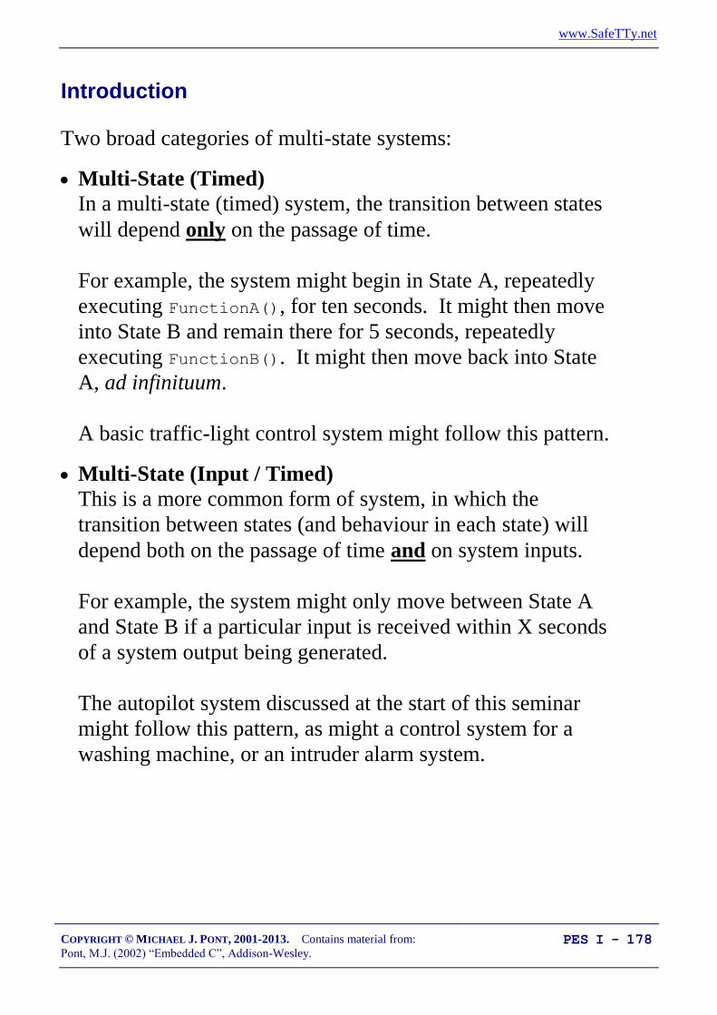
www.SafeTTy.net
COPYRIGHT © MICHAEL J. PONT, 2001-2013. Contains material from:
Pont, M.J. (2002) “Embedded C”, Addison-Wesley. PES I - 178
Introduction
Two broad categories of multi-state systems:
Multi-State (Timed)
In a multi-state (timed) system, the transition between states
will depend only on the passage of time.
For example, the system might begin in State A, repeatedly
executing FunctionA(), for ten seconds. It might then move
into State B and remain there for 5 seconds, repeatedly
executing FunctionB(). It might then move back into State
A, ad infinituum.
A basic traffic-light control system might follow this pattern.
Multi-State (Input / Timed)
This is a more common form of system, in which the
transition between states (and behaviour in each state) will
depend both on the passage of time and on system inputs.
For example, the system might only move between State A
and State B if a particular input is received within X seconds
of a system output being generated.
The autopilot system discussed at the start of this seminar
might follow this pattern, as might a control system for a
washing machine, or an intruder alarm system.

www.SafeTTy.net
COPYRIGHT © MICHAEL J. PONT, 2001-2013. Contains material from:
Pont, M.J. (2002) “Embedded C”, Addison-Wesley. PES I - 179
For completeness, we will mention on further possibility:
Multi-State (Input)
This is a comparatively rare form of system, in which the
transition between states (and behaviour in each state)
depends only on the system inputs.
For example, the system might only move between State A
and State B if a particular input is received. It will remain
indefinitely in State A if this input is not received.
Such systems have no concept of time, and - therefore - no
way of implementing timeout or similar behaviours. We will
not consider such systems in this course.
In this seminar, we will consider how the Multi-State (Time) and
Multi-State (Input / Time) architectures can be implemented in C.

www.SafeTTy.net
COPYRIGHT © MICHAEL J. PONT, 2001-2013. Contains material from:
Pont, M.J. (2002) “Embedded C”, Addison-Wesley. PES I - 180
Implementing a Multi-State (Timed) system
We can describe the time-driven, multi-state architecture as follows:
The system will operate in two or more states.
Each state may be associated with one or more function
calls.
Transitions between states will be controlled by the passage
of time.
Transitions between states may also involve function calls.
Please note that, in order to ease subsequent maintenance tasks, the
system states should not be arbitrarily named, but should - where
possible - reflect a physical state observable by the user and / or
developer.
Please also note that the system states will usually be represented
by means of a switch statement in the operating system ISR.

www.SafeTTy.net
COPYRIGHT © MICHAEL J. PONT, 2001-2013. Contains material from:
Pont, M.J. (2002) “Embedded C”, Addison-Wesley. PES I - 181
Example: Traffic light sequencing
Red
Amber
Green
Time
Note:
European sequence!
www.SafeTTy.net
COPYRIGHT © MICHAEL J. PONT, 2001-2013. Contains material from:
Pont, M.J. (2002) “Embedded C”, Addison-Wesley. PES I - 182
In this case, the various states are easily identified:
Red
Red-Amber
Green
Amber
In the code, we will represent these states as follows:
/* Possible system states */
typedef enum {RED, RED_AND_AMBER, GREEN, AMBER} eLight_State;
We will store the time to be spent in each state as follows:
/* (Times are in seconds) */
#define RED_DURATION 20
#define RED_AND_AMBER_DURATION 5
#define GREEN_DURATION 30
#define AMBER_DURATION 5
www.SafeTTy.net
COPYRIGHT © MICHAEL J. PONT, 2001-2013. Contains material from:
Pont, M.J. (2002) “Embedded C”, Addison-Wesley. PES I - 183
In this simple case, we do not require function calls from (or
between) system states: the required behaviour will be implemented
directly through control of the (three) port pins which – in the final
system – would be connected to appropriate bulbs.
For example:
case RED:
{
Red_light = ON;
Amber_light = OFF;
Green_light = OFF;
...

www.SafeTTy.net
COPYRIGHT © MICHAEL J. PONT, 2001-2013. Contains material from:
Pont, M.J. (2002) “Embedded C”, Addison-Wesley. PES I - 184
/*-------------------------------------------------------------*-
Main.c (v1.00)
--------------------------------------------------------
Traffic light example.
-*-------------------------------------------------------------*/
#include "Main.H"
#include "Port.H"
#include "Simple_EOS.H"
#include "T_Lights.H"
/* --------------------------------------------------------------- */
void main(void)
{
/* Prepare to run traffic sequence */
TRAFFIC_LIGHTS_Init(RED);
/* Set up simple EOS (50 ms ticks) */
sEOS_Init_Timer2(50);
while(1) /* Super Loop */
{
/* Enter idle mode to save power */
sEOS_Go_To_Sleep();
}
}
/*-------------------------------------------------------------*-
---- END OF FILE ---------------------------------------
-*-------------------------------------------------------------*/

www.SafeTTy.net
COPYRIGHT © MICHAEL J. PONT, 2001-2013. Contains material from:
Pont, M.J. (2002) “Embedded C”, Addison-Wesley. PES I - 185
/*-------------------------------------------------------------*-
T_Lights.H (v1.00)
--------------------------------------------------------
- See T_Lights.C for details.
-*-------------------------------------------------------------*/
#ifndef _T_LIGHTS_H
#define _T_LIGHTS_H
/* ------ Public data type declarations ----------------------- */
/* Possible system states */
typedef enum {RED, RED_AND_AMBER, GREEN, AMBER} eLight_State;
/* ------ Public function prototypes -------------------------- */
void TRAFFIC_LIGHTS_Init(const eLight_State);
void TRAFFIC_LIGHTS_Update(void);
#endif
/*-------------------------------------------------------------*-
---- END OF FILE ---------------------------------------
-*-------------------------------------------------------------*/

www.SafeTTy.net
COPYRIGHT © MICHAEL J. PONT, 2001-2013. Contains material from:
Pont, M.J. (2002) “Embedded C”, Addison-Wesley. PES I - 186
/*-------------------------------------------------------------*-
T_lights.C (v1.00)
-*-------------------------------------------------------------*/
#include "Main.H"
#include "Port.H"
#include "T_lights.H"
/* ------ Private constants ----------------------------------- */
/* Easy to change logic here */
#define ON 0
#define OFF 1
/* Times in each of the (four) possible light states
(Times are in seconds) */
#define RED_DURATION 20
#define RED_AND_AMBER_DURATION 5
#define GREEN_DURATION 30
#define AMBER_DURATION 5
/* ------ Private variables ----------------------------------- */
/* The state of the system */
static eLight_State Light_state_G;
/* The time in that state */
static tLong Time_in_state;
/* Used by sEOS */
static tByte Call_count_G = 0;
/*-------------------------------------------------------------*-
TRAFFIC_LIGHTS_Init()
Prepare for traffic light activity.
-*-------------------------------------------------------------*/
void TRAFFIC_LIGHTS_Init(const eLight_State START_STATE)
{
Light_state_G = START_STATE; /* Decide on initial state */
}

www.SafeTTy.net
COPYRIGHT © MICHAEL J. PONT, 2001-2013. Contains material from:
Pont, M.J. (2002) “Embedded C”, Addison-Wesley. PES I - 187
/*-------------------------------------------------------------*-
TRAFFIC_LIGHTS_Update()
Must be called once per second.
-*-------------------------------------------------------------*/
void TRAFFIC_LIGHTS_Update(void)
{
switch (Light_state_G)
{
case RED:
{
Red_light = ON;
Amber_light = OFF;
Green_light = OFF;
if (++Time_in_state == RED_DURATION)
{
Light_state_G = RED_AND_AMBER;
Time_in_state = 0;
}
break;
}
case RED_AND_AMBER:
{
Red_light = ON;
Amber_light = ON;
Green_light = OFF;
if (++Time_in_state == RED_AND_AMBER_DURATION)
{
Light_state_G = GREEN;
Time_in_state = 0;
}
break;
}

www.SafeTTy.net
COPYRIGHT © MICHAEL J. PONT, 2001-2013. Contains material from:
Pont, M.J. (2002) “Embedded C”, Addison-Wesley. PES I - 188
case GREEN:
{
Red_light = OFF;
Amber_light = OFF;
Green_light = ON;
if (++Time_in_state == GREEN_DURATION)
{
Light_state_G = AMBER;
Time_in_state = 0;
}
break;
}
case AMBER:
{
Red_light = OFF;
Amber_light = ON;
Green_light = OFF;
if (++Time_in_state == AMBER_DURATION)
{
Light_state_G = RED;
Time_in_state = 0;
}
break;
}
}
}
/*-------------------------------------------------------------*-
---- END OF FILE ---------------------------------------
-*-------------------------------------------------------------*/

www.SafeTTy.net
COPYRIGHT © MICHAEL J. PONT, 2001-2013. Contains material from:
Pont, M.J. (2002) “Embedded C”, Addison-Wesley. PES I - 189
Example: Animatronic dinosaur
SleepingSleeping
WakingWaking
GrowlingGrowling
AttackingAttacking

www.SafeTTy.net
COPYRIGHT © MICHAEL J. PONT, 2001-2013. Contains material from:
Pont, M.J. (2002) “Embedded C”, Addison-Wesley. PES I - 190
The system states
Sleeping:
The dinosaur will be largely motionless, but will be
obviously ‘breathing’. Irregular snoring noises, or slight
movements during this time will add interest for the
audience.
Waking:
The dinosaur will begin to wake up. Eyelids will begin to
flicker. Breathing will become more rapid.
Growling:
Eyes will suddenly open, and the dinosaur will emit a very
loud growl. Some further movement and growling will
follow.
Attacking:
Rapid ‘random’ movements towards the audience. Lots of
noise (you should be able to hear this from the next floor in
the museum).
typedef enum {SLEEPING, WAKING, GROWLING, ATTACKING} eDinosaur_State;
/* Times in each of the (four) possible states */
/* (Times are in seconds) */
#define SLEEPING_DURATION 255
#define WAKING_DURATION 60
#define GROWLING_DURATION 40
#define ATTACKING_DURATION 120
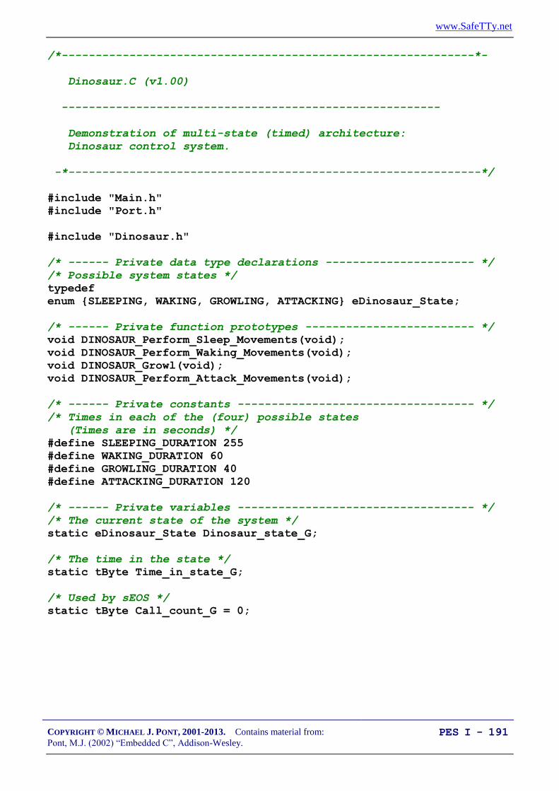
www.SafeTTy.net
COPYRIGHT © MICHAEL J. PONT, 2001-2013. Contains material from:
Pont, M.J. (2002) “Embedded C”, Addison-Wesley. PES I - 191
/*-------------------------------------------------------------*-
Dinosaur.C (v1.00)
--------------------------------------------------------
Demonstration of multi-state (timed) architecture:
Dinosaur control system.
-*-------------------------------------------------------------*/
#include "Main.h"
#include "Port.h"
#include "Dinosaur.h"
/* ------ Private data type declarations ---------------------- */
/* Possible system states */
typedef
enum {SLEEPING, WAKING, GROWLING, ATTACKING} eDinosaur_State;
/* ------ Private function prototypes ------------------------- */
void DINOSAUR_Perform_Sleep_Movements(void);
void DINOSAUR_Perform_Waking_Movements(void);
void DINOSAUR_Growl(void);
void DINOSAUR_Perform_Attack_Movements(void);
/* ------ Private constants ----------------------------------- */
/* Times in each of the (four) possible states
(Times are in seconds) */
#define SLEEPING_DURATION 255
#define WAKING_DURATION 60
#define GROWLING_DURATION 40
#define ATTACKING_DURATION 120
/* ------ Private variables ----------------------------------- */
/* The current state of the system */
static eDinosaur_State Dinosaur_state_G;
/* The time in the state */
static tByte Time_in_state_G;
/* Used by sEOS */
static tByte Call_count_G = 0;

www.SafeTTy.net
COPYRIGHT © MICHAEL J. PONT, 2001-2013. Contains material from:
Pont, M.J. (2002) “Embedded C”, Addison-Wesley. PES I - 192
/*-------------------------------------------------------------*-
DINOSAUR_Init()
-*-------------------------------------------------------------*/
void DINOSAUR_Init(void)
{
/* Initial dinosaur state */
Dinosaur_state_G = SLEEPING;
}
/*-------------------------------------------------------------*-
DINOSAUR_Update()
Must be scheduled once per second (from the sEOS ISR).
-*-------------------------------------------------------------*/
void DINOSAUR_Update(void)
{
switch (Dinosaur_state_G)
{
case SLEEPING:
{
/* Call relevant function */
DINOSAUR_Perform_Sleep_Movements();
if (++Time_in_state_G == SLEEPING_DURATION)
{
Dinosaur_state_G = WAKING;
Time_in_state_G = 0;
}
break;
}
case WAKING:
{
DINOSAUR_Perform_Waking_Movements();
if (++Time_in_state_G == WAKING_DURATION)
{
Dinosaur_state_G = GROWLING;
Time_in_state_G = 0;
}
break;
}

www.SafeTTy.net
COPYRIGHT © MICHAEL J. PONT, 2001-2013. Contains material from:
Pont, M.J. (2002) “Embedded C”, Addison-Wesley. PES I - 193
case GROWLING:
{
/* Call relevant function */
DINOSAUR_Growl();
if (++Time_in_state_G == GROWLING_DURATION)
{
Dinosaur_state_G = ATTACKING;
Time_in_state_G = 0;
}
break;
}
case ATTACKING:
{
/* Call relevant function */
DINOSAUR_Perform_Attack_Movements();
if (++Time_in_state_G == ATTACKING_DURATION)
{
Dinosaur_state_G = SLEEPING;
Time_in_state_G = 0;
}
break;
}
}
}

www.SafeTTy.net
COPYRIGHT © MICHAEL J. PONT, 2001-2013. Contains material from:
Pont, M.J. (2002) “Embedded C”, Addison-Wesley. PES I - 194
/*-------------------------------------------------------------*/
void DINOSAUR_Perform_Sleep_Movements(void)
{
/* Demo only... */
P1 = (tByte) Dinosaur_state_G;
P2 = Time_in_state_G;
}
/*-------------------------------------------------------------*/
void DINOSAUR_Perform_Waking_Movements(void)
{
/* Demo only... */
P1 = (tByte) Dinosaur_state_G;
P2 = Time_in_state_G;
}
/*-------------------------------------------------------------*/
void DINOSAUR_Growl(void)
{
/* Demo only... */
P1 = (tByte) Dinosaur_state_G;
P2 = Time_in_state_G;
}
/*-------------------------------------------------------------*/
void DINOSAUR_Perform_Attack_Movements(void)
{
/* Demo only... */
P1 = (tByte) Dinosaur_state_G;
P2 = Time_in_state_G;
}
/*-------------------------------------------------------------*-
---- END OF FILE ---------------------------------------
-*-------------------------------------------------------------*/

www.SafeTTy.net
COPYRIGHT © MICHAEL J. PONT, 2001-2013. Contains material from:
Pont, M.J. (2002) “Embedded C”, Addison-Wesley. PES I - 195
Implementing a Multi-State (Input/Timed) system
The system will operate in two or more states.
Each state may be associated with one or more function
calls.
Transitions between states may be controlled by the passage
of time, by system inputs or a combination of time and
inputs.
Transitions between states may also involve function calls.
www.SafeTTy.net
COPYRIGHT © MICHAEL J. PONT, 2001-2013. Contains material from:
Pont, M.J. (2002) “Embedded C”, Addison-Wesley. PES I - 196
Implementing state timeouts
Consider the following - informal - system requirements:
The pump should be run for 10 seconds. If, during this time,
no liquid is detected in the outflow tank, then the pump
should be switched off and ‘low water’ warning should be
sounded. If liquid is detected, the pump should be run for a
further 45 seconds, or until the ‘high water’ sensor is
activated (whichever is first).
After the front door is opened, the correct password must be
entered on the control panel within 30 seconds or the alarm
will sound.
The ‘down flap’ signal will be issued. If, after 50 ms, no
flap movement is detected, it should be concluded that the
flap hydraulics are damaged. The system should then alert
the user and enter manual mode.
To meet this type of requirement, we can do two things:
Keep track of the time in each system state;
If the time exceeds a pre-determined error value, then we
should move to a different state.
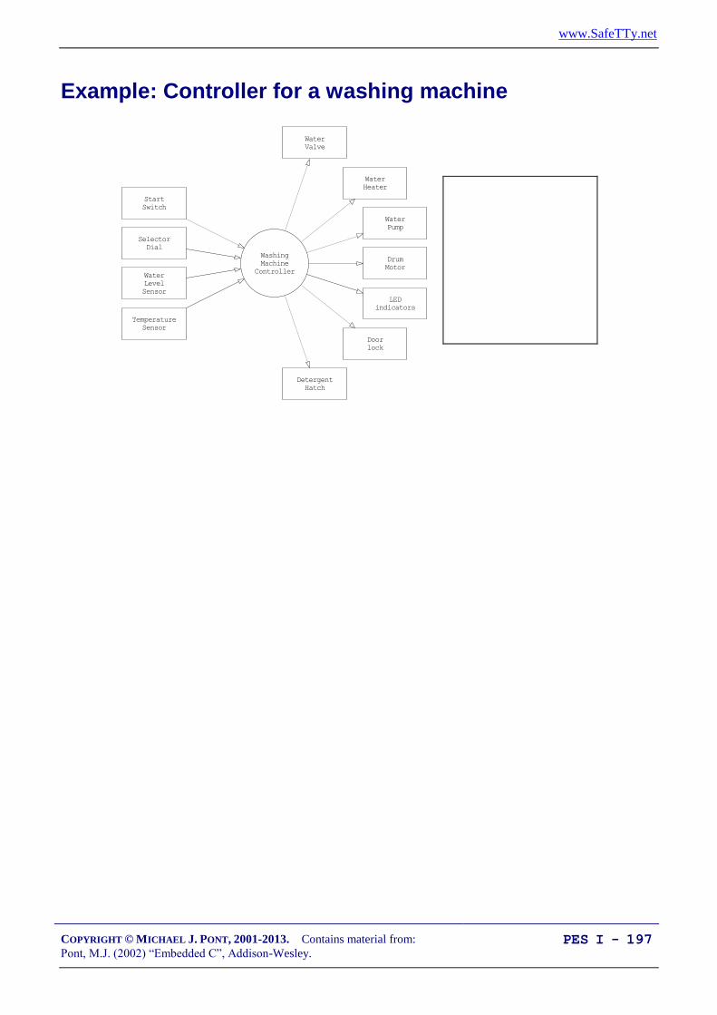
www.SafeTTy.net
COPYRIGHT © MICHAEL J. PONT, 2001-2013. Contains material from:
Pont, M.J. (2002) “Embedded C”, Addison-Wesley. PES I - 197
Example: Controller for a washing machine
Washing
Machine
Controller
Water
Valve
Start
Switch
Selector
Dial
Drum
Motor
Door
lock
LED
indicators
Water
Level
Sensor
Temperature
Sensor
Detergent
Hatch
Water
Heater
Water
Pump

www.SafeTTy.net
COPYRIGHT © MICHAEL J. PONT, 2001-2013. Contains material from:
Pont, M.J. (2002) “Embedded C”, Addison-Wesley. PES I - 198
Here is a brief description of the way in which we expect the system
to operate:
1. The user selects a wash program (e.g. ‘Wool’, ‘Cotton’) on
the selector dial.
2. The user presses the ‘Start’ switch.
3. The door lock is engaged.
4. The water valve is opened to allow water into the wash drum.
5. If the wash program involves detergent, the detergent hatch is
opened. When the detergent has been released, the detergent
hatch is closed.
6. When the ‘full water level’ is sensed, the water valve is
closed.
7. If the wash program involves warm water, the water heater is
switched on. When the water reaches the correct
temperature, the water heater is switched off.
8. The washer motor is turned on to rotate the drum. The motor
then goes through a series of movements, both forward and
reverse (at various speeds) to wash the clothes. (The precise
set of movements carried out depends on the wash program
that the user has selected.) At the end of the wash cycle, the
motor is stopped.
9. The pump is switched on to drain the drum. When the drum
is empty, the pump is switched off.

www.SafeTTy.net
COPYRIGHT © MICHAEL J. PONT, 2001-2013. Contains material from:
Pont, M.J. (2002) “Embedded C”, Addison-Wesley. PES I - 199
The Input / Timed architecture discussed here is by no means unique to
‘white goods’ (such as washing machines).
For example, the sequence of events used to raise the landing
gear in a passenger aircraft will be controlled in a similar
manner. In this case, basic tests (such as ‘WoW’ - ‘Weight
on Wheels’) will be used to determine whether the aircraft is
on the ground or in the air: these tests will be completed
before the operation begins.
Feedback from various door and landing-gear sensors will
then be used to ensure that each phase of the manoeuvre
completes correctly.

www.SafeTTy.net
COPYRIGHT © MICHAEL J. PONT, 2001-2013. Contains material from:
Pont, M.J. (2002) “Embedded C”, Addison-Wesley. PES I - 200
/*-------------------------------------------------------------*-
Washer.C (v1.01)
--------------------------------------------------------
Multi-state framework for washing-machine controller.
-*-------------------------------------------------------------*/
#include "Main.H"
#include "Port.H"
#include "Washer.H"
/* ------ Private data type declarations ---------------------- */
/* Possible system states */
typedef enum {INIT, START, FILL_DRUM, HEAT_WATER,
WASH_01, WASH_02, ERROR} eSystem_state;
/* ------ Private function prototypes ------------------------- */
tByte WASHER_Read_Selector_Dial(void);
bit WASHER_Read_Start_Switch(void);
bit WASHER_Read_Water_Level(void);
bit WASHER_Read_Water_Temperature(void);
void WASHER_Control_Detergent_Hatch(bit);
void WASHER_Control_Door_Lock(bit);
void WASHER_Control_Motor(bit);
void WASHER_Control_Pump(bit);
void WASHER_Control_Water_Heater(bit);
void WASHER_Control_Water_Valve(bit);
/* ------ Private constants ----------------------------------- */
#define OFF 0
#define ON 1
#define MAX_FILL_DURATION (tLong) 1000
#define MAX_WATER_HEAT_DURATION (tLong) 1000
#define WASH_01_DURATION 30000
www.SafeTTy.net
COPYRIGHT © MICHAEL J. PONT, 2001-2013. Contains material from:
Pont, M.J. (2002) “Embedded C”, Addison-Wesley. PES I - 201
/* ------ Private variables ----------------------------------- */
static eSystem_state System_state_G;
static tWord Time_in_state_G;
static tByte Program_G;
/* Ten different programs are supported
Each one may or may not use detergent */
static tByte Detergent_G[10] = {1,1,1,0,0,1,0,1,1,0};
/* Each one may or may not use hot water */
static tByte Hot_Water_G[10] = {1,1,1,0,0,1,0,1,1,0};
/* --------------------------------------------------------------- */
void WASHER_Init(void)
{
System_state_G = INIT;
}

www.SafeTTy.net
COPYRIGHT © MICHAEL J. PONT, 2001-2013. Contains material from:
Pont, M.J. (2002) “Embedded C”, Addison-Wesley. PES I - 202
/* --------------------------------------------------------------- */
void WASHER_Update(void)
{
/* Call once per second */
switch (System_state_G)
{
case INIT:
{
/* For demo purposes only */
Debug_port = (tByte) System_state_G;
/* Set up initial state */
/* Motor is off */
WASHER_Control_Motor(OFF);
/* Pump is off */
WASHER_Control_Pump(OFF);
/* Heater is off */
WASHER_Control_Water_Heater(OFF);
/* Valve is closed */
WASHER_Control_Water_Valve(OFF);
/* Wait (indefinitely) until START is pressed */
if (WASHER_Read_Start_Switch() != 1)
{
return;
}
/* Start switch pressed
-> read the selector dial */
Program_G = WASHER_Read_Selector_Dial();
/* Change state */
System_state_G = START;
break;
}

www.SafeTTy.net
COPYRIGHT © MICHAEL J. PONT, 2001-2013. Contains material from:
Pont, M.J. (2002) “Embedded C”, Addison-Wesley. PES I - 203
case START:
{
/* For demo purposes only */
Debug_port = (tByte) System_state_G;
/* Lock the door */
WASHER_Control_Door_Lock(ON);
/* Start filling the drum */
WASHER_Control_Water_Valve(ON);
/* Release the detergent (if any) */
if (Detergent_G[Program_G] == 1)
{
WASHER_Control_Detergent_Hatch(ON);
}
/* Ready to go to next state */
System_state_G = FILL_DRUM;
Time_in_state_G = 0;
break;
}

www.SafeTTy.net
COPYRIGHT © MICHAEL J. PONT, 2001-2013. Contains material from:
Pont, M.J. (2002) “Embedded C”, Addison-Wesley. PES I - 204
case FILL_DRUM:
{
/* For demo purposes only */
Debug_port = (tByte) System_state_G;
/* Remain in this state until drum is full
NOTE: Timeout facility included here */
if (++Time_in_state_G >= MAX_FILL_DURATION)
{
/* Should have filled the drum by now... */
System_state_G = ERROR;
}
/* Check the water level */
if (WASHER_Read_Water_Level() == 1)
{
/* Drum is full */
/* Does the program require hot water? */
if (Hot_Water_G[Program_G] == 1)
{
WASHER_Control_Water_Heater(ON);
/* Ready to go to next state */
System_state_G = HEAT_WATER;
Time_in_state_G = 0;
}
else
{
/* Using cold water only */
/* Ready to go to next state */
System_state_G = WASH_01;
Time_in_state_G = 0;
}
}
break;
}

www.SafeTTy.net
COPYRIGHT © MICHAEL J. PONT, 2001-2013. Contains material from:
Pont, M.J. (2002) “Embedded C”, Addison-Wesley. PES I - 205
case HEAT_WATER:
{
/* For demo purposes only */
Debug_port = (tByte) System_state_G;
/* Remain in this state until water is hot
NOTE: Timeout facility included here */
if (++Time_in_state_G >= MAX_WATER_HEAT_DURATION)
{
/* Should have warmed the water by now... */
System_state_G = ERROR;
}
/* Check the water temperature */
if (WASHER_Read_Water_Temperature() == 1)
{
/* Water is at required temperature */
/* Ready to go to next state */
System_state_G = WASH_01;
Time_in_state_G = 0;
}
break;
}

www.SafeTTy.net
COPYRIGHT © MICHAEL J. PONT, 2001-2013. Contains material from:
Pont, M.J. (2002) “Embedded C”, Addison-Wesley. PES I - 206
case WASH_01:
{
/* For demo purposes only */
Debug_port = (tByte) System_state_G;
/* All wash program involve WASH_01
Drum is slowly rotated to ensure clothes are fully wet */
WASHER_Control_Motor(ON);
if (++Time_in_state_G >= WASH_01_DURATION)
{
System_state_G = WASH_02;
Time_in_state_G = 0;
}
break;
}
/* REMAINING WASH PHASES OMITTED HERE ... */
case WASH_02:
{
/* For demo purposes only */
Debug_port = (tByte) System_state_G;
break;
}
case ERROR:
{
/* For demo purposes only */
Debug_port = (tByte) System_state_G;
break;
}
}
}

www.SafeTTy.net
COPYRIGHT © MICHAEL J. PONT, 2001-2013. Contains material from:
Pont, M.J. (2002) “Embedded C”, Addison-Wesley. PES I - 207
/* --------------------------------------------------------------- */
tByte WASHER_Read_Selector_Dial(void)
{
/* User code here... */
return 0;
}
/* --------------------------------------------------------------- */
bit WASHER_Read_Start_Switch(void)
{
/* Simplified for demo ... */
if (Start_pin == 0)
{
/* Start switch pressed */
return 1;
}
else
{
return 0;
}
}
/* --------------------------------------------------------------- */
bit WASHER_Read_Water_Level(void)
{
/* User code here... */
return 1;
}
/* --------------------------------------------------------------- */
bit WASHER_Read_Water_Temperature(void)
{
/* User code here... */
return 1;
}
/* --------------------------------------------------------------- */
void WASHER_Control_Detergent_Hatch(bit State)
{
bit Tmp = State;
/* User code here... */
}

www.SafeTTy.net
COPYRIGHT © MICHAEL J. PONT, 2001-2013. Contains material from:
Pont, M.J. (2002) “Embedded C”, Addison-Wesley. PES I - 208
Conclusions
This seminar has discussed the implementation of multi-state
(timed) and multi-state (input / timed) systems. Used in
conjunction with an operating system like that presented in
“Embedded C” Chapter 7, this flexible system architecture is in
widespread use in embedded applications.

www.SafeTTy.net
COPYRIGHT © MICHAEL J. PONT, 2001-2013. Contains material from:
Pont, M.J. (2002) “Embedded C”, Addison-Wesley. PES I - 209
Preparation for the next seminar
Please read Chapter 9
before the next seminar

www.SafeTTy.net
COPYRIGHT © MICHAEL J. PONT, 2001-2013. Contains material from:
Pont, M.J. (2002) “Embedded C”, Addison-Wesley. PES I - 210

www.SafeTTy.net
COPYRIGHT © MICHAEL J. PONT, 2001-2013. Contains material from:
Pont, M.J. (2002) “Embedded C”, Addison-Wesley. PES I - 211
Seminar 8: Using the Serial
Interface

www.SafeTTy.net
COPYRIGHT © MICHAEL J. PONT, 2001-2013. Contains material from:
Pont, M.J. (2002) “Embedded C”, Addison-Wesley. PES I - 212
Overview of this seminar
This seminar will:
Discuss the RS-232 data communication standard
Consider how we can use RS-232 to transfer data to and
from deskbound PCs (and similar devices).
This can be useful, for example:
In data acquisition applications.
In control applications (sending controller parameters).
For general debugging.

www.SafeTTy.net
COPYRIGHT © MICHAEL J. PONT, 2001-2013. Contains material from:
Pont, M.J. (2002) “Embedded C”, Addison-Wesley. PES I - 213
What is ‘RS-232’?
In 1997 the Telecommunications Industry Association released
what is formally known as TIA-232 Version F, a serial
communication protocol which has been universally referred to as
‘RS-232’ since its first ‘Recommended Standard’ appeared in the
1960s. Similar standards (V.28) are published by the International
Telecommunications Union (ITU) and by CCITT (The Consultative
Committee International Telegraph and Telephone).
The ‘RS-232’ standard includes details of:
The protocol to be used for data transmission.
The voltages to be used on the signal lines.
The connectors to be used to link equipment together.
Overall, the standard is comprehensive and widely used, at data
transfer rates of up to around 115 or 330 kbits / second (115 / 330 k
baud). Data transfer can be over distances of 15 metres or more.
Note that RS-232 is a peer-to-peer communication standard.

www.SafeTTy.net
COPYRIGHT © MICHAEL J. PONT, 2001-2013. Contains material from:
Pont, M.J. (2002) “Embedded C”, Addison-Wesley. PES I - 214
Basic RS-232 Protocol
RS-232 is a character-oriented protocol. That is, it is intended to be
used to send single 8-bit blocks of data. To transmit a byte of data
over an RS-232 link, we generally encode the information as
follows:
We send a ‘Start’ bit.
We send the data (8 bits).
We send a ‘Stop’ bit (or bits).
NOTE: The UART takes care of these details!

www.SafeTTy.net
COPYRIGHT © MICHAEL J. PONT, 2001-2013. Contains material from:
Pont, M.J. (2002) “Embedded C”, Addison-Wesley. PES I - 215
Asynchronous data transmission and baud rates
RS-232 uses an asynchronous protocol.
Both ends of the communication link have an internal clock,
running at the same rate. The data (in the case of RS-232,
the ‘Start’ bit) is then used to synchronise the clocks, if
necessary, to ensure successful data transfer.
RS-232 generally operates at one of a (restricted) range of
baud rates.
Typically these are: 75, 110, 300, 1200, 2400, 4800, 9600,
14400, 19200, 28800, 33600, 56000, 115000 and (rarely)
330000 baud.
9600 baud is a very ‘safe’ choice, as it is very widely
supported.

www.SafeTTy.net
COPYRIGHT © MICHAEL J. PONT, 2001-2013. Contains material from:
Pont, M.J. (2002) “Embedded C”, Addison-Wesley. PES I - 216
RS-232 voltage levels
The threshold levels used by the receiver are +3 V and -3 V
and the lines are inverted.
The maximum voltage allowed is +/- 15V.
Note that these voltages cannot be obtained directly from the
naked microcontroller port pins: some form of interface
hardware is required.
For example, the Maxim Max232 and Max233 are popular
and widely-used line driver chips.
15
96
Vcc
Max
233 1
20
7
18
6,9Connect together:
Pins 12 & 17
Pins 11 & 15
Pins 16 & 10
1.0 µF
19
Rx
Tx
To Tx pin ( P3.1)
To Rx pin ( P3.0)
Using a Max 233 as an RS-232 tranceiver.
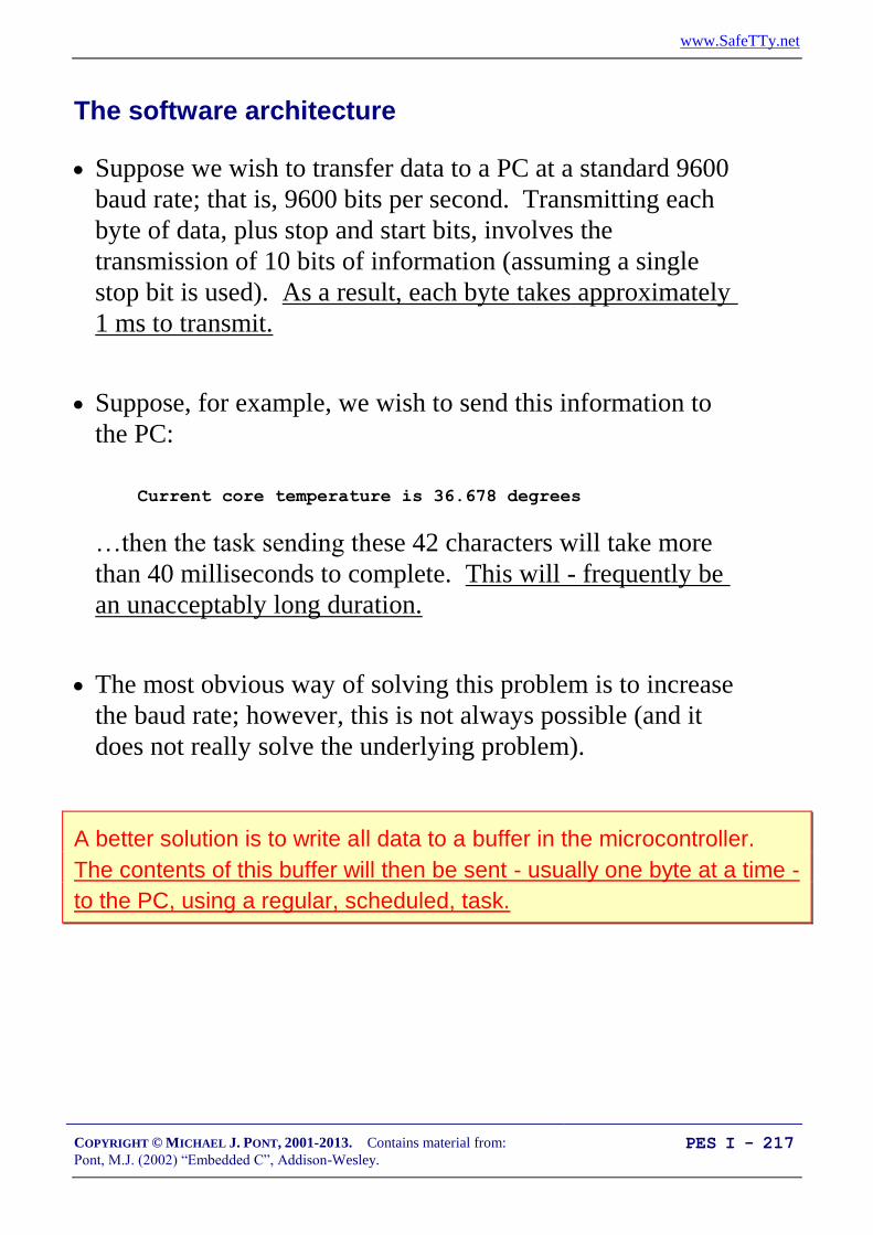
www.SafeTTy.net
COPYRIGHT © MICHAEL J. PONT, 2001-2013. Contains material from:
Pont, M.J. (2002) “Embedded C”, Addison-Wesley. PES I - 217
The software architecture
Suppose we wish to transfer data to a PC at a standard 9600
baud rate; that is, 9600 bits per second. Transmitting each
byte of data, plus stop and start bits, involves the
transmission of 10 bits of information (assuming a single
stop bit is used). As a result, each byte takes approximately
1 ms to transmit.
Suppose, for example, we wish to send this information to
the PC:
Current core temperature is 36.678 degrees
…then the task sending these 42 characters will take more
than 40 milliseconds to complete. This will - frequently be
an unacceptably long duration.
The most obvious way of solving this problem is to increase
the baud rate; however, this is not always possible (and it
does not really solve the underlying problem).
A better solution is to write all data to a buffer in the microcontroller.
The contents of this buffer will then be sent - usually one byte at a time -
to the PC, using a regular, scheduled, task.

www.SafeTTy.net
COPYRIGHT © MICHAEL J. PONT, 2001-2013. Contains material from:
Pont, M.J. (2002) “Embedded C”, Addison-Wesley. PES I - 218
Overview
Cur r ent cor e t emper at ur e
i s 36. 678 degr ees
Buffer
All characters
written immediately
to buffer
(very fast operation)
Scheduler sends one
character to PC
every 10 ms
(for example)

www.SafeTTy.net
COPYRIGHT © MICHAEL J. PONT, 2001-2013. Contains material from:
Pont, M.J. (2002) “Embedded C”, Addison-Wesley. PES I - 219
Using the on-chip U(S)ART for RS-232 communications
The UART is full duplex, meaning it can transmit and
receive simultaneously.
It is also receive-buffered, meaning it can commence
reception of a second byte before a previously received byte
has been read from the receive register.
The serial port can operate in 4 modes (one synchronous
mode, three asynchronous modes).
We are primarily interested in Mode 1.
In this mode, 10 bits are transmitted (through TxD) or
received (through RxD): a start bit (0), 8 data bits (lsb first),
and a stop bit (1).

www.SafeTTy.net
COPYRIGHT © MICHAEL J. PONT, 2001-2013. Contains material from:
Pont, M.J. (2002) “Embedded C”, Addison-Wesley. PES I - 220
Serial port registers
The serial port control and status register is the special function
register SCON. This register contains the mode selection bits (and
the serial port interrupt bits, TI and RI: not used here).
SBUF is the receive and transmit buffer of serial interface.
Writing to SBUF loads the transmit register and initiates
transmission.
SBUF = 0x0D; /* Output CR */
Reading out SBUF accesses a physically separate receive register.
/* Read the data from UART */
Data = SBUF;

www.SafeTTy.net
COPYRIGHT © MICHAEL J. PONT, 2001-2013. Contains material from:
Pont, M.J. (2002) “Embedded C”, Addison-Wesley. PES I - 221
Baud rate generation
We are primarily concerned here with the use of the serial
port in Mode 1.
In this mode the baud rate is determined by the overflow rate
of Timer 1 or Timer 2.
We focus on the use of Timer 1 for baud rate generation.
The baud rate is determined by the Timer 1 overflow rate and the
value of SMOD follows:
Baud rate (Mode 1) =
Where:
SMOD …is the ‘double baud rate’ bit in the PCON register;
…is the oscillator / resonator frequency;
…is the number of machine instructions per oscillator
cycle (e.g. 12 or 6)
TH1 …is the reload value for Timer 1
Note that Timer is used in 8-bit auto-reload mode and that interrupt
generation should be disabled.

www.SafeTTy.net
COPYRIGHT © MICHAEL J. PONT, 2001-2013. Contains material from:
Pont, M.J. (2002) “Embedded C”, Addison-Wesley. PES I - 222
Why use 11.0592 MHz crystals?
It is very important to appreciate that it is not generally possible to
produce standard baud rates (e.g. 9600) using Timer 1 (or Timer 2),
unless you use an 11.0592 MHz crystal oscillator.
Remember: this is an asynchronous protocol, and relies for correct
operation on the fact that both ends of the connection are working
at the same baud rate. In practice, you can generally work with a
difference in baud rates at both ends of the connection by up to 5%,
but no more.
Despite the possible 5% margin, it is always good policy to get the baud
rate as close as possible to the standard value because, in the field,
there may be significant temperature variations between the oscillator in
the PC and that in the embedded system.
Note also that it is generally essential to use some form of crystal
oscillator (rather than a ceramic resonator) when working with
asynchronous serial links (such as RS-232, RS-485, or CAN): the
ceramic resonator is not sufficiently stable for this purpose.

www.SafeTTy.net
COPYRIGHT © MICHAEL J. PONT, 2001-2013. Contains material from:
Pont, M.J. (2002) “Embedded C”, Addison-Wesley. PES I - 223
PC Software
If your desktop computer is running Windows (95, 98, NT, 2000),
then a simple but effective option is the ‘Hyperterminal’ application
which is included with all of these operating systems.

www.SafeTTy.net
COPYRIGHT © MICHAEL J. PONT, 2001-2013. Contains material from:
Pont, M.J. (2002) “Embedded C”, Addison-Wesley. PES I - 224
What about printf()?
We do not generally recommend the use of standard library
function “printf()”, because:
this function sends data immediately to the UART. As a
result, the duration of the transmission is often too long to be
safely handled in a co-operatively scheduled application,
and,
most implementations of printf() do not incorporate
timeouts, making it possible that use of this functions can
‘hang’ the whole application if errors occur.

www.SafeTTy.net
COPYRIGHT © MICHAEL J. PONT, 2001-2013. Contains material from:
Pont, M.J. (2002) “Embedded C”, Addison-Wesley. PES I - 225
RS-232 and 8051: Overall strengths and weaknesses
RS-232 support is part of the 8051 core: applications based on RS-232
are very portable.
At the PC end too, RS-232 is ubiquitous: every PC has one or more
RS-232 ports.
Links can - with modern tranceiver chips - be up to 30 m (100 ft) in
length.
Because of the hardware support, RS-232 generally imposes a low
software load.
BUT:
RS-232 is a peer-to-peer protocol (unlike, for example, RS-485): you
can only connect one microcontroller directly (simultaneously) to each
PC.
RS-232 has little or no error checking at the hardware level (unlike, for
example, CAN): if you want to be sure that the data you received at the
PC is valid, you need to carry out checks in software.

www.SafeTTy.net
COPYRIGHT © MICHAEL J. PONT, 2001-2013. Contains material from:
Pont, M.J. (2002) “Embedded C”, Addison-Wesley. PES I - 226
Example: Displaying elapsed time on a PC

www.SafeTTy.net
COPYRIGHT © MICHAEL J. PONT, 2001-2013. Contains material from:
Pont, M.J. (2002) “Embedded C”, Addison-Wesley. PES I - 227

www.SafeTTy.net
COPYRIGHT © MICHAEL J. PONT, 2001-2013. Contains material from:
Pont, M.J. (2002) “Embedded C”, Addison-Wesley. PES I - 228
/*-------------------------------------------------------------*-
Main.c (v1.00)
--------------------------------------------------------
RS-232 (Elapsed Time) example - sEOS.
-*-------------------------------------------------------------*/
#include "Main.H"
#include "Port.H"
#include "Simple_EOS.H"
#include "PC_O_T1.h"
#include "Elap_232.h"
/* --------------------------------------------------------------- */
void main(void)
{
/* Set baud rate to 9600 */
PC_LINK_O_Init_T1(9600);
/* Prepare for elapsed time measurement */
Elapsed_Time_RS232_Init();
/* Set up simple EOS (5ms tick) */
sEOS_Init_Timer2(5);
while(1) /* Super Loop */
{
sEOS_Go_To_Sleep(); /* Enter idle mode to save power */
}
}
/*-------------------------------------------------------------*-
---- END OF FILE ---------------------------------------
-*-------------------------------------------------------------*/

www.SafeTTy.net
COPYRIGHT © MICHAEL J. PONT, 2001-2013. Contains material from:
Pont, M.J. (2002) “Embedded C”, Addison-Wesley. PES I - 229
/*-------------------------------------------------------------*-
Elap_232.C (v1.00)
--------------------------------------------------------
Simple library function for keeping track of elapsed time
Demo version to display time on PC screen via RS232 link.
-*-------------------------------------------------------------*/
#include "Main.h"
#include "Elap_232.h"
#include "PC_O.h"
/* ------ Public variable definitions ------------------------- */
tByte Hou_G;
tByte Min_G;
tByte Sec_G;
/* ------ Public variable declarations ------------------------ */
/* See Char_Map.c */
extern const char code CHAR_MAP_G[10];
/*-------------------------------------------------------------*-
Elapsed_Time_RS232_Init()
Init function for simple library displaying elapsed time on PC
via RS-232 link.
-*-------------------------------------------------------------*/
void Elapsed_Time_RS232_Init(void)
{
Hou_G = 0;
Min_G = 0;
Sec_G = 0;
}

www.SafeTTy.net
COPYRIGHT © MICHAEL J. PONT, 2001-2013. Contains material from:
Pont, M.J. (2002) “Embedded C”, Addison-Wesley. PES I - 230
/*-------------------------------------------------------------*/
void Elapsed_Time_RS232_Update(void)
{
char Time_Str[30] = "\rElapsed time: ";
if (++Sec_G == 60)
{
Sec_G = 0;
if (++Min_G == 60)
{
Min_G = 0;
if (++Hou_G == 24)
{
Hou_G = 0;
}
}
}
Time_Str[15] = CHAR_MAP_G[Hou_G / 10];
Time_Str[16] = CHAR_MAP_G[Hou_G % 10];
Time_Str[18] = CHAR_MAP_G[Min_G / 10];
Time_Str[19] = CHAR_MAP_G[Min_G % 10];
Time_Str[21] = CHAR_MAP_G[Sec_G / 10];
Time_Str[22] = CHAR_MAP_G[Sec_G % 10];
/* We use the "seconds" data to turn on and off the colon
(between hours and minutes) */
if ((Sec_G % 2) == 0)
{
Time_Str[17] = ':';
Time_Str[20] = ':';
}
else
{
Time_Str[17] = ' ';
Time_Str[20] = ' ';
}
PC_LINK_O_Write_String_To_Buffer(Time_Str);
}

www.SafeTTy.net
COPYRIGHT © MICHAEL J. PONT, 2001-2013. Contains material from:
Pont, M.J. (2002) “Embedded C”, Addison-Wesley. PES I - 231
/*-------------------------------------------------------------*-
PC_LINK_O_Init_T1()
This version uses T1 for baud rate generation.
Uses 8051 (internal) UART hardware
-*-------------------------------------------------------------*/
void PC_LINK_O_Init_T1(const tWord BAUD_RATE)
{
PCON &= 0x7F; /* Set SMOD bit to 0 (don't double baud rates) */
/* Receiver disabled
8-bit data, 1 start bit, 1 stop bit, variable baud */
SCON = 0x42;
TMOD |= 0x20; /* T1 in mode 2, 8-bit auto reload */
TH1 = (256 - (tByte)((((tLong)OSC_FREQ / 100) * 3125)
/ ((tLong) BAUD_RATE * OSC_PER_INST * 1000)));
TL1 = TH1;
TR1 = 1; /* Run the timer */
TI = 1; /* Send first character (dummy) */
/* Set up the buffers for reading and writing */
Out_written_index_G = 0;
Out_waiting_index_G = 0;
/* Interrupt *NOT* enabled */
ES = 0;
}

www.SafeTTy.net
COPYRIGHT © MICHAEL J. PONT, 2001-2013. Contains material from:
Pont, M.J. (2002) “Embedded C”, Addison-Wesley. PES I - 232
/*-------------------------------------------------------------*/
void PC_LINK_O_Update(void)
{
/* Deal with transmit bytes here.
Are there any data ready to send? */
if (Out_written_index_G < Out_waiting_index_G)
{
PC_LINK_O_Send_Char(Tran_buffer[Out_written_index_G]);
Out_written_index_G++;
}
else
{
/* No data to send - just reset the buffer index */
Out_waiting_index_G = 0;
Out_written_index_G = 0;
}
}
/*-------------------------------------------------------------*/
void PC_LINK_O_Write_String_To_Buffer(const char* const STR_PTR)
{
tByte i = 0;
while (STR_PTR[i] != '\0')
{
PC_LINK_O_Write_Char_To_Buffer(STR_PTR[i]);
i++;
}
}

www.SafeTTy.net
COPYRIGHT © MICHAEL J. PONT, 2001-2013. Contains material from:
Pont, M.J. (2002) “Embedded C”, Addison-Wesley. PES I - 233
/*-------------------------------------------------------------*/
void PC_LINK_O_Write_Char_To_Buffer(const char CHARACTER)
{
/* Write to the buffer *only* if there is space
(No error reporting in this simple library...) */
if (Out_waiting_index_G < TRAN_BUFFER_LENGTH)
{
Tran_buffer[Out_waiting_index_G] = CHARACTER;
Out_waiting_index_G++;
}
}
/*-------------------------------------------------------------*/
void PC_LINK_O_Send_Char(const char CHARACTER)
{
tLong Timeout1 = 0;
if (CHARACTER == '\n')
{
Timeout1 = 0;
while ((++Timeout1) && (TI == 0));
if (Timeout1 == 0)
{
/* UART did not respond - error
No error reporting in this simple library... */
return;
}
TI = 0;
SBUF = 0x0d; /* Output CR */
}
Timeout1 = 0;
while ((++Timeout1) && (TI == 0));
if (Timeout1 == 0)
{
/* UART did not respond - error
No error reporting in this simple library... */
return;
}
TI = 0;
SBUF = CHARACTER;
}

www.SafeTTy.net
COPYRIGHT © MICHAEL J. PONT, 2001-2013. Contains material from:
Pont, M.J. (2002) “Embedded C”, Addison-Wesley. PES I - 234
sEOS_ISR() interrupt INTERRUPT_Timer_2_Overflow
{
TF2 = 0; /* Must manually reset the T2 flag */
/*===== USER CODE - Begin ================================== */
/* Call RS-232 update function every 5ms */
PC_LINK_O_Update();
/* This ISR is called every 5 ms
- only want to update time every second */
if (++Call_count_G == 200)
{
/* Time to update time */
Call_count_G = 0;
/* Call time update function */
Elapsed_Time_RS232_Update();
}
/*===== USER CODE - End ==================================== */
}

www.SafeTTy.net
COPYRIGHT © MICHAEL J. PONT, 2001-2013. Contains material from:
Pont, M.J. (2002) “Embedded C”, Addison-Wesley. PES I - 235
Example: Data acquisition
In this section, we give an example of a simple data acquisition
system with a serial-menu architecture.
In this case, using the menu, the user can determine the state of the
input pins on Port 1 or Port 2:

www.SafeTTy.net
COPYRIGHT © MICHAEL J. PONT, 2001-2013. Contains material from:
Pont, M.J. (2002) “Embedded C”, Addison-Wesley. PES I - 236
void MENU_Command_Processor(void)
{
char Ch;
if (First_time_only_G == 0)
{
First_time_only_G = 1;
MENU_Show_Menu();
}
/* Check for user inputs */
PC_LINK_IO_Update();
Ch = PC_LINK_IO_Get_Char_From_Buffer();
if (Ch != PC_LINK_IO_NO_CHAR)
{
MENU_Perform_Task(Ch);
MENU_Show_Menu();
}
}
void MENU_Show_Menu(void)
{
PC_LINK_IO_Write_String_To_Buffer("Menu:\n");
PC_LINK_IO_Write_String_To_Buffer("a - Read P1\n");
PC_LINK_IO_Write_String_To_Buffer("b - Read P2\n\n");
PC_LINK_IO_Write_String_To_Buffer("? : ");
}

www.SafeTTy.net
COPYRIGHT © MICHAEL J. PONT, 2001-2013. Contains material from:
Pont, M.J. (2002) “Embedded C”, Addison-Wesley. PES I - 237
void MENU_Perform_Task(char c)
{
PC_LINK_IO_Write_Char_To_Buffer(c); /* Echo the menu option */
PC_LINK_IO_Write_Char_To_Buffer('\n');
/* Perform the task */
switch (c)
{
case 'a':
case 'A':
{
Get_Data_From_Port1();
break;
}
case 'b':
case 'B':
{
Get_Data_From_Port2();
break;
}
}
}
void Get_Data_From_Port1(void)
{
tByte Port1 = Data_Port1;
char String[11] = "\nP1 = XXX\n\n";
String[6] = CHAR_MAP_G[Port1 / 100];
String[7] = CHAR_MAP_G[(Port1 / 10) % 10];
String[8] = CHAR_MAP_G[Port1 % 10];
PC_LINK_IO_Write_String_To_Buffer(String);
}
void Get_Data_From_Port2(void)
{
tByte Port2 = Data_Port2;
char String[11] = "\nP2 = XXX\n\n";
String[6] = CHAR_MAP_G[Port2 / 100];
String[7] = CHAR_MAP_G[(Port2 / 10) % 10];
String[8] = CHAR_MAP_G[Port2 % 10];
PC_LINK_IO_Write_String_To_Buffer(String);
}

www.SafeTTy.net
COPYRIGHT © MICHAEL J. PONT, 2001-2013. Contains material from:
Pont, M.J. (2002) “Embedded C”, Addison-Wesley. PES I - 238
sEOS_ISR() interrupt INTERRUPT_Timer_2_Overflow
{
TF2 = 0; /* Must manually reset the T2 flag */
/*===== USER CODE - Begin ================================== */
/* Call MENU_Command_Processor every 5ms */
MENU_Command_Processor();
/*===== USER CODE - End ==================================== */
}

www.SafeTTy.net
COPYRIGHT © MICHAEL J. PONT, 2001-2013. Contains material from:
Pont, M.J. (2002) “Embedded C”, Addison-Wesley. PES I - 239
Conclusions
In this seminar, we have illustrated how the serial interface on the
8051 microcontroller may be used.
In the next seminar, we will use a case study to illustrate how the
various techniques discussed in this can be used in practical
applications.

www.SafeTTy.net
COPYRIGHT © MICHAEL J. PONT, 2001-2013. Contains material from:
Pont, M.J. (2002) “Embedded C”, Addison-Wesley. PES I - 240
Preparation for the next seminar
Please read Chapter 10
before the next seminar

www.SafeTTy.net
COPYRIGHT © MICHAEL J. PONT, 2001-2013. Contains material from:
Pont, M.J. (2002) “Embedded C”, Addison-Wesley. PES I - 241
Seminar 9: Case Study:
Intruder Alarm System
WindowBell box
Control
panel
W
W
W
W
W
Door
D
Statue

www.SafeTTy.net
COPYRIGHT © MICHAEL J. PONT, 2001-2013. Contains material from:
Pont, M.J. (2002) “Embedded C”, Addison-Wesley. PES I - 242
Introduction
Window
Bell box
Control
panel
W
W
W
W
W
Door
D
Statue
1 32
4 65
7 98
* #0

www.SafeTTy.net
COPYRIGHT © MICHAEL J. PONT, 2001-2013. Contains material from:
Pont, M.J. (2002) “Embedded C”, Addison-Wesley. PES I - 243
System Operation
When initially activated, the system is in ‘Disarmed’ state.
In Disarmed state, the sensors are ignored. The alarm does
not sound. The system remains in this state until the user
enters a valid password via the keypad (in our demonstration
system, the password is “1234”). When a valid password is
entered, the systems enters ‘Arming’ state.
In Arming state, the system waits for 60 seconds, to allow
the user to leave the area before the monitoring process
begins. After 60 seconds, the system enters ‘Armed’ state.
In Armed state, the status of the various system sensors is
monitored. If a window sensor is tripped, the system enters
‘Intruder’ state. If the door sensor is tripped, the system
enters ‘Disarming’ state. The keypad activity is also
monitored: if a correct password is typed in, the system
enters ‘Disarmed’ state.
In Disarming state, we assume that the door has been
opened by someone who may be an authorised system user.
The system remains in this state for up to 60 seconds, after
which - by default - it enters Intruder state. If, during the 60-
second period, the user enters the correct password, the
system enters ‘Disarmed’ state.
In Intruder state, an alarm will sound. The alarm will keep
sounding (indefinitely), until the correct password is entered.
www.SafeTTy.net
COPYRIGHT © MICHAEL J. PONT, 2001-2013. Contains material from:
Pont, M.J. (2002) “Embedded C”, Addison-Wesley. PES I - 244
Key software components used in this example
This case study uses the following software components:
Software to control external port pins (to activate the
external bell), as introduced in “Embedded C” Chapter 3.
Switch reading, as discussed in “Embedded C” Chapter 4, to
process the inputs from the door and window sensors. Note
that - in this simple example (intended for use in the
simulator) - no switch debouncing is carried out. This
feature can be added, if required, without difficulty.
The embedded operating system, sEOS, introduced in
“Embedded C” Chapter 7.
A simple ‘keypad’ library, based on a bank of switches.
Note that - to simplify the use of the keypad library in the
simulator - we have assumed the presence of only eight keys
in the example program (0 - 7). This final system would
probably use at least 10 keys: support for additional keys can
be easily added if required.
The RS-232 library (from “Embedded C” Chapter 9) is used
to illustrate the operation of the program. This library would
not be necessary in the final system (but it might be useful to
retain it, to support system maintenance).

www.SafeTTy.net
COPYRIGHT © MICHAEL J. PONT, 2001-2013. Contains material from:
Pont, M.J. (2002) “Embedded C”, Addison-Wesley. PES I - 245
Running the program

www.SafeTTy.net
COPYRIGHT © MICHAEL J. PONT, 2001-2013. Contains material from:
Pont, M.J. (2002) “Embedded C”, Addison-Wesley. PES I - 246
The software
/*-------------------------------------------------------------*-
Port.H (v1.00)
--------------------------------------------------------
'Port Header' (see Chap 5) for project INTRUDER (see Chap 10)
-*-------------------------------------------------------------*/
/* ------ Keypad.C ------------------------------------------- */
#define KEYPAD_PORT P2
sbit K0 = KEYPAD_PORT^0;
sbit K1 = KEYPAD_PORT^1;
sbit K2 = KEYPAD_PORT^2;
sbit K3 = KEYPAD_PORT^3;
sbit K4 = KEYPAD_PORT^4;
sbit K5 = KEYPAD_PORT^5;
sbit K6 = KEYPAD_PORT^6;
sbit K7 = KEYPAD_PORT^7;
/* ------ Intruder.C --------------------------------------- */
sbit Sensor_pin = P1^0;
sbit Sounder_pin = P1^7;
/* ------ Lnk_O.C ------------------------------------------ */
/* Pins 3.0 and 3.1 used for RS-232 interface */
/*-------------------------------------------------------------*-
---- END OF FILE ---------------------------------------
-*-------------------------------------------------------------*/

www.SafeTTy.net
COPYRIGHT © MICHAEL J. PONT, 2001-2013. Contains material from:
Pont, M.J. (2002) “Embedded C”, Addison-Wesley. PES I - 247
/*-------------------------------------------------------------*-
Main.c (v1.00)
--------------------------------------------------------
Simple intruder alarm system.
-*-------------------------------------------------------------*/
#include "Main.H"
#include "Port.H"
#include "Simple_EOS.H"
#include "PC_O_T1.h"
#include "Keypad.h"
#include "Intruder.h"
/* ............................................................... */
void main(void)
{
/* Set baud rate to 9600 */
PC_LINK_O_Init_T1(9600);
/* Prepare the keypad */
KEYPAD_Init();
/* Prepare the intruder alarm */
INTRUDER_Init();
/* Set up simple EOS (5ms tick) */
sEOS_Init_Timer2(5);
while(1) /* Super Loop */
{
sEOS_Go_To_Sleep(); /* Enter idle mode to save power */
}
}
/*-------------------------------------------------------------*-
---- END OF FILE ---------------------------------------
-*-------------------------------------------------------------*/

www.SafeTTy.net
COPYRIGHT © MICHAEL J. PONT, 2001-2013. Contains material from:
Pont, M.J. (2002) “Embedded C”, Addison-Wesley. PES I - 248
/*-------------------------------------------------------------*-
Intruder.C (v1.00)
-*-------------------------------------------------------------*/
...
/* ------ Private data type declarations ---------------------- */
/* Possible system states */
typedef enum {DISARMED, ARMING, ARMED, DISARMING, INTRUDER}
eSystem_state;
/* ------ Private function prototypes ------------------------- */
bit INTRUDER_Get_Password_G(void);
bit INTRUDER_Check_Window_Sensors(void);
bit INTRUDER_Check_Door_Sensor(void);
void INTRUDER_Sound_Alarm(void);
...
/* --------------------------------------------------------------- */
void INTRUDER_Init(void)
{
/* Set the initial system state (DISARMED) */
System_state_G = DISARMED;
/* Set the 'time in state' variable to 0 */
State_call_count_G = 0;
/* Clear the keypad buffer */
KEYPAD_Clear_Buffer();
/* Set the 'New state' flag */
New_state_G = 1;
/* Set the (two) sensor pins to 'read' mode */
Window_sensor_pin = 1;
Sounder_pin = 1;
}

www.SafeTTy.net
COPYRIGHT © MICHAEL J. PONT, 2001-2013. Contains material from:
Pont, M.J. (2002) “Embedded C”, Addison-Wesley. PES I - 249
void INTRUDER_Update(void)
{
/* Incremented every time */
if (State_call_count_G < 65534)
{
State_call_count_G++;
}
/* Call every 50 ms */
switch (System_state_G)
{
case DISARMED:
{
if (New_state_G)
{
PC_LINK_O_Write_String_To_Buffer("\nDisarmed");
New_state_G = 0;
}
/* Make sure alarm is switched off */
Sounder_pin = 1;
/* Wait for correct password ... */
if (INTRUDER_Get_Password_G() == 1)
{
System_state_G = ARMING;
New_state_G = 1;
State_call_count_G = 0;
break;
}
break;
}

www.SafeTTy.net
COPYRIGHT © MICHAEL J. PONT, 2001-2013. Contains material from:
Pont, M.J. (2002) “Embedded C”, Addison-Wesley. PES I - 250
case ARMING:
{
if (New_state_G)
{
PC_LINK_O_Write_String_To_Buffer("\nArming...");
New_state_G = 0;
}
/* Remain here for 60 seconds (50 ms tick assumed) */
if (++State_call_count_G > 1200)
{
System_state_G = ARMED;
New_state_G = 1;
State_call_count_G = 0;
break;
}
break;
}

www.SafeTTy.net
COPYRIGHT © MICHAEL J. PONT, 2001-2013. Contains material from:
Pont, M.J. (2002) “Embedded C”, Addison-Wesley. PES I - 251
case ARMED:
{
if (New_state_G)
{
PC_LINK_O_Write_String_To_Buffer("\nArmed");
New_state_G = 0;
}
/* First, check the window sensors */
if (INTRUDER_Check_Window_Sensors() == 1)
{
/* An intruder detected */
System_state_G = INTRUDER;
New_state_G = 1;
State_call_count_G = 0;
break;
}
/* Next, check the door sensors */
if (INTRUDER_Check_Door_Sensor() == 1)
{
/* May be authorised user - go to 'Disarming' state */
System_state_G = DISARMING;
New_state_G = 1;
State_call_count_G = 0;
break;
}
/* Finally, check for correct password */
if (INTRUDER_Get_Password_G() == 1)
{
System_state_G = DISARMED;
New_state_G = 1;
State_call_count_G = 0;
break;
}
break;
}

www.SafeTTy.net
COPYRIGHT © MICHAEL J. PONT, 2001-2013. Contains material from:
Pont, M.J. (2002) “Embedded C”, Addison-Wesley. PES I - 252
case DISARMING:
{
if (New_state_G)
{
PC_LINK_O_Write_String_To_Buffer("\nDisarming...");
New_state_G = 0;
}
/* Remain here for 60 seconds (50 ms tick assumed)
to allow user to enter the password
- after time up, sound alarm. */
if (++State_call_count_G > 1200)
{
System_state_G = INTRUDER;
New_state_G = 1;
State_call_count_G = 0;
break;
}
/* Still need to check the window sensors */
if (INTRUDER_Check_Window_Sensors() == 1)
{
/* An intruder detected */
System_state_G = INTRUDER;
New_state_G = 1;
State_call_count_G = 0;
break;
}
/* Finally, check for correct password */
if (INTRUDER_Get_Password_G() == 1)
{
System_state_G = DISARMED;
New_state_G = 1;
State_call_count_G = 0;
break;
}
break;
}
www.SafeTTy.net
COPYRIGHT © MICHAEL J. PONT, 2001-2013. Contains material from:
Pont, M.J. (2002) “Embedded C”, Addison-Wesley. PES I - 253
case INTRUDER:
{
if (New_state_G)
{
PC_LINK_O_Write_String_To_Buffer("\n** INTRUDER! **");
New_state_G = 0;
}
/* Sound the alarm! */
INTRUDER_Sound_Alarm();
/* Keep sounding alarm until we get correct password */
if (INTRUDER_Get_Password_G() == 1)
{
System_state_G = DISARMED;
New_state_G = 1;
State_call_count_G = 0;
}
break;
}
}
}

www.SafeTTy.net
COPYRIGHT © MICHAEL J. PONT, 2001-2013. Contains material from:
Pont, M.J. (2002) “Embedded C”, Addison-Wesley. PES I - 254
bit INTRUDER_Get_Password_G(void)
{
signed char Key;
tByte Password_G_count = 0;
tByte i;
/* Update the keypad buffer */
KEYPAD_Update();
/* Are there any new data in the keypad buffer? */
if (KEYPAD_Get_Data_From_Buffer(&Key) == 0)
{
/* No new data - password can't be correct */
return 0;
}
/* If we are here, a key has been pressed */
/* How long since last key was pressed?
Must be pressed within 50 seconds (assume 50 ms 'tick') */
if (State_call_count_G > 1000)
{
/* More than 5 seconds since last key
- restart the input process */
State_call_count_G = 0;
Position_G = 0;
}
if (Position_G == 0)
{
PC_LINK_O_Write_Char_To_Buffer('\n');
}
PC_LINK_O_Write_Char_To_Buffer(Key);
Input_G[Position_G] = Key;

www.SafeTTy.net
COPYRIGHT © MICHAEL J. PONT, 2001-2013. Contains material from:
Pont, M.J. (2002) “Embedded C”, Addison-Wesley. PES I - 255
/* Have we got four numbers? */
if ((++Position_G) == 4)
{
Position_G = 0;
Password_G_count = 0;
/* Check the password */
for (i = 0; i < 4; i++)
{
if (Input_G[i] == Password_G[i])
{
Password_G_count++;
}
}
}
if (Password_G_count == 4)
{
/* Password correct */
return 1;
}
else
{
/* Password NOT correct */
return 0;
}
}

www.SafeTTy.net
COPYRIGHT © MICHAEL J. PONT, 2001-2013. Contains material from:
Pont, M.J. (2002) “Embedded C”, Addison-Wesley. PES I - 256
bit INTRUDER_Check_Window_Sensors(void)
{
/* Just a single window 'sensor' here
- easily extended. */
if (Window_sensor_pin == 0)
{
/* Intruder detected... */
PC_LINK_O_Write_String_To_Buffer("\nWindow damaged");
return 1;
}
/* Default */
return 0;
}
/* --------------------------------------------------------------- */
bit INTRUDER_Check_Door_Sensor(void)
{
/* Single door sensor (access route) */
if (Door_sensor_pin == 0)
{
/* Someone has opened the door... */
PC_LINK_O_Write_String_To_Buffer("\nDoor open");
return 1;
}
/* Default */
return 0;
}
/* --------------------------------------------------------------- */
void INTRUDER_Sound_Alarm(void)
{
if (Alarm_bit)
{
/* Alarm connected to this pin */
Sounder_pin = 0;
Alarm_bit = 0;
}
else
{
Sounder_pin = 1;
Alarm_bit = 1;
}
}

www.SafeTTy.net
COPYRIGHT © MICHAEL J. PONT, 2001-2013. Contains material from:
Pont, M.J. (2002) “Embedded C”, Addison-Wesley. PES I - 257
void KEYPAD_Update(void)
{
char Key;
/* Scan keypad here... */
if (KEYPAD_Scan(&Key) == 0)
{
/* No new key data - just return */
return;
}
/* Want to read into index 0, if old data has been read
(simple ~circular buffer). */
if (KEYPAD_in_waiting_index == KEYPAD_in_read_index)
{
KEYPAD_in_waiting_index = 0;
KEYPAD_in_read_index = 0;
}
/* Load keypad data into buffer */
KEYPAD_recv_buffer[KEYPAD_in_waiting_index] = Key;
if (KEYPAD_in_waiting_index < KEYPAD_RECV_BUFFER_LENGTH)
{
/* Increment without overflowing buffer */
KEYPAD_in_waiting_index++;
}
}
bit KEYPAD_Get_Data_From_Buffer(char* const pKey)
{
/* If there is new data in the buffer */
if (KEYPAD_in_read_index < KEYPAD_in_waiting_index)
{
*pKey = KEYPAD_recv_buffer[KEYPAD_in_read_index];
KEYPAD_in_read_index++;
return 1;
}
return 0;
}

www.SafeTTy.net
COPYRIGHT © MICHAEL J. PONT, 2001-2013. Contains material from:
Pont, M.J. (2002) “Embedded C”, Addison-Wesley. PES I - 258
bit KEYPAD_Scan(char* const pKey)
{
char Key = KEYPAD_NO_NEW_DATA;
if (K0 == 0) { Key = '0'; }
if (K1 == 0) { Key = '1'; }
if (K2 == 0) { Key = '2'; }
if (K3 == 0) { Key = '3'; }
if (K4 == 0) { Key = '4'; }
if (K5 == 0) { Key = '5'; }
if (K6 == 0) { Key = '6'; }
if (K7 == 0) { Key = '7'; }
if (Key == KEYPAD_NO_NEW_DATA)
{
/* No key pressed */
Old_key_G = KEYPAD_NO_NEW_DATA;
Last_valid_key_G = KEYPAD_NO_NEW_DATA;
return 0; /* No new data */
}
/* A key has been pressed: debounce by checking twice */
if (Key == Old_key_G)
{
/* A valid (debounced) key press has been detected */
/* Must be a new key to be valid - no 'auto repeat' */
if (Key != Last_valid_key_G)
{
/* New key! */
*pKey = Key;
Last_valid_key_G = Key;
return 1;
}
}
/* No new data */
Old_key_G = Key;
return 0;
}
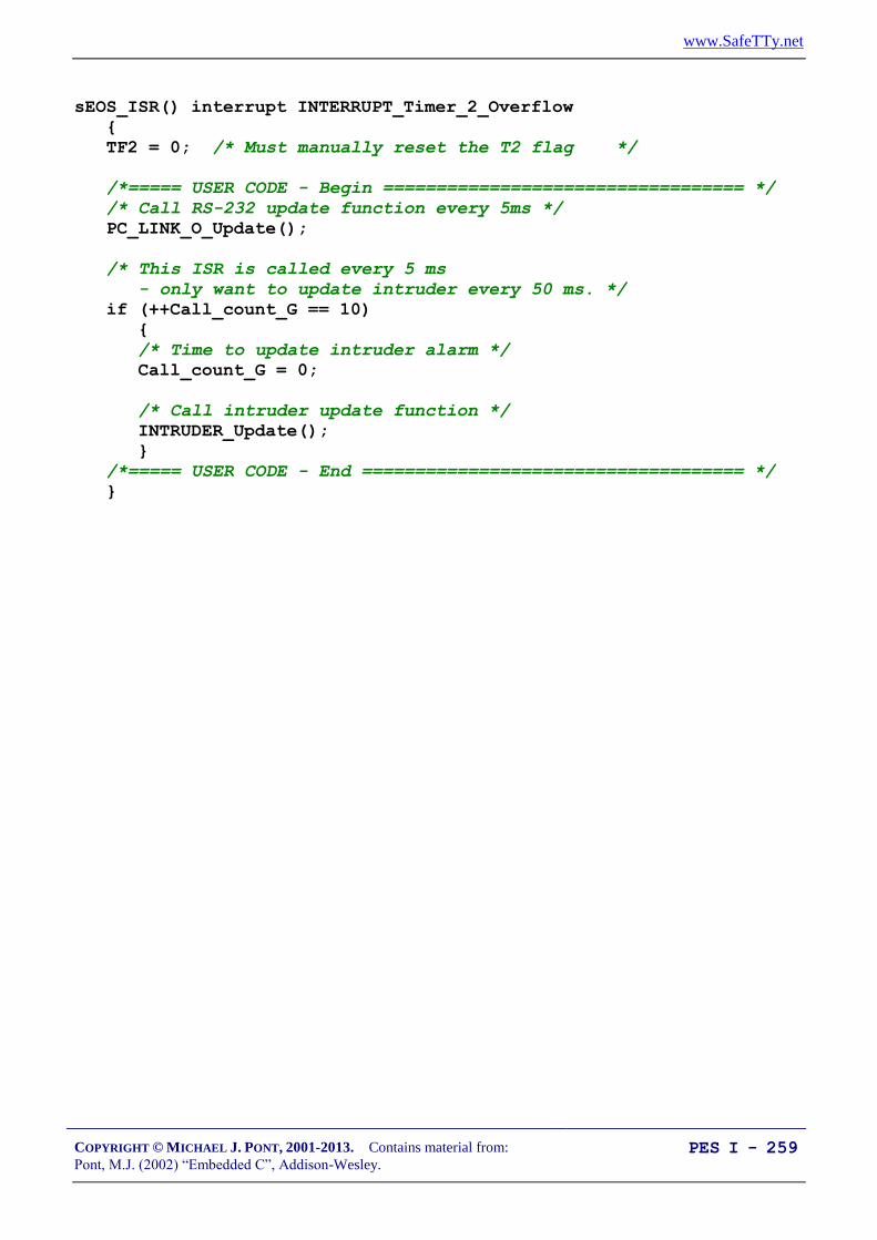
www.SafeTTy.net
COPYRIGHT © MICHAEL J. PONT, 2001-2013. Contains material from:
Pont, M.J. (2002) “Embedded C”, Addison-Wesley. PES I - 259
sEOS_ISR() interrupt INTERRUPT_Timer_2_Overflow
{
TF2 = 0; /* Must manually reset the T2 flag */
/*===== USER CODE - Begin ================================== */
/* Call RS-232 update function every 5ms */
PC_LINK_O_Update();
/* This ISR is called every 5 ms
- only want to update intruder every 50 ms. */
if (++Call_count_G == 10)
{
/* Time to update intruder alarm */
Call_count_G = 0;
/* Call intruder update function */
INTRUDER_Update();
}
/*===== USER CODE - End ==================================== */
}

www.SafeTTy.net
COPYRIGHT © MICHAEL J. PONT, 2001-2013. Contains material from:
Pont, M.J. (2002) “Embedded C”, Addison-Wesley. PES I - 260
Extending and modifying the system
How would you add a “real” keypad?
(See “Patterns for Time-Triggered Embedded Systems, Chap. 20)
How would you add an LCD display?
(See “Patterns for Time-Triggered Embedded Systems, Chap. 22)
How would you add additional nodes?
(See “Patterns for Time-Triggered Embedded Systems, Part F)

www.SafeTTy.net
COPYRIGHT © MICHAEL J. PONT, 2001-2013. Contains material from:
Pont, M.J. (2002) “Embedded C”, Addison-Wesley. PES I - 261
Conclusions
This case study has illustrated most of the key features of embedded
C, as discussed throughout the earlier sessions in this course.
We’ll consider a final case study in the next seminar.

www.SafeTTy.net
COPYRIGHT © MICHAEL J. PONT, 2001-2013. Contains material from:
Pont, M.J. (2002) “Embedded C”, Addison-Wesley. PES I - 262

www.SafeTTy.net
COPYRIGHT © MICHAEL J. PONT, 2001-2013. Contains material from:
Pont, M.J. (2002) “Embedded C”, Addison-Wesley. PES I - 263
Seminar 10: Case Study:
Controlling a
Mobile Robot

www.SafeTTy.net
COPYRIGHT © MICHAEL J. PONT, 2001-2013. Contains material from:
Pont, M.J. (2002) “Embedded C”, Addison-Wesley. PES I - 264
Overview
In this session, we will discuss the design of software to control a
small mobile robot.
The robot is “Mr Line”
He is produced by “Microrobot NA”
http://www.microrobotna.com

www.SafeTTy.net
COPYRIGHT © MICHAEL J. PONT, 2001-2013. Contains material from:
Pont, M.J. (2002) “Embedded C”, Addison-Wesley. PES I - 265
What can the robot do?
The robot has IR sensors and transmitters that allow him to detect a
black line on a white surface - and follow it.
http://www.microrobotna.com

www.SafeTTy.net
COPYRIGHT © MICHAEL J. PONT, 2001-2013. Contains material from:
Pont, M.J. (2002) “Embedded C”, Addison-Wesley. PES I - 266
The robot brain
Mr Line is controlled by an 8051 microcontroller (an AT89C2051).
We’ll use a pin-compatible AT89C4051 in this study.
http://www.microrobotna.com

www.SafeTTy.net
COPYRIGHT © MICHAEL J. PONT, 2001-2013. Contains material from:
Pont, M.J. (2002) “Embedded C”, Addison-Wesley. PES I - 267
How does the robot move?
Mr Line has two DC motors: by controlling the relative speed of
these motors, we can control the speed and direction in which he
will move.
http://www.microrobotna.com

www.SafeTTy.net
COPYRIGHT © MICHAEL J. PONT, 2001-2013. Contains material from:
Pont, M.J. (2002) “Embedded C”, Addison-Wesley. PES I - 268
Pulse-width modulation
x yV
Time
Duty cycle (%) =
Period = x + y, where x and y are in seconds.
Frequency = , where x and y are in seconds.
The key point to note is that the average voltage seen by the load is
given by the duty cycle multiplied by the load voltage.
See: “Patterns for Time-Triggered Embedded Systems”, Chapter 33

www.SafeTTy.net
COPYRIGHT © MICHAEL J. PONT, 2001-2013. Contains material from:
Pont, M.J. (2002) “Embedded C”, Addison-Wesley. PES I - 269
Software PWM
PWM_PERIOD_G
PWM_position_G
if (PWM_position_G < PWM_G)
{
PWM_pin = PWM_ON;
}
else
{
PWM_pin = PWM_OFF;
}
PWM_G
See: “Patterns for Time-Triggered Embedded Systems”, Chapter 33

www.SafeTTy.net
COPYRIGHT © MICHAEL J. PONT, 2001-2013. Contains material from:
Pont, M.J. (2002) “Embedded C”, Addison-Wesley. PES I - 270
The resulting code
< We’ll discuss the resulting code in the lecture … >

www.SafeTTy.net
COPYRIGHT © MICHAEL J. PONT, 2001-2013. Contains material from:
Pont, M.J. (2002) “Embedded C”, Addison-Wesley. PES I - 271
More about the robot
Please see:
http://www.le.ac.uk/engineering/mjp9/robot.htm

www.SafeTTy.net
COPYRIGHT © MICHAEL J. PONT, 2001-2013. Contains material from:
Pont, M.J. (2002) “Embedded C”, Addison-Wesley. PES I - 272
Conclusions
That brings us to the end of this course!