Embed Size (px)
Citation preview
Programming an Internet Interface
for the HYDRA Game Development Kit
Scott Marks and Rick Haberkamp
CEN 3213 – Embedded Systems Programming
Dr. Janusz Zalewski
April 28, 2008
Marks & Haberkamp
Page 2 of 38
Table of Contents
Table of Contents 2
Section 1: Introduction 3
Section 2: Problem Specification 9
Section 3: Design Description 12
Section 4: Implementation & Testing 16
Section 5: Conclusion 23
References 25
Appendix A: Source Code of HYDRA Game in Parallax Spin 26
Appendix B: Source Code of PC Application in Microsoft Visual Basic .NET 32
Appendix C: Setup Procedure 37

Marks & Haberkamp
Page 3 of 38
Section 1: Introduction
General Information
The HYDRA Game Development Kit, as shown in Figure 1.1, is the most advanced gaming
console provided by XGameStation. The HYDRA is powered by Parallax’s Propeller multiprocessor, which
has eight 32-bit processors and operates at 160 MIPS (20 MIPS per processor). Propeller can be
programmed using Propeller Assembly, Spin or both. Spin is an object-oriented language specifically
designed for the Propeller multiprocessor and should be the language of choice to program games for
the HYDRA due to its relative simplicity and similarities to other object-oriented languages such as C++
and Java. [2]
Figure 1.1: Parts Included in the HYDRA Game Development Kit [2]
The HYDRA has significant advantages over its cheaper sibling XGS Pico Edition 2.0 since it is
smarter and more powerful. First, Pico only provides assembly language for programming, which makes
game building a lengthy and tedious process. HYDRA offers Spin, which allows the developer to focus
more on game design than on detailed hardware handling. The second advantage is the dramatic
graphic improvement. While the Pico console permits some color to be programmed, it is apparently so
Marks & Haberkamp
Page 4 of 38
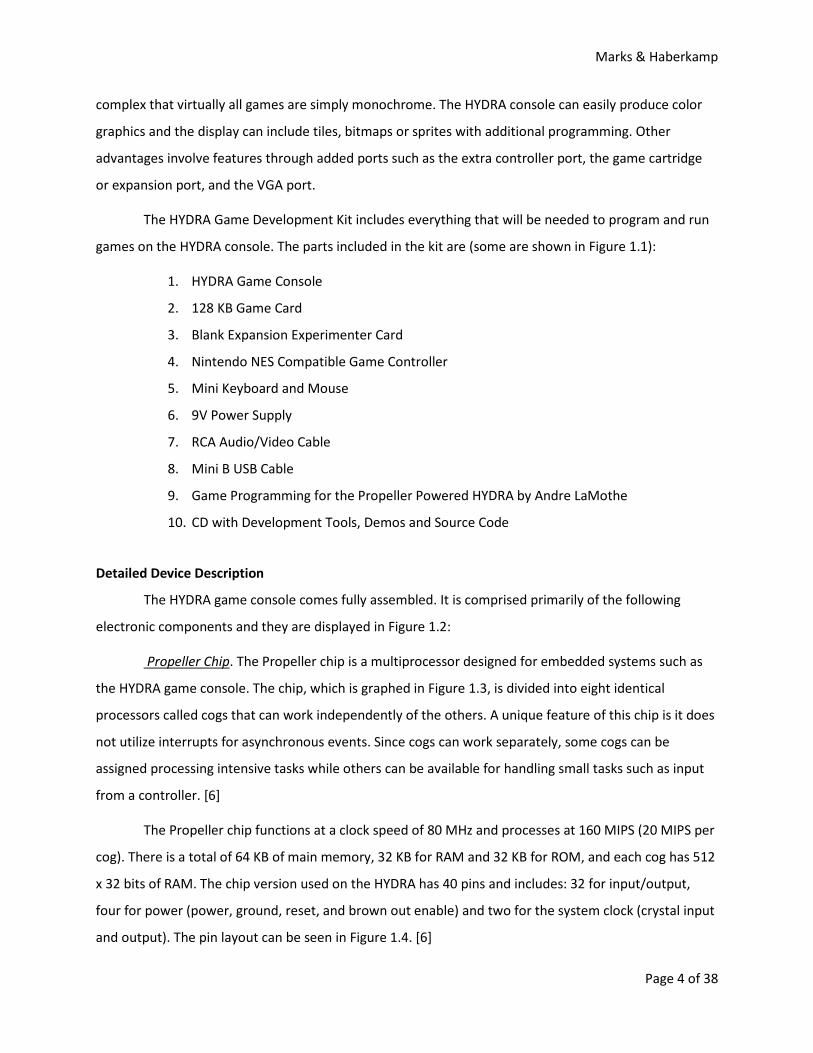
complex that virtually all games are simply monochrome. The HYDRA console can easily produce color
graphics and the display can include tiles, bitmaps or sprites with additional programming. Other
advantages involve features through added ports such as the extra controller port, the game cartridge
or expansion port, and the VGA port.
The HYDRA Game Development Kit includes everything that will be needed to program and run
games on the HYDRA console. The parts included in the kit are (some are shown in Figure 1.1):
1. HYDRA Game Console
2. 128 KB Game Card
3. Blank Expansion Experimenter Card
4. Nintendo NES Compatible Game Controller
5. Mini Keyboard and Mouse
6. 9V Power Supply
7. RCA Audio/Video Cable
8. Mini B USB Cable
9. Game Programming for the Propeller Powered HYDRA by Andre LaMothe
10. CD with Development Tools, Demos and Source Code
Detailed Device Description
The HYDRA game console comes fully assembled. It is comprised primarily of the following
electronic components and they are displayed in Figure 1.2:
Propeller Chip
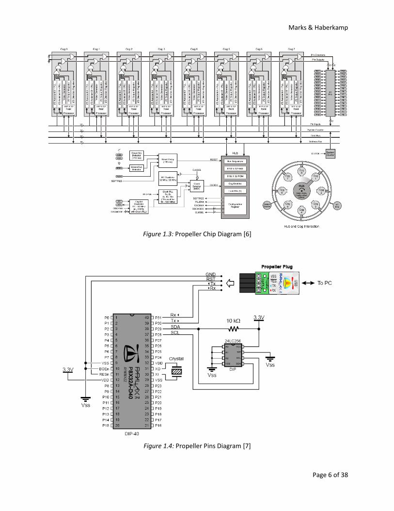
The Propeller chip functions at a clock speed of 80 MHz and processes at 160 MIPS (20 MIPS per
cog). There is a total of 64 KB of main memory, 32 KB for RAM and 32 KB for ROM, and each cog has 512
x 32 bits of RAM. The chip version used on the HYDRA has 40 pins and includes: 32 for input/output,
four for power (power, ground, reset, and brown out enable) and two for the system clock (crystal input
and output). The pin layout can be seen in Figure 1.4. [6]
. The Propeller chip is a multiprocessor designed for embedded systems such as
the HYDRA game console. The chip, which is graphed in Figure 1.3, is divided into eight identical
processors called cogs that can work independently of the others. A unique feature of this chip is it does
not utilize interrupts for asynchronous events. Since cogs can work separately, some cogs can be
assigned processing intensive tasks while others can be available for handling small tasks such as input
from a controller. [6]

Marks & Haberkamp
Page 5 of 38
Figure 1.2: HYDRA Gaming Console with a 128 KB Game Cartridge Attached [2]
128 KB EEPROM. EEPROM is short for Electrically Erasable Programmable Read-Only Memory
and is used to store a small amount of information when power is no longer supplied to the unit. Field
emission (or Fowler-Nordheim tunneling) is used to program or erase the EEPROM electrically. [1]
Nintendo NES Compatible Game Ports
Interestingly, in order to use a different format controller there is little programming work
required to enable compatibility. Most of the work consists of changing the controller-in-question's form
factor to match that of an NES controller. The remainder of the work is simply changing the controller
driver to handle the (possibly) different number of bits coming through the data out stream. For
example, the NES controller outputs 8 bits (one for each button-press; Up, Down, Left, Right, Start,
Select, A, B), while the Super NES controller outputs four additional bits to handle the inclusion of the
four extra buttons (X, Y, L-Shoulder, R-Shoulder).
. Two of these ports are included on the HYDRA unit. With
the exception of the data out signals, all of the signals received from both of these controllers are
paralleled. The data out signals are not paralleled as these are completely independent data streams. An
LED is connected to each controller's data out line and is used to indicate whether or not a controller is
plugged in. In order to counteract the power drain, and resultant signal degradation, resistors are placed
in-line between the data out and respective LED.
Marks & Haberkamp
Page 6 of 38
Figure 1.3: Propeller Chip Diagram [6]
Figure 1.4: Propeller Pins Diagram [7]
Marks & Haberkamp
Page 7 of 38
USB2SER Compatible Programming Port. This port is used to supply a convenient way to connect
a computer and a microcontroller (more specifically; a PC to the HYDRA unit). Particularly, the USB2SER
interface takes the data from the PC through a USB port and converts it to logic-level RX/TX signals
which can directly communicate with a microcontroller's I/O pins via a 4-pin female connector. On the
PC side, this connection is recognized as a virtual COM port; while on the microcontroller side, it is
recognized as a 3.3V-5V serial connection, comprised of the RX/TX signals and a RESET signal. The power
required to drive the USB2SER is drawn from the PC side, USB connection and LEDs are used to indicate
any RX/TX activity. [11]
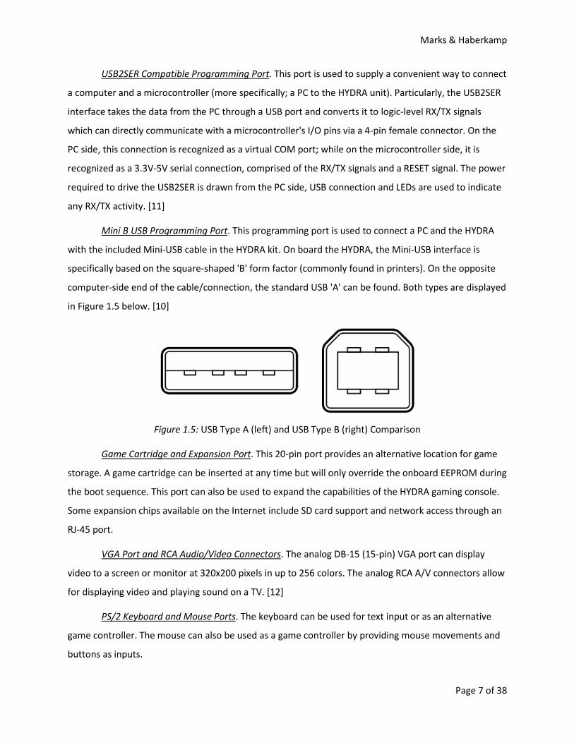
Mini B USB Programming Port. This programming port is used to connect a PC and the HYDRA
with the included Mini-USB cable in the HYDRA kit. On board the HYDRA, the Mini-USB interface is
specifically based on the square-shaped 'B' form factor (commonly found in printers). On the opposite
computer-side end of the cable/connection, the standard USB 'A' can be found. Both types are displayed
in Figure 1.5 below. [10]
Figure 1.5: USB Type A (left) and USB Type B (right) Comparison
Game Cartridge and Expansion Port. This 20-pin port provides an alternative location for game
storage. A game cartridge can be inserted at any time but will only override the onboard EEPROM during
the boot sequence. This port can also be used to expand the capabilities of the HYDRA gaming console.
Some expansion chips available on the Internet include SD card support and network access through an
RJ-45 port.
VGA Port and RCA Audio/Video Connectors. The analog DB-15 (15-pin) VGA port can display
video to a screen or monitor at 320x200 pixels in up to 256 colors. The analog RCA A/V connectors allow
for displaying video and playing sound on a TV. [12]
PS/2 Keyboard and Mouse Ports. The keyboard can be used for text input or as an alternative
game controller. The mouse can also be used as a game controller by providing mouse movements and
buttons as inputs.
Marks & Haberkamp
Page 8 of 38
RJ-11 Networking Port. The RJ-11 connector is commonly known as a phone jack. This port is
full-duplex, which means that it can send and receive information, and should provide a means for
connecting to another HYDRA console.
Debug LED. This LED is used to show whether or not the user has enabled debugging mode.
Power and Reset Switches. The power switch is a toggle switch used to turn the HYDRA on and
off. It is a simple SPST switch with only two states: connected or not. The reset switch is a push-button
switch used to, when depressed, interrupt the power flow to the HYDRA.
3.3/5.0V Power Supplies. These supply and regulate power required by the HYDRA console and
its components. Different components may require differing voltages, thus there are two parts to this
component (3.3V supply and 5.0V supply).
Marks & Haberkamp
Page 9 of 38
Section 2: Problem Specification
Concept Overview
The purpose of this project is to create a multiplayer game that can be played between two
HYDRA gaming consoles over a network or Internet connection as follows:
• The result shall be divided into two main components: the HYDRA game and a computer
program for the network interface.
• The HYDRA game shall be simplistic in design to avoid unnecessary complications and
will involve two moveable sprites that may have basic interaction.
• The computer program shall be used to send and receive game state information
between HYDRA consoles.
Why pick the HYDRA over the Pico?
The HYDRA gaming console was chosen for this project over the Pico Edition 2.0 for several
reasons. The primary reason for excluding the Pico was because of its lack of full-duplex communication
ports. While the Pico’s single Atari joystick port, a regular DB-9 serial port, may have output
functionality, there was never any mention of this feature or how one would go about creating an
output signal. Still, even if this port is full-duplex, the only other possible controls would be through a
computer interface, which would be cumbersome, or the onboard control buttons, which would
dramatically increase the potential of short due to static electricity.
Both gaming consoles include a proprietary assembly language but only the HYDRA includes the
object-oriented language Spin for programming games, which is provided by the Propeller processor.
The complex coding that is required to handle a multiplayer game through a network or the Internet
would make the Spin language the easy choice over assembly. It would not be feasible to attempt to
program an entire networked multiplayer game in assembly, with the Pico or HYDRA, during the allotted
semester.
Client-Server vs. Peer-to-Peer Network
Two general network relationships are client-server and peer-to-peer. There are a few
advantages that peer-to-peer networking holds over client-server networking; it is generally the simplest
kind of network to build, while it is also fast and easy to maintain. Specifically, the most apparent
Marks & Haberkamp
Page 10 of 38
advantage of choosing peer-to-peer is that there is more programming involved in establishing a client-
server network, as each HYDRA would be required to perform a different set of tasks for their distinct
roles.
In a basic client-server network, a computer (or node) will only be one of two types: a client or
server. If we were to implement a client-server networking relationship for our project, one of the
HYDRA units would be established as the server and the other would be a client. In order to
communicate, the client HYDRA would send requests to the server HYDRA and then wait for the replies.
This kind of networking relies heavily on the server's ability to perform calculations quickly and
efficiently, upon receiving a request from the client, and then send a reply back in order for the client to
complete a specific task. As a side note, the server is passive in the sense that it will not directly
communicate with the client, after establishing a connection, without first receiving a request.
In a peer-to-peer network, the line between client and server becomes blurred as each node
acts on an equal level and does its own share of the work. Each node can directly communicate with
another and issue instructions without having to wait for a reply. This has the benefit of reducing
network latency as there is no waiting done on either end from request-reply communication. The
bottleneck that arises from having only one node perform all of the calculations is avoided.
Multithreading
Both the game and network interface will require multithreaded programming. The game will
utilize most, if not all, of the Propeller’s eight cogs. Several communication threads will be used in the
HYDRA for sending its game state information and receiving the other HYDRA’s game state information.
The network interface program will also need to handle several tasks at once. There will be four threads
running concurrently for game operation: reading the serial port, sending to the serial port, reading
incoming game state information and sending game state information. Since both team members are
significantly more fluent in Java than any other language, this object-oriented language will be utilized
for the network interface program.
Serial and Network Communication using Java
The Java Development Kit (JDK) 6 does not include any classes to use a computer’s serial port.
Fortunately, Sun Microsystems provides the Java Communications API for free through their Sun
Developer Network (SDN). With the inclusion of this API, by importing the javax.comm package, the
Marks & Haberkamp
Page 11 of 38
ability to access and communicate using hardware serial (RS232/434, COM, tty) ports can be extended
to an application. [3]
Access to commonly used signals is supported; specifically, TxD (Transmitted Data), RxD
(Received Data), DTR (Data Terminal Ready; used to indicate if equipment is ready to be connected), CD
(Carrier Detect; used to indicate that a connection has been established with some remote equipment),
CTS (Clear To Send; used to acknowledge a request and allows equipment to transmit data), RTS
(Request To Send; used to prepare remotely connected equipment to receive data), and DSR (Data Set
Ready; used to indicate an active connection). [3]
Unlike serial communication, the JDK 6 includes all of the necessary classes for networking
under the java.net package. Implementing this aspect of the network interface program should be
relatively simple—there is just a relay of information without any processing on either end. While the
HYDRA game consoles will use a peer-to-peer relationship, this program will use a client-to-server
relationship. The computers running this program have significantly larger processing power and
capabilities so they can easily handle this type of relationship. Only one program needs to be written
because it will contain both server and client roles. It will be up to the users to decide who fills these
roles for that particular gaming session.
Marks & Haberkamp
Page 12 of 38
Section 3: Design Description
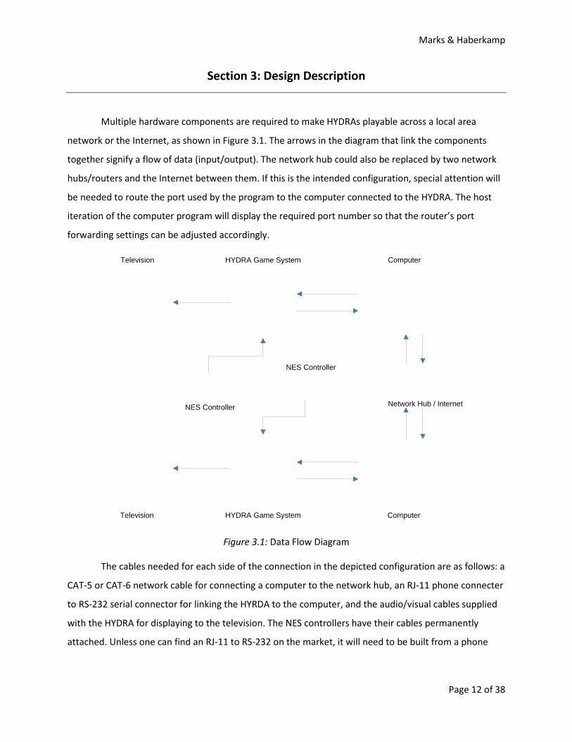
Multiple hardware components are required to make HYDRAs playable across a local area
network or the Internet, as shown in Figure 3.1. The arrows in the diagram that link the components
together signify a flow of data (input/output). The network hub could also be replaced by two network
hubs/routers and the Internet between them. If this is the intended configuration, special attention will
be needed to route the port used by the program to the computer connected to the HYDRA. The host
iteration of the computer program will display the required port number so that the router’s port
forwarding settings can be adjusted accordingly.
Television HYDRA Game System Computer
Network Hub / InternetNES Controller
NES Controller
HYDRA Game SystemTelevision Computer
Figure 3.1: Data Flow Diagram
The cables needed for each side of the connection in the depicted configuration are as follows: a
CAT-5 or CAT-6 network cable for connecting a computer to the network hub, an RJ-11 phone connecter
to RS-232 serial connector for linking the HYRDA to the computer, and the audio/visual cables supplied
with the HYDRA for displaying to the television. The NES controllers have their cables permanently
attached. Unless one can find an RJ-11 to RS-232 on the market, it will need to be built from a phone
Marks & Haberkamp
Page 13 of 38
cord and a serial port connector, some of which can be found with a RJ-11 port built in. This may require
some manual manipulation of the wires within the serial port connector.
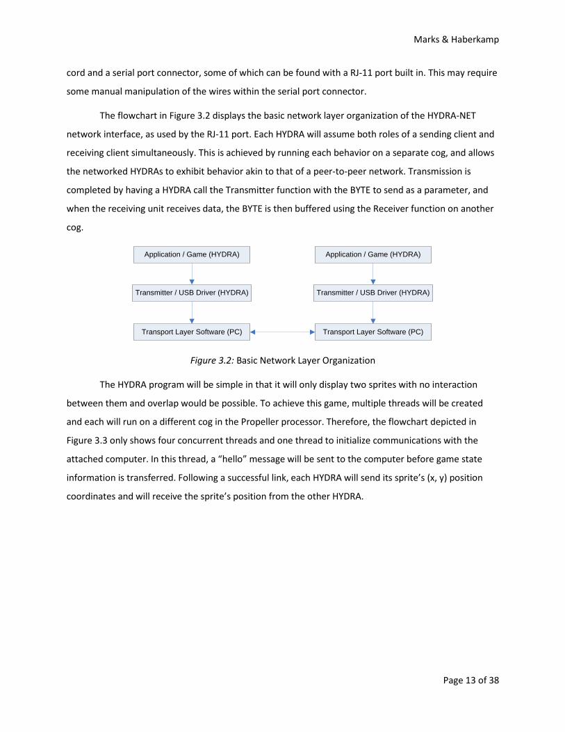
The flowchart in Figure 3.2 displays the basic network layer organization of the HYDRA-NET
network interface, as used by the RJ-11 port. Each HYDRA will assume both roles of a sending client and
receiving client simultaneously. This is achieved by running each behavior on a separate cog, and allows
the networked HYDRAs to exhibit behavior akin to that of a peer-to-peer network. Transmission is
completed by having a HYDRA call the Transmitter function with the BYTE to send as a parameter, and
when the receiving unit receives data, the BYTE is then buffered using the Receiver function on another
cog.
Application / Game (HYDRA)
Transmitter / USB Driver (HYDRA)
Transport Layer Software (PC)
Application / Game (HYDRA)
Transmitter / USB Driver (HYDRA)
Transport Layer Software (PC)
Figure 3.2: Basic Network Layer Organization
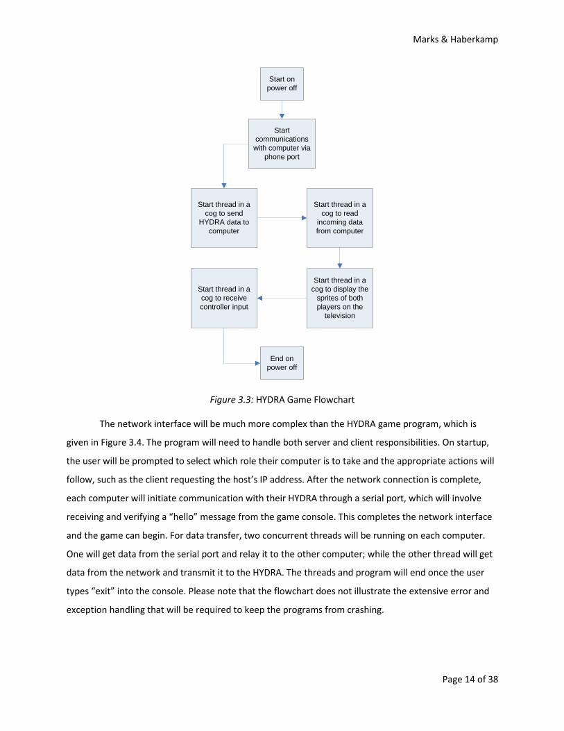
The HYDRA program will be simple in that it will only display two sprites with no interaction
between them and overlap would be possible. To achieve this game, multiple threads will be created
and each will run on a different cog in the Propeller processor. Therefore, the flowchart depicted in
Figure 3.3 only shows four concurrent threads and one thread to initialize communications with the
attached computer. In this thread, a “hello” message will be sent to the computer before game state
information is transferred. Following a successful link, each HYDRA will send its sprite’s (x, y) position
coordinates and will receive the sprite’s position from the other HYDRA.
Marks & Haberkamp
Page 14 of 38
Start communications with computer via
phone port
Start thread in a cog to send
HYDRA data to computer
End on power off
Start thread in a cog to read
incoming data from computer
Start thread in a cog to display the
sprites of both players on the
television
Start thread in a cog to receive controller input
Start on power off
Figure 3.3: HYDRA Game Flowchart
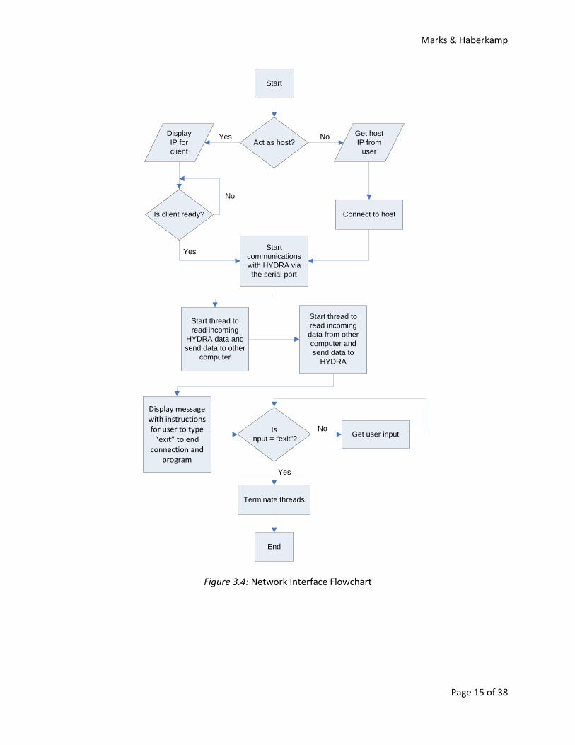
The network interface will be much more complex than the HYDRA game program, which is
given in Figure 3.4. The program will need to handle both server and client responsibilities. On startup,
the user will be prompted to select which role their computer is to take and the appropriate actions will
follow, such as the client requesting the host’s IP address. After the network connection is complete,
each computer will initiate communication with their HYDRA through a serial port, which will involve
receiving and verifying a “hello” message from the game console. This completes the network interface
and the game can begin. For data transfer, two concurrent threads will be running on each computer.
One will get data from the serial port and relay it to the other computer; while the other thread will get
data from the network and transmit it to the HYDRA. The threads and program will end once the user
types “exit” into the console. Please note that the flowchart does not illustrate the extensive error and
exception handling that will be required to keep the programs from crashing.
Marks & Haberkamp
Page 15 of 38
Start
Act as host?Display IP for client
Get host IP from
user
Connect to host
Start communications with HYDRA via the serial port
Start thread to read incoming
HYDRA data and send data to other
computer
Start thread to read incoming data from other computer and send data to
HYDRA
Display message with instructions for user to type
“exit” to end connection and
program
Isinput = “exit”? Get user input
Terminate threads
End
Yes No
Is client ready?
Yes
No
Yes
No
Figure 3.4: Network Interface Flowchart
Marks & Haberkamp
Page 16 of 38
Section 4: Implementation and Testing
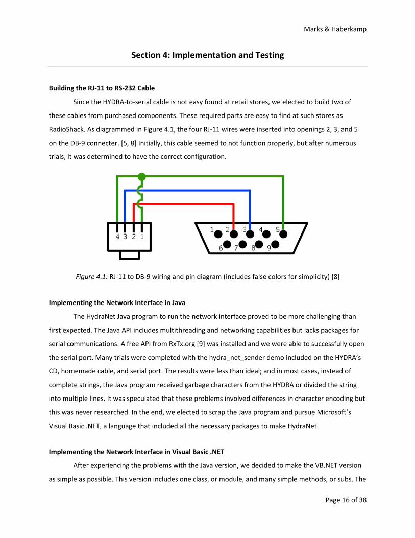
Building the RJ-11 to RS-232 Cable
Since the HYDRA-to-serial cable is not easy found at retail stores, we elected to build two of
these cables from purchased components. These required parts are easy to find at such stores as
RadioShack. As diagrammed in Figure 4.1, the four RJ-11 wires were inserted into openings 2, 3, and 5
on the DB-9 connecter. [5, 8] Initially, this cable seemed to not function properly, but after numerous
trials, it was determined to have the correct configuration.
Figure 4.1: RJ-11 to DB-9 wiring and pin diagram (includes false colors for simplicity) [8]
Implementing the Network Interface in Java
The HydraNet Java program to run the network interface proved to be more challenging than
first expected. The Java API includes multithreading and networking capabilities but lacks packages for
serial communications. A free API from RxTx.org [9] was installed and we were able to successfully open
the serial port. Many trials were completed with the hydra_net_sender demo included on the HYDRA’s
CD, homemade cable, and serial port. The results were less than ideal; and in most cases, instead of
complete strings, the Java program received garbage characters from the HYDRA or divided the string
into multiple lines. It was speculated that these problems involved differences in character encoding but
this was never researched. In the end, we elected to scrap the Java program and pursue Microsoft’s
Visual Basic .NET, a language that included all the necessary packages to make HydraNet.
Implementing the Network Interface in Visual Basic .NET
After experiencing the problems with the Java version, we decided to make the VB.NET version
as simple as possible. This version includes one class, or module, and many simple methods, or subs. The
Marks & Haberkamp
Page 17 of 38
program can handle both host and client roles, depending on user input. In each instance, there are
three concurrent threads that run: main, server/client, and serial. The most recent versions of VB.NET
include class libraries such as: Ports, Net, and Sockets. These allowed us to easily create objects for the
connections for program implementation. The most challenging aspect of coding this version of
HydraNet was verifying that all data communications were sending and receiving bytes of data. There
four groups of subs within the program and briefly explained below. The full source code is provided in
Appendix B.
First are the Main and CloseProgram subs, which together handle startup, operations, and
closing of the program. Main determines from the user if it should take on the role as host or client and
it runs the appropriate subs. It also calls for the serial communications to open. Finally, it waits for an
“exit” command from the user so that it may call the CloseProgram, which shuts down all open threads
and connections.
Next, the program contains server and client regions. Both have a sub for starting and another
for running the given role. StartServer displays the computer’s IP address and asks the user to input a
port number. It then proceeds to wait for a client to connect. ConnectClient asks the user for the
server’s IP address and port number and then connects to the server. The RunSever and RunClient subs
call the ReadNetwork sub to initiate communications.
Finally, the serial and network communication sections handle all transfers of data. The
ConnectSerial is called by Main and initiates the COM port provided by the user. All data transfers are in
the form of a byte—this is crucial. ReadSerial retrieves data from the serial port and passes the data
through a call to the SendNetwork sub. This sub in turn sends the data through a BinaryWriter stream
over a network or Internet connection to the other computer. The ReadNetwork sub then reads the
data on the other computer through a BinaryReader stream. The data is then sent to the SendSerial sub
in which it is written as a one element byte array to the virtual serial port.
Implementing the HYDRA Game
The HYDRA game implements a very simple tag game in which one player chases and tries to
touch the other player’s sprite, then the roles reverse. No interactions, sound, or scoring were
implemented in the game—this is the most basic of “games.” The source code consists of just two
methods: Start and readP2. These methods are explained below and the full source code is provided in
Appendix A.
Marks & Haberkamp
Page 18 of 38
Start is the primary method that includes almost the entire running program. First, it initializes
the graphics engine, USB communications, gamepad, and player positions. All of these are relatively
easy to understand, expect for the graphics engine which was copied and only slightly modified from the
pacman_tile_demo_005 source included on the HYDRA CD. The last half of the Start method is an
endless loop to run the game. First, gamepad button presses are detected and the player 1 sprite is
moved accordingly. Next, the player 1 position is sent to the computer using a trick to indicate x- and y-
coordinates. The x-value has a least significant bit (LSB) of 0 and the y-value has a LSB of 1. Lastly, the
sprite positions are updated and a delay set.
Before the Start method started the endless loop, it also started a new cog to run the readP2
method. This method continuous checks the USB connection for inbound player 2 positions. It
determines if the current packet of data is an x- or y-coordinate and it saves the value to the appropriate
position variable.
The sprites are only generally understood. Simply put, a tile map is the background, which in our
case is all blank, and sprites are defined by 4 possible colors. These colors are actually set by the tile map
and the sprites only allow certain colors to show through to the television screen. Some sprite options
include mirroring and enlarging. The tile map and sprites can be changed on demand. For further
information, please see the HYDRA manual [5] or the demos included on the HYDRA CD.
Testing the System
Test of Java Networking.
In the beginning, the variables that were initialized with the SerialComm class were commented
out so as to allow us to focus entirely on the NetworkComm class. Since prior testing had not been done
with regard to these two classes, many bugs had to be worked out in order for us to proceed onto
testing the Spin programs on each HYDRA. Initially, an exception resulted every few lines of our source
code and, after many println statements, most were solved by changing minor errors in logic. After all
A lot of time was spent debugging the Java portion of our project. First,
debugging was done by running two separate source files with different parameters in order for each to
assume a different role (client or server). On the client side, rather than asking the user to input the IP
address of the host, the IP was hard-coded in the source as the “localhost”. This was done to enable
testing to be performed on the same machine as it assumed both roles simultaneously. Care was taken
to ensure that no serial ports would be used during testing, which would have led to more runtime
exceptions upon running.
Marks & Haberkamp
Page 19 of 38
problems were addressed within the NetworkComm class, we proceeded to debugging the SerialComm
class. There were considerably fewer problems stemmed from the SerialComm class, and debugging was
completed relatively quickly.
Finally, another computer was included in order to completely separate the roles of client and
server. One computer waited for a client to connect and the other attempted to establish a connection
with the host at the IP address supplied by the user. In order to conduct testing in a more efficient
manner, the response to each prompt was again hard-coded so that we would be spared the redundant
task of entering in “host” or “client” along with the IP address upon running the programs each time. By
going through an additional testing phase with the Java program, we were able to catch more problems
that stemmed from erroneously parsing the user’s responses and any connection issues that occurred
between the two machines.
Test of HYDRA Communications.
Computer
HYDRASender
Television
Computer
HYDRAReceiver
Keyboard
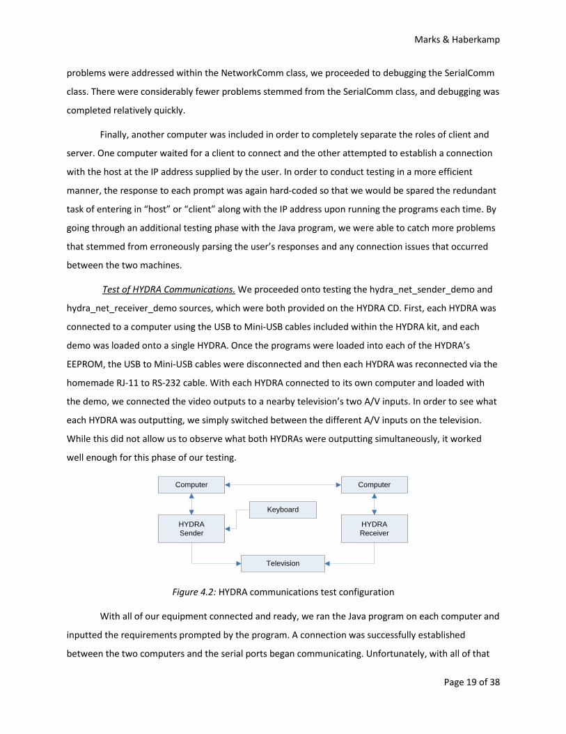
We proceeded onto testing the hydra_net_sender_demo and
hydra_net_receiver_demo sources, which were both provided on the HYDRA CD. First, each HYDRA was
connected to a computer using the USB to Mini-USB cables included within the HYDRA kit, and each
demo was loaded onto a single HYDRA. Once the programs were loaded into each of the HYDRA’s
EEPROM, the USB to Mini-USB cables were disconnected and then each HYDRA was reconnected via the
homemade RJ-11 to RS-232 cable. With each HYDRA connected to its own computer and loaded with
the demo, we connected the video outputs to a nearby television’s two A/V inputs. In order to see what
each HYDRA was outputting, we simply switched between the different A/V inputs on the television.
While this did not allow us to observe what both HYDRAs were outputting simultaneously, it worked
well enough for this phase of our testing.
Figure 4.2: HYDRA communications test configuration
With all of our equipment connected and ready, we ran the Java program on each computer and
inputted the requirements prompted by the program. A connection was successfully established
between the two computers and the serial ports began communicating. Unfortunately, with all of that
Marks & Haberkamp
Page 20 of 38
seemingly working properly, we could not get the two HYDRAs to communicate with each other. When
text was inputted on the HYDRA with the sender demo running, it would only be displayed on that unit.
The text was never received by the other HYDRA through the connection in order to allow the text to be
displayed on both machines.
Test of Serial Communications.
While this test did not yield a successful result, the Java program saw that data was being sent
from the HYDRA when the HYDRA started up—the program never received a data due to a key press.
What’s even more puzzling was that the program only knew that data was received; it could not actually
read the data. After looking into the sender demo, it was obvious that the HYDRA sends a “hello”
message on startup in the form of a byte equaling 2E (the ASCII code for a period/decimal point) and it
uses the same method to send this initial message and any subsequent characters.
To verify that the problem was not caused by improper logic in
our HydraNet Java code, we found an example on the Internet of a null modem test written in Java. [4] A
null modem test assumes that the send pin on the computer’s serial port is directly connected, with a
wire, to the receive pin on same serial port. The sample Java code had a thread to send a string of text
to the serial port and had a serial port event listener to read from the serial port upon data reception.
Instead of running this code as a null modem test, we attached a HYDRA, with the sender demo loaded,
to the serial port to see if we could receive any data from the HYDRA. The string sent to the serial port
by the Java program would just be ignored by the HYDRA.
Switch to USB Cable. By chance, we found a chapter in the HYDRA manual on using the USB
cable for communications during games. Previously, this option was ignored because it was considered
to be much more complex than serial and we were under the impression that it was only for uploading
programs to the HYDRA. The manual declared that neither is true and that it behaved as a virtual serial
port. [5] The decision to abandon the homemade serial cables and switch to USB proved to be the
turning point in the project. Even the Spin programming was simpler to understand and implement in
USB than serial.
Test of HydraNet in VB.NET. With the drastic change from Java to Visual Basic .NET for the
HydraNet program, additional time was dedicated towards debugging the new program to make it more
efficient and catch any potentially game-breaking issues. We were able to discover the source of an
issue that was originally thought to be within the HYDRA Spin programming. An erroneous game state
was created on the receiving HYDRA when data was being passed in an incorrect data format. These bad
translations, primarily as a byte value in the form of a string (i.e. 80 as ‘8’, ‘0’), interfered with the
Marks & Haberkamp
Page 21 of 38
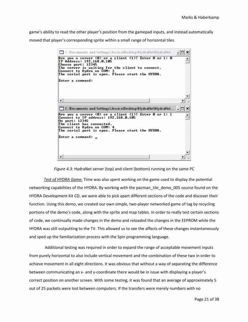
game’s ability to read the other player’s position from the gamepad inputs, and instead automatically
moved that player’s corresponding sprite within a small range of horizontal tiles.
Figure 4.3: HydraNet server (top) and client (bottom) running on the same PC
Test of HYDRA Game.
Additional testing was required in order to expand the range of acceptable movement inputs
from purely horizontal to also include vertical movement and the combination of these two in order to
achieve movement in all eight directions. It was obvious that without a way of separating the difference
between communicating an x- and y-coordinate there would be in issue with displaying a player’s
correct position on another screen. With some testing, it was found that an average of approximately 5
out of 25 packets were lost between computers. If the transfers were merely numbers with no
Time was also spent working on the game used to display the potential
networking capabilities of the HYDRA. By working with the pacman_tile_demo_005 source found on the
HYDRA Development Kit CD, we were able to pick apart different sections of the code and discover their
function. Using this demo, we created our own simple, two-player networked game of tag by recycling
portions of the demo’s code, along with the sprite and map tables. In order to really test certain sections
of code, we continually made changes in the demo and reloaded the changes in the EEPROM while the
HYDRA was still outputting to the TV. This allowed us to see the affects of these changes instantaneously
and sped up the familiarization process with the Spin programming language.
Marks & Haberkamp
Page 22 of 38
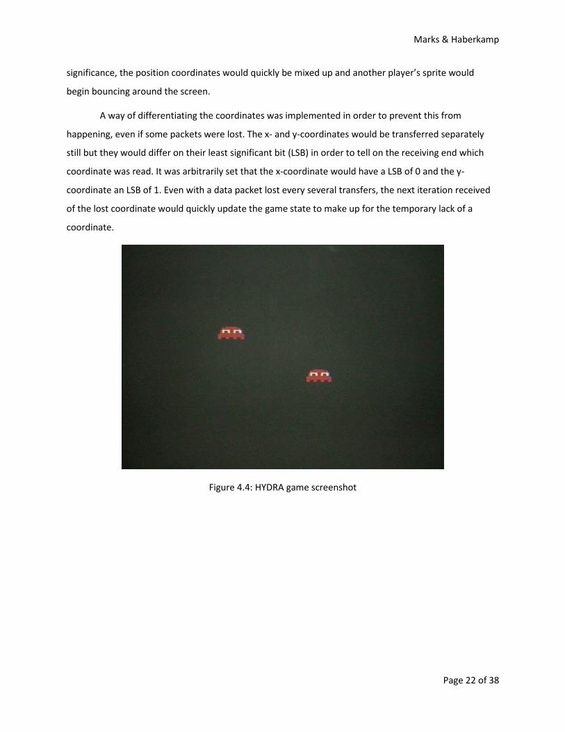
significance, the position coordinates would quickly be mixed up and another player’s sprite would
begin bouncing around the screen.
A way of differentiating the coordinates was implemented in order to prevent this from
happening, even if some packets were lost. The x- and y-coordinates would be transferred separately
still but they would differ on their least significant bit (LSB) in order to tell on the receiving end which
coordinate was read. It was arbitrarily set that the x-coordinate would have a LSB of 0 and the y-
coordinate an LSB of 1. Even with a data packet lost every several transfers, the next iteration received
of the lost coordinate would quickly update the game state to make up for the temporary lack of a
coordinate.
Figure 4.4: HYDRA game screenshot
Marks & Haberkamp
Page 23 of 38
Section 5: Conclusion
Over the course of this project, we were challenged with developing a game for the HYDRA
console and a method of connecting two units over an internet connection. We accomplished both of
these feats by dedicating a considerable amount of time to this project. The HYDRA-based programming
that was initially obscure proved to be understandable to a degree, and this newfound comprehension
allowed us to develop a simple game of two-player tag.
We also learned that familiarity should not be the only reason for picking a programming
language. Other factors should also be addressed such as included abilities, simplicity in
implementation, and available documentation. This project would have been quicker and easier to finish
if we had spent more time in the initial planning stages on choosing the correct language for the
HydraNet program. While Visual Basic seems to incur a negative reaction from many programmers, it
did prove to be the simplest solution for this project.
Currently, the HYDRA game that was developed for this project is very simplistic. Future
development of the game shall add in additional features and improve upon the basic game of tag that
was used to test the networking capabilities of the two HYDRA units. Improvements could be made in
every aspect of the game: the color palette, sound effects, background music, and a scorekeeping
system.
Support was only included for a two player game, by using two separate computers and HYDRA
game consoles. With additional time to improve upon the project, support could be extended to allow
for a range of players as long as each player had their own computer and HYDRA. When a user assumes
the role of the server, they could be prompted to choose how many players, up to a reasonable number,
would be joining their game. By passing this number to the HYDRA game, the appropriate number of
sprites could be drawn on each player’s screen, and allow for a more interesting game of free-for-all
multiplayer tag. Players could then be prompted to choose their color at the beginning of the game in
order to help differentiate them from others.
For our game’s purposes, the only information that was required to pass over the network were
x- and y-coordinates of a player’s current position in order to tell the other HYDRA where to draw them
on the screen. Future development would lead to a more complex game requiring more information to
be sent in order to keep the game-states of the separate HYDRAs to be nearly identical. We were able to
Marks & Haberkamp
Page 24 of 38
overcome any synchronization issues using a small trick to distinguish between x- and y-coordinates.
With more information passing between HYDRAs, a new system would need to be devised in order to
minimize problems associated with syncing and data packet loss.
To pursue networking in a different direction, a Java applet could be created and published on
the web to simulate a HYRDA client in a networked game. The applet would require a visual display (no
television necessary) and communications that could properly sync with the current HydraNet program.
The resultant game could therefore contain multiple instances of physical and simulated HYDRAs
communicating together.
Marks & Haberkamp
Page 25 of 38
References
[1] “EEPROM.” Wikipedia: The Free Encyclopedia
[2] “HYDRA Game Development Kit.”
. 19 Feb 2008. Wikimedia Foundation, Inc. 20 Feb 2008.
<http://en.wikipedia.org/w/index.php?title=EEPROM&oldid=192525848>.
XGameStation: Video Game System Development
[3] “Java Communications.”
. 2008. Nurve
Networks, LLC. 19 Feb 2008. <http://www.xgamestation.com/view_product.php?id=33>.
Sun Developer Network (SDN)
[4] “JAVA: Serial Port access with javax.comm or rxtx on Windows, Linux etc.”
. 2008. Sun Microsystems, Inc. 26 Feb 2008.
<http://java.sun.com/products/javacomm/>.
Captain’s Universe
[5] LaMothe, Andre.
. 2007.
Captain’s Universe. 1 Apr 2008.
<http://www.captain.at/howto-java-serial-port-javax-comm-rxtx.php>
Game Programming for the Propeller Powered HYDRA
[6] “Propeller Information.”
. 2006. Nurve Networks, LLC.
Parallax, Inc
[7] “Propeller Manual.”
. 2007. Parallax, Inc. 19 Feb 2008.
<http://www.parallax.com/tabid/407/Default.aspx>.
Parallax, Inc
[8] “RS-232. ”
. 2006. Parallax, Inc. 19 Feb 2008.
<http://www.parallax.com/Portals/0/Downloads/docs/prod/prop/WebPM-v1.01.pdf>.
Wikipedia: The Free Encyclopedia
[9]
. 24 Feb 2008. Wikimedia Foundation, Inc. 26 Feb 2008.
<http://en.wikipedia.org/w/index.php?title=RS-232&oldid=193698118>.
RxTx.org
[10] “Universal Serial Bus. ”
. 2007. Keane Jarvi. 1 Apr 2008. <http://rxtx.org/>
Wikipedia: The Free Encyclopedia
[11] “USB2SER: FTDI FT232BM USB to Serial Development Tool.”
. 18 Feb 2008. Wikimedia Foundation, Inc.
20 Feb 2008.
<http://en.wikipedia.org/w/index.php?title=Universal_Serial_Bus&oldid=192285395>.
Parallax, Inc
[12] “Video Graphics Array. ”
. 2005.Parallax, Inc. 19 Feb
2008. <http://www.parallax.com/dl/docs/prod/acc/USB2SER-v1.1.pdf>.
Wikipedia: The Free Encyclopedia
. 15 Feb 2008. Wikimedia Foundation,
Inc. 20 Feb 2008.
<http://en.wikipedia.org/w/index.php?title=Video_Graphics_Array&oldid=191667995>.
Marks & Haberkamp
Page 26 of 38
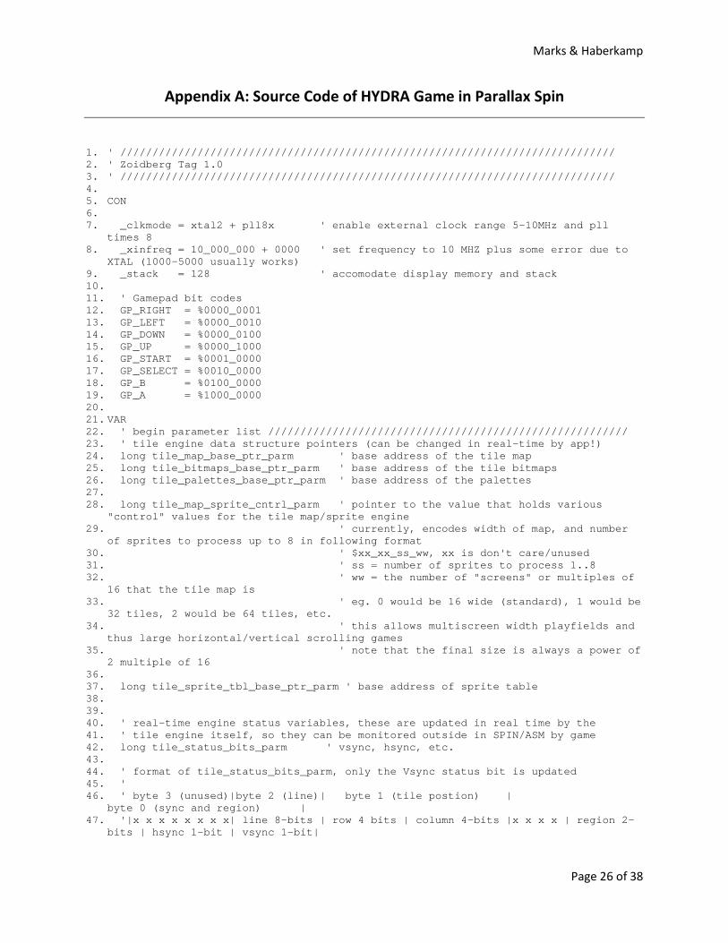
Appendix A: Source Code of HYDRA Game in Parallax Spin
1. ' ///////////////////////////////////////////////////////////////////////////// 2. ' Zoidberg Tag 1.0 3. ' ///////////////////////////////////////////////////////////////////////////// 4. 5. CON 6. 7. _clkmode = xtal2 + pll8x ' enable external clock range 5-10MHz and pll
times 8 8. _xinfreq = 10_000_000 + 0000 ' set frequency to 10 MHZ plus some error due to
XTAL (1000-5000 usually works) 9. _stack = 128 ' accomodate display memory and stack 10. 11. ' Gamepad bit codes 12. GP_RIGHT = %0000_0001 13. GP_LEFT = %0000_0010 14. GP_DOWN = %0000_0100 15. GP_UP = %0000_1000 16. GP_START = %0001_0000 17. GP_SELECT = %0010_0000 18. GP_B = %0100_0000 19. GP_A = %1000_0000 20. 21. VAR 22. ' begin parameter list //////////////////////////////////////////////////////// 23. ' tile engine data structure pointers (can be changed in real-time by app!) 24. long tile_map_base_ptr_parm ' base address of the tile map 25. long tile_bitmaps_base_ptr_parm ' base address of the tile bitmaps 26. long tile_palettes_base_ptr_parm ' base address of the palettes 27. 28. long tile_map_sprite_cntrl_parm ' pointer to the value that holds various
"control" values for the tile map/sprite engine 29. ' currently, encodes width of map, and number
of sprites to process up to 8 in following format 30. ' $xx_xx_ss_ww, xx is don't care/unused 31. ' ss = number of sprites to process 1..8 32. ' ww = the number of "screens" or multiples of
16 that the tile map is 33. ' eg. 0 would be 16 wide (standard), 1 would be
32 tiles, 2 would be 64 tiles, etc. 34. ' this allows multiscreen width playfields and
thus large horizontal/vertical scrolling games 35. ' note that the final size is always a power of
2 multiple of 16 36. 37. long tile_sprite_tbl_base_ptr_parm ' base address of sprite table 38. 39. 40. ' real-time engine status variables, these are updated in real time by the 41. ' tile engine itself, so they can be monitored outside in SPIN/ASM by game 42. long tile_status_bits_parm ' vsync, hsync, etc. 43. 44. ' format of tile_status_bits_parm, only the Vsync status bit is updated 45. ' 46. ' byte 3 (unused)|byte 2 (line)| byte 1 (tile postion) |
byte 0 (sync and region) | 47. '|x x x x x x x x| line 8-bits | row 4 bits | column 4-bits |x x x x | region 2-
bits | hsync 1-bit | vsync 1-bit|
Marks & Haberkamp
Page 27 of 38
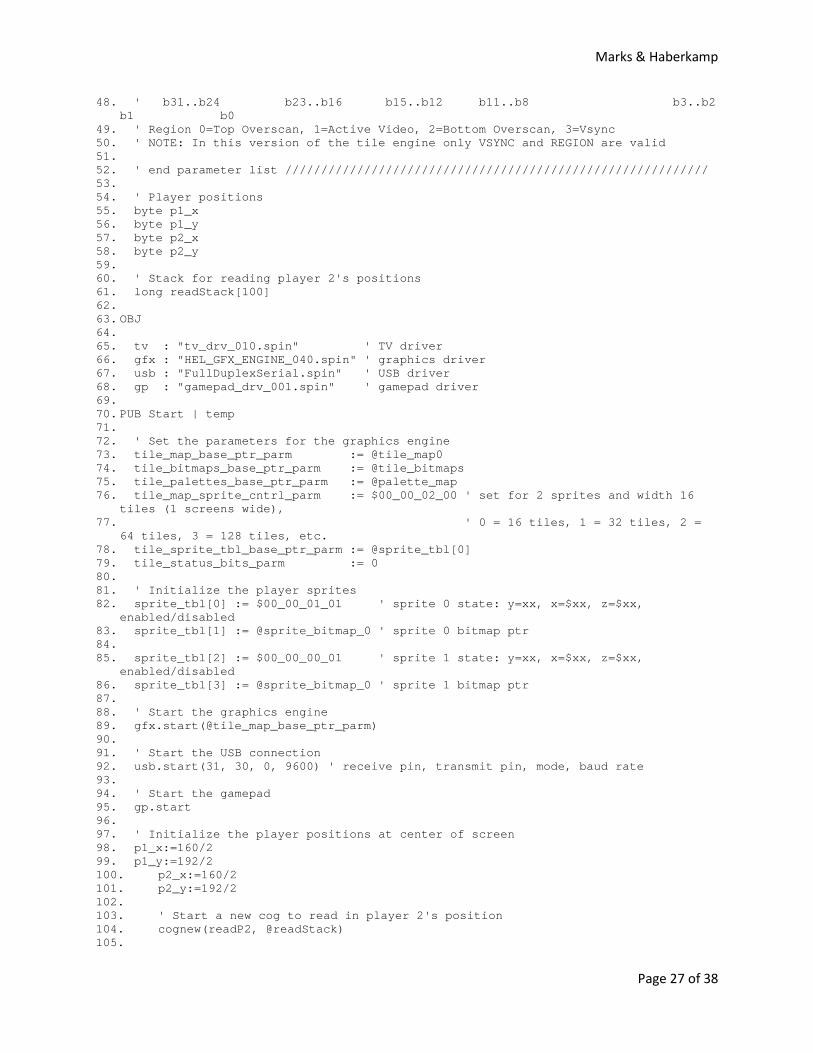
48. ' b31..b24 b23..b16 b15..b12 b11..b8 b3..b2 b1 b0
49. ' Region 0=Top Overscan, 1=Active Video, 2=Bottom Overscan, 3=Vsync 50. ' NOTE: In this version of the tile engine only VSYNC and REGION are valid 51. 52. ' end parameter list /////////////////////////////////////////////////////////// 53. 54. ' Player positions 55. byte p1_x 56. byte p1_y 57. byte p2_x 58. byte p2_y 59. 60. ' Stack for reading player 2's positions 61. long readStack[100] 62. 63. OBJ 64. 65. tv : "tv_drv_010.spin" ' TV driver 66. gfx : "HEL_GFX_ENGINE_040.spin" ' graphics driver 67. usb : "FullDuplexSerial.spin" ' USB driver 68. gp : "gamepad_drv_001.spin" ' gamepad driver 69. 70. PUB Start | temp 71. 72. ' Set the parameters for the graphics engine 73. tile_map_base_ptr_parm := @tile_map0 74. tile_bitmaps_base_ptr_parm := @tile_bitmaps 75. tile_palettes_base_ptr_parm := @palette_map 76. tile_map_sprite_cntrl_parm := $00_00_02_00 ' set for 2 sprites and width 16
tiles (1 screens wide), 77. ' 0 = 16 tiles, 1 = 32 tiles, 2 =
64 tiles, 3 = 128 tiles, etc. 78. tile_sprite_tbl_base_ptr_parm := @sprite_tbl[0] 79. tile_status_bits_parm := 0 80. 81. ' Initialize the player sprites 82. sprite_tbl[0] := $00_00_01_01 ' sprite 0 state: y=xx, x=$xx, z=$xx,
enabled/disabled 83. sprite_tbl[1] := @sprite_bitmap_0 ' sprite 0 bitmap ptr 84. 85. sprite_tbl[2] := $00_00_00_01 ' sprite 1 state: y=xx, x=$xx, z=$xx,
enabled/disabled 86. sprite_tbl[3] := @sprite_bitmap_0 ' sprite 1 bitmap ptr 87. 88. ' Start the graphics engine 89. gfx.start(@tile_map_base_ptr_parm) 90. 91. ' Start the USB connection 92. usb.start(31, 30, 0, 9600) ' receive pin, transmit pin, mode, baud rate 93. 94. ' Start the gamepad 95. gp.start 96. 97. ' Initialize the player positions at center of screen 98. p1_x:=160/2 99. p1_y:=192/2 100. p2_x:=160/2 101. p2_y:=192/2 102. 103. ' Start a new cog to read in player 2's position 104. cognew(readP2, @readStack) 105.
Marks & Haberkamp
Page 28 of 38
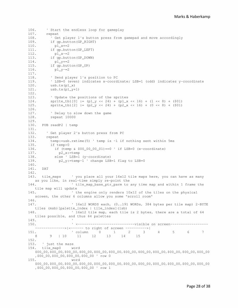
106. ' Start the endless loop for gameplay 107. repeat 108. ' Get player 1's button press from gamepad and move accordingly 109. if gp.button(GP_RIGHT) 110. p1_x+=2 111. if gp.button(GP_LEFT) 112. p1_x-=2 113. if gp.button(GP_DOWN) 114. p1_y+=2 115. if gp.button(GP_UP) 116. p1_y-=2 117. 118. ' Send player 1's position to PC 119. ' LSB=0 (even) indicates x-coordinate; LSB=1 (odd) indicates y-coordinate 120. usb.tx(p1_x) 121. usb.tx(p1_y+1) 122. 123. ' Update the positions of the sprites 124. sprite_tbl[0] := (p1_y << 24) + (p1_x << 16) + (1 << 8) + ($01) 125. sprite_tbl[2] := (p2_y << 24) + (p2_x << 16) + (0 << 8) + ($01) 126. 127. ' Delay to slow down the game 128. repeat 10000 129. 130. PUB readP2 | temp 131. 132. ' Get player 2's button press from PC 133. repeat 134. temp:=usb.rxtime(5) ' temp is -1 if nothing sent within 5ms 135. if temp>0 136. if (temp & $00_00_00_01)==0 ' if LSB=0 (x-coordinate) 137. p2_x:=temp 138. else ' LSB=1 (y-coordinate) 139. p2_y:=temp-1 ' change LSB=1 flag to LSB=0 140. 141. DAT 142. 143. tile_maps ' you place all your 16x12 tile maps here, you can have as many
as you like, in real-time simply re-point the 144. ' tile_map_base_ptr_parm to any time map and within 1 frame the
tile map will update 145. ' the engine only renders 10x12 of the tiles on the physical
screen, the other 6 columns allow you some "scroll room" 146. 147. ' 16x12 WORDS each, (0..191 WORDs, 384 bytes per tile map) 2-BYTE
tiles (msb)[palette_index | tile_index](lsb) 148. ' 16x12 tile map, each tile is 2 bytes, there are a total of 64
tiles possible, and thus 64 palettes 149. ' 150. ' <---------------------------visible on screen------------------
-------------->|<------ to right of screen ---------->| 151. ' column 0 1 2 3 4 5 6 7
8 9 | 10 11 12 13 14 15 152. 153. ' just the maze 154. tile_map0 word
$00_00,$00_00,$00_00,$00_00,$00_00,$00_00,$00_00,$00_00,$00_00,$00_00,$00_00,$00_00,$00_00,$00_00,$00_00,$00_00 ' row 0
155. word $00_00,$00_00,$00_00,$00_00,$00_00,$00_00,$00_00,$00_00,$00_00,$00_00,$00_00,$00_00,$00_00,$00_00,$00_00,$00_00 ' row 1
Marks & Haberkamp
Page 29 of 38
156. word $00_00,$00_00,$00_00,$00_00,$00_00,$00_00,$00_00,$00_00,$00_00,$00_00,$00_00,$00_00,$00_00,$00_00,$00_00,$00_00 ' row 2
157. word $00_00,$00_00,$00_00,$00_00,$00_00,$00_00,$00_00,$00_00,$00_00,$00_00,$00_00,$00_00,$00_00,$00_00,$00_00,$00_00 ' row 3
158. word $00_00,$00_00,$00_00,$00_00,$00_00,$00_00,$00_00,$00_00,$00_00,$00_00,$00_00,$00_00,$00_00,$00_00,$00_00,$00_00 ' row 4
159. word $00_00,$00_00,$00_00,$00_00,$00_00,$00_00,$00_00,$00_00,$00_00,$00_00,$00_00,$00_00,$00_00,$00_00,$00_00,$00_00 ' row 5
160. word $00_00,$00_00,$00_00,$00_00,$00_00,$00_00,$00_00,$00_00,$00_00,$00_00,$00_00,$00_00,$00_00,$00_00,$00_00,$00_00 ' row 6
161. word $00_00,$00_00,$00_00,$00_00,$00_00,$00_00,$00_00,$00_00,$00_00,$00_00,$00_00,$00_00,$00_00,$00_00,$00_00,$00_00 ' row 7
162. word $00_00,$00_00,$00_00,$00_00,$00_00,$00_00,$00_00,$00_00,$00_00,$00_00,$00_00,$00_00,$00_00,$00_00,$00_00,$00_00 ' row 8
163. word $00_00,$00_00,$00_00,$00_00,$00_00,$00_00,$00_00,$00_00,$00_00,$00_00,$00_00,$00_00,$00_00,$00_00,$00_00,$00_00 ' row 9
164. word $00_00,$00_00,$00_00,$00_00,$00_00,$00_00,$00_00,$00_00,$00_00,$00_00,$00_00,$00_00,$00_00,$00_00,$00_00,$00_00 ' row 10
165. word $00_00,$00_00,$00_00,$00_00,$00_00,$00_00,$00_00,$00_00,$00_00,$00_00,$00_00,$00_00,$00_00,$00_00,$00_00,$00_00 ' row 11
166. 167. ' ///////////////////////////////////////////////////////////////////////////// 168. 169. tile_bitmaps long 170. ' tile bitmap memory, each tile 16x16 pixels, or 1 LONG by 16, 171. ' 64-bytes each, also, note that they are mirrored right to left 172. ' since the VSU streams from low to high bits, so your art must 173. ' be reflected, we could remedy this in the engine, but for fun 174. ' I leave it as a challenge in the art, since many engines have 175. ' this same artifact 176. ' for this demo, only 4 tile bitmaps defined 177. 178. ' empty tile 179. ' palette black, blue, gray, white 180. tile_blank long %%0_0_0_0_0_0_0_0_0_0_0_0_0_0_0_0 ' tile 0 181. long %%0_0_0_0_0_0_0_0_0_0_0_0_0_0_0_0 182. long %%0_0_0_0_0_0_0_0_0_0_0_0_0_0_0_0 183. long %%0_0_0_0_0_0_0_0_0_0_0_0_0_0_0_0 184. long %%0_0_0_0_0_0_0_0_0_0_0_0_0_0_0_0 185. long %%0_0_0_0_0_0_0_0_0_0_0_0_0_0_0_0 186. long %%0_0_0_0_0_0_0_0_0_0_0_0_0_0_0_0 187. long %%0_0_0_0_0_0_0_0_0_0_0_0_0_0_0_0 188. long %%0_0_0_0_0_0_0_0_0_0_0_0_0_0_0_0 189. long %%0_0_0_0_0_0_0_0_0_0_0_0_0_0_0_0 190. long %%0_0_0_0_0_0_0_0_0_0_0_0_0_0_0_0 191. long %%0_0_0_0_0_0_0_0_0_0_0_0_0_0_0_0 192. long %%0_0_0_0_0_0_0_0_0_0_0_0_0_0_0_0 193. long %%0_0_0_0_0_0_0_0_0_0_0_0_0_0_0_0 194. long %%0_0_0_0_0_0_0_0_0_0_0_0_0_0_0_0 195. long %%0_0_0_0_0_0_0_0_0_0_0_0_0_0_0_0 196. 197. {
Marks & Haberkamp
Page 30 of 38
198. each sprite is composed of a 2 LONGs, the first is a control/state LONG (broken into 4 bytes), followed by a LONG ptr to the bitmap data
199. the format of the control/state LONG 200. 201. Header format: 202. 203. Long 0 - state / control bits 204. 205. | Byte 3 | Byte 2 | Byte 1 | Byte 0
| 206. | y7 y y y y y y y0 | x7 x x x x x x x0 | z7 z z z z z z z0 | s7 s s s s s s s0
| 207. y - pos x - pos z-pos state/control
bits 208. 209. State/Control bits 210. 211. Enabled %00_000_0_0_1 212. Mirrorx %00_000_0_1_0 213. Mirrory %00_000_1_0_0 214. Scale1x %00_000_0_0_0 215. Scale2x %00_001_0_0_0 216. Scale4x %00_010_0_0_0 217. Scale8x %00_100_0_0_0 218. Raster_OP %xx_000_0_0_0 219. 220. The 2nd long is simply a pointer to the bitmap data, can be any 16x16
palettized bitmap, tile, sprite, whatever. 221. However, sprites have NO palette, they "use" the palette of the tile(s) that
they are rendered onto, so beware... 222. } 223. 224. ' sprite table, 8 sprites, 2 LONGs per sprite, 8 LONGs total length 225. 226. ' sprite 0 header 227. sprite_tbl long $00_00_00_00 ' state/control word: y,x,z,state, enabled,
x=$50, y=$60 228. long $00_00_00_00 ' bitmap ptr 229. 230. ' sprite 1 header 231. long $00_00_00_00 ' state/control word: y,x,z,state 232. long $00_00_00_00 ' bitmap ptr 233. 234. ' end sprite table 235. 236. ' sprite bitmap table 237. ' each bitmap is 16x16 pixels, 1 long x 16 longs 238. ' bitmaps are reflected left to right, so keep that in mind 239. ' they are numbered for reference only and any bitmap can be assigned to any
sprite thru the use of the 240. ' sprite pointer in the sprite header, this allows easy animation without data
movement 241. ' additionally, each sprite needs a "mask" to help the rendering engine,
computation of the mask is 242. ' too time sensitive, thus the mask must follow immediately after the sprite 243. 244. sprite_bitmaps long 245. 246. ' bitmap for sprite use, uses the palette of the tile its
rendered into 247. sprite_bitmap_0 long %%0_0_0_0_0_0_0_0_0_0_0_0_0_0_0_0 248. long %%0_0_0_0_0_0_0_0_0_0_0_0_0_0_0_0 249. long %%0_0_0_0_0_2_2_2_2_2_2_0_0_0_0_0
Marks & Haberkamp
Page 31 of 38
250. long %%0_0_0_2_2_2_2_2_2_2_2_2_2_0_0_0 251. long %%0_0_0_2_2_2_2_2_2_2_2_2_2_0_0_0 252. long %%0_0_2_3_3_3_3_2_2_3_3_3_3_2_0_0 253. long %%0_0_2_3_1_1_3_2_2_3_1_1_3_2_0_0 254. long %%0_0_2_3_1_1_3_2_2_3_1_1_3_2_0_0 255. long %%0_0_2_2_2_2_2_2_2_2_2_2_2_2_0_0 256. long %%0_2_2_2_2_2_2_2_2_2_2_2_2_2_2_0 257. long %%0_2_2_2_2_2_2_2_2_2_2_2_2_2_2_0 258. long %%0_2_2_2_2_2_2_2_2_2_2_2_2_2_2_0 259. long %%0_2_2_0_0_2_2_0_0_2_2_0_0_2_2_0 260. long %%0_2_2_0_0_2_2_0_0_2_2_0_0_2_2_0 261. long %%0_0_0_0_0_0_0_0_0_0_0_0_0_0_0_0 262. 263. ' the mask needs to be a NEGATIVE of the bitmap, basically a "stencil" where we
are going to write the sprite into, all the values are 0 (mask) or 3 (write thru) 264. ' however, the algorithm needs a POSITIVE to make some of the shifting easier,
so we only need to apply the rule to each pixel of the bitmap: 265. ' if (p_source == 0) p_dest = 0, else p_dest = 3 266. sprite_bitmap_mask_0 long %%0_0_0_0_0_0_0_0_0_0_0_0_0_0_0_0 267. long %%0_0_0_0_0_0_0_0_0_0_0_0_0_0_0_0 268. long %%0_0_0_0_0_3_3_3_3_3_3_0_0_0_0_0 269. long %%0_0_0_3_3_3_3_3_3_3_3_3_3_0_0_0 270. long %%0_0_0_3_3_3_3_3_3_3_3_3_3_0_0_0 271. long %%0_0_3_3_3_3_3_3_3_3_3_3_3_3_0_0 272. long %%0_0_3_3_3_3_3_3_3_3_3_3_3_3_0_0 273. long %%0_0_3_3_3_3_3_3_3_3_3_3_3_3_0_0 274. long %%0_0_3_3_3_3_3_3_3_3_3_3_3_3_0_0 275. long %%0_0_3_3_3_3_3_3_3_3_3_3_3_3_0_0 276. long %%0_3_3_3_3_3_3_3_3_3_3_3_3_3_3_0 277. long %%0_3_3_3_3_3_3_3_3_3_3_3_3_3_3_0 278. long %%0_3_3_3_3_3_3_3_3_3_3_3_3_3_3_0 279. long %%0_3_3_0_0_3_3_0_0_3_3_0_0_3_3_0 280. long %%0_3_3_0_0_3_3_0_0_3_3_0_0_3_3_0 281. long %%0_0_0_0_0_0_0_0_0_0_0_0_0_0_0_0 282. 283. ' ///////////////////////////////////////////////////////////////////////////// 284. 285. ' palette memory (1..255 palettes) each palette 4-BYTEs or 1-LONG 286. ' pacman ish palette needs 4 colors in each palette to have
certain properties 287. ' color 0 - used for black 288. ' color 1 - used for walls (unless, ghost will cross a wall, we
can reuse this color for the ghost if we need 2 colors for ghost, or have multiple colored walls)
289. ' color 2 - used for ghost color (can change possibly tile to tile)
290. ' color 3 - white 291. 292. ' some pacman palettes... 293. palette_map long $07_5C_AC_02 ' red
Marks & Haberkamp
Page 32 of 38
Appendix B: Source Code of PC Application in Microsoft Visual Basic .NET
1. Imports System.IO.Ports 2. Imports System.Net 3. Imports System.Net.Sockets 4. 5. Module HydraNet 6. Dim WithEvents serial As SerialPort 7. Private hydraThread As System.Threading.Thread 8. Private serverThread As System.Threading.Thread 9. Private clientThread As System.Threading.Thread 10. Private server As TcpListener 11. Dim client As TcpClient 12. Public isClientConnected As Boolean 13. 14. Sub Main() 15. ' Determine if this PC will act as a server or a client. 16. While True 17. Console.Write("Are you a server (0) or a client (1)? Enter 0 or 1: ") 18. Select Case Console.ReadLine() 19. Case Is = "0" ' Server 20. ' Start the server using the public StartListening() sub. 21. StartServer() 22. While True 23. ' Once the client connects... 24. If isClientConnected = True Then 25. ' Connect to the hydra 26. ConnectSerial() 27. Exit While 28. End If 29. End While 30. Exit While 31. Case Is = "1" ' Client 32. ' Connect the client to the server using the public Connect()
sub. 33. ConnectClient() 34. ' Connect to the hydra 35. ConnectSerial() 36. Exit While 37. Case Else 38. ' If the uesr fails to choose 0 or 1, ask again. 39. Console.WriteLine("You must enter 0 or 1.") 40. End Select 41. End While 42. 43. ' Enable sending commands to the PC program. 44. While True 45. Dim cmd As String = "" 46. Console.Write("Enter a command: ") 47. cmd = Console.ReadLine() 48. If cmd.ToLower = "exit" Then 49. CloseProgram() 50. Exit While 51. End If 52. End While 53. End Sub 54. 55. #Region "Server Connection" 56. 57. Public Sub StartServer()
Marks & Haberkamp
Page 33 of 38
58. ' Display the server IP address. 59. Dim ip As String =
Dns.GetHostEntry(Dns.GetHostName).AddressList(0).ToString 60. Console.WriteLine("IP Address: " & ip) 61. 62. ' Allow the user to choose their port. 63. Console.Write("Choose port: ") 64. Dim port As Integer = CType(Console.ReadLine(), Integer) 65. 66. ' This creates and starts the TcpListener instance 67. server = New TcpListener(IPAddress.Parse(ip), port) 68. server.Start() 69. 70. ' Wait for the client. 71. Console.WriteLine("The server is waiting for the client to connect.") 72. isClientConnected = False 73. 74. ' Start the thread. 75. serverThread = New System.Threading.Thread(AddressOf RunServer) 76. serverThread.IsBackground = True 77. serverThread.Start() 78. End Sub 79. 80. Private Sub RunServer() 81. ' Run this until a client connects 82. ' Note! The server will wait until it senses a client connection. 83. While True 84. ' This looks for a pending client 85. If server.Pending = True Then 86. ' Accepts the client 87. client = server.AcceptTcpClient() 88. isClientConnected = True 89. Exit While 90. End If 91. End While 92. 93. ' Run this until you're done listening for messages 94. While True 95. ' Accepts incoming messages 96. ReadNetwork() 97. End While 98. End Sub 99. 100. #End Region 101. 102. #Region "Client Connection" 103. 104. Public Sub ConnectClient() 105. client = New TcpClient 106. 107. ' Run this until you are able to successfully find the server 108. While True 109. Try 110. ' Poll the user to input the server's IP address: 111. Console.Write("Connect to IP address: ") 112. Dim ip As String = Console.ReadLine() 113. ' Poll the user to input the connection port: 114. Console.Write("On port: ") 115. Dim port As String = Console.ReadLine() 116. 117. ' Attempt to connect: 118. client.Connect(ip, port)
Marks & Haberkamp
Page 34 of 38
119. ' If successful, tell both the user and the server that you have connected.
120. Console.WriteLine("The client has connected.") 121. 122. ' Start the thread. 123. clientThread = New System.Threading.Thread(AddressOf RunClient) 124. clientThread.IsBackground = True 125. clientThread.Start() 126. 127. Exit While 128. Catch ex As Exception 129. ' If the IP address or port is wrong, loop. 130. Console.WriteLine("The server could not be found.") 131. End Try 132. End While 133. End Sub 134. 135. Private Sub RunClient() 136. ' Run this until you're done listening for messages 137. While True 138. ReadNetwork() 139. End While 140. End Sub 141. 142. #End Region 143. 144. #Region "Serial Communication" 145. 146. Private Sub ConnectSerial() 147. Dim portNum As Integer 148. While True 149. Console.Write("Connect to Hydra on COM: ") 150. Try 151. portNum = CInt(Console.ReadLine()) 152. Catch ex As Exception 153. Console.WriteLine("That is not a valid COM port number.") 154. Continue While 155. End Try 156. 157. serial = New SerialPort("COM" & portNum, 9600, Parity.None, 8,
StopBits.One) 158. 159. Try 160. serial.Open() 161. Exit While 162. Catch ex As Exception 163. Console.WriteLine("There was an error opening the serial port.
Try again.") 164. End Try 165. End While 166. 167. Console.WriteLine("The serial port is open. Please start the HYDRA." &
vbNewLine) 168. 169. hydraThread = New System.Threading.Thread(AddressOf ReadSerial) 170. hydraThread.Start() 171. End Sub 172. 173. ' PC to Hydra 174. Private Sub SendSerial(ByVal data As Byte) 175. Try 176. Dim buffer As Byte() = New Byte(0) {} 177. buffer(0) = data
Marks & Haberkamp
Page 35 of 38
178. serial.Write(buffer, 0, 1) 179. Catch ex As Exception 180. ' Do nothing 181. End Try 182. End Sub 183. 184. ' Hydra to PC 185. Private Sub ReadSerial() 186. Dim data As Byte 187. While True 188. Try 189. ' Read in what comes in over the serial port and send it to the
other PC. 190. data = serial.ReadByte() 191. SendNetwork(data) 192. Catch ex As Exception 193. ' Do nothing 194. End Try 195. End While 196. End Sub 197. 198. #End Region 199. 200. #Region "Network Communication" 201. 202. ' PC to PC 203. Public Sub SendNetwork(ByVal data As Byte) 204. ' Get the stream for writing over the network 205. Dim networkWriter As New System.IO.BinaryWriter(client.GetStream) 206. ' Write to the stream 207. networkWriter.Write(data) 208. ' Flush the message to the network stream 209. networkWriter.Flush() 210. End Sub 211. 212. ' PC to PC 213. Private Sub ReadNetwork() 214. Dim data As Byte 215. Try 216. ' Get the stream for reading over the network 217. Dim networkReader As New System.IO.BinaryReader(client.GetStream()) 218. data = networkReader.ReadByte() 219. 220. ' Write to the Hydra 221. SendSerial(data) 222. Catch ex As Exception 223. ' Do nothing 224. End Try 225. End Sub 226. 227. #End Region 228. 229. Private Sub CloseProgram() 230. ' Stop all threads 231. If Not hydraThread Is Nothing Then 232. hydraThread.Abort() 233. End If 234. If Not serverThread Is Nothing Then 235. serverThread.Abort() 236. End If 237. If Not clientThread Is Nothing Then 238. clientThread.Abort() 239. End If
Marks & Haberkamp
Page 36 of 38
240. If serial.IsOpen Then 241. serial.Close() 242. End If 243. ' Stop the server and client 244. If Not server Is Nothing Then 245. server.Stop() 246. End If 247. If Not client Is Nothing Then 248. client.Close() 249. End If 250. End Sub 251. 252. End Module
Marks & Haberkamp
Page 37 of 38
Appendix C: Setup Procedure
Required Equipment
1. Computer with network/Internet access (2)
2. Television (2)
3. HYDRA game console (2)
4. NES-compatible gamepad (2)
5. VGA cable (2)
6. Mini-USB to USB cable (2)
7. HYDRA power cable (2)
8. CD included with HYDRA kit
9. HYDRA game files, including game drivers
10. HydraNet computer application executable file
Setup Procedure
1. Download and install the latest Propeller Tool Software and USB cable drivers from Parallax at
http://www.parallax.com/tabid/442/Default.aspx on to both computers. Older versions of both
can also be installed from the HYDRA CD.
2. Restart the computers to finish the USB driver installation.
3. Connect the following cables:
a. NES-compatible gamepad to HYDRA
b. VGA cable to HYDRA and television
c. Mini-USB to USB cable to HYDRA and computer
d. HYDRA power cable to HYDRA and wall outlet
4. Open the Propeller Tool Software.
Marks & Haberkamp
Page 38 of 38
5. Open the .spin file containing the game’s source and verify that the necessary game drivers are
also stored within the same folder on the computer. These drivers will also be transferred to the
HYDRAs on upload.
6. Upload the files to a HYDRA by pressing F11 in the Propeller Tool Software. The software will
automatically detect which COM port the HYDRA is connected—make note of this port. Repeat
for the other HYDRA.
7. Turn off both HYDRAs.
8. Run the HydraNet software on one computer and enter “0” to take the role of the server. Note
the IP address of the computer and type in a proper port—“12345” usually works.
9. Run the HydraNet software on the other computer and enter “1” to take the role of the client.
Next, enter the server’s IP address and port.
10. Enter the COM port found in Step 6 on both the server and client programs. Please note that
these may not be the same number!
11. Turn on the televisions and HYDRAs.
12. Move the “ghosts” around the screen by pressing any one of the 8 directions on the gamepad.
13. When finished playing, turn off the HYDRAs and televisions.
14. Type “exit” at the command prompt on each of the HydraNet instances to close them.
15. Unplug and neatly wrap all cables.
16. Take inventory of all the parts to verify that none are missing and then pack up the HYDRA
boxes.