Embed Size (px)
Citation preview
Intel® Open Source HD Graphics and
Intel Iris™ Graphics
Programmer's Reference Manual
For the 2014-2015 Intel Core™ Processors, Celeron™ Processors
and Pentium™ Processors based on the "Broadwell" Platform
Volume 2d: Command Reference: Structures
November 2015, Revision 1.2
Command Reference: Structures
ii Doc Ref # IHD-OS-BDW-Vol 2d-11.15
Creative Commons License
You are free to Share - to copy, distribute, display, and perform the work under the following
conditions:
Attribution. You must attribute the work in the manner specified by the author or licensor (but
not in any way that suggests that they endorse you or your use of the work).
No Derivative Works. You may not alter, transform, or build upon this work.
Notices and Disclaimers
INFORMATION IN THIS DOCUMENT IS PROVIDED IN CONNECTION WITH INTEL® PRODUCTS. NO
LICENSE, EXPRESS OR IMPLIED, BY ESTOPPEL OR OTHERWISE, TO ANY INTELLECTUAL PROPERTY RIGHTS
IS GRANTED BY THIS DOCUMENT. EXCEPT AS PROVIDED IN INTEL'S TERMS AND CONDITIONS OF SALE
FOR SUCH PRODUCTS, INTEL ASSUMES NO LIABILITY WHATSOEVER AND INTEL DISCLAIMS ANY
EXPRESS OR IMPLIED WARRANTY, RELATING TO SALE AND/OR USE OF INTEL PRODUCTS INCLUDING
LIABILITY OR WARRANTIES RELATING TO FITNESS FOR A PARTICULAR PURPOSE, MERCHANTABILITY, OR
INFRINGEMENT OF ANY PATENT, COPYRIGHT OR OTHER INTELLECTUAL PROPERTY RIGHT.
A "Mission Critical Application" is any application in which failure of the Intel Product could result,
directly or indirectly, in personal injury or death. SHOULD YOU PURCHASE OR USE INTEL'S PRODUCTS
FOR ANY SUCH MISSION CRITICAL APPLICATION, YOU SHALL INDEMNIFY AND HOLD INTEL AND ITS
SUBSIDIARIES, SUBCONTRACTORS AND AFFILIATES, AND THE DIRECTORS, OFFICERS, AND EMPLOYEES
OF EACH, HARMLESS AGAINST ALL CLAIMS COSTS, DAMAGES, AND EXPENSES AND REASONABLE
ATTORNEYS' FEES ARISING OUT OF, DIRECTLY OR INDIRECTLY, ANY CLAIM OF PRODUCT LIABILITY,
PERSONAL INJURY, OR DEATH ARISING IN ANY WAY OUT OF SUCH MISSION CRITICAL APPLICATION,
WHETHER OR NOT INTEL OR ITS SUBCONTRACTOR WAS NEGLIGENT IN THE DESIGN, MANUFACTURE,
OR WARNING OF THE INTEL PRODUCT OR ANY OF ITS PARTS.
Intel may make changes to specifications and product descriptions at any time, without notice. Designers
must not rely on the absence or characteristics of any features or instructions marked "reserved" or
"undefined". Intel reserves these for future definition and shall have no responsibility whatsoever for
conflicts or incompatibilities arising from future changes to them. The information here is subject to
change without notice. Do not finalize a design with this information.
The products described in this document may contain design defects or errors known as errata which
may cause the product to deviate from published specifications. Current characterized errata are
available on request.
Implementations of the I2C bus/protocol may require licenses from various entities, including Philips
Electronics N.V. and North American Philips Corporation.
Intel and the Intel logo are trademarks of Intel Corporation in the U.S. and other countries.
* Other names and brands may be claimed as the property of others.
Copyright © 2015, Intel Corporation. All rights reserved.
Command Reference: Structures
Doc Ref # IHD-OS-BDW-Vol 2d-11.15 iii
Table of Contents
3DSTATE_CONSTANT(Body) ......................................................................................................... 1
A32 Buffer Base Address Message Header Control .................................................................. 4
A64 Data Size Message Descriptor Control Field ...................................................................... 5
A64 Dual Oword Block Message Header .................................................................................... 6
A64 Hword Block Message Header .............................................................................................. 7
A64 Hword Data Blocks Message Descriptor Control Field ..................................................... 8
A64 Oword Block Message Header .............................................................................................. 9
A64 Oword Data Blocks Message Descriptor Control Field ................................................... 10
A64 Oword Dual Data Blocks Message Descriptor Control Field .......................................... 11
AddrSubRegNum .......................................................................................................................... 12
Any Binding Table Index Message Descriptor Control Field ................................................. 13
Atomic Integer Binary Operation Message Descriptor Control Field ................................... 14
Atomic Integer Trinary Operation Message Descriptor Control Field ................................. 15
Atomic Integer Unary Operation Message Descriptor Control Field .................................... 16
Audio Power State Format .......................................................................................................... 17
AVC CABAC .................................................................................................................................... 18
AVC CAVLC ..................................................................................................................................... 19
BCS Hardware-Detected Error Bit Definitions .......................................................................... 21
BINDING_TABLE_EDIT_ENTRY ..................................................................................................... 22
BINDING_TABLE_STATE ............................................................................................................... 23
Bit Definition for Interrupt Control Registers - Blitter ........................................................... 24
Bit Definition for Interrupt Control Registers - Media#1 ....................................................... 26
Bit Definition for Interrupt Control Registers - Media#2 ....................................................... 28
Bit Definition for Interrupt Control Registers - Render .......................................................... 30
Bit Definition for Interrupt Control Registers - Video Enhancement ................................... 32
Black Level Correction State - DW75..76 .................................................................................. 34
BLEND_STATE ................................................................................................................................ 35
BLEND_STATE_ENTRY................................................................................................................... 37
Block Dimensions Message Header Control ............................................................................. 41
Block Message Header ................................................................................................................. 42
BR00 - BLT Opcode and Control ................................................................................................. 43
BR01 - Setup BLT Raster OP, Control, and Destination Offset .............................................. 47
Command Reference: Structures
iv Doc Ref # IHD-OS-BDW-Vol 2d-11.15
BR05 - Setup Expansion Background Color .............................................................................. 50
BR06 - Setup Expansion Foreground Color .............................................................................. 51
BR07 - Setup Blit Color Pattern Address Lower Order Address bits ..................................... 52
BR09 - Destination Address Lower Order Address Bits .......................................................... 53
BR11 - BLT Source Pitch (Offset) ................................................................................................ 54
BR12 - Source Address Lower order Address bits ................................................................... 55
BR13 - BLT Raster OP, Control, and Destination Pitch ........................................................... 56
BR14 - Destination Width and Height ....................................................................................... 59
BR15 - Color Pattern Address Lower order Address bits ........................................................ 60
BR16 - Pattern Expansion Background and Solid Pattern Color ........................................... 61
BR17 - Pattern Expansion Foreground Color ........................................................................... 62
BR18 - Source Expansion Background and Destination Color .............................................. 63
BR19 - Source Expansion Foreground Color ............................................................................ 64
BR27 - Destination Address Higher Order Address ................................................................. 65
BR28 - Source Address Higher order Address.......................................................................... 66
BR29 - Color Pattern Address Higher order Address .............................................................. 67
BR30 - Setup Blit Color Pattern Address Higher Order Address ........................................... 68
Byte Masked Media Block Message Header ............................................................................. 69
Byte Masked Media Block Message Header Control .............................................................. 70
CC_VIEWPORT ............................................................................................................................... 72
Channel Mask Message Descriptor Control Field .................................................................... 73
Channel Mode Message Descriptor Control Field ................................................................... 74
Clock Gating Disable Format ...................................................................................................... 75
Clock Gating Disable Format ...................................................................................................... 76
COLOR_CALC_STATE ..................................................................................................................... 77
COLOR_PROCESSING_STATE - ACE State .................................................................................. 79
COLOR_PROCESSING_STATE - CSC State .................................................................................. 84
COLOR_PROCESSING_STATE - PROCAMP State ...................................................................... 87
COLOR_PROCESSING_STATE - STD/STE State .......................................................................... 88
COLOR_PROCESSING_STATE - TCC State ............................................................................... 100
Color Calculator State Pointer Message Header Control .................................................... 105
Color Code Message Header Control ...................................................................................... 106
Context Descriptor Format ....................................................................................................... 107
Context Status ............................................................................................................................ 111
Command Reference: Structures
Doc Ref # IHD-OS-BDW-Vol 2d-11.15 v
CSC COEFFICIENT FORMAT ...................................................................................................... 113
Data Port 0 Message Types ...................................................................................................... 114
Data Port 1 Message Types ...................................................................................................... 115
Data Size Message Descriptor Control Field .......................................................................... 117
Display Engine Render Response Message Definition ......................................................... 118
DstRegNum................................................................................................................................. 120
DstSubRegNum .......................................................................................................................... 121
Dword Data Payload Register .................................................................................................. 122
Dword SIMD4x2 Atomic CMPWR Message Data Payload .................................................. 124
Dword SIMD4x2 Atomic Operation Message Data Payload ............................................... 125
Dword SIMD4x2 Data Payload ................................................................................................ 126
Dword SIMD8 Atomic Operation CMPWR Message Data Payload ................................... 128
Dword SIMD8 Data Payload..................................................................................................... 129
Dword SIMD16 Atomic Operation CMPWR Message Data Payload ................................. 130
Dword SIMD16 Data Payload .................................................................................................. 131
DX9_CONSTANTB_ENTRY ......................................................................................................... 132
DX9_CONSTANTF_ENTRY ......................................................................................................... 133
DX9_CONSTANTI_ENTRY .......................................................................................................... 134
Encoder Statistics Format ......................................................................................................... 135
EU_INSTRUCTION_BASIC_ONE_SRC ........................................................................................ 139
EU_INSTRUCTION_BASIC_THREE_SRC .................................................................................... 140
EU_INSTRUCTION_BASIC_TWO_SRC ....................................................................................... 143
EU_INSTRUCTION_BRANCH_CONDITIONAL ......................................................................... 144
EU_INSTRUCTION_BRANCH_ONE_SRC ................................................................................... 146
EU_INSTRUCTION_BRANCH_TWO_SRC .................................................................................. 147
EU_INSTRUCTION_COMPACT_THREE_SRC ............................................................................. 148
EU_INSTRUCTION_COMPACT_TWO_SRC ............................................................................... 151
EU_INSTRUCTION_CONTROLS_A ............................................................................................. 157
EU_INSTRUCTION_CONTROLS_B ............................................................................................. 160
EU_INSTRUCTION_CONTROLS ................................................................................................. 162
EU_INSTRUCTION_HEADER ...................................................................................................... 163
EU_INSTRUCTION_ILLEGAL ...................................................................................................... 164
EU_INSTRUCTION_MATH ......................................................................................................... 165
EU_INSTRUCTION_NOP ............................................................................................................. 166
Command Reference: Structures
vi Doc Ref # IHD-OS-BDW-Vol 2d-11.15
EU_INSTRUCTION_OPERAND_CONTROLS ............................................................................. 167
EU_INSTRUCTION_OPERAND_DST_ALIGN1 ........................................................................... 169
EU_INSTRUCTION_OPERAND_DST_ALIGN16......................................................................... 170
EU_INSTRUCTION_OPERAND_SEND_MSG ............................................................................. 172
EU_INSTRUCTION_OPERAND_SRC_REG_ALIGN1 .................................................................. 173
EU_INSTRUCTION_OPERAND_SRC_REG_ALIGN16 ................................................................ 174
EU_INSTRUCTION_OPERAND_SRC_REG_THREE_SRC ............................................................ 176
EU_INSTRUCTION_SEND ........................................................................................................... 177
EU_INSTRUCTION_SOURCES_IMM32 ...................................................................................... 179
EU_INSTRUCTION_SOURCES_REG ........................................................................................... 180
EU_INSTRUCTION_SOURCES_REG_IMM ................................................................................. 181
EU_INSTRUCTION_SOURCES_REG_REG ................................................................................... 182
ExtMsgDescpt ............................................................................................................................. 184
ExtMsgDescptImmediate.......................................................................................................... 186
FFTID Message Header Control ............................................................................................... 188
Filter_Coefficient ........................................................................................................................ 189
Filter_Coefficients ...................................................................................................................... 190
FrameDeltaQp ............................................................................................................................ 191
FrameDeltaQpRange ................................................................................................................. 192
FunctionControl ......................................................................................................................... 193
GATHER_CONSTANT_ENTRY.................................................................................................... 194
GTC CPU Interrupt Bit Definition ............................................................................................ 195
GT Interrupt Bit Definition ....................................................................................................... 196
Hardware-Detected Error Bit Definitions............................................................................... 198
Hardware Status Page Layout .................................................................................................. 199
Header Forbidden Message Descriptor Control Field .......................................................... 204
Header Present Message Descriptor Control Field ............................................................... 205
Header Required Message Descriptor Control Field ............................................................ 206
HW Generated BINDING_TABLE_STATE ................................................................................. 207
Hword 1 Block Data Payload ................................................................................................... 208
Hword 2 Block Data Payload ................................................................................................... 209
Hword 4 Block Data Payload ................................................................................................... 210
Hword 8 Block Data Payload ................................................................................................... 211
Hword Channel Mode Message Header Control .................................................................. 213
Command Reference: Structures
Doc Ref # IHD-OS-BDW-Vol 2d-11.15 vii
Hword Register Blocks Message Descriptor Control Field .................................................. 214
Ignored Message Header .......................................................................................................... 215
Inline Data Description for MFD_AVC_BSD_Object .............................................................. 216
Inline Data Description - VP8 PAK OBJECT ........................................................................... 224
INTERFACE_DESCRIPTOR_DATA .............................................................................................. 228
INTERRUPT ................................................................................................................................. 234
Invalidate After Read Message Descriptor Control Field .................................................... 236
JPEG ............................................................................................................................................. 237
LOD Message Address Payload Control ................................................................................. 238
Lower Oword Block Data Payload ........................................................................................... 239
MEDIA_SURFACE_STATE ........................................................................................................... 240
MEMORY_OBJECT_CONTROL_STATE ...................................................................................... 248
MemoryAddressAttributes ....................................................................................................... 250
Merged Media Block Message Header ................................................................................... 252
Merged Media Block Message Header Control .................................................................... 253
Message Descriptor - Render Target Write ........................................................................... 255
Message Descriptor - Sampling Engine ................................................................................. 257
MFD_MPEG2_BSD_OBJECT Inline Data Description ............................................................. 259
MPEG2 ......................................................................................................................................... 261
MsgDescpt31 .............................................................................................................................. 262
Normal Media Block Message Header ................................................................................... 263
Normal Media Block Message Header Control ..................................................................... 264
oMask Message Data Payload Register ................................................................................. 266
OM Replicated SIMD16 Render Target Data Payload .......................................................... 268
OM S0A SIMD8 Render Target Data Payload........................................................................ 269
OM S0A SIMD16 Render Target Data Payload ..................................................................... 270
OM SIMD8 Dual Source Render Target Data Payload ......................................................... 272
OM SIMD8 Render Target Data Payload................................................................................ 274
OM SIMD16 Render Target Data Payload ............................................................................. 275
Oword 1 Dual Block Data Payload .......................................................................................... 277
Oword 2 Block Data Payload ................................................................................................... 278
Oword 4 Block Data Payload ................................................................................................... 279
Oword 4 Dual Block Data Payload .......................................................................................... 280
Oword 8 Block Data Payload ................................................................................................... 282
Command Reference: Structures
viii Doc Ref # IHD-OS-BDW-Vol 2d-11.15
Oword A64 SIMD4x2 Atomic CMPWR16B Message Data Payload ................................... 283
Oword A64 SIMD4x2 Atomic Operation Return Data Message Data Payload ................ 284
Oword A64 SIMD8 Atomic Operation CMPWR16B Message Data Payload ..................... 285
Oword Data Blocks Message Descriptor Control Field ........................................................ 287
Oword Data Payload Register .................................................................................................. 288
Oword Dual Data Blocks Message Descriptor Control Field ............................................... 289
PALETTE_ENTRY ......................................................................................................................... 290
Performance Counter Report Format 101b ........................................................................... 291
Per Thread Scratch Space Message Header Control ............................................................ 294
Pixel Masked Media Block Message Header ......................................................................... 295
Pixel Masked Media Block Message Header Control ........................................................... 297
Pixel Sample Mask Message Header Control ........................................................................ 299
Pixel Sample Mask Render Target Message Header Control .............................................. 300
Power Clock State Format ........................................................................................................ 301
Power Management Interrupt Bit Definition ............................... Error! Bookmark not defined.
PPHWSP_LAYOUT ...................................................................................................................... 303
Qword A64 SIMD4x2 Atomic CMPWR Message Data Payload .......................................... 304
Qword Data Payload Register .................................................................................................. 306
Qword SIMD4x2 Atomic CMPWR8B Message Data Payload.............................................. 307
Qword SIMD4x2 Atomic Operation Message Data Payload ............................................... 308
Qword SIMD8 Atomic Operation CMPWR8B Message Data Payload ............................... 309
Qword SIMD8 Atomic Operation CMPWR Message Data Payload ................................... 310
Qword SIMD8 Atomic Operation Return Data Message Data Payload ............................. 311
Qword SIMD8 Data Payload .................................................................................................... 312
Qword SIMD16 Atomic Operation CMPWR8B Message Data Payload ............................. 313
Qword SIMD16 Atomic Operation Return Data Message Data Payload .......................... 315
Qword SIMD16 Data Payload .................................................................................................. 316
Read-Only Data Port Message Types ..................................................................................... 317
Read Surface Info 32-Bit Address Payload ............................................................................ 318
Read Surface Info Data Payload .............................................................................................. 319
RENDER_SURFACE_STATE ......................................................................................................... 321
Render Data Port Message Types ........................................................................................... 350
Render Target Index Message Header Control ..................................................................... 351
Render Target Message Header .............................................................................................. 352
Command Reference: Structures
Doc Ref # IHD-OS-BDW-Vol 2d-11.15 ix
Render Target Message Header Control ................................................................................ 354
Replicated Pixel Render Target Data Payload Register ....................................................... 357
Replicated SIMD16 Render Target Data Payload ................................................................. 358
Reversed SIMD Mode 2 Message Descriptor Control Field ................................................ 359
RoundingPrecisionTable_3_Bits ............................................................................................... 360
S0A SIMD8 Render Target Data Payload ............................................................................... 361
S0A SIMD16 Render Target Data Payload ............................................................................. 362
SAMPLER_BORDER_COLOR_STATE ......................................................................................... 364
SAMPLER_INDIRECT_STATE_BORDER_COLOR....................................................................... 366
SAMPLER_INDIRECT_STATE ..................................................................................................... 369
SAMPLER_STATE_8x8_AVS_COEFFICIENTS ............................................................................ 372
SAMPLER_STATE_8x8_AVS ....................................................................................................... 376
SAMPLER_STATE_8x8_CONVOLVE .......................................................................................... 388
SAMPLER_STATE_8x8_ERODE_DILATE_MINMAXFILTER ...................................................... 393
SAMPLER_STATE ........................................................................................................................ 394
SCISSOR_RECT ............................................................................................................................ 406
Scratch Hword Block Message Header ................................................................................... 408
SF_CLIP_VIEWPORT .................................................................................................................... 409
SF_OUTPUT_ATTRIBUTE_DETAIL ............................................................................................. 412
SFC_8x8_AVS_COEFFICIENTS .................................................................................................... 415
SIMD4x2 Typed Surface 32-Bit Address Payload ................................................................. 418
SIMD4x2 Untyped BUFFER Surface 32-Bit Address Payload .............................................. 419
SIMD4x2 Untyped BUFFER Surface 64-Bit Address Payload .............................................. 420
SIMD4x2 Untyped STRBUF Surface 32-Bit Address Payload .............................................. 421
SIMD4x2 32-Bit Address Payload ........................................................................................... 422
SIMD8 Dual Source Render Target Data Payload ................................................................. 423
SIMD8 LOD Message Address Payload Control .................................................................... 425
SIMD8 Render Target Data Payload ....................................................................................... 427
SIMD8 Typed Surface 32-Bit Address Payload ..................................................................... 428
SIMD8 Untyped BUFFER Surface 32-Bit Address Payload .................................................. 429
SIMD8 Untyped BUFFER Surface 64-Bit Address Payload .................................................. 430
SIMD8 Untyped STRBUF Surface 32-Bit Address Payload .................................................. 431
SIMD16 Render Target Data Payload ..................................................................................... 432
SIMD16 Untyped BUFFER Surface 32-Bit Address Payload ................................................ 434
Command Reference: Structures
x Doc Ref # IHD-OS-BDW-Vol 2d-11.15
SIMD16 Untyped BUFFER Surface 64-Bit Address Payload ................................................ 435
SIMD16 Untyped STRBUF Surface 32-Bit Address Payload ................................................ 436
SIMD 32-Bit Address Payload Control.................................................................................... 437
SIMD 64-Bit Address Payload Control.................................................................................... 439
SIMD8 32-Bit Address Payload ................................................................................................ 440
SIMD8 64-Bit Address Payload ................................................................................................ 441
SIMD16 32-Bit Address Payload.............................................................................................. 442
SIMD16 64-Bit Address Payload.............................................................................................. 443
SIMD Mode 2 Message Descriptor Control Field .................................................................. 444
SIMD Mode 3 Message Descriptor Control Field .................................................................. 445
SLM Surface Pixel Mask Message Header ............................................................................. 446
Slot Group 2 Message Descriptor Control Field .................................................................... 447
Slot Group 3 Message Descriptor Control Field .................................................................... 448
Slot Group Select Render Cache Message Descriptor Control Field .................................. 449
SO_DECL ...................................................................................................................................... 450
SO_DECL_ENTRY ......................................................................................................................... 452
SplitBaseAddress4KByteAligned ............................................................................................. 453
SplitBaseAddress64ByteAligned ............................................................................................. 454
SrcRegNum ................................................................................................................................. 455
SrcSubRegNum .......................................................................................................................... 456
SRD Interrupt Bit Definition..................................................................................................... 457
Stateless Binding Table Index Message Descriptor Control Field ...................................... 459
Stateless Block Message Header ............................................................................................. 460
Stateless Surface Message Header .......................................................................................... 462
Stateless Surface Pixel Mask Message Header...................................................................... 463
Subset Atomic Integer Trinary Operation Message Descriptor Control Field.................. 464
Subset Reversed SIMD Mode 2 Message Descriptor Control Field ................................... 465
Subset SIMD Mode 2 Message Descriptor Control Field ..................................................... 466
Subset SIMD Mode 3 Message Descriptor Control Field ..................................................... 467
Subspan Render Target Message Header Control ................................................................ 468
Surface Binding Table Index Message Descriptor Control Field ........................................ 469
Surface or Stateless Binding Table Index Message Descriptor Control Field................... 470
Surface Pixel Mask Message Header ...................................................................................... 471
SW Generated BINDING_TABLE_STATE .................................................................................. 472
Command Reference: Structures
Doc Ref # IHD-OS-BDW-Vol 2d-11.15 xi
SZ OM S0A SIMD8 Render Target Data Payload .................................................................. 473
SZ OM S0A SIMD16 Render Target Data Payload ................................................................ 475
SZ OM SIMD8 Dual Source Render Target Data Payload .................................................... 477
SZ OM SIMD8 Render Target Data Payload .......................................................................... 479
SZ OM SIMD16 Render Target Data Payload ........................................................................ 481
SZ S0A SIMD8 Render Target Data Payload .......................................................................... 483
SZ S0A SIMD16 Render Target Data Payload ....................................................................... 485
SZ SIMD8 Dual Source Render Target Data Payload ........................................................... 487
SZ SIMD8 Render Target Data Payload .................................................................................. 489
SZ SIMD16 Render Target Data Payload ............................................................................... 490
Thread EOT Message Descriptor ............................................................................................. 492
Thread Spawn Message Descriptor ......................................................................................... 493
TileW SIMD8 Data Control Dword .......................................................................................... 495
TileW SIMD8 Data Payload ...................................................................................................... 496
Transpose Message Header ...................................................................................................... 498
Untyped Write Channel Mask Message Descriptor Control Field ...................................... 499
Upper Oword Block Data Payload ........................................................................................... 500
VC1 ............................................................................................................................................... 501
VCS Hardware-Detected Error Bit Definitions ...................................................................... 502
VEBOX_ACE_LACE_STATE .......................................................................................................... 503
VEBOX_ALPHA_AOI_STATE ....................................................................................................... 510
VEBOX_CAPTURE_PIPE_STATE ................................................................................................. 512
VEBOX_CCM_STATE ................................................................................................................... 515
VEBOX_Ch_Dir_Filter_Coefficient ............................................................................................. 517
VEBOX_CSC_STATE..................................................................................................................... 518
VEBOX_DNDI_STATE .................................................................................................................. 522
VEBOX_Filter_Coefficient .......................................................................................................... 530
VEBOX_FORWARD_GAMMA_CORRECTION_STATE .............................................................. 531
VEBOX_FRONT_END_CSC_STATE ............................................................................................. 536
VEBOX_GAMUT_STATE ............................................................................................................. 539
VEBOX_PROCAMP_STATE ......................................................................................................... 556
VEBOX_RGB_TO_GAMMA_CORRECTION ................................................................................ 557
VEBOX_STD_STE_STATE ............................................................................................................ 558
VEBOX_TCC_STATE .................................................................................................................... 574
Command Reference: Structures
xii Doc Ref # IHD-OS-BDW-Vol 2d-11.15
VEBOX_VERTEX_TABLE .............................................................................................................. 579
VECS Hardware-Detected Error Bit Definitions .................................................................... 582
VERTEX_BUFFER_STATE ............................................................................................................ 583
VERTEX_ELEMENT_STATE ......................................................................................................... 586
Vertical Line Stride Override Message Descriptor Control Field ........................................ 590
VFE_STATE_EX ............................................................................................................................. 591
VP8 Encoder StreamOut Format ............................................................................................. 594
WD Interrupt Bit Definition ..................................................................................................... 596
Command Reference: Structures
Doc Ref # IHD-OS-BDW-Vol 2d-11.15 1
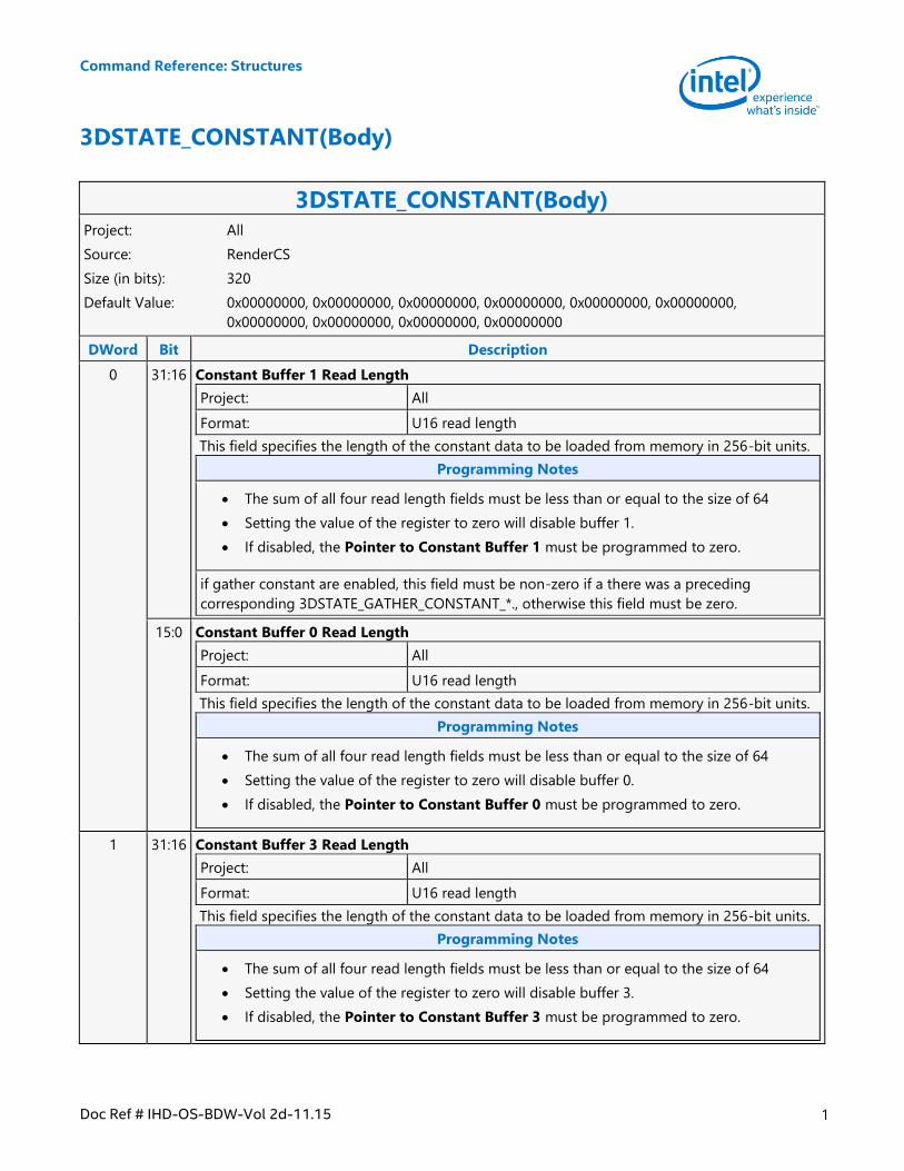
3DSTATE_CONSTANT(Body)
3DSTATE_CONSTANT(Body) Project: All
Source: RenderCS
Size (in bits): 320
Default Value: 0x00000000, 0x00000000, 0x00000000, 0x00000000, 0x00000000, 0x00000000,
0x00000000, 0x00000000, 0x00000000, 0x00000000
DWord Bit Description
0 31:16 Constant Buffer 1 Read Length
Project: All
Format: U16 read length
This field specifies the length of the constant data to be loaded from memory in 256-bit units.
Programming Notes
The sum of all four read length fields must be less than or equal to the size of 64
Setting the value of the register to zero will disable buffer 1.
If disabled, the Pointer to Constant Buffer 1 must be programmed to zero.
if gather constant are enabled, this field must be non-zero if a there was a preceding
corresponding 3DSTATE_GATHER_CONSTANT_*., otherwise this field must be zero.
15:0 Constant Buffer 0 Read Length
Project: All
Format: U16 read length
This field specifies the length of the constant data to be loaded from memory in 256-bit units.
Programming Notes
The sum of all four read length fields must be less than or equal to the size of 64
Setting the value of the register to zero will disable buffer 0.
If disabled, the Pointer to Constant Buffer 0 must be programmed to zero.
1 31:16 Constant Buffer 3 Read Length
Project: All
Format: U16 read length
This field specifies the length of the constant data to be loaded from memory in 256-bit units.
Programming Notes
The sum of all four read length fields must be less than or equal to the size of 64
Setting the value of the register to zero will disable buffer 3.
If disabled, the Pointer to Constant Buffer 3 must be programmed to zero.
Command Reference: Structures
2 Doc Ref # IHD-OS-BDW-Vol 2d-11.15
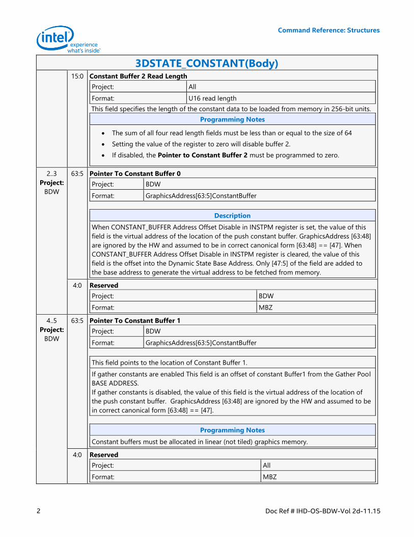
3DSTATE_CONSTANT(Body) 15:0 Constant Buffer 2 Read Length
Project: All
Format: U16 read length
This field specifies the length of the constant data to be loaded from memory in 256-bit units.
Programming Notes
The sum of all four read length fields must be less than or equal to the size of 64
Setting the value of the register to zero will disable buffer 2.
If disabled, the Pointer to Constant Buffer 2 must be programmed to zero.
2..3
Project:
BDW
63:5 Pointer To Constant Buffer 0
Project: BDW
Format: GraphicsAddress[63:5]ConstantBuffer
Description
When CONSTANT_BUFFER Address Offset Disable in INSTPM register is set, the value of this
field is the virtual address of the location of the push constant buffer. GraphicsAddress [63:48]
are ignored by the HW and assumed to be in correct canonical form [63:48] == [47]. When
CONSTANT_BUFFER Address Offset Disable in INSTPM register is cleared, the value of this
field is the offset into the Dynamic State Base Address. Only [47:5] of the field are added to
the base address to generate the virtual address to be fetched from memory.
4:0 Reserved
Project: BDW
Format: MBZ
4..5
Project:
BDW
63:5 Pointer To Constant Buffer 1
Project: BDW
Format: GraphicsAddress[63:5]ConstantBuffer
This field points to the location of Constant Buffer 1.
If gather constants are enabled This field is an offset of constant Buffer1 from the Gather Pool
BASE ADDRESS.
If gather constants is disabled, the value of this field is the virtual address of the location of
the push constant buffer. GraphicsAddress [63:48] are ignored by the HW and assumed to be
in correct canonical form [63:48] == [47].
Programming Notes
Constant buffers must be allocated in linear (not tiled) graphics memory.
4:0 Reserved
Project: All
Format: MBZ
Command Reference: Structures
Doc Ref # IHD-OS-BDW-Vol 2d-11.15 3
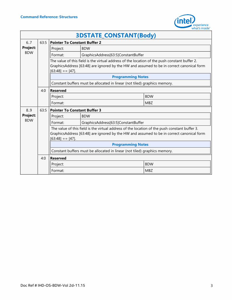
3DSTATE_CONSTANT(Body) 6..7
Project:
BDW
63:5 Pointer To Constant Buffer 2
Project: BDW
Format: GraphicsAddress[63:5]ConstantBuffer
The value of this field is the virtual address of the location of the push constant buffer 2.
GraphicsAddress [63:48] are ignored by the HW and assumed to be in correct canonical form
[63:48] == [47].
Programming Notes
Constant buffers must be allocated in linear (not tiled) graphics memory.
4:0 Reserved
Project: BDW
Format: MBZ
8..9
Project:
BDW
63:5 Pointer To Constant Buffer 3
Project: BDW
Format: GraphicsAddress[63:5]ConstantBuffer
The value of this field is the virtual address of the location of the push constant buffer 3.
GraphicsAddress [63:48] are ignored by the HW and assumed to be in correct canonical form
[63:48] == [47].
Programming Notes
Constant buffers must be allocated in linear (not tiled) graphics memory.
4:0 Reserved
Project: BDW
Format: MBZ
Command Reference: Structures
4 Doc Ref # IHD-OS-BDW-Vol 2d-11.15
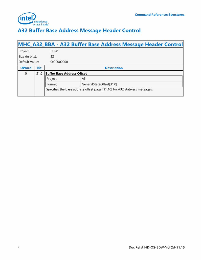
A32 Buffer Base Address Message Header Control
MHC_A32_BBA - A32 Buffer Base Address Message Header Control Project: BDW
Size (in bits): 32
Default Value: 0x00000000
DWord Bit Description
0 31:0 Buffer Base Address Offset
Project: All
Format: GeneralStateOffset[31:0]
Specifies the base address offset page [31:10] for A32 stateless messages.
Command Reference: Structures
Doc Ref # IHD-OS-BDW-Vol 2d-11.15 5
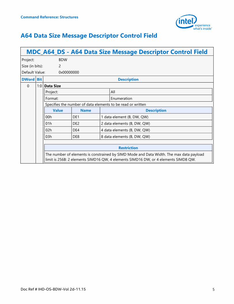
A64 Data Size Message Descriptor Control Field
MDC_A64_DS - A64 Data Size Message Descriptor Control Field Project: BDW
Size (in bits): 2
Default Value: 0x00000000
DWord Bit Description
0 1:0 Data Size
Project: All
Format: Enumeration
Specifies the number of data elements to be read or written
Value Name Description
00h DE1 1 data element (B, DW, QW)
01h DE2 2 data elements (B, DW, QW)
02h DE4 4 data elements (B, DW, QW)
03h DE8 8 data elements (B, DW, QW)
Restriction
The number of elements is constrained by SIMD Mode and Data Width. The max data payload
limit is 256B: 2 elements SIMD16 QW, 4 elements SIMD16 DW, or 4 elements SIMD8 QW.
Command Reference: Structures
6 Doc Ref # IHD-OS-BDW-Vol 2d-11.15
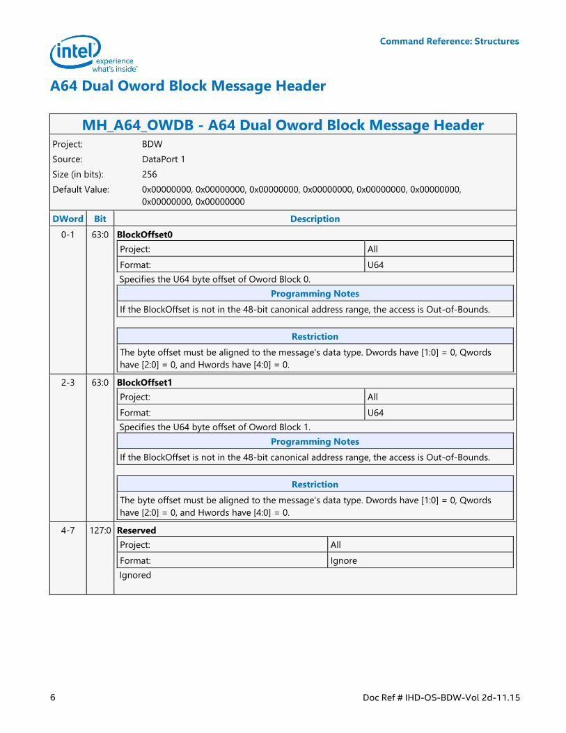
A64 Dual Oword Block Message Header
MH_A64_OWDB - A64 Dual Oword Block Message Header Project: BDW
Source: DataPort 1
Size (in bits): 256
Default Value: 0x00000000, 0x00000000, 0x00000000, 0x00000000, 0x00000000, 0x00000000,
0x00000000, 0x00000000
DWord Bit Description
0-1 63:0 BlockOffset0
Project: All
Format: U64
Specifies the U64 byte offset of Oword Block 0.
Programming Notes
If the BlockOffset is not in the 48-bit canonical address range, the access is Out-of-Bounds.
Restriction
The byte offset must be aligned to the message's data type. Dwords have [1:0] = 0, Qwords
have [2:0] = 0, and Hwords have [4:0] = 0.
2-3 63:0 BlockOffset1
Project: All
Format: U64
Specifies the U64 byte offset of Oword Block 1.
Programming Notes
If the BlockOffset is not in the 48-bit canonical address range, the access is Out-of-Bounds.
Restriction
The byte offset must be aligned to the message's data type. Dwords have [1:0] = 0, Qwords
have [2:0] = 0, and Hwords have [4:0] = 0.
4-7 127:0 Reserved
Project: All
Format: Ignore
Ignored
Command Reference: Structures
Doc Ref # IHD-OS-BDW-Vol 2d-11.15 7
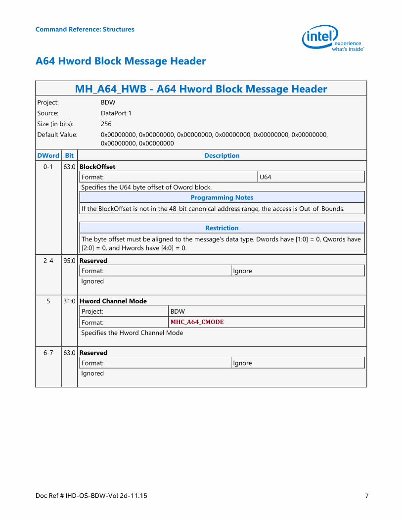
A64 Hword Block Message Header
MH_A64_HWB - A64 Hword Block Message Header Project: BDW
Source: DataPort 1
Size (in bits): 256
Default Value: 0x00000000, 0x00000000, 0x00000000, 0x00000000, 0x00000000, 0x00000000,
0x00000000, 0x00000000
DWord Bit Description
0-1 63:0 BlockOffset
Format: U64
Specifies the U64 byte offset of Oword block.
Programming Notes
If the BlockOffset is not in the 48-bit canonical address range, the access is Out-of-Bounds.
Restriction
The byte offset must be aligned to the message's data type. Dwords have [1:0] = 0, Qwords have
[2:0] = 0, and Hwords have [4:0] = 0.
2-4 95:0 Reserved
Format: Ignore
Ignored
5 31:0 Hword Channel Mode
Project: BDW
Format: MHC_A64_CMODE
Specifies the Hword Channel Mode
6-7 63:0 Reserved
Format: Ignore
Ignored
Command Reference: Structures
8 Doc Ref # IHD-OS-BDW-Vol 2d-11.15
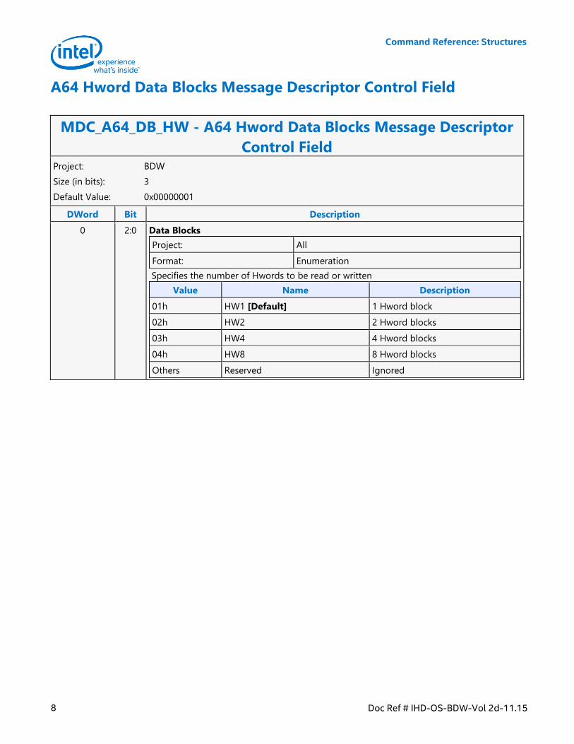
A64 Hword Data Blocks Message Descriptor Control Field
MDC_A64_DB_HW - A64 Hword Data Blocks Message Descriptor
Control Field Project: BDW
Size (in bits): 3
Default Value: 0x00000001
DWord Bit Description
0 2:0 Data Blocks
Project: All
Format: Enumeration
Specifies the number of Hwords to be read or written
Value Name Description
01h HW1 [Default] 1 Hword block
02h HW2 2 Hword blocks
03h HW4 4 Hword blocks
04h HW8 8 Hword blocks
Others Reserved Ignored
Command Reference: Structures
Doc Ref # IHD-OS-BDW-Vol 2d-11.15 9
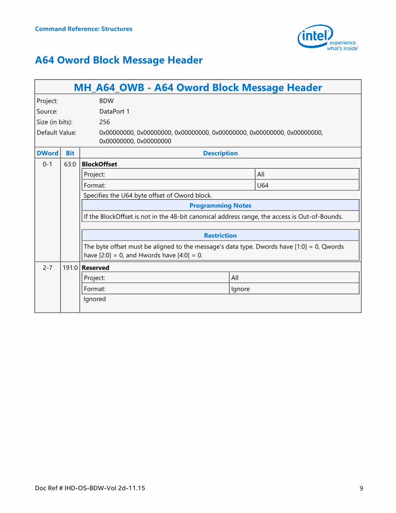
A64 Oword Block Message Header
MH_A64_OWB - A64 Oword Block Message Header Project: BDW
Source: DataPort 1
Size (in bits): 256
Default Value: 0x00000000, 0x00000000, 0x00000000, 0x00000000, 0x00000000, 0x00000000,
0x00000000, 0x00000000
DWord Bit Description
0-1 63:0 BlockOffset
Project: All
Format: U64
Specifies the U64 byte offset of Oword block.
Programming Notes
If the BlockOffset is not in the 48-bit canonical address range, the access is Out-of-Bounds.
Restriction
The byte offset must be aligned to the message's data type. Dwords have [1:0] = 0, Qwords
have [2:0] = 0, and Hwords have [4:0] = 0.
2-7 191:0 Reserved
Project: All
Format: Ignore
Ignored
Command Reference: Structures
10 Doc Ref # IHD-OS-BDW-Vol 2d-11.15
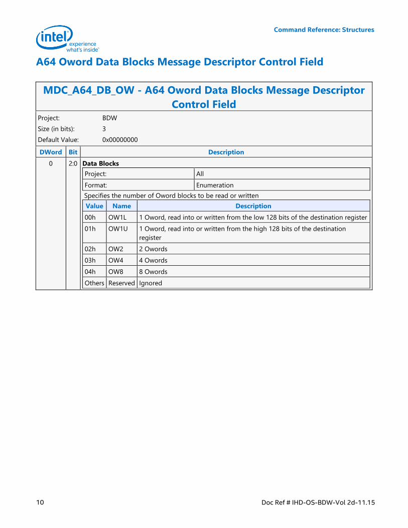
A64 Oword Data Blocks Message Descriptor Control Field
MDC_A64_DB_OW - A64 Oword Data Blocks Message Descriptor
Control Field Project: BDW
Size (in bits): 3
Default Value: 0x00000000
DWord Bit Description
0 2:0 Data Blocks
Project: All
Format: Enumeration
Specifies the number of Oword blocks to be read or written
Value Name Description
00h OW1L 1 Oword, read into or written from the low 128 bits of the destination register
01h OW1U 1 Oword, read into or written from the high 128 bits of the destination
register
02h OW2 2 Owords
03h OW4 4 Owords
04h OW8 8 Owords
Others Reserved Ignored
Command Reference: Structures
Doc Ref # IHD-OS-BDW-Vol 2d-11.15 11
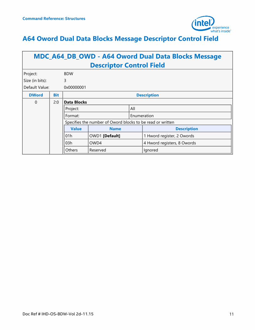
A64 Oword Dual Data Blocks Message Descriptor Control Field
MDC_A64_DB_OWD - A64 Oword Dual Data Blocks Message
Descriptor Control Field Project: BDW
Size (in bits): 3
Default Value: 0x00000001
DWord Bit Description
0 2:0 Data Blocks
Project: All
Format: Enumeration
Specifies the number of Oword blocks to be read or written
Value Name Description
01h OWD1 [Default] 1 Hword register, 2 Owords
03h OWD4 4 Hword registers, 8 Owords
Others Reserved Ignored
Command Reference: Structures
12 Doc Ref # IHD-OS-BDW-Vol 2d-11.15
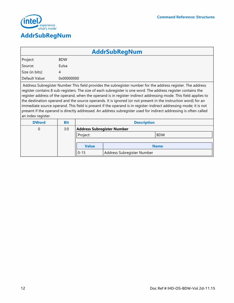
AddrSubRegNum
AddrSubRegNum Project: BDW
Source: EuIsa
Size (in bits): 4
Default Value: 0x00000000
Address Subregister Number This field provides the subregister number for the address register. The address
register contains 8 sub-registers. The size of each subregister is one word. The address register contains the
register address of the operand, when the operand is in register-indirect addressing mode. This field applies to
the destination operand and the source operands. It is ignored (or not present in the instruction word) for an
immediate source operand. This field is present if the operand is in register-indirect addressing mode; it is not
present if the operand is directly addressed. An address subregister used for indirect addressing is often called
an index register.
DWord Bit Description
0 3:0 Address Subregister Number
Project: BDW
Value Name
0-15 Address Subregister Number
Command Reference: Structures
Doc Ref # IHD-OS-BDW-Vol 2d-11.15 13
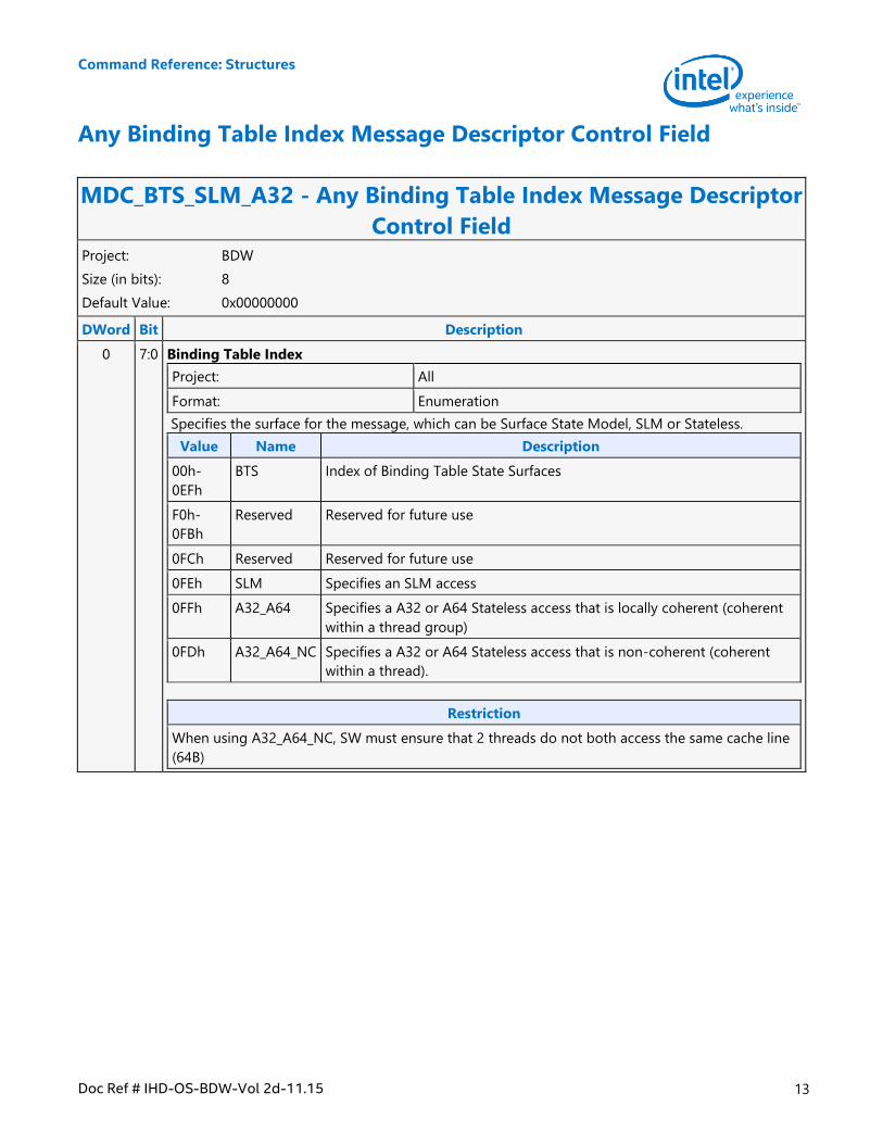
Any Binding Table Index Message Descriptor Control Field
MDC_BTS_SLM_A32 - Any Binding Table Index Message Descriptor
Control Field Project: BDW
Size (in bits): 8
Default Value: 0x00000000
DWord Bit Description
0 7:0 Binding Table Index
Project: All
Format: Enumeration
Specifies the surface for the message, which can be Surface State Model, SLM or Stateless.
Value Name Description
00h-
0EFh
BTS Index of Binding Table State Surfaces
F0h-
0FBh
Reserved Reserved for future use
0FCh Reserved Reserved for future use
0FEh SLM Specifies an SLM access
0FFh A32_A64 Specifies a A32 or A64 Stateless access that is locally coherent (coherent
within a thread group)
0FDh A32_A64_NC Specifies a A32 or A64 Stateless access that is non-coherent (coherent
within a thread).
Restriction
When using A32_A64_NC, SW must ensure that 2 threads do not both access the same cache line
(64B)
Command Reference: Structures
14 Doc Ref # IHD-OS-BDW-Vol 2d-11.15
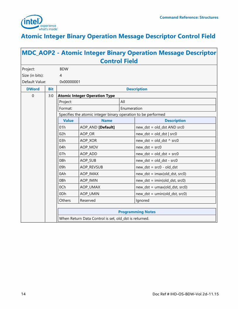
Atomic Integer Binary Operation Message Descriptor Control Field
MDC_AOP2 - Atomic Integer Binary Operation Message Descriptor
Control Field Project: BDW
Size (in bits): 4
Default Value: 0x00000001
DWord Bit Description
0 3:0 Atomic Integer Operation Type
Project: All
Format: Enumeration
Specifies the atomic integer binary operation to be performed
Value Name Description
01h AOP_AND [Default] new_dst = old_dst AND src0
02h AOP_OR new_dst = old_dst | src0
03h AOP_XOR new_dst = old_dst ^ src0
04h AOP_MOV new_dst = src0
07h AOP_ADD new_dst = old_dst + src0
08h AOP_SUB new_dst = old_dst - src0
09h AOP_REVSUB new_dst = src0 - old_dst
0Ah AOP_IMAX new_dst = imax(old_dst, src0)
0Bh AOP_IMIN new_dst = imin(old_dst, src0)
0Ch AOP_UMAX new_dst = umax(old_dst, src0)
0Dh AOP_UMIN new_dst = umin(old_dst, src0)
Others Reserved Ignored
Programming Notes
When Return Data Control is set, old_dst is returned.
Command Reference: Structures
Doc Ref # IHD-OS-BDW-Vol 2d-11.15 15
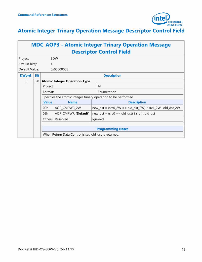
Atomic Integer Trinary Operation Message Descriptor Control Field
MDC_AOP3 - Atomic Integer Trinary Operation Message
Descriptor Control Field Project: BDW
Size (in bits): 4
Default Value: 0x0000000E
DWord Bit Description
0 3:0 Atomic Integer Operation Type
Project: All
Format: Enumeration
Specifies the atomic integer trinary operation to be performed
Value Name Description
00h AOP_CMPWR_2W new_dst = (src0_2W == old_dst_2W) ? src1_2W : old_dst_2W
0Eh AOP_CMPWR [Default] new_dst = (src0 == old_dst) ? src1 : old_dst
Others Reserved Ignored
Programming Notes
When Return Data Control is set, old_dst is returned.
Command Reference: Structures
16 Doc Ref # IHD-OS-BDW-Vol 2d-11.15
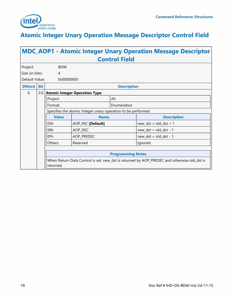
Atomic Integer Unary Operation Message Descriptor Control Field
MDC_AOP1 - Atomic Integer Unary Operation Message Descriptor
Control Field Project: BDW
Size (in bits): 4
Default Value: 0x00000005
DWord Bit Description
0 3:0 Atomic Integer Operation Type
Project: All
Format: Enumeration
Specifies the atomic integer unary operation to be performed
Value Name Description
05h AOP_INC [Default] new_dst = old_dst + 1
06h AOP_DEC new_dst = old_dst - 1
0Fh AOP_PREDEC new_dst = old_dst - 1
Others Reserved Ignored
Programming Notes
When Return Data Control is set, new_dst is returned by AOP_PREDEC and otherwise old_dst is
returned.
Command Reference: Structures
Doc Ref # IHD-OS-BDW-Vol 2d-11.15 17
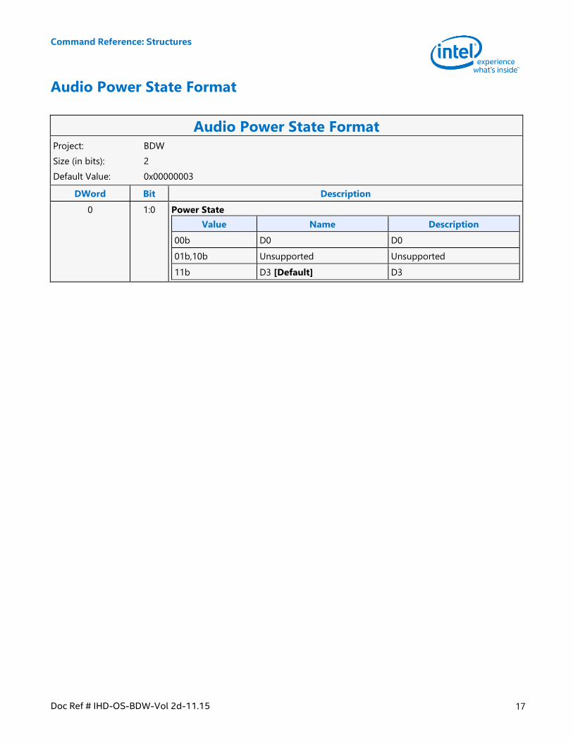
Audio Power State Format
Audio Power State Format Project: BDW
Size (in bits): 2
Default Value: 0x00000003
DWord Bit Description
0 1:0 Power State
Value Name Description
00b D0 D0
01b,10b Unsupported Unsupported
11b D3 [Default] D3
Command Reference: Structures
18 Doc Ref # IHD-OS-BDW-Vol 2d-11.15
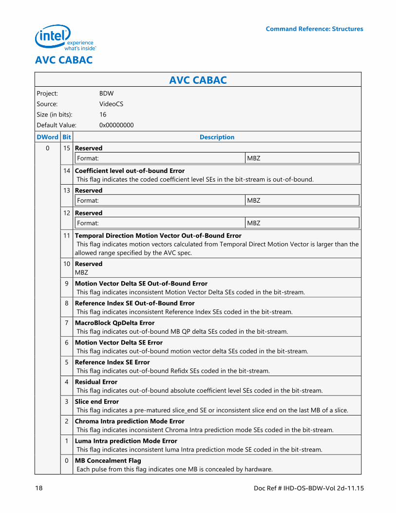
AVC CABAC
AVC CABAC Project: BDW
Source: VideoCS
Size (in bits): 16
Default Value: 0x00000000
DWord Bit Description
0 15 Reserved
Format: MBZ
14 Coefficient level out-of-bound Error
This flag indicates the coded coefficient level SEs in the bit-stream is out-of-bound.
13 Reserved
Format: MBZ
12 Reserved
Format: MBZ
11 Temporal Direction Motion Vector Out-of-Bound Error
This flag indicates motion vectors calculated from Temporal Direct Motion Vector is larger than the
allowed range specified by the AVC spec.
10 Reserved
MBZ
9 Motion Vector Delta SE Out-of-Bound Error
This flag indicates inconsistent Motion Vector Delta SEs coded in the bit-stream.
8 Reference Index SE Out-of-Bound Error
This flag indicates inconsistent Reference Index SEs coded in the bit-stream.
7 MacroBlock QpDelta Error
This flag indicates out-of-bound MB QP delta SEs coded in the bit-stream.
6 Motion Vector Delta SE Error
This flag indicates out-of-bound motion vector delta SEs coded in the bit-stream.
5 Reference Index SE Error
This flag indicates out-of-bound Refidx SEs coded in the bit-stream.
4 Residual Error
This flag indicates out-of-bound absolute coefficient level SEs coded in the bit-stream.
3 Slice end Error
This flag indicates a pre-matured slice_end SE or inconsistent slice end on the last MB of a slice.
2 Chroma Intra prediction Mode Error
This flag indicates inconsistent Chroma Intra prediction mode SEs coded in the bit-stream.
1 Luma Intra prediction Mode Error
This flag indicates inconsistent luma Intra prediction mode SE coded in the bit-stream.
0 MB Concealment Flag
Each pulse from this flag indicates one MB is concealed by hardware.
Command Reference: Structures
Doc Ref # IHD-OS-BDW-Vol 2d-11.15 19
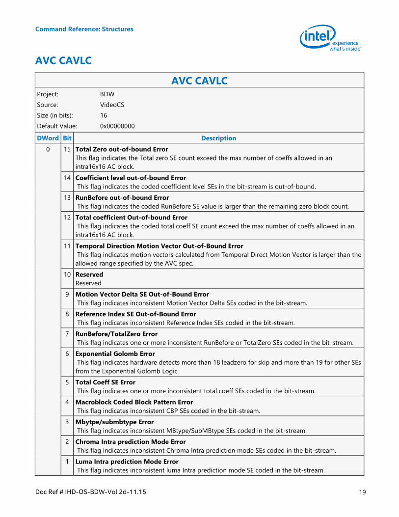
AVC CAVLC
AVC CAVLC Project: BDW
Source: VideoCS
Size (in bits): 16
Default Value: 0x00000000
DWord Bit Description
0 15 Total Zero out-of-bound Error
This flag indicates the Total zero SE count exceed the max number of coeffs allowed in an
intra16x16 AC block.
14 Coefficient level out-of-bound Error
This flag indicates the coded coefficient level SEs in the bit-stream is out-of-bound.
13 RunBefore out-of-bound Error
This flag indicates the coded RunBefore SE value is larger than the remaining zero block count.
12 Total coefficient Out-of-bound Error
This flag indicates the coded total coeff SE count exceed the max number of coeffs allowed in an
intra16x16 AC block.
11 Temporal Direction Motion Vector Out-of-Bound Error
This flag indicates motion vectors calculated from Temporal Direct Motion Vector is larger than the
allowed range specified by the AVC spec.
10 Reserved
Reserved
9 Motion Vector Delta SE Out-of-Bound Error
This flag indicates inconsistent Motion Vector Delta SEs coded in the bit-stream.
8 Reference Index SE Out-of-Bound Error
This flag indicates inconsistent Reference Index SEs coded in the bit-stream.
7 RunBefore/TotalZero Error
This flag indicates one or more inconsistent RunBefore or TotalZero SEs coded in the bit-stream.
6 Exponential Golomb Error
This flag indicates hardware detects more than 18 leadzero for skip and more than 19 for other SEs
from the Exponential Golomb Logic
5 Total Coeff SE Error
This flag indicates one or more inconsistent total coeff SEs coded in the bit-stream.
4 Macroblock Coded Block Pattern Error
This flag indicates inconsistent CBP SEs coded in the bit-stream.
3 Mbytpe/submbtype Error
This flag indicates inconsistent MBtype/SubMBtype SEs coded in the bit-stream.
2 Chroma Intra prediction Mode Error
This flag indicates inconsistent Chroma Intra prediction mode SEs coded in the bit-stream.
1 Luma Intra prediction Mode Error
This flag indicates inconsistent luma Intra prediction mode SE coded in the bit-stream.
Command Reference: Structures
20 Doc Ref # IHD-OS-BDW-Vol 2d-11.15
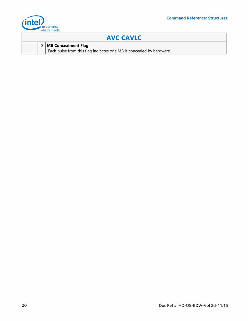
AVC CAVLC 0 MB Concealment Flag
Each pulse from this flag indicates one MB is concealed by hardware.
Command Reference: Structures
Doc Ref # IHD-OS-BDW-Vol 2d-11.15 21
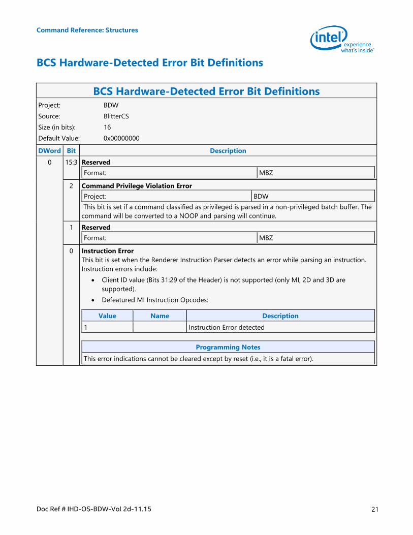
BCS Hardware-Detected Error Bit Definitions
BCS Hardware-Detected Error Bit Definitions Project: BDW
Source: BlitterCS
Size (in bits): 16
Default Value: 0x00000000
DWord Bit Description
0 15:3 Reserved
Format: MBZ
2 Command Privilege Violation Error
Project: BDW
This bit is set if a command classified as privileged is parsed in a non-privileged batch buffer. The
command will be converted to a NOOP and parsing will continue.
1 Reserved
Format: MBZ
0 Instruction Error
This bit is set when the Renderer Instruction Parser detects an error while parsing an instruction.
Instruction errors include:
Client ID value (Bits 31:29 of the Header) is not supported (only MI, 2D and 3D are
supported).
Defeatured MI Instruction Opcodes:
Value Name Description
1 Instruction Error detected
Programming Notes
This error indications cannot be cleared except by reset (i.e., it is a fatal error).
Command Reference: Structures
22 Doc Ref # IHD-OS-BDW-Vol 2d-11.15
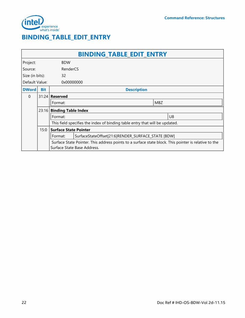
BINDING_TABLE_EDIT_ENTRY
BINDING_TABLE_EDIT_ENTRY Project: BDW
Source: RenderCS
Size (in bits): 32
Default Value: 0x00000000
DWord Bit Description
0 31:24 Reserved
Format: MBZ
23:16 Binding Table Index
Format: U8
This field specifies the index of binding table entry that will be updated.
15:0 Surface State Pointer
Format: SurfaceStateOffset[21:6]RENDER_SURFACE_STATE [BDW]
Surface State Pointer. This address points to a surface state block. This pointer is relative to the
Surface State Base Address.
Command Reference: Structures
Doc Ref # IHD-OS-BDW-Vol 2d-11.15 23
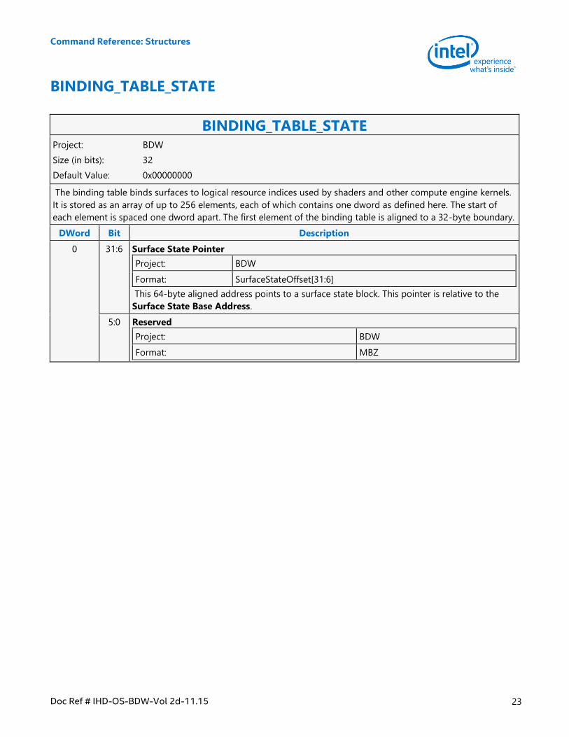
BINDING_TABLE_STATE
BINDING_TABLE_STATE Project: BDW
Size (in bits): 32
Default Value: 0x00000000
The binding table binds surfaces to logical resource indices used by shaders and other compute engine kernels.
It is stored as an array of up to 256 elements, each of which contains one dword as defined here. The start of
each element is spaced one dword apart. The first element of the binding table is aligned to a 32-byte boundary.
DWord Bit Description
0 31:6 Surface State Pointer
Project: BDW
Format: SurfaceStateOffset[31:6]
This 64-byte aligned address points to a surface state block. This pointer is relative to the
Surface State Base Address.
5:0 Reserved
Project: BDW
Format: MBZ
Command Reference: Structures
24 Doc Ref # IHD-OS-BDW-Vol 2d-11.15
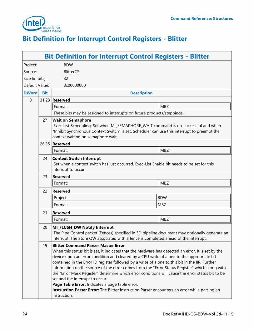
Bit Definition for Interrupt Control Registers - Blitter
Bit Definition for Interrupt Control Registers - Blitter Project: BDW
Source: BlitterCS
Size (in bits): 32
Default Value: 0x00000000
DWord Bit Description
0 31:28 Reserved
Format: MBZ
These bits may be assigned to interrupts on future products/steppings.
27 Wait on Semaphore
Exec-List Scheduling: Set when MI_SEMAPHORE_WAIT command is un-successful and when
"Inhibit Synchronous Context Switch" is set. Scheduler can use this interrupt to preempt the
context waiting on semaphore wait.
26:25 Reserved
Format: MBZ
24 Context Switch Interrupt
Set when a context switch has just occurred. Exec-List Enable bit needs to be set for this
interrupt to occur.
23 Reserved
Format: MBZ
22 Reserved
Project: BDW
Format: MBZ
21 Reserved
Format: MBZ
20 MI_FLUSH_DW Notify Interrupt
The Pipe Control packet (Fences) specified in 3D pipeline document may optionally generate an
Interrupt. The Store QW associated with a fence is completed ahead of the interrupt.
19 Blitter Command Parser Master Error
When this status bit is set, it indicates that the hardware has detected an error. It is set by the
device upon an error condition and cleared by a CPU write of a one to the appropriate bit
contained in the Error ID register followed by a write of a one to this bit in the IIR. Further
information on the source of the error comes from the "Error Status Register" which along with
the "Error Mask Register" determine which error conditions will cause the error status bit to be
set and the interrupt to occur.
Page Table Error: Indicates a page table error.
Instruction Parser Error: The Blitter Instruction Parser encounters an error while parsing an
instruction.
Command Reference: Structures
Doc Ref # IHD-OS-BDW-Vol 2d-11.15 25
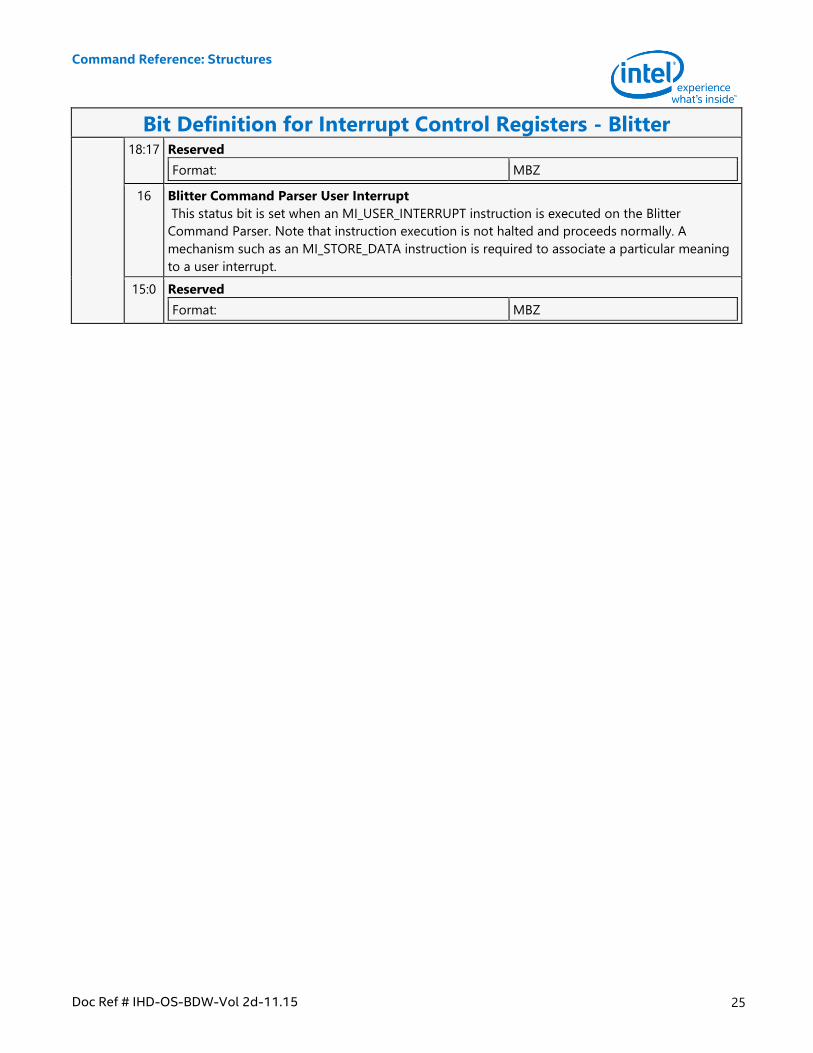
Bit Definition for Interrupt Control Registers - Blitter 18:17 Reserved
Format: MBZ
16 Blitter Command Parser User Interrupt
This status bit is set when an MI_USER_INTERRUPT instruction is executed on the Blitter
Command Parser. Note that instruction execution is not halted and proceeds normally. A
mechanism such as an MI_STORE_DATA instruction is required to associate a particular meaning
to a user interrupt.
15:0 Reserved
Format: MBZ
Command Reference: Structures
26 Doc Ref # IHD-OS-BDW-Vol 2d-11.15
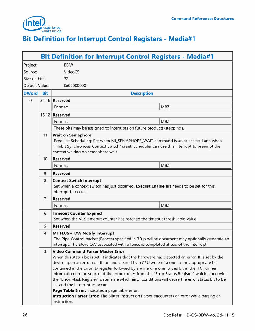
Bit Definition for Interrupt Control Registers - Media#1
Bit Definition for Interrupt Control Registers - Media#1 Project: BDW
Source: VideoCS
Size (in bits): 32
Default Value: 0x00000000
DWord Bit Description
0 31:16 Reserved
Format: MBZ
15:12 Reserved
Format: MBZ
These bits may be assigned to interrupts on future products/steppings.
11 Wait on Semaphore
Exec-List Scheduling: Set when MI_SEMAPHORE_WAIT command is un-successful and when
"Inhibit Synchronous Context Switch" is set. Scheduler can use this interrupt to preempt the
context waiting on semaphore wait.
10 Reserved
Format: MBZ
9 Reserved
8 Context Switch Interrupt
Set when a context switch has just occurred. Execlist Enable bit needs to be set for this
interrupt to occur.
7 Reserved
Format: MBZ
6 Timeout Counter Expired
Set when the VCS timeout counter has reached the timeout thresh-hold value.
5 Reserved
4 MI_FLUSH_DW Notify Interrupt
The Pipe Control packet (Fences) specified in 3D pipeline document may optionally generate an
Interrupt. The Store QW associated with a fence is completed ahead of the interrupt.
3 Video Command Parser Master Error
When this status bit is set, it indicates that the hardware has detected an error. It is set by the
device upon an error condition and cleared by a CPU write of a one to the appropriate bit
contained in the Error ID register followed by a write of a one to this bit in the IIR. Further
information on the source of the error comes from the "Error Status Register" which along with
the "Error Mask Register" determine which error conditions will cause the error status bit to be
set and the interrupt to occur.
Page Table Error: Indicates a page table error.
Instruction Parser Error: The Blitter Instruction Parser encounters an error while parsing an
instruction.
Command Reference: Structures
Doc Ref # IHD-OS-BDW-Vol 2d-11.15 27
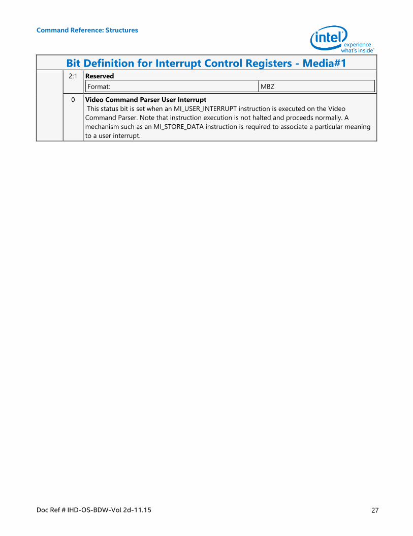
Bit Definition for Interrupt Control Registers - Media#1 2:1 Reserved
Format: MBZ
0 Video Command Parser User Interrupt
This status bit is set when an MI_USER_INTERRUPT instruction is executed on the Video
Command Parser. Note that instruction execution is not halted and proceeds normally. A
mechanism such as an MI_STORE_DATA instruction is required to associate a particular meaning
to a user interrupt.
Command Reference: Structures
28 Doc Ref # IHD-OS-BDW-Vol 2d-11.15
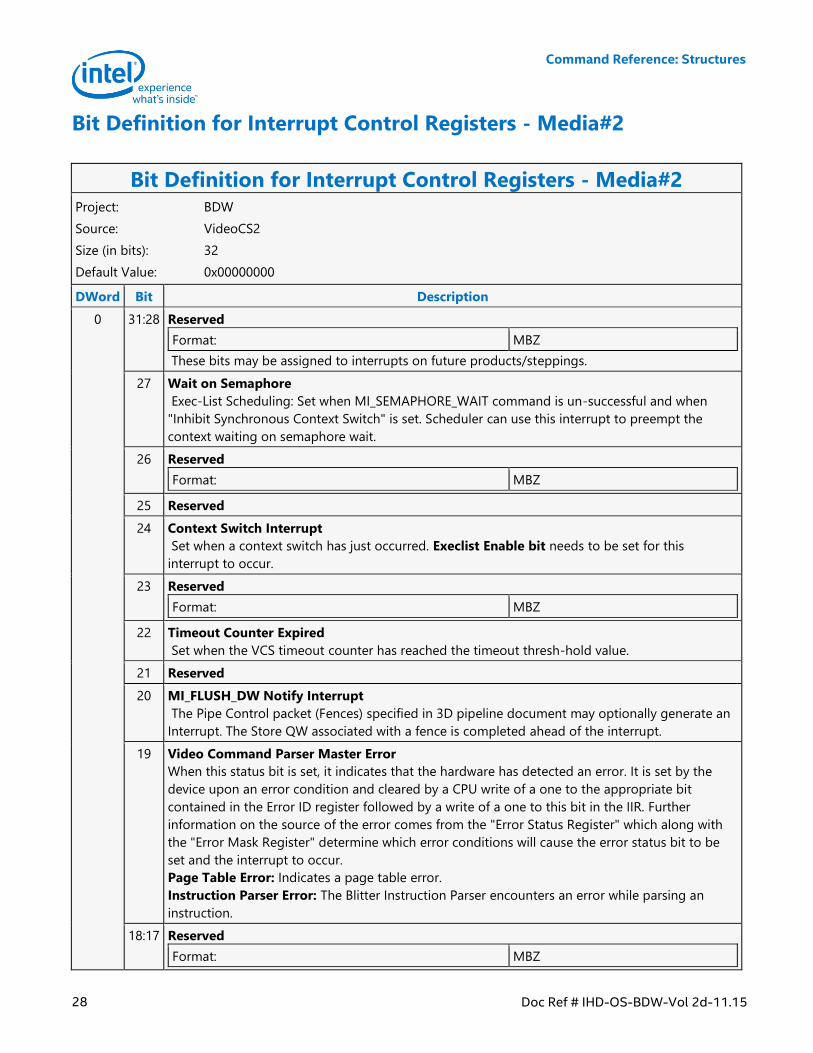
Bit Definition for Interrupt Control Registers - Media#2
Bit Definition for Interrupt Control Registers - Media#2 Project: BDW
Source: VideoCS2
Size (in bits): 32
Default Value: 0x00000000
DWord Bit Description
0 31:28 Reserved
Format: MBZ
These bits may be assigned to interrupts on future products/steppings.
27 Wait on Semaphore
Exec-List Scheduling: Set when MI_SEMAPHORE_WAIT command is un-successful and when
"Inhibit Synchronous Context Switch" is set. Scheduler can use this interrupt to preempt the
context waiting on semaphore wait.
26 Reserved
Format: MBZ
25 Reserved
24 Context Switch Interrupt
Set when a context switch has just occurred. Execlist Enable bit needs to be set for this
interrupt to occur.
23 Reserved
Format: MBZ
22 Timeout Counter Expired
Set when the VCS timeout counter has reached the timeout thresh-hold value.
21 Reserved
20 MI_FLUSH_DW Notify Interrupt
The Pipe Control packet (Fences) specified in 3D pipeline document may optionally generate an
Interrupt. The Store QW associated with a fence is completed ahead of the interrupt.
19 Video Command Parser Master Error
When this status bit is set, it indicates that the hardware has detected an error. It is set by the
device upon an error condition and cleared by a CPU write of a one to the appropriate bit
contained in the Error ID register followed by a write of a one to this bit in the IIR. Further
information on the source of the error comes from the "Error Status Register" which along with
the "Error Mask Register" determine which error conditions will cause the error status bit to be
set and the interrupt to occur.
Page Table Error: Indicates a page table error.
Instruction Parser Error: The Blitter Instruction Parser encounters an error while parsing an
instruction.
18:17 Reserved
Format: MBZ
Command Reference: Structures
Doc Ref # IHD-OS-BDW-Vol 2d-11.15 29
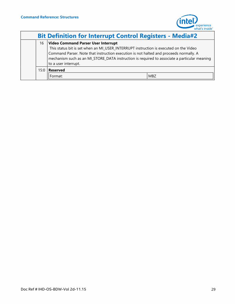
Bit Definition for Interrupt Control Registers - Media#2 16 Video Command Parser User Interrupt
This status bit is set when an MI_USER_INTERRUPT instruction is executed on the Video
Command Parser. Note that instruction execution is not halted and proceeds normally. A
mechanism such as an MI_STORE_DATA instruction is required to associate a particular meaning
to a user interrupt.
15:0 Reserved
Format: MBZ
Command Reference: Structures
30 Doc Ref # IHD-OS-BDW-Vol 2d-11.15
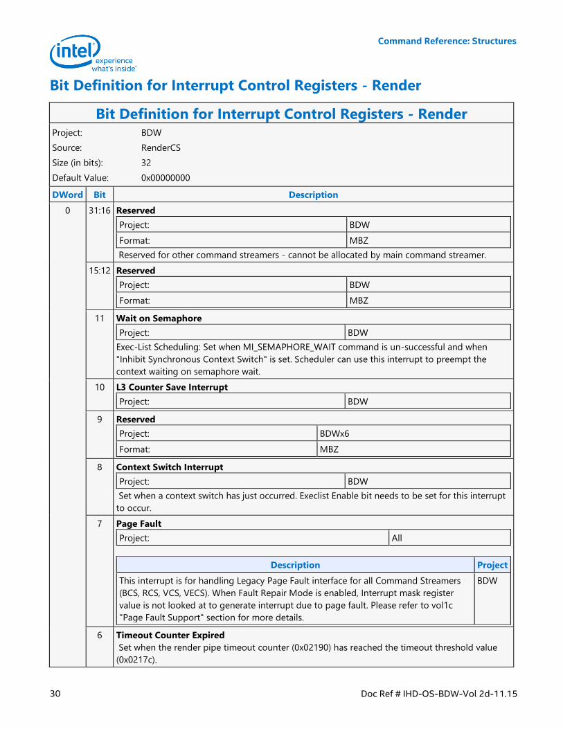
Bit Definition for Interrupt Control Registers - Render
Bit Definition for Interrupt Control Registers - Render Project: BDW
Source: RenderCS
Size (in bits): 32
Default Value: 0x00000000
DWord Bit Description
0 31:16 Reserved
Project: BDW
Format: MBZ
Reserved for other command streamers - cannot be allocated by main command streamer.
15:12 Reserved
Project: BDW
Format: MBZ
11 Wait on Semaphore
Project: BDW
Exec-List Scheduling: Set when MI_SEMAPHORE_WAIT command is un-successful and when
"Inhibit Synchronous Context Switch" is set. Scheduler can use this interrupt to preempt the
context waiting on semaphore wait.
10 L3 Counter Save Interrupt
Project: BDW
9 Reserved
Project: BDWx6
Format: MBZ
8 Context Switch Interrupt
Project: BDW
Set when a context switch has just occurred. Execlist Enable bit needs to be set for this interrupt
to occur.
7 Page Fault
Project: All
Description Project
This interrupt is for handling Legacy Page Fault interface for all Command Streamers
(BCS, RCS, VCS, VECS). When Fault Repair Mode is enabled, Interrupt mask register
value is not looked at to generate interrupt due to page fault. Please refer to vol1c
"Page Fault Support" section for more details.
BDW
6 Timeout Counter Expired
Set when the render pipe timeout counter (0x02190) has reached the timeout threshold value
(0x0217c).
Command Reference: Structures
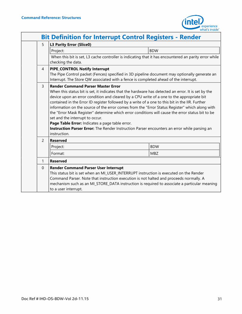
Doc Ref # IHD-OS-BDW-Vol 2d-11.15 31
Bit Definition for Interrupt Control Registers - Render 5 L3 Parity Error (Slice0)
Project: BDW
When this bit is set, L3 cache controller is indicating that it has encountered an parity error while
checking the data.
4 PIPE_CONTROL Notify Interrupt
The Pipe Control packet (Fences) specified in 3D pipeline document may optionally generate an
Interrupt. The Store QW associated with a fence is completed ahead of the interrupt.
3 Render Command Parser Master Error
When this status bit is set, it indicates that the hardware has detected an error. It is set by the
device upon an error condition and cleared by a CPU write of a one to the appropriate bit
contained in the Error ID register followed by a write of a one to this bit in the IIR. Further
information on the source of the error comes from the "Error Status Register" which along with
the "Error Mask Register" determine which error conditions will cause the error status bit to be
set and the interrupt to occur.
Page Table Error: Indicates a page table error.
Instruction Parser Error: The Render Instruction Parser encounters an error while parsing an
instruction.
2 Reserved
Project: BDW
Format: MBZ
1 Reserved
0 Render Command Parser User Interrupt
This status bit is set when an MI_USER_INTERRUPT instruction is executed on the Render
Command Parser. Note that instruction execution is not halted and proceeds normally. A
mechanism such as an MI_STORE_DATA instruction is required to associate a particular meaning
to a user interrupt.
Command Reference: Structures
32 Doc Ref # IHD-OS-BDW-Vol 2d-11.15
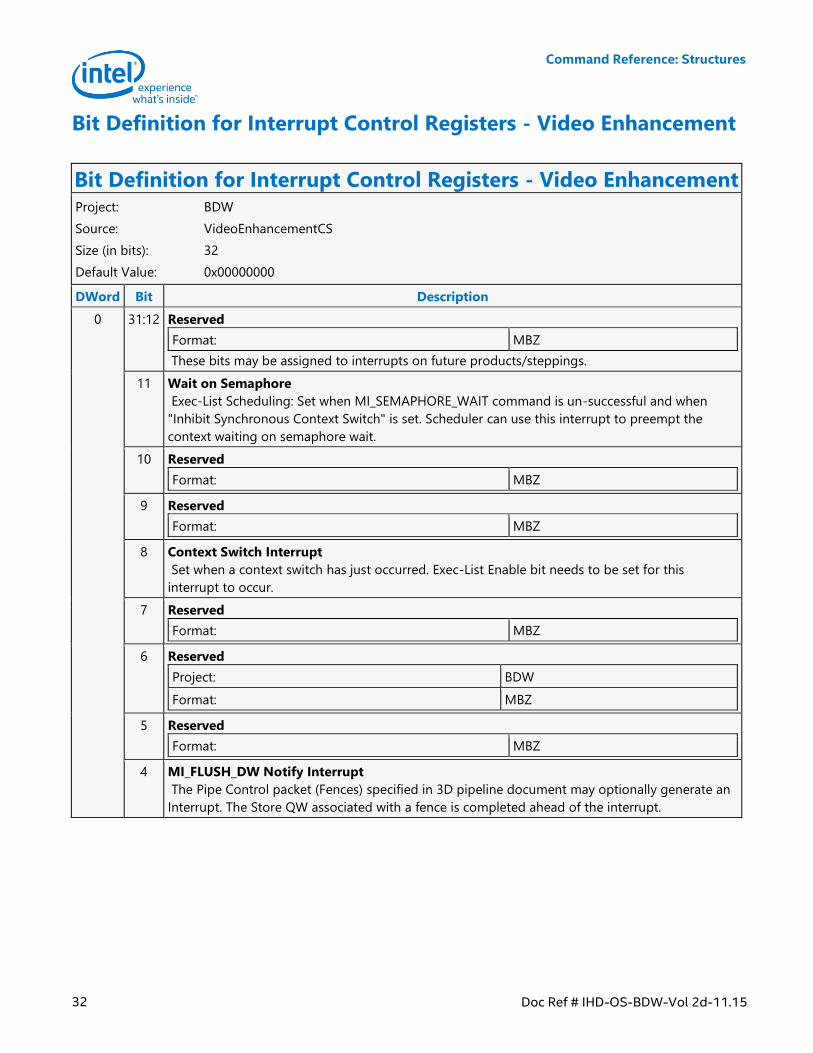
Bit Definition for Interrupt Control Registers - Video Enhancement
Bit Definition for Interrupt Control Registers - Video Enhancement Project: BDW
Source: VideoEnhancementCS
Size (in bits): 32
Default Value: 0x00000000
DWord Bit Description
0 31:12 Reserved
Format: MBZ
These bits may be assigned to interrupts on future products/steppings.
11 Wait on Semaphore
Exec-List Scheduling: Set when MI_SEMAPHORE_WAIT command is un-successful and when
"Inhibit Synchronous Context Switch" is set. Scheduler can use this interrupt to preempt the
context waiting on semaphore wait.
10 Reserved
Format: MBZ
9 Reserved
Format: MBZ
8 Context Switch Interrupt
Set when a context switch has just occurred. Exec-List Enable bit needs to be set for this
interrupt to occur.
7 Reserved
Format: MBZ
6 Reserved
Project: BDW
Format: MBZ
5 Reserved
Format: MBZ
4 MI_FLUSH_DW Notify Interrupt
The Pipe Control packet (Fences) specified in 3D pipeline document may optionally generate an
Interrupt. The Store QW associated with a fence is completed ahead of the interrupt.
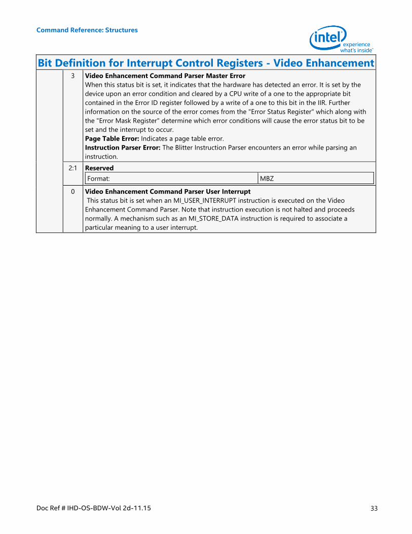
Command Reference: Structures
Doc Ref # IHD-OS-BDW-Vol 2d-11.15 33
Bit Definition for Interrupt Control Registers - Video Enhancement 3 Video Enhancement Command Parser Master Error
When this status bit is set, it indicates that the hardware has detected an error. It is set by the
device upon an error condition and cleared by a CPU write of a one to the appropriate bit
contained in the Error ID register followed by a write of a one to this bit in the IIR. Further
information on the source of the error comes from the "Error Status Register" which along with
the "Error Mask Register" determine which error conditions will cause the error status bit to be
set and the interrupt to occur.
Page Table Error: Indicates a page table error.
Instruction Parser Error: The Blitter Instruction Parser encounters an error while parsing an
instruction.
2:1 Reserved
Format: MBZ
0 Video Enhancement Command Parser User Interrupt
This status bit is set when an MI_USER_INTERRUPT instruction is executed on the Video
Enhancement Command Parser. Note that instruction execution is not halted and proceeds
normally. A mechanism such as an MI_STORE_DATA instruction is required to associate a
particular meaning to a user interrupt.
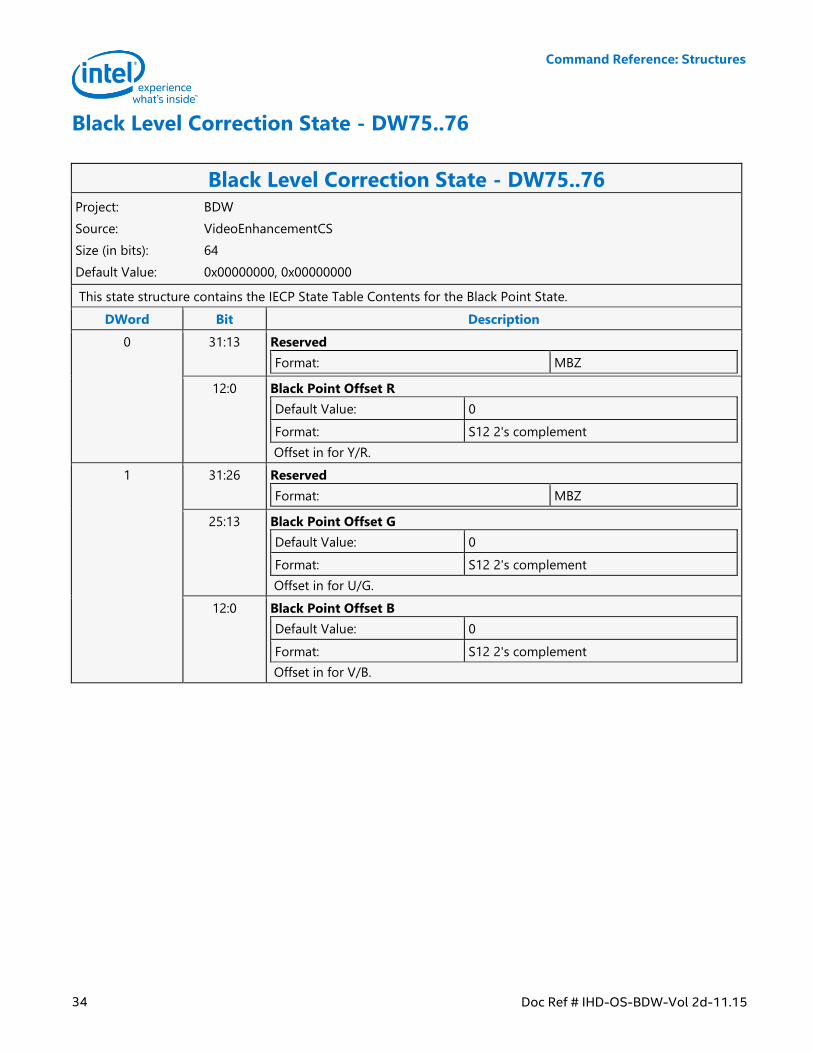
Command Reference: Structures
34 Doc Ref # IHD-OS-BDW-Vol 2d-11.15
Black Level Correction State - DW75..76
Black Level Correction State - DW75..76 Project: BDW
Source: VideoEnhancementCS
Size (in bits): 64
Default Value: 0x00000000, 0x00000000
This state structure contains the IECP State Table Contents for the Black Point State.
DWord Bit Description
0 31:13 Reserved
Format: MBZ
12:0 Black Point Offset R
Default Value: 0
Format: S12 2's complement
Offset in for Y/R.
1 31:26 Reserved
Format: MBZ
25:13 Black Point Offset G
Default Value: 0
Format: S12 2's complement
Offset in for U/G.
12:0 Black Point Offset B
Default Value: 0
Format: S12 2's complement
Offset in for V/B.
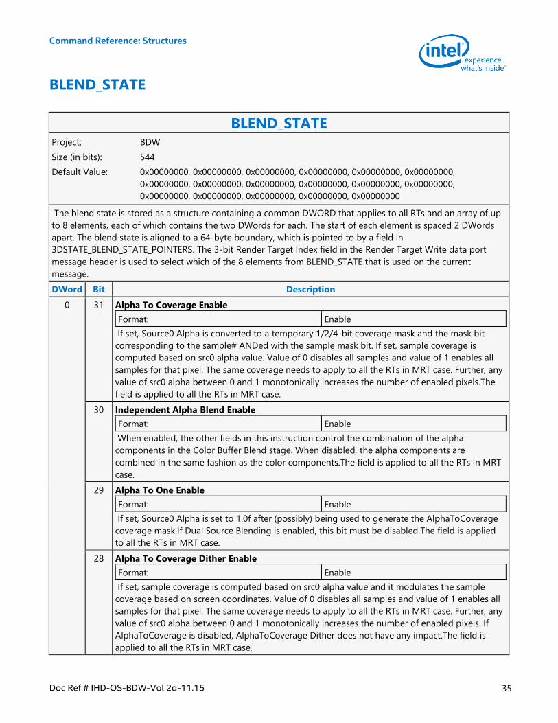
Command Reference: Structures
Doc Ref # IHD-OS-BDW-Vol 2d-11.15 35
BLEND_STATE
BLEND_STATE Project: BDW
Size (in bits): 544
Default Value: 0x00000000, 0x00000000, 0x00000000, 0x00000000, 0x00000000, 0x00000000,
0x00000000, 0x00000000, 0x00000000, 0x00000000, 0x00000000, 0x00000000,
0x00000000, 0x00000000, 0x00000000, 0x00000000, 0x00000000
The blend state is stored as a structure containing a common DWORD that applies to all RTs and an array of up
to 8 elements, each of which contains the two DWords for each. The start of each element is spaced 2 DWords
apart. The blend state is aligned to a 64-byte boundary, which is pointed to by a field in
3DSTATE_BLEND_STATE_POINTERS. The 3-bit Render Target Index field in the Render Target Write data port
message header is used to select which of the 8 elements from BLEND_STATE that is used on the current
message.
DWord Bit Description
0 31 Alpha To Coverage Enable
Format: Enable
If set, Source0 Alpha is converted to a temporary 1/2/4-bit coverage mask and the mask bit
corresponding to the sample# ANDed with the sample mask bit. If set, sample coverage is
computed based on src0 alpha value. Value of 0 disables all samples and value of 1 enables all
samples for that pixel. The same coverage needs to apply to all the RTs in MRT case. Further, any
value of src0 alpha between 0 and 1 monotonically increases the number of enabled pixels.The
field is applied to all the RTs in MRT case.
30 Independent Alpha Blend Enable
Format: Enable
When enabled, the other fields in this instruction control the combination of the alpha
components in the Color Buffer Blend stage. When disabled, the alpha components are
combined in the same fashion as the color components.The field is applied to all the RTs in MRT
case.
29 Alpha To One Enable
Format: Enable
If set, Source0 Alpha is set to 1.0f after (possibly) being used to generate the AlphaToCoverage
coverage mask.If Dual Source Blending is enabled, this bit must be disabled.The field is applied
to all the RTs in MRT case.
28 Alpha To Coverage Dither Enable
Format: Enable
If set, sample coverage is computed based on src0 alpha value and it modulates the sample
coverage based on screen coordinates. Value of 0 disables all samples and value of 1 enables all
samples for that pixel. The same coverage needs to apply to all the RTs in MRT case. Further, any
value of src0 alpha between 0 and 1 monotonically increases the number of enabled pixels. If
AlphaToCoverage is disabled, AlphaToCoverage Dither does not have any impact.The field is
applied to all the RTs in MRT case.
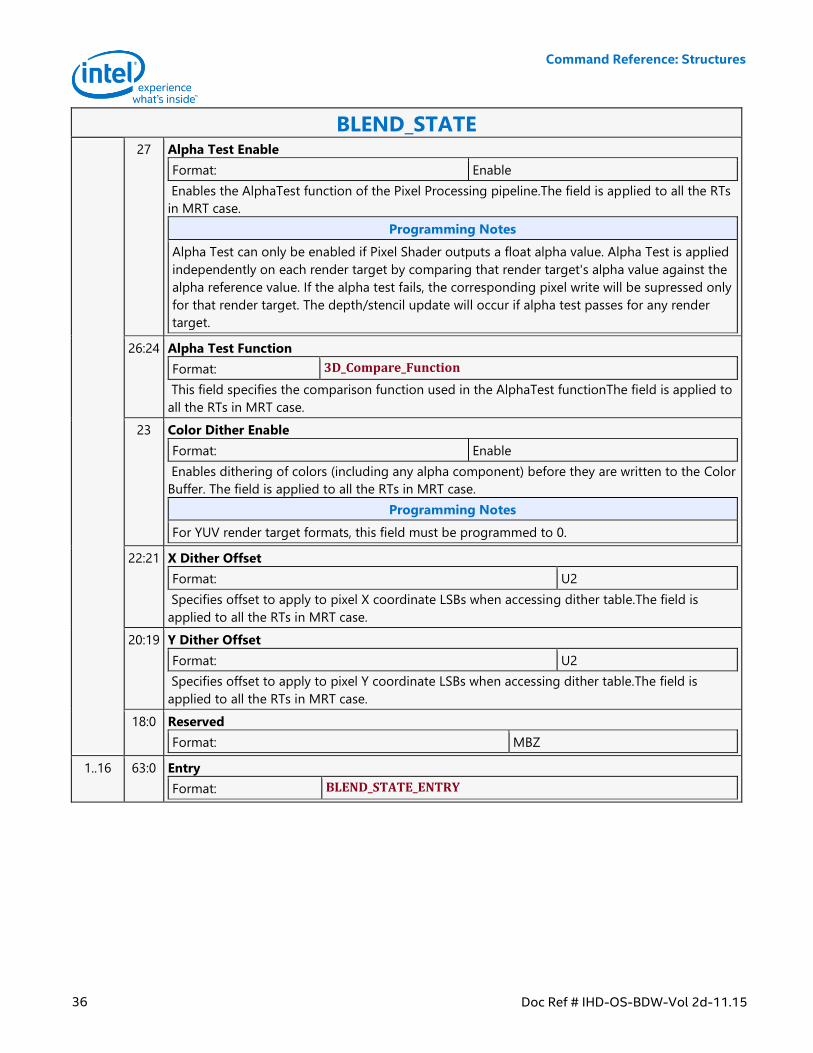
Command Reference: Structures
36 Doc Ref # IHD-OS-BDW-Vol 2d-11.15
BLEND_STATE 27 Alpha Test Enable
Format: Enable
Enables the AlphaTest function of the Pixel Processing pipeline.The field is applied to all the RTs
in MRT case.
Programming Notes
Alpha Test can only be enabled if Pixel Shader outputs a float alpha value. Alpha Test is applied
independently on each render target by comparing that render target's alpha value against the
alpha reference value. If the alpha test fails, the corresponding pixel write will be supressed only
for that render target. The depth/stencil update will occur if alpha test passes for any render
target.
26:24 Alpha Test Function
Format: 3D_Compare_Function
This field specifies the comparison function used in the AlphaTest functionThe field is applied to
all the RTs in MRT case.
23 Color Dither Enable
Format: Enable
Enables dithering of colors (including any alpha component) before they are written to the Color
Buffer. The field is applied to all the RTs in MRT case.
Programming Notes
For YUV render target formats, this field must be programmed to 0.
22:21 X Dither Offset
Format: U2
Specifies offset to apply to pixel X coordinate LSBs when accessing dither table.The field is
applied to all the RTs in MRT case.
20:19 Y Dither Offset
Format: U2
Specifies offset to apply to pixel Y coordinate LSBs when accessing dither table.The field is
applied to all the RTs in MRT case.
18:0 Reserved
Format: MBZ
1..16 63:0 Entry
Format: BLEND_STATE_ENTRY
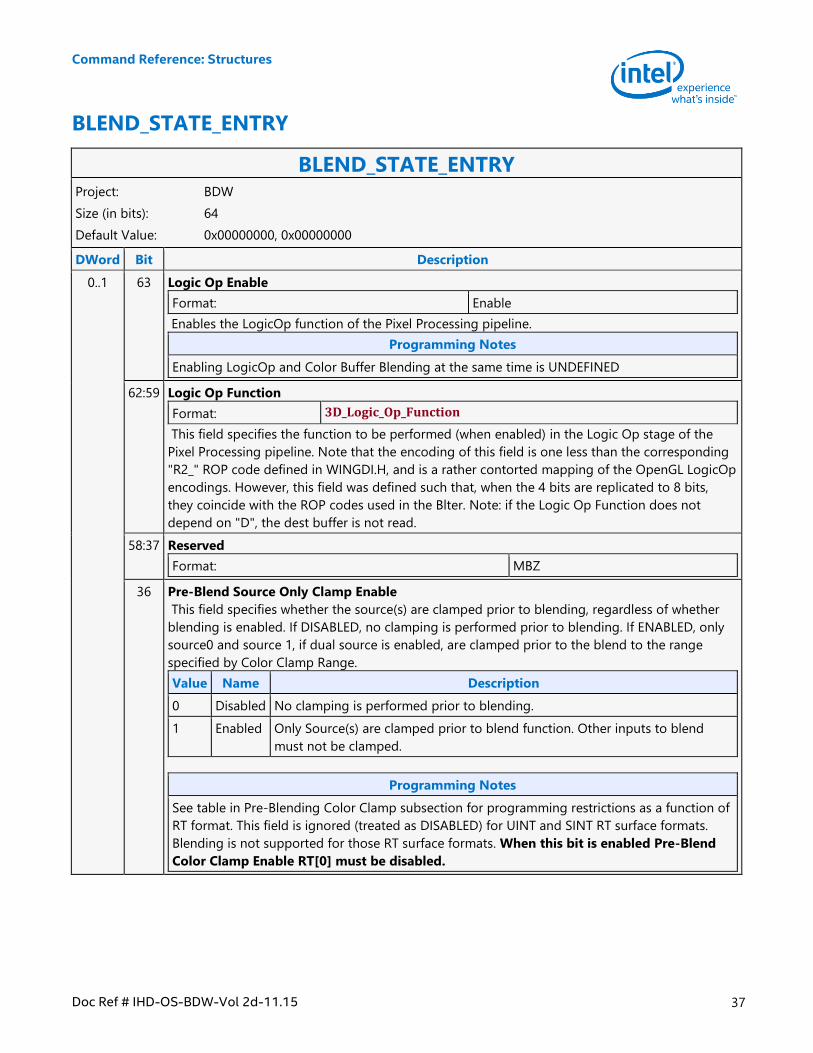
Command Reference: Structures
Doc Ref # IHD-OS-BDW-Vol 2d-11.15 37
BLEND_STATE_ENTRY
BLEND_STATE_ENTRY Project: BDW
Size (in bits): 64
Default Value: 0x00000000, 0x00000000
DWord Bit Description
0..1 63 Logic Op Enable
Format: Enable
Enables the LogicOp function of the Pixel Processing pipeline.
Programming Notes
Enabling LogicOp and Color Buffer Blending at the same time is UNDEFINED
62:59 Logic Op Function
Format: 3D_Logic_Op_Function
This field specifies the function to be performed (when enabled) in the Logic Op stage of the
Pixel Processing pipeline. Note that the encoding of this field is one less than the corresponding
"R2_" ROP code defined in WINGDI.H, and is a rather contorted mapping of the OpenGL LogicOp
encodings. However, this field was defined such that, when the 4 bits are replicated to 8 bits,
they coincide with the ROP codes used in the Blter. Note: if the Logic Op Function does not
depend on "D", the dest buffer is not read.
58:37 Reserved
Format: MBZ
36 Pre-Blend Source Only Clamp Enable
This field specifies whether the source(s) are clamped prior to blending, regardless of whether
blending is enabled. If DISABLED, no clamping is performed prior to blending. If ENABLED, only
source0 and source 1, if dual source is enabled, are clamped prior to the blend to the range
specified by Color Clamp Range.
Value Name Description
0 Disabled No clamping is performed prior to blending.
1 Enabled Only Source(s) are clamped prior to blend function. Other inputs to blend
must not be clamped.
Programming Notes
See table in Pre-Blending Color Clamp subsection for programming restrictions as a function of
RT format. This field is ignored (treated as DISABLED) for UINT and SINT RT surface formats.
Blending is not supported for those RT surface formats. When this bit is enabled Pre-Blend
Color Clamp Enable RT[0] must be disabled.
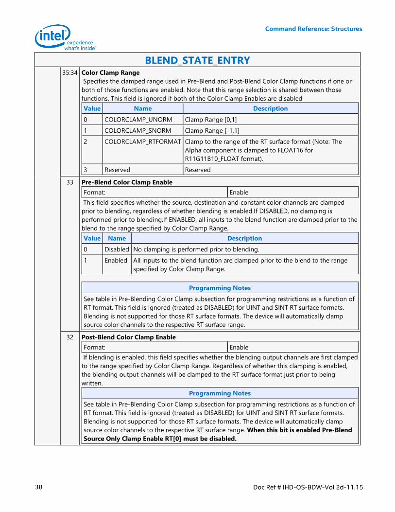
Command Reference: Structures
38 Doc Ref # IHD-OS-BDW-Vol 2d-11.15
BLEND_STATE_ENTRY 35:34 Color Clamp Range
Specifies the clamped range used in Pre-Blend and Post-Blend Color Clamp functions if one or
both of those functions are enabled. Note that this range selection is shared between those
functions. This field is ignored if both of the Color Clamp Enables are disabled
Value Name Description
0 COLORCLAMP_UNORM Clamp Range [0,1]
1 COLORCLAMP_SNORM Clamp Range [-1,1]
2 COLORCLAMP_RTFORMAT Clamp to the range of the RT surface format (Note: The
Alpha component is clamped to FLOAT16 for
R11G11B10_FLOAT format).
3 Reserved Reserved
33 Pre-Blend Color Clamp Enable
Format: Enable
This field specifies whether the source, destination and constant color channels are clamped
prior to blending, regardless of whether blending is enabled.If DISABLED, no clamping is
performed prior to blending.If ENABLED, all inputs to the blend function are clamped prior to the
blend to the range specified by Color Clamp Range.
Value Name Description
0 Disabled No clamping is performed prior to blending.
1 Enabled All inputs to the blend function are clamped prior to the blend to the range
specified by Color Clamp Range.
Programming Notes
See table in Pre-Blending Color Clamp subsection for programming restrictions as a function of
RT format. This field is ignored (treated as DISABLED) for UINT and SINT RT surface formats.
Blending is not supported for those RT surface formats. The device will automatically clamp
source color channels to the respective RT surface range.
32 Post-Blend Color Clamp Enable
Format: Enable
If blending is enabled, this field specifies whether the blending output channels are first clamped
to the range specified by Color Clamp Range. Regardless of whether this clamping is enabled,
the blending output channels will be clamped to the RT surface format just prior to being
written.
Programming Notes
See table in Pre-Blending Color Clamp subsection for programming restrictions as a function of
RT format. This field is ignored (treated as DISABLED) for UINT and SINT RT surface formats.
Blending is not supported for those RT surface formats. The device will automatically clamp
source color channels to the respective RT surface range. When this bit is enabled Pre-Blend
Source Only Clamp Enable RT[0] must be disabled.
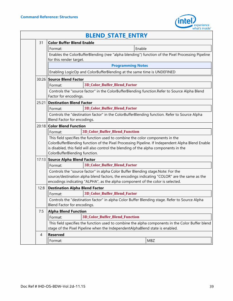
Command Reference: Structures
Doc Ref # IHD-OS-BDW-Vol 2d-11.15 39
BLEND_STATE_ENTRY 31 Color Buffer Blend Enable
Format: Enable
Enables the ColorBufferBlending (nee "alpha blending") function of the Pixel Processing Pipeline
for this render target.
Programming Notes
Enabling LogicOp and ColorBufferBlending at the same time is UNDEFINED
30:26 Source Blend Factor
Format: 3D_Color_Buffer_Blend_Factor
Controls the "source factor" in the ColorBufferBlending function.Refer to Source Alpha Blend
Factor for encodings.
25:21 Destination Blend Factor
Format: 3D_Color_Buffer_Blend_Factor
Controls the "destination factor" in the ColorBufferBlending function. Refer to Source Alpha
Blend Factor for encodings.
20:18 Color Blend Function
Format: 3D_Color_Buffer_Blend_Function
This field specifies the function used to combine the color components in the
ColorBufferBlending function of the Pixel Processing Pipeline. If Independent Alpha Blend Enable
is disabled, this field will also control the blending of the alpha components in the
ColorBufferBlending function.
17:13 Source Alpha Blend Factor
Format: 3D_Color_Buffer_Blend_Factor
Controls the "source factor" in alpha Color Buffer Blending stage.Note: For the
source/destination alpha blend factors, the encodings indicating "COLOR" are the same as the
encodings indicating "ALPHA", as the alpha component of the color is selected.
12:8 Destination Alpha Blend Factor
Format: 3D_Color_Buffer_Blend_Factor
Controls the "destination factor" in alpha Color Buffer Blending stage. Refer to Source Alpha
Blend Factor for encodings.
7:5 Alpha Blend Function
Format: 3D_Color_Buffer_Blend_Function
This field specifies the function used to combine the alpha components in the Color Buffer blend
stage of the Pixel Pipeline when the IndependentAlphaBlend state is enabled.
4 Reserved
Format: MBZ
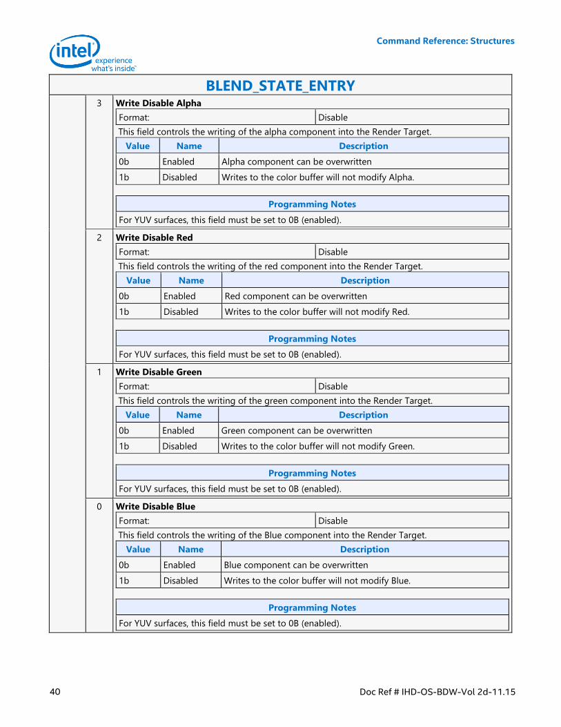
Command Reference: Structures
40 Doc Ref # IHD-OS-BDW-Vol 2d-11.15
BLEND_STATE_ENTRY 3 Write Disable Alpha
Format: Disable
This field controls the writing of the alpha component into the Render Target.
Value Name Description
0b Enabled Alpha component can be overwritten
1b Disabled Writes to the color buffer will not modify Alpha.
Programming Notes
For YUV surfaces, this field must be set to 0B (enabled).
2 Write Disable Red
Format: Disable
This field controls the writing of the red component into the Render Target.
Value Name Description
0b Enabled Red component can be overwritten
1b Disabled Writes to the color buffer will not modify Red.
Programming Notes
For YUV surfaces, this field must be set to 0B (enabled).
1 Write Disable Green
Format: Disable
This field controls the writing of the green component into the Render Target.
Value Name Description
0b Enabled Green component can be overwritten
1b Disabled Writes to the color buffer will not modify Green.
Programming Notes
For YUV surfaces, this field must be set to 0B (enabled).
0 Write Disable Blue
Format: Disable
This field controls the writing of the Blue component into the Render Target.
Value Name Description
0b Enabled Blue component can be overwritten
1b Disabled Writes to the color buffer will not modify Blue.
Programming Notes
For YUV surfaces, this field must be set to 0B (enabled).
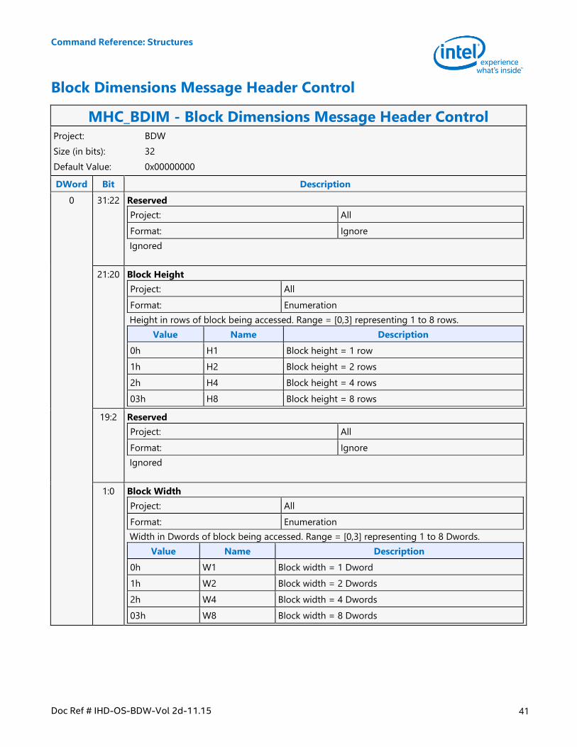
Command Reference: Structures
Doc Ref # IHD-OS-BDW-Vol 2d-11.15 41
Block Dimensions Message Header Control
MHC_BDIM - Block Dimensions Message Header Control Project: BDW
Size (in bits): 32
Default Value: 0x00000000
DWord Bit Description
0 31:22 Reserved
Project: All
Format: Ignore
Ignored
21:20 Block Height
Project: All
Format: Enumeration
Height in rows of block being accessed. Range = [0,3] representing 1 to 8 rows.
Value Name Description
0h H1 Block height = 1 row
1h H2 Block height = 2 rows
2h H4 Block height = 4 rows
03h H8 Block height = 8 rows
19:2 Reserved
Project: All
Format: Ignore
Ignored
1:0 Block Width
Project: All
Format: Enumeration
Width in Dwords of block being accessed. Range = [0,3] representing 1 to 8 Dwords.
Value Name Description
0h W1 Block width = 1 Dword
1h W2 Block width = 2 Dwords
2h W4 Block width = 4 Dwords
03h W8 Block width = 8 Dwords
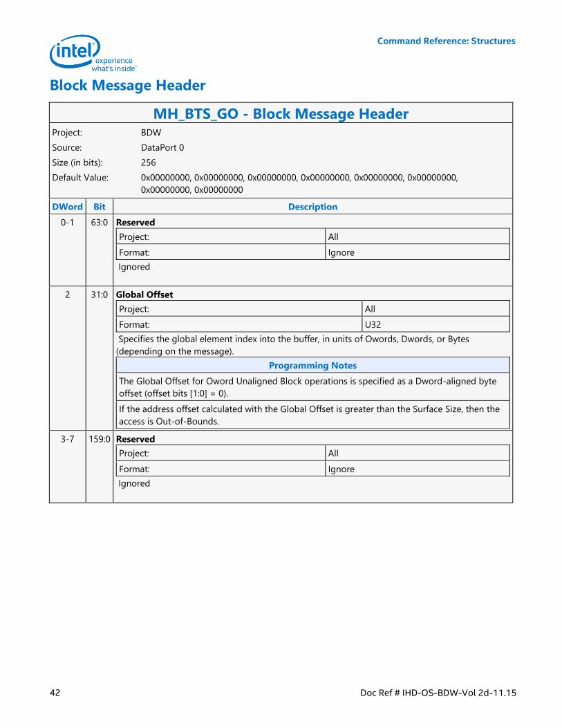
Command Reference: Structures
42 Doc Ref # IHD-OS-BDW-Vol 2d-11.15
Block Message Header
MH_BTS_GO - Block Message Header Project: BDW
Source: DataPort 0
Size (in bits): 256
Default Value: 0x00000000, 0x00000000, 0x00000000, 0x00000000, 0x00000000, 0x00000000,
0x00000000, 0x00000000
DWord Bit Description
0-1 63:0 Reserved
Project: All
Format: Ignore
Ignored
2 31:0 Global Offset
Project: All
Format: U32
Specifies the global element index into the buffer, in units of Owords, Dwords, or Bytes
(depending on the message).
Programming Notes
The Global Offset for Oword Unaligned Block operations is specified as a Dword-aligned byte
offset (offset bits [1:0] = 0).
If the address offset calculated with the Global Offset is greater than the Surface Size, then the
access is Out-of-Bounds.
3-7 159:0 Reserved
Project: All
Format: Ignore
Ignored
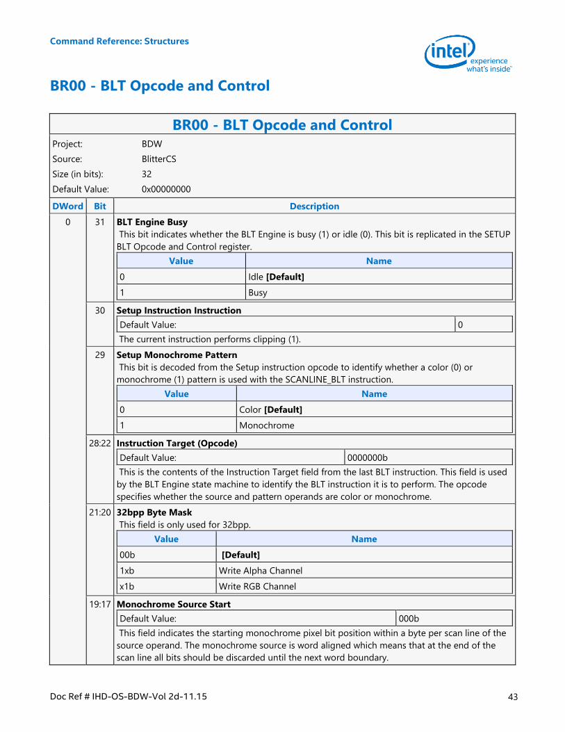
Command Reference: Structures
Doc Ref # IHD-OS-BDW-Vol 2d-11.15 43
BR00 - BLT Opcode and Control
BR00 - BLT Opcode and Control Project: BDW
Source: BlitterCS
Size (in bits): 32
Default Value: 0x00000000
DWord Bit Description
0 31 BLT Engine Busy
This bit indicates whether the BLT Engine is busy (1) or idle (0). This bit is replicated in the SETUP
BLT Opcode and Control register.
Value Name
0 Idle [Default]
1 Busy
30 Setup Instruction Instruction
Default Value: 0
The current instruction performs clipping (1).
29 Setup Monochrome Pattern
This bit is decoded from the Setup instruction opcode to identify whether a color (0) or
monochrome (1) pattern is used with the SCANLINE_BLT instruction.
Value Name
0 Color [Default]
1 Monochrome
28:22 Instruction Target (Opcode)
Default Value: 0000000b
This is the contents of the Instruction Target field from the last BLT instruction. This field is used
by the BLT Engine state machine to identify the BLT instruction it is to perform. The opcode
specifies whether the source and pattern operands are color or monochrome.
21:20 32bpp Byte Mask
This field is only used for 32bpp.
Value Name
00b [Default]
1xb Write Alpha Channel
x1b Write RGB Channel
19:17 Monochrome Source Start
Default Value: 000b
This field indicates the starting monochrome pixel bit position within a byte per scan line of the
source operand. The monochrome source is word aligned which means that at the end of the
scan line all bits should be discarded until the next word boundary.
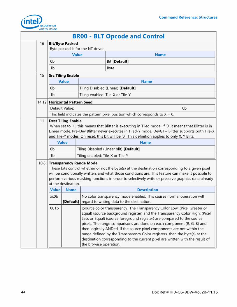
Command Reference: Structures
44 Doc Ref # IHD-OS-BDW-Vol 2d-11.15
BR00 - BLT Opcode and Control 16 Bit/Byte Packed
Byte packed is for the NT driver.
Value Name
0b Bit [Default]
1b Byte
15 Src Tiling Enable
Value Name
0b Tiling Disabled (Linear) [Default]
1b Tiling enabled: Tile-X or Tile-Y
14:12 Horizontal Pattern Seed
Default Value: 0b
This field indicates the pattern pixel position which corresponds to X = 0.
11 Dest Tiling Enable
When set to '1', this means that Blitter is executing in Tiled mode. If '0' it means that Blitter is in
Linear mode. Pre-Dev Blitter never executes in Tiled-Y mode, DevGT+ Blitter supports both Tile-X
and Tile-Y modes. On reset, this bit will be '0'. This definition applies to only X, Y Blits.
Value Name
0b Tiling Disabled (Linear blit) [Default]
1b Tiling enabled: Tile-X or Tile-Y
10:8 Transparency Range Mode
These bits control whether or not the byte(s) at the destination corresponding to a given pixel
will be conditionally written, and what those conditions are. This feature can make it possible to
perform various masking functions in order to selectively write or preserve graphics data already
at the destination.
Value Name Description
xx0b
[Default]
No color transparency mode enabled. This causes normal operation with
regard to writing data to the destination.
001b [Source color transparency] The Transparency Color Low: (Pixel Greater or
Equal) (source background register) and the Transparency Color High: (Pixel
Less or Equal) (source foreground register) are compared to the source
pixels. The range comparisons are done on each component (R, G, B) and
then logically ANDed. If the source pixel components are not within the
range defined by the Transparency Color registers, then the byte(s) at the
destination corresponding to the current pixel are written with the result of
the bit-wise operation.
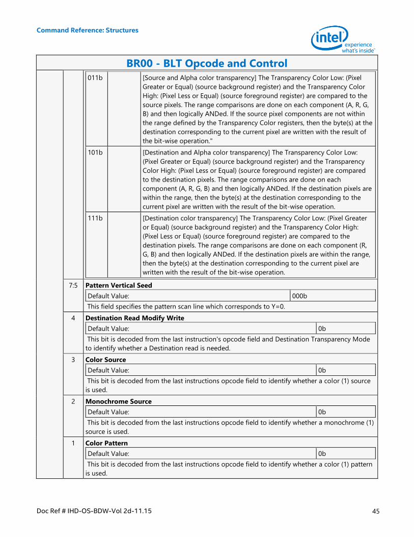
Command Reference: Structures
Doc Ref # IHD-OS-BDW-Vol 2d-11.15 45
BR00 - BLT Opcode and Control
011b [Source and Alpha color transparency] The Transparency Color Low: (Pixel
Greater or Equal) (source background register) and the Transparency Color
High: (Pixel Less or Equal) (source foreground register) are compared to the
source pixels. The range comparisons are done on each component (A, R, G,
B) and then logically ANDed. If the source pixel components are not within
the range defined by the Transparency Color registers, then the byte(s) at the
destination corresponding to the current pixel are written with the result of
the bit-wise operation."
101b [Destination and Alpha color transparency] The Transparency Color Low:
(Pixel Greater or Equal) (source background register) and the Transparency
Color High: (Pixel Less or Equal) (source foreground register) are compared
to the destination pixels. The range comparisons are done on each
component (A, R, G, B) and then logically ANDed. If the destination pixels are
within the range, then the byte(s) at the destination corresponding to the
current pixel are written with the result of the bit-wise operation.
111b [Destination color transparency] The Transparency Color Low: (Pixel Greater
or Equal) (source background register) and the Transparency Color High:
(Pixel Less or Equal) (source foreground register) are compared to the
destination pixels. The range comparisons are done on each component (R,
G, B) and then logically ANDed. If the destination pixels are within the range,
then the byte(s) at the destination corresponding to the current pixel are
written with the result of the bit-wise operation.
7:5 Pattern Vertical Seed
Default Value: 000b
This field specifies the pattern scan line which corresponds to Y=0.
4 Destination Read Modify Write
Default Value: 0b
This bit is decoded from the last instruction's opcode field and Destination Transparency Mode
to identify whether a Destination read is needed.
3 Color Source
Default Value: 0b
This bit is decoded from the last instructions opcode field to identify whether a color (1) source
is used.
2 Monochrome Source
Default Value: 0b
This bit is decoded from the last instructions opcode field to identify whether a monochrome (1)
source is used.
1 Color Pattern
Default Value: 0b
This bit is decoded from the last instructions opcode field to identify whether a color (1) pattern
is used.
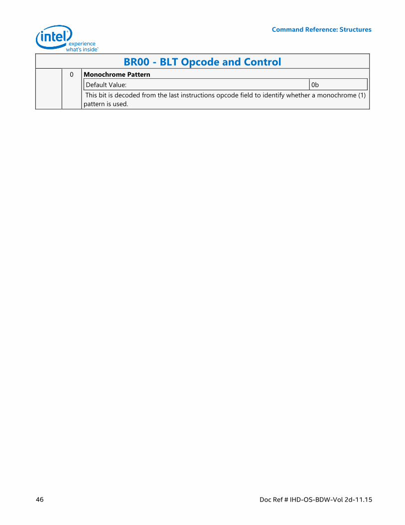
Command Reference: Structures
46 Doc Ref # IHD-OS-BDW-Vol 2d-11.15
BR00 - BLT Opcode and Control 0 Monochrome Pattern
Default Value: 0b
This bit is decoded from the last instructions opcode field to identify whether a monochrome (1)
pattern is used.
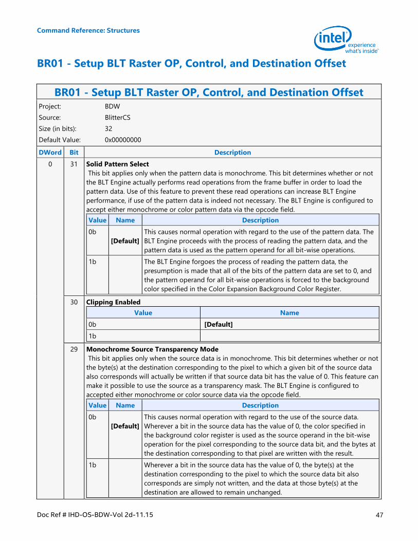
Command Reference: Structures
Doc Ref # IHD-OS-BDW-Vol 2d-11.15 47
BR01 - Setup BLT Raster OP, Control, and Destination Offset
BR01 - Setup BLT Raster OP, Control, and Destination Offset Project: BDW
Source: BlitterCS
Size (in bits): 32
Default Value: 0x00000000
DWord Bit Description
0 31 Solid Pattern Select
This bit applies only when the pattern data is monochrome. This bit determines whether or not
the BLT Engine actually performs read operations from the frame buffer in order to load the
pattern data. Use of this feature to prevent these read operations can increase BLT Engine
performance, if use of the pattern data is indeed not necessary. The BLT Engine is configured to
accept either monochrome or color pattern data via the opcode field.
Value Name Description
0b
[Default]
This causes normal operation with regard to the use of the pattern data. The
BLT Engine proceeds with the process of reading the pattern data, and the
pattern data is used as the pattern operand for all bit-wise operations.
1b The BLT Engine forgoes the process of reading the pattern data, the
presumption is made that all of the bits of the pattern data are set to 0, and
the pattern operand for all bit-wise operations is forced to the background
color specified in the Color Expansion Background Color Register.
30 Clipping Enabled
Value Name
0b [Default]
1b
29 Monochrome Source Transparency Mode
This bit applies only when the source data is in monochrome. This bit determines whether or not
the byte(s) at the destination corresponding to the pixel to which a given bit of the source data
also corresponds will actually be written if that source data bit has the value of 0. This feature can
make it possible to use the source as a transparency mask. The BLT Engine is configured to
accepted either monochrome or color source data via the opcode field.
Value Name Description
0b
[Default]
This causes normal operation with regard to the use of the source data.
Wherever a bit in the source data has the value of 0, the color specified in
the background color register is used as the source operand in the bit-wise
operation for the pixel corresponding to the source data bit, and the bytes at
the destination corresponding to that pixel are written with the result.
1b Wherever a bit in the source data has the value of 0, the byte(s) at the
destination corresponding to the pixel to which the source data bit also
corresponds are simply not written, and the data at those byte(s) at the
destination are allowed to remain unchanged.
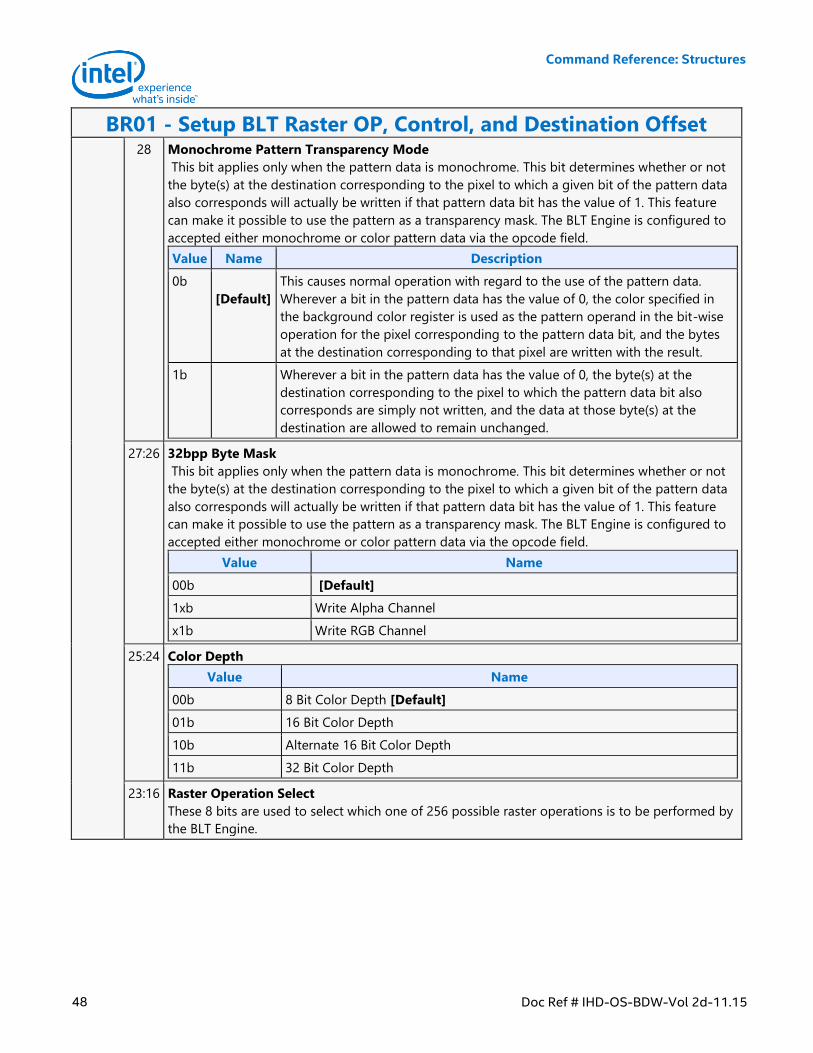
Command Reference: Structures
48 Doc Ref # IHD-OS-BDW-Vol 2d-11.15
BR01 - Setup BLT Raster OP, Control, and Destination Offset 28 Monochrome Pattern Transparency Mode
This bit applies only when the pattern data is monochrome. This bit determines whether or not
the byte(s) at the destination corresponding to the pixel to which a given bit of the pattern data
also corresponds will actually be written if that pattern data bit has the value of 1. This feature
can make it possible to use the pattern as a transparency mask. The BLT Engine is configured to
accepted either monochrome or color pattern data via the opcode field.
Value Name Description
0b
[Default]
This causes normal operation with regard to the use of the pattern data.
Wherever a bit in the pattern data has the value of 0, the color specified in
the background color register is used as the pattern operand in the bit-wise
operation for the pixel corresponding to the pattern data bit, and the bytes
at the destination corresponding to that pixel are written with the result.
1b Wherever a bit in the pattern data has the value of 0, the byte(s) at the
destination corresponding to the pixel to which the pattern data bit also
corresponds are simply not written, and the data at those byte(s) at the
destination are allowed to remain unchanged.
27:26 32bpp Byte Mask
This bit applies only when the pattern data is monochrome. This bit determines whether or not
the byte(s) at the destination corresponding to the pixel to which a given bit of the pattern data
also corresponds will actually be written if that pattern data bit has the value of 1. This feature
can make it possible to use the pattern as a transparency mask. The BLT Engine is configured to
accepted either monochrome or color pattern data via the opcode field.
Value Name
00b [Default]
1xb Write Alpha Channel
x1b Write RGB Channel
25:24 Color Depth
Value Name
00b 8 Bit Color Depth [Default]
01b 16 Bit Color Depth
10b Alternate 16 Bit Color Depth
11b 32 Bit Color Depth
23:16 Raster Operation Select
These 8 bits are used to select which one of 256 possible raster operations is to be performed by
the BLT Engine.
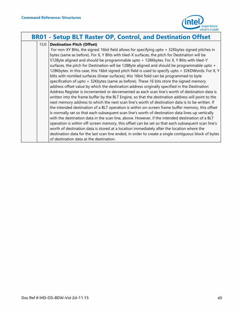
Command Reference: Structures
Doc Ref # IHD-OS-BDW-Vol 2d-11.15 49
BR01 - Setup BLT Raster OP, Control, and Destination Offset 15:0 Destination Pitch (Offset)
For non-XY Blits, the signed 16bit field allows for specifying upto + 32Kbytes signed pitches in
bytes (same as before). For X, Y Blits with tiled-X surfaces, the pitch for Destination will be
512Byte aligned and should be programmable upto + 128Kbytes. For X, Y Blits with tiled-Y
surfaces, the pitch for Destination will be 128Byte aligned and should be programmable upto +
128Kbytes. In this case, this 16bit signed pitch field is used to specify upto + 32KDWords. For X, Y
blits with nontiled surfaces (linear surfaces), this 16bit field can be programmed to byte
specification of upto + 32Kbytes (same as before). These 16 bits store the signed memory
address offset value by which the destination address originally specified in the Destination
Address Register is incremented or decremented as each scan line's worth of destination data is
written into the frame buffer by the BLT Engine, so that the destination address will point to the
next memory address to which the next scan line's worth of destination data is to be written. If
the intended destination of a BLT operation is within on-screen frame buffer memory, this offset
is normally set so that each subsequent scan line's worth of destination data lines up vertically
with the destination data in the scan line, above. However, if the intended destination of a BLT
operation is within off-screen memory, this offset can be set so that each subsequent scan line's
worth of destination data is stored at a location immediately after the location where the
destination data for the last scan line ended, in order to create a single contiguous block of bytes
of destination data at the destination.
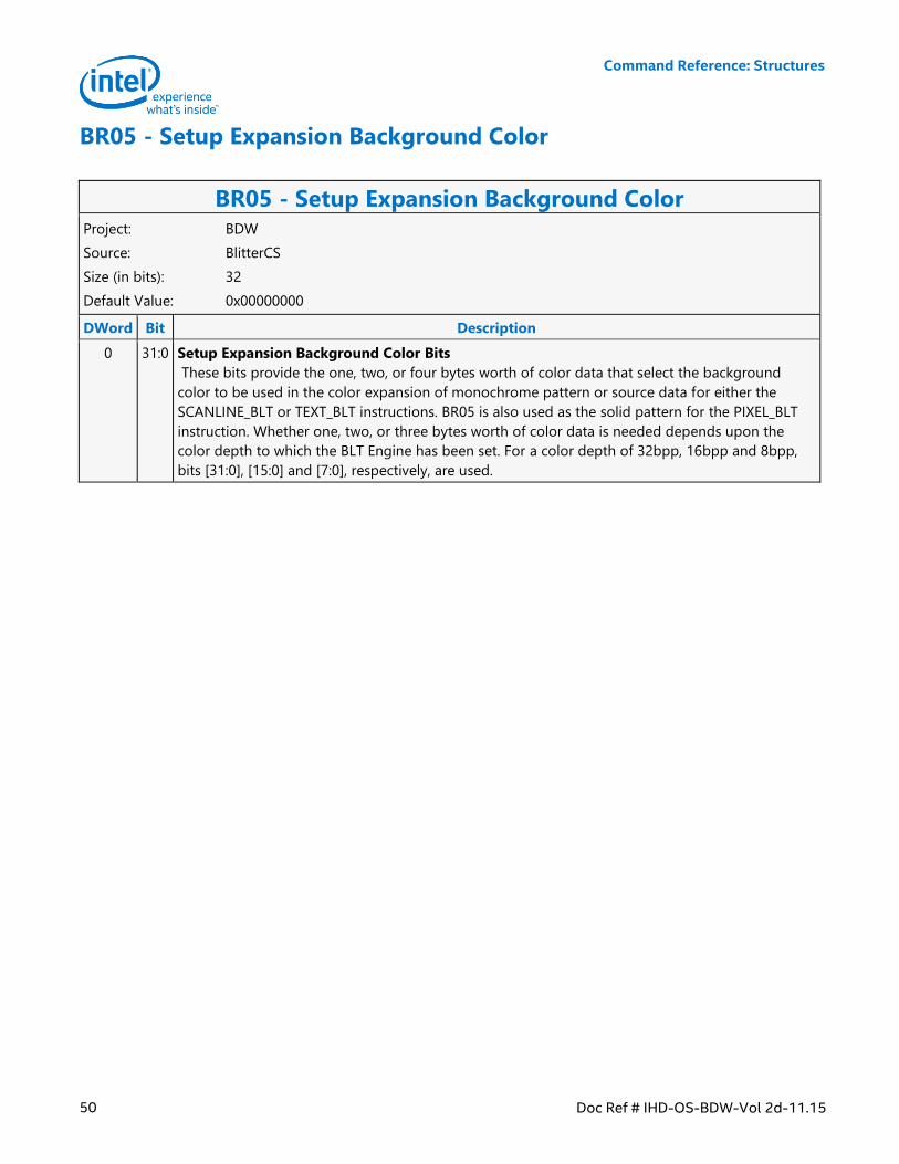
Command Reference: Structures
50 Doc Ref # IHD-OS-BDW-Vol 2d-11.15
BR05 - Setup Expansion Background Color
BR05 - Setup Expansion Background Color Project: BDW
Source: BlitterCS
Size (in bits): 32
Default Value: 0x00000000
DWord Bit Description
0 31:0 Setup Expansion Background Color Bits
These bits provide the one, two, or four bytes worth of color data that select the background
color to be used in the color expansion of monochrome pattern or source data for either the
SCANLINE_BLT or TEXT_BLT instructions. BR05 is also used as the solid pattern for the PIXEL_BLT
instruction. Whether one, two, or three bytes worth of color data is needed depends upon the
color depth to which the BLT Engine has been set. For a color depth of 32bpp, 16bpp and 8bpp,
bits [31:0], [15:0] and [7:0], respectively, are used.
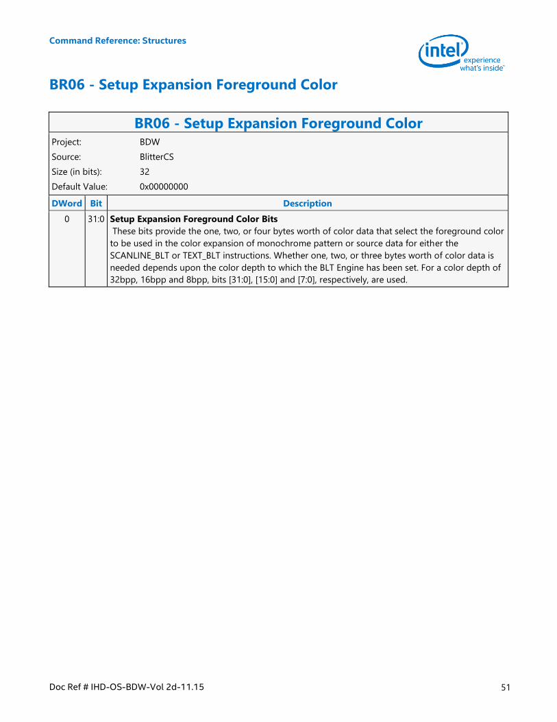
Command Reference: Structures
Doc Ref # IHD-OS-BDW-Vol 2d-11.15 51
BR06 - Setup Expansion Foreground Color
BR06 - Setup Expansion Foreground Color Project: BDW
Source: BlitterCS
Size (in bits): 32
Default Value: 0x00000000
DWord Bit Description
0 31:0 Setup Expansion Foreground Color Bits
These bits provide the one, two, or four bytes worth of color data that select the foreground color
to be used in the color expansion of monochrome pattern or source data for either the
SCANLINE_BLT or TEXT_BLT instructions. Whether one, two, or three bytes worth of color data is
needed depends upon the color depth to which the BLT Engine has been set. For a color depth of
32bpp, 16bpp and 8bpp, bits [31:0], [15:0] and [7:0], respectively, are used.
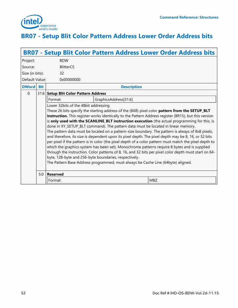
Command Reference: Structures
52 Doc Ref # IHD-OS-BDW-Vol 2d-11.15
BR07 - Setup Blit Color Pattern Address Lower Order Address bits
BR07 - Setup Blit Color Pattern Address Lower Order Address bits Project: BDW
Source: BlitterCS
Size (in bits): 32
Default Value: 0x00000000
DWord Bit Description
0 31:6 Setup Blit Color Pattern Address
Format: GraphicsAddress[31:6]
Lower 32bits of the 48bit addressing.
These 26 bits specify the starting address of the (8X8) pixel color pattern from the SETUP_BLT
instruction. This register works identically to the Pattern Address register (BR15), but this version
is only used with the SCANLINE_BLT instruction execution (the actual programming for this, is
done in XY_SETUP_BLT command). The pattern data must be located in linear memory.
The pattern data must be located on a pattern-size boundary. The pattern is always of 8x8 pixels,
and therefore, its size is dependent upon its pixel depth. The pixel depth may be 8, 16, or 32 bits
per pixel if the pattern is in color (the pixel depth of a color pattern must match the pixel depth to
which the graphics system has been set). Monochrome patterns require 8 bytes and is supplied
through the instruction. Color patterns of 8, 16, and 32 bits per pixel color depth must start on 64-
byte, 128-byte and 256-byte boundaries, respectively.
The Pattern Base Address programmed, must always be Cache Line (64byte) aligned.
5:0 Reserved
Format: MBZ
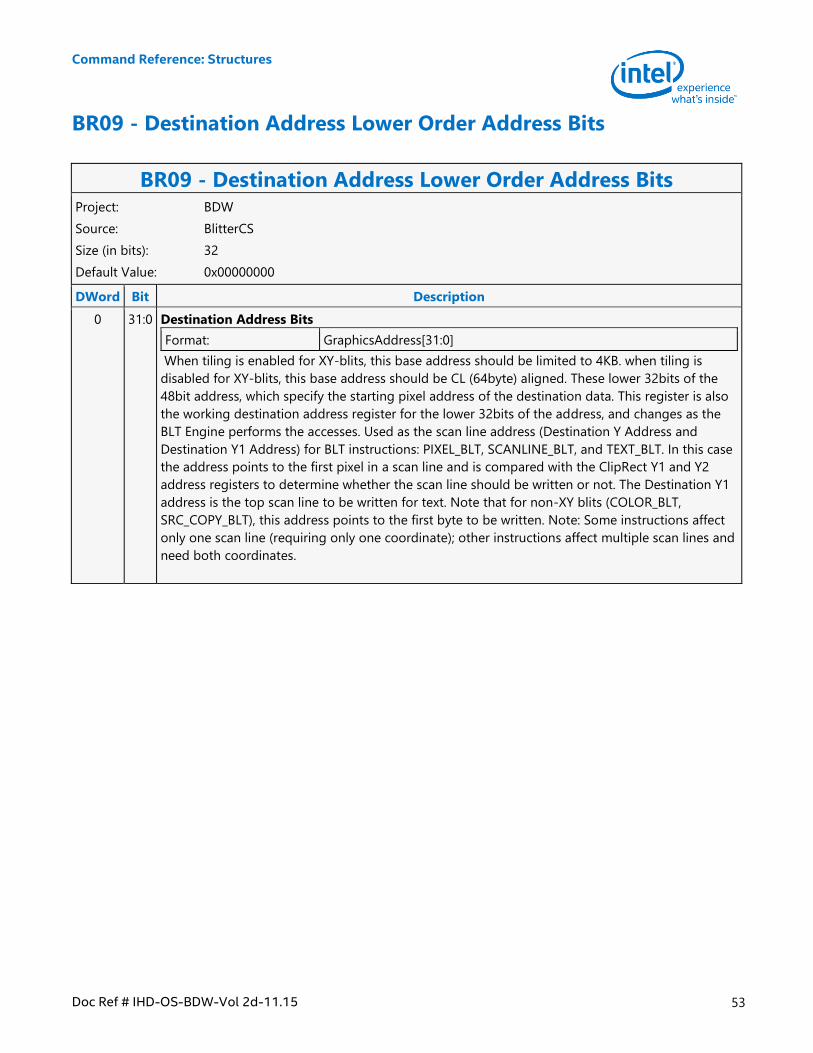
Command Reference: Structures
Doc Ref # IHD-OS-BDW-Vol 2d-11.15 53
BR09 - Destination Address Lower Order Address Bits
BR09 - Destination Address Lower Order Address Bits Project: BDW
Source: BlitterCS
Size (in bits): 32
Default Value: 0x00000000
DWord Bit Description
0 31:0 Destination Address Bits
Format: GraphicsAddress[31:0]
When tiling is enabled for XY-blits, this base address should be limited to 4KB. when tiling is
disabled for XY-blits, this base address should be CL (64byte) aligned. These lower 32bits of the
48bit address, which specify the starting pixel address of the destination data. This register is also
the working destination address register for the lower 32bits of the address, and changes as the
BLT Engine performs the accesses. Used as the scan line address (Destination Y Address and
Destination Y1 Address) for BLT instructions: PIXEL_BLT, SCANLINE_BLT, and TEXT_BLT. In this case
the address points to the first pixel in a scan line and is compared with the ClipRect Y1 and Y2
address registers to determine whether the scan line should be written or not. The Destination Y1
address is the top scan line to be written for text. Note that for non-XY blits (COLOR_BLT,
SRC_COPY_BLT), this address points to the first byte to be written. Note: Some instructions affect
only one scan line (requiring only one coordinate); other instructions affect multiple scan lines and
need both coordinates.
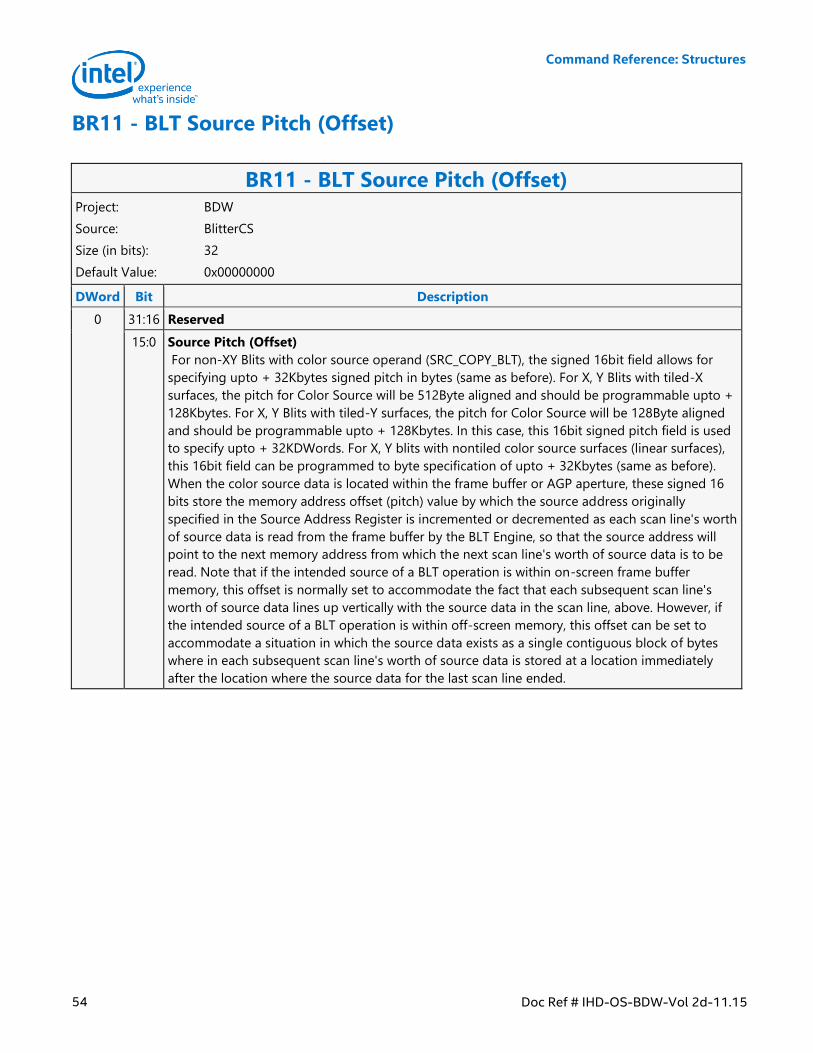
Command Reference: Structures
54 Doc Ref # IHD-OS-BDW-Vol 2d-11.15
BR11 - BLT Source Pitch (Offset)
BR11 - BLT Source Pitch (Offset) Project: BDW
Source: BlitterCS
Size (in bits): 32
Default Value: 0x00000000
DWord Bit Description
0 31:16 Reserved
15:0 Source Pitch (Offset)
For non-XY Blits with color source operand (SRC_COPY_BLT), the signed 16bit field allows for
specifying upto + 32Kbytes signed pitch in bytes (same as before). For X, Y Blits with tiled-X
surfaces, the pitch for Color Source will be 512Byte aligned and should be programmable upto +
128Kbytes. For X, Y Blits with tiled-Y surfaces, the pitch for Color Source will be 128Byte aligned
and should be programmable upto + 128Kbytes. In this case, this 16bit signed pitch field is used
to specify upto + 32KDWords. For X, Y blits with nontiled color source surfaces (linear surfaces),
this 16bit field can be programmed to byte specification of upto + 32Kbytes (same as before).
When the color source data is located within the frame buffer or AGP aperture, these signed 16
bits store the memory address offset (pitch) value by which the source address originally
specified in the Source Address Register is incremented or decremented as each scan line's worth
of source data is read from the frame buffer by the BLT Engine, so that the source address will
point to the next memory address from which the next scan line's worth of source data is to be
read. Note that if the intended source of a BLT operation is within on-screen frame buffer
memory, this offset is normally set to accommodate the fact that each subsequent scan line's
worth of source data lines up vertically with the source data in the scan line, above. However, if
the intended source of a BLT operation is within off-screen memory, this offset can be set to
accommodate a situation in which the source data exists as a single contiguous block of bytes
where in each subsequent scan line's worth of source data is stored at a location immediately
after the location where the source data for the last scan line ended.
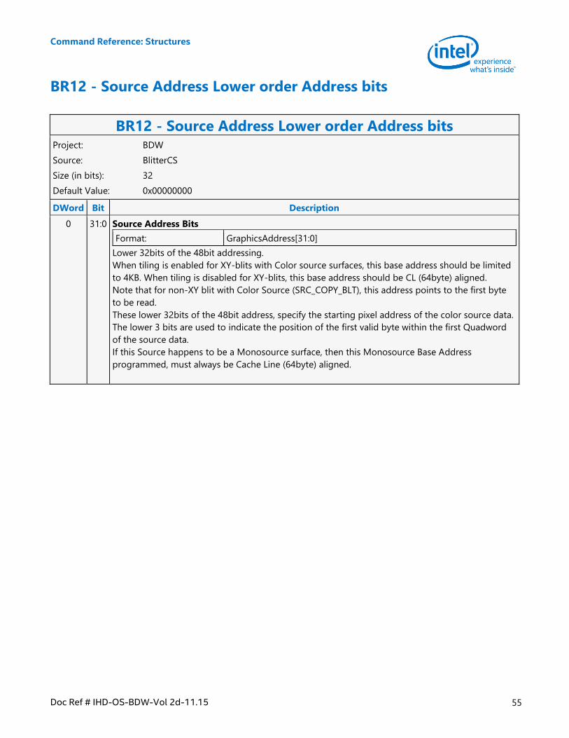
Command Reference: Structures
Doc Ref # IHD-OS-BDW-Vol 2d-11.15 55
BR12 - Source Address Lower order Address bits
BR12 - Source Address Lower order Address bits Project: BDW
Source: BlitterCS
Size (in bits): 32
Default Value: 0x00000000
DWord Bit Description
0 31:0 Source Address Bits
Format: GraphicsAddress[31:0]
Lower 32bits of the 48bit addressing.
When tiling is enabled for XY-blits with Color source surfaces, this base address should be limited
to 4KB. When tiling is disabled for XY-blits, this base address should be CL (64byte) aligned.
Note that for non-XY blit with Color Source (SRC_COPY_BLT), this address points to the first byte
to be read.
These lower 32bits of the 48bit address, specify the starting pixel address of the color source data.
The lower 3 bits are used to indicate the position of the first valid byte within the first Quadword
of the source data.
If this Source happens to be a Monosource surface, then this Monosource Base Address
programmed, must always be Cache Line (64byte) aligned.
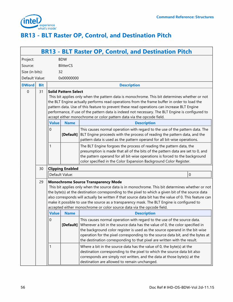
Command Reference: Structures
56 Doc Ref # IHD-OS-BDW-Vol 2d-11.15
BR13 - BLT Raster OP, Control, and Destination Pitch
BR13 - BLT Raster OP, Control, and Destination Pitch Project: BDW
Source: BlitterCS
Size (in bits): 32
Default Value: 0x00000000
DWord Bit Description
0 31 Solid Pattern Select
This bit applies only when the pattern data is monochrome. This bit determines whether or not
the BLT Engine actually performs read operations from the frame buffer in order to load the
pattern data. Use of this feature to prevent these read operations can increase BLT Engine
performance, if use of the pattern data is indeed not necessary. The BLT Engine is configured to
accept either monochrome or color pattern data via the opcode field.
Value Name Description
0
[Default]
This causes normal operation with regard to the use of the pattern data. The
BLT Engine proceeds with the process of reading the pattern data, and the
pattern data is used as the pattern operand for all bit-wise operations.
1 The BLT Engine forgoes the process of reading the pattern data, the
presumption is made that all of the bits of the pattern data are set to 0, and
the pattern operand for all bit-wise operations is forced to the background
color specified in the Color Expansion Background Color Register.
30 Clipping Enabled
Default Value: 0
29 Monochrome Source Transparency Mode
This bit applies only when the source data is in monochrome. This bit determines whether or not
the byte(s) at the destination corresponding to the pixel to which a given bit of the source data
also corresponds will actually be written if that source data bit has the value of 0. This feature can
make it possible to use the source as a transparency mask. The BLT Engine is configured to
accepted either monochrome or color source data via the opcode field.
Value Name Description
0
[Default]
This causes normal operation with regard to the use of the source data.
Wherever a bit in the source data has the value of 0, the color specified in
the background color register is used as the source operand in the bit-wise
operation for the pixel corresponding to the source data bit, and the bytes at
the destination corresponding to that pixel are written with the result.
1 Where a bit in the source data has the value of 0, the byte(s) at the
destination corresponding to the pixel to which the source data bit also
corresponds are simply not written, and the data at those byte(s) at the
destination are allowed to remain unchanged.
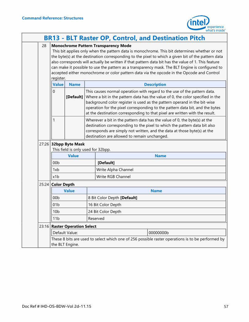
Command Reference: Structures
Doc Ref # IHD-OS-BDW-Vol 2d-11.15 57
BR13 - BLT Raster OP, Control, and Destination Pitch 28 Monochrome Pattern Transparency Mode
This bit applies only when the pattern data is monochrome. This bit determines whether or not
the byte(s) at the destination corresponding to the pixel to which a given bit of the pattern data
also corresponds will actually be written if that pattern data bit has the value of 1. This feature
can make it possible to use the pattern as a transparency mask. The BLT Engine is configured to
accepted either monochrome or color pattern data via the opcode in the Opcode and Control
register.
Value Name Description
0
[Default]
This causes normal operation with regard to the use of the pattern data.
Where a bit in the pattern data has the value of 0, the color specified in the
background color register is used as the pattern operand in the bit-wise
operation for the pixel corresponding to the pattern data bit, and the bytes
at the destination corresponding to that pixel are written with the result.
1 Wherever a bit in the pattern data has the value of 0, the byte(s) at the
destination corresponding to the pixel to which the pattern data bit also
corresponds are simply not written, and the data at those byte(s) at the
destination are allowed to remain unchanged.
27:26 32bpp Byte Mask
This field is only used for 32bpp.
Value Name
00b [Default]
1xb Write Alpha Channel
x1b Write RGB Channel
25:24 Color Depth
Value Name
00b 8 Bit Color Depth [Default]
01b 16 Bit Color Depth
10b 24 Bit Color Depth
11b Reserved
23:16 Raster Operation Select
Default Value: 00000000b
These 8 bits are used to select which one of 256 possible raster operations is to be performed by
the BLT Engine.

Command Reference: Structures
58 Doc Ref # IHD-OS-BDW-Vol 2d-11.15
BR13 - BLT Raster OP, Control, and Destination Pitch 15:0 Destination Pitch(Offset)
These 16 bits store the signed memory address offset value by which the destination address
originally specified in the Destination Address Register is incremented or decremented as each
scan line's worth of destination data is written into the frame buffer by the BLT Engine, so that
the destination address will point to the next memory address to which the next scan line's worth
of destination data is to be written. If the intended destination of a BLT operation is within on-
screen frame buffer memory, this offset is normally set so that each subsequent scan line's worth
of destination data lines up vertically with the destination data in the scan line, above. However,
if the intended destination of a BLT operation is within off-screen memory, this offset can be set
so that each subsequent scan line's worth of destination data is stored at a location immediately
after the location where the destination data for the last scan line ended, in order to create a
single contiguous block of bytes of destination data at the destination.
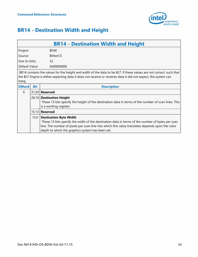
Command Reference: Structures
Doc Ref # IHD-OS-BDW-Vol 2d-11.15 59
BR14 - Destination Width and Height
BR14 - Destination Width and Height Project: BDW
Source: BlitterCS
Size (in bits): 32
Default Value: 0x00000000
BR14 contains the values for the height and width of the data to be BLT. If these values are not correct, such that
the BLT Engine is either expecting data it does not receive or receives data it did not expect, the system can
hang.
DWord Bit Description
0 31:29 Reserved
28:16 Destination Height
These 13 bits specify the height of the destination data in terms of the number of scan lines. This
is a working register.
15:13 Reserved
12:0 Destination Byte Width
These 13 bits specify the width of the destination data in terms of the number of bytes per scan
line. The number of pixels per scan line into which this value translates depends upon the color
depth to which the graphics system has been set.
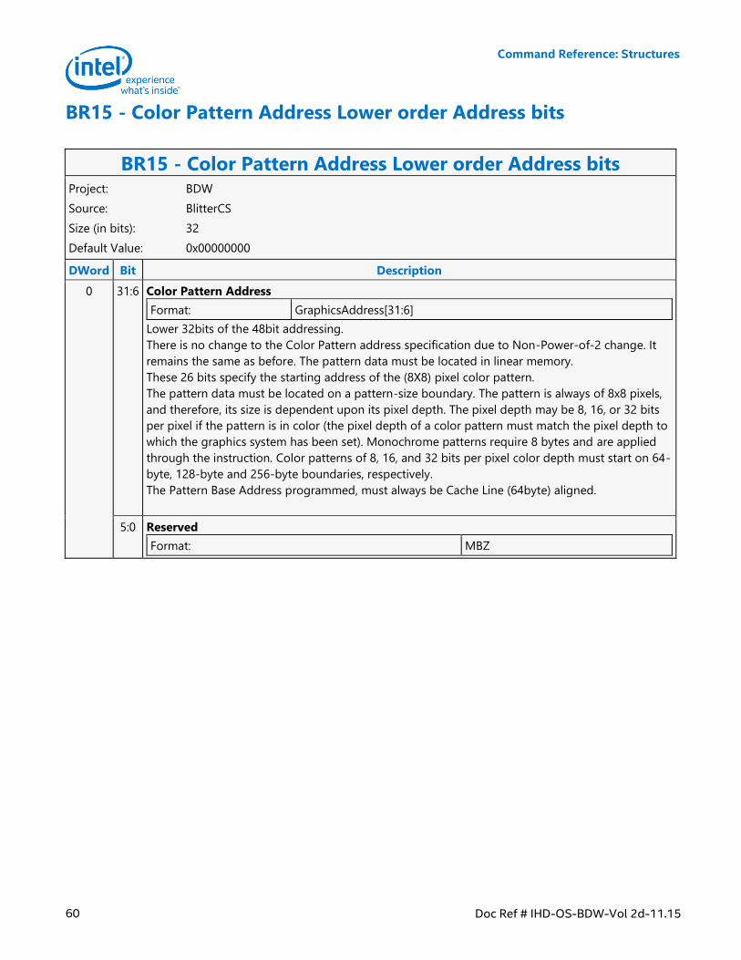
Command Reference: Structures
60 Doc Ref # IHD-OS-BDW-Vol 2d-11.15
BR15 - Color Pattern Address Lower order Address bits
BR15 - Color Pattern Address Lower order Address bits Project: BDW
Source: BlitterCS
Size (in bits): 32
Default Value: 0x00000000
DWord Bit Description
0 31:6 Color Pattern Address
Format: GraphicsAddress[31:6]
Lower 32bits of the 48bit addressing.
There is no change to the Color Pattern address specification due to Non-Power-of-2 change. It
remains the same as before. The pattern data must be located in linear memory.
These 26 bits specify the starting address of the (8X8) pixel color pattern.
The pattern data must be located on a pattern-size boundary. The pattern is always of 8x8 pixels,
and therefore, its size is dependent upon its pixel depth. The pixel depth may be 8, 16, or 32 bits
per pixel if the pattern is in color (the pixel depth of a color pattern must match the pixel depth to
which the graphics system has been set). Monochrome patterns require 8 bytes and are applied
through the instruction. Color patterns of 8, 16, and 32 bits per pixel color depth must start on 64-
byte, 128-byte and 256-byte boundaries, respectively.
The Pattern Base Address programmed, must always be Cache Line (64byte) aligned.
5:0 Reserved
Format: MBZ
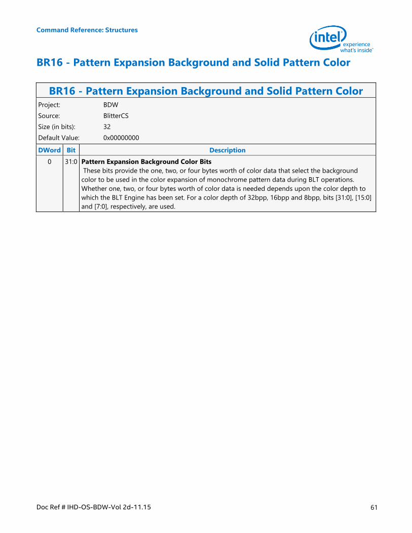
Command Reference: Structures
Doc Ref # IHD-OS-BDW-Vol 2d-11.15 61
BR16 - Pattern Expansion Background and Solid Pattern Color
BR16 - Pattern Expansion Background and Solid Pattern Color Project: BDW
Source: BlitterCS
Size (in bits): 32
Default Value: 0x00000000
DWord Bit Description
0 31:0 Pattern Expansion Background Color Bits
These bits provide the one, two, or four bytes worth of color data that select the background
color to be used in the color expansion of monochrome pattern data during BLT operations.
Whether one, two, or four bytes worth of color data is needed depends upon the color depth to
which the BLT Engine has been set. For a color depth of 32bpp, 16bpp and 8bpp, bits [31:0], [15:0]
and [7:0], respectively, are used.
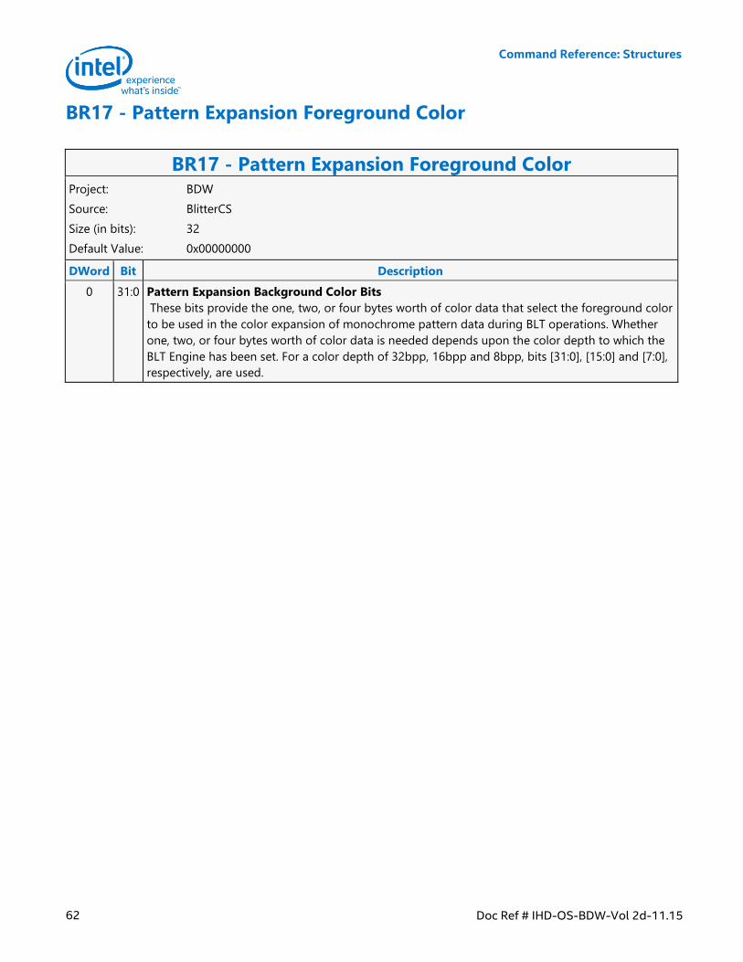
Command Reference: Structures
62 Doc Ref # IHD-OS-BDW-Vol 2d-11.15
BR17 - Pattern Expansion Foreground Color
BR17 - Pattern Expansion Foreground Color Project: BDW
Source: BlitterCS
Size (in bits): 32
Default Value: 0x00000000
DWord Bit Description
0 31:0 Pattern Expansion Background Color Bits
These bits provide the one, two, or four bytes worth of color data that select the foreground color
to be used in the color expansion of monochrome pattern data during BLT operations. Whether
one, two, or four bytes worth of color data is needed depends upon the color depth to which the
BLT Engine has been set. For a color depth of 32bpp, 16bpp and 8bpp, bits [31:0], [15:0] and [7:0],
respectively, are used.
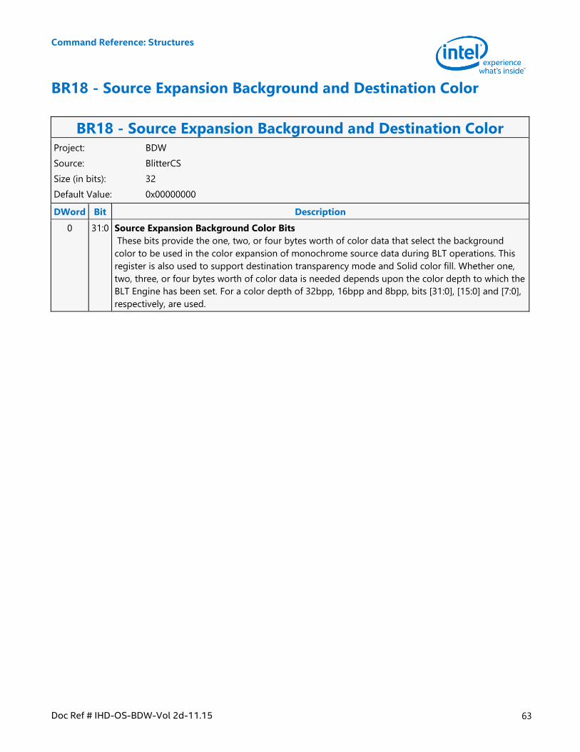
Command Reference: Structures
Doc Ref # IHD-OS-BDW-Vol 2d-11.15 63
BR18 - Source Expansion Background and Destination Color
BR18 - Source Expansion Background and Destination Color Project: BDW
Source: BlitterCS
Size (in bits): 32
Default Value: 0x00000000
DWord Bit Description
0 31:0 Source Expansion Background Color Bits
These bits provide the one, two, or four bytes worth of color data that select the background
color to be used in the color expansion of monochrome source data during BLT operations. This
register is also used to support destination transparency mode and Solid color fill. Whether one,
two, three, or four bytes worth of color data is needed depends upon the color depth to which the
BLT Engine has been set. For a color depth of 32bpp, 16bpp and 8bpp, bits [31:0], [15:0] and [7:0],
respectively, are used.
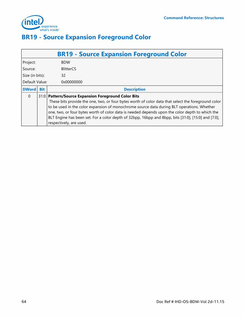
Command Reference: Structures
64 Doc Ref # IHD-OS-BDW-Vol 2d-11.15
BR19 - Source Expansion Foreground Color
BR19 - Source Expansion Foreground Color Project: BDW
Source: BlitterCS
Size (in bits): 32
Default Value: 0x00000000
DWord Bit Description
0 31:0 Pattern/Source Expansion Foreground Color Bits
These bits provide the one, two, or four bytes worth of color data that select the foreground color
to be used in the color expansion of monochrome source data during BLT operations. Whether
one, two, or four bytes worth of color data is needed depends upon the color depth to which the
BLT Engine has been set. For a color depth of 32bpp, 16bpp and 8bpp, bits [31:0], [15:0] and [7:0],
respectively, are used.
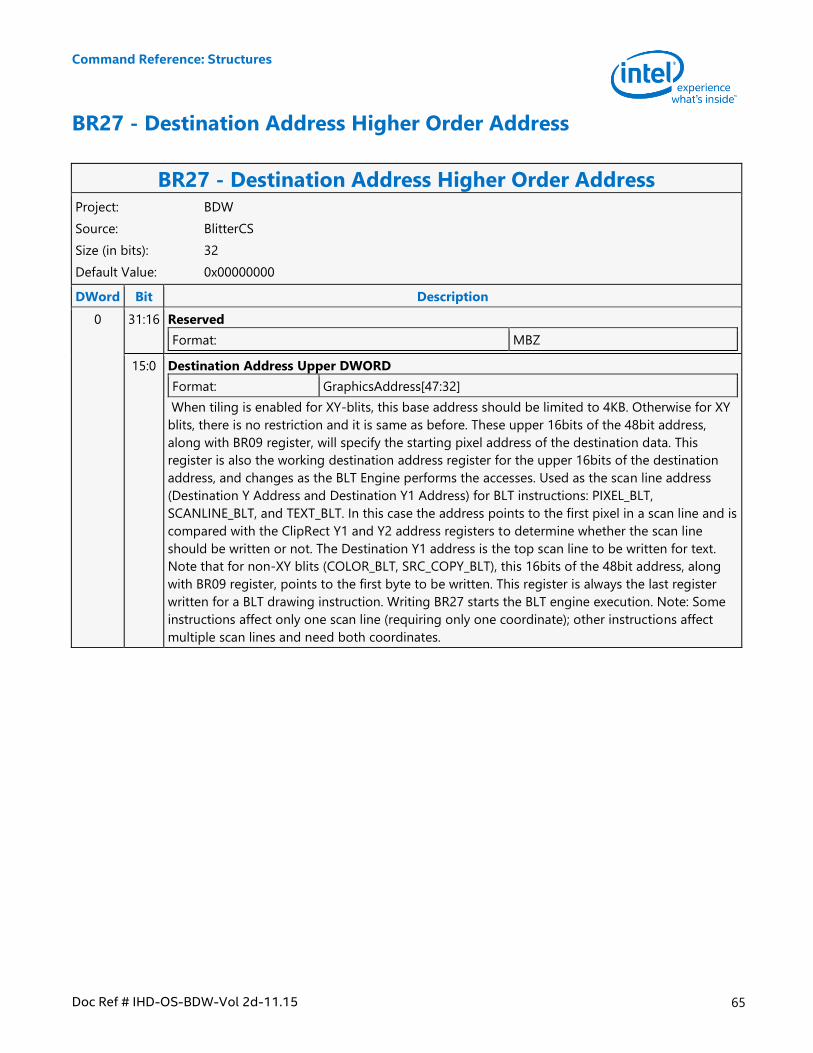
Command Reference: Structures
Doc Ref # IHD-OS-BDW-Vol 2d-11.15 65
BR27 - Destination Address Higher Order Address
BR27 - Destination Address Higher Order Address Project: BDW
Source: BlitterCS
Size (in bits): 32
Default Value: 0x00000000
DWord Bit Description
0 31:16 Reserved
Format: MBZ
15:0 Destination Address Upper DWORD
Format: GraphicsAddress[47:32]
When tiling is enabled for XY-blits, this base address should be limited to 4KB. Otherwise for XY
blits, there is no restriction and it is same as before. These upper 16bits of the 48bit address,
along with BR09 register, will specify the starting pixel address of the destination data. This
register is also the working destination address register for the upper 16bits of the destination
address, and changes as the BLT Engine performs the accesses. Used as the scan line address
(Destination Y Address and Destination Y1 Address) for BLT instructions: PIXEL_BLT,
SCANLINE_BLT, and TEXT_BLT. In this case the address points to the first pixel in a scan line and is
compared with the ClipRect Y1 and Y2 address registers to determine whether the scan line
should be written or not. The Destination Y1 address is the top scan line to be written for text.
Note that for non-XY blits (COLOR_BLT, SRC_COPY_BLT), this 16bits of the 48bit address, along
with BR09 register, points to the first byte to be written. This register is always the last register
written for a BLT drawing instruction. Writing BR27 starts the BLT engine execution. Note: Some
instructions affect only one scan line (requiring only one coordinate); other instructions affect
multiple scan lines and need both coordinates.
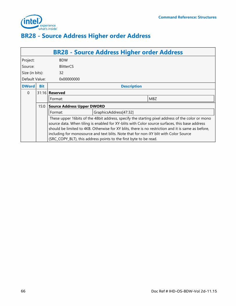
Command Reference: Structures
66 Doc Ref # IHD-OS-BDW-Vol 2d-11.15
BR28 - Source Address Higher order Address
BR28 - Source Address Higher order Address Project: BDW
Source: BlitterCS
Size (in bits): 32
Default Value: 0x00000000
DWord Bit Description
0 31:16 Reserved
Format: MBZ
15:0 Source Address Upper DWORD
Format: GraphicsAddress[47:32]
These upper 16bits of the 48bit address, specify the starting pixel address of the color or mono
source data. When tiling is enabled for XY-blits with Color source surfaces, this base address
should be limited to 4KB. Otherwise for XY blits, there is no restriction and it is same as before,
including for monosource and text blits. Note that for non-XY blit with Color Source
(SRC_COPY_BLT), this address points to the first byte to be read.
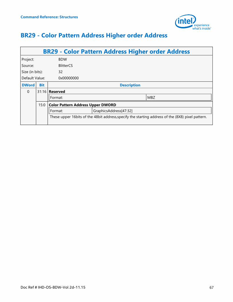
Command Reference: Structures
Doc Ref # IHD-OS-BDW-Vol 2d-11.15 67
BR29 - Color Pattern Address Higher order Address
BR29 - Color Pattern Address Higher order Address Project: BDW
Source: BlitterCS
Size (in bits): 32
Default Value: 0x00000000
DWord Bit Description
0 31:16 Reserved
Format: MBZ
15:0 Color Pattern Address Upper DWORD
Format: GraphicsAddress[47:32]
These upper 16bits of the 48bit address,specify the starting address of the (8X8) pixel pattern.
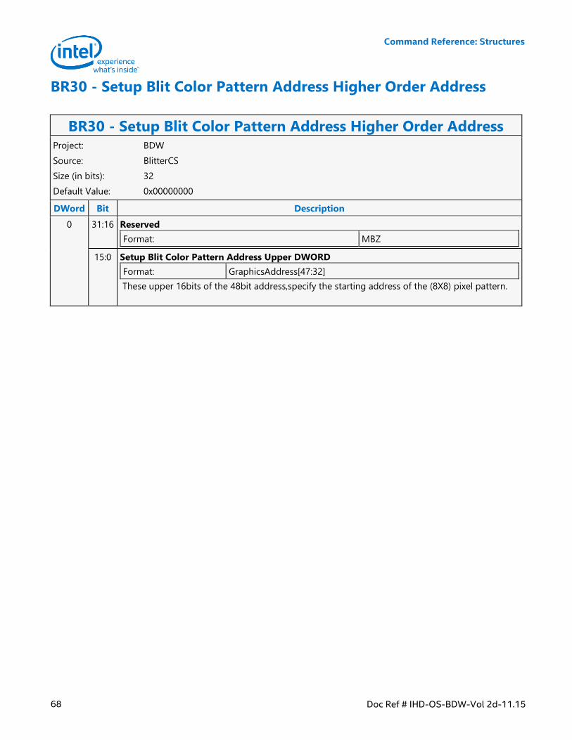
Command Reference: Structures
68 Doc Ref # IHD-OS-BDW-Vol 2d-11.15
BR30 - Setup Blit Color Pattern Address Higher Order Address
BR30 - Setup Blit Color Pattern Address Higher Order Address Project: BDW
Source: BlitterCS
Size (in bits): 32
Default Value: 0x00000000
DWord Bit Description
0 31:16 Reserved
Format: MBZ
15:0 Setup Blit Color Pattern Address Upper DWORD
Format: GraphicsAddress[47:32]
These upper 16bits of the 48bit address,specify the starting address of the (8X8) pixel pattern.
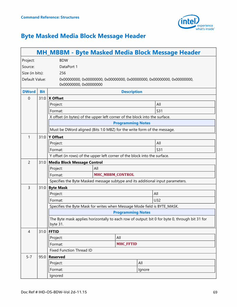
Command Reference: Structures
Doc Ref # IHD-OS-BDW-Vol 2d-11.15 69
Byte Masked Media Block Message Header
MH_MBBM - Byte Masked Media Block Message Header Project: BDW
Source: DataPort 1
Size (in bits): 256
Default Value: 0x00000000, 0x00000000, 0x00000000, 0x00000000, 0x00000000, 0x00000000,
0x00000000, 0x00000000
DWord Bit Description
0 31:0 X Offset
Project: All
Format: S31
X offset (in bytes) of the upper left corner of the block into the surface.
Programming Notes
Must be DWord aligned (Bits 1:0 MBZ) for the write form of the message.
1 31:0 Y Offset
Project: All
Format: S31
Y offset (in rows) of the upper left corner of the block into the surface.
2 31:0 Media Block Message Control
Project: All
Format: MHC_MBBM_CONTROL
Specifies the Byte Masked message subtype and its additional input parameters.
3 31:0 Byte Mask
Project: All
Format: U32
Specifies the Byte Mask for writes when Message Mode field is BYTE_MASK.
Programming Notes
The Byte mask applies horizontally to each row of output: bit 0 for byte 0, through bit 31 for
byte 31.
4 31:0 FFTID
Project: All
Format: MHC_FFTID
Fixed Function Thread ID
5-7 95:0 Reserved
Project: All
Format: Ignore
Ignored
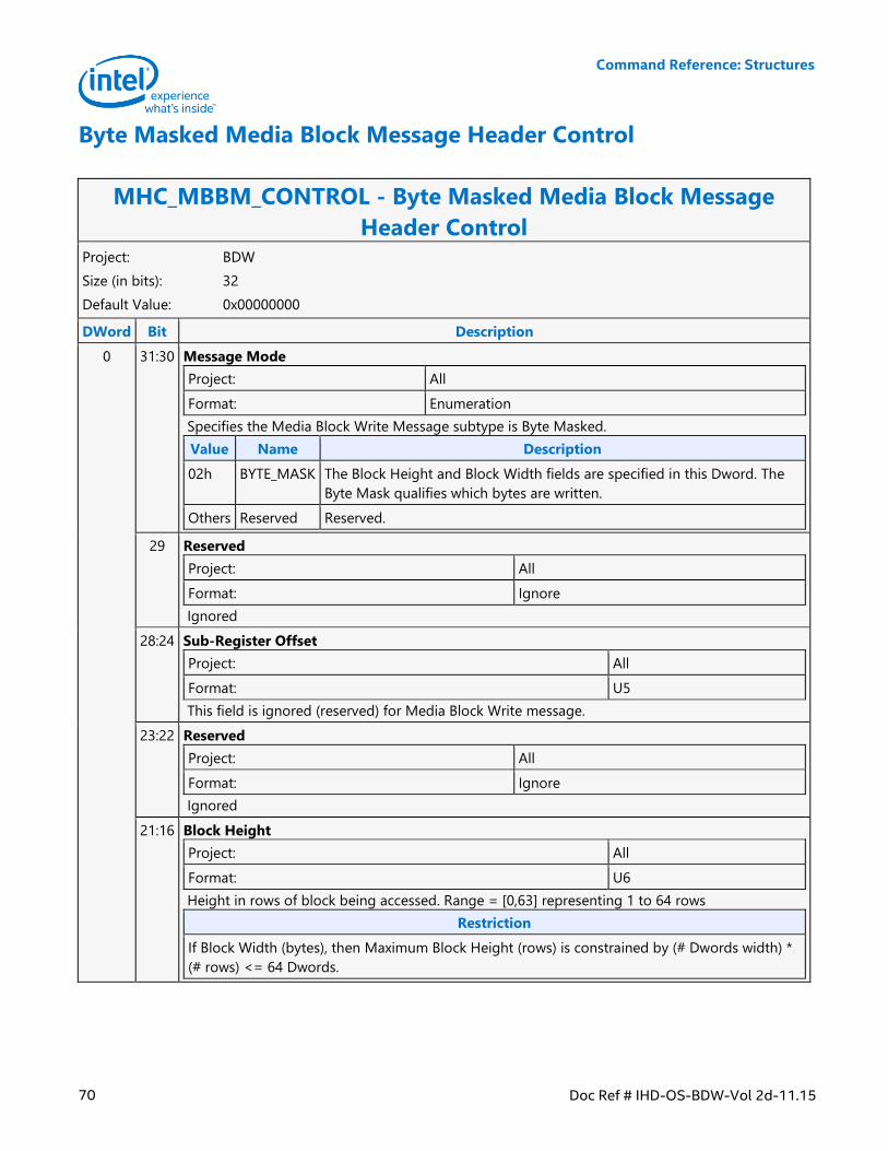
Command Reference: Structures
70 Doc Ref # IHD-OS-BDW-Vol 2d-11.15
Byte Masked Media Block Message Header Control
MHC_MBBM_CONTROL - Byte Masked Media Block Message
Header Control Project: BDW
Size (in bits): 32
Default Value: 0x00000000
DWord Bit Description
0 31:30 Message Mode
Project: All
Format: Enumeration
Specifies the Media Block Write Message subtype is Byte Masked.
Value Name Description
02h BYTE_MASK The Block Height and Block Width fields are specified in this Dword. The
Byte Mask qualifies which bytes are written.
Others Reserved Reserved.
29 Reserved
Project: All
Format: Ignore
Ignored
28:24 Sub-Register Offset
Project: All
Format: U5
This field is ignored (reserved) for Media Block Write message.
23:22 Reserved
Project: All
Format: Ignore
Ignored
21:16 Block Height
Project: All
Format: U6
Height in rows of block being accessed. Range = [0,63] representing 1 to 64 rows
Restriction
If Block Width (bytes), then Maximum Block Height (rows) is constrained by (# Dwords width) *
(# rows) <= 64 Dwords.
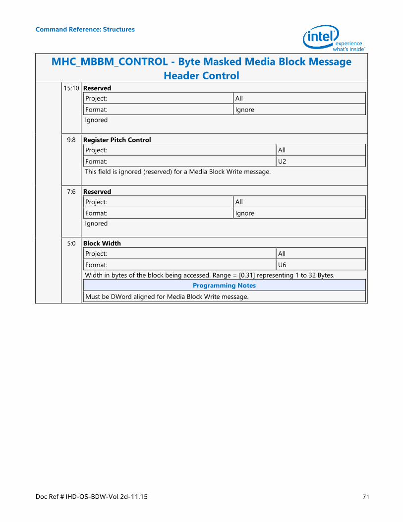
Command Reference: Structures
Doc Ref # IHD-OS-BDW-Vol 2d-11.15 71
MHC_MBBM_CONTROL - Byte Masked Media Block Message
Header Control 15:10 Reserved
Project: All
Format: Ignore
Ignored
9:8 Register Pitch Control
Project: All
Format: U2
This field is ignored (reserved) for a Media Block Write message.
7:6 Reserved
Project: All
Format: Ignore
Ignored
5:0 Block Width
Project: All
Format: U6
Width in bytes of the block being accessed. Range = [0,31] representing 1 to 32 Bytes.
Programming Notes
Must be DWord aligned for Media Block Write message.
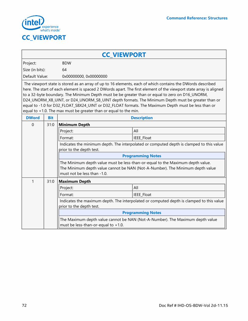
Command Reference: Structures
72 Doc Ref # IHD-OS-BDW-Vol 2d-11.15
CC_VIEWPORT
CC_VIEWPORT Project: BDW
Size (in bits): 64
Default Value: 0x00000000, 0x00000000
The viewport state is stored as an array of up to 16 elements, each of which contains the DWords described
here. The start of each element is spaced 2 DWords apart. The first element of the viewport state array is aligned
to a 32-byte boundary. The Minimum Depth must be be greater than or equal to zero on D16_UNORM,
D24_UNORM_X8_UINT, or D24_UNORM_S8_UINT depth formats. The Minimum Depth must be greater than or
equal to -1.0 for D32_FLOAT_S8X24_UINT or D32_FLOAT formats. The Maximum Depth must be less than or
equal to +1.0. The max must be greater than or equal to the min.
DWord Bit Description
0 31:0 Minimum Depth
Project: All
Format: IEEE_Float
Indicates the minimum depth. The interpolated or computed depth is clamped to this value
prior to the depth test.
Programming Notes
The Minimum depth value must be less-than-or-equal to the Maximum depth value.
The Minimum depth value cannot be NAN (Not-A-Number). The Minimum depth value
must not be less than -1.0.
1 31:0 Maximum Depth
Project: All
Format: IEEE_Float
Indicates the maximum depth. The interpolated or computed depth is clamped to this value
prior to the depth test.
Programming Notes
The Maximum depth value cannot be NAN (Not-A-Number). The Maximum depth value
must be less-than-or-equal to +1.0.
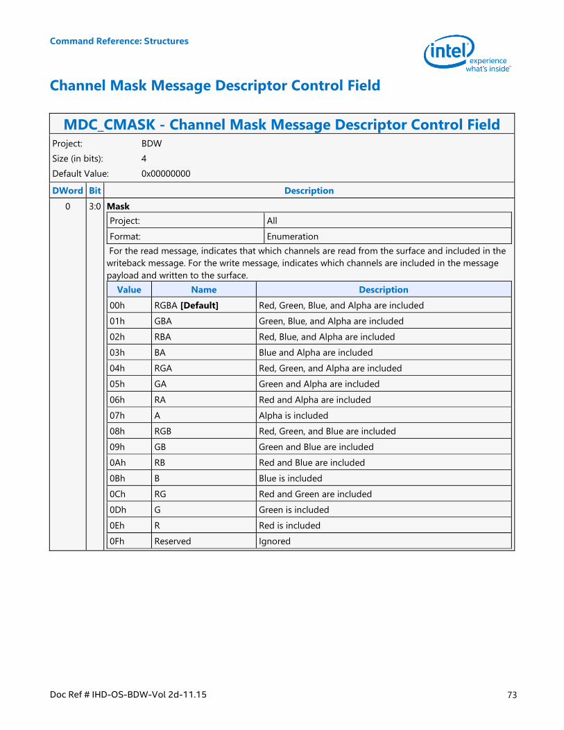
Command Reference: Structures
Doc Ref # IHD-OS-BDW-Vol 2d-11.15 73
Channel Mask Message Descriptor Control Field
MDC_CMASK - Channel Mask Message Descriptor Control Field Project: BDW
Size (in bits): 4
Default Value: 0x00000000
DWord Bit Description
0 3:0 Mask
Project: All
Format: Enumeration
For the read message, indicates that which channels are read from the surface and included in the
writeback message. For the write message, indicates which channels are included in the message
payload and written to the surface.
Value Name Description
00h RGBA [Default] Red, Green, Blue, and Alpha are included
01h GBA Green, Blue, and Alpha are included
02h RBA Red, Blue, and Alpha are included
03h BA Blue and Alpha are included
04h RGA Red, Green, and Alpha are included
05h GA Green and Alpha are included
06h RA Red and Alpha are included
07h A Alpha is included
08h RGB Red, Green, and Blue are included
09h GB Green and Blue are included
0Ah RB Red and Blue are included
0Bh B Blue is included
0Ch RG Red and Green are included
0Dh G Green is included
0Eh R Red is included
0Fh Reserved Ignored
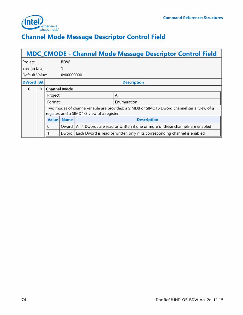
Command Reference: Structures
74 Doc Ref # IHD-OS-BDW-Vol 2d-11.15
Channel Mode Message Descriptor Control Field
MDC_CMODE - Channel Mode Message Descriptor Control Field Project: BDW
Size (in bits): 1
Default Value: 0x00000000
DWord Bit Description
0 0 Channel Mode
Project: All
Format: Enumeration
Two modes of channel-enable are provided: a SIMD8 or SIMD16 Dword channel serial view of a
register, and a SIMD4x2 view of a register.
Value Name Description
0 Oword All 4 Dwords are read or written if one or more of these channels are enabled
1 Dword Each Dword is read or written only if its corresponding channel is enabled.
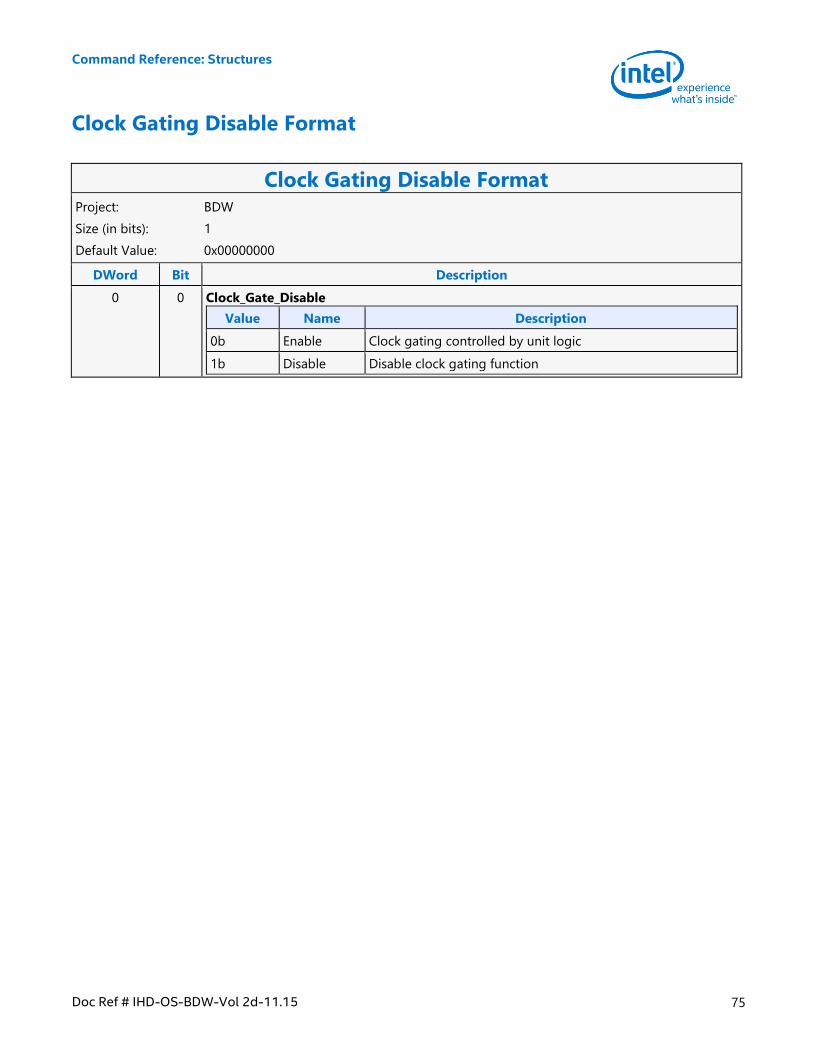
Command Reference: Structures
Doc Ref # IHD-OS-BDW-Vol 2d-11.15 75
Clock Gating Disable Format
Clock Gating Disable Format Project: BDW
Size (in bits): 1
Default Value: 0x00000000
DWord Bit Description
0 0 Clock_Gate_Disable
Value Name Description
0b Enable Clock gating controlled by unit logic
1b Disable Disable clock gating function
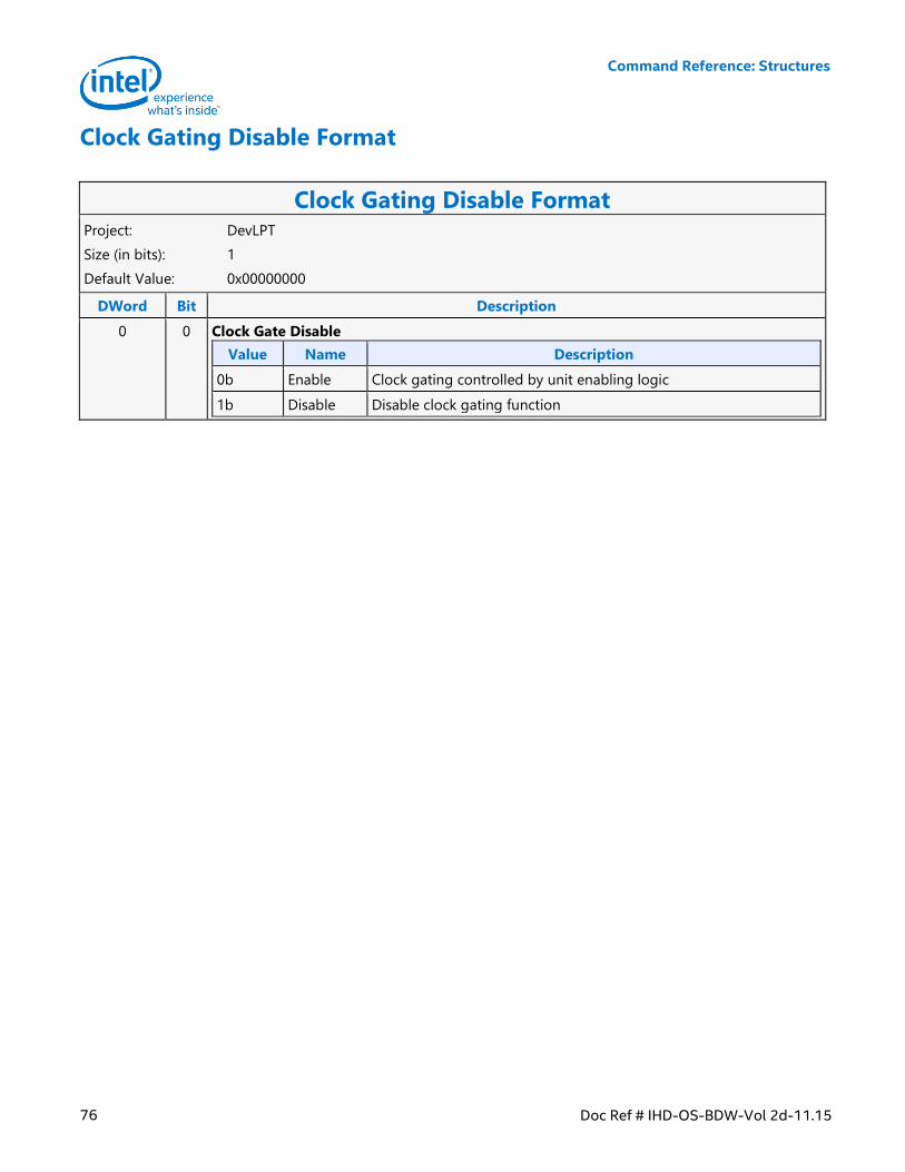
Command Reference: Structures
76 Doc Ref # IHD-OS-BDW-Vol 2d-11.15
Clock Gating Disable Format
Clock Gating Disable Format Project: DevLPT
Size (in bits): 1
Default Value: 0x00000000
DWord Bit Description
0 0 Clock Gate Disable
Value Name Description
0b Enable Clock gating controlled by unit enabling logic
1b Disable Disable clock gating function
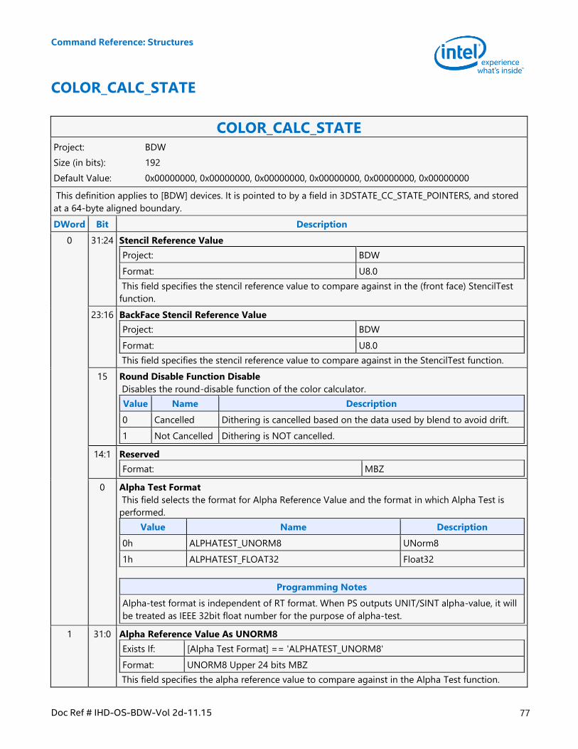
Command Reference: Structures
Doc Ref # IHD-OS-BDW-Vol 2d-11.15 77
COLOR_CALC_STATE
COLOR_CALC_STATE Project: BDW
Size (in bits): 192
Default Value: 0x00000000, 0x00000000, 0x00000000, 0x00000000, 0x00000000, 0x00000000
This definition applies to [BDW] devices. It is pointed to by a field in 3DSTATE_CC_STATE_POINTERS, and stored
at a 64-byte aligned boundary.
DWord Bit Description
0 31:24 Stencil Reference Value
Project: BDW
Format: U8.0
This field specifies the stencil reference value to compare against in the (front face) StencilTest
function.
23:16 BackFace Stencil Reference Value
Project: BDW
Format: U8.0
This field specifies the stencil reference value to compare against in the StencilTest function.
15 Round Disable Function Disable
Disables the round-disable function of the color calculator.
Value Name Description
0 Cancelled Dithering is cancelled based on the data used by blend to avoid drift.
1 Not Cancelled Dithering is NOT cancelled.
14:1 Reserved
Format: MBZ
0 Alpha Test Format
This field selects the format for Alpha Reference Value and the format in which Alpha Test is
performed.
Value Name Description
0h ALPHATEST_UNORM8 UNorm8
1h ALPHATEST_FLOAT32 Float32
Programming Notes
Alpha-test format is independent of RT format. When PS outputs UNIT/SINT alpha-value, it will
be treated as IEEE 32bit float number for the purpose of alpha-test.
1 31:0 Alpha Reference Value As UNORM8
Exists If: [Alpha Test Format] == 'ALPHATEST_UNORM8'
Format: UNORM8 Upper 24 bits MBZ
This field specifies the alpha reference value to compare against in the Alpha Test function.
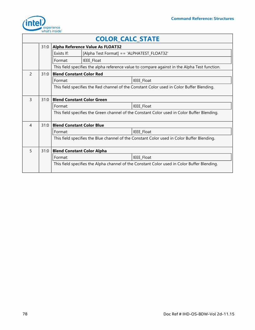
Command Reference: Structures
78 Doc Ref # IHD-OS-BDW-Vol 2d-11.15
COLOR_CALC_STATE 31:0 Alpha Reference Value As FLOAT32
Exists If: [Alpha Test Format] == 'ALPHATEST_FLOAT32'
Format: IEEE_Float
This field specifies the alpha reference value to compare against in the Alpha Test function.
2 31:0 Blend Constant Color Red
Format: IEEE_Float
This field specifies the Red channel of the Constant Color used in Color Buffer Blending.
3 31:0 Blend Constant Color Green
Format: IEEE_Float
This field specifies the Green channel of the Constant Color used in Color Buffer Blending.
4 31:0 Blend Constant Color Blue
Format: IEEE_Float
This field specifies the Blue channel of the Constant Color used in Color Buffer Blending.
5 31:0 Blend Constant Color Alpha
Format: IEEE_Float
This field specifies the Alpha channel of the Constant Color used in Color Buffer Blending.
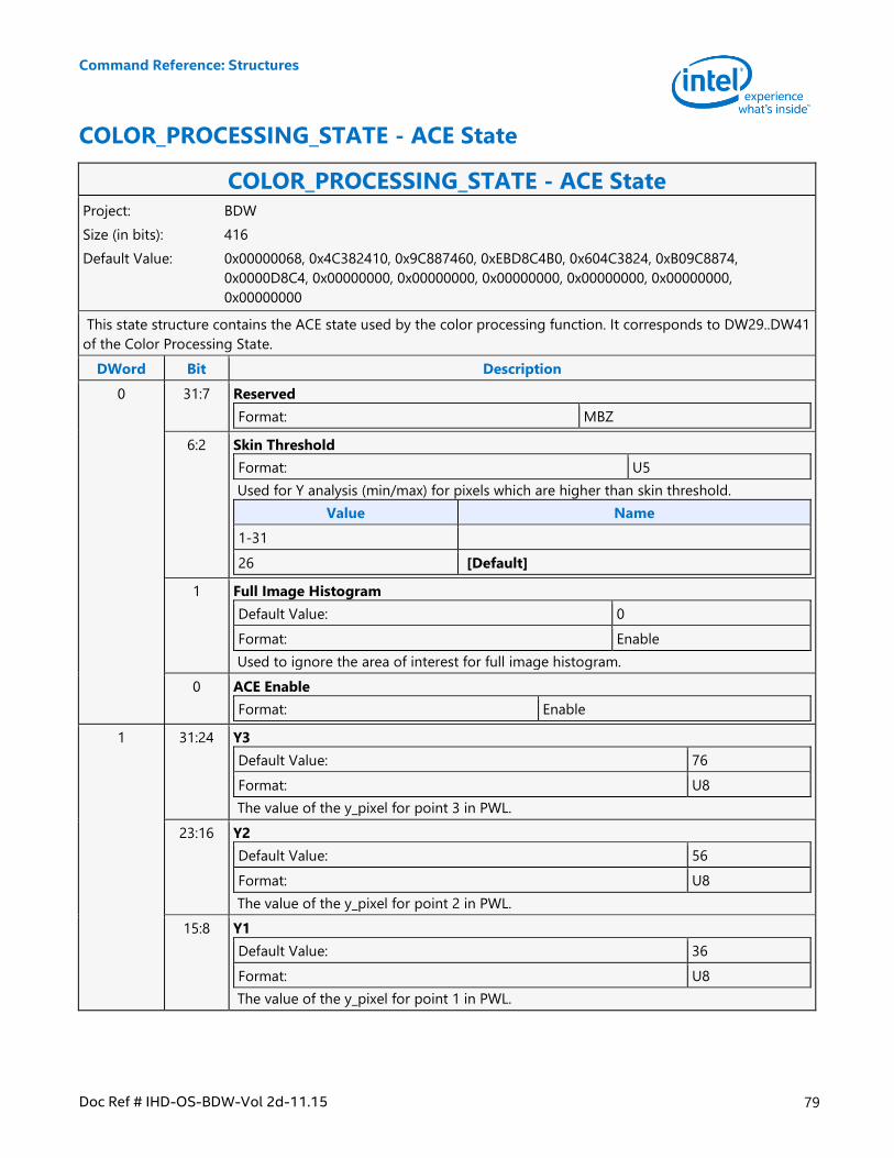
Command Reference: Structures
Doc Ref # IHD-OS-BDW-Vol 2d-11.15 79
COLOR_PROCESSING_STATE - ACE State
COLOR_PROCESSING_STATE - ACE State Project: BDW
Size (in bits): 416
Default Value: 0x00000068, 0x4C382410, 0x9C887460, 0xEBD8C4B0, 0x604C3824, 0xB09C8874,
0x0000D8C4, 0x00000000, 0x00000000, 0x00000000, 0x00000000, 0x00000000,
0x00000000
This state structure contains the ACE state used by the color processing function. It corresponds to DW29..DW41
of the Color Processing State.
DWord Bit Description
0 31:7 Reserved
Format: MBZ
6:2 Skin Threshold
Format: U5
Used for Y analysis (min/max) for pixels which are higher than skin threshold.
Value Name
1-31
26 [Default]
1 Full Image Histogram
Default Value: 0
Format: Enable
Used to ignore the area of interest for full image histogram.
0 ACE Enable
Format: Enable
1 31:24 Y3
Default Value: 76
Format: U8
The value of the y_pixel for point 3 in PWL.
23:16 Y2
Default Value: 56
Format: U8
The value of the y_pixel for point 2 in PWL.
15:8 Y1
Default Value: 36
Format: U8
The value of the y_pixel for point 1 in PWL.
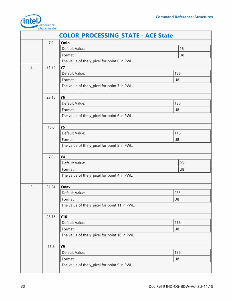
Command Reference: Structures
80 Doc Ref # IHD-OS-BDW-Vol 2d-11.15
COLOR_PROCESSING_STATE - ACE State 7:0 Ymin
Default Value: 16
Format: U8
The value of the y_pixel for point 0 in PWL.
2 31:24 Y7
Default Value: 156
Format: U8
The value of the y_pixel for point 7 in PWL.
23:16 Y6
Default Value: 136
Format: U8
The value of the y_pixel for point 6 in PWL.
15:8 Y5
Default Value: 116
Format: U8
The value of the y_pixel for point 5 in PWL.
7:0 Y4
Default Value: 96
Format: U8
The value of the y_pixel for point 4 in PWL.
3 31:24 Ymax
Default Value: 235
Format: U8
The value of the y_pixel for point 11 in PWL.
23:16 Y10
Default Value: 216
Format: U8
The value of the y_pixel for point 10 in PWL.
15:8 Y9
Default Value: 196
Format: U8
The value of the y_pixel for point 9 in PWL.
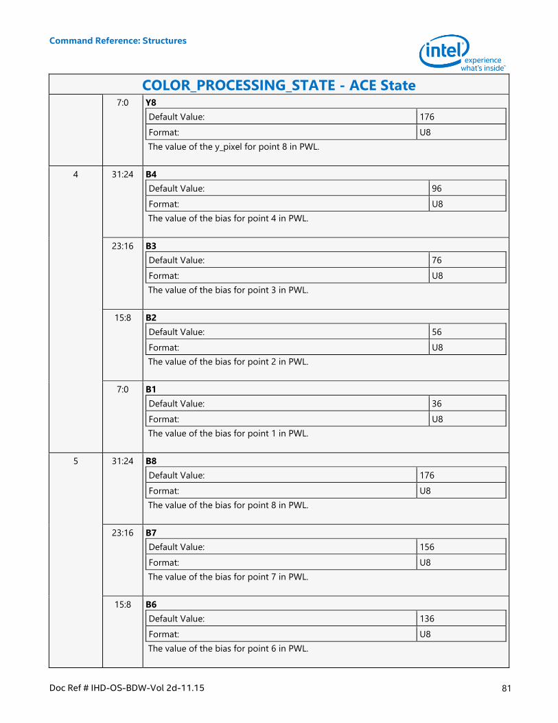
Command Reference: Structures
Doc Ref # IHD-OS-BDW-Vol 2d-11.15 81
COLOR_PROCESSING_STATE - ACE State 7:0 Y8
Default Value: 176
Format: U8
The value of the y_pixel for point 8 in PWL.
4 31:24 B4
Default Value: 96
Format: U8
The value of the bias for point 4 in PWL.
23:16 B3
Default Value: 76
Format: U8
The value of the bias for point 3 in PWL.
15:8 B2
Default Value: 56
Format: U8
The value of the bias for point 2 in PWL.
7:0 B1
Default Value: 36
Format: U8
The value of the bias for point 1 in PWL.
5 31:24 B8
Default Value: 176
Format: U8
The value of the bias for point 8 in PWL.
23:16 B7
Default Value: 156
Format: U8
The value of the bias for point 7 in PWL.
15:8 B6
Default Value: 136
Format: U8
The value of the bias for point 6 in PWL.
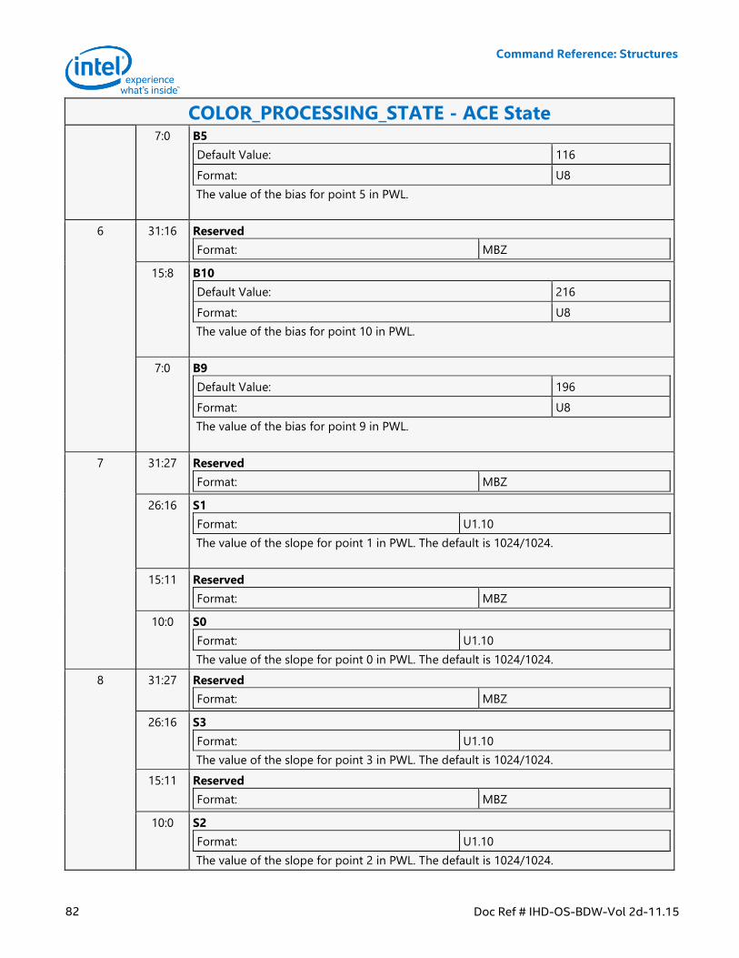
Command Reference: Structures
82 Doc Ref # IHD-OS-BDW-Vol 2d-11.15
COLOR_PROCESSING_STATE - ACE State 7:0 B5
Default Value: 116
Format: U8
The value of the bias for point 5 in PWL.
6 31:16 Reserved
Format: MBZ
15:8 B10
Default Value: 216
Format: U8
The value of the bias for point 10 in PWL.
7:0 B9
Default Value: 196
Format: U8
The value of the bias for point 9 in PWL.
7 31:27 Reserved
Format: MBZ
26:16 S1
Format: U1.10
The value of the slope for point 1 in PWL. The default is 1024/1024.
15:11 Reserved
Format: MBZ
10:0 S0
Format: U1.10
The value of the slope for point 0 in PWL. The default is 1024/1024.
8 31:27 Reserved
Format: MBZ
26:16 S3
Format: U1.10
The value of the slope for point 3 in PWL. The default is 1024/1024.
15:11 Reserved
Format: MBZ
10:0 S2
Format: U1.10
The value of the slope for point 2 in PWL. The default is 1024/1024.
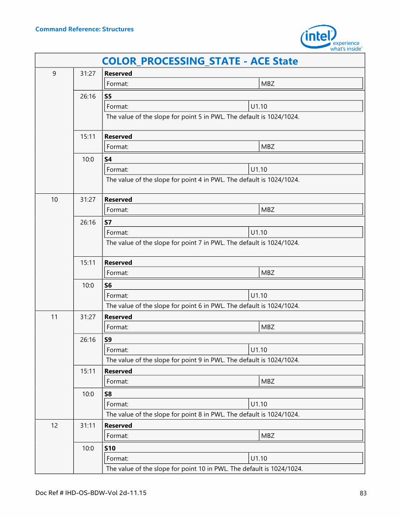
Command Reference: Structures
Doc Ref # IHD-OS-BDW-Vol 2d-11.15 83
COLOR_PROCESSING_STATE - ACE State 9 31:27 Reserved
Format: MBZ
26:16 S5
Format: U1.10
The value of the slope for point 5 in PWL. The default is 1024/1024.
15:11 Reserved
Format: MBZ
10:0 S4
Format: U1.10
The value of the slope for point 4 in PWL. The default is 1024/1024.
10 31:27 Reserved
Format: MBZ
26:16 S7
Format: U1.10
The value of the slope for point 7 in PWL. The default is 1024/1024.
15:11 Reserved
Format: MBZ
10:0 S6
Format: U1.10
The value of the slope for point 6 in PWL. The default is 1024/1024.
11 31:27 Reserved
Format: MBZ
26:16 S9
Format: U1.10
The value of the slope for point 9 in PWL. The default is 1024/1024.
15:11 Reserved
Format: MBZ
10:0 S8
Format: U1.10
The value of the slope for point 8 in PWL. The default is 1024/1024.
12 31:11 Reserved
Format: MBZ
10:0 S10
Format: U1.10
The value of the slope for point 10 in PWL. The default is 1024/1024.
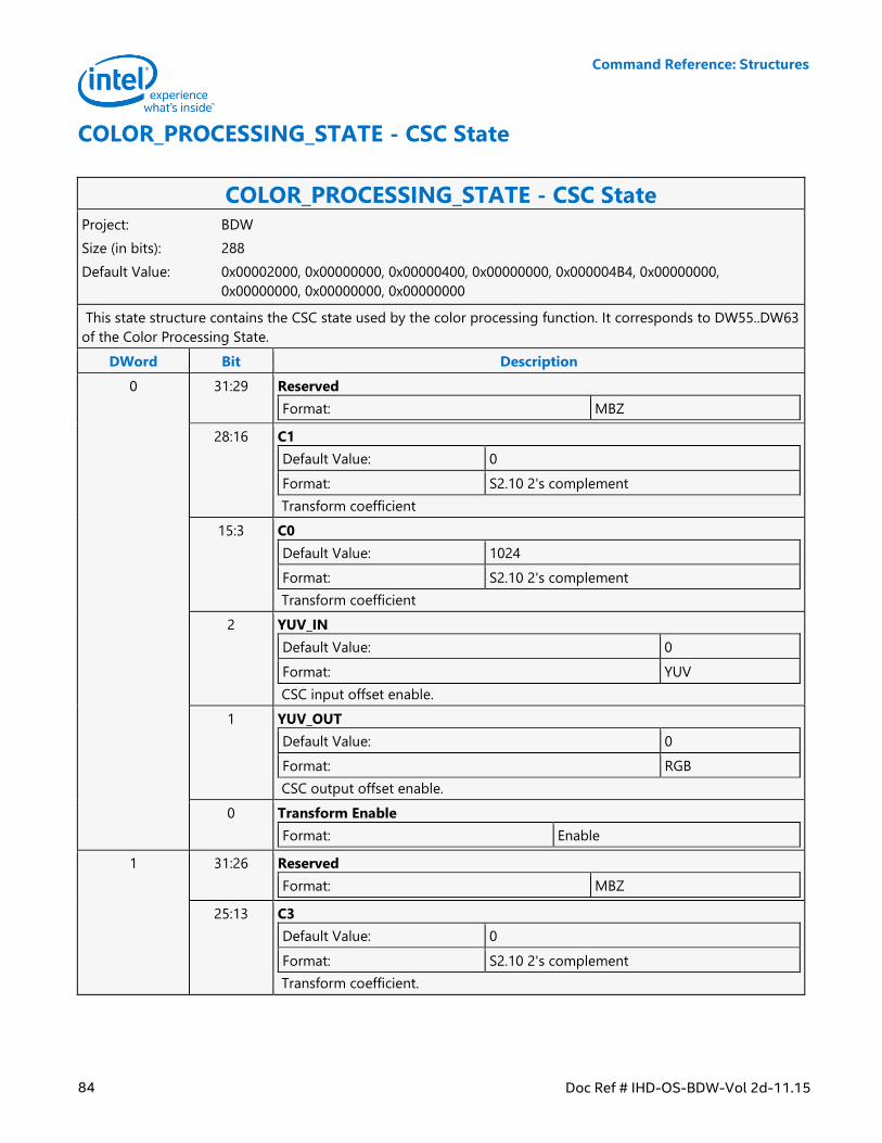
Command Reference: Structures
84 Doc Ref # IHD-OS-BDW-Vol 2d-11.15
COLOR_PROCESSING_STATE - CSC State
COLOR_PROCESSING_STATE - CSC State Project: BDW
Size (in bits): 288
Default Value: 0x00002000, 0x00000000, 0x00000400, 0x00000000, 0x000004B4, 0x00000000,
0x00000000, 0x00000000, 0x00000000
This state structure contains the CSC state used by the color processing function. It corresponds to DW55..DW63
of the Color Processing State.
DWord Bit Description
0 31:29 Reserved
Format: MBZ
28:16 C1
Default Value: 0
Format: S2.10 2's complement
Transform coefficient
15:3 C0
Default Value: 1024
Format: S2.10 2's complement
Transform coefficient
2 YUV_IN
Default Value: 0
Format: YUV
CSC input offset enable.
1 YUV_OUT
Default Value: 0
Format: RGB
CSC output offset enable.
0 Transform Enable
Format: Enable
1 31:26 Reserved
Format: MBZ
25:13 C3
Default Value: 0
Format: S2.10 2's complement
Transform coefficient.
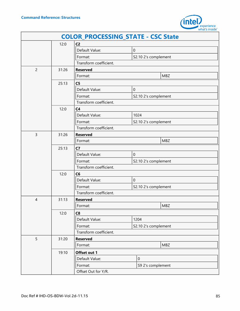
Command Reference: Structures
Doc Ref # IHD-OS-BDW-Vol 2d-11.15 85
COLOR_PROCESSING_STATE - CSC State 12:0 C2
Default Value: 0
Format: S2.10 2's complement
Transform coefficient.
2 31:26 Reserved
Format: MBZ
25:13 C5
Default Value: 0
Format: S2.10 2's complement
Transform coefficient.
12:0 C4
Default Value: 1024
Format: S2.10 2's complement
Transform coefficient.
3 31:26 Reserved
Format: MBZ
25:13 C7
Default Value: 0
Format: S2.10 2's complement
Transform coefficient.
12:0 C6
Default Value: 0
Format: S2.10 2's complement
Transform coefficient.
4 31:13 Reserved
Format: MBZ
12:0 C8
Default Value: 1204
Format: S2.10 2's complement
Transform coefficient.
5 31:20 Reserved
Format: MBZ
19:10 Offset out 1
Default Value: 0
Format: S9 2's complement
Offset Out for Y/R.
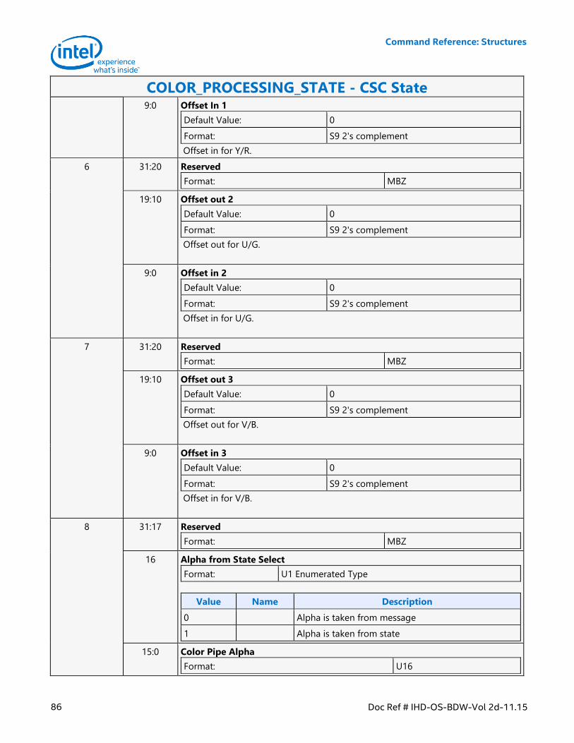
Command Reference: Structures
86 Doc Ref # IHD-OS-BDW-Vol 2d-11.15
COLOR_PROCESSING_STATE - CSC State 9:0 Offset In 1
Default Value: 0
Format: S9 2's complement
Offset in for Y/R.
6 31:20 Reserved
Format: MBZ
19:10 Offset out 2
Default Value: 0
Format: S9 2's complement
Offset out for U/G.
9:0 Offset in 2
Default Value: 0
Format: S9 2's complement
Offset in for U/G.
7 31:20 Reserved
Format: MBZ
19:10 Offset out 3
Default Value: 0
Format: S9 2's complement
Offset out for V/B.
9:0 Offset in 3
Default Value: 0
Format: S9 2's complement
Offset in for V/B.
8 31:17 Reserved
Format: MBZ
16 Alpha from State Select
Format: U1 Enumerated Type
Value Name Description
0 Alpha is taken from message
1 Alpha is taken from state
15:0 Color Pipe Alpha
Format: U16
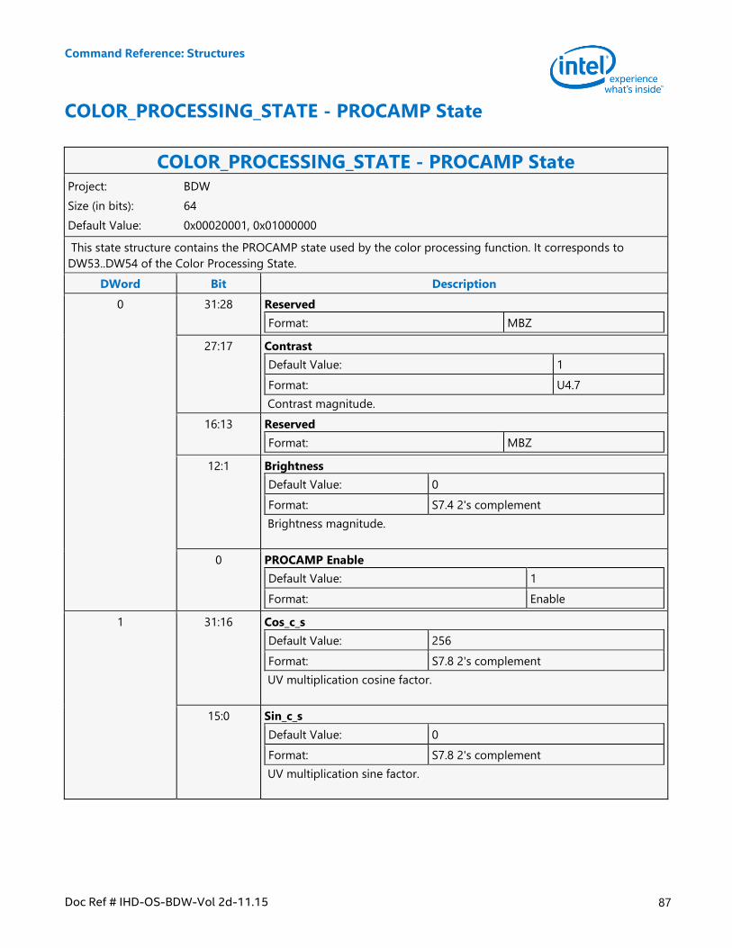
Command Reference: Structures
Doc Ref # IHD-OS-BDW-Vol 2d-11.15 87
COLOR_PROCESSING_STATE - PROCAMP State
COLOR_PROCESSING_STATE - PROCAMP State Project: BDW
Size (in bits): 64
Default Value: 0x00020001, 0x01000000
This state structure contains the PROCAMP state used by the color processing function. It corresponds to
DW53..DW54 of the Color Processing State.
DWord Bit Description
0 31:28 Reserved
Format: MBZ
27:17 Contrast
Default Value: 1
Format: U4.7
Contrast magnitude.
16:13 Reserved
Format: MBZ
12:1 Brightness
Default Value: 0
Format: S7.4 2's complement
Brightness magnitude.
0 PROCAMP Enable
Default Value: 1
Format: Enable
1 31:16 Cos_c_s
Default Value: 256
Format: S7.8 2's complement
UV multiplication cosine factor.
15:0 Sin_c_s
Default Value: 0
Format: S7.8 2's complement
UV multiplication sine factor.
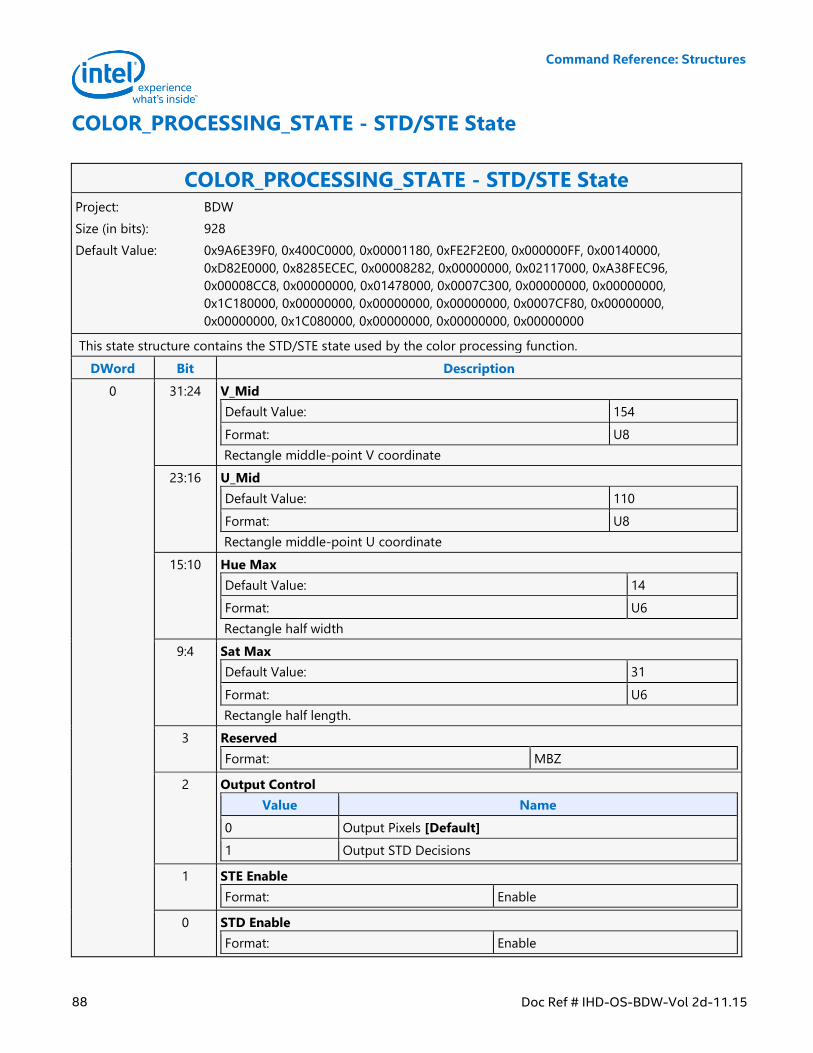
Command Reference: Structures
88 Doc Ref # IHD-OS-BDW-Vol 2d-11.15
COLOR_PROCESSING_STATE - STD/STE State
COLOR_PROCESSING_STATE - STD/STE State Project: BDW
Size (in bits): 928
Default Value: 0x9A6E39F0, 0x400C0000, 0x00001180, 0xFE2F2E00, 0x000000FF, 0x00140000,
0xD82E0000, 0x8285ECEC, 0x00008282, 0x00000000, 0x02117000, 0xA38FEC96,
0x00008CC8, 0x00000000, 0x01478000, 0x0007C300, 0x00000000, 0x00000000,
0x1C180000, 0x00000000, 0x00000000, 0x00000000, 0x0007CF80, 0x00000000,
0x00000000, 0x1C080000, 0x00000000, 0x00000000, 0x00000000
This state structure contains the STD/STE state used by the color processing function.
DWord Bit Description
0 31:24 V_Mid
Default Value: 154
Format: U8
Rectangle middle-point V coordinate
23:16 U_Mid
Default Value: 110
Format: U8
Rectangle middle-point U coordinate
15:10 Hue Max
Default Value: 14
Format: U6
Rectangle half width
9:4 Sat Max
Default Value: 31
Format: U6
Rectangle half length.
3 Reserved
Format: MBZ
2 Output Control
Value Name
0 Output Pixels [Default]
1 Output STD Decisions
1 STE Enable
Format: Enable
0 STD Enable
Format: Enable
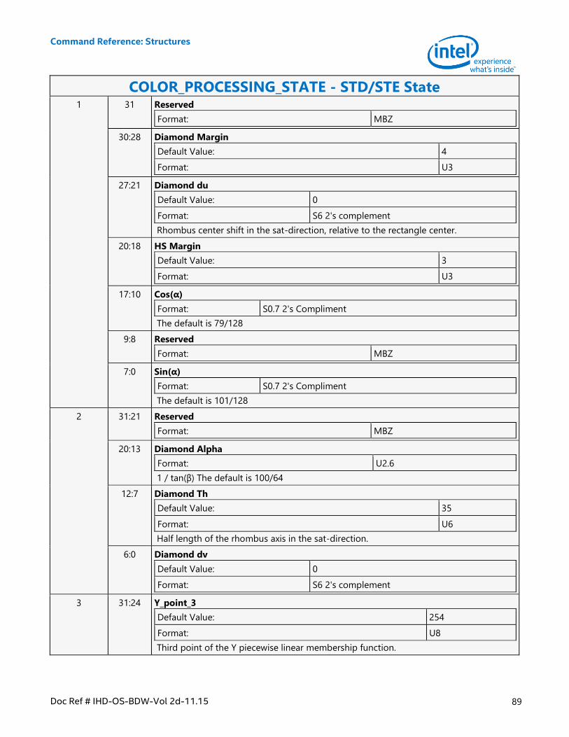
Command Reference: Structures
Doc Ref # IHD-OS-BDW-Vol 2d-11.15 89
COLOR_PROCESSING_STATE - STD/STE State 1 31 Reserved
Format: MBZ
30:28 Diamond Margin
Default Value: 4
Format: U3
27:21 Diamond du
Default Value: 0
Format: S6 2's complement
Rhombus center shift in the sat-direction, relative to the rectangle center.
20:18 HS Margin
Default Value: 3
Format: U3
17:10 Cos(α)
Format: S0.7 2's Compliment
The default is 79/128
9:8 Reserved
Format: MBZ
7:0 Sin(α)
Format: S0.7 2's Compliment
The default is 101/128
2 31:21 Reserved
Format: MBZ
20:13 Diamond Alpha
Format: U2.6
1 / tan(β) The default is 100/64
12:7 Diamond Th
Default Value: 35
Format: U6
Half length of the rhombus axis in the sat-direction.
6:0 Diamond dv
Default Value: 0
Format: S6 2's complement
3 31:24 Y_point_3
Default Value: 254
Format: U8
Third point of the Y piecewise linear membership function.
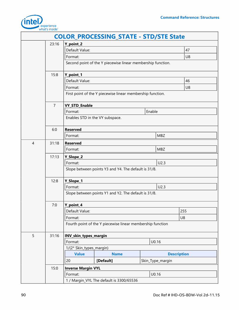
Command Reference: Structures
90 Doc Ref # IHD-OS-BDW-Vol 2d-11.15
COLOR_PROCESSING_STATE - STD/STE State 23:16 Y_point_2
Default Value: 47
Format: U8
Second point of the Y piecewise linear membership function.
15:8 Y_point_1
Default Value: 46
Format: U8
First point of the Y piecewise linear membership function.
7 VY_STD_Enable
Format: Enable
Enables STD in the VY subspace.
6:0 Reserved
Format: MBZ
4 31:18 Reserved
Format: MBZ
17:13 Y_Slope_2
Format: U2.3
Slope between points Y3 and Y4. The default is 31/8.
12:8 Y_Slope_1
Format: U2.3
Slope between points Y1 and Y2. The default is 31/8.
7:0 Y_point_4
Default Value: 255
Format: U8
Fourth point of the Y piecewise linear membership function
5 31:16 INV_skin_types_margin
Format: U0.16
1/(2* Skin_types_margin)
Value Name Description
20 [Default] Skin_Type_margin
15:0 Inverse Margin VYL
Format: U0.16
1 / Margin_VYL The default is 3300/65536
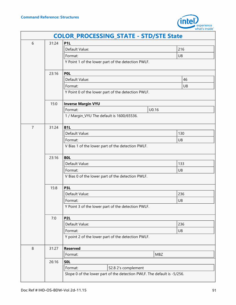
Command Reference: Structures
Doc Ref # IHD-OS-BDW-Vol 2d-11.15 91
COLOR_PROCESSING_STATE - STD/STE State 6 31:24 P1L
Default Value: 216
Format: U8
Y Point 1 of the lower part of the detection PWLF.
23:16 P0L
Default Value: 46
Format: U8
Y Point 0 of the lower part of the detection PWLF.
15:0 Inverse Margin VYU
Format: U0.16
1 / Margin_VYU The default is 1600/65536.
7 31:24 B1L
Default Value: 130
Format: U8
V Bias 1 of the lower part of the detection PWLF.
23:16 B0L
Default Value: 133
Format: U8
V Bias 0 of the lower part of the detection PWLF.
15:8 P3L
Default Value: 236
Format: U8
Y Point 3 of the lower part of the detection PWLF.
7:0 P2L
Default Value: 236
Format: U8
Y point 2 of the lower part of the detection PWLF.
8 31:27 Reserved
Format: MBZ
26:16 S0L
Format: S2.8 2's complement
Slope 0 of the lower part of the detection PWLF. The default is -5/256.
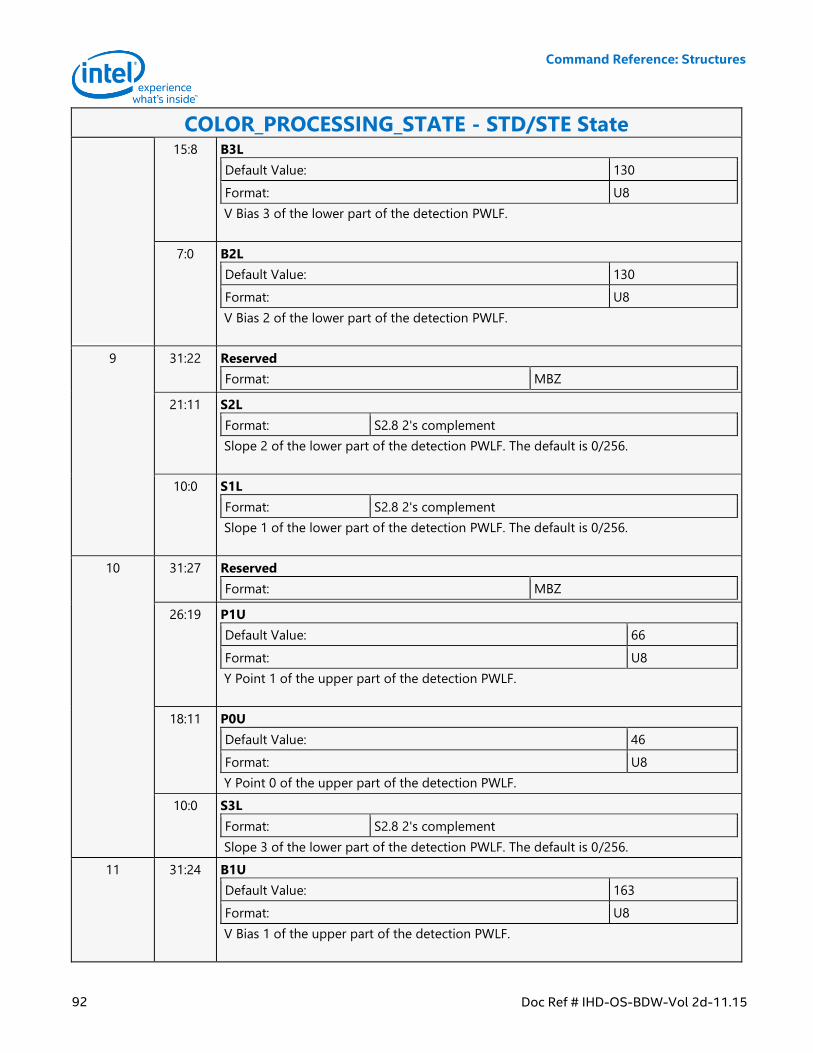
Command Reference: Structures
92 Doc Ref # IHD-OS-BDW-Vol 2d-11.15
COLOR_PROCESSING_STATE - STD/STE State 15:8 B3L
Default Value: 130
Format: U8
V Bias 3 of the lower part of the detection PWLF.
7:0 B2L
Default Value: 130
Format: U8
V Bias 2 of the lower part of the detection PWLF.
9 31:22 Reserved
Format: MBZ
21:11 S2L
Format: S2.8 2's complement
Slope 2 of the lower part of the detection PWLF. The default is 0/256.
10:0 S1L
Format: S2.8 2's complement
Slope 1 of the lower part of the detection PWLF. The default is 0/256.
10 31:27 Reserved
Format: MBZ
26:19 P1U
Default Value: 66
Format: U8
Y Point 1 of the upper part of the detection PWLF.
18:11 P0U
Default Value: 46
Format: U8
Y Point 0 of the upper part of the detection PWLF.
10:0 S3L
Format: S2.8 2's complement
Slope 3 of the lower part of the detection PWLF. The default is 0/256.
11 31:24 B1U
Default Value: 163
Format: U8
V Bias 1 of the upper part of the detection PWLF.
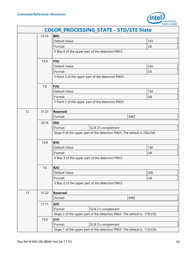
Command Reference: Structures
Doc Ref # IHD-OS-BDW-Vol 2d-11.15 93
COLOR_PROCESSING_STATE - STD/STE State 23:16 B0U
Default Value: 143
Format: U8
V Bias 0 of the upper part of the detection PWLF.
15:8 P3U
Default Value: 236
Format: U8
Y Point 3 of the upper part of the detection PWLF.
7:0 P2U
Default Value: 150
Format: U8
Y Point 2 of the upper part of the detection PWLF.
12 31:27 Reserved
Format: MBZ
26:16 S0U
Format: S2.8 2's complement
Slope 0 of the upper part of the detection PWLF. The default is 256/256.
15:8 B3U
Default Value: 140
Format: U8
V Bias 3 of the upper part of the detection PWLF.
7:0 B2U
Default Value: 200
Format: U8
V Bias 2 of the upper part of the detection PWLF.
13 31:22 Reserved
Format: MBZ
21:11 S2U
Format: S2.8 2's complement
Slope 2 of the upper part of the detection PWLF. The default is -179/256.
10:0 S1U
Format: S2.8 2's complement
Slope 1 of the upper part of the detection PWLF. The default is -113/256.
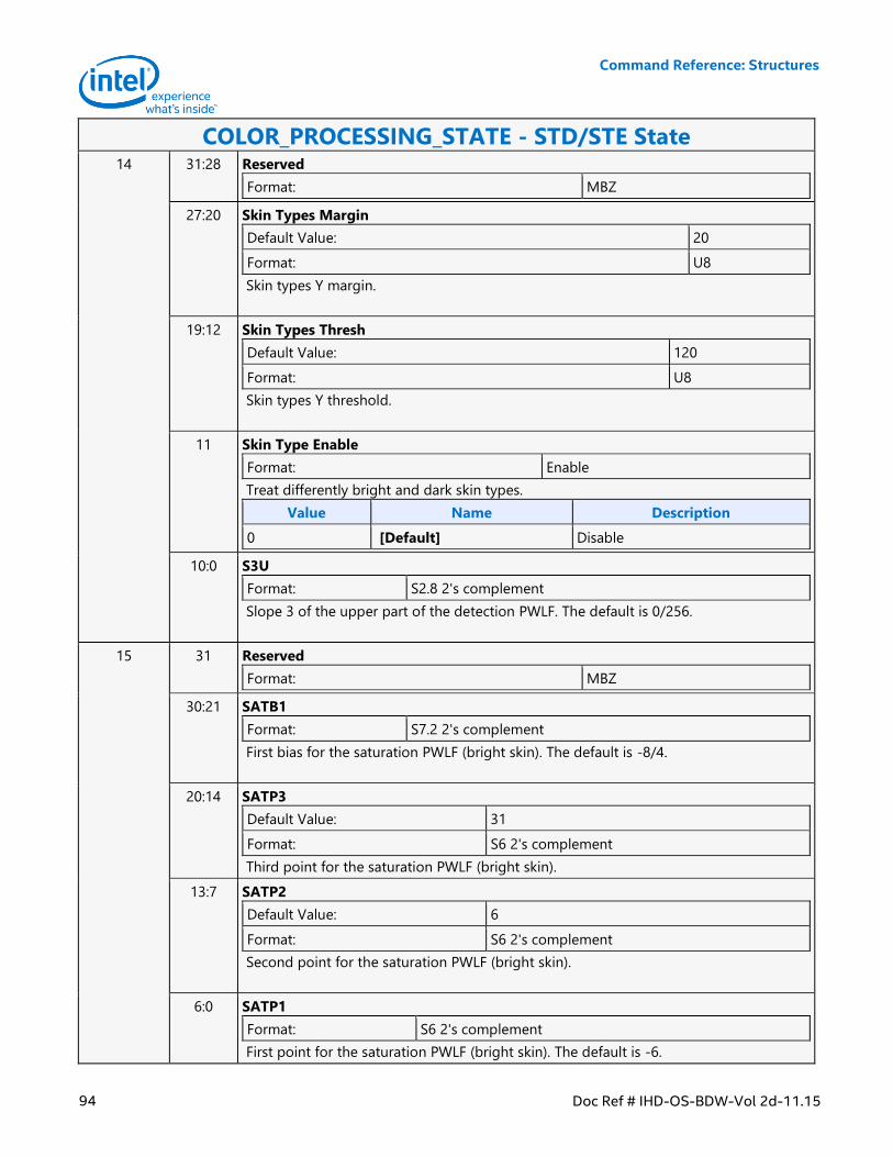
Command Reference: Structures
94 Doc Ref # IHD-OS-BDW-Vol 2d-11.15
COLOR_PROCESSING_STATE - STD/STE State 14 31:28 Reserved
Format: MBZ
27:20 Skin Types Margin
Default Value: 20
Format: U8
Skin types Y margin.
19:12 Skin Types Thresh
Default Value: 120
Format: U8
Skin types Y threshold.
11 Skin Type Enable
Format: Enable
Treat differently bright and dark skin types.
Value Name Description
0 [Default] Disable
10:0 S3U
Format: S2.8 2's complement
Slope 3 of the upper part of the detection PWLF. The default is 0/256.
15 31 Reserved
Format: MBZ
30:21 SATB1
Format: S7.2 2's complement
First bias for the saturation PWLF (bright skin). The default is -8/4.
20:14 SATP3
Default Value: 31
Format: S6 2's complement
Third point for the saturation PWLF (bright skin).
13:7 SATP2
Default Value: 6
Format: S6 2's complement
Second point for the saturation PWLF (bright skin).
6:0 SATP1
Format: S6 2's complement
First point for the saturation PWLF (bright skin). The default is -6.
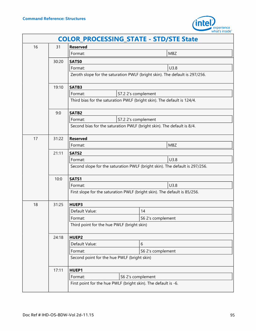
Command Reference: Structures
Doc Ref # IHD-OS-BDW-Vol 2d-11.15 95
COLOR_PROCESSING_STATE - STD/STE State 16 31 Reserved
Format: MBZ
30:20 SATS0
Format: U3.8
Zeroth slope for the saturation PWLF (bright skin). The default is 297/256.
19:10 SATB3
Format: S7.2 2's complement
Third bias for the saturation PWLF (bright skin). The default is 124/4.
9:0 SATB2
Format: S7.2 2's complement
Second bias for the saturation PWLF (bright skin). The default is 8/4.
17 31:22 Reserved
Format: MBZ
21:11 SATS2
Format: U3.8
Second slope for the saturation PWLF (bright skin). The default is 297/256.
10:0 SATS1
Format: U3.8
First slope for the saturation PWLF (bright skin). The default is 85/256.
18 31:25 HUEP3
Default Value: 14
Format: S6 2's complement
Third point for the hue PWLF (bright skin)
24:18 HUEP2
Default Value: 6
Format: S6 2's complement
Second point for the hue PWLF (bright skin)
17:11 HUEP1
Format: S6 2's complement
First point for the hue PWLF (bright skin). The default is -6.
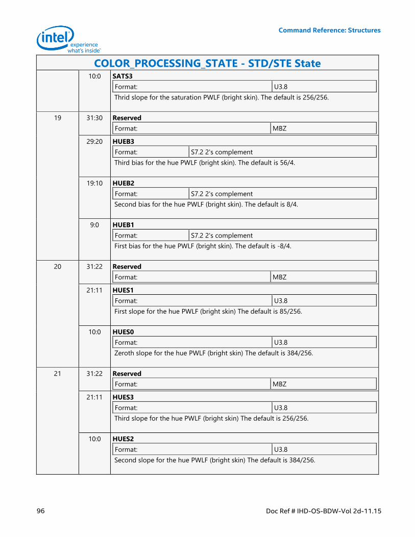
Command Reference: Structures
96 Doc Ref # IHD-OS-BDW-Vol 2d-11.15
COLOR_PROCESSING_STATE - STD/STE State 10:0 SATS3
Format: U3.8
Thrid slope for the saturation PWLF (bright skin). The default is 256/256.
19 31:30 Reserved
Format: MBZ
29:20 HUEB3
Format: S7.2 2's complement
Third bias for the hue PWLF (bright skin). The default is 56/4.
19:10 HUEB2
Format: S7.2 2's complement
Second bias for the hue PWLF (bright skin). The default is 8/4.
9:0 HUEB1
Format: S7.2 2's complement
First bias for the hue PWLF (bright skin). The default is -8/4.
20 31:22 Reserved
Format: MBZ
21:11 HUES1
Format: U3.8
First slope for the hue PWLF (bright skin) The default is 85/256.
10:0 HUES0
Format: U3.8
Zeroth slope for the hue PWLF (bright skin) The default is 384/256.
21 31:22 Reserved
Format: MBZ
21:11 HUES3
Format: U3.8
Third slope for the hue PWLF (bright skin) The default is 256/256.
10:0 HUES2
Format: U3.8
Second slope for the hue PWLF (bright skin) The default is 384/256.
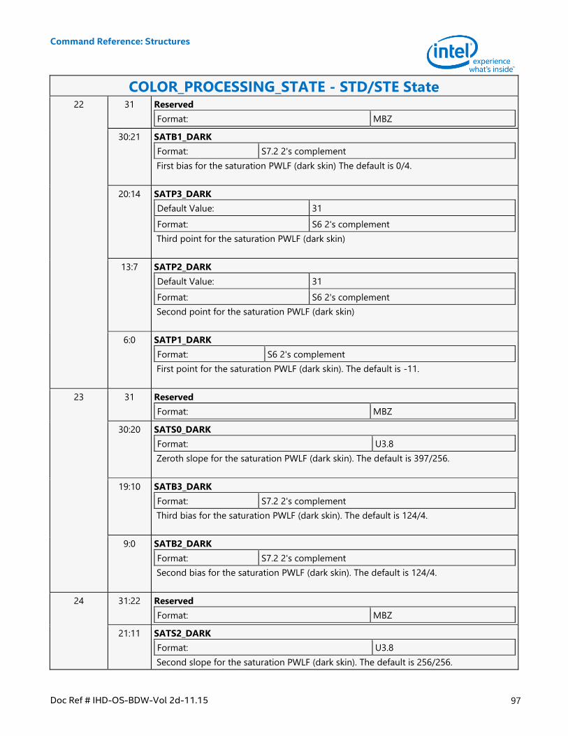
Command Reference: Structures
Doc Ref # IHD-OS-BDW-Vol 2d-11.15 97
COLOR_PROCESSING_STATE - STD/STE State 22 31 Reserved
Format: MBZ
30:21 SATB1_DARK
Format: S7.2 2's complement
First bias for the saturation PWLF (dark skin) The default is 0/4.
20:14 SATP3_DARK
Default Value: 31
Format: S6 2's complement
Third point for the saturation PWLF (dark skin)
13:7 SATP2_DARK
Default Value: 31
Format: S6 2's complement
Second point for the saturation PWLF (dark skin)
6:0 SATP1_DARK
Format: S6 2's complement
First point for the saturation PWLF (dark skin). The default is -11.
23 31 Reserved
Format: MBZ
30:20 SATS0_DARK
Format: U3.8
Zeroth slope for the saturation PWLF (dark skin). The default is 397/256.
19:10 SATB3_DARK
Format: S7.2 2's complement
Third bias for the saturation PWLF (dark skin). The default is 124/4.
9:0 SATB2_DARK
Format: S7.2 2's complement
Second bias for the saturation PWLF (dark skin). The default is 124/4.
24 31:22 Reserved
Format: MBZ
21:11 SATS2_DARK
Format: U3.8
Second slope for the saturation PWLF (dark skin). The default is 256/256.
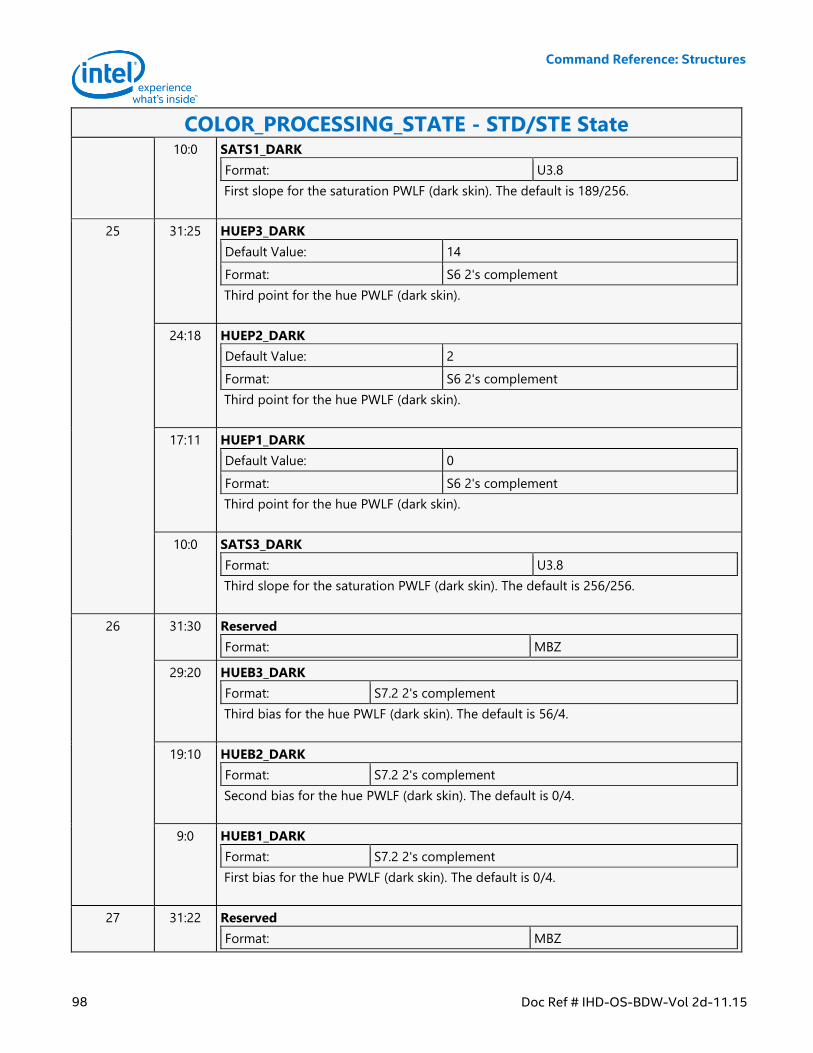
Command Reference: Structures
98 Doc Ref # IHD-OS-BDW-Vol 2d-11.15
COLOR_PROCESSING_STATE - STD/STE State 10:0 SATS1_DARK
Format: U3.8
First slope for the saturation PWLF (dark skin). The default is 189/256.
25 31:25 HUEP3_DARK
Default Value: 14
Format: S6 2's complement
Third point for the hue PWLF (dark skin).
24:18 HUEP2_DARK
Default Value: 2
Format: S6 2's complement
Third point for the hue PWLF (dark skin).
17:11 HUEP1_DARK
Default Value: 0
Format: S6 2's complement
Third point for the hue PWLF (dark skin).
10:0 SATS3_DARK
Format: U3.8
Third slope for the saturation PWLF (dark skin). The default is 256/256.
26 31:30 Reserved
Format: MBZ
29:20 HUEB3_DARK
Format: S7.2 2's complement
Third bias for the hue PWLF (dark skin). The default is 56/4.
19:10 HUEB2_DARK
Format: S7.2 2's complement
Second bias for the hue PWLF (dark skin). The default is 0/4.
9:0 HUEB1_DARK
Format: S7.2 2's complement
First bias for the hue PWLF (dark skin). The default is 0/4.
27 31:22 Reserved
Format: MBZ
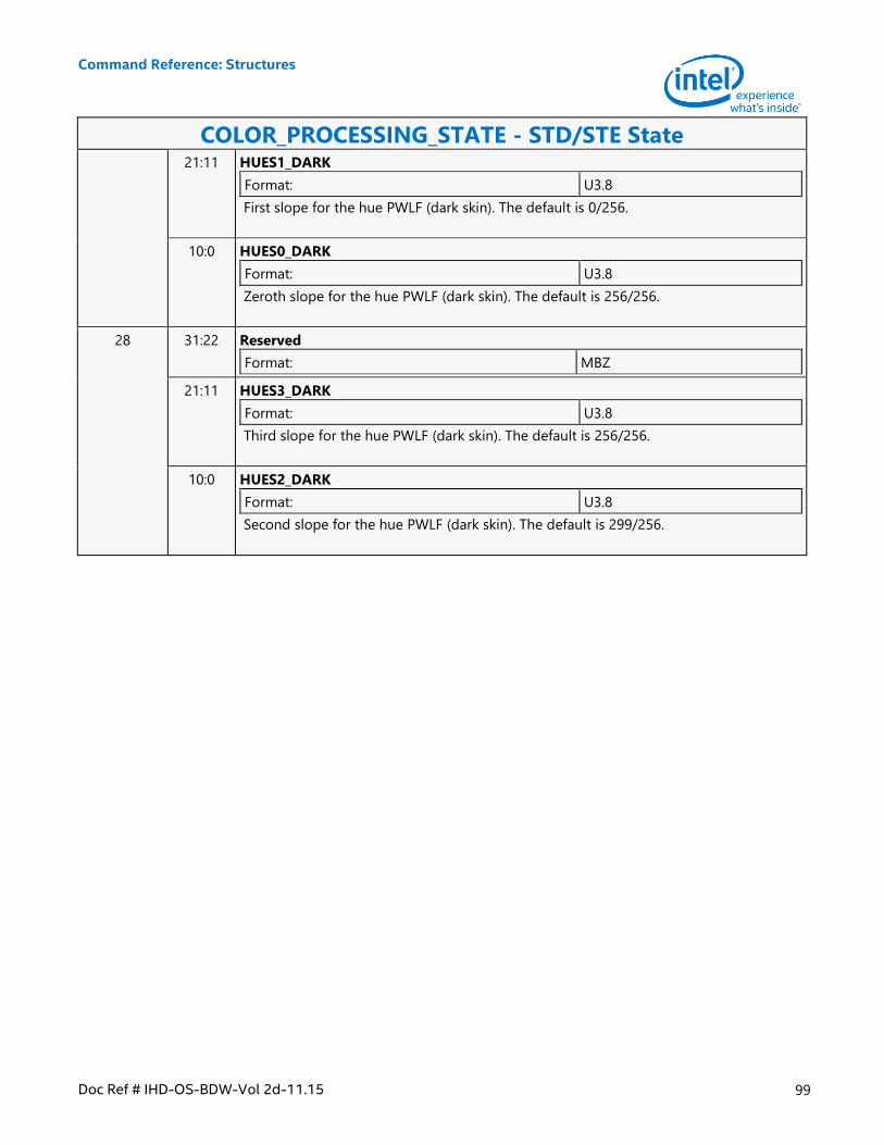
Command Reference: Structures
Doc Ref # IHD-OS-BDW-Vol 2d-11.15 99
COLOR_PROCESSING_STATE - STD/STE State 21:11 HUES1_DARK
Format: U3.8
First slope for the hue PWLF (dark skin). The default is 0/256.
10:0 HUES0_DARK
Format: U3.8
Zeroth slope for the hue PWLF (dark skin). The default is 256/256.
28 31:22 Reserved
Format: MBZ
21:11 HUES3_DARK
Format: U3.8
Third slope for the hue PWLF (dark skin). The default is 256/256.
10:0 HUES2_DARK
Format: U3.8
Second slope for the hue PWLF (dark skin). The default is 299/256.
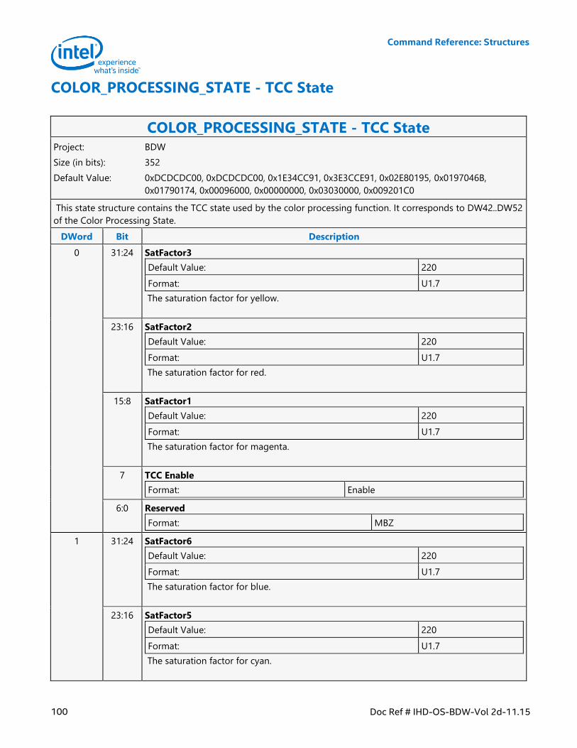
Command Reference: Structures
100 Doc Ref # IHD-OS-BDW-Vol 2d-11.15
COLOR_PROCESSING_STATE - TCC State
COLOR_PROCESSING_STATE - TCC State Project: BDW
Size (in bits): 352
Default Value: 0xDCDCDC00, 0xDCDCDC00, 0x1E34CC91, 0x3E3CCE91, 0x02E80195, 0x0197046B,
0x01790174, 0x00096000, 0x00000000, 0x03030000, 0x009201C0
This state structure contains the TCC state used by the color processing function. It corresponds to DW42..DW52
of the Color Processing State.
DWord Bit Description
0 31:24 SatFactor3
Default Value: 220
Format: U1.7
The saturation factor for yellow.
23:16 SatFactor2
Default Value: 220
Format: U1.7
The saturation factor for red.
15:8 SatFactor1
Default Value: 220
Format: U1.7
The saturation factor for magenta.
7 TCC Enable
Format: Enable
6:0 Reserved
Format: MBZ
1 31:24 SatFactor6
Default Value: 220
Format: U1.7
The saturation factor for blue.
23:16 SatFactor5
Default Value: 220
Format: U1.7
The saturation factor for cyan.
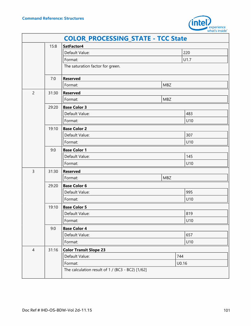
Command Reference: Structures
Doc Ref # IHD-OS-BDW-Vol 2d-11.15 101
COLOR_PROCESSING_STATE - TCC State 15:8 SatFactor4
Default Value: 220
Format: U1.7
The saturation factor for green.
7:0 Reserved
Format: MBZ
2 31:30 Reserved
Format: MBZ
29:20 Base Color 3
Default Value: 483
Format: U10
19:10 Base Color 2
Default Value: 307
Format: U10
9:0 Base Color 1
Default Value: 145
Format: U10
3 31:30 Reserved
Format: MBZ
29:20 Base Color 6
Default Value: 995
Format: U10
19:10 Base Color 5
Default Value: 819
Format: U10
9:0 Base Color 4
Default Value: 657
Format: U10
4 31:16 Color Transit Slope 23
Default Value: 744
Format: U0.16
The calculation result of 1 / (BC3 - BC2) [1/62]
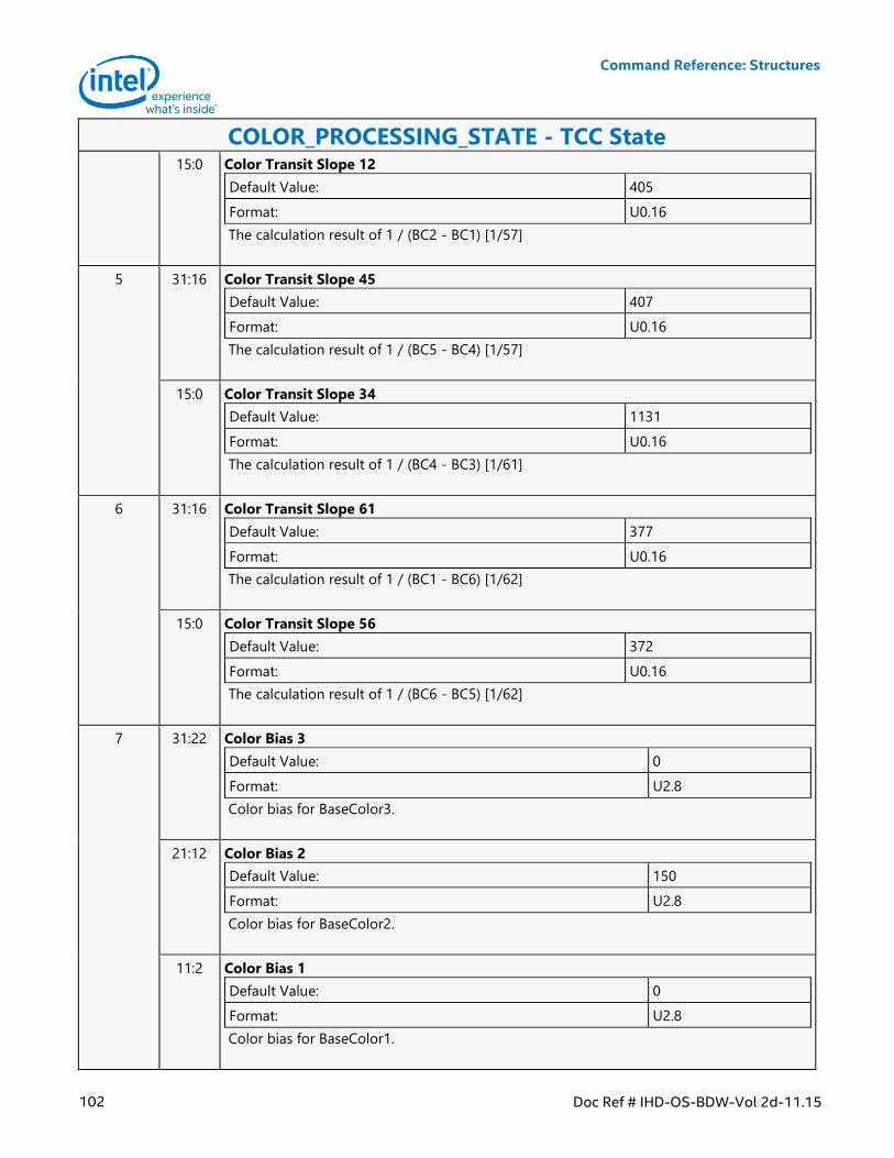
Command Reference: Structures
102 Doc Ref # IHD-OS-BDW-Vol 2d-11.15
COLOR_PROCESSING_STATE - TCC State 15:0 Color Transit Slope 12
Default Value: 405
Format: U0.16
The calculation result of 1 / (BC2 - BC1) [1/57]
5 31:16 Color Transit Slope 45
Default Value: 407
Format: U0.16
The calculation result of 1 / (BC5 - BC4) [1/57]
15:0 Color Transit Slope 34
Default Value: 1131
Format: U0.16
The calculation result of 1 / (BC4 - BC3) [1/61]
6 31:16 Color Transit Slope 61
Default Value: 377
Format: U0.16
The calculation result of 1 / (BC1 - BC6) [1/62]
15:0 Color Transit Slope 56
Default Value: 372
Format: U0.16
The calculation result of 1 / (BC6 - BC5) [1/62]
7 31:22 Color Bias 3
Default Value: 0
Format: U2.8
Color bias for BaseColor3.
21:12 Color Bias 2
Default Value: 150
Format: U2.8
Color bias for BaseColor2.
11:2 Color Bias 1
Default Value: 0
Format: U2.8
Color bias for BaseColor1.

Command Reference: Structures
Doc Ref # IHD-OS-BDW-Vol 2d-11.15 103
COLOR_PROCESSING_STATE - TCC State 1:0 Reserved
Format: MBZ
8 31:22 Color Bias 6
Default Value: 0
Format: U2.8
Color bias for BaseColor6.
21:12 Color Bias 5
Default Value: 0
Format: U2.8
Color bias for BaseColor5.
11:2 ColorBias4
Default Value: 0
Format: U2.8
Color bias for BaseColor4.
1:0 Reserved
Format: MBZ
9 31 Reserved
Format: MBZ
30:24 UV Threshold
Default Value: 3
Format: U7
Low UV threshold.
23:19 Reserved
Format: MBZ
18:16 UV Threshold Bits
Default Value: 3
Format: U3
Low UV transition width bits.
15:13 Reserved
Format: MBZ
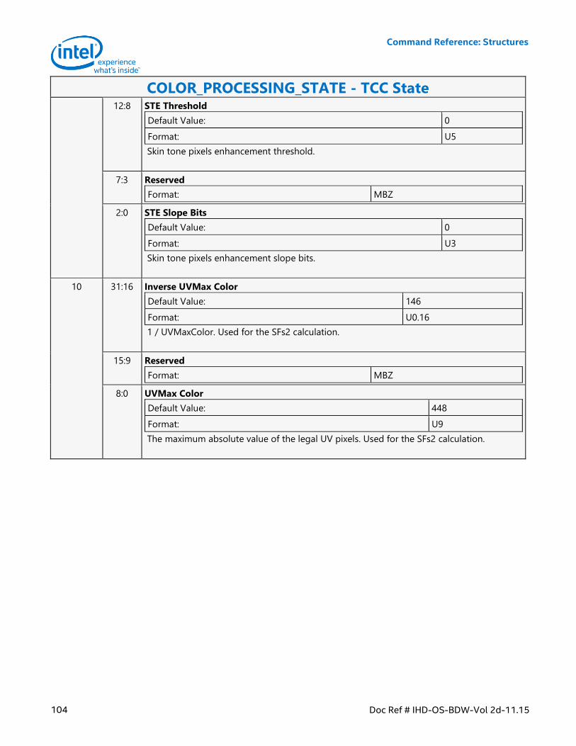
Command Reference: Structures
104 Doc Ref # IHD-OS-BDW-Vol 2d-11.15
COLOR_PROCESSING_STATE - TCC State 12:8 STE Threshold
Default Value: 0
Format: U5
Skin tone pixels enhancement threshold.
7:3 Reserved
Format: MBZ
2:0 STE Slope Bits
Default Value: 0
Format: U3
Skin tone pixels enhancement slope bits.
10 31:16 Inverse UVMax Color
Default Value: 146
Format: U0.16
1 / UVMaxColor. Used for the SFs2 calculation.
15:9 Reserved
Format: MBZ
8:0 UVMax Color
Default Value: 448
Format: U9
The maximum absolute value of the legal UV pixels. Used for the SFs2 calculation.
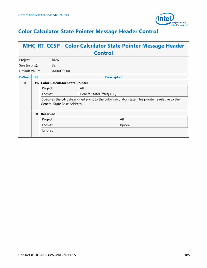
Command Reference: Structures
Doc Ref # IHD-OS-BDW-Vol 2d-11.15 105
Color Calculator State Pointer Message Header Control
MHC_RT_CCSP - Color Calculator State Pointer Message Header
Control Project: BDW
Size (in bits): 32
Default Value: 0x00000000
DWord Bit Description
0 31:6 Color Calculator State Pointer
Project: All
Format: GeneralStateOffset[31:6]
Specifies the 64-byte aligned point to the color calculator state. This pointer is relative to the
General State Base Address.
5:0 Reserved
Project: All
Format: Ignore
Ignored
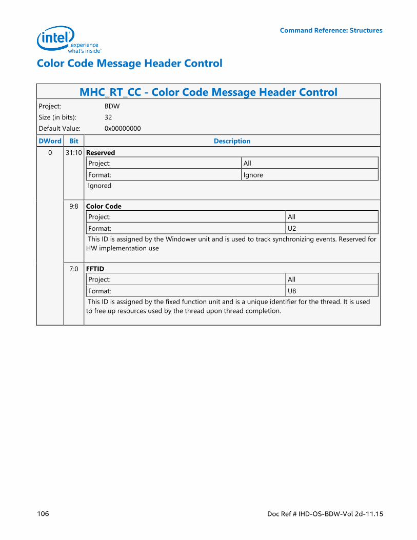
Command Reference: Structures
106 Doc Ref # IHD-OS-BDW-Vol 2d-11.15
Color Code Message Header Control
MHC_RT_CC - Color Code Message Header Control Project: BDW
Size (in bits): 32
Default Value: 0x00000000
DWord Bit Description
0 31:10 Reserved
Project: All
Format: Ignore
Ignored
9:8 Color Code
Project: All
Format: U2
This ID is assigned by the Windower unit and is used to track synchronizing events. Reserved for
HW implementation use
7:0 FFTID
Project: All
Format: U8
This ID is assigned by the fixed function unit and is a unique identifier for the thread. It is used
to free up resources used by the thread upon thread completion.
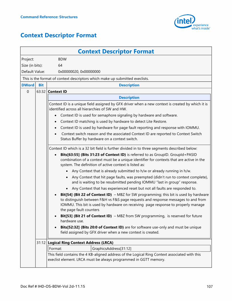
Command Reference: Structures
Doc Ref # IHD-OS-BDW-Vol 2d-11.15 107
Context Descriptor Format
Context Descriptor Format Project: BDW
Size (in bits): 64
Default Value: 0x00000020, 0x00000000
This is the format of context descriptors which make up submitted execlists.
DWord Bit Description
0 63:32 Context ID
Description
Context ID is a unique field assigned by GFX driver when a new context is created by which it is
identified across all hierarchies of SW and HW.
Context ID is used for semaphore signaling by hardware and software.
Context ID matching is used by hardware to detect Lite Restore.
Context ID is used by hardware for page fault reporting and response with IOMMU.
Context switch reason and the associated Context ID are reported to Context Switch
Status Buffer by hardware on a context switch.
Context ID which is a 32 bit field is further divided in to three segments described below:
Bits[63:55] (Bits 31:23 of Context ID) is referred to as GroupID. GroupId+PASID
combination of a context must be a unique identifier for contexts that are active in the
system. The definition of active context is listed as:
Any Context that is already submitted to h/w or already running in h/w.
Any Context that hit page faults, was preempted (didn’t run to context complete),
and is waiting to be resubmitted pending IOMMU “last in group” response.
Any Context that has experienced reset but not all faults are responded to.
Bit[54] (Bit 22 of Context ID) – MBZ for SW programming; this bit is used by hardware
to distinguish between F&H vs F&S page requests and response messages to and from
IOMMU. This bit is used by hardware on receiving page response to properly manage
the page fault counters
Bit[53] (Bit 21 of Context ID) – MBZ from SW programming, is reserved for future
hardware use.
Bits[52:32] (Bits 20:0 of Context ID) are for software use-only and must be unique
field assigned by GFX driver when a new context is created.
31:12 Logical Ring Context Address (LRCA)
Format: GraphicsAddress[31:12]
This field contains the 4 KB-aligned address of the Logical Ring Context associated with this
execlist element. LRCA must be always programmed in GGTT memory.
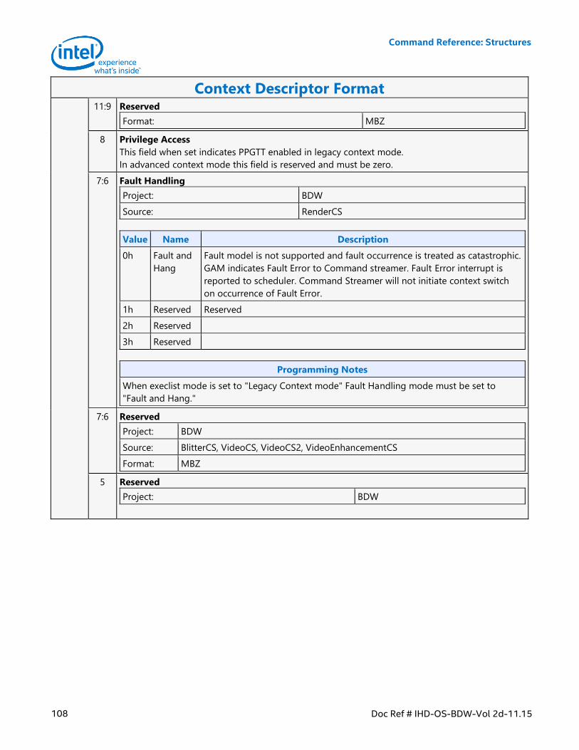
Command Reference: Structures
108 Doc Ref # IHD-OS-BDW-Vol 2d-11.15
Context Descriptor Format 11:9 Reserved
Format: MBZ
8 Privilege Access
This field when set indicates PPGTT enabled in legacy context mode.
In advanced context mode this field is reserved and must be zero.
7:6 Fault Handling
Project: BDW
Source: RenderCS
Value Name Description
0h Fault and
Hang
Fault model is not supported and fault occurrence is treated as catastrophic.
GAM indicates Fault Error to Command streamer. Fault Error interrupt is
reported to scheduler. Command Streamer will not initiate context switch
on occurrence of Fault Error.
1h Reserved Reserved
2h Reserved
3h Reserved
Programming Notes
When execlist mode is set to "Legacy Context mode" Fault Handling mode must be set to
"Fault and Hang."
7:6 Reserved
Project: BDW
Source: BlitterCS, VideoCS, VideoCS2, VideoEnhancementCS
Format: MBZ
5 Reserved
Project: BDW
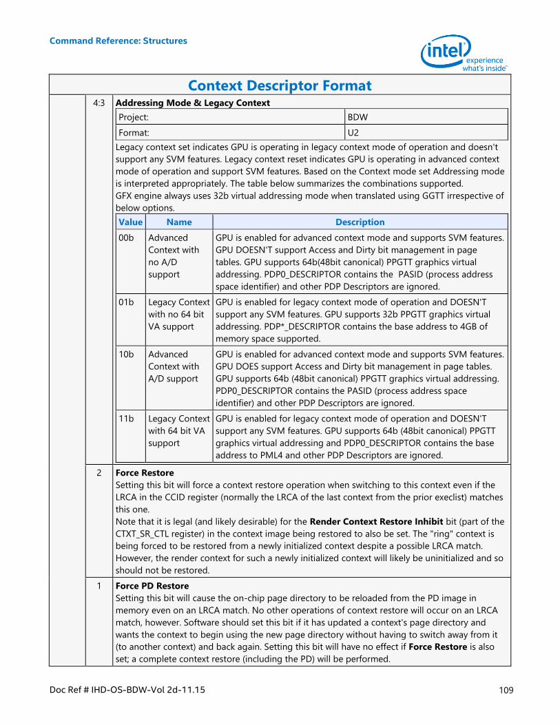
Command Reference: Structures
Doc Ref # IHD-OS-BDW-Vol 2d-11.15 109
Context Descriptor Format 4:3 Addressing Mode & Legacy Context
Project: BDW
Format: U2
Legacy context set indicates GPU is operating in legacy context mode of operation and doesn't
support any SVM features. Legacy context reset indicates GPU is operating in advanced context
mode of operation and support SVM features. Based on the Context mode set Addressing mode
is interpreted appropriately. The table below summarizes the combinations supported.
GFX engine always uses 32b virtual addressing mode when translated using GGTT irrespective of
below options.
Value Name Description
00b Advanced
Context with
no A/D
support
GPU is enabled for advanced context mode and supports SVM features.
GPU DOESN'T support Access and Dirty bit management in page
tables. GPU supports 64b(48bit canonical) PPGTT graphics virtual
addressing. PDP0_DESCRIPTOR contains the PASID (process address
space identifier) and other PDP Descriptors are ignored.
01b Legacy Context
with no 64 bit
VA support
GPU is enabled for legacy context mode of operation and DOESN'T
support any SVM features. GPU supports 32b PPGTT graphics virtual
addressing. PDP*_DESCRIPTOR contains the base address to 4GB of
memory space supported.
10b Advanced
Context with
A/D support
GPU is enabled for advanced context mode and supports SVM features.
GPU DOES support Access and Dirty bit management in page tables.
GPU supports 64b (48bit canonical) PPGTT graphics virtual addressing.
PDP0_DESCRIPTOR contains the PASID (process address space
identifier) and other PDP Descriptors are ignored.
11b Legacy Context
with 64 bit VA
support
GPU is enabled for legacy context mode of operation and DOESN'T
support any SVM features. GPU supports 64b (48bit canonical) PPGTT
graphics virtual addressing and PDP0_DESCRIPTOR contains the base
address to PML4 and other PDP Descriptors are ignored.
2 Force Restore
Setting this bit will force a context restore operation when switching to this context even if the
LRCA in the CCID register (normally the LRCA of the last context from the prior execlist) matches
this one.
Note that it is legal (and likely desirable) for the Render Context Restore Inhibit bit (part of the
CTXT_SR_CTL register) in the context image being restored to also be set. The "ring" context is
being forced to be restored from a newly initialized context despite a possible LRCA match.
However, the render context for such a newly initialized context will likely be uninitialized and so
should not be restored.
1 Force PD Restore
Setting this bit will cause the on-chip page directory to be reloaded from the PD image in
memory even on an LRCA match. No other operations of context restore will occur on an LRCA
match, however. Software should set this bit if it has updated a context's page directory and
wants the context to begin using the new page directory without having to switch away from it
(to another context) and back again. Setting this bit will have no effect if Force Restore is also
set; a complete context restore (including the PD) will be performed.
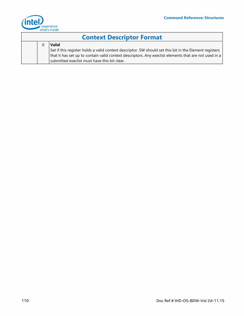
Command Reference: Structures
110 Doc Ref # IHD-OS-BDW-Vol 2d-11.15
Context Descriptor Format 0 Valid
Set if this register holds a valid context descriptor. SW should set this bit in the Element registers
that it has set up to contain valid context descriptors. Any execlist elements that are not used in a
submitted execlist must have this bit clear.
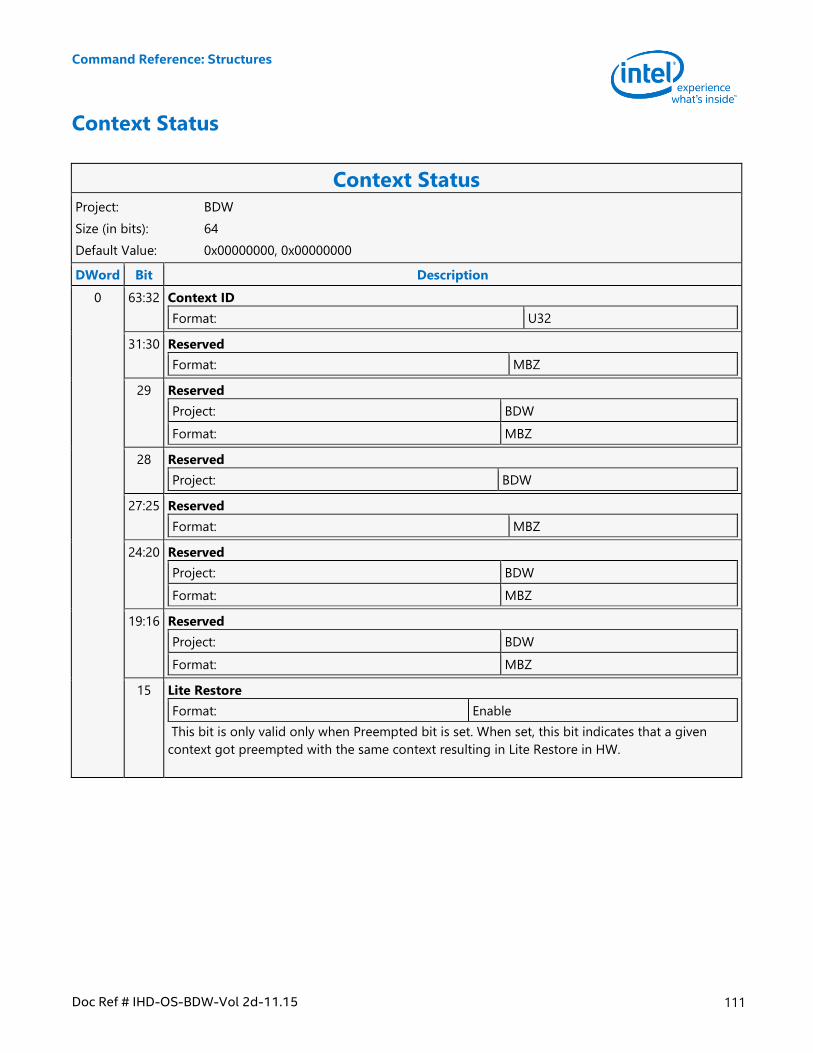
Command Reference: Structures
Doc Ref # IHD-OS-BDW-Vol 2d-11.15 111
Context Status
Context Status Project: BDW
Size (in bits): 64
Default Value: 0x00000000, 0x00000000
DWord Bit Description
0 63:32 Context ID
Format: U32
31:30 Reserved
Format: MBZ
29 Reserved
Project: BDW
Format: MBZ
28 Reserved
Project: BDW
27:25 Reserved
Format: MBZ
24:20 Reserved
Project: BDW
Format: MBZ
19:16 Reserved
Project: BDW
Format: MBZ
15 Lite Restore
Format: Enable
This bit is only valid only when Preempted bit is set. When set, this bit indicates that a given
context got preempted with the same context resulting in Lite Restore in HW.
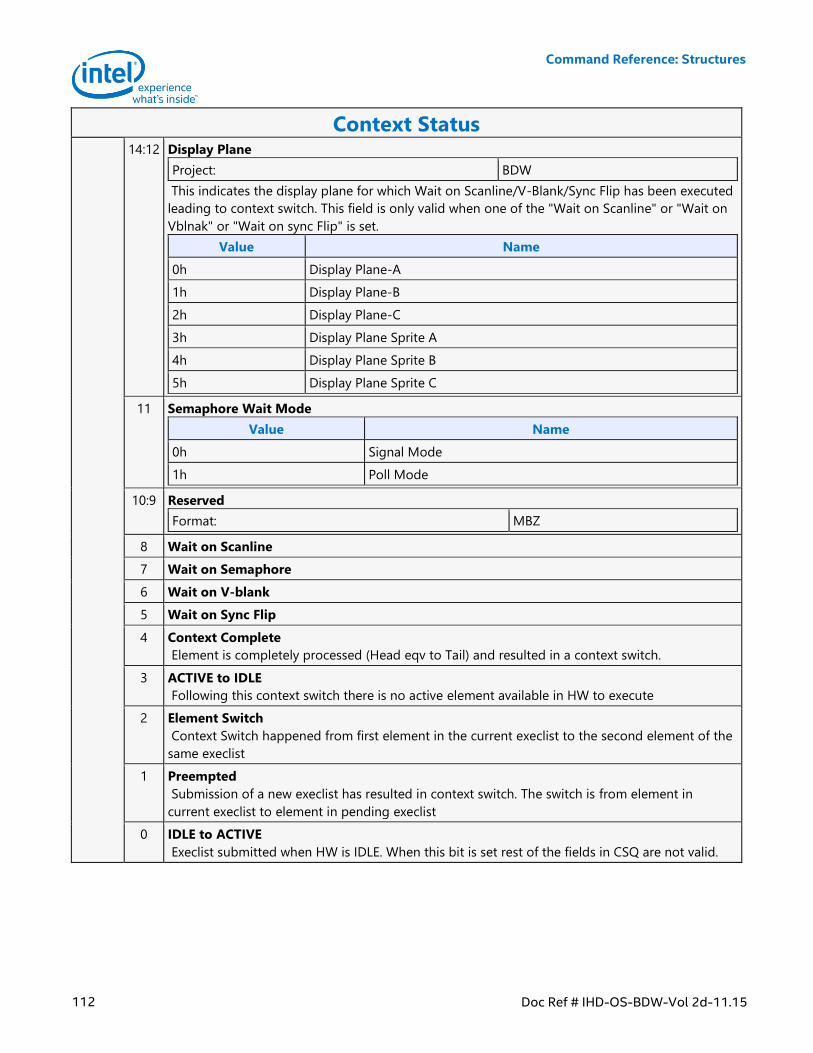
Command Reference: Structures
112 Doc Ref # IHD-OS-BDW-Vol 2d-11.15
Context Status 14:12 Display Plane
Project: BDW
This indicates the display plane for which Wait on Scanline/V-Blank/Sync Flip has been executed
leading to context switch. This field is only valid when one of the "Wait on Scanline" or "Wait on
Vblnak" or "Wait on sync Flip" is set.
Value Name
0h Display Plane-A
1h Display Plane-B
2h Display Plane-C
3h Display Plane Sprite A
4h Display Plane Sprite B
5h Display Plane Sprite C
11 Semaphore Wait Mode
Value Name
0h Signal Mode
1h Poll Mode
10:9 Reserved
Format: MBZ
8 Wait on Scanline
7 Wait on Semaphore
6 Wait on V-blank
5 Wait on Sync Flip
4 Context Complete
Element is completely processed (Head eqv to Tail) and resulted in a context switch.
3 ACTIVE to IDLE
Following this context switch there is no active element available in HW to execute
2 Element Switch
Context Switch happened from first element in the current execlist to the second element of the
same execlist
1 Preempted
Submission of a new execlist has resulted in context switch. The switch is from element in
current execlist to element in pending execlist
0 IDLE to ACTIVE
Execlist submitted when HW is IDLE. When this bit is set rest of the fields in CSQ are not valid.
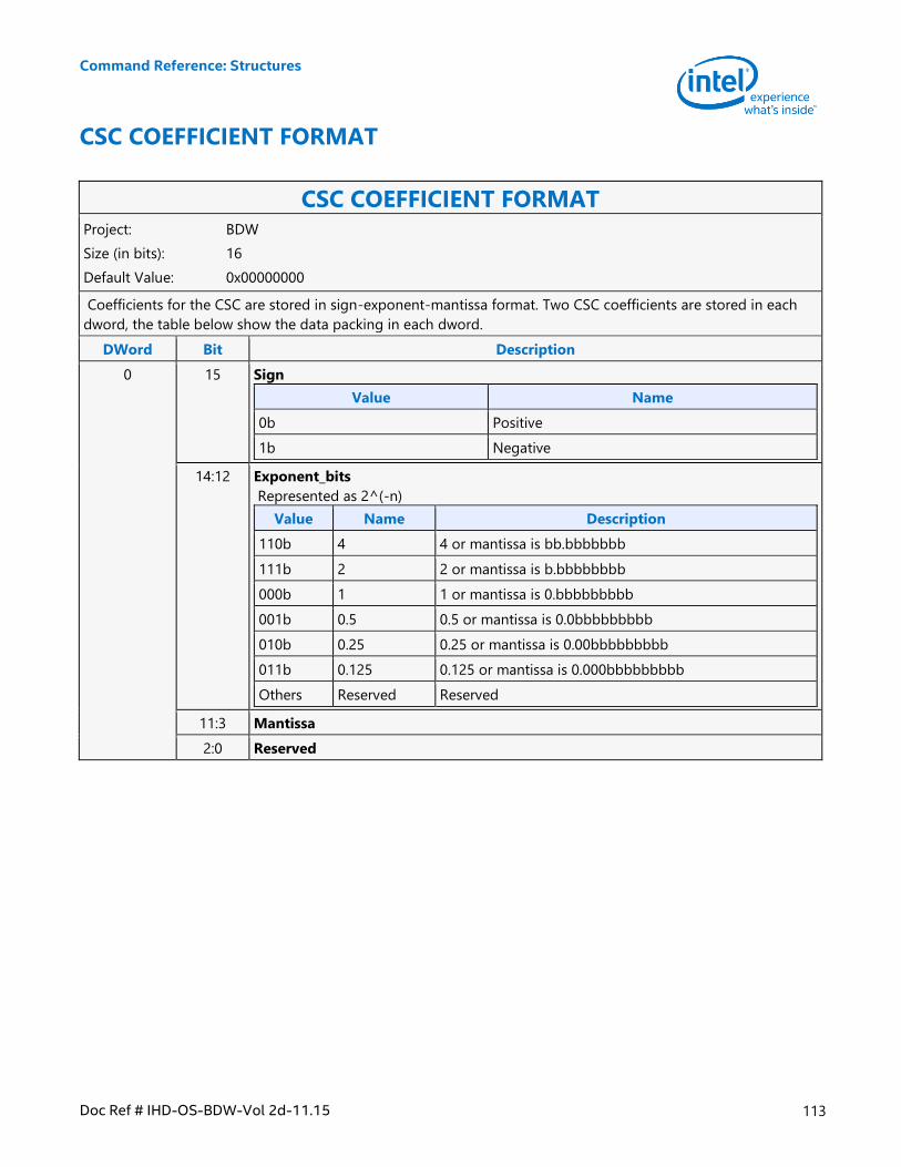
Command Reference: Structures
Doc Ref # IHD-OS-BDW-Vol 2d-11.15 113
CSC COEFFICIENT FORMAT
CSC COEFFICIENT FORMAT Project: BDW
Size (in bits): 16
Default Value: 0x00000000
Coefficients for the CSC are stored in sign-exponent-mantissa format. Two CSC coefficients are stored in each
dword, the table below show the data packing in each dword.
DWord Bit Description
0 15 Sign
Value Name
0b Positive
1b Negative
14:12 Exponent_bits
Represented as 2^(-n)
Value Name Description
110b 4 4 or mantissa is bb.bbbbbbb
111b 2 2 or mantissa is b.bbbbbbbb
000b 1 1 or mantissa is 0.bbbbbbbbb
001b 0.5 0.5 or mantissa is 0.0bbbbbbbbb
010b 0.25 0.25 or mantissa is 0.00bbbbbbbbb
011b 0.125 0.125 or mantissa is 0.000bbbbbbbbb
Others Reserved Reserved
11:3 Mantissa
2:0 Reserved
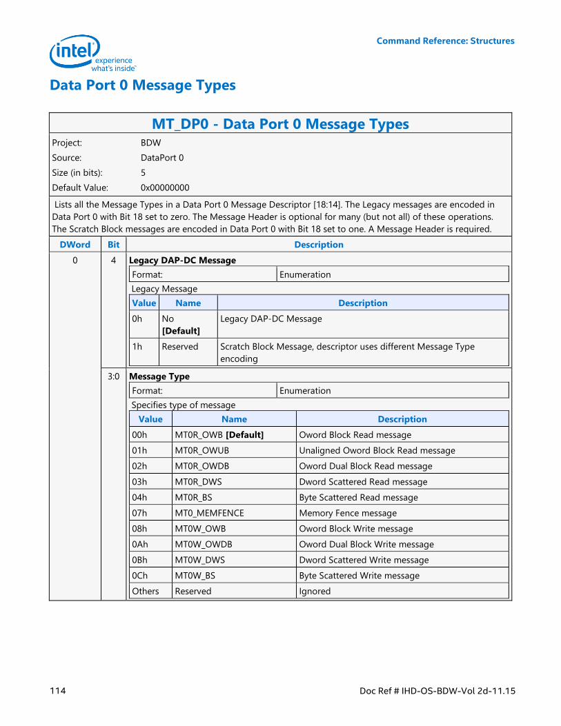
Command Reference: Structures
114 Doc Ref # IHD-OS-BDW-Vol 2d-11.15
Data Port 0 Message Types
MT_DP0 - Data Port 0 Message Types Project: BDW
Source: DataPort 0
Size (in bits): 5
Default Value: 0x00000000
Lists all the Message Types in a Data Port 0 Message Descriptor [18:14]. The Legacy messages are encoded in
Data Port 0 with Bit 18 set to zero. The Message Header is optional for many (but not all) of these operations.
The Scratch Block messages are encoded in Data Port 0 with Bit 18 set to one. A Message Header is required.
DWord Bit Description
0 4 Legacy DAP-DC Message
Format: Enumeration
Legacy Message
Value Name Description
0h No
[Default]
Legacy DAP-DC Message
1h Reserved Scratch Block Message, descriptor uses different Message Type
encoding
3:0 Message Type
Format: Enumeration
Specifies type of message
Value Name Description
00h MT0R_OWB [Default] Oword Block Read message
01h MT0R_OWUB Unaligned Oword Block Read message
02h MT0R_OWDB Oword Dual Block Read message
03h MT0R_DWS Dword Scattered Read message
04h MT0R_BS Byte Scattered Read message
07h MT0_MEMFENCE Memory Fence message
08h MT0W_OWB Oword Block Write message
0Ah MT0W_OWDB Oword Dual Block Write message
0Bh MT0W_DWS Dword Scattered Write message
0Ch MT0W_BS Byte Scattered Write message
Others Reserved Ignored
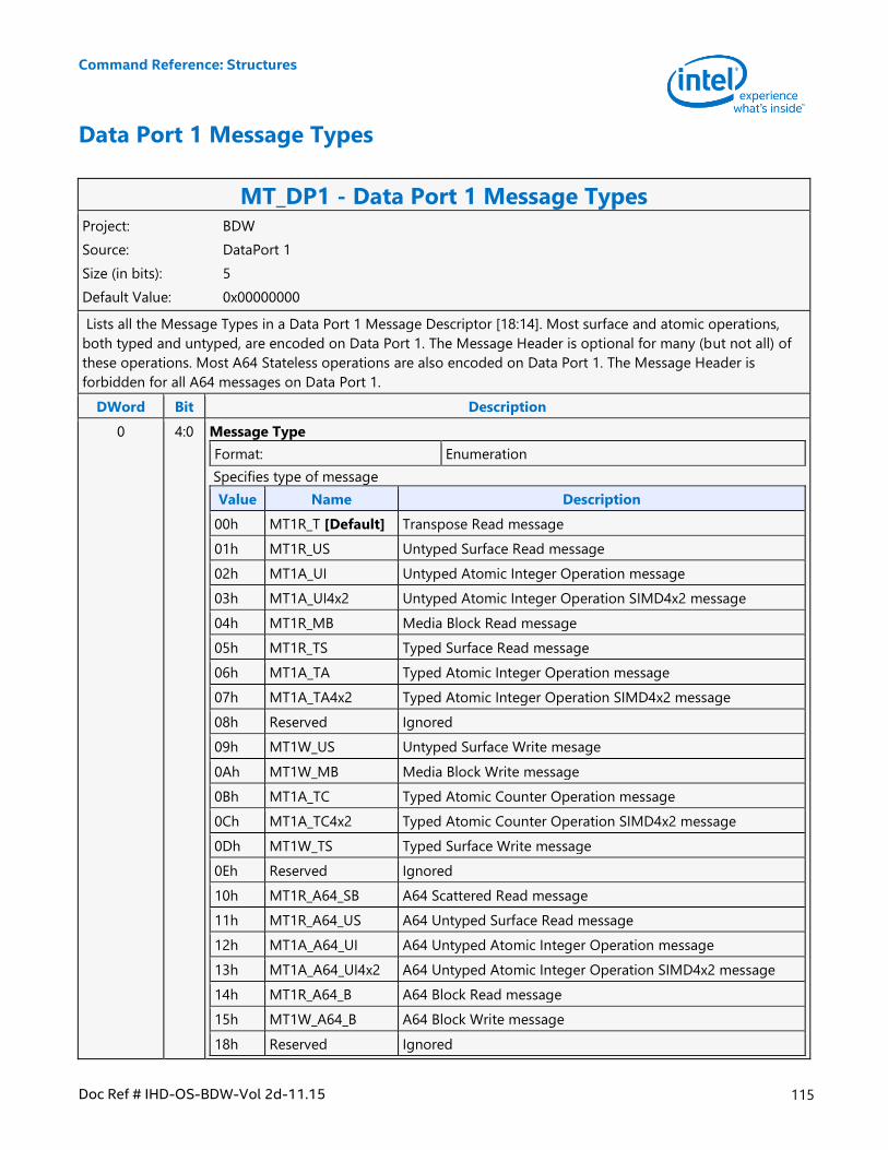
Command Reference: Structures
Doc Ref # IHD-OS-BDW-Vol 2d-11.15 115
Data Port 1 Message Types
MT_DP1 - Data Port 1 Message Types Project: BDW
Source: DataPort 1
Size (in bits): 5
Default Value: 0x00000000
Lists all the Message Types in a Data Port 1 Message Descriptor [18:14]. Most surface and atomic operations,
both typed and untyped, are encoded on Data Port 1. The Message Header is optional for many (but not all) of
these operations. Most A64 Stateless operations are also encoded on Data Port 1. The Message Header is
forbidden for all A64 messages on Data Port 1.
DWord Bit Description
0 4:0 Message Type
Format: Enumeration
Specifies type of message
Value Name Description
00h MT1R_T [Default] Transpose Read message
01h MT1R_US Untyped Surface Read message
02h MT1A_UI Untyped Atomic Integer Operation message
03h MT1A_UI4x2 Untyped Atomic Integer Operation SIMD4x2 message
04h MT1R_MB Media Block Read message
05h MT1R_TS Typed Surface Read message
06h MT1A_TA Typed Atomic Integer Operation message
07h MT1A_TA4x2 Typed Atomic Integer Operation SIMD4x2 message
08h Reserved Ignored
09h MT1W_US Untyped Surface Write mesage
0Ah MT1W_MB Media Block Write message
0Bh MT1A_TC Typed Atomic Counter Operation message
0Ch MT1A_TC4x2 Typed Atomic Counter Operation SIMD4x2 message
0Dh MT1W_TS Typed Surface Write message
0Eh Reserved Ignored
10h MT1R_A64_SB A64 Scattered Read message
11h MT1R_A64_US A64 Untyped Surface Read message
12h MT1A_A64_UI A64 Untyped Atomic Integer Operation message
13h MT1A_A64_UI4x2 A64 Untyped Atomic Integer Operation SIMD4x2 message
14h MT1R_A64_B A64 Block Read message
15h MT1W_A64_B A64 Block Write message
18h Reserved Ignored
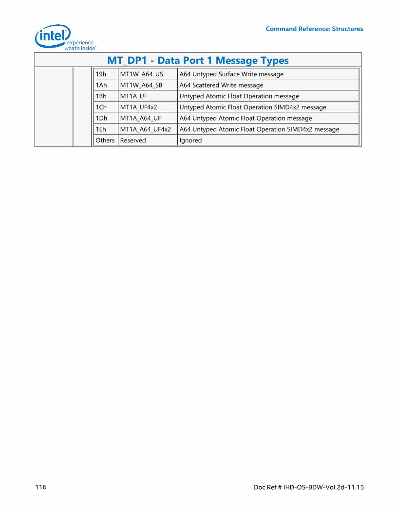
Command Reference: Structures
116 Doc Ref # IHD-OS-BDW-Vol 2d-11.15
MT_DP1 - Data Port 1 Message Types
19h MT1W_A64_US A64 Untyped Surface Write message
1Ah MT1W_A64_SB A64 Scattered Write message
1Bh MT1A_UF Untyped Atomic Float Operation message
1Ch MT1A_UF4x2 Untyped Atomic Float Operation SIMD4x2 message
1Dh MT1A_A64_UF A64 Untyped Atomic Float Operation message
1Eh MT1A_A64_UF4x2 A64 Untyped Atomic Float Operation SIMD4x2 message
Others Reserved Ignored
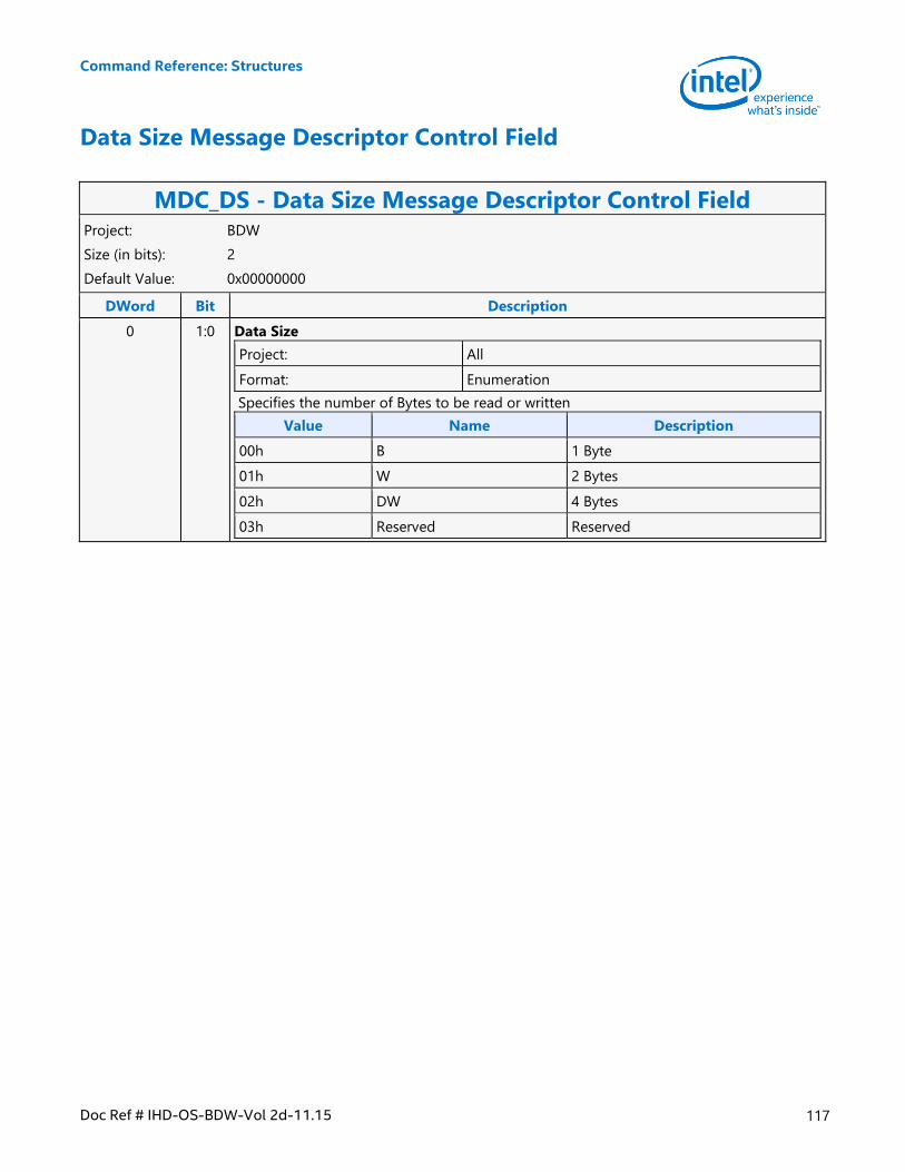
Command Reference: Structures
Doc Ref # IHD-OS-BDW-Vol 2d-11.15 117
Data Size Message Descriptor Control Field
MDC_DS - Data Size Message Descriptor Control Field Project: BDW
Size (in bits): 2
Default Value: 0x00000000
DWord Bit Description
0 1:0 Data Size
Project: All
Format: Enumeration
Specifies the number of Bytes to be read or written
Value Name Description
00h B 1 Byte
01h W 2 Bytes
02h DW 4 Bytes
03h Reserved Reserved
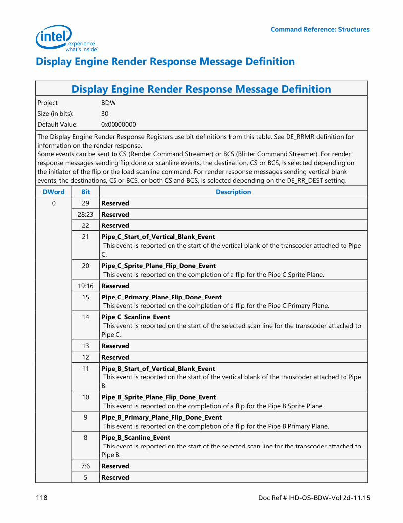
Command Reference: Structures
118 Doc Ref # IHD-OS-BDW-Vol 2d-11.15
Display Engine Render Response Message Definition
Display Engine Render Response Message Definition Project: BDW
Size (in bits): 30
Default Value: 0x00000000
The Display Engine Render Response Registers use bit definitions from this table. See DE_RRMR definition for
information on the render response.
Some events can be sent to CS (Render Command Streamer) or BCS (Blitter Command Streamer). For render
response messages sending flip done or scanline events, the destination, CS or BCS, is selected depending on
the initiator of the flip or the load scanline command. For render response messages sending vertical blank
events, the destinations, CS or BCS, or both CS and BCS, is selected depending on the DE_RR_DEST setting.
DWord Bit Description
0 29 Reserved
28:23 Reserved
22 Reserved
21 Pipe_C_Start_of_Vertical_Blank_Event
This event is reported on the start of the vertical blank of the transcoder attached to Pipe
C.
20 Pipe_C_Sprite_Plane_Flip_Done_Event
This event is reported on the completion of a flip for the Pipe C Sprite Plane.
19:16 Reserved
15 Pipe_C_Primary_Plane_Flip_Done_Event
This event is reported on the completion of a flip for the Pipe C Primary Plane.
14 Pipe_C_Scanline_Event
This event is reported on the start of the selected scan line for the transcoder attached to
Pipe C.
13 Reserved
12 Reserved
11 Pipe_B_Start_of_Vertical_Blank_Event
This event is reported on the start of the vertical blank of the transcoder attached to Pipe
B.
10 Pipe_B_Sprite_Plane_Flip_Done_Event
This event is reported on the completion of a flip for the Pipe B Sprite Plane.
9 Pipe_B_Primary_Plane_Flip_Done_Event
This event is reported on the completion of a flip for the Pipe B Primary Plane.
8 Pipe_B_Scanline_Event
This event is reported on the start of the selected scan line for the transcoder attached to
Pipe B.
7:6 Reserved
5 Reserved
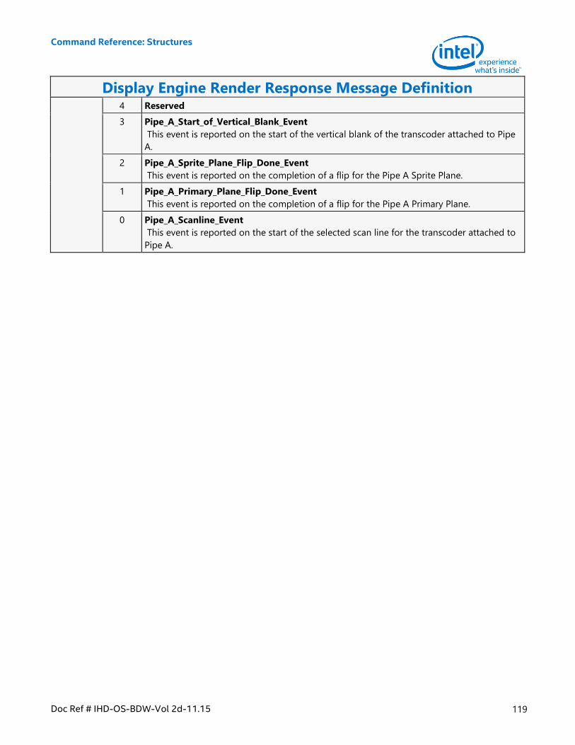
Command Reference: Structures
Doc Ref # IHD-OS-BDW-Vol 2d-11.15 119
Display Engine Render Response Message Definition 4 Reserved
3 Pipe_A_Start_of_Vertical_Blank_Event
This event is reported on the start of the vertical blank of the transcoder attached to Pipe
A.
2 Pipe_A_Sprite_Plane_Flip_Done_Event
This event is reported on the completion of a flip for the Pipe A Sprite Plane.
1 Pipe_A_Primary_Plane_Flip_Done_Event
This event is reported on the completion of a flip for the Pipe A Primary Plane.
0 Pipe_A_Scanline_Event
This event is reported on the start of the selected scan line for the transcoder attached to
Pipe A.
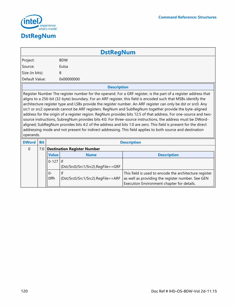
Command Reference: Structures
120 Doc Ref # IHD-OS-BDW-Vol 2d-11.15
DstRegNum
DstRegNum Project: BDW
Source: EuIsa
Size (in bits): 8
Default Value: 0x00000000
Description
Register Number The register number for the operand. For a GRF register, is the part of a register address that
aligns to a 256-bit (32-byte) boundary. For an ARF register, this field is encoded such that MSBs identify the
architecture register type and LSBs provide the register number. An ARF register can only be dst or src0. Any
src1 or src2 operands cannot be ARF registers. RegNum and SubRegNum together provide the byte-aligned
address for the origin of a register region. RegNum provides bits 12:5 of that address. For one-source and two-
source instructions, SubregNum provides bits 4:0. For three-source instructions, the address must be DWord-
aligned; SubRegNum provides bits 4:2 of the address and bits 1:0 are zero. This field is present for the direct
addressing mode and not present for indirect addressing. This field applies to both source and destination
operands.
DWord Bit Description
0 7:0 Destination Register Number
Value Name Description
0-127 If
{Dst/Src0/Src1/Src2}.RegFile==GRF
0-
0ffh
If
{Dst/Src0/Src1/Src2}.RegFile==ARF
This field is used to encode the architecture register
as well as providing the register number. See GEN
Execution Environment chapter for details.
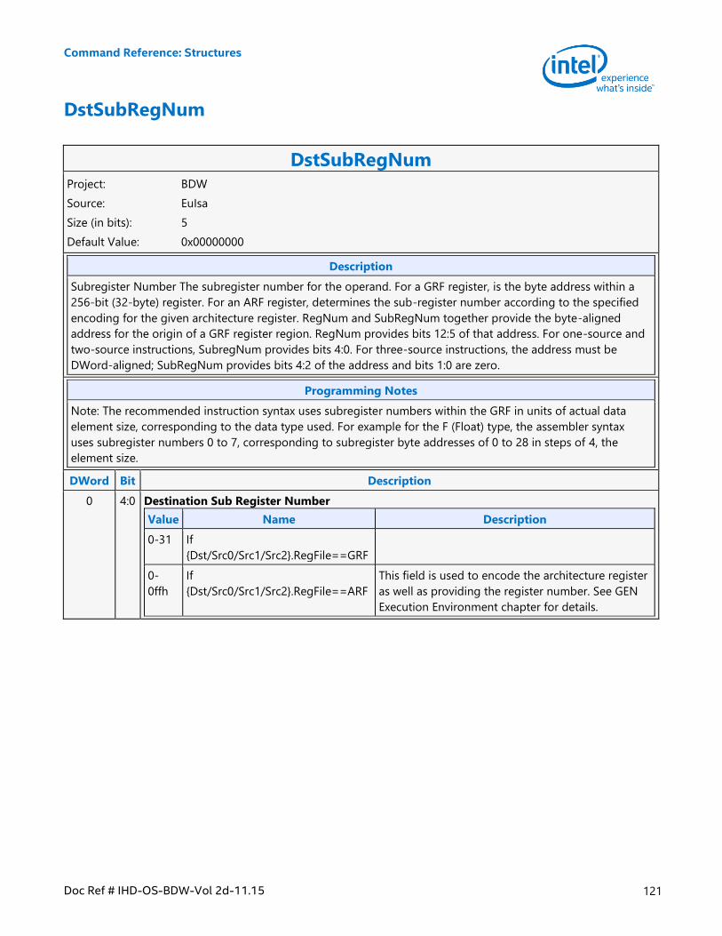
Command Reference: Structures
Doc Ref # IHD-OS-BDW-Vol 2d-11.15 121
DstSubRegNum
DstSubRegNum Project: BDW
Source: EuIsa
Size (in bits): 5
Default Value: 0x00000000
Description
Subregister Number The subregister number for the operand. For a GRF register, is the byte address within a
256-bit (32-byte) register. For an ARF register, determines the sub-register number according to the specified
encoding for the given architecture register. RegNum and SubRegNum together provide the byte-aligned
address for the origin of a GRF register region. RegNum provides bits 12:5 of that address. For one-source and
two-source instructions, SubregNum provides bits 4:0. For three-source instructions, the address must be
DWord-aligned; SubRegNum provides bits 4:2 of the address and bits 1:0 are zero.
Programming Notes
Note: The recommended instruction syntax uses subregister numbers within the GRF in units of actual data
element size, corresponding to the data type used. For example for the F (Float) type, the assembler syntax
uses subregister numbers 0 to 7, corresponding to subregister byte addresses of 0 to 28 in steps of 4, the
element size.
DWord Bit Description
0 4:0 Destination Sub Register Number
Value Name Description
0-31 If
{Dst/Src0/Src1/Src2}.RegFile==GRF
0-
0ffh
If
{Dst/Src0/Src1/Src2}.RegFile==ARF
This field is used to encode the architecture register
as well as providing the register number. See GEN
Execution Environment chapter for details.
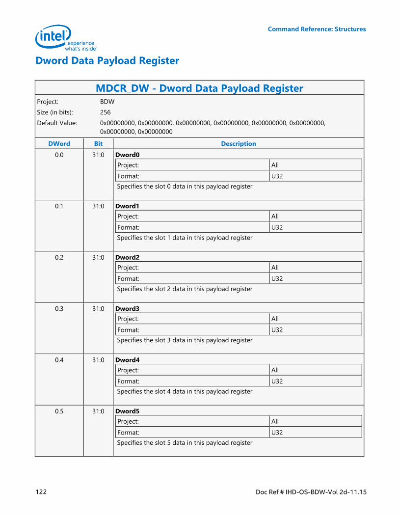
Command Reference: Structures
122 Doc Ref # IHD-OS-BDW-Vol 2d-11.15
Dword Data Payload Register
MDCR_DW - Dword Data Payload Register Project: BDW
Size (in bits): 256
Default Value: 0x00000000, 0x00000000, 0x00000000, 0x00000000, 0x00000000, 0x00000000,
0x00000000, 0x00000000
DWord Bit Description
0.0 31:0 Dword0
Project: All
Format: U32
Specifies the slot 0 data in this payload register
0.1 31:0 Dword1
Project: All
Format: U32
Specifies the slot 1 data in this payload register
0.2 31:0 Dword2
Project: All
Format: U32
Specifies the slot 2 data in this payload register
0.3 31:0 Dword3
Project: All
Format: U32
Specifies the slot 3 data in this payload register
0.4 31:0 Dword4
Project: All
Format: U32
Specifies the slot 4 data in this payload register
0.5 31:0 Dword5
Project: All
Format: U32
Specifies the slot 5 data in this payload register
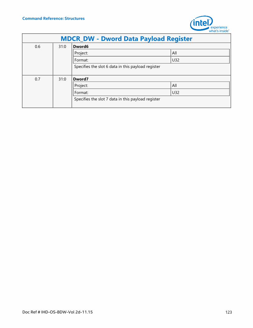
Command Reference: Structures
Doc Ref # IHD-OS-BDW-Vol 2d-11.15 123
MDCR_DW - Dword Data Payload Register 0.6 31:0 Dword6
Project: All
Format: U32
Specifies the slot 6 data in this payload register
0.7 31:0 Dword7
Project: All
Format: U32
Specifies the slot 7 data in this payload register
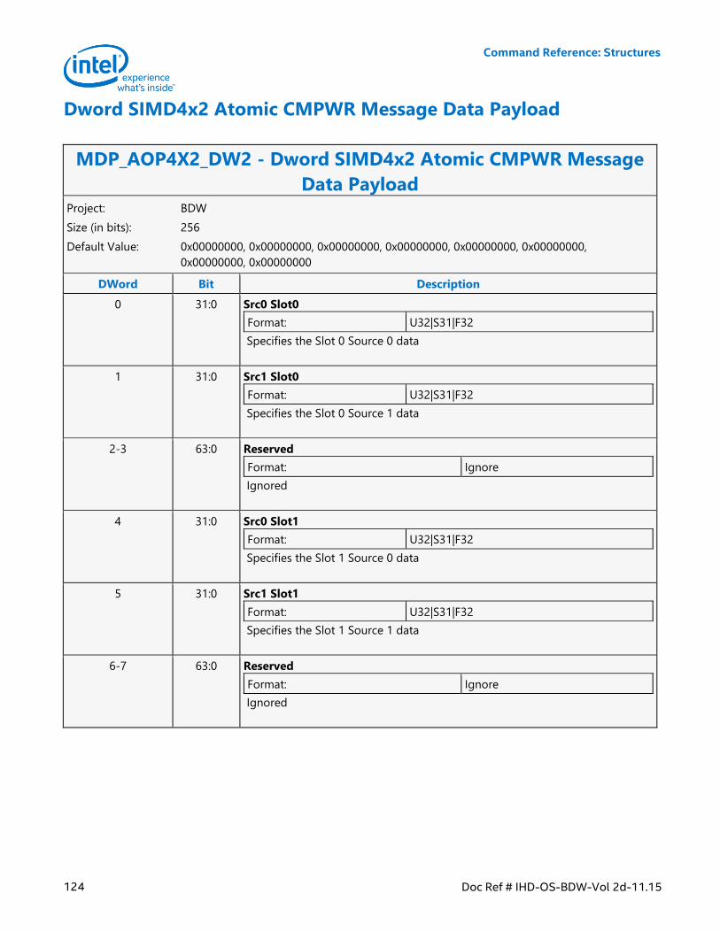
Command Reference: Structures
124 Doc Ref # IHD-OS-BDW-Vol 2d-11.15
Dword SIMD4x2 Atomic CMPWR Message Data Payload
MDP_AOP4X2_DW2 - Dword SIMD4x2 Atomic CMPWR Message
Data Payload Project: BDW
Size (in bits): 256
Default Value: 0x00000000, 0x00000000, 0x00000000, 0x00000000, 0x00000000, 0x00000000,
0x00000000, 0x00000000
DWord Bit Description
0 31:0 Src0 Slot0
Format: U32|S31|F32
Specifies the Slot 0 Source 0 data
1 31:0 Src1 Slot0
Format: U32|S31|F32
Specifies the Slot 0 Source 1 data
2-3 63:0 Reserved
Format: Ignore
Ignored
4 31:0 Src0 Slot1
Format: U32|S31|F32
Specifies the Slot 1 Source 0 data
5 31:0 Src1 Slot1
Format: U32|S31|F32
Specifies the Slot 1 Source 1 data
6-7 63:0 Reserved
Format: Ignore
Ignored
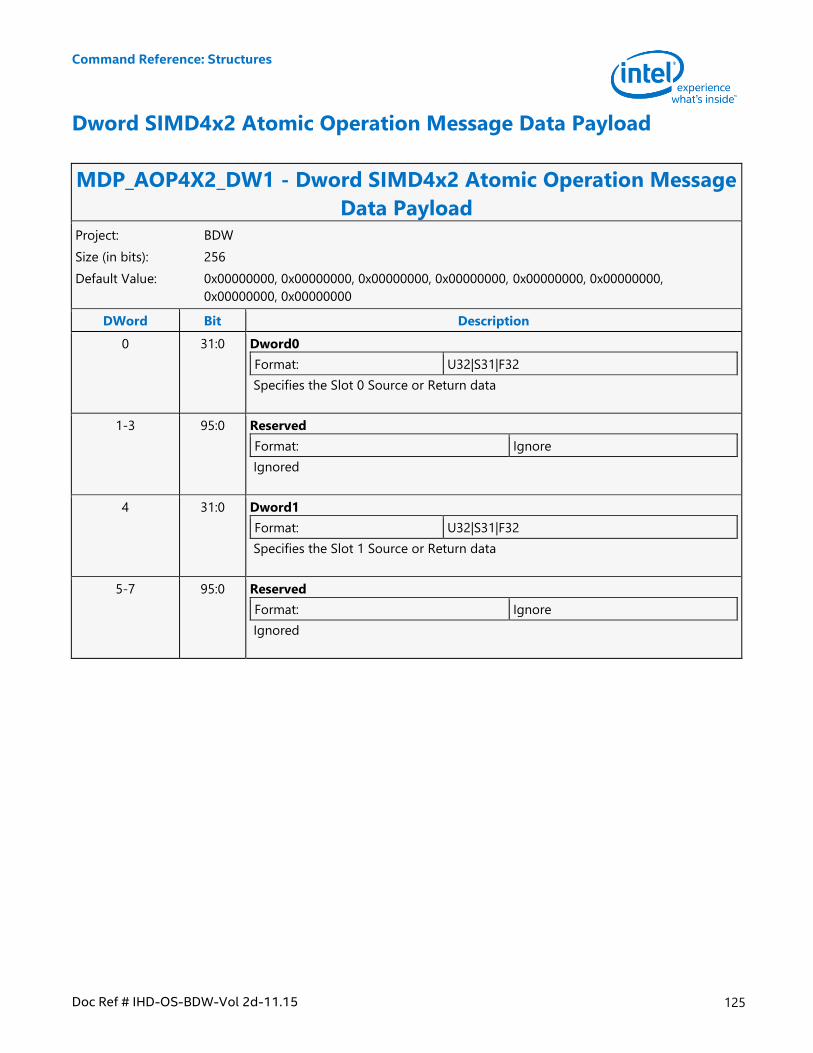
Command Reference: Structures
Doc Ref # IHD-OS-BDW-Vol 2d-11.15 125
Dword SIMD4x2 Atomic Operation Message Data Payload
MDP_AOP4X2_DW1 - Dword SIMD4x2 Atomic Operation Message
Data Payload Project: BDW
Size (in bits): 256
Default Value: 0x00000000, 0x00000000, 0x00000000, 0x00000000, 0x00000000, 0x00000000,
0x00000000, 0x00000000
DWord Bit Description
0 31:0 Dword0
Format: U32|S31|F32
Specifies the Slot 0 Source or Return data
1-3 95:0 Reserved
Format: Ignore
Ignored
4 31:0 Dword1
Format: U32|S31|F32
Specifies the Slot 1 Source or Return data
5-7 95:0 Reserved
Format: Ignore
Ignored
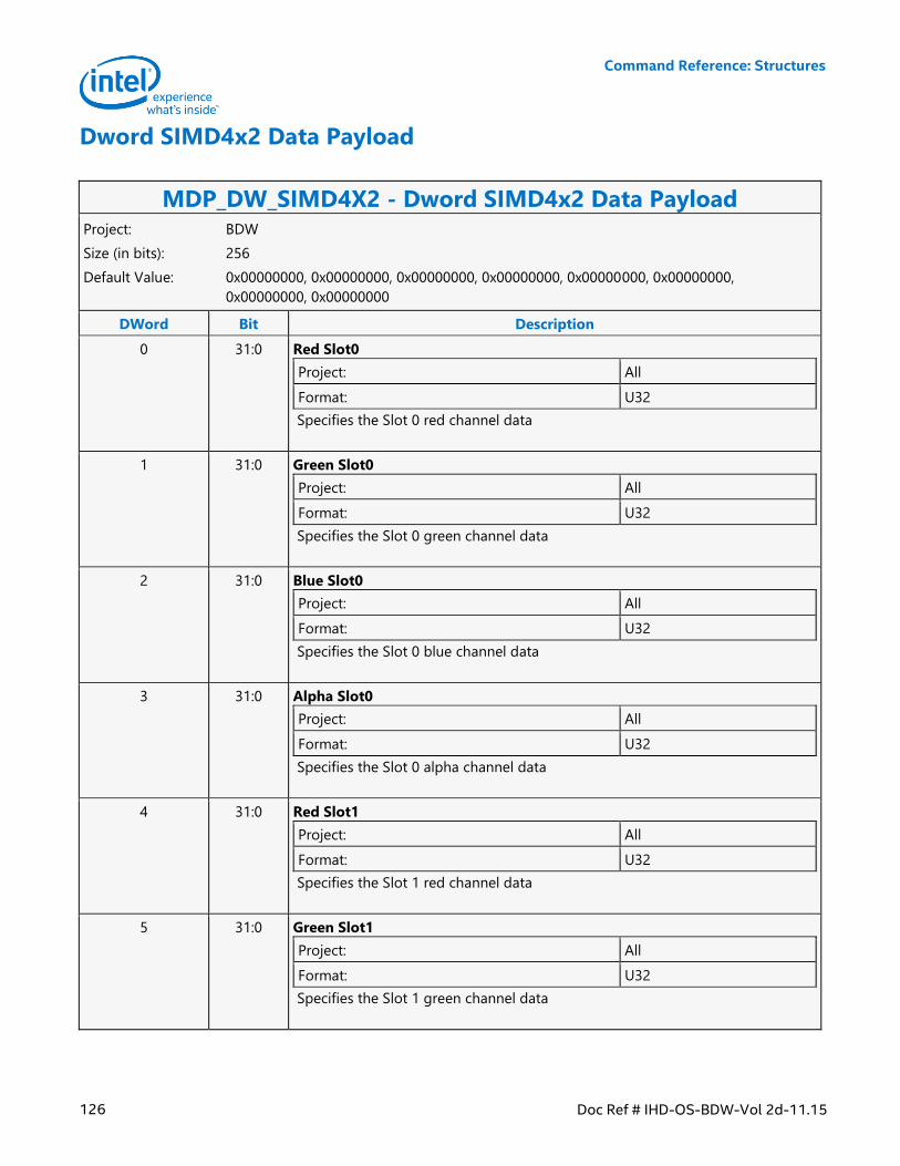
Command Reference: Structures
126 Doc Ref # IHD-OS-BDW-Vol 2d-11.15
Dword SIMD4x2 Data Payload
MDP_DW_SIMD4X2 - Dword SIMD4x2 Data Payload Project: BDW
Size (in bits): 256
Default Value: 0x00000000, 0x00000000, 0x00000000, 0x00000000, 0x00000000, 0x00000000,
0x00000000, 0x00000000
DWord Bit Description
0 31:0 Red Slot0
Project: All
Format: U32
Specifies the Slot 0 red channel data
1 31:0 Green Slot0
Project: All
Format: U32
Specifies the Slot 0 green channel data
2 31:0 Blue Slot0
Project: All
Format: U32
Specifies the Slot 0 blue channel data
3 31:0 Alpha Slot0
Project: All
Format: U32
Specifies the Slot 0 alpha channel data
4 31:0 Red Slot1
Project: All
Format: U32
Specifies the Slot 1 red channel data
5 31:0 Green Slot1
Project: All
Format: U32
Specifies the Slot 1 green channel data
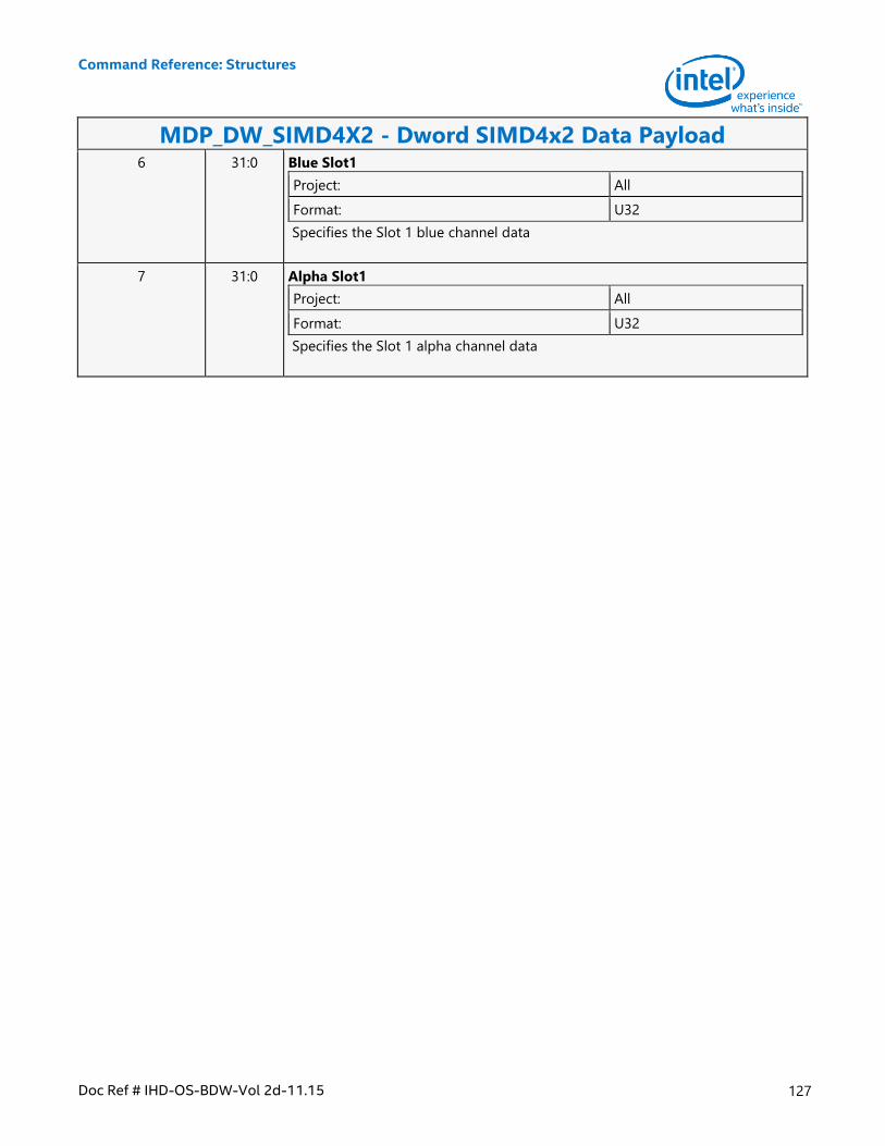
Command Reference: Structures
Doc Ref # IHD-OS-BDW-Vol 2d-11.15 127
MDP_DW_SIMD4X2 - Dword SIMD4x2 Data Payload 6 31:0 Blue Slot1
Project: All
Format: U32
Specifies the Slot 1 blue channel data
7 31:0 Alpha Slot1
Project: All
Format: U32
Specifies the Slot 1 alpha channel data
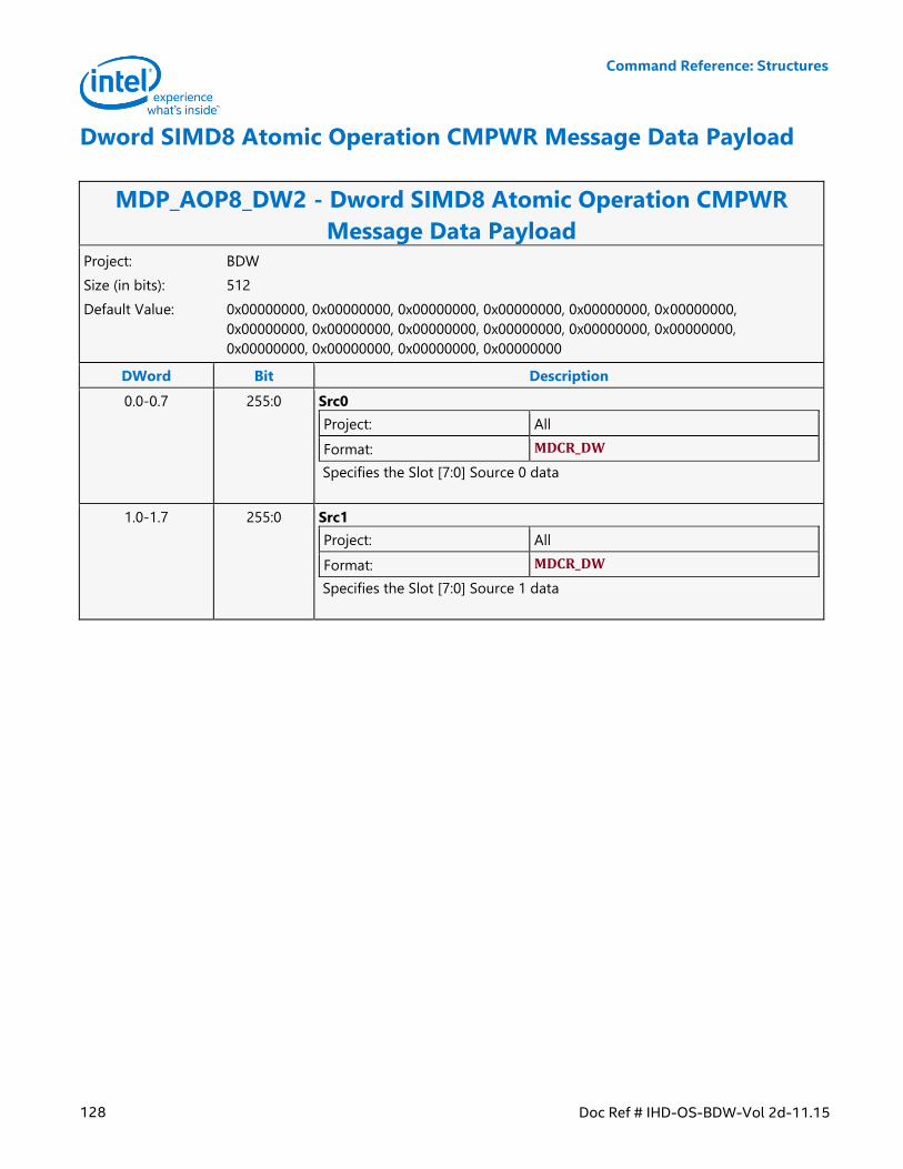
Command Reference: Structures
128 Doc Ref # IHD-OS-BDW-Vol 2d-11.15
Dword SIMD8 Atomic Operation CMPWR Message Data Payload
MDP_AOP8_DW2 - Dword SIMD8 Atomic Operation CMPWR
Message Data Payload Project: BDW
Size (in bits): 512
Default Value: 0x00000000, 0x00000000, 0x00000000, 0x00000000, 0x00000000, 0x00000000,
0x00000000, 0x00000000, 0x00000000, 0x00000000, 0x00000000, 0x00000000,
0x00000000, 0x00000000, 0x00000000, 0x00000000
DWord Bit Description
0.0-0.7 255:0 Src0
Project: All
Format: MDCR_DW
Specifies the Slot [7:0] Source 0 data
1.0-1.7 255:0 Src1
Project: All
Format: MDCR_DW
Specifies the Slot [7:0] Source 1 data
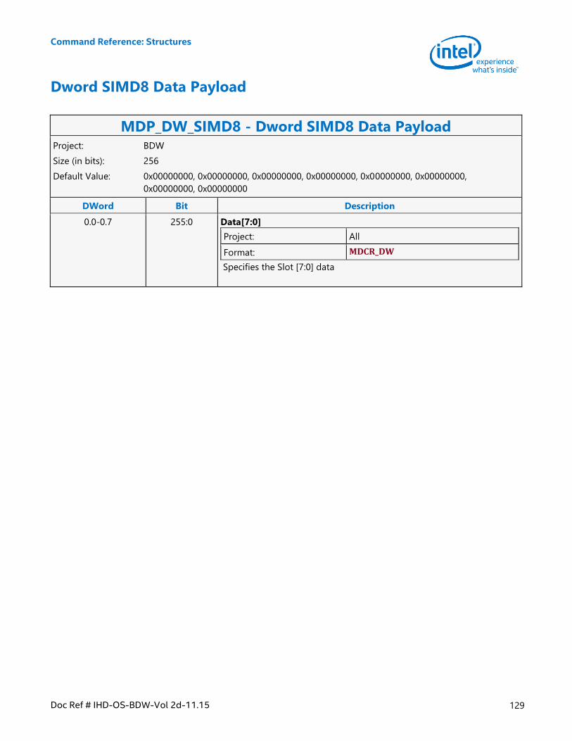
Command Reference: Structures
Doc Ref # IHD-OS-BDW-Vol 2d-11.15 129
Dword SIMD8 Data Payload
MDP_DW_SIMD8 - Dword SIMD8 Data Payload Project: BDW
Size (in bits): 256
Default Value: 0x00000000, 0x00000000, 0x00000000, 0x00000000, 0x00000000, 0x00000000,
0x00000000, 0x00000000
DWord Bit Description
0.0-0.7 255:0 Data[7:0]
Project: All
Format: MDCR_DW
Specifies the Slot [7:0] data
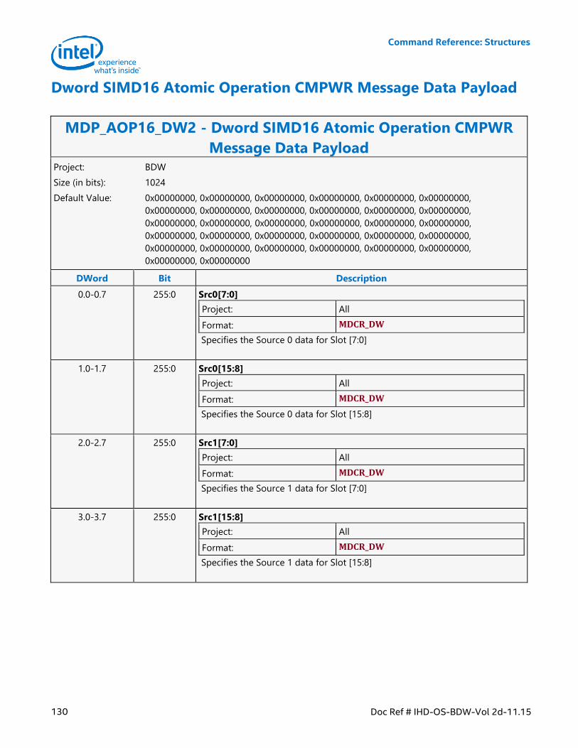
Command Reference: Structures
130 Doc Ref # IHD-OS-BDW-Vol 2d-11.15
Dword SIMD16 Atomic Operation CMPWR Message Data Payload
MDP_AOP16_DW2 - Dword SIMD16 Atomic Operation CMPWR
Message Data Payload Project: BDW
Size (in bits): 1024
Default Value: 0x00000000, 0x00000000, 0x00000000, 0x00000000, 0x00000000, 0x00000000,
0x00000000, 0x00000000, 0x00000000, 0x00000000, 0x00000000, 0x00000000,
0x00000000, 0x00000000, 0x00000000, 0x00000000, 0x00000000, 0x00000000,
0x00000000, 0x00000000, 0x00000000, 0x00000000, 0x00000000, 0x00000000,
0x00000000, 0x00000000, 0x00000000, 0x00000000, 0x00000000, 0x00000000,
0x00000000, 0x00000000
DWord Bit Description
0.0-0.7 255:0 Src0[7:0]
Project: All
Format: MDCR_DW
Specifies the Source 0 data for Slot [7:0]
1.0-1.7 255:0 Src0[15:8]
Project: All
Format: MDCR_DW
Specifies the Source 0 data for Slot [15:8]
2.0-2.7 255:0 Src1[7:0]
Project: All
Format: MDCR_DW
Specifies the Source 1 data for Slot [7:0]
3.0-3.7 255:0 Src1[15:8]
Project: All
Format: MDCR_DW
Specifies the Source 1 data for Slot [15:8]
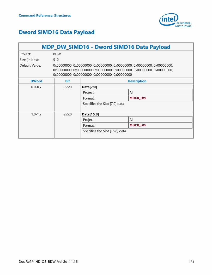
Command Reference: Structures
Doc Ref # IHD-OS-BDW-Vol 2d-11.15 131
Dword SIMD16 Data Payload
MDP_DW_SIMD16 - Dword SIMD16 Data Payload Project: BDW
Size (in bits): 512
Default Value: 0x00000000, 0x00000000, 0x00000000, 0x00000000, 0x00000000, 0x00000000,
0x00000000, 0x00000000, 0x00000000, 0x00000000, 0x00000000, 0x00000000,
0x00000000, 0x00000000, 0x00000000, 0x00000000
DWord Bit Description
0.0-0.7 255:0 Data[7:0]
Project: All
Format: MDCR_DW
Specifies the Slot [7:0] data
1.0-1.7 255:0 Data[15:8]
Project: All
Format: MDCR_DW
Specifies the Slot [15:8] data
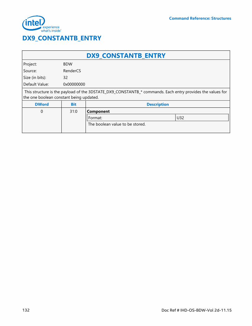
Command Reference: Structures
132 Doc Ref # IHD-OS-BDW-Vol 2d-11.15
DX9_CONSTANTB_ENTRY
DX9_CONSTANTB_ENTRY Project: BDW
Source: RenderCS
Size (in bits): 32
Default Value: 0x00000000
This structure is the payload of the 3DSTATE_DX9_CONSTANTB_* commands. Each entry provides the values for
the one boolean constant being updated.
DWord Bit Description
0 31:0 Component
Format: U32
The boolean value to be stored.
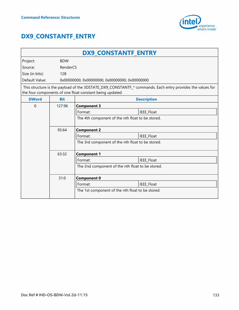
Command Reference: Structures
Doc Ref # IHD-OS-BDW-Vol 2d-11.15 133
DX9_CONSTANTF_ENTRY
DX9_CONSTANTF_ENTRY Project: BDW
Source: RenderCS
Size (in bits): 128
Default Value: 0x00000000, 0x00000000, 0x00000000, 0x00000000
This structure is the payload of the 3DSTATE_DX9_CONSTANTF_* commands. Each entry provides the values for
the four components of one float constant being updated.
DWord Bit Description
0 127:96 Component 3
Format: IEEE_Float
The 4th component of the nth float to be stored.
95:64 Component 2
Format: IEEE_Float
The 3rd component of the nth float to be stored.
63:32 Component 1
Format: IEEE_Float
The 2nd component of the nth float to be stored.
31:0 Component 0
Format: IEEE_Float
The 1st component of the nth float to be stored.
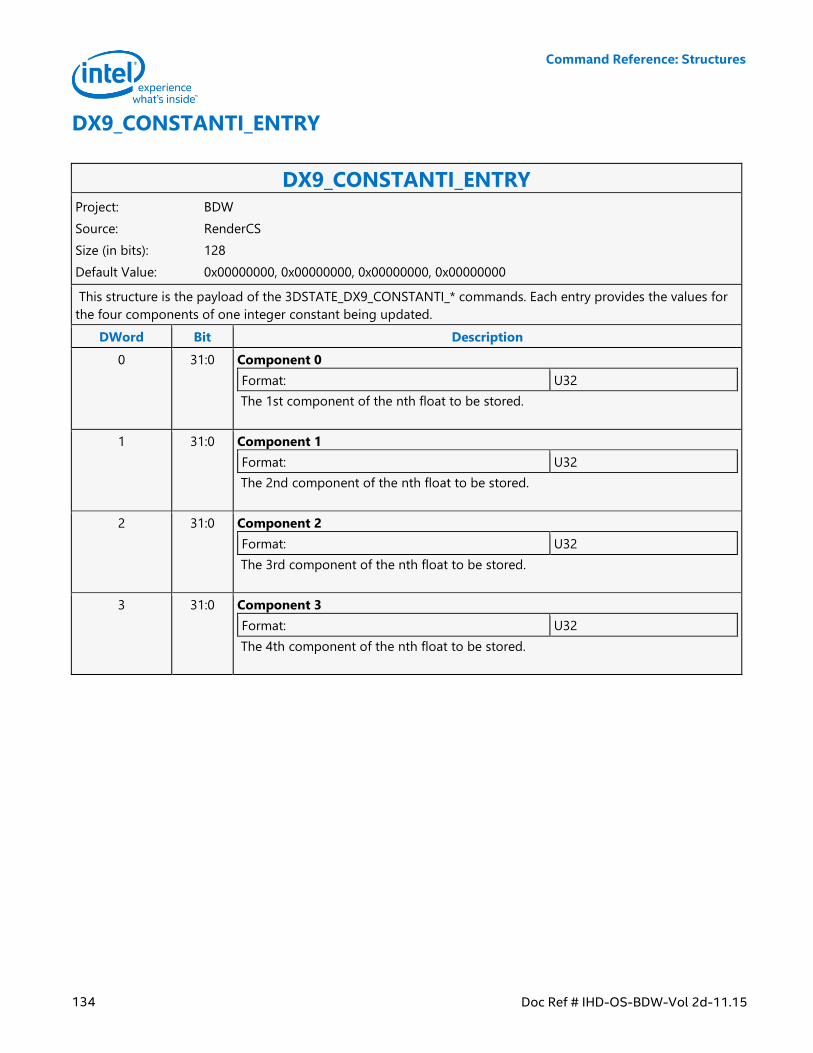
Command Reference: Structures
134 Doc Ref # IHD-OS-BDW-Vol 2d-11.15
DX9_CONSTANTI_ENTRY
DX9_CONSTANTI_ENTRY Project: BDW
Source: RenderCS
Size (in bits): 128
Default Value: 0x00000000, 0x00000000, 0x00000000, 0x00000000
This structure is the payload of the 3DSTATE_DX9_CONSTANTI_* commands. Each entry provides the values for
the four components of one integer constant being updated.
DWord Bit Description
0 31:0 Component 0
Format: U32
The 1st component of the nth float to be stored.
1 31:0 Component 1
Format: U32
The 2nd component of the nth float to be stored.
2 31:0 Component 2
Format: U32
The 3rd component of the nth float to be stored.
3 31:0 Component 3
Format: U32
The 4th component of the nth float to be stored.
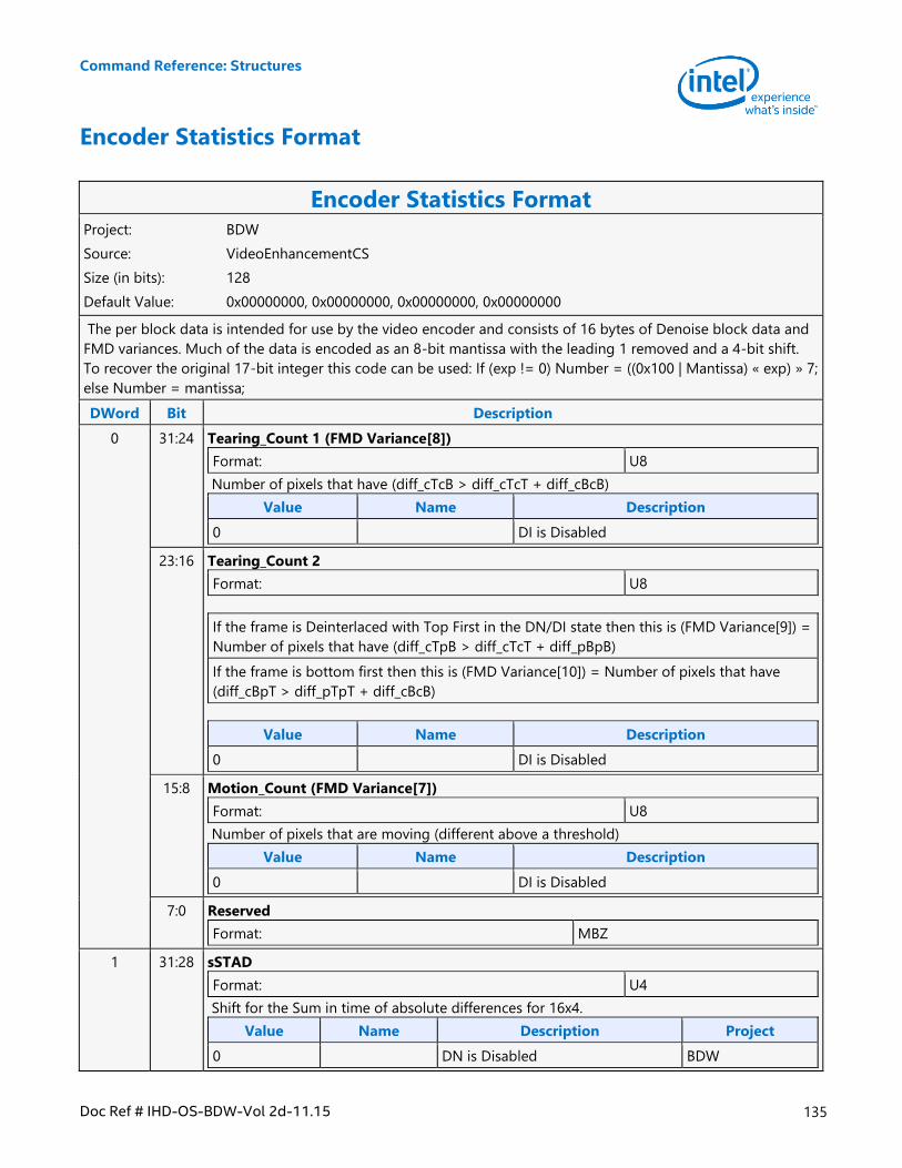
Command Reference: Structures
Doc Ref # IHD-OS-BDW-Vol 2d-11.15 135
Encoder Statistics Format
Encoder Statistics Format Project: BDW
Source: VideoEnhancementCS
Size (in bits): 128
Default Value: 0x00000000, 0x00000000, 0x00000000, 0x00000000
The per block data is intended for use by the video encoder and consists of 16 bytes of Denoise block data and
FMD variances. Much of the data is encoded as an 8-bit mantissa with the leading 1 removed and a 4-bit shift.
To recover the original 17-bit integer this code can be used: If (exp != 0) Number = ((0x100 | Mantissa) « exp) » 7;
else Number = mantissa;
DWord Bit Description
0 31:24 Tearing_Count 1 (FMD Variance[8])
Format: U8
Number of pixels that have (diff_cTcB > diff_cTcT + diff_cBcB)
Value Name Description
0 DI is Disabled
23:16 Tearing_Count 2
Format: U8
If the frame is Deinterlaced with Top First in the DN/DI state then this is (FMD Variance[9]) =
Number of pixels that have (diff_cTpB > diff_cTcT + diff_pBpB)
If the frame is bottom first then this is (FMD Variance[10]) = Number of pixels that have
(diff_cBpT > diff_pTpT + diff_cBcB)
Value Name Description
0 DI is Disabled
15:8 Motion_Count (FMD Variance[7])
Format: U8
Number of pixels that are moving (different above a threshold)
Value Name Description
0 DI is Disabled
7:0 Reserved
Format: MBZ
1 31:28 sSTAD
Format: U4
Shift for the Sum in time of absolute differences for 16x4.
Value Name Description Project
0 DN is Disabled BDW
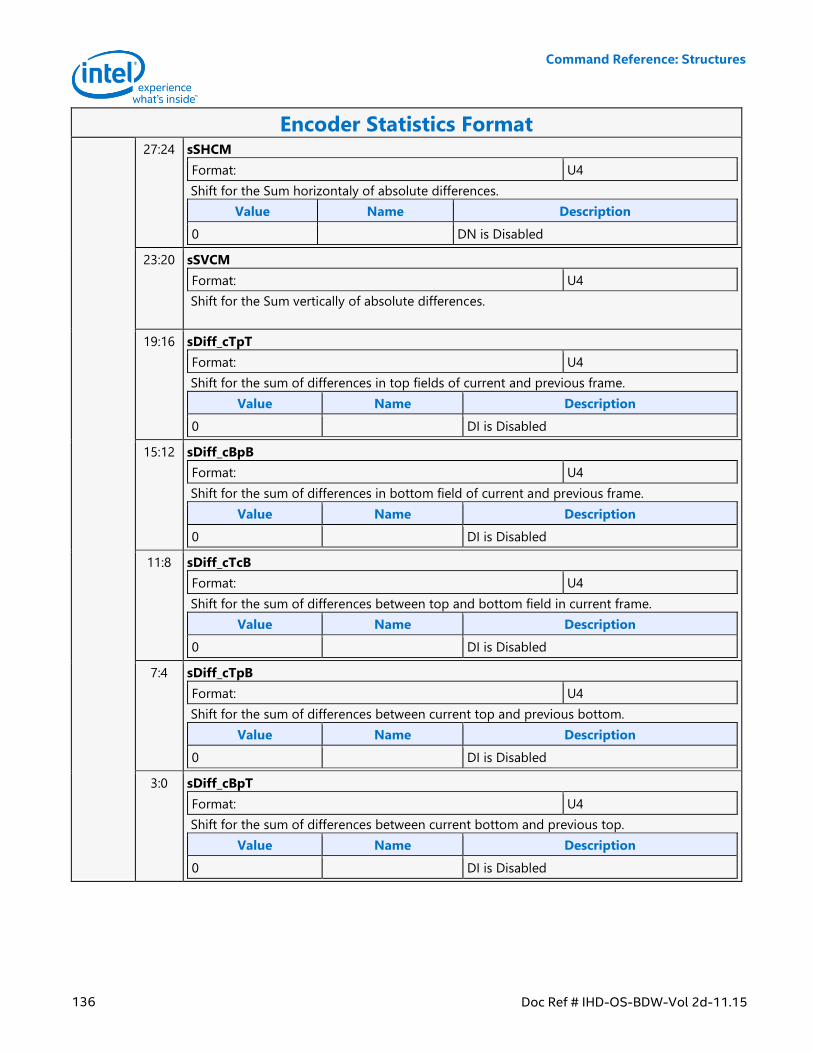
Command Reference: Structures
136 Doc Ref # IHD-OS-BDW-Vol 2d-11.15
Encoder Statistics Format 27:24 sSHCM
Format: U4
Shift for the Sum horizontaly of absolute differences.
Value Name Description
0 DN is Disabled
23:20 sSVCM
Format: U4
Shift for the Sum vertically of absolute differences.
19:16 sDiff_cTpT
Format: U4
Shift for the sum of differences in top fields of current and previous frame.
Value Name Description
0 DI is Disabled
15:12 sDiff_cBpB
Format: U4
Shift for the sum of differences in bottom field of current and previous frame.
Value Name Description
0 DI is Disabled
11:8 sDiff_cTcB
Format: U4
Shift for the sum of differences between top and bottom field in current frame.
Value Name Description
0 DI is Disabled
7:4 sDiff_cTpB
Format: U4
Shift for the sum of differences between current top and previous bottom.
Value Name Description
0 DI is Disabled
3:0 sDiff_cBpT
Format: U4
Shift for the sum of differences between current bottom and previous top.
Value Name Description
0 DI is Disabled
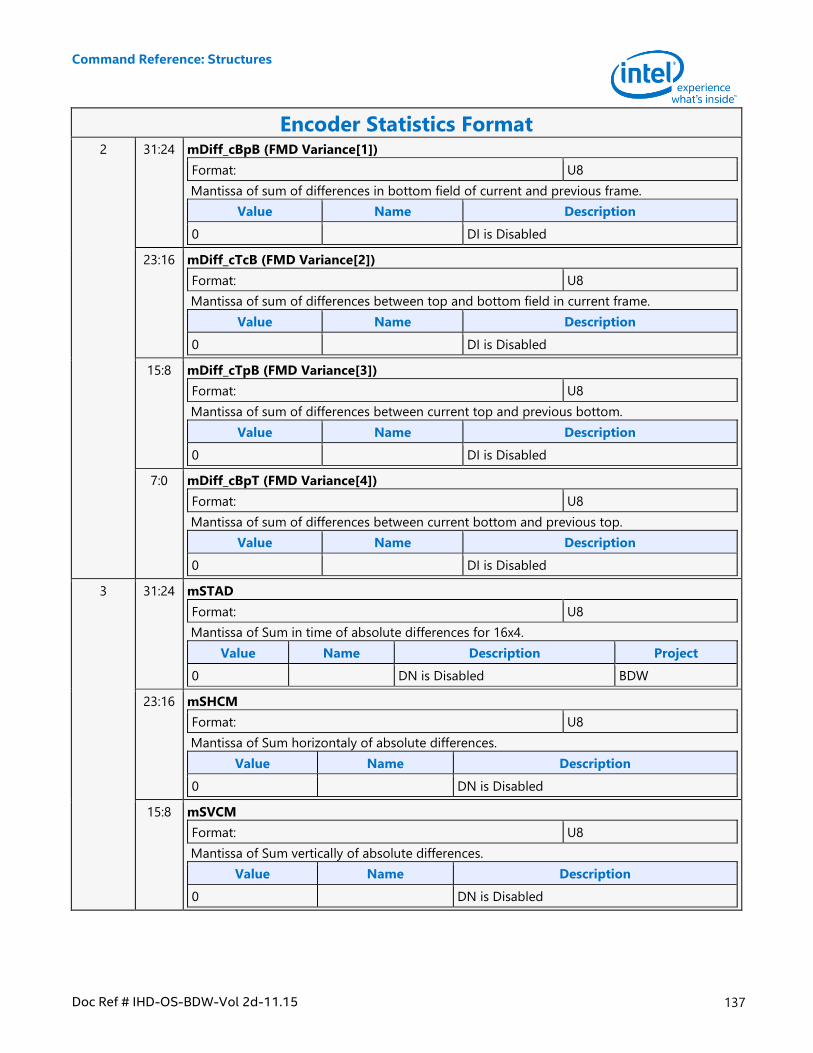
Command Reference: Structures
Doc Ref # IHD-OS-BDW-Vol 2d-11.15 137
Encoder Statistics Format 2 31:24 mDiff_cBpB (FMD Variance[1])
Format: U8
Mantissa of sum of differences in bottom field of current and previous frame.
Value Name Description
0 DI is Disabled
23:16 mDiff_cTcB (FMD Variance[2])
Format: U8
Mantissa of sum of differences between top and bottom field in current frame.
Value Name Description
0 DI is Disabled
15:8 mDiff_cTpB (FMD Variance[3])
Format: U8
Mantissa of sum of differences between current top and previous bottom.
Value Name Description
0 DI is Disabled
7:0 mDiff_cBpT (FMD Variance[4])
Format: U8
Mantissa of sum of differences between current bottom and previous top.
Value Name Description
0 DI is Disabled
3 31:24 mSTAD
Format: U8
Mantissa of Sum in time of absolute differences for 16x4.
Value Name Description Project
0 DN is Disabled BDW
23:16 mSHCM
Format: U8
Mantissa of Sum horizontaly of absolute differences.
Value Name Description
0 DN is Disabled
15:8 mSVCM
Format: U8
Mantissa of Sum vertically of absolute differences.
Value Name Description
0 DN is Disabled
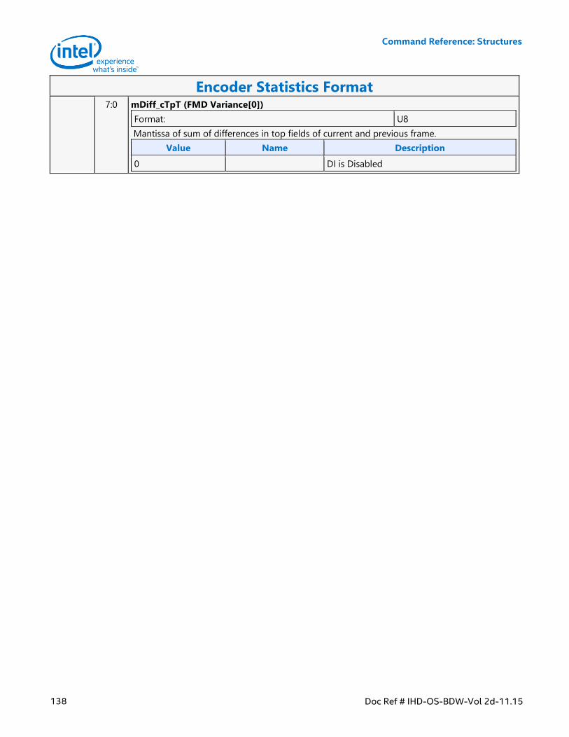
Command Reference: Structures
138 Doc Ref # IHD-OS-BDW-Vol 2d-11.15
Encoder Statistics Format 7:0 mDiff_cTpT (FMD Variance[0])
Format: U8
Mantissa of sum of differences in top fields of current and previous frame.
Value Name Description
0 DI is Disabled
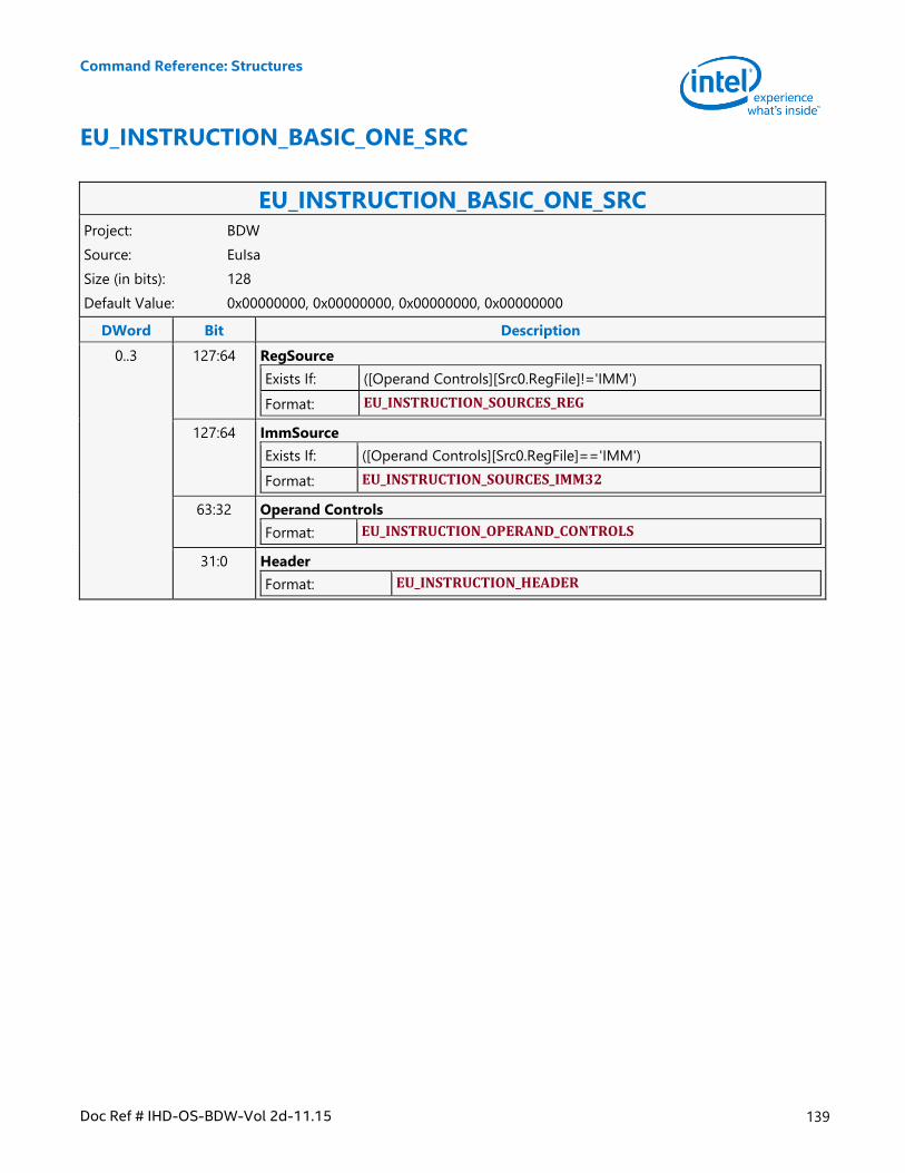
Command Reference: Structures
Doc Ref # IHD-OS-BDW-Vol 2d-11.15 139
EU_INSTRUCTION_BASIC_ONE_SRC
EU_INSTRUCTION_BASIC_ONE_SRC Project: BDW
Source: EuIsa
Size (in bits): 128
Default Value: 0x00000000, 0x00000000, 0x00000000, 0x00000000
DWord Bit Description
0..3 127:64 RegSource
Exists If: ([Operand Controls][Src0.RegFile]!='IMM')
Format: EU_INSTRUCTION_SOURCES_REG
127:64 ImmSource
Exists If: ([Operand Controls][Src0.RegFile]=='IMM')
Format: EU_INSTRUCTION_SOURCES_IMM32
63:32 Operand Controls
Format: EU_INSTRUCTION_OPERAND_CONTROLS
31:0 Header
Format: EU_INSTRUCTION_HEADER
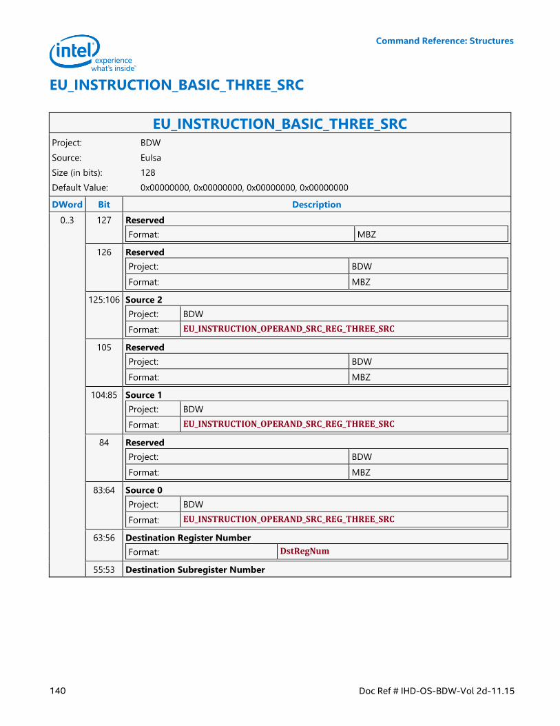
Command Reference: Structures
140 Doc Ref # IHD-OS-BDW-Vol 2d-11.15
EU_INSTRUCTION_BASIC_THREE_SRC
EU_INSTRUCTION_BASIC_THREE_SRC Project: BDW
Source: EuIsa
Size (in bits): 128
Default Value: 0x00000000, 0x00000000, 0x00000000, 0x00000000
DWord Bit Description
0..3 127 Reserved
Format: MBZ
126 Reserved
Project: BDW
Format: MBZ
125:106 Source 2
Project: BDW
Format: EU_INSTRUCTION_OPERAND_SRC_REG_THREE_SRC
105 Reserved
Project: BDW
Format: MBZ
104:85 Source 1
Project: BDW
Format: EU_INSTRUCTION_OPERAND_SRC_REG_THREE_SRC
84 Reserved
Project: BDW
Format: MBZ
83:64 Source 0
Project: BDW
Format: EU_INSTRUCTION_OPERAND_SRC_REG_THREE_SRC
63:56 Destination Register Number
Format: DstRegNum
55:53 Destination Subregister Number
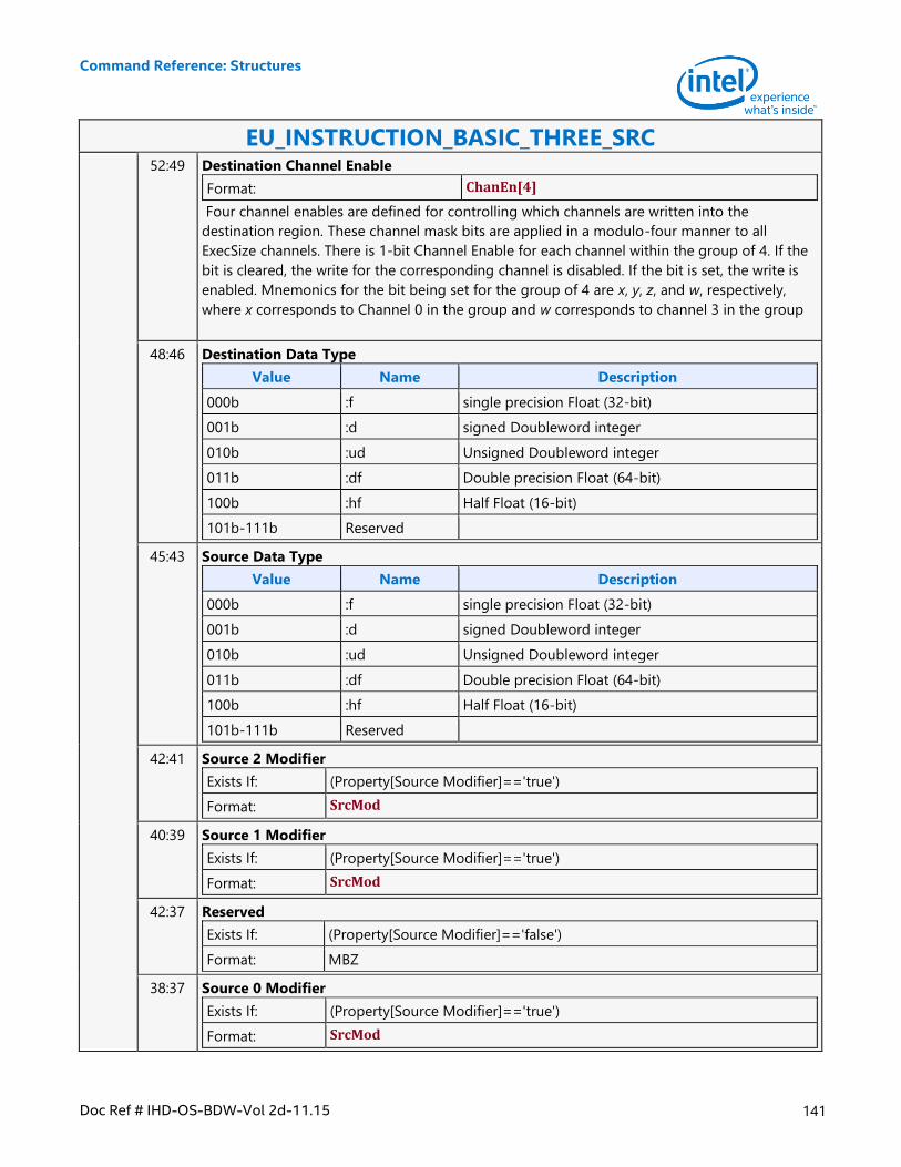
Command Reference: Structures
Doc Ref # IHD-OS-BDW-Vol 2d-11.15 141
EU_INSTRUCTION_BASIC_THREE_SRC 52:49 Destination Channel Enable
Format: ChanEn[4]
Four channel enables are defined for controlling which channels are written into the
destination region. These channel mask bits are applied in a modulo-four manner to all
ExecSize channels. There is 1-bit Channel Enable for each channel within the group of 4. If the
bit is cleared, the write for the corresponding channel is disabled. If the bit is set, the write is
enabled. Mnemonics for the bit being set for the group of 4 are x, y, z, and w, respectively,
where x corresponds to Channel 0 in the group and w corresponds to channel 3 in the group
48:46 Destination Data Type
Value Name Description
000b :f single precision Float (32-bit)
001b :d signed Doubleword integer
010b :ud Unsigned Doubleword integer
011b :df Double precision Float (64-bit)
100b :hf Half Float (16-bit)
101b-111b Reserved
45:43 Source Data Type
Value Name Description
000b :f single precision Float (32-bit)
001b :d signed Doubleword integer
010b :ud Unsigned Doubleword integer
011b :df Double precision Float (64-bit)
100b :hf Half Float (16-bit)
101b-111b Reserved
42:41 Source 2 Modifier
Exists If: (Property[Source Modifier]=='true')
Format: SrcMod
40:39 Source 1 Modifier
Exists If: (Property[Source Modifier]=='true')
Format: SrcMod
42:37 Reserved
Exists If: (Property[Source Modifier]=='false')
Format: MBZ
38:37 Source 0 Modifier
Exists If: (Property[Source Modifier]=='true')
Format: SrcMod
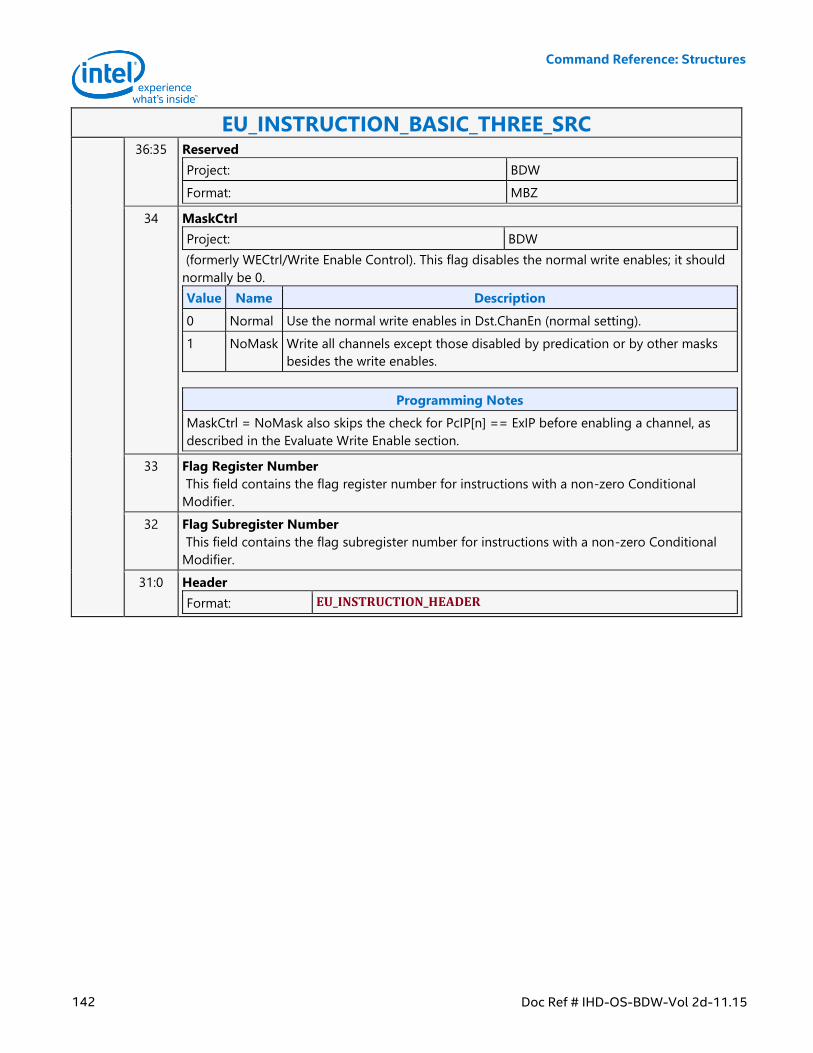
Command Reference: Structures
142 Doc Ref # IHD-OS-BDW-Vol 2d-11.15
EU_INSTRUCTION_BASIC_THREE_SRC 36:35 Reserved
Project: BDW
Format: MBZ
34 MaskCtrl
Project: BDW
(formerly WECtrl/Write Enable Control). This flag disables the normal write enables; it should
normally be 0.
Value Name Description
0 Normal Use the normal write enables in Dst.ChanEn (normal setting).
1 NoMask Write all channels except those disabled by predication or by other masks
besides the write enables.
Programming Notes
MaskCtrl = NoMask also skips the check for PcIP[n] == ExIP before enabling a channel, as
described in the Evaluate Write Enable section.
33 Flag Register Number
This field contains the flag register number for instructions with a non-zero Conditional
Modifier.
32 Flag Subregister Number
This field contains the flag subregister number for instructions with a non-zero Conditional
Modifier.
31:0 Header
Format: EU_INSTRUCTION_HEADER
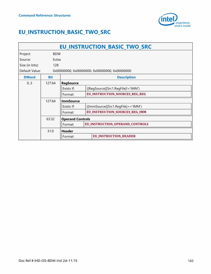
Command Reference: Structures
Doc Ref # IHD-OS-BDW-Vol 2d-11.15 143
EU_INSTRUCTION_BASIC_TWO_SRC
EU_INSTRUCTION_BASIC_TWO_SRC Project: BDW
Source: EuIsa
Size (in bits): 128
Default Value: 0x00000000, 0x00000000, 0x00000000, 0x00000000
DWord Bit Description
0..3 127:64 RegSource
Exists If: ([RegSource][Src1.RegFile]!='IMM')
Format: EU_INSTRUCTION_SOURCES_REG_REG
127:64 ImmSource
Exists If: ([ImmSource][Src1.RegFile]=='IMM')
Format: EU_INSTRUCTION_SOURCES_REG_IMM
63:32 Operand Controls
Format: EU_INSTRUCTION_OPERAND_CONTROLS
31:0 Header
Format: EU_INSTRUCTION_HEADER
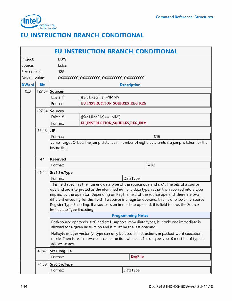
Command Reference: Structures
144 Doc Ref # IHD-OS-BDW-Vol 2d-11.15
EU_INSTRUCTION_BRANCH_CONDITIONAL
EU_INSTRUCTION_BRANCH_CONDITIONAL Project: BDW
Source: EuIsa
Size (in bits): 128
Default Value: 0x00000000, 0x00000000, 0x00000000, 0x00000000
DWord Bit Description
0..3 127:64 Sources
Exists If: ([Src1.RegFile]!='IMM')
Format: EU_INSTRUCTION_SOURCES_REG_REG
127:64 Sources
Exists If: ([Src1.RegFile]=='IMM')
Format: EU_INSTRUCTION_SOURCES_REG_IMM
63:48 JIP
Format: S15
Jump Target Offset. The jump distance in number of eight-byte units if a jump is taken for the
instruction.
47 Reserved
Format: MBZ
46:44 Src1.SrcType
Format: DataType
This field specifies the numeric data type of the source operand src1. The bits of a source
operand are interpreted as the identified numeric data type, rather than coerced into a type
implied by the operator. Depending on RegFile field of the source operand, there are two
different encoding for this field. If a source is a register operand, this field follows the Source
Register Type Encoding. If a source is an immediate operand, this field follows the Source
Immediate Type Encoding.
Programming Notes
Both source operands, src0 and src1, support immediate types, but only one immediate is
allowed for a given instruction and it must be the last operand.
Halfbyte integer vector (v) type can only be used in instructions in packed-word execution
mode. Therefore, in a two-source instruction where src1 is of type :v, src0 must be of type :b,
:ub, :w, or :uw.
43:42 Src1.RegFile
Format: RegFile
41:39 Src0.SrcType
Format: DataType
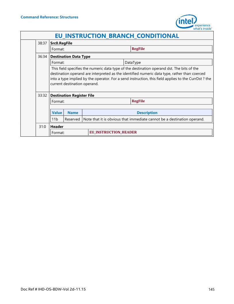
Command Reference: Structures
Doc Ref # IHD-OS-BDW-Vol 2d-11.15 145
EU_INSTRUCTION_BRANCH_CONDITIONAL 38:37 Src0.RegFile
Format: RegFile
36:34 Destination Data Type
Format: DataType
This field specifies the numeric data type of the destination operand dst. The bits of the
destination operand are interpreted as the identified numeric data type, rather than coerced
into a type implied by the operator. For a send instruction, this field applies to the CurrDst ? the
current destination operand.
33:32 Destination Register File
Format: RegFile
Value Name Description
11b Reserved Note that it is obvious that immediate cannot be a destination operand.
31:0 Header
Format: EU_INSTRUCTION_HEADER
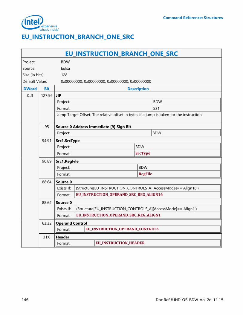
Command Reference: Structures
146 Doc Ref # IHD-OS-BDW-Vol 2d-11.15
EU_INSTRUCTION_BRANCH_ONE_SRC
EU_INSTRUCTION_BRANCH_ONE_SRC Project: BDW
Source: EuIsa
Size (in bits): 128
Default Value: 0x00000000, 0x00000000, 0x00000000, 0x00000000
DWord Bit Description
0..3 127:96 JIP
Project: BDW
Format: S31
Jump Target Offset. The relative offset in bytes if a jump is taken for the instruction.
95 Source 0 Address Immediate [9] Sign Bit
Project: BDW
94:91 Src1.SrcType
Project: BDW
Format: SrcType
90:89 Src1.RegFile
Project: BDW
Format: RegFile
88:64 Source 0
Exists If: (Structure[EU_INSTRUCTION_CONTROLS_A][AccessMode]=='Align16')
Format: EU_INSTRUCTION_OPERAND_SRC_REG_ALIGN16
88:64 Source 0
Exists If: (Structure[EU_INSTRUCTION_CONTROLS_A][AccessMode]=='Align1')
Format: EU_INSTRUCTION_OPERAND_SRC_REG_ALIGN1
63:32 Operand Control
Format: EU_INSTRUCTION_OPERAND_CONTROLS
31:0 Header
Format: EU_INSTRUCTION_HEADER
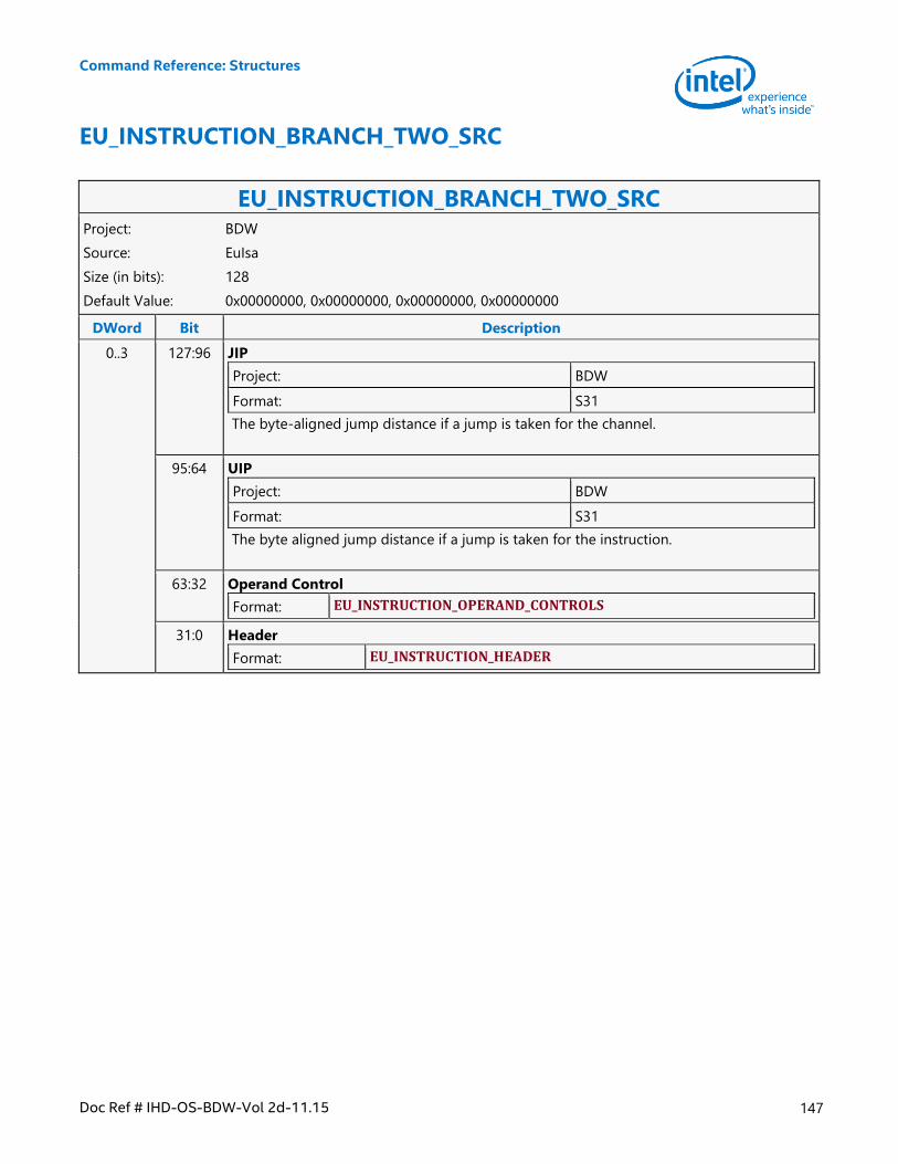
Command Reference: Structures
Doc Ref # IHD-OS-BDW-Vol 2d-11.15 147
EU_INSTRUCTION_BRANCH_TWO_SRC
EU_INSTRUCTION_BRANCH_TWO_SRC Project: BDW
Source: EuIsa
Size (in bits): 128
Default Value: 0x00000000, 0x00000000, 0x00000000, 0x00000000
DWord Bit Description
0..3 127:96 JIP
Project: BDW
Format: S31
The byte-aligned jump distance if a jump is taken for the channel.
95:64 UIP
Project: BDW
Format: S31
The byte aligned jump distance if a jump is taken for the instruction.
63:32 Operand Control
Format: EU_INSTRUCTION_OPERAND_CONTROLS
31:0 Header
Format: EU_INSTRUCTION_HEADER
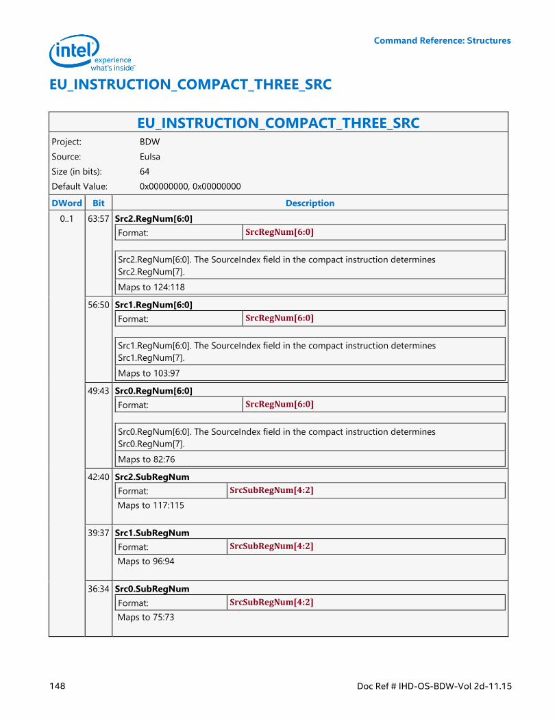
Command Reference: Structures
148 Doc Ref # IHD-OS-BDW-Vol 2d-11.15
EU_INSTRUCTION_COMPACT_THREE_SRC
EU_INSTRUCTION_COMPACT_THREE_SRC Project: BDW
Source: EuIsa
Size (in bits): 64
Default Value: 0x00000000, 0x00000000
DWord Bit Description
0..1 63:57 Src2.RegNum[6:0]
Format: SrcRegNum[6:0]
Src2.RegNum[6:0]. The SourceIndex field in the compact instruction determines
Src2.RegNum[7].
Maps to 124:118
56:50 Src1.RegNum[6:0]
Format: SrcRegNum[6:0]
Src1.RegNum[6:0]. The SourceIndex field in the compact instruction determines
Src1.RegNum[7].
Maps to 103:97
49:43 Src0.RegNum[6:0]
Format: SrcRegNum[6:0]
Src0.RegNum[6:0]. The SourceIndex field in the compact instruction determines
Src0.RegNum[7].
Maps to 82:76
42:40 Src2.SubRegNum
Format: SrcSubRegNum[4:2]
Maps to 117:115
39:37 Src1.SubRegNum
Format: SrcSubRegNum[4:2]
Maps to 96:94
36:34 Src0.SubRegNum
Format: SrcSubRegNum[4:2]
Maps to 75:73
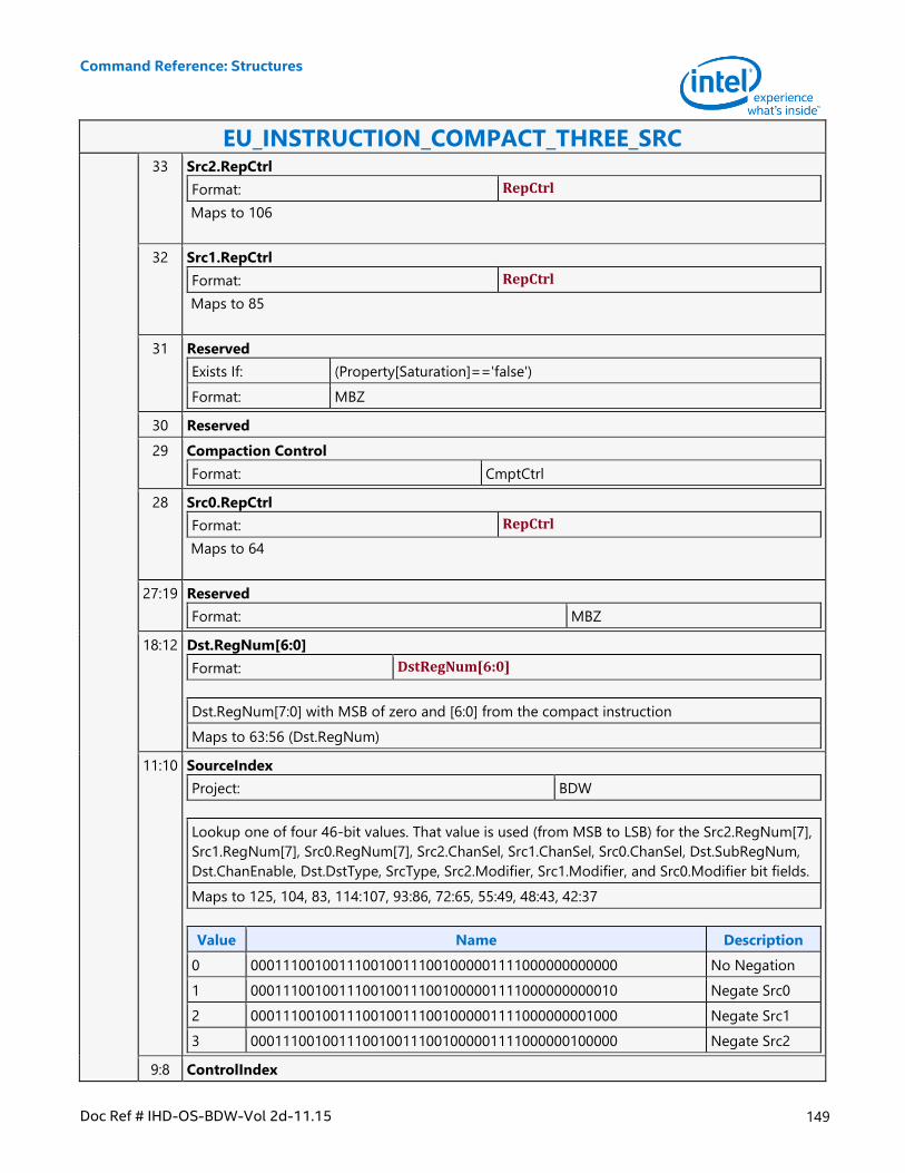
Command Reference: Structures
Doc Ref # IHD-OS-BDW-Vol 2d-11.15 149
EU_INSTRUCTION_COMPACT_THREE_SRC 33 Src2.RepCtrl
Format: RepCtrl
Maps to 106
32 Src1.RepCtrl
Format: RepCtrl
Maps to 85
31 Reserved
Exists If: (Property[Saturation]=='false')
Format: MBZ
30 Reserved
29 Compaction Control
Format: CmptCtrl
28 Src0.RepCtrl
Format: RepCtrl
Maps to 64
27:19 Reserved
Format: MBZ
18:12 Dst.RegNum[6:0]
Format: DstRegNum[6:0]
Dst.RegNum[7:0] with MSB of zero and [6:0] from the compact instruction
Maps to 63:56 (Dst.RegNum)
11:10 SourceIndex
Project: BDW
Lookup one of four 46-bit values. That value is used (from MSB to LSB) for the Src2.RegNum[7],
Src1.RegNum[7], Src0.RegNum[7], Src2.ChanSel, Src1.ChanSel, Src0.ChanSel, Dst.SubRegNum,
Dst.ChanEnable, Dst.DstType, SrcType, Src2.Modifier, Src1.Modifier, and Src0.Modifier bit fields.
Maps to 125, 104, 83, 114:107, 93:86, 72:65, 55:49, 48:43, 42:37
Value Name Description
0 0001110010011100100111001000001111000000000000 No Negation
1 0001110010011100100111001000001111000000000010 Negate Src0
2 0001110010011100100111001000001111000000001000 Negate Src1
3 0001110010011100100111001000001111000000100000 Negate Src2
9:8 ControlIndex
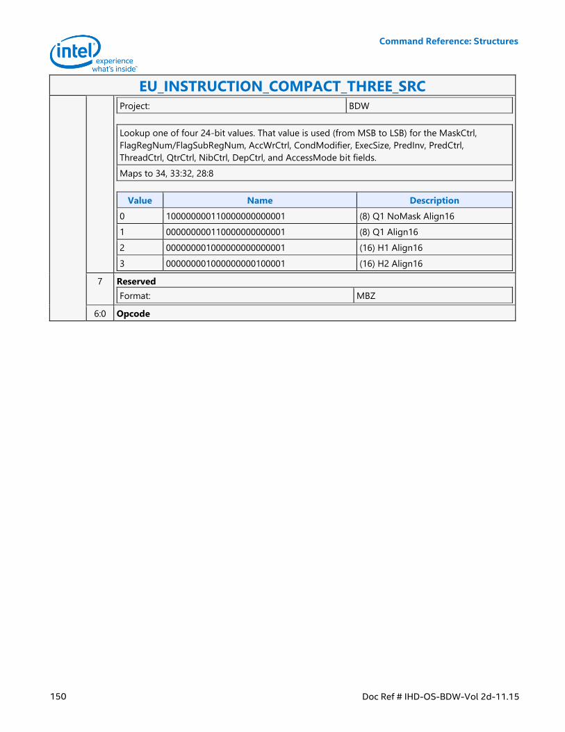
Command Reference: Structures
150 Doc Ref # IHD-OS-BDW-Vol 2d-11.15
EU_INSTRUCTION_COMPACT_THREE_SRC
Project: BDW
Lookup one of four 24-bit values. That value is used (from MSB to LSB) for the MaskCtrl,
FlagRegNum/FlagSubRegNum, AccWrCtrl, CondModifier, ExecSize, PredInv, PredCtrl,
ThreadCtrl, QtrCtrl, NibCtrl, DepCtrl, and AccessMode bit fields.
Maps to 34, 33:32, 28:8
Value Name Description
0 100000000110000000000001 (8) Q1 NoMask Align16
1 000000000110000000000001 (8) Q1 Align16
2 000000001000000000000001 (16) H1 Align16
3 000000001000000000100001 (16) H2 Align16
7 Reserved
Format: MBZ
6:0 Opcode
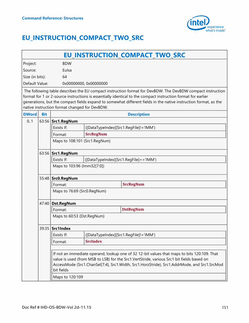
Command Reference: Structures
Doc Ref # IHD-OS-BDW-Vol 2d-11.15 151
EU_INSTRUCTION_COMPACT_TWO_SRC
EU_INSTRUCTION_COMPACT_TWO_SRC Project: BDW
Source: EuIsa
Size (in bits): 64
Default Value: 0x00000000, 0x00000000
The following table describes the EU compact instruction format for DevBDW. The DevBDW compact instruction
format for 1 or 2-source instructions is essentially identical to the compact instruction format for earlier
generations, but the compact fields expand to somewhat different fields in the native instruction format, as the
native instruction format changed for DevBDW.
DWord Bit Description
0..1 63:56 Src1.RegNum
Exists If: ([DataTypeIndex][Src1.RegFile]!='IMM')
Format: SrcRegNum
Maps to 108:101 (Src1.RegNum)
63:56 Src1.RegNum
Exists If: ([DataTypeIndex][Src1.RegFile]=='IMM')
Maps to 103:96 (Imm32[7:0])
55:48 Src0.RegNum
Format: SrcRegNum
Maps to 76:69 (Src0.RegNum)
47:40 Dst.RegNum
Format: DstRegNum
Maps to 60:53 (Dst.RegNum)
39:35 Src1Index
Exists If: ([DataTypeIndex][Src1.RegFile]!='IMM')
Format: SrcIndex
If not an immediate operand, lookup one of 32 12-bit values that maps to bits 120:109. That
value is used (from MSB to LSB) for the Src1.VertStride, various Src1 bit fields based on
AccessMode (Src1.ChanSel[7:4], Src1.Width, Src1.HorzStride), Src1.AddrMode, and Src1.SrcMod
bit fields
Maps to 120:109
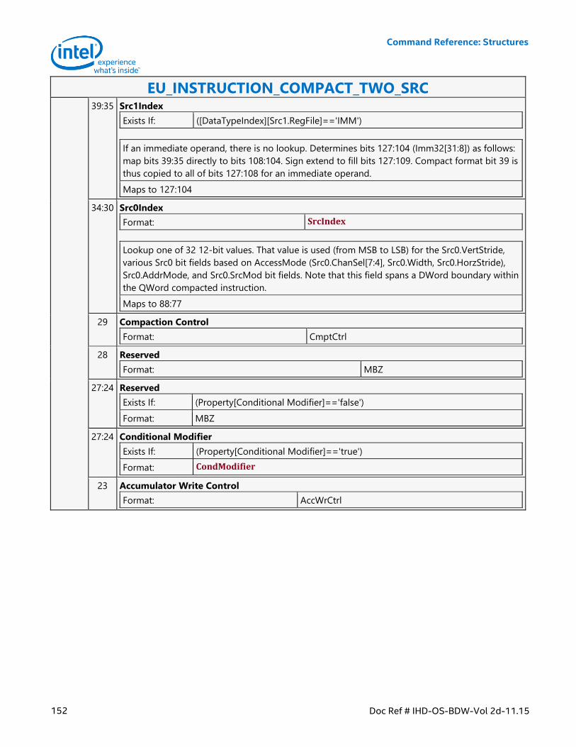
Command Reference: Structures
152 Doc Ref # IHD-OS-BDW-Vol 2d-11.15
EU_INSTRUCTION_COMPACT_TWO_SRC 39:35 Src1Index
Exists If: ([DataTypeIndex][Src1.RegFile]=='IMM')
If an immediate operand, there is no lookup. Determines bits 127:104 (Imm32[31:8]) as follows:
map bits 39:35 directly to bits 108:104. Sign extend to fill bits 127:109. Compact format bit 39 is
thus copied to all of bits 127:108 for an immediate operand.
Maps to 127:104
34:30 Src0Index
Format: SrcIndex
Lookup one of 32 12-bit values. That value is used (from MSB to LSB) for the Src0.VertStride,
various Src0 bit fields based on AccessMode (Src0.ChanSel[7:4], Src0.Width, Src0.HorzStride),
Src0.AddrMode, and Src0.SrcMod bit fields. Note that this field spans a DWord boundary within
the QWord compacted instruction.
Maps to 88:77
29 Compaction Control
Format: CmptCtrl
28 Reserved
Format: MBZ
27:24 Reserved
Exists If: (Property[Conditional Modifier]=='false')
Format: MBZ
27:24 Conditional Modifier
Exists If: (Property[Conditional Modifier]=='true')
Format: CondModifier
23 Accumulator Write Control
Format: AccWrCtrl
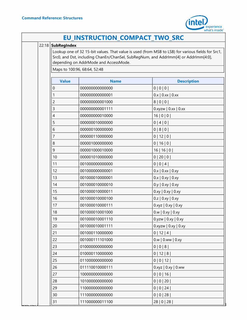
Command Reference: Structures
Doc Ref # IHD-OS-BDW-Vol 2d-11.15 153
EU_INSTRUCTION_COMPACT_TWO_SRC 22:18 SubRegIndex
Lookup one of 32 15-bit values. That value is used (from MSB to LSB) for various fields for Src1,
Src0, and Dst, including ChanEn/ChanSel, SubRegNum, and AddrImm[4] or AddrImm[4:0],
depending on AddrMode and AccessMode.
Maps to 100:96, 68:64, 52:48
Value Name Description
0 000000000000000 0 | 0 | 0 |
1 000000000000001 0.x | 0.xx | 0.xx
2 000000000001000 8 | 0 | 0 |
3 000000000001111 0.xyzw | 0.xx | 0.xx
4 000000000010000 16 | 0 | 0 |
5 000000010000000 0 | 4 | 0 |
6 000000100000000 0 | 8 | 0 |
7 000000110000000 0 | 12 | 0 |
8 000001000000000 0 | 16 | 0 |
9 000001000010000 16 | 16 | 0 |
10 000001010000000 0 | 20 | 0 |
11 001000000000000 0 | 0 | 4 |
12 001000000000001 0.x | 0.xx | 0.xy
13 001000010000001 0.x | 0.xy | 0.xy
14 001000010000010 0.y | 0.xy | 0.xy
15 001000010000011 0.xy | 0.xy | 0.xy
16 001000010000100 0.z | 0.xy | 0.xy
17 001000010000111 0.xyz | 0.xy | 0.xy
18 001000010001000 0.w | 0.xy | 0.xy
19 001000010001110 0.yzw | 0.xy | 0.xy
20 001000010001111 0.xyzw | 0.xy | 0.xy
21 001000110000000 0 | 12 | 4 |
22 001000111101000 0.w | 0.ww | 0.xy
23 010000000000000 0 | 0 | 8 |
24 010000110000000 0 | 12 | 8 |
25 011000000000000 0 | 0 | 12 |
26 011110010000111 0.xyz | 0.xy | 0.ww
27 100000000000000 0 | 0 | 16 |
28 101000000000000 0 | 0 | 20 |
29 110000000000000 0 | 0 | 24 |
30 111000000000000 0 | 0 | 28 |
31 111000000011100 28 | 0 | 28 |
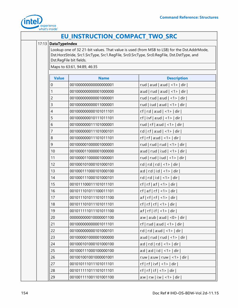
Command Reference: Structures
154 Doc Ref # IHD-OS-BDW-Vol 2d-11.15
EU_INSTRUCTION_COMPACT_TWO_SRC 17:13 DataTypeIndex
Lookup one of 32 21-bit values. That value is used (from MSB to LSB) for the Dst.AddrMode,
Dst.HorzStride, Src1.SrcType, Src1.RegFile, Src0.SrcType, Src0.RegFile, Dst.DstType, and
Dst.RegFile bit fields.
Maps to 63:61, 94:89, 46:35
Value Name Description
0 001000000000000000001 r:ud | a:ud | a:ud | <1> | dir |
1 001000000000001000000 a:ud | r:ud | a:ud | <1> | dir |
2 001000000000001000001 r:ud | r:ud | a:ud | <1> | dir |
3 001000000000011000001 r:ud | i:ud | a:ud | <1> | dir |
4 001000000000101011101 r:f | r:d | a:ud | <1> | dir |
5 001000000010111011101 r:f | i:vf | a:ud | <1> | dir |
6 001000000011101000001 r:ud | r:f | a:ud | <1> | dir |
7 001000000011101000101 r:d | r:f | a:ud | <1> | dir |
8 001000000011101011101 r:f | r:f | a:ud | <1> | dir |
9 001000001000001000001 r:ud | r:ud | r:ud | <1> | dir |
10 001000011000001000000 a:ud | r:ud | i:ud | <1> | dir |
11 001000011000001000001 r:ud | r:ud | i:ud | <1> | dir |
12 001000101000101000101 r:d | r:d | r:d | <1> | dir |
13 001000111000101000100 a:d | r:d | i:d | <1> | dir |
14 001000111000101000101 r:d | r:d | i:d | <1> | dir |
15 001011100011101011101 r:f | r:f | a:f | <1> | dir |
16 001011101011100011101 r:f | a:f | r:f | <1> | dir |
17 001011101011101011100 a:f | r:f | r:f | <1> | dir |
18 001011101011101011101 r:f | r:f | r:f | <1> | dir |
19 001011111011101011100 a:f | r:f | i:f | <1> | dir |
20 000000000010000001100 a:w | a:ub | a:ud | <0> | dir |
21 001000000000001011101 r:f | r:ud | a:ud | <1> | dir |
22 001000000000101000101 r:d | r:d | a:ud | <1> | dir |
23 001000001000001000000 a:ud | r:ud | r:ud | <1> | dir |
24 001000101000101000100 a:d | r:d | r:d | <1> | dir |
25 001000111000100000100 a:d | a:d | i:d | <1> | dir |
26 001001001001000001001 r:uw | a:uw | r:uw | <1> | dir |
27 001010111011101011101 r:f | r:f | i:vf | <1> | dir |
28 001011111011101011101 r:f | r:f | i:f | <1> | dir |
29 001001111001101001100 a:w | r:w | i:w | <1> | dir |
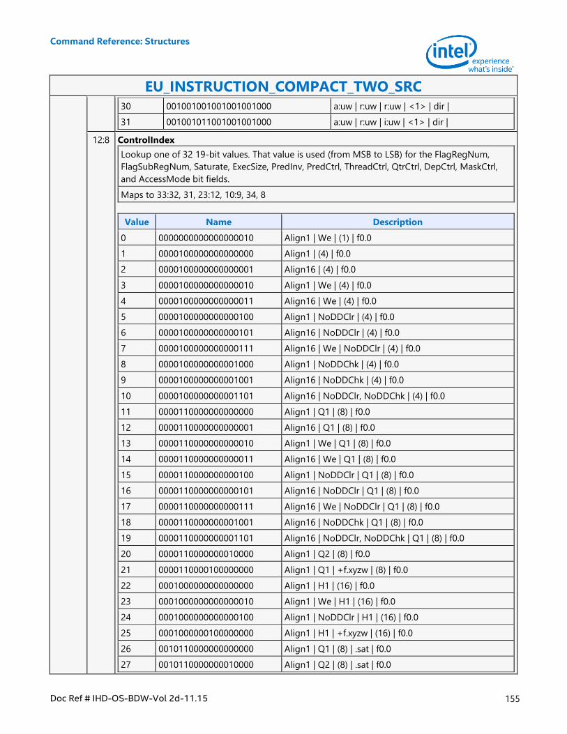
Command Reference: Structures
Doc Ref # IHD-OS-BDW-Vol 2d-11.15 155
EU_INSTRUCTION_COMPACT_TWO_SRC
30 001001001001001001000 a:uw | r:uw | r:uw | <1> | dir |
31 001001011001001001000 a:uw | r:uw | i:uw | <1> | dir |
12:8 ControlIndex
Lookup one of 32 19-bit values. That value is used (from MSB to LSB) for the FlagRegNum,
FlagSubRegNum, Saturate, ExecSize, PredInv, PredCtrl, ThreadCtrl, QtrCtrl, DepCtrl, MaskCtrl,
and AccessMode bit fields.
Maps to 33:32, 31, 23:12, 10:9, 34, 8
Value Name Description
0 0000000000000000010 Align1 | We | (1) | f0.0
1 0000100000000000000 Align1 | (4) | f0.0
2 0000100000000000001 Align16 | (4) | f0.0
3 0000100000000000010 Align1 | We | (4) | f0.0
4 0000100000000000011 Align16 | We | (4) | f0.0
5 0000100000000000100 Align1 | NoDDClr | (4) | f0.0
6 0000100000000000101 Align16 | NoDDClr | (4) | f0.0
7 0000100000000000111 Align16 | We | NoDDClr | (4) | f0.0
8 0000100000000001000 Align1 | NoDDChk | (4) | f0.0
9 0000100000000001001 Align16 | NoDDChk | (4) | f0.0
10 0000100000000001101 Align16 | NoDDClr, NoDDChk | (4) | f0.0
11 0000110000000000000 Align1 | Q1 | (8) | f0.0
12 0000110000000000001 Align16 | Q1 | (8) | f0.0
13 0000110000000000010 Align1 | We | Q1 | (8) | f0.0
14 0000110000000000011 Align16 | We | Q1 | (8) | f0.0
15 0000110000000000100 Align1 | NoDDClr | Q1 | (8) | f0.0
16 0000110000000000101 Align16 | NoDDClr | Q1 | (8) | f0.0
17 0000110000000000111 Align16 | We | NoDDClr | Q1 | (8) | f0.0
18 0000110000000001001 Align16 | NoDDChk | Q1 | (8) | f0.0
19 0000110000000001101 Align16 | NoDDClr, NoDDChk | Q1 | (8) | f0.0
20 0000110000000010000 Align1 | Q2 | (8) | f0.0
21 0000110000100000000 Align1 | Q1 | +f.xyzw | (8) | f0.0
22 0001000000000000000 Align1 | H1 | (16) | f0.0
23 0001000000000000010 Align1 | We | H1 | (16) | f0.0
24 0001000000000000100 Align1 | NoDDClr | H1 | (16) | f0.0
25 0001000000100000000 Align1 | H1 | +f.xyzw | (16) | f0.0
26 0010110000000000000 Align1 | Q1 | (8) | .sat | f0.0
27 0010110000000010000 Align1 | Q2 | (8) | .sat | f0.0
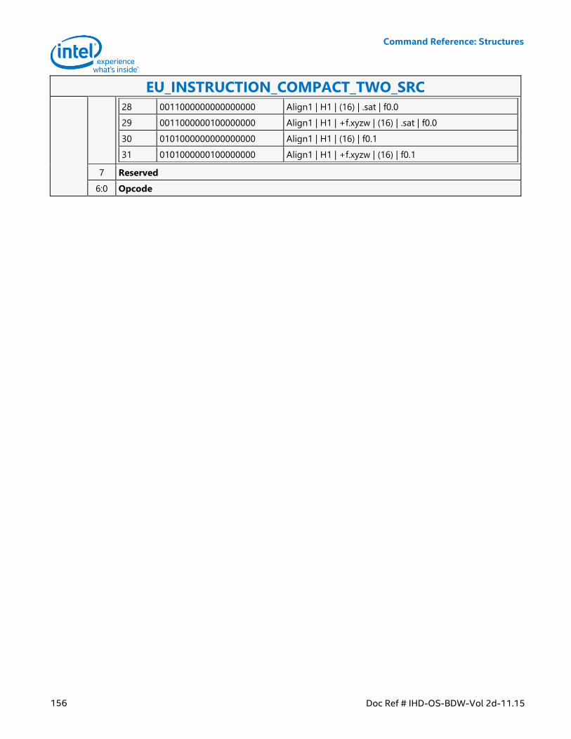
Command Reference: Structures
156 Doc Ref # IHD-OS-BDW-Vol 2d-11.15
EU_INSTRUCTION_COMPACT_TWO_SRC
28 0011000000000000000 Align1 | H1 | (16) | .sat | f0.0
29 0011000000100000000 Align1 | H1 | +f.xyzw | (16) | .sat | f0.0
30 0101000000000000000 Align1 | H1 | (16) | f0.1
31 0101000000100000000 Align1 | H1 | +f.xyzw | (16) | f0.1
7 Reserved
6:0 Opcode
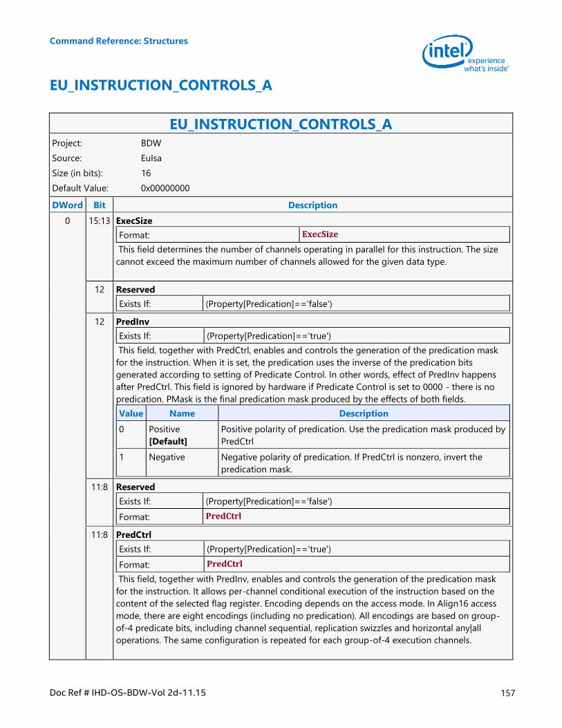
Command Reference: Structures
Doc Ref # IHD-OS-BDW-Vol 2d-11.15 157
EU_INSTRUCTION_CONTROLS_A
EU_INSTRUCTION_CONTROLS_A Project: BDW
Source: EuIsa
Size (in bits): 16
Default Value: 0x00000000
DWord Bit Description
0 15:13 ExecSize
Format: ExecSize
This field determines the number of channels operating in parallel for this instruction. The size
cannot exceed the maximum number of channels allowed for the given data type.
12 Reserved
Exists If: (Property[Predication]=='false')
12 PredInv
Exists If: (Property[Predication]=='true')
This field, together with PredCtrl, enables and controls the generation of the predication mask
for the instruction. When it is set, the predication uses the inverse of the predication bits
generated according to setting of Predicate Control. In other words, effect of PredInv happens
after PredCtrl. This field is ignored by hardware if Predicate Control is set to 0000 - there is no
predication. PMask is the final predication mask produced by the effects of both fields.
Value Name Description
0 Positive
[Default]
Positive polarity of predication. Use the predication mask produced by
PredCtrl
1 Negative Negative polarity of predication. If PredCtrl is nonzero, invert the
predication mask.
11:8 Reserved
Exists If: (Property[Predication]=='false')
Format: PredCtrl
11:8 PredCtrl
Exists If: (Property[Predication]=='true')
Format: PredCtrl
This field, together with PredInv, enables and controls the generation of the predication mask
for the instruction. It allows per-channel conditional execution of the instruction based on the
content of the selected flag register. Encoding depends on the access mode. In Align16 access
mode, there are eight encodings (including no predication). All encodings are based on group-
of-4 predicate bits, including channel sequential, replication swizzles and horizontal any|all
operations. The same configuration is repeated for each group-of-4 execution channels.
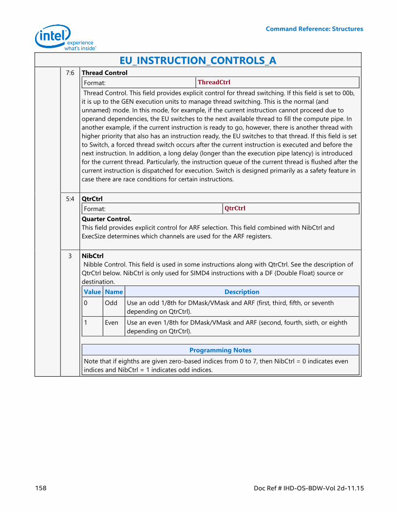
Command Reference: Structures
158 Doc Ref # IHD-OS-BDW-Vol 2d-11.15
EU_INSTRUCTION_CONTROLS_A 7:6 Thread Control
Format: ThreadCtrl
Thread Control. This field provides explicit control for thread switching. If this field is set to 00b,
it is up to the GEN execution units to manage thread switching. This is the normal (and
unnamed) mode. In this mode, for example, if the current instruction cannot proceed due to
operand dependencies, the EU switches to the next available thread to fill the compute pipe. In
another example, if the current instruction is ready to go, however, there is another thread with
higher priority that also has an instruction ready, the EU switches to that thread. If this field is set
to Switch, a forced thread switch occurs after the current instruction is executed and before the
next instruction. In addition, a long delay (longer than the execution pipe latency) is introduced
for the current thread. Particularly, the instruction queue of the current thread is flushed after the
current instruction is dispatched for execution. Switch is designed primarily as a safety feature in
case there are race conditions for certain instructions.
5:4 QtrCtrl
Format: QtrCtrl
Quarter Control.
This field provides explicit control for ARF selection. This field combined with NibCtrl and
ExecSize determines which channels are used for the ARF registers.
3 NibCtrl
Nibble Control. This field is used in some instructions along with QtrCtrl. See the description of
QtrCtrl below. NibCtrl is only used for SIMD4 instructions with a DF (Double Float) source or
destination.
Value Name Description
0 Odd Use an odd 1/8th for DMask/VMask and ARF (first, third, fifth, or seventh
depending on QtrCtrl).
1 Even Use an even 1/8th for DMask/VMask and ARF (second, fourth, sixth, or eighth
depending on QtrCtrl).
Programming Notes
Note that if eighths are given zero-based indices from 0 to 7, then NibCtrl = 0 indicates even
indices and NibCtrl = 1 indicates odd indices.
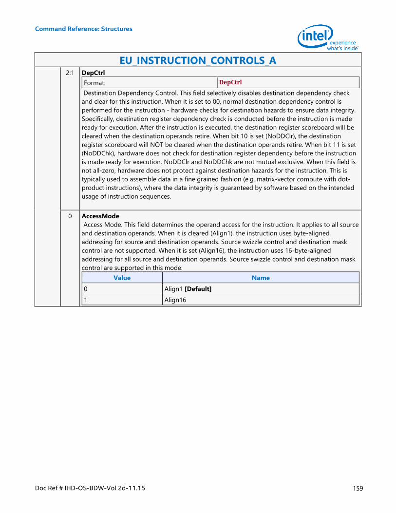
Command Reference: Structures
Doc Ref # IHD-OS-BDW-Vol 2d-11.15 159
EU_INSTRUCTION_CONTROLS_A 2:1 DepCtrl
Format: DepCtrl
Destination Dependency Control. This field selectively disables destination dependency check
and clear for this instruction. When it is set to 00, normal destination dependency control is
performed for the instruction - hardware checks for destination hazards to ensure data integrity.
Specifically, destination register dependency check is conducted before the instruction is made
ready for execution. After the instruction is executed, the destination register scoreboard will be
cleared when the destination operands retire. When bit 10 is set (NoDDClr), the destination
register scoreboard will NOT be cleared when the destination operands retire. When bit 11 is set
(NoDDChk), hardware does not check for destination register dependency before the instruction
is made ready for execution. NoDDClr and NoDDChk are not mutual exclusive. When this field is
not all-zero, hardware does not protect against destination hazards for the instruction. This is
typically used to assemble data in a fine grained fashion (e.g. matrix-vector compute with dot-
product instructions), where the data integrity is guaranteed by software based on the intended
usage of instruction sequences.
0 AccessMode
Access Mode. This field determines the operand access for the instruction. It applies to all source
and destination operands. When it is cleared (Align1), the instruction uses byte-aligned
addressing for source and destination operands. Source swizzle control and destination mask
control are not supported. When it is set (Align16), the instruction uses 16-byte-aligned
addressing for all source and destination operands. Source swizzle control and destination mask
control are supported in this mode.
Value Name
0 Align1 [Default]
1 Align16
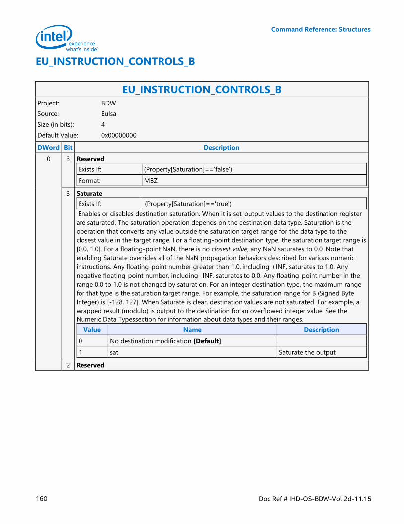
Command Reference: Structures
160 Doc Ref # IHD-OS-BDW-Vol 2d-11.15
EU_INSTRUCTION_CONTROLS_B
EU_INSTRUCTION_CONTROLS_B Project: BDW
Source: EuIsa
Size (in bits): 4
Default Value: 0x00000000
DWord Bit Description
0 3 Reserved
Exists If: (Property[Saturation]=='false')
Format: MBZ
3 Saturate
Exists If: (Property[Saturation]=='true')
Enables or disables destination saturation. When it is set, output values to the destination register
are saturated. The saturation operation depends on the destination data type. Saturation is the
operation that converts any value outside the saturation target range for the data type to the
closest value in the target range. For a floating-point destination type, the saturation target range is
[0.0, 1.0]. For a floating-point NaN, there is no closest value; any NaN saturates to 0.0. Note that
enabling Saturate overrides all of the NaN propagation behaviors described for various numeric
instructions. Any floating-point number greater than 1.0, including +INF, saturates to 1.0. Any
negative floating-point number, including -INF, saturates to 0.0. Any floating-point number in the
range 0.0 to 1.0 is not changed by saturation. For an integer destination type, the maximum range
for that type is the saturation target range. For example, the saturation range for B (Signed Byte
Integer) is [-128, 127]. When Saturate is clear, destination values are not saturated. For example, a
wrapped result (modulo) is output to the destination for an overflowed integer value. See the
Numeric Data Typessection for information about data types and their ranges.
Value Name Description
0 No destination modification [Default]
1 sat Saturate the output
2 Reserved
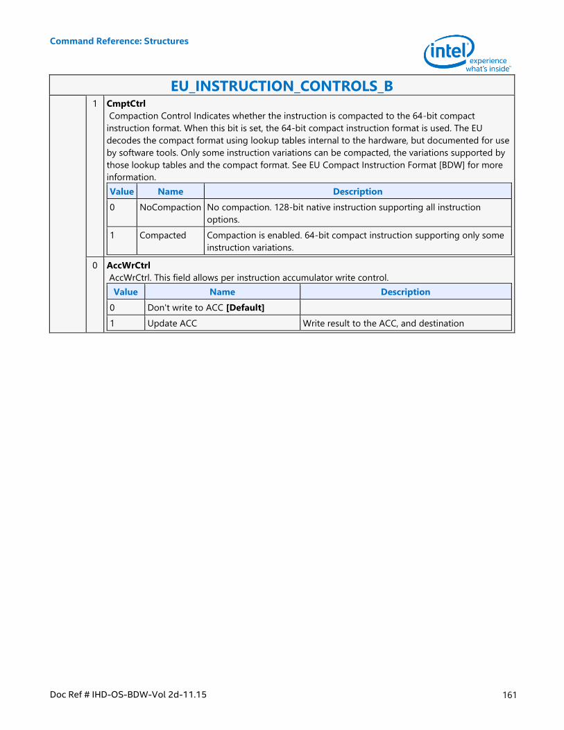
Command Reference: Structures
Doc Ref # IHD-OS-BDW-Vol 2d-11.15 161
EU_INSTRUCTION_CONTROLS_B 1 CmptCtrl
Compaction Control Indicates whether the instruction is compacted to the 64-bit compact
instruction format. When this bit is set, the 64-bit compact instruction format is used. The EU
decodes the compact format using lookup tables internal to the hardware, but documented for use
by software tools. Only some instruction variations can be compacted, the variations supported by
those lookup tables and the compact format. See EU Compact Instruction Format [BDW] for more
information.
Value Name Description
0 NoCompaction No compaction. 128-bit native instruction supporting all instruction
options.
1 Compacted Compaction is enabled. 64-bit compact instruction supporting only some
instruction variations.
0 AccWrCtrl
AccWrCtrl. This field allows per instruction accumulator write control.
Value Name Description
0 Don't write to ACC [Default]
1 Update ACC Write result to the ACC, and destination
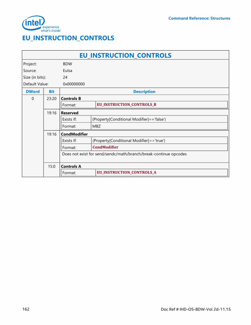
Command Reference: Structures
162 Doc Ref # IHD-OS-BDW-Vol 2d-11.15
EU_INSTRUCTION_CONTROLS
EU_INSTRUCTION_CONTROLS Project: BDW
Source: EuIsa
Size (in bits): 24
Default Value: 0x00000000
DWord Bit Description
0 23:20 Controls B
Format: EU_INSTRUCTION_CONTROLS_B
19:16 Reserved
Exists If: (Property[Conditional Modifier]=='false')
Format: MBZ
19:16 CondModifier
Exists If: (Property[Conditional Modifier]=='true')
Format: CondModifier
Does not exist for send/sendc/math/branch/break-continue opcodes
15:0 Controls A
Format: EU_INSTRUCTION_CONTROLS_A
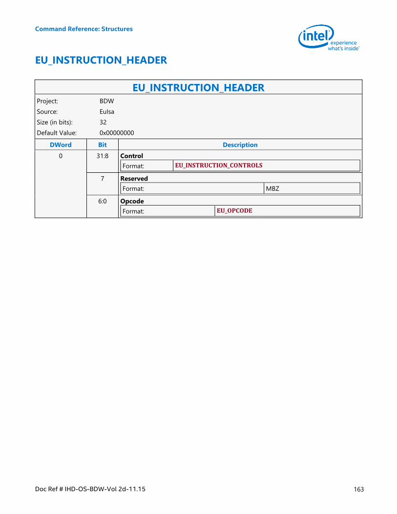
Command Reference: Structures
Doc Ref # IHD-OS-BDW-Vol 2d-11.15 163
EU_INSTRUCTION_HEADER
EU_INSTRUCTION_HEADER Project: BDW
Source: EuIsa
Size (in bits): 32
Default Value: 0x00000000
DWord Bit Description
0 31:8 Control
Format: EU_INSTRUCTION_CONTROLS
7 Reserved
Format: MBZ
6:0 Opcode
Format: EU_OPCODE
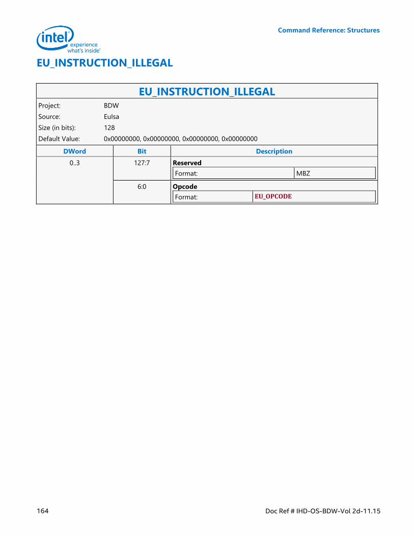
Command Reference: Structures
164 Doc Ref # IHD-OS-BDW-Vol 2d-11.15
EU_INSTRUCTION_ILLEGAL
EU_INSTRUCTION_ILLEGAL Project: BDW
Source: EuIsa
Size (in bits): 128
Default Value: 0x00000000, 0x00000000, 0x00000000, 0x00000000
DWord Bit Description
0..3 127:7 Reserved
Format: MBZ
6:0 Opcode
Format: EU_OPCODE
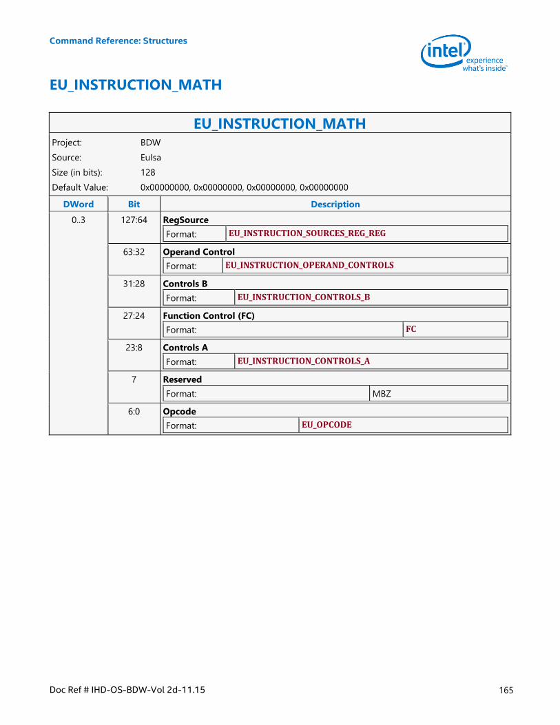
Command Reference: Structures
Doc Ref # IHD-OS-BDW-Vol 2d-11.15 165
EU_INSTRUCTION_MATH
EU_INSTRUCTION_MATH Project: BDW
Source: EuIsa
Size (in bits): 128
Default Value: 0x00000000, 0x00000000, 0x00000000, 0x00000000
DWord Bit Description
0..3 127:64 RegSource
Format: EU_INSTRUCTION_SOURCES_REG_REG
63:32 Operand Control
Format: EU_INSTRUCTION_OPERAND_CONTROLS
31:28 Controls B
Format: EU_INSTRUCTION_CONTROLS_B
27:24 Function Control (FC)
Format: FC
23:8 Controls A
Format: EU_INSTRUCTION_CONTROLS_A
7 Reserved
Format: MBZ
6:0 Opcode
Format: EU_OPCODE
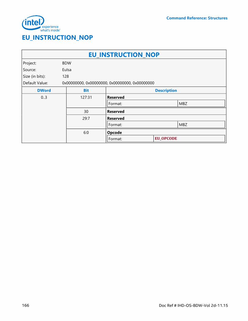
Command Reference: Structures
166 Doc Ref # IHD-OS-BDW-Vol 2d-11.15
EU_INSTRUCTION_NOP
EU_INSTRUCTION_NOP Project: BDW
Source: EuIsa
Size (in bits): 128
Default Value: 0x00000000, 0x00000000, 0x00000000, 0x00000000
DWord Bit Description
0..3 127:31 Reserved
Format: MBZ
30 Reserved
29:7 Reserved
Format: MBZ
6:0 Opcode
Format: EU_OPCODE
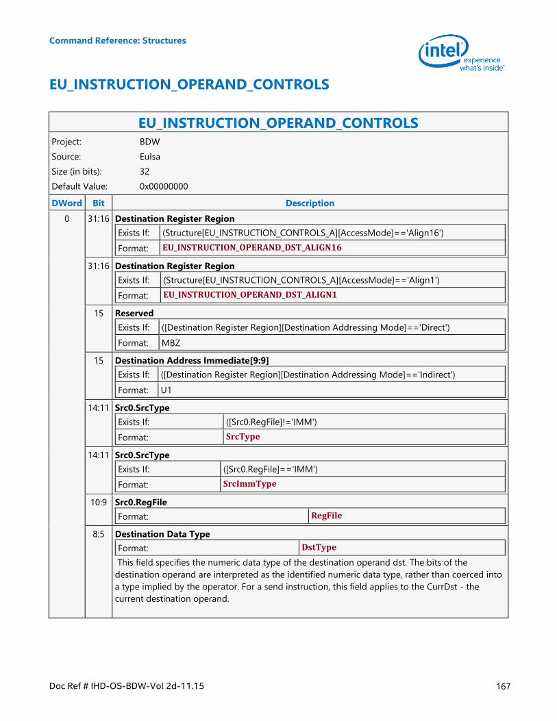
Command Reference: Structures
Doc Ref # IHD-OS-BDW-Vol 2d-11.15 167
EU_INSTRUCTION_OPERAND_CONTROLS
EU_INSTRUCTION_OPERAND_CONTROLS Project: BDW
Source: EuIsa
Size (in bits): 32
Default Value: 0x00000000
DWord Bit Description
0 31:16 Destination Register Region
Exists If: (Structure[EU_INSTRUCTION_CONTROLS_A][AccessMode]=='Align16')
Format: EU_INSTRUCTION_OPERAND_DST_ALIGN16
31:16 Destination Register Region
Exists If: (Structure[EU_INSTRUCTION_CONTROLS_A][AccessMode]=='Align1')
Format: EU_INSTRUCTION_OPERAND_DST_ALIGN1
15 Reserved
Exists If: ([Destination Register Region][Destination Addressing Mode]=='Direct')
Format: MBZ
15 Destination Address Immediate[9:9]
Exists If: ([Destination Register Region][Destination Addressing Mode]=='Indirect')
Format: U1
14:11 Src0.SrcType
Exists If: ([Src0.RegFile]!='IMM')
Format: SrcType
14:11 Src0.SrcType
Exists If: ([Src0.RegFile]=='IMM')
Format: SrcImmType
10:9 Src0.RegFile
Format: RegFile
8:5 Destination Data Type
Format: DstType
This field specifies the numeric data type of the destination operand dst. The bits of the
destination operand are interpreted as the identified numeric data type, rather than coerced into
a type implied by the operator. For a send instruction, this field applies to the CurrDst - the
current destination operand.
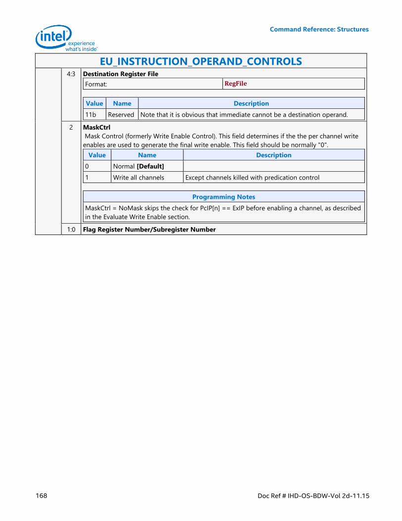
Command Reference: Structures
168 Doc Ref # IHD-OS-BDW-Vol 2d-11.15
EU_INSTRUCTION_OPERAND_CONTROLS 4:3 Destination Register File
Format: RegFile
Value Name Description
11b Reserved Note that it is obvious that immediate cannot be a destination operand.
2 MaskCtrl
Mask Control (formerly Write Enable Control). This field determines if the the per channel write
enables are used to generate the final write enable. This field should be normally "0".
Value Name Description
0 Normal [Default]
1 Write all channels Except channels killed with predication control
Programming Notes
MaskCtrl = NoMask skips the check for PcIP[n] == ExIP before enabling a channel, as described
in the Evaluate Write Enable section.
1:0 Flag Register Number/Subregister Number
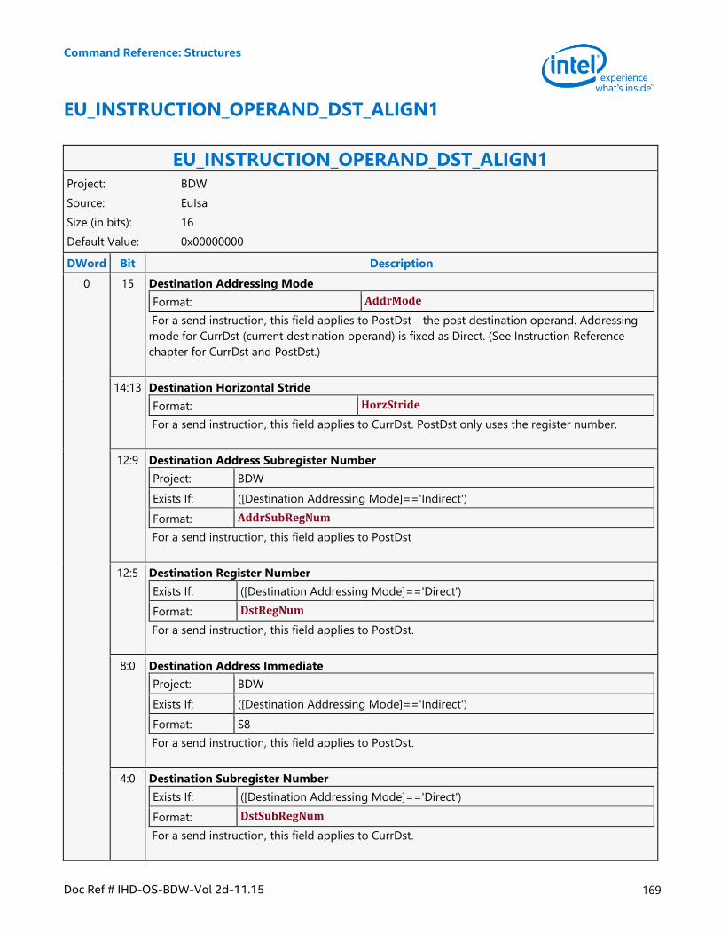
Command Reference: Structures
Doc Ref # IHD-OS-BDW-Vol 2d-11.15 169
EU_INSTRUCTION_OPERAND_DST_ALIGN1
EU_INSTRUCTION_OPERAND_DST_ALIGN1 Project: BDW
Source: EuIsa
Size (in bits): 16
Default Value: 0x00000000
DWord Bit Description
0 15 Destination Addressing Mode
Format: AddrMode
For a send instruction, this field applies to PostDst - the post destination operand. Addressing
mode for CurrDst (current destination operand) is fixed as Direct. (See Instruction Reference
chapter for CurrDst and PostDst.)
14:13 Destination Horizontal Stride
Format: HorzStride
For a send instruction, this field applies to CurrDst. PostDst only uses the register number.
12:9 Destination Address Subregister Number
Project: BDW
Exists If: ([Destination Addressing Mode]=='Indirect')
Format: AddrSubRegNum
For a send instruction, this field applies to PostDst
12:5 Destination Register Number
Exists If: ([Destination Addressing Mode]=='Direct')
Format: DstRegNum
For a send instruction, this field applies to PostDst.
8:0 Destination Address Immediate
Project: BDW
Exists If: ([Destination Addressing Mode]=='Indirect')
Format: S8
For a send instruction, this field applies to PostDst.
4:0 Destination Subregister Number
Exists If: ([Destination Addressing Mode]=='Direct')
Format: DstSubRegNum
For a send instruction, this field applies to CurrDst.
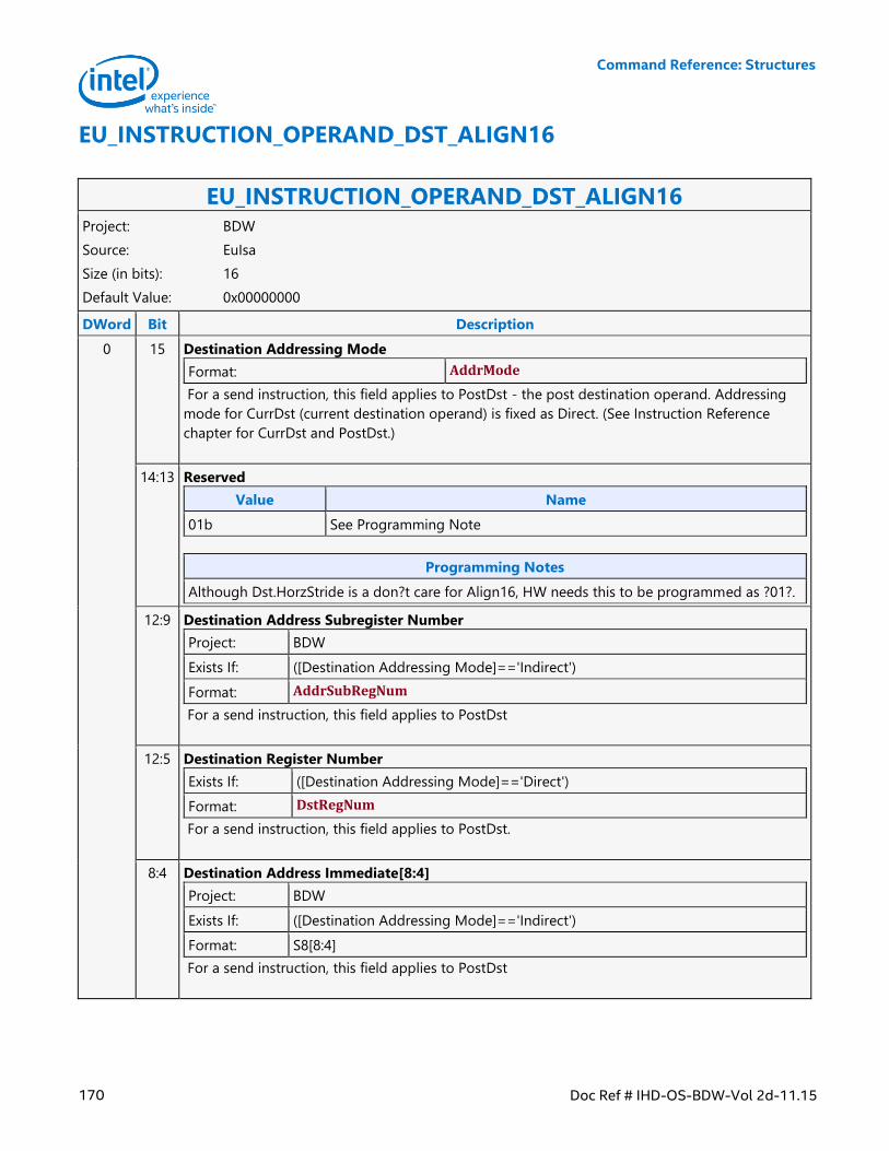
Command Reference: Structures
170 Doc Ref # IHD-OS-BDW-Vol 2d-11.15
EU_INSTRUCTION_OPERAND_DST_ALIGN16
EU_INSTRUCTION_OPERAND_DST_ALIGN16 Project: BDW
Source: EuIsa
Size (in bits): 16
Default Value: 0x00000000
DWord Bit Description
0 15 Destination Addressing Mode
Format: AddrMode
For a send instruction, this field applies to PostDst - the post destination operand. Addressing
mode for CurrDst (current destination operand) is fixed as Direct. (See Instruction Reference
chapter for CurrDst and PostDst.)
14:13 Reserved
Value Name
01b See Programming Note
Programming Notes
Although Dst.HorzStride is a don?t care for Align16, HW needs this to be programmed as ?01?.
12:9 Destination Address Subregister Number
Project: BDW
Exists If: ([Destination Addressing Mode]=='Indirect')
Format: AddrSubRegNum
For a send instruction, this field applies to PostDst
12:5 Destination Register Number
Exists If: ([Destination Addressing Mode]=='Direct')
Format: DstRegNum
For a send instruction, this field applies to PostDst.
8:4 Destination Address Immediate[8:4]
Project: BDW
Exists If: ([Destination Addressing Mode]=='Indirect')
Format: S8[8:4]
For a send instruction, this field applies to PostDst
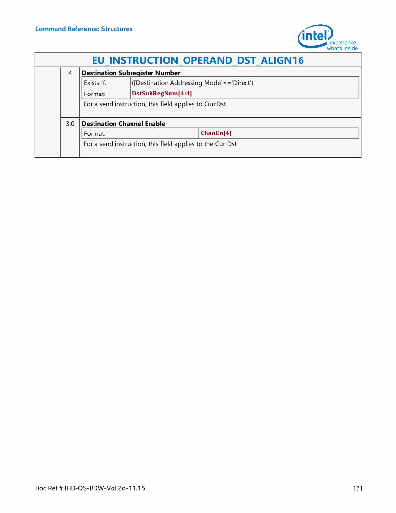
Command Reference: Structures
Doc Ref # IHD-OS-BDW-Vol 2d-11.15 171
EU_INSTRUCTION_OPERAND_DST_ALIGN16 4 Destination Subregister Number
Exists If: ([Destination Addressing Mode]=='Direct')
Format: DstSubRegNum[4:4]
For a send instruction, this field applies to CurrDst.
3:0 Destination Channel Enable
Format: ChanEn[4]
For a send instruction, this field applies to the CurrDst
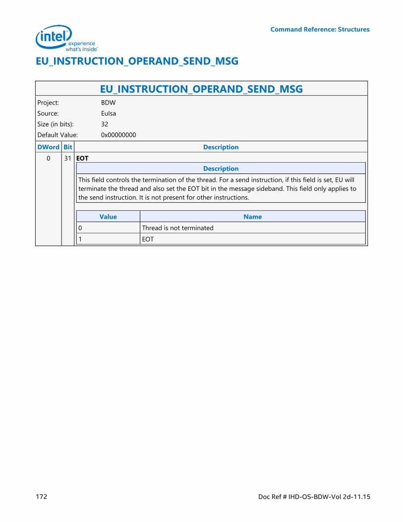
Command Reference: Structures
172 Doc Ref # IHD-OS-BDW-Vol 2d-11.15
EU_INSTRUCTION_OPERAND_SEND_MSG
EU_INSTRUCTION_OPERAND_SEND_MSG Project: BDW
Source: EuIsa
Size (in bits): 32
Default Value: 0x00000000
DWord Bit Description
0 31 EOT
Description
This field controls the termination of the thread. For a send instruction, if this field is set, EU will
terminate the thread and also set the EOT bit in the message sideband. This field only applies to
the send instruction. It is not present for other instructions.
Value Name
0 Thread is not terminated
1 EOT
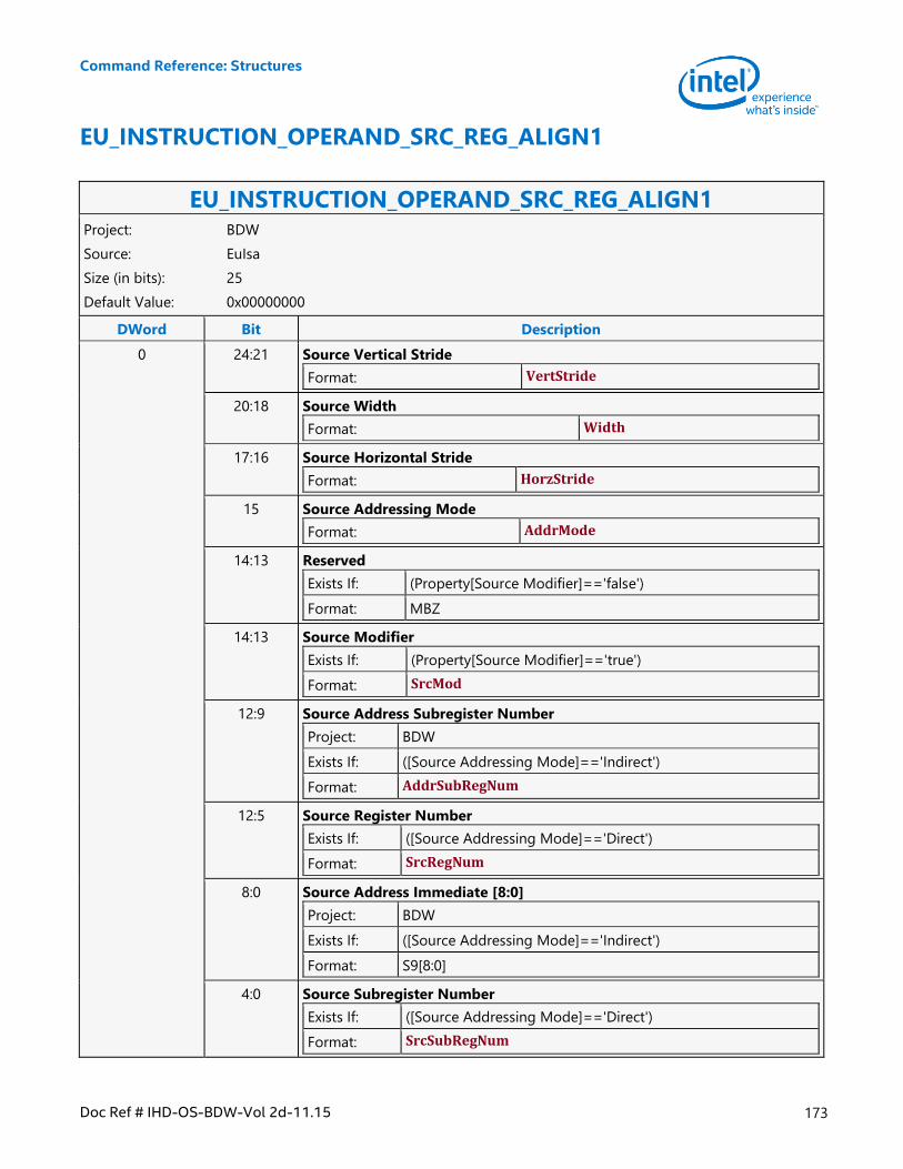
Command Reference: Structures
Doc Ref # IHD-OS-BDW-Vol 2d-11.15 173
EU_INSTRUCTION_OPERAND_SRC_REG_ALIGN1
EU_INSTRUCTION_OPERAND_SRC_REG_ALIGN1 Project: BDW
Source: EuIsa
Size (in bits): 25
Default Value: 0x00000000
DWord Bit Description
0 24:21 Source Vertical Stride
Format: VertStride
20:18 Source Width
Format: Width
17:16 Source Horizontal Stride
Format: HorzStride
15 Source Addressing Mode
Format: AddrMode
14:13 Reserved
Exists If: (Property[Source Modifier]=='false')
Format: MBZ
14:13 Source Modifier
Exists If: (Property[Source Modifier]=='true')
Format: SrcMod
12:9 Source Address Subregister Number
Project: BDW
Exists If: ([Source Addressing Mode]=='Indirect')
Format: AddrSubRegNum
12:5 Source Register Number
Exists If: ([Source Addressing Mode]=='Direct')
Format: SrcRegNum
8:0 Source Address Immediate [8:0]
Project: BDW
Exists If: ([Source Addressing Mode]=='Indirect')
Format: S9[8:0]
4:0 Source Subregister Number
Exists If: ([Source Addressing Mode]=='Direct')
Format: SrcSubRegNum
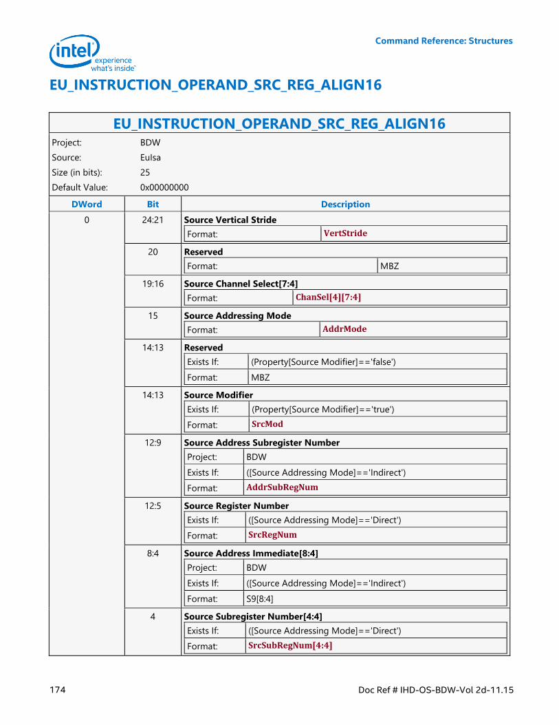
Command Reference: Structures
174 Doc Ref # IHD-OS-BDW-Vol 2d-11.15
EU_INSTRUCTION_OPERAND_SRC_REG_ALIGN16
EU_INSTRUCTION_OPERAND_SRC_REG_ALIGN16 Project: BDW
Source: EuIsa
Size (in bits): 25
Default Value: 0x00000000
DWord Bit Description
0 24:21 Source Vertical Stride
Format: VertStride
20 Reserved
Format: MBZ
19:16 Source Channel Select[7:4]
Format: ChanSel[4][7:4]
15 Source Addressing Mode
Format: AddrMode
14:13 Reserved
Exists If: (Property[Source Modifier]=='false')
Format: MBZ
14:13 Source Modifier
Exists If: (Property[Source Modifier]=='true')
Format: SrcMod
12:9 Source Address Subregister Number
Project: BDW
Exists If: ([Source Addressing Mode]=='Indirect')
Format: AddrSubRegNum
12:5 Source Register Number
Exists If: ([Source Addressing Mode]=='Direct')
Format: SrcRegNum
8:4 Source Address Immediate[8:4]
Project: BDW
Exists If: ([Source Addressing Mode]=='Indirect')
Format: S9[8:4]
4 Source Subregister Number[4:4]
Exists If: ([Source Addressing Mode]=='Direct')
Format: SrcSubRegNum[4:4]

Command Reference: Structures
Doc Ref # IHD-OS-BDW-Vol 2d-11.15 175
EU_INSTRUCTION_OPERAND_SRC_REG_ALIGN16 3:0 Source Channel Select[3:0]
Format: ChanSel[4][3:0]
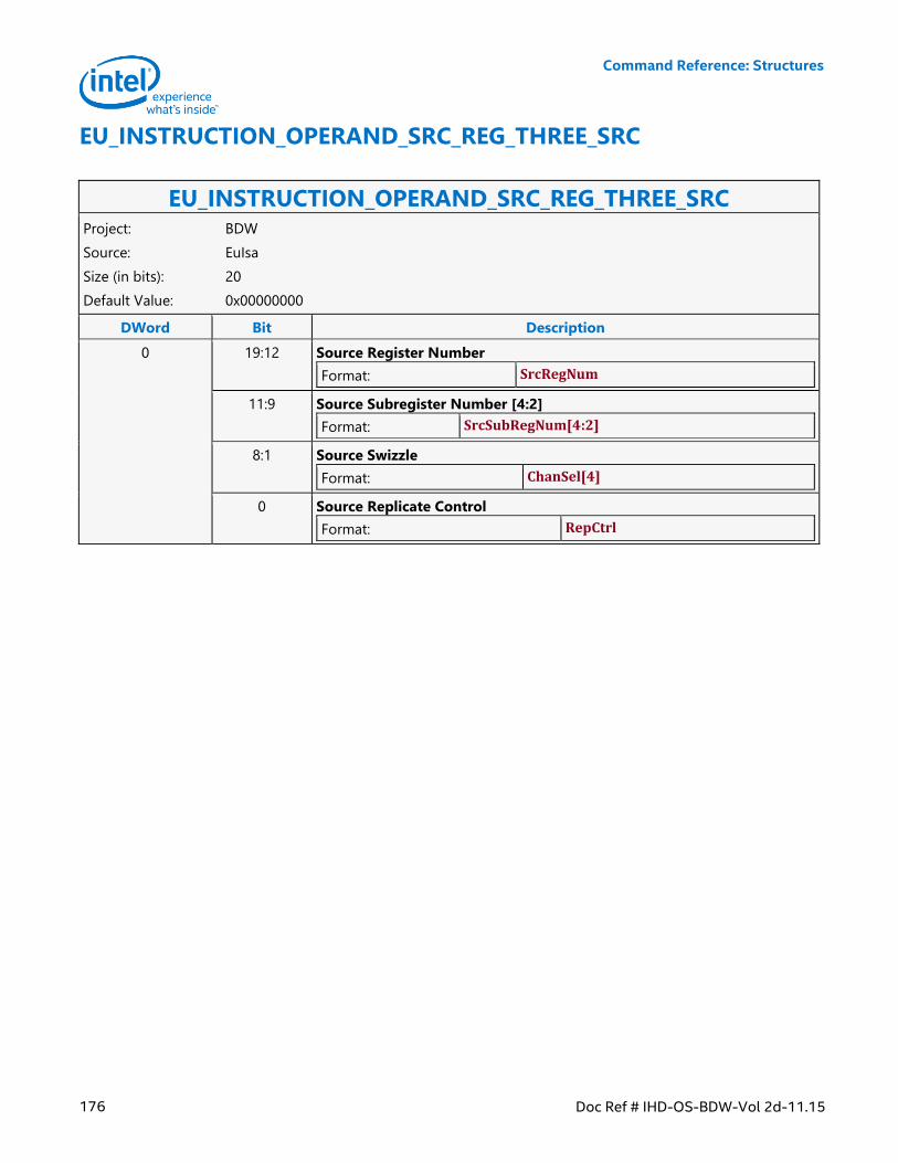
Command Reference: Structures
176 Doc Ref # IHD-OS-BDW-Vol 2d-11.15
EU_INSTRUCTION_OPERAND_SRC_REG_THREE_SRC
EU_INSTRUCTION_OPERAND_SRC_REG_THREE_SRC Project: BDW
Source: EuIsa
Size (in bits): 20
Default Value: 0x00000000
DWord Bit Description
0 19:12 Source Register Number
Format: SrcRegNum
11:9 Source Subregister Number [4:2]
Format: SrcSubRegNum[4:2]
8:1 Source Swizzle
Format: ChanSel[4]
0 Source Replicate Control
Format: RepCtrl
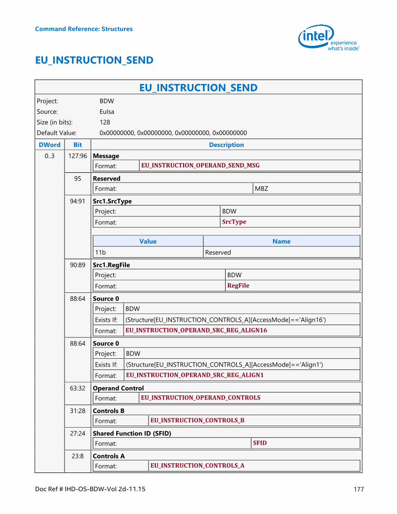
Command Reference: Structures
Doc Ref # IHD-OS-BDW-Vol 2d-11.15 177
EU_INSTRUCTION_SEND
EU_INSTRUCTION_SEND Project: BDW
Source: EuIsa
Size (in bits): 128
Default Value: 0x00000000, 0x00000000, 0x00000000, 0x00000000
DWord Bit Description
0..3 127:96 Message
Format: EU_INSTRUCTION_OPERAND_SEND_MSG
95 Reserved
Format: MBZ
94:91 Src1.SrcType
Project: BDW
Format: SrcType
Value Name
11b Reserved
90:89 Src1.RegFile
Project: BDW
Format: RegFile
88:64 Source 0
Project: BDW
Exists If: (Structure[EU_INSTRUCTION_CONTROLS_A][AccessMode]=='Align16')
Format: EU_INSTRUCTION_OPERAND_SRC_REG_ALIGN16
88:64 Source 0
Project: BDW
Exists If: (Structure[EU_INSTRUCTION_CONTROLS_A][AccessMode]=='Align1')
Format: EU_INSTRUCTION_OPERAND_SRC_REG_ALIGN1
63:32 Operand Control
Format: EU_INSTRUCTION_OPERAND_CONTROLS
31:28 Controls B
Format: EU_INSTRUCTION_CONTROLS_B
27:24 Shared Function ID (SFID)
Format: SFID
23:8 Controls A
Format: EU_INSTRUCTION_CONTROLS_A
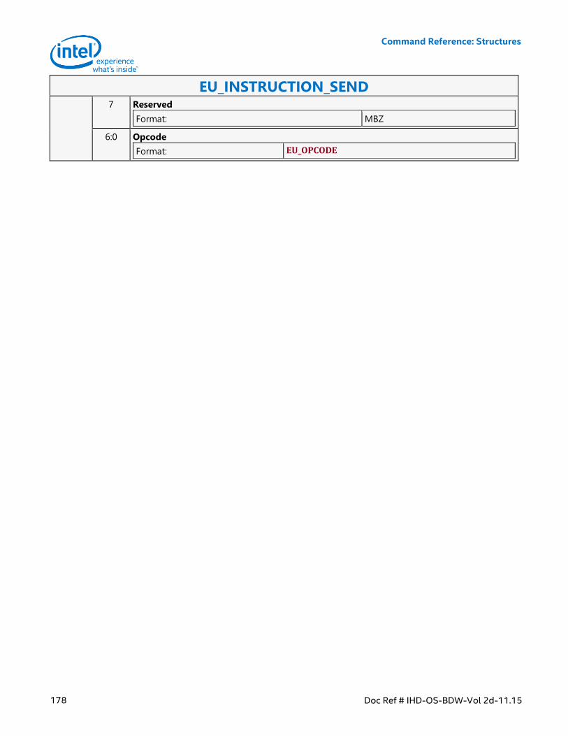
Command Reference: Structures
178 Doc Ref # IHD-OS-BDW-Vol 2d-11.15
EU_INSTRUCTION_SEND 7 Reserved
Format: MBZ
6:0 Opcode
Format: EU_OPCODE
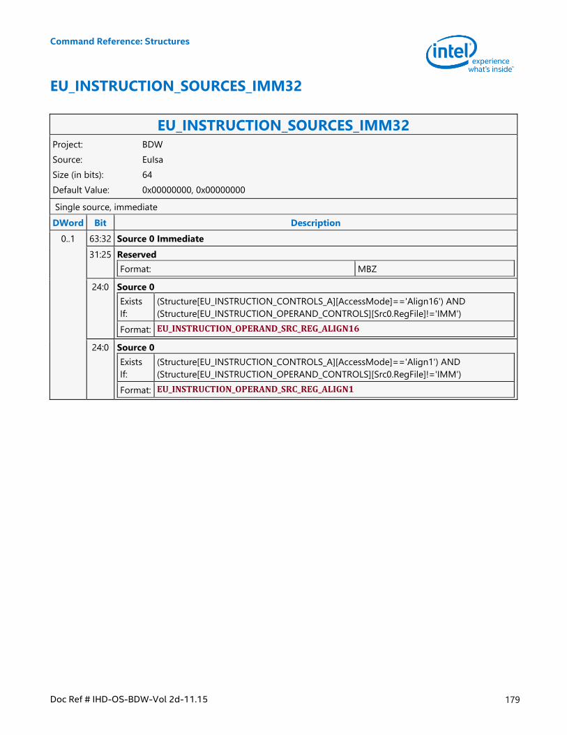
Command Reference: Structures
Doc Ref # IHD-OS-BDW-Vol 2d-11.15 179
EU_INSTRUCTION_SOURCES_IMM32
EU_INSTRUCTION_SOURCES_IMM32 Project: BDW
Source: EuIsa
Size (in bits): 64
Default Value: 0x00000000, 0x00000000
Single source, immediate
DWord Bit Description
0..1 63:32 Source 0 Immediate
31:25 Reserved
Format: MBZ
24:0 Source 0
Exists
If:
(Structure[EU_INSTRUCTION_CONTROLS_A][AccessMode]=='Align16') AND
(Structure[EU_INSTRUCTION_OPERAND_CONTROLS][Src0.RegFile]!='IMM')
Format: EU_INSTRUCTION_OPERAND_SRC_REG_ALIGN16
24:0 Source 0
Exists
If:
(Structure[EU_INSTRUCTION_CONTROLS_A][AccessMode]=='Align1') AND
(Structure[EU_INSTRUCTION_OPERAND_CONTROLS][Src0.RegFile]!='IMM')
Format: EU_INSTRUCTION_OPERAND_SRC_REG_ALIGN1
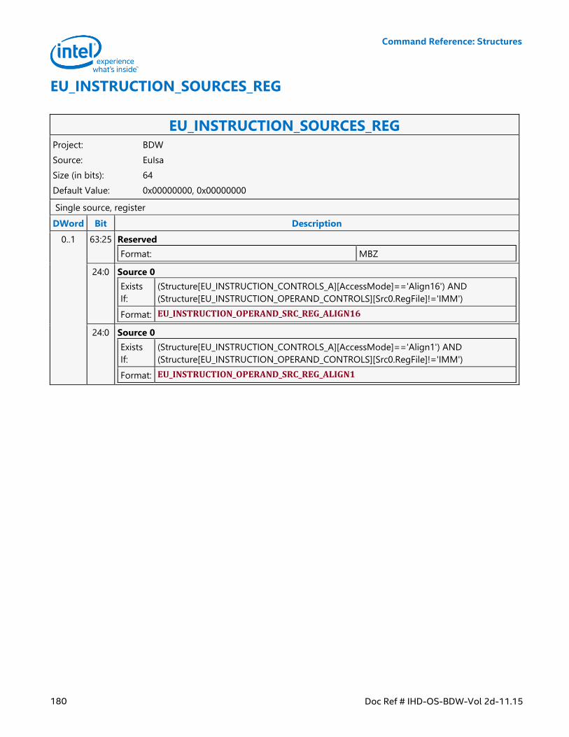
Command Reference: Structures
180 Doc Ref # IHD-OS-BDW-Vol 2d-11.15
EU_INSTRUCTION_SOURCES_REG
EU_INSTRUCTION_SOURCES_REG Project: BDW
Source: EuIsa
Size (in bits): 64
Default Value: 0x00000000, 0x00000000
Single source, register
DWord Bit Description
0..1 63:25 Reserved
Format: MBZ
24:0 Source 0
Exists
If:
(Structure[EU_INSTRUCTION_CONTROLS_A][AccessMode]=='Align16') AND
(Structure[EU_INSTRUCTION_OPERAND_CONTROLS][Src0.RegFile]!='IMM')
Format: EU_INSTRUCTION_OPERAND_SRC_REG_ALIGN16
24:0 Source 0
Exists
If:
(Structure[EU_INSTRUCTION_CONTROLS_A][AccessMode]=='Align1') AND
(Structure[EU_INSTRUCTION_OPERAND_CONTROLS][Src0.RegFile]!='IMM')
Format: EU_INSTRUCTION_OPERAND_SRC_REG_ALIGN1
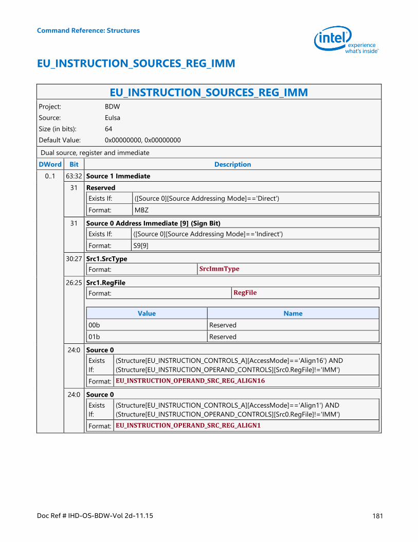
Command Reference: Structures
Doc Ref # IHD-OS-BDW-Vol 2d-11.15 181
EU_INSTRUCTION_SOURCES_REG_IMM
EU_INSTRUCTION_SOURCES_REG_IMM Project: BDW
Source: EuIsa
Size (in bits): 64
Default Value: 0x00000000, 0x00000000
Dual source, register and immediate
DWord Bit Description
0..1 63:32 Source 1 Immediate
31 Reserved
Exists If: ([Source 0][Source Addressing Mode]=='Direct')
Format: MBZ
31 Source 0 Address Immediate [9] (Sign Bit)
Exists If: ([Source 0][Source Addressing Mode]=='Indirect')
Format: S9[9]
30:27 Src1.SrcType
Format: SrcImmType
26:25 Src1.RegFile
Format: RegFile
Value Name
00b Reserved
01b Reserved
24:0 Source 0
Exists
If:
(Structure[EU_INSTRUCTION_CONTROLS_A][AccessMode]=='Align16') AND
(Structure[EU_INSTRUCTION_OPERAND_CONTROLS][Src0.RegFile]!='IMM')
Format: EU_INSTRUCTION_OPERAND_SRC_REG_ALIGN16
24:0 Source 0
Exists
If:
(Structure[EU_INSTRUCTION_CONTROLS_A][AccessMode]=='Align1') AND
(Structure[EU_INSTRUCTION_OPERAND_CONTROLS][Src0.RegFile]!='IMM')
Format: EU_INSTRUCTION_OPERAND_SRC_REG_ALIGN1
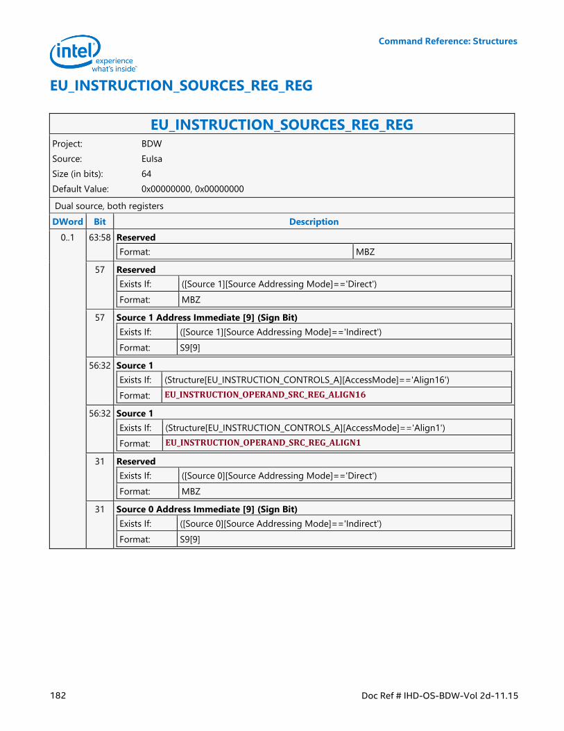
Command Reference: Structures
182 Doc Ref # IHD-OS-BDW-Vol 2d-11.15
EU_INSTRUCTION_SOURCES_REG_REG
EU_INSTRUCTION_SOURCES_REG_REG Project: BDW
Source: EuIsa
Size (in bits): 64
Default Value: 0x00000000, 0x00000000
Dual source, both registers
DWord Bit Description
0..1 63:58 Reserved
Format: MBZ
57 Reserved
Exists If: ([Source 1][Source Addressing Mode]=='Direct')
Format: MBZ
57 Source 1 Address Immediate [9] (Sign Bit)
Exists If: ([Source 1][Source Addressing Mode]=='Indirect')
Format: S9[9]
56:32 Source 1
Exists If: (Structure[EU_INSTRUCTION_CONTROLS_A][AccessMode]=='Align16')
Format: EU_INSTRUCTION_OPERAND_SRC_REG_ALIGN16
56:32 Source 1
Exists If: (Structure[EU_INSTRUCTION_CONTROLS_A][AccessMode]=='Align1')
Format: EU_INSTRUCTION_OPERAND_SRC_REG_ALIGN1
31 Reserved
Exists If: ([Source 0][Source Addressing Mode]=='Direct')
Format: MBZ
31 Source 0 Address Immediate [9] (Sign Bit)
Exists If: ([Source 0][Source Addressing Mode]=='Indirect')
Format: S9[9]
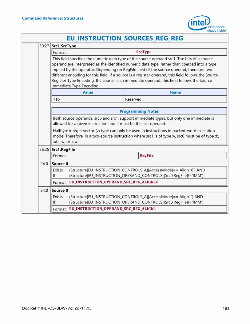
Command Reference: Structures
Doc Ref # IHD-OS-BDW-Vol 2d-11.15 183
EU_INSTRUCTION_SOURCES_REG_REG 30:27 Src1.SrcType
Format: SrcType
This field specifies the numeric data type of the source operand src1. The bits of a source
operand are interpreted as the identified numeric data type, rather than coerced into a type
implied by the operator. Depending on RegFile field of the source operand, there are two
different encoding for this field. If a source is a register operand, this field follows the Source
Register Type Encoding. If a source is an immediate operand, this field follows the Source
Immediate Type Encoding.
Value Name
11b Reserved
Programming Notes
Both source operands, src0 and src1, support immediate types, but only one immediate is
allowed for a given instruction and it must be the last operand.
Halfbyte integer vector (v) type can only be used in instructions in packed-word execution
mode. Therefore, in a two-source instruction where src1 is of type :v, src0 must be of type :b,
:ub, :w, or :uw.
26:25 Src1.RegFile
Format: RegFile
24:0 Source 0
Exists
If:
(Structure[EU_INSTRUCTION_CONTROLS_A][AccessMode]=='Align16') AND
(Structure[EU_INSTRUCTION_OPERAND_CONTROLS][Src0.RegFile]!='IMM')
Format: EU_INSTRUCTION_OPERAND_SRC_REG_ALIGN16
24:0 Source 0
Exists
If:
(Structure[EU_INSTRUCTION_CONTROLS_A][AccessMode]=='Align1') AND
(Structure[EU_INSTRUCTION_OPERAND_CONTROLS][Src0.RegFile]!='IMM')
Format: EU_INSTRUCTION_OPERAND_SRC_REG_ALIGN1
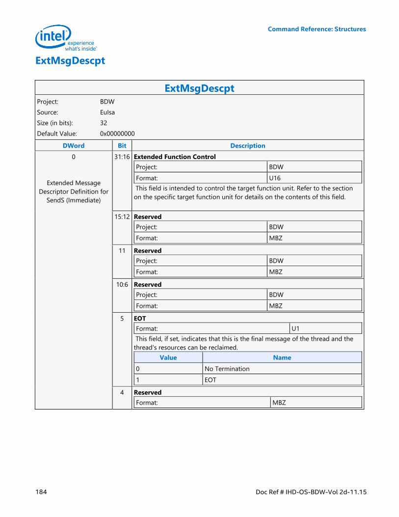
Command Reference: Structures
184 Doc Ref # IHD-OS-BDW-Vol 2d-11.15
ExtMsgDescpt
ExtMsgDescpt Project: BDW
Source: EuIsa
Size (in bits): 32
Default Value: 0x00000000
DWord Bit Description
0
Extended Message
Descriptor Definition for
SendS (Immediate)
31:16 Extended Function Control
Project: BDW
Format: U16
This field is intended to control the target function unit. Refer to the section
on the specific target function unit for details on the contents of this field.
15:12 Reserved
Project: BDW
Format: MBZ
11 Reserved
Project: BDW
Format: MBZ
10:6 Reserved
Project: BDW
Format: MBZ
5 EOT
Format: U1
This field, if set, indicates that this is the final message of the thread and the
thread's resources can be reclaimed.
Value Name
0 No Termination
1 EOT
4 Reserved
Format: MBZ
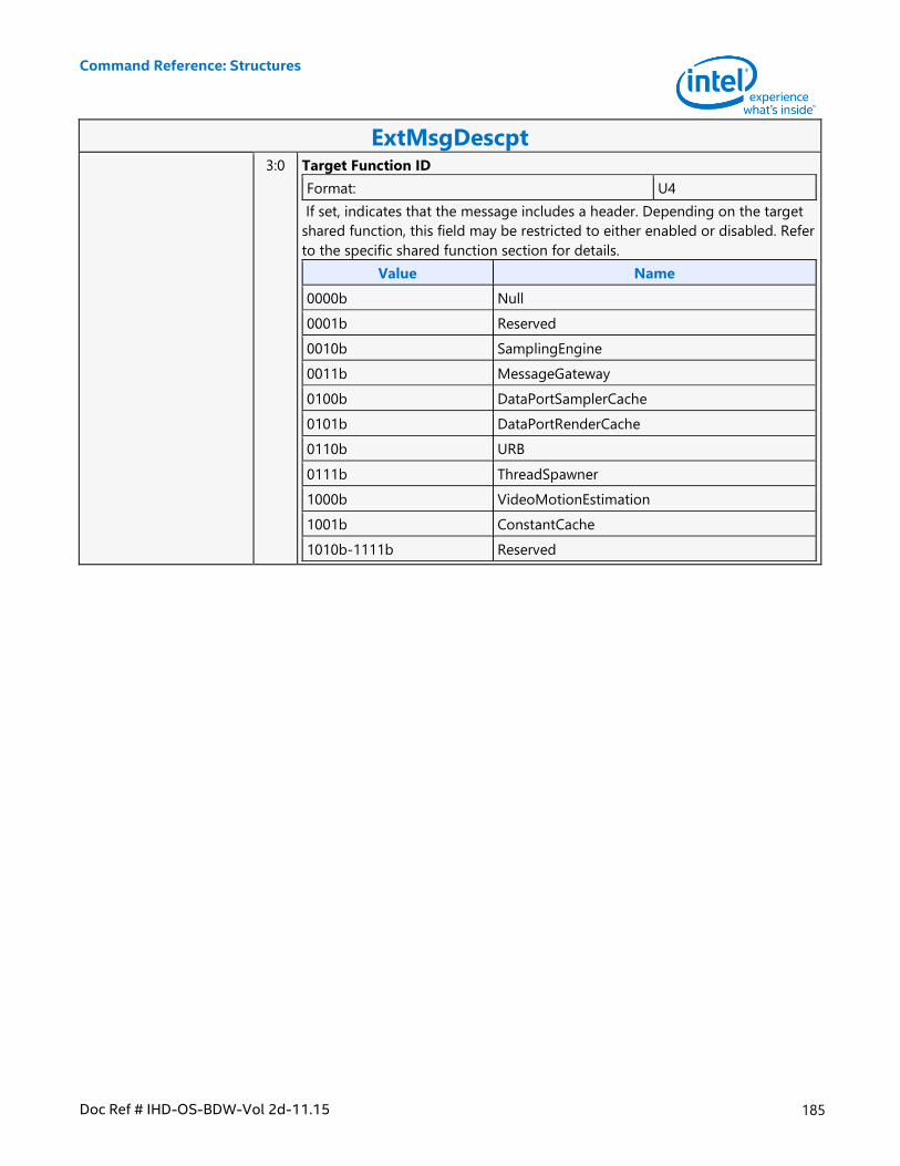
Command Reference: Structures
Doc Ref # IHD-OS-BDW-Vol 2d-11.15 185
ExtMsgDescpt 3:0 Target Function ID
Format: U4
If set, indicates that the message includes a header. Depending on the target
shared function, this field may be restricted to either enabled or disabled. Refer
to the specific shared function section for details.
Value Name
0000b Null
0001b Reserved
0010b SamplingEngine
0011b MessageGateway
0100b DataPortSamplerCache
0101b DataPortRenderCache
0110b URB
0111b ThreadSpawner
1000b VideoMotionEstimation
1001b ConstantCache
1010b-1111b Reserved
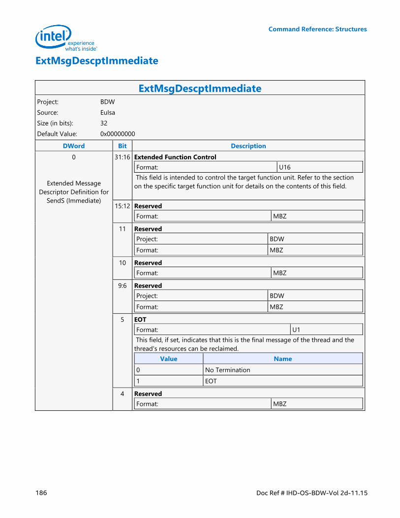
Command Reference: Structures
186 Doc Ref # IHD-OS-BDW-Vol 2d-11.15
ExtMsgDescptImmediate
ExtMsgDescptImmediate Project: BDW
Source: EuIsa
Size (in bits): 32
Default Value: 0x00000000
DWord Bit Description
0
Extended Message
Descriptor Definition for
SendS (Immediate)
31:16 Extended Function Control
Format: U16
This field is intended to control the target function unit. Refer to the section
on the specific target function unit for details on the contents of this field.
15:12 Reserved
Format: MBZ
11 Reserved
Project: BDW
Format: MBZ
10 Reserved
Format: MBZ
9:6 Reserved
Project: BDW
Format: MBZ
5 EOT
Format: U1
This field, if set, indicates that this is the final message of the thread and the
thread's resources can be reclaimed.
Value Name
0 No Termination
1 EOT
4 Reserved
Format: MBZ
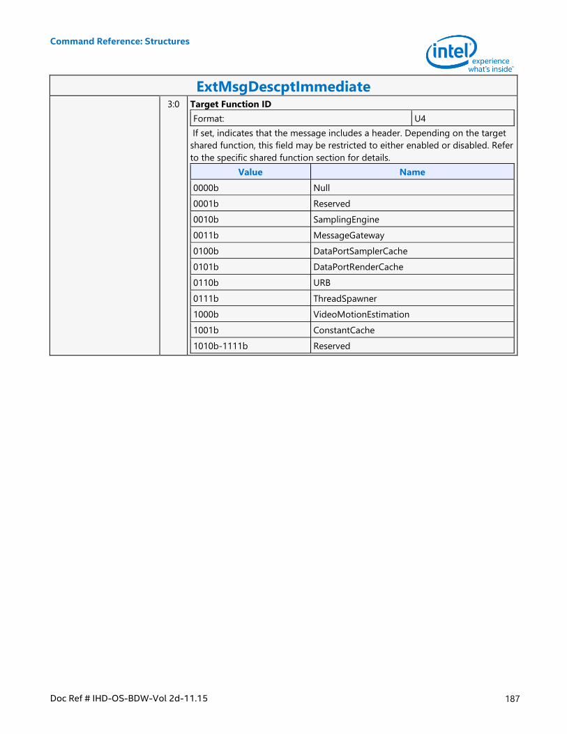
Command Reference: Structures
Doc Ref # IHD-OS-BDW-Vol 2d-11.15 187
ExtMsgDescptImmediate 3:0 Target Function ID
Format: U4
If set, indicates that the message includes a header. Depending on the target
shared function, this field may be restricted to either enabled or disabled. Refer
to the specific shared function section for details.
Value Name
0000b Null
0001b Reserved
0010b SamplingEngine
0011b MessageGateway
0100b DataPortSamplerCache
0101b DataPortRenderCache
0110b URB
0111b ThreadSpawner
1000b VideoMotionEstimation
1001b ConstantCache
1010b-1111b Reserved
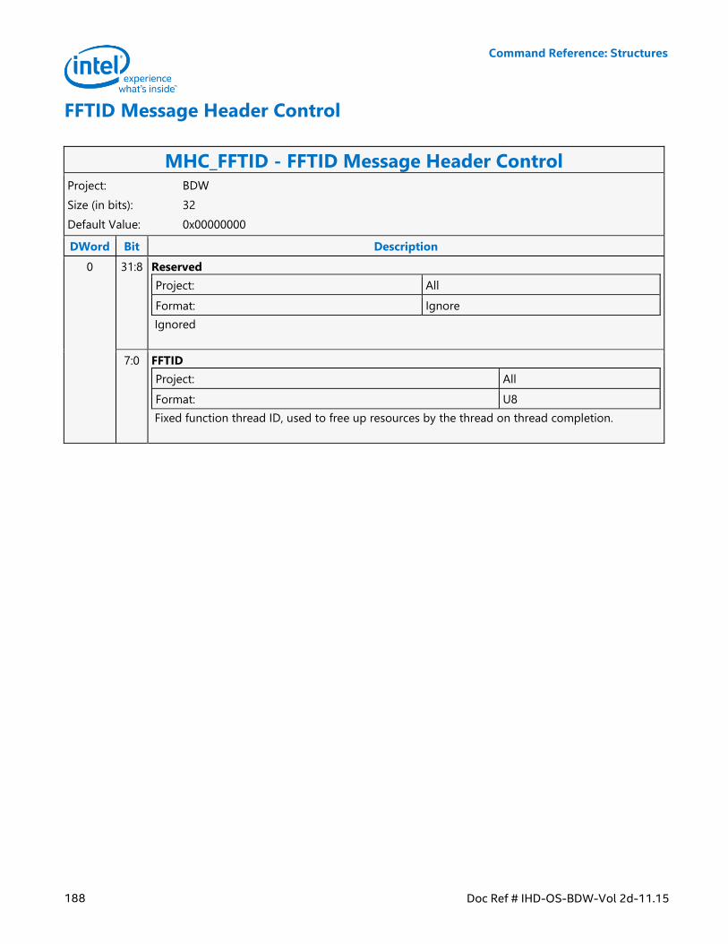
Command Reference: Structures
188 Doc Ref # IHD-OS-BDW-Vol 2d-11.15
FFTID Message Header Control
MHC_FFTID - FFTID Message Header Control Project: BDW
Size (in bits): 32
Default Value: 0x00000000
DWord Bit Description
0 31:8 Reserved
Project: All
Format: Ignore
Ignored
7:0 FFTID
Project: All
Format: U8
Fixed function thread ID, used to free up resources by the thread on thread completion.
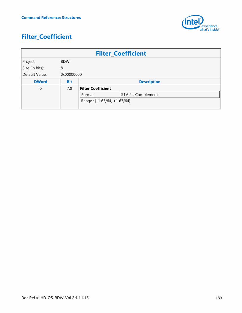
Command Reference: Structures
Doc Ref # IHD-OS-BDW-Vol 2d-11.15 189
Filter_Coefficient
Filter_Coefficient Project: BDW
Size (in bits): 8
Default Value: 0x00000000
DWord Bit Description
0 7:0 Filter Coefficient
Format: S1.6 2's Complement
Range : [-1 63/64, +1 63/64]
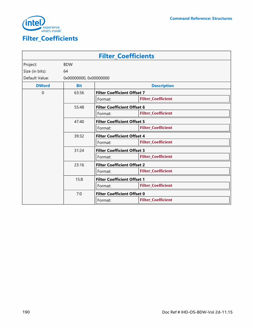
Command Reference: Structures
190 Doc Ref # IHD-OS-BDW-Vol 2d-11.15
Filter_Coefficients
Filter_Coefficients Project: BDW
Size (in bits): 64
Default Value: 0x00000000, 0x00000000
DWord Bit Description
0 63:56 Filter Coefficient Offset 7
Format: Filter_Coefficient
55:48 Filter Coefficient Offset 6
Format: Filter_Coefficient
47:40 Filter Coefficient Offset 5
Format: Filter_Coefficient
39:32 Filter Coefficient Offset 4
Format: Filter_Coefficient
31:24 Filter Coefficient Offset 3
Format: Filter_Coefficient
23:16 Filter Coefficient Offset 2
Format: Filter_Coefficient
15:8 Filter Coefficient Offset 1
Format: Filter_Coefficient
7:0 Filter Coefficient Offset 0
Format: Filter_Coefficient
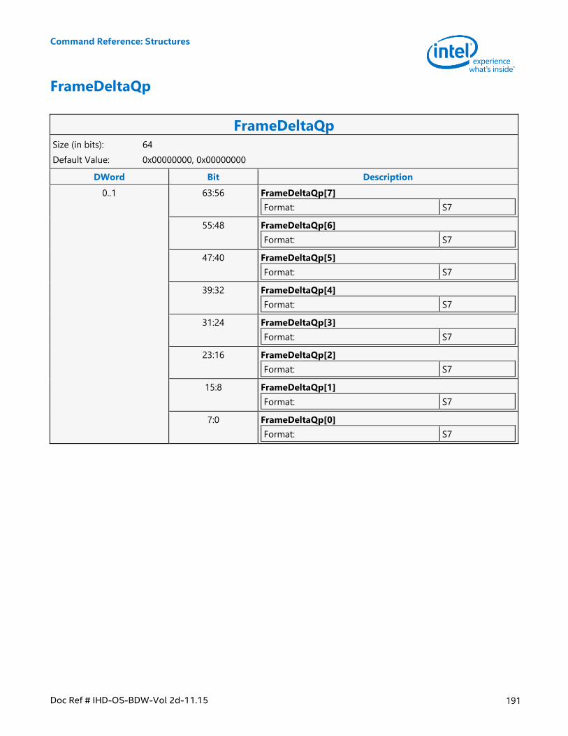
Command Reference: Structures
Doc Ref # IHD-OS-BDW-Vol 2d-11.15 191
FrameDeltaQp
FrameDeltaQp Size (in bits): 64
Default Value: 0x00000000, 0x00000000
DWord Bit Description
0..1 63:56 FrameDeltaQp[7]
Format: S7
55:48 FrameDeltaQp[6]
Format: S7
47:40 FrameDeltaQp[5]
Format: S7
39:32 FrameDeltaQp[4]
Format: S7
31:24 FrameDeltaQp[3]
Format: S7
23:16 FrameDeltaQp[2]
Format: S7
15:8 FrameDeltaQp[1]
Format: S7
7:0 FrameDeltaQp[0]
Format: S7
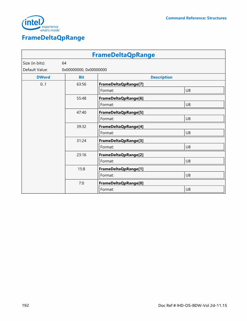
Command Reference: Structures
192 Doc Ref # IHD-OS-BDW-Vol 2d-11.15
FrameDeltaQpRange
FrameDeltaQpRange Size (in bits): 64
Default Value: 0x00000000, 0x00000000
DWord Bit Description
0..1 63:56 FrameDeltaQpRange[7]
Format: U8
55:48 FrameDeltaQpRange[6]
Format: U8
47:40 FrameDeltaQpRange[5]
Format: U8
39:32 FrameDeltaQpRange[4]
Format: U8
31:24 FrameDeltaQpRange[3]
Format: U8
23:16 FrameDeltaQpRange[2]
Format: U8
15:8 FrameDeltaQpRange[1]
Format: U8
7:0 FrameDeltaQpRange[0]
Format: U8
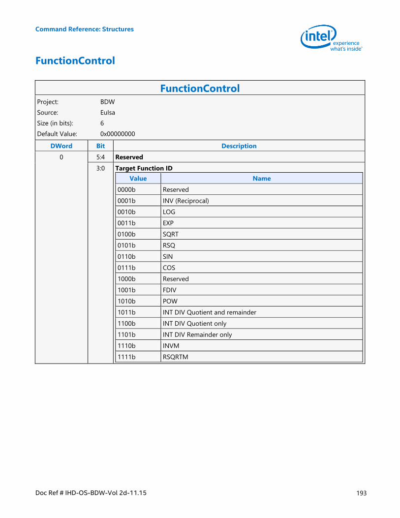
Command Reference: Structures
Doc Ref # IHD-OS-BDW-Vol 2d-11.15 193
FunctionControl
FunctionControl Project: BDW
Source: EuIsa
Size (in bits): 6
Default Value: 0x00000000
DWord Bit Description
0 5:4 Reserved
3:0 Target Function ID
Value Name
0000b Reserved
0001b INV (Reciprocal)
0010b LOG
0011b EXP
0100b SQRT
0101b RSQ
0110b SIN
0111b COS
1000b Reserved
1001b FDIV
1010b POW
1011b INT DIV Quotient and remainder
1100b INT DIV Quotient only
1101b INT DIV Remainder only
1110b INVM
1111b RSQRTM
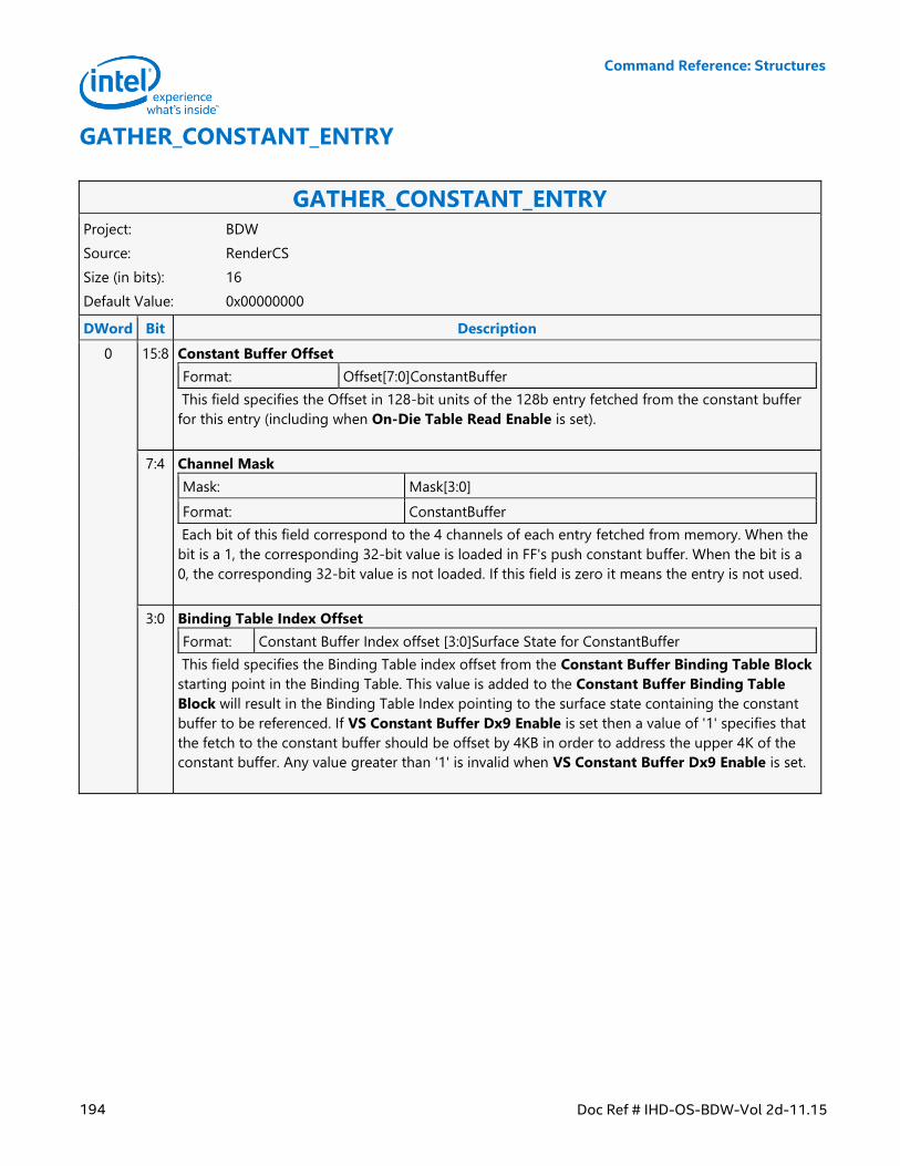
Command Reference: Structures
194 Doc Ref # IHD-OS-BDW-Vol 2d-11.15
GATHER_CONSTANT_ENTRY
GATHER_CONSTANT_ENTRY Project: BDW
Source: RenderCS
Size (in bits): 16
Default Value: 0x00000000
DWord Bit Description
0 15:8 Constant Buffer Offset
Format: Offset[7:0]ConstantBuffer
This field specifies the Offset in 128-bit units of the 128b entry fetched from the constant buffer
for this entry (including when On-Die Table Read Enable is set).
7:4 Channel Mask
Mask: Mask[3:0]
Format: ConstantBuffer
Each bit of this field correspond to the 4 channels of each entry fetched from memory. When the
bit is a 1, the corresponding 32-bit value is loaded in FF's push constant buffer. When the bit is a
0, the corresponding 32-bit value is not loaded. If this field is zero it means the entry is not used.
3:0 Binding Table Index Offset
Format: Constant Buffer Index offset [3:0]Surface State for ConstantBuffer
This field specifies the Binding Table index offset from the Constant Buffer Binding Table Block
starting point in the Binding Table. This value is added to the Constant Buffer Binding Table
Block will result in the Binding Table Index pointing to the surface state containing the constant
buffer to be referenced. If VS Constant Buffer Dx9 Enable is set then a value of '1' specifies that
the fetch to the constant buffer should be offset by 4KB in order to address the upper 4K of the
constant buffer. Any value greater than '1' is invalid when VS Constant Buffer Dx9 Enable is set.
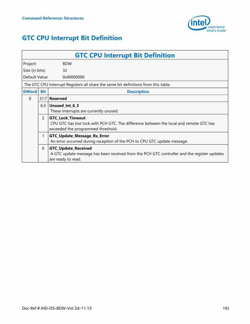
Command Reference: Structures
Doc Ref # IHD-OS-BDW-Vol 2d-11.15 195
GTC CPU Interrupt Bit Definition
GTC CPU Interrupt Bit Definition Project: BDW
Size (in bits): 32
Default Value: 0x00000000
The GTC CPU Interrupt Registers all share the same bit definitions from this table.
DWord Bit Description
0 31:7 Reserved
6:3 Unused_Int_6_3
These interrupts are currently unused.
2 GTC_Lock_Timeout
CPU GTC has lost lock with PCH GTC. The difference between the local and remote GTC has
exceeded the programmed threshold.
1 GTC_Update_Message_Rx_Error
An error occurred during reception of the PCH to CPU GTC update message.
0 GTC_Update_Received
A GTC update message has been received from the PCH GTC controller and the register updates
are ready to read.
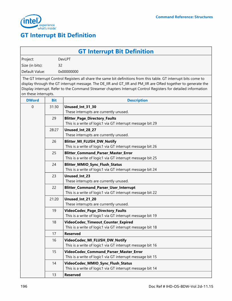
Command Reference: Structures
196 Doc Ref # IHD-OS-BDW-Vol 2d-11.15
GT Interrupt Bit Definition
GT Interrupt Bit Definition Project: DevLPT
Size (in bits): 32
Default Value: 0x00000000
The GT Interrupt Control Registers all share the same bit definitions from this table. GT interrupt bits come to
display through the GT interrupt message. The DE_IIR and GT_IIR and PM_IIR are ORed together to generate the
Display interrupt. Refer to the Command Streamer chapters Interrupt Control Registers for detailed information
on these interrupts.
DWord Bit Description
0 31:30 Unused_Int_31_30
These interrupts are currently unused.
29 Blitter_Page_Directory_Faults
This is a write of logic1 via GT interrupt message bit 29
28:27 Unused_Int_28_27
These interrupts are currently unused.
26 Blitter_MI_FLUSH_DW_Notify
This is a write of logic1 via GT interrupt message bit 26
25 Blitter_Command_Parser_Master_Error
This is a write of logic1 via GT interrupt message bit 25
24 Blitter_MMIO_Sync_Flush_Status
This is a write of logic1 via GT interrupt message bit 24
23 Unused_Int_23
These interrupts are currently unused.
22 Blitter_Command_Parser_User_Interrupt
This is a write of logic1 via GT interrupt message bit 22
21:20 Unused_Int_21_20
These interrupts are currently unused.
19 VideoCodec_Page_Directory_Faults
This is a write of logic1 via GT interrupt message bit 19
18 VideoCodec_Timeout_Counter_Expired
This is a write of logic1 via GT interrupt message bit 18
17 Reserved
16 VideoCodec_MI_FLUSH_DW_Notify
This is a write of logic1 via GT interrupt message bit 16
15 VideoCodec_Command_Parser_Master_Error
This is a write of logic1 via GT interrupt message bit 15
14 VideoCodec_MMIO_Sync_Flush_Status
This is a write of logic1 via GT interrupt message bit 14
13 Reserved
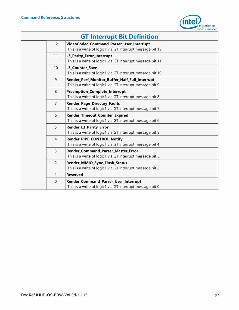
Command Reference: Structures
Doc Ref # IHD-OS-BDW-Vol 2d-11.15 197
GT Interrupt Bit Definition 12 VideoCodec_Command_Parser_User_Interrupt
This is a write of logic1 via GT interrupt message bit 12
11 L3_Parity_Error_Interrupt
This is a write of logic1 via GT interrupt message bit 11
10 L3_Counter_Save
This is a write of logic1 via GT interrupt message bit 10
9 Render_Perf_Monitor_Buffer_Half_Full_Interrupt
This is a write of logic1 via GT interrupt message bit 9
8 Preemption_Complete_Interrupt
This is a write of logic1 via GT interrupt message bit 8
7 Render_Page_Directoy_Faults
This is a write of logic1 via GT interrupt message bit 7
6 Render_Timeout_Counter_Expired
This is a write of logic1 via GT interrupt message bit 6
5 Render_L3_Parity_Error
This is a write of logic1 via GT interrupt message bit 5
4 Render_PIPE_CONTROL_Notify
This is a write of logic1 via GT interrupt message bit 4
3 Render_Command_Parser_Master_Error
This is a write of logic1 via GT interrupt message bit 3
2 Render_MMIO_Sync_Flush_Status
This is a write of logic1 via GT interrupt message bit 2
1 Reserved
0 Render_Command_Parser_User_Interrupt
This is a write of logic1 via GT interrupt message bit 0
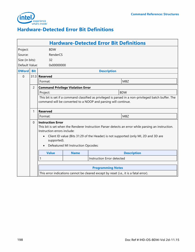
Command Reference: Structures
198 Doc Ref # IHD-OS-BDW-Vol 2d-11.15
Hardware-Detected Error Bit Definitions
Hardware-Detected Error Bit Definitions Project: BDW
Source: RenderCS
Size (in bits): 32
Default Value: 0x00000000
DWord Bit Description
0 31:3 Reserved
Format: MBZ
2 Command Privilege Violation Error
Project: BDW
This bit is set if a command classified as privileged is parsed in a non-privileged batch buffer. The
command will be converted to a NOOP and parsing will continue.
1 Reserved
Format: MBZ
0 Instruction Error
This bit is set when the Renderer Instruction Parser detects an error while parsing an instruction.
Instruction errors include:
Client ID value (Bits 31:29 of the Header) is not supported (only MI, 2D and 3D are
supported).
Defeatured MI Instruction Opcodes:
Value Name Description
1 Instruction Error detected
Programming Notes
This error indications cannot be cleared except by reset (i.e., it is a fatal error).
Command Reference: Structures
Doc Ref # IHD-OS-BDW-Vol 2d-11.15 199
Hardware Status Page Layout
Hardware Status Page Layout Project: BDW
Source: RenderCS
Size (in bits): 32768
Default Value: 0x00000000, 0x00000000, 0x00000000, 0x00000000, 0x00000000, 0x00000000,
0x00000000, 0x00000000, 0x00000000, 0x00000000, 0x00000000, 0x00000000,
0x00000000, 0x00000000, 0x00000000, 0x00000000, 0x00000000, 0x00000000,
0x00000000, 0x00000000, 0x00000000, 0x00000000, 0x00000000, 0x00000000,
0x00000000, 0x00000000, 0x00000000, 0x00000000, 0x00000000, 0x00000000,
0x00000000, 0x00000000, 0x00000000, 0x00000000, 0x00000000, 0x00000000,
0x00000000, 0x00000000, 0x00000000, 0x00000000, 0x00000000, 0x00000000,
0x00000000, 0x00000000, 0x00000000, 0x00000000, 0x00000000, 0x00000000,
0x00000000, 0x00000000, 0x00000000, 0x00000000, 0x00000000, 0x00000000,
0x00000000, 0x00000000, 0x00000000, 0x00000000, 0x00000000, 0x00000000,
0x00000000, 0x00000000, 0x00000000, 0x00000000, 0x00000000, 0x00000000,
0x00000000, 0x00000000, 0x00000000, 0x00000000, 0x00000000, 0x00000000,
0x00000000, 0x00000000, 0x00000000, 0x00000000, 0x00000000, 0x00000000,
0x00000000, 0x00000000, 0x00000000, 0x00000000, 0x00000000, 0x00000000,
0x00000000, 0x00000000, 0x00000000, 0x00000000, 0x00000000, 0x00000000,
0x00000000, 0x00000000, 0x00000000, 0x00000000, 0x00000000, 0x00000000,
0x00000000, 0x00000000, 0x00000000, 0x00000000, 0x00000000, 0x00000000,
0x00000000, 0x00000000, 0x00000000, 0x00000000, 0x00000000, 0x00000000,
0x00000000, 0x00000000, 0x00000000, 0x00000000, 0x00000000, 0x00000000,
0x00000000, 0x00000000, 0x00000000, 0x00000000, 0x00000000, 0x00000000,
0x00000000, 0x00000000, 0x00000000, 0x00000000, 0x00000000, 0x00000000,
0x00000000, 0x00000000, 0x00000000, 0x00000000, 0x00000000, 0x00000000,
0x00000000, 0x00000000, 0x00000000, 0x00000000, 0x00000000, 0x00000000,
0x00000000, 0x00000000, 0x00000000, 0x00000000, 0x00000000, 0x00000000,
0x00000000, 0x00000000, 0x00000000, 0x00000000, 0x00000000, 0x00000000,
0x00000000, 0x00000000, 0x00000000, 0x00000000, 0x00000000, 0x00000000,
0x00000000, 0x00000000, 0x00000000, 0x00000000, 0x00000000, 0x00000000,
0x00000000, 0x00000000, 0x00000000, 0x00000000, 0x00000000, 0x00000000,
0x00000000, 0x00000000, 0x00000000, 0x00000000, 0x00000000, 0x00000000,
0x00000000, 0x00000000, 0x00000000, 0x00000000, 0x00000000, 0x00000000,
0x00000000, 0x00000000, 0x00000000, 0x00000000, 0x00000000, 0x00000000,
0x00000000, 0x00000000, 0x00000000, 0x00000000, 0x00000000, 0x00000000,
0x00000000, 0x00000000, 0x00000000, 0x00000000, 0x00000000, 0x00000000,
0x00000000, 0x00000000, 0x00000000, 0x00000000, 0x00000000, 0x00000000,
0x00000000, 0x00000000, 0x00000000, 0x00000000, 0x00000000, 0x00000000,
0x00000000, 0x00000000, 0x00000000, 0x00000000, 0x00000000, 0x00000000,
0x00000000, 0x00000000, 0x00000000, 0x00000000, 0x00000000, 0x00000000,
0x00000000, 0x00000000, 0x00000000, 0x00000000, 0x00000000, 0x00000000,
0x00000000, 0x00000000, 0x00000000, 0x00000000, 0x00000000, 0x00000000,
0x00000000, 0x00000000, 0x00000000, 0x00000000, 0x00000000, 0x00000000,
Command Reference: Structures
200 Doc Ref # IHD-OS-BDW-Vol 2d-11.15
Hardware Status Page Layout 0x00000000, 0x00000000, 0x00000000, 0x00000000, 0x00000000, 0x00000000,
0x00000000, 0x00000000, 0x00000000, 0x00000000, 0x00000000, 0x00000000,
0x00000000, 0x00000000, 0x00000000, 0x00000000, 0x00000000, 0x00000000,
0x00000000, 0x00000000, 0x00000000, 0x00000000, 0x00000000, 0x00000000,
0x00000000, 0x00000000, 0x00000000, 0x00000000, 0x00000000, 0x00000000,
0x00000000, 0x00000000, 0x00000000, 0x00000000, 0x00000000, 0x00000000,
0x00000000, 0x00000000, 0x00000000, 0x00000000, 0x00000000, 0x00000000,
0x00000000, 0x00000000, 0x00000000, 0x00000000, 0x00000000, 0x00000000,
0x00000000, 0x00000000, 0x00000000, 0x00000000, 0x00000000, 0x00000000,
0x00000000, 0x00000000, 0x00000000, 0x00000000, 0x00000000, 0x00000000,
0x00000000, 0x00000000, 0x00000000, 0x00000000, 0x00000000, 0x00000000,
0x00000000, 0x00000000, 0x00000000, 0x00000000, 0x00000000, 0x00000000,
0x00000000, 0x00000000, 0x00000000, 0x00000000, 0x00000000, 0x00000000,
0x00000000, 0x00000000, 0x00000000, 0x00000000, 0x00000000, 0x00000000,
0x00000000, 0x00000000, 0x00000000, 0x00000000, 0x00000000, 0x00000000,
0x00000000, 0x00000000, 0x00000000, 0x00000000, 0x00000000, 0x00000000,
0x00000000, 0x00000000, 0x00000000, 0x00000000, 0x00000000, 0x00000000,
0x00000000, 0x00000000, 0x00000000, 0x00000000, 0x00000000, 0x00000000,
0x00000000, 0x00000000, 0x00000000, 0x00000000, 0x00000000, 0x00000000,
0x00000000, 0x00000000, 0x00000000, 0x00000000, 0x00000000, 0x00000000,
0x00000000, 0x00000000, 0x00000000, 0x00000000, 0x00000000, 0x00000000,
0x00000000, 0x00000000, 0x00000000, 0x00000000, 0x00000000, 0x00000000,
0x00000000, 0x00000000, 0x00000000, 0x00000000, 0x00000000, 0x00000000,
0x00000000, 0x00000000, 0x00000000, 0x00000000, 0x00000000, 0x00000000,
0x00000000, 0x00000000, 0x00000000, 0x00000000, 0x00000000, 0x00000000,
0x00000000, 0x00000000, 0x00000000, 0x00000000, 0x00000000, 0x00000000,
0x00000000, 0x00000000, 0x00000000, 0x00000000, 0x00000000, 0x00000000,
0x00000000, 0x00000000, 0x00000000, 0x00000000, 0x00000000, 0x00000000,
0x00000000, 0x00000000, 0x00000000, 0x00000000, 0x00000000, 0x00000000,
0x00000000, 0x00000000, 0x00000000, 0x00000000, 0x00000000, 0x00000000,
0x00000000, 0x00000000, 0x00000000, 0x00000000, 0x00000000, 0x00000000,
0x00000000, 0x00000000, 0x00000000, 0x00000000, 0x00000000, 0x00000000,
0x00000000, 0x00000000, 0x00000000, 0x00000000, 0x00000000, 0x00000000,
0x00000000, 0x00000000, 0x00000000, 0x00000000, 0x00000000, 0x00000000,
0x00000000, 0x00000000, 0x00000000, 0x00000000, 0x00000000, 0x00000000,
0x00000000, 0x00000000, 0x00000000, 0x00000000, 0x00000000, 0x00000000,
0x00000000, 0x00000000, 0x00000000, 0x00000000, 0x00000000, 0x00000000,
0x00000000, 0x00000000, 0x00000000, 0x00000000, 0x00000000, 0x00000000,
0x00000000, 0x00000000, 0x00000000, 0x00000000, 0x00000000, 0x00000000,
0x00000000, 0x00000000, 0x00000000, 0x00000000, 0x00000000, 0x00000000,
0x00000000, 0x00000000, 0x00000000, 0x00000000, 0x00000000, 0x00000000,
0x00000000, 0x00000000, 0x00000000, 0x00000000, 0x00000000, 0x00000000,
0x00000000, 0x00000000, 0x00000000, 0x00000000, 0x00000000, 0x00000000,
0x00000000, 0x00000000, 0x00000000, 0x00000000, 0x00000000, 0x00000000,
0x00000000, 0x00000000, 0x00000000, 0x00000000, 0x00000000, 0x00000000,
0x00000000, 0x00000000, 0x00000000, 0x00000000, 0x00000000, 0x00000000,
Command Reference: Structures
Doc Ref # IHD-OS-BDW-Vol 2d-11.15 201
Hardware Status Page Layout 0x00000000, 0x00000000, 0x00000000, 0x00000000, 0x00000000, 0x00000000,
0x00000000, 0x00000000, 0x00000000, 0x00000000, 0x00000000, 0x00000000,
0x00000000, 0x00000000, 0x00000000, 0x00000000, 0x00000000, 0x00000000,
0x00000000, 0x00000000, 0x00000000, 0x00000000, 0x00000000, 0x00000000,
0x00000000, 0x00000000, 0x00000000, 0x00000000, 0x00000000, 0x00000000,
0x00000000, 0x00000000, 0x00000000, 0x00000000, 0x00000000, 0x00000000,
0x00000000, 0x00000000, 0x00000000, 0x00000000, 0x00000000, 0x00000000,
0x00000000, 0x00000000, 0x00000000, 0x00000000, 0x00000000, 0x00000000,
0x00000000, 0x00000000, 0x00000000, 0x00000000, 0x00000000, 0x00000000,
0x00000000, 0x00000000, 0x00000000, 0x00000000, 0x00000000, 0x00000000,
0x00000000, 0x00000000, 0x00000000, 0x00000000, 0x00000000, 0x00000000,
0x00000000, 0x00000000, 0x00000000, 0x00000000, 0x00000000, 0x00000000,
0x00000000, 0x00000000, 0x00000000, 0x00000000, 0x00000000, 0x00000000,
0x00000000, 0x00000000, 0x00000000, 0x00000000, 0x00000000, 0x00000000,
0x00000000, 0x00000000, 0x00000000, 0x00000000, 0x00000000, 0x00000000,
0x00000000, 0x00000000, 0x00000000, 0x00000000, 0x00000000, 0x00000000,
0x00000000, 0x00000000, 0x00000000, 0x00000000, 0x00000000, 0x00000000,
0x00000000, 0x00000000, 0x00000000, 0x00000000, 0x00000000, 0x00000000,
0x00000000, 0x00000000, 0x00000000, 0x00000000, 0x00000000, 0x00000000,
0x00000000, 0x00000000, 0x00000000, 0x00000000, 0x00000000, 0x00000000,
0x00000000, 0x00000000, 0x00000000, 0x00000000, 0x00000000, 0x00000000,
0x00000000, 0x00000000, 0x00000000, 0x00000000, 0x00000000, 0x00000000,
0x00000000, 0x00000000, 0x00000000, 0x00000000, 0x00000000, 0x00000000,
0x00000000, 0x00000000, 0x00000000, 0x00000000, 0x00000000, 0x00000000,
0x00000000, 0x00000000, 0x00000000, 0x00000000, 0x00000000, 0x00000000,
0x00000000, 0x00000000, 0x00000000, 0x00000000, 0x00000000, 0x00000000,
0x00000000, 0x00000000, 0x00000000, 0x00000000, 0x00000000, 0x00000000,
0x00000000, 0x00000000, 0x00000000, 0x00000000, 0x00000000, 0x00000000,
0x00000000, 0x00000000, 0x00000000, 0x00000000, 0x00000000, 0x00000000,
0x00000000, 0x00000000, 0x00000000, 0x00000000, 0x00000000, 0x00000000,
0x00000000, 0x00000000, 0x00000000, 0x00000000, 0x00000000, 0x00000000,
0x00000000, 0x00000000, 0x00000000, 0x00000000, 0x00000000, 0x00000000,
0x00000000, 0x00000000, 0x00000000, 0x00000000, 0x00000000, 0x00000000,
0x00000000, 0x00000000, 0x00000000, 0x00000000, 0x00000000, 0x00000000,
0x00000000, 0x00000000, 0x00000000, 0x00000000, 0x00000000, 0x00000000,
0x00000000, 0x00000000, 0x00000000, 0x00000000, 0x00000000, 0x00000000,
0x00000000, 0x00000000, 0x00000000, 0x00000000, 0x00000000, 0x00000000,
0x00000000, 0x00000000, 0x00000000, 0x00000000, 0x00000000, 0x00000000,
0x00000000, 0x00000000, 0x00000000, 0x00000000, 0x00000000, 0x00000000,
0x00000000, 0x00000000, 0x00000000, 0x00000000, 0x00000000, 0x00000000,
0x00000000, 0x00000000, 0x00000000, 0x00000000, 0x00000000, 0x00000000,
0x00000000, 0x00000000, 0x00000000, 0x00000000, 0x00000000, 0x00000000,
0x00000000, 0x00000000, 0x00000000, 0x00000000, 0x00000000, 0x00000000,
0x00000000, 0x00000000, 0x00000000, 0x00000000, 0x00000000, 0x00000000,
0x00000000, 0x00000000, 0x00000000, 0x00000000, 0x00000000, 0x00000000,
0x00000000, 0x00000000, 0x00000000, 0x00000000, 0x00000000, 0x00000000,
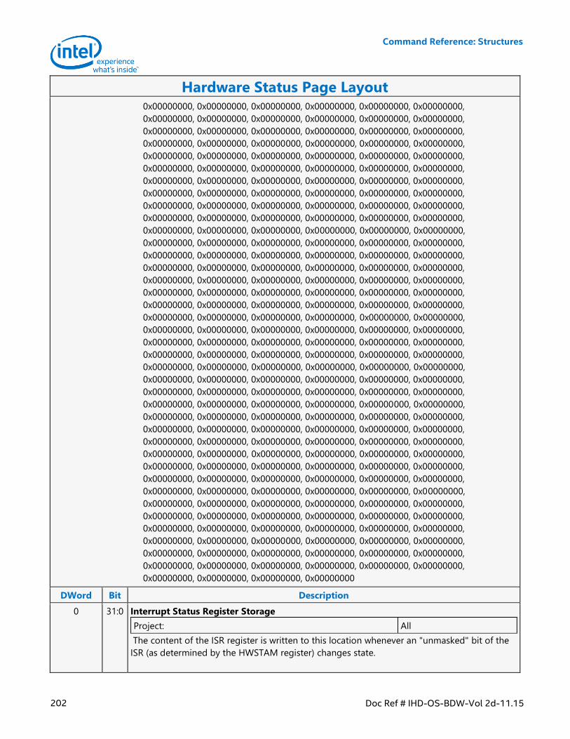
Command Reference: Structures
202 Doc Ref # IHD-OS-BDW-Vol 2d-11.15
Hardware Status Page Layout 0x00000000, 0x00000000, 0x00000000, 0x00000000, 0x00000000, 0x00000000,
0x00000000, 0x00000000, 0x00000000, 0x00000000, 0x00000000, 0x00000000,
0x00000000, 0x00000000, 0x00000000, 0x00000000, 0x00000000, 0x00000000,
0x00000000, 0x00000000, 0x00000000, 0x00000000, 0x00000000, 0x00000000,
0x00000000, 0x00000000, 0x00000000, 0x00000000, 0x00000000, 0x00000000,
0x00000000, 0x00000000, 0x00000000, 0x00000000, 0x00000000, 0x00000000,
0x00000000, 0x00000000, 0x00000000, 0x00000000, 0x00000000, 0x00000000,
0x00000000, 0x00000000, 0x00000000, 0x00000000, 0x00000000, 0x00000000,
0x00000000, 0x00000000, 0x00000000, 0x00000000, 0x00000000, 0x00000000,
0x00000000, 0x00000000, 0x00000000, 0x00000000, 0x00000000, 0x00000000,
0x00000000, 0x00000000, 0x00000000, 0x00000000, 0x00000000, 0x00000000,
0x00000000, 0x00000000, 0x00000000, 0x00000000, 0x00000000, 0x00000000,
0x00000000, 0x00000000, 0x00000000, 0x00000000, 0x00000000, 0x00000000,
0x00000000, 0x00000000, 0x00000000, 0x00000000, 0x00000000, 0x00000000,
0x00000000, 0x00000000, 0x00000000, 0x00000000, 0x00000000, 0x00000000,
0x00000000, 0x00000000, 0x00000000, 0x00000000, 0x00000000, 0x00000000,
0x00000000, 0x00000000, 0x00000000, 0x00000000, 0x00000000, 0x00000000,
0x00000000, 0x00000000, 0x00000000, 0x00000000, 0x00000000, 0x00000000,
0x00000000, 0x00000000, 0x00000000, 0x00000000, 0x00000000, 0x00000000,
0x00000000, 0x00000000, 0x00000000, 0x00000000, 0x00000000, 0x00000000,
0x00000000, 0x00000000, 0x00000000, 0x00000000, 0x00000000, 0x00000000,
0x00000000, 0x00000000, 0x00000000, 0x00000000, 0x00000000, 0x00000000,
0x00000000, 0x00000000, 0x00000000, 0x00000000, 0x00000000, 0x00000000,
0x00000000, 0x00000000, 0x00000000, 0x00000000, 0x00000000, 0x00000000,
0x00000000, 0x00000000, 0x00000000, 0x00000000, 0x00000000, 0x00000000,
0x00000000, 0x00000000, 0x00000000, 0x00000000, 0x00000000, 0x00000000,
0x00000000, 0x00000000, 0x00000000, 0x00000000, 0x00000000, 0x00000000,
0x00000000, 0x00000000, 0x00000000, 0x00000000, 0x00000000, 0x00000000,
0x00000000, 0x00000000, 0x00000000, 0x00000000, 0x00000000, 0x00000000,
0x00000000, 0x00000000, 0x00000000, 0x00000000, 0x00000000, 0x00000000,
0x00000000, 0x00000000, 0x00000000, 0x00000000, 0x00000000, 0x00000000,
0x00000000, 0x00000000, 0x00000000, 0x00000000, 0x00000000, 0x00000000,
0x00000000, 0x00000000, 0x00000000, 0x00000000, 0x00000000, 0x00000000,
0x00000000, 0x00000000, 0x00000000, 0x00000000, 0x00000000, 0x00000000,
0x00000000, 0x00000000, 0x00000000, 0x00000000, 0x00000000, 0x00000000,
0x00000000, 0x00000000, 0x00000000, 0x00000000, 0x00000000, 0x00000000,
0x00000000, 0x00000000, 0x00000000, 0x00000000, 0x00000000, 0x00000000,
0x00000000, 0x00000000, 0x00000000, 0x00000000, 0x00000000, 0x00000000,
0x00000000, 0x00000000, 0x00000000, 0x00000000
DWord Bit Description
0 31:0 Interrupt Status Register Storage
Project: All
The content of the ISR register is written to this location whenever an "unmasked" bit of the
ISR (as determined by the HWSTAM register) changes state.
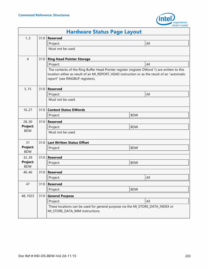
Command Reference: Structures
Doc Ref # IHD-OS-BDW-Vol 2d-11.15 203
Hardware Status Page Layout 1..3 31:0 Reserved
Project: All
Must not be used.
4 31:0 Ring Head Pointer Storage
Project: All
The contents of the Ring Buffer Head Pointer register (register DWord 1) are written to this
location either as result of an MI_REPORT_HEAD instruction or as the result of an "automatic
report" (see RINGBUF registers).
5..15 31:0 Reserved
Project: All
Must not be used.
16..27 31:0 Context Status DWords
Project: BDW
28..30
Project:
BDW
31:0 Reserved
Project: BDW
Must not be used.
31
Project:
BDW
31:0 Last Written Status Offset
Project: BDW
32..39
Project:
BDW
31:0 Reserved
Project: BDW
40..46 31:0 Reserved
Project: All
47 31:0 Reserved
Project: BDW
48..1023 31:0 General Purpose
Project: All
These locations can be used for general purpose via the MI_STORE_DATA_INDEX or
MI_STORE_DATA_IMM instructions.
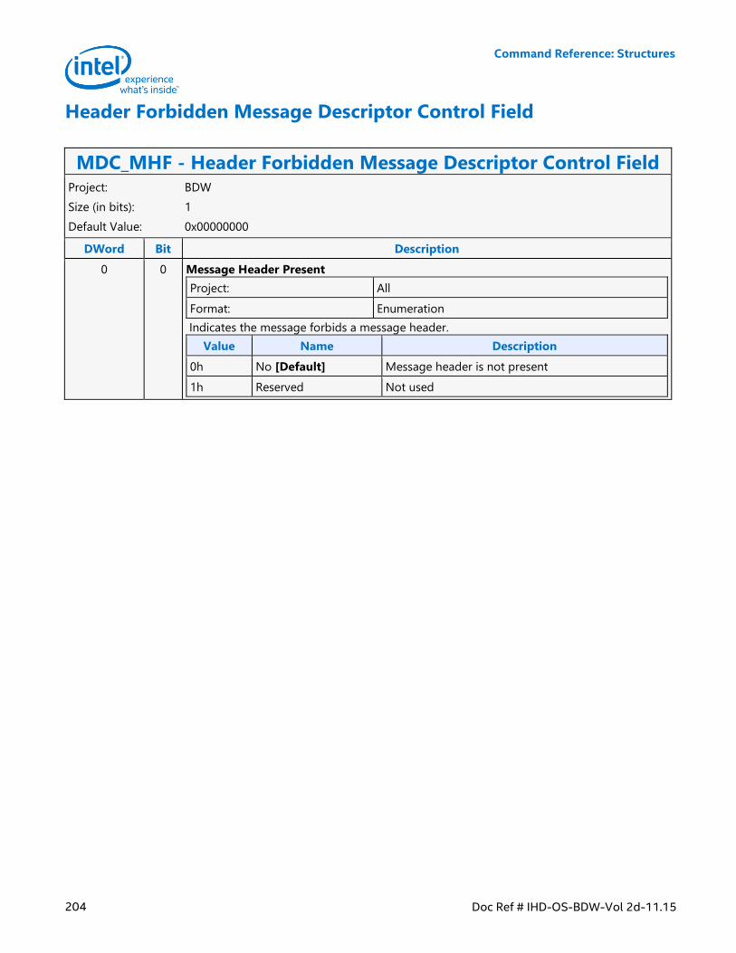
Command Reference: Structures
204 Doc Ref # IHD-OS-BDW-Vol 2d-11.15
Header Forbidden Message Descriptor Control Field
MDC_MHF - Header Forbidden Message Descriptor Control Field Project: BDW
Size (in bits): 1
Default Value: 0x00000000
DWord Bit Description
0 0 Message Header Present
Project: All
Format: Enumeration
Indicates the message forbids a message header.
Value Name Description
0h No [Default] Message header is not present
1h Reserved Not used
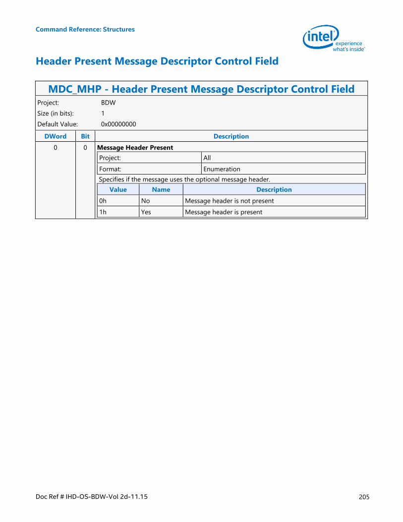
Command Reference: Structures
Doc Ref # IHD-OS-BDW-Vol 2d-11.15 205
Header Present Message Descriptor Control Field
MDC_MHP - Header Present Message Descriptor Control Field Project: BDW
Size (in bits): 1
Default Value: 0x00000000
DWord Bit Description
0 0 Message Header Present
Project: All
Format: Enumeration
Specifies if the message uses the optional message header.
Value Name Description
0h No Message header is not present
1h Yes Message header is present
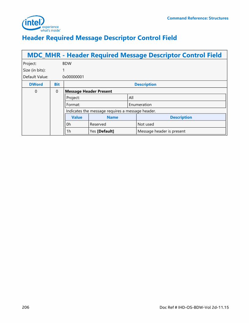
Command Reference: Structures
206 Doc Ref # IHD-OS-BDW-Vol 2d-11.15
Header Required Message Descriptor Control Field
MDC_MHR - Header Required Message Descriptor Control Field Project: BDW
Size (in bits): 1
Default Value: 0x00000001
DWord Bit Description
0 0 Message Header Present
Project: All
Format: Enumeration
Indicates the message requires a message header.
Value Name Description
0h Reserved Not used
1h Yes [Default] Message header is present
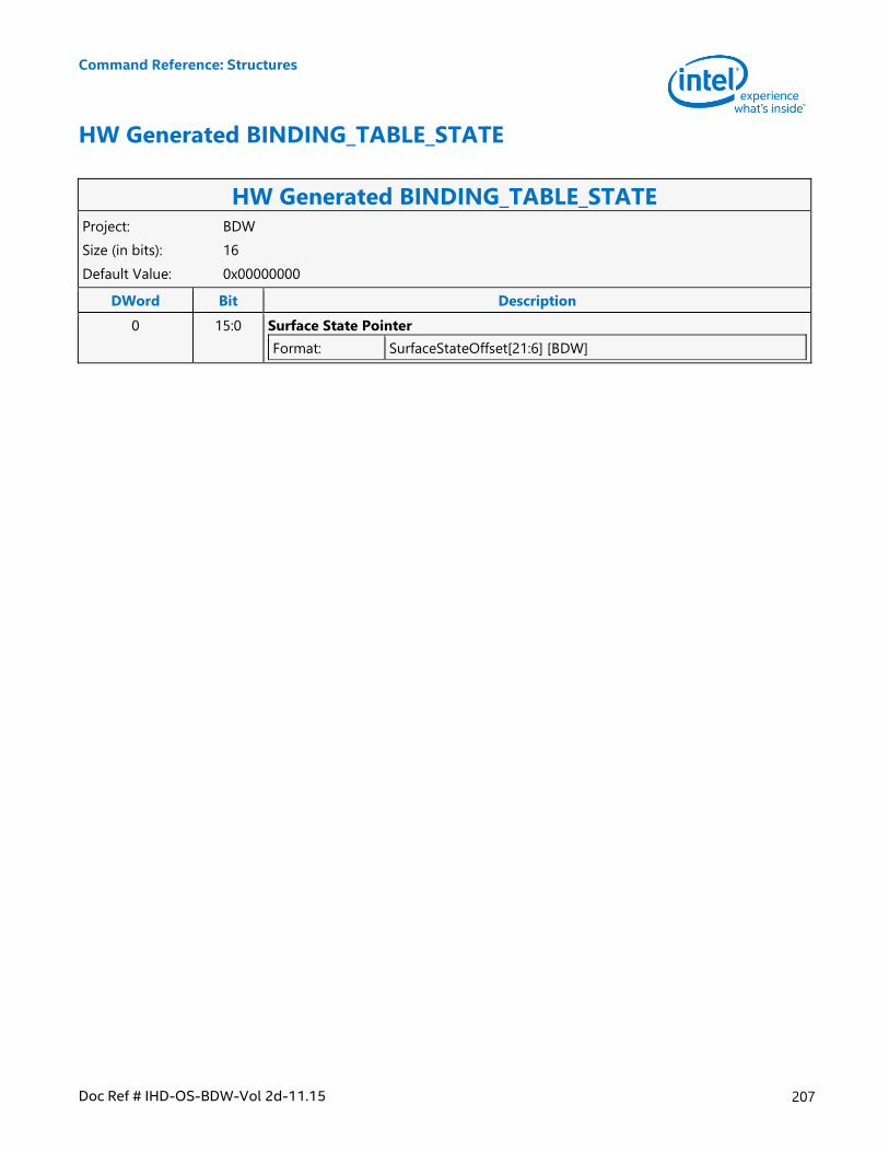
Command Reference: Structures
Doc Ref # IHD-OS-BDW-Vol 2d-11.15 207
HW Generated BINDING_TABLE_STATE
HW Generated BINDING_TABLE_STATE Project: BDW
Size (in bits): 16
Default Value: 0x00000000
DWord Bit Description
0 15:0 Surface State Pointer
Format: SurfaceStateOffset[21:6] [BDW]
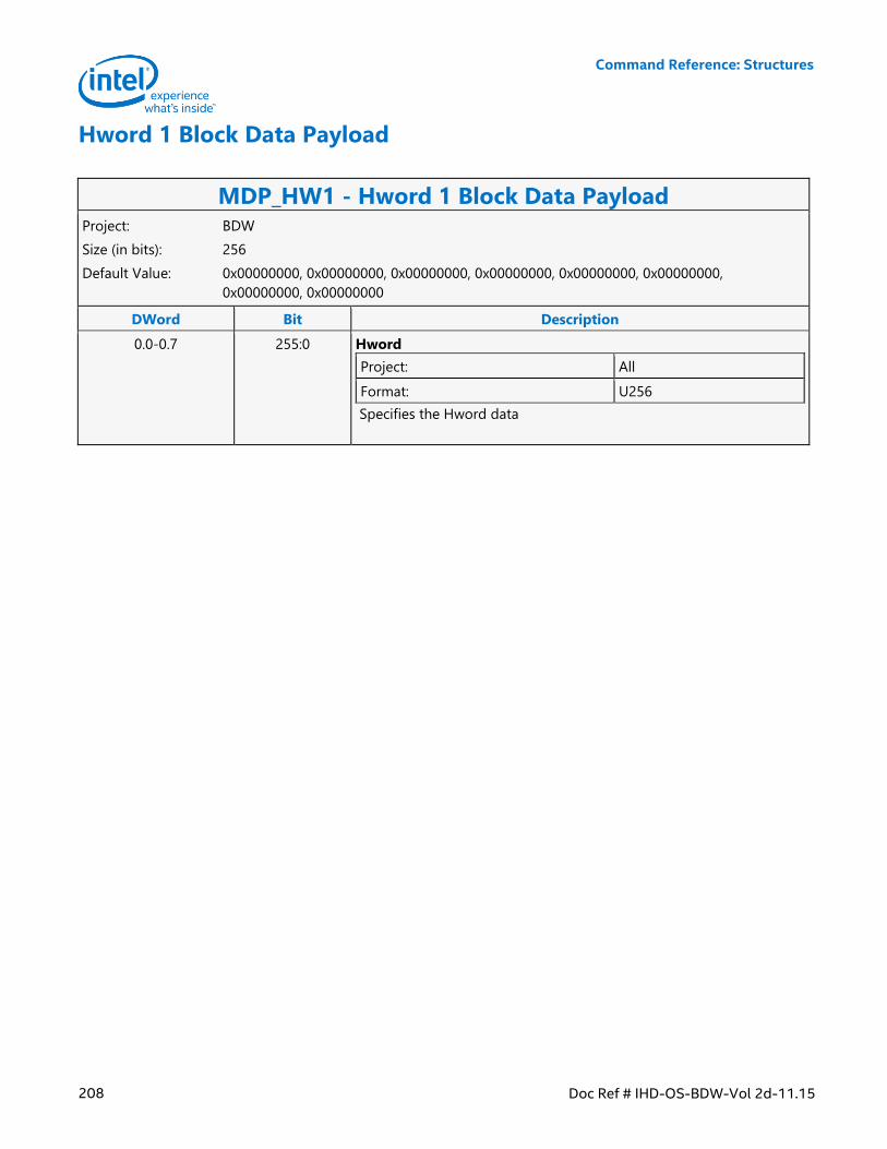
Command Reference: Structures
208 Doc Ref # IHD-OS-BDW-Vol 2d-11.15
Hword 1 Block Data Payload
MDP_HW1 - Hword 1 Block Data Payload Project: BDW
Size (in bits): 256
Default Value: 0x00000000, 0x00000000, 0x00000000, 0x00000000, 0x00000000, 0x00000000,
0x00000000, 0x00000000
DWord Bit Description
0.0-0.7 255:0 Hword
Project: All
Format: U256
Specifies the Hword data
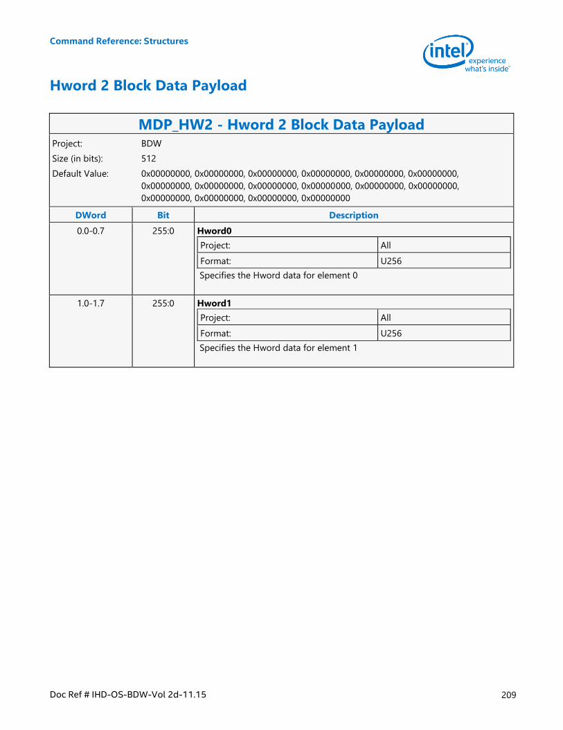
Command Reference: Structures
Doc Ref # IHD-OS-BDW-Vol 2d-11.15 209
Hword 2 Block Data Payload
MDP_HW2 - Hword 2 Block Data Payload Project: BDW
Size (in bits): 512
Default Value: 0x00000000, 0x00000000, 0x00000000, 0x00000000, 0x00000000, 0x00000000,
0x00000000, 0x00000000, 0x00000000, 0x00000000, 0x00000000, 0x00000000,
0x00000000, 0x00000000, 0x00000000, 0x00000000
DWord Bit Description
0.0-0.7 255:0 Hword0
Project: All
Format: U256
Specifies the Hword data for element 0
1.0-1.7 255:0 Hword1
Project: All
Format: U256
Specifies the Hword data for element 1
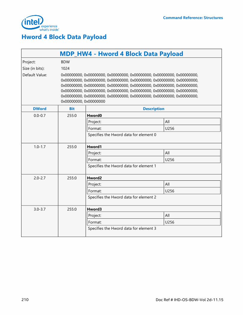
Command Reference: Structures
210 Doc Ref # IHD-OS-BDW-Vol 2d-11.15
Hword 4 Block Data Payload
MDP_HW4 - Hword 4 Block Data Payload Project: BDW
Size (in bits): 1024
Default Value: 0x00000000, 0x00000000, 0x00000000, 0x00000000, 0x00000000, 0x00000000,
0x00000000, 0x00000000, 0x00000000, 0x00000000, 0x00000000, 0x00000000,
0x00000000, 0x00000000, 0x00000000, 0x00000000, 0x00000000, 0x00000000,
0x00000000, 0x00000000, 0x00000000, 0x00000000, 0x00000000, 0x00000000,
0x00000000, 0x00000000, 0x00000000, 0x00000000, 0x00000000, 0x00000000,
0x00000000, 0x00000000
DWord Bit Description
0.0-0.7 255:0 Hword0
Project: All
Format: U256
Specifies the Hword data for element 0
1.0-1.7 255:0 Hword1
Project: All
Format: U256
Specifies the Hword data for element 1
2.0-2.7 255:0 Hword2
Project: All
Format: U256
Specifies the Hword data for element 2
3.0-3.7 255:0 Hword3
Project: All
Format: U256
Specifies the Hword data for element 3
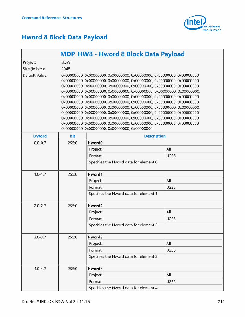
Command Reference: Structures
Doc Ref # IHD-OS-BDW-Vol 2d-11.15 211
Hword 8 Block Data Payload
MDP_HW8 - Hword 8 Block Data Payload Project: BDW
Size (in bits): 2048
Default Value: 0x00000000, 0x00000000, 0x00000000, 0x00000000, 0x00000000, 0x00000000,
0x00000000, 0x00000000, 0x00000000, 0x00000000, 0x00000000, 0x00000000,
0x00000000, 0x00000000, 0x00000000, 0x00000000, 0x00000000, 0x00000000,
0x00000000, 0x00000000, 0x00000000, 0x00000000, 0x00000000, 0x00000000,
0x00000000, 0x00000000, 0x00000000, 0x00000000, 0x00000000, 0x00000000,
0x00000000, 0x00000000, 0x00000000, 0x00000000, 0x00000000, 0x00000000,
0x00000000, 0x00000000, 0x00000000, 0x00000000, 0x00000000, 0x00000000,
0x00000000, 0x00000000, 0x00000000, 0x00000000, 0x00000000, 0x00000000,
0x00000000, 0x00000000, 0x00000000, 0x00000000, 0x00000000, 0x00000000,
0x00000000, 0x00000000, 0x00000000, 0x00000000, 0x00000000, 0x00000000,
0x00000000, 0x00000000, 0x00000000, 0x00000000
DWord Bit Description
0.0-0.7 255:0 Hword0
Project: All
Format: U256
Specifies the Hword data for element 0
1.0-1.7 255:0 Hword1
Project: All
Format: U256
Specifies the Hword data for element 1
2.0-2.7 255:0 Hword2
Project: All
Format: U256
Specifies the Hword data for element 2
3.0-3.7 255:0 Hword3
Project: All
Format: U256
Specifies the Hword data for element 3
4.0-4.7 255:0 Hword4
Project: All
Format: U256
Specifies the Hword data for element 4
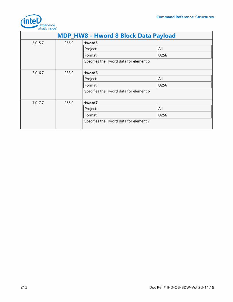
Command Reference: Structures
212 Doc Ref # IHD-OS-BDW-Vol 2d-11.15
MDP_HW8 - Hword 8 Block Data Payload 5.0-5.7 255:0 Hword5
Project: All
Format: U256
Specifies the Hword data for element 5
6.0-6.7 255:0 Hword6
Project: All
Format: U256
Specifies the Hword data for element 6
7.0-7.7 255:0 Hword7
Project: All
Format: U256
Specifies the Hword data for element 7
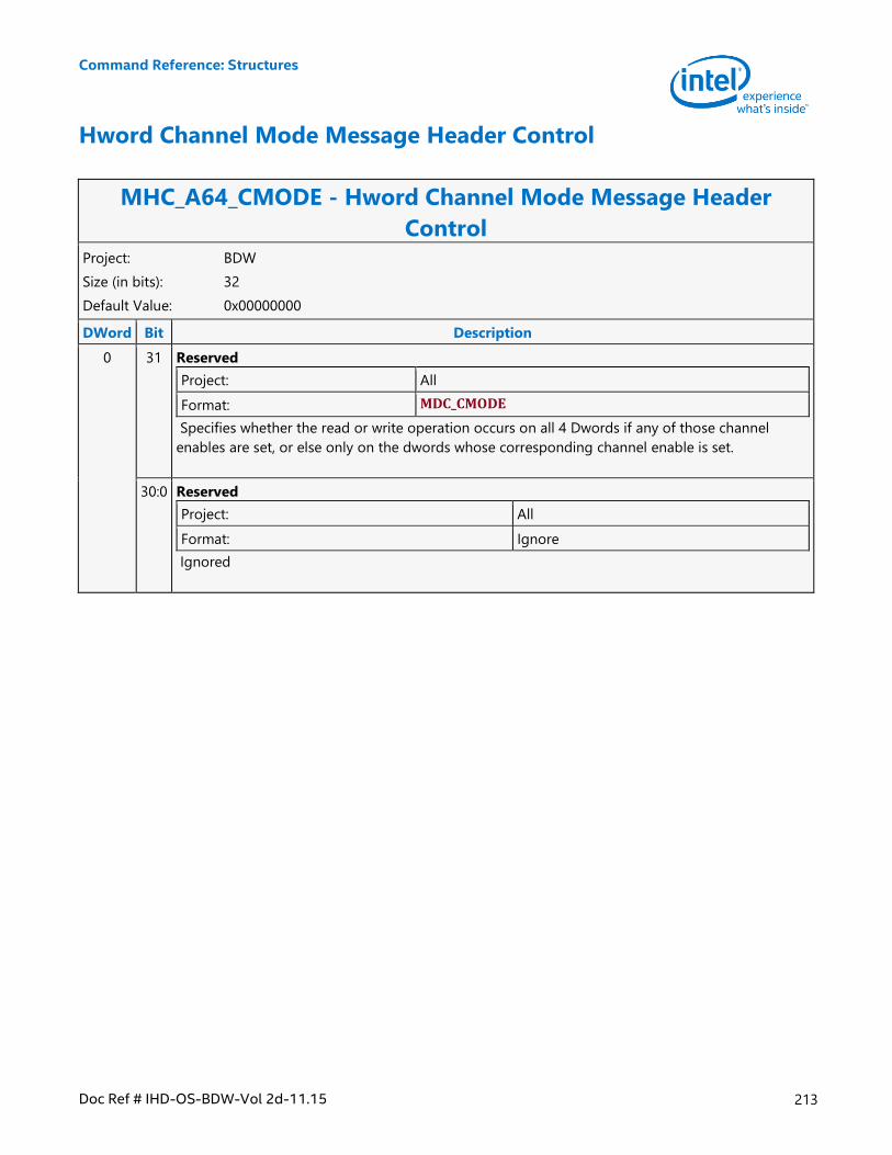
Command Reference: Structures
Doc Ref # IHD-OS-BDW-Vol 2d-11.15 213
Hword Channel Mode Message Header Control
MHC_A64_CMODE - Hword Channel Mode Message Header
Control Project: BDW
Size (in bits): 32
Default Value: 0x00000000
DWord Bit Description
0 31 Reserved
Project: All
Format: MDC_CMODE
Specifies whether the read or write operation occurs on all 4 Dwords if any of those channel
enables are set, or else only on the dwords whose corresponding channel enable is set.
30:0 Reserved
Project: All
Format: Ignore
Ignored
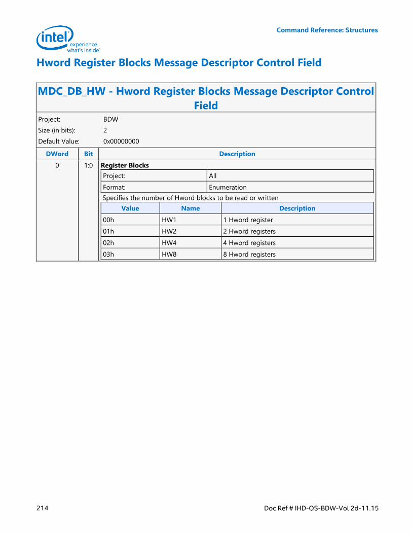
Command Reference: Structures
214 Doc Ref # IHD-OS-BDW-Vol 2d-11.15
Hword Register Blocks Message Descriptor Control Field
MDC_DB_HW - Hword Register Blocks Message Descriptor Control
Field Project: BDW
Size (in bits): 2
Default Value: 0x00000000
DWord Bit Description
0 1:0 Register Blocks
Project: All
Format: Enumeration
Specifies the number of Hword blocks to be read or written
Value Name Description
00h HW1 1 Hword register
01h HW2 2 Hword registers
02h HW4 4 Hword registers
03h HW8 8 Hword registers
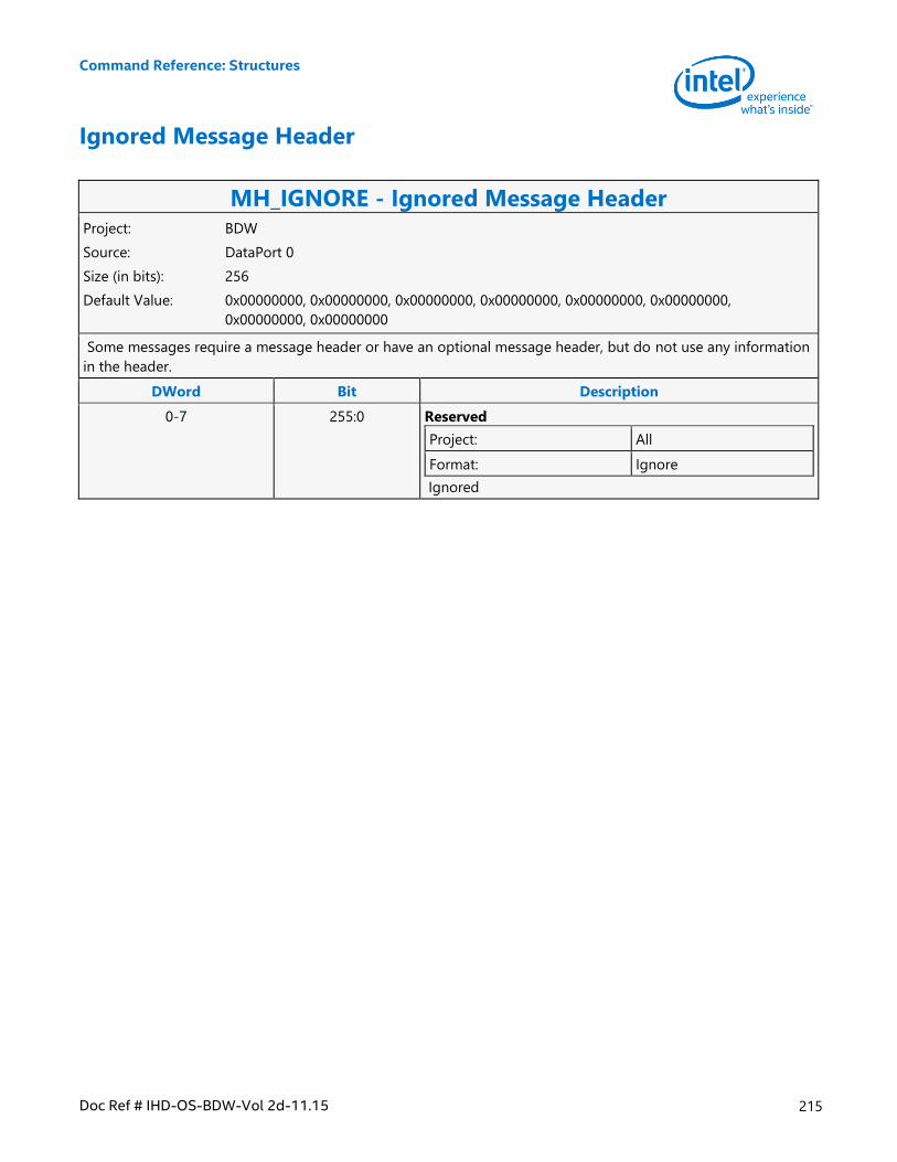
Command Reference: Structures
Doc Ref # IHD-OS-BDW-Vol 2d-11.15 215
Ignored Message Header
MH_IGNORE - Ignored Message Header Project: BDW
Source: DataPort 0
Size (in bits): 256
Default Value: 0x00000000, 0x00000000, 0x00000000, 0x00000000, 0x00000000, 0x00000000,
0x00000000, 0x00000000
Some messages require a message header or have an optional message header, but do not use any information
in the header.
DWord Bit Description
0-7 255:0 Reserved
Project: All
Format: Ignore
Ignored
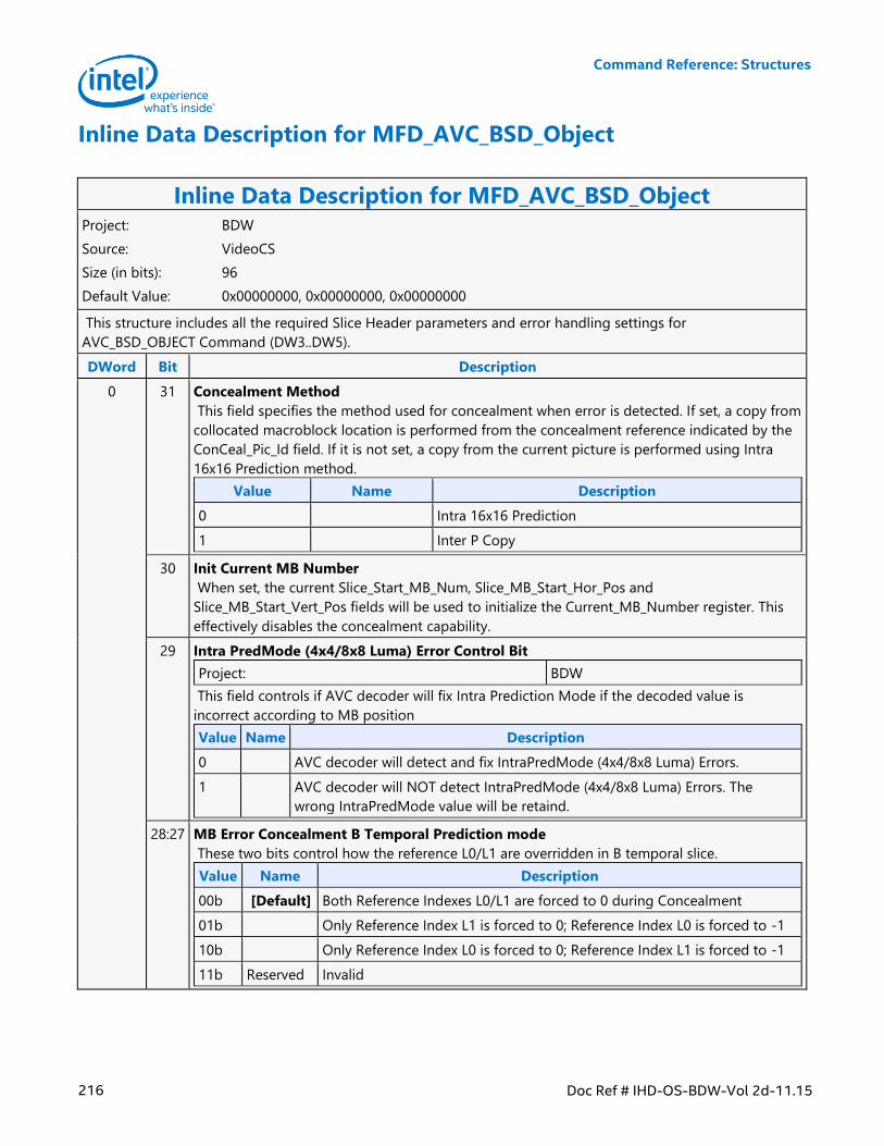
Command Reference: Structures
216 Doc Ref # IHD-OS-BDW-Vol 2d-11.15
Inline Data Description for MFD_AVC_BSD_Object
Inline Data Description for MFD_AVC_BSD_Object Project: BDW
Source: VideoCS
Size (in bits): 96
Default Value: 0x00000000, 0x00000000, 0x00000000
This structure includes all the required Slice Header parameters and error handling settings for
AVC_BSD_OBJECT Command (DW3..DW5).
DWord Bit Description
0 31 Concealment Method
This field specifies the method used for concealment when error is detected. If set, a copy from
collocated macroblock location is performed from the concealment reference indicated by the
ConCeal_Pic_Id field. If it is not set, a copy from the current picture is performed using Intra
16x16 Prediction method.
Value Name Description
0 Intra 16x16 Prediction
1 Inter P Copy
30 Init Current MB Number
When set, the current Slice_Start_MB_Num, Slice_MB_Start_Hor_Pos and
Slice_MB_Start_Vert_Pos fields will be used to initialize the Current_MB_Number register. This
effectively disables the concealment capability.
29 Intra PredMode (4x4/8x8 Luma) Error Control Bit
Project: BDW
This field controls if AVC decoder will fix Intra Prediction Mode if the decoded value is
incorrect according to MB position
Value Name Description
0 AVC decoder will detect and fix IntraPredMode (4x4/8x8 Luma) Errors.
1 AVC decoder will NOT detect IntraPredMode (4x4/8x8 Luma) Errors. The
wrong IntraPredMode value will be retaind.
28:27 MB Error Concealment B Temporal Prediction mode
These two bits control how the reference L0/L1 are overridden in B temporal slice.
Value Name Description
00b [Default] Both Reference Indexes L0/L1 are forced to 0 during Concealment
01b Only Reference Index L1 is forced to 0; Reference Index L0 is forced to -1
10b Only Reference Index L0 is forced to 0; Reference Index L1 is forced to -1
11b Reserved Invalid
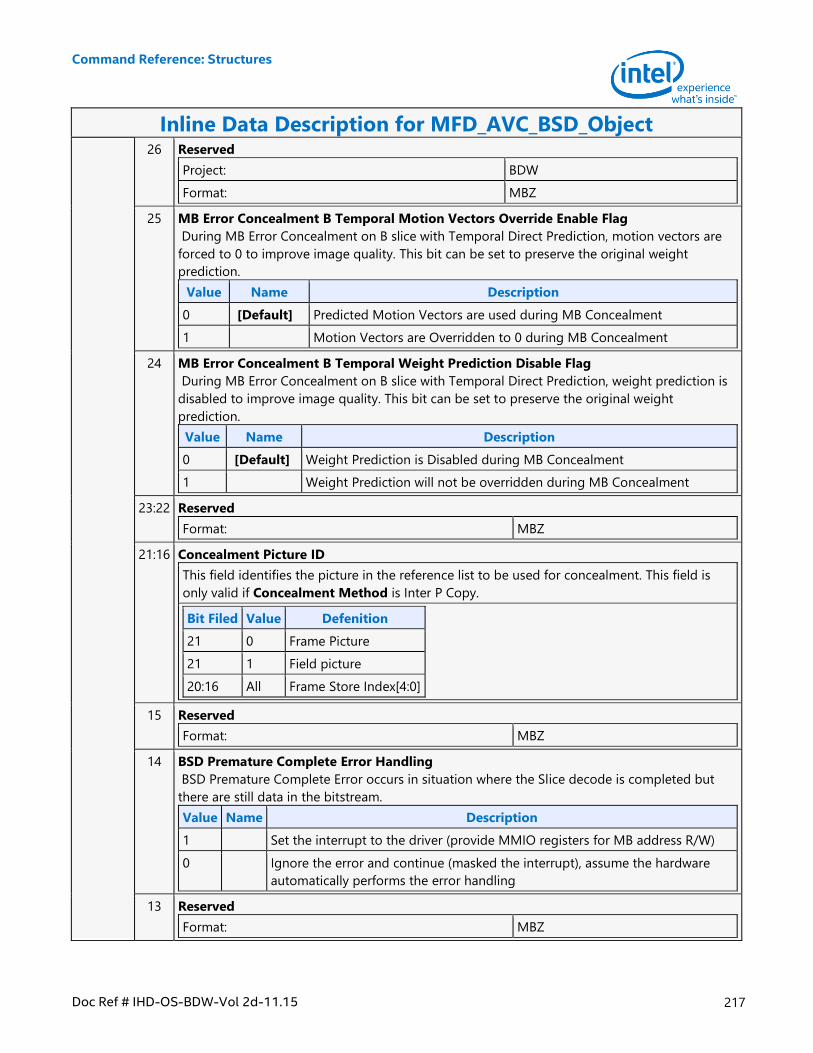
Command Reference: Structures
Doc Ref # IHD-OS-BDW-Vol 2d-11.15 217
Inline Data Description for MFD_AVC_BSD_Object 26 Reserved
Project: BDW
Format: MBZ
25 MB Error Concealment B Temporal Motion Vectors Override Enable Flag
During MB Error Concealment on B slice with Temporal Direct Prediction, motion vectors are
forced to 0 to improve image quality. This bit can be set to preserve the original weight
prediction.
Value Name Description
0 [Default] Predicted Motion Vectors are used during MB Concealment
1 Motion Vectors are Overridden to 0 during MB Concealment
24 MB Error Concealment B Temporal Weight Prediction Disable Flag
During MB Error Concealment on B slice with Temporal Direct Prediction, weight prediction is
disabled to improve image quality. This bit can be set to preserve the original weight
prediction.
Value Name Description
0 [Default] Weight Prediction is Disabled during MB Concealment
1 Weight Prediction will not be overridden during MB Concealment
23:22 Reserved
Format: MBZ
21:16 Concealment Picture ID
This field identifies the picture in the reference list to be used for concealment. This field is
only valid if Concealment Method is Inter P Copy.
Bit Filed Value Defenition
21 0 Frame Picture
21 1 Field picture
20:16 All Frame Store Index[4:0]
15 Reserved
Format: MBZ
14 BSD Premature Complete Error Handling
BSD Premature Complete Error occurs in situation where the Slice decode is completed but
there are still data in the bitstream.
Value Name Description
1 Set the interrupt to the driver (provide MMIO registers for MB address R/W)
0 Ignore the error and continue (masked the interrupt), assume the hardware
automatically performs the error handling
13 Reserved
Format: MBZ
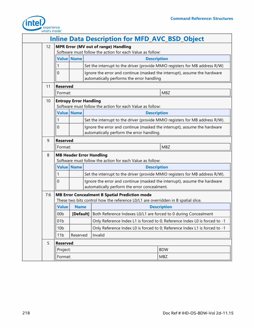
Command Reference: Structures
218 Doc Ref # IHD-OS-BDW-Vol 2d-11.15
Inline Data Description for MFD_AVC_BSD_Object 12 MPR Error (MV out of range) Handling
Software must follow the action for each Value as follow:
Value Name Description
1 Set the interrupt to the driver (provide MMIO registers for MB address R/W)
0 Ignore the error and continue (masked the interrupt), assume the hardware
automatically performs the error handling
11 Reserved
Format: MBZ
10 Entropy Error Handling
Software must follow the action for each Value as follow:
Value Name Description
1 Set the interrupt to the driver (provide MMIO registers for MB address R/W).
0 Ignore the error and continue (masked the interrupt), assume the hardware
automatically perform the error handling.
9 Reserved
Format: MBZ
8 MB Header Error Handling
Software must follow the action for each Value as follow:
Value Name Description
1 Set the interrupt to the driver (provide MMIO registers for MB address R/W).
0 Ignore the error and continue (masked the interrupt), assume the hardware
automatically perform the error concealment.
7:6 MB Error Concealment B Spatial Prediction mode
These two bits control how the reference L0/L1 are overridden in B spatial slice.
Value Name Description
00b [Default] Both Reference Indexes L0/L1 are forced to 0 during Concealment
01b Only Reference Index L1 is forced to 0; Reference Index L0 is forced to -1
10b Only Reference Index L0 is forced to 0; Reference Index L1 is forced to -1
11b Reserved Invalid
5 Reserved
Project: BDW
Format: MBZ
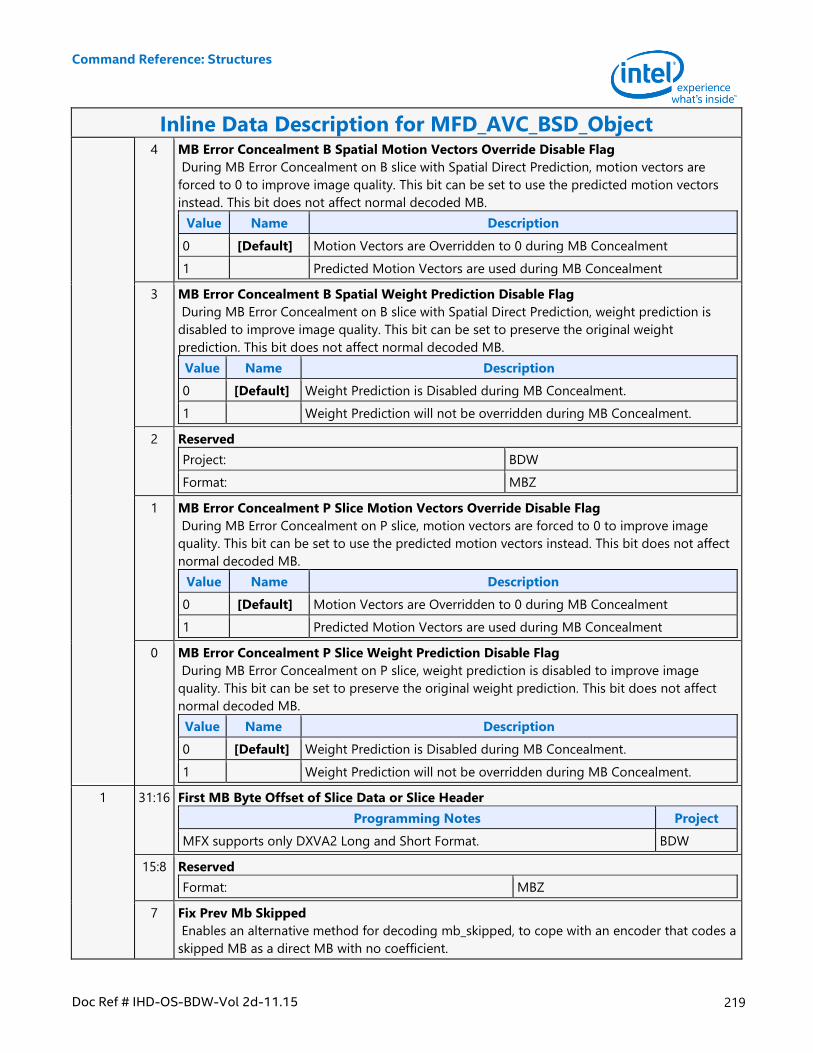
Command Reference: Structures
Doc Ref # IHD-OS-BDW-Vol 2d-11.15 219
Inline Data Description for MFD_AVC_BSD_Object 4 MB Error Concealment B Spatial Motion Vectors Override Disable Flag
During MB Error Concealment on B slice with Spatial Direct Prediction, motion vectors are
forced to 0 to improve image quality. This bit can be set to use the predicted motion vectors
instead. This bit does not affect normal decoded MB.
Value Name Description
0 [Default] Motion Vectors are Overridden to 0 during MB Concealment
1 Predicted Motion Vectors are used during MB Concealment
3 MB Error Concealment B Spatial Weight Prediction Disable Flag
During MB Error Concealment on B slice with Spatial Direct Prediction, weight prediction is
disabled to improve image quality. This bit can be set to preserve the original weight
prediction. This bit does not affect normal decoded MB.
Value Name Description
0 [Default] Weight Prediction is Disabled during MB Concealment.
1 Weight Prediction will not be overridden during MB Concealment.
2 Reserved
Project: BDW
Format: MBZ
1 MB Error Concealment P Slice Motion Vectors Override Disable Flag
During MB Error Concealment on P slice, motion vectors are forced to 0 to improve image
quality. This bit can be set to use the predicted motion vectors instead. This bit does not affect
normal decoded MB.
Value Name Description
0 [Default] Motion Vectors are Overridden to 0 during MB Concealment
1 Predicted Motion Vectors are used during MB Concealment
0 MB Error Concealment P Slice Weight Prediction Disable Flag
During MB Error Concealment on P slice, weight prediction is disabled to improve image
quality. This bit can be set to preserve the original weight prediction. This bit does not affect
normal decoded MB.
Value Name Description
0 [Default] Weight Prediction is Disabled during MB Concealment.
1 Weight Prediction will not be overridden during MB Concealment.
1 31:16 First MB Byte Offset of Slice Data or Slice Header
Programming Notes Project
MFX supports only DXVA2 Long and Short Format. BDW
15:8 Reserved
Format: MBZ
7 Fix Prev Mb Skipped
Enables an alternative method for decoding mb_skipped, to cope with an encoder that codes a
skipped MB as a direct MB with no coefficient.
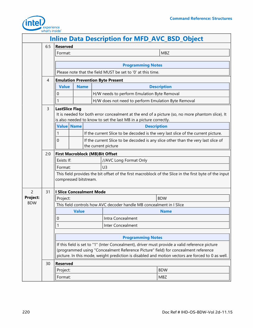
Command Reference: Structures
220 Doc Ref # IHD-OS-BDW-Vol 2d-11.15
Inline Data Description for MFD_AVC_BSD_Object 6:5 Reserved
Format: MBZ
Programming Notes
Please note that the field MUST be set to '0' at this time.
4 Emulation Prevention Byte Present
Value Name Description
0 H/W needs to perform Emulation Byte Removal
1 H/W does not need to perform Emulation Byte Removal
3 LastSlice Flag
It is needed for both error concealment at the end of a picture (so, no more phantom slice). It
is also needed to know to set the last MB in a picture correctly.
Value Name Description
1 If the current Slice to be decoded is the very last slice of the current picture.
0 If the current Slice to be decoded is any slice other than the very last slice of
the current picture
2:0 First Macroblock (MB)Bit Offset
Exists If: //AVC Long Format Only
Format: U3
This field provides the bit offset of the first macroblock of the Slice in the first byte of the input
compressed bitstream.
2
Project:
BDW
31 I Slice Concealment Mode
Project: BDW
This field controls how AVC decoder handle MB concealment in I Slice
Value Name
0 Intra Concealment
1 Inter Concealment
Programming Notes
If this field is set to "1" (Inter Concealment), driver must provide a valid reference picture
(programmed using "Concealment Reference Picture" field) for concealment reference
picture. In this mode, weight prediction is disabled and motion vectors are forced to 0 as well.
30 Reserved
Project: BDW
Format: MBZ
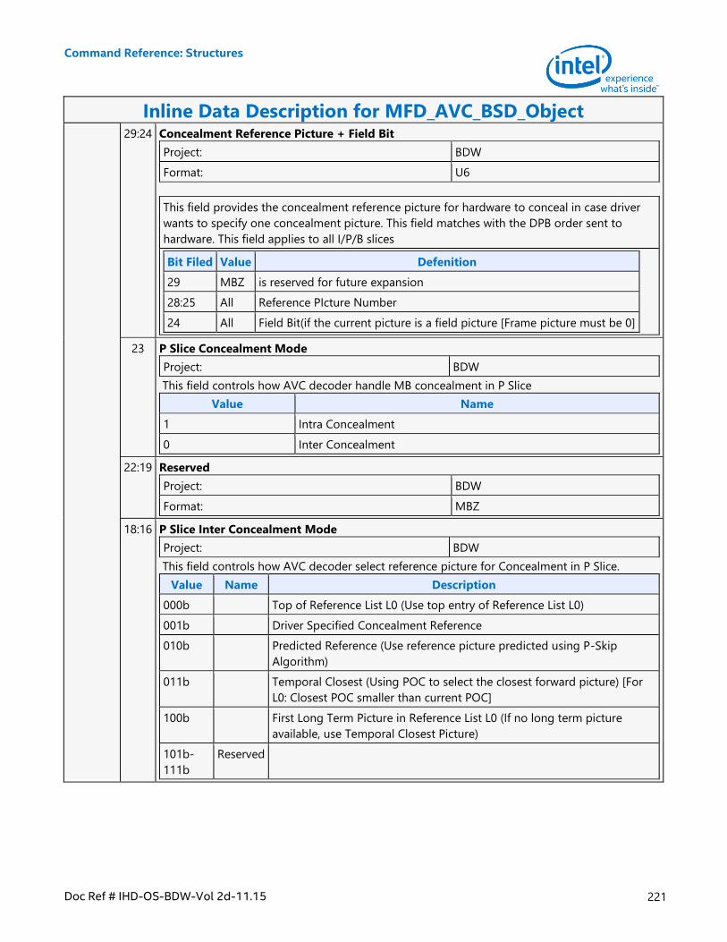
Command Reference: Structures
Doc Ref # IHD-OS-BDW-Vol 2d-11.15 221
Inline Data Description for MFD_AVC_BSD_Object 29:24 Concealment Reference Picture + Field Bit
Project: BDW
Format: U6
This field provides the concealment reference picture for hardware to conceal in case driver
wants to specify one concealment picture. This field matches with the DPB order sent to
hardware. This field applies to all I/P/B slices
Bit Filed Value Defenition
29 MBZ is reserved for future expansion
28:25 All Reference PIcture Number
24 All Field Bit(if the current picture is a field picture [Frame picture must be 0]
23 P Slice Concealment Mode
Project: BDW
This field controls how AVC decoder handle MB concealment in P Slice
Value Name
1 Intra Concealment
0 Inter Concealment
22:19 Reserved
Project: BDW
Format: MBZ
18:16 P Slice Inter Concealment Mode
Project: BDW
This field controls how AVC decoder select reference picture for Concealment in P Slice.
Value Name Description
000b Top of Reference List L0 (Use top entry of Reference List L0)
001b Driver Specified Concealment Reference
010b Predicted Reference (Use reference picture predicted using P-Skip
Algorithm)
011b Temporal Closest (Using POC to select the closest forward picture) [For
L0: Closest POC smaller than current POC]
100b First Long Term Picture in Reference List L0 (If no long term picture
available, use Temporal Closest Picture)
101b-
111b
Reserved
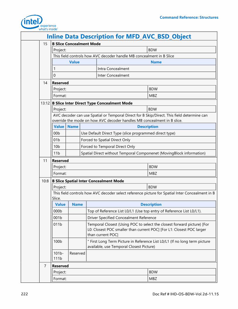
Command Reference: Structures
222 Doc Ref # IHD-OS-BDW-Vol 2d-11.15
Inline Data Description for MFD_AVC_BSD_Object 15 B Slice Concealment Mode
Project: BDW
This field controls how AVC decoder handle MB concealment in B Slice
Value Name
1 Intra Concealment
0 Inter Concealment
14 Reserved
Project: BDW
Format: MBZ
13:12 B Slice Inter Direct Type Concealment Mode
Project: BDW
AVC decoder can use Spatial or Temporal Direct for B Skip/Direct. This field determine can
override the mode on how AVC decoder handles MB concealment in B slice.
Value Name Description
00b Use Default Direct Type (slice programmed direct type)
01b Forced to Spatial Direct Only
10b Forced to Temporal Direct Only
11b Spatial Direct without Temporal Componenet (MovingBlock information)
11 Reserved
Project: BDW
Format: MBZ
10:8 B Slice Spatial Inter Concealment Mode
Project: BDW
This field controls how AVC decoder select reference picture for Spatial Inter Concealment in B
Slice.
Value Name Description
000b Top of Reference List L0/L1 (Use top entry of Reference List L0/L1).
001b Driver Specified Concealment Reference
011b Temporal Closest (Using POC to select the closest forward picture) [For
L0: Closest POC smaller than current POC] [For L1: Closest POC larger
than current POC]
100b " First Long Term Picture in Reference List L0/L1 (If no long term picture
available, use Temporal Closest Picture)
101b-
111b
Reserved
7 Reserved
Project: BDW
Format: MBZ
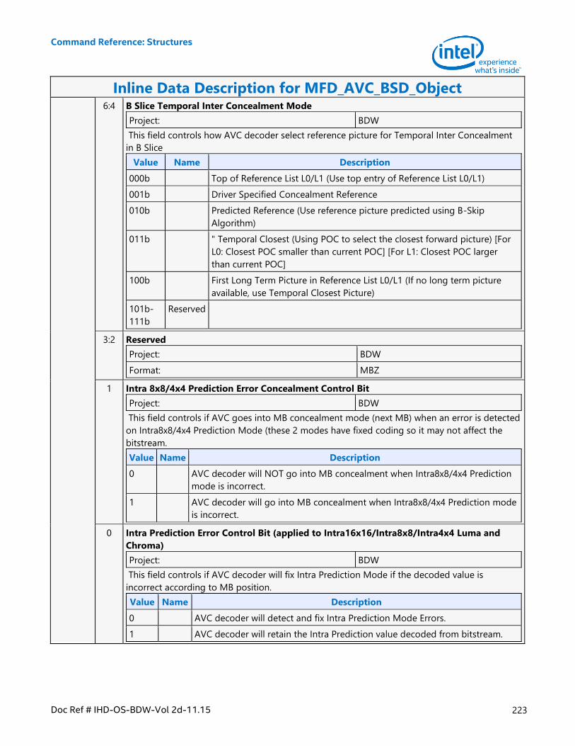
Command Reference: Structures
Doc Ref # IHD-OS-BDW-Vol 2d-11.15 223
Inline Data Description for MFD_AVC_BSD_Object 6:4 B Slice Temporal Inter Concealment Mode
Project: BDW
This field controls how AVC decoder select reference picture for Temporal Inter Concealment
in B Slice
Value Name Description
000b Top of Reference List L0/L1 (Use top entry of Reference List L0/L1)
001b Driver Specified Concealment Reference
010b Predicted Reference (Use reference picture predicted using B-Skip
Algorithm)
011b " Temporal Closest (Using POC to select the closest forward picture) [For
L0: Closest POC smaller than current POC] [For L1: Closest POC larger
than current POC]
100b First Long Term Picture in Reference List L0/L1 (If no long term picture
available, use Temporal Closest Picture)
101b-
111b
Reserved
3:2 Reserved
Project: BDW
Format: MBZ
1 Intra 8x8/4x4 Prediction Error Concealment Control Bit
Project: BDW
This field controls if AVC goes into MB concealment mode (next MB) when an error is detected
on Intra8x8/4x4 Prediction Mode (these 2 modes have fixed coding so it may not affect the
bitstream.
Value Name Description
0 AVC decoder will NOT go into MB concealment when Intra8x8/4x4 Prediction
mode is incorrect.
1 AVC decoder will go into MB concealment when Intra8x8/4x4 Prediction mode
is incorrect.
0 Intra Prediction Error Control Bit (applied to Intra16x16/Intra8x8/Intra4x4 Luma and
Chroma)
Project: BDW
This field controls if AVC decoder will fix Intra Prediction Mode if the decoded value is
incorrect according to MB position.
Value Name Description
0 AVC decoder will detect and fix Intra Prediction Mode Errors.
1 AVC decoder will retain the Intra Prediction value decoded from bitstream.
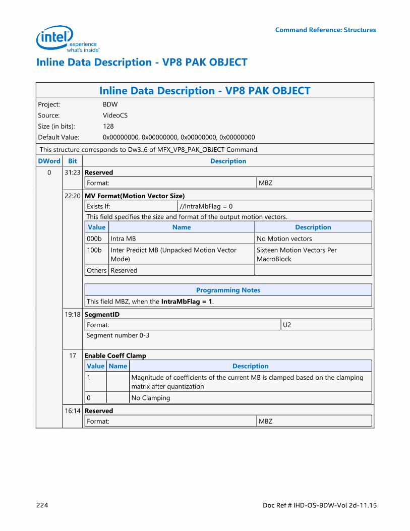
Command Reference: Structures
224 Doc Ref # IHD-OS-BDW-Vol 2d-11.15
Inline Data Description - VP8 PAK OBJECT
Inline Data Description - VP8 PAK OBJECT Project: BDW
Source: VideoCS
Size (in bits): 128
Default Value: 0x00000000, 0x00000000, 0x00000000, 0x00000000
This structure corresponds to Dw3..6 of MFX_VP8_PAK_OBJECT Command.
DWord Bit Description
0 31:23 Reserved
Format: MBZ
22:20 MV Format(Motion Vector Size)
Exists If: //IntraMbFlag = 0
This field specifies the size and format of the output motion vectors.
Value Name Description
000b Intra MB No Motion vectors
100b Inter Predict MB (Unpacked Motion Vector
Mode)
Sixteen Motion Vectors Per
MacroBlock
Others Reserved
Programming Notes
This field MBZ, when the IntraMbFlag = 1.
19:18 SegmentID
Format: U2
Segment number 0-3
17 Enable Coeff Clamp
Value Name Description
1 Magnitude of coefficients of the current MB is clamped based on the clamping
matrix after quantization
0 No Clamping
16:14 Reserved
Format: MBZ
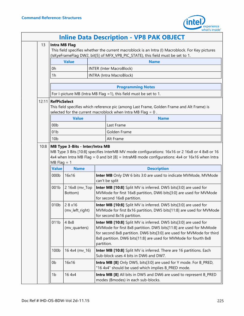
Command Reference: Structures
Doc Ref # IHD-OS-BDW-Vol 2d-11.15 225
Inline Data Description - VP8 PAK OBJECT 13 Intra MB Flag
This field specifies whether the current macroblock is an Intra (I) Macroblock. For Key pictures
(IsKyeFrameFlag DW2, bit[5] of MFX_VP8_PIC_STATE), this field must be set to 1.
Value Name
0h INTER (Inter MacroBlock)
1h INTRA (Intra MacroBlock)
Programming Notes
For I-picture MB (Intra MB Flag =1), this field must be set to 1.
12:11 RefPicSelect
This field specifies which reference pic (among Last Frame, Golden Frame and Alt Frame) is
selected for the current macroblock when Intra MB Flag = 0 .
Value Name
00b Last Frame
01b Golden Frame
10b Alt Frame
10:8 MB Type 3-Bits - Inter/Intra MB
MB Type 3 Bits [10:8] specifies InterMB MV mode configurations: 16x16 or 2 16x8 or 4 8x8 or 16
4x4 when Intra MB Flag = 0 and bit [8] = IntraMB mode configurations: 4x4 or 16x16 when Intra
MB Flag = 1
Value Name Description
000b 16x16 Inter MB Only DW 6 bits 3:0 are used to indicate MVMode, MVMode
can't be split
001b 2 16x8 (mv_Top
Bottom)
Inter MB [10:8] Split MV is inferred. DW5 bits[3:0] are used for
MVMode for first 16x8 partition, DW6 bits[3:0] are used for MVMode
for second 16x8 partition.
010b 2 8 x16
(mv_left_right)
Inter MB [10:8] Split MV is inferred. DW5 bits[3:0] are used for
MVMode for first 8x16 partition, DW5 bits[11:8] are used for MVMode
for second 8x16 partition.
011b 4 8x8
(mv_quarters)
Inter MB [10:8] Split MV is inferred. DW5 bits[3:0] are used for
MVMode for first 8x8 partition. DW5 bits[11:8] are used for MvMode
for second 8x8 partition. DW6 bits[3:0] are used for MVMode for third
8x8 partition. DW6 bits[11:8] are used for MVMode for fourth 8x8
partition.
100b 16 4x4 (mv_16) Inter MB [10:8] Split MV is inferred. There are 16 partitions. Each
Sub-block uses 4 bits in DW6 and DW7.
0b 16x16 Intra MB [8] Only DW5, bits[3:0] are used for Y mode. For B_PRED,
"16 4x4" should be used which implies B_PRED mode.
1b 16 4x4 Intra MB [8] All bits in DW5 and DW6 are used to represent B_PRED
modes (Bmodes) in each sub-blocks.
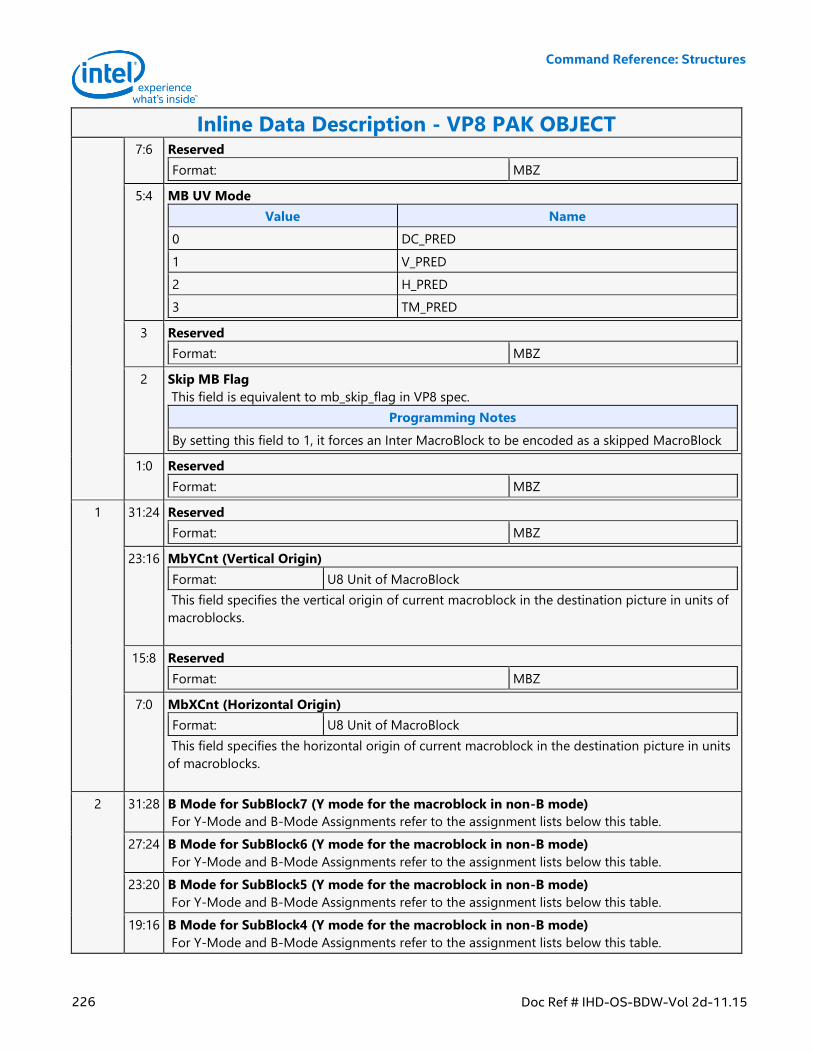
Command Reference: Structures
226 Doc Ref # IHD-OS-BDW-Vol 2d-11.15
Inline Data Description - VP8 PAK OBJECT 7:6 Reserved
Format: MBZ
5:4 MB UV Mode
Value Name
0 DC_PRED
1 V_PRED
2 H_PRED
3 TM_PRED
3 Reserved
Format: MBZ
2 Skip MB Flag
This field is equivalent to mb_skip_flag in VP8 spec.
Programming Notes
By setting this field to 1, it forces an Inter MacroBlock to be encoded as a skipped MacroBlock
1:0 Reserved
Format: MBZ
1 31:24 Reserved
Format: MBZ
23:16 MbYCnt (Vertical Origin)
Format: U8 Unit of MacroBlock
This field specifies the vertical origin of current macroblock in the destination picture in units of
macroblocks.
15:8 Reserved
Format: MBZ
7:0 MbXCnt (Horizontal Origin)
Format: U8 Unit of MacroBlock
This field specifies the horizontal origin of current macroblock in the destination picture in units
of macroblocks.
2 31:28 B Mode for SubBlock7 (Y mode for the macroblock in non-B mode)
For Y-Mode and B-Mode Assignments refer to the assignment lists below this table.
27:24 B Mode for SubBlock6 (Y mode for the macroblock in non-B mode)
For Y-Mode and B-Mode Assignments refer to the assignment lists below this table.
23:20 B Mode for SubBlock5 (Y mode for the macroblock in non-B mode)
For Y-Mode and B-Mode Assignments refer to the assignment lists below this table.
19:16 B Mode for SubBlock4 (Y mode for the macroblock in non-B mode)
For Y-Mode and B-Mode Assignments refer to the assignment lists below this table.
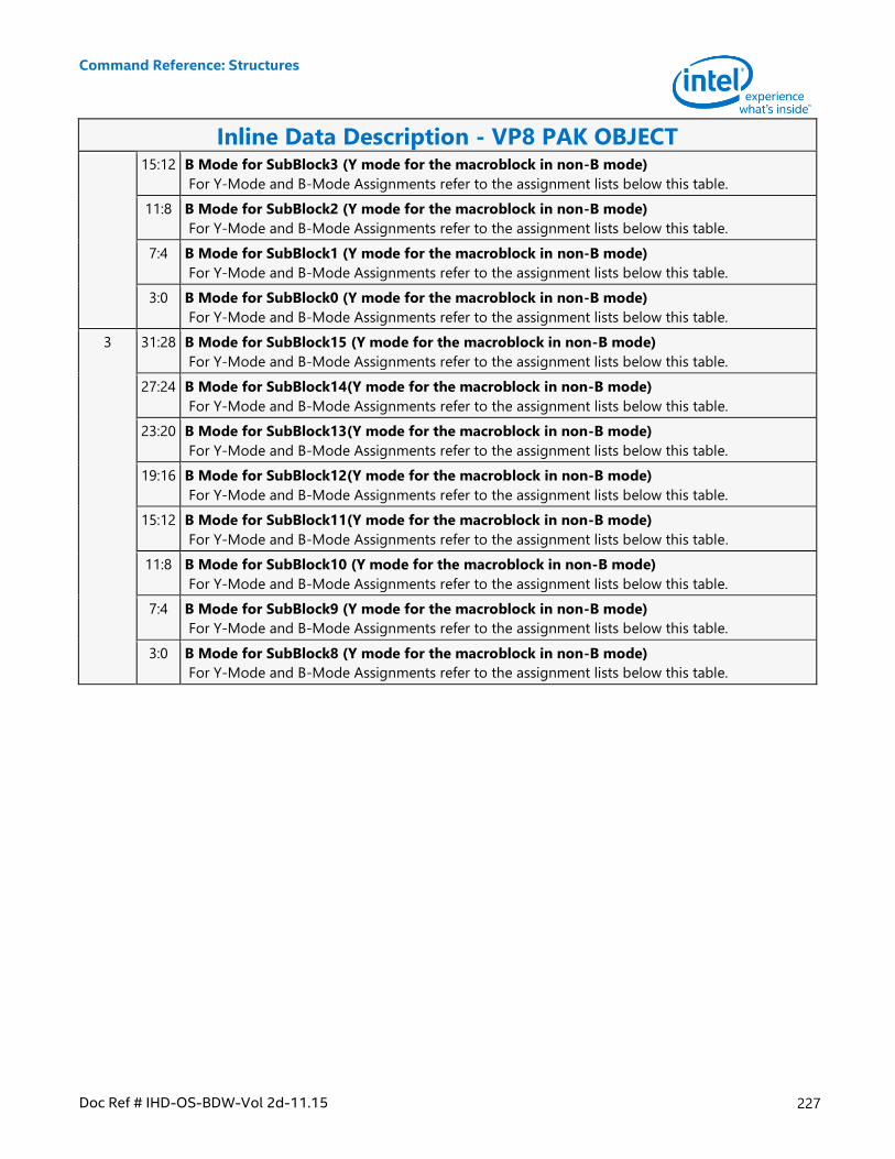
Command Reference: Structures
Doc Ref # IHD-OS-BDW-Vol 2d-11.15 227
Inline Data Description - VP8 PAK OBJECT 15:12 B Mode for SubBlock3 (Y mode for the macroblock in non-B mode)
For Y-Mode and B-Mode Assignments refer to the assignment lists below this table.
11:8 B Mode for SubBlock2 (Y mode for the macroblock in non-B mode)
For Y-Mode and B-Mode Assignments refer to the assignment lists below this table.
7:4 B Mode for SubBlock1 (Y mode for the macroblock in non-B mode)
For Y-Mode and B-Mode Assignments refer to the assignment lists below this table.
3:0 B Mode for SubBlock0 (Y mode for the macroblock in non-B mode)
For Y-Mode and B-Mode Assignments refer to the assignment lists below this table.
3 31:28 B Mode for SubBlock15 (Y mode for the macroblock in non-B mode)
For Y-Mode and B-Mode Assignments refer to the assignment lists below this table.
27:24 B Mode for SubBlock14(Y mode for the macroblock in non-B mode)
For Y-Mode and B-Mode Assignments refer to the assignment lists below this table.
23:20 B Mode for SubBlock13(Y mode for the macroblock in non-B mode)
For Y-Mode and B-Mode Assignments refer to the assignment lists below this table.
19:16 B Mode for SubBlock12(Y mode for the macroblock in non-B mode)
For Y-Mode and B-Mode Assignments refer to the assignment lists below this table.
15:12 B Mode for SubBlock11(Y mode for the macroblock in non-B mode)
For Y-Mode and B-Mode Assignments refer to the assignment lists below this table.
11:8 B Mode for SubBlock10 (Y mode for the macroblock in non-B mode)
For Y-Mode and B-Mode Assignments refer to the assignment lists below this table.
7:4 B Mode for SubBlock9 (Y mode for the macroblock in non-B mode)
For Y-Mode and B-Mode Assignments refer to the assignment lists below this table.
3:0 B Mode for SubBlock8 (Y mode for the macroblock in non-B mode)
For Y-Mode and B-Mode Assignments refer to the assignment lists below this table.
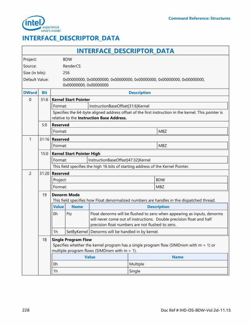
Command Reference: Structures
228 Doc Ref # IHD-OS-BDW-Vol 2d-11.15
INTERFACE_DESCRIPTOR_DATA
INTERFACE_DESCRIPTOR_DATA Project: BDW
Source: RenderCS
Size (in bits): 256
Default Value: 0x00000000, 0x00000000, 0x00000000, 0x00000000, 0x00000000, 0x00000000,
0x00000000, 0x00000000
DWord Bit Description
0 31:6 Kernel Start Pointer
Format: InstructionBaseOffset[31:6]Kernel
Specifies the 64-byte aligned address offset of the first instruction in the kernel. This pointer is
relative to the Instruction Base Address.
5:0 Reserved
Format: MBZ
1 31:16 Reserved
Format: MBZ
15:0 Kernel Start Pointer High
Format: InstructionBaseOffset[47:32]Kernel
This field specifies the high 16 bits of starting address of the Kernel Pointer.
2 31:20 Reserved
Project: BDW
Format: MBZ
19 Denorm Mode
This field specifies how Float denormalized numbers are handles in the dispatched thread.
Value Name Description
0h Ftz Float denorms will be flushed to zero when appearing as inputs, denorms
will never come out of instructions. Double precision float and half
precision float numbers are not flushed to zero.
1h SetByKernel Denorms will be handled in by kernel.
18 Single Program Flow
Specifies whether the kernel program has a single program flow (SIMDnxm with m = 1) or
multiple program flows (SIMDnxm with m > 1).
Value Name
0h Multiple
1h Single
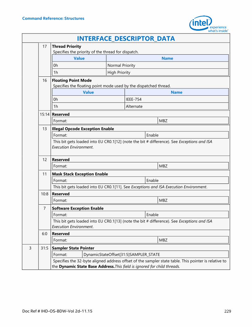
Command Reference: Structures
Doc Ref # IHD-OS-BDW-Vol 2d-11.15 229
INTERFACE_DESCRIPTOR_DATA 17 Thread Priority
Specifies the priority of the thread for dispatch.
Value Name
0h Normal Priority
1h High Priority
16 Floating Point Mode
Specifies the floating point mode used by the dispatched thread.
Value Name
0h IEEE-754
1h Alternate
15:14 Reserved
Format: MBZ
13 Illegal Opcode Exception Enable
Format: Enable
This bit gets loaded into EU CR0.1[12] (note the bit # difference). See Exceptions and ISA
Execution Environment.
12 Reserved
Format: MBZ
11 Mask Stack Exception Enable
Format: Enable
This bit gets loaded into EU CR0.1[11]. See Exceptions and ISA Execution Environment.
10:8 Reserved
Format: MBZ
7 Software Exception Enable
Format: Enable
This bit gets loaded into EU CR0.1[13] (note the bit # difference). See Exceptions and ISA
Execution Environment.
6:0 Reserved
Format: MBZ
3 31:5 Sampler State Pointer
Format: DynamicStateOffset[31:5]SAMPLER_STATE
Specifies the 32-byte aligned address offset of the sampler state table. This pointer is relative to
the Dynamic State Base Address.This field is ignored for child threads.
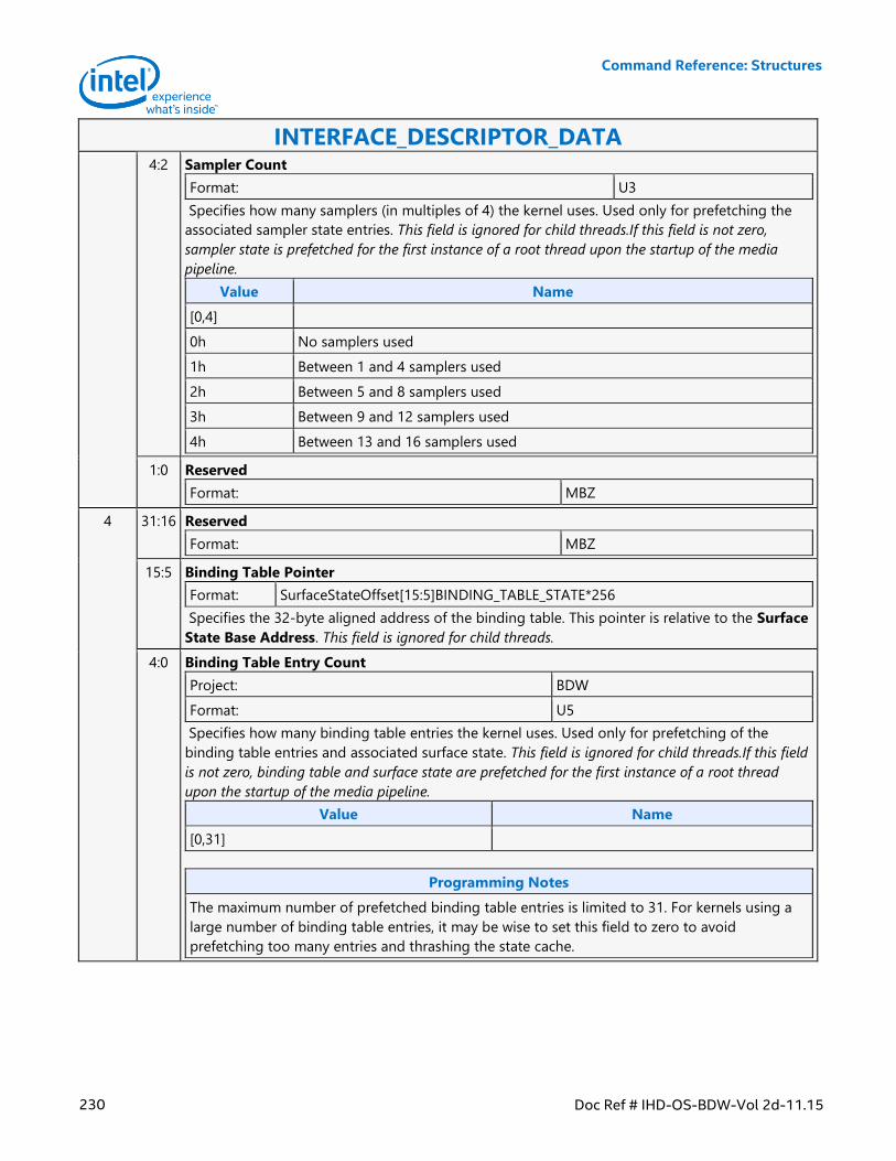
Command Reference: Structures
230 Doc Ref # IHD-OS-BDW-Vol 2d-11.15
INTERFACE_DESCRIPTOR_DATA 4:2 Sampler Count
Format: U3
Specifies how many samplers (in multiples of 4) the kernel uses. Used only for prefetching the
associated sampler state entries. This field is ignored for child threads.If this field is not zero,
sampler state is prefetched for the first instance of a root thread upon the startup of the media
pipeline.
Value Name
[0,4]
0h No samplers used
1h Between 1 and 4 samplers used
2h Between 5 and 8 samplers used
3h Between 9 and 12 samplers used
4h Between 13 and 16 samplers used
1:0 Reserved
Format: MBZ
4 31:16 Reserved
Format: MBZ
15:5 Binding Table Pointer
Format: SurfaceStateOffset[15:5]BINDING_TABLE_STATE*256
Specifies the 32-byte aligned address of the binding table. This pointer is relative to the Surface
State Base Address. This field is ignored for child threads.
4:0 Binding Table Entry Count
Project: BDW
Format: U5
Specifies how many binding table entries the kernel uses. Used only for prefetching of the
binding table entries and associated surface state. This field is ignored for child threads.If this field
is not zero, binding table and surface state are prefetched for the first instance of a root thread
upon the startup of the media pipeline.
Value Name
[0,31]
Programming Notes
The maximum number of prefetched binding table entries is limited to 31. For kernels using a
large number of binding table entries, it may be wise to set this field to zero to avoid
prefetching too many entries and thrashing the state cache.
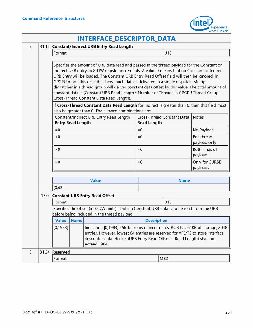
Command Reference: Structures
Doc Ref # IHD-OS-BDW-Vol 2d-11.15 231
INTERFACE_DESCRIPTOR_DATA 5 31:16 Constant/Indirect URB Entry Read Length
Format: U16
Specifies the amount of URB data read and passed in the thread payload for the Constant or
Indirect URB entry, in 8-DW register increments. A value 0 means that no Constant or Indirect
URB Entry will be loaded. The Constant URB Entry Read Offset field will then be ignored. In
GPGPU mode this describes how much data is delivered in a single dispatch. Multiple
dispatches in a thread group will deliver constant data offset by this value. The total amount of
constant data is (Constant URB Read Length * Number of Threads in GPGPU Thread Group +
Cross-Thread Constant Data Read Length).
If Cross-Thread Constant Data Read Length for Indirect is greater than 0, then this field must
also be greater than 0. The allowed combinations are:
Constant/Indirect URB Entry Read Length
Entry Read Length
Cross-Thread Constant Data
Read Length
Notes
=0 =0 No Payload
>0 =0 Per-thread
payload only
>0 >0 Both kinds of
payload
=0 >0 Only for CURBE
payloads
Value Name
[0,63]
15:0 Constant URB Entry Read Offset
Format: U16
Specifies the offset (in 8-DW units) at which Constant URB data is to be read from the URB
before being included in the thread payload.
Value Name Description
[0,1983] Indicating [0,1983] 256-bit register increments. ROB has 64KB of storage; 2048
entries. However, lowest 64 entries are reserved for VFE/TS to store interface
descriptor data. Hence, (URB Entry Read Offset + Read Length) shall not
exceed 1984.
6 31:24 Reserved
Format: MBZ
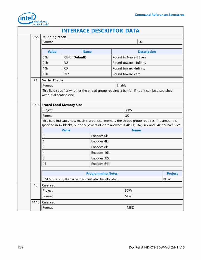
Command Reference: Structures
232 Doc Ref # IHD-OS-BDW-Vol 2d-11.15
INTERFACE_DESCRIPTOR_DATA 23:22 Rounding Mode
Format: U2
Value Name Description
00b RTNE [Default] Round to Nearest Even
01b RU Round toward +Infinity
10b RD Round toward -Infinity
11b RTZ Round toward Zero
21 Barrier Enable
Format: Enable
This field specifies whether the thread group requires a barrier. If not, it can be dispatched
without allocating one.
20:16 Shared Local Memory Size
Project: BDW
Format: U5
This field indicates how much shared local memory the thread group requires. The amount is
specified in 4k blocks, but only powers of 2 are allowed: 0, 4k, 8k, 16k, 32k and 64k per half-slice.
Value Name
0 Encodes 0k
1 Encodes 4k
2 Encodes 8k
4 Encodes 16k
8 Encodes 32k
16 Encodes 64k
Programming Notes Project
If SLMSize > 0, then a barrier must also be allocated. BDW
15 Reserved
Project: BDW
Format: MBZ
14:10 Reserved
Format: MBZ
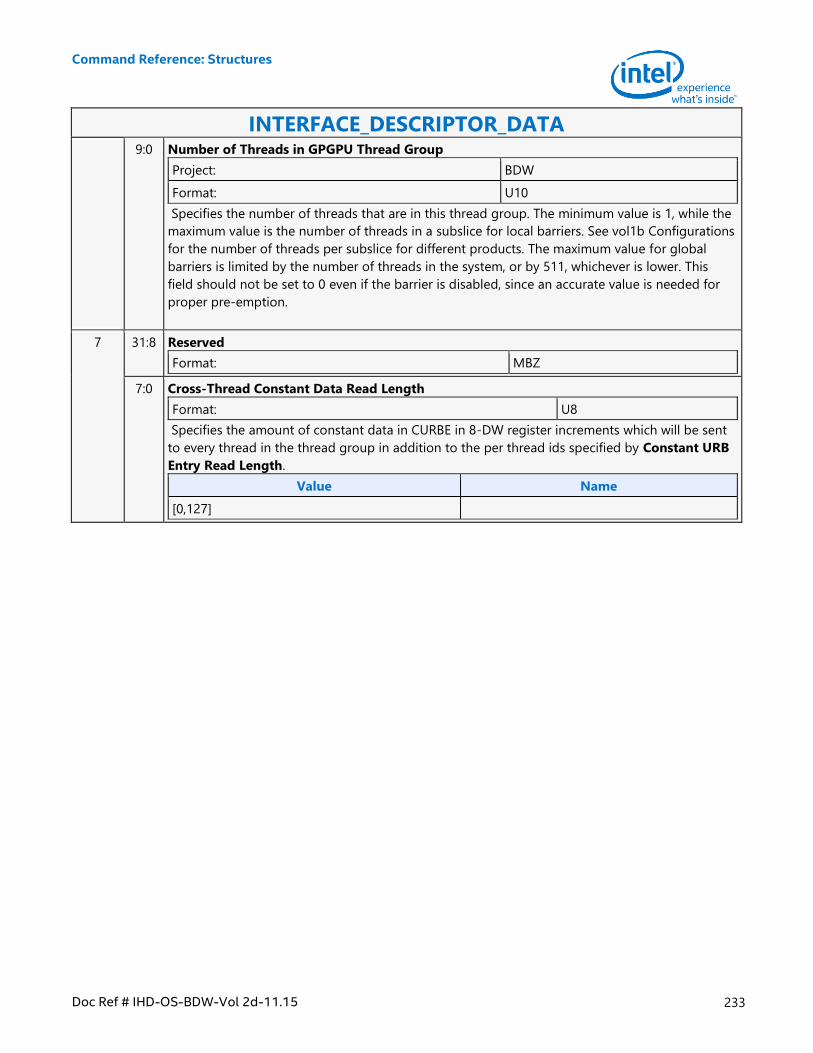
Command Reference: Structures
Doc Ref # IHD-OS-BDW-Vol 2d-11.15 233
INTERFACE_DESCRIPTOR_DATA 9:0 Number of Threads in GPGPU Thread Group
Project: BDW
Format: U10
Specifies the number of threads that are in this thread group. The minimum value is 1, while the
maximum value is the number of threads in a subslice for local barriers. See vol1b Configurations
for the number of threads per subslice for different products. The maximum value for global
barriers is limited by the number of threads in the system, or by 511, whichever is lower. This
field should not be set to 0 even if the barrier is disabled, since an accurate value is needed for
proper pre-emption.
7 31:8 Reserved
Format: MBZ
7:0 Cross-Thread Constant Data Read Length
Format: U8
Specifies the amount of constant data in CURBE in 8-DW register increments which will be sent
to every thread in the thread group in addition to the per thread ids specified by Constant URB
Entry Read Length.
Value Name
[0,127]
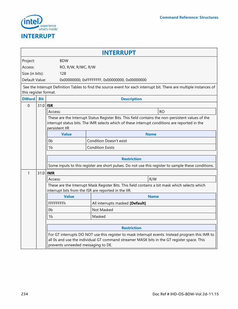
Command Reference: Structures
234 Doc Ref # IHD-OS-BDW-Vol 2d-11.15
INTERRUPT
INTERRUPT Project: BDW
Access: RO, R/W, R/WC, R/W
Size (in bits): 128
Default Value: 0x00000000, 0xFFFFFFFF, 0x00000000, 0x00000000
See the Interrupt Definition Tables to find the source event for each interrupt bit. There are multiple instances of
this register format.
DWord Bit Description
0 31:0 ISR
Access: RO
These are the Interrupt Status Register Bits. This field contains the non-persistent values of the
interrupt status bits. The IMR selects which of these interrupt conditions are reported in the
persistent IIR
Value Name
0b Condition Doesn't exist
1b Condition Exists
Restriction
Some inputs to this register are short pulses. Do not use this register to sample these conditions.
1 31:0 IMR
Access: R/W
These are the Interrupt Mask Register Bits. This field contains a bit mask which selects which
interrupt bits from the ISR are reported in the IIR.
Value Name
FFFFFFFFh All interrupts masked [Default]
0b Not Masked
1b Masked
Restriction
For GT interrupts DO NOT use this register to mask interrupt events. Instead program this IMR to
all 0s and use the individual GT command streamer MASK bits in the GT register space. This
prevents unneeded messaging to DE.
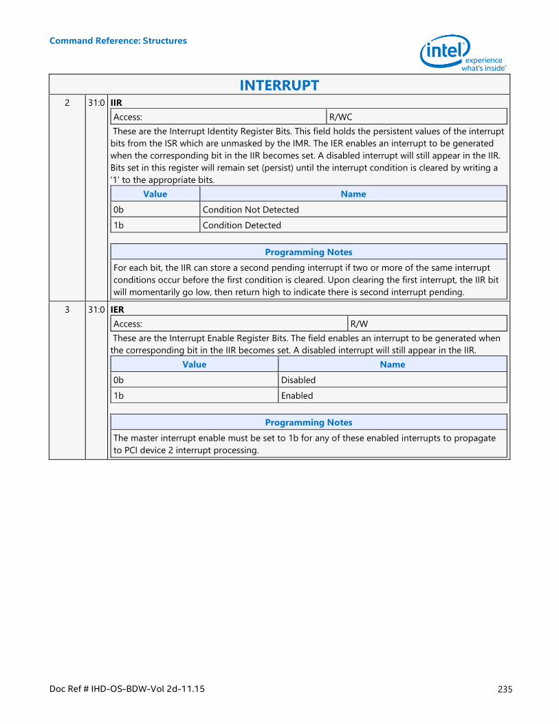
Command Reference: Structures
Doc Ref # IHD-OS-BDW-Vol 2d-11.15 235
INTERRUPT 2 31:0 IIR
Access: R/WC
These are the Interrupt Identity Register Bits. This field holds the persistent values of the interrupt
bits from the ISR which are unmasked by the IMR. The IER enables an interrupt to be generated
when the corresponding bit in the IIR becomes set. A disabled interrupt will still appear in the IIR.
Bits set in this register will remain set (persist) until the interrupt condition is cleared by writing a
'1' to the appropriate bits.
Value Name
0b Condition Not Detected
1b Condition Detected
Programming Notes
For each bit, the IIR can store a second pending interrupt if two or more of the same interrupt
conditions occur before the first condition is cleared. Upon clearing the first interrupt, the IIR bit
will momentarily go low, then return high to indicate there is second interrupt pending.
3 31:0 IER
Access: R/W
These are the Interrupt Enable Register Bits. The field enables an interrupt to be generated when
the corresponding bit in the IIR becomes set. A disabled interrupt will still appear in the IIR.
Value Name
0b Disabled
1b Enabled
Programming Notes
The master interrupt enable must be set to 1b for any of these enabled interrupts to propagate
to PCI device 2 interrupt processing.
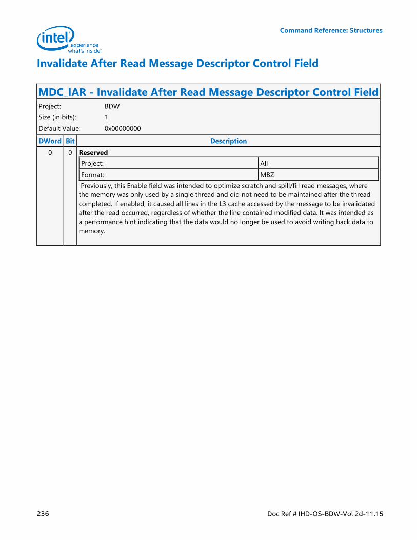
Command Reference: Structures
236 Doc Ref # IHD-OS-BDW-Vol 2d-11.15
Invalidate After Read Message Descriptor Control Field
MDC_IAR - Invalidate After Read Message Descriptor Control Field Project: BDW
Size (in bits): 1
Default Value: 0x00000000
DWord Bit Description
0 0 Reserved
Project: All
Format: MBZ
Previously, this Enable field was intended to optimize scratch and spill/fill read messages, where
the memory was only used by a single thread and did not need to be maintained after the thread
completed. If enabled, it caused all lines in the L3 cache accessed by the message to be invalidated
after the read occurred, regardless of whether the line contained modified data. It was intended as
a performance hint indicating that the data would no longer be used to avoid writing back data to
memory.
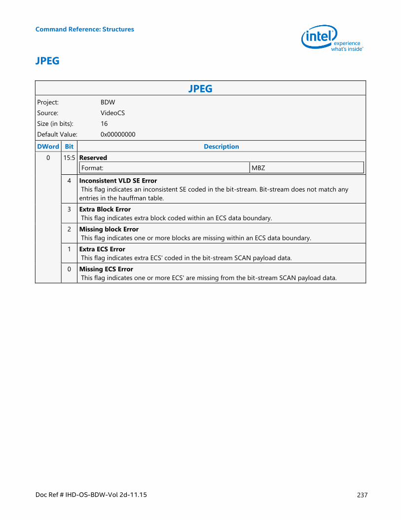
Command Reference: Structures
Doc Ref # IHD-OS-BDW-Vol 2d-11.15 237
JPEG
JPEG Project: BDW
Source: VideoCS
Size (in bits): 16
Default Value: 0x00000000
DWord Bit Description
0 15:5 Reserved
Format: MBZ
4 Inconsistent VLD SE Error
This flag indicates an inconsistent SE coded in the bit-stream. Bit-stream does not match any
entries in the hauffman table.
3 Extra Block Error
This flag indicates extra block coded within an ECS data boundary.
2 Missing block Error
This flag indicates one or more blocks are missing within an ECS data boundary.
1 Extra ECS Error
This flag indicates extra ECS' coded in the bit-stream SCAN payload data.
0 Missing ECS Error
This flag indicates one or more ECS' are missing from the bit-stream SCAN payload data.
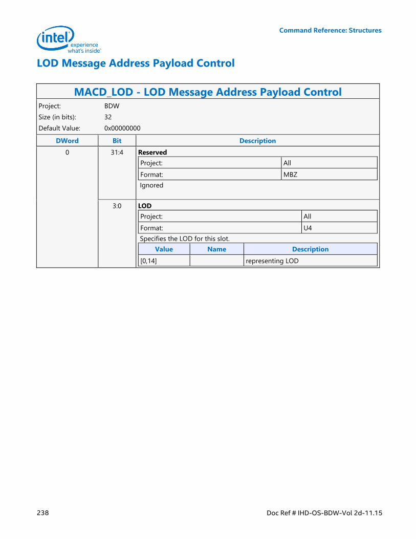
Command Reference: Structures
238 Doc Ref # IHD-OS-BDW-Vol 2d-11.15
LOD Message Address Payload Control
MACD_LOD - LOD Message Address Payload Control Project: BDW
Size (in bits): 32
Default Value: 0x00000000
DWord Bit Description
0 31:4 Reserved
Project: All
Format: MBZ
Ignored
3:0 LOD
Project: All
Format: U4
Specifies the LOD for this slot.
Value Name Description
[0,14] representing LOD
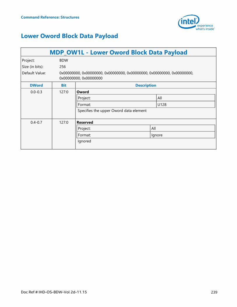
Command Reference: Structures
Doc Ref # IHD-OS-BDW-Vol 2d-11.15 239
Lower Oword Block Data Payload
MDP_OW1L - Lower Oword Block Data Payload Project: BDW
Size (in bits): 256
Default Value: 0x00000000, 0x00000000, 0x00000000, 0x00000000, 0x00000000, 0x00000000,
0x00000000, 0x00000000
DWord Bit Description
0.0-0.3 127:0 Oword
Project: All
Format: U128
Specifies the upper Oword data element
0.4-0.7 127:0 Reserved
Project: All
Format: Ignore
Ignored
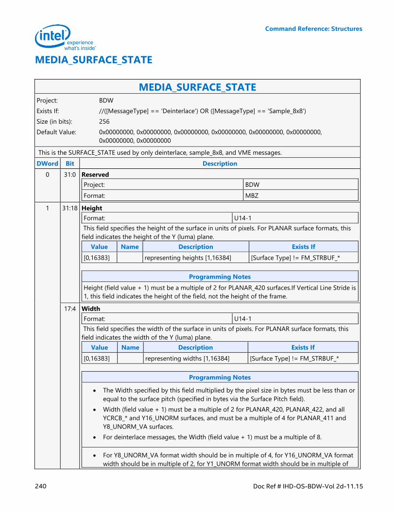
Command Reference: Structures
240 Doc Ref # IHD-OS-BDW-Vol 2d-11.15
MEDIA_SURFACE_STATE
MEDIA_SURFACE_STATE Project: BDW
Exists If: //([MessageType] == 'Deinterlace') OR ([MessageType] == 'Sample_8x8')
Size (in bits): 256
Default Value: 0x00000000, 0x00000000, 0x00000000, 0x00000000, 0x00000000, 0x00000000,
0x00000000, 0x00000000
This is the SURFACE_STATE used by only deinterlace, sample_8x8, and VME messages.
DWord Bit Description
0 31:0 Reserved
Project: BDW
Format: MBZ
1 31:18 Height
Format: U14-1
This field specifies the height of the surface in units of pixels. For PLANAR surface formats, this
field indicates the height of the Y (luma) plane.
Value Name Description Exists If
[0,16383] representing heights [1,16384] [Surface Type] != FM_STRBUF_*
Programming Notes
Height (field value + 1) must be a multiple of 2 for PLANAR_420 surfaces.If Vertical Line Stride is
1, this field indicates the height of the field, not the height of the frame.
17:4 Width
Format: U14-1
This field specifies the width of the surface in units of pixels. For PLANAR surface formats, this
field indicates the width of the Y (luma) plane.
Value Name Description Exists If
[0,16383] representing widths [1,16384] [Surface Type] != FM_STRBUF_*
Programming Notes
The Width specified by this field multiplied by the pixel size in bytes must be less than or
equal to the surface pitch (specified in bytes via the Surface Pitch field).
Width (field value + 1) must be a multiple of 2 for PLANAR_420, PLANAR_422, and all
YCRCB_* and Y16_UNORM surfaces, and must be a multiple of 4 for PLANAR_411 and
Y8_UNORM_VA surfaces.
For deinterlace messages, the Width (field value + 1) must be a multiple of 8.
For Y8_UNORM_VA format width should be in multiple of 4, for Y16_UNORM_VA format
width should be in multiple of 2, for Y1_UNORM format width should be in multiple of
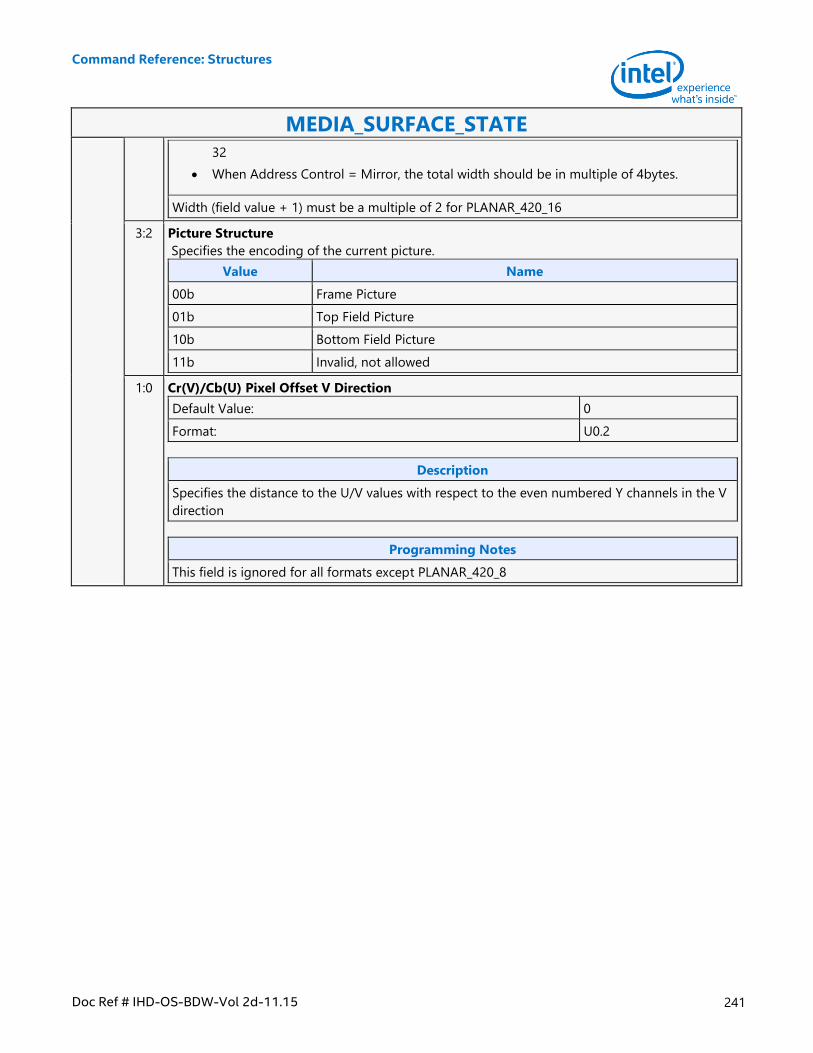
Command Reference: Structures
Doc Ref # IHD-OS-BDW-Vol 2d-11.15 241
MEDIA_SURFACE_STATE
32
When Address Control = Mirror, the total width should be in multiple of 4bytes.
Width (field value + 1) must be a multiple of 2 for PLANAR_420_16
3:2 Picture Structure
Specifies the encoding of the current picture.
Value Name
00b Frame Picture
01b Top Field Picture
10b Bottom Field Picture
11b Invalid, not allowed
1:0 Cr(V)/Cb(U) Pixel Offset V Direction
Default Value: 0
Format: U0.2
Description
Specifies the distance to the U/V values with respect to the even numbered Y channels in the V
direction
Programming Notes
This field is ignored for all formats except PLANAR_420_8
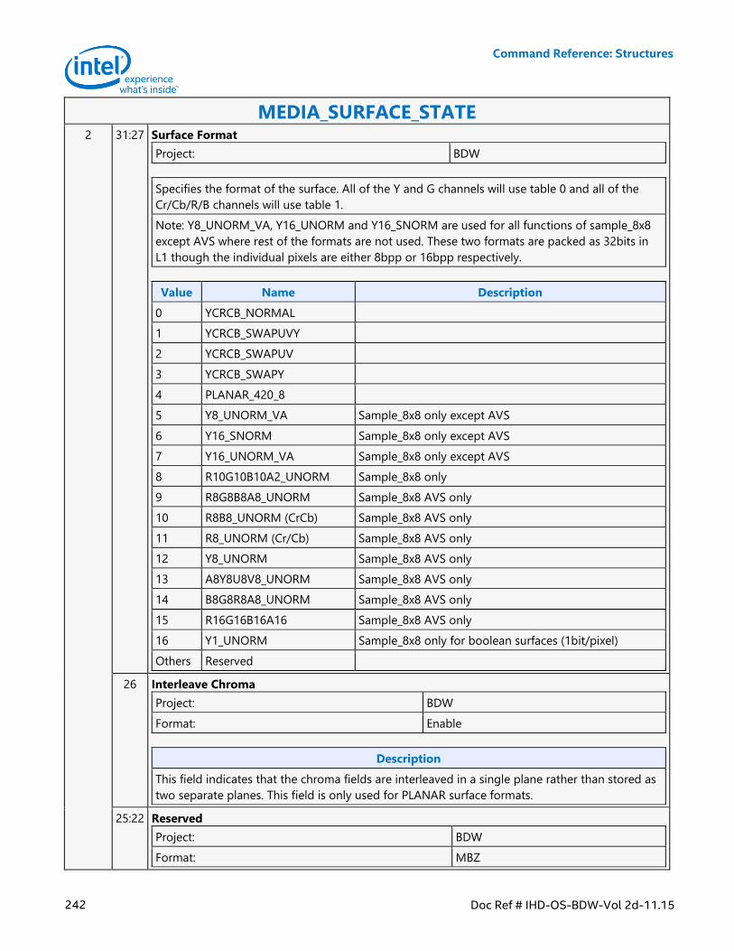
Command Reference: Structures
242 Doc Ref # IHD-OS-BDW-Vol 2d-11.15
MEDIA_SURFACE_STATE 2 31:27 Surface Format
Project: BDW
Specifies the format of the surface. All of the Y and G channels will use table 0 and all of the
Cr/Cb/R/B channels will use table 1.
Note: Y8_UNORM_VA, Y16_UNORM and Y16_SNORM are used for all functions of sample_8x8
except AVS where rest of the formats are not used. These two formats are packed as 32bits in
L1 though the individual pixels are either 8bpp or 16bpp respectively.
Value Name Description
0 YCRCB_NORMAL
1 YCRCB_SWAPUVY
2 YCRCB_SWAPUV
3 YCRCB_SWAPY
4 PLANAR_420_8
5 Y8_UNORM_VA Sample_8x8 only except AVS
6 Y16_SNORM Sample_8x8 only except AVS
7 Y16_UNORM_VA Sample_8x8 only except AVS
8 R10G10B10A2_UNORM Sample_8x8 only
9 R8G8B8A8_UNORM Sample_8x8 AVS only
10 R8B8_UNORM (CrCb) Sample_8x8 AVS only
11 R8_UNORM (Cr/Cb) Sample_8x8 AVS only
12 Y8_UNORM Sample_8x8 AVS only
13 A8Y8U8V8_UNORM Sample_8x8 AVS only
14 B8G8R8A8_UNORM Sample_8x8 AVS only
15 R16G16B16A16 Sample_8x8 AVS only
16 Y1_UNORM Sample_8x8 only for boolean surfaces (1bit/pixel)
Others Reserved
26 Interleave Chroma
Project: BDW
Format: Enable
Description
This field indicates that the chroma fields are interleaved in a single plane rather than stored as
two separate planes. This field is only used for PLANAR surface formats.
25:22 Reserved
Project: BDW
Format: MBZ
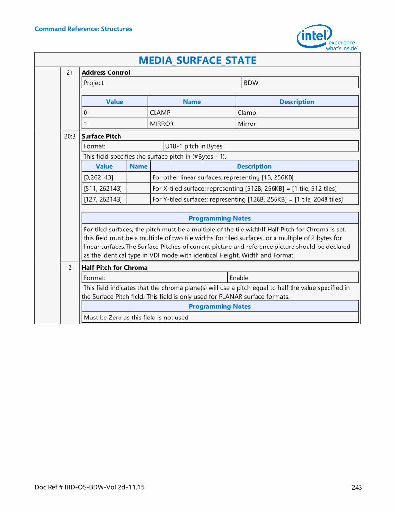
Command Reference: Structures
Doc Ref # IHD-OS-BDW-Vol 2d-11.15 243
MEDIA_SURFACE_STATE 21 Address Control
Project: BDW
Value Name Description
0 CLAMP Clamp
1 MIRROR Mirror
20:3 Surface Pitch
Format: U18-1 pitch in Bytes
This field specifies the surface pitch in (#Bytes - 1).
Value Name Description
[0,262143] For other linear surfaces: representing [1B, 256KB]
[511, 262143] For X-tiled surface: representing [512B, 256KB] = [1 tile, 512 tiles]
[127, 262143] For Y-tiled surfaces: representing [128B, 256KB] = [1 tile, 2048 tiles]
Programming Notes
For tiled surfaces, the pitch must be a multiple of the tile widthIf Half Pitch for Chroma is set,
this field must be a multiple of two tile widths for tiled surfaces, or a multiple of 2 bytes for
linear surfaces.The Surface Pitches of current picture and reference picture should be declared
as the identical type in VDI mode with identical Height, Width and Format.
2 Half Pitch for Chroma
Format: Enable
This field indicates that the chroma plane(s) will use a pitch equal to half the value specified in
the Surface Pitch field. This field is only used for PLANAR surface formats.
Programming Notes
Must be Zero as this field is not used.
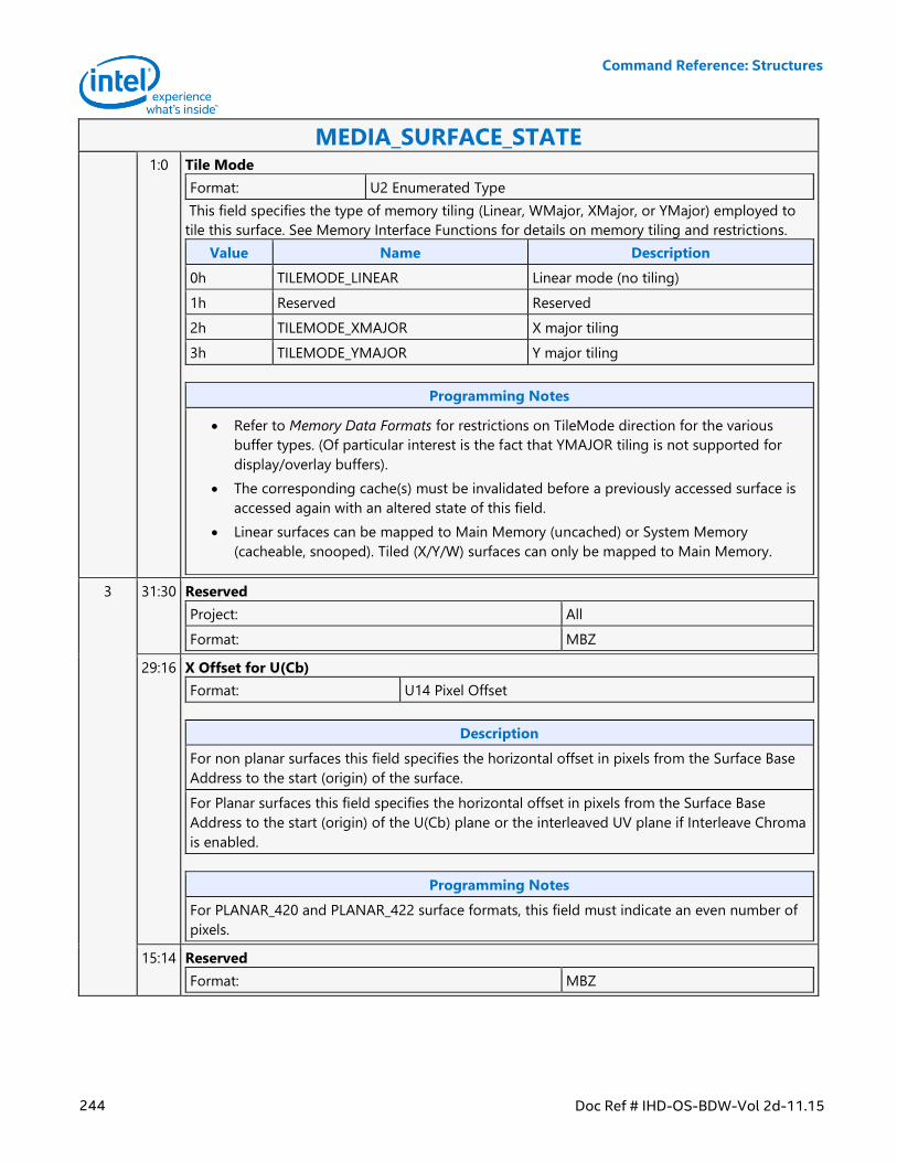
Command Reference: Structures
244 Doc Ref # IHD-OS-BDW-Vol 2d-11.15
MEDIA_SURFACE_STATE 1:0 Tile Mode
Format: U2 Enumerated Type
This field specifies the type of memory tiling (Linear, WMajor, XMajor, or YMajor) employed to
tile this surface. See Memory Interface Functions for details on memory tiling and restrictions.
Value Name Description
0h TILEMODE_LINEAR Linear mode (no tiling)
1h Reserved Reserved
2h TILEMODE_XMAJOR X major tiling
3h TILEMODE_YMAJOR Y major tiling
Programming Notes
Refer to Memory Data Formats for restrictions on TileMode direction for the various
buffer types. (Of particular interest is the fact that YMAJOR tiling is not supported for
display/overlay buffers).
The corresponding cache(s) must be invalidated before a previously accessed surface is
accessed again with an altered state of this field.
Linear surfaces can be mapped to Main Memory (uncached) or System Memory
(cacheable, snooped). Tiled (X/Y/W) surfaces can only be mapped to Main Memory.
3 31:30 Reserved
Project: All
Format: MBZ
29:16 X Offset for U(Cb)
Format: U14 Pixel Offset
Description
For non planar surfaces this field specifies the horizontal offset in pixels from the Surface Base
Address to the start (origin) of the surface.
For Planar surfaces this field specifies the horizontal offset in pixels from the Surface Base
Address to the start (origin) of the U(Cb) plane or the interleaved UV plane if Interleave Chroma
is enabled.
Programming Notes
For PLANAR_420 and PLANAR_422 surface formats, this field must indicate an even number of
pixels.
15:14 Reserved
Format: MBZ
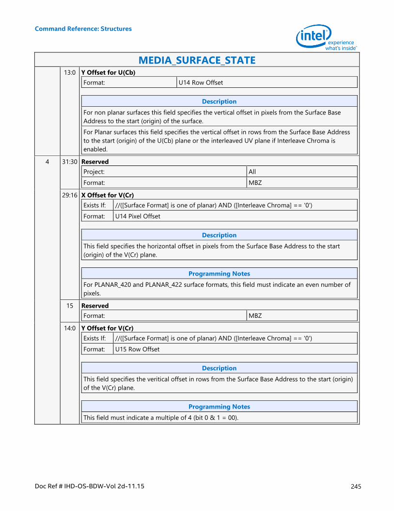
Command Reference: Structures
Doc Ref # IHD-OS-BDW-Vol 2d-11.15 245
MEDIA_SURFACE_STATE 13:0 Y Offset for U(Cb)
Format: U14 Row Offset
Description
For non planar surfaces this field specifies the vertical offset in pixels from the Surface Base
Address to the start (origin) of the surface.
For Planar surfaces this field specifies the vertical offset in rows from the Surface Base Address
to the start (origin) of the U(Cb) plane or the interleaved UV plane if Interleave Chroma is
enabled.
4 31:30 Reserved
Project: All
Format: MBZ
29:16 X Offset for V(Cr)
Exists If: //([Surface Format] is one of planar) AND ([Interleave Chroma] == '0')
Format: U14 Pixel Offset
Description
This field specifies the horizontal offset in pixels from the Surface Base Address to the start
(origin) of the V(Cr) plane.
Programming Notes
For PLANAR_420 and PLANAR_422 surface formats, this field must indicate an even number of
pixels.
15 Reserved
Format: MBZ
14:0 Y Offset for V(Cr)
Exists If: //([Surface Format] is one of planar) AND ([Interleave Chroma] == '0')
Format: U15 Row Offset
Description
This field specifies the veritical offset in rows from the Surface Base Address to the start (origin)
of the V(Cr) plane.
Programming Notes
This field must indicate a multiple of 4 (bit 0 & 1 = 00).
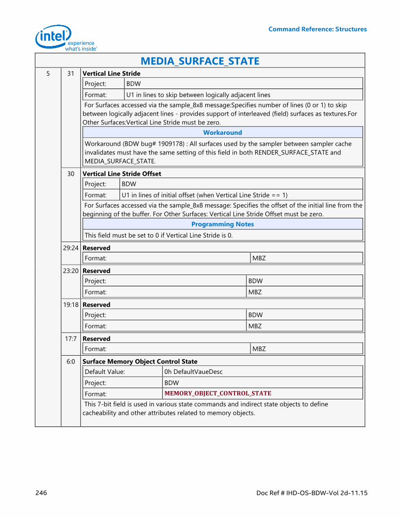
Command Reference: Structures
246 Doc Ref # IHD-OS-BDW-Vol 2d-11.15
MEDIA_SURFACE_STATE 5 31 Vertical Line Stride
Project: BDW
Format: U1 in lines to skip between logically adjacent lines
For Surfaces accessed via the sample_8x8 message:Specifies number of lines (0 or 1) to skip
between logically adjacent lines - provides support of interleaved (field) surfaces as textures.For
Other Surfaces:Vertical Line Stride must be zero.
Workaround
Workaround (BDW bug# 1909178) : All surfaces used by the sampler between sampler cache
invalidates must have the same setting of this field in both RENDER_SURFACE_STATE and
MEDIA_SURFACE_STATE.
30 Vertical Line Stride Offset
Project: BDW
Format: U1 in lines of initial offset (when Vertical Line Stride == 1)
For Surfaces accessed via the sample_8x8 message: Specifies the offset of the initial line from the
beginning of the buffer. For Other Surfaces: Vertical Line Stride Offset must be zero.
Programming Notes
This field must be set to 0 if Vertical Line Stride is 0.
29:24 Reserved
Format: MBZ
23:20 Reserved
Project: BDW
Format: MBZ
19:18 Reserved
Project: BDW
Format: MBZ
17:7 Reserved
Format: MBZ
6:0 Surface Memory Object Control State
Default Value: 0h DefaultVaueDesc
Project: BDW
Format: MEMORY_OBJECT_CONTROL_STATE
This 7-bit field is used in various state commands and indirect state objects to define
cacheability and other attributes related to memory objects.
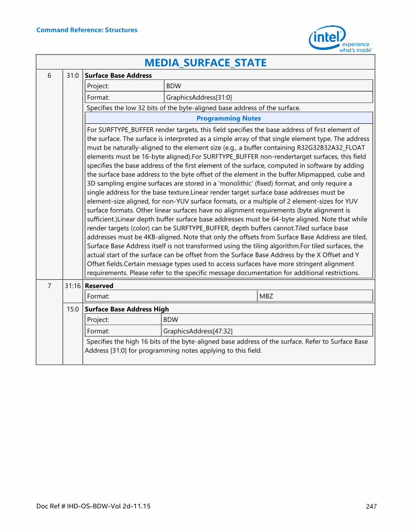
Command Reference: Structures
Doc Ref # IHD-OS-BDW-Vol 2d-11.15 247
MEDIA_SURFACE_STATE 6 31:0 Surface Base Address
Project: BDW
Format: GraphicsAddress[31:0]
Specifies the low 32 bits of the byte-aligned base address of the surface.
Programming Notes
For SURFTYPE_BUFFER render targets, this field specifies the base address of first element of
the surface. The surface is interpreted as a simple array of that single element type. The address
must be naturally-aligned to the element size (e.g., a buffer containing R32G32B32A32_FLOAT
elements must be 16-byte aligned).For SURFTYPE_BUFFER non-rendertarget surfaces, this field
specifies the base address of the first element of the surface, computed in software by adding
the surface base address to the byte offset of the element in the buffer.Mipmapped, cube and
3D sampling engine surfaces are stored in a 'monolithic' (fixed) format, and only require a
single address for the base texture.Linear render target surface base addresses must be
element-size aligned, for non-YUV surface formats, or a multiple of 2 element-sizes for YUV
surface formats. Other linear surfaces have no alignment requirements (byte alignment is
sufficient.)Linear depth buffer surface base addresses must be 64-byte aligned. Note that while
render targets (color) can be SURFTYPE_BUFFER, depth buffers cannot.Tiled surface base
addresses must be 4KB-aligned. Note that only the offsets from Surface Base Address are tiled,
Surface Base Address itself is not transformed using the tiling algorithm.For tiled surfaces, the
actual start of the surface can be offset from the Surface Base Address by the X Offset and Y
Offset fields.Certain message types used to access surfaces have more stringent alignment
requirements. Please refer to the specific message documentation for additional restrictions.
7 31:16 Reserved
Format: MBZ
15:0 Surface Base Address High
Project: BDW
Format: GraphicsAddress[47:32]
Specifies the high 16 bits of the byte-aligned base address of the surface. Refer to Surface Base
Address [31:0] for programming notes applying to this field.
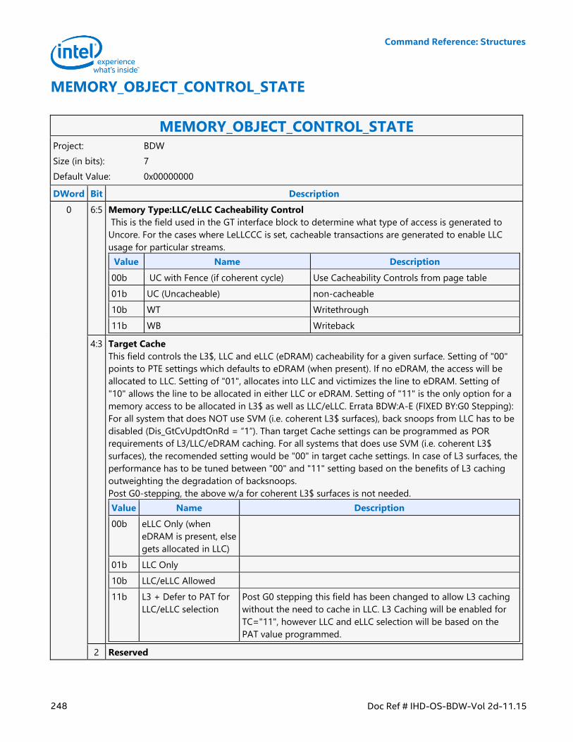
Command Reference: Structures
248 Doc Ref # IHD-OS-BDW-Vol 2d-11.15
MEMORY_OBJECT_CONTROL_STATE
MEMORY_OBJECT_CONTROL_STATE Project: BDW
Size (in bits): 7
Default Value: 0x00000000
DWord Bit Description
0 6:5 Memory Type:LLC/eLLC Cacheability Control
This is the field used in the GT interface block to determine what type of access is generated to
Uncore. For the cases where LeLLCCC is set, cacheable transactions are generated to enable LLC
usage for particular streams.
Value Name Description
00b UC with Fence (if coherent cycle) Use Cacheability Controls from page table
01b UC (Uncacheable) non-cacheable
10b WT Writethrough
11b WB Writeback
4:3 Target Cache
This field controls the L3$, LLC and eLLC (eDRAM) cacheability for a given surface. Setting of "00"
points to PTE settings which defaults to eDRAM (when present). If no eDRAM, the access will be
allocated to LLC. Setting of "01", allocates into LLC and victimizes the line to eDRAM. Setting of
"10" allows the line to be allocated in either LLC or eDRAM. Setting of "11" is the only option for a
memory access to be allocated in L3$ as well as LLC/eLLC. Errata BDW:A-E (FIXED BY:G0 Stepping):
For all system that does NOT use SVM (i.e. coherent L3$ surfaces), back snoops from LLC has to be
disabled (Dis_GtCvUpdtOnRd = “1”). Than target Cache settings can be programmed as POR
requirements of L3/LLC/eDRAM caching. For all systems that does use SVM (i.e. coherent L3$
surfaces), the recomended setting would be "00" in target cache settings. In case of L3 surfaces, the
performance has to be tuned between "00" and "11" setting based on the benefits of L3 caching
outweighting the degradation of backsnoops.
Post G0-stepping, the above w/a for coherent L3$ surfaces is not needed.
Value Name Description
00b eLLC Only (when
eDRAM is present, else
gets allocated in LLC)
01b LLC Only
10b LLC/eLLC Allowed
11b L3 + Defer to PAT for
LLC/eLLC selection
Post G0 stepping this field has been changed to allow L3 caching
without the need to cache in LLC. L3 Caching will be enabled for
TC="11", however LLC and eLLC selection will be based on the
PAT value programmed.
2 Reserved
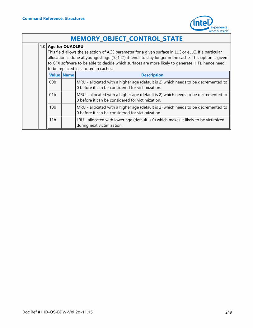
Command Reference: Structures
Doc Ref # IHD-OS-BDW-Vol 2d-11.15 249
MEMORY_OBJECT_CONTROL_STATE 1:0 Age for QUADLRU
This field allows the selection of AGE parameter for a given surface in LLC or eLLC. If a particular
allocation is done at youngest age (“0,1,2”) it tends to stay longer in the cache. This option is given
to GFX software to be able to decide which surfaces are more likely to generate HITs, hence need
to be replaced least often in caches.
Value Name Description
00b MRU - allocated with a higher age (default is 2) which needs to be decremented to
0 before it can be considered for victimization.
01b MRU - allocated with a higher age (default is 2) which needs to be decremented to
0 before it can be considered for victimization.
10b MRU - allocated with a higher age (default is 2) which needs to be decremented to
0 before it can be considered for victimization.
11b LRU - allocated with lower age (default is 0) which makes it likely to be victimized
during next victimization.
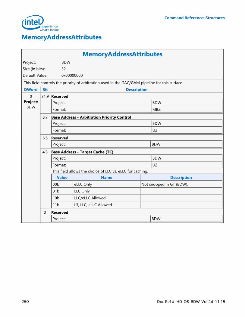
Command Reference: Structures
250 Doc Ref # IHD-OS-BDW-Vol 2d-11.15
MemoryAddressAttributes
MemoryAddressAttributes Project: BDW
Size (in bits): 32
Default Value: 0x00000000
This field controls the priority of arbitration used in the GAC/GAM pipeline for this surface.
DWord Bit Description
0
Project:
BDW
31:9 Reserved
Project: BDW
Format: MBZ
8:7 Base Address - Arbitration Priority Control
Project: BDW
Format: U2
6:5 Reserved
Project: BDW
4:3 Base Address - Target Cache (TC)
Project: BDW
Format: U2
This field allows the choice of LLC vs. eLLC for caching.
Value Name Description
00b eLLC Only Not snooped in GT (BDW).
01b LLC Only
10b LLC/eLLC Allowed
11b L3, LLC, eLLC Allowed
2 Reserved
Project: BDW
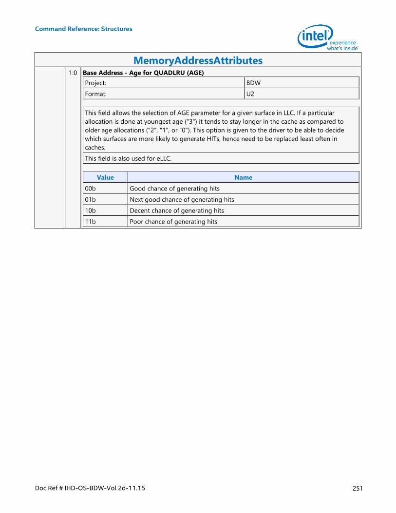
Command Reference: Structures
Doc Ref # IHD-OS-BDW-Vol 2d-11.15 251
MemoryAddressAttributes 1:0 Base Address - Age for QUADLRU (AGE)
Project: BDW
Format: U2
This field allows the selection of AGE parameter for a given surface in LLC. If a particular
allocation is done at youngest age ("3") it tends to stay longer in the cache as compared to
older age allocations ("2", "1", or "0"). This option is given to the driver to be able to decide
which surfaces are more likely to generate HITs, hence need to be replaced least often in
caches.
This field is also used for eLLC.
Value Name
00b Good chance of generating hits
01b Next good chance of generating hits
10b Decent chance of generating hits
11b Poor chance of generating hits
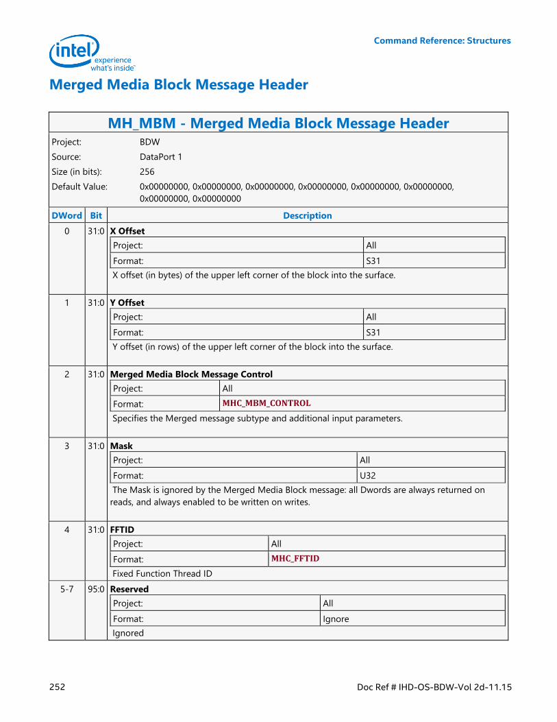
Command Reference: Structures
252 Doc Ref # IHD-OS-BDW-Vol 2d-11.15
Merged Media Block Message Header
MH_MBM - Merged Media Block Message Header Project: BDW
Source: DataPort 1
Size (in bits): 256
Default Value: 0x00000000, 0x00000000, 0x00000000, 0x00000000, 0x00000000, 0x00000000,
0x00000000, 0x00000000
DWord Bit Description
0 31:0 X Offset
Project: All
Format: S31
X offset (in bytes) of the upper left corner of the block into the surface.
1 31:0 Y Offset
Project: All
Format: S31
Y offset (in rows) of the upper left corner of the block into the surface.
2 31:0 Merged Media Block Message Control
Project: All
Format: MHC_MBM_CONTROL
Specifies the Merged message subtype and additional input parameters.
3 31:0 Mask
Project: All
Format: U32
The Mask is ignored by the Merged Media Block message: all Dwords are always returned on
reads, and always enabled to be written on writes.
4 31:0 FFTID
Project: All
Format: MHC_FFTID
Fixed Function Thread ID
5-7 95:0 Reserved
Project: All
Format: Ignore
Ignored
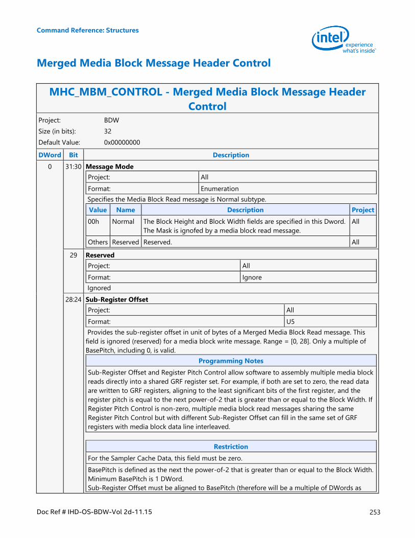
Command Reference: Structures
Doc Ref # IHD-OS-BDW-Vol 2d-11.15 253
Merged Media Block Message Header Control
MHC_MBM_CONTROL - Merged Media Block Message Header
Control Project: BDW
Size (in bits): 32
Default Value: 0x00000000
DWord Bit Description
0 31:30 Message Mode
Project: All
Format: Enumeration
Specifies the Media Block Read message is Normal subtype.
Value Name Description Project
00h Normal The Block Height and Block Width fields are specified in this Dword.
The Mask is ignofed by a media block read message.
All
Others Reserved Reserved. All
29 Reserved
Project: All
Format: Ignore
Ignored
28:24 Sub-Register Offset
Project: All
Format: U5
Provides the sub-register offset in unit of bytes of a Merged Media Block Read message. This
field is ignored (reserved) for a media block write message. Range = [0, 28]. Only a multiple of
BasePitch, including 0, is valid.
Programming Notes
Sub-Register Offset and Register Pitch Control allow software to assembly multiple media block
reads directly into a shared GRF register set. For example, if both are set to zero, the read data
are written to GRF registers, aligning to the least significant bits of the first register, and the
register pitch is equal to the next power-of-2 that is greater than or equal to the Block Width. If
Register Pitch Control is non-zero, multiple media block read messages sharing the same
Register Pitch Control but with different Sub-Register Offset can fill in the same set of GRF
registers with media block data line interleaved.
Restriction
For the Sampler Cache Data, this field must be zero.
BasePitch is defined as the next the power-of-2 that is greater than or equal to the Block Width.
Minimum BasePitch is 1 DWord.
Sub-Register Offset must be aligned to BasePitch (therefore will be a multiple of DWords as
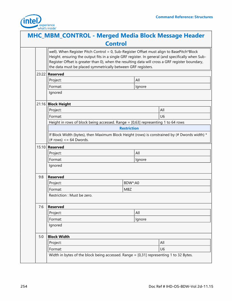
Command Reference: Structures
254 Doc Ref # IHD-OS-BDW-Vol 2d-11.15
MHC_MBM_CONTROL - Merged Media Block Message Header
Control
well). When Register Pitch Control = 0, Sub-Register Offset must align to BasePitch*Block
Height. ensuring the output fits in a single GRF register. In general (and specifically when Sub-
Register Offset is greater than 0), when the resulting data will cross a GRF register boundary,
the data must be placed symmetrically between GRF registers.
23:22 Reserved
Project: All
Format: Ignore
Ignored
21:16 Block Height
Project: All
Format: U6
Height in rows of block being accessed. Range = [0,63] representing 1 to 64 rows
Restriction
If Block Width (bytes), then Maximum Block Height (rows) is constrained by (# Dwords width) *
(# rows) <= 64 Dwords.
15:10 Reserved
Project: All
Format: Ignore
Ignored
9:8 Reserved
Project: BDW*:A0
Format: MBZ
Restriction : Must be zero.
7:6 Reserved
Project: All
Format: Ignore
Ignored
5:0 Block Width
Project: All
Format: U6
Width in bytes of the block being accessed. Range = [0,31] representing 1 to 32 Bytes.
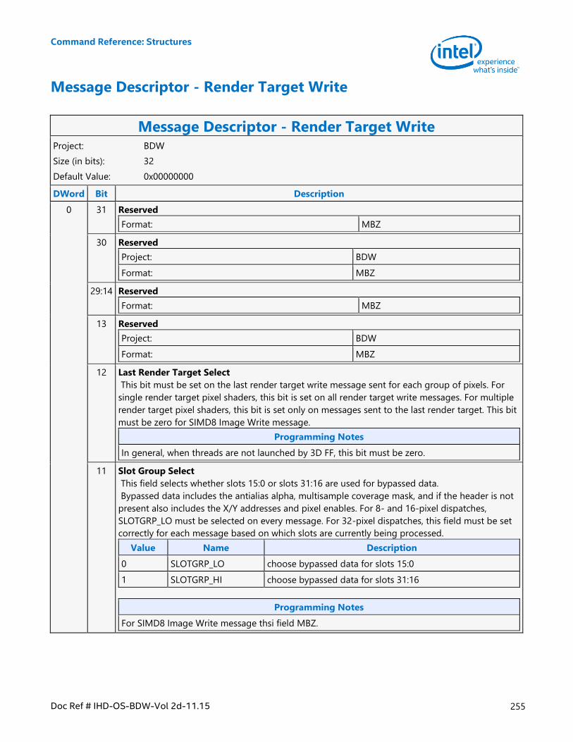
Command Reference: Structures
Doc Ref # IHD-OS-BDW-Vol 2d-11.15 255
Message Descriptor - Render Target Write
Message Descriptor - Render Target Write Project: BDW
Size (in bits): 32
Default Value: 0x00000000
DWord Bit Description
0 31 Reserved
Format: MBZ
30 Reserved
Project: BDW
Format: MBZ
29:14 Reserved
Format: MBZ
13 Reserved
Project: BDW
Format: MBZ
12 Last Render Target Select
This bit must be set on the last render target write message sent for each group of pixels. For
single render target pixel shaders, this bit is set on all render target write messages. For multiple
render target pixel shaders, this bit is set only on messages sent to the last render target. This bit
must be zero for SIMD8 Image Write message.
Programming Notes
In general, when threads are not launched by 3D FF, this bit must be zero.
11 Slot Group Select
This field selects whether slots 15:0 or slots 31:16 are used for bypassed data.
Bypassed data includes the antialias alpha, multisample coverage mask, and if the header is not
present also includes the X/Y addresses and pixel enables. For 8- and 16-pixel dispatches,
SLOTGRP_LO must be selected on every message. For 32-pixel dispatches, this field must be set
correctly for each message based on which slots are currently being processed.
Value Name Description
0 SLOTGRP_LO choose bypassed data for slots 15:0
1 SLOTGRP_HI choose bypassed data for slots 31:16
Programming Notes
For SIMD8 Image Write message thsi field MBZ.
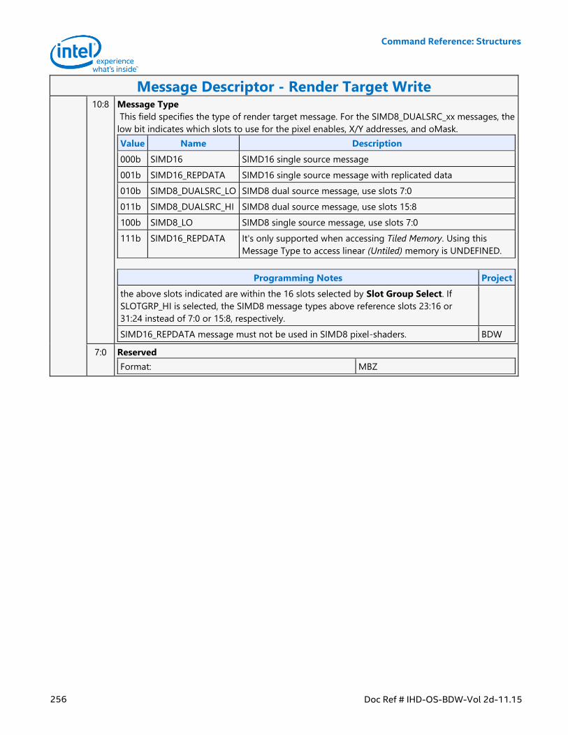
Command Reference: Structures
256 Doc Ref # IHD-OS-BDW-Vol 2d-11.15
Message Descriptor - Render Target Write 10:8 Message Type
This field specifies the type of render target message. For the SIMD8_DUALSRC_xx messages, the
low bit indicates which slots to use for the pixel enables, X/Y addresses, and oMask.
Value Name Description
000b SIMD16 SIMD16 single source message
001b SIMD16_REPDATA SIMD16 single source message with replicated data
010b SIMD8_DUALSRC_LO SIMD8 dual source message, use slots 7:0
011b SIMD8_DUALSRC_HI SIMD8 dual source message, use slots 15:8
100b SIMD8_LO SIMD8 single source message, use slots 7:0
111b SIMD16_REPDATA It's only supported when accessing Tiled Memory. Using this
Message Type to access linear (Untiled) memory is UNDEFINED.
Programming Notes Project
the above slots indicated are within the 16 slots selected by Slot Group Select. If
SLOTGRP_HI is selected, the SIMD8 message types above reference slots 23:16 or
31:24 instead of 7:0 or 15:8, respectively.
SIMD16_REPDATA message must not be used in SIMD8 pixel-shaders. BDW
7:0 Reserved
Format: MBZ
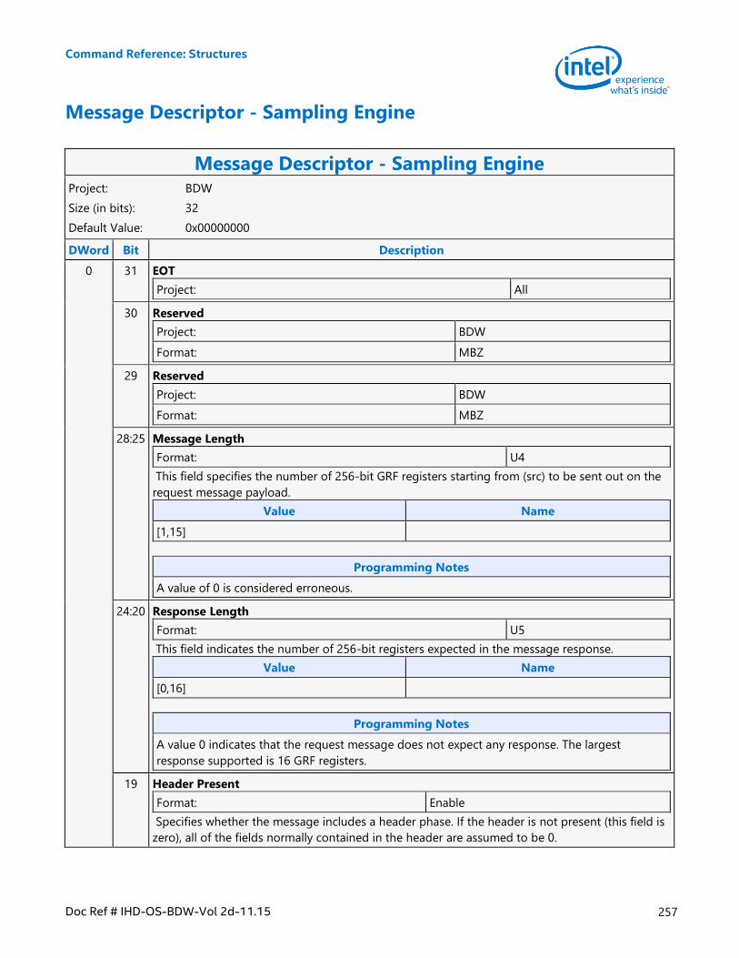
Command Reference: Structures
Doc Ref # IHD-OS-BDW-Vol 2d-11.15 257
Message Descriptor - Sampling Engine
Message Descriptor - Sampling Engine Project: BDW
Size (in bits): 32
Default Value: 0x00000000
DWord Bit Description
0 31 EOT
Project: All
30 Reserved
Project: BDW
Format: MBZ
29 Reserved
Project: BDW
Format: MBZ
28:25 Message Length
Format: U4
This field specifies the number of 256-bit GRF registers starting from (src) to be sent out on the
request message payload.
Value Name
[1,15]
Programming Notes
A value of 0 is considered erroneous.
24:20 Response Length
Format: U5
This field indicates the number of 256-bit registers expected in the message response.
Value Name
[0,16]
Programming Notes
A value 0 indicates that the request message does not expect any response. The largest
response supported is 16 GRF registers.
19 Header Present
Format: Enable
Specifies whether the message includes a header phase. If the header is not present (this field is
zero), all of the fields normally contained in the header are assumed to be 0.
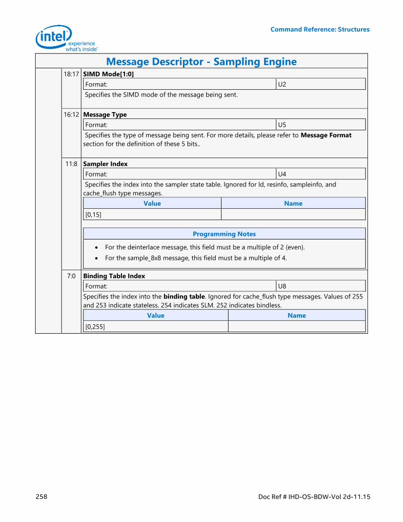
Command Reference: Structures
258 Doc Ref # IHD-OS-BDW-Vol 2d-11.15
Message Descriptor - Sampling Engine 18:17 SIMD Mode[1:0]
Format: U2
Specifies the SIMD mode of the message being sent.
16:12 Message Type
Format: U5
Specifies the type of message being sent. For more details, please refer to Message Format
section for the definition of these 5 bits..
11:8 Sampler Index
Format: U4
Specifies the index into the sampler state table. Ignored for ld, resinfo, sampleinfo, and
cache_flush type messages.
Value Name
[0,15]
Programming Notes
For the deinterlace message, this field must be a multiple of 2 (even).
For the sample_8x8 message, this field must be a multiple of 4.
7:0 Binding Table Index
Format: U8
Specifies the index into the binding table. Ignored for cache_flush type messages. Values of 255
and 253 indicate stateless. 254 indicates SLM. 252 indicates bindless.
Value Name
[0,255]
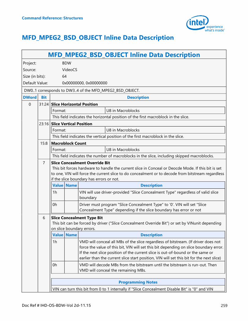
Command Reference: Structures
Doc Ref # IHD-OS-BDW-Vol 2d-11.15 259
MFD_MPEG2_BSD_OBJECT Inline Data Description
MFD_MPEG2_BSD_OBJECT Inline Data Description Project: BDW
Source: VideoCS
Size (in bits): 64
Default Value: 0x00000000, 0x00000000
DW0..1 corresponds to DW3..4 of the MFD_MPEG2_BSD_OBJECT.
DWord Bit Description
0 31:24 Slice Horizontal Position
Format: U8 in Macroblocks
This field indicates the horizontal position of the first macroblock in the slice.
23:16 Slice Vertical Position
Format: U8 in Macroblocks
This field indicates the vertical position of the first macroblock in the slice.
15:8 Macroblock Count
Format: U8 in Macroblocks
This field indicates the number of macroblocks in the slice, including skipped macroblocks.
7 Slice Concealment Override Bit
This bit forces hardware to handle the current slice in Conceal or Deocde Mode. If this bit is set
to one, VIN will force the current slice to do concealment or to decode from bitstream regardless
if the slice boundary has errors or not.
Value Name Description
1h VIN will use driver-provided "Slice Concealment Type" regardless of valid slice
boundary
0h Driver must program "Slice Concealment Type" to '0'. VIN will set "Slice
Concealment Type" depending if the slice boundary has error or not
6 Slice Concealment Type Bit
This bit can be forced by driver ("Slice Concealment Override Bit") or set by VINunit depending
on slice boundary errors.
Value Name Description
1h VMD will conceal all MBs of the slice regardless of bitstream. (If driver does not
force the value of this bit, VIN will set this bit depending on slice boundary error.
If the next slice position of the current slice is out-of-bound or the same or
earlier than the current slice start position, VIN will set this bit for the next slice)
0h VMD will decode MBs from the bitstream until the bitstream is run-out. Then
VMD will conceal the remaining MBs.
Programming Notes
VIN can turn this bit from 0 to 1 internally if "Slice Concealment Disable Bit" is "0" and VIN
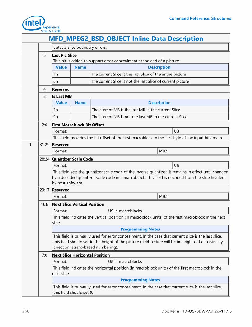
Command Reference: Structures
260 Doc Ref # IHD-OS-BDW-Vol 2d-11.15
MFD_MPEG2_BSD_OBJECT Inline Data Description
detects slice boundary errors.
5 Last Pic Slice
This bit is added to support error concealment at the end of a picture.
Value Name Description
1h The current Slice is the last Slice of the entire picture
0h The current Slice is not the last Slice of current picture
4 Reserved
3 Is Last MB
Value Name Description
1h The current MB is the last MB in the current Slice
0h The current MB is not the last MB in the current Slice
2:0 First Macroblock Bit Offset
Format: U3
This field provides the bit offset of the first macroblock in the first byte of the input bitstream.
1 31:29 Reserved
Format: MBZ
28:24 Quantizer Scale Code
Format: U5
This field sets the quantizer scale code of the inverse quantizer. It remains in effect until changed
by a decoded quantizer scale code in a macroblock. This field is decoded from the slice header
by host software.
23:17 Reserved
Format: MBZ
16:8 Next Slice Vertical Position
Format: U9 in macroblocks
This field indicates the vertical position (in macroblock units) of the first macroblock in the next
slice.
Programming Notes
This field is primarily used for error concealment. In the case that current slice is the last slice,
this field should set to the height of the picture (field picture will be in height of field) (since y-
direction is zero-based numbering).
7:0 Next Slice Horizontal Position
Format: U8 in macroblocks
This field indicates the horizontal position (in macroblock units) of the first macroblock in the
next slice.
Programming Notes
This field is primarily used for error concealment. In the case that current slice is the last slice,
this field should set 0.
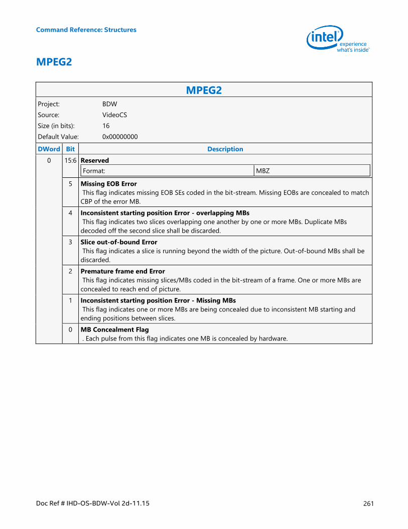
Command Reference: Structures
Doc Ref # IHD-OS-BDW-Vol 2d-11.15 261
MPEG2
MPEG2 Project: BDW
Source: VideoCS
Size (in bits): 16
Default Value: 0x00000000
DWord Bit Description
0 15:6 Reserved
Format: MBZ
5 Missing EOB Error
This flag indicates missing EOB SEs coded in the bit-stream. Missing EOBs are concealed to match
CBP of the error MB.
4 Inconsistent starting position Error - overlapping MBs
This flag indicates two slices overlapping one another by one or more MBs. Duplicate MBs
decoded off the second slice shall be discarded.
3 Slice out-of-bound Error
This flag indicates a slice is running beyond the width of the picture. Out-of-bound MBs shall be
discarded.
2 Premature frame end Error
This flag indicates missing slices/MBs coded in the bit-stream of a frame. One or more MBs are
concealed to reach end of picture.
1 Inconsistent starting position Error - Missing MBs
This flag indicates one or more MBs are being concealed due to inconsistent MB starting and
ending positions between slices.
0 MB Concealment Flag
. Each pulse from this flag indicates one MB is concealed by hardware.
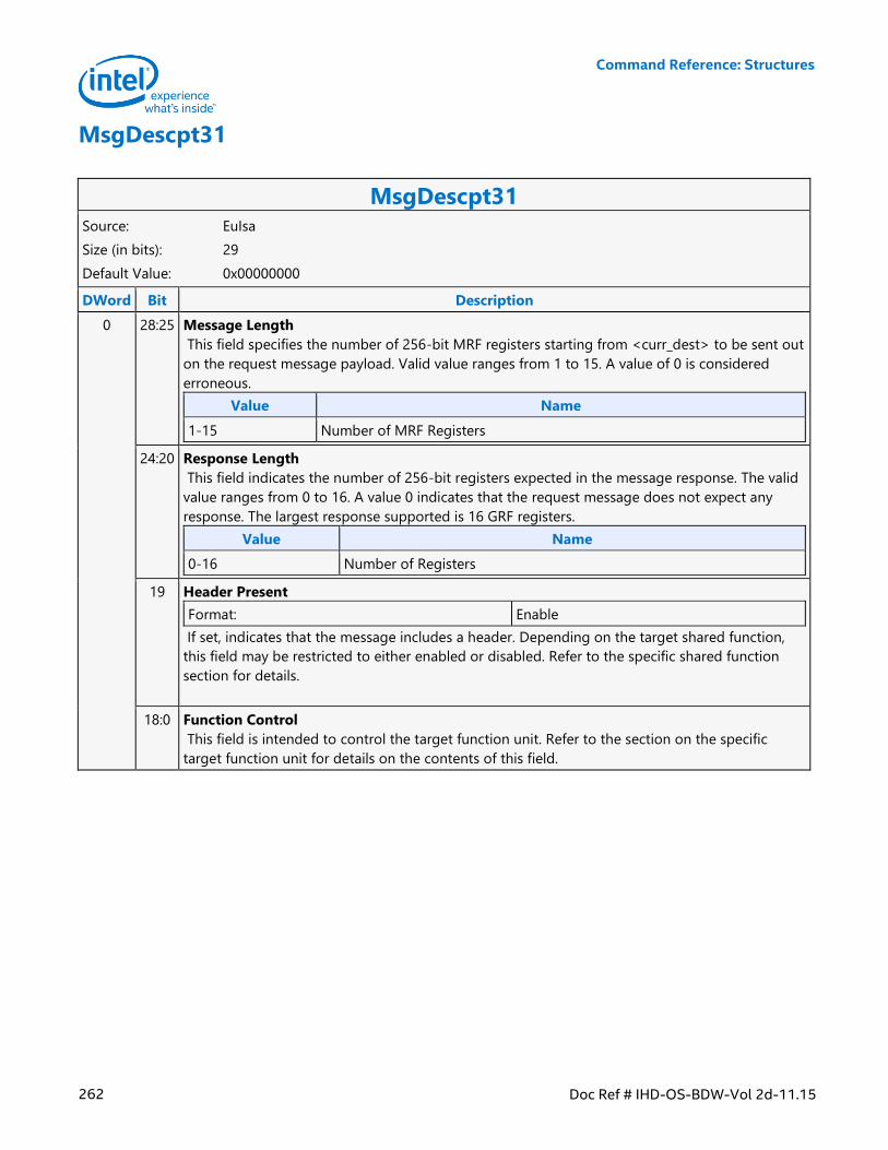
Command Reference: Structures
262 Doc Ref # IHD-OS-BDW-Vol 2d-11.15
MsgDescpt31
MsgDescpt31 Source: EuIsa
Size (in bits): 29
Default Value: 0x00000000
DWord Bit Description
0 28:25 Message Length
This field specifies the number of 256-bit MRF registers starting from <curr_dest> to be sent out
on the request message payload. Valid value ranges from 1 to 15. A value of 0 is considered
erroneous.
Value Name
1-15 Number of MRF Registers
24:20 Response Length
This field indicates the number of 256-bit registers expected in the message response. The valid
value ranges from 0 to 16. A value 0 indicates that the request message does not expect any
response. The largest response supported is 16 GRF registers.
Value Name
0-16 Number of Registers
19 Header Present
Format: Enable
If set, indicates that the message includes a header. Depending on the target shared function,
this field may be restricted to either enabled or disabled. Refer to the specific shared function
section for details.
18:0 Function Control
This field is intended to control the target function unit. Refer to the section on the specific
target function unit for details on the contents of this field.
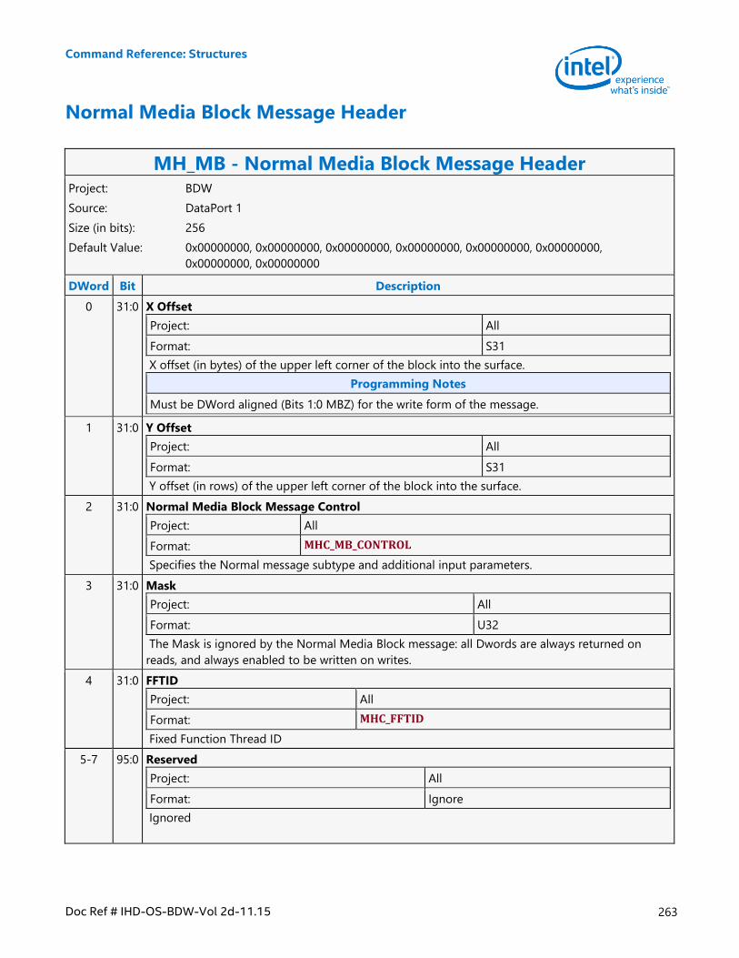
Command Reference: Structures
Doc Ref # IHD-OS-BDW-Vol 2d-11.15 263
Normal Media Block Message Header
MH_MB - Normal Media Block Message Header Project: BDW
Source: DataPort 1
Size (in bits): 256
Default Value: 0x00000000, 0x00000000, 0x00000000, 0x00000000, 0x00000000, 0x00000000,
0x00000000, 0x00000000
DWord Bit Description
0 31:0 X Offset
Project: All
Format: S31
X offset (in bytes) of the upper left corner of the block into the surface.
Programming Notes
Must be DWord aligned (Bits 1:0 MBZ) for the write form of the message.
1 31:0 Y Offset
Project: All
Format: S31
Y offset (in rows) of the upper left corner of the block into the surface.
2 31:0 Normal Media Block Message Control
Project: All
Format: MHC_MB_CONTROL
Specifies the Normal message subtype and additional input parameters.
3 31:0 Mask
Project: All
Format: U32
The Mask is ignored by the Normal Media Block message: all Dwords are always returned on
reads, and always enabled to be written on writes.
4 31:0 FFTID
Project: All
Format: MHC_FFTID
Fixed Function Thread ID
5-7 95:0 Reserved
Project: All
Format: Ignore
Ignored
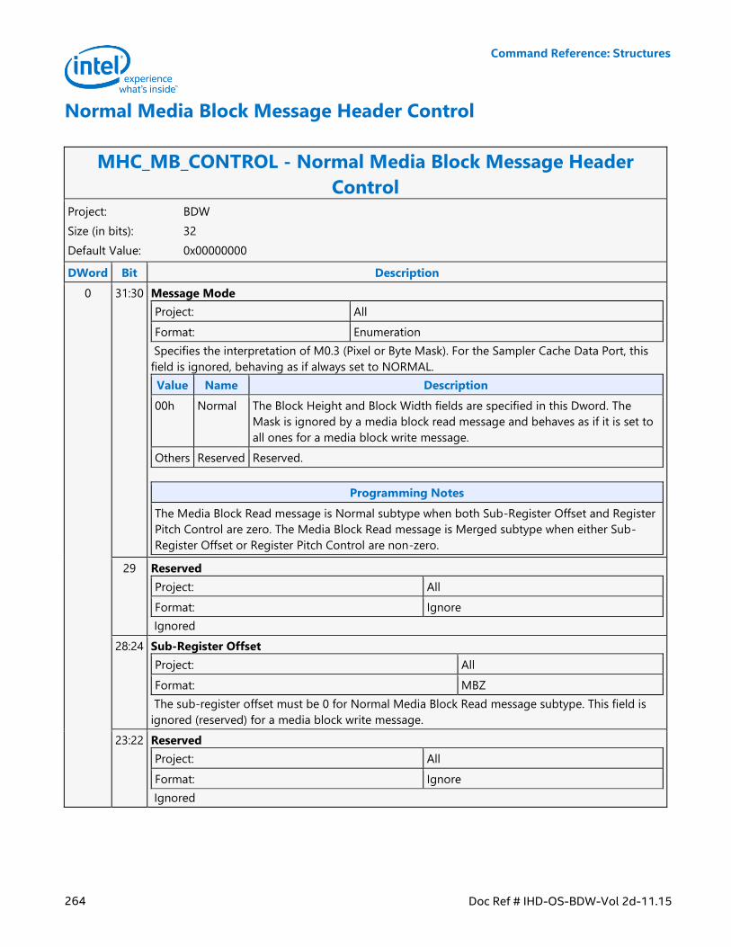
Command Reference: Structures
264 Doc Ref # IHD-OS-BDW-Vol 2d-11.15
Normal Media Block Message Header Control
MHC_MB_CONTROL - Normal Media Block Message Header
Control Project: BDW
Size (in bits): 32
Default Value: 0x00000000
DWord Bit Description
0 31:30 Message Mode
Project: All
Format: Enumeration
Specifies the interpretation of M0.3 (Pixel or Byte Mask). For the Sampler Cache Data Port, this
field is ignored, behaving as if always set to NORMAL.
Value Name Description
00h Normal The Block Height and Block Width fields are specified in this Dword. The
Mask is ignored by a media block read message and behaves as if it is set to
all ones for a media block write message.
Others Reserved Reserved.
Programming Notes
The Media Block Read message is Normal subtype when both Sub-Register Offset and Register
Pitch Control are zero. The Media Block Read message is Merged subtype when either Sub-
Register Offset or Register Pitch Control are non-zero.
29 Reserved
Project: All
Format: Ignore
Ignored
28:24 Sub-Register Offset
Project: All
Format: MBZ
The sub-register offset must be 0 for Normal Media Block Read message subtype. This field is
ignored (reserved) for a media block write message.
23:22 Reserved
Project: All
Format: Ignore
Ignored
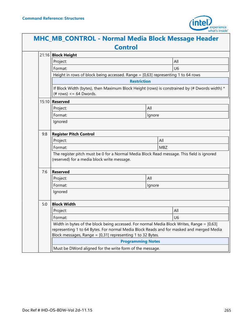
Command Reference: Structures
Doc Ref # IHD-OS-BDW-Vol 2d-11.15 265
MHC_MB_CONTROL - Normal Media Block Message Header
Control 21:16 Block Height
Project: All
Format: U6
Height in rows of block being accessed. Range = [0,63] representing 1 to 64 rows
Restriction
If Block Width (bytes), then Maximum Block Height (rows) is constrained by (# Dwords width) *
(# rows) <= 64 Dwords.
15:10 Reserved
Project: All
Format: Ignore
Ignored
9:8 Register Pitch Control
Project: All
Format: MBZ
The register pitch must be 0 for a Normal Media Block Read message. This field is ignored
(reserved) for a media block write message.
7:6 Reserved
Project: All
Format: Ignore
Ignored
5:0 Block Width
Project: All
Format: U6
Width in bytes of the block being accessed. For normal Media Block Writes, Range = [0,63]
representing 1 to 64 Bytes. For normal Media Block Reads and for masked and merged Media
Block messages, Range = [0,31] representing 1 to 32 Bytes.
Programming Notes
Must be DWord aligned for the write form of the message.
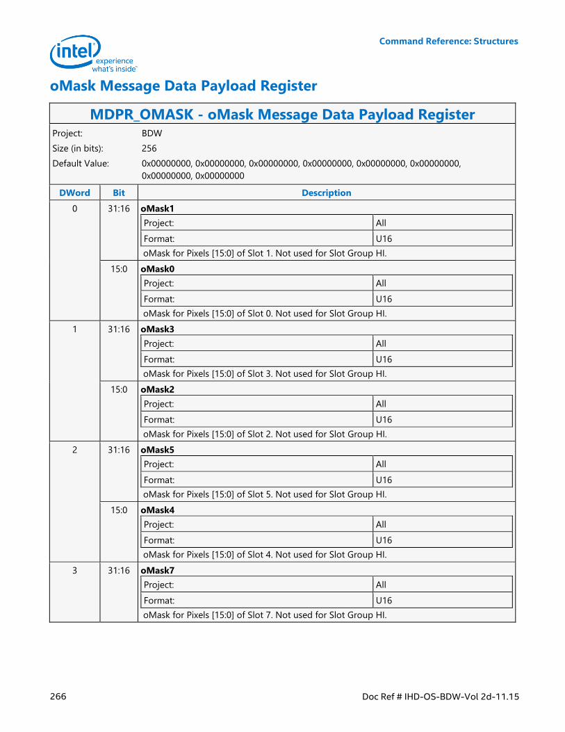
Command Reference: Structures
266 Doc Ref # IHD-OS-BDW-Vol 2d-11.15
oMask Message Data Payload Register
MDPR_OMASK - oMask Message Data Payload Register Project: BDW
Size (in bits): 256
Default Value: 0x00000000, 0x00000000, 0x00000000, 0x00000000, 0x00000000, 0x00000000,
0x00000000, 0x00000000
DWord Bit Description
0 31:16 oMask1
Project: All
Format: U16
oMask for Pixels [15:0] of Slot 1. Not used for Slot Group HI.
15:0 oMask0
Project: All
Format: U16
oMask for Pixels [15:0] of Slot 0. Not used for Slot Group HI.
1 31:16 oMask3
Project: All
Format: U16
oMask for Pixels [15:0] of Slot 3. Not used for Slot Group HI.
15:0 oMask2
Project: All
Format: U16
oMask for Pixels [15:0] of Slot 2. Not used for Slot Group HI.
2 31:16 oMask5
Project: All
Format: U16
oMask for Pixels [15:0] of Slot 5. Not used for Slot Group HI.
15:0 oMask4
Project: All
Format: U16
oMask for Pixels [15:0] of Slot 4. Not used for Slot Group HI.
3 31:16 oMask7
Project: All
Format: U16
oMask for Pixels [15:0] of Slot 7. Not used for Slot Group HI.
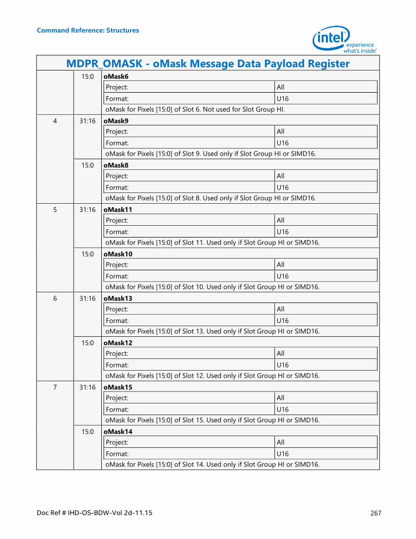
Command Reference: Structures
Doc Ref # IHD-OS-BDW-Vol 2d-11.15 267
MDPR_OMASK - oMask Message Data Payload Register 15:0 oMask6
Project: All
Format: U16
oMask for Pixels [15:0] of Slot 6. Not used for Slot Group HI.
4 31:16 oMask9
Project: All
Format: U16
oMask for Pixels [15:0] of Slot 9. Used only if Slot Group HI or SIMD16.
15:0 oMask8
Project: All
Format: U16
oMask for Pixels [15:0] of Slot 8. Used only if Slot Group HI or SIMD16.
5 31:16 oMask11
Project: All
Format: U16
oMask for Pixels [15:0] of Slot 11. Used only if Slot Group HI or SIMD16.
15:0 oMask10
Project: All
Format: U16
oMask for Pixels [15:0] of Slot 10. Used only if Slot Group HI or SIMD16.
6 31:16 oMask13
Project: All
Format: U16
oMask for Pixels [15:0] of Slot 13. Used only if Slot Group HI or SIMD16.
15:0 oMask12
Project: All
Format: U16
oMask for Pixels [15:0] of Slot 12. Used only if Slot Group HI or SIMD16.
7 31:16 oMask15
Project: All
Format: U16
oMask for Pixels [15:0] of Slot 15. Used only if Slot Group HI or SIMD16.
15:0 oMask14
Project: All
Format: U16
oMask for Pixels [15:0] of Slot 14. Used only if Slot Group HI or SIMD16.
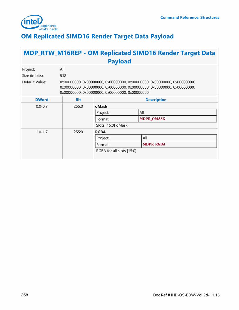
Command Reference: Structures
268 Doc Ref # IHD-OS-BDW-Vol 2d-11.15
OM Replicated SIMD16 Render Target Data Payload
MDP_RTW_M16REP - OM Replicated SIMD16 Render Target Data
Payload Project: All
Size (in bits): 512
Default Value: 0x00000000, 0x00000000, 0x00000000, 0x00000000, 0x00000000, 0x00000000,
0x00000000, 0x00000000, 0x00000000, 0x00000000, 0x00000000, 0x00000000,
0x00000000, 0x00000000, 0x00000000, 0x00000000
DWord Bit Description
0.0-0.7 255:0 oMask
Project: All
Format: MDPR_OMASK
Slots [15:0] oMask
1.0-1.7 255:0 RGBA
Project: All
Format: MDPR_RGBA
RGBA for all slots [15:0]
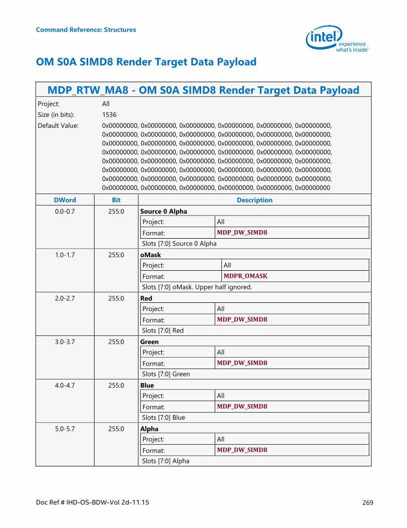
Command Reference: Structures
Doc Ref # IHD-OS-BDW-Vol 2d-11.15 269
OM S0A SIMD8 Render Target Data Payload
MDP_RTW_MA8 - OM S0A SIMD8 Render Target Data Payload Project: All
Size (in bits): 1536
Default Value: 0x00000000, 0x00000000, 0x00000000, 0x00000000, 0x00000000, 0x00000000,
0x00000000, 0x00000000, 0x00000000, 0x00000000, 0x00000000, 0x00000000,
0x00000000, 0x00000000, 0x00000000, 0x00000000, 0x00000000, 0x00000000,
0x00000000, 0x00000000, 0x00000000, 0x00000000, 0x00000000, 0x00000000,
0x00000000, 0x00000000, 0x00000000, 0x00000000, 0x00000000, 0x00000000,
0x00000000, 0x00000000, 0x00000000, 0x00000000, 0x00000000, 0x00000000,
0x00000000, 0x00000000, 0x00000000, 0x00000000, 0x00000000, 0x00000000,
0x00000000, 0x00000000, 0x00000000, 0x00000000, 0x00000000, 0x00000000
DWord Bit Description
0.0-0.7 255:0 Source 0 Alpha
Project: All
Format: MDP_DW_SIMD8
Slots [7:0] Source 0 Alpha
1.0-1.7 255:0 oMask
Project: All
Format: MDPR_OMASK
Slots [7:0] oMask. Upper half ignored.
2.0-2.7 255:0 Red
Project: All
Format: MDP_DW_SIMD8
Slots [7:0] Red
3.0-3.7 255:0 Green
Project: All
Format: MDP_DW_SIMD8
Slots [7:0] Green
4.0-4.7 255:0 Blue
Project: All
Format: MDP_DW_SIMD8
Slots [7:0] Blue
5.0-5.7 255:0 Alpha
Project: All
Format: MDP_DW_SIMD8
Slots [7:0] Alpha
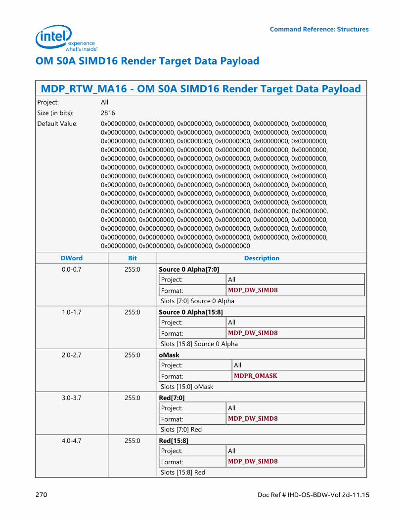
Command Reference: Structures
270 Doc Ref # IHD-OS-BDW-Vol 2d-11.15
OM S0A SIMD16 Render Target Data Payload
MDP_RTW_MA16 - OM S0A SIMD16 Render Target Data Payload Project: All
Size (in bits): 2816
Default Value: 0x00000000, 0x00000000, 0x00000000, 0x00000000, 0x00000000, 0x00000000,
0x00000000, 0x00000000, 0x00000000, 0x00000000, 0x00000000, 0x00000000,
0x00000000, 0x00000000, 0x00000000, 0x00000000, 0x00000000, 0x00000000,
0x00000000, 0x00000000, 0x00000000, 0x00000000, 0x00000000, 0x00000000,
0x00000000, 0x00000000, 0x00000000, 0x00000000, 0x00000000, 0x00000000,
0x00000000, 0x00000000, 0x00000000, 0x00000000, 0x00000000, 0x00000000,
0x00000000, 0x00000000, 0x00000000, 0x00000000, 0x00000000, 0x00000000,
0x00000000, 0x00000000, 0x00000000, 0x00000000, 0x00000000, 0x00000000,
0x00000000, 0x00000000, 0x00000000, 0x00000000, 0x00000000, 0x00000000,
0x00000000, 0x00000000, 0x00000000, 0x00000000, 0x00000000, 0x00000000,
0x00000000, 0x00000000, 0x00000000, 0x00000000, 0x00000000, 0x00000000,
0x00000000, 0x00000000, 0x00000000, 0x00000000, 0x00000000, 0x00000000,
0x00000000, 0x00000000, 0x00000000, 0x00000000, 0x00000000, 0x00000000,
0x00000000, 0x00000000, 0x00000000, 0x00000000, 0x00000000, 0x00000000,
0x00000000, 0x00000000, 0x00000000, 0x00000000
DWord Bit Description
0.0-0.7 255:0 Source 0 Alpha[7:0]
Project: All
Format: MDP_DW_SIMD8
Slots [7:0] Source 0 Alpha
1.0-1.7 255:0 Source 0 Alpha[15:8]
Project: All
Format: MDP_DW_SIMD8
Slots [15:8] Source 0 Alpha
2.0-2.7 255:0 oMask
Project: All
Format: MDPR_OMASK
Slots [15:0] oMask
3.0-3.7 255:0 Red[7:0]
Project: All
Format: MDP_DW_SIMD8
Slots [7:0] Red
4.0-4.7 255:0 Red[15:8]
Project: All
Format: MDP_DW_SIMD8
Slots [15:8] Red
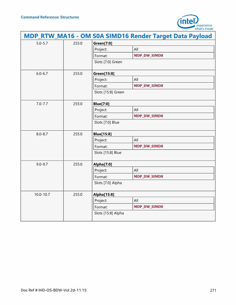
Command Reference: Structures
Doc Ref # IHD-OS-BDW-Vol 2d-11.15 271
MDP_RTW_MA16 - OM S0A SIMD16 Render Target Data Payload 5.0-5.7 255:0 Green[7:0]
Project: All
Format: MDP_DW_SIMD8
Slots [7:0] Green
6.0-6.7 255:0 Green[15:8]
Project: All
Format: MDP_DW_SIMD8
Slots [15:8] Green
7.0-7.7 255:0 Blue[7:0]
Project: All
Format: MDP_DW_SIMD8
Slots [7:0] Blue
8.0-8.7 255:0 Blue[15:8]
Project: All
Format: MDP_DW_SIMD8
Slots [15:8] Blue
9.0-9.7 255:0 Alpha[7:0]
Project: All
Format: MDP_DW_SIMD8
Slots [7:0] Alpha
10.0-10.7 255:0 Alpha[15:8]
Project: All
Format: MDP_DW_SIMD8
Slots [15:8] Alpha
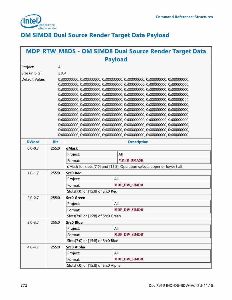
Command Reference: Structures
272 Doc Ref # IHD-OS-BDW-Vol 2d-11.15
OM SIMD8 Dual Source Render Target Data Payload
MDP_RTW_M8DS - OM SIMD8 Dual Source Render Target Data
Payload Project: All
Size (in bits): 2304
Default Value: 0x00000000, 0x00000000, 0x00000000, 0x00000000, 0x00000000, 0x00000000,
0x00000000, 0x00000000, 0x00000000, 0x00000000, 0x00000000, 0x00000000,
0x00000000, 0x00000000, 0x00000000, 0x00000000, 0x00000000, 0x00000000,
0x00000000, 0x00000000, 0x00000000, 0x00000000, 0x00000000, 0x00000000,
0x00000000, 0x00000000, 0x00000000, 0x00000000, 0x00000000, 0x00000000,
0x00000000, 0x00000000, 0x00000000, 0x00000000, 0x00000000, 0x00000000,
0x00000000, 0x00000000, 0x00000000, 0x00000000, 0x00000000, 0x00000000,
0x00000000, 0x00000000, 0x00000000, 0x00000000, 0x00000000, 0x00000000,
0x00000000, 0x00000000, 0x00000000, 0x00000000, 0x00000000, 0x00000000,
0x00000000, 0x00000000, 0x00000000, 0x00000000, 0x00000000, 0x00000000,
0x00000000, 0x00000000, 0x00000000, 0x00000000, 0x00000000, 0x00000000,
0x00000000, 0x00000000, 0x00000000, 0x00000000, 0x00000000, 0x00000000
DWord Bit Description
0.0-0.7 255:0 oMask
Project: All
Format: MDPR_OMASK
oMask for slots [7:0] and [15:8]. Operation selects upper or lower half.
1.0-1.7 255:0 Src0 Red
Project: All
Format: MDP_DW_SIMD8
Slots[7:0] or [15:8] of Src0 Red
2.0-2.7 255:0 Src0 Green
Project: All
Format: MDP_DW_SIMD8
Slots[7:0] or [15:8] of Src0 Green
3.0-3.7 255:0 Src0 Blue
Project: All
Format: MDP_DW_SIMD8
Slots[7:0] or [15:8] of Src0 Blue
4.0-4.7 255:0 Src0 Alpha
Project: All
Format: MDP_DW_SIMD8
Slots[7:0] or [15:8] of Src0 Alpha
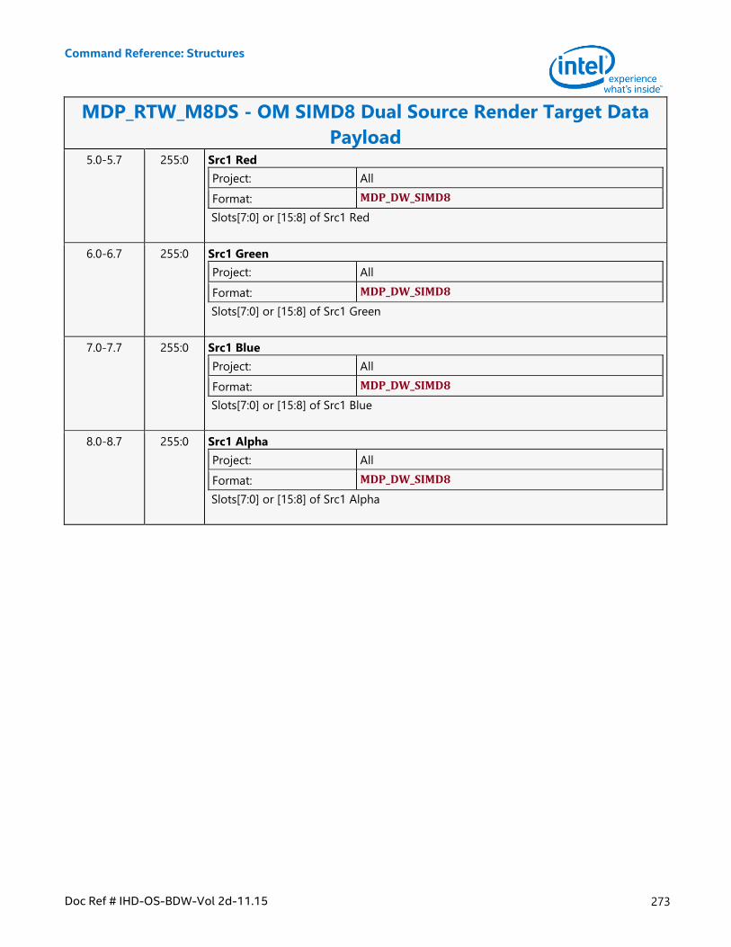
Command Reference: Structures
Doc Ref # IHD-OS-BDW-Vol 2d-11.15 273
MDP_RTW_M8DS - OM SIMD8 Dual Source Render Target Data
Payload 5.0-5.7 255:0 Src1 Red
Project: All
Format: MDP_DW_SIMD8
Slots[7:0] or [15:8] of Src1 Red
6.0-6.7 255:0 Src1 Green
Project: All
Format: MDP_DW_SIMD8
Slots[7:0] or [15:8] of Src1 Green
7.0-7.7 255:0 Src1 Blue
Project: All
Format: MDP_DW_SIMD8
Slots[7:0] or [15:8] of Src1 Blue
8.0-8.7 255:0 Src1 Alpha
Project: All
Format: MDP_DW_SIMD8
Slots[7:0] or [15:8] of Src1 Alpha
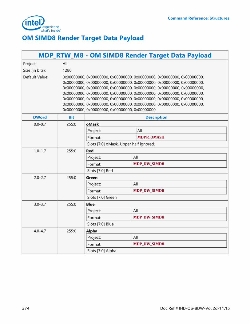
Command Reference: Structures
274 Doc Ref # IHD-OS-BDW-Vol 2d-11.15
OM SIMD8 Render Target Data Payload
MDP_RTW_M8 - OM SIMD8 Render Target Data Payload Project: All
Size (in bits): 1280
Default Value: 0x00000000, 0x00000000, 0x00000000, 0x00000000, 0x00000000, 0x00000000,
0x00000000, 0x00000000, 0x00000000, 0x00000000, 0x00000000, 0x00000000,
0x00000000, 0x00000000, 0x00000000, 0x00000000, 0x00000000, 0x00000000,
0x00000000, 0x00000000, 0x00000000, 0x00000000, 0x00000000, 0x00000000,
0x00000000, 0x00000000, 0x00000000, 0x00000000, 0x00000000, 0x00000000,
0x00000000, 0x00000000, 0x00000000, 0x00000000, 0x00000000, 0x00000000,
0x00000000, 0x00000000, 0x00000000, 0x00000000
DWord Bit Description
0.0-0.7 255:0 oMask
Project: All
Format: MDPR_OMASK
Slots [7:0] oMask. Upper half ignored.
1.0-1.7 255:0 Red
Project: All
Format: MDP_DW_SIMD8
Slots [7:0] Red
2.0-2.7 255:0 Green
Project: All
Format: MDP_DW_SIMD8
Slots [7:0] Green
3.0-3.7 255:0 Blue
Project: All
Format: MDP_DW_SIMD8
Slots [7:0] Blue
4.0-4.7 255:0 Alpha
Project: All
Format: MDP_DW_SIMD8
Slots [7:0] Alpha
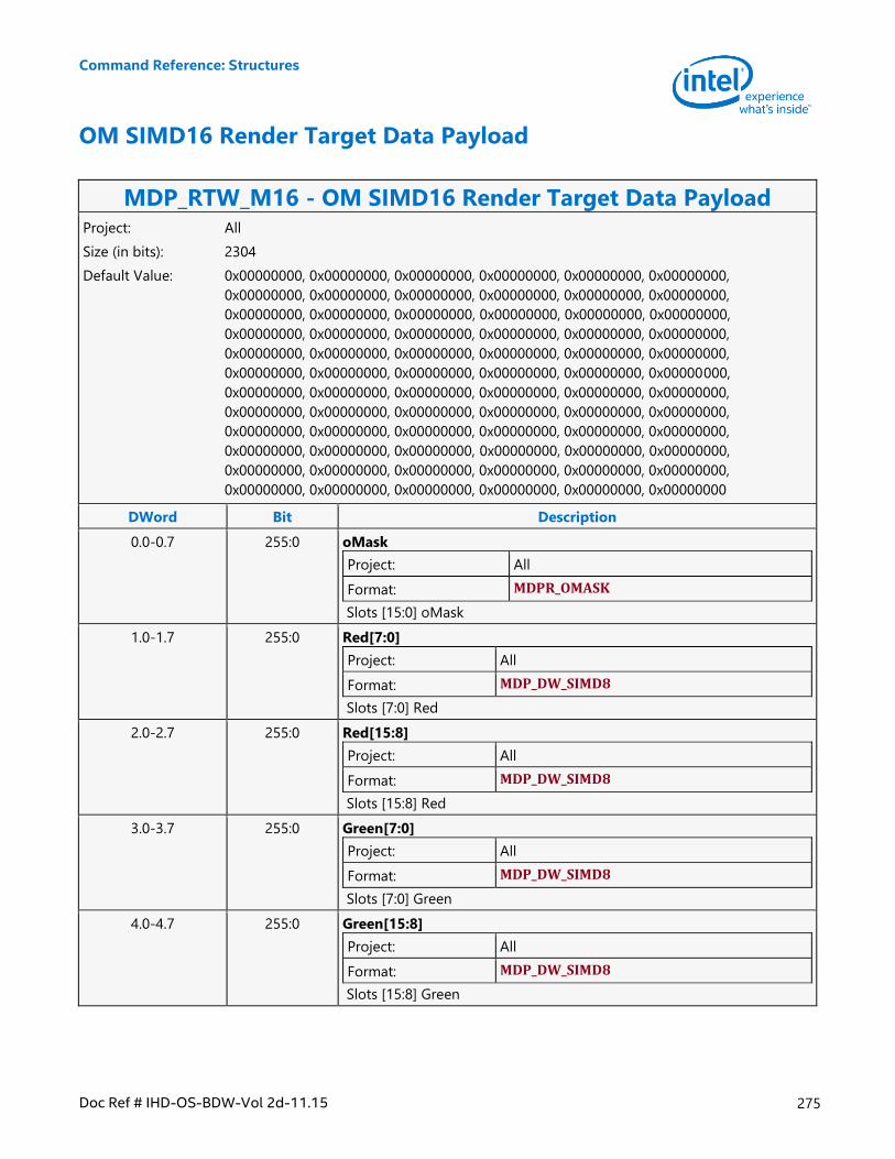
Command Reference: Structures
Doc Ref # IHD-OS-BDW-Vol 2d-11.15 275
OM SIMD16 Render Target Data Payload
MDP_RTW_M16 - OM SIMD16 Render Target Data Payload Project: All
Size (in bits): 2304
Default Value: 0x00000000, 0x00000000, 0x00000000, 0x00000000, 0x00000000, 0x00000000,
0x00000000, 0x00000000, 0x00000000, 0x00000000, 0x00000000, 0x00000000,
0x00000000, 0x00000000, 0x00000000, 0x00000000, 0x00000000, 0x00000000,
0x00000000, 0x00000000, 0x00000000, 0x00000000, 0x00000000, 0x00000000,
0x00000000, 0x00000000, 0x00000000, 0x00000000, 0x00000000, 0x00000000,
0x00000000, 0x00000000, 0x00000000, 0x00000000, 0x00000000, 0x00000000,
0x00000000, 0x00000000, 0x00000000, 0x00000000, 0x00000000, 0x00000000,
0x00000000, 0x00000000, 0x00000000, 0x00000000, 0x00000000, 0x00000000,
0x00000000, 0x00000000, 0x00000000, 0x00000000, 0x00000000, 0x00000000,
0x00000000, 0x00000000, 0x00000000, 0x00000000, 0x00000000, 0x00000000,
0x00000000, 0x00000000, 0x00000000, 0x00000000, 0x00000000, 0x00000000,
0x00000000, 0x00000000, 0x00000000, 0x00000000, 0x00000000, 0x00000000
DWord Bit Description
0.0-0.7 255:0 oMask
Project: All
Format: MDPR_OMASK
Slots [15:0] oMask
1.0-1.7 255:0 Red[7:0]
Project: All
Format: MDP_DW_SIMD8
Slots [7:0] Red
2.0-2.7 255:0 Red[15:8]
Project: All
Format: MDP_DW_SIMD8
Slots [15:8] Red
3.0-3.7 255:0 Green[7:0]
Project: All
Format: MDP_DW_SIMD8
Slots [7:0] Green
4.0-4.7 255:0 Green[15:8]
Project: All
Format: MDP_DW_SIMD8
Slots [15:8] Green
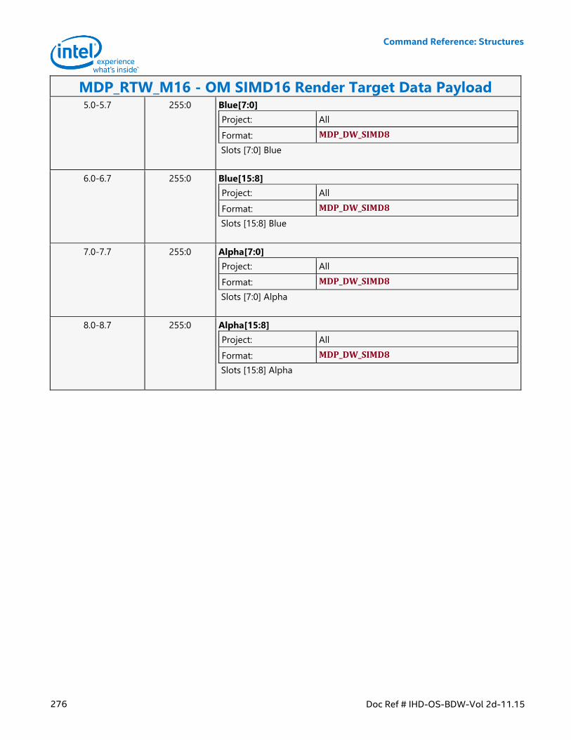
Command Reference: Structures
276 Doc Ref # IHD-OS-BDW-Vol 2d-11.15
MDP_RTW_M16 - OM SIMD16 Render Target Data Payload 5.0-5.7 255:0 Blue[7:0]
Project: All
Format: MDP_DW_SIMD8
Slots [7:0] Blue
6.0-6.7 255:0 Blue[15:8]
Project: All
Format: MDP_DW_SIMD8
Slots [15:8] Blue
7.0-7.7 255:0 Alpha[7:0]
Project: All
Format: MDP_DW_SIMD8
Slots [7:0] Alpha
8.0-8.7 255:0 Alpha[15:8]
Project: All
Format: MDP_DW_SIMD8
Slots [15:8] Alpha
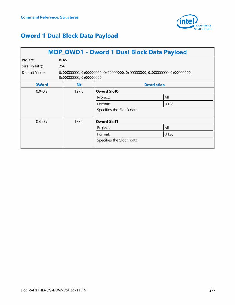
Command Reference: Structures
Doc Ref # IHD-OS-BDW-Vol 2d-11.15 277
Oword 1 Dual Block Data Payload
MDP_OWD1 - Oword 1 Dual Block Data Payload Project: BDW
Size (in bits): 256
Default Value: 0x00000000, 0x00000000, 0x00000000, 0x00000000, 0x00000000, 0x00000000,
0x00000000, 0x00000000
DWord Bit Description
0.0-0.3 127:0 Oword Slot0
Project: All
Format: U128
Specifies the Slot 0 data
0.4-0.7 127:0 Oword Slot1
Project: All
Format: U128
Specifies the Slot 1 data

Command Reference: Structures
278 Doc Ref # IHD-OS-BDW-Vol 2d-11.15
Oword 2 Block Data Payload
MDP_OW2 - Oword 2 Block Data Payload Project: BDW
Size (in bits): 256
Default Value: 0x00000000, 0x00000000, 0x00000000, 0x00000000, 0x00000000, 0x00000000,
0x00000000, 0x00000000
DWord Bit Description
0.0-0.3 127:0 Oword0
Project: All
Format: U128
Specifies the Oword data for block element 0
0.4-0.7 127:0 Oword1
Project: All
Format: U128
Specifies the Oword data for block element 1
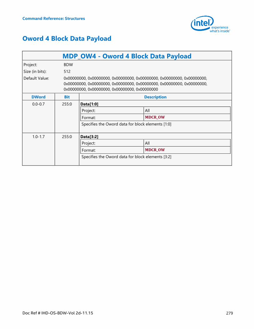
Command Reference: Structures
Doc Ref # IHD-OS-BDW-Vol 2d-11.15 279
Oword 4 Block Data Payload
MDP_OW4 - Oword 4 Block Data Payload Project: BDW
Size (in bits): 512
Default Value: 0x00000000, 0x00000000, 0x00000000, 0x00000000, 0x00000000, 0x00000000,
0x00000000, 0x00000000, 0x00000000, 0x00000000, 0x00000000, 0x00000000,
0x00000000, 0x00000000, 0x00000000, 0x00000000
DWord Bit Description
0.0-0.7 255:0 Data[1:0]
Project: All
Format: MDCR_OW
Specifies the Oword data for block elements [1:0]
1.0-1.7 255:0 Data[3:2]
Project: All
Format: MDCR_OW
Specifies the Oword data for block elements [3:2]
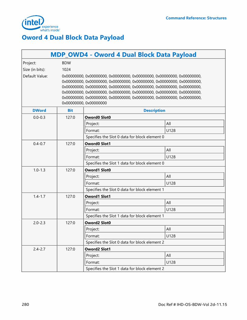
Command Reference: Structures
280 Doc Ref # IHD-OS-BDW-Vol 2d-11.15
Oword 4 Dual Block Data Payload
MDP_OWD4 - Oword 4 Dual Block Data Payload Project: BDW
Size (in bits): 1024
Default Value: 0x00000000, 0x00000000, 0x00000000, 0x00000000, 0x00000000, 0x00000000,
0x00000000, 0x00000000, 0x00000000, 0x00000000, 0x00000000, 0x00000000,
0x00000000, 0x00000000, 0x00000000, 0x00000000, 0x00000000, 0x00000000,
0x00000000, 0x00000000, 0x00000000, 0x00000000, 0x00000000, 0x00000000,
0x00000000, 0x00000000, 0x00000000, 0x00000000, 0x00000000, 0x00000000,
0x00000000, 0x00000000
DWord Bit Description
0.0-0.3 127:0 Oword0 Slot0
Project: All
Format: U128
Specifies the Slot 0 data for block element 0
0.4-0.7 127:0 Oword0 Slot1
Project: All
Format: U128
Specifies the Slot 1 data for block element 0
1.0-1.3 127:0 Oword1 Slot0
Project: All
Format: U128
Specifies the Slot 0 data for block element 1
1.4-1.7 127:0 Oword1 Slot1
Project: All
Format: U128
Specifies the Slot 1 data for block element 1
2.0-2.3 127:0 Oword2 Slot0
Project: All
Format: U128
Specifies the Slot 0 data for block element 2
2.4-2.7 127:0 Oword2 Slot1
Project: All
Format: U128
Specifies the Slot 1 data for block element 2
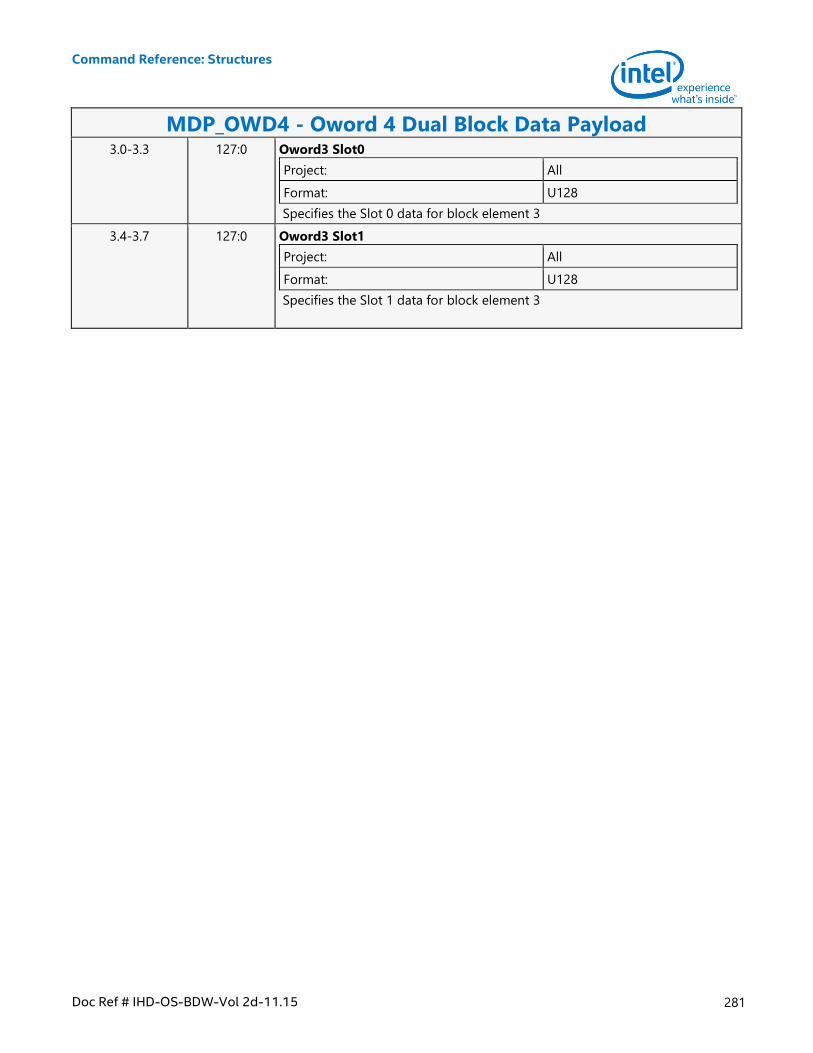
Command Reference: Structures
Doc Ref # IHD-OS-BDW-Vol 2d-11.15 281
MDP_OWD4 - Oword 4 Dual Block Data Payload 3.0-3.3 127:0 Oword3 Slot0
Project: All
Format: U128
Specifies the Slot 0 data for block element 3
3.4-3.7 127:0 Oword3 Slot1
Project: All
Format: U128
Specifies the Slot 1 data for block element 3
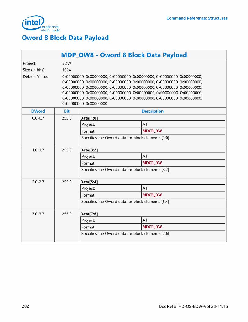
Command Reference: Structures
282 Doc Ref # IHD-OS-BDW-Vol 2d-11.15
Oword 8 Block Data Payload
MDP_OW8 - Oword 8 Block Data Payload Project: BDW
Size (in bits): 1024
Default Value: 0x00000000, 0x00000000, 0x00000000, 0x00000000, 0x00000000, 0x00000000,
0x00000000, 0x00000000, 0x00000000, 0x00000000, 0x00000000, 0x00000000,
0x00000000, 0x00000000, 0x00000000, 0x00000000, 0x00000000, 0x00000000,
0x00000000, 0x00000000, 0x00000000, 0x00000000, 0x00000000, 0x00000000,
0x00000000, 0x00000000, 0x00000000, 0x00000000, 0x00000000, 0x00000000,
0x00000000, 0x00000000
DWord Bit Description
0.0-0.7 255:0 Data[1:0]
Project: All
Format: MDCR_OW
Specifies the Oword data for block elements [1:0]
1.0-1.7 255:0 Data[3:2]
Project: All
Format: MDCR_OW
Specifies the Oword data for block elements [3:2]
2.0-2.7 255:0 Data[5:4]
Project: All
Format: MDCR_OW
Specifies the Oword data for block elements [5:4]
3.0-3.7 255:0 Data[7:6]
Project: All
Format: MDCR_OW
Specifies the Oword data for block elements [7:6]
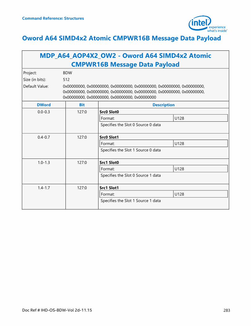
Command Reference: Structures
Doc Ref # IHD-OS-BDW-Vol 2d-11.15 283
Oword A64 SIMD4x2 Atomic CMPWR16B Message Data Payload
MDP_A64_AOP4X2_OW2 - Oword A64 SIMD4x2 Atomic
CMPWR16B Message Data Payload Project: BDW
Size (in bits): 512
Default Value: 0x00000000, 0x00000000, 0x00000000, 0x00000000, 0x00000000, 0x00000000,
0x00000000, 0x00000000, 0x00000000, 0x00000000, 0x00000000, 0x00000000,
0x00000000, 0x00000000, 0x00000000, 0x00000000
DWord Bit Description
0.0-0.3 127:0 Src0 Slot0
Format: U128
Specifies the Slot 0 Source 0 data
0.4-0.7 127:0 Src0 Slot1
Format: U128
Specifies the Slot 1 Source 0 data
1.0-1.3 127:0 Src1 Slot0
Format: U128
Specifies the Slot 0 Source 1 data
1.4-1.7 127:0 Src1 Slot1
Format: U128
Specifies the Slot 1 Source 1 data
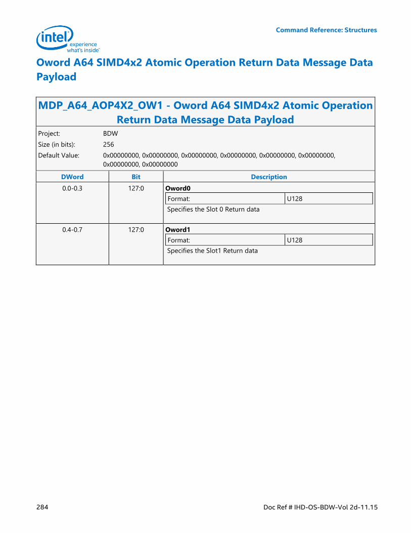
Command Reference: Structures
284 Doc Ref # IHD-OS-BDW-Vol 2d-11.15
Oword A64 SIMD4x2 Atomic Operation Return Data Message Data
Payload
MDP_A64_AOP4X2_OW1 - Oword A64 SIMD4x2 Atomic Operation
Return Data Message Data Payload Project: BDW
Size (in bits): 256
Default Value: 0x00000000, 0x00000000, 0x00000000, 0x00000000, 0x00000000, 0x00000000,
0x00000000, 0x00000000
DWord Bit Description
0.0-0.3 127:0 Oword0
Format: U128
Specifies the Slot 0 Return data
0.4-0.7 127:0 Oword1
Format: U128
Specifies the Slot1 Return data
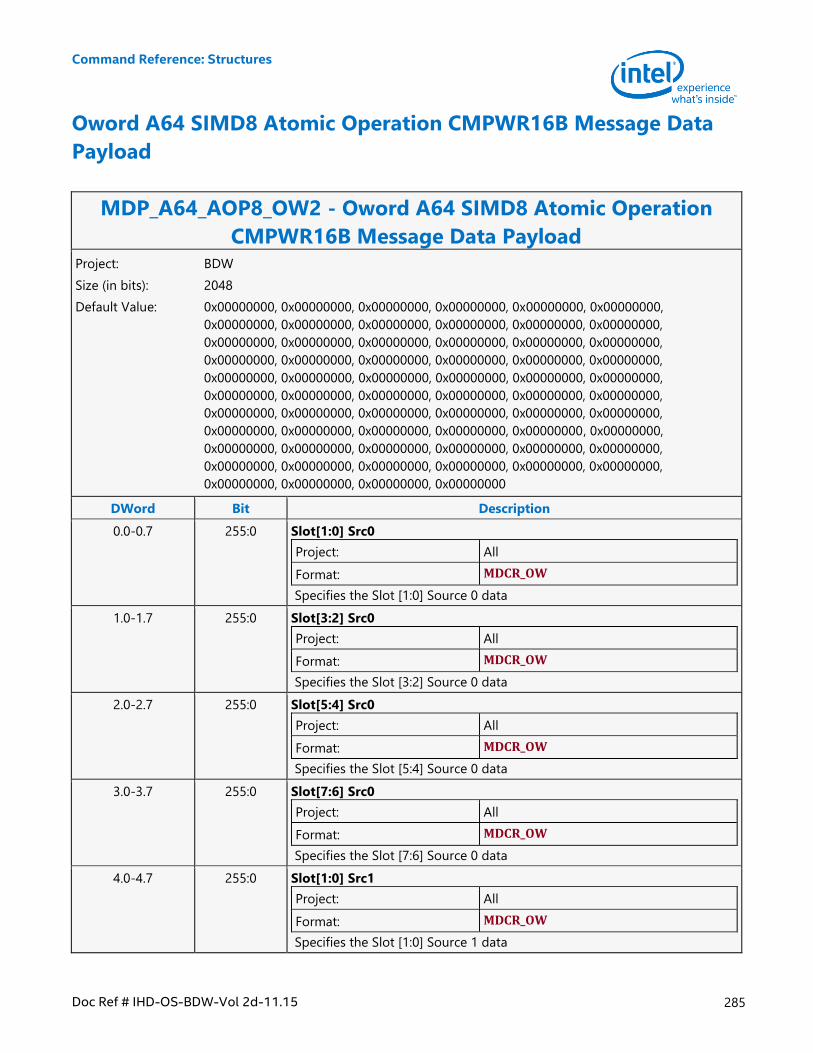
Command Reference: Structures
Doc Ref # IHD-OS-BDW-Vol 2d-11.15 285
Oword A64 SIMD8 Atomic Operation CMPWR16B Message Data
Payload
MDP_A64_AOP8_OW2 - Oword A64 SIMD8 Atomic Operation
CMPWR16B Message Data Payload Project: BDW
Size (in bits): 2048
Default Value: 0x00000000, 0x00000000, 0x00000000, 0x00000000, 0x00000000, 0x00000000,
0x00000000, 0x00000000, 0x00000000, 0x00000000, 0x00000000, 0x00000000,
0x00000000, 0x00000000, 0x00000000, 0x00000000, 0x00000000, 0x00000000,
0x00000000, 0x00000000, 0x00000000, 0x00000000, 0x00000000, 0x00000000,
0x00000000, 0x00000000, 0x00000000, 0x00000000, 0x00000000, 0x00000000,
0x00000000, 0x00000000, 0x00000000, 0x00000000, 0x00000000, 0x00000000,
0x00000000, 0x00000000, 0x00000000, 0x00000000, 0x00000000, 0x00000000,
0x00000000, 0x00000000, 0x00000000, 0x00000000, 0x00000000, 0x00000000,
0x00000000, 0x00000000, 0x00000000, 0x00000000, 0x00000000, 0x00000000,
0x00000000, 0x00000000, 0x00000000, 0x00000000, 0x00000000, 0x00000000,
0x00000000, 0x00000000, 0x00000000, 0x00000000
DWord Bit Description
0.0-0.7 255:0 Slot[1:0] Src0
Project: All
Format: MDCR_OW
Specifies the Slot [1:0] Source 0 data
1.0-1.7 255:0 Slot[3:2] Src0
Project: All
Format: MDCR_OW
Specifies the Slot [3:2] Source 0 data
2.0-2.7 255:0 Slot[5:4] Src0
Project: All
Format: MDCR_OW
Specifies the Slot [5:4] Source 0 data
3.0-3.7 255:0 Slot[7:6] Src0
Project: All
Format: MDCR_OW
Specifies the Slot [7:6] Source 0 data
4.0-4.7 255:0 Slot[1:0] Src1
Project: All
Format: MDCR_OW
Specifies the Slot [1:0] Source 1 data
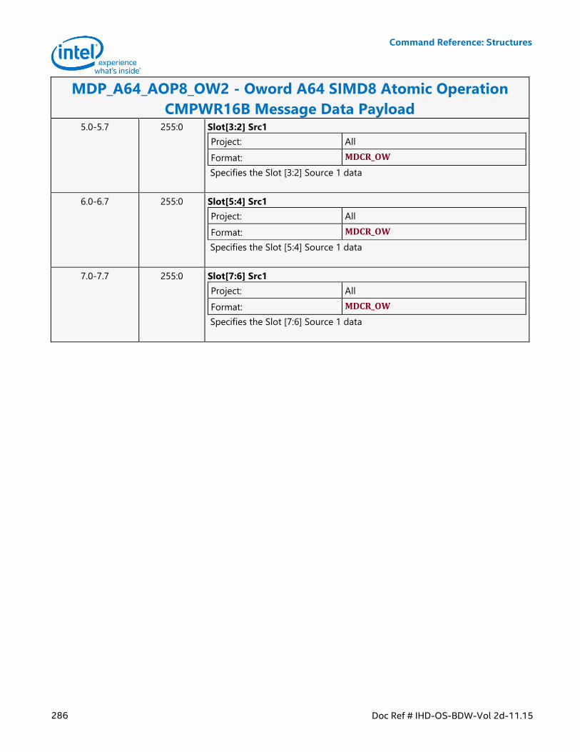
Command Reference: Structures
286 Doc Ref # IHD-OS-BDW-Vol 2d-11.15
MDP_A64_AOP8_OW2 - Oword A64 SIMD8 Atomic Operation
CMPWR16B Message Data Payload 5.0-5.7 255:0 Slot[3:2] Src1
Project: All
Format: MDCR_OW
Specifies the Slot [3:2] Source 1 data
6.0-6.7 255:0 Slot[5:4] Src1
Project: All
Format: MDCR_OW
Specifies the Slot [5:4] Source 1 data
7.0-7.7 255:0 Slot[7:6] Src1
Project: All
Format: MDCR_OW
Specifies the Slot [7:6] Source 1 data
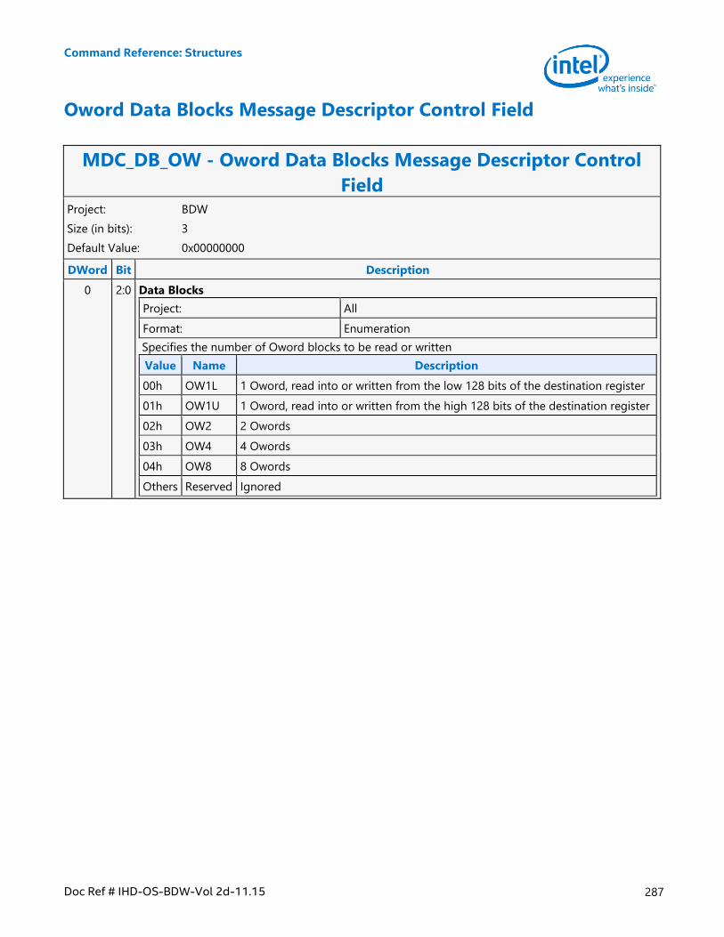
Command Reference: Structures
Doc Ref # IHD-OS-BDW-Vol 2d-11.15 287
Oword Data Blocks Message Descriptor Control Field
MDC_DB_OW - Oword Data Blocks Message Descriptor Control
Field Project: BDW
Size (in bits): 3
Default Value: 0x00000000
DWord Bit Description
0 2:0 Data Blocks
Project: All
Format: Enumeration
Specifies the number of Oword blocks to be read or written
Value Name Description
00h OW1L 1 Oword, read into or written from the low 128 bits of the destination register
01h OW1U 1 Oword, read into or written from the high 128 bits of the destination register
02h OW2 2 Owords
03h OW4 4 Owords
04h OW8 8 Owords
Others Reserved Ignored

Command Reference: Structures
288 Doc Ref # IHD-OS-BDW-Vol 2d-11.15
Oword Data Payload Register
MDCR_OW - Oword Data Payload Register Project: BDW
Size (in bits): 256
Default Value: 0x00000000, 0x00000000, 0x00000000, 0x00000000, 0x00000000, 0x00000000,
0x00000000, 0x00000000
DWord Bit Description
0.0-0.3 127:0 Oword0
Project: All
Format: U128
Specifies the slot 0 data in this payload register
0.4-0.7 127:0 Oword1
Project: All
Format: U128
Specifies the slot 1 data in this payload register
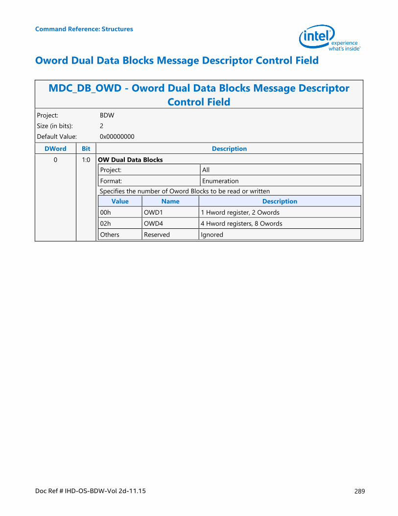
Command Reference: Structures
Doc Ref # IHD-OS-BDW-Vol 2d-11.15 289
Oword Dual Data Blocks Message Descriptor Control Field
MDC_DB_OWD - Oword Dual Data Blocks Message Descriptor
Control Field Project: BDW
Size (in bits): 2
Default Value: 0x00000000
DWord Bit Description
0 1:0 OW Dual Data Blocks
Project: All
Format: Enumeration
Specifies the number of Oword Blocks to be read or written
Value Name Description
00h OWD1 1 Hword register, 2 Owords
02h OWD4 4 Hword registers, 8 Owords
Others Reserved Ignored
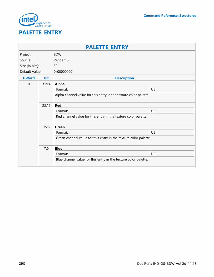
Command Reference: Structures
290 Doc Ref # IHD-OS-BDW-Vol 2d-11.15
PALETTE_ENTRY
PALETTE_ENTRY Project: BDW
Source: RenderCS
Size (in bits): 32
Default Value: 0x00000000
DWord Bit Description
0 31:24 Alpha
Format: U8
Alpha channel value for this entry in the texture color palette.
23:16 Red
Format: U8
Red channel value for this entry in the texture color palette.
15:8 Green
Format: U8
Green channel value for this entry in the texture color palette.
7:0 Blue
Format: U8
Blue channel value for this entry in the texture color palette.
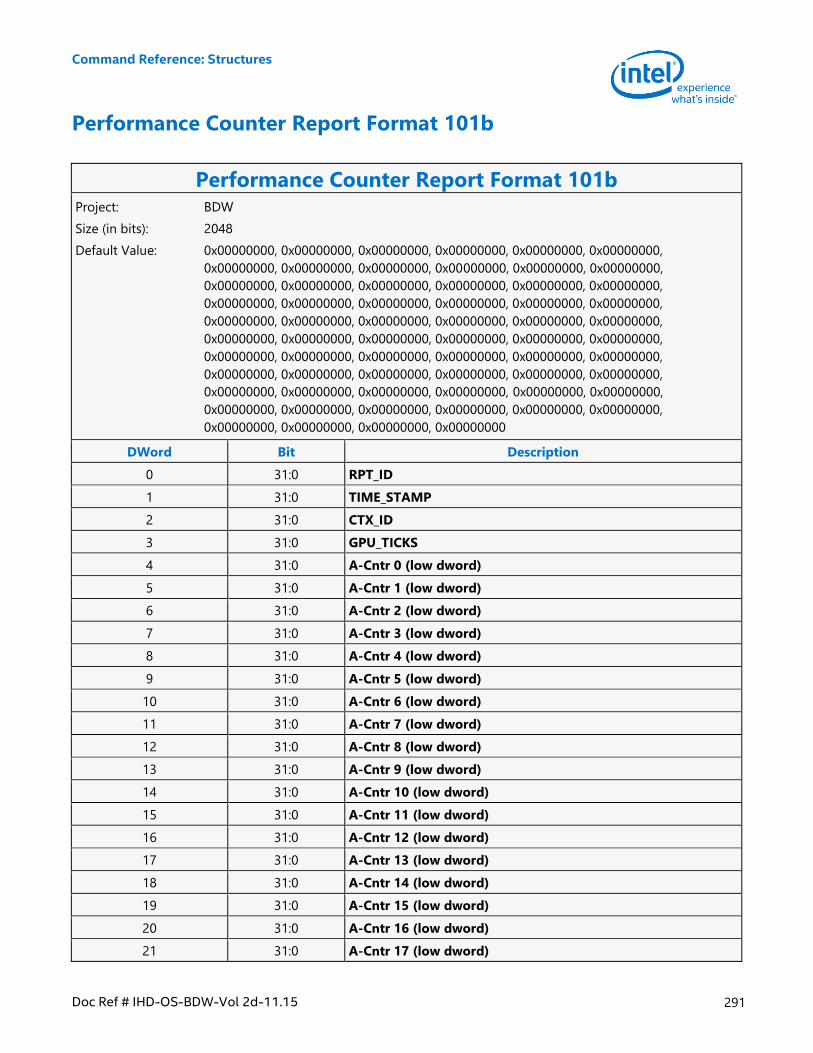
Command Reference: Structures
Doc Ref # IHD-OS-BDW-Vol 2d-11.15 291
Performance Counter Report Format 101b
Performance Counter Report Format 101b Project: BDW
Size (in bits): 2048
Default Value: 0x00000000, 0x00000000, 0x00000000, 0x00000000, 0x00000000, 0x00000000,
0x00000000, 0x00000000, 0x00000000, 0x00000000, 0x00000000, 0x00000000,
0x00000000, 0x00000000, 0x00000000, 0x00000000, 0x00000000, 0x00000000,
0x00000000, 0x00000000, 0x00000000, 0x00000000, 0x00000000, 0x00000000,
0x00000000, 0x00000000, 0x00000000, 0x00000000, 0x00000000, 0x00000000,
0x00000000, 0x00000000, 0x00000000, 0x00000000, 0x00000000, 0x00000000,
0x00000000, 0x00000000, 0x00000000, 0x00000000, 0x00000000, 0x00000000,
0x00000000, 0x00000000, 0x00000000, 0x00000000, 0x00000000, 0x00000000,
0x00000000, 0x00000000, 0x00000000, 0x00000000, 0x00000000, 0x00000000,
0x00000000, 0x00000000, 0x00000000, 0x00000000, 0x00000000, 0x00000000,
0x00000000, 0x00000000, 0x00000000, 0x00000000
DWord Bit Description
0 31:0 RPT_ID
1 31:0 TIME_STAMP
2 31:0 CTX_ID
3 31:0 GPU_TICKS
4 31:0 A-Cntr 0 (low dword)
5 31:0 A-Cntr 1 (low dword)
6 31:0 A-Cntr 2 (low dword)
7 31:0 A-Cntr 3 (low dword)
8 31:0 A-Cntr 4 (low dword)
9 31:0 A-Cntr 5 (low dword)
10 31:0 A-Cntr 6 (low dword)
11 31:0 A-Cntr 7 (low dword)
12 31:0 A-Cntr 8 (low dword)
13 31:0 A-Cntr 9 (low dword)
14 31:0 A-Cntr 10 (low dword)
15 31:0 A-Cntr 11 (low dword)
16 31:0 A-Cntr 12 (low dword)
17 31:0 A-Cntr 13 (low dword)
18 31:0 A-Cntr 14 (low dword)
19 31:0 A-Cntr 15 (low dword)
20 31:0 A-Cntr 16 (low dword)
21 31:0 A-Cntr 17 (low dword)
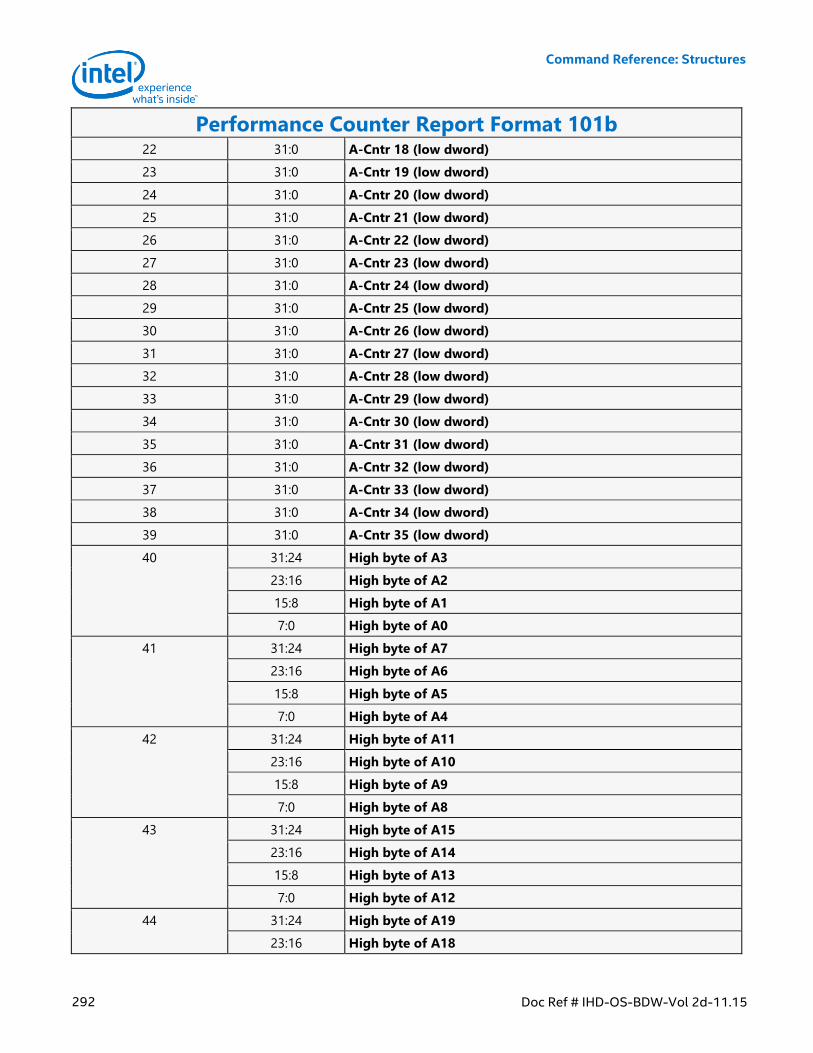
Command Reference: Structures
292 Doc Ref # IHD-OS-BDW-Vol 2d-11.15
Performance Counter Report Format 101b 22 31:0 A-Cntr 18 (low dword)
23 31:0 A-Cntr 19 (low dword)
24 31:0 A-Cntr 20 (low dword)
25 31:0 A-Cntr 21 (low dword)
26 31:0 A-Cntr 22 (low dword)
27 31:0 A-Cntr 23 (low dword)
28 31:0 A-Cntr 24 (low dword)
29 31:0 A-Cntr 25 (low dword)
30 31:0 A-Cntr 26 (low dword)
31 31:0 A-Cntr 27 (low dword)
32 31:0 A-Cntr 28 (low dword)
33 31:0 A-Cntr 29 (low dword)
34 31:0 A-Cntr 30 (low dword)
35 31:0 A-Cntr 31 (low dword)
36 31:0 A-Cntr 32 (low dword)
37 31:0 A-Cntr 33 (low dword)
38 31:0 A-Cntr 34 (low dword)
39 31:0 A-Cntr 35 (low dword)
40 31:24 High byte of A3
23:16 High byte of A2
15:8 High byte of A1
7:0 High byte of A0
41 31:24 High byte of A7
23:16 High byte of A6
15:8 High byte of A5
7:0 High byte of A4
42 31:24 High byte of A11
23:16 High byte of A10
15:8 High byte of A9
7:0 High byte of A8
43 31:24 High byte of A15
23:16 High byte of A14
15:8 High byte of A13
7:0 High byte of A12
44 31:24 High byte of A19
23:16 High byte of A18
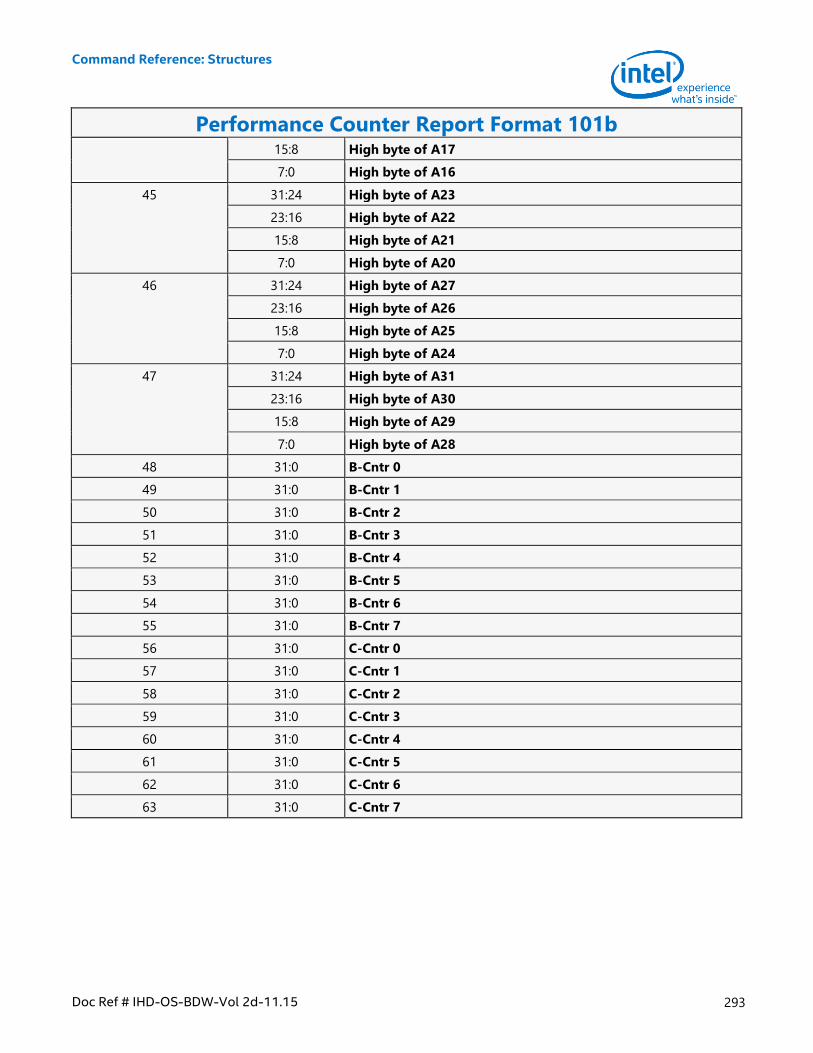
Command Reference: Structures
Doc Ref # IHD-OS-BDW-Vol 2d-11.15 293
Performance Counter Report Format 101b 15:8 High byte of A17
7:0 High byte of A16
45 31:24 High byte of A23
23:16 High byte of A22
15:8 High byte of A21
7:0 High byte of A20
46 31:24 High byte of A27
23:16 High byte of A26
15:8 High byte of A25
7:0 High byte of A24
47 31:24 High byte of A31
23:16 High byte of A30
15:8 High byte of A29
7:0 High byte of A28
48 31:0 B-Cntr 0
49 31:0 B-Cntr 1
50 31:0 B-Cntr 2
51 31:0 B-Cntr 3
52 31:0 B-Cntr 4
53 31:0 B-Cntr 5
54 31:0 B-Cntr 6
55 31:0 B-Cntr 7
56 31:0 C-Cntr 0
57 31:0 C-Cntr 1
58 31:0 C-Cntr 2
59 31:0 C-Cntr 3
60 31:0 C-Cntr 4
61 31:0 C-Cntr 5
62 31:0 C-Cntr 6
63 31:0 C-Cntr 7
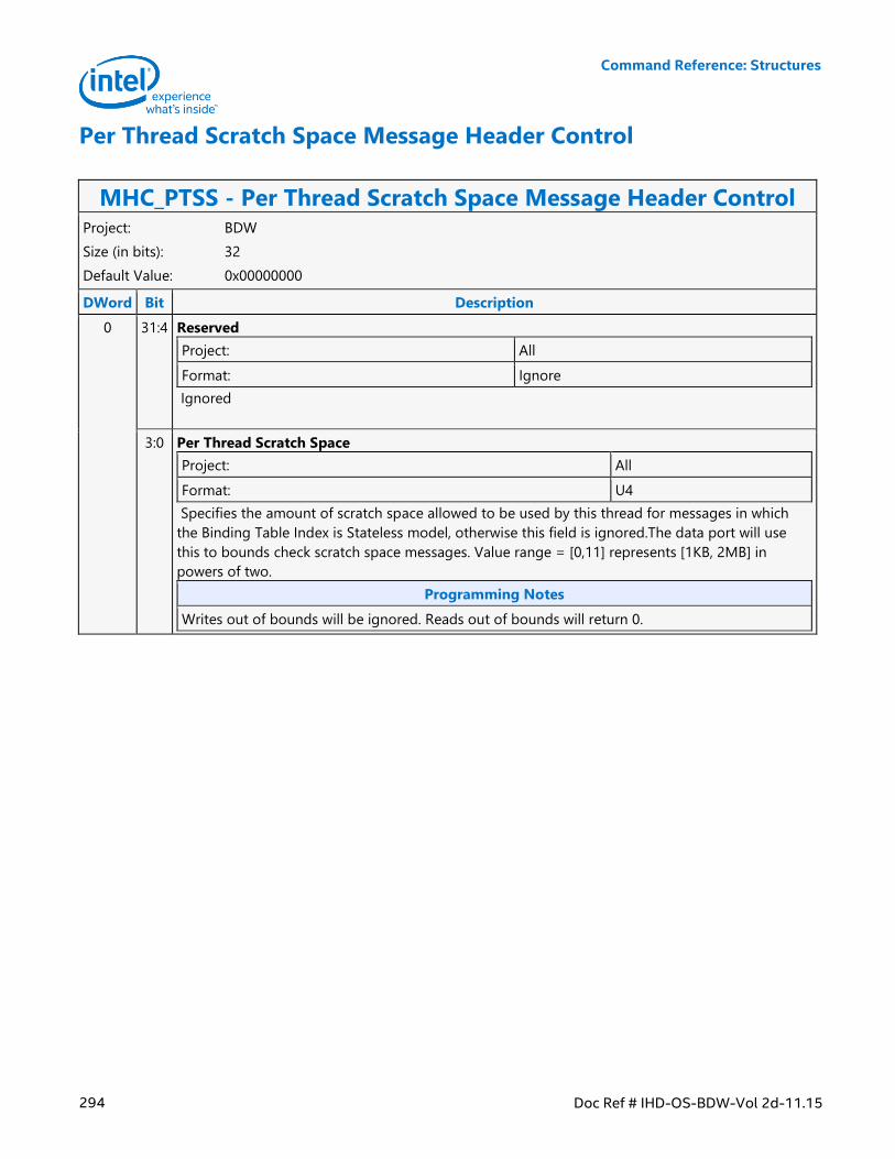
Command Reference: Structures
294 Doc Ref # IHD-OS-BDW-Vol 2d-11.15
Per Thread Scratch Space Message Header Control
MHC_PTSS - Per Thread Scratch Space Message Header Control Project: BDW
Size (in bits): 32
Default Value: 0x00000000
DWord Bit Description
0 31:4 Reserved
Project: All
Format: Ignore
Ignored
3:0 Per Thread Scratch Space
Project: All
Format: U4
Specifies the amount of scratch space allowed to be used by this thread for messages in which
the Binding Table Index is Stateless model, otherwise this field is ignored.The data port will use
this to bounds check scratch space messages. Value range = [0,11] represents [1KB, 2MB] in
powers of two.
Programming Notes
Writes out of bounds will be ignored. Reads out of bounds will return 0.
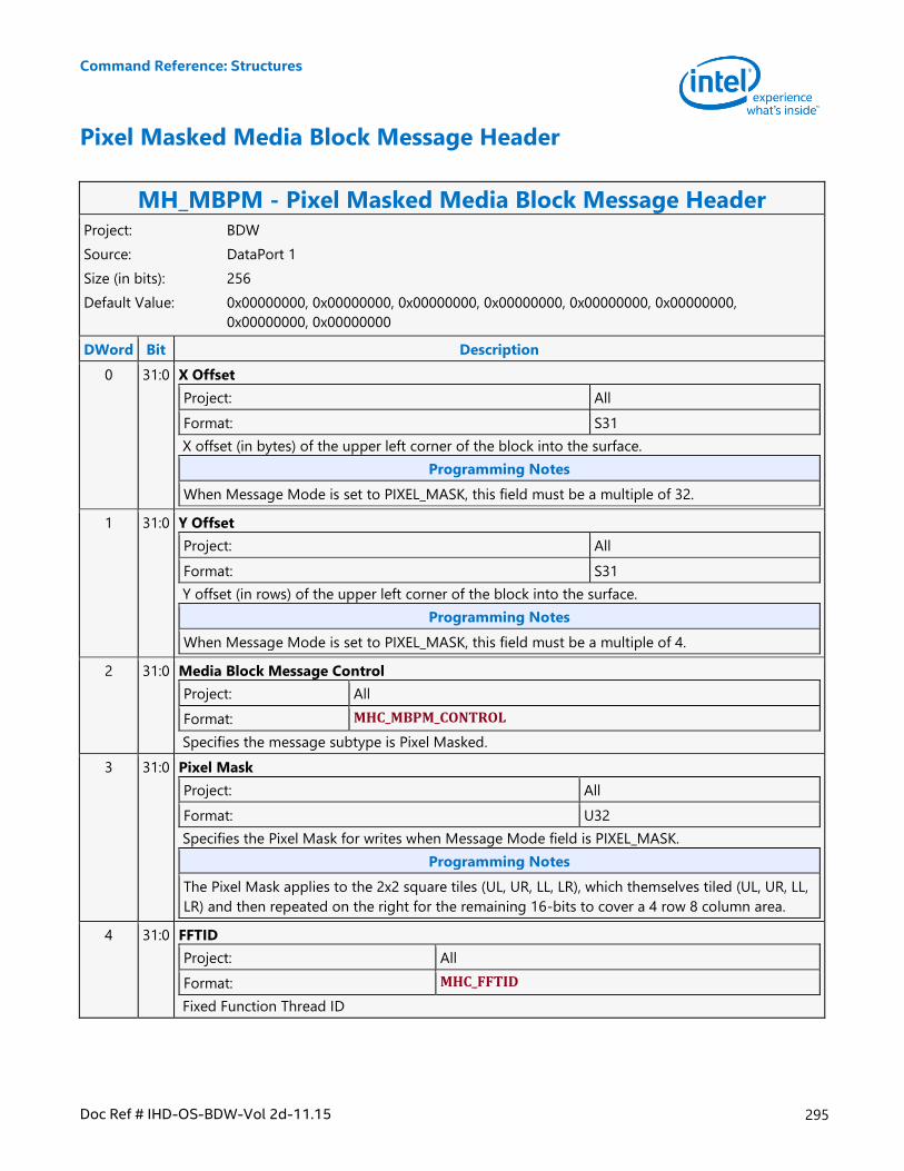
Command Reference: Structures
Doc Ref # IHD-OS-BDW-Vol 2d-11.15 295
Pixel Masked Media Block Message Header
MH_MBPM - Pixel Masked Media Block Message Header Project: BDW
Source: DataPort 1
Size (in bits): 256
Default Value: 0x00000000, 0x00000000, 0x00000000, 0x00000000, 0x00000000, 0x00000000,
0x00000000, 0x00000000
DWord Bit Description
0 31:0 X Offset
Project: All
Format: S31
X offset (in bytes) of the upper left corner of the block into the surface.
Programming Notes
When Message Mode is set to PIXEL_MASK, this field must be a multiple of 32.
1 31:0 Y Offset
Project: All
Format: S31
Y offset (in rows) of the upper left corner of the block into the surface.
Programming Notes
When Message Mode is set to PIXEL_MASK, this field must be a multiple of 4.
2 31:0 Media Block Message Control
Project: All
Format: MHC_MBPM_CONTROL
Specifies the message subtype is Pixel Masked.
3 31:0 Pixel Mask
Project: All
Format: U32
Specifies the Pixel Mask for writes when Message Mode field is PIXEL_MASK.
Programming Notes
The Pixel Mask applies to the 2x2 square tiles (UL, UR, LL, LR), which themselves tiled (UL, UR, LL,
LR) and then repeated on the right for the remaining 16-bits to cover a 4 row 8 column area.
4 31:0 FFTID
Project: All
Format: MHC_FFTID
Fixed Function Thread ID
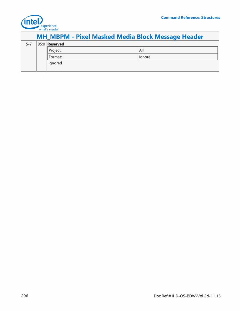
Command Reference: Structures
296 Doc Ref # IHD-OS-BDW-Vol 2d-11.15
MH_MBPM - Pixel Masked Media Block Message Header 5-7 95:0 Reserved
Project: All
Format: Ignore
Ignored
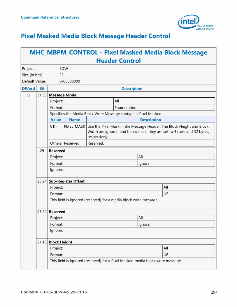
Command Reference: Structures
Doc Ref # IHD-OS-BDW-Vol 2d-11.15 297
Pixel Masked Media Block Message Header Control
MHC_MBPM_CONTROL - Pixel Masked Media Block Message
Header Control Project: BDW
Size (in bits): 32
Default Value: 0x00000000
DWord Bit Description
0 31:30 Message Mode
Project: All
Format: Enumeration
Specifies the Media Block Write Message subtype is Pixel Masked.
Value Name Description
01h PIXEL_MASK Use the Pixel Mask in the Message Header. The Block Height and Block
Width are ignored and behave as if they are set to 4 rows and 32 bytes,
respectively.
Others Reserved Reserved.
29 Reserved
Project: All
Format: Ignore
Ignored
28:24 Sub-Register Offset
Project: All
Format: U5
This field is ignored (reserved) for a media block write message.
23:22 Reserved
Project: All
Format: Ignore
Ignored
21:16 Block Height
Project: All
Format: U6
This field is ignored (reserved) for a Pixel Masked media block write message.
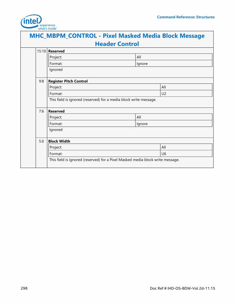
Command Reference: Structures
298 Doc Ref # IHD-OS-BDW-Vol 2d-11.15
MHC_MBPM_CONTROL - Pixel Masked Media Block Message
Header Control 15:10 Reserved
Project: All
Format: Ignore
Ignored
9:8 Register Pitch Control
Project: All
Format: U2
This field is ignored (reserved) for a media block write message.
7:6 Reserved
Project: All
Format: Ignore
Ignored
5:0 Block Width
Project: All
Format: U6
This field is ignored (reserved) for a Pixel Masked media block write message.
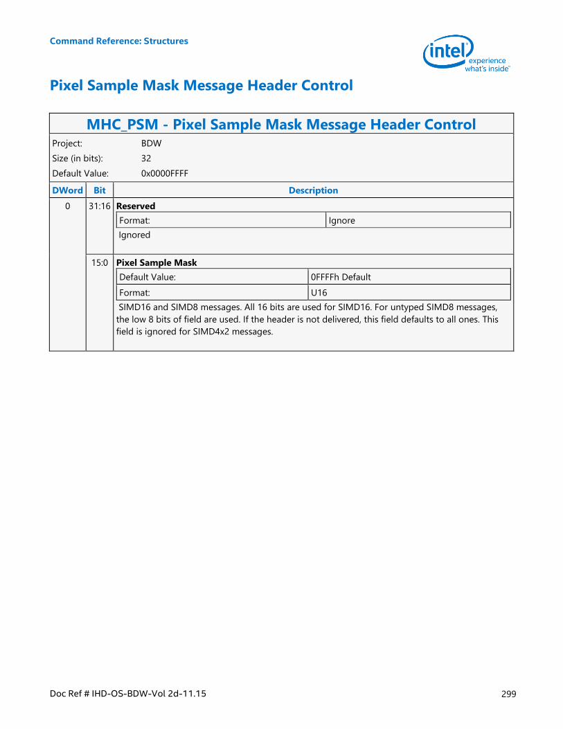
Command Reference: Structures
Doc Ref # IHD-OS-BDW-Vol 2d-11.15 299
Pixel Sample Mask Message Header Control
MHC_PSM - Pixel Sample Mask Message Header Control Project: BDW
Size (in bits): 32
Default Value: 0x0000FFFF
DWord Bit Description
0 31:16 Reserved
Format: Ignore
Ignored
15:0 Pixel Sample Mask
Default Value: 0FFFFh Default
Format: U16
SIMD16 and SIMD8 messages. All 16 bits are used for SIMD16. For untyped SIMD8 messages,
the low 8 bits of field are used. If the header is not delivered, this field defaults to all ones. This
field is ignored for SIMD4x2 messages.
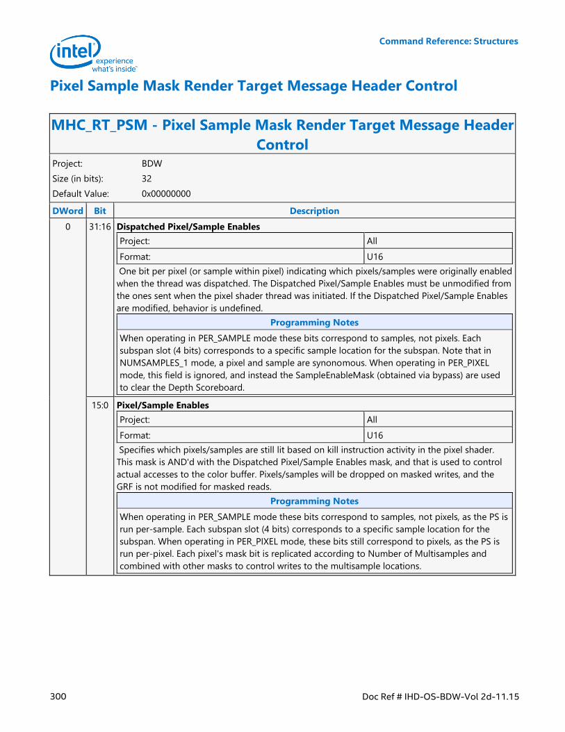
Command Reference: Structures
300 Doc Ref # IHD-OS-BDW-Vol 2d-11.15
Pixel Sample Mask Render Target Message Header Control
MHC_RT_PSM - Pixel Sample Mask Render Target Message Header
Control Project: BDW
Size (in bits): 32
Default Value: 0x00000000
DWord Bit Description
0 31:16 Dispatched Pixel/Sample Enables
Project: All
Format: U16
One bit per pixel (or sample within pixel) indicating which pixels/samples were originally enabled
when the thread was dispatched. The Dispatched Pixel/Sample Enables must be unmodified from
the ones sent when the pixel shader thread was initiated. If the Dispatched Pixel/Sample Enables
are modified, behavior is undefined.
Programming Notes
When operating in PER_SAMPLE mode these bits correspond to samples, not pixels. Each
subspan slot (4 bits) corresponds to a specific sample location for the subspan. Note that in
NUMSAMPLES_1 mode, a pixel and sample are synonomous. When operating in PER_PIXEL
mode, this field is ignored, and instead the SampleEnableMask (obtained via bypass) are used
to clear the Depth Scoreboard.
15:0 Pixel/Sample Enables
Project: All
Format: U16
Specifies which pixels/samples are still lit based on kill instruction activity in the pixel shader.
This mask is AND'd with the Dispatched Pixel/Sample Enables mask, and that is used to control
actual accesses to the color buffer. Pixels/samples will be dropped on masked writes, and the
GRF is not modified for masked reads.
Programming Notes
When operating in PER_SAMPLE mode these bits correspond to samples, not pixels, as the PS is
run per-sample. Each subspan slot (4 bits) corresponds to a specific sample location for the
subspan. When operating in PER_PIXEL mode, these bits still correspond to pixels, as the PS is
run per-pixel. Each pixel's mask bit is replicated according to Number of Multisamples and
combined with other masks to control writes to the multisample locations.
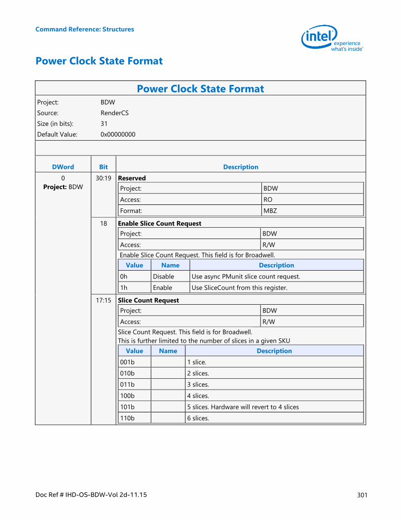
Command Reference: Structures
Doc Ref # IHD-OS-BDW-Vol 2d-11.15 301
Power Clock State Format
Power Clock State Format Project: BDW
Source: RenderCS
Size (in bits): 31
Default Value: 0x00000000
DWord Bit Description
0
Project: BDW
30:19 Reserved
Project: BDW
Access: RO
Format: MBZ
18 Enable Slice Count Request
Project: BDW
Access: R/W
Enable Slice Count Request. This field is for Broadwell.
Value Name Description
0h Disable Use async PMunit slice count request.
1h Enable Use SliceCount from this register.
17:15 Slice Count Request
Project: BDW
Access: R/W
Slice Count Request. This field is for Broadwell.
This is further limited to the number of slices in a given SKU
Value Name Description
001b 1 slice.
010b 2 slices.
011b 3 slices.
100b 4 slices.
101b 5 slices. Hardware will revert to 4 slices
110b 6 slices.
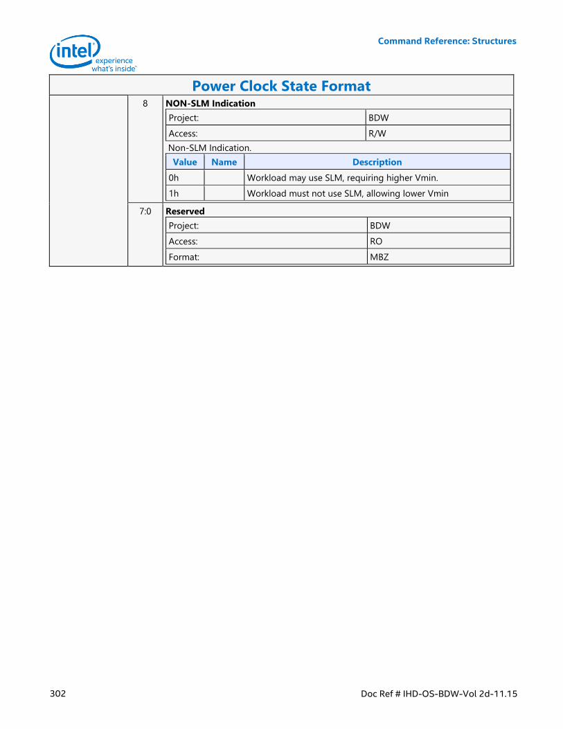
Command Reference: Structures
302 Doc Ref # IHD-OS-BDW-Vol 2d-11.15
Power Clock State Format 8 NON-SLM Indication
Project: BDW
Access: R/W
Non-SLM Indication.
Value Name Description
0h Workload may use SLM, requiring higher Vmin.
1h Workload must not use SLM, allowing lower Vmin
7:0 Reserved
Project: BDW
Access: RO
Format: MBZ
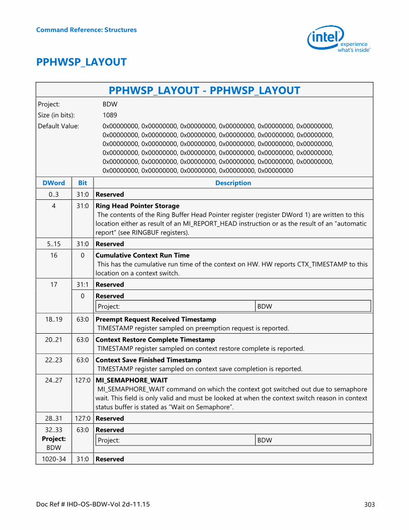
Command Reference: Structures
Doc Ref # IHD-OS-BDW-Vol 2d-11.15 303
PPHWSP_LAYOUT
PPHWSP_LAYOUT - PPHWSP_LAYOUT Project: BDW
Size (in bits): 1089
Default Value: 0x00000000, 0x00000000, 0x00000000, 0x00000000, 0x00000000, 0x00000000,
0x00000000, 0x00000000, 0x00000000, 0x00000000, 0x00000000, 0x00000000,
0x00000000, 0x00000000, 0x00000000, 0x00000000, 0x00000000, 0x00000000,
0x00000000, 0x00000000, 0x00000000, 0x00000000, 0x00000000, 0x00000000,
0x00000000, 0x00000000, 0x00000000, 0x00000000, 0x00000000, 0x00000000,
0x00000000, 0x00000000, 0x00000000, 0x00000000, 0x00000000
DWord Bit Description
0..3 31:0 Reserved
4 31:0 Ring Head Pointer Storage
The contents of the Ring Buffer Head Pointer register (register DWord 1) are written to this
location either as result of an MI_REPORT_HEAD instruction or as the result of an “automatic
report” (see RINGBUF registers).
5..15 31:0 Reserved
16 0 Cumulative Context Run Time
This has the cumulative run time of the context on HW. HW reports CTX_TIMESTAMP to this
location on a context switch.
17 31:1 Reserved
0 Reserved
Project: BDW
18..19 63:0 Preempt Request Received Timestamp
TIMESTAMP register sampled on preemption request is reported.
20..21 63:0 Context Restore Complete Timestamp
TIMESTAMP register sampled on context restore complete is reported.
22..23 63:0 Context Save Finished Timestamp
TIMESTAMP register sampled on context save completion is reported.
24..27 127:0 MI_SEMAPHORE_WAIT
MI_SEMAPHORE_WAIT command on which the context got switched out due to semaphore
wait. This field is only valid and must be looked at when the context switch reason in context
status buffer is stated as “Wait on Semaphore”.
28..31 127:0 Reserved
32..33
Project:
BDW
63:0 Reserved
Project: BDW
1020-34 31:0 Reserved
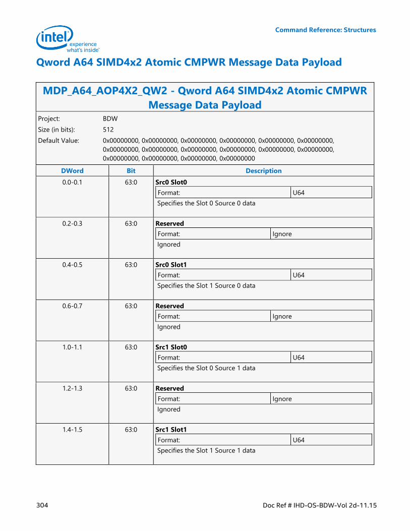
Command Reference: Structures
304 Doc Ref # IHD-OS-BDW-Vol 2d-11.15
Qword A64 SIMD4x2 Atomic CMPWR Message Data Payload
MDP_A64_AOP4X2_QW2 - Qword A64 SIMD4x2 Atomic CMPWR
Message Data Payload Project: BDW
Size (in bits): 512
Default Value: 0x00000000, 0x00000000, 0x00000000, 0x00000000, 0x00000000, 0x00000000,
0x00000000, 0x00000000, 0x00000000, 0x00000000, 0x00000000, 0x00000000,
0x00000000, 0x00000000, 0x00000000, 0x00000000
DWord Bit Description
0.0-0.1 63:0 Src0 Slot0
Format: U64
Specifies the Slot 0 Source 0 data
0.2-0.3 63:0 Reserved
Format: Ignore
Ignored
0.4-0.5 63:0 Src0 Slot1
Format: U64
Specifies the Slot 1 Source 0 data
0.6-0.7 63:0 Reserved
Format: Ignore
Ignored
1.0-1.1 63:0 Src1 Slot0
Format: U64
Specifies the Slot 0 Source 1 data
1.2-1.3 63:0 Reserved
Format: Ignore
Ignored
1.4-1.5 63:0 Src1 Slot1
Format: U64
Specifies the Slot 1 Source 1 data
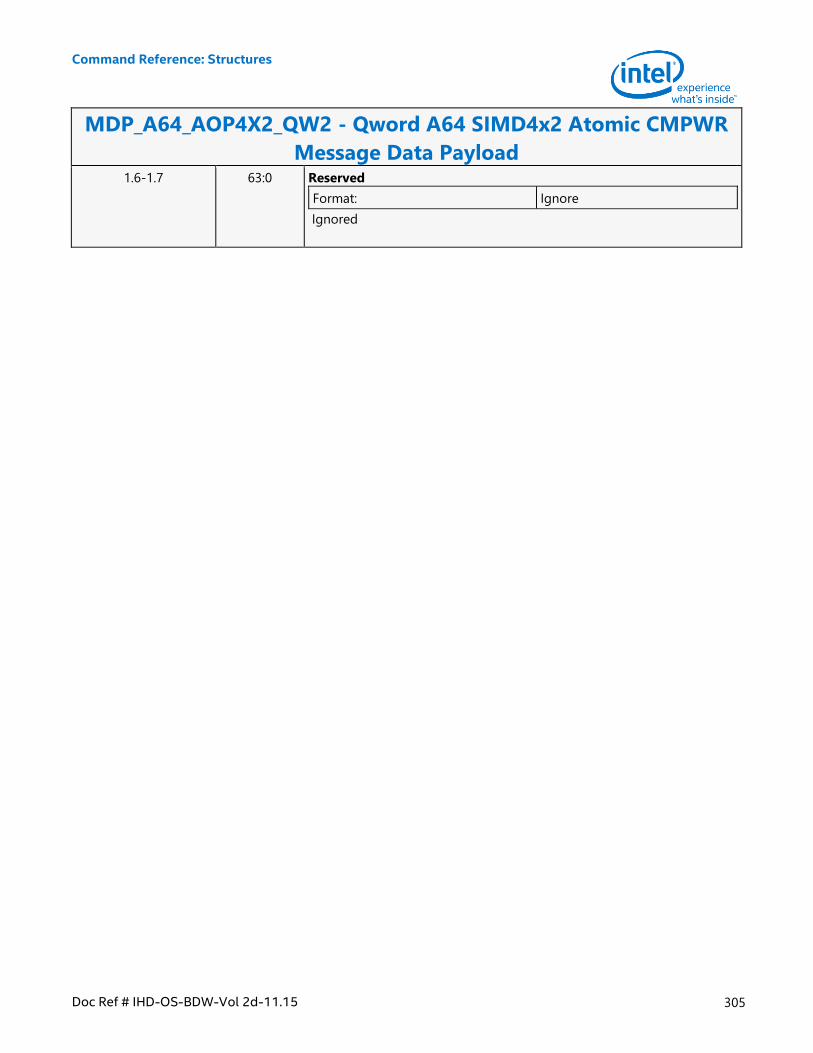
Command Reference: Structures
Doc Ref # IHD-OS-BDW-Vol 2d-11.15 305
MDP_A64_AOP4X2_QW2 - Qword A64 SIMD4x2 Atomic CMPWR
Message Data Payload 1.6-1.7 63:0 Reserved
Format: Ignore
Ignored
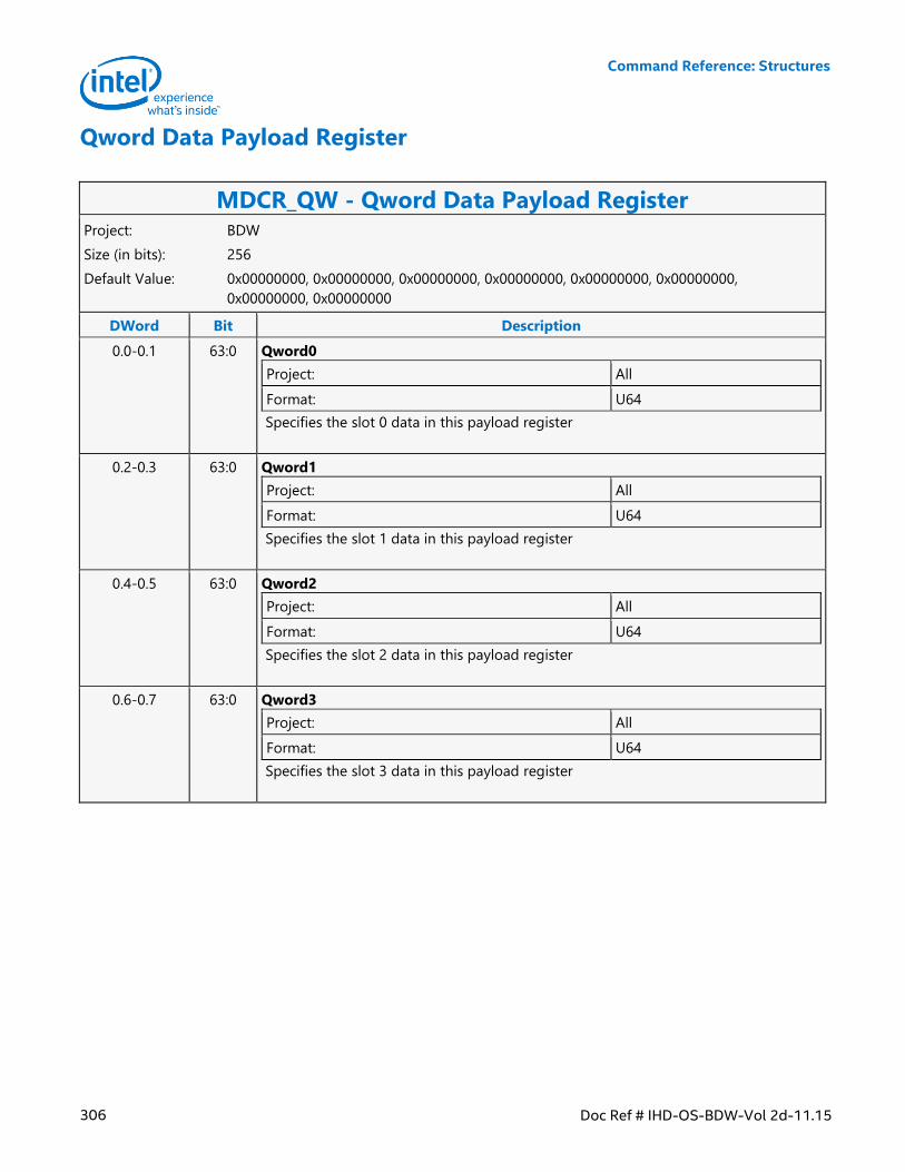
Command Reference: Structures
306 Doc Ref # IHD-OS-BDW-Vol 2d-11.15
Qword Data Payload Register
MDCR_QW - Qword Data Payload Register Project: BDW
Size (in bits): 256
Default Value: 0x00000000, 0x00000000, 0x00000000, 0x00000000, 0x00000000, 0x00000000,
0x00000000, 0x00000000
DWord Bit Description
0.0-0.1 63:0 Qword0
Project: All
Format: U64
Specifies the slot 0 data in this payload register
0.2-0.3 63:0 Qword1
Project: All
Format: U64
Specifies the slot 1 data in this payload register
0.4-0.5 63:0 Qword2
Project: All
Format: U64
Specifies the slot 2 data in this payload register
0.6-0.7 63:0 Qword3
Project: All
Format: U64
Specifies the slot 3 data in this payload register
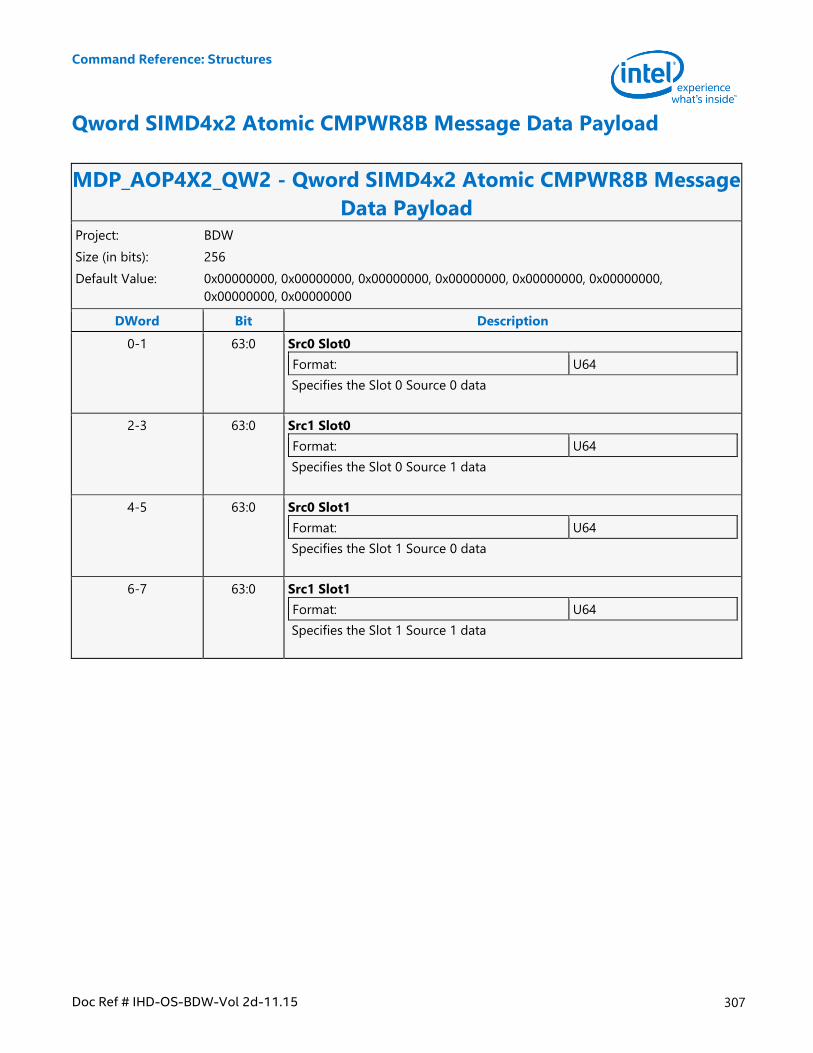
Command Reference: Structures
Doc Ref # IHD-OS-BDW-Vol 2d-11.15 307
Qword SIMD4x2 Atomic CMPWR8B Message Data Payload
MDP_AOP4X2_QW2 - Qword SIMD4x2 Atomic CMPWR8B Message
Data Payload Project: BDW
Size (in bits): 256
Default Value: 0x00000000, 0x00000000, 0x00000000, 0x00000000, 0x00000000, 0x00000000,
0x00000000, 0x00000000
DWord Bit Description
0-1 63:0 Src0 Slot0
Format: U64
Specifies the Slot 0 Source 0 data
2-3 63:0 Src1 Slot0
Format: U64
Specifies the Slot 0 Source 1 data
4-5 63:0 Src0 Slot1
Format: U64
Specifies the Slot 1 Source 0 data
6-7 63:0 Src1 Slot1
Format: U64
Specifies the Slot 1 Source 1 data
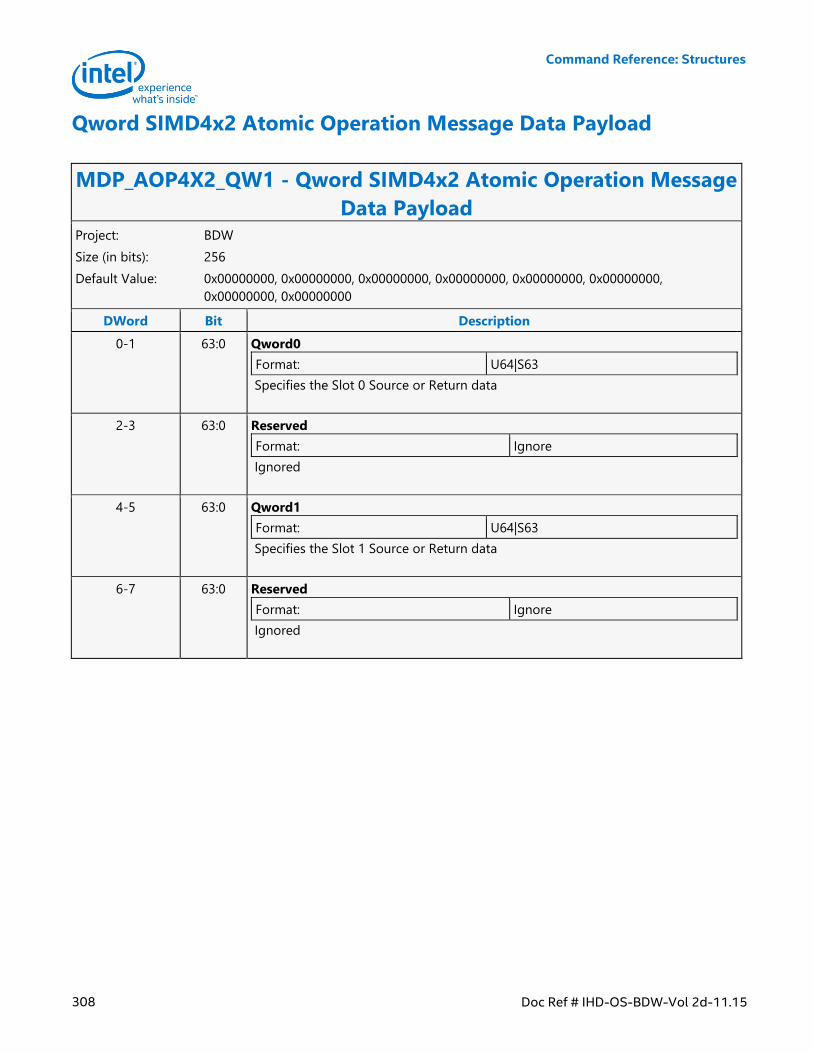
Command Reference: Structures
308 Doc Ref # IHD-OS-BDW-Vol 2d-11.15
Qword SIMD4x2 Atomic Operation Message Data Payload
MDP_AOP4X2_QW1 - Qword SIMD4x2 Atomic Operation Message
Data Payload Project: BDW
Size (in bits): 256
Default Value: 0x00000000, 0x00000000, 0x00000000, 0x00000000, 0x00000000, 0x00000000,
0x00000000, 0x00000000
DWord Bit Description
0-1 63:0 Qword0
Format: U64|S63
Specifies the Slot 0 Source or Return data
2-3 63:0 Reserved
Format: Ignore
Ignored
4-5 63:0 Qword1
Format: U64|S63
Specifies the Slot 1 Source or Return data
6-7 63:0 Reserved
Format: Ignore
Ignored
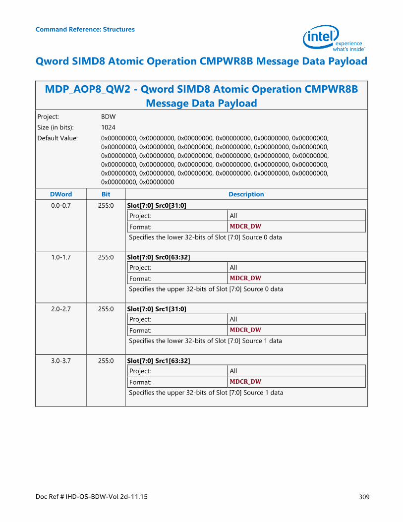
Command Reference: Structures
Doc Ref # IHD-OS-BDW-Vol 2d-11.15 309
Qword SIMD8 Atomic Operation CMPWR8B Message Data Payload
MDP_AOP8_QW2 - Qword SIMD8 Atomic Operation CMPWR8B
Message Data Payload Project: BDW
Size (in bits): 1024
Default Value: 0x00000000, 0x00000000, 0x00000000, 0x00000000, 0x00000000, 0x00000000,
0x00000000, 0x00000000, 0x00000000, 0x00000000, 0x00000000, 0x00000000,
0x00000000, 0x00000000, 0x00000000, 0x00000000, 0x00000000, 0x00000000,
0x00000000, 0x00000000, 0x00000000, 0x00000000, 0x00000000, 0x00000000,
0x00000000, 0x00000000, 0x00000000, 0x00000000, 0x00000000, 0x00000000,
0x00000000, 0x00000000
DWord Bit Description
0.0-0.7 255:0 Slot[7:0] Src0[31:0]
Project: All
Format: MDCR_DW
Specifies the lower 32-bits of Slot [7:0] Source 0 data
1.0-1.7 255:0 Slot[7:0] Src0[63:32]
Project: All
Format: MDCR_DW
Specifies the upper 32-bits of Slot [7:0] Source 0 data
2.0-2.7 255:0 Slot[7:0] Src1[31:0]
Project: All
Format: MDCR_DW
Specifies the lower 32-bits of Slot [7:0] Source 1 data
3.0-3.7 255:0 Slot[7:0] Src1[63:32]
Project: All
Format: MDCR_DW
Specifies the upper 32-bits of Slot [7:0] Source 1 data
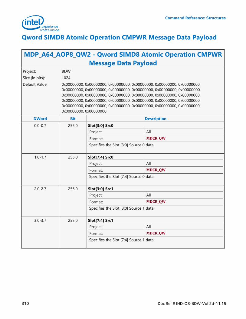
Command Reference: Structures
310 Doc Ref # IHD-OS-BDW-Vol 2d-11.15
Qword SIMD8 Atomic Operation CMPWR Message Data Payload
MDP_A64_AOP8_QW2 - Qword SIMD8 Atomic Operation CMPWR
Message Data Payload Project: BDW
Size (in bits): 1024
Default Value: 0x00000000, 0x00000000, 0x00000000, 0x00000000, 0x00000000, 0x00000000,
0x00000000, 0x00000000, 0x00000000, 0x00000000, 0x00000000, 0x00000000,
0x00000000, 0x00000000, 0x00000000, 0x00000000, 0x00000000, 0x00000000,
0x00000000, 0x00000000, 0x00000000, 0x00000000, 0x00000000, 0x00000000,
0x00000000, 0x00000000, 0x00000000, 0x00000000, 0x00000000, 0x00000000,
0x00000000, 0x00000000
DWord Bit Description
0.0-0.7 255:0 Slot[3:0] Src0
Project: All
Format: MDCR_QW
Specifies the Slot [3:0] Source 0 data
1.0-1.7 255:0 Slot[7:4] Src0
Project: All
Format: MDCR_QW
Specifies the Slot [7:4] Source 0 data
2.0-2.7 255:0 Slot[3:0] Src1
Project: All
Format: MDCR_QW
Specifies the Slot [3:0] Source 1 data
3.0-3.7 255:0 Slot[7:4] Src1
Project: All
Format: MDCR_QW
Specifies the Slot [7:4] Source 1 data
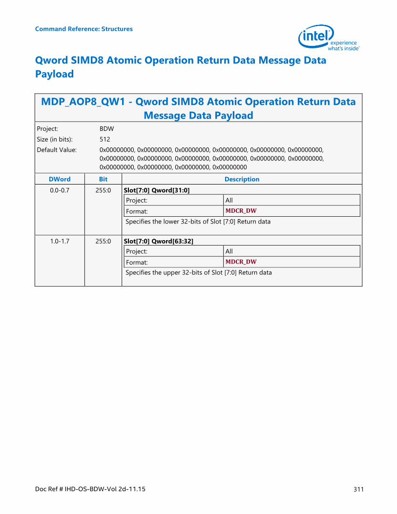
Command Reference: Structures
Doc Ref # IHD-OS-BDW-Vol 2d-11.15 311
Qword SIMD8 Atomic Operation Return Data Message Data
Payload
MDP_AOP8_QW1 - Qword SIMD8 Atomic Operation Return Data
Message Data Payload Project: BDW
Size (in bits): 512
Default Value: 0x00000000, 0x00000000, 0x00000000, 0x00000000, 0x00000000, 0x00000000,
0x00000000, 0x00000000, 0x00000000, 0x00000000, 0x00000000, 0x00000000,
0x00000000, 0x00000000, 0x00000000, 0x00000000
DWord Bit Description
0.0-0.7 255:0 Slot[7:0] Qword[31:0]
Project: All
Format: MDCR_DW
Specifies the lower 32-bits of Slot [7:0] Return data
1.0-1.7 255:0 Slot[7:0] Qword[63:32]
Project: All
Format: MDCR_DW
Specifies the upper 32-bits of Slot [7:0] Return data
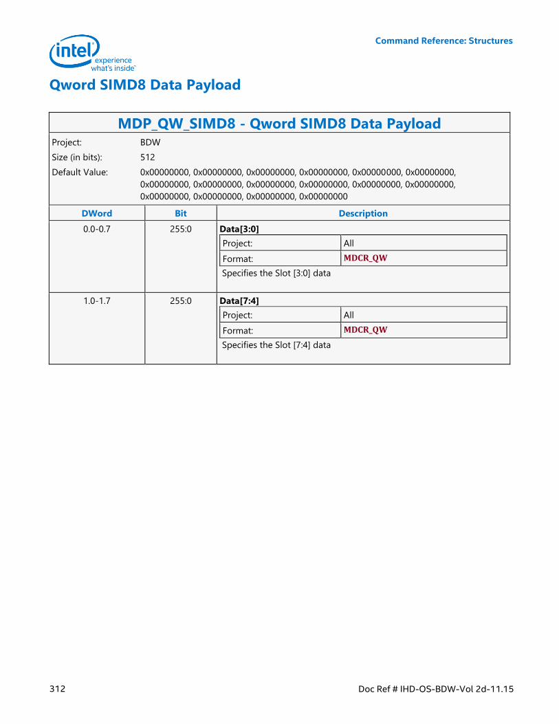
Command Reference: Structures
312 Doc Ref # IHD-OS-BDW-Vol 2d-11.15
Qword SIMD8 Data Payload
MDP_QW_SIMD8 - Qword SIMD8 Data Payload Project: BDW
Size (in bits): 512
Default Value: 0x00000000, 0x00000000, 0x00000000, 0x00000000, 0x00000000, 0x00000000,
0x00000000, 0x00000000, 0x00000000, 0x00000000, 0x00000000, 0x00000000,
0x00000000, 0x00000000, 0x00000000, 0x00000000
DWord Bit Description
0.0-0.7 255:0 Data[3:0]
Project: All
Format: MDCR_QW
Specifies the Slot [3:0] data
1.0-1.7 255:0 Data[7:4]
Project: All
Format: MDCR_QW
Specifies the Slot [7:4] data
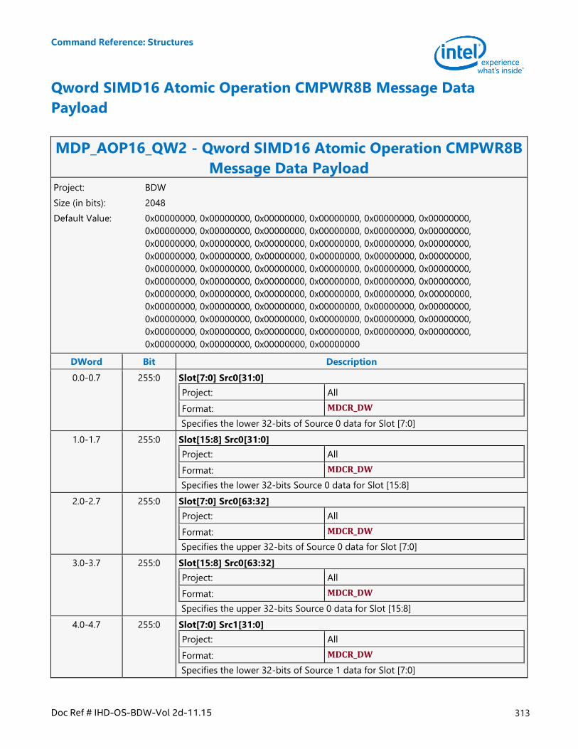
Command Reference: Structures
Doc Ref # IHD-OS-BDW-Vol 2d-11.15 313
Qword SIMD16 Atomic Operation CMPWR8B Message Data
Payload
MDP_AOP16_QW2 - Qword SIMD16 Atomic Operation CMPWR8B
Message Data Payload Project: BDW
Size (in bits): 2048
Default Value: 0x00000000, 0x00000000, 0x00000000, 0x00000000, 0x00000000, 0x00000000,
0x00000000, 0x00000000, 0x00000000, 0x00000000, 0x00000000, 0x00000000,
0x00000000, 0x00000000, 0x00000000, 0x00000000, 0x00000000, 0x00000000,
0x00000000, 0x00000000, 0x00000000, 0x00000000, 0x00000000, 0x00000000,
0x00000000, 0x00000000, 0x00000000, 0x00000000, 0x00000000, 0x00000000,
0x00000000, 0x00000000, 0x00000000, 0x00000000, 0x00000000, 0x00000000,
0x00000000, 0x00000000, 0x00000000, 0x00000000, 0x00000000, 0x00000000,
0x00000000, 0x00000000, 0x00000000, 0x00000000, 0x00000000, 0x00000000,
0x00000000, 0x00000000, 0x00000000, 0x00000000, 0x00000000, 0x00000000,
0x00000000, 0x00000000, 0x00000000, 0x00000000, 0x00000000, 0x00000000,
0x00000000, 0x00000000, 0x00000000, 0x00000000
DWord Bit Description
0.0-0.7 255:0 Slot[7:0] Src0[31:0]
Project: All
Format: MDCR_DW
Specifies the lower 32-bits of Source 0 data for Slot [7:0]
1.0-1.7 255:0 Slot[15:8] Src0[31:0]
Project: All
Format: MDCR_DW
Specifies the lower 32-bits Source 0 data for Slot [15:8]
2.0-2.7 255:0 Slot[7:0] Src0[63:32]
Project: All
Format: MDCR_DW
Specifies the upper 32-bits of Source 0 data for Slot [7:0]
3.0-3.7 255:0 Slot[15:8] Src0[63:32]
Project: All
Format: MDCR_DW
Specifies the upper 32-bits Source 0 data for Slot [15:8]
4.0-4.7 255:0 Slot[7:0] Src1[31:0]
Project: All
Format: MDCR_DW
Specifies the lower 32-bits of Source 1 data for Slot [7:0]
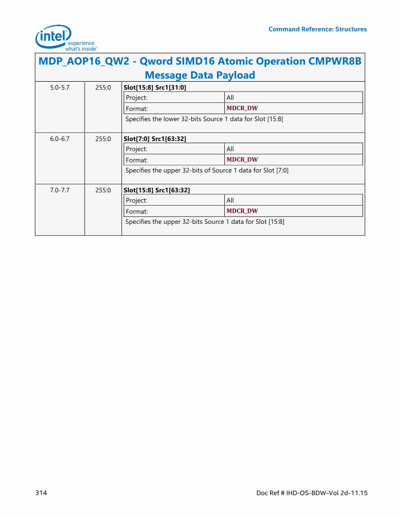
Command Reference: Structures
314 Doc Ref # IHD-OS-BDW-Vol 2d-11.15
MDP_AOP16_QW2 - Qword SIMD16 Atomic Operation CMPWR8B
Message Data Payload 5.0-5.7 255:0 Slot[15:8] Src1[31:0]
Project: All
Format: MDCR_DW
Specifies the lower 32-bits Source 1 data for Slot [15:8]
6.0-6.7 255:0 Slot[7:0] Src1[63:32]
Project: All
Format: MDCR_DW
Specifies the upper 32-bits of Source 1 data for Slot [7:0]
7.0-7.7 255:0 Slot[15:8] Src1[63:32]
Project: All
Format: MDCR_DW
Specifies the upper 32-bits Source 1 data for Slot [15:8]
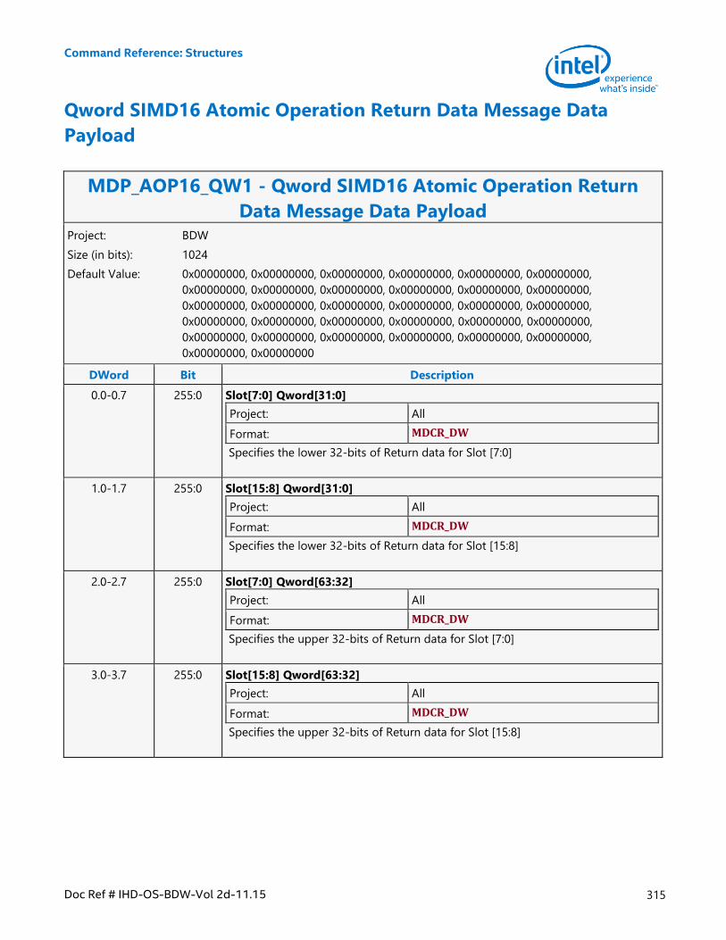
Command Reference: Structures
Doc Ref # IHD-OS-BDW-Vol 2d-11.15 315
Qword SIMD16 Atomic Operation Return Data Message Data
Payload
MDP_AOP16_QW1 - Qword SIMD16 Atomic Operation Return
Data Message Data Payload Project: BDW
Size (in bits): 1024
Default Value: 0x00000000, 0x00000000, 0x00000000, 0x00000000, 0x00000000, 0x00000000,
0x00000000, 0x00000000, 0x00000000, 0x00000000, 0x00000000, 0x00000000,
0x00000000, 0x00000000, 0x00000000, 0x00000000, 0x00000000, 0x00000000,
0x00000000, 0x00000000, 0x00000000, 0x00000000, 0x00000000, 0x00000000,
0x00000000, 0x00000000, 0x00000000, 0x00000000, 0x00000000, 0x00000000,
0x00000000, 0x00000000
DWord Bit Description
0.0-0.7 255:0 Slot[7:0] Qword[31:0]
Project: All
Format: MDCR_DW
Specifies the lower 32-bits of Return data for Slot [7:0]
1.0-1.7 255:0 Slot[15:8] Qword[31:0]
Project: All
Format: MDCR_DW
Specifies the lower 32-bits of Return data for Slot [15:8]
2.0-2.7 255:0 Slot[7:0] Qword[63:32]
Project: All
Format: MDCR_DW
Specifies the upper 32-bits of Return data for Slot [7:0]
3.0-3.7 255:0 Slot[15:8] Qword[63:32]
Project: All
Format: MDCR_DW
Specifies the upper 32-bits of Return data for Slot [15:8]
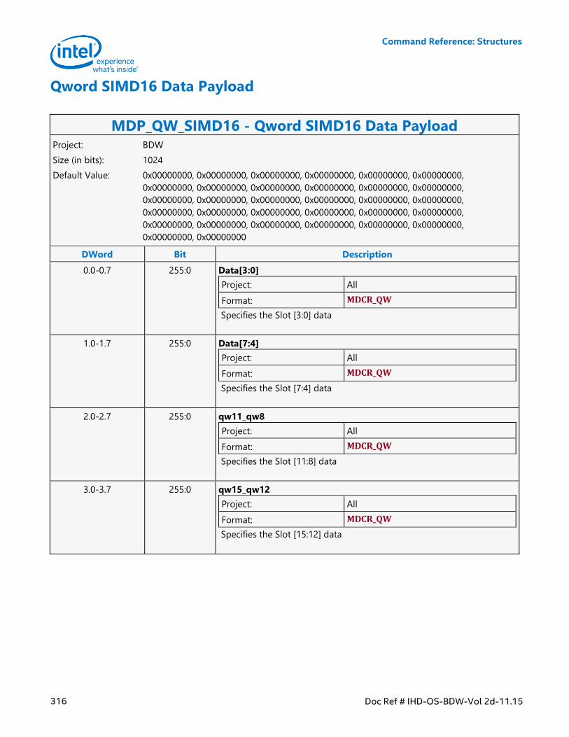
Command Reference: Structures
316 Doc Ref # IHD-OS-BDW-Vol 2d-11.15
Qword SIMD16 Data Payload
MDP_QW_SIMD16 - Qword SIMD16 Data Payload Project: BDW
Size (in bits): 1024
Default Value: 0x00000000, 0x00000000, 0x00000000, 0x00000000, 0x00000000, 0x00000000,
0x00000000, 0x00000000, 0x00000000, 0x00000000, 0x00000000, 0x00000000,
0x00000000, 0x00000000, 0x00000000, 0x00000000, 0x00000000, 0x00000000,
0x00000000, 0x00000000, 0x00000000, 0x00000000, 0x00000000, 0x00000000,
0x00000000, 0x00000000, 0x00000000, 0x00000000, 0x00000000, 0x00000000,
0x00000000, 0x00000000
DWord Bit Description
0.0-0.7 255:0 Data[3:0]
Project: All
Format: MDCR_QW
Specifies the Slot [3:0] data
1.0-1.7 255:0 Data[7:4]
Project: All
Format: MDCR_QW
Specifies the Slot [7:4] data
2.0-2.7 255:0 qw11_qw8
Project: All
Format: MDCR_QW
Specifies the Slot [11:8] data
3.0-3.7 255:0 qw15_qw12
Project: All
Format: MDCR_QW
Specifies the Slot [15:12] data
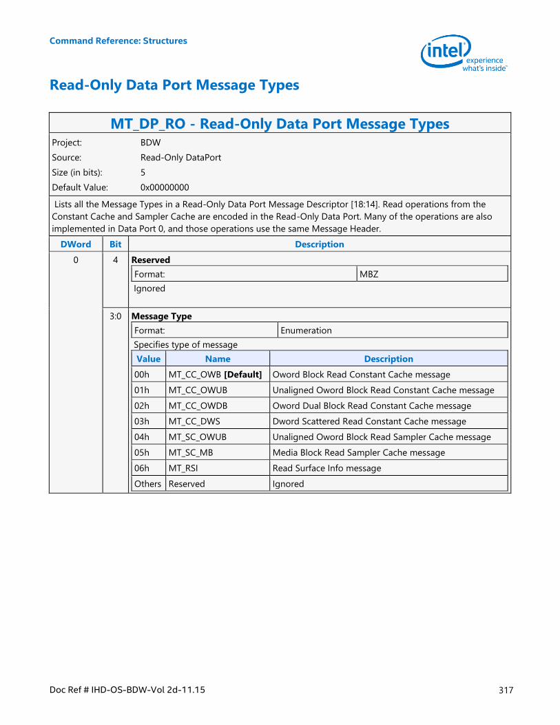
Command Reference: Structures
Doc Ref # IHD-OS-BDW-Vol 2d-11.15 317
Read-Only Data Port Message Types
MT_DP_RO - Read-Only Data Port Message Types Project: BDW
Source: Read-Only DataPort
Size (in bits): 5
Default Value: 0x00000000
Lists all the Message Types in a Read-Only Data Port Message Descriptor [18:14]. Read operations from the
Constant Cache and Sampler Cache are encoded in the Read-Only Data Port. Many of the operations are also
implemented in Data Port 0, and those operations use the same Message Header.
DWord Bit Description
0 4 Reserved
Format: MBZ
Ignored
3:0 Message Type
Format: Enumeration
Specifies type of message
Value Name Description
00h MT_CC_OWB [Default] Oword Block Read Constant Cache message
01h MT_CC_OWUB Unaligned Oword Block Read Constant Cache message
02h MT_CC_OWDB Oword Dual Block Read Constant Cache message
03h MT_CC_DWS Dword Scattered Read Constant Cache message
04h MT_SC_OWUB Unaligned Oword Block Read Sampler Cache message
05h MT_SC_MB Media Block Read Sampler Cache message
06h MT_RSI Read Surface Info message
Others Reserved Ignored
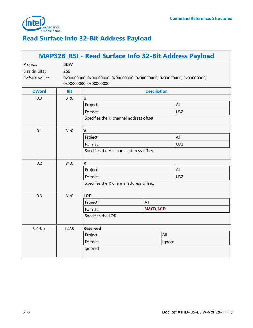
Command Reference: Structures
318 Doc Ref # IHD-OS-BDW-Vol 2d-11.15
Read Surface Info 32-Bit Address Payload
MAP32B_RSI - Read Surface Info 32-Bit Address Payload Project: BDW
Size (in bits): 256
Default Value: 0x00000000, 0x00000000, 0x00000000, 0x00000000, 0x00000000, 0x00000000,
0x00000000, 0x00000000
DWord Bit Description
0.0 31:0 U
Project: All
Format: U32
Specifies the U channel address offset.
0.1 31:0 V
Project: All
Format: U32
Specifies the V channel address offset.
0.2 31:0 R
Project: All
Format: U32
Specifies the R channel address offset.
0.3 31:0 LOD
Project: All
Format: MACD_LOD
Specifies the LOD.
0.4-0.7 127:0 Reserved
Project: All
Format: Ignore
Ignored
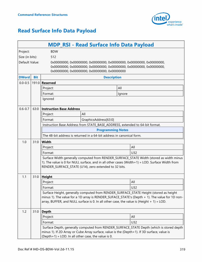
Command Reference: Structures
Doc Ref # IHD-OS-BDW-Vol 2d-11.15 319
Read Surface Info Data Payload
MDP_RSI - Read Surface Info Data Payload Project: BDW
Size (in bits): 512
Default Value: 0x00000000, 0x00000000, 0x00000000, 0x00000000, 0x00000000, 0x00000000,
0x00000000, 0x00000000, 0x00000000, 0x00000000, 0x00000000, 0x00000000,
0x00000000, 0x00000000, 0x00000000, 0x00000000
DWord Bit Description
0.0-0.5 191:0 Reserved
Project: All
Format: Ignore
Ignored
0.6-0.7 63:0 Instruction Base Address
Project: All
Format: GraphicsAddress[63:0]
Instruction Base Address from STATE_BASE_ADDRESS, extended to 64-bit format.
Programming Notes
The 48-bit address is returned in a 64-bit address in canonical form.
1.0 31:0 Width
Project: All
Format: U32
Surface Width generally computed from RENDER_SURFACE_STATE Width (stored as width minus
1). The value is 0 for NULL surface, and in all other cases (Width+1) » LOD. Surface Width from
RENDER_SURFACE_STATE (U14), zero extended to 32 bits.
1.1 31:0 Height
Project: All
Format: U32
Surface Height, generally computed from RENDER_SURFACE_STATE Height (stored as height
minus 1). The value for a 1D array is RENDER_SUFACE_STATE's (Depth + 1). The value for 1D non-
array, BUFFER, and NULL surface is 0. In all other case, the value is (Height + 1) » LOD.
1.2 31:0 Depth
Project: All
Format: U32
Surface Depth, generally computed from RENDER_SURFACE_STATE Depth (which is stored depth
minus 1). If 2D Array or Cube Array surface, value is the (Depth+1). If 3D surface, value is
(Depth+1) » LOD. In all other case, the value is 0.
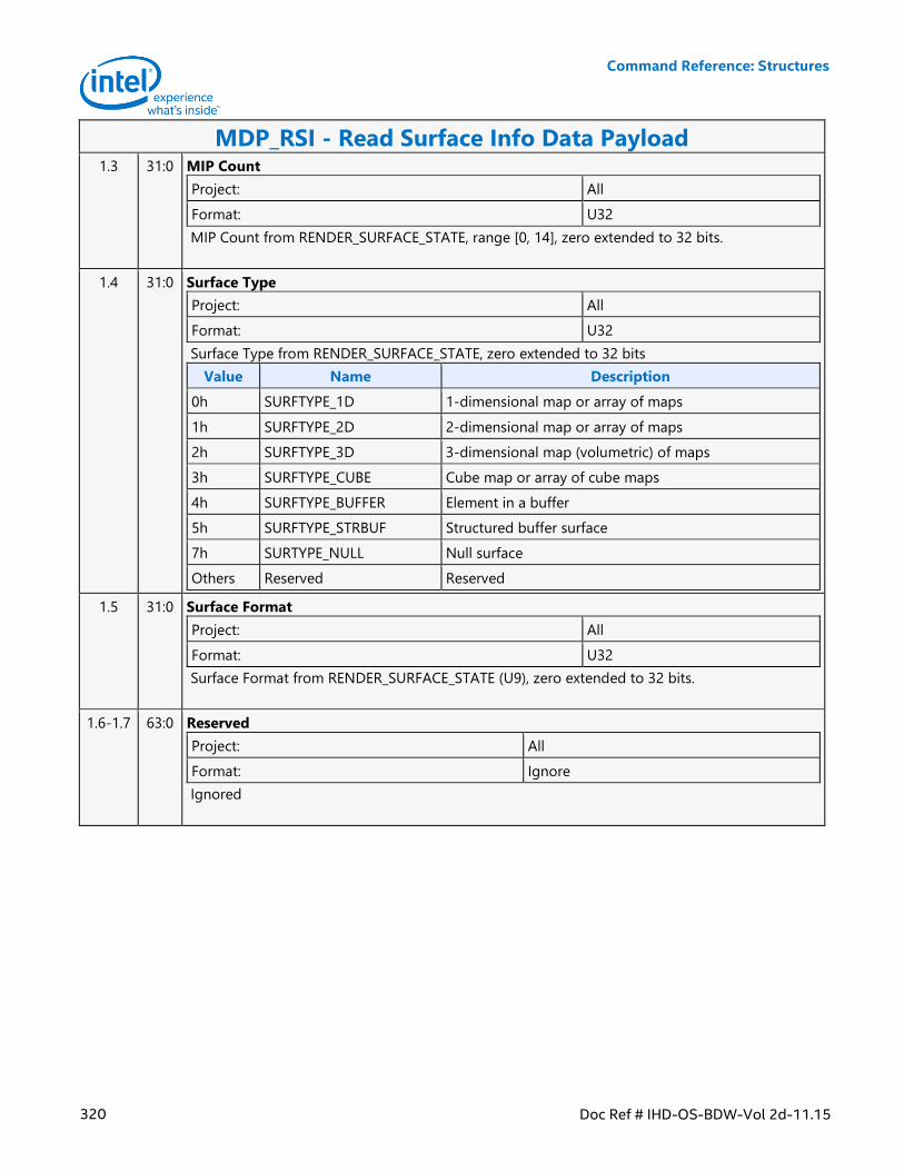
Command Reference: Structures
320 Doc Ref # IHD-OS-BDW-Vol 2d-11.15
MDP_RSI - Read Surface Info Data Payload 1.3 31:0 MIP Count
Project: All
Format: U32
MIP Count from RENDER_SURFACE_STATE, range [0, 14], zero extended to 32 bits.
1.4 31:0 Surface Type
Project: All
Format: U32
Surface Type from RENDER_SURFACE_STATE, zero extended to 32 bits
Value Name Description
0h SURFTYPE_1D 1-dimensional map or array of maps
1h SURFTYPE_2D 2-dimensional map or array of maps
2h SURFTYPE_3D 3-dimensional map (volumetric) of maps
3h SURFTYPE_CUBE Cube map or array of cube maps
4h SURFTYPE_BUFFER Element in a buffer
5h SURFTYPE_STRBUF Structured buffer surface
7h SURTYPE_NULL Null surface
Others Reserved Reserved
1.5 31:0 Surface Format
Project: All
Format: U32
Surface Format from RENDER_SURFACE_STATE (U9), zero extended to 32 bits.
1.6-1.7 63:0 Reserved
Project: All
Format: Ignore
Ignored
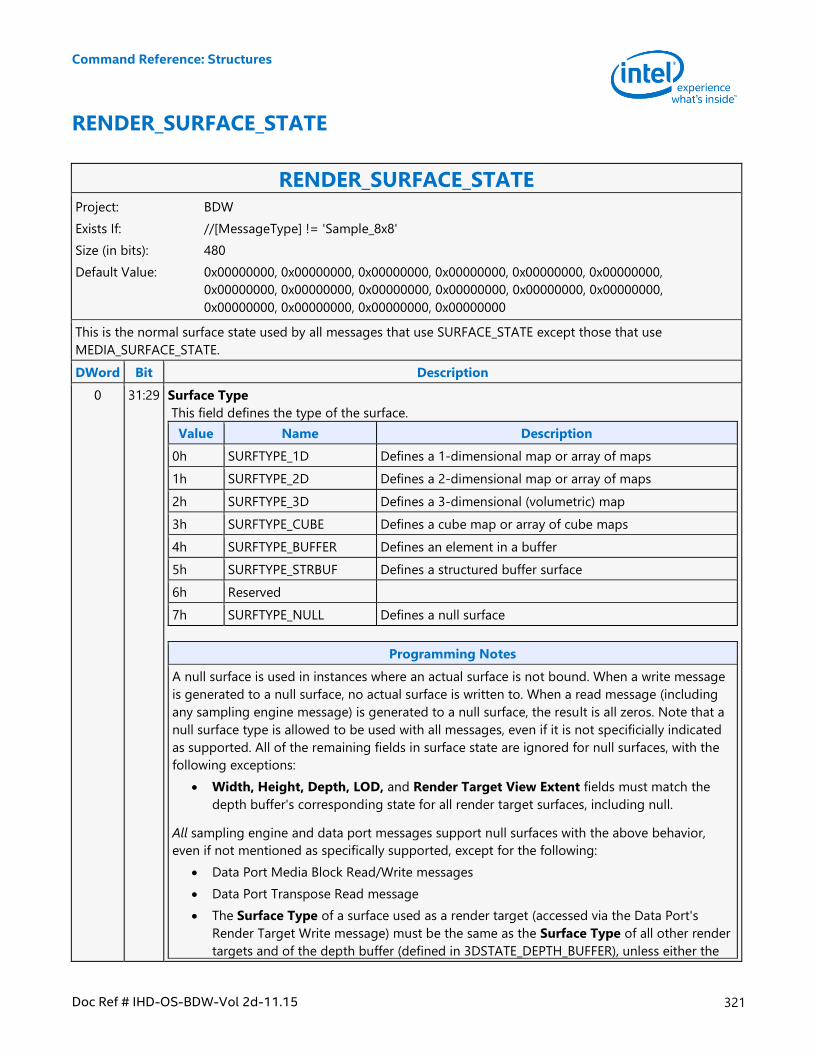
Command Reference: Structures
Doc Ref # IHD-OS-BDW-Vol 2d-11.15 321
RENDER_SURFACE_STATE
RENDER_SURFACE_STATE Project: BDW
Exists If: //[MessageType] != 'Sample_8x8'
Size (in bits): 480
Default Value: 0x00000000, 0x00000000, 0x00000000, 0x00000000, 0x00000000, 0x00000000,
0x00000000, 0x00000000, 0x00000000, 0x00000000, 0x00000000, 0x00000000,
0x00000000, 0x00000000, 0x00000000, 0x00000000
This is the normal surface state used by all messages that use SURFACE_STATE except those that use
MEDIA_SURFACE_STATE.
DWord Bit Description
0 31:29 Surface Type
This field defines the type of the surface.
Value Name Description
0h SURFTYPE_1D Defines a 1-dimensional map or array of maps
1h SURFTYPE_2D Defines a 2-dimensional map or array of maps
2h SURFTYPE_3D Defines a 3-dimensional (volumetric) map
3h SURFTYPE_CUBE Defines a cube map or array of cube maps
4h SURFTYPE_BUFFER Defines an element in a buffer
5h SURFTYPE_STRBUF Defines a structured buffer surface
6h Reserved
7h SURFTYPE_NULL Defines a null surface
Programming Notes
A null surface is used in instances where an actual surface is not bound. When a write message
is generated to a null surface, no actual surface is written to. When a read message (including
any sampling engine message) is generated to a null surface, the result is all zeros. Note that a
null surface type is allowed to be used with all messages, even if it is not specificially indicated
as supported. All of the remaining fields in surface state are ignored for null surfaces, with the
following exceptions:
Width, Height, Depth, LOD, and Render Target View Extent fields must match the
depth buffer's corresponding state for all render target surfaces, including null.
All sampling engine and data port messages support null surfaces with the above behavior,
even if not mentioned as specifically supported, except for the following:
Data Port Media Block Read/Write messages
Data Port Transpose Read message
The Surface Type of a surface used as a render target (accessed via the Data Port's
Render Target Write message) must be the same as the Surface Type of all other render
targets and of the depth buffer (defined in 3DSTATE_DEPTH_BUFFER), unless either the
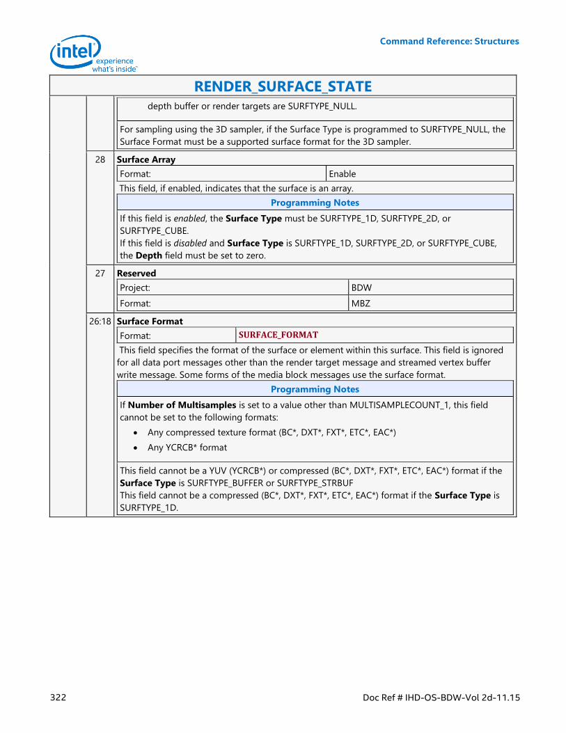
Command Reference: Structures
322 Doc Ref # IHD-OS-BDW-Vol 2d-11.15
RENDER_SURFACE_STATE
depth buffer or render targets are SURFTYPE_NULL.
For sampling using the 3D sampler, if the Surface Type is programmed to SURFTYPE_NULL, the
Surface Format must be a supported surface format for the 3D sampler.
28 Surface Array
Format: Enable
This field, if enabled, indicates that the surface is an array.
Programming Notes
If this field is enabled, the Surface Type must be SURFTYPE_1D, SURFTYPE_2D, or
SURFTYPE_CUBE.
If this field is disabled and Surface Type is SURFTYPE_1D, SURFTYPE_2D, or SURFTYPE_CUBE,
the Depth field must be set to zero.
27 Reserved
Project: BDW
Format: MBZ
26:18 Surface Format
Format: SURFACE_FORMAT
This field specifies the format of the surface or element within this surface. This field is ignored
for all data port messages other than the render target message and streamed vertex buffer
write message. Some forms of the media block messages use the surface format.
Programming Notes
If Number of Multisamples is set to a value other than MULTISAMPLECOUNT_1, this field
cannot be set to the following formats:
Any compressed texture format (BC*, DXT*, FXT*, ETC*, EAC*)
Any YCRCB* format
This field cannot be a YUV (YCRCB*) or compressed (BC*, DXT*, FXT*, ETC*, EAC*) format if the
Surface Type is SURFTYPE_BUFFER or SURFTYPE_STRBUF
This field cannot be a compressed (BC*, DXT*, FXT*, ETC*, EAC*) format if the Surface Type is
SURFTYPE_1D.
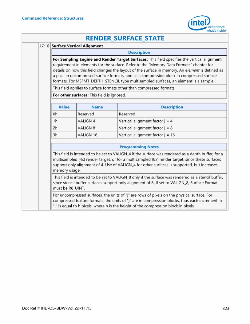
Command Reference: Structures
Doc Ref # IHD-OS-BDW-Vol 2d-11.15 323
RENDER_SURFACE_STATE 17:16 Surface Vertical Alignment
Description
For Sampling Engine and Render Target Surfaces: This field specifies the vertical alignment
requirement in elements for the surface. Refer to the "Memory Data Formats" chapter for
details on how this field changes the layout of the surface in memory. An element is defined as
a pixel in uncompresed surface formats, and as a compression block in compressed surface
formats. For MSFMT_DEPTH_STENCIL type multisampled surfaces, an element is a sample.
This field applies to surface formats other than compressed formats.
For other surfaces: This field is ignored.
Value Name Description
0h Reserved Reserved
1h VALIGN 4 Vertical alignment factor j = 4
2h VALIGN 8 Vertical alignment factor j = 8
3h VALIGN 16 Vertical alignment factor j = 16
Programming Notes
This field is intended to be set to VALIGN_4 if the surface was rendered as a depth buffer, for a
multisampled (4x) render target, or for a multisampled (8x) render target, since these surfaces
support only alignment of 4. Use of VALIGN_4 for other surfaces is supported, but increases
memory usage.
This field is intended to be set to VALIGN_8 only if the surface was rendered as a stencil buffer,
since stencil buffer surfaces support only alignment of 8. If set to VALIGN_8, Surface Format
must be R8_UINT.
For uncompressed surfaces, the units of "j" are rows of pixels on the physical surface. For
compressed texture formats, the units of "j" are in compression blocks, thus each increment in
"j" is equal to h pixels, where h is the height of the compression block in pixels.
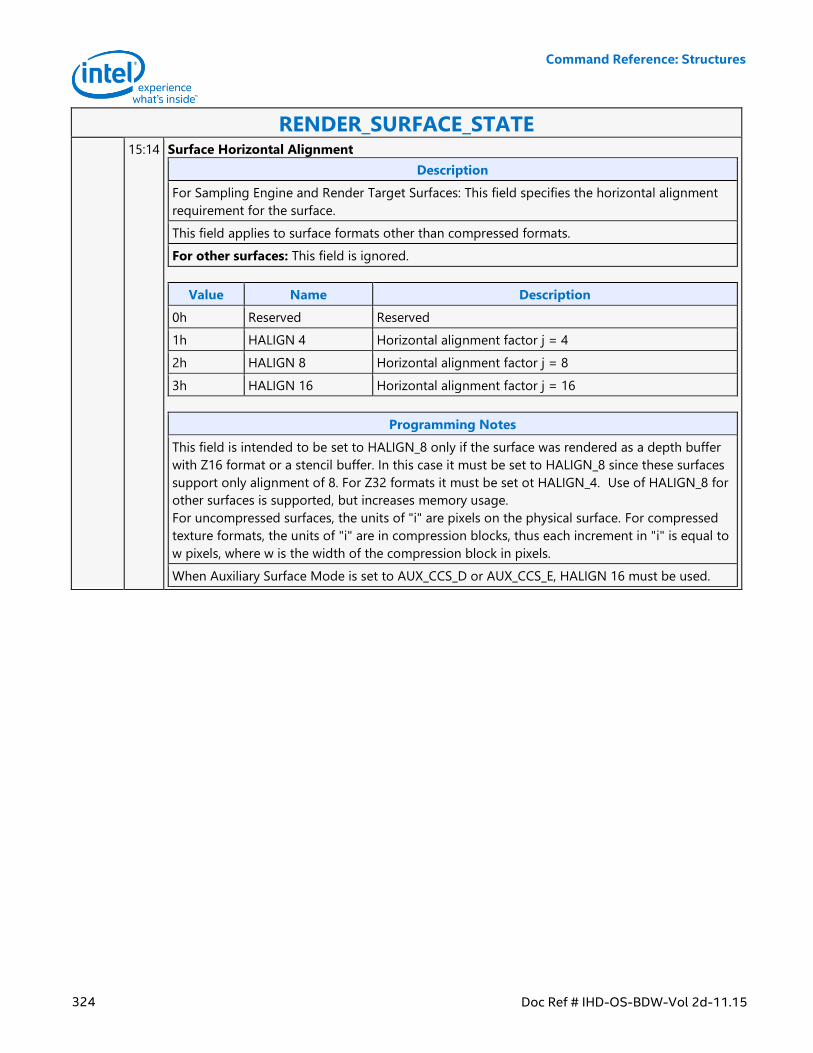
Command Reference: Structures
324 Doc Ref # IHD-OS-BDW-Vol 2d-11.15
RENDER_SURFACE_STATE 15:14 Surface Horizontal Alignment
Description
For Sampling Engine and Render Target Surfaces: This field specifies the horizontal alignment
requirement for the surface.
This field applies to surface formats other than compressed formats.
For other surfaces: This field is ignored.
Value Name Description
0h Reserved Reserved
1h HALIGN 4 Horizontal alignment factor j = 4
2h HALIGN 8 Horizontal alignment factor j = 8
3h HALIGN 16 Horizontal alignment factor j = 16
Programming Notes
This field is intended to be set to HALIGN_8 only if the surface was rendered as a depth buffer
with Z16 format or a stencil buffer. In this case it must be set to HALIGN_8 since these surfaces
support only alignment of 8. For Z32 formats it must be set ot HALIGN_4. Use of HALIGN_8 for
other surfaces is supported, but increases memory usage.
For uncompressed surfaces, the units of "i" are pixels on the physical surface. For compressed
texture formats, the units of "i" are in compression blocks, thus each increment in "i" is equal to
w pixels, where w is the width of the compression block in pixels.
When Auxiliary Surface Mode is set to AUX_CCS_D or AUX_CCS_E, HALIGN 16 must be used.
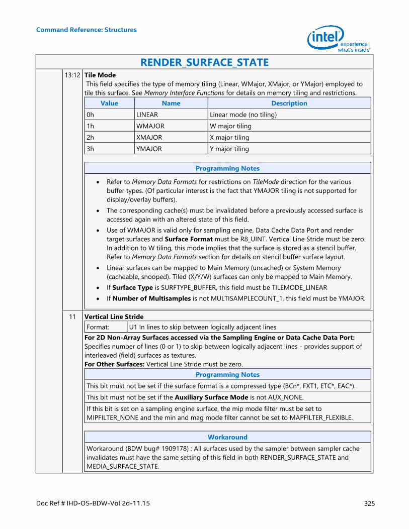
Command Reference: Structures
Doc Ref # IHD-OS-BDW-Vol 2d-11.15 325
RENDER_SURFACE_STATE 13:12 Tile Mode
This field specifies the type of memory tiling (Linear, WMajor, XMajor, or YMajor) employed to
tile this surface. See Memory Interface Functions for details on memory tiling and restrictions.
Value Name Description
0h LINEAR Linear mode (no tiling)
1h WMAJOR W major tiling
2h XMAJOR X major tiling
3h YMAJOR Y major tiling
Programming Notes
Refer to Memory Data Formats for restrictions on TileMode direction for the various
buffer types. (Of particular interest is the fact that YMAJOR tiling is not supported for
display/overlay buffers).
The corresponding cache(s) must be invalidated before a previously accessed surface is
accessed again with an altered state of this field.
Use of WMAJOR is valid only for sampling engine, Data Cache Data Port and render
target surfaces and Surface Format must be R8_UINT. Vertical Line Stride must be zero.
In addition to W tiling, this mode implies that the surface is stored as a stencil buffer.
Refer to Memory Data Formats section for details on stencil buffer surface layout.
Linear surfaces can be mapped to Main Memory (uncached) or System Memory
(cacheable, snooped). Tiled (X/Y/W) surfaces can only be mapped to Main Memory.
If Surface Type is SURFTYPE_BUFFER, this field must be TILEMODE_LINEAR
If Number of Multisamples is not MULTISAMPLECOUNT_1, this field must be YMAJOR.
11 Vertical Line Stride
Format: U1 In lines to skip between logically adjacent lines
For 2D Non-Array Surfaces accessed via the Sampling Engine or Data Cache Data Port:
Specifies number of lines (0 or 1) to skip between logically adjacent lines - provides support of
interleaved (field) surfaces as textures.
For Other Surfaces: Vertical Line Stride must be zero.
Programming Notes
This bit must not be set if the surface format is a compressed type (BCn*, FXT1, ETC*, EAC*).
This bit must not be set if the Auxiliary Surface Mode is not AUX_NONE.
If this bit is set on a sampling engine surface, the mip mode filter must be set to
MIPFILTER_NONE and the min and mag mode filter cannot be set to MAPFILTER_FLEXIBLE.
Workaround
Workaround (BDW bug# 1909178) : All surfaces used by the sampler between sampler cache
invalidates must have the same setting of this field in both RENDER_SURFACE_STATE and
MEDIA_SURFACE_STATE.
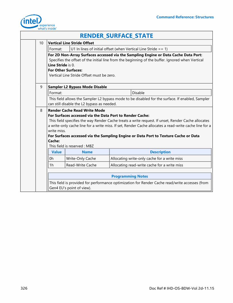
Command Reference: Structures
326 Doc Ref # IHD-OS-BDW-Vol 2d-11.15
RENDER_SURFACE_STATE 10 Vertical Line Stride Offset
Format: U1 In lines of initial offset (when Vertical Line Stride == 1)
For 2D Non-Array Surfaces accessed via the Sampling Engine or Data Cache Data Port:
Specifies the offset of the initial line from the beginning of the buffer. Ignored when Vertical
Line Stride is 0.
For Other Surfaces:
Vertical Line Stride Offset must be zero.
9 Sampler L2 Bypass Mode Disable
Format: Disable
This field allows the Sampler L2 bypass mode to be disabled for the surface. If enabled, Sampler
can still disable the L2 bypass as needed.
8 Render Cache Read Write Mode
For Surfaces accessed via the Data Port to Render Cache:
This field specifies the way Render Cache treats a write request. If unset, Render Cache allocates
a write-only cache line for a write miss. If set, Render Cache allocates a read-write cache line for a
write miss.
For Surfaces accessed via the Sampling Engine or Data Port to Texture Cache or Data
Cache:
This field is reserved : MBZ
Value Name Description
0h Write-Only Cache Allocating write-only cache for a write miss
1h Read-Write Cache Allocating read-write cache for a write miss
Programming Notes
This field is provided for performance optimization for Render Cache read/write accesses (from
Gen4 EU's point of view).
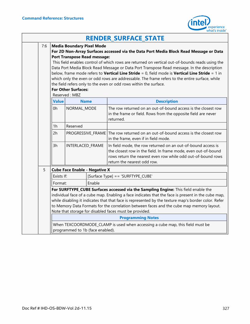
Command Reference: Structures
Doc Ref # IHD-OS-BDW-Vol 2d-11.15 327
RENDER_SURFACE_STATE 7:6 Media Boundary Pixel Mode
For 2D Non-Array Surfaces accessed via the Data Port Media Block Read Message or Data
Port Transpose Read message:
This field enables control of which rows are returned on vertical out-of-bounds reads using the
Data Port Media Block Read Message or Data Port Transpose Read message. In the description
below, frame mode refers to Vertical Line Stride = 0, field mode is Vertical Line Stride = 1 in
which only the even or odd rows are addressable. The frame refers to the entire surface, while
the field refers only to the even or odd rows within the surface.
For Other Surfaces:
Reserved : MBZ
Value Name Description
0h NORMAL_MODE The row returned on an out-of-bound access is the closest row
in the frame or field. Rows from the opposite field are never
returned.
1h Reserved
2h PROGRESSIVE_FRAME The row returned on an out-of-bound access is the closest row
in the frame, even if in field mode.
3h INTERLACED_FRAME In field mode, the row returned on an out-of-bound access is
the closest row in the field. In frame mode, even out-of-bound
rows return the nearest even row while odd out-of-bound rows
return the nearest odd row.
5 Cube Face Enable - Negative X
Exists If: [Surface Type] == 'SURFTYPE_CUBE'
Format: Enable
For SURFTYPE_CUBE Surfaces accessed via the Sampling Engine: This field enable the
individual face of a cube map. Enabling a face indicates that the face is present in the cube map,
while disabling it indicates that that face is represented by the texture map's border color. Refer
to Memory Data Formats for the correlation between faces and the cube map memory layout.
Note that storage for disabled faces must be provided.
Programming Notes
When TEXCOORDMODE_CLAMP is used when accessing a cube map, this field must be
programmed to 1b (face enabled).
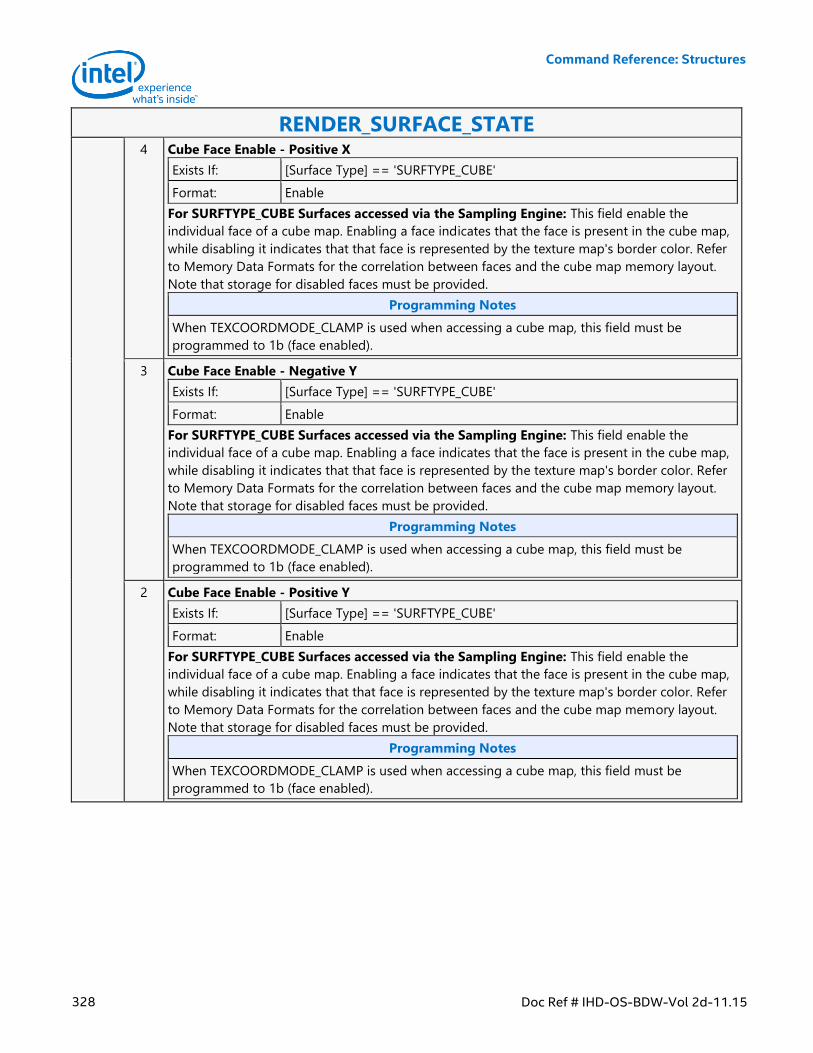
Command Reference: Structures
328 Doc Ref # IHD-OS-BDW-Vol 2d-11.15
RENDER_SURFACE_STATE 4 Cube Face Enable - Positive X
Exists If: [Surface Type] == 'SURFTYPE_CUBE'
Format: Enable
For SURFTYPE_CUBE Surfaces accessed via the Sampling Engine: This field enable the
individual face of a cube map. Enabling a face indicates that the face is present in the cube map,
while disabling it indicates that that face is represented by the texture map's border color. Refer
to Memory Data Formats for the correlation between faces and the cube map memory layout.
Note that storage for disabled faces must be provided.
Programming Notes
When TEXCOORDMODE_CLAMP is used when accessing a cube map, this field must be
programmed to 1b (face enabled).
3 Cube Face Enable - Negative Y
Exists If: [Surface Type] == 'SURFTYPE_CUBE'
Format: Enable
For SURFTYPE_CUBE Surfaces accessed via the Sampling Engine: This field enable the
individual face of a cube map. Enabling a face indicates that the face is present in the cube map,
while disabling it indicates that that face is represented by the texture map's border color. Refer
to Memory Data Formats for the correlation between faces and the cube map memory layout.
Note that storage for disabled faces must be provided.
Programming Notes
When TEXCOORDMODE_CLAMP is used when accessing a cube map, this field must be
programmed to 1b (face enabled).
2 Cube Face Enable - Positive Y
Exists If: [Surface Type] == 'SURFTYPE_CUBE'
Format: Enable
For SURFTYPE_CUBE Surfaces accessed via the Sampling Engine: This field enable the
individual face of a cube map. Enabling a face indicates that the face is present in the cube map,
while disabling it indicates that that face is represented by the texture map's border color. Refer
to Memory Data Formats for the correlation between faces and the cube map memory layout.
Note that storage for disabled faces must be provided.
Programming Notes
When TEXCOORDMODE_CLAMP is used when accessing a cube map, this field must be
programmed to 1b (face enabled).
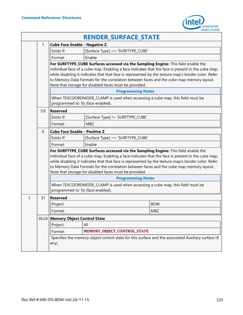
Command Reference: Structures
Doc Ref # IHD-OS-BDW-Vol 2d-11.15 329
RENDER_SURFACE_STATE 1 Cube Face Enable - Negative Z
Exists If: [Surface Type] == 'SURFTYPE_CUBE'
Format: Enable
For SURFTYPE_CUBE Surfaces accessed via the Sampling Engine: This field enable the
individual face of a cube map. Enabling a face indicates that the face is present in the cube map,
while disabling it indicates that that face is represented by the texture map's border color. Refer
to Memory Data Formats for the correlation between faces and the cube map memory layout.
Note that storage for disabled faces must be provided.
Programming Notes
When TEXCOORDMODE_CLAMP is used when accessing a cube map, this field must be
programmed to 1b (face enabled).
5:0 Reserved
Exists If: [Surface Type] != 'SURFTYPE_CUBE'
Format: MBZ
0 Cube Face Enable - Positive Z
Exists If: [Surface Type] == 'SURFTYPE_CUBE'
Format: Enable
For SURFTYPE_CUBE Surfaces accessed via the Sampling Engine: This field enable the
individual face of a cube map. Enabling a face indicates that the face is present in the cube map,
while disabling it indicates that that face is represented by the texture map's border color. Refer
to Memory Data Formats for the correlation between faces and the cube map memory layout.
Note that storage for disabled faces must be provided.
Programming Notes
When TEXCOORDMODE_CLAMP is used when accessing a cube map, this field must be
programmed to 1b (face enabled).
1 31 Reserved
Project: BDW
Format: MBZ
30:24 Memory Object Control State
Project: All
Format: MEMORY_OBJECT_CONTROL_STATE
Specifies the memory object control state for this surface and the associated Auxiliary surface (if
any).
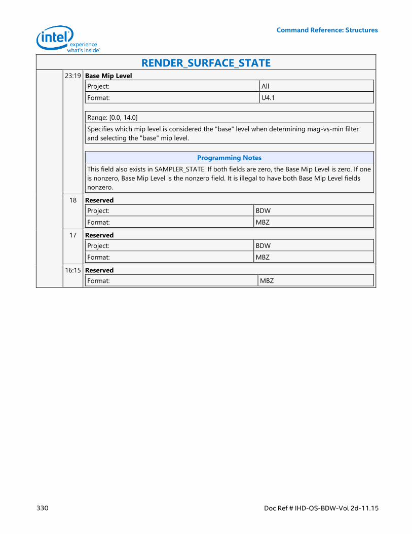
Command Reference: Structures
330 Doc Ref # IHD-OS-BDW-Vol 2d-11.15
RENDER_SURFACE_STATE 23:19 Base Mip Level
Project: All
Format: U4.1
Range: [0.0, 14.0]
Specifies which mip level is considered the "base" level when determining mag-vs-min filter
and selecting the "base" mip level.
Programming Notes
This field also exists in SAMPLER_STATE. If both fields are zero, the Base Mip Level is zero. If one
is nonzero, Base Mip Level is the nonzero field. It is illegal to have both Base Mip Level fields
nonzero.
18 Reserved
Project: BDW
Format: MBZ
17 Reserved
Project: BDW
Format: MBZ
16:15 Reserved
Format: MBZ
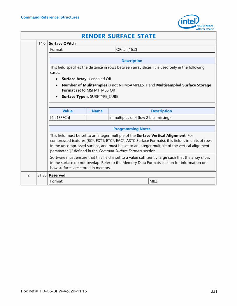
Command Reference: Structures
Doc Ref # IHD-OS-BDW-Vol 2d-11.15 331
RENDER_SURFACE_STATE 14:0 Surface QPitch
Format: QPitch[16:2]
Description
This field specifies the distance in rows between array slices. It is used only in the following
cases:
Surface Array is enabled OR
Number of Mulitsamples is not NUMSAMPLES_1 and Multisampled Surface Storage
Format set to MSFMT_MSS OR
Surface Type is SURFTYPE_CUBE
Value Name Description
[4h,1FFFCh] in multiples of 4 (low 2 bits missing)
Programming Notes
This field must be set to an integer multiple of the Surface Vertical Alignment. For
compressed textures (BC*, FXT1, ETC*, EAC*, ASTC Surface Formats), this field is in units of rows
in the uncompressed surface, and must be set to an integer multiple of the vertical alignment
parameter "j" defined in the Common Surface Formats section.
Software must ensure that this field is set to a value sufficiently large such that the array slices
in the surface do not overlap. Refer to the Memory Data Formats section for information on
how surfaces are stored in memory.
2 31:30 Reserved
Format: MBZ
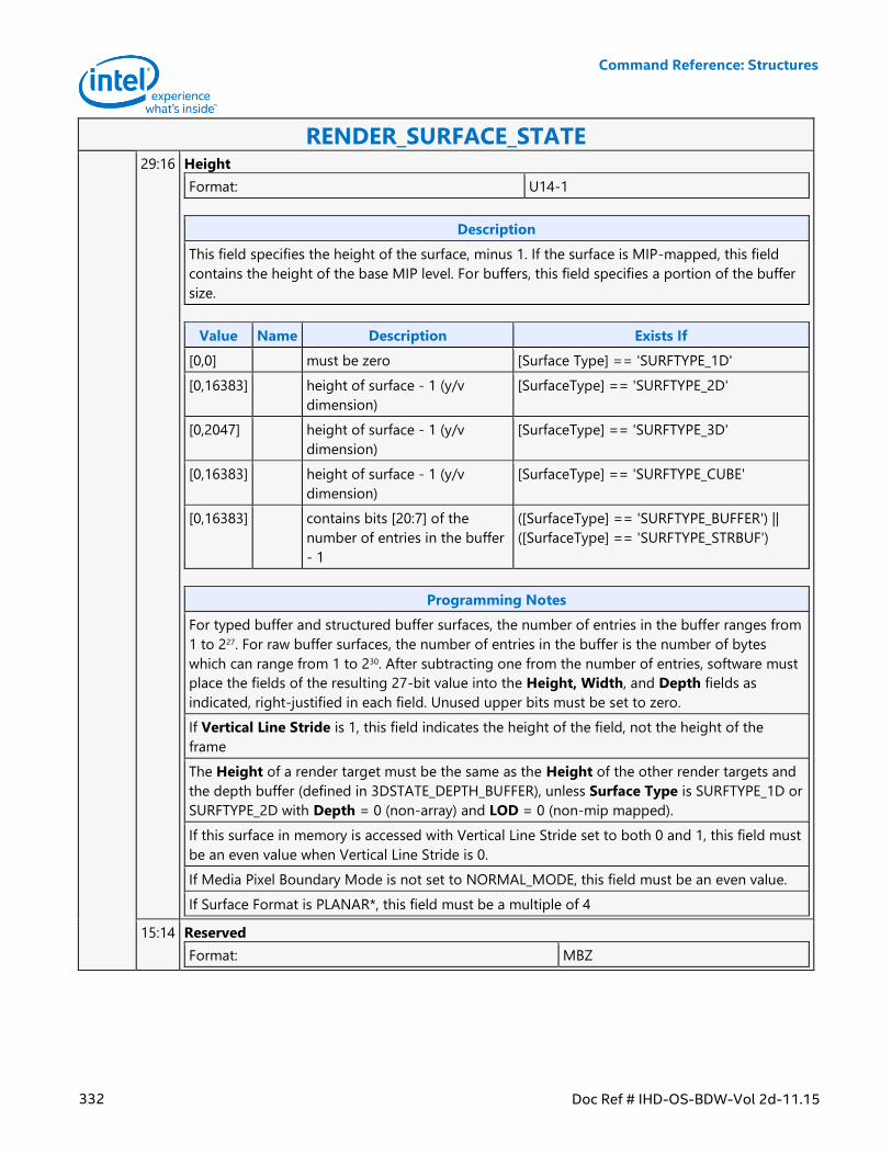
Command Reference: Structures
332 Doc Ref # IHD-OS-BDW-Vol 2d-11.15
RENDER_SURFACE_STATE 29:16 Height
Format: U14-1
Description
This field specifies the height of the surface, minus 1. If the surface is MIP-mapped, this field
contains the height of the base MIP level. For buffers, this field specifies a portion of the buffer
size.
Value Name Description Exists If
[0,0] must be zero [Surface Type] == 'SURFTYPE_1D'
[0,16383] height of surface - 1 (y/v
dimension)
[SurfaceType] == 'SURFTYPE_2D'
[0,2047] height of surface - 1 (y/v
dimension)
[SurfaceType] == 'SURFTYPE_3D'
[0,16383] height of surface - 1 (y/v
dimension)
[SurfaceType] == 'SURFTYPE_CUBE'
[0,16383] contains bits [20:7] of the
number of entries in the buffer
- 1
([SurfaceType] == 'SURFTYPE_BUFFER') ||
([SurfaceType] == 'SURFTYPE_STRBUF')
Programming Notes
For typed buffer and structured buffer surfaces, the number of entries in the buffer ranges from
1 to 227. For raw buffer surfaces, the number of entries in the buffer is the number of bytes
which can range from 1 to 230. After subtracting one from the number of entries, software must
place the fields of the resulting 27-bit value into the Height, Width, and Depth fields as
indicated, right-justified in each field. Unused upper bits must be set to zero.
If Vertical Line Stride is 1, this field indicates the height of the field, not the height of the
frame
The Height of a render target must be the same as the Height of the other render targets and
the depth buffer (defined in 3DSTATE_DEPTH_BUFFER), unless Surface Type is SURFTYPE_1D or
SURFTYPE_2D with Depth = 0 (non-array) and LOD = 0 (non-mip mapped).
If this surface in memory is accessed with Vertical Line Stride set to both 0 and 1, this field must
be an even value when Vertical Line Stride is 0.
If Media Pixel Boundary Mode is not set to NORMAL_MODE, this field must be an even value.
If Surface Format is PLANAR*, this field must be a multiple of 4
15:14 Reserved
Format: MBZ
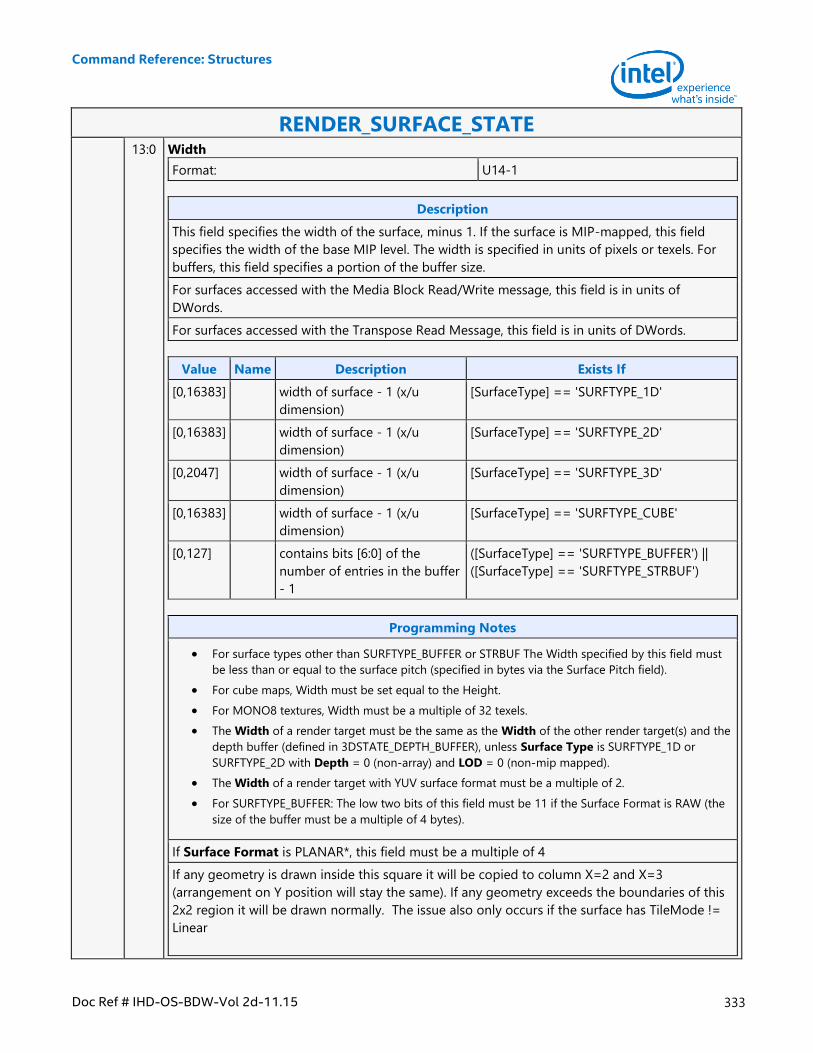
Command Reference: Structures
Doc Ref # IHD-OS-BDW-Vol 2d-11.15 333
RENDER_SURFACE_STATE 13:0 Width
Format: U14-1
Description
This field specifies the width of the surface, minus 1. If the surface is MIP-mapped, this field
specifies the width of the base MIP level. The width is specified in units of pixels or texels. For
buffers, this field specifies a portion of the buffer size.
For surfaces accessed with the Media Block Read/Write message, this field is in units of
DWords.
For surfaces accessed with the Transpose Read Message, this field is in units of DWords.
Value Name Description Exists If
[0,16383] width of surface - 1 (x/u
dimension)
[SurfaceType] == 'SURFTYPE_1D'
[0,16383] width of surface - 1 (x/u
dimension)
[SurfaceType] == 'SURFTYPE_2D'
[0,2047] width of surface - 1 (x/u
dimension)
[SurfaceType] == 'SURFTYPE_3D'
[0,16383] width of surface - 1 (x/u
dimension)
[SurfaceType] == 'SURFTYPE_CUBE'
[0,127] contains bits [6:0] of the
number of entries in the buffer
- 1
([SurfaceType] == 'SURFTYPE_BUFFER') ||
([SurfaceType] == 'SURFTYPE_STRBUF')
Programming Notes
For surface types other than SURFTYPE_BUFFER or STRBUF The Width specified by this field must
be less than or equal to the surface pitch (specified in bytes via the Surface Pitch field).
For cube maps, Width must be set equal to the Height.
For MONO8 textures, Width must be a multiple of 32 texels.
The Width of a render target must be the same as the Width of the other render target(s) and the
depth buffer (defined in 3DSTATE_DEPTH_BUFFER), unless Surface Type is SURFTYPE_1D or
SURFTYPE_2D with Depth = 0 (non-array) and LOD = 0 (non-mip mapped).
The Width of a render target with YUV surface format must be a multiple of 2.
For SURFTYPE_BUFFER: The low two bits of this field must be 11 if the Surface Format is RAW (the
size of the buffer must be a multiple of 4 bytes).
If Surface Format is PLANAR*, this field must be a multiple of 4
If any geometry is drawn inside this square it will be copied to column X=2 and X=3
(arrangement on Y position will stay the same). If any geometry exceeds the boundaries of this
2x2 region it will be drawn normally. The issue also only occurs if the surface has TileMode !=
Linear
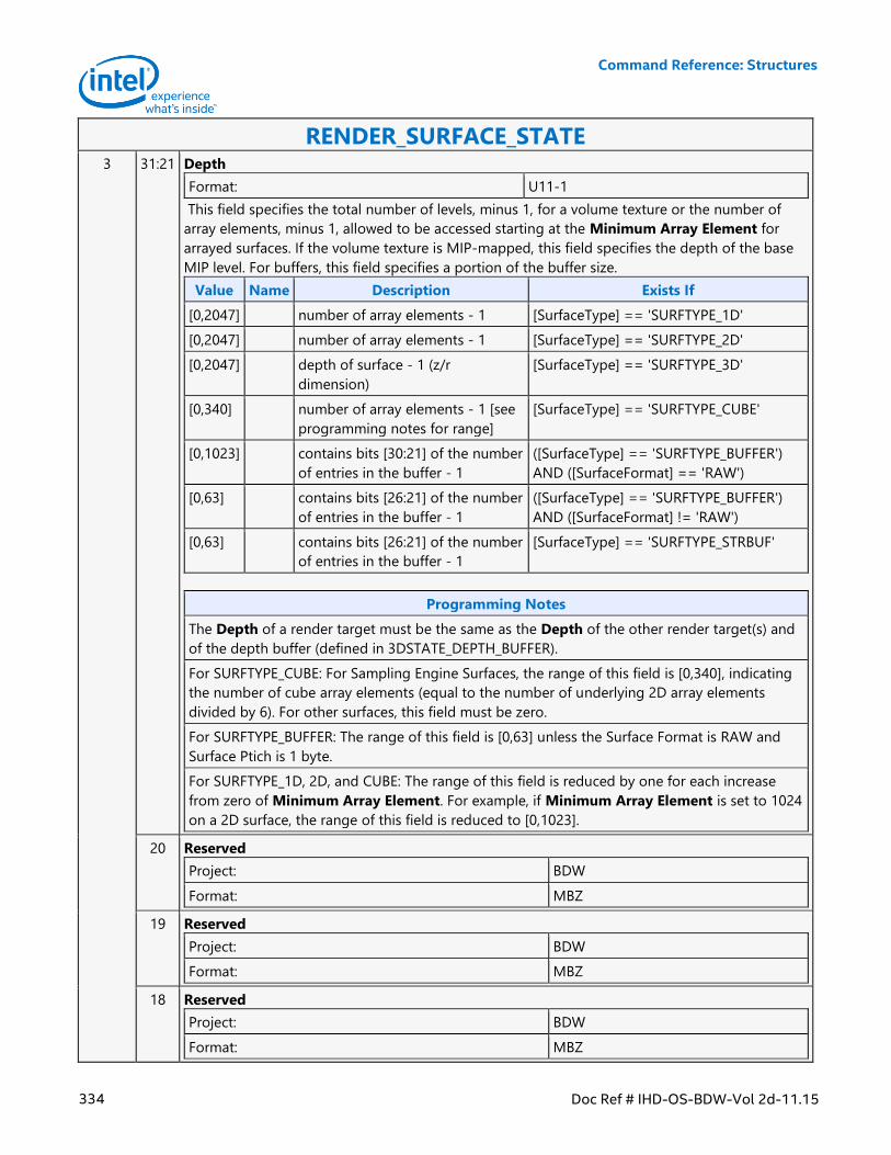
Command Reference: Structures
334 Doc Ref # IHD-OS-BDW-Vol 2d-11.15
RENDER_SURFACE_STATE 3 31:21 Depth
Format: U11-1
This field specifies the total number of levels, minus 1, for a volume texture or the number of
array elements, minus 1, allowed to be accessed starting at the Minimum Array Element for
arrayed surfaces. If the volume texture is MIP-mapped, this field specifies the depth of the base
MIP level. For buffers, this field specifies a portion of the buffer size.
Value Name Description Exists If
[0,2047] number of array elements - 1 [SurfaceType] == 'SURFTYPE_1D'
[0,2047] number of array elements - 1 [SurfaceType] == 'SURFTYPE_2D'
[0,2047] depth of surface - 1 (z/r
dimension)
[SurfaceType] == 'SURFTYPE_3D'
[0,340] number of array elements - 1 [see
programming notes for range]
[SurfaceType] == 'SURFTYPE_CUBE'
[0,1023] contains bits [30:21] of the number
of entries in the buffer - 1
([SurfaceType] == 'SURFTYPE_BUFFER')
AND ([SurfaceFormat] == 'RAW')
[0,63] contains bits [26:21] of the number
of entries in the buffer - 1
([SurfaceType] == 'SURFTYPE_BUFFER')
AND ([SurfaceFormat] != 'RAW')
[0,63] contains bits [26:21] of the number
of entries in the buffer - 1
[SurfaceType] == 'SURFTYPE_STRBUF'
Programming Notes
The Depth of a render target must be the same as the Depth of the other render target(s) and
of the depth buffer (defined in 3DSTATE_DEPTH_BUFFER).
For SURFTYPE_CUBE: For Sampling Engine Surfaces, the range of this field is [0,340], indicating
the number of cube array elements (equal to the number of underlying 2D array elements
divided by 6). For other surfaces, this field must be zero.
For SURFTYPE_BUFFER: The range of this field is [0,63] unless the Surface Format is RAW and
Surface Ptich is 1 byte.
For SURFTYPE_1D, 2D, and CUBE: The range of this field is reduced by one for each increase
from zero of Minimum Array Element. For example, if Minimum Array Element is set to 1024
on a 2D surface, the range of this field is reduced to [0,1023].
20 Reserved
Project: BDW
Format: MBZ
19 Reserved
Project: BDW
Format: MBZ
18 Reserved
Project: BDW
Format: MBZ
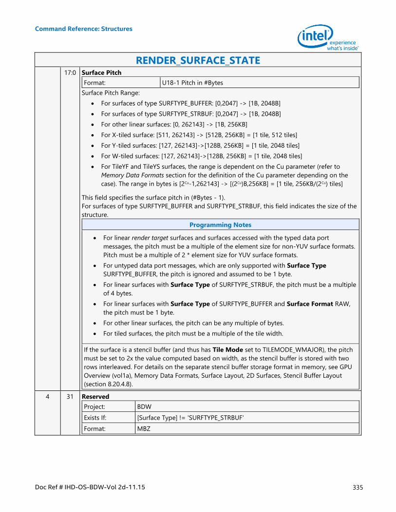
Command Reference: Structures
Doc Ref # IHD-OS-BDW-Vol 2d-11.15 335
RENDER_SURFACE_STATE 17:0 Surface Pitch
Format: U18-1 Pitch in #Bytes
Surface Pitch Range:
For surfaces of type SURFTYPE_BUFFER: [0,2047] -> [1B, 2048B]
For surfaces of type SURFTYPE_STRBUF: [0,2047] -> [1B, 2048B]
For other linear surfaces: [0, 262143] -> [1B, 256KB]
For X-tiled surface: [511, 262143] -> [512B, 256KB] = [1 tile, 512 tiles]
For Y-tiled surfaces: [127, 262143]->[128B, 256KB] = [1 tile, 2048 tiles]
For W-tiled surfaces: [127, 262143]->[128B, 256KB] = [1 tile, 2048 tiles]
For TileYF and TileYS surfaces, the range is dependent on the Cu parameter (refer to
Memory Data Formats section for the definition of the Cu parameter depending on the
case). The range in bytes is [2Cu-1,262143] -> [(2Cu)B,256KB] = [1 tile, 256KB/(2Cu) tiles]
This field specifies the surface pitch in (#Bytes - 1).
For surfaces of type SURFTYPE_BUFFER and SURFTYPE_STRBUF, this field indicates the size of the
structure.
Programming Notes
For linear render target surfaces and surfaces accessed with the typed data port
messages, the pitch must be a multiple of the element size for non-YUV surface formats.
Pitch must be a multiple of 2 * element size for YUV surface formats.
For untyped data port messages, which are only supported with Surface Type
SURFTYPE_BUFFER, the pitch is ignored and assumed to be 1 byte.
For linear surfaces with Surface Type of SURFTYPE_STRBUF, the pitch must be a multiple
of 4 bytes.
For linear surfaces with Surface Type of SURFTYPE_BUFFER and Surface Format RAW,
the pitch must be 1 byte.
For other linear surfaces, the pitch can be any multiple of bytes.
For tiled surfaces, the pitch must be a multiple of the tile width.
If the surface is a stencil buffer (and thus has Tile Mode set to TILEMODE_WMAJOR), the pitch
must be set to 2x the value computed based on width, as the stencil buffer is stored with two
rows interleaved. For details on the separate stencil buffer storage format in memory, see GPU
Overview (vol1a), Memory Data Formats, Surface Layout, 2D Surfaces, Stencil Buffer Layout
(section 8.20.4.8).
4 31 Reserved
Project: BDW
Exists If: [Surface Type] != 'SURFTYPE_STRBUF'
Format: MBZ
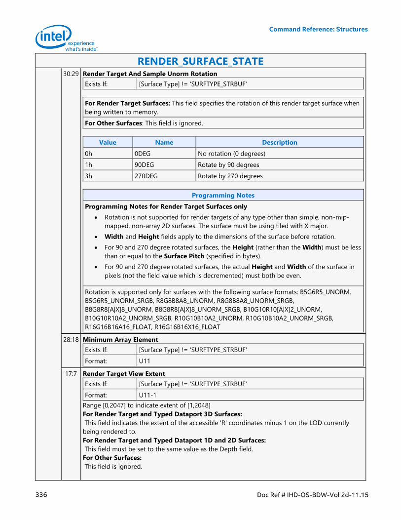
Command Reference: Structures
336 Doc Ref # IHD-OS-BDW-Vol 2d-11.15
RENDER_SURFACE_STATE 30:29 Render Target And Sample Unorm Rotation
Exists If: [Surface Type] != 'SURFTYPE_STRBUF'
For Render Target Surfaces: This field specifies the rotation of this render target surface when
being written to memory.
For Other Surfaces: This field is ignored.
Value Name Description
0h 0DEG No rotation (0 degrees)
1h 90DEG Rotate by 90 degrees
3h 270DEG Rotate by 270 degrees
Programming Notes
Programming Notes for Render Target Surfaces only
Rotation is not supported for render targets of any type other than simple, non-mip-
mapped, non-array 2D surfaces. The surface must be using tiled with X major.
Width and Height fields apply to the dimensions of the surface before rotation.
For 90 and 270 degree rotated surfaces, the Height (rather than the Width) must be less
than or equal to the Surface Pitch (specified in bytes).
For 90 and 270 degree rotated surfaces, the actual Height and Width of the surface in
pixels (not the field value which is decremented) must both be even.
Rotation is supported only for surfaces with the following surface formats: B5G6R5_UNORM,
B5G6R5_UNORM_SRGB, R8G8B8A8_UNORM, R8G8B8A8_UNORM_SRGB,
B8G8R8[A|X]8_UNORM, B8G8R8[A|X]8_UNORM_SRGB, B10G10R10[A|X]2_UNORM,
B10G10R10A2_UNORM_SRGB, R10G10B10A2_UNORM, R10G10B10A2_UNORM_SRGB,
R16G16B16A16_FLOAT, R16G16B16X16_FLOAT
28:18 Minimum Array Element
Exists If: [Surface Type] != 'SURFTYPE_STRBUF'
Format: U11
17:7 Render Target View Extent
Exists If: [Surface Type] != 'SURFTYPE_STRBUF'
Format: U11-1
Range [0,2047] to indicate extent of [1,2048]
For Render Target and Typed Dataport 3D Surfaces:
This field indicates the extent of the accessible 'R' coordinates minus 1 on the LOD currently
being rendered to.
For Render Target and Typed Dataport 1D and 2D Surfaces:
This field must be set to the same value as the Depth field.
For Other Surfaces:
This field is ignored.
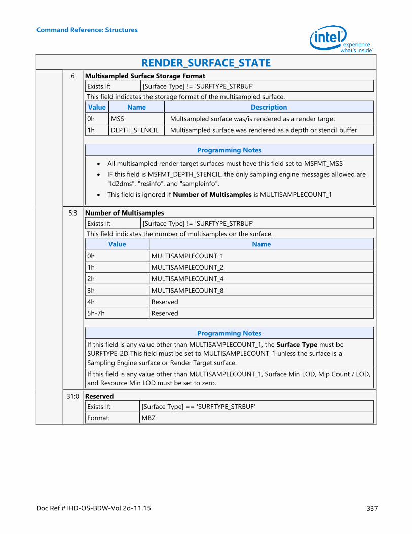
Command Reference: Structures
Doc Ref # IHD-OS-BDW-Vol 2d-11.15 337
RENDER_SURFACE_STATE 6 Multisampled Surface Storage Format
Exists If: [Surface Type] != 'SURFTYPE_STRBUF'
This field indicates the storage format of the multisampled surface.
Value Name Description
0h MSS Multsampled surface was/is rendered as a render target
1h DEPTH_STENCIL Multisampled surface was rendered as a depth or stencil buffer
Programming Notes
All multisampled render target surfaces must have this field set to MSFMT_MSS
IF this field is MSFMT_DEPTH_STENCIL, the only sampling engine messages allowed are
"ld2dms", "resinfo", and "sampleinfo".
This field is ignored if Number of Multisamples is MULTISAMPLECOUNT_1
5:3 Number of Multisamples
Exists If: [Surface Type] != 'SURFTYPE_STRBUF'
This field indicates the number of multisamples on the surface.
Value Name
0h MULTISAMPLECOUNT_1
1h MULTISAMPLECOUNT_2
2h MULTISAMPLECOUNT_4
3h MULTISAMPLECOUNT_8
4h Reserved
5h-7h Reserved
Programming Notes
If this field is any value other than MULTISAMPLECOUNT_1, the Surface Type must be
SURFTYPE_2D This field must be set to MULTISAMPLECOUNT_1 unless the surface is a
Sampling Engine surface or Render Target surface.
If this field is any value other than MULTISAMPLECOUNT_1, Surface Min LOD, Mip Count / LOD,
and Resource Min LOD must be set to zero.
31:0 Reserved
Exists If: [Surface Type] == 'SURFTYPE_STRBUF'
Format: MBZ
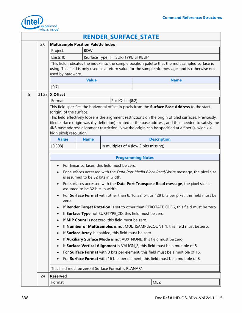
Command Reference: Structures
338 Doc Ref # IHD-OS-BDW-Vol 2d-11.15
RENDER_SURFACE_STATE 2:0 Multisample Position Palette Index
Project: BDW
Exists If: [Surface Type] != 'SURFTYPE_STRBUF'
This field indicates the index into the sample position palette that the multisampled surface is
using. This field is only used as a return value for the sampleinfo message, and is otherwise not
used by hardware.
Value Name
[0,7]
5 31:25 X Offset
Format: PixelOffset[8:2]
This field specifies the horizontal offset in pixels from the Surface Base Address to the start
(origin) of the surface.
This field effectively loosens the alignment restrictions on the origin of tiled surfaces. Previously,
tiled surface origin was (by definition) located at the base address, and thus needed to satisfy the
4KB base address alignment restriction. Now the origin can be specified at a finer (4-wide x 4-
high pixel) resolution.
Value Name Description
[0,508] In multiples of 4 (low 2 bits missing)
Programming Notes
For linear surfaces, this field must be zero.
For surfaces accessed with the Data Port Media Block Read/Write message, the pixel size
is assumed to be 32 bits in width.
For surfaces accessed with the Data Port Transpose Read message, the pixel size is
assumed to be 32 bits in width.
For Surface Format with other than 8, 16, 32, 64, or 128 bits per pixel, this field must be
zero.
If Render Target Rotation is set to other than RTROTATE_0DEG, this field must be zero.
If Surface Type not SURFTYPE_2D, this field must be zero.
If MIP Count is not zero, this field must be zero.
If Number of Multisamples is not MULTISAMPLECOUNT_1, this field must be zero.
If Surface Array is enabled, this field must be zero.
If Auxiliary Surface Mode is not AUX_NONE, this field must be zero.
If Surface Vertical Alignment is VALIGN_8, this field must be a multiple of 8.
For Surface Format with 8 bits per element, this field must be a multiple of 16.
For Surface Format with 16 bits per element, this field must be a multiple of 8.
This field must be zero if Surface Format is PLANAR*.
24 Reserved
Format: MBZ
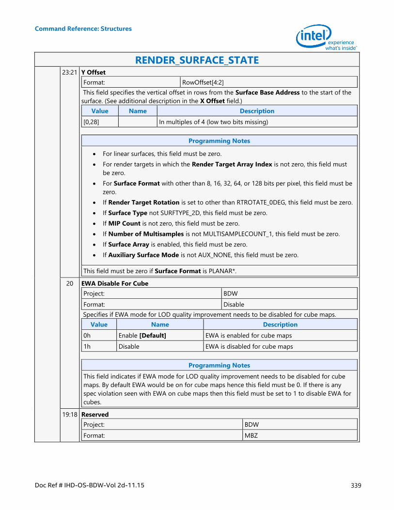
Command Reference: Structures
Doc Ref # IHD-OS-BDW-Vol 2d-11.15 339
RENDER_SURFACE_STATE 23:21 Y Offset
Format: RowOffset[4:2]
This field specifies the vertical offset in rows from the Surface Base Address to the start of the
surface. (See additional description in the X Offset field.)
Value Name Description
[0,28] In multiples of 4 (low two bits missing)
Programming Notes
For linear surfaces, this field must be zero.
For render targets in which the Render Target Array Index is not zero, this field must
be zero.
For Surface Format with other than 8, 16, 32, 64, or 128 bits per pixel, this field must be
zero.
If Render Target Rotation is set to other than RTROTATE_0DEG, this field must be zero.
If Surface Type not SURFTYPE_2D, this field must be zero.
If MIP Count is not zero, this field must be zero.
If Number of Multisamples is not MULTISAMPLECOUNT_1, this field must be zero.
If Surface Array is enabled, this field must be zero.
If Auxiliary Surface Mode is not AUX_NONE, this field must be zero.
This field must be zero if Surface Format is PLANAR*.
20 EWA Disable For Cube
Project: BDW
Format: Disable
Specifies if EWA mode for LOD quality improvement needs to be disabled for cube maps.
Value Name Description
0h Enable [Default] EWA is enabled for cube maps
1h Disable EWA is disabled for cube maps
Programming Notes
This field indicates if EWA mode for LOD quality improvement needs to be disabled for cube
maps. By default EWA would be on for cube maps hence this field must be 0. If there is any
spec violation seen with EWA on cube maps then this field must be set to 1 to disable EWA for
cubes.
19:18 Reserved
Project: BDW
Format: MBZ
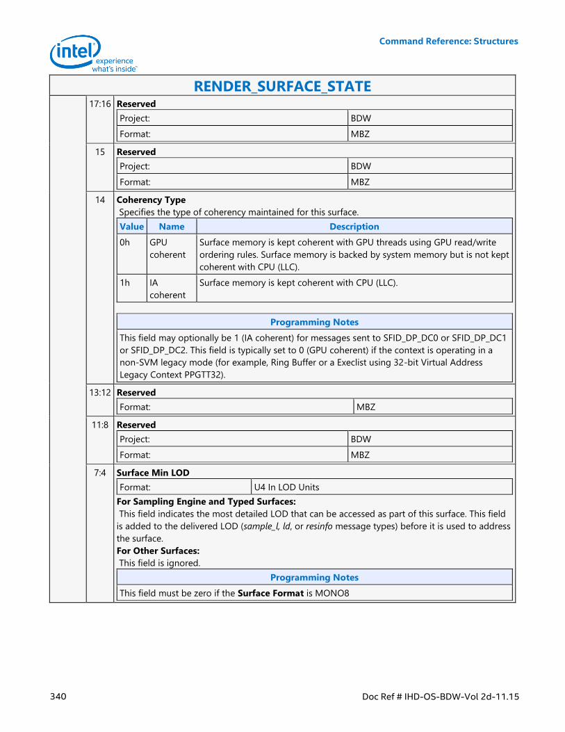
Command Reference: Structures
340 Doc Ref # IHD-OS-BDW-Vol 2d-11.15
RENDER_SURFACE_STATE 17:16 Reserved
Project: BDW
Format: MBZ
15 Reserved
Project: BDW
Format: MBZ
14 Coherency Type
Specifies the type of coherency maintained for this surface.
Value Name Description
0h GPU
coherent
Surface memory is kept coherent with GPU threads using GPU read/write
ordering rules. Surface memory is backed by system memory but is not kept
coherent with CPU (LLC).
1h IA
coherent
Surface memory is kept coherent with CPU (LLC).
Programming Notes
This field may optionally be 1 (IA coherent) for messages sent to SFID_DP_DC0 or SFID_DP_DC1
or SFID_DP_DC2. This field is typically set to 0 (GPU coherent) if the context is operating in a
non-SVM legacy mode (for example, Ring Buffer or a Execlist using 32-bit Virtual Address
Legacy Context PPGTT32).
13:12 Reserved
Format: MBZ
11:8 Reserved
Project: BDW
Format: MBZ
7:4 Surface Min LOD
Format: U4 In LOD Units
For Sampling Engine and Typed Surfaces:
This field indicates the most detailed LOD that can be accessed as part of this surface. This field
is added to the delivered LOD (sample_l, ld, or resinfo message types) before it is used to address
the surface.
For Other Surfaces:
This field is ignored.
Programming Notes
This field must be zero if the Surface Format is MONO8
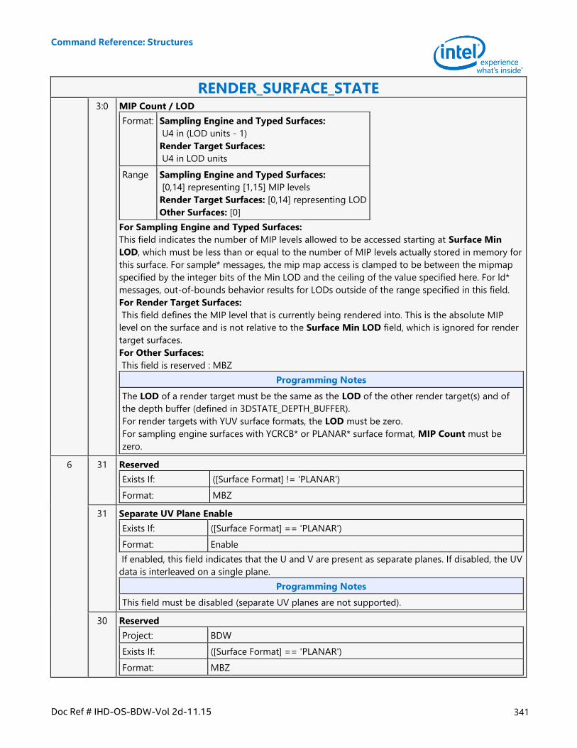
Command Reference: Structures
Doc Ref # IHD-OS-BDW-Vol 2d-11.15 341
RENDER_SURFACE_STATE 3:0 MIP Count / LOD
Format: Sampling Engine and Typed Surfaces:
U4 in (LOD units - 1)
Render Target Surfaces:
U4 in LOD units
Range Sampling Engine and Typed Surfaces:
[0,14] representing [1,15] MIP levels
Render Target Surfaces: [0,14] representing LOD
Other Surfaces: [0]
For Sampling Engine and Typed Surfaces:
This field indicates the number of MIP levels allowed to be accessed starting at Surface Min
LOD, which must be less than or equal to the number of MIP levels actually stored in memory for
this surface. For sample* messages, the mip map access is clamped to be between the mipmap
specified by the integer bits of the Min LOD and the ceiling of the value specified here. For ld*
messages, out-of-bounds behavior results for LODs outside of the range specified in this field.
For Render Target Surfaces:
This field defines the MIP level that is currently being rendered into. This is the absolute MIP
level on the surface and is not relative to the Surface Min LOD field, which is ignored for render
target surfaces.
For Other Surfaces:
This field is reserved : MBZ
Programming Notes
The LOD of a render target must be the same as the LOD of the other render target(s) and of
the depth buffer (defined in 3DSTATE_DEPTH_BUFFER).
For render targets with YUV surface formats, the LOD must be zero.
For sampling engine surfaces with YCRCB* or PLANAR* surface format, MIP Count must be
zero.
6 31 Reserved
Exists If: ([Surface Format] != 'PLANAR')
Format: MBZ
31 Separate UV Plane Enable
Exists If: ([Surface Format] == 'PLANAR')
Format: Enable
If enabled, this field indicates that the U and V are present as separate planes. If disabled, the UV
data is interleaved on a single plane.
Programming Notes
This field must be disabled (separate UV planes are not supported).
30 Reserved
Project: BDW
Exists If: ([Surface Format] == 'PLANAR')
Format: MBZ

Command Reference: Structures
342 Doc Ref # IHD-OS-BDW-Vol 2d-11.15
RENDER_SURFACE_STATE 30:16 Auxiliary Surface QPitch
Exists If: ([Surface Format] != 'PLANAR')
Format: QPitch[16:2]
This field specifies the distance in rows between array slices on the auxiliary surface.
Value Name Description
[4h,1FFFCh] in multiples of 4 (low 2 bits missing)
Programming Notes
This field must be set to an integer multiple of the Surface Vertical Alignment
Software must ensure that this field is set to a value sufficiently large such that the array slices
in the auxiliary surface do not overlap. Refer to the Memory Data Formats section for
information on how surfaces are stored in memory.
For non-multisampled render target's auxiliary surface, MCS, QPitch must be computed with
Horizontal Alignment = 256 and Surface Vertical Alignment = 128. These alignments are only
for MCS buffer and not for associated render target.
29:16 X Offset for U or UV Plane
Exists If: ([Surface Format] == 'PLANAR')
Format: U14
This field specifies the horizontal offset in pixels from the Surface Base Address to the start
(origin) of the U plane or interleaved UV plane, depending on the setting of Separate UV Plane
Enable.
Programming Notes
This field must be a multiple of 4 (bits 1:0 MBZ).
Auxiliary Surface Mode is forced to AUX_NONE.
15 Reserved
Project: BDW
Format: MBZ
14 Reserved
Project: All
Exists If: ([Surface Format] == 'PLANAR')
Format: MBZ
14:12 Reserved
Exists If: ([Surface Format] != 'PLANAR')
Format: MBZ
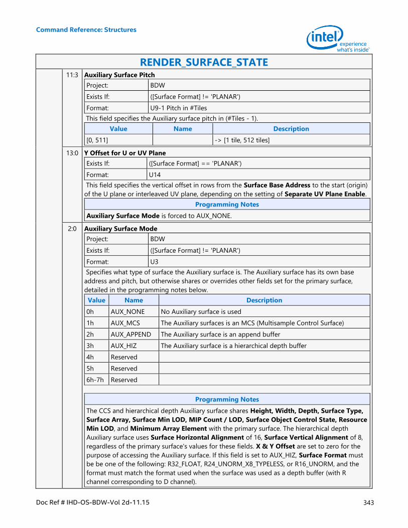
Command Reference: Structures
Doc Ref # IHD-OS-BDW-Vol 2d-11.15 343
RENDER_SURFACE_STATE 11:3 Auxiliary Surface Pitch
Project: BDW
Exists If: ([Surface Format] != 'PLANAR')
Format: U9-1 Pitch in #Tiles
This field specifies the Auxiliary surface pitch in (#Tiles - 1).
Value Name Description
[0, 511] -> [1 tile, 512 tiles]
13:0 Y Offset for U or UV Plane
Exists If: ([Surface Format] == 'PLANAR')
Format: U14
This field specifies the vertical offset in rows from the Surface Base Address to the start (origin)
of the U plane or interleaved UV plane, depending on the setting of Separate UV Plane Enable.
Programming Notes
Auxiliary Surface Mode is forced to AUX_NONE.
2:0 Auxiliary Surface Mode
Project: BDW
Exists If: ([Surface Format] != 'PLANAR')
Format: U3
Specifies what type of surface the Auxiliary surface is. The Auxiliary surface has its own base
address and pitch, but otherwise shares or overrides other fields set for the primary surface,
detailed in the programming notes below.
Value Name Description
0h AUX_NONE No Auxiliary surface is used
1h AUX_MCS The Auxiliary surfaces is an MCS (Multisample Control Surface)
2h AUX_APPEND The Auxiliary surface is an append buffer
3h AUX_HIZ The Auxiliary surface is a hierarchical depth buffer
4h Reserved
5h Reserved
6h-7h Reserved
Programming Notes
The CCS and hierarchical depth Auxiliary surface shares Height, Width, Depth, Surface Type,
Surface Array, Surface Min LOD, MIP Count / LOD, Surface Object Control State, Resource
Min LOD, and Minimum Array Element with the primary surface. The hierarchical depth
Auxiliary surface uses Surface Horizontal Alignment of 16, Surface Vertical Alignment of 8,
regardless of the primary surface's values for these fields. X & Y Offset are set to zero for the
purpose of accessing the Auxiliary surface. If this field is set to AUX_HIZ, Surface Format must
be be one of the following: R32_FLOAT, R24_UNORM_X8_TYPELESS, or R16_UNORM, and the
format must match the format used when the surface was used as a depth buffer (with R
channel corresponding to D channel).
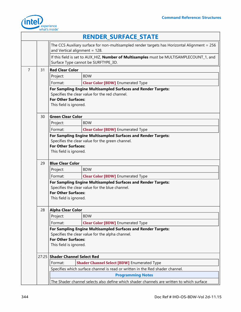
Command Reference: Structures
344 Doc Ref # IHD-OS-BDW-Vol 2d-11.15
RENDER_SURFACE_STATE
The CCS Auxiliary surface for non-multisampled render targets has Horizontal Alignment = 256
and Vertical alignment = 128.
If this field is set to AUX_HIZ, Number of Multisamples must be MULTISAMPLECOUNT_1, and
Surface Type cannot be SURFTYPE_3D.
7 31 Red Clear Color
Project: BDW
Format: Clear Color [BDW] Enumerated Type
For Sampling Engine Multisampled Surfaces and Render Targets:
Specifies the clear value for the red channel.
For Other Surfaces:
This field is ignored.
30 Green Clear Color
Project: BDW
Format: Clear Color [BDW] Enumerated Type
For Sampling Engine Multisampled Surfaces and Render Targets:
Specifies the clear value for the green channel.
For Other Surfaces:
This field is ignored.
29 Blue Clear Color
Project: BDW
Format: Clear Color [BDW] Enumerated Type
For Sampling Engine Multisampled Surfaces and Render Targets:
Specifies the clear value for the blue channel.
For Other Surfaces:
This field is ignored.
28 Alpha Clear Color
Project: BDW
Format: Clear Color [BDW] Enumerated Type
For Sampling Engine Multisampled Surfaces and Render Targets:
Specifies the clear value for the alpha channel.
For Other Surfaces:
This field is ignored.
27:25 Shader Channel Select Red
Format: Shader Channel Select [BDW] Enumerated Type
Specifies which surface channel is read or written in the Red shader channel.
Programming Notes
The Shader channel selects also define which shader channels are written to which surface
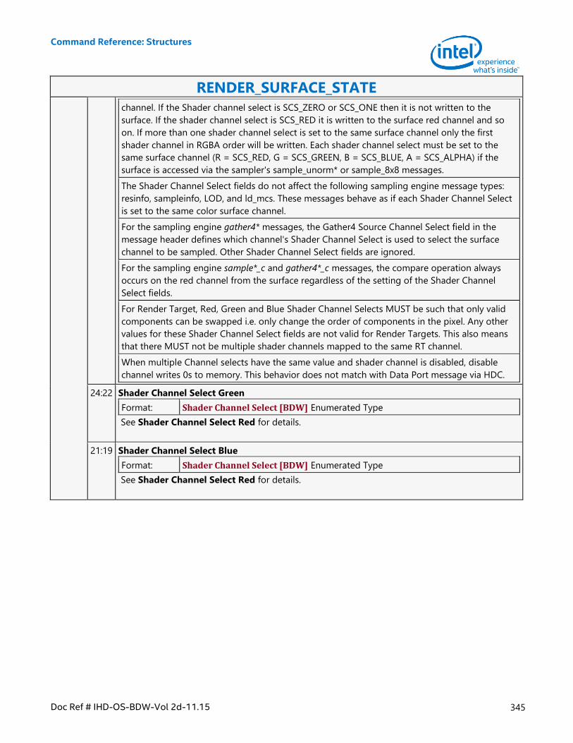
Command Reference: Structures
Doc Ref # IHD-OS-BDW-Vol 2d-11.15 345
RENDER_SURFACE_STATE
channel. If the Shader channel select is SCS_ZERO or SCS_ONE then it is not written to the
surface. If the shader channel select is SCS_RED it is written to the surface red channel and so
on. If more than one shader channel select is set to the same surface channel only the first
shader channel in RGBA order will be written. Each shader channel select must be set to the
same surface channel (R = SCS_RED, G = SCS_GREEN, B = SCS_BLUE, A = SCS_ALPHA) if the
surface is accessed via the sampler's sample_unorm* or sample_8x8 messages.
The Shader Channel Select fields do not affect the following sampling engine message types:
resinfo, sampleinfo, LOD, and ld_mcs. These messages behave as if each Shader Channel Select
is set to the same color surface channel.
For the sampling engine gather4* messages, the Gather4 Source Channel Select field in the
message header defines which channel's Shader Channel Select is used to select the surface
channel to be sampled. Other Shader Channel Select fields are ignored.
For the sampling engine sample*_c and gather4*_c messages, the compare operation always
occurs on the red channel from the surface regardless of the setting of the Shader Channel
Select fields.
For Render Target, Red, Green and Blue Shader Channel Selects MUST be such that only valid
components can be swapped i.e. only change the order of components in the pixel. Any other
values for these Shader Channel Select fields are not valid for Render Targets. This also means
that there MUST not be multiple shader channels mapped to the same RT channel.
When multiple Channel selects have the same value and shader channel is disabled, disable
channel writes 0s to memory. This behavior does not match with Data Port message via HDC.
24:22 Shader Channel Select Green
Format: Shader Channel Select [BDW] Enumerated Type
See Shader Channel Select Red for details.
21:19 Shader Channel Select Blue
Format: Shader Channel Select [BDW] Enumerated Type
See Shader Channel Select Red for details.
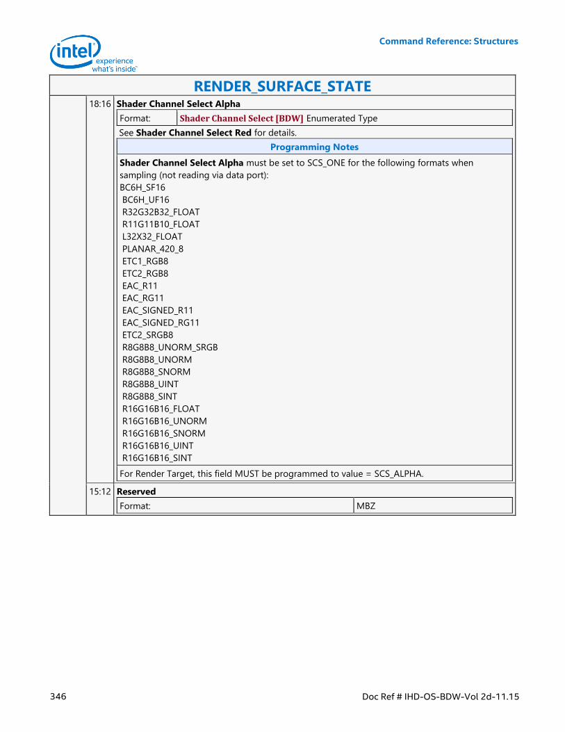
Command Reference: Structures
346 Doc Ref # IHD-OS-BDW-Vol 2d-11.15
RENDER_SURFACE_STATE 18:16 Shader Channel Select Alpha
Format: Shader Channel Select [BDW] Enumerated Type
See Shader Channel Select Red for details.
Programming Notes
Shader Channel Select Alpha must be set to SCS_ONE for the following formats when
sampling (not reading via data port):
BC6H_SF16
BC6H_UF16
R32G32B32_FLOAT
R11G11B10_FLOAT
L32X32_FLOAT
PLANAR_420_8
ETC1_RGB8
ETC2_RGB8
EAC_R11
EAC_RG11
EAC_SIGNED_R11
EAC_SIGNED_RG11
ETC2_SRGB8
R8G8B8_UNORM_SRGB
R8G8B8_UNORM
R8G8B8_SNORM
R8G8B8_UINT
R8G8B8_SINT
R16G16B16_FLOAT
R16G16B16_UNORM
R16G16B16_SNORM
R16G16B16_UINT
R16G16B16_SINT
For Render Target, this field MUST be programmed to value = SCS_ALPHA.
15:12 Reserved
Format: MBZ
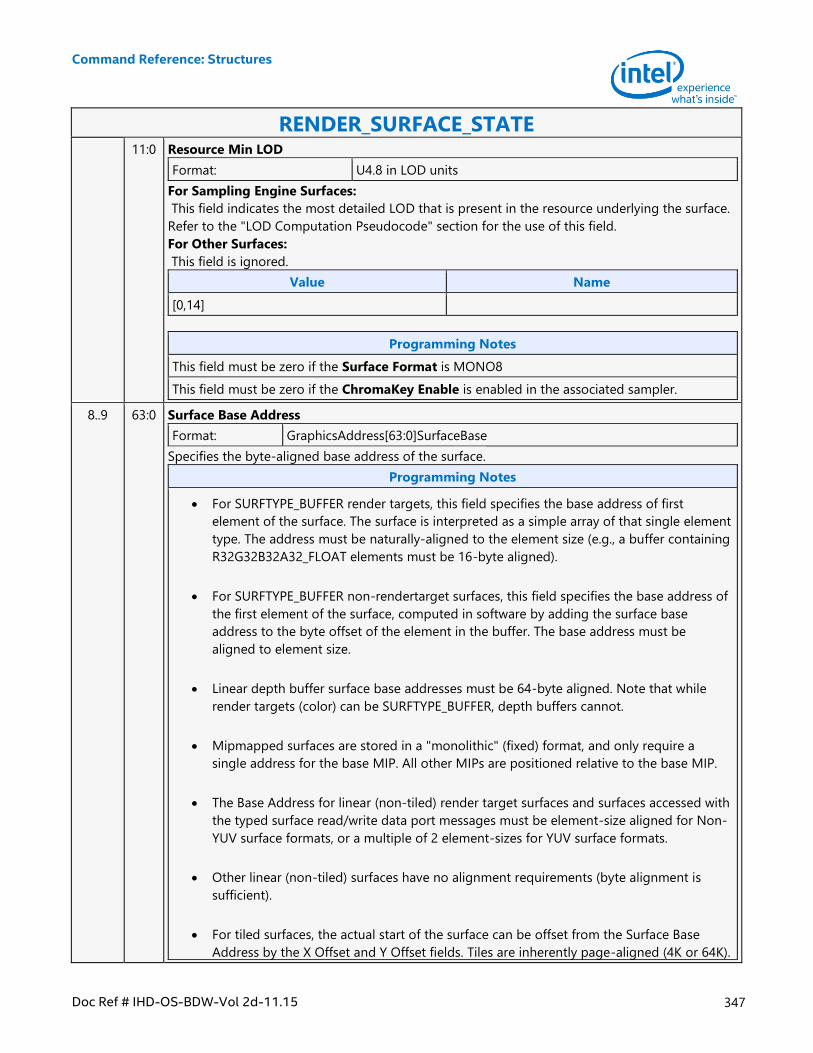
Command Reference: Structures
Doc Ref # IHD-OS-BDW-Vol 2d-11.15 347
RENDER_SURFACE_STATE 11:0 Resource Min LOD
Format: U4.8 in LOD units
For Sampling Engine Surfaces:
This field indicates the most detailed LOD that is present in the resource underlying the surface.
Refer to the "LOD Computation Pseudocode" section for the use of this field.
For Other Surfaces:
This field is ignored.
Value Name
[0,14]
Programming Notes
This field must be zero if the Surface Format is MONO8
This field must be zero if the ChromaKey Enable is enabled in the associated sampler.
8..9 63:0 Surface Base Address
Format: GraphicsAddress[63:0]SurfaceBase
Specifies the byte-aligned base address of the surface.
Programming Notes
For SURFTYPE_BUFFER render targets, this field specifies the base address of first
element of the surface. The surface is interpreted as a simple array of that single element
type. The address must be naturally-aligned to the element size (e.g., a buffer containing
R32G32B32A32_FLOAT elements must be 16-byte aligned).
For SURFTYPE_BUFFER non-rendertarget surfaces, this field specifies the base address of
the first element of the surface, computed in software by adding the surface base
address to the byte offset of the element in the buffer. The base address must be
aligned to element size.
Linear depth buffer surface base addresses must be 64-byte aligned. Note that while
render targets (color) can be SURFTYPE_BUFFER, depth buffers cannot.
Mipmapped surfaces are stored in a "monolithic" (fixed) format, and only require a
single address for the base MIP. All other MIPs are positioned relative to the base MIP.
The Base Address for linear (non-tiled) render target surfaces and surfaces accessed with
the typed surface read/write data port messages must be element-size aligned for Non-
YUV surface formats, or a multiple of 2 element-sizes for YUV surface formats.
Other linear (non-tiled) surfaces have no alignment requirements (byte alignment is
sufficient).
For tiled surfaces, the actual start of the surface can be offset from the Surface Base
Address by the X Offset and Y Offset fields. Tiles are inherently page-aligned (4K or 64K).
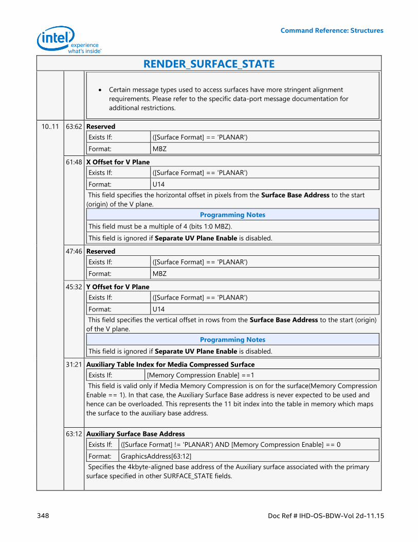
Command Reference: Structures
348 Doc Ref # IHD-OS-BDW-Vol 2d-11.15
RENDER_SURFACE_STATE
Certain message types used to access surfaces have more stringent alignment
requirements. Please refer to the specific data-port message documentation for
additional restrictions.
10..11 63:62 Reserved
Exists If: ([Surface Format] == 'PLANAR')
Format: MBZ
61:48 X Offset for V Plane
Exists If: ([Surface Format] == 'PLANAR')
Format: U14
This field specifies the horizontal offset in pixels from the Surface Base Address to the start
(origin) of the V plane.
Programming Notes
This field must be a multiple of 4 (bits 1:0 MBZ).
This field is ignored if Separate UV Plane Enable is disabled.
47:46 Reserved
Exists If: ([Surface Format] == 'PLANAR')
Format: MBZ
45:32 Y Offset for V Plane
Exists If: ([Surface Format] == 'PLANAR')
Format: U14
This field specifies the vertical offset in rows from the Surface Base Address to the start (origin)
of the V plane.
Programming Notes
This field is ignored if Separate UV Plane Enable is disabled.
31:21 Auxiliary Table Index for Media Compressed Surface
Exists If: [Memory Compression Enable] ==1
This field is valid only if Media Memory Compression is on for the surface(Memory Compression
Enable == 1). In that case, the Auxiliary Surface Base address is never expected to be used and
hence can be overloaded. This represents the 11 bit index into the table in memory which maps
the surface to the auxiliary base address.
63:12 Auxiliary Surface Base Address
Exists If: ([Surface Format] != 'PLANAR') AND [Memory Compression Enable] == 0
Format: GraphicsAddress[63:12]
Specifies the 4kbyte-aligned base address of the Auxiliary surface associated with the primary
surface specified in other SURFACE_STATE fields.
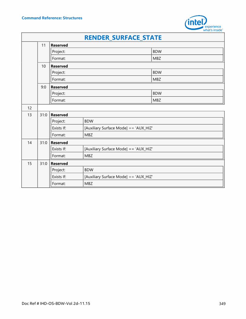
Command Reference: Structures
Doc Ref # IHD-OS-BDW-Vol 2d-11.15 349
RENDER_SURFACE_STATE 11 Reserved
Project: BDW
Format: MBZ
10 Reserved
Project: BDW
Format: MBZ
9:0 Reserved
Project: BDW
Format: MBZ
12
13 31:0 Reserved
Project: BDW
Exists If: [Auxiliary Surface Mode] == 'AUX_HIZ'
Format: MBZ
14 31:0 Reserved
Exists If: [Auxiliary Surface Mode] == 'AUX_HIZ'
Format: MBZ
15 31:0 Reserved
Project: BDW
Exists If: [Auxiliary Surface Mode] == 'AUX_HIZ'
Format: MBZ
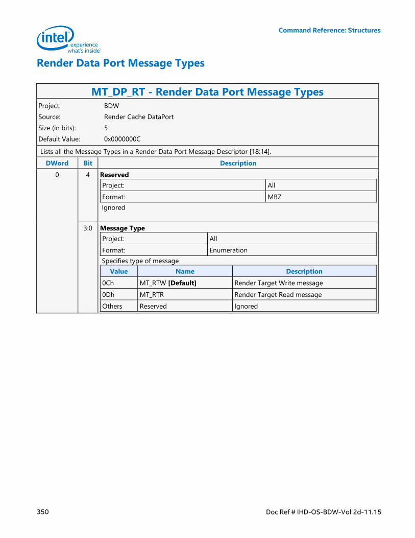
Command Reference: Structures
350 Doc Ref # IHD-OS-BDW-Vol 2d-11.15
Render Data Port Message Types
MT_DP_RT - Render Data Port Message Types Project: BDW
Source: Render Cache DataPort
Size (in bits): 5
Default Value: 0x0000000C
Lists all the Message Types in a Render Data Port Message Descriptor [18:14].
DWord Bit Description
0 4 Reserved
Project: All
Format: MBZ
Ignored
3:0 Message Type
Project: All
Format: Enumeration
Specifies type of message
Value Name Description
0Ch MT_RTW [Default] Render Target Write message
0Dh MT_RTR Render Target Read message
Others Reserved Ignored
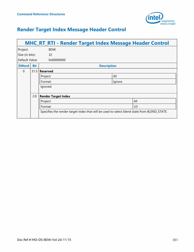
Command Reference: Structures
Doc Ref # IHD-OS-BDW-Vol 2d-11.15 351
Render Target Index Message Header Control
MHC_RT_RTI - Render Target Index Message Header Control Project: BDW
Size (in bits): 32
Default Value: 0x00000000
DWord Bit Description
0 31:3 Reserved
Project: All
Format: Ignore
Ignored
2:0 Render Target Index
Project: All
Format: U3
Specifies the render target index that will be used to select blend state from BLEND_STATE.
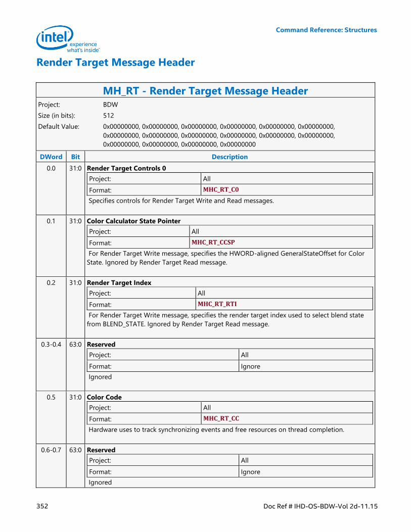
Command Reference: Structures
352 Doc Ref # IHD-OS-BDW-Vol 2d-11.15
Render Target Message Header
MH_RT - Render Target Message Header Project: BDW
Size (in bits): 512
Default Value: 0x00000000, 0x00000000, 0x00000000, 0x00000000, 0x00000000, 0x00000000,
0x00000000, 0x00000000, 0x00000000, 0x00000000, 0x00000000, 0x00000000,
0x00000000, 0x00000000, 0x00000000, 0x00000000
DWord Bit Description
0.0 31:0 Render Target Controls 0
Project: All
Format: MHC_RT_C0
Specifies controls for Render Target Write and Read messages.
0.1 31:0 Color Calculator State Pointer
Project: All
Format: MHC_RT_CCSP
For Render Target Write message, specifies the HWORD-aligned GeneralStateOffset for Color
State. Ignored by Render Target Read message.
0.2 31:0 Render Target Index
Project: All
Format: MHC_RT_RTI
For Render Target Write message, specifies the render target index used to select blend state
from BLEND_STATE. Ignored by Render Target Read message.
0.3-0.4 63:0 Reserved
Project: All
Format: Ignore
Ignored
0.5 31:0 Color Code
Project: All
Format: MHC_RT_CC
Hardware uses to track synchronizing events and free resources on thread completion.
0.6-0.7 63:0 Reserved
Project: All
Format: Ignore
Ignored
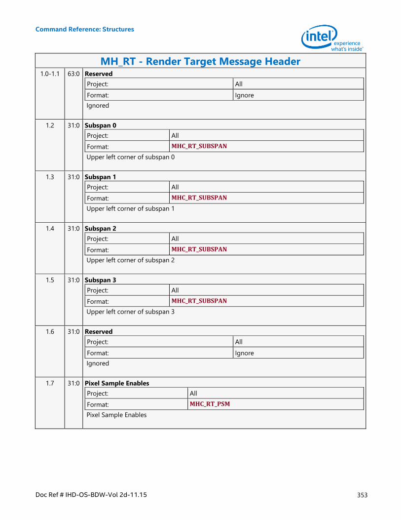
Command Reference: Structures
Doc Ref # IHD-OS-BDW-Vol 2d-11.15 353
MH_RT - Render Target Message Header 1.0-1.1 63:0 Reserved
Project: All
Format: Ignore
Ignored
1.2 31:0 Subspan 0
Project: All
Format: MHC_RT_SUBSPAN
Upper left corner of subspan 0
1.3 31:0 Subspan 1
Project: All
Format: MHC_RT_SUBSPAN
Upper left corner of subspan 1
1.4 31:0 Subspan 2
Project: All
Format: MHC_RT_SUBSPAN
Upper left corner of subspan 2
1.5 31:0 Subspan 3
Project: All
Format: MHC_RT_SUBSPAN
Upper left corner of subspan 3
1.6 31:0 Reserved
Project: All
Format: Ignore
Ignored
1.7 31:0 Pixel Sample Enables
Project: All
Format: MHC_RT_PSM
Pixel Sample Enables
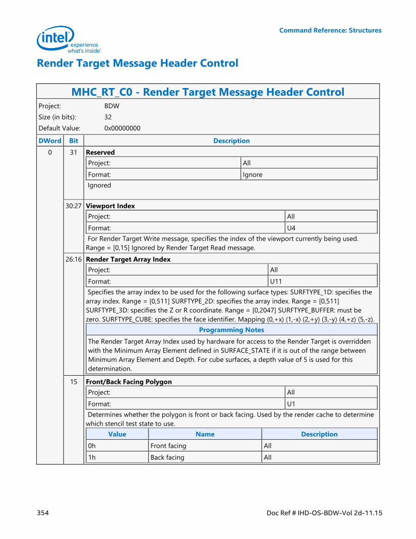
Command Reference: Structures
354 Doc Ref # IHD-OS-BDW-Vol 2d-11.15
Render Target Message Header Control
MHC_RT_C0 - Render Target Message Header Control Project: BDW
Size (in bits): 32
Default Value: 0x00000000
DWord Bit Description
0 31 Reserved
Project: All
Format: Ignore
Ignored
30:27 Viewport Index
Project: All
Format: U4
For Render Target Write message, specifies the index of the viewport currently being used.
Range = [0,15] Ignored by Render Target Read message.
26:16 Render Target Array Index
Project: All
Format: U11
Specifies the array index to be used for the following surface types: SURFTYPE_1D: specifies the
array index. Range = [0,511] SURFTYPE_2D: specifies the array index. Range = [0,511]
SURFTYPE_3D: specifies the Z or R coordinate. Range = [0,2047] SURFTYPE_BUFFER: must be
zero. SURFTYPE_CUBE: specifies the face identifier. Mapping (0,+x) (1,-x) (2,+y) (3,-y) (4,+z) (5,-z).
Programming Notes
The Render Target Array Index used by hardware for access to the Render Target is overridden
with the Minimum Array Element defined in SURFACE_STATE if it is out of the range between
Minimum Array Element and Depth. For cube surfaces, a depth value of 5 is used for this
determination.
15 Front/Back Facing Polygon
Project: All
Format: U1
Determines whether the polygon is front or back facing. Used by the render cache to determine
which stencil test state to use.
Value Name Description
0h Front facing All
1h Back facing All
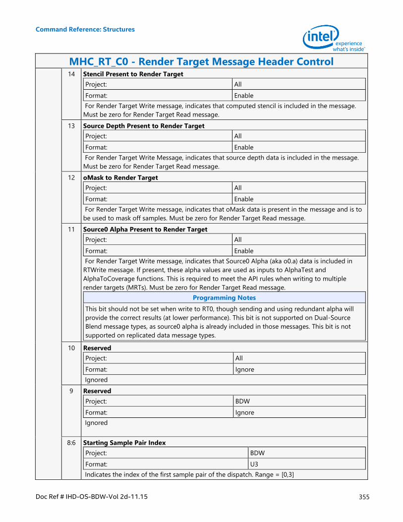
Command Reference: Structures
Doc Ref # IHD-OS-BDW-Vol 2d-11.15 355
MHC_RT_C0 - Render Target Message Header Control 14 Stencil Present to Render Target
Project: All
Format: Enable
For Render Target Write message, indicates that computed stencil is included in the message.
Must be zero for Render Target Read message.
13 Source Depth Present to Render Target
Project: All
Format: Enable
For Render Target Write Message, indicates that source depth data is included in the message.
Must be zero for Render Target Read message.
12 oMask to Render Target
Project: All
Format: Enable
For Render Target Write message, indicates that oMask data is present in the message and is to
be used to mask off samples. Must be zero for Render Target Read message.
11 Source0 Alpha Present to Render Target
Project: All
Format: Enable
For Render Target Write message, indicates that Source0 Alpha (aka o0.a) data is included in
RTWrite message. If present, these alpha values are used as inputs to AlphaTest and
AlphaToCoverage functions. This is required to meet the API rules when writing to multiple
render targets (MRTs). Must be zero for Render Target Read message.
Programming Notes
This bit should not be set when write to RT0, though sending and using redundant alpha will
provide the correct results (at lower performance). This bit is not supported on Dual-Source
Blend message types, as source0 alpha is already included in those messages. This bit is not
supported on replicated data message types.
10 Reserved
Project: All
Format: Ignore
Ignored
9 Reserved
Project: BDW
Format: Ignore
Ignored
8:6 Starting Sample Pair Index
Project: BDW
Format: U3
Indicates the index of the first sample pair of the dispatch. Range = [0,3]
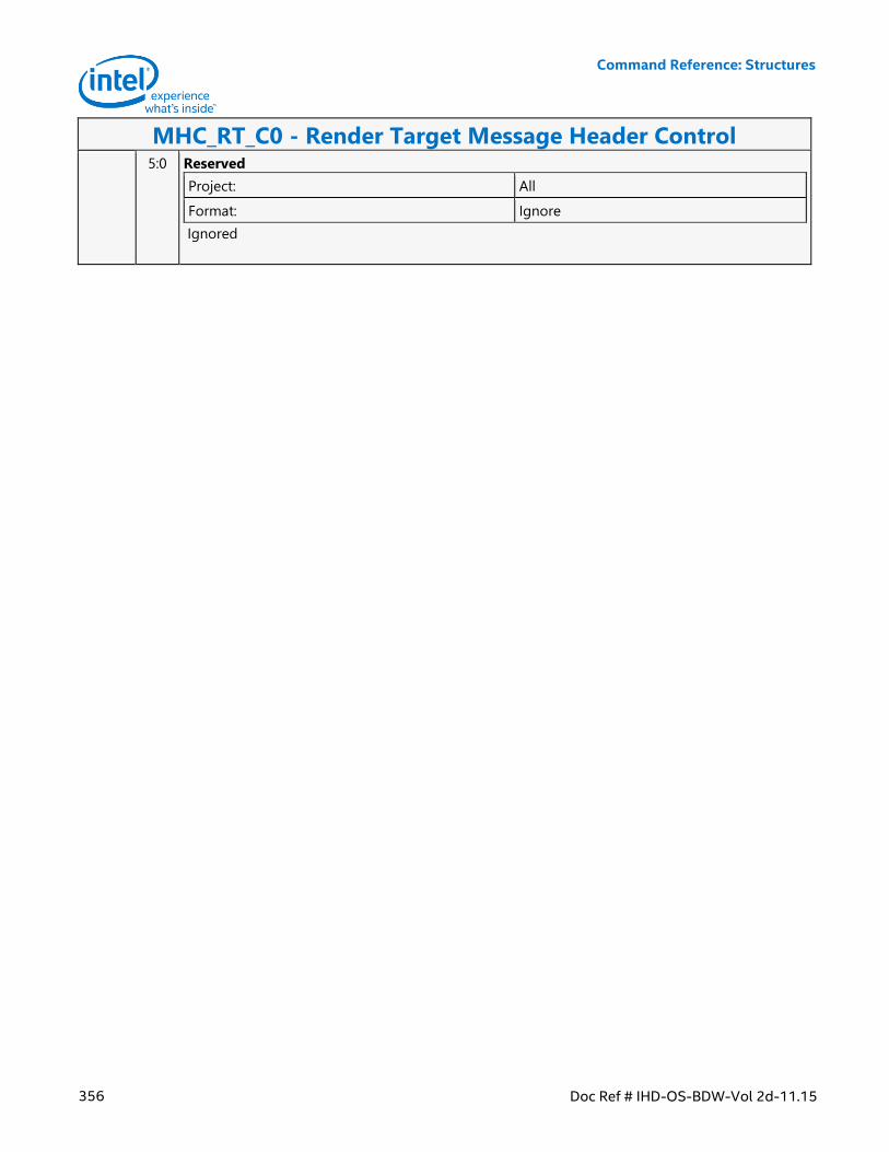
Command Reference: Structures
356 Doc Ref # IHD-OS-BDW-Vol 2d-11.15
MHC_RT_C0 - Render Target Message Header Control 5:0 Reserved
Project: All
Format: Ignore
Ignored
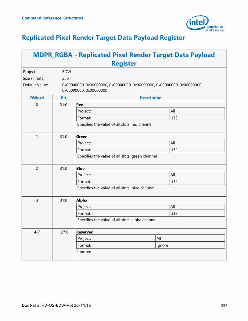
Command Reference: Structures
Doc Ref # IHD-OS-BDW-Vol 2d-11.15 357
Replicated Pixel Render Target Data Payload Register
MDPR_RGBA - Replicated Pixel Render Target Data Payload
Register Project: BDW
Size (in bits): 256
Default Value: 0x00000000, 0x00000000, 0x00000000, 0x00000000, 0x00000000, 0x00000000,
0x00000000, 0x00000000
DWord Bit Description
0 31:0 Red
Project: All
Format: U32
Specifies the value of all slots' red channel.
1 31:0 Green
Project: All
Format: U32
Specifies the value of all slots' green channel.
2 31:0 Blue
Project: All
Format: U32
Specifies the value of all slots' blue channel.
3 31:0 Alpha
Project: All
Format: U32
Specifies the value of all slots' alpha channel.
4-7 127:0 Reserved
Project: All
Format: Ignore
Ignored
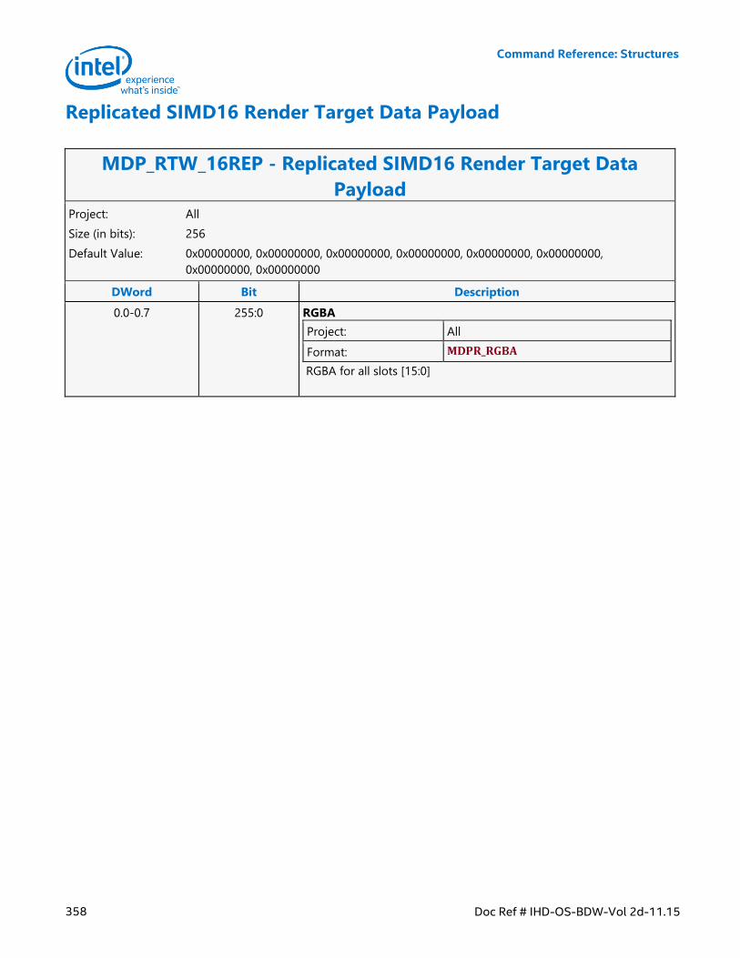
Command Reference: Structures
358 Doc Ref # IHD-OS-BDW-Vol 2d-11.15
Replicated SIMD16 Render Target Data Payload
MDP_RTW_16REP - Replicated SIMD16 Render Target Data
Payload Project: All
Size (in bits): 256
Default Value: 0x00000000, 0x00000000, 0x00000000, 0x00000000, 0x00000000, 0x00000000,
0x00000000, 0x00000000
DWord Bit Description
0.0-0.7 255:0 RGBA
Project: All
Format: MDPR_RGBA
RGBA for all slots [15:0]
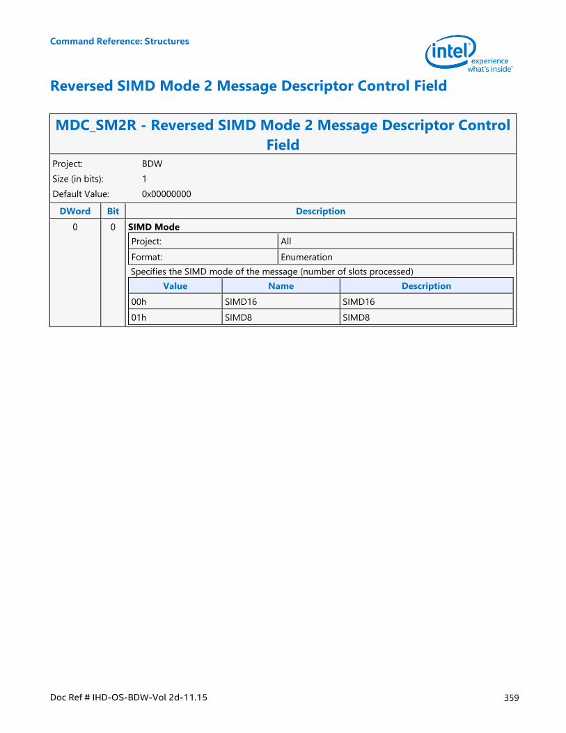
Command Reference: Structures
Doc Ref # IHD-OS-BDW-Vol 2d-11.15 359
Reversed SIMD Mode 2 Message Descriptor Control Field
MDC_SM2R - Reversed SIMD Mode 2 Message Descriptor Control
Field Project: BDW
Size (in bits): 1
Default Value: 0x00000000
DWord Bit Description
0 0 SIMD Mode
Project: All
Format: Enumeration
Specifies the SIMD mode of the message (number of slots processed)
Value Name Description
00h SIMD16 SIMD16
01h SIMD8 SIMD8
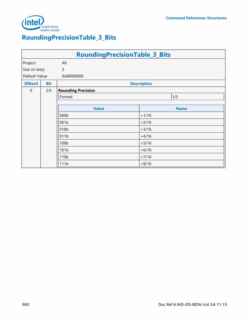
Command Reference: Structures
360 Doc Ref # IHD-OS-BDW-Vol 2d-11.15
RoundingPrecisionTable_3_Bits
RoundingPrecisionTable_3_Bits Project: All
Size (in bits): 3
Default Value: 0x00000000
DWord Bit Description
0 2:0 Rounding Precision
Format: U3
Value Name
000b +1/16
001b +2/16
010b +3/16
011b +4/16
100b +5/16
101b +6/16
110b +7/16
111b +8/16
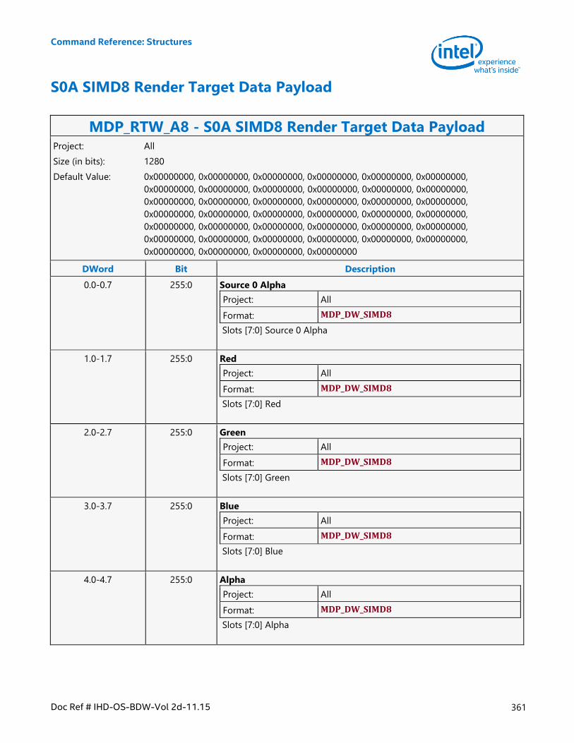
Command Reference: Structures
Doc Ref # IHD-OS-BDW-Vol 2d-11.15 361
S0A SIMD8 Render Target Data Payload
MDP_RTW_A8 - S0A SIMD8 Render Target Data Payload Project: All
Size (in bits): 1280
Default Value: 0x00000000, 0x00000000, 0x00000000, 0x00000000, 0x00000000, 0x00000000,
0x00000000, 0x00000000, 0x00000000, 0x00000000, 0x00000000, 0x00000000,
0x00000000, 0x00000000, 0x00000000, 0x00000000, 0x00000000, 0x00000000,
0x00000000, 0x00000000, 0x00000000, 0x00000000, 0x00000000, 0x00000000,
0x00000000, 0x00000000, 0x00000000, 0x00000000, 0x00000000, 0x00000000,
0x00000000, 0x00000000, 0x00000000, 0x00000000, 0x00000000, 0x00000000,
0x00000000, 0x00000000, 0x00000000, 0x00000000
DWord Bit Description
0.0-0.7 255:0 Source 0 Alpha
Project: All
Format: MDP_DW_SIMD8
Slots [7:0] Source 0 Alpha
1.0-1.7 255:0 Red
Project: All
Format: MDP_DW_SIMD8
Slots [7:0] Red
2.0-2.7 255:0 Green
Project: All
Format: MDP_DW_SIMD8
Slots [7:0] Green
3.0-3.7 255:0 Blue
Project: All
Format: MDP_DW_SIMD8
Slots [7:0] Blue
4.0-4.7 255:0 Alpha
Project: All
Format: MDP_DW_SIMD8
Slots [7:0] Alpha
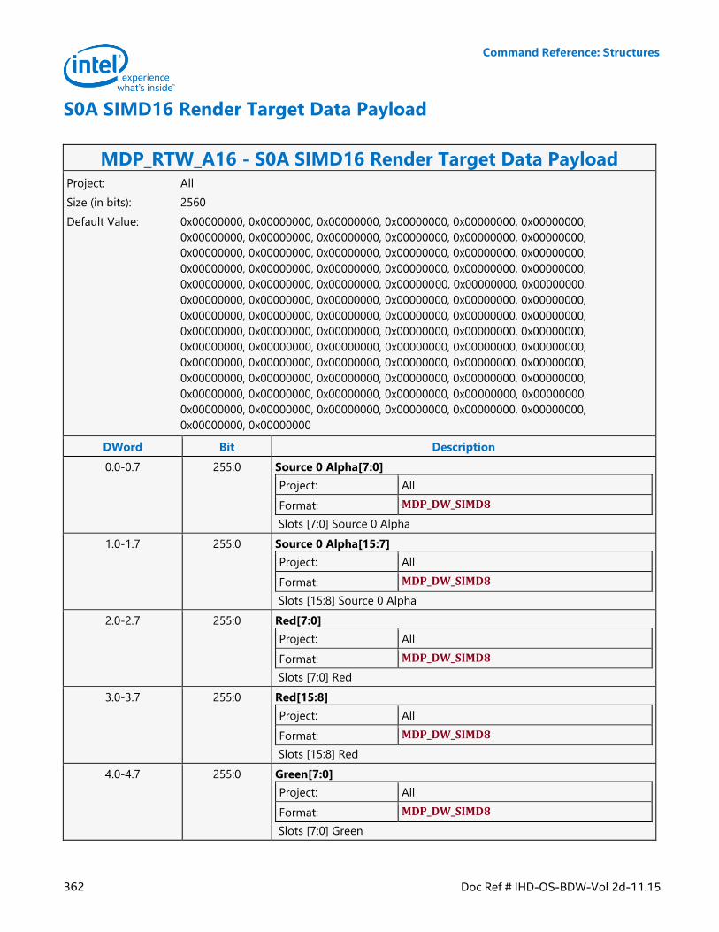
Command Reference: Structures
362 Doc Ref # IHD-OS-BDW-Vol 2d-11.15
S0A SIMD16 Render Target Data Payload
MDP_RTW_A16 - S0A SIMD16 Render Target Data Payload Project: All
Size (in bits): 2560
Default Value: 0x00000000, 0x00000000, 0x00000000, 0x00000000, 0x00000000, 0x00000000,
0x00000000, 0x00000000, 0x00000000, 0x00000000, 0x00000000, 0x00000000,
0x00000000, 0x00000000, 0x00000000, 0x00000000, 0x00000000, 0x00000000,
0x00000000, 0x00000000, 0x00000000, 0x00000000, 0x00000000, 0x00000000,
0x00000000, 0x00000000, 0x00000000, 0x00000000, 0x00000000, 0x00000000,
0x00000000, 0x00000000, 0x00000000, 0x00000000, 0x00000000, 0x00000000,
0x00000000, 0x00000000, 0x00000000, 0x00000000, 0x00000000, 0x00000000,
0x00000000, 0x00000000, 0x00000000, 0x00000000, 0x00000000, 0x00000000,
0x00000000, 0x00000000, 0x00000000, 0x00000000, 0x00000000, 0x00000000,
0x00000000, 0x00000000, 0x00000000, 0x00000000, 0x00000000, 0x00000000,
0x00000000, 0x00000000, 0x00000000, 0x00000000, 0x00000000, 0x00000000,
0x00000000, 0x00000000, 0x00000000, 0x00000000, 0x00000000, 0x00000000,
0x00000000, 0x00000000, 0x00000000, 0x00000000, 0x00000000, 0x00000000,
0x00000000, 0x00000000
DWord Bit Description
0.0-0.7 255:0 Source 0 Alpha[7:0]
Project: All
Format: MDP_DW_SIMD8
Slots [7:0] Source 0 Alpha
1.0-1.7 255:0 Source 0 Alpha[15:7]
Project: All
Format: MDP_DW_SIMD8
Slots [15:8] Source 0 Alpha
2.0-2.7 255:0 Red[7:0]
Project: All
Format: MDP_DW_SIMD8
Slots [7:0] Red
3.0-3.7 255:0 Red[15:8]
Project: All
Format: MDP_DW_SIMD8
Slots [15:8] Red
4.0-4.7 255:0 Green[7:0]
Project: All
Format: MDP_DW_SIMD8
Slots [7:0] Green
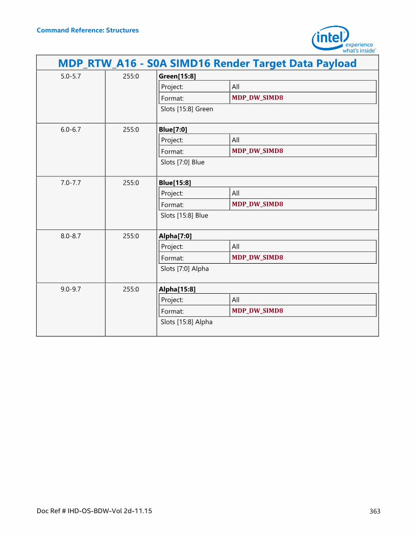
Command Reference: Structures
Doc Ref # IHD-OS-BDW-Vol 2d-11.15 363
MDP_RTW_A16 - S0A SIMD16 Render Target Data Payload 5.0-5.7 255:0 Green[15:8]
Project: All
Format: MDP_DW_SIMD8
Slots [15:8] Green
6.0-6.7 255:0 Blue[7:0]
Project: All
Format: MDP_DW_SIMD8
Slots [7:0] Blue
7.0-7.7 255:0 Blue[15:8]
Project: All
Format: MDP_DW_SIMD8
Slots [15:8] Blue
8.0-8.7 255:0 Alpha[7:0]
Project: All
Format: MDP_DW_SIMD8
Slots [7:0] Alpha
9.0-9.7 255:0 Alpha[15:8]
Project: All
Format: MDP_DW_SIMD8
Slots [15:8] Alpha
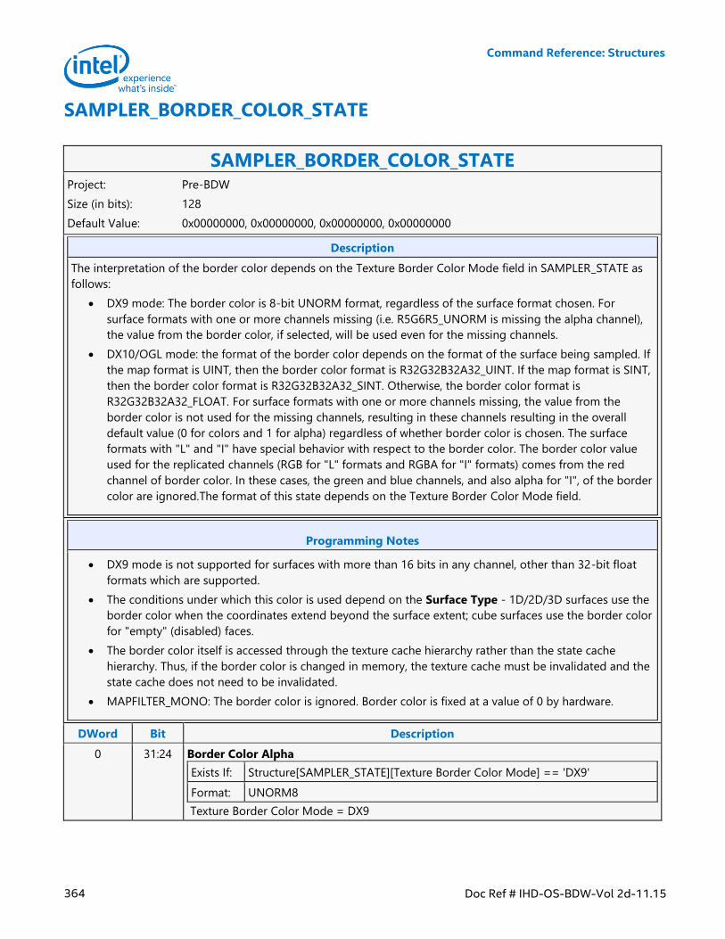
Command Reference: Structures
364 Doc Ref # IHD-OS-BDW-Vol 2d-11.15
SAMPLER_BORDER_COLOR_STATE
SAMPLER_BORDER_COLOR_STATE Project: Pre-BDW
Size (in bits): 128
Default Value: 0x00000000, 0x00000000, 0x00000000, 0x00000000
Description
The interpretation of the border color depends on the Texture Border Color Mode field in SAMPLER_STATE as
follows:
DX9 mode: The border color is 8-bit UNORM format, regardless of the surface format chosen. For
surface formats with one or more channels missing (i.e. R5G6R5_UNORM is missing the alpha channel),
the value from the border color, if selected, will be used even for the missing channels.
DX10/OGL mode: the format of the border color depends on the format of the surface being sampled. If
the map format is UINT, then the border color format is R32G32B32A32_UINT. If the map format is SINT,
then the border color format is R32G32B32A32_SINT. Otherwise, the border color format is
R32G32B32A32_FLOAT. For surface formats with one or more channels missing, the value from the
border color is not used for the missing channels, resulting in these channels resulting in the overall
default value (0 for colors and 1 for alpha) regardless of whether border color is chosen. The surface
formats with "L" and "I" have special behavior with respect to the border color. The border color value
used for the replicated channels (RGB for "L" formats and RGBA for "I" formats) comes from the red
channel of border color. In these cases, the green and blue channels, and also alpha for "I", of the border
color are ignored.The format of this state depends on the Texture Border Color Mode field.
Programming Notes
DX9 mode is not supported for surfaces with more than 16 bits in any channel, other than 32-bit float
formats which are supported.
The conditions under which this color is used depend on the Surface Type - 1D/2D/3D surfaces use the
border color when the coordinates extend beyond the surface extent; cube surfaces use the border color
for "empty" (disabled) faces.
The border color itself is accessed through the texture cache hierarchy rather than the state cache
hierarchy. Thus, if the border color is changed in memory, the texture cache must be invalidated and the
state cache does not need to be invalidated.
MAPFILTER_MONO: The border color is ignored. Border color is fixed at a value of 0 by hardware.
DWord Bit Description
0 31:24 Border Color Alpha
Exists If: Structure[SAMPLER_STATE][Texture Border Color Mode] == 'DX9'
Format: UNORM8
Texture Border Color Mode = DX9
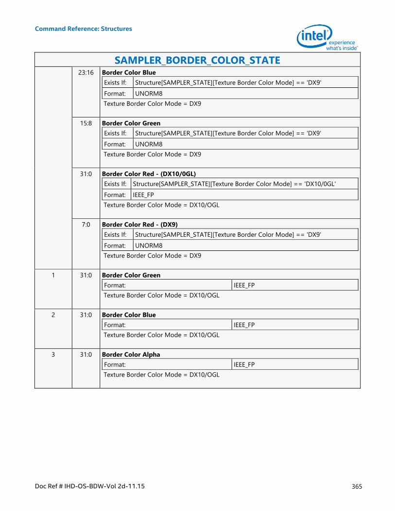
Command Reference: Structures
Doc Ref # IHD-OS-BDW-Vol 2d-11.15 365
SAMPLER_BORDER_COLOR_STATE 23:16 Border Color Blue
Exists If: Structure[SAMPLER_STATE][Texture Border Color Mode] == 'DX9'
Format: UNORM8
Texture Border Color Mode = DX9
15:8 Border Color Green
Exists If: Structure[SAMPLER_STATE][Texture Border Color Mode] == 'DX9'
Format: UNORM8
Texture Border Color Mode = DX9
31:0 Border Color Red - (DX10/0GL)
Exists If: Structure[SAMPLER_STATE][Texture Border Color Mode] == 'DX10/0GL'
Format: IEEE_FP
Texture Border Color Mode = DX10/OGL
7:0 Border Color Red - (DX9)
Exists If: Structure[SAMPLER_STATE][Texture Border Color Mode] == 'DX9'
Format: UNORM8
Texture Border Color Mode = DX9
1 31:0 Border Color Green
Format: IEEE_FP
Texture Border Color Mode = DX10/OGL
2 31:0 Border Color Blue
Format: IEEE_FP
Texture Border Color Mode = DX10/OGL
3 31:0 Border Color Alpha
Format: IEEE_FP
Texture Border Color Mode = DX10/OGL
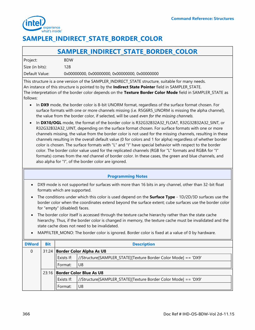
Command Reference: Structures
366 Doc Ref # IHD-OS-BDW-Vol 2d-11.15
SAMPLER_INDIRECT_STATE_BORDER_COLOR
SAMPLER_INDIRECT_STATE_BORDER_COLOR Project: BDW
Size (in bits): 128
Default Value: 0x00000000, 0x00000000, 0x00000000, 0x00000000
This structure is a one version of the SAMPLER_INDIRECT_STATE structure, suitable for many needs.
An instance of this structure is pointed to by the Indirect State Pointer field in SAMPLER_STATE.
The interpretation of the border color depends on the Texture Border Color Mode field in SAMPLER_STATE as
follows:
In DX9 mode, the border color is 8-bit UNORM format, regardless of the surface format chosen. For
surface formats with one or more channels missing (i.e. R5G6R5_UNORM is missing the alpha channel),
the value from the border color, if selected, will be used even for the missing channels.
In DX10/OGL mode, the format of the border color is R32G32B32A32_FLOAT, R32G32B32A32_SINT, or
R32G32B32A32_UINT, depending on the surface format chosen. For surface formats with one or more
channels missing, the value from the border color is not used for the missing channels, resulting in these
channels resulting in the overall default value (0 for colors and 1 for alpha) regardless of whether border
color is chosen. The surface formats with "L" and "I" have special behavior with respect to the border
color. The border color value used for the replicated channels (RGB for "L" formats and RGBA for "I"
formats) comes from the red channel of border color. In these cases, the green and blue channels, and
also alpha for "I", of the border color are ignored.
Programming Notes
DX9 mode is not supported for surfaces with more than 16 bits in any channel, other than 32-bit float
formats which are supported.
The conditions under which this color is used depend on the Surface Type - 1D/2D/3D surfaces use the
border color when the coordinates extend beyond the surface extent; cube surfaces use the border color
for "empty" (disabled) faces.
The border color itself is accessed through the texture cache hierarchy rather than the state cache
hierarchy. Thus, if the border color is changed in memory, the texture cache must be invalidated and the
state cache does not need to be invalidated.
MAPFILTER_MONO: The border color is ignored. Border color is fixed at a value of 0 by hardware.
DWord Bit Description
0 31:24 Border Color Alpha As U8
Exists If: //Structure[SAMPLER_STATE][Texture Border Color Mode] == 'DX9'
Format: U8
23:16 Border Color Blue As U8
Exists If: //Structure[SAMPLER_STATE][Texture Border Color Mode] == 'DX9'
Format: U8
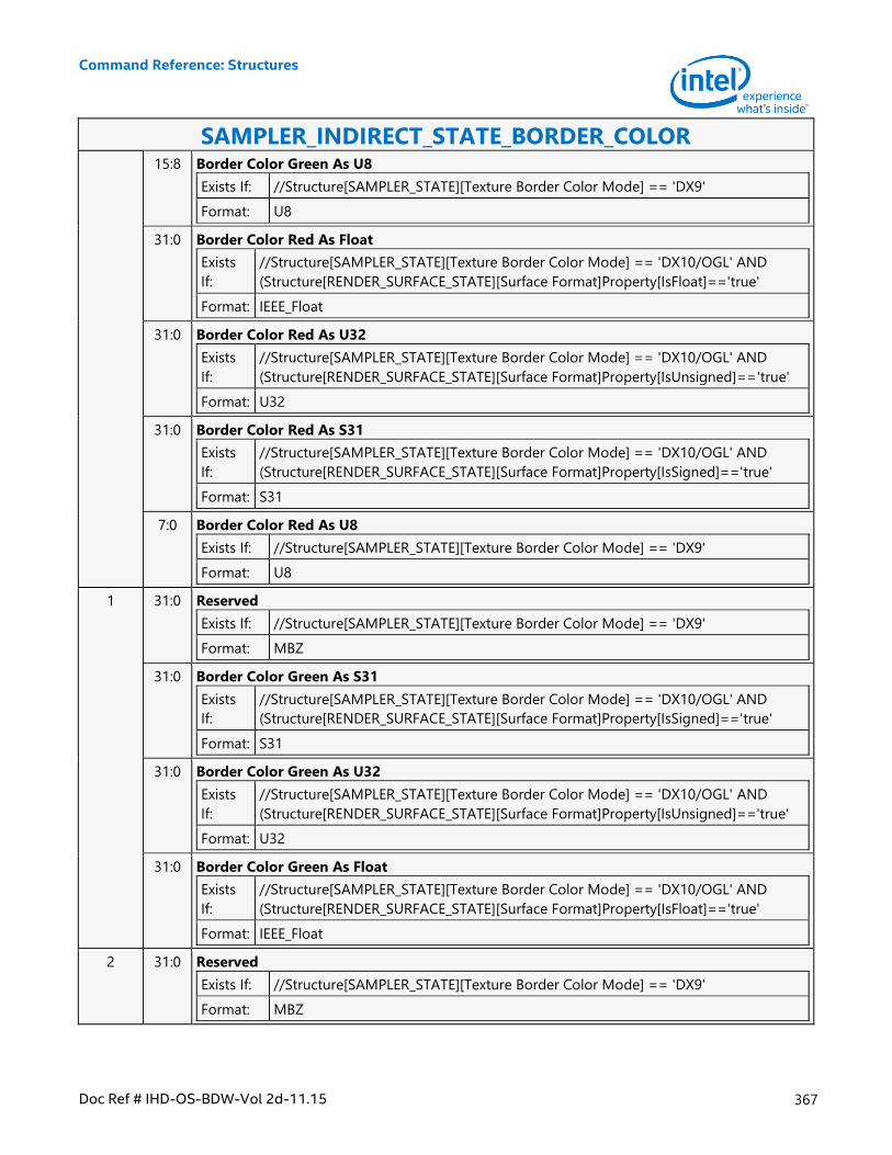
Command Reference: Structures
Doc Ref # IHD-OS-BDW-Vol 2d-11.15 367
SAMPLER_INDIRECT_STATE_BORDER_COLOR 15:8 Border Color Green As U8
Exists If: //Structure[SAMPLER_STATE][Texture Border Color Mode] == 'DX9'
Format: U8
31:0 Border Color Red As Float
Exists
If:
//Structure[SAMPLER_STATE][Texture Border Color Mode] == 'DX10/OGL' AND
(Structure[RENDER_SURFACE_STATE][Surface Format]Property[IsFloat]=='true'
Format: IEEE_Float
31:0 Border Color Red As U32
Exists
If:
//Structure[SAMPLER_STATE][Texture Border Color Mode] == 'DX10/OGL' AND
(Structure[RENDER_SURFACE_STATE][Surface Format]Property[IsUnsigned]=='true'
Format: U32
31:0 Border Color Red As S31
Exists
If:
//Structure[SAMPLER_STATE][Texture Border Color Mode] == 'DX10/OGL' AND
(Structure[RENDER_SURFACE_STATE][Surface Format]Property[IsSigned]=='true'
Format: S31
7:0 Border Color Red As U8
Exists If: //Structure[SAMPLER_STATE][Texture Border Color Mode] == 'DX9'
Format: U8
1 31:0 Reserved
Exists If: //Structure[SAMPLER_STATE][Texture Border Color Mode] == 'DX9'
Format: MBZ
31:0 Border Color Green As S31
Exists
If:
//Structure[SAMPLER_STATE][Texture Border Color Mode] == 'DX10/OGL' AND
(Structure[RENDER_SURFACE_STATE][Surface Format]Property[IsSigned]=='true'
Format: S31
31:0 Border Color Green As U32
Exists
If:
//Structure[SAMPLER_STATE][Texture Border Color Mode] == 'DX10/OGL' AND
(Structure[RENDER_SURFACE_STATE][Surface Format]Property[IsUnsigned]=='true'
Format: U32
31:0 Border Color Green As Float
Exists
If:
//Structure[SAMPLER_STATE][Texture Border Color Mode] == 'DX10/OGL' AND
(Structure[RENDER_SURFACE_STATE][Surface Format]Property[IsFloat]=='true'
Format: IEEE_Float
2 31:0 Reserved
Exists If: //Structure[SAMPLER_STATE][Texture Border Color Mode] == 'DX9'
Format: MBZ
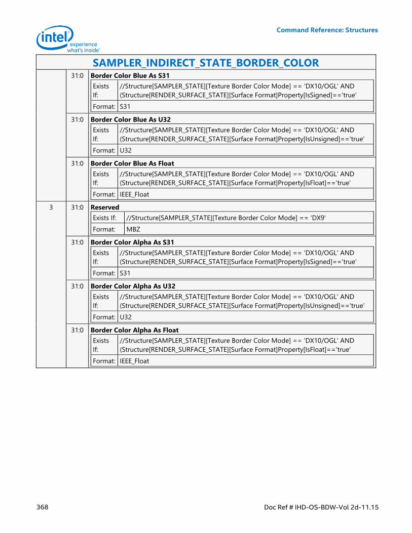
Command Reference: Structures
368 Doc Ref # IHD-OS-BDW-Vol 2d-11.15
SAMPLER_INDIRECT_STATE_BORDER_COLOR 31:0 Border Color Blue As S31
Exists
If:
//Structure[SAMPLER_STATE][Texture Border Color Mode] == 'DX10/OGL' AND
(Structure[RENDER_SURFACE_STATE][Surface Format]Property[IsSigned]=='true'
Format: S31
31:0 Border Color Blue As U32
Exists
If:
//Structure[SAMPLER_STATE][Texture Border Color Mode] == 'DX10/OGL' AND
(Structure[RENDER_SURFACE_STATE][Surface Format]Property[IsUnsigned]=='true'
Format: U32
31:0 Border Color Blue As Float
Exists
If:
//Structure[SAMPLER_STATE][Texture Border Color Mode] == 'DX10/OGL' AND
(Structure[RENDER_SURFACE_STATE][Surface Format]Property[IsFloat]=='true'
Format: IEEE_Float
3 31:0 Reserved
Exists If: //Structure[SAMPLER_STATE][Texture Border Color Mode] == 'DX9'
Format: MBZ
31:0 Border Color Alpha As S31
Exists
If:
//Structure[SAMPLER_STATE][Texture Border Color Mode] == 'DX10/OGL' AND
(Structure[RENDER_SURFACE_STATE][Surface Format]Property[IsSigned]=='true'
Format: S31
31:0 Border Color Alpha As U32
Exists
If:
//Structure[SAMPLER_STATE][Texture Border Color Mode] == 'DX10/OGL' AND
(Structure[RENDER_SURFACE_STATE][Surface Format]Property[IsUnsigned]=='true'
Format: U32
31:0 Border Color Alpha As Float
Exists
If:
//Structure[SAMPLER_STATE][Texture Border Color Mode] == 'DX10/OGL' AND
(Structure[RENDER_SURFACE_STATE][Surface Format]Property[IsFloat]=='true'
Format: IEEE_Float
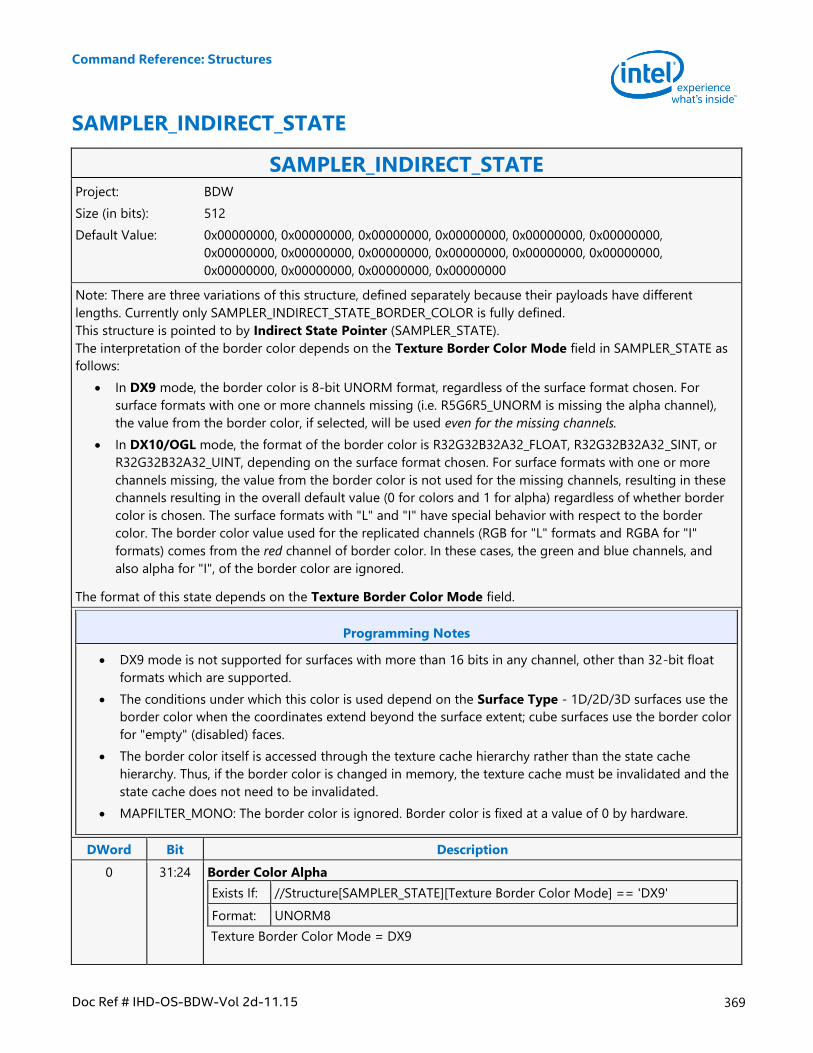
Command Reference: Structures
Doc Ref # IHD-OS-BDW-Vol 2d-11.15 369
SAMPLER_INDIRECT_STATE
SAMPLER_INDIRECT_STATE Project: BDW
Size (in bits): 512
Default Value: 0x00000000, 0x00000000, 0x00000000, 0x00000000, 0x00000000, 0x00000000,
0x00000000, 0x00000000, 0x00000000, 0x00000000, 0x00000000, 0x00000000,
0x00000000, 0x00000000, 0x00000000, 0x00000000
Note: There are three variations of this structure, defined separately because their payloads have different
lengths. Currently only SAMPLER_INDIRECT_STATE_BORDER_COLOR is fully defined.
This structure is pointed to by Indirect State Pointer (SAMPLER_STATE).
The interpretation of the border color depends on the Texture Border Color Mode field in SAMPLER_STATE as
follows:
In DX9 mode, the border color is 8-bit UNORM format, regardless of the surface format chosen. For
surface formats with one or more channels missing (i.e. R5G6R5_UNORM is missing the alpha channel),
the value from the border color, if selected, will be used even for the missing channels.
In DX10/OGL mode, the format of the border color is R32G32B32A32_FLOAT, R32G32B32A32_SINT, or
R32G32B32A32_UINT, depending on the surface format chosen. For surface formats with one or more
channels missing, the value from the border color is not used for the missing channels, resulting in these
channels resulting in the overall default value (0 for colors and 1 for alpha) regardless of whether border
color is chosen. The surface formats with "L" and "I" have special behavior with respect to the border
color. The border color value used for the replicated channels (RGB for "L" formats and RGBA for "I"
formats) comes from the red channel of border color. In these cases, the green and blue channels, and
also alpha for "I", of the border color are ignored.
The format of this state depends on the Texture Border Color Mode field.
Programming Notes
DX9 mode is not supported for surfaces with more than 16 bits in any channel, other than 32-bit float
formats which are supported.
The conditions under which this color is used depend on the Surface Type - 1D/2D/3D surfaces use the
border color when the coordinates extend beyond the surface extent; cube surfaces use the border color
for "empty" (disabled) faces.
The border color itself is accessed through the texture cache hierarchy rather than the state cache
hierarchy. Thus, if the border color is changed in memory, the texture cache must be invalidated and the
state cache does not need to be invalidated.
MAPFILTER_MONO: The border color is ignored. Border color is fixed at a value of 0 by hardware.
DWord Bit Description
0 31:24 Border Color Alpha
Exists If: //Structure[SAMPLER_STATE][Texture Border Color Mode] == 'DX9'
Format: UNORM8
Texture Border Color Mode = DX9
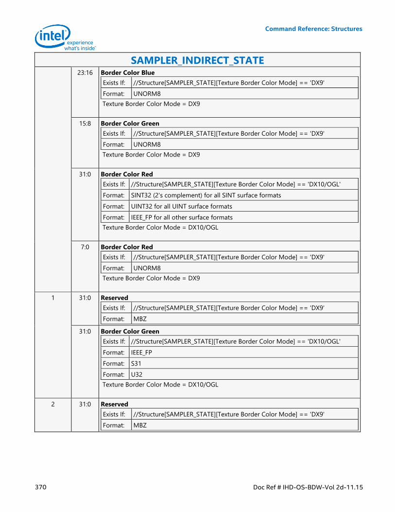
Command Reference: Structures
370 Doc Ref # IHD-OS-BDW-Vol 2d-11.15
SAMPLER_INDIRECT_STATE 23:16 Border Color Blue
Exists If: //Structure[SAMPLER_STATE][Texture Border Color Mode] == 'DX9'
Format: UNORM8
Texture Border Color Mode = DX9
15:8 Border Color Green
Exists If: //Structure[SAMPLER_STATE][Texture Border Color Mode] == 'DX9'
Format: UNORM8
Texture Border Color Mode = DX9
31:0 Border Color Red
Exists If: //Structure[SAMPLER_STATE][Texture Border Color Mode] == 'DX10/OGL'
Format: SINT32 (2's complement) for all SINT surface formats
Format: UINT32 for all UINT surface formats
Format: IEEE_FP for all other surface formats
Texture Border Color Mode = DX10/OGL
7:0 Border Color Red
Exists If: //Structure[SAMPLER_STATE][Texture Border Color Mode] == 'DX9'
Format: UNORM8
Texture Border Color Mode = DX9
1 31:0 Reserved
Exists If: //Structure[SAMPLER_STATE][Texture Border Color Mode] == 'DX9'
Format: MBZ
31:0 Border Color Green
Exists If: //Structure[SAMPLER_STATE][Texture Border Color Mode] == 'DX10/OGL'
Format: IEEE_FP
Format: S31
Format: U32
Texture Border Color Mode = DX10/OGL
2 31:0 Reserved
Exists If: //Structure[SAMPLER_STATE][Texture Border Color Mode] == 'DX9'
Format: MBZ
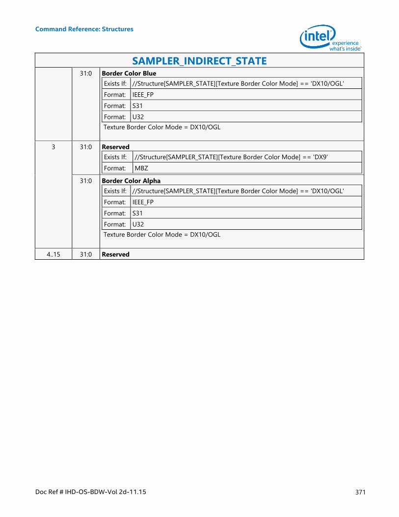
Command Reference: Structures
Doc Ref # IHD-OS-BDW-Vol 2d-11.15 371
SAMPLER_INDIRECT_STATE 31:0 Border Color Blue
Exists If: //Structure[SAMPLER_STATE][Texture Border Color Mode] == 'DX10/OGL'
Format: IEEE_FP
Format: S31
Format: U32
Texture Border Color Mode = DX10/OGL
3 31:0 Reserved
Exists If: //Structure[SAMPLER_STATE][Texture Border Color Mode] == 'DX9'
Format: MBZ
31:0 Border Color Alpha
Exists If: //Structure[SAMPLER_STATE][Texture Border Color Mode] == 'DX10/OGL'
Format: IEEE_FP
Format: S31
Format: U32
Texture Border Color Mode = DX10/OGL
4..15 31:0 Reserved
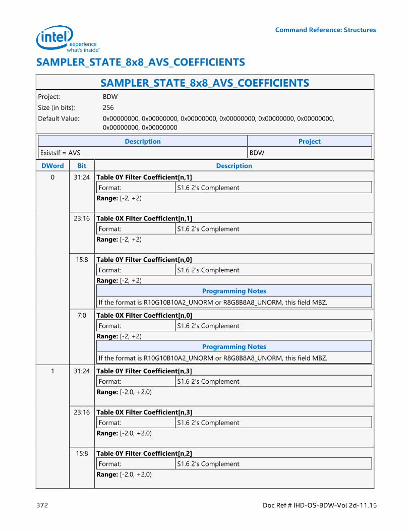
Command Reference: Structures
372 Doc Ref # IHD-OS-BDW-Vol 2d-11.15
SAMPLER_STATE_8x8_AVS_COEFFICIENTS
SAMPLER_STATE_8x8_AVS_COEFFICIENTS Project: BDW
Size (in bits): 256
Default Value: 0x00000000, 0x00000000, 0x00000000, 0x00000000, 0x00000000, 0x00000000,
0x00000000, 0x00000000
Description Project
ExistsIf = AVS BDW
DWord Bit Description
0 31:24 Table 0Y Filter Coefficient[n,1]
Format: S1.6 2's Complement
Range: [-2, +2)
23:16 Table 0X Filter Coefficient[n,1]
Format: S1.6 2's Complement
Range: [-2, +2)
15:8 Table 0Y Filter Coefficient[n,0]
Format: S1.6 2's Complement
Range: [-2, +2)
Programming Notes
If the format is R10G10B10A2_UNORM or R8G8B8A8_UNORM, this field MBZ.
7:0 Table 0X Filter Coefficient[n,0]
Format: S1.6 2's Complement
Range: [-2, +2)
Programming Notes
If the format is R10G10B10A2_UNORM or R8G8B8A8_UNORM, this field MBZ.
1 31:24 Table 0Y Filter Coefficient[n,3]
Format: S1.6 2's Complement
Range: [-2.0, +2.0)
23:16 Table 0X Filter Coefficient[n,3]
Format: S1.6 2's Complement
Range: [-2.0, +2.0)
15:8 Table 0Y Filter Coefficient[n,2]
Format: S1.6 2's Complement
Range: [-2.0, +2.0)
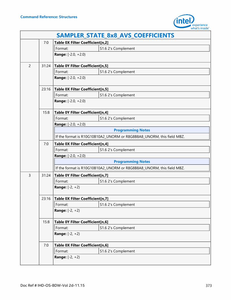
Command Reference: Structures
Doc Ref # IHD-OS-BDW-Vol 2d-11.15 373
SAMPLER_STATE_8x8_AVS_COEFFICIENTS 7:0 Table 0X Filter Coefficient[n,2]
Format: S1.6 2's Complement
Range: [-2.0, +2.0)
2 31:24 Table 0Y Filter Coefficient[n,5]
Format: S1.6 2's Complement
Range: [-2.0, +2.0)
23:16 Table 0X Filter Coefficient[n,5]
Format: S1.6 2's Complement
Range: [-2.0, +2.0)
15:8 Table 0Y Filter Coefficient[n,4]
Format: S1.6 2's Complement
Range: [-2.0, +2.0)
Programming Notes
If the format is R10G10B10A2_UNORM or R8G8B8A8_UNORM, this field MBZ.
7:0 Table 0X Filter Coefficient[n,4]
Format: S1.6 2's Complement
Range: [-2.0, +2.0)
Programming Notes
If the format is R10G10B10A2_UNORM or R8G8B8A8_UNORM, this field MBZ.
3 31:24 Table 0Y Filter Coefficient[n,7]
Format: S1.6 2's Complement
Range: [-2, +2)
23:16 Table 0X Filter Coefficient[n,7]
Format: S1.6 2's Complement
Range: [-2, +2)
15:8 Table 0Y Filter Coefficient[n,6]
Format: S1.6 2's Complement
Range: [-2, +2)
7:0 Table 0X Filter Coefficient[n,6]
Format: S1.6 2's Complement
Range: [-2, +2)
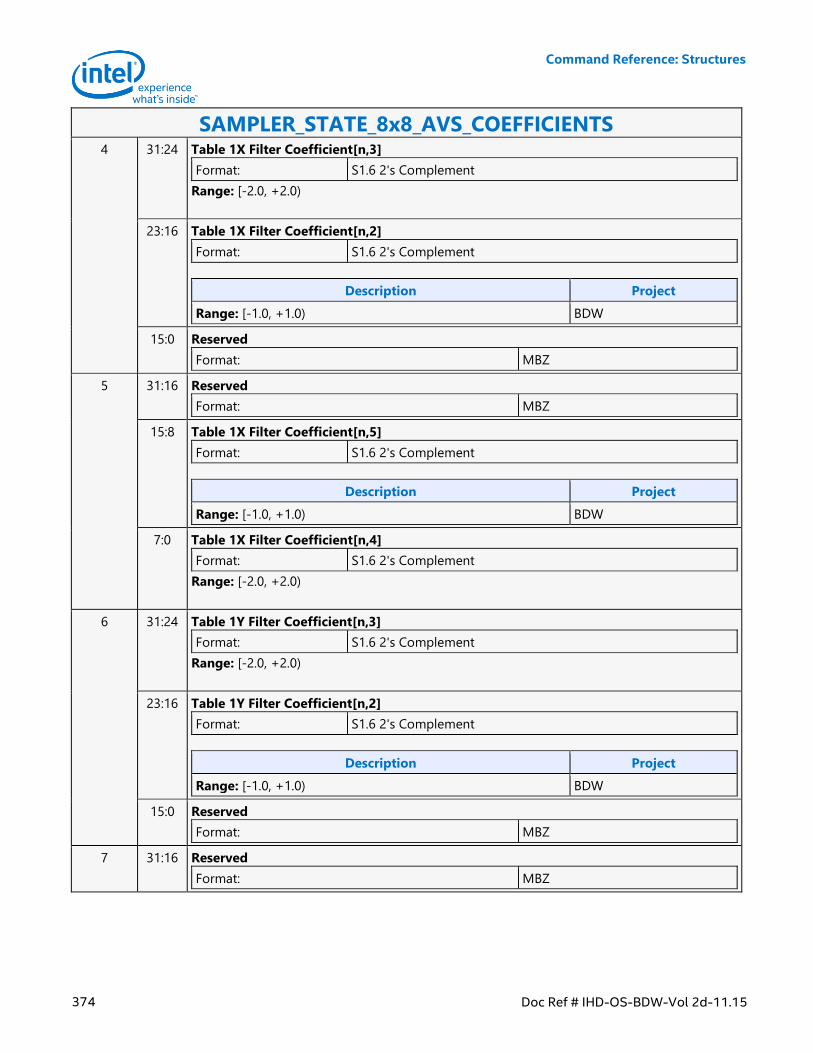
Command Reference: Structures
374 Doc Ref # IHD-OS-BDW-Vol 2d-11.15
SAMPLER_STATE_8x8_AVS_COEFFICIENTS 4 31:24 Table 1X Filter Coefficient[n,3]
Format: S1.6 2's Complement
Range: [-2.0, +2.0)
23:16 Table 1X Filter Coefficient[n,2]
Format: S1.6 2's Complement
Description Project
Range: [-1.0, +1.0) BDW
15:0 Reserved
Format: MBZ
5 31:16 Reserved
Format: MBZ
15:8 Table 1X Filter Coefficient[n,5]
Format: S1.6 2's Complement
Description Project
Range: [-1.0, +1.0) BDW
7:0 Table 1X Filter Coefficient[n,4]
Format: S1.6 2's Complement
Range: [-2.0, +2.0)
6 31:24 Table 1Y Filter Coefficient[n,3]
Format: S1.6 2's Complement
Range: [-2.0, +2.0)
23:16 Table 1Y Filter Coefficient[n,2]
Format: S1.6 2's Complement
Description Project
Range: [-1.0, +1.0) BDW
15:0 Reserved
Format: MBZ
7 31:16 Reserved
Format: MBZ
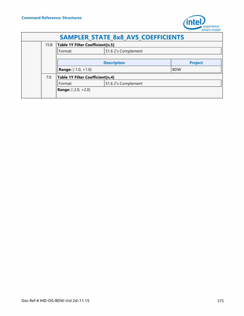
Command Reference: Structures
Doc Ref # IHD-OS-BDW-Vol 2d-11.15 375
SAMPLER_STATE_8x8_AVS_COEFFICIENTS 15:8 Table 1Y Filter Coefficient[n,5]
Format: S1.6 2's Complement
Description Project
Range: [-1.0, +1.0) BDW
7:0 Table 1Y Filter Coefficient[n,4]
Format: S1.6 2's Complement
Range: [-2.0, +2.0)
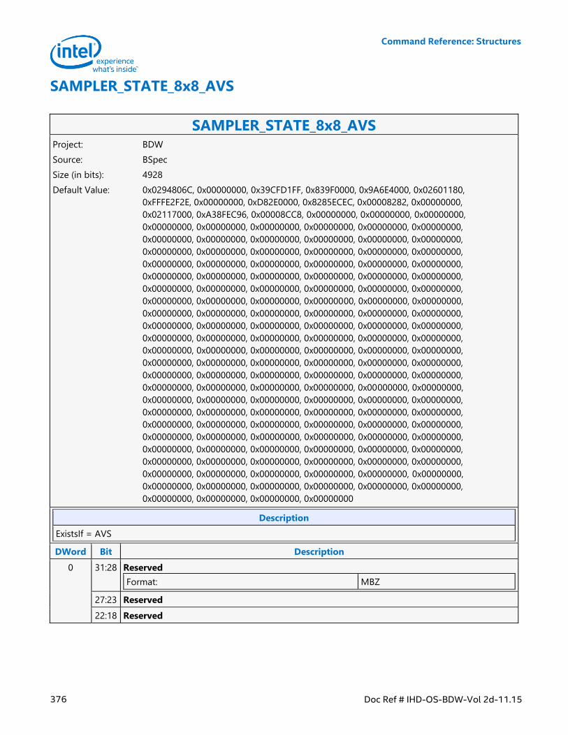
Command Reference: Structures
376 Doc Ref # IHD-OS-BDW-Vol 2d-11.15
SAMPLER_STATE_8x8_AVS
SAMPLER_STATE_8x8_AVS Project: BDW
Source: BSpec
Size (in bits): 4928
Default Value: 0x0294806C, 0x00000000, 0x39CFD1FF, 0x839F0000, 0x9A6E4000, 0x02601180,
0xFFFE2F2E, 0x00000000, 0xD82E0000, 0x8285ECEC, 0x00008282, 0x00000000,
0x02117000, 0xA38FEC96, 0x00008CC8, 0x00000000, 0x00000000, 0x00000000,
0x00000000, 0x00000000, 0x00000000, 0x00000000, 0x00000000, 0x00000000,
0x00000000, 0x00000000, 0x00000000, 0x00000000, 0x00000000, 0x00000000,
0x00000000, 0x00000000, 0x00000000, 0x00000000, 0x00000000, 0x00000000,
0x00000000, 0x00000000, 0x00000000, 0x00000000, 0x00000000, 0x00000000,
0x00000000, 0x00000000, 0x00000000, 0x00000000, 0x00000000, 0x00000000,
0x00000000, 0x00000000, 0x00000000, 0x00000000, 0x00000000, 0x00000000,
0x00000000, 0x00000000, 0x00000000, 0x00000000, 0x00000000, 0x00000000,
0x00000000, 0x00000000, 0x00000000, 0x00000000, 0x00000000, 0x00000000,
0x00000000, 0x00000000, 0x00000000, 0x00000000, 0x00000000, 0x00000000,
0x00000000, 0x00000000, 0x00000000, 0x00000000, 0x00000000, 0x00000000,
0x00000000, 0x00000000, 0x00000000, 0x00000000, 0x00000000, 0x00000000,
0x00000000, 0x00000000, 0x00000000, 0x00000000, 0x00000000, 0x00000000,
0x00000000, 0x00000000, 0x00000000, 0x00000000, 0x00000000, 0x00000000,
0x00000000, 0x00000000, 0x00000000, 0x00000000, 0x00000000, 0x00000000,
0x00000000, 0x00000000, 0x00000000, 0x00000000, 0x00000000, 0x00000000,
0x00000000, 0x00000000, 0x00000000, 0x00000000, 0x00000000, 0x00000000,
0x00000000, 0x00000000, 0x00000000, 0x00000000, 0x00000000, 0x00000000,
0x00000000, 0x00000000, 0x00000000, 0x00000000, 0x00000000, 0x00000000,
0x00000000, 0x00000000, 0x00000000, 0x00000000, 0x00000000, 0x00000000,
0x00000000, 0x00000000, 0x00000000, 0x00000000, 0x00000000, 0x00000000,
0x00000000, 0x00000000, 0x00000000, 0x00000000, 0x00000000, 0x00000000,
0x00000000, 0x00000000, 0x00000000, 0x00000000, 0x00000000, 0x00000000,
0x00000000, 0x00000000, 0x00000000, 0x00000000
Description
ExistsIf = AVS
DWord Bit Description
0 31:28 Reserved
Format: MBZ
27:23 Reserved
22:18 Reserved
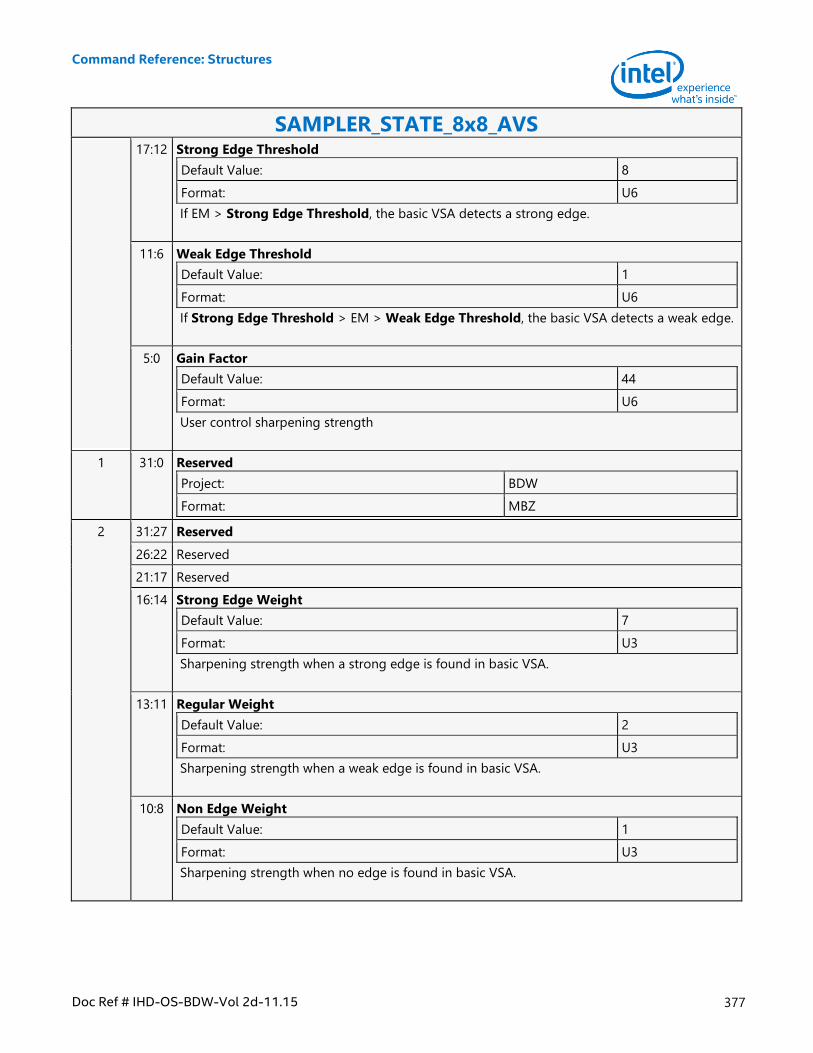
Command Reference: Structures
Doc Ref # IHD-OS-BDW-Vol 2d-11.15 377
SAMPLER_STATE_8x8_AVS 17:12 Strong Edge Threshold
Default Value: 8
Format: U6
If EM > Strong Edge Threshold, the basic VSA detects a strong edge.
11:6 Weak Edge Threshold
Default Value: 1
Format: U6
If Strong Edge Threshold > EM > Weak Edge Threshold, the basic VSA detects a weak edge.
5:0 Gain Factor
Default Value: 44
Format: U6
User control sharpening strength
1 31:0 Reserved
Project: BDW
Format: MBZ
2 31:27 Reserved
26:22 Reserved
21:17 Reserved
16:14 Strong Edge Weight
Default Value: 7
Format: U3
Sharpening strength when a strong edge is found in basic VSA.
13:11 Regular Weight
Default Value: 2
Format: U3
Sharpening strength when a weak edge is found in basic VSA.
10:8 Non Edge Weight
Default Value: 1
Format: U3
Sharpening strength when no edge is found in basic VSA.
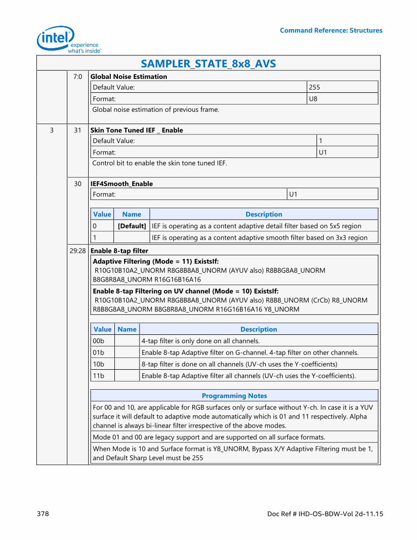
Command Reference: Structures
378 Doc Ref # IHD-OS-BDW-Vol 2d-11.15
SAMPLER_STATE_8x8_AVS 7:0 Global Noise Estimation
Default Value: 255
Format: U8
Global noise estimation of previous frame.
3 31 Skin Tone Tuned IEF _ Enable
Default Value: 1
Format: U1
Control bit to enable the skin tone tuned IEF.
30 IEF4Smooth_Enable
Format: U1
Value Name Description
0 [Default] IEF is operating as a content adaptive detail filter based on 5x5 region
1 IEF is operating as a content adaptive smooth filter based on 3x3 region
29:28 Enable 8-tap filter
Adaptive Filtering (Mode = 11) ExistsIf:
R10G10B10A2_UNORM R8G8B8A8_UNORM (AYUV also) R8B8G8A8_UNORM
B8G8R8A8_UNORM R16G16B16A16
Enable 8-tap Filtering on UV channel (Mode = 10) ExistsIf:
R10G10B10A2_UNORM R8G8B8A8_UNORM (AYUV also) R8B8_UNORM (CrCb) R8_UNORM
R8B8G8A8_UNORM B8G8R8A8_UNORM R16G16B16A16 Y8_UNORM
Value Name Description
00b 4-tap filter is only done on all channels.
01b Enable 8-tap Adaptive filter on G-channel. 4-tap filter on other channels.
10b 8-tap filter is done on all channels (UV-ch uses the Y-coefficients)
11b Enable 8-tap Adaptive filter all channels (UV-ch uses the Y-coefficients).
Programming Notes
For 00 and 10, are applicable for RGB surfaces only or surface without Y-ch. In case it is a YUV
surface it will default to adaptive mode automatically which is 01 and 11 respectively. Alpha
channel is always bi-linear filter irrespective of the above modes.
Mode 01 and 00 are legacy support and are supported on all surface formats.
When Mode is 10 and Surface format is Y8_UNORM, Bypass X/Y Adaptive Filtering must be 1,
and Default Sharp Level must be 255
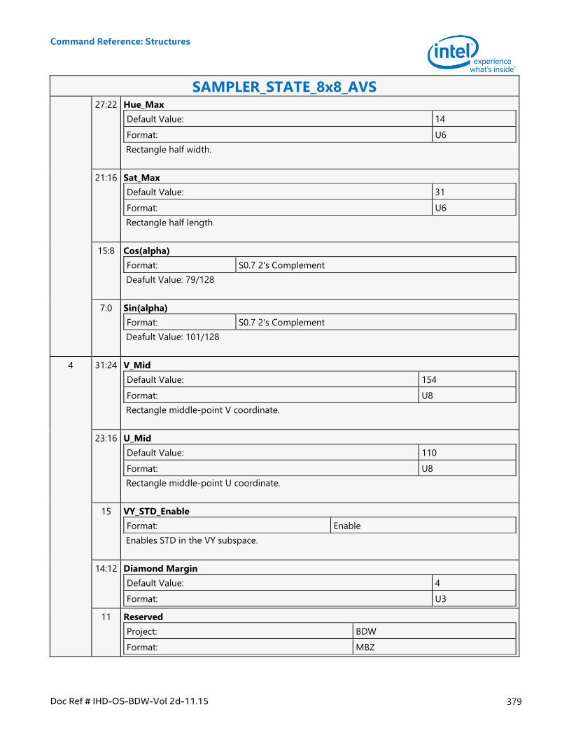
Command Reference: Structures
Doc Ref # IHD-OS-BDW-Vol 2d-11.15 379
SAMPLER_STATE_8x8_AVS 27:22 Hue_Max
Default Value: 14
Format: U6
Rectangle half width.
21:16 Sat_Max
Default Value: 31
Format: U6
Rectangle half length
15:8 Cos(alpha)
Format: S0.7 2's Complement
Deafult Value: 79/128
7:0 Sin(alpha)
Format: S0.7 2's Complement
Deafult Value: 101/128
4 31:24 V_Mid
Default Value: 154
Format: U8
Rectangle middle-point V coordinate.
23:16 U_Mid
Default Value: 110
Format: U8
Rectangle middle-point U coordinate.
15 VY_STD_Enable
Format: Enable
Enables STD in the VY subspace.
14:12 Diamond Margin
Default Value: 4
Format: U3
11 Reserved
Project: BDW
Format: MBZ
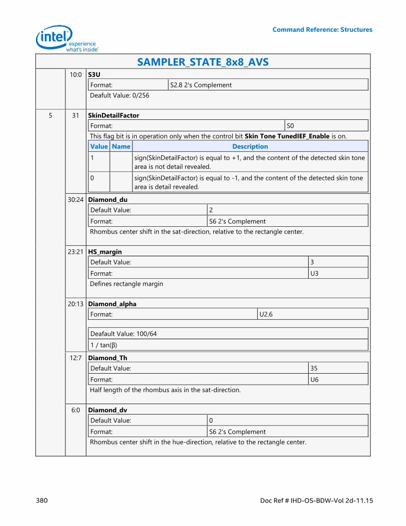
Command Reference: Structures
380 Doc Ref # IHD-OS-BDW-Vol 2d-11.15
SAMPLER_STATE_8x8_AVS 10:0 S3U
Format: S2.8 2's Complement
Deafult Value: 0/256
5 31 SkinDetailFactor
Format: S0
This flag bit is in operation only when the control bit Skin Tone TunedIEF_Enable is on.
Value Name Description
1 sign(SkinDetailFactor) is equal to +1, and the content of the detected skin tone
area is not detail revealed.
0 sign(SkinDetailFactor) is equal to -1, and the content of the detected skin tone
area is detail revealed.
30:24 Diamond_du
Default Value: 2
Format: S6 2's Complement
Rhombus center shift in the sat-direction, relative to the rectangle center.
23:21 HS_margin
Default Value: 3
Format: U3
Defines rectangle margin
20:13 Diamond_alpha
Format: U2.6
Deafault Value: 100/64
1 / tan(β)
12:7 Diamond_Th
Default Value: 35
Format: U6
Half length of the rhombus axis in the sat-direction.
6:0 Diamond_dv
Default Value: 0
Format: S6 2's Complement
Rhombus center shift in the hue-direction, relative to the rectangle center.
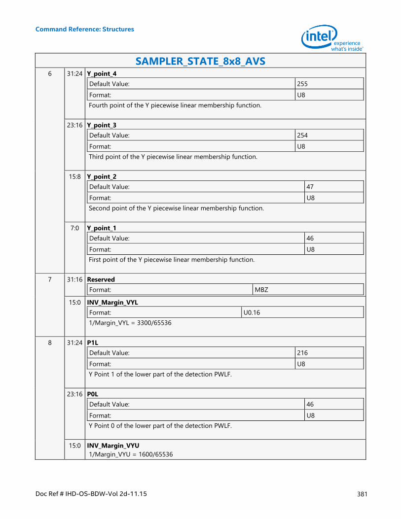
Command Reference: Structures
Doc Ref # IHD-OS-BDW-Vol 2d-11.15 381
SAMPLER_STATE_8x8_AVS 6 31:24 Y_point_4
Default Value: 255
Format: U8
Fourth point of the Y piecewise linear membership function.
23:16 Y_point_3
Default Value: 254
Format: U8
Third point of the Y piecewise linear membership function.
15:8 Y_point_2
Default Value: 47
Format: U8
Second point of the Y piecewise linear membership function.
7:0 Y_point_1
Default Value: 46
Format: U8
First point of the Y piecewise linear membership function.
7 31:16 Reserved
Format: MBZ
15:0 INV_Margin_VYL
Format: U0.16
1/Margin_VYL = 3300/65536
8 31:24 P1L
Default Value: 216
Format: U8
Y Point 1 of the lower part of the detection PWLF.
23:16 P0L
Default Value: 46
Format: U8
Y Point 0 of the lower part of the detection PWLF.
15:0 INV_Margin_VYU
1/Margin_VYU = 1600/65536
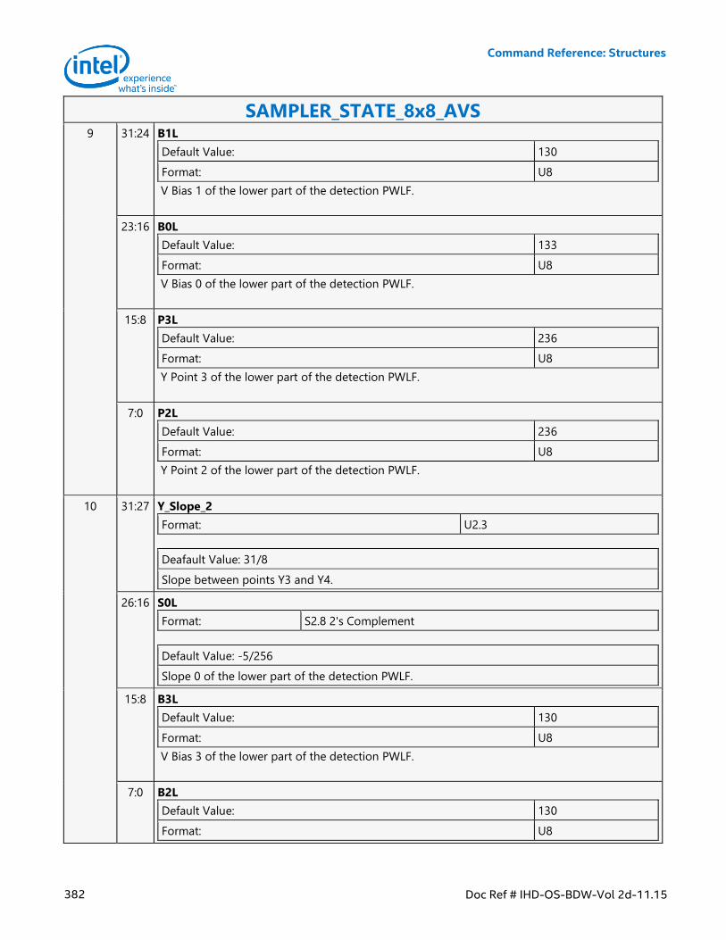
Command Reference: Structures
382 Doc Ref # IHD-OS-BDW-Vol 2d-11.15
SAMPLER_STATE_8x8_AVS 9 31:24 B1L
Default Value: 130
Format: U8
V Bias 1 of the lower part of the detection PWLF.
23:16 B0L
Default Value: 133
Format: U8
V Bias 0 of the lower part of the detection PWLF.
15:8 P3L
Default Value: 236
Format: U8
Y Point 3 of the lower part of the detection PWLF.
7:0 P2L
Default Value: 236
Format: U8
Y Point 2 of the lower part of the detection PWLF.
10 31:27 Y_Slope_2
Format: U2.3
Deafault Value: 31/8
Slope between points Y3 and Y4.
26:16 S0L
Format: S2.8 2's Complement
Default Value: -5/256
Slope 0 of the lower part of the detection PWLF.
15:8 B3L
Default Value: 130
Format: U8
V Bias 3 of the lower part of the detection PWLF.
7:0 B2L
Default Value: 130
Format: U8
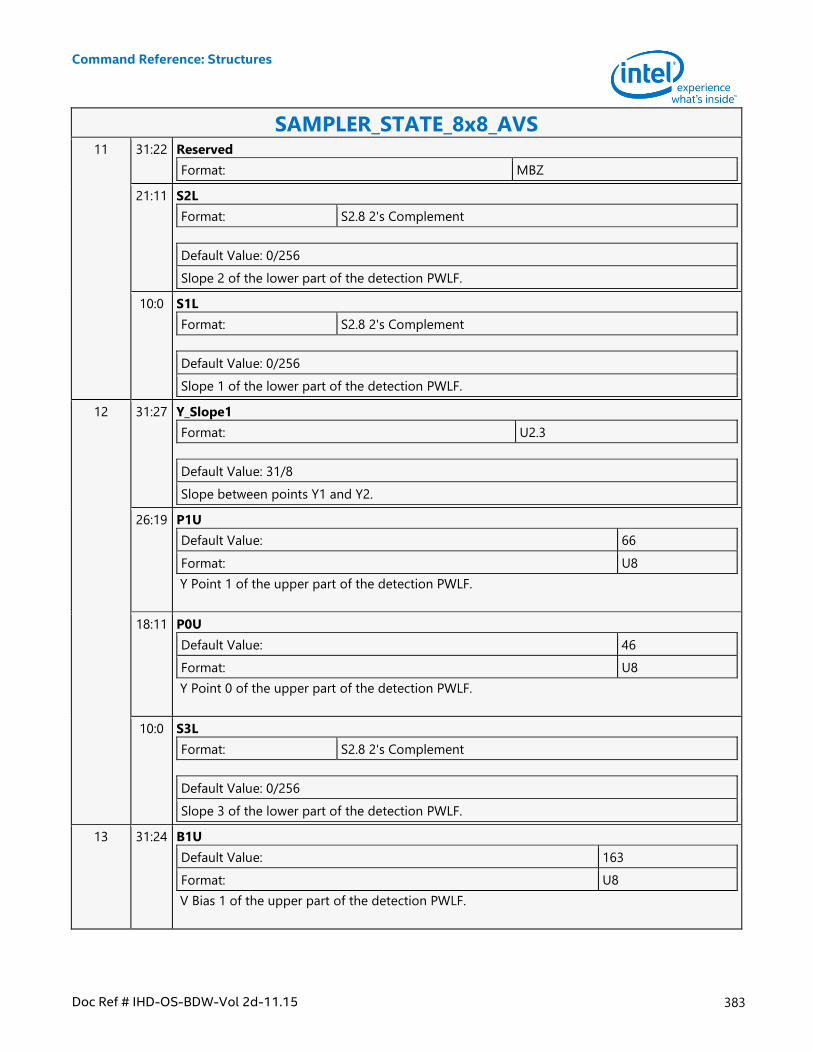
Command Reference: Structures
Doc Ref # IHD-OS-BDW-Vol 2d-11.15 383
SAMPLER_STATE_8x8_AVS 11 31:22 Reserved
Format: MBZ
21:11 S2L
Format: S2.8 2's Complement
Default Value: 0/256
Slope 2 of the lower part of the detection PWLF.
10:0 S1L
Format: S2.8 2's Complement
Default Value: 0/256
Slope 1 of the lower part of the detection PWLF.
12 31:27 Y_Slope1
Format: U2.3
Default Value: 31/8
Slope between points Y1 and Y2.
26:19 P1U
Default Value: 66
Format: U8
Y Point 1 of the upper part of the detection PWLF.
18:11 P0U
Default Value: 46
Format: U8
Y Point 0 of the upper part of the detection PWLF.
10:0 S3L
Format: S2.8 2's Complement
Default Value: 0/256
Slope 3 of the lower part of the detection PWLF.
13 31:24 B1U
Default Value: 163
Format: U8
V Bias 1 of the upper part of the detection PWLF.
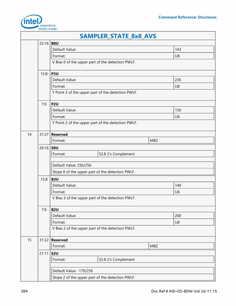
Command Reference: Structures
384 Doc Ref # IHD-OS-BDW-Vol 2d-11.15
SAMPLER_STATE_8x8_AVS 23:16 B0U
Default Value: 143
Format: U8
V Bias 0 of the upper part of the detection PWLF.
15:8 P3U
Default Value: 236
Format: U8
Y Point 3 of the upper part of the detection PWLF.
7:0 P2U
Default Value: 150
Format: U8
Y Point 2 of the upper part of the detection PWLF.
14 31:27 Reserved
Format: MBZ
26:16 S0U
Format: S2.8 2's Complement
Default Value: 256/256
Slope 0 of the upper part of the detection PWLF.
15:8 B3U
Default Value: 140
Format: U8
V Bias 3 of the upper part of the detection PWLF.
7:0 B2U
Default Value: 200
Format: U8
V Bias 2 of the upper part of the detection PWLF.
15 31:22 Reserved
Format: MBZ
21:11 S2U
Format: S2.8 2's Complement
Default Value: -179/256
Slope 2 of the upper part of the detection PWLF.
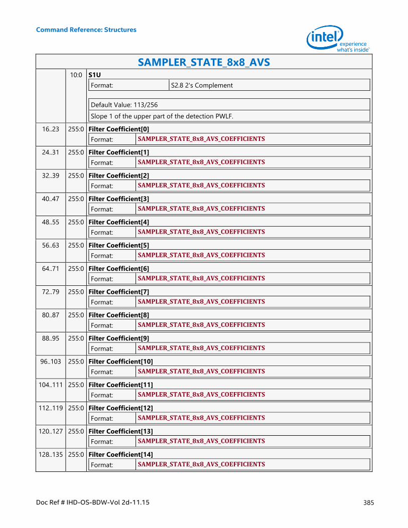
Command Reference: Structures
Doc Ref # IHD-OS-BDW-Vol 2d-11.15 385
SAMPLER_STATE_8x8_AVS 10:0 S1U
Format: S2.8 2's Complement
Default Value: 113/256
Slope 1 of the upper part of the detection PWLF.
16..23 255:0 Filter Coefficient[0]
Format: SAMPLER_STATE_8x8_AVS_COEFFICIENTS
24..31 255:0 Filter Coefficient[1]
Format: SAMPLER_STATE_8x8_AVS_COEFFICIENTS
32..39 255:0 Filter Coefficient[2]
Format: SAMPLER_STATE_8x8_AVS_COEFFICIENTS
40..47 255:0 Filter Coefficient[3]
Format: SAMPLER_STATE_8x8_AVS_COEFFICIENTS
48..55 255:0 Filter Coefficient[4]
Format: SAMPLER_STATE_8x8_AVS_COEFFICIENTS
56..63 255:0 Filter Coefficient[5]
Format: SAMPLER_STATE_8x8_AVS_COEFFICIENTS
64..71 255:0 Filter Coefficient[6]
Format: SAMPLER_STATE_8x8_AVS_COEFFICIENTS
72..79 255:0 Filter Coefficient[7]
Format: SAMPLER_STATE_8x8_AVS_COEFFICIENTS
80..87 255:0 Filter Coefficient[8]
Format: SAMPLER_STATE_8x8_AVS_COEFFICIENTS
88..95 255:0 Filter Coefficient[9]
Format: SAMPLER_STATE_8x8_AVS_COEFFICIENTS
96..103 255:0 Filter Coefficient[10]
Format: SAMPLER_STATE_8x8_AVS_COEFFICIENTS
104..111 255:0 Filter Coefficient[11]
Format: SAMPLER_STATE_8x8_AVS_COEFFICIENTS
112..119 255:0 Filter Coefficient[12]
Format: SAMPLER_STATE_8x8_AVS_COEFFICIENTS
120..127 255:0 Filter Coefficient[13]
Format: SAMPLER_STATE_8x8_AVS_COEFFICIENTS
128..135 255:0 Filter Coefficient[14]
Format: SAMPLER_STATE_8x8_AVS_COEFFICIENTS
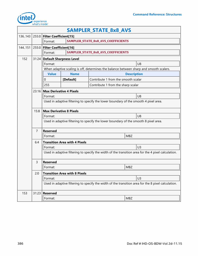
Command Reference: Structures
386 Doc Ref # IHD-OS-BDW-Vol 2d-11.15
SAMPLER_STATE_8x8_AVS 136..143 255:0 Filter Coefficient[15]
Format: SAMPLER_STATE_8x8_AVS_COEFFICIENTS
144..151 255:0 Filter Coefficient[16]
Format: SAMPLER_STATE_8x8_AVS_COEFFICIENTS
152 31:24 Default Sharpness Level
Format: U8
When adaptive scaling is off, determines the balance between sharp and smooth scalers.
Value Name Description
0 [Default] Contribute 1 from the smooth scalar
255 Contribute 1 from the sharp scalar
23:16 Max Derivative 4 Pixels
Format: U8
Used in adaptive filtering to specify the lower boundary of the smooth 4 pixel area.
15:8 Max Derivative 8 Pixels
Format: U8
Used in adaptive filtering to specify the lower boundary of the smooth 8 pixel area.
7 Reserved
Format: MBZ
6:4 Transition Area with 4 Pixels
Format: U3
Used in adaptive filtering to specify the width of the transition area for the 4 pixel calculation.
3 Reserved
Format: MBZ
2:0 Transition Area with 8 Pixels
Format: U3
Used in adaptive filtering to specify the width of the transition area for the 8 pixel calculation.
153 31:23 Reserved
Format: MBZ
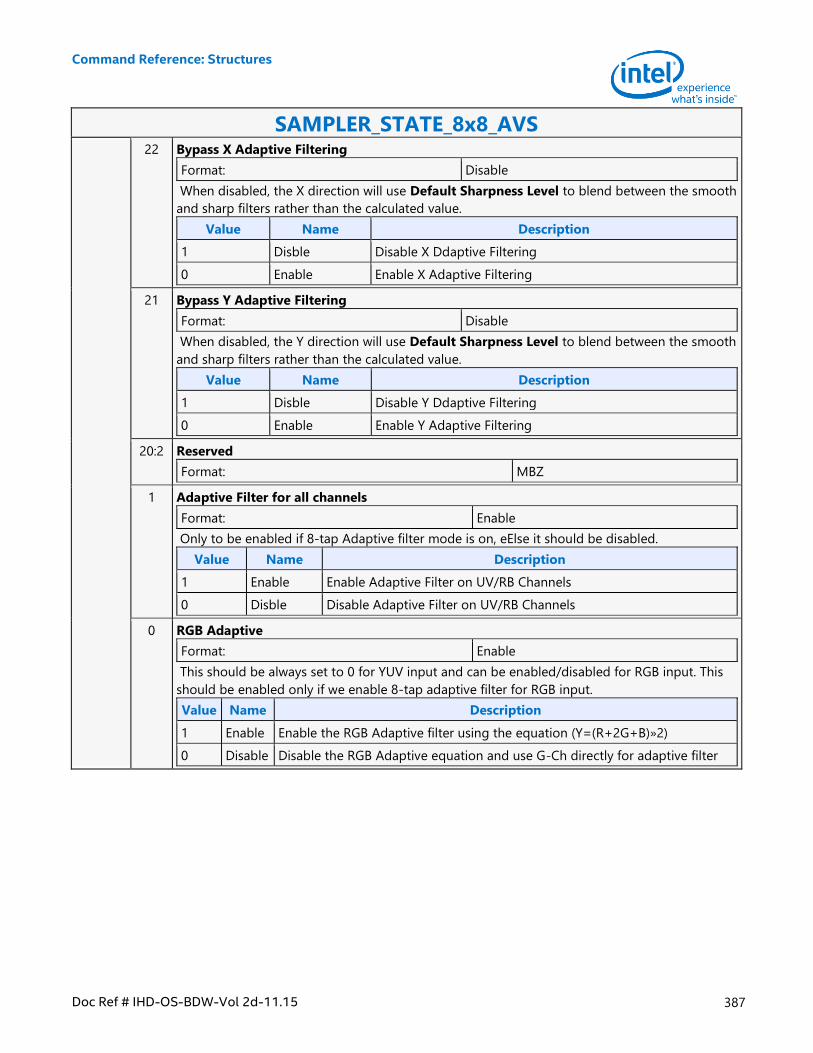
Command Reference: Structures
Doc Ref # IHD-OS-BDW-Vol 2d-11.15 387
SAMPLER_STATE_8x8_AVS 22 Bypass X Adaptive Filtering
Format: Disable
When disabled, the X direction will use Default Sharpness Level to blend between the smooth
and sharp filters rather than the calculated value.
Value Name Description
1 Disble Disable X Ddaptive Filtering
0 Enable Enable X Adaptive Filtering
21 Bypass Y Adaptive Filtering
Format: Disable
When disabled, the Y direction will use Default Sharpness Level to blend between the smooth
and sharp filters rather than the calculated value.
Value Name Description
1 Disble Disable Y Ddaptive Filtering
0 Enable Enable Y Adaptive Filtering
20:2 Reserved
Format: MBZ
1 Adaptive Filter for all channels
Format: Enable
Only to be enabled if 8-tap Adaptive filter mode is on, eElse it should be disabled.
Value Name Description
1 Enable Enable Adaptive Filter on UV/RB Channels
0 Disble Disable Adaptive Filter on UV/RB Channels
0 RGB Adaptive
Format: Enable
This should be always set to 0 for YUV input and can be enabled/disabled for RGB input. This
should be enabled only if we enable 8-tap adaptive filter for RGB input.
Value Name Description
1 Enable Enable the RGB Adaptive filter using the equation (Y=(R+2G+B)»2)
0 Disable Disable the RGB Adaptive equation and use G-Ch directly for adaptive filter
Command Reference: Structures
388 Doc Ref # IHD-OS-BDW-Vol 2d-11.15
SAMPLER_STATE_8x8_CONVOLVE
SAMPLER_STATE_8x8_CONVOLVE Project: BDW
Size (in bits): 16384
Default Value: 0x00000000, 0x00000000, 0x00000000, 0x00000000, 0x00000000, 0x00000000,
0x00000000, 0x00000000, 0x00000000, 0x00000000, 0x00000000, 0x00000000,
0x00000000, 0x00000000, 0x00000000, 0x00000000, 0x00000000, 0x00000000,
0x00000000, 0x00000000, 0x00000000, 0x00000000, 0x00000000, 0x00000000,
0x00000000, 0x00000000, 0x00000000, 0x00000000, 0x00000000, 0x00000000,
0x00000000, 0x00000000, 0x00000000, 0x00000000, 0x00000000, 0x00000000,
0x00000000, 0x00000000, 0x00000000, 0x00000000, 0x00000000, 0x00000000,
0x00000000, 0x00000000, 0x00000000, 0x00000000, 0x00000000, 0x00000000,
0x00000000, 0x00000000, 0x00000000, 0x00000000, 0x00000000, 0x00000000,
0x00000000, 0x00000000, 0x00000000, 0x00000000, 0x00000000, 0x00000000,
0x00000000, 0x00000000, 0x00000000, 0x00000000, 0x00000000, 0x00000000,
0x00000000, 0x00000000, 0x00000000, 0x00000000, 0x00000000, 0x00000000,
0x00000000, 0x00000000, 0x00000000, 0x00000000, 0x00000000, 0x00000000,
0x00000000, 0x00000000, 0x00000000, 0x00000000, 0x00000000, 0x00000000,
0x00000000, 0x00000000, 0x00000000, 0x00000000, 0x00000000, 0x00000000,
0x00000000, 0x00000000, 0x00000000, 0x00000000, 0x00000000, 0x00000000,
0x00000000, 0x00000000, 0x00000000, 0x00000000, 0x00000000, 0x00000000,
0x00000000, 0x00000000, 0x00000000, 0x00000000, 0x00000000, 0x00000000,
0x00000000, 0x00000000, 0x00000000, 0x00000000, 0x00000000, 0x00000000,
0x00000000, 0x00000000, 0x00000000, 0x00000000, 0x00000000, 0x00000000,
0x00000000, 0x00000000, 0x00000000, 0x00000000, 0x00000000, 0x00000000,
0x00000000, 0x00000000, 0x00000000, 0x00000000, 0x00000000, 0x00000000,
0x00000000, 0x00000000, 0x00000000, 0x00000000, 0x00000000, 0x00000000,
0x00000000, 0x00000000, 0x00000000, 0x00000000, 0x00000000, 0x00000000,
0x00000000, 0x00000000, 0x00000000, 0x00000000, 0x00000000, 0x00000000,
0x00000000, 0x00000000, 0x00000000, 0x00000000, 0x00000000, 0x00000000,
0x00000000, 0x00000000, 0x00000000, 0x00000000, 0x00000000, 0x00000000,
0x00000000, 0x00000000, 0x00000000, 0x00000000, 0x00000000, 0x00000000,
0x00000000, 0x00000000, 0x00000000, 0x00000000, 0x00000000, 0x00000000,
0x00000000, 0x00000000, 0x00000000, 0x00000000, 0x00000000, 0x00000000,
0x00000000, 0x00000000, 0x00000000, 0x00000000, 0x00000000, 0x00000000,
0x00000000, 0x00000000, 0x00000000, 0x00000000, 0x00000000, 0x00000000,
0x00000000, 0x00000000, 0x00000000, 0x00000000, 0x00000000, 0x00000000,
0x00000000, 0x00000000, 0x00000000, 0x00000000, 0x00000000, 0x00000000,
0x00000000, 0x00000000, 0x00000000, 0x00000000, 0x00000000, 0x00000000,
0x00000000, 0x00000000, 0x00000000, 0x00000000, 0x00000000, 0x00000000,
0x00000000, 0x00000000, 0x00000000, 0x00000000, 0x00000000, 0x00000000,
0x00000000, 0x00000000, 0x00000000, 0x00000000, 0x00000000, 0x00000000,
0x00000000, 0x00000000, 0x00000000, 0x00000000, 0x00000000, 0x00000000,
0x00000000, 0x00000000, 0x00000000, 0x00000000, 0x00000000, 0x00000000,
0x00000000, 0x00000000, 0x00000000, 0x00000000, 0x00000000, 0x00000000,
0x00000000, 0x00000000, 0x00000000, 0x00000000, 0x00000000, 0x00000000,
Command Reference: Structures
Doc Ref # IHD-OS-BDW-Vol 2d-11.15 389
SAMPLER_STATE_8x8_CONVOLVE 0x00000000, 0x00000000, 0x00000000, 0x00000000, 0x00000000, 0x00000000,
0x00000000, 0x00000000, 0x00000000, 0x00000000, 0x00000000, 0x00000000,
0x00000000, 0x00000000, 0x00000000, 0x00000000, 0x00000000, 0x00000000,
0x00000000, 0x00000000, 0x00000000, 0x00000000, 0x00000000, 0x00000000,
0x00000000, 0x00000000, 0x00000000, 0x00000000, 0x00000000, 0x00000000,
0x00000000, 0x00000000, 0x00000000, 0x00000000, 0x00000000, 0x00000000,
0x00000000, 0x00000000, 0x00000000, 0x00000000, 0x00000000, 0x00000000,
0x00000000, 0x00000000, 0x00000000, 0x00000000, 0x00000000, 0x00000000,
0x00000000, 0x00000000, 0x00000000, 0x00000000, 0x00000000, 0x00000000,
0x00000000, 0x00000000, 0x00000000, 0x00000000, 0x00000000, 0x00000000,
0x00000000, 0x00000000, 0x00000000, 0x00000000, 0x00000000, 0x00000000,
0x00000000, 0x00000000, 0x00000000, 0x00000000, 0x00000000, 0x00000000,
0x00000000, 0x00000000, 0x00000000, 0x00000000, 0x00000000, 0x00000000,
0x00000000, 0x00000000, 0x00000000, 0x00000000, 0x00000000, 0x00000000,
0x00000000, 0x00000000, 0x00000000, 0x00000000, 0x00000000, 0x00000000,
0x00000000, 0x00000000, 0x00000000, 0x00000000, 0x00000000, 0x00000000,
0x00000000, 0x00000000, 0x00000000, 0x00000000, 0x00000000, 0x00000000,
0x00000000, 0x00000000, 0x00000000, 0x00000000, 0x00000000, 0x00000000,
0x00000000, 0x00000000, 0x00000000, 0x00000000, 0x00000000, 0x00000000,
0x00000000, 0x00000000, 0x00000000, 0x00000000, 0x00000000, 0x00000000,
0x00000000, 0x00000000, 0x00000000, 0x00000000, 0x00000000, 0x00000000,
0x00000000, 0x00000000, 0x00000000, 0x00000000, 0x00000000, 0x00000000,
0x00000000, 0x00000000, 0x00000000, 0x00000000, 0x00000000, 0x00000000,
0x00000000, 0x00000000, 0x00000000, 0x00000000, 0x00000000, 0x00000000,
0x00000000, 0x00000000, 0x00000000, 0x00000000, 0x00000000, 0x00000000,
0x00000000, 0x00000000, 0x00000000, 0x00000000, 0x00000000, 0x00000000,
0x00000000, 0x00000000, 0x00000000, 0x00000000, 0x00000000, 0x00000000,
0x00000000, 0x00000000, 0x00000000, 0x00000000, 0x00000000, 0x00000000,
0x00000000, 0x00000000, 0x00000000, 0x00000000, 0x00000000, 0x00000000,
0x00000000, 0x00000000, 0x00000000, 0x00000000, 0x00000000, 0x00000000,
0x00000000, 0x00000000, 0x00000000, 0x00000000, 0x00000000, 0x00000000,
0x00000000, 0x00000000, 0x00000000, 0x00000000, 0x00000000, 0x00000000,
0x00000000, 0x00000000, 0x00000000, 0x00000000, 0x00000000, 0x00000000,
0x00000000, 0x00000000, 0x00000000, 0x00000000, 0x00000000, 0x00000000,
0x00000000, 0x00000000, 0x00000000, 0x00000000, 0x00000000, 0x00000000,
0x00000000, 0x00000000, 0x00000000, 0x00000000, 0x00000000, 0x00000000,
0x00000000, 0x00000000, 0x00000000, 0x00000000, 0x00000000, 0x00000000,
0x00000000, 0x00000000, 0x00000000, 0x00000000, 0x00000000, 0x00000000,
0x00000000, 0x00000000, 0x00000000, 0x00000000, 0x00000000, 0x00000000,
0x00000000, 0x00000000, 0x00000000, 0x00000000, 0x00000000, 0x00000000,
0x00000000, 0x00000000, 0x00000000, 0x00000000, 0x00000000, 0x00000000,
0x00000000, 0x00000000, 0x00000000, 0x00000000, 0x00000000, 0x00000000,
0x00000000, 0x00000000, 0x00000000, 0x00000000, 0x00000000, 0x00000000,
0x00000000, 0x00000000
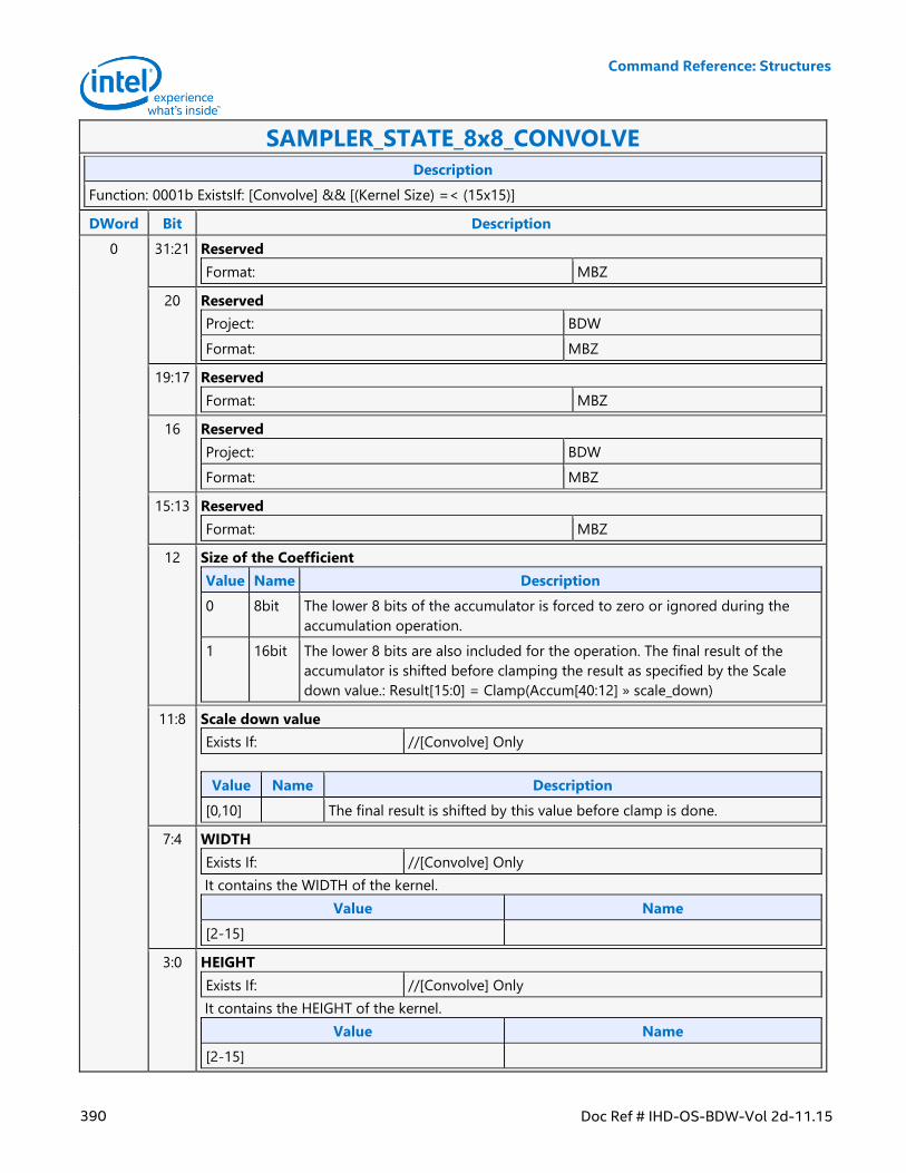
Command Reference: Structures
390 Doc Ref # IHD-OS-BDW-Vol 2d-11.15
SAMPLER_STATE_8x8_CONVOLVE
Description
Function: 0001b ExistsIf: [Convolve] && [(Kernel Size) =< (15x15)]
DWord Bit Description
0 31:21 Reserved
Format: MBZ
20 Reserved
Project: BDW
Format: MBZ
19:17 Reserved
Format: MBZ
16 Reserved
Project: BDW
Format: MBZ
15:13 Reserved
Format: MBZ
12 Size of the Coefficient
Value Name Description
0 8bit The lower 8 bits of the accumulator is forced to zero or ignored during the
accumulation operation.
1 16bit The lower 8 bits are also included for the operation. The final result of the
accumulator is shifted before clamping the result as specified by the Scale
down value.: Result[15:0] = Clamp(Accum[40:12] » scale_down)
11:8 Scale down value
Exists If: //[Convolve] Only
Value Name Description
[0,10] The final result is shifted by this value before clamp is done.
7:4 WIDTH
Exists If: //[Convolve] Only
It contains the WIDTH of the kernel.
Value Name
[2-15]
3:0 HEIGHT
Exists If: //[Convolve] Only
It contains the HEIGHT of the kernel.
Value Name
[2-15]
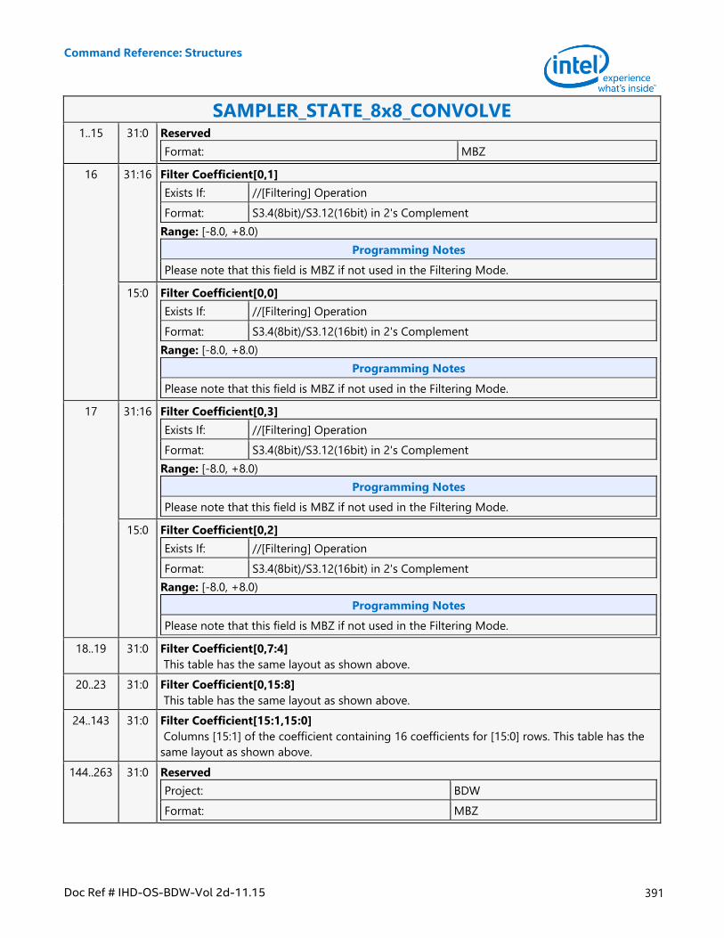
Command Reference: Structures
Doc Ref # IHD-OS-BDW-Vol 2d-11.15 391
SAMPLER_STATE_8x8_CONVOLVE 1..15 31:0 Reserved
Format: MBZ
16 31:16 Filter Coefficient[0,1]
Exists If: //[Filtering] Operation
Format: S3.4(8bit)/S3.12(16bit) in 2's Complement
Range: [-8.0, +8.0)
Programming Notes
Please note that this field is MBZ if not used in the Filtering Mode.
15:0 Filter Coefficient[0,0]
Exists If: //[Filtering] Operation
Format: S3.4(8bit)/S3.12(16bit) in 2's Complement
Range: [-8.0, +8.0)
Programming Notes
Please note that this field is MBZ if not used in the Filtering Mode.
17 31:16 Filter Coefficient[0,3]
Exists If: //[Filtering] Operation
Format: S3.4(8bit)/S3.12(16bit) in 2's Complement
Range: [-8.0, +8.0)
Programming Notes
Please note that this field is MBZ if not used in the Filtering Mode.
15:0 Filter Coefficient[0,2]
Exists If: //[Filtering] Operation
Format: S3.4(8bit)/S3.12(16bit) in 2's Complement
Range: [-8.0, +8.0)
Programming Notes
Please note that this field is MBZ if not used in the Filtering Mode.
18..19 31:0 Filter Coefficient[0,7:4]
This table has the same layout as shown above.
20..23 31:0 Filter Coefficient[0,15:8]
This table has the same layout as shown above.
24..143 31:0 Filter Coefficient[15:1,15:0]
Columns [15:1] of the coefficient containing 16 coefficients for [15:0] rows. This table has the
same layout as shown above.
144..263 31:0 Reserved
Project: BDW
Format: MBZ
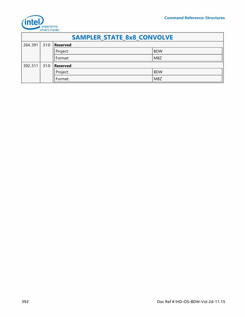
Command Reference: Structures
392 Doc Ref # IHD-OS-BDW-Vol 2d-11.15
SAMPLER_STATE_8x8_CONVOLVE 264..391 31:0 Reserved
Project: BDW
Format: MBZ
392..511 31:0 Reserved
Project: BDW
Format: MBZ
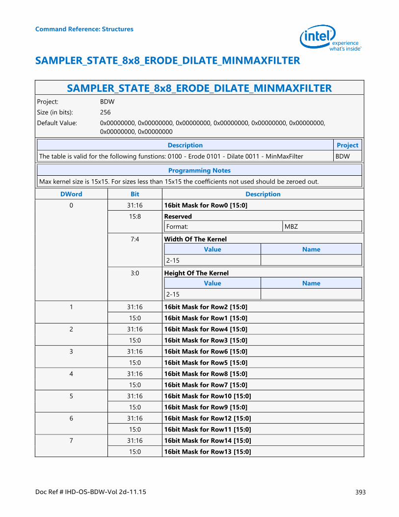
Command Reference: Structures
Doc Ref # IHD-OS-BDW-Vol 2d-11.15 393
SAMPLER_STATE_8x8_ERODE_DILATE_MINMAXFILTER
SAMPLER_STATE_8x8_ERODE_DILATE_MINMAXFILTER Project: BDW
Size (in bits): 256
Default Value: 0x00000000, 0x00000000, 0x00000000, 0x00000000, 0x00000000, 0x00000000,
0x00000000, 0x00000000
Description Project
The table is valid for the following funstions: 0100 - Erode 0101 - Dilate 0011 - MinMaxFilter BDW
Programming Notes
Max kernel size is 15x15. For sizes less than 15x15 the coefficients not used should be zeroed out.
DWord Bit Description
0 31:16 16bit Mask for Row0 [15:0]
15:8 Reserved
Format: MBZ
7:4 Width Of The Kernel
Value Name
2-15
3:0 Height Of The Kernel
Value Name
2-15
1 31:16 16bit Mask for Row2 [15:0]
15:0 16bit Mask for Row1 [15:0]
2 31:16 16bit Mask for Row4 [15:0]
15:0 16bit Mask for Row3 [15:0]
3 31:16 16bit Mask for Row6 [15:0]
15:0 16bit Mask for Row5 [15:0]
4 31:16 16bit Mask for Row8 [15:0]
15:0 16bit Mask for Row7 [15:0]
5 31:16 16bit Mask for Row10 [15:0]
15:0 16bit Mask for Row9 [15:0]
6 31:16 16bit Mask for Row12 [15:0]
15:0 16bit Mask for Row11 [15:0]
7 31:16 16bit Mask for Row14 [15:0]
15:0 16bit Mask for Row13 [15:0]
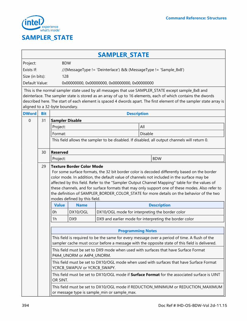
Command Reference: Structures
394 Doc Ref # IHD-OS-BDW-Vol 2d-11.15
SAMPLER_STATE
SAMPLER_STATE Project: BDW
Exists If: //(MessageType != 'Deinterlace') && (MessageType != 'Sample_8x8')
Size (in bits): 128
Default Value: 0x00000000, 0x00000000, 0x00000000, 0x00000000
This is the normal sampler state used by all messages that use SAMPLER_STATE except sample_8x8 and
deinterlace. The sampler state is stored as an array of up to 16 elements, each of which contains the dwords
described here. The start of each element is spaced 4 dwords apart. The first element of the sampler state array is
aligned to a 32-byte boundary.
DWord Bit Description
0 31 Sampler Disable
Project: All
Format: Disable
This field allows the sampler to be disabled. If disabled, all output channels will return 0.
30 Reserved
Project: BDW
29 Texture Border Color Mode
For some surface formats, the 32 bit border color is decoded differently based on the border
color mode. In addition, the default value of channels not included in the surface may be
affected by this field. Refer to the "Sampler Output Channel Mapping" table for the values of
these channels, and for surface formats that may only support one of these modes. Also refer to
the definition of SAMPLER_BORDER_COLOR_STATE for more details on the behavior of the two
modes defined by this field.
Value Name Description
0h DX10/OGL DX10/OGL mode for interpreting the border color
1h DX9 DX9 and earlier mode for interpreting the border color
Programming Notes
This field is required to be the same for every message over a period of time. A flush of the
sampler cache must occur before a message with the opposite state of this field is delivered.
This field must be set to DX9 mode when used with surfaces that have Surface Format
P4A4_UNORM or A4P4_UNORM.
This field must be set to DX10/OGL mode when used with surfaces that have Surface Format
YCRCB_SWAPUV or YCRCB_SWAPY.
This field must be set to DX10/OGL mode if Surface Format for the associated surface is UINT
OR SINT.
This field must be set to DX10/OGL mode if REDUCTION_MINIMUM or REDUCTION_MAXIMUM
or message type is sample_min or sample_max.
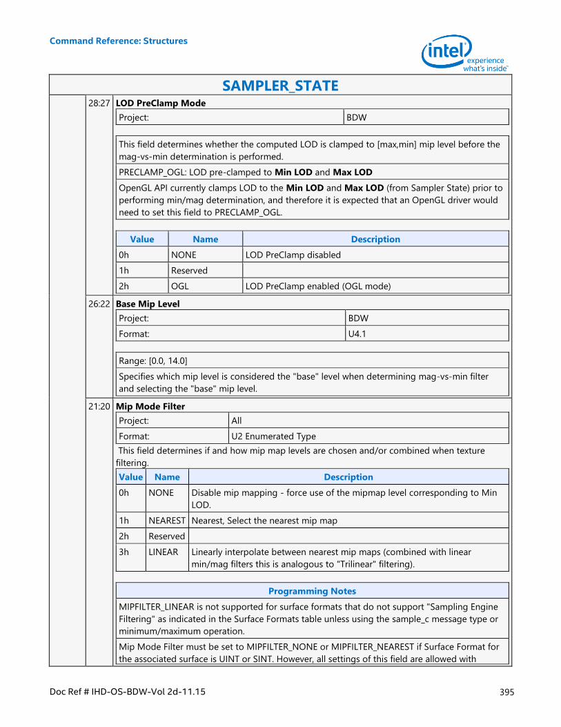
Command Reference: Structures
Doc Ref # IHD-OS-BDW-Vol 2d-11.15 395
SAMPLER_STATE 28:27 LOD PreClamp Mode
Project: BDW
This field determines whether the computed LOD is clamped to [max,min] mip level before the
mag-vs-min determination is performed.
PRECLAMP_OGL: LOD pre-clamped to Min LOD and Max LOD
OpenGL API currently clamps LOD to the Min LOD and Max LOD (from Sampler State) prior to
performing min/mag determination, and therefore it is expected that an OpenGL driver would
need to set this field to PRECLAMP_OGL.
Value Name Description
0h NONE LOD PreClamp disabled
1h Reserved
2h OGL LOD PreClamp enabled (OGL mode)
26:22 Base Mip Level
Project: BDW
Format: U4.1
Range: [0.0, 14.0]
Specifies which mip level is considered the "base" level when determining mag-vs-min filter
and selecting the "base" mip level.
21:20 Mip Mode Filter
Project: All
Format: U2 Enumerated Type
This field determines if and how mip map levels are chosen and/or combined when texture
filtering.
Value Name Description
0h NONE Disable mip mapping - force use of the mipmap level corresponding to Min
LOD.
1h NEAREST Nearest, Select the nearest mip map
2h Reserved
3h LINEAR Linearly interpolate between nearest mip maps (combined with linear
min/mag filters this is analogous to "Trilinear" filtering).
Programming Notes
MIPFILTER_LINEAR is not supported for surface formats that do not support "Sampling Engine
Filtering" as indicated in the Surface Formats table unless using the sample_c message type or
minimum/maximum operation.
Mip Mode Filter must be set to MIPFILTER_NONE or MIPFILTER_NEAREST if Surface Format for
the associated surface is UINT or SINT. However, all settings of this field are allowed with
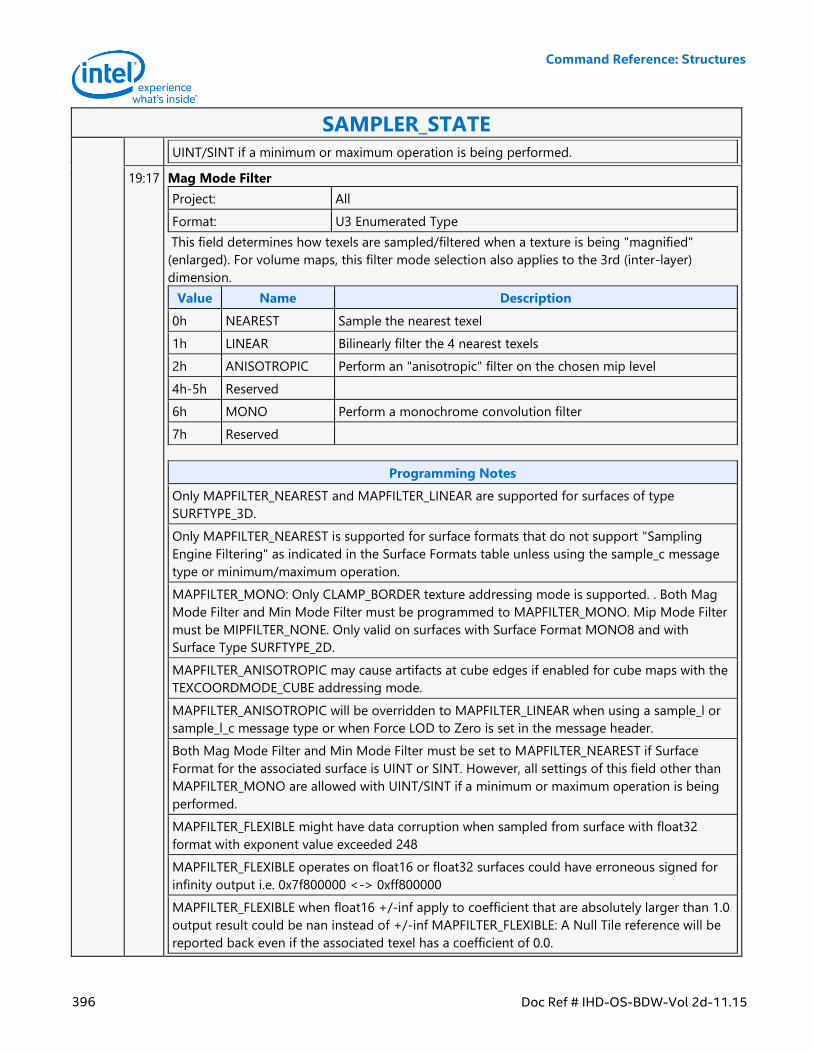
Command Reference: Structures
396 Doc Ref # IHD-OS-BDW-Vol 2d-11.15
SAMPLER_STATE
UINT/SINT if a minimum or maximum operation is being performed.
19:17 Mag Mode Filter
Project: All
Format: U3 Enumerated Type
This field determines how texels are sampled/filtered when a texture is being "magnified"
(enlarged). For volume maps, this filter mode selection also applies to the 3rd (inter-layer)
dimension.
Value Name Description
0h NEAREST Sample the nearest texel
1h LINEAR Bilinearly filter the 4 nearest texels
2h ANISOTROPIC Perform an "anisotropic" filter on the chosen mip level
4h-5h Reserved
6h MONO Perform a monochrome convolution filter
7h Reserved
Programming Notes
Only MAPFILTER_NEAREST and MAPFILTER_LINEAR are supported for surfaces of type
SURFTYPE_3D.
Only MAPFILTER_NEAREST is supported for surface formats that do not support "Sampling
Engine Filtering" as indicated in the Surface Formats table unless using the sample_c message
type or minimum/maximum operation.
MAPFILTER_MONO: Only CLAMP_BORDER texture addressing mode is supported. . Both Mag
Mode Filter and Min Mode Filter must be programmed to MAPFILTER_MONO. Mip Mode Filter
must be MIPFILTER_NONE. Only valid on surfaces with Surface Format MONO8 and with
Surface Type SURFTYPE_2D.
MAPFILTER_ANISOTROPIC may cause artifacts at cube edges if enabled for cube maps with the
TEXCOORDMODE_CUBE addressing mode.
MAPFILTER_ANISOTROPIC will be overridden to MAPFILTER_LINEAR when using a sample_l or
sample_l_c message type or when Force LOD to Zero is set in the message header.
Both Mag Mode Filter and Min Mode Filter must be set to MAPFILTER_NEAREST if Surface
Format for the associated surface is UINT or SINT. However, all settings of this field other than
MAPFILTER_MONO are allowed with UINT/SINT if a minimum or maximum operation is being
performed.
MAPFILTER_FLEXIBLE might have data corruption when sampled from surface with float32
format with exponent value exceeded 248
MAPFILTER_FLEXIBLE operates on float16 or float32 surfaces could have erroneous signed for
infinity output i.e. 0x7f800000 <-> 0xff800000
MAPFILTER_FLEXIBLE when float16 +/-inf apply to coefficient that are absolutely larger than 1.0
output result could be nan instead of +/-inf MAPFILTER_FLEXIBLE: A Null Tile reference will be
reported back even if the associated texel has a coefficient of 0.0.
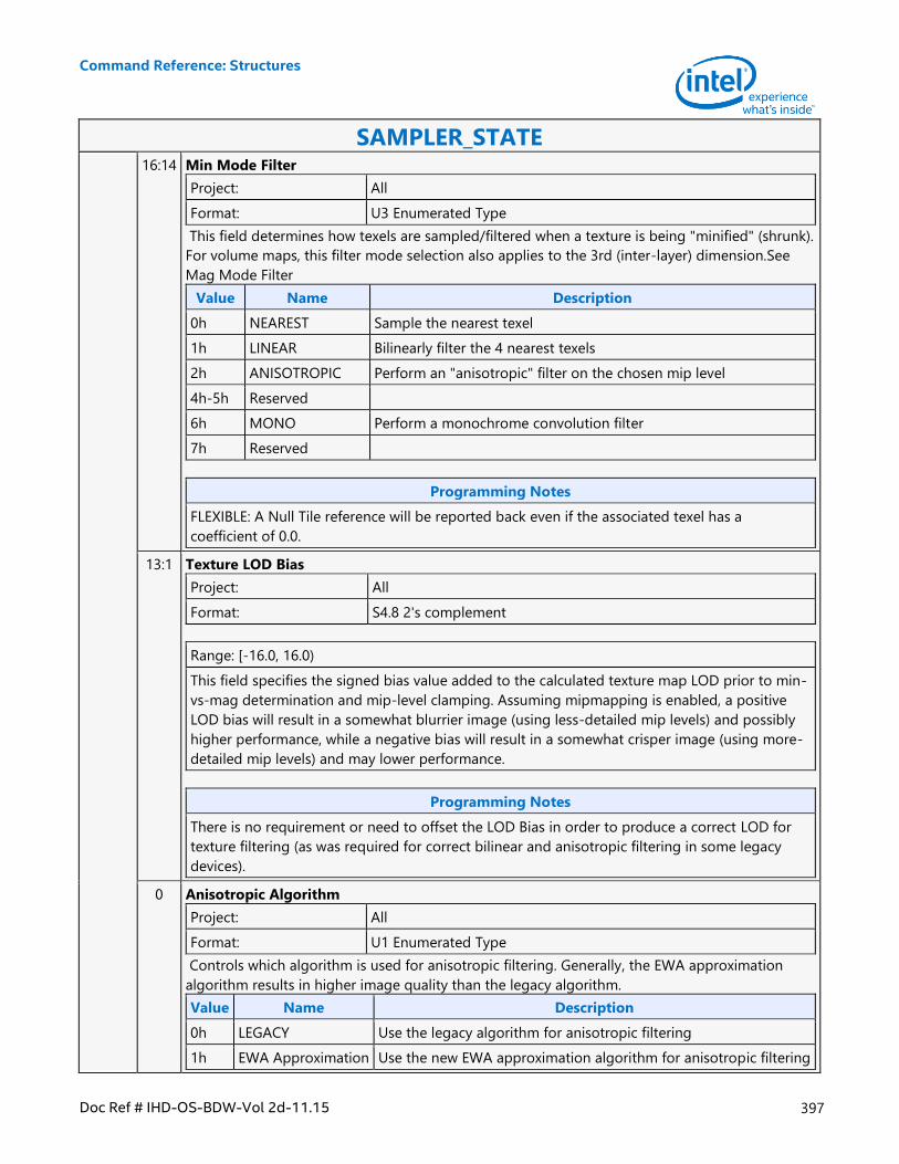
Command Reference: Structures
Doc Ref # IHD-OS-BDW-Vol 2d-11.15 397
SAMPLER_STATE 16:14 Min Mode Filter
Project: All
Format: U3 Enumerated Type
This field determines how texels are sampled/filtered when a texture is being "minified" (shrunk).
For volume maps, this filter mode selection also applies to the 3rd (inter-layer) dimension.See
Mag Mode Filter
Value Name Description
0h NEAREST Sample the nearest texel
1h LINEAR Bilinearly filter the 4 nearest texels
2h ANISOTROPIC Perform an "anisotropic" filter on the chosen mip level
4h-5h Reserved
6h MONO Perform a monochrome convolution filter
7h Reserved
Programming Notes
FLEXIBLE: A Null Tile reference will be reported back even if the associated texel has a
coefficient of 0.0.
13:1 Texture LOD Bias
Project: All
Format: S4.8 2's complement
Range: [-16.0, 16.0)
This field specifies the signed bias value added to the calculated texture map LOD prior to min-
vs-mag determination and mip-level clamping. Assuming mipmapping is enabled, a positive
LOD bias will result in a somewhat blurrier image (using less-detailed mip levels) and possibly
higher performance, while a negative bias will result in a somewhat crisper image (using more-
detailed mip levels) and may lower performance.
Programming Notes
There is no requirement or need to offset the LOD Bias in order to produce a correct LOD for
texture filtering (as was required for correct bilinear and anisotropic filtering in some legacy
devices).
0 Anisotropic Algorithm
Project: All
Format: U1 Enumerated Type
Controls which algorithm is used for anisotropic filtering. Generally, the EWA approximation
algorithm results in higher image quality than the legacy algorithm.
Value Name Description
0h LEGACY Use the legacy algorithm for anisotropic filtering
1h EWA Approximation Use the new EWA approximation algorithm for anisotropic filtering
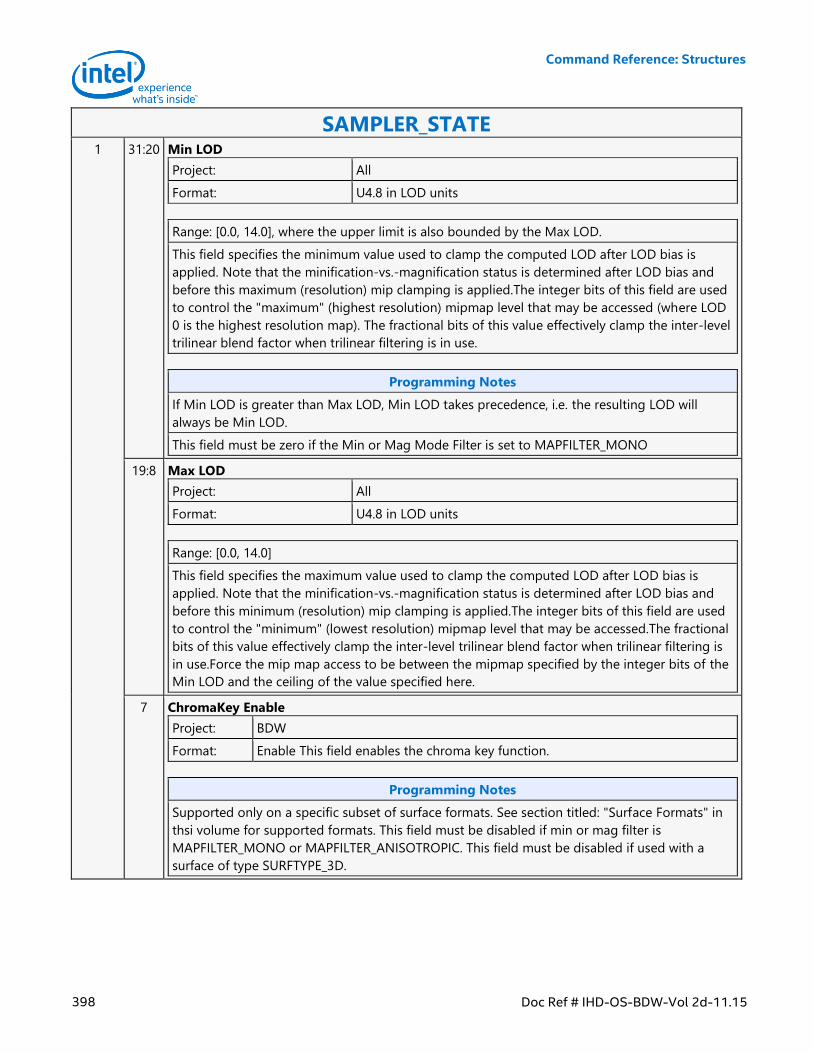
Command Reference: Structures
398 Doc Ref # IHD-OS-BDW-Vol 2d-11.15
SAMPLER_STATE 1 31:20 Min LOD
Project: All
Format: U4.8 in LOD units
Range: [0.0, 14.0], where the upper limit is also bounded by the Max LOD.
This field specifies the minimum value used to clamp the computed LOD after LOD bias is
applied. Note that the minification-vs.-magnification status is determined after LOD bias and
before this maximum (resolution) mip clamping is applied.The integer bits of this field are used
to control the "maximum" (highest resolution) mipmap level that may be accessed (where LOD
0 is the highest resolution map). The fractional bits of this value effectively clamp the inter-level
trilinear blend factor when trilinear filtering is in use.
Programming Notes
If Min LOD is greater than Max LOD, Min LOD takes precedence, i.e. the resulting LOD will
always be Min LOD.
This field must be zero if the Min or Mag Mode Filter is set to MAPFILTER_MONO
19:8 Max LOD
Project: All
Format: U4.8 in LOD units
Range: [0.0, 14.0]
This field specifies the maximum value used to clamp the computed LOD after LOD bias is
applied. Note that the minification-vs.-magnification status is determined after LOD bias and
before this minimum (resolution) mip clamping is applied.The integer bits of this field are used
to control the "minimum" (lowest resolution) mipmap level that may be accessed.The fractional
bits of this value effectively clamp the inter-level trilinear blend factor when trilinear filtering is
in use.Force the mip map access to be between the mipmap specified by the integer bits of the
Min LOD and the ceiling of the value specified here.
7 ChromaKey Enable
Project: BDW
Format: Enable This field enables the chroma key function.
Programming Notes
Supported only on a specific subset of surface formats. See section titled: "Surface Formats" in
thsi volume for supported formats. This field must be disabled if min or mag filter is
MAPFILTER_MONO or MAPFILTER_ANISOTROPIC. This field must be disabled if used with a
surface of type SURFTYPE_3D.
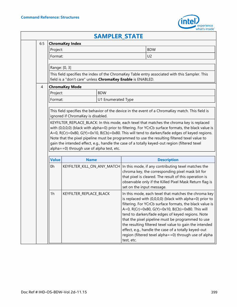
Command Reference: Structures
Doc Ref # IHD-OS-BDW-Vol 2d-11.15 399
SAMPLER_STATE 6:5 ChromaKey Index
Project: BDW
Format: U2
Range: [0, 3]
This field specifies the index of the ChromaKey Table entry associated with this Sampler. This
field is a "don't care" unless ChromaKey Enable is ENABLED.
4 ChromaKey Mode
Project: BDW
Format: U1 Enumerated Type
This field specifies the behavior of the device in the event of a ChromaKey match. This field is
ignored if ChromaKey is disabled.
KEYFILTER_REPLACE_BLACK: In this mode, each texel that matches the chroma key is replaced
with (0,0,0,0) (black with alpha=0) prior to filtering. For YCrCb surface formats, the black value is
A=0, R(Cr)=0x80, G(Y)=0x10, B(Cb)=0x80. This will tend to darken/fade edges of keyed regions.
Note that the pixel pipeline must be programmed to use the resulting filtered texel value to
gain the intended effect, e.g., handle the case of a totally keyed-out region (filtered texel
alpha==0) through use of alpha test, etc.
Value Name Description
0h KEYFILTER_KILL_ON_ANY_MATCH In this mode, if any contributing texel matches the
chroma key, the corresponding pixel mask bit for
that pixel is cleared. The result of this operation is
observable only if the Killed Pixel Mask Return flag is
set on the input message.
1h KEYFILTER_REPLACE_BLACK In this mode, each texel that matches the chroma key
is replaced with (0,0,0,0) (black with alpha=0) prior to
filtering. For YCrCb surface formats, the black value is
A=0, R(Cr)=0x80, G(Y)=0x10, B(Cb)=0x80. This will
tend to darken/fade edges of keyed regions. Note
that the pixel pipeline must be programmed to use
the resulting filtered texel value to gain the intended
effect, e.g., handle the case of a totally keyed-out
region (filtered texel alpha==0) through use of alpha
test, etc.
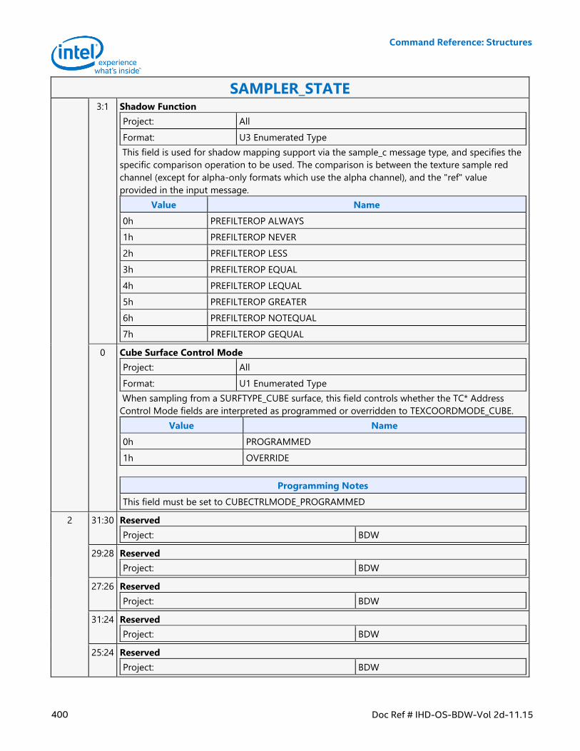
Command Reference: Structures
400 Doc Ref # IHD-OS-BDW-Vol 2d-11.15
SAMPLER_STATE 3:1 Shadow Function
Project: All
Format: U3 Enumerated Type
This field is used for shadow mapping support via the sample_c message type, and specifies the
specific comparison operation to be used. The comparison is between the texture sample red
channel (except for alpha-only formats which use the alpha channel), and the "ref" value
provided in the input message.
Value Name
0h PREFILTEROP ALWAYS
1h PREFILTEROP NEVER
2h PREFILTEROP LESS
3h PREFILTEROP EQUAL
4h PREFILTEROP LEQUAL
5h PREFILTEROP GREATER
6h PREFILTEROP NOTEQUAL
7h PREFILTEROP GEQUAL
0 Cube Surface Control Mode
Project: All
Format: U1 Enumerated Type
When sampling from a SURFTYPE_CUBE surface, this field controls whether the TC* Address
Control Mode fields are interpreted as programmed or overridden to TEXCOORDMODE_CUBE.
Value Name
0h PROGRAMMED
1h OVERRIDE
Programming Notes
This field must be set to CUBECTRLMODE_PROGRAMMED
2 31:30 Reserved
Project: BDW
29:28 Reserved
Project: BDW
27:26 Reserved
Project: BDW
31:24 Reserved
Project: BDW
25:24 Reserved
Project: BDW
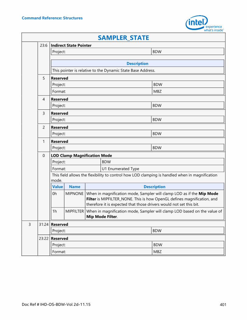
Command Reference: Structures
Doc Ref # IHD-OS-BDW-Vol 2d-11.15 401
SAMPLER_STATE 23:6 Indirect State Pointer
Project: BDW
Description
This pointer is relative to the Dynamic State Base Address.
5 Reserved
Project: BDW
Format: MBZ
4 Reserved
Project: BDW
3 Reserved
Project: BDW
2 Reserved
Project: BDW
1 Reserved
Project: BDW
0 LOD Clamp Magnification Mode
Project: BDW
Format: U1 Enumerated Type
This field allows the flexibility to control how LOD clamping is handled when in magnification
mode.
Value Name Description
0h MIPNONE When in magnification mode, Sampler will clamp LOD as if the Mip Mode
Filter is MIPFILTER_NONE. This is how OpenGL defines magnification, and
therefore it is expected that those drivers would not set this bit.
1h MIPFILTER When in magnification mode, Sampler will clamp LOD based on the value of
Mip Mode Filter.
3 31:24 Reserved
Project: BDW
23:22 Reserved
Project: BDW
Format: MBZ
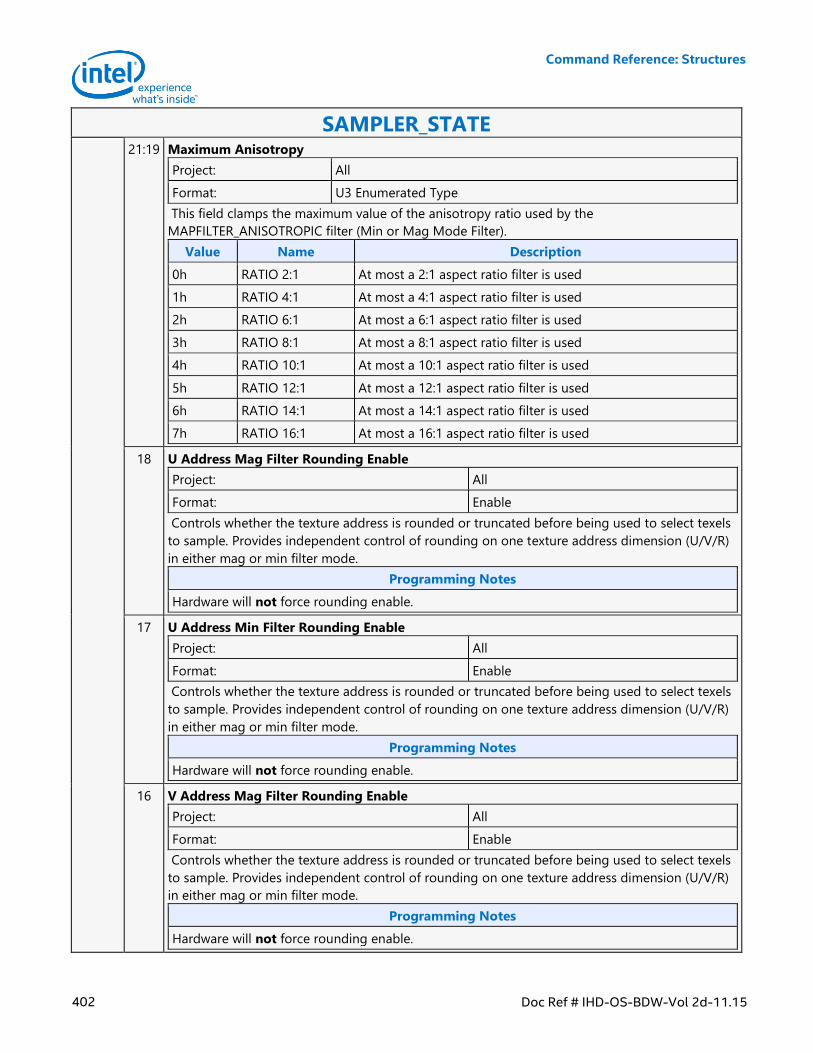
Command Reference: Structures
402 Doc Ref # IHD-OS-BDW-Vol 2d-11.15
SAMPLER_STATE 21:19 Maximum Anisotropy
Project: All
Format: U3 Enumerated Type
This field clamps the maximum value of the anisotropy ratio used by the
MAPFILTER_ANISOTROPIC filter (Min or Mag Mode Filter).
Value Name Description
0h RATIO 2:1 At most a 2:1 aspect ratio filter is used
1h RATIO 4:1 At most a 4:1 aspect ratio filter is used
2h RATIO 6:1 At most a 6:1 aspect ratio filter is used
3h RATIO 8:1 At most a 8:1 aspect ratio filter is used
4h RATIO 10:1 At most a 10:1 aspect ratio filter is used
5h RATIO 12:1 At most a 12:1 aspect ratio filter is used
6h RATIO 14:1 At most a 14:1 aspect ratio filter is used
7h RATIO 16:1 At most a 16:1 aspect ratio filter is used
18 U Address Mag Filter Rounding Enable
Project: All
Format: Enable
Controls whether the texture address is rounded or truncated before being used to select texels
to sample. Provides independent control of rounding on one texture address dimension (U/V/R)
in either mag or min filter mode.
Programming Notes
Hardware will not force rounding enable.
17 U Address Min Filter Rounding Enable
Project: All
Format: Enable
Controls whether the texture address is rounded or truncated before being used to select texels
to sample. Provides independent control of rounding on one texture address dimension (U/V/R)
in either mag or min filter mode.
Programming Notes
Hardware will not force rounding enable.
16 V Address Mag Filter Rounding Enable
Project: All
Format: Enable
Controls whether the texture address is rounded or truncated before being used to select texels
to sample. Provides independent control of rounding on one texture address dimension (U/V/R)
in either mag or min filter mode.
Programming Notes
Hardware will not force rounding enable.
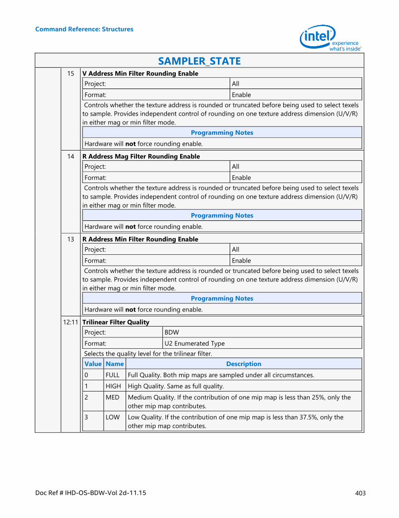
Command Reference: Structures
Doc Ref # IHD-OS-BDW-Vol 2d-11.15 403
SAMPLER_STATE 15 V Address Min Filter Rounding Enable
Project: All
Format: Enable
Controls whether the texture address is rounded or truncated before being used to select texels
to sample. Provides independent control of rounding on one texture address dimension (U/V/R)
in either mag or min filter mode.
Programming Notes
Hardware will not force rounding enable.
14 R Address Mag Filter Rounding Enable
Project: All
Format: Enable
Controls whether the texture address is rounded or truncated before being used to select texels
to sample. Provides independent control of rounding on one texture address dimension (U/V/R)
in either mag or min filter mode.
Programming Notes
Hardware will not force rounding enable.
13 R Address Min Filter Rounding Enable
Project: All
Format: Enable
Controls whether the texture address is rounded or truncated before being used to select texels
to sample. Provides independent control of rounding on one texture address dimension (U/V/R)
in either mag or min filter mode.
Programming Notes
Hardware will not force rounding enable.
12:11 Trilinear Filter Quality
Project: BDW
Format: U2 Enumerated Type
Selects the quality level for the trilinear filter.
Value Name Description
0 FULL Full Quality. Both mip maps are sampled under all circumstances.
1 HIGH High Quality. Same as full quality.
2 MED Medium Quality. If the contribution of one mip map is less than 25%, only the
other mip map contributes.
3 LOW Low Quality. If the contribution of one mip map is less than 37.5%, only the
other mip map contributes.
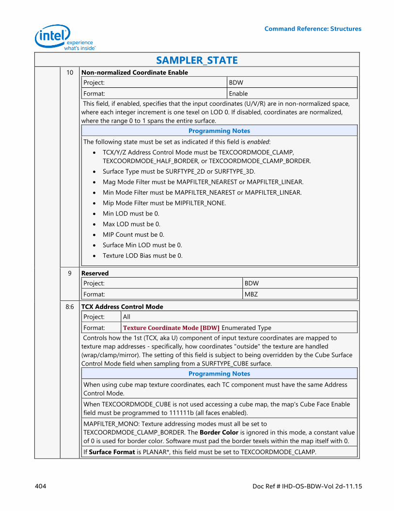
Command Reference: Structures
404 Doc Ref # IHD-OS-BDW-Vol 2d-11.15
SAMPLER_STATE 10 Non-normalized Coordinate Enable
Project: BDW
Format: Enable
This field, if enabled, specifies that the input coordinates (U/V/R) are in non-normalized space,
where each integer increment is one texel on LOD 0. If disabled, coordinates are normalized,
where the range 0 to 1 spans the entire surface.
Programming Notes
The following state must be set as indicated if this field is enabled:
TCX/Y/Z Address Control Mode must be TEXCOORDMODE_CLAMP,
TEXCOORDMODE_HALF_BORDER, or TEXCOORDMODE_CLAMP_BORDER.
Surface Type must be SURFTYPE_2D or SURFTYPE_3D.
Mag Mode Filter must be MAPFILTER_NEAREST or MAPFILTER_LINEAR.
Min Mode Filter must be MAPFILTER_NEAREST or MAPFILTER_LINEAR.
Mip Mode Filter must be MIPFILTER_NONE.
Min LOD must be 0.
Max LOD must be 0.
MIP Count must be 0.
Surface Min LOD must be 0.
Texture LOD Bias must be 0.
9 Reserved
Project: BDW
Format: MBZ
8:6 TCX Address Control Mode
Project: All
Format: Texture Coordinate Mode [BDW] Enumerated Type
Controls how the 1st (TCX, aka U) component of input texture coordinates are mapped to
texture map addresses - specifically, how coordinates "outside" the texture are handled
(wrap/clamp/mirror). The setting of this field is subject to being overridden by the Cube Surface
Control Mode field when sampling from a SURFTYPE_CUBE surface.
Programming Notes
When using cube map texture coordinates, each TC component must have the same Address
Control Mode.
When TEXCOORDMODE_CUBE is not used accessing a cube map, the map's Cube Face Enable
field must be programmed to 111111b (all faces enabled).
MAPFILTER_MONO: Texture addressing modes must all be set to
TEXCOORDMODE_CLAMP_BORDER. The Border Color is ignored in this mode, a constant value
of 0 is used for border color. Software must pad the border texels within the map itself with 0.
If Surface Format is PLANAR*, this field must be set to TEXCOORDMODE_CLAMP.
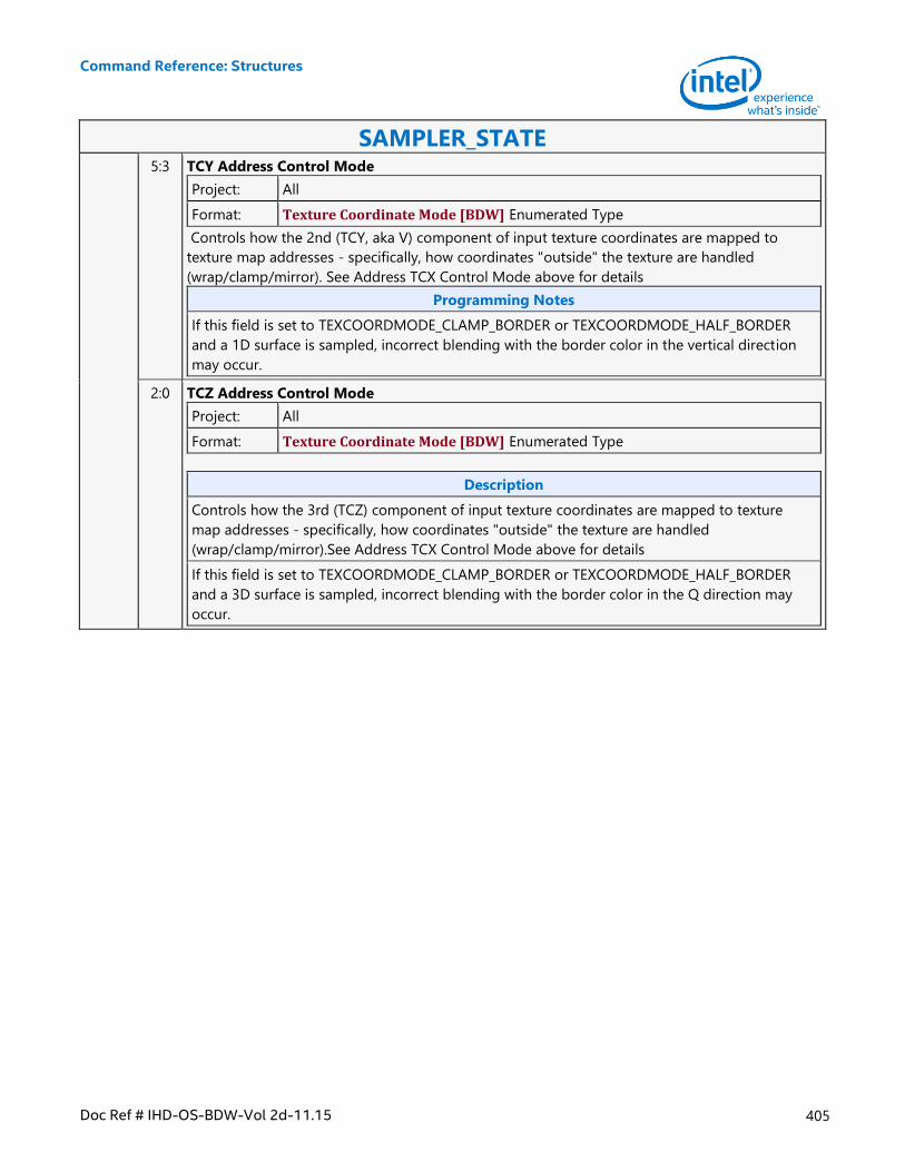
Command Reference: Structures
Doc Ref # IHD-OS-BDW-Vol 2d-11.15 405
SAMPLER_STATE 5:3 TCY Address Control Mode
Project: All
Format: Texture Coordinate Mode [BDW] Enumerated Type
Controls how the 2nd (TCY, aka V) component of input texture coordinates are mapped to
texture map addresses - specifically, how coordinates "outside" the texture are handled
(wrap/clamp/mirror). See Address TCX Control Mode above for details
Programming Notes
If this field is set to TEXCOORDMODE_CLAMP_BORDER or TEXCOORDMODE_HALF_BORDER
and a 1D surface is sampled, incorrect blending with the border color in the vertical direction
may occur.
2:0 TCZ Address Control Mode
Project: All
Format: Texture Coordinate Mode [BDW] Enumerated Type
Description
Controls how the 3rd (TCZ) component of input texture coordinates are mapped to texture
map addresses - specifically, how coordinates "outside" the texture are handled
(wrap/clamp/mirror).See Address TCX Control Mode above for details
If this field is set to TEXCOORDMODE_CLAMP_BORDER or TEXCOORDMODE_HALF_BORDER
and a 3D surface is sampled, incorrect blending with the border color in the Q direction may
occur.
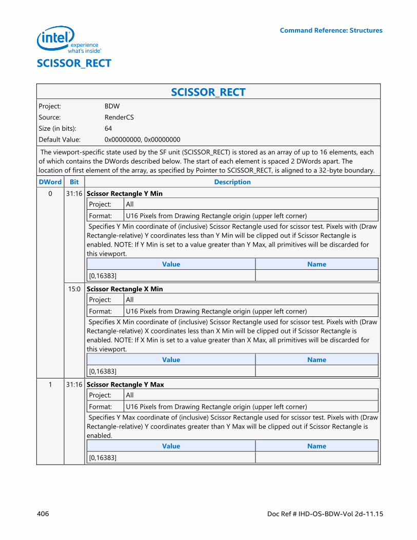
Command Reference: Structures
406 Doc Ref # IHD-OS-BDW-Vol 2d-11.15
SCISSOR_RECT
SCISSOR_RECT Project: BDW
Source: RenderCS
Size (in bits): 64
Default Value: 0x00000000, 0x00000000
The viewport-specific state used by the SF unit (SCISSOR_RECT) is stored as an array of up to 16 elements, each
of which contains the DWords described below. The start of each element is spaced 2 DWords apart. The
location of first element of the array, as specified by Pointer to SCISSOR_RECT, is aligned to a 32-byte boundary.
DWord Bit Description
0 31:16 Scissor Rectangle Y Min
Project: All
Format: U16 Pixels from Drawing Rectangle origin (upper left corner)
Specifies Y Min coordinate of (inclusive) Scissor Rectangle used for scissor test. Pixels with (Draw
Rectangle-relative) Y coordinates less than Y Min will be clipped out if Scissor Rectangle is
enabled. NOTE: If Y Min is set to a value greater than Y Max, all primitives will be discarded for
this viewport.
Value Name
[0,16383]
15:0 Scissor Rectangle X Min
Project: All
Format: U16 Pixels from Drawing Rectangle origin (upper left corner)
Specifies X Min coordinate of (inclusive) Scissor Rectangle used for scissor test. Pixels with (Draw
Rectangle-relative) X coordinates less than X Min will be clipped out if Scissor Rectangle is
enabled. NOTE: If X Min is set to a value greater than X Max, all primitives will be discarded for
this viewport.
Value Name
[0,16383]
1 31:16 Scissor Rectangle Y Max
Project: All
Format: U16 Pixels from Drawing Rectangle origin (upper left corner)
Specifies Y Max coordinate of (inclusive) Scissor Rectangle used for scissor test. Pixels with (Draw
Rectangle-relative) Y coordinates greater than Y Max will be clipped out if Scissor Rectangle is
enabled.
Value Name
[0,16383]
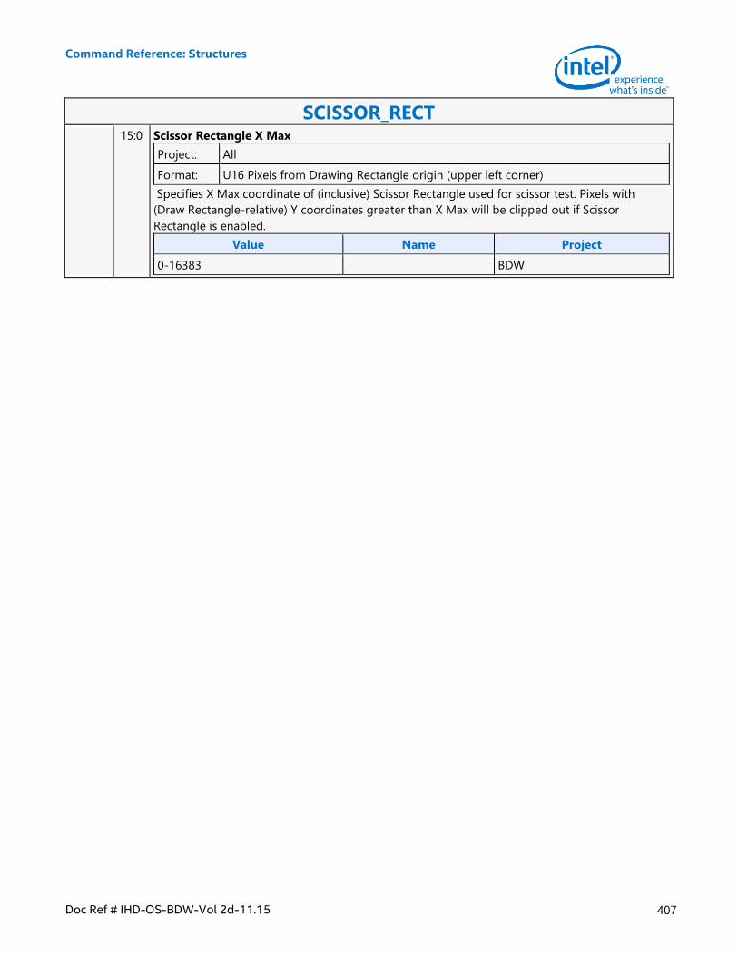
Command Reference: Structures
Doc Ref # IHD-OS-BDW-Vol 2d-11.15 407
SCISSOR_RECT 15:0 Scissor Rectangle X Max
Project: All
Format: U16 Pixels from Drawing Rectangle origin (upper left corner)
Specifies X Max coordinate of (inclusive) Scissor Rectangle used for scissor test. Pixels with
(Draw Rectangle-relative) Y coordinates greater than X Max will be clipped out if Scissor
Rectangle is enabled.
Value Name Project
0-16383 BDW
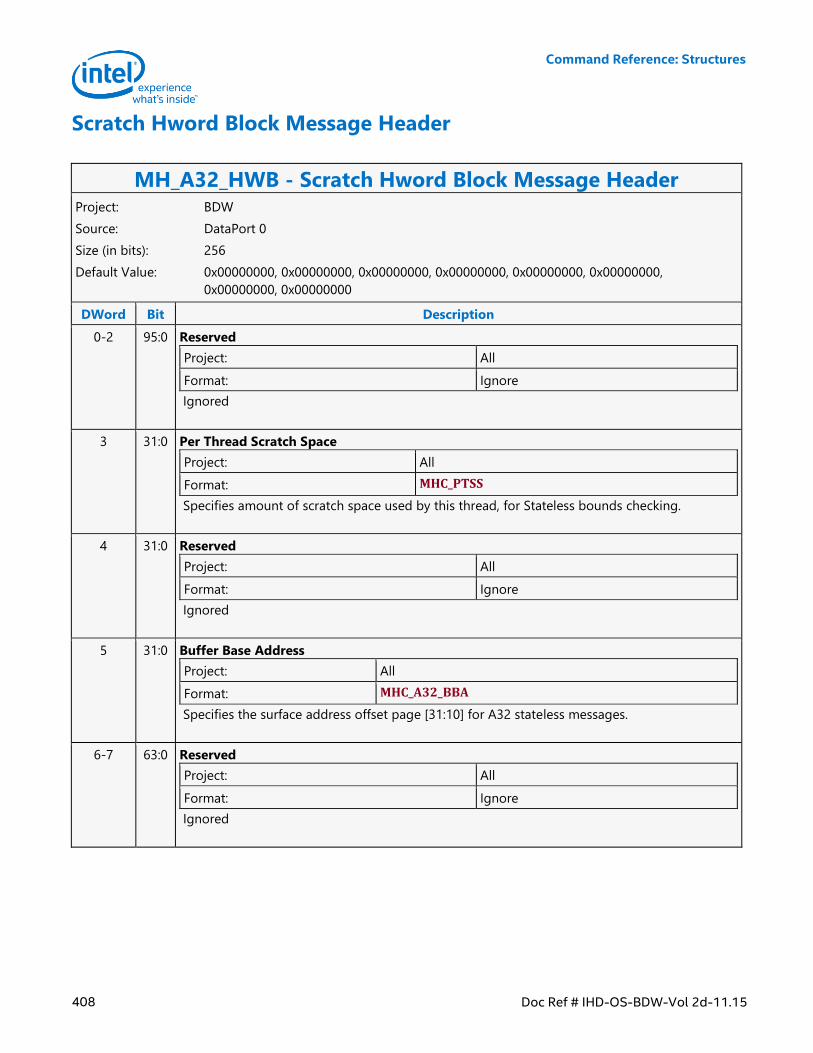
Command Reference: Structures
408 Doc Ref # IHD-OS-BDW-Vol 2d-11.15
Scratch Hword Block Message Header
MH_A32_HWB - Scratch Hword Block Message Header Project: BDW
Source: DataPort 0
Size (in bits): 256
Default Value: 0x00000000, 0x00000000, 0x00000000, 0x00000000, 0x00000000, 0x00000000,
0x00000000, 0x00000000
DWord Bit Description
0-2 95:0 Reserved
Project: All
Format: Ignore
Ignored
3 31:0 Per Thread Scratch Space
Project: All
Format: MHC_PTSS
Specifies amount of scratch space used by this thread, for Stateless bounds checking.
4 31:0 Reserved
Project: All
Format: Ignore
Ignored
5 31:0 Buffer Base Address
Project: All
Format: MHC_A32_BBA
Specifies the surface address offset page [31:10] for A32 stateless messages.
6-7 63:0 Reserved
Project: All
Format: Ignore
Ignored
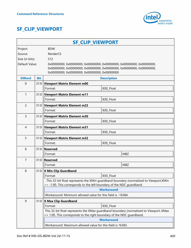
Command Reference: Structures
Doc Ref # IHD-OS-BDW-Vol 2d-11.15 409
SF_CLIP_VIEWPORT
SF_CLIP_VIEWPORT Project: BDW
Source: RenderCS
Size (in bits): 512
Default Value: 0x00000000, 0x00000000, 0x00000000, 0x00000000, 0x00000000, 0x00000000,
0x00000000, 0x00000000, 0x00000000, 0x00000000, 0x00000000, 0x00000000,
0x00000000, 0x00000000, 0x00000000, 0x00000000
DWord Bit Description
0 31:0 Viewport Matrix Element m00
Format: IEEE_Float
1 31:0 Viewport Matrix Element m11
Format: IEEE_Float
2 31:0 Viewport Matrix Element m22
Format: IEEE_Float
3 31:0 Viewport Matrix Element m30
Format: IEEE_Float
4 31:0 Viewport Matrix Element m31
Format: IEEE_Float
5 31:0 Viewport Matrix Element m32
Format: IEEE_Float
6 31:0 Reserved
Format: MBZ
7 31:0 Reserved
Format: MBZ
8 31:0 X Min Clip Guardband
Format: IEEE_Float
. This 32-bit float represents the XMin guardband boundary (normalized to Viewport.XMin
== -1.0f). This corresponds to the left boundary of the NDC guardband.
Workaround
Workaround: Minimum allowed value for this field is -16384.
9 31:0 X Max Clip Guardband
Format: IEEE_Float
This 32-bit float represents the XMax guardband boundary (normalized to Viewport..XMax
== 1.0f). This corresponds to the right boundary of the NDC guardband.
Workaround
Workaround: Maximum allowed value for this field is 16383.
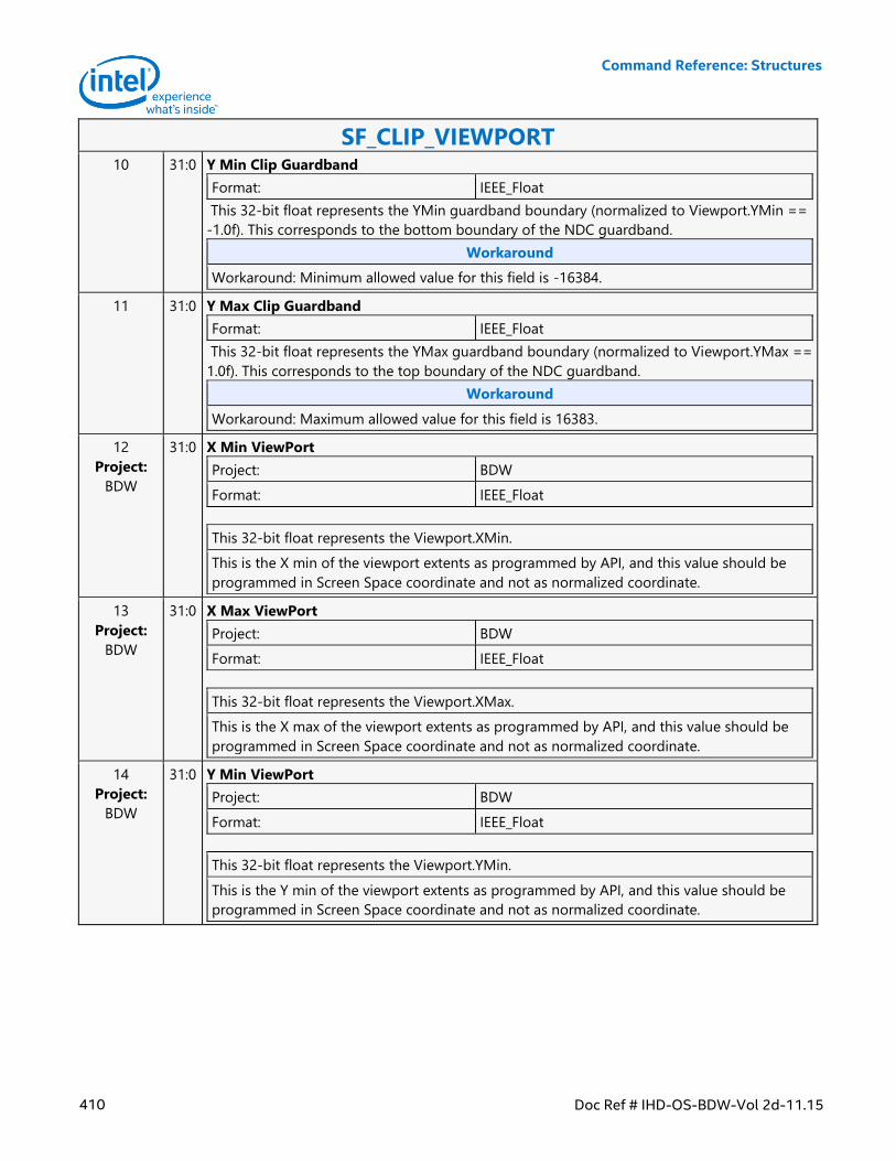
Command Reference: Structures
410 Doc Ref # IHD-OS-BDW-Vol 2d-11.15
SF_CLIP_VIEWPORT 10 31:0 Y Min Clip Guardband
Format: IEEE_Float
This 32-bit float represents the YMin guardband boundary (normalized to Viewport.YMin ==
-1.0f). This corresponds to the bottom boundary of the NDC guardband.
Workaround
Workaround: Minimum allowed value for this field is -16384.
11 31:0 Y Max Clip Guardband
Format: IEEE_Float
This 32-bit float represents the YMax guardband boundary (normalized to Viewport.YMax ==
1.0f). This corresponds to the top boundary of the NDC guardband.
Workaround
Workaround: Maximum allowed value for this field is 16383.
12
Project:
BDW
31:0 X Min ViewPort
Project: BDW
Format: IEEE_Float
This 32-bit float represents the Viewport.XMin.
This is the X min of the viewport extents as programmed by API, and this value should be
programmed in Screen Space coordinate and not as normalized coordinate.
13
Project:
BDW
31:0 X Max ViewPort
Project: BDW
Format: IEEE_Float
This 32-bit float represents the Viewport.XMax.
This is the X max of the viewport extents as programmed by API, and this value should be
programmed in Screen Space coordinate and not as normalized coordinate.
14
Project:
BDW
31:0 Y Min ViewPort
Project: BDW
Format: IEEE_Float
This 32-bit float represents the Viewport.YMin.
This is the Y min of the viewport extents as programmed by API, and this value should be
programmed in Screen Space coordinate and not as normalized coordinate.
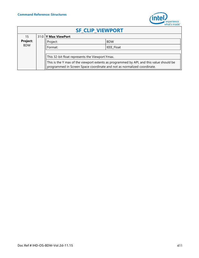
Command Reference: Structures
Doc Ref # IHD-OS-BDW-Vol 2d-11.15 411
SF_CLIP_VIEWPORT 15
Project:
BDW
31:0 Y Max ViewPort
Project: BDW
Format: IEEE_Float
This 32-bit float represents the Viewport.Ymax.
This is the Y max of the viewport extents as programmed by API, and this value should be
programmed in Screen Space coordinate and not as normalized coordinate.
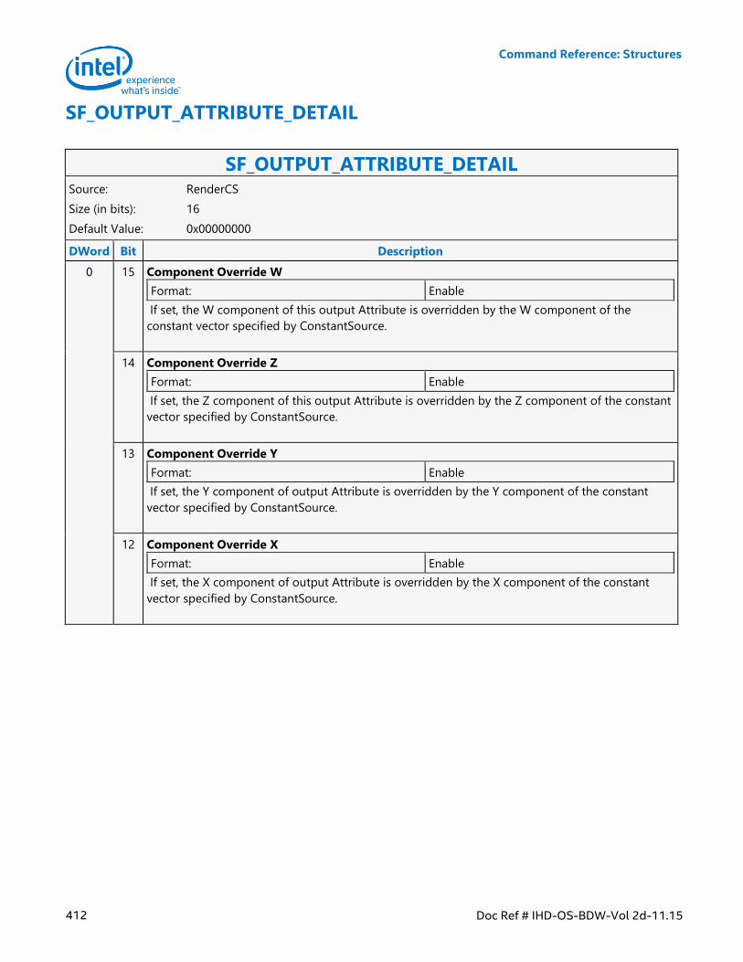
Command Reference: Structures
412 Doc Ref # IHD-OS-BDW-Vol 2d-11.15
SF_OUTPUT_ATTRIBUTE_DETAIL
SF_OUTPUT_ATTRIBUTE_DETAIL Source: RenderCS
Size (in bits): 16
Default Value: 0x00000000
DWord Bit Description
0 15 Component Override W
Format: Enable
If set, the W component of this output Attribute is overridden by the W component of the
constant vector specified by ConstantSource.
14 Component Override Z
Format: Enable
If set, the Z component of this output Attribute is overridden by the Z component of the constant
vector specified by ConstantSource.
13 Component Override Y
Format: Enable
If set, the Y component of output Attribute is overridden by the Y component of the constant
vector specified by ConstantSource.
12 Component Override X
Format: Enable
If set, the X component of output Attribute is overridden by the X component of the constant
vector specified by ConstantSource.
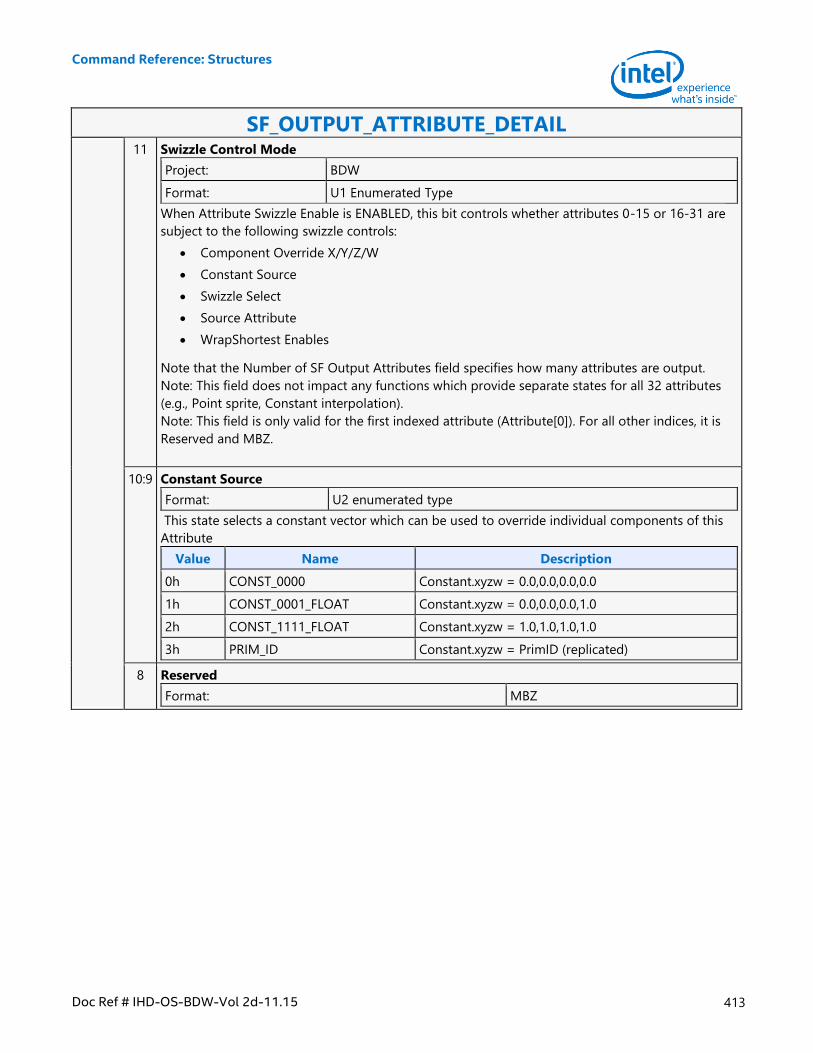
Command Reference: Structures
Doc Ref # IHD-OS-BDW-Vol 2d-11.15 413
SF_OUTPUT_ATTRIBUTE_DETAIL 11 Swizzle Control Mode
Project: BDW
Format: U1 Enumerated Type
When Attribute Swizzle Enable is ENABLED, this bit controls whether attributes 0-15 or 16-31 are
subject to the following swizzle controls:
Component Override X/Y/Z/W
Constant Source
Swizzle Select
Source Attribute
WrapShortest Enables
Note that the Number of SF Output Attributes field specifies how many attributes are output.
Note: This field does not impact any functions which provide separate states for all 32 attributes
(e.g., Point sprite, Constant interpolation).
Note: This field is only valid for the first indexed attribute (Attribute[0]). For all other indices, it is
Reserved and MBZ.
10:9 Constant Source
Format: U2 enumerated type
This state selects a constant vector which can be used to override individual components of this
Attribute
Value Name Description
0h CONST_0000 Constant.xyzw = 0.0,0.0,0.0,0.0
1h CONST_0001_FLOAT Constant.xyzw = 0.0,0.0,0.0,1.0
2h CONST_1111_FLOAT Constant.xyzw = 1.0,1.0,1.0,1.0
3h PRIM_ID Constant.xyzw = PrimID (replicated)
8 Reserved
Format: MBZ
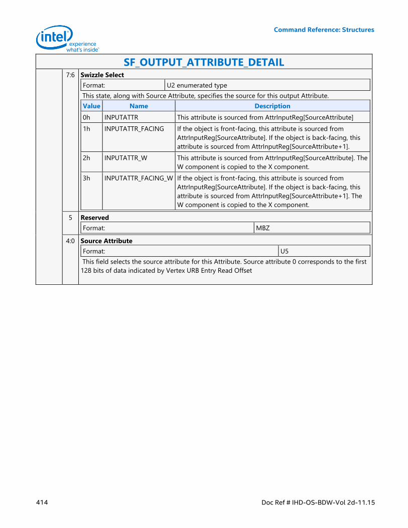
Command Reference: Structures
414 Doc Ref # IHD-OS-BDW-Vol 2d-11.15
SF_OUTPUT_ATTRIBUTE_DETAIL 7:6 Swizzle Select
Format: U2 enumerated type
This state, along with Source Attribute, specifies the source for this output Attribute.
Value Name Description
0h INPUTATTR This attribute is sourced from AttrInputReg[SourceAttribute]
1h INPUTATTR_FACING If the object is front-facing, this attribute is sourced from
AttrInputReg[SourceAttribute]. If the object is back-facing, this
attribute is sourced from AttrInputReg[SourceAttribute+1].
2h INPUTATTR_W This attribute is sourced from AttrInputReg[SourceAttribute]. The
W component is copied to the X component.
3h INPUTATTR_FACING_W If the object is front-facing, this attribute is sourced from
AttrInputReg[SourceAttribute]. If the object is back-facing, this
attribute is sourced from AttrInputReg[SourceAttribute+1]. The
W component is copied to the X component.
5 Reserved
Format: MBZ
4:0 Source Attribute
Format: U5
This field selects the source attribute for this Attribute. Source attribute 0 corresponds to the first
128 bits of data indicated by Vertex URB Entry Read Offset
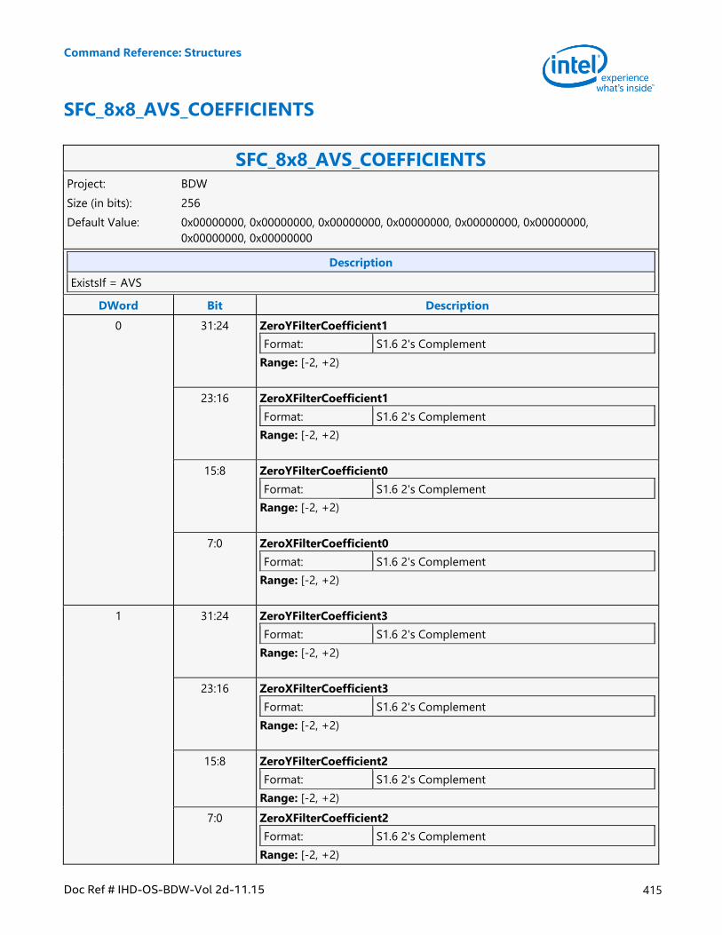
Command Reference: Structures
Doc Ref # IHD-OS-BDW-Vol 2d-11.15 415
SFC_8x8_AVS_COEFFICIENTS
SFC_8x8_AVS_COEFFICIENTS Project: BDW
Size (in bits): 256
Default Value: 0x00000000, 0x00000000, 0x00000000, 0x00000000, 0x00000000, 0x00000000,
0x00000000, 0x00000000
Description
ExistsIf = AVS
DWord Bit Description
0 31:24 ZeroYFilterCoefficient1
Format: S1.6 2's Complement
Range: [-2, +2)
23:16 ZeroXFilterCoefficient1
Format: S1.6 2's Complement
Range: [-2, +2)
15:8 ZeroYFilterCoefficient0
Format: S1.6 2's Complement
Range: [-2, +2)
7:0 ZeroXFilterCoefficient0
Format: S1.6 2's Complement
Range: [-2, +2)
1 31:24 ZeroYFilterCoefficient3
Format: S1.6 2's Complement
Range: [-2, +2)
23:16 ZeroXFilterCoefficient3
Format: S1.6 2's Complement
Range: [-2, +2)
15:8 ZeroYFilterCoefficient2
Format: S1.6 2's Complement
Range: [-2, +2)
7:0 ZeroXFilterCoefficient2
Format: S1.6 2's Complement
Range: [-2, +2)
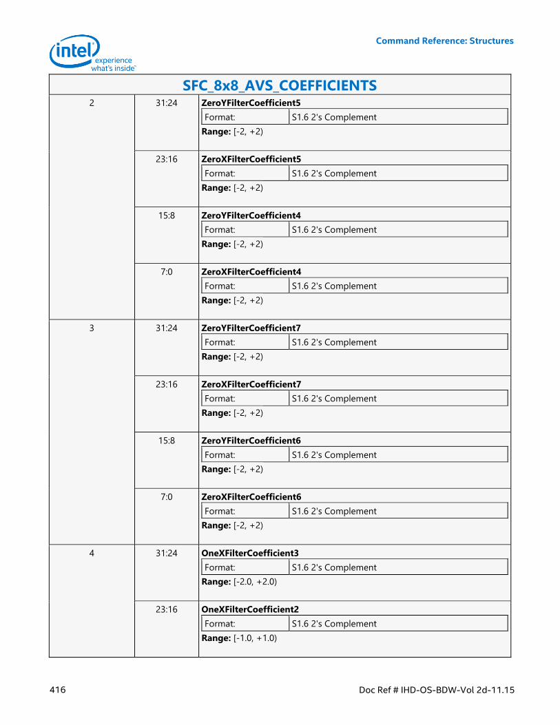
Command Reference: Structures
416 Doc Ref # IHD-OS-BDW-Vol 2d-11.15
SFC_8x8_AVS_COEFFICIENTS 2 31:24 ZeroYFilterCoefficient5
Format: S1.6 2's Complement
Range: [-2, +2)
23:16 ZeroXFilterCoefficient5
Format: S1.6 2's Complement
Range: [-2, +2)
15:8 ZeroYFilterCoefficient4
Format: S1.6 2's Complement
Range: [-2, +2)
7:0 ZeroXFilterCoefficient4
Format: S1.6 2's Complement
Range: [-2, +2)
3 31:24 ZeroYFilterCoefficient7
Format: S1.6 2's Complement
Range: [-2, +2)
23:16 ZeroXFilterCoefficient7
Format: S1.6 2's Complement
Range: [-2, +2)
15:8 ZeroYFilterCoefficient6
Format: S1.6 2's Complement
Range: [-2, +2)
7:0 ZeroXFilterCoefficient6
Format: S1.6 2's Complement
Range: [-2, +2)
4 31:24 OneXFilterCoefficient3
Format: S1.6 2's Complement
Range: [-2.0, +2.0)
23:16 OneXFilterCoefficient2
Format: S1.6 2's Complement
Range: [-1.0, +1.0)
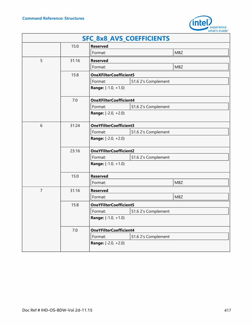
Command Reference: Structures
Doc Ref # IHD-OS-BDW-Vol 2d-11.15 417
SFC_8x8_AVS_COEFFICIENTS 15:0 Reserved
Format: MBZ
5 31:16 Reserved
Format: MBZ
15:8 OneXFilterCoefficient5
Format: S1.6 2's Complement
Range: [-1.0, +1.0)
7:0 OneXFilterCoefficient4
Format: S1.6 2's Complement
Range: [-2.0, +2.0)
6 31:24 OneYFilterCoefficient3
Format: S1.6 2's Complement
Range: [-2.0, +2.0)
23:16 OneYFilterCoefficient2
Format: S1.6 2's Complement
Range: [-1.0, +1.0)
15:0 Reserved
Format: MBZ
7 31:16 Reserved
Format: MBZ
15:8 OneYFilterCoefficient5
Format: S1.6 2's Complement
Range: [-1.0, +1.0)
7:0 OneYFilterCoefficient4
Format: S1.6 2's Complement
Range: [-2.0, +2.0)
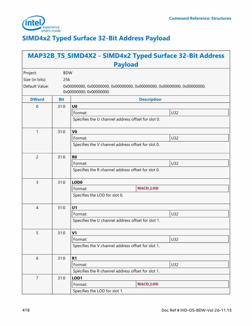
Command Reference: Structures
418 Doc Ref # IHD-OS-BDW-Vol 2d-11.15
SIMD4x2 Typed Surface 32-Bit Address Payload
MAP32B_TS_SIMD4X2 - SIMD4x2 Typed Surface 32-Bit Address
Payload Project: BDW
Size (in bits): 256
Default Value: 0x00000000, 0x00000000, 0x00000000, 0x00000000, 0x00000000, 0x00000000,
0x00000000, 0x00000000
DWord Bit Description
0 31:0 U0
Format: U32
Specifies the U channel address offset for slot 0.
1 31:0 V0
Format: U32
Specifies the V channel address offset for slot 0.
2 31:0 R0
Format: U32
Specifies the R channel address offset for slot 0.
3 31:0 LOD0
Format: MACD_LOD
Specifies the LOD for slot 0.
4 31:0 U1
Format: U32
Specifies the U channel address offset for slot 1.
5 31:0 V1
Format: U32
Specifies the V channel address offset for slot 1.
6 31:0 R1
Format: U32
Specifies the R channel address offset for slot 1.
7 31:0 LOD1
Format: MACD_LOD
Specifies the LOD for slot 1.
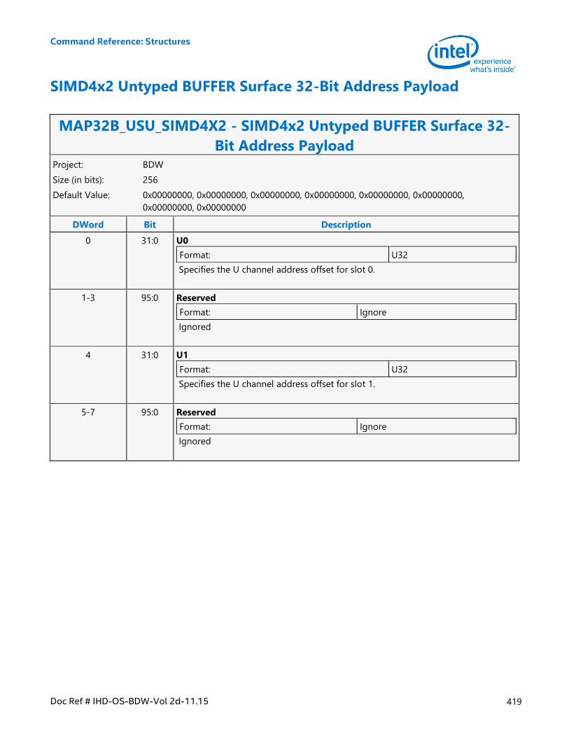
Command Reference: Structures
Doc Ref # IHD-OS-BDW-Vol 2d-11.15 419
SIMD4x2 Untyped BUFFER Surface 32-Bit Address Payload
MAP32B_USU_SIMD4X2 - SIMD4x2 Untyped BUFFER Surface 32-
Bit Address Payload Project: BDW
Size (in bits): 256
Default Value: 0x00000000, 0x00000000, 0x00000000, 0x00000000, 0x00000000, 0x00000000,
0x00000000, 0x00000000
DWord Bit Description
0 31:0 U0
Format: U32
Specifies the U channel address offset for slot 0.
1-3 95:0 Reserved
Format: Ignore
Ignored
4 31:0 U1
Format: U32
Specifies the U channel address offset for slot 1.
5-7 95:0 Reserved
Format: Ignore
Ignored
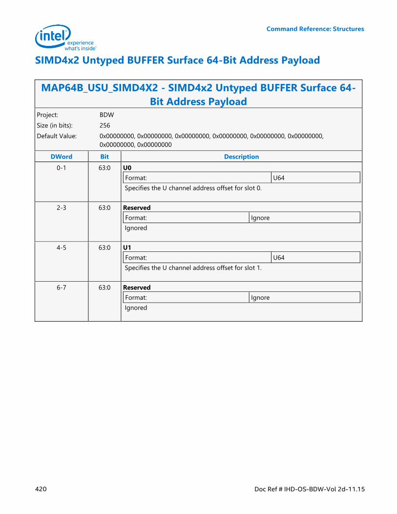
Command Reference: Structures
420 Doc Ref # IHD-OS-BDW-Vol 2d-11.15
SIMD4x2 Untyped BUFFER Surface 64-Bit Address Payload
MAP64B_USU_SIMD4X2 - SIMD4x2 Untyped BUFFER Surface 64-
Bit Address Payload Project: BDW
Size (in bits): 256
Default Value: 0x00000000, 0x00000000, 0x00000000, 0x00000000, 0x00000000, 0x00000000,
0x00000000, 0x00000000
DWord Bit Description
0-1 63:0 U0
Format: U64
Specifies the U channel address offset for slot 0.
2-3 63:0 Reserved
Format: Ignore
Ignored
4-5 63:0 U1
Format: U64
Specifies the U channel address offset for slot 1.
6-7 63:0 Reserved
Format: Ignore
Ignored
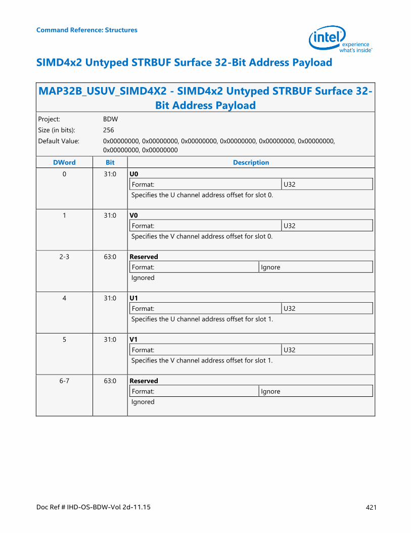
Command Reference: Structures
Doc Ref # IHD-OS-BDW-Vol 2d-11.15 421
SIMD4x2 Untyped STRBUF Surface 32-Bit Address Payload
MAP32B_USUV_SIMD4X2 - SIMD4x2 Untyped STRBUF Surface 32-
Bit Address Payload Project: BDW
Size (in bits): 256
Default Value: 0x00000000, 0x00000000, 0x00000000, 0x00000000, 0x00000000, 0x00000000,
0x00000000, 0x00000000
DWord Bit Description
0 31:0 U0
Format: U32
Specifies the U channel address offset for slot 0.
1 31:0 V0
Format: U32
Specifies the V channel address offset for slot 0.
2-3 63:0 Reserved
Format: Ignore
Ignored
4 31:0 U1
Format: U32
Specifies the U channel address offset for slot 1.
5 31:0 V1
Format: U32
Specifies the V channel address offset for slot 1.
6-7 63:0 Reserved
Format: Ignore
Ignored
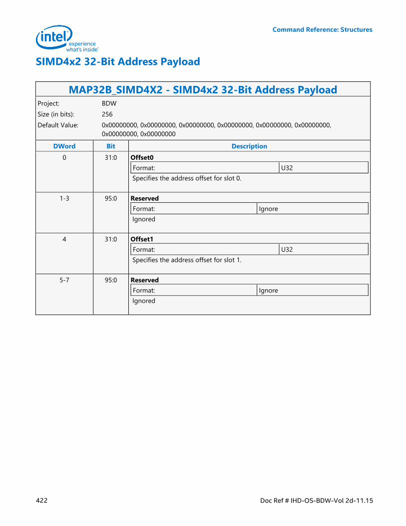
Command Reference: Structures
422 Doc Ref # IHD-OS-BDW-Vol 2d-11.15
SIMD4x2 32-Bit Address Payload
MAP32B_SIMD4X2 - SIMD4x2 32-Bit Address Payload Project: BDW
Size (in bits): 256
Default Value: 0x00000000, 0x00000000, 0x00000000, 0x00000000, 0x00000000, 0x00000000,
0x00000000, 0x00000000
DWord Bit Description
0 31:0 Offset0
Format: U32
Specifies the address offset for slot 0.
1-3 95:0 Reserved
Format: Ignore
Ignored
4 31:0 Offset1
Format: U32
Specifies the address offset for slot 1.
5-7 95:0 Reserved
Format: Ignore
Ignored
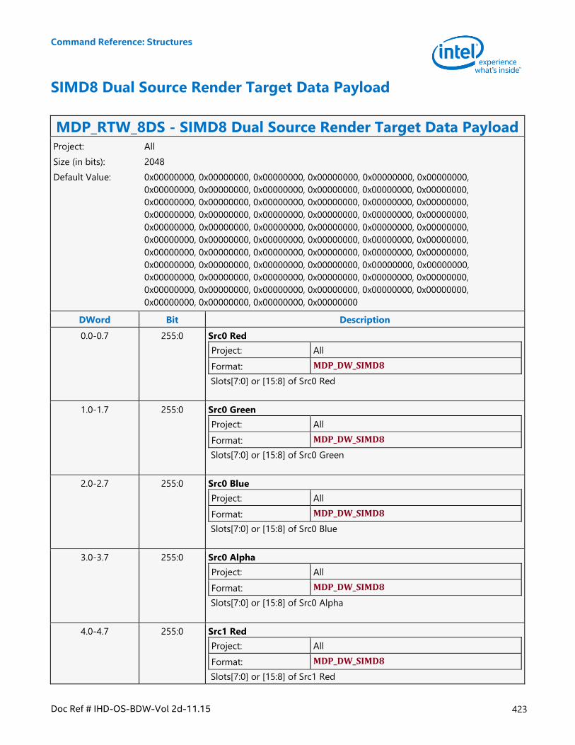
Command Reference: Structures
Doc Ref # IHD-OS-BDW-Vol 2d-11.15 423
SIMD8 Dual Source Render Target Data Payload
MDP_RTW_8DS - SIMD8 Dual Source Render Target Data Payload Project: All
Size (in bits): 2048
Default Value: 0x00000000, 0x00000000, 0x00000000, 0x00000000, 0x00000000, 0x00000000,
0x00000000, 0x00000000, 0x00000000, 0x00000000, 0x00000000, 0x00000000,
0x00000000, 0x00000000, 0x00000000, 0x00000000, 0x00000000, 0x00000000,
0x00000000, 0x00000000, 0x00000000, 0x00000000, 0x00000000, 0x00000000,
0x00000000, 0x00000000, 0x00000000, 0x00000000, 0x00000000, 0x00000000,
0x00000000, 0x00000000, 0x00000000, 0x00000000, 0x00000000, 0x00000000,
0x00000000, 0x00000000, 0x00000000, 0x00000000, 0x00000000, 0x00000000,
0x00000000, 0x00000000, 0x00000000, 0x00000000, 0x00000000, 0x00000000,
0x00000000, 0x00000000, 0x00000000, 0x00000000, 0x00000000, 0x00000000,
0x00000000, 0x00000000, 0x00000000, 0x00000000, 0x00000000, 0x00000000,
0x00000000, 0x00000000, 0x00000000, 0x00000000
DWord Bit Description
0.0-0.7 255:0 Src0 Red
Project: All
Format: MDP_DW_SIMD8
Slots[7:0] or [15:8] of Src0 Red
1.0-1.7 255:0 Src0 Green
Project: All
Format: MDP_DW_SIMD8
Slots[7:0] or [15:8] of Src0 Green
2.0-2.7 255:0 Src0 Blue
Project: All
Format: MDP_DW_SIMD8
Slots[7:0] or [15:8] of Src0 Blue
3.0-3.7 255:0 Src0 Alpha
Project: All
Format: MDP_DW_SIMD8
Slots[7:0] or [15:8] of Src0 Alpha
4.0-4.7 255:0 Src1 Red
Project: All
Format: MDP_DW_SIMD8
Slots[7:0] or [15:8] of Src1 Red
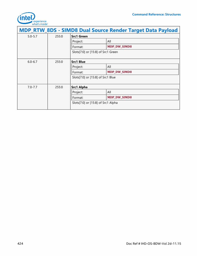
Command Reference: Structures
424 Doc Ref # IHD-OS-BDW-Vol 2d-11.15
MDP_RTW_8DS - SIMD8 Dual Source Render Target Data Payload 5.0-5.7 255:0 Src1 Green
Project: All
Format: MDP_DW_SIMD8
Slots[7:0] or [15:8] of Src1 Green
6.0-6.7 255:0 Src1 Blue
Project: All
Format: MDP_DW_SIMD8
Slots[7:0] or [15:8] of Src1 Blue
7.0-7.7 255:0 Src1 Alpha
Project: All
Format: MDP_DW_SIMD8
Slots[7:0] or [15:8] of Src1 Alpha
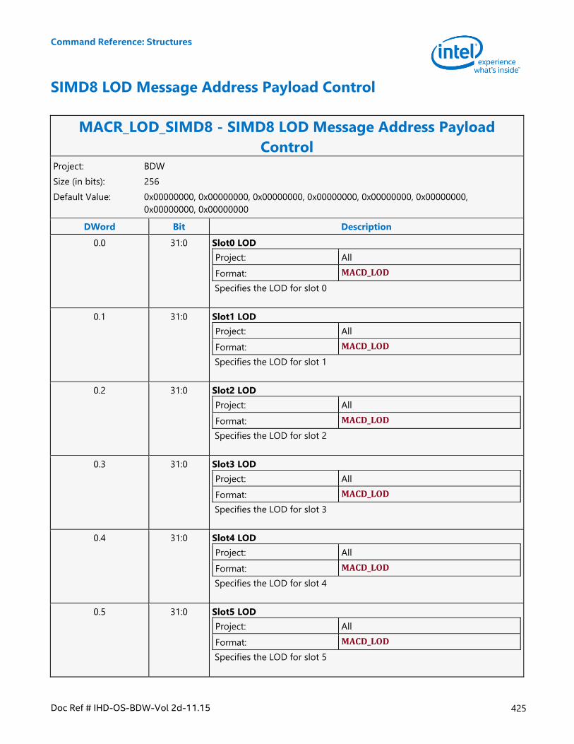
Command Reference: Structures
Doc Ref # IHD-OS-BDW-Vol 2d-11.15 425
SIMD8 LOD Message Address Payload Control
MACR_LOD_SIMD8 - SIMD8 LOD Message Address Payload
Control Project: BDW
Size (in bits): 256
Default Value: 0x00000000, 0x00000000, 0x00000000, 0x00000000, 0x00000000, 0x00000000,
0x00000000, 0x00000000
DWord Bit Description
0.0 31:0 Slot0 LOD
Project: All
Format: MACD_LOD
Specifies the LOD for slot 0
0.1 31:0 Slot1 LOD
Project: All
Format: MACD_LOD
Specifies the LOD for slot 1
0.2 31:0 Slot2 LOD
Project: All
Format: MACD_LOD
Specifies the LOD for slot 2
0.3 31:0 Slot3 LOD
Project: All
Format: MACD_LOD
Specifies the LOD for slot 3
0.4 31:0 Slot4 LOD
Project: All
Format: MACD_LOD
Specifies the LOD for slot 4
0.5 31:0 Slot5 LOD
Project: All
Format: MACD_LOD
Specifies the LOD for slot 5
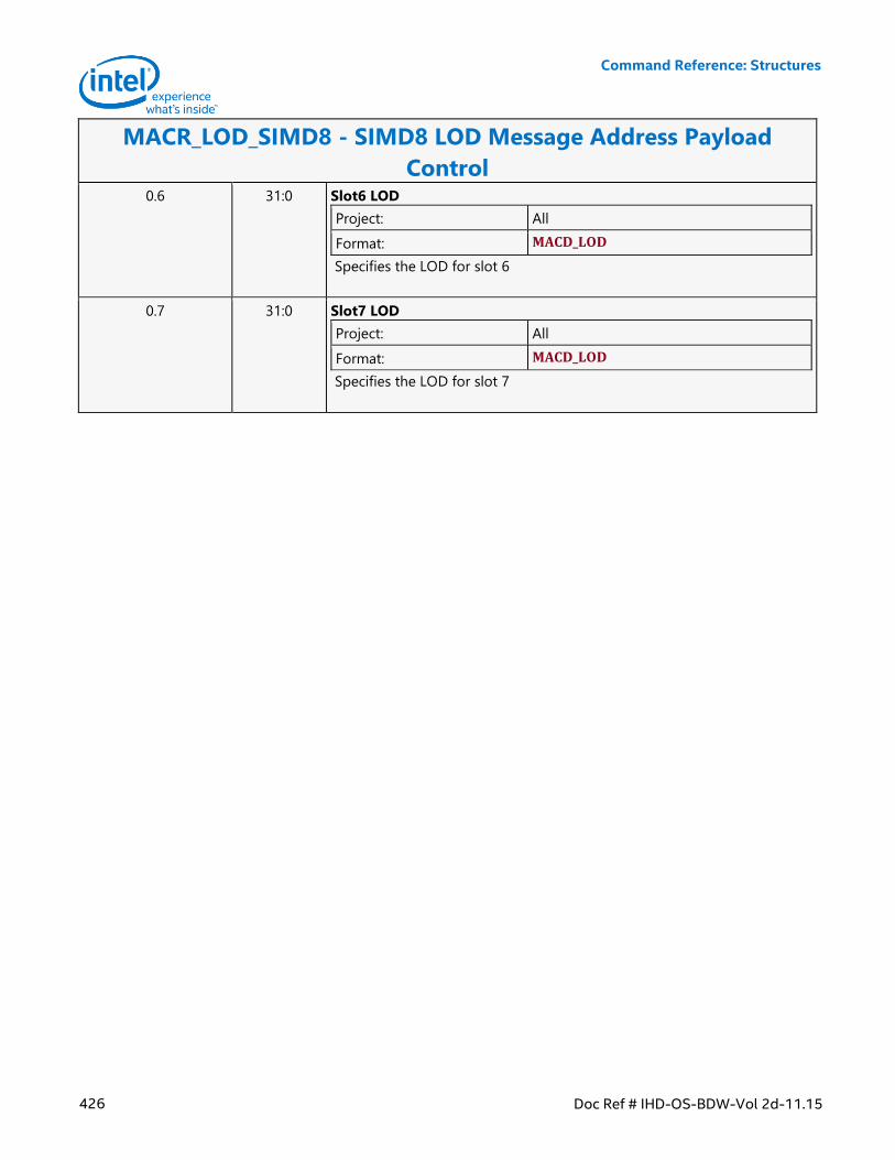
Command Reference: Structures
426 Doc Ref # IHD-OS-BDW-Vol 2d-11.15
MACR_LOD_SIMD8 - SIMD8 LOD Message Address Payload
Control 0.6 31:0 Slot6 LOD
Project: All
Format: MACD_LOD
Specifies the LOD for slot 6
0.7 31:0 Slot7 LOD
Project: All
Format: MACD_LOD
Specifies the LOD for slot 7
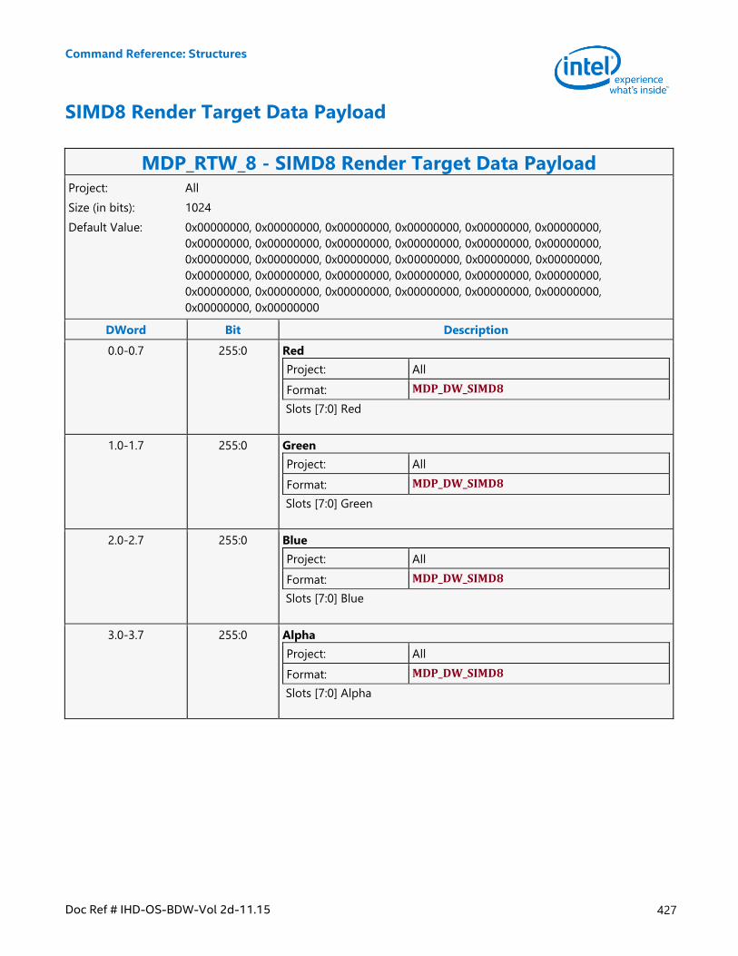
Command Reference: Structures
Doc Ref # IHD-OS-BDW-Vol 2d-11.15 427
SIMD8 Render Target Data Payload
MDP_RTW_8 - SIMD8 Render Target Data Payload Project: All
Size (in bits): 1024
Default Value: 0x00000000, 0x00000000, 0x00000000, 0x00000000, 0x00000000, 0x00000000,
0x00000000, 0x00000000, 0x00000000, 0x00000000, 0x00000000, 0x00000000,
0x00000000, 0x00000000, 0x00000000, 0x00000000, 0x00000000, 0x00000000,
0x00000000, 0x00000000, 0x00000000, 0x00000000, 0x00000000, 0x00000000,
0x00000000, 0x00000000, 0x00000000, 0x00000000, 0x00000000, 0x00000000,
0x00000000, 0x00000000
DWord Bit Description
0.0-0.7 255:0 Red
Project: All
Format: MDP_DW_SIMD8
Slots [7:0] Red
1.0-1.7 255:0 Green
Project: All
Format: MDP_DW_SIMD8
Slots [7:0] Green
2.0-2.7 255:0 Blue
Project: All
Format: MDP_DW_SIMD8
Slots [7:0] Blue
3.0-3.7 255:0 Alpha
Project: All
Format: MDP_DW_SIMD8
Slots [7:0] Alpha
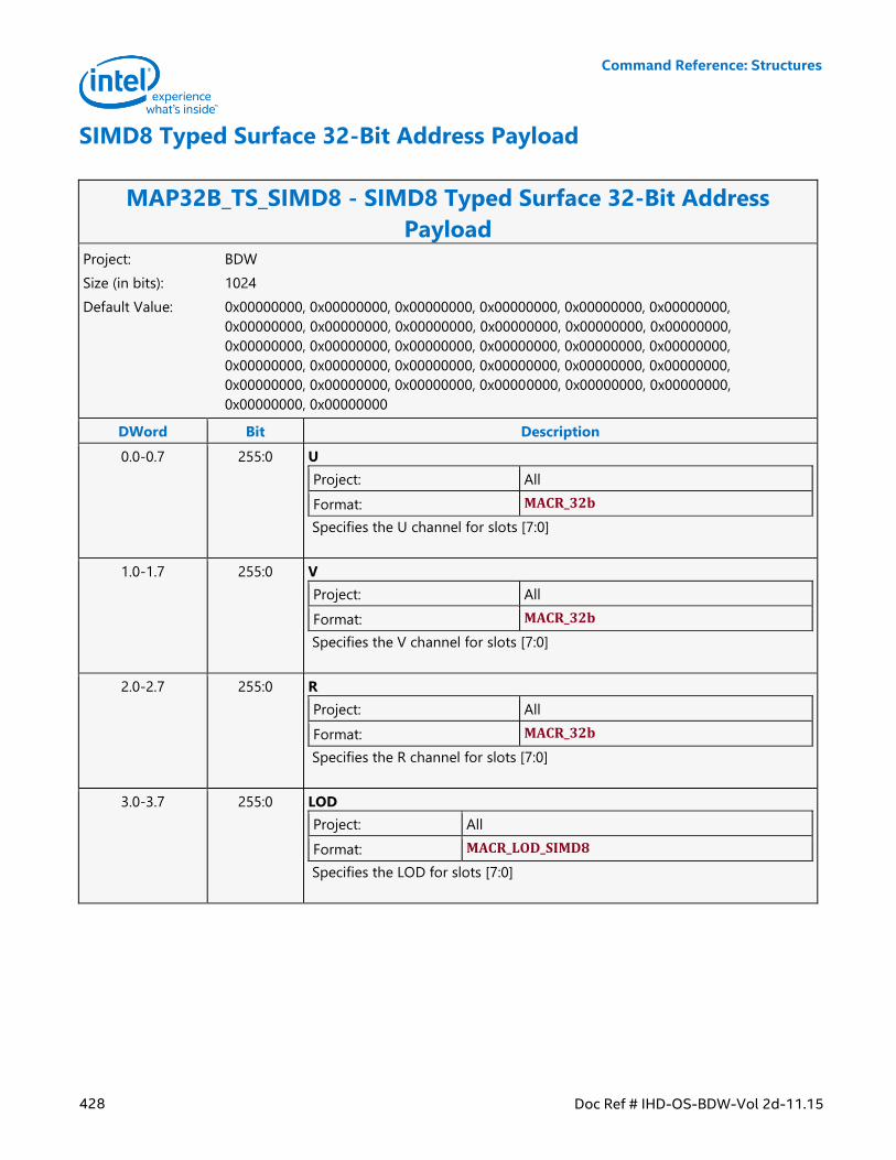
Command Reference: Structures
428 Doc Ref # IHD-OS-BDW-Vol 2d-11.15
SIMD8 Typed Surface 32-Bit Address Payload
MAP32B_TS_SIMD8 - SIMD8 Typed Surface 32-Bit Address
Payload Project: BDW
Size (in bits): 1024
Default Value: 0x00000000, 0x00000000, 0x00000000, 0x00000000, 0x00000000, 0x00000000,
0x00000000, 0x00000000, 0x00000000, 0x00000000, 0x00000000, 0x00000000,
0x00000000, 0x00000000, 0x00000000, 0x00000000, 0x00000000, 0x00000000,
0x00000000, 0x00000000, 0x00000000, 0x00000000, 0x00000000, 0x00000000,
0x00000000, 0x00000000, 0x00000000, 0x00000000, 0x00000000, 0x00000000,
0x00000000, 0x00000000
DWord Bit Description
0.0-0.7 255:0 U
Project: All
Format: MACR_32b
Specifies the U channel for slots [7:0]
1.0-1.7 255:0 V
Project: All
Format: MACR_32b
Specifies the V channel for slots [7:0]
2.0-2.7 255:0 R
Project: All
Format: MACR_32b
Specifies the R channel for slots [7:0]
3.0-3.7 255:0 LOD
Project: All
Format: MACR_LOD_SIMD8
Specifies the LOD for slots [7:0]
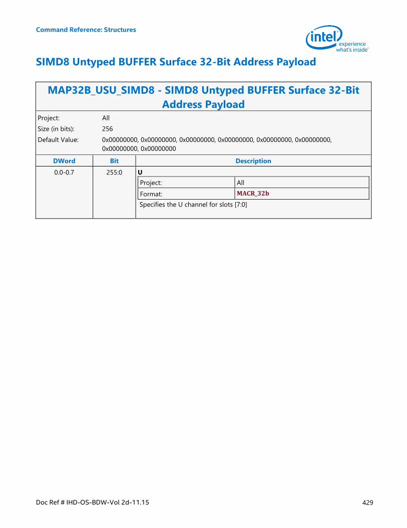
Command Reference: Structures
Doc Ref # IHD-OS-BDW-Vol 2d-11.15 429
SIMD8 Untyped BUFFER Surface 32-Bit Address Payload
MAP32B_USU_SIMD8 - SIMD8 Untyped BUFFER Surface 32-Bit
Address Payload Project: All
Size (in bits): 256
Default Value: 0x00000000, 0x00000000, 0x00000000, 0x00000000, 0x00000000, 0x00000000,
0x00000000, 0x00000000
DWord Bit Description
0.0-0.7 255:0 U
Project: All
Format: MACR_32b
Specifies the U channel for slots [7:0]
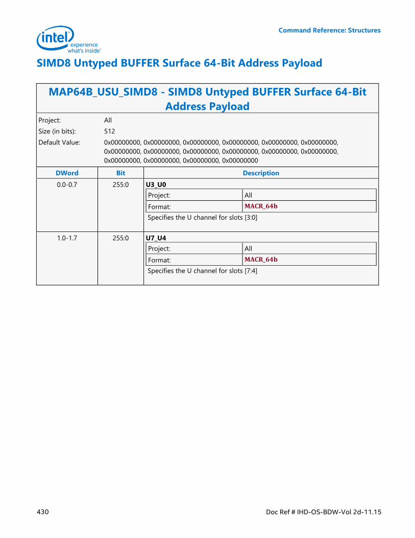
Command Reference: Structures
430 Doc Ref # IHD-OS-BDW-Vol 2d-11.15
SIMD8 Untyped BUFFER Surface 64-Bit Address Payload
MAP64B_USU_SIMD8 - SIMD8 Untyped BUFFER Surface 64-Bit
Address Payload Project: All
Size (in bits): 512
Default Value: 0x00000000, 0x00000000, 0x00000000, 0x00000000, 0x00000000, 0x00000000,
0x00000000, 0x00000000, 0x00000000, 0x00000000, 0x00000000, 0x00000000,
0x00000000, 0x00000000, 0x00000000, 0x00000000
DWord Bit Description
0.0-0.7 255:0 U3_U0
Project: All
Format: MACR_64b
Specifies the U channel for slots [3:0]
1.0-1.7 255:0 U7_U4
Project: All
Format: MACR_64b
Specifies the U channel for slots [7:4]
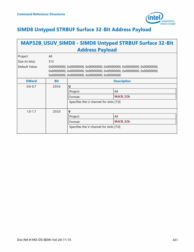
Command Reference: Structures
Doc Ref # IHD-OS-BDW-Vol 2d-11.15 431
SIMD8 Untyped STRBUF Surface 32-Bit Address Payload
MAP32B_USUV_SIMD8 - SIMD8 Untyped STRBUF Surface 32-Bit
Address Payload Project: All
Size (in bits): 512
Default Value: 0x00000000, 0x00000000, 0x00000000, 0x00000000, 0x00000000, 0x00000000,
0x00000000, 0x00000000, 0x00000000, 0x00000000, 0x00000000, 0x00000000,
0x00000000, 0x00000000, 0x00000000, 0x00000000
DWord Bit Description
0.0-0.7 255:0 U
Project: All
Format: MACR_32b
Specifies the U channel for slots [7:0]
1.0-1.7 255:0 V
Project: All
Format: MACR_32b
Specifies the V channel for slots [7:0]
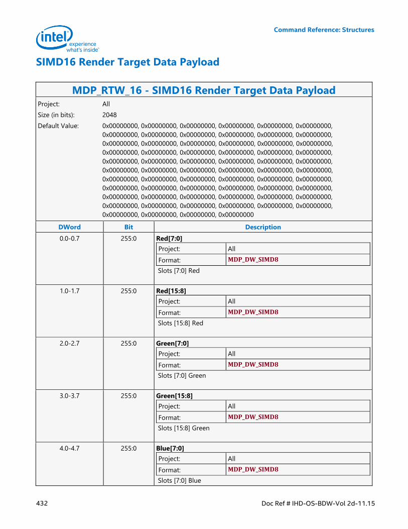
Command Reference: Structures
432 Doc Ref # IHD-OS-BDW-Vol 2d-11.15
SIMD16 Render Target Data Payload
MDP_RTW_16 - SIMD16 Render Target Data Payload Project: All
Size (in bits): 2048
Default Value: 0x00000000, 0x00000000, 0x00000000, 0x00000000, 0x00000000, 0x00000000,
0x00000000, 0x00000000, 0x00000000, 0x00000000, 0x00000000, 0x00000000,
0x00000000, 0x00000000, 0x00000000, 0x00000000, 0x00000000, 0x00000000,
0x00000000, 0x00000000, 0x00000000, 0x00000000, 0x00000000, 0x00000000,
0x00000000, 0x00000000, 0x00000000, 0x00000000, 0x00000000, 0x00000000,
0x00000000, 0x00000000, 0x00000000, 0x00000000, 0x00000000, 0x00000000,
0x00000000, 0x00000000, 0x00000000, 0x00000000, 0x00000000, 0x00000000,
0x00000000, 0x00000000, 0x00000000, 0x00000000, 0x00000000, 0x00000000,
0x00000000, 0x00000000, 0x00000000, 0x00000000, 0x00000000, 0x00000000,
0x00000000, 0x00000000, 0x00000000, 0x00000000, 0x00000000, 0x00000000,
0x00000000, 0x00000000, 0x00000000, 0x00000000
DWord Bit Description
0.0-0.7 255:0 Red[7:0]
Project: All
Format: MDP_DW_SIMD8
Slots [7:0] Red
1.0-1.7 255:0 Red[15:8]
Project: All
Format: MDP_DW_SIMD8
Slots [15:8] Red
2.0-2.7 255:0 Green[7:0]
Project: All
Format: MDP_DW_SIMD8
Slots [7:0] Green
3.0-3.7 255:0 Green[15:8]
Project: All
Format: MDP_DW_SIMD8
Slots [15:8] Green
4.0-4.7 255:0 Blue[7:0]
Project: All
Format: MDP_DW_SIMD8
Slots [7:0] Blue
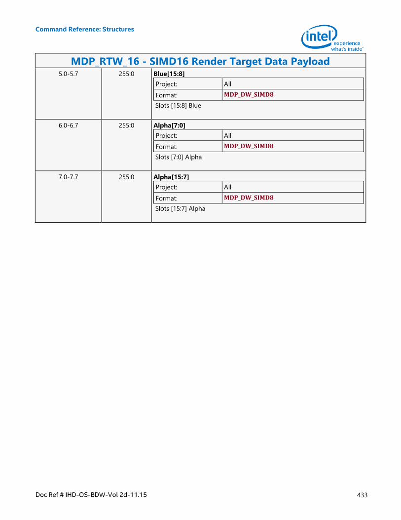
Command Reference: Structures
Doc Ref # IHD-OS-BDW-Vol 2d-11.15 433
MDP_RTW_16 - SIMD16 Render Target Data Payload 5.0-5.7 255:0 Blue[15:8]
Project: All
Format: MDP_DW_SIMD8
Slots [15:8] Blue
6.0-6.7 255:0 Alpha[7:0]
Project: All
Format: MDP_DW_SIMD8
Slots [7:0] Alpha
7.0-7.7 255:0 Alpha[15:7]
Project: All
Format: MDP_DW_SIMD8
Slots [15:7] Alpha
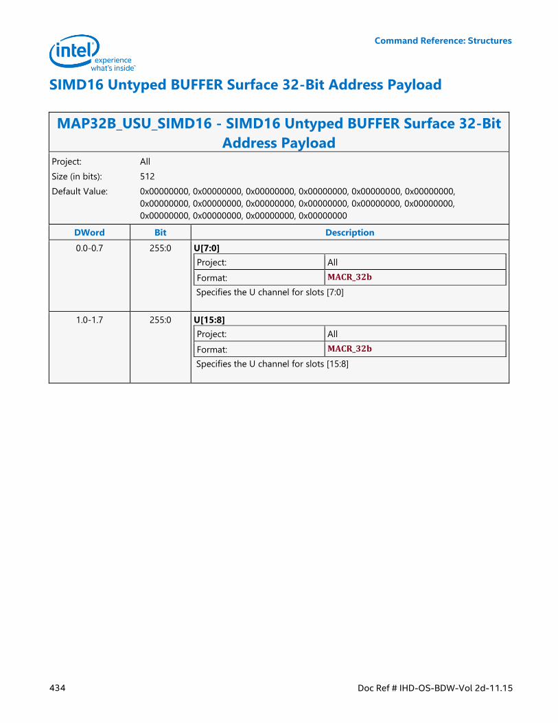
Command Reference: Structures
434 Doc Ref # IHD-OS-BDW-Vol 2d-11.15
SIMD16 Untyped BUFFER Surface 32-Bit Address Payload
MAP32B_USU_SIMD16 - SIMD16 Untyped BUFFER Surface 32-Bit
Address Payload Project: All
Size (in bits): 512
Default Value: 0x00000000, 0x00000000, 0x00000000, 0x00000000, 0x00000000, 0x00000000,
0x00000000, 0x00000000, 0x00000000, 0x00000000, 0x00000000, 0x00000000,
0x00000000, 0x00000000, 0x00000000, 0x00000000
DWord Bit Description
0.0-0.7 255:0 U[7:0]
Project: All
Format: MACR_32b
Specifies the U channel for slots [7:0]
1.0-1.7 255:0 U[15:8]
Project: All
Format: MACR_32b
Specifies the U channel for slots [15:8]
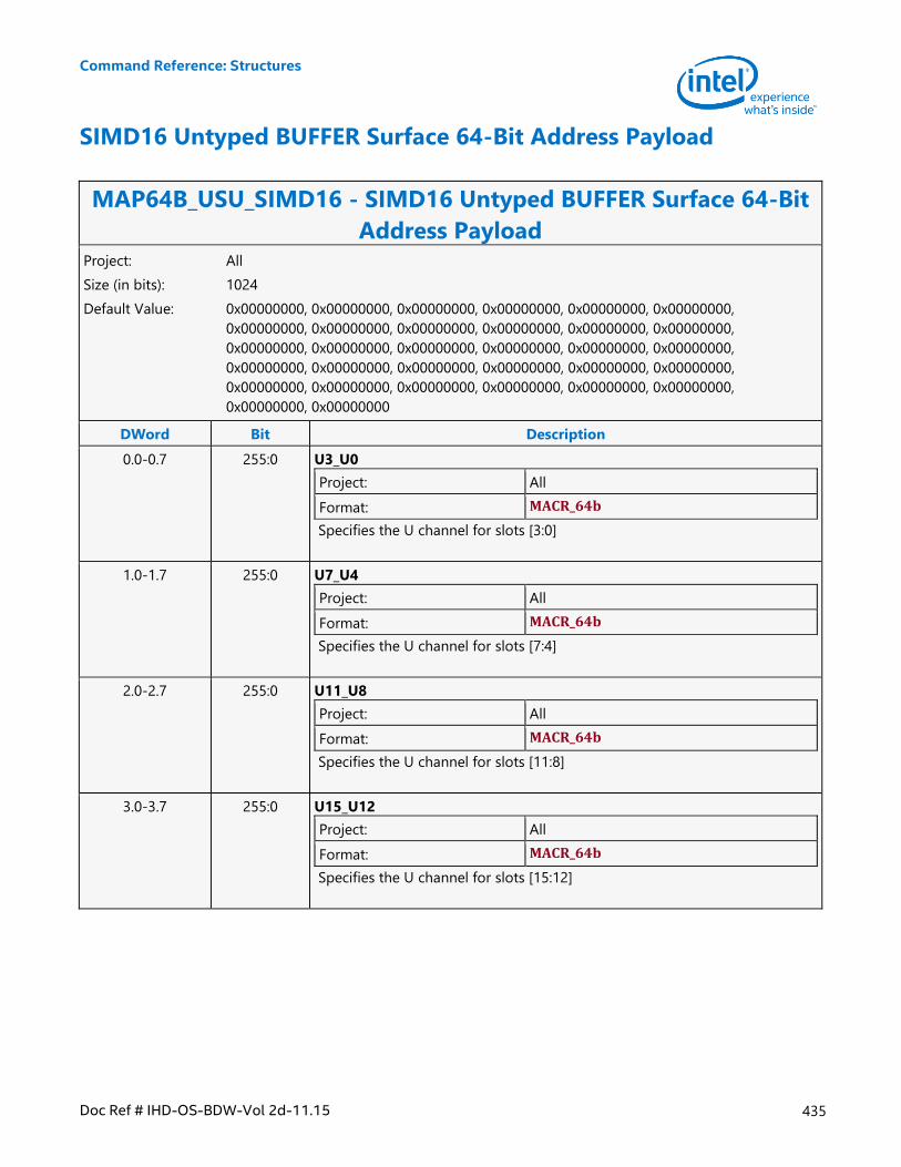
Command Reference: Structures
Doc Ref # IHD-OS-BDW-Vol 2d-11.15 435
SIMD16 Untyped BUFFER Surface 64-Bit Address Payload
MAP64B_USU_SIMD16 - SIMD16 Untyped BUFFER Surface 64-Bit
Address Payload Project: All
Size (in bits): 1024
Default Value: 0x00000000, 0x00000000, 0x00000000, 0x00000000, 0x00000000, 0x00000000,
0x00000000, 0x00000000, 0x00000000, 0x00000000, 0x00000000, 0x00000000,
0x00000000, 0x00000000, 0x00000000, 0x00000000, 0x00000000, 0x00000000,
0x00000000, 0x00000000, 0x00000000, 0x00000000, 0x00000000, 0x00000000,
0x00000000, 0x00000000, 0x00000000, 0x00000000, 0x00000000, 0x00000000,
0x00000000, 0x00000000
DWord Bit Description
0.0-0.7 255:0 U3_U0
Project: All
Format: MACR_64b
Specifies the U channel for slots [3:0]
1.0-1.7 255:0 U7_U4
Project: All
Format: MACR_64b
Specifies the U channel for slots [7:4]
2.0-2.7 255:0 U11_U8
Project: All
Format: MACR_64b
Specifies the U channel for slots [11:8]
3.0-3.7 255:0 U15_U12
Project: All
Format: MACR_64b
Specifies the U channel for slots [15:12]
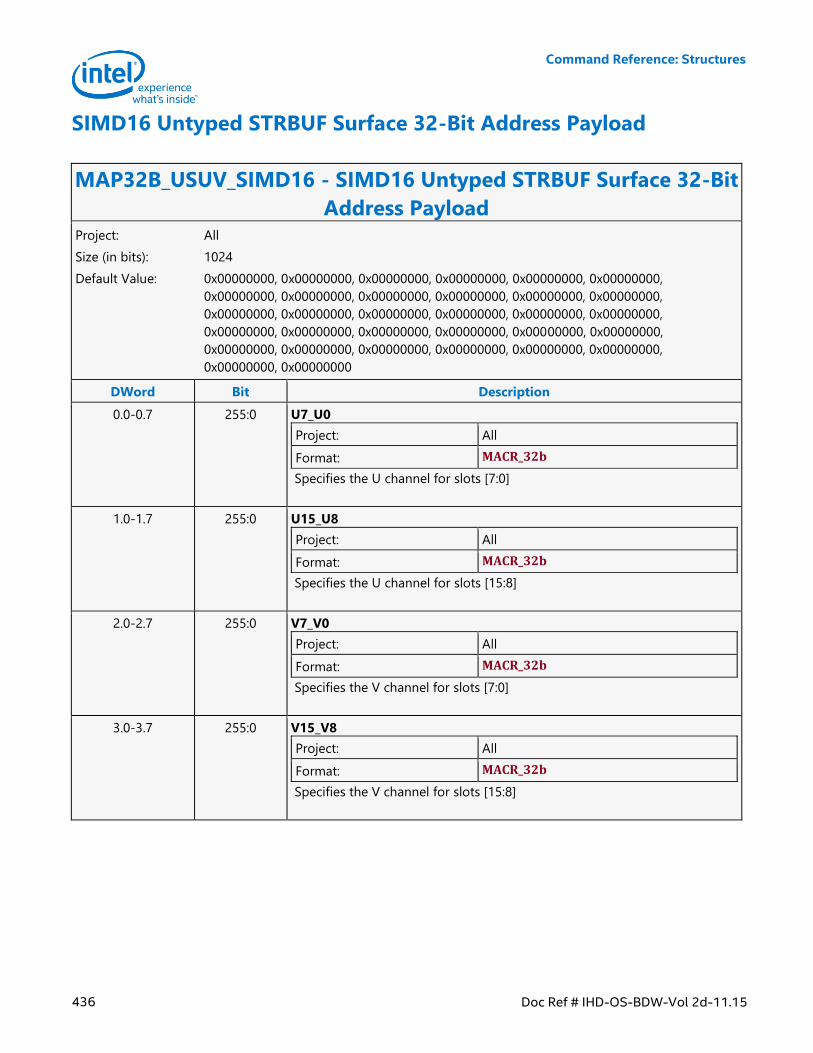
Command Reference: Structures
436 Doc Ref # IHD-OS-BDW-Vol 2d-11.15
SIMD16 Untyped STRBUF Surface 32-Bit Address Payload
MAP32B_USUV_SIMD16 - SIMD16 Untyped STRBUF Surface 32-Bit
Address Payload Project: All
Size (in bits): 1024
Default Value: 0x00000000, 0x00000000, 0x00000000, 0x00000000, 0x00000000, 0x00000000,
0x00000000, 0x00000000, 0x00000000, 0x00000000, 0x00000000, 0x00000000,
0x00000000, 0x00000000, 0x00000000, 0x00000000, 0x00000000, 0x00000000,
0x00000000, 0x00000000, 0x00000000, 0x00000000, 0x00000000, 0x00000000,
0x00000000, 0x00000000, 0x00000000, 0x00000000, 0x00000000, 0x00000000,
0x00000000, 0x00000000
DWord Bit Description
0.0-0.7 255:0 U7_U0
Project: All
Format: MACR_32b
Specifies the U channel for slots [7:0]
1.0-1.7 255:0 U15_U8
Project: All
Format: MACR_32b
Specifies the U channel for slots [15:8]
2.0-2.7 255:0 V7_V0
Project: All
Format: MACR_32b
Specifies the V channel for slots [7:0]
3.0-3.7 255:0 V15_V8
Project: All
Format: MACR_32b
Specifies the V channel for slots [15:8]
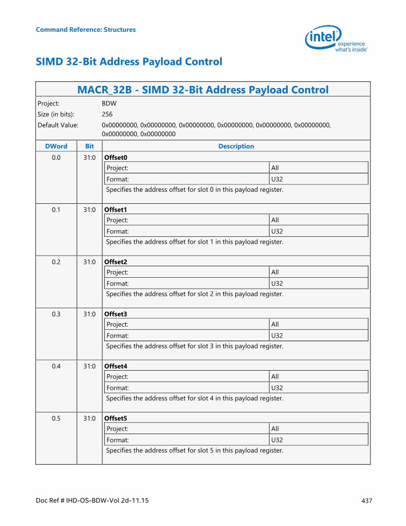
Command Reference: Structures
Doc Ref # IHD-OS-BDW-Vol 2d-11.15 437
SIMD 32-Bit Address Payload Control
MACR_32B - SIMD 32-Bit Address Payload Control Project: BDW
Size (in bits): 256
Default Value: 0x00000000, 0x00000000, 0x00000000, 0x00000000, 0x00000000, 0x00000000,
0x00000000, 0x00000000
DWord Bit Description
0.0 31:0 Offset0
Project: All
Format: U32
Specifies the address offset for slot 0 in this payload register.
0.1 31:0 Offset1
Project: All
Format: U32
Specifies the address offset for slot 1 in this payload register.
0.2 31:0 Offset2
Project: All
Format: U32
Specifies the address offset for slot 2 in this payload register.
0.3 31:0 Offset3
Project: All
Format: U32
Specifies the address offset for slot 3 in this payload register.
0.4 31:0 Offset4
Project: All
Format: U32
Specifies the address offset for slot 4 in this payload register.
0.5 31:0 Offset5
Project: All
Format: U32
Specifies the address offset for slot 5 in this payload register.
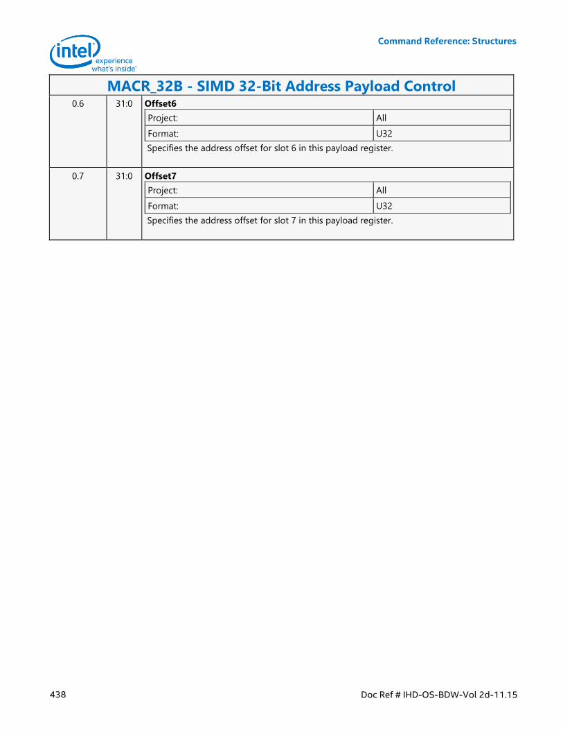
Command Reference: Structures
438 Doc Ref # IHD-OS-BDW-Vol 2d-11.15
MACR_32B - SIMD 32-Bit Address Payload Control 0.6 31:0 Offset6
Project: All
Format: U32
Specifies the address offset for slot 6 in this payload register.
0.7 31:0 Offset7
Project: All
Format: U32
Specifies the address offset for slot 7 in this payload register.
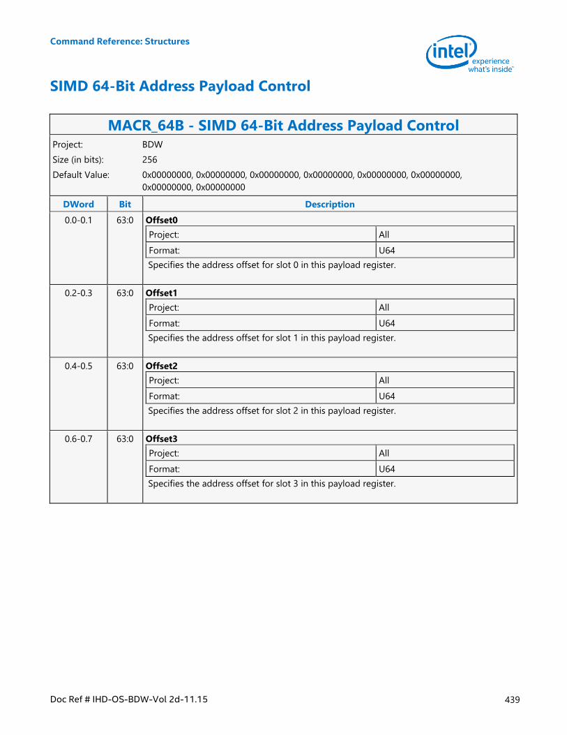
Command Reference: Structures
Doc Ref # IHD-OS-BDW-Vol 2d-11.15 439
SIMD 64-Bit Address Payload Control
MACR_64B - SIMD 64-Bit Address Payload Control Project: BDW
Size (in bits): 256
Default Value: 0x00000000, 0x00000000, 0x00000000, 0x00000000, 0x00000000, 0x00000000,
0x00000000, 0x00000000
DWord Bit Description
0.0-0.1 63:0 Offset0
Project: All
Format: U64
Specifies the address offset for slot 0 in this payload register.
0.2-0.3 63:0 Offset1
Project: All
Format: U64
Specifies the address offset for slot 1 in this payload register.
0.4-0.5 63:0 Offset2
Project: All
Format: U64
Specifies the address offset for slot 2 in this payload register.
0.6-0.7 63:0 Offset3
Project: All
Format: U64
Specifies the address offset for slot 3 in this payload register.
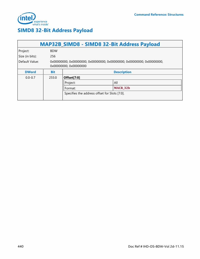
Command Reference: Structures
440 Doc Ref # IHD-OS-BDW-Vol 2d-11.15
SIMD8 32-Bit Address Payload
MAP32B_SIMD8 - SIMD8 32-Bit Address Payload Project: BDW
Size (in bits): 256
Default Value: 0x00000000, 0x00000000, 0x00000000, 0x00000000, 0x00000000, 0x00000000,
0x00000000, 0x00000000
DWord Bit Description
0.0-0.7 255:0 Offset[7:0]
Project: All
Format: MACR_32b
Specifies the address offset for Slots [7:0].
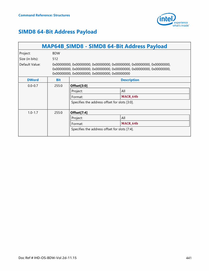
Command Reference: Structures
Doc Ref # IHD-OS-BDW-Vol 2d-11.15 441
SIMD8 64-Bit Address Payload
MAP64B_SIMD8 - SIMD8 64-Bit Address Payload Project: BDW
Size (in bits): 512
Default Value: 0x00000000, 0x00000000, 0x00000000, 0x00000000, 0x00000000, 0x00000000,
0x00000000, 0x00000000, 0x00000000, 0x00000000, 0x00000000, 0x00000000,
0x00000000, 0x00000000, 0x00000000, 0x00000000
DWord Bit Description
0.0-0.7 255:0 Offset[3:0]
Project: All
Format: MACR_64b
Specifies the address offset for slots [3:0].
1.0-1.7 255:0 Offset[7:4]
Project: All
Format: MACR_64b
Specifies the address offset for slots [7:4].
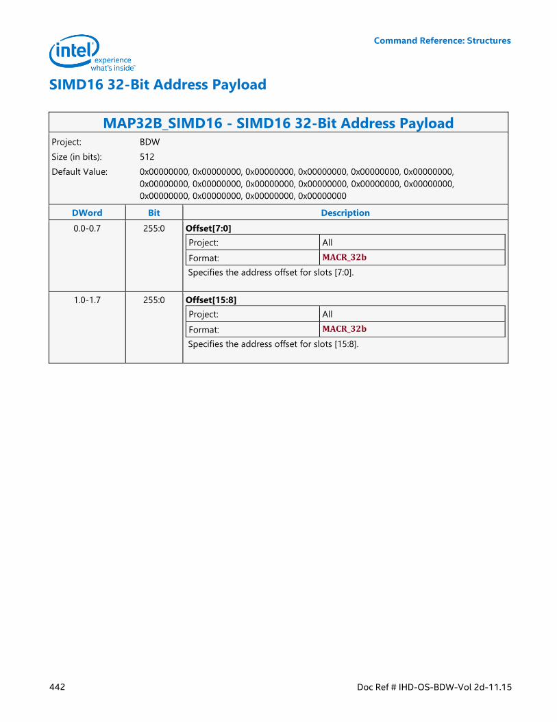
Command Reference: Structures
442 Doc Ref # IHD-OS-BDW-Vol 2d-11.15
SIMD16 32-Bit Address Payload
MAP32B_SIMD16 - SIMD16 32-Bit Address Payload Project: BDW
Size (in bits): 512
Default Value: 0x00000000, 0x00000000, 0x00000000, 0x00000000, 0x00000000, 0x00000000,
0x00000000, 0x00000000, 0x00000000, 0x00000000, 0x00000000, 0x00000000,
0x00000000, 0x00000000, 0x00000000, 0x00000000
DWord Bit Description
0.0-0.7 255:0 Offset[7:0]
Project: All
Format: MACR_32b
Specifies the address offset for slots [7:0].
1.0-1.7 255:0 Offset[15:8]
Project: All
Format: MACR_32b
Specifies the address offset for slots [15:8].
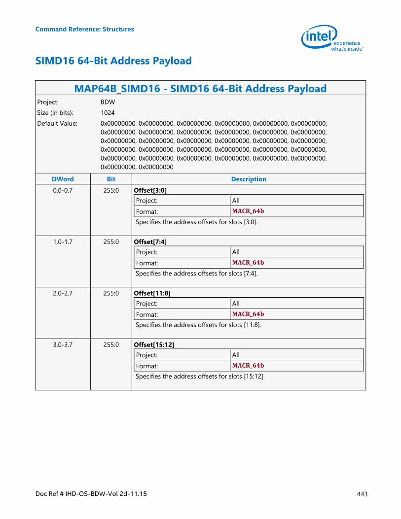
Command Reference: Structures
Doc Ref # IHD-OS-BDW-Vol 2d-11.15 443
SIMD16 64-Bit Address Payload
MAP64B_SIMD16 - SIMD16 64-Bit Address Payload Project: BDW
Size (in bits): 1024
Default Value: 0x00000000, 0x00000000, 0x00000000, 0x00000000, 0x00000000, 0x00000000,
0x00000000, 0x00000000, 0x00000000, 0x00000000, 0x00000000, 0x00000000,
0x00000000, 0x00000000, 0x00000000, 0x00000000, 0x00000000, 0x00000000,
0x00000000, 0x00000000, 0x00000000, 0x00000000, 0x00000000, 0x00000000,
0x00000000, 0x00000000, 0x00000000, 0x00000000, 0x00000000, 0x00000000,
0x00000000, 0x00000000
DWord Bit Description
0.0-0.7 255:0 Offset[3:0]
Project: All
Format: MACR_64b
Specifies the address offsets for slots [3:0].
1.0-1.7 255:0 Offset[7:4]
Project: All
Format: MACR_64b
Specifies the address offsets for slots [7:4].
2.0-2.7 255:0 Offset[11:8]
Project: All
Format: MACR_64b
Specifies the address offsets for slots [11:8].
3.0-3.7 255:0 Offset[15:12]
Project: All
Format: MACR_64b
Specifies the address offsets for slots [15:12].
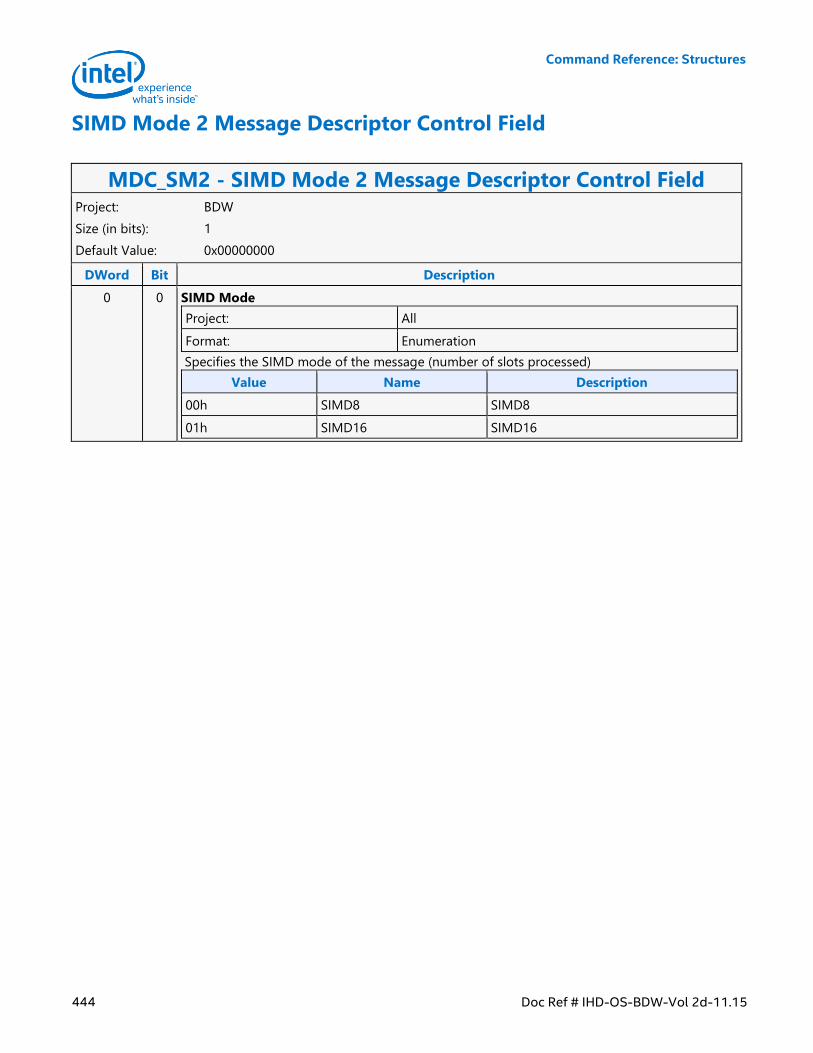
Command Reference: Structures
444 Doc Ref # IHD-OS-BDW-Vol 2d-11.15
SIMD Mode 2 Message Descriptor Control Field
MDC_SM2 - SIMD Mode 2 Message Descriptor Control Field Project: BDW
Size (in bits): 1
Default Value: 0x00000000
DWord Bit Description
0 0 SIMD Mode
Project: All
Format: Enumeration
Specifies the SIMD mode of the message (number of slots processed)
Value Name Description
00h SIMD8 SIMD8
01h SIMD16 SIMD16
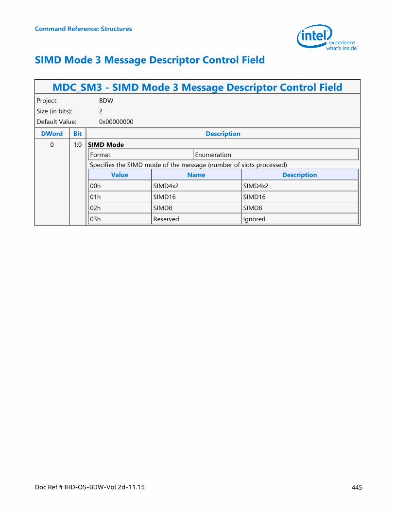
Command Reference: Structures
Doc Ref # IHD-OS-BDW-Vol 2d-11.15 445
SIMD Mode 3 Message Descriptor Control Field
MDC_SM3 - SIMD Mode 3 Message Descriptor Control Field Project: BDW
Size (in bits): 2
Default Value: 0x00000000
DWord Bit Description
0 1:0 SIMD Mode
Format: Enumeration
Specifies the SIMD mode of the message (number of slots processed)
Value Name Description
00h SIMD4x2 SIMD4x2
01h SIMD16 SIMD16
02h SIMD8 SIMD8
03h Reserved Ignored
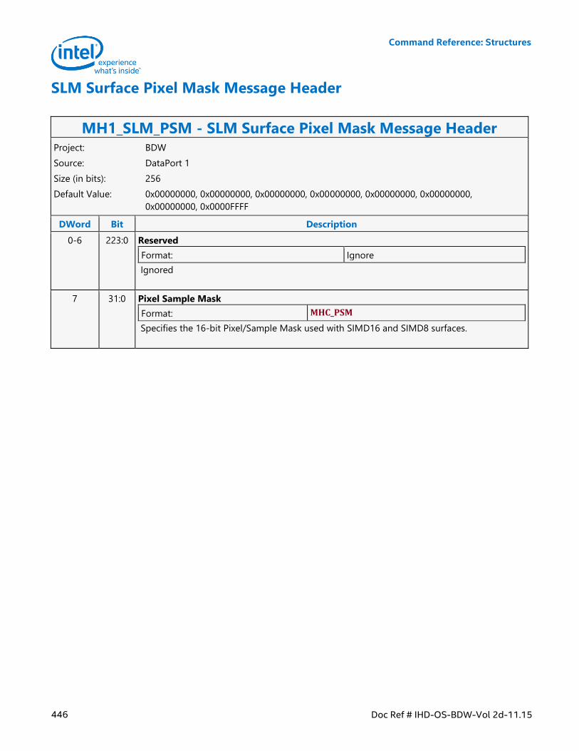
Command Reference: Structures
446 Doc Ref # IHD-OS-BDW-Vol 2d-11.15
SLM Surface Pixel Mask Message Header
MH1_SLM_PSM - SLM Surface Pixel Mask Message Header Project: BDW
Source: DataPort 1
Size (in bits): 256
Default Value: 0x00000000, 0x00000000, 0x00000000, 0x00000000, 0x00000000, 0x00000000,
0x00000000, 0x0000FFFF
DWord Bit Description
0-6 223:0 Reserved
Format: Ignore
Ignored
7 31:0 Pixel Sample Mask
Format: MHC_PSM
Specifies the 16-bit Pixel/Sample Mask used with SIMD16 and SIMD8 surfaces.
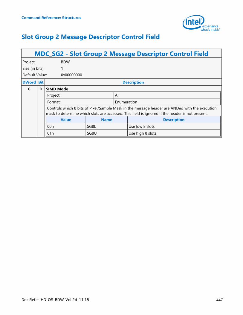
Command Reference: Structures
Doc Ref # IHD-OS-BDW-Vol 2d-11.15 447
Slot Group 2 Message Descriptor Control Field
MDC_SG2 - Slot Group 2 Message Descriptor Control Field Project: BDW
Size (in bits): 1
Default Value: 0x00000000
DWord Bit Description
0 0 SIMD Mode
Project: All
Format: Enumeration
Controls which 8 bits of Pixel/Sample Mask in the message header are ANDed with the execution
mask to determine which slots are accessed. This field is ignored if the header is not present.
Value Name Description
00h SG8L Use low 8 slots
01h SG8U Use high 8 slots
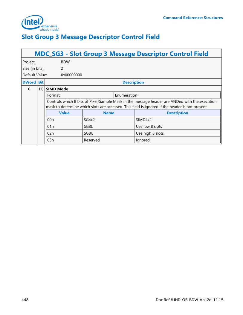
Command Reference: Structures
448 Doc Ref # IHD-OS-BDW-Vol 2d-11.15
Slot Group 3 Message Descriptor Control Field
MDC_SG3 - Slot Group 3 Message Descriptor Control Field Project: BDW
Size (in bits): 2
Default Value: 0x00000000
DWord Bit Description
0 1:0 SIMD Mode
Format: Enumeration
Controls which 8 bits of Pixel/Sample Mask in the message header are ANDed with the execution
mask to determine which slots are accessed. This field is ignored if the header is not present.
Value Name Description
00h SG4x2 SIMD4x2
01h SG8L Use low 8 slots
02h SG8U Use high 8 slots
03h Reserved Ignored
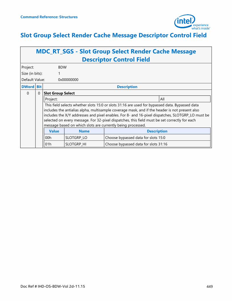
Command Reference: Structures
Doc Ref # IHD-OS-BDW-Vol 2d-11.15 449
Slot Group Select Render Cache Message Descriptor Control Field
MDC_RT_SGS - Slot Group Select Render Cache Message
Descriptor Control Field Project: BDW
Size (in bits): 1
Default Value: 0x00000000
DWord Bit Description
0 0 Slot Group Select
Project: All
This field selects whether slots 15:0 or slots 31:16 are used for bypassed data. Bypassed data
includes the antialias alpha, multisample coverage mask, and if the header is not present also
includes the X/Y addresses and pixel enables. For 8- and 16-pixel dispatches, SLOTGRP_LO must be
selected on every message. For 32-pixel dispatches, this field must be set correctly for each
message based on which slots are currently being processed.
Value Name Description
00h SLOTGRP_LO Choose bypassed data for slots 15:0
01h SLOTGRP_HI Choose bypassed data for slots 31:16
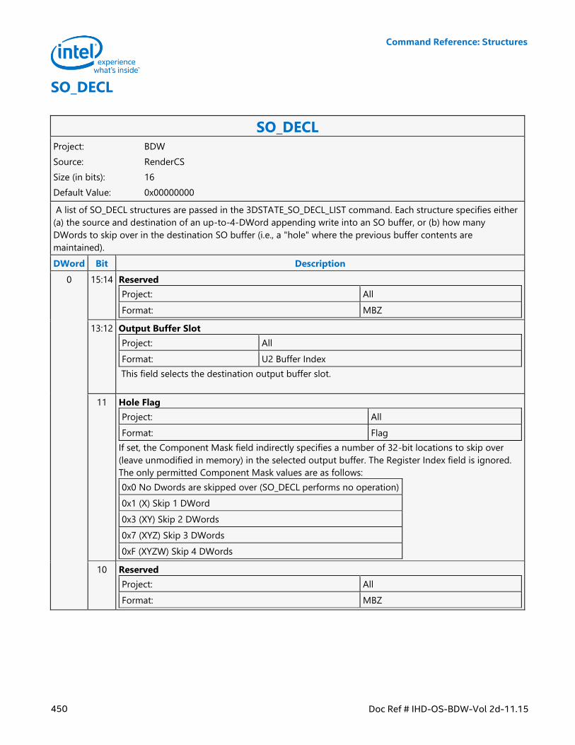
Command Reference: Structures
450 Doc Ref # IHD-OS-BDW-Vol 2d-11.15
SO_DECL
SO_DECL Project: BDW
Source: RenderCS
Size (in bits): 16
Default Value: 0x00000000
A list of SO_DECL structures are passed in the 3DSTATE_SO_DECL_LIST command. Each structure specifies either
(a) the source and destination of an up-to-4-DWord appending write into an SO buffer, or (b) how many
DWords to skip over in the destination SO buffer (i.e., a "hole" where the previous buffer contents are
maintained).
DWord Bit Description
0 15:14 Reserved
Project: All
Format: MBZ
13:12 Output Buffer Slot
Project: All
Format: U2 Buffer Index
This field selects the destination output buffer slot.
11 Hole Flag
Project: All
Format: Flag
If set, the Component Mask field indirectly specifies a number of 32-bit locations to skip over
(leave unmodified in memory) in the selected output buffer. The Register Index field is ignored.
The only permitted Component Mask values are as follows:
0x0 No Dwords are skipped over (SO_DECL performs no operation)
0x1 (X) Skip 1 DWord
0x3 (XY) Skip 2 DWords
0x7 (XYZ) Skip 3 DWords
0xF (XYZW) Skip 4 DWords
10 Reserved
Project: All
Format: MBZ
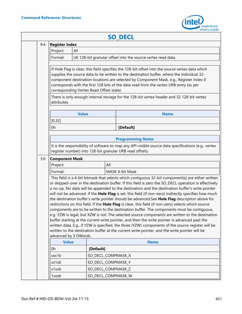
Command Reference: Structures
Doc Ref # IHD-OS-BDW-Vol 2d-11.15 451
SO_DECL 9:4 Register Index
Project: All
Format: U6 128-bit granular offset into the source vertex read data
If Hole Flag is clear, this field specifies the 128-bit offset into the source vertex data which
supplies the source data to be written to the destination buffer, where the individual 32-
component destination locations are selected by Component Mask. e.g., Register Index 0
corresponds with the first 128 bits of the data read from the vertex URB entry (as per
corresponding Vertex Read Offset state)
There is only enough internal storage for the 128-bit vertex header and 32 128-bit vertex
attributes.
Value Name
[0,32]
0h [Default]
Programming Notes
It is the responsibility of software to map any API-visible source data specifications (e.g., vertex
register number) into 128-bit granular URB read offsets.
3:0 Component Mask
Project: All
Format: MASK 4-bit Mask
This field is a 4-bit bitmask that selects which contiguous 32-bit component(s) are either written
or skipped-over in the destination buffer. If this field is zero the SO_DECL operation is effectively
a no-op. No data will be appended to the destination and the destination buffer's write pointer
will not be advanced. If the Hole Flag is set, this field (if non-zero) indirectly specifies how much
the destination buffer's write pointer should be advanced.See Hole Flag description above for
restrictions on this field. If the Hole Flag is clear, this field (if non-zero) selects which source
components are to be written to the destination buffer. The components must be contiguous,
e.g. YZW is legal, but XZW is not. The selected source components are written to the destination
buffer starting at the current write pointer, and then the write pointer is advanced past the
written data. E.g., if YZW is specified, the three (YZW) components of the source register will be
written to the destination buffer at the current write pointer, and the write pointer will be
advanced by 3 DWords.
Value Name
0h [Default]
xxx1b SO_DECL_COMPMASK_X
xx1xb SO_DECL_COMPMASK_Y
x1xxb SO_DECL_COMPMASK_Z
1xxxb SO_DECL_COMPMASK_W
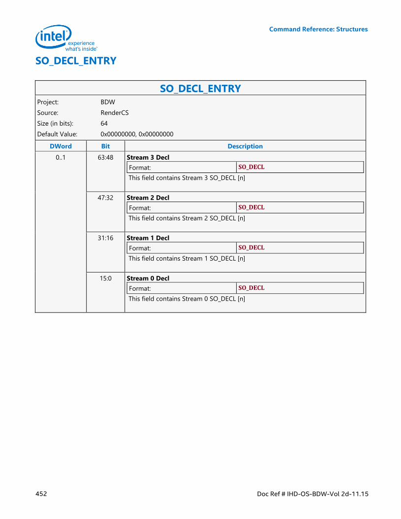
Command Reference: Structures
452 Doc Ref # IHD-OS-BDW-Vol 2d-11.15
SO_DECL_ENTRY
SO_DECL_ENTRY Project: BDW
Source: RenderCS
Size (in bits): 64
Default Value: 0x00000000, 0x00000000
DWord Bit Description
0..1 63:48 Stream 3 Decl
Format: SO_DECL
This field contains Stream 3 SO_DECL [n]
47:32 Stream 2 Decl
Format: SO_DECL
This field contains Stream 2 SO_DECL [n]
31:16 Stream 1 Decl
Format: SO_DECL
This field contains Stream 1 SO_DECL [n]
15:0 Stream 0 Decl
Format: SO_DECL
This field contains Stream 0 SO_DECL [n]
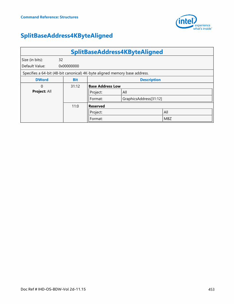
Command Reference: Structures
Doc Ref # IHD-OS-BDW-Vol 2d-11.15 453
SplitBaseAddress4KByteAligned
SplitBaseAddress4KByteAligned Size (in bits): 32
Default Value: 0x00000000
Specifies a 64-bit (48-bit canonical) 4K-byte aligned memory base address.
DWord Bit Description
0
Project: All
31:12 Base Address Low
Project: All
Format: GraphicsAddress[31:12]
11:0 Reserved
Project: All
Format: MBZ
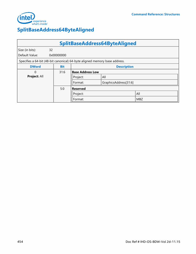
Command Reference: Structures
454 Doc Ref # IHD-OS-BDW-Vol 2d-11.15
SplitBaseAddress64ByteAligned
SplitBaseAddress64ByteAligned Size (in bits): 32
Default Value: 0x00000000
Specifies a 64-bit (48-bit canonical) 64-byte aligned memory base address.
DWord Bit Description
0
Project: All
31:6 Base Address Low
Project: All
Format: GraphicsAddress[31:6]
5:0 Reserved
Project: All
Format: MBZ
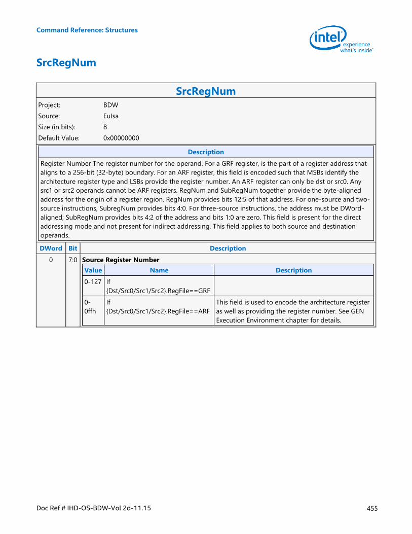
Command Reference: Structures
Doc Ref # IHD-OS-BDW-Vol 2d-11.15 455
SrcRegNum
SrcRegNum Project: BDW
Source: EuIsa
Size (in bits): 8
Default Value: 0x00000000
Description
Register Number The register number for the operand. For a GRF register, is the part of a register address that
aligns to a 256-bit (32-byte) boundary. For an ARF register, this field is encoded such that MSBs identify the
architecture register type and LSBs provide the register number. An ARF register can only be dst or src0. Any
src1 or src2 operands cannot be ARF registers. RegNum and SubRegNum together provide the byte-aligned
address for the origin of a register region. RegNum provides bits 12:5 of that address. For one-source and two-
source instructions, SubregNum provides bits 4:0. For three-source instructions, the address must be DWord-
aligned; SubRegNum provides bits 4:2 of the address and bits 1:0 are zero. This field is present for the direct
addressing mode and not present for indirect addressing. This field applies to both source and destination
operands.
DWord Bit Description
0 7:0 Source Register Number
Value Name Description
0-127 If
{Dst/Src0/Src1/Src2}.RegFile==GRF
0-
0ffh
If
{Dst/Src0/Src1/Src2}.RegFile==ARF
This field is used to encode the architecture register
as well as providing the register number. See GEN
Execution Environment chapter for details.
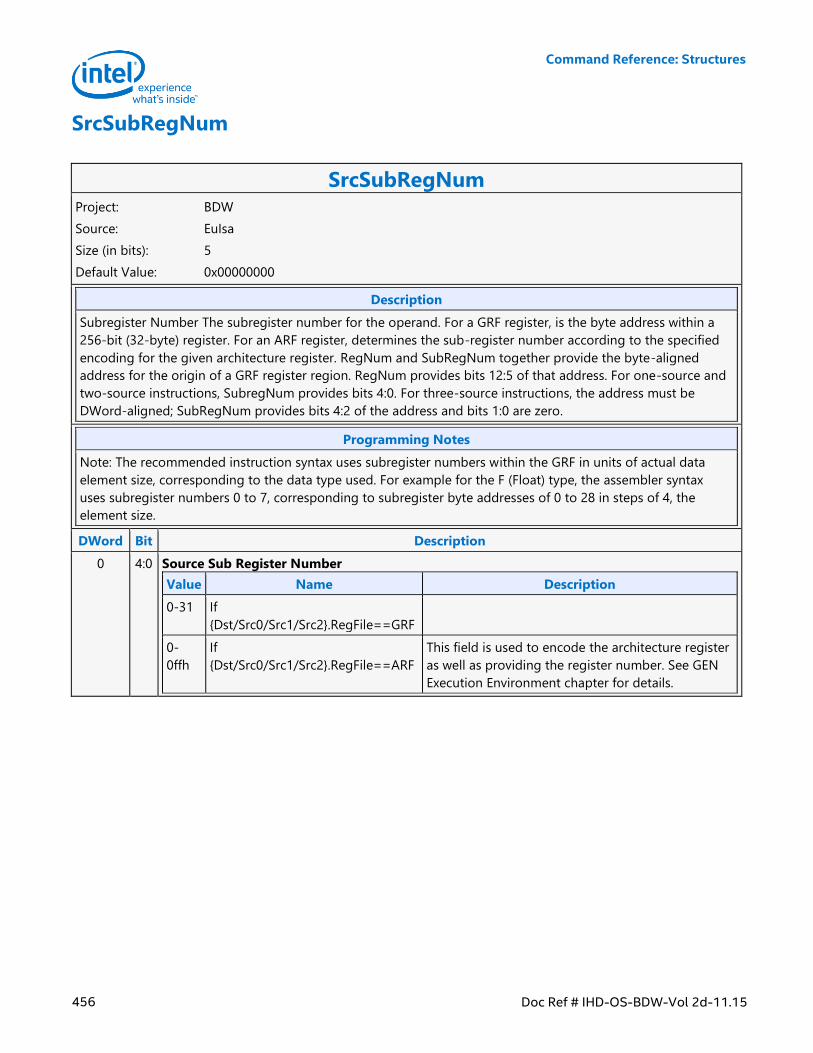
Command Reference: Structures
456 Doc Ref # IHD-OS-BDW-Vol 2d-11.15
SrcSubRegNum
SrcSubRegNum Project: BDW
Source: EuIsa
Size (in bits): 5
Default Value: 0x00000000
Description
Subregister Number The subregister number for the operand. For a GRF register, is the byte address within a
256-bit (32-byte) register. For an ARF register, determines the sub-register number according to the specified
encoding for the given architecture register. RegNum and SubRegNum together provide the byte-aligned
address for the origin of a GRF register region. RegNum provides bits 12:5 of that address. For one-source and
two-source instructions, SubregNum provides bits 4:0. For three-source instructions, the address must be
DWord-aligned; SubRegNum provides bits 4:2 of the address and bits 1:0 are zero.
Programming Notes
Note: The recommended instruction syntax uses subregister numbers within the GRF in units of actual data
element size, corresponding to the data type used. For example for the F (Float) type, the assembler syntax
uses subregister numbers 0 to 7, corresponding to subregister byte addresses of 0 to 28 in steps of 4, the
element size.
DWord Bit Description
0 4:0 Source Sub Register Number
Value Name Description
0-31 If
{Dst/Src0/Src1/Src2}.RegFile==GRF
0-
0ffh
If
{Dst/Src0/Src1/Src2}.RegFile==ARF
This field is used to encode the architecture register
as well as providing the register number. See GEN
Execution Environment chapter for details.
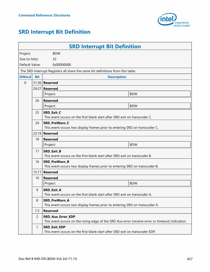
Command Reference: Structures
Doc Ref # IHD-OS-BDW-Vol 2d-11.15 457
SRD Interrupt Bit Definition
SRD Interrupt Bit Definition Project: BDW
Size (in bits): 32
Default Value: 0x00000000
The SRD Interrupt Registers all share the same bit definitions from this table.
DWord Bit Description
0 31:30 Reserved
29:27 Reserved
Project: BDW
26 Reserved
Project: BDW
25 SRD_Exit_C
This event occurs on the first blank start after SRD exit on transcoder C.
24 SRD_PreWarn_C
This event occurs two display frames prior to entering SRD on transcoder C.
23:19 Reserved
18 Reserved
Project: BDW
17 SRD_Exit_B
This event occurs on the first blank start after SRD exit on transcoder B.
16 SRD_PreWarn_B
This event occurs two display frames prior to entering SRD on transcoder B.
15:11 Reserved
10 Reserved
Project: BDW
9 SRD_Exit_A
This event occurs on the first blank start after SRD exit on transcoder A.
8 SRD_PreWarn_A
This event occurs two display frames prior to entering SRD on transcoder A.
7:3 Reserved
2 SRD_Aux_Error_EDP
This event occurs on the rising edge of the SRD Aux error (receive error or timeout) indication.
1 SRD_Exit_EDP
This event occurs on the first blank start after SRD exit on transcoder EDP.
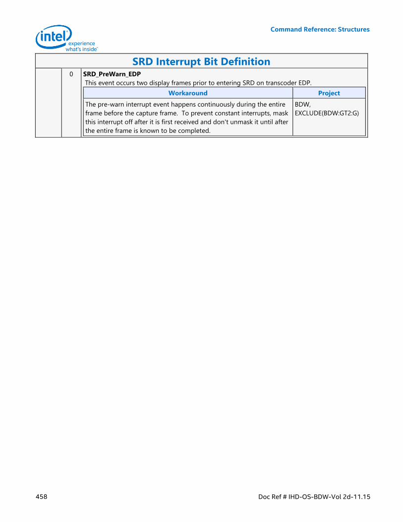
Command Reference: Structures
458 Doc Ref # IHD-OS-BDW-Vol 2d-11.15
SRD Interrupt Bit Definition 0 SRD_PreWarn_EDP
This event occurs two display frames prior to entering SRD on transcoder EDP.
Workaround Project
The pre-warn interrupt event happens continuously during the entire
frame before the capture frame. To prevent constant interrupts, mask
this interrupt off after it is first received and don't unmask it until after
the entire frame is known to be completed.
BDW,
EXCLUDE(BDW:GT2:G)
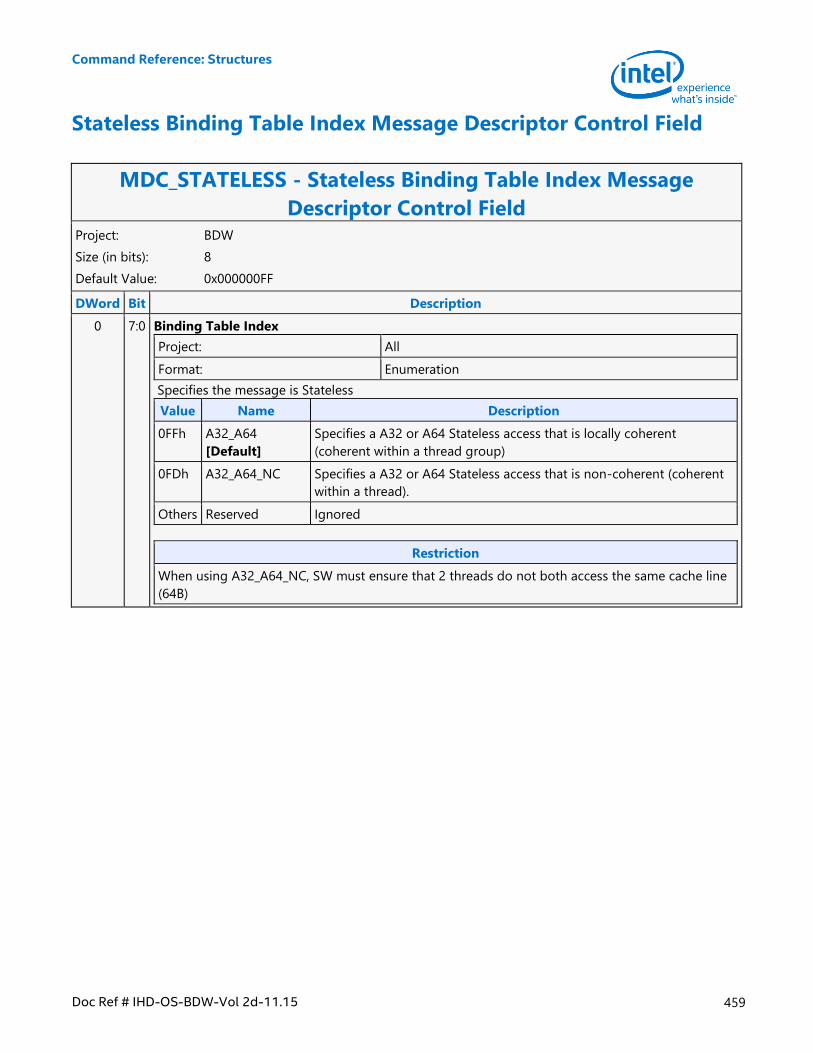
Command Reference: Structures
Doc Ref # IHD-OS-BDW-Vol 2d-11.15 459
Stateless Binding Table Index Message Descriptor Control Field
MDC_STATELESS - Stateless Binding Table Index Message
Descriptor Control Field Project: BDW
Size (in bits): 8
Default Value: 0x000000FF
DWord Bit Description
0 7:0 Binding Table Index
Project: All
Format: Enumeration
Specifies the message is Stateless
Value Name Description
0FFh A32_A64
[Default]
Specifies a A32 or A64 Stateless access that is locally coherent
(coherent within a thread group)
0FDh A32_A64_NC Specifies a A32 or A64 Stateless access that is non-coherent (coherent
within a thread).
Others Reserved Ignored
Restriction
When using A32_A64_NC, SW must ensure that 2 threads do not both access the same cache line
(64B)
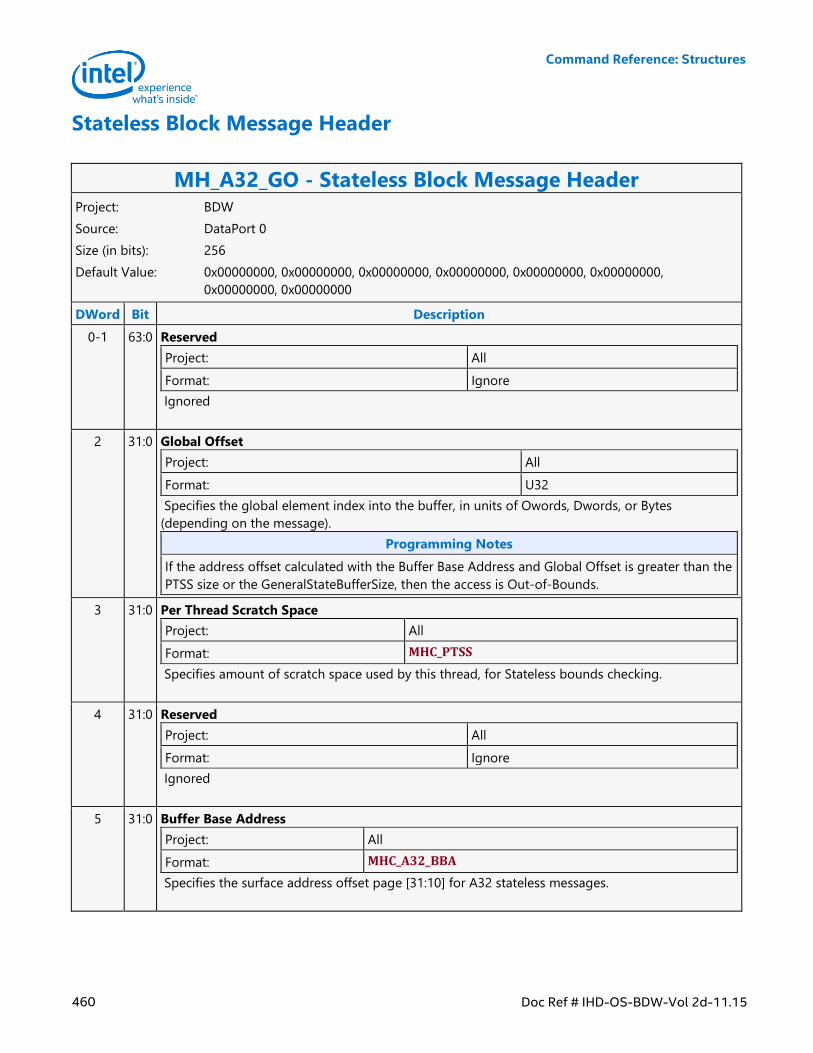
Command Reference: Structures
460 Doc Ref # IHD-OS-BDW-Vol 2d-11.15
Stateless Block Message Header
MH_A32_GO - Stateless Block Message Header Project: BDW
Source: DataPort 0
Size (in bits): 256
Default Value: 0x00000000, 0x00000000, 0x00000000, 0x00000000, 0x00000000, 0x00000000,
0x00000000, 0x00000000
DWord Bit Description
0-1 63:0 Reserved
Project: All
Format: Ignore
Ignored
2 31:0 Global Offset
Project: All
Format: U32
Specifies the global element index into the buffer, in units of Owords, Dwords, or Bytes
(depending on the message).
Programming Notes
If the address offset calculated with the Buffer Base Address and Global Offset is greater than the
PTSS size or the GeneralStateBufferSize, then the access is Out-of-Bounds.
3 31:0 Per Thread Scratch Space
Project: All
Format: MHC_PTSS
Specifies amount of scratch space used by this thread, for Stateless bounds checking.
4 31:0 Reserved
Project: All
Format: Ignore
Ignored
5 31:0 Buffer Base Address
Project: All
Format: MHC_A32_BBA
Specifies the surface address offset page [31:10] for A32 stateless messages.
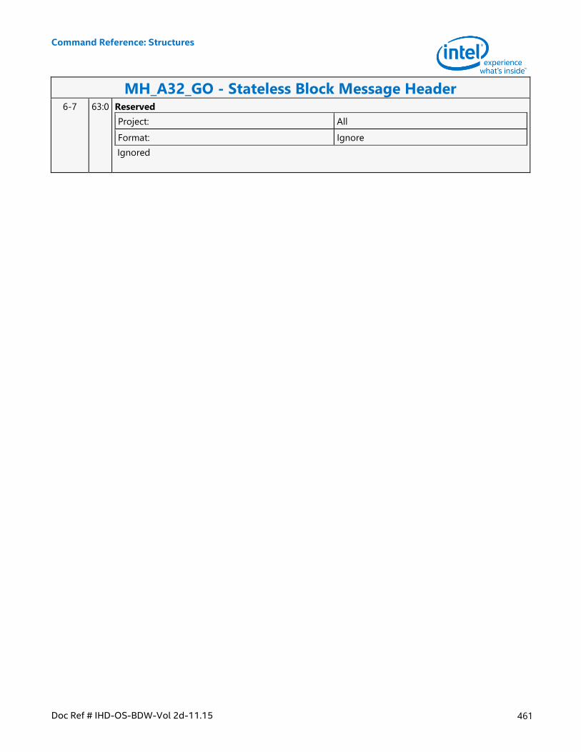
Command Reference: Structures
Doc Ref # IHD-OS-BDW-Vol 2d-11.15 461
MH_A32_GO - Stateless Block Message Header 6-7 63:0 Reserved
Project: All
Format: Ignore
Ignored
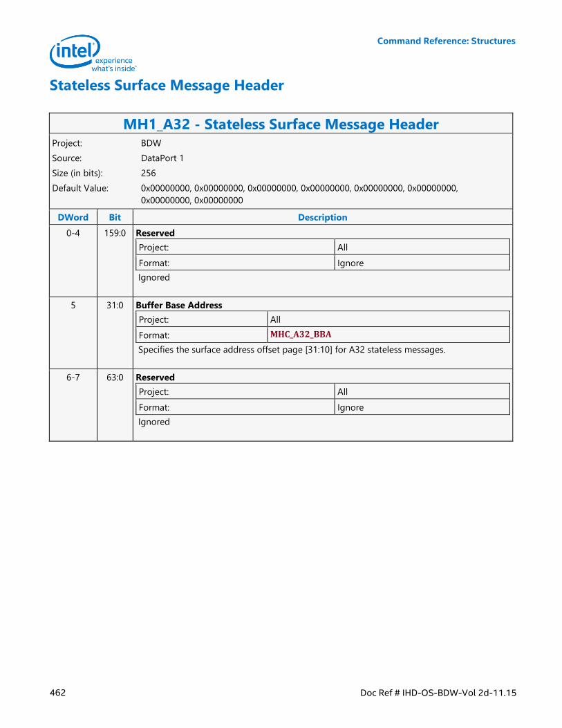
Command Reference: Structures
462 Doc Ref # IHD-OS-BDW-Vol 2d-11.15
Stateless Surface Message Header
MH1_A32 - Stateless Surface Message Header Project: BDW
Source: DataPort 1
Size (in bits): 256
Default Value: 0x00000000, 0x00000000, 0x00000000, 0x00000000, 0x00000000, 0x00000000,
0x00000000, 0x00000000
DWord Bit Description
0-4 159:0 Reserved
Project: All
Format: Ignore
Ignored
5 31:0 Buffer Base Address
Project: All
Format: MHC_A32_BBA
Specifies the surface address offset page [31:10] for A32 stateless messages.
6-7 63:0 Reserved
Project: All
Format: Ignore
Ignored
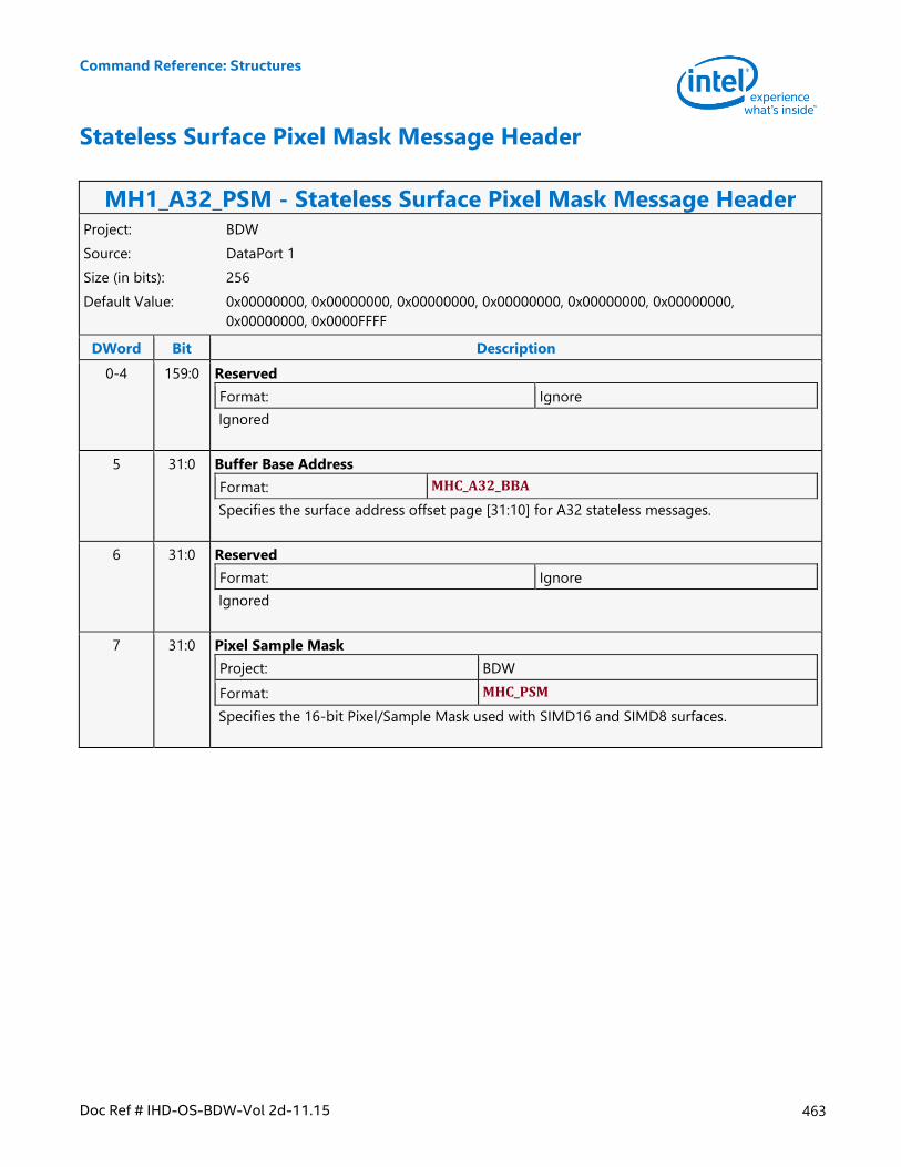
Command Reference: Structures
Doc Ref # IHD-OS-BDW-Vol 2d-11.15 463
Stateless Surface Pixel Mask Message Header
MH1_A32_PSM - Stateless Surface Pixel Mask Message Header Project: BDW
Source: DataPort 1
Size (in bits): 256
Default Value: 0x00000000, 0x00000000, 0x00000000, 0x00000000, 0x00000000, 0x00000000,
0x00000000, 0x0000FFFF
DWord Bit Description
0-4 159:0 Reserved
Format: Ignore
Ignored
5 31:0 Buffer Base Address
Format: MHC_A32_BBA
Specifies the surface address offset page [31:10] for A32 stateless messages.
6 31:0 Reserved
Format: Ignore
Ignored
7 31:0 Pixel Sample Mask
Project: BDW
Format: MHC_PSM
Specifies the 16-bit Pixel/Sample Mask used with SIMD16 and SIMD8 surfaces.
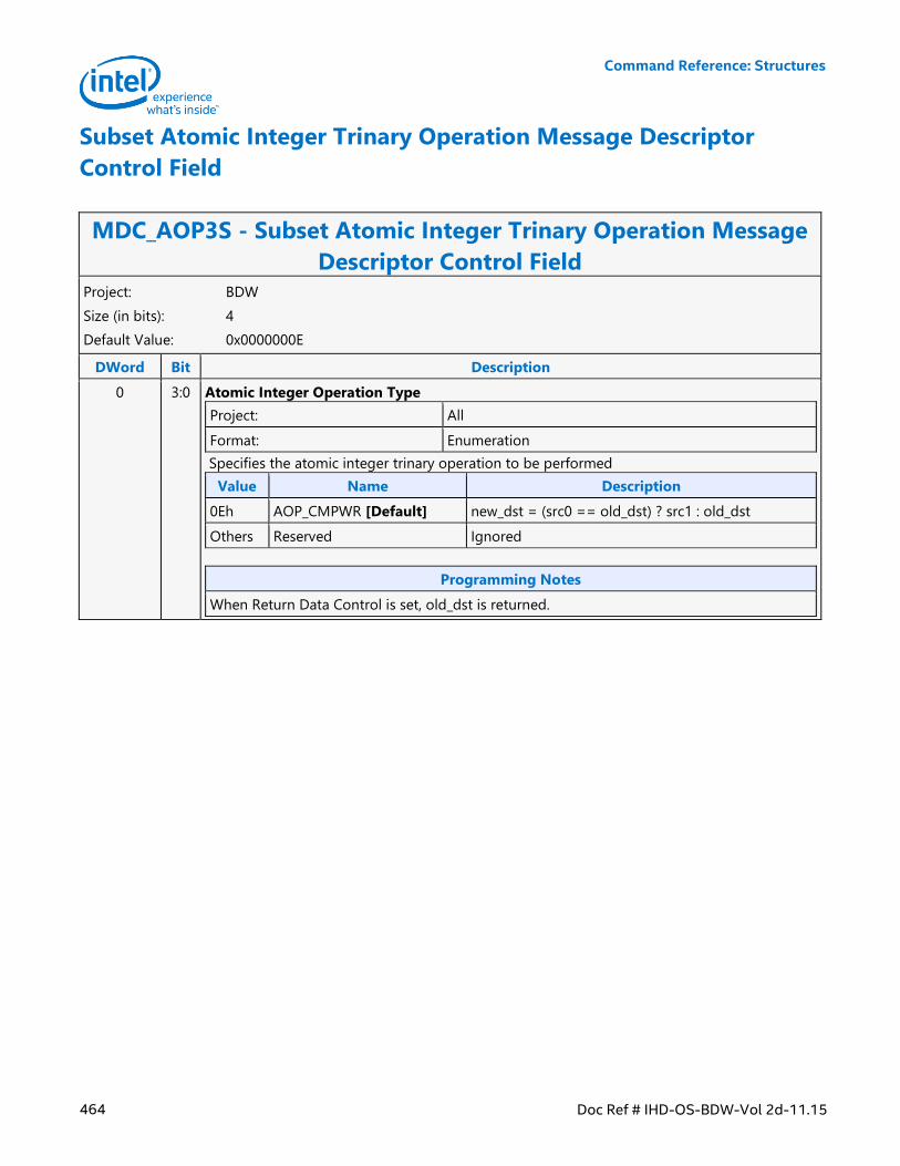
Command Reference: Structures
464 Doc Ref # IHD-OS-BDW-Vol 2d-11.15
Subset Atomic Integer Trinary Operation Message Descriptor
Control Field
MDC_AOP3S - Subset Atomic Integer Trinary Operation Message
Descriptor Control Field Project: BDW
Size (in bits): 4
Default Value: 0x0000000E
DWord Bit Description
0 3:0 Atomic Integer Operation Type
Project: All
Format: Enumeration
Specifies the atomic integer trinary operation to be performed
Value Name Description
0Eh AOP_CMPWR [Default] new_dst = (src0 == old_dst) ? src1 : old_dst
Others Reserved Ignored
Programming Notes
When Return Data Control is set, old_dst is returned.
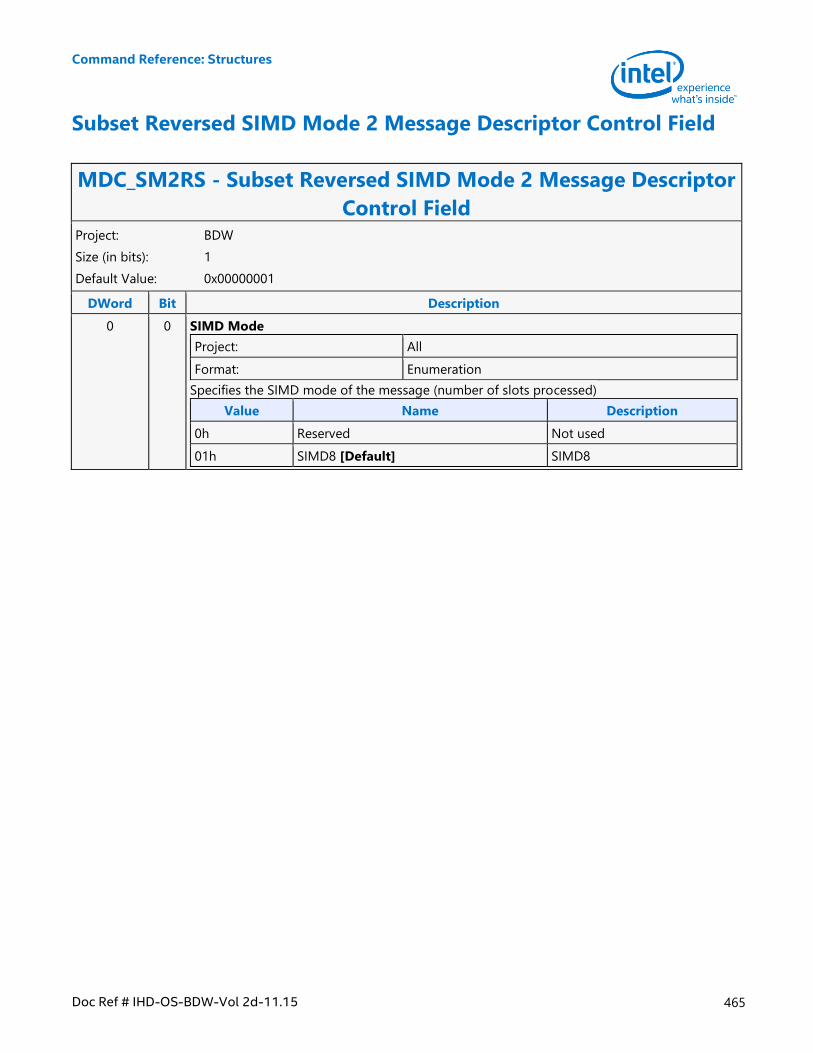
Command Reference: Structures
Doc Ref # IHD-OS-BDW-Vol 2d-11.15 465
Subset Reversed SIMD Mode 2 Message Descriptor Control Field
MDC_SM2RS - Subset Reversed SIMD Mode 2 Message Descriptor
Control Field Project: BDW
Size (in bits): 1
Default Value: 0x00000001
DWord Bit Description
0 0 SIMD Mode
Project: All
Format: Enumeration
Specifies the SIMD mode of the message (number of slots processed)
Value Name Description
0h Reserved Not used
01h SIMD8 [Default] SIMD8
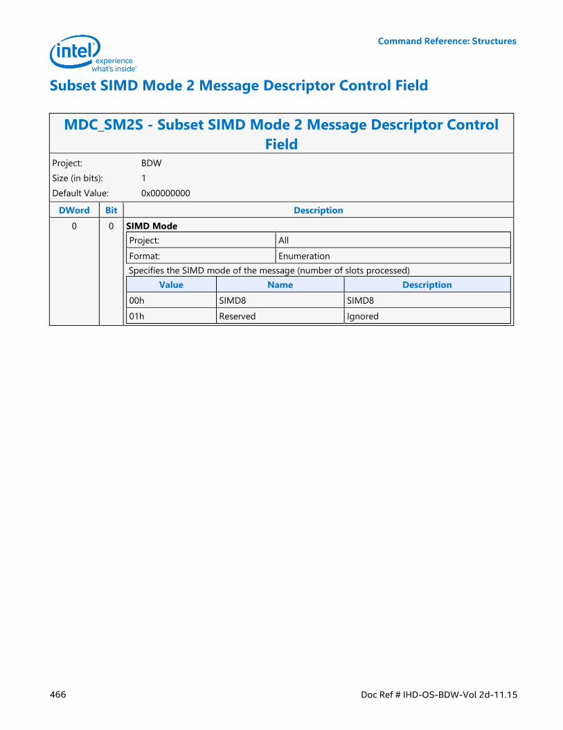
Command Reference: Structures
466 Doc Ref # IHD-OS-BDW-Vol 2d-11.15
Subset SIMD Mode 2 Message Descriptor Control Field
MDC_SM2S - Subset SIMD Mode 2 Message Descriptor Control
Field Project: BDW
Size (in bits): 1
Default Value: 0x00000000
DWord Bit Description
0 0 SIMD Mode
Project: All
Format: Enumeration
Specifies the SIMD mode of the message (number of slots processed)
Value Name Description
00h SIMD8 SIMD8
01h Reserved Ignored
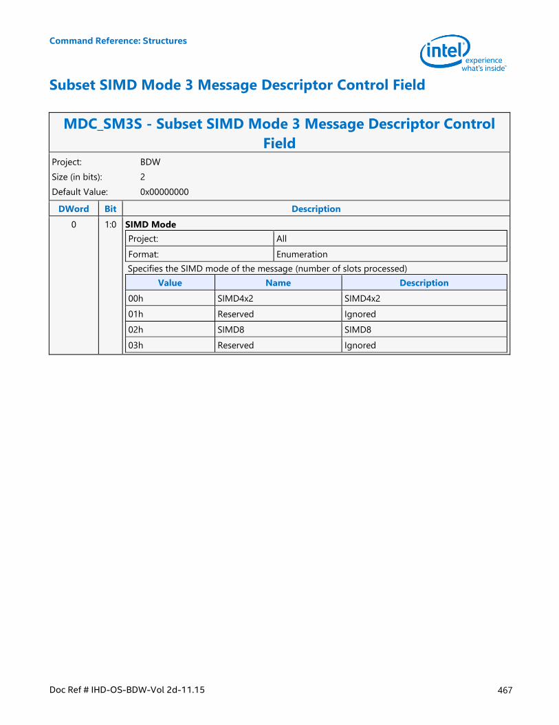
Command Reference: Structures
Doc Ref # IHD-OS-BDW-Vol 2d-11.15 467
Subset SIMD Mode 3 Message Descriptor Control Field
MDC_SM3S - Subset SIMD Mode 3 Message Descriptor Control
Field Project: BDW
Size (in bits): 2
Default Value: 0x00000000
DWord Bit Description
0 1:0 SIMD Mode
Project: All
Format: Enumeration
Specifies the SIMD mode of the message (number of slots processed)
Value Name Description
00h SIMD4x2 SIMD4x2
01h Reserved Ignored
02h SIMD8 SIMD8
03h Reserved Ignored
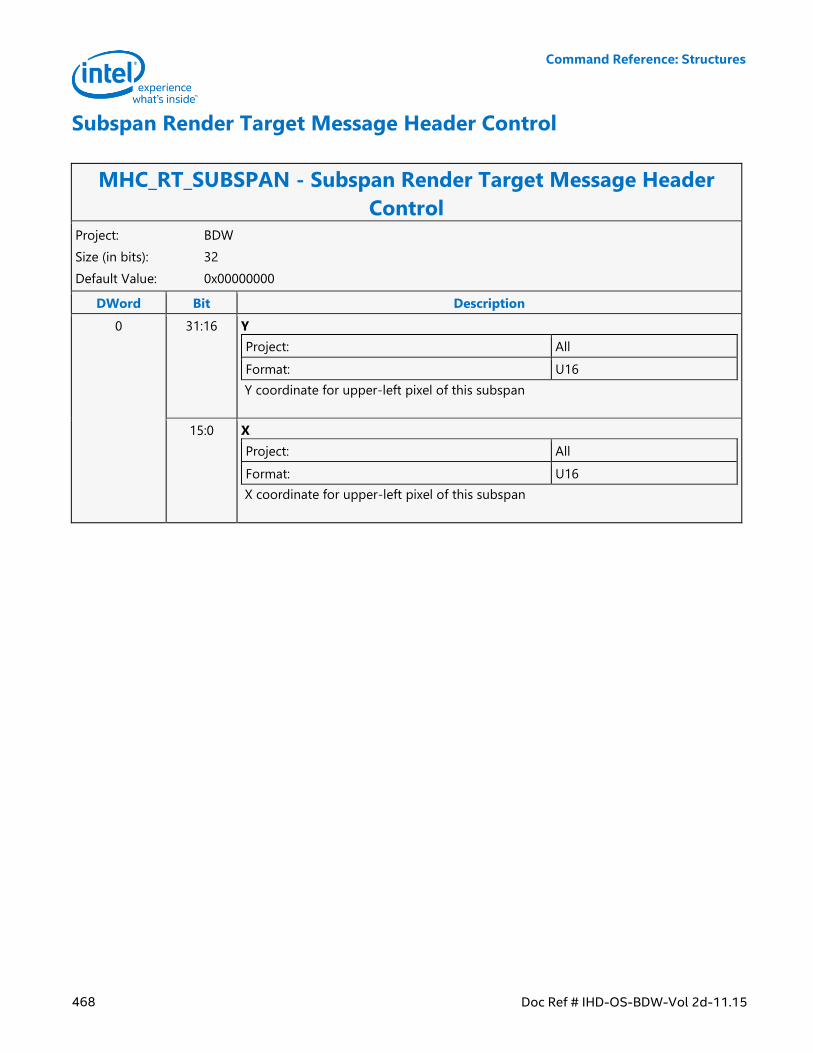
Command Reference: Structures
468 Doc Ref # IHD-OS-BDW-Vol 2d-11.15
Subspan Render Target Message Header Control
MHC_RT_SUBSPAN - Subspan Render Target Message Header
Control Project: BDW
Size (in bits): 32
Default Value: 0x00000000
DWord Bit Description
0 31:16 Y
Project: All
Format: U16
Y coordinate for upper-left pixel of this subspan
15:0 X
Project: All
Format: U16
X coordinate for upper-left pixel of this subspan
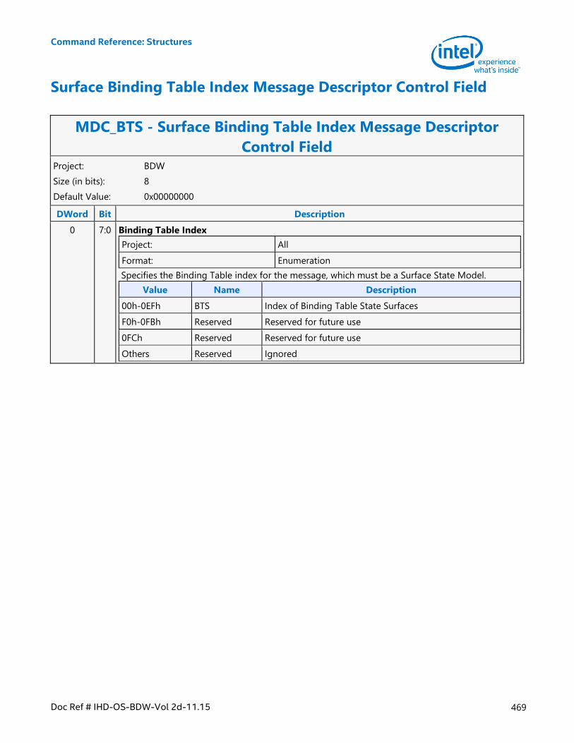
Command Reference: Structures
Doc Ref # IHD-OS-BDW-Vol 2d-11.15 469
Surface Binding Table Index Message Descriptor Control Field
MDC_BTS - Surface Binding Table Index Message Descriptor
Control Field Project: BDW
Size (in bits): 8
Default Value: 0x00000000
DWord Bit Description
0 7:0 Binding Table Index
Project: All
Format: Enumeration
Specifies the Binding Table index for the message, which must be a Surface State Model.
Value Name Description
00h-0EFh BTS Index of Binding Table State Surfaces
F0h-0FBh Reserved Reserved for future use
0FCh Reserved Reserved for future use
Others Reserved Ignored
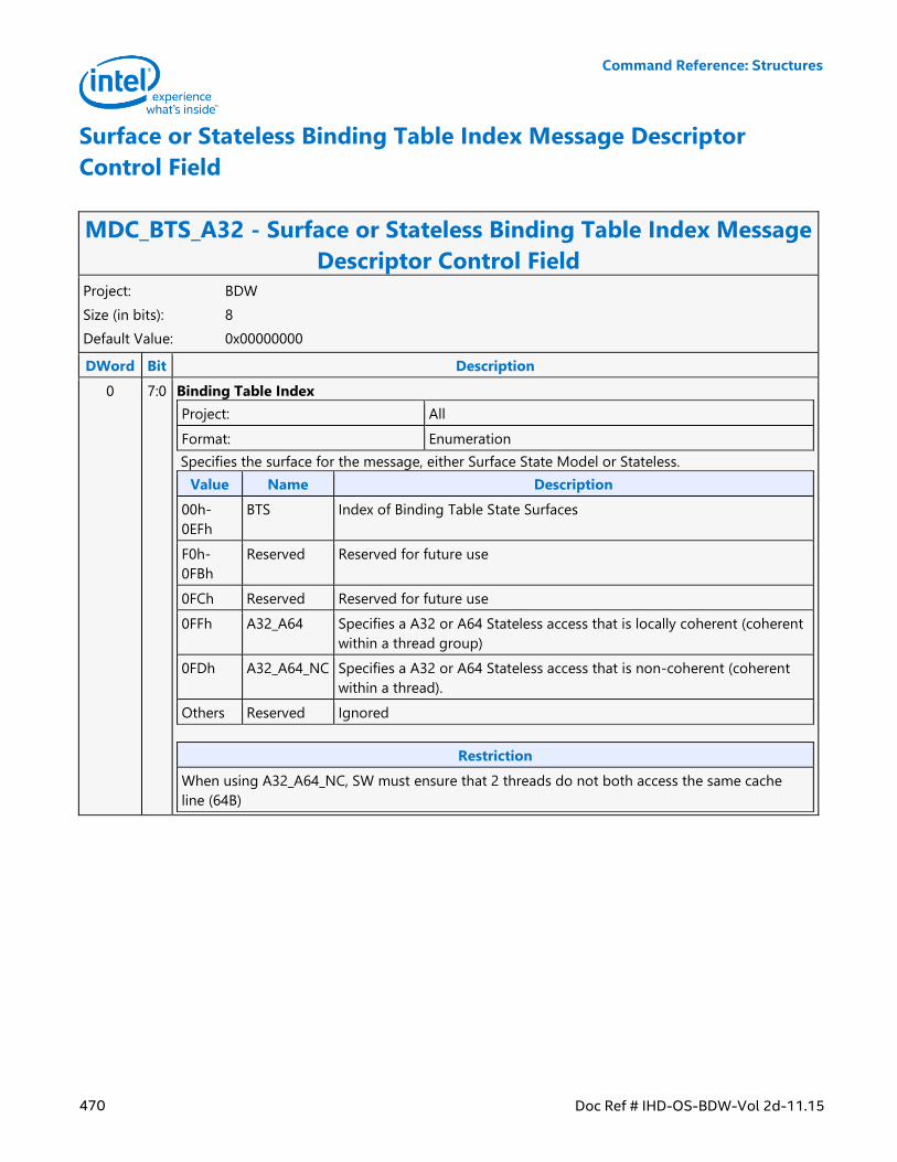
Command Reference: Structures
470 Doc Ref # IHD-OS-BDW-Vol 2d-11.15
Surface or Stateless Binding Table Index Message Descriptor
Control Field
MDC_BTS_A32 - Surface or Stateless Binding Table Index Message
Descriptor Control Field Project: BDW
Size (in bits): 8
Default Value: 0x00000000
DWord Bit Description
0 7:0 Binding Table Index
Project: All
Format: Enumeration
Specifies the surface for the message, either Surface State Model or Stateless.
Value Name Description
00h-
0EFh
BTS Index of Binding Table State Surfaces
F0h-
0FBh
Reserved Reserved for future use
0FCh Reserved Reserved for future use
0FFh A32_A64 Specifies a A32 or A64 Stateless access that is locally coherent (coherent
within a thread group)
0FDh A32_A64_NC Specifies a A32 or A64 Stateless access that is non-coherent (coherent
within a thread).
Others Reserved Ignored
Restriction
When using A32_A64_NC, SW must ensure that 2 threads do not both access the same cache
line (64B)
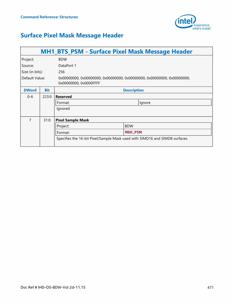
Command Reference: Structures
Doc Ref # IHD-OS-BDW-Vol 2d-11.15 471
Surface Pixel Mask Message Header
MH1_BTS_PSM - Surface Pixel Mask Message Header Project: BDW
Source: DataPort 1
Size (in bits): 256
Default Value: 0x00000000, 0x00000000, 0x00000000, 0x00000000, 0x00000000, 0x00000000,
0x00000000, 0x0000FFFF
DWord Bit Description
0-6 223:0 Reserved
Format: Ignore
Ignored
7 31:0 Pixel Sample Mask
Project: BDW
Format: MHC_PSM
Specifies the 16-bit Pixel/Sample Mask used with SIMD16 and SIMD8 surfaces.
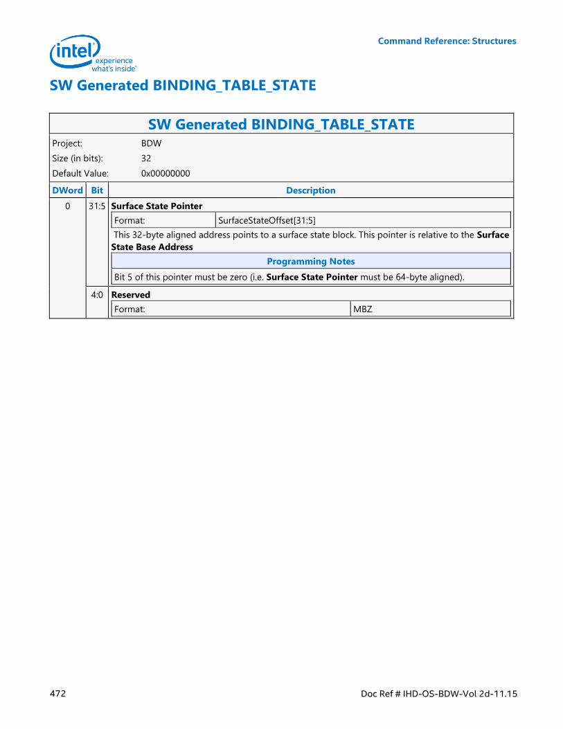
Command Reference: Structures
472 Doc Ref # IHD-OS-BDW-Vol 2d-11.15
SW Generated BINDING_TABLE_STATE
SW Generated BINDING_TABLE_STATE Project: BDW
Size (in bits): 32
Default Value: 0x00000000
DWord Bit Description
0 31:5 Surface State Pointer
Format: SurfaceStateOffset[31:5]
This 32-byte aligned address points to a surface state block. This pointer is relative to the Surface
State Base Address
Programming Notes
Bit 5 of this pointer must be zero (i.e. Surface State Pointer must be 64-byte aligned).
4:0 Reserved
Format: MBZ
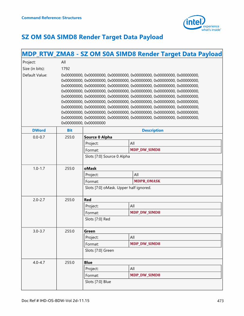
Command Reference: Structures
Doc Ref # IHD-OS-BDW-Vol 2d-11.15 473
SZ OM S0A SIMD8 Render Target Data Payload
MDP_RTW_ZMA8 - SZ OM S0A SIMD8 Render Target Data Payload Project: All
Size (in bits): 1792
Default Value: 0x00000000, 0x00000000, 0x00000000, 0x00000000, 0x00000000, 0x00000000,
0x00000000, 0x00000000, 0x00000000, 0x00000000, 0x00000000, 0x00000000,
0x00000000, 0x00000000, 0x00000000, 0x00000000, 0x00000000, 0x00000000,
0x00000000, 0x00000000, 0x00000000, 0x00000000, 0x00000000, 0x00000000,
0x00000000, 0x00000000, 0x00000000, 0x00000000, 0x00000000, 0x00000000,
0x00000000, 0x00000000, 0x00000000, 0x00000000, 0x00000000, 0x00000000,
0x00000000, 0x00000000, 0x00000000, 0x00000000, 0x00000000, 0x00000000,
0x00000000, 0x00000000, 0x00000000, 0x00000000, 0x00000000, 0x00000000,
0x00000000, 0x00000000, 0x00000000, 0x00000000, 0x00000000, 0x00000000,
0x00000000, 0x00000000
DWord Bit Description
0.0-0.7 255:0 Source 0 Alpha
Project: All
Format: MDP_DW_SIMD8
Slots [7:0] Source 0 Alpha
1.0-1.7 255:0 oMask
Project: All
Format: MDPR_OMASK
Slots [7:0] oMask. Upper half ignored.
2.0-2.7 255:0 Red
Project: All
Format: MDP_DW_SIMD8
Slots [7:0] Red
3.0-3.7 255:0 Green
Project: All
Format: MDP_DW_SIMD8
Slots [7:0] Green
4.0-4.7 255:0 Blue
Project: All
Format: MDP_DW_SIMD8
Slots [7:0] Blue
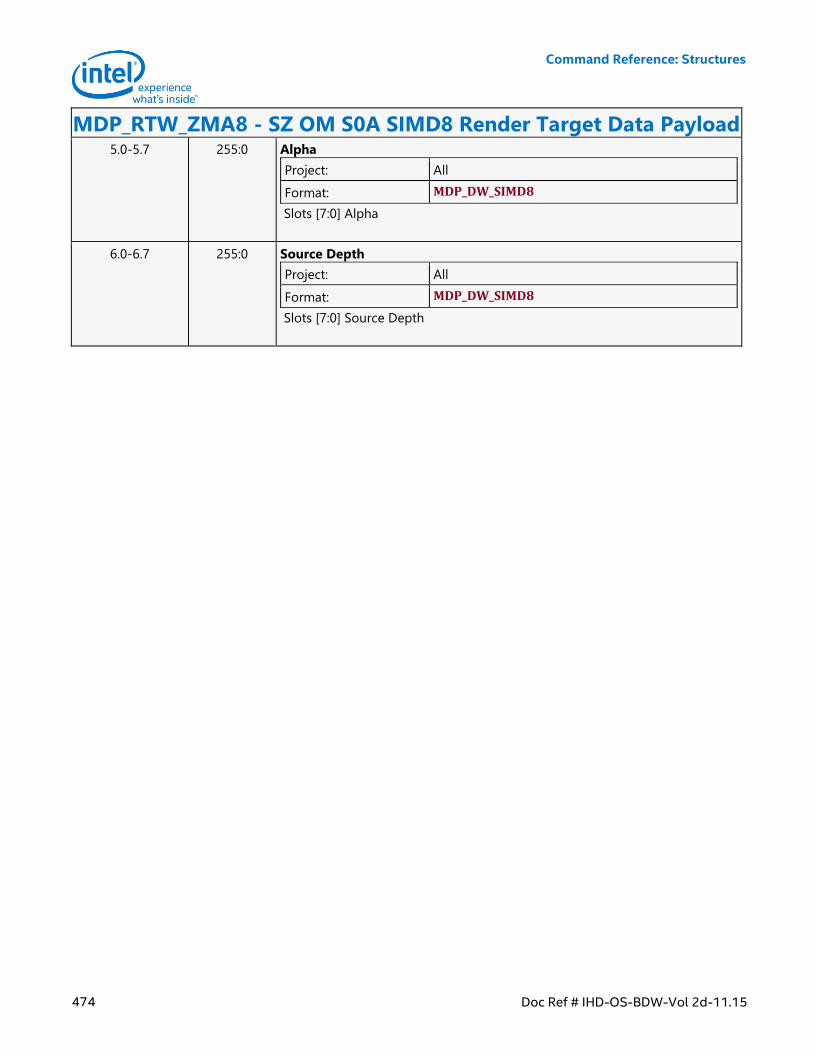
Command Reference: Structures
474 Doc Ref # IHD-OS-BDW-Vol 2d-11.15
MDP_RTW_ZMA8 - SZ OM S0A SIMD8 Render Target Data Payload 5.0-5.7 255:0 Alpha
Project: All
Format: MDP_DW_SIMD8
Slots [7:0] Alpha
6.0-6.7 255:0 Source Depth
Project: All
Format: MDP_DW_SIMD8
Slots [7:0] Source Depth
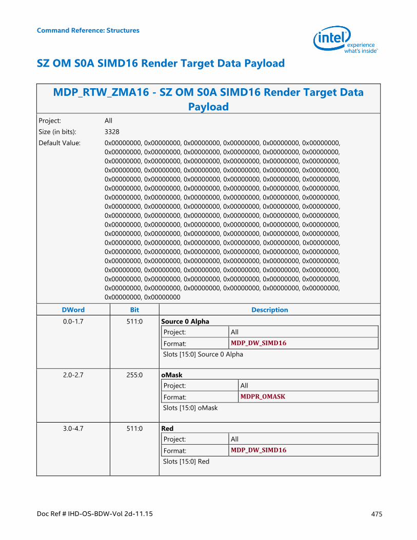
Command Reference: Structures
Doc Ref # IHD-OS-BDW-Vol 2d-11.15 475
SZ OM S0A SIMD16 Render Target Data Payload
MDP_RTW_ZMA16 - SZ OM S0A SIMD16 Render Target Data
Payload Project: All
Size (in bits): 3328
Default Value: 0x00000000, 0x00000000, 0x00000000, 0x00000000, 0x00000000, 0x00000000,
0x00000000, 0x00000000, 0x00000000, 0x00000000, 0x00000000, 0x00000000,
0x00000000, 0x00000000, 0x00000000, 0x00000000, 0x00000000, 0x00000000,
0x00000000, 0x00000000, 0x00000000, 0x00000000, 0x00000000, 0x00000000,
0x00000000, 0x00000000, 0x00000000, 0x00000000, 0x00000000, 0x00000000,
0x00000000, 0x00000000, 0x00000000, 0x00000000, 0x00000000, 0x00000000,
0x00000000, 0x00000000, 0x00000000, 0x00000000, 0x00000000, 0x00000000,
0x00000000, 0x00000000, 0x00000000, 0x00000000, 0x00000000, 0x00000000,
0x00000000, 0x00000000, 0x00000000, 0x00000000, 0x00000000, 0x00000000,
0x00000000, 0x00000000, 0x00000000, 0x00000000, 0x00000000, 0x00000000,
0x00000000, 0x00000000, 0x00000000, 0x00000000, 0x00000000, 0x00000000,
0x00000000, 0x00000000, 0x00000000, 0x00000000, 0x00000000, 0x00000000,
0x00000000, 0x00000000, 0x00000000, 0x00000000, 0x00000000, 0x00000000,
0x00000000, 0x00000000, 0x00000000, 0x00000000, 0x00000000, 0x00000000,
0x00000000, 0x00000000, 0x00000000, 0x00000000, 0x00000000, 0x00000000,
0x00000000, 0x00000000, 0x00000000, 0x00000000, 0x00000000, 0x00000000,
0x00000000, 0x00000000, 0x00000000, 0x00000000, 0x00000000, 0x00000000,
0x00000000, 0x00000000
DWord Bit Description
0.0-1.7 511:0 Source 0 Alpha
Project: All
Format: MDP_DW_SIMD16
Slots [15:0] Source 0 Alpha
2.0-2.7 255:0 oMask
Project: All
Format: MDPR_OMASK
Slots [15:0] oMask
3.0-4.7 511:0 Red
Project: All
Format: MDP_DW_SIMD16
Slots [15:0] Red
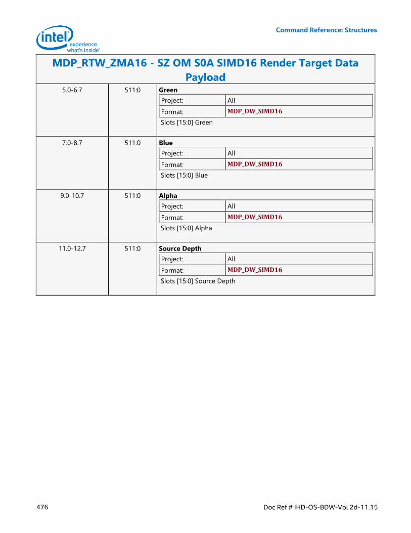
Command Reference: Structures
476 Doc Ref # IHD-OS-BDW-Vol 2d-11.15
MDP_RTW_ZMA16 - SZ OM S0A SIMD16 Render Target Data
Payload 5.0-6.7 511:0 Green
Project: All
Format: MDP_DW_SIMD16
Slots [15:0] Green
7.0-8.7 511:0 Blue
Project: All
Format: MDP_DW_SIMD16
Slots [15:0] Blue
9.0-10.7 511:0 Alpha
Project: All
Format: MDP_DW_SIMD16
Slots [15:0] Alpha
11.0-12.7 511:0 Source Depth
Project: All
Format: MDP_DW_SIMD16
Slots [15:0] Source Depth
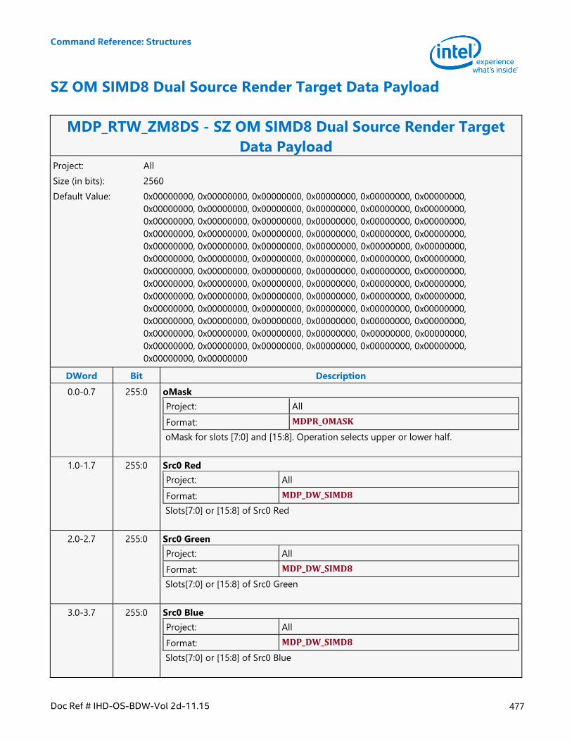
Command Reference: Structures
Doc Ref # IHD-OS-BDW-Vol 2d-11.15 477
SZ OM SIMD8 Dual Source Render Target Data Payload
MDP_RTW_ZM8DS - SZ OM SIMD8 Dual Source Render Target
Data Payload Project: All
Size (in bits): 2560
Default Value: 0x00000000, 0x00000000, 0x00000000, 0x00000000, 0x00000000, 0x00000000,
0x00000000, 0x00000000, 0x00000000, 0x00000000, 0x00000000, 0x00000000,
0x00000000, 0x00000000, 0x00000000, 0x00000000, 0x00000000, 0x00000000,
0x00000000, 0x00000000, 0x00000000, 0x00000000, 0x00000000, 0x00000000,
0x00000000, 0x00000000, 0x00000000, 0x00000000, 0x00000000, 0x00000000,
0x00000000, 0x00000000, 0x00000000, 0x00000000, 0x00000000, 0x00000000,
0x00000000, 0x00000000, 0x00000000, 0x00000000, 0x00000000, 0x00000000,
0x00000000, 0x00000000, 0x00000000, 0x00000000, 0x00000000, 0x00000000,
0x00000000, 0x00000000, 0x00000000, 0x00000000, 0x00000000, 0x00000000,
0x00000000, 0x00000000, 0x00000000, 0x00000000, 0x00000000, 0x00000000,
0x00000000, 0x00000000, 0x00000000, 0x00000000, 0x00000000, 0x00000000,
0x00000000, 0x00000000, 0x00000000, 0x00000000, 0x00000000, 0x00000000,
0x00000000, 0x00000000, 0x00000000, 0x00000000, 0x00000000, 0x00000000,
0x00000000, 0x00000000
DWord Bit Description
0.0-0.7 255:0 oMask
Project: All
Format: MDPR_OMASK
oMask for slots [7:0] and [15:8]. Operation selects upper or lower half.
1.0-1.7 255:0 Src0 Red
Project: All
Format: MDP_DW_SIMD8
Slots[7:0] or [15:8] of Src0 Red
2.0-2.7 255:0 Src0 Green
Project: All
Format: MDP_DW_SIMD8
Slots[7:0] or [15:8] of Src0 Green
3.0-3.7 255:0 Src0 Blue
Project: All
Format: MDP_DW_SIMD8
Slots[7:0] or [15:8] of Src0 Blue
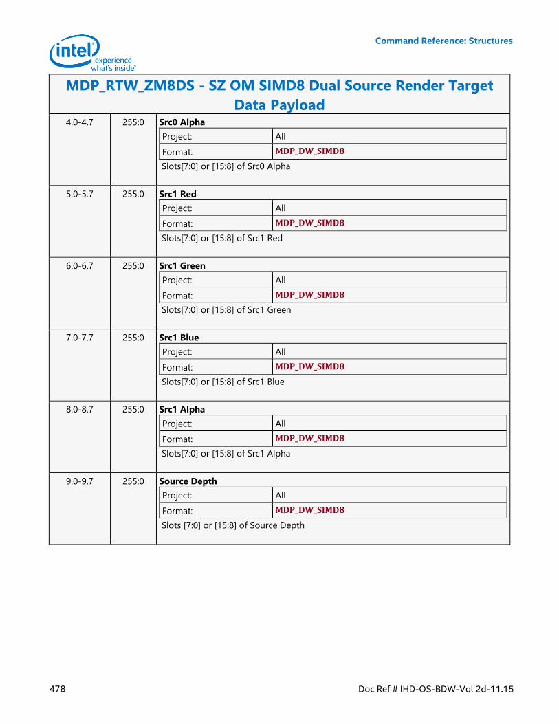
Command Reference: Structures
478 Doc Ref # IHD-OS-BDW-Vol 2d-11.15
MDP_RTW_ZM8DS - SZ OM SIMD8 Dual Source Render Target
Data Payload 4.0-4.7 255:0 Src0 Alpha
Project: All
Format: MDP_DW_SIMD8
Slots[7:0] or [15:8] of Src0 Alpha
5.0-5.7 255:0 Src1 Red
Project: All
Format: MDP_DW_SIMD8
Slots[7:0] or [15:8] of Src1 Red
6.0-6.7 255:0 Src1 Green
Project: All
Format: MDP_DW_SIMD8
Slots[7:0] or [15:8] of Src1 Green
7.0-7.7 255:0 Src1 Blue
Project: All
Format: MDP_DW_SIMD8
Slots[7:0] or [15:8] of Src1 Blue
8.0-8.7 255:0 Src1 Alpha
Project: All
Format: MDP_DW_SIMD8
Slots[7:0] or [15:8] of Src1 Alpha
9.0-9.7 255:0 Source Depth
Project: All
Format: MDP_DW_SIMD8
Slots [7:0] or [15:8] of Source Depth
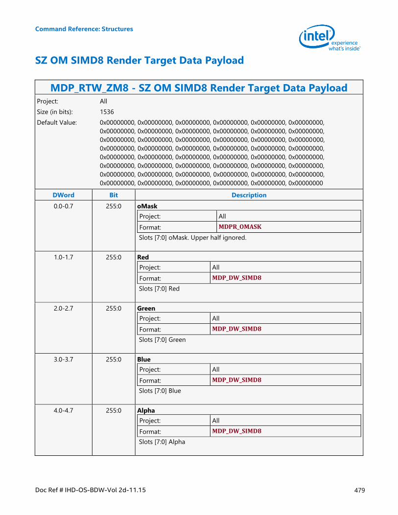
Command Reference: Structures
Doc Ref # IHD-OS-BDW-Vol 2d-11.15 479
SZ OM SIMD8 Render Target Data Payload
MDP_RTW_ZM8 - SZ OM SIMD8 Render Target Data Payload Project: All
Size (in bits): 1536
Default Value: 0x00000000, 0x00000000, 0x00000000, 0x00000000, 0x00000000, 0x00000000,
0x00000000, 0x00000000, 0x00000000, 0x00000000, 0x00000000, 0x00000000,
0x00000000, 0x00000000, 0x00000000, 0x00000000, 0x00000000, 0x00000000,
0x00000000, 0x00000000, 0x00000000, 0x00000000, 0x00000000, 0x00000000,
0x00000000, 0x00000000, 0x00000000, 0x00000000, 0x00000000, 0x00000000,
0x00000000, 0x00000000, 0x00000000, 0x00000000, 0x00000000, 0x00000000,
0x00000000, 0x00000000, 0x00000000, 0x00000000, 0x00000000, 0x00000000,
0x00000000, 0x00000000, 0x00000000, 0x00000000, 0x00000000, 0x00000000
DWord Bit Description
0.0-0.7 255:0 oMask
Project: All
Format: MDPR_OMASK
Slots [7:0] oMask. Upper half ignored.
1.0-1.7 255:0 Red
Project: All
Format: MDP_DW_SIMD8
Slots [7:0] Red
2.0-2.7 255:0 Green
Project: All
Format: MDP_DW_SIMD8
Slots [7:0] Green
3.0-3.7 255:0 Blue
Project: All
Format: MDP_DW_SIMD8
Slots [7:0] Blue
4.0-4.7 255:0 Alpha
Project: All
Format: MDP_DW_SIMD8
Slots [7:0] Alpha
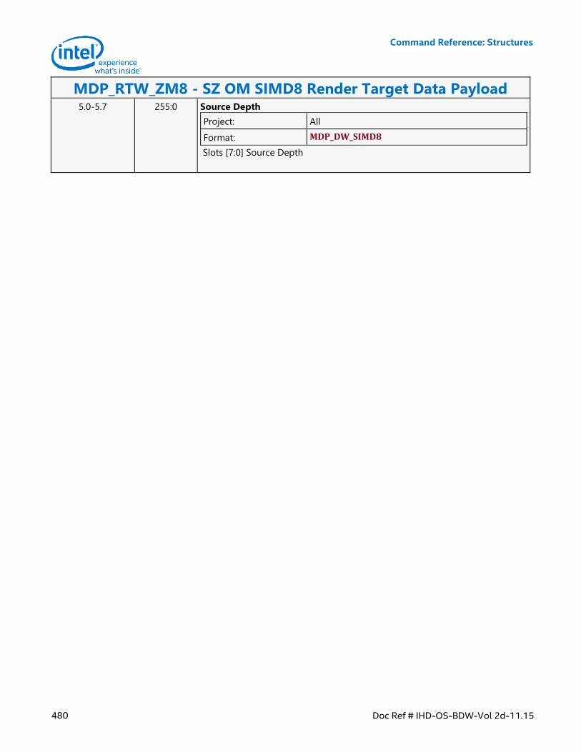
Command Reference: Structures
480 Doc Ref # IHD-OS-BDW-Vol 2d-11.15
MDP_RTW_ZM8 - SZ OM SIMD8 Render Target Data Payload 5.0-5.7 255:0 Source Depth
Project: All
Format: MDP_DW_SIMD8
Slots [7:0] Source Depth
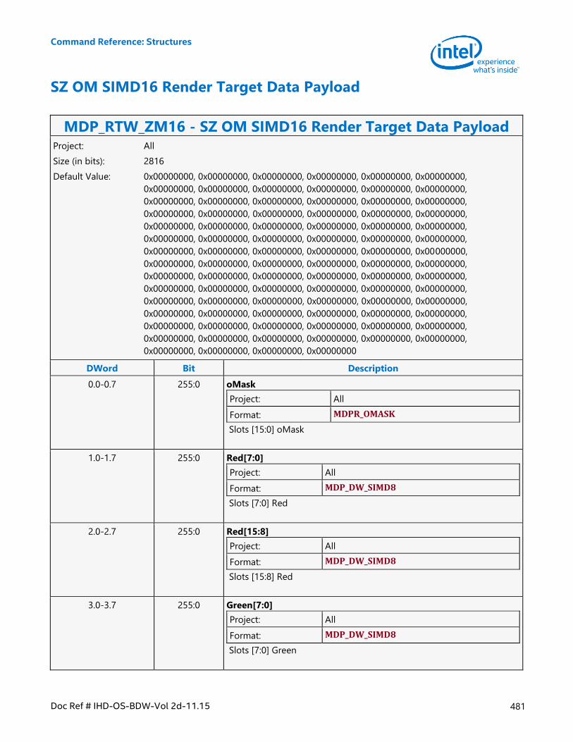
Command Reference: Structures
Doc Ref # IHD-OS-BDW-Vol 2d-11.15 481
SZ OM SIMD16 Render Target Data Payload
MDP_RTW_ZM16 - SZ OM SIMD16 Render Target Data Payload Project: All
Size (in bits): 2816
Default Value: 0x00000000, 0x00000000, 0x00000000, 0x00000000, 0x00000000, 0x00000000,
0x00000000, 0x00000000, 0x00000000, 0x00000000, 0x00000000, 0x00000000,
0x00000000, 0x00000000, 0x00000000, 0x00000000, 0x00000000, 0x00000000,
0x00000000, 0x00000000, 0x00000000, 0x00000000, 0x00000000, 0x00000000,
0x00000000, 0x00000000, 0x00000000, 0x00000000, 0x00000000, 0x00000000,
0x00000000, 0x00000000, 0x00000000, 0x00000000, 0x00000000, 0x00000000,
0x00000000, 0x00000000, 0x00000000, 0x00000000, 0x00000000, 0x00000000,
0x00000000, 0x00000000, 0x00000000, 0x00000000, 0x00000000, 0x00000000,
0x00000000, 0x00000000, 0x00000000, 0x00000000, 0x00000000, 0x00000000,
0x00000000, 0x00000000, 0x00000000, 0x00000000, 0x00000000, 0x00000000,
0x00000000, 0x00000000, 0x00000000, 0x00000000, 0x00000000, 0x00000000,
0x00000000, 0x00000000, 0x00000000, 0x00000000, 0x00000000, 0x00000000,
0x00000000, 0x00000000, 0x00000000, 0x00000000, 0x00000000, 0x00000000,
0x00000000, 0x00000000, 0x00000000, 0x00000000, 0x00000000, 0x00000000,
0x00000000, 0x00000000, 0x00000000, 0x00000000
DWord Bit Description
0.0-0.7 255:0 oMask
Project: All
Format: MDPR_OMASK
Slots [15:0] oMask
1.0-1.7 255:0 Red[7:0]
Project: All
Format: MDP_DW_SIMD8
Slots [7:0] Red
2.0-2.7 255:0 Red[15:8]
Project: All
Format: MDP_DW_SIMD8
Slots [15:8] Red
3.0-3.7 255:0 Green[7:0]
Project: All
Format: MDP_DW_SIMD8
Slots [7:0] Green
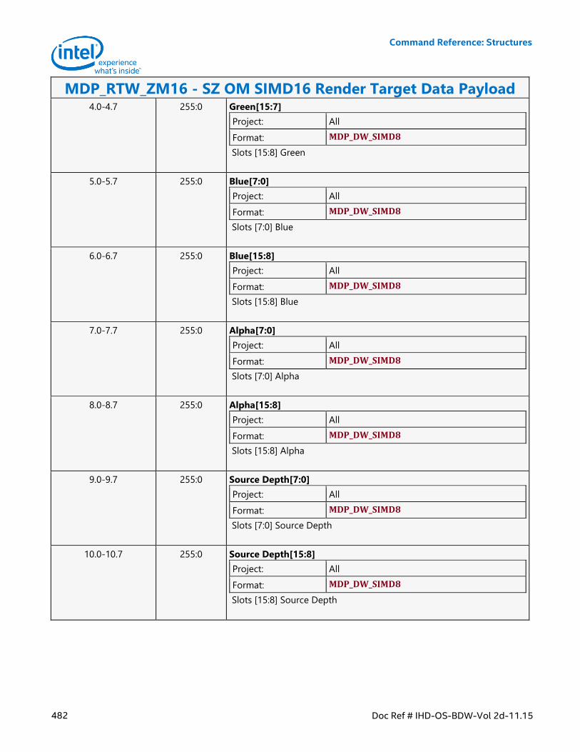
Command Reference: Structures
482 Doc Ref # IHD-OS-BDW-Vol 2d-11.15
MDP_RTW_ZM16 - SZ OM SIMD16 Render Target Data Payload 4.0-4.7 255:0 Green[15:7]
Project: All
Format: MDP_DW_SIMD8
Slots [15:8] Green
5.0-5.7 255:0 Blue[7:0]
Project: All
Format: MDP_DW_SIMD8
Slots [7:0] Blue
6.0-6.7 255:0 Blue[15:8]
Project: All
Format: MDP_DW_SIMD8
Slots [15:8] Blue
7.0-7.7 255:0 Alpha[7:0]
Project: All
Format: MDP_DW_SIMD8
Slots [7:0] Alpha
8.0-8.7 255:0 Alpha[15:8]
Project: All
Format: MDP_DW_SIMD8
Slots [15:8] Alpha
9.0-9.7 255:0 Source Depth[7:0]
Project: All
Format: MDP_DW_SIMD8
Slots [7:0] Source Depth
10.0-10.7 255:0 Source Depth[15:8]
Project: All
Format: MDP_DW_SIMD8
Slots [15:8] Source Depth
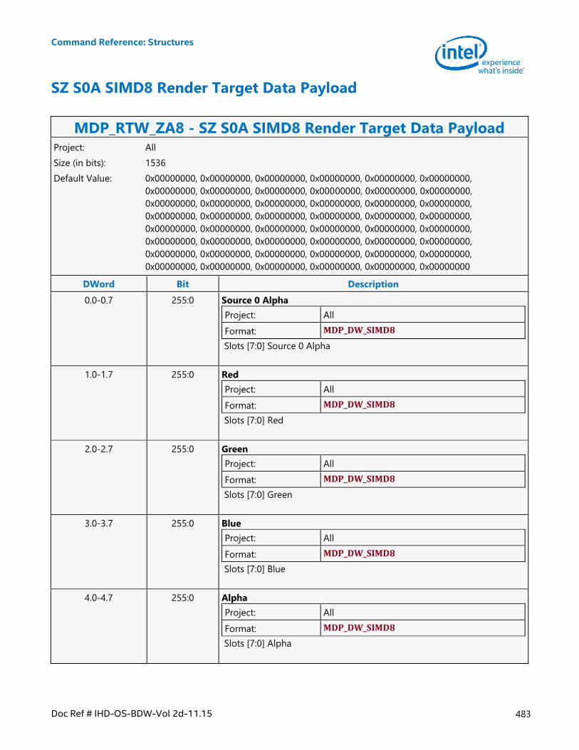
Command Reference: Structures
Doc Ref # IHD-OS-BDW-Vol 2d-11.15 483
SZ S0A SIMD8 Render Target Data Payload
MDP_RTW_ZA8 - SZ S0A SIMD8 Render Target Data Payload Project: All
Size (in bits): 1536
Default Value: 0x00000000, 0x00000000, 0x00000000, 0x00000000, 0x00000000, 0x00000000,
0x00000000, 0x00000000, 0x00000000, 0x00000000, 0x00000000, 0x00000000,
0x00000000, 0x00000000, 0x00000000, 0x00000000, 0x00000000, 0x00000000,
0x00000000, 0x00000000, 0x00000000, 0x00000000, 0x00000000, 0x00000000,
0x00000000, 0x00000000, 0x00000000, 0x00000000, 0x00000000, 0x00000000,
0x00000000, 0x00000000, 0x00000000, 0x00000000, 0x00000000, 0x00000000,
0x00000000, 0x00000000, 0x00000000, 0x00000000, 0x00000000, 0x00000000,
0x00000000, 0x00000000, 0x00000000, 0x00000000, 0x00000000, 0x00000000
DWord Bit Description
0.0-0.7 255:0 Source 0 Alpha
Project: All
Format: MDP_DW_SIMD8
Slots [7:0] Source 0 Alpha
1.0-1.7 255:0 Red
Project: All
Format: MDP_DW_SIMD8
Slots [7:0] Red
2.0-2.7 255:0 Green
Project: All
Format: MDP_DW_SIMD8
Slots [7:0] Green
3.0-3.7 255:0 Blue
Project: All
Format: MDP_DW_SIMD8
Slots [7:0] Blue
4.0-4.7 255:0 Alpha
Project: All
Format: MDP_DW_SIMD8
Slots [7:0] Alpha
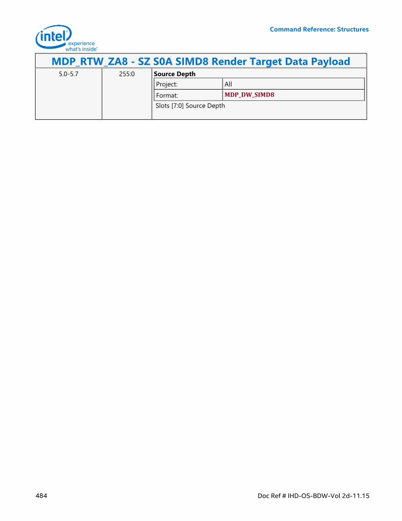
Command Reference: Structures
484 Doc Ref # IHD-OS-BDW-Vol 2d-11.15
MDP_RTW_ZA8 - SZ S0A SIMD8 Render Target Data Payload 5.0-5.7 255:0 Source Depth
Project: All
Format: MDP_DW_SIMD8
Slots [7:0] Source Depth
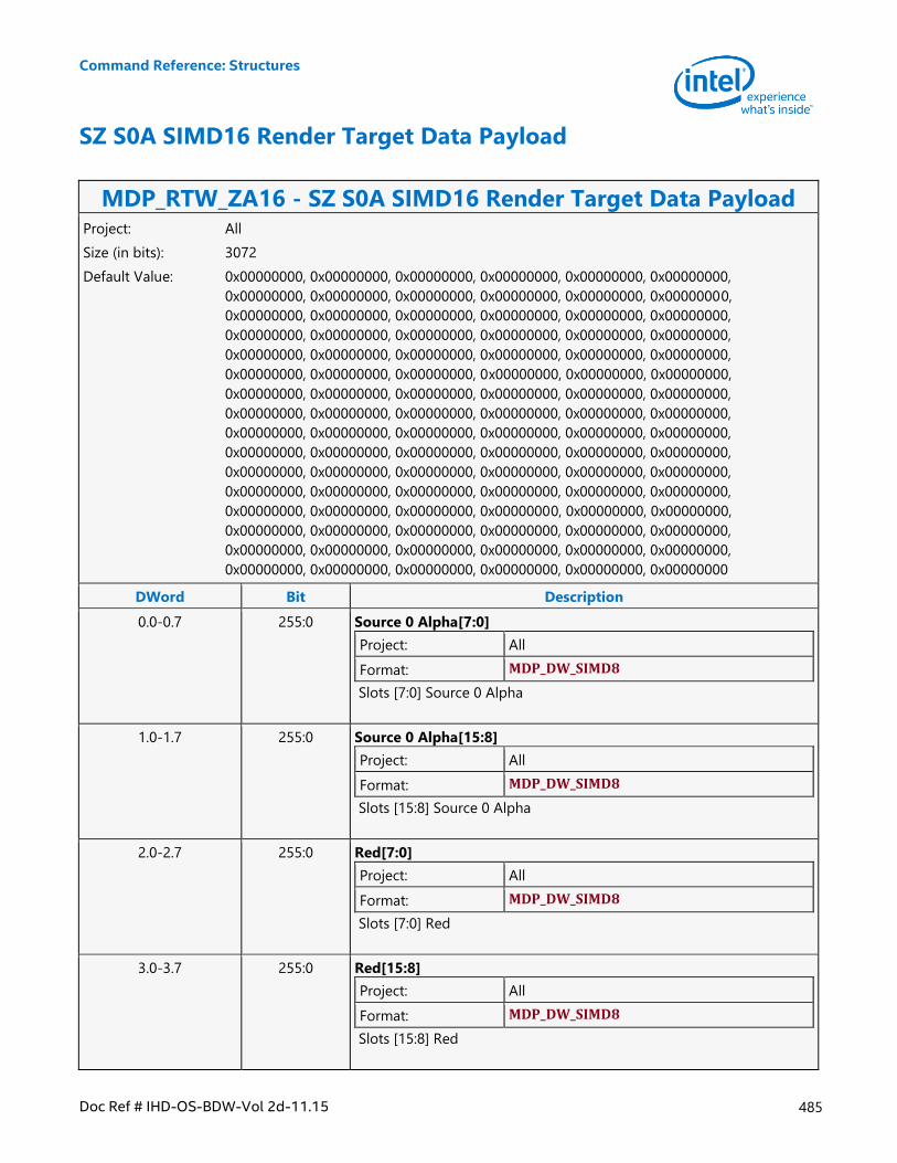
Command Reference: Structures
Doc Ref # IHD-OS-BDW-Vol 2d-11.15 485
SZ S0A SIMD16 Render Target Data Payload
MDP_RTW_ZA16 - SZ S0A SIMD16 Render Target Data Payload Project: All
Size (in bits): 3072
Default Value: 0x00000000, 0x00000000, 0x00000000, 0x00000000, 0x00000000, 0x00000000,
0x00000000, 0x00000000, 0x00000000, 0x00000000, 0x00000000, 0x00000000,
0x00000000, 0x00000000, 0x00000000, 0x00000000, 0x00000000, 0x00000000,
0x00000000, 0x00000000, 0x00000000, 0x00000000, 0x00000000, 0x00000000,
0x00000000, 0x00000000, 0x00000000, 0x00000000, 0x00000000, 0x00000000,
0x00000000, 0x00000000, 0x00000000, 0x00000000, 0x00000000, 0x00000000,
0x00000000, 0x00000000, 0x00000000, 0x00000000, 0x00000000, 0x00000000,
0x00000000, 0x00000000, 0x00000000, 0x00000000, 0x00000000, 0x00000000,
0x00000000, 0x00000000, 0x00000000, 0x00000000, 0x00000000, 0x00000000,
0x00000000, 0x00000000, 0x00000000, 0x00000000, 0x00000000, 0x00000000,
0x00000000, 0x00000000, 0x00000000, 0x00000000, 0x00000000, 0x00000000,
0x00000000, 0x00000000, 0x00000000, 0x00000000, 0x00000000, 0x00000000,
0x00000000, 0x00000000, 0x00000000, 0x00000000, 0x00000000, 0x00000000,
0x00000000, 0x00000000, 0x00000000, 0x00000000, 0x00000000, 0x00000000,
0x00000000, 0x00000000, 0x00000000, 0x00000000, 0x00000000, 0x00000000,
0x00000000, 0x00000000, 0x00000000, 0x00000000, 0x00000000, 0x00000000
DWord Bit Description
0.0-0.7 255:0 Source 0 Alpha[7:0]
Project: All
Format: MDP_DW_SIMD8
Slots [7:0] Source 0 Alpha
1.0-1.7 255:0 Source 0 Alpha[15:8]
Project: All
Format: MDP_DW_SIMD8
Slots [15:8] Source 0 Alpha
2.0-2.7 255:0 Red[7:0]
Project: All
Format: MDP_DW_SIMD8
Slots [7:0] Red
3.0-3.7 255:0 Red[15:8]
Project: All
Format: MDP_DW_SIMD8
Slots [15:8] Red
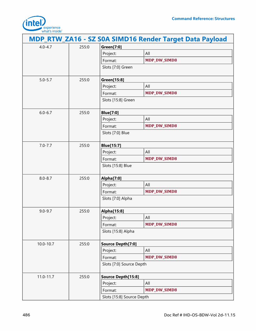
Command Reference: Structures
486 Doc Ref # IHD-OS-BDW-Vol 2d-11.15
MDP_RTW_ZA16 - SZ S0A SIMD16 Render Target Data Payload 4.0-4.7 255:0 Green[7:0]
Project: All
Format: MDP_DW_SIMD8
Slots [7:0] Green
5.0-5.7 255:0 Green[15:8]
Project: All
Format: MDP_DW_SIMD8
Slots [15:8] Green
6.0-6.7 255:0 Blue[7:0]
Project: All
Format: MDP_DW_SIMD8
Slots [7:0] Blue
7.0-7.7 255:0 Blue[15:7]
Project: All
Format: MDP_DW_SIMD8
Slots [15:8] Blue
8.0-8.7 255:0 Alpha[7:0]
Project: All
Format: MDP_DW_SIMD8
Slots [7:0] Alpha
9.0-9.7 255:0 Alpha[15:8]
Project: All
Format: MDP_DW_SIMD8
Slots [15:8] Alpha
10.0-10.7 255:0 Source Depth[7:0]
Project: All
Format: MDP_DW_SIMD8
Slots [7:0] Source Depth
11.0-11.7 255:0 Source Depth[15:8]
Project: All
Format: MDP_DW_SIMD8
Slots [15:8] Source Depth
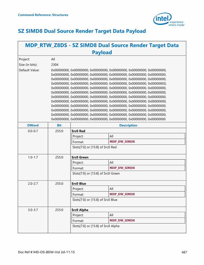
Command Reference: Structures
Doc Ref # IHD-OS-BDW-Vol 2d-11.15 487
SZ SIMD8 Dual Source Render Target Data Payload
MDP_RTW_Z8DS - SZ SIMD8 Dual Source Render Target Data
Payload Project: All
Size (in bits): 2304
Default Value: 0x00000000, 0x00000000, 0x00000000, 0x00000000, 0x00000000, 0x00000000,
0x00000000, 0x00000000, 0x00000000, 0x00000000, 0x00000000, 0x00000000,
0x00000000, 0x00000000, 0x00000000, 0x00000000, 0x00000000, 0x00000000,
0x00000000, 0x00000000, 0x00000000, 0x00000000, 0x00000000, 0x00000000,
0x00000000, 0x00000000, 0x00000000, 0x00000000, 0x00000000, 0x00000000,
0x00000000, 0x00000000, 0x00000000, 0x00000000, 0x00000000, 0x00000000,
0x00000000, 0x00000000, 0x00000000, 0x00000000, 0x00000000, 0x00000000,
0x00000000, 0x00000000, 0x00000000, 0x00000000, 0x00000000, 0x00000000,
0x00000000, 0x00000000, 0x00000000, 0x00000000, 0x00000000, 0x00000000,
0x00000000, 0x00000000, 0x00000000, 0x00000000, 0x00000000, 0x00000000,
0x00000000, 0x00000000, 0x00000000, 0x00000000, 0x00000000, 0x00000000,
0x00000000, 0x00000000, 0x00000000, 0x00000000, 0x00000000, 0x00000000
DWord Bit Description
0.0-0.7 255:0 Src0 Red
Project: All
Format: MDP_DW_SIMD8
Slots[7:0] or [15:8] of Src0 Red
1.0-1.7 255:0 Src0 Green
Project: All
Format: MDP_DW_SIMD8
Slots[7:0] or [15:8] of Src0 Green
2.0-2.7 255:0 Src0 Blue
Project: All
Format: MDP_DW_SIMD8
Slots[7:0] or [15:8] of Src0 Blue
3.0-3.7 255:0 Src0 Alpha
Project: All
Format: MDP_DW_SIMD8
Slots[7:0] or [15:8] of Src0 Alpha
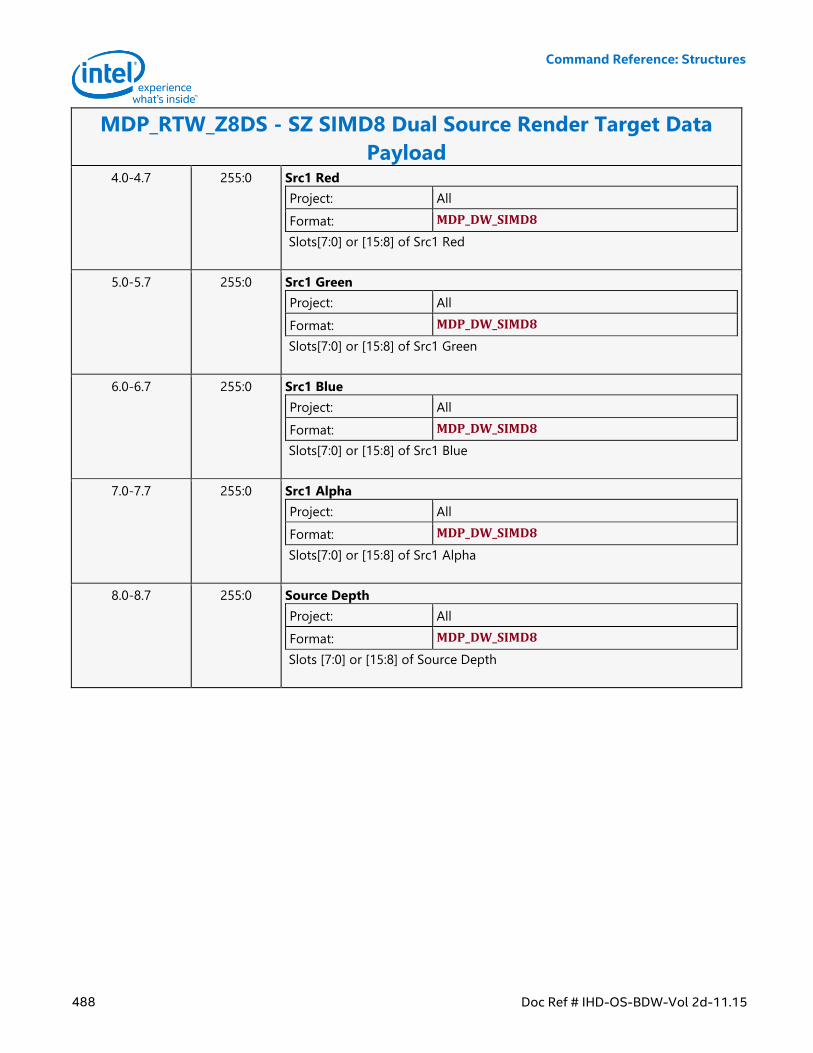
Command Reference: Structures
488 Doc Ref # IHD-OS-BDW-Vol 2d-11.15
MDP_RTW_Z8DS - SZ SIMD8 Dual Source Render Target Data
Payload 4.0-4.7 255:0 Src1 Red
Project: All
Format: MDP_DW_SIMD8
Slots[7:0] or [15:8] of Src1 Red
5.0-5.7 255:0 Src1 Green
Project: All
Format: MDP_DW_SIMD8
Slots[7:0] or [15:8] of Src1 Green
6.0-6.7 255:0 Src1 Blue
Project: All
Format: MDP_DW_SIMD8
Slots[7:0] or [15:8] of Src1 Blue
7.0-7.7 255:0 Src1 Alpha
Project: All
Format: MDP_DW_SIMD8
Slots[7:0] or [15:8] of Src1 Alpha
8.0-8.7 255:0 Source Depth
Project: All
Format: MDP_DW_SIMD8
Slots [7:0] or [15:8] of Source Depth
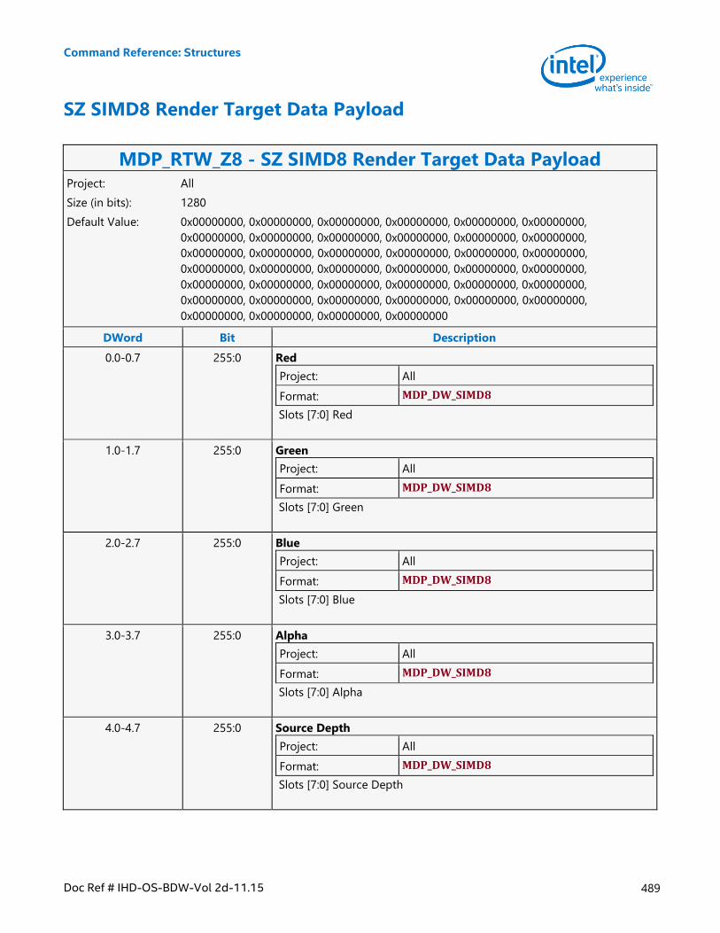
Command Reference: Structures
Doc Ref # IHD-OS-BDW-Vol 2d-11.15 489
SZ SIMD8 Render Target Data Payload
MDP_RTW_Z8 - SZ SIMD8 Render Target Data Payload Project: All
Size (in bits): 1280
Default Value: 0x00000000, 0x00000000, 0x00000000, 0x00000000, 0x00000000, 0x00000000,
0x00000000, 0x00000000, 0x00000000, 0x00000000, 0x00000000, 0x00000000,
0x00000000, 0x00000000, 0x00000000, 0x00000000, 0x00000000, 0x00000000,
0x00000000, 0x00000000, 0x00000000, 0x00000000, 0x00000000, 0x00000000,
0x00000000, 0x00000000, 0x00000000, 0x00000000, 0x00000000, 0x00000000,
0x00000000, 0x00000000, 0x00000000, 0x00000000, 0x00000000, 0x00000000,
0x00000000, 0x00000000, 0x00000000, 0x00000000
DWord Bit Description
0.0-0.7 255:0 Red
Project: All
Format: MDP_DW_SIMD8
Slots [7:0] Red
1.0-1.7 255:0 Green
Project: All
Format: MDP_DW_SIMD8
Slots [7:0] Green
2.0-2.7 255:0 Blue
Project: All
Format: MDP_DW_SIMD8
Slots [7:0] Blue
3.0-3.7 255:0 Alpha
Project: All
Format: MDP_DW_SIMD8
Slots [7:0] Alpha
4.0-4.7 255:0 Source Depth
Project: All
Format: MDP_DW_SIMD8
Slots [7:0] Source Depth
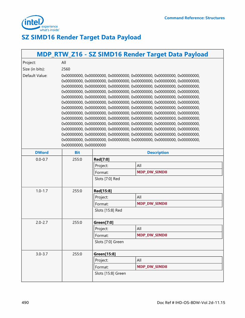
Command Reference: Structures
490 Doc Ref # IHD-OS-BDW-Vol 2d-11.15
SZ SIMD16 Render Target Data Payload
MDP_RTW_Z16 - SZ SIMD16 Render Target Data Payload Project: All
Size (in bits): 2560
Default Value: 0x00000000, 0x00000000, 0x00000000, 0x00000000, 0x00000000, 0x00000000,
0x00000000, 0x00000000, 0x00000000, 0x00000000, 0x00000000, 0x00000000,
0x00000000, 0x00000000, 0x00000000, 0x00000000, 0x00000000, 0x00000000,
0x00000000, 0x00000000, 0x00000000, 0x00000000, 0x00000000, 0x00000000,
0x00000000, 0x00000000, 0x00000000, 0x00000000, 0x00000000, 0x00000000,
0x00000000, 0x00000000, 0x00000000, 0x00000000, 0x00000000, 0x00000000,
0x00000000, 0x00000000, 0x00000000, 0x00000000, 0x00000000, 0x00000000,
0x00000000, 0x00000000, 0x00000000, 0x00000000, 0x00000000, 0x00000000,
0x00000000, 0x00000000, 0x00000000, 0x00000000, 0x00000000, 0x00000000,
0x00000000, 0x00000000, 0x00000000, 0x00000000, 0x00000000, 0x00000000,
0x00000000, 0x00000000, 0x00000000, 0x00000000, 0x00000000, 0x00000000,
0x00000000, 0x00000000, 0x00000000, 0x00000000, 0x00000000, 0x00000000,
0x00000000, 0x00000000, 0x00000000, 0x00000000, 0x00000000, 0x00000000,
0x00000000, 0x00000000
DWord Bit Description
0.0-0.7 255:0 Red[7:0]
Project: All
Format: MDP_DW_SIMD8
Slots [7:0] Red
1.0-1.7 255:0 Red[15:8]
Project: All
Format: MDP_DW_SIMD8
Slots [15:8] Red
2.0-2.7 255:0 Green[7:0]
Project: All
Format: MDP_DW_SIMD8
Slots [7:0] Green
3.0-3.7 255:0 Green[15:8]
Project: All
Format: MDP_DW_SIMD8
Slots [15:8] Green
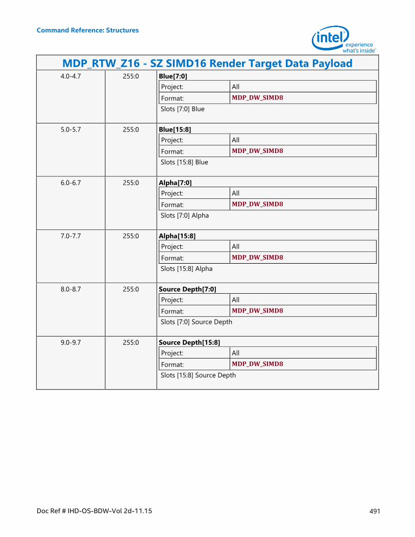
Command Reference: Structures
Doc Ref # IHD-OS-BDW-Vol 2d-11.15 491
MDP_RTW_Z16 - SZ SIMD16 Render Target Data Payload 4.0-4.7 255:0 Blue[7:0]
Project: All
Format: MDP_DW_SIMD8
Slots [7:0] Blue
5.0-5.7 255:0 Blue[15:8]
Project: All
Format: MDP_DW_SIMD8
Slots [15:8] Blue
6.0-6.7 255:0 Alpha[7:0]
Project: All
Format: MDP_DW_SIMD8
Slots [7:0] Alpha
7.0-7.7 255:0 Alpha[15:8]
Project: All
Format: MDP_DW_SIMD8
Slots [15:8] Alpha
8.0-8.7 255:0 Source Depth[7:0]
Project: All
Format: MDP_DW_SIMD8
Slots [7:0] Source Depth
9.0-9.7 255:0 Source Depth[15:8]
Project: All
Format: MDP_DW_SIMD8
Slots [15:8] Source Depth
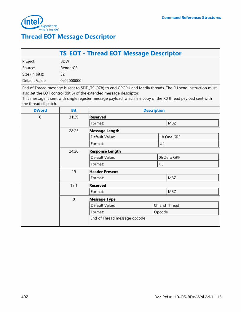
Command Reference: Structures
492 Doc Ref # IHD-OS-BDW-Vol 2d-11.15
Thread EOT Message Descriptor
TS_EOT - Thread EOT Message Descriptor Project: BDW
Source: RenderCS
Size (in bits): 32
Default Value: 0x02000000
End of Thread message is sent to SFID_TS (07h) to end GPGPU and Media threads. The EU send instruction must
also set the EOT control (bit 5) of the extended message descriptor.
This message is sent with single register message payload, which is a copy of the R0 thread payload sent with
the thread dispatch.
DWord Bit Description
0 31:29 Reserved
Format: MBZ
28:25 Message Length
Default Value: 1h One GRF
Format: U4
24:20 Response Length
Default Value: 0h Zero GRF
Format: U5
19 Header Present
Format: MBZ
18:1 Reserved
Format: MBZ
0 Message Type
Default Value: 0h End Thread
Format: Opcode
End of Thread message opcode
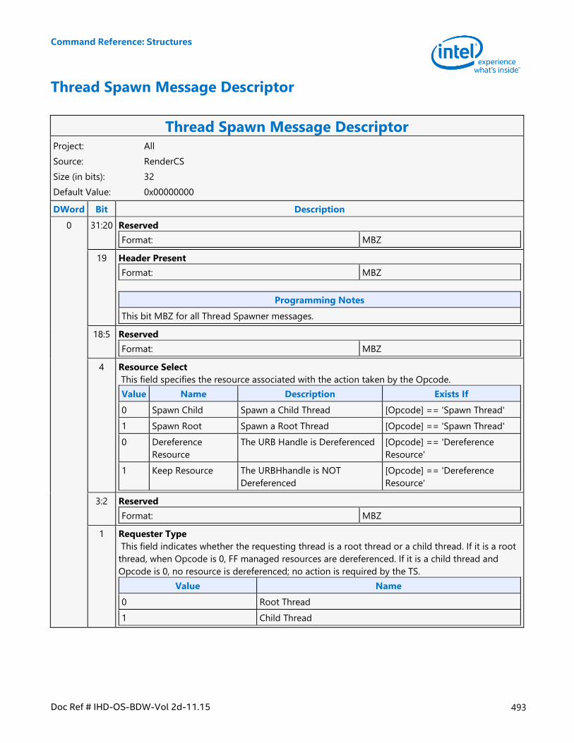
Command Reference: Structures
Doc Ref # IHD-OS-BDW-Vol 2d-11.15 493
Thread Spawn Message Descriptor
Thread Spawn Message Descriptor Project: All
Source: RenderCS
Size (in bits): 32
Default Value: 0x00000000
DWord Bit Description
0 31:20 Reserved
Format: MBZ
19 Header Present
Format: MBZ
Programming Notes
This bit MBZ for all Thread Spawner messages.
18:5 Reserved
Format: MBZ
4 Resource Select
This field specifies the resource associated with the action taken by the Opcode.
Value Name Description Exists If
0 Spawn Child Spawn a Child Thread [Opcode] == 'Spawn Thread'
1 Spawn Root Spawn a Root Thread [Opcode] == 'Spawn Thread'
0 Dereference
Resource
The URB Handle is Dereferenced [Opcode] == 'Dereference
Resource'
1 Keep Resource The URBHhandle is NOT
Dereferenced
[Opcode] == 'Dereference
Resource'
3:2 Reserved
Format: MBZ
1 Requester Type
This field indicates whether the requesting thread is a root thread or a child thread. If it is a root
thread, when Opcode is 0, FF managed resources are dereferenced. If it is a child thread and
Opcode is 0, no resource is dereferenced; no action is required by the TS.
Value Name
0 Root Thread
1 Child Thread
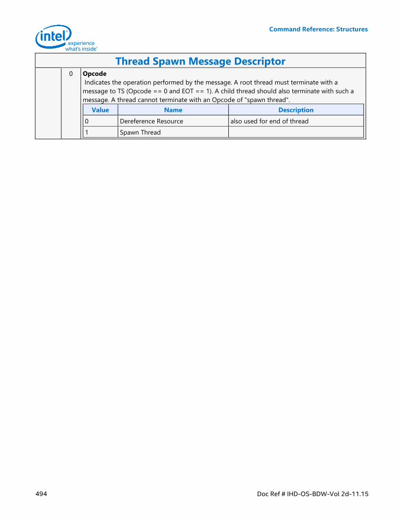
Command Reference: Structures
494 Doc Ref # IHD-OS-BDW-Vol 2d-11.15
Thread Spawn Message Descriptor 0 Opcode
Indicates the operation performed by the message. A root thread must terminate with a
message to TS (Opcode == 0 and EOT == 1). A child thread should also terminate with such a
message. A thread cannot terminate with an Opcode of "spawn thread".
Value Name Description
0 Dereference Resource also used for end of thread
1 Spawn Thread
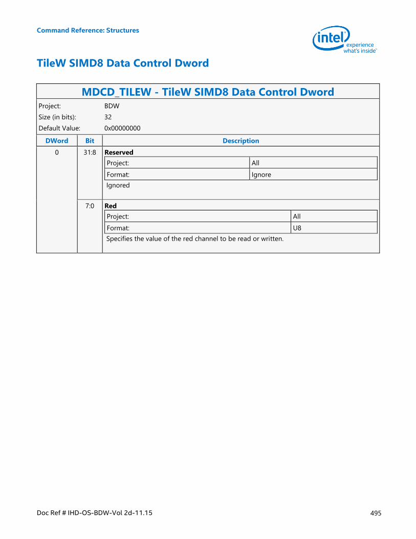
Command Reference: Structures
Doc Ref # IHD-OS-BDW-Vol 2d-11.15 495
TileW SIMD8 Data Control Dword
MDCD_TILEW - TileW SIMD8 Data Control Dword Project: BDW
Size (in bits): 32
Default Value: 0x00000000
DWord Bit Description
0 31:8 Reserved
Project: All
Format: Ignore
Ignored
7:0 Red
Project: All
Format: U8
Specifies the value of the red channel to be read or written.
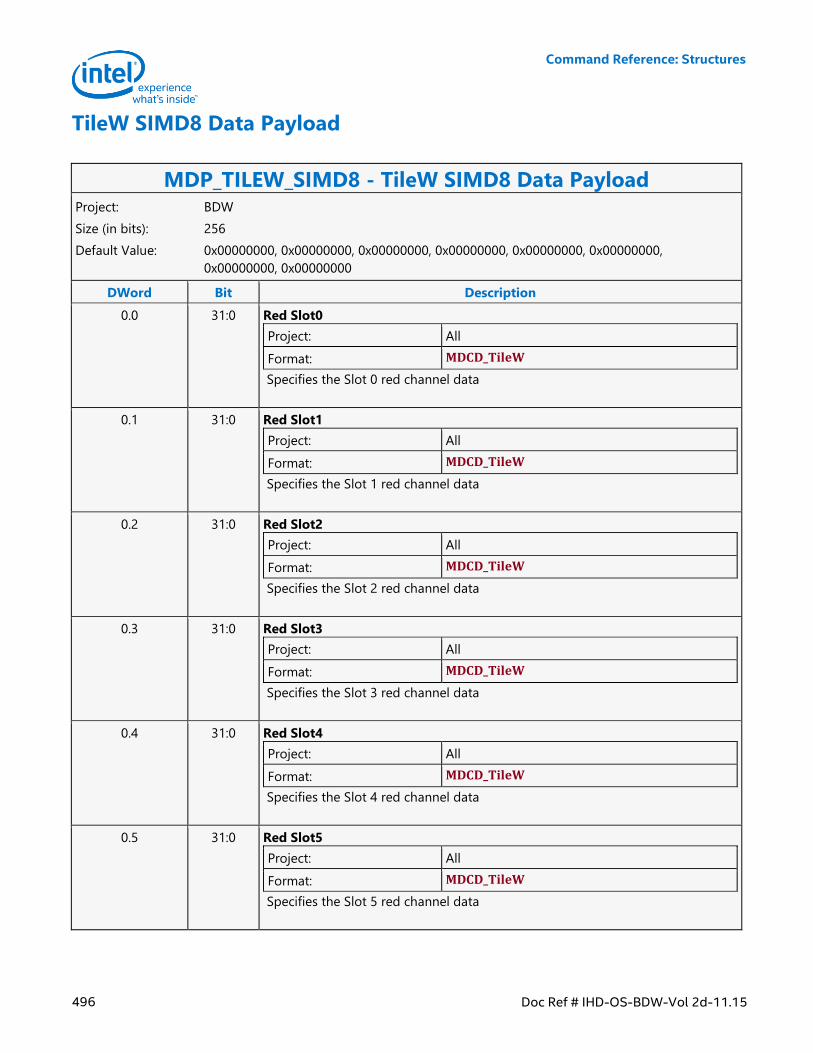
Command Reference: Structures
496 Doc Ref # IHD-OS-BDW-Vol 2d-11.15
TileW SIMD8 Data Payload
MDP_TILEW_SIMD8 - TileW SIMD8 Data Payload Project: BDW
Size (in bits): 256
Default Value: 0x00000000, 0x00000000, 0x00000000, 0x00000000, 0x00000000, 0x00000000,
0x00000000, 0x00000000
DWord Bit Description
0.0 31:0 Red Slot0
Project: All
Format: MDCD_TileW
Specifies the Slot 0 red channel data
0.1 31:0 Red Slot1
Project: All
Format: MDCD_TileW
Specifies the Slot 1 red channel data
0.2 31:0 Red Slot2
Project: All
Format: MDCD_TileW
Specifies the Slot 2 red channel data
0.3 31:0 Red Slot3
Project: All
Format: MDCD_TileW
Specifies the Slot 3 red channel data
0.4 31:0 Red Slot4
Project: All
Format: MDCD_TileW
Specifies the Slot 4 red channel data
0.5 31:0 Red Slot5
Project: All
Format: MDCD_TileW
Specifies the Slot 5 red channel data
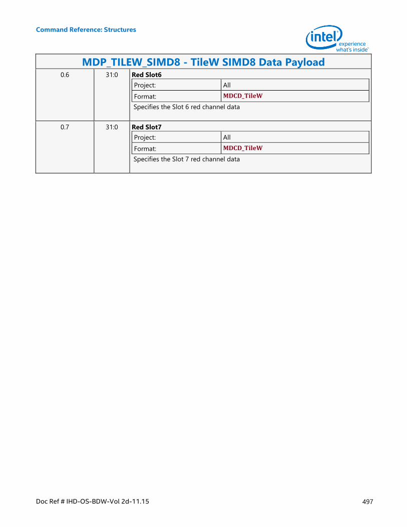
Command Reference: Structures
Doc Ref # IHD-OS-BDW-Vol 2d-11.15 497
MDP_TILEW_SIMD8 - TileW SIMD8 Data Payload 0.6 31:0 Red Slot6
Project: All
Format: MDCD_TileW
Specifies the Slot 6 red channel data
0.7 31:0 Red Slot7
Project: All
Format: MDCD_TileW
Specifies the Slot 7 red channel data
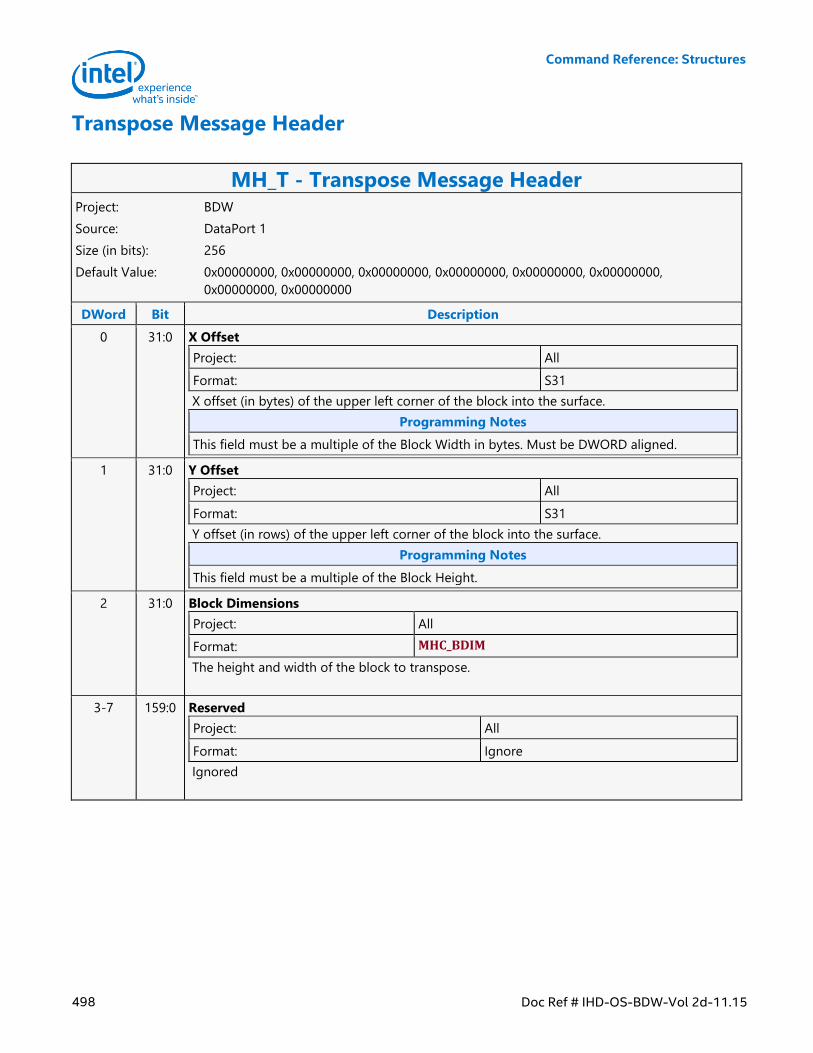
Command Reference: Structures
498 Doc Ref # IHD-OS-BDW-Vol 2d-11.15
Transpose Message Header
MH_T - Transpose Message Header Project: BDW
Source: DataPort 1
Size (in bits): 256
Default Value: 0x00000000, 0x00000000, 0x00000000, 0x00000000, 0x00000000, 0x00000000,
0x00000000, 0x00000000
DWord Bit Description
0 31:0 X Offset
Project: All
Format: S31
X offset (in bytes) of the upper left corner of the block into the surface.
Programming Notes
This field must be a multiple of the Block Width in bytes. Must be DWORD aligned.
1 31:0 Y Offset
Project: All
Format: S31
Y offset (in rows) of the upper left corner of the block into the surface.
Programming Notes
This field must be a multiple of the Block Height.
2 31:0 Block Dimensions
Project: All
Format: MHC_BDIM
The height and width of the block to transpose.
3-7 159:0 Reserved
Project: All
Format: Ignore
Ignored
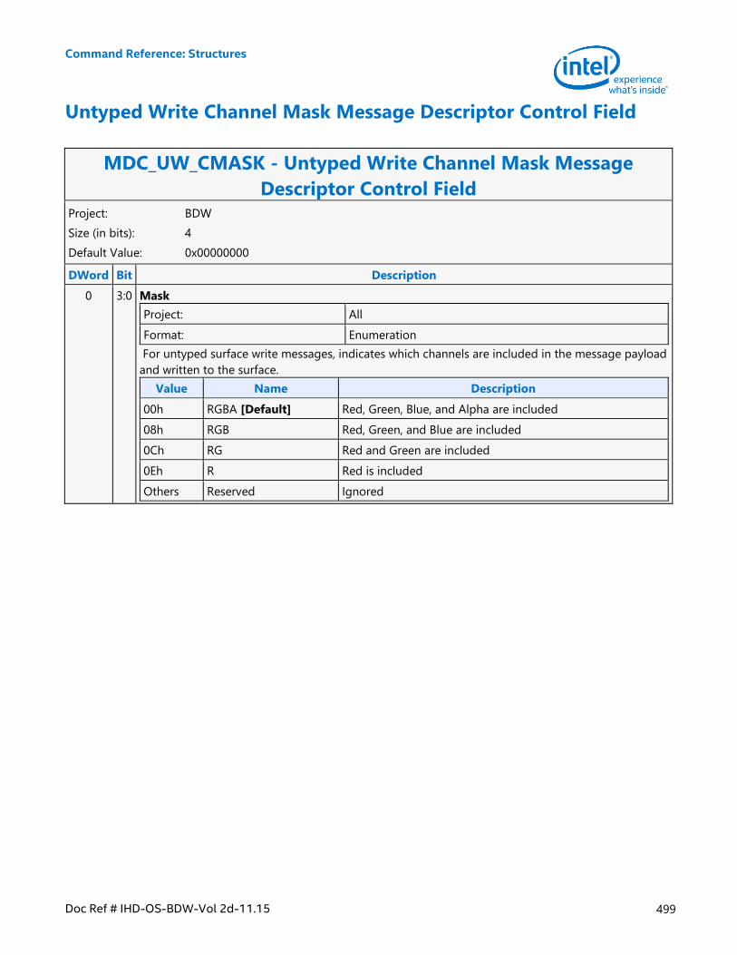
Command Reference: Structures
Doc Ref # IHD-OS-BDW-Vol 2d-11.15 499
Untyped Write Channel Mask Message Descriptor Control Field
MDC_UW_CMASK - Untyped Write Channel Mask Message
Descriptor Control Field Project: BDW
Size (in bits): 4
Default Value: 0x00000000
DWord Bit Description
0 3:0 Mask
Project: All
Format: Enumeration
For untyped surface write messages, indicates which channels are included in the message payload
and written to the surface.
Value Name Description
00h RGBA [Default] Red, Green, Blue, and Alpha are included
08h RGB Red, Green, and Blue are included
0Ch RG Red and Green are included
0Eh R Red is included
Others Reserved Ignored

Command Reference: Structures
500 Doc Ref # IHD-OS-BDW-Vol 2d-11.15
Upper Oword Block Data Payload
MDP_OW1U - Upper Oword Block Data Payload Project: BDW
Size (in bits): 256
Default Value: 0x00000000, 0x00000000, 0x00000000, 0x00000000, 0x00000000, 0x00000000,
0x00000000, 0x00000000
DWord Bit Description
0.0-0.3 127:0 Reserved
Project: All
Format: Ignore
Ignored
0.4-0.7 127:0 Oword
Project: All
Format: U128
Specifies the upper Oword data element
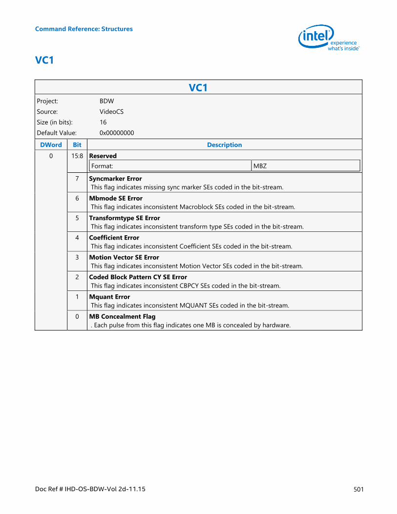
Command Reference: Structures
Doc Ref # IHD-OS-BDW-Vol 2d-11.15 501
VC1
VC1 Project: BDW
Source: VideoCS
Size (in bits): 16
Default Value: 0x00000000
DWord Bit Description
0 15:8 Reserved
Format: MBZ
7 Syncmarker Error
This flag indicates missing sync marker SEs coded in the bit-stream.
6 Mbmode SE Error
This flag indicates inconsistent Macroblock SEs coded in the bit-stream.
5 Transformtype SE Error
This flag indicates inconsistent transform type SEs coded in the bit-stream.
4 Coefficient Error
This flag indicates inconsistent Coefficient SEs coded in the bit-stream.
3 Motion Vector SE Error
This flag indicates inconsistent Motion Vector SEs coded in the bit-stream.
2 Coded Block Pattern CY SE Error
This flag indicates inconsistent CBPCY SEs coded in the bit-stream.
1 Mquant Error
This flag indicates inconsistent MQUANT SEs coded in the bit-stream.
0 MB Concealment Flag
. Each pulse from this flag indicates one MB is concealed by hardware.
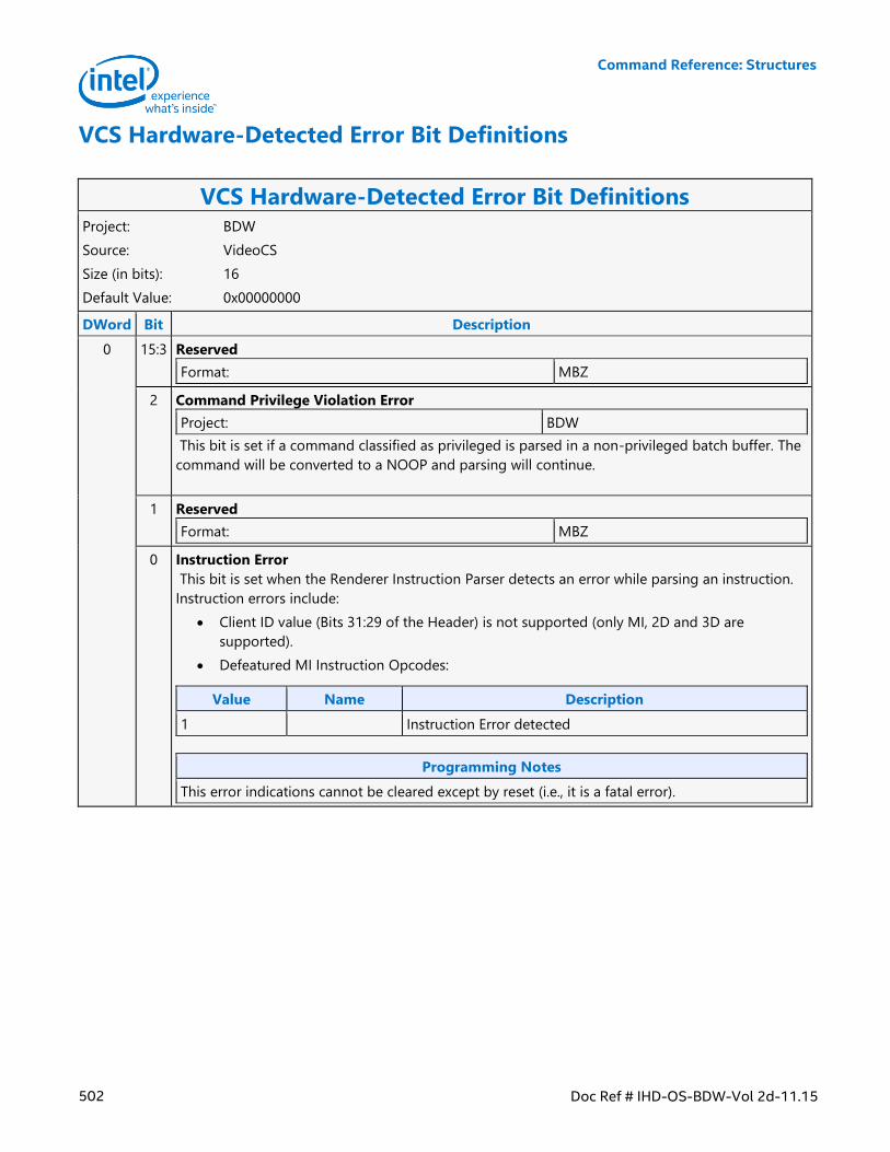
Command Reference: Structures
502 Doc Ref # IHD-OS-BDW-Vol 2d-11.15
VCS Hardware-Detected Error Bit Definitions
VCS Hardware-Detected Error Bit Definitions Project: BDW
Source: VideoCS
Size (in bits): 16
Default Value: 0x00000000
DWord Bit Description
0 15:3 Reserved
Format: MBZ
2 Command Privilege Violation Error
Project: BDW
This bit is set if a command classified as privileged is parsed in a non-privileged batch buffer. The
command will be converted to a NOOP and parsing will continue.
1 Reserved
Format: MBZ
0 Instruction Error
This bit is set when the Renderer Instruction Parser detects an error while parsing an instruction.
Instruction errors include:
Client ID value (Bits 31:29 of the Header) is not supported (only MI, 2D and 3D are
supported).
Defeatured MI Instruction Opcodes:
Value Name Description
1 Instruction Error detected
Programming Notes
This error indications cannot be cleared except by reset (i.e., it is a fatal error).
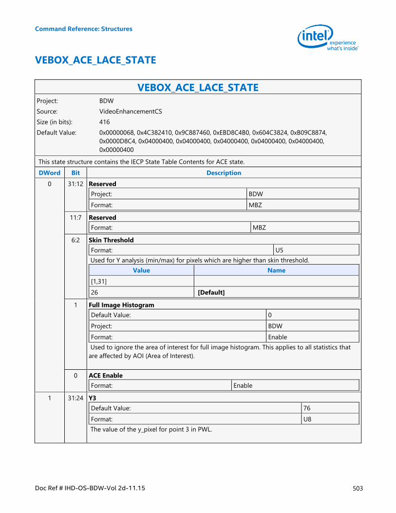
Command Reference: Structures
Doc Ref # IHD-OS-BDW-Vol 2d-11.15 503
VEBOX_ACE_LACE_STATE
VEBOX_ACE_LACE_STATE Project: BDW
Source: VideoEnhancementCS
Size (in bits): 416
Default Value: 0x00000068, 0x4C382410, 0x9C887460, 0xEBD8C4B0, 0x604C3824, 0xB09C8874,
0x0000D8C4, 0x04000400, 0x04000400, 0x04000400, 0x04000400, 0x04000400,
0x00000400
This state structure contains the IECP State Table Contents for ACE state.
DWord Bit Description
0 31:12 Reserved
Project: BDW
Format: MBZ
11:7 Reserved
Format: MBZ
6:2 Skin Threshold
Format: U5
Used for Y analysis (min/max) for pixels which are higher than skin threshold.
Value Name
[1,31]
26 [Default]
1 Full Image Histogram
Default Value: 0
Project: BDW
Format: Enable
Used to ignore the area of interest for full image histogram. This applies to all statistics that
are affected by AOI (Area of Interest).
0 ACE Enable
Format: Enable
1 31:24 Y3
Default Value: 76
Format: U8
The value of the y_pixel for point 3 in PWL.
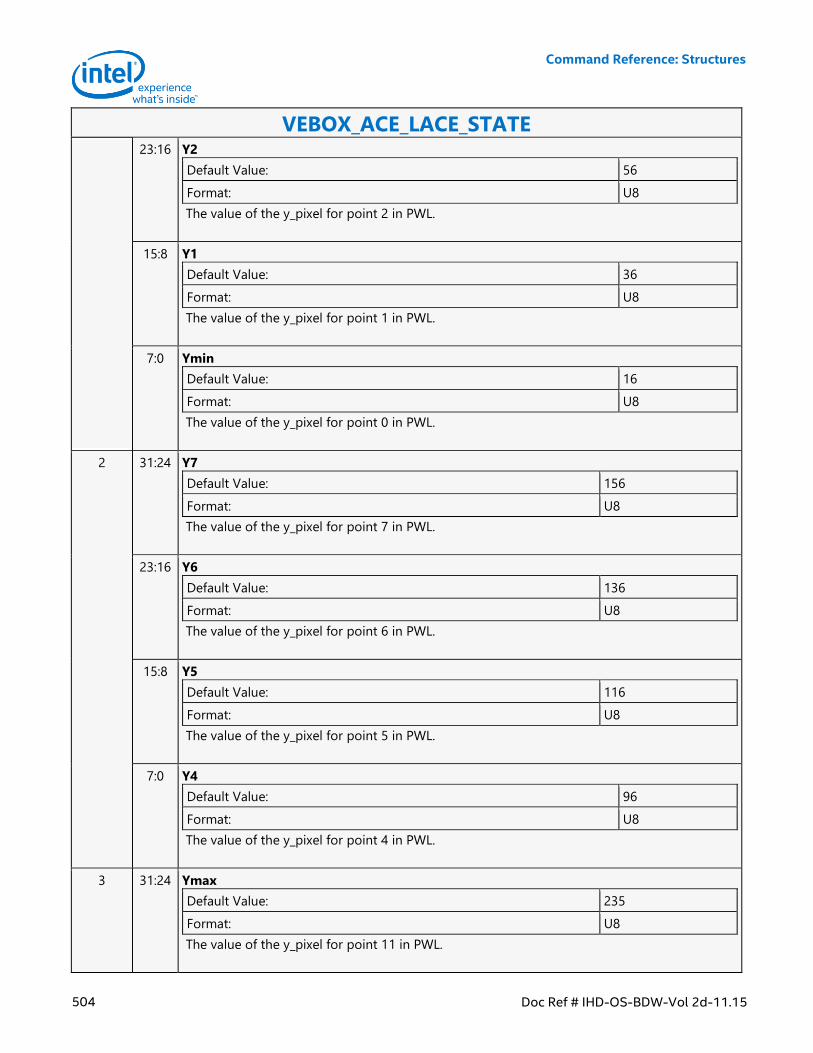
Command Reference: Structures
504 Doc Ref # IHD-OS-BDW-Vol 2d-11.15
VEBOX_ACE_LACE_STATE 23:16 Y2
Default Value: 56
Format: U8
The value of the y_pixel for point 2 in PWL.
15:8 Y1
Default Value: 36
Format: U8
The value of the y_pixel for point 1 in PWL.
7:0 Ymin
Default Value: 16
Format: U8
The value of the y_pixel for point 0 in PWL.
2 31:24 Y7
Default Value: 156
Format: U8
The value of the y_pixel for point 7 in PWL.
23:16 Y6
Default Value: 136
Format: U8
The value of the y_pixel for point 6 in PWL.
15:8 Y5
Default Value: 116
Format: U8
The value of the y_pixel for point 5 in PWL.
7:0 Y4
Default Value: 96
Format: U8
The value of the y_pixel for point 4 in PWL.
3 31:24 Ymax
Default Value: 235
Format: U8
The value of the y_pixel for point 11 in PWL.
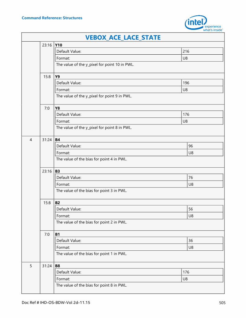
Command Reference: Structures
Doc Ref # IHD-OS-BDW-Vol 2d-11.15 505
VEBOX_ACE_LACE_STATE 23:16 Y10
Default Value: 216
Format: U8
The value of the y_pixel for point 10 in PWL.
15:8 Y9
Default Value: 196
Format: U8
The value of the y_pixel for point 9 in PWL.
7:0 Y8
Default Value: 176
Format: U8
The value of the y_pixel for point 8 in PWL.
4 31:24 B4
Default Value: 96
Format: U8
The value of the bias for point 4 in PWL.
23:16 B3
Default Value: 76
Format: U8
The value of the bias for point 3 in PWL.
15:8 B2
Default Value: 56
Format: U8
The value of the bias for point 2 in PWL.
7:0 B1
Default Value: 36
Format: U8
The value of the bias for point 1 in PWL.
5 31:24 B8
Default Value: 176
Format: U8
The value of the bias for point 8 in PWL.
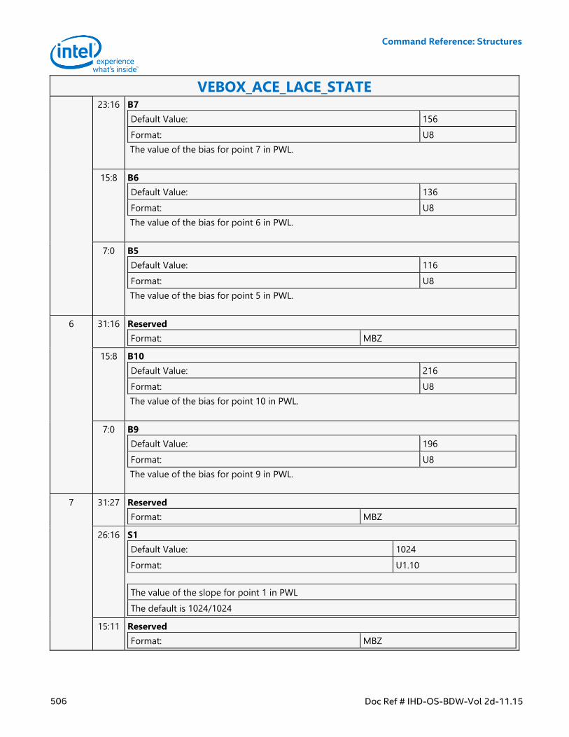
Command Reference: Structures
506 Doc Ref # IHD-OS-BDW-Vol 2d-11.15
VEBOX_ACE_LACE_STATE 23:16 B7
Default Value: 156
Format: U8
The value of the bias for point 7 in PWL.
15:8 B6
Default Value: 136
Format: U8
The value of the bias for point 6 in PWL.
7:0 B5
Default Value: 116
Format: U8
The value of the bias for point 5 in PWL.
6 31:16 Reserved
Format: MBZ
15:8 B10
Default Value: 216
Format: U8
The value of the bias for point 10 in PWL.
7:0 B9
Default Value: 196
Format: U8
The value of the bias for point 9 in PWL.
7 31:27 Reserved
Format: MBZ
26:16 S1
Default Value: 1024
Format: U1.10
The value of the slope for point 1 in PWL
The default is 1024/1024
15:11 Reserved
Format: MBZ
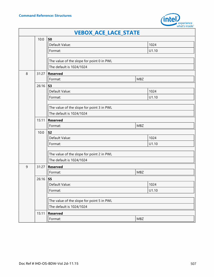
Command Reference: Structures
Doc Ref # IHD-OS-BDW-Vol 2d-11.15 507
VEBOX_ACE_LACE_STATE 10:0 S0
Default Value: 1024
Format: U1.10
The value of the slope for point 0 in PWL
The default is 1024/1024
8 31:27 Reserved
Format: MBZ
26:16 S3
Default Value: 1024
Format: U1.10
The value of the slope for point 3 in PWL
The default is 1024/1024
15:11 Reserved
Format: MBZ
10:0 S2
Default Value: 1024
Format: U1.10
The value of the slope for point 2 in PWL
The default is 1024/1024
9 31:27 Reserved
Format: MBZ
26:16 S5
Default Value: 1024
Format: U1.10
The value of the slope for point 5 in PWL
The default is 1024/1024
15:11 Reserved
Format: MBZ
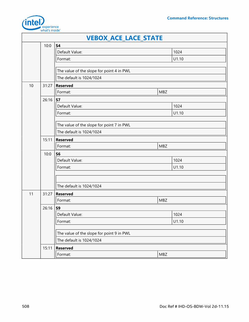
Command Reference: Structures
508 Doc Ref # IHD-OS-BDW-Vol 2d-11.15
VEBOX_ACE_LACE_STATE 10:0 S4
Default Value: 1024
Format: U1.10
The value of the slope for point 4 in PWL
The default is 1024/1024
10 31:27 Reserved
Format: MBZ
26:16 S7
Default Value: 1024
Format: U1.10
The value of the slope for point 7 in PWL
The default is 1024/1024
15:11 Reserved
Format: MBZ
10:0 S6
Default Value: 1024
Format: U1.10
The default is 1024/1024
11 31:27 Reserved
Format: MBZ
26:16 S9
Default Value: 1024
Format: U1.10
The value of the slope for point 9 in PWL
The default is 1024/1024
15:11 Reserved
Format: MBZ
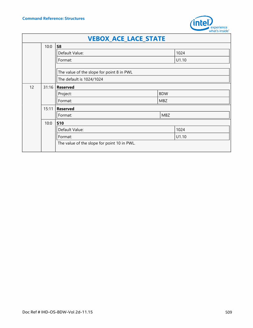
Command Reference: Structures
Doc Ref # IHD-OS-BDW-Vol 2d-11.15 509
VEBOX_ACE_LACE_STATE 10:0 S8
Default Value: 1024
Format: U1.10
The value of the slope for point 8 in PWL
The default is 1024/1024
12 31:16 Reserved
Project: BDW
Format: MBZ
15:11 Reserved
Format: MBZ
10:0 S10
Default Value: 1024
Format: U1.10
The value of the slope for point 10 in PWL.
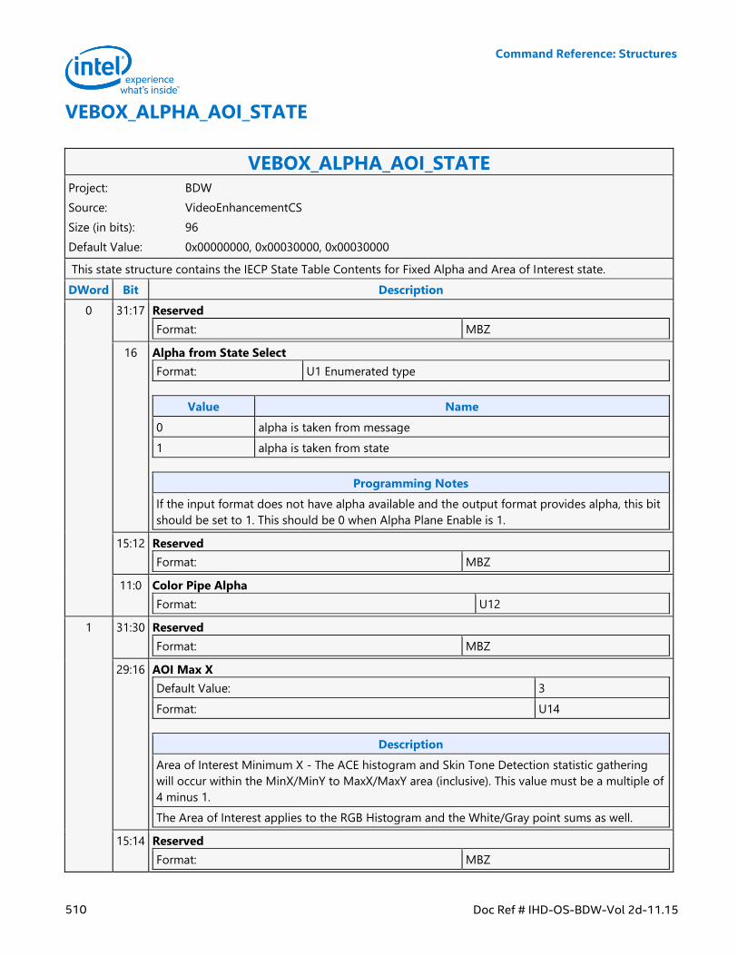
Command Reference: Structures
510 Doc Ref # IHD-OS-BDW-Vol 2d-11.15
VEBOX_ALPHA_AOI_STATE
VEBOX_ALPHA_AOI_STATE Project: BDW
Source: VideoEnhancementCS
Size (in bits): 96
Default Value: 0x00000000, 0x00030000, 0x00030000
This state structure contains the IECP State Table Contents for Fixed Alpha and Area of Interest state.
DWord Bit Description
0 31:17 Reserved
Format: MBZ
16 Alpha from State Select
Format: U1 Enumerated type
Value Name
0 alpha is taken from message
1 alpha is taken from state
Programming Notes
If the input format does not have alpha available and the output format provides alpha, this bit
should be set to 1. This should be 0 when Alpha Plane Enable is 1.
15:12 Reserved
Format: MBZ
11:0 Color Pipe Alpha
Format: U12
1 31:30 Reserved
Format: MBZ
29:16 AOI Max X
Default Value: 3
Format: U14
Description
Area of Interest Minimum X - The ACE histogram and Skin Tone Detection statistic gathering
will occur within the MinX/MinY to MaxX/MaxY area (inclusive). This value must be a multiple of
4 minus 1.
The Area of Interest applies to the RGB Histogram and the White/Gray point sums as well.
15:14 Reserved
Format: MBZ
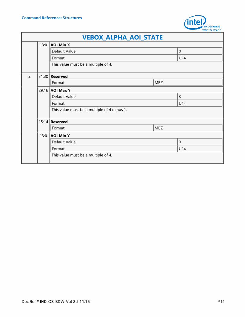
Command Reference: Structures
Doc Ref # IHD-OS-BDW-Vol 2d-11.15 511
VEBOX_ALPHA_AOI_STATE 13:0 AOI Min X
Default Value: 0
Format: U14
This value must be a multiple of 4.
2 31:30 Reserved
Format: MBZ
29:16 AOI Max Y
Default Value: 3
Format: U14
This value must be a multiple of 4 minus 1.
15:14 Reserved
Format: MBZ
13:0 AOI Min Y
Default Value: 0
Format: U14
This value must be a multiple of 4.
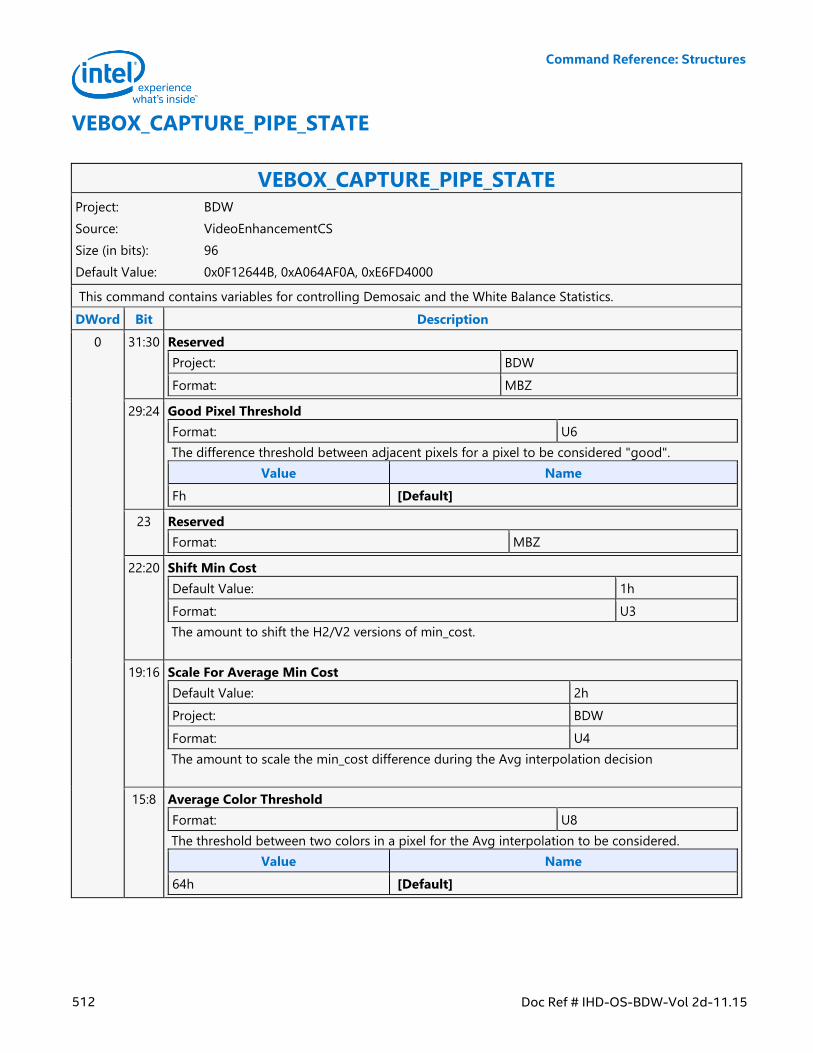
Command Reference: Structures
512 Doc Ref # IHD-OS-BDW-Vol 2d-11.15
VEBOX_CAPTURE_PIPE_STATE
VEBOX_CAPTURE_PIPE_STATE Project: BDW
Source: VideoEnhancementCS
Size (in bits): 96
Default Value: 0x0F12644B, 0xA064AF0A, 0xE6FD4000
This command contains variables for controlling Demosaic and the White Balance Statistics.
DWord Bit Description
0 31:30 Reserved
Project: BDW
Format: MBZ
29:24 Good Pixel Threshold
Format: U6
The difference threshold between adjacent pixels for a pixel to be considered "good".
Value Name
Fh [Default]
23 Reserved
Format: MBZ
22:20 Shift Min Cost
Default Value: 1h
Format: U3
The amount to shift the H2/V2 versions of min_cost.
19:16 Scale For Average Min Cost
Default Value: 2h
Project: BDW
Format: U4
The amount to scale the min_cost difference during the Avg interpolation decision
15:8 Average Color Threshold
Format: U8
The threshold between two colors in a pixel for the Avg interpolation to be considered.
Value Name
64h [Default]
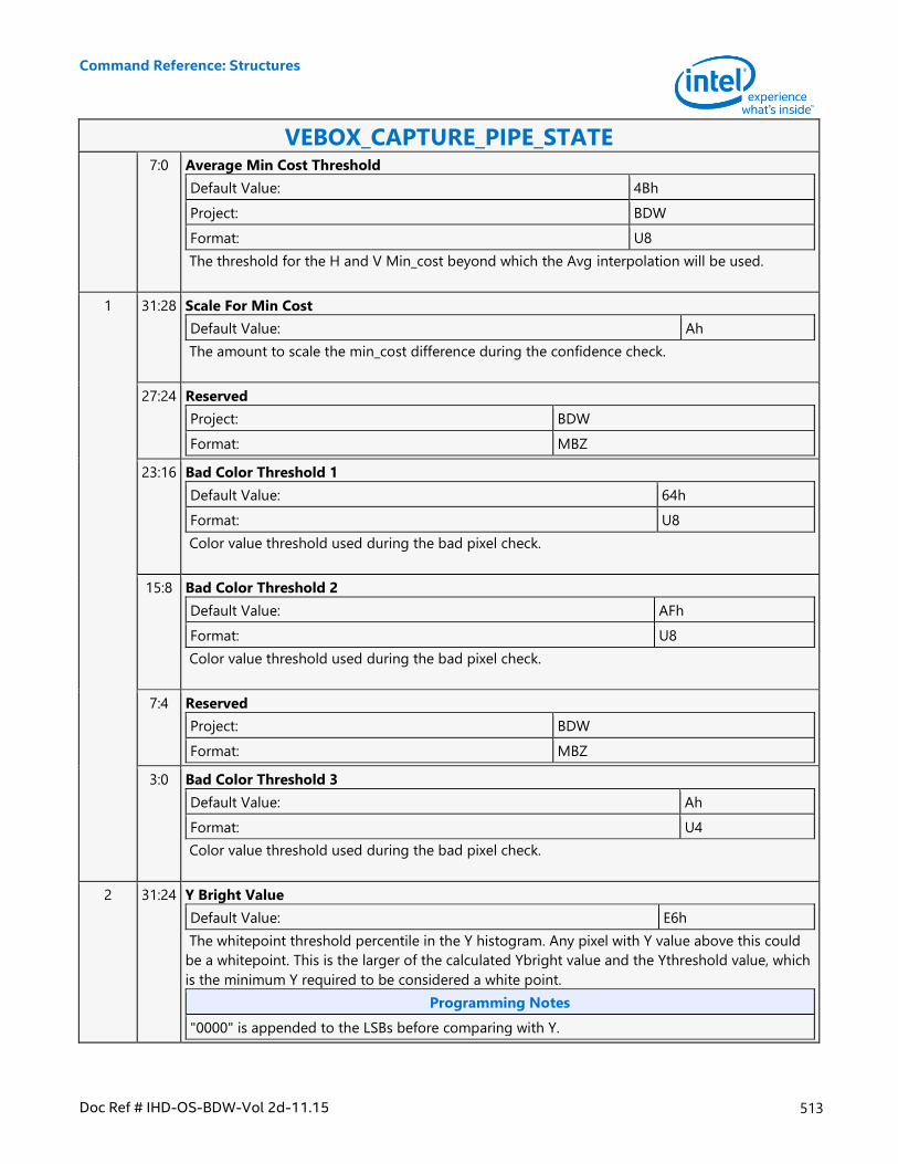
Command Reference: Structures
Doc Ref # IHD-OS-BDW-Vol 2d-11.15 513
VEBOX_CAPTURE_PIPE_STATE 7:0 Average Min Cost Threshold
Default Value: 4Bh
Project: BDW
Format: U8
The threshold for the H and V Min_cost beyond which the Avg interpolation will be used.
1 31:28 Scale For Min Cost
Default Value: Ah
The amount to scale the min_cost difference during the confidence check.
27:24 Reserved
Project: BDW
Format: MBZ
23:16 Bad Color Threshold 1
Default Value: 64h
Format: U8
Color value threshold used during the bad pixel check.
15:8 Bad Color Threshold 2
Default Value: AFh
Format: U8
Color value threshold used during the bad pixel check.
7:4 Reserved
Project: BDW
Format: MBZ
3:0 Bad Color Threshold 3
Default Value: Ah
Format: U4
Color value threshold used during the bad pixel check.
2 31:24 Y Bright Value
Default Value: E6h
The whitepoint threshold percentile in the Y histogram. Any pixel with Y value above this could
be a whitepoint. This is the larger of the calculated Ybright value and the Ythreshold value, which
is the minimum Y required to be considered a white point.
Programming Notes
"0000" is appended to the LSBs before comparing with Y.
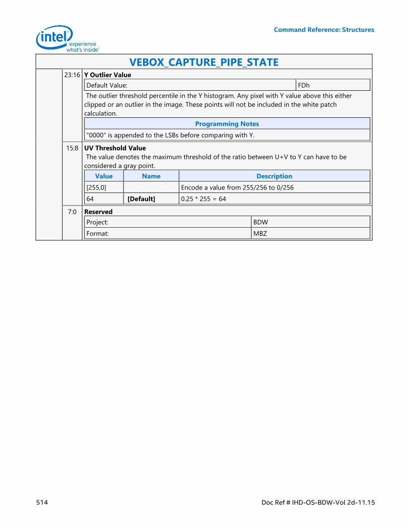
Command Reference: Structures
514 Doc Ref # IHD-OS-BDW-Vol 2d-11.15
VEBOX_CAPTURE_PIPE_STATE 23:16 Y Outlier Value
Default Value: FDh
The outlier threshold percentile in the Y histogram. Any pixel with Y value above this either
clipped or an outlier in the image. These points will not be included in the white patch
calculation.
Programming Notes
"0000" is appended to the LSBs before comparing with Y.
15:8 UV Threshold Value
The value denotes the maximum threshold of the ratio between U+V to Y can have to be
considered a gray point.
Value Name Description
[255,0] Encode a value from 255/256 to 0/256
64 [Default] 0.25 * 255 = 64
7:0 Reserved
Project: BDW
Format: MBZ
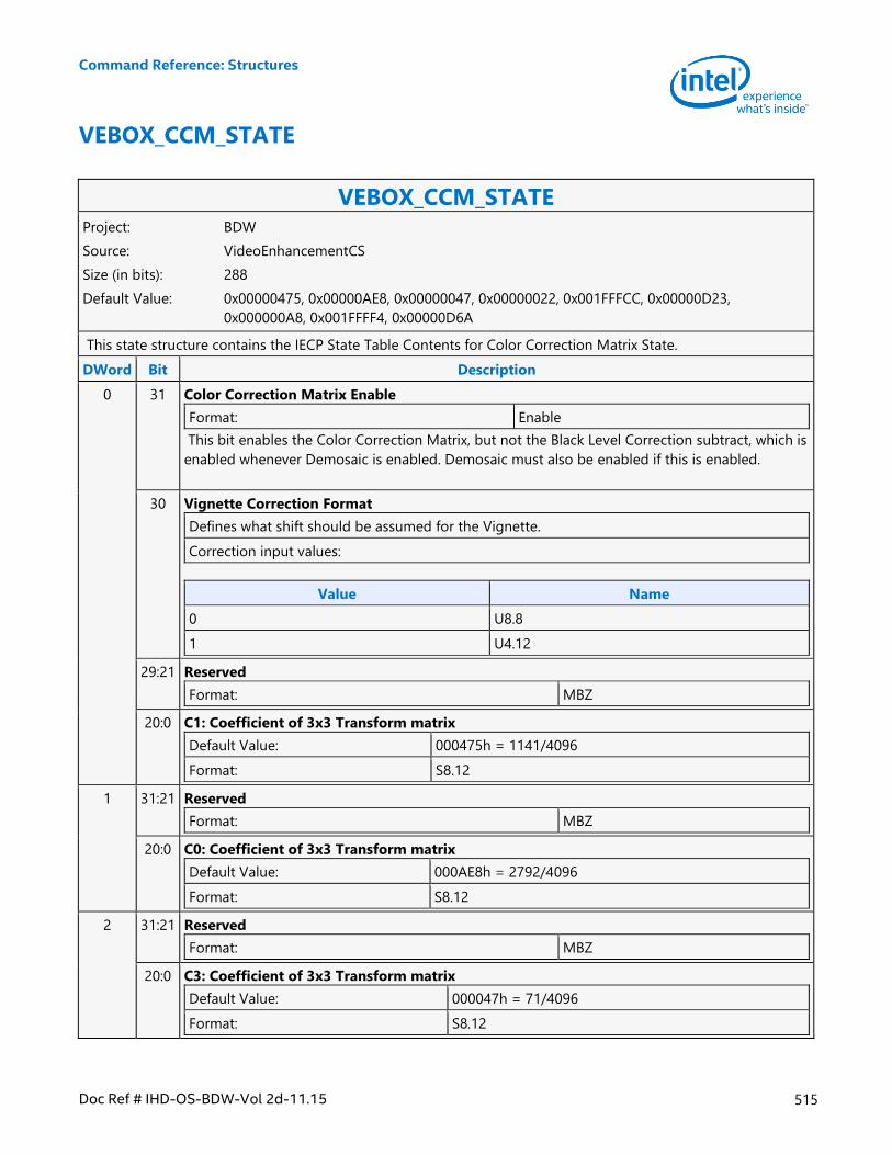
Command Reference: Structures
Doc Ref # IHD-OS-BDW-Vol 2d-11.15 515
VEBOX_CCM_STATE
VEBOX_CCM_STATE Project: BDW
Source: VideoEnhancementCS
Size (in bits): 288
Default Value: 0x00000475, 0x00000AE8, 0x00000047, 0x00000022, 0x001FFFCC, 0x00000D23,
0x000000A8, 0x001FFFF4, 0x00000D6A
This state structure contains the IECP State Table Contents for Color Correction Matrix State.
DWord Bit Description
0 31 Color Correction Matrix Enable
Format: Enable
This bit enables the Color Correction Matrix, but not the Black Level Correction subtract, which is
enabled whenever Demosaic is enabled. Demosaic must also be enabled if this is enabled.
30 Vignette Correction Format
Defines what shift should be assumed for the Vignette.
Correction input values:
Value Name
0 U8.8
1 U4.12
29:21 Reserved
Format: MBZ
20:0 C1: Coefficient of 3x3 Transform matrix
Default Value: 000475h = 1141/4096
Format: S8.12
1 31:21 Reserved
Format: MBZ
20:0 C0: Coefficient of 3x3 Transform matrix
Default Value: 000AE8h = 2792/4096
Format: S8.12
2 31:21 Reserved
Format: MBZ
20:0 C3: Coefficient of 3x3 Transform matrix
Default Value: 000047h = 71/4096
Format: S8.12
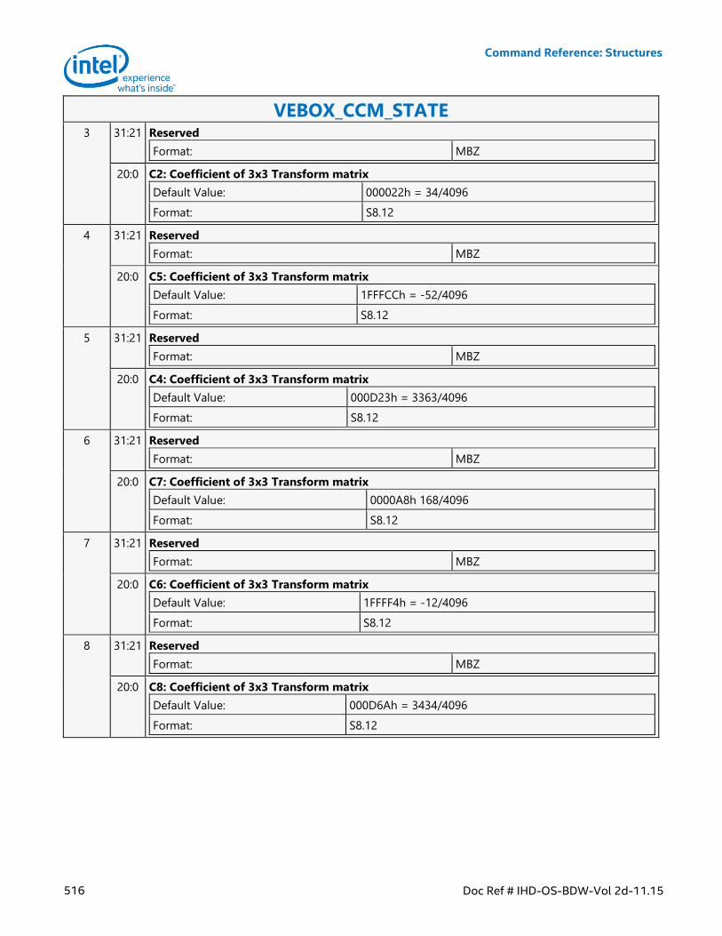
Command Reference: Structures
516 Doc Ref # IHD-OS-BDW-Vol 2d-11.15
VEBOX_CCM_STATE 3 31:21 Reserved
Format: MBZ
20:0 C2: Coefficient of 3x3 Transform matrix
Default Value: 000022h = 34/4096
Format: S8.12
4 31:21 Reserved
Format: MBZ
20:0 C5: Coefficient of 3x3 Transform matrix
Default Value: 1FFFCCh = -52/4096
Format: S8.12
5 31:21 Reserved
Format: MBZ
20:0 C4: Coefficient of 3x3 Transform matrix
Default Value: 000D23h = 3363/4096
Format: S8.12
6 31:21 Reserved
Format: MBZ
20:0 C7: Coefficient of 3x3 Transform matrix
Default Value: 0000A8h 168/4096
Format: S8.12
7 31:21 Reserved
Format: MBZ
20:0 C6: Coefficient of 3x3 Transform matrix
Default Value: 1FFFF4h = -12/4096
Format: S8.12
8 31:21 Reserved
Format: MBZ
20:0 C8: Coefficient of 3x3 Transform matrix
Default Value: 000D6Ah = 3434/4096
Format: S8.12
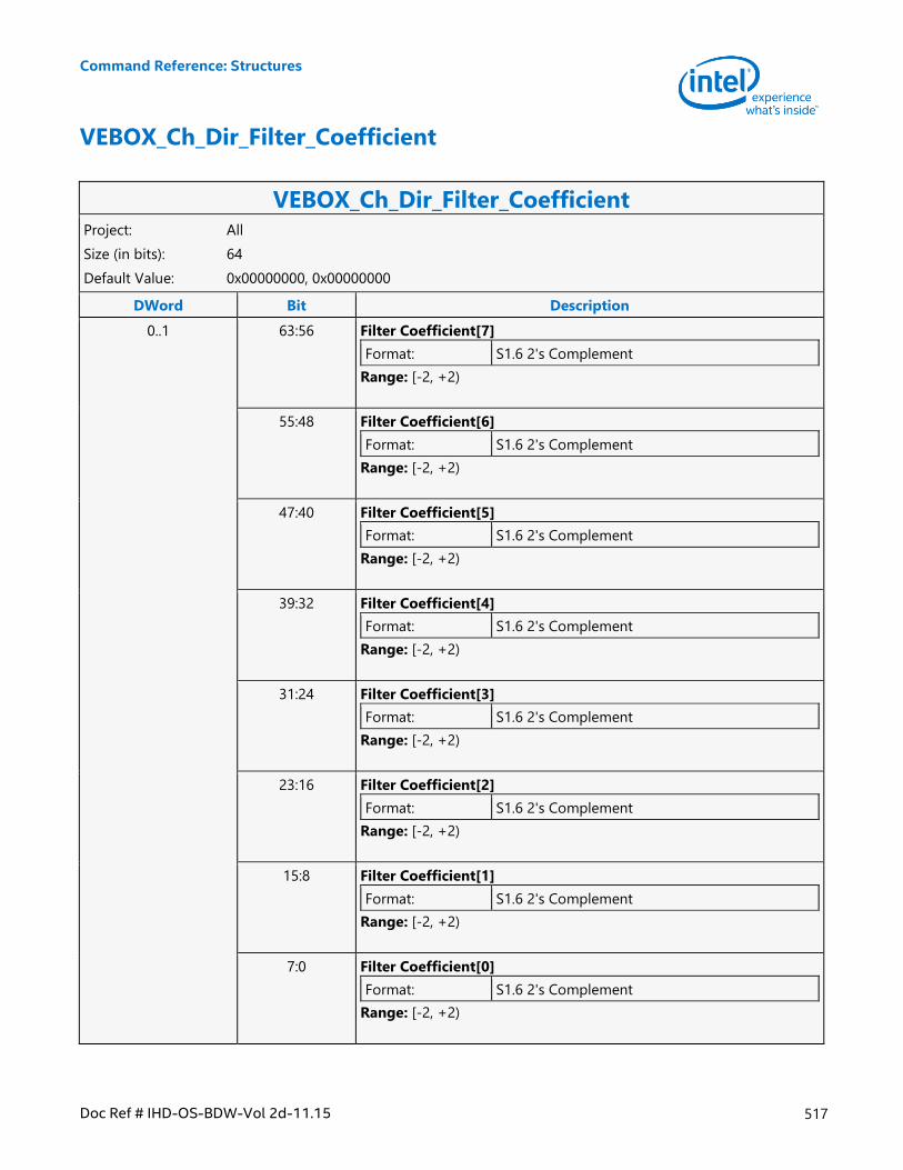
Command Reference: Structures
Doc Ref # IHD-OS-BDW-Vol 2d-11.15 517
VEBOX_Ch_Dir_Filter_Coefficient
VEBOX_Ch_Dir_Filter_Coefficient Project: All
Size (in bits): 64
Default Value: 0x00000000, 0x00000000
DWord Bit Description
0..1 63:56 Filter Coefficient[7]
Format: S1.6 2's Complement
Range: [-2, +2)
55:48 Filter Coefficient[6]
Format: S1.6 2's Complement
Range: [-2, +2)
47:40 Filter Coefficient[5]
Format: S1.6 2's Complement
Range: [-2, +2)
39:32 Filter Coefficient[4]
Format: S1.6 2's Complement
Range: [-2, +2)
31:24 Filter Coefficient[3]
Format: S1.6 2's Complement
Range: [-2, +2)
23:16 Filter Coefficient[2]
Format: S1.6 2's Complement
Range: [-2, +2)
15:8 Filter Coefficient[1]
Format: S1.6 2's Complement
Range: [-2, +2)
7:0 Filter Coefficient[0]
Format: S1.6 2's Complement
Range: [-2, +2)
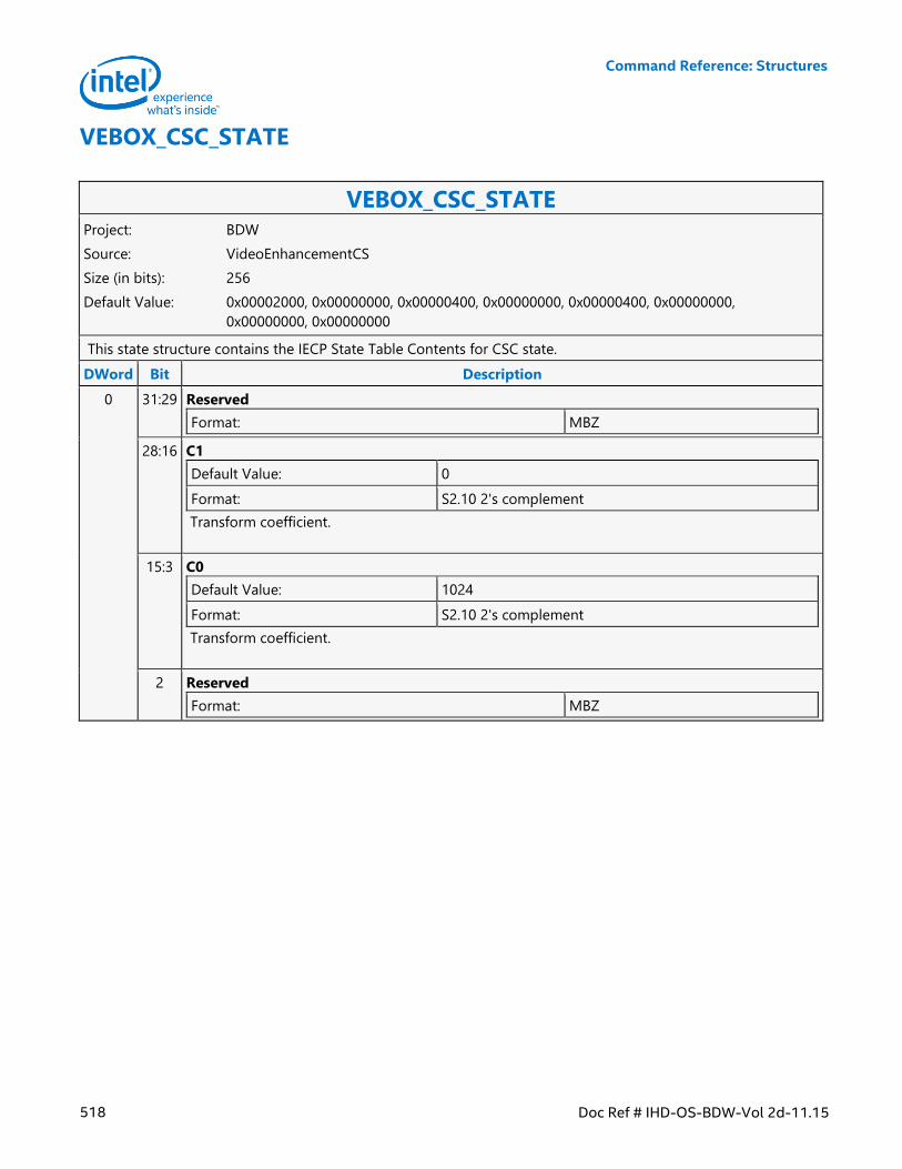
Command Reference: Structures
518 Doc Ref # IHD-OS-BDW-Vol 2d-11.15
VEBOX_CSC_STATE
VEBOX_CSC_STATE Project: BDW
Source: VideoEnhancementCS
Size (in bits): 256
Default Value: 0x00002000, 0x00000000, 0x00000400, 0x00000000, 0x00000400, 0x00000000,
0x00000000, 0x00000000
This state structure contains the IECP State Table Contents for CSC state.
DWord Bit Description
0 31:29 Reserved
Format: MBZ
28:16 C1
Default Value: 0
Format: S2.10 2's complement
Transform coefficient.
15:3 C0
Default Value: 1024
Format: S2.10 2's complement
Transform coefficient.
2 Reserved
Format: MBZ
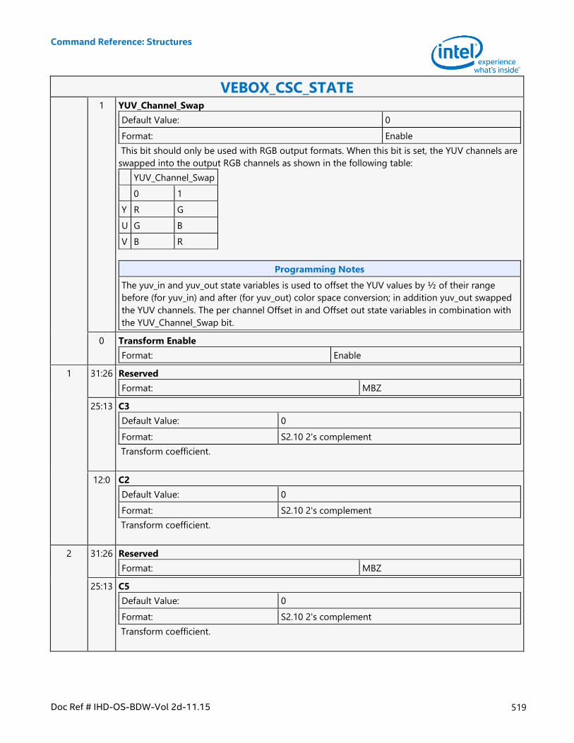
Command Reference: Structures
Doc Ref # IHD-OS-BDW-Vol 2d-11.15 519
VEBOX_CSC_STATE 1 YUV_Channel_Swap
Default Value: 0
Format: Enable
This bit should only be used with RGB output formats. When this bit is set, the YUV channels are
swapped into the output RGB channels as shown in the following table:
YUV_Channel_Swap
0 1
Y R G
U G B
V B R
Programming Notes
The yuv_in and yuv_out state variables is used to offset the YUV values by ½ of their range
before (for yuv_in) and after (for yuv_out) color space conversion; in addition yuv_out swapped
the YUV channels. The per channel Offset in and Offset out state variables in combination with
the YUV_Channel_Swap bit.
0 Transform Enable
Format: Enable
1 31:26 Reserved
Format: MBZ
25:13 C3
Default Value: 0
Format: S2.10 2's complement
Transform coefficient.
12:0 C2
Default Value: 0
Format: S2.10 2's complement
Transform coefficient.
2 31:26 Reserved
Format: MBZ
25:13 C5
Default Value: 0
Format: S2.10 2's complement
Transform coefficient.
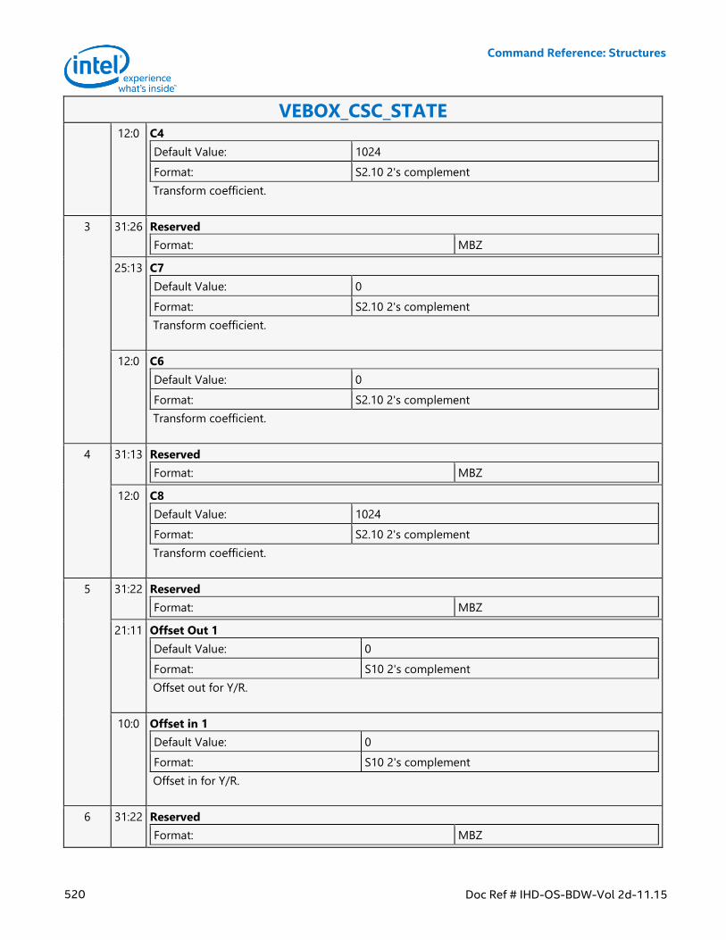
Command Reference: Structures
520 Doc Ref # IHD-OS-BDW-Vol 2d-11.15
VEBOX_CSC_STATE 12:0 C4
Default Value: 1024
Format: S2.10 2's complement
Transform coefficient.
3 31:26 Reserved
Format: MBZ
25:13 C7
Default Value: 0
Format: S2.10 2's complement
Transform coefficient.
12:0 C6
Default Value: 0
Format: S2.10 2's complement
Transform coefficient.
4 31:13 Reserved
Format: MBZ
12:0 C8
Default Value: 1024
Format: S2.10 2's complement
Transform coefficient.
5 31:22 Reserved
Format: MBZ
21:11 Offset Out 1
Default Value: 0
Format: S10 2's complement
Offset out for Y/R.
10:0 Offset in 1
Default Value: 0
Format: S10 2's complement
Offset in for Y/R.
6 31:22 Reserved
Format: MBZ
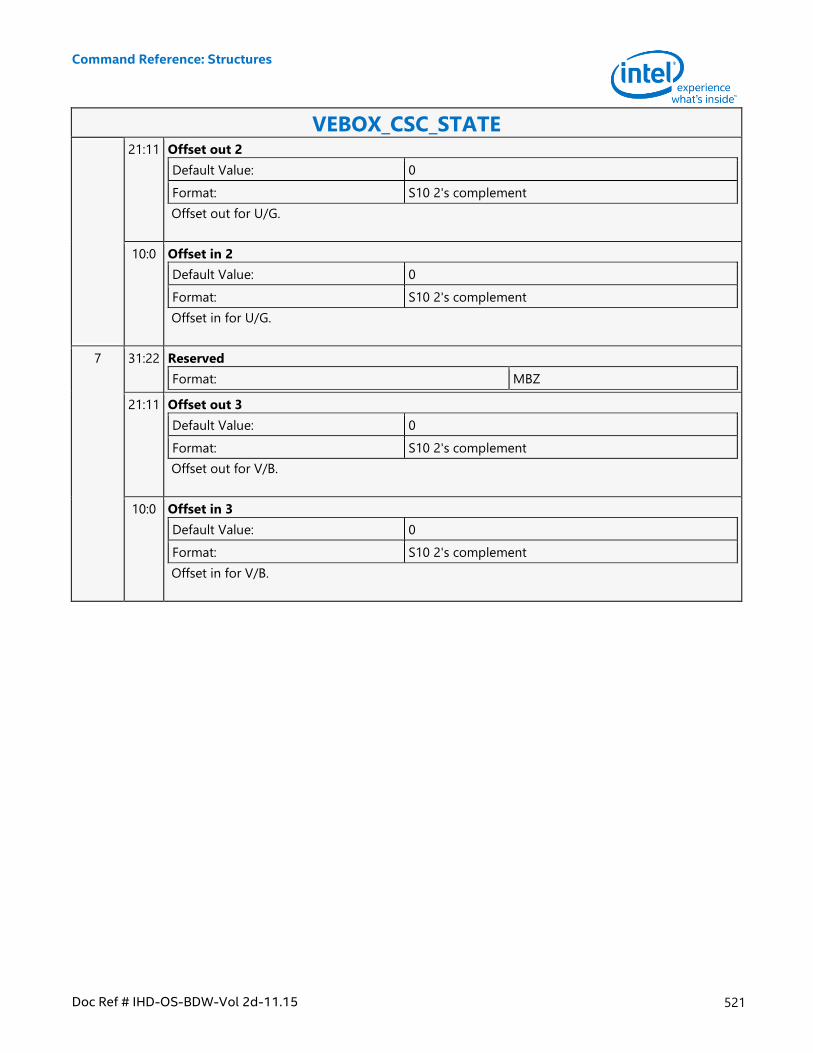
Command Reference: Structures
Doc Ref # IHD-OS-BDW-Vol 2d-11.15 521
VEBOX_CSC_STATE 21:11 Offset out 2
Default Value: 0
Format: S10 2's complement
Offset out for U/G.
10:0 Offset in 2
Default Value: 0
Format: S10 2's complement
Offset in for U/G.
7 31:22 Reserved
Format: MBZ
21:11 Offset out 3
Default Value: 0
Format: S10 2's complement
Offset out for V/B.
10:0 Offset in 3
Default Value: 0
Format: S10 2's complement
Offset in for V/B.
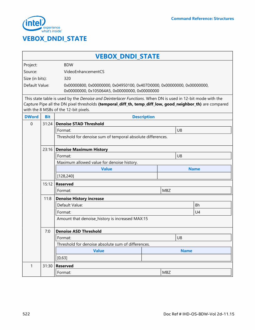
Command Reference: Structures
522 Doc Ref # IHD-OS-BDW-Vol 2d-11.15
VEBOX_DNDI_STATE
VEBOX_DNDI_STATE Project: BDW
Source: VideoEnhancementCS
Size (in bits): 320
Default Value: 0x00000800, 0x00000000, 0x04950100, 0x407D0000, 0x00000000, 0x00000000,
0x00000000, 0x105064A5, 0x00000000, 0x00000000
This state table is used by the Denoise and Deinterlacer Functions. When DN is used in 12-bit mode with the
Capture Pipe all the DN pixel thresholds (temporal_diff_th, temp_diff_low, good_neighbor_th) are compared
with the 8 MSBs of the 12-bit pixels.
DWord Bit Description
0 31:24 Denoise STAD Threshold
Format: U8
Threshold for denoise sum of temporal absolute differences.
23:16 Denoise Maximum History
Format: U8
Maximum allowed value for denoise history.
Value Name
[128,240]
15:12 Reserved
Format: MBZ
11:8 Denoise History increase
Default Value: 8h
Format: U4
Amount that denoise_history is increased MAX:15
7:0 Denoise ASD Threshold
Format: U8
Threshold for denoise absolute sum of differences.
Value Name
[0,63]
1 31:30 Reserved
Format: MBZ
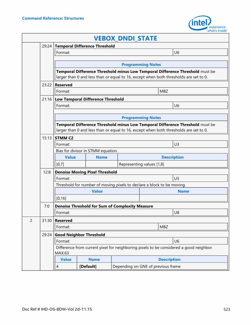
Command Reference: Structures
Doc Ref # IHD-OS-BDW-Vol 2d-11.15 523
VEBOX_DNDI_STATE 29:24 Temporal Difference Threshold
Format: U6
Programming Notes
Temporal Difference Threshold minus Low Temporal Difference Threshold must be
larger than 0 and less than or equal to 16, except when both thresholds are set to 0.
23:22 Reserved
Format: MBZ
21:16 Low Temporal Difference Threshold
Format: U6
Programming Notes
Temporal Difference Threshold minus Low Temporal Difference Threshold must be
larger than 0 and less than or equal to 16, except when both thresholds are set to 0.
15:13 STMM C2
Format: U3
Bias for divisor in STMM equation.
Value Name Description
[0,7] Representing values [1,8]
12:8 Denoise Moving Pixel Threshold
Format: U5
Threshold for number of moving pixels to declare a block to be moving.
Value Name
[0,16]
7:0 Denoise Threshold for Sum of Complexity Measure
Format: U8
2 31:30 Reserved
Format: MBZ
29:24 Good Neighbor Threshold
Format: U6
Difference from current pixel for neighboring pixels to be considered a good neighbor.
MAX:63
Value Name Description
4 [Default] Depending on GNE of previous frame
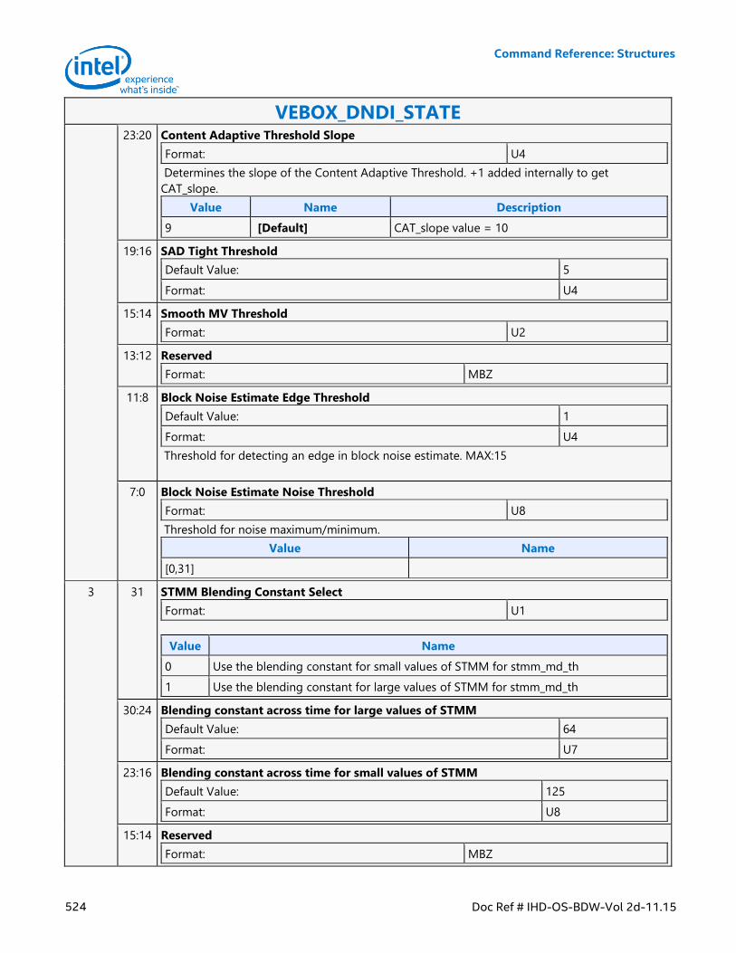
Command Reference: Structures
524 Doc Ref # IHD-OS-BDW-Vol 2d-11.15
VEBOX_DNDI_STATE 23:20 Content Adaptive Threshold Slope
Format: U4
Determines the slope of the Content Adaptive Threshold. +1 added internally to get
CAT_slope.
Value Name Description
9 [Default] CAT_slope value = 10
19:16 SAD Tight Threshold
Default Value: 5
Format: U4
15:14 Smooth MV Threshold
Format: U2
13:12 Reserved
Format: MBZ
11:8 Block Noise Estimate Edge Threshold
Default Value: 1
Format: U4
Threshold for detecting an edge in block noise estimate. MAX:15
7:0 Block Noise Estimate Noise Threshold
Format: U8
Threshold for noise maximum/minimum.
Value Name
[0,31]
3 31 STMM Blending Constant Select
Format: U1
Value Name
0 Use the blending constant for small values of STMM for stmm_md_th
1 Use the blending constant for large values of STMM for stmm_md_th
30:24 Blending constant across time for large values of STMM
Default Value: 64
Format: U7
23:16 Blending constant across time for small values of STMM
Default Value: 125
Format: U8
15:14 Reserved
Format: MBZ
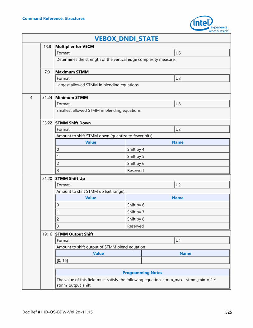
Command Reference: Structures
Doc Ref # IHD-OS-BDW-Vol 2d-11.15 525
VEBOX_DNDI_STATE 13:8 Multiplier for VECM
Format: U6
Determines the strength of the vertical edge complexity measure.
7:0 Maximum STMM
Format: U8
Largest allowed STMM in blending equations
4 31:24 Minimum STMM
Format: U8
Smallest allowed STMM in blending equations
23:22 STMM Shift Down
Format: U2
Amount to shift STMM down (quantize to fewer bits)
Value Name
0 Shift by 4
1 Shift by 5
2 Shift by 6
3 Reserved
21:20 STMM Shift Up
Format: U2
Amount to shift STMM up (set range).
Value Name
0 Shift by 6
1 Shift by 7
2 Shift by 8
3 Reserved
19:16 STMM Output Shift
Format: U4
Amount to shift output of STMM blend equation
Value Name
[0, 16]
Programming Notes
The value of this field must satisfy the following equation: stmm_max - stmm_min = 2 ^
stmm_output_shift
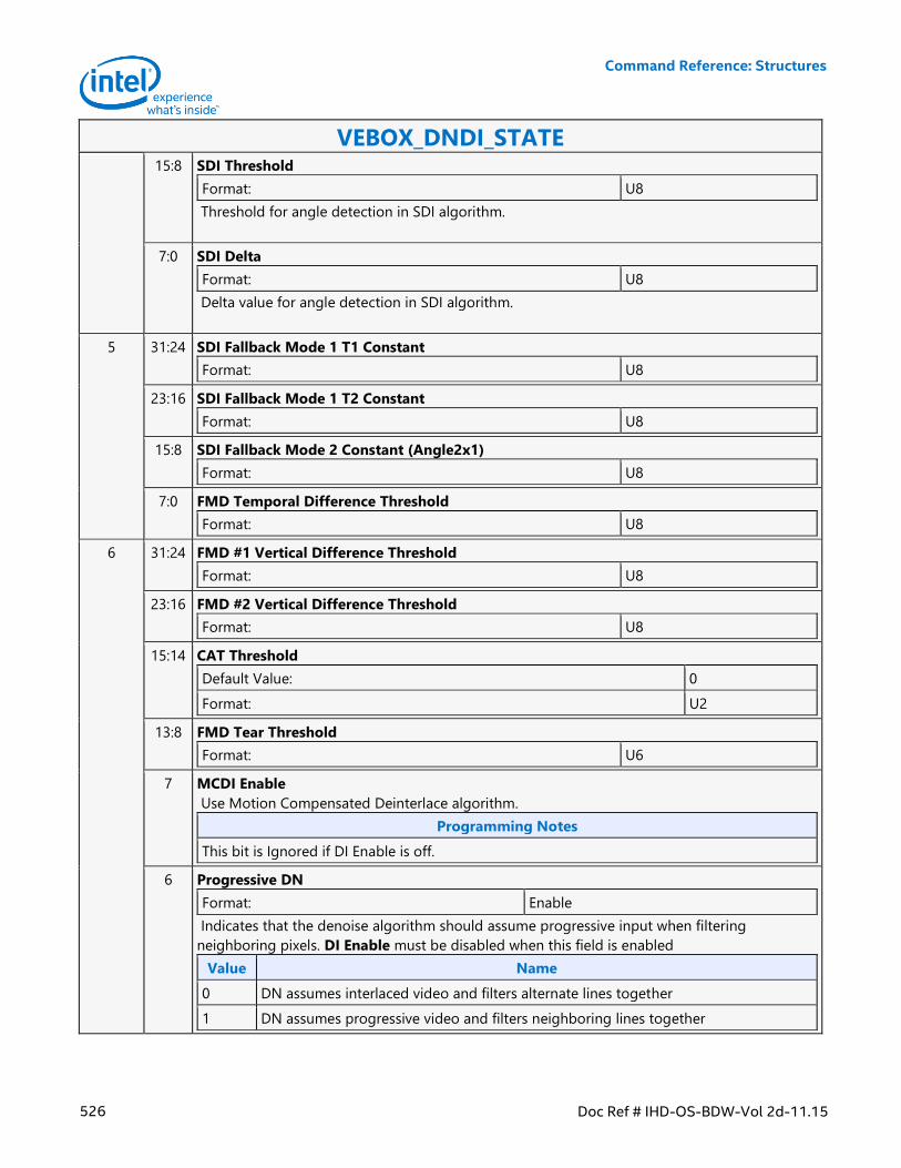
Command Reference: Structures
526 Doc Ref # IHD-OS-BDW-Vol 2d-11.15
VEBOX_DNDI_STATE 15:8 SDI Threshold
Format: U8
Threshold for angle detection in SDI algorithm.
7:0 SDI Delta
Format: U8
Delta value for angle detection in SDI algorithm.
5 31:24 SDI Fallback Mode 1 T1 Constant
Format: U8
23:16 SDI Fallback Mode 1 T2 Constant
Format: U8
15:8 SDI Fallback Mode 2 Constant (Angle2x1)
Format: U8
7:0 FMD Temporal Difference Threshold
Format: U8
6 31:24 FMD #1 Vertical Difference Threshold
Format: U8
23:16 FMD #2 Vertical Difference Threshold
Format: U8
15:14 CAT Threshold
Default Value: 0
Format: U2
13:8 FMD Tear Threshold
Format: U6
7 MCDI Enable
Use Motion Compensated Deinterlace algorithm.
Programming Notes
This bit is Ignored if DI Enable is off.
6 Progressive DN
Format: Enable
Indicates that the denoise algorithm should assume progressive input when filtering
neighboring pixels. DI Enable must be disabled when this field is enabled
Value Name
0 DN assumes interlaced video and filters alternate lines together
1 DN assumes progressive video and filters neighboring lines together
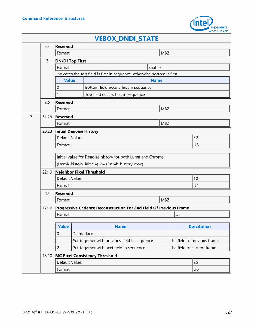
Command Reference: Structures
Doc Ref # IHD-OS-BDW-Vol 2d-11.15 527
VEBOX_DNDI_STATE 5:4 Reserved
Format: MBZ
3 DN/DI Top First
Format: Enable
Indicates the top field is first in sequence, otherwise bottom is first
Value Name
0 Bottom field occurs first in sequence
1 Top field occurs first in sequence
2:0 Reserved
Format: MBZ
7 31:29 Reserved
Format: MBZ
28:23 Initial Denoise History
Default Value: 32
Format: U6
Initial value for Denoise history for both Luma and Chroma.
(Dnmh_history_init * 4) <= (Dnmh_history_max)
22:19 Neighbor Pixel Threshold
Default Value: 10
Format: U4
18 Reserved
Format: MBZ
17:16 Progressive Cadence Reconstruction For 2nd Field Of Previous Frame
Format: U2
Value Name Description
0 Deinterlace
1 Put together with previous field in sequence 1st field of previous frame
2 Put together with next field in sequence 1st field of current frame
15:10 MC Pixel Consistency Threshold
Default Value: 25
Format: U6
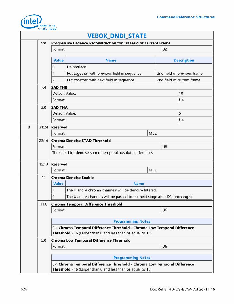
Command Reference: Structures
528 Doc Ref # IHD-OS-BDW-Vol 2d-11.15
VEBOX_DNDI_STATE 9:8 Progressive Cadence Reconstruction for 1st Field of Current Frame
Format: U2
Value Name Description
0 Deinterlace
1 Put together with previous field in sequence 2nd field of previous frame
2 Put together with next field in sequence 2nd field of current frame
7:4 SAD THB
Default Value: 10
Format: U4
3:0 SAD THA
Default Value: 5
Format: U4
8 31:24 Reserved
Format: MBZ
23:16 Chroma Denoise STAD Threshold
Format: U8
Threshold for denoise sum of temporal absolute differences.
15:13 Reserved
Format: MBZ
12 Chroma Denoise Enable
Value Name
1 The U and V chroma channels will be denoise filtered.
0 The U and V channels will be passed to the next stage after DN unchanged.
11:6 Chroma Temporal Difference Threshold
Format: U6
Programming Notes
0<[Chroma Temporal Difference Threshold - Chroma Low Temporal Difference
Threshold]«16 (Larger than 0 and less than or equal to 16)
5:0 Chroma Low Temporal Difference Threshold
Format: U6
Programming Notes
0<[Chroma Temporal Difference Threshold - Chroma Low Temporal Difference
Threshold]«16 (Larger than 0 and less than or equal to 16)
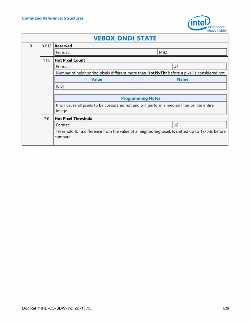
Command Reference: Structures
Doc Ref # IHD-OS-BDW-Vol 2d-11.15 529
VEBOX_DNDI_STATE 9 31:12 Reserved
Format: MBZ
11:8 Hot Pixel Count
Format: U4
Number of neighboring pixels different more than HotPixThr before a pixel is considered hot.
Value Name
[0,8]
Programming Notes
0 will cause all pixels to be considered hot and will perform a median filter on the entire
image.
7:0 Hot Pixel Threshold
Format: U8
Threshold for a difference from the value of a neighboring pixel. Is shifted up to 12-bits before
compare.
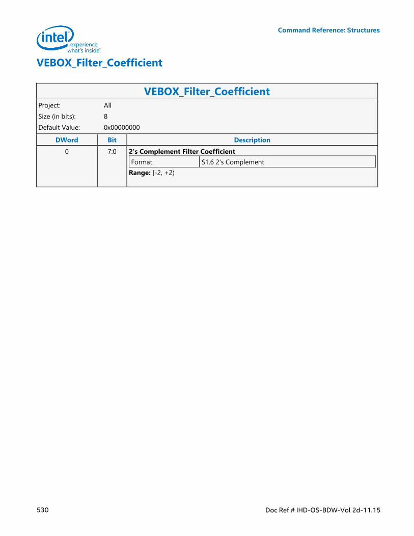
Command Reference: Structures
530 Doc Ref # IHD-OS-BDW-Vol 2d-11.15
VEBOX_Filter_Coefficient
VEBOX_Filter_Coefficient Project: All
Size (in bits): 8
Default Value: 0x00000000
DWord Bit Description
0 7:0 2's Complement Filter Coefficient
Format: S1.6 2's Complement
Range: [-2, +2)
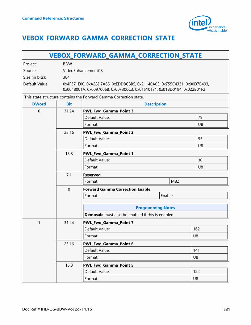
Command Reference: Structures
Doc Ref # IHD-OS-BDW-Vol 2d-11.15 531
VEBOX_FORWARD_GAMMA_CORRECTION_STATE
VEBOX_FORWARD_GAMMA_CORRECTION_STATE Project: BDW
Source: VideoEnhancementCS
Size (in bits): 384
Default Value: 0x4F371E00, 0xA28D7A65, 0xEDDBC8B5, 0x21140A03, 0x755C4331, 0x00D7B493,
0x0048001A, 0x0097006B, 0x00F300C3, 0x01510131, 0x01BD0194, 0x022B01F2
This state structure contains the Forward Gamma Correction state.
DWord Bit Description
0 31:24 PWL_Fwd_Gamma_Point 3
Default Value: 79
Format: U8
23:16 PWL_Fwd_Gamma_Point 2
Default Value: 55
Format: U8
15:8 PWL_Fwd_Gamma_Point 1
Default Value: 30
Format: U8
7:1 Reserved
Format: MBZ
0 Forward Gamma Correction Enable
Format: Enable
Programming Notes
Demosaic must also be enabled if this is enabled.
1 31:24 PWL_Fwd_Gamma_Point 7
Default Value: 162
Format: U8
23:16 PWL_Fwd_Gamma_Point 6
Default Value: 141
Format: U8
15:8 PWL_Fwd_Gamma_Point 5
Default Value: 122
Format: U8
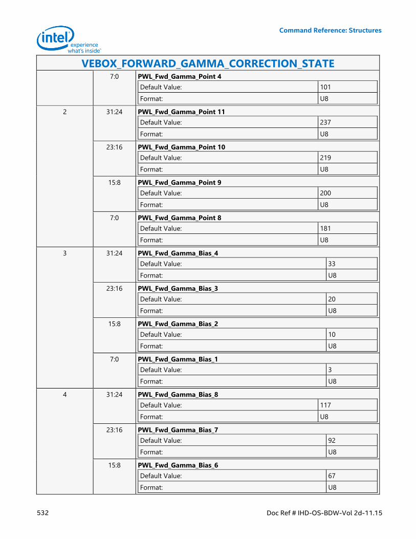
Command Reference: Structures
532 Doc Ref # IHD-OS-BDW-Vol 2d-11.15
VEBOX_FORWARD_GAMMA_CORRECTION_STATE 7:0 PWL_Fwd_Gamma_Point 4
Default Value: 101
Format: U8
2 31:24 PWL_Fwd_Gamma_Point 11
Default Value: 237
Format: U8
23:16 PWL_Fwd_Gamma_Point 10
Default Value: 219
Format: U8
15:8 PWL_Fwd_Gamma_Point 9
Default Value: 200
Format: U8
7:0 PWL_Fwd_Gamma_Point 8
Default Value: 181
Format: U8
3 31:24 PWL_Fwd_Gamma_Bias_4
Default Value: 33
Format: U8
23:16 PWL_Fwd_Gamma_Bias_3
Default Value: 20
Format: U8
15:8 PWL_Fwd_Gamma_Bias_2
Default Value: 10
Format: U8
7:0 PWL_Fwd_Gamma_Bias_1
Default Value: 3
Format: U8
4 31:24 PWL_Fwd_Gamma_Bias_8
Default Value: 117
Format: U8
23:16 PWL_Fwd_Gamma_Bias_7
Default Value: 92
Format: U8
15:8 PWL_Fwd_Gamma_Bias_6
Default Value: 67
Format: U8
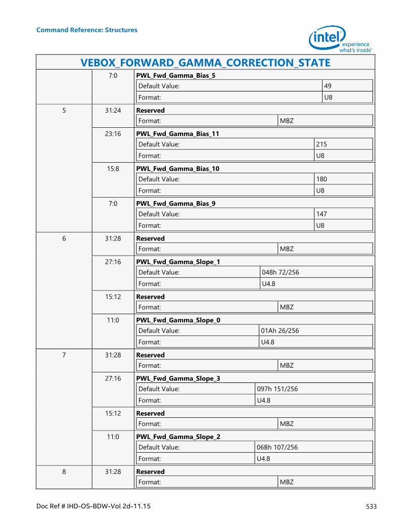
Command Reference: Structures
Doc Ref # IHD-OS-BDW-Vol 2d-11.15 533
VEBOX_FORWARD_GAMMA_CORRECTION_STATE 7:0 PWL_Fwd_Gamma_Bias_5
Default Value: 49
Format: U8
5 31:24 Reserved
Format: MBZ
23:16 PWL_Fwd_Gamma_Bias_11
Default Value: 215
Format: U8
15:8 PWL_Fwd_Gamma_Bias_10
Default Value: 180
Format: U8
7:0 PWL_Fwd_Gamma_Bias_9
Default Value: 147
Format: U8
6 31:28 Reserved
Format: MBZ
27:16 PWL_Fwd_Gamma_Slope_1
Default Value: 048h 72/256
Format: U4.8
15:12 Reserved
Format: MBZ
11:0 PWL_Fwd_Gamma_Slope_0
Default Value: 01Ah 26/256
Format: U4.8
7 31:28 Reserved
Format: MBZ
27:16 PWL_Fwd_Gamma_Slope_3
Default Value: 097h 151/256
Format: U4.8
15:12 Reserved
Format: MBZ
11:0 PWL_Fwd_Gamma_Slope_2
Default Value: 06Bh 107/256
Format: U4.8
8 31:28 Reserved
Format: MBZ
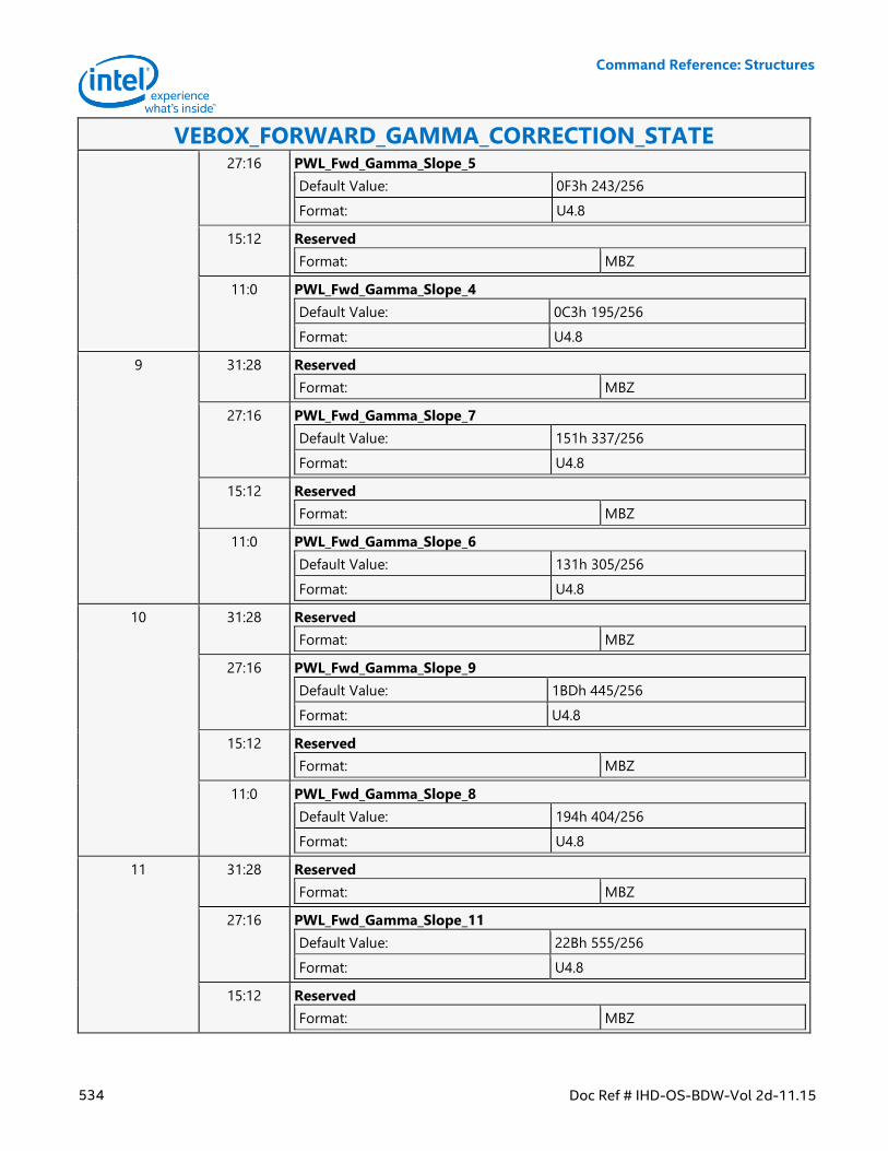
Command Reference: Structures
534 Doc Ref # IHD-OS-BDW-Vol 2d-11.15
VEBOX_FORWARD_GAMMA_CORRECTION_STATE 27:16 PWL_Fwd_Gamma_Slope_5
Default Value: 0F3h 243/256
Format: U4.8
15:12 Reserved
Format: MBZ
11:0 PWL_Fwd_Gamma_Slope_4
Default Value: 0C3h 195/256
Format: U4.8
9 31:28 Reserved
Format: MBZ
27:16 PWL_Fwd_Gamma_Slope_7
Default Value: 151h 337/256
Format: U4.8
15:12 Reserved
Format: MBZ
11:0 PWL_Fwd_Gamma_Slope_6
Default Value: 131h 305/256
Format: U4.8
10 31:28 Reserved
Format: MBZ
27:16 PWL_Fwd_Gamma_Slope_9
Default Value: 1BDh 445/256
Format: U4.8
15:12 Reserved
Format: MBZ
11:0 PWL_Fwd_Gamma_Slope_8
Default Value: 194h 404/256
Format: U4.8
11 31:28 Reserved
Format: MBZ
27:16 PWL_Fwd_Gamma_Slope_11
Default Value: 22Bh 555/256
Format: U4.8
15:12 Reserved
Format: MBZ
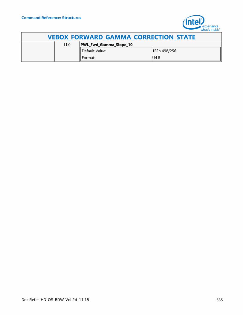
Command Reference: Structures
Doc Ref # IHD-OS-BDW-Vol 2d-11.15 535
VEBOX_FORWARD_GAMMA_CORRECTION_STATE 11:0 PWL_Fwd_Gamma_Slope_10
Default Value: 1F2h 498/256
Format: U4.8
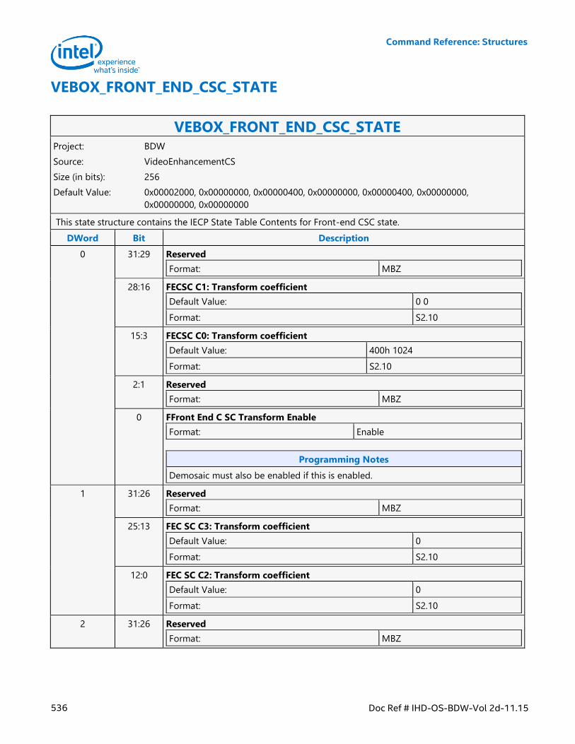
Command Reference: Structures
536 Doc Ref # IHD-OS-BDW-Vol 2d-11.15
VEBOX_FRONT_END_CSC_STATE
VEBOX_FRONT_END_CSC_STATE Project: BDW
Source: VideoEnhancementCS
Size (in bits): 256
Default Value: 0x00002000, 0x00000000, 0x00000400, 0x00000000, 0x00000400, 0x00000000,
0x00000000, 0x00000000
This state structure contains the IECP State Table Contents for Front-end CSC state.
DWord Bit Description
0 31:29 Reserved
Format: MBZ
28:16 FECSC C1: Transform coefficient
Default Value: 0 0
Format: S2.10
15:3 FECSC C0: Transform coefficient
Default Value: 400h 1024
Format: S2.10
2:1 Reserved
Format: MBZ
0 FFront End C SC Transform Enable
Format: Enable
Programming Notes
Demosaic must also be enabled if this is enabled.
1 31:26 Reserved
Format: MBZ
25:13 FEC SC C3: Transform coefficient
Default Value: 0
Format: S2.10
12:0 FEC SC C2: Transform coefficient
Default Value: 0
Format: S2.10
2 31:26 Reserved
Format: MBZ
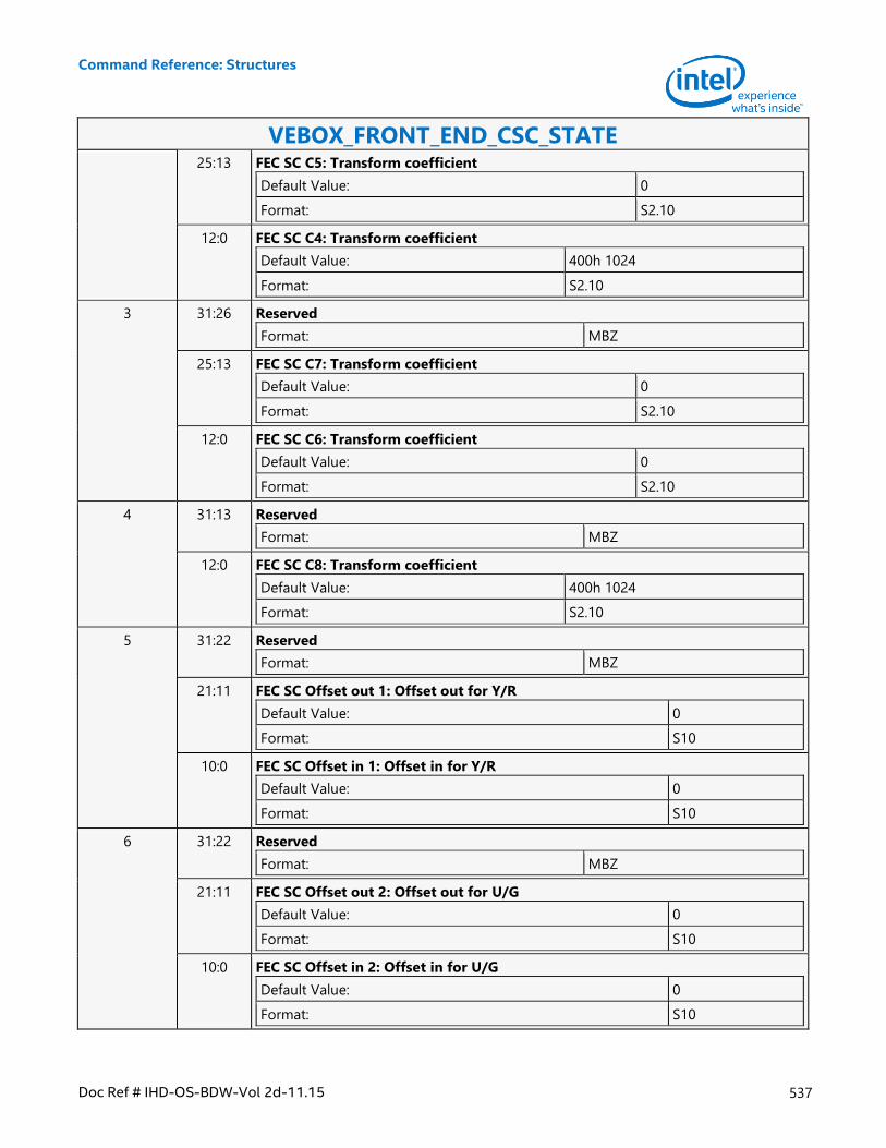
Command Reference: Structures
Doc Ref # IHD-OS-BDW-Vol 2d-11.15 537
VEBOX_FRONT_END_CSC_STATE 25:13 FEC SC C5: Transform coefficient
Default Value: 0
Format: S2.10
12:0 FEC SC C4: Transform coefficient
Default Value: 400h 1024
Format: S2.10
3 31:26 Reserved
Format: MBZ
25:13 FEC SC C7: Transform coefficient
Default Value: 0
Format: S2.10
12:0 FEC SC C6: Transform coefficient
Default Value: 0
Format: S2.10
4 31:13 Reserved
Format: MBZ
12:0 FEC SC C8: Transform coefficient
Default Value: 400h 1024
Format: S2.10
5 31:22 Reserved
Format: MBZ
21:11 FEC SC Offset out 1: Offset out for Y/R
Default Value: 0
Format: S10
10:0 FEC SC Offset in 1: Offset in for Y/R
Default Value: 0
Format: S10
6 31:22 Reserved
Format: MBZ
21:11 FEC SC Offset out 2: Offset out for U/G
Default Value: 0
Format: S10
10:0 FEC SC Offset in 2: Offset in for U/G
Default Value: 0
Format: S10
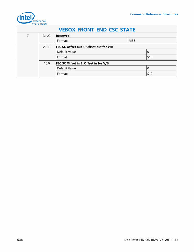
Command Reference: Structures
538 Doc Ref # IHD-OS-BDW-Vol 2d-11.15
VEBOX_FRONT_END_CSC_STATE 7 31:22 Reserved
Format: MBZ
21:11 FEC SC Offset out 3: Offset out for V/B
Default Value: 0
Format: S10
10:0 FEC SC Offset in 3: Offset in for V/B
Default Value: 0
Format: S10
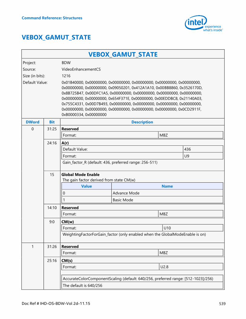
Command Reference: Structures
Doc Ref # IHD-OS-BDW-Vol 2d-11.15 539
VEBOX_GAMUT_STATE
VEBOX_GAMUT_STATE Project: BDW
Source: VideoEnhancementCS
Size (in bits): 1216
Default Value: 0x01B40000, 0x00000000, 0x00000000, 0x00000000, 0x00000000, 0x00000000,
0x00000000, 0x00000000, 0x09050201, 0x412A1A10, 0x00BB8860, 0x3526170D,
0x8B725B47, 0x00DFC1A5, 0x00000000, 0x00000000, 0x00000000, 0x00000000,
0x00000000, 0x00000000, 0x654F371E, 0x00000000, 0x00EDDBC8, 0x21140A03,
0x755C4331, 0x00D7B493, 0x00000000, 0x00000000, 0x00000000, 0x00000000,
0x00000000, 0x00000000, 0x00000000, 0x00000000, 0x00000000, 0x0CD2911F,
0xB0000334, 0x00000000
DWord Bit Description
0 31:25 Reserved
Format: MBZ
24:16 A(r)
Default Value: 436
Format: U9
Gain_factor_R (default: 436, preferred range: 256-511)
15 Global Mode Enable
The gain factor derived from state CM(w)
Value Name
0 Advance Mode
1 Basic Mode
14:10 Reserved
Format: MBZ
9:0 CM(w)
Format: U10
WeightingFactorForGain_factor (only enabled when the GlobalModeEnable is on)
1 31:26 Reserved
Format: MBZ
25:16 CM(s)
Format: U2.8
AccurateColorComponentScaling (default: 640/256, preferred range: [512-1023]/256)
The default is 640/256
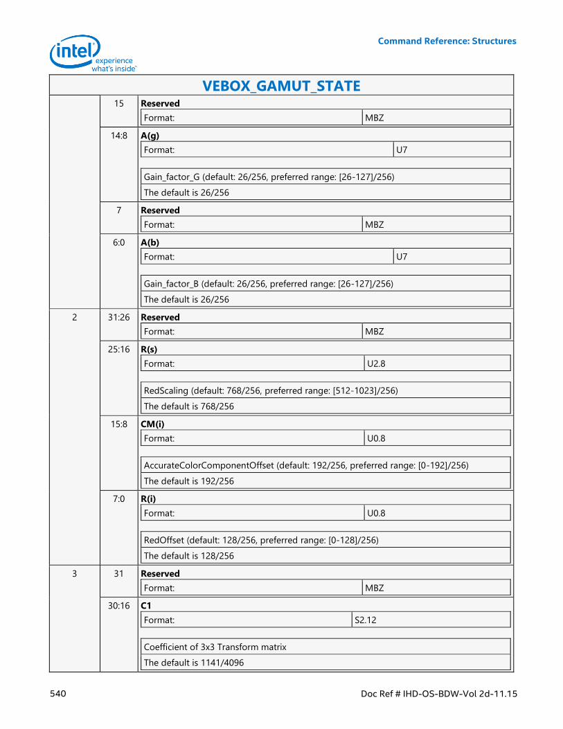
Command Reference: Structures
540 Doc Ref # IHD-OS-BDW-Vol 2d-11.15
VEBOX_GAMUT_STATE 15 Reserved
Format: MBZ
14:8 A(g)
Format: U7
Gain_factor_G (default: 26/256, preferred range: [26-127]/256)
The default is 26/256
7 Reserved
Format: MBZ
6:0 A(b)
Format: U7
Gain_factor_B (default: 26/256, preferred range: [26-127]/256)
The default is 26/256
2 31:26 Reserved
Format: MBZ
25:16 R(s)
Format: U2.8
RedScaling (default: 768/256, preferred range: [512-1023]/256)
The default is 768/256
15:8 CM(i)
Format: U0.8
AccurateColorComponentOffset (default: 192/256, preferred range: [0-192]/256)
The default is 192/256
7:0 R(i)
Format: U0.8
RedOffset (default: 128/256, preferred range: [0-128]/256)
The default is 128/256
3 31 Reserved
Format: MBZ
30:16 C1
Format: S2.12
Coefficient of 3x3 Transform matrix
The default is 1141/4096
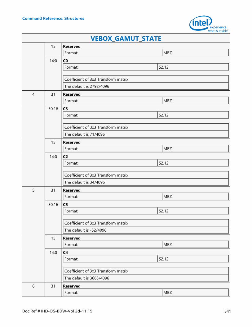
Command Reference: Structures
Doc Ref # IHD-OS-BDW-Vol 2d-11.15 541
VEBOX_GAMUT_STATE 15 Reserved
Format: MBZ
14:0 C0
Format: S2.12
Coefficient of 3x3 Transform matrix
The default is 2792/4096
4 31 Reserved
Format: MBZ
30:16 C3
Format: S2.12
Coefficient of 3x3 Transform matrix
The default is 71/4096
15 Reserved
Format: MBZ
14:0 C2
Format: S2.12
Coefficient of 3x3 Transform matrix
The default is 34/4096
5 31 Reserved
Format: MBZ
30:16 C5
Format: S2.12
Coefficient of 3x3 Transform matrix
The default is -52/4096
15 Reserved
Format: MBZ
14:0 C4
Format: S2.12
Coefficient of 3x3 Transform matrix
The default is 3663/4096
6 31 Reserved
Format: MBZ
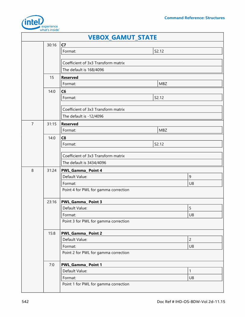
Command Reference: Structures
542 Doc Ref # IHD-OS-BDW-Vol 2d-11.15
VEBOX_GAMUT_STATE 30:16 C7
Format: S2.12
Coefficient of 3x3 Transform matrix
The default is 168/4096
15 Reserved
Format: MBZ
14:0 C6
Format: S2.12
Coefficient of 3x3 Transform matrix
The default is -12/4096
7 31:15 Reserved
Format: MBZ
14:0 C8
Format: S2.12
Coefficient of 3x3 Transform matrix
The default is 3434/4096
8 31:24 PWL_Gamma_ Point 4
Default Value: 9
Format: U8
Point 4 for PWL for gamma correction
23:16 PWL_Gamma_ Point 3
Default Value: 5
Format: U8
Point 3 for PWL for gamma correction
15:8 PWL_Gamma_ Point 2
Default Value: 2
Format: U8
Point 2 for PWL for gamma correction
7:0 PWL_Gamma_ Point 1
Default Value: 1
Format: U8
Point 1 for PWL for gamma correction
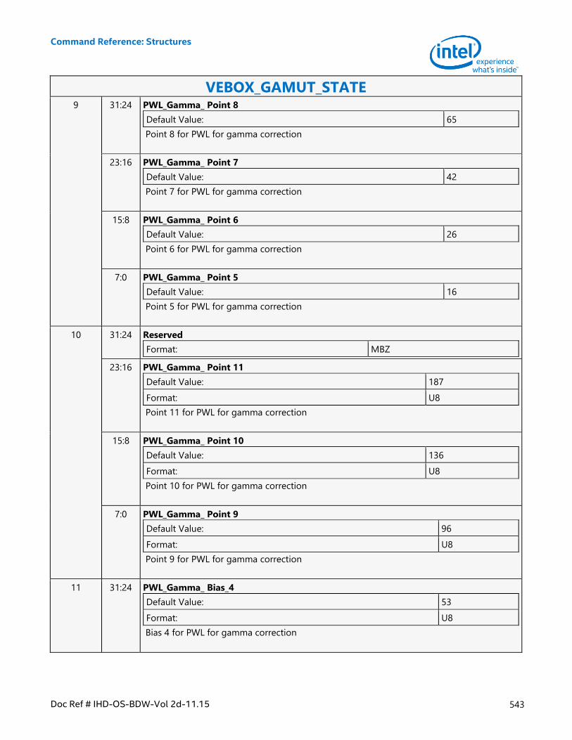
Command Reference: Structures
Doc Ref # IHD-OS-BDW-Vol 2d-11.15 543
VEBOX_GAMUT_STATE 9 31:24 PWL_Gamma_ Point 8
Default Value: 65
Point 8 for PWL for gamma correction
23:16 PWL_Gamma_ Point 7
Default Value: 42
Point 7 for PWL for gamma correction
15:8 PWL_Gamma_ Point 6
Default Value: 26
Point 6 for PWL for gamma correction
7:0 PWL_Gamma_ Point 5
Default Value: 16
Point 5 for PWL for gamma correction
10 31:24 Reserved
Format: MBZ
23:16 PWL_Gamma_ Point 11
Default Value: 187
Format: U8
Point 11 for PWL for gamma correction
15:8 PWL_Gamma_ Point 10
Default Value: 136
Format: U8
Point 10 for PWL for gamma correction
7:0 PWL_Gamma_ Point 9
Default Value: 96
Format: U8
Point 9 for PWL for gamma correction
11 31:24 PWL_Gamma_ Bias_4
Default Value: 53
Format: U8
Bias 4 for PWL for gamma correction
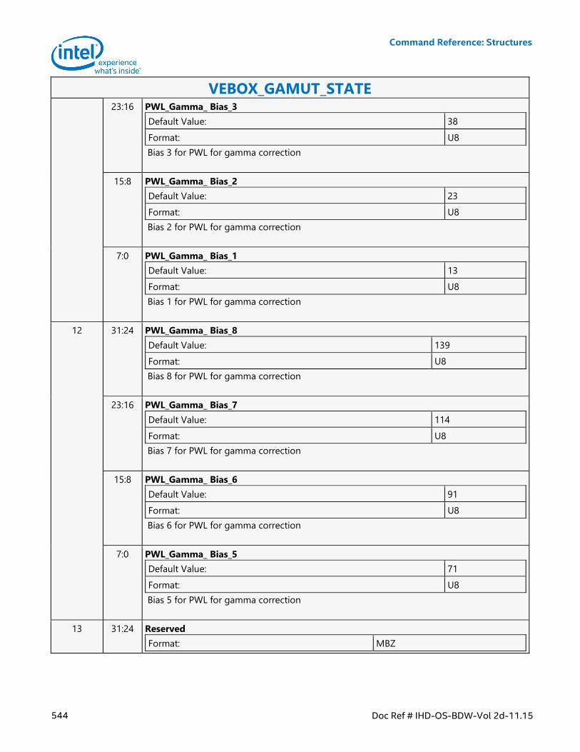
Command Reference: Structures
544 Doc Ref # IHD-OS-BDW-Vol 2d-11.15
VEBOX_GAMUT_STATE 23:16 PWL_Gamma_ Bias_3
Default Value: 38
Format: U8
Bias 3 for PWL for gamma correction
15:8 PWL_Gamma_ Bias_2
Default Value: 23
Format: U8
Bias 2 for PWL for gamma correction
7:0 PWL_Gamma_ Bias_1
Default Value: 13
Format: U8
Bias 1 for PWL for gamma correction
12 31:24 PWL_Gamma_ Bias_8
Default Value: 139
Format: U8
Bias 8 for PWL for gamma correction
23:16 PWL_Gamma_ Bias_7
Default Value: 114
Format: U8
Bias 7 for PWL for gamma correction
15:8 PWL_Gamma_ Bias_6
Default Value: 91
Format: U8
Bias 6 for PWL for gamma correction
7:0 PWL_Gamma_ Bias_5
Default Value: 71
Format: U8
Bias 5 for PWL for gamma correction
13 31:24 Reserved
Format: MBZ
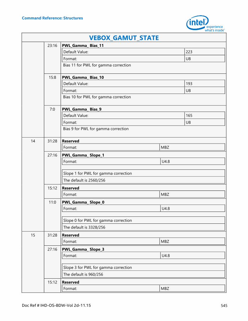
Command Reference: Structures
Doc Ref # IHD-OS-BDW-Vol 2d-11.15 545
VEBOX_GAMUT_STATE 23:16 PWL_Gamma_ Bias_11
Default Value: 223
Format: U8
Bias 11 for PWL for gamma correction
15:8 PWL_Gamma_ Bias_10
Default Value: 193
Format: U8
Bias 10 for PWL for gamma correction
7:0 PWL_Gamma_ Bias_9
Default Value: 165
Format: U8
Bias 9 for PWL for gamma correction
14 31:28 Reserved
Format: MBZ
27:16 PWL_Gamma_ Slope_1
Format: U4.8
Slope 1 for PWL for gamma correction
The default is 2560/256
15:12 Reserved
Format: MBZ
11:0 PWL_Gamma_ Slope_0
Format: U4.8
Slope 0 for PWL for gamma correction
The default is 3328/256
15 31:28 Reserved
Format: MBZ
27:16 PWL_Gamma_ Slope_3
Format: U4.8
Slope 3 for PWL for gamma correction
The default is 960/256
15:12 Reserved
Format: MBZ
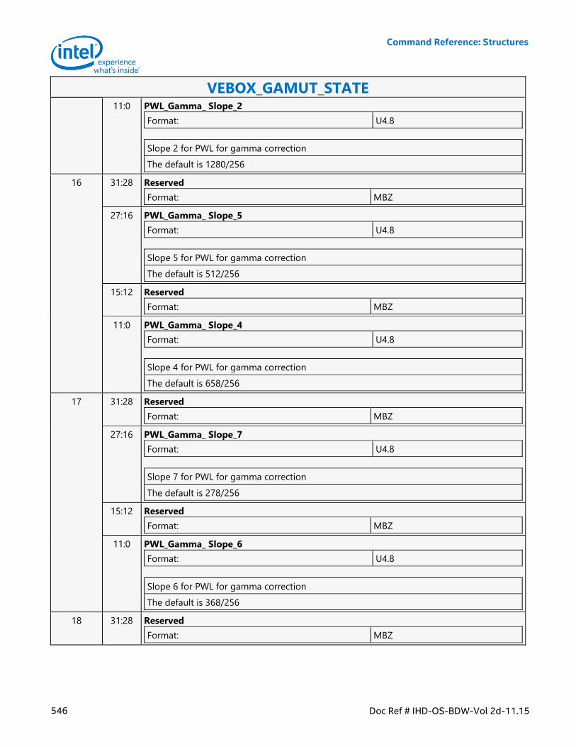
Command Reference: Structures
546 Doc Ref # IHD-OS-BDW-Vol 2d-11.15
VEBOX_GAMUT_STATE 11:0 PWL_Gamma_ Slope_2
Format: U4.8
Slope 2 for PWL for gamma correction
The default is 1280/256
16 31:28 Reserved
Format: MBZ
27:16 PWL_Gamma_ Slope_5
Format: U4.8
Slope 5 for PWL for gamma correction
The default is 512/256
15:12 Reserved
Format: MBZ
11:0 PWL_Gamma_ Slope_4
Format: U4.8
Slope 4 for PWL for gamma correction
The default is 658/256
17 31:28 Reserved
Format: MBZ
27:16 PWL_Gamma_ Slope_7
Format: U4.8
Slope 7 for PWL for gamma correction
The default is 278/256
15:12 Reserved
Format: MBZ
11:0 PWL_Gamma_ Slope_6
Format: U4.8
Slope 6 for PWL for gamma correction
The default is 368/256
18 31:28 Reserved
Format: MBZ
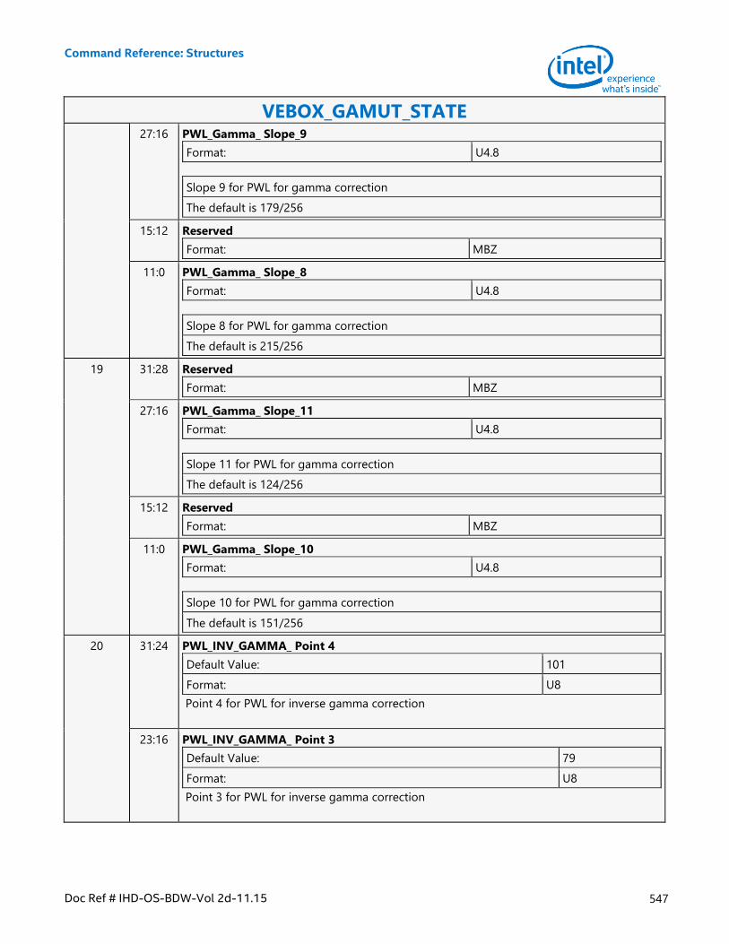
Command Reference: Structures
Doc Ref # IHD-OS-BDW-Vol 2d-11.15 547
VEBOX_GAMUT_STATE 27:16 PWL_Gamma_ Slope_9
Format: U4.8
Slope 9 for PWL for gamma correction
The default is 179/256
15:12 Reserved
Format: MBZ
11:0 PWL_Gamma_ Slope_8
Format: U4.8
Slope 8 for PWL for gamma correction
The default is 215/256
19 31:28 Reserved
Format: MBZ
27:16 PWL_Gamma_ Slope_11
Format: U4.8
Slope 11 for PWL for gamma correction
The default is 124/256
15:12 Reserved
Format: MBZ
11:0 PWL_Gamma_ Slope_10
Format: U4.8
Slope 10 for PWL for gamma correction
The default is 151/256
20 31:24 PWL_INV_GAMMA_ Point 4
Default Value: 101
Format: U8
Point 4 for PWL for inverse gamma correction
23:16 PWL_INV_GAMMA_ Point 3
Default Value: 79
Format: U8
Point 3 for PWL for inverse gamma correction
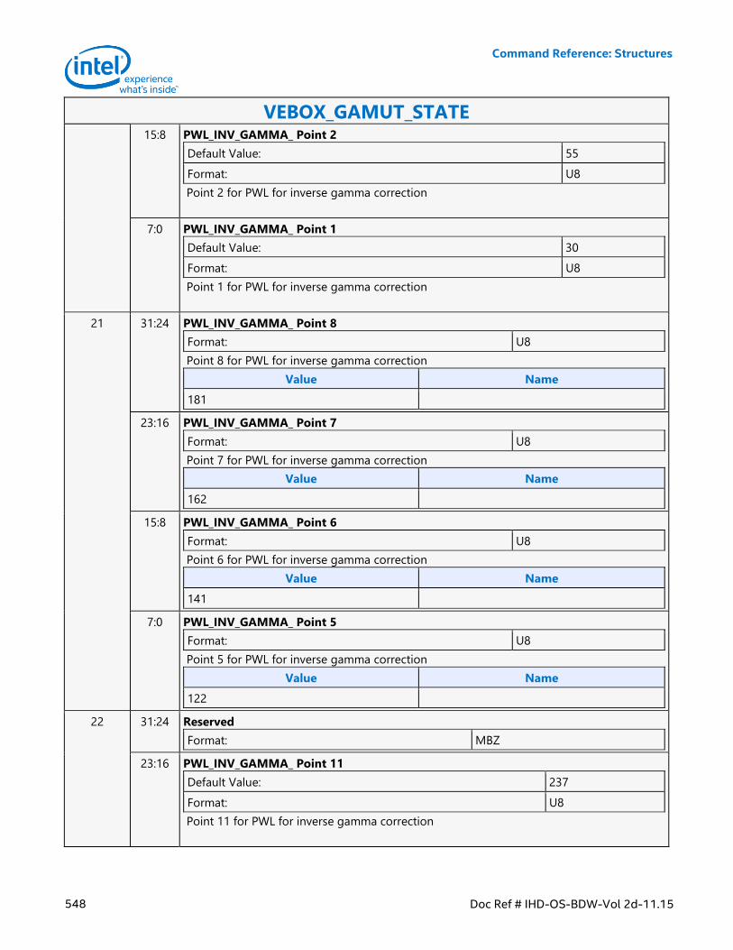
Command Reference: Structures
548 Doc Ref # IHD-OS-BDW-Vol 2d-11.15
VEBOX_GAMUT_STATE 15:8 PWL_INV_GAMMA_ Point 2
Default Value: 55
Format: U8
Point 2 for PWL for inverse gamma correction
7:0 PWL_INV_GAMMA_ Point 1
Default Value: 30
Format: U8
Point 1 for PWL for inverse gamma correction
21 31:24 PWL_INV_GAMMA_ Point 8
Format: U8
Point 8 for PWL for inverse gamma correction
Value Name
181
23:16 PWL_INV_GAMMA_ Point 7
Format: U8
Point 7 for PWL for inverse gamma correction
Value Name
162
15:8 PWL_INV_GAMMA_ Point 6
Format: U8
Point 6 for PWL for inverse gamma correction
Value Name
141
7:0 PWL_INV_GAMMA_ Point 5
Format: U8
Point 5 for PWL for inverse gamma correction
Value Name
122
22 31:24 Reserved
Format: MBZ
23:16 PWL_INV_GAMMA_ Point 11
Default Value: 237
Format: U8
Point 11 for PWL for inverse gamma correction
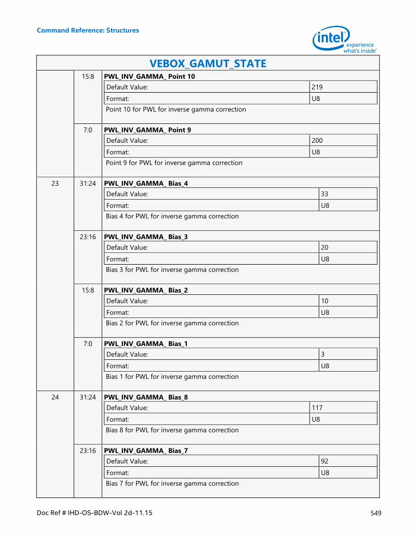
Command Reference: Structures
Doc Ref # IHD-OS-BDW-Vol 2d-11.15 549
VEBOX_GAMUT_STATE 15:8 PWL_INV_GAMMA_ Point 10
Default Value: 219
Format: U8
Point 10 for PWL for inverse gamma correction
7:0 PWL_INV_GAMMA_ Point 9
Default Value: 200
Format: U8
Point 9 for PWL for inverse gamma correction
23 31:24 PWL_INV_GAMMA_ Bias_4
Default Value: 33
Format: U8
Bias 4 for PWL for inverse gamma correction
23:16 PWL_INV_GAMMA_ Bias_3
Default Value: 20
Format: U8
Bias 3 for PWL for inverse gamma correction
15:8 PWL_INV_GAMMA_ Bias_2
Default Value: 10
Format: U8
Bias 2 for PWL for inverse gamma correction
7:0 PWL_INV_GAMMA_ Bias_1
Default Value: 3
Format: U8
Bias 1 for PWL for inverse gamma correction
24 31:24 PWL_INV_GAMMA_ Bias_8
Default Value: 117
Format: U8
Bias 8 for PWL for inverse gamma correction
23:16 PWL_INV_GAMMA_ Bias_7
Default Value: 92
Format: U8
Bias 7 for PWL for inverse gamma correction
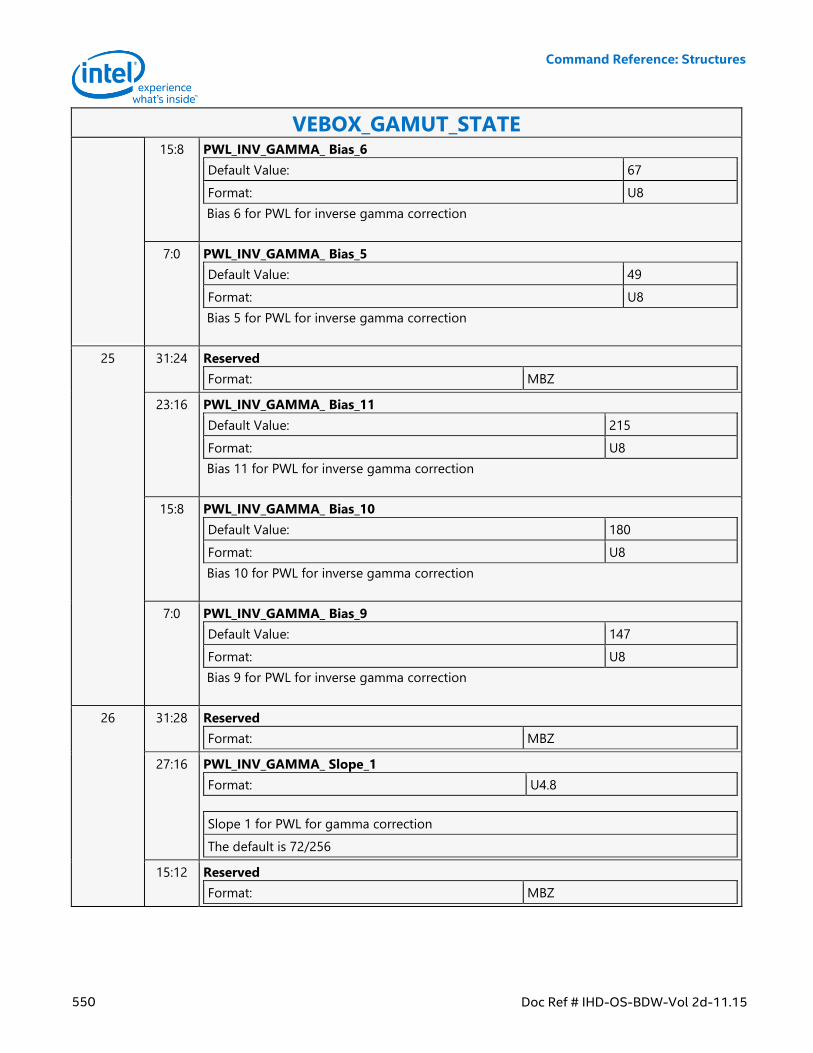
Command Reference: Structures
550 Doc Ref # IHD-OS-BDW-Vol 2d-11.15
VEBOX_GAMUT_STATE 15:8 PWL_INV_GAMMA_ Bias_6
Default Value: 67
Format: U8
Bias 6 for PWL for inverse gamma correction
7:0 PWL_INV_GAMMA_ Bias_5
Default Value: 49
Format: U8
Bias 5 for PWL for inverse gamma correction
25 31:24 Reserved
Format: MBZ
23:16 PWL_INV_GAMMA_ Bias_11
Default Value: 215
Format: U8
Bias 11 for PWL for inverse gamma correction
15:8 PWL_INV_GAMMA_ Bias_10
Default Value: 180
Format: U8
Bias 10 for PWL for inverse gamma correction
7:0 PWL_INV_GAMMA_ Bias_9
Default Value: 147
Format: U8
Bias 9 for PWL for inverse gamma correction
26 31:28 Reserved
Format: MBZ
27:16 PWL_INV_GAMMA_ Slope_1
Format: U4.8
Slope 1 for PWL for gamma correction
The default is 72/256
15:12 Reserved
Format: MBZ
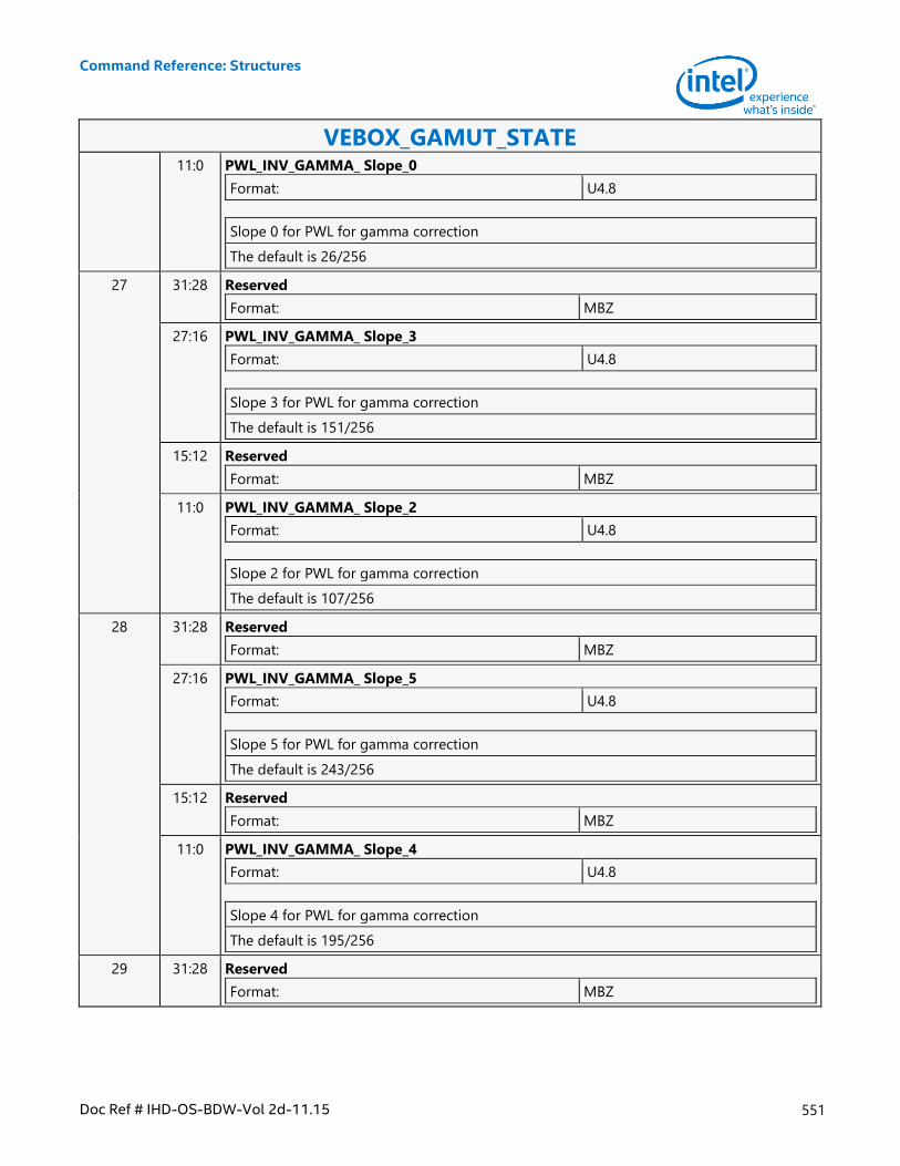
Command Reference: Structures
Doc Ref # IHD-OS-BDW-Vol 2d-11.15 551
VEBOX_GAMUT_STATE 11:0 PWL_INV_GAMMA_ Slope_0
Format: U4.8
Slope 0 for PWL for gamma correction
The default is 26/256
27 31:28 Reserved
Format: MBZ
27:16 PWL_INV_GAMMA_ Slope_3
Format: U4.8
Slope 3 for PWL for gamma correction
The default is 151/256
15:12 Reserved
Format: MBZ
11:0 PWL_INV_GAMMA_ Slope_2
Format: U4.8
Slope 2 for PWL for gamma correction
The default is 107/256
28 31:28 Reserved
Format: MBZ
27:16 PWL_INV_GAMMA_ Slope_5
Format: U4.8
Slope 5 for PWL for gamma correction
The default is 243/256
15:12 Reserved
Format: MBZ
11:0 PWL_INV_GAMMA_ Slope_4
Format: U4.8
Slope 4 for PWL for gamma correction
The default is 195/256
29 31:28 Reserved
Format: MBZ
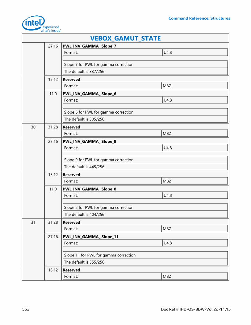
Command Reference: Structures
552 Doc Ref # IHD-OS-BDW-Vol 2d-11.15
VEBOX_GAMUT_STATE 27:16 PWL_INV_GAMMA_ Slope_7
Format: U4.8
Slope 7 for PWL for gamma correction
The default is 337/256
15:12 Reserved
Format: MBZ
11:0 PWL_INV_GAMMA_ Slope_6
Format: U4.8
Slope 6 for PWL for gamma correction
The default is 305/256
30 31:28 Reserved
Format: MBZ
27:16 PWL_INV_GAMMA_ Slope_9
Format: U4.8
Slope 9 for PWL for gamma correction
The default is 445/256
15:12 Reserved
Format: MBZ
11:0 PWL_INV_GAMMA_ Slope_8
Format: U4.8
Slope 8 for PWL for gamma correction
The default is 404/256
31 31:28 Reserved
Format: MBZ
27:16 PWL_INV_GAMMA_ Slope_11
Format: U4.8
Slope 11 for PWL for gamma correction
The default is 555/256
15:12 Reserved
Format: MBZ
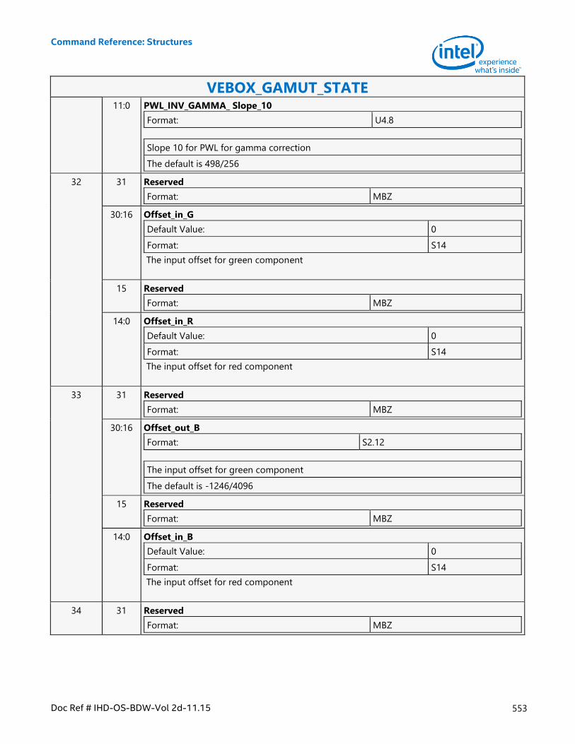
Command Reference: Structures
Doc Ref # IHD-OS-BDW-Vol 2d-11.15 553
VEBOX_GAMUT_STATE 11:0 PWL_INV_GAMMA_ Slope_10
Format: U4.8
Slope 10 for PWL for gamma correction
The default is 498/256
32 31 Reserved
Format: MBZ
30:16 Offset_in_G
Default Value: 0
Format: S14
The input offset for green component
15 Reserved
Format: MBZ
14:0 Offset_in_R
Default Value: 0
Format: S14
The input offset for red component
33 31 Reserved
Format: MBZ
30:16 Offset_out_B
Format: S2.12
The input offset for green component
The default is -1246/4096
15 Reserved
Format: MBZ
14:0 Offset_in_B
Default Value: 0
Format: S14
The input offset for red component
34 31 Reserved
Format: MBZ
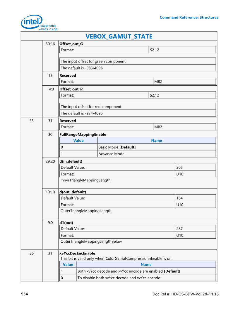
Command Reference: Structures
554 Doc Ref # IHD-OS-BDW-Vol 2d-11.15
VEBOX_GAMUT_STATE 30:16 Offset_out_G
Format: S2.12
The input offset for green component
The default is -983/4096
15 Reserved
Format: MBZ
14:0 Offset_out_R
Format: S2.12
The input offset for red component
The default is -974/4096
35 31 Reserved
Format: MBZ
30 FullRangeMappingEnable
Value Name
0 Basic Mode [Default]
1 Advance Mode
29:20 d(in,default)
Default Value: 205
Format: U10
InnerTriangleMappingLength
19:10 d(out, default)
Default Value: 164
Format: U10
OuterTriangleMappingLength
9:0 d1(out)
Default Value: 287
Format: U10
OuterTriangleMappingLengthBelow
36 31 xvYccDecEncEnable
This bit is valid only when ColorGamutCompressionnEnable is on.
Value Name
1 Both xvYcc decode and xvYcc encode are enabled [Default]
0 To disable both xvYcc decode and xvYcc encode
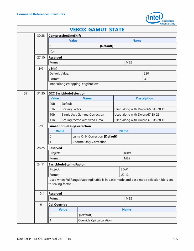
Command Reference: Structures
Doc Ref # IHD-OS-BDW-Vol 2d-11.15 555
VEBOX_GAMUT_STATE 30:28 CompressionLineShift
Value Name
3 [Default]
[0,4]
27:10 Reserved
Format: MBZ
9:0 d1(in)
Default Value: 820
Format: U10
InnerTriangleMappingLengthBelow
37 31:30 GCC BasicModeSelection
Value Name Description
00b Default
01b Scaling Factor Used along with Dword66 Bits 28:11
10b Single Axis Gamma Correction Used along with Dword67 Bit 29
11b Scaling factor with fixed luma Used along with Dword37 Bits 28:11
29 LumaChormaOnlyCorrection
Value Name
0 Luma Only Correction [Default]
1 Chorma Only Correction
28:25 Reserved
Project: BDW
Format: MBZ
24:11 BasicModeScalingFactor
Project: BDW
Format: U2.12
Used when FullRangeMappingEnable is in basic mode and base mode selection bit is set
to scaling factor.
10:1 Reserved
Format: MBZ
0 Cpi Override
Value Name
0 [Default]
1 Override Cpi calculation
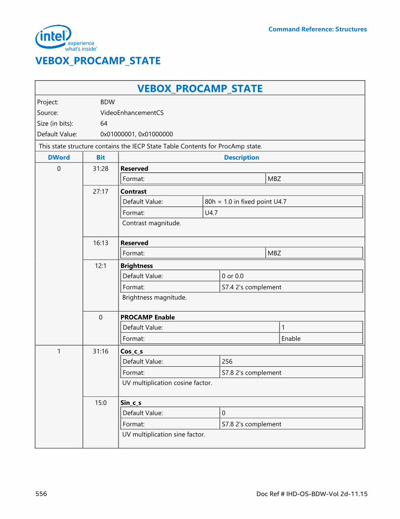
Command Reference: Structures
556 Doc Ref # IHD-OS-BDW-Vol 2d-11.15
VEBOX_PROCAMP_STATE
VEBOX_PROCAMP_STATE Project: BDW
Source: VideoEnhancementCS
Size (in bits): 64
Default Value: 0x01000001, 0x01000000
This state structure contains the IECP State Table Contents for ProcAmp state.
DWord Bit Description
0 31:28 Reserved
Format: MBZ
27:17 Contrast
Default Value: 80h = 1.0 in fixed point U4.7
Format: U4.7
Contrast magnitude.
16:13 Reserved
Format: MBZ
12:1 Brightness
Default Value: 0 or 0.0
Format: S7.4 2's complement
Brightness magnitude.
0 PROCAMP Enable
Default Value: 1
Format: Enable
1 31:16 Cos_c_s
Default Value: 256
Format: S7.8 2's complement
UV multiplication cosine factor.
15:0 Sin_c_s
Default Value: 0
Format: S7.8 2's complement
UV multiplication sine factor.
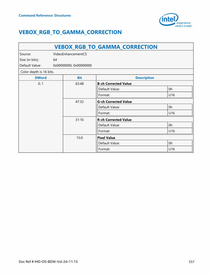
Command Reference: Structures
Doc Ref # IHD-OS-BDW-Vol 2d-11.15 557
VEBOX_RGB_TO_GAMMA_CORRECTION
VEBOX_RGB_TO_GAMMA_CORRECTION Source: VideoEnhancementCS
Size (in bits): 64
Default Value: 0x00000000, 0x00000000
Color depth is 16 bits.
DWord Bit Description
0..1 63:48 B-ch Corrected Value
Default Value: 0h
Format: U16
47:32 G-ch Corrected Value
Default Value: 0h
Format: U16
31:16 R-ch Corrected Value
Default Value: 0h
Format: U16
15:0 Pixel Value
Default Value: 0h
Format: U16
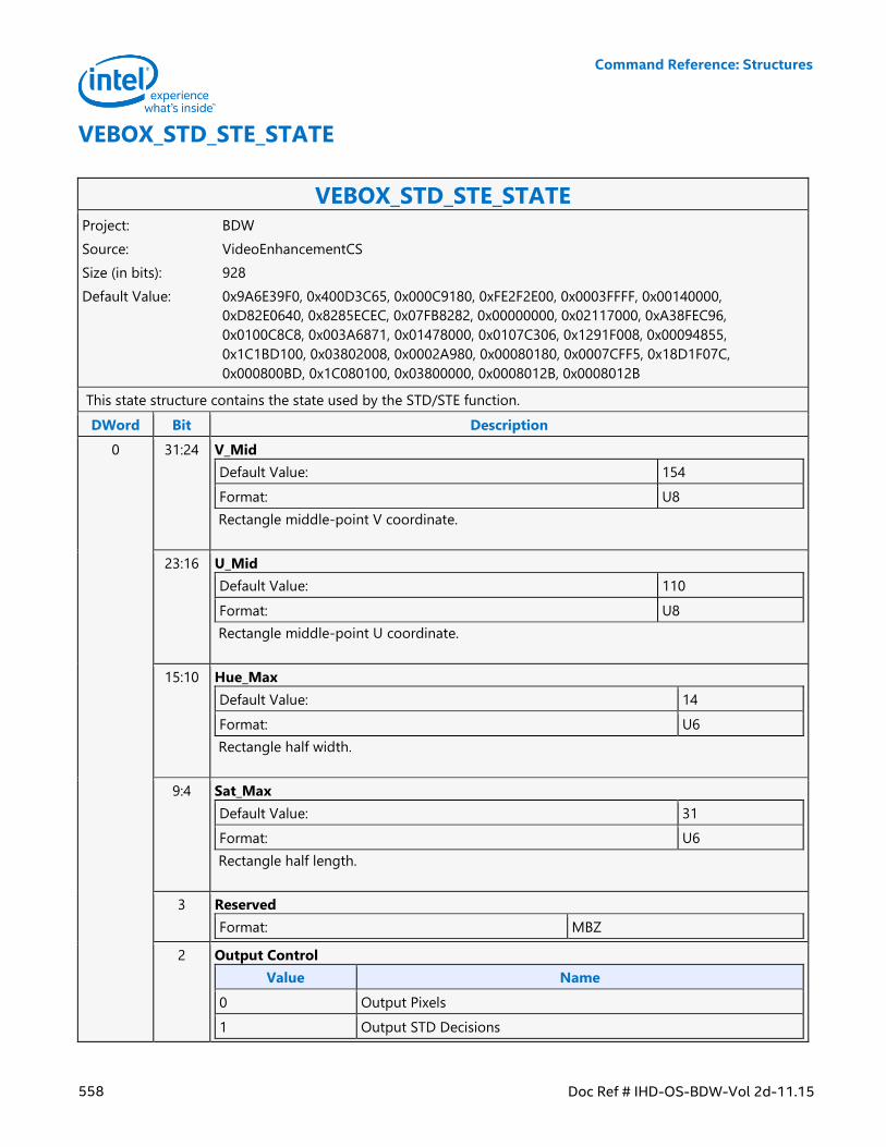
Command Reference: Structures
558 Doc Ref # IHD-OS-BDW-Vol 2d-11.15
VEBOX_STD_STE_STATE
VEBOX_STD_STE_STATE Project: BDW
Source: VideoEnhancementCS
Size (in bits): 928
Default Value: 0x9A6E39F0, 0x400D3C65, 0x000C9180, 0xFE2F2E00, 0x0003FFFF, 0x00140000,
0xD82E0640, 0x8285ECEC, 0x07FB8282, 0x00000000, 0x02117000, 0xA38FEC96,
0x0100C8C8, 0x003A6871, 0x01478000, 0x0107C306, 0x1291F008, 0x00094855,
0x1C1BD100, 0x03802008, 0x0002A980, 0x00080180, 0x0007CFF5, 0x18D1F07C,
0x000800BD, 0x1C080100, 0x03800000, 0x0008012B, 0x0008012B
This state structure contains the state used by the STD/STE function.
DWord Bit Description
0 31:24 V_Mid
Default Value: 154
Format: U8
Rectangle middle-point V coordinate.
23:16 U_Mid
Default Value: 110
Format: U8
Rectangle middle-point U coordinate.
15:10 Hue_Max
Default Value: 14
Format: U6
Rectangle half width.
9:4 Sat_Max
Default Value: 31
Format: U6
Rectangle half length.
3 Reserved
Format: MBZ
2 Output Control
Value Name
0 Output Pixels
1 Output STD Decisions
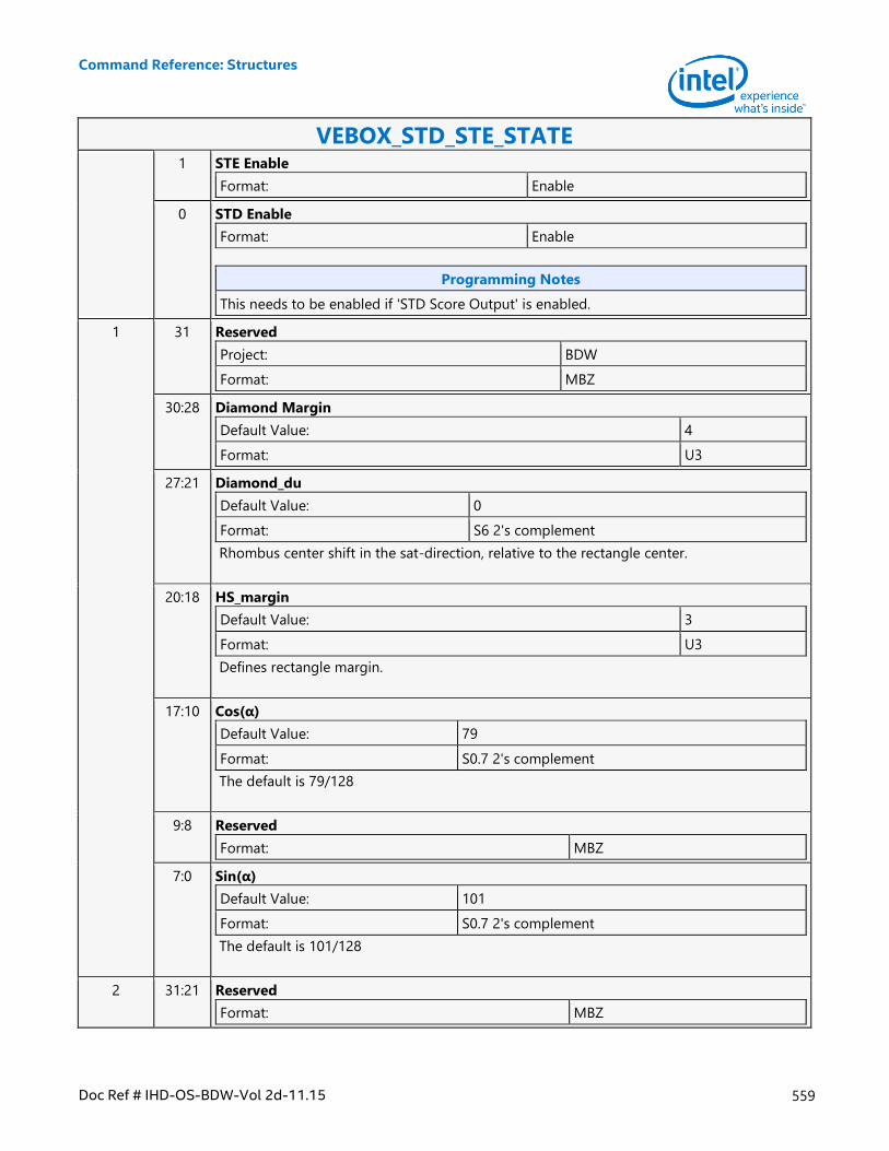
Command Reference: Structures
Doc Ref # IHD-OS-BDW-Vol 2d-11.15 559
VEBOX_STD_STE_STATE 1 STE Enable
Format: Enable
0 STD Enable
Format: Enable
Programming Notes
This needs to be enabled if 'STD Score Output' is enabled.
1 31 Reserved
Project: BDW
Format: MBZ
30:28 Diamond Margin
Default Value: 4
Format: U3
27:21 Diamond_du
Default Value: 0
Format: S6 2's complement
Rhombus center shift in the sat-direction, relative to the rectangle center.
20:18 HS_margin
Default Value: 3
Format: U3
Defines rectangle margin.
17:10 Cos(α)
Default Value: 79
Format: S0.7 2's complement
The default is 79/128
9:8 Reserved
Format: MBZ
7:0 Sin(α)
Default Value: 101
Format: S0.7 2's complement
The default is 101/128
2 31:21 Reserved
Format: MBZ
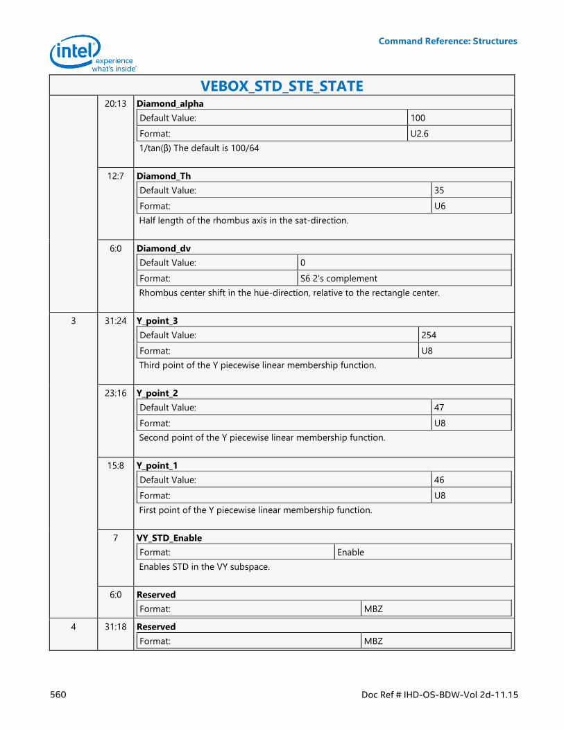
Command Reference: Structures
560 Doc Ref # IHD-OS-BDW-Vol 2d-11.15
VEBOX_STD_STE_STATE 20:13 Diamond_alpha
Default Value: 100
Format: U2.6
1/tan(β) The default is 100/64
12:7 Diamond_Th
Default Value: 35
Format: U6
Half length of the rhombus axis in the sat-direction.
6:0 Diamond_dv
Default Value: 0
Format: S6 2's complement
Rhombus center shift in the hue-direction, relative to the rectangle center.
3 31:24 Y_point_3
Default Value: 254
Format: U8
Third point of the Y piecewise linear membership function.
23:16 Y_point_2
Default Value: 47
Format: U8
Second point of the Y piecewise linear membership function.
15:8 Y_point_1
Default Value: 46
Format: U8
First point of the Y piecewise linear membership function.
7 VY_STD_Enable
Format: Enable
Enables STD in the VY subspace.
6:0 Reserved
Format: MBZ
4 31:18 Reserved
Format: MBZ
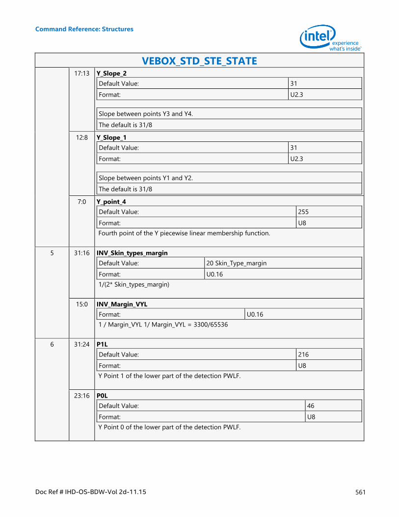
Command Reference: Structures
Doc Ref # IHD-OS-BDW-Vol 2d-11.15 561
VEBOX_STD_STE_STATE 17:13 Y_Slope_2
Default Value: 31
Format: U2.3
Slope between points Y3 and Y4.
The default is 31/8
12:8 Y_Slope_1
Default Value: 31
Format: U2.3
Slope between points Y1 and Y2.
The default is 31/8
7:0 Y_point_4
Default Value: 255
Format: U8
Fourth point of the Y piecewise linear membership function.
5 31:16 INV_Skin_types_margin
Default Value: 20 Skin_Type_margin
Format: U0.16
1/(2* Skin_types_margin)
15:0 INV_Margin_VYL
Format: U0.16
1 / Margin_VYL 1/ Margin_VYL = 3300/65536
6 31:24 P1L
Default Value: 216
Format: U8
Y Point 1 of the lower part of the detection PWLF.
23:16 P0L
Default Value: 46
Format: U8
Y Point 0 of the lower part of the detection PWLF.
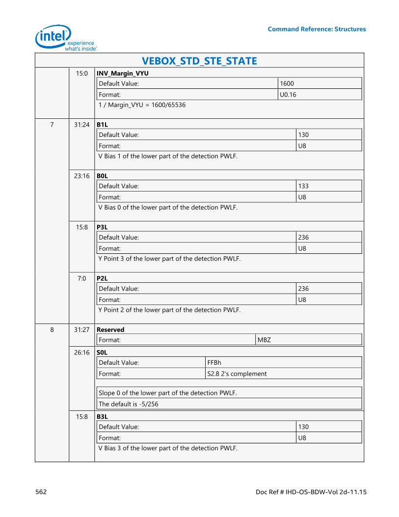
Command Reference: Structures
562 Doc Ref # IHD-OS-BDW-Vol 2d-11.15
VEBOX_STD_STE_STATE 15:0 INV_Margin_VYU
Default Value: 1600
Format: U0.16
1 / Margin_VYU = 1600/65536
7 31:24 B1L
Default Value: 130
Format: U8
V Bias 1 of the lower part of the detection PWLF.
23:16 B0L
Default Value: 133
Format: U8
V Bias 0 of the lower part of the detection PWLF.
15:8 P3L
Default Value: 236
Format: U8
Y Point 3 of the lower part of the detection PWLF.
7:0 P2L
Default Value: 236
Format: U8
Y Point 2 of the lower part of the detection PWLF.
8 31:27 Reserved
Format: MBZ
26:16 S0L
Default Value: FFBh
Format: S2.8 2's complement
Slope 0 of the lower part of the detection PWLF.
The default is -5/256
15:8 B3L
Default Value: 130
Format: U8
V Bias 3 of the lower part of the detection PWLF.
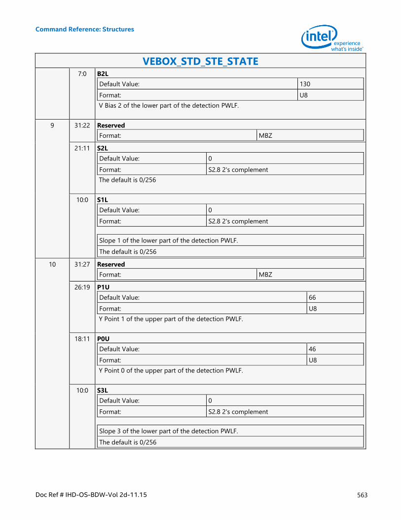
Command Reference: Structures
Doc Ref # IHD-OS-BDW-Vol 2d-11.15 563
VEBOX_STD_STE_STATE 7:0 B2L
Default Value: 130
Format: U8
V Bias 2 of the lower part of the detection PWLF.
9 31:22 Reserved
Format: MBZ
21:11 S2L
Default Value: 0
Format: S2.8 2's complement
The default is 0/256
10:0 S1L
Default Value: 0
Format: S2.8 2's complement
Slope 1 of the lower part of the detection PWLF.
The default is 0/256
10 31:27 Reserved
Format: MBZ
26:19 P1U
Default Value: 66
Format: U8
Y Point 1 of the upper part of the detection PWLF.
18:11 P0U
Default Value: 46
Format: U8
Y Point 0 of the upper part of the detection PWLF.
10:0 S3L
Default Value: 0
Format: S2.8 2's complement
Slope 3 of the lower part of the detection PWLF.
The default is 0/256
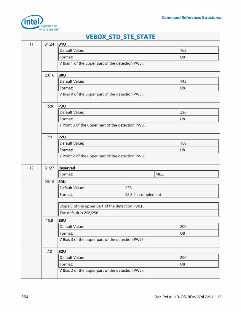
Command Reference: Structures
564 Doc Ref # IHD-OS-BDW-Vol 2d-11.15
VEBOX_STD_STE_STATE 11 31:24 B1U
Default Value: 163
Format: U8
V Bias 1 of the upper part of the detection PWLF.
23:16 B0U
Default Value: 143
Format: U8
V Bias 0 of the upper part of the detection PWLF.
15:8 P3U
Default Value: 236
Format: U8
Y Point 3 of the upper part of the detection PWLF.
7:0 P2U
Default Value: 150
Format: U8
Y Point 2 of the upper part of the detection PWLF.
12 31:27 Reserved
Format: MBZ
26:16 S0U
Default Value: 256
Format: S2.8 2's complement
Slope 0 of the upper part of the detection PWLF.
The default is 256/256
15:8 B3U
Default Value: 200
Format: U8
V Bias 3 of the upper part of the detection PWLF.
7:0 B2U
Default Value: 200
Format: U8
V Bias 2 of the upper part of the detection PWLF.
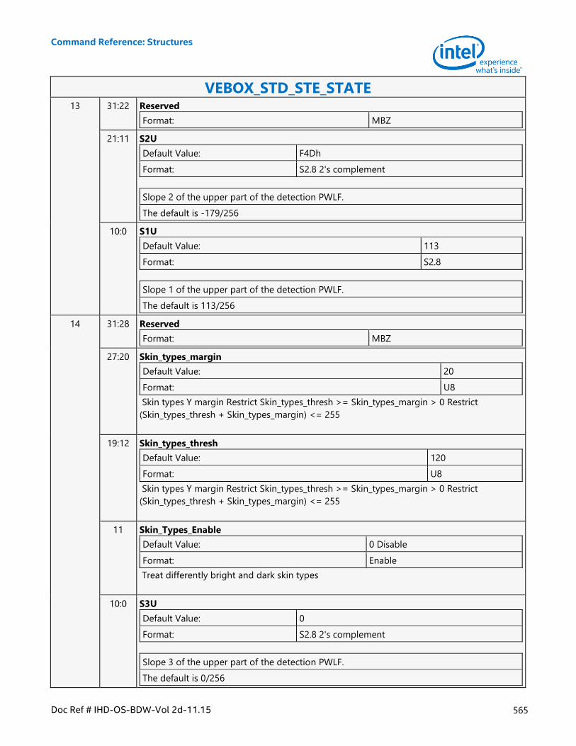
Command Reference: Structures
Doc Ref # IHD-OS-BDW-Vol 2d-11.15 565
VEBOX_STD_STE_STATE 13 31:22 Reserved
Format: MBZ
21:11 S2U
Default Value: F4Dh
Format: S2.8 2's complement
Slope 2 of the upper part of the detection PWLF.
The default is -179/256
10:0 S1U
Default Value: 113
Format: S2.8
Slope 1 of the upper part of the detection PWLF.
The default is 113/256
14 31:28 Reserved
Format: MBZ
27:20 Skin_types_margin
Default Value: 20
Format: U8
Skin types Y margin Restrict Skin_types_thresh >= Skin_types_margin > 0 Restrict
(Skin_types_thresh + Skin_types_margin) <= 255
19:12 Skin_types_thresh
Default Value: 120
Format: U8
Skin types Y margin Restrict Skin_types_thresh >= Skin_types_margin > 0 Restrict
(Skin_types_thresh + Skin_types_margin) <= 255
11 Skin_Types_Enable
Default Value: 0 Disable
Format: Enable
Treat differently bright and dark skin types
10:0 S3U
Default Value: 0
Format: S2.8 2's complement
Slope 3 of the upper part of the detection PWLF.
The default is 0/256
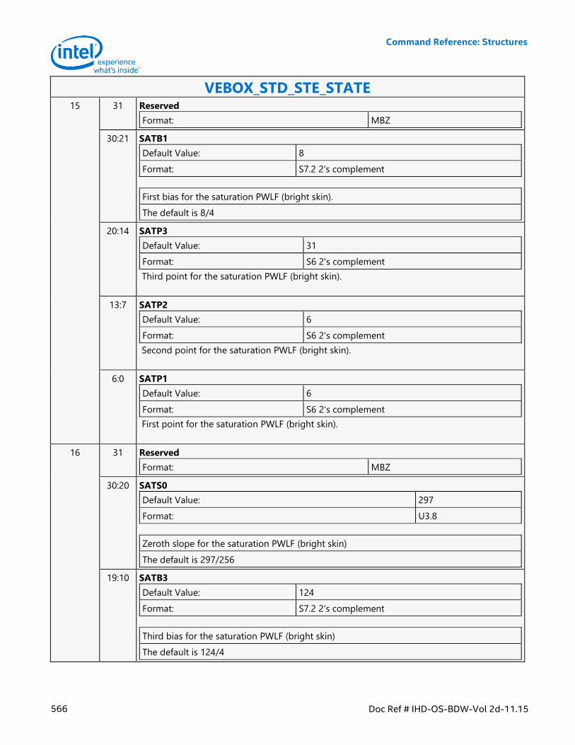
Command Reference: Structures
566 Doc Ref # IHD-OS-BDW-Vol 2d-11.15
VEBOX_STD_STE_STATE 15 31 Reserved
Format: MBZ
30:21 SATB1
Default Value: 8
Format: S7.2 2's complement
First bias for the saturation PWLF (bright skin).
The default is 8/4
20:14 SATP3
Default Value: 31
Format: S6 2's complement
Third point for the saturation PWLF (bright skin).
13:7 SATP2
Default Value: 6
Format: S6 2's complement
Second point for the saturation PWLF (bright skin).
6:0 SATP1
Default Value: 6
Format: S6 2's complement
First point for the saturation PWLF (bright skin).
16 31 Reserved
Format: MBZ
30:20 SATS0
Default Value: 297
Format: U3.8
Zeroth slope for the saturation PWLF (bright skin)
The default is 297/256
19:10 SATB3
Default Value: 124
Format: S7.2 2's complement
Third bias for the saturation PWLF (bright skin)
The default is 124/4
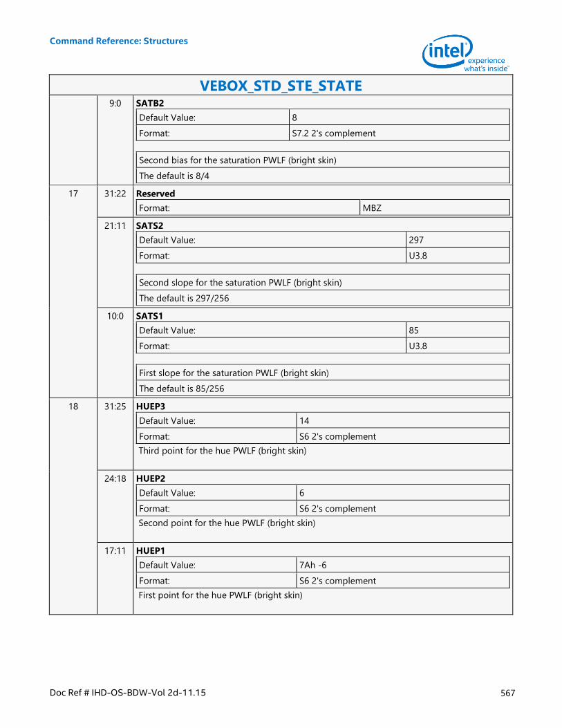
Command Reference: Structures
Doc Ref # IHD-OS-BDW-Vol 2d-11.15 567
VEBOX_STD_STE_STATE 9:0 SATB2
Default Value: 8
Format: S7.2 2's complement
Second bias for the saturation PWLF (bright skin)
The default is 8/4
17 31:22 Reserved
Format: MBZ
21:11 SATS2
Default Value: 297
Format: U3.8
Second slope for the saturation PWLF (bright skin)
The default is 297/256
10:0 SATS1
Default Value: 85
Format: U3.8
First slope for the saturation PWLF (bright skin)
The default is 85/256
18 31:25 HUEP3
Default Value: 14
Format: S6 2's complement
Third point for the hue PWLF (bright skin)
24:18 HUEP2
Default Value: 6
Format: S6 2's complement
Second point for the hue PWLF (bright skin)
17:11 HUEP1
Default Value: 7Ah -6
Format: S6 2's complement
First point for the hue PWLF (bright skin)
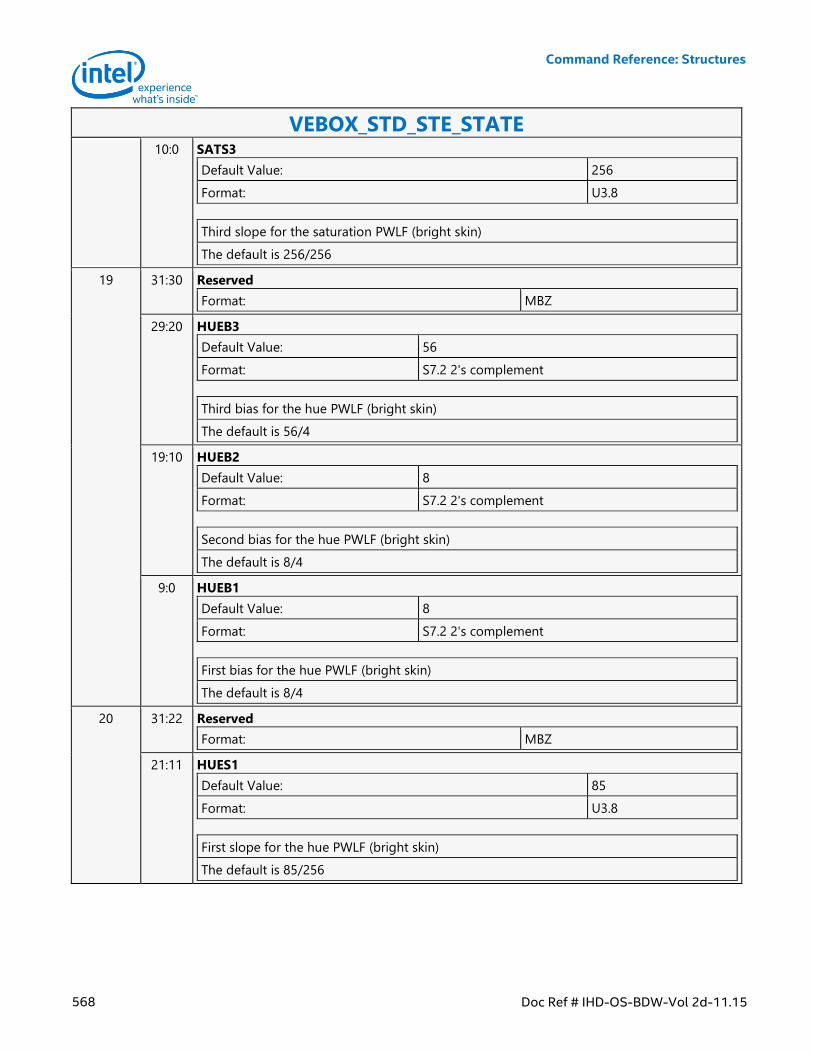
Command Reference: Structures
568 Doc Ref # IHD-OS-BDW-Vol 2d-11.15
VEBOX_STD_STE_STATE 10:0 SATS3
Default Value: 256
Format: U3.8
Third slope for the saturation PWLF (bright skin)
The default is 256/256
19 31:30 Reserved
Format: MBZ
29:20 HUEB3
Default Value: 56
Format: S7.2 2's complement
Third bias for the hue PWLF (bright skin)
The default is 56/4
19:10 HUEB2
Default Value: 8
Format: S7.2 2's complement
Second bias for the hue PWLF (bright skin)
The default is 8/4
9:0 HUEB1
Default Value: 8
Format: S7.2 2's complement
First bias for the hue PWLF (bright skin)
The default is 8/4
20 31:22 Reserved
Format: MBZ
21:11 HUES1
Default Value: 85
Format: U3.8
First slope for the hue PWLF (bright skin)
The default is 85/256
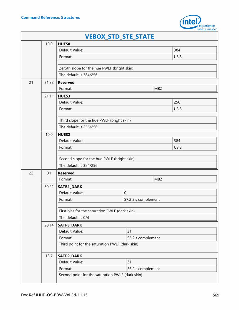
Command Reference: Structures
Doc Ref # IHD-OS-BDW-Vol 2d-11.15 569
VEBOX_STD_STE_STATE 10:0 HUES0
Default Value: 384
Format: U3.8
Zeroth slope for the hue PWLF (bright skin)
The default is 384/256
21 31:22 Reserved
Format: MBZ
21:11 HUES3
Default Value: 256
Format: U3.8
Third slope for the hue PWLF (bright skin)
The default is 256/256
10:0 HUES2
Default Value: 384
Format: U3.8
Second slope for the hue PWLF (bright skin)
The default is 384/256
22 31 Reserved
Format: MBZ
30:21 SATB1_DARK
Default Value: 0
Format: S7.2 2's complement
First bias for the saturation PWLF (dark skin)
The default is 0/4
20:14 SATP3_DARK
Default Value: 31
Format: S6 2's complement
Third point for the saturation PWLF (dark skin)
13:7 SATP2_DARK
Default Value: 31
Format: S6 2's complement
Second point for the saturation PWLF (dark skin)
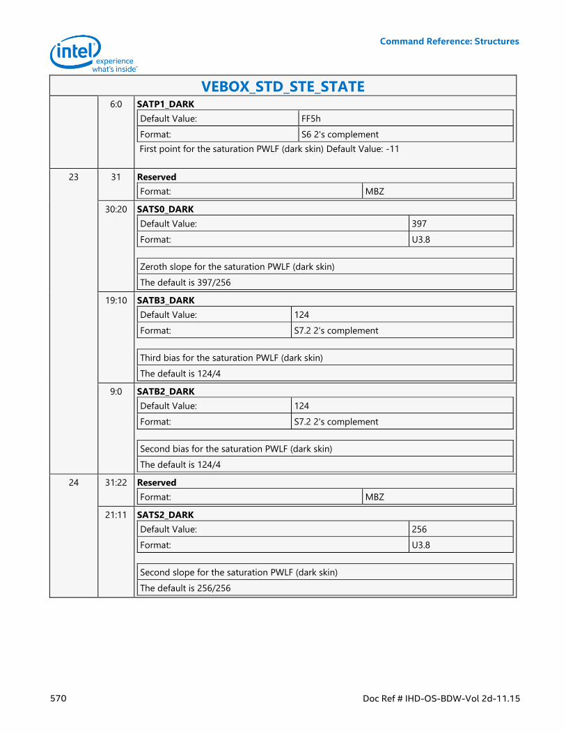
Command Reference: Structures
570 Doc Ref # IHD-OS-BDW-Vol 2d-11.15
VEBOX_STD_STE_STATE 6:0 SATP1_DARK
Default Value: FF5h
Format: S6 2's complement
First point for the saturation PWLF (dark skin) Default Value: -11
23 31 Reserved
Format: MBZ
30:20 SATS0_DARK
Default Value: 397
Format: U3.8
Zeroth slope for the saturation PWLF (dark skin)
The default is 397/256
19:10 SATB3_DARK
Default Value: 124
Format: S7.2 2's complement
Third bias for the saturation PWLF (dark skin)
The default is 124/4
9:0 SATB2_DARK
Default Value: 124
Format: S7.2 2's complement
Second bias for the saturation PWLF (dark skin)
The default is 124/4
24 31:22 Reserved
Format: MBZ
21:11 SATS2_DARK
Default Value: 256
Format: U3.8
Second slope for the saturation PWLF (dark skin)
The default is 256/256
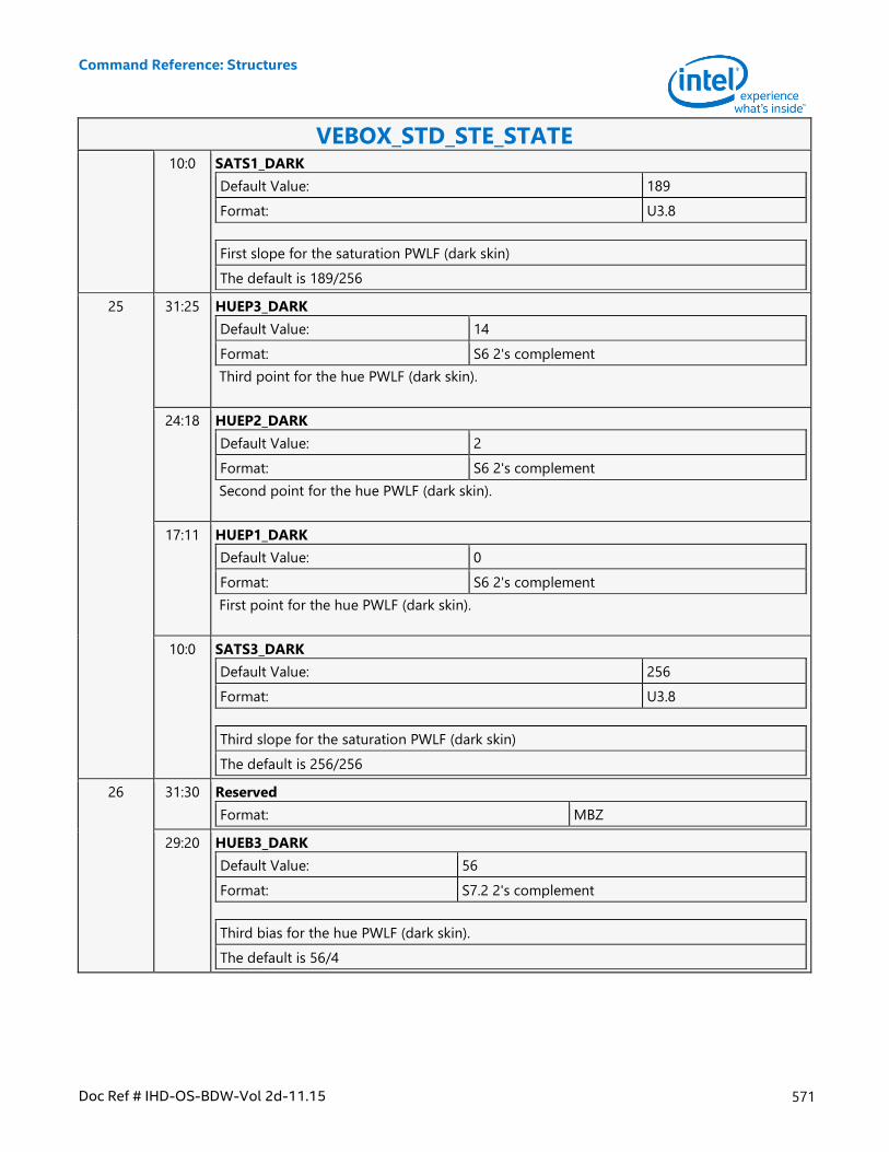
Command Reference: Structures
Doc Ref # IHD-OS-BDW-Vol 2d-11.15 571
VEBOX_STD_STE_STATE 10:0 SATS1_DARK
Default Value: 189
Format: U3.8
First slope for the saturation PWLF (dark skin)
The default is 189/256
25 31:25 HUEP3_DARK
Default Value: 14
Format: S6 2's complement
Third point for the hue PWLF (dark skin).
24:18 HUEP2_DARK
Default Value: 2
Format: S6 2's complement
Second point for the hue PWLF (dark skin).
17:11 HUEP1_DARK
Default Value: 0
Format: S6 2's complement
First point for the hue PWLF (dark skin).
10:0 SATS3_DARK
Default Value: 256
Format: U3.8
Third slope for the saturation PWLF (dark skin)
The default is 256/256
26 31:30 Reserved
Format: MBZ
29:20 HUEB3_DARK
Default Value: 56
Format: S7.2 2's complement
Third bias for the hue PWLF (dark skin).
The default is 56/4
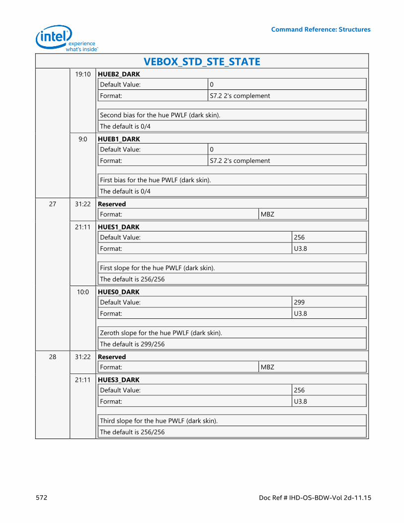
Command Reference: Structures
572 Doc Ref # IHD-OS-BDW-Vol 2d-11.15
VEBOX_STD_STE_STATE 19:10 HUEB2_DARK
Default Value: 0
Format: S7.2 2's complement
Second bias for the hue PWLF (dark skin).
The default is 0/4
9:0 HUEB1_DARK
Default Value: 0
Format: S7.2 2's complement
First bias for the hue PWLF (dark skin).
The default is 0/4
27 31:22 Reserved
Format: MBZ
21:11 HUES1_DARK
Default Value: 256
Format: U3.8
First slope for the hue PWLF (dark skin).
The default is 256/256
10:0 HUES0_DARK
Default Value: 299
Format: U3.8
Zeroth slope for the hue PWLF (dark skin).
The default is 299/256
28 31:22 Reserved
Format: MBZ
21:11 HUES3_DARK
Default Value: 256
Format: U3.8
Third slope for the hue PWLF (dark skin).
The default is 256/256
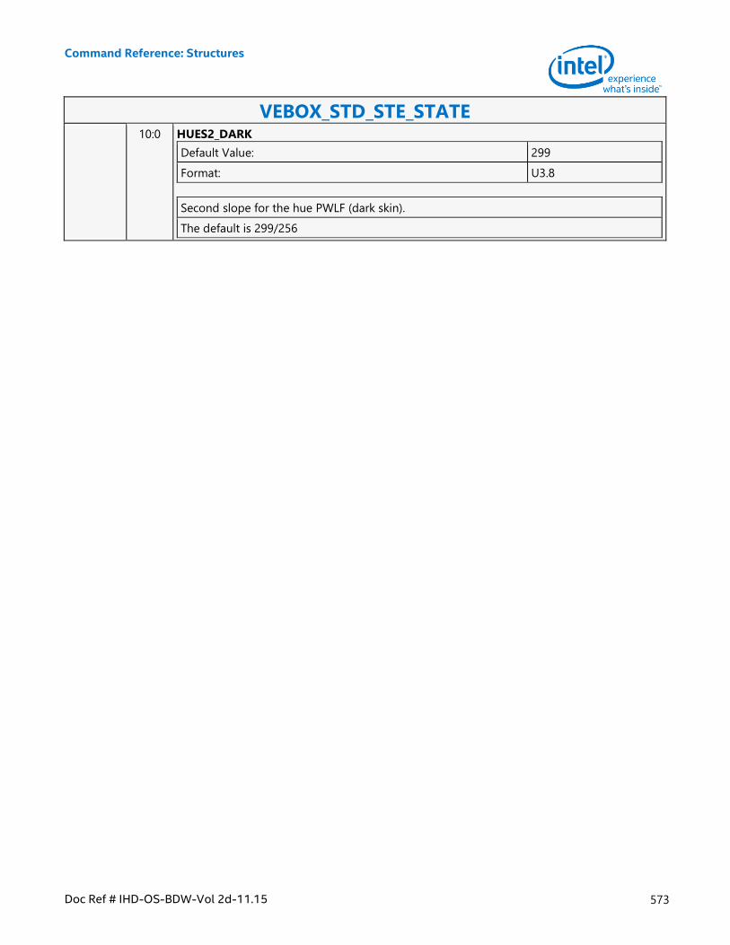
Command Reference: Structures
Doc Ref # IHD-OS-BDW-Vol 2d-11.15 573
VEBOX_STD_STE_STATE 10:0 HUES2_DARK
Default Value: 299
Format: U3.8
Second slope for the hue PWLF (dark skin).
The default is 299/256
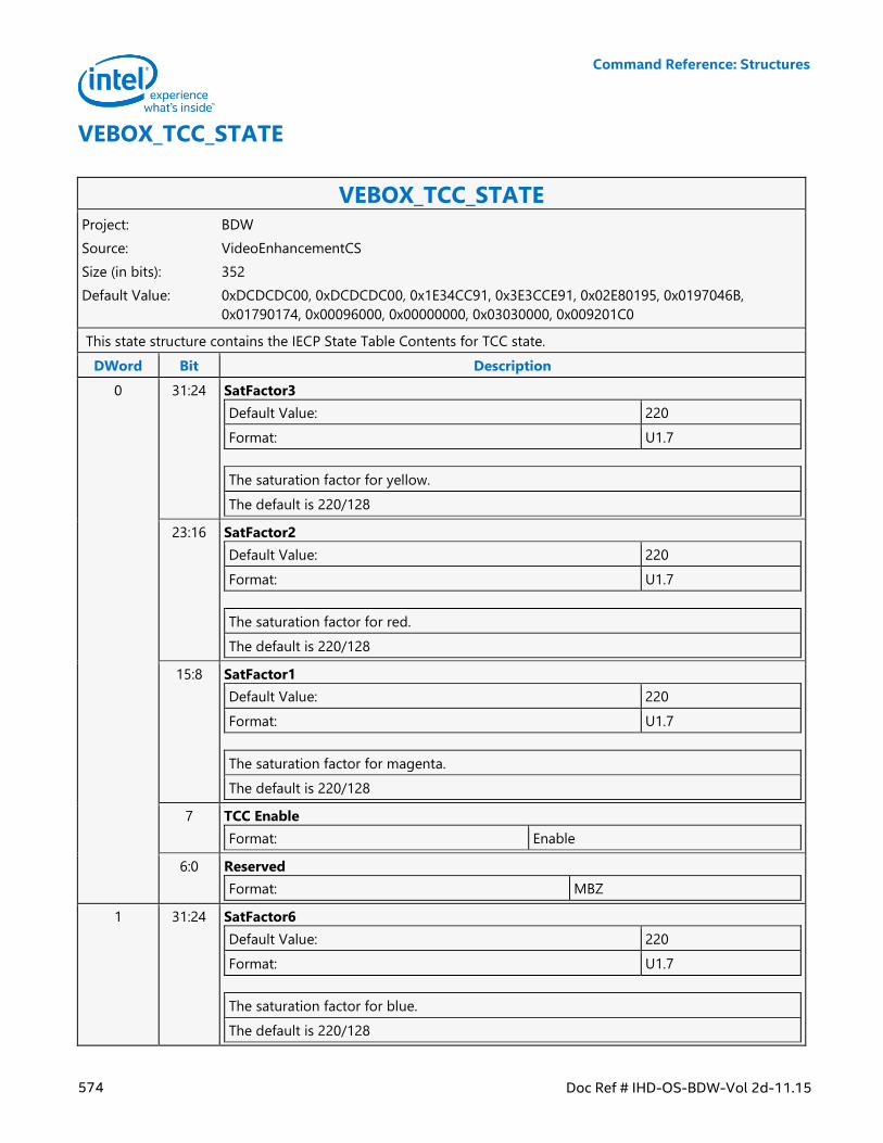
Command Reference: Structures
574 Doc Ref # IHD-OS-BDW-Vol 2d-11.15
VEBOX_TCC_STATE
VEBOX_TCC_STATE Project: BDW
Source: VideoEnhancementCS
Size (in bits): 352
Default Value: 0xDCDCDC00, 0xDCDCDC00, 0x1E34CC91, 0x3E3CCE91, 0x02E80195, 0x0197046B,
0x01790174, 0x00096000, 0x00000000, 0x03030000, 0x009201C0
This state structure contains the IECP State Table Contents for TCC state.
DWord Bit Description
0 31:24 SatFactor3
Default Value: 220
Format: U1.7
The saturation factor for yellow.
The default is 220/128
23:16 SatFactor2
Default Value: 220
Format: U1.7
The saturation factor for red.
The default is 220/128
15:8 SatFactor1
Default Value: 220
Format: U1.7
The saturation factor for magenta.
The default is 220/128
7 TCC Enable
Format: Enable
6:0 Reserved
Format: MBZ
1 31:24 SatFactor6
Default Value: 220
Format: U1.7
The saturation factor for blue.
The default is 220/128
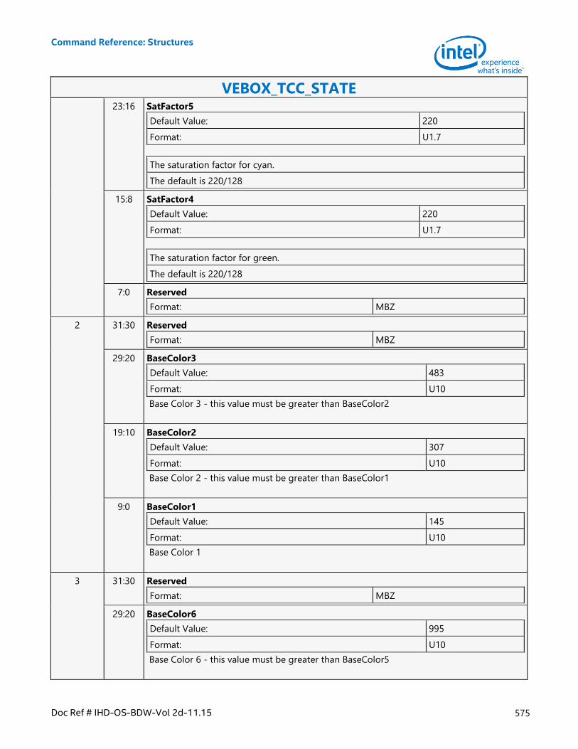
Command Reference: Structures
Doc Ref # IHD-OS-BDW-Vol 2d-11.15 575
VEBOX_TCC_STATE 23:16 SatFactor5
Default Value: 220
Format: U1.7
The saturation factor for cyan.
The default is 220/128
15:8 SatFactor4
Default Value: 220
Format: U1.7
The saturation factor for green.
The default is 220/128
7:0 Reserved
Format: MBZ
2 31:30 Reserved
Format: MBZ
29:20 BaseColor3
Default Value: 483
Format: U10
Base Color 3 - this value must be greater than BaseColor2
19:10 BaseColor2
Default Value: 307
Format: U10
Base Color 2 - this value must be greater than BaseColor1
9:0 BaseColor1
Default Value: 145
Format: U10
Base Color 1
3 31:30 Reserved
Format: MBZ
29:20 BaseColor6
Default Value: 995
Format: U10
Base Color 6 - this value must be greater than BaseColor5
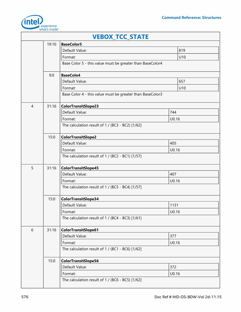
Command Reference: Structures
576 Doc Ref # IHD-OS-BDW-Vol 2d-11.15
VEBOX_TCC_STATE 19:10 BaseColor5
Default Value: 819
Format: U10
Base Color 5 - this value must be greater than BaseColor4
9:0 BaseColo4
Default Value: 657
Format: U10
Base Color 4 - this value must be greater than BaseColor3
4 31:16 ColorTransitSlope23
Default Value: 744
Format: U0.16
The calculation result of 1 / (BC3 - BC2) [1/62]
15:0 ColorTransitSlope2
Default Value: 405
Format: U0.16
The calculation result of 1 / (BC2 - BC1) [1/57]
5 31:16 ColorTransitSlope45
Default Value: 407
Format: U0.16
The calculation result of 1 / (BC5 - BC4) [1/57]
15:0 ColorTransitSlope34
Default Value: 1131
Format: U0.16
The calculation result of 1 / (BC4 - BC3) [1/61]
6 31:16 ColorTransitSlope61
Default Value: 377
Format: U0.16
The calculation result of 1 / (BC1 - BC6) [1/62]
15:0 ColorTransitSlope56
Default Value: 372
Format: U0.16
The calculation result of 1 / (BC6 - BC5) [1/62]
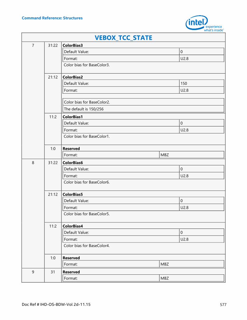
Command Reference: Structures
Doc Ref # IHD-OS-BDW-Vol 2d-11.15 577
VEBOX_TCC_STATE 7 31:22 ColorBias3
Default Value: 0
Format: U2.8
Color bias for BaseColor3.
21:12 ColorBias2
Default Value: 150
Format: U2.8
Color bias for BaseColor2.
The default is 150/256
11:2 ColorBias1
Default Value: 0
Format: U2.8
Color bias for BaseColor1.
1:0 Reserved
Format: MBZ
8 31:22 ColorBias6
Default Value: 0
Format: U2.8
Color bias for BaseColor6.
21:12 ColorBias5
Default Value: 0
Format: U2.8
Color bias for BaseColor5.
11:2 ColorBias4
Default Value: 0
Format: U2.8
Color bias for BaseColor4.
1:0 Reserved
Format: MBZ
9 31 Reserved
Format: MBZ
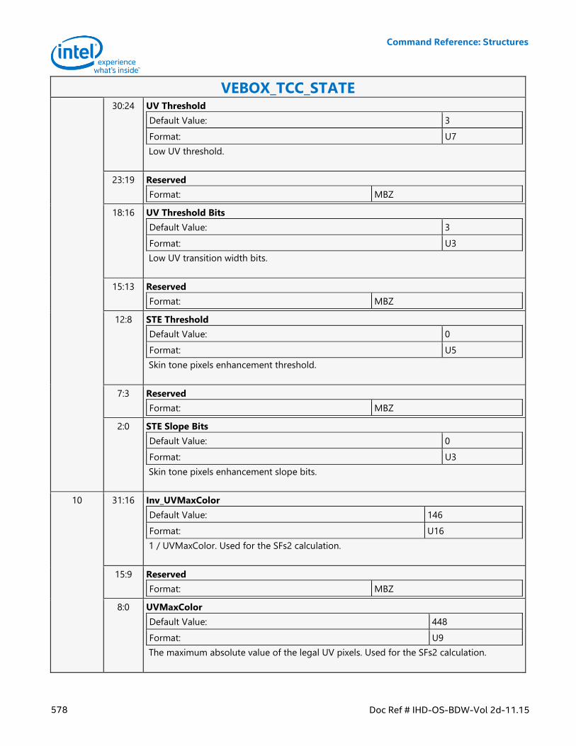
Command Reference: Structures
578 Doc Ref # IHD-OS-BDW-Vol 2d-11.15
VEBOX_TCC_STATE 30:24 UV Threshold
Default Value: 3
Format: U7
Low UV threshold.
23:19 Reserved
Format: MBZ
18:16 UV Threshold Bits
Default Value: 3
Format: U3
Low UV transition width bits.
15:13 Reserved
Format: MBZ
12:8 STE Threshold
Default Value: 0
Format: U5
Skin tone pixels enhancement threshold.
7:3 Reserved
Format: MBZ
2:0 STE Slope Bits
Default Value: 0
Format: U3
Skin tone pixels enhancement slope bits.
10 31:16 Inv_UVMaxColor
Default Value: 146
Format: U16
1 / UVMaxColor. Used for the SFs2 calculation.
15:9 Reserved
Format: MBZ
8:0 UVMaxColor
Default Value: 448
Format: U9
The maximum absolute value of the legal UV pixels. Used for the SFs2 calculation.
Command Reference: Structures
Doc Ref # IHD-OS-BDW-Vol 2d-11.15 579
VEBOX_VERTEX_TABLE
VEBOX_VERTEX_TABLE Project: BDW
Source: VideoEnhancementCS
Size (in bits): 16384
Default Value: 0x00000000, 0x00000000, 0x00000000, 0x00000000, 0x00000000, 0x00000000,
0x00000000, 0x00000000, 0x00000000, 0x00000000, 0x00000000, 0x00000000,
0x00000000, 0x00000000, 0x00000000, 0x00000000, 0x00000000, 0x00000000,
0x00000000, 0x00000000, 0x00000000, 0x00000000, 0x00000000, 0x00000000,
0x00000000, 0x00000000, 0x00000000, 0x00000000, 0x00000000, 0x00000000,
0x00000000, 0x00000000, 0x00000000, 0x00000000, 0x00000000, 0x00000000,
0x00000000, 0x00000000, 0x00000000, 0x00000000, 0x00000000, 0x00000000,
0x00000000, 0x00000000, 0x00000000, 0x00000000, 0x00000000, 0x00000000,
0x00000000, 0x00000000, 0x00000000, 0x00000000, 0x00000000, 0x00000000,
0x00000000, 0x00000000, 0x00000000, 0x00000000, 0x00000000, 0x00000000,
0x00000000, 0x00000000, 0x00000000, 0x00000000, 0x00000000, 0x00000000,
0x00000000, 0x00000000, 0x00000000, 0x00000000, 0x00000000, 0x00000000,
0x00000000, 0x00000000, 0x00000000, 0x00000000, 0x00000000, 0x00000000,
0x00000000, 0x00000000, 0x00000000, 0x00000000, 0x00000000, 0x00000000,
0x00000000, 0x00000000, 0x00000000, 0x00000000, 0x00000000, 0x00000000,
0x00000000, 0x00000000, 0x00000000, 0x00000000, 0x00000000, 0x00000000,
0x00000000, 0x00000000, 0x00000000, 0x00000000, 0x00000000, 0x00000000,
0x00000000, 0x00000000, 0x00000000, 0x00000000, 0x00000000, 0x00000000,
0x00000000, 0x00000000, 0x00000000, 0x00000000, 0x00000000, 0x00000000,
0x00000000, 0x00000000, 0x00000000, 0x00000000, 0x00000000, 0x00000000,
0x00000000, 0x00000000, 0x00000000, 0x00000000, 0x00000000, 0x00000000,
0x00000000, 0x00000000, 0x00000000, 0x00000000, 0x00000000, 0x00000000,
0x00000000, 0x00000000, 0x00000000, 0x00000000, 0x00000000, 0x00000000,
0x00000000, 0x00000000, 0x00000000, 0x00000000, 0x00000000, 0x00000000,
0x00000000, 0x00000000, 0x00000000, 0x00000000, 0x00000000, 0x00000000,
0x00000000, 0x00000000, 0x00000000, 0x00000000, 0x00000000, 0x00000000,
0x00000000, 0x00000000, 0x00000000, 0x00000000, 0x00000000, 0x00000000,
0x00000000, 0x00000000, 0x00000000, 0x00000000, 0x00000000, 0x00000000,
0x00000000, 0x00000000, 0x00000000, 0x00000000, 0x00000000, 0x00000000,
0x00000000, 0x00000000, 0x00000000, 0x00000000, 0x00000000, 0x00000000,
0x00000000, 0x00000000, 0x00000000, 0x00000000, 0x00000000, 0x00000000,
0x00000000, 0x00000000, 0x00000000, 0x00000000, 0x00000000, 0x00000000,
0x00000000, 0x00000000, 0x00000000, 0x00000000, 0x00000000, 0x00000000,
0x00000000, 0x00000000, 0x00000000, 0x00000000, 0x00000000, 0x00000000,
0x00000000, 0x00000000, 0x00000000, 0x00000000, 0x00000000, 0x00000000,
0x00000000, 0x00000000, 0x00000000, 0x00000000, 0x00000000, 0x00000000,
0x00000000, 0x00000000, 0x00000000, 0x00000000, 0x00000000, 0x00000000,
0x00000000, 0x00000000, 0x00000000, 0x00000000, 0x00000000, 0x00000000,
0x00000000, 0x00000000, 0x00000000, 0x00000000, 0x00000000, 0x00000000,
0x00000000, 0x00000000, 0x00000000, 0x00000000, 0x00000000, 0x00000000,
Command Reference: Structures
580 Doc Ref # IHD-OS-BDW-Vol 2d-11.15
VEBOX_VERTEX_TABLE 0x00000000, 0x00000000, 0x00000000, 0x00000000, 0x00000000, 0x00000000,
0x00000000, 0x00000000, 0x00000000, 0x00000000, 0x00000000, 0x00000000,
0x00000000, 0x00000000, 0x00000000, 0x00000000, 0x00000000, 0x00000000,
0x00000000, 0x00000000, 0x00000000, 0x00000000, 0x00000000, 0x00000000,
0x00000000, 0x00000000, 0x00000000, 0x00000000, 0x00000000, 0x00000000,
0x00000000, 0x00000000, 0x00000000, 0x00000000, 0x00000000, 0x00000000,
0x00000000, 0x00000000, 0x00000000, 0x00000000, 0x00000000, 0x00000000,
0x00000000, 0x00000000, 0x00000000, 0x00000000, 0x00000000, 0x00000000,
0x00000000, 0x00000000, 0x00000000, 0x00000000, 0x00000000, 0x00000000,
0x00000000, 0x00000000, 0x00000000, 0x00000000, 0x00000000, 0x00000000,
0x00000000, 0x00000000, 0x00000000, 0x00000000, 0x00000000, 0x00000000,
0x00000000, 0x00000000, 0x00000000, 0x00000000, 0x00000000, 0x00000000,
0x00000000, 0x00000000, 0x00000000, 0x00000000, 0x00000000, 0x00000000,
0x00000000, 0x00000000, 0x00000000, 0x00000000, 0x00000000, 0x00000000,
0x00000000, 0x00000000, 0x00000000, 0x00000000, 0x00000000, 0x00000000,
0x00000000, 0x00000000, 0x00000000, 0x00000000, 0x00000000, 0x00000000,
0x00000000, 0x00000000, 0x00000000, 0x00000000, 0x00000000, 0x00000000,
0x00000000, 0x00000000, 0x00000000, 0x00000000, 0x00000000, 0x00000000,
0x00000000, 0x00000000, 0x00000000, 0x00000000, 0x00000000, 0x00000000,
0x00000000, 0x00000000, 0x00000000, 0x00000000, 0x00000000, 0x00000000,
0x00000000, 0x00000000, 0x00000000, 0x00000000, 0x00000000, 0x00000000,
0x00000000, 0x00000000, 0x00000000, 0x00000000, 0x00000000, 0x00000000,
0x00000000, 0x00000000, 0x00000000, 0x00000000, 0x00000000, 0x00000000,
0x00000000, 0x00000000, 0x00000000, 0x00000000, 0x00000000, 0x00000000,
0x00000000, 0x00000000, 0x00000000, 0x00000000, 0x00000000, 0x00000000,
0x00000000, 0x00000000, 0x00000000, 0x00000000, 0x00000000, 0x00000000,
0x00000000, 0x00000000, 0x00000000, 0x00000000, 0x00000000, 0x00000000,
0x00000000, 0x00000000, 0x00000000, 0x00000000, 0x00000000, 0x00000000,
0x00000000, 0x00000000, 0x00000000, 0x00000000, 0x00000000, 0x00000000,
0x00000000, 0x00000000, 0x00000000, 0x00000000, 0x00000000, 0x00000000,
0x00000000, 0x00000000, 0x00000000, 0x00000000, 0x00000000, 0x00000000,
0x00000000, 0x00000000, 0x00000000, 0x00000000, 0x00000000, 0x00000000,
0x00000000, 0x00000000, 0x00000000, 0x00000000, 0x00000000, 0x00000000,
0x00000000, 0x00000000, 0x00000000, 0x00000000, 0x00000000, 0x00000000,
0x00000000, 0x00000000, 0x00000000, 0x00000000, 0x00000000, 0x00000000,
0x00000000, 0x00000000, 0x00000000, 0x00000000, 0x00000000, 0x00000000,
0x00000000, 0x00000000, 0x00000000, 0x00000000, 0x00000000, 0x00000000,
0x00000000, 0x00000000, 0x00000000, 0x00000000, 0x00000000, 0x00000000,
0x00000000, 0x00000000, 0x00000000, 0x00000000, 0x00000000, 0x00000000,
0x00000000, 0x00000000, 0x00000000, 0x00000000, 0x00000000, 0x00000000,
0x00000000, 0x00000000, 0x00000000, 0x00000000, 0x00000000, 0x00000000,
0x00000000, 0x00000000, 0x00000000, 0x00000000, 0x00000000, 0x00000000,
0x00000000, 0x00000000, 0x00000000, 0x00000000, 0x00000000, 0x00000000,
0x00000000, 0x00000000, 0x00000000, 0x00000000, 0x00000000, 0x00000000,
0x00000000, 0x00000000, 0x00000000, 0x00000000, 0x00000000, 0x00000000,
0x00000000, 0x00000000
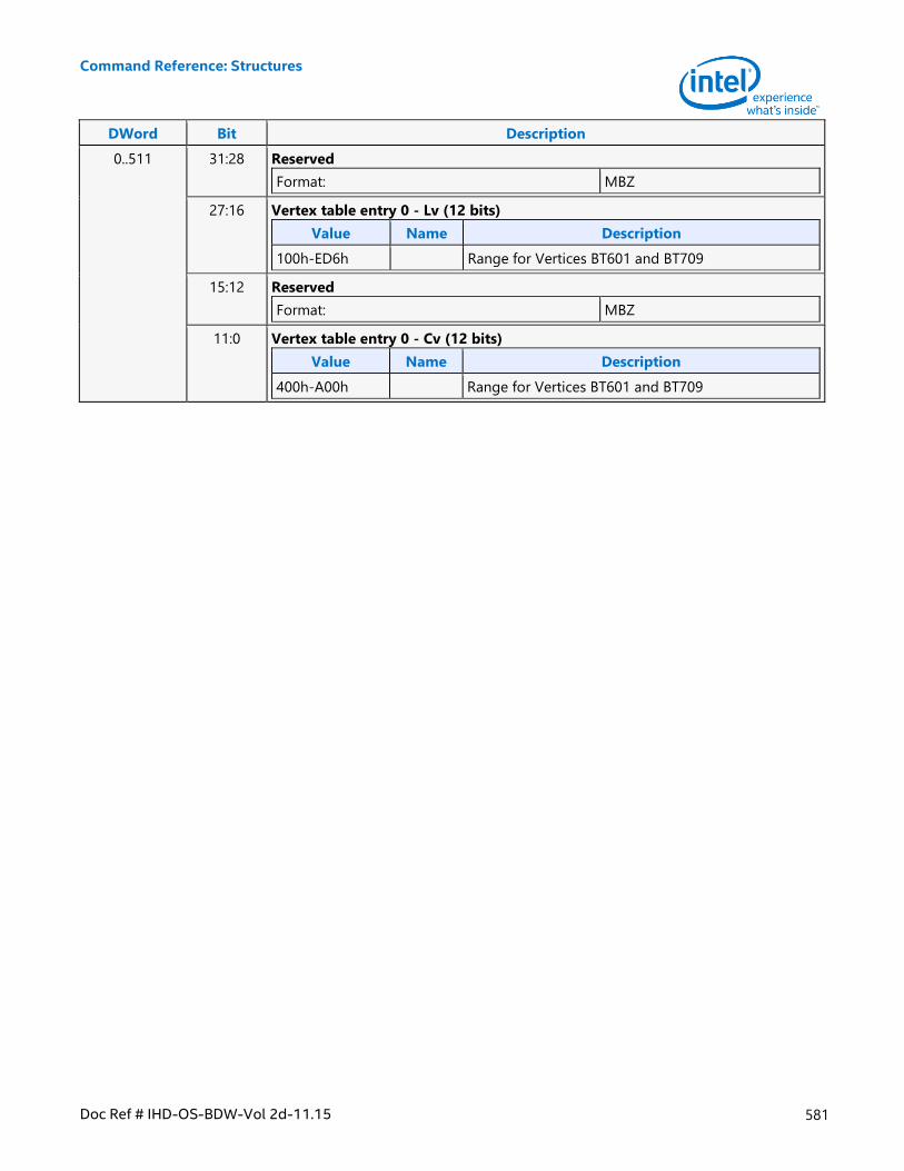
Command Reference: Structures
Doc Ref # IHD-OS-BDW-Vol 2d-11.15 581
DWord Bit Description
0..511 31:28 Reserved
Format: MBZ
27:16 Vertex table entry 0 - Lv (12 bits)
Value Name Description
100h-ED6h Range for Vertices BT601 and BT709
15:12 Reserved
Format: MBZ
11:0 Vertex table entry 0 - Cv (12 bits)
Value Name Description
400h-A00h Range for Vertices BT601 and BT709
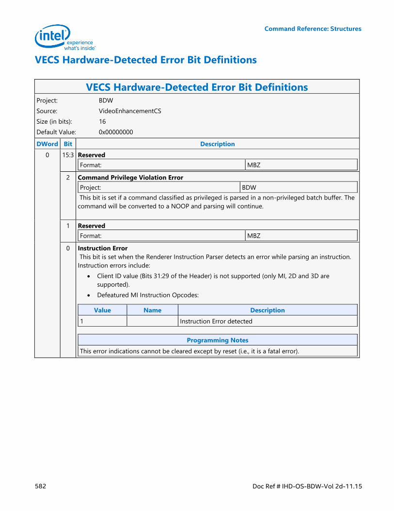
Command Reference: Structures
582 Doc Ref # IHD-OS-BDW-Vol 2d-11.15
VECS Hardware-Detected Error Bit Definitions
VECS Hardware-Detected Error Bit Definitions Project: BDW
Source: VideoEnhancementCS
Size (in bits): 16
Default Value: 0x00000000
DWord Bit Description
0 15:3 Reserved
Format: MBZ
2 Command Privilege Violation Error
Project: BDW
This bit is set if a command classified as privileged is parsed in a non-privileged batch buffer. The
command will be converted to a NOOP and parsing will continue.
1 Reserved
Format: MBZ
0 Instruction Error
This bit is set when the Renderer Instruction Parser detects an error while parsing an instruction.
Instruction errors include:
Client ID value (Bits 31:29 of the Header) is not supported (only MI, 2D and 3D are
supported).
Defeatured MI Instruction Opcodes:
Value Name Description
1 Instruction Error detected
Programming Notes
This error indications cannot be cleared except by reset (i.e., it is a fatal error).

Command Reference: Structures
Doc Ref # IHD-OS-BDW-Vol 2d-11.15 583
VERTEX_BUFFER_STATE
VERTEX_BUFFER_STATE Project: BDW
Source: RenderCS
Size (in bits): 128
Default Value: 0x00000000, 0x00000000, 0x00000000, 0x00000000
This structure is used in 3DSTATE_VERTEX_BUFFERS to set the state associated with a VB. The VF function will
use this state to determine how/where to extract vertex element data for all vertex elements associated with the
VB.
DWord Bit Description
0 31:26 Vertex Buffer Index
Project: All
Format: U6 index
This field contains an index value which selects the VB state being defined.
Value Name
[0,32]
25:23 Reserved
Project: All
Format: MBZ
22:16 Memory Object Control State
Project: All
Format: MEMORY_OBJECT_CONTROL_STATE
Specifies the memory object control state for this vertex buffer.
15 Reserved
Project: All
Format: MBZ
14 Address Modify Enable
Project: All
If set, the Buffer Starting Address field is used to update the state of this buffer. If clear, that field
is ignored and the previously-programmed value is maintained.
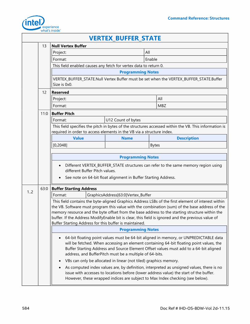
Command Reference: Structures
584 Doc Ref # IHD-OS-BDW-Vol 2d-11.15
VERTEX_BUFFER_STATE 13 Null Vertex Buffer
Project: All
Format: Enable
This field enabled causes any fetch for vertex data to return 0.
Programming Notes
VERTEX_BUFFER_STATE.Null Vertex Buffer must be set when the VERTEX_BUFFER_STATE.Buffer
Size is 0x0.
12 Reserved
Project: All
Format: MBZ
11:0 Buffer Pitch
Format: U12 Count of bytes
This field specifies the pitch in bytes of the structures accessed within the VB. This information is
required in order to access elements in the VB via a structure index.
Value Name Description
[0,2048] Bytes
Programming Notes
Different VERTEX_BUFFER_STATE structures can refer to the same memory region using
different Buffer Pitch values.
See note on 64-bit float alignment in Buffer Starting Address.
1..2 63:0 Buffer Starting Address
Format: GraphicsAddress[63:0]Vertex_Buffer
This field contains the byte-aligned Graphics Address LSBs of the first element of interest within
the VB. Software must program this value with the combination (sum) of the base address of the
memory resource and the byte offset from the base address to the starting structure within the
buffer. If the Address ModifyEnable bit is clear, this field is ignored and the previous value of
Buffer Starting Address for this buffer is maintained.
Programming Notes
64-bit floating point values must be 64-bit aligned in memory, or UNPREDICTABLE data
will be fetched. When accessing an element containing 64-bit floating point values, the
Buffer Starting Address and Source Element Offset values must add to a 64-bit aligned
address, and BufferPitch must be a multiple of 64-bits.
VBs can only be allocated in linear (not tiled) graphics memory.
As computed index values are, by definition, interpreted as unsigned values, there is no
issue with accesses to locations before (lower address value) the start of the buffer.
However, these wrapped indices are subject to Max Index checking (see below).
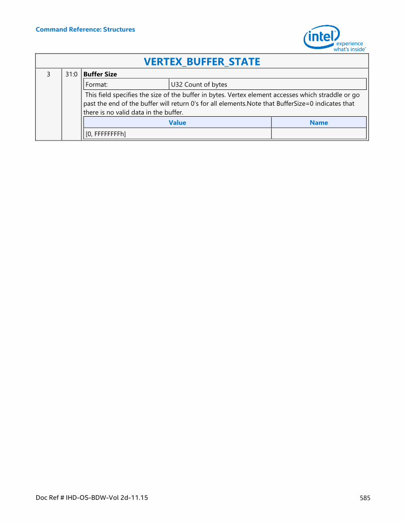
Command Reference: Structures
Doc Ref # IHD-OS-BDW-Vol 2d-11.15 585
VERTEX_BUFFER_STATE 3 31:0 Buffer Size
Format: U32 Count of bytes
This field specifies the size of the buffer in bytes. Vertex element accesses which straddle or go
past the end of the buffer will return 0's for all elements.Note that BufferSize=0 indicates that
there is no valid data in the buffer.
Value Name
[0, FFFFFFFFh]
Command Reference: Structures
586 Doc Ref # IHD-OS-BDW-Vol 2d-11.15
VERTEX_ELEMENT_STATE
VERTEX_ELEMENT_STATE Project: All
Source: RenderCS
Size (in bits): 64
Default Value: 0x00000000, 0x00000000
Description
This structure is used in 3DSTATE_VERTEX_ELEMENTS to set the state associated with a vertex element. A vertex
element is defined as an entity supplying from one to four DWord vertex components, to be stored in the
vertex URB entry.
The number of supported vertex elements is 34.
The VF function will use this state, and possibly the state of the associated vertex buffer, to fetch/generate the
source vertex element data, perform any required format conversions, padding with zeros, and store the
resulting destination vertex element data into the vertex URB entry.
Programming Notes
The (new) 3DSTATE_VF_SGVS command is used to specify optional insertion of VertexID and/or
InstanceID into the input vertex data, logically following the processing of the VERTEX_ELEMENT_STATE
structures. The VFCOMP_STORE_VID/IID encodings are no longer available in VERTEX_ELEMENT_STATE.
When SourceElementFormat is set to one of the *64*_PASSTHRU formats, 64-bit components are stored
in the URB without any conversion. In this case, vertex elements must be written as 128 or 256 bits, with
VFCOMP_STORE_0 being used to pad the output as required. E.g., if R64_PASSTHRU is used to copy a
64-bit Red component into the URB, Component 1 must be specified as VFCOMP_STORE_0 (with
Components 2,3 set to VFCOMP_NOSTORE) in order to output a 128-bit vertex element, or Components
1-3 must be specified as VFCOMP_STORE_0 in order to output a 256-bit vertex element. Likewise, use of
R64G64B64_PASSTHRU requires Component 3 to be specified as VFCOMP_STORE_0 in order to output a
256-bit vertex element.
When SourceElementFormat is set to one of the *64*_PASSTHRU formats then VFCOMP_STORE_SRC
must be used for every valid component.
Any SourceElementFormat of *64*_PASSTHRU cannot be used with an element which has edge flag
enabled.
The SourceElementFormat needs to be a single-component format with an element which has edge flag
enabled.
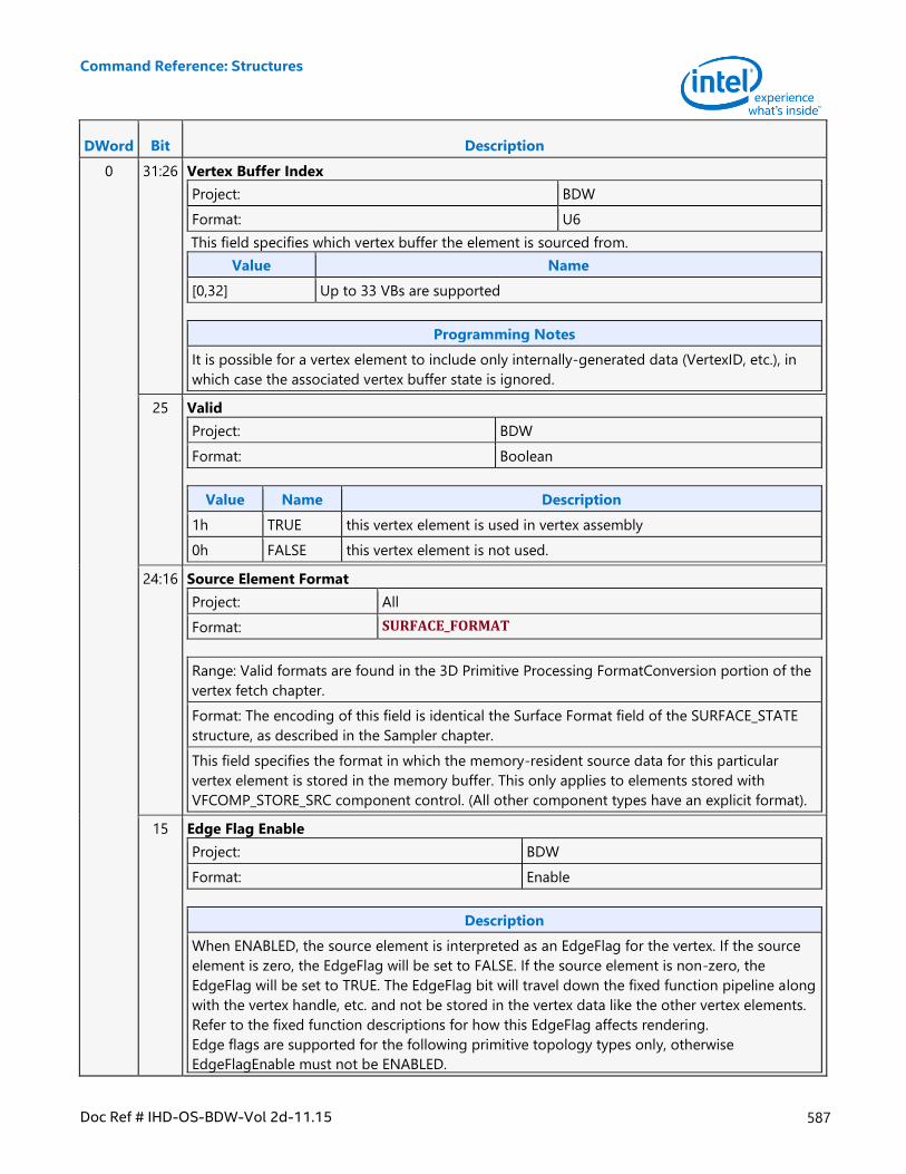
Command Reference: Structures
Doc Ref # IHD-OS-BDW-Vol 2d-11.15 587
DWord Bit Description
0 31:26 Vertex Buffer Index
Project: BDW
Format: U6
This field specifies which vertex buffer the element is sourced from.
Value Name
[0,32] Up to 33 VBs are supported
Programming Notes
It is possible for a vertex element to include only internally-generated data (VertexID, etc.), in
which case the associated vertex buffer state is ignored.
25 Valid
Project: BDW
Format: Boolean
Value Name Description
1h TRUE this vertex element is used in vertex assembly
0h FALSE this vertex element is not used.
24:16 Source Element Format
Project: All
Format: SURFACE_FORMAT
Range: Valid formats are found in the 3D Primitive Processing FormatConversion portion of the
vertex fetch chapter.
Format: The encoding of this field is identical the Surface Format field of the SURFACE_STATE
structure, as described in the Sampler chapter.
This field specifies the format in which the memory-resident source data for this particular
vertex element is stored in the memory buffer. This only applies to elements stored with
VFCOMP_STORE_SRC component control. (All other component types have an explicit format).
15 Edge Flag Enable
Project: BDW
Format: Enable
Description
When ENABLED, the source element is interpreted as an EdgeFlag for the vertex. If the source
element is zero, the EdgeFlag will be set to FALSE. If the source element is non-zero, the
EdgeFlag will be set to TRUE. The EdgeFlag bit will travel down the fixed function pipeline along
with the vertex handle, etc. and not be stored in the vertex data like the other vertex elements.
Refer to the fixed function descriptions for how this EdgeFlag affects rendering.
Edge flags are supported for the following primitive topology types only, otherwise
EdgeFlagEnable must not be ENABLED.
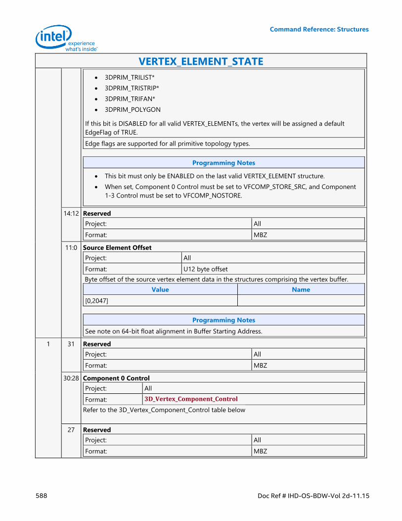
Command Reference: Structures
588 Doc Ref # IHD-OS-BDW-Vol 2d-11.15
VERTEX_ELEMENT_STATE
3DPRIM_TRILIST*
3DPRIM_TRISTRIP*
3DPRIM_TRIFAN*
3DPRIM_POLYGON
If this bit is DISABLED for all valid VERTEX_ELEMENTs, the vertex will be assigned a default
EdgeFlag of TRUE.
Edge flags are supported for all primitive topology types.
Programming Notes
This bit must only be ENABLED on the last valid VERTEX_ELEMENT structure.
When set, Component 0 Control must be set to VFCOMP_STORE_SRC, and Component
1-3 Control must be set to VFCOMP_NOSTORE.
14:12 Reserved
Project: All
Format: MBZ
11:0 Source Element Offset
Project: All
Format: U12 byte offset
Byte offset of the source vertex element data in the structures comprising the vertex buffer.
Value Name
[0,2047]
Programming Notes
See note on 64-bit float alignment in Buffer Starting Address.
1 31 Reserved
Project: All
Format: MBZ
30:28 Component 0 Control
Project: All
Format: 3D_Vertex_Component_Control
Refer to the 3D_Vertex_Component_Control table below
27 Reserved
Project: All
Format: MBZ
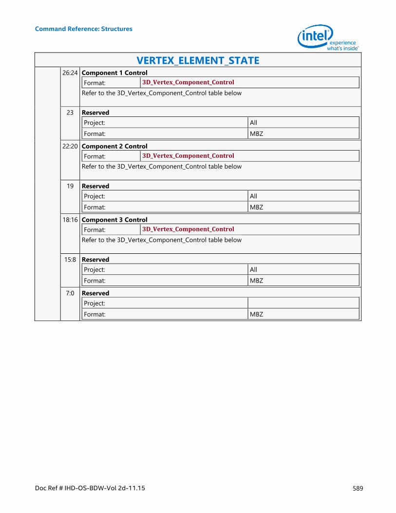
Command Reference: Structures
Doc Ref # IHD-OS-BDW-Vol 2d-11.15 589
VERTEX_ELEMENT_STATE 26:24 Component 1 Control
Format: 3D_Vertex_Component_Control
Refer to the 3D_Vertex_Component_Control table below
23 Reserved
Project: All
Format: MBZ
22:20 Component 2 Control
Format: 3D_Vertex_Component_Control
Refer to the 3D_Vertex_Component_Control table below
19 Reserved
Project: All
Format: MBZ
18:16 Component 3 Control
Format: 3D_Vertex_Component_Control
Refer to the 3D_Vertex_Component_Control table below
15:8 Reserved
Project: All
Format: MBZ
7:0 Reserved
Project:
Format: MBZ
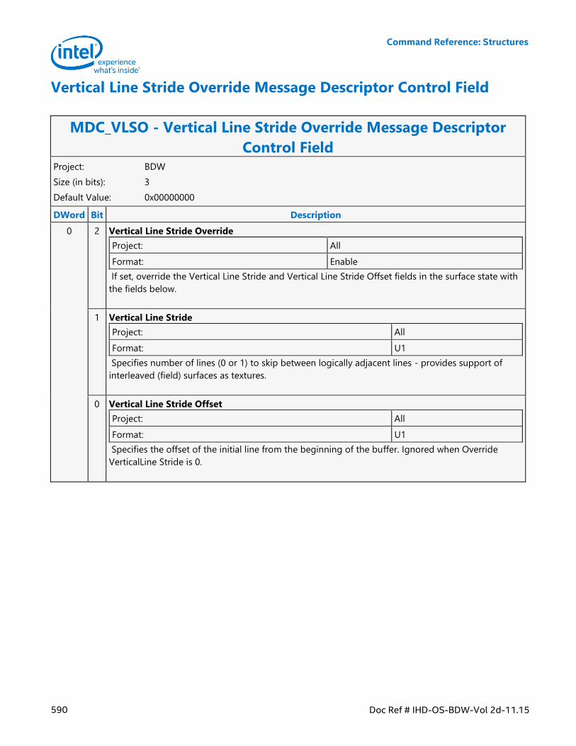
Command Reference: Structures
590 Doc Ref # IHD-OS-BDW-Vol 2d-11.15
Vertical Line Stride Override Message Descriptor Control Field
MDC_VLSO - Vertical Line Stride Override Message Descriptor
Control Field Project: BDW
Size (in bits): 3
Default Value: 0x00000000
DWord Bit Description
0 2 Vertical Line Stride Override
Project: All
Format: Enable
If set, override the Vertical Line Stride and Vertical Line Stride Offset fields in the surface state with
the fields below.
1 Vertical Line Stride
Project: All
Format: U1
Specifies number of lines (0 or 1) to skip between logically adjacent lines - provides support of
interleaved (field) surfaces as textures.
0 Vertical Line Stride Offset
Project: All
Format: U1
Specifies the offset of the initial line from the beginning of the buffer. Ignored when Override
VerticalLine Stride is 0.
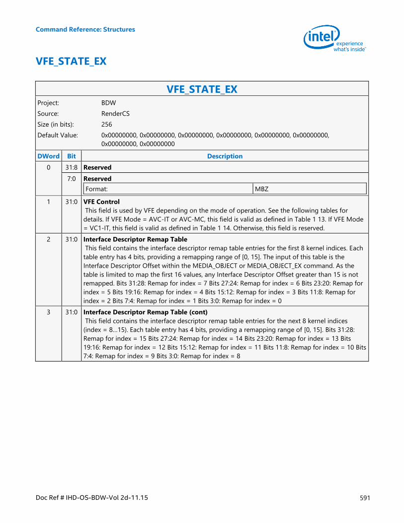
Command Reference: Structures
Doc Ref # IHD-OS-BDW-Vol 2d-11.15 591
VFE_STATE_EX
VFE_STATE_EX Project: BDW
Source: RenderCS
Size (in bits): 256
Default Value: 0x00000000, 0x00000000, 0x00000000, 0x00000000, 0x00000000, 0x00000000,
0x00000000, 0x00000000
DWord Bit Description
0 31:8 Reserved
7:0 Reserved
Format: MBZ
1 31:0 VFE Control
This field is used by VFE depending on the mode of operation. See the following tables for
details. If VFE Mode = AVC-IT or AVC-MC, this field is valid as defined in Table 1 13. If VFE Mode
= VC1-IT, this field is valid as defined in Table 1 14. Otherwise, this field is reserved.
2 31:0 Interface Descriptor Remap Table
This field contains the interface descriptor remap table entries for the first 8 kernel indices. Each
table entry has 4 bits, providing a remapping range of [0, 15]. The input of this table is the
Interface Descriptor Offset within the MEDIA_OBJECT or MEDIA_OBJECT_EX command. As the
table is limited to map the first 16 values, any Interface Descriptor Offset greater than 15 is not
remapped. Bits 31:28: Remap for index = 7 Bits 27:24: Remap for index = 6 Bits 23:20: Remap for
index = 5 Bits 19:16: Remap for index = 4 Bits 15:12: Remap for index = 3 Bits 11:8: Remap for
index = 2 Bits 7:4: Remap for index = 1 Bits 3:0: Remap for index = 0
3 31:0 Interface Descriptor Remap Table (cont)
This field contains the interface descriptor remap table entries for the next 8 kernel indices
(index = 8…15). Each table entry has 4 bits, providing a remapping range of [0, 15]. Bits 31:28:
Remap for index = 15 Bits 27:24: Remap for index = 14 Bits 23:20: Remap for index = 13 Bits
19:16: Remap for index = 12 Bits 15:12: Remap for index = 11 Bits 11:8: Remap for index = 10 Bits
7:4: Remap for index = 9 Bits 3:0: Remap for index = 8
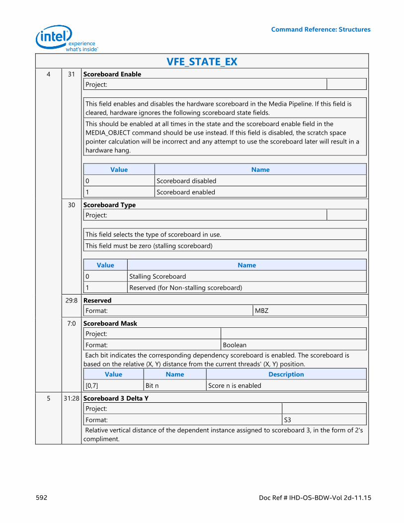
Command Reference: Structures
592 Doc Ref # IHD-OS-BDW-Vol 2d-11.15
VFE_STATE_EX 4 31 Scoreboard Enable
Project:
This field enables and disables the hardware scoreboard in the Media Pipeline. If this field is
cleared, hardware ignores the following scoreboard state fields.
This should be enabled at all times in the state and the scoreboard enable field in the
MEDIA_OBJECT command should be use instead. If this field is disabled, the scratch space
pointer calculation will be incorrect and any attempt to use the scoreboard later will result in a
hardware hang.
Value Name
0 Scoreboard disabled
1 Scoreboard enabled
30 Scoreboard Type
Project:
This field selects the type of scoreboard in use.
This field must be zero (stalling scoreboard)
Value Name
0 Stalling Scoreboard
1 Reserved (for Non-stalling scoreboard)
29:8 Reserved
Format: MBZ
7:0 Scoreboard Mask
Project:
Format: Boolean
Each bit indicates the corresponding dependency scoreboard is enabled. The scoreboard is
based on the relative (X, Y) distance from the current threads' (X, Y) position.
Value Name Description
[0,7] Bit n Score n is enabled
5 31:28 Scoreboard 3 Delta Y
Project:
Format: S3
Relative vertical distance of the dependent instance assigned to scoreboard 3, in the form of 2's
compliment.
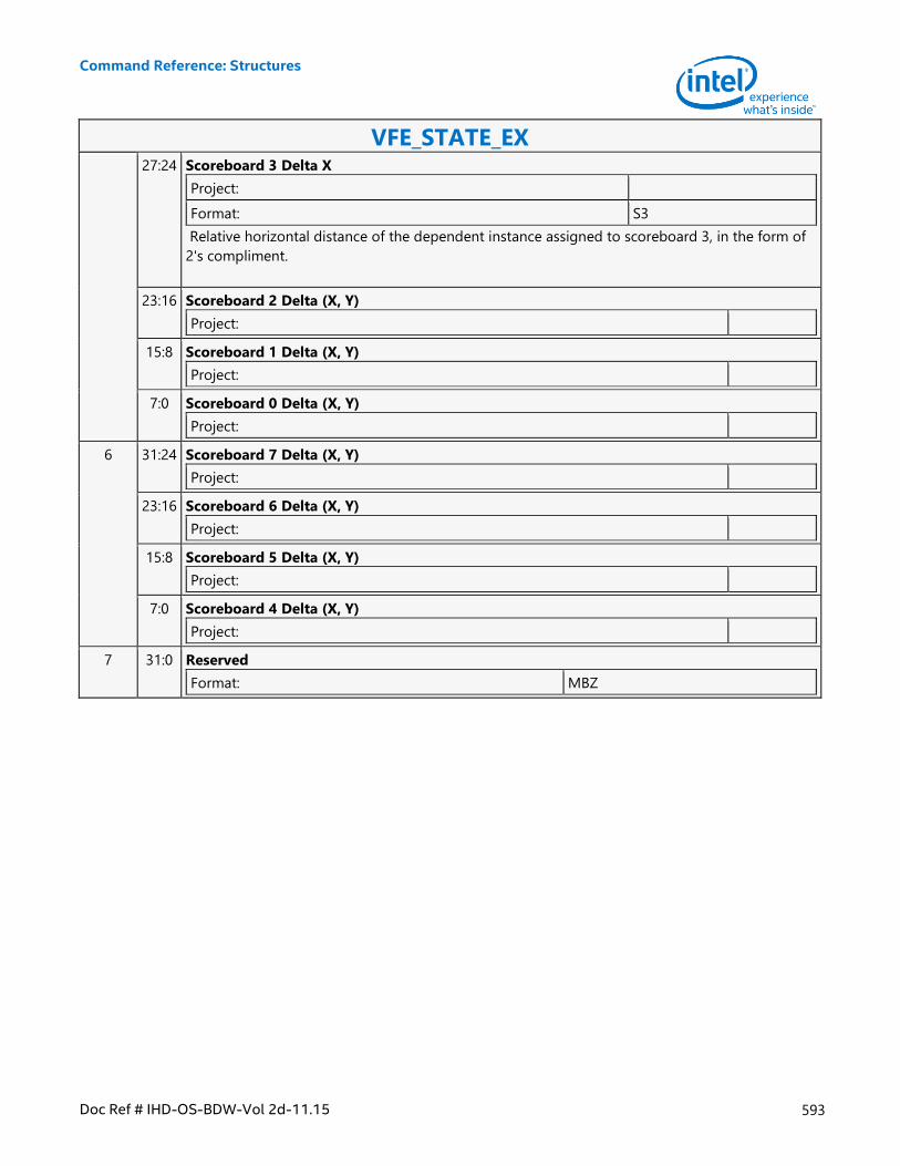
Command Reference: Structures
Doc Ref # IHD-OS-BDW-Vol 2d-11.15 593
VFE_STATE_EX 27:24 Scoreboard 3 Delta X
Project:
Format: S3
Relative horizontal distance of the dependent instance assigned to scoreboard 3, in the form of
2's compliment.
23:16 Scoreboard 2 Delta (X, Y)
Project:
15:8 Scoreboard 1 Delta (X, Y)
Project:
7:0 Scoreboard 0 Delta (X, Y)
Project:
6 31:24 Scoreboard 7 Delta (X, Y)
Project:
23:16 Scoreboard 6 Delta (X, Y)
Project:
15:8 Scoreboard 5 Delta (X, Y)
Project:
7:0 Scoreboard 4 Delta (X, Y)
Project:
7 31:0 Reserved
Format: MBZ
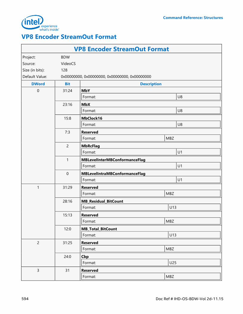
Command Reference: Structures
594 Doc Ref # IHD-OS-BDW-Vol 2d-11.15
VP8 Encoder StreamOut Format
VP8 Encoder StreamOut Format Project: BDW
Source: VideoCS
Size (in bits): 128
Default Value: 0x00000000, 0x00000000, 0x00000000, 0x00000000
DWord Bit Description
0 31:24 MbY
Format: U8
23:16 MbX
Format: U8
15:8 MbClock16
Format: U8
7:3 Reserved
Format: MBZ
2 MbRcFlag
Format: U1
1 MBLevelInterMBConformanceFlag
Format: U1
0 MBLevelIntraMBConformanceFlag
Format: U1
1 31:29 Reserved
Format: MBZ
28:16 MB_Residual_BitCount
Format: U13
15:13 Reserved
Format: MBZ
12:0 MB_Total_BitCount
Format: U13
2 31:25 Reserved
Format: MBZ
24:0 Cbp
Format: U25
3 31 Reserved
Format: MBZ
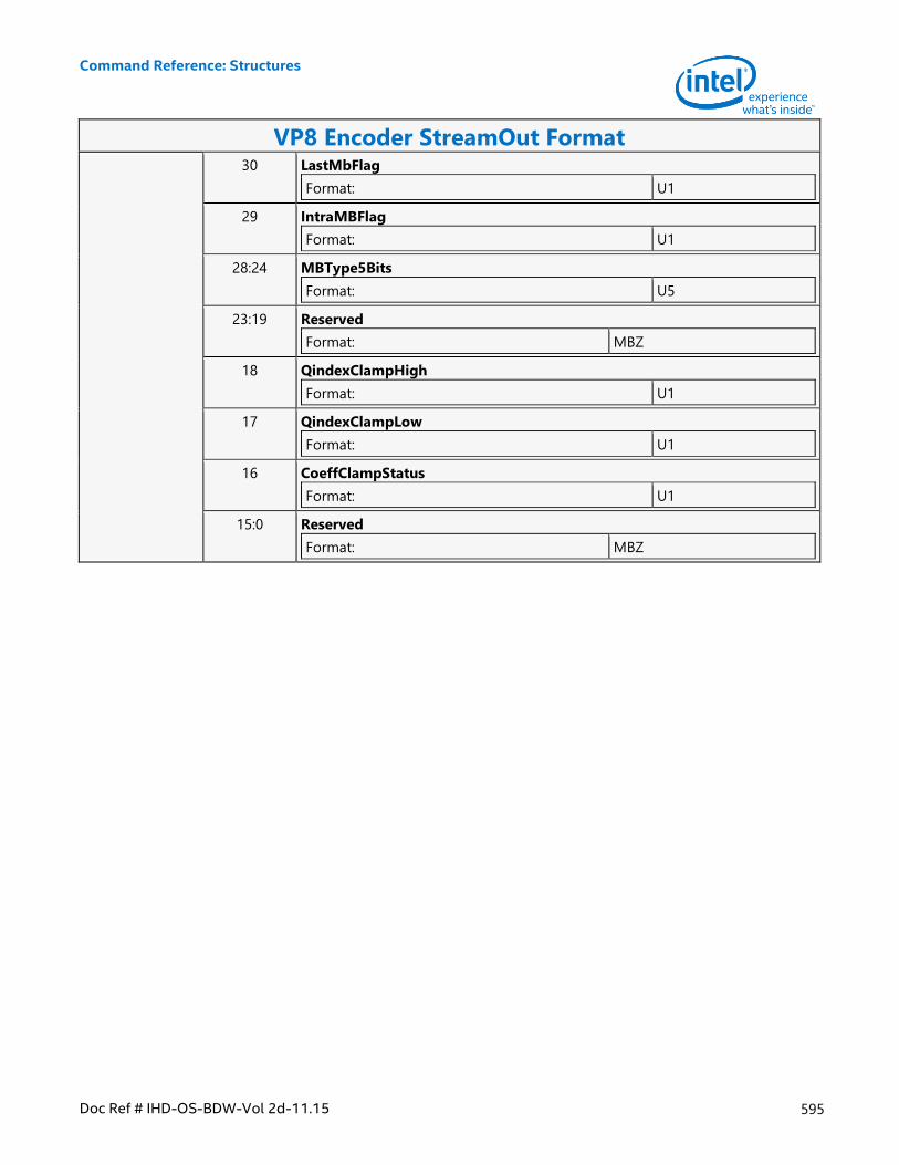
Command Reference: Structures
Doc Ref # IHD-OS-BDW-Vol 2d-11.15 595
VP8 Encoder StreamOut Format 30 LastMbFlag
Format: U1
29 IntraMBFlag
Format: U1
28:24 MBType5Bits
Format: U5
23:19 Reserved
Format: MBZ
18 QindexClampHigh
Format: U1
17 QindexClampLow
Format: U1
16 CoeffClampStatus
Format: U1
15:0 Reserved
Format: MBZ
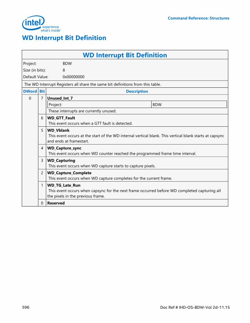
Command Reference: Structures
596 Doc Ref # IHD-OS-BDW-Vol 2d-11.15
WD Interrupt Bit Definition
WD Interrupt Bit Definition Project: BDW
Size (in bits): 8
Default Value: 0x00000000
The WD Interrupt Registers all share the same bit definitions from this table.
DWord Bit Description
0 7 Unused_Int_7
Project: BDW
These interrupts are currently unused.
6 WD_GTT_Fault
This event occurs when a GTT fault is detected.
5 WD_Vblank
This event occurs at the start of the WD internal vertical blank. This vertical blank starts at capsync
and ends at framestart.
4 WD_Capture_sync
This event occurs when WD counter reached the programmed frame time interval.
3 WD_Capturing
This event occurs when WD capture starts to capture pixels.
2 WD_Capture_Complete
This event occurs when WD capture completes for the current frame.
1 WD_TG_Late_Run
This event occurs when capsync for the next frame occurred before WD completed capturing all
the pixels in the previous frame.
0 Reserved