Embed Size (px)
Citation preview
\
Denne rapporttilhører
L&U DOK. SENTERL. NR.
Returneres etter bruk
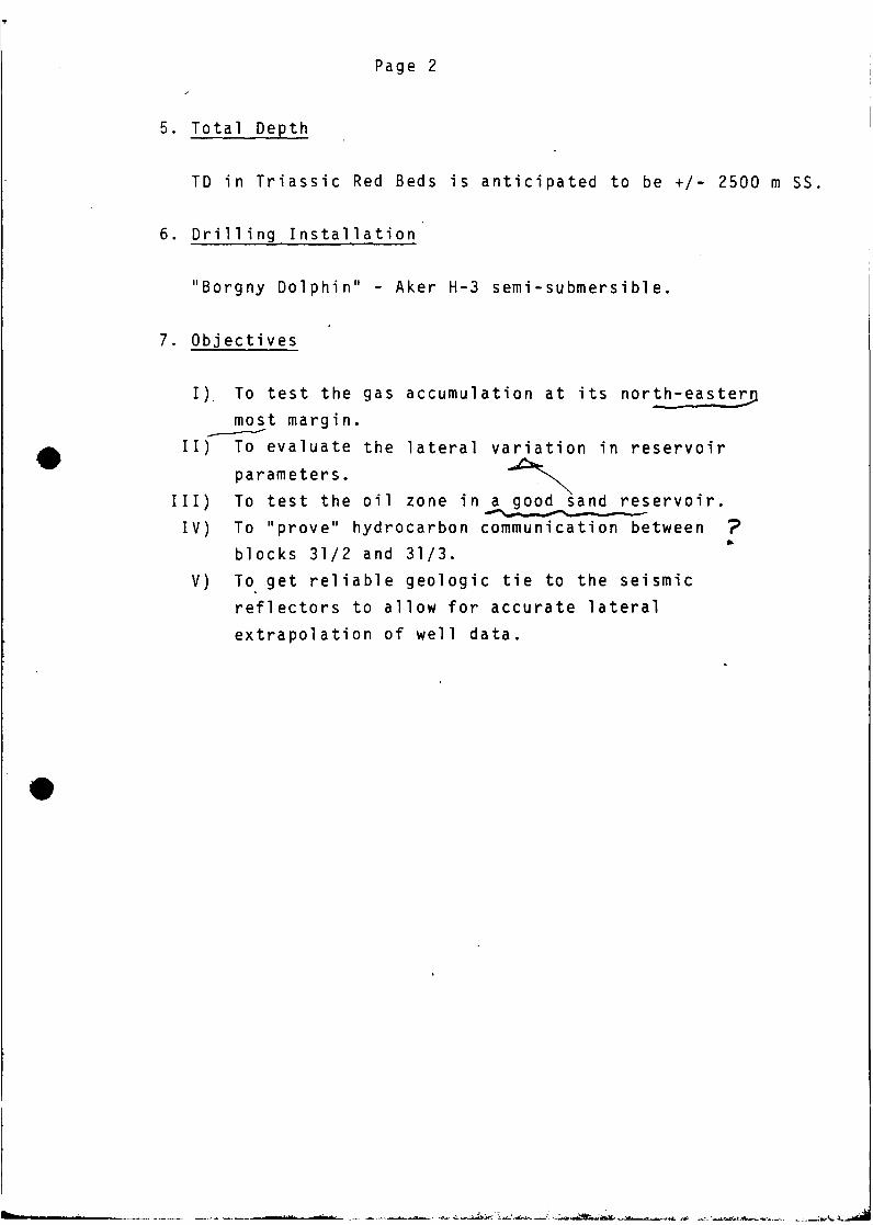
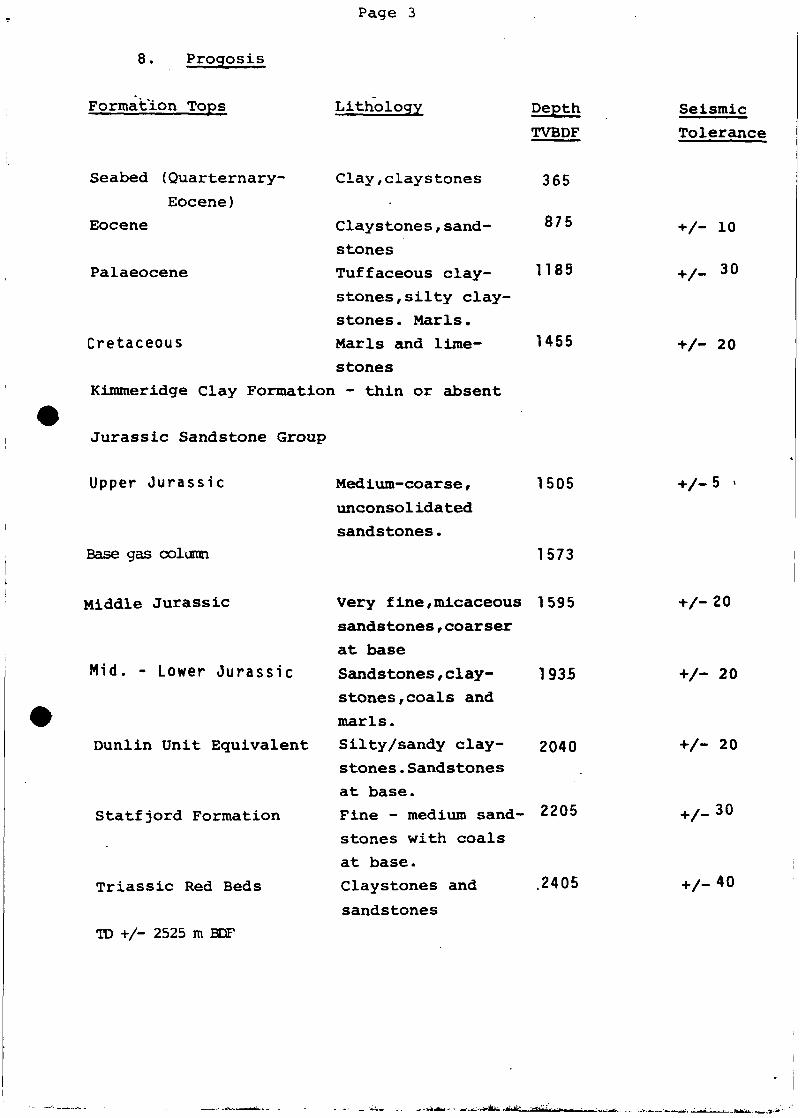
PROGRAMME
LQCATION 31/2-E
c
A/S NORSKE SHELL
•LICENCE 054
--ev
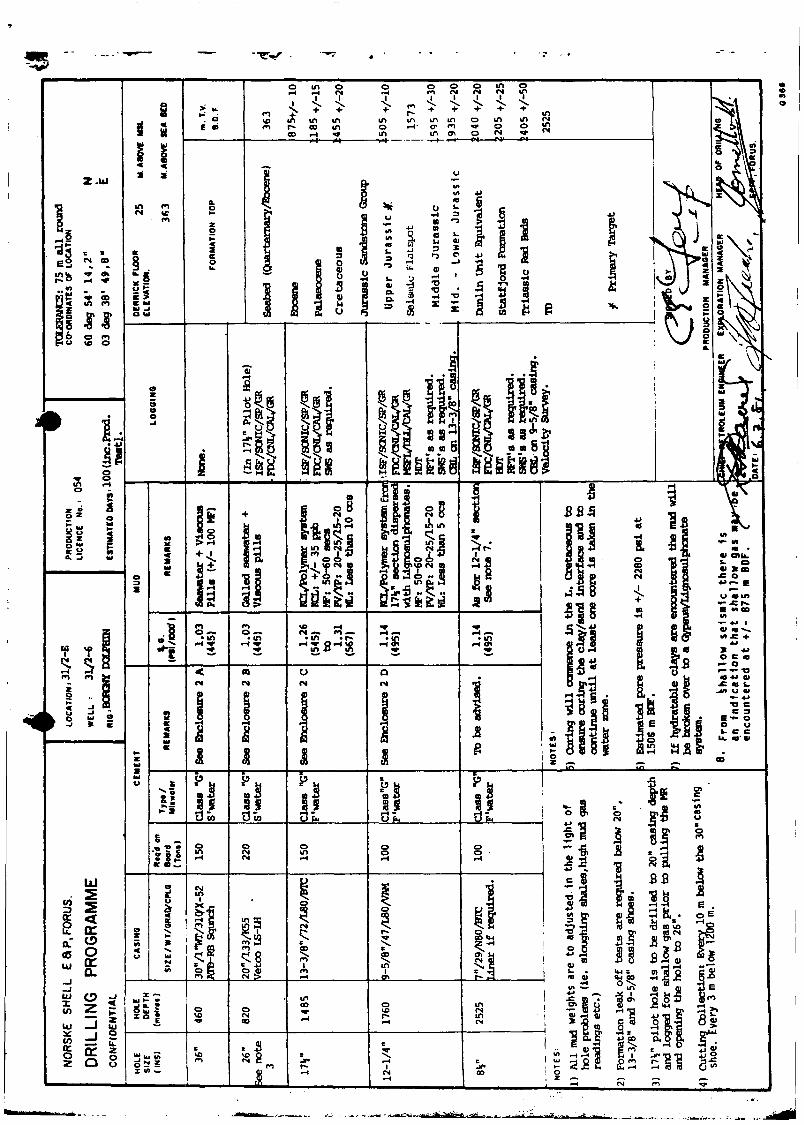
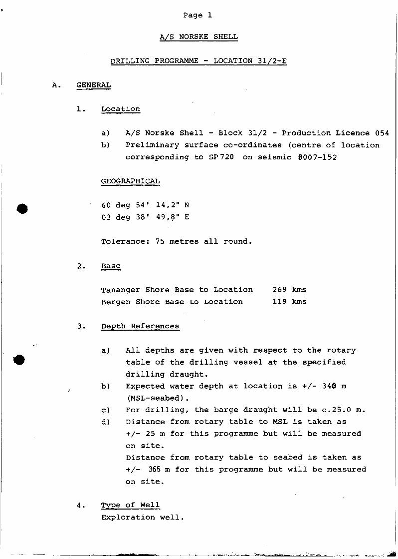
31/2-E DRILLING PROGRESS CURVE
TIME BREAKDOWN (DAYS)RIGMOVE/ANCHORING 4
DRILL. LOG. CASE TO TD 49
PRODUCTION TESTING 43
ABANDONMENT 4
RTGMOVE /ANCHORING
V ae* HOLE30 CAS ING
PRODUCTION MANAGER
113s/»!1 CASING
fcORING
PF ODUCTIQM TESTING
DAYS ON LOCATION
Page 1
A/S NORSKE SHELL
DRILLING PROGRAMME - LOCATION 31/2-E
A. GENERAL
1. Location
a) A/S Norske Shell - Block 31/2 - Production Licence 054
b) Preliminary surface co-ordinates (centre of location
corresponding to SP720 on seismic 6007-152
GEOGRAPHICAL
60 deg 54' 14,2" N
03 deg 38' 49,8" E
Tolerance: 75 metres all round.
2. Base
Tananger Shore Base to Location 269 kms
Bergen Shore Base to Location 119 kms
3. Depth References
a) All depths are given with respect to the rotarytable of the drilling vessel at the specified
drilling draught.b) Expected water depth at location is +/- 340 m
(MSL-seabed).c) For drilling, the barge draught will be c.25.0 m.
d) Distance from rotary table to MSL is taken as
+/- 25 m for this programme but will be measuredon site.
Distance from rotary table to seabed is taken as
+/- 365 m for this programme but will be measured
on site.
4. Type of Well
Exploration well.
Page 2->
5. Total Depth
TD in Triassic Red Beds is anticipated to be +/- 2500 m SS
6. D r i l l i n g Installation
"Borgny Dolphin" - Aker H-3 semi-submersible.
7. Objectives
I) To test the gas accumulation at its north-easterpmost margin.
II) To evaluate the lateral variation in reservoir
parameters. ^̂ \̂III) To test the oil zone in a good sand reservoir.IV) To "prove" hydrocarbon communication between "?
blocks 31/2 and 31/3.V) To get reliable geologic tie to the seismic
reflectors to allow for accurate lateralextrapolation of well data.
Page 3
8. Progosis
Formation Tops
Seabed (Quarternary-
Eocene)Eocene
Lithology
Clay,claystones
Claystones,sand-
stones
Tuffaceous clay-
stones, silty clay-
stones . Marls.
Marls and lime-
stones
Kimmeridge Clay Formation - thin or absent
Palaeocene
Cretaceous
DepthTVBDF
365
875
1185
1455
Jurassic Sandstone Group
Upper Jurassic
Base gas column
Middle Jurassic
Mid. - Lower Jurassic
Dunlin Unit Equivalent
Statfjord Formation
Triassic Red Beds
TD +/- 2525 m BDF
Medium-coarse,unconsolidatedsandstones.
1505
1573
Very f ine,micaceous 1595
sandstones,coarser
at base
Sandstones,clay- 1 935stones,coals and
marls.
Silty/sandy clay- 2040stones.Sandstones
at base.Fine - medium sand- 2205
stones with coals
at base.Claystones and .2405
sandstones
Seismic
Tolerance
+/- 10
V- 30
V- 20
+/-20
- 20
+/- 20
_ 30
V-40
Page 4
9. Pressure
From data gained in the drilling, the subsequent electriclogging and RFT pressure measurements made in 31/2-1, and fromthe production tests performed on 31/2-2 and 31/2-3 it wasfound that these wells are hydrostatically pressured.
The proposed location 31/2-E is located in a separate faultblock some 15 kms and 7,5 kms NNE of 31/2-1 and 31/2-3respectively. The seismic flatspot can be traced across thefaults at the same depth indicating that the faults arenon-sealing. Therefore, the location 31/2-E is considered tobe in the same hydrostatically pressured regime. (See Encl.3).
10. Mud Resume
The 36" hole section is to be drilled with a seawater andviscous pill combination.
The 17i" pilot hole for the 26" hole section is to be drilledwith an unweighted gelled water mud combined with the frequentspotting of viscous pills. The 17i" pilot hole will be openedup to 26" using seawater and viscous pills, with the riserremoved and returns to seabed.
Note;Prior to pulling put of the 17i" pilot hole and 26" hole forlogging and the running of 20" casing respectively, mud of1.40 SG is to be spotted in the open hole section, to ensurehole stability.
The 17i" hole section will be drilled with a KCL/Polymer mudsystem with a mud weight of 1.26 - 1.31 SG (.545 - .567psi/ft)
Page 5
Note:
From experience gained on wells 31/2-1,2 and 3 a
mud weight of 1.31 SG was required to stabilize
this hole section.
For the 12-1/4" hole section the KCL/Polymer mud will
be dispersed by the use of Lignosulphonates. A mud
weight of 1.14 SG (.494 psi/ft) will be used in this
section.
Note:
This mud weight will exert +/- 100 psi overbalance
on top of the main reservoir in the evenj: of the
riser being disconnected.
The 8V hole section will be drilled with a dispersed
Lignosulphonate mud system with a mud weight of 1.14 SG
(.494 psi/ft).
Note:
1) Mud weights mentioned are a guide only and are
liable to change if hole conditions dictate.
2) If hydratable clays are encountered in the 12 1/4"
or 8V hole sections, the mud will be "broken over"
to a Gypsum/Lignosulphonate mud system.
Detailed mud properties and parameters will be
specified in a separate mud programme.
11. Well Control
A diverter will be hooked up to the riser during the
drilling of the 17V pilot hole for 20" casing.In
addition, 1.4 SG mud (.600 psi/ft) should be available
during this diverter drilling in case flows are
encountered. Cement will also be available on the rig
for use in an emergency.Pressure control will be
maintained from the 20" casing point to TD in accordance
with the well control policy.
Page 6
12. Deviation Control
Magnetic single shot surveys will be taken every
90 metres, to concide with bit trips where possible.
The well path is to be calculated using the "Minimum
Radius of Curvature" Method.
13. Casing Summary
Size Grade Weight Coupling Interval BDF
30" X-52,1" WT 310 lbs/ft ATD-RB Squnch Seabed - 450 m
20" K-55 133 lbs/ft Vetco LS-LH Seabed - 810 m
13-3/8" L-80 72 lbs/ft ETC Seabed -1450 m
9-5/8" L-80 47 lbs/ft VAM Seabed -1750 m
N.B. The 13-3/8", L-80, 72 lbs/ft, ETC casing will be
specially drifted at the mill (during manufacture) and
again at the rig (before running)to ensure it will
pass a 12-1/4" bit.
14. Wellhead Equipment
Cameron 18-3/4", 10,000 psi wellhead equipment will
be used.
15. Formation Gradient Tests
Leak off test will be made after drilling 5 metres
of new hole below 20", 13-3/8" and 9-5/8" casing shoes.
16. Casing Accessories
The 30",. 20", 13-3/8", 9-5/8" casing scheme will be
used.Casing attachments will be as follows:
30" Float shoe.
20" Float shoe + float collar one joint above shoe
Two spring centralizers on the shoetrack and 3
on the next 6 joints (one per two joints).
Two rigid centralizers equally inside30" conductor.
Page 7
13-3/8" Float shoe + float collar one joint above
shoe. 10 spring centralizers - 2 on shoe joint,
6 on the next 12 joints (one every second joint)
and 2 inside 20" shoe, spaced 1 joint apart.
9-5/8" Float shoe + float collar 2 joints above the
shoe. Two spring centralizers on the shoe track,
1 centralizer per 3 joints up to the base of
the reservoir, 1 centralizer per joint across
the reservoir, 1 centralizer per 3 joints up
to the 13-3/8" shoe and 1 rigid centralizer
per 3 joints over the first 100 m of 9-5/8"
inside the 13-3/8" casing.
Casing test pressures will be as follows:
20" 1000 psi for 15 mins
13-3-/8" 3000 psi for 15 mins
9-5/8" 4000 psi for 15 mins
Pressure tests on the 13-3/8" and 9-5/8" casings to
be done immediately after bumping the top plug. The
casing may be restested using an RTTS packer set below
the top of cement around the particular casing if
there is concern over the casing being worn.
Cement calculations: See enclosure 2.
Page 8
B. SUMMARY OF OPERATIONS
1. Pre-Spud Phase
Site SurveyA combined seafloor and high resolution seismic surcey wascarried out by Geoteam A/S In May/June 1980.
The seafloor survey covers an area of approximately 6x7 kmsaround the proposed well location, and the area was surveyedwith echo sounder, side scan sonar and analog boomer. Noobstructions which may cause any problems to drilling wereobserved.
The high resolution seismic surveys covers an area of 2 x 4kms centred on the location. In the northern part of thesurvey area a seismic reflection interpreted as a possible gascharged sand was observed between 880 - 950 m (SS). This ispossibly the same as the anomaly observed, on deep seismic dataat 850 m (SS) and indicated as a possible gas pocket in theprognosis.(Ref: Geoteam report 6574.01 and 02 2.7.80)
2. Rig Positioning
The rig will be brought on to location utilizing Decca Pulse-8with HP minicomputer. All anchors will be run out plus/minus1450 m. The rig will be positioned with a heading of 315 deg(T). After anchors have been set, eachanchor will be testedto plus/minus 400,000 Ibs for 1 hour. After a satisfactorymooring test, approximately 250,000 Ibs will be held on allanchor chains.
The final coordinates will be determined with an accuracy of10 m (RMS) using Satnav.
Page 9
3. Spudding in, drilling 36" hole and running 30" Casing
1. Check the seabed condition by an observation dive.
2. Set TGB (with 5 m skirt) at slack tide. A Regan
slope indicator is to be run on the TGB running tool
to give an indication of the TGB angle. The TGB
guide lines are to be marked at the spider deck
level so that any subsequent sinking or tilting
will be detected.
Note:
Calculate the DF - seabed distance and Mean Sea
Level (MSL) after landing the TGB,taking into
account the drilling draught and tidal variation.
3. Make up a 36" hole opener and 26" pilot bit
assembly (a monel collar to be included for MSS).
Drill down to 30" casing setting depth, taking a
MSS after the first Kelly down. Additional surveys
will be carried out as necessary,depending on
hole angle. If hole angle is greater than 1^ degree
then contact base, where the various options will
be considered.
Before POH to run 30" casing circulate high
viscosity mud in the hole,using 200% excess.
4. Run 30" casing plus MGB equipped with a Regan slope
indicator (to be installed in the middle of a
side beam, as close to the beam as possible).
Install a second Regan slope indicator on the
30" running tool. Ensure that the slope indicators
are properly level and zeroed and will be visible
to the subsea TV.
5. When the 30" casing is landed observe the angle
with the subsea TV camera. If the angle is 1 degree or
less, cement the casing using 200% excess cement.
Page 10
6. WOC. Divers to check cratering around the guide
bases with an observation dive. Run a check-totco
in 30" running tool. (Install a totco ring in a
sub below the running tool).
7. If excessive eratering is observed,re-cementing
around the guide base or seabed may be considered
prior to drilling out of the 30" casing. Or if
this problem is anticipated,consider using 300%
excess cement instead of 200%.
Note:
a) For the single stack system the angle of the
MGB and BOP stack, and the base being level,
are of utmost importance and good support is
required to carry the very heavy load of the
stack.
b) Observe operations such as the penetration test,
placing of TGB and MGB, spudding in, stabbing
in, drilling with returns to seabed,cementing
of the 30" and 20" casing, with the rig's
underwater TV camera.
c) Maintain a tension in the anchor chains at
the upper limits until the 30" casing is
cemented, in order to minimize rig offset.
Otherwise,the stack and conductor could
be set under an angle which could lead to
serious damage to the U.W. equipment.
d) Ensure that the tension of the guide lines
is optimum so that the TGB will not be lifted
on one side or be tilted by excessive uneven
guide line tension.
e) It is evident that the weather conditions should
be moderate for most of these above operations.
Page 11
4. Drilling 26" hole and running 20" casing
1. Drill out cement in 30" casing and 36" pocket
with 26" hole opener and 17V pilot bit with a
stabilizer at 20 m and start 17V pilot hole.
POH and lay down 26" hole opener.
2. Run 30" pin connector and dump valve complete
with flex joint on 21" riser. Use minimum required
tension on ruckers. Fill up riser with seawater
and observe fluid level.
3. Make up 17V pilot hole drilling assembly.
Use a float sub, with the float installed, and
run in the hole.
4. Close diverter around drill pipe, and circulate
through diverter lines to check the diverter
equipment, gradually building up to maximum
circulating rate. Open diverter packing.
5. Drill 17V pilot hole to the 20" casing setting
depth,allowing for a 10 m pocket.
Note:
This section is to be drilled using an unweighted
gelled mud and the weight of annular returns is
to be continuously monitored. If the weight of
annular returns causes losses or exceeds 1.10 SG
(475 psi/1000 ft) stop drilling and circulate the
hole clean. It is evident that the ROP will have
to be controlled whilst drilling this section.
6. Perform a check trip to the 30" shoe and back to
bottom, clean out any fill and spot viscous mud of
1.4 SG (606 psi/1000 ft) in the open hole section
prior to pulling out of hole for logging.
7. Rig up Schlumberger and log as programmed.
Note:Inspect the logs for indications of shallow gas
prior to continuing with the programme. If any
indications of shallow gas are observed thencall Base and a revised programme will be issued.
Page 12
8. Rig down Schlumberger and run in hole to TD.
Circulate the hole volume to seawater and open
the dump valve. Observe well static for \ hour
and then spot high viscosity mud in the open hole
section.
9. Pull out of hole and retrieve the 30" pin connector.
10. Pick up a 17V pilot bit and 26" hole opener with
a 26" stabilizer at 10 m and 30 m above the bit.
Open the hole up to 26" using seawater and viscouspills.
11. Run and cement 20" casing as per programme.
Note:
Use a long drillpipe stinger (+/- 60 m above the
float collar) inside the casing.
12. Unlatch the running tool,pick up until the bottom
of the stinger is just below 18-3/4" housing.
Wash in and around the housing with seawater prior
to retrieving the running tool.
13. Install the 18-3/4" BOP stack and 21" Marine Riser.
Test BOP stack,complete with casing. For stack test
procedure see "Stack Testing" item C.Make up drill
pipe hang off assembly and circulating head assembly.
Install wearbushing.
Notes on Diverter Drilling
a) Diverter systems are fitted on offshore rigs to
provide a means of controlling the flow should
shallow pressures be encountered whilst drilling
for the first casing string (surface casing).
b) The diverter system is not a blowout preventer.
It is not designed to hold pressure, but instead,to direct the flow overboard. The controls of theflowline valves are manifolded in such a way thatit is impossible to hold any pressure in the diverter.
The downwind blow-off line must always be open.
Page 13
c) Severe Losses
If severe losses are encountered while drilling
with returns to surface pull out and drill a 12-1/4"
pilot hole instead of 17V and restrict penetration
rates to obtain the lightest possible annular returns.
If severe losses are continuing, open the dumpvalve
and drill a 12-1/4" pilot hole with returns to seabed.
If gas is encountered whilst drilling 12-1/4" pilot
hole with seawater and returns to seabed, spot heavy
mud and inform Base.
d) Gas Flow (No Losses)
If any flow of gas is encountered whilst drilling
the 17V pilot hole, drill to 20" casing point with1 required mud weight. Circulate hole clean and make
check trip. Circulate, drop Totco and pull out of
hole. Run logs as required. Make up 26" hydraulic
under-reamer with 17V stabilizer 20 m above under-
reamer.
Under-ream 17%" hole to 26". Circulate and increase
mud weight on bottom to compensate for the loss in
hydrostatic head as a result of the removal of the
Marine Riser later on. Check trip to shoe. Run back
to bottom. POH.Run BGT to check holesize. RIH with
bit and under-reamer. Circulate, if required. Observe
well. Open dump valve. Fill up Marine Riser with sea-
water to give a column equal to the water depth. After
level in Marine Riser is equalised to sea level, observe
well in Marine Riser and check flow on open dump valve
with TV. Close dump valve. Make another check trip,
circulate and pull back to pin connector, circulate
to seawater. POH. Retrieve Marine Riser. Stand back
18-3/4" housing in derrick. Make additional check
trip prior to running 20" casing.
Page 14
e) Gas Flow and Severe Losses
If any flow of gas is encountered whilst drilling
the 17^" pilot hole with returns to surface, and
the required increased mud weight to counteract
the gas flow causes severe losses, then inform Base.
Note:
There should be sufficient barytes and SAPP onboard to
allow for the setting of baryte plugs.
Further programme will be advised in this case.
5. Drilling 17V hole and running 13-3/8" casing
Note:Due to concern about the possibi l i ty of shallowgas being encountered at +/- 875 m a 12 1/4"pilot is to be drilled through the interval priorto d r i l l i n g 17 1/2" hole.
1. Drill out float collar, shoe track and shoe witha 17 T/2" bit. Drill 5 m of new hole and carryout a formation leak off test. POH.
2. Pick up a 12 1/4" dr i l l i n g assembly and RIH.Drill 12 1/4" hole to +/- 1050 m POH.
NB Exercise extreme care while drilling thoughthis interval and monitor closely for anyevidence of increasing gas readings and/orpore pressure. Perform a flow check uponany increase in d r i l l i n g rate. Advise Baseimmediately of any significant changes and arevised programme will be issued.
3. Pick up a 17 1/2" drilling assembly and RIH.Open up the 12 1/4" pilot hole to 17 1/2".Drill 17 1/2" hole to programme depth.
4. Log as per programme.Make up 13-3/8" hanger with
subsea cementing assembly (top plug only) and
stand back in derrick.
5. Make checktrip, pull wearbushing and run 13-3/8"
casing to landing point, leaving 10 m pocket at
below the 13-3/8" shoe.
6- Cement 13-3/8" casing as per programme. Clean
out the stack area prior to pulling out with
the running string.
7. Carry out stack and casing tests as per "Stack
Testing" Item C. Install wearbushing. Make up
drillpipe hang-off assembly and circulating head
assembly. Carry out a kickdrill.
r ay c
6. Drilling 12-1/4" hole and running 9-5/8" casing
1. Drill out float collar, cement and shoe.Drill
5 m of new hole, and carry out a formation leak offtest.
2. Drill 12-1/4" hole to programmed depth. Bit weight,
RPM, bit selection and bottom hole assembly to be
determined on site for optimum penetration rate.Note :Coring will commence using fibreglass sleeves in the L.Cretaceouslimestones and marls and will continue until at least one corehas been taken in the water zone.
3. Carry out logging programme,including wire line
tests if necessary. Make up 9-5/8" hanger with
subsea cementing assembly (top plug only)
and stand back in derrick.
4. Make check trip, pull wearbushing and run 9-5/8"
casing to landing point, leaving a 10 m pocket
below the 9-5/8" shoe.
5. Cement the 9-5/8" casing as per programme.Clean
out the stack area prior to pulling out the
running tool. Whilst displacing, (in turbulent
flow at 250 ft/min or higher), returns are to be
monitored closely. If losses are observed adjust
pump rates accordingly.
6. Carry out stack and casing tests as per "Stack
Testing" Item C. Install wearbushing. Make up
drillpipe hang-off and circulating head assembly.
Carry out a kickdrill.
7. Drilling 8V hole
1. Drill out float collar,shoetrack and float shoe.
Drill 5 m of new hole and carry out a formation
leak off test.
Note:
An RTTS will be set inside the 9-5/8" casing to avoid
damaging the cement bond across the reservoir.
2. Drill 8^" hole to T.D. with a mud weight as
dictated by hole conditions.
Note:
Coring will commence on the occurence of good
hydrocarbon shows and will continue until at
least one core is taken in the water zone.
3. Rig up Schlumberger and carry out the logging
programme, including wireline tests if necessary.
4. Dependent upon the results of the logs and wireline
tests the hole will either be plugged back to allow for
testing of the upper reservoir or a 7" liner will beset to allow testing of a lower reservoir.
Page 178. Abandonment
1. If there is open hole below the last casing then
all porous zones in the open hole interval will be
isolated with cement plugs extending 30 m above
and below each zone. In addition a cement plug,
extending 30 m above and below the casing shoe,
shall be set. "A mechanical bridge plug may be set
in the lower part of the casing but not more than
50 m above the shoe. A 15 m cement plug must be
placed on top of the bridge plug. The plugs at the
last casing shoe shall be tested to 1000 psi
differential pressure.
2. Perforations shall be isolated by means of a
mechanical bridge plug and squeeze cemented, or
a cement plug shall be placed across the
perforations extending 30 metres above and below
the perforated interval or down to a casing plug
whichever is less.
3. Cement plugs of at least 30 metres shall be placed
in the smallest casing string extending to seabed.
These plugs shall be placed at the level of the
13-3/8" casing shoe and the 20" casing shoe.
4. A cement plug of at least 50 metres, with the top
of the plug not more than 50 metres below the
sea floor, shall be placed in the smallest string
of casing extending to the sea floor.
5. Casing strings and other installations extending
above the sea floor must be removed to a depth of
at least 5 metres below the ocean floor.
6. The sea floor in the vicinity of the borehole will
be inspected by TV/observation dive to ensure that
no obstructions remain on the sea bed which may
cause danger or impediment to fishing or shipping.
7. A specific abandonment/suspension program will be
prepared and issued when the well reaches total depth.
Page 18
C. STACK TESTING
The regular tests of the BOP Stack in service have to be
limited to the following pressures, unless differently
advised by the base.
18-3/4",10.OOP psi BOP Stack
1. Pipe Rams : 5000 psi
2. Blind Rams : Casing test pressure, as
specified in Item A-16
3. Kill/choke lines and valves : 5000 psi
4. Annular preventers : 2000 psi around 5" DP
1500 psi around 3-1/2" DP
a) Tests 1,3 and 4 to be carried out with a boll weevil tester
run on DP and landed in the wellhead.
b) Test 2 to be carried out only when the cement of the
last casing is not yet drilled out.
Accumulator Tests
The accumulators must have sufficient capacity to be able to
close, open and close all preventer with both air and
electric charge pumps off, and then still have enough pressure
left to provide working fluid for 25% of one closing function.
Minimum recharge time from above condition with both air and
electric pumps running should be in accordance with
manufactorer's specifications. A note that this test has
been carried out (and results) must be made in the Drilling
Report and on weekly BOP test checklist. For frequency
see (this Section) item 10.
Notes on Testing
1. The BOP stack has to be tested on all functions and all
rams tested to the full rated WP at surface prior to
running the Stack.However, the blind/shear rams will be teste
only on orders of Base, but at least once per month during •
a routine stack test.
Page 19
After the surface tests all Cameron clamp connections and
all studded connections must be checked for tightness.
2. All pressure tests to be carried out with water,
unless differently advised by Base.
3. All surface equipment has to be satisfactorily pressure
tested prior to testing the BOP stack underwater.
4. When running the Marine Riser with integral kill-and
choke lines, the kill-and choke lines can be tested
while running in at various stages. This should be done
at least twice, firstly as soon as the stack is below
sea level, and secondly, just before landing the stack.
5. When testing the BOP stack underwater with a boll weevil
test tool in the wellhead, use the vented red-painted
test single.
6. The test pressure should be kept on for 15 minutes, and
the acceptable pressure drop over this 15 minutes period
is 10% of the initial test pressure, provided that the
pressure remains constant for the next 5 to 10 minutes.
7. All pressure tests to be recorded on pressure recorder
charts. A record is to be kept of the volumes required
to obtain the test pressure, and of the volumes returned
when bleeding off.
8. The opening/closing times and the volumes of hydraulic
operating fluid required for the operation of the various
underwater stack components (such as: rams, kill and
choke valves, annular preventers, hydraulic connectors,etc.)
should be recorded during testing of the stack underwater.
These results should be compared with the normal
opening/closing times and volumes required of the
hydraulic system. Any major differences are in indication
that the system is not operating "normally" and may
require further investigations and/or repairs.
Page 20
9. The testing of 10,000 psi BOP stack will be done to
5000 psi only,at the weekly routine BOP test underwater,
If higher test pressures are required then, depending
on the well programme, the test pressure will be
increased to the value required and carried out with
a boll weevil test tool, e.g. subjecting the seals
of the seal assembly to the same pressure as the BOP
stack, or by means of a weight set tester, subjecting
only the stack to the required test pressure.
Run 2 stands drill collars below the weight set
tester to assist in shearing the pins with set down
weight.
See item 1 on blind/shear rams.
10. Accumulator tests (as described previously) should be
done either on request of Base, or after repair have
been done to the accumulator system, i.e. bottles,
bladders, pumps, etc.
Page 21
D. EVALUATION REQUIREMENTS
1. Cutting Samples
Ditch cuttings to be collected every 10 m below 30"
casing down to 1200 m, and every 3 m thereafter.
The following samples will be required for partners/
government bodies:
a) 6 x small cuttings bags of washed dried samples.
b) 4x2 kilograms bags of wet samples.
1x2 kilogram bag of wet samples from each interval
should be kept on board until the well has reached
TD when the complete set should be sent in. Otherwise,
samples should be sent ashore ASAP, marked for
attention of EPXV/1,Tananger.
2. Coring
a) Jurassj.c Sandstone Groupt
Interval 4 :
Coring is to commence immediately above the reservoir,
i.e. in the L.Cretaceous limestones and marls,
and is to continue until at least one core
is taken in the water zone. Approximate interval is
1490 - 1600 m BDF.
b) Deeper Reservoir Intervals
Coring is to commence on occurence of good
hydrocarbon shows in sands and is to continue
until at least one core is taken in the water zone.
Page 22
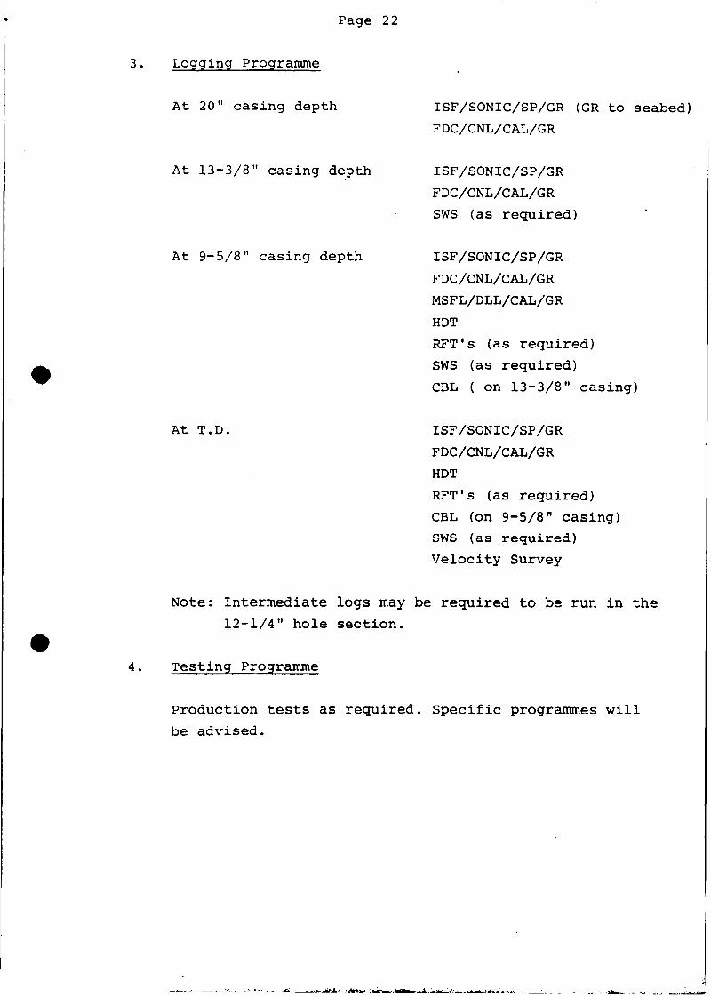
3. Logging Programme
At 20" casing depth
At 13-3/8" casing depth
At 9-5/8" casing depth
At T.D.
ISF/SONIC/SP/GR (GR to seabed)
FDC/CNL/CAL/GR
ISF/SONIC/SP/GR
FDC/CNL/CAL/GR
SWS (as required)
ISF/SONIC/SP/GR
FDC/CNL/CAL/GR
MSFL/DLL/CAL/GR
HOT
RFT's (as required)
SWS (as required)
CBL ( on 13-3/8" casing)
ISF/SONIC/SP/GR
FDC/CNL/CAL/GR
HOT
RFT's (as required)
CBL (on 9-5/8" casing)
SWS (as required)
Velocity Survey
Note: Intermediate logs may be required to be run in the
12-1/4" hole section.
4. Testing Programme
Production tests as required. Specific programmes will
be advised.
Page 23
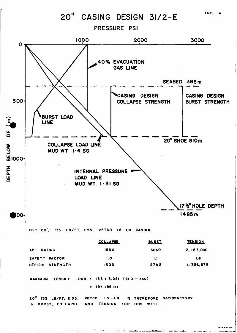
E. CASING DESIGN
Casing designs are presented for the 20", 13-3/8" and
9-5/8" casings (See Encl. 1.0.)
The following assumptions apply:
1. For tension, a design safety factor of 1.6 is used,
neglecting buoyancy in the drilling fluid.
2. Bi-axial effects have been neglected except in the
case of the lowering of collapse resistance caused by
tension. No allowance is given for the increase of
burst resistance caused by tension.
3. For burst, a design safety factor of 1.1 is employed.
The pressure distribution for the burst loading assumes
a 40% evacuation of mud from the well by a kick.
4. For collapse, a design safety factor of 1.0 is employed.
Total evacuation of the casing is assumed for the design.
5. In the production test design for casing burst, a tubing
leak is assumed putting full THP on the tubing/casing
annulus.
Page 24
F. GLOSSARY OF ABREVIATIONS
BDF
BGT
BOP
FS
ID
MF
MGB
MSL
MS S
OD
PPG
PV
SS
TGB
TMCM
UGF
WHP
YP
below derrick floor
borehole geometry tool
blow out preventer
fail safe, (as in FS valve)
internal diameter
Marsh funnel (mud viscosity)
main guide base
mean sea level
magnetic single shot
outside diameter
pounds per US gallon
plastic viscosity
sub sea
temporary guide base
Transverse Mercator, Central Meridian
universal guide frame
wellhead pressure
yield point
20" CASING DESIGN 31/2-EPRESSURE PSI
ENCL. IA
1000 2000 3000
500
3m 1000
o.LUO
100
BURST LOADLINE
40% EVACUATIONGAS LINE
SEABED 365m
^CASING DESIGNCOLLAPSE STRENGTH
CASING DESIGNBURST STRENGTH
COLLAPSE LOAD LINEMUD WT. 1-4 SG
20" SHOE 810m
INTERNAL PRESSURELOAD LINEMUD WT. 1 -31 SG
|7V|HOLE DEPTH
1485m
FOR 20", 133 LB/FT, K 55, VETCO L3 - LH CASINO
API RATING
SAFETY FACTOR
DESIGN STRENGTH
COLLAPSE
1500
1.0
1500
BURST
3060
I . I
2782
TENSION
2, 123,000
1.6
1, 326.875
MAXIMUM TENSILE LOAD = 1 3 3 x 3 . 2 8 1 ( 8 1 0 - 3 6 5 )
s 194,18611)1
20" 133 LB/FT, K 55, VETCO LS-LH IS THEREFORE SATISFACTORY
IN BURST, COLLAPSE AND TENSION FOR THIS WELL
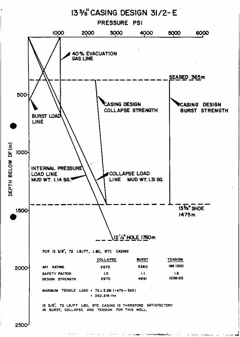
II!33/8 CASING DESIGN 31/2-E
PRESSURE PSI
1000 2000 3000 4000 5000 6000
500-
BURST LOADLINE
40% EVACUATIONGAS LINE
SEABED 365m
1\A
1000-
oUJm
Q.UJO
INTERNAL PRESS U RLOAD LINEMUDWT. I.I4S6
1500
SING DESIGNCOLLAPSE STRENGTH
COLLAPSE LOADLINE MUD WT. 1.31 SG.
ASING DESIGNBURST STRENGTH
13V SHOE1475m
12 74 HOLE 1760m
2000-
FOR 13 3/8", 72 LB/FT, L 80, BTC CASING
COLLAPSE
API RATING
SAFETY FACTOR
DESIGN STRENGTH
2670
1.02670
BURST
5380
I . I4691
TENSION
1661000
1.61036125
MAXIMUM TENSILE LOAD = 72x3.281(1475-365): 262,216 Ibs
13 3/8", 72 LB/FT L80, BTC CASING IS THEREFORE SATISFACTORYIN BURST, COLLAPSE AND TENSION FOR THIS WELL.
250O1
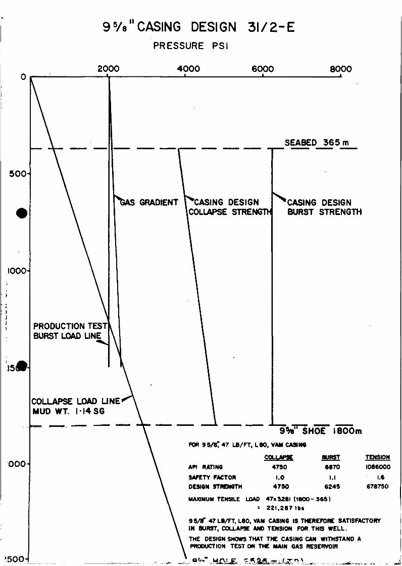
II95/e CASING DESIGN 31/2-E
PRESSURE PSI
2000 4000 6000 8000
500
1000-
000-
>500-
SEABED 365m
GRADIENT "CASING DESIGNICOLLAPSE STRENGTH
PRODUCTION TEST]BURST LOAD LINE
COLLAPSE LOAD LINE'MUD WT. I-1486
CASING DESIGNBURST STRENGTH
1800mFOR 99/87 «7 LB/FT, L80, VAM CASIN9
COLLAPSE BURST TENSION
API RATING 4790 6870 1086000
SAFETY FACTOR 1.0 I.I 1.6
DESIGN STRENGTH 4790 6249 678750
MAXIMUM TENSILE LOAD 47x3281(1800-969)
= 22l.287lbt
99/8" 47 LB/FT, L80, VAM CASING IS THEREFORE SATISFACTORYIN BURST, COLLAPSE AND TENSION FOR THIS WELL.
THE DESIGN SHOWS THAT THE CASING CAN WITHSTAND APRODUCTION TEST ON THE MAIN GAS RESERVOIR
ENCL. 2 A
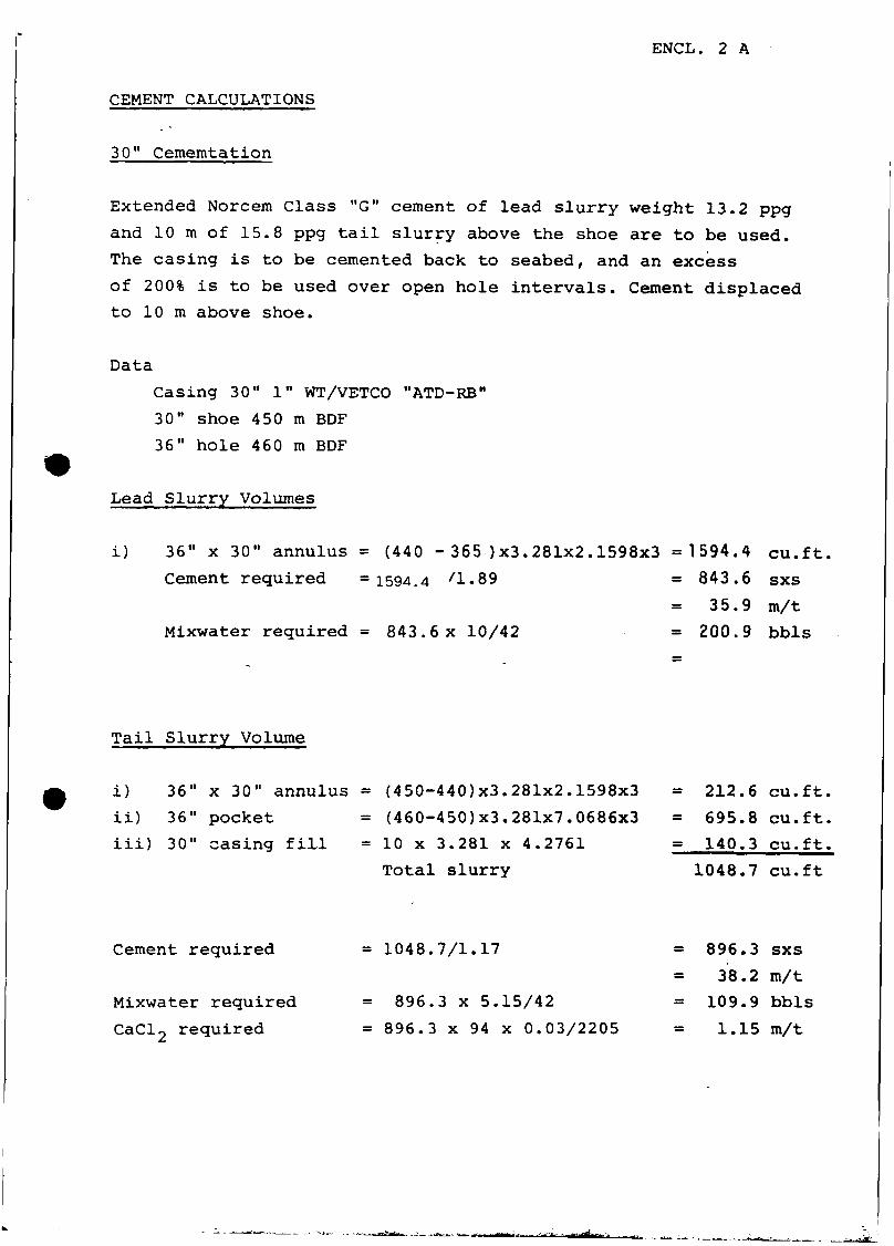
CEMENT CALCULATIONS
30" Cememtation
Extended Norcem Class "G" cement of lead slurry weight 13.2 ppg
and 10 m of 15.8 ppg tail slurry above the shoe are to be used.
The casing is to be cemented back to seabed, and an excess
of 200% is to be used over open hole intervals. Cement displaced
to 10 m above shoe.
Data
Casing 30" 1" WT/VETCO "ATD-RB"
30" shoe 450 m BDF
36" hole 460 m BDF
Lead Slurry Volumes
i) 36" x 30" annulus
Cement required
(440 - 365 )x3.281x2.1598x3
1594.4 'I- 89
Mixwater required = 843.6 x 10/42
1594.4 cu.ft.
843.6 sxs
35.9 m/t
200.9 bbls
Tail Slurry Volume
i) 36" x 30" annulus
ii) 36" pocket
iii) 30" casing fill
(450-440)x3.281x2.1598x3
(460-450)x3.281x7.0686x3
10 x 3.281 x 4.2761
Total slurry
212.6 cu.ft.
695.8 cu.ft.
140.3 cu.ft.
1048.7 cu.ft
Cement required
Mixwater required
CaCl2 required
= 1048.7/1.17
= 896.3 x 5.15/42
= 896.3 x 94 x 0.03/2205
896.3 sxs
38.2 m/t
109.9 bbls
1.15 m/t
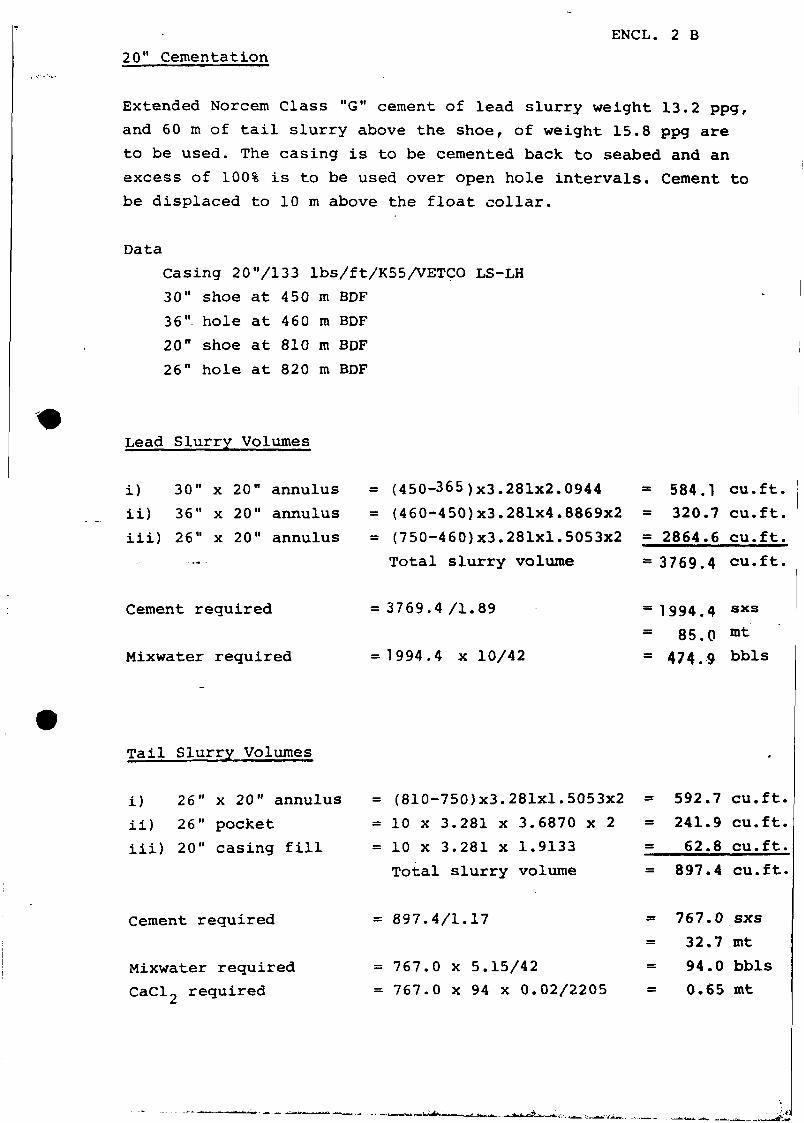
ENCL. 2 B
20" Cementation
Extended Norcem Class "G" cement of lead slurry weight 13.2 ppg,
and 60 m of tail slurry above the shoe, of weight 15.8 ppg are
to be used. The casing is to be cemented back to seabed and an
excess of 100% is to be used over open hole intervals. Cement to
be displaced to 10 m above the float collar.
Data
Casing 20"/133 Ibs/ft/K55/VETCO LS-LH
30" shoe at 450 m BDF
36" hole at 460 m BDF
20" shoe at 810 m BDF
26" hole at 820 m BDF
Lead Slurry Volumes
i) 30" x 20" annulus
ii) 36" x 20" annulus
iii) 26" x 20" annulus
(450-365)x3.281x2.0944
(460-450)x3.281x4.8869x2
(750-460)x3.281x1.5053x2
Total slurry volume
= 584.1 cu.ft.
= 320.7 cu.ft.
= 2864.6 cu.ft.
= 3769.4 cu.ft.
Cement required
Mixwater required
= 3769.4 /I.89
=1994.4 x 10/42
1994.4 sxs
85.0 mt
474.9 bbls
Tail Slurry Volumes
i) 26" x 20" annulus
ii) 26" pocket
iii) 20" casing fill
(810-750)x3.281x1.5053x2
10 x 3.281 x 3.6870 x 2
10 x 3.281 x 1.9133
Total slurry volume
= 592.7 cu.ft.
= 241.9 cu.ft.
= 62.8 cu.ft.
= 897.4 cu.ft.
Cement required
Mixwater required
CaCl2 required
= 897.4/1.17
= 767.0 x 5.15/42
= 767.0 x 94 x 0.02/2205
767.0 sxs
32.7 mt
94.0 bbls
0.65 mt
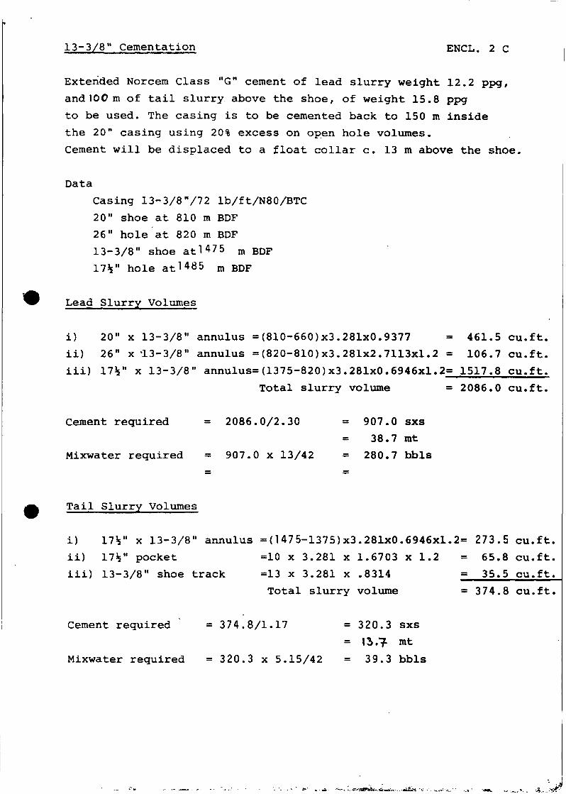
13-3/8" Cementation ENCL. 2 C
Extended Norcem Class "G" cement of lead slurry weight 12.2 ppg,
and 100 m of tail slurry above the shoe, of weight 15.8 ppg
to be used. The casing is to be cemented back to 150 m inside
the 20" casing using 20% excess on open hole volumes.
Cement will be displaced to a float collar c. 13 m above the shoe.
Data
Casing 13-3/8"/72 lb/ft/N80/BTC
20" shoe at 810 m BDF
26" hole at 820 m BDF
13-3/8" shoe at l475 m BDF
17V hole at 1485 m BDF
Lead Slurry Volumes
i) 20" x 13-3/8" annulus =(810-660)x3.281x0.9377 = 461.5 cu.ft.
ii) 26" x 13-3/8" annulus =(820-810)x3.281x2.7113x1.2 = 106.7 cu.ft.
iii) 17V x 13-3/8" annulus=(1375-820)x3.281x0.6946x1.2= 1517.8 cu.ft.
Total slurry volume = 2086.0 cu.ft,
Cement required = 2086.0/2.30 = 907.0 sxs
38.7 mt
Mixwater required = 907.0 x 13/42 = 280.7 bbls
Tail Slurry Volumes
i) 1735" x 13-3/8" annulus =(1 475-1375) x3.281x0.6946x1.2= 273 .5 cu.ft.
ii) 17V pocket =10 x 3.281 x 1.6703 x 1.2 = 65.8 cu.ft.
iii) 13-3/8" shoe track =13 x 3.281 x .8314 = 35.5 cu.ft.
Total slurry volume = 374.8 cu.ft.
Cement required = 374.8/1.17 = 320.3 sxs
= 13.f mt
Mixwater required = 320.3 x 5.15/42 = 39.3 bbls
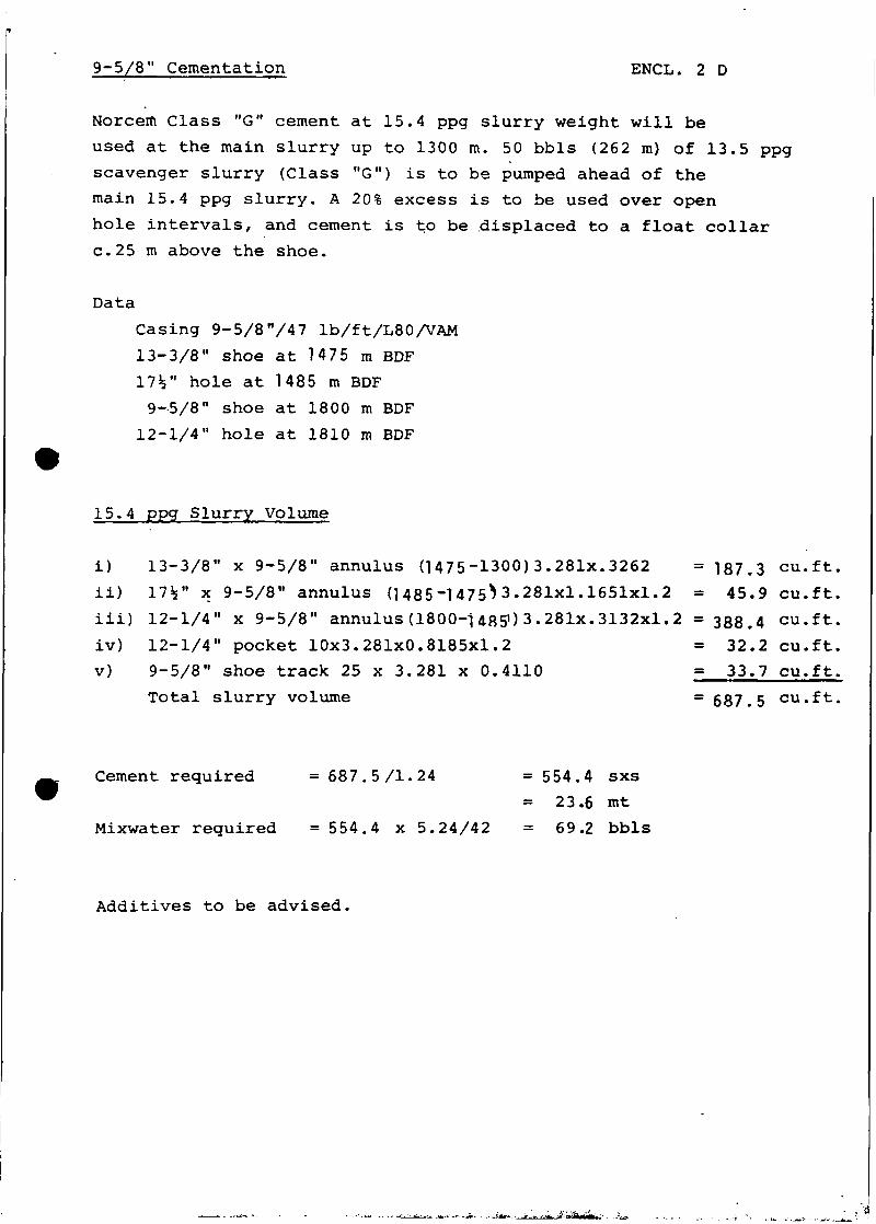
9-5/8" Cementation ENCL. 2 D
Norcerti Class "G" cement at 15.4 ppg slurry weight will be
used at the main slurry up to 1300 m. 50 bbls (262 m) of 13.5 ppg
scavenger slurry (Class "G") is to be pumped ahead of the
main 15.4 ppg slurry. A 20% excess is to be used over open
hole intervals, and cement is to be displaced to a float collar
c.25 m above the shoe.
Data
Casing 9-5/8"/47 lb/ft/L80/VAM
13-3/8" shoe at 1475 m BDF
17V hole at 1485 m BDF
9-5/8" shoe at 1800 m BDF
12-1/4" hole at 1810 m BDF
15.4 ppg Slurry Volume
i) 13-3/8" x 9-5/8" annulus (1475-1300)3.281x.3262 = 187.3 cu.ft,
ii) 17V x 9-5/8" annulus d 485~1 475*> 3 .281x1.1651x1.2 = 45.9 cu.ft,
iii) 12-1/4" x 9-5/8" annulus (1800-1 485») 3 .281x. 3132x1.2 = 388.4 cu.ft,
iv) 12-1/4" pocket 10x3.281x0.8185x1.2 = 32.2 cu.ft,
v) 9-5/8" shoe track 25 x 3.281 x 0.4110 = 33.7 cu.ft.
Total slurry volume = 687.5 cu.ft,
Cement required =687.5/1.24 =554.4 sxs
= 23.6 mt
Mixwater required =554.4 x 5.24/42 = 69.2 bbls
Additives to be advised.
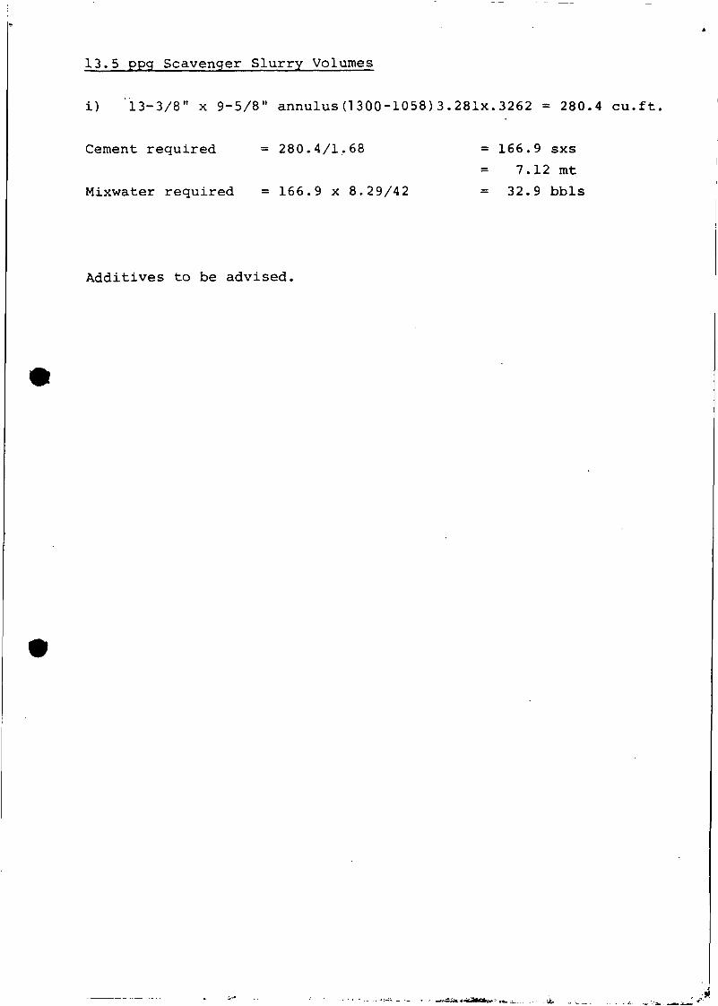
13.5 ppg Scavenger Slurry Volumes
i) "13-3/8" x 9-5/8" annulus (1 300-1058) 3 . 281x. 3262 = 280.4 cu.ft,
Cement required = 280.4/1.68 = 166.9 sxs
7.12 mt
Mixwater required = 166.9 x 8.29/42 = 32.9 bbls
Additives to be advised.
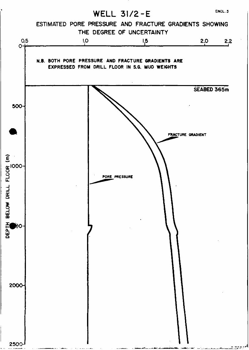
ENCL.3WELL 31/2-EESTIMATED PORE PRESSURE AND FRACTURE GRADIENTS SHOWING
THE DEGREE OF UNCERTAINTY
0.5 1.0 2.0 2.2
500-
<rlOOOo3.-I-JXO
UJOD
UJO
2000-
N.B. BOTH PORE PRESSURE AND FRACTURE GRADIENTS AREEXPRESSED FROM DRILL FLOOR IN S.6. MUD WEIGHTS
FRACTURE GRADIENT
SEABED 365m