Embed Size (px)
Citation preview
Programmable Time Dependent Router
Martin Olausson
Submitted in partial fulfilment of the requirements of Napier University
for the degree of
MSc Software Engineering
School of Computing
September 2000
Martin Olausson, MSc Software Engineering, 2000 2
Authorship Declaration I, Martin Olausson, confirm that this dissertation and the work presented in this report is my own achievement. 1. Where I have consulted the published work of others this is always clearly attributed; 2. Where I have quoted from work of others the source is always given. With the exception
of such quotations this dissertation is entirely my own work; 3. I have acknowledge all main sources of help; 4. If my research follows on from previous work is part of a larger collaborative research
project I have made clear exactly what was done by others and what I have contributed myself;
5. I have read and understand the penalties associated with this plagiarism. Signed: Date: Matriculation number: 99067765
Martin Olausson, MSc Software Engineering, 2000 3
Abstract
Aims and Objectives The Aim is to develop a test and verification program for the software in a programmable time dependent router. The development of the test and verification software e.g. performed according to established software engineering practice. One of the aims is to after the project got a good understanding how software engineer works and solve problems that might occur while working with a project of developing software.
Methods The method of working would be a practice of a software engineer work, especially when developing an Object Oriented Software Application. The program is being developed and modelled by UML and written in an Object Oriented programming language.
Deliverables During the developing process of the project technical documents will be created such as Product specification, Implementation specification, project work plan and programming source code. The project report would include Use case diagrams, an overview of the whole system, general and specified descriptions of how the system works, a general description of the software for the whole system.
Achievement The goals of this project are to, deliver the documents and produce a fully working program that tests the router. To be able to reach the goals of this project the books in the reference list had to be read and understood. Also the specification for the router, communication server and the database had to be read and fully understood, they are the most important parts in the system. The different units had to be analysed, how they work as single units and together with each other. It had to be an especially good understanding of how the router work and behave in different situations.
Martin Olausson, MSc Software Engineering, 2000 4
Table of Contents Authorship Declaration .............................................................................................................2 Abstract .....................................................................................................................................3 Table of Contents ......................................................................................................................4 List of Figures ...........................................................................................................................7 Acknowledgements ...................................................................................................................8 1. Introduction .......................................................................................................................9
1.1 Background ...............................................................................................................9 1.1.1 MSc project / Thesis work ................................................................................. 9 1.1.2 Viking Telecom AB ........................................................................................... 9
1.2 Introduction .............................................................................................................10 1.2.1 System .............................................................................................................. 10 1.2.2 Router ............................................................................................................... 10
1.3 Project road map......................................................................................................11 1.4 Limits ......................................................................................................................12
2 Research ..........................................................................................................................13 2.1 Project requirement .................................................................................................13 2.2 UML, Unified Modelling Language........................................................................13
2.2.1 Use case view ................................................................................................... 13 2.2.2 Use case driven design ..................................................................................... 14
2.3 The developing of the requirements specification...................................................14 2.4 The development technique.....................................................................................15
2.4.1 Prototype technique.......................................................................................... 15 2.4.2 Spiral technique................................................................................................ 15 2.4.3 Waterfall technique .......................................................................................... 16 2.4.4 The Rational Unified Process........................................................................... 16
2.5 Testing.....................................................................................................................16 2.5.1 Code reuse ........................................................................................................ 17
2.6 Conclusion:..............................................................................................................17 3 Requirements and Implementations ................................................................................19
3.1 Feature list ...............................................................................................................19 3.2 General Use Cases...................................................................................................19
3.2.1 Use Case: Start up Program.............................................................................. 20 3.2.2 Use Case: Test Router ...................................................................................... 20
3.3 System description ..................................................................................................21 3.3.1 PC..................................................................................................................... 22 3.3.2 Communication Unit ........................................................................................ 22 3.3.3 Router ............................................................................................................... 23 3.3.4 PSTN ................................................................................................................ 23 3.3.5 Server ............................................................................................................... 23 3.3.6 Interfaces .......................................................................................................... 23 3.3.7 Configuration ................................................................................................... 23
3.4 Telephone call .........................................................................................................24 3.5 Router functionality.................................................................................................24
3.5.1 Why different telephone operators? ................................................................. 24 3.5.2 What does the Router do? ................................................................................ 24 3.5.3 Different kind of routers................................................................................... 25
Martin Olausson, MSc Software Engineering, 2000 5
3.5.4 What does the Router contain?......................................................................... 25 3.6 Different call types ..................................................................................................25
3.6.1 Exception calls ................................................................................................. 25 3.6.2 Conversion calls ............................................................................................... 26 3.6.3 Local call .......................................................................................................... 26 3.6.4 City call ............................................................................................................ 26 3.6.5 Long distance call............................................................................................. 26 3.6.6 User Defined call 1........................................................................................... 26 3.6.7 User Defined call 2........................................................................................... 26 3.6.8 Mobile call........................................................................................................ 26 3.6.9 International call............................................................................................... 27 3.6.10 Prefix ................................................................................................................ 27
3.7 Database Structure...................................................................................................27 3.8 Detailed Use Cases..................................................................................................27
3.8.1 Start up program............................................................................................... 28 3.8.2 Test Router ....................................................................................................... 28
3.9 Sequence diagram....................................................................................................28 3.10 Class diagram ..........................................................................................................29
3.10.1 UserInterface .................................................................................................... 30 3.10.2 TestInterface ..................................................................................................... 30 3.10.3 RouterUpdateInterface ..................................................................................... 31 3.10.4 SortInterface ..................................................................................................... 31
4 Test ..................................................................................................................................32 4.1 Test Specification....................................................................................................32
4.1.1 What is being tested?........................................................................................ 32 4.1.2 Testing the Router’s software........................................................................... 32
4.2 Software Description...............................................................................................32 4.2.1 Router Updating ............................................................................................... 33 4.2.2 Sort Database information................................................................................ 34 4.2.3 Test ................................................................................................................... 34 4.2.4 Result................................................................................................................ 34
4.3 System description in a view of testing...................................................................34 4.4 Test properties .........................................................................................................35
4.4.1 Same information in both the Router and the program.................................... 35 4.4.2 Random numbers in the calls ........................................................................... 35
4.5 How to read the test results .....................................................................................35 4.6 How the Router rout different types of calls ...........................................................36
4.6.1 Theory behind the routing algorithms .............................................................. 36 4.7 Different Routing Methods .....................................................................................36
4.7.1 Exception routing methods............................................................................... 37 4.7.2 Conversion routing methods ............................................................................ 37 4.7.3 Local calls routing methods ............................................................................. 37 4.7.4 National calls (City, Long distance, User 1 and User 2) .................................. 37 4.7.5 International calls routing methods .................................................................. 37
5 Conclusion.......................................................................................................................38 5.1 Router ......................................................................................................................38 5.2 Software ..................................................................................................................38 5.3 Test ..........................................................................................................................38 5.4 Project......................................................................................................................39
Martin Olausson, MSc Software Engineering, 2000 6
5.4.1 Project approach ............................................................................................... 39 5.4.2 Research ........................................................................................................... 39 5.4.3 Modelling language.......................................................................................... 40 5.4.4 Technical writing.............................................................................................. 40 5.4.5 Project Plan ...................................................................................................... 40 5.4.6 Used programs during development................................................................. 40
5.5 Further development................................................................................................41 Appendix A: Class diagrams...................................................................................................42 Appendix B: Sequence diagrams ............................................................................................45 Appendix C: Test Result File ..................................................................................................49 Appendix D: Result summary .................................................................................................50 Appendix E: Project Plan ........................................................................................................51 Appendix F: Diary...................................................................................................................52 Appendix G: Definitions and abbreviations............................................................................70 References: ..............................................................................................................................71
Martin Olausson, MSc Software Engineering, 2000 7
List of Figures Figure 1: Viking products..........................................................................................................9 Figure 2: The system, including the Router ............................................................................10 Figure 3: The UML version of the 4+1 model ........................................................................13 Figure 4: Use Cases: Start Up program and Test Router. Actors: Communication Server,
Router and User. .............................................................................................................20 Figure 5: The Whole System...................................................................................................22 Figure 6: Telephone call..........................................................................................................24 Figure 7: Sequence diagram, how the Router gets tested........................................................29 Figure 8: Class diagram, an overview. ....................................................................................30 Figure 9: User Interface of the test program............................................................................33 Figure 10: Class diagram, Result classes ................................................................................42 Figure 11: Class diagram, Router Update classes ...................................................................43 Figure 12: Class diagram, Test classes....................................................................................43 Figure 13: Class diagram, Sort classes ....................................................................................44 Figure 14: Sequence diagram, File saving ..............................................................................45 Figure 15: Sequence diagram, Initiating of structuring and organising database information.46 Figure 16: Sequence diagram, Exception calls for Router model D1 .....................................47 Figure 17: Sequence diagram, Local calls for Router model D2 ............................................48 Figure 18: Result Summary.....................................................................................................50
Martin Olausson, MSc Software Engineering, 2000 8
Acknowledgements I would like to thank Martin Engström who let me do the project and supervised me at Viking Telecom AB and I would also like to thank Bill Buchanan, my Project Supervisor at Napier University.
Martin Olausson, MSc Software Engineering, 2000 9
1. Introduction The introduction contains a background of the project, a description of Viking Telecom AB, a project road map and the projects limitations. It also gives a small introducing to the whole system which has to be analysed and understood to further understand what part in the system the Router has and then also its significance for the system.
1.1 Background This section contains a presentation of the background of the MSc-project, Viking Telecom AB, the Router and the System that the Router is a part of.
1.1.1 MSc project / Thesis work The project is a thesis work for the Software Engineering Program at Napier University. The thesis is the last 15 credits of the Software Engineering program. The thesis work takes place at Viking Telecom AB in Gothenburg, Sweden. The project is about Routers, how to test and verify theirs software so they rout in the most effective and correct way.
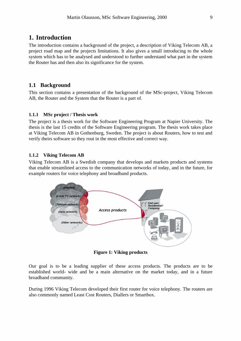
1.1.2 Viking Telecom AB Viking Telecom AB is a Swedish company that develops and markets products and systems that enable streamlined access to the communication networks of today, and in the future, for example routers for voice telephony and broadband products.
Figure 1: Viking products
Our goal is to be a leading supplier of these access products. The products are to be established world- wide and be a main alternative on the market today, and in a future broadband community. During 1996 Viking Telecom developed their first router for voice telephony. The routers are also commonly named Least Cost Routers, Diallers or Smartbox.
Martin Olausson, MSc Software Engineering, 2000 10
Viking Telecom has further developed their routers to include a complete family of products, CallCorrect Routers, for both analogue (PSTN) and digital (ISDN) telecommunication. They have also developed a Management system for update and control of the routers. The CallCorrect product family have gradually been developed to correspond to their customers’ demands concerning increased functionality, cost efficiency and contingency to implement value added services.
1.2 Introduction This Introduction to the system is meant to give a brief understanding and a picture of how it works.
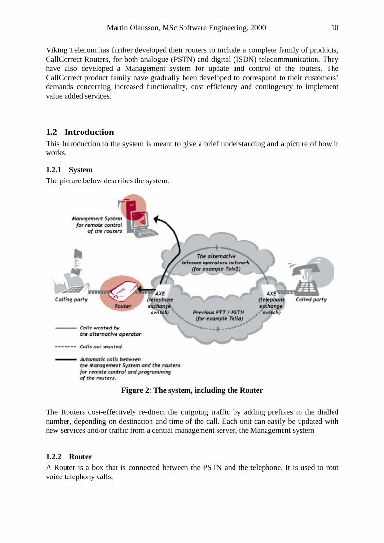
1.2.1 System The picture below describes the system.
Figure 2: The system, including the Router
The Routers cost-effectively re-direct the outgoing traffic by adding prefixes to the dialled number, depending on destination and time of the call. Each unit can easily be updated with new services and/or traffic from a central management server, the Management system
1.2.2 Router A Router is a box that is connected between the PSTN and the telephone. It is used to rout voice telephony calls.
Martin Olausson, MSc Software Engineering, 2000 11
The user can connect to the PSTN and add a Prefix Operator to the call without changing his or her dialling habits. The Router, routs telephone calls, both analogue and digital, meaning it reads the number that the user dial, rout it and then send it to the PSTN. The routing can be done in many different ways such as the dialled number can be changed, digits can be added, removed or it can be passed through without doing anything to it. The purpose with a router is to get your phone call handled by the operator that you want. It can be of a lot of different reasons that you want your call to be handle by a specific operator, such as one is cheaper to call with than the others, the call don’t get interrupted so often, the transfer is of a high quality or the phone call gets connected faster.
1.3 Project road map The project presents how the development process of a test program which will test Routers’ of different models. Section 1: will start with an introduction to the project, which contains of a background to both the project and to Viking Telecom where the project has taking place. It will also contain what’s being in this report and also in the project. Section 2: shows the research part of the project. It will describe which approach that had been chosen, description of the different development techniques, the development of the requirements and a bit of the testing. Section 3: will start to focus more on the project and the development of the test program. In this section there are a feature list, use case diagram and description of the whole system and its different units. It will also contain an extra detailed description of the Routers functionality, telephone calls and different types of telephone calls. Important information about the database structure and different diagrams as class and sequence of the project will be in here too. Section 4: are only about the test. It will describe different things around the test like the software, system, the Router and its routing methods, the test properties and specification. The test produce test results and how this had been created and how to read them are also shown in this section. Section 5: will contain of a conclusion of the whole project. It is containing different parts such as the Router, Software Test and it will also be a subsection with Further development of this project.
Martin Olausson, MSc Software Engineering, 2000 12
1.4 Limits This Report will not contain things like
• Detailed descriptions of different routing algorithms. • How the PSTN works. • Hardware description of the different units that the system contains of, only a small
introduction of how they behave. • Only an overview of how to get the information from the database to the program, no
SQL queries, queuing technique or accessing procedure will be detailed described. • Documentation about the research for testing software. • Nothing about the Management system will be in this report. • The test program will only test the Router’s routing decisions. • Source code of the test program.
Martin Olausson, MSc Software Engineering, 2000 13
2 Research The research part contains some of the most important part of the project. It is also important to get all the research that is needed to a project like this.
2.1 Project requirement One of the important things in the project is that the people that are going to use the developed program also can come up with some comments how it should work, what it would test and how it would be designed by keeping future development in mind. As Jacobsen, Christerson, Jonson, Övergaard (1995) say it is an aim to divide the complicated development of a large system, as I think this is into a number of activities and then let some people comment it and give their opinion about the system.
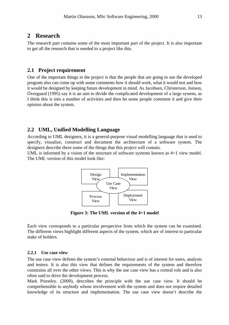
2.2 UML, Unified Modelling Language According to UML designers, it is a general-purpose visual modelling language that is used to specify, visualize, construct and document the architecture of a software system. The designers describe there some of the things that this project will contain. UML is informed by a vision of the structure of software systems known as 4+1 view model. The UML version of this model look like:
DesignView
ImplementationView
ProcessView
DeploymentView
Use CaseView
Figure 3: The UML version of the 4+1 model
Each view corresponds to a particular perspective from which the system can be examined. The different views highlight different aspects of the system, which are of interest to particular stake of holders.
2.2.1 Use case view The use case view defines the system’s external behaviour and is of interest for users, analysts and testers. It is also this view that defines the requirements of the system and therefore constrains all over the other views. This is why the use case view has a central role and is also often said to drive the development process. Mark Priestley. (2000), describes the principle with the use case view. It should be comprehensible to anybody whose involvement with the system and does not require detailed knowledge of its structure and implementation. The use case view doesn’t describe the
Martin Olausson, MSc Software Engineering, 2000 14
organisation or the structure of a software system, its role is to impose a constraint the designer, who must come up with a structure that will provide the functionality specified in the use case view.
2.2.2 Use case driven design Part of the development process is the design and it can be use case driven. There are advantages that belong to a design, driven by the use case. If the router changes, the system behaviour had to be changed, the only thing that had to be done then is to remodel the appropriate actor and use case. The whole system architecture will be controlled from changes made to the router. As it is traceable through all the models in the whole system it is possible to modify the system to the new changes with just change in the models that are affected by this new changes.
By the use case driven design it is by Jacobsen, Christerson, Jonson, Övergaard (1995) appropriate to develop interfaces of the use cases. A prototype of the user interface is a perfect tool to simulate the use case for the user. By showing the user the different views of the prototype program it is possible to get a conception of what the user want to see when the whole system is built. It is now easy for the designer to talk to the user and have a good understanding for what both of them is meaning when they talk about the system. It is then often appropriate by Jacobsen, Christerson, Jonson, Övergaard (1995) to sketch a logical and surveyable domain object model of the system. Such a model should consist of problem domain objects and serve as a support for the development of the requirements model.
Both Mark Priestley. (2000) and Jacobsen, Christerson, Jonson, Övergaard (1995) want to have the use case model/view as the control of all the other models/views. They have both the same opinion about its stability to changes. According to Jacobsen, Christerson, Jonson, Övergaard (1995) the use case even gives a tool when testing the system, mainly during the integration of the testing. The use case model will also give some support when writing manuals and other operation instructions.
2.3 The developing of the requirements specification The primary input for the development of a system is the requirements specification. The requirements specification is going to be developed from the facts about the environment that the system is going to serve. It is the role of the system that its environment that are being identified and then the requirements are formulated in terms of the behaviour, which in this case is the router.
In this project the requirements specification had been important. It had also been important to use a development technique that can handle the difficulties by develop the requirements specification. For some systems the requirements specification is a dialogue between the customer and the producer, but in this project the situation is a little bit different. Like in other technical systems the software had to cooperate with other machines or software, so the software requirements of this system are given by the interfaces to the environments. As Jacobsen, Christerson, Jonson, Övergaard (1995, page 19) say, “it is practically impossible to foresee all the requirements of a system during the introductory specification work”. For handle the
Martin Olausson, MSc Software Engineering, 2000 15
difficulties when developing a good requirement specification, the incremental development technique was used in this project and it is also recommended by Jacobsen, Christerson, Jonson, Övergaard (1995).
2.4 The development technique There are several technique models such as Prototyping, Spiral, Waterfall model and the Rational Unified Process.
Before the description of the different techniques another question needs its answer, what is a technique? An answer of that is given by Derrick Morris, Gareth Evans, Peter Green, Colin Theaker. (1996, page 23), they define a technique as “A way of accomplishing a specific task that forms part of a method”.
Some of the main root causes that make the project to fail are according to Philippe Kruchten (1998),
• Ambiguous and imprecise communication, • Brittle architecture • Overwhelming complexity • Undetected inconsistencies in requirements, designs and implementation. • Insufficient testing • Subjective project status assessment • Failure to attack risks
To avoid that the project will fail these causes had to be avoided. The technique that handles these causes in the best way I think will be the best technique to use in this project.
2.4.1 Prototype technique The Prototype technique are often used when it is difficult to determine how a system is supposed to work, it could be of both technical and functional reasons. It can then help to develop a prototype of the intended system. A prototype often focuses on the properties that need further insight; it also allows a developer to experiment with different design options. As Jacobson, Christerson, Jonsson, Övergaard. (1992) A prototype serves as a complement to incremental system development. A specific advantage of a prototype is that it can serve as a means of communication between a developer and a customer. It is much easier to express a view that can be demonstrated and used than to express an opinion about a specification. This could be useful in this project since the router is still under development and new features are added all the time. The test application had to be flexible and the communications between the developer and the future users had to be close they had to understand each other very good.
2.4.2 Spiral technique The spiral model start from the center of the spiral and moves on like a circle with bigger and bigger radius. A project following this process goes through successive risk analysis, planning, requirements analysis, engineering and evaluation phases. According to Perdita, Stevens, Rob
Martin Olausson, MSc Software Engineering, 2000 16
Pooley. (2000) is the engineering phase involving design, implementation and testing. The numbers of iterations is arbitrary.
2.4.3 Waterfall technique Using the waterfall technique, Derrick Morris, Gareth Evans, Peter Green, Colin Theaker. (1996), they place all the phases of the development in strict time, sequence and makes each phase firmly dependent upon the completed results of the previous one. This doesn’t fit so well to this project, the waterfall model is not going to be used.
2.4.4 The Rational Unified Process The Rational Unified process is to treat the root causes, Philippe Kruchten (1998). That would not only eliminate the symptoms, it will also be in a much better position to develop and maintain quality software in a repeatable and predictable fashion. To treat this causes Rational have created what they call the “best practices”. These practices are:
1. Develop software iteratively 2. Manage requirements 3. Use component-based architectures 4. Visually model software 5. Verify software quality 6. Control changes to software
They are not called the best practices because you can precisely quantify their value but rather because they are observed to be commonly used in industry by successful organizations.
The best practices are all about commercially proven approaches to software development, when used in combination they strike at the root causes of software development problems, according to the Software Program Managers Network (2000). The Rational Unified Process is described for how a team should develop software but I think this way of thinking and the way of how they specify how a developing process should look like even could be applied to project with only one person, like this project for the test program.
This technique seems to be the best one for this project. It handles the causes that could make a project to fail and several of the Rational Unified Process techniques could be applied to this project such as the iterative way of working, to visually model the software that is being develop, identify the system’s true requirements-those that weigh most heavily on the systems technical goals-that is a continuous process.
2.5 Testing To test a product is relatively independent of the development method that is being used. The standard work on testing is still like Myers (1979) describes it. A more comprehensive description has been made of Sommerville (1989). According to Jacobsen, Christerson, Jonson, Övergaard (1995) testing can be divided into verification and validation. They can be summarized as two questions
Martin Olausson, MSc Software Engineering, 2000 17
Verification: am I building the system correctly? Validation: am I building the correct system? In this project it is important to have both of Verification and Validation in mind. How do I test my program, the router or the software inside the router? All these question don’t have a single answer, Jacobsen, Christerson, Jonson, Övergaard (1995) say that the first lesson about testing is that no one can never prove that a program never will fail; it can only be shown that it contains faults. If the test found many faults the test have been successful and not the opposite. If there is any faults when the test application is executed it had to be a fault either in the test application, the router, the software inside the router or in some of the external units but lets focus on the test application. Cyclic or iterative development of a software program includes a test development step. As Beizer (1983) points out, test development often reveals as many design problems as testing does, so it is desirable to develop the tests before writing the code. Watts S. Humphrey. (1998) Recommend that it would be an advantage of an early thinking about the test planning and development. It would force the developer, me to think about the product, which is this test application from a test perspective. As it is a test program that are being developed a lot of different perspectives had to be kept in mind, not only the development of the test application. The software and a little bit of the hardware that is being tested had to be thought about so it is not testing something it is not designed or meant to test, quite similar to Jacobsen, Christerson, Jonson, Övergaard (1995) validation question.
2.5.1 Code reuse The test application is going to test the router. How the Router is going to behave is described in the tables in the database. The Management system for this system gets all this information from the database. The operators’ uses the Management system to set up the database. To get the test system to get the same behavioural profile as the Management system the same source code are being used. According to Grady Booch (1998), it is a major benefit of object-oriented languages such as C++ to the degree of reuse that can be achieved in well-engineered systems. Grady Booch (1998) also talk about what a high degree of reuse mean. Some of the benefits are that, far less code had to be written for each new application; consequently, that it is going to be less code to maintain.
2.6 Conclusion: The conclusion of the Literature review end up with answers to some of the questions that had to be answered before and during the development of this project. Since this project is in the telecommunication area where things happen very fast and new routers are being developed or “old” routers are getting new features all time. This makes it more important that the software that is going to be developed fulfil the users requests and is doing what the documents and models describe. To get easily maintained software, the best approach to the project would be by use cases, even the design would be use case driven.
Martin Olausson, MSc Software Engineering, 2000 18
The modelling language will be UML. Testing is what the developed software is going to do. What is even more important is that this software are tested, evaluated, verified and checked before any conclusion can be made that it is the software/hardware, which is being tested that is not correct. According to Grady Booch (1998), it is easier to reuse code from the same language, this makes it easier to use the same code as the Management system uses, the answer of the question which language the system would be developed in, are C++.
Martin Olausson, MSc Software Engineering, 2000 19
3 Requirements and Implementations The product, which is going to be tested by a test application, is a Router. This Router is connected to an analogue telephone line in the PSTN, Public Switch Telephone Network. It provides functionality like LCR, Least Cost Routing.
3.1 Feature list
• A User Interface that will make it difficult for the user to make any wrong inputs to the program.
• It tells the Router to update before the test starts, which will make the application and the Router to always work with the same version of the routing tables since the application get the routing tables just after the Router.
• It uses the same information as the Router, which will make it possible for the test parameters to be less wrong.
• It avoids to get the information at same time as the Router get it from the database, just to get an extra check that the information had been transferred correctly.
• It tests the Router in the environment that it operates. • It will be able to discover if the Communication server don’t behave normal. • The program will discover if there is something wrong with the Modem or the DTMF
reader. • It tests the Routers different routing functions, that it makes the right routing decisions
according to different types of calls such as Exceptions, Conversions, Mobile, International, Long distance, City and Local, calls.
• It is possible to discover even if something outside the Router isn’t behaving, as it should.
• How specific tests have been made can be looked at any time, after the test if the test results have been saved.
3.2 General Use Cases The functionality of this program is described in terms of use cases. A use case is simply a description of a typical interaction between the user and the system resulting in something of value to the user. The use cases have an important part in this project. These are the ones that drive this development process forward. This section and the one that gives a more detailed description of the use cases will explain in a more concrete way how to use the advantages that are mentioned in Section 2.2.2, Use case driven design The use cases presented in this section are a general description of the use case. The use case descriptions are reintroduced further in this report but with more technical details.
Martin Olausson, MSc Software Engineering, 2000 20
Router
Communication Server
Test Router User
Start up program
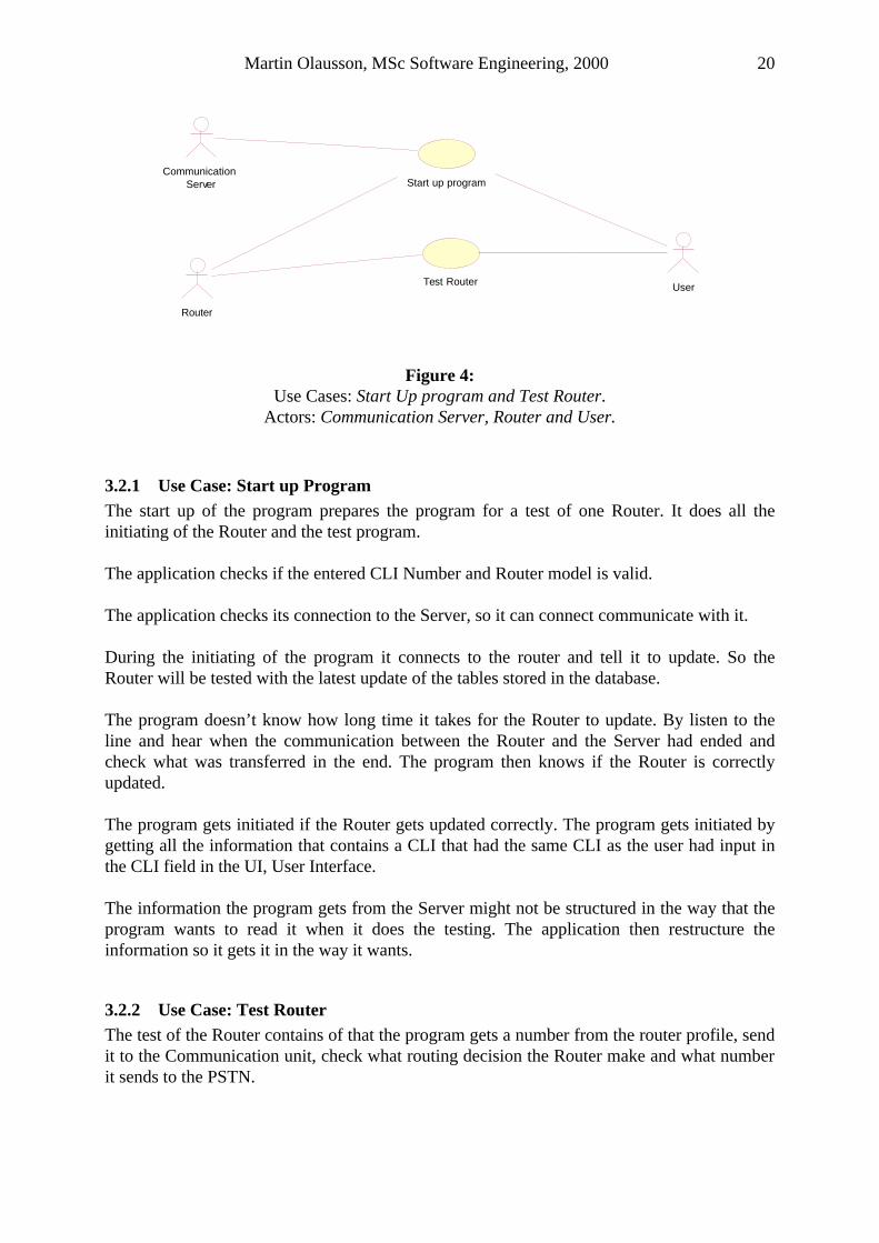
Figure 4: Use Cases: Start Up program and Test Router.
Actors: Communication Server, Router and User.
3.2.1 Use Case: Start up Program The start up of the program prepares the program for a test of one Router. It does all the initiating of the Router and the test program. The application checks if the entered CLI Number and Router model is valid. The application checks its connection to the Server, so it can connect communicate with it. During the initiating of the program it connects to the router and tell it to update. So the Router will be tested with the latest update of the tables stored in the database. The program doesn’t know how long time it takes for the Router to update. By listen to the line and hear when the communication between the Router and the Server had ended and check what was transferred in the end. The program then knows if the Router is correctly updated. The program gets initiated if the Router gets updated correctly. The program gets initiated by getting all the information that contains a CLI that had the same CLI as the user had input in the CLI field in the UI, User Interface. The information the program gets from the Server might not be structured in the way that the program wants to read it when it does the testing. The application then restructure the information so it gets it in the way it wants.
3.2.2 Use Case: Test Router The test of the Router contains of that the program gets a number from the router profile, send it to the Communication unit, check what routing decision the Router make and what number it sends to the PSTN.
Martin Olausson, MSc Software Engineering, 2000 21
All the numbers that will be tested are in the structure as the program built based on the information it got from the Server. Each number the Router receives will be treated separately. The Router makes a routing decision for each number and when it had reach a decision it sends the number to the PSTN. The different routing decisions can be of several different kinds such as, just let it through as it was received, and convert the received number to a new number or add/remove digits from the received one before sending it. For the program to get what routing decision the Router had made it had to listen what it sends to the PSTN. The program listens to the PSTN with the Communication unit and get what the Router sends. By listen and also receiving what the Router sends the program get the routed number. The program can do the test of a specific number when it got the routed number, the number it sent to the Router and the Routers time and date. By comparing the numbers, routed number and expected routed number the application can tell if the Router made the right routing decision or not. A test of a Router ends with a short summarise. This summarise will tell the user how many of the numbers that were successfully tested or how many that failed. The test result for each number can be saved and looked at later.
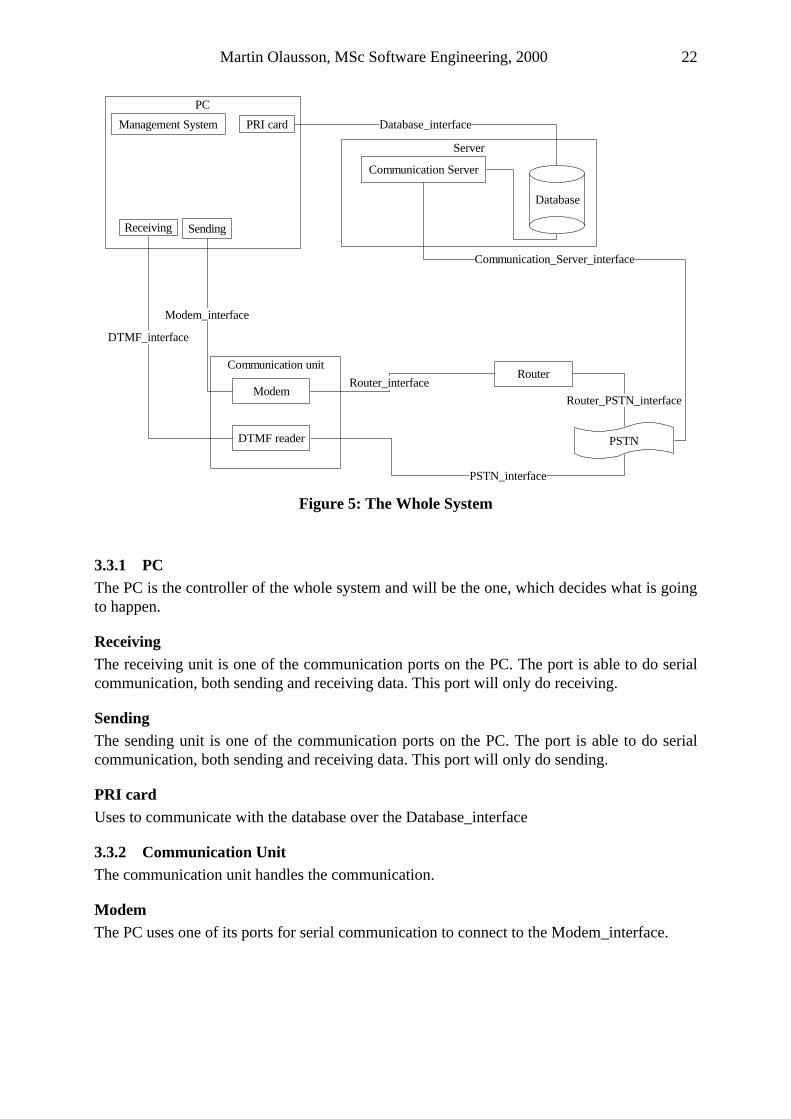
3.3 System description The Figure will give an orientation how the system is connected. Some of the parts had also been given names. Further on in this report these names will be used when a specific part of the system will be analysed. According to the research part of this project this picture will illustrate the deployment view of the 4+1 view model that is explained in Section 2.2, UML, Unified Modelling Language
Martin Olausson, MSc Software Engineering, 2000 22
PC
Router
PSTN
Communication unit
Modem
DTMF reader
Server
Communication Server
Database
PRI cardManagement System
SendingReceiving
DTMF_interface
Modem_interface
Database_interface
Router_interface
PSTN_interface
Router_PSTN_interface
Communication_Server_interface
Created with the Trial Edition of SmartDraw 5.
Figure 5: The Whole System
3.3.1 PC The PC is the controller of the whole system and will be the one, which decides what is going to happen.
Receiving The receiving unit is one of the communication ports on the PC. The port is able to do serial communication, both sending and receiving data. This port will only do receiving.
Sending The sending unit is one of the communication ports on the PC. The port is able to do serial communication, both sending and receiving data. This port will only do sending.
PRI card Uses to communicate with the database over the Database_interface
3.3.2 Communication Unit The communication unit handles the communication.
Modem The PC uses one of its ports for serial communication to connect to the Modem_interface.
Martin Olausson, MSc Software Engineering, 2000 23
DTMF reader The DTMF reader is like a converter between the two interfaces, PSTN_interface and DTMF_interface. To the PSTN_interface it communicate with DTMF signals and to DTMF_interface it communicates with RS232.
3.3.3 Router The Router can be of model D1, D1+, D2 orD3.
3.3.4 PSTN PSTN is where the Router is going to operate.
3.3.5 Server The server contains of the database and will be the unit except the PC that handles all the events and decisions outside the PC.
Database The database contains all the tables with information about how the Router should behave. It is here the Trig Number, Group Number and the Configuration tables are stored.
Communication Server The communication server handles the communication between the Router and the database.
3.3.6 Interfaces The interfaces act like interfaces between the different parts. They are also a big help when the system is being described and explained to someone else that haven’t been involved during the development.
3.3.7 Configuration The PC and Modem had to be configured for the program would work.
ODBC An ODBC had to be configured for the PC. An ODBC System stores information about how to connect to a data provider that is indicated by the user. If no ODBC is configured the program wouldn’t get any connection to the database. The configuration contains of defining a name of a database, login to a database, the name of a server that the application are going to connect to and what kind of driver it will use.
Modem For the program would be able to send it uses a modem. If the shall work as the program want it to do, it also had to be configured.
DTMF reader The DTMF reader doesn’t have to be configured. It operates with constant values.
Martin Olausson, MSc Software Engineering, 2000 24
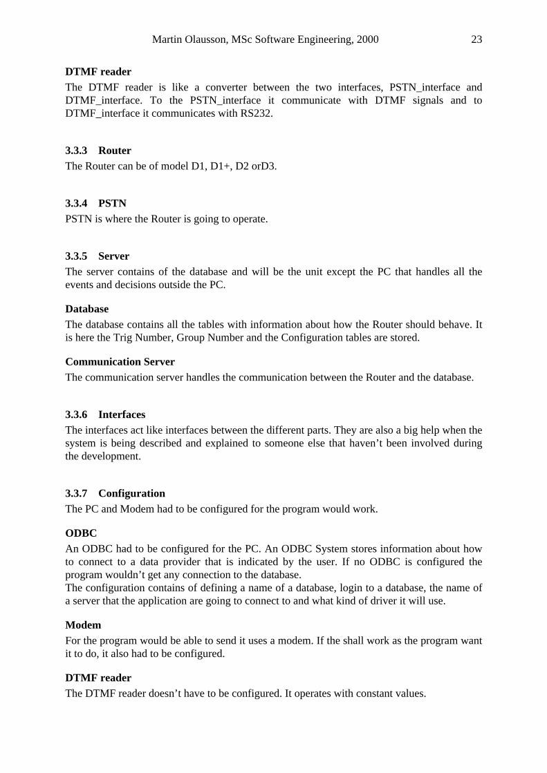
3.4 Telephone call A telephone call could look different depending on what number the user had dialled, where the destination of the call are and from where the user are making the call. For clearance and to make it easier to understand the functionality of a Router an example of a telephone call is shown below. The chosen call is a long distance call with an area code. Settings:
Telephone number: 4554675 Area Code: 0131 Carrier: BT Operator prefix for BT is here chose to be 9501
0131 4554675 9501 0131 4554675
Figure 6: Telephone call
The top line in Figure 6, Telephone call will show what the user will dial with the telephone. The bottom line in Figure 6, Telephone call will show what number that a Router will send if it is set up as the settings.
3.5 Router functionality When the Router has get aware of that an outgoing call is about to take place, when enough digits dialled from the telephone are registered and stored by the Router. The registered digits are compared to routing data that the Router contains of. The Router receives and stores digits until it has received enough to manage to make a routing decision.
3.5.1 Why different telephone operators? It can be many reasons for a caller to chose different operators such as economical, one operator may be cheaper than another, the operators reliability can be different, a particular type of calls could only be done with some operators.
3.5.2 What does the Router do? When the Router had been set up it can chose between different operators depending of which the caller want it to use. Each operator has a unique prefix that will be added to the call. This is mainly what the Router does. How the Router add the Prefix to the call can be done in many ways depending on what type of call it is, what time it is or how the Router would rout it.
Martin Olausson, MSc Software Engineering, 2000 25
3.5.3 Different kind of routers It doesn’t matter what kind of telephone the user uses to make the telephone call, the Router suits the most of them but the ISDN telephones need another type of Router but it work in the same way as the ordinary ones. It is not possible to use a Router when making a telephone call with a Mobile telephone because in that case you have already chosen your operator. If you want to use a wireless telephone, a telephone with loudspeaker or making a telephone call to a mobile phone you can use the ordinary Router. It is just to connect it as shown at Figure 2, the System.
3.5.4 What does the Router contain? The Router contains of two copies of routing information. One set of routing information known as the current/working tables that is used for the routing operations and one set of tables that are known as the alteration tables on to which remote configurations are applied and upon activation copied to the working tables. This scheme serves two purposes. Firstly security, in case of a failed remote programming, in which case the alteration tables can be restored by copying the working table. Secondly it provides a possibility to upload new routing configuration in advance for activation at a later date.
3.6 Different call types There are different types of telephone calls. They can be split up into mainly two different parts, the Trig number part and the Group Number part. These parts can also be split up into smaller parts like the following sections. All these parts are stored in different tables in a database. The routing decision that the Router does don’t only depend of the call type, it also depends on the day and the time. By split the calls into different sections there would be easier to keep control of which types of calls that are working. It will also be a good example to show the use a good development technique. According to Section 2.4.4, The Rational Unified Process this shows that the iterative technique can be very useful in this kind of situation. The development of the software for one type of calls can be fully developed and implemented before starting with the next one. That will make it easy to keep control of the changes. The visual models of the software could be updated with the extension of the new types of calls.
3.6.1 Exception calls Exception calls are defined as numbers that should not be routed. This type of call the Router send exactly as it receives them, nothing is done with them. Exception calls are defined in the database in the Exception tables. They would exist at 2 different levels, at Group Level in form of Global Exceptions and at Trig Number Level as Local Exceptions. If a number matches a trig-number in an exception type entry it will always be excluded from routing. An example of an exception call is an emergency call, which should in no circumstances have a prefix added to it.
Martin Olausson, MSc Software Engineering, 2000 26
3.6.2 Conversion calls A call that would be recognised, as a Conversion call would be changed to another number rather than have a prefix added to it. Conversion calls are defined in the database in Conversions tables. They exist at Group level and Trig Number level. Information from the database for conversion calls isn’t the same for D1 and D2, but the Routers routing decisions are the same. These types of calls have the highest priority. The Router routs the incoming number to a different outgoing number, i.e. convert 654321 to 112233. The router receives 654321, routs it to 112233 and then sends it. The Conversions for the D2 router will be routed differently depending on which date and time it is when the number gets to the Router.
3.6.3 Local call The Local call holds the area code for the home area where the Router is installed. It knows about the home area code and can look in the local call table to see if the call hit any of the Trig numbers there, if it is a hit then the call is a local call. It then also determines which Routing method that is going to be used.
3.6.4 City call When the Trig Number found an entry hit in this Table it will have a prefix added in front of it that is selected from another table depending on which day it is.
3.6.5 Long distance call Long distance calls are similar to City calls and will be routed in the same way.
3.6.6 User Defined call 1 User Defined call 1 is being routed as City calls.
3.6.7 User Defined call 2 User Defined call 2 is being routed as City calls.
3.6.8 Mobile call Mobile calls are looking for a Trig number in its Tables, when it finds one, a carrier is selected and its prefix is added to the call. Different telephone operator is being chosen depending on which day and time it is.
Martin Olausson, MSc Software Engineering, 2000 27
3.6.9 International call The International call will look in its Trig table to find a hit, if it gets one a prefix will be added. It would chose of a table of a type with two operators. One is going to be the primary and the other is being the secondary operator. The decision is depending on the day and the time.
3.6.10 Prefix A prefix is added to a call to describe which carrier or operator it uses. Depending of what type of call it is, Mobile, International, Local or National (City, Long distance, User1 orUser2) the prefix is added in different ways. The call that the Router sends to PSTN is always based on the same structure, this is shown at Figure 6, Telephone call
3.7 Database Structure This section will give a description of the structure of the database and also some help to understand how it is designed. The database contains of a lot of data but the program doesn’t need all of it. The data that the program needs is about the Router and how it should behave. Information from the database that doesn’t contain anything about the routing decisions is going to be sorted out when the program is doing the structuring. Each Router can be identified by its CLI. The CLI is like a Router Identification Number. To get all the information that’s needed for testing the Router, its CLI had to be known. All the tables in the database can be referred by a Router’s CLI. Everything that contains information about a specific Router and how it should behave at a specific time can be described in a Profile. By knowing the Router’s CLI it is possible to get the PID, Profile Identification Number. If the PID is known then the Group Table Set Id and the Trig Number Table Set Id are known too. By Trig Number Table Set Id and Group Table Set Id it is possible to get all the Trig number tables, Group tables and Configuration tables that are in the database for a specific Router. A Trig Number has a set of configuration tables associated with it. The Trig number tables are of call type, how the Router finds out what type of call it is receiving. Each table in the database has a name so it can be identified; each row has a unique identifier, a primary key, which is a unique identifier to each table entry or maybe a composite of several columns.
3.8 Detailed Use Cases This section will specify the Use cases a bit more than section, General Use Cases. It will describe the Use cases in a more technical view.
Martin Olausson, MSc Software Engineering, 2000 28
3.8.1 Start up program The fields in the UI for the user to input data to are, login to database, the CLI number and type of Router that shall be tested (D1, D2 or D3). The program instruct the Router to make a server call and will by that get the latest version of the tables in the database. The call is initiated by using a unique code. The call is taking care of by the Communication unit, Figure 5. It is the modem that handles all the sending. The program presumes that after the Router had made the server call and then get on-hook and the controlling are correct the Router would be updated. If this isn’t the case and the user will notify it anyway, then in the end of the test none of the numbers will be routed. Connected to the database the program gets all the information it needs for the specific Router that will be tested. This information is in Trig Number tables and Group Number Tables. This information had to be structured and organized so it can easily be read by both the user and the program. The program will need all this information when it does the test and the test report. For the D2 router the Conversions type calls can be different in up-to 12 time zones. The Router rout differently depending on which day type and time it is. For the program should be able to test all the different combinations and types of numbers that exist, all the numbers had to be unique or else the program do a priority of the numbers. The routing decisions that contains of only a few numbers i.e. a conversion that convert a number that begins with 123xxx to 444xxx . The program will in this case change the xxx to some random numbers and then check them so it only fulfils this specified condition. If it would happen that it fulfil more than one condition the random numbers had to be changed.
3.8.2 Test Router When doing the testing the program had to check what number it sends and the time and day the Router has for being able to check if it is doing the right routing decision. After the program had received the routed number, it had to look in the routing profile to get the other number it would compare it with. By comparing the routed number with the number that the Router was expected to send it can decide if the Router made the right routing decision. All the information that are available for testing one number such as sent number, routed number, expected routed number, time and day type for the test are being saved after the test if the user want to.
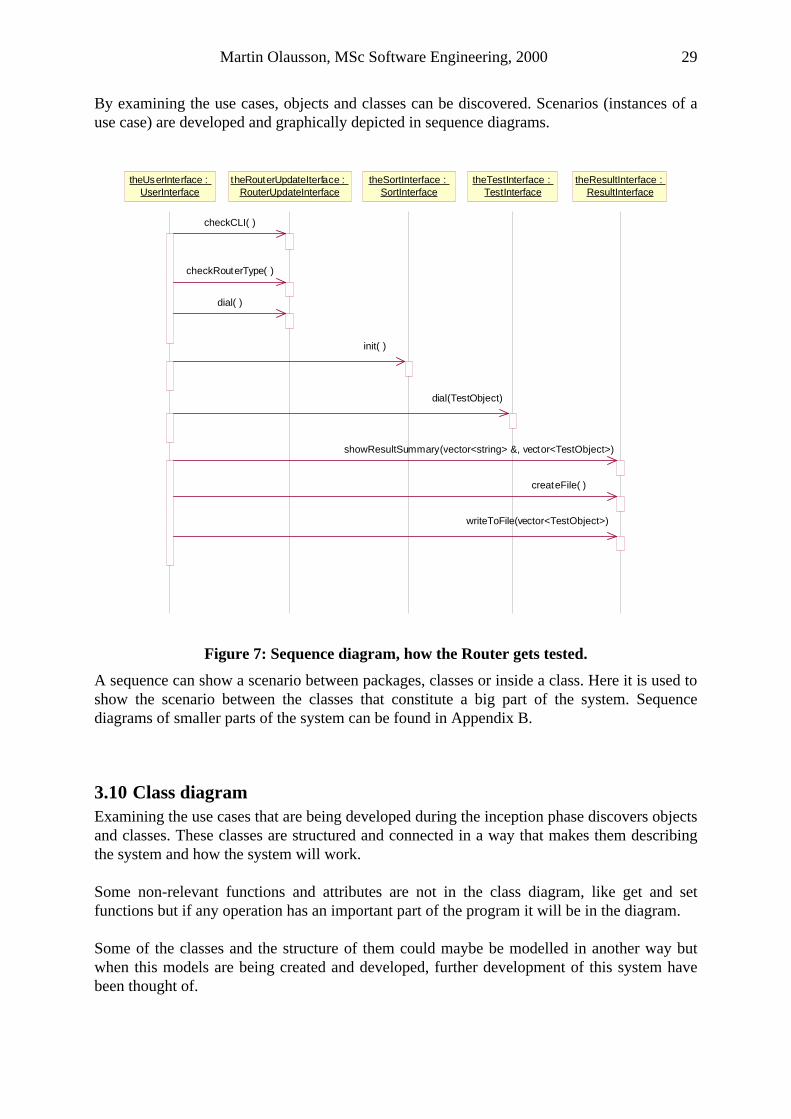
3.9 Sequence diagram A Sequence Diagram is a realization of a use case. It is typically one path through the flow of events for the use case. Sequence diagrams contain objects and messages between the objects that show how the behaviour is realized.
Martin Olausson, MSc Software Engineering, 2000 29
By examining the use cases, objects and classes can be discovered. Scenarios (instances of a use case) are developed and graphically depicted in sequence diagrams.
writeToFile(vector<TestObject>)
theUserInterface : UserInterface
theRouterUpdateIterface : RouterUpdateInterface
theSortInterface : SortInterface
theTestInterface : TestInterface
theResultInterface : ResultInterface
checkCLI( )
checkRouterType( )
dial( )
init( )
dial(TestObject)
showResultSummary(vector<string> &, vector<TestObject>)
createFile( )
Figure 7: Sequence diagram, how the Router gets tested.
A sequence can show a scenario between packages, classes or inside a class. Here it is used to show the scenario between the classes that constitute a big part of the system. Sequence diagrams of smaller parts of the system can be found in Appendix B.
3.10 Class diagram Examining the use cases that are being developed during the inception phase discovers objects and classes. These classes are structured and connected in a way that makes them describing the system and how the system will work. Some non-relevant functions and attributes are not in the class diagram, like get and set functions but if any operation has an important part of the program it will be in the diagram. Some of the classes and the structure of them could maybe be modelled in another way but when this models are being created and developed, further development of this system have been thought of.
Martin Olausson, MSc Software Engineering, 2000 30
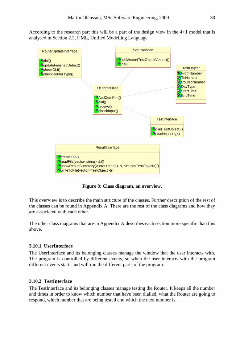
According to the research part this will be a part of the design view in the 4+1 model that is analysed in Section 2.2, UML, Unified Modelling Language
UserInterface
ApdComPort()dial()receive()checkInput()
ResultInterface
createFile()readFile(vector<string> &)()showResultSummary(vector<string> &, vector<TestObject>)()writeToFile(vector<TestObject>)()
TestInterface
dial(TestObject)()receive(string)()
RouterUpdateInterface
dial()updateFinishedDetect()checkCLI()checkRouterType()
TestObject
FromNumberToNumberRoutedNumberDayTypeStartTimeEndTime
SortInterface
addVector(TestObjectVector)()init()
Figure 8: Class diagram, an overview.
This overview is to describe the main structure of the classes. Further description of the rest of the classes can be found in Appendix A. There are the rest of the class diagrams and how they are associated with each other. The other class diagrams that are in Appendix A describes each section more specific than this above.
3.10.1 UserInterface The UserInterface and its belonging classes manage the window that the user interacts with. The program is controlled by different events, so when the user interacts with the program different events starts and will run the different parts of the program.
3.10.2 TestInterface The TestInterface and its belonging classes manage testing the Router. It keeps all the number and times in order to know which number that have been dialled, what the Router are going to respond, which number that are being tested and which the next number is.
Martin Olausson, MSc Software Engineering, 2000 31
3.10.3 RouterUpdateInterface Before the test starts the program had to make sure that the Router contains of the latest version of the Tables that are in the database. It starts with checking that the CLI number that the user had input is valid and that the Router model is valid too. If both the CLI number and the Router model are valid the program tell the Router to update and download the latest version of the tables that are in the database.
3.10.4 SortInterface After the Router is updated the program need to get the same information that the Router got, just to be able to know what the Router is going to respond when calling different numbers. This information is stored in a database in different tables. For the program to be sure that it gets the same information it will use the same software as the Management system do. The program doesn’t need all the information that the Router does and the information are also being treated in a totally different way comparing with the Router. The information are being structured in the SortInterface and its belonging classes, to something that can be called a Router behaviour profile. The behaviour profile contains information such as what number is being dialled for the Router to rout, what number is it suppose to send according to the database information, what number does it actually sends, what is the Router’s time and date.
Martin Olausson, MSc Software Engineering, 2000 32
4 Test The test chapter contains of different subchapters, what is being tested, how is it tested, software structure, how looks the User Interface and how to read the results of the test.
4.1 Test Specification The test specification is about what the program actually test and how it is going to test it.
4.1.1 What is being tested? The main thing is to test the Router’s software. It is not easy to test software and it can be done in many ways. This test program will test the Router by sending different types of telephone numbers to it. After the Router had been tested by this program it is not a guarantee that it will work but the main things that the Router are supposed to do will be tested. Not every possible type of phone call can be tested, that would be impossible and the market would not want the Router at the time that the test will be finished. A test can take a long time, it is depending on how many calls that are being tested and how many of the features in the Router that is being tested. The Router contains of more information than just how routing telephone calls. These other information will not being tested by this program because this program will only test the Router’s behaviour according to rout telephone calls.
4.1.2 Testing the Router’s software There are different opinions how to test software. The software in the Router is not easy to test. In this case I have chose to test the Router’s functionality, which leads to testing its software. The Router routs telephone calls. This program will simulate different telephone calls. By sending these calls to the Router and listen to the PSTN what the Router sends the program knows how the Router is going to rout it. It can then do a comparison between these numbers and if they are equal the Router behaves and rout, as it should. This will also mean that the software in the Router will work.
4.2 Software Description The software inside the Router or any of the other units that contain software is not going to be described. It is only the test program that is being described. No source code is being put into this report. The software is based upon a Main Form and the user controls it. The user start different events and that leads to that different parts of the software will start to execute. The different parts that will start to execute can be symbolised by the subchapters below.
Martin Olausson, MSc Software Engineering, 2000 33
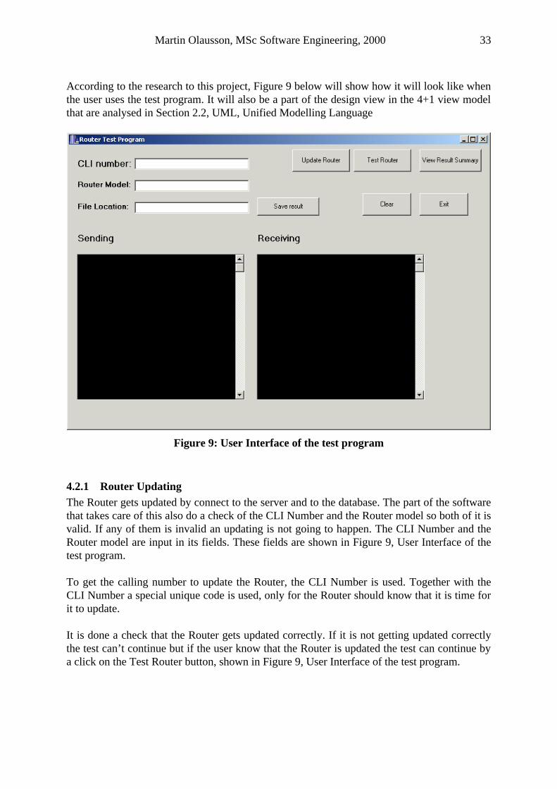
According to the research to this project, Figure 9 below will show how it will look like when the user uses the test program. It will also be a part of the design view in the 4+1 view model that are analysed in Section 2.2, UML, Unified Modelling Language
Figure 9: User Interface of the test program
4.2.1 Router Updating The Router gets updated by connect to the server and to the database. The part of the software that takes care of this also do a check of the CLI Number and the Router model so both of it is valid. If any of them is invalid an updating is not going to happen. The CLI Number and the Router model are input in its fields. These fields are shown in Figure 9, User Interface of the test program. To get the calling number to update the Router, the CLI Number is used. Together with the CLI Number a special unique code is used, only for the Router should know that it is time for it to update. It is done a check that the Router gets updated correctly. If it is not getting updated correctly the test can’t continue but if the user know that the Router is updated the test can continue by a click on the Test Router button, shown in Figure 9, User Interface of the test program.
Martin Olausson, MSc Software Engineering, 2000 34
4.2.2 Sort Database information The program needs the information from the database about how the Router will rout the calls. This information is unstructured and not organised in the way that the test program wants it to be. When this information gets structured and organised it will constitute as a Router profile, meaning it will tell how the Router is going to behave and rout different types of calls in different situations. After the program got all the information, it structure and organise it, there might be some numbers that is to short, contains of too few digits if it is compared to a real telephone number. If this is the case some random numbers will be added.
4.2.3 Test The Router is getting tested by different numbers are being sent to it. The Router receives the numbers, rout them and send them to the PSTN. The test part of the software gets the Router profile that had been created in Sort Database information part of the software. The test part does exactly as it is in the Router profile and then also adds the results of the test to the Profile. Everything that the test part had to know is in the profile so it only had to follow that.
4.2.4 Result Some parts of the result are already created when this part of the software starts, it had been added by the Test part. The Result Part get the Router Profile from the Test Part and it then create a result Summary containing a summary of the whole test. It contains a summary of how many numbers that have been tested, how many of them have been routed correctly or incorrectly and then also a list that contain all the numbers that have been routed incorrectly including all the information about these specific numbers.
4.3 System description in a view of testing During the testing the whole system are not being used, such as the server and the database. Even if these parts are not needed during the test they are important and the system will not be able to do the test without them. There will be a short description of the parts of the system that are being used during the test such as modem, DTMF reader, router and the test program.
Modem If some parts are sending or not, the modem doesn’t care about that, it only sends to the Router what is being sent to it. To prepare so it not will send when the PSTN is occupied it get a message from the DTMF reader that the PSTN is unoccupied. After it has sent what it had been told to send it doesn’t do anything else, just wait.
Martin Olausson, MSc Software Engineering, 2000 35
DTMF reader Everything that is being sent over the PSTN the DTMF reader will listen to. If there is any information of use such as when the PSTN is occupied or unoccupied, the updating of the Router had been done correctly or when the Router sends something. It also gives an indication to the modem when the PSTN is unoccupied so it knows when it can send.
Router The Router will rout telephone calls. It will rout them as the tables in the database have told it.
4.4 Test properties To make the test to be as close as possible to the reality a few things had to be thought of a little bit extra.
4.4.1 Same information in both the Router and the program It is difficult to test software, but a way that would make it a little bit easier is to use the same software when getting the same information from the same external units. The Router gets some of its information from a database and to be able to test the Router, the program need some of the same information. This information is also needed by the Management system and by using the same code, as the Management system the test program can be sure that it gets the same information. There would also be a good example of code reuse as mentioned in Section 2.5.1, Code reuse. This will also mean that it would be less code to check during the development process for this test program.
4.4.2 Random numbers in the calls To make the test calls as similar to a real telephone calls as possible the program are adding random digits to some of the numbers. If a number contains of just a few digits and cannot be compared to a similar telephone call a few digits are added to it. This is done in both of the numbers, the numbers that are sent to the Router and the number that it is suppose to receive. This will make that all the numbers that are being sent to the Router are of the same length but it is not sure that they are of the same length when the Router sends it to the PSTN that is depending on the routing decision.
4.5 How to read the test results The test results are being created when the test is finish. The results show how each number is tested and if it is routed correctly or not. A call that is routed correctly is a call that is routed as the tables in the database are set up to rout this type of call.
Martin Olausson, MSc Software Engineering, 2000 36
The results then are a comparison between what the Router routs and send to the PSTN and what’s in the tables in the database. If these numbers are equal the call is routed correctly, and if they are not equal the routing have been incorrectly. This is being showed in the test results in the two columns, ToNumber and RoutedNumber. ToNumber column: is showing what the Router is supposed to send to the PSTN after it has done its routing decision. This number the program get directly from the database and if it is not long enough a few digits had been added. RoutedNumber column: is showing what the Router actually sends to the PSTN. This number the program gets by listen to the PSTN with the DTMF reader. If the test results seems to be right but there still is some error. Then there might be an error in the test program. A method to discover errors in the test program have not been included in the test results, an indication of an error in the test results doesn’t always mean that it is the Router that have made a wrong routing decision. It might be some of the other parts in the system that is not acting correctly.
4.6 How the Router rout different types of calls How the Router routs the different types of calls is decide by the routing algorithms. These algorithms are not being described here but the theory behind it is.
4.6.1 Theory behind the routing algorithms The router try to find a match for the first digits of the telephone number as soon as possible and it doesn’t receive all the numbers that the call contains of before it start to make its routing decision. After the router receives each digit of the number it looks in its table and try to find a match for the number after so many digits as it has received. If it finds more than one match in its tables it doesn’t make any routing decision, it only waits to receive another digit of the number. The Router will continue doing this until it only get one match for this specific number then it make its routing decision and start to send the new routed number. There could be an unwanted situation, when the Router had received one or more digits and get several matches, it wait for another digit. When this digit is received and the Router looks in its tables it might not get a match. If this situation appears it does it routing decision by the prioritising of the call type. By looking at the matches for the last time it got any it looks where in the tables these matches are and what kind of call type it is. Depending on the call type of the matches it looks which call types that have the highest priority. It routs the call by the match that had the highest priority.
4.7 Different Routing Methods The router has built in algorithms for determine which routing method to use for different types of calls. The different methods are not going to be fully described but an overview of the different call types and how they are being routed are given.
Martin Olausson, MSc Software Engineering, 2000 37
4.7.1 Exception routing methods The exception calls are being forwarded through the Router without the Router doing any routing.
4.7.2 Conversion routing methods A number that is determined as a conversion number will convert the whole number as it is and rout it to the new converted number.
4.7.3 Local calls routing methods The routing methods for local calls could be of two different types. It depends if the home area code is configured.
Home area code is configured The local area code is put between the carrier prefix, obtained from the routing decision, and the subscriber number.
Home area code is not configured The carrier prefix, obtained for the routing decision, is put in front of the subscriber number.
4.7.4 National calls (City, Long distance, User 1 and User 2) The carrier prefix is put in front of the subscriber number including the area code.
4.7.5 International calls routing methods International calls can be routed with two different methods. It is depending on if a common international access code had been defined.
A common international access code had been defined The common international access code is put in between the carrier prefix, obtained from the routing decision, and the subscriber number including the country code.
A common international access code had not been defined The carrier prefix, obtained from the routing decision, is put in front of the subscriber number including the country code.
Martin Olausson, MSc Software Engineering, 2000 38
5 Conclusion This conclusion part will give an evaluation and summation of the project. It will look at different parts as Router, Software, Test, Project and Further development.
5.1 Router There are different methods to use to test software. The method for testing the software in this project has been by testing its functionality. It seems to work well so the choice might have been right. The Router has more information and facilities than this program is testing but there wouldn’t be any difficulties to extend the program to test that too. For this project there was no use of these facilities, it was the Router’s routing decisions that were meant to be tested this testing program. There are Routers constant under development. This program could work for the new Router models too but since they still are under development and their facilities haven’t been decided yet so no correct answer can be given on this question.
5.2 Software The software has been developed with thoughts about further development and that it would be possible to test other router models with the same software. For this project it looked like it was better to write the software in an object-oriented language. This choice was based on that it was then possible to use the facilities that belong to software written in an object-oriented language. The facilities that have been used or will be used in the future is for maintain, modify or extend the software. There does exist models, diagrams, and technical written documents that will show the architecture behind the software and also how it has been developed. These could be read, analysed and understood by future developer. It would make it a lot easier for the developer to work with the software and also save a lot of time instead of developing the whole system one more time. The software is today working for several Router models, and it is prepared for other models but it isn’t fully tested for those yet. If there would be more features added to the already existing models or if more models are being developed the program wouldn’t need that many changes because it is prepared and have been developed with that in mind.
5.3 Test There are many different opinions of how to test software and which way that is the best. In my opinion every software project is unique and had to be treated in that way. It is not easy to chose the right testing method but by looking at each software project and know exactly what it is going to test, it would make it easier to chose the right testing method. An important thing
Martin Olausson, MSc Software Engineering, 2000 39
to keep in mind is that it should always in some way relate to the product requirements. This will make the testing test what it is created for. This test program tests the Router’s software but it also indicates that there are some obvious things that are wrong with the other parts of the system. This includes the test program. The test program test the Router’s ability to rout different types of telephone calls. The test program will create results that contain all necessary information about the test such as the routed numbers, time and date for the routing.
5.4 Project This project has been fun to work with but difficult too. New things have happen all the time and the Routers’ get more and more complicated. I have got well aware of that developing software is not only to produce source code, that seems to be one of the smallest part of a software project. To work, as Software Engineer is a lot more than writing code there are all kinds of problems that had to be solved and if they are not possible to solve you had to work around them. Writing technical documents and model the software are very important parts during the development process. For the users of the software the documents and diagrams will be useful so they could understand what it does and what it is meant to test. For new developers who will maintain, extend or modify the software the technical documents and the diagrams would be useful, they will make it easier for them to understand the system. These documents and diagrams have been developed during the whole developing process and would give the new developer a good view at the systems from different perspectives.
5.4.1 Project approach It looks like the choice of approach to the project was right and the iterative way of thinking has been very useful for developing process of this software. Keeping in mind that the software might be further developed makes the choice of approach even more right. Thinking of the Router models that are being tested with this program have constant been under development, it was difficult to choose the right approach.
5.4.2 Research The time spent on research was very useful for the work with the project. The books, documents and specifications that have been read had to be understood or else I haven’t been able to produce any source code or technical documents. It is a testing program that had been developed. To be able to create such a program you had to know what is going to be tested, how it should work, how other part of the system could affect your testing object, how to minimize the part of the system that can go wrong, to discover if it is the testing unit that is wrong or some other part of the system, if it is the
Martin Olausson, MSc Software Engineering, 2000 40
hardware or the software that are not working properly. To be able to find answers to questions like this the research part has been very useful. Some parts took a little more time to find out the right answer to and other took not so long time, it might sometimes even be enough to ask someone that is working with the Routers. Every views of the 4+1 view model in Section 2.2, UML, Unified Modelling Language haven’t been in this report, the process view that shows the concurrency in the system haven’t be shown because there would not be an use of it.
5.4.3 Modelling language It was of big value to use a modelling language for the project. It was especially useful when it got necessary to specify and visualize the architecture of the software. Software Engineers in today’s work use it in their work and that was one of the aims with this project, to know how they work and what they use to solve problems.
5.4.4 Technical writing The project has given me a lot of useful experience of writing technical documents. These documents fulfil several purposes. In this case they have been of big value for the communication to, and understanding the people that works with the development of the Routers’. It also showed that it is of big value when you move to the next step in a project. If then someone forgets or people get different opinion how things should work, it is just to go back to the documents and see what’s in there.
5.4.5 Project Plan This project contains a Project Plan, Appendix E. My experience is that it is good to have one in the beginning of the project. After some time it should be possible to revise the plan. It is important to follow the plan as close as possible, but it is also necessary to do some exceptions from it. That might be both good and bad for the whole project. If some exceptions have to be done it is necessary to think of everything it might affect the whole project and its idea and economical status.
5.4.6 Used programs during development During whole project it has been necessary to use different programs for different purposes, the program that have been used the most of the time are shown below. Borland C++ Builder: The programming language is C++ and Borland’s development kit has been used to create the source code of test program.
Microsoft Word: To create the technical documents such as Requirement specification, Implementation documents, and this report have used MS Word.
Martin Olausson, MSc Software Engineering, 2000 41
Rational Rose: Rational Rose has been used to create the class and sequence diagrams and even the use cases.
5.5 Further development There are some further developments to do to this program especially since new router models are being still under development, this test program has been developed with that in mind. The development of Routers happens very fast and that leads to that the test program had to do the testing fast too. There is not that much time to save at some parts of the program but during the testing time when dialling and receiving, it would be possible to save some time. The Router uses the CLI Number to get identified with and that number and a special code is also used when calling the server. This presuppose that the Router always calls the server that it is pre-programmed to do, it would be good if the user have an option to use the already known code or if it wants the Router to update from somewhere else. If the same test is being used several times the program might not connect to the database every time, it would than be good to read all the necessary information from a text file and in that way make the testing time a little bit shorter and also to make sure that the same version are being used every time. The User Interface are adjust to people with computer knowledge and knows what a Router is and how it works, the User Interface could be more interactive so the user get more possibilities to test specific Router functions.
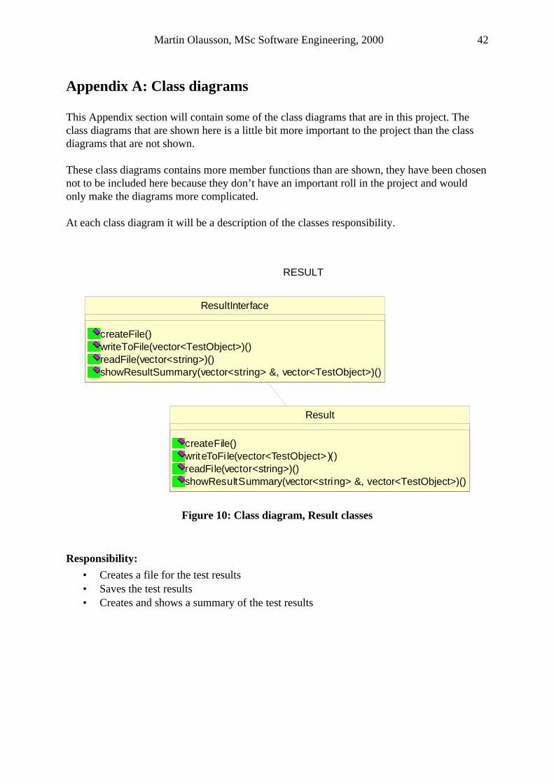
Martin Olausson, MSc Software Engineering, 2000 42
Appendix A: Class diagrams This Appendix section will contain some of the class diagrams that are in this project. The class diagrams that are shown here is a little bit more important to the project than the class diagrams that are not shown. These class diagrams contains more member functions than are shown, they have been chosen not to be included here because they don’t have an important roll in the project and would only make the diagrams more complicated. At each class diagram it will be a description of the classes responsibility.
Result
createFile()writeToFi le(vector<TestObject>)()readFile(vector<string>)()showResultSummary(vector<string> &, vector<TestObject>)()
ResultInterface
createFile()writeToFile(vector<TestObject>)()readFile(vector<string>)()showResultSummary(vector<string> &, vector<TestObject>)()
RESULT
Figure 10: Class diagram, Result classes
Responsibility:
• Creates a file for the test results • Saves the test results • Creates and shows a summary of the test results
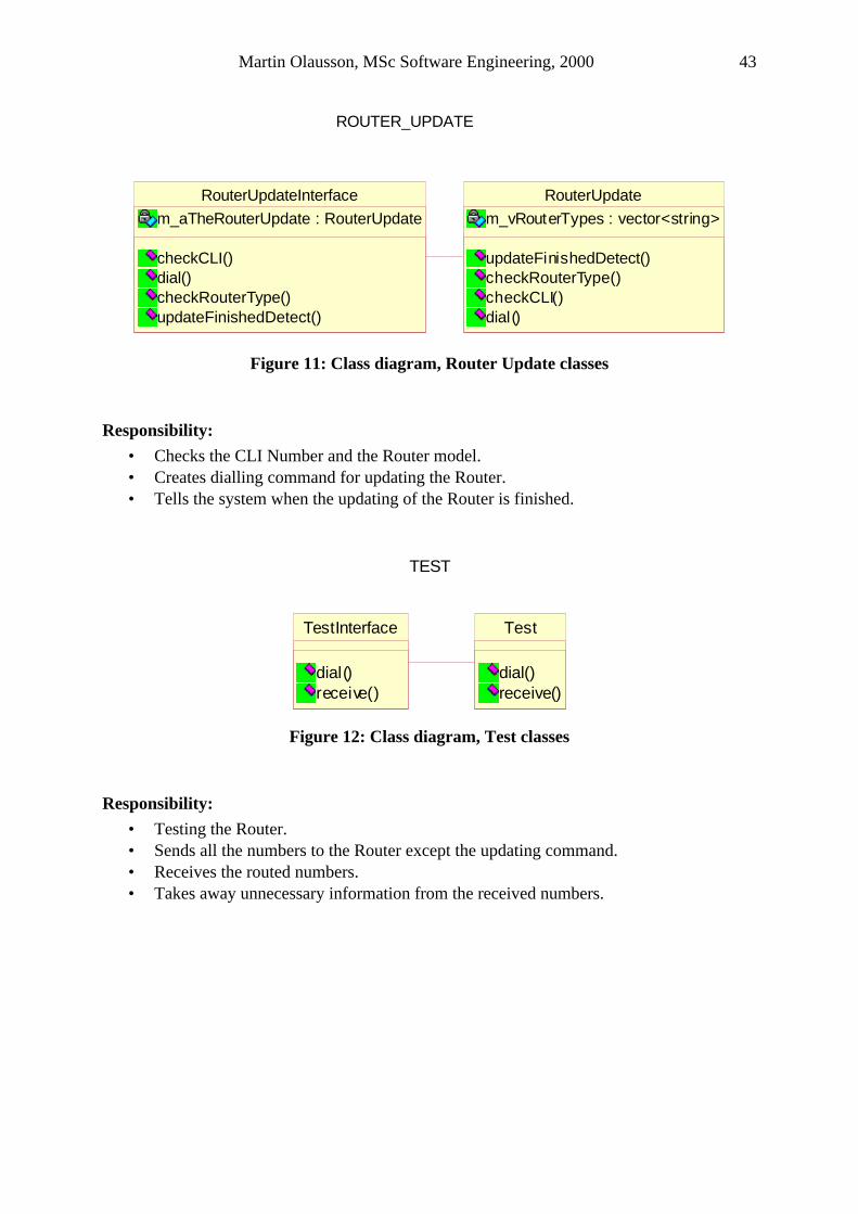
Martin Olausson, MSc Software Engineering, 2000 43
RouterUpdate
m_vRouterTypes : vector<string>
updateFinishedDetect()checkRouterType()checkCLI()dial()
ROUTER_UPDATE
RouterUpdateInterface
m_aTheRouterUpdate : RouterUpdate
checkCLI()dial()checkRouterType()updateFinishedDetect()
Figure 11: Class diagram, Router Update classes
Responsibility:
• Checks the CLI Number and the Router model. • Creates dialling command for updating the Router. • Tells the system when the updating of the Router is finished.
Test
dial()receive()
TestInterface
dial()receive()
TEST
Figure 12: Class diagram, Test classes
Responsibility:
• Testing the Router. • Sends all the numbers to the Router except the updating command. • Receives the routed numbers. • Takes away unnecessary information from the received numbers.
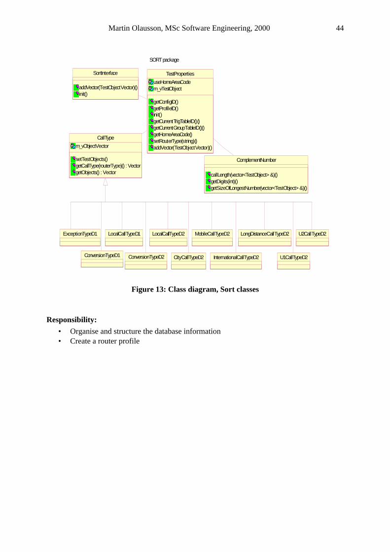
Martin Olausson, MSc Software Engineering, 2000 44
LongDistanceCallTypeD2
SORT package
ConversionTypeD2
ExceptionTypeD1
ConversionTypeD1
LocalCallTypeD2
InternationalCallTypeD2
MobileCallTypeD2
CityCallTypeD2 U1CallTypeD2
U2CallTypeD2
SortInterface
addVector(TestObjectVector)()init()
CallType
m_vObjectVector
setTestObjects()getCallType(routerType)() : VectorgetObjects() : Vector
ComplementNumber
callLength(vector<TestObject> &)()getDigits(int)()getSizeOfLongestNumber(vector<TestObject> &)()
TestProperties
useHomeAreaCodem_vTestObject
getConfigID()getProfileID()init()getCurrentTrigTableID()()getCurrentGroupTableID()()getHomeAreaCode()setRouterType(string)()addVector(TestObjectVector)()
LocalCallTypeD1
Figure 13: Class diagram, Sort classes
Responsibility:
• Organise and structure the database information • Create a router profile
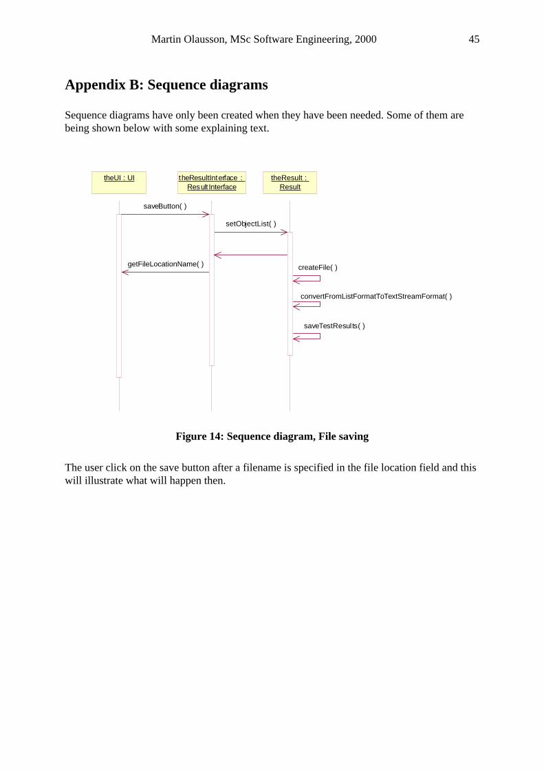
Martin Olausson, MSc Software Engineering, 2000 45
Appendix B: Sequence diagrams Sequence diagrams have only been created when they have been needed. Some of them are being shown below with some explaining text.
theResultInterface : Result Interface
theResult : Result
theUI : UI
saveButton( )
setObjectList( )
getFileLocationName( )
convertFromListFormatToTextStreamFormat( )
saveTestResults( )
createFile( )
Figure 14: Sequence diagram, File saving
The user click on the save button after a filename is specified in the file location field and this will illustrate what will happen then.
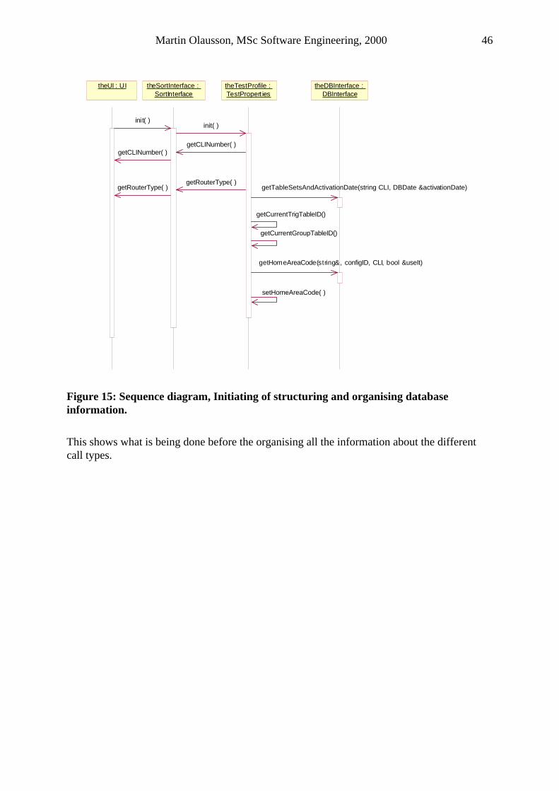
Martin Olausson, MSc Software Engineering, 2000 46
getHomeAreaCode(string&, configID, CLI, bool &useIt)
theSortInterface : SortInterface
theUI : UI
getCLINumber( )
theTestProfile : TestPropert ies
theDBInterface : DBInterface
init( )init( )
getCLINumber( )
getTableSetsAndActivationDate(string CLI, DBDate &activationDate)
getCurrentTrigTableID()
getCurrentGroupTableID()
setHomeAreaCode( )
getRouterType( )getRouterType( )
Figure 15: Sequence diagram, Initiating of structuring and organising database information.
This shows what is being done before the organising all the information about the different call types.
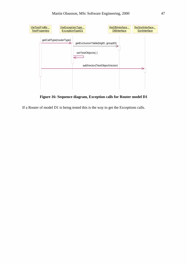
Martin Olausson, MSc Software Engineering, 2000 47
addVector(TestObjectVector)
theExcept ionType : ExceptionTypeD1
theTestProfile : TestProperties
theDBInterface : DBInterface
theSortInterface : SortInterface
getCallType(routerType)getExclusionTable(trigID, groupID)
setTestObjects( )
Figure 16: Sequence diagram, Exception calls for Router model D1
If a Router of model D1 is being tested this is the way to get the Exceptions calls.
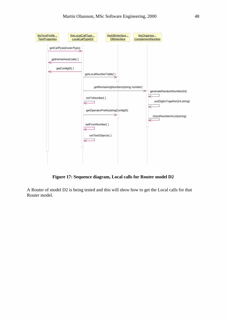
Martin Olausson, MSc Software Engineering, 2000 48
theTestProfi le : TestProperties
theLocalCallType : LocalCallTypeD2
theDBInterface : DBInterface
theOrganise : ComplementNumber
getCallType(routerType)
getRemainingNumbers(string number)
generateRandomNumber(int)
putDigitsTogether(int,string)
checkNumberInList(string)
getHomeAreaCode( )
getConfigID( )
getLocalNumberTable( )
setToNumber( )
getOperatorPrefix(stringConfigID)
setFromNumber( )
setTestObjects( )
Figure 17: Sequence diagram, Local calls for Router model D2
A Router of model D2 is being tested and this will show how to get the Local calls for that Router model.
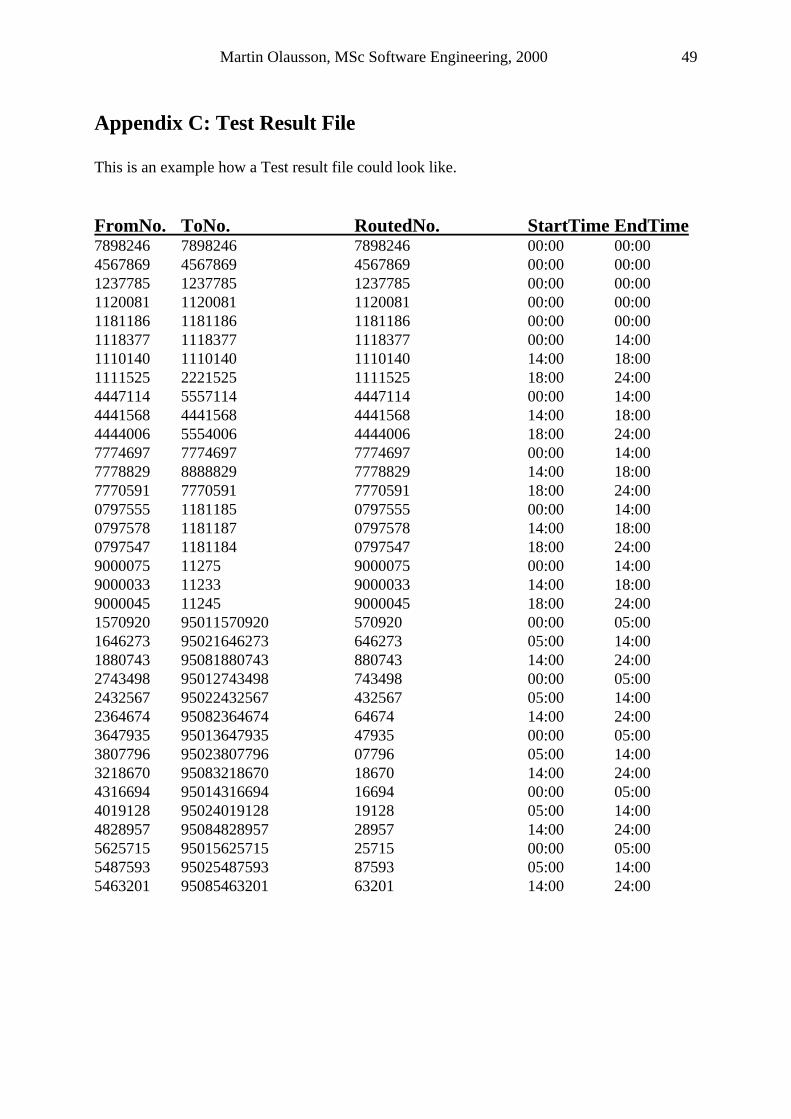
Martin Olausson, MSc Software Engineering, 2000 49
Appendix C: Test Result File This is an example how a Test result file could look like. FromNo. ToNo. RoutedNo. StartTime EndTime 7898246 7898246 7898246 00:00 00:00 4567869 4567869 4567869 00:00 00:00 1237785 1237785 1237785 00:00 00:00 1120081 1120081 1120081 00:00 00:00 1181186 1181186 1181186 00:00 00:00 1118377 1118377 1118377 00:00 14:00 1110140 1110140 1110140 14:00 18:00 1111525 2221525 1111525 18:00 24:00 4447114 5557114 4447114 00:00 14:00 4441568 4441568 4441568 14:00 18:00 4444006 5554006 4444006 18:00 24:00 7774697 7774697 7774697 00:00 14:00 7778829 8888829 7778829 14:00 18:00 7770591 7770591 7770591 18:00 24:00 0797555 1181185 0797555 00:00 14:00 0797578 1181187 0797578 14:00 18:00 0797547 1181184 0797547 18:00 24:00 9000075 11275 9000075 00:00 14:00 9000033 11233 9000033 14:00 18:00 9000045 11245 9000045 18:00 24:00 1570920 95011570920 570920 00:00 05:00 1646273 95021646273 646273 05:00 14:00 1880743 95081880743 880743 14:00 24:00 2743498 95012743498 743498 00:00 05:00 2432567 95022432567 432567 05:00 14:00 2364674 95082364674 64674 14:00 24:00 3647935 95013647935 47935 00:00 05:00 3807796 95023807796 07796 05:00 14:00 3218670 95083218670 18670 14:00 24:00 4316694 95014316694 16694 00:00 05:00 4019128 95024019128 19128 05:00 14:00 4828957 95084828957 28957 14:00 24:00 5625715 95015625715 25715 00:00 05:00 5487593 95025487593 87593 05:00 14:00 5463201 95085463201 63201 14:00 24:00
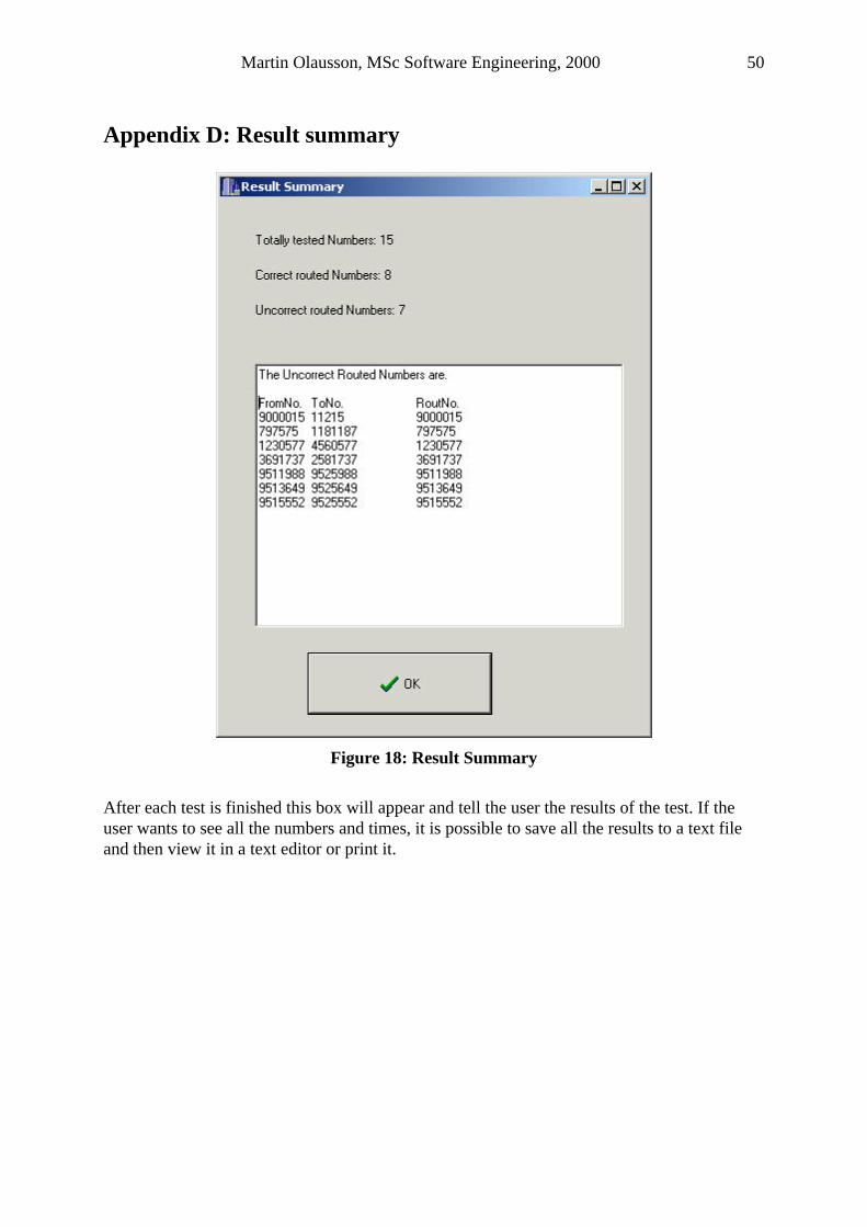
Martin Olausson, MSc Software Engineering, 2000 50
Appendix D: Result summary
Figure 18: Result Summary
After each test is finished this box will appear and tell the user the results of the test. If the user wants to see all the numbers and times, it is possible to save all the results to a text file and then view it in a text editor or print it.
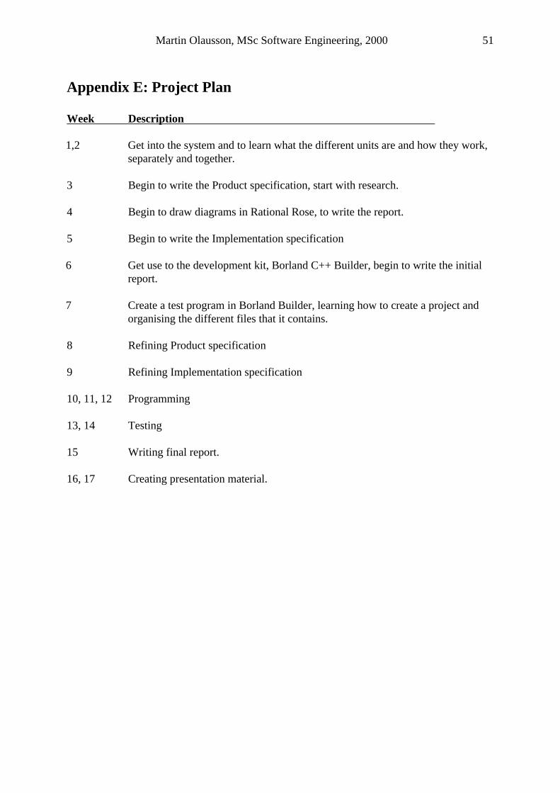
Martin Olausson, MSc Software Engineering, 2000 51
Appendix E: Project Plan Week Description 1,2 Get into the system and to learn what the different units are and how they work,
separately and together. 3 Begin to write the Product specification, start with research. 4 Begin to draw diagrams in Rational Rose, to write the report. 5 Begin to write the Implementation specification 6 Get use to the development kit, Borland C++ Builder, begin to write the initial
report. 7 Create a test program in Borland Builder, learning how to create a project and
organising the different files that it contains. 8 Refining Product specification 9 Refining Implementation specification 10, 11, 12 Programming 13, 14 Testing 15 Writing final report. 16, 17 Creating presentation material.
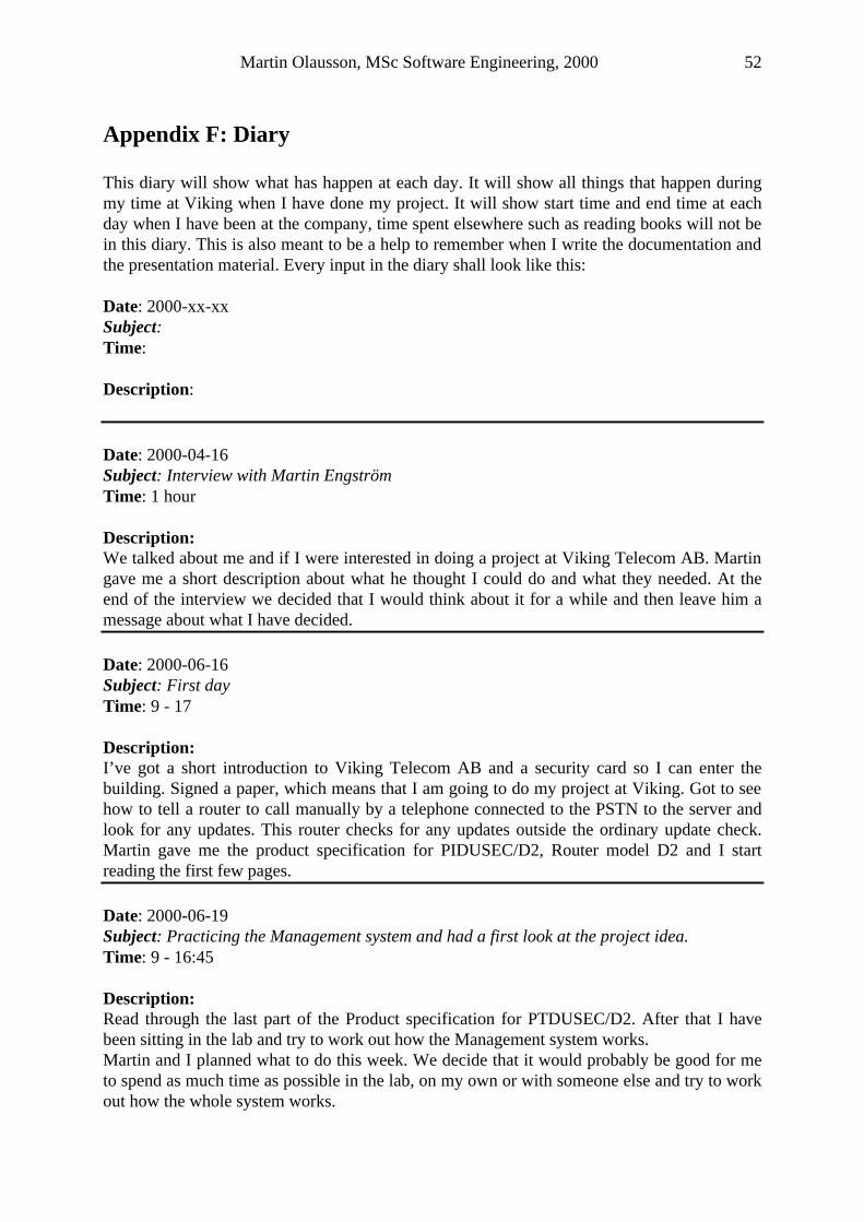
Martin Olausson, MSc Software Engineering, 2000 52
Appendix F: Diary This diary will show what has happen at each day. It will show all things that happen during my time at Viking when I have done my project. It will show start time and end time at each day when I have been at the company, time spent elsewhere such as reading books will not be in this diary. This is also meant to be a help to remember when I write the documentation and the presentation material. Every input in the diary shall look like this: Date: 2000-xx-xx Subject: Time: Description: Date: 2000-04-16 Subject: Interview with Martin Engström Time: 1 hour Description: We talked about me and if I were interested in doing a project at Viking Telecom AB. Martin gave me a short description about what he thought I could do and what they needed. At the end of the interview we decided that I would think about it for a while and then leave him a message about what I have decided. Date: 2000-06-16 Subject: First day Time: 9 - 17 Description: I’ve got a short introduction to Viking Telecom AB and a security card so I can enter the building. Signed a paper, which means that I am going to do my project at Viking. Got to see how to tell a router to call manually by a telephone connected to the PSTN to the server and look for any updates. This router checks for any updates outside the ordinary update check. Martin gave me the product specification for PIDUSEC/D2, Router model D2 and I start reading the first few pages.
Date: 2000-06-19 Subject: Practicing the Management system and had a first look at the project idea. Time: 9 - 16:45 Description: Read through the last part of the Product specification for PTDUSEC/D2. After that I have been sitting in the lab and try to work out how the Management system works. Martin and I planned what to do this week. We decide that it would probably be good for me to spend as much time as possible in the lab, on my own or with someone else and try to work out how the whole system works.
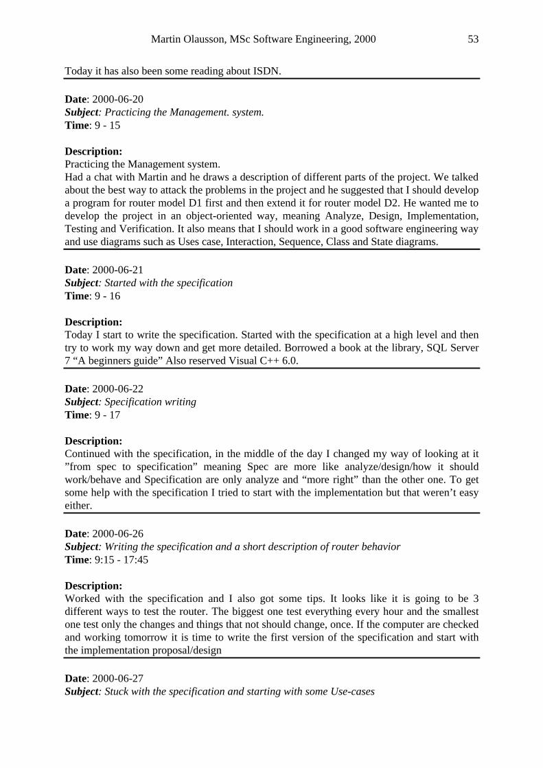
Martin Olausson, MSc Software Engineering, 2000 53
Today it has also been some reading about ISDN.
Date: 2000-06-20 Subject: Practicing the Management. system. Time: 9 - 15 Description: Practicing the Management system. Had a chat with Martin and he draws a description of different parts of the project. We talked about the best way to attack the problems in the project and he suggested that I should develop a program for router model D1 first and then extend it for router model D2. He wanted me to develop the project in an object-oriented way, meaning Analyze, Design, Implementation, Testing and Verification. It also means that I should work in a good software engineering way and use diagrams such as Uses case, Interaction, Sequence, Class and State diagrams.
Date: 2000-06-21 Subject: Started with the specification Time: 9 - 16 Description: Today I start to write the specification. Started with the specification at a high level and then try to work my way down and get more detailed. Borrowed a book at the library, SQL Server 7 “A beginners guide” Also reserved Visual C++ 6.0.
Date: 2000-06-22 Subject: Specification writing Time: 9 - 17 Description: Continued with the specification, in the middle of the day I changed my way of looking at it ”from spec to specification” meaning Spec are more like analyze/design/how it should work/behave and Specification are only analyze and “more right” than the other one. To get some help with the specification I tried to start with the implementation but that weren’t easy either. Date: 2000-06-26 Subject: Writing the specification and a short description of router behavior Time: 9:15 - 17:45 Description: Worked with the specification and I also got some tips. It looks like it is going to be 3 different ways to test the router. The biggest one test everything every hour and the smallest one test only the changes and things that not should change, once. If the computer are checked and working tomorrow it is time to write the first version of the specification and start with the implementation proposal/design
Date: 2000-06-27 Subject: Stuck with the specification and starting with some Use-cases
Martin Olausson, MSc Software Engineering, 2000 54
Time: 8:30 - 17:15 Description: I got stuck with the specification. Started to create some Use-cases at a very high level, don’t know if they are of so much use but it is more to get my mind used to think in another way for the moment and start to get a little bit deeper into the project. Christian showed me a little bit how the router is working at a low level and how he downloaded some new software to it. Date: 2000-06-28 Subject: Start modeling, created Use cases and Interaction diagrams Time: 9 - 19:15 Description: Today I got my computer and now it is installed properly. Installed Rational Modeler Edition. Talk to Martin before lunch and he tell me another way to look at the problem. He also told me some stuff about Use cases and Interaction diagrams. I started with the Use cases and after that I tried to draw some Interaction diagrams.
Date: 2000-06-29 Subject: Use case and diary Time: 8 - 16:30 Description: It is a lot of things to do. I have put in almost everything that was in the notebook into Word or Rational Rose models. That had taking a lot of time but I have done some work with the Use cases’ top and try to get them a little bit more specified or bringing them down a level or two, but it is a lot more to do. Date: 2000-06-30 Subject: Moving to new office, department meeting, database…….. Time: 8 - 19:30 Description: Left “my” own office and moved into Jens’. Sharing it with him for a while but in the beginning I will be alone because he is on holiday. I were at my first department meeting, the split my department into four smaller groups, Martin is my group leader. Start to look at the database structure. Talked to Tobias and he promised to create a structure diagram of the database sometime next week. There were some time spent in the lab and try to get a diagram from there but I weren’t any successful. Date: 2000-07-03 Subject: Martin gave me some hand in dates Time: 7:45 - 18 Description:
Martin Olausson, MSc Software Engineering, 2000 55
Started the day with organizing some files and documents. Worked a little bit with Spc-ver1(a file created by me) and had a chat with Martin after lunch. He suggested that I give him the specification and implementation to look through at Friday 6/7. Start to write Specification-ver1e and implementation-ver1e, I didn’t do so much but it looks like I might handle it to Martin on Friday.
Date: 2000-07-04 Subject: A first look at the database Time: 8:30 - 17:45 Description: Worked on the specification, it is about 1.5 pages for the moment and I think it is not going to be so much more. It is time to think about the implementation, started to write a little bit but it isn’t easy. Talked to Johan and it looks like I am going to use some of his code to get the information from the database. I have had a look at the implementation and I think that paper is going to take all my time this week. Date: 2000-07-05 Subject: The implementation grows Time: 8 - 19 Description: Started the morning with doing some research and found some articles but it were only the abstract of the articles but I sent them an email to ask how to get he rest of the article. Worked with the implementation, it’s getting better but I think I need some more Rose models to make it even better. I am not sure how much an implementation is supposed to contain. Date: 2000-07-06 Subject: A mixed day Time: 8:30 - 16:30 Description: This day I have been a doing a lot of different things. First of all I have as the main part of the time been writing the implementation. A few administrative things had to be sorted out. I have been in contact with the office at school and try to get my results for the exams but weren’t ready yet, but they will probably tomorrow. Date: 2000-07-07 Subject: Hand-in day for preliminary specification and implementation Time: 9 - 17:15 Description: I called the office of computing to ask them about my results for the exam and coursework, I have got “transfer to MSc” YESSSSSSSS!!!!!!!!!!!!!!!!!!!!!!!!!!!!!!!!!!!!!!!!!!!!!!!!!!!!!!!!! Martin got the Specification and Implementation so he could look it through and give me some comments to see if I am going in the right direction. This day I try to finish the Specification and Implementation but it is still some work to do.
Martin Olausson, MSc Software Engineering, 2000 56
Date: 2000-07-10 Subject: The documents need some further work Time: 9 - 17:30 Description: Continued to work with the implementation and talked to Martin before lunch so we could have a chat before he went to Spain. After lunch he and Johan visit my office and we had a discussion about the documents that I have produce. There were some things in the document that I had to look at a little bit more. Martin told me that I should fill in a project report document for each week, this report will contain: Intro, Milestones, What’s done this week, what to do next week, Risks and maybe comments. When Martin is away I should ask Johan if I have any questions. Date: 2000-07-11 Subject: Specification and requirements Time: 8:30 - 18 Description: I continued working with the requirements. So far I just put the requirements with bullets and I haven’t started the implementation. Surf into different libraries to see if they have any useful book about my subject but I wasn’t any successful. On my way home I stopped by the city library to see if they have any books but they didn’t. I got a weekly project report template from Christian that I can use, so Martin can see what I am doing at each week. Date: 2000-07-12 Subject: Use cases and flow of events Time: 8:45 - 19:45 Description: I talked to Martin and he gave me some tips how he would like to see the specification. In the afternoon he looked at what I have done and said “it is ok. for now, go on with the other parts” so I did that and we (me, Martin and Johan) would have a look at it tomorrow to see if I got the Use case diagram and the Flow of Events right. Date: 2000-07-13 Subject: Ended the day with After Work Time: 8:15 - 18:30 Description: Worked with the Use cases and tried to do some of the Flow of Events, and did all of them. Talked to Martin and he wanted to see everything that I had done here at Viking so far. Martin, Johan and me had a talk in the conference room about the documents; they still need some more work. I got a template document from Martin about how a Specification looks like at Viking. He also showed me 2-3 specifications so I could see how they looked like. I chose one of them to have as a template or to look at how I should write mine.
Martin Olausson, MSc Software Engineering, 2000 57
The day ended with After Work at Babar bar with some Viking people. Date: 2000-07-14 Subject: Looking at a Viking specification Time: 9 - 17 Description: Start to look at the specification I got. I took one as a template so I get the headings and the other part that should be in a specification. I think I go for a model that Johan explained for me, one general part that everyone with some technical interest can understand and one more detailed and describing. I haven’t done so much to the Literature review or the Research proposal but I think I will next week. Next week I plan to do all the things I had to do because I “must” before all knowledge about the development kit or the documentation disappears in form of Johan or someone else. Date: 2000-07-17 Subject: Specification and installation day Time: 8:15 - 16:45 Description: Worked with the specification almost all day. Installed Borland C++ Builder version 4 on my computer. Tried to install Rational Requisite pro too and today it got ok. Something has happened to Rational Rose, I don’t know what it is, but it isn’t working, as it should. Date: 2000-07-21 Subject: Continued with Specification Time: 8:15 - 17:45 Description: 18, 19, and 20 of July were holidays. The specification starts to get a new form. The general part gets more finished and today I started with the more detailed one. Date: 2000-07-24 Subject: The specification getting closer to its end. Time: 8:00 - 19 Description: Today I have been working with the specification too. Before lunch I talked to Niklas and the test system he had developed. He might have done something I can use so I thought it would be a good idea to hear his thoughts about my test program, but after we had talked a little we find out that the difference between our test programs were quite big. It looks like it isn’t worth the effort for me to get into his program and understand what he has done because I can’t use so much of it.
Martin Olausson, MSc Software Engineering, 2000 58
Today I got the red thread through the database tables (I think), I can by just knowing the CLI get down through the hierarchy to the Exception and the Conversion tables. The Prefix part is still left to solve. Jens was back today and I have a chat with him and he suggests that I go on with the specification as fast as possible and get on with the programming part. I think that were a good suggestion and I take it a little bit easy now with the specification, implementation and get to the programming as fast as possible. Date: 2000-07-25 Subject: Start with the implementation/design document. Time: 8:15 - 18 Description: Talked to Fredrik today about the implementation and what it should contain. He suggested that I put almost all my effort to the implementation/design document. That document should specify all the way down to a specific level, it should be like writing program code in Microsoft Word. I wrote a little bit more to the specification and then I started with the implementation/design document. I don’t have a template for that kind of document so I have to figure out something on my own. I think the exceptions and the conversions are almost finished and I plan to get some of the other stuff finished too so I can start look at the development environment while Jens is here. Date: 2000-07-26 Subject: First look at the programming part Time: 8:30 - 16 Description: Today I didn’t do anything to the specification. I only added a few things to the implementation. I talked to Jens about some of the objects I had to create and how they should look like. Then started with the programming part. I didn’t start to program the project, I just look at Borland and did the “Hello World” program. Configured my PC to an ODBC so I can get connected to a database when I do my program. It is a short day today but it had to be that because I had to go to the library today at it is not open so late at night. Date: 2000-07-27 Subject: Programming Time: 8 - 18 Description: Start to program a little bit more serious. Try to get connected to a database and succeeded but then I tried to do some SQL queries and work with the information that I get from the database but in that area I didn’t be so successful. This database part of the project doesn’t seem to be that easy. Date: 2000-07-28 Subject: Databases are difficult
Martin Olausson, MSc Software Engineering, 2000 59
Time: 8:30 - 16 Description: Today I have tried to use Johan’s file about the database to get something from a table but it isn’t working and I don’t know what is wrong. I learned a little bit more today about Borland Builder but I think it is a lot left to learn about that program. Date: 2000-07-31 Subject: A mixed day Time: 8:45 - 16:30 Description: Still struggling with the database connection, I can’t get a program that I have made connected to the database when I use the same functions as the Router are using. I have asked Jens for help but he isn’t so in to it either. Looked through the specification and added a few things, I think I had to work a little bit more with the Use cases, not the general ones but the more specific one need a little bit more description. Date: 2000-08-01 Subject: Databases……… Time: 9 - 17:30 Description: Only worked with the database and I can’t get it to work and I don’t understand what is wrong. I have tried to use Johan’s files and then also create some files on my own but nothing seems to work. I got it to work when I used a DBGrid to show what is in one particular database but that is not what I want to do and it seems like it isn’t the same. Date: 2000-08-02 Subject: Stuck with the database Time: 9 - 20 Description: I have been sitting with the database all day and I can’t get what is wrong. Tomorrow Jens said he could have a look at it to see if he knows what is wrong. Because I am stuck I start to draw some package diagram and class diagram. I am very unsure if it is right or not but I think I go on with it as long as I am stuck with the database problem. I will try to get some help with the database stuff and go on with the other things for the moment. Date: 2000-08-03 Subject: Database connection Time: 8:15 - 20 Description:
Martin Olausson, MSc Software Engineering, 2000 60
Finally I succeeded to connect to the database. Now I can access it from my program and get stuff from it. It is with help of the already specified classes, DBInterface, DatabaseWorker and QueryDispatcher. Those classes then uses TQuery to access the database. Anyway it works so far and I have also tried to use some functions in the DBInterface class that I think can be useful later on in my project. No work with the implementation or specification today. Date: 2000-08-04 Subject: A working test program Time: 9:15 - 17 Description: Today have been a good day, I got stuck yesterday with some pointers but today most of it gets solved. For the moment a test program works that uses the DBInterface class and it is possible to read from a StringTable (which is used quite often) so some of future problems I think were solved today. It looks like I found a way to access dialog boxes and fields that will make it easier later on when it is time to develop the UI. Worked a little bit with the “Sort” package and it looks like it is going to be as it is now. Date: 2000-08-07 Subject: Interaction diagram Time: 8:45 – 18 Description: Start this day by draw some class diagrams but that wasn’t easy so I start to draw some interaction diagrams too and that made it a little bit easier the iteration technique when I draw the iteration diagrams and it felt like that technique was good use. The diagrams are not finished, only the first version had been created and it is a lot of things left to do to them. Added some comments to the specification and the implementation documents. The documents are not finished yet, things pop up when I draw the diagrams that had to be added. Date: 2000-08-08 Subject: As yesterday Time: 8 – 20 Description: Interaction and class diagram had been drawn today. It took the whole day to draw them and I don’t know if I am finished yet. I had to do some refining of the diagram that I drawn yesterday and I think today’s diagrams might be a little bit better. The diagrams need to be looked at a little bit more but it is probably better to do that another day. Date: 2000-08-09 Subject: Updating the implementation Time: 9:15 – 18:30 Description: By looking at the project planning the implementation had to be finished this week and it is a lot of things left to implement so today I have been adding, removing and changing the implementation.

Martin Olausson, MSc Software Engineering, 2000 61
I was stuck with the programming for a while but with some reconfiguration of the ODBC settings I think I can do some programming again, but the implementation is the most important thing for the moment so that have higher priority and I will work with that a lot more. Date: 2000-08-10 Subject: Structuring the implementation specification Time: 8:30 – 19:30 Description: This day has been an implementation day. It looks like its getting some structure, it is a lot of work left but I think almost everything concerning the Exceptions and Conversions are in the implementation now, of course it has to be refined a couple of times but now I have at least something to refine. I think it is about time to start programming, and get a real good look at Borland Builder. It can take some time to understand that program; it isn’t easy Date: 2000-08-11 Subject: My first class Time: 8:45 – 18:30 Description: TestObject, that is the name of the class that I created today. I started to develop a test application. This test application is meant to test different features that are going to be in the final program. If I test the separate parts at this stage I think I will be easier when I start with final application and put everything together if I know that they work separately from each other. It looks like it is going to be difficult to keep up with the project schedule; the time is going to fast. Date: 2000-08-14 Subject: Refining the product- and implementation specification Time: 8 – 21 Description: Martin was back from his holiday today and he wanted to see the product and the implementation specification that I have done so far. I refined it and made it ready for printing, the final version isn’t ready yet but I don’t think it is so much work left for the product specification. It had to be done some more work to the implementation specification, all the algorithms for the structuring of the database information aren’t ready yet (only for the exceptions and conversion) and the description of the important objects have I just start with. Date: 2000-08-15 Subject: Initial report Time: 9 – 21 Description: Today I finished the initial report, tomorrow I had to refined it and read it a couple of time so it isn’t to many errors in it before I give it to Bill. Maybe I had to add a few things to the
Martin Olausson, MSc Software Engineering, 2000 62
conclusion. It feels good to have produced some documents and I hope that Bill doesn’t find too many errors. I also looked at the “Dissertation flowchart” today and I think it is time to work with the report very soon. I printed the product specification and the implementation specification so Martin could see what I have done during the week he has had a holiday. Date: 2000-08-16 Subject: Refining the Literature review Time: 9 – 17:30 Description: Looked through the Literature Review and change the parts that were wrong, and try to do all the references, quotations, and word order the right way but it isn’t easy. Send it to Bill so we can discuss it on Friday at our meeting. Talked to Martin and he said that the implementation and specification is looking better than before. Now it is time for a 2 days holiday in Edinburgh. Date: 2000-08-21 Subject: Taking care of notes after the meeting with Bill Time: 9:45 – 17:30 Description: Started a little bit late but I was tired after the trip to Scotland. I met my supervisor; Bill there and we talked about the project. We discussed what have happen so far, what is going to happen next and the Viva. I have written down a conclusion of our meeting so I can follow that further in the project. We decide that I will send him a chapter of the project report at a time and he will read it and give me some feedback. Continued with the programming, today’s success is that I am able to create objects of an own created class and put them into a vector and then display it in a Memo box. Date: 2000-08-22 Subject: The Router Update part Time: 8:30 – 19:30 Description: Tried to work with the RouterUpdate part, both Rose diagrams, interaction and class, and to do it in program code. Defined h-files and cpp-files for the different classes. I have included these new files to a project, which I later on intend to have in the first version of the final program. Of course it is some parts that I still haven’t thought about but that will be solved later. Date: 2000-08-23 Subject: Structuring the Sort part Time: 9 – 18:30 Description:
Martin Olausson, MSc Software Engineering, 2000 63
Worked with Sort part all day, both in Rose and in Borland. I am not finished with the “main” structure yet but I think I will tomorrow, and then I can start to test it and see if it works. I haven’t looked at the modem/DTMF part yet but it is only to put in some comments at those lines and the rest will probably work. Date: 2000-08-24 Subject: Created a prototype Time: 8:30 - 19 Description: A small system contains of UserInterface, RouterUpdate and Sorting which includes the ExceptionCallTypes. I try with this first and then I see how far I get. I start to compile everything today and it had been some problems such as bi-directional associations, global variables and objects lifetime. All of them are not solved yet but I think it is possible to do it in a couple of days. I haven’t been able to follow the implementation all the time but I think some of these new solutions are better than the old ones so I go for the new ones. Date: 2000-08-25 Subject: A compiling day Time: 9 - 17:30 Description: Try to compile the whole system, but it looks like the inheritance doesn’t work, as it should. It might be an idea to go around it or avoid it just to get everything compiled and to see if the rest is working, as it should. The rest of the program need some attention too and since it is only 1/3 left of the time for the project I don’t assume it is not so good to get stuck somewhere and then the project doesn’t get any further. Date: 2000-08-28 Subject: It is working Time: 8:15 - 18 Description: Finally I got to compile the whole program and after some debugging I got it to work too. The part that is working is the connection to the database and to get the information from the tables, Exceptions for router model D1 and Conversions for router model D1. I manage to almost get all that information; the missing part is the operators’ prefix and the prefix conversion. I had to give up the inheritance part for a while but I intend to change that part later and get back to the version that included the inheritance. Today I downloaded some help from www.turbopower.com to help me with the communication part, but that will be tomorrow’s problem. Date: 2000-08-29 Subject: Using Modem and DTMF reader Time: 8:45 – 20:15 Description:
Martin Olausson, MSc Software Engineering, 2000 64
Installation of the software that I downloaded from TurboPower went ok. Martin and I tried to use some of its components and after a while we succeeded to use both the modem and the DTMF reader for dialing and receiving numbers by using the downloaded components. I even tried to read a number from a file, dial it and receive the same number. Date: 2000-08-30 Subject: Everything together Time: 8:15 – 20:30 Description: I got some structure on the program code, reduced the global variables so instead of a global variables I pass it through to the different functions. Put all the “small” program parts together and try to use everything as a working system. It is not working, yet but I got everything to compiled, it is some linking errors but that I could take care of tomorrow. I got stuck with some problem with the communication part, maybe I had to use different threads to get the program to work, I hope not but it might be impossible to avoid. Date: 2000-08-31 Subject: The whole system, except the Router Time: 8:45 – 21:00 Description: Everything is connected, except the Router. The whole program is compiled and it is working properly. It might need some “minor adjustments”, the code isn’t that nice but it wouldn’t take that long to fix. It will be easier to develop the program further if these minor adjustments will be taking care of. Since the program is developed by object oriented methods I think it don’t need that much effort from the developer to develop it further. The big things that are left to do is to connect the Router, find out about the algorithms for the all the call types except Exception and Conversions for router D1 and to write the documentation. Date: 2000-09-01 Subject: Still small things to fix Time: 8:45 – 14:45 Description: Not a long day today so I didn’t had enough time to fix all the minor adjustments such as a summary of the test results, test the whole system including the Router and to check all the inputs that are made by the user. The big things are still left to take care of and that will be next week’s problem and that might take a while. Date: 2000-09-04 Subject: Test summary Time: 8 – 17:30 Description:
Martin Olausson, MSc Software Engineering, 2000 65
I have created a summary of the test result and a separate button for that. It might not be such a good idea to have an “extra” button for that but as long as the system is being developed it is a good place to split the program. Started to look at the Conversions for D2 and the Local numbers, it seems like it is not going to be easy to configure the program to be able to handle that. Date: 2000-09-05 Subject: Code structuring and start with the algorithms Time: 8:15 – 17:45 Description: The code that I have already written have been a little bit unstructured but after today it looks better. Start to think and create the algorithms for the different CallTypes that are much more complicated. They are built on several different tables where the answer had the form of references to several matrixes. Date: 2000-09-06 Subject: Database trouble Time: 8:15 - 21 Description: Getting into the algorithms quite much now and some of them seems to work but I have some trouble to test them. The problem is to find a database that contains of tables that contains of a small amount of entries in almost every table (if it was in every table it would be good), if I can’t find any in the following days I probably create some by myself. Worked a little bit with the report today. It is difficult to know how much and in which section to put all the information. Date: 2000-09-07 Subject: An own database to test with Time: 8:30 - 20 Description: I couldn’t find any good database with tables tat contained that amount of data that I wanted so I decided to create an own database with the kind of tables that I wanted. This makes it also easier with the testing because I know what I have put into the database and then I also know what is going to come out. To be able to do this I had to install some new software on my computer, StarTeam and the Management system. StarTeam is for keeping all the files in the correct order and the Management system is to setup the different tables in the database. Begin to test some of my algorithms; Exception for the D2 seems to work ok. Also tried to test the Conversions for D2 they work but it is some errors with the dates and times to take care of. Date: 2000-09-08 Subject: Another types of call Time: 9 – 15:30
Martin Olausson, MSc Software Engineering, 2000 66
Description: The wrong things with the Conversions are fixed and now and they seems to work. I started after that with the Local calls but that was a little bit trickier, I don’t know exactly how they work but I have some ideas but I haven’t tried them in the code yet. I thought it would be some time left today to work with the report but it isn’t, it looks like I had to do it during the weekend. Date: 2000-09-11 Subject: Local calls Time: 9 - 17 Description: It is getting a little bit trickier. I tried to get the Local calls today but it is something that is wrong. Probably it is something with the carrier’s prefix but I am not sure. Anyway it doesn’t seem it would be that difficult to find out what it is but that will be tomorrow’s problem.
Date: 2000-09-12 Subject: Different call types Time: 8:45 – 20:45 Description: Local calls are working! It took a while to get what were wrong but now it is fixed. City calls is not so different to Local calls so I tried to do that too and it seems to work too, it isn’t tested yet but it is possible to compile it and run it so I have high expectations that it will work when I test it tomorrow. I haven’t looked at the other call types yet but since I (probably) fixed these call types today I think I will be able to do the others the following days. Date: 2000-09-13 Subject: More call types Time: 8:45 - 15 Description: Tried to test the City call types but I didn’t succeeded. Went on to do the Long distance and the User defined call types it went well but when were going to test it didn’t work. After some debugging I noticed that the database didn’t contain any calls of that type so tomorrow I had to setup a new database or add these type of call to the old on. Looked a little bit to the International call types and the Mobile ones and they seem to be more difficult to get then the one I have done so far. Date: 2000-09-14 Subject: Mixed day Time: 9 – 20:30 Description: I understand the International call types a little bit better now and I can get all the information out from it that I want. The difficult part is to put it together so it will be an International call. I haven’t test that yet, the database have been a little bit unreliable today.
Martin Olausson, MSc Software Engineering, 2000 67
Date: 2000-09-15 Subject: Report Time: 8:30 - 17 Description: Some part of the report are finished and sent to Bill. The most general class- and sequence diagrams are updated and inserted to the report. Talked to Martin and he wants that the D1+ version also would be able to test with my program. I don’t know if this will make it much more difficult, maybe it is only a few features that had to be added. Date: 2000-09-18 Subject: international calls Time: 9:15 – 17:30 Description: Now I am getting into the International calls and I try to compile and run the program with them included. It is not going at all for the moment but I have only discovered some small bugs yet so tomorrow I think it will take care of the International calls. Date: 2000-09-19 Subject: Call types for D1 Time: 8:30 – 16:20 Description: All the different call types for router model D1 have been looked after and some of them are not working, like the one for Conversion calls and the OperatorConversions. Tried to make them working today but with not so good results. Maybe something with the database is wrong. The database is quite busy in the afternoon so I think I look at it first thing tomorrow morning before it gets to busy. Date: 2000-09-20 Subject: Local calls and the Home Area Code Time: 8:30 – 14:30 Description: The local calls might work now, I haven’t tested it yet but the only thing that is left is the Home Area Code. I don’t think that will cause any problems but I am not sure. When the Home Area Code is fixed it is only the + features left to implement. Date: 2000-09-21 Subject: Result Summary Window Time: 9 – 15:10 Description: Almost everything is finished. It is only the Result Summary window that is left then would the first version be ok.
Martin Olausson, MSc Software Engineering, 2000 68
To do the complement for the plus (+) version for router model D1 I need to update my version of the Management system and some of the code that I share with the Router. After that is completed I think I had to focus on the report. Date: 2000-09-22 Subject: The Window works Time: 8:15 - 15 Description: Been looking throw the code and it is getting better and better. The summary window is now working, it is possible to see total tested numbers, correct routed numbers and incorrect routed numbers and even all information that is about the incorrect tested numbers are listed in a Memo box. It is also containing an OK button that the user had to click to get through to the main Window as a confirmation that the results had been read. Date: 2000-09-24 Subject: Report writing Time: 13:30 – 19:20 Description: The report starts to look like a report. Chapter after chapter is getting completed, it looks like it is only chapter 5 left, the Appendix and the corrections when Bill has looked it through. It is a little bit difficult to get everything into the report and to explain it in an easy way. Date: 2000-09-25 Subject: Report writing and reading Time: 9:15 – 17:30 Description: Now I have read through chapter 4 and correct the things that I have discovered so far. I haven’t been that much written to chapter 5 as I thought today but maybe it will tomorrow. It is time to start thinking about the appendences, which might take some time. The Diary would not need so much work but the others need much more. Date: 2000-09-26 Subject: Writing the report Time: 8 – 17:15 Description: The report is almost finished; it is only small things left here there. The report might not be complete but if something is forgotten Bill promised that he would let me know about it after he has read it through so I can correct it. There might also be some part that is placed in the right section but after I read it through today I think I discover that. Date: 2000-09-27 Subject: The report Time: 9:15 – 15:15
Martin Olausson, MSc Software Engineering, 2000 69
Description: I have read through the Diary and made some corrections to it. I think that part is finished; I will not put any more attention to it, it is also included in the report by now. I have printed the report and for the moment I am reading it through and try to correct every mistake that is in it. Date: 2000-09-28 Subject: The report Time: 8 – 15:15 Description: Today I have read though the report another time and even correct some of the spellings so it now sounds more technical. The report still needs some minor corrections. Martin has look it through too he had some good comments and thoughts about it for raising its quality a bit more. I will thinking about them tomorrow and add the parts that have been missing. Date: 2000-09-29 Subject: The report Time: 9:15 - 20 Description: Now the report looks like a report, I have correct the things that was wrong and read Martin’s comments and looked them through in the report. Today I will send it to Bill and then wait for his comments.
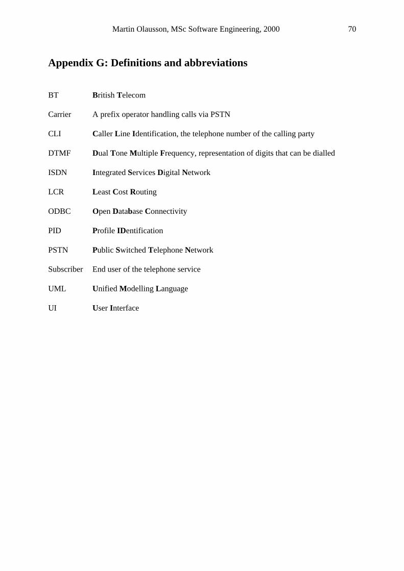
Martin Olausson, MSc Software Engineering, 2000 70
Appendix G: Definitions and abbreviations BT British Telecom Carrier A prefix operator handling calls via PSTN CLI Caller Line Identification, the telephone number of the calling party DTMF Dual Tone Multiple Frequency, representation of digits that can be dialled ISDN Integrated Services Digital Network LCR Least Cost Routing ODBC Open Database Connectivity PID Profile IDentification PSTN Public Switched Telephone Network Subscriber End user of the telephone service UML Unified Modelling Language UI User Interface
Martin Olausson, MSc Software Engineering, 2000 71
References: Beizer B. 1983. Software Testing Techniques. New York: Van Norstrand Reinhold
Derrick Morris, Gareth Evans, Peter Green, Colin Theaker. 1996. Objec tOriented Computer Systems Engineering. Gateshead: Athenæum Press Ltd
Grady Booch. 1998. Object-Oriented Analysis And Design. USA: Addison Wesley Longman Inc
Ivar Jacobson, Grady Booch, James Rumbaugh. 1999. The Unified Software Development Process. Massachusetts USA. Addison Wesley Longman Inc
Ivar Jacobson, Magnus Christerson, Patrik jonsson, Gunnar Övergaard. 1992. Object Oriented Software Engineering, A Use Case Driven Approach. USA: The Riverside Printing Co
Jan Skansholm. 1996. C++ direkt. Sweden: Studentlitteratur
Kent Reisdorph. 1998. Borland C++ Builder 3 In 21 Days. USA: Macmillan Computer Publishing
Kent Reisdorph. 1999. Teach Yourself Borland C++ Builder in 24 Hours. USA: Macmillan Computer Publishing
Mark Priestley. 2000. Practical Object-Oriented Design with UML. Cambridge: The University Press
Michael Duck, Peter Bishop, Richard Read. 1997. Data Communications For Engineers. Great Britain: T.J. International Ltd.
Myers G.J. 1979. The Art Of Software Testing. New York: Wiley
Oscar Nierstrasz, Dennis Tsichritzis. 1995. Object-Oriented Software Composition. Great Britain: T.J. Press Ltd
Perdita Stevens, Rob Pooley. 2000. Using UML Software Engineering With Objects And Components. Great Britain: T.J. International Ltd.
Peter Wisskirchen. 1996. Object-Oriented and Mixed Programming Paradigms. Germany: Springer-Verlag
Philippe Kruchten. 1998. The Rational Unified Process. Massachusetts USA. Addison Wesley Longman Inc.
Ramez Elmasri, Shamkant B Navathe. 2000. Fundamentals Of Database Systems, USA: Buschlen/Mowatt Fine Arts Ltd.
Rational. 1995-2000. http://www.rational.com [29 June, 2000]
Software Programmers Network. 2000. http://www.spmn.com [July 2000]
Sommerville I. 1989. Software Engineering 3rd Edn. Wookingham: Addison Wesley
TurboPower Software Co. July 06, 2000. http://www.turbopower.com/trialrun/ [29 August 2000]
Martin Olausson, MSc Software Engineering, 2000 72
Viking Telecom AB. August 09, 2000 http://www.viking-telecom.com/ [6 September 2000]
Watts S Humphrey. 1998. A Discipline For Software Engineering. USA: Addison Wesley Longman Inc