Embed Size (px)
Citation preview

APGR
Doc #9004859Rev A1, 03/2017
Programmable Magnetic FlowmeterUser Manual
FM100 Series

ii Tel: 1/888/525-7300 • Fax: 1/435/753-7490 • www.apgsensors.com • [email protected]
Table of Contents
Introduction ................................................................................................................ iii
Warranty and Warranty Restrictions .................................................................... iv
Chapter 1: Specifications and Options..................................................................... 1 Dimensions ........................................................................................................................................1 Specifications ................................................................................................................................... 2 Flow Rates per Line Size ................................................................................................................ 2 Model Number Configurator .......................................................................................................... 3 Wiring Diagram and Terminal Layout ........................................................................................ 4
Chapter 2: Installation and Removal Procedures and Notes ..............................5 Tools Needed ..................................................................................................................................... 5 Installation Requirements and Recommendations ...............................................................5-7 Electrical Installation ..................................................................................................................... 7 Grounding Instructions .................................................................................................................. 8 Removal Instructions ..................................................................................................................... 8
Chapter 3: Set Up and Operation ..............................................................................9 User Interface ................................................................................................................................... 9 FM100 Display Mode Menu ......................................................................................................... 10 FM100 Setup Menus .................................................................................................................10-13 Enter/Change Password ............................................................................................................... 14 Display Mode Menus ................................................................................................................ 15-16 Onboard Archives .......................................................................................................................... 16 Production Data Setup Menu ...................................................................................................... 17 Sensor Setup Menu ..................................................................................................................18-19 Analog Output Setup Menu ................................................................................................... 19-20 Display Setup Menu ................................................................................................................20-22 Exit Menu ........................................................................................................................................22
Chapter 4: Error Messages .......................................................................................23 Error Codes and Explanations............................................................................................... 23-24
Chapter 5: Maintenance ...........................................................................................25 General Care .................................................................................................................................... 25 Troubleshooting ............................................................................................................................. 25 Repair and Returns ........................................................................................................................ 25

iiiTel: 1/888/525-7300 • Fax: 1/435/753-7490 • www.apgsensors.com • [email protected]
IntroductionThank you for purchasing an FM100 programmable magnetic flowmeter from APG. We appreciate your business! Please take a few minutes to familiarize yourself with your FM100 and this manual.
The FM100 Programmable Magnetic Flowmeter is a highly accurate, bi-directional flowmeter, with configur-able 4-20 mA output. It comes with a two-line LCD display and four-button keypad for intuitive display set up and menu navigation. The hard technical rubber liner of the FM100 is compatible with most water and waste water applications.
Reading your labelEvery APG FM100 comes with a two labels, one on the sensor and one on the converter. The converter label will include the APG model number (starting with FM100-) and serial number, while the sensor will have the sensor number. Please ensure that the model number on your converter label matches your order.

iv Tel: 1/888/525-7300 • Fax: 1/435/753-7490 • www.apgsensors.com • [email protected]
Warranty and Warranty RestrictionsThis product is covered by APG’s waranty to be free from defects in material and workmanship under normal use and service of the product for 24 months. For a full explanation of our Warranty, please visit https://www.apgsensors.com/about-us/terms-conditions. Contact Technical Support to recieve a Return Material Authorization before shipping your product back.
Scan the QR code below to read the full explanation of our Warranty on your tablet or smartphone.

1Tel: 1/888/525-7300 • Fax: 1/435/753-7490 • www.apgsensors.com • [email protected]
Chapter 1: Specifications and Options
• Dimensions
6.30" [160mm]
6.61" [168mm]
2.56" [65mm]
A
ø Size
I
L
3.94" [100mm]
5.35" [136mm]
ø D
ø Size
Size Flange ø D* L** A Weight1” (25mm) 150lbs 4.53” (115mm) 7.87” (200mm) 7.09” (180mm) 9.7 lbs (4.4 kg)
2” (50mm) 150lbs 6.30” (160mm) 7.87” (200mm) 8.78” (223mm) 19.6 lbs (8.9 kb)
3” (80mm) 150lbs 7.68” (195mm) 7.87” (200mm) 10.2” (260mm) 28.4 lbs (12.9 kg)
4” (100mm) 150lbs 8.46” (215mm) 9.84” (250mm) 11.0” (280mm) 37.2 lbs (16.9 kg)
6” (150mm) 150lbs 11.0” (280mm) 11.8” (300mm) 13.4” (340mm) 63.6 lbs (28.9 kg)*Flange dimensions meet ANSI B 16.5**Standard construction length meets ISO 13359.

2 Tel: 1/888/525-7300 • Fax: 1/435/753-7490 • www.apgsensors.com • [email protected]
Accuracy Accuracy <0.5% of full scale Resolution 16 bit resolution DAC
Environmental Process Temperature 32 - 158 °F (0.1- 70 °C) Enclosure Protection IP67
Electrical Supply Voltage 85 - 265 VAC 4-20 mA Loop Resistence 1000Ω Minimum Fluid Conductivity 20μS/cm
Materials of Construction Measuring Tube Stainless Steel Flanges, Housing Carbon Steel, Polyurethane paint Converter Box Aluminum, Powder paint Sensor Lining Hard Technical Rubber Electrodes AISI 316Ti Stainless Steel
• Specifications
Size Flow Rates R25 Range (Q3)Inches mm Qmin Qmax (Q3 @ Q3/Q1=25)
1” 25 0.7740 gpm 2.94 l/m 93.36 gpm 353.4 l/m 27.74 gpm 6.3 m3/hr
2” 50 3.114 gpm 11.78 l/m 373.4 gpm 1414 l/m 110.1 gpm 25 m3/hr
3” 80 7.968 gpm 30.16 l/m 955.8 gpm 3619 l/m 277.4 gpm 63 m3/hr
4” 100 12.45 gpm 47.12 l/m 1494 gpm 5654 l/m 440.3 gpm 100 m3/hr
6” 150 28.01 gpm 106.0 l/m 3360 gpm 12.72 x 10³ l/m 1101 gpm 250 m3/hr
• Flow Rates per Line size

3Tel: 1/888/525-7300 • Fax: 1/435/753-7490 • www.apgsensors.com • [email protected]
• Model Number Configurator
Model Number: FM100 - _____ - _____ - _____ - _____ - _____ - _____ A B C D E F
A. Size (Pipe Diameter)□ 01 1” □ 02 2” □ 03 3” □ 04 4” □ 06 6”
B. Process Connection□ F 150 lb Flange
C. Liner Material□ 1 Hard Rubber
D. Output□ A6 4-20 mA
E. Input Power□ 1 85 - 240 VAC
F. Display□ LCD LCD Display

4 Tel: 1/888/525-7300 • Fax: 1/435/753-7490 • www.apgsensors.com • [email protected]
• Wiring Diagram and Terminal Layout
12
13
GND
4-20 mA Out
FM100 Active 4-20 mA Circuit
4-20 mACURRENT
LOOP
ControllerProcess
LRFM100
Pins
-
+
T0,5A250V
A B C D E 1 2 3 4 5 6 7 8 9 10 11 12 13 14 15 16 PEL N
A6
S1V1
- -Magnetic flowmeter www.apgsensors.comF M 100Display
Sensorconnection
4-20
mA
Cur
rent
out
put
85 -
240
V
50
- 60
Hz
Power
T0,5
A /
250V
+-
The FM100 comes with an active 4-20 mA output, and requires 85 - 240 VAC input power. The 4-20 mA loop is connected to pins 12 and 13 (See Figures 1.1 and 1.2), and power is connected on the L, N, and PE termi-nals at the far right (Figure 1.2).
Figure 1.1 - 4-20 mA Wiring Diagram
Figure 1.2 - FM100 Terminal Layout

5Tel: 1/888/525-7300 • Fax: 1/435/753-7490 • www.apgsensors.com • [email protected]
Chapter 2: Installation and Removal Procedures and Notes
Two sets of tools will be needed to install your FM100. One set will be necessary to physically install the FM100 in the pipe line. Physical installation of your FM100 in the pipeline should be done by a piping install-er, using appropriate tools.
To electrically install your FM100, you will need:• A small phillips head screwdriver• A small flat head screwdriver
• Tools Needed
• Installation Requirements and Recommendations
To ensure proper opperation of your FM100, the following installation requirements must be met.
1. Pipe adjacent to the FM100 must match the sensor exactly (see Figure 2.1). Any transitions will create turbulence that will disupt sensor operation.
2. Pipe adjacent to the FM100 must be straight, without fittings or bends) for at least 5 times the diameter of the sensor upstream and 3 times the diameter of the sensor down stream (see Figure 2.2).
Figure 2.1 Figure 2.2
NOTE: Physical installation of your FM100 in the pipeline should be done by a piping installer, using appropriate tools.
x x
min 5 x diameter min 3 x diameter
8° m
ax
NOTE: Straight-line lengths may include up to 8° slopes (see Figure 2.3)
Figure 2.3

6 Tel: 1/888/525-7300 • Fax: 1/435/753-7490 • www.apgsensors.com • [email protected]
3. The FM100 must be located downstream of any pumps in the pipeline (see Figure 2.4). Straight-line length of at least 25 times the diameter of the sensor is required between a pump and the FM100.
4. Stop valves must be located downstream of the sensor (see Figure 2.5), ensuring that the sensor does not run dry when the valve is closed.
5. If necessary, a bypass can be installed for sensor imstallation and removal (see Figure 2.6).
Figure 2.4 Figure 2.5 Figure 2.6
For optimal opperation of your FM100, the following installation recommendations should be followed.
1. For sensors installed near vertical sections of pipe, the FM100 can be either in the horizontal section upstream of the vertical, or on the upstream vertical (see Figure 2.7). To avoid airlock, it must not be installed on the raised section of pipe, nor on the downstream vertical.
2. Where continuous flow is to low to ensure permanent flooding of the full cross section of the sensor, a low-water trap can be used to create permanent flood in the FM100 (see Figure 2.8).
3. Pipe supports of adjacent pipe should be placed as close to the FM100 as possible to reduce the risk of vibration (see Figure 2.9).
4. For horizontal installation of the FM100, the electrodes must be within 45° of the horizontal plane (see Figure 2.10).
NOTE: For sensors installed on vertical pipe, nominal flow should be upward through the FM100 (see Figure 2.7).
IMPORTANT: Do NOT touch the electrodes inside the FM100 sensor chamber.

7Tel: 1/888/525-7300 • Fax: 1/435/753-7490 • www.apgsensors.com • [email protected]
Figure 2.7
min 2 xdiameter m
ax45
°
Figure 2.8 Figure 2.9 Figure 2.10
• Use the philips head screwdriver to remove the four small screws on the top of the cover, and open the cover (hinged on the left side).
• Insert the incoming power line through the right-most cable gland. Connect the wires to the L, N, and PE terminals (see Figure 1.2). Use the small flat head screwdriver to operate the terminals if necessary.
• Insert the 4-20 mA loop cable through another cable gland. Connect the wires to terminals 12 and 13 (see Figure 1.2). Use the small flat head screwdriver to operate the terminals if necessary.
• Replace the cover and screws.
• Electrical Installation

8 Tel: 1/888/525-7300 • Fax: 1/435/753-7490 • www.apgsensors.com • [email protected]
• Ensure that power to the sensor and current loop are both off.• Ensure that liquid is not flowing through the sensor.• Disconnect both cables to sensor.• Remove the sensor and store it in a dry place, at a temperature between -40° F and 180° F.
• Removal Instructions
There are three grounding scenarios for the FM100: • For adjacent conductive pipe:1. Wire each flange of the FM100 to the adjacent pipe.2. Ground both sections of the pipeline.
• For non-conductive adjacent pipe:1. Use conductive grounding rings between the flanges to establish a connection from the conducting
fluid to ground.2. Wire each flange of the FM100 to a ground ring.3. Ground both grounding rings.
• For electrified fluid (e.g. cathodic protection against corrosion):1. Ensure complete electrical isolation of the FM100 from the adjacent pipe.2. Wire the adjacent upstream pipe to the adjacent downstream pipe, bridging over the FM100.3. Use galvanized conduit for the electical connection to the FM100 to ensure isolation.
• Grounding Instructions

9Tel: 1/888/525-7300 • Fax: 1/435/753-7490 • www.apgsensors.com • [email protected]
Chapter 3: Set Up and Operation
• User Interface
During Display Mode
Display Button: Cycles through sensor readings selected for displayBack Navigation Button: Cycles between Total readings, Current or Temporary readings, and Hourly/Daily/Monthly Archives Increase/Down Navigation Button: Disabled in Display ModeEnter Button: Brings up Password prompt to enter Setup Menus
Within FM100 Setup Menus
Display Button: Switches to Display ModeBack Navigation Button:
Exit current menu or parameter to previous menu level, or cycles through character positions for text input
Increase/Down Navigation Button: Cycles to next shown menu or parameter, or increases a blinking valueEnter Button: Press to enter selected menu or parameter, or accept text input.
The operation of the FM100’s three buttons depends on whether the FM100 is in Display Mode or you are navigating the FM100 Setup Menus.
Enter ButtonDisplay Button
Back Navigation Button Increase/Down Navigation Button
Figure 3.1

10 Tel: 1/888/525-7300 • Fax: 1/435/753-7490 • www.apgsensors.com • [email protected]
• FM100 Display Mode Menu
Enter PasswordXXXX
1. Sensor
7. Analog Output
Flow Rate 0. Production data
8. Display
Exit MenuNew Password
9. Exit
Figure 3.2
Current flowrateFlow Rate
25. 8.2012 12÷13Total volume +
Total volume -
Total difference
Operational time
Percent.flowrate
Last error
Real time
Temp. volume +
Temp. volume -
Temp. difference
Temp. time
25. 8.2012 0÷24 1.÷31. 8.2012
25. 8.2012 11÷12 24. 8.2012 0÷24 1.÷31. 7.2012
25. 8.2012 10÷11 23. 8.2012 0÷24 1.÷30. 6.2012
<Hourly Archive> <Daily Archive> <Monthly Archive>
• FM100 Setup Menus
Figure 3.3

11Tel: 1/888/525-7300 • Fax: 1/435/753-7490 • www.apgsensors.com • [email protected]
Production date
Serial number
Meter’s type
Software
0. Production data
Embedded modules
Date
Production date
Serial number
Software
Meter’s type
Modules used
Date setting
1. Sensor
7. Analog Output
8. Display
TimeTime setting
9. Exit
Upgrade PIN
Delete PIN
Permit upgrade
Delete history
Reset PINReset volumes
Figure 3.4

12 Tel: 1/888/525-7300 • Fax: 1/435/753-7490 • www.apgsensors.com • [email protected]
Constant 1Constant 2
2.775 Hz3.125 Hz5.55 Hz6.66 Hz12.5 Hz25 Hz
Do not meas. Q<
125 mA250 mA
0. Production data
Samples
Noise filterDynamic filter
Sensor constants
Excitation freq.
Excitation curr.
Supressed flow
Samples
Filters
1. Sensor
7. Analog Output
8. Display
Autozero PINZero setting
9. Exit
Figure 3.5
Figure 3.6
Output 4÷20 mAOutput 0÷10 mAOutput 0÷5 mAOutput 0÷20 mA
Output 4÷20 mAOutput 0÷10 mAOutput 0÷5 mAOutput 0÷20 mA
Output 4÷20 mAOutput 0÷10 mAOutput 0÷5 mAOutput 0÷20 mA
7. Analog Output
0÷-Q output
0÷IQI output
2. Sensor
8. Display
0÷+Q output
Output 4÷20 mAOutput 0÷10 mAOutput 0÷5 mAOutput 0÷20 mA
-Q÷+Q output
<enter value>Fixed current
Imax flowrate <enter value> gal/hr

13Tel: 1/888/525-7300 • Fax: 1/435/753-7490 • www.apgsensors.com • [email protected]
<multiple choices>
<enter value>
<enter value>
<enter value>
m³/secm³/minm³/hrml/secml/minml/hrgal/secgal/mingal/hMgal/dUser”sl/secl/minl/hrhl/sechl/minhl/hr
8. Display
<multiple options>
<multiple options>
Language
100 per cent
Flow rate units
Decimal places
Backlight
Display select
Error messages
7. Analog Output
9. Exit
Figure 3.7

14 Tel: 1/888/525-7300 • Fax: 1/435/753-7490 • www.apgsensors.com • [email protected]
• Enter/Change Password
The default password for the FM100 Setup Menus is 0000. Correct password entry is required to access the Setup Menus (See Figure 3.3).
To change the password:1. Use the Increase/Down Button (See Figure 3.1) to navigate through the Setup Menus to 9. Exit (See
Figure 3.3).2. Select 9. Exit using the Enter Button.3. Use the Increase/Down button to navigate to New Password, and select using the Enter Button.4. Use the Increase/Down button to increase the value of a blinking character.5. Use the Back Navigation Button to cycle through the character positions.6. Use the Enter Button to save the displayed password.
NOTE: Write down your new password, as the correct password must be entered to access the FM100 Setup Menus. Password is NOT required to navigate the Display Mode Menus.
IMPORTANT: You MUST use the Exit Menu to save any changes in the Setup Menus. Cycling back to Display Mode using the Display Button leaves unsaved changes vulnerable to being lost in the event of power outage.

15Tel: 1/888/525-7300 • Fax: 1/435/753-7490 • www.apgsensors.com • [email protected]
• Display Mode Menus
DISPLAY PARAMETER TEMPORARY/INSTANTANEOUS PARAMETERFlowrate Current flowrate
Flowrate displays an averaged value in the units selected in the Display Setup Menu (Figure 3.7). See Samples in the Sensor Menu below for setting the number of samples to be averaged.Current Flowrate displays an instantaneous, unaveraged value also in the units selected in the Display Setup Menu.
DISPLAY PARAMETER TEMPORARY/INSTANTANEOUS PARAMETERTotal volume + Temp. volume +
Total volume + displays the total volume of liquid that has flowed in the direction of the arrow (Figure 3.8), from the start of measurement.Temp. volume + displays the total volume of liquid that has flowed in the direction of the arrow during user specified time. See Temp. time below.
DISPLAY PARAMETER TEMPORARY/INSTANTANEOUS PARAMETERTotal volume - Temp. volume -
Total volume - displays the total volume of liquid that has flowed against the direction of the arrow (Figure 3.8), from the start of measurement.Temp. volume - displays the total volume of liquid that has flowed against the direction of the arrow during user specified time. See Temp. time below.
DISPLAY PARAMETER TEMPORARY/INSTANTANEOUS PARAMETERTotal difference Temp. difference
Total difference displays the total volume difference between the positive (volume +) and negative (volume -) flows from the start of measurement.Temp. difference displays the volume difference between the positive (volume +) and negative (volume -) flows during user specified time. See Temp. time below.
DISPLAY PARAMETER TEMPORARY/INSTANTANEOUS PARAMETEROperational time Temp. time
Operational time displays the total time, in hours and minutes from the start of measurement (unit powered on). This is the time used for Total volume +, Total volume -, and Total difference.Temp. time displays the time elapsed, in hours and minutes, since being set/reset by the user. Temp. time is reset by holding the Increase/Down Navigation Button and the Enter Button (See Figure 3.1) at the same time. This will reset Temp. time and all three Temp. volume parameters.

16 Tel: 1/888/525-7300 • Fax: 1/435/753-7490 • www.apgsensors.com • [email protected]
DISPLAY PARAMETER Percent.flowrate
Percent.flowrate displays the current flow in a horizontal bar compared to the 100 per cent flow rate set in the Display Setup Menu (See Figure 3.8).
DISPLAY PARAMETER Last error
Last error displays a shortened version of the last error message. A complete lest of error messages is found in the Display Setup Menu (See Figure 3.8).
DISPLAY PARAMETER Real time
Real time displays the actual time, in 24 hours and minutes, and date (day.month.year), as set in the Production Data Setup Menu (See Figure 3.4).
• Onboard Archives
The FM100 automatically archives cumulative flow volumes for three set time intervals: Hourly, Daily, and Monthly. The Hourly archive will maintain up to 192 hours (eight days), the Daily archive up to 192 days (more than half a year), and the Monthly archive up to 12 months.
The screen for each archive is laid out similarly. The top line (See Figure 3.2) shows the time interval. For Hourly and Daily archives, the interval number is listed first, followed by the date and hour interval. For Monthly archives, the time interval is shown as the days of the month (e.g., 1.÷30. or 1.÷30.) followed by the year. The bottom line shows the volume of flow for the stated interval and any elapsed time during that interval that the FM100 was powered off.
NOTE: The Back Navigation Button moves from Daily to Hourly to Monthly archives. The Increase/Down Navigation Button moves back through the selected archive. Pushing the Increase/Down Navigation Button and the Enter Button at the same time returns to the most recent entry in the selected archive.

17Tel: 1/888/525-7300 • Fax: 1/435/753-7490 • www.apgsensors.com • [email protected]
MENU PARAMETER Production date
Production date displays the date the convter box was assembled.
MENU PARAMETER Serial number
Serial number displays the serial number of the converter box.
MENU PARAMETER Software
Software displays the current version of software installed on the converter.
MENU PARAMETER Meter’s type
Meter’s type displays type number of the flow meter.
MENU PARAMETER Modules used
Modules used lists the modules installed in the converter box.
MENU PARAMETER Date setting
Date setting allows the user to set the current date. The date set here is used for Real Time and for the three archives.
MENU PARAMETER Time setting
Time setting allows the user to set the current time. The time set here is used for Real Time and for the three archives.
MENU PARAMETER Upgrade enabled
Upgrade enabled allows the user to upload a new firmware version after entering a PIN.
• Production Data Setup Menu

18 Tel: 1/888/525-7300 • Fax: 1/435/753-7490 • www.apgsensors.com • [email protected]
MENU PARAMETER RANGE Sensor constants Constant 1 Constant 2 Sensor constants allows the user to set the sensor calibration constants.
MENU PARAMETER RANGE Excitation freq. 2.775 Hz 3.125 Hz 5.55 Hz 6.66 Hz 12.5 Hz 25 Hz Excitation freq. allows the user to choose the frequency of the sensor coils.
MENU PARAMETER RANGE Excitation curr. 125 mA 250 mA Excitation curr. allows the user to choose the current of the sensor coils.
MENU PARAMETER RANGE Supressed flow Do not meas. Q< Supressed flow allows the user to set a minimum measured flow rate. Measured flow below this level will show as 0 on the display and will not count towards totalizers.
MENU PARAMETER Delete history
Delete history allows the user to clear the Hourly, Daily, and Monthly archives after entering a PIN.
MENU PARAMETER Reset volumes
Reset volumes allows the user to reset the display volume totalizers after entering a PIN.
• Sensor Setup Menu
19Tel: 1/888/525-7300 • Fax: 1/435/753-7490 • www.apgsensors.com • [email protected]
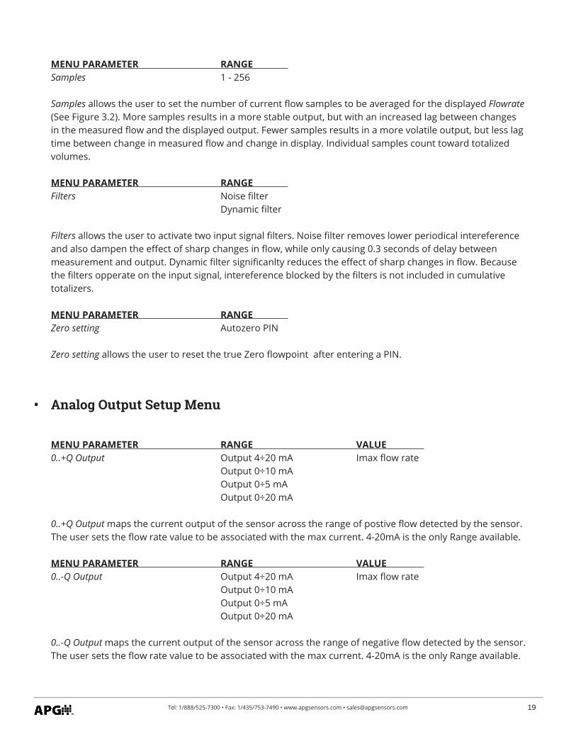
MENU PARAMETER RANGE Samples 1 - 256 Samples allows the user to set the number of current flow samples to be averaged for the displayed Flowrate (See Figure 3.2). More samples results in a more stable output, but with an increased lag between changes in the measured flow and the displayed output. Fewer samples results in a more volatile output, but less lag time between change in measured flow and change in display. Individual samples count toward totalized volumes.
MENU PARAMETER RANGE Filters Noise filter Dynamic filter Filters allows the user to activate two input signal filters. Noise filter removes lower periodical intereference and also dampen the effect of sharp changes in flow, while only causing 0.3 seconds of delay between measurement and output. Dynamic filter significanlty reduces the effect of sharp changes in flow. Because the filters opperate on the input signal, intereference blocked by the filters is not included in cumulative totalizers.
MENU PARAMETER RANGE Zero setting Autozero PIN Zero setting allows the user to reset the true Zero flowpoint after entering a PIN.
MENU PARAMETER RANGE VALUE 0..+Q Output Output 4÷20 mA Imax flow rate Output 0÷10 mA Output 0÷5 mA Output 0÷20 mA 0..+Q Output maps the current output of the sensor across the range of postive flow detected by the sensor. The user sets the flow rate value to be associated with the max current. 4-20mA is the only Range available.
MENU PARAMETER RANGE VALUE 0..-Q Output Output 4÷20 mA Imax flow rate Output 0÷10 mA Output 0÷5 mA Output 0÷20 mA 0..-Q Output maps the current output of the sensor across the range of negative flow detected by the sensor. The user sets the flow rate value to be associated with the max current. 4-20mA is the only Range available.
• Analog Output Setup Menu
20 Tel: 1/888/525-7300 • Fax: 1/435/753-7490 • www.apgsensors.com • [email protected]
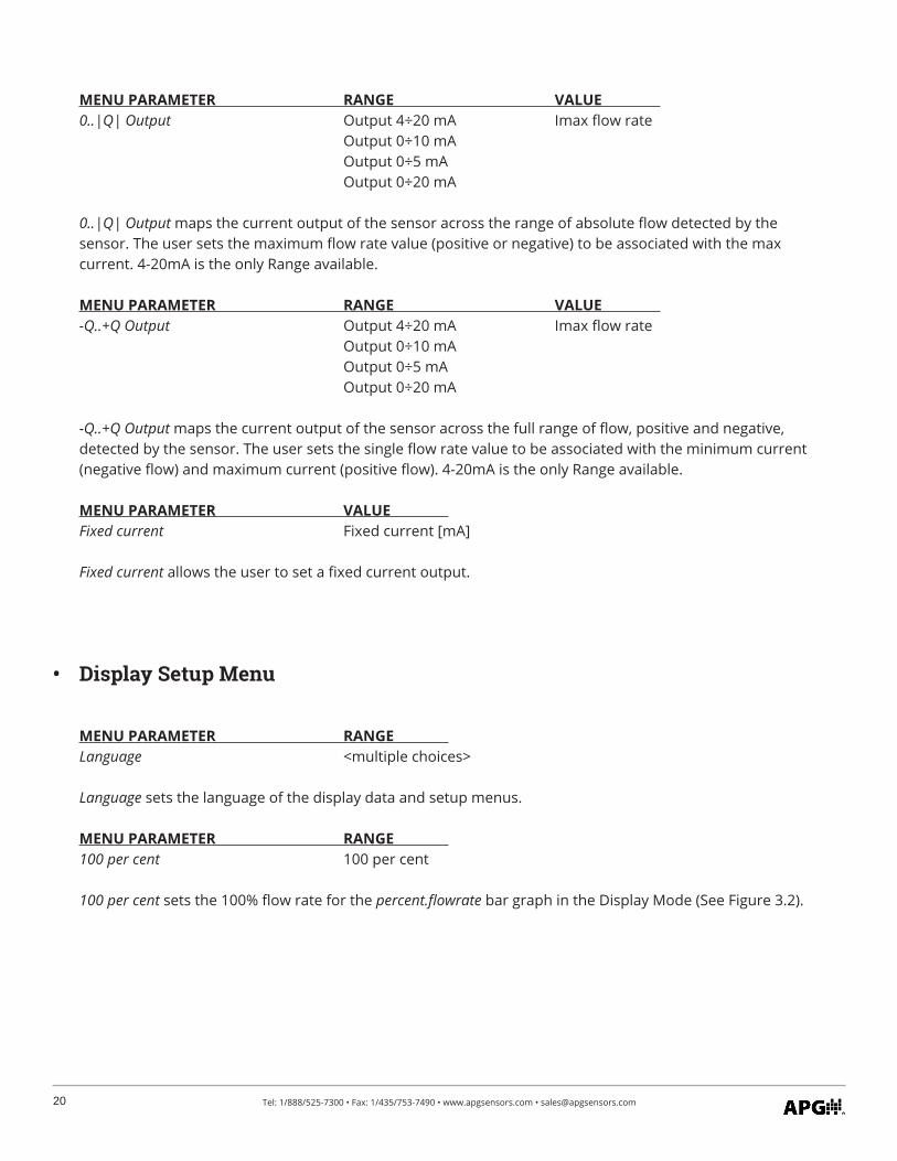
MENU PARAMETER RANGE VALUE 0..|Q| Output Output 4÷20 mA Imax flow rate Output 0÷10 mA Output 0÷5 mA Output 0÷20 mA 0..|Q| Output maps the current output of the sensor across the range of absolute flow detected by the sensor. The user sets the maximum flow rate value (positive or negative) to be associated with the max current. 4-20mA is the only Range available.
MENU PARAMETER RANGE VALUE -Q..+Q Output Output 4÷20 mA Imax flow rate Output 0÷10 mA Output 0÷5 mA Output 0÷20 mA -Q..+Q Output maps the current output of the sensor across the full range of flow, positive and negative, detected by the sensor. The user sets the single flow rate value to be associated with the minimum current (negative flow) and maximum current (positive flow). 4-20mA is the only Range available.
MENU PARAMETER VALUE Fixed current Fixed current [mA] Fixed current allows the user to set a fixed current output.
MENU PARAMETER RANGE Language <multiple choices> Language sets the language of the display data and setup menus.
MENU PARAMETER RANGE 100 per cent 100 per cent 100 per cent sets the 100% flow rate for the percent.flowrate bar graph in the Display Mode (See Figure 3.2).
• Display Setup Menu

21Tel: 1/888/525-7300 • Fax: 1/435/753-7490 • www.apgsensors.com • [email protected]
MENU PARAMETER RANGE Value 1 Value 2 Flow rate units m3/sec m3/min m3/hr ml/sec ml/min ml/hr gal/sec gal/min gal/h Mgal/d User’s Flow rate multipl Unit’s name l/sec l/min l/hr hl/sec hl/min hl/hr Flow rate units sets the volume units used for all displays and totalizers. User’s allows the user to define units as a multiple of l/s.
MENU PARAMETER RANGE Decimal places 0-4 Decimal places sets the number of displayed decimal places for flow and volume.
MENU PARAMETER RANGE Backlight 0 (always off) 1-254 seconds 255 (always on) Backlight sets the number of seconds the backlight remains on after the last button press.
MENU PARAMETER RANGE Display select Flowrate Total volume+ Total volume- Total difference Operational time Percent.flowrate Last error Real time Display select allows the user to choose the values displayed in Display Mode (See Figure 3.2).

22 Tel: 1/888/525-7300 • Fax: 1/435/753-7490 • www.apgsensors.com • [email protected]
MENU PARAMETER Exit Menu Exit Menu save all changes made in Setup Menus and returns the FM100 to Display Mode.
MENU PARAMETER Value New Password 4 alpha-numeric characters New Password sets a new 4-character password for the Setup Menus. See Enter/Change Password.
• Exit Menu
IMPORTANT: You MUST use the Exit Menu to save any changes in the Setup Menus. Cycling back to Display Mode using the Display Button leaves unsaved changes vulnerable to being lost in the event of power outage.
MENU PARAMETER RANGE Error messages E0 E1 E2 E3 E4 E5 E6 E7 E8 E9 E10 E11 E12 E13 Error messages allows the user to enable or disable each error code. See Chapter 4 Error Messages for explanations of each error message.

23Tel: 1/888/525-7300 • Fax: 1/435/753-7490 • www.apgsensors.com • [email protected]
Chapter 4: Error Messages
ERROR CODE ERROR TITLE E0 No Error
E0 indicates no recent error. ERROR CODE ERROR TITLE E1Mx EEPROM Checksum error E1 indicates a checksum error (invalid input) in the module indicated (Mx). Check data in indicated module and resave. Menu module numbers are shown in Figure 3.3. ERROR CODE ERROR TITLE E2 Stack overflowE3 Frequency limit exceeded E2 and E3 indicate pulse frequency settings are too low for measured flow rate. ERROR CODE ERROR TITLE E4 Power fail E4 appears for a short time after a power failure. ERROR CODE ERROR TITLE E5 Old software E5 indicates that firmware in the converter is too old to work with an installed module. Firmware upgrade is required. ERROR CODE ERROR TITLE E6 Can’t use this mode E6 indicates a module has been installed in the wrong position. ERROR CODE ERROR TITLE E7 Sensor loop disconnected E7 indicates current is not flowing to the current detecting coils.
• Error Codes and Explanations

24 Tel: 1/888/525-7300 • Fax: 1/435/753-7490 • www.apgsensors.com • [email protected]
ERROR CODE ERROR TITLE E8 Empty pipe E8 indicates full pipe sensor is not submersed.
ERROR CODE ERROR TITLE E9 Low medium conductivity E9 indicates sensing electrodes are not sensing current in fluid. ERROR CODE ERROR TITLE E10 MBus conflict E10 indicates networking error. ERROR CODE ERROR TITLE E11 Current output overrange E11 indicates that flow rate measured is higher than max flow rate set in Analog Output Setup Menu. Increase max current setting. ERROR CODE ERROR TITLE E12 Serial line fail communication error E12 indicates a network communication error. ERROR CODE ERROR TITLE E13 Sensor signal overrange E13 indicates the signal from the sensor to the converter is beyond the converter’s range. Check sensor and cables for short circuit.

25Tel: 1/888/525-7300 • Fax: 1/435/753-7490 • www.apgsensors.com • [email protected]
Should you have problems with your FM100, here are some troubleshooting steps.• Check the Last Error display (See Figure 3.2) for recent error. See Chapter 4 Error Messages for error
codes and explanations.• Check that all wiring is connected correctly and securely.• Check that sensor is grounded correctly and completely (See Grounding Instructions, page 8).
• Trouble Shooting
Your FM100 flowmeter is very low maintenance and will need little care as long as it was installed correctly (See Installation Requirements and Recommendations, pages 5-7). However, in general, you should:
• Avoid applications for which the sensor was not designed, such as extreme temperatures, contact with incompatible corrosive chemicals, or other damaging environments.
• Ensure that the sensor chamber is fully flooded whenever the sensor is powered on.
Chapter 5: Maintenance
• General Care
Should your flowmeter require service, please contact the factory via phone, email, or online chat. We will issue you a Return Material Authorization (RMA) number with instructions.
• Phone: 888-525-7300• Email: [email protected]• Online chat at www.apgsensors.com
Please have your FM100’s part number and serial number available. See Warranty and Warranty Restrictions for more information.
• Repair and Returns

Automation Products Group, Inc.Tel: 1/888/525-7300 • Fax: 1/435/753-7490 • www.apgsensors.com • [email protected]
APGR

![User's AXF Manual Magnetic Flowmeter Integral Flowmeter ... · Magnetic Flowmeter Integral Flowmeter/ Remote Flowtube [Hardware Edition] IM 01E20D01-01E IM 01E20D01-01E 7th Edition](https://img.pdfslide.us/doc/110x75/5e9c29fa54300501b21ae83a/users-axf-manual-magnetic-flowmeter-integral-flowmeter-magnetic-flowmeter-integral.jpg)


![AXR Two-wire Magnetic Flowmeter Integral Flowmeter [Style:S2]User’s Manual AXR Two-wire Magnetic Flowmeter Integral Flowmeter [Style:S2] IM 01E30D01-01EN IM 01E30D01-01EN 8th Edition](https://img.pdfslide.us/doc/110x75/6030690230362b13964fde5e/axr-two-wire-magnetic-flowmeter-integral-flowmeter-styles2-useras-manual-axr.jpg)


![AXR Two-wire Magnetic Flowmeter Integral Flowmeter [Style:S2]](https://img.pdfslide.us/doc/110x75/62cb14e07ee31d38b74d3e5b/axr-two-wire-magnetic-flowmeter-integral-flowmeter-styles2.jpg)