Embed Size (px)
Citation preview
MELSEC A Series
Programmable Logic Controller
User's Manual(Hardware)
A(1S)J71QE71N3-T,A(1S)J71QE71N-B5,A(1S)J71QE71N-B2
Ethernet Interface Module
MITSUBISHI ELECTRIC
MITSUBISHI ELECTRIC
01 12 2004IB(NA)-0800309Version A
INDUSTRIAL AUTOMATION

A-1
DANGER
CAUTION
SAFETY PRECAUTIONS (Always read before starting use)
When using Mitsubishi equipment, thoroughly read this manual and theassociated manuals introduced in the manual. Also pay careful attention tosafety and handle the module properly.These precautions apply only to the installation of Mitsubishi equipment and thewiring with the external device. Refer to the user's manual of the CPU moduleto be used for a description of the PLC system safety precautions.These SAFETY PRECAUTIONS classify the safety precautions into twocategories: "DANGER" and "CAUTION".
Procedures which may lead to a dangerous condition andcause death or serious injury if not carried out properly.
Procedures which may lead to a dangerous condition andcause superficial to medium injury, or physical damageonly, if not carried out properly.
Depending on circumstances, procedures indicated by CAUTION may alsobe linked to serious results.In any case, it is important to follow the directions for usage.Store this manual in a safe place so that you can take it out and read itwhenever necessary. Always forward it to the end user.

A-2
[DESIGN PRECAUTIONS]
CAUTION When laying the control wire or communication cable, do not bundle with orplace near main circuit or power line.Keep them at least 100 mm (3.94 in.) away from such cables.Noise may cause erroneous operation.
[INSTALLATION PRECAUTIONS]
CAUTION Use the PLC in the environment given in the general specifications sectionof the user's manual to be used. Using the PLC outside the range of thegeneral specifications may result in electric shock, fire, or erroneousoperation or may damage or degrade the product.
Insert the fixing latch on the bottom of the module into the fixing hole in thebase unit and install the module using the hole point as a fulcrum. (TheQ2AS series module shall be fastened by screws in the base unit at thespecified torque.)Not installing the module correctly could result in erroneous operation,damage, or pieces of the product falling.
Tighten the screw within the range of specified torque.If the screws are loose, it may result in fallout, short circuits or malfunction.Tightening the screws to far may cause damage to the screw and/or themodule, resulting in fallout, short circuits or malfunction.
Shut off all phases of the external power supply in the system beforemounting or dismounting the module.If you do not switch off the external power supply, it will cause electricshock or damage to the product.
Do not touch the electronic parts or the module conducting area directly.It may cause erroneous operation or failure.

A-3
[WIRING PRECAUTIONS]
CAUTION Perform correct pressure-displacement, crimp-contact or soldering forexternal wire connections using the tools specified by the manufactures.Incorrect connection may cause short circuits, fire or malfunction.
Attach connector to the module securely. Be sure to fix communication cables or power supply cables leading fromthe module by placing them in the duct or clamping them. Cables notplaced in the duct or without clamping may hang or shift, alllowing them tobe accidentally pulled, which may cause a module malfunction and cabledamage.
Tighten the screw within the range of specified torque.If the screws are loose, it may result in short circuits or malfunction.Tightening the screws to far may cause damage to the screw and/or themodule, resulting in fallout, short circuits or malfunction.
Do not grab on the cable when removing the communication cableconnected to the module.When removing the cable with a connector, hold the connector on the sidethat is connected to the module.When removing the cable connected to the terminal block, first loosen thescrews on the part that is connected to the terminal block.Pulling the cable that is still connected to the module may cause amalfunction or damage to the module or cable.
Solder coaxial cable connectors properly.Insufficient soldering may cause malfunction.
Be sure that cuttings, wire chips, or other foreign matter do not enter themodule.Foreign matter may start a fire or cause an accident or erroneousoperation.

A-4
RevisionsThe manual number is noted at the lower right of the top cover.
Print Date *Manual Number RevisionDec.,2004 IB(NA)-0800309-A First printing
This manual confers no industrial property rights or any rights of any other kind, nor doesit confer any patent licenses. Mitsubishi electric Corporation cannot be held responsiblefor any problems involving industrial property rights which may occur as a result of usingthe contents noted in this manual.
2004 MITSUBISHI ELECTRIC CORPORATION

A-5
CONTENTS
1. Overview....................................................................................................... 12. Performance Specifications .......................................................................... 23. Settings and Names of Each Part ................................................................. 54. Loading and Installation................................................................................ 9
4.1 Handling Precautions ............................................................................... 94.2 Installation Environment ........................................................................... 9
5. Connection to a Network............................................................................. 105.1 Connecting to the 10BASE-T (AJ71QE71N3-T, A1SJ71QE71N3-T)...... 115.2 Connecting to the 10BASE5 (AJ71QE71N-B5, A1SJ71QE71N-B5)....... 115.3 Connecting to the 10BASE2 (AJ71QE71N-B2, A1SJ71QE71N-B2)....... 11
6. External Dimensions................................................................................... 12
A-6
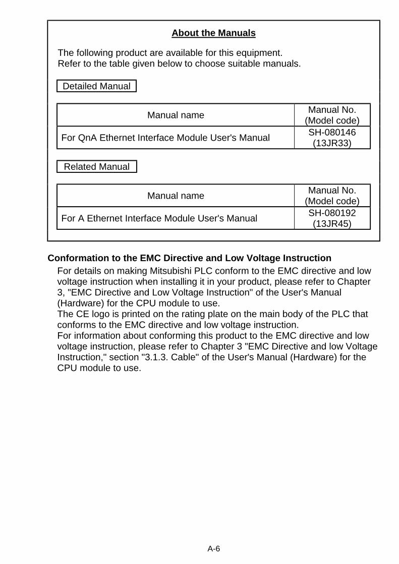
About the Manuals
The following product are available for this equipment.Refer to the table given below to choose suitable manuals.
Detailed Manual
Manual name Manual No.(Model code)
For QnA Ethernet Interface Module User's Manual SH-080146(13JR33)
Related Manual
Manual name Manual No.(Model code)
For A Ethernet Interface Module User's Manual SH-080192(13JR45)
Conformation to the EMC Directive and Low Voltage InstructionFor details on making Mitsubishi PLC conform to the EMC directive and lowvoltage instruction when installing it in your product, please refer to Chapter3, "EMC Directive and Low Voltage Instruction" of the User's Manual(Hardware) for the CPU module to use.The CE logo is printed on the rating plate on the main body of the PLC thatconforms to the EMC directive and low voltage instruction.For information about conforming this product to the EMC directive and lowvoltage instruction, please refer to Chapter 3 "EMC Directive and low VoltageInstruction," section "3.1.3. Cable" of the User's Manual (Hardware) for theCPU module to use.
1
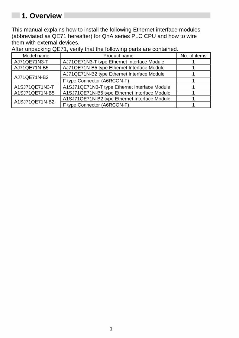
1. Overview
This manual explains how to install the following Ethernet interface modules(abbreviated as QE71 hereafter) for QnA series PLC CPU and how to wirethem with external devices.After unpacking QE71, verify that the following parts are contained.
Model name Product name No. of itemsAJ71QE71N3-T AJ71QE71N3-T type Ethernet Interface Module 1AJ71QE71N-B5 AJ71QE71N-B5 type Ethernet Interface Module 1
AJ71QE71N-B2 type Ethernet Interface Module 1AJ71QE71N-B2
F type Connector (A6RCON-F) 1A1SJ71QE71N3-T A1SJ71QE71N3-T type Ethernet Interface Module 1A1SJ71QE71N-B5 A1SJ71QE71N-B5 type Ethernet Interface Module 1
A1SJ71QE71N-B2 type Ethernet Interface Module 1A1SJ71QE71N-B2 F type Connector (A6RCON-F) 1

2
2. Performance Specifications
The performance specifications of QE71 is shown below. See CPU moduleuser's manual to be used for QE71 general specifications.
SpecificationsAJ71QE71N3-T
A1SJ71QE71N3-TItem
10BASE-TData transmissionspeed 10 Mbps
Communication mode Half-duplexTransmission method Base bandMaximum distancebetween nodes —Maximum segmentlength 100 m (328.08 ft.) ( 1)
Maximum number ofnodes/connection Cascade connection is a maximum 4 stages
Transmissionspecifications
Minimum node interval —Number of allowablesimultaneously openconnections
8 connections(Connections usable by the sequence program)
Fixed buffer 1 k word × 8
Transmissiondata storagememory
Random access buffer 6 k word × 1Number of remote nodes that can becommunicated in a single initialprocessing
No restrictions
EEPROM write frequency Maximum of 10,000 times in the same areaNumber of occupied I/O points 32 points /1 slot (I/O assignments : special 32 points)
5 V DC internal current consumption AJ71QE71N3-T : 0.53AA1SJ71QE71N3-T : 0.53A
Connector Modular jack (RJ45)
Connection cable Unshielded twisted pair cable (UTP), or shielded twistedpair cable (STP) rated in category 3, 4 or 5
12 V DC external power supplycapacity (for transceiver) —
External dimensions
AJ71QE71N3-T : 250 (9.84) (H) × 37.5 (1.48) (W) × 106 (4.17) (D) [mm (in.)]A1SJ71QE71N3-T : 130 (5.12) (H) × 34.5 (1.36) (W) × 94 (3.70) (D) [mm (in.)] All do not include the protruded section on the frontsurface.
Weight AJ71QE71N3-T : 0.30 kg (0.66Ib.)A1SJ71QE71N3-T : 0.18 kg (0.37Ib.)

3
SpecificationsAJ71QE71N-B5
A1SJ71QE71N-B5AJ71QE71N-B2
A1SJ71QE71N-B2Item
10BASE5 10BASE2Data transmissionspeed 10 Mbps
Communication mode Half-duplexTransmission method Base bandMaximum distancebetween nodes 2500 m (8202.10 ft.) 925 m (3034.77 ft.)
Maximum segmentlength 500 m (1640.42 ft.) 185 m (606.96 ft.)
Maximum number ofnodes/connection 100 nodes per segment 30 nodes per segment
Transmissionspecifications
Minimum node interval 2.5m (8.20 ft.) 0.5m (1.64 ft.)Number of allowablesimultaneously openconnections
8 connections(Connections usable by the sequence program)
Fixed buffer 1 k word × 8
Transmissiondata storagememory
Random access buffer 6 k word × 1Number of remote nodes that can becommunicated in a single initialprocessing
No restrictions
EEPROM write frequency Maximum of 10,000 times in the same areaNumber of occupied I/O points 32 points /1 slot (I/O assignments : special 32 points)
5 V DC internal current consumption AJ71QE71N-B5 : 0.40AA1SJ71QE71N-B5 : 0.40A
AJ71QE71N-B2 : 0.56AA1SJ71QE71N-B2 : 0.53A
Connector D-sub connector(Male 15-pin) BCN connector
Connection cable AUI cable(Twisted pair cable)
Coaxial Cable(RG58A/U, RG58C/U)
12 V DC external power supplycapacity (for transceiver) ( 2) —
External dimensions
AJ71QE71N-B5, AJ71QE71N-B2 : 250 (9.84) (H) × 37.5 (1.48) (W) × 106 (4.17) (D) [mm (in.)]A1SJ71QE71N-B5, A1SJ71QE71N-B2 : 130 (5.12) (H) × 34.5 (1.36) (W) × 94 (3.70) (D) [mm (in.)] All do not include the protruded section on the frontsurface.
Weight
AJ71QE71N-B5 : 0.33kg (0.73Ib.)A1SJ71QE71N-B5 : 0.19kg (0.42Ib.)
AJ71QE71N-B2 : 0.35kg (0.77Ib.)A1SJ71QE71N-B2 : 0.20kg (0.44Ib.)
1 Length between hub and node.2 It is required to use the one that satisfies the specifications of the
transceiver and the AUI cable. Also, for the AJ71QE71N-B5, the voltagedrop (Max. 0.8V) must be taken into account.

4
Notes (1) Each item in the transmission specifications gives supplementaryexplanation.•When connected by 10BASE2, 10BASE5
Segment lengthSe
gmen
t len
gth
Node
Node
Node
Node
Node
Transceiver
Terminator
Repe- ater
Maximum distance between nodes
Repe- ater
Segm
ent l
engt
h
• When connected by 10BASE-T
Maximum 100 m (328.08 ft.)
Maximum 100 m (328.08 ft.)
QE71
Hub
Cascade connection is a maximum of 4 stages
(2) Hardware specifications for QE71 are based on IEEE802.3.

5
3. Settings and Names of Each Part AJ71QE71N-B5 AJ71QE71N-B2AJ71QE71N3-T
1)
ON
10BASE5
EXT.PW
(FG)
EXT.PW
AJ71QE71N-B5
RUN BUF1BUF2BUF3BUF4BUF5BUF6BUF7BUF8
RDYBSY
SW.ERR.COM.ERR.CPU R/W
TESTTEST ERR.
SW1SW2SW3SW4SW5SW6SW7SW8
MODE
0:ONLINE1:OFFLINE2:TEST13:TEST24:TEST35:TEST4
4
CBA9
DEF123567
8 0
ON
SW1SW2SW3SW4SW5SW6SW7SW8
MODE
4
CB
9
D F1
3578
0
OFF
AJ71QE71N-B2
RUN BUF1BUF2BUF3BUF4BUF5BUF6BUF7BUF8
RDYBSY
SW.ERR.COM.ERR.CPU R/W
TESTTEST ERR.
0:ONLINE1:OFFLINE2:TEST13:TEST24:TEST35:TEST4
3)
2)
1)
3)
2)
1)
3)
2)
5)
6)
7)
8)
10BASE-T
B
43210F
EDCA98 7 6 5
RUN BUF1BUF2BUF3BUF4BUF5BUF6BUF7BUF8
RDYBSY
SW.ERR.COM.ERR.
CPU R/W
TESTTEST ERR.
AJ71QE71N3-T
ON
0:ONLINE
5:TEST44:TEST33:TEST22:TEST11:OFFLINE
MODE
SW8SW7SW6SW5SW4SW3SW2SW1
4)(*1)
A1SJ71QE71N-B5
EXT.PW
10BASE5
MODE
A1SJ71QE71N-B5
BSYSW.ERR.
COM.ERR.
CPU R/WTEST ERR.
TEST
RDYRUN BUF1
BUF2BUF3BUF4BUF5BUF6BUF7BUF8
0:ONLINE1:OFFLINE2:TEST13:TEST24:TEST35:TEST4
4
CBA9
DEF123567
8 0
A1SJ71QE71N-B5 A1SJ71QE71N-B2A1SJ71QE71N3-T
1)
2)
3)
8)
1)
2)
7)
6)
1)
2)
3)
3)OFF ON
Side view indicatedby arrow A
A1SJ71QE71N-B2
SW2 SW3 SW4 SW5 SW6 SW7
OFF ON
MODE
08
F
7E
6
D
5
C
4
B
3
A
29
1
SW8
SW1
A1SJ71QE71N-B2
BSYSW.ERR.
COM.ERR.
CPU R/WTEST ERR.
TEST
RDYRUN BUF1
BUF2BUF3BUF4BUF5BUF6BUF7BUF8
0:ONLINE1:OFFLINE2:TEST13:TEST24:TEST35:TEST4
A
ON
SW1SW2SW3SW4SW5SW6SW7SW8
10BASE-T
A1SJ71QE71N3-T
4:TEST33:TEST22:TEST11:OFFLINE0:ONLINE
5:TEST4
MODE
56789
ABCDEF‚O1234
BSYSW.ERR.
COM.ERR.
CPU R/WTEST ERR.
TEST
RDYRUN BUF1
BUF2BUF3BUF4BUF5BUF6BUF7BUF8
A1SJ71QE71N3-T
4)(*1)

6
No. Designation Contents1) Display LED Refer to (1)
2) Operation mode settingswitch Refer to (2)
3) Exchange condition settingswitch Refer to (3)
4) 10BASE-T connector (RJ45) Connector for connecting the QE71 to the 10BASE-T.
5) External power supplyindicator lamp
Lamp for verifying if power is being supplied to thetransceiver.ON: Power supplyingOFF: Power not supplied
6) External power supplyterminal
Power source terminals for power source supply tothe transceiverAJ71QE71N-B5 : 14.08V to 15.75VA1SJ71QE71N-B5 :13.28V to 15.75V
7) AUI cable connectorConnector for connecting the QE71 to the 10BASE5.(For connection of 10BASE5-use AUI cable(transceiver cable))
8) 10BASE2 connector Connector for connecting the QE71 to the 10BASE2.
(1) Display LED display contentsDisplay LED Display contents When lamp is lit Lamp is not lit
RUN Normal operation display Normal Error
RDY Exchange ready end display Starts flashing when On-lineOperations begin
BSY Exchange processing executingdisplay
Turns on when exchange processingwith remote node is being executed.
SW.ERR. CPU error, CPU type error display Error NormalCOM.ERR. Exchange error detection display Exchange error Normal
CPU R/W Exchange processing executingwith PLC CPU display Exchanging Not exchanging
BUF1 toBUF8
Display of communication lineconnection status of connectionNo.n corresponding to BUFn.
Open completed Closed status
TEST Self diagnostic executing display Self diagnosisexecuting
Self diagnosiscompleted
TEST ERR. Self diagnosis results display Error Normal

7
Remark
The order of the display LEDs is shown below.
RUN RDY
BSY SW.ERR.
COM.ERR. CPU R/W
BUF1 BUF2 BUF3 BUF4 BUF5 BUF6 BUF7 BUF8
TEST TEST ERR.
RUN RDY BSY
SW.ERR.COM.ERR.
TEST TEST ERR.
CPU R/W
BUF1 BUF2 BUF3 BUF4 BUF5 BUF6 BUF7 BUF8
AJ71QE71N3-T, AJ71QE71N-B5,AJ71QE71N-B2
A1SJ71QE71N3-T, A1SJ71QE71N-B5,A1SJ71QE71N-B2
(2) Operation mode setting switch settingSet the QE71 operation mode. (Usually set to on-line)
Operation modesetting switch
Settingnumber
Settingdesignation Setting contents
0 On-line Performs exchange with remote node in thenormal operation mode.
1 Off-line Disconnects the local station from the network.
2 Test 1 Performs a self diagnosis test using a selfloopback test.
3 Test 2 Performs a RAM test.4 Test 3 Performs a ROM test.5 Test 4 Performs an EEPROM test.
C
4
B
3
A
2
9
18 0
7
F6
E
5
D
6 to F Usage not impossible(This is set at ''0 (on-line)'' at the time of shipping from factory.)
8
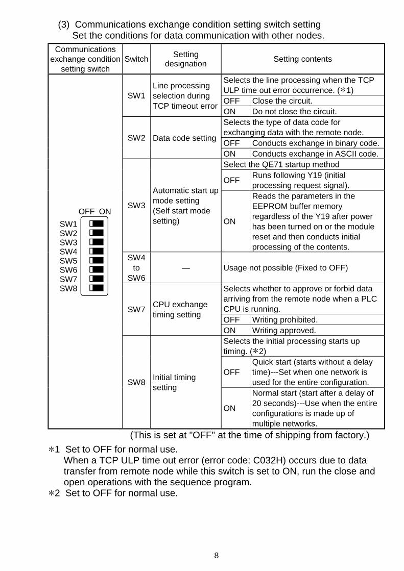
(3) Communications exchange condition setting switch settingSet the conditions for data communication with other nodes.
Communicationsexchange condition
setting switchSwitch Setting
designation Setting contents
Selects the line processing when the TCPULP time out error occurrence. ( 1)OFF Close the circuit.SW1
Line processingselection duringTCP timeout error ON Do not close the circuit.
Selects the type of data code forexchanging data with the remote node.OFF Conducts exchange in binary code.SW2 Data code setting
ON Conducts exchange in ASCII code.Select the QE71 startup method
OFF Runs following Y19 (initialprocessing request signal).
SW3
Automatic start upmode setting(Self start modesetting) ON
Reads the parameters in theEEPROM buffer memoryregardless of the Y19 after powerhas been turned on or the modulereset and then conducts initialprocessing of the contents.
SW4to
SW6— Usage not possible (Fixed to OFF)
Selects whether to approve or forbid dataarriving from the remote node when a PLCCPU is running.OFF Writing prohibited.
SW7 CPU exchangetiming setting
ON Writing approved.Selects the initial processing starts uptiming. ( 2)
OFFQuick start (starts without a delaytime)---Set when one network isused for the entire configuration.
OFF ONSW1 SW2 SW3 SW4 SW5 SW6 SW7 SW8
SW8 Initial timingsetting
ON
Normal start (start after a delay of20 seconds)---Use when the entireconfigurations is made up ofmultiple networks.
(This is set at "OFF" at the time of shipping from factory.)1 Set to OFF for normal use.
When a TCP ULP time out error (error code: C032H) occurs due to datatransfer from remote node while this switch is set to ON, run the close andopen operations with the sequence program.
2 Set to OFF for normal use.

9
4. Loading and Installation
The following is explanations of the handling precautions and installationenvironment which is common to modules when handling QE71 fromunpacking to installation.For the details of loading and installation of the module, refer to User's Manualof CPU module to be used.
4.1 Handling PrecautionsThe following is an explanation of handling precautions of the module.
(1) Because the case of the module is made of resin, be careful not to drop itor expose it to strong impact.
(2) Always make sure to touch the grounded metal to discharge the electricitycharged in the body, etc., before touching the module.Failure to do so may cause a failure or malfunctions of the module.
(3) Execute tightening of the module's installation screws within the rangeindicated below.
Screw position Tightening torque rangeExternal power supply terminalscrew ( 1)
AJ71QE71N-B5 : 98 to 137 N⋅cm (M4 screw)A1SJ71QE71N-B5 : 40 N⋅cm(M2.5 screw)
Module fixing screw 78 to 118 N⋅cm (M4 screw)1: This terminal is used as an external power input terminal for supplying
power to the transceiver when being connected to a 10BASE5.
4.2 Installation EnvironmentRefer to User's Manual of CPU module to be used.
10
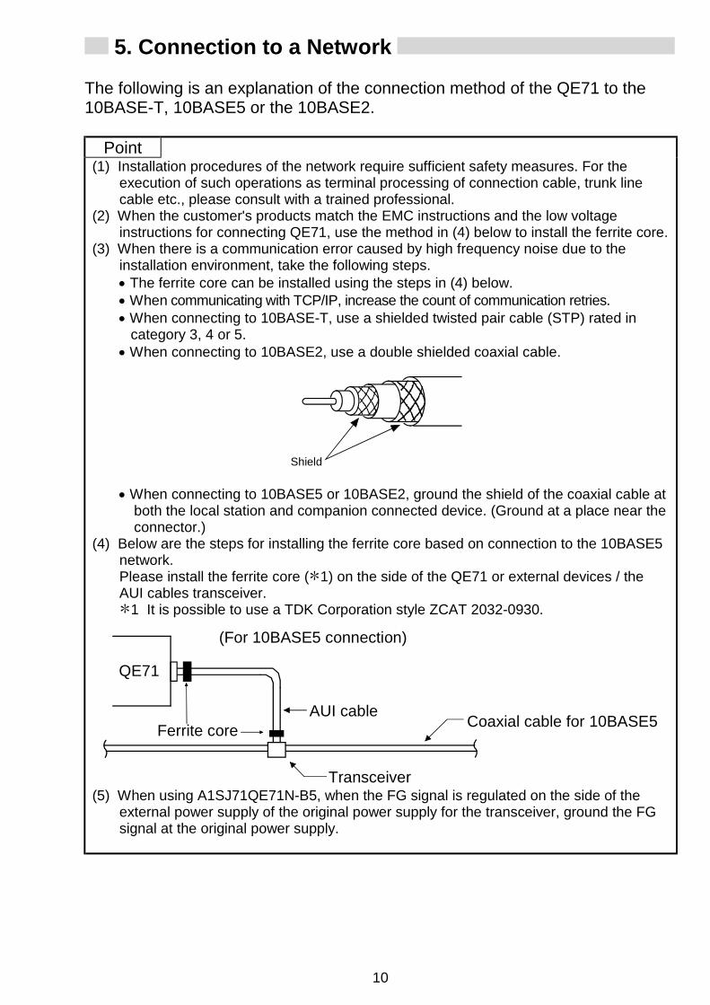
5. Connection to a Network
The following is an explanation of the connection method of the QE71 to the10BASE-T, 10BASE5 or the 10BASE2.
Point(1) Installation procedures of the network require sufficient safety measures. For the
execution of such operations as terminal processing of connection cable, trunk linecable etc., please consult with a trained professional.
(2) When the customer's products match the EMC instructions and the low voltageinstructions for connecting QE71, use the method in (4) below to install the ferrite core.
(3) When there is a communication error caused by high frequency noise due to theinstallation environment, take the following steps.• The ferrite core can be installed using the steps in (4) below.• When communicating with TCP/IP, increase the count of communication retries.• When connecting to 10BASE-T, use a shielded twisted pair cable (STP) rated in
category 3, 4 or 5.• When connecting to 10BASE2, use a double shielded coaxial cable.
Shield
• When connecting to 10BASE5 or 10BASE2, ground the shield of the coaxial cable atboth the local station and companion connected device. (Ground at a place near theconnector.)
(4) Below are the steps for installing the ferrite core based on connection to the 10BASE5network.Please install the ferrite core ( 1) on the side of the QE71 or external devices / theAUI cables transceiver.
1 It is possible to use a TDK Corporation style ZCAT 2032-0930.
QE71
Ferrite coreAUI cable Coaxial cable for 10BASE5
Transceiver
(For 10BASE5 connection)
(5) When using A1SJ71QE71N-B5, when the FG signal is regulated on the side of theexternal power supply of the original power supply for the transceiver, ground the FGsignal at the original power supply.

11
5.1 Connecting to the 10BASE-T (AJ71QE71N3-T, A1SJ71QE71N3-T)
For AJ71QE71N3-T
<Connection procedure>1) Connect the twisted pair cable and the
hub.2) Connect the twisted pair cable to the
QE71.
5.2 Connecting to the 10BASE5 (AJ71QE71N-B5, A1SJ71QE71N-B5)
Supply power for transceiver
AUI Cable A
B
Retainer
For AJ71QE71N-B5
<Connection procedure> ( 1)1) Slide the retainer toward the direction A as
shown in the figure.2) Push in the AUI cable connector all the
way.3) Slide the retainer toward the direction B as
shown in the figure.4) Confirm that the AUI cable is locked.5) Supply power to the transceiver ( 2).
(Refer to 2 in Chapter 2)
1 Connect the AUI cable while the power to the module mounting station isturned off.
2 Use a transceiver with a function that is generally called SQETEST orheart beat (a transceiver function that emits signals to notify whether thetransceiver is operating normally at the end of communication).
5.3 Connecting to the 10BASE2 (AJ71QE71N-B2, A1SJ71QE71N-B2)
[2]
[1]
For AJ71QE71N-B2
<Connection procedure> ( 2)1) Push in the connector by aligning the
groove [1] and tab [2] as shown in thefigure.
2) While pushing in the connector, rotate itclockwise by a 1/4 turn.
3) Turn until the connector locks.4) Confirm that the connector is locked.

12
6. External Dimensions
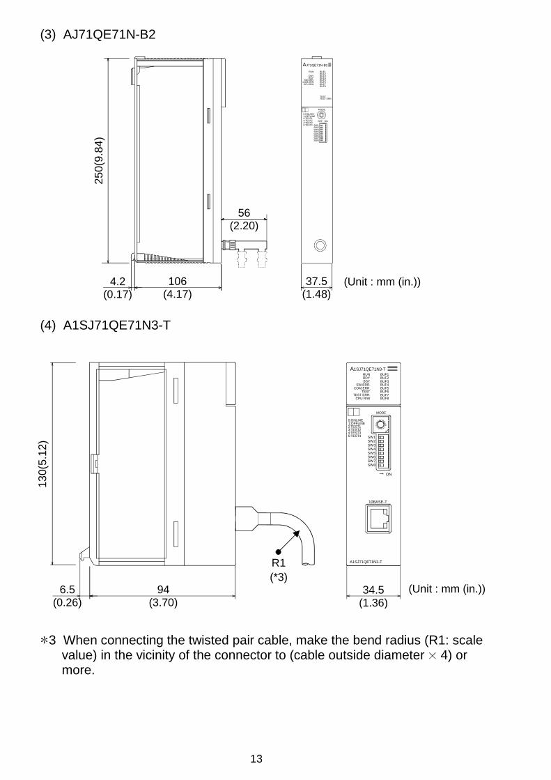
(1) AJ71QE71N3-T
250(
9.84
)
(Unit : mm (in.))106(4.17)
4.2(0.17)
37.5(1.48)
R1(*1)
10BASE-T
B
43210F
EDCA98 7 65
RUN BUF1BUF2BUF3BUF4BUF5BUF6BUF7BUF8
RDYBSY
SW.ERR.COM.ERR.
CPU R/W
TESTTEST ERR.
AJ71QE71N3-T
ON
0:ONLINE
5:TEST44:TEST33:TEST22:TEST11:OFFLINE
MODE
SW8SW7SW6SW5SW4SW3SW2SW1
1 When connecting the twisted pair cable, make the bend radius (R1: scalevalue) in the vicinity of the connector to (cable outside diameter 4) ormore.
(2) AJ71QE71N-B5
250(
9.84
)
(Unit : mm (in.))4.2(0.17)
106(4.17)
14(0.55)
37.5(1.48)
ON
10BASE5
EXT.PW
(FG)
EXT.PW
AJ71QE71N-B5
RUN BUF1BUF2BUF3BUF4BUF5BUF6BUF7BUF8
RDYBSY
SW.ERR.COM.ERR.CPU R/W
TESTTEST ERR.
SW1SW2SW3SW4SW5SW6SW7SW8
MODE
0:ONLINE1:OFFLINE2:TEST13:TEST24:TEST35:TEST4
4
CBA9
DEF123567
8 0
R2(*2)
2 When connecting the AUI cable, make the bend radius (R2: scale value)in the vicinity of the connector to (cable outside diameter 4) or more.
13
(3) AJ71QE71N-B2
ON
SW1SW2SW3SW4SW5SW6SW7SW8
MODE
4
CBA9
DEF1235678
0
OFF
AJ71QE71N-B2
RUN BUF1BUF2BUF3BUF4BUF5BUF6BUF7BUF8
RDYBSY
SW.ERR.COM.ERR.CPU R/W
TESTTEST ERR.
0:ONLINE1:OFFLINE2:TEST13:TEST24:TEST35:TEST4
250(
9.84
)
(Unit : mm (in.))4.2(0.17)
106(4.17)
37.5(1.48)
56(2.20)
(4) A1SJ71QE71N3-T
(Unit : mm (in.))
130(
5.12
)
6.5(0.26)
94(3.70)
34.5(1.36)
R1(*3)
ON
SW1SW2SW3SW4SW5SW6SW7SW8
10BASE-T
A1SJ71QE71N3-T
4:TEST33:TEST22:TEST11:OFFLINE0:ONLINE
5:TEST4
MODE
56789
ABCDEF ‚O1234
BSYSW.ERR.
COM.ERR.
CPU R/WTEST ERR.
TEST
RDYRUN BUF1
BUF2BUF3BUF4BUF5BUF6BUF7BUF8
A1SJ71QE71N3-T
3 When connecting the twisted pair cable, make the bend radius (R1: scalevalue) in the vicinity of the connector to (cable outside diameter 4) ormore.

14
(5) A1SJ71QE71N-B5
(Unit : mm (in.))
130(
5.12
)
6.5(0.26)
94(3.70)
7.5(0.30)
34.5(1.36)
A1SJ71QE71N-B5
EXT.PW
10BASE5
MODE
A1SJ71QE71N-B5
BSYSW.ERR.
COM.ERR.
CPU R/WTEST ERR.
TEST
RDYRUN BUF1
BUF2BUF3BUF4BUF5BUF6BUF7BUF8
0:ONLINE1:OFFLINE2:TEST13:TEST24:TEST35:TEST4
4
CBA9
DEF123567
8 0
OFF ON
R2(*4)
4 When connecting the AUI cable, make the bend radius (R2: scale value)in the vicinity of the connector to (cable outside diameter 4) or more.
(6) A1SJ71QE71N-B2
A1SJ71QE71N-B2
SW2 SW3 SW4 SW5 SW6 SW7
OFF ON
MODE
08
F
7
E
6
D
5
C
4
B
3
A
2
9
1
SW8
SW1
A1SJ71QE71N-B2
BSYSW.ERR.
COM.ERR.
CPU R/WTEST ERR.
TEST
RDYRUN BUF1
BUF2BUF3BUF4BUF5BUF6BUF7BUF8
0:ONLINE1:OFFLINE2:TEST13:TEST24:TEST35:TEST4
(Unit : mm(in.))
130(
5.12
)
6.5(0.26)
94(3.70)
34.5(1.36)
56(2.20)
Ethernet is the registered trademark of XEROX CO., LTD.10BASE2 is the formal way to say Cheapernet.There is no registered trademark for Cheapernet.
WarrantyMitsubishi will not be held liable for damage caused by factors found not to be the cause ofMitsubishi; machine damage or lost profits caused by faults in the Mitsubishi products;damage, secondary damage, accident compensation caused by special factorsunpredictable by Mitsubishi; damages to products other than Mitsubishi products; and toother duties.
For safe use This product has been manufactured as a general-purpose part for general industries, andhas not been designed or manufactured to be incorporated in a device or system used inpurposes related to human life.
Before using the product for special purposes such as nuclear power, electric power,aerospace, medicine or passenger movement vehicles, consult with Mitsubishi.
This product has been manufactured under strict quality control. However, when installingthe product where major accidents or losses could occur if the product fails, installappropriate backup or failsafe functions in the system.
U.S.A Mitsubishi Electric Automation Inc. 500 Corporate Woods Parkway Vernon Hills, IL 60061 Tel : +1-847-478-2100Brazil MELCO-TEC Rep. Com.e Assessoria Tecnica Ltda. Rua Correia Dias, 184, Edificio Paraiso Trade Center-8 andar Paraiso, Sao Paulo, SP Brazil Tel : +55-11-5908-8331Germany Mitsubishi Electric Europe B.V. German Branch Gothaer Strasse 8 D-40880 Ratingen, GERMANY Tel : +49-2102-486-0U.K Mitsubishi Electric Europe B.V. UK Branch Travellers Lane, Hatfield, Herts., AL10 8XB,UK Tel : +44-1707-276100Italy Mitsubishi Electric Europe B.V. Italian Branch Centro Dir. Colleoni, Pal. Perseo-Ingr.2 Via Paracelso 12, 20041 Agrate B., Milano, Italy Tel : +39-039-6053344Spain Mitsubishi Electric Europe B.V. Spanish Branch Carretera de Rubi 76-80 08190 Sant Cugat del Valles, Barcelona, Spain Tel : +34-93-565-3131France Mitsubishi Electric Europe B.V. French Branch 25 Boulevard des Bouvets, F-92741 Nanterre Cedex, France TEL: +33-1-5568-5568South Africa Circuit Breaker Industries LTD. Tripswitch Drive, Elandsfontein Gauteng, South Africa Tel : +27-11-928-2000
Hong Kong Ryoden Automation Ltd. 10th Floor, Manulife Tower, 169 Electric Road, North Point, HongKong Tel : +852-2887-8870China Ryoden Automation Shanghai Ltd. 3F Block5 Building Automation Instrumentation Plaza 103 Cao Bao Rd. Shanghai 200233 China Tel : +86-21-6120-0808Taiwan Setsuyo Enterprise Co., Ltd. 6F., No.105 Wu-Kung 3rd.RD, Wu-Ku Hsiang, Taipei Hsine, Taiwan Tel : +886-2-2299-2499Korea HAN NEUNG TECHNO CO.,LTD. 1F Dong Seo Game Channel Bldg., 660-11, Deungchon-dong Kangsec-ku, Seoul, Korea Tel : +82-2-3660-9552Singapore Mitsubishi Electric Asia Pte, Ltd. 307 Alexandra Road #05-01/02, Mitsubishi Electric Building Singapore 159943 Tel : +65-6473-2308Thailand F. A. Tech Co.,Ltd. 898/28,29,30 S.V.City Building,Office Tower 2,Floor 17-18 Rama 3 Road, Bangkpongpang, Yannawa, Bangkok 10120 Tel : +66-2-682-6522Indonesia P.T. Autoteknindo SUMBER MAKMUR Jl. Muara Karang Selatan Block a Utara No.1 Kav. No.11 Kawasan Industri/ Pergudangan Jakarta - Utara 14440 Tel : +62-21-663-0833India Messung Systems Put,Ltd. Electronic Sadan NO:111 Unit No15, M.I.D.C BHOSARI,PUNE-411026, India Tel : +91-20-712-2807Australia Mitsubishi Electric Australia Pty. Ltd. 348 Victoria Road, PostalBag, No 2, Rydalmere, N.S.W 2116, Australia Tel : +61-2-9684-7777
Country/Region Sales office/Tel
When exported from Japan, this manual does not require application to the Ministry of Economy, Trade and Industry for service transaction permission.
Specifications subject to change without notice.Printed in Japan on recycled paper.
HEAD OFFICE : 1-8-12, OFFICE TOWER Z 14F HARUMI CHUO-KU 104-6212, JAPANNAGOYA WORKS : 1-14, YADA-MINAMI 5-CHOME, HIGASHI-KU, NAGOYA, JAPAN
Country/Region Sales office/Tel


HEADQUARTERS
EUROPEMITSUBISHI ELECTRIC EUROPE B.V.German BranchGothaer Straße 8D-40880 RatingenPhone: +49 (0)2102 / 486-0Fax: +49 (0)2102 / 486-1120
CZECH REP.MITSUBISHI ELECTRIC EUROPE B.V.-org.sl.Czech BranchAvenir Business Park, Radlická 714/113aCZ-158 00 Praha 5Phone: +420 - 251 551 470Fax: +420 - 251-551-471
FRANCEMITSUBISHI ELECTRIC EUROPE B.V.French Branch25, Boulevard des BouvetsF-92741 Nanterre CedexPhone: +33 (0)1 / 55 68 55 68Fax: +33 (0)1 / 55 68 57 57
IRELANDMITSUBISHI ELECTRIC EUROPE B.V.Irish BranchWestgate Business Park, BallymountIRL-Dublin 24Phone: +353 (0)1 4198800Fax: +353 (0)1 4198890
ITALYMITSUBISHI ELECTRIC EUROPE B.V.Italian BranchViale Colleoni 7I-20041 Agrate Brianza (MB)Phone: +39 039 / 60 53 1Fax: +39 039 / 60 53 312
POLANDMITSUBISHI ELECTRIC EUROPE B.V.Poland BranchKrakowska 50PL-32-083 BalicePhone: +48 (0)12 / 630 47 00Fax: +48 (0)12 / 630 47 01
RUSSIAMITSUBISHI ELECTRIC EUROPE B.V.52, bld. 3 Kosmodamianskaya nab 8 floorRU-115054 МoscowPhone: +7 495 721-2070Fax: +7 495 721-2071
SPAINMITSUBISHI ELECTRIC EUROPE B.V.Spanish BranchCarretera de Rubí 76-80E-08190 Sant Cugat del Vallés (Barcelona)Phone: 902 131121 // +34 935653131Fax: +34 935891579
UKMITSUBISHI ELECTRIC EUROPE B.V.UK BranchTravellers LaneUK-Hatfield, Herts. AL10 8XBPhone: +44 (0)1707 / 27 61 00Fax: +44 (0)1707 / 27 86 95
JAPANMITSUBISHI ELECTRIC CORPORATIONOffice Tower “Z” 14 F8-12,1 chome, Harumi Chuo-KuTokyo 104-6212Phone: +81 3 622 160 60Fax: +81 3 622 160 75
USAMITSUBISHI ELECTRIC AUTOMATION, Inc.500 Corporate Woods ParkwayVernon Hills, IL 60061Phone: +1 847 478 21 00Fax: +1 847 478 22 53
EUROPEAN REPRESENTATIVES
AUSTRIAGEVAWiener Straße 89AT-2500 BadenPhone: +43 (0)2252 / 85 55 20Fax: +43 (0)2252 / 488 60
BELARUSTEHNIKONOktyabrskaya 16/5, Off. 703-711BY-220030 MinskPhone: +375 (0)17 / 210 46 26Fax: +375 (0)17 / 210 46 26
BELGIUMESCO DRIVES & AUTOMATIONCulliganlaan 3BE-1831 DiegemPhone: +32 (0)2 / 717 64 30Fax: +32 (0)2 / 717 64 31
BELGIUMKoning & Hartman b.v.Woluwelaan 31BE-1800 VilvoordePhone: +32 (0)2 / 257 02 40Fax: +32 (0)2 / 257 02 49
BOSNIA AND HERZEGOVINAINEA BH d.o.o.Aleja Lipa 56BA-71000 SarajevoPhone: +387 (0)33 / 921 164Fax: +387 (0)33/ 524 539
BULGARIAAKHNATON4 Andrej Ljapchev Blvd. Pb 21BG-1756 SofiaPhone: +359 (0)2 / 817 6044Fax: +359 (0)2 / 97 44 06 1
CROATIAINEA CR d.o.o.Losinjska 4 aHR-10000 ZagrebPhone: +385 (0)1 / 36 940 - 01/ -02/ -03Fax: +385 (0)1 / 36 940 - 03
CZECH REPUBLICAutoCont C.S. s.r.o.Technologická 374/6CZ-708 00 Ostrava-PustkovecPhone: +420 595 691 150Fax: +420 595 691 199
DENMARKBeijer Electronics A/SLykkegårdsvej 17DK-4000 RoskildePhone: +45 (0)46/ 75 76 66Fax: +45 (0)46 / 75 56 26
ESTONIABeijer Electronics Eesti OÜPärnu mnt.160iEE-11317 TallinnPhone: +372 (0)6 / 51 81 40Fax: +372 (0)6 / 51 81 49
FINLANDBeijer Electronics OYPeltoie 37FIN-28400 UlvilaPhone: +358 (0)207 / 463 540Fax: +358 (0)207 / 463 541
GREECEUTECO5, Mavrogenous Str.GR-18542 PiraeusPhone: +30 211 / 1206 900Fax: +30 211 / 1206 999
HUNGARYMELTRADE Kft.Fertő utca 14.HU-1107 BudapestPhone: +36 (0)1 / 431-9726Fax: +36 (0)1 / 431-9727
LATVIABeijer Electronics SIARitausmas iela 23LV-1058 RigaPhone: +371 (0)784 / 2280Fax: +371 (0)784 / 2281
LITHUANIABeijer Electronics UABSavanoriu Pr. 187LT-02300 VilniusPhone: +370 (0)5 / 232 3101Fax: +370 (0)5 / 232 2980
EUROPEAN REPRESENTATIVES
MALTAALFATRADE Ltd.99, Paola HillMalta- Paola PLA 1702Phone: +356 (0)21 / 697 816Fax: +356 (0)21 / 697 817
MOLDOVAINTEHSIS srlbld. Traian 23/1MD-2060 KishinevPhone: +373 (0)22 / 66 4242Fax: +373 (0)22 / 66 4280
NETHERLANDSHIFLEX AUTOM.TECHNIEK B.V.Wolweverstraat 22NL-2984 CD RidderkerkPhone: +31 (0)180 – 46 60 04Fax: +31 (0)180 – 44 23 55
NETHERLANDSKoning & Hartman b.v.Haarlerbergweg 21-23NL-1101 CH AmsterdamPhone: +31 (0)20 / 587 76 00Fax: +31 (0)20 / 587 76 05
NORWAYBeijer Electronics ASPostboks 487NO-3002 DrammenPhone: +47 (0)32 / 24 30 00Fax: +47 (0)32 / 84 85 77
PORTUGALFonseca S.A.R. João Francisco do Casal 87/89PT - 3801-997 Aveiro, EsgueiraPhone: +351 (0)234 / 303 900Fax: +351 (0)234 / 303 910
ROMANIASirius Trading & Services srlAleea Lacul Morii Nr. 3RO-060841 Bucuresti, Sector 6Phone: +40 (0)21 / 430 40 06Fax: +40 (0)21 / 430 40 02
SERBIACraft Con. & Engineering d.o.o.Bulevar Svetog Cara Konstantina 80-86SER-18106 NisPhone: +381 (0)18 / 292-24-4/5Fax: +381 (0)18 / 292-24-4/5
SERBIAINEA SR d.o.o.Izletnicka 10SER-113000 SmederevoPhone: +381 (0)26 / 617 163Fax: +381 (0)26 / 617 163
SLOVAKIASIMAP s.r.o.Jána Derku 1671SK-911 01 TrencínPhone: +421 (0)32 743 04 72Fax: +421 (0)32 743 75 20
SLOVAKIAPROCONT, spol. s r.o. PrešovKúpelná 1/ASK-080 01 PrešovPhone: +421 (0)51 7580 611Fax: +421 (0)51 7580 650
SLOVENIAINEA d.o.o.Stegne 11SI-1000 LjubljanaPhone: +386 (0)1 / 513 8100Fax: +386 (0)1 / 513 8170
SWEDENBeijer Electronics ABBox 426SE-20124 MalmöPhone: +46 (0)40 / 35 86 00Fax: +46 (0)40 / 93 23 01
SWITZERLANDOmni Ray AGIm Schörli 5CH-8600 DübendorfPhone: +41 (0)44 / 802 28 80Fax: +41 (0)44 / 802 28 28
TURKEYGTSBayraktar Bulvari Nutuk Sok. No:5TR-34775 Yukarı Dudullu-Ümraniye-İSTANBULPhone: +90 (0)216 526 39 90Fax: +90 (0)216 526 3995
UKRAINECSC Automation Ltd.4-B, M. Raskovoyi St.UA-02660 KievPhone: +380 (0)44 / 494 33 55Fax: +380 (0)44 / 494-33-66
EURASIAN REPRESENTATIVES
KAZAKHSTANTOO KazpromavtomatikaUl. Zhambyla 28KAZ-100017 KaragandaPhone: +7 7212 / 50 10 00Fax: +7 7212 / 50 11 50
MIDDLE EAST REPRESENTATIVES
ISRAELILAN & GAVISH Ltd.24 Shenkar St., Kiryat ArieIL-49001 Petah-TiqvaPhone: +972 (0)3 / 922 18 24Fax: +972 (0)3 / 924 0761
ISRAELTEXEL ELECTRONICS Ltd.2 Ha´umanut, P.O.B. 6272IL-42160 NetanyaPhone: +972 (0)9 / 863 39 80Fax: +972 (0)9 / 885 24 30
LEBANONCEG INTERNATIONALCebaco Center/Block A Autostrade DORALebanon - BeirutPhone: +961 (0)1 / 240 430Fax: +961 (0)1 / 240 438
AFRICAN REPRESENTATIVE
SOUTH AFRICACBI Ltd.Private Bag 2016ZA-1600 IsandoPhone: + 27 (0)11 / 977 0770Fax: + 27 (0)11 / 977 0761
Mitsubishi Electric Europe B.V. /// FA - European Business Group /// Gothaer Straße 8 /// D-40880 Ratingen /// GermanyTel.: +49(0)2102-4860 /// Fax: +49(0)2102-4861120 /// [email protected] /// www.mitsubishi-automation.com
MITSUBISHI ELECTRIC


![AvnET EmBEddEd SpEcificATion.€¦ · B3 B2 DE B5 B4 B3 B2 VS HS DE RXIN0+/- RXIN1+/- RXIN12/- RXCLKIN-+/- 4-3. Backlight driving ... mV VCM=1.2V threshold ... [Note5] Since lamp](https://img.pdfslide.us/doc/110x75/5f6a36976abcd14a8865d5d6/avnet-embedded-b3-b2-de-b5-b4-b3-b2-vs-hs-de-rxin0-rxin1-rxin12-rxclkin-.jpg)