Embed Size (px)
Citation preview

Rev. 20170817
DL 2210B
1
Programmable Logic Controller
DL 2210B
Rev. 20170817 Copyright © 2016 De Lorenzo S.p.A.
8
DL 2210B
Rev. 20170817
5. OPERATING INSTRUCTIONSPLC programming
Programming the DL 2210B is extremely easy using the STEP 7 (TIA Portal) software. To under-stand how to connect the PLC, follow the simple operations described in this chapter.All that is needed is an Ethernet cable, a S7-1200 (DL 2210B) and a PC with the STEP 7 (TIA Portal) programming software.
PLC connection
Connecting the DL 2210B is very simple; just plug the module into the power supply and con-nect it to the PC using the communication cable.
Setting
First of all, the DL 2210B must be connected to a power supply. Before installing or uninstalling electrical devices, make sure that they are not live!
Refer to the S7-1200 automation system manual for further details about the installation of the software, the establishing of the communication between the PLC and the PC and the creation of a simple application.
Also refer to the S7-1200 automation system manual for the technical data of the CPU used in the DL 2210B (1214C CPU_14DI/10DO_relay/2AI).
As previously mentioned, the 37 pin connectors for the digital In/Out can be used to facilitate the connections between the DL 2210B PLC module and the existing applications in the De Lorenzo automation laboratory.

9 Rev. 20170817
DL 2210B
In this case, the switch on the left side of the panel must be set to the lower position, as the following figure shows together with the needed connections.
The following table shows the pin-out correspondence list between the 37/25 pin connectors and the PLC’s Inputs/Outputs.
10
DL 2210B
Rev. 20170817
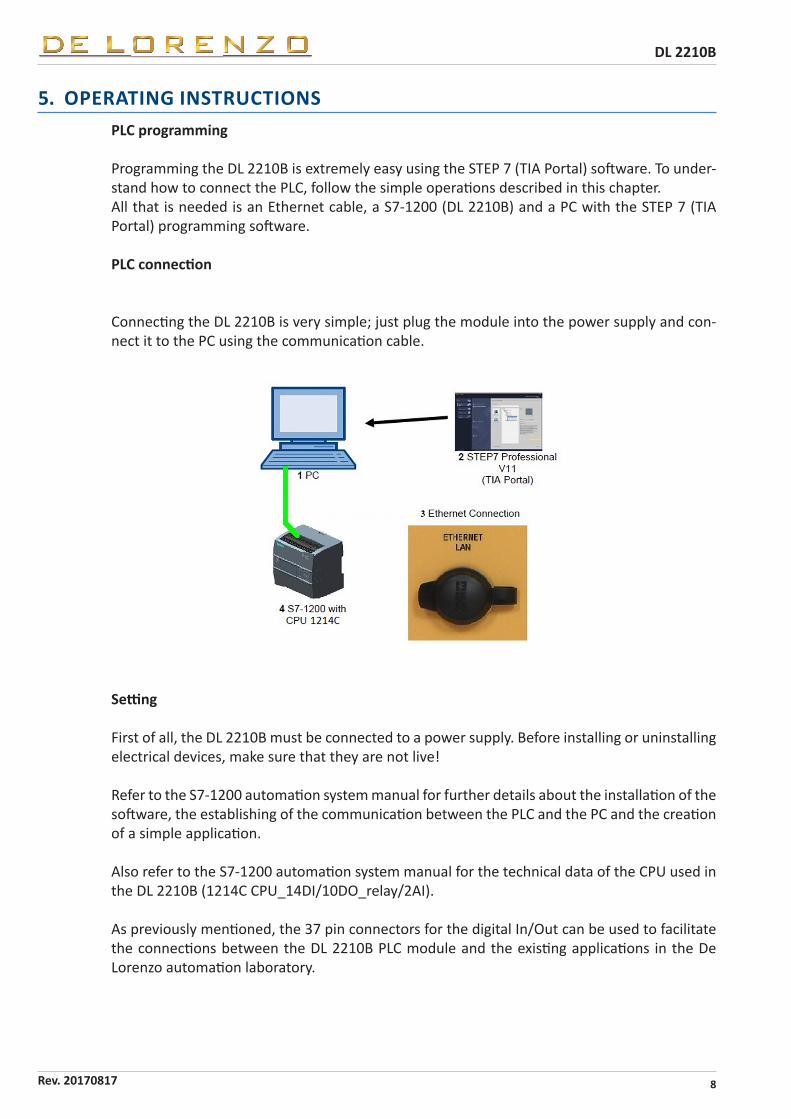
If the module has to be used for applications other than those provided by De Lorenzo, the connections will have to be realized in a point-to-point way and the switch will have to be set to the upper position, as shown in the following picture together with the needed connections.
The 0V – COM connection will have to be performed on the selected application.Moreover, the terminals on the panel will have to be connected to the application’s relevant ones following a linear scheme which must correspond to the settings programmed on the PLC.

13 Rev. 20170817
DL 2210B
6.2 REGULATION SYSTEMS
6.2.1 INTRODUCTION
With the scope of clarifying certain concepts that will be explained in later sections, some ex-tremely basic notions are given about regulation systems.
The control systems of a machine or of any process can basically be divided into two categori-es: closed circuit control systems and open circuit control systems.
6.2.2 CLOSED CIRCUIT CONTROL SYSTEMS
The closed circuit control systems are complete control systems that have the capability of correcting an action being carried out and, therefore, emulating human behaviour in the four factors indicated in the first chapter.
Closed circuit control system
A closed circuit control system is recommended for systems equipped with feedback signals, or the signal that the machine sends back to the control system via a sensor.
Specifically, these systems are composed as follows: By a start or set-point signal that starts the process. By a power organ that carries it out. By a sensor that detects the action in course. By a control unit that decides how to correct the action in course on the basis of the feed-back signal coming from the sensor.
14
DL 2210B
Rev. 20170817
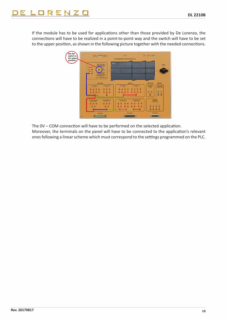
6.2.3 OPEN CIRCUIT CONTROL SYSTEMS
In open circuit control systems, the control system does not have knowledge about the outco-me of the control action, because there is no sensor that controls the process with the relative feedback signal.
Specifically, these systems are composed as follows:
By a start or set-point signal that starts the process. By a power organ that carries it out.
As it is lacking the feedback signal, this is not a regulation system but only a control system.
Open circuit control system
24
DL 2210B
Rev. 20170817
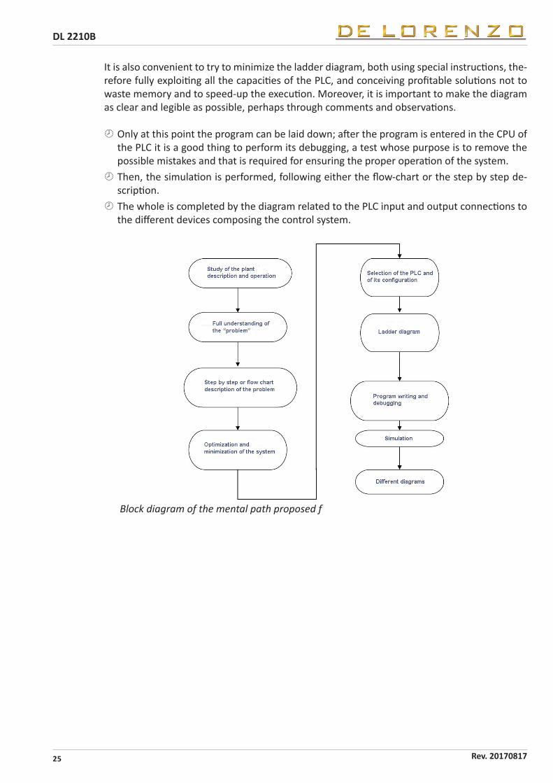
8. GENERAL METHOD FOR THE SOLUTION OF AN AUTOMATIONPROBLEM
In order to be able to solve an automation problem, the student must have a considerable ran-ge of knowledge available, ranging from electrotechnics to electronics, from computer science to mechanics and communications: in other words, he must be in possess of the facets and the multiplicity of capacities that are at the base of any good engineer and that will make him able to skilfully and rationally solve any problem. The purpose of this section of the manual is to teach the mental path that every student must follow to face and solve any automation problem: simple suggestions are given to both teacher or student, who can modify or extend them at their will.
At first, a deep reading of both the description and the operation of the plant is required.This will allow to understand and deeply analyse the problem, to achieve a clear and overallunderstanding of the whole, of the purposes and of the results to be obtained.
The solving method, i.e. the algorithm, must be defined in all its details.
A problem can be described in different ways: either through a sequential talkative exposi-tion, through a step by step ordered diagram or through a flow-chart.
The latter is composed of a graph showing the flow of the elementary operations to be per-formed for achieving the wanted transformation of the initial data into the final results of the problem. This chart is specially important for representing the structural details of a problem, even a complex one, for making it intelligible to everyone and to easily allow the understan-ding of the relationships among its different parts. This is an excellent instrument to think and to thoroughly catch the problem; it explains what to do, not how to do it.The algorithm is, therefore, a finite set of elementary steps: when all the elementary steps are known, it can be said that the problem is solved.
It is essential to optimize and minimize the system, making it as economical as possible. The next step is to select the PLC and its configuration, i.e. the kind of CPU, of input andoutput modules and of special modules as a function of the performances that must beachieved for satisfying the requirements of both the obtained model and the plant to beautomated.
Now, the inputs and outputs allocation can be performed; the allocation of the internal vari-ables, on the other hand, will occur when the ladder diagram will be drawn.
Only after all this preparation work it is possible to proceed to the realization of the ladderdiagram. This has to follow a well defined logic. By referring to either the step by step
description or to the flow-chart, it is necessary to lay down a line of ladder logic at a timeand to proceed to the following line only after all the required data are available.
It is preferable not to insert in a line contacts that are not sequentially available at that time in the flow-chart, even when it is anticipated that these contacts will be successively introdu-ced on the basis of data available in a following level of the logic diagram. In other words, it is necessary always to consider sequentially the already drawn lines, that may be modified at a second time, but only when the required data are available in the chart. In this way, it is always possible to have an orderly vision and to avoid gross blunders.
25 Rev. 20170817
DL 2210B
It is also convenient to try to minimize the ladder diagram, both using special instructions, the-refore fully exploiting all the capacities of the PLC, and conceiving profitable solutions not to waste memory and to speed-up the execution. Moreover, it is important to make the diagram as clear and legible as possible, perhaps through comments and observations.
Only at this point the program can be laid down; after the program is entered in the CPU ofthe PLC it is a good thing to perform its debugging, a test whose purpose is to remove thepossible mistakes and that is required for ensuring the proper operation of the system.
Then, the simulation is performed, following either the flow-chart or the step by step de-scription.
The whole is completed by the diagram related to the PLC input and output connections tothe different devices composing the control system.
Block diagram of the mental path proposed f���������������������

26
DL 2210B
Rev. 20170817
9. MAINTENANCE, STORAGE AND REPAIR
MAINTENANCEFor safety reasons, only qualified personnel may carry out maintenance and repair activities.
Qualified personnel are those persons who, according to their professional training, experience and instruction, have sufficient knowledge of:
health & safety regulations, accident prevention regulations, guide lines and acknowledged technical standards.
The qualified personnel must: be able to assess the work assigned to them and recognize and avoid possible dangers, be authorized by those responsible for health & safety at work to carry out the required work.
The module does not need any special preventive maintenance.
STORAGEShort term storageIf the module is not immediately installed, it can be stored in a dry room and in an area that is free from vibrations.
Long term storageIf the module has to be stored for a large period of time, it has to be stored in a well ventilated, dry room. The storage area must be free from dust and vibrations as much as possible.The module must be well covered to protect it from dust.An improper storage can cause damage to the module.Take precautions in case of extreme weather conditions or in humid environments with salt and/or dust.Choose a storage place that is flood-proof, dry and vibration free. Before storing, repair any possible damage to the packaging, if this is necessary for proper storage.If necessary, place the module on pallets, wooden beams or foundations to ensure protection against soil moi-sture. Prevent that a collapse occurs on the floor. Do not obstruct the air circulation around the stored module.
CLEANINGDo not wash the module with water or other liquids.In the event of severe dirt deposits, dismantle the module and remove the deposits using suitable cleaning agents.
TROUBLE SHOOTING / REPAIR INSTRUCTIONSA faulty module can only be repaired by qualified personnel at the request of the person responsible for the installation. Inform the manufacturer when damage occurs during the warranty period. When determining the cause of a malfunction, or during repair, observe the following:
applicable rules, accident prevention regulations.
Ensure that the module is switched off. Lock it against reactivation and designate such by placing a warning sign next to the activation switch. Ascertain that the module is not live! Cover or cordon off any neighbouring parts, which are live! Ensure that the auxiliary circuits are switched off.

Printed in Italy - All rights reserved
DE LORENZO SPAViale Romagna, 20 - 20089 Rozzano ( MI ) - Italy
Tel. +39 02 8254551 - Fax +39 02 8255181E-mail : [email protected]
website : www.delorenzoglobal.com