Embed Size (px)
Citation preview
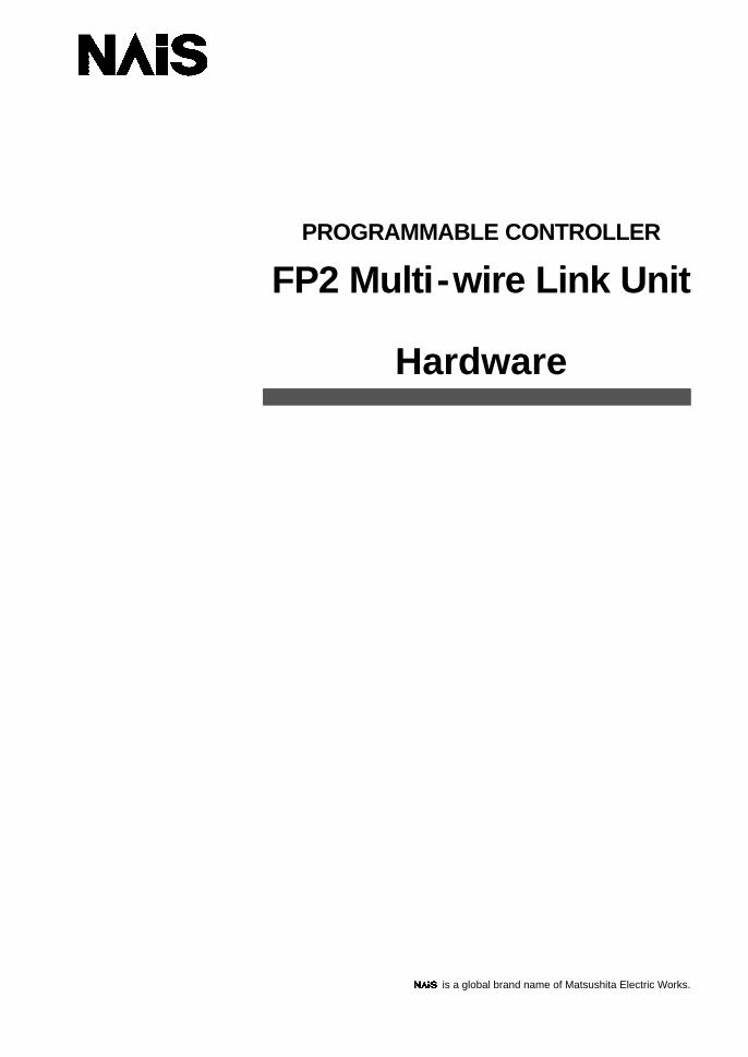
PROGRAMMABLE CONTROLLER
FP2 Multi-wire Link Unit
Hardware
is a global brand name of Matsushita Electric Works.

BEFORE BEGINNING
This manual and everything described in it are copyrighted. You may not copy thismanual, in whole or part, without written consent of Matsushita Electric Works, Ltd.
Matsushita Electric Works, Ltd. pursues a policy of continuous improvement of thedesign and performance of its products, therefore, we reserve the right to change themanual/product without notice. In no event will Matsushita Electric Works, Ltd. beliable for direct, special, incidental, or consequential damage resulting from anydefect in the product or its documentation, even if advised of the possibility of suchdamages.
LIMITED WARRANTY
All implied warranties on the product, including merchantability and fitness, arelimited to one year from the date of purchase.
If physical defects caused by distribution are found, Matsushita Electric Works, Ltd.,will replace/repair the product free of charge. Exceptions include:
D When physical defects are due to different usage/treatment of theproduct other than described in the manual.
D When physical defects are due to defective equipment other than thedistributed product.
D When physical defects are due to modifications/repairs by someoneother than Matsushita Electric Works, Ltd.
D When physical defects are due to natural disasters.
MS-DOS and Windows are registered trademarks of Microsoft Corporation.IBM Personal Computer AT is a registered trademark of the International BusinessMachines Corporation.
IntroductionFP2 Multi-wire Link Unit
iMatsushita Automation Controls
Introduction
The FP2 Multi -wire link unit was developed exclusively for use with the programmablecontroller FP2. It is equipped with various functions which facilitate communicationbetween programmable controllers. This manual describes the functions, wiring,operation, and other aspects of the FP2 Multi -wire link unit.
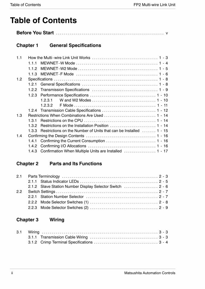
Table of Contents FP2 Multi-wire Link Unit
ii Matsushita Automation Controls
Table of ContentsBefore You Start v. . . . . . . . . . . . . . . . . . . . . . . . . . . . . . . . . . . . . . . . . . . . . . . . . . . . . .
Chapter 1 General Specifications
1.1 How the Multi -wire Link Unit Works 1 - 3. . . . . . . . . . . . . . . . . . . . . . . . . . . . . . . . .1.1.1 MEWNET-W Mode 1 - 4. . . . . . . . . . . . . . . . . . . . . . . . . . . . . . . . . . . . . . . . .1.1.2 MEWNET-W2 Mode 1 - 5. . . . . . . . . . . . . . . . . . . . . . . . . . . . . . . . . . . . . . . .1.1.3 MEWNET-F Mode 1 - 6. . . . . . . . . . . . . . . . . . . . . . . . . . . . . . . . . . . . . . . . .
1.2 Specifications 1 - 8. . . . . . . . . . . . . . . . . . . . . . . . . . . . . . . . . . . . . . . . . . . . . . . . . . . .1.2.1 General Specifications 1 - 8. . . . . . . . . . . . . . . . . . . . . . . . . . . . . . . . . . . . . .1.2.2 Transmission Specifications 1 - 9. . . . . . . . . . . . . . . . . . . . . . . . . . . . . . . . .1.2.3 Performance Specifications 1 - 10. . . . . . . . . . . . . . . . . . . . . . . . . . . . . . . . .
1.2.3.1 W and W2 Modes 1 - 10. . . . . . . . . . . . . . . . . . . . . . . . . . . . . . . .1.2.3.2 F Mode 1 - 11. . . . . . . . . . . . . . . . . . . . . . . . . . . . . . . . . . . . . . . . .
1.2.4 Transmission Cable Specifications 1 - 12. . . . . . . . . . . . . . . . . . . . . . . . . . .1.3 Restrictions When Combinations Are Used 1 - 14. . . . . . . . . . . . . . . . . . . . . . . . . .
1.3.1 Restrictions on the CPU 1 - 14. . . . . . . . . . . . . . . . . . . . . . . . . . . . . . . . . . . .1.3.2 Restrictions on the Installation Position 1 - 14. . . . . . . . . . . . . . . . . . . . . . .1.3.3 Restrictions on the Number of Units that can be Installed 1 - 15. . . . . . .
1.4 Confirming the Design Contents 1 - 16. . . . . . . . . . . . . . . . . . . . . . . . . . . . . . . . . . .1.4.1 Confirming the Current Consumption 1 - 16. . . . . . . . . . . . . . . . . . . . . . . . .1.4.2 Confirming I/O Allocations 1 - 16. . . . . . . . . . . . . . . . . . . . . . . . . . . . . . . . . .1.4.3 Confirmation When Multiple Units are Installed 1 - 17. . . . . . . . . . . . . . . .
Chapter 2 Parts and Its Functions
2.1 Parts Terminology 2 - 3. . . . . . . . . . . . . . . . . . . . . . . . . . . . . . . . . . . . . . . . . . . . . . . .2.1.1 Status Indicator LEDs 2 - 5. . . . . . . . . . . . . . . . . . . . . . . . . . . . . . . . . . . . . . .2.1.2 Slave Station Number Display Selector Switch 2 - 6. . . . . . . . . . . . . . . . .
2.2 Switch Settings 2 - 7. . . . . . . . . . . . . . . . . . . . . . . . . . . . . . . . . . . . . . . . . . . . . . . . . . .2.2.1 Station Number Selector 2 - 7. . . . . . . . . . . . . . . . . . . . . . . . . . . . . . . . . . . .2.2.2 Mode Selector Switches (1) 2 - 8. . . . . . . . . . . . . . . . . . . . . . . . . . . . . . . . . .2.2.3 Mode Selector Switches (2) 2 - 9. . . . . . . . . . . . . . . . . . . . . . . . . . . . . . . . . .
Chapter 3 Wiring
3.1 Wiring 3 - 3. . . . . . . . . . . . . . . . . . . . . . . . . . . . . . . . . . . . . . . . . . . . . . . . . . . . . . . . . .3.1.1 Transmission Cable Wiring 3 - 3. . . . . . . . . . . . . . . . . . . . . . . . . . . . . . . . . .3.1.2 Crimp Terminal Specifications 3 - 4. . . . . . . . . . . . . . . . . . . . . . . . . . . . . . . .
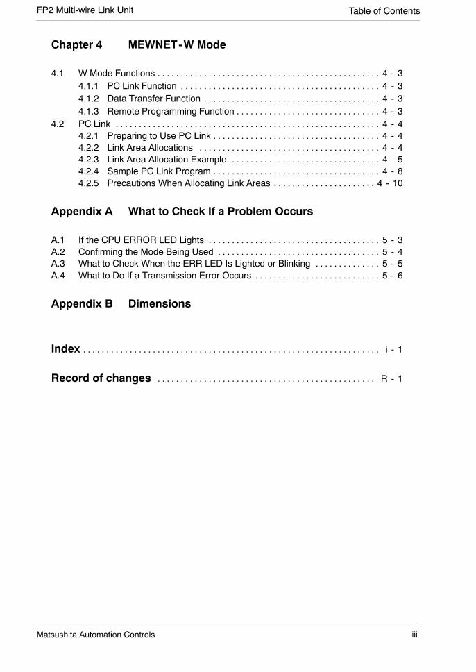
Table of ContentsFP2 Multi-wire Link Unit
iiiMatsushita Automation Controls
Chapter 4 MEWNET-W Mode
4.1 W Mode Functions 4 - 3. . . . . . . . . . . . . . . . . . . . . . . . . . . . . . . . . . . . . . . . . . . . . . . .4.1.1 PC Link Function 4 - 3. . . . . . . . . . . . . . . . . . . . . . . . . . . . . . . . . . . . . . . . . . .4.1.2 Data Transfer Function 4 - 3. . . . . . . . . . . . . . . . . . . . . . . . . . . . . . . . . . . . . .4.1.3 Remote Programming Function 4 - 3. . . . . . . . . . . . . . . . . . . . . . . . . . . . . . .
4.2 PC Link 4 - 4. . . . . . . . . . . . . . . . . . . . . . . . . . . . . . . . . . . . . . . . . . . . . . . . . . . . . . . . .4.2.1 Preparing to Use PC Link 4 - 4. . . . . . . . . . . . . . . . . . . . . . . . . . . . . . . . . . . .4.2.2 Link Area Allocations 4 - 4. . . . . . . . . . . . . . . . . . . . . . . . . . . . . . . . . . . . . . .4.2.3 Link Area Allocation Example 4 - 5. . . . . . . . . . . . . . . . . . . . . . . . . . . . . . . .4.2.4 Sample PC Link Program 4 - 8. . . . . . . . . . . . . . . . . . . . . . . . . . . . . . . . . . . .4.2.5 Precautions When Allocating Link Areas 4 - 10. . . . . . . . . . . . . . . . . . . . . .
Appendix A What to Check If a Problem Occurs
A.1 If the CPU ERROR LED Lights 5 - 3. . . . . . . . . . . . . . . . . . . . . . . . . . . . . . . . . . . . .A.2 Confirming the Mode Being Used 5 - 4. . . . . . . . . . . . . . . . . . . . . . . . . . . . . . . . . . .A.3 What to Check When the ERR LED Is Lighted or Blinking 5 - 5. . . . . . . . . . . . . .A.4 What to Do If a Transmission Error Occurs 5 - 6. . . . . . . . . . . . . . . . . . . . . . . . . . .
Appendix B Dimensions
Index i - 1. . . . . . . . . . . . . . . . . . . . . . . . . . . . . . . . . . . . . . . . . . . . . . . . . . . . . . . . . . . . . . . .
Record of changes R - 1. . . . . . . . . . . . . . . . . . . . . . . . . . . . . . . . . . . . . . . . . . . . . . .
Before You Start FP2 Multi-wire Link Unit
iv Matsushita Automation Controls
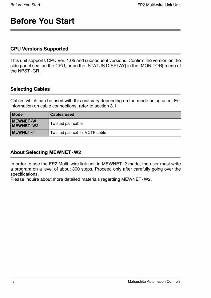
Before You Start
CPU Versions Supported
This unit supports CPU Ver. 1.05 and subsequent versions. Confirm the version on theside panel seal on the CPU, or on the [STATUS DISPLAY] in the [MONITOR] menu ofthe NPST-GR.
Selecting Cables
Cables which can be used with this unit vary depending on the mode being used. Forinformation on cable connections, refer to section 3.1.
Mode Cables used
MEWNET-WMEWNET-W2 Twisted pair cable
MEWNET-F Twisted pair cable, VCTF cable
About Selecting MEWNET-W2
In order to use the FP2 Multi -wire link unit in MEWNET-2 mode, the user must writea program on a level of about 300 steps. Proceed only after carefully going over thespecifications.Please inquire about more detailed materials regarding MEWNET-W2.

Before You StartFP2 Multi-wire Link Unit
vMatsushita Automation Controls
Reference Manuals
The following reference manuals are available for use with this unit, and should beused in conjunction with this manual.
Manual name Manual number Description
FP2 Hardwaremanual
ARCT1F298EThis introduces the hardware configuration, wiringmethods, I/O allocation, maintenance methods, andother information pertaining to the FP2 series.
FP3/FP5 W TYPE(WIRE) LINKSYSTEM Manual
ACG-M0032
This introduces the hardware configuration, wiringmethods, I/O allocation, maintenance methods, andother information pertaining to the MEWNET-W.Refer to this manual when using the MEWNET-Wmode.
FP3/FP5REMOTE I/OSYSTEM Manual
ACG-M0028
This introduces the hardware configuration, wiringmethods, I/O allocation, maintenance methods, andother information pertaining to the MEWNET-F.Refer to this manual when using the MEWNET-Fmode.

Before You Start FP2 Multi-wire Link Unit
vi Matsushita Automation Controls

Chapter 1
General Specifications
1.1 How the Multi -wire Link Unit Works 1 - 3. . . . . . . .
1.1.1 MEWNET-W Mode 1 - 4. . . . . . . . . . . . . . .
1.1.2 MEWNET-W2 Mode 1 - 5. . . . . . . . . . . . . .
1.1.3 MEWNET-F Mode 1 - 6. . . . . . . . . . . . . . . .
1.2 Specifications 1 - 8. . . . . . . . . . . . . . . . . . . . . . . . . . . .
1.2.1 General Specifications 1 - 8. . . . . . . . . . . .
1.2.2 Transmission Specifications 1 - 9. . . . . . . .
1.2.3 Performance Specifications 1 - 10. . . . . . .
1.2.3.1 W and W2 Modes 1 - 10. . . . . . . .
1.2.3.2 F Mode 1 - 11. . . . . . . . . . . . . . . . .
1.2.4 Transmission Cable Specifications 1 - 12.
1.3 Restrictions When Combinations Are Used 1 - 14.
1.3.1 Restrictions on the CPU 1 - 14. . . . . . . . . .
1.3.2 Restrictions on the InstallationPosition 1 - 14. . . . . . . . . . . . . . . . . . . . . . . .
1.3.3 Restrictions on the Number of Unitsthat can be Installed 1 - 15. . . . . . . . . . . . .
1.4 Confirming the Design Contents 1 - 16. . . . . . . . . . .
1.4.1 Confirming the CurrentConsumption 1 - 16. . . . . . . . . . . . . . . . . . .
1.4.2 Confirming I/O Allocations 1 - 16. . . . . . . .
1.4.3 Confirmation When Multiple Units areInstalled 1 - 17. . . . . . . . . . . . . . . . . . . . . . . .

General Specifications FP2 Multi-wire Link Unit
1 - 2 Matsushita Automation Controls
General SpecificationsFP2 Multi-wire Link Unit
1 - 3Matsushita Automation Controls
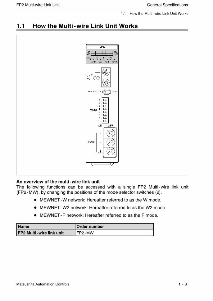
1.1 How the Multi -wire Link Unit Works
1.1 How the Multi -wire Link Unit Works
An overview of the multi -wire link unitThe following functions can be accessed with a single FP2 Multi -wire link unit(FP2-MW), by changing the positions of the mode selector switches (2).
D MEWNET-W network: Hereafter referred to as the W mode.
D MEWNET-W2 network: Hereafter referred to as the W2 mode.
D MEWNET-F network: Hereafter referred to as the F mode.
Name Order number
FP2 Multi -wire link unit FP2-MW

General Specifications FP2 Multi-wire Link Unit
1 - 4 Matsushita Automation Controls
1.1 How the Multi -wire Link Unit Works
1.1.1 MEWNET-W Mode
A system can be configured economically between programmable controllers,using twisted pair cables.Link communication can be carried out between various programmable controllers, us-ing link relays and link registers.Communication is possible with conventional FP series devices capable of using theMEWNET-W.The link relays and link registers used for PCLink communication are specified using thesystem register.FP2 Multi -wire link unit(W mode)
FP-C andMEWNET-W type
link board
Twisted pair cable
FP3 andMEWNET-Wtype link unit
FP10SH andMEWNET-W type
link unit
FP2 Multi -wire linkunit (W mode)
SpecificationsItem Description
Communication method Token bus
Transmission method Baseband transmission
Communication path Twisted pair cable
Transmission distance Total length: 800 m/2,625 ft.
Transmission speed(Baud rate)
500 kbps
Functions/number of PC link function: max. 16 stations/stations Data transfer function: max. 32 stations
PC link capacity per one Link relay: 1,024 pointsp y punit Link register: 128 words
Other functions Remote programming
Interface Conforming to RS485
R.A.S. function Hardware self-diagnostic function

General SpecificationsFP2 Multi-wire Link Unit
1 - 5Matsushita Automation Controls
1.1 How the Multi -wire Link Unit Works
1.1.2 MEWNET-W2 Mode
Large volumes of data can now be transmitted over long distances.Link communication can be carried out between various FP2 units, using link relays andlink registers.Communication limited to only FP2 units is possible.Using the MEWNET-W mode increases the volume of data that can be handled.Using theMEWNET-Wmodeextends the transmissiondistance (whenset to 250kbps).The link relay and link register areas used for PC link communication are specified usinguser programs.
Twisted pair cable
FP2 Multi -wire linkunit (W2 mode)
FP2 Multi -wire linkunit (W2 mode)
FP2 Multi -wire linkunit (W2 mode)
SpecificationsItem Description
Communication method Token bus
Transmission method Baseband transmission
Communication path Twisted pair cable
Transmission at 250 kbps Total length: 1200 m/3,937 ft.distance at 500 kbps Total length: 800 m/2,625 ft.
Transmission speed(Baud rate)
500 kbps or 250 kbps
Functions/number of PC link function: max. 32 stations/stations Data transfer function: max. 32 stations
PC link capacity per one Link relay: 4,096 pointsp y punit Link register: 4,096 words
Other functions Remote programming
Interface Conforming to RS485
R.A.S. function Hardware self-diagnostic function
. Note
When using the PC Link in the MEWNET-W2 mode, the defaultsettings must be obtained from the user program.
General Specifications FP2 Multi-wire Link Unit
1 - 6 Matsushita Automation Controls
1.1 How the Multi -wire Link Unit Works
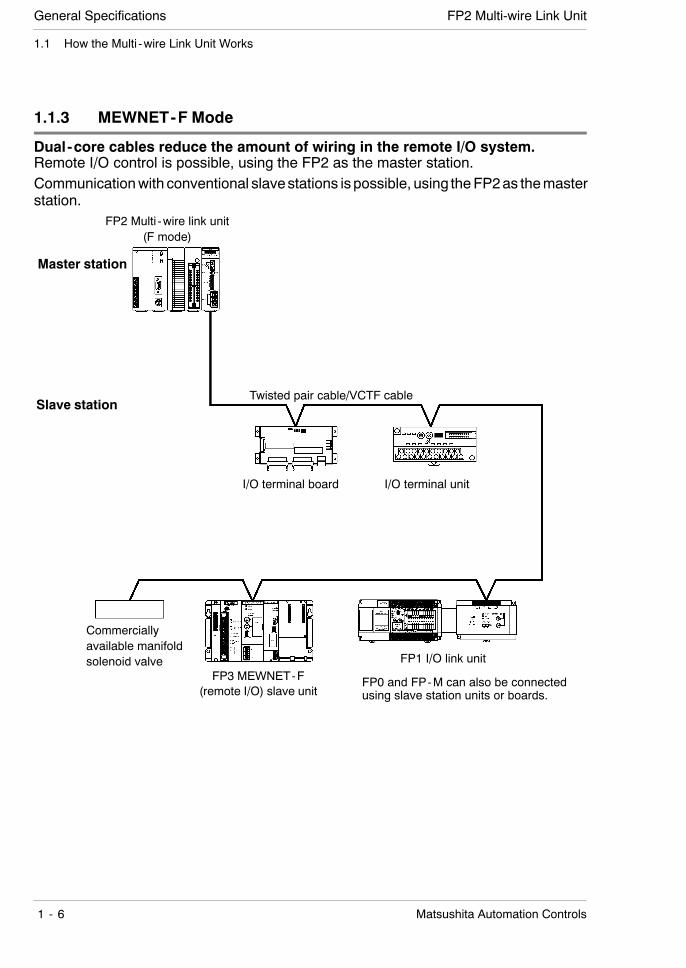
1.1.3 MEWNET-F Mode
Dual-core cables reduce the amount of wiring in the remote I/O system.Remote I/O control is possible, using the FP2 as the master station.Communicationwith conventional slavestations ispossible, using theFP2as themasterstation.
Commerciallyavailable manifoldsolenoid valve
Master station
FP2 Multi -wire link unit(F mode)
Slave station
FP3 MEWNET-F(remote I/O) slave unit
FP1 I/O link unit
I/O terminal unit
Twisted pair cable/VCTF cable
I/O terminal board
FP0 and FP-M can also be connectedusing slave station units or boards.

General SpecificationsFP2 Multi-wire Link Unit
1 - 7Matsushita Automation Controls
1.1 How the Multi -wire Link Unit Works
SpecificationsItem Description
Communication method Two-line, half -duplex transmission
Synchronization method Start -stop synchronous system
Communication path Twisted pair cable or VCTF cable
Transmission distance Total distance: max. 700 m/2,296.59 ft
Transmission speed(Baud rate)
500 kbps
Number of slave stations Max. 32 stations
Controllable I/O points Max. 2,048 points
Interface Conforming to RS485
Transmission error check CRC (Cyclic Redundancy Check) method
. Note
The user should avoid mixing different types of transmissioncables in a single network. The same type of transmission cableshould be used throughout the network.
General Specifications FP2 Multi-wire Link Unit
1 - 8 Matsushita Automation Controls
1.2 Specifications
1.2 Specifications
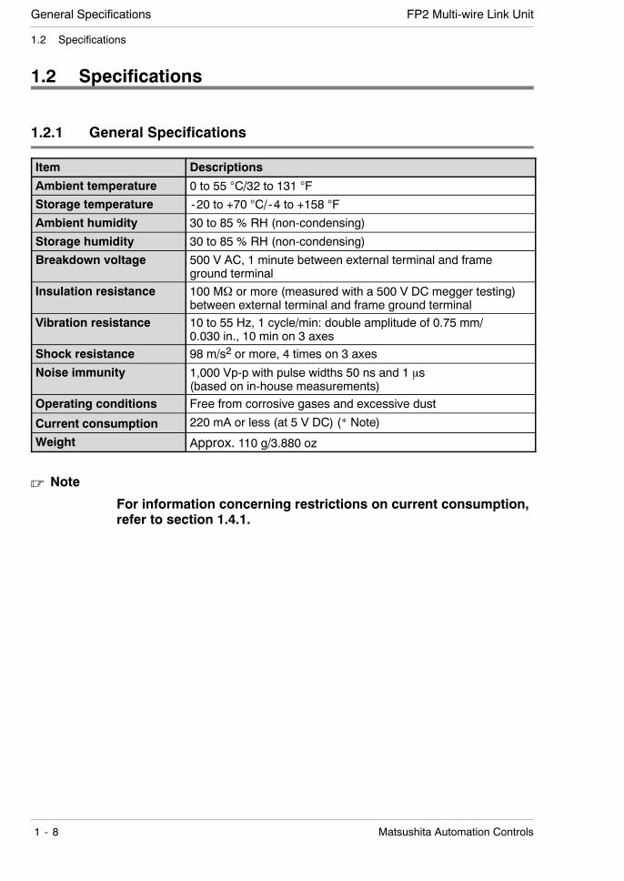
1.2.1 General Specifications
Item Descriptions
Ambient temperature 0 to 55 C/32 to 131 F
Storage temperature -20 to +70 C/-4 to +158 F
Ambient humidity 30 to 85 % RH (non-condensing)
Storage humidity 30 to 85 % RH (non-condensing)
Breakdown voltage 500 V AC, 1 minute between external terminal and frameground terminal
Insulation resistance 100 MΩ or more (measured with a 500 V DC megger testing)between external terminal and frame ground terminal
Vibration resistance 10 to 55 Hz, 1 cycle/min: double amplitude of 0.75 mm/0.030 in., 10 min on 3 axes
Shock resistance 98 m/s2 or more, 4 times on 3 axes
Noise immunity 1,000 Vp-p with pulse widths 50 ns and 1 μs(based on in-house measurements)
Operating conditions Free from corrosive gases and excessive dust
Current consumption 220 mA or less (at 5 V DC) (* Note)
Weight Approx. 110 g/3.880 oz
. Note
For information concerning restrictions on current consumption,refer to section 1.4.1.

General SpecificationsFP2 Multi-wire Link Unit
1 - 9Matsushita Automation Controls
1.2 Specifications
1.2.2 Transmission Specifications
Item Descriptions
W mode W2 mode F mode
Communication method Token bus method Polling method
Transmission method Baseband transmission method
Transmission speed(Baud rate)
500kbps 500kbps/250kbps 500kbps
Transmission distance(* section 1.2.4)
Overall distance:max. 800m/2,625ft.
Overall distance:max.1200m/3,937 ft.(at 250 kbps)800m/2,625 ft.(at 500 kbps)
Overall distance:max.700m/2,296.58 ft.
Number of slave stations Max. 32 stations One master unitand max. 32 slavestations
Error check method CRC (Cyclic Redundancy Check) method
Synchronized method Start -stop synchronous system
Interface Conforming to RS485
Communication path Twisted pair cable Twisted pair cable,VCTF cable
RAS function Hardware self -diagnostic function

General Specifications FP2 Multi-wire Link Unit
1 - 10 Matsushita Automation Controls
1.2 Specifications
1.2.3 Performance Specifications
1.2.3.1 W and W2 Modes
Item Specification
W mode W2 mode
Communication functions PC linkComputer linkData transferRemote programmingHierarchical link
Functions/number of PC link Max. 16 stations Max. 32 stations/stations Other
functionsMax. 32 stations
PC link Area ofuse
Linkrelays
Fixed at WL Set by selecting amongWL, WR, LD, DT and FL.
Linkregisters
Fixed at LD, , ,
(* Note)
Setting method Specified using systemregister.
Specified using userprogram.
Capacity Linkrelays
Max. 1,024 points Max. 4,096 points (* Note)
Linkregisters
Max. 128 words Max. 4,096 words (* Note)
Movementstatus/error alert
Area of use Special internal relaysSpecial data registers
Special internal relaysSpecial data registersDetailed information isoutput to WL, WR, LD,DT, or FL, depending onthe setting.
Setting method — Specified using F145(SEND)/P145 (PSEND)instruction.
Data transfer capacity Max. 16 words Max. 1,020 words
. Note
Use a program to keep WL, WR, LD, DT and FL settings within thePC link capacity.
General SpecificationsFP2 Multi-wire Link Unit
1 - 11Matsushita Automation Controls
1.2 Specifications
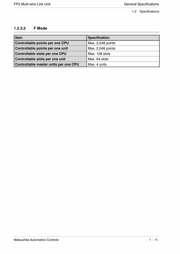
1.2.3.2 F Mode
Item Specification
Controllable points per one CPU Max. 2,048 points
Controllable points per one unit Max. 2,048 points
Controllable slots per one CPU Max. 128 slots
Controllable slots per one unit Max. 64 slots
Controllable master units per one CPU Max. 4 units
General Specifications FP2 Multi-wire Link Unit
1 - 12 Matsushita Automation Controls
1.2 Specifications
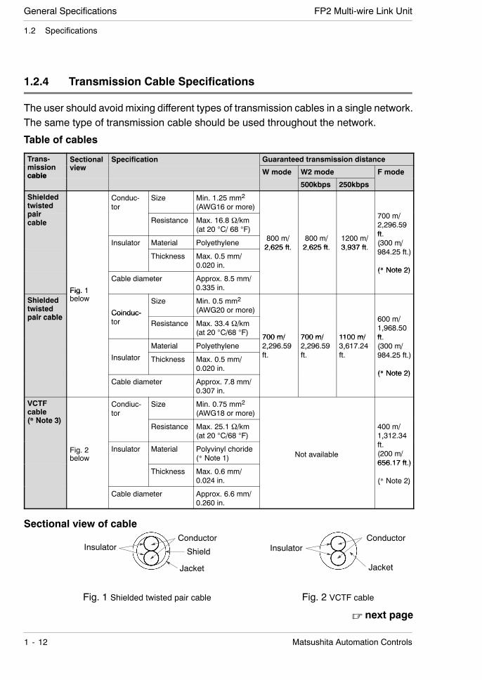
1.2.4 Transmission Cable Specifications
The user should avoid mixing different types of transmission cables in a single network.The same type of transmission cable should be used throughout the network.
Table of cables
Trans-i i
Sectionali
Specification Guaranteed transmission distancemissioncable
viewp
W mode W2 mode F modecable500kbps 250kbps
Shieldedtwistedpair
Conduc-tor
Size Min. 1.25 mm2
(AWG16 or more)paircable Resistance Max. 16.8 Ω/km
(at 20 C/ 68 F)
700 m/2,296.59ft
Insulator Material Polyethylene 800 m/2 625 ft
800 m/2 625 ft
1200 m/3 937 ft
ft.(300 m/
Thickness Max. 0.5 mm/0.020 in.
2,625 ft. 2,625 ft. 3,937 ft. ( /984.25 ft.)
(* Note 2)
Fig. 1
Cable diameter Approx. 8.5 mm/0.335 in.
(* Note 2)
Shieldedtwistedpair cable
Fig. 1below
Coinduc-
Size Min. 0.5 mm2
(AWG20 or more)pair cable
Coinduc-tor Resistance Max. 33.4 Ω/km
(at 20 C/68 F) 700 m/ 700 m/ 1100 m/
600 m/1,968.50ft
Material Polyethylene700 m/2,296.59
700 m/2,296.59
1100 m/3,617.24
ft.(300 m/
Insulator Thickness Max. 0.5 mm/0.020 in.
,ft.
,ft.
,ft.
( /984.25 ft.)
(* Note 2)Cable diameter Approx. 7.8 mm/
0.307 in.
(* Note 2)
VCTFcable(* Note 3)
Condiuc-tor
Size Min. 0.75 mm2
(AWG18 or more)(* Note 3)
Resistance Max. 25.1 Ω/km(at 20 C/68 F)
400 m/1,312.34
Fig. 2below
Insulator Material Polyvinyl choride(* Note 1) Not available
,ft.(200 m/656 17 ft )
Thickness Max. 0.6 mm/0.024 in.
656.17 ft.)
(* Note 2)
Cable diameter Approx. 6.6 mm/0.260 in.
( ote )
Sectional view of cable
Shield
Fig. 1 Shielded twisted pair cable Fig. 2 VCTF cable
InsulatorConductor
Jacket
InsulatorConductor
Jacket
. next page
General SpecificationsFP2 Multi-wire Link Unit
1 - 13Matsushita Automation Controls
1.2 Specifications
. Notes
D (*1):Because polyvinyl chloride has poorer electrical character-istics than polyethylene, the overall transmission distanceis shorter.
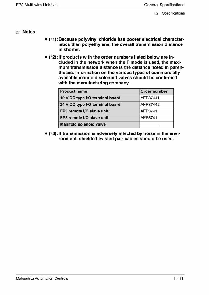
D (*2): If products with the order numbers listed below are in-cluded in the network when the F mode is used, the maxi-mum transmission distance is the distance noted in paren-theses. Information on the various types of commerciallyavailable manifold solenoid valves should be confirmedwith the manufacturing company.
Product name Order number
12 V DC type I/O terminal board AFP87441
24 V DC type I/O terminal board AFP87442
FP3 remote I/O slave unit AFP3741
FP5 remote I/O slave unit AFP5741
Manifold solenoid valve —————
D (*3): If transmission is adversely affected by noise in the envi-ronment, shielded twisted pair cables should be used.
General Specifications FP2 Multi-wire Link Unit
1 - 14 Matsushita Automation Controls
1.3 Restrictions When Combinations Are Used
1.3 Restrictions When Combinations Are Used
1.3.1 Restrictions on the CPU
Using the FP2 Multi -wire link unit requires CPU Ver. 1.05 or a subsequent version.Confirm the version on the side panel seal on the CPU, or on the [STATUS DISPLAY]in the [MONITOR] menu of the NPST-GR.
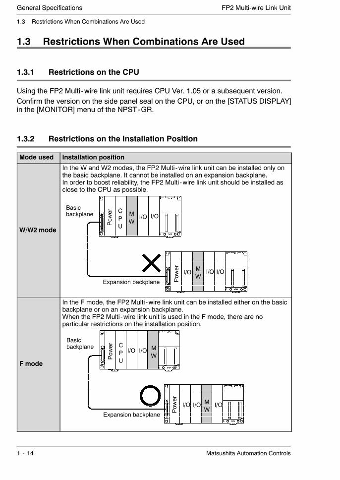
1.3.2 Restrictions on the Installation Position
Mode used Installation position
W/W2 mode
In the W and W2 modes, the FP2 Multi -wire link unit can be installed only onthe basic backplane. It cannot be installed on an expansion backplane.In order to boost reliability, the FP2 Multi -wire link unit should be installed asclose to the CPU as possible.
CPU
MW
I/O I/O
Pow
er MW
I/O I/OI/O
Pow
er
Basicbackplane
Expansion backplane
F mode
In the F mode, the FP2 Multi -wire link unit can be installed either on the basicbackplane or on an expansion backplane.When the FP2 Multi -wire link unit is used in the F mode, there are noparticular restrictions on the installation position.
CPU
MW
I/O I/O
MW
I/O I/OI/O
Pow
er
Pow
er
Basicbackplane
Expansion backplane
General SpecificationsFP2 Multi-wire Link Unit
1 - 15Matsushita Automation Controls
1.3 Restrictions When Combinations Are Used
1.3.3 Restrictions on the Number of Units that can be Installed
MEWNET mode Number of units installed
W mode Up to three units can be installed for one CPU.(If the Multi -wire link unit is one that can be used with PC linkcommunication, up to two of the three units can be installed.)
W2 mode Up to three units can be installed for one CPU.(If the Multi -wire link unit is one that can be used with PC linkcommunication, up to two of the three units can be installed.)
F mode Up to four units can be installed for one CPU.
. Notes
D Of the intelligent units scheduled for future marketing, theremay be restrictions on the number of units that can beinstalled if the unit is equipped with link functions.
D The various MEWNET modes may be used in combinationwithin the individual ranges of restrictions that apply. Forinstance, three W mode units may be used in combination withthree W2 mode units and four F mode units, for a maximumnumber of ten multi -wire link units.
General Specifications FP2 Multi-wire Link Unit
1 - 16 Matsushita Automation Controls
1.4 Confirming the Design Contents
1.4 Confirming the Design Contents
1.4.1 Confirming the Current Consumption
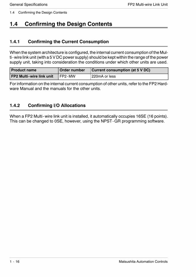
When the systemarchitecture is configured, the internal current consumptionof theMul-ti -wire link unit (with a 5VDCpower supply) should be kept within the range of the powersupply unit, taking into consideration the conditions under which other units are used.
Product name Order number Current consumption (at 5 V DC)
FP2 Multi -wire link unit FP2-MW 220mA or less
For information on the internal current consumption of other units, refer to the FP2Hard-ware Manual and the manuals for the other units.
1.4.2 Confirming I/O Allocations
When a FP2 Multi -wire link unit is installed, it automatically occupies 16SE (16 points).This can be changed to 0SE, however, using the NPST-GR programming software.
General SpecificationsFP2 Multi-wire Link Unit
1 - 17Matsushita Automation Controls
1.4 Confirming the Design Contents
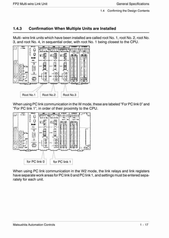
1.4.3 Confirmation When Multiple Units are Installed
Multi -wire link units which have been installed are called root No. 1, root No. 2, root No.3, and root No. 4, in sequential order, with root No. 1 being closest to the CPU.
Root No.2 Root No.3Root No.1
When usingPC link communication in theWmode, these are labeled “For PC link 0” and“For PC link 1”, in order of their proximity to the CPU.
for PC link 0 for PC link 1
When using PC link communication in the W2 mode, the link relays and link registershave separatework areas for PC link 0 andPC link 1, and settingsmust be entered sepa-rately for each unit.

General Specifications FP2 Multi-wire Link Unit
1 - 18 Matsushita Automation Controls
1.4 Confirming the Design Contents
Chapter 2
Parts and Its Functions
2.1 Parts Terminology 2 - 3. . . . . . . . . . . . . . . . . . . . . . . .
2.1.1 Status Indicator LEDs 2 - 5. . . . . . . . . . . . .
2.1.2 Slave Station Number DisplaySelector Switch 2 - 6. . . . . . . . . . . . . . . . . .
2.2 Switch Settings 2 - 7. . . . . . . . . . . . . . . . . . . . . . . . . .
2.2.1 Station Number Selector 2 - 7. . . . . . . . . . .
2.2.2 Mode Selector Switches (1) 2 - 8. . . . . . . .
2.2.3 Mode Selector Switches (2) 2 - 9. . . . . . . .

Parts and Its Functions FP2 Multi-wire Link Unit
2 - 2 Matsushita Automation Controls
Parts and Its FunctionsFP2 Multi-wire Link Unit
2 - 3Matsushita Automation Controls
2.1 Parts Terminology
2.1 Parts Terminology
Front
1
2
3
4
5
7
8
6
10
9
Rear
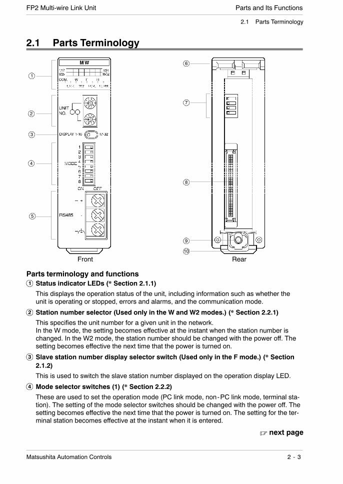
Parts terminology and functions1 Status indicator LEDs (* Section 2.1.1)
This displays the operation status of the unit, including information such as whether theunit is operating or stopped, errors and alarms, and the communication mode.
2 Station number selector (Used only in the W and W2 modes.) (* Section 2.2.1)
This specifies the unit number for a given unit in the network.In the W mode, the setting becomes effective at the instant when the station number ischanged. In the W2 mode, the station number should be changed with the power off. Thesetting becomes effective the next time that the power is turned on.
3 Slave station number display selector switch (Used only in the F mode.) (* Section2.1.2)
This is used to switch the slave station number displayed on the operation display LED.
4 Mode selector switches (1) (* Section 2.2.2)
These are used to set the operation mode (PC link mode, non-PC link mode, terminal sta-tion). The setting of the mode selector switches should be changed with the power off. Thesetting becomes effective the next time that the power is turned on. The setting for the ter-minal station becomes effective at the instant when it is entered.
. next page
Parts and Its Functions FP2 Multi-wire Link Unit
2 - 4 Matsushita Automation Controls
2.1 Parts Terminology
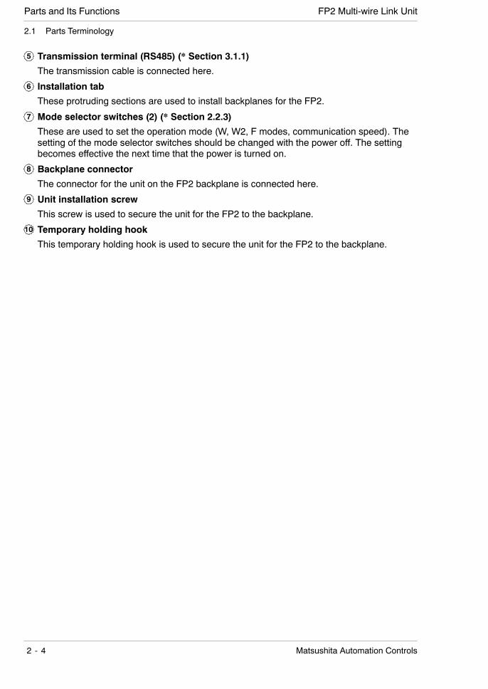
5 Transmission terminal (RS485) (* Section 3.1.1)
The transmission cable is connected here.
6 Installation tab
These protruding sections are used to install backplanes for the FP2.
7 Mode selector switches (2) (* Section 2.2.3)
These are used to set the operation mode (W, W2, F modes, communication speed). Thesetting of the mode selector switches should be changed with the power off. The settingbecomes effective the next time that the power is turned on.
8 Backplane connector
The connector for the unit on the FP2 backplane is connected here.
9 Unit installation screw
This screw is used to secure the unit for the FP2 to the backplane.
10 Temporary holding hook
This temporary holding hook is used to secure the unit for the FP2 to the backplane.
Parts and Its FunctionsFP2 Multi-wire Link Unit
2 - 5Matsushita Automation Controls
2.1 Parts Terminology
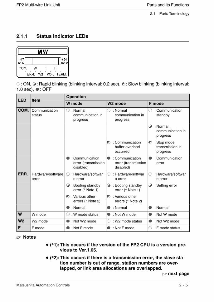
2.1.1 Status Indicator LEDs
:ON, : Rapid blinking (blinking interval: 0.2 sec), : Slow blinking (blinking interval:1.0 sec), : OFF
LED ItemOperation
LED ItemW mode W2 mode F mode
COM. Communicationstatus
: Normalcommunication inprogress
: Normalcommunication inprogress
: Communicationstandby
: Normalcommunication inprogress
: Communicationbuffer overloadoccurred
: Stop modetransmission inprogress
: Communicationerror (transmissiondisabled)
: Communicationerror (transmissiondisabled)
: Communicationerror
ERR. Hardware/softwareerror
: Hardware/software error
: Hardware/software error
: Hardware/software error
: Booting standbyerror (* Note 1)
: Booting standbyerror (* Note 1)
: Setting error
: Various othererrors (* Note 2)
: Various othererrors (* Note 2)
: Normal : Normal : Normal
W W mode :W mode status : Not W mode : Not W mode
W2 W2 mode : Not W2 mode :W2 mode status : Not W2 mode
F F mode : Not F mode : Not F mode : F mode status
. Notes
D (*1):This occurs if the version of the FP2 CPU is a version pre-vious to Ver.1.05.
D (*2):This occurs if there is a transmission error, the slave sta-tion number is out of range, station numbers are over-lapped, or link area allocations are overlapped.
. next page
Parts and Its Functions FP2 Multi-wire Link Unit
2 - 6 Matsushita Automation Controls
2.1 Parts Terminology
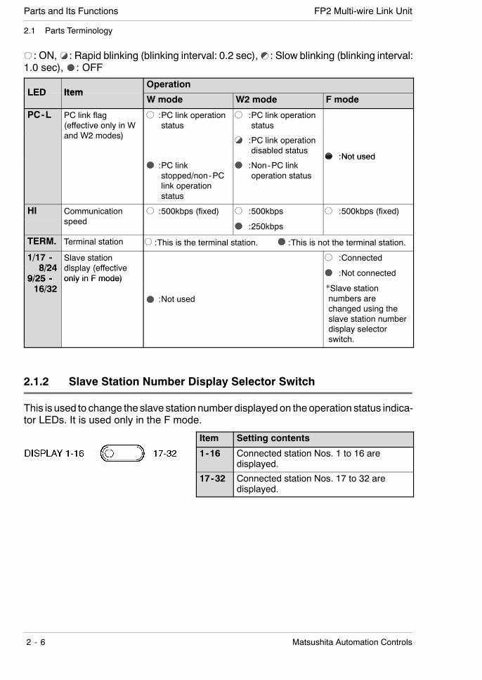
:ON, : Rapid blinking (blinking interval: 0.2 sec), : Slow blinking (blinking interval:1.0 sec), : OFF
LED ItemOperation
LED ItemW mode W2 mode F mode
PC-L PC link flag(effective only in Wd W2 d )
:PC link operationstatus
:PC link operationstatus
and W2 modes) :PC link operationdisabled status
:Not used:PC linkstopped/non-PClink operationstatus
:Non-PC linkoperation status
:Not used
HI Communicationd
:500kbps (fixed) :500kbps :500kbps (fixed)speed :250kbps
TERM. Terminal station :This is the terminal station. :This is not the terminal station.
1/17 -8/24
Slave stationdi l ( ff ti
:Connected8/24
9/25 -display (effectiveonly in F mode)
:Not connected9/25 -16/32
only in F mode)
:Not used*Slave stationnumbers arechanged using theslave station numberdisplay selectorswitch.
2.1.2 Slave Station Number Display Selector Switch
This is used to change the slave station number displayedon the operation status indica-tor LEDs. It is used only in the F mode.
Item Setting contents
1-16 Connected station Nos. 1 to 16 aredisplayed.
17-32 Connected station Nos. 17 to 32 aredisplayed.
Parts and Its FunctionsFP2 Multi-wire Link Unit
2 - 7Matsushita Automation Controls
2.2 Switch Settings
2.2 Switch Settings
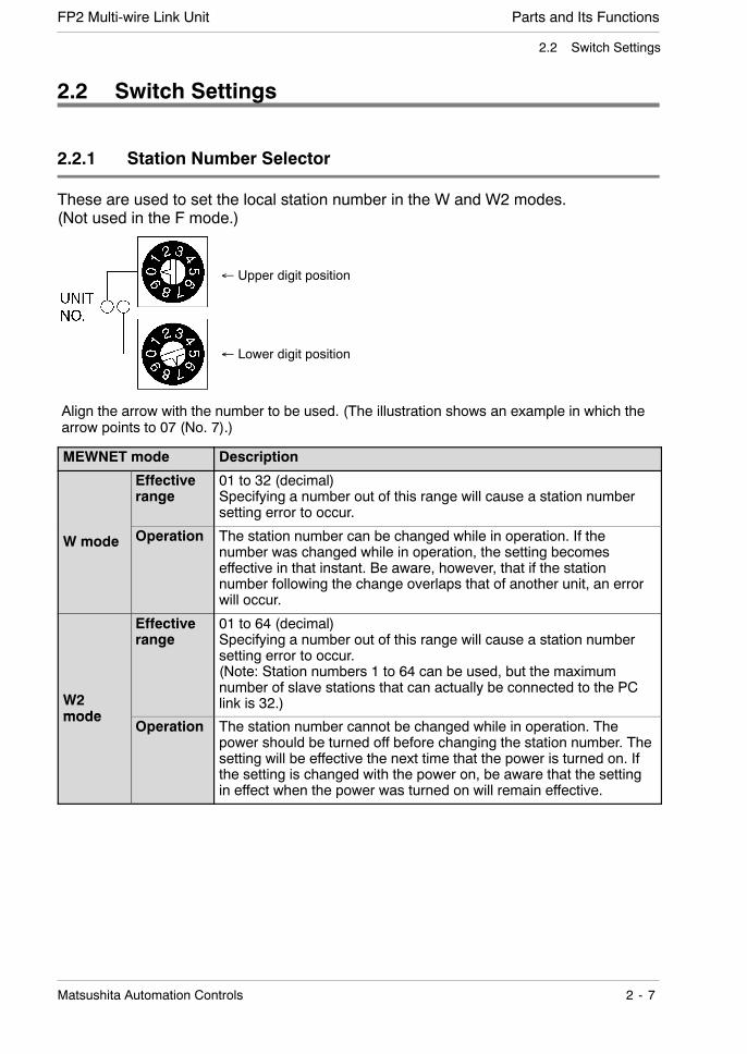
2.2.1 Station Number Selector
These are used to set the local station number in the W and W2 modes.(Not used in the F mode.)
Align the arrow with the number to be used. (The illustration shows an example in which thearrow points to 07 (No. 7).)
Upper digit position
Lower digit position
MEWNET mode Description
Effectiverange
01 to 32 (decimal)Specifying a number out of this range will cause a station numbersetting error to occur.
Wmode Operation The station number can be changed while in operation. If thenumber was changed while in operation, the setting becomeseffective in that instant. Be aware, however, that if the stationnumber following the change overlaps that of another unit, an errorwill occur.
W2mode
Effectiverange
01 to 64 (decimal)Specifying a number out of this range will cause a station numbersetting error to occur.(Note: Station numbers 1 to 64 can be used, but the maximumnumber of slave stations that can actually be connected to the PClink is 32.)
modeOperation The station number cannot be changed while in operation. The
power should be turned off before changing the station number. Thesetting will be effective the next time that the power is turned on. Ifthe setting is changed with the power on, be aware that the settingin effect when the power was turned on will remain effective.

Parts and Its Functions FP2 Multi-wire Link Unit
2 - 8 Matsushita Automation Controls
2.2 Switch Settings
2.2.2 Mode Selector Switches (1)
Operation mode
Terminal station: With MEWNET, the units at both ends of the network must bespecified as “terminal stations”.
(Front)
When the unit is shipped from the factory, all switches are set to the “OFF” position.
No ItemSetting contents
No. ItemW mode W2 mode F mode
1 OperationOFF PC link mode Operation stops if a
communication error occurs.1 Operation
mode ON Not PC link mode Operation continues if acommunication error occurs.
2
3
4 Not used — — —
5
6
7Terminal
Set to terminalstation
ON OFF
8
Terminalstation Not set to terminal
stationON OFF
. Notes
D The settings of the mode selector switches (1) and (2) shouldalways be changed with the power off. The setting will be ef-fective the next time that the power is turned on. (If the settingis changed with the power on, be aware that the setting in ef-fect when the power was turned on will remain effective.)
D Only the settings of the mode selector switches (1) No. 7 andNo. 8 (terminal station settings) will be effective at the instantthat they are changed.

Parts and Its FunctionsFP2 Multi-wire Link Unit
2 - 9Matsushita Automation Controls
2.2 Switch Settings
2.2.3 Mode Selector Switches (2)
(Rear)
Communication speed(W2 mode only)
Operation mode(W/W2/F mode selection)
When the unit is shipped from the factory, all switches are set to the ”OFF” position.The contents of the mode selector switches (2) are indicated by the status indicator LEDs.
No ItemSetting contents
No. ItemW mode W2 mode F mode
1 Operation mode ONOFF ONOFF ONOFF
2Operation modesetting
ONOFF
3 Communicationspeed (* Note 1) 500kbps (fixed)
500kbps
ONOFF
250kbps
ONOFF
500kbps (fixed)
4 ——————— This should always be secured at “OFF” when being used.
. Notes
D (*1):When the W2 mode is set, 500 kbps and 250 kbps settingunits should not be mixed in the same network.
D The settings of the mode selector switches (1) and (2) shouldalways be changed with the power off. The setting will be ef-fective the next time that the power is turned on. (If the settingis changed with the power on, be aware that the setting in ef-fect when the power was turned on will remain effective.)
D Only the settings of the mode selector switches (1) No. 7 andNo. 8 (terminal station settings) will be effective at the instantthat they are changed.

Parts and Its Functions FP2 Multi-wire Link Unit
2 - 10 Matsushita Automation Controls
2.2 Switch Settings

Chapter 3
Wiring
3.1 Wiring 3 - 3. . . . . . . . . . . . . . . . . . . . . . . . . . . . . . . . . .
3.1.1 Transmission Cable Wiring 3 - 3. . . . . . . . .
3.1.2 Crimp Terminal Specifications 3 - 4. . . . . .

Wiring FP2 Multi-wire Link Unit
3 - 2 Matsushita Automation Controls
WiringFP2 Multi-wire Link Unit
3 - 3Matsushita Automation Controls
3.1 Wiring
3.1 Wiring
3.1.1 Transmission Cable Wiring
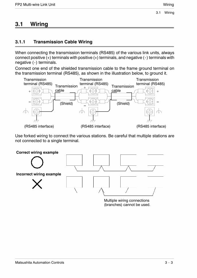
When connecting the transmission terminals (RS485) of the various link units, alwaysconnect positive (+) terminals with positive (+) terminals, and negative ( - ) terminals withnegative ( - ) terminals.Connect one end of the shielded transmission cable to the frame ground terminal onthe transmission terminal (RS485), as shown in the illustration below, to ground it.
Transmissionterminal (RS485)
Transmissionterminal (RS485)
Transmissionterminal (RS485)
Transmissioncable
Transmissioncable
(Shield) (Shield)
(RS485 interface) (RS485 interface) (RS485 interface)
Use forked wiring to connect the various stations. Be careful that multiple stations arenot connected to a single terminal.
Incorrect wiring example
Multiple wiring connections(branches) cannot be used.
Correct wiring example
×
Wiring FP2 Multi-wire Link Unit
3 - 4 Matsushita Automation Controls
3.1 Wiring
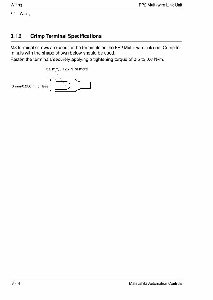
3.1.2 Crimp Terminal Specifications
M3 terminal screws are used for the terminals on the FP2Multi -wire link unit. Crimp ter-minals with the shape shown below should be used.Fasten the terminals securely applying a tightening torque of 0.5 to 0.6 NSm.
6 mm/0.236 in. or less
3.2 mm/0.126 in. or more
Chapter 4
MEWNET-W Mode
4.1 W Mode Functions 4 - 3. . . . . . . . . . . . . . . . . . . . . . .
4.1.1 PC Link Function 4 - 3. . . . . . . . . . . . . . . . .
4.1.2 Data Transfer Function 4 - 3. . . . . . . . . . . .
4.1.3 Remote Programming Function 4 - 3. . . .
4.2 PC Link 4 - 4. . . . . . . . . . . . . . . . . . . . . . . . . . . . . . . . .
4.2.1 Preparing to Use PC Link 4 - 4. . . . . . . . . .
4.2.2 Link Area Allocations 4 - 4. . . . . . . . . . . . . .
4.2.3 Link Area Allocation Example 4 - 5. . . . . .
4.2.4 Sample PC Link Program 4 - 8. . . . . . . . . .
4.2.5 Precautions When Allocating LinkAreas 4 - 10. . . . . . . . . . . . . . . . . . . . . . . . . .

MEWNET-W Mode FP2 Multi-wire Link Unit
4 - 2 Matsushita Automation Controls
MEWNET-W ModeFP2 Multi-wire Link Unit
4 - 3Matsushita Automation Controls
4.1 W Mode Functions
4.1 W Mode Functions
4.1.1 PC Link Function
The PC link function is a communication function that enables data to be shared be-tween programmable controllers, using cyclically transmitted link relays (L) and link reg-isters (LD).In order for the link relay and link register to specify the configuration in which the variousCPUs in the same system are to be used, it is necessary to allocate a link area. Linkarea allocations are specified using system registers (* Section 4.2).
4.1.2 Data Transfer Function
Data transfer is a communication function by which programmable controllers in thesame system send and receive information pertaining to contacts and registers, usingprograms. High- level instructions F145/P145 and F146/P146 are used to exchangedata directly with other CPUs.For detailed information, refer to the FP series (FP-C/FP2/FP3/FP5/FP10/ FP10S/FP10SH) programming manual.
4.1.3 Remote Programming Function
With the remote programming function, the same operations can be carried out froma remote location with respect to programmable controllers in the same system as thosepossible when the programming software (NPST-GR) has been connected directly tothe system.If the programmable controllers are in the same system, which is connected by the linkunits, the programming functions of a nearby programmable controller can be used toprogram other programmable controllers, and for operations such as monitoring thevarious contacts and registers.

MEWNET-W Mode FP2 Multi-wire Link Unit
4 - 4 Matsushita Automation Controls
4.2 PC Link
4.2 PC Link
4.2.1 Preparing to Use PC Link
When using PC link in the W mode, link area allocations must be specified.
. Notes
D Allocations must be specified for both link relays and link reg-isters.
D PC link communication is carried out on a programmable con-troller which has been booted in the PC link mode.
4.2.2 Link Area Allocations
Link relays and link registers used with the PC link function are allocated to the link areaof CPU. The link area is allocated by specifying the system register for the CPU.
System register
No. Name Defaultvalue Setting range
40 Specification of range of link relays used forcommunication 0 0 to 63 words
41 Specification of range of link registers usedfor communication 0 0 to 127 words
For PC link 0 42 Starting number for link relay transmission(no. of first word) 0 0 to 63
43 Link relay transmission size 0 0 to 64 words
44 Starting number for link registertransmission (first number) 0 0 to 127
45 Link register transmission size 0 0 to 127 words
50 Specification of range of link relays used forcommunication 0 0 to 63 words
51 Specification of range of link registers usedfor communication 0 0 to 127 words
For PC link 1 52 Starting number for link relay transmission(no. of first word) 64 64 to 127
53 Link relay transmission size 0 0 to 64 words
54 Starting number for link registertransmission (first number) 128 128 to 255
55 Link register transmission size 0 0 to 127 words
MEWNET-W ModeFP2 Multi-wire Link Unit
4 - 5Matsushita Automation Controls
4.2 PC Link
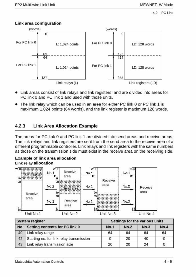
Link area configuration
For PC link 0
For PC link 1
(words)
L: 1,024 points
L: 1,024 points
Link relays (L)
For PC link 0
For PC link 1
(words)
LD: 128 words
LD: 128 words
Link registers (LD)
D Link areas consist of link relays and link registers, and are divided into areas forPC link 0 and PC link 1 and used with those units.
D The link relay which can be used in an area for either PC link 0 or PC link 1 ismaximum 1,024 points (64 words), and the link register is maximum 128 words.
4.2.3 Link Area Allocation Example
The areas for PC link 0 and PC link 1 are divided into send areas and receive areas.The link relays and link registers are sent from the send area to the receive area of adifferent programmable controller. Link relays and link registers with the same numbersas those on the transmission side must exist in the receive area on the receiving side.
Example of link area allocationLink relay allocation
Send area
Send area
Receivearea
Send area
Receivearea
Receivearea
Receivearea
Receivearea
Unit No.1 Unit No.2 Unit No.3 Unit No.4
System register Settings for the various units
No. Setting contents for PC link 0 No.1 No.2 No.3 No.4
40 Link relay range 64 64 64 64
42 Starting no. for link relay transmission 0 20 40 0
43 Link relay transmission size 20 20 24 0

MEWNET-W Mode FP2 Multi-wire Link Unit
4 - 6 Matsushita Automation Controls
4.2 PC Link
Link register allocation
Send area
Send area
Send area
Receivearea
Receivearea
Receivearea
Receivearea
Receivearea
Unit No.1 Unit No.2 Unit No.3 Unit No.4
System register Settings for the various units
No. Setting contents for PC link 0 No.1 No.2 No.3 No.4
41 Link register range 128 128 128 128
44 Starting no. for link register transmission 0 40 80 0
45 Link register transmission size 40 40 48 0
When link areas are allocated as shown above, the No. 1 send area can be sent to theNo. 2, No. 3 and No. 4 receive areas. Also, the No. 1 receive area can receive data fromthe No. 2 and No. 3 send areas. No. 4 is allocated as a receive area only, and can re-ceive data from No. 1, No. 2, and No. 3, but cannot transmit it to other stations.

MEWNET-W ModeFP2 Multi-wire Link Unit
4 - 7Matsushita Automation Controls
4.2 PC Link
Using only a part of the link areaLink areas are available for PC link 0 and PC link 1, and 1,024 link relay points and 128link register words can be used. This does not mean, however, that it is necessary toreserve the entire area. Parts of the area which have not been reserved can be usedas internal relays and internal registers.Example of link relay allocation
System register SettingNo. Setting contents for PC link 0
Settingvalue
40 Link relay range 50
42 Starting no. for link relaytransmission 20
43 Link relay transmission size 20
Example of link register allocation
System register SettingNo. Setting contents for PC link 0
Settingvalue
41 Link register range 100
44 Starting no. for link registertransmission 40
45 Link register transmission size 40
Receive area
Send area
Receive area
Used
Not used Internal relays
With the above setting, the 14 words (224 points)consisting of WL50 to 63 can be used as internalrelays.
Receive area
Send area
Receive area
Used
Internal registersNot used
With the above setting, the 28 words consistingof LD100 to 127 can be used as internalregisters.
LD0
MEWNET-W Mode FP2 Multi-wire Link Unit
4 - 8 Matsushita Automation Controls
4.2 PC Link
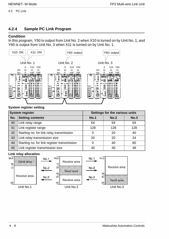
4.2.4 Sample PC Link Program
ConditionIn this program, Y50 is output from Unit No. 2 when X10 is turned on by Unit No. 1, andY60 is output from Unit No. 3 when X11 is turned on by Unit No. 1.
Y50: outputX11: ON Y60: outputX10: ON
Unit No. 1 Unit No. 2 Unit No. 3
I/ONo.
0toF
X10to
X4F
Y50to
Y8FI/ONo.
0toF
X10to
X4F
Y50to
Y8FI/ONo.
0toF
X10to
X4F
Y50to
Y8F
System register setting
System register Settings for the various units
No. Setting contents No.1 No.2 No.3
40 Link relay range 64 64 64
41 Link register range 128 128 128
42 Starting no. for link relay transmission 0 20 40
43 Link relay transmission size 20 20 24
44 Starting no. for link register transmission 0 40 80
45 Link register transmission size 40 40 48
Link relay allocation
Send area
Receive area
Send area
Receive area
Receive area
Receive area
Send area
Unit No.1 Unit No.2 Unit No.3
20
MEWNET-W ModeFP2 Multi-wire Link Unit
4 - 9Matsushita Automation Controls
4.2 PC Link
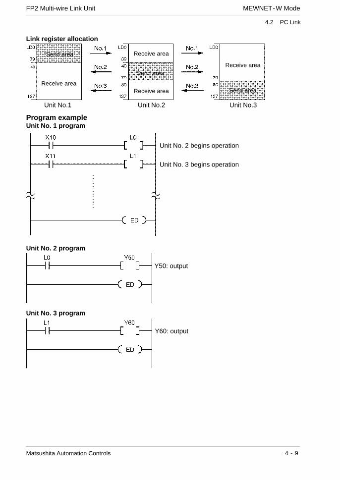
Link register allocation
Send area
Receive area
Send area
Receive area
Receive area
Receive area
Send area
Unit No.1 Unit No.2 Unit No.3
40
Program exampleUnit No. 1 program
Unit No. 2 begins operation
Unit No. 3 begins operation
Unit No. 2 program
Y50: output
Unit No. 3 program
Y60: output

MEWNET-W Mode FP2 Multi-wire Link Unit
4 - 10 Matsushita Automation Controls
4.2 PC Link
4.2.5 Precautions When Allocating Link Areas
If a mistake is made when allocating a link area, be aware that an error will result, andcommunication will be disabled.
Avoid overlapping send areasWhen sending data from a send area to the receive area of another programmable con-troller, there must be a link relay and link register with the same number in the receivearea on the receiving side. In the example shown below, there is an area between No.2 and No. 3 which is overlapped, and this will cause an error, so that communicationcannot be carried out (the ERR. LED will blink).Example of link relay allocations
Send area
Receivearea
Receivearea
Send area
Receivearea
Receivearea
Send area
Overlap
Unit No.1 Unit No.2 Unit No.3
System register Settings for the various units
No. Setting contents for PC link 0 No.1 No.2 No.3
40 Link relay range 64 64 64
42 Starting no. for link relay transmission 0 20 30
43 Link relay transmission size 20 20 34
MEWNET-W ModeFP2 Multi-wire Link Unit
4 - 11Matsushita Automation Controls
4.2 PC Link
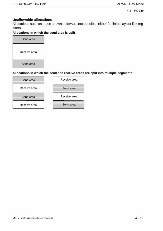
Unallowable allocationsAllocations such as those shown below are not possible, either for link relays or link reg-isters.Allocations in which the send area is split
Send area
Receive area
Send area
Allocations in which the send and receive areas are split into multiple segments
Send area
Receive area
Send area
Receive area
Receive area
Send area
Receive area
Send area

MEWNET-W Mode FP2 Multi-wire Link Unit
4 - 12 Matsushita Automation Controls
4.2 PC Link
Appendix A
What to Check If a Problem Occurs
A.1 If the CPU ERROR LED Lights 5 - 3. . . . . . . . . . . . .
A.2 Confirming the Mode Being Used 5 - 4. . . . . . . . . .
A.3 What to Check When the ERR LED Is Lightedor Blinking 5 - 5. . . . . . . . . . . . . . . . . . . . . . . . . . . . . . .
A.4 What to Do If a Transmission Error Occurs 5 - 6. .

What to Check If a Problem Occurs FP2 Multi -wire Link Unit
A - 2 Matsushita Automation Controls
What to Check If a Problem OccursFP2 Multi -wire Link Unit
A - 3Matsushita Automation Controls
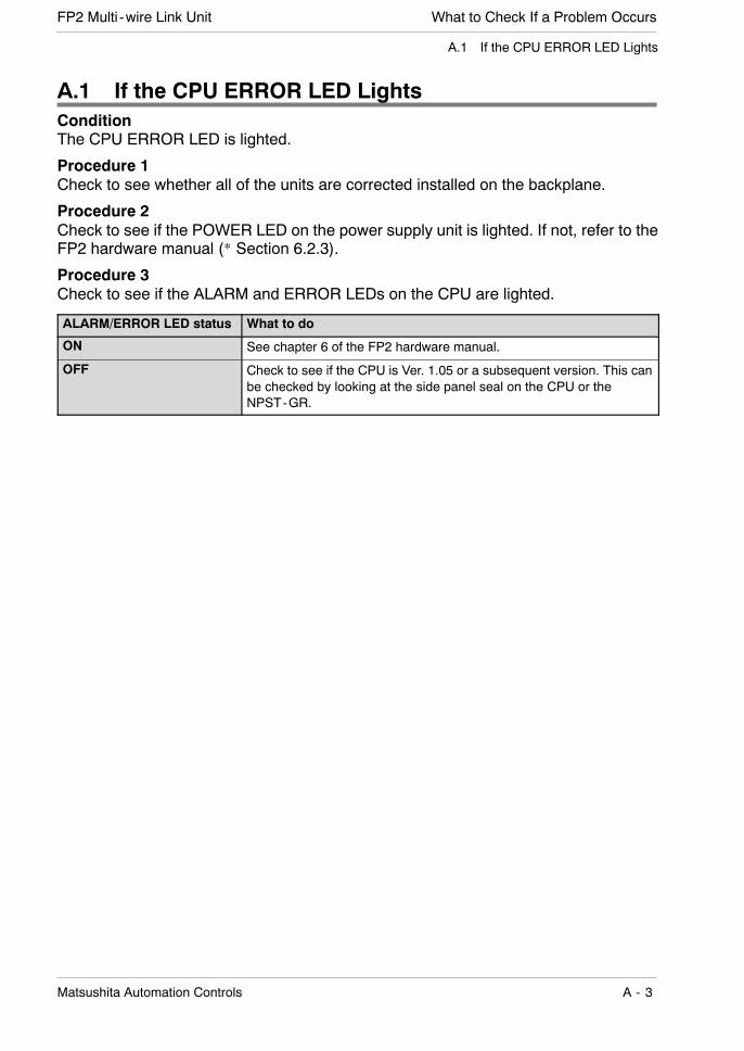
A.1 If the CPU ERROR LED Lights
A.1 If the CPU ERROR LED LightsConditionThe CPU ERROR LED is lighted.
Procedure 1Check to see whether all of the units are corrected installed on the backplane.
Procedure 2Check to see if the POWER LED on the power supply unit is lighted. If not, refer to theFP2 hardware manual (* Section 6.2.3).
Procedure 3Check to see if the ALARM and ERROR LEDs on the CPU are lighted.
ALARM/ERROR LED status What to do
ON See chapter 6 of the FP2 hardware manual.
OFF Check to see if the CPU is Ver. 1.05 or a subsequent version. This canbe checked by looking at the side panel seal on the CPU or theNPST-GR.

What to Check If a Problem Occurs FP2 Multi -wire Link Unit
A - 4 Matsushita Automation Controls
A.2 Confirming the Mode Being Used
A.2 Confirming the Mode Being UsedProcedure 1To see if the mode being used is appropriate for the objective, check the mode selectorswitches (2) on the rear panel.
Mode What to check Mode selector switches(2)
MEWNET-Wmode
Check to see if all of the units in the link are in theMEWNET-W mode.If the problem is not corrected, regardless of whetheror not the units are in the MEWNET-W mode, seechapter 5 of the FP3/FP5 W type (wire) link systemmanual.
MEWNET-W2mode
Check to see if all of the units in the link are in theMEWNET-W2 mode.If the problem is not corrected, regardless of whetheror not the units are in the MEWNET-W2 mode, refer toMEWNET-W2 Wire Link Specification Explanations.
MEWNET-Fmode
Check to see if all of the units in the link are in theMEWNET-F mode.If the problem is not corrected, regardless of whetheror not the units are in the MEWNET-F mode, seechapter 8 of the FP3/FP5 Remote I/O system manual.
. Note
The setting of the mode selector switches (2) should be changedwith the power off.
What to Check If a Problem OccursFP2 Multi -wire Link Unit
A - 5Matsushita Automation Controls
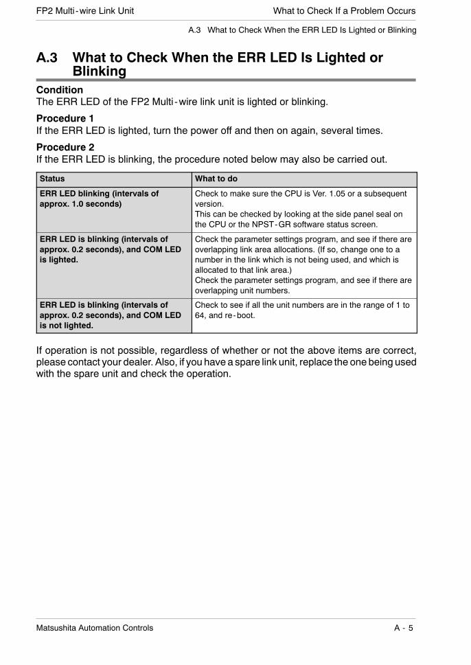
A.3 What to Check When the ERR LED Is Lighted or Blinking
A.3 What to Check When the ERR LED Is Lighted orBlinking
ConditionThe ERR LED of the FP2 Multi -wire link unit is lighted or blinking.
Procedure 1If the ERR LED is lighted, turn the power off and then on again, several times.
Procedure 2If the ERR LED is blinking, the procedure noted below may also be carried out.
Status What to do
ERR LED blinking (intervals ofapprox. 1.0 seconds)
Check to make sure the CPU is Ver. 1.05 or a subsequentversion.This can be checked by looking at the side panel seal onthe CPU or the NPST-GR software status screen.
ERR LED is blinking (intervals ofapprox. 0.2 seconds), and COM LEDis lighted.
Check the parameter settings program, and see if there areoverlapping link area allocations. (If so, change one to anumber in the link which is not being used, and which isallocated to that link area.)Check the parameter settings program, and see if there areoverlapping unit numbers.
ERR LED is blinking (intervals ofapprox. 0.2 seconds), and COM LEDis not lighted.
Check to see if all the unit numbers are in the range of 1 to64, and re-boot.
If operation is not possible, regardless of whether or not the above items are correct,please contact your dealer. Also, if you have a spare link unit, replace the one being usedwith the spare unit and check the operation.
What to Check If a Problem Occurs FP2 Multi -wire Link Unit
A - 6 Matsushita Automation Controls
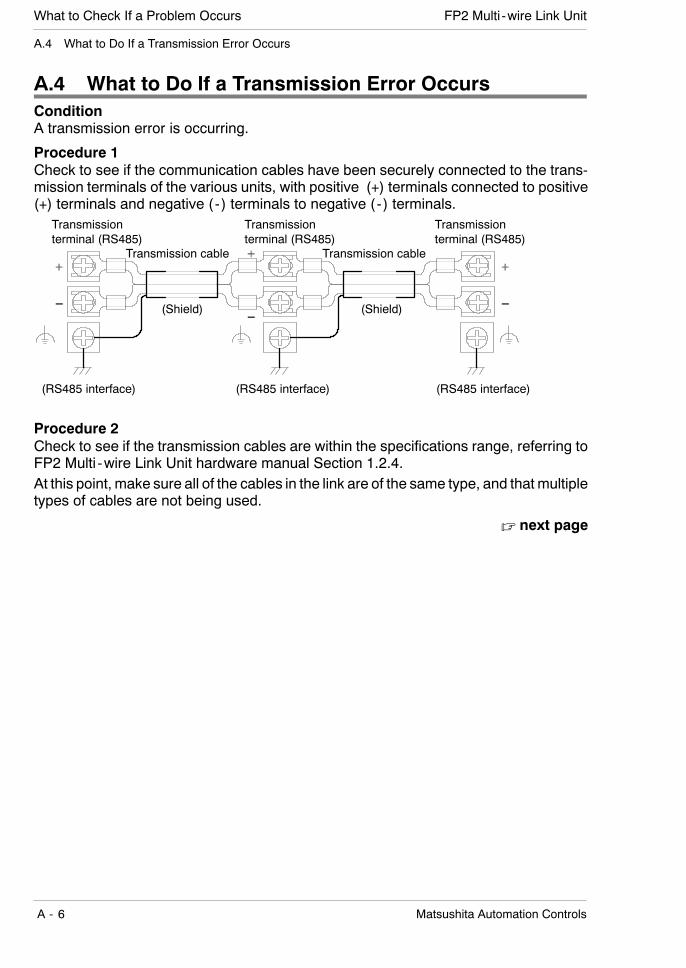
A.4 What to Do If a Transmission Error Occurs
A.4 What to Do If a Transmission Error OccursConditionA transmission error is occurring.
Procedure 1Check to see if the communication cables have been securely connected to the trans-mission terminals of the various units, with positive (+) terminals connected to positive(+) terminals and negative ( - ) terminals to negative ( - ) terminals.
Transmissionterminal (RS485)
Transmission cable Transmission cable
(Shield) (Shield)
Transmissionterminal (RS485)
Transmissionterminal (RS485)
(RS485 interface) (RS485 interface) (RS485 interface)
Procedure 2Check to see if the transmission cables are within the specifications range, referring toFP2 Multi -wire Link Unit hardware manual Section 1.2.4.At this point, make sure all of the cables in the link are of the same type, and that multipletypes of cables are not being used.
. next page
What to Check If a Problem OccursFP2 Multi -wire Link Unit
A - 7Matsushita Automation Controls
A.4 What to Do If a Transmission Error Occurs
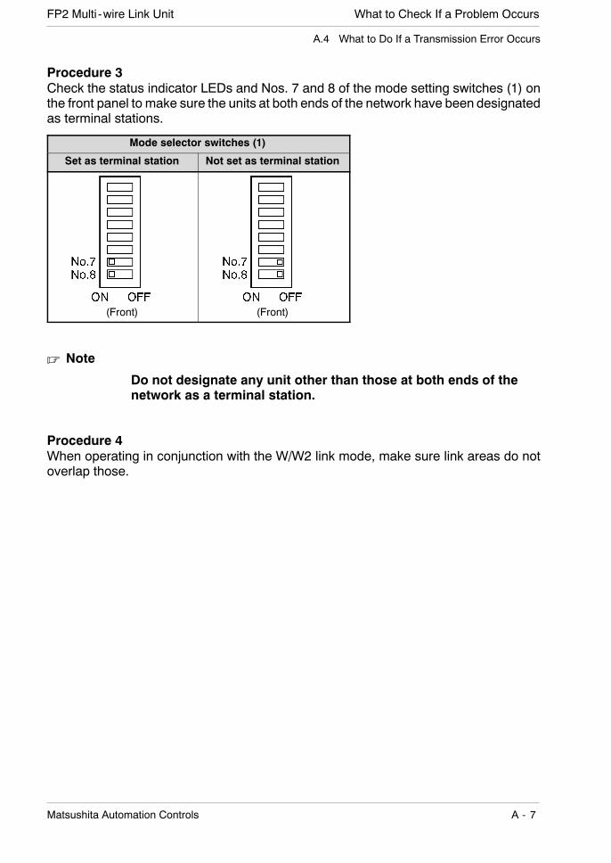
Procedure 3Check the status indicator LEDs and Nos. 7 and 8 of the mode setting switches (1) onthe front panel to make sure the units at both ends of the network have been designatedas terminal stations.
Mode selector switches (1)
Set as terminal station Not set as terminal station
(Front) (Front)
. Note
Do not designate any unit other than those at both ends of thenetwork as a terminal station.
Procedure 4When operating in conjunction with the W/W2 link mode, make sure link areas do notoverlap those.

What to Check If a Problem Occurs FP2 Multi -wire Link Unit
A - 8 Matsushita Automation Controls
A.4 What to Do If a Transmission Error Occurs

Appendix B
Dimensions

Dimensions FP2 Multi -wire Link Unit
B - 2 Matsushita Automation Controls

DimensionsFP2 Multi -wire Link Unit
B - 3Matsushita Automation Controls
(unit: mm/in.)
28/ 1.102100/3.937
(12.6/0.496) 93/ 3.661

Dimensions FP2 Multi -wire Link Unit
B - 4 Matsushita Automation Controls
IndexFP2 Multi-wire Link Unit
i - 1Matsushita Automation Controls
Index
C
confirming, 1 - 16
crimp terminal, 3 - 4
current consumption, 1 - 16
D
data transfer function, 4 - 3
F
flags, A - 9
I
I/O allocations, 1 - 16
L
link area, 4 - 4, 4 - 5, 4 - 7
link areas, 4 - 10
M
MEWNET-F mode, 1 - 6
MEWNET-W mode, 1 - 4
MEWNET-W2 mode, 1 - 5
mode selector switches (1), 2 - 3, 2 - 8
mode selector switches (2), 2 - 4, 2 - 9
multi -wire link unit, 1 - 3
P
parts terminology, 2 - 3
PC link, 4 - 4, 4 - 8
PC link function, 4 - 3
R
remote programming function, 4 - 3
restrictions, 1 - 14
S
slave station number display selectorswitch, 2 - 3, 2 - 6
specifications, 1 - 8
station number selector, 2 - 3, 2 - 7
status indicator LEDs, 2 - 3, 2 - 5
T
transmission cable, 1 - 12
transmission cable wiring, 3 - 3

Index FP2 Multi-wire Link Unit
i - 2 Matsushita Automation Controls
Record of changesFP2 Multi-wire Link Unit
R - 1Matsushita Automation Controls
Record of changes
Manual No. Date Description of Changes
ARCT1F302E/ACG-M302E
JUN. 1999 First edition

Record of changes FP2 Multi-wire Link Unit
R - 2 Matsushita Automation Controls

Please contact .........
Matsushita Electric Works, Ltd.AUTOMATION CONTROLS COMPANYH Head Office: 1048, Kadoma, Kadoma-shi, Osaka 571-8686, JapanH Telephone: Japan (81) Osaka (06) 6908 - 1050H Facsimile: Japan (81) Osaka (06) 6908 - 5781
ARCT1F302E JUN. 99 8ZTACG-M302E
Specifications are subject to change without notice. Printed in Japan.
COPYRIGHT 1999 All Rights Reserved