Embed Size (px)
Citation preview

GE Automation & Controls
Programmable Control Products
PACSystems* RSTi-EP EPSCPE100 Enhanced performance standalone controller for RSTi-EP Platform CPU Quick Start Guide GFK-3012
April 2017
g
2 RSTi-EP EPSCPE100 Standalone CPU Quick Start Guide GFK-3012
Contents
1. User Features ................................................................................................................. 3
1.1. Membrane Run/Stop push button ........................................................................ 4 1.2. LED Indicators (LEDs)........................................................................................... 5 1.3 Ethernet Ports .................................................................................................... 6
2. Hardware Installation................................................................................................... 8
2.1. Initial Checks ...................................................................................................... 8 2.2. Installation Location ........................................................................................... 8 2.3. Grounding .........................................................................................................11
3. Module Start-up ........................................................................................................... 12
3.1. You Will Need: ...................................................................................................12 3.2. Basic Installation Steps:......................................................................................12
4. Programming the EPSCPE100 ................................................................................... 13
4.1. Backwards Compatibility ....................................................................................13 4.2. PROFINET Controller Configuration .....................................................................13
5. Firmware upgrade procedure ................................................................................... 14
6. Product Limitations ..................................................................................................... 16
7. Troubleshooting ........................................................................................................... 17
8. Additional Information ............................................................................................... 18

GFK-3012 April 2017 3
1. User Features The PACSystems* RSTi-EP EPSCPE100, is an enhanced performance standalone 1GHz programmable controller equipped with 1MB of user memory and four Ethernet ports to run real time deterministic control applications. LAN1 is dedicated to highspeed Ethernet and LAN2 comprised of 3 switched ports configurable as either an embedded Ethernet controller or an embedded PROFINET controller, which provides the PROFINET functionality and supports only simplex mode of operation. It is a standalone PLC that supports distributed I/O. From now on in rest of the document this controller will be referred to as CPE100.
Figure 1: EPSCPE100 Features at a Glance
The CPE100 is programmed and configured over Ethernet via GE’s Proficy Machine Edition (PME) software. It can control/process up to 2K I/O points.
Highlights include:
A built-in PACSystems RSTi-EP PLC CPU o User may program in Ladder Diagram,
Structured Text, Function Block Diagram. o Contains 1Mbytes of configurable data and
program memory. o Supports auto-located Symbolic Variables that
can use any amount of user memory. o Reference table sizes include 2k bits for discrete
%I and %Q and up to 2k words each for analog %AI and %AQ. Bulk memory (%W) also supported for data exchanges.
o Supports up to 512 program blocks. Maximum block size is 128KB.
Supports two independent 10/100 Ethernet LANs. LAN1 has only one port and is dedicated to highspeed Ethernet and whereas LAN2 comprises of 3 switched ports configurable as either an embedded Ethernet controller or an embedded

4 RSTi-EP EPSCPE100 Standalone CPU Quick Start Guide GFK-3012
PROFINET controller. All four ports are located on the front panel, as shown in Figure 1.
The embedded communications interface has dedicated processing capability, which permits the CPU to independently support LAN1 and LAN2 with: o up to 16 combined SRTP Server and Modbus TCP Server connections out
of which Modbus TCP cannot exceed more than 8 connections (or) up to 16 simultaneous SRTP Server connections (or) up to 8 simultaneous Modbus TCP Server connections.
o 8 Clients are permitted; each may be SRTP or Modbus TCP or a Combination of both.
o up to 8 simultaneous Class 1 Ethernet Global Data (EGD) exchanges. o When used in combination for optimal performance, user must not
exceed 4 Channels for Server (Modbus/SRTP) & 4 Channels for client (Modbus/SRTP), 8 PROFINET nodes and 8 EGD data exchanges.
Ability to display serial number and date code in PME Device Information Details.
Operating temperature range -40C to 70C (-40F to 158F).
1.1. Membrane Run/Stop push button
Pressing Membrane Run/Stop push button briefly, will change the state of CPU from the state it is in to the next state. Switch operation state as given in the following state diagram:
The Run/Stop switch is enabled by default; it can be disabled in PME Hardware Configuration (HWC) settings.
STOP/IO Disabled
RUN/IO Enabled
GFK-3012 April 2017 5
1.2. LED Indicators (LEDs)
Ethernet Status Indicators
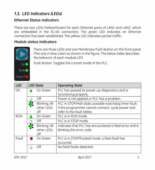
There are two LEDs (Yellow/Green) for each Ethernet ports of LAN1 and LAN2, which are embedded in the RJ-45 connectors. The green LED indicates an Ethernet connection has been established. The yellow LED indicates packet traffic.
Module status Indicators
There are three LEDs and one Membrane Push Button on the front panel (The one in blue color) as shown in the figure. The below table describes the behavior of each module LED:
Push Button: Toggles the current mode of the PLC.
LED LED State Operating State
OK On Green PLC has passed its power-up diagnostics and is functioning properly
Off Power is not applied or PLC has a problem.
Blinking; All other LEDs off
PLC in STOP/Halt state; possible watchdog timer fault. If the programmer cannot connect, cycle power and refer to the fault tables.
RUN On Green PLC is in RUN mode.
Off PLC is in STOP mode.
Blinking; All other LEDs off
Indicates that PLC has encountered a fatal error and is blinking the error code.
Fault On Green PLC is in STOP/Faulted mode: a fatal fault has occurred.
Off No fatal faults detected.
6 RSTi-EP EPSCPE100 Standalone CPU Quick Start Guide GFK-3012
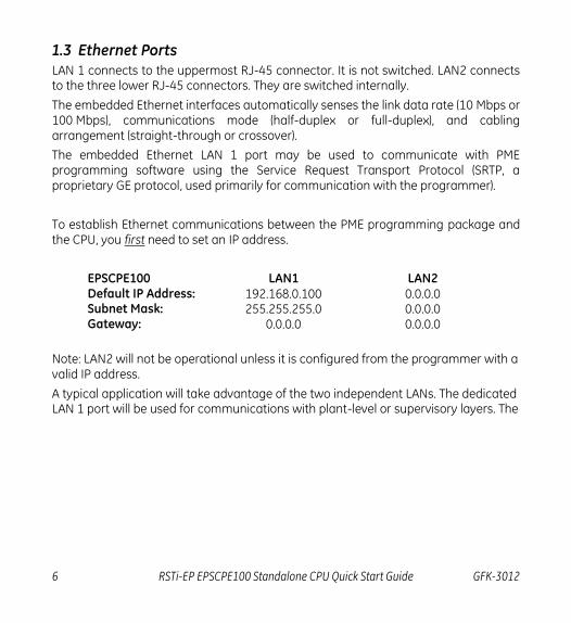
1.3 Ethernet Ports
LAN 1 connects to the uppermost RJ-45 connector. It is not switched. LAN2 connects to the three lower RJ-45 connectors. They are switched internally.
The embedded Ethernet interfaces automatically senses the link data rate (10 Mbps or 100 Mbps), communications mode (half-duplex or full-duplex), and cabling arrangement (straight-through or crossover).
The embedded Ethernet LAN 1 port may be used to communicate with PME programming software using the Service Request Transport Protocol (SRTP, a proprietary GE protocol, used primarily for communication with the programmer).
To establish Ethernet communications between the PME programming package and the CPU, you first need to set an IP address.
EPSCPE100 LAN1 LAN2 Default IP Address: 192.168.0.100 0.0.0.0 Subnet Mask: 255.255.255.0 0.0.0.0 Gateway: 0.0.0.0 0.0.0.0
Note: LAN2 will not be operational unless it is configured from the programmer with a valid IP address.
A typical application will take advantage of the two independent LANs. The dedicated LAN 1 port will be used for communications with plant-level or supervisory layers. The

GFK-3012 April 2017 7
switched LAN 2 will be used to communicate with devices over PROFINET within the manufacturing cell or process.
Figure 2: Typical Multi-Tier LAN Application (supports only Star/Bus network topology)

8 RSTi-EP EPSCPE100 Standalone CPU Quick Start Guide GFK-3012
2. Hardware Installation
2.1. Initial Checks
Upon receiving your equipment, carefully inspect all shipping containers for damage. If any part of the system is damaged, notify the carrier immediately. The damaged shipping container should be saved as evidence for inspection by carrier.
As the consignee, it is your responsibility to register a claim with the carrier for damage incurred during shipment. GE Automation & Controls will fully cooperate with you, however, should such action be necessary.
After unpacking the equipment, record all serial numbers. Serial numbers are required if you should need to contact Customer Care during the warranty period. All shipping containers and all packing material should be saved should it be necessary to transport or ship any part of the system.
Verify that all components of the system have been received and that they agree with your order. If the system received does not agree with your order, contact Customer Care.
2.2. Installation Location
As shipped, the CPE100 is intended for mounting on a DIN rail. An optional panel-mount adaptor is also available with part number (ICMFAACC001-AA). If panel-mounting is required, replace the DIN-rail adaptor with the panel-mount adaptor using the screws supplied with that adaptor. Both adaptors attach to the rear of the CPE100 chassis using four Torx M3 screws. Torque newly-installed screws to 5.3 in-Ibs (0.6 Nm) if installing a new adaptor plate.
Thermal Requirements:
When mounting the CPE100, allow a minimum clearance of 50mm on the left & right side of the unit and a minimum clearance of 100mm on the top & bottom sides.
Instructions to mount the CPE100 on a DIN Rail:
The CPE100 snaps easily onto the DIN rail. No additional tools are required.
(1) Incline the unit so that the upper hooks of the DIN rail adaptor engage with the upper edge of the DIN rail.

GFK-3012 April 2017 9
(2) Press on the lower part of the unit until you hear a click. The click indicates that the lower hooks of the DIN rail adaptor have engaged with the lower edge of the DIN rail.
If you need any technical help, please contact Technical Support. For phone numbers and email addresses, refer to the back cover of this Guide.
Figure 3: Mounting positions of the EPSCPE100 on DIN rail
Instructions to mount the CPE100 on a Panel (1) Attach the panel mount plate to the rear side of CPE100 using the four M3 screws supplied with the adapter.
(2) Fasten the tabs of panel mount adapter in the appropriate location of panel with the four screws. The screw size used for each panel mount tab should not exceed M5.
10 RSTi-EP EPSCPE100 Standalone CPU Quick Start Guide GFK-3012
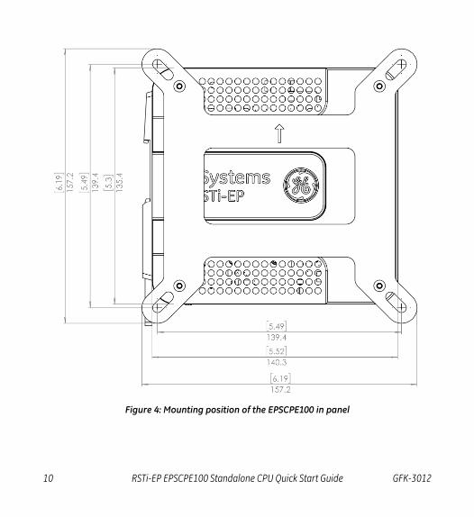
Figure 4: Mounting position of the EPSCPE100 in panel
GFK-3012 April 2017 11
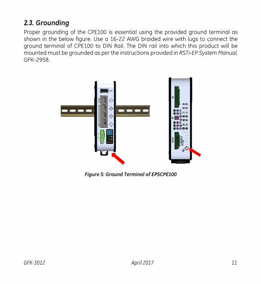
2.3. Grounding
Proper grounding of the CPE100 is essential using the provided ground terminal as shown in the below figure. Use a 16-22 AWG braided wire with lugs to connect the ground terminal of CPE100 to DIN Rail. The DIN rail into which this product will be mounted must be grounded as per the instructions provided in RSTi-EP System Manual, GFK-2958.
Figure 5: Ground Terminal of EPSCPE100

12 RSTi-EP EPSCPE100 Standalone CPU Quick Start Guide GFK-3012
3. Module Start-up
3.1. You Will Need:
This PACSystems standalone controller RSTi-EP CPE100.
Generic power source which can output 9-30 V DC, 5 W.
A DIN rail, typically mounted in an enclosure, as discussed above. Alternately, mount the unit using the (optional) compatible panel-mount adaptor.
A computer running Proficy Machine Edition (PME) configuration and programming software. PME Version 9.50 & SIM 1 or later.
Ethernet cable for connecting the PME programmer computer to the EPSCPE100.
Very small slotted screwdriver (1.4mm jeweler’s size).
3.2. Basic Installation Steps:
For startup and configuration of the EPSCPE100, complete the following steps.
1. Be sure to disconnect the power to EPSCPE100,
2. The ESCPE100 is designed to be DIN-rail-mounted.
3. An external power supply 9- 30 V DC provided by a Class II power supply marked as "double insulated", Limited Power Source (LPS), or a SELV source with a minimum 32 V dc listed fuse with 3 A max rating is required to power the EPSCPE100. Wire sizes: 22 to 16 AWG Screw torque: 2 in-Ib. Temperature rating for copper wire: 80 °C. Wiring to power input terminals shall be limited to 30 meters in length.
4. Plug the Ethernet cable for Programmer & Protocol (SRTP, Modbus, EGD) on LAN 1 port.
5. Plug the Ethernet cable for PROFINET network in LAN 1 port.
6. Apply power to EPSCPE100.

GFK-3012 April 2017 13
4. Programming the EPSCPE100 To configure the CPE100, connect the computer running the PME programming software to an Ethernet port of LAN1 using the default IP address 192.168.0.100. PME 9.5 SIM 1 or later is required. Configuration will either start out using the RSTi-EP CPE100 template when creating a new project, or will convert an existing project to the CPE100 using the Family Conversion feature in PME.
4.1. Backwards Compatibility
To convert an existing project which uses any other PLC, use the Family Conversion feature in PME. Be aware of the constraints involved, as will be notified in PME. For instance, the first PROFINET Controller in an RX3i CPU320 application will be assigned to the embedded PROFINET Controller feature of the CPE100.
4.2. PROFINET Controller Configuration
An Embedded PROFINET Controller may be configured on LAN2. To enable the PROFINET Controller in a CPE100 project, select the CPE100 target in the PME Navigator (Figure 10) and open the Hardware Configuration. On the Settings tab, change the LAN2 Mode of the selected port to PROFINET. The PROFINET Controller node description then displays that a PROFINET node exists on the selected LAN (under the CPE100). For further details, refer to the PACSystems RX3i & RSTi-EP PROFINET IO Controller User Manual, GFK-2571.
14 RSTi-EP EPSCPE100 Standalone CPU Quick Start Guide GFK-3012
5. Firmware upgrade procedure EPSCPE100 comes with the default IP address 192.168.0.100 assigned to the Ethernet Port of LAN1, user can change the default IP address through PME (Proficy Machine Edition). Use the Ethernet Port of LAN1 to connect to the webserver of CPE100 through which user can upgrade the Firmware.
It is always recommended to check if there are any new firmware updates available for this product at our support site prior to proceeding with upgrading the module firmware.
Steps are as below (For detailed instructions follow upgrade instructions manual provided with upgrade kit):
1. Copy the firmware upgrade file (PAC) to any directory on your PC.
2. Use programming software or the controller’s Run/Stop switch place the
Controller module in Stop Disabled mode.
3. If your PC uses a proxy server, it may be necessary to modify your Network
Settings to disable the proxy server (or disable use of automatic proxy
configuration scripts).
4. Open a browser window and go to the EPSCPE100 Controller’s homepage using
the IP address you have configured for Programmer communications (e.g.
http://192.168.0.100).
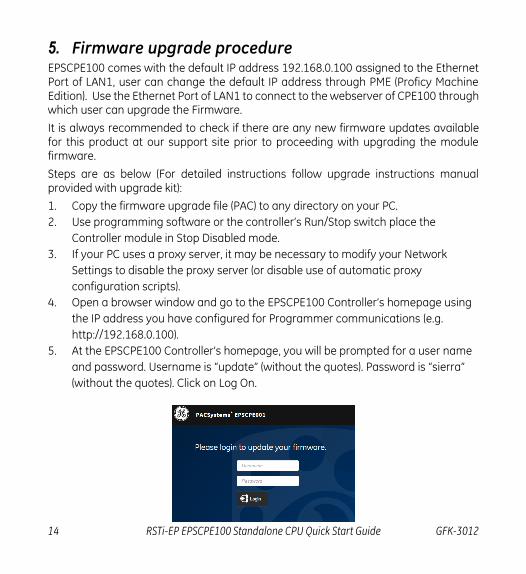
5. At the EPSCPE100 Controller’s homepage, you will be prompted for a user name
and password. Username is “update” (without the quotes). Password is “sierra”
(without the quotes). Click on Log On.

GFK-3012 April 2017 15
6. Click on “Choose File” and navigate to the location of the firmware update file
obtained and saved earlier. Select the file and click “Open”.
7. Click on “Upload File” to get the file upload started. The
EPSCPE100 Controller’s Firmware Update web page will indicate the upload
progress.
8. The firmware upgrade process may take up to four minutes to complete
depending on the module being upgraded. Do not power cycle the EPSCPE100
Controller during the update process as this may place the module being
updated in an unrecoverable and unusable state. Once the file upload is
completed, EPSCPE100 will automatically reset
9. When the firmware upgrade completes successfully the browser will remain on
the Firmware Update web page and will indicate that the upgrade process is
complete. Note: The processing is complete when the DONE status is displayed.
10. If the firmware upgrade is not successful, a Firmware Update Status page is
displayed with an error status.
11. When you have successfully completed the firmware upgrade:
Close your browser window.
Mark or label your EPSCPE100 to indicate the new firmware version.
Ensure the label does not cover any vents.
12. Return the EPSCPE100 Controller to Run Enabled mode using the programming
software.

16 RSTi-EP EPSCPE100 Standalone CPU Quick Start Guide GFK-3012
6. Product Limitations
1. MRP (Media Redundancy Protocol) is not supported on Release 1.0.
2. C Toolkit is not supported in Release 1.0.
3. Timed interrupt blocks are not supported.
4. RDSD not supported in Release 1.0.
Note: The above features may be supported in the subsequent FW release. Refer to the data sheet.

GFK-3012 April 2017 17
7. Troubleshooting
1. Resetting of the IP Address to default one i.e. 192.168.0.100 or to restore the controller from undermined state, user need to press the Run/Stop switch during the power-up (till it gets powered up, approx. 60 sec), this action will reset IP address back to default one i.e. 192.168.0.100 in addition to this it will also clear the contents of Flash and RAM.
18 RSTi-EP EPSCPE100 Standalone CPU Quick Start Guide GFK-3012
8. Additional Information
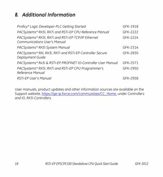
Proficy* Logic Developer-PLC Getting Started GFK-1918
PACSystems* RX3i, RX7i and RSTi-EP CPU Reference Manual GFK-2222
PACSystems* RX3i, RX7i and RSTi-EP TCP/IP Ethernet Communications User’s Manual
GFK-2224
PACSystems* RX3i System Manual GFK-2314
PACSystems* RXi, RX3i, RX7i and RSTi-EP Controller Secure Deployment Guide
GFK-2830
PACSystems* Rx3i & RSTi-EP PROFINET IO-Controller User Manual GFK-2571
PACSystems* RX3i, RX7i and RSTi-EP CPU Programmer’s Reference Manual
GFK-2950
RSTi-EP User’s Manual GFK-2958
User manuals, product updates and other information sources are available on the Support website, https://ge-ip.force.com/communities/CC_Home, under Controllers and IO, RX3i Controllers.

GE Automation & Controls
Contact Information
Americas: 1-800-433-2682 or 1-780-420-2010 (if toll free 800 option is unavailable)
Global regional phone numbers are available on our web site
www.geautomation.com Copyright © 2017 General Electric Company. All Rights Reserved.
* Trademark of General Electric Company and/or its subsidiaries.
All other trademarks are property of their respective holders
g