Embed Size (px)
Citation preview
SSC-216
PROGRAM “TRANSHIP”A COMPUTER PROGRAM FOR THE DESIGN OF ~THE MIDSHIP SECTION OF A TRANSVERSELY-
FRAMED DRY CARGO SHIP IPART TWO
This document has been approvedfor public release and sale; its
distribution is unlimited.
SHIP STRUCTURE COMMITTEE
1971
SHU= STRUCTURE COMMl~EE
AN INTERAGENCY ADVISORY
COMMITTEE DEDICATED TO IMPROVING
THE STRUCTURE OF SHIPS
IEMBER AGENCIES: AODRESS CORRESPONDENCE TO:
!1P411c11STAIFS cDAS1 I;(IARO SECRETARYr4A\,AI 51411,sYslcMs Ci3MMANDMllltiHY:!Ldll1(:OMMAND
SHIFSTRU(:lL.JHF1COMM!T7EEIJ.S.COASTIJJARLIHEADOLJARIERS
MA1l11\4,ArlbhiN151RAT10N~kll[411/,!)1<(lfll:A\J01 SHIP1xlNG
WASHING1(>N,3(:.?0591
SR-175
1972
Dear Sir:
?:~e Ship Structure Committee has mderta.ken a series of
research projects to develop analytical methods and computer
?rograrns ,{hich will apply modern high-speed electronic com-
putational techniques to ship hull structures .
This report contains the detai 1s of the computer program
discussed in SSC-215 , A Guide for the Synthes~. s of Ship Structure --
Part @e--The Mid-Ship Hold of a Transversely Framed Dry Cargo
Ship.
Comments on this report would be welcomed.
Sijere_
W. F. RSA, III
Rear Admiral, U. S. Coast Guard
Chairman, Ship Structure Committee
SSC-216 ‘
Final Technical Report
on
Project SR-175, “Rational Ship Structural Design”
PROGRAM “TRPJISHIP”
A COMPUTER PROGRAN FOR THE OESIGNOF THE
MIDSHIP SECTIOIJ OF A TRAi/SVERSELY-FRAMED
ORY CARGO SHIP
PART TWO
by
Manley St. DenisUniversity of Hawaii
underDepartment of the Iiavy
Naval Ship Engineering CenterContract No. NOO024-68-C-5403
This document has been approvedfor public release and sale;
its distribution is unlimited.
U.S. Coast Guard HeadquartersWashington, D.C.
1971
ABSTRACT
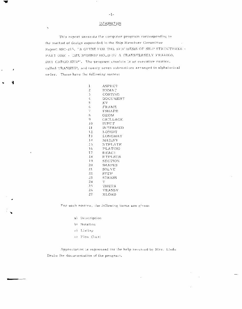
This report presents the computer program corresponding to themethod of design expounded in the Ship Structure Committee Report SSC-215 , I Guide for the Synthesis of ship s I;YWCture.q - Part one. – The
/viu!$;;i,:,p HO ‘Zd of ~ yrarLs.Jeps@ Q -Irme{i, L&y cargo ship . The program +COn SiStS ifl an executive routine, called 7’.R.ZVJSH.TP,and twenty sevensubroutines.
INDEX
Introduction
Description of Input
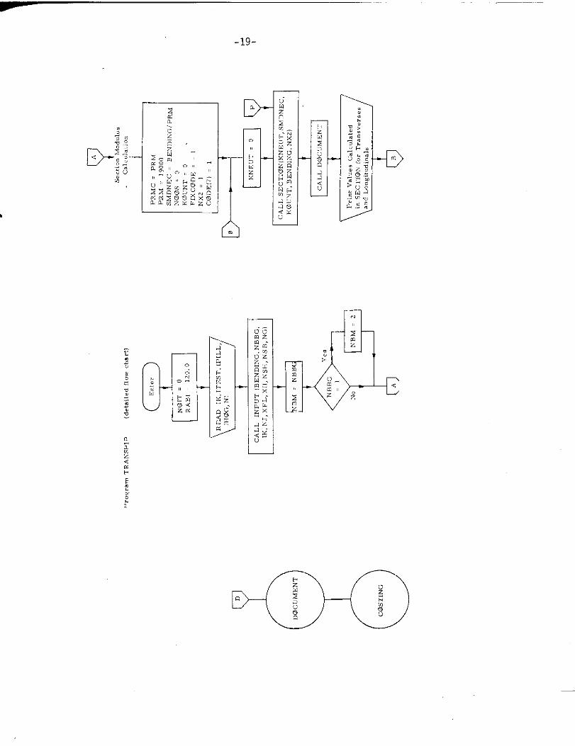
Program TRANSHIPDescription
Notation - Mathematical Symbols to FORTRANFORTRAN Symbols to Mathematical
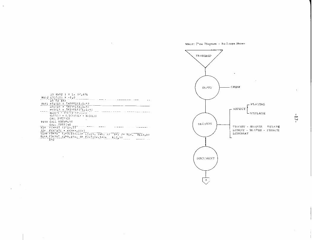
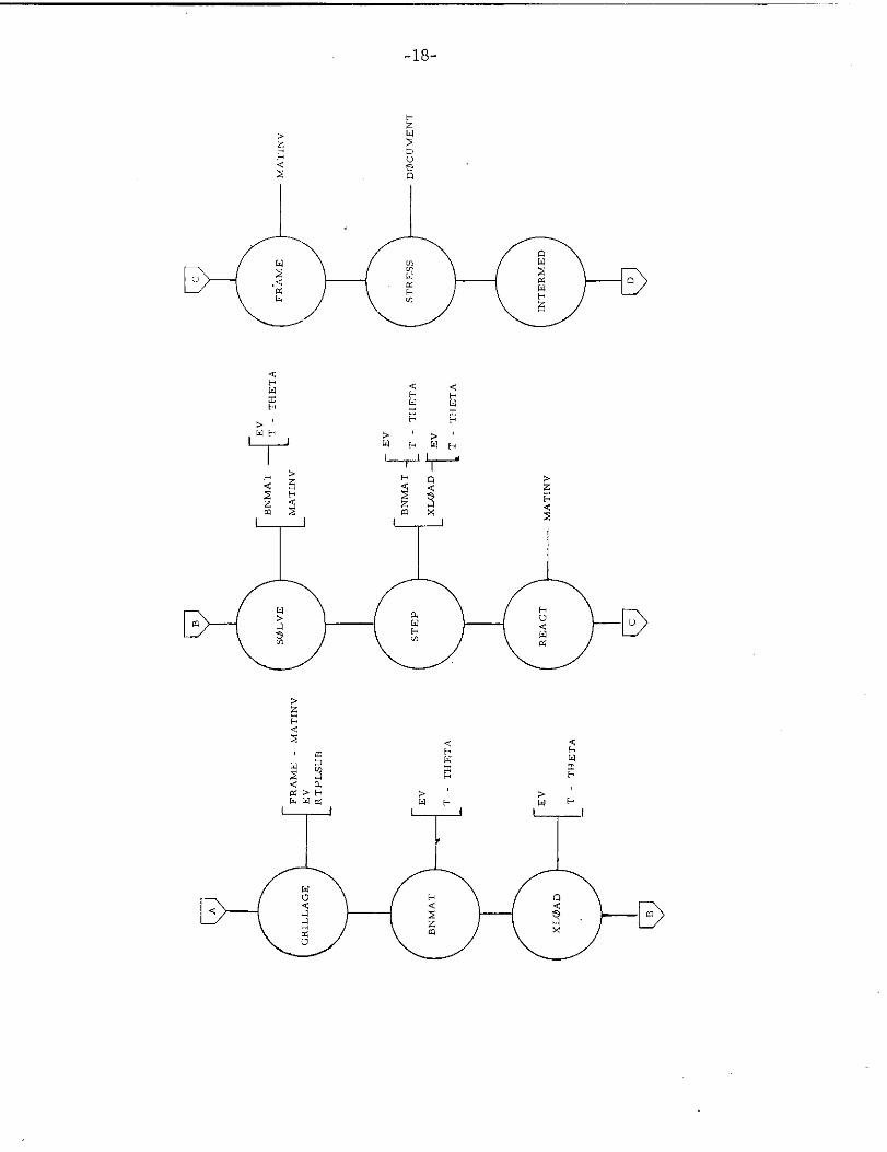
ListingMacro Flow DiagramDetailed Flow Diagram
Subroutine ASPECTDescription andListingF1 ow Diagram
Subroutine BNMATDescription andListing
F1 ow Diagram
Subroutine COSTINGDescription andListingFlow Diagram
Subroutine DOCUMENTDescription andListingFlow Di agr.m
Subroutine EVDescription andListing
Flow Diagram
Subroutine FRAMEDescription andListingFlow Diagram
Subroutine FSHAPEDescription andListingFlow Diagram
Notation
Notation
Notation
Notation
Notation
Notation
Notation
Page No.
3
4
151719
242526
293D30
313233
424346
565757
-iii-

INDEX (Cent’d)
Page No.
.,uroutine GEOMDescription andListingF1 ow Diagram
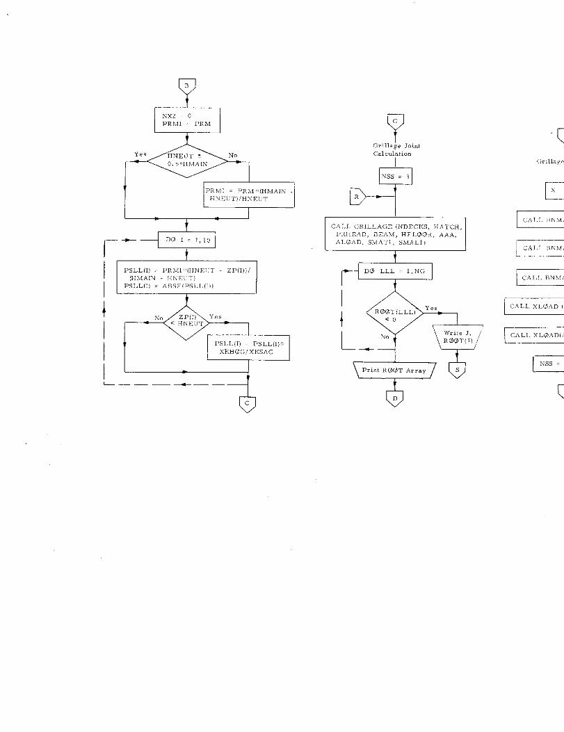
Scibroutine GRILLAGEDescription andListingFlow Diagram
Subroutine INPUTDescription andListingFlow Diagram
Subroutine INTERMEDDescription andListingFlow Diagram
Subroutine LONGITDescription andListingFlow Diagram
Subroutine LONGMATDescription andListingF1 ow Diagram
Subroutine MATINVDescription andListing
F1 ow Diagram
Subroutine NTPLATE
Description andListingFlow Diagram
Subroutine PLATINGDescription andListingF1 ow Diagram
SQ~routjne REACT
Description andListing~low Diagram
Notation
Notation
Notation
Notation
Notation
Notation
Notation
Notation
Notation
Notation
-iv-
585960
686971
747576
777879
858687
899091
929496
101102102
— –-— –.
Subroutine RTPLSUBDescription and NotationListinaF1 ow D~agram
Subroutine SECTION. . Description and Notation
ListingFlow Diagram
t{
Subroutine SHAPESDescription and Notation
ListingFlow Diagram
Subroutine SOLVEDescription and NotationListing
Flow Diagram
Subroutine STEPDescription and NotationListingFlow Diagram
Subroutine STRESSDescription and NotationListingFlow Diagram
Function TDescription and NotationListing
Flow Diagram
Function THETADescription and NotationListingFlow Diagram
Subroutine TRANSVDescription and NotationListing
Flow Diagram
Subroutine XLOADDescription and NotationListing
F1 ow Diagram
INDEX (Cent’d)
Page No.
103104105
110111
112
114115115
117118120
125126126
128129130
134
135135
136
137137
138139140
142143143
program to
pertaining
CaDt. J. E.
,SHIP STRUCTURE COMMITTEE
The SHIP STRUCTURE COMMITTEE is constituted to prosecute a researchimprove the hull structures of ships by an extension of knowledgeto design, materials and methods of fabrication.
RADM W. F. Rea, 111, USCG, ChairmanChief, Office of Merchant Marine Safety
U.S. Coast Guard Headquarters
Rasmussen, USN Mr. E. S. DillonHead, Ship Systems Enaineerina Chi Pf
and De&ig; Department “Naval Ship Engineering CenterNaval Ship Systems Command
Mr. K. Morland, Vice PresidentAmerican Bureau of Shipping
Office of Ship ConstructionMaritime Administration
Capt. L. L. Jackson, USNMaintenance and Repair OfficerMi1itary Sealift Command
SHIP STRUCTURE SUBCOMMITTEE
The SHIP STRUCTURE SUBCOMMITTEE acts for the Ship Structure Committeeon tecimical matters by providing technical coordination for the determination ofgoals and objectives of the program, and by evaluating and interpreting the re-SU1ts in terms of ship structural design, construction and operation.
NAVAL SHIP ENGINEERING CENTER
Mr. P. M. Palermo - ChairmanMr. J,.B. O’Brien - Contract AdministratorMr. G. Sorkin - MemberMr. H. S. Sayre - AlternateMr. I. Fioriti - Alternate
U.S COAST GUARD
LCOR C. S. Loosmore, USCG - SecretaryCOR C. R. Thompson, USCG - MemberCOR J. W. Kime, USCG - AlternateCOR J. L. Coburn, USCG - Alternate
MARITIME ADMINISTRATION
Mr. F. Oashnaw - MemberMr. A. Maillar - MemberMr. R. Falls - AlternateMr. R. F. Coombs - Alternate
MILITARY SEALIFT COMMANO
Mr. R. R. Askren - MemberLTJG E. T. Powers, USNR - Member
AMERICAN BUREAU OF SHIPPING
Mr. S, G. Stiansen - Member!Mr.F. J. Crum - Member
–vi–
OFFICE OF NAVAL RESEARCH
Mr. J. M. Crowl ey - MemberOr. W. G. Rauch - Alternate
NAVAL SHIP RESEARCH & DEVELOPMENTCENTER
Mr. A. B. Stavovy - Alternate
NATIONAL ACADEMY OF SCIENCES -Ship Research Committee
Mr. R. W. Rumke, LiaisonProf. R. A. Yagle, Liaison
SOCIETY OF NAVAL ARCHITEC”rSENGINEERS
& MARINE
Mr. T. M. Buermann, Liaison
BRITISH NAVY STAFF
Dr. V. Flint, LaisionCOR P. H. H. Ablett, RCNC, Liaison
WELDING RESEARCH COUNCIL
Mr. K. H. Koopman, LiaisonMr. C. Larson, Liaison
-1-
INTRODUCTION
ASPECTII N,MAT
COSTIIYC;
DOCC WENT
EV
FRAMF:
I?SHAPIC
C.EOM
GRILL AGE
lNPIIT
IN TERMED
LON1[;TT
LONGMA?
,M.A’rlNv
NTPLATE
PLA TING
REAC-I
RI PLS[i H
SE CTIOK
SHAPES
SOLVE
STEP
STRESS
‘r
THETA
TRh Nsv
XLOAD
———
-2-
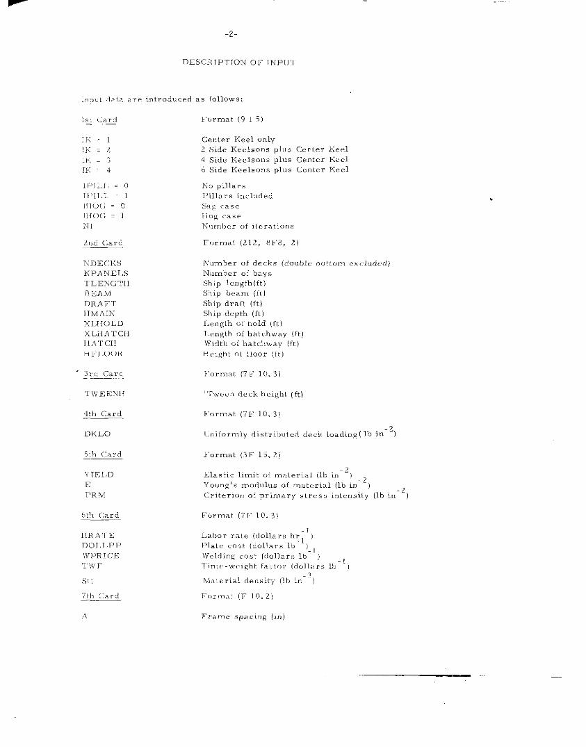
DESCRIPTION OF INP1ll
Input data are introduced as [O11OWS:
1s! (.;ard
11< . 1
fK=2
II’.;
IK4
lPI1. J = C
11>[1,L 1
117(>(; = o
JHO(; = 1
N1
z,, d Card
NJ)>:(:KS
KPANELS
‘l LENGTF1
t>IEAM
DRAFT
HMAIN
xLIIOLD
X LH A ‘T CH
H A T CH
HFLOOR
Format (9 1 5)
Gf!nler Keel only
2 Side Keclsons plus center Keel
4 Side Keelsons plus Center Keel
b Side Keelsons PIJS center Keel
h-o pillar.
I>illar. included
sag <.,s’2
Ilog case
Number of iterations
Format (212, 8F8, z)
Number of deck. (cfoubk lb. ttorn excl.dcdj
Number of bay,
Ship length (ft.)
Sl, ip beam (ft)
Ship draft (ft)
Ship depth (ft)
I,englb of hold (ftl
Length of hatchway (ft)
Width ofhatc.hway (ft)
Height o[flcmr (ft)
3rd card Format (7F 10.3)
TwEENH ‘Twe. n deck hcighl (ft)
4th Card I-’”rmat (7F 10. 3)
DKLO-2
lJniformly distribut..d deck loading (lb in )
ht), Card
S(;
71h card——
l’orrnat (3F 15.2)
Elastic limit of material (lh in-” ‘) .2Young’s modulus of material (lb i“ )
-2~.,it,er ion of primary ,tress intensity (lb 1,1 )
r<>rmat (7F 10. 3)
A Frame .spaci,, g (In)
-3-
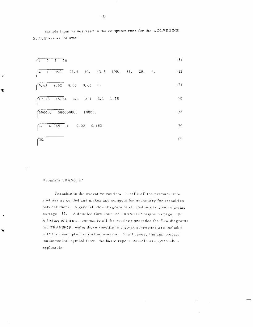
5ample input values used in the computer runs for the wOLVERINE
.- .:E a., as follOws:-.,.
(r--i-l o
‘Z7-4>C 71.5 30. 43.5 100. 33. 20. .5
p=i- 9.63 ,.(,3 o.
r’ 2“’ 2“ 2“’ 1“78
7°0000” 1’000”
(r-i%r3. 0.0, 0.2”3
7
Program TRA31SH[P
(1)
(2)
(3)
(4)
(5)
(())
(71
-4-
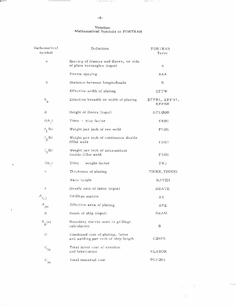
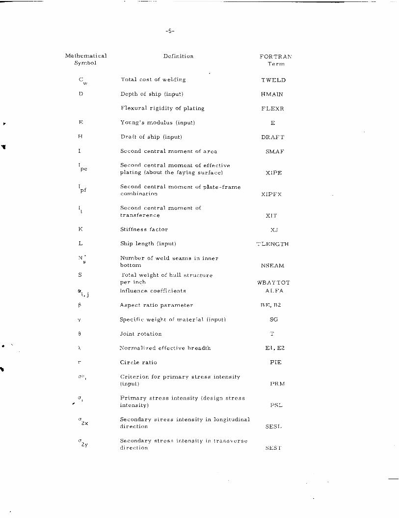
NotationMathematical Symbols to FORTRAN
Mathcrnatical
Symbol
b
be
c1
f(A. )
flh)
fz(h)
f3(M
f(w)
h
r
A.lsJ
Ape
n
np[x)
cf,
Definition
spa.in~ of frames and floors, or sideof plal. e rectangles (input)
Frame spacing
Dislance between Iongitudinals
Effec~ivc width of plating
Effective breadth or width of plaling
Height of floors (input)
Tim. size factor
Weight per inch of vee weld
Weight per inch of continuous double
fillet weld
Weight per inch of intermittent
double fillet weld
Tim. weight factor
Tbick”css of plating
Wave height
11OUI-1Y rate of Iahor (input)
Grillagc matrix
Effec live area of plating
Beam of ship (input)
Boundary matrix used in grill age
calculat io”
Combined cost of plating, labor
and welding per inch of ship length
Total labor cost of erectior,
and fabrication
Total rn.aLerial .0s1
FOR TRAK
‘Term
A
AAA
n
EFFW
ZFFBI, EFFwI,
EFFBR
II F1.00R
,:4(H)
F1 (lIJ
F2(H)
F3(H)
TV<,
THIKK, THIKKI
WA V EH
llRATE
A x
APE
13E A M
B
C@STS
xLAf30R
PLC; (jiS’:1’
Mathematical
Symbol
cw
D
E
H
I
‘pf
w.,,J
b
Y
8
A
o,
‘2X
‘2Y
-5-
Definition
Total cost of welding
Depth of ship (input)
Flexui-al rigidity of plating
Young’s modulus (input)
Draft of ship (input)
Second central moment of area
Second central moment of effective
plating (about the faying surface)
Second central moment of plate-frame
combination
Second central moment of
transference
Stiffness factor
ship length (input)
Number of weld seams in inner
bottom
Total weight of hull structure
per inch
Influence coefficients
Aspect ratio parameter
specific Weight Of material (input)
,Toint rotation
Normalized effective breadth
Circle ratio
Criterion for primary stress intensity
(input)
Primary stress intensity (design stress
intensity)
Secondary sLress intensity in longitudinal
direction
Secondary stress intc”sity i“ transverse
direction
FORTRAN
Term
TwELD
HMAIN
FLExR
E
DRAFT
SMAF
XIPE
XIPFX
XIT
X.r
TLENGTH
NSEAM
WBAYTOT
ALFA
BE, B2
SG
T
El, E2
PIE
PR )4
PSL
SESL
SEST
X;athanati. al
Sullbol
.2xf
‘zyf
‘3X
“3Y
.C,
“xb ‘ “xb
.xb
,, ,yb’ yb
,,,
yb
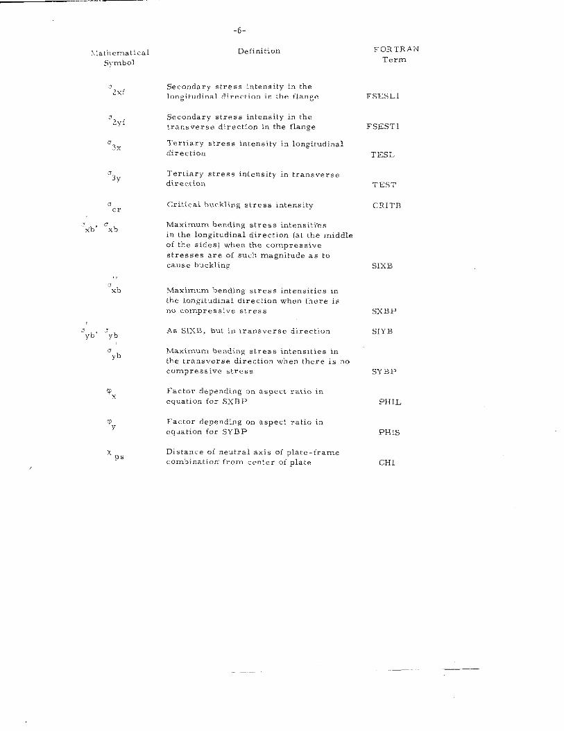
-6-
Definition
Secondary stress intensity in the
longitudinal direction in the flange
Secondary stress intensity in the
transverse direction in the flange
Tertiary stress intensity in longitudinal
directim
Tertiary stress intensity in transverse
direc.t. ion
Critical buckling stress intensity
Maximum bending stress intensiti’cs
in the longitudinal direction (at the middle
of the sides) when the comp. cssive
stresses are of such magnitude as to
cause buckling
Maximum bending stress intensities in
the longitudinal direction when there is
no compress,”. s,,., ,
A. SIXB, but in transverse direction
Maximum bending stres E intensities in
the transverse direction when lhere is no
compressive stress
Factor depending on aspect ratio in
equation for SXBP
Factor depending on aspect ratio i“
equation for SYBP
Distance oi neutral axis of plate-frame.Ombinati. n from center of plate
FORTRAN
Term
FSESL1
FSESTI
TESL
TEST
CRITB
SIXB
SXBP
SIYB
SYBP
PHIL
PHIs
CH1
FORTRAN
Term
A
AA
AAA
AFAC
ALFA
AREATI
AX
B
B
BB
BEAM
cc
CN
c@DE
DEJ?L
DKL(l
DQLLPP
DRAFT
E
EFFB1
EFFW1
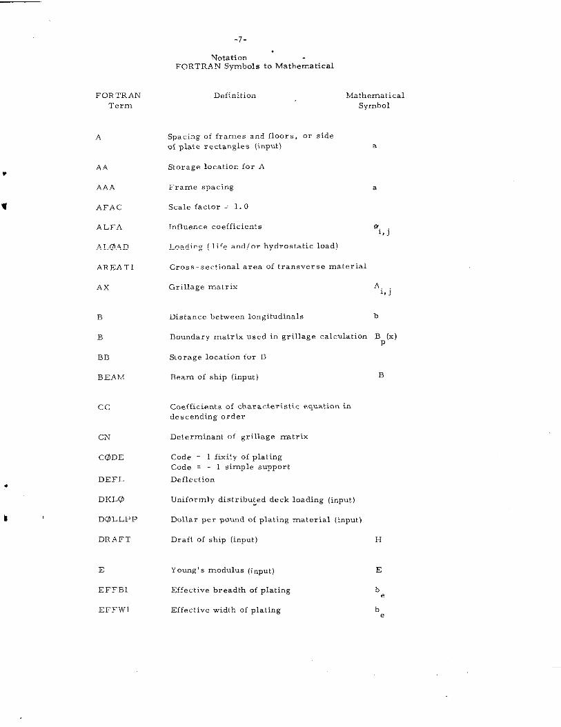
-7-
NotationFoRTRAN Symbols to Mathematical
Definition Mathematical
Symbol
Spacing Of frames and f100rs, Or sideof plate rectangles (input) a
Storage location for A
Frame spacing a
Scale factor = 1.0
Influence coefficients u.,,J
Loading ( life andlor hydrostatic load)
Cross-sectional area of transverse material
Grillage matrix A.1, J
Distance between longitudinal b
Boundary matrix used in grillage calculation BP(x)
Storage location for B
Beam of ship (input) B
Goeffi.ients of characteristic equation in
descending order
Determinant of grillage matrix
Code = 1 fixity of plating
Code = 1 simple support
Deflection
Uniformly distribu~ed deck loading (input)
Dollar per pound of plating material (input)
Draft of ship (imp”t) H
Young’ s modulus (inPut) E
Effective breadth of plating be
Effective width of plating be
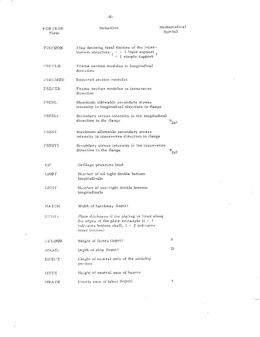
-8-
De finib ion Mathematical
symbolFORTRAN
Term
FIX C@JDE
FSECL@
FSECivi@Ll
FSECTR
FSESL
FSESL1
FSEST
FSESTI
GP
GNGI T
GP.TNT
HATCH
HT! iI)
HFL@OR
HMAIX
IIh-ELT
IINTX
l<RATE
Flag denoting ideal fixities of the inner-
bottom structure = - 1 fixed support( = 1 simple support
)
Frame section modulus i,, Iongit”dinal
direction
Required section modulus
Frame section modulus in lramverse
direction
Maximum allowable secondary stress
intensity in longitudinal direction in flange
Secondary stres8 intensity in tbe longitudinal
direction in the flange‘2xf
til.xizzwrn allowable secondary stress
intensity in transverse direction in flange
Secondary stress intensity in the transverse
direction in the flange‘2yf
Grills.ge pressure load
Number of oil tight double bottom
longitudinal.
Number of non-tight double bottom
longitudinal
Width of hatchway (input)
Flat. tkicknes. if the plating is fixed along
the edges of {he plate rectangle (1 = 1
indicates bottom shell, 1 = 2 indicates
inner b“tto*n\
Height o{ floors (inPUL) d
Depth of ship (input) D
Height of neutral axis of the midship
sect, on
Height of neutral axis of beams
Hourly rate of labor (inPut)
FORTRAN
Term
Hsl (1)
HWF(L)
HWFS(L)
HWS(L)
IB T
lHOG
IK
ILG
IPILL
lPLATE
IPLT
lTR
J
KPANELS
-9-
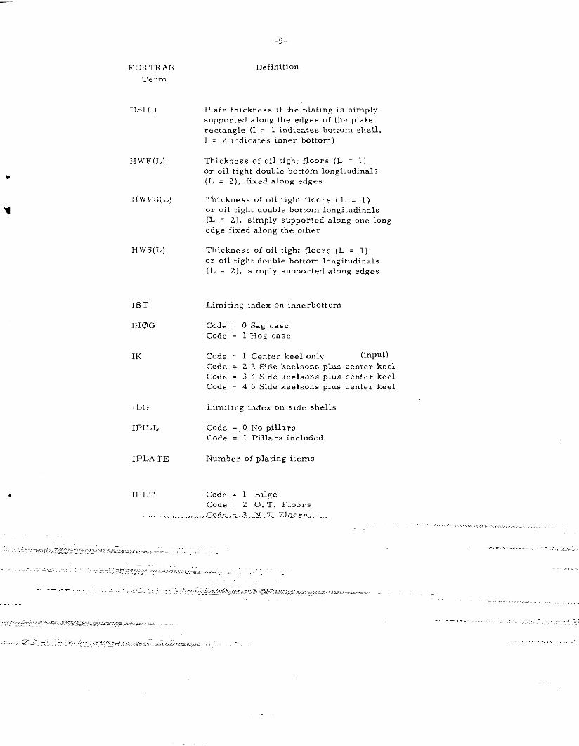
Definition
Plate thickness if the plating is simply
supported along the edges of the plate
rectangle (I = 1 indicates bottom shell,
1 . 2 indicates inner bottom)
Thickness of oil tight floors (L = 1)
or oil tight double bottom longitudinal
(L . 2), fixed along edges
Thickness of oil tight floors [ L = 1 )
or oil tight donble bottom longitudinal.
(L . 2), simply supported along one long
edge fixed along the other
Thickness of oil tight floors (L . 1)
or oil tight double bottom Io”gitudi, nals
(L . 2], simply snpported along edges
Limiting index on innerhottom
Code . 0 Sag case
Code = 1 Hog case
Code . 1 Center keel only (input )
Code = 2 2 Side keelsons plus center keel
Code . 3 4 Side keelsons PI”S center keel
Code = 4 6 Side keelsons plus center keel
Limiting index on side shells
Code =, O No pillars
Code = 1 Pillars included
Number of plating items
Code = 1 Bilge
Code = 2 0. T. Floors
Code = 3 N. T. Floors
Code = 4 0. T. Longitudinal.
Code = 5 N. T. Longitudinal.
Limitin,g index on decks
Code = 1 outboard
COde . 2 inboa, d
Number of bays per hold (inPut)
-1o-
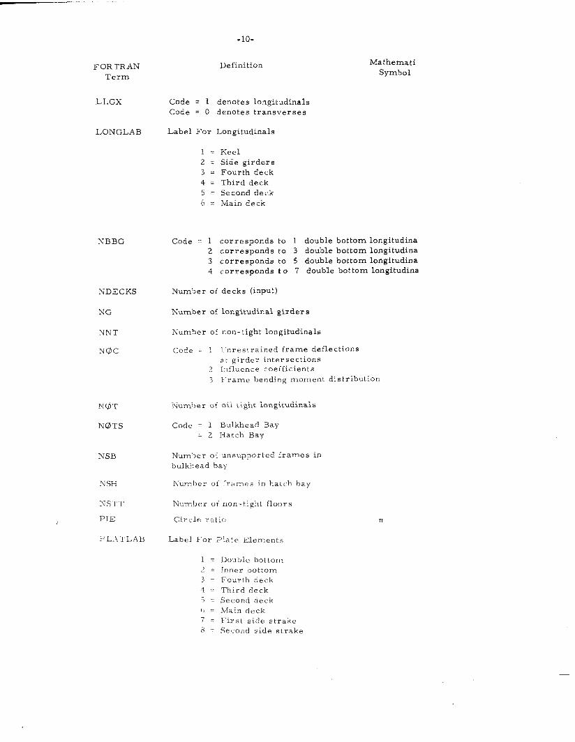
FOR TRAIN Definition
Term
LLGx Code = 1 denotes longitudinal
Code = O denotes transverses
LONGLAB Label For Longitudinal
~ . Keel
2 = Side girders
3 = .Fourth deck
4 . Third deck5 z Second deck
6 = Main deck
iXBBG
NDECKS
NG
NNT
?lIi5c
NSH
NSH
NSTT
PIE
?L.4TLAI?
Mathenmti
Symbol
Code = 1 corresponds to 1 double bottom longitudinal
2 corresponds to 3 double bottom longitudinal
3 corresponds to 5 double bottom longitudinal
4 corresponds t o 7 double bottom longitudinal
?fumber of decks (input)
Number of longitudinal girders
h-umber of non-tight longitudinal
Code = 1 I.[nrestr. ined frame deflections
at girder intersections2 I,, fluence coefficients
3 Frame he. ding moment distribution
Num’her of oil tight longitudinal
Code = 1 Bulkhead Bay
= 2 Hatch Bay
Number of uns L,ppOrted frames in
bulkhead bay
Nu.ml>er of [ra m,. in ha.t.ch hay
IVumbe. of nomtight floors
Circlv ratio
Label For l>late Elemen l.,
1 . Doubl<? bottom~= Inner bottom3 = Fourth deck
4 . Third deck
‘i = Second deck
f, = !Main deck
7 = First side strakc
8 Second side strake
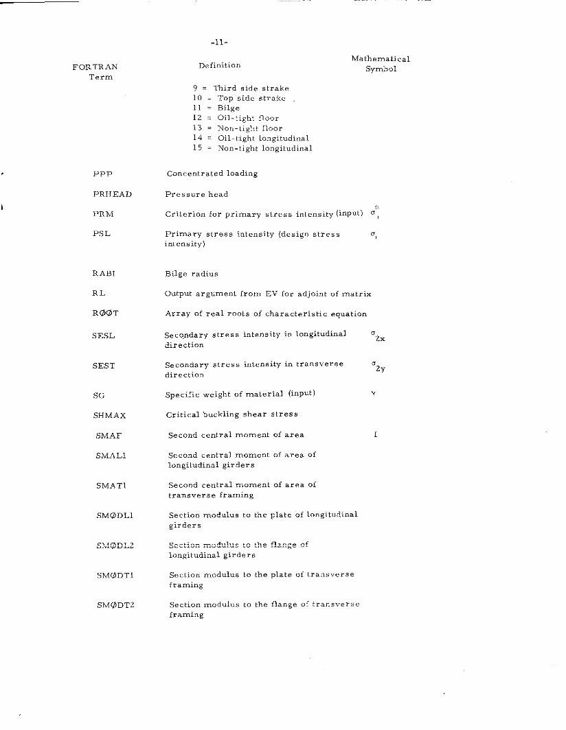
.11-
FORTRAN
Term
DefinitionMathematical
Symbol
PPP
PRHEAD
PR M
PS L
RABI
RL
RU@T
SESL
SEST
SG
SHMAX
SMAF
SMAL1
SMAT1
SMG5DLI
SMODL2
SM@DTl
SM@DT2
9 = Third side strake
10 = Top side strake
11 = Bilge
12 . Oil-tight floor
13 . Non-tight floor
14 . Oil-1ight longitudinal
15 . Non-tight longitudinal
Concentrated loading
Pressure head
,x
Criterion for primary stress intensity [inpnt) 0,
Primary stress intensity (design stress g,intensity)
Bilge radius
Output argument from EV for ad joint of matrix
Array of real rooks of charzckeristic equation
SecQ.ndary stress inkensitY in longitudinal azX
direction
Secondary stress intensity in transverse
direction“2Y
Specific weight of material (input) Y
Critical buckling shear stress
Second central moment of area 1
Second central moment of axe. of
longitudinal girders
Second central moment of area of
transverse framing
Section modulus to the plate of longitudinal
girders
Section modulus to the flange of
longitudinal girders
Section modulus to the plate of transverse
framing
Section modulus to the flange of transverse
framing
FORTRAN
Term
Ss
SLTNfAREA
SIHvfAREAL
SIJMAREAP
SUMML
SUMMOM
SUMMP
SUMSMA
SUMSMA1
SUMSMAL
SUMSMAP
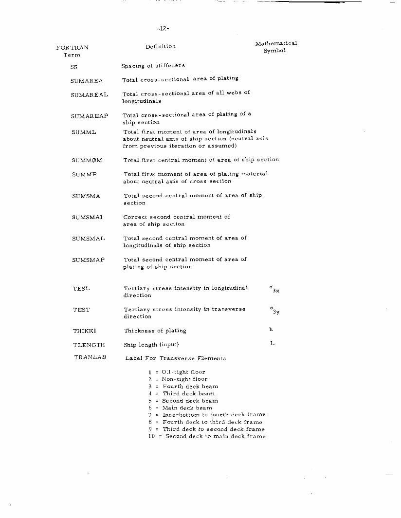
.12-
Definition
Spacing of stiffeners
Total cross-sectional area Of plating
Total cross-sectional area of all webs of
longitudinal.
Mathematical
symbol
Total cross-sectional area of plating of a
ship section
Total first moment of area of lcmgitudinals
about neutral axis of ship section (neutral axis
from previous iteration or assumed)
Total first central moment of area of ship section
Total first moment of area of plating material
about neutral axis of cross section
Total second central moment of area of ship
section
Correct second central moment of
area of ship section
Total second central moment of area of
longitudinal of ship section
Total second central moment of area of
plating of ship section
TESL Tertiary stre, s intensity in longitudinal
direction‘3X
TEST Tertiary stress intensity in transverse
direction“3Y
THIKK1 Thickness of plating h
TLENGTH Skip length (input) L
TRAFL LAB Label For Transverse Elements
1 = Oil-tight floor
2 . Non-tight floor
3 = Fourth deck beam
4 . Third deck beam
5 = Second deck beam
6 . Main deck beam
7 . Innerbottom to fourth deck frame
8 . Fourth deck to third deck frame
? = Third deck to second deck frame
10 = Second deck !O main deck frame
FORTRAN
Term
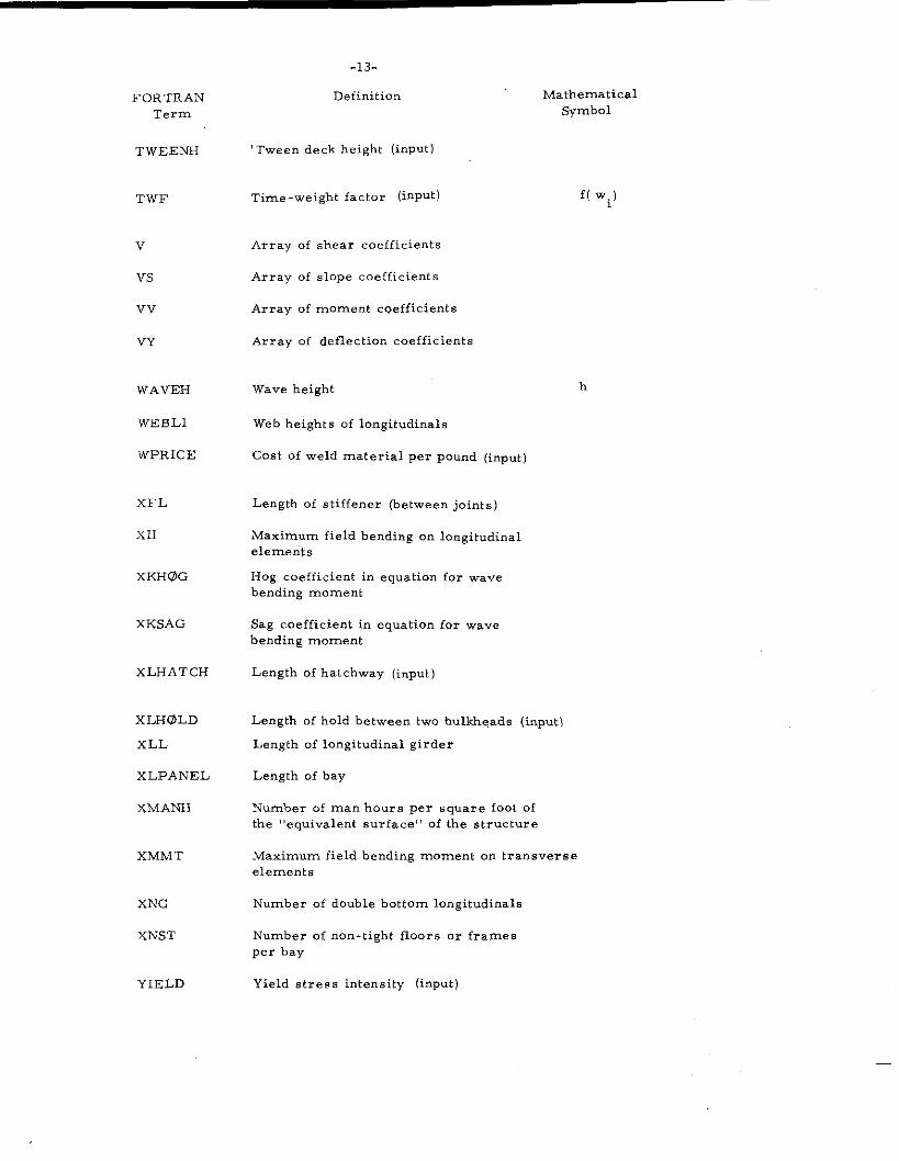
TWEENH
TWF
v
Vs
Vv
VY
WAVEH
WEBL1
wPRICE
XFL
x11
xKH@G
xKSAG
xLHATCH
xLHOLD
xLL
xLPANEL
xMANH
xMMT
xNG
xNs’r
YIELD
h
-13.
Definition Mathematical
Symbol
Tween deck height (input)
Time-weight factor (inPut) f( Wi)
Array of shear coefficients
Array of slope coefficients
Array of moment cveffi.ients
Array of deflection coefficients
Wave height
Web heights of lo~gitudinals
Cost of weld material per pound (input)
Length of stiffener (between joints)
Maximmn field bending on longitudinal
elements
Hog coefficient in equation for wave
bending moment
Sag coefficient in equation for wave
bending moment
Length of hatchway (input)
Length of hold between two bulkheads (input)
Length of longitudinal girder
Length of bay
Number of man hours per square foot of
the “equivalent surface” of the structure
Maximum field bending moment on transverse
element,
Nunber of double bottom longitudinal
Number of non-tight floors or frames
per bay
Yield stress intensity (input)
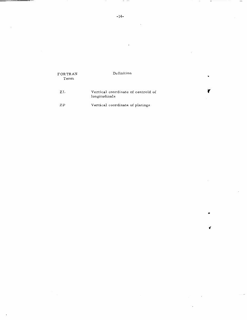
FOR TR APJTerm
ZL
ZP
-14-
Definition
Vertical coordinate of centroid of
longitudinal.
Vertical coordinate of +tings
-15-
II I<,,
,“ ,, ,,,,
C05Tl~Gi, ,,,.;,.,, I
TRANSHIP
mlP L,r —
/$
SECr!ON
DOC[:l”lEXT
A
[
PLATING
rASPECT
NT F’LATEL
1TRANSlr SH.4PES FSIIAPEi. OhrGIT SH,>PES FS1lAPELOhTGMAT
-18-
D
-19-
D-
.
-!iLB
w
DO 1 .-1,10
‘F*
PSLL(l) PRM1;(llNE,:T ZP[ll]I
I II
————— —+
F’c
Crillage Jointcalculation
I
JTNSS.3
R
cA 1.1.GRILLAC.E (hDECI<S, HATCHPRHEAD, BEAM, HFLOOK AAA,A1.OAD, SM.AT1, SMAL1)
0D
x
t
CAI.1 !3NM>
G41.1.13Nk4,
t
CALL BNS$%
t
C.4L1.XLIL4D L
t
\ CA1.1.XL0.4D(.kX
9
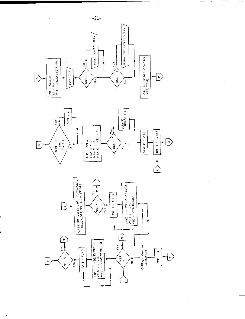
-21-
—
1.1
D-
QE.—
L._
L_.—.— JI@r-
-D
A>
m
L
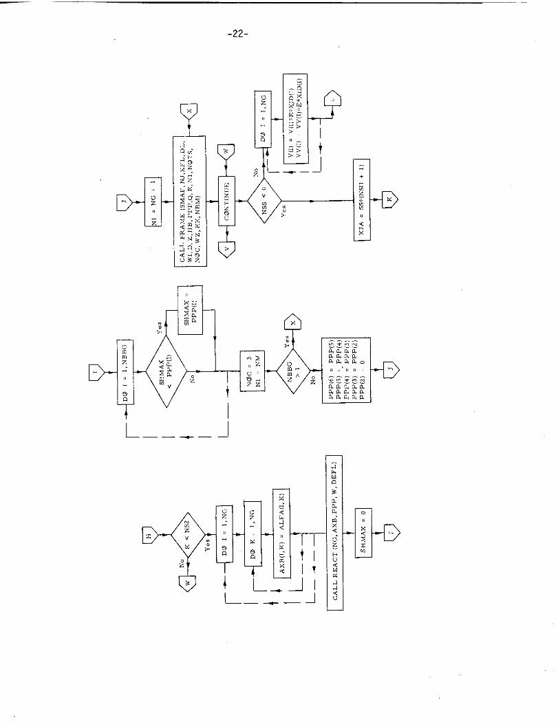
-22-
9
0z
.-
—-——
-D
-D
u
,.
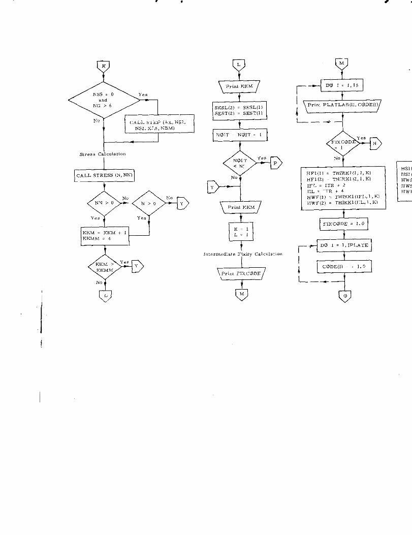
No cALL STEP (AX, Ns2,1 NS2, XJA, NBMI
i
Is,..,, Cdculat<o.
I
s?3-No No
NN>O N>o Y
Ye, Y,,
KKM = KKM + 1KKMM = 4
0L
i
I
SESL(2) = SESL(l )SEST(21 = SEST(l)
t
NI.31T. NOIT + 11
N.
\Priri KKM
t
In,ermedia,e Fy calculation
I
-
w
w
L.-1
mmHWFS
I“PC@ DE(I) = 1.0
L---
.
-24-
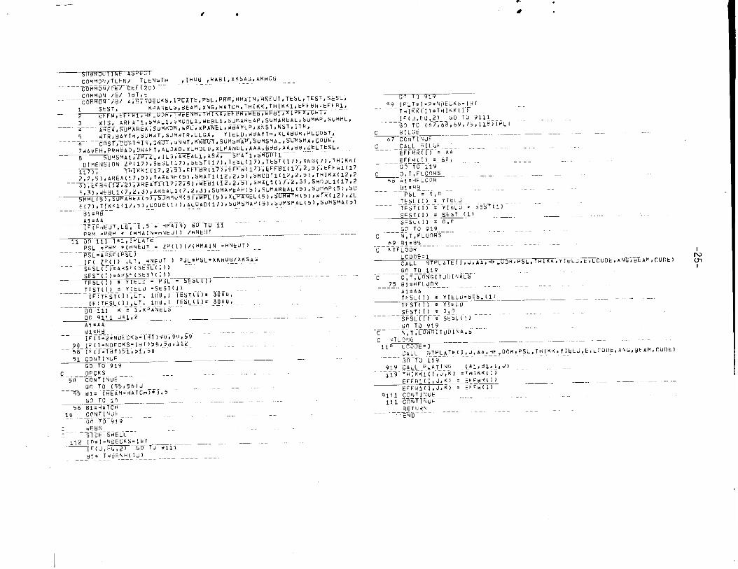
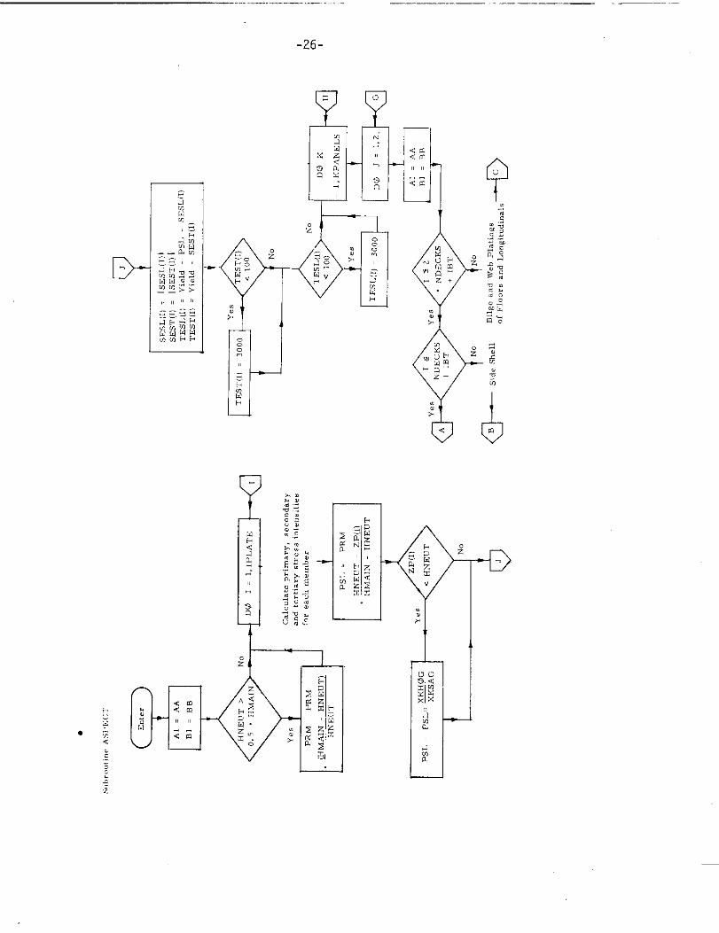
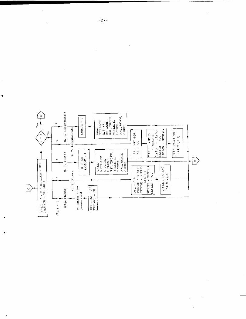
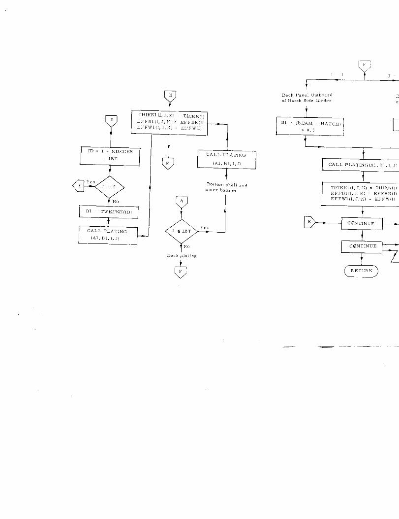
1. ‘Subroutine ASPECT
a) Abstract:
Subroutine ASPECT is called from subroutine SECTION. It calculates
the aspect ratio of all plating and calls subroutine PLATING or NTPLATE
..5 appropriate.
b) Terms specific to this subroutine:
FORTRAN Definition
Term
Al Side of plate rectangle used to
determine aspect ratio
B1 Length of plate rectangle used to
determine aspect ratio
LC(3DZ Code = 1 denotes non-tight floors. 0 denotes non-tight kmgitudinals
_.—
, .<.,)”,,,”, RL, ,su. AN, ,P,S”MARk,L, SUMMP.SuMMLI
., , T
ILm
—. -. ..-_ . . . ,.._ .
-26-
—
Y
—
L
&m
-E)
-27-
E)-
I
.
.
WI
T~llKKl (1,J, KI ~ THIKK,[)B EFFB1(l, .l, K, EFF,5R(I)
EFFWI (I, .7,K) . EFFWC
t-
B.!tom shelland,nner bo,fo,,,
Deck plating
{’%
+
PCALL PLATINc, (AI ,,, ,, ,,
1
\ /
—
-29-
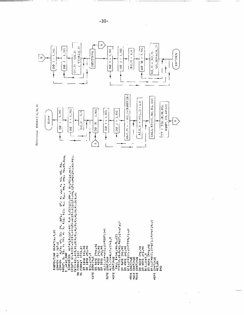
2. Subroutine BNMAT (A, B, M)
a) Abstract:
Subroutine BNMAT calculates the boundary matricea used in the
g, i~lag. calculation called from subroutine GRILLAGE, SOLVEand STEP,
b) Terms specific to this subroutine:
FORTRAN Definition
Term
A Grillage matrix
AL Characteristic matrix
M Index of Nielsen function
D-
~-l
L.
-30-
n
—— — J— .2
-31-
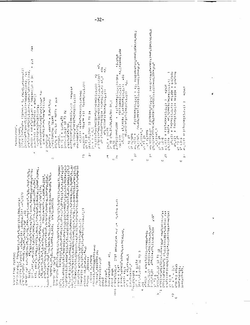
3. Subroutine COSTING
a) Abstrzct:
Subroutine COSTING is called from program TRANSHIP. It calculates
the weight and cost of all transverse and longitudinal members, as well
as all welding and labor costs. The overall weight and cost of hull
structure per inch of length are then determined.
b) Terms specific to this subroutine:
FORTRAN De fi”itio” Mathematical
Term symbol
COSTS Combined cost of plati !-, labor
and welding per inch of : ip length c
Fl (H) Weight per inch of v.. weld fl ill)
F2 (H) Weight per inch of continuous
double fillet weld f2(h)
F3(H) Weight per inch of intermittent
double fillet weld f3(h)
F4(H) Time size factor f(Ai)
NSEAM Number of weld seam, in inner N
bottom,
PLCOST Total material c.w+t c
TWELD Total cost of welding cw
WBAYTOT Total weight of hull structure
per in.h s
xLABOR Total labor cost of erection
and fabricationc fe
-32-
N,.
,..
c
..-. . .>5,2

>,, .j,
s.br.utine COSTING
TEnter
EEF3(H)F4(II)IF5(H1
—“’10.4,*H
--—-
s=SL:MSTAN . 0SAREA1 . ,5CMS.4RE 0
Print “COST BREAKDOWN’,
*
A DO R = 1,KPANELS
SIJMWTR(K1 = 0
B
Y13Transverses
Im.z, ‘A
+
I > m’r ‘es c
No
i
J=,
WTR(ll = AR EATl (l,I,K);:UEAM %SG I
t
@
1=2Y”
No WTR[l) = WTR(ll/[email protected]*XNST
D
Lw
END
-34-
—
—- .
I
D-@
t
IJ
!,
—-—. _— _ —
!! ,! ,, ,,
— ~.–
—
rl,(l)= “ . 5 . THIKK1 (1,1,K)SG3LD(I) . FI (THIKKI (1,1,1))*z
~1I
EWELD(1I = F2(TH1KK1 (1,1,1,,2*(BEAM , XKGIIIWFLOmI
CSL(l) . 2/xLE1@LD:F5, T131KK1 (1,1,1).
GWELD(11 = 2:F3(TH1KK1 (1,1,1))*XNST*(BE.4.V . XNC,(,):WFLo@,R,
F5(TH1KK(L 1,1))%Hi7LQ@R%: BEAM
O’10, .Ludimal,
ml.Longitudinal.
<
WELD(1) . F2(T111KK1(1,1,1],:
CSL(lI .-GN@T %Hi71aOR:%
WELD(1) = F3(TH1KK1 [1,1,1GN iiT
~)CSL(lI = GNNT::HFLG!OR~F5(T111KK1 (1,1,1))
1
&H
Print Perk,ne,lt,Materlalfor Plate,
t
IDeck Longitudinal.
r- 4&
,.P,,”, PertinentMaterialfor Deck Lan,iCudinals/
t
TWELD = 1.03*TWELD51GMAL . 51rMcs T . suMcs L +SUM CSL1,
XLA13Q’R = SIGMA L;:HRATE + SLr.MSTAN
C@STS = PLCC4ST + XLAB@R +TWELD
-~
SUMSARE . SEJMSARE + SAREAL(I]WELDL1 = WELDL1 + WE LDL(l)
--”+
-36-
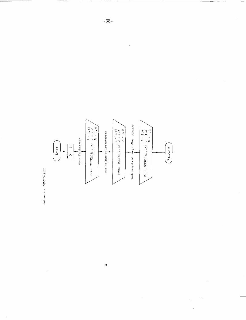
4. Subroutine DOCUMENT
.) Abstract,
Subroutine DOCUMENT is called from program TRANSHIP. It prints
out tables .[ scant lir. gs of all structural members, lhe values of which
have been computed and stored in the memory of the computer.
I
.=,
7714,is,16,17.
2114,15,2,3,4,5,
78,9.
10.11,
(((1(([(
1[(([f
::(1
[(((((
((
THTK<l( 12, J,61, J=1,2), K=1 ,N)THIKK1115, J, K1. Jzi,2), K=i, N)T“16K1( 14, J, K>, J, I,2), K,I,N)THIKKlll>,J,%).J=l,2],K=l,W)
WEBI (l, J,(), J
WE8L II, J< U), JUEB1(3, J, K)8J
NFlil[4, J, K), J
WE131(5, J, K), J
WEtii(6, J, K1, J
,1,2), K = 1,N)
1,21, K = 1*N)1,21 , K = 1,U)1,21 , K = 1,N1
1,2) , K = l,h)1,2) , K = l,N)
UGUI(7, J, K)>J 1.?) , K = l,N1
HFH1(8,J,R).J 1,2) , K = l,M)HEd119,J,K>,J 1,2) , K = l,N)WFtilllO,J,Kl,J.l,2),K=i,N)
?31NT 22PRINT Iq, (( HEBLI( L, J, K), J=1,7), K=l, N)
PRINT 15, [1 blEil L1( lsJ>K1, J=1,21, K=l, NIPRINT 2, (f IIERLI< 3, J, K). J= 1,2), U.I, N)PRINT 3, (( ktEn LII 4, J, K), J=i,7), K:i, N)
PRINT ~. (( UEULII 5oJs K), J=~,2), K=l, N1PRINT 2, (( UE?LI( 6, J8K), J=1,2), K=l, N)
-.
-38-
●
-39-
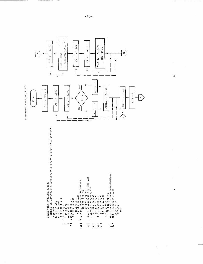
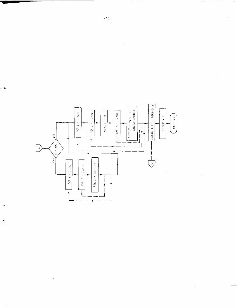
5. Subroutine EV
a) Abstract:
This subroutine is called from subroutine GRILLAGE, BNMAT, XLG5AD.
It calculates the characteristic equation of the A matrix. The cayley -
Hamilton theorem is used to reduce the characteristic equation of the
A matrix.
b) Terms specific to this subroutine:
FORTRAN Definition
Term
A A matrix
ccc Coefficients of characteristic equation
in descending order
D Identity matrix
NG Order of matrix (Number oflongitudinal girders)
R Ad joint of A matrix
.-
-40-
l_i—-
—
uz--
->
;. —.— -’l
L——.—.—— ——
3’
A
.
\
-41-
. .
rr .
*--
LL_
q-
tt
1/——
.3t
———- —— -1.
.
-42-
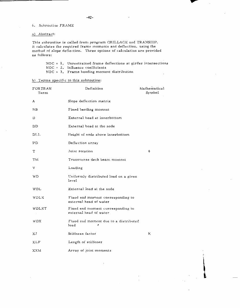
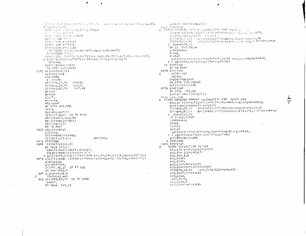
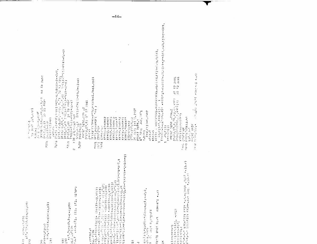
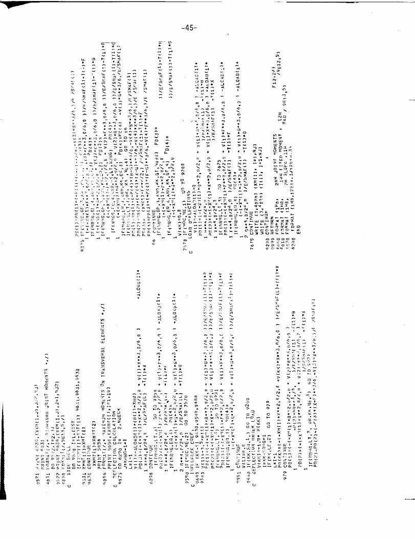
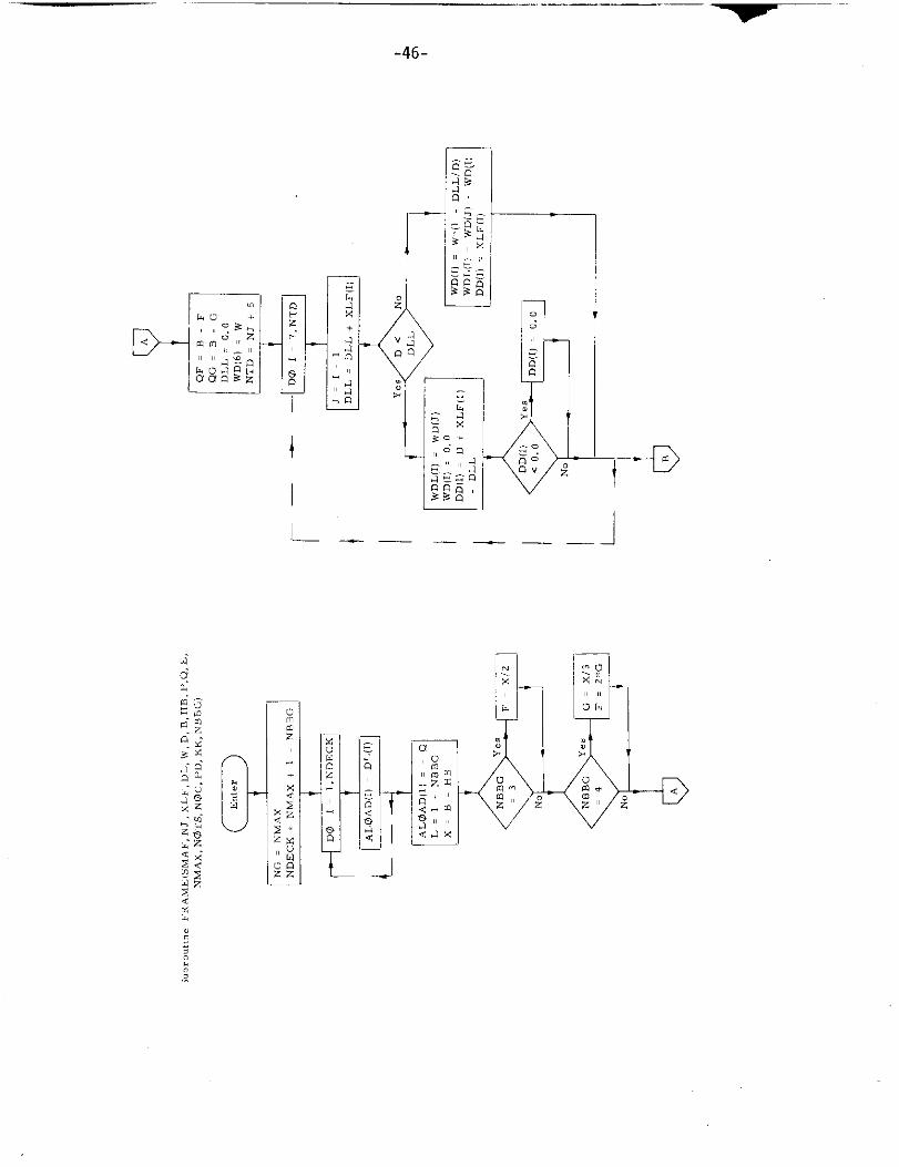
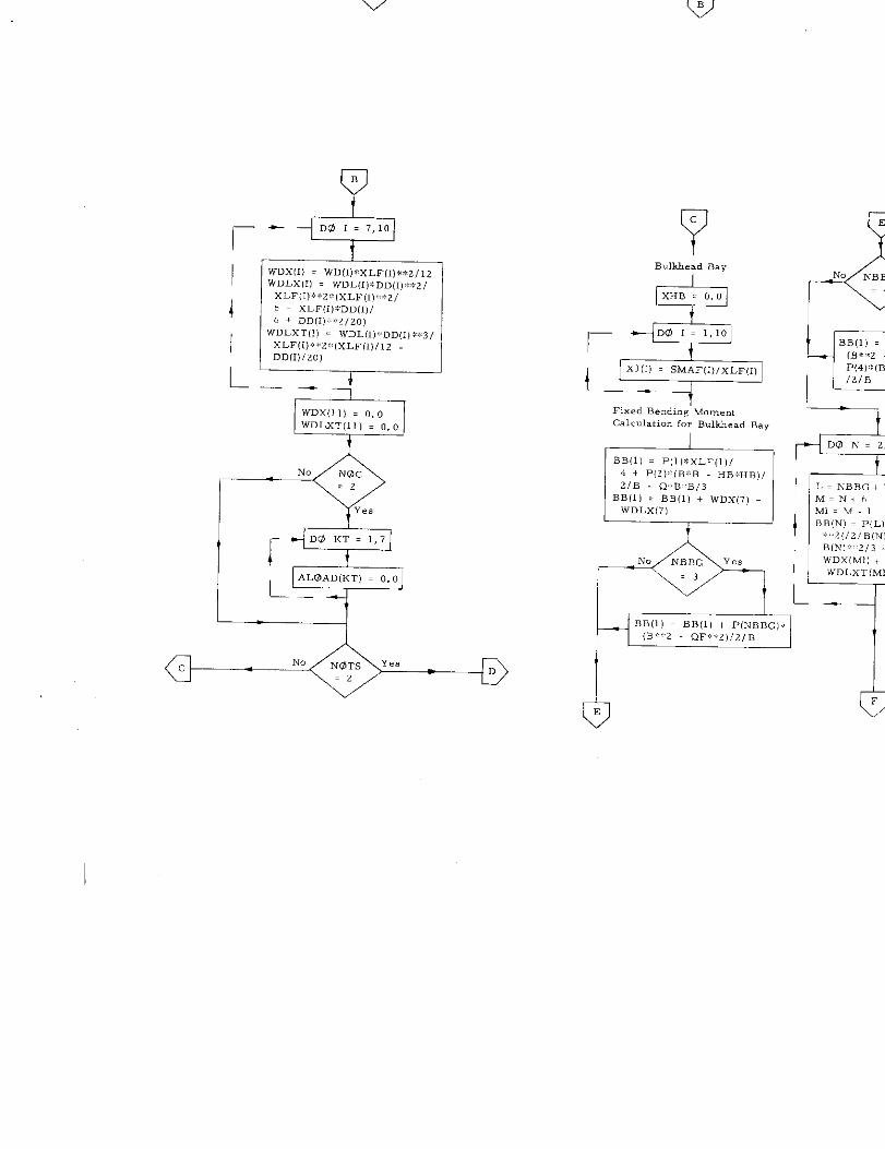
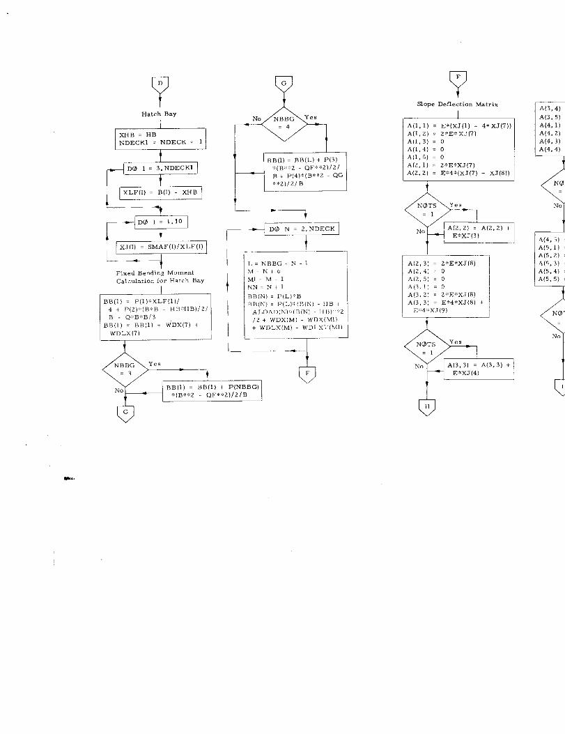
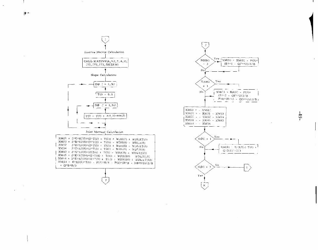
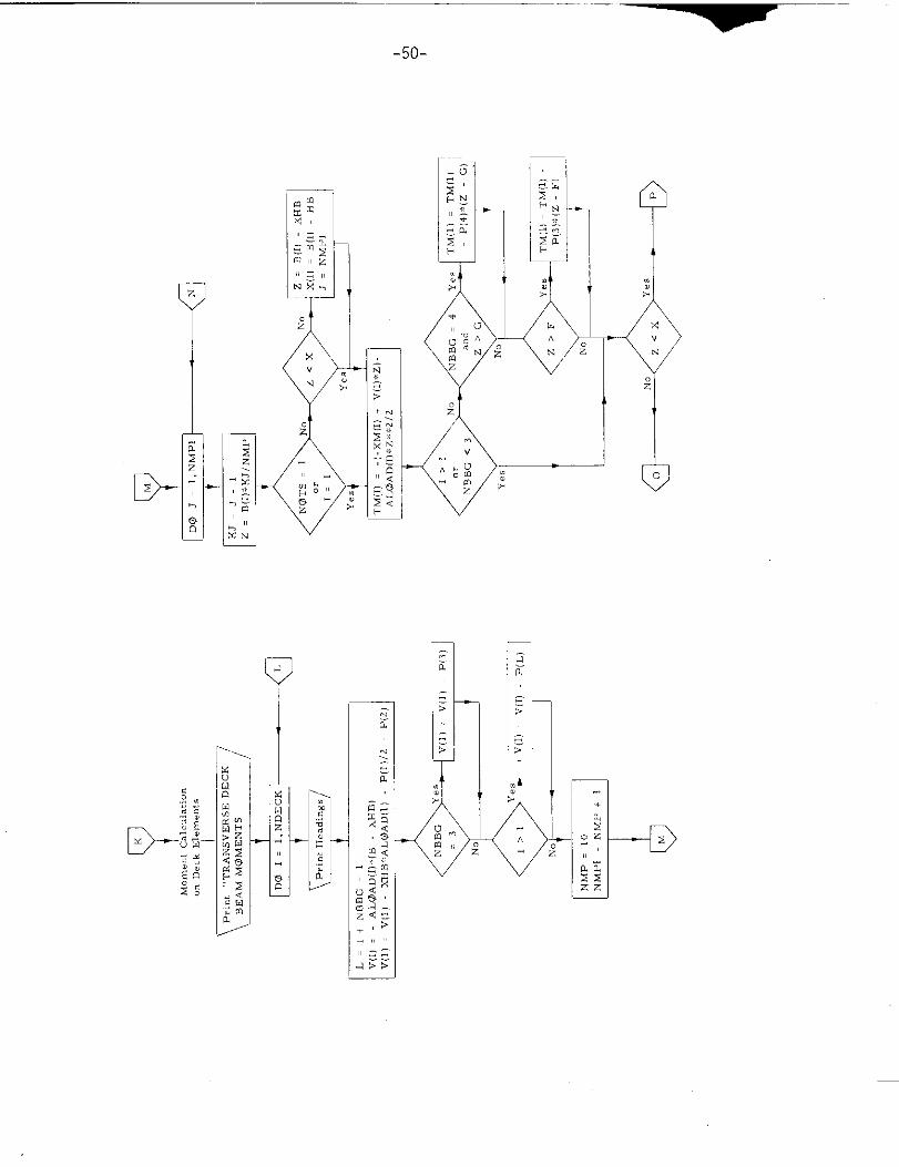
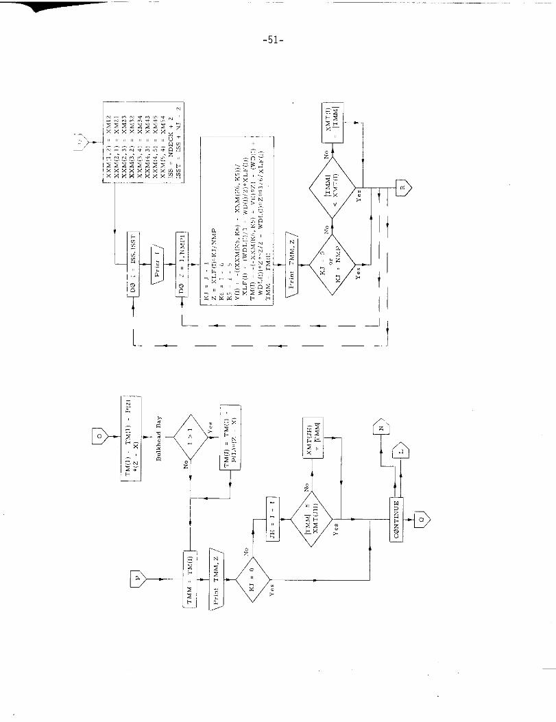
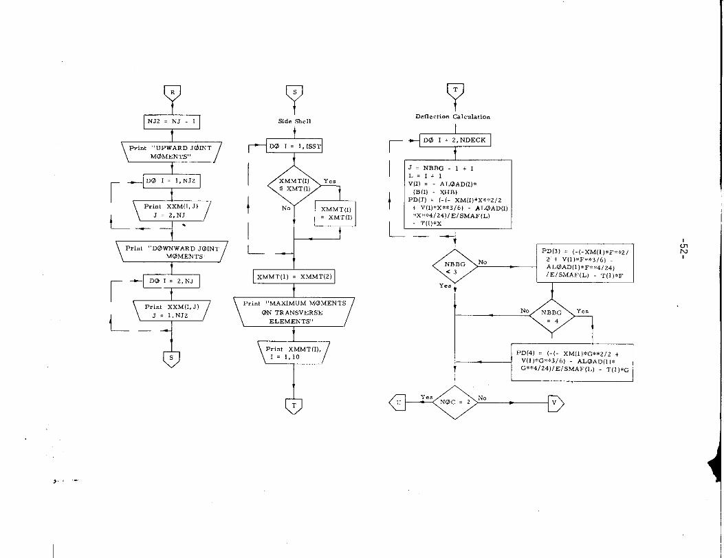
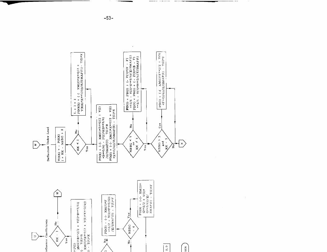
6. Subroutine FRAME
a) Abstract:
This subroutine is called from program GRILLAGE and TRANSHIP.
It calculates the required frame moments and deflection, using the
method of elope deflection. Three options of calculation are provided
as follow, :
NOC= 1, Unrestrained frame deflections at girder intersections
Noc = 2, Influence coefficients
NOC = 3, Frame bending moment distribution
b) Terms specific to this subroutine:
FORTRAN
Term
A
BB
D
DD
DLL
PD
T
TM
v
W’D
WDL
WDLX
WDLXT
WDX
x-l
xLF
XXM
Definition Mathematical
Symbol
Slope deflection matrix
Fixed bending moment
External head at innerbottom
External head at the node
Height of node above innerbottom
Deflection array
Joint rotation
Transverse deck beam moment
Loading
Uniformly distributed load on a given
level
External load at the node
Fixed end moment corresponding to
external head of water
Fixed end moment corresponding to
external head of water
Fixed end moment due to a distributed
load ,
Stiffness factor
Length of stiffener
Array of joint moments
e
K
It
.,, ....,. .-.,,,),/,,=.?JTD=C4.1.5Do 59fll ,.,, ?470I., ...
~“4
c3(I2
Unxfll)=o,WnL’XT1li]=fl,IF-(,,OC. NE,2) Go T“ 392
DO 2“4 KT=1,7
A1. OADIK, )= fi, Of>”~~H~~~ 8A”
IF{ NO IS. EO, ?) 69 TO 6999
,+3.1) .
Do 60,)0 1=~,1~
:<J{ I)= .::iJl!l)/XL}(i)
6999
c
6,49
A(1,4>ZOS’A{i,51=n,A(2,11z7~0. V.XJ17)*(2, ~>z E.4e(x J(71. xJ(nl)lFINo Ts,kO, ll 4(2, 2):A12,2)*E, XJ 131A(?,3)=7,0, F,x J18)
!. 2/2,
-44-
-->
--
“,‘)
-.
. . .,—..— .——“—7
-46-
D-
.
I
— ——— — J
_l
k’”
GJ
“*— DO 1=7,10
1
JwDx(l) = WD[ll*XLF(I,**2,1ZWDLX(l) . wDI,,I,:,:DD(I,:ti~,XLF(1]:k*2:%(XLF(I,,:,Z,6 xLF(I)*DD(I,)6 + DDII,,W,ZO,
WDLXT (l). WDI,(I),DD(I].eS,
XLF(1)**2*(XLFC) I12DD(l)/ZO,
dL
I 52No NW.2
Yes
~
‘ FD13 KT= 1,7
L ?“(”)‘0’0
I
Bulkhead Bay(
@XHB = 0,0
r*
DQ1.1,1o
xJ(l I = SMAF(I)IXI, F(I)
L– _
Fixed Bending Mo.nentcalculation f., Bulkhead Bay
~.BB(l) . P(l),kxLF(l]/4 + P(Z)*(B.B HB*H~,,2/B 0:.D%.B,3
BB(l) . BB(, ) + J“mx(,, +WDLX(7 )
&E
NO NBBG
r
=4
*Iiv. NP,BG Yes
=3
BB(l I = BB[l) + P(NEIBG).%(B*:2 QF*%2)12/B
l-lBB[l I =(B*:%2P(4):(B**121B
L t
1
I
III
t
I
I
1-i_
1
xLF(I) = B(I) XHB
-J~ .+”” Da ,. 1.10 I
L_
–iFixed BendinE M<>me”tCalculationfor Hatch Bay
I
IBB(l) . PI1)*xLF(l)I4 + P(21;IB*E H13W11B)/2/B Q< B* B/3
BB(l) = BBIII + WDX(7) iWDLX171
~-—””-
G
No NBBG ‘esFi%.4
BB(l)= RB1l.1+ P(3):[B:::2 0F;:::2)/2/R + P(’1l;*(B*:*2 QG:*21/2/B.
i
I
I
I
t
%“ ~NBBG YCE=3
N. BE!(1)= L3ii(l)+ P(NBBG)*(B.+S2 QF**21 /2/B
.—
CJi
Slc+w Deflectionlvfa,ri,
I
L
A[l,l)= E*(xJ [l) + 4*xJ[7))A(I,Z) = Z*E* XJ(7)A(1,3) = OA(1,4) = 0A[1,5) = OA(2,1] = 2*E:xJ(7)A(2,2) = E*4*(xJ (7)+ xJ(8))
-
NOT5 Ye.
=1
NoA(Z,2) . A(2,2) ,E: XJ(3)
A(2,3] = 2*E*xJ(8)A(2,41 0A(2,51 = 0A(3,1) = 0A(3,2) = 2:*E~xJ(8)A(3,3) = E*4*XJ (81+E*4. XJ,9,
+
LA(3,4)
A(3,5)A(4,1) =A(4,2) =A(4,31Ai4,4)
i
*
iWTS.1
No
mA(4,51 =A[5,1) =A(5,21 =A[5,3) .A[5,41A(5,5) =
$NQ’.1
.No
.
Qt
Inverse Matrix calculation
-Slope Calculation
,— —
I 5=D(Z 1. I,NJ/
T(1) =0.0
, r-~.~
T(1) = T(1) + A(l,J):kBB(J)
Join,Mm”.., CalCula,iOn
XM21 . 2*E*xJ(7):(2:%T(2) , I?(1,]+ WDX(7, + WDLXT (?,XM23 = 2*E;% J(8):(2:*T(L) + T(3)) WDX(8, WDLX(8, ,XM32 . 2;:E%XJ(8)*(2*T(3, + 77(2,,+ WDX(8, + WDLXT (S)XIM34 = Z::E3XJ(9)%:(2:T(3, + I’(4)). WDX{9) WDLX,~)XM43 = 2:*E;wJ(9):(2(T(41 + T(3))+ WDX(9) + WDLXT,9,XM45 = 2:*E:::X.T(10)%(2%T{4). T(5)) WDX(IO, WDLX( I”,XM54 = 2*W;,X3(10):12kT(5) + T(4)) + W“X(LO) + WDLXT(,O,XM(l) = E*xJ(l):,T(l, F(,)::B,4 P(z,:,(B,<B HB.H”), ~,B
+ R* B*B131 I
IX,M12 = XM(l]XM(21 = X,M21 XM23XM(3) = XM32 XM34X34(4) . XM45 XM43xM(5) = XM54-——
“-’”-””’’”-”~-50-
1,
.
I .
-@
L
L
1-”-=&
-
-51-
+
—.— .—— —
w-
———
.
B
~
NJ2=NS-1
Print ‘<UPWARD J@lNTMOMENTS,,
r
—DO 1= l,NJZ
‘PPrint XXM(l, J)
~_ J=2,N:
1
YSide .%.11A
:%
XMMT(l] Ye,S XMT(l)
1 No XMMT(I)=XMT(l)
1 ,
. .6Y%F XMMT(l I = XMMT[2)
6 TPrint XMMT[ l),
s 1.1,10
T
YT
Deflection Calc.latio.
r-izE+lI
t
tS. NBBG. l+l
1,.1+1vu) . ALOAD(IP(B(1) XHB)
PD(J) = (-(-XM(I]*X*, W/2+ V[l)*X**316) AI.&iD(I*x~6sk4/24)lEls MAFILI
I T(l)*x
9-NBBG ‘O<3
Yes c=PD[3) . (.(.xM(l, *F. *z,
2 + V(1)*F**316)ALOAD(l)*F*W/Z4)IE/5h4AF(L) TOIW
I ! 1
&N
- —
.
!
— —.——.
-54-
-D
-55-
3-”!
I
‘---
I—J
-56-
7. Subroutine FSHAPE
a) Abstract:
This subroutine is called from subroutine SHAPES and is ueed to
calculate the scantlings of shapes by empirical formulae given in
Appendix J.
b) Terms ~pecific to this subroutine:
FORTRAN Definition
Term
K Flag to select type of section
(1 in this study)
XASX Cross-sectional area of shape
XWEB Web height of section
XXIS Second central moment of area of shape
XXKSX Toe to centroid distance
. . . ...”
-57-
+----71
-58-
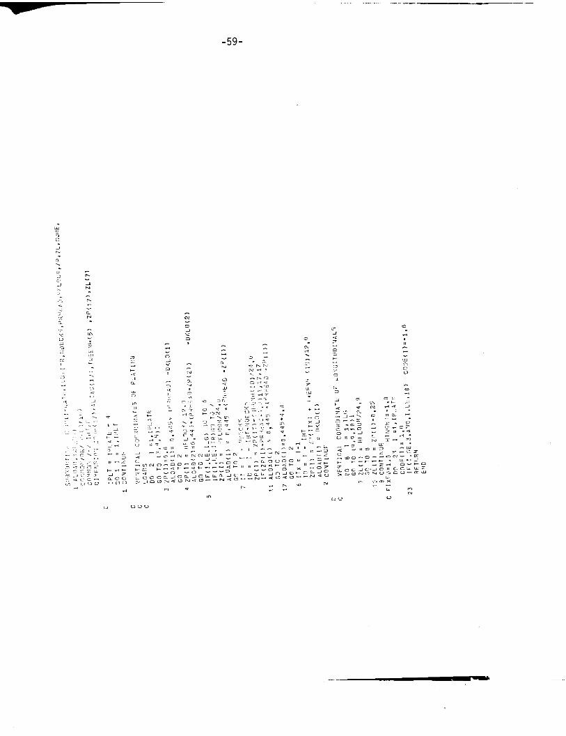
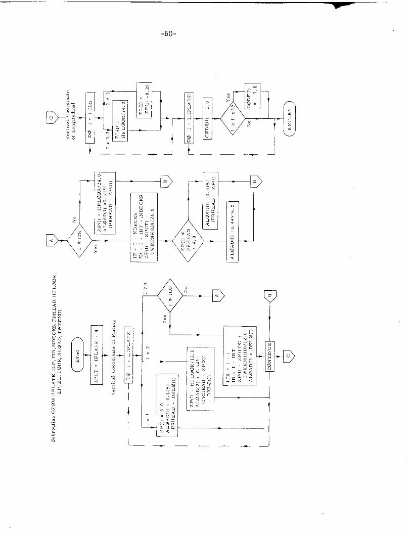
8. S.broutinc GEOM
a) Abstract:
This subroutine is called by program RATIONAL. It is used to calculate:
a) The vertical coordinate of the .entroid of the cross sectional
area of each item of plating.
b) The vertical coordinate of the centroid of the cross sectional
area of each longitudinal stiffener (shape or longitudinal
girder).
c) The external loading on the shell.
d) The internal loading on the decks and inner bottom.
b) Description
The following observations are pertinent:
. Each item of vertical plating is considered to extend from deck to
deck, so that its centroid is located at midheight between decks. This
artificiality is pro-t empo.. and cm he later removed when the seams
are located.
. The external hydrodynamic loading and the internal loads are treated
as if statically applied.
- The pressure head on the side shell is calculated to correspond to
the midheight between decks.
, The design head on the inner bottom is assumed to correspond to
the second deck.
. For simplicity the centroid of a deck longitudinal is assumed to be
O. 5 ft. below the deck plating.
. The initial value of the secondary stress intensity is introduced in
this routine.
, In the subroutine, each item of plating is flagged according to
whether it is to be treated as having fixed or simply-supported
boundaries.
-59-
.--%
.c, L, ..,”
, .-. .
—----
-60-
.— JL:-
--- -@-u-’‘*
o
—-
w
9
I___ —__ .1
-61-
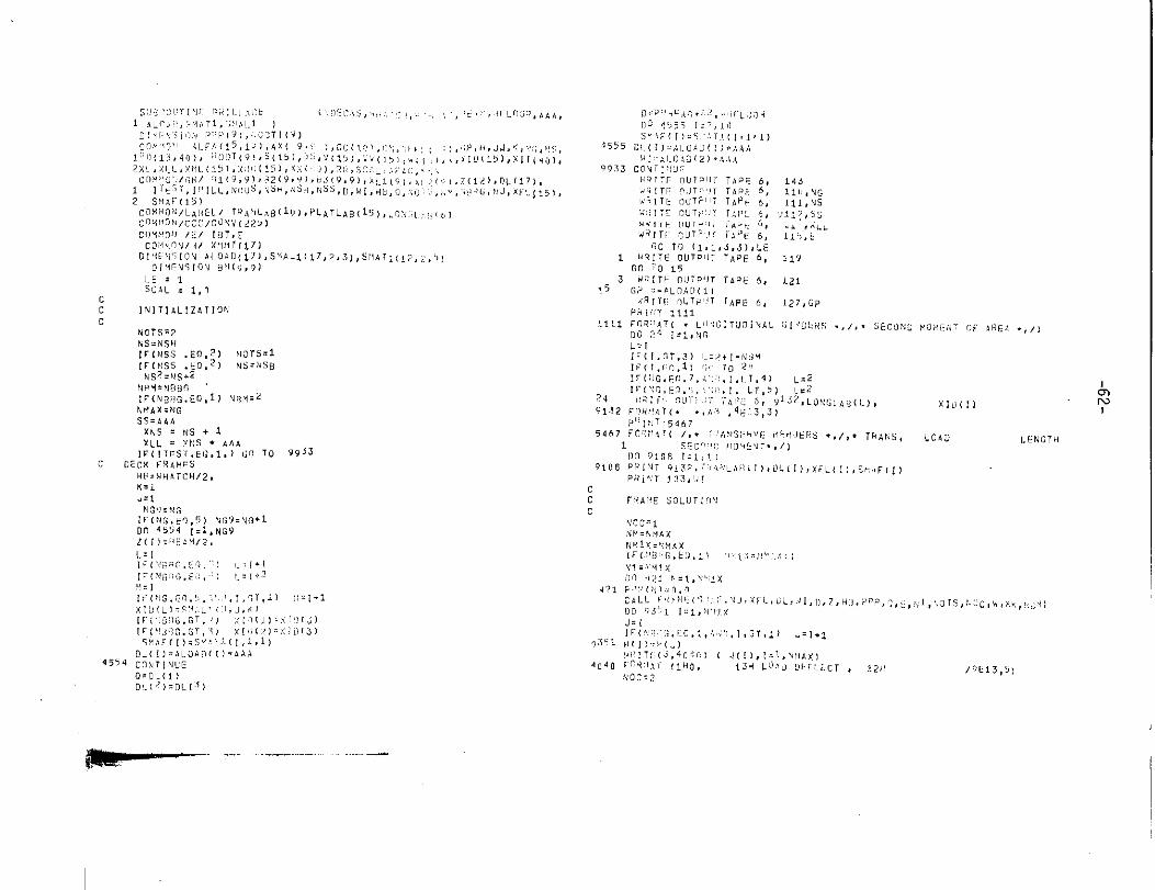
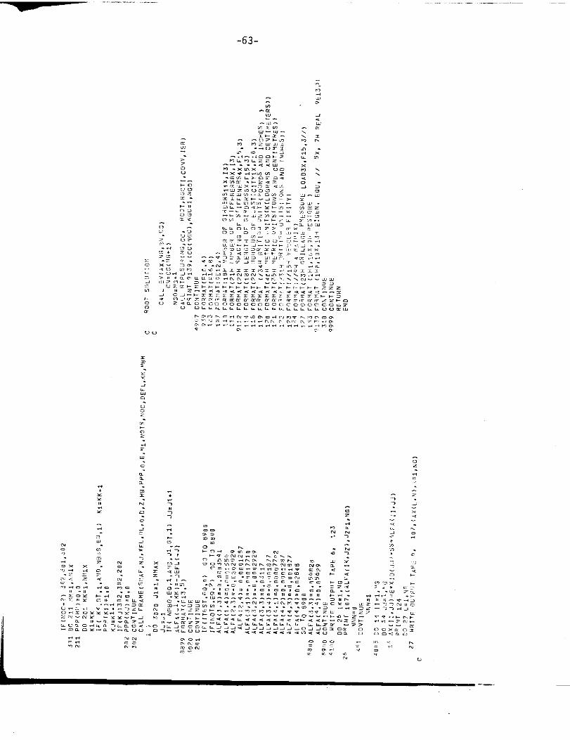
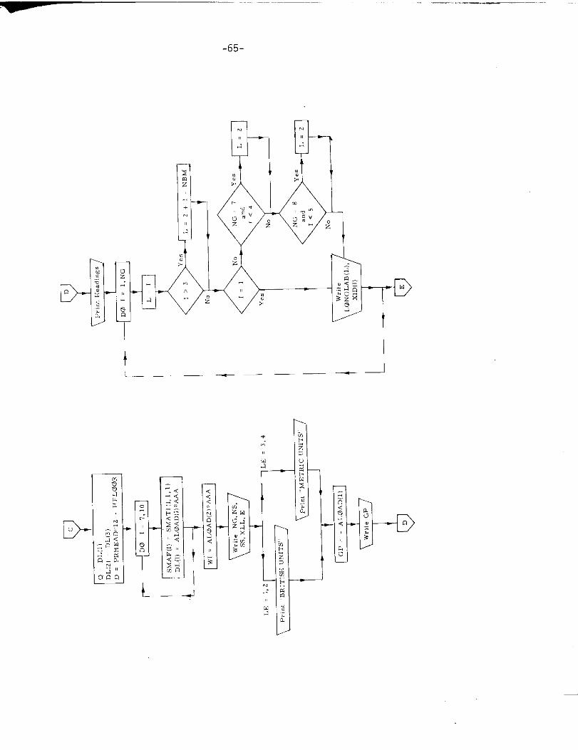
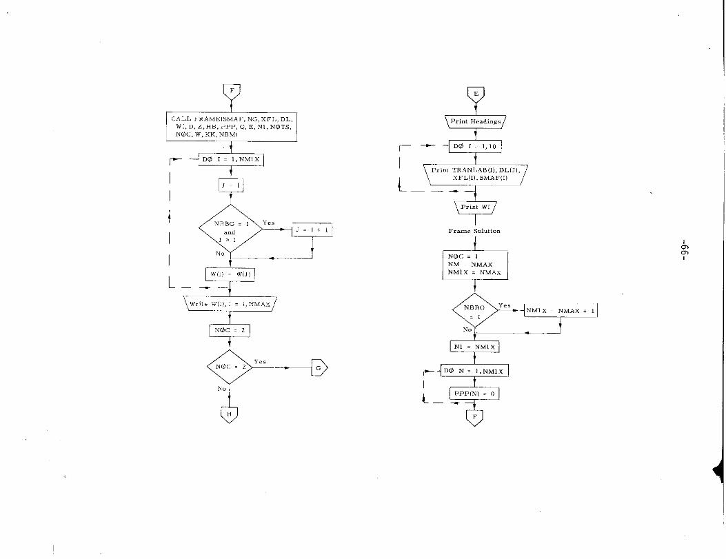
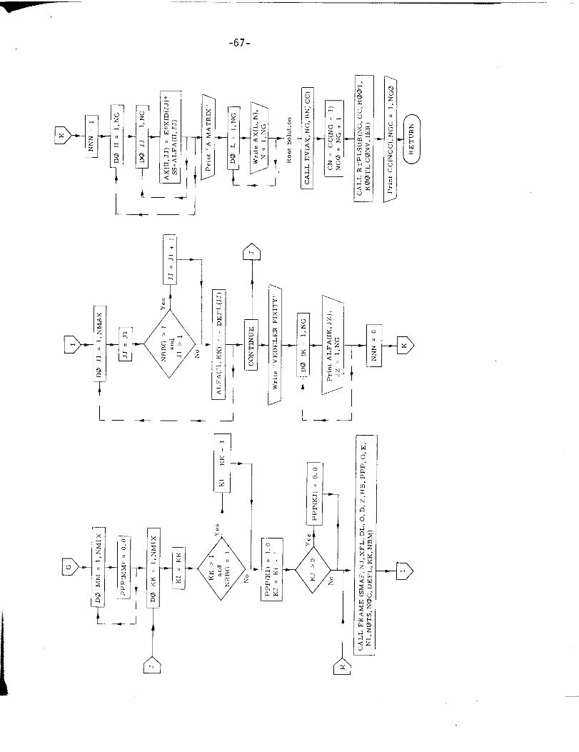
9. Subroutine GRILLAGE
a) Abstract:
This subroutine is called from program TRAI.. S ~~t and is the executive
routine for tbe grill age calculation. It calls su>r:mlin. FRAME, EV,
and RTPLSUB.
b) Terms specific to this subroutine:
‘FORTRAN Definition
Term
D External head at innerbottom
HB Half -breadtb of hatchway
LE Code = 1, 2 indicates British units
= 3, 4 indicates Metric units
Ns Number of stiffeners
w Deflection due to external load only
LE:lSCAL = 1,0
c
4555
9933
1
INITIALIZATION
9132
4554
119
121
127, CP
,s,
AXlti (f) y
LOAD LENGTh
-63-

-64-
:1 ,— —
- ...7..
r-1+1
hu
-65-
-— . ..—
D
I
t
t
——— — _—d
—
-D
EJt
1CALL FRAME(SMAF,NC,XF1,,DL,
wl, D,z, HB, PPP, Q, E, N1, NOTS,NOC, W, KK, NBMI
I
-.
II
!A=NBBG . 1 ~-e,J. 1+1and
1>1
No
QNOC = 2
?
‘“c ‘2 ‘e’+x.
&E
Print Heading,
r+%=
-MAX+”t
1-‘2=DO N= 1,iwMIx
L–y””o
-67-
7I
.J—.
“.
I
L – v L.——
l–
D- D—.T
tI
‘1
-68-
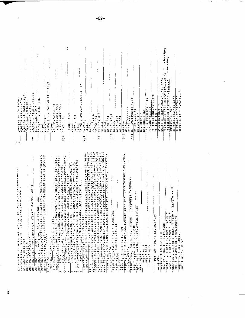
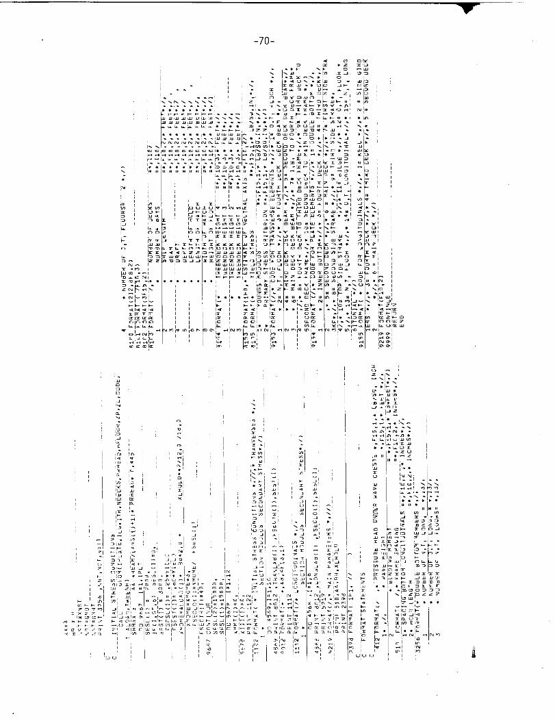
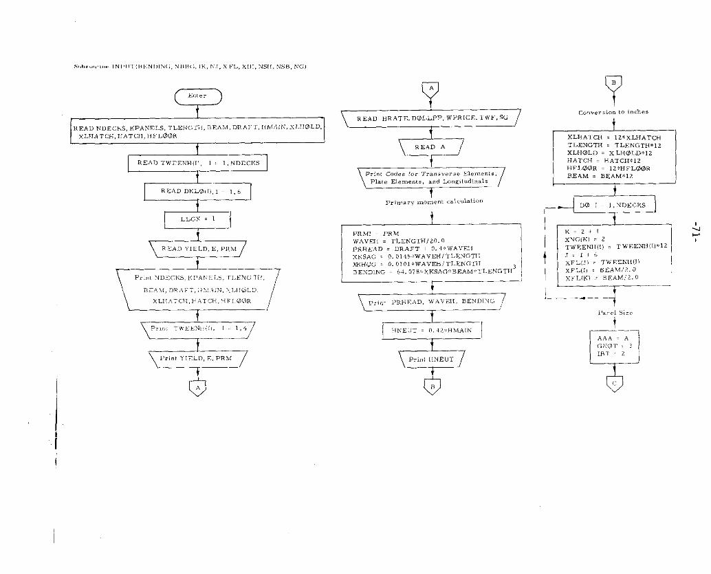
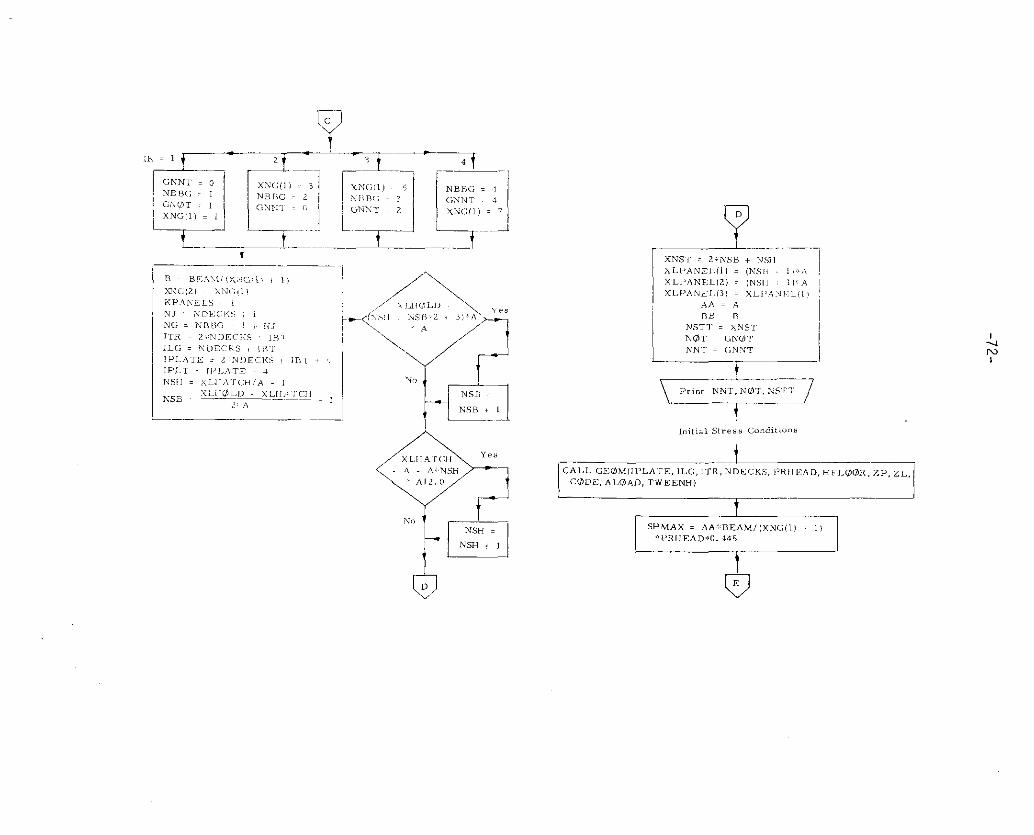
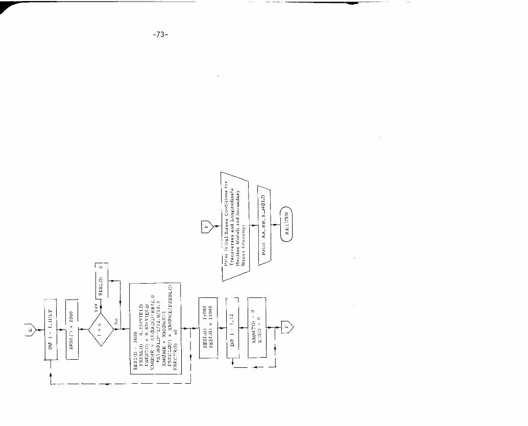
10. Subroutine lINPIJT
a) Abstract:
Subroutine INPUT is called from TRANSIf IP. It reads in the input data
and calculates initial stress conditions. Subroutine C,EOM is called.
b) Terms specific to this subroutine:
FORTRAN De fintim
Term
f3ENDING Ship bending moment for sag
xMOME Bending moment
~—”- ““-
-69-
,’
,,,
‘.-!
:,
,,
.;-,..---. ..!.
,---
-::,
:.-..-.
=,
;
$
-,
,,,,!
I
I
I
-70-
. .;>.-: .-
. .-.-.,.
::
,.
. .
S!,l),!),,,,,!.INI,,!,,I!I,NI),N(;, N],,,(,,lK,N.,,K,~L,x,11,NSI[,NSB, NC;l
( En,,, )READ NDECKS, XPANELS, TLE!<C.T1l,BEAM, DR.\FT, 1lMAIN, xLHOLD,xLHATCH, HA TCH, HFL@@R
eREAD TWEEXH(ll, , . 1,NDECKS
‘1READ I)KL@, I,,I ~~1,6
=1
+“+Print TWEENIJ II,, 1 . 1,+
%“Print YIELD, E, PR).:
A
&READ HRATE, DcZLLPP, WPRICE. TWF, sG
I
I_ 7
Print cad,. for Transverse Elemen t.,
Plate Ele,mnts, and Lm~itudinals—..
i
PRM1 = PRh4WAVEH = TLENGTH120. OPRHE.4D . DR.4FT + 0.4. WAVEHxKsAc, : 0.0145%WAVEHl TLENGTHXKHC4G = O.OIOl*W.&VEHITLENCT1lEEXDING = 64.078$XKSA@~BEAM*TL EYCxTH3
~
\Print PRHEAD, W’AVE13, BEhrDINc, 7
—f
*
HNEUT = 0.42xHM.4!&-
Prin, tlNEu T
con.er.i.. k. ~“.h.,
m!r ~
D@ I = 1,!iDECKS
‘; ~=,,,
XNC(K) = 2TWEEN H(l) =.TWEENH(l) ’12
1J- 1,6XFL(J) ~ TWEEXJ1 (l)XE’L,I) = BEAM/2. O
xFLiKl . BE.4M /2.0
I. .. —— 4Panel Size
L
‘-’-lAAA = .4G;<or , 3
IBT 2
6
.1
c
Lt
—
& Y,.
kNo tdNSH .
N.5H I ,
t
1:.4A = .4
I nB II
NSTT = X%SI
NOT GNGi T
NN, = r,NNT
~-–”- “
I SHMAX.AA$BEAMIIXNG(l) , 1)
*PRHEAD!O .445i
-LN
c1D
-73-
1
——— —
T
i
—i_,
—
-74-
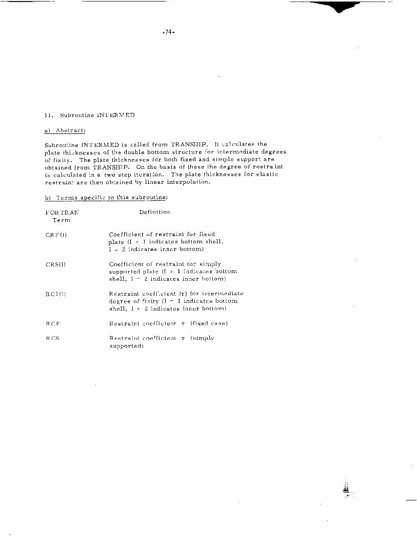
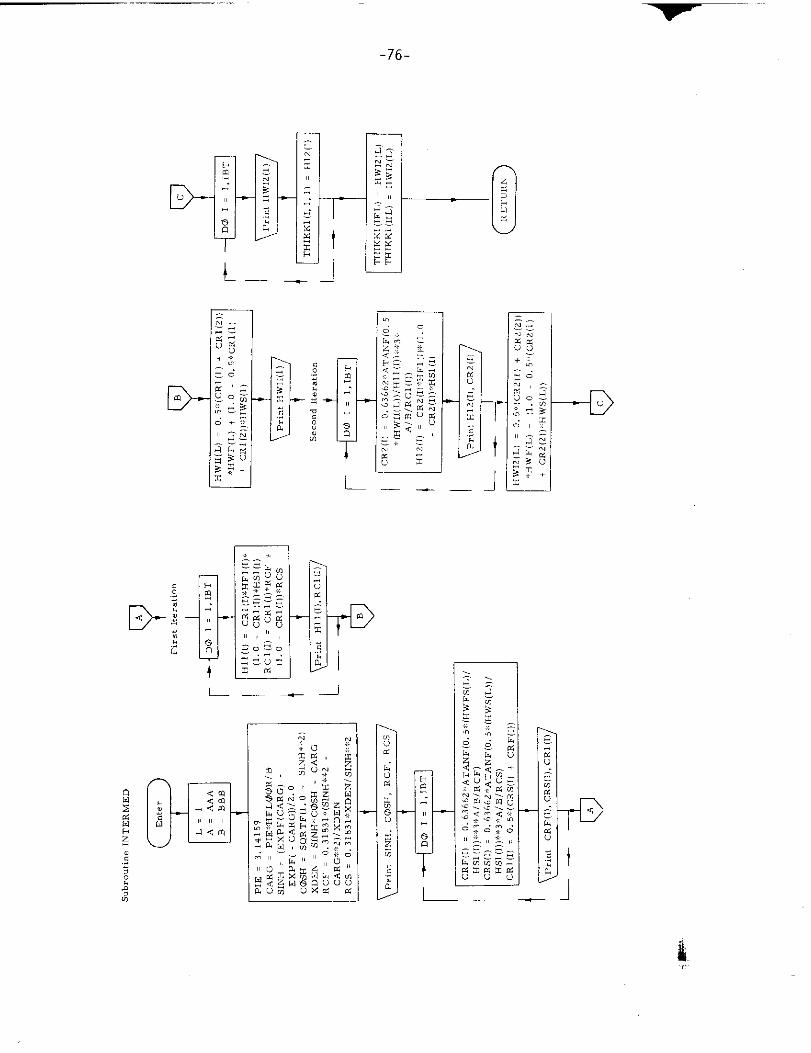
11. Subroutine INTERMED
a) Abstract:
Subroutine INTERMED is called from TRANSHIP. It calculates the
plate thicknesses of the double bottom structure for intermediate degrees
of fixiiy. ~e plate thicknesses for both fixed and simple support are
obtained from TRANSHIP. On the basis of these the degree of restraint
is calculated in a two step iteration. The plate thicknesses for elastic
restraint are then obtained by linear interpolation.
b) Terms specific to this subroutine:
FORTRAN Definition
Term
CRF(l) Coefficient of restraint for fixed
plate (1 = 1 indicates bottom shell,
I = 2 indicates inner bottom)
CRS(l) Coefficient of restraint for simply
supported plate (1 = 1 indicates bottom
shell, 1 = 2 indicates inner bottom)
RCI(l) Restraint coefficient (r) for irdermediatc
degree of fixity (1 = 1 indicates bottom
shell, 1 = 2 indicates inner bottom)
~cF Restraint coefficient r (fixed case)
R CS Restraint coefficient r (simply
SUpportmf)
,,
&:.....-

c
6
7
c
,’
6,7, ,Ti K”, ,(, ;,5)
Evn
-76-
D-
D- --D
—— JL
IJL
.
—
~–
-77-
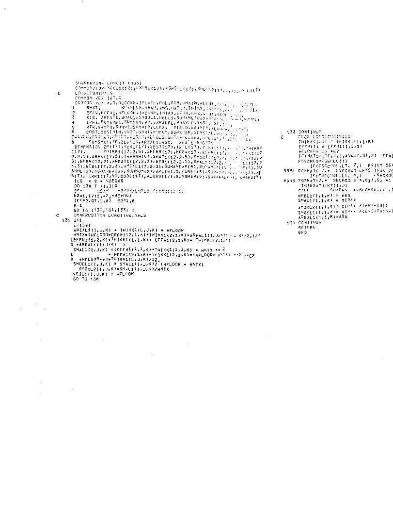
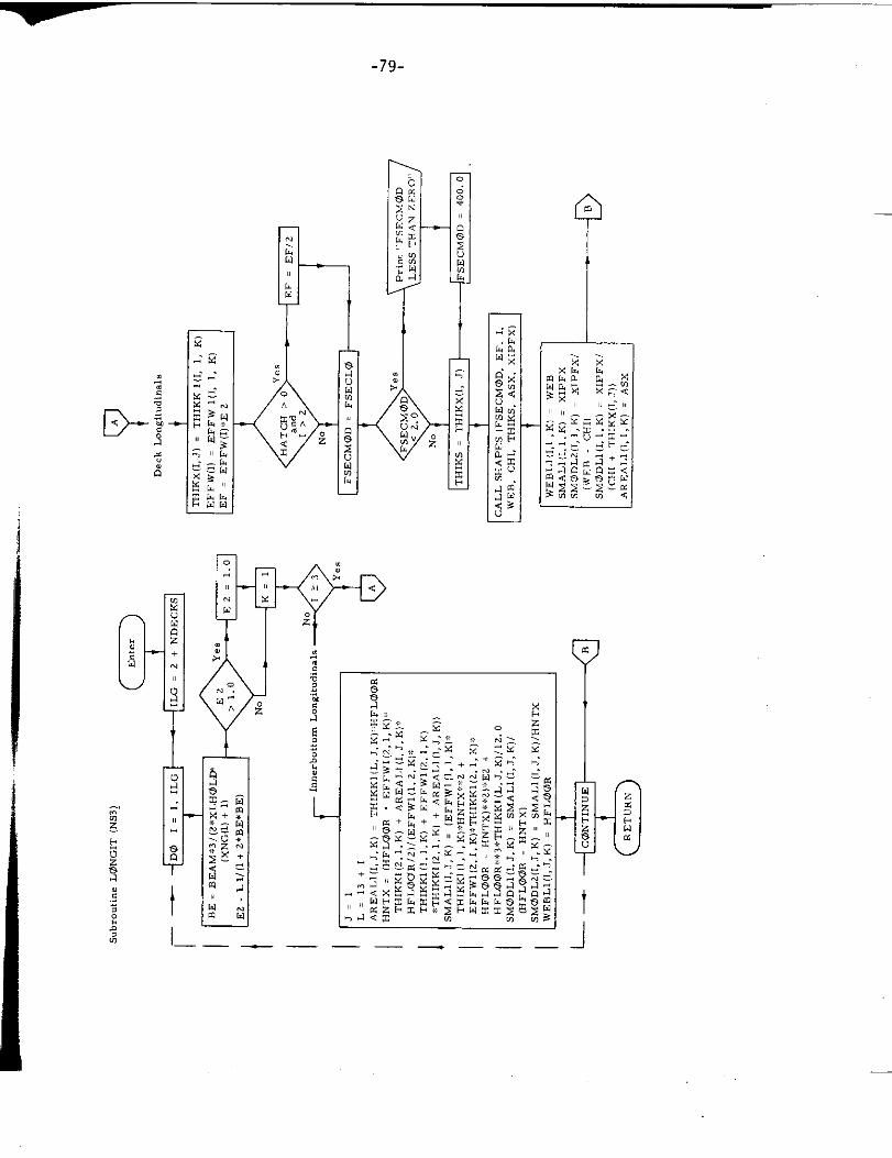
12. Subroutine LON~GIT
a) Abstract:
Subroutine LONGIT is called from subroutine SECTION. H calculates
the section moduli of all Iongitudinals. The c.:ross sectional area, the
second central moment of are. and the section modulus of O. T. and
N. T. double bottom longitudinal girders are compul.d directly in
subroutine LONGIT. For all other longitudinal. lhe above quantities
are obtained via subroutine SHAPES, which is called f,”om subroutine
LONGIT.
b) Terms specific to this subroutine:
FORTRAN Definition Mathematical
Term SymhOl
BE Aspect ratio parameter 3
E2 Normalized effective breadth ;,
EF Combined effective breaclth-w:, cld,
133c
354*
8995
*SO
, ..3.,2,,/(
..? ).E2
CONTINLII:
-79-
I
u
—
I
I— —___ — —— —
-80-
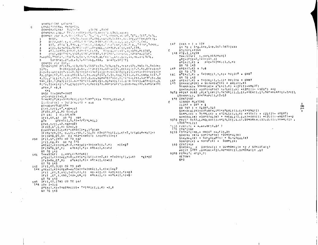
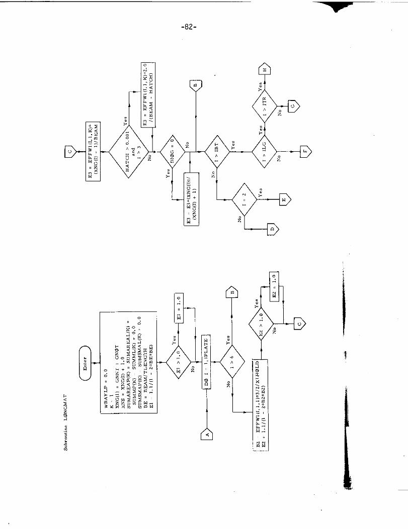
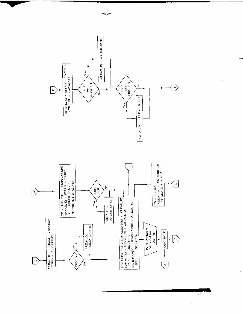
13. Subroutine LONGMA T
a) Abstract
This subroutine i~ called from SECTION. It calculate, the cross
sectional area as well as first and second central moment of area
of all longitudinal members.
b) Terms specific to this subroutine:
FORTRAN Definition
Term
ARC Arc length of bilge plating
AREA Cross- sectional area of plating
B2 Aspect r-tio parameter
BE Aspect ratio parameter
El Normalized effective breadth
E2 Normalized effective breadth
Mathematical
Symbol
P
P
A
a
WBAY LP Weight of longitudinal and
plating per hold
898
141
142144
wPAYLP =0,0K,~
XNG( I)= GNN7.GNoT
1’45146
no 10”143lFII. G1. ITR) Go 1[1 147
ID. 1“ILG~R5~(,,K).T,,EENH(lU).7tiISK>(~,l,K].2,0Go To 143
147
c*48
149
161
162143
q~s~
160
9355
A1
-82-
D-
L_./
,, ,,
ZG
-83-
D
r
tL —
--c)
—
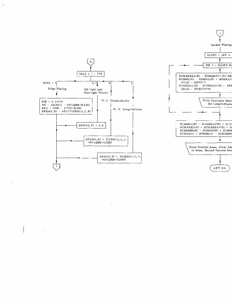
IXxx=,=%--mBilge Plating Oil-tightand
4Non-tightFloor.
t !
- l“”’’i:n~.”ARC = (PIE 2*TH)%RP.BIAREA(l, K) = AR C* THIKK1(I, l,K)
I 1AR EA(I,K) . THIKK1(l. 1,1]:*HFLOQR*GNOT
I*-4AREA(l, K1 = THIKK1(l, 1,1I
Girder Plating
I
I 1SUMAREAL(K) = SUMAREA LIK)S$AR
ISUMML(K) = SUMML(K) + AREAL1(l,(zLm HNEUT)
I I Sjyi&LiK)= SUMSMAL (K) + AR E[11 HNEUT)**2
1 tPrint PertinentMater
for Longitudinal
I
L_A —1t
1SUMSMA (w . SUMSMA P(K) + SUMSMWMAREA(KI = SUMARZAP(K1 + SU5uMM0M(K) . SUM MP(K) + SUMML(SUMSMA1 = SUMSMA1 - SUMMOM(l)
\Pri.t Overall Area, First Cenof Area, Second Central Mome
(5RETURNQJ
-85-
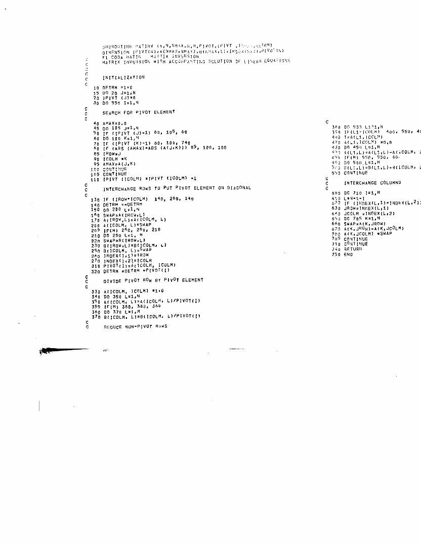
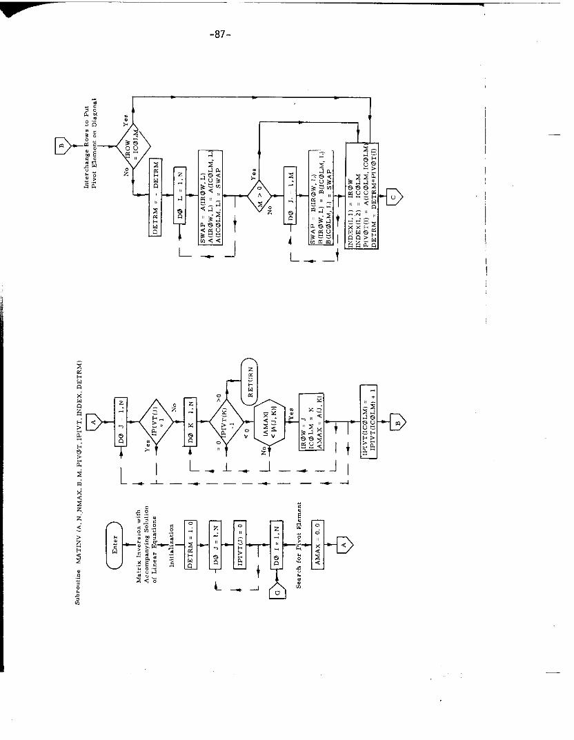
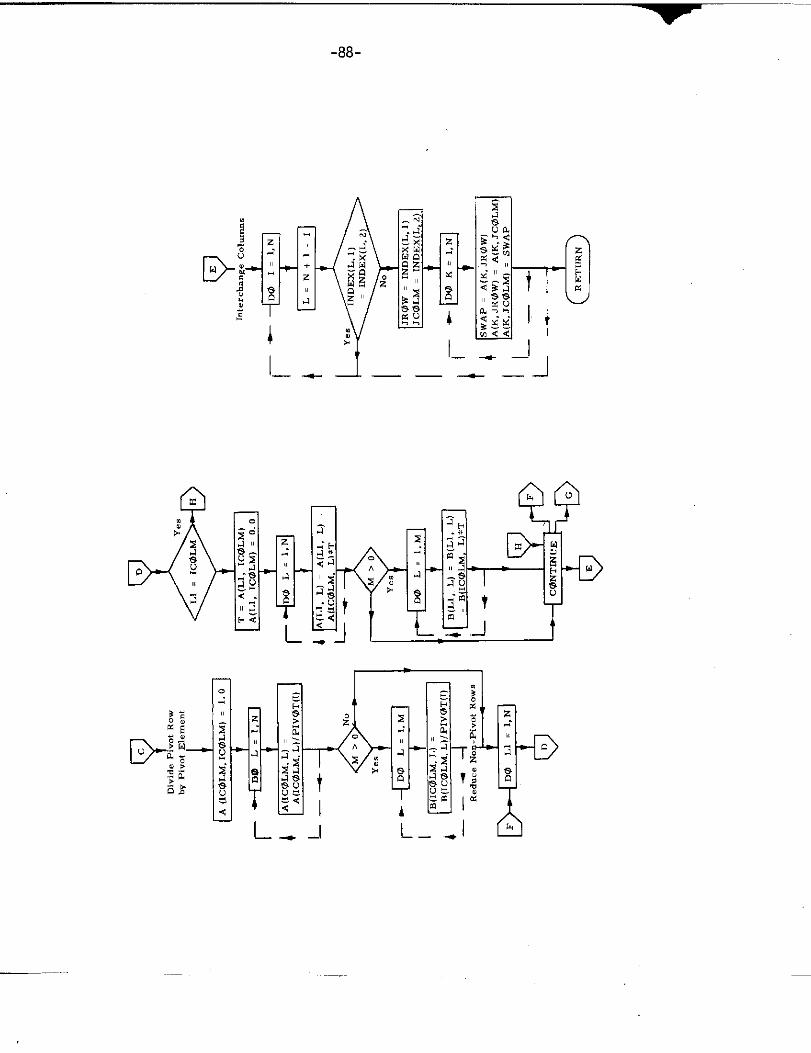
14. Subroutine MATINV
a) Abstract:
This subroutine calculates the inverse matrix of a square matrix. with
accompanying solution of linear equations.
b) Terms specific to this subroutine:
FORTRAN Definition
Term
A Input array
B Solution mabrix for linear equations
DETRM Oat put argument for determinant
of A
N DsgI. ee of input array
00 20 JzI,NlPIVT (.)1=0DO 550 Izl,U
AH AX, O.OrJ” 105 J.l, N
IF 1, PIVT (J)-11 6!J,i05, 60DO 100 K,l, %l
IF (I PIVT (K1 -l) 80, 10U, 7~0IF IAfIS IA HAx)-ABs (k(J,K))) 05, Ion, 100IRCW,JlCOLli:K~!l~K.A[J,K],. ”.,,,,,,,. . . . . .cONTINUFIPIVT (I COL,41 =[PIVT llc OLM) .1
INTERCHANGE 8UU3 TU PUT PIvOT ELEMEN1 01{lllacONhl
ccc
61106>0‘?063064065”66067!77C07“57107.;,1?50
lMTERc!lk\CEcOLUMN>
DO 7LI)1=1,NL,!l.t.,IV (l:4nEX tL, $l-14Dk XlLJR DN=IN,, EX(L, lJ
JC9Lt4 z11413EX(L,21DO ?0!! K.l, N
5wAP.,[K,JROH)A(<,JRU$!).A(<,JCOLM)~(~,JCOLUl =SU~PCOMTl~IJE~oN7,”,~E
RFTuR~4END
,,2))
.c ?EUUCF NON-PIVOT RuMS
~--–””-——-87-
tl
1- +-1
m L--—+ ———- —— --4
,
I
-88-
I tI_ _ _l
II—. J—— — — --
L-.
——-
-89-
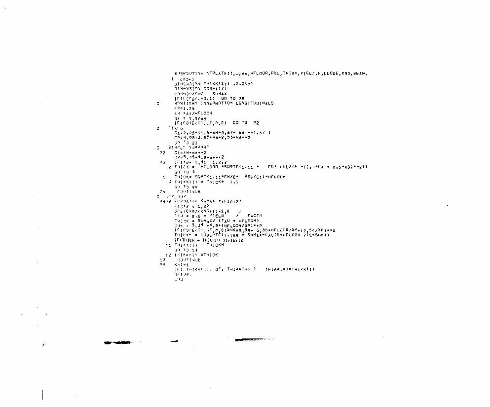
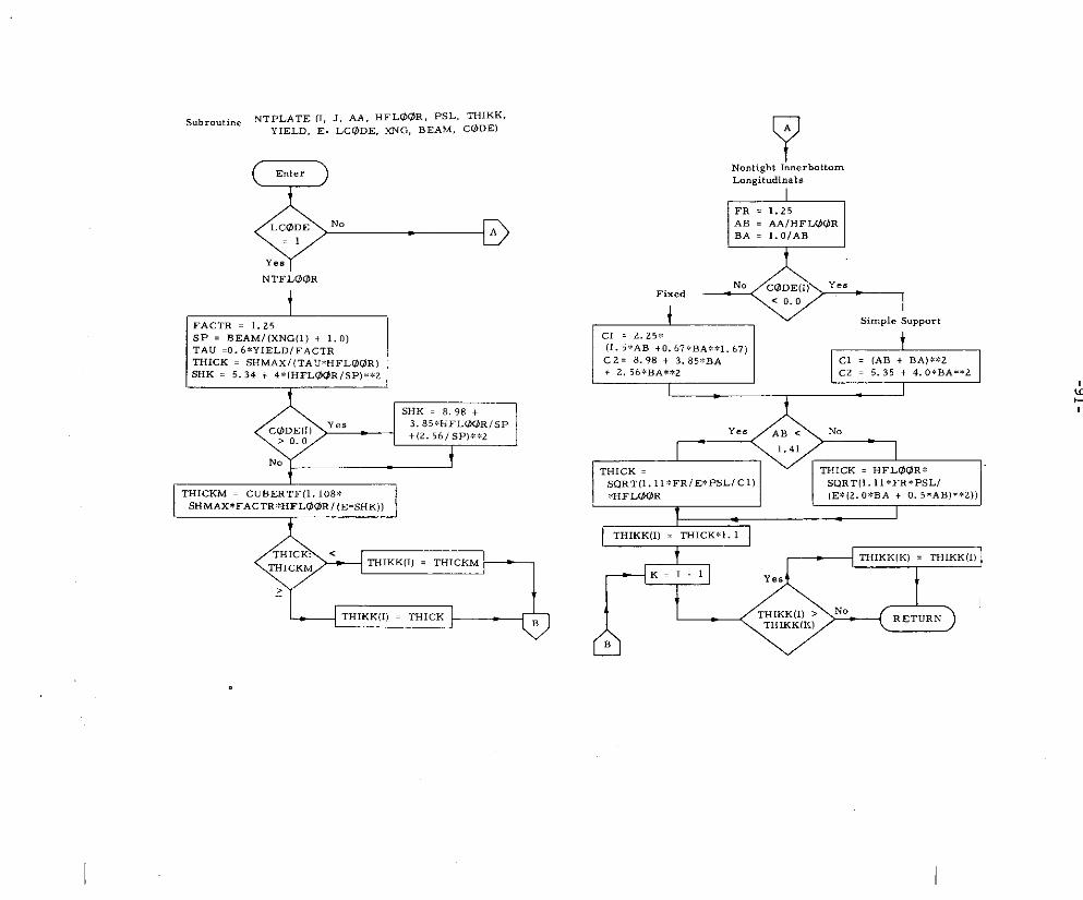
15. Subroutine NTPLATE
a) Abstract:
Subroutine NTPLATE is called from subroutine ASPECT. It calculates
the thicknesses of the non-tight floors and non-tight Iongitudinals.
The non-tight floors are designed to the critical buckling shear stress
or to tbe maximum allowable shear stress intensity in the floor web,
depending upon which will yield the greater floor thickness.
The non-tight longitudinal do not carry any lateral load, hence they
are only subject to in-plane loading, and are designed to the critical
buckling compressive load. The critical buckling load depends on the
aspect re.tio of the plate and separate equations are used depending
upon whether tbe aspect ratio is greater m smaller than ~
b) Terms specific to this subroutine:
FORTRAN Definition
Term
AB Aspect ratio
SP Span of floor (between longitudimals)
TAU shear stress intensity
THICKM Minimum plate thickness with respect
to buckling stability
3A =“”l; n/4Mi,(cO?E(ll, LT, O,O) GO lU 22
c F!xcoCl=~.75- 11,5. AU.OS 67. Vh ..1 ,67 )C,:. .93+3, 85. HA.2, 55. 8A..?
$. Td 25S1H,L7 suPPOR1
?2 c,ZAlj.d,..?,.>=5,5.4.”.”..,2
c
- .-
Subroutine NT PLATE (1, J, AA, HFLWR, psL. THIKK.YIELD, E, LCQDE, XNG, BEA>d, c@ DE)
Nontight In.erbottmnLongit.dimls
1
NTFLW3R
t
THICKM = CUBER TF(l. 108*5HMAX*FACTR*HFL00R l(E*SHK)I
c!FR = 1.25AB . AAIHFLW?RBA = l.OIAB
*
.
-92-
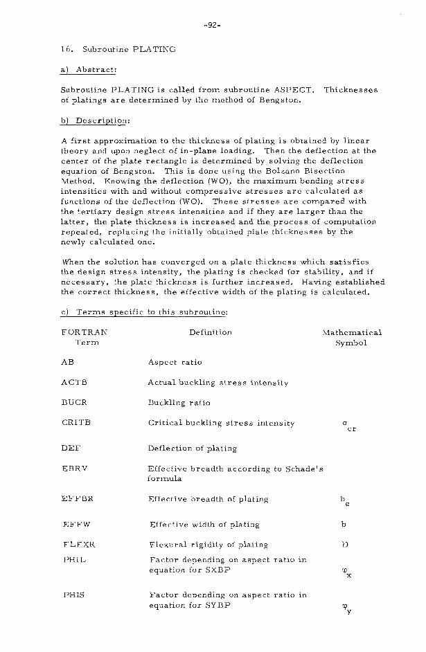
16. Subroutine PLATING
a) Abstract:
Subroutine PLATING is called from subroutine ASPECT. Thicknesses
of platings are determined by the method of Bengston.
b) Description:
A first approximation to the thickness of plating is obtained by linear
theory and upon neglect of in-plane loading. Then the deflection at the
center of the plate rectangle is determined by solving the deflection
equation of Bengston. This is done using the Bolzano Bisection
Method. Knowing the deflection (WO), the maximum bending stress
intensities with and without compressive stresses are calculated as
functions of the deflection (WO). These stresses are compared with
the tertiary design stress intensities and if they are larger than the
latter, the plate thickness is increased and the process of computation
repeated, replacing the initially obtained plate thicknesses by the
newly calculated one.
When the solution has converged on a plate thickness which satisfies
the design stress intensity, the plating is checked for stability, and if
necessary, the plate thickness is further increased. Having established
the correct thickness, the effective width of the plating is calculated.
c) Terms specific to this subroutine:
FORTRAN Definition
Term
AB Aspect ratio
ACTB Actual buckling stress intensity
BUCR Buckling ratio
CRITB Critical buckling stress intensity
DEF Deflection of plating
EBRV Effective breadth according to Schade’s
for mula
Mathematical
Symbol
EFFBR Effective breadth of plating
EFFW Effective width of plating
FLEXR Flexural rigidity of plating
PHIL Factor depending on aspect ratio in
equation for SXBP
PHIS Factor depending on aspect ratio in
equation for SYBP
ucr
be
b
D
‘TY
-93-
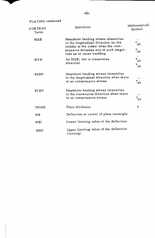
PLATING continued
FORTRAN DefinitionMathematical
SymbolTerm
SIXB Maximum bending etrese iritensities
in the longitudinal direction (at the
SIY B
SXBP
SYBP
THIKK
Wa
Wol
w@lI
middle of the aide6) when the com-
pressive “stresses are of such magni-
tude as to cause buckling
As SIXB, but in transverse
direction
Maximum bending strees intensities
in the longitudinal direction when there
is no compressive stress
Maximum bending stress intensities
in tbe transverse direction when there
is no compressive stress
Plate thickness
Deflection at center of plate rectangle
Lower limiting value of the deflection
UppeI limiting value of the deflection
(varying)
0xb
0xb
oyb
0yb
!,mxb
1!ayb
h
-94-
44,157
959
158
421
*59
1003
. 3,0 . BAS. 2.)
.GoDEiTbl
TO 157.THI.K , ,s!Yn . TEST(I) ) . Tl+lCK/r ESTll)
;n 70 157.THICK = (SIXB . TESL(ll ) ● THIc K/TESL(ll
.;81~;7= (51Yq - TEST(LI I . TI+lcK/TESTll)[cKzT.IcK.vELTtllGK[THIcK,CT,11,i) Go ro 158[CK..25[NT 959,1?MAT(/.. lI+[CK. ,25 }-ORPLATE ] = .!]s~j)
41CK), -421,421,159
T14ii Kl l)= TH[CiIF(h BSFCDELTH ICK1, LE,O, UO9t GO 70
KXPL . 1 +KX12L0S1X8 . SIX?
OTHICK = lNIc K
IF IKXPL-K XPLM1112S 1*2,159FLFXH = E + lHIc K .* 3,0t1U ,92
THIKK (I) . ‘HICK
FOSHAT( 1H11,7F 11,21
IF (C ODE(l], !+o,l) ~$~ To 165ACT8 , ( PSL . SESL(l) ) + ARS ●
CR IT@ z 9,87 + FLKXR . { AM + BA
159
sEs T(l)) ..2 /(
.0 ,25
.,),5
. 0,5
IICK . B1*, 2)
THICK ● B1** 21
i65 ‘: Q%5!213 .16 . FL EXH/(THi CK. Bi . . 2). (3,0 .AB5 . 3,0 ● IJAS.2,1
i:(C+li ;I, GT,’fl EL!l) :3 TU 501
co To M,JC; IT@ = YIE1. D
U(ICS = ,,c Tu / C“l Td
KXXPL = IKxx!,l. . 1IF (KxxpL. Et!, !:xx PL, ?,l I;U T!J lb”
IF ( bl~CR - 1.,, ) 161! sl$l ,161T,([cx z l}, ICK . ,,2
THIKKII>=TH!CKGo To ,59
c400
410420
rlxED
C0N1=9. O/25 bqU, Ph. *NGO 10 ~?OCO V1z PIF,.4 /16,0
CO&lll = COV1 . ( 1,0 . 0,3 . A8S 1 ● 8A
Cllx z cRIT* / < P>L ● SE SL( l>]
BBK=A9s. SEST(I )/(p:L+5EsL1 I ))EFFN(!) = R1/ ( 1,0 . COY1i , CONST . 1
lF(l, B8x, LT, c8x) EFF.,I,=BI
RETURN
END
1,0.. 8BX. CIJX1)
507 CO!411NUEilllC14=4CTR/C~!TtJ1F(I?UC,3.L?, I,IJ1 60 TO lbO
nn5 roR”AT<,~>
II
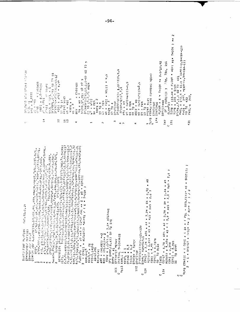
ISubroutine PLATING (Al, Bl, 1, J]
tKXPLM , I 5
KxxPLM = 20
PIE . 3.14159AB = A1/BlBA = B1/A1ABS = (A1/B 1);BAS . (BIIAIJEBRV = 1.1/(1 + 2:ABs).A1
vInitial Thickness
nKxPL . 1KXXPL . 1OSIXB = 0.0THICK z 1.2OTHICK = THIGK
&+ ‘~CONST . 3.78*A13s*
3.24*BA + 0.92*ABRC@NST . 4.05~*AB,IABs + BAS + z.0)
CONI = 4.49cONI1 = O.7376
-
cON1ll . (cONI*(BA*(PSL + SESW))
BoIzar.o Bi8e.tion Method
AB + 3.78*BA + 1.64*ABRCONST = 4,05?%AB*(3.O*ABS + 3*BAS + z)
C(2N1 = 3.368Cmn = 0.4’55
&m
-97-
—
.
-
I
—
—
—
—
—
&c
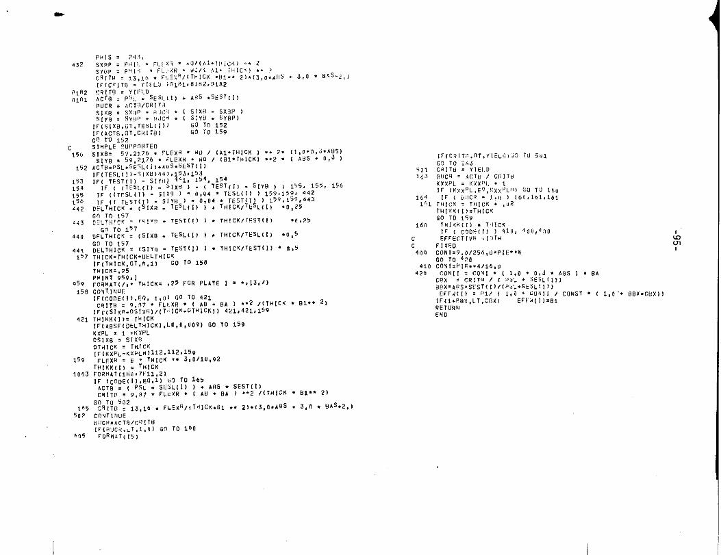
FLEXR = E:3TH1CK:%::3110.92DE F(11= W13
,,,H, GK). .’.
-, 3*ABS)
, . 3Y. 2176*FLEXR*W0/....... . ISIXB = 118. 44* FLEXR.WO
l(A1iTHIcK)M$2SIYB . ABS. SIXB
II 1
— I
/7E
~ ‘His= 243 I
W*rsx6P . PHIC*FLEXR *wO/
(A1 *THIGK] *.2
SYBP = PHIS*l?LExR:: W@,
(Al (THICK) **2CRITB = 13,16*FLEXR/(THICK*BI .)21.(3*ABS + 3W.AS 21
1.
I I
D
1
ACT% = PSL + SESL(l)+ ABS*SEST(l)
BUCR . ACTE3{CRITBSIXB = SXBP + BUCR*
1 I I I
ACTB = PSL + SESL(l) + ABS*SEST(I)I I I
.
B ---- ---
—’ --
I I
THICK = THICK + DELTHICK
t
THICK = 0.25
+. 1\
\
Print Thickness
of PlatingI
GTHICK . THICK
Ye.
FLEXR = E* TT11CK3110.92THIKK(l) = THICK
t
1=AGTB = (PSL + SESL[ l))+ ABS-SEST(llCRITB . 9.87+FLEXR*[AB + BA)
cRITB . 13.16*FLExRllTHlcK*B1***)*(3*.4BS+ 3*BAS + 2)

r .
-D
-J
u
\
-1o1-
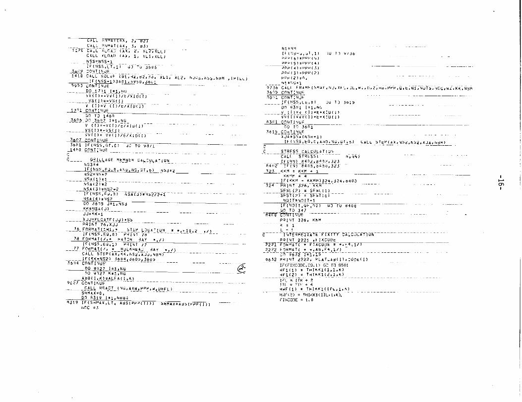
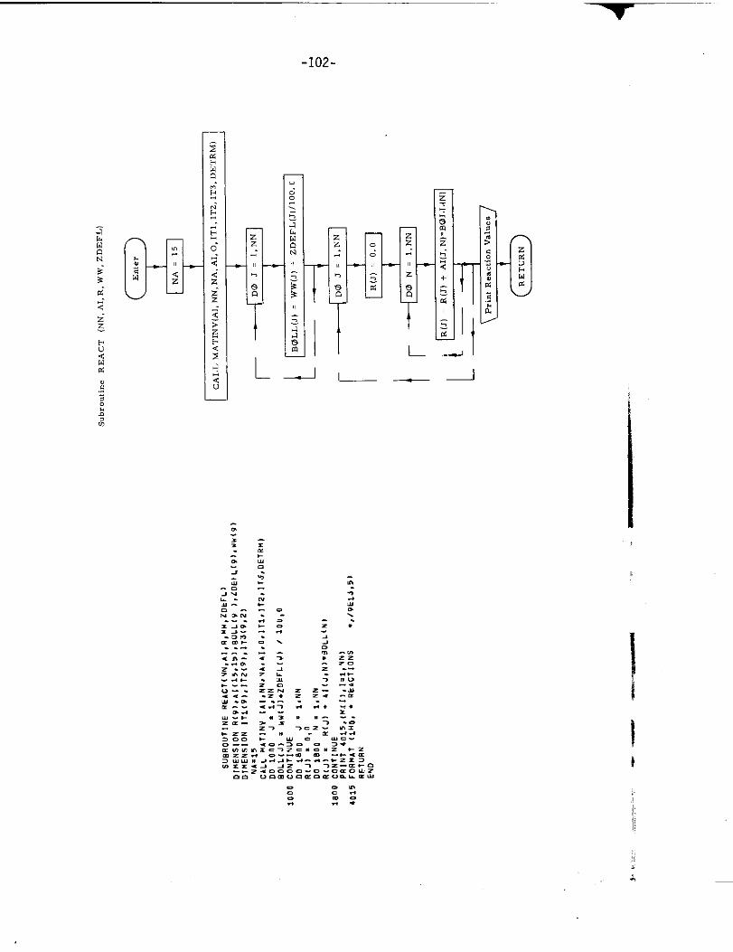
17. Subroutine REACT
a) Abstract:
This subroutine calculates the reactions at tbe inter aectiions of frames
and longitudinal girders. The reactions are obtained by application
of the influence matrix to the difference of the released frame deflections
obtained by subroutine FRAME and the grillage deflections obtained by
subroutine STEP.
b) Terms specific to this subroutine:
FORTRAN Definition
Term
Al Array of influence coefficients
BUJLL Difference between released
frame deflection and grillage
deflection
NN Number of longitudinal
R Reaction
Ww Unrestrained deflection
ZDEFL Restrained deflection
I
-1o2-
L.
-1o3-
—
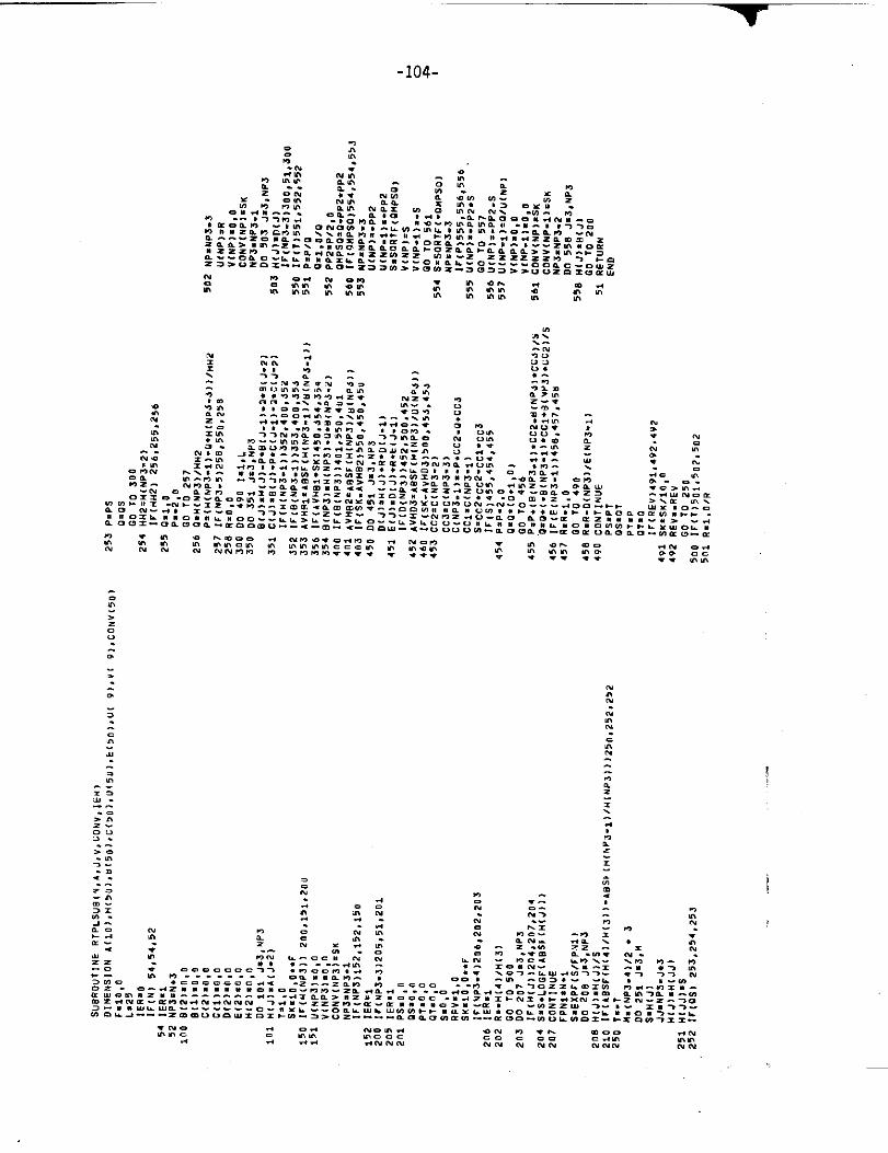
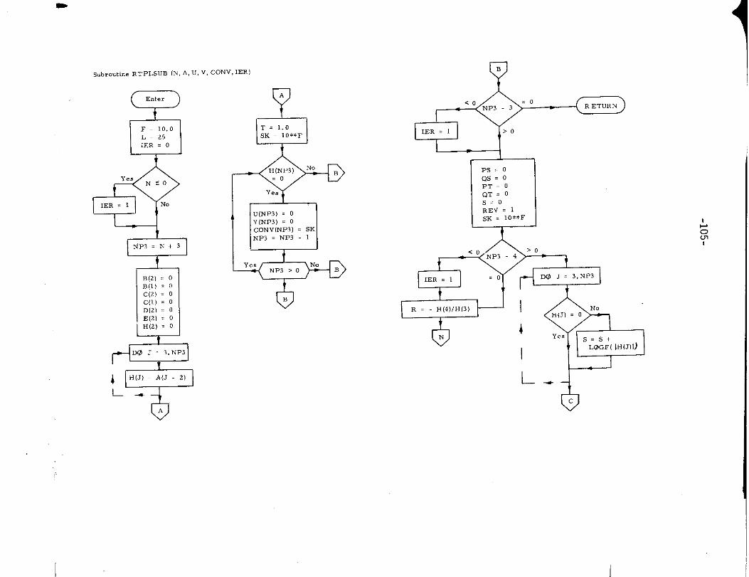
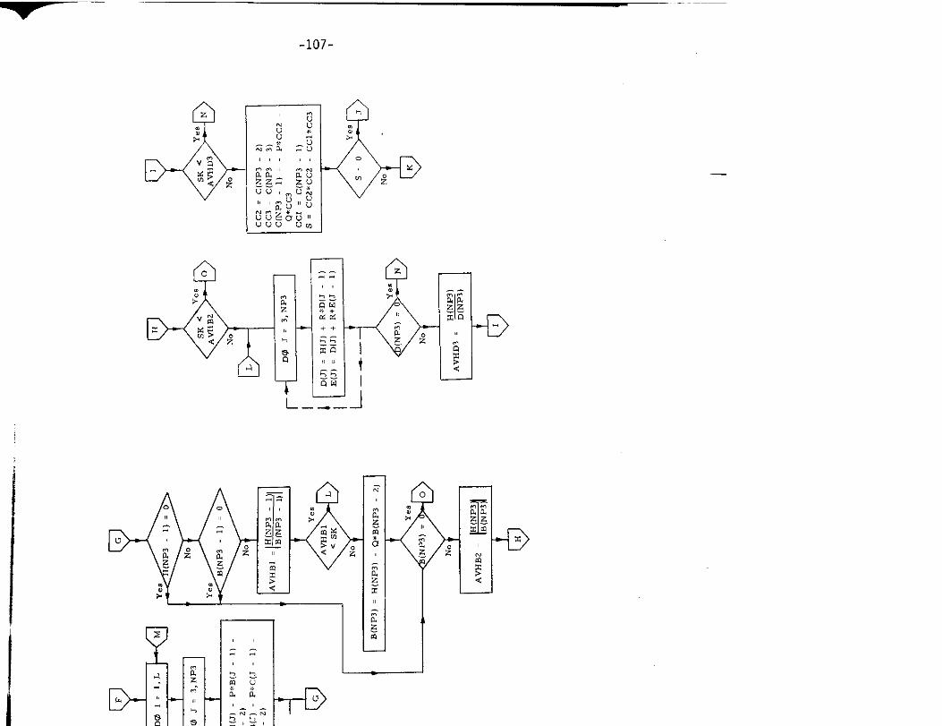
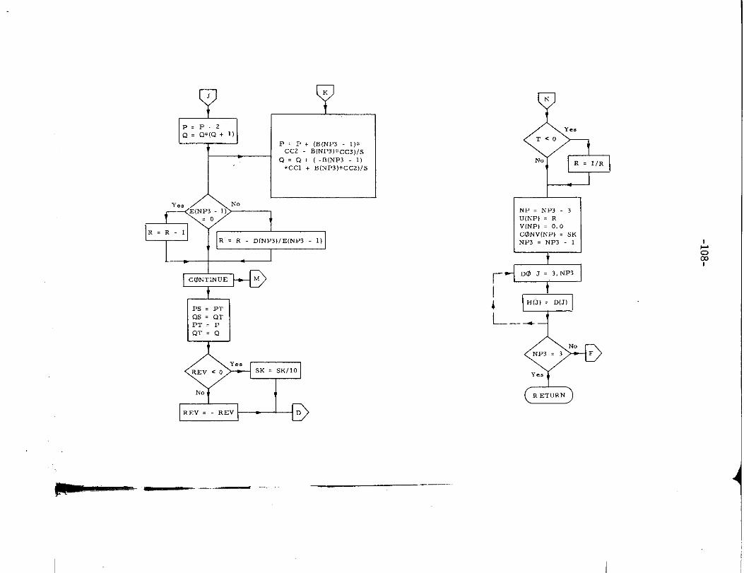
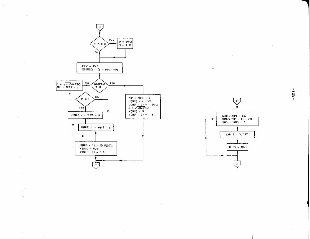
18. Subroutine RTPLSUB
a) Abstract:
Subroutine RTPLSUB calculates tbe roots of tbe .bara. teris tic equation.
b) Terms specific to this subroutine:
FOR TRAIN Definition
Term
A Input array of coefficients
Cotw Degree of convergence
lER Error code
N Order of matrix
u Output array of real roots
v Output array of imaginary roots
““~””-”
-1o4-
I
%b.o.tin. RTPLSUB (N,A, U, V, CONV, IER)
Q-’
DF= 10.0L=25IER . 0
dYes
Nso
lER = 1 NO
4B(2) . 0
B(l) = O
c(2) = 0
c(l) = 0
D[2) = 0
E(2I = 0
H(2) = 0
DO J = 3.NP3
~ H(J) = A(J 2)
L 4.
A
wT = 1.0SK . 10**F
R = H(4)/H(3)
TIk
I
L
QB
L-JPs. oQs. oPT. O
QT=OS=oREV . 1SK . 10**F
bNo
H(J) = 0
Yes S=s+L@GF( IHIJ)I)
‘/7c
I

!
t
1
4 PH(J) = H(J)/3
L. 8
D
T=. TM . (NP3 4)/2 + 3
r
DO J= 3,M
s = H(J)
, ,,=NP3-J+3
H(J) = H(JJ)
H[JJ) = S
L-+
%
QS. O ‘0
Ye, P.PSG Q=OS
F
-1-
?
HH2 = o ‘e’
NO
a
Q=,F=. *
I I
+--DYesNP3 . 5 0
NO1
R=o. o
ioF
!a!iw!r ~-~,-——.__
-----
-1o7-
,,, ,,
1-00
—
—
-D
1 P = P + (B(NI=3 1,*CC2 B(NP31. CC3,/.S
Q= Q+(-BINP3 -1)*CC1 + B(NP3)*GCC2)IS
Ye,
f
R = R D(NP3,1E(NP3 1)
oPS = PTQS = QTPT. PQT=Q
- --
7’N
BY..
T<O
N. R . IIR
II
LNP. NP3.3
U(NP) = RV(NP) = 0.0CONV(NP) = SKNP3 = NP3 1
‘?D@ J = 3,NP3
r
4H(J) = D(J)
L–-.
9-”NoNP3=3F
-f.,
GE)
%7Ye.P = PIQ
TCo. oQ= IIQ
NO
PP2 = P12
QMPSQ . Q PP2.PP2
b
EE=lt
NP=NP3-3
UINP) = PP2U(NP 1) = PPZs.~V(NP) = SV(NP -1)=-S
‘dU(NP 1] . QIU(NP)V(NP) = 0.0V(NP 1) = 0.0
*
dCLZ5NV(NP)=SK~+CONVINP 1) = SKNP3 = NP3 2
~
,=
DO J = 3,NP3
H(7) = B(J)
L—. .-t
6B

-11o-
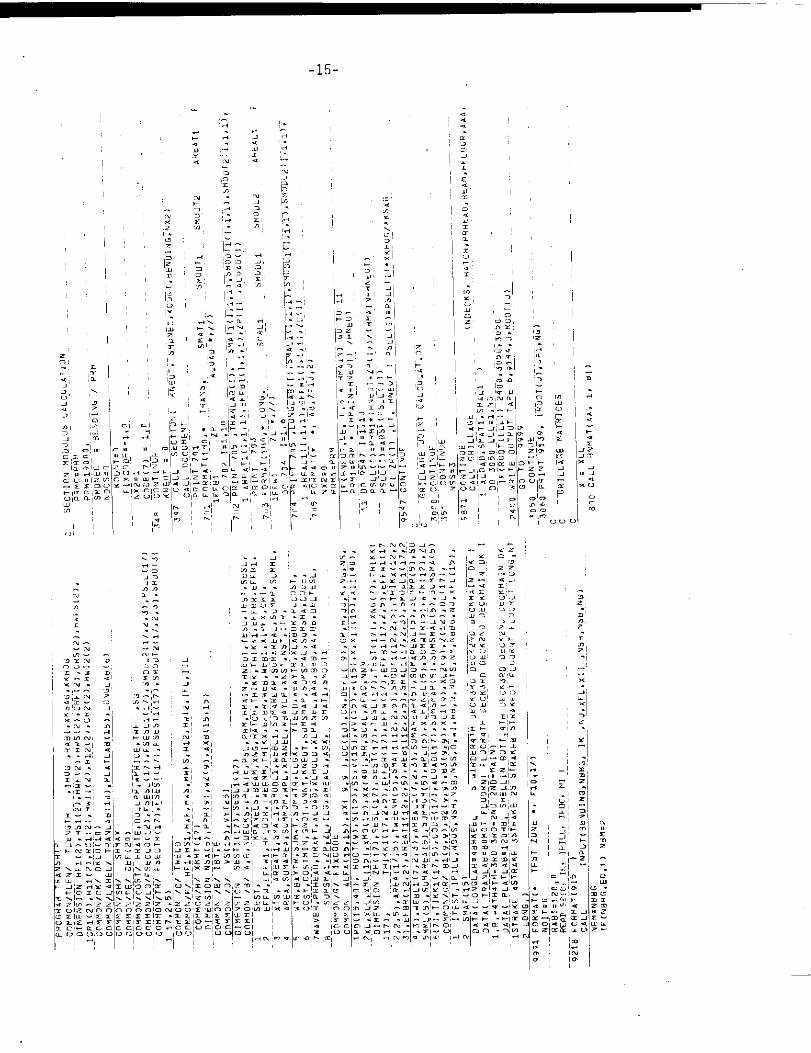
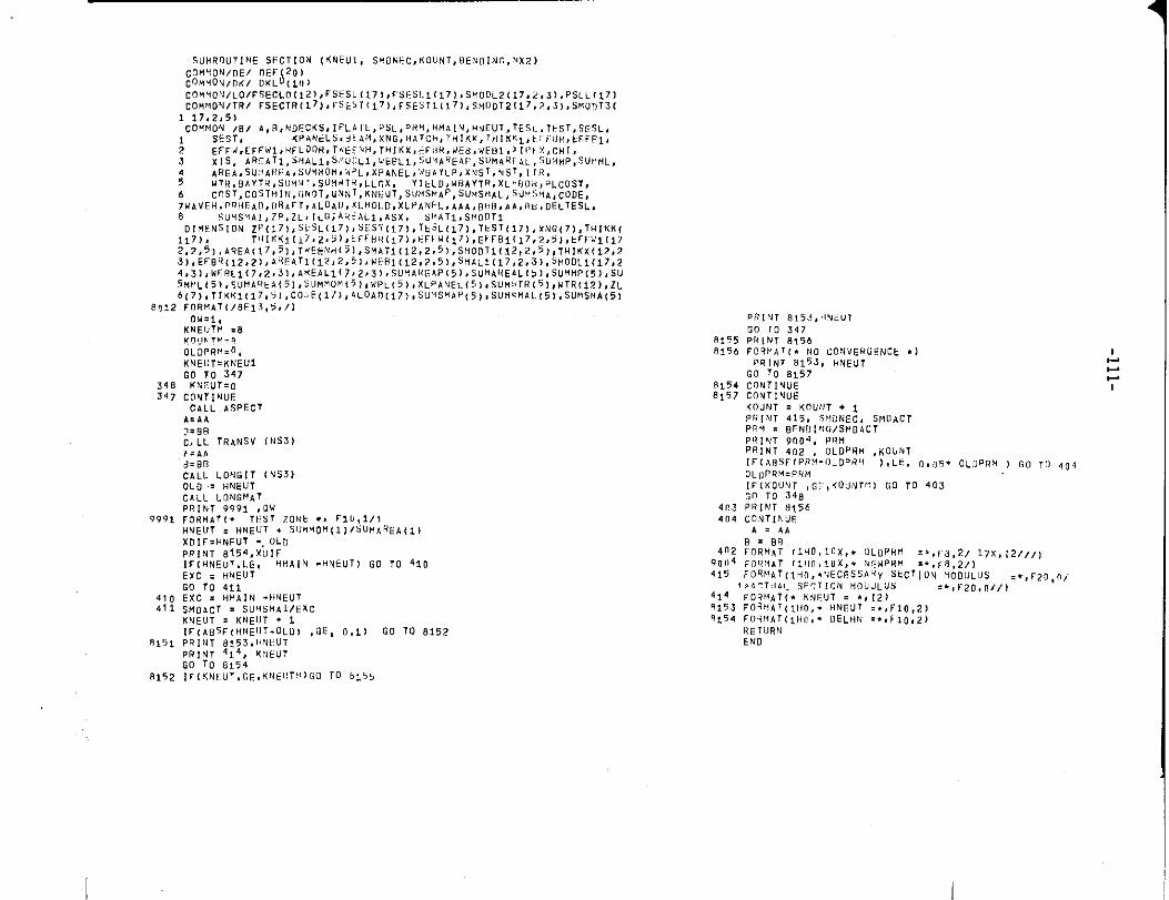
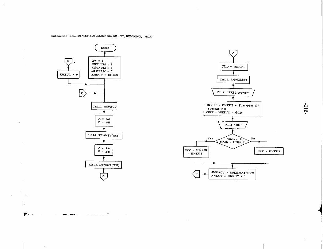
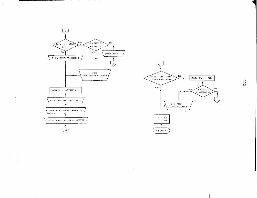
19. Subroutine SECTION
a) Abstract:
Subroutine SECTION is called from program TRANSHIP. It calculates
the section modulus of the midship section. The neutral axis and
section modulus are solved by iteration, the first starting from an
assumed value (based on empirical data). To accomplish this, the
subroutine makes use of subroutines ASPECT, TRANSV, LONGIT
and LONGMAT.
b) Terms specific to this subroutine:
FORTRAN Definition
Term
KNEUT Number of iterations in determination
of neutral axis of ship section
KOUNT Number of iteraticms in determination
of correct ship section moddus
SMDNEC Necessary section modulus
—
!
I
S“RRO” T,h, E sSCTIO* (K NkUl, SYD&FC, KOUNT,8EVDING, XX% 1
cOMHoN, D!i/ nW(20)cOM” ON, ”(, l) KLo( It,)
cOflHO*l/LO/C3ECL0[iZ),~SESL{171,f5ESL1117)>S”OOL2(17,2,31,PSLL(*7)cOfi%O+l/TR/rSECTR(17),F-$k:$TllT),FSEST1(17),sM0DT211T,?,51,SKOnTS1
1 17,2,5!co.tn:~s{~/ A,o, NDFc<s, lPLi Tk, vsL,Ptin,H.A[N, HNEu7, TESL.,TfST,5EsL,
6P AhlELS, YbA:4, Xti G,){,lTC h, TM! KK,lHIK .l, t,:P!]l,, kF+-Ri,
; EFFN, EFFW1,liF LOOfl, l~ECti H, THIKX, kF:i H,, WE B, WF81, kll>}:, CH1,
3 XIS, ARFATl,SHAL1,$,011L1,wk6L1, ~OHAtikAF>,SIJU&RE~l.,~V:+HP,su+ltiL,~RG~,5U<~~!E,,SU?tiON,ti~L,,XP~NEL,W:j,YLP,X?$T,%ST,[1R,
; ull+,OhYTW,SU,~’d!>SuM~l?,LLGX, YlkLD, W@AYTR, XL,U0ti$?LC0S7,
6 CO ST, CO ST Hlh,, (; N9T, GXNr, KNEUT, SUHSMAp, SUVSt!A L,sU"SVA, CODE,
7NAVEH, P~llEAD, [18 AFT, AL OAlJ, ,1. HO1. D, XL PA NFL, AbA, Bk$B, Ab ,Ru. DE LTESL,8 SUM SI+A1,7P, ZL, IL C; AR<ALI ,ASX, S(~ATl, SMO!JTi
D[!IENSION Zlx(17), Sk SL(17), 5ES.i[171, TksL( 17) ,Tt S1(171, XNG[7], TH1KK(
117), T+ll KK1(17.2s 51, tif HR(17), i:Ft W117), EFFB1(i 7,~,5>, EFf U1(172,2,5 ), AR EA(17,5, ,Tw EENH(5] ,sMATI( 12,2,5 ), SHOD1l (12,2,5) ,THIK X(12,2
3), EFB,?<12,2 ), AR F4T1C 12, 2,5], wEHI[12, 2.5), SMAL1( 17,2, 3), $HODL1 (17,2
4,3], WF8LI(?,2,3 ), ANEAL1 [7?2,3>, SUHAI<L; AP(5), SUHAIIEAL I,), SUHMP(5), SU5MML(5), s” HA,, kA(5), Skl MHUM(7 ),w PL(51, XLPANEL (5). SUU!,l R(S) ,wTR112), ZL
6(7), T! KK1c17,51, CO IJE1171, 4LOAD(17), SU~SMAP (5), SUP1. MAL( 51, SUMSH A(5)
8“12 FOR HA T(/8E13,5, /)
On.1.
34E34,
9991
410411
8151
8,52
1.4Ad=BR
CALL LONQIT (NS3)
OLD = HNEUTCALL L0NGt4ATPRINT 9991 ,0!4
FOR MAT(. TFS1 TOMt ., FIU, l/)HMEUT , HhIEUT . S11.40H i11/suMAREA(Il
lF. HWFUT -, OLD
INT 8154, XLIIF(H NE” T,LE, HMAIN .HNEUT] GO 10 410
C = HNEUTTo 4i1
C . HMAIN -b414EUTOACT , SU&4Sti A1/EXC
CUT , KNE!JT + i
(A BSF, HNEIIT-OLU, ,G6, 0,1) GO TO 8152
PRINT 8153, H.IEUTPRINT 414, <:)k UT
GO TO 815ilFIKNEU T, GE, KNE1!T,4)G0 TO 8L55
PRINT als,$, livb”,
GO TO 3478155 PRINT 8,56
8156 FO?M,,,l. NO CONVERGENCE .)
PRINT 815S, HNEU7G“ lo ~~rj,
8154 C13N11MUE8157 CO YTIVUE
KOUNT = KOUNT . IPl?lhl T 415, 5$! UN EC, Srlll ACTPRY , BP N!l[MG/SHD ACT
PQIVT 9004, PRMPR, NT 4“* , OLLIPRM ,60UN1
ITl A85Ff PRti-~ILDP d,, IsLk, 0,05. OLDpHX I GO TO qo.IOL”}>RM=PRM
lrl KOUN1 ,G::, KOU’iTf) [iO TO 403GO TO 348
4c3 PRINT 8156
404 cONTINUEA= AA
!3= LIB402 F“RHAT (1 HO,10 X,. ULOPRM =+, F-8,2/ 17X,12///)
90,,4 :Ilrl,, h, (I, il, l.” x,. ,, EN P”, ,.,~a,~,)
415 FOQkl AT(l HO, .,i EC ES SA, Y Skc7 ioN MODULUS =., F20 ,0,.!.:,,,lll, (. SF? TION tiOU” LUS ... F20 <o//)
414 FDRHA 1(. K!4!+IJT , ., ,2)?153 FO?ti AT(Il, O,. HNEUT .,, FIO ,2)9i54 F0314AT(I H”,. OELHM =+. F1O,2)
RE1URt4END
IL.1
Subroutine SECT1@N(KNEU1, SMDNEC, KOUNT, BENDmG, NXZ)
&D.
KNEUT . 0
8
Enter
QW=l~EuTM . 8K(3uNTM . 8OLDPRM . 0KNEUT . KNmJI
D---l
3CALL ASPEC
A. AAB=BB
cALL TRANSV(NS3)
\
A. AA
B=BB
-
0A
d@LD = HNEUT
Ib
I
- .— ——
I
—
NEUT OLD
NO
\Print HNEUT, KNEUT !
I/
bE
l--+==VP,<”, sMDNEC, SMDACT
\ PRM . BEND,NGISMDACT /
oc
Yc
OLDPRM . PRM
Ye.Yes
1
1-
52A= AAB=BB
RETURN
I
-114-
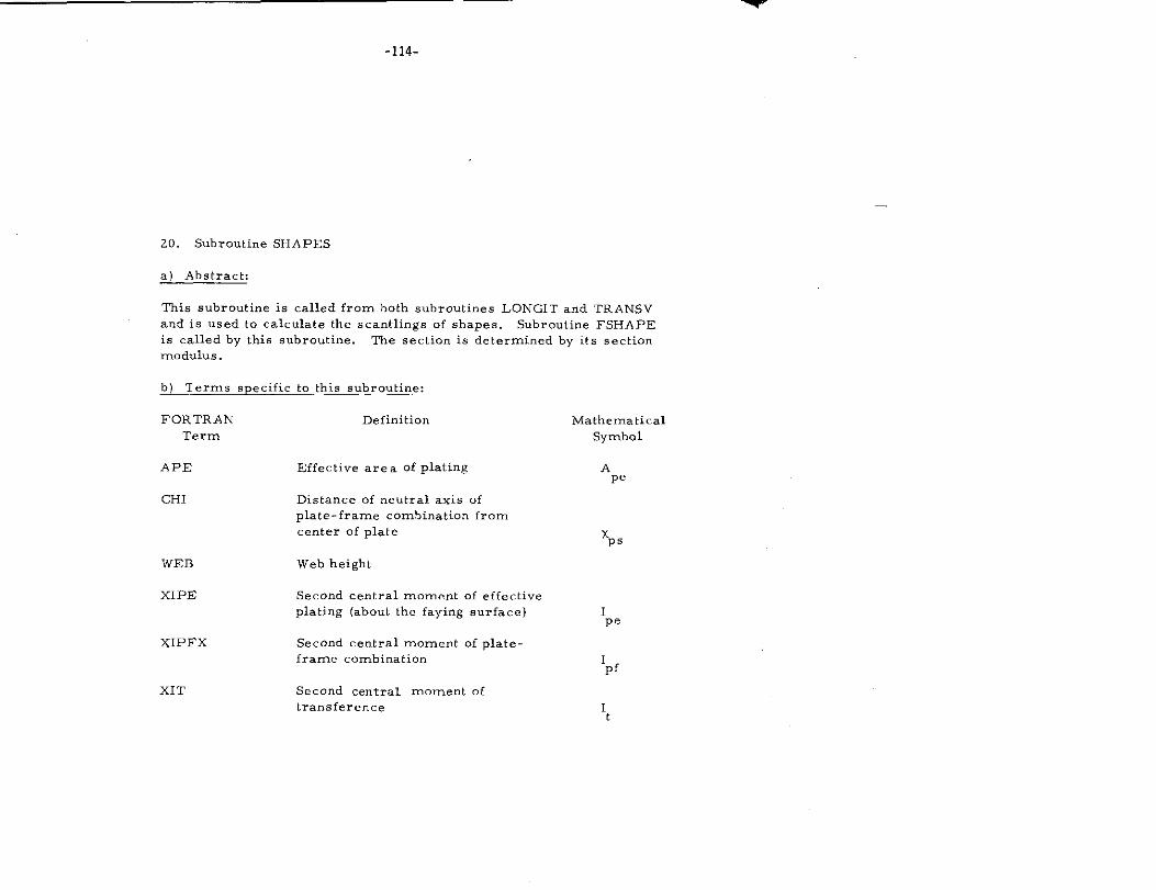
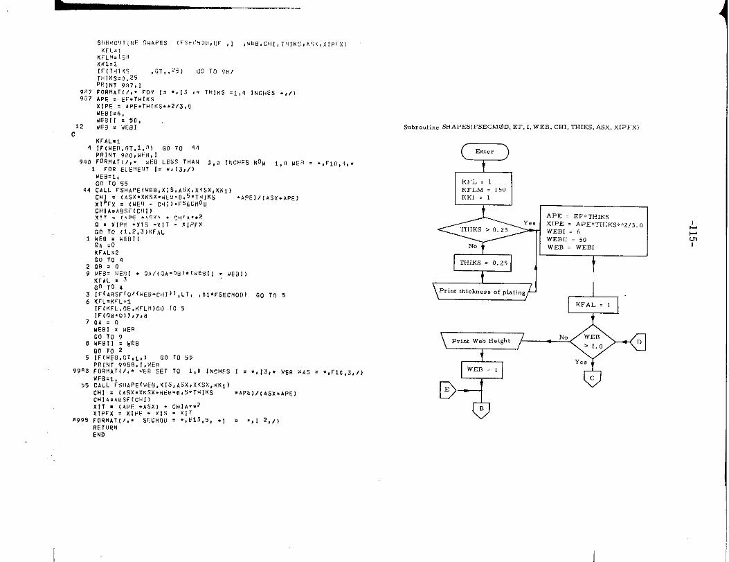
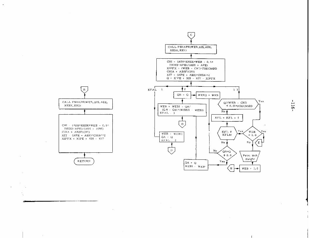
20. Subroutine SHAPES
a) Abstract:
This subroutine is called from both subroutines LONGIT and l’RA,NSV
and is used to calculate the scant lings of shapes. ,%brcutine FSHAPE
is called by this subroutine. The section is determined by its section
modulus .
b) Terms specific to this subrrmtine:
FORTRAN Definition
Term
APE Effective are a of plating
CH1 Distance of neutral axis of
plate-frame combination from
center of plate
WEB Web height
xIPE Second central moment of effective
plating (about the faying surface)
XIPFX Second central moment of plate-
frame combination
xIT Second central moment of
transference
Mathematical
Symbol
Ap,
xP,
IP.
1pf
1t
9tJ7937
12n
KFLf4.i~!lK!(1=1[C(1MIK5 ,CT,,~5) G9 TO 987T,ilK$.o.25PR,NT w),,,~ORfiAT1/,. PO* 1= .,13 ,. THIKS .1,”APE . EF.THIKSXIPF = ~PE.?91<5.,2/3,0UE6’1=6,UEB[l = 50,
IF? : WE81
KfAL=l
4 :fIw ER. GT,l, a)WlNT900,WB, rG0T0 4“’
9(IO F02. AT (/.. #EO LESS 7HAN 1,0 INCHES NOH i,~ WE$? , ., FLO ,40,
1 FOR EL EI!EIJ1 1. .>!3, /)
1
29
7
8
5
V9”*
55
n995
WE B=I,Go 10 55CALL FsHAp E(wE8, x; S, ASx, x%sX, KKI iC!(I = (As X. XKSX.,<k 8.0,5 .THIKS
X!PFX . (ME:? - cH1]. FSECtlll”
CHIAZABSF(C III )v!, . !,,DE .,, :,! . ~H!,i. ..2
O . XIPF .XIS -X11 - XIPFX
GO TO 11, Z,3)I:FALHEO = WEB! 1OA .0KFAI =7
.APE1/(ASX+)PE)
Go “+0-408:(2
IUE3= WE!ll . OA/(QA-OB). (W Et?lj ~ NEBI>
KFAL = ~go To 4
Irl ABs F1”/lkl Ew-c>il)l, LT, ,O1*FSECHOD) GO TO 5
KrL. KFL.;
tr[KFL, GE, KFLt4)fi0 fo 5!FIOB. IJ17,7,8
OA=QuEOl = WEB
GO TO 9UEBII = VEB
00 To 21F(UE13, G1,l, ) Go ro 55
PRl!4T 9’J88, I,t4ERfORMAT (/.. .IER SET 10 1,0 iNCHFS
WFB=I,
CALL FsHAPE( wEG, XI S, AS X, X6 SX, KKI)CHl = (h SX. XKSX. dCti-0,3’THIKSCHIA. &8 Sf[Ck11)
x11 . (API: .ASX) . CHl A**2X!PFX . XIVE . X!s - XlrF08H4T [/,. S1:CH O,> = ., E13 ,5, .,
REIIJRN
. .,rlo ,3,/)
subroutine 5HAPES(FSECM0D, Er, 1,WEB, CHI, THIK5, ASX, XIPFX)
IKFL = 1KFLM = 150KK1 = 1 I
~ II “-- ‘-
EzEEiE@ ,+KFAL . 1
Li
I
oc
L.m
END
I
AKF
1
cHl . (A5x*xKsx*w EB 0. 5*
TE31KS;::APE)I(ASX + APE)
CIHIA = ABSF(CH1)
xIT = (APE . ASX). CIIIA:!?2
‘YIPFX = XIPE + xrs X,T
CJ1
CALL FSHAPEiWEB, XIS, ASX,
xKSX, KK1)
t
I
cHI . (A5x.xK5x*wEB 0, 5*
THIKS:kAPE)/(AS.X + APEI
xIPFx = (WEB cHI)::cF5EctJ0D
CHIA = ABSFICHI,
xIT = (APE + AS.X). GHIM:, Z
Q = XIPE + XIS .XIT XIFFX
4
IWEB . wEBI + Q.4/
(QA QB1;:IWEBH WEBO
KE’AL , 3 I E%?lNo
No
QA=QYes
WEB1 . WEB.
oP,,., Web
Height
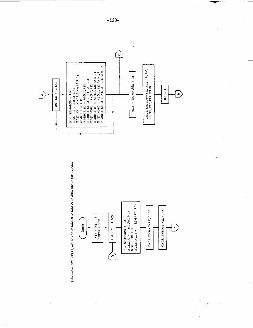
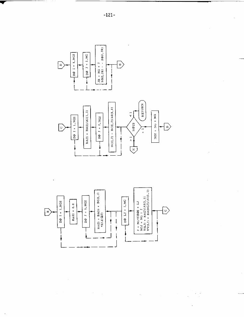
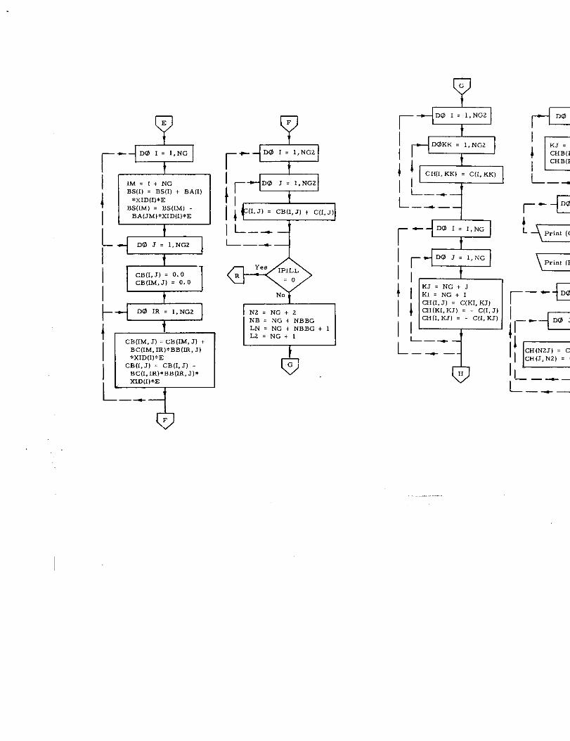
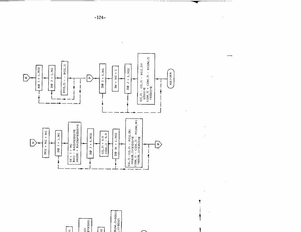
21. Subroutine SOLVE
a) Abstract:
This subroutine ~ets “p and solves the grillage slope-deflection equations
for the joint deformation and forces with the aid of subroutine BNMAT.
Subroutine MA TINV is used in the calculation for the joint deformation
and forces.
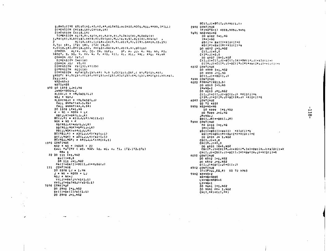
SUBROUTINE sOLVEik 1,42. ,Jo A4, RLOAD1, RL0AD2, NOOs, Nsb, NHBu,Ll[NEN510NC!411Ll,181,C@(16,18)DIHENSXOM CX(18,18)n[.EN510M A1(9,9),Az(Y,9),AJcv,9),nL0bDI(9),UL0~U2(9)
l,eA1is),x1EO1lnl,A4(9,Y),Ek(18J,ULL(6,9,9J,XLI(9),N05(~)2 8C(16,18),![(18j,cK(9,9),H1(9,9),”(91,sMH(6,153,11( !8,, 112, 18), lTd< 10,2)4,C(lO,lB),@8[18,ie), 6>(181,ti419,91,#5(9,9>,HD($LI)cOMMON ALFA, ,X, cC, CN, Uk6L, GP, H, JJO ,, N(3,Ns,
1!7001, S. SS, V, V“, H, K, xIII, X11, XL, XLL, &t4L, xl!”, X,
COMMON /E/ !lJT,EDI.EQSION c.8[1s1
COMMON /D/ VS, VYD! HE NS1ON VS115), VV[ 2>)
900
,000
22
111
?000
D,UENS, ON EILiLl, ilJ)D1HENS1ON 4LFA(15,1, ),AX[ V,9 l, CC1l U], DkFL( 9), PU113,4D1,
lROOT( 91, S(15), V(I>I, VV115), U(15) ,xl”(15), xHL[i5) 4x M”(15), xx(
2x*,1411)NS2:NS.2
NO TS. NSS
DO iDOO LJ=l, NGJXNG. NOOS+LJ
XL EO(J) = .RLOAD1l LJ)NGJ = NO*J
xLEO(NGJl = -RL3A02(LJ)CALL 6NHA71AX,5, H5)CALL 6NHAT(A x,4,9+)
DO 1000 LK.l, NGK. NG. NOOS. L5
9B1J, K)= B41LJ, LK)Bc(J, K) . A1[LJ, LX)/ A1(l, ll. . . . . . . ..801NGJ,KJ. ”,(LJ, LK)BB(NGJ, NGK)=B41LJ, LK1BBIJ, NGK). A4(LJ, LKI
BC[NGJ, K) . A3[LJ, LTl)/A1[I,l)
BCIJ, NGK) s A2(LJ, L<llh 1(1,1)BC(NGJ, NGK) x A4[LJ, L61/A1, l,l)
CONTINUEVG2 . NG . INO05 . 2)
CALL M471NV I WC, N02, 18, SC, U,
DC
BA(!)z O,ODO 111 JE1, NG2
P.A< II=6A(1)+BC[1, J)cON71NUP
DC
J=N1NGJ % No*J
V{ LJ)*BAIJ )/11(1,1)
VVILJ)= BAINOJ1/A1ll,CONTIN”EDO 2900 1=<. NG2
8A I!)=BA(DO 29f10 J.l, NG2
RR. 10 111 1.1, NIi2
;“2000 LJ . I,VU
10 . NOOS . LJ
Ir;ilil,l)
!1, lT2, JT3, DTt)
2900
5951
6002
,401,4999
6020
6003
5950
5999
6000
6502
5962
BC{l>J1. OC(!, J1/41 (1,1,
CONTINUEIF(NOIS.11 4000,5950, ,,,,
NG2=NG.NQDO 6002 I.l, NG
IH=I. No
as(i).BA(l). XI VI I)*E8Sll M)=8A(1H1, X10( l). t
DO 6002 J=l, NG2C(l, J1=O, Q
CIIM, J)=O, O
DO 6007 IR.10NG2C(I, J)= C(I, J1-UC(I, IRI. BH (l H, J). xIu(l). t
C(IH, J1:C(l MO J). BC(IH, lH)*HHI IR, J). xII, (,,.,
CONTINUEDO 4999 1.1, NG2
DO 4999 J=l, NGBC[l, J1=. BCII, J)CONTINUE
fORHAT(9E13,5iDO 6003 1=1, NGI!4*NG.1
DO 6003 J=l, NG2
C(I. J1=C(I, J1-BCll #J) .Xt Dlil. tC(l H, J)= CILM, J). BC(l H,J1 ..XID(I).E
cONTINUE00 TO 4000N02=NG+NG
DO 5999 !=l. NG2
DO 5999 J*l, NGJR=NQ. J
BB1l, JR>=. BB(I, JH)CONTINUE
DO 61100 !=l, NGIM=J.NG
BS(I). BS(l). BA (l) .X IU(l)*k
eS1!M1= BS(IM1- BA1l Y). XIU1l I*EDO 6000 J= 1,NG2
CB(I, J)=O, OcR[l M. JI. n,o
00 6000 IR=l, NG2CBII.. J): CBit M, JI.3CIi?, IHI. BMI lR, J)* KID Ii]. b
CR(!, J). CB{l, Jl-BCll, lH). Oul lR, JI. xID[l). ECONTINUEDO 6502 1=1, NG2
DO 65o2 .I=l, NB2cll, JI. cBII, J). c(l, J]
cONIINUE!FIIPILL, EO, II) GO lU 596s
N2=NQ+2NR=NG. N88GLN=NE. NRBQ+l
L2. NQ.1DO 9661 1=1, NG2
DO 9661 KKx 1,NG2CH(l, KK,, C,[, KK)
-.

~_..
-119-
z!:
---
-120-
I_
.
——-———
Q‘3
T-l-1
.
—
~“
-121-
—
D-
D-
L
r-
-xv oz+
-Doz
—
-D
.—
.
-_J II1..-. -——— J
—— —
—.
eE
r-DO I= I,NG
IM=I+NG
~
BS(l) = BS(l)+ 8A(1)
*xID(II*EBS(lM)= BS(lM)BA(JM)*xID(l)*E
r“*DO 1 . 1,NG2
[.% yDO m I,NG2 N2=NG+2
NB = NG + NBBGLN. NG+NBBG+IL2. NG+l
CB(lM, J) = cBIIM, J] +BC(lM, lR)*BB(IR,J)*XIDIII*E
CB(l,J) = CB(l,J)BC(l,lR)*BB(IR,J)*xID(l)*E
““”4—-
+’G
r
D@ 1 = 1,NG2
D’OKK . 1,NG2
II
1 J CH,I,KK, = IX,KK)
I ~_
L.+:
1
r-DO
~EKJ=KK.CHB(KJCHB(KK
L—.
sr- DO
~
Print (C
i=rint(B
-—- —
——-—
0F

:s=,–DO SK = LN, NG2
~ HB(N21 = m B(N2) + CHB(JK]
L—.—ir--
1
*
Ll=rint ,cH(l, J], J = 1,NG)
Pr,nt (CHB(l), l = I, NC)
ICALL MATINV(C, NG2, 18, C, 0,
T1, 1T2, 1T3, DTE)
—-i---
%
r-
DO 1= 1,NG2
BD(l) = 0.0
~ [- ,; ::(l:’::l,J)*BS,J)BD 1
I L--–
L–-.—
rElDO J . 1,NG
I MN% l&J)
BD(J] = BDD(NGJ)
1- .A
i--+
L
r‘FDO J = I,NG
~ NGJ=NG +.1
I %)= TJR)
L.–
@
-“’—~””””
-124-
—
D-
1––. *—.—— ____ J 1
.—— — -— —.
—,
.__l.L——-__J _
—s
r
-125-
—
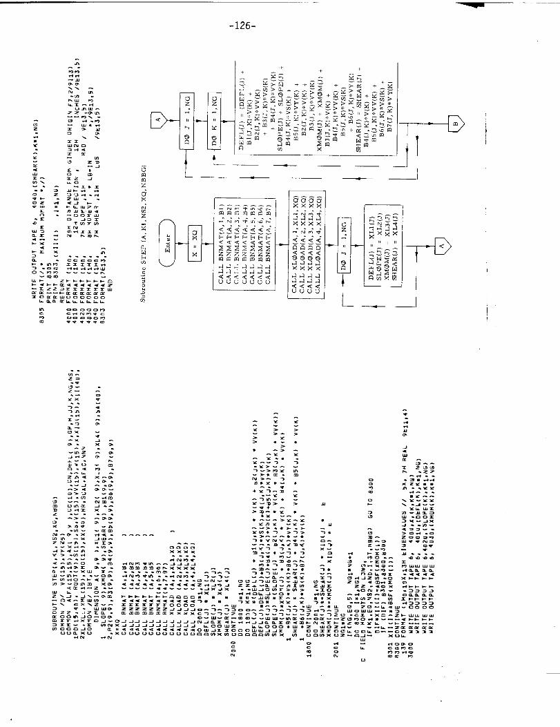
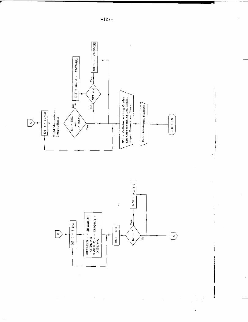
22. Subroutine STEP
a) Abstract:
This subroutine is used to calculate tbe deformations and forces at
tbe frame intersections of the longitudinal girders of the grillage.
It solves the grillage deflection equation.
b) Terms specific to this subroutine:
FORTRAN Definition
Term
SHEA R Shear
SLOPE slope
xMOM Moment
—
-126-
.—. — —1
——
I I
—1
—
,
I
-127-
D-
I______
I
I_ —.
.
—
—
-128-
1
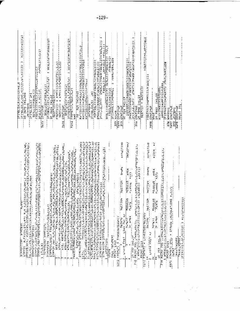
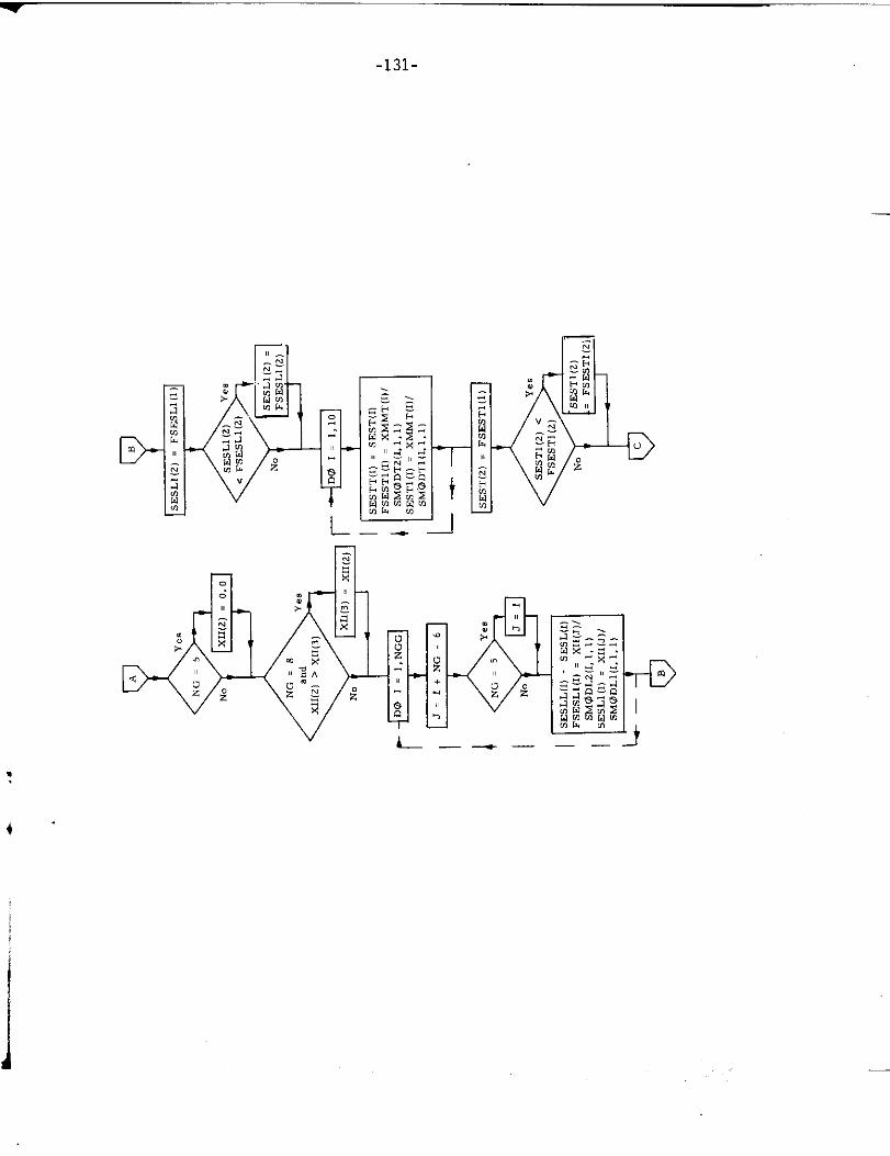
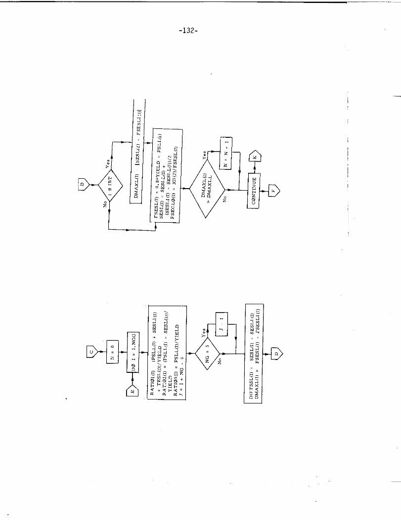
23. Sub rout in. STRESS
a) Abstract:
Subroutine STRESS is called from program TRANSHIP and it admini~ters
the convergence of the solution. It calculates *tress intensities based
on scant lings calculated in *ubroutine SECTION and grillage moments
calculated in subroutine GRILLAGE. New criterion stress intensities
are then calculated unless the last calculation meets the criteria for
stress intensities.
1.
-!:.
—

~“-—””-130-
*
-131-
—
L_ ..-
v L-
--D
—-—-
.
*“
-132-
—
I

-133-
D-
I
.
L .—
L_-— ———-
r
‘ l__
—
M
8:
—
D-Z
-+ –1
+
o
uzz
t
I
—
IL——+ —-
-134-
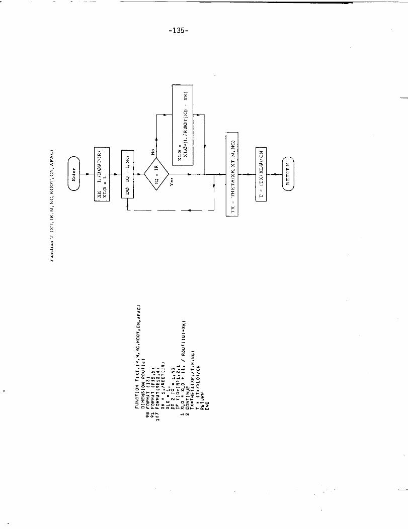
24. Function T
a) Abstract:
This function calculates the values of the Lapla. e transform used in
the grillage calculation. This function is called for by both subroutines
BNMAT and xLOAD and in turn calls for function THETA.
b) Term specific to this subroutine:
FORTRAN Definition
Term
AFAc Scale factor Set equal to tmity in
this study
CN Determinmt of A matrix
lR Number of Nielsen functions
M Xmnber of Nielsen functions
NG Number of longitudinal girders
ROOT Root array of A matrix
XT Distance of the longitudinal girder
from the origin
-135-
rL___ J
—
—
-136-
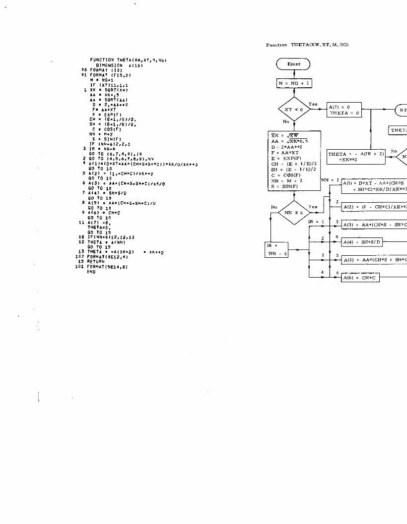
25. Function THETA
a) Abstract:
This function is called by function T to calculate the Nielsen functions
N used in the grillage calculation.M
b) Terms epecific to this subroutine:
FORTRAN Definition
Term
M Index of Nielsen function
NG Numbe= of longitudinal girders in
the grillage
XT Transverse distance of the longitudinal
girder from the origin
Xw Root of the grillage matrix
ruNclloN THETAIxw,xT,Y,~G)DIMENSION b(151
98 FORMA, (,3,VI rORMAT (r15,5)
M . NO+,IF (Xl)il, i,l
1 XK = SO R1(XW)
AA = XK..5
). XK,”, XK.. J
6 ~;3;o,1:4. {CH. S. SH. C~, XK, D
7 Al, ) . SH. S/D
GO 10 10
8 A(5) s AA.l CH. S. SH. C)/UGO 70 in
9 A(6) . CH. C
co 10 1“11 A,7, ,“..- ..- ,
THETA.0,00 To is
10 lr(NN.6)i2, i2,1J12 :TE;~ ;9A(NN,
13 THETA . .411*.2) . XK..Z107 FORHAT(9E12,4).. ..,,,.,,. . ,..,.,,,”
101 FORUAT(5E14,81
END
Function THETA(XW, XT, M, NGl
QEnter
QN= NG+l
A(7) . 0mETA . 0
RET
No
Is = >,,.,, , 1 1 I + sH*c)*xK/D/xK**3
~ 3 A(3) . AA*(CH*S SH*C
-138-
–—
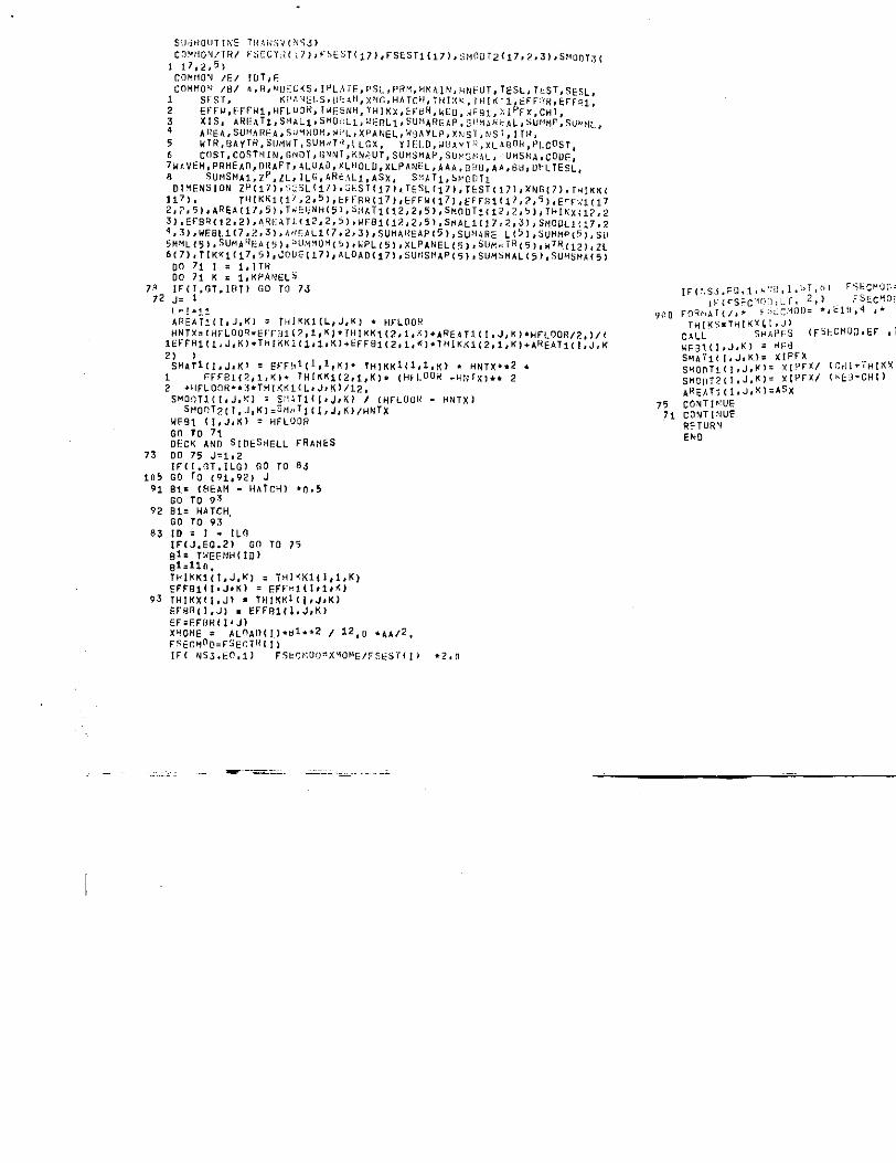
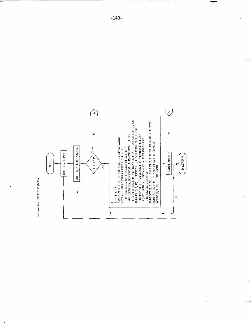
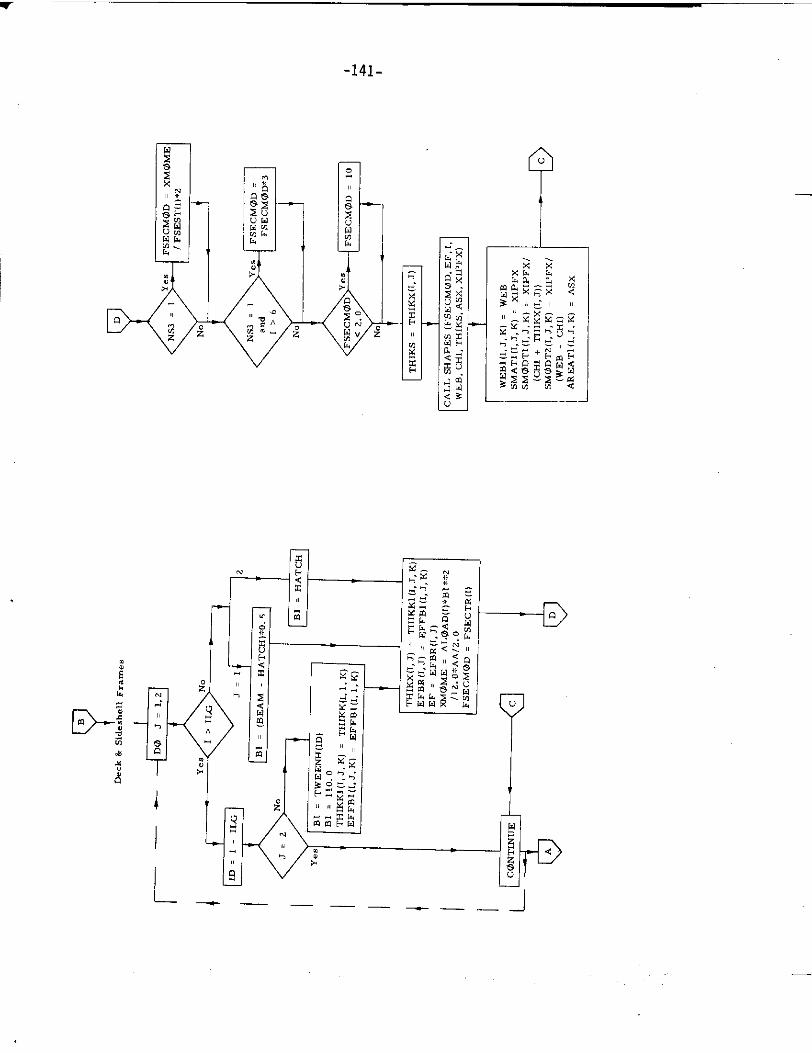
26. Subroutine TRANSV
a) Abstract:
Subroutine TRANSV is called from subroutine SECTION. It calculates
the section moduli of all transverses.
b) Description:
The cross sectional area, tbe second central moment of area, and the
section modulus of O. T. floors and N. T. floors are computed directly
in mbro”tine TRANSV. For all other transverse, and frames the
above quantities are obtained from subroutine SHAPES.
73
105
91
92
83
Ls!. !,i
AR FA1i(l, J,Kl = THl~611L, J,KI . HFLOORHNTX=l HFLIIO? .EFF31(2,1, K 1. TtIIKKI 12,1, Kl+AREA1i(l ,J, K1. HFLOOR/?, )/t
IEFr Rif I, J, K).lti IKKIIL ai, K1+k FFm(2,1, K1.lHIKK 1(2, l, K). AR EAIII!, J,K
2) )
SMk Till. J.K, = Et- Fi, t(l, ltK)* THIKKII1, I,K> . HNTX..2 .1 FI-FF31(?, I, K). TH1KK112, $, K). ,Hf L008 .H?JIx ).. 2
2 +tIFLOO 17..3 .THTKK1lL, J, K)/12,SMOn TLll, J,K] = S:) AT1l I, J,X) I (H FLO13H . HNTx)
stioo T~(I, J, KI,3t4,t TLll, J, K)/HNTx
UF91 [l, J,K) = HFLOOR
Go To 71DECK AND SIDE SUELL FRAtIESDO 75 J=1,2
lF1[. nT. lLG) 00 TOGO Tg (91,92) J
81. I!4EAM - HATCH)
GO TO 93B1= HATCH,Go 10 93
[D=l. !LCl
iF[J. Eo.21- Go To 7?~1: ~:,~~,,ti(!~]~l=lln.lltl Kl(l[l, J,K) = THl<K1tl, i,K)EFF8111, J.1() = FFF. 1,(1,1, A1
93 l“IKx II, J) = lHI!(KIII, J,K)
5FUR(1, J1 . EFf13111, J,K)
EF=FFOR(l. J)X.! L3,4E . A1-nA,, {,,..1..2 , 12, ” .~b,z,
FS6CM0E. FSECT,*( 1)
IF I NS3. EO,l) Fsk?fiuu ~xYOb!G/7sEsr {11
. - .== ——.
.2, ”
----HE31(I, J,X) = *EaSMb71[[, JS K)= xIPf Xstion TI(I, J,K1= XI?FX/ 117,! l+”i HIKY[l,
s.o,, ??(I, J, K)= xIPFX/ (. EJ-CH1)AR E,, T,{ I, J,%) =As X
75
?l. .RETURN
cOVTIfi!UE
CO VT INUE
END
—
-140-
1- ——. — —.
——— ——
—
w
-141-
r--
I
7
7
.
—
1
-+
L_”_– –____-J
—
—
-142-
.
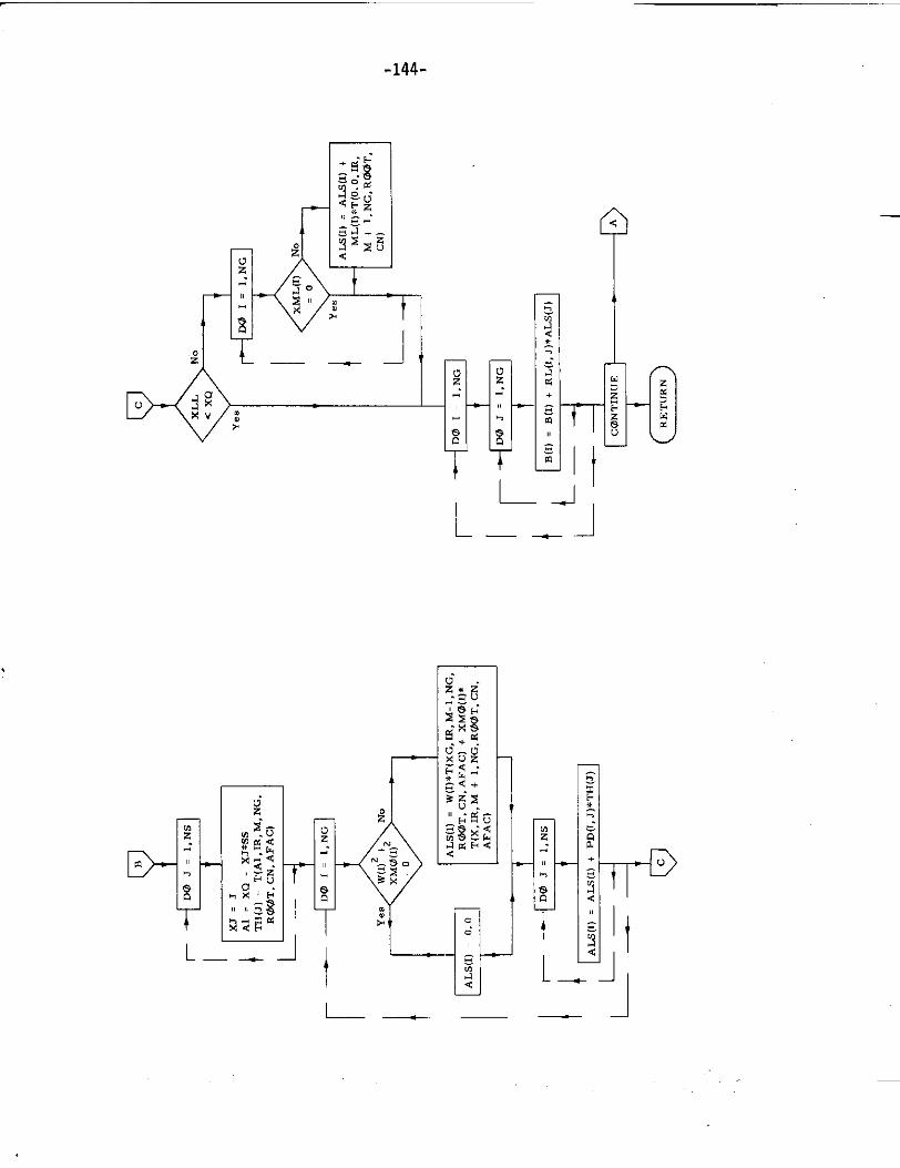
27. Subroutine XLOAD
a) Abstract:
This subroutine is called from program TRANSHIP. It calculates the
load transforms for the grillage system.
b) Terms specific to this subroutine:
FORTRAN Definition
Term
A A matrix
AL Characteristic matrix
B Load matrix
M Index of Nielsen s function Nm(u)
XQ x-distance in Nielsents function
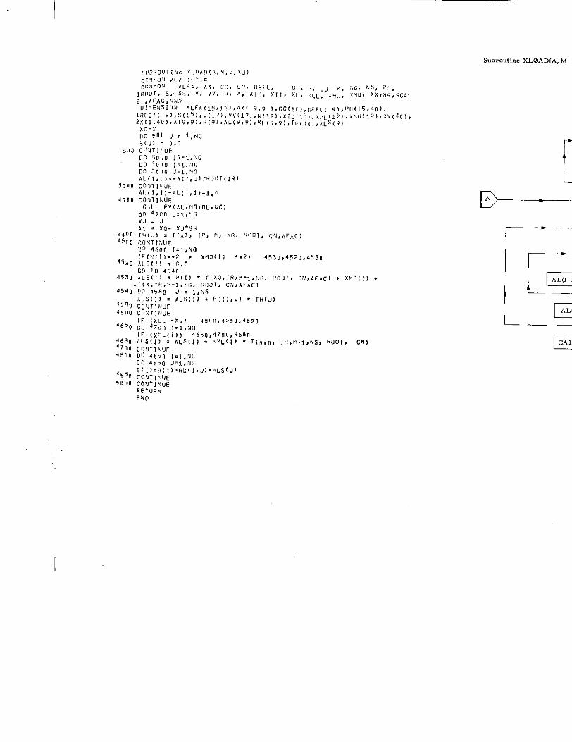
I
UJ=J
4650 DOIF
XMO{ll .
, CN)
Subronkir,exLOAD(A, M, B
=
~--
‘=AL(
L__
CALL
-144-
r
L—_–l
D-
t
L-J
—— -1
u
L—— —.—__
T—
ImcL&gHmSecuritv Classification
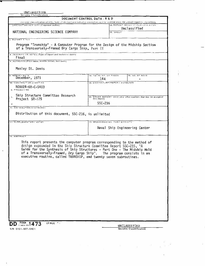
DOCUMENT CONTROL OATA R & O
Program “Tranship“ - A Computer Program for the Design of the Midship Sectionof a Transversely-Framed Dry Cargo Ship, Part II
Manley St. Denis
“~e~e~b;r, 19717.. ,0, . . . . ., “.. .s 7,. .0. OF .,,,
144c o.,..,,....,.,.. ,.. 0., .,. .,... s REPORT .“. s.., s,
NOO024-68-C-5403,.O, ,., .0, IShip Structure Committee ResearchProject SR-I75
,,.0,.,. ...0...0,8,(A.,.,,., ,,.”,..,.$ ,,., “,s, be 0,s,4”..
,., s r...,,,
[ SSC-216.,s,.,,”,,0..........
Distribution of this document, SSC-216, is Unlfmited
I Naval Ship Engineering Center
This report presents the computer program corresponding to the method ofdesign expounded in the Ship Structure Committee Report SSC-215, “AGuide for the Synthesis of Ship Structures - Part One - The Midship Holdof a Transversely-Framed, Dry Cargo Ship”. The program consists in anexecutive routine, cal1ed TRANSHIP, and twenty seven subroutines.
J
DD ,F.N’~,1473 (PAGE , UNCLASSIFIEDS/N 0101.607.6801 Securiw C1. ssific. ticm
.K,” .0 ...
LINK . .,. . s .,. . c
... . v,, .0, , w, ... . .,
,- .“.. a ---
—
I
—
StiIP RESEARCH COMMITTEE“iaritiineTransportation Research Board
‘,::ion,-1 Academy of Sciences-National Research Counci 1
“:): !i P Research Committee has technical cognizance of the inter-agency!

SSC-214,
SSC-215,
SSC-216>
SSC-217,
SSC-218,
SSC-219,
S5C-220,
SSC-221,
SSC-222 ,
SSC-223,
SSC-224 ,