Embed Size (px)
Citation preview

Program to Determine the Uniqueness of Three Forks Bench Reserves, Determine Optimal Well
Density in the Bakken Pool, and Optimize Bakken Production
Participant Kickoff Meeting
Dickinson, North Dakota August 15, 2013
© 2013 University of North Dakota Energy & Environmental Research Center.
John Harju Stan Wilson Associate Director for Research Manager, Resource Development, Northern Region
Energy & Environmental Research Center Continental Resources, Inc.

Introduction to the EERC

The International Center for Applied Energy Technology®
EERC
More than 254,000 square feet of state-of-the art laboratory, demonstration, and office space.

The International Center for Applied Energy Technology®
EERC Facilities
• The EERC possesses specialized facilities supporting engineering development of oilfield technology: – Chemistry/geology/emission laboratories – Mobile groundwater-sampling and remediation trailers – Liquid fuels production pilot-scale units – Multiple flexible-configuration furnaces to simulate
process unit operations – Rich-gas mixture generator and delivery system
EERC Oil- and Gas-Related
Capabilities

The International Center for Applied Energy Technology®
Center for Oil and Gas Oil- and gas-related research programs at the EERC address a broad range of topics relevant to the industry. • Three decades of practical laboratory, pilot-
scale, and field experience • Petroleum engineering expertise • Reservoir simulation capabilities • Geological characterization and resource
assessment • Process and mechanical engineering
– Design, fabrication, and operation • Combustion science and emission control • Coalbed methane and other unconventional
resource-related services • Soil and groundwater remediation • Water management

The International Center for Applied Energy Technology®
EERC Engineering Capabilities
• The EERC has dedicated staff to carry mechanical and chemical process designs from conception through fabrication and installation. – Multiskilled, matrixed engineering and science staff – Instrumentation and automation specialists – Process design group – Mechanical design group – Fabrication shop – Quality assurance/quality control personnel – Skilled technician/operator staff

The International Center for Applied Energy Technology®
EERC Laboratory Capabilities
• The EERC has a long history of laboratory testing and providing quality data in a timely manner.
– Analytical Research Laboratory (ARL) – Applied Geology Laboratory (AGL) – Gas Chromatography−Mass
Spectroscopy Laboratory (GC–MS) – Natural Materials Analytical Research
Laboratory (NMARL) – Computer modeling
• Specialized staff in each area. • Ever-expanding laboratory
capabilities.

Project Experience

The International Center for Applied Energy Technology®
Gas/Diesel-Powered Drilling Rig Project Overview
• Tested dual-fuel operation of a Caterpillar 3512 engine at the EERC using simulated rich gas. – Simulated rich-gas mixture produced using
bottled/tank-delivered industrial gases and EERC- fabricated gas-metering system.
– Monitored engine performance and emissions over a range of operating conditions and fuel mixtures.
• Field demonstration of gas-powered drilling operations using rich Bakken gas. – Two wells drilled using GTI Bi-Fuel system and
rich wellhead gas from nearby well. – Monitored engine performance, gaseous and
diesel fuel use, and emissions.

The International Center for Applied Energy Technology®
Benchmarking Proppants, Stimulation Methods, and Fracture Fluids
Proppants (ceramic vs. sand)
Fracture Fluid Types (diesel-based vs. water-based)
Stimulation Methods (sliding sleeves vs. plug and perf. vs. combo)
The International Center for Applied Energy Technology®
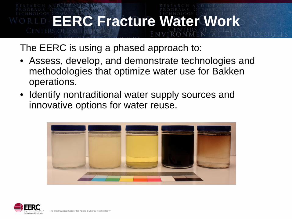
EERC Fracture Water Work The EERC is using a phased approach to: • Assess, develop, and demonstrate technologies and
methodologies that optimize water use for Bakken operations.
• Identify nontraditional water supply sources and innovative options for water reuse.

The International Center for Applied Energy Technology®
Bakken Water Opportunities Assessment
• Fracture flowback quantity and quality data collected from 89 wells, representing five producers.
• Because of low initial flowback water recovery rates and extremely high dissolved salt content, recycling of Bakken fracture flowback water is challenging.
• A pilot project using reverse osmosis (RO) to treat brackish groundwater was conducted.
• If access to freshwater sources is limited, RO treatment may be economically feasible.

Bakken Optimization Program Kickoff

The International Center for Applied Energy Technology®
Program Goals
• Maximize oil production from Bakken and Three Forks wells by employing an “all of the above” approach, including: – Advanced reservoir characterization. – Improved drilling/stimulation/completion/production
techniques and sequences. – Optimizing wellsite surface operations:
♦ Reduce costs ♦ Reduce development and operation impacts to
surrounding landowners ♦ Reduce demands on surrounding infrastructure and
water sources

The International Center for Applied Energy Technology®
Today’s Desired Outcomes
• Define consortium membership – Identify point of contact within each consortium
member organization • Develop prioritized list of projects
– Define specific project goals – Outline scope of work – Convey rough schedule

The International Center for Applied Energy Technology®
Program Description
• Phase I – Drilling 11 New Wells
• Phase II – Completions • Phase III – Reservoir
Engineering • Phase IV – Expansion
Applications via 3-D Seismic
• Phase V – Optimization of Wellsite Operations
• Pilot hole logs, core data, other data gathering from multiple wells to create a 3-D picture of what happens during and after the hydraulic fracture treatments in a multistage horizontal well. Continental will analyze this data set to: – Assess total resource available in the
second and third benches of the Three Forks Formation (separate and unique?).
– Confirm whether these benches are distinct and independent of the existing Middle Bakken.
– Predict areas of future sweet spots.
• Site logistics, waste management, on-site hydrocarbon utilization, water management, process optimization, and systems failure analysis with an eye on decreased environmental impact.

Hawkinson Project Summary
Stan Wilson Continental Resources, Inc. (CLR)

The International Center for Applied Energy Technology®
Lodgepole
Middle Bakken
Three Forks 1
TF2
TF4
TF3
Upper Shale
Lower Shale
Nisku
Charlotte 1-22H core photos (UV light) 308’ with 154’ of oil fluorescence
Bakken Petroleum System Redefined

The International Center for Applied Energy Technology®
Nor
th D
akot
a M
onta
na
25 Miles
Three Forks Isopach Map
CLR Core Location Other Lower TF Producer
160-acre Development 320-acre Development 160 320
320
320 160
320
TF 2,3
CLR Lower TF Producer TF
Angus 2-9H-2 2,107 Boepd TF
2,3
TF 2,3,4
TF 2,3,4
Ten-well coring program (2012)
Lower Three Forks exploration net CAPEX 2013
Productivity Project • Exploratory and appraisal: $123MM net cost (20 gross wells)
Pilot Density Projects • Three 320-acre density tests: $161MM net cost (34 gross wells)
• One 160-acre density test: $36MM net cost (13 gross wells)
Charlotte 2-22H Charlotte 3-22H
Stedman 2-24-H-2 Stedman 3-24-H-3
Barney 2-29-H
TF 2,3
TF 2
TF 2,3
CLR: Deep Three Forks Development

The International Center for Applied Energy Technology®
Upper Bakken Shale
Lower Bakken Shale
Middle Bakken
Three Forks
10,000’ below surface
Lodgepole
1320’
660’
1320’
660’
Multiple Fracture Stages
Past: Dual-Reservoir Development
Middle Bakken and Three Forks Wells on 320- acre Spacing

The International Center for Applied Energy Technology®
Dual-Zone Tests
Medicine Hole 14-27H and 2-27H wells Dunn Co., North Dakota

The International Center for Applied Energy Technology®
Conclusion from Dual-Zone Tests
• Neither zone can be adequately drained by completion in another zone.
• Limited connectivity will require wells in both zones to adequately harvest the reserves.
• Reserves from Middle Bakken and Three Forks are similar in magnitude.

The International Center for Applied Energy Technology®
660’ 660’ 1320’
Multiple Fracture Stages
Three Forks 1st Bench
Middle Bakken
Upper Bakken Shale
Lower Three Forks 2nd Bench
Lower Bakken Shale
Lower Three Forks 3rd Bench
Lower Three Forks 4th Bench
Middle Bakken
LODGEPOLE
NISKU
OVE
RPR
ESSU
RED
BAK
KEN
PET
RO
LEU
M S
YSTE
M
BAK
KEN
(BK
KN
)
TEC
HN
ICAL
LY R
ECO
VER
ABLE
AD
DIT
ION
AL IN
DIC
ATED
PAY
TH
REE
FO
RK
S (T
FS) Upper Three Forks
1st Bench
10,000’ Below
Surface
Three Forks 2nd Bench
Three Forks 4th Bench
Three Forks 3rd Bench
Current Development: Bakken and Three Forks

The International Center for Applied Energy Technology®
Charlotte 1280-acre unit
Producing zones today
Middle Bakken
2nd bench TF
3rd bench TF
WOC- MB, TF1, and TF2
First unit to have wellbores in four different zones
1280 acres Sec 15 and 22, T152N-R99W
1 MILE
LB
NISKU
MB
UB
TF1
TF2
TF4
TF3
LODGEPOLE
Charlotte 3-22H-3
Charlotte 2-22H
Charlotte 1-22H
310’
Producing
Charlotte 5-22H
Waiting on Completion
Charlotte 6-22H Charlotte 4-22H
Multiple Bench Testing

The International Center for Applied Energy Technology®
•1280-acre unit •45 ft net pay •8.4% porosity
• 6900 psi • 1,000 psi FBHP • 1,100 BFPD IP
Third-Party* Simulation Supports 160-Acre Spacing
• Eight wells per zone • First well recovers
1.0 MMBoe • Eight wells recover
5.6 MMBoe • Eight wells average
700 MBoe per well (70% of one-well scenario)
*Ryder Scott Co. LP, Reservoir Solutions, June-August 2012 /Vol. 15, No. 2.
Conclusions of third party simulation:

The International Center for Applied Energy Technology®
14 wells in 1280 unit (4 MB, 3 TF1, 4 TF2, 3 TF3)
1 MILE
?
200
‘ +
/-
1320’
1320’ interwell spacing between same-zone wells
660’ 68’
Monitor well as of 11/20/12 Established producing wells 10 frac’d wells microseismic program Wells frac’d from W, C & E Pads
5 8 3 13
1 10 2
4 7 11 14
6 9 12
Continental Resources Hawkinson – 22-27-147N-96W
1280-acre-Unit Full Development Project

The International Center for Applied Energy Technology®
Phases I–IV (Hawkinson Project)
• Define reservoir drainage of the MBK, TF1, TF2, and TF3
• Confirm whether these formations are distinct and separate from each other
• Determine the optimal number of fracture stages
• Determine appropriate well spacing required for most efficient reservoir drainage
• Increase spacing unit ultimate recovery
• Predict areas of future reservoir sweet spots

Bakken Wellsite Optimization Summary
John Harju
EERC

The International Center for Applied Energy Technology®
Phase V – Optimization of Wellsite Operations
• Consortium-based phase to help industry partners optimize oil and gas activities and improve the efficiency of operation.
• Project scope of work will be directed by the consortium (industry partners and Oil and Gas Research Council representative), with priority along, but not limited to, the following topic areas: – Site logistics
♦ Focused on evaluation of equipment siting and workflow at multioperation and/or multiwell locations
– Waste management ♦ Focused on improved means of handling drilling and production wastes
– Hydrocarbon utilization ♦ Focused on improving the production of oil, gas, or natural gas liquids (NGLs)
from wellsites – Water management
♦ Focused on technologies to limit demand for freshwater, decrease wastewater production, and reduce water/wastewater trucking to and from the wellsite
– Process optimization and systems analysis ♦ Focused on analysis of failures at the wellsite that affect production efficiency

The International Center for Applied Energy Technology®
This Work Addresses North Dakota Priorities
• Reduce flaring – Survey available technologies, assess their application, and demonstrate scaled
technologies • Reduce environmental impacts
– Explore surface operations that minimize truck traffic (resulting in decreased diesel emissions, decreased road damage, decreased maintenance costs, decreased road dust, and decreased incidence of spills)
– Investigate technologies to recycle wastewater and decrease freshwater demand – Minimize land use impacts (well pad footprints) – Address the NORM (naturally occurring radioactive material) waste issue with science and
outreach/education • Define Bakken system resources
– Gather new data with advanced tools to characterize the Middle Bakken and multiple benches of the Three Forks
• Maximize Bakken system recovery – Use new data to define two new undeveloped zones and to feed models that will help
predict optimum well spacing to maximize resource extraction – Reduce OPEX via focus on systems assessment toward holistic reservoir and operations
management • Public education and outreach

The International Center for Applied Energy Technology®
Budget
Sponsors Y1 Y2 Y3 Total North Dakota Industrial Commission (NDIC) Share – Cash
$3,000,000 $3,000,000 $2,000,000 $8,000,000
Industry Share – Cash $400,000 $400,000 $400,000 $1,200,000
CLR Share – In-Kind $40,989,233 $40,989,233 $24,051,534 $106,030,000
Total $44,389,233 $44,389,233 $26,451,534 $115,230,000
$6.26M CLR subcontract; $2.94M EERC
Commercial Partners • Continental Resources, Inc. (subcontract and in-kind
agreement in final negotiations) • Marathon Oil Company (Paid – Year 1) • Whiting Petroleum Corporation (Paid – Year 1) • Nuverra Environmental Solutions (Invoiced – Year 1)

The International Center for Applied Energy Technology®
Participation Framework
No. of Wells Fee ≥150 $100,000/year ˂150 $50,000/year Select Service Companies $25,000/year
The International Center for Applied Energy Technology®
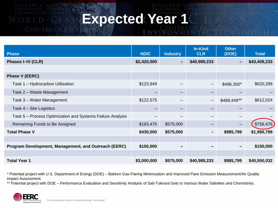
Expected Year 1
Phase
NDIC
Industry
In-Kind CLR
Other (DOE)
Total
Phases I–IV (CLR) $2,420,000 – $40,989,233 – $43,409,233
Phase V (EERC)
Task 1 – Hydrocarbon Utilization $123,949 – – $496,350* $620,299
Task 2 – Waste Management – – – – –
Task 3 – Water Management $122,575 – – $489,449** $612,024
Task 4 – Site Logistics – – – – –
Task 5 – Process Optimization and Systems Failure Analysis – – – – –
Remaining Funds to Be Assigned $183,476 $575,000 – – $758,476
Total Phase V $430,000 $575,000 – $985,799 $1,990,799
Program Development, Management, and Outreach (EERC) $150,000 – – – $150,000
Total Year 1 $3,000,000 $575,000 $40,989,233 $985,799 $45,550,032
* Potential project with U.S. Department of Energy (DOE) – Bakken Gas-Flaring Minimization and Improved Flare Emission Measurement/Air Quality Impact Assessment. ** Potential project with DOE – Performance Evaluation and Sensitivity Analysis of Salt-Tolerant Gels to Various Water Salinities and Chemistries.

The International Center for Applied Energy Technology®
Schedule

Seeding the Conversation – Development of Project Priorities
The International Center for Applied Energy Technology®
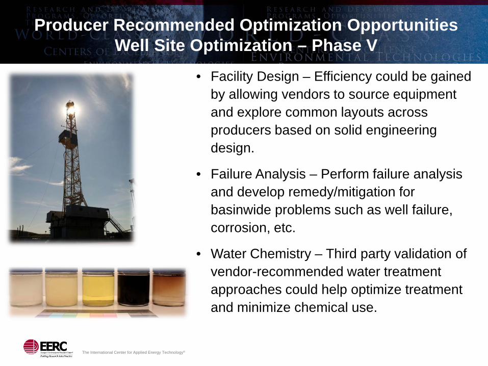
Producer Recommended Optimization Opportunities Well Site Optimization – Phase V
• Facility Design – Efficiency could be gained by allowing vendors to source equipment and explore common layouts across producers based on solid engineering design.
• Failure Analysis – Perform failure analysis and develop remedy/mitigation for basinwide problems such as well failure, corrosion, etc.
• Water Chemistry – Third party validation of vendor-recommended water treatment approaches could help optimize treatment and minimize chemical use.

The International Center for Applied Energy Technology®
Producer Recommended Optimization Opportunities Well Site Optimization – Phase V (continued)
• Waste Management – Investigate options for drill cuttings disposal including viability of disposal via injection well, land farming, and others.
• Emission Testing – Third party validation of equipment designed to reduce emissions including engineered flares, bifuel, exhaust gas treatment.
• Fracture Modeling – Desire for data showing the extent of fractures and impacts to formations of interest.
• Pressure Maintenance/Enhanced Oil Recovery (EOR) – Investigation into the effectiveness of different strategies to enhance oil recovery in the Bakken.

The International Center for Applied Energy Technology®
Additional Optimization Project Concepts Well Site Optimization – Phase V (continued)
• Site Logistics – Evaluate design, layout, and workflow to improve efficiency at
simultaneous operation sites • Waste Management
– Investigate alternative options for waste (trash, packaging, sewage) – Process drill cuttings (hydrocarbon recovery or destruction) – NORM waste inventory or regulation science
• Hydrocarbon Utilization – Evaluate technologies that use wellhead gas for drilling, completions, and
production activities – Evaluate small-scale NGL recovery viability, define threshold efficiency
• Water Management – Water supply and disposal options; assess quantity, quality, and capacity – Develop wastewater treatment demonstration facility to enable technology
demonstration/validation • Process Optimization and Systems Failure Analysis
– Investigate systems integration opportunities

A Potential DOE Project – A Look at Flaring Emissions,
Flaring Minimization on Already Connected Wells, and
Gathering Network Modeling

The International Center for Applied Energy Technology®
Flaring Minimization, Improved Emission Measurement, and Air Quality Impact Assessment
• Proposal submitted in response to DOE solicitation
• Total amount requested: $1,175,307 – DOE funds: $940,397 – Bakken Optimization
Program (NDIC): $234,910 • Proposed start date:
October 1, 2013 • Project duration: 30 months • Project participants: ONEOK

The International Center for Applied Energy Technology®
Project Goals
• Define new methodologies for wellsite flare emission measurement. – Must be developed to provide accurate
emission data in several pollutant categories if regional air quality models are to be improved.
• Assess technical requirements and economics of various operational methods to limit gas flaring at wells already connected to gas-gathering networks.
• Develop modeling tools to help industry predict dynamics of adding new wells to existing gas-gathering infrastructure.

Another Potential DOE Project – Salt-Tolerant Gels

The International Center for Applied Energy Technology®
Performance Evaluation and Sensitivity Analysis of Salt-Tolerant Gels
• Proposal submitted in response to DOE solicitation
• Total amount requested: $1,059,849 – DOE funds: $847,726 – Bakken Optimization
Program (NDIC): $212,123 • Proposed start date:
October 1, 2013 • Project duration: 30 months • Potential collaborators: Baker
Hughes and Schlumberger

The International Center for Applied Energy Technology®
Project Goals
• To provide an objective, systematic performance assessment of various salt-tolerant gels utilizing nonpotable water resources from the Williston Basin.
• To estimate the economic and environmental benefits of this approach. – Reduced truck traffic
and associated impacts – Lower water acquisition
and disposal costs – Increased flexibility for
industry
The International Center for Applied Energy Technology®
Contact Information
Energy & Environmental Research Center University of North Dakota 15 North 23rd Street, Stop 9018 Grand Forks, ND 58202-9018 World Wide Web: www.undeerc.org Telephone No.: (701) 777-5157 Fax No.: (701) 777-5181 John Harju, Associate Director for Research E-Mail: [email protected]
The International Center for Applied Energy Technology®
Action Items
• Define consortium membership
• Identify point of contact within each consortium member organization
• Develop prioritized list of projects – Project 1:
– Project 2:
– Project 3:

Backup Slides

The International Center for Applied Energy Technology®
Applied Geology Lab Equipment
• Optical profilometer • +20-ton universal compression frame • Flexible-wall permeameter • Hoek-style triaxial and core-flood
cells • Scanning electron microscopy (SEM) • Supergamma spectrometer • GC–MS • Thermal dilatometer • Ion chromatographer • X-ray diffraction (XRD) and x-ray
fluorescence (XRF) • Helium porosimeter • Petrographic microscope

The International Center for Applied Energy Technology®
Geomechanical Work
• Bakken peak strength
consistently fell in the area of 45,000 psi, with minor fluctuations likely tied to microstructure and facies.
• Three Forks geomechanical strength tended to be less predictable.
• In general, for both Bakken and Three Forks: – Structureless and weakly
laminated samples yielded higher peak strength.
– Strongly laminated and chaotically bedded samples were weaker.
>

The International Center for Applied Energy Technology®
Proppant Embedment and Penetration Testing

The International Center for Applied Energy Technology®
Modeling and Simulation Modeling Capabilities • Log and well test normalization and interpretation • Petrophysical analysis • Property modeling, including facies modeling using multiple-point
statistics • Fluid modeling and equation-of-state calibration • Numerical simulation, including history matching and prediction

The International Center for Applied Energy Technology®
Dickinson Lodgepole Mounds

The International Center for Applied Energy Technology®
Soil Gas Field Analyses
Agilent 490 Micro Quad GC (field laboratory)
RAE Systems PGM-54 Handheld Multigas Analyzer
CO2, total VOCs, O2, H2S CO2, individual VOCs, N2, O2, H2, H2S
– Near active wells and between active wells (interspaced)
– Near plugged and abandoned (P&A) wells (three-spot)

The International Center for Applied Energy Technology®
Soil Remediation
• Complete removal of amines after 200 days of operation.
• Other parameters were below regulatory limits after 300 days of operation.
• Joint industry–government-funded programs.
• Remediation of soils impacted by hydrocarbons and gas-processing constituents.

The International Center for Applied Energy Technology®
Innovative Management of Produced Water and Fracture Fluids
Freeze–Thaw Evaporation (FTE®) facility at Jonah Gas Field, Wyoming. Joint industry–government-funded project.
Produced brine is suitable (ideal) for use in deep (>2200 ft) drilling applications. Treated water is suitable for use in surface and near-surface (<2200 ft) drilling applications. In some states, treated water can be used for stock-watering and/or irrigation.

The International Center for Applied Energy Technology®
• Field testing of gas-powered drilling operations – GTI Bi-Fuel system was operated August–September. – The EERC installed a data acquisition system to enable real-
time continuous monitoring and logging of engine performance; provided on-site technical support throughout field test.
– Data analysis and reporting are ongoing; final report will be submitted to NDIC in late 2012.
– Demonstrated efficient, economical use of wellhead gas; vendor claimed savings of >$3000/day.
Rich-Gas Test Results • Simulated rich-gas tests at the EERC
– Tests completed June 2012; report summarizing results submitted to North Dakota Industrial Commission (NDIC).
– Diesel replacement rates of greater than 40% can be achieved, and the GTI Bi-Fuel system can control fuel use to ensure safe engine operation.
– Matching engine load with diesel replacement rate is important to prevent poor fuel utilization and to minimize unburned hydrocarbon emissions.

![Grand Forks herald (Grand Forks, N.D.). 1917-12-01 [p ]. · Grand Forks herald (Grand Forks, N.D.). 1917-12-01 [p ]](https://img.pdfslide.us/doc/110x75/5e9b4cea4169af71771cee98/grand-forks-herald-grand-forks-nd-1917-12-01-p-grand-forks-herald-grand.jpg)