Embed Size (px)
Citation preview
Program 60-5406—Crowned and Straight External Involute Gear Compressive Stress
Introduction The ideal uniform load distribution along gear teeth is seldom obtained, because of many factors that include dimensional errors and elasticity in the gear teeth themselves and in supporting elements such as shafts, bearings and housings. Even if parallelism between the teeth is achieved at a specific load condition it cannot be maintained if the load changes because of deflections in the supporting structure. Thermal effects, centrifugal deflections and external shaft bending moments also play a role in causing face mismatch. Of course, any deviation from a perfectly parallel condition between mating teeth causes a non-uniform load distribution along the teeth. The usual design procedure for assessing the compressive stress on teeth with no longitudinal (lead) modification is to use the Hertz equations for parallel cylinders and then to apply a multiplier based on the face mismatch to obtain the actual compressive stress in the misaligned position. (The use of the parallel cylinder equations is not quite correct as the radii of curvature on involute teeth change across the load “footprint” when under load.) Standards of the American Gear Manufacturers Association provide a multiplier (designated Face Load Distribution Factor, or FLD Factor, or Cmf in the TK Solver model) to account for the increase in compressive stress due to face mismatch above the stress calculated with the Hertz equations. The FLD Factor is defined as the peak load intensity divided by the average load intensity across the face width of the gears. FLD Factor determined by the “analytical method” in the standard assumes a linear load distribution across the teeth and is based on the stiffness of the teeth along with the load (for helical gears the effect of the profile contact ratio along the line of contact in the transverse plane is included.) The stress distribution is semi-cylindrical. When the teeth are misaligned the contact zone is no longer a rectangle. The stress distribution is then semi-conical. The multiplier, FLD Factor, gives us the stress at the wide end of the trapezoidal or triangular load pattern. When we have two surfaces in contact with curvature in all directions (crowned teeth) it is necessary to use the Hertz equations for elliptical contacts instead of the parallel cylinder equations. In this case the zone of contact is assumed to be an ellipse with the long dimension along the tooth (direction of least curvature) and the short dimension in the normal direction of the involute profile. The dimensions of the ellipse are determined by the load, the radius of the crown (or crowns) and the radii of the involute profiles for a given combination of materials. The stress distribution is a semi-ellipsoid. If the contact ellipse (under load) is cut off by the end(s) of the teeth (spur) or by the start or end of the contact zone (helicals) the stress distribution is assumed to be a truncated ellipsoid cut by a plane (or planes) parallel to the minor axis of the contact ellipse. The stress and the minor dimension of the contact pattern
UTS Integrated Gear Software
2
are then adjusted to keep the same volume for the truncated ellipsoid and the full contact ellipsoid. (The numerical eccentricities of the elliptical sections are held constant.) In any case, no contact is assumed until the center of the ellipsoid is in the contact zone. This model incorporates both conditions and uses the parallel cylinder equations for straight teeth and the elliptical contact equations for teeth with crown on one or both gears. When stress for gears with straight teeth is being calculated, the FLD Factor will also be calculated (or must be input). The stress will be calculated by the methods from reference 3 for straight line contacts. When stress for gears with crowned teeth is being calculated, an equivalent FLD Factor will also be calculated at many points along the line of action which will give the same stress on straight teeth. If the gears are spur or LCR helicals the equivalent FLD Factor will be selected for the lowest point of single tooth contact on the pinion. If the gears are full helicals the equivalent FLD Factor will be selected for the mean diameter of the working depth. If desired, the equivalent FLD Factor can be used with AGMA standards to obtain equivalent data for the crowned gears. (See also UTS Program 540.) The stress will be calculated by the methods from reference 3 for elliptical contacts. The equations from reference 3 are used for both straight and crowned contacts to obtain a valid ratio for the calculation of the equivalent FLD Factor. The calculated compressive stress will not be the same as AGMA for helicals as load sharing between the teeth is handled differently. For helicals reference 3 uses the equivalent spur gear to obtain loads and tooth curvatures. The model uses actual dimensions and loads. The major axis of the contact ellipse (or rectangle) is not parallel to the axis. The equivalent face width is considered to be the actual face divided by the cosine of the helix angle. For comparison of the straight and crowned contacts it is, of course, necessary to use the same calculation method for both. The model will save the compressive stress and contact pattern dimensions from the previous straight tooth calculation if crown is being run or the previous crown stress and dimensions if straight is being run. To save the previous stress, click off the checkbox labeled “Blank previous stress” in the data input form. The center of the crown is assumed to be in the center of the face width. (If the teeth are chamfered from the root to the tip at the ends use the mean value for the face widths.) If the initial (no load) contact of the crowned profile(s) falls off the end of the tooth due to the lead mismatch the model will not be solved and the note “INITIAL TOOTH CONTACT OFF END” will appear.
60-5406—Crowned and Straight External Involute Gear Compressive Stress
3
Spur Gears If the contact ellipse (under load) falls off one or both ends of the gear tooth the calculated stress will be increased due to the reduced contact pattern. “CROWNED TOOTH CONTACT OFF END” will appear if the ellipse is off one end of the tooth. If the ellipse falls off both ends of the tooth the comment “CROWN CONTACT OFF BOTH ENDS” will appear. Helical Gears The contact ellipse is always truncated at the start and end of the contact zone. It is assumed that the initial contact of the CROWN is closest to the start of the contact zone. (In many cases the ellipse is truncated for the entire mesh cycle.) The model calculates the compressive stress on the teeth and the contact pattern dimensions from the start of active profile to the tooth tip. (This, of course, includes the entire zone of action.) It is assumed that there is no undercut that reduces the length of action. (See UTS Program 500 or TK model 60-400.) The pinion roll angle from the start of active profile to the tip is divided into a specified number of intervals and a stress calculation is done at each interval. (The “Number of Pinion Roll Angle Calculation Intervals” is defaulted to 36 if you do not make an entry.) Two calculations are made at points where the tooth load may make a “step” change. The roll angles at various load points are given at the bottom of the report. The load is determined by the load due to driving torque adjusted by the AGMA “Application Factor” and the “Dynamic Factor” (labeled Ca and Cv, respectively, in the TK Solver model). The “Application Factor” may be obtained from AGMA standards. It is defaulted to one. The “Dynamic Factor” is calculated in accordance with AGMA standards if a value is not input. The portion of the total tooth load carried at each point on the tooth is determined by the load schedule selected. If the “Adjust Tooth Load per AGMA 217” checkbox is clicked off then 100% of the load will be applied to all points on the tooth. This would be a condition where the combination of tooth errors and load deflection prevent sharing of load between teeth. (See AGMA standards or UTS Program 500 and UTS TK Model 60-1111 for guidance on load sharing and base pitch error.) If the checkbox is checked, then the load schedule from AGMA 217 will be applied. (Gears with a profile contact ratio above 2 require a consideration of load sharing between 2 and 3 teeth and are not included in this model.)
UTS Integrated Gear Software
4
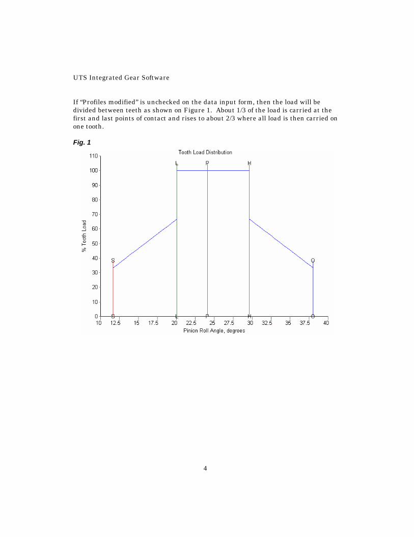
If “Profiles modified” is unchecked on the data input form, then the load will be divided between teeth as shown on Figure 1. About 1/3 of the load is carried at the first and last points of contact and rises to about 2/3 where all load is then carried on one tooth. Fig. 1
60-5406—Crowned and Straight External Involute Gear Compressive Stress
5
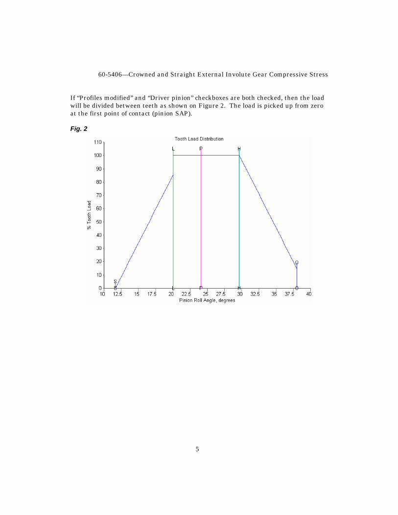
If “Profiles modified” and “Driver pinion” checkboxes are both checked, then the load will be divided between teeth as shown on Figure 2. The load is picked up from zero at the first point of contact (pinion SAP). Fig. 2
UTS Integrated Gear Software
6
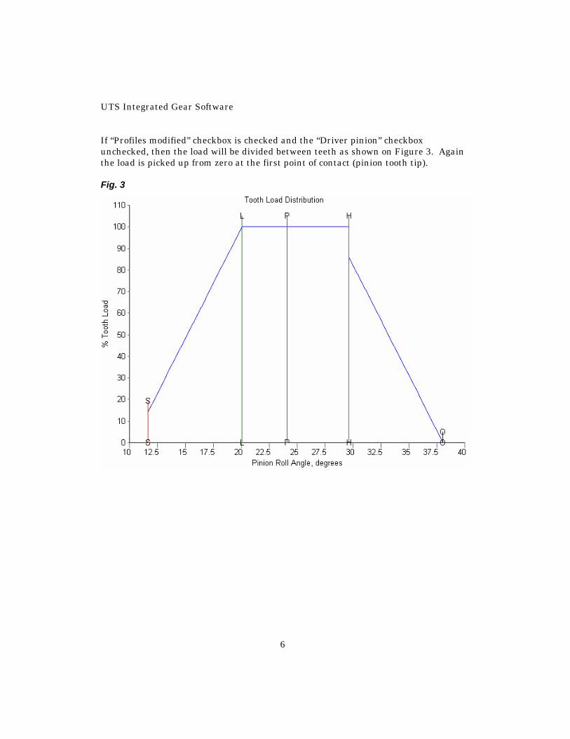
If “Profiles modified” checkbox is checked and the “Driver pinion” checkbox unchecked, then the load will be divided between teeth as shown on Figure 3. Again the load is picked up from zero at the first point of contact (pinion tooth tip). Fig. 3
60-5406—Crowned and Straight External Involute Gear Compressive Stress
7
Figures 1, 2 and 3 are displays of the plot “load” in the TK Solver model. To view any of the plots, toggle to the TK model and select the plot from the Object Bar plot list or from the Plot Sheet. To obtain the load sharing schedules specified by AGMA 217 the amount and location of the tip relief modification must be carefully applied. See UTS Model 60-1111 for suggested values for various gear accuracy classes and loading.
UTS Integrated Gear Software
8
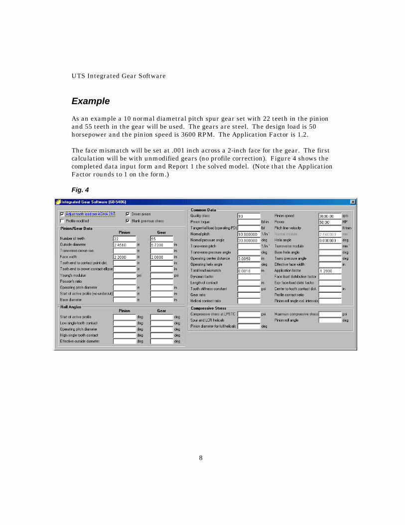
Example As an example a 10 normal diametral pitch spur gear set with 22 teeth in the pinion and 55 teeth in the gear will be used. The gears are steel. The design load is 50 horsepower and the pinion speed is 3600 RPM. The Application Factor is 1.2. The face mismatch will be set at .001 inch across a 2-inch face for the gear. The first calculation will be with unmodified gears (no profile correction). Figure 4 shows the completed data input form and Report 1 the solved model. (Note that the Application Factor rounds to 1 on the form.) Fig. 4
60-5406—Crowned and Straight External Involute Gear Compressive Stress
9
Report 1
Model Title : Program 60-5406 Unit System: US
MESSAGE FIELD
Message Field STRAIGHT
m2 TEETH
m3 PROF NOT
m4 MODIFIED
COMMON DATA
Adjust Tooth Load per AGMA 217? y
Profiles Modified? n
Driver: p
Quality Class 10
PINION Speed 3600.00 rpm
PINION Torque 875.3472 lbf-in
Power 50.00 HP
Tangential Load at Operating PD 788.4387 lbf
Pitch Line Velocity 2092.7 ft/min
Normal pitch 10.000000 1/in `
Normal Module 2.540000 mm `
Normal Pressure Angle 20.000000 deg
Helix Angle 0.000000 deg
Transverse Pitch 10.000000 1/in `
UTS Integrated Gear Software
10
Model Title : Program 60-5406 Unit System: US Transverse Module 2.540000 mm `
Transverse Pressure Angle 20.000000 deg
Base Helix Angle 0.0000 deg
Operating Center Distance 3.8858 in
Operating Trans Pressure Angle 21.4032 deg
Operating Helix Angle 0.0000 deg
Effective Face Width 2.0000 in
Total Lead Mismatch Between Teeth 0.0010 in
Application Factor 1.2000
Dynamic Factor 0.841
Face Load Distribution Factor 3.046
Length of Contact, Straight Tooth 1.3132 in
Equiv Face Load Distribution NA
Tooth Stiffness Constant 1829000.000 psi
Distance from Center of Tooth to Initial 1.0000 in Tooth Contact
Gear Ratio 2.5000
Profile Contact Ratio (Theoretical) 1.5776
Helical Contact Ratio (Theoretical) 0.0000
PINION DATA
Number of Teeth 22
Outside Diameter 2.4510 in
Transverse Crown Rise 0.000 in
Face Width 2.2000 in
Tooth End to Initial Contact Point 0.1000 in
60-5406—Crowned and Straight External Involute Gear Compressive Stress
11
Model Title : Program 60-5406 Unit System: US Tooth End to Crown Contact Ellipse with in Crown Centered On Tooth
Young's Modulus 30000000.000 psi
Poisson's Ratio 0.300
Operating Pitch Diameter 2.2205 in
Start of Active Profile-No Undercut 2.1029 in
Base Diameter 2.0673 in
GEAR DATA
Number of Teeth 55
Outside Diameter 5.7200 in
Transverse Crown Rise 0.000 in
Face Width 2.0000 in
Tooth End to Initial Contact Point 0.0000 in
Tooth End to Crown Contact Ellipse in
Young's Modulus 30000000.000 psi
Poisson's Ratio 0.300
Operating Pitch Diameter 5.5511 in
Start of Active Profile-No Undercut 5.3870 in
Base Diameter 5.1683 in
Number of Pinion Roll Angle 72
COMPRESSIVE STRESS
Compressive Stress at LPSTC for 189041 psi
Spur and LCR Helicals or at Mean LPSTC
Pinion Diameter for Full Helicals Includes 20.127 deg Ca,Cv,Cmf (Straight Teeth)
UTS Integrated Gear Software
12
Model Title : Program 60-5406 Unit System: US Maximum Compressive Stress 189041 psi
Pinion Roll Angle at Max Comp Stress 20.127 deg
ROLL ANGLES PINION
Start of Active Profile 10.675 deg
Low Single Tooth Contact (LPSTC) 20.127 deg
Pitch Diameter, Operating 22.458 deg
High Single Tooth Contact 27.039 deg
Outside Diameter, Effective 36.491 deg
ROLL ANGLES GEAR
Start of Active Profile 16.844 deg
Low Single Tooth Contact (LPSTC) 20.625 deg
Pitch Diameter, Operating 22.458 deg
High Single Tooth Contact 23.390 deg
Outside Diameter, Effective 27.171 deg
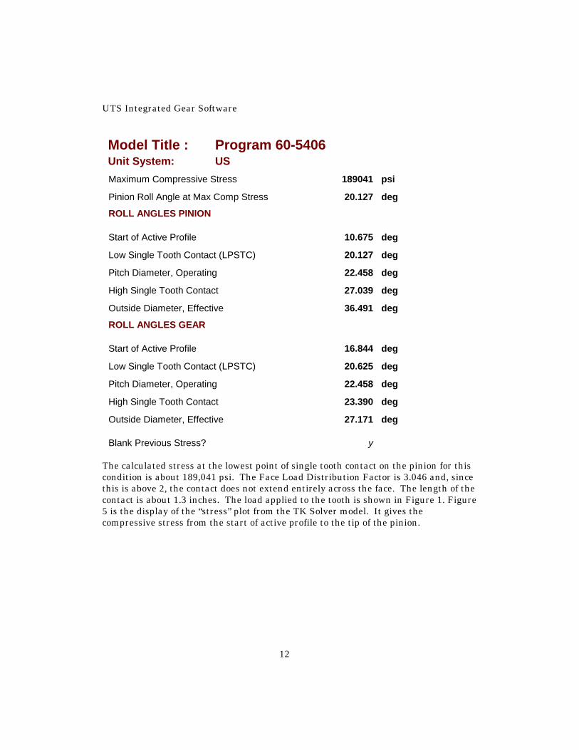
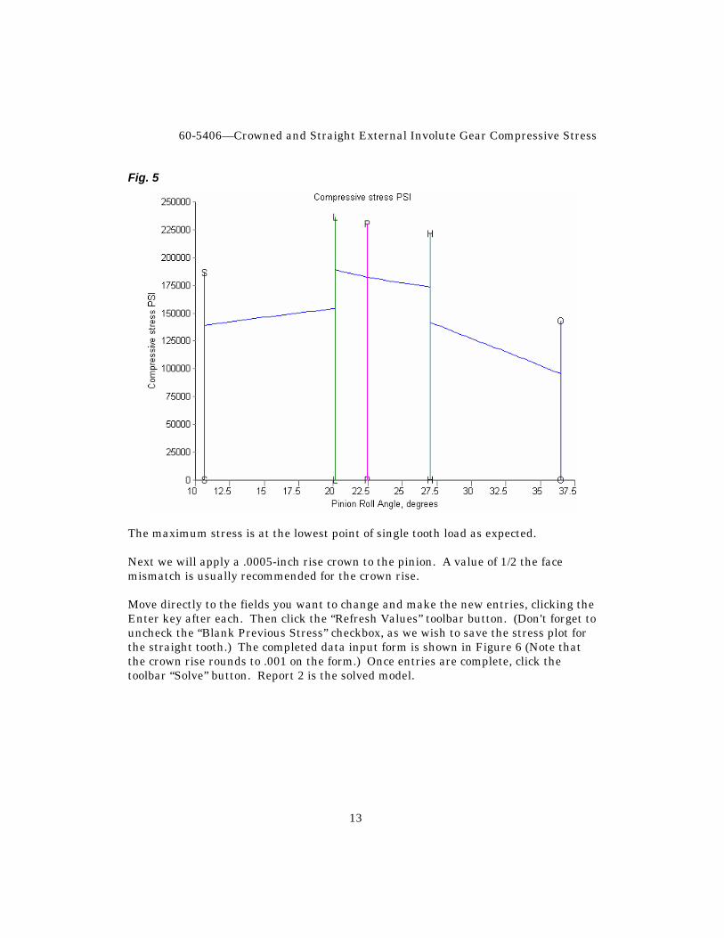
Blank Previous Stress? y The calculated stress at the lowest point of single tooth contact on the pinion for this condition is about 189,041 psi. The Face Load Distribution Factor is 3.046 and, since this is above 2, the contact does not extend entirely across the face. The length of the contact is about 1.3 inches. The load applied to the tooth is shown in Figure 1. Figure 5 is the display of the “stress” plot from the TK Solver model. It gives the compressive stress from the start of active profile to the tip of the pinion.
60-5406—Crowned and Straight External Involute Gear Compressive Stress
13
Fig. 5
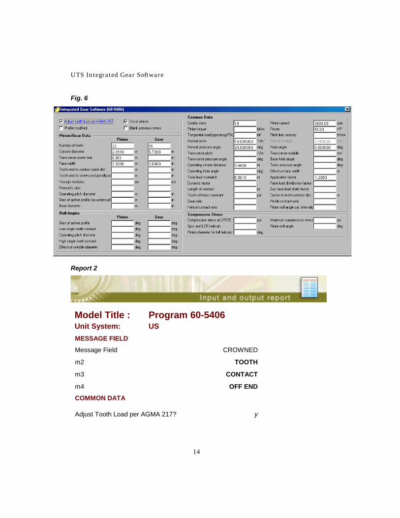
The maximum stress is at the lowest point of single tooth load as expected. Next we will apply a .0005-inch rise crown to the pinion. A value of 1/2 the face mismatch is usually recommended for the crown rise. Move directly to the fields you want to change and make the new entries, clicking the Enter key after each. Then click the “Refresh Values” toolbar button. (Don't forget to uncheck the “Blank Previous Stress” checkbox, as we wish to save the stress plot for the straight tooth.) The completed data input form is shown in Figure 6 (Note that the crown rise rounds to .001 on the form.) Once entries are complete, click the toolbar “Solve” button. Report 2 is the solved model.
UTS Integrated Gear Software
14
Fig. 6
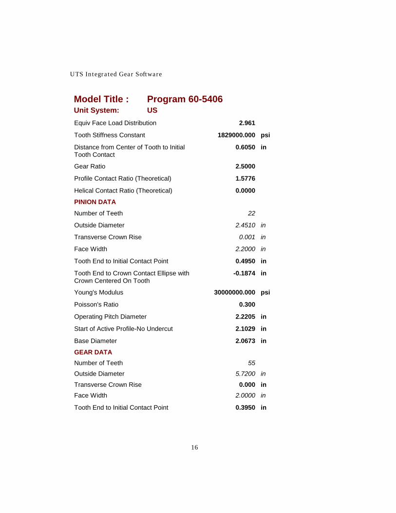
Report 2
Model Title : Program 60-5406 Unit System: US MESSAGE FIELD
Message Field CROWNED
m2 TOOTH
m3 CONTACT
m4 OFF END
COMMON DATA
Adjust Tooth Load per AGMA 217? y

60-5406—Crowned and Straight External Involute Gear Compressive Stress
15
Model Title : Program 60-5406 Unit System: US Profiles Modified? n
Driver: p
Quality Class 10
PINION Speed 3600.00 rpm
PINION Torque 875.3472 lbf-in
Power 50.00 HP
Tangential Load at Operating PD 788.4387 lbf
Pitch Line Velocity 2092.7 ft/min
Normal pitch 10.000000 1/in `
Normal Module 2.540000 mm `
Normal Pressure Angle 20.000000 deg
Helix Angle 0.000000 deg
Transverse Pitch 10.000000 1/in `
Transverse Module 2.540000 mm `
Transverse Pressure Angle 20.000000 deg
Base Helix Angle 0.0000 deg
Operating Center Distance 3.8858 in
Operating Trans Pressure Angle 21.4032 deg
Operating Helix Angle 0.0000 deg
Effective Face Width 2.0000 in
Total Lead Mismatch Between Teeth 0.0010 in
Application Factor 1.2000
Dynamic Factor 0.841
Face Load Distribution Factor NA
Length of Contact, Straight Tooth NA in
UTS Integrated Gear Software
16
Model Title : Program 60-5406 Unit System: US Equiv Face Load Distribution 2.961
Tooth Stiffness Constant 1829000.000 psi
Distance from Center of Tooth to Initial 0.6050 in Tooth Contact
Gear Ratio 2.5000
Profile Contact Ratio (Theoretical) 1.5776
Helical Contact Ratio (Theoretical) 0.0000
PINION DATA
Number of Teeth 22
Outside Diameter 2.4510 in
Transverse Crown Rise 0.001 in
Face Width 2.2000 in
Tooth End to Initial Contact Point 0.4950 in
Tooth End to Crown Contact Ellipse with -0.1874 in Crown Centered On Tooth
Young's Modulus 30000000.000 psi
Poisson's Ratio 0.300
Operating Pitch Diameter 2.2205 in
Start of Active Profile-No Undercut 2.1029 in
Base Diameter 2.0673 in
GEAR DATA Number of Teeth 55
Outside Diameter 5.7200 in
Transverse Crown Rise 0.000 in Face Width 2.0000 in
Tooth End to Initial Contact Point 0.3950 in
60-5406—Crowned and Straight External Involute Gear Compressive Stress
17
Model Title : Program 60-5406 Unit System: US Tooth End to Crown Contact Ellipse -0.2874 in Young's Modulus 30000000.000 psi Poisson's Ratio 0.300 Operating Pitch Diameter 5.5511 in Start of Active Profile-No Undercut 5.3870 in Base Diameter 5.1683 in Number of Pinion Roll Angle 72
COMPRESSIVE STRESS Compressive Stress at LPSTC for 186387 psi Spur and LCR Helicals or at Mean LPSTC Pinion Diameter for Full Helicals Includes 20.127 deg Ca,Cv,Cmf (Straight Teeth)
Maximum Compressive Stress 186387 psi Pinion Roll Angle at Max Comp Stress 20.127 deg
ROLL ANGLES PINION Start of Active Profile 10.675 deg Low Single Tooth Contact (LPSTC) 20.127 deg Pitch Diameter, Operating 22.458 deg High Single Tooth Contact 27.039 deg Outside Diameter, Effective 36.491 deg
ROLL ANGLES GEAR Start of Active Profile 16.844 deg Low Single Tooth Contact (LPSTC) 20.625 deg Pitch Diameter, Operating 22.458 deg High Single Tooth Contact 23.390 deg Outside Diameter, Effective 27.171 deg Blank Previous Stress? n
UTS Integrated Gear Software
18
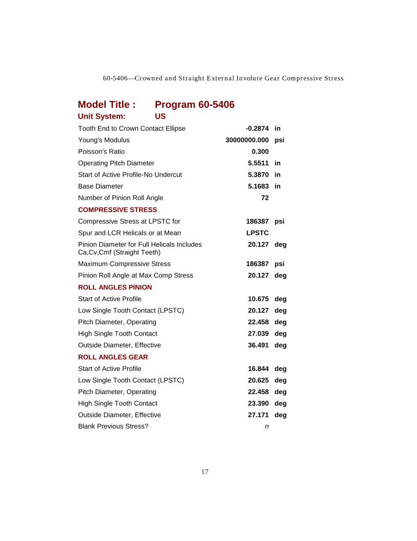
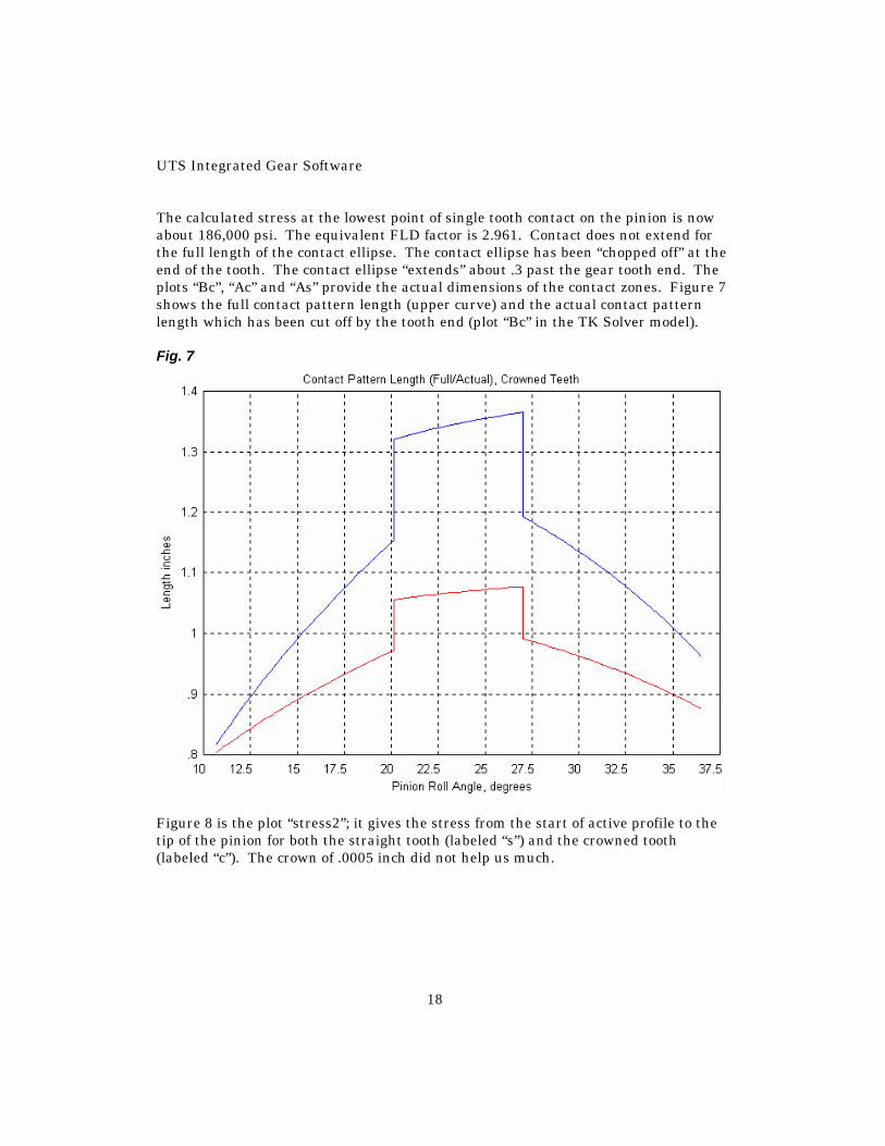
The calculated stress at the lowest point of single tooth contact on the pinion is now about 186,000 psi. The equivalent FLD factor is 2.961. Contact does not extend for the full length of the contact ellipse. The contact ellipse has been “chopped off” at the end of the tooth. The contact ellipse “extends” about .3 past the gear tooth end. The plots “Bc”, “Ac” and “As” provide the actual dimensions of the contact zones. Figure 7 shows the full contact pattern length (upper curve) and the actual contact pattern length which has been cut off by the tooth end (plot “Bc” in the TK Solver model). Fig. 7
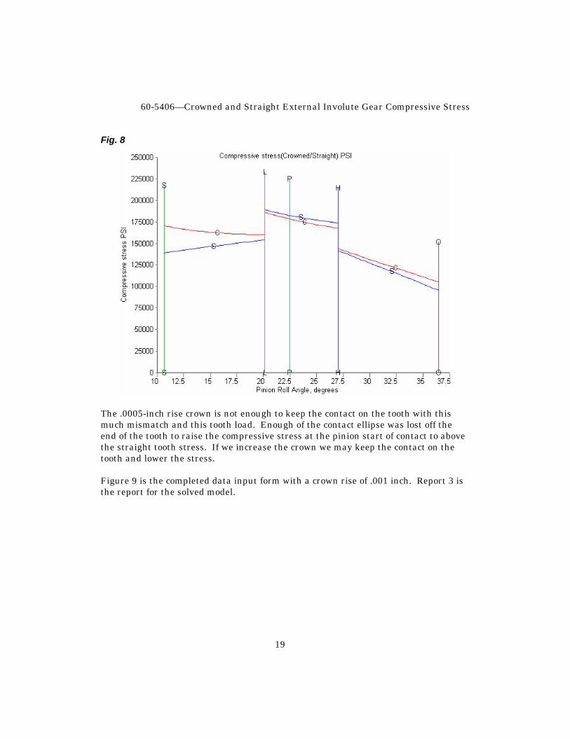
Figure 8 is the plot “stress2”; it gives the stress from the start of active profile to the tip of the pinion for both the straight tooth (labeled “s”) and the crowned tooth (labeled “c”). The crown of .0005 inch did not help us much.
60-5406—Crowned and Straight External Involute Gear Compressive Stress
19
Fig. 8
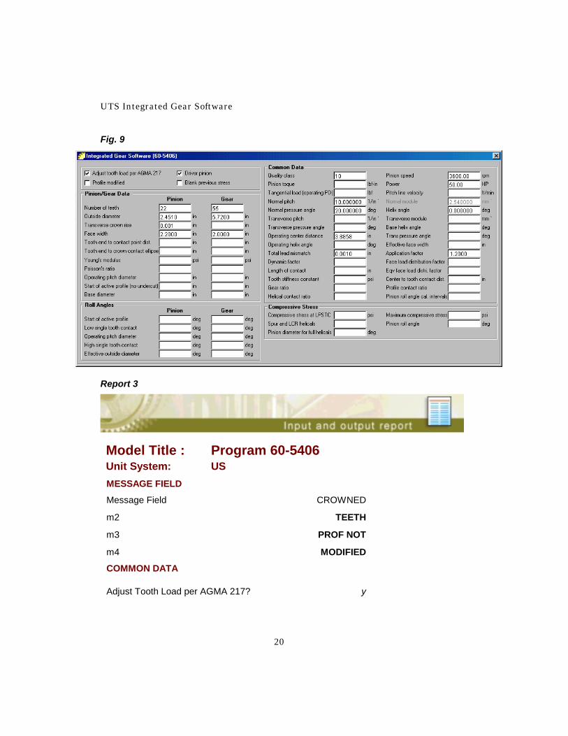
The .0005-inch rise crown is not enough to keep the contact on the tooth with this much mismatch and this tooth load. Enough of the contact ellipse was lost off the end of the tooth to raise the compressive stress at the pinion start of contact to above the straight tooth stress. If we increase the crown we may keep the contact on the tooth and lower the stress. Figure 9 is the completed data input form with a crown rise of .001 inch. Report 3 is the report for the solved model.
UTS Integrated Gear Software
20
Fig. 9
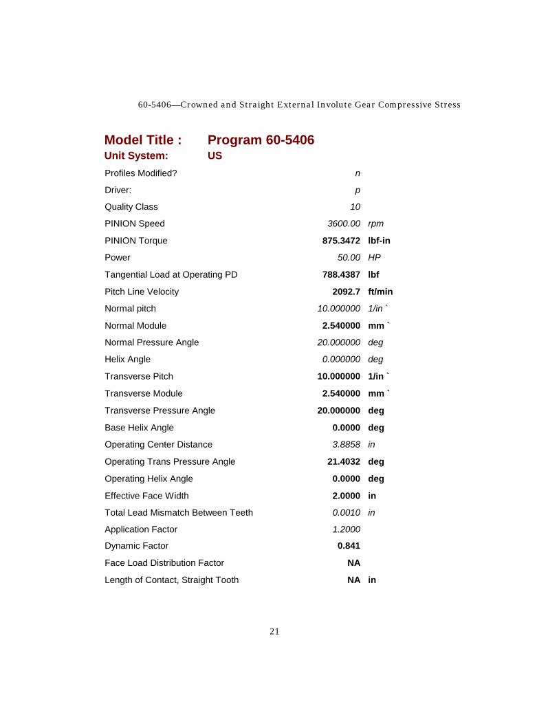
Report 3
Model Title : Program 60-5406 Unit System: US MESSAGE FIELD
Message Field CROWNED
m2 TEETH
m3 PROF NOT
m4 MODIFIED
COMMON DATA
Adjust Tooth Load per AGMA 217? y
60-5406—Crowned and Straight External Involute Gear Compressive Stress
21
Model Title : Program 60-5406 Unit System: US Profiles Modified? n
Driver: p
Quality Class 10
PINION Speed 3600.00 rpm
PINION Torque 875.3472 lbf-in
Power 50.00 HP
Tangential Load at Operating PD 788.4387 lbf
Pitch Line Velocity 2092.7 ft/min
Normal pitch 10.000000 1/in `
Normal Module 2.540000 mm `
Normal Pressure Angle 20.000000 deg
Helix Angle 0.000000 deg
Transverse Pitch 10.000000 1/in `
Transverse Module 2.540000 mm `
Transverse Pressure Angle 20.000000 deg
Base Helix Angle 0.0000 deg
Operating Center Distance 3.8858 in
Operating Trans Pressure Angle 21.4032 deg
Operating Helix Angle 0.0000 deg
Effective Face Width 2.0000 in
Total Lead Mismatch Between Teeth 0.0010 in
Application Factor 1.2000
Dynamic Factor 0.841
Face Load Distribution Factor NA
Length of Contact, Straight Tooth NA in

UTS Integrated Gear Software
22
Model Title : Program 60-5406 Unit System: US Equiv Face Load Distribution 2.875
Tooth Stiffness Constant 1829000.000 psi
Distance from Center of Tooth to Initial 0.3025 in Tooth Contact
Gear Ratio 2.5000
Profile Contact Ratio (Theoretical) 1.5776
Helical Contact Ratio (Theoretical) 0.0000
PINION DATA
Number of Teeth 22
Outside Diameter 2.4510 in
Transverse Crown Rise 0.001 in
Face Width 2.2000 in
Tooth End to Initial Contact Point 0.7975 in
Tooth End to Crown Contact Ellipse with 0.2146 in Crown Centered On Tooth
Young's Modulus 30000000.000 psi
Poisson's Ratio 0.300
Operating Pitch Diameter 2.2205 in
Start of Active Profile-No Undercut 2.1029 in
Base Diameter 2.0673 in
GEAR DATA
Number of Teeth 55
Outside Diameter 5.7200 in
Transverse Crown Rise 0.000 in
Face Width 2.0000 in
Tooth End to Initial Contact Point 0.6975 in
60-5406—Crowned and Straight External Involute Gear Compressive Stress
23
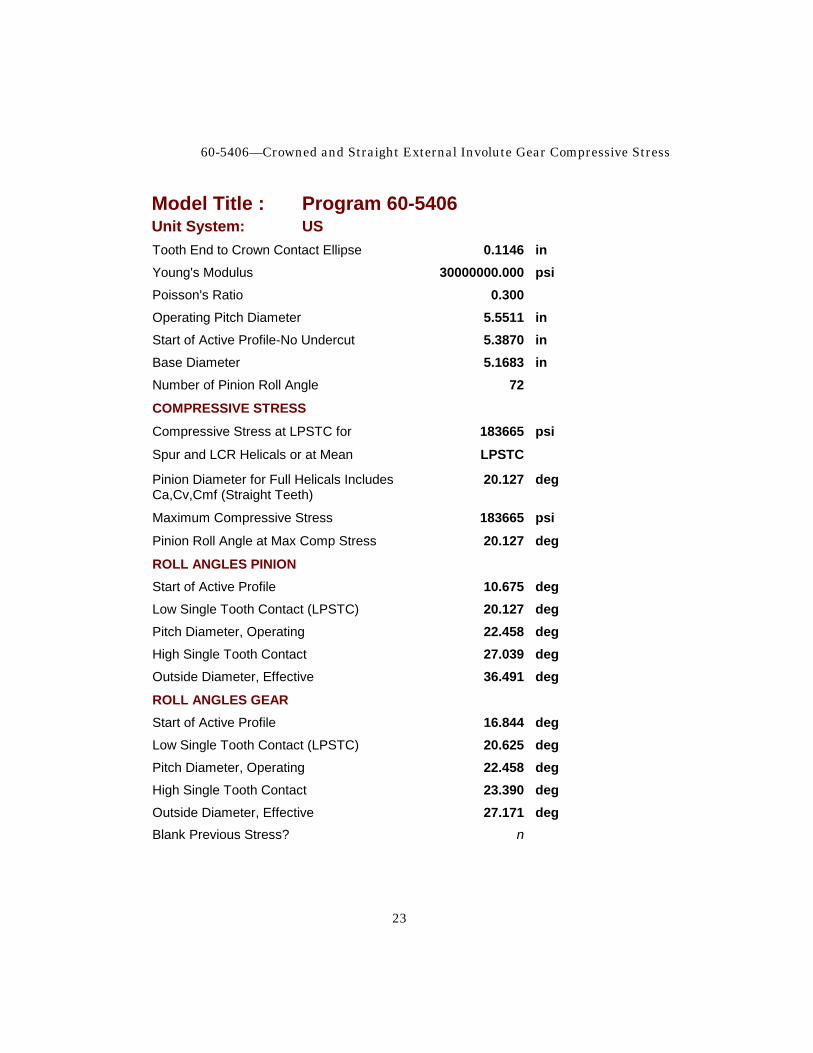
Model Title : Program 60-5406 Unit System: US Tooth End to Crown Contact Ellipse 0.1146 in Young's Modulus 30000000.000 psi Poisson's Ratio 0.300 Operating Pitch Diameter 5.5511 in Start of Active Profile-No Undercut 5.3870 in Base Diameter 5.1683 in Number of Pinion Roll Angle 72
COMPRESSIVE STRESS
Compressive Stress at LPSTC for 183665 psi
Spur and LCR Helicals or at Mean LPSTC
Pinion Diameter for Full Helicals Includes 20.127 deg Ca,Cv,Cmf (Straight Teeth)
Maximum Compressive Stress 183665 psi
Pinion Roll Angle at Max Comp Stress 20.127 deg
ROLL ANGLES PINION Start of Active Profile 10.675 deg Low Single Tooth Contact (LPSTC) 20.127 deg Pitch Diameter, Operating 22.458 deg High Single Tooth Contact 27.039 deg Outside Diameter, Effective 36.491 deg
ROLL ANGLES GEAR Start of Active Profile 16.844 deg Low Single Tooth Contact (LPSTC) 20.625 deg Pitch Diameter, Operating 22.458 deg High Single Tooth Contact 23.390 deg Outside Diameter, Effective 27.171 deg Blank Previous Stress? n
UTS Integrated Gear Software
24
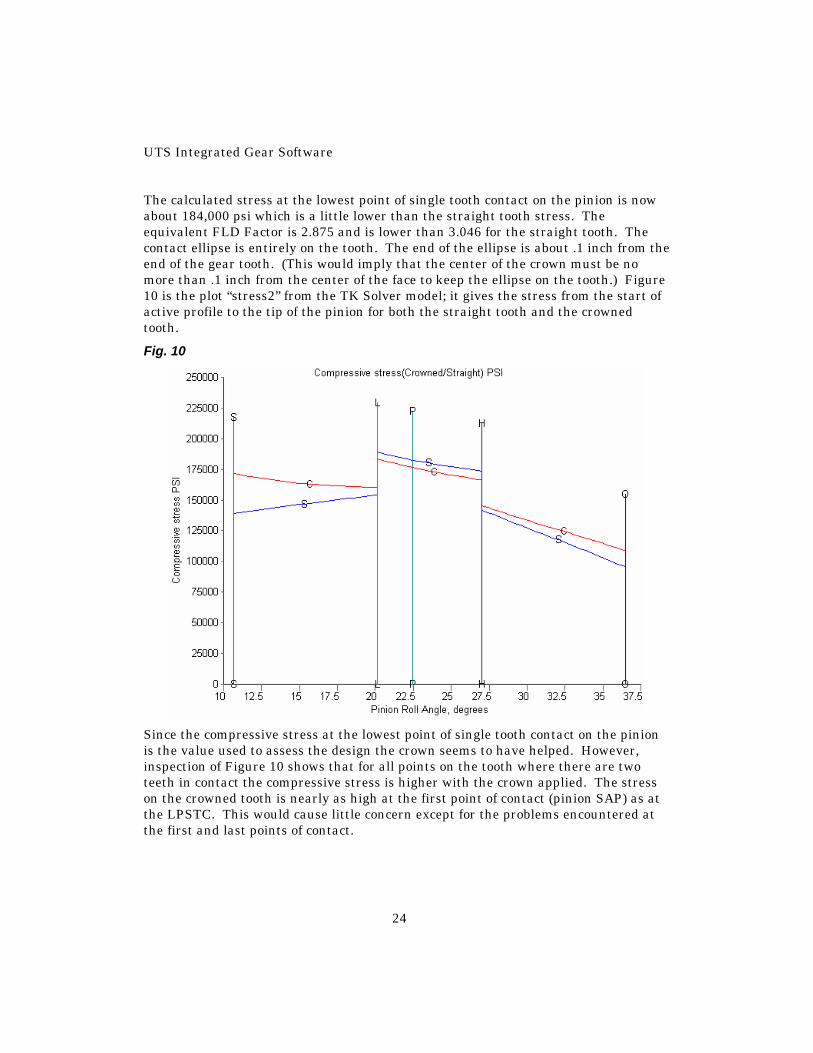
The calculated stress at the lowest point of single tooth contact on the pinion is now about 184,000 psi which is a little lower than the straight tooth stress. The equivalent FLD Factor is 2.875 and is lower than 3.046 for the straight tooth. The contact ellipse is entirely on the tooth. The end of the ellipse is about .1 inch from the end of the gear tooth. (This would imply that the center of the crown must be no more than .1 inch from the center of the face to keep the ellipse on the tooth.) Figure 10 is the plot “stress2” from the TK Solver model; it gives the stress from the start of active profile to the tip of the pinion for both the straight tooth and the crowned tooth.
Fig. 10
Since the compressive stress at the lowest point of single tooth contact on the pinion is the value used to assess the design the crown seems to have helped. However, inspection of Figure 10 shows that for all points on the tooth where there are two teeth in contact the compressive stress is higher with the crown applied. The stress on the crowned tooth is nearly as high at the first point of contact (pinion SAP) as at the LPSTC. This would cause little concern except for the problems encountered at the first and last points of contact.
60-5406—Crowned and Straight External Involute Gear Compressive Stress
25
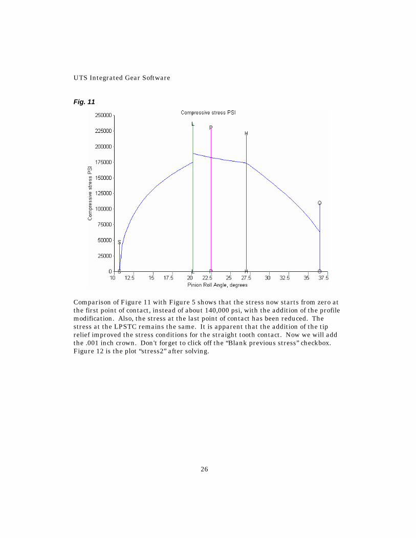
At the first point of contact (gear tip and pinion root for a reduction gear) the deflection of the teeth already under load causes the incoming pinion tooth to seem to be ahead of where it should be. This insures that the load will be picked up very abruptly at the tip of the gear tooth. (This condition is more serious on spur and LACR helicals than on full helicals.) This applies a heavy shock load at the gear tooth tip where the “cantilever beam” is the longest and produces large root stresses. The same thing happens to the pinion tooth at the last point of contact but the effect of dropping the load abruptly is not as severe (mostly noise and vibration). When the tip of the tooth first makes or leaves contact, the contact “footprint” is broken by the top edge of the tooth and the stress is higher than if the whole rectangle or ellipse is carrying the load. This does not show on the stress plots as the load pattern under this condition is uncertain and would approach infinity. In practice, tooth deflection, wear, plastic flow, etc. would reduce the stress but it would still be quite high. From the first point of contact to the pitch point the action is approach action. The gear tooth is approaching the pinion tooth (and the center of the pinion) and the tip acts much like a sharp edged scraper (or in severe cases, a cutting tool). After contact has passed the pitch point the action is recess action. The gear tooth is retreating from the pinion tooth. Recess action is much more conducive to building and maintaining a lubricant film than is approach action, especially at start or end of action. Tooth spacing errors, pitch or profile, add to this effect for those teeth that are “ahead” of where they should be. Even lightly loaded gears, with little deflection, suffer the same type of problem due to manufacturing tolerances. The application of tip relief on the gears will reduce the engagement shock and the tendency to scrape the driver root. (This will also help the abrupt dropping of load at the last point of contact.) The load can then be picked up smoothly and the full load (plus shock) on the tooth tips eliminated. This will produce approximately the load schedule shown on Figure 2. (See UTS Model 60-1111 for suggested values for various gear accuracy classes and loading.) Set the data input form up to be the same as Report 4, and click the “Profiles Modified” checkbox. Figure 11 is the plot “stress” for this solution.
UTS Integrated Gear Software
26
Fig. 11
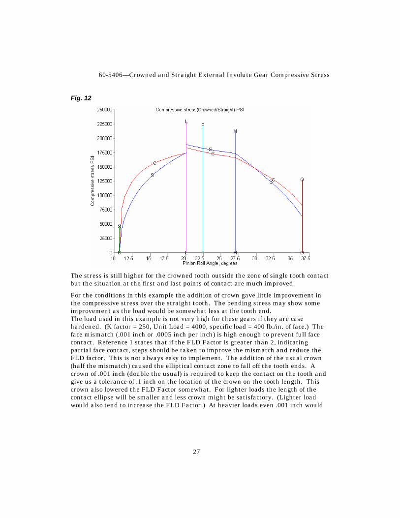
Comparison of Figure 11 with Figure 5 shows that the stress now starts from zero at the first point of contact, instead of about 140,000 psi, with the addition of the profile modification. Also, the stress at the last point of contact has been reduced. The stress at the LPSTC remains the same. It is apparent that the addition of the tip relief improved the stress conditions for the straight tooth contact. Now we will add the .001 inch crown. Don't forget to click off the “Blank previous stress” checkbox. Figure 12 is the plot “stress2” after solving.
60-5406—Crowned and Straight External Involute Gear Compressive Stress
27
Fig. 12
The stress is still higher for the crowned tooth outside the zone of single tooth contact but the situation at the first and last points of contact are much improved.
For the conditions in this example the addition of crown gave little improvement in the compressive stress over the straight tooth. The bending stress may show some improvement as the load would be somewhat less at the tooth end. The load used in this example is not very high for these gears if they are case hardened. (K factor = 250, Unit Load = 4000, specific load = 400 lb./in. of face.) The face mismatch (.001 inch or .0005 inch per inch) is high enough to prevent full face contact. Reference 1 states that if the FLD Factor is greater than 2, indicating partial face contact, steps should be taken to improve the mismatch and reduce the FLD factor. This is not always easy to implement. The addition of the usual crown (half the mismatch) caused the elliptical contact zone to fall off the tooth ends. A crown of .001 inch (double the usual) is required to keep the contact on the tooth and give us a tolerance of .1 inch on the location of the crown on the tooth length. This crown also lowered the FLD Factor somewhat. For lighter loads the length of the contact ellipse will be smaller and less crown might be satisfactory. (Lighter load would also tend to increase the FLD Factor.) At heavier loads even .001 inch would

UTS Integrated Gear Software
28
not be enough to keep the load on the teeth. (Heavier load would, however, decrease the FLD Factor.)
NOTE: Any causes of face mismatch where the direction is known, such as bending of overhung gear shafts and pinion torsional windup, should be dealt with by using lead modification, thereby reducing the mismatch, and not by use of crowning alone.
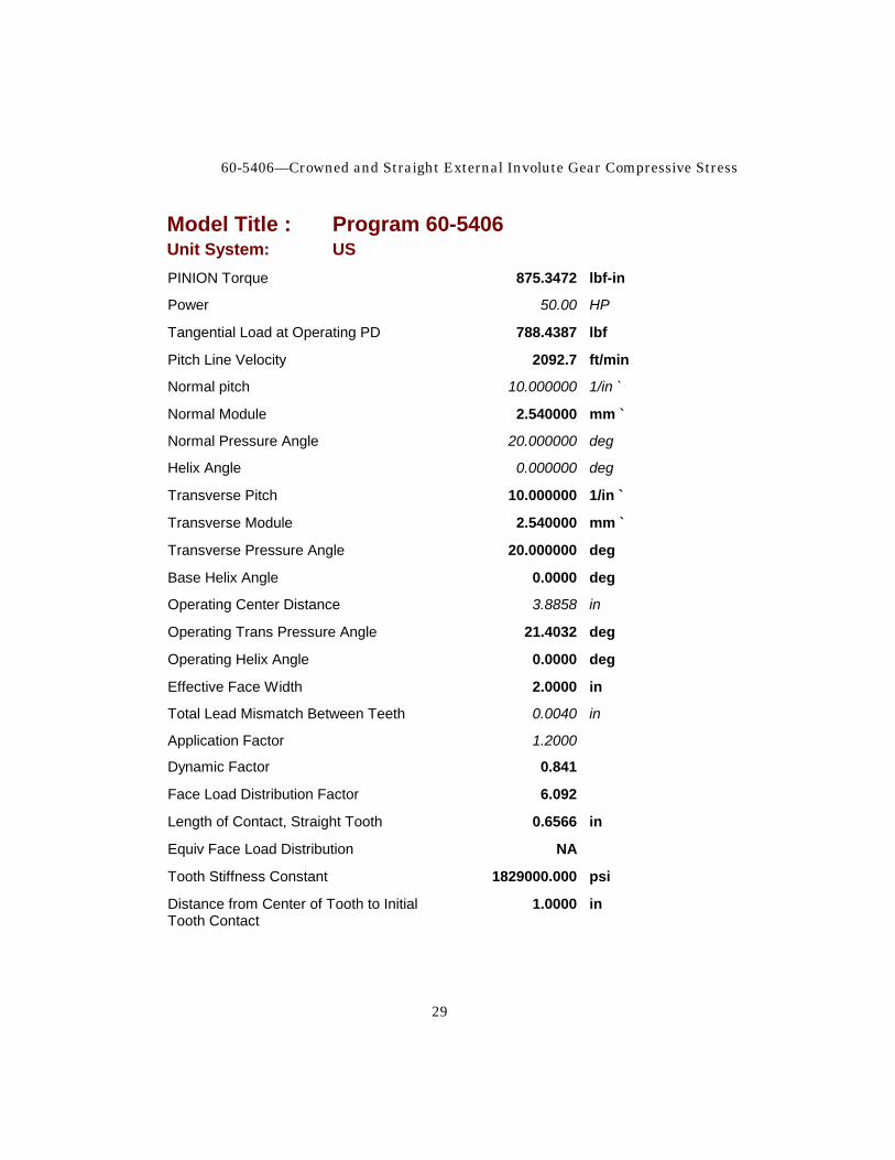
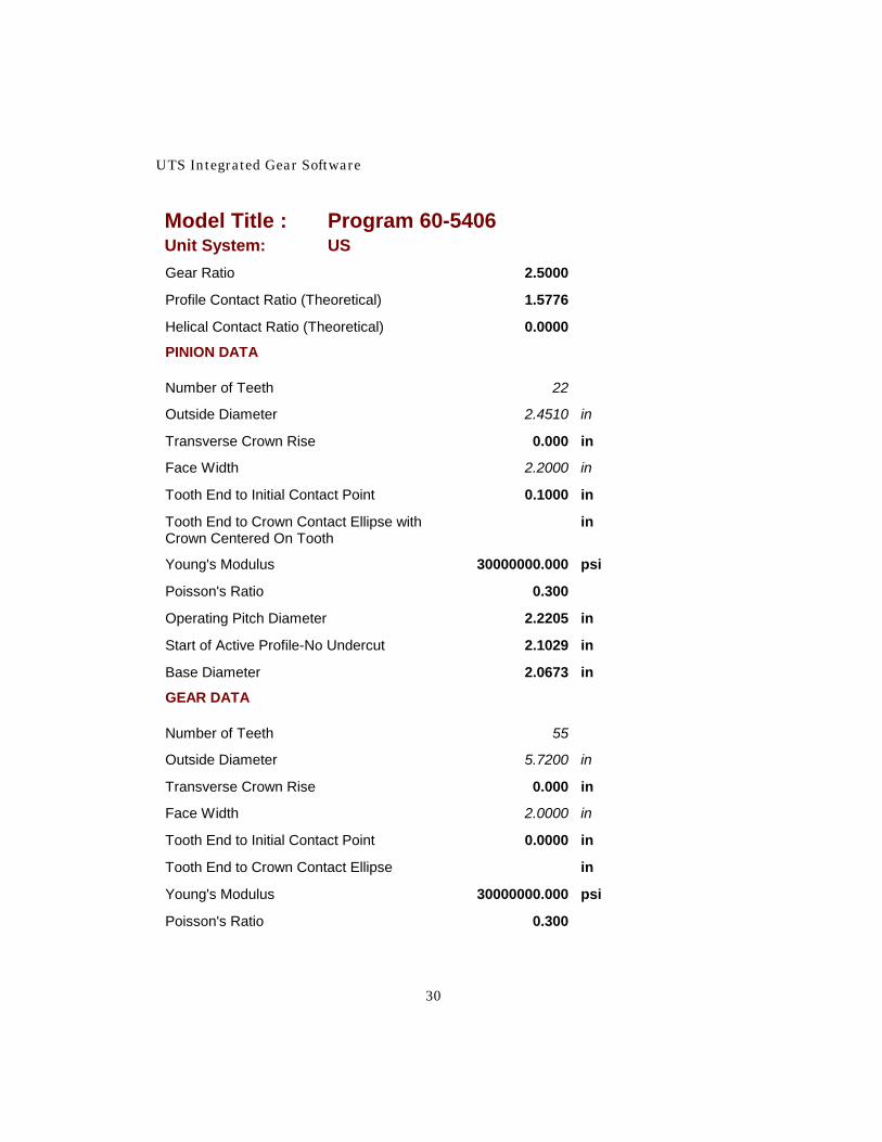
If the face mismatch is extremely high the addition of crown can be of considerable help in reducing the compressive stress. Very high mismatch, of course, should be avoided at the design stage but, at times, may be encountered through design oversight or use of a gear set in a situation not originally planned. In the next example we will look at the implications of crowning for a very badly misaligned gear set. We will use the same set as the first example but will increase the mismatch to .004 inch. Report 4 is the solved model for this condition with straight teeth.
Report 4
Model Title : Program 60-5406 Unit System: US
MESSAGE FIELD
Message Field STRAIGHT
m2 TEETH
m3 PROFILES
m4 MODIFIED
COMMON DATA
Adjust Tooth Load per AGMA 217? y
Profiles Modified? y
Driver: p
Quality Class 10
PINION Speed 3600.00 rpm
60-5406—Crowned and Straight External Involute Gear Compressive Stress
29
Model Title : Program 60-5406 Unit System: US PINION Torque 875.3472 lbf-in
Power 50.00 HP
Tangential Load at Operating PD 788.4387 lbf
Pitch Line Velocity 2092.7 ft/min
Normal pitch 10.000000 1/in `
Normal Module 2.540000 mm `
Normal Pressure Angle 20.000000 deg
Helix Angle 0.000000 deg
Transverse Pitch 10.000000 1/in `
Transverse Module 2.540000 mm `
Transverse Pressure Angle 20.000000 deg
Base Helix Angle 0.0000 deg
Operating Center Distance 3.8858 in
Operating Trans Pressure Angle 21.4032 deg
Operating Helix Angle 0.0000 deg
Effective Face Width 2.0000 in
Total Lead Mismatch Between Teeth 0.0040 in
Application Factor 1.2000
Dynamic Factor 0.841
Face Load Distribution Factor 6.092
Length of Contact, Straight Tooth 0.6566 in
Equiv Face Load Distribution NA
Tooth Stiffness Constant 1829000.000 psi
Distance from Center of Tooth to Initial 1.0000 in Tooth Contact
UTS Integrated Gear Software
30
Model Title : Program 60-5406 Unit System: US Gear Ratio 2.5000
Profile Contact Ratio (Theoretical) 1.5776
Helical Contact Ratio (Theoretical) 0.0000
PINION DATA
Number of Teeth 22
Outside Diameter 2.4510 in
Transverse Crown Rise 0.000 in
Face Width 2.2000 in
Tooth End to Initial Contact Point 0.1000 in
Tooth End to Crown Contact Ellipse with in Crown Centered On Tooth
Young's Modulus 30000000.000 psi
Poisson's Ratio 0.300
Operating Pitch Diameter 2.2205 in
Start of Active Profile-No Undercut 2.1029 in
Base Diameter 2.0673 in
GEAR DATA
Number of Teeth 55
Outside Diameter 5.7200 in
Transverse Crown Rise 0.000 in
Face Width 2.0000 in
Tooth End to Initial Contact Point 0.0000 in
Tooth End to Crown Contact Ellipse in
Young's Modulus 30000000.000 psi
Poisson's Ratio 0.300
60-5406—Crowned and Straight External Involute Gear Compressive Stress
31
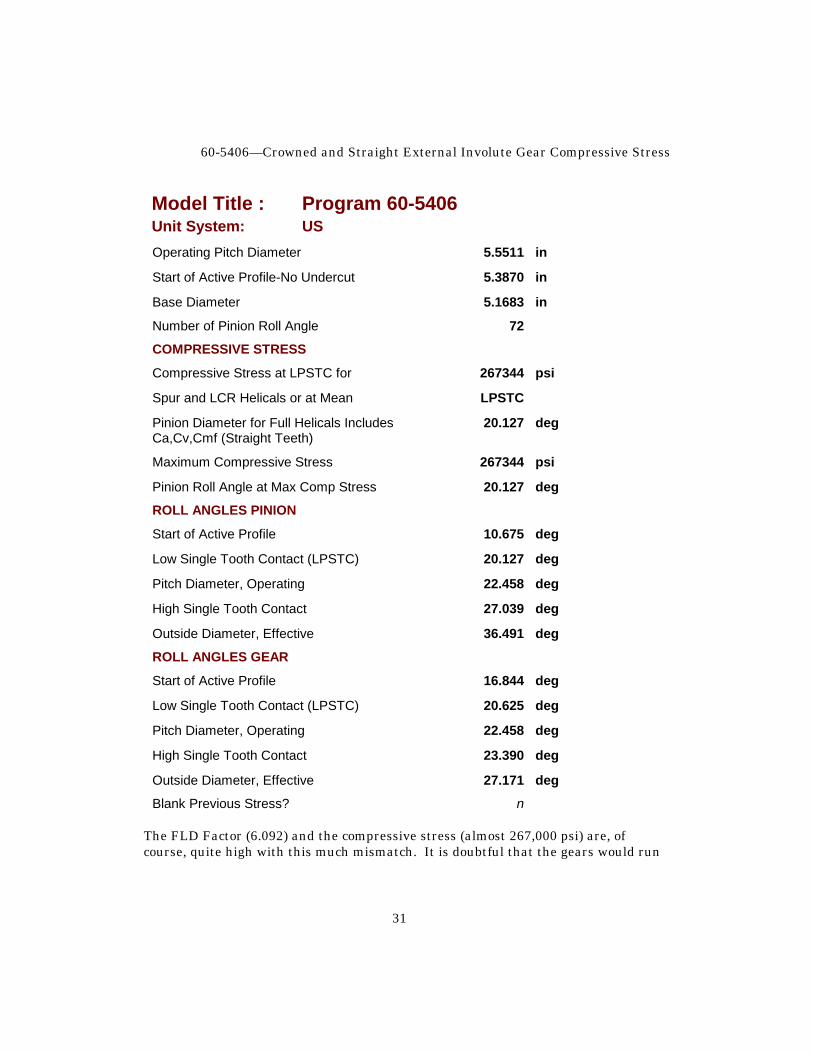
Model Title : Program 60-5406 Unit System: US Operating Pitch Diameter 5.5511 in
Start of Active Profile-No Undercut 5.3870 in
Base Diameter 5.1683 in
Number of Pinion Roll Angle 72
COMPRESSIVE STRESS
Compressive Stress at LPSTC for 267344 psi
Spur and LCR Helicals or at Mean LPSTC
Pinion Diameter for Full Helicals Includes 20.127 deg Ca,Cv,Cmf (Straight Teeth)
Maximum Compressive Stress 267344 psi
Pinion Roll Angle at Max Comp Stress 20.127 deg
ROLL ANGLES PINION
Start of Active Profile 10.675 deg
Low Single Tooth Contact (LPSTC) 20.127 deg
Pitch Diameter, Operating 22.458 deg
High Single Tooth Contact 27.039 deg
Outside Diameter, Effective 36.491 deg
ROLL ANGLES GEAR
Start of Active Profile 16.844 deg
Low Single Tooth Contact (LPSTC) 20.625 deg
Pitch Diameter, Operating 22.458 deg
High Single Tooth Contact 23.390 deg
Outside Diameter, Effective 27.171 deg
Blank Previous Stress? n The FLD Factor (6.092) and the compressive stress (almost 267,000 psi) are, of course, quite high with this much mismatch. It is doubtful that the gears would run
UTS Integrated Gear Software
32
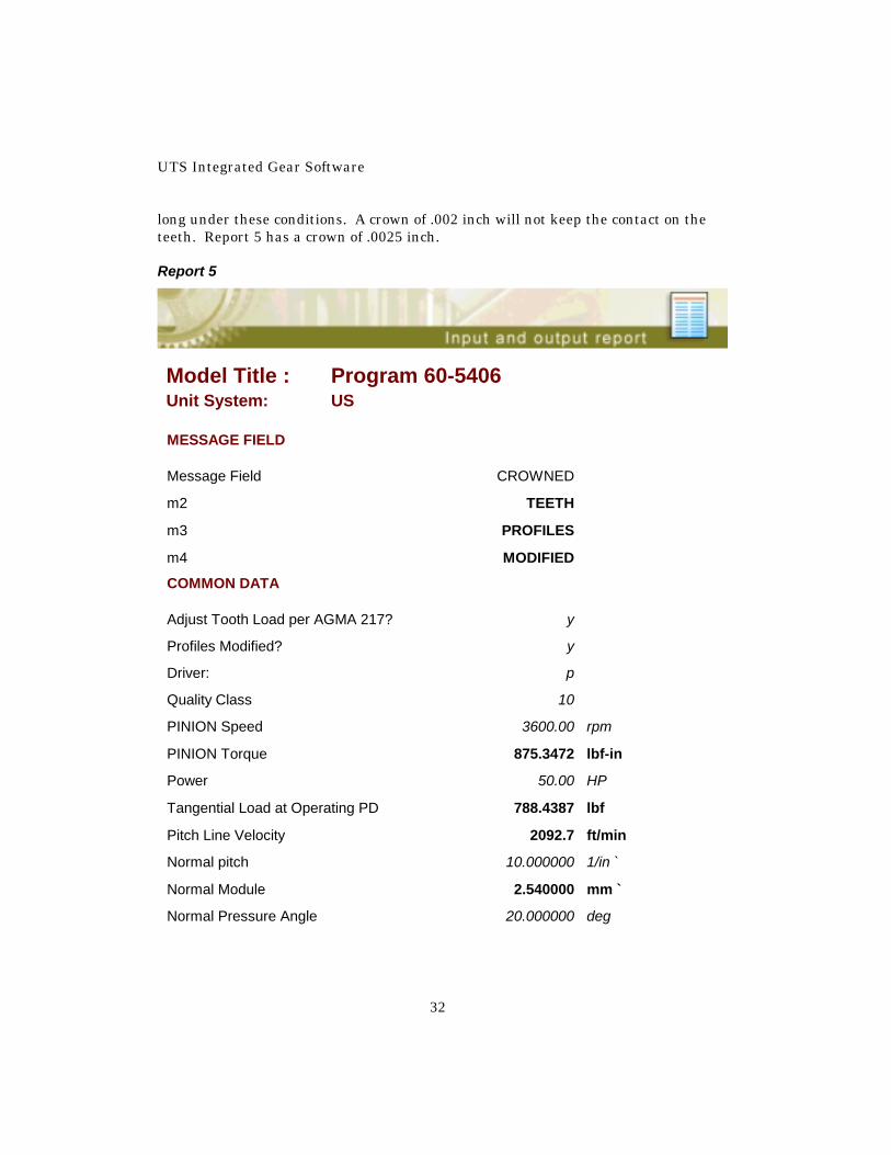
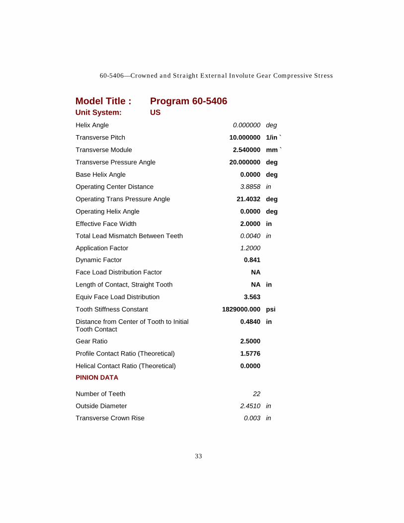
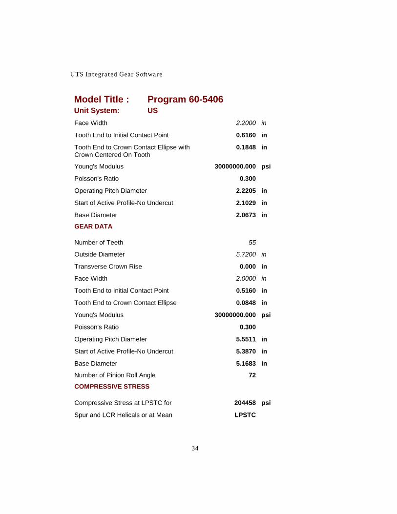
long under these conditions. A crown of .002 inch will not keep the contact on the teeth. Report 5 has a crown of .0025 inch. Report 5
Model Title : Program 60-5406 Unit System: US
MESSAGE FIELD
Message Field CROWNED
m2 TEETH
m3 PROFILES
m4 MODIFIED
COMMON DATA
Adjust Tooth Load per AGMA 217? y
Profiles Modified? y
Driver: p
Quality Class 10
PINION Speed 3600.00 rpm
PINION Torque 875.3472 lbf-in
Power 50.00 HP
Tangential Load at Operating PD 788.4387 lbf
Pitch Line Velocity 2092.7 ft/min
Normal pitch 10.000000 1/in `
Normal Module 2.540000 mm `
Normal Pressure Angle 20.000000 deg
60-5406—Crowned and Straight External Involute Gear Compressive Stress
33
Model Title : Program 60-5406 Unit System: US Helix Angle 0.000000 deg
Transverse Pitch 10.000000 1/in `
Transverse Module 2.540000 mm `
Transverse Pressure Angle 20.000000 deg
Base Helix Angle 0.0000 deg
Operating Center Distance 3.8858 in
Operating Trans Pressure Angle 21.4032 deg
Operating Helix Angle 0.0000 deg
Effective Face Width 2.0000 in
Total Lead Mismatch Between Teeth 0.0040 in
Application Factor 1.2000
Dynamic Factor 0.841
Face Load Distribution Factor NA
Length of Contact, Straight Tooth NA in
Equiv Face Load Distribution 3.563
Tooth Stiffness Constant 1829000.000 psi
Distance from Center of Tooth to Initial 0.4840 in Tooth Contact
Gear Ratio 2.5000
Profile Contact Ratio (Theoretical) 1.5776
Helical Contact Ratio (Theoretical) 0.0000
PINION DATA
Number of Teeth 22
Outside Diameter 2.4510 in
Transverse Crown Rise 0.003 in
UTS Integrated Gear Software
34
Model Title : Program 60-5406 Unit System: US Face Width 2.2000 in
Tooth End to Initial Contact Point 0.6160 in
Tooth End to Crown Contact Ellipse with 0.1848 in Crown Centered On Tooth
Young's Modulus 30000000.000 psi
Poisson's Ratio 0.300
Operating Pitch Diameter 2.2205 in
Start of Active Profile-No Undercut 2.1029 in
Base Diameter 2.0673 in
GEAR DATA
Number of Teeth 55
Outside Diameter 5.7200 in
Transverse Crown Rise 0.000 in
Face Width 2.0000 in
Tooth End to Initial Contact Point 0.5160 in
Tooth End to Crown Contact Ellipse 0.0848 in
Young's Modulus 30000000.000 psi
Poisson's Ratio 0.300
Operating Pitch Diameter 5.5511 in
Start of Active Profile-No Undercut 5.3870 in
Base Diameter 5.1683 in
Number of Pinion Roll Angle 72
COMPRESSIVE STRESS
Compressive Stress at LPSTC for 204458 psi
Spur and LCR Helicals or at Mean LPSTC
60-5406—Crowned and Straight External Involute Gear Compressive Stress
35
Model Title : Program 60-5406 Unit System: US Pinion Diameter for Full Helicals Includes 20.127 deg Ca,Cv,Cmf (Straight Teeth)
Maximum Compressive Stress 204458 psi
Pinion Roll Angle at Max Comp Stress 20.127 deg
ROLL ANGLES PINION
Start of Active Profile 10.675 deg
Low Single Tooth Contact (LPSTC) 20.127 deg
Pitch Diameter, Operating 22.458 deg
High Single Tooth Contact 27.039 deg
Outside Diameter, Effective 36.491 deg
ROLL ANGLES GEAR
Start of Active Profile 16.844 deg
Low Single Tooth Contact (LPSTC) 20.625 deg
Pitch Diameter, Operating 22.458 deg
High Single Tooth Contact 23.390 deg
Outside Diameter, Effective 27.171 deg
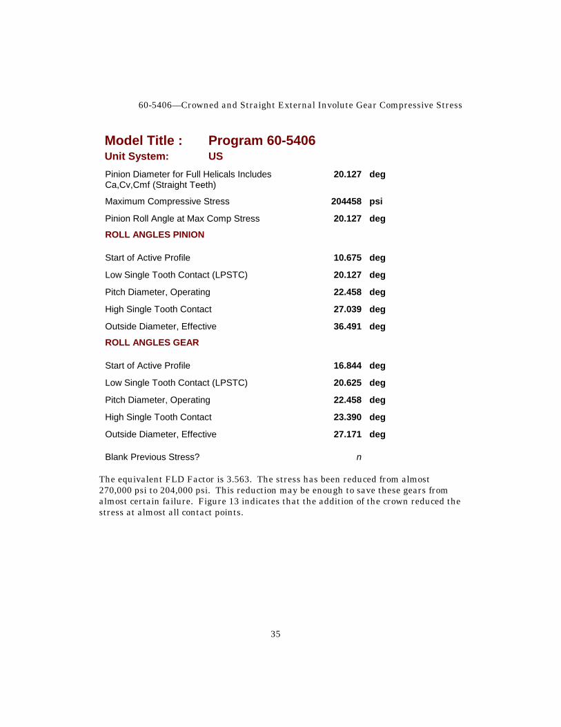
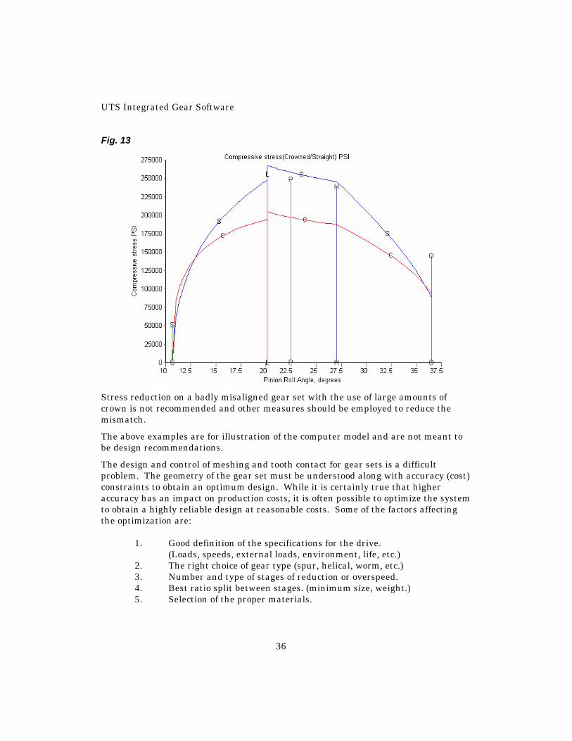
Blank Previous Stress? n The equivalent FLD Factor is 3.563. The stress has been reduced from almost 270,000 psi to 204,000 psi. This reduction may be enough to save these gears from almost certain failure. Figure 13 indicates that the addition of the crown reduced the stress at almost all contact points.
UTS Integrated Gear Software
36
Fig. 13
Stress reduction on a badly misaligned gear set with the use of large amounts of crown is not recommended and other measures should be employed to reduce the mismatch.
The above examples are for illustration of the computer model and are not meant to be design recommendations.
The design and control of meshing and tooth contact for gear sets is a difficult problem. The geometry of the gear set must be understood along with accuracy (cost) constraints to obtain an optimum design. While it is certainly true that higher accuracy has an impact on production costs, it is often possible to optimize the system to obtain a highly reliable design at reasonable costs. Some of the factors affecting the optimization are: 1. Good definition of the specifications for the drive. (Loads, speeds, external loads, environment, life, etc.) 2. The right choice of gear type (spur, helical, worm, etc.) 3. Number and type of stages of reduction or overspeed. 4. Best ratio split between stages. (minimum size, weight.) 5. Selection of the proper materials.
60-5406—Crowned and Straight External Involute Gear Compressive Stress
37
6. Selection of the best pitch and pressure angle. (trade off on beam and compressive stress and scoring.) 7. Selection of the correct center distance for high-low addendum. 8. Setting the OD's for strength balance (high-low addendum). 9. Proper tip relief and location. (contact ratio over one and satisfactory load pattern.) 10. Optimum lead modification to reduce Cmf. (bending, torsional windup, thermal, centrifugal, etc.) 11. Setting of crown (if any) and crown tolerance. 12. Design and specification of optimum tooling. (vendor communication - outside or own shop.) 13. Consideration of the gear production machines available. (vendor communication - outside or own shop.) 14. Proper lubrication system and oil type for the application. (cooling and hot and cold scoring.) 15. Proper housing design. (strength, deflection, vibration, thermal, etc.) 16. Type and mounting of bearings. (effect of bearing clearance and mounting deflections.) 17. Shaft design for bending, torque and vibration. 18. System vibration analysis to avoid resonance. References:
1. AGMA 218.01, AGMA Standard for Rating the Pitting Resistance and Bending Strength of Spur and Helical Involute Gear Teeth
2. AGMA 217.01, AGMA Information Sheet - Gear Scoring Design Guide for Aerospace Spur and Helical Power Gears
Data extracted from the above standards with the permission of the publisher, the American Gear Manufacturers Association, 1500 King Street, Suite 201, Alexandria, VA 22314
3. Mobil EHL Guidebook, Third Edition Mobil Oil Corporation Commercial Marketing Technical Publications 3225 Gallows Road Fairfax, VA 22037