Embed Size (px)
Citation preview
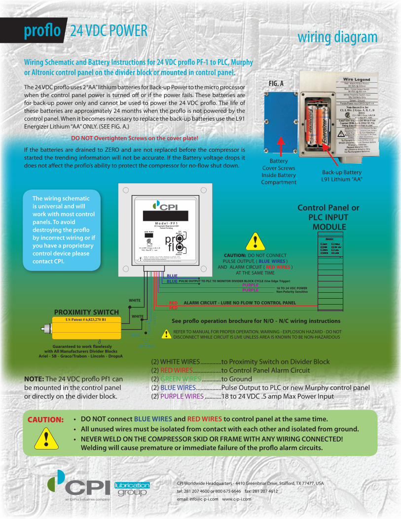
The 24 VDC proflo uses 2 “AA” lithium batteries for Back-up Power to the micro processor when the control panel power is turned off or if the power fails. These batteries are for back-up power only and cannot be used to power the 24 VDC proflo. The life of these batteries are approximately 24 months when the proflo is not powered by the control panel. When it becomes necessary to replace the back-up batteries use the L91 Energizer Lithium “AA” ONLY. (SEE FIG. A.)
DO NOT Overtighten Screws on the cover plate!
If the batteries are drained to ZERO and are not replaced before the compressor is started the trending information will not be accurate. If the Battery voltage drops it does not affect the proflo’s ability to protect the compressor for no-flow shut down.
Wiring Schematic and Battery Instructions for 24 VDC proflo PF-1 to PLC, Murphy or Altronic control panel on the divider block or mounted in control panel.
wiring diagram
CPI Worldwide Headquarters - 4410 Greenbriar Drive, Stafford, TX 77477, USA
tel: 281 207 4600 or 800 675 6646 fax: 281 207 4612
email: [email protected] www.c-p-i.com
BatteryCover ScrewsInside BatteryCompartment
Back-up BatteryL91 Lithium “AA”
FIG. A
(2) WHITE WIRES ..............to Proximity Switch on Divider Block(2) RED WIRES ...................to Control Panel Alarm Circuit (2) GREEN WIRES .............to Ground (2) BLUE WIRES .................Pulse Output to PLC or new Murphy control panel (2) PURPLE WIRES ...........18 to 24 VDC .5 amp Max Power Input
SetButton
ModeButton
prOflO203633
CL I, DIV 2 Grps A, B, C, DT4A Max 85 o C Amb.
C US
IrDA PORT
M o d e l - P F 1
R
US Copyright Registered 2001Patent Pending
REFER TO MANUAL FOR PROPER OPERATION & BATTERY TYPEWARNING - EXPLOSION HAZARD - DO NOT DISCONNECT WHILE CIRCUIT IS LIVE UNLESS AREA IS KNOWN TO BE NON-HAZARDOUS
BATTERIES MUST ONLY BE CHANGED IN AN AREA KNOWN TO BE NON-HAZARDOUS!
BLUEBLUE PULSE OUTPUT TO PLC TO MONITOR DIVIDER BLOCK CYCLE (Use Edge Trigger)
REDRED
WHITE
WHITE
NE
ER
G
GROUND
PROXIMITY SWITCH
REFER TO MANUAL FOR PROPER OPERATION. WARNING - EXPLOSION HAZARD - DO NOTDISCONNECT WHILE CIRCUIT IS LIVE UNLESS AREA IS KNOWN TO BE NON-HAZARDOUSGREEN
Control Panel orPLC INPUT
MODULE
PURPLEPURPLE 18 TO 24 VDC POWER
Non-Polarity Sensitive
NE
ER
G
ALARM CIRCUIT - LUBE NO FLOW TO CONTROL PANEL
See pro�o operation brochure for N/O - N/C wiring instructions
CAUTION: DO NOT CONNECTPULSE OUTPUT, ( BLUE WIRES )
AND ALARM CIRCUIT ( RED WIRES )AT THE SAME TIME
!
!Guaranteed to work flawlessly
with All Manufacturers Divider BlocksAriel - SB - Graco/Trabon - Lincoln - DropsA
US Patent # 6,823,270 B1
• DO NOT connect blue wireS and reD wireS to control panel at the same time.• All unused wires must be isolated from contact with each other and isolated from ground. • NeVer welD ON THe COMPreSSOr SKiD Or FrAMe wiTH ANY wiriNG CONNeCTeD!
welding will cause premature or immediate failure of the proflo alarm circuits.!CAUTION:
The wiring schematic is universal and will work with most control panels. To avoid destroying the proflo by incorrect wiring or if you have a proprietary control device please contact CPi.
NOTE: The 24 VDC proflo Pf1 can be mounted in the control panel or directly on the divider block.
proflo 24 VDC POWER


![Illuminating OpenMP + MPI Performance€¦ · cpi-mpi.c:48 cpi-mpi.c:84 cpi-mpi.c:109 cpi-mpi.c:97 1.0% cpi-mpi [program] main main [OpenMP region O] MPI Finalize MPI Reduce Showing](https://img.pdfslide.us/doc/110x75/6022cc2b9a65990f6b41506f/illuminating-openmp-mpi-performance-cpi-mpic48-cpi-mpic84-cpi-mpic109-cpi-mpic97.jpg)