Embed Size (px)
Citation preview

© 2005 Process Computer Technology, Inc.
PROFILINK/908
Modicon® S908 Remote I/O To Profibus DP
Gateway
www.pct-inc.com www.profibus.com

PROFILINK/908
Process Computer Technology, Inc i Process Computer Technology, Inc.713-861-4808 All Rights Reservedwww.pct-inc.com
Tables.................................................................................................................................. 1Table of Figures .............................................................................................................. 1Table of Tables................................................................................................................ 1
Revision History.................................................................................................................. 2Acknowledgements ............................................................................................................. 3Introduction......................................................................................................................... 1
Application...................................................................................................................... 1Features ........................................................................................................................... 1Table of Acronyms .......................................................................................................... 1
Specifications ...................................................................................................................... 2Maximum Power Requirements...................................................................................... 2Dimensions ...................................................................................................................... 2Mounting......................................................................................................................... 2
Overview............................................................................................................................. 3About PCT....................................................................................................................... 3Profibus-DP..................................................................................................................... 3Modicon® S908 RIO Network ....................................................................................... 4PROFILINK/908 Functional Overview.......................................................................... 4
Configuration...................................................................................................................... 6General............................................................................................................................ 6Configuration Sequence .................................................................................................. 6PROFILINK/908 Management Slave ............................................................................. 8
General........................................................................................................................ 8Slave Parameters......................................................................................................... 8
Gateway Type ............................................................................................. 8Media Redundancy...................................................................................... 8Report Informational Diagnostics ............................................................... 9Max Diag Byte Count ................................................................................. 9PFB Interface Failover Priority................................................................... 9Failover Priority Threshold ......................................................................... 9
S908 Interface Module................................................................................................ 9Parameters ................................................................................................... 9
Quantum I/O Slave Module ...................................................................................... 10Parameters ................................................................................................. 10
Modicon® 800 Series I/O Slave Module.................................................................. 10Parameters ................................................................................................. 11
System Monitor Module............................................................................................ 11Input Data.................................................................................................. 11
PROFILINK/908 Quantum I/O Slave........................................................................... 12General...................................................................................................................... 12Parameters ................................................................................................................. 12
Drop holdup word ..................................................................................... 12Supported Quantum Modules.................................................................................... 12Redundancy Support Module.................................................................................... 13
PROFILINK/908 Modicon® 800 Series I/O Slaves..................................................... 13

PROFILINK/908
Process Computer Technology, Inc ii Process Computer Technology, Inc.713-861-4808 All Rights Reservedwww.pct-inc.com
General...................................................................................................................... 13Parameters ................................................................................................................. 14
Holdup Word............................................................................................. 14Supported Modules ................................................................................................... 15
PROFILINK/908 Operation.............................................................................................. 17Startup ........................................................................................................................... 17Profibus Diagnostics ..................................................................................................... 17Indicators, Switches and Connectors ............................................................................ 17
Profibus Interface Indicators ..................................................................................... 18S908 Interface Indicators .......................................................................................... 18General Indicators..................................................................................................... 19Setup Switches .......................................................................................................... 19Connectors................................................................................................................. 20
Typical Installations .......................................................................................................... 21Non-Redundant ............................................................................................................. 21Redundant/Simplex Profibus......................................................................................... 22Redundant/Duplex Profibus .......................................................................................... 23

PROFILINK/908
Process Computer Technology, Inc 1 Process Computer Technology, Inc.713-861-4808 All Rights Reservedwww.pct-inc.com
Tables
Table of FiguresFigure 1 General PROFILINK/908 Configuration Steps.................................................... 7Figure 2 PROFILINK/908 Front Panel............................................................................. 17Figure 3 PROFILINK/908 End Panel............................................................................... 18Figure 4 Typical Non-redundant Installation.................................................................... 21Figure 5 Typical Redundant Installation with Simplex Profibus Cabling ........................ 22Figure 6 Typical Redundant Installation with Duplex Profibus Cabling.......................... 23
Table of TablesTable 1 Revision History..................................................................................................... 2Table 2 Acronyms ............................................................................................................... 1Table 3 Supported Quantum Modules .............................................................................. 13Table 4 Supported Modicon ® 800 Series Modules ......................................................... 16Table 5 Profibus Interface Indicators................................................................................ 18Table 6 S908 Interface Indicators ..................................................................................... 19
PROFILINK/908
Process Computer Technology, Inc 2 Process Computer Technology, Inc.713-861-4808 All Rights Reservedwww.pct-inc.com
Revision History1/2005 Initial release4/2005 Updated support for holdup word emulationTable 1 Revision History

PROFILINK/908
Process Computer Technology, Inc 3 Process Computer Technology, Inc.713-861-4808 All Rights Reservedwww.pct-inc.com
AcknowledgementsPCT is not affiliated with Schneider Automation or GSE in any manner.Modicon® is a trademark of Schneider Automation, Inc.D/3 DCS® is a trademark of Novatech Process Systems, LLCPROFILINK/908 ™ 2002 Process Computer Technology, Inc.GATEWAY 16000 ™ 2002 Process Computer Technology, Inc.
PROFILINK/908
Process Computer Technology, Inc 1 Process Computer Technology, Inc.713-861-4808 All Rights Reservedwww.pct-inc.com
Introduction
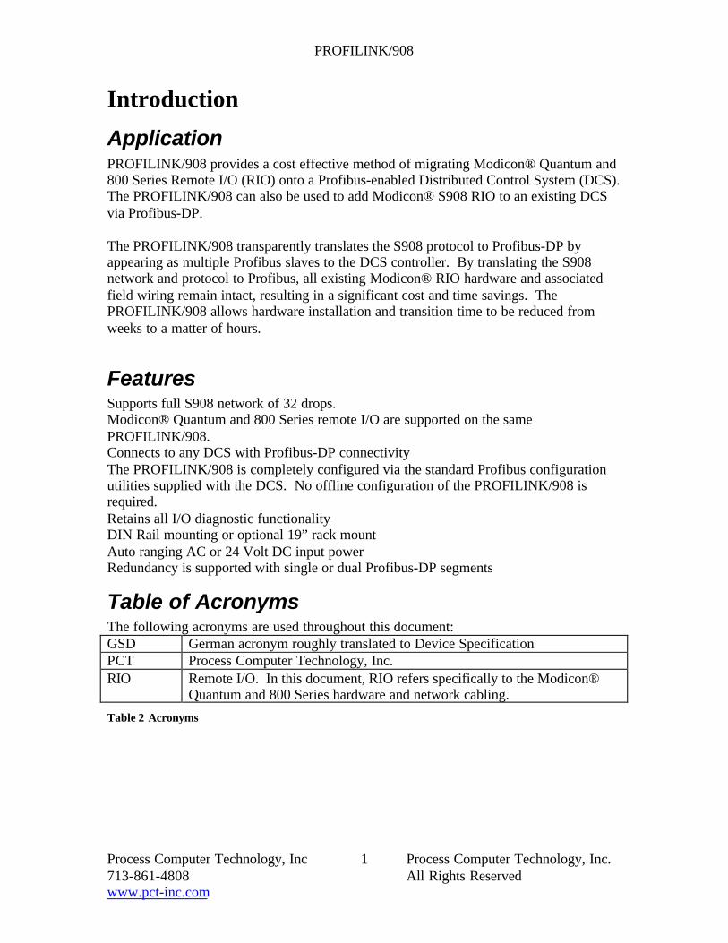
ApplicationPROFILINK/908 provides a cost effective method of migrating Modicon® Quantum and800 Series Remote I/O (RIO) onto a Profibus-enabled Distributed Control System (DCS).The PROFILINK/908 can also be used to add Modicon® S908 RIO to an existing DCSvia Profibus-DP.
The PROFILINK/908 transparently translates the S908 protocol to Profibus-DP byappearing as multiple Profibus slaves to the DCS controller. By translating the S908network and protocol to Profibus, all existing Modicon® RIO hardware and associatedfield wiring remain intact, resulting in a significant cost and time savings. ThePROFILINK/908 allows hardware installation and transition time to be reduced fromweeks to a matter of hours.
FeaturesSupports full S908 network of 32 drops.Modicon® Quantum and 800 Series remote I/O are supported on the samePROFILINK/908.Connects to any DCS with Profibus-DP connectivityThe PROFILINK/908 is completely configured via the standard Profibus configurationutilities supplied with the DCS. No offline configuration of the PROFILINK/908 isrequired.Retains all I/O diagnostic functionalityDIN Rail mounting or optional 19” rack mountAuto ranging AC or 24 Volt DC input powerRedundancy is supported with single or dual Profibus-DP segments
Table of AcronymsThe following acronyms are used throughout this document:GSD German acronym roughly translated to Device SpecificationPCT Process Computer Technology, Inc.RIO Remote I/O. In this document, RIO refers specifically to the Modicon®
Quantum and 800 Series hardware and network cabling.
Table 2 Acronyms

PROFILINK/908
Process Computer Technology, Inc 2 Process Computer Technology, Inc.713-861-4808 All Rights Reservedwww.pct-inc.com
Specifications
Maximum Power Requirements120 VAC 60HZ 240 VAC 50HZ 24 VDC0.2 Amps 0.1 Amps 0.78 Amps
DimensionsThe dimensions of the PROFILINK/908 enclosure are 9” (Length) x 5.6” (height) x 5.2”(depth).
MountingThe PROFILINK/908 is designed to be DIN Rail mounted An optional chassis isavailable to mount the PROFILINK/908 in a standard 19” rack.

PROFILINK/908
Process Computer Technology, Inc 3 Process Computer Technology, Inc.713-861-4808 All Rights Reservedwww.pct-inc.com
Overview
About PCT
Process Computer Technology (PCT) is an innovative dynamic company serving theprocess control industry. PCT has been providing engineered solutions for IndustrialAutomation and Process Control for ten years.
The PROFILINK/908, gateway for connecting Modicon® Remote I/O to Profibusenabled control systems, is the result of a convergence between two PCT corecompetencies: PLC systems integration and upgrade hardware development for the D/3DCS®. Many D/3 DCS® systems have Modicon® Remote I/O utilizing the S908 protocolas the native I/O in place of the original 16000 I/O.
After successfully developing the GATEWAY 16000 for connecting the D/3 DCS®
16000 I/O to any Profibus enabled control system, PCT hardware and software designersapplied their skills to the Modicon® Remote I/O. The result is the PROFILINK/908,which is a gateway for the Modicon® I/O S908 protocol, and Profibus enabled controlsystems.
PCT was incorporated in 1992 to provide products and services for Factory Automationand Process Control. We specialize in programmable logic controller (PLC) systemsintegration, D/3 DCS® third party hardware upgrades and Profibus solutions for opencontrol systems.
For more information about PCT’s products and services, refer to the web site atwww.pct-inc.com.
Profibus-DPProfibus is a defacto industry-standard remote I/O network supported by most major DCSvendors. Profibus–DP is specifically optimized to support large volumes of high-speedremote I/O on a single network.
Profibus supports I/O equipment from several vendors in a very structured andstandardized manner. All Profibus device vendors must supply information on thecharacteristics of their device via a GSD file. This GSD file (German acronym forDevice Specification) contains information used by the control system to present vendor-specific configuration options to the user for new equipment in a consistent manner.
Profibus devices are addressed by means of Slave ID (0-125) and offset. Most controlsystems present the addressing to the user by means of slave, module, offset or channel.Each Profibus slave can be configured with up to 244 bytes of input data and up to 244bytes of output data. Some control systems and configurations may limit the maximumamount of data a slave can handle.

PROFILINK/908
Process Computer Technology, Inc 4 Process Computer Technology, Inc.713-861-4808 All Rights Reservedwww.pct-inc.com
Process Computer Technology, Inc (PCT) is a member of the Profibus TradeOrganization (PTO). For more information on Profibus and the PTO, refer to the PTOweb site at www.profibus.com.
Modicon® S908 RIO NetworkS908 is a Remote I/O (RIO) network by Schneider Automation, Inc.’s Modicon® unit.The network and protocol are optimized for the Modicon® RIO hardware and processors.S908 supports, among others, remote I/O hardware from the Modicon® Quantum and800 Series. Modicon® Quantum and 800 Series RIO hardware can be mixed on the samenetwork. Both redundant (dual cable) and non-redundant (single cable) configurationsare supported.
S908 addressing is based upon Drop Number (1-32), Rack Number (1-5), Slot Number(1-16) and Point Number. The PROFILINK/908 transparently translates between theProfibus Slave/Module/Channel addressing and the S908 Drop/Rack/Slot/Pointaddressing. All module diagnostics are translated to standard or vendor-specific Profibusdiagnostics for presentation via the control system’s diagnostic reporting mechanisms.Each S908 drop can be configured with up to 128 bytes of input data and up to 128 bytesof output data.
For more information regarding the S908 network, Quantum RIO hardware or 800 SeriesRIO hardware, refer to the Modicon® web site at www.modicon.com.
PROFILINK/908 Functional OverviewThe PROFILINK/908 appears as several slaves on the Profibus network. It creates oneProfibus “Management Slave” and multiple Profibus I/O slaves. The Management Slaveis used to configure and control the PROFILINK/908 as a unit. The Profibus I/O slavescommunicate with the Modicon® Quantum or 800 Series RIO hardware.
The PROFILINK/908 Profibus “Management Slave” configures the PROFILINK/908unit as a whole. By adding and configuring virtual modules into the management slave,the PROFILINK/908 is directed to create Profibus I/O slaves to map to Modicon®Quantum and/or 800 Series RIO hardware. This management slave does not correspondto any physical I/O hardware external to the PROFILINK/908.
The PROFILINK/908 creates multiple I/O slaves, one for each Modicon® Quantumand/or 800 Series RIO rack. The PROFILINK/908 translates between Profibuscommands and data and Modicon® S908 RIO commands and data. For each RIO rack,the PROFILINK/908 creates an I/O slave for presenting data to the control system. Eachmodule in the RIO rack is configured as a module in the Profibus slave on the controlsystem. Different Profibus slave types are used for Modicon® Quantum and 800 SeriesRIO racks. Output data is received from the Profibus network, translated and presentedto the Modicon® S908 RIO network. Input data and status are received from theModicon® S908 RIO network, translated and presented to the control system via

PROFILINK/908
Process Computer Technology, Inc 5 Process Computer Technology, Inc.713-861-4808 All Rights Reservedwww.pct-inc.com
Profibus. This translation is completely transparent to the control system and Modicon®RIO hardware.

PROFILINK/908
Process Computer Technology, Inc 6 Process Computer Technology, Inc.713-861-4808 All Rights Reservedwww.pct-inc.com
Configuration
GeneralAll configuration of the PROFILINK/908 and RIO modules is performed via the Profibusslave configuration utilities supplied by the control system vendor. No additional utilitiesare required. This configuration capability is facilitated by device-specific Profibus GSDfiles supplied by PCT. These files are loaded in accordance with the control system’sinstructions. Three English language GSD files, corresponding to each Profibus slavetype, are supplied with the PROFILINK/908: PROFILINK/908 Management Slave(06D6.GSE), PROFILINK/908 Quantum I/O Slave (06D8.GSE) and PROFILINK/908Modicon® 800 Series I/O Slave (06D9.GSE).
Configuration SequenceThe general steps involved in configuring the control system for use withPROFILINK/908 are as follows:Install the GSD files on the control system. This is done in accordance with the controlsystem’s procedures and varies by system. Note that this step is required to be completedbefore any PROFILINK/908 units can be configured. Regardless of the number ofPROFILINK/908 units installed, this step is only performed once for the control system.Create Management Slave. This Management slave is the central management unit foreach PROFILINK/908 and must be created first. The Profibus slave ID of themanagement slave must be set to an unused Profibus address on the segment and mustmatch the ID set on the thumbwheel switch on the PROFILINK/908 unit shown in Figure2.Configure the S908 Interface Module in the Management Slave. This module is requiredto be the first module in the Management slave. This module defines parameters thatrefer to the S908 RIO network as a whole.For each RIO rack to be configured create and configure a Slave I/O module into theManagement slave. This module directs the PROFILINK/908 unit to create a Profibusslave and maps it to the appropriate S908 RIO Hardware.For each RIO rack to be configured create and configure a Profibus I/O slave of thecorresponding type (Quantum or 800 Series).Create and configure I/O modules in the Profibus I/O slave.Repeat steps 0-0 for each RIO rack connected to the PROFILINK/908 unitRepeat steps 0-0 for each PROFILINK/908 unit to be connected to the control system.

PROFILINK/908
Process Computer Technology, Inc 7 Process Computer Technology, Inc.713-861-4808 All Rights Reservedwww.pct-inc.com
Install GSD fileson DCS
CreateManagement
Slave
Create &Configure S908
Interface Module
Create &Configure I/OSlave Module
Create &Configure Profibus
I/O Slave
Create andConfigure I/O
Module
More I/O Modulesin Rack?
Yes
More I/O Slaves?
No
Yes
MorePROFILINK.908
units?
No
Yes
No
Figure 1 General PROFILINK/908 Configuration Steps

PROFILINK/908
Process Computer Technology, Inc 8 Process Computer Technology, Inc.713-861-4808 All Rights Reservedwww.pct-inc.com
PROFILINK/908 Management Slave
GeneralWhen initially configuring a PROFILINK/908, the Profibus Management Slave for theunit is created and configured first in the control system. The address assigned to theManagement Slave in the control system is also set on the thumbwheel switches on theactual unit. Once the slave is created, an “S908 Interface Module” is configured as thefirst module in the Management Slave. For each Quantum RIO rack, an “S908 QuantumI/O Slave Module” is configured into the Management Slave. For each Modicon® 800Series RIO rack, an “S908 800 Series I/O Slave Module” is configured into theManagement Slave. A “System Monitoring Module” can optionally be configured intothe Management Slave to retrieve PROFILINK/908 internal statistics.
Slave Parameters
Gateway TypeThe Gateway Type parameter specifies whether the PROFILINK is used in a redundantor non-redundant configuration. Valid values are:
Non-redundantThis value indicates the PROFILINK is in a non-redundant configuration.
Redundant/Fault TolerantThe PROFILINK is installed in a redundant configuration with 2 PROFILINKsconnected together.
Media RedundancyThe “Media Redundancy” parameter is used to indicate the Profibus cabling used inredundant configurations. Please see the Typical Installations section for the the variouscabling methodologies. This parameter is only used for redundant PROFILINKconfigurations and is ignored in non-redundant configurations.
Single MediaA single Profibus cable is connected to both units in a redundant PROFILINKconfiguration. This configuration does not provide redundant Profibus media, but stillprovides redundant Proflinks and S908 cabling.
Redundant MediaAn independent Profibus cable is connected to each unit in a redundant PROFILINKconfiguration. This methodology provides fully redundant Profibus cabling as well asredundant PROFILINK and S908 cabling.

PROFILINK/908
Process Computer Technology, Inc 9 Process Computer Technology, Inc.713-861-4808 All Rights Reservedwww.pct-inc.com
Report Informational DiagnosticsThe PROFILINK reports several informational diagnostics to aid in configuration andtroubleshooting. Since Profibus does not differentiate the severity level of diagnosticsreported by a slave, all diagnostics are reported as an error. This parameter allows thePROFILINK to be configured to not report these “informational” diagnostics unlessanother error is reported.
Report AlwaysSelecting this setting causes the PROFILINK to always report informational diagnostics.On some control systems, this will cause a fault condition to be reported.
Report on Errors OnlySelecting this setting causes the PROFILINK to mask informationaldiagnostics unless some other error is reported.
Max Diag Byte CountSome control systems cannot handle the Profibus-defined maximum of 237 bytes ofdiagnostic data. The PROFILINK can be configured to limit the maximum number ofbytes of diagnostic data. This parameter should be left at the default of 237, unless thecontrol system documentation explicitly states a smaller maximum.
PFB Interface Failover PriorityIn redundant configurations, this parameter assigns a point value to the Profibus interfaceto be used in calculating relative failover values. If the difference in failover valuesexceeds the threshold, the unit will fail to the redundant side. This parameter is ignoredin a non-redundant configuration. This parameter should be left at the default value.
Failover Priority ThresholdWhen the failover point value difference between the two sides in a redundantconfiguration exceeds this threshold, a failover occurs. This parameter is ignored in anon-redundant configuration. This parameter should be left at the default value.
S908 Interface ModuleThe “S908 Interface Module” is always the first module configured into the ManagementSlave for each PROFILINK/908. This module directs the PROFILINK to configure theS908 interface for communicating with the S908 RIO network. Any network-wideparameters are set on this module.
Parameters
Watchdog Timeout Word

PROFILINK/908
Process Computer Technology, Inc 10 Process Computer Technology, Inc.713-861-4808 All Rights Reservedwww.pct-inc.com
This is the Watchdog Timeout word used by the S908 interface to disable the S908interface in the event of an internal failure. This parameter should be left at the defaultvalue.
Quantum I/O Slave ModuleEach Quantum RIO rack to be scanned by the PROFILINK/908 must have acorresponding “S908 Quantum I/O Slave Module” configured into the ManagementSlave. The parameters to this module determine the mapping between Profibus (SlaveAddress) and S908 (Drop Number, Rack Number) addressing. In addition, the fail overpriority is set for the slave. By configuring this module into the Management Slave, thePROFILINK/908 creates a Profibus slave of the appropriate type and maps it to thecorresponding Quantum RIO hardware.
Parameters
Profibus Slave AddressThis parameter instructs the PROFILINK as to the Profibus Station number to associatewith this Quantum I/O slave. This value must match the value used in the host controlsystem’s configuration for the Quantum drop/Rack.
Failover PriorityFailover point value to be used in calculating failover points in a redundant configuration.This value is ignored in non-redundant configurations. This value should be left at thedefault setting.
Drop NumberS908 Drop number for the physical I/O associated with this slave.
Rack NumberS908 rack number for the physical I/O associated with this slave. Quantum remote I/Odoes not currently support more than one rack per drop. This setting should be left at thedefault value of 1.
Modicon® 800 Series I/O Slave ModuleEach Modicon® 800 Series RIO rack to be scanned by the PROFILINK/908 must have acorresponding “S908 800 Series I/O Slave Module” configured into the ManagementSlave. The parameters to this module determine the mapping between Profibus (SlaveAddress) and S908 (Drop Number, Rack Number) addressing. In addition, the fail overpriority is set for the slave. By configuring this module into the Management Slave, thePROFILINK/908 creates a Profibus slave of the appropriate type and maps it to thecorresponding Modicon® 800 Series RIO hardware.

PROFILINK/908
Process Computer Technology, Inc 11 Process Computer Technology, Inc.713-861-4808 All Rights Reservedwww.pct-inc.com
Parameters
Profibus Slave AddressThis parameter instructs the PROFILINK as to the Profibus Station number to associatewith this 800 Series I/O slave. This value must match the value used in the host controlsystem’s configuration for the 800 Series drop/rack.
Failover PriorityFailover point value to be used in calculating failover points in a redundant configuration.This value is ignored in non-redundant configurations. This value should be left at thedefault setting.
Drop NumberS908 Drop number for the physical I/O associated with this slave.
Rack NumberS908 rack number for the physical I/O associated with this slave.
System Monitor ModuleThe System Monitor Module provides a means to retrieve PROFILINK internal systemstatistics as Profibus input data. These values are not of any general value to an end user.This module is documented for informational purposes only and is not supported by PCT.
Input DataThe System Monitor Module provides 30 bytes of input data as described below. Allvalues and offsets are subject to change without notice.
Byte Type Description0 byte A Side Reboot Count1 byte B Side Reboot Count2 long A Side Uptime (in seconds)6 long B Side Uptime (in seconds)10 long A Side Polling Time (in milliseconds)14 long B Side Polling Time (in milliseconds)18 long Not used22 long Not used26 byte A Side Software Major Version27 byte A Side Software Minor Version28 byte B Side Software Major Version29 byte B Side Software Minor Version
PROFILINK/908
Process Computer Technology, Inc 12 Process Computer Technology, Inc.713-861-4808 All Rights Reservedwww.pct-inc.com
PROFILINK/908 Quantum I/O Slave
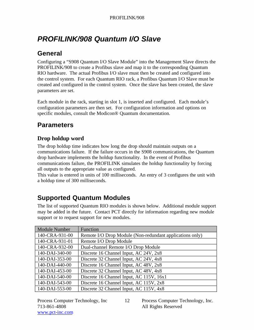
GeneralConfiguring a “S908 Quantum I/O Slave Module” into the Management Slave directs thePROFILINK/908 to create a Profibus slave and map it to the corresponding QuantumRIO hardware. The actual Profibus I/O slave must then be created and configured intothe control system. For each Quantum RIO rack, a Profibus Quantum I/O Slave must becreated and configured in the control system. Once the slave has been created, the slaveparameters are set.
Each module in the rack, starting in slot 1, is inserted and configured. Each module’sconfiguration parameters are then set. For configuration information and options onspecific modules, consult the Modicon® Quantum documentation.
Parameters
Drop holdup wordThe drop holdup time indicates how long the drop should maintain outputs on acommunications failure. If the failure occurs in the S908 communications, the Quantumdrop hardware implements the holdup functionality. In the event of Profibuscommunications failure, the PROFILINK simulates the holdup functionality by forcingall outputs to the appropriate value as configured.This value is entered in units of 100 milliseconds. An entry of 3 configures the unit witha holdup time of 300 milliseconds.
Supported Quantum ModulesThe list of supported Quantum RIO modules is shown below. Additional module supportmay be added in the future. Contact PCT directly for information regarding new modulesupport or to request support for new modules.
Module Number Function140-CRA-931-00 Remote I/O Drop Module (Non-redundant applications only)140-CRA-931-01 Remote I/O Drop Module140-CRA-932-00 Dual-channel Remote I/O Drop Module140-DAI-340-00 Discrete 16 Channel Input, AC 24V, 2x8140-DAI-353-00 Discrete 32 Channel Input, AC 24V, 4x8140-DAI-440-00 Discrete 16 Channel Input, AC 48V, 2x8140-DAI-453-00 Discrete 32 Channel Input, AC 48V, 4x8140-DAI-540-00 Discrete 16 Channel Input, AC 115V, 16x1140-DAI-543-00 Discrete 16 Channel Input, AC 115V, 2x8140-DAI-553-00 Discrete 32 Channel Input, AC 115V, 4x8

PROFILINK/908
Process Computer Technology, Inc 13 Process Computer Technology, Inc.713-861-4808 All Rights Reservedwww.pct-inc.com
Module Number Function140-DAI-740-00 Discrete 16 Channel Input, AC 230V, 16x1140-DAO-840-00 Discrete 16 Channel Output, AC 24-230V, 16x1140-DAO-842-10 Discrete 16 Channel Output, AC 100-230V, 4x4140-DAO-842-20 Discrete 16 Channel Output, AC 24-48V, 4x4140-DAM-590-00 Discrete 16 Channel Input, 8 Channel Output, AC 115V140-DDI-153-10 Discrete 32 Channel Input, DC 5V, 4x8140-DDI-353-00 Discrete 32 Channel Input, DC 24V, 4x8140-DDI-841-00 Discrete 16 Channel Input, DC 10-60V, 8x2140-DDI-853-00 Discrete 32 Channel Input, DC 10-60V, 4x8140-DDO-153-00 Discrete 32 Channel Output, DC 5V, 4x8140-DDO-353-00 Discrete 32 Channel Output, DC 24V, 4x8140-DDO-843-00 Discrete 16 Channel Output, DC 10-60V, 2x8140-DDM-390-00 Discrete 16 Channel Input, 8 Channel Output, DC 24V140-DRA-840-00 Discrete 16 Channel Output, Relay Output (NO)140-DRC-830-00 Discrete 8 Channel Output, Relay Output (NO/NC)140-ACI-030-00 Analog 8 Channel Input, Unipolar140-AVI-030-00 Analog 8 Channel Input, Bipolar140-ACO-020-00 Analog 4 Channel Output, Current140-AVO-020-00 Analog 4 Channel Output, Voltage140-ATI-030-00 Analog 8 Channel Thermocouple Input140-ARI-030-00 Analog 8 Channel RTD Input140-AMM-090-00 Analog 4 Channel Input, 2 Channel Output140-CPS-124-xx 8A Redundant Power supply140-CPS-114-xx 10A Power supply140-CPS-111-xx 3A Power supply
Table 3 Supported Quantum Modules
Redundancy Support ModuleIn addition to physical I/O, the redundancy support module can be installed to retrievemodule health information as Profibus input data. If installed, this must be the lastmodule in the slave.
The Redundancy Support Module returns one bit per module per data path indicating themodule can be accessed. This information is useful in redundant systems to determinewhich data path to use in retrieving input data.
PROFILINK/908 Modicon® 800 Series I/O Slaves
GeneralConfiguring a “S908 800 Series I/O Slave Module” into the Management Slave directsthe PROFILINK/908 to create a Profibus slave and map it to the corresponding

PROFILINK/908
Process Computer Technology, Inc 14 Process Computer Technology, Inc.713-861-4808 All Rights Reservedwww.pct-inc.com
Modicon® 800 Series RIO hardware. The actual Profibus I/O slave must then be createdand configured into the control system. For each Modicon® 800 Series RIO rack, aProfibus S908 800 Series I/O Slave must be created and configured in the control system.Once the slave has been created, the slave parameters (Drop Holdup Time) are set. Eachmodule in the rack, starting in slot 1, is inserted and configured. Each module’sconfiguration parameters are then set.
Parameters
Holdup WordThe drop holdup word indicates how long the drop should maintain outputs in the eventof a communications failure. If the failure occurs in the S908 communications, the 800Series drop hardware implements the holdup functionality. In the event of Profibuscommunications failure, the PROFILINK simulates the holdup functionality by forcingall outputs to zero after the holdup time has expired.
NOTE: All racks on the same drop should have this value set to thesame value. If the Holdup Word is set differently for each rack on thesame drop, the results are unpredictable.
This value is entered in units of 100 milliseconds. An entry of 3 configures the unit witha holdup time of 300 milliseconds.

PROFILINK/908
Process Computer Technology, Inc 15 Process Computer Technology, Inc.713-861-4808 All Rights Reservedwww.pct-inc.com
Supported ModulesModule Number FunctionB802 8 Channel Discrete OutputB803 8 Channel Discrete Input ModuleB804 16 Channel Discrete Output ModuleB805 16 Channel Discrete Input ModuleB806 32 Channel Discrete Output ModuleB807 32 Channel Discrete Input ModuleB808 16 Channel Discrete Output ModuleB809 16 Channel Discrete Input ModuleB810 8 Channel Discrete Output ModuleB814 8 Channel Discrete Output ModuleB816 16 Channel Discrete Output ModuleB817 16 Channel Discrete Input ModuleB818 32 Channel Discrete Output ModuleB819 32 Channel Discrete Input ModuleB820 8 Channel Discrete Output ModuleB821 8 Channel Discrete Input ModuleB824 16 Channel Discrete Output ModuleB825 16 Channel Discrete Input ModuleB826 32 Channel Discrete Output ModuleB827 32 Channel Discrete Input ModuleB828 16 Channel Discrete Output ModuleB829 16Channel Discrete Input ModuleB832 16 Channel Discrete Output ModuleB833 16 Channel Discrete Input ModuleB834 8 Channel Discrete Output ModuleB835 8 Channel Discrete Input ModuleB836 16 Channel Discrete Output ModuleB837 16 Channel Discrete Input ModuleB838 32 Channel Discrete Output ModuleB840 8 Channel Discrete Output ModuleB842 8 Channel Discrete Output ModuleB846 16 Register I/O ModuleB849 16 Channel Discrete Input ModuleB853 16 Channel Discrete Input ModuleB855 16 Channel Discrete Input ModuleB872 4 Channel Analog Output ModuleB873 4 Channel Analog Input ModuleB875 8 Channel Analog Input ModuleB877 6 Channel Analog Input ModuleB881 1 Input, 1 Output Register I/O Module

PROFILINK/908
Process Computer Technology, Inc 16 Process Computer Technology, Inc.713-861-4808 All Rights Reservedwww.pct-inc.com
Module Number FunctionB882 2 Input, 2 Output Register I/O ModuleB883 3 Input, 3 Output Register I/O ModuleB884 4 Input, 4 Output Register I/O ModuleB885 6 Input, 6 Output Register I/O ModuleB886 8 Input, 8 Output Register I/O ModuleB887 12 Input, 12 Output Register I/O ModuleB888 16 Input, 16 Output Register I/O ModuleB883-200 10-channel Thermocouple input module. This module is currently
supported only as an 883 Register I/O Module.P810 Power Supply ModuleJ890 S908 RIO communication Module
Table 4 Supported Modicon ® 800 Series Modules

PROFILINK/908
Process Computer Technology, Inc 17 Process Computer Technology, Inc.713-861-4808 All Rights Reservedwww.pct-inc.com
PROFILINK/908 Operation
StartupDuring startup, the PROFILINK/908 performs the following:The PROFILINK/908 unit performs self tests on the CPU, RAM, Profibus interface andS908 interface. If any of these self-tests fail, the unit will not go online.The S908 RIO configuration and mappings to Profibus are downloaded from the controlsystem via Profibus. This step eliminates all off-line configuration for thePROFILINK/908.Once the complete configuration is downloaded, the PROFILINK/908 starts Profibuscommunications with the host. The PROFILINK/908 will not start scanning the RIOhardware until good output data has been received and verified. During this state, thePROFILINK/908 will communicate with the RIO network in “standby” mode to ensurenetwork integrity.Once all output data has been received, the PROFILINK/908 starts normal scanning.
Profibus DiagnosticsAll S908 module diagnostics are either handled internally by the PROFILINK/908 or aretranslated into standard or vendor-specific Profibus diagnostics for presentation to the usevia the standard control system mechanisms. Diagnostic capabilities vary by family andmodule type within the family. For more information on diagnostics for a particularmodule, refer to the documentation supplied with the module.
Indicators, Switches and Connectors
Figure 2 PROFILINK/908 Front Panel

PROFILINK/908
Process Computer Technology, Inc 18 Process Computer Technology, Inc.713-861-4808 All Rights Reservedwww.pct-inc.com
Figure 3 PROFILINK/908 End Panel
Profibus Interface IndicatorsThe two indicator LEDs below the Profibus connector are indicators for the Profibusinterface status. The meanings of the indicators shown in Figure 3 are as follows:
UpperLED
LowerLED Description
Green Green Normal operation, communicating with host for all slaves.Orange Green Normal internal operation. Not communicating with Host(s) on
one or more slaves. This is also normal operation for standby unitin single Profibus cabling configuration.
Red Off The PROFILINK/908 unit is starting.Green/RedFlickering
Off The PROFILINK/908 unit is initializing and synchronizing withthe host.
Table 5 Profibus Interface Indicators
S908 Interface IndicatorsThe two indicator LEDs below the S908 network connector are indicators for the S908interface status. The meanings of the indicators shown in Figure 3 are as follows:

PROFILINK/908
Process Computer Technology, Inc 19 Process Computer Technology, Inc.713-861-4808 All Rights Reservedwww.pct-inc.com
StandbyLED
Remote I/OActivity LED
Description
Off Off The PROFILINK/908 is starting or has failed.Green Off The PROFILINK/908 is initializing configuration
information. No scanning of I/O is taking place.Green Red
(Dim/Flickering)The PROFILINK/908 unit is operating in Standbymode. This indication is also given when unit hasinitially configured and is performing consistencychecks before scanning I/O.
Off Red(Dim/Flickering)
The PROFILINK/908 unit is functioning normally inPrimary mode.
Table 6 S908 Interface Indicators
General IndicatorsThe general indicators shown in Figure 2 are as follows:
A Side: In redundant configurations, this indicator illuminates to indicate the “A” sidecommunications gateway. For non-redundant, this indicator is always lit.Primary: In redundant configurations, this indicator illuminates to indicate the unit that isscanning the S908 RIO in “Primary” mode, i.e. is performing inputs and outputs.Run: When illuminated, indicates the unit is in running mode.
Setup SwitchesGateway ID: This thumbwheel switch (Fig. 2) sets the Profibus Slave ID for theManagement slave for the PROFILINK/908 unit. In redundant configurations, both partsof the redundant unit must be set to the same ID.S1 and S2 (Fig. 3) select the Profibus Baud Rate:
Baud Rate S1 S2 (Left = Off)500KB On On
1.5MB Off On6MB On Off12MB Off Off
S3 (Fig.3) Simplex/Duplex Profibus: Off = Simplex On = Duplex. Simplex indicates asingle Profibus cable is connected to both sides. In duplex mode, a separate Profibuscable is connected to each side and to different Profibus Master interfaces in the controlsystem host.PRI SELECT/AUTO/PRI LOCK Switch (Fig. 2): This switch has no effect in non-redundant PROFILINK/908.AUTO (Center Position): Will allow automatic “failover” from Primary unit to Backupunit, if Backup unit is running, if a watchdog timeout or a loss of power occurs in thePrimary unit.

PROFILINK/908
Process Computer Technology, Inc 20 Process Computer Technology, Inc.713-861-4808 All Rights Reservedwww.pct-inc.com
PRI SELECT (Momentary): Causes unit to become Primary and scan I/O if unit isrunning.PRI LOCK: Forces unit to be Primary, if unit is running, and “locks out” Standby unitfrom becoming Primary.
ConnectorsRefer to Figure 3 for location of the connectors described below.Profibus Cable: The Profibus cable from the control system host connects to thisconnector. For redundant Simplex installations, a single Profibus cable connects to bothsides of the PROFILINK/908 and to a single Profibus interface in the control system. Forredundant Duplex configurations, each side of the PROFILINK/908 is connected to aseparate Profibus cable to separate Profibus interfaces in the control system host. Caremust be taken to ensure that the “A” side Profibus cable is connected to the “A” sidePROFILINK/908 and to the “A” side S908 RIO cable. Refer to Figure 4, Figure 5 andFigure 6 for typical cabling and installation options.S908 Cable: The S908 RIO cable connects to this connector and to the drop modules ineach Quantum and 800 Series drop.Redundancy Link: For redundant configurations, the redundancy interlink cable connectsboth sides of the PROFILINK/908 together. Care should be taken to ensure that the “A”side of the redundancy interlink cable is connected to the “A” side PROFILINK/908. Fornon-redundant configurations, the Redundancy terminator is placed on this connectorinstead.IPC Link: The interprocessor communication link connects both sides of thePROFILINK/908 together. Status and data is communicated to both sides via this cable.

PROFILINK/908
Process Computer Technology, Inc 21 Process Computer Technology, Inc.713-861-4808 All Rights Reservedwww.pct-inc.com
Typical Installations
Non-Redundant
DCSController
PFB
PROFILINK.908
Quantum Drop
800 SeriesDrop
Pro
fibus
S90
8
800 SeriesRack
800 SeriesRack
Figure 4 Typical Non-redundant Installation

PROFILINK/908
Process Computer Technology, Inc 22 Process Computer Technology, Inc.713-861-4808 All Rights Reservedwww.pct-inc.com
Redundant/Simplex Profibus
S90
8 B
Sid
e
DCSController
PFB
PROFILINK.908A Side
Quantum Drop
800 SeriesDrop
Pro
fibus
S90
8 A
Sid
e
800 SeriesRack
800 SeriesRack
PROFILINK.908 B Side
Figure 5 Typical Redundant Installation with Simplex Profibus Cabling

PROFILINK/908
Process Computer Technology, Inc 23 Process Computer Technology, Inc.713-861-4808 All Rights Reservedwww.pct-inc.com
Redundant/Duplex Profibus
S90
8 B
Sid
e
DCSController
PFBB
PROFILINK.908A Side
Quantum Drop
800 SeriesDrop
Pro
fibus
B
S90
8 A
Sid
e
800 SeriesRack
800 SeriesRack
PROFILINK.908 B Side
PFBA
Pro
fibus
A
Figure 6 Typical Redundant Installation with Duplex Profibus Cabling
PROFILINK/908.doc