Embed Size (px)
Citation preview
Revision 145 Page 1
Profiler MIDI Parameter Documentation
Table of Content List of Tables ............................................................................................................................................ 2
Introduction ............................................................................................................................................. 3
MIDI Commands ...................................................................................................................................... 3
Responses ........................................................................................................................................ 5
NRPN Definition ....................................................................................................................................... 6
Examples .............................................................................................................................................. 6
MIDI Channel vs. Instance ....................................................................................................................... 7
Parameter Types ..................................................................................................................................... 7
Continuous Parameters (e.g. Gain, Volume,) .................................................................................. 7
Switch or Section Parameters (e.g. Type, On/Off Switches) ........................................................... 7
Parameter List ......................................................................................................................................... 7
Rig (Address Page 4) ........................................................................................................................ 7
Input (Address Page 9) .................................................................................................................... 7
Amplifier (Address Page 10) ............................................................................................................ 8
Equalizer (Address Page 11) ............................................................................................................ 8
Cabinet (Address Page 12) .............................................................................................................. 8
Stomp A (Address Page 50) ............................................................................................................. 8
Stomp B (Address Page 51) ........................................................................................................... 10
Stomp C (Address Page 52) ........................................................................................................... 10
Stomp D (Address Page 53) ........................................................................................................... 10
Stomp X (Address Page 56) ........................................................................................................... 11
Stomp MOD (Address Page 58) ..................................................................................................... 11
Stomp DELAY (Address Page 60) ................................................................................................... 11
Delay (Address Page 74) ................................................................................................................ 11
Reverb (Address Page 75).............................................................................................................. 11
System / Global (Address Page 125) ............................................................................................. 11
System / Global (Address Page 127) ............................................................................................. 12
SYSEX Definition .................................................................................................................................... 13
General Message Layout ................................................................................................................... 13
Single Parameter Change .............................................................................................................. 13
Revision 145 Page 2
Multi Parameter Change ............................................................................................................... 14
String Parameter Change .............................................................................................................. 14
BLOB Parameter Change ............................................................................................................... 15
Extended Parameter/Extended String Parameter Change ........................................................... 15
Request Single Parameter ............................................................................................................. 16
Request Multi Parameter .............................................................................................................. 16
Request String Parameter ............................................................................................................. 17
Request Extended String Parameter ............................................................................................. 17
Request Parameter Value as Rendered String .............................................................................. 17
Appendix A (valid ASCII characters) ...................................................................................................... 18
List of Tables Table 1: MIDI commands ......................................................................................................................... 4
Table 2: Example communication for performance mode Preselection ................................................ 5
Table 3: NRPN controller assignments .................................................................................................... 6
Table 4: structure of a Kemper Profiler SYSEX message ....................................................................... 13
Table 5: function codes for Kemper Profiler SYSEX messages .............................................................. 13
Table 6: message part for single parameter change ............................................................................. 13
Table 7: message part for a multi parameter change ........................................................................... 14
Table 8: message part for a string parameter change .......................................................................... 14
Table 9: message part for a BLOB parameter ....................................................................................... 15
Table 10: message part for a single parameter request ....................................................................... 16
Table 11: message part for a multi parameter request ........................................................................ 16
Table 12: message part for a string parameter request........................................................................ 17
Table 13: message part for a string render request .............................................................................. 17
Table 14: ASCII characters allowed in tags ............................................................................................ 18
Revision 145 Page 3
Introduction This document reflects the state of the Profiler firmware version 4.2.1 or higher.
The Kemper Profiler features more than 800 parameters. Of course, you can’t address them all with a standard MIDI controller message, where only 128 parameters can be reached. Therefore, the Kemper Profiler supports the NRPN (Non-Registered Parameter Numbers) protocol additionally to the proprietary SYSEX protocol. Though, there are also MIDI commands at the standard controller range for commonly used functionality.
MIDI Commands The Kemper Profiler supports several simple MIDI commands that can be sent from 3rd-Party MIDI-
Devices that control effects of the current Rig and performance mode.
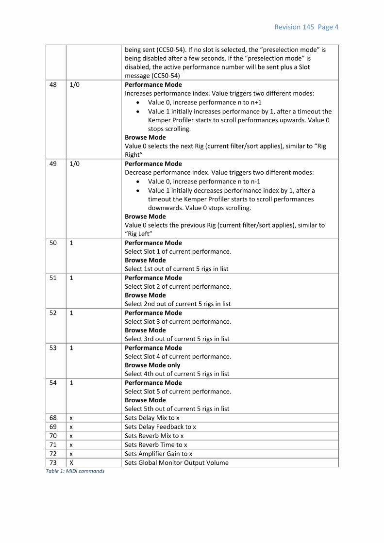
CC Value Remarks
16 Any Toggles all Stomps between On and Off setting. Select Type “Empty” to disable a slot completely.
17 Any Toggles Stomp A between On and Off setting.
18 Any Toggles Stomp B between On and Off setting.
19 Any Toggles Stomp C between On and Off setting.
20 Any Toggles Stomp D between On and Off setting.
22 Any Toggles Stomp X between On and Off setting.
24 Any Toggles Stomp MOD between On and Off setting.
26 Any Toggles Stomp DELAY between On and Off setting.
27 Any Toggles Stomp DELAY between On and Off setting with tail.
28 Any Toggles Reverb between On and Off setting.
29 Any Toggles Reverb between On and Off setting with tail.
30 1/0 Sets Tempo Tap If your floorboard supports separate events on “pressing” and “releasing” a button, send 1 when “pressed” and 0 when “released”. If the floorboard can only send one event, use value 0. When value 1 has been sent and no value 0 for 3 seconds, the Beat Scanner1 is being activated.
31 1/0 1: Show Tuner 0: Hide Tuner
33 0/1 0: Rotary Speaker slow 1: Rotary Speaker fast
342 0/1 0: Delay Feedback Infinity off 1: Delay Feedback infinity on
353 0/1 0: Delay Hold off 1: Delay Hold on
47 [0,124] (Performance Mode only) Preselected performance index4. Can be set directly or scrolled via CC48/CC49. The performance will be loaded when a slot selection is
1 Available in firmware 2.3.0 or later 2 Available in firmware 3.3.0 or later 3 Available in firmware 3.3.0 or later 4 Available in firmware 2.3.0 or later
Revision 145 Page 4
being sent (CC50-54). If no slot is selected, the “preselection mode” is being disabled after a few seconds. If the “preselection mode” is disabled, the active performance number will be sent plus a Slot message (CC50-54)
48 1/0 Performance Mode Increases performance index. Value triggers two different modes:
Value 0, increase performance n to n+1
Value 1 initially increases performance by 1, after a timeout the Kemper Profiler starts to scroll performances upwards. Value 0 stops scrolling.
Browse Mode Value 0 selects the next Rig (current filter/sort applies), similar to “Rig Right”
49 1/0 Performance Mode Decrease performance index. Value triggers two different modes:
Value 0, increase performance n to n-1
Value 1 initially decreases performance index by 1, after a timeout the Kemper Profiler starts to scroll performances downwards. Value 0 stops scrolling.
Browse Mode Value 0 selects the previous Rig (current filter/sort applies), similar to “Rig Left”
50 1 Performance Mode Select Slot 1 of current performance. Browse Mode Select 1st out of current 5 rigs in list
51 1 Performance Mode Select Slot 2 of current performance. Browse Mode Select 2nd out of current 5 rigs in list
52 1 Performance Mode Select Slot 3 of current performance. Browse Mode Select 3rd out of current 5 rigs in list
53 1 Performance Mode Select Slot 4 of current performance. Browse Mode only Select 4th out of current 5 rigs in list
54 1 Performance Mode Select Slot 5 of current performance. Browse Mode Select 5th out of current 5 rigs in list
68 x Sets Delay Mix to x
69 x Sets Delay Feedback to x
70 x Sets Reverb Mix to x
71 x Sets Reverb Time to x
72 x Sets Amplifier Gain to x
73 X Sets Global Monitor Output Volume Table 1: MIDI commands

Revision 145 Page 5
Responses
With firmware 2.3.0, the profiler, if in performance mode, will send back the current performance
number via CC47 and the appropriate slot selection. Example:
Floorboard (or another Client) Kemper Profiler
B0 2F 03 Shows preselected performance 4
B0 31 00 Shows preselected performance 5
B0 2F 04
B0 35 01 Selects and loads Performance 5, Slot 3
B0 35 01 Table 2: Example communication for performance mode Preselection
Revision 145 Page 6
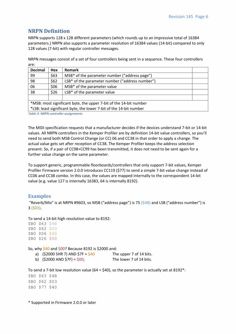
NRPN Definition NRPN supports 128 x 128 different parameters (which rounds up to an impressive total of 16384 parameters.) NRPN also supports a parameter resolution of 16384 values (14-bit) compared to only 128 values (7-bit) with regular controller messages. NRPN messages consist of a set of four controllers being sent in a sequence. These four controllers are:
Decimal Hex Remark
99 $63 MSB* of the parameter number (“address page”)
98 $62 LSB* of the parameter number (“address number”)
06 $06 MSB* of the parameter value
38 $26 LSB* of the parameter value
*MSB: most significant byte, the upper 7-bit of the 14-bit number *LSB: least significant byte, the lower 7-bit of the 14-bit number
Table 3: NRPN controller assignments
The MIDI specification requests that a manufacturer decides if the devices understand 7-bit or 14-bit values. All NRPN controllers in the Kemper Profiler are by definition 14-bit value controllers, so you’ll need to send both MSB Control Change (or CC) 06 and CC38 in that order to apply a change. The actual value gets set after reception of CC38. The Kemper Profiler keeps the address selection present. So, if a pair of CC98+CC99 has been transmitted, it does not need to be sent again for a further value change on the same parameter. To support generic, programmable floorboards/controllers that only support 7-bit values, Kemper Profiler Firmware version 2.0.0 introduces CC119 ($77) to send a simple 7-bit value change instead of CC06 and CC38 combo. In this case, the values are mapped internally to the correspondent 14-bit value (e.g. value 127 is internally 16383, 64 is internally 8192).
Examples “Reverb/Mix” is at NRPN #9603, so MSB (“address page”) is 75 ($4B) and LSB (“address number”) is 3 ($03). To send a 14-bit high resolution value to 8192: $B0 $63 $4B $B0 $62 $03 $B0 $06 $40 $B0 $26 $00
So, why $40 and $00? Because 8192 is $2000 and: a) ($2000 SHR 7) AND $7F = $40 The upper 7 of 14 bits. b) ($2000 AND $7F) = $00; The lower 7 of 14 bits.
To send a 7-bit low resolution value (64 = $40), so the parameter is actually set at 8192*:
$B0 $63 $4B
$B0 $62 $03
$B0 $77 $40
* Supported in Firmware 2.0.0 or later
Revision 145 Page 7
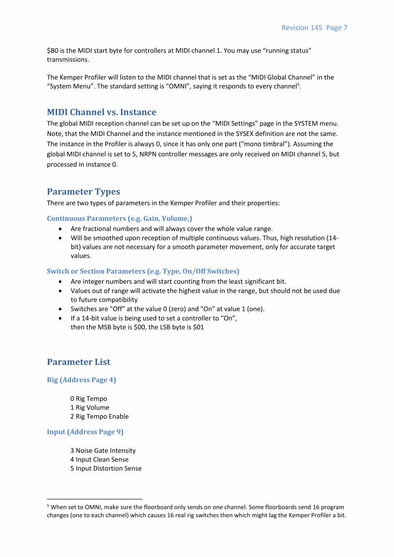
$B0 is the MIDI start byte for controllers at MIDI channel 1. You may use “running status” transmissions. The Kemper Profiler will listen to the MIDI channel that is set as the “MIDI Global Channel” in the “System Menu”. The standard setting is “OMNI”, saying it responds to every channel5.
MIDI Channel vs. Instance The global MIDI reception channel can be set up on the “MIDI Settings” page in the SYSTEM menu.
Note, that the MIDI Channel and the instance mentioned in the SYSEX definition are not the same.
The instance in the Profiler is always 0, since it has only one part (“mono timbral”). Assuming the
global MIDI channel is set to 5, NRPN controller messages are only received on MIDI channel 5, but
processed in instance 0.
Parameter Types There are two types of parameters in the Kemper Profiler and their properties:
Continuous Parameters (e.g. Gain, Volume,)
Are fractional numbers and will always cover the whole value range.
Will be smoothed upon reception of multiple continuous values. Thus, high resolution (14-bit) values are not necessary for a smooth parameter movement, only for accurate target values.
Switch or Section Parameters (e.g. Type, On/Off Switches)
Are integer numbers and will start counting from the least significant bit.
Values out of range will activate the highest value in the range, but should not be used due to future compatibility
Switches are "Off" at the value 0 (zero) and "On" at value 1 (one).
If a 14-bit value is being used to set a controller to “On”, then the MSB byte is $00, the LSB byte is $01
Parameter List
Rig (Address Page 4)
0 Rig Tempo 1 Rig Volume 2 Rig Tempo Enable
Input (Address Page 9)
3 Noise Gate Intensity 4 Input Clean Sense 5 Input Distortion Sense
5 When set to OMNI, make sure the floorboard only sends on one channel. Some floorboards send 16 program changes (one to each channel) which causes 16 real rig switches then which might lag the Kemper Profiler a bit.
Revision 145 Page 8
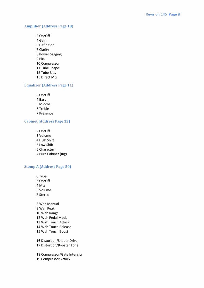
Amplifier (Address Page 10)
2 On/Off 4 Gain 6 Definition 7 Clarity 8 Power Sagging 9 Pick 10 Compressor 11 Tube Shape 12 Tube Bias 15 Direct Mix
Equalizer (Address Page 11)
2 On/Off 4 Bass 5 Middle 6 Treble 7 Presence
Cabinet (Address Page 12)
2 On/Off 3 Volume 4 High Shift 5 Low Shift 6 Character 7 Pure Cabinet (Rig)
Stomp A (Address Page 50)
0 Type 3 On/Off 4 Mix 6 Volume 7 Stereo 8 Wah Manual 9 Wah Peak 10 Wah Range 12 Wah Pedal Mode 13 Wah Touch Attack 14 Wah Touch Release 15 Wah Touch Boost 16 Distortion/Shaper Drive 17 Distortion/Booster Tone 18 Compressor/Gate Intensity 19 Compressor Attack
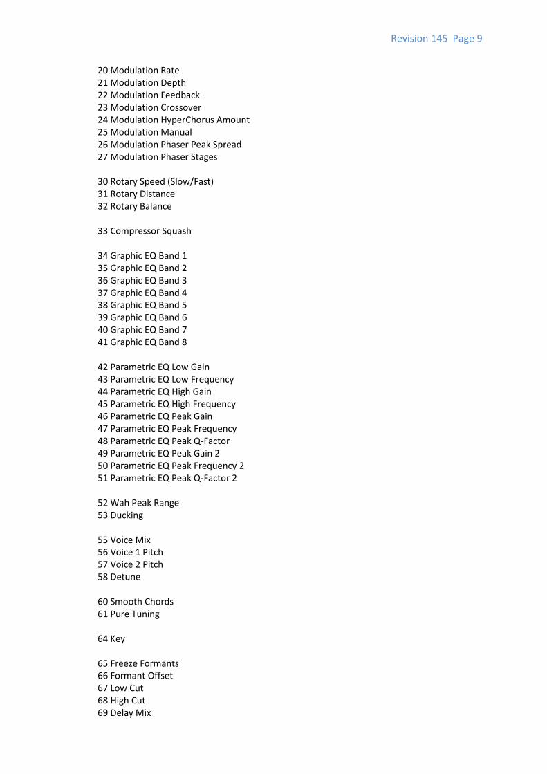
Revision 145 Page 9
20 Modulation Rate 21 Modulation Depth 22 Modulation Feedback 23 Modulation Crossover 24 Modulation HyperChorus Amount 25 Modulation Manual 26 Modulation Phaser Peak Spread 27 Modulation Phaser Stages 30 Rotary Speed (Slow/Fast) 31 Rotary Distance 32 Rotary Balance 33 Compressor Squash 34 Graphic EQ Band 1 35 Graphic EQ Band 2 36 Graphic EQ Band 3 37 Graphic EQ Band 4 38 Graphic EQ Band 5 39 Graphic EQ Band 6 40 Graphic EQ Band 7 41 Graphic EQ Band 8 42 Parametric EQ Low Gain 43 Parametric EQ Low Frequency 44 Parametric EQ High Gain 45 Parametric EQ High Frequency 46 Parametric EQ Peak Gain 47 Parametric EQ Peak Frequency 48 Parametric EQ Peak Q-Factor 49 Parametric EQ Peak Gain 2 50 Parametric EQ Peak Frequency 2 51 Parametric EQ Peak Q-Factor 2 52 Wah Peak Range 53 Ducking 55 Voice Mix 56 Voice 1 Pitch 57 Voice 2 Pitch 58 Detune 60 Smooth Chords 61 Pure Tuning 64 Key 65 Freeze Formants 66 Formant Offset 67 Low Cut 68 High Cut 69 Delay Mix
Revision 145 Page 10
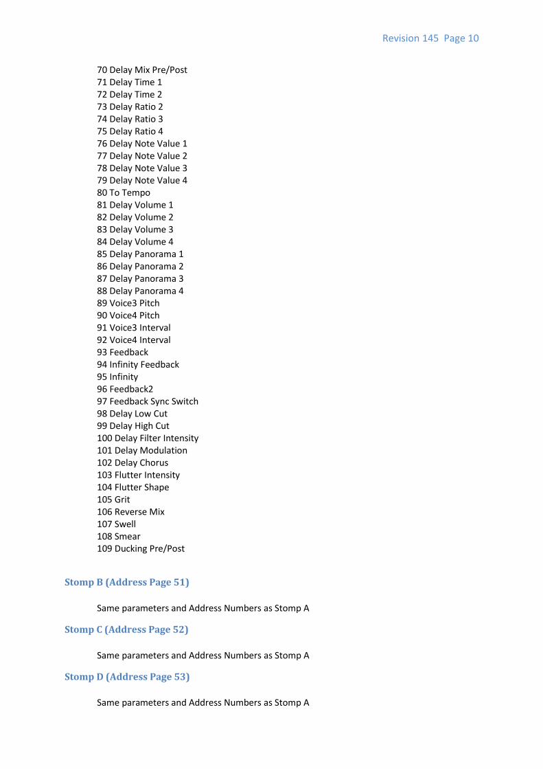
70 Delay Mix Pre/Post 71 Delay Time 1 72 Delay Time 2 73 Delay Ratio 2 74 Delay Ratio 3 75 Delay Ratio 4 76 Delay Note Value 1 77 Delay Note Value 2 78 Delay Note Value 3 79 Delay Note Value 4 80 To Tempo 81 Delay Volume 1 82 Delay Volume 2 83 Delay Volume 3 84 Delay Volume 4 85 Delay Panorama 1 86 Delay Panorama 2 87 Delay Panorama 3 88 Delay Panorama 4 89 Voice3 Pitch 90 Voice4 Pitch 91 Voice3 Interval 92 Voice4 Interval 93 Feedback 94 Infinity Feedback 95 Infinity 96 Feedback2 97 Feedback Sync Switch 98 Delay Low Cut 99 Delay High Cut 100 Delay Filter Intensity 101 Delay Modulation 102 Delay Chorus 103 Flutter Intensity 104 Flutter Shape 105 Grit 106 Reverse Mix 107 Swell 108 Smear 109 Ducking Pre/Post
Stomp B (Address Page 51)
Same parameters and Address Numbers as Stomp A
Stomp C (Address Page 52)
Same parameters and Address Numbers as Stomp A
Stomp D (Address Page 53)
Same parameters and Address Numbers as Stomp A
Revision 145 Page 11
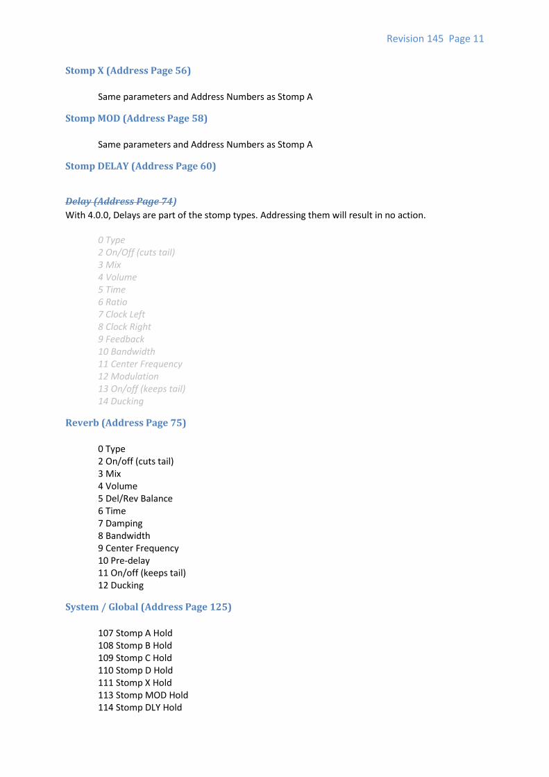
Stomp X (Address Page 56)
Same parameters and Address Numbers as Stomp A
Stomp MOD (Address Page 58)
Same parameters and Address Numbers as Stomp A
Stomp DELAY (Address Page 60)
Delay (Address Page 74)
With 4.0.0, Delays are part of the stomp types. Addressing them will result in no action.
0 Type 2 On/Off (cuts tail) 3 Mix 4 Volume 5 Time 6 Ratio 7 Clock Left 8 Clock Right 9 Feedback 10 Bandwidth 11 Center Frequency 12 Modulation 13 On/off (keeps tail) 14 Ducking
Reverb (Address Page 75)
0 Type 2 On/off (cuts tail) 3 Mix 4 Volume 5 Del/Rev Balance 6 Time 7 Damping 8 Bandwidth 9 Center Frequency 10 Pre-delay 11 On/off (keeps tail) 12 Ducking
System / Global (Address Page 125)
107 Stomp A Hold 108 Stomp B Hold 109 Stomp C Hold 110 Stomp D Hold 111 Stomp X Hold 113 Stomp MOD Hold 114 Stomp DLY Hold
Revision 145 Page 12
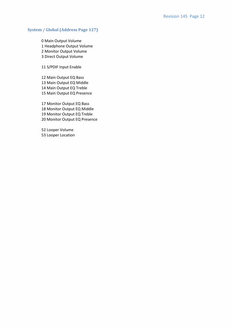
System / Global (Address Page 127)
0 Main Output Volume 1 Headphone Output Volume 2 Monitor Output Volume 3 Direct Output Volume 11 S/PDIF Input Enable 12 Main Output EQ Bass 13 Main Output EQ Middle 14 Main Output EQ Treble 15 Main Output EQ Presence 17 Monitor Output EQ Bass 18 Monitor Output EQ Middle 19 Monitor Output EQ Treble 20 Monitor Output EQ Presence 52 Looper Volume 53 Looper Location
Revision 145 Page 13
SYSEX Definition
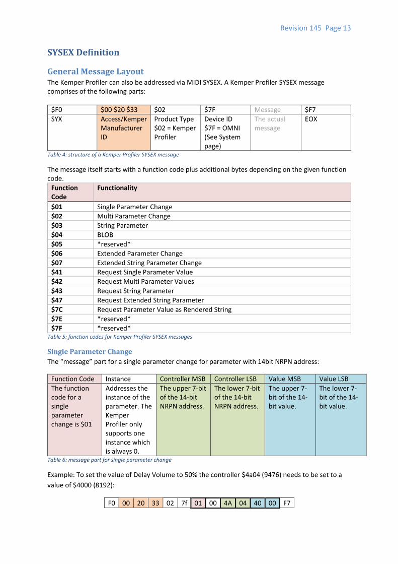
General Message Layout The Kemper Profiler can also be addressed via MIDI SYSEX. A Kemper Profiler SYSEX message comprises of the following parts:
$F0 $00 $20 $33 $02 $7F Message $F7
SYX Access/Kemper Manufacturer ID
Product Type $02 = Kemper Profiler
Device ID $7F = OMNI (See System page)
The actual message
EOX
Table 4: structure of a Kemper Profiler SYSEX message
The message itself starts with a function code plus additional bytes depending on the given function code.
Function Code
Functionality
$01 Single Parameter Change
$02 Multi Parameter Change
$03 String Parameter
$04 BLOB
$05 *reserved*
$06 Extended Parameter Change
$07 Extended String Parameter Change
$41 Request Single Parameter Value
$42 Request Multi Parameter Values
$43 Request String Parameter
$47 Request Extended String Parameter
$7C Request Parameter Value as Rendered String
$7E *reserved*
$7F *reserved* Table 5: function codes for Kemper Profiler SYSEX messages
Single Parameter Change
The “message” part for a single parameter change for parameter with 14bit NRPN address:
Function Code Instance Controller MSB Controller LSB Value MSB Value LSB
The function code for a single parameter change is $01
Addresses the instance of the parameter. The Kemper Profiler only supports one instance which is always 0.
The upper 7-bit of the 14-bit NRPN address.
The lower 7-bit of the 14-bit NRPN address.
The upper 7-bit of the 14-bit value.
The lower 7-bit of the 14-bit value.
Table 6: message part for single parameter change
Example: To set the value of Delay Volume to 50% the controller $4a04 (9476) needs to be set to a
value of $4000 (8192):
F0 00 20 33 02 7f 01 00 4A 04 40 00 F7
Revision 145 Page 14
Multi Parameter Change
To change a whole bunch of parameters you can send multiple values for a whole range of
parameters by using function code $02 and repeating the value MSB/LSB bytes in a message:
Function Code
Instance Controller MSB
Controller LSB
Value MSB Value LSB Value MSB*
Value LSB*
The function code for a single parameter change is $02
Addresses the instance of the parameter. The Kemper Profiler only supports one instance which is always 0.
The upper 7-bit of the 14-bit NRPN address.
The lower 7-bit of the 14-bit NRPN address.
The upper 7-bit of the 14-bit value.
The lower 7-bit of the 14-bit value.
The upper 7-bit of the 14-bit value of the next NRPN address.
The lower 7-bit of the 14-bit value of the next NRPN address.
Repeat with Value MSB/LSB for more values (up to 64 values)
Table 7: message part for a multi parameter change
Example: To set the values for all (numeric) Reverb parameters (starting with $4B00) send:
F0 00 20 33 02 7f 02 00 4B 00 00 03 00 01 00 01 4C 04 .. .. F7
String Parameter Change
A number of parameters do present text (“string”) values. These string parameters do have their own
batch of controller numbers. They exist in parallel to the numeric parameters. E.g. there is one
numeric controller 6400 (“Stomp 1/Type”) and a string controller 6400 which represents the textual
name of a preset loaded in Stomp 1.
The string controllers can be encoded using function code $03 and character bytes using ASCII
encoding:
Function Code Instance Controller MSB Controller LSB Characters… $00
The function code for text value: $03
Addresses the instance of the parameter. The Kemper Profiler only supports one instance which is always 0.
The upper 7-bit of the 14-bit NRPN address (string controller)
The lower 7-bit of the 14-bit NRPN address.
A 7-bit value representing an ASCII character. Concatenate as much characters being necessary. Use only valid characters (see Appendix A (valid ASCII characters))
A null byte ($00) terminating the string.
Table 8: message part for a string parameter change
Revision 145 Page 15
Example: To set the string “Hello” as current rig name (string #0001) send:
F0 00 20 33 02 7f 03 00 00 01 48 65 6C 6C 6F 00 F7
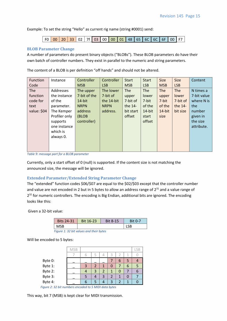
BLOB Parameter Change
A number of parameters do present binary objects (“BLOBs”). These BLOB parameters do have their
own batch of controller numbers. They exist in parallel to the numeric and string parameters.
The content of a BLOB is per definition “off hands” and should not be altered.
Function Code
Instance Controller MSB
Controller LSB
Start MSB
Start LSB
Size MSB
Size LSB
Content
The function code for text value: $04
Addresses the instance of the parameter. The Kemper Profiler only supports one instance which is always 0.
The upper 7-bit of the 14-bit NRPN address (BLOB controller)
The lower 7-bit of the 14-bit NRPN address.
The upper 7-bit of the 14-bit start offset
The lower 7-bit of the 14-bit start offset
The upper 7-bit of the 14-bit size
The lower 7-bit of the 14-bit size
N times a 7-bit value where N is the number given in the size attribute.
Table 9: message part for a BLOB parameter
Currently, only a start offset of 0 (null) is supported. If the content size is not matching the
announced size, the message will be ignored.
Extended Parameter/Extended String Parameter Change
The “extended” function codes $06/$07 are equal to the $02/$03 except that the controller number
and value are not encoded in 2 but in 5 bytes to allow an address range of 231 and a value range of
232 for numeric controllers. The encoding is Big Endian, additional bits are ignored. The encoding
looks like this:
Given a 32-bit value:
Bits 24-31 Bit 16-23 Bit 8-15 Bit 0-7
MSB LSB Figure 1: 32 bit values and their bytes
Will be encoded to 5 bytes:
MSB LSB
7 6 5 4 3 2 1 0
Byte 0: _ _ _ _ 7 6 5 4
Byte 1: _ 3 2 1 0 7 6 5
Byte 2: _ 4 3 2 1 0 7 6
Byte 3: _ 5 4 3 2 1 0 7
Byte 4: _ 6 5 4 3 2 1 0 Figure 2: 32 bit numbers encoded to 5 MIDI data bytes
This way, bit 7 (MSB) is kept clear for MIDI transmission.
Revision 145 Page 16
Request Single Parameter
The function code $41 can be used to request a single numeric value for an NRPN parameter. The
requested value is being send back with function code $01.
Function Code Instance Controller MSB Controller LSB
The function code for a single parameter request is $41
Addresses the instance of the parameter. The Kemper Profiler only supports one instance which is always 0.
The upper 7-bit of the 14-bit NRPN address.
The lower 7-bit of the 14-bit NRPN address.
Table 10: message part for a single parameter request
Example: Request the value of Delay Volume $4a04 (9476):
F0 00 20 33 02 7f 41 00 4A 04 F7
If a parameter is being request that does not exist, the request is being ignored and nothing is being
sent back.
Request Multi Parameter
The function code $42 can be used to request a number of numeric values for an NRPN parameter
block. The requested value is being send back with function code $02. You might notice that there is
no size attribute defined. The response does cover all parameter of the requested unit. Expect up to
128 values.
Function Code Instance Controller MSB Controller LSB
The function code for a single parameter request is $42
Addresses the instance of the parameter. The Kemper Profiler only supports one instance which is always 0.
The upper 7-bit of the 14-bit NRPN address.
The lower 7-bit of the 14-bit NRPN address.
Table 11: message part for a multi parameter request
Example: Request the current values for the Delay effect (starting with controller 94726).
F0 00 20 33 02 7f 42 00 4A 00 F7
In case the controller does not exist or the request does not address the first controller number in a
unit, the request is being ignored. No data is being sent back.
6 The Kemper Profiler only responds to requests that encode the first controller number of a parameter block. Others might be ignored or the result might cover the whole block. You cannot request “snippets” of a unit.
Revision 145 Page 17
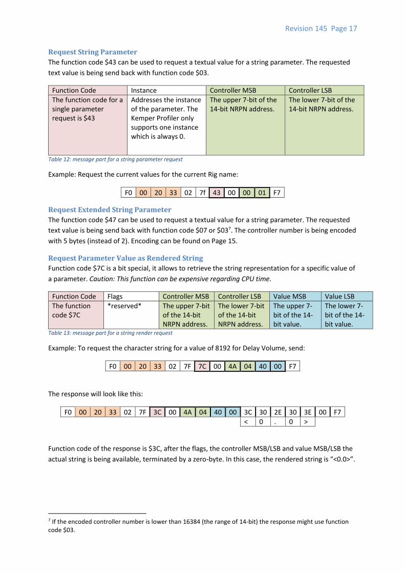
Request String Parameter
The function code $43 can be used to request a textual value for a string parameter. The requested
text value is being send back with function code $03.
Function Code Instance Controller MSB Controller LSB
The function code for a single parameter request is $43
Addresses the instance of the parameter. The Kemper Profiler only supports one instance which is always 0.
The upper 7-bit of the 14-bit NRPN address.
The lower 7-bit of the 14-bit NRPN address.
Table 12: message part for a string parameter request
Example: Request the current values for the current Rig name:
F0 00 20 33 02 7f 43 00 00 01 F7
Request Extended String Parameter
The function code $47 can be used to request a textual value for a string parameter. The requested
text value is being send back with function code $07 or $037. The controller number is being encoded
with 5 bytes (instead of 2). Encoding can be found on Page 15.
Request Parameter Value as Rendered String
Function code $7C is a bit special, it allows to retrieve the string representation for a specific value of
a parameter. Caution: This function can be expensive regarding CPU time.
Function Code Flags Controller MSB Controller LSB Value MSB Value LSB
The function code $7C
*reserved* The upper 7-bit of the 14-bit NRPN address.
The lower 7-bit of the 14-bit NRPN address.
The upper 7-bit of the 14-bit value.
The lower 7-bit of the 14-bit value.
Table 13: message part for a string render request
Example: To request the character string for a value of 8192 for Delay Volume, send:
F0 00 20 33 02 7F 7C 00 4A 04 40 00 F7
The response will look like this:
F0 00 20 33 02 7F 3C 00 4A 04 40 00 3C 30 2E 30 3E 00 F7
< 0 . 0 >
Function code of the response is $3C, after the flags, the controller MSB/LSB and value MSB/LSB the
actual string is being available, terminated by a zero-byte. In this case, the rendered string is “<0.0>”.
7 If the encoded controller number is lower than 16384 (the range of 14-bit) the response might use function code $03.
Revision 145 Page 18
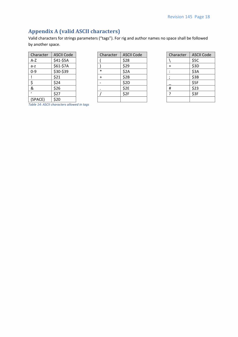
Appendix A (valid ASCII characters) Valid characters for strings parameters (“tags”). For rig and author names no space shall be followed
by another space.
Character ASCII Code Character ASCII Code Character ASCII Code
A-Z $41-$5A ( $28 \ $5C
a-z $61-$7A ) $29 = $3D
0-9 $30-$39 * $2A : $3A
! $21 + $2B ; $3B
$ $24 - $2D _ $5F
& $26 . $2E # $23
‘ $27 / $2F ? $3F
(SPACE) $20 Table 14: ASCII characters allowed in tags